JP6552112B2 - Small animal breeding equipment - Google Patents
Small animal breeding equipment Download PDFInfo
- Publication number
- JP6552112B2 JP6552112B2 JP2016066173A JP2016066173A JP6552112B2 JP 6552112 B2 JP6552112 B2 JP 6552112B2 JP 2016066173 A JP2016066173 A JP 2016066173A JP 2016066173 A JP2016066173 A JP 2016066173A JP 6552112 B2 JP6552112 B2 JP 6552112B2
- Authority
- JP
- Japan
- Prior art keywords
- cage
- frame
- rack
- lid
- air supply
- Prior art date
- Legal status (The legal status is an assumption and is not a legal conclusion. Google has not performed a legal analysis and makes no representation as to the accuracy of the status listed.)
- Active
Links
Images


Classifications
-
- A—HUMAN NECESSITIES
- A01—AGRICULTURE; FORESTRY; ANIMAL HUSBANDRY; HUNTING; TRAPPING; FISHING
- A01K—ANIMAL HUSBANDRY; AVICULTURE; APICULTURE; PISCICULTURE; FISHING; REARING OR BREEDING ANIMALS, NOT OTHERWISE PROVIDED FOR; NEW BREEDS OF ANIMALS
- A01K1/00—Housing animals; Equipment therefor
- A01K1/0047—Air-conditioning, e.g. ventilation, of animal housings
Landscapes
- Life Sciences & Earth Sciences (AREA)
- Environmental Sciences (AREA)
- Zoology (AREA)
- Animal Husbandry (AREA)
- Biodiversity & Conservation Biology (AREA)
- Housing For Livestock And Birds (AREA)
Description
本発明は、医療研究などに用いられるマウスなどの小動物を飼育するための飼育装置に関するものである。 The present invention relates to a rearing device for rearing small animals such as mice used for medical research and the like.
一般的な飼育ケースは、ケージ入れ替えなどの都度、扉を開閉させなければならず、その都度飼育ケース内外の空気が混ざってしまい、外気の雑菌が飼育ケース内に侵入したり、ケージ内の汚損物が外部に放出されたりする虞があるという問題があった。 In general rearing cases, the door must be opened and closed each time the cage is replaced, and the air inside and outside the rearing case is mixed each time, and various bacteria in the outside air intrude into the rearing case, and the inside of the cage is contaminated. There was a problem that there was a risk that things would be released to the outside.
このような問題点を解決し、飼育装置内外の空気が混ざる虞がなく、手間がかからず、安価な飼育装置として、ケージをラックに挿入した時に、ラックに設けられた下方に開口したラック側給気口とケージに設けられたケージ側給気口とが連結する飼育装置が提案されている(特許文献1)。 There is no possibility that the air inside and outside the breeding apparatus will be mixed, and it takes less time and effort, and when the cage is inserted into the rack, a rack opened in the lower part of the rack. There has been proposed a breeding apparatus in which a side air supply port and a cage side air supply port provided in a cage are connected (Patent Document 1).
この装置によれば、ケージ単位でバリアを構築でき、給気口の接続、開閉を容易に行えるという利点を有するが、ラック側給気口とケージ側給気口との連結に加わる力は、ケージの押入力のみなので、当該連結部の気密性が十分ではなく、排気口は室内に開放しているのでケージ内の臭気が室内に流入し、停電などで給気ダクトからの給気が停止すると、前記排気口より室内の細菌などがケージ内に侵入してしまう危険性があった。 According to this device, a barrier can be constructed in units of cages, and there is an advantage that the supply port can be easily connected and opened / closed, but the force applied to the connection between the rack-side supply port and the cage-side supply port is: Since only the pushing force is applied to the cage, the airtightness of the connecting part is not sufficient, and since the exhaust port is open to the room, odors in the cage flow into the room, and supply from the air supply duct stops due to a power failure, etc. Then, there was a risk that indoor bacteria and the like would enter the cage from the exhaust port.
また、マウスなど小動物用のケージを複数収納する筐体を備えた小動物飼育装置において、筐体の後部側に支柱を設け、その支柱の上下方向に間隔を置いて、略U字状のアームを前後方向スライド自在に設けると共に前方にスライドした着脱位置で上下回動可能に設け、その各U字状のアームに、ケージのフランジを着脱自在に係合して保持させ、そのアームの後方にスライドした固定位置の上方に、その各ケージ内を換気するための給排気手段を設けたものが提案されている(特許文献2)。 In addition, in a small animal breeding apparatus provided with a housing for storing a plurality of cages for small animals such as mice, a support is provided on the rear side of the housing, and a substantially U-shaped arm is provided at intervals in the vertical direction of the support. Provided to be slidable in the front-rear direction and provided to be pivotable up and down at the attachment / detachment position slid forward. The U-shaped arms detachably engage and hold the cage flange, and slide to the rear of the arms. There has been proposed a device provided with air supply / exhaust means for ventilating the inside of each cage above the fixed position (Patent Document 2).
この装置は、ケージ毎に、給気、排気を個別に行うため、外気と各ケージ内及び各ケージ相互間の空気が互いに混入するのを防ぐことができ、ケージの空気取入口と給気水平ダクトの給気口は、外周をフードカバーに覆われてシールされているため、外気がケージ内に侵入することもなく、ケージの空気排出口と排気水平ダクトの排気口も、外周をフードカバーに覆われてシールされているため、ケージ内の汚れた空気が外部に漏れることもなく、各ケージの通気性を個々に保ちつつ、各ケージ相互間及びケージ2内の汚損空気の外部への放出を防止できるといった効果を奏することができた。 Since this device supplies and exhausts air separately for each cage, it can prevent the outside air and air in each cage and between each cage from being mixed with each other. Since the air supply port of the duct is sealed with the outer periphery covered with a hood cover, outside air does not enter the cage, and the air discharge port of the cage and the exhaust port of the exhaust horizontal duct also have a hood cover on the outer periphery. Since the air in the cage is not covered with the air and leaked to the outside, the air permeability of the cages is kept individually, while the air in the cage 2 and the outside of the air in the cage 2 are exposed to the outside. The effect of being able to prevent the release was achieved.
しかしながら、上述の飼育装置は、各ケージを筐体内に収納した後、ケージをその上方に設けた給排気手段に接続するため、U字状のアームにケージのフランジを係合させて回動し、ケージを上方に移動させる必要があった。
このように、従来の飼育装置は、ケージの装着に2工程の操作が必要で手間がかかると共に、装脱着時にケージが上下に移動するので、外部からケージ内への給水手段を設けることが困難であり、また、ケージを収納する際、底面を摺動させるため振動や騒音が発生するので、ケージ内の小動物に対するストレスの原因となった。
However, after housing each cage in the housing, the above-mentioned breeding apparatus engages the U-shaped arm with the flange of the cage and turns it in order to connect the cage to the air supply and discharge means provided above it. It was necessary to move the cage upward.
As described above, the conventional breeding apparatus requires two steps to mount the cage, which is troublesome, and the cage moves up and down at the time of loading and unloading. Therefore, it is difficult to provide water supply means to the cage from the outside. Also, when the cage is stored, vibration and noise are generated due to the sliding of the bottom surface, which causes stress on small animals in the cage.
かかる問題点を解決するため、ケージを上下動させるのではなく、ケージを飼育装置の枠体に挿入する動作により、伸縮自在なジャバラ付の給排気フードの開口部をケージ蓋に設けた給排気口に密着させるようにした小動物用飼育装置が提案された(特許文献3)。 In order to solve such problems, the air supply / exhaust in which the opening / closing of the air supply / exhaust hood with retractable bellows is provided in the cage lid by the operation of inserting the cage into the frame of the breeding device instead of moving the cage up and down. There has been proposed a small animal breeding apparatus that is brought into close contact with the mouth (Patent Document 3).
しかし、この飼育装置では、ケージの上方に伸縮自在なジャバラ付の給排気フードの開口部を設置しなければならず、そのためのスペースを必要とし、また、確実な機密状態を形成するため、ジャバラの収縮力に抗してケージ蓋の給排気口に強い力で密着させなければならなかった。 However, in this breeding apparatus, the opening of the telescopic bellows-equipped air supply and exhaust hood has to be installed above the cage, which requires a space for it, and in order to form a reliable security state, the bellows is required. It had to be brought into close contact with the air outlet of the cage lid against the contraction force of the
本発明は、従来の小動物飼育装置が有する問題点を解決するものであって、ケージの収納スペース効率が良く、ケージの出し入れが簡単で、装置に装着する際、ケージに与えられる振動や騒音が少なく、ケージ内の換気や、ケージへの給水手段の取り付けが容易な小動物飼育装置を提供することを目的とする。 The present invention solves the problems of the conventional small animal breeding device, which is efficient in the storage space of the cage, easy to put in and out of the cage, and is free from vibration and noise given to the cage when mounted on the device. An object of the present invention is to provide a small animal breeding device that is easy to ventilate the cage and attach the water supply means to the cage.
本発明者らは、ラックに回動可能に支持されている枠体に給気フード及び排気フードを固定し、飼育ケージの蓋体に開口した給排気口に連通するようにすれば、少ないスペースで、給排気ダクトとケージ内を確実に連通させることができることに想い至り、本発明に至った。 The present inventors fix the air supply hood and the exhaust hood to the frame rotatably supported by the rack, and communicate with the air supply / exhaust port opened in the lid of the rearing cage, thereby reducing the space. Thus, the inventors came up with the idea that the air supply / exhaust duct and the inside of the cage can be reliably communicated with each other.
本発明の実施の態様は以下の通り。
(1)複数の飼育ケージを収納可能なラック、
前記ラックに回転可能に支持されている枠体に固定された給気フード及び排気フード、
給気ダクトと前記給気フード、排気ダクトと前記排気フードを接続するジャバラ、
蓋体と容器本体からなる飼育ケージ、からなる小動物用飼育装置において、
前記蓋体には、飼育ケージを飼育装置のラックに挿入したとき、前記枠体の一部と接触し、枠体を上方に移動させる斜面と、飼育ケージがラック内の所定の位置まで挿入された時、前記枠体の一部が嵌合して、前記枠体を下方に移動させ、前記給気フードを前記蓋体に形成された給気口に、前記排気フードを前記蓋体に形成された給排気口に、それぞれ接合させる、凹部が形成され、
前記枠体を上方に移動させ、枠体の一部とケージ蓋体に形成された凹部との係合を外す手段と、前記枠体の一部とケージ蓋体に形成された凹部との係合を外された時に、当該飼育ケージをラックの外方向に移動させる付勢手段、
を備えていることを特徴とする小動物用飼育装置。
(2)前記蓋体の斜面と接触する前記枠体の一部が、枠体に回転軸が固定された回転ローラーである(1)の小動物用飼育装置。
(3)前記ラックに回転可能に支持されている枠体が、下方向に回動するよう付勢されている請(1)又は(2)の小動物用飼育装置。
Embodiments of the present invention are as follows.
(1) A rack capable of storing a plurality of breeding cages,
An air supply hood and an exhaust hood fixed to a frame body rotatably supported by the rack;
Bellows connecting the air supply duct and the air supply hood, the exhaust hood and the exhaust duct,
In a breeding apparatus for small animals comprising a breeding cage comprising a lid and a container body,
When the rearing cage is inserted into the rack of the rearing apparatus, the lid contacts with a part of the frame to move the frame upward, and the rearing cage is inserted to a predetermined position in the rack. When the frame body is partially fitted, the frame body is moved downward, the air supply hood is formed in the air supply port formed in the lid body, and the exhaust hood is formed in the lid body. Recesses that are joined to the air supply / exhaust ports are formed,
Means for moving the frame upward to disengage the part of the frame from the recess formed in the cage lid, and the relationship between the part of the frame and the recess formed in the cage lid An urging means for moving the breeding cage to the outside of the rack when the joint is removed;
A small animal breeding apparatus comprising:
(2) The small animal breeding apparatus according to (1), wherein a part of the frame in contact with the slope of the lid is a rotating roller having a rotating shaft fixed to the frame.
(3) The breeding apparatus for small animals according to (1) or (2), wherein the frame rotatably supported by the rack is biased to pivot downward.
本発明の飼育ケージは、内部が目視でき、高温殺菌可能な、透明プラスチック製であり、耐熱性や耐薬品性に優れたものが好適に使用できる。 The rearing cage of the present invention is made of a transparent plastic which can be seen inside and which can be sterilized by high temperature and which is excellent in heat resistance and chemical resistance.
本発明の給排気フードの開口の形状は問わないが、飼育ケージの蓋体に形成された給排気口を同じ形状とし、給排気フードの開口及び/又は蓋体の給排気口の縁部に弾性のガスケットを装着し、給排気フードとケージの給排気口との気密性を保つ。 The shape of the supply and exhaust hood opening of the present invention is not limited, the supply and exhaust port formed in the lid of the breeding cage with the same shape, the edge of the supply and exhaust vent openings and / or the lid of the supply and exhaust hoods Equipped with an elastic gasket to maintain airtightness between the air supply / exhaust hood and the air supply / exhaust port of the cage.
給排気ダクトは、本発明のラックに取り付けられ、各飼育ケージと連通させるための開口を有するが、当該開口は、飼育ケージの収納部ごとに設けることが好ましい。 The air supply and exhaust duct is attached to the rack of the present invention and has an opening for communicating with each breeding cage, but the opening is preferably provided for each storage section of the breeding cage.
飼育ケージの蓋体に設ける斜面と凹部は、給排気フードを固定した枠体を上下動させ得れば、設置位置を問わないが、枠体を確実かつ安定して上下動させるには、蓋体の両端部に設け、枠体の両端部と接触するよう構成することが好ましい。 The slopes and recesses provided on the lid of the rearing cage can be moved up and down the frame to which the air supply and exhaust hood is fixed, regardless of the installation position, but the lid is used to move the frame up and down reliably and stably. It is preferable to provide at both ends of the body and to be in contact with both ends of the frame.
枠体の一部とケージ蓋体に形成された凹部との係合を外す手段は、飼育ケージ側に設けても、ラック側に設けてもよいが、飼育ケージは洗浄や殺菌処理をする必要があることからラック側に設けることが好ましい。 The means for releasing the engagement between a part of the frame and the recess formed in the cage lid may be provided on the rearing cage side or on the rack side, but the rearing cage needs to be cleaned and sterilized. Therefore, it is preferably provided on the rack side.
ラックに回転可能に支持されている枠体に給気フード及び排気フードを固定し、飼育ケージの蓋体に開口した給排気口に連通するようにしたので、少ないスペースで、給排気ダクトとケージ内を確実に連通させることができ、飼育ケージがラック内の所定の位置まで挿入された時、前記枠体の一部が嵌合するので、飼育ケージをラック内の所定の位置に保持することができ、また、枠体を上方に移動させ、枠体の一部とケージ蓋体に形成された凹部との係合を外すと、付勢手段により飼育ケージがラックの外方向に押し出されるので、ラックから飼育ケージを取り出すのが容易となり、枠体の一部とケージ蓋体に形成された凹部と再係合することが防がれる。 The air supply hood and the exhaust hood are fixed to the frame rotatably supported by the rack, and are communicated with the air supply and exhaust ports opened in the lid of the rearing cage, so the air supply and exhaust duct and the cage can be performed in a small space. The interior can be reliably communicated, and when the breeding cage is inserted to a predetermined position in the rack, a part of the frame is fitted, so that the breeding cage is held in the predetermined position in the rack In addition, when the frame is moved upward and the engagement between a part of the frame and the recess formed in the cage lid is released, the feeding cage is pushed out of the rack by the biasing means. This facilitates removal of the rearing cage from the rack and prevents reengagement with a part of the frame and the recess formed in the cage lid.
また、給排気の開口部が比較的大きくてもケージ内と給排気ダクトとが確実に気密性が保てるので、ケージ内の気流の速度を低く抑えることができ飼育小動物に与えるストレスを小さくすることができる。 In addition, air tightness can be reliably maintained in the cage and the air supply / exhaust duct even if the air supply / exhaust opening is relatively large, so the air flow speed in the cage can be suppressed to a low level, and the stress given to the breeding small animals can be reduced. Can do.
本発明の飼育装置を図面で説明する。
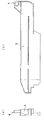
図1は、飼育ケージを収納するラック1の一部を示す図で、飼育ケージの収納スペースは両側が複数の支柱2で区画されている。
The breeding apparatus of the present invention will be described with reference to the drawings.
FIG. 1 is a view showing a part of a rack 1 for storing breeding cages, and the storage space of the breeding cage is divided by a plurality of columns 2 on both sides.
ラック1の飼育ケージが収納される空間の両側の支柱2には、ラックレール3が固定され、ラックレール3には、図2に示されるように、飼育ケージのフランジ11に係合する溝部9及びバランスリンク5の軸受4が形成され、当該軸受4に連結したバランスリンク5の他端は、給気フード7及び排気フード8が固定された枠体6と連結され、枠体6の両側には回転ローラー22が軸支されている。
Rack rails 3 are fixed to the pillars 2 on both sides of the space in which the breeding cage of the rack 1 is accommodated, and the rack rail 3 has a
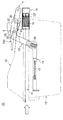
図3は、飼育ケージ10の側面図で、蓋体12と容器本体13からなり、両者は図示されないガスケットを介して、気密性が保持された状態で結合している。
両者の結合部分には、前記ラックレール3に形成された溝部9と係合するフランジ11が形成されている。
FIG. 3 is a side view of the
A
前記給排気フード7,8は、夫々ラック1の背面に固定された給排気ダクト25,26とジャバラ23,24を介して接続されている。
飼育ケージ10の蓋体12には、前記枠体6に軸支された回転ローラー22と接触し、飼育ケージをラック内に押し込める方向に移動させると、前記枠体を上方に移動させる斜面20と、飼育ケージ11をラック内の所定位置まで移動したとき、前記回転ローラー22と嵌合する凹部21が形成されている。16は、前記ラック側に取り付けられた飼育ケージ解放手段であり、復元バネ19とそれに連結されたフック27からなる。
The air supply and
The
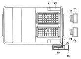
図4は飼育ケージ10の平面図で、前記給排気フード7,8と接続する給排気口28,29が形成されている。前記ラック側に取り付けられた飼育ケージ解放手段16のフック27は、飼育ケージ10の先端側面と係合しており、飼育ケージ10をラックの所定位置まで移動させると、前記フック27も移動し、前記復元バネ19が圧縮するので、飼育ケージ11の端側面を係止しているフック17が、飼育ケージ10をラックの外方に飛び出させる方向に付勢することとなる。
Figure 4 is a plan view of the
図5〜7に、飼育ケージをラックに収納する工程を示す。 5-7 shows the process of storing a breeding cage in a rack.
図5は、ラック1内に飼育ケージ10を収納し始めたところを示す。図のように当初、回転ローラー22は飼育ケージ蓋体12に形成された斜面20と接触していない。さらに飼育ケージを押し込むと、回転ローラー22は蓋体の斜面20と接触し、給排気フード7,8を固定した枠体6を上方に移動させるので、飼育ケージの押し込み時に給排気フードが飼育ケージの蓋体と接触ことが避けられる。
FIG. 5 shows the start of housing the
図6は、さらに、飼育ケージ10を押し込めたところを示し、回転ローラー22が斜面20に当接して押し上げられるに従い、枠体6もさらに上方に移動するとともに、飼育ケージの先端側面に前記フック27が当接し、復元バネ19を圧縮させる。
FIG. 6 further shows that the
飼育ケージ10を所定の位置まで押し込めると、図7に示されるように、前記回転ローラー22は、蓋体に形成された斜面20に連続して形成された凹部21に嵌合し、フック27の移動により前記復元バネ19は最大限圧縮された状態となる。
When the
この状態では、回転ローラー22は、前記凹部21にしっかり嵌合するので、飼育ケージ11は所定に位置に固定され、回転ローラー22の下方への移動に伴い、枠体6に固定された給排気フード7,8も下方に移動し、飼育ケージの蓋体に形成された給排気口28,29とそれぞれが接続する。この時、後述するロックレバーロット15に内在する復元バネ18により、ロットが縮小する方向に付勢されているので、給排気フード7,8とケージ蓋体の給排気口との気密性が保たれる。
In this state, since the rotating
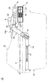
図7は、飼育ケージ10をラックから取り出す場合の操作を示す。
飼育ケージをラックから取り出すには、ラックレール3に摺動自在に取り付けられた、排出レバー14を押し込むことにより、排出レバー14の先端と前駆枠体6とにそれぞれ連結されたロックレバーロット15が、排出レバー14の水平方向の移動を、垂直方向の移動に変換して枠体6を上方に移動させる。
FIG. 7 shows an operation for removing the
In order to take out the breeding cage from the rack, the
枠体6の上昇により回転ローラー22と蓋体凹部21との係合が外れると、前記復元フック27の付勢力により、飼育ケージ10はラックの外側方向に飛び出すので、飼育ケージ10をラックから容易に取り出すことができる。このとき、ロックレバーロット15に設けられたピン32が、枠体6に設けられた長孔33の上端部に当接し、枠体6をほぼ水平に保つので、飼育ケージ10が移動する際、蓋体12と接触することが避けられる。
When the engagement between the
排出レバー14には復元バネ17が取り付けられ、排出レバー14は元の位置に戻るよう設定されているが、上述したように、フック27により飼育ケージ10には常時ラックの外側方向に付勢されており、回転ローラー22と蓋体凹部21との係合が外れると同時に飼育ケージ10はラックの外方に飛び出すので、排出レバー14が元の位置に戻っても、回転ローラー22が蓋体凹部21と再び係合することはない。
A restoring
また、ロックレバーロット15には、所定の長さ以下には伸縮せず、所定の長さを超える場合に伸縮自在となるよう復元バネ18が装着されている。
したがって、飼育ケージの収納時に枠体6が上方に移動しても、ロックレバーロット15が伸張して追従するので、飼育ケージをスムーズに収納でき、さらに、所定の長さ以下には伸縮しないので、排出レバー14の押し込みによる枠体6の上方への移動は確実に行うことができる。
また、回転ローラー22が凹部21に係合したときに、ロックレバーロット15が若干伸張した状態となるようにすれば、復元バネ18の復元力により、給排気フード7,8が給排気開口部28,29に押し付けられるので、両者の密封が確実に行われる。
In addition, a restoring
Therefore, even if the
If the
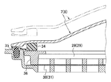
図8は、飼育ケージの蓋体に設けられた給排気開口部28,29と給排気フード7,8の接触部の拡大図であり、想像線は、飼育ケージ排出時の状態を示す。
FIG. 8 is an enlarged view of a contact portion between the air supply /
給排気開口部28,29は、多数の開口を有する格子状部材で構成され、これらの開口は、固定具36で固定されたフィルター30,31で覆い、常時、外気からの細菌の侵入を防いでいる。
The air supply and
飼育ケージ10をラック1内に収納したときは、給排気開口部28、29は給排気フード7,8と接触するが、この時給排気開口部の周囲に取り付けたOリング35が給排気フードの周縁に取り付けたガスケットに押し付けられ、確実に気密性が保たれる。
When housing the
飼育ケージ10が所定の位置まで押し込まれていないと、給排気開口部28、29は給排気フード7,8と完全に接触せず、飼育ケージ内の換気が不完全、もしくは全く行われない状態となってしまう。
このような事故を未然に防ぐため、ラック1に飼育ケージ10が所定の位置に収納されたことを検知する手段を設け、操作者に、給排気開口部28、29は給排気フード7,8と完全に接触したか否かを表示させることが望ましい。
If the rearing
Order to prevent such an accident, rearing
1 飼育ケージを収納するラック
2 ラックを構成する支柱
3 ラックレール
4 軸受
5 バランスリンク
6 枠体
7 給気フード
8 排気フード
9 溝部
10 飼育ケージ
11 フランジ部
12 蓋体
13 容器本体
14 排出レバー
15 ロックレバーロット
16 ケージ解放手段
17〜19 復元バネ
20 斜面
21 凹部
22 回転ローラー
23、24 ジャバラ
25、26 給排気ダクト
27 解放フック
28 給気開口部
29 排気開口部
30、31 フィルター
32 ピン
33 長孔
34 ガスケット
35 Oリング
36 固定具
DESCRIPTION OF SYMBOLS 1 Rack 2 for storing a rearing cage 2 pillars constituting rack 3 rack rail 4 bearing 5
Claims (3)
前記ラックに回動可能に支持されている枠体に固定された給気フード及び排気フード、
給気ダクトと前記給気フード、排気ダクトと前記排気フードを、それぞれ接続するジャバラ、
蓋体と容器本体からなる飼育ケージ、を含む小動物用飼育装置において、
前記蓋体には、飼育ケージを飼育装置のラックに挿入したとき、前記枠体の一部と接触し、枠体を上方に移動させる斜面と、飼育ケージがラック内の所定の位置まで挿入された時、前記枠体の一部が嵌合して、前記枠体を下方に移動させ、前記給気フードを前記蓋体に形成された給気口に、前記排気フードを前記蓋体に形成された排気口に、それぞれ接合させる、凹部が形成され、
前記枠体を上方に移動させ、枠体の一部とケージ蓋体に形成された凹部との係合を外す手段と、前記枠体の一部とケージ蓋体に形成された凹部との係合を外された時に、当該飼育ケージをラックの外方向に移動させる付勢手段、
を備えていることを特徴とする小動物用飼育装置。 Rack that can store multiple breeding cages,
An air supply hood and an exhaust hood fixed to a frame body rotatably supported by the rack;
The air supply duct and the air supply hood, the exhaust hood and the exhaust duct, respectively connected bellows,
In a breeding apparatus for small animals including a breeding cage comprising a lid and a container body,
When the rearing cage is inserted into the rack of the rearing apparatus, the lid contacts with a part of the frame to move the frame upward, and the rearing cage is inserted to a predetermined position in the rack. When the frame body is partially fitted, the frame body is moved downward, the air supply hood is formed in the air supply port formed in the lid body, and the exhaust hood is formed in the lid body. Recesses that are joined to the exhaust ports respectively formed are formed,
Means for moving the frame upward to disengage the part of the frame from the recess formed in the cage lid, and the relationship between the part of the frame and the recess formed in the cage lid An urging means for moving the breeding cage to the outside of the rack when the joint is removed;
A small animal breeding apparatus comprising:
3. The small animal breeding apparatus according to claim 1, wherein the frame rotatably supported by the rack is biased to pivot downward.
Priority Applications (2)
| Application Number | Priority Date | Filing Date | Title |
|---|---|---|---|
| JP2016066173A JP6552112B2 (en) | 2016-03-29 | 2016-03-29 | Small animal breeding equipment |
| CN201611026615.7A CN107232068B (en) | 2016-03-29 | 2016-11-15 | Raising device for small animals |
Applications Claiming Priority (1)
| Application Number | Priority Date | Filing Date | Title |
|---|---|---|---|
| JP2016066173A JP6552112B2 (en) | 2016-03-29 | 2016-03-29 | Small animal breeding equipment |
Publications (2)
| Publication Number | Publication Date |
|---|---|
| JP2017175994A JP2017175994A (en) | 2017-10-05 |
| JP6552112B2 true JP6552112B2 (en) | 2019-07-31 |
Family
ID=59982989
Family Applications (1)
| Application Number | Title | Priority Date | Filing Date |
|---|---|---|---|
| JP2016066173A Active JP6552112B2 (en) | 2016-03-29 | 2016-03-29 | Small animal breeding equipment |
Country Status (2)
| Country | Link |
|---|---|
| JP (1) | JP6552112B2 (en) |
| CN (1) | CN107232068B (en) |
Families Citing this family (1)
| Publication number | Priority date | Publication date | Assignee | Title |
|---|---|---|---|---|
| KR102094411B1 (en) * | 2018-03-09 | 2020-03-27 | 주식회사 오리엔트 | Laboratory animal breeding apparatus |
Family Cites Families (7)
| Publication number | Priority date | Publication date | Assignee | Title |
|---|---|---|---|---|
| US5809936A (en) * | 1997-01-09 | 1998-09-22 | Wall; Ryan A. | Subterranean animal sanctuary |
| JP4634772B2 (en) * | 2004-10-14 | 2011-02-16 | ミライアル株式会社 | Storage container |
| KR20110000212U (en) * | 2009-07-01 | 2011-01-07 | 박춘수 | Fishing bag |
| CN102405847B (en) * | 2011-07-28 | 2013-08-14 | 四川大学华西医院 | Environmental simulation experimental device |
| CN203152206U (en) * | 2012-11-29 | 2013-08-28 | 凌云博际(北京)科技有限公司 | Negative-pressure independent ventilating cage |
| CN203120650U (en) * | 2012-12-18 | 2013-08-14 | 北京百业源空气净化工程技术有限公司 | Independent ventilation cage system |
| CN203505262U (en) * | 2013-08-05 | 2014-04-02 | 广东省实验动物监测所 | Test monkey negative-pressure isolation feeding cabin |
-
2016
- 2016-03-29 JP JP2016066173A patent/JP6552112B2/en active Active
- 2016-11-15 CN CN201611026615.7A patent/CN107232068B/en active Active
Also Published As
| Publication number | Publication date |
|---|---|
| CN107232068A (en) | 2017-10-10 |
| CN107232068B (en) | 2020-08-11 |
| JP2017175994A (en) | 2017-10-05 |
Similar Documents
| Publication | Publication Date | Title |
|---|---|---|
| CN209564080U (en) | A cleaning box that can be mounted to an autonomous cleaning robot | |
| CN209489965U (en) | Mobile clean robot | |
| EP2708330B1 (en) | Container assembly | |
| CN104519777B (en) | Vacuum cleaner | |
| US9420929B2 (en) | Vacuum appliance | |
| CN107360726B (en) | The indoor unit of air-conditioning | |
| JP3284267B2 (en) | Dehumidifier drainage device | |
| US11007387B2 (en) | Sealed and ventilated receptacle | |
| US8037847B2 (en) | Closure system for a cage containing laboratory animals and methods thereof | |
| RU2602356C1 (en) | Incineration toilet | |
| CN112515574A (en) | Containing box and cleaning robot | |
| JP6552112B2 (en) | Small animal breeding equipment | |
| CN102843945A (en) | Integrated bag door and carry handle for a vacuum cleaner | |
| WO2008063765A2 (en) | Valve assembly | |
| US11045374B2 (en) | Incubator | |
| JP4175407B2 (en) | Air conditioner | |
| JP4933310B2 (en) | Small animal breeding equipment | |
| JP2010158287A (en) | Simplified hydrant apparatus | |
| JP5219567B2 (en) | Dust collector | |
| JP4961404B2 (en) | Laboratory animal breeding rack equipment | |
| US20190226385A1 (en) | Fan Shroud | |
| JP2013198756A (en) | Clothing dryer | |
| KR102878485B1 (en) | Filter Box For Clean Room | |
| JP4571535B2 (en) | Rack equipment for breeding laboratory animals | |
| JP4441765B2 (en) | Detachable slot cap for garbage disposal and latch lock used for them. |
Legal Events
| Date | Code | Title | Description |
|---|---|---|---|
| A621 | Written request for application examination |
Free format text: JAPANESE INTERMEDIATE CODE: A621 Effective date: 20180906 |
|
| A977 | Report on retrieval |
Free format text: JAPANESE INTERMEDIATE CODE: A971007 Effective date: 20190516 |
|
| A131 | Notification of reasons for refusal |
Free format text: JAPANESE INTERMEDIATE CODE: A131 Effective date: 20190605 |
|
| A521 | Request for written amendment filed |
Free format text: JAPANESE INTERMEDIATE CODE: A523 Effective date: 20190611 |
|
| TRDD | Decision of grant or rejection written | ||
| A01 | Written decision to grant a patent or to grant a registration (utility model) |
Free format text: JAPANESE INTERMEDIATE CODE: A01 Effective date: 20190626 |
|
| A61 | First payment of annual fees (during grant procedure) |
Free format text: JAPANESE INTERMEDIATE CODE: A61 Effective date: 20190701 |
|
| R150 | Certificate of patent or registration of utility model |
Ref document number: 6552112 Country of ref document: JP Free format text: JAPANESE INTERMEDIATE CODE: R150 |
|
| R250 | Receipt of annual fees |
Free format text: JAPANESE INTERMEDIATE CODE: R250 |
|
| R250 | Receipt of annual fees |
Free format text: JAPANESE INTERMEDIATE CODE: R250 |