JP6551068B2 - Display device - Google Patents
Display device Download PDFInfo
- Publication number
- JP6551068B2 JP6551068B2 JP2015172243A JP2015172243A JP6551068B2 JP 6551068 B2 JP6551068 B2 JP 6551068B2 JP 2015172243 A JP2015172243 A JP 2015172243A JP 2015172243 A JP2015172243 A JP 2015172243A JP 6551068 B2 JP6551068 B2 JP 6551068B2
- Authority
- JP
- Japan
- Prior art keywords
- light
- image
- display device
- vehicle
- seat
- Prior art date
- Legal status (The legal status is an assumption and is not a legal conclusion. Google has not performed a legal analysis and makes no representation as to the accuracy of the status listed.)
- Active
Links
- 230000003287 optical effect Effects 0.000 claims description 16
- 239000011521 glass Substances 0.000 claims description 7
- 230000008859 change Effects 0.000 claims description 6
- 238000003384 imaging method Methods 0.000 claims description 6
- 238000010586 diagram Methods 0.000 description 8
- 230000009471 action Effects 0.000 description 4
- 239000000463 material Substances 0.000 description 3
- 230000007480 spreading Effects 0.000 description 3
- 230000000694 effects Effects 0.000 description 2
- 229920003229 poly(methyl methacrylate) Polymers 0.000 description 2
- 229920005668 polycarbonate resin Polymers 0.000 description 2
- 239000004431 polycarbonate resin Substances 0.000 description 2
- 239000004926 polymethyl methacrylate Substances 0.000 description 2
- 239000011347 resin Substances 0.000 description 2
- 229920005989 resin Polymers 0.000 description 2
- 238000005452 bending Methods 0.000 description 1
- 239000000446 fuel Substances 0.000 description 1
- 229910010272 inorganic material Inorganic materials 0.000 description 1
- 239000011147 inorganic material Substances 0.000 description 1
- 230000004048 modification Effects 0.000 description 1
- 238000012986 modification Methods 0.000 description 1
- 230000001902 propagating effect Effects 0.000 description 1
- XLYOFNOQVPJJNP-UHFFFAOYSA-N water Substances O XLYOFNOQVPJJNP-UHFFFAOYSA-N 0.000 description 1
Images


Classifications
-
- H—ELECTRICITY
- H05—ELECTRIC TECHNIQUES NOT OTHERWISE PROVIDED FOR
- H05B—ELECTRIC HEATING; ELECTRIC LIGHT SOURCES NOT OTHERWISE PROVIDED FOR; CIRCUIT ARRANGEMENTS FOR ELECTRIC LIGHT SOURCES, IN GENERAL
- H05B33/00—Electroluminescent light sources
- H05B33/02—Details
-
- B—PERFORMING OPERATIONS; TRANSPORTING
- B60—VEHICLES IN GENERAL
- B60K—ARRANGEMENT OR MOUNTING OF PROPULSION UNITS OR OF TRANSMISSIONS IN VEHICLES; ARRANGEMENT OR MOUNTING OF PLURAL DIVERSE PRIME-MOVERS IN VEHICLES; AUXILIARY DRIVES FOR VEHICLES; INSTRUMENTATION OR DASHBOARDS FOR VEHICLES; ARRANGEMENTS IN CONNECTION WITH COOLING, AIR INTAKE, GAS EXHAUST OR FUEL SUPPLY OF PROPULSION UNITS IN VEHICLES
- B60K35/00—Arrangement of adaptations of instruments
-
- B60K35/22—
-
- B60K35/23—
-
- B60K35/28—
-
- B60K35/60—
-
- G—PHYSICS
- G02—OPTICS
- G02B—OPTICAL ELEMENTS, SYSTEMS OR APPARATUS
- G02B30/00—Optical systems or apparatus for producing three-dimensional [3D] effects, e.g. stereoscopic images
- G02B30/20—Optical systems or apparatus for producing three-dimensional [3D] effects, e.g. stereoscopic images by providing first and second parallax images to an observer's left and right eyes
- G02B30/26—Optical systems or apparatus for producing three-dimensional [3D] effects, e.g. stereoscopic images by providing first and second parallax images to an observer's left and right eyes of the autostereoscopic type
-
- G—PHYSICS
- G02—OPTICS
- G02B—OPTICAL ELEMENTS, SYSTEMS OR APPARATUS
- G02B6/00—Light guides; Structural details of arrangements comprising light guides and other optical elements, e.g. couplings
- G02B6/0001—Light guides; Structural details of arrangements comprising light guides and other optical elements, e.g. couplings specially adapted for lighting devices or systems
-
- G—PHYSICS
- G03—PHOTOGRAPHY; CINEMATOGRAPHY; ANALOGOUS TECHNIQUES USING WAVES OTHER THAN OPTICAL WAVES; ELECTROGRAPHY; HOLOGRAPHY
- G03B—APPARATUS OR ARRANGEMENTS FOR TAKING PHOTOGRAPHS OR FOR PROJECTING OR VIEWING THEM; APPARATUS OR ARRANGEMENTS EMPLOYING ANALOGOUS TECHNIQUES USING WAVES OTHER THAN OPTICAL WAVES; ACCESSORIES THEREFOR
- G03B21/00—Projectors or projection-type viewers; Accessories therefor
- G03B21/10—Projectors with built-in or built-on screen
-
- G—PHYSICS
- G03—PHOTOGRAPHY; CINEMATOGRAPHY; ANALOGOUS TECHNIQUES USING WAVES OTHER THAN OPTICAL WAVES; ELECTROGRAPHY; HOLOGRAPHY
- G03B—APPARATUS OR ARRANGEMENTS FOR TAKING PHOTOGRAPHS OR FOR PROJECTING OR VIEWING THEM; APPARATUS OR ARRANGEMENTS EMPLOYING ANALOGOUS TECHNIQUES USING WAVES OTHER THAN OPTICAL WAVES; ACCESSORIES THEREFOR
- G03B21/00—Projectors or projection-type viewers; Accessories therefor
- G03B21/14—Details
- G03B21/20—Lamp housings
- G03B21/2006—Lamp housings characterised by the light source
-
- G—PHYSICS
- G03—PHOTOGRAPHY; CINEMATOGRAPHY; ANALOGOUS TECHNIQUES USING WAVES OTHER THAN OPTICAL WAVES; ELECTROGRAPHY; HOLOGRAPHY
- G03B—APPARATUS OR ARRANGEMENTS FOR TAKING PHOTOGRAPHS OR FOR PROJECTING OR VIEWING THEM; APPARATUS OR ARRANGEMENTS EMPLOYING ANALOGOUS TECHNIQUES USING WAVES OTHER THAN OPTICAL WAVES; ACCESSORIES THEREFOR
- G03B21/00—Projectors or projection-type viewers; Accessories therefor
- G03B21/54—Accessories
- G03B21/56—Projection screens
- G03B21/60—Projection screens characterised by the nature of the surface
- G03B21/62—Translucent screens
-
- G—PHYSICS
- G03—PHOTOGRAPHY; CINEMATOGRAPHY; ANALOGOUS TECHNIQUES USING WAVES OTHER THAN OPTICAL WAVES; ELECTROGRAPHY; HOLOGRAPHY
- G03B—APPARATUS OR ARRANGEMENTS FOR TAKING PHOTOGRAPHS OR FOR PROJECTING OR VIEWING THEM; APPARATUS OR ARRANGEMENTS EMPLOYING ANALOGOUS TECHNIQUES USING WAVES OTHER THAN OPTICAL WAVES; ACCESSORIES THEREFOR
- G03B29/00—Combinations of cameras, projectors or photographic printing apparatus with non-photographic non-optical apparatus, e.g. clocks or weapons; Cameras having the shape of other objects
-
- B60K2360/178—
-
- B60K2360/334—
-
- G—PHYSICS
- G02—OPTICS
- G02B—OPTICAL ELEMENTS, SYSTEMS OR APPARATUS
- G02B30/00—Optical systems or apparatus for producing three-dimensional [3D] effects, e.g. stereoscopic images
- G02B30/20—Optical systems or apparatus for producing three-dimensional [3D] effects, e.g. stereoscopic images by providing first and second parallax images to an observer's left and right eyes
- G02B30/34—Stereoscopes providing a stereoscopic pair of separated images corresponding to parallactically displaced views of the same object, e.g. 3D slide viewers
- G02B30/36—Stereoscopes providing a stereoscopic pair of separated images corresponding to parallactically displaced views of the same object, e.g. 3D slide viewers using refractive optical elements, e.g. prisms, in the optical path between the images and the observer
-
- G—PHYSICS
- G02—OPTICS
- G02B—OPTICAL ELEMENTS, SYSTEMS OR APPARATUS
- G02B6/00—Light guides; Structural details of arrangements comprising light guides and other optical elements, e.g. couplings
- G02B6/0001—Light guides; Structural details of arrangements comprising light guides and other optical elements, e.g. couplings specially adapted for lighting devices or systems
- G02B6/0011—Light guides; Structural details of arrangements comprising light guides and other optical elements, e.g. couplings specially adapted for lighting devices or systems the light guides being planar or of plate-like form
- G02B6/0033—Means for improving the coupling-out of light from the light guide
- G02B6/0035—Means for improving the coupling-out of light from the light guide provided on the surface of the light guide or in the bulk of it
- G02B6/0036—2-D arrangement of prisms, protrusions, indentations or roughened surfaces
-
- G—PHYSICS
- G02—OPTICS
- G02B—OPTICAL ELEMENTS, SYSTEMS OR APPARATUS
- G02B6/00—Light guides; Structural details of arrangements comprising light guides and other optical elements, e.g. couplings
- G02B6/24—Coupling light guides
- G02B6/26—Optical coupling means
- G02B6/34—Optical coupling means utilising prism or grating
Description
本発明は、車両等の乗り物の内装部材として像を表示する表示装置に関する。 The present invention relates to a display device that displays an image as an interior member of a vehicle such as a vehicle.
乗用車等の車両には、車両の状態を知らせるための各種警告灯がインパネ(インストルメントパネル)に配置されている。配置された警告灯により警告される内容は、重要な情報であるにも関わらず、表示が小さい、見にくい位置に配置されている等の理由により、視認し難いという問題がある。 In vehicles such as passenger cars, various warning lights for notifying the state of the vehicle are disposed in an instrument panel (instrument panel). There is a problem that it is difficult to visually recognize the content to be warned by the arranged warning light, although it is important information, because it is disposed at a small position or in a position where it is difficult to see.
例えば、特許文献1は、個別に表示可能な複数の表示項目の全てが一覧状に配置された警告表示器と、複数の表示項目の詳細を表示可能なマルチ表示器とを備え、マルチ表示器に警告表示項目を表示させる際、対応する警告表示器の該当表示項目を表示させる車両用表示装置を開示している。
For example,
しかしながら、インパネに表示される警告灯等の表示内容は、種類が多いため、インパネをデザインする上で、個々の警告灯等の表示は、視認し難いような大きさ及び配置となる場合がある。このことは、視認し易いように警告灯等の大きさ及び配置を決定すると、インパネをデザインする上での制約となるという問題に繋がる。特許文献1では、詳細を表示可能なマルチ表示器を備えているものの、複数の表示項目の全てを一覧状に配置した警告表示器を用いるため、インパネをデザインする上での制約についての問題を解決し切れていない。
However, since there are many types of display contents such as warning lights displayed on the instrument panel, the display of individual warning lights and the like may be in a size and arrangement that is difficult to visually recognize when designing the instrument panel. . This leads to a problem that if the size and arrangement of the warning light and the like are determined so that they can be easily recognized, it becomes a restriction in designing the instrument panel.
本発明は斯かる事情に鑑みてなされたものであり、内装部材として、光路を変更して外部に結像させる導光部材を備えることにより、インパネ等の他の部材のデザイン上の制約を軽減しながらも、視認性を向上させることが可能な表示装置の提供を目的とする。 This invention is made | formed in view of such a situation, and the restrictions on the design of other members, such as an instrument panel, are reduced by providing the light guide member which changes an optical path and forms an image outside as an interior member. It is an object of the present invention to provide a display device capable of improving the visibility.
上述した問題を解決するため、本願記載の表示装置は、車両の内装部材として搭載され、車両内に像を表示する表示装置であって、光を発する光源と、前記光源から入光した光を導く導光部材とを備え、前記導光部材は、入光した光を出射する出射面と、前記出射面に相対する反対側の背面にあり、入光した光の光路を出射面側へ変更し、かつ、自部材の外部の収束点若しくは収束線に収束する方向へ出射して結像させるか、又は、自部材の外部の収束点若しくは収束線から発散する方向へ出射して自部材の外部に結像させる、複数の光収束部とを有し、前記光収束部は、車両内の座席から視認可能な位置に結像させることを特徴とする。 In order to solve the problems described above, the display device described in the present application is a display device mounted as an interior member of a vehicle and displaying an image in the vehicle, and a light source emitting light and light incident from the light source The light guide member includes a light guide member for guiding, and the light guide member is provided on an emission surface for emitting the incident light and a back surface opposite to the emission surface, and changes an optical path of the incident light to the emission surface side and, and, of the self-member or is emitted in a direction that converges to the outside of the convergence point or the convergence line is imaged, or the own member external convergence point or exit to the own member from the convergence line in a direction diverging is imaged on the outside, have a plurality of light converging portion, the light converging unit may be imaged on a position visible from the seat in the vehicle.
また、本願記載の表示装置は、前記光収束部は、出射面と斜交又は直交する仮想面に沿って結像させることを特徴とする。 Further, the display device described in the present application is characterized in that the light converging section forms an image along a virtual plane that is oblique or orthogonal to the emission surface.
また、本願記載の表示装置は、前記導光部材は、出射面を上方に向けてダッシュボード上部に配設可能であり、前記光収束部は、配設されたダッシュボード上に結像させることを特徴とする。 Further, in the display device described in the present application, the light guide member can be disposed on the upper portion of the dashboard with the emission surface facing upward, and the light converging portion can form an image on the disposed dashboard. It is characterized by
また、本願記載のる表示装置は、前記導光部材は、出射面を車内側に向けて車両のガラス面に配設可能であることを特徴とする。 Further, the display device described in the present application is characterized in that the light guide member can be disposed on a glass surface of a vehicle with the light emission surface facing inward of the vehicle.
また、本願記載の表示装置は、前記導光部材は、内装部材であるグローブボックス、センターコンソール、アームレスト、ドアトリム、コンテナトリム及び前部座席のうちの少なくとも一に配設可能であることを特徴とする。 The display device according to the present application is characterized in that the light guide member can be disposed in at least one of a glove box, a center console, an armrest, a door trim, a container trim, and a front seat that are interior members. Do.
また、本願記載の表示装置は、前記光収束部は、運転席から視認可能な位置に結像させることを特徴とする。 Further, the display device described in the present application is characterized in that the light converging unit forms an image at a position visible from the driver's seat.
また、本願記載の表示装置は、前記光収束部は、運転席より後方の座席から視認可能な位置に結像させることを特徴とする。 Further, the display device described in the present application is characterized in that the light converging section forms an image at a position visible from a seat behind the driver's seat.
また、本願記載の表示装置は、前記光収束部は、車両の状態に関する表示、搭乗に関する表示及び車両の運転に関する表示のうちの少なくとも一を示す像が表示されるように結像させることを特徴とする。 Further, the display device described in the present application is characterized in that the light converging section forms an image indicating at least one of a display regarding a state of the vehicle, a display regarding boarding, and a display regarding driving of the vehicle. I assume.
さらに、本願記載の表示装置は、乗り物に搭載され、乗り物の内部に像を表示する表示装置であって、光を発する光源と、前記光源から入光した光を導く導光部材とを備え、前記導光部材は、入光した光を出射する出射面と、前記出射面に相対する反対側の背面にあり、入光した光の光路を出射面側へ変更し、かつ、自部材の外部の収束点若しくは収束線に収束する方向へ出射して結像させるか、又は、自部材の外部の収束点若しくは収束線から発散する方向へ出射して自部材の外部に結像させる、複数の光収束部とを有し、前記光収束部は、乗り物内の座席から視認可能な位置に結像させることを特徴とする。 Furthermore, the display device described in the present application is a display device mounted on a vehicle and displaying an image inside the vehicle, and includes a light source that emits light, and a light guide member that guides light incident from the light source. The light guide member is provided on an emission surface for emitting the incident light and a rear surface opposite to the emission surface, and changes the optical path of the incident light to the emission surface side, and the outside of the self member whether to form an image by emitting a direction converging to the convergence point or the convergence line, or is emitted in a direction diverging from the outside of the convergence point or the convergence line of its own members for imaging outside of its own member, a plurality of It possesses a light converging unit, the light converging unit, you characterized by focusing on a position visible from the seat in the vehicle.
本願記載の表示装置は、乗用車等の乗り物内に、結像させた像を表示することが可能である。 The display device described in the present application can display an image formed in a vehicle such as a passenger car.
本発明は、内装部材として搭載され、光源及び導光部材を備え、導光部材は、光源から入光した光を外部に結像させる。これにより、各種警告灯等の表示内容を装置外部、例えば、ダッシュボード上の空間に表示させることができる。従って、他の内装部材のデザイン、例えば、インパネのデザインの制約を大きく受けること無く、また他の部材のデザイン上の制約を軽減しながらも、視認し易い表示が可能となる等、優れた効果を奏する。 The present invention is mounted as an interior member, and includes a light source and a light guide member, and the light guide member focuses light incident from the light source to the outside. Thereby, display contents such as various warning lights can be displayed outside the apparatus, for example, in a space on a dashboard. Therefore, excellent effects can be obtained such that display can be made easy to view while being not greatly restricted by the design of other interior members, for example, the design of the instrument panel, and while reducing the restrictions on the design of other members. Play.
以下、本発明の実施形態について図面を参照しながら説明する。なお、以下の実施形態は、本発明を具現化した一例であって、本発明の技術的範囲を限定する性格のものではない。 Hereinafter, embodiments of the present invention will be described with reference to the drawings. The following embodiments are merely examples embodying the present invention, and are not intended to limit the technical scope of the present invention.
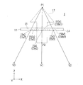
本発明に係る表示装置は、乗り物、例えば、乗用車等の車両内の空間に光を収束させて像を形成することができる。先ず、空間上に像を形成する原理について説明する。図1は、本発明に係る表示装置を、空間上に形成される像と共に概略的に示す説明図である。なお、分かり易く説明することを目的として、説明に用いる図は、概略的、かつ模式的に示している。また、説明に用いる図は、各部材の縦横比、部材間の大きさの比等も含め実際のスケール比で描かれていない場合がある。 The display device according to the present invention can form an image by focusing light in a space in a vehicle, such as a passenger car. First, the principle of forming an image in space will be described. FIG. 1 is an explanatory view schematically showing a display device according to the present invention together with an image formed on a space. In addition, for the purpose of explaining intelligibly, the figure used for description is shown schematically and schematically. Further, the drawings used for the description may not be drawn in actual scale ratios, including the aspect ratio of each member, the ratio of sizes between members, and the like.
表示装置1は、光を発する光源10と、光源10から入光した光を導く導光板(導光部材)11とを備えている。光源10は、LED等の発光素子を用いて構成されており、発光により導光板11へ光を出射する。導光板11は、透明で屈折率が高いポリカーボネート樹脂(PC)、ポリメチルメタクリレート樹脂(PMMA)等の樹脂材料、ガラス等の無機材料等の材料を用いて、可撓性を有する薄膜状、硬質の板状等の長方形の面状に形成されている。ここでいう面状とは、図1に例示するように、二次元に広がる面方向(XY面)に比べ、その方向に直交する厚さ方向(Z軸方向)の長さ(厚み)が小さい形状を示す。即ち、導光板11は、直方体状に形成されているが、二次元に広がる面状となる長手方向(X軸方向)及び短手方向(Y軸方向)に比べて、厚み方向(Z軸方向)の長さが小さい形状となっている。
The
導光板11の長手方向の一端側の面、即ち、長方形の短辺及び厚み方向の辺により構成される面のうちの一方は、光源10が取り付けられた入光端面12となっており、光源10から出射された光が入光する。導光板11は、入光端面12から導光板11内に入光した光を、面状に広げて導く。また、面状をなす導光板11は、光源10から入光した光を出射する出射面13と、出射面13に相対する反対側の背面14とを有する。
One of the surfaces on one end side in the longitudinal direction of the
なお、以降の説明において、必要に応じてX軸、Y軸及びZ軸の右手系の直交座標系を用いる。X軸は、導光板11の短手方向、即ち、長方形の短辺方向である。Y軸は、導光板11の長手方向、即ち、長方形の長辺方向であり、入光端面12側から相対する端面への方向を正方向とする。Z軸は、導光板11の厚み方向であり、背面14から出射面13への方向を正方向とする。なお、導光板11を折り曲げて使用する等、平面的な使用ではない場合、出射面13の主要部分を含む面又はその面に近似される面を基準にX軸、Y軸及びZ軸を用いるものとする。
In the following description, an X-axis, Y-axis, and Z-axis right-handed orthogonal coordinate system is used as necessary. The X axis is the short side direction of the
導光板11の背面14には、図中、光収束部15a,15b,…,15gとして示す複数の光収束部15が形成されている。各光収束部15は、入光端面12から入光した光の進路、即ち光路を出射面13側へ変更する部位である。ここでは光収束部15として、入光端面12から入光した光を反射する反射面150(図2の150x,150y、図3の150x1,150x2,150x3参照)等の光学面を導光板11内に形成した形態を示しており、例えば、背面14に斜交する切り欠きを形成することにより、切り欠きによる斜面が反射面150として機能する。光収束部15の反射面150はX軸方向に実質的に連続して形成されている。具体的には、複数の光収束部15a,15a,…は、線16aに沿って形成され、複数の光収束部15b,15b,…は、線16bに沿って形成されている。同様にして、複数の光収束部15c,15d,…,15gは、線16c,16d,…,線16gにそれぞれ沿って形成されている。ここで、線16(線16a,16b,…,16g)は、背面14においてX軸に略平行に延びる仮想上の直線である。任意の光収束部15,15,…は、X軸に略平行な直線16に沿って実質的に連続的に形成されており、導光板11内に入光した光は、X軸方向に並ぶ各光収束部15,15,…へと導かれる。
On the
光収束部15は、光路を変更する反射面150等の構成を有しており、光収束部15の反射面150に入光した光の進路を変更し、出射面13から出射して各光収束部15にそれぞれ対応する収束点Pに実質的に収束させる。図1では、光収束部15の一部として、光収束部15a,15b,…,15gを例示しており、光収束部15a,15b,…,15gのそれぞれにおいて、光収束部15a,15b,…,15gのそれぞれにて光路を変更された複数の光線が収束点Pa,Pb,…,Pgにそれぞれ収束する様子が示されている。そして、各光収束部15が各収束点Pに光線を収束させて結像することにより、像17が形成される。
The light converging unit 15 has a configuration such as a reflecting surface 150 that changes the light path, changes the path of light incident on the reflecting surface 150 of the light converging unit 15, and emits light from the
具体的には、線16a,16b,…のうちの任意の線16上の複数の光収束部15は、像17上の収束点Pに対応する。任意の線16上の複数の光収束部15の各位置からの光線は、例えば、各反射面150等の光学面での反射によりそれぞれ光路が変更され出射面13から出射して収束点Pに収束する。従って、複数の光収束部15からの光の波面は、収束点Pから発するような光の波面となる。例えば、線16a上の複数の光収束部15aは、像17上の収束点Paに対応する。線16a上の複数の光収束部15aへそれぞれ導かれる光線は、各光収束部15aにて光路が変更され出射面13から出射して収束点Paに収束する。他の線16上の複数の光収束部15にて反射される光も同様に収束点Pに収束する。これにより、任意の光収束部15によって、対応する収束点Pから光が発するような光の波面を提供できる。各光収束部15が対応する収束点Pは互いに異なり、光収束部15にそれぞれ対応する複数の収束点Pの集まりによって、空間上に認識される像17が形成される。このようにして、表示装置1は空間上に立体像として像17を投影する。なお、図1に例示した像17は、線で描かれる立体像であり、像17を描く線は、光収束部15にそれぞれ対応する複数の収束点Pの集まりによって形成される。
Specifically, the plurality of light converging portions 15 on any one of the
表示装置1は、出射面13から出射する光を結像することにより、立体像としての像17を形成する。像17は、視認者によって空間上に認識される立体像である。なお、本願において説明する立体像とは、表示装置1の外部で出射面13とは異なる位置にあるように認識される像17をいう。立体像は、三次元像だけでなく、例えば、表示装置1の出射面13から離れた位置に認識される二次元像をも含む。即ち、本願でいう立体像とは、立体的な形状として認識される像17だけでなく、表示装置1の出射面13上とは異なる位置に認識される二次元の形状の像17も含む概念であり、表示装置1の導光板11から飛び出した様に視認される像17を示している。
The
導光板11によって導かれている光は、導光板11内の各位置と光源10とを結ぶ方向に指向性を有し、導光板11内の各位置と光源10とを結ぶ方向に直交する広がりを有しない。光収束部15が光源10から離れた位置に設けられている場合、導光板11によって導かれている光は、光収束部15が設けられた位置において、概ねY軸方向に指向性を有し、X軸方向に広がりを有しない。従って、例えば収束点Pを含みXZ平面に平行な面では、光収束部15からの光は実質的に1つの収束点Pに収束する。
The light guided by the
なお、光収束部15に入光する光にZ軸方向に広がりがある場合、光収束部15からの光は、空間上の収束点Pを含む、Y軸に沿う収束線上に収束する。しかしながら、実施形態を分かり易く説明することを目的として、適宜、XZ面内における光の収束に注目し、光収束部15からの光が収束点Pに収束するとして説明する。 When the light entering the light converging portion 15 spreads in the Z-axis direction, the light from the light converging portion 15 converges on a convergence line along the Y axis including the convergence point P in space. However, for the purpose of explaining the embodiment in an easy-to-understand manner, it is assumed that the light from the light converging unit 15 converges to the convergence point P by paying attention to the convergence of the light in the XZ plane as appropriate.
図2及び図3は、本発明に係る表示装置1の断面及び光路の概略を模式的に示す概念図である。図2は、YZ面に平行な断面を示しており、図3は、XZ面に平行な断面を観察者によって視認される像17と共に示している。図2及び図3は、導光板11の出射面13側(Z軸正方向)だけで無く、背面14側(Z軸負方向)にも広がる矢印を模した像17を形成する例について説明する。図2及び図3に示す例では、矢印を模した像17は、矢印の前部が出射面13側から飛び出し、矢印の後部が背面14側から飛び出しているように視認される。
2 and 3 are conceptual views schematically showing the cross section and the optical path of the
図2に示すように、光源10は、導光板11の入光端面12に取り付けられており、また、入光端面12と、出射面13とは略直交している。また出射面13に相対する面は背面14となっており、背面14も入光端面12と略直交している。背面14は、出射面13に略平行で平坦な面と、光収束部15(15x,15y)の反射面150(150x,150y)を形成する傾斜した面とを備えている。背面14の平坦な面は、出射面13と共に、入光端面12から導光板11内に入光した光を双方で全反射させながら導き、導光板11内の光を面状に広げる機能を有している。光収束部15の傾斜した反射面150は、導光板11内に入光した光を反射させ、出射面13側へ光路を変更させる。
As shown in FIG. 2, the
即ち、光源10から発せられ、入光端面12から導光板11内に入光した光は、出射面13及び背面14の間で全反射を繰り返しながら、導光板11内に閉じ込められた状態で導かれ面状に伝搬する。また、導光板11内で伝搬する光が光収束部15を形成する反射面150のいずれかに達した場合、反射面150で反射され、光は出射面13から外部へ出射される。
That is, the light emitted from the
図2及び図3に示すように、一の線16上に位置する複数の光収束部15x(光収束部15x1,15x2,15x3,…)は、それぞれ反射面150x1,150x2,150x3,…を含む。一の線16上に位置する複数の光収束部15xのそれぞれの反射面150x1,150x2,150x3,…は、出射面13側の収束点P1に収束する方向へ向けて出射面13側へ光を反射させる。また、他の線16上に位置する複数の光収束部15y(光収束部15y1,15y2,15y3,…)は、それぞれ反射面150y1,150y2,150y3,…を含む。また、他の線16上に位置する複数の光収束部15yのそれぞれの反射面150y1,150y2,150y3,…は、背面14側の収束点P2から発散する方向となるように、出射面13側へ光を反射させる。従って、図3のうち括弧書きで記載した光収束部15y2の反射面150y2及び光収束部15y3の反射面150y3の傾きは、図3とは反対となり、導光板11の端部側に向けて傾斜している。
As shown in FIGS. 2 and 3, the plurality of light converging
反射面150x1,150x2,150x3,…等の反射面150xは、光源10からの光を、各反射面150x上の点と収束点P1とを結ぶ直線に沿う方向へそれぞれ反射させる。各反射面150xが反射した光線は、収束点P1に収束する。このように、各光収束部15xがそれぞれ含む複数の反射面150xは、光源10から入光した光を、それぞれの反射面150x上の点と収束点P1とを結ぶ直線に沿う方向に反射させる。従って、表示装置1は、収束点P1から、位置V2から位置V1を通って位置V3までの範囲内のどの位置へも向かう光を提供することができる。このような収束点P1は、出射面13側に飛び出したように認識される像17を形成する。
The reflecting
反射面150y1,150y2,150y3,…等の反射面150yは、光源10から入光した光を、反射面150y上の点と収束点P2とを結ぶ直線に沿う方向へそれぞれ反射させる。各反射面150yが反射した光線を、それぞれ光線の進む方向と反対の方向へ延長した場合、各光線の延長線は、収束点P2に収束する。このように、各光収束部15yがそれぞれ含む複数の反射面150yは、光源10から入光した光を、それぞれの反射面150y上の点と収束点P2とを結ぶ直線に沿う方向に反射させる。従って、表示装置1は、収束点P2から、位置V2から位置V1を通って位置V3までの範囲内のどの位置へも向かう光を提供することができる。このような収束点P2は、出射面13の反対側(背面14側)に飛び出したように認識される像17を形成する。
The reflecting
以上のように、導光板11は、互いに異なる点を収束点Pとする光収束部15を複数有しており、収束点P1及び収束点P2を含む複数の収束点Pの集まりによって、立体像として像17を形成することができる。即ち、導光板11は、入光した光の進路を出射面13側へ変更し、外部の収束点P1若しくは収束線に収束する方向、又は外部の収束点P2若しくは収束線から発散する方向へ出射して外部に結像させる複数の光収束部15を備えている。そして、表示装置1は、複数の収束点P又は収束線の集まりにより、観察者から視認可能な立体像として像17を導光板11の外部に結像させることができる。
As described above, the
換言すれば以下のように表現することができる。即ち、光源10から発せられた光が入光する導光板11は、出射面13に平行な面内で光を導く。導光板11には、出射面13に並行な面内において導光板11の導光方向(Y軸方向)に直交する方向(X軸方向)に長さをもった複数の光収束部15が形成されている。複数の光収束部15のそれぞれは、出射面13に並行な面に投影した法線の方向がそれぞれの光収束部15の長さ方向(X軸方向)に沿って連続的又は断続的に変化する光学面を有している。導光板11によって導かれた光は、光学面で反射されることによって空間上の一つの収束点P若しくは収束線に実質的に収束する又は空間上の一つの収束点P若しくは収束線から実質的に発散する方向の出射光として出射面13から出射される。収束点P若しくは収束線は、Y軸上の位置が異なる複数の光収束部15のそれぞれの間で互いに異なり、複数の収束点P若しくは収束線の集まりによって空間上に像17が形成される。
In other words, it can be expressed as follows. That is, the
なお、図2及び図3並びにこれらの図を用いた説明では、立体像を形成する基本原理を説明するため、出射面13側及び背面14側の双方に飛び出すように視認される立体像について説明したが、図1に例示するように一方の側の面からのみ飛び出すように視認される立体像を形成するようにしても良い。
In addition, in the description using FIG.2 and FIG.3 and these figures, in order to demonstrate the basic principle which forms a three-dimensional image, the three-dimensional image visually recognized so that it may protrude on both the
また、ここでは、光収束部15として、反射面150を形成する形態を示したが、導光板11内に入光した光の進路を変更することが可能であれば、様々な光収束部15を形成することが可能である。例えば、光収束部15をシリンドリカル型等の形式のフレネルレンズにて形成し、フレネルレンズの屈折面(プリズム面)による屈折作用により、入光した光の進路を変更することも可能である。また、その場合、フレネルレンズを、それぞれ間隙を有する複数の部位にて構成するようにしても良い。また、光収束部15を回折格子にて形成し、回折作用により、入光した光の進路を変更することも可能である。更には、プリズムの反射作用又は屈折作用により、入光した光の進路を変更することも可能である。
Further, although the form in which the reflective surface 150 is formed as the light converging portion 15 is shown here, various light converging portions 15 can be used if it is possible to change the path of the light entering the
また、全ての収束点Pと出射面13との距離が一定ではない場合、例えば、三次元に広がる像17を形成する場合、また、出射面13と斜交する平面に含まれる二次元の像17を形成する場合、出射面13からの距離が長くなるほど、収束される光の密度が高くなるように構成する。これにより、形成される像17に生じるボケが略一定となり、視認する観察者に違和感を生じさせない像17を形成することができる。
In addition, when the distances between all the convergence points P and the
更に、光源10から発せられた光が、導光板11の長手方向の一端側の面である入光端面12から導光板11に入光する形態を示したが、これに限るものではない。例えば、背面14を入光面とし、背面14から入光する等、適宜、設計することが可能である。
Furthermore, although the form which the light emitted from the
<第1の実施形態>
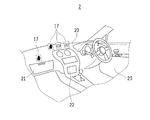
以上のように構成された本発明に係る表示装置1を車両2の内装部材として搭載した実施形態について説明する。図4は、本発明の第1の実施形態に係る表示装置1を内装部材として搭載した車両2内の運転席付近を示す概略図である。図4に示す車両2は、乗用車であり、車両2には本発明に係る表示装置1が搭載されており、表示装置1により形成された像17が、運転席前方及び助手席前方のダッシュボード20上に投影されている。投影される像17は、車両2の状態に関する表示、搭乗に関する表示、車両2の運転に関する表示等の内容の表示であり、特に表示態様が固定された静止画としての表示である。図4では、車両2の状態に関するブレーキ警告灯、搭乗に関する助手席及び運転席のシートベルトの着用状態を示すシートベルト未装着者警告灯、並びに車両2の運転に関するシフトギアの位置(図4では「N」)を示す表示灯としての画像が表示された例を示している。このような像17としては、図4に例示する画像だけでなく、水温表示灯、ヘッドランプ上向き表示灯、フォグランプ表示灯、4WDインジケータ、エンジン警告灯、油圧警告灯、充電警告灯、燃料残量警告灯、ABS警告灯、SRS警告灯、方向指示灯等の内容を示す画像が表示される。また、シフトギアについても、図4に例示する「N」だけでなく、「P」、「R」、「D」、「2」、「L」等の各位置、更にはオーバードライブオフを示す画像が表示される。なお、図4では、図示の都合上、細線で示す四角形枠により、表示される像17を囲って示しているが、実際には四角形枠にて示される長方形を含む空間上に、四角形枠内に示した像17が浮かび上がるように表示される。
First Embodiment
An embodiment in which the
図5は、本発明の第1の実施形態に係る表示装置1を内装部材として搭載した車両2の運転席付近の断面及び運転者の概略を模式的に示す概念図である。図5は、YZ面に平行な断面を模式的に示している。表示装置1は、車両2のダッシュボード20上部に、導光板11の出射面13が上方に向くようにして配設されている。表示装置1の導光板11は、可撓性を有する材料にて形成されており、入光端面12を有する光源10側の端部及び相対する側の端部は折り曲げられて、ダッシュボード20内に埋設されている。また、出射面13となる光収束部15が形成された中央の部位は、平面状をなし、出射面13を上方に向けて配設されている。そして、入光端面12に取り付けられた光源10は、ダッシュボード20内に埋設されており、図示しない車両2内の制御装置に接続され、制御装置からの制御に基づいて適宜発光する。
FIG. 5 is a conceptual diagram schematically showing a cross section of the vicinity of the driver's seat of the
導光板11内に形成された光収束部15は、上方にのみ像17を形成するように構成されており、出射面13と斜交又は直交する仮想面に沿って、シフトギアの位置を示す画像等の各種平面画像が形成されるように、配設されたダッシュボード20上に結像させる。図6は、本発明の第1の実施形態に係る表示装置1の出射面13と形成される像7との関係を模式的に示す説明図である。図6(a)は、表示装置1が備える導光板11の出射面13と形成された像17との関係を模式的に示す概略斜視図であり、図6(b)は、概略側面図である。図6では、出射面13と像17が形成された仮想面とが、角度θをもって斜交している状態を示している。形成された像17は、視認者となる運転者からの視線方向に対して略直交する平面上に結像されており、運転者は形成された像17を容易に視認することができる。なお、導光板11の配置位置によっては、角度θが直角をなすように、即ち出射面と仮想面とが直交するように像17が形成される。また、全ての像17を運転者側に向けて結像させるのではなく、例えば、助手席のシートベルト未装着者警告灯は、視認者となる助手席搭乗者からの視線方向に対して略直交する平面上に結像させるようにしてもよい。
The light converging portion 15 formed in the
また、表示装置1、特に導光板11の配設場所は、前述のダッシュボード20に限るものでは無い。例えば、図4に示した助手席前方のグローブボックスの蓋部21及びその周辺、運転席及び助手席の間のセンターコンソール22、更にはアームレスト(図示せず)、ドアの内装部分となるドアトリム23の任意の部位等の様々な場所に表示装置1を配設することが可能である。そして、運転席、助手席、後部座席等の座席に搭乗した搭乗者は、配設された表示装置1にて形成された像17を視認することが可能である。
Further, the disposition place of the
このように構成された表示装置1は、インパネ内に警告灯を配置する必要が無いため、インパネのデザインに係る自由度を向上させることが可能であり、また、表示する警告灯の視認性を向上させるべく、適切な大きさの像17を形成させることも可能である。また、同時に表示する必要が無い画像、例えば、シフトギアの位置を示す画像は、それぞれの導光板11を積層することにより、同じ位置に各ギアに係る画像を切り替え表示することができるので、表示に要する空間をコンパクトにすることが可能である。
Since the
<第2の実施形態>
図7は、本発明の第2の実施形態に係る表示装置1を内装部材として搭載した車両2内の運転席近傍を示す概略図である。第2の実施形態では、表示装置1により形成された像17が、運転席前方のフロントガラス24下部近傍となるダッシュボード20上に投影されている。形成される像17は、図4を用いて説明した第1の実施形態と同様であるので、第1の実施形態を参照するものとし、詳細な説明を省略する。なお、図7においても、図示の都合上、細線で示す四角形枠により、表示される像17を囲って示しているが、実際には四角形枠にて示される長方形を含む空間上に、四角形枠内に示した像17が表示される。
Second Embodiment
FIG. 7 is a schematic diagram showing the vicinity of the driver's seat in the
図8は、本発明の第2の実施形態に係る表示装置1を内装部材として搭載した車両2の運転席付近の断面及び運転者の概略を模式的に示す概念図である。図8は、YZ面に平行な断面を模式的に示している。表示装置1は、車両2のフロントガラス24下部に、導光板11の出射面13が下方に向くようにして配設されている。表示装置1の導光板11は、可撓性を有する材料にて形成されており、入光端面12を有する光源10側の端部は折り曲げられて、ダッシュボード20内に埋設されている。また、出射面13となる光収束部15が形成された部位は、平面状をなし、出射面13を下方に向けて配設されている。そして、入光端面12に取り付けられた光源10は、ダッシュボード20内に埋設されており、図示しない車両2内の制御装置に接続され、制御装置からの制御に基づいて適宜発光する。
FIG. 8 is a conceptual diagram schematically showing a cross section of the vicinity of the driver's seat of the
導光板11内に形成された光収束部15は、車内側にのみ像17を形成するように構成されており、出射面13と斜交又は直交する仮想面に沿って、シフトギアの位置を示す画像等の各種平面画像が形成されるように、配設されたフロントガラス24下部近傍(ダッシュボード20上方)に結像させる。形成された像17は、視認者となる運転者からの視線方向に対して略直交する平面上に結像されており、運転者は形成された像17を容易に視認することができる。なお、全ての像17を運転者側に向けて結像させるのではなく、例えば、助手席のシートベルト未装着者警告灯は、視認者となる助手席搭乗者からの視線方向に対して略直交する平面上に結像させるようにしてもよい。また、像17を全て車内側に形成するのではなく、視認性に問題が無い限り、一部又は全部が車外に形成されるようにしても良い。
The light converging part 15 formed in the
このように構成された表示装置1は、車両2の内装のデザインの自由度を高めながらも、必要な情報を運転者に提供することが可能である等、優れた効果を奏する。
The
<第3の実施形態>
図9は、本発明の第3の実施形態に係る表示装置1を内装部材として搭載した車両2内の後部座席近傍を示す概略図である。第3の実施形態は、表示装置1により形成された像17が、前部座席のヘッドレスト25後方に投影されている。形成される像17は、例えば、後部座席のシートベルト未装着者警告灯等の像17である。例えば、前部座席のヘッドレスト25後部、前部座席26背面の下部、天井等の箇所に表示装置1を取り付けることにより、図9に例示するような像17を投影することが可能である。更には、後部座席の後方にあたるコンテナトリム(図示せず)、後部側ドアの内装部分となるドアトリム(図示せず)等の様々な場所に表示装置1を配設することが可能である。車両2の後部に像17を形成する場合、後部座席の搭乗者が形成された像を視認可能に構成することは言うまでも無く、例えば、運転席に搭乗する運転者が後方を確認する際に、形成された像17を視認することができるように構成することも可能である。具体的には、シフトギアが後進「R」位置にある場合、コンテナトリムに配設した表示装置1から各種警告灯等の像17を表示することにより、車両2の状態に関する表示等の各種表示を行い、運転者に各種情報を認識させることが可能である。
Third Embodiment
FIG. 9 is a schematic view showing the vicinity of the rear seat in the
本発明は、以上説明した実施形態に限定されるものではなく、他のいろいろな形態で実施することが可能である。そのため、上述した実施形態はあらゆる点で単なる例示にすぎず、限定的に解釈してはならない。本発明の範囲は請求の範囲によって示すものであって、明細書本文には、なんら拘束されない。更に、請求の範囲の均等範囲に属する変形及び変更は、全て本発明の範囲内のものである。 The present invention is not limited to the embodiments described above, and can be implemented in various other forms. For this reason, the above-described embodiment is merely an example in all respects and should not be interpreted in a limited manner. The scope of the present invention is indicated by the scope of the claims, and is not limited at all by the text of the specification. Further, all modifications and changes belonging to the equivalent scope of the claims are within the scope of the present invention.
例えば、前記実施形態では、二次元の平面状の画像を形成する形態を示したが、本発明はこれに限らず、三次元の像を形成する等、様々な形態に展開することが可能である。また、前記実施形態では、フロントガラス24のガラス面に配設する形態を示したが、本発明はこれに限らず、フロントガラス24以外のガラス、例えば、リアガラス、サイドガラス等の他のガラス面に配設することが可能である。
For example, in the above-described embodiment, a form in which a two-dimensional planar image is formed is shown. However, the present invention is not limited to this, and can be developed in various forms such as a three-dimensional image. is there. Further, in the embodiment described above, a mode of arranging on the glass surface of the
さらに、前記実施形態では、乗用車に搭載する形態を示したが、乗用車以外の車、更には電車等の様々な車両2の内部に搭載し、車内に像を形成することが可能であり、更には、航空機、船舶等の車両2以外の乗り物の内部に搭載し、内部に像を形成することが可能である。
Furthermore, although the form which mounts in a passenger car was shown in the said embodiment, it is possible to mount in the inside of
1 表示装置
10 光源
11 導光板(導光部材)
12 入光端面
13 出射面
15(15a,15b,…,15x1,…,15y3)
光収束部
17 像
P(Pa,Pb,…,P1,P2)
収束点
2 車両
20 ダッシュボード
21 グローブボックス
22 センターコンソール
23 ドアトリム
24 フロントガラス
25 ヘッドレスト
26 後部座席
12 light entrance end face 13 exit face 15 (15a, 15b, ..., 15x1, ..., 15y3)
Claims (9)
光を発する光源と、
前記光源から入光した光を導く導光部材と
を備え、
前記導光部材は、
入光した光を出射する出射面と、
前記出射面に相対する反対側の背面にあり、入光した光の光路を出射面側へ変更し、かつ、自部材の外部の収束点若しくは収束線に収束する方向へ出射して結像させるか、又は、自部材の外部の収束点若しくは収束線から発散する方向へ出射して自部材の外部に結像させる、複数の光収束部と
を有し、
前記光収束部は、車両内の座席から視認可能な位置に結像させる
ことを特徴とする表示装置。 A display device that is mounted as an interior member of a vehicle and displays an image in the vehicle,
A light source that emits light,
A light guiding member for guiding light incident from the light source;
The light guide member is
An exit surface that emits the incident light;
The back of the opposite side opposite to the emission surface, to change the optical path of a light beam inputted to the emission surface side, and forming an image by emitting a direction that converges to the outside of the convergence point or the convergence line of the own member or, it possesses is emitted in a direction diverging from the outside of the convergence point or the convergence line of its own members for imaging outside of its own member, a plurality of the light converging portion,
The display device characterized in that the light converging portion forms an image at a position visible from a seat in a vehicle .
前記光収束部は、
出射面と斜交又は直交する仮想面に沿って結像させる
ことを特徴とする表示装置。 The display device according to claim 1,
The light converging part is
An image is formed along a virtual plane that is oblique or orthogonal to the emission surface.
前記導光部材は、出射面を上方に向けてダッシュボード上部に配設可能であり、
前記光収束部は、配設されたダッシュボード上に結像させる
ことを特徴とする表示装置。 The display device according to claim 1 or 2, wherein
The light guide member can be disposed on the upper part of the dashboard with the emission surface facing upward.
The display unit characterized in that the light converging section forms an image on a dashboard provided.
前記導光部材は、出射面を車内側に向けて車両のガラス面に配設可能である
ことを特徴とする表示装置。 The display device according to claim 1 or 2, wherein
The display device according to claim 1, wherein the light guide member can be disposed on a glass surface of the vehicle with an emission surface facing the vehicle interior.
前記導光部材は、内装部材であるグローブボックス、センターコンソール、アームレスト、ドアトリム、コンテナトリム及び前部座席のうちの少なくとも一に配設可能である
ことを特徴とする表示装置。 The display device according to claim 1 or 2, wherein
The display device is characterized in that the light guide member can be disposed in at least one of a glove box that is an interior member, a center console, an arm rest, a door trim, a container trim, and a front seat.
前記光収束部は、運転席から視認可能な位置に結像させる
ことを特徴とする表示装置。 The display device according to any one of claims 1 to 5, wherein
The display device, wherein the light converging section forms an image at a position visible from the driver's seat.
前記光収束部は、運転席より後方の座席から視認可能な位置に結像させる
ことを特徴とする表示装置。 The display device according to any one of claims 1 to 6, wherein
The light converging unit forms an image at a position visible from a seat behind the driver seat.
前記光収束部は、車両の状態に関する表示、搭乗に関する表示及び車両の運転に関する表示のうちの少なくとも一を示す像が表示されるように結像させる
ことを特徴とする表示装置。 The display device according to any one of claims 1 to 7, wherein
The display device characterized in that the light converging section forms an image indicating at least one of a display related to a state of a vehicle, a display related to boarding, and a display related to driving of the vehicle.
光を発する光源と、
前記光源から入光した光を導く導光部材と
を備え、
前記導光部材は、
入光した光を出射する出射面と、
前記出射面に相対する反対側の背面にあり、入光した光の光路を出射面側へ変更し、かつ、自部材の外部の収束点若しくは収束線に収束する方向へ出射して結像させるか、又は、自部材の外部の収束点若しくは収束線から発散する方向へ出射して自部材の外部に結像させる、複数の光収束部と
を有し、
前記光収束部は、乗り物内の座席から視認可能な位置に結像させる
ことを特徴とする表示装置。 A display device mounted on a vehicle and displaying an image inside the vehicle ,
A light source that emits light;
A light guiding member for guiding light incident from the light source;
The light guide member is
An exit surface that emits the incident light;
The back of the opposite side opposite to the emission surface, to change the optical path of a light beam inputted to the emission surface side, and forming an image by emitting a direction that converges to the outside of the convergence point or the convergence line of the own member or, it possesses is emitted in a direction diverging from the outside of the convergence point or the convergence line of its own members for imaging outside of its own member, a plurality of the light converging portion,
The light converging unit forms an image at a position visible from a seat in a vehicle .
Priority Applications (6)
| Application Number | Priority Date | Filing Date | Title |
|---|---|---|---|
| JP2015172243A JP6551068B2 (en) | 2015-09-01 | 2015-09-01 | Display device |
| PCT/JP2016/073686 WO2017038424A1 (en) | 2015-09-01 | 2016-08-11 | Display device |
| DE112016003971.9T DE112016003971B4 (en) | 2015-09-01 | 2016-08-11 | DISPLAY DEVICE |
| CN201680041488.XA CN107850789B (en) | 2015-09-01 | 2016-08-11 | Display device |
| TW105127603A TW201712300A (en) | 2015-09-01 | 2016-08-29 | Display device |
| US15/876,056 US10841987B2 (en) | 2015-09-01 | 2018-01-19 | Display device |
Applications Claiming Priority (1)
| Application Number | Priority Date | Filing Date | Title |
|---|---|---|---|
| JP2015172243A JP6551068B2 (en) | 2015-09-01 | 2015-09-01 | Display device |
Publications (3)
| Publication Number | Publication Date |
|---|---|
| JP2017049420A JP2017049420A (en) | 2017-03-09 |
| JP2017049420A5 JP2017049420A5 (en) | 2018-10-25 |
| JP6551068B2 true JP6551068B2 (en) | 2019-07-31 |
Family
ID=58188861
Family Applications (1)
| Application Number | Title | Priority Date | Filing Date |
|---|---|---|---|
| JP2015172243A Active JP6551068B2 (en) | 2015-09-01 | 2015-09-01 | Display device |
Country Status (6)
| Country | Link |
|---|---|
| US (1) | US10841987B2 (en) |
| JP (1) | JP6551068B2 (en) |
| CN (1) | CN107850789B (en) |
| DE (1) | DE112016003971B4 (en) |
| TW (1) | TW201712300A (en) |
| WO (1) | WO2017038424A1 (en) |
Families Citing this family (8)
| Publication number | Priority date | Publication date | Assignee | Title |
|---|---|---|---|---|
| JP6743419B2 (en) * | 2015-11-10 | 2020-08-19 | オムロン株式会社 | Display system and gate device |
| JP6866738B2 (en) * | 2017-04-12 | 2021-04-28 | オムロン株式会社 | Image display unit |
| JP6885215B2 (en) * | 2017-06-21 | 2021-06-09 | 日本精機株式会社 | Display device |
| CN109114517A (en) * | 2017-06-22 | 2019-01-01 | 欧姆龙株式会社 | Vehicle light emitting device |
| JP7172207B2 (en) * | 2018-07-10 | 2022-11-16 | オムロン株式会社 | input device |
| JP7063167B2 (en) * | 2018-07-26 | 2022-05-09 | トヨタ自動車株式会社 | Display control device, vehicle display device, display control method and program |
| WO2020081413A1 (en) * | 2018-10-16 | 2020-04-23 | Walbro Llc. | System for improved starting of a powered device including one or more threshold conditions |
| JP7239042B2 (en) * | 2019-03-07 | 2023-03-14 | オムロン株式会社 | Light-emitting device and vehicle lamp |
Family Cites Families (24)
| Publication number | Priority date | Publication date | Assignee | Title |
|---|---|---|---|---|
| DE4211728A1 (en) * | 1992-04-08 | 1993-10-14 | Zeiss Carl Fa | Holographic display device e.g. for vehicle or aircraft head=up display - uses curved windscreen incorporating monomode waveguide for supplied light and holographic gratings |
| AU695608B2 (en) | 1995-06-07 | 1998-08-20 | Toyoda Gosei Co. Ltd. | Light-driven display device |
| JP3608274B2 (en) * | 1995-11-30 | 2005-01-05 | 豊田合成株式会社 | Vehicle meter |
| US5668907A (en) * | 1996-01-11 | 1997-09-16 | Associated Universities, Inc. | Thin optical display panel |
| SE9600758D0 (en) * | 1996-02-28 | 1996-02-28 | Forskarpatent I Goeteborg Ab | Hologram |
| EP0818701B1 (en) * | 1996-07-09 | 2002-10-02 | Harness System Technologies Research, Ltd. | Display device |
| US20080024463A1 (en) * | 2001-02-22 | 2008-01-31 | Timothy Pryor | Reconfigurable tactile control display applications |
| CN100562686C (en) * | 2004-02-20 | 2009-11-25 | 欧姆龙株式会社 | Planar light source device |
| JP4254719B2 (en) | 2005-02-01 | 2009-04-15 | 株式会社デンソー | Vehicle display device |
| JP2006243641A (en) * | 2005-03-07 | 2006-09-14 | Matsushita Electric Ind Co Ltd | Video display controller and video display device |
| JP2007127871A (en) * | 2005-11-04 | 2007-05-24 | Alps Electric Co Ltd | Three-dimensional display device |
| US7830368B2 (en) | 2006-06-06 | 2010-11-09 | 3M Innovative Properties Company | Keypad with virtual image |
| BRPI0712226A2 (en) * | 2006-06-06 | 2012-01-10 | 3M Innovative Properies Company | numeric keypad with virtual image |
| DE102008015997B4 (en) * | 2007-03-29 | 2015-09-10 | Denso Corporation | Head-Up Display |
| JP4825165B2 (en) * | 2007-04-27 | 2011-11-30 | 株式会社フジクラ | Display device |
| WO2009122716A1 (en) | 2008-04-03 | 2009-10-08 | パナソニック株式会社 | Information display |
| CA2796519A1 (en) | 2010-04-16 | 2011-10-20 | Flex Lighting Ii, Llc | Illumination device comprising a film-based lightguide |
| CN101876753B (en) * | 2010-06-03 | 2012-06-27 | 香港应用科技研究院有限公司 | Mixed illumination system of head-up display |
| JP2012126251A (en) * | 2010-12-15 | 2012-07-05 | Toyota Motor Corp | Light source device for vehicle |
| JP5941292B2 (en) | 2012-02-10 | 2016-06-29 | 矢崎総業株式会社 | Vehicle display device |
| US9251743B2 (en) * | 2013-03-15 | 2016-02-02 | Seattle Photonics Associates | Optical system for head-up and near-to-eye displays |
| US20140268327A1 (en) * | 2013-03-15 | 2014-09-18 | Opsec Security Group, Inc. | Optically variable device exhibiting non-diffractive three-dimensional optical effect |
| US20150091874A1 (en) * | 2013-09-30 | 2015-04-02 | Continental Automotive Systems, Inc. | Button selection trace light indicator |
| US9678351B2 (en) * | 2014-02-03 | 2017-06-13 | Lg Innotek Co., Ltd. | Stereoscopic display device and dashboard using the same |
-
2015
- 2015-09-01 JP JP2015172243A patent/JP6551068B2/en active Active
-
2016
- 2016-08-11 CN CN201680041488.XA patent/CN107850789B/en active Active
- 2016-08-11 WO PCT/JP2016/073686 patent/WO2017038424A1/en active Application Filing
- 2016-08-11 DE DE112016003971.9T patent/DE112016003971B4/en active Active
- 2016-08-29 TW TW105127603A patent/TW201712300A/en unknown
-
2018
- 2018-01-19 US US15/876,056 patent/US10841987B2/en active Active
Also Published As
| Publication number | Publication date |
|---|---|
| JP2017049420A (en) | 2017-03-09 |
| US20180146519A1 (en) | 2018-05-24 |
| WO2017038424A1 (en) | 2017-03-09 |
| DE112016003971B4 (en) | 2023-07-20 |
| TW201712300A (en) | 2017-04-01 |
| DE112016003971T5 (en) | 2018-06-07 |
| US10841987B2 (en) | 2020-11-17 |
| CN107850789B (en) | 2020-05-19 |
| CN107850789A (en) | 2018-03-27 |
Similar Documents
| Publication | Publication Date | Title |
|---|---|---|
| JP6551068B2 (en) | Display device | |
| JP6610099B2 (en) | Mirror unit and display device | |
| JP6866738B2 (en) | Image display unit | |
| US9891433B2 (en) | Virtual image generation device and head-up display | |
| WO2018000806A1 (en) | 3d head-up display system and method | |
| WO2017038425A1 (en) | Display device | |
| JP2006106254A (en) | Head-up display for vehicle | |
| CN102033317A (en) | Display device | |
| EP3605191B1 (en) | Virtual image display device | |
| JP2017047851A (en) | Display device for vehicle | |
| US20190077416A1 (en) | Display device | |
| CN113375119A (en) | Light emitting device for vehicle | |
| EP3605194A1 (en) | Virtual image display device | |
| JP6515796B2 (en) | Head-up display device | |
| JP2019009100A (en) | Vehicular light emitting device | |
| JP2018176991A (en) | Vehicular seat and image display unit | |
| US20200049987A1 (en) | Virtual image display device | |
| JP2017134178A (en) | Head-up display device | |
| CN217879827U (en) | Projection system for vehicle and vehicle | |
| EP4163701A1 (en) | Image generation unit and head-up display | |
| JP2018180262A (en) | Image display unit for vehicle | |
| US10502953B2 (en) | Display device, and mobile body having same | |
| US20190082167A1 (en) | Alert display system | |
| JP5993117B2 (en) | Vehicle display device |
Legal Events
| Date | Code | Title | Description |
|---|---|---|---|
| A621 | Written request for application examination |
Free format text: JAPANESE INTERMEDIATE CODE: A621 Effective date: 20180706 |
|
| A521 | Request for written amendment filed |
Free format text: JAPANESE INTERMEDIATE CODE: A523 Effective date: 20180913 |
|
| A131 | Notification of reasons for refusal |
Free format text: JAPANESE INTERMEDIATE CODE: A131 Effective date: 20190507 |
|
| A521 | Request for written amendment filed |
Free format text: JAPANESE INTERMEDIATE CODE: A523 Effective date: 20190528 |
|
| TRDD | Decision of grant or rejection written | ||
| A01 | Written decision to grant a patent or to grant a registration (utility model) |
Free format text: JAPANESE INTERMEDIATE CODE: A01 Effective date: 20190604 |
|
| A61 | First payment of annual fees (during grant procedure) |
Free format text: JAPANESE INTERMEDIATE CODE: A61 Effective date: 20190617 |
|
| R150 | Certificate of patent or registration of utility model |
Ref document number: 6551068 Country of ref document: JP Free format text: JAPANESE INTERMEDIATE CODE: R150 |
|
| R250 | Receipt of annual fees |
Free format text: JAPANESE INTERMEDIATE CODE: R250 |