JP6549185B2 - injector - Google Patents
injector Download PDFInfo
- Publication number
- JP6549185B2 JP6549185B2 JP2017118871A JP2017118871A JP6549185B2 JP 6549185 B2 JP6549185 B2 JP 6549185B2 JP 2017118871 A JP2017118871 A JP 2017118871A JP 2017118871 A JP2017118871 A JP 2017118871A JP 6549185 B2 JP6549185 B2 JP 6549185B2
- Authority
- JP
- Japan
- Prior art keywords
- injector
- cap
- housing
- lancet
- plunger
- Prior art date
- Legal status (The legal status is an assumption and is not a legal conclusion. Google has not performed a legal analysis and makes no representation as to the accuracy of the status listed.)
- Active
Links
Images


Classifications
-
- A—HUMAN NECESSITIES
- A61—MEDICAL OR VETERINARY SCIENCE; HYGIENE
- A61B—DIAGNOSIS; SURGERY; IDENTIFICATION
- A61B5/00—Measuring for diagnostic purposes; Identification of persons
- A61B5/15—Devices for taking samples of blood
- A61B5/150007—Details
- A61B5/150015—Source of blood
- A61B5/150022—Source of blood for capillary blood or interstitial fluid
-
- A—HUMAN NECESSITIES
- A61—MEDICAL OR VETERINARY SCIENCE; HYGIENE
- A61B—DIAGNOSIS; SURGERY; IDENTIFICATION
- A61B5/00—Measuring for diagnostic purposes; Identification of persons
- A61B5/15—Devices for taking samples of blood
- A61B5/150007—Details
- A61B5/150053—Details for enhanced collection of blood or interstitial fluid at the sample site, e.g. by applying compression, heat, vibration, ultrasound, suction or vacuum to tissue; for reduction of pain or discomfort; Skin piercing elements, e.g. blades, needles, lancets or canulas, with adjustable piercing speed
- A61B5/150106—Means for reducing pain or discomfort applied before puncturing; desensitising the skin at the location where body is to be pierced
- A61B5/15016—Means for reducing pain or discomfort applied before puncturing; desensitising the skin at the location where body is to be pierced by accessories for bringing the piercing element into the body, e.g. through rotation of the piercing element
-
- A—HUMAN NECESSITIES
- A61—MEDICAL OR VETERINARY SCIENCE; HYGIENE
- A61B—DIAGNOSIS; SURGERY; IDENTIFICATION
- A61B5/00—Measuring for diagnostic purposes; Identification of persons
- A61B5/15—Devices for taking samples of blood
- A61B5/150007—Details
- A61B5/150175—Adjustment of penetration depth
- A61B5/150183—Depth adjustment mechanism using end caps mounted at the distal end of the sampling device, i.e. the end-caps are adjustably positioned relative to the piercing device housing for example by rotating or screwing
-
- A—HUMAN NECESSITIES
- A61—MEDICAL OR VETERINARY SCIENCE; HYGIENE
- A61B—DIAGNOSIS; SURGERY; IDENTIFICATION
- A61B5/00—Measuring for diagnostic purposes; Identification of persons
- A61B5/15—Devices for taking samples of blood
- A61B5/150007—Details
- A61B5/150374—Details of piercing elements or protective means for preventing accidental injuries by such piercing elements
- A61B5/150381—Design of piercing elements
- A61B5/150412—Pointed piercing elements, e.g. needles, lancets for piercing the skin
-
- A—HUMAN NECESSITIES
- A61—MEDICAL OR VETERINARY SCIENCE; HYGIENE
- A61B—DIAGNOSIS; SURGERY; IDENTIFICATION
- A61B5/00—Measuring for diagnostic purposes; Identification of persons
- A61B5/15—Devices for taking samples of blood
- A61B5/150007—Details
- A61B5/150374—Details of piercing elements or protective means for preventing accidental injuries by such piercing elements
- A61B5/150381—Design of piercing elements
- A61B5/150503—Single-ended needles
- A61B5/150519—Details of construction of hub, i.e. element used to attach the single-ended needle to a piercing device or sampling device
-
- A—HUMAN NECESSITIES
- A61—MEDICAL OR VETERINARY SCIENCE; HYGIENE
- A61B—DIAGNOSIS; SURGERY; IDENTIFICATION
- A61B5/00—Measuring for diagnostic purposes; Identification of persons
- A61B5/15—Devices for taking samples of blood
- A61B5/150007—Details
- A61B5/150374—Details of piercing elements or protective means for preventing accidental injuries by such piercing elements
- A61B5/150534—Design of protective means for piercing elements for preventing accidental needle sticks, e.g. shields, caps, protectors, axially extensible sleeves, pivotable protective sleeves
- A61B5/150541—Breakable protectors, e.g. caps, shields or sleeves, i.e. protectors separated destructively, e.g. by breaking a connecting area
- A61B5/150549—Protectors removed by rotational movement, e.g. torsion or screwing
-
- A—HUMAN NECESSITIES
- A61—MEDICAL OR VETERINARY SCIENCE; HYGIENE
- A61B—DIAGNOSIS; SURGERY; IDENTIFICATION
- A61B5/00—Measuring for diagnostic purposes; Identification of persons
- A61B5/15—Devices for taking samples of blood
- A61B5/150007—Details
- A61B5/150374—Details of piercing elements or protective means for preventing accidental injuries by such piercing elements
- A61B5/150534—Design of protective means for piercing elements for preventing accidental needle sticks, e.g. shields, caps, protectors, axially extensible sleeves, pivotable protective sleeves
- A61B5/15058—Joining techniques used for protective means
- A61B5/150595—Joining techniques used for protective means by snap-lock (i.e. based on axial displacement)
-
- A—HUMAN NECESSITIES
- A61—MEDICAL OR VETERINARY SCIENCE; HYGIENE
- A61B—DIAGNOSIS; SURGERY; IDENTIFICATION
- A61B5/00—Measuring for diagnostic purposes; Identification of persons
- A61B5/15—Devices for taking samples of blood
- A61B5/150007—Details
- A61B5/150374—Details of piercing elements or protective means for preventing accidental injuries by such piercing elements
- A61B5/150534—Design of protective means for piercing elements for preventing accidental needle sticks, e.g. shields, caps, protectors, axially extensible sleeves, pivotable protective sleeves
- A61B5/15058—Joining techniques used for protective means
- A61B5/150618—Integrally moulded protectors, e.g. protectors simultaneously moulded together with a further component, e.g. a hub, of the piercing element
-
- A—HUMAN NECESSITIES
- A61—MEDICAL OR VETERINARY SCIENCE; HYGIENE
- A61B—DIAGNOSIS; SURGERY; IDENTIFICATION
- A61B5/00—Measuring for diagnostic purposes; Identification of persons
- A61B5/15—Devices for taking samples of blood
- A61B5/150007—Details
- A61B5/150374—Details of piercing elements or protective means for preventing accidental injuries by such piercing elements
- A61B5/150534—Design of protective means for piercing elements for preventing accidental needle sticks, e.g. shields, caps, protectors, axially extensible sleeves, pivotable protective sleeves
- A61B5/150694—Procedure for removing protection means at the time of piercing
- A61B5/150717—Procedure for removing protection means at the time of piercing manually removed
-
- A—HUMAN NECESSITIES
- A61—MEDICAL OR VETERINARY SCIENCE; HYGIENE
- A61B—DIAGNOSIS; SURGERY; IDENTIFICATION
- A61B5/00—Measuring for diagnostic purposes; Identification of persons
- A61B5/15—Devices for taking samples of blood
- A61B5/150007—Details
- A61B5/150801—Means for facilitating use, e.g. by people with impaired vision; means for indicating when used correctly or incorrectly; means for alarming
- A61B5/150824—Means for facilitating use, e.g. by people with impaired vision; means for indicating when used correctly or incorrectly; means for alarming by visual feedback
-
- A—HUMAN NECESSITIES
- A61—MEDICAL OR VETERINARY SCIENCE; HYGIENE
- A61B—DIAGNOSIS; SURGERY; IDENTIFICATION
- A61B5/00—Measuring for diagnostic purposes; Identification of persons
- A61B5/15—Devices for taking samples of blood
- A61B5/150007—Details
- A61B5/150885—Preventing re-use
- A61B5/150916—Preventing re-use by blocking components, e.g. piston, driving device or fluid passageway
-
- A—HUMAN NECESSITIES
- A61—MEDICAL OR VETERINARY SCIENCE; HYGIENE
- A61B—DIAGNOSIS; SURGERY; IDENTIFICATION
- A61B5/00—Measuring for diagnostic purposes; Identification of persons
- A61B5/15—Devices for taking samples of blood
- A61B5/151—Devices specially adapted for taking samples of capillary blood, e.g. by lancets, needles or blades
- A61B5/15101—Details
- A61B5/15103—Piercing procedure
- A61B5/15107—Piercing being assisted by a triggering mechanism
- A61B5/15113—Manually triggered, i.e. the triggering requires a deliberate action by the user such as pressing a drive button
-
- A—HUMAN NECESSITIES
- A61—MEDICAL OR VETERINARY SCIENCE; HYGIENE
- A61B—DIAGNOSIS; SURGERY; IDENTIFICATION
- A61B5/00—Measuring for diagnostic purposes; Identification of persons
- A61B5/15—Devices for taking samples of blood
- A61B5/151—Devices specially adapted for taking samples of capillary blood, e.g. by lancets, needles or blades
- A61B5/15101—Details
- A61B5/15115—Driving means for propelling the piercing element to pierce the skin, e.g. comprising mechanisms based on shape memory alloys, magnetism, solenoids, piezoelectric effect, biased elements, resilient elements, vacuum or compressed fluids
- A61B5/15117—Driving means for propelling the piercing element to pierce the skin, e.g. comprising mechanisms based on shape memory alloys, magnetism, solenoids, piezoelectric effect, biased elements, resilient elements, vacuum or compressed fluids comprising biased elements, resilient elements or a spring, e.g. a helical spring, leaf spring, or elastic strap
-
- A—HUMAN NECESSITIES
- A61—MEDICAL OR VETERINARY SCIENCE; HYGIENE
- A61B—DIAGNOSIS; SURGERY; IDENTIFICATION
- A61B5/00—Measuring for diagnostic purposes; Identification of persons
- A61B5/15—Devices for taking samples of blood
- A61B5/151—Devices specially adapted for taking samples of capillary blood, e.g. by lancets, needles or blades
- A61B5/15101—Details
- A61B5/15126—Means for controlling the lancing movement, e.g. 2D- or 3D-shaped elements, tooth-shaped elements or sliding guides
- A61B5/1513—Means for controlling the lancing movement, e.g. 2D- or 3D-shaped elements, tooth-shaped elements or sliding guides comprising linear sliding guides
-
- A—HUMAN NECESSITIES
- A61—MEDICAL OR VETERINARY SCIENCE; HYGIENE
- A61B—DIAGNOSIS; SURGERY; IDENTIFICATION
- A61B5/00—Measuring for diagnostic purposes; Identification of persons
- A61B5/15—Devices for taking samples of blood
- A61B5/151—Devices specially adapted for taking samples of capillary blood, e.g. by lancets, needles or blades
- A61B5/15186—Devices loaded with a single lancet, i.e. a single lancet with or without a casing is loaded into a reusable drive device and then discarded after use; drive devices reloadable for multiple use
- A61B5/15188—Constructional features of reusable driving devices
- A61B5/1519—Constructional features of reusable driving devices comprising driving means, e.g. a spring, for propelling the piercing unit
-
- A—HUMAN NECESSITIES
- A61—MEDICAL OR VETERINARY SCIENCE; HYGIENE
- A61B—DIAGNOSIS; SURGERY; IDENTIFICATION
- A61B5/00—Measuring for diagnostic purposes; Identification of persons
- A61B5/15—Devices for taking samples of blood
- A61B5/151—Devices specially adapted for taking samples of capillary blood, e.g. by lancets, needles or blades
- A61B5/15186—Devices loaded with a single lancet, i.e. a single lancet with or without a casing is loaded into a reusable drive device and then discarded after use; drive devices reloadable for multiple use
- A61B5/15188—Constructional features of reusable driving devices
- A61B5/15192—Constructional features of reusable driving devices comprising driving means, e.g. a spring, for retracting the lancet unit into the driving device housing
- A61B5/15194—Constructional features of reusable driving devices comprising driving means, e.g. a spring, for retracting the lancet unit into the driving device housing fully automatically retracted, i.e. the retraction does not require a deliberate action by the user, e.g. by terminating the contact with the patient's skin
-
- A—HUMAN NECESSITIES
- A61—MEDICAL OR VETERINARY SCIENCE; HYGIENE
- A61B—DIAGNOSIS; SURGERY; IDENTIFICATION
- A61B5/00—Measuring for diagnostic purposes; Identification of persons
- A61B5/15—Devices for taking samples of blood
- A61B5/150007—Details
- A61B5/150374—Details of piercing elements or protective means for preventing accidental injuries by such piercing elements
- A61B5/150381—Design of piercing elements
- A61B5/150442—Blade-like piercing elements, e.g. blades, cutters, knives, for cutting the skin
-
- A—HUMAN NECESSITIES
- A61—MEDICAL OR VETERINARY SCIENCE; HYGIENE
- A61B—DIAGNOSIS; SURGERY; IDENTIFICATION
- A61B5/00—Measuring for diagnostic purposes; Identification of persons
- A61B5/15—Devices for taking samples of blood
- A61B5/150007—Details
- A61B5/150374—Details of piercing elements or protective means for preventing accidental injuries by such piercing elements
- A61B5/150381—Design of piercing elements
- A61B5/150503—Single-ended needles
Description
本発明は、血液などの体液を採取する目的で身体の所定の箇所を鋭利な部材(例えば針)で穿刺する用途に用いられるインジェクターに関する。より具体的には、本発明は、いわゆるランセットと組み合わせて用いるインジェクターに関する。 The present invention relates to an injector used for puncturing a predetermined part of a body with a sharp member (for example, a needle) for the purpose of collecting body fluid such as blood. More particularly, the invention relates to an injector for use in combination with a so-called lancet.
糖尿病患者の血糖値の測定には血液を採取する必要がある。微少量の血液を採取するために種々の穿刺デバイスが使用されている。そのようなデバイスは、ランセット(例えば特許文献1)およびインジェクターから一般に構成されている。ランセットは実際の穿刺に供する部材である一方、インジェクターはランセットを所定箇所に向かって発射させる機能を有している。 Blood needs to be collected to measure the blood glucose level of diabetic patients. Various puncture devices have been used to collect small amounts of blood. Such devices are generally comprised of a lancet (e.g., U.S. Pat. No. 5,648,859) and an injector. The lancet is a member to be used for the actual puncture, while the injector has a function of firing the lancet toward a predetermined position.
具体的には、ランセットに“穿刺針”が設けられている一方、インジェクターに“ランセット装着部およびスプリングを具備したプランジャー”が設けられている。プランジャーのスプリングは圧縮状態で使用され、その圧縮状態を解放することによって、プランジャーが瞬時に動くことになる。使用に際しては、インジェクターのプランジャーに対してランセットを取り付けた後、トリガーなどによってプランジャーのスプリングの圧縮状態を解放する。これによって、「ランセットが装着されたプランジャー」が穿刺方向へと発射されることになり、所定箇所の穿刺が行われる。 Specifically, while the lancet is provided with a "puncture needle", the injector is provided with a "plunger equipped with a lancet mounting portion and a spring". The spring of the plunger is used in compression, and releasing the compression will cause the plunger to move instantaneously. In use, after the lancet is attached to the plunger of the injector, the compression state of the spring of the plunger is released by a trigger or the like. As a result, the "plunger to which the lancet is attached" is fired in the puncturing direction, and puncturing is performed at a predetermined location.
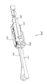
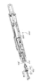
穿刺デバイスとしては、以下で説明するデバイスが提案されている(国際特許公開第2007/018215号公報、出願日:2006年8月8日、発明の名称:「穿刺デバイスならびにそれを構成するランセットアッセンブリおよびインジェクター・アッセンブリ」)。図面を参照しながら、この発明に係るランセットアッセンブリおよびインジェクター・アッセンブリを簡潔に説明する(以後では、「インジェクター・アッセンブリ」を「インジェクター」とも称して説明する)。図16にランセットアッセンブリ100’の外観を示すと共に、図17にインジェクター200’の外観を示す。図16に示すように、ランセットアッセンブリ100’は、ランセット101’および保護カバー102’から構成されている。図18および図19に示すように、ランセット101’は、ランセットボディ104’、ランセットキャップ106’および穿刺針105’を有して成る。金属製の穿刺針105’は、樹脂製のランセットボディ104’およびランセットキャップ106’にまたがって存在している。穿刺針105’の先端部は、ランセットキャップ106’によってカバーされていると共に、ランセットキャップ106’とランセットボディ104’とが弱化部材108’を介して一体に結合している。図16および図19に示すように、保護カバー102’は、ランセットボディ104’の一部を包囲するように設けられている。このようなランセットアッセンブリ100’は、インジェクター200’に装填された後でランセットキャップ106’が取り外される。これにより、穿刺針105’の先端部が露出するので、ランセットを穿刺に供すことができる。 As the lancing device, the devices described below have been proposed (International Patent Publication No. 2007/018215, filing date: August 8, 2006, title of the invention: "Lancing device and lancet assembly constituting the same And injector assembly '). The lancet assembly and the injector assembly according to the present invention will be briefly described with reference to the drawings (hereinafter, the “injector assembly” will also be described as “injector”). FIG. 16 shows the appearance of the lancet assembly 100 'and FIG. 17 shows the appearance of the injector 200'. As shown in FIG. 16, the lancet assembly 100 'comprises a lancet 101' and a protective cover 102 '. As shown in FIGS. 18 and 19, the lancet 101 'comprises a lancet body 104', a lancet cap 106 'and a puncture needle 105'. The metal puncture needle 105 'is present across the resin lancet body 104' and the lancet cap 106 '. The tip of the puncture needle 105 'is covered by the lancet cap 106', and the lancet cap 106 'and the lancet body 104' are integrally coupled via the weakening member 108 '. As shown in FIGS. 16 and 19, a protective cover 102 'is provided to surround a portion of the lancet body 104'. After such a lancet assembly 100 'is loaded into the injector 200', the lancet cap 106 'is removed. Thereby, since the tip of the puncture needle 105 'is exposed, the lancet can be subjected to puncture.
図17に示すインジェクター200’は、ランセットアッセンブリ100’と組み合わせて用いて、「穿刺針105’の先端が露出した状態のランセットボディ」を発射することができるデバイスである。インジェクター200’は、「ランセットボディの後端部と係合でき、ランセットボディを穿刺方向に発射させるプランジャー204’」を有して成る(図20参照)。インジェクター200’に装填するに際しては、図20に示すように、ランセットアッセンブリ100’をインジェクター200’の前端開口部214’から挿入する。ある程度挿入すると、図21に示すように、ランセットアッセンブリ100’の後方部分116’が、プランジャー204’の先端部264’, 266’によって把持される。引き続いて挿入を継続すると、プランジャー204’が後退して発射エネルギーが蓄積される。つまり、プランジャー204’の後退により、プランジャー204’に設けられたバネ(図示せず)が圧縮する(従って、その圧縮状態を解放すると、プランジャーが前方へと瞬時に移動し、ランセットが発射されることになる)。プランジャーが後退して発射エネルギーが蓄積された状態のインジェクター200’を図22に示す。
The
ランセットアッセンブリ100’のインジェクター200’への装着(装填)が完了すると、ランセットキャップ106’を取り外して穿刺針105’の先端を露出させる。ランセットキャップ106’の取外しについて詳述すると次のようになる。図18および図19に示すように、ランセットボディ104’とランセットキャップ106’とは、その間に位置する弱化部分108’によって一体に結合されている。かかる弱化部材108’は、ランセットボディ104’とランセットキャップ106’とを穿刺針の周囲で相対的に反対方向に回すことによって破壊させることができ(図22にはG方向に回す態様が示されている)、それによって、ランセットキャップ106’を取り外すことができる。即ち、いわゆる“ツイストオフ”によって、穿刺針105’の先端を露出させる。
When attachment (loading) of the lancet assembly 100 'to the injector 200' is completed, the lancet cap 106 'is removed to expose the tip of the puncture needle 105'. The removal of the lancet cap 106 'will be described in detail as follows. As shown in FIGS. 18 and 19, the
穿刺に際しては、穿刺すべき所定の部位(例えば指先)にインジェクター200’の前端開口部214’をあてがった後、トリガー部材514’のプレス部分542’を押す(図23参照)。かかるプレス部分542’の押し込みによって、プランジャー204’が前方へと発射され(つまり、圧縮されていたバネが解放され)、穿刺針によって穿刺が行われることになる。 At the time of puncturing, after applying the front end opening 214 'of the injector 200' to a predetermined site (for example, a fingertip) to be punctured, the pressing portion 542 'of the trigger member 514' is pushed (see FIG. 23). The pressing of the press portion 542 'causes the plunger 204' to be fired forward (that is, the spring that has been compressed is released), and puncture is performed by the puncture needle.
ここで、インジェクターは、ランセットを発射させる機能を担う重要なものであるところ、以下の如く改善すべき事項が依然あること本願発明者らは見出した。
● 穿刺時に被採血者が感じる痛みを低減すべくランセットの針先を極細に加工したり、また、そのような針先が使用時に曲がらない対策をとることがあるが、インジェクターのプランジャーの発射時の直進性は痛み低減に特に資する。つまり、ランセットの針先が極細であったり、曲がってなかったとしても、ランセットと共に使用されるインジェクターの発射直進性が十分でないと、穿刺時に被採血者が感じる痛みが増してしまう虞がある。
● ランセットをインジェクターのプランジャーに装着させる際にはインジェクターのキャップ(インジェクター・キャップ)を取り外し、また装着後に再度インジェクター・キャップを取り付ける必要がある。このような穿刺に伴う操作はより簡易な方が使用者にとって利便性が増す。また、インジェクター・キャップを再度取り付けた後では、それが偶発的または不必要に外れたりすると、安全性の点で好ましくない。
Here, the inventors have found that there is still a matter to be improved as follows, while the injector is an important one responsible for firing the lancet.
● The needle tip of the lancet may be finely processed to reduce pain felt by the subject at the time of puncturing, and such a needle tip may take measures not to bend at the time of use. Straightness at the time especially contributes to pain reduction. In other words, even if the needle tip of the lancet is very thin or not bent, if the straightness of the injector used with the lancet is not sufficient, pain may be felt by the subject at the time of puncturing.
● When attaching the lancet to the plunger of the injector, it is necessary to remove the injector cap (injector cap) and attach the injector cap again after the installation. A simpler operation for such a puncture operation is more convenient for the user. Also, after reattaching the injector cap, accidental or unnecessary detachment is not preferable in terms of safety.
本発明は、上記事情に鑑みて為されたものである。つまり、本発明の課題は、発射直進性および/またはインジェクター・キャップの利便性・安全性の点でより好適なインジェクターを提供することである。 The present invention has been made in view of the above circumstances. That is, the object of the present invention is to provide a more suitable injector in terms of the straightness of launch and / or the convenience and safety of the injector cap.
上記課題を解決するため、本発明では、
ランセットを発射させて穿刺に供するためのインジェクターであって、
ランセットの装着が可能で穿刺方向に発射可能なプランジャー、そのプランジャーを囲むように設けられるインジェクター・ハウジング、および、インジェクター・ハウジングに対して取付け及び取外し可能なインジェクター・キャップを有して成り、
インジェクター・キャップの内側面にリブが設けられ、当該リブと発射されたプランジャーとは互いに当接可能となっている、インジェクターが提供される。
In order to solve the above-mentioned problems, in the present invention,
An injector for firing a lancet for puncture
A lancet mountable plunger having an injector housing provided so as to surround the plunger, and an injector cap attachable to and removable from the injector housing;
An injector is provided in which a rib is provided on the inside surface of the injector cap, and the rib and the fired plunger can come into contact with each other.
本発明に係るインジェクターの特徴の1つ(以下「第1特徴」とも称す)は、「インジェクター・キャップの内側面に設けられたリブ」と「発射されたプランジャー」とが互いに当接可能となっていることである。つまり、穿刺時においてはインジェクター・キャップの内側にプランジャーが位置することになるところ、インジェクター・キャップの内側のリブとプランジャーの外側面とが互いに当接可能となっている。 One of the features of the injector according to the present invention (hereinafter also referred to as "the first feature") is that "the rib provided on the inner surface of the injector cap" and the "launched plunger" can contact each other. It is becoming. That is, at the time of puncturing, the plunger is positioned inside the injector cap, and the inner rib of the injector cap and the outer surface of the plunger can contact each other.
また、上記課題を解決するため、本発明では、
ランセットを発射させて穿刺に供するためのインジェクターであって、
ランセットの装着が可能で穿刺方向に発射可能なプランジャー、そのプランジャーを囲むように設けられるインジェクター・ハウジング、および、インジェクター・ハウジングに対して取付け及び取外し可能なインジェクター・キャップを有して成り、
インジェクター・キャップが、その内面に第1隆起部を有する一方、インジェクター・ハウジングが、その外面に対の土手部を有し、かかる土手部の内側の溝領域に第2隆起部を有する、インジェクターが提供される。
Moreover, in order to solve the above-mentioned subject, in the present invention,
An injector for firing a lancet for puncture
A lancet mountable plunger having an injector housing provided so as to surround the plunger, and an injector cap attachable to and removable from the injector housing;
The injector cap has a first ridge on its inner surface, while the injector housing has a pair of bank portions on its outer surface and a second ridge in the inner groove area of such bank. Provided.
本発明に係るインジェクターの特徴の1つ(以下「第2特徴」とも称す)は、「インジェクター・キャップの内面に第1隆起部」が設けられていると共に、「インジェクター・ハウジングの外面に対の土手部およびその対の土手部の内側に第2隆起部」が設けられていることである。つまり、インジェクター・キャップはインジェクター・ハウジングに取付け及びそれからの取外しが可能となっているところ、キャップ側に1隆起部が設けられている一方、ハウジング側に土手部および土手部により形成された溝領域に第2隆起部が設けられている。 One of the features of the injector according to the present invention (hereinafter also referred to as "the second feature") is that "the first protrusion on the inner surface of the injector cap" is provided and "the outer surface of the injector housing is paired. The second raised portion is provided on the inner side of the bank portion and the pair of bank portions. That is, while the injector cap can be attached to and detached from the injector housing, one ridge is provided on the cap side while the groove area formed by the bank portion and the bank portion on the housing side The second ridge is provided on the
本発明の第1特徴に係るインジェクターでは、発射直進性が向上する。この発射直進性の向上により、穿刺時に被採血者が感じる痛みを減じることができる。より具体的には、「インジェクター・キャップの内側面に設けられたリブ」と「発射されたプランジャー」とが互いに当接可能となっているので、穿刺時のプランジャーの直進性が向上し、ひいては、プランジャーに装着されたランセットの針の直進性が向上する。特に、本発明では、使用者の穿刺ポイントにより近い位置でプランジャーの穿刺軌道が矯正されることになるので、直進性がより効果的に向上する。 In the injector according to the first feature of the present invention, the firing straightness is improved. The improvement of the straight-ahead emission can reduce the pain felt by the subject at the time of puncture. More specifically, since the “rib provided on the inner surface of the injector cap” and the “fired plunger” can come into contact with each other, the linearity of the plunger at the time of puncture is improved. As a result, the straightness of the lancet needle attached to the plunger is improved. In particular, in the present invention, since the puncturing trajectory of the plunger is corrected at a position closer to the puncturing point of the user, the rectilinearity is more effectively improved.
また、本発明の第2特徴に係るインジェクターでは、使用者の操作時の利便性が増し、および/または、安全性が向上する。具体的には、「インジェクター・キャップの内面に第1隆起部」が設けられていると共に、「インジェクター・ハウジングの外面に土手部およびその土手部の内側に第2隆起部」が設けられていることに起因して、インジェクター・キャップの取付けに際して、より好適な“スナップフィット”がもたらされる。より具体的には、インジェクター・キャップをインジェクター・ハウジングに取り付けるに際しては、キャップをインジェクターの方向に“まっすぐ”に取り付けてスナップフィットさせることができ、一旦そのように取り付けられると今度はその“まっすぐ”には取り外せないようになっている。よって、取り付けられたキャップは、非所望に外れたりしないようになっており、より好適な安全性が確保される。一方、キャップの取り外し時には、キャップを軸方向中心にねじるとスナップフィットが解除されるので、取り外しを意図した場合には簡易にインジェクター・キャップを取外しすることができる。特に、ねじる方向は一方向に限定されず、互いに逆方向となっているので、本発明のインジェクターは、キャップ取外しの利便性に優れている。 In addition, in the injector according to the second feature of the present invention, the convenience at the time of operation by the user is increased and / or the safety is improved. Specifically, "the first ridge on the inner surface of the injector cap" is provided, and "the bank on the outer surface of the injector housing and the second ridge on the inner side of the bank" This results in a more suitable "snap fit" upon attachment of the injector cap. More specifically, when attaching the injector cap to the injector housing, the cap can be attached "snap" straight in the direction of the injector to snap fit, and once so attached, this "straight" It is not possible to remove it. Thus, the attached cap is prevented from coming off undesirably, and more preferable safety is secured. On the other hand, when removing the cap, twisting the cap about the axial direction releases the snap fit, so that the injector cap can be easily removed if the removal is intended. In particular, since the twisting direction is not limited to one direction but is opposite to each other, the injector of the present invention is excellent in the convenience of cap removal.
添付図面を参照して本発明を説明する。図面における各種の要素は、本発明の理解のために模式的に示している。 The invention will be described with reference to the accompanying drawings. Various elements in the drawings are schematically illustrated for the understanding of the present invention.
本明細書において“方向”に関した用語は、穿刺に供すべく発射されたプランジャーが移動する「穿刺方向」を「前」方向とし、その反対の方向を「後」方向としている。また、「横断方向」は、インジェクターの軸方向または長手方向に対して直交する方向とする。これら明細書本文で用いる方向は図面に示している。 In the present specification, the term "direction" refers to the "forward direction" as the "puncture direction" in which the plunger, which has been fired for puncturing, moves is the "forward" direction, and the opposite direction as the "back" direction. Also, the “cross direction” is a direction orthogonal to the axial direction or the longitudinal direction of the injector. The directions used in the text of these specifications are shown in the drawings.
本発明は、インジェクターに関する。まず、インジェクターの基本構成および使用態様について説明する。その後、本発明に係るインジェクターの特徴について説明する。 The present invention relates to an injector. First, the basic configuration and mode of use of the injector will be described. Thereafter, the features of the injector according to the present invention will be described.
(インジェクターの基本構成および使用態様)
本発明の対象となるインジェクターは、発射機能を有するデバイスである。具体的には、インジェクターは、いわゆる“ランセット”と共に使用され、装着されたランセットを発射させることで穿刺に供するデバイスである。つまり、インジェクターを用いることによって、穿刺すべき箇所に対して「穿刺針を備えたランセット」を発射させることができる。
(Basic configuration and usage of injector)
The injector targeted by the present invention is a device having a launch function. Specifically, an injector is a device that is used in conjunction with a so-called "lancet" to provide puncture by firing a mounted lancet. That is, by using the injector, it is possible to fire a "lancet equipped with a puncture needle" to the location to be punctured.
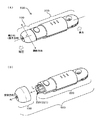
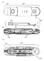
図1にインジェクター500の外観を示す。また、図2には、インジェクター500をその内部と共に模式的に示す。インジェクターは、その外観構成においてインジェクター・ハウジングとインジェクター・キャップとを有して成る。図1および図2に示されるように、インジェクター500は、「相対的に前方側に位置するインジェクター・キャップ100」と「相対的に後方側に位置するインジェクター・ハウジング200」とを少なくとも有している。
The external appearance of the
インジェクター・ハウジング200の内側には、図2に示すように、プランジャー220が設けられている。プランジャーは、インジェクターへのランセット装着を可能とするランセットホルダー225が前端に設けられると共に、適当なバネも設けられており、使用時にランセットと共に発射に付される。よって、インジェクター・ハウジング200は、「使用時にランセットが装着され、そのランセットを穿刺方向に発射するためのプランジャー220」を囲むようにして設けられる部材であるといえる。
Inside the
インジェクター・キャップ100は、インジェクター・ハウジング200に対して取付け及び取外し可能な部材となっている。使用前(すなわち、非使用時)においては、インジェクター・キャップ100はインジェクター・ハウジング200に通常取り付けられた状態となっている。使用に際してインジェクター・キャップ100はインジェクター・ハウジング200から一旦取り外される(図1(B)参照)。かかるインジェクター・キャップ100の取外しにより、インジェクター・ハウジング200の内側に設けられているプランジャー200の先端部221が部分的に露出し、プランジャー220に対してランセットを装着できるようになる。ランセットの装着後は、インジェクター・キャップ100がインジェクター・ハウジング200に対して再度取り付けられ、所望の穿刺操作が行われる。
The
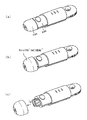
図3に、インジェクター500の使用時における例示的な経時態様に示す。図3(a)および(b)に示すように、使用に際しては、まずインジェクター・キャップ100を取り外す。次いで、図3(c)に示すように、プランジャーの先端部221(特にランセットホルダー225)に対してランセット400を取り付ける。つまり、インジェクター500に対してランセット400を装着する。ランセット400が装着されると、ランセット400のキャップをもぎって穿刺針410を露出させる(図3(c)および図3(d)参照)。次いで、図3(e)に示すようにインジェクター・キャップ100を元に戻す。つまり、一旦取り外されたインジェクター・キャップ100をインジェクター・ハウジング200に再度取り付ける。そして、チャージ部材230を後方へと一旦スライドさせる。これにより、チャージ部材230と協動するファイヤー・スプリング(図示せず)が圧縮に付されることになり、ランセットの発射に必要な力がプランジャーに蓄えられる。ファイヤー・スプリングとプランジャーとは互いに連結された状態にあるところ、ファイヤー・スプリングの圧縮状態は、プランジャーがインジェクター・ハウジング内で係止されることで維持される。以上を経ることで“穿刺可能状態”のインジェクターが得られることになる。
FIG. 3 illustrates an exemplary aging scheme during use of the
穿刺可能状態が得られた後、穿刺すべき所定の部位(例えば指先)にインジェクターの前端(図3(e)の“120”)をあてがった後、発射ボタン240を押す。これにより、プランジャーの係止状態が解除され、圧縮されていたファイヤー・スプリングが瞬時に伸びる。よって、プランジャーが前方へと発射される。つまり、かかるプランジャーに装着された「穿刺針を備えたランセットボディ」が前方の穿刺方向に向かって発射され、所望の穿刺が行われることになる。図3(f)は、発射ボタン240を押すことで穿刺が行われる態様、即ち、穿刺針410がインジェクターの前端120(より具体的には、インジェクター・キャップ100の穿刺開口部125)から露出した時点の態様を示している。発射により穿刺に供したプランジャーは、インジェクター・ハウジング200内に設けられたリターン・バネ(図示せず)の働きによって、引っ込むように後退する。
After the puncturable state is obtained, after the front end of the injector ("120" in FIG. 3 (e)) is applied to a predetermined site (for example, a fingertip) to be punctured, the
穿刺後においては、再度、インジェクター・キャップ100が取り外され、使用済みのランセットがプランジャーから取り外される。このように、発射に供するインジェクターは、使い捨てランセットの穿刺に適したデバイスとなっている。
After puncturing, the
《本発明のインジェクターの特徴》
本発明のインジェクターは、特にインジェクター・キャップに関連する事項に特徴がある。その特徴の1つは、“穿刺針の直進性”に鑑みたものである。また、別の特徴は、“キャップの利便性/安全性”に鑑みたものである。
<< Features of the injector of the present invention >>
The injector according to the invention is characterized in particular in connection with the injector cap. One of the characteristics is in view of "the straightness of the puncture needle". Another feature is in light of "the convenience / safety of the cap".
(穿刺針の直進性)
“穿刺針の直進性”の特徴を有するインジェクターにおいては、図4に示すように、インジェクター・キャップ100の内側面にリブ150が設けられている。“内側面”ゆえに、リブ150はインジェクターの内部構造に相当する。また、リブ150は、インジェクター・キャップ100に設けられており、穿刺箇所(被採血者の穿刺される箇所)に対してより近位に位置付けられた部材に相当する。
(Straightness of puncture needle)
In the injector having the feature of "the straightness of the puncture needle", as shown in FIG. 4, a
図5および図6に示すように、リブ150は、穿刺時において、インジェクター・ハウジング200側に設けられた部材と協働するようになっている。具体的には、図示するように、「発射されたプランジャー220」と「リブ150」とは互いに当接可能となっている。穿刺時においては、インジェクター・キャップ100はインジェクター・ハウジング200に取り付けられた状態となっているところ(図3(e)参照)、その状態において、穿刺に供すべく発射されたプランジャー220(特にその先端のランセットホルダー225)がリブ150に当接できるようになっている。
As shown in FIGS. 5 and 6, the
本明細書で用いる「当接可能」といった用語は、広義には、穿刺に供すべく発射されたプランジャーがリブに対して接することができる態様を意味している。また狭義には、当該用語は、発射ボタンを押すことで前方に発射された「ランセットが装着されたプランジャー(特にその先端のランセットホルダー)」がリブに対して接することができる態様を意味している。 As used herein, the term "abutable" generally refers to the manner in which a plunger fired to be punctured can contact a rib. Also, in a narrow sense, the term means a mode in which a “lancet-mounted plunger (especially its lancet holder at its tip)”, which is fired forward by pressing the launch button, can contact the rib. ing.
特に、本発明では、発射によって穿刺方向に移動し、その後、かかる穿刺方向と逆方向に引っ込むようにプランジャーが移動するまでの過程において、プランジャーとリブとが互いに当接可能となっている。あくまでも、当接“可能”ゆえ、当該過程においてプランジャーとリブとが常に接触している必要はない。 In particular, in the present invention, the plunger and the rib can be brought into contact with each other in the process of moving in the puncture direction by firing and thereafter moving the plunger so as to retract in the direction opposite to the puncture direction. . It is not necessary for the plunger and the rib to always be in contact in the process, since the contact is "possible".
本発明のインジェクターでは、インジェクター・キャップ側に設けられたリブと、インジェクター・ハウジング側に設けられたプランジャーとが当接可能となっているので、発射直進性が向上する。具体的には、穿刺時のプランジャーの軌道直進性が向上するところ、それに伴い「プランジャーに装着されたランセットの穿刺針の直進性」が向上する。特に、本発明では、被採血者に直接あてがわれるインジェクター・キャップに設けられたリブが作用し、被採血者の穿刺ポイントにより近い位置でプランジャーの穿刺軌道が矯正されるので、直進性向上がより効果的になる。その結果、被穿刺者(すなわち被採血者)が穿刺時に感じる痛みを特に効果的に低減することができる。これは、特定の理論に拘束されるわけではないが、穿刺時の穿刺針のぶれが穿刺ポイントのごく近傍で抑制されるので、被採血者の穿刺箇所が“えぐられる”といった現象がより効果的に減じられることに起因するものと推測される。また、本発明のインジェクターでは、使用者が異なる場合であっても常に一定の針軌道が担保され得る。よって、被穿刺者が異なっても穿刺針の穿刺軌道が実質的に一定となり、使用者ごとのばらつきが低減されるといった効果も奏され得る。 In the injector according to the present invention, since the rib provided on the injector cap side and the plunger provided on the injector housing side can be in contact with each other, the firing straightness is improved. Specifically, while the trajectory straightness of the plunger at the time of puncturing is improved, the "straightness of the puncture needle of the lancet attached to the plunger" is improved accordingly. In particular, in the present invention, the rib provided on the injector cap directly applied to the blood collection subject acts, and the puncture track of the plunger is corrected at a position closer to the puncture point of the blood collection subject. Will be more effective. As a result, it is possible to particularly effectively reduce the pain felt by the recipient (that is, the recipient) at the time of puncturing. This is not limited to a specific theory, but the movement of the puncture needle at the time of puncture is suppressed in the vicinity of the puncture point, so the phenomenon that the blood-punctured part of the blood-collecting person is "cut up" is more effective It is presumed to be due to being reduced. Moreover, in the injector of the present invention, a constant needle trajectory can always be secured even when the user is different. Therefore, the effect that the puncture trajectory of the puncture needle becomes substantially constant even if the punctured person is different, and the variation among users can be reduced.
インジェクター・キャップ100のリブ150は、プランジャー220の先端部分(即ち、プランジャーのなかでも特に前方部分)に当接可能となっていることが好ましい。穿刺時の痛み低減に資する穿刺針のぶれ防止が特に効果的となるからである。例えば、インジェクターの使用に際してランセット400はプランジャー220のランセットホルダー225に装着させるが、そのランセットホルダー225が、発射時に、インジェクター・キャップのリブ150と当接できるようになっていることが好ましい(図6参照)。特に、ランセット400が装着されたランセットホルダー225の外面226と、リブ150の頂端155とが当接できるようになっていることが好ましい。図6において参照番号226’で示すように、ランセットホルダーの外面は、リブとの好適な当接のために、凸形状を有していてもよい(例えば、穿刺方向に沿った隆起部をランセットホルダーの外面が有していてもよい)。
Preferably, the
ここで従来における当業者の認識について説明しておく。従来においては、インジェクター・キャップには直進性向上のためのリブを設けることができないか、または、設けるべきではないとの先入観があった。なぜなら、プランジャーのランセットホルダーというものは、ランセットが装着されるとホルダーのスリットに起因して径方向外側へと拡がるよう設計されているからである(ランセットホルダーの胴部における“スリット”は、汎用性を高めるのに設けられており、ランセットのサイズが多少異なっても装着できるようにインジェクターの設計がなされていることが多い)。つまり、インジェクター・キャップにおいて直進性向上のためのリブを設けると、ランセット装着に起因するランセットホルダーの拡がりの程度によっては、発射されたホルダーがリブに衝突してしまい、所望の穿刺ができない虞(すなわち、穿刺針がインジェクターの穿刺開口部から出てこないなどの虞)があるというのが当業者の認識になっていた。この点、本願発明者らが鋭意検討した結果、インジェクター・キャップにリブを仮に設けたとしても発射されたホルダーがリブに不都合に衝突せず直進性向上を図ることができることを見出した。特に、本発明のインジェクターにおいては、ランセットホルダーに敢えて“スリット”(特にランセット装着時に拡がるように機能する先端スリット)などを設けず、上記の衝突を好適に回避している。よって、本発明のインジェクターの好適な態様において、インジェクターのランセットホルダーは、その胴部に“拡張用スリット”が設けられていない「非スリット型のホルダー」となっている。 Here, the recognition of those skilled in the art will be described. Heretofore, there has been a preconception that the injector cap can not be provided with a rib for improving the linearity, or should not be provided. This is because the lancet holder of the plunger is designed to expand radially outward due to the slit of the holder when the lancet is attached (the "slit" in the body of the lancet holder is It is provided to enhance versatility, and the injector is often designed to be mounted even if the lancet size is slightly different). That is, when a rib for improving the straightness is provided in the injector cap, depending on the extent of the spread of the lancet holder due to the lancet mounting, the fired holder may collide with the rib and the desired puncture may not be performed ( That is, it has been recognized by those skilled in the art that there is a possibility that the puncture needle may not come out of the puncture opening of the injector. In this respect, as a result of intensive studies by the inventors of the present application, it has been found that even if the rib is provided temporarily on the injector cap, the fired holder can improve the rectilinearity without disadvantageously colliding with the rib. In particular, in the injector according to the present invention, the lancet holder is not provided with a "slit" (in particular, a tip slit which functions to expand when the lancet is attached), and the above-mentioned collision is preferably avoided. Thus, in a preferred embodiment of the injector of the present invention, the lancet holder of the injector is a "non-slit type holder" in which the "slit for expansion" is not provided on the body.
ある好適な態様では、リブが対を成すように設けられている。例えば図6に示す断面視において、インジェクター・キャップの対向する面にてリブ150が対を成して設けられている。図示する態様では、互いに対向する内側面160Aおよび内側面160Bにそれぞれ設けられたリブ150が対を成しており、および/または、互いに対向する内側面170Aおよび内側面170Bにそれぞれ設けられたリブ150が対を成している。
In a preferred embodiment, the ribs are provided in pairs. For example, in the cross-sectional view shown in FIG. 6, the
インジェクター・キャップに関して用いる「対を成すように」といった用語は、広義には、一方のリブと他方リブとが互いに向き合うように設けられていることを意味している。狭義には、当該用語は、発射されたプランジャーのランセットホルダーを外側から挟み込むように一方のリブと他方リブとが互いに向き合って設けられていることを意味している。 The term "paired" used in reference to the injector cap generally means that one rib and the other rib are provided to face each other. In a narrow sense, the term means that one rib and the other rib are provided facing each other so as to sandwich the lancet holder of the fired plunger from the outside.
このようにリブが対を成すように設けられていると、発射されたプランジャーの穿刺軌道矯正の点で不都合な偏りがより減じられ、直進性向上がより効果的となり得る。 When the ribs are provided in pairs as described above, the disadvantageous deviation can be further reduced in terms of correcting the puncture trajectory of the fired plunger, and the improvement of the straightness can be more effective.
より好ましくは、リブの対が“2対”となっており、その2対のそれぞれの対向する方向は互いに直交している。図6に示すように、例えば「互いに対向するキャップ内側面160Aおよびキャップ内側面160Bにそれぞれ設けられたリブ150」の対と、「互いに対向するキャップ内側面170Aおよびキャップ内側面170Bにそれぞれ設けられたリブ150」の対とが互いに直交していてよい。このように2対が直交していると、図6に示す断面視における“左右方向”および“上下方向”の双方で不都合な偏りをより減じることができ、直進性向上が更に効果的となり得る。
More preferably, the rib pairs are “two pairs”, and the facing directions of the two pairs are orthogonal to each other. As shown in FIG. 6, for example, a pair of "
インジェクター・キャップに設けられるリブは単数に限らず、複数であってよい。つまり、リブは複数個の形態を有していてよい。“対を成す”といった点でいえば、偶数個のリブが設けられていることが好ましい。リブが複数個の形態を有している場合、図6に示すように「穿刺方向に直交する方向のインジェクター・キャップの断面視形状」において複数個のリブが対称的となっていてよい。例えば断面視にて複数個のリブが点対称または線対称となっていてよい。ここでいう「対称的となっている」とは、断面視(インジェクターの横断方向に沿って切り取った断面視)において、一方のリブと他方のリブとが互いに点対称または線対称の関係を有していることを意味している。よって、一方のリブを対称中心に180°回転させると、他方に重なり、その逆も同じである。あるいは、一方のリブを対称軸で仮想的に折り曲げると、他方に重なり、その逆も同じである。このように対称的な配置関係を有するリブでは、発射されたプランジャーの穿刺軌道矯正の点で不都合な偏りがより減じられ易くなる。 The number of ribs provided on the injector cap is not limited to one, and may be plural. That is, the rib may have a plurality of forms. In terms of "pairing", it is preferable that an even number of ribs be provided. When the ribs have a plurality of forms, as shown in FIG. 6, the plurality of ribs may be symmetrical in the “cross-sectional view of the injector cap in the direction orthogonal to the puncturing direction”. For example, the plurality of ribs may be point-symmetrical or line-symmetrical in cross-sectional view. Here, "symmetrical" means that one rib and the other rib have a point-symmetrical or line-symmetrical relationship with each other in a cross-sectional view (a cross-sectional view taken along the transverse direction of the injector). It means that you are doing. Therefore, when one rib is rotated 180 degrees around the symmetry center, it overlaps with the other, and vice versa. Alternatively, if one rib is virtually folded at the symmetry axis, it overlaps the other, and vice versa. Such a symmetrical arrangement of ribs makes it more likely to reduce undesirable deviations in terms of puncture trajectory correction of the fired plunger.
ある好適な態様では、インジェクター・キャップの内側面に対して略垂直方向にリブが立設している。例えば図6に示すように、内側面160Aおよび/または内側面160Bに対してリブ150が略垂直方向に立設している。図示する形態から分かるように、内側面が湾曲している場合では、リブ設置点における略法線方向に沿ってリブが延在していることになる。ここでいう「略垂直」とは、完全な“垂直”でなくてもよく、それから僅かにずれた態様(例えばリブ設置点における法線との成す角度が0°〜10°程度となるようにリブが延在する態様)であってもよいことを意味している。
In a preferred embodiment, a rib stands in a direction substantially perpendicular to the inner surface of the injector cap. For example, as shown in FIG. 6, a
略垂直方向にリブ150が立設していると、リブの頂端155に対してより好適に「発射されたプランジャー」が当接可能となるので、リブから受ける摩擦抵抗が過度にならない。つまり、プランジャー発射力を過度に弱めることなく、直進性向上を図ることができる。
When the
リブの立設サイズ、特にリブ高さは、「リブとプランジャーとの当接可能」に資するものであれば特に制限はない。あくまでも例示であるが、図6の断面視でいえば“リブ頂端”と“仮想的なプランジャー外面”(全くぶれなく前進移動したと仮想した場合のプランジャーの外面)との間にごく僅かな隙間(約1mm以内、例えば0.8mm以内または0.5mm以内)が形成されるリブ高さであってよい。 The standing size of the rib, in particular the height of the rib, is not particularly limited as long as it contributes to "the abutment between the rib and the plunger". This is merely an example, but in the cross-sectional view of FIG. 6, it is very small between the “rib top end” and the “virtual plunger outer surface” (the outer surface of the plunger when it is assumed to have moved forward without any movement). The rib height may be such that a clearance (within about 1 mm, for example within 0.8 mm or within 0.5 mm) is formed.
図4〜図6に示されるように、リブ150が設けられるインジェクター・キャップ100は、その全体外観として、扁平したような形状を有していてよい。例えば、穿刺方向に直交する方向のインジェクター・キャップの断面視形状が略楕円形となっていてよい。つまり、図6の断面視で示されるインジェクター・キャップ100でいえば、その全体的な形状が略楕円となっていてよい。
As shown in FIGS. 4 to 6, the
本明細書でいう「略楕円形」とは、完全な楕円形であることに限らず、それから変更されつつも当業者の認識として依然“楕円”に通常含まれ得る形状をも含んでいる。よって、キャップ断面視において互いに直交する短軸長さと長軸長さを有する形状であれば、楕円の曲部分の態様はいかなるものであってもよい。 The term "generally elliptical" as used herein is not limited to a perfect ellipse, but includes modifications that can be generally included in an "ellipse" as recognized by those skilled in the art. Therefore, as long as it is a shape having a short axis length and a long axis length orthogonal to each other in the cap cross sectional view, the aspect of the curved portion of the ellipse may be any shape.
インジェクター・キャップの断面視形状が略楕円形となる場合、リブ個数に関する設計自由度が高くなる。図6に示す態様でいうと、「互いに対向するキャップ内側面160Aおよびキャップ内側面160Bにそれぞれ設けられたリブ150」と、「互いに対向するキャップ内側面170Aおよびキャップ内側面170Bにそれぞれ設けられたリブ150」とでは設置個数に違いをもたせ易くなる。このような設計個数の違いは、プランジャーの形態(断面形状)、特にランセットホルダーの形態(断面形状)に合わせたより好適なリブ設置を可能にする。
When the cross-sectional shape of the injector cap is substantially elliptical, the degree of freedom in designing the number of ribs is increased. In the embodiment shown in FIG. 6, “
図示するように、インジェクター・キャップは、その内壁面よりも内側に対を成す湾曲壁部材180を有していてもよい。図6に示すように、“断面視の略楕円形”の短軸に沿って延在するような湾曲壁部材180が設けられていてよい。かかる場合、その湾曲壁部材180の内側面にリブ150が設けられていてよく、かかるリブがプランジャー220(特にランセットホルダー225)との“当接可能”に資するようにしてよい。
As shown, the injector cap may have a pair of
(キャップの利便性/安全性)
“キャップの利便性・安全性”の特徴を有するインジェクターでは、インジェクター・キャップとインジェクター・ハウジングとの互いの取付けおよび取外しに関連する特異的な部材/部分が付加的に設けられている。
(Convenience / safety of cap)
In the case of an injector having the "cap convenience and safety" feature, additional parts / parts are additionally provided which relate to the mounting and dismounting of the injector cap and the injector housing from one another.
かかるインジェクターにおいては、インジェクター・キャップ100が、図7に示すように、その内面に第1隆起部190を有している。図示するように、第1隆起部190は、インジェクター・キャップの内面が“局所的に隆起した形態”を有している。これに対して、インジェクター・ハウジング200は、その外面に対を成す土手部250(250a,250b)を有し、その土手部の内側の溝領域260に第2隆起部270を有している。第1隆起部と同様、第2隆起部270は、インジェクター・ハウジングの外面が“局所的に隆起した形態”を有している。
In such an injector, the
第1隆起部190は、図示するように、インジェクター・キャップ100の後方端110に隣接して位置付けられることが好ましく、その後方端110に対して直ぐ隣合せとなるように設けられていることがより好ましい。つまり、インジェクター・キャップ100において、第1隆起部190は相対的に後方側に位置付けられているところ、特にインジェクター・キャップ100の後端エッジ115により近位するように位置付けられることが好ましい。一方、第2隆起部270は、インジェクター・ハウジング200の前方側210の外面に設けられていることが好ましく、特に、取り付けられるインジェクター・キャップ100と部分的に重なる外面に対して位置付けられていることがより好ましい。
The
特に、第2隆起部270は、対を成す土手部250の内側に設けられている。この対を成す土手部250は、穿刺方向に沿って延在していることが好ましい。つまり、図7に示すように、インジェクターの軸方向に沿って延びるように一方の土手部250aと他方の土手部250bとが対向するように設けられていることが好ましい。第2隆起部270は、対を形成する一方の土手部250aと他方の土手部250bとの間に挟まれるように設けられている。このような土手部の延在ゆえ、インジェクター・キャップの取付け及び取外しに際して第1隆起部190がその土手部250(又はその内側の溝領域260)と好適に協働できるようになっている。なお、第2隆起部270は、土手部250と連続的な形態を有していてよく(つまり、第2隆起部270と土手部250とが互いに一体化した形態を有していてよく)、図示するように、一方の土手部250aと他方の土手部250bとの間を橋渡しするような形態を第2隆起部270が有していてよい。
In particular, the second raised
本発明のインジェクターでは、第1隆起部が溝領域に嵌り込み可能となっている。特に、インジェクター・キャップ100のインジェクター・ハウジング200への取付けに際して、インジェクター・キャップ100の第1隆起部190が、インジェクター・ハウジング200の溝領域260に対して嵌り込むことができるようになっている(これにつき、例えば第1隆起部190の幅寸法と溝領域260の幅寸法とが互いに略同じとなっていてよい)。換言すれば、インジェクター・キャップ100の第1隆起部190が、インジェクター・ハウジング200の対を成す土手部250(より具体的には、一方の土手部250aと他方の土手部250bとの間)に嵌まり込むことができるようになっている。このように嵌り込むことによって、インジェクター・キャップ100の第1隆起部190が溝領域260に沿って案内されることになり、インジェクター・キャップの好適な取付けが助力される。特に、インジェクターの軸方向に沿って“まっすぐに”インジェクター・キャップを取付けることができる。
In the injector according to the invention, the first raised portion can be fitted into the groove area. In particular, upon attachment of the
インジェクター・キャップの取付けに際しては、溝領域を摺動する第1隆起部が第2隆起部を乗り越えることが好ましい。つまり、インジェクター・キャップの取付け時において、第1隆起部が溝領域を摺動しながらも第2隆起部を乗り越えることが好ましい。より具体的には、インジェクター・キャップの取付け時において、インジェクター・キャップ100の第1隆起部190がインジェクター・ハウジング200の土手部250によって案内されるように溝領域260をスライド移動するが、かかるスライド移動の過程において第2隆起部270を第1隆起部190が乗り越えることが好ましい(図8(a)〜(c)の経時変化態様を併せて参照のこと)。これは、土手部250の内側の溝領域260に沿ってスライド移動する第1隆起部190が、その溝領域260に沿った状態を維持するように第2隆起部270を乗り越えることを意味している。
When mounting the injector cap, it is preferred that the first ridge sliding on the groove area ride over the second ridge. That is, at the time of attachment of the injector cap, it is preferred that the first ridge slide over the groove area but over the second ridge. More specifically, during the installation of the injector cap, the
本発明のある好適な態様では、溝領域260を移動する第1隆起部190が第2隆起部270を乗り越えることによってスナップフィットがもたらされ、インジェクター・キャップの取付けが完了する。なお、インジェクター・ハウジングの第2隆起部は、テーパ面(特に「前方側から後方側に向けて徐々に隆起度が大きくなるテーパ面」)を備えていることが好ましく、そのテーパ面を第1隆起部190が乗り越えることでスナップフィットがもたらされる態様が好ましい。
In one preferred aspect of the present invention, the
第2隆起部は、テーパ面に加えて、急峻面を有していることが好ましい。図8に示すように、第2隆起部270の上面は、前方側のテーパ面272および後方側の急峻面274から少なくとも構成されていることが好ましい。かかる場合、溝領域260(一対の土手部250の間)に位置する第1隆起部190が第2隆起部270のテーパ面272を乗り越え、かつ、急峻面274よりも後方側へと至るに際してスナップフィットがもたらされる。かかるスナップフィットによって、インジェクター・キャップのインジェクター・ハウジングへの取付けが完了する。したがって、インジェクター・キャップがインジェクター・ハウジングに取り付けられた状態においては、土手部の内側かつ第2隆起部の急峻面よりも後方側に第1隆起部が位置していることになる。第2隆起部の急峻面よりも後方側に第1隆起部が位置することで、第1隆起部と急峻面とが互いに係合可能となり(別の観点で捉えると、第1隆起部が急峻面に引っ掛る作用がもたらされるので)、取付け後のキャップにおいて安定性がもたらされる。尚、同様の目的で、インジェクター・キャップの第1隆起部190が、その上面としてテーパ面および/または急峻面を有していてもよい。具体的には、第1隆起部190の上面が、前方側の急峻面および後方側のテーパ面から構成されていてもよい。
The second raised portion preferably has a steep surface in addition to the tapered surface. As shown in FIG. 8, it is preferable that the upper surface of the second raised
スナップフィット後において、すなわち、インジェクター・キャップの取付け完了後では、インジェクター・キャップの非所望の取外しが回避されている。具体的には、インジェクター・キャップ100とインジェクター・ハウジング200とが互いに引き離される方向で外力を受けた場合、第1隆起部190が第2隆起部270の急峻面274によって係止され、インジェクター・ハウジング200に対するインジェクター・キャップ100の取り外しが防止される(図8(c)参照)。つまり、インジェクター・ハウジング200に対するインジェクター・キャップ100の相対的な前方移動は、第1隆起部190が第2隆起部270の急峻面274に引っ掛ることで阻止される。特に“急峻面”ゆえ、インジェクターの軸方向に“まっすぐに”インジェクター・キャップを強く引っ張ったとしてもキャップが取外せないようになっている。ここでいう「急峻面」とは、図8に示す断面視でとらえてみて、インジェクターの軸方向との成す角度が90°±20°程度、好ましくは90°±10°程度、より好ましくは90°±5°程度となった面のことを指している。
After snap fitting, i.e. after installation of the injector cap is complete, undesired removal of the injector cap is avoided. Specifically, when an external force is applied to the
このような機構を備えるインジェクターでは、インジェクター・キャップのインジェクター・ハウジングへの取付けに際して、キャップをインジェクターの方向に沿って“まっすぐ”挿入してスナップフィットさせることができる一方、一旦そのように取り付けると今度はキャップを“まっすぐ”に取り外せないようになっている。よって、意図して取り付けられたキャップは、非所望に外れないようになっており、より好適な安全性が確保される。 In an injector with such a mechanism, when attaching the injector cap to the injector housing, the cap can be inserted "straightly" along the direction of the injector and snap fit, but once so attached it is now possible The cap can not be removed "straight". Thus, the intentionally attached cap is prevented from coming off undesirably, and more preferable safety is ensured.
本発明に係るインジェクターは、インジェクター・キャップの取外しにおいても特異的な特徴を有している。特に、取外しに際しては、インジェクター・キャップの第1隆起部とインジェクター・ハウジングの土手部とが互いに協働する。 The injector according to the invention also has unique features in the removal of the injector cap. In particular, upon dismounting, the first bulge of the injector cap and the bank of the injector housing cooperate with one another.
インジェクター・ハウジング200に対して取り付けられているインジェクター・キャップ100をインジェクターの軸中心に回転させると(図9(a)および(b)に示すように“ねじり回転”に付すと)、インジェクター・キャップ100の第1隆起部190が、インジェクター・ハウジング200の土手部250を乗り越えることができる(図10(a)〜(c)および図11参照)。図示するように、かかる回転に際しては、土手部250に嵌り込んでいた第1隆起部190が、その嵌込みを解除するように土手部250から外側へと変位する。より具体的には、第1隆起部190の側方面191が土手部250の内側面251を摺動しながら、それを乗り越え(特に図10(b)参照)、これにより第1隆起部190の嵌込み状態(土手部250による嵌込み状態)が解除される。図10(a)〜(c)から分かるように、第1隆起部190の側方面191および土手部250の内側面251はそれぞれ非急峻面を成しており、それらの断面視形状は、互いに相補的な形状となっていてよい。
When the
上記回転により第1隆起部が土手部を乗り越えると、第2隆起部の急峻面に対する第1隆起部の係止が回避され、インジェクター・キャップをインジェクター・ハウジングから取り外すことができるようになる(図9(b)および(c)参照)。“ねじり回転”無しでインジェクターの軸方向に沿って“まっすぐに”インジェクター・キャップを引っ張った場合では第1隆起部190が第2隆起部270の急峻面274に係止されキャップ取外しができないものの、インジェクター・キャップをねじるように回転させると、当該係止が解除されてキャップ取外しができるようになる。
When the first raised portion passes over the bank due to the above rotation, the locking of the first raised portion against the steep surface of the second raised portion is avoided, and the injector cap can be removed from the injector housing (see FIG. 9 (b) and (c)). If the injector cap is pulled "straightly" along the axial direction of the injector without "torsion rotation", the
本発明のインジェクターではキャップ取外しのための回転が利便性の高いものとなっている。具体的には、図10(c)および図11に示すように、インジェクター・キャップ100の回転の方向が互いに逆向き可能な方向となっている。図示する態様から分かるように、インジェクター・キャップ100は、時計回りに回転させることができる一方、逆の反時計回りにも回転させることができ、そのような回転で第1隆起部が土手部を乗り越えることになり第1隆起部の急峻面への係止が回避される。かかる態様においては、一対の土手部250、すなわち、一方の土手部250aと他方の土手部250bとが関与している。例えば図10(c)に示すように、インジェクター・キャップ100を時計回りに相対的に回転させると、第1隆起部190が“一方の土手部250b”を乗り越えて第1隆起部190の急峻面274(図8参照)への係止が解除される。その一方、インジェクター・キャップ100を反時計回りに相対的に回転させると、第1隆起部190が“他方の土手部250a”を乗り越えて第1隆起部190の急峻面274(図8参照)への係止が解除される。
In the injector of the present invention, the rotation for removing the cap is highly convenient. Specifically, as shown in FIGS. 10 (c) and 11, the directions of rotation of the
また、本発明のインジェクターでは、使用者によるキャップ取外しのねじり回転がより利便性の高いものとなっている。キャップ取外しのための回転が無制限になっているわけでなく、所定範囲内に制限され、その制限によって使用者が「急峻面274に対する第1隆起部190の係止」の解除を把握し易くなっている。具体的には、図11の真ん中図および下側図に示すように、「インジェクター・キャップ100の内面」と「インジェクター・ハウジング200の外面」とが互いに局所的に当接することによって、インジェクター・キャップの回転が所定範囲内に制限されている。あくまでも例示にすぎないが、インジェクター・キャップの軸中心の回転が約±30°の範囲内に制限されている。
In addition, in the injector of the present invention, the twisting rotation for removing the cap by the user is more convenient. The rotation for removing the cap is not unlimited, and is limited within a predetermined range, which makes it easy for the user to grasp the release of the “locking of the
なお、インジェクター・キャップの上記回転(すなわち、捻じる/捻るような回転)でキャップが斜め状態に付されることによって第1隆起部の係止が解除され、インジェクター・キャップを取り外せるということは、取り付けも同様となっていることを意味している。つまり、一旦取り外されたインジェクターキャップは、上記“斜め状態”にすると、実質的な抵抗なくインジェクター・ハウジング200に取り付けることができる。
Note that the locking of the first raised portion is released by the cap being put in an oblique state by the above rotation (ie, twisting / twisting rotation) of the injector cap, and the injector cap can be removed, It means that the installation is also the same. That is, the injector cap once removed can be attached to the
本発明のインジェクターにおけるキャップの取付けおよび取外しは、図12にまとめて例示している。図示するように、インジェクター・キャップを例えば時計回りに約30°のねじり回転に付すことによって、かかるキャップを比較的簡易に取り外すことができる。同様にして、インジェクター・キャップを例えば反時計回りに約30°のねじり回転に付すことによっても、かかるキャップを取り外すことができる。一方、取り外されたインジェクター・キャップはインジェクター・ハウジングの前端部に対してまっすぐ挿入するとスナップフィットしてキャップの取付けを行うことができる。一旦そのように取り付けられると今度は“まっすぐ”には取り外せないようになっている。さらにいえば、取り外されたインジェクター・キャップは、上記の“時計回りに約30°のねじり回転”に付された後の斜め状態でインジェクター・ハウジングの前端部に対して組み合わせると、抵抗なく挿入することでき、挿入後に斜め状態を解除するように反時計回りにねじり回転するとスナップフィットしてキャップの取付けが完了する。同様にして、取り外されたインジェクター・キャップは、上記の“反時計回りに約30°のねじり回転”に付された後の斜め状態でインジェクター・ハウジングの前端部に対して組み合わせると、抵抗なく挿入することでき、挿入後に斜め状態を解除するように時計回りにねじり回転するとスナップフィットしてキャップの取付けが完了する。このように本発明のインジェクターは、特にキャップ取外しおよび取付けの点で利便性に優れたデバイスとなっている。 The attachment and removal of the cap in the injector of the present invention is illustrated collectively in FIG. As shown, such a cap can be removed relatively easily by subjecting the injector cap to a twisting rotation of, for example, approximately 30 ° clockwise. Similarly, such a cap can be removed by subjecting the injector cap to a twisting rotation of, for example, about 30 ° counterclockwise. On the other hand, the removed injector cap can be snap-fit when inserted straight into the front end of the injector housing for attachment of the cap. Once so attached, it can not now be removed "straight". Furthermore, the removed injector cap inserts without resistance when combined with the front end of the injector housing at an angle after being subjected to the above "clockwise rotation about 30 °" It can be snap fit when it twists and turns counterclockwise so as to release the oblique state after insertion, and installation of the cap is completed. Similarly, the removed injector cap can be inserted without resistance when assembled against the front end of the injector housing in the angled state after being subjected to the above-mentioned "anticlockwise rotation about 30 °" It can be snap-fit when it twists and turns clockwise to release the skew after insertion and the installation of the cap is complete. Thus, the injector of the present invention is a convenient device, particularly in terms of cap removal and attachment.
本発明は種々の態様でもって具現化され得る。これにつき例えば以下の態様を挙げることができる。 The invention can be embodied in various ways. For example, the following aspects can be mentioned.
(ネック形態のハウジング前端部に関する態様)
インジェクター・ハウジングの前端は、インジェクター・キャップの取付けおよび取外しに好適な形態となっていてよい。図7などに示すように、例えばインジェクター・ハウジング200は、その前端210が径狭になったネック部215を有して成るものであってよい。つまり、インジェクター・ハウジングの先端部が、本体部分よりも一回りほど小さい形態を有していてよい。キャップ取付けに際しては、このような先端部に対してインジェクター・キャップが被さるようにキャップ挿入される態様が好ましい。本明細書において「ネック部」とは、“首状”にハウジング本体よりもサイズが小さい開口端部のことを意味している。
(Aspect about the housing front end of the neck form)
The front end of the injector housing may be configured for attachment and removal of the injector cap. As shown in FIG. 7 or the like, for example, the
インジェクター・ハウジング200がその前端としてネック部を有する場合、かかるネック部215の外周面215Aに土手部250が設けられていることが好ましい。そして、かかる土手部の内側の溝領域260に第2隆起部270を有していることがより好ましい。ネック部215にインジェクター・キャップ100が被さるようにキャップ取付けがなされるに際しては、ネック部251の土手部250に嵌まり込んだ第1隆起部190が、溝領域260を摺動しながら第2隆起部270を乗り越え、スナップフィットがもたされることになる。
When the
(キャップ内側の湾曲壁部材に関する態様)
インジェクター・キャップの内部構造は、キャップの取付けおよび取外しに特に好適な形態を有していてよい。図4などに示すように、例えばインジェクター・キャップ100は、その外壁130よりも内側に湾曲壁部材180(特に対を成すような湾曲壁部材)を有して成っていてよい。図示するように、側方外壁130の一部分よりも一回り小さい形態を有する湾曲壁部材180が設けられていてよい。特に、断面視で捉えた場合にインジェクター・キャップの略楕円形状の短軸に沿う方向に延在する湾曲壁部材180が設けられていることが好ましい。
(Aspect about curved wall member inside cap)
The internal structure of the injector cap may have a form particularly suitable for the attachment and removal of the cap. As shown in FIG. 4 and the like, for example, the
湾曲壁部材が設けられている場合、インジェクター・キャップがインジェクター・ハウジングに取り付けられた状態では、湾曲壁部材180の内側にインジェクター・ハウジング200のネック部215が位置付けられることが好ましい。これによって、キャップの取付けおよび取外しに際し、湾曲壁部材180がネック部215によって好適に案内されるようになり、インジェクター・キャップのネック部215への取り付けが助力される。特に、使用者にとってみれば、キャップの取付けおよび取外し時に“がたつき感”が減り、スムーズな操作感が得られる。例えば、インジェクター・キャップの“ねじり回転”では、キャップの湾曲壁部材がハウジング本体のネック部上を滑動できるので、その点で“がたつき感”が減じられる。これは、インジェクター・キャップの回転においては湾曲壁部材の内面とネック部の外周面とが互いに摺動可能となっていることを意味している。図11に示す形態でいえば、“時計回りにねじり回転”する場合では(右下側の図)、湾曲壁部材180の内面の一方の略半部分180aと、ネック部215の側方部分216の外面216’とが互いに摺動可能となっている。一方、“反場時計回りにねじり回転”する場合では(左下側の図)、湾曲壁部材180の内面の他方の略半部分180bと、ネック部215の側方部分216の外面216’とが互いに摺動可能となっている。
If a curved wall member is provided, it is preferable that the
ちなみに、インジェクター・キャップの回転が所定範囲内に収まることは、上述したように「インジェクター・キャップの内面」と「インジェクター・ハウジングの外面」とが互いに局所的に当接でもたらされる。より具体的な態様でいえば、図13に示される「インジェクター・キャップ100の内面の嶺部140」と「インジェクター・ハウジング200のネック部215の外周面215Aの局所領域(特に上記の側方部分に隣接する局所的外面領域215A’)」との相互当接によって回転制限がなされることが好ましい。
Incidentally, the fact that the rotation of the injector cap falls within a predetermined range results in the "inner surface of the injector cap" and the "outer surface of the injector housing" being in local abutment with each other as described above. More specifically, the "
(弾性変形に関する態様)
インジェクターは、キャップの取付けおよび取外しがより好適に実現されるべく適当な弾性変形可能なデバイスとなっていてよい。例えば、インジェクター・キャップおよびインジェクター・ハウジングのネック部の少なくとも一方は弾性変形することができ、その弾性変形を通じてインジェクター・キャップの取付け及び取外しがされるようになっていてよい。
(Aspect about elastic deformation)
The injector may be a suitable elastically deformable device such that attachment and removal of the cap is more suitably realized. For example, at least one of the injector cap and the neck portion of the injector housing may be elastically deformed, and through the elastic deformation, attachment and detachment of the injector cap may be made.
例えば、インジェクター・キャップをインジェクター・ハウジングの前端部に“まっすぐ”挿入してスナップフィットさせる際に「インジェクター・キャップ」および「インジェクター・ハウジングのネック部」の少なくとも一方が弾性変形することが好ましい。かかる場合、キャップ取付けのためにスライド移動する第1隆起部190が第2隆起部270をよりスムーズに乗り越えることができ、より好適なスナップフィットが得られることになる。つまり、より自然にスナップフィットしてインジェクター・キャップの取付けを行うことができる。また、取り付けられているキャップのねじり回転に際して「インジェクター・キャップ」および「インジェクター・ハウジングのネック部」の少なくとも一方が弾性変形することも好ましい。かかる場合、回転に伴って第1隆起部190が土手部250をよりスムーズに乗り越えることができ、より自然なスナップ感が得られることになる。
For example, it is preferable that at least one of the "injector cap" and the "injector housing neck" be elastically deformed when the injector cap is inserted "straight" into the front end of the injector housing for snap fitting. In such a case, the
弾性変形は、構造に起因したものであってよく、あるいは、材質に起因したものであってもよい。あくまでも1つの例示にすぎないが、インジェクター・キャップに対して“一部切欠き”が設けられ、それによって、構造的に弾性変形がもたらされていてよい。例えば、インジェクター・キャップ100の湾曲壁部材180に一部切欠き185が設けられ(図4参照)、かかる一部切欠きに起因してインジェクター・キャップ100に弾性変形がもたらされてよい。インジェクター・キャップをインジェクター・ハウジングの前端部に“まっすぐ”挿入してキャップ取付けを行うに際しては、一部切欠き185に起因してインジェクター・キャップが弾性変形し、より好適なスナップフィットがもたらされることになる。あるいは、取り付けられているインジェクター・キャップをねじり回転してキャップ取外しを行うに際しては、一部切欠き185に起因してインジェクター・キャップが弾性変形し、より好適なスナップ感が得られることになる。
The elastic deformation may be due to the structure or may be due to the material. By way of example only, a "partial notch" may be provided for the injector cap, whereby an elastic deformation may be provided structurally. For example, the
また、同様にして1つの例示にすぎないが、インジェクター・ハウジングに対して“一部切欠き”が設けられ、それによって、構造的に弾性変形がインジェクター・ハウジングにもたらされてもよい。例えば、図14に示すようにインジェクター・ハウジング200のネック部215に一部切欠き218(より具体的には“ネック部の壁を貫通するような一部切欠き”)が設けられ、かかる一部切欠き218に起因してネック部215に弾性変形がもたらされてよい。インジェクター・キャップをネック部215に対して“まっすぐ”挿入してキャップ取付けを行うに際しては、一部切欠き218に起因してインジェクター・ハウジング(特にそのネック部215)が弾性変形し、より好適なスナップフィットがもたらされることになる。あるいは、取り付けられているインジェクター・キャップをねじり回転してキャップ取外しを行うに際しては、一部切欠き218に起因してインジェクター・ハウジング(特にそのネック部215)が弾性変形することになり、取外し時におけるスナップ感がより好適に得られ易くなる。なお、ネック部215に設けられる一部切欠き218は、穿刺方向に延びるスロット形態をその少なくとも一部に有していることが好ましい(図14(A)〜(C)参照)。より好適な弾性変形がネック部215にもたらされ得るからである。穿刺方向に沿ってスロット状に延びる一部切欠き218は、対を成す土手部250の外側に設けられていてよく、図14(A)〜(C)に示すように例えば土手部250と隣接するように設けられていてもよい。また、スロット状の一部切欠き218は、穿刺方向に限らず、その穿刺方向と直交する方向にも延びる形態を有していてもよい。例えば図14(A)および14(C)に示す如くの“コの字”状(平面視形状)となっていてよく、それによって、弾性変形がより好適に促進される効果が期待される。
Also, likewise by way of example only, "partial notches" may be provided to the injector housing, whereby structurally elastic deformation may be provided to the injector housing. For example, as shown in FIG. 14, the
なお、弾性変形のための“一部切欠き”は「インジェクター・キャップ」および「インジェクター・ハウジングのネック部」のいずれか一方に設けられていてよいものの、それらの双方であっても当然よい。「インジェクター・キャップ」および「インジェクター・ハウジングのネック部」の双方に“一部切欠き”が設けられていると、弾性変形がより容易に発現する効果が期待される。 Although the "partial notch" for elastic deformation may be provided in either one of the "injector cap" and the "neck portion of the injector housing", it is naturally also possible to use both of them. If the "injector cap" and the "neck portion of the injector housing" are provided with "partial notches", it is expected that the elastic deformation is more easily developed.
以上、本発明の実施形態について説明してきたが、本発明はこれに限定されない。本発明では種々の形態が考えられるだけでなく、種々の改変がなされ得ることを当業者は容易に理解されよう。例えば、穿刺針410は、図示されたように最先端が針状に尖った形態を有するものであったが、必ずしもかかる形態に限定されない。例えば、穿刺針410は、先端部の一側面が鋭利になった“ブレード形態(blade)”であってもよい。
As mentioned above, although embodiment of this invention was described, this invention is not limited to this. Those skilled in the art will readily understand that not only various forms can be considered in the present invention, but also various modifications can be made. For example, as shown in the drawing, the
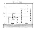
本発明に係るインジェクターの直進性向上の効果を確認するために試験を行った。 A test was conducted to confirm the effect of the straightness improvement of the injector according to the present invention.
使用したインジェクターは2種類である。具体的には『穿刺針の直進性向上を意図してインジェクター・キャップにリブを設けたタイプ』(実施例:インジェクターA)と、その比較例となる『穿刺針の直進性向上を意図したリブをインジェクター・キャップに設けなかったタイプ』(比較例:インジェクターB)とを用いた。 There are two types of injectors used. Specifically, "the type in which a rib is provided on the injector cap for the purpose of improving the straightness of the puncture needle" (Example: Injector A), and the rib intended for the improvement of the straightness of the puncture needle Of the type not provided with the injector cap (Comparative example: Injector B).
結果を以下の表1および図15に示す。

表1および図15に示される結果から分かるように、本発明のインジェクターでは穿刺針の直進性(穿刺軌道の直線性)が向上することが理解できるであろう。 As can be seen from the results shown in Table 1 and FIG. 15, it will be understood that the injector of the present invention improves the straightness of the puncture needle (linearity of the puncture trajectory).
本発明のインジェクターは、ランセットを発射させて穿刺に供すことができるので、ランセットと共に使用できる採血器具として用いることができる。 The injector of the present invention can be used as a blood collection device that can be used with a lancet because the lancet can be fired and punctured.
100 インジェクター・キャップ
110 インジェクター・キャップの後方端
115 インジェクター・キャップの後方エッジ
120 インジェクターの前端(インジェクター・キャップの最先端部分)
125 穿刺開口部
130 インジェクター・キャップの外壁
140 インジェクター・キャップの内面の嶺部
150 リブ
155 リブの頂端または頂部
160A インジェクター・キャップの内面
160B インジェクター・キャップの内面
170A インジェクター・キャップの内面
170B インジェクター・キャップの内面
180 湾曲壁部材
180a 湾曲壁部材の内面に関する一方の略半部分
180b 湾曲壁部材の内面に関する他方の略半部分
185 一部切欠き
190 第1隆起部
191 第1隆起部の側方面
200 インジェクター・ハウジング
215 インジェクター・ハウジングのネック部
215A ネック部の外周面
215A’ネック部における側方部分に隣接する局所的外面領域
216 ネック部の側方部分
216’ ネック部の側方部分の外面
218 ネック部の一部切欠き
220 プランジャー
225 ランセットホルダー
226 ランセットホルダーの外面
230 チャージ部材
240 発射ボタン
250 土手部
250a 一方の土手部(サブ土手部)
250b 他方の土手部(サブ土手部)
251 土手部の内側面
260 溝領域
270 第2隆起部
272 第2隆起部の前方側テーパ面
274 第2隆起部の後方側急峻面
400 ランセット
410 穿刺針
500 インジェクター
100
125
250b The other bank (sub bank)
251 Inner side of
Claims (21)
ランセットの装着が可能で穿刺方向に発射可能なプランジャー、該プランジャーを囲むように設けられるインジェクター・ハウジング、および、該インジェクター・ハウジングに対して取付け及び取外し可能なインジェクター・キャップを有して成り、
前記インジェクター・キャップの内側面にリブが設けられ、該リブと発射された前記プランジャーとは互いに当接可能となっている、インジェクター。 An injector for firing a lancet for puncture
A lancet mountable plunger having an injector housing provided so as to surround the plunger, and an injector cap attachable to and removable from the injector housing. ,
An injector, wherein a rib is provided on an inner surface of the injector cap, and the rib and the fired plunger can come into contact with each other.
ランセットの装着が可能で穿刺方向に発射可能なプランジャー、該プランジャーを囲むように設けられるインジェクター・ハウジング、および、該インジェクター・ハウジングに対して取付け及び取外し可能なインジェクター・キャップを有して成り、
前記インジェクター・キャップが、その内面に第1隆起部を有する一方、前記インジェクター・ハウジングが、その外面に対を成す土手部を有し、該土手部の内側の溝領域に第2隆起部を有する、インジェクター。 An injector for firing a lancet for puncture
A lancet mountable plunger having an injector housing provided so as to surround the plunger, and an injector cap attachable to and removable from the injector housing. ,
The injector cap has a first ridge on its inner surface, while the injector housing has a pair of ridges on its outer surface and a second ridge in the inner groove area of the ridge ,injector.
前記インジェクター・キャップが前記インジェクター・ハウジングに取り付けられた状態においては、前記湾曲壁部材の内側に前記ネック部が位置付けられる、請求項17に記載のインジェクター。 Said injector cap comprises a curved wall member inside its outer wall;
18. The injector of claim 17, wherein the neck portion is positioned inside the curved wall member when the injector cap is attached to the injector housing.
Priority Applications (20)
| Application Number | Priority Date | Filing Date | Title |
|---|---|---|---|
| JP2017118871A JP6549185B2 (en) | 2017-06-16 | 2017-06-16 | injector |
| EP17186353.3A EP3415092B1 (en) | 2017-06-16 | 2017-08-16 | Injector |
| HUE17186353A HUE047885T2 (en) | 2017-06-16 | 2017-08-16 | Injector |
| SI201730152T SI3415092T1 (en) | 2017-06-16 | 2017-08-16 | Injector |
| HUE18185407A HUE048595T2 (en) | 2017-06-16 | 2017-08-16 | Injector |
| US15/678,795 US10687748B2 (en) | 2017-06-16 | 2017-08-16 | Injector |
| PT171863533T PT3415092T (en) | 2017-06-16 | 2017-08-16 | Injector |
| ES17186353T ES2761843T3 (en) | 2017-06-16 | 2017-08-16 | Injector |
| PT181854076T PT3441002T (en) | 2017-06-16 | 2017-08-16 | Injector |
| DK18185407.6T DK3441002T3 (en) | 2017-06-16 | 2017-08-16 | Injector |
| SI201730237T SI3441002T1 (en) | 2017-06-16 | 2017-08-16 | Injector |
| EP18185407.6A EP3441002B1 (en) | 2017-06-16 | 2017-08-16 | Injector |
| PL18185407T PL3441002T3 (en) | 2017-06-16 | 2017-08-16 | Injector |
| ES18185407T ES2784529T3 (en) | 2017-06-16 | 2017-08-16 | Injector |
| PL17186353T PL3415092T3 (en) | 2017-06-16 | 2017-08-16 | Injector |
| DK17186353.3T DK3415092T3 (en) | 2017-06-16 | 2017-08-16 | Injector |
| CN201810606633.5A CN109106377B (en) | 2017-06-16 | 2018-06-13 | Syringe with a needle |
| CN202010980481.2A CN112043288A (en) | 2017-06-16 | 2018-06-13 | Syringe with a needle |
| HRP20191998TT HRP20191998T1 (en) | 2017-06-16 | 2019-11-05 | Injector |
| HRP20200660TT HRP20200660T1 (en) | 2017-06-16 | 2020-04-24 | Injector |
Applications Claiming Priority (1)
| Application Number | Priority Date | Filing Date | Title |
|---|---|---|---|
| JP2017118871A JP6549185B2 (en) | 2017-06-16 | 2017-06-16 | injector |
Publications (3)
| Publication Number | Publication Date |
|---|---|
| JP2019000461A JP2019000461A (en) | 2019-01-10 |
| JP2019000461A5 JP2019000461A5 (en) | 2019-04-04 |
| JP6549185B2 true JP6549185B2 (en) | 2019-07-24 |
Family
ID=59649525
Family Applications (1)
| Application Number | Title | Priority Date | Filing Date |
|---|---|---|---|
| JP2017118871A Active JP6549185B2 (en) | 2017-06-16 | 2017-06-16 | injector |
Country Status (11)
| Country | Link |
|---|---|
| US (1) | US10687748B2 (en) |
| EP (2) | EP3441002B1 (en) |
| JP (1) | JP6549185B2 (en) |
| CN (2) | CN112043288A (en) |
| DK (2) | DK3415092T3 (en) |
| ES (2) | ES2761843T3 (en) |
| HR (2) | HRP20191998T1 (en) |
| HU (2) | HUE048595T2 (en) |
| PL (2) | PL3441002T3 (en) |
| PT (2) | PT3441002T (en) |
| SI (2) | SI3415092T1 (en) |
Families Citing this family (1)
| Publication number | Priority date | Publication date | Assignee | Title |
|---|---|---|---|---|
| JP1650295S (en) | 2019-01-11 | 2020-01-20 | semiconductor module |
Family Cites Families (25)
| Publication number | Priority date | Publication date | Assignee | Title |
|---|---|---|---|---|
| JP2561697Y2 (en) | 1992-08-28 | 1998-02-04 | アプルス株式会社 | Lancet |
| US6346114B1 (en) * | 1998-06-11 | 2002-02-12 | Stat Medical Devices, Inc. | Adjustable length member such as a cap of a lancet device for adjusting penetration depth |
| US6558402B1 (en) * | 1999-08-03 | 2003-05-06 | Becton, Dickinson And Company | Lancer |
| EP1393678A4 (en) * | 2001-06-07 | 2007-05-09 | Arkray Inc | Ejecting device |
| US6572565B2 (en) * | 2001-10-10 | 2003-06-03 | Maxxon, Inc. | Blood sampling assembly with a retractable needle |
| JP4761701B2 (en) * | 2003-05-21 | 2011-08-31 | アークレイ株式会社 | Puncture device with adjustable puncture depth |
| US9380975B2 (en) | 2004-05-07 | 2016-07-05 | Becton, Dickinson And Company | Contact activated lancet device |
| CN101849831B (en) * | 2004-05-07 | 2013-12-18 | 贝克顿·迪金森公司 | Contact activated lancet device |
| CN1968651A (en) * | 2004-05-07 | 2007-05-23 | 贝克顿·迪金森公司 | Cam-actuated medical puncturing device and method |
| US20070083222A1 (en) * | 2005-06-16 | 2007-04-12 | Stat Medical Devices, Inc. | Lancet device, removal system for lancet device, and method |
| CN101889867A (en) | 2005-08-10 | 2010-11-24 | 泉株式会社 | Needle insertion device, and lancet assembly and injector assembly that form the same |
| WO2007102576A1 (en) * | 2006-03-08 | 2007-09-13 | Arkray, Inc. | Lancet device |
| US8888713B2 (en) | 2007-03-07 | 2014-11-18 | Becton, Dickinson And Company | Safety blood collection assembly with indicator |
| CN102274030B (en) | 2007-03-07 | 2013-12-25 | 贝克顿·迪金森公司 | Safety blood collection assembly with indicator |
| EP2198781B1 (en) * | 2007-10-02 | 2012-05-23 | Terumo Kabushiki Kaisha | Puncture set |
| US20090281457A1 (en) | 2008-05-09 | 2009-11-12 | Lifescan Soctland Ltd. | Prime and fire lancing device with non-contacting bias drive and method |
| US20120022460A1 (en) * | 2009-02-06 | 2012-01-26 | Horvath Joshua | Pen needle assembly having biodegradable components |
| JP5540617B2 (en) * | 2009-09-10 | 2014-07-02 | ニプロ株式会社 | Disposable blood collection device |
| WO2011050142A1 (en) * | 2009-10-22 | 2011-04-28 | Facet Technologies, Llc. | Lancing device with improved guidance assembly |
| JP5878872B2 (en) * | 2010-10-08 | 2016-03-08 | 株式会社旭ポリスライダー | Puncture device and lancet assembly and injector assembly constituting the same |
| JP5918483B2 (en) * | 2011-06-21 | 2016-05-18 | 株式会社スズケン | Prefilled syringe |
| JP5753071B2 (en) * | 2011-12-20 | 2015-07-22 | 泉株式会社 | Lancet assembly and lancing device |
| JP6013025B2 (en) * | 2012-05-18 | 2016-10-25 | 株式会社旭ポリスライダー | injector |
| CN206007688U (en) * | 2013-12-04 | 2017-03-15 | 贝克顿·迪金森公司 | Pen needles |
| TWM496457U (en) * | 2014-09-11 | 2015-03-01 | Biotest Medical Corp | Blood collection device with needle seat guiding structure |
-
2017
- 2017-06-16 JP JP2017118871A patent/JP6549185B2/en active Active
- 2017-08-16 SI SI201730152T patent/SI3415092T1/en unknown
- 2017-08-16 PT PT181854076T patent/PT3441002T/en unknown
- 2017-08-16 DK DK17186353.3T patent/DK3415092T3/en active
- 2017-08-16 DK DK18185407.6T patent/DK3441002T3/en active
- 2017-08-16 PL PL18185407T patent/PL3441002T3/en unknown
- 2017-08-16 SI SI201730237T patent/SI3441002T1/en unknown
- 2017-08-16 US US15/678,795 patent/US10687748B2/en active Active
- 2017-08-16 ES ES17186353T patent/ES2761843T3/en active Active
- 2017-08-16 PL PL17186353T patent/PL3415092T3/en unknown
- 2017-08-16 EP EP18185407.6A patent/EP3441002B1/en active Active
- 2017-08-16 HU HUE18185407A patent/HUE048595T2/en unknown
- 2017-08-16 HU HUE17186353A patent/HUE047885T2/en unknown
- 2017-08-16 EP EP17186353.3A patent/EP3415092B1/en active Active
- 2017-08-16 ES ES18185407T patent/ES2784529T3/en active Active
- 2017-08-16 PT PT171863533T patent/PT3415092T/en unknown
-
2018
- 2018-06-13 CN CN202010980481.2A patent/CN112043288A/en active Pending
- 2018-06-13 CN CN201810606633.5A patent/CN109106377B/en active Active
-
2019
- 2019-11-05 HR HRP20191998TT patent/HRP20191998T1/en unknown
-
2020
- 2020-04-24 HR HRP20200660TT patent/HRP20200660T1/en unknown
Also Published As
| Publication number | Publication date |
|---|---|
| DK3441002T3 (en) | 2020-04-14 |
| CN109106377A (en) | 2019-01-01 |
| DK3415092T3 (en) | 2020-01-13 |
| PT3441002T (en) | 2020-02-21 |
| HRP20191998T1 (en) | 2020-02-07 |
| CN109106377B (en) | 2021-01-08 |
| EP3441002A1 (en) | 2019-02-13 |
| HUE048595T2 (en) | 2020-07-28 |
| EP3415092B1 (en) | 2019-10-09 |
| US10687748B2 (en) | 2020-06-23 |
| PL3415092T3 (en) | 2020-06-01 |
| SI3441002T1 (en) | 2020-07-31 |
| EP3415092A1 (en) | 2018-12-19 |
| SI3415092T1 (en) | 2020-02-28 |
| CN112043288A (en) | 2020-12-08 |
| JP2019000461A (en) | 2019-01-10 |
| PL3441002T3 (en) | 2020-07-13 |
| EP3441002B1 (en) | 2020-01-29 |
| US20180360360A1 (en) | 2018-12-20 |
| HRP20200660T1 (en) | 2020-08-07 |
| ES2761843T3 (en) | 2020-05-21 |
| PT3415092T (en) | 2019-10-30 |
| ES2784529T3 (en) | 2020-09-28 |
| HUE047885T2 (en) | 2020-05-28 |
Similar Documents
| Publication | Publication Date | Title |
|---|---|---|
| JP5514008B2 (en) | Disposable puncture device | |
| US9566028B2 (en) | Lancet pricking device | |
| JP4923109B2 (en) | Lancet assembly and lancing device | |
| EP0926985B1 (en) | Improvements relating to skin prickers | |
| JP6549185B2 (en) | injector | |
| WO2011158669A1 (en) | Lancet and puncture device using same | |
| JP5486183B2 (en) | Puncture device | |
| JP5267870B2 (en) | Disposable blood collection device | |
| JP3187362U (en) | Blood collection puncture needle | |
| US9649060B2 (en) | Puncture needle cartridge and puncture device using same | |
| JP5337592B2 (en) | Lancet puncture mechanism | |
| JP5488868B2 (en) | Disposable blood collection device | |
| JP2019217300A (en) | Injector, lancet assembly, and puncture device | |
| JP5948256B2 (en) | Lancet device | |
| JP5686215B2 (en) | Disposable puncture device | |
| JP6676899B2 (en) | Puncture device | |
| JPWO2015159845A1 (en) | Lancet | |
| JP6253654B2 (en) | Puncture needle and puncture device | |
| JP6200754B2 (en) | Puncture tool |
Legal Events
| Date | Code | Title | Description |
|---|---|---|---|
| A521 | Request for written amendment filed |
Free format text: JAPANESE INTERMEDIATE CODE: A523 Effective date: 20190221 |
|
| A621 | Written request for application examination |
Free format text: JAPANESE INTERMEDIATE CODE: A621 Effective date: 20190221 |
|
| A871 | Explanation of circumstances concerning accelerated examination |
Free format text: JAPANESE INTERMEDIATE CODE: A871 Effective date: 20190221 |
|
| A975 | Report on accelerated examination |
Free format text: JAPANESE INTERMEDIATE CODE: A971005 Effective date: 20190415 |
|
| A131 | Notification of reasons for refusal |
Free format text: JAPANESE INTERMEDIATE CODE: A131 Effective date: 20190423 |
|
| A521 | Request for written amendment filed |
Free format text: JAPANESE INTERMEDIATE CODE: A523 Effective date: 20190426 |
|
| TRDD | Decision of grant or rejection written | ||
| A01 | Written decision to grant a patent or to grant a registration (utility model) |
Free format text: JAPANESE INTERMEDIATE CODE: A01 Effective date: 20190618 |
|
| A61 | First payment of annual fees (during grant procedure) |
Free format text: JAPANESE INTERMEDIATE CODE: A61 Effective date: 20190626 |
|
| R150 | Certificate of patent or registration of utility model |
Ref document number: 6549185 Country of ref document: JP Free format text: JAPANESE INTERMEDIATE CODE: R150 |
|
| R250 | Receipt of annual fees |
Free format text: JAPANESE INTERMEDIATE CODE: R250 |
|
| R250 | Receipt of annual fees |
Free format text: JAPANESE INTERMEDIATE CODE: R250 |