JP6548672B2 - Beverage machine cartridge holder - Google Patents
Beverage machine cartridge holder Download PDFInfo
- Publication number
- JP6548672B2 JP6548672B2 JP2016565106A JP2016565106A JP6548672B2 JP 6548672 B2 JP6548672 B2 JP 6548672B2 JP 2016565106 A JP2016565106 A JP 2016565106A JP 2016565106 A JP2016565106 A JP 2016565106A JP 6548672 B2 JP6548672 B2 JP 6548672B2
- Authority
- JP
- Japan
- Prior art keywords
- cartridge
- beverage
- holder
- cartridge holder
- cartridges
- Prior art date
- Legal status (The legal status is an assumption and is not a legal conclusion. Google has not performed a legal analysis and makes no representation as to the accuracy of the status listed.)
- Expired - Fee Related
Links
Images


Classifications
-
- A—HUMAN NECESSITIES
- A47—FURNITURE; DOMESTIC ARTICLES OR APPLIANCES; COFFEE MILLS; SPICE MILLS; SUCTION CLEANERS IN GENERAL
- A47J—KITCHEN EQUIPMENT; COFFEE MILLS; SPICE MILLS; APPARATUS FOR MAKING BEVERAGES
- A47J31/00—Apparatus for making beverages
- A47J31/06—Filters or strainers for coffee or tea makers ; Holders therefor
- A47J31/0647—Filters or strainers for coffee or tea makers ; Holders therefor with means to adjust the brewing chamber volume to accommodate different quantities of brewing material
-
- A—HUMAN NECESSITIES
- A47—FURNITURE; DOMESTIC ARTICLES OR APPLIANCES; COFFEE MILLS; SPICE MILLS; SUCTION CLEANERS IN GENERAL
- A47J—KITCHEN EQUIPMENT; COFFEE MILLS; SPICE MILLS; APPARATUS FOR MAKING BEVERAGES
- A47J31/00—Apparatus for making beverages
- A47J31/24—Coffee-making apparatus in which hot water is passed through the filter under pressure, i.e. in which the coffee grounds are extracted under pressure
- A47J31/34—Coffee-making apparatus in which hot water is passed through the filter under pressure, i.e. in which the coffee grounds are extracted under pressure with hot water under liquid pressure
- A47J31/36—Coffee-making apparatus in which hot water is passed through the filter under pressure, i.e. in which the coffee grounds are extracted under pressure with hot water under liquid pressure with mechanical pressure-producing means
- A47J31/3604—Coffee-making apparatus in which hot water is passed through the filter under pressure, i.e. in which the coffee grounds are extracted under pressure with hot water under liquid pressure with mechanical pressure-producing means with a mechanism arranged to move the brewing chamber between loading, infusing and ejecting stations
- A47J31/3623—Cartridges being employed
- A47J31/3633—Means to perform transfer from a loading position to an infusing position
-
- A—HUMAN NECESSITIES
- A47—FURNITURE; DOMESTIC ARTICLES OR APPLIANCES; COFFEE MILLS; SPICE MILLS; SUCTION CLEANERS IN GENERAL
- A47J—KITCHEN EQUIPMENT; COFFEE MILLS; SPICE MILLS; APPARATUS FOR MAKING BEVERAGES
- A47J31/00—Apparatus for making beverages
- A47J31/06—Filters or strainers for coffee or tea makers ; Holders therefor
- A47J31/0657—Filters or strainers for coffee or tea makers ; Holders therefor for brewing coffee under pressure, e.g. for espresso machines
- A47J31/0668—Filters or strainers for coffee or tea makers ; Holders therefor for brewing coffee under pressure, e.g. for espresso machines specially adapted for cartridges
-
- A—HUMAN NECESSITIES
- A47—FURNITURE; DOMESTIC ARTICLES OR APPLIANCES; COFFEE MILLS; SPICE MILLS; SUCTION CLEANERS IN GENERAL
- A47J—KITCHEN EQUIPMENT; COFFEE MILLS; SPICE MILLS; APPARATUS FOR MAKING BEVERAGES
- A47J31/00—Apparatus for making beverages
- A47J31/40—Beverage-making apparatus with dispensing means for adding a measured quantity of ingredients, e.g. coffee, water, sugar, cocoa, milk, tea
- A47J31/407—Beverage-making apparatus with dispensing means for adding a measured quantity of ingredients, e.g. coffee, water, sugar, cocoa, milk, tea with ingredient-containing cartridges; Cartridge-perforating means
-
- A—HUMAN NECESSITIES
- A47—FURNITURE; DOMESTIC ARTICLES OR APPLIANCES; COFFEE MILLS; SPICE MILLS; SUCTION CLEANERS IN GENERAL
- A47J—KITCHEN EQUIPMENT; COFFEE MILLS; SPICE MILLS; APPARATUS FOR MAKING BEVERAGES
- A47J31/00—Apparatus for making beverages
- A47J31/44—Parts or details or accessories of beverage-making apparatus
- A47J31/4403—Constructional details
- A47J31/446—Filter holding means; Attachment of filters to beverage-making apparatus
Landscapes
- Engineering & Computer Science (AREA)
- Food Science & Technology (AREA)
- Mechanical Engineering (AREA)
- Apparatus For Making Beverages (AREA)
- Devices For Dispensing Beverages (AREA)
Description
本発明は、コーヒー飲料を形成するために液体を使用するコーヒーブリューワなどのような飲料形成システムに関する。 The present invention relates to beverage forming systems, such as coffee breweries and the like that use liquid to form a coffee beverage.
飲料を形成するために水などのような液体を使用する飲料形成システムが、よく知られている。たとえば、米国特許第8,361,527号は、カートリッジの中へ液体を導入することによって飲料を作製するために、飲料材料を含有する飲料カートリッジを使用する飲料形成システムを開示している。カートリッジに提供される液体は、カートリッジへの送達の前に、タンクの中で加熱され得る。 Beverage forming systems that use liquids, such as water, to form a beverage are well known. For example, US Pat. No. 8,361,527 discloses a beverage forming system using a beverage cartridge containing a beverage material to make a beverage by introducing a liquid into the cartridge. The liquid provided to the cartridge may be heated in the tank prior to delivery to the cartridge.
本発明の態様は、飲料形成マシンのカートリッジホルダの中に異なるサイズおよび/または形状のカートリッジを受け入れるための方法および装置に関する。たとえば、いくつかの実施形態では、カートリッジホルダは、ユーザーがアダプタまたはカートリッジホルダの他のコンポーネントを操作する必要なく、異なるサイズ(たとえば、異なる直径の円形リム部)、および/または、異なる形状(たとえば、1つのカートリッジは、円形リム部を有することが可能であり、一方、別のカートリッジは、不規則な形状を備えるリム部を有することが可能である)を有するカートリッジを受け入れて支持するように構成され得る。1つの実施形態では、カートリッジホルダは、カートリッジがその中に受け入れられる開口部のサイズおよび/または形状を調節するために、拡張および/または収縮するように構成され得る。したがって、ユーザーは、ホルダの受け入れ開口部を調節するために任意の特定の行為をとる必要なく、または、そうでなければ、マシンを設定するために任意の特定の行為をとる必要なく、単に、異なるサイズまたは形状を有するカートリッジをカートリッジホルダの中に置くことが可能である。 Aspects of the present invention relate to methods and apparatus for receiving cartridges of different sizes and / or shapes in a cartridge holder of a beverage forming machine. For example, in some embodiments, the cartridge holder may be of different sizes (eg, circular rim portions of different diameters) and / or different shapes (eg, for example, without the user having to manipulate the adapter or other components of the cartridge holder). One cartridge may have a circular rim portion, while another cartridge may have a rim portion with an irregular shape) to receive and support a cartridge having a rim portion). It can be configured. In one embodiment, the cartridge holder may be configured to expand and / or contract to adjust the size and / or shape of the opening in which the cartridge is received. Thus, the user does not have to take any particular action to adjust the receiving opening of the holder, or else, simply without having to take any particular action to set up the machine. Cartridges of different sizes or shapes can be placed in the cartridge holder.
いくつかの実施形態では、カートリッジホルダは、係合部分を有することが可能であり、係合部分は、ホルダの中に設置されるカートリッジに係合し、随意的に、ホルダの中に設置されるカートリッジの重量を支持する。係合部分は、1つまたは複数の半径方向に移動可能な部分を含むことが可能であり、1つまたは複数の半径方向に移動可能な部分は、カートリッジがその中に受け入れられる開口部のサイズおよび/または形状を調節するように移動することが可能である。いくつかの実施形態では、係合部分は、1つまたは複数の追従部分を含むことが可能であり、ホルダの中にカートリッジを設置する行為が、追従部分の移動、ならびに、受け入れ開口部のサイズおよび/または形状の調節を引き起こすように、1つまたは複数の追従部分は、弾性的に移動することが可能である。そのような構成は、ユーザーが異なるサイズ/形状に定められたカートリッジをカートリッジホルダの中に設置することに関して、容易で便利な方式を生み出すことが可能である。 In some embodiments, the cartridge holder can have an engagement portion, the engagement portion engaging the cartridge disposed in the holder and optionally disposed in the holder Support the weight of the cartridge. The engagement portion may include one or more radially movable portions, and the one or more radially movable portions may be sized for the opening in which the cartridge is received It is possible to move to adjust the shape and / or. In some embodiments, the engagement portion can include one or more following portions, the act of placing the cartridge in the holder moving the following portion as well as the size of the receiving opening The one or more following parts can be moved elastically so as to cause an adjustment of the shape and / or the shape. Such an arrangement can create an easy and convenient way for the user to install differently sized / shaped cartridges in the cartridge holder.
いくつかの実施形態では、カートリッジは、カートリッジホルダがカートリッジに係合してカートリッジの重量を支持する領域において、異なるサイズおよび/または形状に定められ得る。たとえば、カートリッジホルダの係合部分は、カートリッジのリム部において(たとえば、シーリング蓋がカートリッジに取り付けられている上部縁部の直ぐ下方の場所、および/または、上部縁部の周辺の場所において)、カートリッジに係合することが可能である。いくつかの実施形態では、種々のカートリッジは、異なる直径および/または形状のリム部を有することが可能である。たとえば、1つの実施形態では、第1のカートリッジは、不規則な形状を備えるリム部(たとえば、円形セクションと、円形セクションの一部から延在する注ぎ口部分とを備えるリム部など)を有することが可能であり、第2のカートリッジは、円形リム部を有することが可能である。カートリッジリム部におけるこれらの異なる形状にかかわらず、カートリッジホルダは、リム部の場所において、または、リム部の近くで、カートリッジを支持しながら、両方のカートリッジタイプを収容することが可能である。 In some embodiments, the cartridge can be defined in different sizes and / or shapes in the area where the cartridge holder engages the cartridge and supports the weight of the cartridge. For example, the engagement portion of the cartridge holder may be at the rim of the cartridge (e.g., just below the top edge where the sealing lid is attached to the cartridge and / or at a location around the top edge) It is possible to engage the cartridge. In some embodiments, different cartridges can have rims of different diameters and / or shapes. For example, in one embodiment, the first cartridge has a rim having an irregular shape (eg, a rim having a circular section and a spout portion extending from a portion of the circular section). And the second cartridge can have a circular rim portion. Regardless of these different configurations of the cartridge rim, the cartridge holder can accommodate both cartridge types while supporting the cartridge at or near the rim.
本発明の態様では、飲料形成マシンは、異なる入口ポートおよび/または出口ポートを使用して、水または他の流体を種々のカートリッジに提供することが可能であり、および/または、種々のカートリッジから飲料を受け取ることが可能である。たとえば、第1のカートリッジは、カートリッジの上部蓋を穿孔する入口ポートから水を受け入れることが可能であり、飲料は、またカートリッジの上部蓋を穿孔する出口ポート(入口ポートとは異なる場所にあるが)へとカートリッジから出ていくことが可能である。しかし、同じカートリッジホルダによって保持されている第2のカートリッジは、異なる場所(たとえば、上部とは反対側のカートリッジの底部など)においてカートリッジを穿孔する入口ポートから水を受け入れることが可能であり、および/または、飲料は、異なる場所(たとえば、カートリッジの底部など)においてカートリッジを穿孔する出口ポートへと第2のカートリッジから出ていくことが可能である。たとえば、第1のカートリッジの中への水の流入は、カートリッジの中へ下向きであることが可能であり、一方、飲料の流出は、カートリッジから上向きである。それとは対照的に、第2のカートリッジの中への水の流入は、カートリッジの中へ下向きであることが可能であるが、飲料の流出は、第2のカートリッジから下向きであることが可能である。したがって、種々のカートリッジに関して、流入および/または流出は、異なる相対的な場所および/または方向において起こることが可能である。 In aspects of the invention, the beverage forming machine can provide water or other fluid to various cartridges using different inlet and / or outlet ports and / or from various cartridges. It is possible to receive a beverage. For example, the first cartridge is capable of receiving water from an inlet port that pierces the top lid of the cartridge, and the beverage is also at an outlet port (which is different from the inlet port but punctures the top lid of the cartridge It is possible to get out of the cartridge). However, a second cartridge held by the same cartridge holder can receive water from an inlet port that punctures the cartridge at a different location (e.g., the bottom of the cartridge opposite the top), and Alternatively, the beverage can exit the second cartridge to an outlet port that punctures the cartridge at a different location (e.g., the bottom of the cartridge, etc.). For example, the inflow of water into the first cartridge can be downward into the cartridge, while the outflow of the beverage is upward from the cartridge. In contrast, the inflow of water into the second cartridge can be downward into the cartridge, but the outflow of the beverage can be downward from the second cartridge is there. Thus, for various cartridges, inflow and / or outflow can occur at different relative locations and / or orientations.
1つの実施形態では、第1のカートリッジは、それぞれ、入口開口部および出口開口部に関して、上部蓋における2つの場所において穿孔され得る。水または他の流体は、入口開口部を通してカートリッジの中へ下向き方向に導入され得、飲料は、出口開口部を通って上向き方向にカートリッジから出ていくことが可能である。それとは対照的に、第2のカートリッジは、入口開口部に関して、上部蓋における1つの場所において穿孔され得、また、出口開口部に関して、蓋の下方の場所において、たとえば、カートリッジの底部において穿孔され得る。したがって、水または他の流体は、入口開口部を通してカートリッジの中へ下向き方向に導入され得、飲料は、出口開口部を通って下向き方向にカートリッジから出ていくことが可能である。そのような種々の流れが、単一のカートリッジホルダによって適応され得る。単一のカートリッジホルダは、異なるサイズおよび/または形状に定められたカートリッジに適応するだけでなく、カートリッジの中への流体およびカートリッジからの飲料のための異なる流れの取り合わせについても適応することが可能である。 In one embodiment, the first cartridge can be perforated at two locations in the top lid, with respect to the inlet and outlet openings, respectively. Water or other fluid may be introduced downward into the cartridge through the inlet opening, and the beverage may exit the cartridge in the upward direction through the outlet opening. In contrast, the second cartridge may be perforated at one location in the top lid with respect to the inlet opening and may also be perforated at a location below the lid with respect to the outlet opening, for example at the bottom of the cartridge obtain. Thus, water or other fluid can be introduced downward into the cartridge through the inlet opening, and the beverage can exit the cartridge in the downward direction through the outlet opening. Such different flows can be accommodated by a single cartridge holder. A single cartridge holder not only accommodates cartridges defined in different sizes and / or shapes, but can also accommodate different flow arrangements for fluid from the cartridge and beverage from the cartridge It is.
本発明の1つの態様では、飲料形成装置は、飲料形成装置のコンポーネントを支持するように構成されているフレームと、カートリッジ係合部分を含むカートリッジホルダであって、カートリッジ係合部分は、開口部を画定し、かつ開口部の中に設置されるカートリッジと係合するように構成されている、カートリッジホルダを含む。係合部分は、1つまたは複数の半径方向に移動可能なセクションを含むことが可能であり、1つまたは複数の半径方向に移動可能なセクションは、第1および第2のカートリッジを収容し、第1および第2のカートリッジに係合するように移動可能であり、第1および第2のカートリッジは、係合部分が第1および第2のカートリッジに係合する領域において、互いに他に対して異なるサイズおよび/または形状に定められている。たとえば、第1および第2のカートリッジは、異なるサイズに定められたリム部を有することが可能であり、係合部分は、カートリッジのうちの1つまたは両方を収容するために、1つまたは複数のセクションの移動を有することが可能である。カバーは、カートリッジホルダと協働し、カートリッジを使用して飲料を形成するためにカートリッジホルダによって保持されているカートリッジを少なくとも部分的に取り囲むことが可能である。たとえば、カバーは、カートリッジの一部をカバーするように移動することが可能であり、または、カバーは、フレームに固定され得、カートリッジホルダは、カバーがカートリッジの少なくとも一部の上に位置決めされるように移動することが可能である。フレームによって少なくとも部分的に支持されている液体供給システムは、飲料を形成するためにカートリッジホルダによって保持されているカートリッジの中の飲料媒体と混合するために、液体を提供するように構成され得る。 In one aspect of the invention, a beverage forming device is a cartridge holder including a frame configured to support components of the beverage forming device and a cartridge engaging portion, the cartridge engaging portion comprising an opening And a cartridge holder configured to engage with the cartridge placed in the opening. The engagement portion can include one or more radially movable sections, and the one or more radially movable sections accommodate the first and second cartridges, Movable to engage the first and second cartridges, the first and second cartridges being opposite one another in the area where the engagement portion engages the first and second cartridges It is defined in different sizes and / or shapes. For example, the first and second cartridges can have rim portions defined to be different sizes, and the engagement portion may be one or more to accommodate one or both of the cartridges. It is possible to have a section move. The cover cooperates with the cartridge holder and can at least partially surround the cartridge held by the cartridge holder to form a beverage using the cartridge. For example, the cover can be moved to cover a portion of the cartridge, or the cover can be fixed to the frame, and the cartridge holder is positioned on at least a portion of the cartridge It is possible to move. The liquid supply system supported at least partially by the frame may be configured to provide liquid for mixing with the beverage medium in the cartridge held by the cartridge holder to form the beverage.
1つの実施形態では、カートリッジ係合部分は、第1または第2のカートリッジを収容するように互いに離れるように(および/または互いに向かって)移動可能な複数の壁部セクションを含むことが可能である。カートリッジ係合部分は、少なくとも1つのトリガを含むことが可能であり、少なくとも1つのトリガは、開口部から離れるスライド移動をするように装着されており、たとえば、トリガは、第1または第2のカートリッジの注ぎ口を受け入れるために移動可能であり得る。いくつかの実施形態では、カートリッジ係合部分は、第1および第2のカートリッジのリム部に係合することが可能であり、カートリッジの重量を支持し、第1のカートリッジは、第1の直径を備えるリム部を有しており、第2のカートリッジは、第1の直径よりも小さい第2の直径を備えるリム部を有している。第2のカートリッジのリム部は、円形であることが可能であり、第1のカートリッジのリム部は、円形部分と、円形部分から外向きに延在する注ぎ口部分とを有することが可能である。 In one embodiment, the cartridge engagement portion can include a plurality of wall sections moveable away from each other (and / or towards each other) to receive the first or second cartridge. is there. The cartridge engaging portion may include at least one trigger, the at least one trigger being mounted for sliding movement away from the opening, eg, the trigger may be a first or a second It may be movable to receive the spout of the cartridge. In some embodiments, the cartridge engaging portion is capable of engaging the rim portions of the first and second cartridges and supports the weight of the cartridge, the first cartridge having a first diameter And the second cartridge has a rim portion with a second diameter smaller than the first diameter. The rim portion of the second cartridge can be circular and the rim portion of the first cartridge can have a circular portion and a spout portion extending outwardly from the circular portion is there.
1つの実施形態では、カートリッジ係合部分は、この係合部分の底部から上部へ上向きに延在する複数の壁部部分を含むことが可能であり、係合部分の底部において、複数の壁部部分が一緒に接合されている。係合部分の上部に位置する複数の壁部部分は、互いに他に対して半径方向に移動可能であり得、たとえば、第1および第2のカートリッジを収容して係合するように移動するようになっている。壁部部分は、係合部分の底部に対して壁部部分が撓む移動に基づいて、半径方向に移動可能であり得、または、たとえば、ヒンジの周りに回動することなど、他の方式により移動可能であり得る。 In one embodiment, the cartridge engagement portion can include a plurality of wall portions extending upwardly from the bottom to the top of the engagement portion, and at the bottom of the engagement portion, the plurality of wall portions The parts are joined together. The plurality of wall portions located at the top of the engagement portion may be radially movable relative to each other, for example for movement to receive and engage the first and second cartridges. It has become. The wall portion may be radially moveable based on the movement of the wall portion flexing relative to the bottom of the engagement portion, or other manners such as, for example, pivoting about a hinge May be mobile.
1つの実施形態では、カバーは、液体供給システムからカートリッジホルダの中に保持されているカートリッジへ液体を導入するための液体入口部を含み、および/または、カバーは、カートリッジホルダの中に保持されているカートリッジから出ていく飲料を受け取るための第1の飲料出口部を含む。装置は、第2の飲料出口部をさらに含むことが可能であり、第2の飲料出口部は、カートリッジホルダに装着されており、また、カートリッジホルダの中に保持されているカートリッジから出ていく飲料を受け取るように構成されている。第1および第2の飲料出口部は、たとえば、カートリッジのタイプに応じて、カートリッジから飲料を受け取るように選択的に用いられ得る。たとえば、第2の飲料出口部は、第1または第2のカートリッジのどちらがカートリッジホルダの中に受け入れられるかということに基づいて、カートリッジホルダのカートリッジ受け入れエリアの中へ、および、カートリッジホルダのカートリッジ受け入れエリアから外へ、選択的に移動可能であり得る。液体入口部ならびに第1および第2の飲料出口部は、カートリッジを穿孔するための穿孔エレメントをそれぞれ含むことが可能であり、液体入口部および第1の飲料出口部の穿孔エレメントは、下向きに向いていることが可能であり、第2の飲料出口部は、上向きに向いていることが可能である。 In one embodiment, the cover includes a liquid inlet for introducing liquid from the liquid supply system into the cartridge held in the cartridge holder and / or the cover is held in the cartridge holder A first beverage outlet for receiving the beverage exiting the cartridge. The apparatus may further include a second beverage outlet, wherein the second beverage outlet is attached to the cartridge holder and exits the cartridge held in the cartridge holder. It is configured to receive a beverage. The first and second beverage outlets may, for example, be selectively used to receive a beverage from the cartridge, depending on the type of cartridge. For example, the second beverage outlet may be received into the cartridge receiving area of the cartridge holder and on the cartridge holder of the cartridge holder based on which of the first or second cartridge is received in the cartridge holder. It may be selectively moveable out of the area. The liquid inlet portion and the first and second beverage outlet portions may each include a piercing element for piercing the cartridge, and the liquid inlet portion and the piercing elements of the first beverage outlet portion face downward. And the second beverage outlet may be facing upwards.
1つの実施形態では、係合部分は、複数の半径方向に移動可能なセクションを含み、半径方向に移動可能なセクションのうちの少なくとも1つは、少なくとも1つの他の半径方向に移動可能なセクションよりも小さい動作範囲を有する。この構成は、カートリッジホルダの中にカートリッジを適正に位置付けするのを助けることが可能であり、たとえば、入口部および/または出口部がカートリッジに適正に整合することができるようになっている。たとえば、種々のカートリッジは異なるサイズを有している場合、係合部分は、種々のカートリッジを収容するために異なる量を移動することが必要とされ得る。しかし、係合部分が適当な方式で移動しない場合には、カートリッジは、入口部および/または出口部に対して不整合となる可能性がある。したがって、1つまたは複数の係合部分が限定された動作範囲を有するようにすることによって、係合部分は、1つまたは複数のカートリッジのためのストッパとしての機能を効果的に果たし、カートリッジの適正な位置決めを確実にすることを助けることが可能である。1つの実施形態では、カートリッジホルダは、部分的に円形の部分と、部分的に円形の部分から外向きに延在する注ぎ口セクションとを有するリム部を備えるカートリッジを受け入れるように構成されている。より小さい動作範囲の少なくとも1つの半径方向に移動可能なセクションは、カートリッジの注ぎ口セクションが受け入れられる場所とは反対側の開口部の側部に位置付けされ得る。より小さい動作範囲を有する移動可能なセクションのこの位置決めは、注ぎ口セクションがトリガに接触する場所において役立つことが可能であり、それは、他の係合部分よりも大きい程度に、半径方向外向きの移動に抵抗することが可能である。トリガの反対側の可動部分の移動を制限することによって、カートリッジに対するトリガの半径方向内向きの力が抵抗され、カートリッジを適正に位置決めすることを助けることが可能である。 In one embodiment, the engagement portion includes a plurality of radially movable sections, at least one of the radially movable sections being at least one other radially movable section It has a smaller operating range. This configuration can help to properly position the cartridge in the cartridge holder, eg, to allow the inlet and / or outlet to be properly aligned with the cartridge. For example, if the various cartridges have different sizes, the engagement portion may be required to move different amounts to accommodate the various cartridges. However, if the engagement portion does not move in an appropriate manner, the cartridge may be misaligned with the inlet and / or outlet. Thus, by having the one or more engagement portions have a limited operating range, the engagement portions effectively act as a stopper for the one or more cartridges, and It can help to ensure proper positioning. In one embodiment, the cartridge holder is configured to receive a cartridge comprising a rim portion having a partially circular portion and a spout section extending outwardly from the partially circular portion . At least one radially movable section of the smaller operating range may be located on the side of the opening opposite to where the spout section of the cartridge is received. This positioning of the moveable section with a smaller range of motion can be helpful where the spout section contacts the trigger, which is radially outward, to a greater extent than other engagement sections. It is possible to resist movement. By limiting the movement of the moveable portion opposite the trigger, the radially inward force of the trigger on the cartridge can be resisted to help properly position the cartridge.
本発明の別の態様では、飲料形成装置を使用して飲料を形成するための方法は、係合部分を備えるカートリッジホルダを有する飲料形成装置を提供するステップであって、係合部分は、カートリッジホルダの開口部の中に設置されているカートリッジに係合するように構成されている、ステップを含む。第1または第2のカートリッジは、カートリッジホルダの開口部の中へ第1または第2のカートリッジを提供され得、第1および第2のカートリッジは、係合部分が第1および第2のカートリッジに係合してカートリッジの重量を支持する領域において、互いに異なるサイズおよび/または形状に定められている。開口部の中へ提供される第1または第2のカートリッジの領域を収容して係合するために、係合部分の1つまたは複数のセクションが、半径方向に移動させられ得、液体が、カートリッジホルダによって保持されている第1または第2のカートリッジの中の飲料媒体と混合され、飲料を形成することが可能である。1つの実施形態では、複数の壁部セクションは、第1または第2のカートリッジを収容するために、互いに離れるように移動することが可能である。 In another aspect of the present invention, a method for forming a beverage using a beverage forming apparatus comprises the steps of providing a beverage forming apparatus having a cartridge holder comprising an engaging portion, the engaging portion being a cartridge And including a step configured to engage a cartridge disposed in the opening of the holder. The first or second cartridge may be provided with the first or second cartridge into the opening of the cartridge holder, and the first and second cartridge may have engagement portions in the first and second cartridge. The areas which engage and support the weight of the cartridge are defined in different sizes and / or shapes. One or more sections of the engagement portion may be moved radially to receive and engage the area of the first or second cartridge provided into the opening, the liquid being The beverage medium in the first or second cartridge held by the cartridge holder can be mixed to form a beverage. In one embodiment, the plurality of wall sections can move away from one another to receive the first or second cartridge.
1つの実施形態では、カバーは、カートリッジを少なくとも部分的に取り囲むように、カートリッジホルダと協働することが可能であり、液体は、液体供給システムからカートリッジホルダの中に保持されているカートリッジへ、カバーの液体入口部を介して導入され得る。飲料は、第1の飲料出口部においてカートリッジから受け取られ得、第1の飲料出口部は、カバーに取り付けられ得る。いくつかのケースでは、第1のカートリッジがカートリッジホルダの中に受け入れられている場合には、飲料が第1の飲料出口部において受け取られ得るが、第2のカートリッジがカートリッジホルダの中に受け入れられている場合には、第2の飲料出口部において飲料が受け取られ得る。たとえば、第1のカートリッジがカートリッジホルダの中に受け入れられている場合には、第2の飲料出口部が、カートリッジホルダのカートリッジ受け入れエリアから外へ選択的に移動させられ得、第1の飲料出口部は、第1のカートリッジと相互作用し、飲料を受け取ることが可能である。 In one embodiment, the cover can cooperate with the cartridge holder to at least partially surround the cartridge, and the liquid is from the liquid supply system to the cartridge held in the cartridge holder. It can be introduced via the liquid inlet of the cover. A beverage may be received from the cartridge at the first beverage outlet, and the first beverage outlet may be attached to the cover. In some cases, if the first cartridge is received in the cartridge holder, a beverage may be received at the first beverage outlet but the second cartridge is received in the cartridge holder If so, a beverage may be received at the second beverage outlet. For example, if the first cartridge is received in the cartridge holder, the second beverage outlet may be selectively moved out of the cartridge receiving area of the cartridge holder, the first beverage outlet The portion is capable of interacting with the first cartridge to receive a beverage.
本発明の別の態様では、飲料形成装置は、飲料形成装置のコンポーネントを支持するように構成されているフレームと、カートリッジ係合部分を有するカートリッジホルダであって、カートリッジ係合部分は、開口部を画定しており、カートリッジ係合部分は、開口部の中に設置されるカートリッジと係合するように、および、カートリッジの重量を支持するように構成されている、カートリッジホルダとを含む。係合部分は、1つまたは複数の追従セクションを含むことが可能であり、1つまたは複数の追従セクションは、開口部のサイズおよび/または形状を調節し、第1および第2のカートリッジを収容し、第1および第2のカートリッジに係合するように移動可能であり、第1および第2のカートリッジは、係合部分が第1および第2のカートリッジに係合する領域において、互いに異なるサイズおよび/または形状に定められている。カバーは、カートリッジホルダと協働し、カートリッジを使用して飲料を形成するためにカートリッジホルダによって保持されているカートリッジを少なくとも部分的に取り囲むように構成され得、液体供給システムは、飲料を形成するためにカートリッジホルダによって保持されているカートリッジの中の飲料媒体と混合させるために、液体を提供するように構成され得る。1つの実施形態では、1つまたは複数の追従セクションは、弾性エレメントをそれぞれ含み、弾性エレメントは、カートリッジホルダの開口部の中への第1または第2のカートリッジの挿入に応答して変形する。たとえば、1つまたは複数の追従セクションは、第1または第2のカートリッジを収容するように互いに離れるように移動可能な複数の壁部セクションを含むことが可能である。1つまたは複数の追従セクションは、少なくとも1つのトリガを含むことが可能であり、少なくとも1つのトリガは、開口部から離れるスライド移動をするように装着されており、たとえば、トリガは、第1または第2のカートリッジの注ぎ口を受け入れるように移動可能であり得る。一緒に接合されており、かつ、1つまたは複数のカートリッジを受け入れるように撓むことができる壁部エレメントを含む、1つまたは複数の追従セクションを有することなど、上記に説明されている他の特徴も同様に組み込まれ得る。 In another aspect of the present invention, a beverage forming device is a cartridge holder having a frame configured to support components of the beverage forming device and a cartridge engaging portion, the cartridge engaging portion having an opening The cartridge engaging portion includes a cartridge holder configured to engage with the cartridge placed in the opening and to support the weight of the cartridge. The engagement portion can include one or more following sections, one or more following sections adjust the size and / or shape of the opening and accommodate the first and second cartridges. And movable to engage the first and second cartridges, the first and second cartridges being of different sizes in the area where the engagement portion engages the first and second cartridges And / or defined in shape. The cover may be configured to cooperate with the cartridge holder and at least partially surround the cartridge held by the cartridge holder to form a beverage using the cartridge, the liquid supply system forming the beverage The liquid may be configured to be provided for mixing with the beverage medium in the cartridge being held by the cartridge holder. In one embodiment, the one or more following sections each comprise a resilient element, which deforms in response to the insertion of the first or second cartridge into the opening of the cartridge holder. For example, the one or more follow-up sections may include a plurality of wall sections moveable away from one another to accommodate the first or second cartridge. The one or more following sections may include at least one trigger, the at least one trigger being mounted for sliding movement away from the opening, eg, the trigger may be the first or the first It may be movable to receive the spout of the second cartridge. Other described above, such as having one or more following sections, including wall elements joined together and capable of flexing to receive one or more cartridges. Features may be incorporated as well.
本発明の別の態様では、飲料形成装置を使用して飲料を形成するための方法は、係合部分を備えるカートリッジホルダを有する飲料形成装置を提供するステップであって、係合部分は、カートリッジホルダの開口部の中に設置されているカートリッジに係合するように、および、カートリッジの重量を支持するように構成されている、ステップを含む。係合部分は、1つまたは複数の弾性エレメントを含むことが可能であり、1つまたは複数の弾性エレメントは、開口部のサイズおよび/または形状を調節するように移動可能である。第1または第2のカートリッジは、カートリッジホルダの開口部の中に設置され得、第1および第2のカートリッジは、係合部分が第1および第2のカートリッジに係合し、カートリッジの重量を支持する領域において、互いに異なるサイズおよび/または形状に定められている。開口部のサイズおよび/または形状を調節するために、ならびに、開口部の中へ提供される第1または第2のカートリッジの領域を収容して係合するために、係合部分の1つまたは複数の弾性エレメントが移動させられ得、カートリッジホルダによって保持されている第1または第2のカートリッジの中の飲料媒体に液体が混合され、飲料を形成することが可能である。 In another aspect of the present invention, a method for forming a beverage using a beverage forming apparatus comprises the steps of providing a beverage forming apparatus having a cartridge holder comprising an engaging portion, the engaging portion being a cartridge And including steps configured to engage the cartridge located in the opening of the holder and to support the weight of the cartridge. The engagement portion can include one or more resilient elements, and the one or more resilient elements are movable to adjust the size and / or shape of the opening. The first or second cartridge may be placed in the opening of the cartridge holder, and the first and second cartridges engage the engaging portions with the first and second cartridges to set the weight of the cartridge In the areas to be supported, they are defined in different sizes and / or shapes. One or more of the engagement portions to adjust the size and / or shape of the opening and to accommodate and engage the area of the first or second cartridge provided into the opening. A plurality of elastic elements can be moved and the liquid can be mixed with the beverage medium in the first or second cartridge held by the cartridge holder to form a beverage.
本発明のこれらの態様および他の態様は、以下の説明および特許請求の範囲から明らかになることとなる。 These and other aspects of the invention will be apparent from the following description and claims.
本発明の態様は、以下の図面を参照して下記に説明されており、図面において、同様の参照数字は、同様の構成要素を表す。 Aspects of the invention are described below with reference to the following drawings, in which like reference numerals represent like components.
本発明の態様は、特定の例示目的の実施形態および図を参照して本明細書で説明されているということが理解されるべきである。本明細書で説明されている例示目的の実施形態は、必ずしも、本発明のすべての態様を示すことが意図されているわけではなく、むしろ、数個の例示目的の実施形態を説明するために使用されている。したがって、本発明の態様は、例示目的の実施形態を考慮して狭く解釈されることは意図されていない。加えて、本発明の態様は、単独で、または、本発明の他の態様との任意の適切な組み合わせで、使用され得るということが理解されるべきである。 It should be understood that aspects of the present invention are described herein with reference to specific illustrative embodiments and figures. The illustrative embodiments described herein are not necessarily intended to represent every aspect of the present invention, but rather to illustrate some exemplary embodiments. It is used. Accordingly, aspects of the present invention are not intended to be narrowly interpreted in view of the illustrated embodiments. In addition, it should be understood that aspects of the invention may be used alone or in any suitable combination with the other aspects of the invention.
図1および図2は、本発明の態様を組み込む例示目的の実施形態における飲料形成装置100の斜視図を示している。飲料形成装置100は、この例示目的の実施形態では、茶、コーヒー、他の浸出タイプの飲料、液体または粉末の濃縮物から形成される飲料、スープ、ジュース、もしくは、乾燥した材料から作製される他の飲料、または、その他などのような、任意の適切な飲料を形成するために使用され得るが、装置100は、コーヒー飲料または茶飲料を形成するように構成されている。当技術分野で知られているように、飲料カートリッジ1が、装置100に提供され得て、容器2の中へ貯められる飲料を形成するために使用され得る。カートリッジ1は、飲料形成マシン10の飲料形成ステーション11のカートリッジホルダ3の中に、手動でまたは自動的に設置され得る。たとえば、ユーザーがハンドル5または他のアクチュエータを動作させるとき、カートリッジホルダ3は、カートリッジ1を受け入れるように露出され得る。この実施形態では、ハンドル5または他のアクチュエータの移動は、カバー8がカートリッジホルダ3に対して移動することを引き起こし(または、そうでなければ、たとえば、ホルダ3を移動させることによって、カバー8およびホルダ3が互いに対して移動することを引き起こす)、カートリッジ1の受け入れのためにホルダ3を露出させることが可能である。カートリッジ1がカートリッジホルダ3の中に設置されている状態で、アクチュエータ5が動作され、カートリッジ1を少なくとも部分的に取り囲むことが可能であり、たとえば、カバー8が、ホルダ3と協働するように移動し、カートリッジ1を少なくとも部分的に取り囲むようになっており、したがって、水または他の前駆液体(precursor liquid)が、カートリッジ1の中へ導入され、飲料を形成することが可能である。たとえば、カートリッジ1がカートリッジホルダ3によって飲料形成ステーション11の中に保持されている状態で、カートリッジ1は、入口開口部および出口開口部を形成するように穿孔され得、それぞれ、入口開口部を通って、水または他の前駆液体がカートリッジ1に進入し、出口開口部を通って、飲料がカートリッジ1から出ていく。米国特許第8,361,527号は、本発明の実施形態において使用され得るカートリッジの中へ液体を導入するためのカートリッジおよびシステムを説明しており、それは、その全体が参照により組み込まれている。当然のことながら、本発明の態様は、ドリップタイプコーヒーブリューワ、炭酸飲料マシン、および、飲料がどのように形成するかということにかかわらず飲料を形成するように構成されているその他のものを含む、任意の適切に構成された装置100とともに用いられ得る。たとえば、カートリッジ1は、水、飲料ミックスなどに炭酸ガスを入れるために使用される二酸化炭素供給源などのような、飲料を形成するための任意の適切な材料を含むことが可能である。
Figures 1 and 2 show a perspective view of a
この実施形態では、飲料形成マシン10は、ハウジング17を含み、ハウジング17は、システム動作を制御するために使用されるユーザーインターフェース14などのような、マシン10のコンポーネントを収容および/または支持し、ハウジング17は、容器受け入れエリア12を画定しており、容器受け入れエリア12において、容器2は、飲料出口部を介してマシン10によって注がれた飲料を受け取るために位置決め可能である。したがって、容器受け入れエリア12において、容器2は、注がれた飲料を受け取るようにマシン10に関連付けられ、ハウジング17によって支持され得る。容器2は、容器受け入れエリア12において受け入れられ得て、容器2がハウジング17によって少なくとも部分的に取り囲まれるようになっており、または、容器2は、図2に示されているように、容器受け入れエリア12にあるときに、より多く露出され得る。
In this embodiment, the
本発明の態様によれば、カートリッジを受け入れおよび支持するように構成されている開口部を有するカートリッジホルダは、異なるサイズおよび/または形状のカートリッジを受け入れるように構成され得る。とりわけ、カートリッジの重量を支持するためにカートリッジホルダがカートリッジに係合する領域において、カートリッジは、異なるサイズおよび/または形状を有することが可能である。たとえば、カートリッジホルダは、リム部において(たとえば、カートリッジの蓋が取り付けられているフランジにおいて、または、その下方において)、カートリッジに係合することが可能であり、異なるカートリッジは、異なるリム部サイズおよび/または形状を有することが可能である。いくつかの実施形態では、カートリッジホルダは、係合部分を含むことが可能であり、係合部分は、カートリッジに係合し、ホルダの中にカートリッジを支持する。係合部分は、1つまたは複数の可動部分を含むことが可能であり、1つまたは複数の可動部分は、互いに他に対して移動し、カートリッジが受け入れられるカートリッジホルダの開口部のサイズおよび/または形状を調節することが可能である。たとえば、可動部分は、互いに他に対して半径方向に移動可能であり得、開口部のサイズを拡大および/もしくは低減させるようになっており、または、開口部の形状を調節するようになっている。したがって、いくつかの実施形態では、可動部分の半径方向の移動は、開口部の平面に対して平行な平面の中で、可動部分の1つまたは複数を移動させることが可能である。半径方向の移動は、円形に形状決めされた開口部の半径または直径に沿った一部分の線形移動を伴うことを必ずしも要しない。その代わりに、開口部は、正方形または他の多角形などのような、任意の適切な形状を有することが可能であり、可動部分は、たとえば、線形経路、湾曲した経路、回転経路などに沿って、任意の適切な方式で移動し、開口部のサイズおよび/または形状を変化させることが可能である。たとえば、円筒形状のエレメントは、長手方向軸線の周りに回転することが可能であり、長手方向軸線は、シリンダの長手方向中心からオフセットされており、シリンダの接触エリアを開口部に対して半径方向に効果的に移動させるようになっている。そのような移動などは、本明細書では半径方向の移動と呼ばれている。係合部分の可動部分は、追従性があり、たとえば、弾性セクションを含むことが可能であり、弾性セクションは撓み、または、そうでなければ、弾性的に変形し、開口部のサイズを調節し、係合部分がカートリッジに係合する領域において、異なるサイズ/形状のカートリッジを収容するようになっている。開口部における係合部分のパーツは、カートリッジに係合し、カートリッジの重量を支持し、または、そうでなければ、カートリッジに力を働かせ、たとえば、カートリッジを適切な場所にクランプすることが可能である。 According to aspects of the present invention, a cartridge holder having an opening configured to receive and support a cartridge may be configured to receive cartridges of different sizes and / or shapes. Among other things, the cartridges can have different sizes and / or shapes in the area where the cartridge holder engages the cartridge to support the weight of the cartridge. For example, the cartridge holder can engage the cartridge at the rim (e.g., at or below the flange to which the lid of the cartridge is attached), and different cartridges have different rim sizes and It is possible to have a shape. In some embodiments, the cartridge holder can include an engagement portion, which engages the cartridge and supports the cartridge in the holder. The engagement portion may include one or more movable portions, wherein the one or more movable portions move relative to one another and the size and / or size of the opening of the cartridge holder in which the cartridge is received. Or it is possible to adjust the shape. For example, the movable parts may be radially movable relative to each other, such as to enlarge and / or reduce the size of the opening, or to adjust the shape of the opening There is. Thus, in some embodiments, radial movement of the movable portion can move one or more of the movable portions in a plane parallel to the plane of the opening. Radial movement need not necessarily involve linear movement of a portion along the radius or diameter of the circularly shaped opening. Instead, the openings may have any suitable shape, such as square or other polygons, the movable part may, for example, be along a linear path, a curved path, a rotational path, etc. It may be moved in any suitable manner to change the size and / or shape of the opening. For example, a cylindrically-shaped element can be rotated about a longitudinal axis, the longitudinal axis being offset from the longitudinal center of the cylinder, and the contact area of the cylinder radially relative to the opening To move effectively. Such movement or the like is referred to herein as radial movement. The movable part of the engagement part may be compliant, for example may include an elastic section, which may flex or otherwise elastically deform and adjust the size of the opening The cartridge of different size / shape is to be accommodated in the area where the engaging portion engages with the cartridge. The parts of the engagement portion at the opening engage the cartridge, support the weight of the cartridge or otherwise exert a force on the cartridge, for example, it is possible to clamp the cartridge in place is there.
図3は、図1および図2の実施形態において用いられ得るカートリッジホルダ3の部分的なクローズアップ図を示している。この実施形態では、カートリッジホルダ3の開口部31は、開口部31がマシン10の前面の方を向いている状態で、上向きに傾けられた位置に配向されている。この上向きに傾けられた位置において、開口部31の平面に対して垂直になっている軸線は、水平方向に対し上方に約25度から85度の、たとえば、約45度の角度で配置され得る。そのような配向は、ホルダの中のカートリッジの設置をユーザーにとって容易かつ便利にすることが可能であり、たとえば、開位置にあるカバー8と共に、ホルダ3が、カートリッジ1をしっかりと保持することが可能であるようにする。その後に、ハンドル5は、図1の位置に戻され得、それに応答して、カバー8は、閉位置に移動することが可能であり、たとえば、カバー8が開口部31の上に位置決めされるようになっている。また、カバー8を閉じることは、1つまたは複数の穿孔エレメントがカートリッジを穿孔することを引き起こし、たとえば、カートリッジの中へ液体を導入すること、または、飲料が出ていくことを可能にすることが可能である。しかし、カートリッジホルダ3は、上向きに傾けられた配向で位置決めされる必要はなく、その代わりに、水平方向の配向、垂直方向の配向、逆の配向、または他の配向で配置され得るということに留意されたい。また、カートリッジホルダ3は、たとえば、水平方向の並進移動、回動運動などで、カバー8および/またはハウジング17に対して移動し、飲料形成ステーション11を開閉することが可能である。
FIG. 3 shows a partial close-up view of a
本発明の態様によれば、カートリッジホルダ3は、1つまたは複数の可動部分32を含むことが可能であり、1つまたは複数の可動部分32は、カートリッジホルダ3がカートリッジを受け入れ、およびカートリッジに係合する部分である開口部31のサイズを調節するように移動可能である。たとえば、この実施形態では、カートリッジホルダ3は、第1のカートリッジ1aおよび第2のカートリッジ1bの両方を受け入れるように構成されており、第1のカートリッジ1aおよび第2のカートリッジ1bは、互いに異なっており、たとえば、第1のカートリッジ1aは、第2のカートリッジ1bの円形リム部19の直径よりも大きい直径を備える円形リム部19を有している。リム部直径のサイズ、および、2つの間の差は、任意の適切な値であることが可能であり、たとえば、一方のリム部19は、約50mmの直径を有することが可能であり、他方のリム部19直径は、約63mmであることが可能である。この実施形態では、リム部19の領域において、または、リム部19の近く(たとえば、直ぐ下方)の領域において、カートリッジホルダ3がカートリッジ1に係合するので、リム部19直径は関係がある。たとえば、カートリッジは、開口部31の中へ受け入れられ得、リム部19の下面が可動部分32の上に置かれるようになっている。カートリッジ1が、たとえば、カートリッジ1の中間セクションにおいて、カートリッジの底部においてなど、他の領域においてホルダ3によって係合されているケースでは、カートリッジ1は、これらの領域において、サイズおよび/または形状が異なることが可能である。
According to aspects of the present invention, the
この実施形態では、可動部分32は、矢印によって示されているように半径方向に移動可能であり、開口部31のサイズが、異なるサイズに定められたカートリッジ1a、1bを受け入れるように調節され得るようになっている。可動部分32は、任意の適切な方式で移動することが可能であり、たとえば、半径方向内向きに移動するようにスプリングで付勢されており、第1および/または第2のカートリッジ1a、1bがホルダ3の中に設置されるときには、リム部19が可動部分32または他のストッパに接触するまで、可動部分32がカートリッジ1a、1b側壁部12によって外向きに押されるようになっている。図3に示されている実施形態では、可動部分32のそれぞれは、カートリッジホルダ3の対応するスロットの中でスライド可能であり得、コイルスプリング(図示せず)は、可動部分32のそれぞれを付勢し、対応するスロットの中で半径方向内向きに移動させることが可能である。ストッパまたは他の特徴部は、それぞれの可動部分32の半径方向の移動を制限することが可能であり、たとえば、可動部分32は、通常、より小さい第2のカートリッジ1bに対応する開口部31のサイズおよび/または形状を可動部分32が画定する位置まで付勢され得る。したがって、第2のカートリッジ1bがホルダ3の中に設置されるときには、可動部分32は、ホルダが第2のカートリッジ1bを受け入れることを可能にするために移動する必要はない。しかし、可動部分32は、半径方向に移動し、より大きい第1のカートリッジ1aを受け入れることが可能である。
In this embodiment, the
他の実施形態では、可動部分32は、たとえば、カム機構、ねじ駆動、またはリンケージなど、他の方式によって移動することが可能である。たとえば、可動部分は、カムフォロアピンをそれぞれ有することが可能であり、カムフォロアピンは、開口部31の周りに延在するカムリングの対応するカムスロットに係合している。カムリングが回転させられるときに、カムスロットは、フォロアピンを半径方向に内側/外側に移動させ、それによって、可動部分を内側/外側に移動させることが可能である。他の機構も可能であり、それは、たとえば、カメラレンズに進入する光の量を制御するためにようにフォトグラフィックカメラダイヤフラムを開/閉させるために使用されるダイヤフラムもしくはアイリス機構、または、ハンドヘルド式のドリルの中のドリルビットを保持するために使用されるコレットチェック機構である。そのようなケースでは、カートリッジホルダ3は、ノブまたはリングなどのような、ユーザー操作可能なエレメントを含むことが可能であり、それは、開口部31のサイズおよび/または形状を調節するために移動可能である。
In other embodiments, the
別の実施形態では、カートリッジホルダの係合部分は、1つまたは複数の「フィンガ」または壁部部分を含むことが可能であり、それは、異なるサイズ/形状に定めらされたカートリッジを収容するために移動するように構成されている。たとえば、図4は、5つの「フィンガ」または壁部部分32を含む係合部分の1つの実施形態を示している。これらの壁部部分32は、カートリッジ1がその中に設置されるバスケットのようなものを形成するために、一緒に配置されている。したがって、図4に示されている構造体は、カートリッジホルダ3の中に位置決めされ得、壁部部分32の上部パーツ32aが、ホルダ3の開口部31を画定するようになっており、たとえば、上部パーツ32aは、カートリッジ1のリム部19の下面に接触することが可能である。複数の壁部部分32は、係合部分の底部において一緒に接合され、少なくとも1つの弾性部分を含むことが可能であり、少なくとも1つの弾性部分は、壁部部分32が外向きにおよび/または内向きに撓むことを可能にし、開口部31のサイズおよび/または形状を調節するようになっている。たとえば、壁部部分32が変形されていない状態に静止している状態で、より小さい第2のカートリッジ1bは、壁部部分32の移動がほとんどない状態、または、壁部部分32の移動が全くない状態で、壁部部分32によって画定された開口部31の中へ受け入れられ得る。しかし、より大きい第1のカートリッジ1aが開口部31の中に設置されるときには、カートリッジ1aの側壁部12は、リム部19の下面が壁部部分32の上部パーツ32aに接触するまで、壁部部分32を外向きに撓ませることが可能である。
In another embodiment, the engagement portion of the cartridge holder can include one or more "fingers" or wall portions, which are for accommodating cartridges of different sizes / shapes. It is configured to move to For example, FIG. 4 illustrates one embodiment of an engagement portion that includes five “fingers” or
また、図3および図4は、本発明の別の態様を図示しており、すなわち、それは、カートリッジホルダが1つまたは複数の追従性の部分を含むことが可能であるというものであり、1つまたは複数の追従性の部分は、(少なくとも、カートリッジがカートリッジホルダによって係合される領域において、)弾性的に変形可能であり、または、そうでなければ、異なるサイズおよび/または形状に定めらされたカートリッジを収容するように移動可能である。すなわち、壁部部分32が、形状を弾性的に変化させ、異なるサイズおよび形状に定められたカートリッジを収容することができるという点において、図4の係合部分は追従性がある(同じことが、図3の中のスプリング荷重式の可動部分32についても当てはまる)。たとえば、マシンもユーザーも、開口部31のサイズおよび/または形状を調節するために何も特定の行動をとる必要はないので、これは、ホルダ3の中への簡単化されたカートリッジ挿入を可能にすることができる。その代わりに、カートリッジ1とカートリッジホルダ3の相互作用は、係合部分の追従性に起因して、それ自身で、開口部31のサイズおよび/または形状を調節することが可能である。当然のことながら、たとえば、開口部31のサイズおよび/または形状を調節するために変形する発泡材料またはシリコーン材料から図3の可動部分を形成することなど、追従性の可動部分32に関して他の構成も可能である。
Also, FIGS. 3 and 4 illustrate another aspect of the present invention, ie, that the cartridge holder can include one or more compliant portions, The one or more compliant portions are elastically deformable (at least in the area where the cartridge is engaged by the cartridge holder) or otherwise defined to a different size and / or shape Movable to receive the cartridge. That is, the engagement portion of FIG. 4 is compliant in that the
本発明の別の態様によれば、カートリッジホルダにおける異なる入口ポートおよび/または出口ポートが、異なるカートリッジと共に使用され、飲料を形成することが可能である。たとえば、1つの実施形態では、第1の出口ポートは、第1のカートリッジから飲料を受け取るために使用され得、第2の出口ポートは、第2のカートリッジから飲料を受け取るために使用され得る。たとえば、第1のカートリッジタイプが、飲料出口部に関して、上部において穿孔されるように構成されており、第2のカートリッジタイプが、飲料出口部に関して、底部において穿孔されるように構成されているときに、そのような構成が有用である可能性がある。図5は、図3に示されているもののような実施形態において用いられ得る入口ポート構成および出口ポート構成の概略側面図を示しており、カートリッジホルダは、異なるサイズおよび/または形状のカートリッジを受け入れるように構成されている。図5において見ることができるように、飲料マシン10のカバー8は、入口ポート50および出口ポート52aを含むことが可能であり、また、開位置(点線で示されている)と閉位置(実線で示されている)との間でカバーピボット81の周りに回動可能であり得る。この実施形態では、入口ポートおよび出口ポート50、52aは、穿孔エレメントを含み、カートリッジ1を穿孔し、開口部を形成するが、いずれかのポートまたは両方のポートに関して、穿孔エレメントは必要とされない。その代わりに、カートリッジ1は、事前形成された入口/出口開口部を有することが可能であり、または、開口部は、カートリッジの外側または内側に印加される圧力によって形成され得る。たとえば、水圧が、カートリッジ1の外部に印加され、入口開口部を形成することが可能であり、カートリッジの内側の飲料圧力が、カートリッジの中に出口開口部を形成することが可能であり、たとえば、セプタム(septum)、破断可能なシール、または他の構造体が、圧力に応答して開くことが可能である。
According to another aspect of the invention, different inlet and / or outlet ports in the cartridge holder can be used with different cartridges to form a beverage. For example, in one embodiment, a first outlet port may be used to receive a beverage from a first cartridge and a second outlet port may be used to receive a beverage from a second cartridge. For example, when the first cartridge type is configured to be perforated at the top with respect to the beverage outlet and the second cartridge type is configured to be perforated at the bottom with respect to the beverage outlet Such an arrangement may be useful. FIG. 5 shows a schematic side view of an inlet port configuration and an outlet port configuration that may be used in an embodiment such as that shown in FIG. 3, wherein the cartridge holder receives cartridges of different sizes and / or shapes Is configured as. As can be seen in FIG. 5, the cover 8 of the
この実施形態では、より大きい第1のカートリッジ1aがカートリッジホルダ3の中へ受け入れられ、カバー8が閉位置に移動させられるとき、入口ポートおよび出口ポート50、52aは、カートリッジ1aの上部に開口部を形成することが可能であり、水または他の流体が、入口ポート50を介してカートリッジ1aの中へ提供され得るようになっており、また、飲料が、出口ポート52aを介してカートリッジ1aから受け取られ得るようになっている。しかし、第1のカートリッジ1aは第2の出口ポート52bに接触するには十分な高さがないので、第2の出口ポート52bは、第1のカートリッジ1aに接触していない。それとは対照的に、第2のカートリッジ1bがカートリッジホルダ3の中に受け入れられるとき、入口ポート50は、カバー8が閉位置にあるときに、カートリッジ1bの上部に開口部を形成することが可能であるが、第2のカートリッジ1bはリム部19における直径がより小さいので、第1の出口ポート52aは、第2のカートリッジ1bを貫通しない。その代わりに、この実施形態では、第2のカートリッジ1bは第1のカートリッジ1aよりも高さがあり、出口ポート52bの穿孔エレメントが第2のカートリッジ1bを貫通するようになっているので、第2の出口ポート52bは、カートリッジ1bの底部に出口開口部を形成することが可能である。したがって、カートリッジ1bの中に形成される飲料は、第2の出口ポート52bへ流れることが可能である。当然のことながら、異なるカートリッジとの使用に関して、他の入口/出口ポート構成(ポートの配置も含む)が可能であり、それは、この例示目的の実施形態に限定されないということが理解されることとなる。たとえば、入口ポートおよび/または出口ポートは、たとえば、カートリッジの上部、底部、側部、または他の場所などにおいて、カートリッジに対して任意の適切な場所の中に流体を導入または受け取ることが可能であり、また、それは、カートリッジ構成に依存する可能性がある。
In this embodiment, when the larger
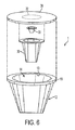
さまざまなカートリッジホルダ実施形態とともに使用されるカートリッジは、種々の方式で構成され得、また、カートリッジの中の飲料媒体がどのように導入されて飲料を形成するかという性質に少なくとも部分的に依存する可能性がある。図6は、分解図を示しており、図7は、いくつかの実施形態において使用され得る1つのカートリッジ実施形態の組立図を示している。そのようなカートリッジに関する詳細が、米国特許第8,361,527号に提供されており、それは、本明細書によって参照により組み込まれている。理解されることとなるように、カートリッジ1は、任意の適切な飲料媒体20を含有することが可能であり、それは、たとえば、挽いたコーヒー、茶葉、乾燥ハーブティー、粉末の飲料濃縮物、ドライフルーツエキスもしくは粉末、粉末もしくは液体の濃縮されたブイヨンまたは他のスープ、粉末もしくは液体の薬用材料(たとえば、粉末のビタミン、薬物もしくは他の薬剤、栄養補助食品など)、および/または、他の飲料作製材料(たとえば、粉末ミルクもしくは他のクリーム、甘味料、増粘剤、香料など)である。
The cartridges used with the various cartridge holder embodiments can be configured in various manners and depend at least in part on the nature of how the beverage medium in the cartridge is introduced to form a beverage there is a possibility. FIG. 6 shows an exploded view and FIG. 7 shows an assembled view of one cartridge embodiment that may be used in some embodiments. Details regarding such cartridges are provided in US Pat. No. 8,361,527, which is hereby incorporated by reference. As will be appreciated, the
この例示目的の実施形態では、カートリッジ1は、容器12を含み、容器12は、フィルタ30によって分離されている第1のチャンバ14aおよび第2のチャンバ14bを有する内部スペース14を含む。容器12は、側壁部17および開口部13を備える円錐台形状のカップ形状を有することが可能であるが、他の構成も可能であり、たとえば、容器12は、縦溝彫りの形状、円錐形状の形状、または円筒形状の形状を有することが可能であり、正方形カップもしくは長方形カップ、ドーム形のカップ、球状もしくは部分的な球状、または、他の適切な形態であることが可能であり、縦溝彫りの側壁部、波形の側壁部、または、その他の形状の側壁部などを有することが可能である。また、いくつかの飲料小袋およびポッドのケースに見られるように、容器12は、輪郭が明確な形状を有することを必ずしも要しない。たとえば、容器12は、この実施形態では、比較的に剛性の高いおよび/または弾性の構造を有しており、容器12がその形状を維持しようとするようになっているが、容器12は、たとえば、変形可能な材料のシートから作製された小袋容器のように、より追従性の、および/または変形可能な構成を有するように作製され得る。したがって、2つのフィルタ紙層(容器材料)が装填量のコーヒー粉の周りで一緒に接合され、ポッドまたは他の形態のカートリッジを形成するときと同様に、容器12によって画定される内部スペースは、容器材料が、飲料媒体、フィルタ、および/または、他のカートリッジコンポーネントの周りに形成された後になって初めて形成され得る。
In this exemplary embodiment, the
開口部13は、たとえば、容器12のリム部19に取り付けられるフォイルおよびポリマーラミネート材料の可撓性のシートなどの、蓋38によって閉められ得る。(この実施形態では、リム部19は、環状のフランジ状の要素として構成されているが、リム部19は、他の方式で構成されることも可能である。たとえば、リム部19は、任意のフランジ要素を備えない側壁部17の上部縁部であることが可能である。)フィルタ30は、たとえば、さらに下記に議論されている理由のために、リム部19から内向きにおよびリム部19から離れるように間隔を置いて配置された周縁部32において、蓋38に取り付けられ得る。加えて、フィルタ30は、周縁部32から少なくとも部分的に内部スペース14の中へ延在することが可能である。この例示目的の実施形態では、フィルタ30は、示されているように、縦溝彫りの側壁部またはプリーツのある側壁部および概して平坦な底部31を備える、実質的に円錐台形状を有することが可能である。しかし、フィルタ30は、円筒形状、正方形カップ形状、ドーム形の形状、平坦なシートなどのような、任意の適切な形状を有することが可能である。また、フィルタ30の使用は必要でなく、その代わりに、カートリッジ1は、フィルタレスであることが可能である。
The opening 13 may be closed by a
飲料を形成するためにカートリッジ1を使用するとき、カートリッジの中へ液体を導入するために、および、カートリッジから飲料を受け取るために、蓋38および/または容器12が穿孔され得る。(本明細書で使用されているように、「飲料」は、液体が飲料媒体と相互作用するときに形成される飲用のための液体物質を表している。したがって、飲料は、消費の用意が整った液体、たとえば、カップの中へ注がれる液体、および、飲む用意が整った液体、ならびに、消費される前に、フィルタリング、または、香料、クリーム、甘味料、別の飲料などの追加などのような、他のプロセスまたは処理を受けることとなる液体を表している。)たとえば、図8に示されているように、カートリッジの中へ液体を導入するために、周縁部32によって概して囲まれている蓋38の一部分が、入口穿孔エレメント50(たとえば、針)によって穿孔され得、水または他の液体が、カートリッジ1の中へ注入され得るようになっている。複数の針、シャワーヘッド、非中空の針、円錐、錐体、ナイフ、ブレードなどのような、他の入口穿孔装置も可能である。本発明はこの点において限定されていないので、カートリッジを使用する飲料マシンは、同じタイプまたは異なるタイプの複数の穿孔エレメントを含むことが可能である。別の装置では、飲料マシンは、開口部を形成する穿孔エレメント(たとえば、大釘など)を含むことが可能であり、その後に、第2の入口エレメント(たとえば、管など)が、形成された孔部を通過し、容器の中へ液体を導入する(または、容器から液体を導く)ことが可能である。他の実施形態では、蓋38は、蓋38の外部に圧力を導入することによって穿孔され、または、そうでなければ、流れのために効果的に開けられ得る。たとえば、水入口部が、蓋38の外部に押圧およびシールされ得、水圧が、その部位に導入され得る。カートリッジ1の中への流れを可能にするために、水圧は、蓋38が穿孔されることを、または、そうでなければ開けられることを引き起こすことが可能である。別の装置では、蓋38は、適切な圧力に露出されるときに、および/または、水入口チューブまたは他の構造体と結合されるときに開く、弁、導管、または他の構造体を含むことが可能である。カートリッジ1の中へ導入される流体は、フローディストリビュータ33、たとえば、より均一に飲料媒体20を濡らすことを助けるために孔部を備えるエレメントによって、遅くさせられ、分配され、または、そうでなければ作用させられ得る。
When using
また、カートリッジ1は、容器12の底部16において、出口穿孔エレメント52b(たとえば、針)によって貫通させられ、または、周縁部32の外側のおよび入口開口部から離れている、蓋38の第2の部分において、出口穿孔エレメント52aによって貫通させられ得る。入口穿孔配置と同様に、出口穿孔配置は、任意の適切な方式で変化させられ得る。したがって、出口穿孔エレメント52は、1つまたは複数の中空の針または中実の針、ナイフ、ブレード、および管などを含むことが可能である。代替的に、カートリッジ1は、弁、セプタム、または他のエレメントを含むことが可能であり、それらは、液体がカートリッジの中へ導入されるときには飲料が出ていくことを許容するように開くが、それ以外のときには、(たとえば、酸素または湿分などのような外部条件飲料媒体を保護するために)閉められたままである。そのような場合では、出口開口部を形成するための穿孔エレメントは、必ずしも必要とされるわけではないが、それは、たとえば、弁または他のエレメントが開くことを可能にするために使用され得る。また、この例示目的の実施形態では、穿孔エレメント52は、飲料が容器12または蓋38の中に形成された開口部から出ていくときに飲料を受け取るために、適切な場所に残ったままである。しかし、他の実施形態では、穿孔エレメント52は、開口部を形成した後に引き抜かれ、飲料が開口部から出ていくこと、および、穿孔エレメント52がカートリッジ1の中へ延在させられることなく、飲料が受け取られることを可能にすることができる。
Also, the
図6〜図8にあるもののように構成されているカートリッジは、図3および図5にあるもののような実施形態の中で使用され得るが、米国特許第6607762号、米国特許第6645537号、および米国特許第6589577号などに説明されているものなどのような、他のカートリッジタイプも可能であるということが理解されるべきである。また、カートリッジホルダ3によって受け入れられ得るカートリッジは、(少なくとも、カートリッジを支持するためにカートリッジがカートリッジホルダによって係合される領域における)サイズに加えて、または、サイズの代わりに、形状が異なることが可能であるということが認識されるべきである。たとえば、また、米国特許第8,361,527号は、不規則なリム部形状を備えるカートリッジを説明しており、それは、図9に示されている。この実施形態では、カートリッジ1は、図6〜図8にあるものと同様に構成されているが、容器12は、円形部分19aおよび注ぎ口部分19bを備えるリム部19を有しており、注ぎ口部分19bは、円形部分19aから延在している。したがって、リム部19は、不規則な形状を有しており、カートリッジホルダ3は、より大きい全体的なカートリッジ1のリム部サイズだけでなく、リム部19の不規則な形状も収容するように構成され得る。
Cartridges configured as those in FIGS. 6-8 may be used in embodiments such as those in FIGS. 3 and 5, but may be used in US Pat. Nos. 6,607,762, 6,645,537, and It should be understood that other cartridge types are also possible, such as those described in U.S. Patent No. 6589577 and the like. Also, the cartridges that can be received by the
図5の例は、異なる入口ポートおよび/または出口ポート50、52が、異なるカートリッジに関してどのように使用され得るかということを図示する単なる1つの例である。たとえば、いくつかの実施形態では、1つまたは複数のポート52は、ホルダ3の中のカートリッジと流体を交換するために、または、ホルダ3の中のカートリッジと流体を交換しないために、移動可能であり得る。たとえば、図10は、(たとえば、図6および図7において見られるような)相対的により小さい円形に形状決めされたリム部直径を有する第2のカートリッジ1bがホルダ3の中に受け入れられている状態の図3のカートリッジホルダ3の概略側面図を示している。それとは対照的に、図11は、(たとえば、図9において見られるような)相対的により大きいリム部直径および不規則なリム部形状を有する第1のカートリッジ1aがホルダ3の中に受け入れられている状態の図3のカートリッジホルダ3の概略側面図を示している。図10の視点は、第2のカートリッジ1bに関して図5の中に示されているもの同様である。すなわち、第2のカートリッジ1bは、この実施形態では相対的に小さい円形リム部19を有しており、第2のカートリッジ1bは、入口ポート50によって上部において穿孔され、カートリッジ1bの中への流体の下向きの流入を収容し、また、第2の出口ポート52bによって底部において穿孔され、カートリッジ1bからの飲料の下向きの流出を収容する。
The example of FIG. 5 is just one example that illustrates how different inlet and / or
しかし、第1のカートリッジ1aがカートリッジホルダ3の中に保持されている状態では、カートリッジの上部が、入口ポート50および第1の出口ポート52aの両方によって穿孔される。第1のカートリッジ1aは、リム部19の注ぎ口部分19bの近くの注ぎ口エリアの中に位置付けされている蓋38のエリアにおいて、第1の出口ポート52aによって穿孔され得るが、蓋の他のエリアも可能である。注ぎ口部分19bがカートリッジ1aの下側端部となるようにカートリッジホルダ3およびカートリッジ1aを傾けることは、上向き方向の流出に対して注ぎ口エリアの中に飲料を収集することが可能であるため、カートリッジ1aから飲料を除去するのを支援することが可能である。
However, when the
図5の実施形態では、第1のカートリッジ1aは、第2の出口ポート52bに接触するには高さが低過ぎたが、そうであることが必要というわけではなく、第1のカートリッジ1aは、より高さを高くされてもよいということに留意されたい。そのような場合では、第2の出口ポート52bは、カートリッジ受け入れスペースから外へ移動させられ得、ポート52bがカートリッジ1aとの接触を回避することができるようになっている。そのような移動は、たとえば、電動式の駆動機構によって、および、カートリッジ受け入れエリアの中へ/カートリッジ受け入れエリアから外へポートのうちの1つをユーザーに物理的に移動させるリンケージなど、種々の方式によって達成され得る。本発明の1つの態様では、1つまたは複数のポートは、カートリッジホルダ3の中へ挿入されるカートリッジの1つまたは複数の特徴に基づいて、カートリッジとの使用に関して選択され得る。たとえば、相対的により大きいリム部直径を有するカートリッジの挿入は、第2の出口ポート52bがカートリッジ受け入れエリアの外へ移動させられることを引き起こすことが可能であり、カートリッジ1との潜在的な接触を回避するようになっている。他の実施形態では、特定のカートリッジタイプの挿入は、移動のためにポートを解放することが可能であり、たとえば、より大きいリム部カートリッジの挿入は、第2の出口ポート52bを解放することが可能であり、カートリッジ1aが、第2の出口ポート52bに接触し、それを移動させることができるようになっている。
In the embodiment of FIG. 5, the
たとえば、図12および図13は、図9に示されているものなどのような、注ぎ口を有するカートリッジの挿入が、第2の出口ポート52bがカートリッジ受け入れエリアから外へ移動することを引き起こす、例示目的の実施形態を示している。この実施形態では、可動部分32のうちの1つ、たとえば、トリガ33が、カートリッジ1aの注ぎ口エリアに接触し、半径方向外向きに、すなわち、図12および図13の中の右の方へ移動させられ得る。トリガ33は、リンケージによって第2の出口ポート52bに連結され得、リンケージは、スライド部分32が半径方向外向きに移動させられるときに、第2の出口ポート52bが軸線53の周りに回動することを引き起こす。これは、カートリッジ1aとの接触の可能性のあるエリアから外へ、第2の出口ポート52bを移動させることが可能である。トリガ33は、スプリング荷重式であることが可能であり、注ぎ口を有する第1のカートリッジ1aがカートリッジホルダ3から除去されると、トリガ33が半径方向内向きに移動することが可能であるようになっており、第2の出口ポート52bがカートリッジ受け入れエリアの中へ回動して戻ることを可能にする。したがって、注ぎ口を有していない第2のカートリッジ1bがホルダ3の中へ挿入される場合には、トリガ33は、静止したままであることが可能であり、第2の出口ポート52bが、第2のカートリッジ1bをその底部または他の適切な場所において穿孔することが可能である。第2の出口ポート52bは、導管を含み、または、導管に接続され、第2のカートリッジ1bから飲料形成マシン10の注ぎエリアへ飲料を導くことが可能であり、または、飲料は、導管によって導かれることなく単にカートリッジ1bから出ていくことが可能である。
For example, FIGS. 12 and 13 illustrate that the insertion of a spouted cartridge, such as that shown in FIG. 9, causes the second outlet port 52b to move out of the cartridge receiving area. An illustrative embodiment is shown. In this embodiment, one of the
別の実施形態では、トリガまたはカートリッジホルダ3の他のパーツの移動が、たとえば、カートリッジとの接触に基づいて、移動のために1つまたは複数のポートを解放することが可能であり、ポートが、カートリッジを穿孔せず、または、そうでなければ、カートリッジと相互作用せず、流体を交換しないようになっている。たとえば、図14は、図12および図13にあるようなトリガ33が、第1のカートリッジ1aの注ぎ口との接触によって移動させられ得る実施形態を示している。トリガ33の移動は、カートリッジ1aと接触するときに、第2の出口ポート52bが移動するためにこれを解放することが可能であり、第2の出口ポート52bが実質的に移動に抵抗しないようになっている。たとえば、第1のカートリッジ1aがカートリッジホルダ3の中へ挿入されている状態で、第1のカートリッジ1aの底部は、第2の出口ポート52bに接触し、水平方向の軸線54の周りにポート52bを回動させることが可能であり、したがって、ポート52bが、カートリッジ受け入れエリアから外へ移動し、カートリッジ1aを穿孔しない。しかし、第2のカートリッジ1bがカートリッジホルダ3の中へ挿入される場合には、トリガ33の移動の欠如によって、第2の出口ポート52bを適切な場所にロックすることが可能であり、第2の出口ポート52bが、第2のカートリッジ1bを穿孔し、または、そうでなければ、第2のカートリッジ1bと相互作用し、飲料を受け取るようになっている。この実施形態では、トリガ33は、ラッチ331にリンク結合されており、ラッチ331は、第2の出口ポート52bに係合し、トリガ33が左の方に位置決めされているときに、軸線54の周りにポート52bが回動することを防止する。しかし、右の方へのトリガ33の移動は、ポート52bからラッチ331を解除し、ポート52bが軸線54の周りに回動することを可能にする。トリガ33は、スプリング荷重式であり、図14に示されているように左の方に移動することが可能である。したがって、トリガ33が、たとえば、第1のカートリッジ1aによって移動させられていない場合には、ラッチ331は、通常、ポート52bと係合していることが可能である。
In another embodiment, movement of the trigger or other part of the
上記の例は、1つの出口ポートだけが移動される実施形態を示して説明しているが、2つ以上の出口ポートが移動されるもの、1つまたは複数の入口ポートが移動されるもの、または、ポート選択の他の組み合わせが行われることなどのような、他の構成も可能である。また、入口ポートおよび/または出口ポートの移動は、モータ駆動または他の機構によって実現され得、カートリッジの上の機械読み取り可能な特徴または他のしるしを読み取ることに基づいて制御され得る。たとえば、マシン10は、カートリッジ1の上のRFIDタグ、バーコードなどを読み取ることが可能であり、カートリッジタイプまたは識別されたカートリッジ1に関連付けられた他の情報に基づいて、適切なポート選択を行うことが可能である。
Although the above example shows and describes an embodiment in which only one outlet port is moved, two or more outlet ports are moved, one or more inlet ports are moved, Alternatively, other configurations are possible, such as other combinations of port selection being performed. Also, movement of the inlet and / or outlet ports may be realized by a motor drive or other mechanism and controlled based on reading machine readable features or other indicia on the cartridge. For example, the
図15および図16は、カートリッジホルダ、関連のカバー、ハンドルアクチュエータ、および、飲料形成装置10の他の選択されたコンポーネントの分解図および組立図を示している。この実施形態では、カートリッジホルダ3の係合部分は、図4にあるように、係合部分の底部において一緒に接合されている「フィンガ」または壁部部分の形態の複数の可動部分32を含む。また、この実施形態は、カートリッジ受け入れエリアからの出口ポートの移動を引き起こしおよび/または可能にするために、トリガ33を含む。すなわち、この実施形態は、円形部分および注ぎ口部分を有する不規則なリム部を有する第1のカートリッジ1a、ならびに、第1のカートリッジ1aの円形部分の直径よりも小さい直径を備える円形リム部を有する第2のカートリッジ1bの両方を受け入れるように構成されている。第1のカートリッジ1aの注ぎ口エリアとトリガ33の接触は、トリガ33が半径方向外向きに移動することを引き起こし、第2の出口ポート52bが移動するためにこれを解放する(または、実際に第2の出口ポート52bを移動させる)。係合部分の壁部部分32は、必要に応じて第2の出口ポート52bがカートリッジ受け入れエリアの中へ/カートリッジ受け入れエリアから外へ移動するのに適切な開口部を提供するように構成されていることに留意されたい。
15 and 16 show an exploded view and an assembled view of the cartridge holder, associated cover, handle actuator, and other selected components of the
図15において見ることができるように、係合部分は、カートリッジホルダ3を画定するのを助けるフレーム6の一部分の中の孔部35の中へ受け入れられる。この実施形態では、係合部分は、孔部35の中に支持されており、トリガ33の反対側に位置付けされている壁部部分32が、トリガ33の近くに位置付けされている壁部部分32よりも小さい範囲の半径方向の運動を有するようになっている。すなわち、トリガ33の反対側の1つまたは複数の壁部部分32は、半径方向外向きに移動することがある程度許容され得るが、移動した後、孔部35またはフレーム6の他のパーツに接触し、壁部部分32がさらに半径方向外向きに移動することが防止されるようになっている。これは、注ぎ口セクションを有するカートリッジ1aを、トリガ33との適正な接触状態になるように押して、トリガ33を適切に半径方向外向きに移動させることについてカートリッジホルダ3を支援する。加えて、これは、入口ポートおよび出口ポート50、52aとの整列のために、カートリッジ1aを適正に位置決めすることについてカートリッジホルダ3を支援する。すなわち、トリガ33は、適切な強度のスプリングまたは他の弾性エレメントによって半径方向内向きに移動するように付勢され得、注ぎ口セクションを有するカートリッジの挿入が、トリガ33の反対側の壁部部分32が外向きに撓むことを引き起こすようになっており、また、カートリッジ1aが開口部31の中へ完全に挿入される前に、トリガ33の反対側の壁部部分32が孔部35または半径方向の移動の他のストッパに接触するようになっている。ストッパに接触後、トリガ33の反対側の壁部部分32がさらに半径方向外向きに移動することを防止されるので、カートリッジ1aのさらなる挿入は、トリガ33が外向きにスライドすることを引き起こすことが可能である。これは、カートリッジ1が、入口部および/または出口穿孔エレメントによって穿孔するのに適正に位置決めされることを確実にすることが可能である。
As can be seen in FIG. 15, the engagement portion is received into a
また、図16は、この実施形態において、カバー8がカートリッジホルダ3に対してどのように移動させられ得るかということを示している。カバー8は、ハンドル5の移動に基づいて、フレーム6に対してカバーピボット61の周りに回動移動するように構成されており、ハンドル5は、ハンドルピボット63において、カバー8に回動可能に装着される。また、プレート81が、プレートピボット62の周りに回動可能にフレーム6に装着されており、ハンドル5の移動に基づいて移動する。プレート81は、カートリッジホルダ3の中に設置されているカートリッジ1に接触するように動作し、ホルダ3の中へカートリッジ1を押し込み、カバー8がカートリッジ1に係合する前に、カートリッジ1がホルダ3の中へ完全に受け入れられるようになっている。これは、カバー8の上の穿孔エレメントがカートリッジ1を穿孔する前に、カートリッジ1がホルダ3の中に完全に着座させられることを確実にする。ハンドル5のピボットピン64は、プレート81のスロット82に係合させられており、それは、フレーム6のカムスロット65の中を移動し、ハンドル5が開位置(図16に示されている)から閉位置へハンドルピボット63の周りに回動させられるときに、ピボットピン64が、カムスロット65の中を移動するようになっており、それによって、プレート81をプレートピボット62の周りにカートリッジホルダ3に向けて回動させる。同時に、カバー8は、カバーピボット63の周りに回動させられ、カートリッジホルダ3に向けて移動する。プレート81は、カバー8の前に、ホルダ3の中のカートリッジ1に接触するように構成されており、カートリッジ1をホルダ3の中へ着座させる。この行為は、係合部分の可動部分32がカートリッジ1を受け入れるために必要に応じて移動することを引き起こすことが可能である。閉位置に向けてのハンドル5のさらなる移動は、ピボットピン64がカムスロット65の中をさらに下向きに移動することを引き起こし、したがって、カバー8がカートリッジ1に係合する。この実施形態では、入口ポートおよび/または出口ポート50、52aにおける穿孔エレメントが、カートリッジ1を穿孔することが可能であるが、そのような穿孔エレメントは必要とされない。ハンドル5が閉位置にある状態で、ピボットピン64は、カムスロット65の「J字」形状のセクションの中へ移動することが可能であり、それは、カバー8およびプレート81をカートリッジホルダ3の上の適切な場所に効果的にロックする。閉位置からハンドル5を持ち上げることは、カムスロット65の中のピボットピン64の移動を逆にし、それによって、開位置へとカバー8およびプレート81を回動させる。
FIG. 16 also shows how the cover 8 can be moved relative to the
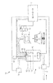
図17は、1つの例示目的の実施形態における飲料形成装置100の中に含まれ得るさまざまなコンポーネントの概略ブロック図を示している。当業者は、飲料形成装置100がさまざまな異なる方式で構成され得、したがって、本発明の態様は、1つのタイプの飲料形成装置だけに関するものとして狭く解釈されるべきではないということを認識することとなる。この実施形態では、水または他の前駆液体が、液体供給部15によって提供され、飲料形成ステーション11において飲料材料と混合することが可能である。飲料材料(たとえば、コーヒー粉、茶葉、粉末のドリンクミックスなど)は、カートリッジ1の中に提供されてもよく、または、カートリッジ1の中に提供されなくてもよく、液体を飲料材料と混合することによって作り出される飲料は、飲料出口部を介して容器2の中へ注がれ得る。
FIG. 17 shows a schematic block diagram of various components that may be included in the
この実施形態では、液体供給部15が、液体ディスペンスレベル159、160までタンクを充填することによって、および、次いで、空気ポンプ154によってタンク152を加圧することによって、飲料形成ステーション11に提供される液体の体積を制御し、タンク152の中の液体が導管156から外へ押し出され、飲料形成ステーション11に至るようになっている。飲料形成ステーション11に送達される液体の体積は、液体送達レベル159、160とタンク152の中の導管156の底部における送達後レベル158との間のタンク152の中の体積に等しい。この実施形態では、2つの送達レベル159、160が存在しているので、2つの異なる体積が、飲料形成ステーション11に提供され得る。しかし、3つ以上のレベルまたは単一のレベルが使用され得る。
In this embodiment, the liquid provided by the liquid supply 15 to the beverage forming station 11 by filling the tank to liquid dispense
この実施形態では、液体供給部15は、供給源Wに連結されている弁151を介してタンク152に液体を提供する。供給源Wは、任意の適切な構成を有することが可能であり、たとえば、ストレージタンク、主要水供給部、または他の供給源から液体を提供することが可能である。したがって、いくつかのケースでは、タンク152に提供される液体は、時期、マシン10が位置付けされている部屋の温度などのような、さまざまな要因に応じて、幅広い程度に温度が変化し得る。たとえば、供給源Wが、ユーザーによって充填される貯蔵部である場合には、貯蔵部の中の液体の温度は、室温(たとえば、液体が長時間にわたって貯蔵部の中に存在する場合)と冷却器温度(たとえば、貯蔵部が蛇口からディスペンスされる水でちょうど充填されたところである場合)との間で変化することが可能である。
In this embodiment, the liquid supply 15 provides liquid to the tank 152 via a
この実施形態では、タンク152に液体を提供するために、弁151が、制御回路16によって制御され、所望の体積の液体をタンク152に提供するために開閉する。たとえば、タンク152が、空であるか、または、ディスペンス後レベル158にある場合には、導電性プローブまたは他の液体レベルセンサ157が、液体がディスペンスレベル159、160に到達するときを示す信号を制御回路16に提供するまで、弁151が開けられ得る。センサ157における液体を検出するレベルセンサ157に応答して、制御回路16は、弁151を閉じることが可能である。当然のことながら、ストレージ貯蔵部からタンク152へ液体を移動させるためにポンプを使用するなど、他の構成も可能である。
In this embodiment, the
この実施形態では、液体レベルセンサは、1対の導電性プローブを含み、1対の導電性プローブは、タンク152の中の液体に接触することができ、かつ、液体がタンク152の中のそれぞれのディスペンスレベル159または160に存在していることを示す信号(たとえば、抵抗変化)を提供することができるが、液体レベルセンサは、他の方式でも構成され得る。たとえば、センサは、付属のフロートを備えるマイクロスイッチを含むことが可能であり、フロートは、タンク152の中の液体レベルとともに上昇し、スイッチを活性化させる。別の実施形態では、液体レベルセンサは、タンクの中の1つまたは複数の液体レベルに関連付けられる静電容量変化を検出することが可能であり、光学的なエミッタ/センサ構成(たとえば、LEDおよびフォトダイオードなど)を使用し、液体レベルの変化を検出することが可能であり、圧力センサを使用することが可能であり、フローティング磁石およびホール効果センサを使用し、レベル変化を検出することなどが可能である。したがって、液体レベルセンサは、必ずしも、導電性プローブ構成に限定されるわけではない。そのうえ、液体レベルセンサは、2つ以上の異なるタイプのセンサを含み、タンクの中の異なるレベルを検出することが可能である。たとえば、圧力センサは、ディスペンスレベル160における液体を検出するために使用され得るが(たとえば、タンク152の充填を完了することは、タンク152の中の圧力の鋭い上昇と一致することが可能である)、導電性プローブは、他のディスペンスレベル159における液体を検出するために使用され得る。
In this embodiment, the liquid level sensor includes a pair of conductive probes, wherein the pair of conductive probes can contact the liquid in the tank 152, and the liquid is in each of the tanks 152. A signal (e.g., a change in resistance) may be provided to indicate that it is present at the dispense
さらに、液体レベルセンサは、タンクをディスペンスレベル159、160まで充填するために使用される必要はない。その代わりに、たとえば、所望のレベルまでのタンク152のおおよその充填に対応することが見出されている所定の期間にわたって弁151を開けることなど、他の技法が、タンク152を適切に充填するために使用され得る。当然のことながら、たとえば、ポンプ(たとえば、遠心ポンプ、ピストンポンプ、ソレノイドポンプ、ダイヤフラムポンプなど)または重力送りなどによって、液体をタンク152に提供するための他の構成も可能であり、タンクがディスペンスレベル159、160まで充填される方式は、液体をタンクに提供するために使用される技法に依存することが可能である。たとえば、ディスペンスレベル159、160までタンク152に充填するために提供される液体の体積の制御は、所定の時間にわたりポンプを稼働することによって実施され得り、(たとえば、流量計を使用して)タンク152に進入する液体の流量または体積を検出し、所望の数のサイクルにわたりポンプを動作させ(たとえば、ポンプが、それぞれのサイクルに関して液体の公知の体積を送達するように構成されている場合など)、圧力センサを使用してタンク152の中の圧力上昇を検出し、または、任意の他の実行可能な技法を使用する。
Further, the liquid level sensor need not be used to fill the tank to the dispense
タンク152の中の液体は、加熱エレメント153によって加熱され得り、加熱エレメント153の動作は、温度センサからの入力または他の適切な入力を使用して、制御回路16によって制御される。当然のことながら、液体の加熱は、必要ではなく、その代わりに(または、追加的に)、装置100は、液体を冷却するためにチラーを含むことが可能であり、液体に炭酸ガスを入れるためにカーボネーターを含むことが可能であり、または、そうでなければ、タンク152の中の液体の体積を変更する方式で液体を調整することが可能である。(一般的に言えば、飲料形成ステーション11に供給される液体を加熱し、冷却し、炭酸ガスを入れ、または、そうでなければ、調整する液体供給部15のコンポーネントは、「液体コンディショナー」と称される。)
The liquid in tank 152 may be heated by
この実施形態では、液体は、空気ポンプ154によってタンク152から吐出され得り、空気ポンプ154は、タンク152の中へ空気を押し込み、タンクを加圧するように動作し、また、導管156の中を飲料形成ステーション11まで液体を流れさせるように動作する。導管がタンク152の中へ下向きに延在しているので、形成ステーション11に送達される液体の体積は、ディスペンスレベル159、160と導管156の底部端部との間の、タンク152の中の体積として規定される。繰り返しになるが、液体は、タンク152から飲料形成ステーション11へ他の方式で流れさせられ得る。たとえば、ポンプが、タンク152から形成ステーション11へ液体をポンプ送りするために使用され得り、液体が、タンク152から重力によって流れることが可能にされ得るなどである。ベント155は、タンク152をベントするために開閉され得り、タンク152の中に圧力の実質的な上昇を引き起こすことなく、タンク152が充填されることを可能にするために、および、空気ポンプ154を使用してタンクを加圧することによって、液体がタンク152から送達されることを可能にするために、ベント155が設けられ得る。この実施形態では、ベント155は、実際には、制御回路16によって制御されないが、タンク152の充填のためにベントすることを可能にするのに適切なサイズのオリフィスを用いて、常に開いたままであり、タンク152の中の空気圧力の構築が、液体送達を可能にする。供給源Wとタンク152との間の導管、または、タンク152と飲料形成ステーション11との間の導管の中の逆流を防止することができる逆止弁または他のフローコントローラーなどのような、他のフロー制御特徴部も同様に提供され得る。
In this embodiment, liquid may be discharged from the tank 152 by the air pump 154, which operates to push air into the tank 152 and pressurize the tank, and also through the
飲料形成ステーション11は、挽いたコーヒー、茶、フレーバードリンクミックス、または他の飲料媒体などのような、任意の飲料作製原料を使用することが可能であり、それは、たとえば、カートリッジ1の中に含有されているか、または、カートリッジ1の中に含有されていない。代替的に、飲料形成ステーション11は、たとえば、飲料媒体が容器2の中に含有されている場合に、単に、加熱された、冷却された、または、そうでなければ温度調整された水または他の液体のための出口部として機能することが可能である。タンク156からステーション11への液体送達が完了すると、空気ポンプ154(または、他の空気ポンプ)が、空気を導管156の中へ押し込み、少なくともある程度、飲料形成ステーション11から液体をパージするように動作させられ得る。
The beverage formation station 11 can use any beverage preparation ingredients, such as ground coffee, tea, flavored drink mixes, or other beverage media, which, for example, are contained in the
弁151、空気ポンプ154、および、装置100の他のコンポーネントの動作は、制御回路16によって制御され得、たとえば、制御回路16は、適切なソフトウェアまたは他の動作指示、1つまたは複数のメモリ(ソフトウェアおよび/または他の動作指示を保存することができる非一時的なストレージ媒体を含む)、温度センサおよび液体レベルセンサ、圧力センサ、入力/出力インターフェース、通信バスまたは他のリンク、ディスプレイ、スイッチ、リレー、トライアック、または、所望の入力/出力または他の機能を果たすために必要な他のコンポーネントとともに、プログラムされたプロセッサおよび/または他のデータ処理デバイスを含むことが可能である。
The operation of the
本発明の態様によれば、飲料形成装置は、複数の検出器を含み、カートリッジホルダの中に受け入れられているカートリッジの特徴を検出することが可能である。装置100の動作は、検出器によって検出される情報に基づいて、制御回路16によって制御され得る。たとえば、図17に示されている実施形態では、装置は、カートリッジホルダ3の中のカートリッジ1に関する異なる特徴をそれぞれ検出する、第1、第2、および第3の検出器161、162、163を含む。第1の検出器161は、カートリッジ1の存在または不在を検出することが可能であり、たとえば、赤外線検出器を含むことが可能であり、赤外線検出器は、カートリッジホルダ3のエリアを赤外光で照射し、赤外光がカートリッジによって反射されているかどうかということを検出する。適切な量または他のレベルの反射光の検出は、カートリッジ1が存在しているということを決定するために使用され得り、一方、まったくない光レベルまたはより低い光レベルは、カートリッジの不在を示す可能性がある。そのような赤外線検出器は、赤外線エミッタおよびフォトディテクタまたは他の適切なエレメントを含むことが可能である。機械的なスイッチ、バーコードリーダ、RFIDインテロゲータなどのような、他の検出器構成も可能である。
According to an aspect of the invention, the beverage forming device comprises a plurality of detectors and is capable of detecting features of the cartridge received in the cartridge holder. The operation of the
第2の検出器162は、カートリッジのタイプを検出することが可能であり、たとえば、カートリッジが注ぎ口部分を含むかどうかということを検出することが可能である。第2の検出器は、さまざまな異なる方式で構成され得り、1つの実施形態では、図12〜図16のトリガ33、および、トリガ33の移動を検出するためのスイッチを含むことが可能である。たとえば、トリガ33は、トリガ33とともに移動する磁石を含むことが可能であり、リードまたは他の適切なスイッチは、磁石の存在または不在を検出し、それによってトリガ33の移動を検出することが可能である。光学検出器、バーコードリーダなどのような、第2の検出器162に関する他の構成も可能である。
The
第3の検出器163は、カートリッジが飲料形成装置とともに使用することを承認されたかどうかということに関連する情報を検出することが可能であり、第3の検出器163は、バーコードリーダ、イメージ分析能力を備えるカメラまたは他のイメージキャプチャーデバイス、およびRFIDインテロゲータなどを含むことが可能である。この例示目的の実施形態では、第3の検出器163は、カートリッジの一部分を適切な光で照射する照射エレメントを含み、たとえば、1つまたは複数のLED供給源は、任意の適切な波長のセットを有する光でカートリッジを照射することが可能である。また、第3の検出器163は、光検出器を含むことが可能であり、光検出器は、カートリッジ部分によって放出および/または反射されたライトを検出するように、および、検出されたライトが承認されたカートリッジと合致しているかということを評価するように、構成されている。たとえば、承認されたカートリッジは、特定のライトによって照射されていることに対して特有のスペクトル応答を提供するセキュリティーインクまたは他の材料を担持することが可能である。第3の検出器163は、スペクトル応答が存在しているかどうかということを検出し、それが存在している場合には、カートリッジは飲料を形成する際に使用することを承認されているということを示すことが可能である。 The third detector 163 can detect information related to whether the cartridge has been approved for use with the beverage forming device, the third detector 163 can be a bar code reader, an image It may include a camera or other image capture device with analysis capabilities, an RFID interrogator, etc. In this illustrative embodiment, the third detector 163 includes an illumination element that illuminates a portion of the cartridge with the appropriate light, eg, one or more LED sources may be any suitable set of wavelengths. It is possible to illuminate the cartridge with light having Also, the third detector 163 may include a light detector, such that the light detector detects light emitted and / or reflected by the cartridge portion, and the detected light is It is configured to evaluate if it is in line with the approved cartridge. For example, an approved cartridge can carry security ink or other material that provides a specific spectral response to what is being illuminated by a particular light. The third detector 163 detects whether a spectral response is present and, if present, that the cartridge is approved for use in forming a beverage It is possible to indicate
制御回路16は、第1、第2、および/または第3の検出器161、162、163によって検出される情報に基づいて、液体供給部15および/または装置100の他の部分の動作を制御することが可能である。たとえば、カートリッジが第1の検出器161によって検出されず、オペレーターがブリューインディケーションボタンを押圧する場合には、制御回路16は、装置100がクリーニング動作を実施することを引き起こすことが可能であり、それによって、カートリッジホルダ3および/または装置100の他のパーツがクリーニングされる。しかし、カートリッジ1が検出される場合には、制御回路16は、ユーザーインターフェース14において、ユーザーに、飲料形成オプションの表示を生じさせることが可能であり、飲料生成サイクルを開始させることが可能であり、タンク152の中の水の加熱を始めることなどが可能である。別の例として、第2の検出器162が特定のタイプのカートリッジを検出する場合には、制御回路16は、たとえば、加熱温度、飲料を作製するために使用される液体の量を調節することによって、ならびに、飲料を形成するための特定のユーザー入力を表示および要求することなどによって、いくつかの方式で、飲料形成パラメータを調節するようにシステムを制御することが可能である。カートリッジが、承認されたものであるということが第3の検出器163によって検出されない場合には、制御回路16は、飲料生産プロセスのうちのすべてまたは特定のものを防止することが可能である。その代わりに、カートリッジがカートリッジホルダの中に検出されないならば、制御回路16は、クリーニング動作だけを許容することが可能である。代替的に、制御回路16は、装置がデフォルトの飲料プロセスを実施することを引き起こすことが可能であり、たとえば、それは、抽出水温度、体積、送達時間などの特定のセットを含む。
The
本発明の態様は、任意の適切なカートリッジとともに使用され得るが、または、全くカートリッジとともに使用されなくてもよいが、いくつかのカートリッジは、飲料形成装置100の動作を強化する特徴を含むことが可能である。当技術分野で知られているように、カートリッジ1は、小袋、ポッド、カプセル、または容器などとして一般に知られているものなどのような、任意の適切な形態をとることが可能である。たとえば、カートリッジ1は、不浸透性の外側カバーを含むことが可能であり、不浸透性の外側カバーの中に、焙煎されたコーヒーおよび挽いたコーヒーなどのような、飲料媒体が収容されている。また、カートリッジ1は、フィルタを含むことが可能であり、液体と飲料媒体の相互作用によって形成された飲料が、容器2の中へディスペンスされる前に、フィルタを通過するようになっている。当業者によって理解されることとなるように、ポッドの形態のカートリッジ(たとえば、飲料媒体をカプセル化する浸透性のフィルタ紙の対向層を有している)は、形成される飲料をろ過するためにカートリッジ1の外側部分を使用することが可能である。この例において、カートリッジ1は、茶、コーヒー、他の浸出タイプの飲料、液体または粉末の濃縮物から形成される飲料などのような、任意の適切な飲料を形成するために、飲料マシンの中で使用され得る。したがって、カートリッジ1は、任意の適切な飲料媒体を含有することが可能であり、それは、たとえば、挽いたコーヒー、茶葉、乾燥ハーブティー、粉末の飲料濃縮物、ドライフルーツエキスもしくは粉末、粉末もしくは液体の濃縮されたブイヨンまたは他のスープ、粉末もしくは液体の薬用材料(たとえば、粉末のビタミン、薬物もしくは他の薬剤、栄養補助食品など)、および/または、他の飲料作製材料(たとえば、粉末ミルクもしくは他のクリーム、甘味料、増粘剤、香料など)である。1つの例示目的の実施形態では、カートリッジ1は、コーヒー飲料および/または茶飲料を形成するマシンとともに使用するために構成されている飲料媒体を含有しているが、しかし、本発明の態様は、この点において限定されない。
Although aspects of the invention may be used with any suitable cartridge, or may not be used at all, some cartridges may include features that enhance the operation of the
本明細書で使用されているように、「飲料」は、液体が飲料媒体と相互作用するときに形成される飲用のための液体物質を表している。したがって、飲料は、消費の用意が整った液体、たとえば、カップの中へ注がれる液体、および、飲む用意が整った液体、ならびに、消費される前に、フィルタリング、または、香料、クリーム、甘味料、別の飲料などの追加などのような、他のプロセスまたは処理を受けることとなる液体を表している。 As used herein, "beverage" refers to the liquid substance for drinking that is formed when the liquid interacts with the beverage medium. Thus, the beverage is a liquid ready for consumption, for example a liquid poured into a cup and a liquid ready to drink, as well as filtering or flavoring, cream, sweetness before being consumed Represents a liquid that is to be subjected to another process or treatment, such as the addition of a charge, another beverage, etc.
このように、本発明の少なくとも1つの実施形態のいくつかの態様を説明してきたが、さまざまな代替例、修正例、および改善例が当業者に容易に考え付くこととなるということが認識されるべきである。そのような代替例、修正例、および改善例は、本開示の一部であることが意図されており、また、本発明の精神および範囲の中にあるということが意図されている。したがって、先述の説明および図面は、単なる例としてのものである。 Thus, while several aspects of at least one embodiment of the invention have been described, it will be appreciated that various alternatives, modifications, and improvements will be readily apparent to those skilled in the art. It should. Such alternatives, modifications, and improvements are intended to be part of the present disclosure and are intended to be within the spirit and scope of the present invention. Accordingly, the foregoing description and drawings are by way of example only.
Claims (64)
前記飲料形成装置のコンポーネントを支持するように構成されているフレームと、
カートリッジ係合部分を含むカートリッジホルダであって、前記カートリッジ係合部分は、開口部を画定し、かつ前記開口部の中に位置決めされるカートリッジと係合するように構成されており、前記カートリッジ係合部分は、1つまたは複数の半径方向に移動可能なセクションを含み、前記1つまたは複数の半径方向に移動可能なセクションは、第1および第2のカートリッジを収容し、前記第1および第2のカートリッジに係合するように移動可能であり、前記第1および第2のカートリッジは、前記カートリッジ係合部分が前記第1および第2のカートリッジに係合する領域において、互いに異なるサイズおよび/または形状に定められている、カートリッジホルダと、
前記カートリッジホルダと協働し、前記カートリッジを使用して飲料を形成するために前記カートリッジホルダによって保持されているカートリッジを少なくとも部分的に取り囲むように構成されているカバーと、
前記フレームによって少なくとも部分的に支持されている液体供給システムであって、飲料を形成するために前記カートリッジホルダによって保持されているカートリッジの中の飲料媒体と混合させるために、液体を提供するように構成されている液体供給システムと、
を含むことを特徴とする飲料形成装置。 A beverage forming device,
A frame configured to support the components of the beverage forming device;
A cartridge holder including a cartridge engagement portion, wherein the cartridge engagement portion is configured to define an opening and to be engaged with a cartridge positioned in the opening, the cartridge engagement The mating portion includes one or more radially movable sections, the one or more radially movable sections accommodating first and second cartridges, the first and second Moveable to engage two cartridges, the first and second cartridges being of different sizes and / or in the area where the cartridge engagement portion engages the first and second cartridges Or a cartridge holder defined in shape,
A cover cooperating with the cartridge holder and configured to at least partially surround the cartridge held by the cartridge holder for forming a beverage using the cartridge;
A liquid supply system at least partially supported by the frame to provide liquid for mixing with the beverage medium in a cartridge held by the cartridge holder to form a beverage. A configured liquid supply system,
A beverage forming apparatus comprising:
係合部分を有するカートリッジホルダを含む飲料形成装置を提供するステップであって、前記係合部分は、前記カートリッジホルダの開口部の中に設置されているカートリッジに係合するように構成されている、ステップと、
前記カートリッジホルダの前記開口部の中へ第1または第2のカートリッジを提供するステップであって、前記第1および第2のカートリッジは、前記係合部分が前記第1および第2のカートリッジに係合する領域において、互いに異なるサイズおよび/または形状に定められている、ステップと、
前記開口部の中へ提供される前記第1または第2のカートリッジの領域を収容して係合するために、前記係合部分の1つまたは複数のセクションを半径方向に移動させるステップと、
飲料を形成するために、前記カートリッジホルダによって保持されている前記第1または第2のカートリッジの中の飲料媒体と液体を混合させるステップと、
を含むことを特徴とする方法。 A method for forming a beverage using a beverage forming apparatus, the method comprising:
Providing a beverage forming apparatus comprising a cartridge holder having an engaging portion, wherein the engaging portion is configured to engage a cartridge disposed in an opening of the cartridge holder , Step, and
Providing a first or second cartridge into the opening of the cartridge holder, the first and second cartridges being engaged with the first and second cartridges in the engagement portion; The steps being defined in different sizes and / or shapes in the matching regions;
Radially moving one or more sections of the engagement portion to receive and engage an area of the first or second cartridge provided into the opening;
Mixing a liquid with a beverage medium in the first or second cartridge held by the cartridge holder to form a beverage;
A method characterized by comprising.
前記飲料形成装置のコンポーネントを支持するように構成されているフレームと、
カートリッジ係合部分を含むカートリッジホルダであって、前記カートリッジ係合部分は、開口部を画定し、かつ前記開口部の中に設置されるカートリッジと係合するように、および、前記カートリッジの重量を支持するように構成されており、前記カートリッジ係合部分は、1つまたは複数の追従セクションを含み、前記1つまたは複数の追従セクションは、前記開口部のサイズおよび/または形状を調節し、第1および第2のカートリッジを収容し、前記第1および第2のカートリッジに係合するように移動可能であり、前記第1および第2のカートリッジは、前記カートリッジ係合部分が前記第1および第2のカートリッジに係合する領域において、互いに異なるサイズおよび/または形状に定められている、カートリッジホルダと、
前記カートリッジホルダと協働し、前記カートリッジを使用して飲料を形成するために前記カートリッジホルダによって保持されているカートリッジを少なくとも部分的に取り囲むように構成されているカバーと、
前記フレームによって少なくとも部分的に支持されている液体供給システムであって、飲料を形成するために前記カートリッジホルダによって保持されているカートリッジの中の飲料媒体と混合させるために、液体を提供するように構成されている、液体供給システムと、
を含むことを特徴とする飲料形成装置。 A beverage forming device,
A frame configured to support the components of the beverage forming device;
A cartridge holder including a cartridge engagement portion, wherein the cartridge engagement portion defines an opening and engages with a cartridge disposed in the opening and the weight of the cartridge Configured to support, the cartridge engaging portion including one or more following sections, the one or more following sections adjusting the size and / or shape of the opening; The first and second cartridges are movable and engageable with the first and second cartridges, and the first and second cartridges are configured to receive the first and second cartridge engaging portions. A cartridge holder which is defined in different sizes and / or shapes from one another in the area engaging with the two cartridges;
A cover cooperating with the cartridge holder and configured to at least partially surround the cartridge held by the cartridge holder for forming a beverage using the cartridge;
A liquid supply system at least partially supported by the frame to provide liquid for mixing with the beverage medium in a cartridge held by the cartridge holder to form a beverage. A liquid supply system configured;
A beverage forming apparatus comprising:
40. The apparatus of claim 39 , wherein the rim portion of the second cartridge is circular and the rim portion of the first cartridge extends outwardly from the circular portion and the circular portion And a spout portion for
係合部分を有するカートリッジホルダを含む飲料形成装置を提供するステップであって、前記係合部分は、前記カートリッジホルダの開口部の中に設置されているカートリッジに係合するように、および、前記カートリッジの重量を支持するように構成されており、前記係合部分は、1つまたは複数の弾性エレメントを含み、前記1つまたは複数の弾性エレメントは、前記開口部のサイズおよび/または形状を調節するように移動可能である、ステップと、
前記カートリッジホルダの前記開口部の中へ第1または第2のカートリッジを提供するステップであって、前記第1および第2のカートリッジは、前記係合部分が前記第1および第2のカートリッジに係合し、前記カートリッジの重量を支持する領域において、互いに異なるサイズおよび/または形状に定められている、ステップと、
前記開口部のサイズおよび/または形状を調節するために、ならびに、前記開口部の中へ提供される前記第1または第2のカートリッジの領域を収容して係合するために、前記係合部分の前記1つまたは複数の弾性エレメントを移動させるステップと、
飲料を形成するために、前記カートリッジホルダによって保持されている前記第1または第2のカートリッジの中の飲料媒体と液体を混合させるステップと、
を含むことを特徴とする方法。 A method for forming a beverage using a beverage forming apparatus, the method comprising:
Providing a beverage forming apparatus including a cartridge holder having an engagement portion, wherein the engagement portion engages a cartridge disposed in an opening of the cartridge holder, and The cartridge is configured to support the weight, the engagement portion includes one or more elastic elements, and the one or more elastic elements adjust the size and / or shape of the opening. Movable to make step
Providing a first or second cartridge into the opening of the cartridge holder, the first and second cartridges being engaged with the first and second cartridges in the engagement portion; And the steps of being sized and / or shaped differently from one another in the area supporting the weight of the cartridge,
The engagement portion for adjusting the size and / or shape of the opening and for receiving and engaging the area of the first or second cartridge provided into the opening. Moving the one or more elastic elements of
Mixing a liquid with a beverage medium in the first or second cartridge held by the cartridge holder to form a beverage;
A method characterized by comprising.
Applications Claiming Priority (3)
| Application Number | Priority Date | Filing Date | Title |
|---|---|---|---|
| US14/157,853 | 2014-01-17 | ||
| US14/157,853 US10136754B2 (en) | 2014-01-17 | 2014-01-17 | Beverage machine cartridge holder |
| PCT/US2015/011542 WO2015109062A1 (en) | 2014-01-17 | 2015-01-15 | Beverage machine cartridge holder |
Publications (3)
| Publication Number | Publication Date |
|---|---|
| JP2017508572A JP2017508572A (en) | 2017-03-30 |
| JP2017508572A5 JP2017508572A5 (en) | 2018-02-22 |
| JP6548672B2 true JP6548672B2 (en) | 2019-07-24 |
Family
ID=52469904
Family Applications (1)
| Application Number | Title | Priority Date | Filing Date |
|---|---|---|---|
| JP2016565106A Expired - Fee Related JP6548672B2 (en) | 2014-01-17 | 2015-01-15 | Beverage machine cartridge holder |
Country Status (9)
| Country | Link |
|---|---|
| US (1) | US10136754B2 (en) |
| EP (1) | EP3094222B1 (en) |
| JP (1) | JP6548672B2 (en) |
| KR (1) | KR102285614B1 (en) |
| CN (1) | CN105916416B (en) |
| AU (1) | AU2015206502A1 (en) |
| CA (1) | CA2934717C (en) |
| MY (1) | MY180752A (en) |
| WO (1) | WO2015109062A1 (en) |
Families Citing this family (22)
| Publication number | Priority date | Publication date | Assignee | Title |
|---|---|---|---|---|
| US10034570B2 (en) | 2011-11-09 | 2018-07-31 | LaVit Technology LLC | Capsule based system for preparing and dispensing a beverage |
| US10080459B2 (en) | 2011-11-09 | 2018-09-25 | La Vit Technology Llc | Capsule-based system for preparing and dispensing a beverage |
| US9320382B2 (en) | 2013-07-15 | 2016-04-26 | La Vit Technology Llc | Capsule based system for preparing and dispensing a beverage |
| US9474406B2 (en) * | 2014-01-17 | 2016-10-25 | Keurig Green Mountain, Inc. | Apparatus with beverage cartridge holder having movable outlet |
| US9295357B2 (en) * | 2014-01-17 | 2016-03-29 | Keurig Green Mountain, Inc. | Apparatus for cup and carafe beverage production |
| US9307860B2 (en) | 2014-02-14 | 2016-04-12 | Remington Designs, Llc | Processor control of solute extraction system |
| WO2016051290A1 (en) * | 2014-09-29 | 2016-04-07 | Luigi Lavazza S.P.A. | Dispensing assembly for machines for the preparation of liquid food products |
| US10647563B2 (en) * | 2014-12-30 | 2020-05-12 | Edward Showalter | Apparatus, systems and methods for dispensing drinks |
| NL2014557B1 (en) * | 2015-03-31 | 2017-01-06 | Bravilor Holding Bv | Beverage preparation device. |
| US10602874B2 (en) * | 2015-06-16 | 2020-03-31 | Starbucks Corporation Dba Starbucks Coffee Company | Beverage preparation systems with brew chamber access mechanisms |
| US10342377B2 (en) * | 2015-06-16 | 2019-07-09 | Starbucks Corporation | Beverage preparation systems with adaptable brew chambers |
| CN105662151B (en) * | 2016-04-06 | 2018-08-10 | 宁波锦宇电器有限公司 | A kind of brewing structure of capsule coffee machine |
| CA3041722A1 (en) | 2016-11-09 | 2018-05-17 | Pepsico, Inc. | Carbonated beverage makers, methods, and systems |
| US20190095751A1 (en) * | 2017-09-25 | 2019-03-28 | Symbol Technologies, Llc | Pattern matching |
| EP3697267B1 (en) * | 2017-10-19 | 2021-10-13 | SAGA COFFEE S.p.A. | Brewing device for producing a beverage |
| KR20210082442A (en) * | 2018-11-01 | 2021-07-05 | 소시에떼 데 프로듀이 네슬레 소시에떼아노님 | Capsule System with Recognition Means and Adaptive Opening and Injection Mechanisms |
| NL2022267B1 (en) * | 2018-12-20 | 2020-07-15 | Douwe Egberts Bv | System for preparing a beverage from a capsule using a fluid supplied under pressure into the capsule and a capsule for use in such a system |
| NL2022265B1 (en) * | 2018-12-20 | 2020-07-15 | Douwe Egberts Bv | System for preparing a beverage from a capsule using a fluid supplied under pressure into the capsule and a capsule for use in such a system |
| USD954483S1 (en) * | 2019-06-17 | 2022-06-14 | Café Três Corações S.A. | Beverage machine |
| US12064051B2 (en) | 2019-12-16 | 2024-08-20 | Healthy Concepts | Single serving pod usable in a beverage forming system and method of mixing pod contents with liquid to dispense as a beverage |
| CN111616591B (en) * | 2020-05-21 | 2022-04-08 | 四川虹美智能科技有限公司 | Tea brewing device |
| CN114224171A (en) * | 2020-09-09 | 2022-03-25 | 富港电子(徐州)有限公司 | Capsule coffee machine and automatic identification and extraction method thereof |
Family Cites Families (66)
| Publication number | Priority date | Publication date | Assignee | Title |
|---|---|---|---|---|
| BR8206233A (en) | 1982-10-26 | 1984-06-05 | Walita Eletro Domesticos | COFFEE PERFECTING |
| US5054733A (en) * | 1990-02-14 | 1991-10-08 | Shields Michael P | Container support device |
| DE69002945T2 (en) * | 1990-07-27 | 1994-01-20 | Nestle Sa | Method for brewing closed portion packs and device for carrying out this method. |
| DK0469162T3 (en) * | 1990-07-27 | 1996-02-12 | Nestle Sa | Device for extraction of closed cartridges |
| EP0468080B1 (en) * | 1990-07-27 | 1994-12-28 | Societe Des Produits Nestle S.A. | Method for extracting open coffee-cartridges, coffee-cartridge and extraction device for implementing this method |
| US5060899A (en) * | 1990-11-19 | 1991-10-29 | Chivas Products Limited | Nested container holders |
| TW199884B (en) | 1991-05-08 | 1993-02-11 | Sociere Des Produits Nestle S A | |
| US5897090A (en) * | 1997-11-13 | 1999-04-27 | Bayer Corporation | Puck for a sample tube |
| PT1090574E (en) | 1999-08-31 | 2005-02-28 | Nestle Sa | DEVICE FOR EXTRACTION OF A SUBSTANCE FOR THE PREPARATION OF A DRINK |
| CA2325978A1 (en) | 1999-11-16 | 2001-05-16 | Robert Hale | Beverage filter cartridge system |
| IT1311722B1 (en) | 1999-12-02 | 2002-03-19 | Electrolux Zanussi Vending S P | AUTOMATIC BEVERAGE DISPENSER WITH PERFECTED DEVICE FOR HANDLING OF THE DISPENSING NOZZLES |
| US6645537B2 (en) | 2000-02-18 | 2003-11-11 | Keurig, Incorporated | Beverage filter cartridge |
| US6589577B2 (en) | 2000-02-18 | 2003-07-08 | Keurig, Inc. | Disposable single serve beverage filter cartridge |
| US6607762B2 (en) | 2000-02-18 | 2003-08-19 | Keurig, Incorporated | Disposable single serve beverage filter cartridge |
| CN2446921Y (en) | 2000-10-24 | 2001-09-12 | 沈顺从 | Coffee-making container |
| EP1208782B1 (en) * | 2000-11-28 | 2004-08-25 | Societe Des Produits Nestle S.A. | Percolation device |
| DE60100785T2 (en) | 2000-12-29 | 2004-07-15 | Sgl Italia S.R.L. | coffee machine |
| DE60236385D1 (en) | 2001-04-27 | 2010-06-24 | Mars Inc | Beverage manufacturing device and process |
| WO2003030696A1 (en) * | 2001-10-05 | 2003-04-17 | Hp Intellectual Corp. | Coffee maker |
| DE20208253U1 (en) * | 2002-05-28 | 2003-10-09 | fischer automotive systems GmbH, 72160 Horb | Holder for a beverage container |
| ES2226531B1 (en) | 2002-07-04 | 2006-05-16 | Francisco Navarro Alcantara | PROCEDURE, MACHINE AND PACK FOR THE PREPARATION AND EXPEDITION OF HOT AND COLD DRINKS. |
| FR2842092B1 (en) | 2002-07-12 | 2004-12-24 | Seb Sa | COFFEE MACHINE OPERATING WITH DOSES |
| US20040045257A1 (en) | 2002-09-05 | 2004-03-11 | Bakker William J. | Container centering device |
| DE20218745U1 (en) * | 2002-12-04 | 2004-04-08 | Fischer Automotive Systems Gmbh | Holder for a beverage container |
| JP2004194796A (en) | 2002-12-17 | 2004-07-15 | Kirin Brewery Co Ltd | Vessel hanging device |
| US6705580B1 (en) * | 2002-12-20 | 2004-03-16 | Daimlerchrysler Corporation | Cup holder for a motor vehicle |
| US7255039B2 (en) | 2003-01-24 | 2007-08-14 | Kraft Foods R & D, Inc. | Machine for the preparation of beverages |
| US6955116B2 (en) | 2003-06-13 | 2005-10-18 | Robert Hale | Beverage dispensing machine including cartridge ejector assembly |
| US20060196364A1 (en) * | 2003-07-22 | 2006-09-07 | The Coca-Cola Company | Coffee & Tea Pod |
| GB2406329A (en) * | 2003-09-29 | 2005-03-30 | Mars Inc | Apparatus for making multiple beverages with reduced cross-contamination |
| US7093530B2 (en) | 2003-10-09 | 2006-08-22 | Applica Consumer Products, Inc. | Coffeemaker pod carrier |
| US7165488B2 (en) | 2003-12-12 | 2007-01-23 | Keurig, Incorporated | Brew chamber for a single serve beverage brewer |
| DE102004004314B4 (en) | 2004-01-28 | 2014-05-15 | Tchibo Gmbh | Brewing device for a coffee machine |
| ITTO20040441A1 (en) | 2004-06-29 | 2004-09-29 | Sgl Italia Srl | METHOD AND INFUSION DEVICE FOR THE SELECTIVE REALIZATION OF AN "AMERICAN" AND "ESPRESSO" TYPE COFFEE FROM A SAME CAPTAIN CONTAINING COFFEE POWDER. |
| GB2416480B (en) | 2004-07-27 | 2007-12-27 | Kraft Foods R & D Inc | A system for the preparation of beverages |
| DE102004046450A1 (en) | 2004-09-24 | 2006-04-06 | BSH Bosch und Siemens Hausgeräte GmbH | Coffee machine with a spout |
| CN100488424C (en) | 2004-10-01 | 2009-05-20 | 豪斯布兰特的里雅斯特1892股份公司 | Apparatus and method for preparing and delivering a beverage with the use of a raw matter contained in a cartridge |
| US7540232B2 (en) | 2005-02-17 | 2009-06-02 | Hamilton Beach Brands, Inc. | Hot beverage maker brew basket adaptor |
| US9844292B2 (en) * | 2009-10-30 | 2017-12-19 | Adrian Rivera | Coffee maker with multi and single cup modes |
| CN2843251Y (en) | 2005-11-07 | 2006-12-06 | 王爽 | Movable cup |
| US7513192B2 (en) | 2006-03-23 | 2009-04-07 | Keurig, Incorporated | Beverage forming device with opening/closing mechanism for a beverage cartridge receiver |
| ITMI20061989A1 (en) | 2006-10-17 | 2008-04-18 | Maddalena Ricotti | INFUSION APPARATUS FOR COFFEE MACHINE AND RELATED DRIVING METHOD |
| ITFI20070028A1 (en) | 2007-02-07 | 2008-08-08 | Saeco Ipr Ltd | INFUSION DEVICE FOR THE PREPARATION OF DRINKS FROM SINGLE-DOSE CAPSULES WITH A CAPSULES CENTERING DEVICE. |
| US9179797B2 (en) * | 2007-07-13 | 2015-11-10 | Adrian Rivera | Disposable single serving beverage pod adapter |
| US8967038B2 (en) * | 2007-07-13 | 2015-03-03 | Adrian Rivera | Cartridge for use in coffee maker |
| US9232871B2 (en) * | 2007-07-13 | 2016-01-12 | ARM Enterprises | Single serving reusable brewing material holder with offset passage for offset bottom needle |
| WO2009084059A1 (en) * | 2008-01-03 | 2009-07-09 | Essence-Sbt Sa | System for delivering infusion beverages and infusion capsule |
| US8087528B1 (en) * | 2008-01-28 | 2012-01-03 | Elizabeth Scarlett | Stabilizer cup holder |
| ITRM20080092A1 (en) | 2008-02-18 | 2009-08-19 | Ides Ltd | MACHINE FOR DISPENSING INFUSES FROM A PODS PREPARATION WITH A RESET SYSTEM. |
| WO2009113035A2 (en) | 2008-03-14 | 2009-09-17 | Monodor S.A. | Apparatus and capsule for making a drink |
| WO2010003878A1 (en) * | 2008-07-08 | 2010-01-14 | Nestec S.A. | Portion-controlled nutrition system and method using capsules |
| US20100078531A1 (en) * | 2008-09-30 | 2010-04-01 | Faurecia Interior Systems U.S.A., Inc. | Cup Holder |
| US8210095B2 (en) | 2008-10-03 | 2012-07-03 | Kraft Foods R & D, Inc. | Brew head of beverage preparation machine |
| RU2542227C2 (en) * | 2009-08-28 | 2015-02-20 | Нестек С.А. | Capsule, system and method for preparation of beverage by way of centrifugation |
| EP2401945A1 (en) * | 2010-07-01 | 2012-01-04 | Nestec S.A. | A device for adapting a food capsule into a capsule holder |
| EP2409608B1 (en) | 2010-07-19 | 2013-05-29 | Nestec S.A. | Device for sensing a capsule in a beverage production apparatus |
| US8361527B2 (en) | 2010-09-02 | 2013-01-29 | Keurig, Incorporated | Beverage cartridge |
| ITMI20110876A1 (en) | 2011-05-18 | 2012-11-19 | Swiss Caffe Asia Ltd | INFUSER GROUP, PARTICULARLY FOR CAPSULES AND / OR PODS FOR OBTAINING INFUSED AND SIMILAR DRINKS. |
| EP2785223B1 (en) | 2011-11-30 | 2015-09-30 | Freydman, Philippe | Machine for preparing beverages by extraction from capsules |
| US20130340626A1 (en) | 2012-06-22 | 2013-12-26 | Touch Coffee and Beverages, LLC. | Beverage brewing system |
| US20140158852A1 (en) * | 2012-07-17 | 2014-06-12 | Lear Corporation | Beverage Holder Assembly |
| EP2931088B1 (en) * | 2012-12-13 | 2016-08-17 | Nestec S.A. | Parametric recipes for preparing beverage with capsules in a centrifugal brewing system |
| ES2753258T3 (en) * | 2012-12-19 | 2020-04-07 | Nestle Sa | Sensor for multi-size cartridge removal unit |
| CN202960135U (en) * | 2012-12-24 | 2013-06-05 | 厦门优尔电器有限公司 | Capsule type coffee machine with modified capsule mounting groove |
| US9295357B2 (en) * | 2014-01-17 | 2016-03-29 | Keurig Green Mountain, Inc. | Apparatus for cup and carafe beverage production |
| US10595666B2 (en) * | 2014-11-24 | 2020-03-24 | 2266170 Ontario Inc. | Capsule machine and components |
-
2014
- 2014-01-17 US US14/157,853 patent/US10136754B2/en active Active
-
2015
- 2015-01-15 AU AU2015206502A patent/AU2015206502A1/en not_active Abandoned
- 2015-01-15 CA CA2934717A patent/CA2934717C/en active Active
- 2015-01-15 WO PCT/US2015/011542 patent/WO2015109062A1/en active Application Filing
- 2015-01-15 KR KR1020167021954A patent/KR102285614B1/en active IP Right Grant
- 2015-01-15 MY MYPI2016702417A patent/MY180752A/en unknown
- 2015-01-15 JP JP2016565106A patent/JP6548672B2/en not_active Expired - Fee Related
- 2015-01-15 EP EP15704407.4A patent/EP3094222B1/en active Active
- 2015-01-15 CN CN201580004743.9A patent/CN105916416B/en active Active
Also Published As
| Publication number | Publication date |
|---|---|
| US20150201789A1 (en) | 2015-07-23 |
| KR20160110435A (en) | 2016-09-21 |
| CN105916416A (en) | 2016-08-31 |
| CA2934717C (en) | 2022-08-16 |
| US10136754B2 (en) | 2018-11-27 |
| EP3094222B1 (en) | 2018-12-12 |
| CA2934717A1 (en) | 2015-07-23 |
| WO2015109062A1 (en) | 2015-07-23 |
| CN105916416B (en) | 2020-06-05 |
| EP3094222A1 (en) | 2016-11-23 |
| AU2015206502A1 (en) | 2016-08-04 |
| JP2017508572A (en) | 2017-03-30 |
| KR102285614B1 (en) | 2021-08-05 |
| MY180752A (en) | 2020-12-08 |
Similar Documents
| Publication | Publication Date | Title |
|---|---|---|
| JP6548672B2 (en) | Beverage machine cartridge holder | |
| JP6653265B2 (en) | Beverage cartridge holder with movable outlet | |
| KR102285611B1 (en) | Method and apparatus for cup and carafe beverage production | |
| US11730307B2 (en) | Reusable beverage cartridge | |
| US9788685B2 (en) | Beverage machine with carafe compatible drip tray | |
| TW201507672A (en) | Reusable beverage cartridge | |
| US9554668B2 (en) | Beverage carafe lid open/closed detection and system control | |
| JP2020500796A (en) | Container and opening arrangement for beverage production | |
| US9527717B2 (en) | Beverage machine outlet |
Legal Events
| Date | Code | Title | Description |
|---|---|---|---|
| A521 | Request for written amendment filed |
Free format text: JAPANESE INTERMEDIATE CODE: A523 Effective date: 20180110 |
|
| A621 | Written request for application examination |
Free format text: JAPANESE INTERMEDIATE CODE: A621 Effective date: 20180110 |
|
| A977 | Report on retrieval |
Free format text: JAPANESE INTERMEDIATE CODE: A971007 Effective date: 20181107 |
|
| A131 | Notification of reasons for refusal |
Free format text: JAPANESE INTERMEDIATE CODE: A131 Effective date: 20181113 |
|
| A521 | Request for written amendment filed |
Free format text: JAPANESE INTERMEDIATE CODE: A523 Effective date: 20190206 |
|
| TRDD | Decision of grant or rejection written | ||
| A01 | Written decision to grant a patent or to grant a registration (utility model) |
Free format text: JAPANESE INTERMEDIATE CODE: A01 Effective date: 20190604 |
|
| A61 | First payment of annual fees (during grant procedure) |
Free format text: JAPANESE INTERMEDIATE CODE: A61 Effective date: 20190625 |
|
| R150 | Certificate of patent or registration of utility model |
Ref document number: 6548672 Country of ref document: JP Free format text: JAPANESE INTERMEDIATE CODE: R150 |
|
| LAPS | Cancellation because of no payment of annual fees |