JP6547887B2 - Illumination optical system, exposure apparatus and device manufacturing method - Google Patents
Illumination optical system, exposure apparatus and device manufacturing method Download PDFInfo
- Publication number
- JP6547887B2 JP6547887B2 JP2018150800A JP2018150800A JP6547887B2 JP 6547887 B2 JP6547887 B2 JP 6547887B2 JP 2018150800 A JP2018150800 A JP 2018150800A JP 2018150800 A JP2018150800 A JP 2018150800A JP 6547887 B2 JP6547887 B2 JP 6547887B2
- Authority
- JP
- Japan
- Prior art keywords
- illumination
- light
- light source
- optical axis
- pattern
- Prior art date
- Legal status (The legal status is an assumption and is not a legal conclusion. Google has not performed a legal analysis and makes no representation as to the accuracy of the status listed.)
- Expired - Fee Related
Links
Images


Description
本発明は照明光学装置、露光装置および露光方法に関し、特に半導体素子、撮像素子、液晶表示素子、薄膜磁気ヘッド等のマイクロデバイスをリソグラフィー工程で製造するための露光装置に関する。 The present invention relates to an illumination optical apparatus, an exposure apparatus and an exposure method, and more particularly to an exposure apparatus for manufacturing micro devices such as semiconductor elements, imaging elements, liquid crystal display elements, thin film magnetic heads and the like by a lithography process.
この種の典型的な露光装置においては、光源から射出された光束が、オプティカルインテグレータとしてのフライアイレンズ(またはマイクロレンズアレイ)を介して、多数の光源からなる実質的な面光源としての二次光源(一般には照明瞳面における所定の光強度分布)を形成する。二次光源からの光束は、フライアイレンズの後側焦点面の近傍に配置された開口絞りを介して制限された後、コンデンサーレンズに入射する。 In a typical exposure apparatus of this type, a light flux emitted from a light source is a secondary surface as a substantial surface light source consisting of a large number of light sources via a fly eye lens (or a microlens array) as an optical integrator. A light source (generally, a predetermined light intensity distribution in the illumination pupil plane) is formed. The luminous flux from the secondary light source is limited via an aperture stop disposed near the back focal plane of the fly's eye lens and then enters a condenser lens.
コンデンサーレンズにより集光された光束は、所定のパターンが形成されたマスクを重畳的に照明する。マスクのパターンを透過した光は、投影光学系を介してウェハ上に結像する。こうして、ウェハ上には、マスクパターンが投影露光(転写)される。なお、マスクに形成されたパターンは高集積化されており、この微細パターンをウェハ上に正確に転写するにはウェハ上において均一な照度分布を得ることが不可欠である。 The luminous flux collected by the condenser lens illuminates the mask on which a predetermined pattern is formed in a superimposed manner. The light transmitted through the mask pattern is imaged on the wafer through the projection optical system. Thus, the mask pattern is projected (transferred) onto the wafer. The pattern formed on the mask is highly integrated, and in order to accurately transfer this fine pattern onto the wafer, it is essential to obtain a uniform illuminance distribution on the wafer.
そこで、フライアイレンズの後側焦点面に円形状の二次光源を形成し、その大きさを変化させて照明のコヒーレンシィσ(σ値=開口絞り径/投影光学系の瞳径、あるいはσ値=照明光学系の射出側開口数/投影光学系の入射側開口数)を変化させる技術が注目されている。また、フライアイレンズの後側焦点面に輪帯状や4極状の二次光源を形成し、投影光学系の焦点深度や解像力を向上させる技術が注目されている。 Therefore, a circular secondary light source is formed on the back focal plane of the fly's eye lens, and its size is changed to change the coherence of illumination σ (σ value = aperture stop diameter / pupil diameter of projection optical system, or σ A technique that changes the value = emission side numerical aperture of the illumination optical system / incident side numerical aperture of the projection optical system) has attracted attention. In addition, a technique of forming a ring-shaped or quadrupolar secondary light source on the rear side focal plane of the fly's eye lens to improve the depth of focus and resolution of the projection optical system has attracted attention.
上述のような従来の露光装置では、マスクのパターン特性に応じて、円形状の二次光源に基づく通常の円形照明を行ったり、輪帯状や4極状の二次光源に基づく変形照明(輪帯照明や4極照明)を行ったりしている。しかしながら、様々な特性を有するマスクパターンを忠実に転写するために必要な適切な照明条件、たとえば二次光源の光強度分布や偏光状態などに関して多様性に富んだ照明条件を実現することができなかった。 In the conventional exposure apparatus as described above, ordinary circular illumination based on the circular secondary light source is performed according to the pattern characteristics of the mask, or modified illumination based on the annular or quadrupolar secondary light source Band illumination and quadruple illumination). However, diverse illumination conditions can not be realized with respect to appropriate illumination conditions necessary for faithfully transferring mask patterns having various characteristics, for example, light intensity distribution and polarization state of secondary light sources. The
本発明は、前述の課題に鑑みてなされたものであり、たとえば露光装置に搭載された場合に、様々な特性を有するマスクパターンを忠実に転写するために必要な適切な照明条件、たとえば二次光源の光強度分布や偏光状態などに関して多様性に富んだ照明条件を実現することのできる照明光学装置を提供することを目的とする。また、本発明は、たとえば様々な特性を有するマスクパターンを忠実に転写するために必要な適切な照明条件を実現することのできる照明光学装置を用いて、マスクのパターン特性に応じて実現された適切な照明条件のもとで良好な露光を行うことのできる露光装置および露光方法を提供することを目的とする。 The present invention has been made in view of the above problems, and for example, when it is mounted on an exposure apparatus, appropriate illumination conditions necessary for faithfully transferring a mask pattern having various characteristics, for example, secondary An object of the present invention is to provide an illumination optical apparatus capable of realizing diverse illumination conditions with respect to the light intensity distribution and the polarization state of a light source. Also, the present invention is realized according to the pattern characteristics of the mask, for example, using an illumination optical device capable of realizing appropriate illumination conditions necessary for faithfully transferring the mask pattern having various characteristics. An object of the present invention is to provide an exposure apparatus and an exposure method capable of performing a good exposure under appropriate illumination conditions.
前記課題を解決するために、本発明の第1形態では、被照射面を照明する照明光学装置において、
前記照明光学装置の瞳面またはその近傍に、光軸を含む中心領域に位置する光強度分布と前記光軸から間隔を隔てた複数の周辺領域に位置する光強度分布とを有する照明瞳分布を形成するための照明瞳形成手段と、前記複数の周辺領域に位置する光強度分布の位置および大きさを前記中心領域に位置する光強度分布とは独立して変更するための領域変更手段とを備えていることを特徴とする照明光学装置を提供する。
In order to solve the above-mentioned subject, in the 1st form of the present invention, in the lighting optical device which illuminates a field to be irradiated,
An illumination pupil distribution having a light intensity distribution located in a central region including an optical axis and light intensity distributions located in a plurality of peripheral regions spaced from the optical axis at or near a pupil plane of the illumination optical device Illumination pupil forming means for forming, and area changing means for changing the position and size of the light intensity distribution located in the plurality of peripheral areas independently of the light intensity distribution located in the central area Provided is an illumination optical apparatus characterized by comprising.
第1形態の好ましい態様によれば、前記照明瞳形成手段は、入射する光束を前記中心領域に対応する中心光束と前記複数の周辺領域にそれぞれ対応する複数の周辺光束とに変換して前記領域変更手段に入射させるための光束変換素子を有する。また、前記領域変更手段は、凹状断面の屈折面を有する第1プリズムと、該第1プリズムの前記凹状断面の屈折面とほぼ相補的に形成された凸状断面の屈折面を有する第2プリズムとを有し、前記第1プリズムと前記第2プリズムとの間隔は可変に構成され、前記屈折面は、前記光軸とほぼ直交する平面状の中央部を有することが好ましい。 According to a preferred aspect of the first aspect, the illumination pupil forming unit converts the incident light beam into a central light beam corresponding to the central region and a plurality of peripheral light beams respectively corresponding to the plurality of peripheral regions, and the region It has a light flux conversion element for entering into the changing means. Further, the area changing means includes: a first prism having a refracting surface of a concave cross section; and a second prism having a refracting surface of a convex cross section formed substantially complementary to the refracting surface of the concave cross section of the first prism. It is preferable that the distance between the first prism and the second prism be variable, and the refracting surface have a planar central portion substantially orthogonal to the optical axis.
この場合、前記屈折面は、前記中央部と、前記光軸を中心とする円錐体の側面に対応する周辺円錐部とを有することが好ましい。また、この場合、前記周辺円錐部は、前記光軸を中心とする1つの円錐体の側面に対応する1つの周辺円錐部を有することが好ましい。あるいは、前記周辺円錐部は、前記光軸を中心とする第1円錐体の側面に対応する内側周辺円錐部と、前記光軸を中心とし且つ前記第1円錐体よりも小さな頂角を有する第2円錐体の側面に対応する外側周辺円錐部とを有することが好ましい。また、第1形態では、前記領域変更手段は、交換可能な前記第1プリズムと前記第2プリズムとの組を複数個有し、各組毎に前記中央部の面積が異なることが好ましい。 In this case, the refracting surface preferably has the central portion and a peripheral conical portion corresponding to a side surface of the conical body centered on the optical axis. Also, in this case, preferably, the peripheral cone has one peripheral cone corresponding to the side of one cone centered on the optical axis. Alternatively, the peripheral cone has an inner peripheral cone corresponding to a side surface of the first cone centered on the optical axis, and a second apex centered on the optical axis and smaller than the first cone. It is preferred to have an outer peripheral cone which corresponds to the side of the two cones. In the first aspect, it is preferable that the area changing unit has a plurality of sets of the replaceable first prism and the second prism, and the area of the central portion is different for each set.
本発明の第2形態では、被照射面を照明する照明光学装置において、
前記照明光学装置の瞳面またはその近傍に、第1領域に位置する光強度分布と第2領域に位置する光強度分布とを有する照明瞳分布を形成するための照明瞳形成手段と、前記第1領域を通過する光束を非偏光状態に設定すると共に、前記第2領域を通過する光束を偏光状態に設定するための偏光設定手段とを備えていることを特徴とする照明光学装置を提供する。
According to a second aspect of the present invention, in an illumination optical apparatus for illuminating a surface to be illuminated,
Illumination pupil forming means for forming an illumination pupil distribution having a light intensity distribution located in a first region and a light intensity distribution located in a second region in the pupil plane of the illumination optical device or in the vicinity thereof; There is provided an illumination optical apparatus comprising: a polarization setting means for setting a light flux passing through one area to a non-polarization state and setting a light flux passing through the second area to a polarization state. .
第2形態の好ましい態様によれば、前記第1領域は、光軸を含む中心領域を有し、前記第2領域は、前記光軸から間隔を隔てた周辺領域を有する。この場合、前記第2領域は、第1方向に沿って前記光軸に関してほぼ対称に配置された2つの周辺領域を有し、前記偏光設定手段は、前記2つの周辺領域を通過する光束の偏光状態を、前記第1方向とほぼ直交する方向に偏光面を有する直線偏光状態に設定することが好ましい。あるいは、前記第2領域は、第1方向に沿った辺と該第1方向とほぼ直交する第2方向に沿った辺とを有する矩形状の四角形の各々の頂点の位置に配置された4つの周辺領域を有し、前記偏光設定手段は、前記4つの周辺領域を通過する光束の偏光状態を、前記第1方向または前記第2方向に偏光面を有する直線偏光状態に設定することが好ましい。 According to a preferred mode of the second aspect, the first region has a central region including an optical axis, and the second region has a peripheral region spaced from the optical axis. In this case, the second area has two peripheral areas arranged substantially symmetrically with respect to the optical axis along the first direction, and the polarization setting means is configured to polarize the light flux passing through the two peripheral areas. It is preferable to set the state to a linear polarization state having a polarization plane in a direction substantially orthogonal to the first direction. Alternatively, the second region may be arranged at the position of each vertex of a rectangular quadrilateral having a side along a first direction and a side along a second direction substantially orthogonal to the first direction. It is preferable that a peripheral region is provided, and the polarization setting unit sets the polarization state of the light flux passing through the four peripheral regions to a linear polarization state having a polarization plane in the first direction or the second direction.
あるいは、第2形態では、前記第2領域は、第1方向に沿った辺と該第1方向とほぼ直交する第2方向に沿った辺とを有する矩形状の四角形の各々の頂点の位置に配置された4つの周辺領域を有し、前記偏光設定手段は、前記4つの周辺領域を通過する光束の偏光状態を、前記第1方向または前記第2方向とほぼ45度の角度をなす方向に偏光面を有する直線偏光状態に設定することが好ましい。この場合、前記偏光設定手段は、前記4つの周辺領域のうち、前記光軸を挟んで対向する一方の対の周辺領域を通過する光束の偏光状態を、前記第1方向とほぼ45度の角度をなす第3方向に偏光面を有する直線偏光状態に設定すると共に、前記光軸を挟んで対向する他方の対の周辺領域を通過する光束の偏光状態を、前記第1方向とほぼ45度の角度をなし且つ前記第3方向とほぼ直交する第4方向に偏光面を有する直線偏光状態に設定することが好ましい。 Alternatively, in the second embodiment, the second region is located at the vertex position of each rectangular quadrilateral having a side along a first direction and a side along a second direction substantially orthogonal to the first direction. There are four peripheral regions arranged, and the polarization setting means makes the polarization state of the light flux passing through the four peripheral regions in a direction forming an angle of approximately 45 degrees with the first direction or the second direction. It is preferable to set to a linear polarization state having a polarization plane. In this case, the polarization setting unit is configured to set the polarization state of the light flux passing through one pair of peripheral regions facing each other across the optical axis among the four peripheral regions at an angle of approximately 45 degrees with the first direction. And the polarization state of the light beam passing through the peripheral region of the other pair opposed across the optical axis is approximately 45 degrees with respect to the first direction. It is preferable to set a linear polarization state having a polarization plane in a fourth direction which is at an angle and substantially orthogonal to the third direction.
あるいは、第2形態では、前記第2領域は、第1方向に沿った辺と該第1方向とほぼ直交する第2方向に沿った辺とを有する矩形状の第1四角形の各々の頂点の位置に配置された4つの内側周辺領域と、前記第1方向に沿った辺と前記第2方向に沿った辺とを有し且つ前記第1四角形を包囲する矩形状の第2四角形の各々の頂点の位置に配置された4つの外側周辺領域とを有し、前記偏光設定手段は、前記4つの内側周辺領域を通過する光束の偏光状態を、前記第1方向または前記第2方向に偏光面を有する直線偏光状態に設定すると共に、前記4つの外側周辺領域を通過する光束の偏光状態を、前記第2方向または前記第1方向に偏光面を有する直線偏光状態に設定することが好ましい。 Alternatively, in the second embodiment, the second region is a vertex of each rectangular first quadrangle having a side along a first direction and a side along a second direction substantially orthogonal to the first direction. Of each of the rectangular second quadrilaterals having four inner peripheral regions arranged at positions, a side along the first direction, and a side along the second direction and surrounding the first quadrilateral And four outer peripheral regions disposed at the position of the vertex, wherein the polarization setting means is configured to polarize the polarization state of the light beam passing through the four inner peripheral regions in the first direction or the second direction. It is preferable that the polarization state of the light flux passing through the four outer peripheral regions is set to a linear polarization state having a polarization plane in the second direction or the first direction, while being set in the linear polarization state having
あるいは、第2形態では、前記第2領域は、第1方向に沿った辺と該第1方向とほぼ直交する第2方向に沿った辺とを有する矩形状の第1四角形の各々の頂点の位置に配置された4つの内側周辺領域と、前記第1方向に沿った辺と前記第2方向に沿った辺とを有し且つ前記第1四角形を包囲する矩形状の第2四角形の各々の頂点の位置に配置された4つの外側周辺領域とを有し、前記偏光設定手段は、前記4つの内側周辺領域および前記4つの外側周辺領域を通過する光束の偏光状態を、前記第1方向とほぼ45度の角度をなす方向に偏光面を有する直線偏光状態に設定することが好ましい。 Alternatively, in the second embodiment, the second region is a vertex of each rectangular first quadrangle having a side along a first direction and a side along a second direction substantially orthogonal to the first direction. Of each of the rectangular second quadrilaterals having four inner peripheral regions arranged at positions, a side along the first direction, and a side along the second direction and surrounding the first quadrilateral And four outer peripheral regions arranged at the position of the vertex, wherein the polarization setting means sets the polarization states of the light beams passing through the four inner peripheral regions and the four outer peripheral regions to the first direction. It is preferable to set a linear polarization state having a polarization plane in a direction forming an angle of approximately 45 degrees.
また、第2形態の好ましい態様によれば、前記偏光設定手段は、前記第1領域へ向かう直線偏光の光束を必要に応じて非偏光化するための偏光解消素子を有する。また、前記偏光設定手段は、前記第2領域へ向かう直線偏光の光束の偏光面を必要に応じて変化させるための位相部材を有することが好ましい。また、前記偏光設定手段は、入射する楕円偏光の光を、所定の方向に偏光面を有する直線偏光の光に変化させるための第2位相部材をさらに有することが好ましい。また、複数の前記周辺領域の位置および大きさを前記中心領域とは独立して変更するための領域変更手段とをさらに備えていることが好ましい。この場合、前記照明瞳形成手段は、入射する光束を前記中心領域へ向かう中心光束と前記複数の周辺領域へそれぞれ向かう複数の周辺光束とに変換して前記領域変更手段へ入射させるための光束変換素子を有することが好ましい。 Further, according to a preferable mode of the second mode, the polarization setting means has a depolarizer for depolarizing a light beam of linearly polarized light directed to the first region as needed. Further, it is preferable that the polarization setting unit has a phase member for changing the polarization plane of the light beam of the linear polarization toward the second region as needed. Preferably, the polarization setting means further includes a second phase member for changing incident elliptically polarized light into linearly polarized light having a polarization plane in a predetermined direction. Further, it is preferable to further include area changing means for changing the position and size of the plurality of peripheral areas independently of the central area. In this case, the illumination pupil forming unit converts the incident luminous flux into a central luminous flux toward the central area and a plurality of peripheral luminous fluxes respectively directing to the plurality of peripheral areas, and makes the luminous flux conversion for entering the area changing section. It is preferable to have an element.
また、第2形態の好ましい態様によれば、前記領域変更手段は、凹状断面の屈折面を有する第1プリズムと、該第1プリズムの前記凹状断面の屈折面とほぼ相補的に形成された凸状断面の屈折面を有する第2プリズムとを有し、前記第1プリズムと前記第2プリズムとの間隔は可変に構成され、前記屈折面は、前記光軸とほぼ直交する平面状の中央部を有する。この場合、前記屈折面は、前記中央部と、前記光軸を中心とする円錐体の側面に対応する周辺円錐部とを有することが好ましい。また、この場合、前記周辺円錐部は、前記光軸を中心とする1つの円錐体の側面に対応する1つの周辺円錐部を有することが好ましい。あるいは、前記周辺円錐部は、前記光軸を中心とする第1円錐体の側面に対応する内側周辺円錐部と、前記光軸を中心とし且つ前記第1円錐体よりも小さな頂角を有する第2円錐体の側面に対応する外側周辺円錐部とを有することが好ましい。また、前記領域変更手段は、交換可能な前記第1プリズムと前記第2プリズムとの組を複数個有し、各組毎に前記中央部の面積が異なることが好ましい。 Further, according to a preferred aspect of the second aspect, the area changing means is a convex formed substantially complementary to the first prism having a refracting surface of a concave cross section and the refracting surface of the concave cross section of the first prism. And a second prism having a refracting surface of a rectangular cross section, wherein a distance between the first prism and the second prism is variably configured, and the refracting surface is a planar central portion substantially orthogonal to the optical axis Have. In this case, the refracting surface preferably has the central portion and a peripheral conical portion corresponding to a side surface of the conical body centered on the optical axis. Also, in this case, preferably, the peripheral cone has one peripheral cone corresponding to the side of one cone centered on the optical axis. Alternatively, the peripheral cone has an inner peripheral cone corresponding to a side surface of the first cone centered on the optical axis, and a second apex centered on the optical axis and smaller than the first cone. It is preferred to have an outer peripheral cone which corresponds to the side of the two cones. Further, it is preferable that the area changing unit has a plurality of sets of the replaceable first prism and the second prism, and the area of the central portion is different for each set.
本発明の第3形態では、被照射面を照明する照明光学装置において、
前記照明光学装置の瞳面またはその近傍に、第1領域に位置する光強度分布と第2領域に位置する光強度分布とを有する照明瞳分布を形成するための照明瞳形成手段と、前記第2領域を通過する光束の偏光状態を、前記第1領域を通過する光束の偏光状態とは独立に変更するための偏光状態変更手段とを備えていることを特徴とする照明光学装置を提供する。
In a third aspect of the present invention, an illumination optical apparatus for illuminating a surface to be illuminated includes:
Illumination pupil forming means for forming an illumination pupil distribution having a light intensity distribution located in a first region and a light intensity distribution located in a second region in the pupil plane of the illumination optical device or in the vicinity thereof; An illumination optical apparatus comprising: polarization state changing means for changing the polarization state of a light beam passing through two regions independently of the polarization state of a light beam passing through the first region. .
第3形態の好ましい態様によれば、前記第1領域は、光軸を含む中心領域を有し、前記第2領域は、前記光軸から間隔を隔てた周辺領域を有する。また、前記偏光状態変更手段は、前記第1領域を通過する光束の状態を非偏光状態と直線偏光状態との間で変更することが好ましい。また、前記偏光状態変更手段は、前記第2領域を通過する光束の状態を互いに異なる方向に偏光面を有する2つの直線偏光状態の間で変更することが好ましい。また、前記偏光状態変更手段は、前記第1領域へ向かう直線偏光の光束を必要に応じて非偏光化するための偏光解消素子を有することが好ましい。この場合、前記偏光解消素子は、光路に対して挿脱可能に構成されていることが好ましい。 According to a preferred aspect of the third aspect, the first region has a central region including an optical axis, and the second region has a peripheral region spaced from the optical axis. Preferably, the polarization state changing means changes the state of the light beam passing through the first region between a non-polarization state and a linear polarization state. Preferably, the polarization state changing means changes the state of the light beam passing through the second region between two linearly polarized states having polarization planes in different directions. Further, it is preferable that the polarization state changing means has a depolarizing element for depolarizing a light beam of linear polarization toward the first region as necessary. In this case, the depolarization element is preferably configured to be insertable into and removable from the optical path.
また、第3形態の好ましい態様によれば、前記偏光状態変更手段は、前記第2領域へ向かう直線偏光の光束の偏光面を必要に応じて変化させるための位相部材を有する。また、前記偏光状態変更手段は、入射する楕円偏光の光を、所定の方向に偏光面を有する直線偏光の光に変化させるための第2位相部材をさらに有することが好ましい。また、複数の前記周辺領域の位置および大きさを前記中心領域とは独立して変更するための領域変更手段とをさらに備えていることが好ましい。この場合、前記照明瞳形成手段は、入射する光束を前記中心領域へ向かう中心光束と前記複数の周辺領域へそれぞれ向かう複数の周辺光束とに変換して前記領域変更手段に入射させるための光束変換素子を有することが好ましい。 Further, according to a preferred aspect of the third aspect, the polarization state changing means has a phase member for changing the polarization plane of the light beam of the linear polarization toward the second region as necessary. Preferably, the polarization state changing means further includes a second phase member for changing incident elliptically polarized light into linearly polarized light having a polarization plane in a predetermined direction. Further, it is preferable to further include area changing means for changing the position and size of the plurality of peripheral areas independently of the central area. In this case, the illumination pupil forming unit converts the incident luminous flux into a central luminous flux toward the central area and a plurality of peripheral luminous fluxes respectively directing to the plurality of peripheral areas, and makes the luminous flux conversion for entering the area changing section. It is preferable to have an element.
また、第3形態の好ましい態様によれば、前記領域変更手段は、凹状断面の屈折面を有する第1プリズムと、該第1プリズムの前記凹状断面の屈折面とほぼ相補的に形成された凸状断面の屈折面を有する第2プリズムとを有し、前記第1プリズムと前記第2プリズムとの間隔は可変に構成され、前記屈折面は、前記光軸とほぼ直交する平面状の中央部を有する。この場合、前記屈折面は、前記中央部と、前記光軸を中心とする円錐体の側面に対応する周辺円錐部とを有することが好ましい。また、この場合、前記周辺円錐部は、前記光軸を中心とする1つの円錐体の側面に対応する1つの周辺円錐部を有することが好ましい。あるいは、前記周辺円錐部は、前記光軸を中心とする第1円錐体の側面に対応する内側周辺円錐部と、前記光軸を中心とし且つ前記第1円錐体よりも小さな頂角を有する第2円錐体の側面に対応する外側周辺円錐部とを有することが好ましい。また、前記領域変更手段は、交換可能な前記第1プリズムと前記第2プリズムとの組を複数個有し、各組毎に前記中央部の面積が異なることが好ましい。 Further, according to a preferable aspect of the third aspect, the area changing means is a convex formed substantially complementary to the first prism having a refracting surface of a concave cross section and the refracting surface of the concave cross section of the first prism. And a second prism having a refracting surface of a rectangular cross section, wherein a distance between the first prism and the second prism is variably configured, and the refracting surface is a planar central portion substantially orthogonal to the optical axis Have. In this case, the refracting surface preferably has the central portion and a peripheral conical portion corresponding to a side surface of the conical body centered on the optical axis. Also, in this case, preferably, the peripheral cone has one peripheral cone corresponding to the side of one cone centered on the optical axis. Alternatively, the peripheral cone has an inner peripheral cone corresponding to a side surface of the first cone centered on the optical axis, and a second apex centered on the optical axis and smaller than the first cone. It is preferred to have an outer peripheral cone which corresponds to the side of the two cones. Further, it is preferable that the area changing unit has a plurality of sets of the replaceable first prism and the second prism, and the area of the central portion is different for each set.
本発明の第4形態では、被照射面を照明する照明光学装置において、
前記照明光学装置の瞳面またはその近傍に、光軸をほぼ中心とする輪帯状の領域に位置する光強度分布を形成するための照明瞳形成手段を備え、
前記輪帯状の領域は、前記光軸をほぼ中心とする円の周方向に沿って複数の領域を有し、前記輪帯状の領域の前記複数の領域をそれぞれ通過する複数の光束の偏光状態を、前記複数の領域の各々のほぼ中心において前記円にほぼ接する方向に沿った偏光面を有する直線偏光状態に設定する偏光設定手段をさらに備えていることを特徴とする照明光学装置を提供する。
According to a fourth aspect of the present invention, there is provided an illumination optical apparatus for illuminating a surface to be illuminated,
An illumination pupil forming means for forming a light intensity distribution located in a ring-shaped area substantially centered on the optical axis is provided at or near the pupil plane of the illumination optical device.
The ring-shaped area has a plurality of areas along the circumferential direction of a circle substantially centered on the optical axis, and the polarization states of a plurality of light beams respectively passing through the plurality of areas of the ring-shaped area The illumination optical apparatus further includes polarization setting means for setting a linear polarization state having a polarization plane along a direction substantially in contact with the circle substantially at the center of each of the plurality of regions.
第4形態の好ましい態様によれば、前記偏光設定手段は、前記複数の領域に対応するように配置された複数の位相部材を有し、各位相部材は入射する直線偏光の光の偏光面を必要に応じて変化させる。 According to a preferred aspect of the fourth aspect, the polarization setting means has a plurality of phase members arranged to correspond to the plurality of regions, and each phase member has a polarization plane of linearly polarized light incident thereon. Change as needed.
本発明の第5形態では、マスクを照明するための第1形態〜第4形態の照明光学装置を備え、前記マスクのパターンを感光性基板上に露光することを特徴とする露光装置を提供する。この場合、前記マスクのパターンの像を前記感光性基板上に形成するための投影光学系をさらに備え、前記照明光学装置の瞳面は、前記投影光学系の瞳位置とほぼ共役に位置決めされていることが好ましい。 According to a fifth aspect of the present invention, there is provided an exposure apparatus comprising the illumination optical device according to any one of the first to fourth aspects for illuminating a mask, and exposing the pattern of the mask onto a photosensitive substrate. . In this case, the apparatus further comprises a projection optical system for forming an image of the pattern of the mask on the photosensitive substrate, and a pupil plane of the illumination optical device is positioned substantially conjugate to a pupil position of the projection optical system Is preferred.
本発明の第6形態では、第1形態〜第4形態の照明光学装置を用いてマスクを照明する照明工程と、
前記マスクのパターンを感光性基板上に露光する露光工程とを含むことを特徴とする露光方法を提供する。この場合、前記露光工程は、投影光学系を用いて前記マスクのパターンの像を前記感光性基板上に形成する投影工程を含み、前記照明光学装置の瞳面は、前記投影光学系の瞳位置とほぼ共役に位置決めされることが好ましい。
In a sixth aspect of the present invention, an illumination step of illuminating a mask using the illumination optical device of the first to fourth aspects,
And an exposure step of exposing the pattern of the mask onto a photosensitive substrate. In this case, the exposure step includes a projection step of forming an image of the pattern of the mask on the photosensitive substrate using a projection optical system, and a pupil plane of the illumination optical device is a pupil position of the projection optical system Preferably, it is positioned approximately conjugate to
本発明の照明光学装置では、たとえばプリズム対からなる領域変更手段の作用により、瞳面またはその近傍に形成されて光軸から間隔を隔てた複数の周辺領域に位置する光強度分布の位置および大きさを、光軸を含む中心領域に位置する光強度分布とは独立して変更することができる。また、たとえば1/2波長板と偏角プリズム組立体とからなる偏光設定手段の作用により、光軸を含む中心領域としての第1領域を通過する光束を非偏光状態に設定すると共に、光軸から間隔を隔てた1つまたは複数の周辺領域としての第2領域を通過する光束を直線偏光状態(一般には偏光状態)に設定することができる。また、たとえば1/2波長板と偏角プリズム組立体とからなる偏光状態変更手段の作用により、光軸から間隔を隔てた1つまたは複数の周辺領域としての第2領域を通過する光束の偏光状態を、光軸を含む中心領域としての第1領域を通過する光束の偏光状態とは独立に変更することができる。 In the illumination optical apparatus according to the present invention, the position and the size of the light intensity distribution formed in the pupil plane or in the vicinity thereof and located in a plurality of peripheral areas separated from the optical axis by the action of the area changing means consisting of a prism pair, for example Can be changed independently of the light intensity distribution located in the central region including the optical axis. Further, for example, by the action of polarization setting means comprising a half-wave plate and a deflection prism assembly, the light flux passing through the first area as a central area including the optical axis is set to a non-polarization state and The light flux passing through the second area as one or more peripheral areas spaced from the light source can be set to a linear polarization state (generally, a polarization state). In addition, the polarization of the light beam passing through the second area as one or more peripheral areas separated from the optical axis by the action of the polarization state changing means consisting of, for example, a half wave plate and the deflection prism assembly. The state can be changed independently of the polarization state of the light flux passing through the first area as a central area including the optical axis.
したがって、たとえば露光装置に本発明の照明光学装置を搭載した場合、様々な特性を有するマスクパターンを忠実に転写するために必要な適切な照明条件、たとえば二次光源の光強度分布や偏光状態などに関して多様性に富んだ照明条件を実現することができる。また、本発明の照明光学装置を用いる露光装置および露光方法では、様々な特性を有するマスクパターンを忠実に転写するために必要な適切な照明条件を実現することができるので、マスクのパターン特性に応じて実現された適切な照明条件のもとで良好な露光を行うことができ、ひいては高いスループットで良好なデバイスを製造することができる。 Therefore, for example, when the illumination optical apparatus of the present invention is mounted on an exposure apparatus, appropriate illumination conditions necessary for faithfully transferring a mask pattern having various characteristics, such as light intensity distribution and polarization state of a secondary light source, etc. Can realize diverse lighting conditions. Further, in the exposure apparatus and the exposure method using the illumination optical device of the present invention, appropriate illumination conditions necessary for faithfully transferring a mask pattern having various characteristics can be realized, so Good exposure can be performed under appropriate lighting conditions realized accordingly, which in turn can produce good devices with high throughput.
本発明の実施形態を、添付図面に基づいて説明する。 Embodiments of the present invention will be described based on the attached drawings.
図1は、本発明の第1実施形態にかかる照明光学装置を備えた露光装置の構成を概略的に示す図である。図1において、感光性基板であるウェハWの法線方向に沿ってZ軸を、ウェハWの面内において図1の紙面に平行な方向にY軸を、ウェハWの面内において図1の紙面に垂直な方向にX軸をそれぞれ設定している。第1実施形態の露光装置は、露光光(照明光)を供給するための光源1を備えている。
FIG. 1 is a view schematically showing a configuration of an exposure apparatus provided with an illumination optical apparatus according to a first embodiment of the present invention. In FIG. 1, the Z axis is along the normal direction of the wafer W, which is a photosensitive substrate, the Y axis is in the direction parallel to the paper surface of FIG. The X axis is set in the direction perpendicular to the paper. The exposure apparatus of the first embodiment includes a
光源1として、たとえば248nmの波長の光を供給するKrFエキシマレーザ光源や193nmの波長の光を供給するArFエキシマレーザ光源などを用いることができる。光源1からZ方向に沿って射出されたほぼ平行な光束は、X方向に沿って細長く延びた矩形状の断面を有し、一対のレンズからなるビームエキスパンダー2に入射する。各レンズは、図1の紙面内(YZ平面内)において負の屈折力および正の屈折力をそれぞれ有する。したがって、ビームエキスパンダー2に入射した光束は、図1の紙面内において拡大され、所定の矩形状の断面を有する光束に整形される。
As the
整形光学系としてのビームエキスパンダー2を介したほぼ平行な光束は、折り曲げミラーでY方向に偏向された後、回折光学素子3を介して、アフォーカルレンズ(リレー光学系)4に入射する。一般に、回折光学素子は、基板に露光光(照明光)の波長程度のピッチを有する段差を形成することによって構成され、入射ビームを所望の角度に回折する作用を有する。具体的には、回折光学素子3は、矩形状の断面を有する平行光束が入射した場合に、そのファーフィールド(またはフラウンホーファー回折領域)に、たとえば光軸AXを中心とする円形状の光強度分布と光軸AXを中心としてZ方向に間隔を隔てた2つの円形状の光強度分布とからなる3つの円形状の光強度分布を形成する機能を有する。
The substantially parallel light flux passing through the
一方、アフォーカルレンズ4は、その前側焦点位置と回折光学素子3の位置とがほぼ一致し且つその後側焦点位置と図中破線で示す所定面5の位置とがほぼ一致するように設定されたアフォーカル系(無焦点光学系)である。したがって、回折光学素子3に入射したほぼ平行光束は、アフォーカルレンズ4の瞳面に3つの円形状の光強度分布を形成した後、ほぼ平行光束となってアフォーカルレンズ4から射出される。なお、アフォーカルレンズ4の前側レンズ群4aと後側レンズ群4bとの間の光路中において瞳またはその近傍には、アキシコン系としてのプリズム対6が配置されているが、その詳細な構成および作用については後述する。
On the other hand, the
回折光学素子3は、照明光路に対して挿脱自在に構成され、そのファーフィールドに異なる光強度分布を形成する他の回折光学素子と交換可能に構成されている。同様に、プリズム対6は、照明光路に対して挿脱自在に構成され、構成および作用の異なる他のプリズム対と交換可能に構成されている。以下、説明を簡単にするために、プリズム対6の作用を無視して、第1実施形態の基本的な構成および作用を説明する。アフォーカルレンズ4を介した光束は、ズームレンズ(変倍光学系)7を介して、マイクロレンズアレイ8に入射する。
The diffractive
ここで、所定面6の位置はズームレンズ7の前側焦点位置の近傍に配置され、マイクロレンズアレイ8の入射面はズームレンズ7の後側焦点位置の近傍に配置されている。換言すると、ズームレンズ7は、所定面6とマイクロレンズアレイ8の入射面とを実質的にフーリエ変換の関係に配置し、ひいてはアフォーカルレンズ4の瞳面とマイクロレンズアレイ8の入射面とを光学的にほぼ共役に配置している。したがって、マイクロレンズアレイ8の入射面上には、アフォーカルレンズ4の瞳面と同様に、光軸AXを中心とする円形状の照野と光軸AXを中心としてZ方向に間隔を隔てた2つの円形状の照野とからなる3つの円形状の照野が形成される。3つの円形状の照野の全体形状は、ズームレンズ7の焦点距離に依存して相似的に変化する。
Here, the position of the
マイクロレンズアレイ8は、縦横に且つ稠密に配列された多数の正屈折力を有する微小レンズからなる光学素子である。一般に、マイクロレンズアレイは、たとえば平行平面板にエッチング処理を施して微小レンズ群を形成することによって構成される。ここで、マイクロレンズアレイを構成する各微小レンズは、フライアイレンズを構成する各レンズエレメントよりも微小である。また、マイクロレンズアレイは、互いに隔絶されたレンズエレメントからなるフライアイレンズとは異なり、多数の微小レンズ(微小屈折面)が互いに隔絶されることなく一体的に形成されている。しかしながら、正屈折力を有するレンズ要素が縦横に配置されている点でマイクロレンズアレイはフライアイレンズと同じ波面分割型のオプティカルインテグレータである。
The
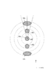
マイクロレンズアレイ8を構成する各微小レンズは、マスクM上において形成すべき照野の形状(ひいてはウェハW上において形成すべき露光領域の形状)と相似な矩形状の断面を有する。マイクロレンズアレイ8に入射した光束は多数の微小レンズにより二次元的に分割され、その後側焦点面(ひいては照明瞳面またはその近傍)には、マイクロレンズアレイ8への入射光束によって形成される照野とほぼ同じ光強度分布を有する二次光源、図2(a)に示すように、光軸AXを中心とする円形状の光強度分布(実質的な面光源)30aと光軸AXを中心としてZ方向に間隔を隔てた2つの円形状の光強度分布(実質的な面光源)30bとからなるZ方向3極状の二次光源が形成される。
Each of the micro lenses forming the
マイクロレンズアレイ8の後側焦点面に形成されたZ方向3極状の二次光源(一般的には照明光学装置の瞳面またはその近傍に形成された所定の光強度分布)からの光束は、コンデンサー光学系9を介した後、マスクブラインド10を重畳的に照明する。こうして、照明視野絞りとしてのマスクブラインド10には、マイクロレンズアレイ8を構成する各微小レンズの形状と焦点距離とに応じた矩形状の照野が形成される。マスクブラインド10の矩形状の開口部(光透過部)を介した光束は、結像光学系11の集光作用を受けた後、所定のパターンが形成されたマスクMを重畳的に照明する。
A light flux from a Z direction tripolar secondary light source formed on the back focal plane of the microlens array 8 (generally, a predetermined light intensity distribution formed in the pupil plane of the illumination optical device or in the vicinity thereof) After passing through the condenser
こうして、結像光学系11は、マスクブラインド10の矩形状開口部の像をマスクM上に形成することになる。マスクMのパターンを透過した光束は、投影光学系PLを介して、感光性基板であるウェハW上にマスクパターンの像を形成する。こうして、投影光学系PLの光軸AXと直交する平面(XY平面)内においてウェハWを二次元的に駆動制御しながら一括露光またはスキャン露光を行うことにより、ウェハWの各露光領域にはマスクMのパターンが逐次露光される。
Thus, the imaging
以上のように、回折光学素子3、アフォーカルレンズ4、ズームレンズ7およびマイクロレンズアレイ8は、照明光学装置(1〜11)の瞳面またはその近傍に、光軸AXを含む中心領域に位置する光強度分布すなわち光軸AXを中心とする円形状の面光源30aと、光軸AXから間隔を隔てた複数の周辺領域に位置する光強度分布すなわち光軸AXを中心としてZ方向に間隔を隔てた2つの円形状の面光源30bとを有する照明瞳分布を形成するための照明瞳形成手段を構成している。また、回折光学素子3は、入射する光束を、光軸AXを中心とする円形状の面光源30aに対応する中心光束と、光軸AXを中心としてZ方向に間隔を隔てた2つの円形状の面光源30bにそれぞれ対応する複数の周辺光束とに変換するための光束変換素子を構成している。
As described above, the diffractive
図3は、アフォーカルレンズの前側レンズ群と後側レンズ群との間の光路中に配置されたプリズム対の構成および動作を概略的に示す図である。プリズム対6は、図3に示すように、光源側から順に、光源側に平面を向け且つマスク側に凹状断面の屈折面を向けた第1プリズム部材6aと、マスク側に平面を向け且つ光源側に凸状断面の屈折面を向けた第2プリズム部材6bとにより構成されている。そして、第1プリズム部材6aの凹状断面の屈折面と第2プリズム部材6bの凸状断面の屈折面とは、互いに当接可能なように相補的に形成されている。
FIG. 3 is a diagram schematically showing the configuration and operation of a prism pair disposed in the optical path between the front lens group and the rear lens group of the afocal lens. As shown in FIG. 3, the
さらに具体的には、第1プリズム部材6aの凹状断面の屈折面は、光軸AXと直交する平面状の中央部6cと、光軸AXを中心とする円錐体の側面に対応する周辺円錐部6dとを有する。同様に、第2プリズム部材6bの凸状断面の屈折面は、光軸AXと直交する平面状の中央部6eと、光軸AXを中心とする円錐体の側面に対応する周辺円錐部6fとを有する。また、第1プリズム部材6aおよび第2プリズム部材6bのうち少なくとも一方の部材が光軸AXに沿って移動可能に構成され、第1プリズム部材6aの凹状断面の屈折面と第2プリズム部材6bの凸状断面の屈折面との間隔が可変に構成されている。
More specifically, the refracting surface of the concave cross section of the
プリズム対6では、図3に示すように、Z方向3極状の二次光源のうち光軸AXを中心とする円形状の中心面光源30aを形成する中心光束31aが、第1プリズム部材6aの中央部6cおよび第2プリズム部材6bの中央部6eを通過する。一方、Z方向3極状の二次光源のうち、光軸AXを中心としてZ方向に間隔を隔てた2つの円形状の周辺面光源30bを形成する2つの周辺光束31bは、第1プリズム部材6aの周辺円錐部6dおよび第2プリズム部材6bの周辺円錐部6fを通過する。
In the
ここで、第1プリズム部材6aの凹状屈折面と第2プリズム部材6bの凸状屈折面とが互いに当接している状態では、中心光束31aおよび2つの周辺光束31bに対してプリズム対6は平行平面板として機能し、形成されるZ方向3極状の二次光源に及ぼす影響はない。しかしながら、第1プリズム部材6aの凹状屈折面と第2プリズム部材6bの凸状屈折面とを離間させると、中心光束31aに対してプリズム対6は影響を及ぼさないが、2つの周辺光束31bに対してプリズム対6はいわゆるビームエキスパンダーとして機能する。
Here, in a state where the concave refracting surface of the
図4は、Z方向3極状の二次光源に対するプリズム対の作用を説明する図である。図4に示すように、Z方向3極状の二次光源を構成する2つの円形状の周辺面光源32bは、プリズム対6の間隔を零から所定の値まで拡大させることにより、光軸AXを中心とした円の径方向に沿って外方へ移動するとともに、その形状が円形状から楕円形状に変化する。すなわち、変化前の円形状の周辺面光源32bの中心点と変化後の楕円形状の周辺面光源33bの中心点とを結ぶ線分は光軸AXを通り、中心点の移動距離はプリズム対6の間隔に依存する。
FIG. 4 is a diagram for explaining the action of a prism pair on a Z-direction tripolar secondary light source. As shown in FIG. 4, the two circular peripheral surface
さらに、変化前の円形状の周辺面光源32bを光軸AXから見込む角度(光軸AXから周辺面光源32bへの一対の接線がなす角度)と、変化後の楕円形状の周辺面光源33bを光軸AXから見込む角度とが等しい。そして、変化前の円形状の周辺面光源32bの直径すなわち光軸AXとして2つの周辺面光源32bに外接する円の半径と内接する円の半径との差と、光軸AXとして変化後の楕円形状の周辺面光源33bに外接する円の半径と内接する円の半径との差とが等しい。このように、円形状の周辺面光源32bはプリズム対6の間隔に依存して周方向に変化するが、径方向には変化しない。一方、Z方向3極状の二次光源を構成する円形状の中心面光源32aは、プリズム対6の間隔を零から所定の値まで拡大させても影響を受けない。
Furthermore, the angle at which the circular peripheral surface
したがって、プリズム対6の間隔を零から所定の値まで拡大させると、Z方向3極状の二次光源を構成する2つの円形状の周辺面光源32bの位置および大きさが、Z方向3極状の二次光源を構成する円形状の中心面光源32aとは独立して変化する。換言すれば、プリズム対6は、瞳面またはその近傍に形成されて光軸AXから間隔を隔てた複数の周辺領域に位置する光強度分布(2つの周辺面光源32b)の位置および大きさを、瞳面またはその近傍に形成されて光軸AXを含む中心領域に位置する光強度分布(中心面光源32a)とは独立して変更するための領域変更手段を構成している。
Therefore, if the distance between the pair of
図5は、Z方向3極状の二次光源に対するズームレンズの作用を説明する図である。図5に示すように、ズームレンズ7の焦点距離が変化すると、光軸AXを中心としてZ方向に間隔を隔てた2つの円形状の周辺面光源32bは、円形状を維持したまま光軸AXを中心とした円の径方向に沿って移動する。そして、変化前の周辺面光源32bの中心点と変化後の周辺面光源34bの中心点とを結ぶ線分は光軸AXを通り、中心点の移動距離および移動の向きはズームレンズ7の焦点距離の変化に依存する。
FIG. 5 is a diagram for explaining the action of the zoom lens with respect to the Z direction tripolar secondary light source. As shown in FIG. 5, when the focal length of the zoom lens 7 changes, the two circular peripheral surface
また、変化前の周辺面光源32bを光軸AXから見込む角度と、変化後の周辺面光源34bを光軸AXから見込む角度とが等しい。一方、ズームレンズ7の焦点距離の変化に際して、光軸AXを中心とする円形状の中心面光源32aの中心点は移動しないが、その大きさが変化する。具体的には、変化前の中心面光源32aの直径と変化後の中心面光源34aの直径との比は、変化前の周辺面光源32bの直径と変化後の周辺面光源34bの直径との比と同じである。こうして、ズームレンズ7の焦点距離を変化させることにより、3極状の二次光源の全体形状を相似的に変化させることができる。
Further, the angle at which the peripheral surface
なお、Z方向3極照明用の回折光学素子3に代えて、X方向3極照明用の回折光学素子を照明光路中に設定することによって、X方向3極照明を行うことができる。X方向3極照明用の回折光学素子は、平行光束が入射した場合に、そのファーフィールドに、たとえば光軸AXを中心とする円形状の光強度分布と光軸AXを中心としてX方向に間隔を隔てた2つの円形状の光強度分布とからなる3つの円形状の光強度分布を形成する機能を有する。したがって、X方向3極照明用の回折光学素子を介した光束は、図2(b)に示すように、光軸AXを中心とする円形状の光強度分布(中心面光源)30aと光軸AXを中心としてX方向に間隔を隔てた2つの円形状の光強度分布(周辺面光源)30cとからなるX方向3極状の二次光源を形成する。
In addition, X direction three pole illumination can be performed by setting a diffractive optical element for X direction three pole illumination in the illumination light path instead of the diffractive
そして、図6に示すように、プリズム対6の間隔を零から所定の値まで拡大させると、図4のZ方向3極照明の場合と同様に、X方向3極状の二次光源を構成する2つの円形状の周辺面光源32cの位置および大きさが、X方向3極状の二次光源を構成する円形状の中心面光源32aとは独立して変化する。すなわち、円形状の周辺面光源32cは、プリズム対6の間隔に依存して、その中心位置が径方向に移動し、その大きさが周方向にだけ変化して、楕円形状の周辺面光源33cになる。一方、円形状の中心面光源32aは、プリズム対6の間隔が変化しても、その中心位置および大きさは変化しない。
Then, as shown in FIG. 6, when the distance between the pair of
また、図7に示すように、ズームレンズ7の焦点距離を変化させると、図5のZ方向3極照明の場合と同様に、円形状の中心面光源32aと2つの円形状の周辺面光源32cとからなるX方向3極状の二次光源の全体形状は相似的に変化する。すなわち、円形状の周辺面光源32cは、ズームレンズ7の焦点距離の変化に依存して、その中心位置が径方向に移動し、その大きさが相似的に変化して、円形状の周辺面光源34cになる。一方、円形状の中心面光源32aは、ズームレンズ7の焦点距離の変化に依存して、その大きさが相似的に変化して円形状の中心面光源34aになるが、その中心位置は変化しない。
Further, as shown in FIG. 7, when the focal length of the zoom lens 7 is changed, as in the case of the Z-direction tripolar illumination of FIG. 5, the circular central surface
また、Z方向3極照明用の回折光学素子3に代えて、5極照明用の回折光学素子を照明光路中に設定することによって、5極照明を行うことができる。5極照明用の回折光学素子は、平行光束が入射した場合に、そのファーフィールドに、たとえば光軸AXを中心とする円形状の光強度分布と、光軸AXを中心としてX方向に沿った辺およびZ方向に沿った辺を有する正方形(または長方形)の各頂点の位置に配置された4つの円形状の光強度分布とからなる5つの円形状の光強度分布を形成する機能を有する。したがって、5極照明用の回折光学素子を介した光束は、図8(a)に示すように、光軸AXを中心とする円形状の光強度分布(中心面光源)30aと、光軸AXを中心としてX方向に沿った辺およびZ方向に沿った辺を有する正方形の各頂点の位置に配置された4つの円形状の光強度分布(周辺面光源)30dとからなる5極状の二次光源を形成する。
In addition, instead of the diffractive
そして、図9に示すように、プリズム対6の間隔を零から所定の値まで拡大させると、図4のZ方向3極照明や図6のX方向3極照明の場合と同様に、5極状の二次光源を構成する4つの円形状の周辺面光源32dの位置および大きさが、5極状の二次光源を構成する円形状の中心面光源32aとは独立して変化する。すなわち、円形状の周辺面光源32dは、プリズム対6の間隔に依存して、その中心位置が径方向に移動し、その大きさが周方向にだけ変化して、楕円形状の周辺面光源33dになる。一方、円形状の中心面光源32aは、プリズム対6の間隔が変化しても、その中心位置および大きさは変化しない。
Then, as shown in FIG. 9, when the distance between the pair of
また、図10に示すように、ズームレンズ7の焦点距離を変化させると、図5のZ方向3極照明や図7のX方向3極照明の場合と同様に、円形状の中心面光源32aと4つの円形状の周辺面光源32dとからなる5極状の二次光源の全体形状は相似的に変化する。すなわち、円形状の周辺面光源32dは、ズームレンズ7の焦点距離の変化に依存して、その中心位置が径方向に移動し、その大きさが相似的に変化して、円形状の周辺面光源34dになる。一方、円形状の中心面光源32aは、ズームレンズ7の焦点距離の変化に依存して、その大きさが相似的に変化して円形状の中心面光源34aになるが、その中心位置は変化しない。
Further, as shown in FIG. 10, when the focal length of the zoom lens 7 is changed, the circular central surface
また、Z方向3極照明用の回折光学素子3に代えて、9極照明用の回折光学素子を照明光路中に設定することによって、9極照明を行うことができる。9極照明用の回折光学素子は、平行光束が入射した場合に、そのファーフィールドに、たとえば光軸AXを中心とする円形状の光強度分布と、光軸AXを中心としてX方向に沿った辺およびZ方向に沿った辺を有する第1正方形(または第1長方形)の各頂点の位置に配置された4つの円形状の光強度分布と、光軸AXを中心としてX方向に沿った辺およびZ方向に沿った辺を有し且つ第1正方形(または第1長方形)を包囲する第2正方形(または第2長方形)の各頂点の位置に配置された4つの円形状の光強度分布とからなる5つの円形状の光強度分布を形成する機能を有する。
Further, nine-pole illumination can be performed by setting a diffractive optical element for nine-pole illumination in the illumination light path instead of the diffractive
したがって、9極照明用の回折光学素子を介した光束は、図8(b)に示すように、光軸AXを中心とする円形状の光強度分布(中心面光源)30aと、光軸AXを中心としてX方向に沿った辺およびZ方向に沿った辺を有する第1正方形の各頂点の位置に配置された4つの円形状の光強度分布(内側周辺面光源)30eと、光軸AXを中心としてX方向に沿った辺およびZ方向に沿った辺を有し且つ第1正方形を包囲する第2正方形の各頂点の位置に配置された4つの円形状の光強度分布(外側周辺面光源)30fとからなる9極状の二次光源を形成する。 Therefore, as shown in FIG. 8B, the light beam passing through the diffractive optical element for nine-pole illumination has a circular light intensity distribution (central surface light source) 30a centered on the optical axis AX, and the optical axis AX Light intensity distribution (inner peripheral surface light source) 30e arranged at the position of each vertex of the first square having a side along the X direction centering on the X direction and a side along the Z direction, and the optical axis AX Light intensity distribution of four circular shapes (outer peripheral surface) arranged at the position of each vertex of the second square surrounding the first square with the side along the X direction and the side along the Z direction centering on Light source) 30f forms a nine-pole secondary light source.
この場合、図示を省略するが、プリズム対6の間隔を零から所定の値まで拡大させると、図9の5極照明の場合と同様に、9極状の二次光源を構成する4つの円形状の内側周辺面光源および4つの円形状の外側周辺面光源の位置および大きさが、9極状の二次光源を構成する円形状の中心面光源とは独立して変化する。すなわち、円形状の内側周辺面光源および外側周辺面光源は、プリズム対6の間隔に依存して、その中心位置が径方向に移動し、その大きさが周方向にだけ変化して、楕円形状の内側周辺面光源および外側周辺面光源になる。一方、円形状の中心面光源は、プリズム対6の間隔が変化しても、その中心位置および大きさは変化しない。
In this case, although not shown, when the distance between the pair of
また、ズームレンズ7の焦点距離を変化させると、図10の5極照明の場合と同様に、円形状の中心面光源と4つの円形状の内側周辺面光源と4つの円形状の外側周辺面光源とからなる9極状の二次光源の全体形状は相似的に変化する。すなわち、円形状の内側周辺面光源および外側周辺面光源は、ズームレンズ7の焦点距離の変化に依存して、その中心位置が径方向に移動し、その大きさが相似的に変化して、円形状の内側周辺面光源および外側周辺面光源になる。一方、円形状の中心面光源は、ズームレンズ7の焦点距離の変化に依存して、その大きさが相似的に変化して円形状の中心面光源になるが、その中心位置は変化しない。 Further, when the focal length of the zoom lens 7 is changed, as in the case of the five-pole illumination of FIG. 10, a circular central surface light source, four circular inner peripheral surface light sources, and four circular outer peripheral surfaces The overall shape of the nine-pole secondary light source comprising the light source changes analogously. That is, the center positions of the circular inner peripheral surface light source and the outer peripheral surface light source move in the radial direction depending on the change of the focal length of the zoom lens 7, and the sizes change similarly. It becomes circular inner peripheral surface light source and outer peripheral surface light source. On the other hand, the circular central surface light source changes its size in a similar manner depending on the change of the focal length of the zoom lens 7 to become a circular central surface light source, but the central position does not change.
なお、上述の説明では、9極照明に際して、図2に示すように屈折面が1つの周辺円錐部(6d,6f)を有する1段式のプリズム対6を用いている。しかしながら、9極照明に際して、図11に示すように屈折面が2つの周辺円錐部を有する2段式のプリズム対60を用いることもできる。図11を参照すると、2段式プリズム対60は、光源側から順に、光源側に平面を向け且つマスク側に凹状断面の屈折面を向けた第1プリズム部材60aと、マスク側に平面を向け且つ光源側に凸状断面の屈折面を向けた第2プリズム部材60bとにより構成されている。そして、第1プリズム部材60aの凹状断面の屈折面と第2プリズム部材60bの凸状断面の屈折面とは、互いに当接可能なように相補的に形成されている。
In the above description, in the case of 9-pole illumination, as shown in FIG. 2, a one-
さらに具体的には、第1プリズム部材60aの凹状断面の屈折面は、光軸AXと直交する平面状の中央部60cと、光軸AXを中心とする第1円錐体の側面に対応する内側周辺円錐部60dと、光軸AXを中心とし且つ第1円錐体よりも小さな頂角を有する第2円錐体の側面に対応する外側周辺円錐部60eとを有する。同様に、第2プリズム部材60bの凸状断面の屈折面は、光軸AXと直交する平面状の中央部60fと、光軸AXを中心とする第1円錐体の側面に対応する内側周辺円錐部60gと、光軸AXを中心とし且つ第1円錐体よりも小さな頂角を有する第2円錐体の側面に対応する外側周辺円錐部60hとを有する。また、第1プリズム部材60aおよび第2プリズム部材60bのうち少なくとも一方の部材が光軸AXに沿って移動可能に構成され、第1プリズム部材60aの凹状断面の屈折面と第2プリズム部材60bの凸状断面の屈折面との間隔が可変に構成されている。
More specifically, the refracting surface of the concave cross section of the
2段式プリズム対60では、図11に示すように、9極状の二次光源のうち光軸AXを中心とする円形状の中心面光源30aを形成する中心光束31aが、第1プリズム部材60aの中央部60cおよび第2プリズム部材60bの中央部60fを通過する。また、9極状の二次光源のうち、光軸AXを中心とした第1正方形の各頂点の位置に配置された4つの内側周辺面光源30eを形成する4つの内側周辺光束31eは、第1プリズム部材60aの内側周辺円錐部60dおよび第2プリズム部材60bの周辺円錐部60gを通過する。また、9極状の二次光源のうち、光軸AXを中心とした第2正方形の各頂点の位置に配置された4つの外側周辺面光源30fを形成する4つの外側周辺光束31fは、第1プリズム部材60aの外側周辺円錐部60eおよび第2プリズム部材60bの周辺円錐部60hを通過する。
In the two-
ここで、第1プリズム部材60aの凹状屈折面と第2プリズム部材60bの凸状屈折面とが互いに当接している状態では、中心光束31a、4つの内側周辺光束31eおよび4つの外側周辺光束31fに対して2段式プリズム対60は平行平面板として機能し、形成される9極状の二次光源に及ぼす影響はない。しかしながら、第1プリズム部材60aの凹状屈折面と第2プリズム部材60bの凸状屈折面とを離間させると、中心光束31aに対して2段式プリズム対60は影響を及ぼさないが、4つの内側周辺光束31eおよび4つの外側周辺光束31fに対して2段式プリズム対60はいわゆるビームエキスパンダーとして機能する。
Here, when the concave refracting surface of the
図12は、9極状の二次光源に対する2段式プリズム対の作用を説明する図である。ただし、図12では、図面の明瞭化のために、9極状の二次光源のうち、中心面光源32a、1つの内側周辺面光源32e、および1つの外側周辺面光源32fだけを示している。図12に示すように、内側周辺面光源32eおよび外側周辺面光源32fは、2段式プリズム対60の間隔を零から所定の値まで拡大させることにより、光軸AXを中心とした円の径方向に沿って外方へ移動するとともに、その形状が円形状から楕円形状に変化する。すなわち、変化前の円形状の内側周辺面光源32eおよび外側周辺面光源32fの中心点と変化後の楕円形状の内側周辺面光源33eおよび外側周辺面光源33fの中心点とを結ぶ線分は光軸AXを通り、中心点の移動距離は2段式プリズム対60の間隔に依存する。
FIG. 12 is a diagram for explaining the operation of a two-stage prism pair on a nine-pole secondary light source. However, in FIG. 12, only the central surface
ここで、2段式プリズム対60の場合には、変化前の円形状の外側周辺面光源32fから変化後の楕円形状の外側周辺面光源33fへの移動距離の方が、変化前の円形状の内側周辺面光源32eから変化後の楕円形状の内側周辺面光源33eへの移動距離よりも大きくなり、その移動距離の差は2段式プリズム対60の間隔に依存して変化する。さらに、変化前の円形状の内側周辺面光源32eを光軸AXから見込む角度(光軸AXから内側周辺面光源32eへの一対の接線がなす角度)と、変化後の楕円形状の内側周辺面光源33eを光軸AXから見込む角度とが等しい。
Here, in the case of the two-
同様に、変化前の円形状の外側周辺面光源32fを光軸AXから見込む角度(光軸AXから外側周辺面光源32fへの一対の接線がなす角度)と、変化後の楕円形状の外側周辺面光源33fを光軸AXから見込む角度とが等しい。ここで、変化前の円形状の内側周辺面光源32eと変化前の円形状の外側周辺面光源32fとが同じ大きさを有する場合、変化前の円形状の内側周辺面光源32eを光軸AXから見込む角度の方が、変化前の円形状の外側周辺面光源32fを光軸AXから見込む角度よりも大きくなる。
Similarly, an angle at which the circular outer peripheral surface light source 32f before change is viewed from the optical axis AX (an angle formed by a pair of tangents from the optical axis AX to the outer peripheral surface light source 32f) and an elliptical outer peripheral edge after the change. The angle at which the
そして、変化前の円形状の内側周辺面光源32eの直径すなわち光軸AXとして4つの内側周辺面光源32eに外接する円の半径と内接する円の半径との差と、光軸AXとして変化後の楕円形状の内側周辺面光源33eに外接する円の半径と内接する円の半径との差とが等しい。同様に、変化前の円形状の外側周辺面光源32fの直径すなわち光軸AXとして4つの外側周辺面光源32fに外接する円の半径と内接する円の半径との差と、光軸AXとして変化後の楕円形状の外側周辺面光源33fに外接する円の半径と内接する円の半径との差とが等しい。一方、9極状の二次光源を構成する円形状の中心面光源32aは、2段式プリズム対60の間隔を零から所定の値まで拡大させても影響を受けない。
Then, the diameter of the circular inner peripheral surface
以上のように、第1実施形態では、領域変更手段としてのプリズム対6(または2段式プリズム対60)の作用により、瞳面またはその近傍に形成されて光軸AXから間隔を隔てた複数の周辺領域に位置する光強度分布(周辺面光源)の位置および大きさを、光軸AXを含む中心領域に位置する光強度分布(中心面光源)とは独立して変更することができる。その結果、第1実施形態では、たとえば中心面光源とは独立して変更される複数の周辺面光源の位置および大きさに関して多様性に富んだ(すなわち瞳面またはその近傍に形成される光強度分布に関して多様性に富んだ)3極照明、5極照明および9極照明を実現することができる。 As described above, in the first embodiment, a plurality of pupils formed at or near the pupil plane and separated from the optical axis AX by the action of the prism pair 6 (or the two-stage prism pair 60) as the area changing means The position and the size of the light intensity distribution (peripheral surface light source) located in the peripheral region of can be changed independently of the light intensity distribution (central surface light source) located in the central region including the optical axis AX. As a result, in the first embodiment, for example, the light intensity is rich in diversity with respect to the position and the size of a plurality of peripheral surface light sources which are changed independently of the central surface light source (that is, light intensity formed in or near the pupil plane) It is possible to realize three-pole illumination, five-pole illumination and nine-pole illumination, which are rich in distribution.
なお、上述の第1実施形態では、光軸AXを中心とする円形状の中心面光源と光軸AXに関して対称に配置された複数の円形状の周辺面光源とからなる二次光源を形成している。しかしながら、各面光源の形状および位置はこれに限定されることなく、一般に、光軸AXを含む中心領域に位置する光強度分布と光軸AXから間隔を隔てた複数の周辺領域に位置する光強度分布とを有する二次光源(照明瞳分布)を形成することができる。 In the first embodiment described above, a secondary light source is formed, which comprises a circular central surface light source centered on the optical axis AX and a plurality of circular peripheral surface light sources arranged symmetrically with respect to the optical axis AX. ing. However, the shape and position of each surface light source are not limited thereto, and in general, the light intensity distribution located in the central region including the optical axis AX and the light located in a plurality of peripheral regions spaced from the optical axis AX It is possible to form a secondary light source (illumination pupil distribution) having an intensity distribution.
また、上述の第1実施形態では、光軸AXを含む中心面光源と光軸AXから間隔を隔てた各周辺面光源とがほぼ同じ大きさを有する二次光源を形成している。しかしながら、これに限定されることなく、所望の特性を有する回折光学素子を照明光路に設定することにより、各周辺面光源よりも中心面光源を実質的に大きくしたり、各周辺面光源よりも中心面光源を実質的に小さくしたりする変形例も可能である。この場合、中央部の面積が異なる1つまたは複数のプリズム対を交換可能に備えていることが好ましい。 Further, in the above-described first embodiment, the secondary light sources having substantially the same size as the central surface light source including the optical axis AX and the peripheral surface light sources spaced from the optical axis AX are formed. However, the present invention is not limited to this, and by setting a diffractive optical element having desired characteristics in the illumination light path, the central surface light source can be made substantially larger than each peripheral surface light source, or each peripheral surface light source Variations are also possible in which the central surface light source is substantially reduced. In this case, it is preferable to replaceably provide one or more prism pairs having different central areas.
具体的には、各周辺面光源よりも中心面光源を実質的に小さく設定する場合には、図13(a)に示すような中央部の面積が比較的小さいプリズム対を用いることができる。また、各周辺面光源よりも中心面光源を実質的に大きく設定する場合には、図13(b)に示すような中央部の面積が比較的大きいプリズム対を用いることができる。なお、図13には1段式プリズム対の例だけを示しているが、必要に応じて、中央部の面積が異なる1つまたは複数の2段式プリズム対を交換可能に備えていることが好ましい。 Specifically, when the central surface light source is set to be substantially smaller than each peripheral surface light source, it is possible to use a prism pair having a relatively small area in the central portion as shown in FIG. 13 (a). When the central surface light source is set to be substantially larger than each peripheral surface light source, it is possible to use a prism pair having a relatively large area in the central portion as shown in FIG. 13 (b). Although only one example of a one-stage prism pair is shown in FIG. 13, it is possible to replaceably provide one or more two-stage prism pairs having different central areas if necessary. preferable.
図14は、本発明の第2実施形態にかかる照明光学装置を備えた露光装置の構成を概略的に示す図である。また、図15は、第2実施形態の要部構成を概略的に示す図である。なお、図14および図15では、照明光学装置がZ方向3極照明の状態に設定されている。第2実施形態は、第1実施形態と類似の構成を有する。しかしながら、第2実施形態では、プリズム対6の光源側に1/4波長板12および1/2波長板13が付設され、プリズム対6のマスク側に1/2波長板14および偏角プリズム組立体15が付設されている点が第1実施形態と相違している。以下、第1実施形態との相違点に着目して第2実施形態を説明する。
FIG. 14 is a view schematically showing a configuration of an exposure apparatus provided with an illumination optical apparatus according to a second embodiment of the present invention. Moreover, FIG. 15 is a figure which shows roughly the principal part structure of 2nd Embodiment. In FIG. 14 and FIG. 15, the illumination optical device is set to the Z-direction tripolar illumination state. The second embodiment has a configuration similar to that of the first embodiment. However, in the second embodiment, the quarter-
図14および図15を参照すると、第2実施形態では、アフォーカルレンズ4の前側レンズ群4aとプリズム対6との間の光路中において、光源側から順に、光軸AXを中心として結晶光学軸が回転自在に構成された1/4波長板12と、光軸AXを中心として結晶光学軸が回転自在に構成された1/2波長板13とが配置されている。ここで、1/4波長板12は、入射する楕円偏光の光を直線偏光の光に変換する機能を有する。また、1/2波長板13は、入射する直線偏光の光を、所定の方向に偏光面を有する直線偏光の光に変換する機能を有する。
Referring to FIGS. 14 and 15, in the second embodiment, in the optical path between the
光源1としてKrFエキシマレーザ光源やArFエキシマレーザ光源を用いる場合、光源1からはほぼ直線偏光の光が供給される。また、光源1と回折光学素子3との間の光路中には、裏面反射鏡としての直角プリズムが複数個配置されるのが通常である。一般に、裏面反射鏡としての直角プリズムに直線偏光が入射する場合、入射する直線偏光の偏光面がP偏光面またはS偏光面に一致していないと、直角プリズムでの全反射により直線偏光が楕円偏光に変わる。
When a KrF excimer laser light source or an ArF excimer laser light source is used as the
第2実施形態では、たとえば直角プリズムに起因して楕円偏光が回折光学素子3に入射することがあっても、入射する楕円偏光の特性に応じて1/4波長板12の結晶光学軸を設定することにより、後続する1/2波長板13に直線偏光が入射する。また、1/2波長板13に入射した直線偏光の光は、その結晶光学軸の方向に応じて、任意の方向に偏光面を有する直線偏光の光に変換される。こうして、1/4波長板12と1/2波長板13との協働作用により、任意の方向に偏光面を有する直線偏光の光がプリズム対6へ導かれる。なお、1/4波長板12を1/2波長板13のマスク側に配置しても光学的に等価な効果が得られる。
In the second embodiment, even if elliptically polarized light is incident on the diffractive
また、第2実施形態では、プリズム対6とアフォーカルレンズ4の後側レンズ群4bとの間において、光軸AXから間隔を隔てた2つの周辺面光源30bを形成する2つの周辺光束31bの光路中には、光軸AXを中心として結晶光学軸が回転自在に構成された輪帯状の1/2波長板14が配置されている。さらに、プリズム対6とアフォーカルレンズ4の後側レンズ群4bとの間において、光軸AXを含む中心面光源30aを形成する中心光束31aの光路中には、くさび形状の水晶プリズム15aと、この水晶プリズム15aと相補的な形状を有するくさび形状の石英プリズム15bとにより一体的に構成された偏角プリズム組立体15が配置されている。
Further, in the second embodiment, between the pair of
偏角プリズム組立体15は、光軸AXを中心として回転可能に構成されている。また、偏角プリズム組立体15では、水晶プリズム15aの頂点方向と石英プリズム15bの頂点方向とが逆向きに設定され、水晶プリズム15aによる偏角作用を石英プリズム15bが補償(補正)するように構成されている。偏角プリズム組立体15では、入射する直線偏光の偏光面に対して水晶プリズム15aの結晶光学軸の方向が45度の角度をなすように設定することにより、偏角プリズム組立体15からの射出光が実質的に非偏光状態の光に変換される。一方、入射する直線偏光の偏光面に対して水晶プリズム15aの結晶光学軸の方向が0度または90度の角度をなすように設定すると、入射した直線偏光の偏光面が変化することなくそのまま偏角プリズム組立体15を通過する。
The
こうして、1/2波長板14は、光軸AXから間隔を隔てた2つの周辺面光源30bへ向かう直線偏光の光束の偏光面を必要に応じて変化させるための位相部材を構成している。具体的には、1/2波長板14の結晶光学軸を所要の角度位置に設定することにより、2つの周辺面光源30bに達する光の偏光状態を、任意の方向に偏光面を有する直線偏光状態に設定することができる。
Thus, the half-
また、偏角プリズム組立体15は、光軸AXを含む中心面光源30aへ向かう直線偏光の光束を必要に応じて非偏光化するための偏光解消素子を構成している。具体的には、偏角プリズム組立体15における水晶プリズム15aの結晶光学軸を所要の角度位置に設定することにより、中心面光源30aに達する光の偏光状態を、直線偏光状態と非偏光状態との間で切り換えることができる。あるいは、偏角プリズム組立体15を光路に対して挿脱自在に構成し、偏角プリズム組立体15を光路中に設定することにより非偏光状態を実現したり、偏角プリズム組立体15を光路から退避させることにより光量損失を回避しつつ直線偏光状態を実現したりすることもできる。以下、具体的に、第2実施形態の3極照明、5極照明および9極照明における周辺面光源および中心面光源の偏光状態の設定例を説明する。
In addition, the
図16は、第2実施形態の3極照明における周辺面光源および中心面光源の偏光状態の設定例を説明する図である。Z方向3極照明またはX方向3極照明の場合、図16に示すように、マスクに形成されたライン・アンド・スペース・パターン51のピッチ方向に沿って光軸AXを中心として間隔を隔てた2つの周辺面光源41bを形成し、この2つの周辺面光源41bを通過する光束の偏光状態を、たとえばパターン51のピッチ方向と直交する方向に偏光面(図中両方向矢印で示す)を有する直線偏光状態に設定する。また、光軸AXを中心とした中心面光源41aを通過する光束の偏光状態を、たとえば非偏光状態に設定する。
FIG. 16 is a diagram for explaining a setting example of the polarization states of the peripheral surface light source and the central surface light source in the three-pole illumination of the second embodiment. In the case of the Z-direction tripolar illumination or the X-direction triode illumination, as shown in FIG. 16, they are spaced around the optical axis AX along the pitch direction of the line-and-
この場合、ライン・アンド・スペース・パターン51に適した2極照明(2つの周辺面光源41bからの光束によるマスクの照明)と、孤立パターン52に適した小σ照明(中心面光源41aからの光束によるマスクの照明)との組み合わせからなる3極照明により、投影光学系の結像性能の向上を図りつつ忠実なパターン転写を実現することができる。なお、3極照明において、中心面光源41aを通過する光束の偏光状態を、所望する方向に偏光面を有する直線偏光状態に設定することもできる。また、2つの周辺面光源41bを通過する光束の偏光状態を、所望する方向に偏光面を有する直線偏光状態に設定することもできる。
In this case, two-pole illumination suitable for the line-and-space pattern 51 (illumination of the mask by light flux from the two peripheral surface
図17は、第2実施形態の5極照明における周辺面光源および中心面光源の偏光状態の設定例を説明する図である。5極照明の場合、図17に示すように、マスクに形成されたライン・アンド・スペース・パターン51のピッチ方向に沿った辺を有する正方形(または長方形)の各頂点の位置に4つの周辺面光源41dを形成し、この4つの周辺面光源41dを通過する光束の偏光状態を、たとえばパターン51のピッチ方向と直交する方向に偏光面(図中両方向矢印で示す)を有する直線偏光状態に設定する。また、光軸AXを中心とした中心面光源41aを通過する光束の偏光状態を、たとえば非偏光状態に設定する。
FIG. 17 is a diagram for explaining a setting example of the polarization states of the peripheral surface light source and the central surface light source in the five-pole illumination of the second embodiment. In the case of five-pole illumination, as shown in FIG. 17, four peripheral planes are located at the apex of each square (or rectangle) having sides along the pitch direction of the line-and-
この場合、ライン・アンド・スペース・パターン51に適した4極照明(4つの周辺面光源41dからの光束によるマスクの照明)と、孤立パターン52に適した小σ照明(中心面光源41aからの光束によるマスクの照明)との組み合わせからなる5極照明により、投影光学系の結像性能の向上を図りつつ忠実なパターン転写を実現することができる。なお、5極照明において、中心面光源41aを通過する光束の偏光状態を、所望する方向に偏光面を有する直線偏光状態に設定することもできる。また、4つの周辺面光源41dを通過する光束の偏光状態を、所望する方向に偏光面を有する直線偏光状態に設定することもできる。特に、4つの周辺面光源41dを通過する光束の偏光状態を、たとえば周辺面光源41dの間隔方向と45度の角度をなす方向に偏光面を有する直線偏光状態に設定することもできる。
In this case, four-pole illumination (illumination of the mask by the light flux from the four peripheral
また、各周辺面光源41dを通過する光束の偏光状態を、それぞれ所望する方向に偏光面を有する直線偏光状態に設定することもできる。典型的には、図18に示すように、4つの周辺面光源のうち、光軸AXを挟んで対向する一方の対の周辺面光源41d1および41d3を通過する光束の偏光状態を、周辺面光源41d1と41d3との間隔方向と45度の角度をなす同一方向に偏光面を有する直線偏光状態に設定し、光軸AXを挟んで対向する他方の対の周辺面光源41d2および41d4を通過する光束の偏光状態を、周辺面光源41d1および41d3を通過する直線偏光の偏光面方向と直交する方向に偏光面を有する直線偏光状態に設定することもできる。ただし、図18に示す偏光状態を実現するには、図15に示す輪帯状の1/2波長板14に代えて、一方の対の周辺面光源41d1および41d3に向かう光束の光路中に第1の1/2波長板を設けると共に、他方の対の周辺面光源41d2および41d4に向かう光束の光路中に第2の1/2波長板を設ける必要がある。
Also, the polarization state of the light flux passing through each peripheral
図19は、第2実施形態の9極照明における周辺面光源および中心面光源の偏光状態の設定例を説明する図である。9極照明の場合、図19に示すように、マスクに形成されたライン・アンド・スペース・パターン51aのピッチ方向に沿った辺を有する正方形(または長方形)の各頂点の位置に4つの内側周辺面光源41eを形成し、この4つの内側周辺面光源41eを通過する光束の偏光状態を、たとえばパターン51aのピッチ方向と直交する方向に偏光面(図中両方向矢印で示す)を有する直線偏光状態に設定する。また、4つの外側周辺面光源41fを通過する光束の偏光状態を、4つの内側周辺面光源41eを通過する直線偏光の偏光面方向と直交する方向に偏光面(図中両方向矢印で示す)を有する直線偏光状態に設定する。
FIG. 19 is a diagram for explaining a setting example of the polarization states of the peripheral surface light source and the central surface light source in the 9-pole illumination of the second embodiment. In the case of nine-pole illumination, as shown in FIG. 19, four inner peripheral edges are located at the respective apexes of a square (or rectangle) having sides along the pitch direction of the line and
また、光軸AXを中心とした中心面光源41aを通過する光束の偏光状態を、たとえば非偏光状態に設定する。この場合、ライン・アンド・スペース・パターン51aに適した4極照明(4つの内側周辺面光源41eからの光束によるマスクの照明)と、パターン51aよりも微細で且つパターン51aのピッチ方向と直交するピッチ方向を有するライン・アンド・スペース・パターン51bに適した4極照明(4つの外側周辺面光源41fからの光束によるマスクの照明)と、孤立パターン52に適した小σ照明(中心面光源41aからの光束によるマスクの照明)との組み合わせからなる9極照明により、投影光学系の結像性能の向上を図りつつ忠実なパターン転写を実現することができる。
In addition, the polarization state of the light flux passing through the central
なお、9極照明において、中心面光源41aを通過する光束の偏光状態を、所望する方向に偏光面を有する直線偏光状態に設定することもできる。また、4つの内側周辺面光源41eを通過する光束の偏光状態、および4つの外側周辺面光源41fを通過する光束の偏光状態を、それぞれ所望する方向に偏光面を有する直線偏光状態に設定することもできる。特に、4つの内側周辺面光源41eを通過する光束の偏光状態および4つの外側周辺面光源41fを通過する光束の偏光状態を、たとえば周辺面光源の間隔方向と45度の角度をなす方向に偏光面を有する直線偏光状態に設定することもできる。
In the nine-pole illumination, the polarization state of the light flux passing through the central surface
典型的には、図20に示すように、4つの内側周辺面光源のうち、光軸AXを挟んで対向する一方の対の内側周辺面光源41e1および41e3を通過する光束の偏光状態を、内側周辺面光源41e1と41e3との間隔方向と45度の角度をなす同一方向に偏光面を有する直線偏光状態に設定し、光軸AXを挟んで対向する他方の対の内側周辺面光源41e2および41e4を通過する光束の偏光状態を、内側周辺面光源41e1および41e3を通過する直線偏光の偏光面方向と直交する方向に偏光面を有する直線偏光状態に設定することもできる。 Typically, as shown in FIG. 20, of the four inner peripheral surface light sources, the polarization state of the light flux passing through one pair of opposed inner peripheral surface light sources 41e1 and 41e3 across the optical axis AX is The other pair of inner peripheral surface light sources 41e2 and 41e4 are set to linearly polarized light having a polarization plane in the same direction that forms an angle of 45 degrees with the spacing direction of the peripheral surface light sources 41e1 and 41e3 and sandwiches the optical axis AX. It is also possible to set the polarization state of the light flux passing through to the linear polarization state having the polarization plane in the direction orthogonal to the polarization plane direction of the linearly polarized light passing through the inner peripheral surface light sources 41e1 and 41e3.
同様に、4つの外側周辺面光源のうち、光軸AXを挟んで対向する一方の対の外側周辺面光源41f1および41f3を通過する光束の偏光状態を、外側周辺面光源41f1と41f3との間隔方向と45度の角度をなす同一方向に偏光面を有する直線偏光状態に設定し、光軸AXを挟んで対向する他方の対の外側周辺面光源41f2および41f4を通過する光束の偏光状態を、外側周辺面光源41f1および41f3を通過する直線偏光の偏光面方向と直交する方向に偏光面を有する直線偏光状態に設定することもできる。 Similarly, among the four outer peripheral surface light sources, the polarization state of the light flux passing through one pair of the outer peripheral surface light sources 41f1 and 41f3 facing each other across the optical axis AX is the distance between the outer peripheral surface light sources 41f1 and 41f3. The polarization state of the light beam passing through the other pair of outer peripheral surface light sources 41f2 and 41f4 opposed to each other across the optical axis AX is set to a linear polarization state having a polarization plane in the same direction forming an angle of 45 degrees with the direction. It is also possible to set a linearly polarized light having a polarization plane in a direction orthogonal to the polarization plane direction of the linearly polarized light passing through the outer peripheral surface light sources 41f1 and 41f3.
ただし、図19に示す偏光状態を実現するには、図21に示すように、図15に示すプリズム対6に代えて2段式プリズム対60を配置し(あるいはプリズム対6をそのまま用いて)、図15に示す輪帯状の1/2波長板14に代えて、内側周辺面光源41eに向かう光束31eの光路中に光軸AXを中心として回転可能な第1の輪帯状の1/2波長板14aを設けると共に、外側周辺面光源41fに向かう光束31fの光路中に光軸AXを中心として回転可能な第2の輪帯状の1/2波長板14bを設ける必要がある。
However, in order to realize the polarization state shown in FIG. 19, as shown in FIG. 21, instead of the
あるいは、図22に示すように、図21の第1の輪帯状の1/2波長板14aに代えて、中心面光源41aに向かう光束31aおよび内側周辺面光源41eに向かう光束31eの光路中に光軸AXを中心として回転可能な第1の円形状の1/2波長板14cを設けると共に、図21の第2の輪帯状の1/2波長板14bに代えて、中心面光源41aに向かう光束31a、内側周辺面光源41eに向かう光束31eおよび外側周辺面光源41fに向かう光束31fの光路中に光軸AXを中心として回転可能な第2の円形状の1/2波長板14dを設ける構成も可能である。
Alternatively, as shown in FIG. 22, instead of the first ring-shaped
図22の構成では、内側周辺面光源41eを通過する光束の偏光状態および外側周辺面光源41fを通過する光束の偏光状態を、ともに横偏光状態または縦偏光状態に設定することができる。また、内側周辺面光源41eを通過する光束の偏光状態を横偏光状態に設定し、外側周辺面光源41fを通過する光束の偏光状態を縦偏光状態に設定することもできる。また、内側周辺面光源41eを通過する光束の偏光状態を縦偏光状態に設定し、外側周辺面光源41fを通過する光束の偏光状態を横偏光状態に設定することもできる。
In the configuration of FIG. 22, the polarization state of the light flux passing through the inner peripheral surface
一方、図20に示す偏光状態を実現するには、図15に示すプリズム対6に代えて2段式プリズム対60を配置し(あるいはプリズム対6をそのまま用いて)、図15に示す輪帯状の1/2波長板14に代えて、一方の対の内側周辺面光源41e1および41e3に向かう光束の光路中に第1の1/2波長板を設け、他方の対の内側周辺面光源41e2および41e4に向かう光束の光路中に第2の1/2波長板を設け、一方の対の外側周辺面光源41f1および41f3に向かう光束の光路中に第3の1/2波長板を設け、他方の対の外側周辺面光源41f2および41f4に向かう光束の光路中に第4の1/2波長板を設ける必要がある。
On the other hand, in order to realize the polarization state shown in FIG. 20, instead of the
以上のように、第2実施形態では、1/2波長板14および偏角プリズム組立体15は、光軸AXを中心とした中心面光源(一般には瞳面またはその近傍において光軸を含む中心領域としての第1領域)を通過する光束を非偏光状態に設定すると共に、光軸AXから間隔を隔てた周辺面光源(一般には瞳面またはその近傍において光軸から間隔を隔てた1つまたは複数の周辺領域としての第2領域)を通過する光束を直線偏光状態(一般には偏光状態)に設定するための偏光設定手段を構成している。
As described above, in the second embodiment, the half-
また、別の観点によれば、1/2波長板14および偏角プリズム組立体15は、光軸AXから間隔を隔てた周辺面光源(一般には瞳面またはその近傍において光軸から間隔を隔てた1つまたは複数の周辺領域としての第2領域)を通過する光束の偏光状態を、光軸AXを中心とした中心面光源(一般には瞳面またはその近傍において光軸を含む中心領域としての第1領域)を通過する光束の偏光状態とは独立に変更するための偏光状態変更手段を構成している。この偏光状態変更手段(14,15)は、たとえば光軸AXを中心とした中心面光源(第1領域)を通過する光束の状態を非偏光状態と直線偏光状態との間で変更する。
According to another aspect, the half-
また、この偏光状態変更手段(14,15)は、たとえば光軸AXから間隔を隔てた周辺面光源(第2領域)を通過する光束の偏光状態を互いに異なる方向に偏光面を有する2つの直線偏光状態の間で変更する。その結果、第2実施形態では、周辺面光源の位置および大きさに関して多様性に富んだ3極照明、5極照明および9極照明を実現することができるという第1実施形態の効果に加えて、周辺面光源および中心面光源の偏光状態(非偏光状態を含む)に関して多様性に富んだ3極照明、5極照明および9極照明を実現することができる。 Further, the polarization state changing means (14, 15) are, for example, two straight lines having polarization planes in directions different from each other in polarization state of light flux passing through the peripheral surface light source (second region) spaced from the optical axis AX. Change between polarization states. As a result, in the second embodiment, in addition to the effect of the first embodiment, tripolar illumination, pentapolar illumination, and nine-pole illumination can be realized with a wide variety of positions and sizes of peripheral surface light sources. It is possible to realize tripolar illumination, pentapole illumination, and 9-pole illumination which are rich in the polarization state (including non-polarization state) of the peripheral surface light source and the central surface light source.
なお、上述の第2実施形態において、Z方向3極照明用の回折光学素子3に代えて輪帯照明用の回折光学素子を照明光路中に設定するとともに、プリズム対6に代えて屈折面が平面状の中央部を有することなく1つの円錐部だけを有するプリズム対(以下、「円錐プリズム対」という)を用いることによって、輪帯照明を行うことができる。輪帯照明用の回折光学素子は、平行光束が入射した場合に、そのファーフィールドに、たとえば光軸AXを中心とする円形状の光強度分布を形成する機能を有する。
In the second embodiment described above, the diffractive optical element for annular illumination is set in the illumination light path instead of the diffractive
したがって、輪帯照明用の回折光学素子を介した光束は、アフォーカルレンズ4の瞳面に、光軸AXを中心とする円形状の光強度分布を形成する。そして、円錐プリズム対の間隔に応じて、マイクロレンズアレイ8の入射面には光軸AXを中心とする輪帯状の照野が形成される。その結果、マイクロレンズアレイ8の後側焦点面(照明光学装置の瞳面またはその近傍)には、図23(a)に示すように、光軸AXを中心とする輪帯状の実質的な面光源35が形成される。
Therefore, the light flux passing through the diffractive optical element for annular illumination forms a circular light intensity distribution centered on the optical axis AX on the pupil plane of the
通常、輪帯状の面光源を通過する光束は、その全体に亘って一定の偏光状態(非偏光状態を含む)を有する。これに対し、図23(a)に示す輪帯状の面光源35は、光軸AXを中心とする円の周方向に沿って複数(図23では8つ)の領域35a〜35hを有し、各領域35a〜35hを通過する光束の偏光状態が、各領域35a〜35hの中心において上記円にほぼ接する方向に沿った偏光面(図中両方向矢印で示す)を有する直線偏光状態に設定されている。
Usually, a light flux passing through a ring-shaped surface light source has a constant polarization state (including a non-polarization state) throughout its entire area. On the other hand, a ring-shaped surface
図23(a)に示す偏光状態を実現するには、図15に示す輪帯状の1/2波長板14および偏角プリズム組立体15に代えて、たとえば図23(b)に示す位相部材組立体16を光路中に設定する必要がある。ここで、位相部材16は、輪帯状の面光源35を構成する8つの領域35a〜35hに対応する8つの位相部材16a〜16hを有し、各位相部材16a〜16hは入射する直線偏光の光の偏光面を必要に応じて変化させる。具体的には、図中水平方向に偏光面を有する直線偏光すなわち横偏光の光が位相部材16に入射する場合、位相部材16aおよび16eは図中水平方向に対して0度の角度をなす方向に結晶光学軸を有する1/2波長板により形成されている。
To realize the polarization state shown in FIG. 23 (a), for example, a phase member set shown in FIG. 23 (b) instead of the ring-shaped
また、位相部材16cおよび16gは図中水平方向に対して45度の角度をなす方向に結晶光学軸を有する1/2波長板により形成されている。また、位相部材16bおよび16fは図中水平方向に対して反時計廻りに22.5度の角度をなす方向に結晶光学軸を有する1/2波長板により形成されている。また、位相部材16dおよび16hは図中水平方向に対して時計廻りに22.5度の角度をなす方向に結晶光学軸を有する1/2波長板により形成されている。
Further, the
この構成により、マスクMまたはウェハW上に照射される光をS偏光を主成分とする偏光状態に設定することが可能である。なお、位相部材組立体16よりもウェハW側の光学系(照明光学系や投影光学系)が偏光収差(リターデーション)を有している場合には、この偏光収差(リターデーション)に起因して偏光方向が変わることがある。この場合には、これらの光学系の偏光収差の影響を考慮した上で、位相部材組立体16により偏光面を変化させる状態を設定すれば良い。また、位相部材組立体16よりもウェハW側の光学系(照明光学系や投影光学系)中に反射部材が配置されている場合、当該反射部材において反射光が偏光方向ごとに位相差を有することがある。この場合においても、反射面の偏光特性に起因する光束の位相差を考慮した上で、位相部材組立体16により偏光面を変化させる状態を設定すれば良い。ここで、上述の事項は、図23に示した変形例だけではなく、第1実施形態および第2実施形態にも適用することができる。なお、図23に示した変形例において、円周方向に偏光面を持つ輪帯状の面光源35に加えて、光軸AXを中心とする円形状の中心面光源を形成するようにしても良い。
With this configuration, it is possible to set the light irradiated onto the mask M or the wafer W to a polarization state having S polarization as a main component. If the optical system (illumination optical system or projection optical system) on the wafer W side of the
上述の実施形態にかかる露光装置では、照明光学装置によってマスク(レチクル)を照明し(照明工程)、投影光学系を用いてマスクに形成された転写用のパターンを感光性基板に露光する(露光工程)ことにより、マイクロデバイス(半導体素子、撮像素子、液晶表示素子、薄膜磁気ヘッド等)を製造することができる。以下、上述の実施形態の露光装置を用いて感光性基板としてのウェハ等に所定の回路パターンを形成することによって、マイクロデバイスとしての半導体デバイスを得る際の手法の一例につき図24のフローチャートを参照して説明する。 In the exposure apparatus according to the above-described embodiment, the mask (reticle) is illuminated by the illumination optical device (illumination step), and the transfer pattern formed on the mask is exposed on the photosensitive substrate using the projection optical system (exposure As a result, micro devices (semiconductor devices, imaging devices, liquid crystal display devices, thin film magnetic heads, etc.) can be manufactured. Hereinafter, referring to the flowchart in FIG. 24 for an example of a method for obtaining a semiconductor device as a micro device by forming a predetermined circuit pattern on a wafer as a photosensitive substrate or the like using the exposure apparatus of the above embodiment. To explain.
先ず、図24のステップ301において、1ロットのウェハ上に金属膜が蒸着される。次のステップ302において、その1ロットのウェハ上の金属膜上にフォトレジストが塗布される。その後、ステップ303において、上述の実施形態の露光装置を用いて、マスク上のパターンの像がその投影光学系を介して、その1ロットのウェハ上の各ショット領域に順次露光転写される。その後、ステップ304において、その1ロットのウェハ上のフォトレジストの現像が行われた後、ステップ305において、その1ロットのウェハ上でレジストパターンをマスクとしてエッチングを行うことによって、マスク上のパターンに対応する回路パターンが、各ウェハ上の各ショット領域に形成される。その後、更に上のレイヤの回路パターンの形成等を行うことによって、半導体素子等のデバイスが製造される。上述の半導体デバイス製造方法によれば、極めて微細な回路パターンを有する半導体デバイスをスループット良く得ることができる。 First, in step 301 of FIG. 24, a metal film is deposited on one lot of wafers. In the next step 302, a photoresist is applied on the metal film on the one lot wafer. Thereafter, in step 303, using the exposure apparatus of the above-described embodiment, the image of the pattern on the mask is sequentially exposed and transferred to each shot area on the wafer of one lot through the projection optical system. Thereafter, development of the photoresist on the wafer of one lot is performed at step 304, and then etching is performed using the resist pattern as a mask on the wafer of one lot at step 305 to form a pattern on the mask. Corresponding circuit patterns are formed in each shot area on each wafer. Thereafter, by forming a circuit pattern of an upper layer and the like, a device such as a semiconductor element is manufactured. According to the above-described semiconductor device manufacturing method, a semiconductor device having a very fine circuit pattern can be obtained with high throughput.
また、上述の実施形態の露光装置では、プレート(ガラス基板)上に所定のパターン(回路パターン、電極パターン等)を形成することによって、マイクロデバイスとしての液晶表示素子を得ることもできる。以下、図25のフローチャートを参照して、このときの手法の一例につき説明する。図25において、パターン形成工程401では、上述の実施形態の露光装置を用いてマスクのパターンを感光性基板(レジストが塗布されたガラス基板等)に転写露光する、所謂光リソグラフィー工程が実行される。この光リソグラフィー工程によって、感光性基板上には多数の電極等を含む所定パターンが形成される。その後、露光された基板は、現像工程、エッチング工程、レジスト剥離工程等の各工程を経ることによって、基板上に所定のパターンが形成され、次のカラーフィルター形成工程402へ移行する。 Moreover, in the exposure apparatus of the above-mentioned embodiment, the liquid crystal display element as a microdevice can also be obtained by forming a predetermined pattern (a circuit pattern, an electrode pattern, etc.) on a plate (glass substrate). Hereinafter, an example of the method at this time will be described with reference to the flowchart of FIG. In FIG. 25, in the pattern formation step 401, a so-called photolithographic step is performed in which the pattern of the mask is transferred and exposed onto a photosensitive substrate (a glass substrate or the like coated with a resist) using the exposure apparatus of the above embodiment. . By the photolithography process, a predetermined pattern including a large number of electrodes and the like is formed on the photosensitive substrate. Thereafter, the exposed substrate is subjected to steps such as a developing step, an etching step and a resist removing step to form a predetermined pattern on the substrate, and the process proceeds to the next color filter forming step 402.
次に、カラーフィルター形成工程402では、R(Red)、G(Green)、B(Blue)に対応した3つのドットの組がマトリックス状に多数配列されたり、またはR、G、Bの3本のストライプのフィルターの組を複数水平走査線方向に配列したカラーフィルターを形成する。そして、カラーフィルター形成工程402の後に、セル組み立て工程403が実行される。セル組み立て工程403では、パターン形成工程401にて得られた所定パターンを有する基板、およびカラーフィルター形成工程402にて得られたカラーフィルター等を用いて液晶パネル(液晶セル)を組み立てる。 Next, in the color filter formation step 402, a set of three dots corresponding to R (Red), G (Green), and B (Blue) are arranged in a large number in a matrix, or three R, G, B The color filters are formed by arranging a set of stripe filters in a plurality of horizontal scan line directions. Then, after the color filter formation step 402, a cell assembly step 403 is performed. In the cell assembling step 403, a liquid crystal panel (liquid crystal cell) is assembled using the substrate having the predetermined pattern obtained in the pattern forming step 401, the color filter obtained in the color filter forming step 402, and the like.
セル組み立て工程403では、例えば、パターン形成工程401にて得られた所定パターンを有する基板とカラーフィルター形成工程402にて得られたカラーフィルターとの間に液晶を注入して、液晶パネル(液晶セル)を製造する。その後、モジュール組み立て工程404にて、組み立てられた液晶パネル(液晶セル)の表示動作を行わせる電気回路、バックライト等の各部品を取り付けて液晶表示素子として完成させる。上述の液晶表示素子の製造方法によれば、極めて微細な回路パターンを有する液晶表示素子をスループット良く得ることができる。 In the cell assembling step 403, for example, a liquid crystal is injected between the substrate having the predetermined pattern obtained in the pattern forming step 401 and the color filter obtained in the color filter forming step 402, Manufacture). Thereafter, in a module assembly process 404, components such as an electric circuit for performing a display operation of the assembled liquid crystal panel (liquid crystal cell) and a backlight are attached to complete a liquid crystal display element. According to the method of manufacturing a liquid crystal display element described above, a liquid crystal display element having a very fine circuit pattern can be obtained with high throughput.
なお、上述の実施形態では、露光光としてKrFエキシマレーザ光(波長:248nm)やArFエキシマレーザ光(波長:193nm)を用いているが、これに限定されることなく、他の適当なレーザ光源、たとえば波長157nmのレーザ光を供給するF2レーザ光源などに対して本発明を適用することもできる。さらに、上述の実施形態では、照明光学装置を備えた投影露光装置を例にとって本発明を説明したが、マスク以外の被照射面を照明するための一般的な照明光学装置に本発明を適用することができることは明らかである。 In the above embodiment, KrF excimer laser light (wavelength: 248 nm) or ArF excimer laser light (wavelength: 193 nm) is used as the exposure light, but the present invention is not limited to this and other appropriate laser light sources The present invention can also be applied to, for example, an F 2 laser light source that supplies laser light having a wavelength of 157 nm. Furthermore, although the present invention has been described by taking the projection exposure apparatus provided with the illumination optical device as an example in the above-mentioned embodiment, the present invention is applied to a general illumination optical apparatus for illuminating an illuminated surface other than a mask. It is clear that you can.
また、上述の実施形態において、投影光学系と感光性基板との間の光路中を1.1よりも大きな屈折率を有する媒体(典型的には液体)で満たす手法、所謂液浸法を適用しても良い。この場合、投影光学系と感光性基板との間の光路中に液体を満たす手法としては、国際公開番号WO99/49504号公報に開示されているような局所的に液体を満たす手法や、特開平6−124873号公報に開示されているような露光対象の基板を保持したステージを液槽の中で移動させる手法や、特開平10−303114号公報に開示されているようなステージ上に所定深さの液体槽を形成し、その中に基板を保持する手法などを採用することができる。 Further, in the above-described embodiment, a method of filling a medium (typically, liquid) having a refractive index larger than 1.1, that is, a so-called liquid immersion method, is applied in the optical path between the projection optical system and the photosensitive substrate. You may. In this case, as a method for filling the liquid in the optical path between the projection optical system and the photosensitive substrate, a method for filling the liquid locally as disclosed in International Publication No. WO 99/49504, or A method of moving a stage holding a substrate to be exposed, as disclosed in Japanese Patent Application Laid-Open No. 6-124873, in a liquid tank, or a predetermined depth on a stage as disclosed in Japanese Patent Application Laid-Open No. 10-303114. For example, a method of forming a liquid reservoir and holding a substrate in the liquid reservoir can be employed.
なお、液体としては、露光光に対する透過性があってできるだけ屈折率が高く、投影光学系や基板表面に塗布されているフォトレジストに対して安定なものを用いることが好ましく、たとえばKrFエキシマレーザ光やArFエキシマレーザ光を露光光とする場合には、液体として純水、脱イオン水を用いることができる。また、露光光としてF2レーザ光を用いる場合は、液体としてはF2レーザ光を透過可能な例えばフッ素系オイルや過フッ化ポリエーテル(PFPE)等のフッ素系の液体を用いればよい。 As the liquid, it is preferable to use a liquid which is transparent to exposure light and has as high a refractive index as possible, and is stable to a projection optical system and a photoresist coated on the substrate surface, for example, KrF excimer laser light When the exposure light is ArF excimer laser light, pure water or deionized water can be used as the liquid. When F 2 laser light is used as the exposure light, a fluorine-based liquid such as fluorine-based oil or perfluoropolyether (PFPE) capable of transmitting F 2 laser light may be used as the liquid.
1 光源
3 回折光学素子
4 アフォーカルレンズ
6 プリズム対(アキシコン系)
7 ズームレンズ
8 マイクロレンズアレイ
9 コンデンサー光学系
10 マスクブラインド
11 結像光学系
12 1/4波長板
13 1/2波長板
14 1/2波長板
15 偏光解消素子
15a 水晶偏角プリズム
15b 石英偏角プリズム
M マスク
PL 投影光学系
W ウェハ
1
Reference Signs List 7
Claims (17)
前記照明光の偏光状態を変化させる偏光素子と、 A polarizing element that changes the polarization state of the illumination light;
前記照明光学装置の照明瞳面において前記照明光学装置の光軸から離れた領域に分布される前記照明光の位置を前記光軸に対して変更可能な領域変更部材と、 An area changing member capable of changing the position of the illumination light distributed in an area away from the optical axis of the illumination optical apparatus in the illumination pupil plane of the illumination optical apparatus;
前記照明光の光路のうち前記偏光素子と前記照明瞳面との間の光路に配置されたフライアイレンズと、を備え、 And a fly's eye lens disposed in an optical path between the polarization element and the illumination pupil plane in the optical path of the illumination light,
前記偏光素子は、前記光軸の方向に関して並んで配置される第1位相部材および第2位相部材を含み、 The polarizing element includes a first phase member and a second phase member arranged side by side with respect to the direction of the optical axis,
前記第1位相部材および前記第2位相部材は、前記照明光の一部の光束が前記第1及び第2位相部材を通過し、前記照明光の他の一部の光束が前記第1及び第2位相部材の一方を通過し他方を通過しないように配置されて、前記一部の光束と前記他の一部の光束とが前記照明瞳面において互いに異なる方向を偏光方向とする直線偏光状態になるように前記照明光の偏光状態を変化させ、 In the first phase member and the second phase member, a part of the luminous flux of the illumination light passes through the first and second phase members, and the other part of the luminous flux is the first and the second phase members. It is arranged so as to pass through one of the two phase members but not through the other, so that the part of the light flux and the other part of the light flux are linearly polarized with polarization directions different from each other in the illumination pupil plane. Change the polarization state of the illumination light to
前記領域変更部材は、前記照明光の光路のうち前記第1位相部材および前記第2位相部材より入射側の光路に配置される、照明光学装置。 The area changing member is disposed in an optical path on an incident side of the first phase member and the second phase member in an optical path of the illumination light.
前記他の一部の光束の光路は、前記第1位相部材において、前記一部の光束の光路よりも光軸から離れている、照明光学装置。 The illumination optical device according to claim 1, wherein the light path of the other part of the light flux is farther from the light axis than the light path of the some light flux in the first phase member.
前記第1及び第2位相部材は、前記一部の光束の偏光方向と前記他の一部の光束の偏光方向とが前記照明瞳面において互いに直交するように前記照明光の偏光状態を変化させる、照明光学装置。 The first and second phase members change the polarization state of the illumination light such that the polarization direction of the part of the light flux and the polarization direction of the other part of the light flux are orthogonal to each other in the illumination pupil plane. , Illumination optics.
前記第1位相部材と前記第2位相部材とは各々回転可能に配置される、照明光学装置。 The illumination optical apparatus, wherein the first phase member and the second phase member are each rotatably disposed.
前記第1位相部材と前記第2位相部材とは、前記光軸の方向に関して互いに間隔を隔てて配置される、照明光学装置。 The illumination optical device according to claim 1, wherein the first phase member and the second phase member are spaced apart from each other in the direction of the optical axis.
前記偏光素子は、前記照明光の光路のうち前記領域変更部材より入射側の光路に回転可能に設けられた1/2波長板を含み、前記1/2波長板は、前記一部の光束および前記他の一部の光束が通過するように配置される、照明光学装置。 The polarizing element includes a half wave plate rotatably provided in an optical path on the incident side of the area changing member in the light path of the illumination light, and the half wave plate includes the light flux of the part An illumination optical device arranged to pass the other part of luminous flux.
前記偏光素子は、前記照明光の光路のうち前記領域変更部材より入射側の光路に回転可能に設けられた1/4波長板を含み、前記1/4波長板は、前記一部の光束および前記他の一部の光束が通過するように配置される、照明光学装置。 The polarizing element includes a quarter wavelength plate rotatably provided in an optical path on the incident side of the area changing member in the light path of the illumination light, and the quarter wavelength plate includes the light flux of the part An illumination optical device arranged to pass the other part of luminous flux.
前記第1位相部材の結晶光学軸と前記第2位相部材の結晶光学軸とは、前記光軸と交差する面内で互いに異なる方向に設定される、照明光学装置。 The illumination optical apparatus, wherein a crystal optical axis of the first phase member and a crystal optical axis of the second phase member are set in different directions in a plane intersecting the optical axis.
前記フライアイレンズは、前記フライアイレンズの後側焦点面と前記照明瞳面とが一致するように配置される、照明光学装置。 The illumination optical device according to any one of claims 1 to 8, wherein
The fly-eye lens is disposed such that a back focal plane of the fly-eye lens coincides with the illumination pupil plane.
前記パターンを照明光により照明する請求項1〜9のいずれか一項に記載の照明光学装置と、
前記照明光により照明された前記パターンの像を前記基板上に投影する投影光学系と、を備える露光装置。 In an exposure apparatus for transferring a pattern formed on a mask to a substrate,
The illumination optical device according to any one of claims 1 to 9, wherein the pattern is illuminated by illumination light;
And a projection optical system for projecting an image of the pattern illuminated by the illumination light onto the substrate.
前記照明光学装置は、前記照明瞳面の位置が前記投影光学系の瞳位置と共役になるように配置される、露光装置。 In the exposure apparatus according to claim 10,
The exposure apparatus according to claim 1, wherein the illumination optical device is disposed such that a position of the illumination pupil plane is conjugate to a pupil position of the projection optical system.
前記投影光学系は、前記投影光学系と前記基板との間の光路に設けられる液体を介して前記パターンの像を前記基板上に形成する、露光装置。 In the exposure apparatus according to claim 10 or 11,
The exposure apparatus, wherein the projection optical system forms an image of the pattern on the substrate through a liquid provided in an optical path between the projection optical system and the substrate.
請求項1〜9のいずれか一項に記載の照明光学装置からの照明光により前記パターンを照明することと、
前記照明光により照明された前記パターンの像を投影光学系によって前記基板上に投影することと、
を含む露光方法。 In an exposure method for transferring a pattern formed on a mask to a substrate,
Illuminating the pattern with illumination light from the illumination optical device according to any one of claims 1 to 9;
Projecting an image of the pattern illuminated by the illumination light onto the substrate by a projection optical system;
Exposure method.
前記投影光学系と前記基板との間の光路に液体を設けることと、
前記液体を介して前記基板上に前記パターンの像を投影することと、
を含む露光方法。 In the exposure method according to claim 13,
Providing a liquid in the light path between the projection optics and the substrate;
Projecting an image of the pattern onto the substrate through the liquid;
Exposure method.
前記照明光により照明された前記マスク上のパターンを基板に転写することと、
前記パターンが転写された前記基板を現像することと、
を含むデバイス製造方法。 Illuminating the mask with illumination light from the illumination optical device according to any one of claims 1 to 9;
Transferring the pattern on the mask illuminated by the illumination light to a substrate;
Developing the substrate to which the pattern has been transferred;
A device manufacturing method including:
前記パターンが転写された前記基板を現像することと、
を含むデバイス製造方法。 Transferring a pattern onto a substrate using the exposure apparatus according to any one of claims 10 to 12;
Developing the substrate to which the pattern has been transferred;
A device manufacturing method including:
前記パターンが転写された前記基板を現像することと、
を含むデバイス製造方法。 Transferring a pattern onto a substrate using the exposure method according to claim 13 or 14;
Developing the substrate to which the pattern has been transferred;
A device manufacturing method including:
Priority Applications (1)
| Application Number | Priority Date | Filing Date | Title |
|---|---|---|---|
| JP2018150800A JP6547887B2 (en) | 2018-08-09 | 2018-08-09 | Illumination optical system, exposure apparatus and device manufacturing method |
Applications Claiming Priority (1)
| Application Number | Priority Date | Filing Date | Title |
|---|---|---|---|
| JP2018150800A JP6547887B2 (en) | 2018-08-09 | 2018-08-09 | Illumination optical system, exposure apparatus and device manufacturing method |
Related Parent Applications (1)
| Application Number | Title | Priority Date | Filing Date |
|---|---|---|---|
| JP2017094910A Division JP6493445B2 (en) | 2017-05-11 | 2017-05-11 | Illumination optical apparatus, exposure apparatus, and exposure method |
Publications (3)
| Publication Number | Publication Date |
|---|---|
| JP2019023732A JP2019023732A (en) | 2019-02-14 |
| JP2019023732A5 JP2019023732A5 (en) | 2019-03-28 |
| JP6547887B2 true JP6547887B2 (en) | 2019-07-24 |
Family
ID=65368923
Family Applications (1)
| Application Number | Title | Priority Date | Filing Date |
|---|---|---|---|
| JP2018150800A Expired - Fee Related JP6547887B2 (en) | 2018-08-09 | 2018-08-09 | Illumination optical system, exposure apparatus and device manufacturing method |
Country Status (1)
| Country | Link |
|---|---|
| JP (1) | JP6547887B2 (en) |
Families Citing this family (1)
| Publication number | Priority date | Publication date | Assignee | Title |
|---|---|---|---|---|
| CN111830616B (en) * | 2019-04-16 | 2021-11-09 | 致晶科技(北京)有限公司 | Achromatic phase retarder made of crystal and manufacturing method |
-
2018
- 2018-08-09 JP JP2018150800A patent/JP6547887B2/en not_active Expired - Fee Related
Also Published As
| Publication number | Publication date |
|---|---|
| JP2019023732A (en) | 2019-02-14 |
Similar Documents
| Publication | Publication Date | Title |
|---|---|---|
| JP6493325B2 (en) | Flux conversion element, illumination optical device, exposure apparatus, and exposure method | |
| JP2010010701A (en) | Illumination optical system, exposure apparatus, and exposure method | |
| JP4470095B2 (en) | Illumination optical apparatus, exposure apparatus, and exposure method | |
| JP4976094B2 (en) | Illumination optical apparatus, exposure apparatus, exposure method, and microdevice manufacturing method | |
| WO2011158912A1 (en) | Illuminating optical system, expose device, and device production method | |
| JP4952800B2 (en) | Illumination optical system, exposure apparatus, and exposure method | |
| JP4952801B2 (en) | Illumination optical system, exposure apparatus, and exposure method | |
| JP5761329B2 (en) | Illumination optical apparatus, exposure apparatus, and exposure method | |
| JP6547887B2 (en) | Illumination optical system, exposure apparatus and device manufacturing method | |
| JP5928632B2 (en) | Illumination optical apparatus, exposure apparatus, and exposure method | |
| JP5644921B2 (en) | Illumination optics | |
| JP5533917B2 (en) | Illumination optical system, exposure apparatus, and device manufacturing method | |
| JP5338863B2 (en) | Illumination optical system, exposure apparatus, exposure method, and device manufacturing method | |
| JP6330830B2 (en) | Illumination optical apparatus, exposure apparatus, and exposure method | |
| JP6493445B2 (en) | Illumination optical apparatus, exposure apparatus, and exposure method | |
| JP2012156536A (en) | Illumination optical device, exposure device and exposure method |
Legal Events
| Date | Code | Title | Description |
|---|---|---|---|
| A521 | Request for written amendment filed |
Free format text: JAPANESE INTERMEDIATE CODE: A523 Effective date: 20190111 |
|
| A977 | Report on retrieval |
Free format text: JAPANESE INTERMEDIATE CODE: A971007 Effective date: 20190515 |
|
| TRDD | Decision of grant or rejection written | ||
| A01 | Written decision to grant a patent or to grant a registration (utility model) |
Free format text: JAPANESE INTERMEDIATE CODE: A01 Effective date: 20190528 |
|
| A61 | First payment of annual fees (during grant procedure) |
Free format text: JAPANESE INTERMEDIATE CODE: A61 Effective date: 20190610 |
|
| R150 | Certificate of patent or registration of utility model |
Ref document number: 6547887 Country of ref document: JP Free format text: JAPANESE INTERMEDIATE CODE: R150 |
|
| LAPS | Cancellation because of no payment of annual fees |