JP6546103B2 - Folding vehicle - Google Patents
Folding vehicle Download PDFInfo
- Publication number
- JP6546103B2 JP6546103B2 JP2016014262A JP2016014262A JP6546103B2 JP 6546103 B2 JP6546103 B2 JP 6546103B2 JP 2016014262 A JP2016014262 A JP 2016014262A JP 2016014262 A JP2016014262 A JP 2016014262A JP 6546103 B2 JP6546103 B2 JP 6546103B2
- Authority
- JP
- Japan
- Prior art keywords
- frame
- handle
- lock
- end portion
- rotation shaft
- Prior art date
- Legal status (The legal status is an assumption and is not a legal conclusion. Google has not performed a legal analysis and makes no representation as to the accuracy of the status listed.)
- Active
Links
Images


Description
本発明は、折畳み機構を備えた折畳車両に関する。 The present invention relates to a folding vehicle provided with a folding mechanism.
従来より、各種の折畳車両が提案されており、例えば、特許文献1には、ハンドルフレーム部を回転可能に支持したハンドル保持部に接続された前部フレームと後部フレームを有し、前部フレームの後端部と後部フレームの前端部が一つの枢結軸にて展開使用状態と山型折畳み不使用状態に切換え自在に枢結され、展開使用状態を保持するためのロック機構を備え、折り畳む際はロック機構を解除することにより、前部フレームと後部フレームが枢結軸を頂点とする山型に回転移動する折畳み機構を備えた三輪車が開示されている。
Conventionally, various types of folding vehicles have been proposed. For example,
また、特許文献2には前輪と後輪との間のフレームおよびリアフォークを複数個所でヒンジ結合した折畳み自転車において、1箇所のみの操作で各ヒンジ部がロックおよびロック解除可能な折畳み自転車が開示されている。
In addition,
特許文献1に開示された折畳み機構を備えた三輪車は、1つの操作でロック状態を解除して前部フレームと後部フレームを、枢結軸を頂点とした山型に折畳むものである。しかしながら、前部フレームがハンドルフレーム部を回転可能に支持したハンドル保持部に接続されているため、折畳んだ状態でも全体の幅は前部フレームの長さにより制限されてしまい、十分にコンパクト化できないという問題がある。
The three-wheeled vehicle provided with the folding mechanism disclosed in
さらに、展開使用状態ではロック機構と門型の展開保持用当接部により安定して保持されるが、山型折畳み不使用状態では前部フレームと後部フレームは保持されていない。そのため、不用意に展開してしまう危険性を孕むおそれがある。 Furthermore, in the deployed and used state, the locking mechanism and the portal-shaped contact for deployment and holding are stably held, but in the mountain-shaped folded and not used state, the front frame and the rear frame are not held. Therefore, there is a risk of risking inadvertent deployment.
また、山型折畳み不使用状態では座位部および座位部に接続された補助ハンドル部が前方に移動することから、重心が前方方向に移動して不安定な状態になり、山型折畳み不使用状態において起立状態を維持することが難しいという問題がある。 In addition, since the sitting position and the auxiliary handle connected to the sitting position move forward in the mountain-shaped folded non-use state, the center of gravity moves in the forward direction and becomes unstable, and the mountain-shaped folded non-use state There is a problem that it is difficult to maintain the standing state.
特許文献2に開示された折畳み自転車は、1つのトルクレバーの操作で各ヒンジ部がロックおよびロック解除できるとしているが、該1つのトルクレバーでロックおよびロック解除できるのは前輪と後輪との間のフロントフレーム、センターフレームおよびメインフレームのみである。他の部分、例えばハンドルポストやシートポストについては、各部分でそれぞれ複数のヒンジ部を備えており、これらヒンジ部についてはそれぞれ手動で折り畳むか、又は上記1つのトルクレバーと同様なロック機構をそれぞれの部分で備える必要がある。そのため、展開状態から折畳状態にする場合、又はその逆の場合、多くの操作が必要となり、操作が煩雑になるという問題がある。
Although the folding bicycle disclosed in
本発明は前記従来の問題点を解消するためになされたものであり、車両の折り畳みと展開が簡易でありコンパクトに折り畳めると共に、折畳状態での状態維持および自立起立姿勢が安定した折畳車両を提供することを目的とする。 The present invention has been made to solve the above-mentioned conventional problems, and it is possible to easily fold and unfold the vehicle, to fold it compactly, and to provide a folded vehicle in which the state maintenance in the folded state and the standing posture are stable. Intended to provide.
前記目的を達成するため請求項1に係る折畳車両は、搭乗可能な展開状態と収納搬送のための折畳状態との切り替えが可能な折畳車両であって、上端部にハンドルが取り付けられるとともに下端部に前輪が取り付けられるハンドルフレームと、ハンドルフレームを回動可能に支持するハンドルシャフトホルダーと、第1最前端部がハンドルシャフトホルダーと第1回転軸で軸支され、ハンドルシャフトホルダーに対して回動可能とされるフロントフレームと、前端部がハンドルシャフトホルダーと第1回転軸の上方にある第2回転軸で軸支され、ハンドルシャフトホルダーに対して回動可能とされる第1リンクレバーと、後部側に後輪が取り付けられており、第2最前端部がフロントフレームの後端部と第3回転軸で軸支され、フロントフレームに対して回動可能とされるリアフレームと、前端部が第1リンクレバーの後端部と第4回転軸で軸支され、後端部がリアフレームの第2最前端部より後方の第2次前端部と第5回転軸で軸支され、第1リンクレバーおよびリアフレームに対して回動可能とされる第2リンクレバーとを備え、第3回転軸を軸として回動しフロントフレームの前端部とリアフレームの後端部とを逆V字状に近接させると共に、第1回転軸を軸として回動しフロントフレームの後端部とハンドルシャフトホルダーとをV字状に近接させることにより折畳状態とすることを特徴とする。
In order to achieve the above object, a folding vehicle according to
請求項2に係る折畳車両は、請求項1に記載の折畳車両において、フロントフレームは、第1最前端部より後方の第1次前端部に位置決めピンを備え、ハンドルシャフトホルダーは、ハンドルシャフトホルダーに対するフロントフレームの回動に応じて位置決めピンが誘導される誘導孔と、誘導孔の端部にあって、展開状態と折畳状態との各々の状態において位置決めピンが嵌合する切欠溝とを備えることを特徴とする。
A folding vehicle according to
請求項3に係る折畳車両は、請求項2に記載の折畳車両において、誘導孔は、第1回転軸を中心とする円弧状に形成されていることを特徴とする。 A folding vehicle according to a third aspect is the folding vehicle according to the second aspect, wherein the guide hole is formed in an arc shape centering on the first rotation axis.
請求項4に係る折畳車両は、請求項3に記載の折畳車両において、切欠溝は、円弧状の誘導孔に対して径方向に形成されていることを特徴とする。 A folding vehicle according to a fourth aspect is the folding vehicle according to the third aspect, wherein the notch groove is formed in a radial direction with respect to the arc-like guide hole.
請求項6に係る折畳車両は、請求項2乃至5の何れか1項に記載の折畳車両において、位置決めピンを切欠溝への嵌合と切欠溝からの離間とで稼働させるロックハンドルと、ロックハンドルによる操作を位置決めピンに伝達するインナーケーブルとを備えることを特徴とする。 A folding vehicle according to a sixth aspect of the present invention is the folding vehicle according to any one of the second to fifth aspects, wherein the lock handle operates the positioning pin in engagement with the notch groove and away from the notch groove And an inner cable for transmitting the operation by the lock handle to the positioning pin.
請求項5に係る折畳車両は、請求項2乃至4の何れか1項に記載の折畳車両において、位置決めピンを切欠溝の方向に付勢する付勢部材を備えることを特徴とする。 A folding vehicle according to a fifth aspect of the present invention is the folding vehicle according to any one of the second to fourth aspects, further comprising a biasing member for biasing the positioning pin in the direction of the notch groove.
請求項7に係る折畳車両は、請求項2乃至4の何れか1項に記載の折畳車両において、位置決めピンを切欠溝の方向に付勢する付勢部材と、位置決めピンを切欠溝への嵌合と切欠溝からの離間とで稼働させるロックハンドルと、ロックハンドルによる操作を位置決めピンに伝達するインナーケーブルとを備え、ロックハンドルは、枠状本体と、枠状本体に囲まれるように設けられ、枠状本体と共に握りしめることにより枠状本体に引き寄せられるロックレバーとを備え、ロックレバーを枠状本体の側に引き寄せることにより、インナーケーブルを介して位置決めピンが付勢部材による付勢力に抗して引張され、位置決めピンが前記切欠溝から離間することを特徴とする。 A folding vehicle according to a seventh aspect of the present invention is the folding vehicle according to any one of the second to fourth aspects, wherein the biasing member biasing the positioning pin in the direction of the notch groove and the positioning pin to the notch groove And an inner cable for transmitting an operation by the lock handle to the positioning pin, the lock handle being surrounded by the frame-like main body and the frame-like main body provided, and a lock lever which is attracted to the frame-shaped body by squeezing together the frame-shaped body, by pulling the lock lever on the side of the frame-shaped body, the biasing force locating pins by the biasing member through the inner cable It is characterized in that it is pulled against and the positioning pin is separated from the notch groove.
請求項8に係る折畳車両は、請求項6又は7に記載の折畳車両において、上端部にシートが取り付けられるとともに下端部にロックハンドルが回動可能に取り付けられ、フロントフレームと一体に連結されるシートポストを備え、ロックハンドルは、展開状態においてシートポストに対するリアフレームの回動を規制するロックハンドル爪部を備えることを特徴とする。
A folding vehicle according to
請求項9に係る折畳車両は、請求項1乃至8の何れか1項に記載の折畳車両において、ハンドルシャフトホルダーは互いに平行関係にある一対の側板を備え、一対の側板の間にフロントフレームの第1最前端部および第1リンクレバーの前端部を挿入し、ハンドルシャフトホルダーとフロントフレームの第1最前端部および第1リンクレバーの前端部とが、それぞれ第1回転軸および第2回転軸で軸支されることを特徴とする。 A folding vehicle according to a ninth aspect of the present invention is the folding vehicle according to any one of the first to eighth aspects, wherein the handle shaft holder comprises a pair of side plates in parallel relation to each other, and a front frame between the pair of side plates And the front end of the first link lever, and the handle shaft holder and the first front end of the front frame and the front end of the first link lever respectively have the first rotation axis and the second rotation. It is characterized by being pivotally supported by a shaft.
請求項10に係る折畳車両は、請求項1乃至9の何れか1項に記載の折畳車両において、リアフレームの少なくとも第2最前端部は互いに平行関係にある1対のフレームを備え、一対のフレームの間にフロントフレームの後端部を挿入し、リアフレームの第2最前端部とフロントフレームの後端部とが第3回転軸で軸支されることを特徴とする。 A folding vehicle according to a tenth aspect of the present invention is the folding vehicle according to any one of the first to ninth aspects, wherein at least a second front end of the rear frame is provided with a pair of frames parallel to each other The rear end portion of the front frame is inserted between the pair of frames, and the second front end portion of the rear frame and the rear end portion of the front frame are pivotally supported by the third rotation shaft.
請求項11に係る折畳車両は、請求項1乃至10の何れか1項に記載の折畳車両において、第2リンクレバーは互いに平行関係にある一対のレバーを備え、一対のレバーの前端部間に第1リンクレバーの後端部を挿入し、第2リンクレバーの前端部と第1リンクレバーの後端部とが第4回転軸で軸支され、第2リンクレバーの一対のレバーの後端部の間にリアフレームの第2次前端部を挟んで、第2リンクレバーの後端部とリアフレームの第2次前端部とが第5回転軸で軸支されることを特徴とする。 A folding vehicle according to an eleventh aspect of the present invention is the folding vehicle according to any one of the first to tenth aspects, wherein the second link lever includes a pair of levers in parallel with each other, and the front ends of the pair of levers The rear end of the first link lever is inserted therebetween, and the front end of the second link lever and the rear end of the first link lever are pivotally supported by the fourth rotation shaft, and the pair of levers of the second link lever The rear end of the second link lever and the second front end of the rear frame are supported by the fifth rotation shaft, with the second front end of the rear frame interposed between the rear ends. Do.
請求項12に係る折畳車両は、請求項1乃至11の何れか1項に記載の折畳車両において、折畳状態において、第3回転軸は、後輪の回転軸より外方に位置することを特徴とする。 A folding vehicle according to a twelfth aspect of the present invention is the folding vehicle according to any one of the first to eleventh aspects, wherein in the folded state, the third rotation shaft is positioned outward from the rotation shaft of the rear wheel It is characterized by
請求項1に係る折畳車両では、第3回転軸を軸として回動しフロントフレームの前端部とリアフレームの後端部とを逆V字状に近接させると共に、第1回転軸を軸として回動しフロントフレームの後端部とハンドルシャフトホルダーとをV字状に近接させて折畳むため、折畳状態における全体の幅は、特許文献1のように前部フレーム(本発明のフロントフレームに相当)の長さで制限されることなく、効果的にコンパクト化が可能なる。 In the folded vehicle according to the first aspect, the front end of the front frame and the rear end of the rear frame are brought close to each other in an inverted V shape by turning about the third rotation axis, and the first rotation axis is about the rotation axis. In order to turn and fold the rear end of the front frame and the handle shaft holder close to each other in a V shape, the entire width in the folded state is the front frame (the front frame of the present invention And the size can be effectively reduced.
請求項2に係る折畳車両では、フロントフレームの回動に応じてフロントフレームの第1次前端部に備えた位置決めピンがハンドルシャフトホルダーに備えられた誘導孔により誘導され、誘導孔の両端部の切欠溝のいずれか1つの切欠溝に嵌合することにより、展開状態と折畳状態が固定可能になる。
In the folded vehicle according to
請求項3に係る折畳車両では、誘導孔が第1回転軸を中心とする円弧状に形成されていることにより、フロントフレームの第1次前端部に備えた位置決めピンをフロントフレームの回動に応じてスムーズに誘導することが可能になる。 In the folded vehicle according to the third aspect, the guide hole is formed in an arc shape centering on the first rotation shaft, whereby the positioning pin provided at the first front end of the front frame is turned It becomes possible to guide smoothly according to.
請求項4に係る折畳車両では、切欠溝が円弧状の誘導孔に対して径方向に形成されていることにより、フロントフレームの第1次前端部に備えた位置決めピンをスムーズにいずれか1つの切欠溝に嵌合することが可能になる。 In the folded vehicle according to the fourth aspect, the notch groove is formed in the radial direction with respect to the arc-shaped guide hole, whereby any one of the positioning pins provided at the first front end of the front frame can be smoothly made. It becomes possible to fit in one notch groove.
請求項6に係る折畳車両では、ロックハンドルによる操作により、簡易に位置決めピンの切欠溝への嵌合と切欠溝からの離間を実施することが可能になる。 In the folded vehicle according to the sixth aspect , it is possible to easily fit the positioning pin into the notch groove and to separate from the notch groove by the operation of the lock handle.
請求項5に係る折畳車両では、位置決めピンが付勢部材により切欠溝の方向に付勢されるため、位置決めピンが切欠溝に嵌合された状態を保持することが可能になる。 In the folded vehicle according to the fifth aspect , since the positioning pin is biased in the direction of the notch groove by the biasing member, it is possible to maintain the state in which the positioning pin is fitted in the notch groove.
請求項7に係る折畳車両では、ロックレバーを枠状本体と共に握りしめてロックレバーを枠状本体の側に引き寄せることにより、インナーケーブルを介して位置決めピンが付勢部材による付勢力に抗して引張されることから、簡易に位置決めピンが切欠溝から離間し、フロントフレームを回動自在にすることが可能になる。
In the folded vehicle according to
請求項8に係る折畳車両では、シートポストの下端部に回動可能に取り付けられたロックハンドルにロックハンドル爪部を備える。展開状態においてロックハンドル爪部がシートポストに対するリアフレームの回動を規制する。シートポストはフロントフレームと一体に連結されているので、リアフレームとフロントフレームとの回転が規制され、展開(使用状態)状態において、リアフレームに前後方向から意図しない力が加えられても折畳方向に畳まれることを抑制することが可能になる。 In the folded vehicle according to the eighth aspect, the lock handle that is rotatably attached to the lower end portion of the seat post includes the lock handle claw portion. The lock handle claws restrict rotation of the rear frame with respect to the seat post in the unfolded state. Since the seat post is integrally connected to the front frame, the rotation of the rear frame and the front frame is restricted, and in the unfolded (in use) state, the rear frame is folded even if an unintended force is applied to the rear frame from the front and rear direction It is possible to suppress the folding in the direction.
請求項9に係る折畳車両では、フロントフレームの第1最前端部および第1リンクレバーの前端部がハンドルシャフトホルダーの一対の側板の間に挿入されて、それぞれ第1回転軸および第2回転軸で軸支されることにより、強度と剛性が増し、ねじれや曲げが抑制されて、快適(スムーズに)に展開および折畳みすることが可能になる。 In the folded vehicle according to claim 9, the first front end of the front frame and the front end of the first link lever are inserted between the pair of side plates of the handle shaft holder, and the first rotation shaft and the second rotation shaft, respectively. As a result, the strength and rigidity increase, and the twisting and bending are suppressed, and it becomes possible to expand and fold comfortably (smoothly).
請求項10に係る折畳車両では、リアフレームの少なくとも第2最前端部に備えた互いに平行関係にある一対のフレームの間にフロントフレームの後端部を挿入して第3回転軸で軸支されることにより、強度と剛性が増し、ねじれや曲げが抑制されて、快適(スムーズに)に展開および折畳みすることが可能になる。
In the folded vehicle according to
請求項11に係る折畳車両では、第2リンクレバーは互いに平行関係にある一対のレバーを備え、第1リンクレバーの後端部を一対のレバーの前端部の間に挟み、リアフレームの第2次前端部を一対のレバーの後端部の間に挟んで、それぞれ第4回転軸および第5回転軸で軸支されることにより、強度や剛性が増し、ねじれや曲げが抑制されて、快適に展開および折畳みすることが可能になる。
In the folding vehicle according to
請求項12に係る折畳車両では、折畳状態において、第3回転軸を後輪の回転軸より外方に位置することにより、リアフレーム自体に回動を規制するロックがない場合でも、後輪が折畳状態を維持する方向に付勢されることから、折畳状態で後輪が前輪から離れて広がってしまうことを抑止することが可能になる。
In the folded vehicle according to
以下、本発明の実施形態を図面に基づいて説明する。
まず、本実施形態に係る折畳車両の基本構成について図1から図6を参照して説明する。折畳車両100はハンドルシャフトホルダー3を備えており、かかるハンドルシャフトホルダー3は、図1、図6に示すように、側面視で湾曲状に形成された一対の側板3a、3aの間を上部にホルダーフレーム3b、下部にホルダーフレーム3cで一体に連結した形状を有している。
Hereinafter, embodiments of the present invention will be described based on the drawings.
First, the basic configuration of a folding vehicle according to the present embodiment will be described with reference to FIGS. 1 to 6. The
かかるハンドルシャフトホルダー3の前端部にはハンドルフレーム24が略水平方向に回動可能に取り付けられている。ハンドルフレーム24の上端部にはハンドル25が固設されており、また、ハンドルフレーム24の下端部に車輪支持フレーム23が固着され、かかる車輪支持フレーム23には、前輪20が回転可能に支持されている。そして、一対の側板3a、3aの下方にはフットレフト19、19が取り付けられている。
A
ハンドルシャフトホルダー3の後部下方には第1リンクレバー4が、そして第1リンクレバー4の下方にはフロントフレーム1が、それぞれ前端部および第1最前端部が第2回転軸9および第1回転軸10を軸心としてハンドルシャフトホルダー3に対して回動可能に軸支されている。ここで、第1最前端部とはフロントフレーム1の前端部のうち最も前端に位置する部分である。さらに、ハンドルシャフトホルダー3の後部には誘導孔および位置決め溝15が設けられており、フロントフレーム1の第1次前端部に設けられた位置決めピン16が係合している。ここで、第1次前端部とはフロントフレーム1の前端部のうち第1最前端部よりも後方に位置する部分である。誘導孔および位置決め溝15および位置決めピン16がロック機構L1として機能する。かかるロック機構L1については後述する。
The first link lever 4 is below the rear of the
フロントフレーム1の後端部とリアフレーム2の最も前端に位置する第2最前端部とは第3回転軸13で回動可能に連結されている。図5に示すように、リアフレーム2は前端部に一対のフレーム2a、2aが設けられ、一対のフレーム2a、2aの間にフロントフレーム1の後端部が挿入され、第3回転軸13により連結されている。このように、回転軸で連結する際に連結する少なくとも一方をリアフレーム2の一対のフレーム2a、2aにすることにより、連結部分の強度や剛性が増して、回動時に障害になる曲げやねじれが抑制されて、フロントフレーム1およびリアフレーム2が快適に回動ができるのである。
A rear end portion of the
図5に示すように、リアフレーム2は後端部にも一対のフレーム2b、2bが設けられており、それぞれに後輪21、21を回転可能に支持する後輪フレーム29、29がそれぞれ一対のフレーム2b、2bにボルトで固着されている。後輪21、21にはそれぞれインラインモーター18、18が取り付けられており、リアフレーム2の下面に取り付けられたモータ駆動制御ユニット30により駆動可能になる。
As shown in FIG. 5, the
フロントフレーム1の後端部にはシートポスト27が一体に連結されている。シートポスト27の上部は筒状になっており、上端部にシート6が固設されたシート支持フレーム26がシートポスト27の筒部に上下移動可能に挿着されている。シート支持フレーム26はシートポスト27の上端部に備えたシートロックレバー22により固定されて保持される。シート6の高さを変更する際はシートロックレバー22を操作してシート支持フレーム26を上下移動可能状態にしてからシート6の高さを調整し、シートロックレバー22を操作してシート支持フレーム26を固定して保持する。シートロックレバー22の構成や操作については、周知の構成や操作が利用できるので、詳細は省略する。
A
第1リンクレバー4は、上記のようにハンドルシャフトホルダー3の後部にその前端部が第2回転軸9を軸心としてハンドルシャフトホルダー3に対して回動可能に軸支されている。第1リンクレバー4の後端部は第2リンクレバー5の前端部と第4回転軸11を軸心として回動可能に連結され、第2リンクレバー5の後端部は、リアフレーム2の前端部のうち第2最前端部より後方に位置する第2次前端部と第5回転軸12を軸心として回動可能に連結されている。本実施形態では、上記の第3回転軸13と同様、第4回転軸11および第5回転軸12の各部分にも高い強度や剛性を持たせるため、第2リンクレバーは一対のレバー5、5の構造を採用している。そして、第1リンクレバー4の後端部とリアフレーム2の第2次前端部とを、第2リンクレバーの一対のレバー5、5で挟んで、それぞれ第4回転軸11および第5回転軸12を軸心として連結することにより、各連結部分の強度や剛性は高められ、第3回転軸13と同様に、回動時に障害になる曲げやねじれが抑制されて、リアフレーム2、第1リンクレバー4、および第2リンクレバー5を快適に回動ができるのである。
As described above, the front end of the first link lever 4 is rotatably supported at the rear of the
上記で、説明しなかったが、第1リンクレバー4の前端部の第2回転軸9およびフロントフレーム1の第1最前端部の第1回転軸10の部分についても、第1リンクレバー4の前端部およびフロントフレーム1の第1最前端部がハンドルシャフトホルダー3の一対の側板3a、3aの間に挿入されて、第2回転軸9および第1回転軸10に軸支されているため、第3、第4、および第5回転軸13、11、12と同様、強度や剛性が高められ、快適に回動できる。すなわち、本実施形態にかかる折畳車両の折畳機構を構成する全ての回転軸で回動可能連結される部分が上記のように高い強度と剛性を備えているため、快適に(スムーズに)展開状態と折畳状態の切替えが実施でき、かつ、耐久性についても優れているのである。
Although not described above, the second rotary shaft 9 at the front end of the first link lever 4 and the first
上記のように、フロントフレーム1、リアフレーム2、第1リンクレバー4、および第2リンクレバー5が5つの回転軸によりそれぞれが回動可能に連結されて回動可能にすることにより、本実施形態の折畳車両は展開(運転可能)状態と折畳状態に簡易に、かつ、快適に切替えることができるのである。
As described above, the present embodiment can be realized by the
次に、本実施形態にかかるロック機構L1について図7、図8に基づいて説明する。尚、ロック機構L1によるロック/ロック解除の操作は展開(運転可能)状態と折畳状態とで同様であることから、ここでは展開(運転可能)状態についてその詳細を説明し、折畳状態については説明を省略する。 Next, the lock mechanism L1 according to the present embodiment will be described based on FIG. 7 and FIG. The operation of locking / unlocking by the lock mechanism L1 is the same in the unfolded (operable) state and the folded state, so the details of the unfolded (operable) state will be described here, and the folded state The description is omitted.
図7は展開(運転可能)状態におけるロック機構L1を示す斜視図である。そして、図8は展開(運転可能)状態において、上記ロック機構L1にてロックした状態を模式的に示した図である。ハンドルシャフトホルダー3を構成する側板3a、3aはフロントフレーム1を挟んで両サイドにあり、その下部に形成された誘導孔および位置決め溝15、15もそれぞれの側板3aにあるが、説明を簡潔にするため、図8に示すように一方の側板3aに基づいて説明する。
FIG. 7 is a perspective view showing the lock mechanism L1 in the unfolded (operable) state. Then, FIG. 8 is a view schematically showing a locked state by the lock mechanism L1 in the unfolded (operable) state. The
上記のようにフロントフレーム1の第1最前端部は第1回転軸10によりハンドルシャフトホルダー3に対して回動可能に軸支されている。本実施形態では、フロントフレーム1は内部にインナーケーブル33、およびアウターケーブル35が入るように、中空のロの字型の角パイプを採用している。
As described above, the first front end of the
ロック状態では、フロントフレーム1の第1次前端部にあって前後方向に移動可能な位置決めピン16は、ハンドルシャフトホルダー3の側板3aに形成された、円弧状の誘導孔15cと誘導孔15cの両端に形成され上下に2つのU字状の切欠溝15a(上側の切欠溝)、15b(下側の切欠溝)を備えた誘導孔および位置決め溝15のうち、下側の切欠溝15bに嵌合されている。そして、位置決めピン16は引っ張りバネ31により第1回転軸10の方向に付勢されている。この引っ張りバネ31の付勢力により、位置決めピン16は下側の切欠溝15bに嵌合され、この位置に保持されている。
In the locked state, the
そして、位置決めピン16の、第1回転軸10と反対側にはインナーケーブル33が接続されている。インナーケーブル33はフロントフレーム1に沿って後方に伸長し、フロントフレーム1の中央部より前方寄りの部分に配設されたアウターケーブル固定ピン32に接続される。
An
アウターケーブル固定ピン32はフロントフレーム1の中央部より前方寄りの部分に開口された貫通穴に挿入されており、インナーケーブル33はアウターケーブル35の中を通ってさらに後方に伸長され、ロックハンドル7のロックレバー8の前端部に接続されている。このように、アウターケーブル固定ピン32とアウターケーブル35を設けることにより、インナーケーブル33がスムーズに移動可能になる。
尚、アウターケーブル35はフロントフレーム1の後端部に形成した開口から外側に配設されて、ロックハンドル7の手前まで伸長されている。
The outer
The
このような状態で、ロックハンドル7のロックレバー8を掴んでロックレバー8を後方に移動させると、アウターケーブル固定ピン32およびインナーケーブル33を介して、位置決めピン16は引っ張りバネ31の付勢力に抗して下側の切欠溝15bに沿って後方に移動して下側の切欠溝15bから外れる(図9にて後述)。これにより、フロントフレーム1のロック状態は解除され、折畳車両100は回動可能になる。
In such a state, when the
ロック状態にする場合はロックハンドル7のロックレバー8を放せば、引っ張りバネ31の付勢力により、位置決めピン16が第1回転軸10の方向(前方)に付勢されて移動し、下側の切欠溝15bに嵌合されて、フロントフレーム1はロックされる(図8参照)。
If the
上記では展開(運転可能)状態におけるロック/ロック解除の方法を説明したが、図示しない折畳状態では、フロントフレーム1をハンドルシャフトホルダー3に近接する方向に回動させて、位置決めピン16を位置決め溝15のうち上側の切欠溝15aに嵌合させることにより、折畳状態でフロントフレーム1はロックされ、折畳状態が保持される。
Although the method of locking / unlocking in the unfolded (operable) state has been described above, in the folded state not shown, the
以上のように、本実施形態にかかるロック機構L1によれば、ロックハンドル7のロックレバー8を掴んだり、放したりするだけで、ロック/ロック解除が簡易にできるのである。
As described above, according to the lock mechanism L1 according to the present embodiment, the locking / unlocking can be simplified simply by grasping or releasing the
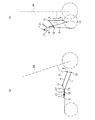
次に、本発明の実施形態に係る折畳車両を折畳む手順について図8から図12を参照して説明する。
図8は本発明の実施形態に係る折畳車両の展開(運転可能)状態の各種フレーム、リンクレバー、ロックハンドルなどの位置関係を説明するための図である。
Next, a procedure for folding the folding vehicle according to the embodiment of the present invention will be described with reference to FIGS. 8 to 12.
FIG. 8 is a view for explaining the positional relationship of various frames, link levers, lock handles, and the like in the unfolded (operable) state of the folded vehicle according to the embodiment of the present invention.
展開状態では位置決めピン16を位置決め溝15のうち下側の切欠溝15bに嵌合させて、折畳車両の展開状態で保持(ロック)されている。そして、ロックハンドル7は第6回転軸17によりフロントフレーム1の後端部に一体に連結されたシートポスト27に対して回動可能に軸支されている。展開(運転可能)状態ではロックハンドル7はリアフレーム2側に回動されて、リアフレーム2に近接して配置される。この位置にロックハンドル7を配置すると、図9に示すように、ロックハンドル7の下方に連設されたロックハンドル爪部14が第5回転軸12に係着される。ロックハンドル7はシートポスト27を介してフロントフレーム1に一体に連結されているため、第5回転軸12はフロントフレーム1に対しても固定されおり、第5回転軸12に接続されているリアフレーム2は第3回転軸13を軸心とするフロントフレーム1に対する回動が抑止される。そのため、前後方向に衝突などによる力が働いたとしても、運転時に折畳状態に形態変形してしまうといった不測事態を抑止することができる。折畳車両100は安定した展開(運転可能)状態を維持することができ安定した運転を実現することができるのである。
In the unfolded state, the
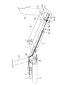
この状態から折畳状態に切換える際は、まず、図9に示すように、ロックハンドル7内に設けたロックレバー8を掴んで、ロックレバー8を後方に引張する。これにより、ロックレバー8に接続されたインナーケーブル33が後方に引張され、位置決めピン16が下側の切欠溝15bから離間して、フロントフレーム1のロック状態が解除され、フロントフレーム1はハンドルシャフトホルダー3に対して回動自在になる。
When switching from this state to the folded state, first, as shown in FIG. 9, the
次に、図10に示すように、ロックレバー8を掴んだ状態でロックハンドル7を、第6回転軸17を回転中心にリアフレーム2から離間する上方に回動させる。ロックハンドル7が上方に回動すると、ロックハンドル7の下方に連設されているロックハンドル爪部14も回動し、第5回転軸12から離れて、第5回転軸12および第5回転軸12に接続されているリアフレーム2は第3回転軸13を軸心とするフロントフレーム1に対する回動が可能になる。これにより、折畳車両100は折畳可能になる。
Next, as shown in FIG. 10, in a state where the
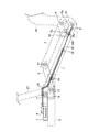
ロックレバー8を掴んだ状態でロックハンドル7とハンドルフレーム24、ハンドル25などとを近づけるようにすると、折畳車両100の自重とも相まって、図11に示すようにシートポスト27を介してフロントフレーム1の後端部がハンドルシャフトホルダー3に近づく方向に回動する。この状態ではフロントフレーム1の位置決めピン16が上・下側の切欠溝15a・15bを繋ぐ誘導孔15cに位置しており、位置決めピン16はフロントフレーム1の回動に伴い、下側の切欠溝15bの位置から上側の切欠溝15aの位置へ誘導孔15cを通って移動する。図11に示すように、フロントフレーム1の回動により、リアフレーム2、第1リンクレバー4、および第2リンクレバー5も、それぞれに連結された回転軸によりハンドルシャフトホルダー3に近づく方向に回動移動する。
When the lock handle 7 is brought close to the
図12に示すように、さらに回転すると、フロントフレーム1の位置決めピン16が誘導孔15cの上側の切欠溝15a側の端面に当接し、フロントフレーム1の回動が抑止される。フロントフレーム1の回動が抑止された状態で、ロックレバー8を放すと、フロントフレーム1の位置決めピン16が上側の切欠溝15aに嵌合される。位置決めピン16は上記のように引っ張りバネ31の付勢力によりこの位置に保持されているため、フロントフレーム1がこの折畳状態の位置でロックされる。フロントフレーム1の回動により、リアフレーム2、第1リンクレバー4、および第2リンクレバー5も、それぞれに連結された回転軸により、さらにハンドルシャフトホルダー3に近づく方向に回動するため、折畳車両100は図1(b)、図4、および図12のように折畳状態になり、上記説明したロック機構L1によりこの状態が保持される。
As shown in FIG. 12, when it is further rotated, the
折畳車両100を折畳状態から展開(運転可能)状態に切換える場合は、上記と逆に手順で操作する。すなわち、ロックレバー8を掴んでロックレバー8を引張すると、フロントフレーム1のロックは解除される。そして、ロックレバー8を掴んだ状態でロックハンドルをハンドル25やハンドルフレーム24とともに下方に押し下げるとフロントフレーム1はハンドルシャフトホルダー3に対して離間する方向に回動し、それと共に、他のフレームやリンクレバーも回動し、折畳車両100は展開状態になる。そして、ロックレバー8を放すことにより、フロントフレーム1はロックされ、展開(運転可能)状態が保持されるのである。
When the folded
上記のように、本実施形態では、折畳車両100の折畳操作および展開操作はフロントフレーム1に一体に連結されたシートポスト27に回動可能に固着されたロックハンドル7により行うことが可能である。ロックハンドル7はフロントフレーム1の回動の軸心となる第1回転軸10から離れた位置にあるため、回動に対して大きなモーメントが得られ、比較的弱い力であっても、折畳操作および展開操作が可能になる。そのため、お年寄りや女性など比較的力が弱い人も楽に本実施形態にかかる折畳車両100の折畳みと展開の操作ができる。
As described above, in the present embodiment, the folding operation and the unfolding operation of the
また、後輪21、21にインラインモーター18、18を配置し、リアフレーム2の背面部にモータ駆動制御ユニット30に配置したことにより、折畳状態で起立させたときに重心が下方に移動し、折畳車両100は折畳状態で安定的に起立状態が維持できる。
Further, the
さらに、折畳状態において、第3回転軸13が後輪21、21の回転軸より外方に位置する構成であることにより、リアフレーム2自体に回動を規制するロックがなくても、折畳状態において、後輪21、21が前輪20に向かって付勢される力が働き、折畳状態を維持することができる。折畳状態で後輪21、21が前輪20を離れて広がってしまうことを抑止することが可能になる。
Furthermore, since the
そして、折畳状態で折畳車両100を移動させる際は、ロックハンドル7を手で持って手前に引いて引っ張る姿勢を採ることが好ましい。これにより、前輪20が地面から離れた状態で後輪21、21により折畳車両100が支えられる姿勢となる。後輪の後方回転により、キャリーバッグを運ぶような要領で、ロックハンドル7を掴んで楽に移動することができる。
よって、いろんな場所に移動して、折畳車両100が利用可能になるのである。
When moving the
Therefore, it moves to various places and the
ここで、引っ張りバネ31は付勢部材の一例であり、上側の切欠溝15aおよび下側の切欠溝15bは切欠溝の一例である。
Here, the
次に、本発明の実施形態に係る折畳車両の展開(運転可能)状態における車幅切り替えについて図13から図18を参照して説明する。折畳車両100は、図13に示す車幅拡大状態又は図14に示す車幅縮小状態の2段階に切り替えることができる。そのために、リアフレーム2は、図13及び図14に示すように、複数のアーム部材からなるリンク構造で構成される。更に、そのリンク構造は、複数のロックピン及び複数のステー部材で保持・補強される。
Next, vehicle width switching in the unfolded (operable) state of the folded vehicle according to the embodiment of the present invention will be described with reference to FIGS. 13 to 18. The
リアフレーム2は、一対のフレーム2C、2Cを有する。一対のフレーム2C、2Cは、第1アーム部材101、第2アーム部材102、及び第3アーム部材103を有する。第1アーム部材101は、角パイプ材から作られる。第2アーム部材102及び第3アーム部材103は、チャンネル材から作られる。第3アーム部材103には、インラインモーター18及び後輪21が取り付けられる。
The
第1アーム部材101の後端部は、第2アーム部材102の前端部に第1ピポット軸P1を介して接合される。その接合では、図15に示すように、第1アーム部材101の後端部が第2アーム部材102の前端部に内挿された状態で、第1ピポット軸P1が第1アーム部材101の後端部及び第2アーム部材102の前端部に軸装される。これにより、第2アーム部材102は、第1ピポット軸P1を介して第1アーム部材101に回動可能に取り付けられる。尚、第1ピポット軸P1は、ボルトB1及びナットN1等で構成される。また、符号H3は、後述する第3固定穴H3である。
The rear end portion of the
第2アーム部材102の後端部は、第3アーム部材103の前端部に第2ピポット軸P2を介して接合される。その接合では、図16に示すように、第2アーム部材102の後端部が第3アーム部材103の前端部に内挿された状態で、第2ピポット軸P2が第2アーム部材102の後端部及び第3アーム部材103の前端部に軸装される。これにより、第3アーム部材103は、第2ピポット軸P2を介して第2アーム部材102に回動可能に取り付けられる。尚、第2ピポット軸P2は、ボルトB2及びナットN2等で構成される。
The rear end portion of the
一対のフレーム2C、2C間では、第1アーム部材101、101の上端部同士が第3回転軸13を介して接合され、第1アーム部材101、101の後端部同士が第4アーム部材104を介して接合される。これにより、第1アーム部材101、101及び第4アーム部材104が固定される。尚、第4アーム部材104は、第1アーム部材101と同様にして、角パイプ材から作られる。
Between the pair of frames 2C, 2C, the upper end portions of the
更に、一対のフレーム2C、2C間では、第5アーム部材105の両端部が、第2ピポット軸P2を介して、第2アーム部材102の後端部及び第3アーム部材103の前端部に接合される。その接合では、図16に示すように、第5アーム部材105の一端部が第2アーム部材102の後端部に内挿されると共に、第2アーム部材102の後端部が第3アーム部材103の前端部に内挿された状態で、第2ピポット軸P2が第5アーム部材105の一端部、第2アーム部材102の後端部、及び第3アーム部材103の前端部に軸装される。これにより、第3アーム部材103及び第5アーム部材105は、第2ピポット軸P2を介して第2アーム部材102に回動可能に取り付けられる。
Further, between the pair of frames 2C, 2C, both ends of the
第5アーム部材105は、チャンネル材から作られ、第6アーム部材106及び第7アーム部107から構成される。第6アーム部材106及び第7アーム部107は、一対のフレーム2C、2C間の中央にて、第3ピポット軸P3を介して接合される。更に、第1ステー部材108が、第6アーム部材106の後側(図視下側)及び第7アーム部107の後側(図視下側)に沿って、第6アーム部材106及び第7アーム部107に第3ピポット軸P3を介して取り付けられる。第1ステー部材108は、第3ピポット軸P3基準の図視左右で均等な長さにあり、チャンネル材から作られる。
The
第3ピポット軸P3では、図17に示すように、第6アーム部材106の一端部が第7アーム部107の一端部に内挿されると共に、第7アーム部107の一端部が第1ステー部材108に内挿された状態にある。つまり、第3ピポット軸P3は、そのような内挿状態で、第6アーム部材106の一端部、第7アーム部107の一端部、及び第1ステー部材108の中央部に軸装される。これにより、第6アーム部材106、第7アーム部107、及び第1ステー部材108は、第3ピポット軸P3を介して互いに回動可能に取り付けられる。更に、第7アーム部107の一端部では、第1ステー部材108側の側面が切欠され、第1ステー部材108との間にスペースが設けられる。これにより、第1ステー部材108が図視左側に移動される際に、第6アーム部材106及び/又は第7アーム部107が引っ掛かることがない。尚、第3ピポット軸P3は、ボルトB3及びナットN3等で構成される。
On the third pivot axis P3, as shown in FIG. 17, one end of the
第3ピポット軸P3と第2ピポット軸P2の間では、第2ステー部材109の前端部が、第5アーム部材105(第6アーム部材106又は第7アーム部107)に第4ピポット軸P4を介して接合される。これにより、第2ステー部材109は、第4ピポット軸P4を介して第5アーム部材105(第6アーム部材106又は第7アーム部107)に回動可能に取り付けられる。尚、第4ピポット軸P4は、図示しないが、各ピポット軸P1、P2、P3と同様にして、ボルト及びナット等で構成される。
Between the third pivot axis P3 and the second pivot axis P2, the front end portion of the
第1アーム部材101の後端部には、第1固定穴H1が貫設される。第2アーム部材102の前端部には、第2固定穴H2が貫設される。更に、第2アーム部材102の前端部では、第4アーム部材104側に設けられた突端部分に第3固定穴H3が貫設される。第4アーム部材104の両端部には、第4固定穴H4が貫設される。第1固定穴H1、第2固定穴H2、第3固定穴H3、及び第4固定穴H4は、第1ピポット軸P1を中心とした同一円上に位置する。
At the rear end of the
第3アーム部材103の長手方向中央部には、第5固定穴H5が貫設される。第3アーム部材103の後端部には、第6固定穴H6が貫設される。更に、第3アーム部材103の後端部では、インラインモーター18側に設けられた突端部分に第7固定穴H7が貫設される。第5アーム部材105(第6アーム部材106及び第7アーム部107)には、第4ピポット軸P4より第3ピポット軸P3側の近傍に第8固定穴H8が貫設される。
A fifth fixing hole H5 is provided in a longitudinally central portion of the
尚、図示はしないが、第1ステー部材108の両端部に、第1ステー部材用固定穴が貫設される。更に、第2ステー部材109の後端部に第2ステー部材用固定穴が貫設される。
Although not shown, fixing holes for the first stay member are provided at both ends of the
図13の車幅拡大状態又は図14の車幅縮小状態が保持されるために、第1ロックピンF1、第2ロックピンF2、及び第3ロックピンF3が使用される。 The first lock pin F1, the second lock pin F2, and the third lock pin F3 are used to maintain the vehicle width expansion state of FIG. 13 or the vehicle width reduction state of FIG.
図13の車幅拡大状態では、第1ロックピンF1は、第1アーム部材101の第1固定穴H1及び第2アーム部材102の第2固定穴H2に嵌挿される。第2ロックピンF2は、第1ステー部材108の第1ステー部材用固定穴及び第5アーム部材105(第6アーム部材106及び第7アーム部107)の第8固定穴H8に挿入される。第3ロックピンF3は、第3アーム部材103の第5固定穴H5及び第2ステー部材109の第2ステー部材用固定穴に挿入される。
In the vehicle width expansion state of FIG. 13, the first lock pin F1 is inserted into the first fixing hole H1 of the
図18に示すように、第1ロックピンF1は、シャフト部FB1及びボールロック部FB2で構成される。ボールロック部FB2は、シャフト部FB1の先端部に設けられ、シャフト部FB1から容易に出し入れされる。第1ロックピンF1では、シャフト部FB1が第1アーム部材101の第1固定穴H1及び第2アーム部材102の第2固定穴H2に嵌挿された後に、ボールロック部FB2がシャフト部FB1から突出される。これにより、第1ロックピンF1は、第1アーム部材101(、その第1アーム部材101に固定された第4アーム部材104、)及び第2アーム部材102を車幅拡大状態で固定する。
As shown in FIG. 18, the first lock pin F1 is composed of a shaft portion FB1 and a ball lock portion FB2. The ball lock portion FB2 is provided at the tip of the shaft portion FB1 and can be easily taken in and out of the shaft portion FB1. In the first lock pin F1, after the shaft portion FB1 is inserted into the first fixed hole H1 of the
このような固定構造は、図示はしないが、第2ロックピンF2及び第3ロックピンF3でも同じである。第2ロックピンF2は、第1ステー部材108及び第5アーム部材105(第6アーム部材106及び第7アーム部107)を車幅拡大状態で固定する。第3ロックピンF3は、第3アーム部材103及び第2ステー部材109を車幅拡大状態で固定する。
Although not shown, such a fixing structure is the same for the second lock pin F2 and the third lock pin F3. The second lock pin F2 fixes the
更に、第2ロックピンF2及び第3ロックピンF3は、第1ステー部材108及び第2ステー部材109を車幅拡大状態で固定することにより、車幅拡大状態での剛性を大きく確保する。
Furthermore, the second lock pin F2 and the third lock pin F3 secure a large rigidity in the vehicle width expansion state by fixing the
図14の車幅縮小状態では、第1ロックピンF1は、第2アーム部材102の第3固定穴H3及び第4アーム部材104の第4固定穴H4に嵌挿される。第2ロックピンF2は、第1ステー部材108の第1ステー部材用固定穴及び第3アーム部材103の第7固定穴H7に嵌挿される。第3ロックピンF3は、第3アーム部材103の第6固定穴H6及び第2ステー部材109の第2ステー部材用固定穴に挿入される。
In the vehicle width reduction state of FIG. 14, the first lock pin F1 is inserted into the third fixing hole H3 of the
これにより、第1ロックピンF1は、第4アーム部材104(、その第4アーム部材104に固定された第1アーム部材101、)及び第2アーム部材102を車幅縮小状態で固定する。第2ロックピンF2は、第1ステー部材108及び第3アーム部材103を車幅縮小状態で固定する。更に、第2ロックピンF2は、第2ピポット軸P2及び第3ピポット軸P3を介して第5アーム部材105(第6アーム部材106及び第7アーム部107)を車幅縮小状態で固定する。第3ロックピンF3は、第2ステー部材109を車幅縮小状態で固定する。
Thereby, the first lock pin F1 fixes the fourth arm member 104 (the
更に、第2ロックピンF2及び第3ロックピンF3は、第1ステー部材108及び第2ステー部材109を車幅縮小状態で固定することにより、車幅縮小状態での剛性を大きく確保する。
Furthermore, the second lock pin F2 and the third lock pin F3 secure a large rigidity in the reduced vehicle width state by fixing the
図13の車幅拡大状態から図14の車幅縮小状態に切り替えるには、先ず、第1ロックピンF1、第2ロックピンF2、及び第3ロックピンF3が引き抜かれる。引き続いて、第1ステー部材108が後方(図視下方)に移動されることにより、第5アーム部材105(第6アーム部材106及び第7アーム部107)が第3ピポット軸P3を頂点とした図視V字状にされる。更に、第3アーム部材103、103同士がインラインモーター18側に移動されることにより、第3アーム部材103、103同士の間隔が狭くなると共に、第2アーム部材102、102の後端部分同士の間隔が狭くなる。
In order to switch from the vehicle width expansion state of FIG. 13 to the vehicle width reduction state of FIG. 14, first, the first lock pin F1, the second lock pin F2, and the third lock pin F3 are pulled out. Subsequently, the fifth arm member 105 (the
そして、第1ステー部材108の第1ステー部材用固定穴と第3アーム部材103の第7固定穴H7が重ね合わされた状態にされ、第2ロックピンF2が、第1ステー部材108の第1ステー部材用固定穴及び第3アーム部材103の第7固定穴H7に嵌挿される。また、第2アーム部材102の第3固定穴H3と第4アーム部材104の第4固定穴H4が重ね合わされた状態にされ、第1ロックピンF1が、第2アーム部材102の第3固定穴H3及び第4アーム部材104の第4固定穴H4に嵌挿される。更に、第3アーム部材103の第6固定穴H6と第2ステー部材109の第2ステー部材用固定穴が重ね合わされた状態にされ、第3ロックピンF3が、第3アーム部材103の第6固定穴H6及び第2ステー部材109の第2ステー部材用固定穴に挿入される。
Then, the first stay member fixing hole of the
これにより、図13の車幅拡大状態から図14の車幅縮小状態に切り替えられ、図14の車幅縮小状態が保持・補強される。 As a result, the vehicle width reduction state of FIG. 13 is switched to the vehicle width reduction state of FIG. 14, and the vehicle width reduction state of FIG. 14 is held and reinforced.
一方、図14の車幅縮小状態から図13の車幅拡大状態に切り替えるには、先ず、第1ロックピンF1、第2ロックピンF2、及び第3ロックピンF3が引き抜かれる。引き続いて、第1ステー部材108が前方(図視上方)に移動されることにより、第5アーム部材105(第6アーム部材106及び第7アーム部107)が、図視左右方向を長手方向とすると共に第3ピポット軸P3をその長手方向の中央とした直線状にされる。更に、第3アーム部材103、103同士が後輪21側に移動されることにより、第3アーム部材103、103同士の間隔が広くなると共に、第2アーム部材102、102の後端部分同士の間隔が広くなる。
On the other hand, in order to switch from the vehicle width reduction state of FIG. 14 to the vehicle width expansion state of FIG. 13, first, the first lock pin F1, the second lock pin F2 and the third lock pin F3 are pulled out. Subsequently, as the
そして、第1ステー部材108の第1ステー部材用固定穴と第5アーム部材105(第6アーム部材106及び第7アーム部107)の第8固定穴H8が重ね合わされた状態にされ、第2ロックピンF2が、第1ステー部材108の第1ステー部材用固定穴及び第5アーム部材105(第6アーム部材106及び第7アーム部107)の第8固定穴H8に嵌挿される。また、第1アーム部材101の第1固定穴H1と第2アーム部材102の第2固定穴H2が重ね合わされた状態にされ、第1ロックピンF1が、第1アーム部材101の第1固定穴H1及び第2アーム部材102の第2固定穴H2に嵌挿される。更に、第3アーム部材103の第5固定穴H5と第2ステー部材109の第2ステー部材用固定穴が重ね合わされた状態にされ、第3ロックピンF3が、第3アーム部材103の第5固定穴H5及び第2ステー部材109の第2ステー部材用固定穴に嵌挿される。
Then, the first stay member fixing hole of the
これにより、図14の車幅縮小状態から図13の車幅拡大状態に切り替えられ、図13の車幅拡大状態が保持・補強される。 Thereby, the vehicle width reduction state of FIG. 14 is switched to the vehicle width expansion state of FIG. 13, and the vehicle width expansion state of FIG. 13 is held and reinforced.
このようにして、折畳車両100は、図13の車幅拡大状態又は図14の車幅縮小状態に切り替えられるので、使用状況に適した車幅(つまり、一対の後輪21、21の間隔)に変更される。
In this manner, the folded
例えば、都市部やイベント会場等では、平坦なスペースはあるけれども、歩行者等が多く混雑しているので、車幅(つまり、一対の後輪21、21の間隔)をなるべく狭くする必要がある場合が想定される。そのような場合には、折畳車両100は、図14の車幅縮小状態に切り替えられることにより、車幅(つまり、一対の後輪21、21の間隔)が最大限に狭められた状態で走行することができる。
For example, although there are flat spaces in urban areas and event venues, many pedestrians are crowded, so it is necessary to narrow the vehicle width (that is, the distance between the pair of
一方、郊外の起伏地等では、歩行者等は少ないけれども、安全性を確保するため、車幅(つまり、一対の後輪21、21の間隔)をなるべく広くする必要がある場合が想定される。そのような場合には、折畳車両100は、図13の車幅拡大状態に切り替えられることにより、車幅(つまり、一対の後輪21、21の間隔)が最大限に広げられた状態で走行することができる。
On the other hand, although there are few pedestrians, etc. in the suburbs, it is assumed that it is necessary to widen the vehicle width (that is, the distance between the pair of
従って、折畳車両100は、使用環境や走行条件等に合わせて、車幅(つまり、一対の後輪21、21の間隔)を変更できるので、利便性が高いモビリティである。
Therefore, since the width of the vehicle (that is, the distance between the pair of
折畳車両100では、車幅(つまり、一対の後輪21、21の間隔)が変更される際に、各ロックピンF1、F2、F3の挿脱、及び第1ステー部材108等の前方(図視上方)又は後方(図視下方)の移動等が行われることによって、リアフレーム2のリンク構造の形状がパンタグラフのように簡単に変更される。従って、折畳車両100は、車幅(つまり、一対の後輪21、21の間隔)の変更を短時間で且つ容易に行うことができる。
In the
以上、本発明の実施形態について詳述してきたが、これらはあくまでも例示であって、本発明はかかる実施形態における具体的な記載によって、何等、限定的に解釈されるものでなく、当業者の知識に基づいて種々なる変更、修正、改良等を加えた態様において実施され得るものであり、また、そのような実施態様が、本発明の趣旨を逸脱しない限り、何れも、本発明の範囲内に含まれるものであることが、理解されるべきである。 As mentioned above, although the embodiment of the present invention has been described in detail, these are merely examples, and the present invention is not construed as being limited in any way by the specific description in the embodiment, and those skilled in the art The present invention can be implemented in an embodiment to which various changes, modifications, improvements, etc. are added based on knowledge, and any such embodiment is within the scope of the present invention unless it deviates from the spirit of the present invention. It should be understood that it is included in
また、本実施形態では、ハンドル25の両サイドに設けられたブレーキレバーおよびブレートレバーとブレーキとの問の配線類、あるいはモータを駆動させるためのバッテリーや電源関係の配線等を省略しており、実施の際にはそれ等を適宜設定すればよいものである。
Further, in the present embodiment, the brake levers provided on both sides of the
また、上記実施形態では、切欠溝として上側の切欠溝15aと下側の切欠溝15bとの2つを備えているが、切欠溝は2つに限定されるものでななく、3つ以上備えてもよい。いろんな角度でロックが可能になるため、例えば、本実施形態の折畳状態よりも開いた状態で保持すれば、前輪と後輪の距離を大きくなり、より安定的に起立状態が維持され、起立状態で放置しておいても安心である。
Moreover, in the said embodiment, although two are provided with the
また、上記実施形態では、前輪を1つとしたが、これも2つ以上あってもよいし、後輪についても、2つに限定されず、3つ以上あってもよい。増やすことにより、より安定的に運転が可能になる。 In the above embodiment, one front wheel is used. However, two or more front wheels may be provided, and the number of rear wheels is not limited to two, and may be three or more. By increasing the number, more stable operation becomes possible.
また、上記実施形態では、シートポスト27に連結したロックハンドル7のロックレバー8により、ロック/ロック解除したが、これに限定するものではない。
Further, in the above embodiment, the lock / unlock is performed by the
1・・フロントフレーム
2・・リアフレーム
3・・ハンドルシャフトホルダー
4・・第1リンクレバー
5、5・・第2リンクレバー
6・・シート
7・・ロックハンドル
8・・ロックレバー
9・・第2回転軸
10・・第1回転軸
11・・第4回転軸
12・・第5回転軸
13・・第3回転軸
14・・ロックハンドル爪部
15、15・・誘導孔および位置決め溝
16・・位置決めピン
17・・第6回転軸
18、18・・インラインモーター
19、19・・フットレフト
20・・前輪
21、21・・後輪
22・・シートロックレバー
23・・前輪支持フレーム
24・・ハンドルフレーム
25・・ハンドル
26・・シート支持フレーム
27・・シートポスト
29、29・・後輪フレーム
30・・モータ駆動制御ユニット
31・・引っ張りバネ
32・・アウターケーブル固定ピン
33・・インナーケーブル
35・・アウターケーブル
100・・折畳車両
1 · · ·
Claims (12)
上端部にハンドルが取り付けられるとともに下端部に前輪が取り付けられるハンドルフレームと、
前記ハンドルフレームを回動可能に支持するハンドルシャフトホルダーと、
第1最前端部が前記ハンドルシャフトホルダーと第1回転軸で軸支され、前記ハンドルシャフトホルダーに対して回動可能とされるフロントフレームと、
前端部が前記ハンドルシャフトホルダーと前記第1回転軸の上方にある第2回転軸で軸支され、前記ハンドルシャフトホルダーに対して回動可能とされる第1リンクレバーと、
後部側に後輪が取り付けられており、第2最前端部が前記フロントフレームの後端部と第3回転軸で軸支され、前記フロントフレームに対して回動可能とされるリアフレームと、
前端部が前記第1リンクレバーの後端部と第4回転軸で軸支され、後端部が前記リアフレームの前記第2最前端部より後方の第2次前端部と第5回転軸で軸支され、前記第1リンクレバーおよび前記リアフレームに対して回動可能とされる第2リンクレバーとを備え、
前記第3回転軸を軸として回動し前記フロントフレームの前端部と前記リアフレームの後端部とを逆V字状に近接させると共に、前記第1回転軸を軸として回動し前記フロントフレームの後端部と前記ハンドルシャフトホルダーとをV字状に近接させることにより折畳状態とすることを特徴とする折畳車両。 A foldable vehicle capable of switching between a deployable state capable of being carried and a folded state for storage and conveyance,
A handle frame having a handle attached to the upper end and a front wheel attached to the lower end;
A handle shaft holder rotatably supporting the handle frame;
A front frame pivotally supported relative to the handle shaft holder by a first front end portion pivotally supported on the handle shaft holder by a first rotation shaft;
A front end portion is pivotally supported by the handle shaft holder and a second rotation shaft above the first rotation shaft, and a first link lever that is rotatable relative to the handle shaft holder;
A rear frame having a rear wheel attached to the rear side, a second front end portion pivotally supported by a rear end portion of the front frame and a third rotation shaft, and rotatable relative to the front frame;
The front end portion is pivotally supported by the rear end portion of the first link lever and the fourth rotation shaft, and the rear end portion is formed by the second front end portion rearward of the second front end portion of the rear frame and the fifth rotation shaft A second link lever pivotally supported relative to the first link lever and the rear frame;
The third frame is rotated about an axis to move the front end of the front frame and the rear end of the rear frame in an inverted V shape, and the first frame is rotated about an axis to rotate the front frame A folded vehicle is characterized in that the rear end portion of the handle and the handle shaft holder are brought close to each other in a V-shape.
前記ハンドルシャフトホルダーは、前記ハンドルシャフトホルダーに対する前記フロントフレームの回動に応じて前記位置決めピンが誘導される誘導孔と、
前記誘導孔の端部にあって、展開状態と折畳状態との各々の状態において前記位置決めピンが嵌合する切欠溝とを備えることを特徴とする請求項1に記載の折畳車両。 The front frame is provided with a positioning pin at a first primary front end behind the first front end.
The handle shaft holder has a guide hole through which the positioning pin is guided in response to rotation of the front frame with respect to the handle shaft holder.
The folding vehicle according to claim 1, further comprising: a notch groove at an end portion of the guide hole, in which the positioning pin is fitted in each of a deployed state and a folded state.
前記ロックハンドルによる操作を前記位置決めピンに伝達するインナーケーブルとを備えることを特徴とする請求項2乃至5の何れか1項に記載の折畳車両。 A lock handle that operates the positioning pin in engagement with the notch groove and away from the notch groove;
The inner cable which transmits operation by the said lock handle to the said positioning pin is provided, The folding vehicle in any one of the Claims 2 thru | or 5 characterized by the above-mentioned.
前記位置決めピンを前記切欠溝への嵌合と前記切欠溝からの離間とで稼働させるロックハンドルと、
前記ロックハンドルによる操作を前記位置決めピンに伝達するインナーケーブルとを備え、
前記ロックハンドルは、
枠状本体と、
前記枠状本体に囲まれるように設けられ、前記枠状本体と共に握りしめることにより前記枠状本体に引き寄せられるロックレバーとを備え、
前記ロックレバーを前記枠状本体の側に引き寄せることにより、前記インナーケーブルを介して前記位置決めピンが前記付勢部材による付勢力に抗して引張され、前記位置決めピンが前記切欠溝から離間することを特徴とする請求項2乃至4の何れか1項に記載の折畳車両。 A biasing member for biasing the positioning pin in the direction of the notch groove;
A lock handle that operates the positioning pin in engagement with the notch groove and away from the notch groove;
And an inner cable for transmitting the operation by the lock handle to the positioning pin,
The lock handle is
Frame-like body,
And a lock lever which is provided so as to be surrounded by the frame-like main body, and is pulled toward the frame-like main body by squeezing together with the frame-like main body ;
By pulling the lock lever toward the frame-like main body , the positioning pin is pulled against the biasing force of the biasing member via the inner cable, and the positioning pin separates from the notch groove. The folding vehicle according to any one of claims 2 to 4 , characterized by
前記ロックハンドルは、展開状態において前記シートポストに対する前記リアフレームの回動を規制するロックハンドル爪部を備えることを特徴とする請求項6又は7に記載の折畳車両。 The seat is attached to the upper end portion and the lock handle is rotatably attached to the lower end portion, and the seat handle is integrally coupled to the front frame,
The foldable vehicle according to claim 6 or 7 , wherein the lock handle includes a lock handle claw portion that restricts rotation of the rear frame with respect to the seatpost in a deployed state.
該一対の側板の間に前記フロントフレームの第1最前端部および前記第1リンクレバーの前端部を挿入し、
前記ハンドルシャフトホルダーと前記フロントフレームの第1最前端部および前記第1リンクレバーの前端部とが、それぞれ前記第1回転軸および前記第2回転軸で軸支されることを特徴とする請求項1乃至8の何れか1項に記載の折畳車両。 The handle shaft holder comprises a pair of side plates in parallel relation to each other,
Inserting the first front end of the front frame and the front end of the first link lever between the pair of side plates;
The handle shaft holder, and the first front end of the front frame and the front end of the first link lever are supported by the first rotation shaft and the second rotation shaft, respectively. The folded vehicle according to any one of 1 to 8.
該一対のフレームの間に前記フロントフレームの後端部を挿入し、
前記リアフレームの第2最前端部と前記フロントフレームの後端部とが前記第3回転軸で軸支されることを特徴とする請求項1乃至9の何れか1項に記載の折畳車両。 At least the second foremost end of the rear frame comprises a pair of frames in parallel relationship with one another,
Inserting the rear end of the front frame between the pair of frames;
The folding vehicle according to any one of claims 1 to 9, wherein a second front end of the rear frame and a rear end of the front frame are supported by the third rotation shaft. .
該一対のレバーの前端部の間に前記第1リンクレバーの後端部を挿入し、
前記第2リンクレバーの前端部と前記第1リンクレバーの後端部とが前記第4回転軸で軸支され、
前記第2リンクレバーの前記一対のレバーの後端部の間に前記リアフレームの第2次前端部を挟んで、
前記第2リンクレバーの後端部と前記リアフレームの第2次前端部とが前記第5回転軸で軸支されることを特徴とする請求項1乃至10の何れか1項に記載の折畳車両。 The second link lever comprises a pair of levers in parallel relation to each other,
Inserting the rear end of the first link lever between the front ends of the pair of levers;
The front end of the second link lever and the rear end of the first link lever are pivotally supported by the fourth rotation shaft,
The second front end of the rear frame is interposed between the rear ends of the pair of levers of the second link lever,
The fold according to any one of claims 1 to 10, wherein a rear end portion of the second link lever and a secondary front end portion of the rear frame are pivotally supported by the fifth rotation shaft. Tatami vehicles.
Applications Claiming Priority (2)
| Application Number | Priority Date | Filing Date | Title |
|---|---|---|---|
| JP2015231548 | 2015-11-27 | ||
| JP2015231548 | 2015-11-27 |
Publications (2)
| Publication Number | Publication Date |
|---|---|
| JP2017105417A JP2017105417A (en) | 2017-06-15 |
| JP6546103B2 true JP6546103B2 (en) | 2019-07-17 |
Family
ID=59060441
Family Applications (1)
| Application Number | Title | Priority Date | Filing Date |
|---|---|---|---|
| JP2016014262A Active JP6546103B2 (en) | 2015-11-27 | 2016-01-28 | Folding vehicle |
Country Status (1)
| Country | Link |
|---|---|
| JP (1) | JP6546103B2 (en) |
Families Citing this family (2)
| Publication number | Priority date | Publication date | Assignee | Title |
|---|---|---|---|---|
| CN108860422B (en) * | 2018-08-21 | 2023-05-30 | 浙江阿尔郎科技有限公司 | Folding mechanism convenient to control and electric vehicle |
| CN114348158B (en) * | 2021-12-31 | 2023-05-30 | 浙江联宜电机有限公司 | Scooter |
Family Cites Families (7)
| Publication number | Priority date | Publication date | Assignee | Title |
|---|---|---|---|---|
| JPS5610613Y2 (en) * | 1978-10-02 | 1981-03-10 | ||
| SE8603880D0 (en) * | 1986-09-16 | 1986-09-16 | Sven Hellestam | BIKE WITH HOPPABLE FRAME |
| DE4311998C2 (en) * | 1993-04-13 | 1996-12-12 | Vinzens Schulte | Collapsible bike frame |
| JPH076078U (en) * | 1993-06-25 | 1995-01-27 | 株式会社大金製作所 | Bicycle pedal coupling device |
| JPH10291488A (en) * | 1997-04-21 | 1998-11-04 | Kanto Auto Works Ltd | Lock device for folding bicycle |
| US6206387B1 (en) * | 1998-12-30 | 2001-03-27 | Shui-Te Tsai | Collapsible skateboard |
| JP2006111222A (en) * | 2004-10-18 | 2006-04-27 | Nonaka Seisakusho:Kk | Tricycle |
-
2016
- 2016-01-28 JP JP2016014262A patent/JP6546103B2/en active Active
Also Published As
| Publication number | Publication date |
|---|---|
| JP2017105417A (en) | 2017-06-15 |
Similar Documents
| Publication | Publication Date | Title |
|---|---|---|
| JP3234584U (en) | Folding stroller | |
| CN101903232B (en) | An improved pushchair frame | |
| TWI379653B (en) | Folding baby stroller | |
| RU2475399C2 (en) | Baby carriage | |
| US6533311B2 (en) | Baby carriage | |
| JP2020521669A (en) | stroller | |
| JP5436911B2 (en) | stroller | |
| US10501141B2 (en) | Folding tricycle | |
| US9227649B2 (en) | Jogging stroller frame with a folding mechanism for automatically flattening wheels | |
| CN104129417B (en) | Folding traveling baby's vehicle bolt and wheel detent mechanism | |
| WO2007071141A1 (en) | A pushcart for infants | |
| WO2010075715A1 (en) | Bidirectional foldable trolley | |
| JP6546103B2 (en) | Folding vehicle | |
| WO2017008411A1 (en) | Folding mechanism and foldable vehicle | |
| JP5020655B2 (en) | stroller | |
| CN110723191A (en) | Folding children's barrow | |
| JP6514096B2 (en) | Folding vehicle | |
| CN206067841U (en) | Children trolley | |
| US20210129886A1 (en) | Foldable Stroller | |
| KR20110015088A (en) | Multi conver tible folding bicycle | |
| CN110937055A (en) | Folding baby carriage | |
| CN210822419U (en) | Baby carriage with foldable seat | |
| JP6391057B2 (en) | Folding bicycle, folding mechanism for folding bicycle and dual arm type crank | |
| CN110294008B (en) | Baby carriage | |
| JP3122139U (en) | Folding storage mechanism for driving assistance vehicles |
Legal Events
| Date | Code | Title | Description |
|---|---|---|---|
| A621 | Written request for application examination |
Free format text: JAPANESE INTERMEDIATE CODE: A621 Effective date: 20171215 |
|
| A977 | Report on retrieval |
Free format text: JAPANESE INTERMEDIATE CODE: A971007 Effective date: 20181116 |
|
| A131 | Notification of reasons for refusal |
Free format text: JAPANESE INTERMEDIATE CODE: A131 Effective date: 20181127 |
|
| A521 | Request for written amendment filed |
Free format text: JAPANESE INTERMEDIATE CODE: A523 Effective date: 20181214 |
|
| TRDD | Decision of grant or rejection written | ||
| A01 | Written decision to grant a patent or to grant a registration (utility model) |
Free format text: JAPANESE INTERMEDIATE CODE: A01 Effective date: 20190528 |
|
| A61 | First payment of annual fees (during grant procedure) |
Free format text: JAPANESE INTERMEDIATE CODE: A61 Effective date: 20190620 |
|
| R150 | Certificate of patent or registration of utility model |
Ref document number: 6546103 Country of ref document: JP Free format text: JAPANESE INTERMEDIATE CODE: R150 |
|
| R250 | Receipt of annual fees |
Free format text: JAPANESE INTERMEDIATE CODE: R250 |
|
| R250 | Receipt of annual fees |
Free format text: JAPANESE INTERMEDIATE CODE: R250 |