JP6545190B2 - Photoacoustic apparatus, signal processing apparatus, signal processing method, program - Google Patents
Photoacoustic apparatus, signal processing apparatus, signal processing method, program Download PDFInfo
- Publication number
- JP6545190B2 JP6545190B2 JP2016564286A JP2016564286A JP6545190B2 JP 6545190 B2 JP6545190 B2 JP 6545190B2 JP 2016564286 A JP2016564286 A JP 2016564286A JP 2016564286 A JP2016564286 A JP 2016564286A JP 6545190 B2 JP6545190 B2 JP 6545190B2
- Authority
- JP
- Japan
- Prior art keywords
- support
- transducers
- subject
- received signal
- weight
- Prior art date
- Legal status (The legal status is an assumption and is not a legal conclusion. Google has not performed a legal analysis and makes no representation as to the accuracy of the status listed.)
- Expired - Fee Related
Links
- 238000012545 processing Methods 0.000 title claims description 47
- 238000003672 processing method Methods 0.000 title claims 4
- 230000015654 memory Effects 0.000 claims description 33
- 238000005259 measurement Methods 0.000 claims description 12
- 230000006870 function Effects 0.000 claims description 10
- 230000001678 irradiating effect Effects 0.000 claims description 4
- 230000007423 decrease Effects 0.000 claims description 3
- 238000013459 approach Methods 0.000 claims 4
- 230000035945 sensitivity Effects 0.000 description 42
- 239000000523 sample Substances 0.000 description 26
- 238000000034 method Methods 0.000 description 19
- 230000008569 process Effects 0.000 description 11
- 230000003287 optical effect Effects 0.000 description 10
- 230000007246 mechanism Effects 0.000 description 8
- 238000004364 calculation method Methods 0.000 description 5
- 230000008859 change Effects 0.000 description 5
- 238000003384 imaging method Methods 0.000 description 5
- 238000003860 storage Methods 0.000 description 5
- 239000000463 material Substances 0.000 description 4
- 239000007787 solid Substances 0.000 description 4
- 238000012935 Averaging Methods 0.000 description 3
- 238000005520 cutting process Methods 0.000 description 3
- 238000010586 diagram Methods 0.000 description 3
- 230000006872 improvement Effects 0.000 description 3
- INGWEZCOABYORO-UHFFFAOYSA-N 2-(furan-2-yl)-7-methyl-1h-1,8-naphthyridin-4-one Chemical compound N=1C2=NC(C)=CC=C2C(O)=CC=1C1=CC=CO1 INGWEZCOABYORO-UHFFFAOYSA-N 0.000 description 2
- 108010054147 Hemoglobins Proteins 0.000 description 2
- 102000001554 Hemoglobins Human genes 0.000 description 2
- 108010064719 Oxyhemoglobins Proteins 0.000 description 2
- 239000002033 PVDF binder Substances 0.000 description 2
- 238000010521 absorption reaction Methods 0.000 description 2
- 238000002591 computed tomography Methods 0.000 description 2
- 108010002255 deoxyhemoglobin Proteins 0.000 description 2
- 229910052451 lead zirconate titanate Inorganic materials 0.000 description 2
- 230000004048 modification Effects 0.000 description 2
- 238000012986 modification Methods 0.000 description 2
- 239000013307 optical fiber Substances 0.000 description 2
- 230000010355 oscillation Effects 0.000 description 2
- 238000010895 photoacoustic effect Methods 0.000 description 2
- 229920002981 polyvinylidene fluoride Polymers 0.000 description 2
- 238000012552 review Methods 0.000 description 2
- 239000000126 substance Substances 0.000 description 2
- QVGXLLKOCUKJST-UHFFFAOYSA-N atomic oxygen Chemical compound [O] QVGXLLKOCUKJST-UHFFFAOYSA-N 0.000 description 1
- 230000008901 benefit Effects 0.000 description 1
- 210000004204 blood vessel Anatomy 0.000 description 1
- 210000000481 breast Anatomy 0.000 description 1
- 229910010293 ceramic material Inorganic materials 0.000 description 1
- 230000003247 decreasing effect Effects 0.000 description 1
- 238000001514 detection method Methods 0.000 description 1
- 238000009792 diffusion process Methods 0.000 description 1
- 238000006073 displacement reaction Methods 0.000 description 1
- 238000009826 distribution Methods 0.000 description 1
- 230000005284 excitation Effects 0.000 description 1
- 239000010408 film Substances 0.000 description 1
- 239000007789 gas Substances 0.000 description 1
- 229920000126 latex Polymers 0.000 description 1
- HFGPZNIAWCZYJU-UHFFFAOYSA-N lead zirconate titanate Chemical compound [O-2].[O-2].[O-2].[O-2].[O-2].[Ti+4].[Zr+4].[Pb+2] HFGPZNIAWCZYJU-UHFFFAOYSA-N 0.000 description 1
- 230000031700 light absorption Effects 0.000 description 1
- 239000004973 liquid crystal related substance Substances 0.000 description 1
- 230000014759 maintenance of location Effects 0.000 description 1
- 239000007769 metal material Substances 0.000 description 1
- 239000001301 oxygen Substances 0.000 description 1
- 229910052760 oxygen Inorganic materials 0.000 description 1
- 239000004065 semiconductor Substances 0.000 description 1
- 229920003002 synthetic resin Polymers 0.000 description 1
- 239000000057 synthetic resin Substances 0.000 description 1
- 238000012360 testing method Methods 0.000 description 1
- 239000010409 thin film Substances 0.000 description 1
- 238000002834 transmittance Methods 0.000 description 1
Images


Classifications
-
- A—HUMAN NECESSITIES
- A61—MEDICAL OR VETERINARY SCIENCE; HYGIENE
- A61B—DIAGNOSIS; SURGERY; IDENTIFICATION
- A61B5/00—Measuring for diagnostic purposes; Identification of persons
- A61B5/0093—Detecting, measuring or recording by applying one single type of energy and measuring its conversion into another type of energy
- A61B5/0095—Detecting, measuring or recording by applying one single type of energy and measuring its conversion into another type of energy by applying light and detecting acoustic waves, i.e. photoacoustic measurements
-
- G—PHYSICS
- G01—MEASURING; TESTING
- G01N—INVESTIGATING OR ANALYSING MATERIALS BY DETERMINING THEIR CHEMICAL OR PHYSICAL PROPERTIES
- G01N21/00—Investigating or analysing materials by the use of optical means, i.e. using sub-millimetre waves, infrared, visible or ultraviolet light
- G01N21/17—Systems in which incident light is modified in accordance with the properties of the material investigated
- G01N21/1702—Systems in which incident light is modified in accordance with the properties of the material investigated with opto-acoustic detection, e.g. for gases or analysing solids
-
- G—PHYSICS
- G01—MEASURING; TESTING
- G01N—INVESTIGATING OR ANALYSING MATERIALS BY DETERMINING THEIR CHEMICAL OR PHYSICAL PROPERTIES
- G01N29/00—Investigating or analysing materials by the use of ultrasonic, sonic or infrasonic waves; Visualisation of the interior of objects by transmitting ultrasonic or sonic waves through the object
- G01N29/22—Details, e.g. general constructional or apparatus details
- G01N29/24—Probes
- G01N29/2418—Probes using optoacoustic interaction with the material, e.g. laser radiation, photoacoustics
-
- G—PHYSICS
- G01—MEASURING; TESTING
- G01N—INVESTIGATING OR ANALYSING MATERIALS BY DETERMINING THEIR CHEMICAL OR PHYSICAL PROPERTIES
- G01N21/00—Investigating or analysing materials by the use of optical means, i.e. using sub-millimetre waves, infrared, visible or ultraviolet light
- G01N21/17—Systems in which incident light is modified in accordance with the properties of the material investigated
- G01N21/1702—Systems in which incident light is modified in accordance with the properties of the material investigated with opto-acoustic detection, e.g. for gases or analysing solids
- G01N2021/1706—Systems in which incident light is modified in accordance with the properties of the material investigated with opto-acoustic detection, e.g. for gases or analysing solids in solids
-
- G—PHYSICS
- G01—MEASURING; TESTING
- G01N—INVESTIGATING OR ANALYSING MATERIALS BY DETERMINING THEIR CHEMICAL OR PHYSICAL PROPERTIES
- G01N21/00—Investigating or analysing materials by the use of optical means, i.e. using sub-millimetre waves, infrared, visible or ultraviolet light
- G01N21/17—Systems in which incident light is modified in accordance with the properties of the material investigated
- G01N21/1702—Systems in which incident light is modified in accordance with the properties of the material investigated with opto-acoustic detection, e.g. for gases or analysing solids
- G01N2021/1708—Systems in which incident light is modified in accordance with the properties of the material investigated with opto-acoustic detection, e.g. for gases or analysing solids with piezotransducers
Landscapes
- Health & Medical Sciences (AREA)
- Life Sciences & Earth Sciences (AREA)
- Physics & Mathematics (AREA)
- General Health & Medical Sciences (AREA)
- Pathology (AREA)
- Chemical & Material Sciences (AREA)
- Analytical Chemistry (AREA)
- Biochemistry (AREA)
- General Physics & Mathematics (AREA)
- Immunology (AREA)
- Acoustics & Sound (AREA)
- Biophysics (AREA)
- Engineering & Computer Science (AREA)
- Biomedical Technology (AREA)
- Heart & Thoracic Surgery (AREA)
- Medical Informatics (AREA)
- Molecular Biology (AREA)
- Surgery (AREA)
- Animal Behavior & Ethology (AREA)
- Public Health (AREA)
- Veterinary Medicine (AREA)
- Optics & Photonics (AREA)
- Ultra Sonic Daignosis Equipment (AREA)
Description
本発明は、光音響効果を利用して被検体情報を取得する光音響装置に関する。 The present invention relates to a photoacoustic apparatus that acquires object information using a photoacoustic effect.
光を被検体に照射し、当該光に起因して被検体内部から発生した音響波を受信し、解析することで被検体内部の情報を画像化する光音響装置が医療分野で研究されている。 A photoacoustic apparatus has been studied in the medical field that emits light to a subject, receives an acoustic wave generated from the inside of the subject due to the light, and analyzes it to image information inside the subject .
特許文献1には、半球上にトランスデューサが配置された探触子を用いて光音響イメージングを行う光音響装置が記載されている。この探触子によれば、特定の領域で発生した光音響波を高感度に受信することができる。そのため、特定の領域における被検体情報の分解能が高くなる。また、特許文献1には、この探触子をある平面内で走査し、探触子が複数の位置で音響波を受信して受信信号を取得する技術が記載されている。また、特許文献1には、複数の位置で受信信号を取得した後に再構成を行う技術が記載されている。 Patent Document 1 describes a photoacoustic apparatus that performs photoacoustic imaging using a probe in which a transducer is disposed on a hemisphere. According to this probe, photoacoustic waves generated in a specific area can be received with high sensitivity. Therefore, the resolution of object information in a specific area is increased. Further, Patent Document 1 describes a technique in which the probe is scanned in a certain plane, and the probe receives acoustic waves at a plurality of positions to acquire a reception signal. Further, Patent Document 1 describes a technique of performing reconstruction after acquiring reception signals at a plurality of positions.
特許文献1に記載されたように複数の位置で受信信号を取得した後に再構成を行う方法では、取得される被検体情報の定量性が低い領域が存在する可能性がある。 As described in Patent Document 1, in the method of performing reconstruction after acquiring reception signals at a plurality of positions, there is a possibility that there is a region where the quantitativity of the acquired object information is low.
本明細書に開示された光音響装置は、光照射部と、光照射部からの光が被検体に照射されることにより生じた音響波を受信し、受信信号群を出力する複数のトランスデューサと、複数のトランスデューサの少なくとも一部のトランスデューサの指向軸が集まるように、複数のトランスデューサを支持する支持体と、支持体及び被検体の少なくとも一方を移動させる駆動部と、複数のトランスデューサから出力された受信信号群を記憶する第1のメモリと、被検体内の注目位置の被検体情報を取得する処理部と、を有し、光照射部は、複数回の光照射を被検体に行い、駆動部は、複数回の光照射のそれぞれにおいて支持体と被検体との相対位置が異なるように支持体を移動させ、複数のトランスデューサは、複数回の光照射のそれぞれによって生じた音響波を受信し、複数回の光照射に対応する複数の受信信号群を出力し、第1のメモリは、複数の受信信号群を記憶し、処理部は、第1のメモリに記憶された複数の受信信号群のそれぞれの受信信号群に対して、指向軸が集まる位置と注目位置との距離に応じた一律の重みで重み付けして注目位置の被検体情報を取得する。 A photoacoustic apparatus disclosed in the present specification includes a light irradiator, and a plurality of transducers that receive an acoustic wave generated by the light from the light irradiator being irradiated to a subject, and output a reception signal group. A support for supporting the plurality of transducers, a drive unit for moving at least one of the support and the subject, and a plurality of transducers output from the plurality of transducers so that the pointing axes of at least some of the plurality of transducers converge having a first memory for storing a received signal group, and a processing unit for acquiring the subject information of the target position in the subject, the light irradiation unit performs a plurality of times of light applied to the specimen, driven The unit moves the support so that the relative position between the support and the subject is different in each of the plurality of light irradiations, and the plurality of transducers are each subjected to the plurality of light irradiations. Receives a second acoustic wave and outputs a plurality of reception signal groups corresponding to a plurality of light irradiations, the first memory stores the plurality of reception signal groups, and the processing unit stores the plurality of reception signal groups in the first memory The subject information of the target position is acquired by weighting each of the received signal groups of the plurality of received signal groups with a uniform weight according to the distance between the position where the directional axes are collected and the target position.
[第一の実施形態]
第一の実施形態に係る光音響装置は、光音響波の受信信号に基づいて被検体情報を取得する。本実施形態に係る被検体情報とは、光音響効果により発生した光音響波の受信信号から得られる被検体に関する情報のことを指す。具体的に被検体情報は、発生音圧(初期音圧)、光エネルギー吸収密度、光吸収係数、および組織を構成する物質の濃度等である。ここで、物質の濃度とは、酸素飽和度、オキシヘモグロビン濃度、デオキシヘモグロビン濃度、および総ヘモグロビン濃度等である。総ヘモグロビン濃度とは、オキシヘモグロビン濃度およびデオキシヘモグロビン濃度の和である。
First Embodiment
The photoacoustic apparatus which concerns on 1st embodiment acquires object information based on the received signal of a photoacoustic wave. The subject information according to the present embodiment refers to information on a subject obtained from the received signal of the photoacoustic wave generated by the photoacoustic effect. Specifically, the object information is generated sound pressure (initial sound pressure), light energy absorption density, light absorption coefficient, and concentration of a substance constituting a tissue. Here, the concentration of the substance means oxygen saturation, oxyhemoglobin concentration, deoxyhemoglobin concentration, total hemoglobin concentration and the like. The total hemoglobin concentration is the sum of oxyhemoglobin concentration and deoxyhemoglobin concentration.
本実施形態では、最も受信感度の高い方向に沿った軸(以下、指向軸と呼ぶ)が集まるように複数のトランスデューサが配置された探触子を備える光音響装置について説明する。すなわち、指向軸が集まる所定の領域で発生した音響波を高感度に受信することができるように複数のトランスデューサが配置された場合について説明する。また、本実施形態に係る光音響装置は、被検体と探触子との相対位置を変更して、この探触子は複数回に亘って音響波を受信する。また、光音響装置は、探触子から出力された時系列の受信信号群を受信信号データとしてメモリに記憶する。また、本実施形態に係る光音響装置は、この複数回に亘る音響波の受信によって得られメモリに記憶された受信信号データを用いて関心領域(ROI)内の各注目位置の被検体情報を取得する。注目位置とは、2次元のROIを設定した場合にはピクセルのことを指し、3次元のROIを設定した場合にはボクセルのことを指す。本明細書では、探触子と被検体とがある相対位置関係にあるときに、1回の光照射により複数のトランスデューサのそれぞれから出力された複数の時系列の信号をまとめて「受信信号群」と呼ぶ。一方、探触子と被検体との相対位置関係が互いに異なる複数の状態のときに光が照射されることにより、複数のトランスデューサが出力した受信信号群のことをまとめて「複数の受信信号群」と呼ぶ。 In the present embodiment, a photoacoustic apparatus will be described that includes a probe in which a plurality of transducers are arranged such that axes along the direction of highest reception sensitivity (hereinafter referred to as directional axes) gather. That is, the case where a plurality of transducers are arranged so as to be able to receive acoustic waves generated in a predetermined area where the directional axes are concentrated with high sensitivity will be described. Moreover, the photoacoustic apparatus which concerns on this embodiment changes the relative position of a to-be-examined object and a probe, and this probe receives an acoustic wave in multiple times. In addition, the photoacoustic apparatus stores, in the memory, received signal groups of time series output from the probe as received signal data. Further, the photoacoustic apparatus according to the present embodiment uses the received signal data obtained by receiving the acoustic waves for a plurality of times and stored in the memory, and uses the object information of each target position in the region of interest (ROI). get. The position of interest refers to a pixel when a two-dimensional ROI is set, and refers to a voxel when a three-dimensional ROI is set. In this specification, when there is a relative positional relationship between the probe and the object, a plurality of time series signals output from each of a plurality of transducers by one light irradiation are collectively referred to as “received signal group I call it ". On the other hand, by irradiating light when the relative positional relationship between the probe and the subject is different from each other, the groups of received signals output from the plurality of transducers are collectively referred to as “a plurality of received signal groups”. I call it ".
本実施形態に係る探触子がある位置に位置するときに音響波を受信して得られた受信信号群を用いて被検体情報を取得した場合、典型的に指向軸が最も集まる所定の位置における被検体情報の分解能が最も高くなる。そして、この位置から離れるに従って被検体情報の分解能は低下していく傾向がある。このとき、最も分解能が高い所定位置から分解能が半分となる所定領域で発生した音響波については探触子が比較的高感度に受信することができていると推定される。本実施形態においては、最も分解能が高い位置から分解能が半分となる領域を「高感度領域」と呼ぶ。 When subject information is acquired using a reception signal group obtained by receiving an acoustic wave when the probe according to the present embodiment is located at a certain position, a predetermined position typically where the directional axes are most concentrated Resolution of the object information in the Then, the resolution of the object information tends to decrease as it gets away from this position. At this time, it is estimated that the probe can receive the acoustic wave generated in a predetermined area where the resolution is the highest from the predetermined position where the resolution is half and the sensitivity is relatively high. In the present embodiment, a region where the resolution is half from the position with the highest resolution is referred to as a “high sensitivity region”.
本実施形態においては、以下の観点に基づいて複数回に亘って得られた複数の受信信号群に重みづけをおこない、注目位置の被検体情報を取得する。 In the present embodiment, weighting is performed on a plurality of reception signal groups obtained a plurality of times based on the following viewpoints, and subject information of a target position is acquired.
注目位置に指向性が向いているトランスデューサが出力した受信信号に大きな重みづけをおこなってもよい。これにより、注目位置で発生した音響波を高感度に受信したトランスデューサから出力された受信信号の重みを大きくできるため、S/N比の高い受信信号の重みを大きくすることができる。そのため、このように加重した受信信号を用いて再構成された注目位置の被検体情報のS/N比についても高くすることができる。すなわち、注目位置の被検体情報の定量性、分解能を高くすることができる。また、この加重をあらゆる注目位置に適用することにより、再構成画像のあらゆる位置における定量性、分解能を高くすることができる。 The received signal output from the transducer whose directivity is directed to the position of interest may be heavily weighted. As a result, the weight of the received signal output from the transducer that received the acoustic wave generated at the target position with high sensitivity can be increased, so that the weight of the received signal having a high S / N ratio can be increased. Therefore, it is possible to increase the S / N ratio of the object information of the target position reconstructed using the received signal weighted in this way. That is, it is possible to enhance the quantitativeness and resolution of the object information at the position of interest. In addition, by applying this weight to any target position, it is possible to increase the quantitativeness and resolution at any position of the reconstructed image.
前述したように、本実施形態に係る探触子に配置された各トランスデューサは、高感度領域で発生した音響波を高感度に受信することができる。そのため、メモリに記憶されている複数の受信信号群のうち、高感度領域が注目位置により近いときに探触子が取得した受信信号群に、より大きな重みを加えてもよい。すなわち、注目位置と探触子との相対位置に応じて、探触子が取得した受信信号群に加える重みを決定してもよい。これにより、高感度に受信されたと推定される受信信号群に大きな重みを加えることができる。 As described above, each transducer disposed in the probe according to the present embodiment can receive acoustic waves generated in the high sensitivity region with high sensitivity. Therefore, of the plurality of received signal groups stored in the memory, a larger weight may be added to the received signal group acquired by the probe when the high sensitivity region is closer to the target position. That is, the weight to be added to the received signal group acquired by the probe may be determined according to the relative position of the target position and the probe. As a result, it is possible to add a large weight to the reception signal group estimated to be received with high sensitivity.
本実施形態によれば、注目位置と探触子とがある相対位置関係にあるときに各トランスデューサから出力された受信信号に対する重みを一律に決定することにより、簡易に各注目位置における定量性、分解能を高くすることができる。 According to the present embodiment, when the position of interest and the probe are in a relative positional relationship, the weight on the reception signal output from each transducer is uniformly determined, whereby the quantitativity at each position of interest is simplified, Resolution can be increased.
本実施形態によれば、各トランスデューサと注目位置との相対位置に応じて各トランスデューサに対する重みをそれぞれ計算するときと比べて、重みを決定するための計算量を低減することができる。 According to the present embodiment, it is possible to reduce the amount of calculation for determining the weights, as compared to when the weights for the respective transducers are calculated according to the relative position between each transducer and the position of interest.
ここで、予め計算された重みがメモリに記憶され、メモリに記憶された重みを読み出すことにより重みづけをおこなう場合を考える。この場合、本実施形態によれば、各トランスデューサと注目位置との相対位置毎の重みを記憶するのではなく、探触子と注目位置との相対位置に応じた重みを記憶するだけでよい。そのため、本実施形態によれば、重みに対応するデータ量を低減することができるため、重みのデータを記憶するためのメモリ容量を減らすことができる。 Here, it is assumed that weights calculated in advance are stored in the memory, and weighting is performed by reading the weights stored in the memory. In this case, according to the present embodiment, it is only necessary to store weights corresponding to the relative positions of the probe and the target position, instead of storing weights for each relative position between each transducer and the target position. Therefore, according to the present embodiment, since the amount of data corresponding to the weight can be reduced, the memory capacity for storing the data of the weight can be reduced.
また、本実施形態に係る光音響装置は、メモリに記憶された受信信号群に対して任意に重みを加えることができるため、受信後に目的に応じて信号に加える重みを変更することができる。 Further, the photoacoustic apparatus according to the present embodiment can arbitrarily add a weight to the received signal group stored in the memory, and thus can change the weight to be added to the signal according to the purpose after reception.
注目位置に音源が存在する場合、注目位置から全方位に等方的に音響波が伝搬する。そこで、注目位置から発生した音響波の多くの波数成分を受信することができるようにトランスデューサを位置させてもよい。これにより、画像を再構成するときに再構成アーティファクトに対応するエネルギーが再構成画像の全体に分散されるため、局所的に再構成アーティファクトが現れることを抑制することができる。 When a sound source is present at the position of interest, acoustic waves propagate isotropically in all directions from the position of interest. Therefore, the transducer may be positioned so that it can receive many wavenumber components of the acoustic wave generated from the position of interest. This makes it possible to suppress the appearance of reconstruction artifacts locally, since the energy corresponding to the reconstruction artifacts is dispersed to the whole of the reconstruction image when the image is reconstructed.
さらに、注目位置を中心として点対称な位置でトランスデューサが出力した受信信号に対して同程度の重みを加えてもよい。これにより、再構成アーティファクトも注目位置を中心に点対称に現れやすくなる。そのため、再構成画像の全体に再構成アーティファクトに対応するエネルギーがより均一に分散されるため、局所的に再構成アーティファクトが現れることをより抑制することができる。 Furthermore, the same weight may be added to the received signal output from the transducer at a point symmetrical position about the position of interest. This makes it easier for the reconstruction artifact to appear point-symmetrically about the position of interest. As a result, the energy corresponding to the reconstruction artifact is distributed more uniformly throughout the reconstructed image, so that the appearance of the reconstruction artifact locally can be further suppressed.
また、ROI内の各注目位置において、以上の観点に基づいて受信信号に重みを加えてもよい。これにより、ROI内の各注目位置において、注目位置の再構成像(シグナル成分)と再構成アーティファクト(ノイズ成分)とのコントラストが高くなる。 Also, weights may be added to the received signal based on the above viewpoints at each target position in the ROI. As a result, at each target position in the ROI, the contrast between the reconstructed image (signal component) of the target position and the reconstruction artifact (noise component) becomes high.
そのため、特に注目位置から等距離に高感度領域が位置するときには、探触子に配置された各トランスデューサに同じ重みを加えてもよい。また、本実施形態に係る光音響装置は、高感度領域で発生した音響波を高感度に受信することができるように配置された複数のトランスデューサを移動させて取得した複数の受信信号群に上記の観点に基づいた重みを加える。これにより、ROI内の各注目位置において注目位置の再構成像(シグナル成分)と再構成アーティファクト(ノイズ成分)とのコントラストが高くなり、高分解能とすることができる。 Therefore, the same weight may be applied to each transducer disposed in the probe, particularly when the high sensitivity region is located equidistant from the position of interest. In the photoacoustic apparatus according to the present embodiment, the plurality of received signal groups acquired by moving the plurality of transducers arranged so as to be able to receive the acoustic wave generated in the high sensitivity region with high sensitivity are the above. Add weights based on the point of view. As a result, the contrast between the reconstructed image (signal component) of the position of interest and the reconstruction artifact (noise component) becomes high at each position of interest in the ROI, and high resolution can be achieved.
以下、図面を参照しつつ、本発明の実施形態を詳細に説明する。なお、同一の構成要素には原則として同一の参照番号を付して、説明を省略する。
<システム構成>
図1を参照しながら、第一の実施形態に係る光音響装置の構成を説明する。なお、説明の便宜上、水平方向のある軸をx軸、x軸に垂直な水平方向の軸をy軸、x軸・y軸に垂直な軸をz軸とする。
Hereinafter, embodiments of the present invention will be described in detail with reference to the drawings. Note that the same reference numerals are attached to the same components in principle, and the description is omitted.
<System configuration>
The configuration of the photoacoustic apparatus according to the first embodiment will be described with reference to FIG. For convenience of explanation, an axis in the horizontal direction is taken as an x axis, an axis in the horizontal direction perpendicular to the x axis is taken as ay axis, and an axis perpendicular to the x axis and the y axis is taken as az axis.
第一の実施形態に係る光音響装置は、保持カップ101、探触子102、入力部103、メインコントローラ104、信号処理部105、光照射部106、駆動装置107、ディスプレイ109を有している。
The photoacoustic apparatus according to the first embodiment includes a holding
以下、各構成要素について説明する。
(保持カップ101)
保持カップ101は、被検体が撮影中動かないように固定するためのものであり、合成樹脂で作られた半球状のカップである。被検体が固定できれば、保持カップ101はラテックスゴムなどの薄膜で作られていてもよい。また、保持カップ101は、被検体に当てるパルス光の減衰を抑えるため、光の透過率が高い素材で作られてもよい。さらに、保持カップ101は、被検体との界面での音響波の反射を減らすため、被検体の音響インピーダンスと近い素材であってもよい。
(探触子102)
探触子102は、複数のトランスデューサ201と、複数のトランスデューサ201を支持する支持体202とから構成される。本実施形態に係る支持体202は、複数のトランスデューサ201が配置された半球状の筐体である。
Each component will be described below.
(Retention cup 101)
The holding
(Probe 102)
The
トランスデューサ201を構成する部材としては、チタン酸ジルコン酸鉛(PZT)に代表される圧電セラミック材料や、ポリフッ化ビニリデン(PVDF)に代表される高分子圧電膜材料などを用いることができる。また、圧電素子以外の素子を用いても良い。例えば、静電容量型超音波トランスデューサ(cMUT)、ファブリペロー干渉計を用いたトランスデューサなどを用いることができる。
As a member constituting the
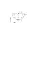
ここで、図2A及び2Bを参照しながら、支持体202におけるトランスデューサ201の配置の一例について説明する。図2Aは、支持体202をz軸方向から見た図、図2Bは、支持体202をy軸方向から見た図である。
Here, with reference to FIGS. 2A and 2B, an example of the arrangement of the
支持体202は、半球の内側の面にトランスデューサ201を放射状に複数支持している。なお、トランスデューサ201の配置の仕方はこの限りでなく、例えば渦巻状に配置してもよい。また、半球形状の支持体202の底部(極)には光射出口108が設置されている。また、支持体202の内側には、音響マッチング材が充填されてもよい。
The
本実施形態において、複数のトランスデューサ201は、図2A及び2Bで示した通り半球面形状に沿って配置される。点Xは半球面形状の支持体202の曲率中心点を示している。支持体202は、複数のトランスデューサ201の指向軸が集まるように複数の複数のトランスデューサ201を支持している。すなわち、支持体202の曲率中心の位置や複数のトランスデューサ201の指向軸が集まる位置は、支持体202の位置から推定することができる。複数のトランスデューサ201の指向軸を半球面形状の曲率中心点付近へ集めることで、曲率中心点を中心に高精度に可視化可能な領域が形成される。本明細書において、このように高精度に可視化可能な領域を高感度領域と呼ぶ。なお、後述する駆動装置107により被検体に対して支持体202を移動させることで、高感度領域が移動されて広い範囲の被検体情報を高精度に可視化することができる。
In the present embodiment, the plurality of
高感度領域は、最高分解能RHを得る曲率中心点を中心とした、式(1)で示す半径dthを有する略球形状の領域として考えることができる。 The high sensitivity region can be considered as a substantially spherical region having a radius d th indicated by the equation (1) centered on the curvature center point for obtaining the highest resolution R H.

ここで、Rは高感度領域Gの下限分解能、r0は半球形状の支持体202の半径、φdはトランスデューサ201の直径である。Rはたとえば、曲率中心点で得る最高分解能の半分の分解能とすることができる。高感度領域が探触子の曲率中心点を中心とした略球形状で形成される場合、その形状と探触子(すなわち曲率中心点)の位置から、探触子の2次元走査上の各位置での高感度領域の範囲を式(1)に従って推定することができる。
Here, R is the lower limit resolution of the high sensitivity region G, r 0 is the radius of the
なお、本発明の本実施形態において、複数のトランスデューサ201の配置は図2A及び2Bのような半球形状の例に限定されない。複数のトランスデューサ201の指向軸が集まり、所望の高感度領域を形成できる配置であればよい。すなわち、所望の高感度領域が形成されるように、曲面形状に沿って複数のトランスデューサ201が配置されればよい。本明細書において曲面とは、真球形状や半球面等の開口がある球面を含む。また、球面と見なせる程度の表面上の凹凸がある面や、球面と見なせる程度の楕円体(楕円を三次元へ拡張した形であり、表面が二次曲面からなる形)上の面も含む。
In the present embodiment of the present invention, the arrangement of the plurality of
また、球を任意の断面で切った形状の支持体に沿って複数のトランスデューサを配置する場合、その支持体の形状の曲率中心にトランスデューサの指向軸が最も集まる。本実施形態で説明する半球形状の支持体202も、球を任意の断面で切った形状の支持体の一例である。本明細書において、このように球を任意の断面で切った形状のことを球に基づく形状と呼ぶ。また、このように球に基づく形状の支持体に支持される複数のトランスデューサは、球面上に支持されることとなる。
In addition, when a plurality of transducers are arranged along a support whose shape is cut in any cross section, the directivity axes of the transducers are most concentrated at the center of curvature of the shape of the support. The hemispherical shaped
なお、所望の高感度領域を形成できる限り、必ずしも各トランスデューサの指向軸が交わらなくてもよい。また、特定の領域で発生した光音響波を高感度に受信できるように、支持体202により支持された複数のトランスデューサ201の少なくとも一部の素子の指向軸が特定の領域に集まっていればよい。すなわち、複数のトランスデューサ201の少なくとも一部の素子が高感度領域で発生する光音響波を高感度に受信することができるように、複数のトランスデューサ201が支持体202上に配置されていればよい。
In addition, as long as a desired high sensitivity region can be formed, the directivity axes of the transducers do not necessarily have to intersect. Further, it is only necessary that the directional axes of at least some of the elements of the plurality of
支持体202は、機械的強度が高い金属材料などを用いて構成されてもよい。
The
支持体202に支持された複数のトランスデューサ201のそれぞれが音響波を受信して時系列の受信信号を出力する。
(入力部103)
入力部103は、ユーザーが所望の情報を入力するために情報を指定できるように構成された部材である。入力部103としては、キーボード、マウス、タッチパネルディスプレイ、ダイヤル、およびボタンなどを用いることができる。入力部103としてタッチパネルを用いる場合、ディスプレイ109が入力部103を兼ねるタッチパネルであってもよい。なお、入力部103は、本発明の本実施形態による光音響装置とは別に提供されていてもよい。
(信号処理部105)
信号処理部105は、トランスデューサ201と信号線でつながっており、トランスデューサ201から出力されたアナログ受信信号をAD変換し、変換された信号をメインコントローラ104に送る。信号処理部105は、例えば、光射出口108に取り付けられた光検出センサと接続されており、パルス光が射出するのに同期して信号を取得してもよい。
(光照射部106)
光照射部106は、光を発する光源と、光源から発せられた光を被検体まで導く光学系とを含む。
Each of the plurality of
(Input unit 103)
The
(Signal processing unit 105)
The
(Light irradiation unit 106)
The
光源は、ナノ秒からマイクロ秒オーダーのパルス光を発生可能なパルス光源であってもよい。具体的には、パルス光のパルス幅は、1〜100ナノ秒程度であってもよい。また、パルス光の波長は、400nmから1600nm程度の範囲であってもよい。特に、生体表面近傍の血管を高解像度でイメージングする際は可視光領域の波長(400nm以上、700nm以下)の光を用いてもよい。一方、生体の深部をイメージングする際には、生体の背景組織において吸収が少ない波長(700nm以上、1100nm以下)の光を用いてもよい。ただし、テラヘルツ波、マイクロ波、ラジオ波領域の使用も可能である。 The light source may be a pulsed light source capable of generating pulsed light of nanosecond to microsecond order. Specifically, the pulse width of the pulsed light may be about 1 to 100 nanoseconds. Also, the wavelength of the pulsed light may be in the range of about 400 nm to about 1600 nm. In particular, when imaging blood vessels near the surface of a living body with high resolution, light of a wavelength (400 nm or more and 700 nm or less) in the visible light region may be used. On the other hand, when imaging a deep part of a living body, light of a wavelength (700 nm or more and 1100 nm or less) with less absorption in the background tissue of the living body may be used. However, it is also possible to use terahertz waves, microwaves, and radio waves.
光源の具体的な例は、レーザーや発光ダイオードである。また、複数波長の光を用いて測定する際には、発振する波長の変換が可能な光源を用いてもよい。複数波長の光を被検体に照射する場合、互いに異なる波長の光を発振する複数台の光源を、それぞれ発振切り替えを行いながら、もしくは交互に照射しながら用いてもよい。複数台の光源を用いた場合もそれらをまとめて光源として表現する。 Specific examples of light sources are lasers and light emitting diodes. When measurement is performed using light of a plurality of wavelengths, a light source capable of converting the oscillating wavelength may be used. In the case of irradiating the subject with light of a plurality of wavelengths, a plurality of light sources oscillating light of different wavelengths may be used while performing oscillation switching or irradiating alternately. Even when a plurality of light sources are used, they are collectively expressed as light sources.
レーザーとしては、固体レーザー、ガスレーザー、色素レーザー、半導体レーザーなど様々なレーザーを使用することができる。特に、Nd:YAGレーザーやアレキサンドライトレーザーなどのパルスレーザーを使用してもよい。また、Nd:YAGレーザー光を励起光とするTi:saレーザーや光パラメトリック発振(OPO)レーザーを用いてもよい。 As the laser, various lasers such as a solid laser, a gas laser, a dye laser, and a semiconductor laser can be used. In particular, a pulsed laser such as an Nd: YAG laser or an alexandrite laser may be used. Alternatively, a Ti: sa laser or an optical parametric oscillation (OPO) laser using Nd: YAG laser light as excitation light may be used.
光学系は、光源から被検体までパルス光を伝達させる。光学系には、レンズ、ミラー、光ファイバ等の光学素子を用いてもよい。乳房等を被検体とする生体情報取得装置においては、光学系の光出射部は拡散板等によりパルス光のビーム径を広げて照射してもよい。一方、光音響顕微鏡においては、解像度を上げるために、光学系の光出射部はレンズ等で構成し、ビーム径をフォーカスして照射してもよい。 The optical system transmits pulsed light from the light source to the subject. For the optical system, an optical element such as a lens, a mirror, or an optical fiber may be used. In a biological information acquiring apparatus in which a breast or the like is a subject, the light emitting unit of the optical system may expand the beam diameter of pulsed light with a diffusion plate or the like, and may perform irradiation. On the other hand, in the photoacoustic microscope, in order to increase the resolution, the light emitting part of the optical system may be constituted by a lens or the like, and the beam diameter may be focused for irradiation.
なお、光照射部106が光学系を備えずに、光源から直接被検体に光を照射してもよい。
The
本実施形態に係る光照射部106は、光源が光射出口108に光学系としての光ファイバで接続されている。パルス光は支持体202の底から半球状の支持体202の曲率中心に向かって射出される。
(駆動装置107)
駆動部としての駆動装置107は、被検体と支持体202との相対位置を変更する。本実施形態では、駆動装置107は、支持体202をxy方向に移動させる装置であり、ステッピングモータを搭載した電動のXYステージを備える。なお、駆動装置107は被検体と支持体202との相対位置を二次元的に変更させるものに限らず、相対位置を一次元または三次元的に変更させるものを用いてもよい。
In the
(Driving device 107)
The
駆動装置107は、移動方向へのガイド機構と、移動方向への駆動機構と、支持体202の位置を検知する位置センサを備えている。図1に示す光音響装置の場合、駆動装置107の上に支持体202が積載されるため、ガイド機構としては大きな荷重に耐えることが可能なリニアガイドなどを用いてもよい。駆動機構としては、リードスクリュー機構、リンク機構、ギア機構、油圧機構、などを用いてもよい。駆動力としてはモーターなどを用いてもよい。位置センサとしては、エンコーダー、可変抵抗器、などを用いたポテンショメータなどを用いてもよい。
The
なお、本発明の実施形態においては、被検体と支持体202との相対的な位置が変わればよいため、支持体202を固定し、被検体を移動させてもよい。被検体を移動させる場合は、被検体を支持する被検体支持部(不図示)を動かすことで被検体を移動させてもよい。被検体と支持体202の両方を移動させてもよい。
In the embodiment of the present invention, since the relative position between the subject and the
また、移動は連続的に行ってもよいが、一定のステップで繰り返しても良い。駆動装置107は、電動ステージであってもよいが、手動ステージでもよい。駆動装置107は、ここに挙げたものだけに限定されず、被検体と支持体202のうち少なくとも一方を移動可能に構成させているものであれば、どのようなものであってもよい。
(メインコントローラ104)
メインコントローラ104は、入力部103、信号処理部105、光照射部106、駆動装置107とそれぞれUSBなどのバスで接続されている。メインコントローラ104は、各装置を制御し、典型的には組み込みPCである。メインコントローラ104は、信号処理部105から受信した信号を用いて被検体から発生した初期音圧などの被検体情報を再構成する。メインコントローラ104は、制御部としてのCPUを備えている。また、メインコントローラ104は、CPU、GPUなどの演算素子やFPGA、ASICなどの演算回路を備えている。また、メインコントローラ104は、ROM、RAM、ハードディスクなどのメモリを備えている。
In addition, the movement may be performed continuously or may be repeated in certain steps. The
(Main controller 104)
The
信号処理部105の機能をメインコントローラ104が実行してもよい。メインコントローラ104と信号処理部105とを合わせて本実施形態に係る処理部とする。複数のハードウェアにより処理部の各機能が実現されてもよい。また、単一のハードウェアにより処理部の各機能が実現されてもよい。また、処理部の各機能が異なるハードウェアにより実行されてもよい。
(ディスプレイ109)
表示部としてのディスプレイ109は、メインコントローラ104から出力される被検体情報を分布画像や数値データなどで表示する。典型的には液晶ディスプレイなどがディスプレイ109として利用されるが、プラズマディスプレイや有機ELディスプレイ、FEDなど他の方式のディスプレイでもよい。ディスプレイ109は、本発明の実施形態に係る光音響装置とは別に提供されていてもよい。
<被検体情報取得処理>
次に、光音響装置が行う処理の詳細を図3に示すフローチャートを参照しながら説明する。この処理は、メインコントローラ104が光音響装置の各部を制御することにより行う。
The
(Display 109)
A
<Subject information acquisition processing>
Next, the details of the process performed by the photoacoustic apparatus will be described with reference to the flowchart illustrated in FIG. This processing is performed by the
処理が開始すると、メインコントローラ104が駆動装置107に命令を送ることで、駆動装置107は支持体202をあらかじめ決められた光照射位置まで移動する(ステップS301)。
When the process starts, the
次に、メインコントローラ104が光照射部106に命令を送ることで、光照射部106がパルス光を発し、光射出口108からパルス光が射出される(ステップS302)。そして、複数のトランスデューサ201のそれぞれは、光音響波を受信して受信信号を信号処理部105に出力する。このとき、信号処理部105は、パルス光の射出に同期して受信信号群に対する信号処理を開始する。その後に、メインコントローラ104が信号処理部105に命令を送ることで、信号処理部105は信号処理した受信信号群をメインコントローラ104の第1のメモリ上に送信する(ステップS303)。ここで、受信信号群のデータの取得とは、複数のトランスデューサ201から出力された時系列の受信信号群をデジタル信号に変換し、デジタル信号をメインコントローラ104の第1のメモリに記憶することを指す。
Next, when the
本実施形態では、保持カップ101と支持体202の相対位置を変えて、複数回受信信号群のデータを取得する。そのため、メインコントローラ104はあらかじめ決められた回数だけ受信信号群のデータを取得したかどうか判断し(ステップS304)、次の信号群のデータを取得する場合にはステップS301へ戻る。この結果、メインコントローラ104の第1のメモリには、複数回の光照射のそれぞれに対応する複数の受信信号群のデータが記憶される。
In the present embodiment, the relative positions of the holding
規定の回数信号を取得し終えた場合には、メインコントローラ104は、メインコントローラ104に記憶された複数の受信信号群のデータに基づいて被検体情報を生成する(ステップS305)。受信信号群のデータは時系列の信号データであり、被検体情報は空間的な2次元データまたは3次元データである。空間的な2次元データをピクセルデータ、空間的な3次元データをボクセルデータまたはボリュームデータとも呼ぶ。ピクセルまたはボクセルが本実施形態に係る注目位置である。すなわち、本工程では、メインコントローラ104が複数の受信信号群のデータを空間的な被検体情報のデータに変換する再構成処理を行う。
When the predetermined number of times of signal acquisition has been completed, the
最後に、メインコントローラ104は、取得した被検体情報をディスプレイ109に表示する(ステップS306)。典型的には、3次元の被検体情報をXY平面、YZ平面、ZX平面で切断したときの切断面を画像化して表示する。
Finally, the
図4は、駆動装置107による支持体202の移動の様子をz軸方向から見た図である。円401、円402、円403はそれぞれ第1のタイミング、第2のタイミング、第3のタイミングの信号取得時(光照射時)における支持体202の位置を示している。円401の信号取得時には領域404が高感度領域になる。円402の信号取得時には領域405が高感度領域になる。円403の信号取得時には領域406が高感度領域になる。移動方法、信号取得タイミング(回数)はこの例に限らない。例えば、駆動装置107は、支持体202を保持カップ101の中央に向かう渦巻状に移動させてもよい。
<再構成処理>
メインコントローラ104がステップS305で行う再構成処理の具体例について図5のフローチャートを用いて説明する。
FIG. 4 is a view of the movement of the
<Reconfiguration processing>
A specific example of the reconstruction processing performed by the
本実施形態では、複数回の光照射により取得された受信信号データに支持体と注目位置との相対位置に応じた重みを重み付けし、再構成処理を行う。 In the present embodiment, a reconstruction process is performed by weighting received signal data acquired by plural times of light irradiation in accordance with the relative position between the support and the position of interest.
メインコントローラ104は、再構成する注目位置(例えばボクセル)を設定する(ステップS315)。設定される注目位置については、予め決定されていてもよいし、入力部103を用いてユーザーにより指定されてもよい。なお、メインコントローラ104は、各光照射時の被検体の位置の情報に基づいて注目位置を設定してもよい。光照射前に設定された注目位置に対応する被検体の位置が、光が照射されたときには変わっている可能性があるので、各光照射時の被検体の位置の情報に応じて再構成すべき注目位置を変更してもよい。光音響装置は、被検体の位置を測定することのできる第1の測定部を有していてもよい。第1の測定部としては、CCDカメラやCMOSカメラなどから得られた画像データから被検体の位置を測定する装置や、ジャイロセンサー等により得られる被検体の変位を示す情報も用いて被検体の位置を測定する装置などを採用してもよい。
The
メインコントローラ104は、ステップS302でパルス光が被検体に照射されたときの支持体202と注目位置との相対位置の情報を取得する(ステップS325)。
The
メインコントローラ104は、各光照射時の支持体202と注目位置との相対位置に応じた重みが予め記憶された第2のメモリを備えてもよい。メインコントローラ104は、第2のメモリから各光照射に対応する重みを読み出すことにより、重みを決定することができる。第1のメモリと第2のメモリとは単一のハードウェアで構成されていてもよいし、別々のハードウェアで構成されていてもよい。
The
メインコントローラ104は、駆動装置107に設けられた第2の測定部としての位置センサが検知した、各光照射時の支持体202の位置の情報を受け取ってもよい。第2の測定部は、光照射部106に対する光照射の制御信号や光照射部106から出射された光をトリガーとして支持体202の位置の情報を取得してもよい。これにより、予め設定された光照射タイミングまたは支持体201の位置と実際の測定時の状態との間に誤差が生じた場合であっても、実際に光が照射されたときの支持体202の位置の情報を精度よく取得することができる。
The
メインコントローラ104は、ステップ315で取得した注目位置の位置情報と、ステップ325で取得した支持体202の位置情報とに基づいて、注目位置と支持体202との相対位置に応じた重みを決定する(ステップS335)。
The
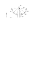
ここで、図6を参照しながら、重みの具体例について説明する。注目位置としてのボクセル501は再構成するボクセルである。点線502は、各トランスデューサ201の指向軸を示す。点503はj回目の光照射時の支持体202の曲率中心である。本実施形態において、曲率中心点503は、複数のトランスデューサ201の少なくとも一部の素子の指向軸が集まる位置に対応する。sjはボクセル501と曲率中心503との距離である。このとき、距離sjが小さいほど重みが大きく、距離sjが大きいほど重みが小さくなってもよい。例えば、重みwjは式(2)に表すように距離sjを指数とする指数関数としてもよい。
Here, a specific example of the weight will be described with reference to FIG. A
支持体202とボクセル501とがある相対位置関係のときに各トランスデューサ201に適応した複数の重みを平均化したものを各トランスデューサ201に加重する重みとしてもよい。例えば、Xu, Minghua, and Lihong V. Wang. “Universal back−projection algorithm for photoacoustic computed tomography” Physical Review E 71.1 (2005)に記載されたUniversal Back Projection(UBP)と呼ばれるタイムドメインの画像再構成に用いられる各トランスデューサ201に適応した重みを平均化したものを重みとしてもよい。UBPの場合、位置ベクトルdi,j(j回目の光照射時のi番目のトランスデューサの位置ベクトル)で表される位置にあるトランスデューサに対する重みwi,jは式(3)で表わされる。
It is also possible to use weights obtained by averaging each of the
ここで、ΔSi,jは位置ベクトルdi,jで表される位置にあるトランスデューサの面積、ns0i,jは位置ベクトルdi,jで表される位置にあるトランスデューサの受信面に対する単位法線ベクトル(指向方向)である。すなわち、UBPにおける各トランスデューサに適応した重みはボクセルを見込む各トランスデューサの立体角である。 Where ΔS i, j is the area of the transducer at the position represented by the position vector d i, j , and n s 0i, j is the unit method for the receiving surface of the transducer at the position represented by the position vector d i, j It is a line vector (pointing direction). That is, the weight applied to each transducer in the UBP is the solid angle of each transducer looking into the voxel.
この場合、j回目の光照射時に支持体202に支持された各トランスデューサ201に加重する重みwjは、各トランスデューサ201の重みwi,jを平均化して式(4)のように表すことができる。
In this case, the weight w j for weighting each
なお、従来技術による画像再構成に用いる各トランスデューサ201に適応した重みを平均化して重みとして用いてもよい。平均化した重みを用いる場合、平均化した重みを第2のメモリに記憶し、再構成時に第2のメモリから読み出してもよい。
The weights adapted to the
メインコントローラ104は、距離sjに応じて段階的に重みを変えてもよい。例えば、メインコントローラ104は図7Aに示すように連続的に重みを変えてもよいし、図7Bに示すように離散的に重みを変えてもよい。
The
重みの値については上記で示した例に限らず、支持体と注目位置との位置関係に基づいて各トランスデューサに一律に加重することのできる重みであればどんな値でも用いてよい。また、メインコントローラ104は、式(2)または式(4)を用いて重みを計算してもよい。また、予め距離sjと重みwjの対応テーブルを作成しておいて、メインコントローラ104内の第2のメモリに記憶しておき、メインコントローラ104が再構成処理時に対応テーブルを参照しても距離sjに応じた重みwjを読み出してもよい。
The value of the weight is not limited to the example described above, and any value can be used as long as it can uniformly weight each transducer based on the positional relationship between the support and the position of interest. Also, the
ここで、再構成する注目位置と支持体202の曲率中心との距離sjが小さいほど重みが大きくなるようにしてもよい理由を説明する。
Here, the reason why the weight may be increased as the distance s j between the position of interest to be reconstructed and the center of curvature of the
本実施形態において、トランスデューサ201には指向性があり、トランスデューサ201が半球の中心方向に向けて固定されている。そのため、半球の中心付近から発生する音響波は、各トランスデューサ201で高感度に受信することができる。一般に、ある音源を再構成するとき、なるべく広い立体角をカバーするような方向で音響波を受信したほうが、より高分解能に再構成できる。この場合、半球の中心からの音響波が最も広い立体角で高感度に受信できているため、半球の中心ほど重みを大きくして再構成してもよい。
In this embodiment, the
なお、注目位置で発生した音響波の初期音圧が大きいときに複数のトランスデューサが出力した受信信号群にさらに大きな重みを加えてもよい。例えば、注目位置に照射された光のフルエンスが高いときに発生した音響波の受信信号群に大きな重みを加えてもよい。すなわち、受信信号群のデータに光量に応じた重みを加えてもよい。これにより、S/N比の高い受信信号群の重みを大きくすることができる。そのため、このように加重した受信信号群を用いて再構成された注目位置の被検体情報のS/N比についても高くすることができる。例えば、支持体と注目位置との相対位置に応じて決定された重みに、注目位置における光量をかけた値を重みとしてもよい。 In addition, when the initial sound pressure of the acoustic wave generated at the position of interest is large, a larger weight may be added to the reception signal group output from the plurality of transducers. For example, a large weight may be added to the reception signal group of the acoustic wave generated when the fluence of the light irradiated to the target position is high. That is, a weight corresponding to the light amount may be added to the data of the reception signal group. Thereby, the weight of the received signal group having a high S / N ratio can be increased. Therefore, it is possible to increase the S / N ratio of the object information of the target position reconstructed using the received signal group weighted in this way. For example, a value obtained by multiplying the amount of light at the target position by the weight determined according to the relative position between the support and the target position may be used as the weight.
本実施形態のように半球の中心に向けてパルス光が照射されている場合には、半球の中心で発生する光音響波の音圧が相対的に高まる。この場合、半球の中心周辺については、光音響波の発生音圧が高い領域と発生した光音響波が高感度に受信される領域とが重なり合うため、再構成する際に大きな重み付けを行ってもよい。この理由から、光照射部106は複数のトランスデューサの指向軸が集まる位置に向けてパルス光を照射してもよい。
When pulse light is irradiated toward the center of the hemisphere as in the present embodiment, the sound pressure of the photoacoustic wave generated at the center of the hemisphere is relatively increased. In this case, since a region where the generated sound pressure of the photoacoustic wave is high and a region where the generated photoacoustic wave is received with high sensitivity overlap in the vicinity of the center of the hemisphere, even when the reconstruction is performed, large weighting is performed. Good. For this reason, the
図8A及び8Bは、光射出口108から出るパルス光の様子と、ボクセル501から出た音響波がトランスデューサ201に到達する様子を表した図である。ボクセル501以外の場所からも音響波が出ている場合があるが、図示は便宜上省略している。
FIGS. 8A and 8B are diagrams showing the appearance of pulse light emitted from the
図8Aは、距離sjが小さい場合の図である。パルス光601がボクセル501に強く当たり、ボクセル501から強い音響波602が出ている。また、音響波602が各トランスデューサ201に、ほぼ垂直の角度で入射している。そのため、各トランスデューサ201では、取得されるボクセル501の被検体情報の定量性の向上に大きく寄与する受信信号が取得される。
FIG. 8A is a diagram when the distance s j is small. The pulsed light 601 strongly strikes the
一方、図8Bは、距離sjが大きい場合の図である。パルス光603はボクセル501にはほとんど当たらず、ボクセル501からの音響波604は弱い。また、音響波604は多くのトランスデューサ201に、受信面の垂直方向からは傾いて入射している。そのため、各トランスデューサ201では、取得されるボクセル501の被検体情報の定量性の向上に大きく寄与しない受信信号が支配的に取得される。
On the other hand, FIG. 8B is a diagram when the distance s j is large. The
以上から、距離sjが小さいほどボクセル501の被検体情報の定量性の向上に大きく寄与する受信信号群が取得されているため、それらの受信信号群には大きな重み付けをしてもよいことが理解される。
From the above, since the received signal group that greatly contributes to the improvement of the quantitativity of the object information of the
前述したように、支持体202の曲率中心の位置や複数のトランスデューサ202の指向軸が集まる位置は、支持体202の位置から推定することができる。そのため、支持体202と注目位置との位置関係を基準に重みを決定してもよい。
As described above, the position of the center of curvature of the
本工程において、第1の測定部により測定された被検体の位置の情報と、第2の測定部により測定された支持体202の位置の情報とに基づいて重みを決定することにより、実際に光が照射されたときの支持体202と被検体との相対位置を精度よく把握することができる。そのため、光照射時の実際の状態に適した、支持体202と注目位置との相対位置に応じた重みを決定することができる。
In this step, the weight is actually determined based on the information on the position of the object measured by the first measurement unit and the information on the position of the
メインコントローラ104は、第1のメモリに記憶された複数の受信信号群のそれぞれの受信信号群に対してS335で決定された重みで重みづけする(ステップS345)。そして、メインコントローラ104は、重みづけされた複数の受信信号群に基づいて注目位置における被検体情報を取得する(ステップS355)。
The
ここで、ステップS345およびステップS355の具体例を説明する。再構成するボクセル(注目位置)の位置ベクトルをr、再構成するボクセルの初期音圧をp0(r)、トランスデューサ201の数をN、信号データ取得回数(光照射回数)をM、音響波の伝播経路の音速をcとする。また、j回目の光照射時の受信信号群のデータにかける重みをwj(1≦j≦M)、j回目の光照射時のi番目のトランスデューサの位置ベクトルをdi,j、位置ベクトルdi,jで表される位置にあるトランスデューサで取得した時系列の受信信号のデータのうち時間t’における信号強度をp(di,j,t’)とする。この場合、例えば、メインコントローラ104は、式(5)で表される計算式で被検体情報としての初期音圧を計算することができる。
Here, specific examples of step S345 and step S355 will be described. The position vector of the voxel (target position) to be reconstructed is r, the initial sound pressure of the voxel to be reconstructed is p 0 (r), the number of
メインコントローラ104は、設定された全注目位置について被検体情報の取得が完了したか否かを判定する(ステップS365)。全注目位置について被検体情報の取得が完了していない場合、S315のステップに戻る。なお、全注目位置について既に完了しているステップについては再度実行しなくてもよい。すなわち、全注目位置について完了していないステップに戻ってもよい。式(5)は、あるひとつのボクセルが再構成される場合のみを表す。複数のボクセル(全注目位置)に対して同じ処理を繰り返すことで、任意の領域を再構成することができる。
The
メインコントローラ104は、1回目からj回目のそれぞれの光照射時の受信信号群のデータに対して式(6)で表わされる計算式で初期音圧を計算した後に、それぞれの初期音圧を合成してもよい。
The
すなわち、ステップS301からステップS303の工程を行う毎にステップS305の工程を行って被検体情報を取得してもよい。そして、ステップS305で得られた複数の被検体情報を合成することにより最終的な被検体情報を取得してもよい。重み付けを行う受信信号p(di,j,t’)については、Xu, Minghua, and Lihong V. Wang. “Universal back−projection algorithm for photoacoustic computed tomography” Physical Review E 71.1 (2005)に記載されたように式(7)に示すように正値化された後に重み付けされてもよい。 That is, every time the process of step S301 to step S303 is performed, the process of step S305 may be performed to acquire the subject information. Then, final subject information may be acquired by combining a plurality of pieces of subject information obtained in step S305. For the received signal p (d i, j , t ') to be weighted, Xu, Minghua, and Lihong V. 2 are used. Wang. As described in “Universal back-projection algorithm for photoacoustic computed tomography” Physical Review E 71.1 (2005), it may be weighted after being normalized as shown in Equation (7).
ここで、b(di,j,t’)は正値化された受信信号の強度である。なお、受信信号を正値化するアルゴリズムは式(7)に限らず、いかなる方法であってもよい。 Here, b (di , j , t ') is the strength of the received signal that has been made positive. The algorithm for converting the received signal into a positive value is not limited to the equation (7), and any method may be used.
本実施形態では、支持体の曲率中心から等方的に画質が低下していく傾向に基づいた重みを説明したが、異なる傾向に基づいた重みを適用してもよい。トランスデューサを完全な球面上に隙間なく配置することができない場合、高感度領域は複数のトランスデューサの指向軸が集まる位置を中心とする球とはならない。この場合、複数のトランスデューサの指向軸が集まる位置に対して、支持体から離れた領域よりも支持体に近い領域の方が、画質が高くなる傾向がある。すなわち、この場合、高感度領域は、複数のトランスデューサの指向軸が集まる位置に対して、支持体から離れた領域よりも支持体に近い領域の方に広がっている傾向がある。 In the present embodiment, the weight based on the tendency of the image quality decreasing isotropically from the center of curvature of the support is described, but a weight based on a different tendency may be applied. If the transducers can not be arranged without gaps on a perfect sphere, the sensitive region will not be a sphere centered at the location where the pointing axes of the multiple transducers converge. In this case, the image quality tends to be higher in the area closer to the support than the area away from the support with respect to the position where the directional axes of the plurality of transducers are gathered. That is, in this case, the high sensitivity region tends to spread toward the region closer to the support than the region farther from the support with respect to the position where the directivity axes of the plurality of transducers are gathered.
この傾向を基に、メインコントローラは、複数のトランスデューサの指向軸が集まる位置に対して、支持体から離れた領域に含まれる注目位置よりも支持体に近い領域に含まれる注目位置に大きな重みづけしてもよい。すなわち、複数のトランスデューサの指向軸が集まる位置からの距離が同じ注目位置であっても、支持体から離れた領域に含まれる注目位置よりも支持体に近い領域に含まれる注目位置により大きな重みづけしてもよい。また、メインコントローラは、複数のトランスデューサの指向軸が集まる位置よりも探触子側に位置する注目位置に最も大きな重み付けをしてもよい。また、メインコントローラは、複数のトランスデューサの指向軸が集まる位置よりも支持体に近い所定の位置から注目位置までの距離が近いほど大きな重みづけを行ってもよい。これらの場合も、支持体と注目位置との相対位置に基づいて重みづけを行うことができる。 On the basis of this tendency, the main controller gives greater weight to the position where the directivity axes of the plurality of transducers are concentrated, to the position of interest included in the area closer to the support than the position of interest included in the area away from the support. You may That is, even if the distance from the position where the directivity axes of a plurality of transducers are concentrated is the same attention position, the weighting is greater for the attention position included in the area closer to the support than the attention position included in the area separated from the support You may Further, the main controller may weight the attention position located on the probe side more than the position at which the directional axes of the plurality of transducers are gathered. In addition, the main controller may perform weighting more as the distance from the predetermined position closer to the support to the target position is closer than the position where the directional axes of the plurality of transducers are collected. Also in these cases, weighting can be performed based on the relative position between the support and the position of interest.
本実施形態によれば、複数のトランスデューサからの受信信号群に支持体と注目位置との位置関係に応じた一様な重み付けを加重することで、定量性、分解能が高い被検体情報を得ることができる。 According to the present embodiment, it is possible to obtain object information having high quantitativity and high resolution by weighting received signals from a plurality of transducers with uniform weighting according to the positional relationship between the support and the position of interest. Can.
[第二の実施形態]
第二の実施形態に係る光音響装置のシステム構成、被検体情報取得処理は、第一の実施形態と同様である。本実施形態においては、第1のメモリに記憶された複数の受信信号群のデータから注目位置の再構成に用いる受信信号群を選択する。すなわち、複数の受信信号群の中から再構成に用いない信号群を選択する。このとき、再構成に用いない受信信号群に0の重みを加重してもよいし、その受信信号群を再構成時に読み出さなくてもよい。
Second Embodiment
The system configuration of the photoacoustic apparatus and the subject information acquisition process according to the second embodiment are the same as in the first embodiment. In this embodiment, the reception signal group to be used for the reconstruction of the target position is selected from the data of the plurality of reception signal groups stored in the first memory. That is, a signal group not to be used for reconstruction is selected from the plurality of received signal groups. At this time, the received signal group not used for reconstruction may be weighted with a weight of 0, or the received signal group may not be read out at the time of reconstruction.
光音響イメージングにおいては、注目位置の画像を再構成するために用いる信号を以下のような観点に基づいて選択してもよい。 In photoacoustic imaging, a signal used to reconstruct an image of a position of interest may be selected based on the following aspects.
注目位置の画像は、注目位置に指向性が向いているトランスデューサが出力した受信信号を用いて再構成してもよい。これにより、注目位置で発生した音響波を高感度に受信することができるため、注目位置で発生した音響波に対応する受信信号のS/N比を高くすることができる。そのため、その受信信号を用いて再構成された注目位置の画像強度のS/N比を高くすることができる。 The image of the position of interest may be reconstructed using the received signal output from the transducer whose directivity is directed to the position of interest. Thereby, since the acoustic wave generated at the position of interest can be received with high sensitivity, the S / N ratio of the reception signal corresponding to the acoustic wave generated at the position of interest can be increased. Therefore, it is possible to increase the S / N ratio of the image intensity of the target position reconstructed using the received signal.
注目位置に音源が存在する場合、注目位置から全方位に等方的に音響波が伝搬する。そこで、注目位置から発生した音響波の多くの波数成分を受信することができるようにトランスデューサを配置してもよい。これにより、画像を再構成するときに、再構成アーティファクトに対応するエネルギーが再構成画像の全体に分散されるため、局所的に再構成アーティファクトが現れることを抑制することができる。 When a sound source is present at the position of interest, acoustic waves propagate isotropically in all directions from the position of interest. Therefore, the transducers may be arranged to be able to receive many wavenumber components of the acoustic wave generated from the position of interest. Thereby, when the image is reconstructed, the energy corresponding to the reconstruction artifact is dispersed to the whole of the reconstruction image, so that the appearance of the reconstruction artifact can be suppressed locally.
さらに、再構成アーティファクトが注目位置を中心として対称に現れるような位置でトランスデューサが音響波を受信してもよい。すなわち、注目位置を中心として点対称な位置でトランスデューサが音響波を受信してもよい。これにより、再構成アーティファクトについても注目位置を中心として点対称に現れる。その結果、再構成画像の全体に再構成アーティファクトに対応するエネルギーがより均一に分散するため、局所的に再構成アーティファクトがより現れにくくなる。 Furthermore, the transducer may receive the acoustic wave at a position such that the reconstruction artifact appears symmetrically about the position of interest. That is, the transducer may receive the acoustic wave at a point-symmetrical position around the position of interest. This causes the reconstruction artifacts to appear point-symmetrically about the position of interest. As a result, the energy corresponding to the reconstruction artifact is more uniformly distributed throughout the reconstructed image, so that the reconstruction artifact is less likely to appear locally.
あらゆる注目位置において、以上の観点に基づいた受信信号を用いて画像を再構成してもよい。これにより、再構成画像内のあらゆる注目位置において、注目位置の再構成像(シグナル成分)と再構成アーティファクト(ノイズ成分)とのコントラストが高くなる。 At any location of interest, the received signal based on the above aspects may be used to reconstruct the image. As a result, the contrast between the reconstructed image (signal component) of the position of interest and the reconstruction artifact (noise component) is increased at every position of interest in the reconstructed image.
本実施形態に係る光音響装置は、支持体と注目位置との相対位置に応じて、第1のメモリに記憶された複数の受信信号群から注目位置の被検体情報の取得に用いる受信信号群を決定する。すなわち、本実施形態に係る光音響装置は、支持体と注目位置との距離に応じて、第1のメモリに記憶された複数の受信信号群から注目位置の被検体情報の取得に用いない受信信号群を決定する。 The photoacoustic apparatus according to the present embodiment is a reception signal group used to acquire object information of a target position from a plurality of reception signal groups stored in the first memory according to the relative position between the support and the target position. Decide. That is, according to the distance between the support and the position of interest, the photoacoustic apparatus according to the present embodiment does not receive the object information of the position of interest from the plurality of received signal groups stored in the first memory. Determine the signal group.
例えば、ステップS335において、本実施形態に係る重みは式(8)を用いて決定される。 For example, in step S335, the weight according to the present embodiment is determined using equation (8).
ここで、dthは高感度領域の半径である。すなわち、ボクセルは、そのボクセルが高感度領域に含まれてない時点で取得した受信信号群を計算に用いずに再構成する。閾値となっている高感度領域の範囲は式(1)から推定してもよい。 Here, d th is the radius of the high sensitivity region. That is, the voxel is reconstructed without using the received signal group acquired when the voxel is not included in the high sensitivity region for calculation. The range of the high sensitivity region serving as the threshold may be estimated from equation (1).
本実施形態では、高感度領域の半径を閾値として、被検体情報の取得に用いる受信信号群を選択したが、閾値はこれに限らない。 In the present embodiment, the radius of the high sensitivity region is used as a threshold to select a received signal group used for acquiring object information, but the threshold is not limited to this.
前述したように、高感度領域は、複数のトランスデューサ201の指向軸が集まる位置を中心とする球とは限らない。高感度領域が、複数のトランスデューサ201の指向軸が集まる位置に対して、支持体202から離れた領域よりも支持体202側の領域の方が大きい場合もあることを本発明者らは見出した。この場合、メインコントローラ104は、複数のトランスデューサ201の指向軸が集まる位置に対して支持体202に近づく方向については、支持体202から離れる方向と比べて、より遠くに位置する注目位置まで再構成してもよい。メインコントローラ104は、複数のトランスデューサ201の指向軸が集まる位置に対して支持体202から離れる方向については、支持体202に近づく方向に比べて、より近くに位置する注目位置までしか再構成しなくてもよい。メインコントローラ104は、複数のトランスデューサ201の指向軸が集まる位置から同じ距離であっても、支持体202に近づく方向に位置する注目位置は再構成し、支持体202から離れる方向に位置する注目位置は再構成しなくてもよい。
As described above, the high sensitivity region is not limited to a sphere centered at the position at which the directivity axes of the plurality of
また、支持体202の位置を基準とした所定の領域までを再構成し、それ以外の領域を再構成しなくてもよい。すなわち、この所定の領域以外の領域に含まれる注目位置に対応する重みを0としてもよい。例えば、所定の領域としては、支持体に支持された複数のトランスデューサの指向軸が集まる位置を中心とした球、円柱、四角柱などの領域を採用すればよい。この場合、複数のトランスデューサの指向軸が集まる位置から所定の領域の外周までの距離を閾値としてもよい。上記したように、高感度領域が支持体202の方に広がっている場合、所定の領域の中心は複数のトランスデューサの指向軸の集まる位置よりも支持体202側にオフセットしてもよい。所定の領域を決定するための形状、大きさ、位置などのパラメータについては、予め設定されていてもよい。また、ユーザーが入力部103を用いて、所定の領域を決定するためのパラメータを閾値に関する情報として入力することにより、閾値が設定されてもよい。
In addition, it is possible to reconstruct up to a predetermined area based on the position of the
閾値は複数のトランスデューサの指向軸が集まる位置から注目位置に向かう方向によって異なっていてもよい。 The threshold may be different depending on the direction from the position where the directional axes of the plurality of transducers gather to the position of interest.
また、再構成されるボクセルに対する重みについては1に限らず、0以外の任意の重みを用いてもよい。選択された再構成に用いる受信信号群に基づいて、UBPなどの従来技術に係る画像再構成アルゴリズムにしたがって被検体情報を取得することができる。すなわち、受信信号群のそれぞれの受信信号に対して、支持体202とボクセル501との相対位置に応じた一律の重みで重みづけを行うとともに、複数のトランスデューサ201のそれぞれの位置とボクセル501との相対位置に応じた重みで重みづけを行ってもよい。
Further, the weight for the voxel to be reconstructed is not limited to 1 but any weight other than 0 may be used. Object information can be acquired according to a conventional image reconstruction algorithm such as UBP based on the received signal group used for the selected reconstruction. That is, each received signal of the received signal group is weighted with a uniform weight according to the relative position of the
このように複数の受信信号群の中から再構成に用いる受信信号群を選択することにより、被検体情報の取得のための計算量を低減することができる。これにより、被検体情報の取得に要する時間を短縮することができる。また、再構成するボクセルが高感度領域に含まれていないときに取得された受信信号群は、高感度に受信することのできなかった受信信号群であるため、この受信信号群を被検体情報の取得に用いると被検対情報の定量性が低減する可能性がある。そこで、この受信信号群を被検体情報の取得に用いないことにより、取得される被検体情報の定量性、分解能を向上させることができる。 By selecting the reception signal group to be used for reconstruction from among the plurality of reception signal groups in this manner, it is possible to reduce the amount of calculation for acquiring the object information. Thereby, the time required to acquire object information can be shortened. Further, since the received signal group acquired when the voxel to be reconstructed is not included in the high sensitivity region is a received signal group which could not be received with high sensitivity, the received signal group is used as object information There is a possibility that the quantitativity of test pair information may be reduced if it is used for acquisition of Therefore, by not using this received signal group for acquiring object information, it is possible to improve the quantitativeness and resolution of the acquired object information.
[変形例]
上記の実施形態は本発明を説明する上での例示であり、本発明は、発明の趣旨を逸脱しない範囲で上記の実施形態を適宜変更または組み合わせて実施することができる。
[Modification]
The above embodiment is an example for describing the present invention, and the present invention can be implemented by appropriately changing or combining the above embodiments without departing from the spirit of the invention.
また、本発明を適用することのできる再構成処理は上記の計算式を用いた処理に限らず、他のタイムドメイン再構成も適用することができる。また、同様にフーリエドメイン再構成やモデルベース再構成にも本発明は適用可能である。 Further, the reconstruction processing to which the present invention can be applied is not limited to the processing using the above formula, and other time domain reconstructions can also be applied. The present invention is also applicable to Fourier domain reconstruction and model-based reconstruction as well.
[その他の実施形態]
本発明の実施形態は、記憶媒体(例えば、非一時的なコンピュータ読み取り可能な記憶媒体)に記録されて本発明の上記実施形態のうち一またはそれ以上の機能を実行するコンピュータ実行可能な指示を、読み出して実行するシステムまたは装置のコンピュータによって、及びそのシステムまたは装置のコンピュータにより実行される方法によって、例えば、上記実施形態のうち一またはそれ以上の機能を実行するコンピュータ実行可能な指示を記憶媒体から読み出して実行することによっても、実現可能である。コンピュータは、CPU、MPU、またはその他の回路のうち一またはそれ以上を含んでもよく、別々のコンピュータまたは別々のコンピュータプロセッサのネットワークを含んでもよい。コンピュータ実行可能な指示は、例えばネットワークまたは記憶媒体からコンピュータに与えられてもよい。記憶媒体は、例えば、ハードディスク、RAM、ROM、分散型コンピューティングシステムの記憶装置、光学ディスク(CD、DVD、ブルーレイディスク(登録商標)など)、フラッシュメモリ装置、メモリカード等のうち一またはそれ以上を含んでもよい。
Other Embodiments
Embodiments of the present invention include computer-executable instructions stored on a storage medium (eg, non-transitory computer readable storage medium) to perform one or more of the functions of the above-described embodiments of the present invention. , By a computer of a system or device for reading and executing, and by a method executed by a computer of the system or device, for example, storing a computer executable instruction for performing one or more functions of the above embodiments It is realizable also by reading and performing from. A computer may include one or more of a CPU, an MPU, or other circuitry, and may include separate computers or networks of separate computer processors. Computer-executable instructions may be provided to a computer, for example, from a network or storage medium. The storage medium is, for example, one or more of a hard disk, a RAM, a ROM, a storage device of a distributed computing system, an optical disk (CD, DVD, Blu-ray Disc (registered trademark), etc.), a flash memory device, a memory card, etc. May be included.
例示的な実施形態に基づいて本発明を述べてきたが、本発明は開示された例示的な実施形態に限定されないことを理解されたい。下記の請求項の範囲は、あらゆる変形例及び同等の構成と機能を包含するように最も広く解釈されるべきである。 Although the present invention has been described based on the exemplary embodiments, it should be understood that the present invention is not limited to the disclosed exemplary embodiments. The scope of the following claims should be construed in the broadest sense so as to encompass all modifications and equivalent arrangements and functions.
本出願は、2014年5月14日に出願された米国特許出願第61/992983号の利益を主張するものであり、その全内容は参照することにより本出願に組み込まれる。 This application claims the benefit of US Patent Application No. 61 / 99,2983, filed May 14, 2014, the entire content of which is incorporated by reference into the present application.
Claims (23)
前記光照射部からの光が被検体に照射されることにより生じた音響波を受信し、受信信号群を出力する複数のトランスデューサと、
前記複数のトランスデューサの少なくとも一部のトランスデューサの指向軸が集まるように、前記複数のトランスデューサを支持する支持体と、
前記支持体及び前記被検体の少なくとも一方を移動させる駆動部と、
前記複数のトランスデューサから出力された前記受信信号群を記憶する第1のメモリと、
前記被検体内の注目位置の被検体情報を取得する処理部と、
を有し、
前記光照射部は、複数回の光照射を前記被検体に行い、
前記駆動部は、前記複数回の光照射のそれぞれにおいて前記支持体と前記被検体との相対位置が異なるように前記支持体を移動させ、
前記複数のトランスデューサは、前記複数回の光照射のそれぞれによって生じた音響波を受信し、前記複数回の光照射に対応する複数の受信信号群を出力し、
前記第1のメモリは、前記複数の受信信号群を記憶し、
前記処理部は、前記第1のメモリに記憶された前記複数の受信信号群のそれぞれの受信信号群に対して、前記指向軸が集まる位置と前記注目位置との距離に応じた一律の重みで重み付けして前記注目位置の被検体情報を取得する
ことを特徴とする光音響装置。 A light irradiator,
A plurality of transducers for receiving an acoustic wave generated by irradiating the object with light from the light irradiation unit and outputting a reception signal group;
A support for supporting the plurality of transducers such that the pointing axes of at least some of the plurality of transducers converge;
A drive unit for moving at least one of the support and the subject;
A first memory storing the received signal group output from the plurality of transducers;
A processing unit that acquires object information of a target position in the object;
Have
The light irradiation unit performs a plurality of times of light irradiation to the specimen,
The driving unit moves the support so that the relative position between the support and the subject is different in each of the plurality of times of light irradiation.
The plurality of transducers receive acoustic waves generated by each of the plurality of light irradiations, and output a plurality of reception signal groups corresponding to the plurality of light irradiations,
The first memory stores the plurality of received signal groups,
The processing unit performs uniform weighting according to the distance between the position at which the directional axis is gathered and the position of interest with respect to received signal groups of the plurality of received signal groups stored in the first memory. A photoacoustic apparatus characterized by acquiring subject information of the target position by weighting.
前記複数のトランスデューサの少なくとも一部の指向軸が集まる位置は、前記球に基づく形状の曲率中心である
ことを特徴とする請求項1に記載の光音響装置。 The support is spherical in shape,
The photoacoustic apparatus according to claim 1, wherein a position at which at least a part of the directivity axes of the plurality of transducers is gathered is a center of curvature of the shape based on the sphere.
ことを特徴とする請求項2に記載の光音響装置。 The photoacoustic apparatus according to claim 2, wherein the support is hemispherical.
ことを特徴とする請求項1から3のいずれか1項に記載の光音響装置。 The photoacoustic apparatus according to any one of claims 1 to 3, wherein the light irradiator irradiates light toward a position where the directional axes are collected.
前記複数の相対位置のそれぞれにおける、前記支持体の位置の情報を測定する第2の測定部と、を更に有し、
前記処理部は、前記第1の測定部により測定された前記被検体の位置の情報と、前記第2の測定部により測定された前記支持体の位置の情報と、に基づいて前記重みを決定する
ことを特徴とする請求項1から4のいずれか1項に記載の光音響装置。 A first measurement unit configured to measure information on the position of the subject at each of a plurality of relative positions;
And a second measurement unit configured to measure information on the position of the support at each of the plurality of relative positions.
The processing unit determines the weight based on the information on the position of the subject measured by the first measurement unit and the information on the position of the support measured by the second measurement unit. The photoacoustic apparatus of any one of Claim 1 to 4 characterized by doing.
前記処理部は、前記第2のメモリから前記相対位置に対応する重みを読み出すことにより前記重みを決定する
ことを特徴とする請求項1から4のいずれか1項に記載の光音響装置。 Further comprising a second memory in which weights corresponding to each of the plurality of relative positions are stored,
The photoacoustic apparatus according to any one of claims 1 to 4, wherein the processing unit determines the weight by reading a weight corresponding to the relative position from the second memory.
ことを特徴とする請求項1から6のいずれか1項に記載の光音響装置。 Wherein the processing unit according to claim 1, characterized in that for each received signal group of said plurality of reception signal group stored in the first memory, weighted with a large weight as the distance decreases 6. A photoacoustic apparatus according to any one of 6. to 6 .
ことを特徴する請求項7に記載の光音響装置。 The processing section is characterized in that weighting is performed on each of the received signal groups of the plurality of received signal groups stored in the first memory, using an exponential function with the distance as an index as a weight. The photoacoustic apparatus of Claim 7 .
ことを特徴とする請求項1から8のいずれか1項に記載の光音響装置。 The photoacoustic apparatus according to any one of claims 1 to 8 , wherein the weight increases in all directions as the position of interest approaches a position at which the directional axes converge.
ことを特徴とする請求項9に記載の光音響装置。 The photoacoustic apparatus according to claim 9 , wherein the weight is isotropically increased as the position of interest approaches a position at which the directional axes are gathered.
ことを特徴とする請求項1から10のいずれか1項に記載の光音響装置。 The processing unit is configured to select the target position without using the reception signal group output from the plurality of transducers when the distance is larger than a threshold among the plurality of reception signal groups stored in the first memory. The photoacoustic apparatus according to any one of claims 1 to 10 , wherein subject information on the subject is acquired.
ことを特徴とする請求項11に記載の光音響装置。 The photoacoustic apparatus according to claim 11 , wherein the threshold value differs depending on a direction from the position where the directional axes are gathered toward the target position.
ことを特徴とする請求項11または12に記載の光音響装置。 Wherein the processing unit from a position where the directional axis gather, photoacoustic device according to distance from the resolution of the position to the resolution is half in claim 11 or 12, characterized in that to set as the threshold value.
前記記憶された前記複数の受信信号群のそれぞれの受信信号群に対して、前記指向軸の集まる位置と前記注目位置との距離に応じた一律の重みで重み付けして前記注目位置の被検体情報を取得することを特徴とする信号処理装置。 The plurality of transducers arranged on the support so that the directional axes of at least some of the plurality of transducers are gathered, when the relative positions of the support and the subject are different from each other, in the plurality of states. A signal processing apparatus for acquiring subject information of a position of interest in the subject based on a plurality of received signal groups corresponding to the plurality of states received and stored acoustic waves generated from the subject. ,
The object information of the target position is weighted with a uniform weight according to the distance between the position where the directional axis is gathered and the target position with respect to the reception signals of each of the plurality of received signal groups stored. A signal processing apparatus characterized by acquiring.
ことを特徴とする請求項14に記載の信号処理装置。 The signal processing apparatus according to claim 14 , wherein the received signal group of each of the plurality of received signal groups is weighted with a large weight as the distance decreases.
ことを特徴する請求項15に記載の信号処理装置。 The signal processing apparatus according to claim 15 , wherein the received signal group of each of the plurality of received signal groups is weighted using an exponential function with the distance as an index.
ことを特徴とする請求項14から16のいずれか1項に記載の信号処理装置。 The signal processing apparatus according to any one of claims 14 to 16 , wherein the weight increases in all directions as the position of interest approaches a position where the directional axes are gathered.
ことを特徴とする請求項17に記載の信号処理装置。 The signal processing apparatus according to claim 17 , wherein the weight is isotropically increased as the position of interest approaches a position where the directional axes are gathered.
ことを特徴とする請求項14から18のいずれか1項に記載の信号処理装置。 Among the plurality of received signal groups, when the distance is larger than a threshold value, subject information of the target position is acquired without using the received signal groups output from the plurality of transducers. The signal processing device according to any one of 14 to 18 .
ことを特徴とする請求項19に記載の信号処理装置。 The signal processing apparatus according to claim 19 , wherein the threshold value differs depending on a direction from the position where the directional axes are gathered toward the target position.
ことを特徴とする請求項19または20に記載の信号処理装置。 The signal processing apparatus according to claim 19 or 20 , wherein a distance from a position where the directional axes are gathered to a half of the resolution from the resolution of the position is set as the threshold.
前記記憶された前記複数の受信信号群のそれぞれの受信信号群に対して、前記指向軸の集まる位置と前記注目位置との距離に応じた一律の重みで重み付けして前記注目位置の被検体情報を取得する工程を有する
ことを特徴とする信号処理方法。 The plurality of transducers arranged on the support so that the directional axes of at least some of the plurality of transducers are gathered, when the relative positions of the support and the subject are different from each other, in the plurality of states. A signal processing method for acquiring subject information of a target position in the subject based on a plurality of reception signal groups corresponding to the plurality of states received and stored acoustic waves generated from the subject. ,
The object information of the target position is weighted with a uniform weight according to the distance between the position where the directional axis is gathered and the target position with respect to the reception signals of each of the plurality of received signal groups stored. A signal processing method comprising the steps of:
Applications Claiming Priority (3)
| Application Number | Priority Date | Filing Date | Title |
|---|---|---|---|
| US201461992983P | 2014-05-14 | 2014-05-14 | |
| US61/992,983 | 2014-05-14 | ||
| PCT/JP2015/002414 WO2015174085A1 (en) | 2014-05-14 | 2015-05-12 | Photoacoustic apparatus |
Publications (3)
| Publication Number | Publication Date |
|---|---|
| JP2017521104A JP2017521104A (en) | 2017-08-03 |
| JP2017521104A5 JP2017521104A5 (en) | 2018-12-06 |
| JP6545190B2 true JP6545190B2 (en) | 2019-07-17 |
Family
ID=53276221
Family Applications (1)
| Application Number | Title | Priority Date | Filing Date |
|---|---|---|---|
| JP2016564286A Expired - Fee Related JP6545190B2 (en) | 2014-05-14 | 2015-05-12 | Photoacoustic apparatus, signal processing apparatus, signal processing method, program |
Country Status (5)
| Country | Link |
|---|---|
| US (1) | US10495567B2 (en) |
| EP (1) | EP3143391B1 (en) |
| JP (1) | JP6545190B2 (en) |
| CN (1) | CN106455992B (en) |
| WO (1) | WO2015174085A1 (en) |
Families Citing this family (7)
| Publication number | Priority date | Publication date | Assignee | Title |
|---|---|---|---|---|
| CN105342567B (en) * | 2015-11-23 | 2018-08-07 | 苏州大学 | Device and method for improving signal-to-noise ratio of reconstructed photoacoustic image |
| JP6594355B2 (en) * | 2017-01-06 | 2019-10-23 | キヤノン株式会社 | Subject information processing apparatus and image display method |
| JP2018126389A (en) * | 2017-02-09 | 2018-08-16 | キヤノン株式会社 | Information processing apparatus, information processing method, and program |
| JP6650908B2 (en) | 2017-06-16 | 2020-02-19 | キヤノン株式会社 | Subject information acquisition device and control method of subject information acquisition device |
| DE102017219338B3 (en) * | 2017-10-27 | 2019-02-28 | Humboldt-Universität Zu Berlin | Photoacoustic sensor head and photoacoustic measuring device with improved noise suppression |
| JP7118718B2 (en) * | 2018-04-18 | 2022-08-16 | キヤノン株式会社 | SUBJECT INFORMATION ACQUISITION APPARATUS, SUBJECT INFORMATION PROGRAM, AND PROGRAM |
| CN114563479B (en) * | 2022-04-20 | 2022-08-30 | 之江实验室 | Real-time three-dimensional high-resolution terahertz photoacoustic imaging method and device |
Family Cites Families (30)
| Publication number | Priority date | Publication date | Assignee | Title |
|---|---|---|---|---|
| US5713356A (en) * | 1996-10-04 | 1998-02-03 | Optosonics, Inc. | Photoacoustic breast scanner |
| GB9704737D0 (en) * | 1997-03-07 | 1997-04-23 | Optel Instr Limited | Biological measurement system |
| US6694799B2 (en) * | 2002-02-22 | 2004-02-24 | Eastern Washington University | Method and apparatus for detection of particles |
| AU2003300052A1 (en) * | 2002-12-31 | 2004-08-10 | John Herbert Cafarella | Multi-sensor breast tumor detection |
| WO2004068405A2 (en) * | 2003-01-25 | 2004-08-12 | Oraevsky Alexander A | High contrast optoacoustical imaging using nanoparticles |
| US9597024B2 (en) * | 2005-02-09 | 2017-03-21 | Medici Instruments Llc | Methods and apparatuses for noninvasive determinations of analytes |
| US20110184260A1 (en) * | 2005-02-09 | 2011-07-28 | Robinson M Ries | Methods and Apparatuses for Noninvasive Determinations of Analytes |
| US20080173093A1 (en) * | 2007-01-18 | 2008-07-24 | The Regents Of The University Of Michigan | System and method for photoacoustic tomography of joints |
| JP4829934B2 (en) * | 2008-07-11 | 2011-12-07 | キヤノン株式会社 | Inspection device |
| EP2344019B1 (en) * | 2008-07-25 | 2013-11-27 | Helmholtz Zentrum München Deutsches Forschungszentrum für Gesundheit und Umwelt (GmbH) | Quantitative multi-spectral opto-acoustic tomography (msot) of tissue biomarkers |
| JP5496098B2 (en) * | 2008-08-27 | 2014-05-21 | キヤノン株式会社 | Subject information acquisition apparatus and control method thereof |
| EP2260754A1 (en) * | 2009-06-10 | 2010-12-15 | Universiteit Twente | Device and method for photon absorption coefficient measurement |
| JP5683213B2 (en) | 2009-11-17 | 2015-03-11 | キヤノン株式会社 | Image forming apparatus and image forming method |
| JP5917039B2 (en) * | 2010-09-13 | 2016-05-11 | キヤノン株式会社 | Subject information acquisition device |
| JP5939786B2 (en) * | 2011-02-10 | 2016-06-22 | キヤノン株式会社 | Acoustic wave acquisition device |
| US9445786B2 (en) * | 2011-11-02 | 2016-09-20 | Seno Medical Instruments, Inc. | Interframe energy normalization in an optoacoustic imaging system |
| JP5988598B2 (en) | 2012-01-31 | 2016-09-07 | キヤノン株式会社 | Subject information acquisition apparatus and subject information acquisition method |
| US20130210058A1 (en) * | 2012-02-15 | 2013-08-15 | Lakeland Ventures Development, Llc | System for noninvasive determination of water in tissue |
| US20140171759A1 (en) * | 2012-02-15 | 2014-06-19 | Craig William WHITE | Noninvasive determination of intravascular and exctravascular hydration using near infrared spectroscopy |
| US20140155760A1 (en) * | 2012-02-15 | 2014-06-05 | Trent Daniel Ridder | Remote and local transfer of information in noninvasive hydration measurements |
| JP2013215236A (en) | 2012-04-04 | 2013-10-24 | Canon Inc | Subject information obtaining apparatus and subject information obtaining method |
| JP6172912B2 (en) * | 2012-10-23 | 2017-08-02 | キヤノン株式会社 | Subject information acquisition apparatus and photoacoustic probe |
| EP2950711A4 (en) * | 2013-01-31 | 2016-09-21 | Univ Ramot | Detection, diagnosis and monitoring of osteoporosis by a photo-acoustic method |
| US9723995B2 (en) * | 2013-12-04 | 2017-08-08 | The Johns Hopkins University | Systems and methods for real-time tracking of photoacoustic sensing |
| US10531828B2 (en) * | 2014-01-31 | 2020-01-14 | The Johns Hopkins University | Method and system for transcranial photoacoustic imaging for guiding skull base surgeries |
| EP3142543B1 (en) * | 2014-05-14 | 2019-12-11 | Canon Kabushiki Kaisha | Photoacoustic apparatus |
| TWI529391B (en) * | 2015-01-22 | 2016-04-11 | 國立臺灣大學 | System and method for using photoacoustic effect |
| US10441250B2 (en) * | 2015-10-08 | 2019-10-15 | Zmk Medical Technologies Inc. | 3D multi-parametric ultrasound imaging |
| US20170209119A1 (en) * | 2016-01-27 | 2017-07-27 | Canon Kabushiki Kaisha | Photoacoustic ultrasonic imaging apparatus |
| WO2018049172A1 (en) * | 2016-09-08 | 2018-03-15 | The Penn State Research Foundation | Handheld device and multimodal contrast agent for early detection of human disease |
-
2015
- 2015-05-12 EP EP15726356.7A patent/EP3143391B1/en active Active
- 2015-05-12 WO PCT/JP2015/002414 patent/WO2015174085A1/en active Application Filing
- 2015-05-12 US US15/310,082 patent/US10495567B2/en not_active Expired - Fee Related
- 2015-05-12 JP JP2016564286A patent/JP6545190B2/en not_active Expired - Fee Related
- 2015-05-12 CN CN201580025861.8A patent/CN106455992B/en not_active Expired - Fee Related
Also Published As
| Publication number | Publication date |
|---|---|
| CN106455992B (en) | 2019-09-10 |
| CN106455992A (en) | 2017-02-22 |
| EP3143391B1 (en) | 2020-07-08 |
| EP3143391A1 (en) | 2017-03-22 |
| US10495567B2 (en) | 2019-12-03 |
| WO2015174085A1 (en) | 2015-11-19 |
| JP2017521104A (en) | 2017-08-03 |
| US20170234790A1 (en) | 2017-08-17 |
Similar Documents
| Publication | Publication Date | Title |
|---|---|---|
| JP6545190B2 (en) | Photoacoustic apparatus, signal processing apparatus, signal processing method, program | |
| JP5528083B2 (en) | Image generating apparatus, image generating method, and program | |
| JP6525565B2 (en) | Object information acquisition apparatus and object information acquisition method | |
| JP6632257B2 (en) | Subject information acquisition device | |
| JP6544910B2 (en) | INFORMATION PROCESSING APPARATUS, OBJECT INFORMATION ACQUIRING APPARATUS, AND METHOD OF DETERMINING SOUND SPEED | |
| JP6472437B2 (en) | Photoacoustic apparatus and acoustic wave receiving apparatus | |
| US10548477B2 (en) | Photoacoustic apparatus, information processing method, and storage medium | |
| JP6742745B2 (en) | Information acquisition device and display method | |
| US11006929B2 (en) | Object information acquiring apparatus and signal processing method | |
| JP6656229B2 (en) | Photoacoustic device | |
| KR20170074171A (en) | Photoacoustic apparatus, information acquiring apparatus, information acquiring method, and program | |
| US10436706B2 (en) | Information processing apparatus, information processing method, and storage medium | |
| US10578588B2 (en) | Photoacoustic apparatus, information processing method, and storage medium | |
| JP2017196026A (en) | Subject information acquisition device | |
| JP2018089371A (en) | Information processing device, information processing method, and program | |
| US20170332913A1 (en) | Object information acquiring apparatus | |
| US20200085345A1 (en) | Object information acquisition apparatus and method of controlling the same | |
| JP2014147825A (en) | Image generation device, image generation method, and program | |
| JP6942847B2 (en) | Subject information acquisition device and signal processing method | |
| JP6381718B2 (en) | Apparatus and image generation method | |
| JP6113330B2 (en) | Apparatus and image generation method | |
| US20190142278A1 (en) | Information processing apparatus, information processing method, and program | |
| JP6614968B2 (en) | Information processing apparatus, subject information acquisition apparatus, information processing method, and program | |
| JP2017012692A (en) | Photoacoustic apparatus, information acquisition device, information acquisition method, and program | |
| JP2017202149A (en) | Apparatus, method, and program |
Legal Events
| Date | Code | Title | Description |
|---|---|---|---|
| A521 | Request for written amendment filed |
Free format text: JAPANESE INTERMEDIATE CODE: A523 Effective date: 20170428 |
|
| A621 | Written request for application examination |
Free format text: JAPANESE INTERMEDIATE CODE: A621 Effective date: 20171225 |
|
| A521 | Request for written amendment filed |
Free format text: JAPANESE INTERMEDIATE CODE: A523 Effective date: 20181029 |
|
| A131 | Notification of reasons for refusal |
Free format text: JAPANESE INTERMEDIATE CODE: A131 Effective date: 20181225 |
|
| A521 | Request for written amendment filed |
Free format text: JAPANESE INTERMEDIATE CODE: A523 Effective date: 20190219 |
|
| TRDD | Decision of grant or rejection written | ||
| A01 | Written decision to grant a patent or to grant a registration (utility model) |
Free format text: JAPANESE INTERMEDIATE CODE: A01 Effective date: 20190521 |
|
| A61 | First payment of annual fees (during grant procedure) |
Free format text: JAPANESE INTERMEDIATE CODE: A61 Effective date: 20190618 |
|
| R151 | Written notification of patent or utility model registration |
Ref document number: 6545190 Country of ref document: JP Free format text: JAPANESE INTERMEDIATE CODE: R151 |
|
| LAPS | Cancellation because of no payment of annual fees |