[1.パチンコ機の全体構造]
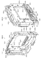
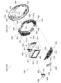
本発明の一実施形態であるパチンコ機1について、図面を参照して詳細に説明する。まず、図1乃至図10を参照して本実施形態のパチンコ機1の全体構成について説明する。図1は本発明の一実施形態であるパチンコ機の正面図である。図2はパチンコ機の右側面図であり、図3はパチンコ機の左側面図であり、図4はパチンコ機の背面図である。図5はパチンコ機を右前から見た斜視図であり、図6はパチンコ機を左前から見た斜視図であり、図7はパチンコ機を後ろから見た斜視図である。また、図8は本体枠から扉枠を開放させると共に、外枠から本体枠を開放させた状態で前から見たパチンコ機の斜視図である。図9はパチンコ機を扉枠、遊技盤、本体枠、及び外枠に分解して前から見た分解斜視図であり、図10はパチンコ機を扉枠、遊技盤、本体枠、及び外枠に分解して後ろから見た分解斜視図である。
[1. Overall structure of pachinko machine]
A pachinko machine 1 according to an embodiment of the present invention will be described in detail with reference to the drawings. First, an entire configuration of a pachinko machine 1 according to the present embodiment will be described with reference to FIGS. 1 to 10. FIG. 1 is a front view of a pachinko machine which is an embodiment of the present invention. FIG. 2 is a right side view of the pachinko machine, FIG. 3 is a left side view of the pachinko machine, and FIG. 4 is a rear view of the pachinko machine. FIG. 5 is a perspective view of the pachinko machine as viewed from the right front, FIG. 6 is a perspective view of the pachinko machine as viewed from the left front, and FIG. 7 is a perspective view of the pachinko machine as viewed from the rear. Moreover, FIG. 8 is a perspective view of the pachinko machine seen from the front in a state in which the door frame is opened from the main body frame and the main body frame is opened from the outer frame. FIG. 9 is an exploded perspective view of a pachinko machine disassembled into a door frame, a game board, a body frame, and an outer frame, and FIG. 10 is a door frame for a pachinko machine, a game board, a body frame, and an outer frame It is the disassembled perspective view which disassembled and was seen from back.
本実施形態のパチンコ機1は、遊技ホールの島設備(図示しない)に設置される枠状の外枠2と、外枠2の前面を開閉可能に閉鎖する扉枠3と、扉枠3を開閉可能に支持していると共に外枠2に開閉可能に取付けられている本体枠4と、本体枠4に前側から着脱可能に取付けられると共に扉枠3を通して遊技者側から視認可能とされ遊技者によって遊技球が打込まれる遊技領域5aを有した遊技盤5と、を備えている。
The pachinko machine 1 of this embodiment includes a frame-shaped outer frame 2 installed on an island facility (not shown) of a game hall, a door frame 3 for closing the front of the outer frame 2 so as to be openable and closable, A main unit frame 4 supported so as to be openable and closable, and removably attached to the main unit frame 4 from the front side, is made visible from the player side through the door frame 3. And a game board 5 having a game area 5a into which game balls are hit.
パチンコ機1の外枠2は、図9及び図10等に示すように、上下に離間しており左右に延びている上枠部材10及び下枠部材20と、上枠部材10及び下枠部材20の両端同士を連結しており上下に延びている左枠部材30及び右枠部材40と、を備えている。上枠部材10、下枠部材20、左枠部材30、及び右枠部材40は、前後の幅が同じ幅に形成されている。また、上枠部材10及び下枠部材20の左右の長さに対して、左枠部材30及び右枠部材40の上下の長さが、長く形成されている。
The outer frame 2 of the pachinko machine 1 is, as shown in FIG. 9 and FIG. 10, an upper frame member 10 and a lower frame member 20 which are vertically separated and extend laterally, an upper frame member 10 and a lower frame member The left frame member 30 and the right frame member 40 which connect the both ends of 20 and extend vertically are provided. The upper frame member 10, the lower frame member 20, the left frame member 30, and the right frame member 40 have the same front and rear width. Further, the upper and lower lengths of the left frame member 30 and the right frame member 40 are formed longer than the left and right lengths of the upper frame member 10 and the lower frame member 20.
また、外枠2は、左枠部材30及び右枠部材40の下端同士を連結し下枠部材20の前側に取付けられる幕板部材50と、上枠部材10の正面視左端部側に取付けられている外枠側上ヒンジ部材60と、幕板部材50の正面視左端側上部と左枠部材30とに取付けられている外枠側下ヒンジ部材70と、を備えている。外枠2の外枠側上ヒンジ部材60と外枠側下ヒンジ部材70とによって、本体枠4及び扉枠3が開閉可能に取付けられている。
Further, the outer frame 2 is attached to the curtain plate member 50 which is attached to the front side of the lower frame member 20 by connecting the lower ends of the left frame member 30 and the right frame member 40 and to the left end side of the upper frame member 10 in front view The outer frame side upper hinge member 60, and the outer frame side lower hinge member 70 attached to the left frame member 30 on the left end side in front view of the curtain plate member 50 are provided. The main frame 4 and the door frame 3 are attached to be openable and closable by the outer frame side upper hinge member 60 and the outer frame side lower hinge member 70 of the outer frame 2.
パチンコ機1の扉枠3は、正面視の外形が上下に延びた四角形で前後に貫通している貫通口111を有した枠状の扉枠ベースユニット100と、扉枠ベースユニット100の貫通口111よりも下側で前面右下隅に取付けられており遊技球を遊技盤5の遊技領域5a内へ打込むために遊技者が操作可能なハンドルユニット300と、扉枠ベースユニット100の貫通口111よりも下側で前面下部に取付けられている皿ユニット320と、皿ユニット320の中央に取付けられており遊技領域5a内に遊技球が打込まれることで変化する遊技状態に応じて遊技者に参加型の演出を提示することが可能な演出操作ユニット400と、皿ユニット320の上側で扉枠ベースユニット100における貫通口111よりも左側の前面左部に取付けられている扉枠左サイドユニット540と、皿ユニット320の上側で扉枠ベースユニット100における貫通口111よりも右側の前面右部に取付けられている扉枠右サイドユニット550と、扉枠左サイドユニット540及び扉枠右サイドユニット550の上側で扉枠ベースユニット100における貫通口111よりも上側の前面上部に取付けられている扉枠トップユニット570と、を備えている。
The door frame 3 of the pachinko machine 1 is a quadrangle in which the external shape of the front view extends vertically and which has a frame-shaped door frame base unit 100 having a through hole 111 which penetrates back and forth, and a through hole of the door frame base unit 100. A handle unit 300 attached to the front lower right corner below the side 111 and operable by the player to drive the game ball into the game area 5a of the game board 5, and the through hole 111 of the door frame base unit 100. The player is attached to the player according to the game state which is changed by the game unit being attached to the center of the dish unit 320 and the dish unit 320 which are attached to the lower front on the lower side and the dish unit 320 It is attached to the front left part on the left side of the through hole 111 in the door frame base unit 100 above the plate unit 320 and the presentation operation unit 400 capable of presenting participatory effects. A door frame left side unit 540, a door frame right side unit 550 mounted on the front right side on the right side of the through hole 111 in the door frame base unit 100 above the plate unit 320, and a door frame left side unit 540 And a door frame top unit 570 attached to a front upper portion above the through hole 111 in the door frame base unit 100 on the upper side of the door frame right side unit 550.
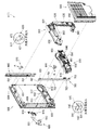
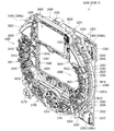
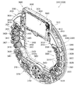
パチンコ機1の本体枠4は、一部が外枠2の枠内に挿入可能とされると共に遊技盤5の外周を支持可能とされた枠状の本体枠ベース600と、本体枠ベース600の正面視左側の上下両端に取付けられ外枠2の外枠側上ヒンジ部材60及び外枠側下ヒンジ部材70に夫々回転可能に取付けられると共に扉枠3の扉枠側上ヒンジ部材140及び扉枠側下ヒンジ部材150が夫々回転可能に取付けられる本体枠側上ヒンジ部材620及び本体枠側下ヒンジ部材640と、本体枠ベース600の正面視左側面に取付けられる補強フレーム660と、本体枠ベース600の前面下部に取付けられており遊技盤5の遊技領域5a内に遊技球を打込むための球発射装置680と、本体枠ベース600の正面視右側面に取付けられており外枠2と本体枠4、及び扉枠3と本体枠4の間を施錠する施錠ユニット700と、本体枠ベース600の正面視上辺及び左辺に沿って後側に取付けられており遊技者側へ遊技球を払出す逆L字状の払出ユニット800と、本体枠ベース600の後面下部に取付けられている基板ユニット900と、本体枠ベース600の後側に開閉可能に取付けられ本体枠ベース600に取付けられた遊技盤5の後側を覆う裏カバー980と、を備えている。
The main frame 4 of the pachinko machine 1 has a frame-like main frame base 600 which is partially insertable into the outer frame 2 and is capable of supporting the outer periphery of the game board 5, and of the main frame base 600. It is attached to upper and lower ends of the left side of the front view and is rotatably attached to the outer frame side upper hinge member 60 and the outer frame side lower hinge member 70 of the outer frame 2 and the door frame upper hinge member 140 of the door frame 3 and the door frame A body frame side upper hinge member 620 and a body frame side lower hinge member 640 to which the side lower hinge members 150 are rotatably attached, a reinforcing frame 660 attached to the left side surface of the body frame base 600 in a front view, and a body frame base 600 The ball launcher 680 is attached to the lower front of the front and is for hitting a game ball into the game area 5a of the game board 5, and is attached to the right side of the main frame base 600 in a front view. 4, A lock unit 700 for locking between the door frame 3 and the main body frame 4 and a reverse L-shaped character attached to the rear side along the front view upper side and the left side of the main body frame base 600 to pay out the game ball to the player -Like payout unit 800, a base board unit 900 attached to the lower part of the rear surface of the main body frame base 600, and a rear of the game board 5 attached to the rear side of the main body frame base 600 openably and closably And a back cover 980 covering the side.
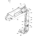
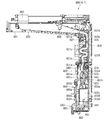
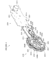
本体枠4の払出ユニット800は、本体枠ベース600の後側に取付けられる逆L字状の払出ユニットベース801と、払出ユニットベース801の上部に取付けられており上方へ開放された左右に延びた箱状で図示しない島設備から供給される遊技球を貯留する球タンク802と、球タンク802の下側で払出ユニットベース801に取付けられており球タンク802内の遊技球を正面視左方向へ誘導する左右に延びたタンクレール803と、払出ユニットベース801における正面視左側上部の後面に取付けられタンクレール803からの遊技球を蛇行状に下方へ誘導する球誘導ユニット820と、球誘導ユニット820の下側で払出ユニットベース801から着脱可能に取付けられており球誘導ユニット820により誘導された遊技球を払出制御基板ボックス950に収容された払出制御基板951からの指示に基づいて一つずつ払出す払出装置830と、払出ユニットベース801の後面に取付けられ払出装置830によって払出された遊技球を下方へ誘導すると共に皿ユニット320における上皿321での遊技球の貯留状態に応じて遊技球を通常放出口850d又は満タン放出口850eの何れかから放出させる上部満タン球経路ユニット850と、払出ユニットベース801の下端に取付けられ上部満タン球経路ユニット850の通常放出口850dから放出された遊技球を前方へ誘導して前端から扉枠3の貫通球通路273へ誘導する通常誘導路861及び満タン放出口850eから放出された遊技球を前方へ誘導して前端から扉枠3の満タン球受口274へ誘導する満タン誘導路862を有した下部満タン球経路ユニット860と、を備えている。
Dispensing unit 800 of body frame 4 is an inverted L-shaped dispensing unit base 801 attached to the rear side of body frame base 600 and attached to the top of dispensing unit base 801 and extends upward and leftwardly. A ball tank 802 for storing gaming balls supplied from a not-shown island facility in a box shape, and attached to the payout unit base 801 below the ball tank 802, and the gaming balls in the ball tank 802 are left as viewed from the front A tank guide 803 extending to the left and right, a ball guiding unit 820 attached to the rear surface of the payout unit base 801 at the upper left side in a front view and guiding the gaming ball from the tank rail 803 downward in a meandering manner; Gaming balls which are detachably mounted on the lower side of the payout unit base 801 and guided by the ball guiding unit 820 A payout device 830 which pays out one by one based on an instruction from the payout control substrate 951 accommodated in the payout control substrate box 950 and a gaming ball attached to the rear surface of the payout unit base 801 and paid out by the payout device 830 downward An upper full-ball path unit 850 which causes the game balls to be released from either the normal outlet 850d or the full tank outlet 850e according to the storage state of the gaming balls in the upper plate 321 in the tray unit 320 and the payout unit A normal guiding path 861 and a full guiding path 861 attached to the lower end of the base 801 and guiding the gaming ball discharged from the normal discharge port 850d of the upper full tank path unit 850 forward to the penetrating ball passage 273 of the door frame 3 from the front end. The game ball released from the tongue outlet 850e is guided forward and guided from the front end to the full tank receptacle 274 of the door frame 3. A lower full sphere path unit 860 having a RuMitsurutan taxiway 862, and a.
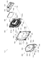
本体枠4の基板ユニット900は、本体枠ベース600の後側に取付けられる基板ユニットベース910と、基板ユニットベース910の正面視左側で本体枠ベース600の後側に取付けられ内部に低音用のスピーカ921を有したスピーカユニット920と、基板ユニットベース910の後側で正面視右側に取付けられ内部に電源基板が収容されている電源基板ボックス930と、スピーカユニット920の後側に取付けられており内部にインターフェイス制御基板が収容されているインターフェイス制御基板ボックス940と、電源基板ボックス930及びインターフェイス制御基板ボックス940に跨って取付けられており内部に遊技球の払出しを制御する払出制御基板951が収容された払出制御基板ボックス950と、を備えている。
The substrate unit 900 of the main body frame 4 is attached to the rear side of the main body frame base 600 on the left side of the main body frame base 600 attached to the rear side of the main body frame base 600 and the speaker for bass A speaker unit 920 having a 921. A power supply substrate box 930 mounted on the right side in front view on the rear side of the substrate unit base 910 and having a power supply substrate housed therein, and attached to the rear side of the speaker unit 920. An interface control board box 940 in which the interface control board is housed, and a payout control board 951 mounted across the power supply board box 930 and the interface control board box 940 and controlling the payout of gaming balls. And a delivery control board box 950. .
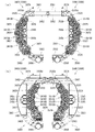
パチンコ機1の遊技盤5は、図9及び図10等に示すように、遊技球が打込まれる遊技領域5aの外周を区画し球発射装置680から発射された遊技球を遊技領域5aの上部に案内する外レール1001及び内レール1002を有した前構成部材1000と、前構成部材1000の後側に取付けられると共に遊技領域5aの後端を区画する平板状の遊技パネル1100と、を備えている。
As shown in FIGS. 9 and 10, etc., the game board 5 of the pachinko machine 1 divides the outer periphery of the game area 5a into which the game balls are hit, and the game balls fired from the ball launcher 680 are the top of the game area 5a. A front component 1000 having an outer rail 1001 and an inner rail 1002 for guiding the game, and a flat game panel 1100 attached to the rear of the front component 1000 and defining the rear end of the game area 5a There is.
本実施形態のパチンコ機1は、上皿321に遊技球を貯留した状態で、遊技者がハンドル302を回転操作すると、球発射装置680によってハンドル302の回転角度に応じた強さで遊技球が遊技盤5の遊技領域5a内へ打込まれる。そして、遊技領域5a内に打込まれた遊技球が、入賞口に受入れられると、受入れられた入賞口に応じて、所定数の遊技球が払出装置830によって上皿321に払出される。この遊技球の払出しによって遊技者の興趣を高めることができるため、上皿321内の遊技球を遊技領域5a内へ打込ませることができ、遊技者に遊技を楽しませることができる。
In the pachinko machine 1 of the present embodiment, when the player rotates the handle 302 in a state where the gaming ball is stored in the upper plate 321, the game ball has a strength according to the rotation angle of the handle 302 by the ball launcher 680. It is driven into the game area 5 a of the game board 5. Then, when the gaming balls driven into the gaming area 5a are received by the winning opening, a predetermined number of gaming balls are paid out by the payout device 830 to the upper tray 321 according to the accepted winning openings. Since the interest of the player can be enhanced by the payout of the game balls, the game balls in the upper plate 321 can be driven into the game area 5a, and the player can enjoy the game.
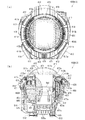
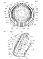
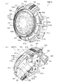
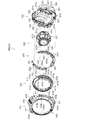
[2.外枠の全体構成]
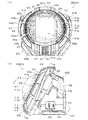
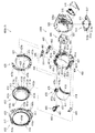
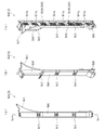
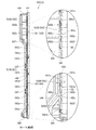
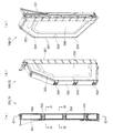
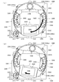
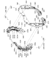
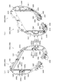
パチンコ機1の外枠2について、図11乃至図16を参照して説明する。図11はパチンコ機における外枠の正面図であり、図12は外枠の右側面図である。また、図13は外枠を前から見た斜視図であり、図14は外枠を後ろから見た斜視図である。図15は、外枠を分解して前から見た分解斜視図である。図16(a)は外枠における外枠側上ヒンジ部材の部位を、左枠部材を省略して下側から見た斜視図であり、(b)は(a)を分解して示す分解斜視図である。外枠2は、遊技ホール等のパチンコ機1が設置される島設備(図示は省略)に取付けられるものである。
[2. Overall configuration of outer frame]
The outer frame 2 of the pachinko machine 1 will be described with reference to FIGS. 11 to 16. FIG. 11 is a front view of an outer frame in a pachinko machine, and FIG. 12 is a right side view of the outer frame. FIG. 13 is a perspective view of the outer frame as viewed from the front, and FIG. 14 is a perspective view of the outer frame as viewed from the back. FIG. 15 is an exploded perspective view of the outer frame as viewed from the front. FIG. 16 (a) is a perspective view of the portion of the outer frame side upper hinge member in the outer frame, viewed from the lower side with the left frame member omitted, and FIG. 16 (b) is an exploded perspective view showing a disassembled (a) FIG. The outer frame 2 is attached to an island facility (not shown) on which the pachinko machine 1 such as a game hall is installed.
外枠2は、図示するように、上下に離間しており左右に延びている上枠部材10及び下枠部材20と、上枠部材10及び下枠部材20の両端同士を連結しており上下に延びている左枠部材30及び右枠部材40と、を備えている。上枠部材10、下枠部材20、左枠部材30、及び右枠部材40は、前後の幅が同じ幅に形成されている。また、上枠部材10及び下枠部材20の左右の長さに対して、左枠部材30及び右枠部材40の上下の長さが、長く形成されている。また、外枠2は、上枠部材10及び下枠部材20の左右両端面と、左枠部材30及び右枠部材40の左右方向の外側を向いた側面とが、同一面となるように組立てられている。
As illustrated, the outer frame 2 connects the upper frame member 10 and the lower frame member 20 which are vertically separated and extends in the left and right direction, and both ends of the upper frame member 10 and the lower frame member 20. And the left frame member 30 and the right frame member 40 which are extended in The upper frame member 10, the lower frame member 20, the left frame member 30, and the right frame member 40 have the same front and rear width. Further, the upper and lower lengths of the left frame member 30 and the right frame member 40 are formed longer than the left and right lengths of the upper frame member 10 and the lower frame member 20. Further, the outer frame 2 is assembled such that the left and right end faces of the upper frame member 10 and the lower frame member 20 and the side faces of the left frame member 30 and the right frame member 40 facing outward in the left and right direction are the same surface. It is done.
また、外枠2は、上枠部材10の正面視左端部側に取付けられている外枠側上ヒンジ部材60と、外枠側上ヒンジ部材60の下面に取付けられているロック部材66と、幕板部材50の正面視左端側上部と左枠部材30とに取付けられている外枠側下ヒンジ部材70と、を備えている。外枠2の外枠側上ヒンジ部材60と外枠側下ヒンジ部材70とによって、本体枠4及び扉枠3を開閉可能に取付けることができる。
Further, the outer frame 2 includes an outer frame side upper hinge member 60 attached to the front end left side of the upper frame member 10 and a lock member 66 attached to the lower surface of the outer frame side upper hinge member 60; An outer frame side lower hinge member 70 attached to the left end upper portion of the curtain plate member 50 in front view and the left frame member 30 is provided. The outer frame side upper hinge member 60 and the outer frame side lower hinge member 70 of the outer frame 2 can attach the main body frame 4 and the door frame 3 so as to be able to open and close.
また、外枠2は、左枠部材30及び右枠部材40の下端同士を連結し下枠部材20の前側に取付けられる幕板部材50と、幕板部材50の後側に取付けられていると共に両端が左枠部材30及び右枠部材40に夫々取付けられる幕板補強部材80と、幕板部材50の上面における左右中央から左寄りの位置に取付けられている平板状の左滑り部材81と、幕板部材50の上面における右端付近の位置に取付けられている平板状の右滑り部材82と、を備えている。幕板補強部材80は、中実の部材(例えば、木材、合板、等)によって形成されており、下枠部材20、左枠部材30、及び右枠部材40に、取付けられている。
Further, the outer frame 2 is mounted on the rear side of the curtain plate member 50 and the curtain plate member 50 attached to the front side of the lower frame member 20 by connecting the lower ends of the left frame member 30 and the right frame member 40. A curtain plate reinforcing member 80 whose both ends are attached to the left frame member 30 and the right frame member 40, a flat left sliding member 81 attached at a position from the left to right center of the upper surface of the curtain plate member 50 And a flat right sliding member 82 mounted at a position near the right end of the upper surface of the plate member 50. The curtain plate reinforcing member 80 is formed of a solid member (for example, wood, plywood, etc.), and is attached to the lower frame member 20, the left frame member 30, and the right frame member 40.
更に、外枠2は、上枠部材10と左枠部材30、上枠部材10と右枠部材40、下枠部材20と左枠部材30、及び下枠部材20と右枠部材40を、夫々連結している連結部材85を備えている。また、外枠2は、右枠部材40の内側(左側面側)に取付けられており後述する施錠ユニット700の外枠用鉤703が係止される上鉤掛部材90及び下鉤掛部材91を、備えている。
Furthermore, the outer frame 2 includes the upper frame member 10 and the left frame member 30, the upper frame member 10 and the right frame member 40, the lower frame member 20 and the left frame member 30, and the lower frame member 20 and the right frame member 40, respectively. It has a connecting member 85 connected. The outer frame 2 is attached to the inner side (left side) of the right frame member 40, and the upper hooking member 90 and the lower hooking member 91 are engaged with the outer frame hook 703 of the locking unit 700 described later. , Equipped.
[2−1.上枠部材]
外枠2の上枠部材10は、所定厚さの無垢(中実)の材料(例えば、木材、合板、等)によって形成されている。この上枠部材10は、左右両端における前後方向の中央に、上下に貫通しており左右方向中央側へ窪んだ係合切欠部11を備えている。この係合切欠部11内には、連結部材85の後述する左上連結部材85A及び右上連結部材85Bの上横固定部87が取付けられる。また、上枠部材10は、正面視左側端部の上面と前面に、一般面よりも窪んだ取付段部12を備えている。この取付段部12には、外枠側上ヒンジ部材60が取付けられる。
[2-1. Upper frame member]
The upper frame member 10 of the outer frame 2 is formed of a solid (solid) material (for example, wood, plywood, etc.) of a predetermined thickness. The upper frame member 10 is provided with an engagement notch 11 which penetrates up and down and is recessed toward the center in the left-right direction at the center in the front-rear direction at both left and right ends. An upper horizontal fixing portion 87 of an upper left connecting member 85A and an upper right connecting member 85B, which will be described later, of the connecting member 85 is attached to the inside of the engagement notch 11. Moreover, the upper frame member 10 is equipped with the mounting step part 12 which was depressed rather than the general surface in the upper surface and front surface of a front view left side edge part. The outer frame side upper hinge member 60 is attached to the attachment step 12.
[2−2.下枠部材]
外枠2の下枠部材20は、所定厚さの無垢(中実)の材料(例えば、木材、合板、等)によって形成されている。この下枠部材20は、左右の長さ及び上下の厚さが、上枠部材10の左右の長さ及び上下の厚さと同じ寸法に形成されていると共に、前後の幅が、上枠部材10の前後の幅よりも長く形成されている。下枠部材20は、左右両端における前後方向の中央よりも後側寄りの位置に、上下に貫通しており左右方向中央側へ窪んだ係合切欠部21を備えている。この係合切欠部21内には、連結部材85の後述する左下連結部材85C及び右下連結部材85Dの下横固定部88が取付けられる。
[2-2. Lower frame member]
The lower frame member 20 of the outer frame 2 is formed of a solid (solid) material (for example, wood, plywood, etc.) of a predetermined thickness. The lower frame member 20 is formed in the same dimensions as the left and right lengths and the upper and lower lengths of the upper frame member 10, and the front and rear widths of the lower frame member 20 are equal to those of the upper frame member 10. It is formed longer than the front and rear width of the. The lower frame member 20 is provided with an engagement notch 21 which penetrates up and down and is recessed toward the center in the left-right direction at a position closer to the rear side than the center in the front-rear direction at both left and right ends. A lower left fixing member 88 of the connecting member 85, which will be described later, and a lower horizontal fixing portion 88 of the lower right connecting member 85D are mounted in the engagement notch 21.
また、下枠部材20は、左右両端の前面から後方へ窪んだ前端切欠部22を備えている。下枠部材20において、前端切欠部22の後端から下枠部材20の後面までの前後方向の幅が、上枠部材10の前後方向の幅と同じ寸法に形成されている。この下枠部材20は、外枠2に組立てた状態で、左右の前端切欠部22同士の間の部位が、幕板部材50内に挿入される。
Further, the lower frame member 20 is provided with a front end notch 22 which is recessed rearward from the front surface of both left and right ends. In the lower frame member 20, the width in the front-rear direction from the rear end of the front end notch 22 to the rear surface of the lower frame member 20 is formed to the same dimension as the width in the front-rear direction of the upper frame member 10. When the lower frame member 20 is assembled to the outer frame 2, a portion between the left and right front end notches 22 is inserted into the curtain plate member 50.
[2−3.左枠部材及び右枠部材]
外枠2の左枠部材30及び右枠部材40は、一定の断面形状で上下に延びており、アルミ合金等の金属の押出形材によって形成されている。左枠部材30及び右枠部材40は、平面視において互いに対称の形状に形成されている。左枠部材30及び右枠部材40は、外枠2として組立てた時に、左右方向の外側となる側面において、前後方向中央に対して後寄りの位置から後端付近までの間に、内側へ窪んだ凹部31,41と、凹部31,41の反対側の側面から膨出しており内部が空洞に形成されている突出部32,42と、を備えている。この左枠部材30及び右枠部材40は、突出部32,42によって、強度・剛性が高められている。また、突出部32,42内には、連結部材85の後述する左上連結部材85A及び右上連結部材85Bの後側の下横固定部88が挿入されて取付けられる。
[2-3. Left frame member and right frame member]
The left frame member 30 and the right frame member 40 of the outer frame 2 extend up and down with a constant cross-sectional shape, and are formed of an extruded shape of a metal such as an aluminum alloy. The left frame member 30 and the right frame member 40 are formed in symmetrical shapes in plan view. When assembled as the outer frame 2, the left frame member 30 and the right frame member 40 are recessed inward between the position near the rear with respect to the center in the front-rear direction and near the rear end on the side surface that is the outside in the left-right direction. It has the convex recessed parts 31 and 41, and the protrusion parts 32 and 42 which bulged from the side surface on the opposite side of the recessed parts 31 and 41, and the inside is formed in the cavity. The left frame member 30 and the right frame member 40 are enhanced in strength and rigidity by the protrusions 32 and 42. Further, in the projecting portions 32 and 42, an upper left connecting member 85A, which will be described later, of the connecting member 85 and a lower horizontal fixing portion 88 on the rear side of the upper right connecting member 85B are inserted and attached.
また、左枠部材30及び右枠部材40は、表面に上下に延びた複数の溝が形成されている。この複数の溝によって、パチンコ機1を遊技ホール等の島設備に設置したり運搬したりする等の際に、作業者の指掛りとなってパチンコ機1を持ち易くすることができると共に、パチンコ機1の外観の意匠性を高めることとができる。
Further, the left frame member 30 and the right frame member 40 have a plurality of grooves extending in the vertical direction on the surface. The plurality of grooves make it easy for the operator to hold the pachinko machine 1 while holding the pachinko machine 1 in place when carrying or installing the pachinko machine 1 on an island facility such as a game hall or the like. The design of the appearance of the machine 1 can be enhanced.
[2−4.幕板部材]
外枠2の幕板部材50は、後側が開放された箱状に形成されている。幕板部材50は、上面における正面視左端付近に後方へ平板状に延出している後方延出部51と、後方延出部51の左端から遊技球が通過可能な大きさでU字状に切欠かれており上下に貫通している左排出孔52と、後方延出部51における左排出孔52の右側において遊技球が通過可能な大きさで上下に貫通している右排出孔53と、後方延出部51の後端を含む幕板部材50の上面の後端から上方へ平板状に延出している立壁部54と、立壁部54の上端付近から前方へ膨出しており前面が上方へ向かうに従って後方へ向かうように傾斜している返し部55と、を備えている。
[2-4. Curtain plate member]
The curtain plate member 50 of the outer frame 2 is formed in a box shape whose rear side is open. The curtain plate member 50 is U-shaped in such a size that the game ball can pass from the left end of the rear extension 51 and the rear extension 51 extending in the form of a flat plate to the rear near the left end in front view on the upper surface. A left discharge hole 52 which is notched and penetrates up and down, and a right discharge hole 53 which penetrates up and down with a size which allows the game ball to pass on the right side of the left discharge hole 52 in the rear extension 51; A standing wall 54 extending flatly upward from the rear end of the upper surface of the curtain plate member 50 including the rear end of the rear extension 51 and a front side bulging forward from near the upper end of the standing wall 54 And a return portion 55 which is inclined so as to move rearward toward the rear.
幕板部材50は、後方延出部51の前側の上面と、後方延出部51の上面とに、外枠側下ヒンジ部材70が載置されるように、外枠側下ヒンジ部材70の後述する水平部71が取付けられる。また、幕板部材50の左排出孔52は、外枠2に組立てた状態で外枠側下ヒンジ部材70の後述する排出孔74と一致する位置に形成されている。また、右排出孔53は、外枠2に組立てた状態で外枠側下ヒンジ部材70よりも右側となる位置に形成されている。右排出孔53は、左排出孔52よりも大きく形成されている。
The curtain plate member 50 is provided on the outer frame side lower hinge member 70 so that the outer frame side lower hinge member 70 is placed on the front upper surface of the rear extension portion 51 and the upper surface of the rear extension portion 51. The horizontal part 71 mentioned later is attached. Further, the left discharge hole 52 of the curtain plate member 50 is formed at a position coincident with a discharge hole 74 described later of the outer frame side lower hinge member 70 in a state of being assembled to the outer frame 2. Further, the right discharge hole 53 is formed at a position on the right side of the outer frame side lower hinge member 70 in a state of being assembled to the outer frame 2. The right discharge hole 53 is formed larger than the left discharge hole 52.
また、幕板部材50は、後方延出部51よりも右側の上面が、前端側が低くなるように傾斜している。また、幕板部材50は、上面における後方延出部51よりも右側の部位に左滑り部材81を取付けるための左取付部56と、上面における右端付近に右滑り部材82を取付けるための右取付部57と、を備えている。幕板部材50は、上面に、左滑り部材81及び右滑り部材82を介して本体枠4の下面が載置される。
Further, the upper surface of the curtain plate member 50 on the right side of the rear extension portion 51 is inclined so that the front end side is lower. In addition, the curtain plate member 50 has a left mounting portion 56 for mounting the left sliding member 81 at a position on the right side of the rear extension 51 at the upper surface and a right mounting for mounting the right sliding member 82 near the right end at the upper surface And a unit 57. The lower surface of the main body frame 4 is placed on the upper surface of the curtain plate member 50 via the left slide member 81 and the right slide member 82.
この幕板部材50は、図示するように、前面に浅いレリーフ状の装飾が形成されている。また、幕板部材50は、図示は省略するが、箱状の内部が複数のリブによって格子状に仕切られており、強度・剛性が高められている。また、幕板部材50は、幕板補強部材80の前側半分を、内部に収容可能に形成されている。
As shown, the curtain plate member 50 has a shallow relief-like decoration formed on the front surface. Further, although the illustration is omitted, the curtain plate member 50 has a box-like interior divided into a grid by a plurality of ribs, and the strength and rigidity are enhanced. Further, the curtain plate member 50 is formed so that the front half of the curtain plate reinforcing member 80 can be accommodated inside.
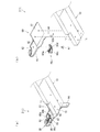
[2−5.外枠側上ヒンジ部材]
外枠2の外枠側上ヒンジ部材60は、図示するように、水平に延びた平板状で外形が四角形の上固定部61と、上固定部61の前端から前方へ延出している平板状の前方延出部62と、前方延出部62の右端から前方へ向かうに従って前方延出部62の左右中央へ延びており上下に貫通している軸受溝63と、上固定部61の平面視左辺から下方へ延びている平板状の横固定部64と、前方延出部62の左端から前端を周って軸受溝63が開口している部位までの端辺から下方へ延びており横固定部64と連続している平板状の垂下部65と、を備えている(図16(b)等を参照)。
[2-5. Outer frame side upper hinge member]
The outer frame side upper hinge member 60 of the outer frame 2 is a flat plate extending horizontally and having a rectangular outer shape fixed to the upper fixing portion 61 and a flat shape extending forward from the front end of the upper fixing portion 61 as illustrated. Of the front extension 62, a bearing groove 63 extending to the left and right center of the front extension 62 as going forward from the right end of the front extension 62, and penetrating vertically, and a plan view of the upper fixing portion 61 A flat horizontal fixing portion 64 extending downward from the left side, and a lower side extending from the end of the front extension 62 from the left end to the portion where the bearing groove 63 is open from the left end to the horizontal fixing A flat plate-like hanging portion 65 continuous with the portion 64 is provided (see FIG. 16 (b) and the like).
外枠側上ヒンジ部材60は、外枠2が組立てられた状態で、上固定部61が、上枠部材10の取付段部12の上面に載置されており、図示しないビスによって固定されている。また、前方延出部62は、上枠部材10の前端よりも前方へ延出している。また、横固定部64は、左枠部材30の外側側面の凹部31内に上側から挿入された状態で、ビスによって左枠部材30に固定されている。
In the outer frame side upper hinge member 60, the upper fixing portion 61 is placed on the upper surface of the mounting stepped portion 12 of the upper frame member 10 in a state where the outer frame 2 is assembled, and fixed by screws not shown. There is. Further, the front extension portion 62 extends forward of the front end of the upper frame member 10. Further, the horizontal fixing portion 64 is fixed to the left frame member 30 by a screw in a state of being inserted from the upper side into the recess 31 of the outer side surface of the left frame member 30.
この外枠側上ヒンジ部材60は、軸受溝63内に本体枠側上ヒンジ部材620の本体枠上ヒンジピン622を挿入させることで、外枠側下ヒンジ部材70と協働して本体枠4を開閉可能に支持することができる。この外枠側上ヒンジ部材60は、金属板をプレス成型により屈曲させて形成されている。
The outer frame side upper hinge member 60 cooperates with the outer frame side lower hinge member 70 to insert the main frame 4 by inserting the main frame upper hinge pin 622 of the main frame upper hinge member 620 into the bearing groove 63. It can be supported openable and closable. The outer frame side upper hinge member 60 is formed by bending a metal plate by press molding.
[2−6.ロック部材]
外枠2のロック部材66は、図16に示すように、左右が所定幅で前後に延びている帯板状のロック本体66aと、ロック本体66aの後端から右方へ突出している操作部66bと、ロック本体66aの後端から左方へ延びた後に斜め左前方へ延びている弾性変形可能な棒状の弾性部66cと、ロック本体66aの後端付近で上下に貫通している取付孔66dと、を備えている。このロック部材66は、合成樹脂によって形成されている。ロック部材66は、取付ビス67によって、外枠側上ヒンジ部材60における前方延出部62の下面に回動可能に取付けられる。
[2-6. Lock member]
The lock member 66 of the outer frame 2 is, as shown in FIG. 16, a band-plate shaped lock main body 66a having a predetermined width on the left and right and extending back and forth, and an operation portion projecting rightward from the rear end of the lock main body 66a. 66b, a resiliently deformable rod-like elastic portion 66c extending diagonally forward to the left after extending from the rear end of the lock main body 66a, and an attachment hole vertically penetrating near the rear end of the lock main body 66a And 66d. The lock member 66 is formed of synthetic resin. The lock member 66 is rotatably attached to the lower surface of the front extension portion 62 of the outer frame side upper hinge member 60 by a mounting screw 67.
このロック部材66は、取付孔66dを通して、ロック本体66aの後端が、外枠側上ヒンジ部材60の前方延出部62における軸受溝63よりも後側の位置に取付けられる。また、ロック部材66を外枠側上ヒンジ部材60に取付けた状態では、ロック本体66aが、平面視で軸受溝63を遮ることができると共に、前端付近の右側面が、外枠側上ヒンジ部材60の垂下部65における軸受溝63の開口まで延びている部位と当接可能となるように前方へ延びている(図18を参照)。
The rear end of the lock body 66a is attached to a position rearward of the bearing groove 63 in the front extension 62 of the outer frame side upper hinge member 60 through the attachment hole 66d. Further, in a state where the lock member 66 is attached to the outer frame side upper hinge member 60, the lock main body 66a can block the bearing groove 63 in plan view, and the right side near the front end is the outer frame side upper hinge member It extends forward so as to be in contact with a portion of the hanging portion 65 extending to the opening of the bearing groove 63 (see FIG. 18).
また、ロック本体66aの後端から左方へ延びている弾性部66cの先端は、外枠側上ヒンジ部材60における垂下部65の内周面に当接している。このロック部材66は、弾性部66cの付勢力によって取付孔66dを中心に、前端が左方へ回動する方向に付勢されている。従って、通常の状態では、ロック部材66のロック本体66aの前端付近の右側面が、垂下部65に当接している(図18を参照)。この状態では、軸受溝63におけるロック本体66aよりも前側の部位に、本体枠側上ヒンジ部材620の後述する本体枠上ヒンジピン622を収容可能な空間が形成される。
Further, the tip end of the elastic portion 66c extending leftward from the rear end of the lock main body 66a is in contact with the inner peripheral surface of the hanging portion 65 of the outer frame side upper hinge member 60. The lock member 66 is biased in a direction such that the front end pivots to the left around the mounting hole 66d by the biasing force of the elastic portion 66c. Therefore, in the normal state, the right side surface near the front end of the lock body 66a of the lock member 66 is in contact with the hanging portion 65 (see FIG. 18). In this state, a space capable of accommodating a main frame upper hinge pin 622 (described later) of the main frame upper upper hinge member 620 is formed in a portion of the bearing groove 63 on the front side of the lock main body 66a.
このロック部材66は、操作部66bを操作することで、弾性部66cの付勢力に抗してロック本体66aを回動させることができる。そして、操作部66bの操作によって、ロック本体66aを、その前端が左方へ移動する方向へ回動させることで、平面視において軸受溝63からロック本体66aを後退させることができ、軸受溝63が全通している状態とすることができる。これにより、軸受溝63内に本体枠上ヒンジピン622を挿入したり、軸受溝63内から本体枠上ヒンジピン622を外したりすることができる。
The lock member 66 can rotate the lock main body 66a against the biasing force of the elastic portion 66c by operating the operation portion 66b. Then, the lock main body 66a can be retracted from the bearing groove 63 in plan view by rotating the lock main body 66a in the direction in which the front end moves to the left by the operation of the operation portion 66b. Can be completely through. Thus, the main frame upper hinge pin 622 can be inserted into the bearing groove 63 or the main frame upper hinge pin 622 can be removed from the bearing groove 63.
[2−7.外枠側下ヒンジ部材]
外枠2の外枠側下ヒンジ部材70は、図示するように、水平に延びている平板状の水平部71と、水平部71の左辺において前後方向中央よりも後側の部位から上方へ立上っている平板状の立上り部72と、水平部71の前端付近から上方へ突出している外枠下ヒンジピン73と、水平部71を上下に貫通しており遊技球が一つのみ通過可能な大きさの排出孔74と、を備えている。この外枠側下ヒンジ部材70は、金属板をプレス成型により屈曲させて形成されている。
[2-7. Outer frame side lower hinge member]
As shown in the figure, the outer frame side lower hinge member 70 of the outer frame 2 stands upward from a portion behind the center in the front-rear direction on the left side of the horizontally extending flat horizontal portion 71 and the horizontal portion 71. A flat plate-like rising portion 72, an outer frame lower hinge pin 73 protruding upward from near the front end of the horizontal portion 71, and a horizontal portion 71 are vertically penetrated, and only one game ball can pass through. And a discharge hole 74 of a size. The outer frame side lower hinge member 70 is formed by bending a metal plate by press molding.
外枠側下ヒンジ部材70の水平部71は、平面視において、左辺を底辺とした台形に形成されている。外枠下ヒンジピン73は、円柱状で、上下方向中央よりも上部が、上端が窄まった円錐台状に形成されている。この外枠下ヒンジピン73は、水平部71の前端付近における左寄りの位置に取付けられている。排出孔74は、水平部71において、立上り部72の前後方向中央の部位と接し、水平部71の左辺から右方へ逆U字状に延びるように形成されている。この排出孔74は、幕板部材50の左排出孔52と、略同じ大きさに形成されている。
The horizontal portion 71 of the outer frame side lower hinge member 70 is formed in a trapezoidal shape whose left side is a base in a plan view. The outer frame lower hinge pin 73 has a cylindrical shape and is formed in a truncated cone shape whose upper end is narrowed at the upper end than the center in the vertical direction. The outer frame lower hinge pin 73 is attached at a position near the front end of the horizontal portion 71 to the left. The discharge hole 74 is formed in the horizontal portion 71 so as to be in contact with a central portion of the rising portion 72 in the front-rear direction, and extends from the left side of the horizontal portion 71 to the right in an inverted U shape. The discharge hole 74 is formed in substantially the same size as the left discharge hole 52 of the curtain plate member 50.
外枠側下ヒンジ部材70は、外枠2が組立てられた状態では、水平部71が、幕板部材50の左端付近の上面と後方延出部51上に載置されており、水平部71が、幕板部材50の上面を貫通する図示しないビスによって幕板補強部材80に固定されている。また、外枠2が組立てられた状態では、立上り部72が、左枠部材30の内側側面における突出部32よりも前側の部位に、図示しないビスによって取付けられている。この外枠側下ヒンジ部材70は、外枠下ヒンジピン73を、本体枠4の本体枠側下ヒンジ部材640における本体枠用下ヒンジ孔(図示は省略)に挿通させることで、外枠側上ヒンジ部材60と協働して本体枠4を開閉可能に取付けることができる。
In the outer frame side lower hinge member 70, when the outer frame 2 is assembled, the horizontal portion 71 is placed on the upper surface near the left end of the curtain plate member 50 and on the rear extension portion 51. Is fixed to the curtain plate reinforcing member 80 by a screw (not shown) penetrating the upper surface of the curtain plate member 50. Further, in a state where the outer frame 2 is assembled, the rising portion 72 is attached to a portion on the front side of the projecting portion 32 on the inner side surface of the left frame member 30 by a screw (not shown). The outer frame side lower hinge member 70 is inserted into the main frame lower lower hinge member (not shown) in the main frame side lower hinge member 640 of the main body frame 4, whereby the outer frame lower upper hinge pin 70 is inserted. The main body frame 4 can be attached so as to be able to open and close in cooperation with the hinge member 60.
また、外枠2が組立てられた状態では、排出孔74が、幕板部材50の左排出孔52と一致している。これにより、水平部71上の遊技球を、排出孔74及び左排出孔52を通して、幕板部材50の後側へ落下(排出)させることができる。詳述すると、外枠2に対して本体枠4を閉じる時に、外枠2と本体枠4との間に落下した遊技球が、本体枠4が閉じられるのに従って、外枠2と本体枠4との間が徐々に狭くなることから、間隔が広い後方側へ転動とすることとなり、排出孔74から排出させることができる。この際に、排出孔74が、パチンコ機1に組立てた状態で、外枠2に対して本体枠4を閉じた時に、本体枠4の後端と略同じとなる位置に形成されているため、外枠2と本体枠4との間に落下した遊技球を、排出孔74から排出させることで本体枠4よりも後側へ転動するのを阻止し易くすることができ、外枠側下ヒンジ部材70の部位に遊技球が留まり難くすることができる。
Further, in the state where the outer frame 2 is assembled, the discharge hole 74 matches the left discharge hole 52 of the curtain plate member 50. Thereby, the gaming ball on the horizontal portion 71 can be dropped (discharged) to the rear side of the curtain plate member 50 through the discharge hole 74 and the left discharge hole 52. Specifically, when the main frame 4 is closed with respect to the outer frame 2, the game ball dropped between the outer frame 2 and the main frame 4 is closed as the main frame 4 is closed. Since the gap between the two gradually narrows, the space is rolled backward and can be discharged from the discharge hole 74. At this time, the discharge hole 74 is formed at a position substantially the same as the rear end of the main body frame 4 when the main body frame 4 is closed to the outer frame 2 in a state assembled to the pachinko machine 1 By discharging the game balls dropped between the outer frame 2 and the main frame 4 from the discharge holes 74, it is possible to easily prevent the game frame 4 from rolling to the rear side, the outer frame side It is possible to make it difficult for the gaming ball to stay at the portion of the lower hinge member 70.
[2−8.連結部材]
外枠2の連結部材85は、上枠部材10と左枠部材30とを連結する左上連結部材85Aと、上枠部材10と右枠部材40とを連結する右上連結部材85Bと、下枠部材20と左枠部材30とを連結する左下連結部材85Cと、下枠部材20と右枠部材40とを連結する右下連結部材85Dと、がある。
[2-8. Connection member]
The connecting member 85 of the outer frame 2 includes an upper left connecting member 85A connecting the upper frame member 10 and the left frame member 30, an upper right connecting member 85B connecting the upper frame member 10 and the right frame member 40, and a lower frame member 20 and a left lower connecting member 85C connecting the left frame member 30 and a lower right connecting member 85D connecting the lower frame member 20 and the right frame member 40.
連結部材85は、水平に延びた平板状の水平固定部86と、水平固定部86の左右側辺の何れか一方から上方へ延出している平板状の上横固定部87と、水平固定部86における上横固定部87が延出している部位と同じ側から下方へ延出している平板状の下横固定部88と、を備えている。この連結部材85は、平板状の金属板を屈曲させて形成されている。
The connecting member 85 includes a horizontally extending flat horizontal fixing portion 86, a flat upper horizontal fixing portion 87 extending upward from either the left or right side of the horizontal fixing portion 86, and a horizontal fixing portion. And 86 a flat lower lower fixing portion 88 extending downward from the same side as the portion where the upper horizontal fixing portion 87 extends. The connection member 85 is formed by bending a flat metal plate.
左上連結部材85A及び右上連結部材85Bでは、水平固定部86の前後方向の中央から上横固定部87が上方へ延出していると共に、上横固定部87の前後両側から下横固定部88が下方へ延出している。つまり、左上連結部材85A及び右上連結部材85Bでは、下横固定部88が前後に離間して二つ備えられている。左上連結部材85A及び右上連結部材85Bの水平固定部86は、上枠部材10の下面に当接した状態で上枠部材10に固定される。また、左上連結部材85A及び右上連結部材85Bの上横固定部87は、上枠部材10の係合切欠部21内に挿入されて、上枠部材10の左右方向の端部に固定される。また、左上連結部材85A及び右上連結部材85Bの前側の下横固定部88は、左枠部材30及び右枠部材40の突出部32,42よりも前側の内側側面に夫々固定される。更に、左上連結部材85A及び右上連結部材85Bの後側の下横固定部88は、左枠部材30及び右枠部材40の突出部32,42内に挿入されて外側側面から捩じ込まれるビスにより左枠部材30及び右枠部材40に夫々固定される。
In the upper left connecting member 85A and the upper right connecting member 85B, the upper horizontal fixing portion 87 extends upward from the center in the front-rear direction of the horizontal fixing portion 86, and the lower horizontal fixing portion 88 from the front and rear both sides of the upper horizontal fixing portion 87. It extends downward. That is, in the upper left connecting member 85A and the upper right connecting member 85B, two lower horizontal fixing portions 88 are provided separately in the front-rear direction. The horizontal fixing portions 86 of the upper left connecting member 85A and the upper right connecting member 85B are fixed to the upper frame member 10 in a state of being in contact with the lower surface of the upper frame member 10. The upper horizontal fixing portion 87 of the upper left connecting member 85A and the upper right connecting member 85B is inserted into the engagement cutout portion 21 of the upper frame member 10 and fixed to the end of the upper frame member 10 in the left-right direction. The lower horizontal fixing portions 88 on the front side of the upper left connecting member 85A and the upper right connecting member 85B are respectively fixed to the inner side surfaces on the front side of the projecting portions 32 and 42 of the left frame member 30 and the right frame member 40. Furthermore, the lower horizontal fixing portion 88 on the rear side of the upper left connecting member 85A and the upper right connecting member 85B is inserted into the projecting portions 32 and 42 of the left frame member 30 and the right frame member 40 and screwed from the outer side surface. As a result, it is fixed to the left frame member 30 and the right frame member 40 respectively.
左下連結部材85C及び右下連結部材85Dでは、上横固定部87の後端が、水平固定部86の後端よりも後方へ突出していると共に、上横固定部87の水平固定部86よりも後方へ突出している部位の下端から下横固定部88が水平固定部86よりも下方へ延出している。また、左下連結部材85C及び右下連結部材85Dでは、上横固定部87の後端から水平固定部86と同じ側へ突出している屈曲部89を更に備えている。左下連結部材85C及び右下連結部材85Dの水平固定部86は、下枠部材20の上面に当接した状態で固定される。また、左下連結部材85C及び右下連結部材85Dの上横固定部87は、左枠部材30及び右枠部材40の突出部32,42よりも前側の内側側面に夫々固定される。更に、左下連結部材85C及び右下連結部材85Dの下横固定部88は、下枠部材20の係合切欠部21内に挿入されて下枠部材20の左右方向の端部面に夫々固定される。
In the lower left connecting member 85C and the lower right connecting member 85D, the rear end of the upper horizontal fixing portion 87 protrudes rearward more than the rear end of the horizontal fixing portion 86 and the horizontal fixing portion 86 of the upper horizontal fixing portion 87. A lower horizontal fixing portion 88 extends downward from the horizontal fixing portion 86 from the lower end of the portion projecting rearward. The lower left connecting member 85C and the lower right connecting member 85D further include a bent portion 89 projecting from the rear end of the upper horizontal fixing portion 87 to the same side as the horizontal fixing portion 86. The horizontal fixing portions 86 of the lower left connecting member 85C and the lower right connecting member 85D are fixed in contact with the upper surface of the lower frame member 20. Further, the upper horizontal fixing portions 87 of the lower left connecting member 85C and the lower right connecting member 85D are fixed to the inner side surface on the front side of the protruding portions 32, 42 of the left frame member 30 and the right frame member 40, respectively. Furthermore, the lower horizontal fixing portion 88 of the lower left connecting member 85C and the lower right connecting member 85D is inserted into the engagement cutout portion 21 of the lower frame member 20 and fixed to the end surface of the lower frame member 20 in the left-right direction. Ru.
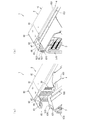
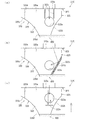
[2−9.外枠側上ヒンジ部材のロック機構]
次に、本実施形態のパチンコ機1の外枠2において、外枠側上ヒンジ部材60におけるロック部材66による本体枠4の本体枠側上ヒンジ部材620に対するロック機構について、図17及び図18を参照して説明する。図17(a)は外枠の外枠側上ヒンジ部材に対して本体枠の本体枠側上ヒンジ部材が取外されている状態を拡大して示す斜視図であり、(b)は外側上ヒンジ部材に本体側上ヒンジ部材が取付けられている状態を拡大して示す斜視図である。図18は、外枠におけるロック部材の作用を示す説明図である。
[2-9. Locking mechanism of outer frame side upper hinge member]
Next, in the outer frame 2 of the pachinko machine 1 of the present embodiment, a lock mechanism for the main frame side upper hinge member 620 of the main body frame 4 by the lock member 66 in the outer frame side upper hinge member 60 will be described with reference to FIGS. Refer to the description. Fig.17 (a) is a perspective view which expands and shows the state by which the main frame side upper hinge member of the main body frame is removed with respect to the outer frame side upper hinge member of an outer frame, (b) is an outer upper side. It is a perspective view which expands and shows the state in which the main body side upper hinge member is attached to the hinge member. FIG. 18 is an explanatory view showing the operation of the lock member in the outer frame.
外枠2におけるロック部材66は、外枠側上ヒンジ部材60の前方延出部62に取付けた状態(通常の状態)では、弾性部66cの先端が垂下部65の内周面と当接しており、ロック本体66aがく字状に屈曲した軸受溝63の一部を閉塞するようになっていると共に、ロック本体66aの先端部分が、軸受溝63の最深部分を閉塞した状態とはならず、軸受溝63の最深部分に本体枠4の本体枠側上ヒンジ部材620の本体枠上ヒンジピン622を挿入可能な空間が形成された状態となっている。
When the lock member 66 in the outer frame 2 is attached to the front extension portion 62 of the outer frame-side upper hinge member 60 (normal state), the tip of the elastic portion 66c abuts on the inner circumferential surface of the hanging portion 65 The lock main body 66a is configured to close a part of the bearing groove 63 bent in a V-shape, and the tip end portion of the lock main body 66a does not close the deepest part of the bearing groove 63, A space in which the main frame upper hinge pin 622 of the main frame side upper hinge member 620 of the main body frame 4 can be inserted is formed at the deepest portion of the bearing groove 63.
本実施形態における外枠側上ヒンジ部材60とロック部材66とを用いた本体枠上ヒンジピン622の支持機構は、本体枠上ヒンジピン622が軸受溝63の最深部分に挿入されてロック本体66aの前端の右側面が、右側の垂下部65と接近している状態(この状態ではロック本体66aの前端の右側面と右側の垂下部65との間に僅かな隙間があり当接した状態となっていない)である通常の軸支状態においては、屈曲している軸受溝63の最深部分に位置する本体枠上ヒンジピン622とロック本体66aの前端面との夫々の中心が斜め方向にずれて対向した状態となっている。
In the supporting mechanism of the main frame upper hinge pin 622 using the outer frame side upper hinge member 60 and the lock member 66 in the present embodiment, the main frame upper hinge pin 622 is inserted into the deepest portion of the bearing groove 63 and the front end of the lock main body 66a The right side face of the lock body 66 is in close proximity to the right hanging portion 65 (in this state, there is a slight gap between the right side face of the front end of the lock main body 66a and the right hanging In the normal pivotally supported state, the respective centers of the main frame upper hinge pin 622 located at the deepest part of the bent bearing groove 63 and the front end face of the lock main body 66a are diagonally offset and opposed It is in the state.
そして、この通常の軸支状態においては、重量のある本体枠4を軸支している本体枠上ヒンジピン622が軸受溝63の前端部分に当接した状態となっているので、本体枠上ヒンジピン622からロック本体66aの前端面への負荷がほとんどかかっていない。つまり、ロック部材66の弾性部66cに対し負荷がかかっていない状態となっている。なお、ロック本体66aの前端面が円弧状に形成されているため、ロック部材66を回動させるために操作部66bを回動操作した時に、ロック部材66がスムーズに回動するようになっている。また、図示では、ロック本体66aの前端面の円弧中心が、取付孔66dの中心(ロック部材66の回転中心)とされている。
And, in this normal support state, since the main frame upper hinge pin 622 supporting the heavy main body frame 4 is in contact with the front end portion of the bearing groove 63, the main frame upper hinge pin There is almost no load from 622 on the front end face of the lock body 66a. That is, no load is applied to the elastic portion 66c of the lock member 66. In addition, since the front end face of the lock main body 66a is formed in a circular arc shape, when the operation portion 66b is turned to turn the lock member 66, the lock member 66 is smoothly turned. There is. Further, in the drawing, the arc center of the front end face of the lock main body 66a is taken as the center of the mounting hole 66d (the rotation center of the lock member 66).
従って、本体枠上ヒンジピン622がく字状に形成された軸受溝63の傾斜に沿って抜ける方向に作用力Fがかかって、ロック本体66aの円弧状の前端面に当接したとき、その作用力Fを、本体枠上ヒンジピン622と円弧状の前端面との当接部分に作用する分力F1(ロック本体66aの前端面の円弧の法線方向)と、本体枠上ヒンジピン622と軸受溝63の一側内面との当接部分に作用する分力F2と、に分けたときに、分力F1の方向が取付孔66d(取付ビス67)の中心(ロック部材66の回転中心)を向くため、ロック部材66のロック本体66aの前端が、右側の垂下部65から離れる方向に回転させるモーメントが働かず、本体枠上ヒンジピン622がロック部材66のロック本体66aの前端部と軸受溝63の一側内面との間に挟持された状態が保持される。
Therefore, when the acting force F is applied in the direction in which the hinge pin 622 on the main body frame comes out along the slope of the bearing groove 63 formed in the V shape and abuts on the arc-shaped front end face of the lock body 66a, the acting force A component force F1 (a normal direction of an arc of a front end face of the lock main body 66a) acting on a contact portion between the body frame upper hinge pin 622 and the arc shaped front end face, a body frame upper hinge pin 622 and a bearing groove 63 The component force F1 is directed to the center (rotation center of the lock member 66) of the mounting hole 66d (mounting screw 67) when divided into the component force F2 acting on the contact portion with the inner surface on one side The moment that the front end of the lock body 66a of the lock member 66 rotates in the direction away from the hanging portion 65 on the right does not work, and the hinge pin 622 of the main body frame is one of the front end portion of the lock body 66a of the lock member 66 and the bearing groove 63. Inside Clamped state is maintained between the.
このため、通常の軸支状態、或は、本体枠上ヒンジピン622の作用力がロック部材66にかかった状態でも、ロック部材66の弾性部66cに常時負荷がかからず、合成樹脂で一体形成される弾性部66cのクリープによる塑性変形を防止し、長期間に亘って本体枠上ヒンジピン622の軸受溝63からの脱落を防止することができる。なお、仮に無理な力がかかってロック部材66のロック本体66aの前端部が右方へ移動する方向へ回転させられても、ロック本体66aの前端右側面が垂下部65に当接してそれ以上回転しないので、ロック部材66が前方延出部62の外側にはみ出ないようになっている。
For this reason, even in a normal pivotally supported state or a state where the action force of the main frame upper hinge pin 622 is applied to the lock member 66, no load is always applied to the elastic portion 66c of the lock member 66, and integrally formed of synthetic resin. It is possible to prevent plastic deformation due to creep of the elastic portion 66c, and to prevent the main frame upper hinge pin 622 from coming off from the bearing groove 63 for a long period of time. Even if an excessive force is applied and the front end of the lock body 66a of the lock member 66 is rotated in the direction to move to the right, the front right side of the lock main body 66a abuts on the hanging portion 65 to further Since it does not rotate, the lock member 66 does not protrude outside the front extension 62.
なお、ロック本体66aの前端面の形状は円弧状でなくても、上記した分力F1の作用により回転モーメントが生じない位置又はロック部材66をその前端部が前方延出部62の外側に向って回転させる回転モーメントが生ずる位置にロック部材66の回転中心(取付ビス67により固定される軸)を位置させることにより、常時ロック部材66の弾性部66cに対しても負荷がかかることはないし、ロック部材66が回転してもロック本体66aの前端の右側面が垂下部65に当接するだけであるため、ロック部材66が前方延出部62の外側にはみ出ることもない。
Note that even if the shape of the front end face of the lock main body 66a is not arc-shaped, the position where the rotational moment is not generated by the action of the component force F1 described above or the front end portion of the lock member 66 faces the outside of the forward extension portion 62. By placing the rotation center of the lock member 66 (the shaft fixed by the mounting screw 67) at a position where a rotational moment to rotate is generated, no load is always applied to the elastic portion 66c of the lock member 66, Even when the lock member 66 rotates, the right side surface of the front end of the lock body 66 a just abuts on the hanging portion 65, and therefore the lock member 66 does not protrude outside the front extension portion 62.
外枠側上ヒンジ部材60の軸受溝63に、本体枠側上ヒンジ部材620の本体枠上ヒンジピン622を支持させる場合は、軸受溝63の開放されている側から軸受溝63内に本体枠上ヒンジピン622を挿入する。軸受溝63内に本体枠上ヒンジピン622を挿入すると、ロック部材66のロック本体66aの右側面に本体枠上ヒンジピン622が当接し、弾性部66cの付勢力に抗してロック本体66aの前端が左方へ移動するようにロック部材66が取付ビス67を中心に回動する。これにより、軸受溝63を閉鎖していたロック本体66aが後退して軸受溝63が開放され、軸受溝63の最深部(前端)へ本体枠上ヒンジピン622を移動させることができるようになる。
When the main frame upper hinge pin 622 of the main frame upper hinge member 620 is supported by the bearing groove 63 of the outer frame side upper hinge member 60, the upper side of the main frame in the bearing groove 63 from the open side of the bearing groove 63 Insert the hinge pin 622. When the main frame upper hinge pin 622 is inserted into the bearing groove 63, the main frame upper hinge pin 622 abuts on the right side surface of the lock main body 66a of the lock member 66 and the front end of the lock main body 66a resists the biasing force of the elastic portion 66c. The lock member 66 pivots around the mounting screw 67 so as to move to the left. As a result, the lock main body 66a closing the bearing groove 63 retracts to open the bearing groove 63, and the main frame upper hinge pin 622 can be moved to the deepest portion (front end) of the bearing groove 63.
そして、軸受溝63の最深部に本体枠上ヒンジピン622を移動させると、本体枠上ヒンジピン622とロック部材66のロック本体66aとの当接が解除され、弾性部66cの付勢力によってロック本体66aの前端が右方へ移動するようにロック部材66が回動し、ロック部材66が通常の状態に復帰する。これにより、本体枠上ヒンジピン622が、軸受溝63内におけるロック本体66aの前端よりも前側の空間に収容された状態となり、本体枠上ヒンジピン622が、軸受溝63の最深部において回動可能な状態で保持(ロック)された状態となる。
Then, when the main frame upper hinge pin 622 is moved to the deepest part of the bearing groove 63, the contact between the main frame upper hinge pin 622 and the lock main body 66a of the lock member 66 is released, and the lock main body 66a is moved by the biasing force of the elastic portion 66c. The lock member 66 is pivoted so that the front end of the arm moves to the right, and the lock member 66 returns to the normal state. As a result, the body frame upper hinge pin 622 is accommodated in the space on the front side of the front end of the lock main body 66 a in the bearing groove 63, and the body frame upper hinge pin 622 can rotate at the deepest portion of the bearing groove 63. It is held (locked) in the state.
軸受溝63内から本体枠上ヒンジピン622を取外す場合は、ロック部材66の操作部66bを操作して、ロック本体66aの前端が左方へ移動するようにロック部材66を回動させ、弾性部66cの付勢力に抗して軸受溝63からロック本体66aを後退させる。これにより、軸受溝63の最深部と開口部とが連通した状態となり、軸受溝63から本体枠上ヒンジピン622を取外すことができる。
When removing the main frame upper hinge pin 622 from the inside of the bearing groove 63, the operating portion 66b of the locking member 66 is operated to turn the locking member 66 so that the front end of the lock main body 66a moves to the left. The lock main body 66a is retracted from the bearing groove 63 against the biasing force of 66c. As a result, the deepest portion of the bearing groove 63 and the opening communicate with each other, and the hinge pin 622 on the main body frame can be removed from the bearing groove 63.
[2−10.外枠側下ヒンジ部材の部位における防犯機構と球噛み防止機構]
本実施形態のパチンコ機1における外枠2の外枠側下ヒンジ部材70の部位における防犯機構と外枠2と本体枠4との間に遊技球が挟まれるのを防止するための球噛み防止機構について説明する。
[2-10. Security mechanism and ball biting prevention mechanism at the portion of the outer frame side lower hinge member]
Ball catching prevention for preventing the game ball from being caught between the crime prevention mechanism and the outer frame 2 and the main body frame 4 at the portion of the outer frame side lower hinge member 70 of the outer frame 2 in the pachinko machine 1 of the present embodiment The mechanism will be described.
外枠2は、組立てた状態では、幕板部材50の上面における正面視左端部に外枠側下ヒンジ部材70が取付けられている。外枠側下ヒンジ部材70の水平部71は、幕板部材50の上面の左端付近と後方延出部51の上面とに載置された状態で取付けられている。この幕板部材50には、上面の後端から上方へ立上っている立壁部54を備えている。これにより、外枠側下ヒンジ部材70と本体枠側下ヒンジ部材640との間の隙間を通して、本体枠4(パチンコ機1)の後側へピアノ線等の不正な工具を侵入させようとしても、不正な工具の先端が幕板部材50の上面の後端から上方へ延出している立壁部54に当接するため、不正な工具がこれ以上後側へ挿入されるのを阻止することができ、外枠側下ヒンジ部材70の部位を介して不正行為が行われるのを防止することができる。
In the assembled state, the outer frame side lower hinge member 70 is attached to the outer frame 2 at the left end in the front view on the upper surface of the curtain plate member 50. The horizontal portion 71 of the outer frame side lower hinge member 70 is mounted in a state of being placed near the left end of the upper surface of the curtain plate member 50 and the upper surface of the rear extension portion 51. The curtain plate member 50 includes an upright wall portion 54 rising upward from the rear end of the upper surface. Thus, even if an unauthorized tool such as a piano wire is made to enter the rear side of the main frame 4 (pachinko machine 1) through the gap between the outer frame side lower hinge member 70 and the main frame side lower hinge member 640. Since the tip of the incorrect tool abuts on the upstanding wall portion 54 extending upward from the rear end of the upper surface of the curtain plate member 50, it is possible to prevent the incorrect tool from being inserted further backward. Thus, it is possible to prevent a fraud from being conducted through the portion of the outer frame side lower hinge member 70.
また、立壁部54の上端に、前方へ延出している返し部55を備えているため、立壁部54に当接した不正な工具が上方へ曲がった場合、返し部55によって不正な工具の先端を更に前方へ折返させることができるため、本体枠4の後側に不正な工具が侵入させられるのを阻止することができ、外枠側下ヒンジ部材70の部位を介して不正行為が行われるのを確実に阻止することができる。
In addition, since the upper end of the standing wall portion 54 is provided with the return portion 55 extending forward, when the incorrect tool in contact with the upper wall portion 54 is bent upward, the end of the incorrect tool by the return portion 55 Can be further folded forward, so that an unauthorized tool can be prevented from invading the rear side of the main body frame 4, and cheating is performed through the portion of the outer frame side lower hinge member 70. Can be reliably blocked.
ところで、幕板部材50の上面の後端に上方へ延出している立壁部54を備えるようにした場合、外枠2に対して本体枠4を開いている状態で、遊技球が外枠側下ヒンジ部材70(水平部71)上に落下した場合、水平部71上の遊技球が、立壁部54の存在によって水平部71の後端から後方へ排出されないため、外枠2と本体枠4との間に挟まれてしまう虞がある。これに対して、本実施形態では、外枠側下ヒンジ部材70の水平部71と、幕板部材50の後方延出部51とに、遊技球が通過可能な排出孔74、左排出孔52、及び右排出孔53を備えているため、外枠側下ヒンジ部材70の水平部71上の遊技球を、排出孔74等から下方へ排出することができ、外枠2と本体枠4との間に遊技球が挟まれるのを低減させることができる。
By the way, when the standing wall portion 54 extending upward is provided at the rear end of the upper surface of the curtain plate member 50, the gaming ball is on the outer frame side with the main body frame 4 open to the outer frame 2. When dropped onto the lower hinge member 70 (horizontal portion 71), the gaming ball on the horizontal portion 71 is not discharged rearward from the rear end of the horizontal portion 71 due to the presence of the standing wall portion 54. There is a risk of being caught between On the other hand, in the present embodiment, the discharge hole 74 and the left discharge hole 52 through which the game ball can pass through the horizontal portion 71 of the outer frame side lower hinge member 70 and the rear extension portion 51 of the curtain plate member 50. Because the right discharge hole 53 is provided, the gaming balls on the horizontal portion 71 of the outer frame side lower hinge member 70 can be discharged downward from the discharge hole 74 or the like, and the outer frame 2 and the body frame 4 Between the game ball and the game ball can be reduced.
従って、外枠2と本体枠4との間に遊技球が挟まれることで、外枠側下ヒンジ部材70の周りが破損したり、本体枠4が正常な状態で閉まらずに外枠2と本体枠4との間に隙間ができてしまい、その隙間を使って不正行為が行われてしまったりするのを防止することができる。
Therefore, by the game ball being pinched between the outer frame 2 and the main body frame 4, the outer frame side lower hinge member 70 may be damaged or the main frame 4 may not be closed in a normal state. A gap is created between the main unit frame 4 and the gap, which can be used to prevent fraudulent acts.
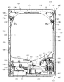
[3.扉枠の全体構成]
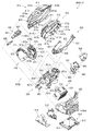
パチンコ機1の扉枠3について、図19乃至図30を参照して説明する。図19はパチンコ機における扉枠の正面図であり、図20は扉枠の右側面図であり、図21は扉枠の左側面図であり、図22は扉枠の背面図である。図23は扉枠を右前から見た斜視図であり、図24は扉枠を左前から見た斜視図であり、図25は扉枠を後ろから見た斜視図である。図26は図19におけるA−A線で切断した断面図であり、図27は図19におけるB−B線で切断した断面図であり、図28は図19におけるC−C線で切断した断面図である。図29は扉枠を主な部材毎に分解して前から見た分解斜視図であり、図30は扉枠を主な部材毎に分解して後ろから見た分解斜視図である。
[3. Overall configuration of the door frame]
The door frame 3 of the pachinko machine 1 will be described with reference to FIGS. 19 to 30. 19 is a front view of a door frame in a pachinko machine, FIG. 20 is a right side view of the door frame, FIG. 21 is a left side view of the door frame, and FIG. 22 is a rear view of the door frame. FIG. 23 is a perspective view of the door frame as viewed from the front right, FIG. 24 is a perspective view of the door frame as viewed from the front left, and FIG. 25 is a perspective view of the door frame as viewed from the rear. 26 is a cross-sectional view taken along the line A-A in FIG. 19, FIG. 27 is a cross-sectional view taken along the line B-B in FIG. 19, and FIG. 28 is a cross section taken along the line C-C in FIG. FIG. FIG. 29 is an exploded perspective view of the door frame disassembled into main members and viewed from the front, and FIG. 30 is an exploded perspective view of the door frame disassembled into main members and viewed from the rear.
扉枠3は、図29及び図30等に示すように、正面視の外形が上下に延びた四角形で枠状の扉枠ベースユニット100と、扉枠ベースユニット100の前面右下隅に取付けられているハンドルユニット300と、扉枠ベースユニット100の前面下部に取付けられている皿ユニット320と、皿ユニット320の中央に取付けられている演出操作ユニット400と、皿ユニット320の上側で扉枠ベースユニット100の前面左部に取付けられている扉枠左サイドユニット540と、皿ユニット320の上側で扉枠ベースユニット100の前面右部に取付けられている扉枠右サイドユニット550と、扉枠左サイドユニット540及び扉枠右サイドユニット550の上側で扉枠ベースユニット100の前面上部に取付けられている扉枠トップユニット570と、を備えている。
As shown in FIG. 29 and FIG. 30, etc., the door frame 3 is attached to the frame-shaped door frame base unit 100 having a rectangular shape with the outline of the front view extending vertically and the front lower right corner of the door frame base unit 100 The handle unit 300, the dish unit 320 attached to the lower front of the door frame base unit 100, the rendering operation unit 400 attached to the center of the dish unit 320, and the door frame base unit above the dish unit 320 A door frame left side unit 540 attached to the front left of the 100, a door frame right side unit 550 attached to the front right of the door frame base unit 100 above the plate unit 320, and a door frame left side Door frame top attached to the upper front of the door frame base unit 100 above the unit 540 and the door frame right side unit 550 Is provided with a knit 570, a.
扉枠3の扉枠ベースユニット100は、詳細は後述するが、正面視の外形が上下に延びた長方形(四角形)で前後に貫通している貫通口111を有した板状の扉枠ベース110と、扉枠ベース110の後側に取付けられている枠状の補強ユニット130と、補強ユニット130の正面視左端側の上下両端に取付けられており本体枠4に対してヒンジ回転可能に取付けられる扉枠側上ヒンジ部材140及び扉枠側下ヒンジ部材150と、扉枠ベース110の後面に取付けられ貫通口111を閉鎖するガラスユニット190と、ガラスユニット190の後面下部を覆う防犯カバー200と、扉枠ベース110の後面に扉枠ベース110を貫通して前方に突出するように取付けられ開閉可能とされている扉枠3と本体枠4、及び本体枠4と外枠2との間を施錠するための開閉シリンダユニット210と、扉枠ベース110の後面下部に取付けられ遊技球を球発射装置680に送るための球送ユニット250と、扉枠ベース110の後面下部に取付けられ球発射装置680により発射されて遊技領域5a内に到達しなかった遊技球を受けて下皿322へ排出させるファールカバーユニット270と、を備えている。
Although details will be described later, the door frame base unit 100 of the door frame 3 is a plate-like door frame base 110 having a through hole 111 penetrating in the front and back in a rectangular shape (square shape) whose outer shape in front view extends vertically. The frame-shaped reinforcing unit 130 attached to the rear side of the door frame base 110 and the upper and lower ends of the reinforcing unit 130 on the left end side in a front view are hinge-rotatably attached to the main body frame 4 A door frame side upper hinge member 140 and a door frame side lower hinge member 150, a glass unit 190 attached to the rear surface of the door frame base 110 and closing the through hole 111, a crime prevention cover 200 covering the lower rear surface of the glass unit 190; A door frame 3 and a main body frame 4 which are attached to the rear surface of the door frame base 110 so as to protrude forward through the door frame base 110 and can be opened and closed, and a main body frame 4 and an outer frame 2 Between the opening / closing cylinder unit 210 for locking the space, the ball feeding unit 250 attached to the lower part of the rear surface of the door frame base 110 for sending game balls to the ball launcher 680, and the ball attached to the lower part of the rear surface of the door frame base 110 And a fall cover unit 270 for receiving the game balls which have been fired by the launch device 680 and have not reached the game area 5a and discharged to the lower tray 322.
扉枠3のハンドルユニット300は、詳細は後述するが、回転可能なハンドル302を遊技者が回転操作することで、上皿321内に貯留されている遊技球を、ハンドル302の回転角度に応じた強さで遊技盤5の遊技領域5a内に打込むことができるものである。
The details of the handle unit 300 of the door frame 3 will be described later, but the game ball stored in the upper plate 321 can be adjusted according to the rotation angle of the handle 302 by the player turning the rotatable handle 302. It is possible to drive into the game area 5a of the game board 5 with an extra strength.
扉枠3の皿ユニット320は、詳細は後述するが、扉枠ベースユニット100における扉枠ベース110の前面において貫通口111の下側の部位に取付けられ、前面が前方へ膨出していると共に、左右方向中央の前端に演出操作ユニット400が取付けられる。皿ユニット320は、遊技領域5a内に打込むための遊技球を貯留する上皿321と、上皿321の下側に配置されており上皿321やファールカバーユニット270から供給される遊技球を貯留可能な下皿322と、上皿321に貯留されている遊技球を下皿322へ抜くための上皿球抜きボタン327と、球貸機に投入した現金やプリペイドカードの残金の範囲内で遊技者に遊技球を貸し出すための球貸ボタン328と、球貸機から貸出された遊技球の分を差し引いた現金やプリペイドカードを返却させるための返却ボタン329と、球貸機に投入した現金やプリペイドカードの残数等を表示する球貸返却表示部330と、演出提示時に遊技者の操作が受付可能とされている演出選択左ボタン331及び演出選択右ボタン332と、下皿322内の遊技球を皿ユニット320の下方へ排出するための下皿球抜きボタン333と、を備えている。
The plate unit 320 of the door frame 3 is attached to the lower portion of the through hole 111 on the front surface of the door frame base 110 of the door frame base unit 100, and the front surface bulges forward. The rendering operation unit 400 is attached to the front end in the center in the left-right direction. The dish unit 320 is provided with an upper dish 321 for storing gaming balls to be driven into the game area 5a, and gaming balls provided under the upper dish 321 and supplied from the upper dish 321 and the far cover unit 270. The lower plate 322 that can be stored, the upper plate ball removal button 327 for extracting the gaming balls stored in the upper plate 321 to the lower plate 322, and the remaining amount of cash or prepaid card inserted into the ball lending machine A ball lending button 328 for lending a game ball to a player, a cash obtained by subtracting a game ball loaned from a ball lending machine or a return button 329 for returning a prepaid card, a cash inserted into the ball lending machine And a ball loan return display unit 330 for displaying the number of remaining prepaid cards and the like, a production selection left button 331 and a production selection right button 332, which allow reception of the player's operation at the time of presentation, and a lower tray Game balls in 22 and lower tray ball vent button 333 for discharging downwardly the dish unit 320, and a.
扉枠3の演出操作ユニット400は、皿ユニット320の正面視左右方向中央の前部に取付けられるものであり、遊技者が押圧操作することができると共に、遊技者に対して演出画像を提示することができるものである。この演出操作ユニット400は、詳細は後述するが、遊技者が操作可能な大型の操作ボタン410と、操作ボタン410内に遊技者側から視認可能に配置され演出画像を表示可能な扉枠側演出表示装置460と、を備えている。
The effect operation unit 400 of the door frame 3 is attached to the front of the plate unit 320 in the center in the left-right direction of the front view, and can be pressed by the player and presents the effect image to the player It can be done. Although this effect operation unit 400 will be described in detail later, a door frame side effect capable of displaying the effect image, which is disposed so as to be visible from the player side in the operation button 410 and the large operation button 410 operable by the player And a display device 460.
扉枠3の扉枠左サイドユニット540は、詳細な内容は後述するが、皿ユニット320の上側で扉枠ベースユニット100における貫通口111よりも左側の前面左部に取付けられ、貫通口111(遊技領域5a)の左外側を装飾するものである。扉枠左サイドユニット540は、発光装飾可能な左ユニット装飾レンズ部材(図示は省略)を備えている。
The door frame left side unit 540 of the door frame 3 is attached to the front left portion on the left side of the through hole 111 in the door frame base unit 100 at the upper side of the plate unit 320, although the detailed contents will be described later. It decorates the left outside of the game area 5a). The door frame left side unit 540 includes a left unit decorative lens member (not shown) capable of emitting light.
扉枠3の扉枠右サイドユニット550は、詳細な内容は後述するが、皿ユニット320の上側で扉枠ベースユニット100における貫通口111よりも右側の前面右部に取付けられ、貫通口111(遊技領域5a)の右外側を装飾するものである。この扉枠右サイドユニット550は、扉枠左サイドユニット540よりも前方へ大きく突出しており、左右両面側に備えられている右ユニット左装飾部材554及び右ユニット右装飾部材557と、前端に備えられている右ユニット装飾レンズ部材561と、を備えている。扉枠右サイドユニット550は、右ユニット左装飾部材554、右ユニット右装飾部材557、及び右ユニット装飾レンズ部材561を発光装飾させることができる。
The door frame right side unit 550 of the door frame 3 is attached to the front right portion on the right side of the through hole 111 in the door frame base unit 100 on the upper side of the plate unit 320, though the detailed contents will be described later. It decorates the right outside of the game area 5a). The door frame right side unit 550 protrudes to the front more largely than the door frame left side unit 540, and is provided at the front end with the right unit left decoration member 554 and the right unit right decoration member 557 provided on both left and right sides. And a right unit decorative lens member 561. The door frame right side unit 550 can emit and decorate the right unit left decoration member 554, the right unit right decoration member 557, and the right unit decoration lens member 561.
扉枠3の扉枠トップユニット570は、扉枠左サイドユニット540及び扉枠右サイドユニット550の上側で扉枠ベースユニット100の扉枠ベース110の前面における貫通口111の上側に取付けられ、扉枠3の上部を装飾するものである。扉枠トップユニット570は、詳細な内容は後述するが、左右に離間した一対の上部スピーカ573と、前面中央で前方へ突出しているトップ中装飾部材576と、トップ中装飾部材576の左右両側を装飾しているトップ左装飾レンズ部材579及びトップ右装飾レンズ部材580と、を備えている。扉枠トップユニット570は、トップ中装飾部材576、トップ左装飾レンズ部材579、及びトップ右装飾レンズ部材580を発光装飾させることができる。
The door frame top unit 570 of the door frame 3 is attached to the upper side of the through hole 111 in the front of the door frame base 110 of the door frame base unit 100 above the door frame left side unit 540 and the door frame right side unit 550 It decorates the upper part of the frame 3. The details of the door frame top unit 570 will be described later, but the left and right sides of the pair of upper speakers 573 spaced apart to the left and right, the top middle decoration member 576 projecting forward at the front center, and the top middle decoration member 576 A top left decorative lens member 579 and a top right decorative lens member 580 are provided. The door frame top unit 570 can emit and decorate the top middle decoration member 576, the top left decoration lens member 579, and the top right decoration lens member 580.
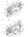
[3−1.扉枠ベースユニットの全体構成]
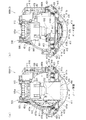
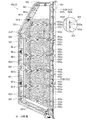
扉枠3の扉枠ベースユニット100について、図31乃至図33を参照して詳細に説明する。図31(a)は扉枠における扉枠ベースユニットを前から見た斜視図であり、(b)は扉枠ベースユニットを後ろから見た斜視図である。図32は扉枠ベースユニットを主な部材毎に分解して前から見た分解斜視図であり、図33は扉枠ベースユニットを主な部材毎に分解して後ろから見た分解斜視図である。
[3-1. Overall configuration of door frame base unit]
The door frame base unit 100 of the door frame 3 will be described in detail with reference to FIGS. 31 to 33. FIG. 31 (a) is a perspective view of the door frame base unit in the door frame as viewed from the front, and FIG. 31 (b) is a perspective view of the door frame base unit as viewed from the rear. 32 is an exploded perspective view of the door frame base unit disassembled into main members and viewed from the front, and FIG. 33 is an exploded perspective view of the door frame base unit disassembled into main members and viewed from the rear is there.
扉枠ベースユニット100は、正面視左辺側が本体枠4の前面を閉鎖するように本体枠4に対して開閉可能(ヒンジ回転可能)に取付けられるものである。扉枠ベースユニット100は、前面下隅にハンドルユニット300が、貫通口111の下側前面に演出操作ユニット400が取付けられる皿ユニット320が、貫通口111の左外側前面に扉枠左サイドユニット540が、貫通口111の右外側前面に扉枠右サイドユニット550が、貫通口111の上外側前面に扉枠トップユニット570が、夫々取付けられるものである。
The door frame base unit 100 is attached to the main body frame 4 so as to be openable / closable (hinge rotatable) so that the left side in a front view closes the front surface of the main body frame 4. In the door frame base unit 100, the handle unit 300 is attached to the front lower corner, and the plate unit 320 to which the rendering operation unit 400 is attached to the lower front surface of the through hole 111, and the door frame left side unit 540 is on the left outer front surface of the through hole 111. The door frame right side unit 550 is attached to the right outer front surface of the through hole 111, and the door frame top unit 570 is attached to the upper outer front surface of the through hole 111, respectively.
扉枠ベースユニット100は、図32及び図33に等に示すように、正面視の外形が上下に延びた長方形で前後に貫通している貫通口111を有した板状の扉枠ベース110と、扉枠ベース110の後側に取付けられている枠状の補強ユニット130と、補強ユニット130の正面視左端側の上下両端に取付けられており扉枠ベース110から前方へ突出して本体枠4の本体枠側上ヒンジ部材620及び本体枠側下ヒンジ部材640に回転可能に取付けられる扉枠側上ヒンジ部材140及び扉枠側下ヒンジ部材150と、扉枠ベース110の前面で貫通口111の正面視左側に取付けられており前面に複数のLEDが実装されている扉枠左サイド装飾基板160と、扉枠ベース110の後側に回動可能に取付けられておりガラスユニット190を着脱可能に取付けるためのガラスユニット取付部材170と、を備えている。
The door frame base unit 100 is, as shown in FIGS. 32 and 33, a plate-like door frame base 110 having a through-hole 111 which has a rectangular shape whose front view outline extends vertically and which penetrates back and forth. The frame-shaped reinforcing unit 130 attached to the rear side of the door frame base 110 and the upper and lower ends of the reinforcing unit 130 on the left end side of the reinforcing unit 130 are projected forward from the door frame base 110. A door frame upper hinge member 140 and a door frame lower hinge member 150 rotatably attached to the body frame upper hinge member 620 and the body frame lower hinge member 640, and a front face of the through hole 111 on the front surface of the door frame base 110 A door frame left side decoration substrate 160 mounted on the left side and having a plurality of LEDs mounted on the front, and a glass unit 19 rotatably mounted on the rear side of the door frame base 110 The glass unit mounting member 170 for mounting the detachably, and a.
また、扉枠ベースユニット100は、扉枠ベース110の前面で正面視右下隅に取付けられておりハンドルユニット300を取付けるための筒状のハンドル取付部材180と、扉枠ベース110の後面に取付けられ貫通口111を閉鎖するガラスユニット190と、ガラスユニット190の後面下部を覆う防犯カバー200と、扉枠ベース110の後面に扉枠ベース110を貫通して前方に突出するように取付けられる開閉シリンダユニット210と、扉枠ベース110の後面下部に取付けられる球送ユニット250と、扉枠ベース110の後面下部に取付けられるファールカバーユニット270と、を備えている。
Further, the door frame base unit 100 is attached to the front lower right corner of the door frame base 110 in front view and is attached to the cylindrical handle attachment member 180 for attaching the handle unit 300 and the rear surface of the door frame base 110. A glass unit 190 for closing the through hole 111, a crime prevention cover 200 for covering a lower rear surface of the glass unit 190, and an open / close cylinder unit attached to the rear surface of the door frame base 110 so as to project forward through the door frame base 110. 210, a ball feeding unit 250 attached to the lower rear surface of the door frame base 110, and a foul cover unit 270 attached to the lower rear surface of the door frame base 110.
更に、扉枠ベースユニット100は、図示は省略するが、扉枠3に備えられている各種の装飾基板、球送ソレノイド255、ハンドル回転検知センサ307、ハンドルタッチセンサ310、単発ボタン操作センサ312、球貸ボタン328、返却ボタン329、球貸返却表示部330、演出選択左ボタン331、演出選択右ボタン332、振動モータ424、押圧検知センサ440、扉枠側演出表示装置460(液晶表示装置461)、上部スピーカ573、等と、本体枠4における基板ユニット900の扉枠用中継基板911との接続を中継するための扉本体中継基板を備えている。
Further, although not shown, the door frame base unit 100 includes various decoration substrates provided in the door frame 3, a ball feeding solenoid 255, a handle rotation detection sensor 307, a handle touch sensor 310, a single button operation sensor 312, Ball lending button 328, return button 329, ball lending display portion 330, effect selection left button 331, effect selection right button 332, vibration motor 424, press detection sensor 440, door frame side effect display device 460 (liquid crystal display device 461) And a door main body relay board for relaying the connection between the upper speakers 573 and the like and the door frame relay board 911 of the board unit 900 in the main body frame 4.
[3−1a.扉枠ベース]
扉枠3における扉枠ベースユニット100の扉枠ベース110について、主に図31乃至図33を参照して詳細に説明する。扉枠ベース110は、正面視の外形が上下に延びた四角形(長方形)に形成されている。扉枠ベース110は、前後に貫通しており、正面視における内周形状が上下に延びた略四角形に形成された貫通口111を備えている。貫通口111は、内周を形成している上辺及び左右両辺が、扉枠ベース110の外周辺に夫々接近しており、内周を形成している下辺が、扉枠ベース110の下端から上下方向の約1/3の高さに位置している。従って、扉枠ベース110は、前後に貫通している貫通口111により全体が枠状に形成されている。この扉枠ベース110は、合成樹脂により一体成形されている。
3-1a. Door frame base]
The door frame base 110 of the door frame base unit 100 in the door frame 3 will be described in detail mainly with reference to FIG. 31 to FIG. The door frame base 110 is formed in a quadrangle (rectangle) in which the outer shape in a front view extends vertically. The door frame base 110 is penetrated back and forth, and is provided with the penetration opening 111 formed in the substantially rectangular shape which the inner peripheral shape in the plain view extended up and down. The upper side and the left and right sides forming the inner periphery of the through hole 111 approach the outer periphery of the door frame base 110 respectively, and the lower side forming the inner periphery is from the lower end of the door frame base 110 vertically It is located at a height of about 1/3 of the direction. Therefore, the door frame base 110 is formed in a frame shape as a whole by the through holes 111 penetrating in the front and rear direction. The door frame base 110 is integrally formed of synthetic resin.
扉枠ベース110は、前面における正面視右下隅に形成されており左端側が右端側よりも前方へやや突出するように傾斜しているハンドル取付座面112と、ハンドル取付座面112と貫通口111との間で正面視右端付近に後面から前方へ向かって窪み、開閉シリンダユニット210のシリンダ取付板金213が取付けられるシリンダ取付部113と、シリンダ取付部113において前後に貫通しており開閉シリンダユニット210のシリンダ錠211が挿通されるシリンダ挿通孔114と、シリンダ挿通孔114及びハンドル取付座面112の正面視左側で前後に貫通しており球送ユニット250の進入口251a及び球抜口251bを前方に臨ませるための球送り開口115と、を備えている。
The door frame base 110 is formed at the lower right corner in the front view of the front view, and is inclined so that the left end side protrudes slightly more forward than the right end side, the handle mounting surface 112, and the through hole 111. The cylinder mounting portion 113 to which the cylinder mounting plate metal 213 of the opening and closing cylinder unit 210 is attached is recessed toward the front from the rear surface in the vicinity of the right end in front view, and the cylinder mounting portion 113 penetrates back and forth The cylinder lock 211 is inserted through the cylinder insertion hole 114, and the cylinder insertion hole 114 and the handle mounting surface 112 in a front view on the left before and behind the entrance 251a and the ball outlet 251b of the ball feeding unit 250. And a ball feed opening 115 for facing the
また、扉枠ベース110は、扉枠ベース110の左右方向中央より左寄りで且つハンドル取付座面112と略同じ高さで前後に貫通しておりファールカバーユニット270の球放出口276を前方に臨ませる下皿用通過口116と、扉枠ベース110の正面視左端付近で貫通口111の下辺に隣接するように前後に貫通しておりファールカバーユニット270の貫通球通路273を前方に臨ませる上皿用通過口117と、貫通口111の内周に沿って後面から前方へ向かって窪み、ガラスユニット190のガラス枠191が挿入されるガラスユニット取付部118と、扉枠ベース110の左右両上隅において前後に貫通しており扉枠トップユニット570の上部スピーカ573の後端が挿通されるスピーカ挿通口119と、を備えている。
Further, the door frame base 110 penetrates back and forth at substantially the same height as the handle mounting seat surface 112 to the left from the center of the door frame base 110 in the left-right direction, The lower plate passage port 116 and the front side of the door frame base 110 are penetrated forward and backward so as to be adjacent to the lower side of the through hole 111 in the vicinity of the left end, and the through ball passage 273 of the far cover unit 270 is faced forward A recess for the plate 117, a recess from the rear to the front along the inner circumference of the through hole 111, a glass unit attachment portion 118 into which the glass frame 191 of the glass unit 190 is inserted, and left and right on the door frame base 110 It has the speaker insertion port 119 which penetrates back and forth in the corner and into which the rear end of the upper speaker 573 of the door frame top unit 570 is inserted.
[3−1b.補強ユニット]
扉枠ベースユニット100の補強ユニット130について、図31及び図33等を参照して詳細に説明する。補強ユニット130は、扉枠ベース110の後側に取付けられることで扉枠ベース110を補強して、扉枠ベース110(扉枠3)の強度剛性を高めている。補強ユニット130は、扉枠ベース110の後面における上辺に沿って取付けられる左右に延びた上補強板金131と、扉枠ベース110の後面における貫通口111の下側に取付けられる左右に延びた中補強板金132と、扉枠ベース110の後面における正面視左辺に沿って取付けられる上下に延びた左補強板金133と、扉枠ベース110の後面における正面視右辺に沿って取付けられる上下に延びた右補強板金134と、右補強板金134の後面に取付けられており施錠ユニット700の扉枠用鉤702が係止される施錠係止部135と、を備えている。
[3-1 b. Reinforcement unit]
The reinforcing unit 130 of the door frame base unit 100 will be described in detail with reference to FIGS. 31 and 33 and the like. The reinforcing unit 130 is attached to the rear side of the door frame base 110 to reinforce the door frame base 110, thereby enhancing the strength and rigidity of the door frame base 110 (the door frame 3). The reinforcing unit 130 includes a left and right extending upper reinforcing sheet metal 131 attached along the upper side of the rear surface of the door frame base 110, and a laterally extending middle reinforcement attached below the through hole 111 on the rear surface of the door frame base 110. A sheet metal 132, a vertically extending left reinforcing sheet metal 133 attached along the left side in a front view on the rear surface of the door frame base 110, and a vertically extending right reinforcement attached along the right side in the front surface on the rear surface of the door frame base 110 It has a sheet metal 134 and a locking / locking portion 135 attached to the rear surface of the right reinforcing sheet metal 134 and to which the door frame wedge 702 of the locking unit 700 is locked.
補強ユニット130は、上補強板金131の左右両端が左補強板金133及び右補強板金134の夫々の上端にビスによって連結固定されており、中補強板金132の左端が左補強板金133にビスによって連結固定されている。中補強板金132の右端は、後述する開閉シリンダユニット210のシリンダ取付板金213を介して右補強板金134に連結固定されている。従って、補強ユニット130は、上補強板金131、中補強板金132、左補強板金133、及び右補強板金134等によって、枠状に形成されている。
The left and right ends of the upper reinforcing sheet metal 131 are connected and fixed to the upper ends of the left reinforcing sheet metal 133 and the right reinforcing sheet metal 134 by screws, and the left end of the middle reinforcing sheet metal 132 is connected to the left reinforcing sheet metal 133 by screws. It is fixed. The right end of the middle reinforcing sheet metal 132 is connected and fixed to the right reinforcing sheet metal 134 via a cylinder mounting sheet metal 213 of the opening / closing cylinder unit 210 described later. Therefore, the reinforcing unit 130 is formed in a frame shape by the upper reinforcing sheet metal 131, the middle reinforcing sheet metal 132, the left reinforcing sheet metal 133, the right reinforcing sheet metal 134, and the like.
補強ユニット130の上補強板金131、中補強板金132、左補強板金133、右補強板金134、及び施錠係止部135は、夫々金属板を適宜屈曲させて形成されている。中補強板金132は、扉枠ベース110の上皿用通過口117と対応する位置に、前後に貫通した切欠部132aが形成されている。
The upper reinforcing sheet metal 131, the middle reinforcing sheet metal 132, the left reinforcing sheet metal 133, the right reinforcing sheet metal 134, and the locking / locking portion 135 of the reinforcing unit 130 are formed by appropriately bending a metal sheet. The middle reinforcing sheet metal 132 is formed with a notch 132 a penetrating in the front and rear direction at a position corresponding to the upper plate passage port 117 of the door frame base 110.
補強ユニット130は、詳細な図示は省略するが、各上補強板金131、中補強板金132、左補強板金133、及び右補強板金134において、夫々前後方向に屈曲された部位を有しており、その部位によって、強度剛性が高められていると共に、外部からのピアノ線やマイナスドライバー等の不正な工具の侵入を防止している。
Although not shown in detail, the reinforcing unit 130 has portions of the upper reinforcing sheet metal 131, the middle reinforcing sheet metal 132, the left reinforcing sheet metal 133, and the right reinforcing sheet metal 134 which are bent in the front-rear direction, The strength and rigidity are enhanced by the portion, and the intrusion of unauthorized tools such as a piano wire and a screwdriver from the outside is prevented.
[3−1c.扉枠側上ヒンジ部材]
扉枠ベースユニット100の扉枠側上ヒンジ部材140について、主に図31乃至図33等を参照して詳細に説明する。扉枠側上ヒンジ部材140は、扉枠ベース110に取付けられ上下に離間している一対の突出片141aを有した扉枠上ヒンジ軸ブラケット141と、扉枠上ヒンジ軸ブラケット141の一対の突出片141aを貫通しており、上端が本体枠側上ヒンジ部材620の扉枠用上ヒンジ孔623に挿入される円柱状の扉枠上ヒンジピン142と、扉枠上ヒンジピン142における一対の突出片141aの間の位置に取付けられている円盤状の鍔部材143と、鍔部材143と一対の突出片141aのうちの下側の突出片141aとの間に介装されていると共に扉枠上ヒンジピン142が挿通されており、扉枠上ヒンジピン142を上方へ付勢しているロックバネ144と、を備えている。
[3-1 c. Door frame side upper hinge member]
The door frame side upper hinge member 140 of the door frame base unit 100 will be described in detail mainly with reference to FIGS. 31 to 33 and the like. The door frame upper hinge member 140 is a door frame upper hinge shaft bracket 141 having a pair of projecting pieces 141 a attached to the door frame base 110 and separated vertically, and a pair of protrusions of the door frame upper hinge shaft bracket 141 A cylindrical door frame upper hinge pin 142 which penetrates the piece 141a and whose upper end is inserted into the door frame upper hinge hole 623 of the main frame side upper hinge member 620, and a pair of projecting pieces 141a of the door frame upper hinge pin 142 Between the wedge member 143 and the lower projecting piece 141a of the pair of projecting pieces 141a, and the door frame upper hinge pin 142 And a lock spring 144 urging the door frame upper hinge pin 142 upward.
扉枠上ヒンジ軸ブラケット141は、図示は省略するが一対の突出片141aの後端同士を連結している平板状の取付片を有しており、側面視の形状が前方へ開放されたコ字状に形成されている。扉枠上ヒンジ軸ブラケット141は、一対の突出片141a同士を連結している取付片が、ビスによって扉枠ベース110の後面に取付けられている。
The door frame upper hinge shaft bracket 141 has a flat plate-like mounting piece connecting the rear ends of a pair of projecting pieces 141a although not shown, and the shape of the side view is opened forward. It is formed in a letter shape. In the door frame upper hinge shaft bracket 141, mounting pieces connecting the pair of projecting pieces 141a are attached to the rear surface of the door frame base 110 by screws.
扉枠上ヒンジピン142は、上側の突出片141aよりも上方に突出している部位(上端)が、本体枠側上ヒンジ部材620の扉枠用上ヒンジ孔623に対して回転可能に挿入される。また、扉枠上ヒンジピン142は、図示は省略するが、下側の突出片141aよりも下方に突出している部位が水平方向に屈曲している。この屈曲している部位が下側の突出片141aの下面に当接することで、扉枠上ヒンジピン142の上方への移動を規制している。
A portion (upper end) of the door frame upper hinge pin 142 projecting upward from the upper projecting piece 141 a is rotatably inserted into the door frame upper hinge hole 623 of the main frame side upper hinge member 620. Moreover, although illustration is abbreviate | omitted, the site | part which protrudes below rather than the lower side piece 141a of the door frame upper hinge pin 142 is bent in the horizontal direction. The bent portion abuts on the lower surface of the lower protruding piece 141a, thereby restricting the upward movement of the door frame upper hinge pin 142.
鍔部材143は、Eリングとされており、扉枠上ヒンジピン142の外周に形成されている溝内に挿入保持されている。ロックバネ144は、扉枠上ヒンジピン142を挿通可能なコイルスプリングとされており、上端が鍔部材143に当接していると共に、下端が下側の突出片141aに当接している。このロックバネ144は、鍔部材143と下側の突出片141aとの間に、圧縮された状態で介装されており、鍔部材143を介して扉枠上ヒンジピン142を上方へ付勢している。
The wedge member 143 is an E-ring, and is inserted and held in a groove formed on the outer periphery of the door frame upper hinge pin 142. The lock spring 144 is a coil spring through which the door frame upper hinge pin 142 can be inserted. The upper end is in contact with the wedge member 143, and the lower end is in contact with the lower projecting piece 141a. The lock spring 144 is interposed between the wedge member 143 and the lower projecting piece 141 a in a compressed state, and biases the door frame upper hinge pin 142 upward through the wedge member 143. .
扉枠側上ヒンジ部材140は、扉枠上ヒンジピン142がロックバネ144により上方へ付勢された状態となっており、扉枠上ヒンジピン142における下端の水平に屈曲している部位が下側の突出片141aの下面に当接することで、これ以上の上方への移動が規制されている。この状態では、扉枠上ヒンジピン142の上端が、上側の突出片141aの上面よりも所定量上方に突出している。
The door frame upper hinge member 140 is in a state in which the door frame upper hinge pin 142 is biased upward by the lock spring 144, and the horizontally bent portion of the lower end of the door frame upper hinge pin 142 protrudes downward. By coming into contact with the lower surface of the piece 141a, further upward movement is restricted. In this state, the upper end of the door frame upper hinge pin 142 protrudes upward by a predetermined amount than the upper surface of the upper protruding piece 141a.
扉枠側上ヒンジ部材140は、扉枠上ヒンジピン142における下端の水平に屈曲している部位を作業者が持って、ロックバネ144の付勢力に抗してその部位を下方へ引張ると、扉枠上ヒンジピン142を全体的に下方へ移動させることができ、扉枠上ヒンジピン142の上端を、上側の突出片141aの上面よりも下方へ没入させることができる。従って、扉枠側上ヒンジ部材140は、扉枠上ヒンジピン142の上端を、本体枠側上ヒンジ部材620の扉枠用上ヒンジ孔623に対して下方から挿入させたり、下方へ抜いたりすることができる。これにより、扉枠側上ヒンジ部材140の扉枠上ヒンジピン142の上端を、本体枠側上ヒンジ部材620の扉枠用上ヒンジ孔623に挿入させることで、扉枠3の正面視上部左端を、本体枠4に対してヒンジ回転可能に支持させることができる。
The door frame upper hinge member 140 holds the horizontally bent portion of the lower end of the door frame upper hinge pin 142, and pulls the portion downward against the biasing force of the lock spring 144, whereby the door frame The upper hinge pin 142 can be moved entirely downward, and the upper end of the door frame upper hinge pin 142 can be recessed below the upper surface of the upper projecting piece 141a. Therefore, the door frame side upper hinge member 140 inserts the upper end of the door frame upper hinge pin 142 into the door frame upper hinge hole 623 of the main frame side upper hinge member 620 from below or pulls it down. Can. Thereby, the upper end of the door frame upper hinge pin 142 of the door frame side upper hinge member 140 is inserted into the door frame upper hinge hole 623 of the main frame side upper hinge member 620, whereby the front left upper end of the door frame 3 is obtained. , And can be rotatably supported relative to the body frame 4.
また、扉枠側上ヒンジ部材140は、扉枠上ヒンジピン142における扉枠上ヒンジ軸ブラケット141の一対の突出片141aにより支持されている部位が、後述する扉枠側下ヒンジ部材150の扉枠下ヒンジピン152と同軸上に支持されている。これにより、扉枠側上ヒンジ部材140と扉枠側下ヒンジ部材150とによって、扉枠3を本体枠4に対して良好な状態でヒンジ回転させることができる。
Further, in the door frame side upper hinge member 140, a portion of the door frame upper hinge pin 142 supported by the pair of projecting pieces 141a of the door frame upper hinge shaft bracket 141 is a door frame of the door frame lower lower hinge member 150 described later. It is coaxially supported with the lower hinge pin 152. Thus, the door frame 3 can be hinge-rotated in a good state with respect to the main body frame 4 by the door frame side upper hinge member 140 and the door frame side lower hinge member 150.
[3−1d.扉枠側下ヒンジ部材]
扉枠ベースユニット100の扉枠側下ヒンジ部材150について、主に図31及び図32等を参照して詳細に説明する。扉枠側下ヒンジ部材150は、扉枠ベース110に取付けられ前方に延出している平板状の延出片151aを有している扉枠下ヒンジ軸ブラケット151と、扉枠下ヒンジ軸ブラケットにおける延出片151aの前端部付近から下方に突出している円柱状の扉枠下ヒンジピン152(図21及び図22を参照)と、を備えている。
[3-1 d. Door frame side lower hinge member]
The door frame side lower hinge member 150 of the door frame base unit 100 will be described in detail mainly with reference to FIGS. 31 and 32 and the like. The door frame lower hinge member 150 includes a door frame lower hinge shaft bracket 151 having a flat extending piece 151a attached to the door frame base 110 and extending forward, and a door frame lower hinge shaft bracket And a cylindrical door frame lower hinge pin 152 (see FIGS. 21 and 22) projecting downward from the vicinity of the front end of the extension piece 151a.
扉枠下ヒンジ軸ブラケット151は、水平に延びた平板状の延出片151aの後端から上方に延出した平板状の取付片(図示は省略)を有しており、側面視の全体形状が略L字状に形成されている。この扉枠下ヒンジ軸ブラケット151は、図示しない取付片がビスによって扉枠ベース110の後面に取付けられている。
The lower door frame hinge shaft bracket 151 has a flat attachment piece (not shown) extending upward from the rear end of the flat extension piece 151a extending horizontally, and the overall shape of the side view Is formed in a substantially L shape. A mounting piece (not shown) of the lower door frame hinge shaft bracket 151 is attached to the rear surface of the door frame base 110 by a screw.
扉枠下ヒンジピン152は、下端部が、下方へ向かうほど窄まる円錐台状に形成されている。この扉枠下ヒンジピン152は、後述する本体枠4における本体枠側下ヒンジ部材640の扉枠用ヒンジ孔644に、上方から回転可能に挿入される。扉枠下ヒンジピン152は、扉枠側上ヒンジ部材140の扉枠上ヒンジピン142と同軸上に配置されている。
The lower end of the lower door frame hinge pin 152 is formed in a truncated cone shape in which the lower end portion is narrowed toward the lower side. The door frame lower hinge pin 152 is rotatably inserted from above into the door frame hinge hole 644 of the main frame side lower hinge member 640 in the main body frame 4 described later. The door frame lower hinge pin 152 is disposed coaxially with the door frame upper hinge pin 142 of the door frame side upper hinge member 140.
この扉枠側下ヒンジ部材150は、扉枠下ヒンジピン152が本体枠側下ヒンジ部材640の扉枠用ヒンジ孔644に挿入されることで、扉枠3を本体枠4に対してヒンジ回転可能に支持することができる。
The door frame lower hinge member 150 can rotate the door frame 3 relative to the body frame 4 by inserting the door frame lower hinge pin 152 into the door frame hinge hole 644 of the body frame lower hinge member 640. Support.
[3−1e.扉枠左サイド装飾基板]
扉枠ベースユニット100の扉枠左サイド装飾基板160について、主に図31及び図32等を参照して詳細に説明する。扉枠左サイド装飾基板160は、扉枠ベース110の前面において、貫通口111の正面視左側に取付けられている。扉枠左サイド装飾基板160は、扉枠ベース110における正面視左側のスピーカ挿通口119よりも下側の位置の高さから貫通口111の上下方向の中央付近の高さまで上下に延びている扉枠左サイド上装飾基板161と、扉枠左サイド上装飾基板161の下側の位置の高さから上皿用通過口117の下端と略同じ高さまで上下に延びている扉枠左サイド下装飾基板162と、を備えている。
[3-1 e. Door frame left side decoration board]
The door frame left side decorative substrate 160 of the door frame base unit 100 will be described in detail with reference mainly to FIGS. 31 and 32 and the like. The door frame left side decorative substrate 160 is attached to the front of the door frame base 110 on the left side in a front view of the through hole 111. The door frame left side decorative substrate 160 extends vertically from the height at a position lower than the speaker insertion opening 119 on the left side in the front view of the door frame base 110 to a height near the center in the vertical direction of the through opening 111 A door frame left side lower decoration extending vertically from the height at the lower position of the frame left side upper decorative substrate 161 and the door frame left side upper decorative substrate 161 to substantially the same height as the lower end of the upper plate passage 117 And a substrate 162.
扉枠左サイド装飾基板160の扉枠左サイド上装飾基板161及び扉枠左サイド下装飾基板162は、夫々前面に、前方へ光を照射可能な複数のLED161a,162aを備えている。これらLED161a,162aは、フルカラーLEDとされている。
The door frame left side upper decoration substrate 161 of the door frame left side decoration substrate 160 and the door frame left side lower decoration substrate 162 are respectively provided with a plurality of LEDs 161 a and 162 a capable of emitting light forward on the front surface. The LEDs 161a and 162a are full color LEDs.
扉枠左サイド装飾基板160は、扉枠3を組立てた状態で、後述する扉枠左サイドユニット540の後方に位置しており、前面に備えられた(実装された)複数のLED161a,162aを適宜発光させることで、扉枠左サイドユニット540の左ユニット装飾レンズ部材を発光装飾させることができる。
The door frame left side decorative substrate 160 is located behind the door frame left side unit 540 described later in a state where the door frame 3 is assembled, and a plurality of (mounted) LEDs 161 a and 162 a provided on the front surface By appropriately emitting light, the left unit decorative lens member of the door frame left side unit 540 can be decorated to emit light.
[3−1f.ガラスユニット取付部材]
扉枠ベースユニット100のガラスユニット取付部材170について、主に図31(b)等を参照して詳細に説明する。ガラスユニット取付部材170は、扉枠ベース110の後側に回動可能に取付けられておりガラスユニット190を着脱可能に取付けるためのものである。ガラスユニット取付部材170は、扉枠ベース110の後側で前後に延びた軸線周りに対して回転可能に取付けられる円盤状の基部171と、基部171から回転軸線に対して直角方向へ棒状に突出している突出部172と、を有している。
[3-1 f. Glass unit mounting member]
The glass unit attachment member 170 of the door frame base unit 100 will be described in detail mainly with reference to FIG. 31 (b) and the like. The glass unit attachment member 170 is rotatably attached to the rear side of the door frame base 110 and is for detachably attaching the glass unit 190. The glass unit attachment member 170 has a disk-like base 171 rotatably mounted about an axis extending back and forth on the rear side of the door frame base 110, and a bar-like projection from the base 171 in a direction perpendicular to the rotation axis. And a protruding portion 172.
ガラスユニット取付部材170は、扉枠ベース110の後面における一対のスピーカ挿通口119の下側で、ガラスユニット取付部118よりも外側の部位に、夫々回転可能に取付けられている。
The glass unit attachment member 170 is rotatably attached to a portion outside the glass unit attachment portion 118 below the pair of speaker insertion holes 119 in the rear surface of the door frame base 110.
ガラスユニット取付部材170は、突出部172が基部171から上方へ突出するように回転させた状態とすることで、背面視において扉枠ベース110のガラスユニット取付部118よりも突出部172が外側に位置した状態となり、扉枠ベース110のガラスユニット取付部118に対してガラスユニット190を挿入したり、ガラスユニット取付部118からガラスユニット190を取外したりすることができる。
By setting the glass unit attachment member 170 to rotate so that the protrusion 172 protrudes upward from the base 171, the protrusion 172 is more outward than the glass unit attachment portion 118 of the door frame base 110 in a rear view. In the state of being positioned, the glass unit 190 can be inserted into the glass unit attachment portion 118 of the door frame base 110 or the glass unit 190 can be removed from the glass unit attachment portion 118.
ガラスユニット取付部材170は、ガラスユニット190を扉枠ベース110のガラスユニット取付部118に挿入させた状態で、突出部172が基部171から下方へ突出するように回転させると、突出部172がガラスユニット190の取付片191aの後側と当接し、ガラスユニット190上部の後方への移動を規制した状態となり、ガラスユニット190を扉枠ベース110に取付けることができる。
When the glass unit mounting member 170 is rotated so that the protruding portion 172 protrudes downward from the base portion 171 with the glass unit 190 inserted in the glass unit mounting portion 118 of the door frame base 110, the protruding portion 172 is glass The rear side of the mounting piece 191 a of the unit 190 abuts against the rear side of the upper part of the glass unit 190, and the glass unit 190 can be attached to the door frame base 110.
ガラスユニット取付部材170は、扉枠ベース110に回転可能に取付けられる円盤状の基部171から突出部172が突出しているため、ガラスユニット取付部材170の重心位置が突出部172内に位置している。このことから、ガラスユニット取付部材170が自由に回転できる状態では、突出部172が基部171から下方へ突出した状態で安定することとなる。そして、ガラスユニット取付部材170では、突出部172が基部171から下方へ突出している回転位置の時に、突出部172によりガラスユニット190の後方への移動を規制させるようにしているため、ガラスユニット取付部材170に振動等が作用しても、突出部172が基部171から上方へ突出するように全体が回転することはなく、ガラスユニット190の後方への移動の規制が自然に解除されることはない。
In the glass unit attachment member 170, the projection 172 projects from the disk-like base 171 rotatably attached to the door frame base 110, so the center of gravity of the glass unit attachment member 170 is located in the projection 172 . From this, in the state where the glass unit attachment member 170 can freely rotate, the protrusion 172 is stabilized in the state of protruding downward from the base 171. And, in the glass unit attachment member 170, since the projection 172 restricts the backward movement of the glass unit 190 at the rotational position where the projection 172 projects downward from the base 171, the glass unit attachment Even if vibration or the like acts on the member 170, the whole does not rotate so that the projecting portion 172 protrudes upward from the base portion 171, and the restriction on the backward movement of the glass unit 190 is naturally released. Absent.
なお、扉枠ベース110からガラスユニット190を取外す場合は、ガラスユニット取付部材170を、突出部172が基部171から上方へ突出するように回転させて、突出部172をガラスユニット190の取付片191aよりも外側へ移動させることで、ガラスユニット190の上部側を後方へ移動させることができるようになり、扉枠ベース110からガラスユニット190を取外すことができる。
When the glass unit 190 is removed from the door frame base 110, the glass unit attachment member 170 is rotated so that the projection 172 protrudes upward from the base 171, and the projection 172 is attached to the attachment piece 191a of the glass unit 190. By moving the glass unit 190 further outward, the upper side of the glass unit 190 can be moved backward, and the glass unit 190 can be removed from the door frame base 110.
[3−1g.ハンドル取付部材]
扉枠ベースユニット100のハンドル取付部材180について、主に図31乃至図33等を参照して詳細に説明する。ハンドル取付部材180は、扉枠ベース110の前面にハンドルユニット300を取付けるためのものである。ハンドル取付部材180は、図32及び図33等に示すように、前後方向へ延びた円筒状の筒部181と、筒部181の後端から筒部181の軸に対して直角方向外方へ延びた円環状のフランジ部182と、筒部181内に突出していると共に筒部181の軸方向全長に亘って延びており筒部181の周方向に対して不等間隔に配置された複数(本例では三つ)の突条183と、筒部181の外周面とフランジ部182の前面とを繋ぎ、筒部181の周方向に対して複数配置された補強リブ184と、を備えている。
[3-1 g. Handle mounting member]
The handle attachment member 180 of the door frame base unit 100 will be described in detail with reference mainly to FIGS. 31 to 33 and the like. The handle attachment member 180 is for attaching the handle unit 300 to the front of the door frame base 110. As shown in FIGS. 32 and 33, the handle mounting member 180 extends outward in a direction perpendicular to the axis of the cylindrical portion 181 from the rear end of the cylindrical cylindrical portion 181 extending in the front-rear direction and the rear end of the cylindrical portion 181. A plurality of annular flanges 182 extending, and a plurality of protruding into the cylindrical portion 181 and extending over the entire axial length of the cylindrical portion 181 and disposed at unequal intervals in the circumferential direction of the cylindrical portion 181 ( In this example, the three protruding ridges 183 are provided, and the outer peripheral surface of the cylindrical portion 181 and the front surface of the flange portion 182 are connected to each other, and a plurality of reinforcing ribs 184 arranged in the circumferential direction of the cylindrical portion 181 .
ハンドル取付部材180は、フランジ部182の後面を、扉枠ベース110におけるハンドル取付座面112の前面に当接させた状態で、ビスによってハンドル取付座面112に取付けられる。
The handle attachment member 180 is attached to the handle attachment surface 112 with a screw in a state where the rear surface of the flange portion 182 is in contact with the front surface of the handle attachment surface 112 of the door frame base 110.
筒部181は、内径がハンドルユニット300におけるハンドルベース301の基部301aの外径よりも若干大きく形成されている。三つの突条183は、一つが筒部181内の上側に備えられており、残り二つが筒部181内の下側に備えられている。これら三つの突条183は、ハンドルベース301における三つの溝部301cと対応する位置に形成されている。従って、ハンドル取付部材180は、三つの突条183と、ハンドルベース301の三つの溝部301cとを一致させた状態でのみ、筒部181内にハンドルベース301の基部301aを挿入させることができ、扉枠ベース110に対してハンドルベース301(ハンドルユニット300)の回転位置を規制することができる。
The cylindrical portion 181 is formed to have an inner diameter slightly larger than the outer diameter of the base portion 301 a of the handle base 301 in the handle unit 300. One of the three protrusions 183 is provided on the upper side in the cylindrical portion 181, and the remaining two are provided on the lower side in the cylindrical portion 181. The three protrusions 183 are formed at positions corresponding to the three grooves 301 c in the handle base 301. Therefore, the handle attachment member 180 can insert the base portion 301a of the handle base 301 into the cylindrical portion 181 only in a state where the three protrusions 183 and the three groove portions 301c of the handle base 301 coincide with each other. The rotational position of the handle base 301 (handle unit 300) can be regulated with respect to the door frame base 110.
なお、ハンドル取付部材180は、フランジ部182の後面に対して、筒部181の軸線が垂直に延びていることから、扉枠ベース110の傾斜したハンドル取付座面112に取付けることで、筒部181の軸線が右前方へ延びるように傾いた状態となり、ハンドルユニット300を同様に傾いた状態で扉枠ベース110に取付けることができる。
The handle mounting member 180 is mounted on the inclined handle mounting surface 112 of the door frame base 110 because the axis of the cylindrical portion 181 extends perpendicularly to the rear surface of the flange portion 182. The axis 181 is inclined so as to extend to the right front, and the handle unit 300 can be attached to the door frame base 110 in the same inclined state.
[3−1h.ガラスユニット]
扉枠ベースユニット100のガラスユニット190について、主に図31乃至図33等を参照して詳細に説明する。ガラスユニット190は、扉枠ベース110の貫通口111を、前方から後方が視認できるように閉鎖するものである。ガラスユニット190は、扉枠ベース110の貫通口111の内周形状よりも大きくガラスユニット取付部118に取付可能な枠状のガラス枠191と、ガラス枠191の枠内を閉鎖し外周がガラス枠191に取付けられている透明な二つのガラス板192と、を備えている。二つのガラス板192は、ガラス枠191の前端側と後端側とに夫々取付けられており、互いの間に空間が形成されるように前後に離間している(図26等を参照)。
[3-1 h. Glass unit]
The glass unit 190 of the door frame base unit 100 will be described in detail mainly with reference to FIGS. 31 to 33 and the like. The glass unit 190 is for closing the through hole 111 of the door frame base 110 so that the rear can be seen from the front. The glass unit 190 has a frame-like glass frame 191 attachable to the glass unit attachment portion 118 larger than the inner peripheral shape of the through hole 111 of the door frame base 110, and the inside of the glass frame 191 closed. And two transparent glass plates 192 attached to 191. The two glass plates 192 are attached to the front end side and the rear end side of the glass frame 191, respectively, and are separated in the front and back direction so as to form a space between each other (see FIG. 26 etc.).
ガラス枠191は、正面視左右上隅よりも下側の位置から外方へ平板状に延出している一対の取付片191aと、下端から下方へ突出していると共に下辺に沿って延びている帯板状の係止片191bと、を有している。ガラス枠191の取付片191aは、ガラスユニット取付部材170の突出部172と当接可能とされている。係止片191bは、扉枠ベース110と補強ユニット130の中補強板金132との間の空間内に挿入可能とされている(図26を参照)。
The glass frame 191 has a pair of mounting pieces 191a extending flatly outward from a position lower than the front left and right upper corners, and a band projecting downward from the lower end and extending along the lower side And a plate-like locking piece 191b. The mounting piece 191 a of the glass frame 191 can be in contact with the projecting portion 172 of the glass unit mounting member 170. The locking piece 191 b is insertable into the space between the door frame base 110 and the middle reinforcing sheet metal 132 of the reinforcing unit 130 (see FIG. 26).
このガラスユニット190は、扉枠ベース110の後側から、ガラス枠191の係止片191bを、扉枠ベース110と補強ユニット130の中補強板金132との間の隙間に上方から挿入した上で、ガラス枠191の前端を扉枠ベース110のガラスユニット取付部118の後面に当接させ、ガラスユニット取付部材170を回転させてガラスユニット取付部材170の突出部172をガラス枠191の取付片191aの後面と当接させることで、扉枠ベース110に取付けられる。
The glass unit 190 is inserted from above from the rear side of the door frame base 110 into the gap between the door frame base 110 and the middle reinforcing sheet metal 132 of the reinforcing unit 130 from above. The front end of the glass frame 191 is brought into contact with the rear surface of the glass unit mounting portion 118 of the door frame base 110, and the glass unit mounting member 170 is rotated to make the projection 172 of the glass unit mounting member 170 a mounting piece 191a of the glass frame 191 It is attached to the door frame base 110 by bringing it into contact with the rear surface of the door frame.
ガラスユニット190を扉枠ベース110から取外す場合は、上記と逆の手順により、取外すことができる。これにより、ガラスユニット190は、扉枠ベース110に対して着脱可能となっている。
When the glass unit 190 is removed from the door frame base 110, it can be removed in the reverse procedure to the above. Thereby, the glass unit 190 is detachable with respect to the door frame base 110.
[3−1i.防犯カバー]
扉枠ベースユニット100の防犯カバー200について、主に図31乃至図33等を参照して詳細に説明する。防犯カバー200は、ガラスユニット190の後面下部を覆うように扉枠ベース110の後側に取付けられ、透明な合成樹脂により形成されている。防犯カバー200は、外周が所定形状に形成された平板状の本体部201と、本体部201の外周縁に沿って後方へ短く突出した平板状の後方突片202と、左右に離間して配置され本体部201よりも前方に突出し、扉枠ベース110の後側に係止可能とされている一対の係止片203と、を備えている。
[3-1 i. Security cover]
The crime prevention cover 200 of the door frame base unit 100 will be described in detail mainly with reference to FIGS. 31 to 33 and the like. The crime prevention cover 200 is attached to the rear side of the door frame base 110 so as to cover the lower part of the rear surface of the glass unit 190, and is formed of a transparent synthetic resin. Security cover 200 is disposed with a flat main body portion 201 whose outer periphery is formed in a predetermined shape, a flat rear projection piece 202 which protrudes backwards short along the outer peripheral edge of main body portion 201, and is separated left and right And a pair of locking pieces 203 that project forward relative to the main body 201 and are lockable on the rear side of the door frame base 110.
防犯カバー200の本体部201は、扉枠ベース110に取付けた状態で下端がガラスユニット190の下端よりも下方へ突出するように形成されている。また、本体部201は、上端が、パチンコ機1に組立てた状態で、遊技盤5における遊技領域5aの下端に沿った形状に形成されている。詳述すると、本体部201の上端は、後述する前構成部材1000の内レール1002の一部、アウト誘導部1003、右下レール1004の一部、及び右レール1005に沿った形状に形成されており、パチンコ機1に組立てた状態で遊技領域5a内に突出しないように形成されている。
The main body portion 201 of the crime prevention cover 200 is formed so that the lower end thereof protrudes downward more than the lower end of the glass unit 190 in a state of being attached to the door frame base 110. Further, the main body portion 201 is formed in a shape along the lower end of the game area 5 a in the game board 5 in a state where the upper end is assembled to the pachinko machine 1. More specifically, the upper end of the main body portion 201 is formed in a shape along a part of the inner rail 1002 of the front component 1000 described later, the out guiding part 1003, a part of the lower right rail 1004, and the right rail 1005 It is formed so as not to protrude into the game area 5 a in a state where it is assembled in the pachinko machine 1.
後方突片202は、本体部201の外周縁の略全周に亘って形成されている。従って、防犯カバー200は、本体部201と後方突片202とによって、後方へ開放された浅い箱状に形成されており、強度・剛性が高くなっている。また、後方突片202は、図33に示すように、本体部201の外周縁とは異なる本体部201の後面の一部からも後方に突出している。この本体部201の後面の一部から後方に突出している後方突片202は、パチンコ機1に組立てた状態で遊技盤5の前構成部材1000における外レール1001の一部と沿うように形成されている。
The rear protrusion 202 is formed over substantially the entire outer periphery of the main body portion 201. Therefore, the crime prevention cover 200 is formed in the shape of a shallow box opened rearward by the main body portion 201 and the rear projecting piece 202, and the strength and the rigidity are high. Further, as shown in FIG. 33, the rear protrusion 202 also protrudes rearward from a part of the rear surface of the main body 201 which is different from the outer peripheral edge of the main body 201. A rear projection 202 projecting rearward from a part of the rear surface of the main body 201 is formed along a part of the outer rail 1001 of the front component 1000 of the game board 5 in a state assembled in the pachinko machine 1 ing.
なお、後方突片202は、パチンコ機1に組立てた状態で、遊技盤5における外レール1001と内レール1002との間に位置する部位には形成されていない。これにより、外レール1001と内レール1002との間を通る遊技球(球発射装置680により発射された遊技球)が、防犯カバー200の後方突片202に当接することはなく、遊技領域5a内への遊技球の打込みを阻害することはない。
The rear projection 202 is not formed at a portion of the game board 5 located between the outer rail 1001 and the inner rail 1002 in the state of being assembled in the pachinko machine 1. As a result, the gaming ball passing between the outer rail 1001 and the inner rail 1002 (the gaming ball launched by the ball launching device 680) does not abut the rear projection 202 of the security cover 200, and the inside of the gaming area 5a There is no impediment to hitting the game ball into.
一対の係止片203は、扉枠ベース110の後側に弾性係止される。これにより、防犯カバー200は、扉枠ベース110に対して容易に着脱することができる。
The pair of locking pieces 203 is elastically locked to the rear side of the door frame base 110. Thereby, the crime prevention cover 200 can be easily attached to and detached from the door frame base 110.
防犯カバー200は、パチンコ機1に組立てた状態で、本体部201の前面がガラスユニット190の後面(ガラス枠191の後端)と当接し、本体部201の下辺から後方へ突出している部位を除いた後方突片202が、前構成部材1000の防犯凹部(図示は省略)内に挿入された状態となる。また、防犯カバー200は、本体部201の下辺から後方に突出している後方突片202が、前構成部材1000の下面と接するように前構成部材1000の前面よりも後方へ突出している状態となる。これにより、防犯カバー200と遊技盤5(前構成部材1000)との間が、防犯カバー200の後方突片202と前構成部材1000の防犯凹部とによって複雑に屈曲した状態となるため、遊技盤5の前面下方より防犯カバー200と前構成部材1000との間を通してピアノ線等の不正な工具を遊技領域5a内に侵入させようとしても、後方突片202や防犯凹部に阻まれることとなり、遊技領域5a内への不正な工具の侵入を阻止することができる。
In the state where the crime prevention cover 200 is assembled in the pachinko machine 1, the front surface of the main body portion 201 is in contact with the rear surface of the glass unit 190 (the rear end of the glass frame 191). The removed rear projection 202 is inserted into the security recess (not shown) of the front component 1000. In addition, the security cover 200 has a state in which the rear projection 202 protruding rearward from the lower side of the main body 201 protrudes rearward more than the front surface of the front component 1000 so as to contact the lower surface of the front component 1000. . As a result, the space between the crime prevention cover 200 and the game board 5 (front component member 1000) is in a complicatedly bent state by the rear projection 202 of the crime prevention cover 200 and the crime prevention recess of the front component member 1000. Even if an unauthorized tool such as a piano wire is made to intrude into the game area 5a from below the front of 5 between the crime prevention cover 200 and the front component 1000, it will be blocked by the rear projection 202 and the crime prevention recess. An unauthorized tool can be prevented from entering the area 5a.
[3−1j.開閉シリンダユニット]
扉枠ベースユニット100の開閉シリンダユニット210について、主に図31乃至図33等を参照して説明する。開閉シリンダユニット210は、正面視において扉枠ベース110の右端付近で貫通口111とハンドル取付座面112との間の位置のシリンダ取付部113に後側から取付けられ、後述する施錠ユニット700と協働して、扉枠3と本体枠4との開閉、及び、外枠2と本体枠4との開閉に使用されるものである。
[3-1 j. Open / close cylinder unit]
The opening / closing cylinder unit 210 of the door frame base unit 100 will be described mainly with reference to FIGS. 31 to 33 and the like. The opening / closing cylinder unit 210 is attached from the rear side to the cylinder attachment portion 113 at a position between the through hole 111 and the handle attachment seat surface 112 near the right end of the door frame base 110 in front view, and cooperates with a locking unit 700 described later. It is used to open and close the door frame 3 and the main body frame 4 and to open and close the outer frame 2 and the main body frame 4.
開閉シリンダユニット210は、前面に鍵穴211aを有し前後に延びた円筒状のシリンダ錠211と、シリンダ錠211の後端に取付けられており鍵穴211aに挿入された鍵の回動操作を施錠ユニット700の鍵シリンダ710に伝達させる回転伝達部材212と、シリンダ錠211を扉枠ベース110(補強ユニット130)に取付けるシリンダ取付板金213と、を備えている。
The opening / closing cylinder unit 210 has a keyhole 211a on the front surface and a cylindrical cylinder lock 211 extending in the front and rear direction, and a lock unit attached to the rear end of the cylinder lock 211 and locking operation of a key inserted in the keyhole 211a. A rotation transmitting member 212 to be transmitted to the key cylinder 710 of 700 and a cylinder mounting plate 213 for mounting the cylinder lock 211 to the door frame base 110 (reinforcement unit 130) are provided.
シリンダ錠211は、対応する鍵(図示は省略)を鍵穴211aに差し込むことで、鍵を回転させることができるものであり、対応する鍵であれば、正面視において時計回り及び反時計回りの何れの方向へも所定角度回転させることができる。
The cylinder lock 211 can rotate a key by inserting a corresponding key (not shown) into the key hole 211a. If the key is a corresponding key, either clockwise or counterclockwise in front view Can also be rotated by a predetermined angle in the direction of.
回転伝達部材212は、後方が開放された円筒状(詳しくは、後方へ向かうに従って直径が大きくなる円錐筒状)に形成されており、中心軸を挟んで対向した位置に後端から前方へ向かって切欠かれた一対の切欠部212aを有している。この回転伝達部材212は、本体枠4における施錠ユニット700の鍵シリンダ710が後方から挿入されるように形成されており、施錠ユニット700の鍵シリンダ710の突起が一対の切欠部212a内に挿入されることで、回転伝達部材212(シリンダ錠211の鍵穴211aに挿入された鍵)の回転を、施錠ユニット700の鍵シリンダ710に伝達させて鍵シリンダ710を回転させることができる。
The rotation transmission member 212 is formed in a cylindrical shape (specifically, a conical cylindrical shape whose diameter increases toward the rear) opened at the rear, and is directed from the rear end to the front at a position opposite to sandwich the central axis. And a pair of notched portions 212a. The rotation transmitting member 212 is formed such that the key cylinder 710 of the locking unit 700 in the main body frame 4 is inserted from the rear, and the projection of the key cylinder 710 of the locking unit 700 is inserted into the pair of cutouts 212a. Thus, the rotation of the rotation transmitting member 212 (a key inserted into the key hole 211 a of the cylinder lock 211) can be transmitted to the key cylinder 710 of the locking unit 700 and the key cylinder 710 can be rotated.
シリンダ取付板金213は、一枚の金属板を屈曲させて形成されており、平面視の形状が前方へ突出している凸形状に形成されている。詳述すると、シリンダ取付板金213は、正面視において上下に延びた長方形で平板状の前板部213aと、前板部213aの左右両辺から後方へ平板状に延出している一対の側板部213bと、一対の側板部213bの夫々の後辺から互いに遠ざかる方向へ平板状に延出している一対の取付板部213cと、を備えている。シリンダ取付板金213の前板部213aは、上下方向略中央の位置で後方からシリンダ錠211が貫通し、前板部213aの後面にシリンダ錠211の後端が取付けられる。シリンダ取付板金213の一対の取付板部213cは、正面視左側の取付板部213cが補強ユニット130の中補強板金132の右端部に取付けられ、正面視右側の取付板部213cが補強ユニット130の右補強板金134に取付けられる。これにより、シリンダ取付板金213によって、補強ユニット130の中補強板金132と右補強板金134とが連結される。
The cylinder mounting plate metal 213 is formed by bending a single metal plate, and is formed in a convex shape in which the shape in plan view is projected forward. More specifically, the cylinder mounting plate 213 has a rectangular plate-like front plate portion 213a that extends vertically in a front view, and a pair of side plate portions 213b that extend in a flat plate shape rearward from both left and right sides of the front plate portion 213a. And a pair of mounting plate portions 213c extending in the form of a flat plate in the direction away from each other from the rear sides of the pair of side plate portions 213b. In the front plate portion 213a of the cylinder mounting plate 213, the cylinder lock 211 penetrates from the rear at a substantially central position in the vertical direction, and the rear end of the cylinder lock 211 is attached to the rear surface of the front plate portion 213a. In the pair of mounting plate portions 213c of the cylinder mounting plate 213, the mounting plate portion 213c on the left in front view is attached to the right end of the middle reinforcing plate 132 of the reinforcing unit 130, and the mounting plate portion 213c on the right in front view is of the reinforcing unit 130 It is attached to the right reinforcing sheet metal 134. Thereby, the middle reinforcing sheet metal 132 of the reinforcing unit 130 and the right reinforcing sheet metal 134 are connected by the cylinder mounting sheet metal 213.
開閉シリンダユニット210は、扉枠ベースユニット100に組立てた状態では、シリンダ取付板金213の前板部213aから前方に突出しているシリンダ錠211の前端が、扉枠ベース110の後側からシリンダ挿通孔114に挿通されて扉枠ベース110の前方へ突出していると共に、シリンダ取付板金213の前板部213a及び一対の側板部213bが後方へ開放されている箱状のシリンダ取付部113内に収容されている。
In the open / close cylinder unit 210 assembled to the door frame base unit 100, the front end of the cylinder lock 211 projecting forward from the front plate portion 213a of the cylinder mounting plate 213 is the cylinder insertion hole from the rear side of the door frame base 110. The front plate portion 213a and the pair of side plate portions 213b of the cylinder mounting plate metal 213 are accommodated in a box-like cylinder mounting portion 113 which is inserted into the housing 114 and protrudes forward of the door frame base 110. ing.
[3−1k.球送りユニット]
扉枠ベースユニット100の球送ユニット250について、主に図34及び図35を参照して詳細に説明する。図34(a)は扉枠ベースユニットの球送りユニットを前から見た斜視図であり、(b)は球送りユニットを後ろから見た斜視図である。図35(a)は球送りユニットを分解して前から見た分解斜視図であり、(b)は球送りユニットの後ケースと不正防止部材を外して後から見た分解斜視図である。球送ユニット250は、皿ユニット320の上皿321から供給される遊技球を一つずつ球発射装置680へ供給することができると共に、上皿321内に貯留された遊技球を、上皿球抜きボタン327の操作によって下皿へ抜くことができるものである。
[3-1 k. Ball feed unit]
The ball feeding unit 250 of the door frame base unit 100 will be described in detail mainly with reference to FIGS. 34 and 35. FIG. 34 (a) is a perspective view of the ball feeding unit of the door frame base unit as viewed from the front, and FIG. 34 (b) is a perspective view of the ball feeding unit as viewed from the rear. FIG. 35 (a) is an exploded perspective view of the ball feeding unit disassembled and viewed from the front, and FIG. 35 (b) is an exploded perspective view of the ball feeding unit with the back case removed and the tamperproof member removed. The ball feeding unit 250 can supply the game balls supplied from the upper plate 321 of the plate unit 320 to the ball launcher 680 one by one, and the game balls stored in the upper plate 321 can be It can be pulled out to the lower plate by the operation of the removal button 327.
球送ユニット250は、皿ユニット320の上皿321に貯留された遊技球が、皿ユニットベース323の上皿球送り口323d及び扉枠ベース110の球送り開口115を通して供給され前後方向に貫通した進入口251a、及び進入口251aの下側に開口する球抜口251bを有し後方が開放された箱状の前カバー251と、前カバー251の後端を閉鎖すると共に前方が開放された箱状で、前後方向に貫通している前カバー251の進入口251aから進入した遊技球を球発射装置680へ供給するための打球供給口252aを有した後カバー252と、後カバー252及び前カバー251の間で前後方向へ延びた軸周りに回動可能に軸支され前カバー251の後側で進入口251aと球抜口251bとの間を仕切る仕切部253aを有した球抜き部材253と、球抜き部材253の仕切部253a上の遊技球を一つずつ後カバー252の打球供給口252aへ送り、前カバー251と後カバー252との間で上下方向へ延びた軸周りに回動可能に支持された球送り部材254と、球送り部材254を回動させる球送ソレノイド255と、を備えている。
In the ball feed unit 250, the gaming balls stored in the upper plate 321 of the plate unit 320 are supplied through the upper plate ball feed port 323d of the plate unit base 323 and the ball feed opening 115 of the door frame base 110 and penetrated in the front and back direction An entrance 251a, and a box-like front cover 251 having a ball outlet 251b opened to the lower side of the entrance 251a and opened at the rear, and a box closing the rear end of the front cover 251 and opening the front And a rear cover 252 having a striking ball supply port 252a for supplying to the ball launcher 680 the gaming ball which has entered from the entrance 251a of the front cover 251 penetrating in the front and rear direction, the rear cover 252 and the front cover A partition 253a rotatably supported about an axis extending in the front-rear direction between 251 and separating the entrance 251a and the ball outlet 251b on the rear side of the front cover 251 The game balls on the separating member 253a of the ball removing member 253 and the ball removing member 253 are sent one by one to the ball hitting supply port 252a of the back cover 252 and extend in the vertical direction between the front cover 251 and the rear cover 252 A ball feeding member 254 rotatably supported around the axis, and a ball feeding solenoid 255 for turning the ball feeding member 254 are provided.
この球送ユニット250は、図示するように、正面視で、球送り部材254が進入口251aの右側に配置されており、球送り部材254の左側に球抜き部材253が、球送り部材254の右側に球送ソレノイド255が夫々配置されている。
The ball feeding unit 250 has a ball feeding member 254 disposed on the right side of the entrance 251 a in a front view, as shown, and the ball removing member 253 is provided on the left side of the ball feeding member 254. The ball feeding solenoids 255 are respectively disposed on the right side.
球送ユニット250の前カバー251は、正面視で球抜口251bの左側に、球抜き部材253の回転中心に対して同心円状に形成された円弧状のスリット251cを備えており、このスリット251cから後述する球抜き部材253の作動棹253cが前方へ延びだすようになっている。また、前カバー251は、進入口251aの上縁から上側が上方へ延びだしており、扉枠3を組立てた際に、皿ユニットベース323の球送り誘導路323e及び球抜き誘導路323fの上流端側の後方へ開放されている部位を後側から閉鎖するように形成されている。
The front cover 251 of the ball feeding unit 250 is provided with an arc-shaped slit 251 c formed concentrically with the center of rotation of the ball removing member 253 on the left side of the ball outlet 251 b in front view. The actuating rod 253c of the ball removing member 253, which will be described later, is designed to extend forward. Further, the front cover 251 extends upward from the upper edge of the entrance 251a, and when the door frame 3 is assembled, the ball feed guiding path 323e of the pan unit base 323 and the upstream side of the ball removing guiding path 323f. It is formed so as to close from the rear side a site which is open to the rear at the end side.
球抜き部材253は、進入口251aよりも下側で進入口251aと球抜口251bとの間を仕切り上面が球送り部材254の方向へ向かって低くなる仕切部253aと、仕切部253aの球送り部材254とは反対側の端部から下方へ延出すると共に上下方向の中間付近から球抜口251bの下側中央へ向かってく字状に屈曲し下端が前後方向へ延びた軸周りに回動可能に支持される回動棹部253bと、回動棹部253bの上端から前方へ向かって突出する棒状の作動棹253cと、作動棹253cよりも下側で回動棹部253bの側面から仕切部253aとは反対側へ突出した錘部253dと、を備えている。球抜き部材253の作動棹253cは、前カバー251に形成された円弧状のスリット251cを通して前方へ突出するように形成されている(図34(a)を参照)。作動棹253cは、扉枠ベース110の球送り開口115を介して皿ユニット320の上皿球抜きボタン327の押圧操作によって動作する作動伝達部327aの上端と当接する。
The ball removing member 253 divides the space between the inlet 251 a and the ball outlet 251 b below the inlet 251 a and divides the lower surface in the direction of the ball feeding member 254, and the ball of the partition 253 a It extends downward from the end opposite to the feed member 254 and is bent in a V shape toward the lower center of the ball outlet 251b from near the middle in the vertical direction, and the lower end is rotated about an axis extending in the front and rear direction From the side surface of the pivoting rod 253b below the actuating rod 253c, the pivoting rod 253b supported movably, the rod-like operating rod 253c projecting forward from the upper end of the pivoting rod 253b, and the operating rod 253c And a weight portion 253d protruding to the opposite side to the partition portion 253a. The operating rod 253 c of the ball removing member 253 is formed to project forward through an arc-shaped slit 251 c formed in the front cover 251 (see FIG. 34A). The actuating rod 253 c abuts on the upper end of the actuating transmission portion 327 a operated by the pressing operation of the upper disc ball release button 327 of the disc unit 320 via the ball feed opening 115 of the door frame base 110.
球送り部材254は、進入口251a及び球抜き部材253の仕切部253aの方を向き上下方向へ延びた回転軸芯を中心とした平面視が扇状の遮断部254aと、遮断部254aの後端から回転軸芯側へ円弧状に窪んだ球保持部254bと、球保持部254bの後端から下方へ延出する棒状の棹部254cと、を備えている。球送り部材254における遮断部254aと球保持部254bは、夫々回転軸芯を中心とした約180゜の角度範囲内に隣接して形成されている。また、球送り部材254の球保持部254bは、一つの遊技球を保持可能な大きさとされている。球送り部材254は、球送ソレノイド255の駆動によって回転軸芯と偏芯した位置に配置された棹部254cが左右方向へ移動させられることで、回転軸芯周りに回動する。
The ball feed member 254 is directed toward the entrance 251a and the partitioning portion 253a of the ball removing member 253, and has a blocking portion 254a having a fan-like plan view centering on a rotation axis extending in the vertical direction and a rear end of the blocking portion 254a The ball holding portion 254b is recessed in an arc shape toward the rotation axis, and a rod-shaped collar portion 254c extending downward from the rear end of the ball holding portion 254b. The blocking portion 254a and the ball holding portion 254b of the ball feeding member 254 are formed adjacent to each other within an angle range of about 180 ° around the rotation axis. Further, the ball holding portion 254b of the ball feeding member 254 is sized to be able to hold one gaming ball. The ball feed member 254 is pivoted about the axis of rotation by moving the collar portion 254 c disposed at a position eccentric to the axis of rotation by driving the ball feed solenoid 255 in the left-right direction.
この球送り部材254は、遮断部254aが仕切部253aの方向を向くと同時に球保持部254bが打球供給口252aと連通した方向を向いた供給位置と、球保持部254bが仕切部253aの方向へ向いた保持位置との間で回動するようになっている。球送り部材254が供給位置の時には、球保持部254bに保持された遊技球が、打球供給口252aから球発射装置680へ供給されると共に、進入口251aから仕切部253a上に進入した遊技球が、遮断部254aによって球保持部254b(打球供給口252a)側への移動が遮断されて仕切部253a上に留まった状態となる。一方、球送り部材254が保持位置へ回動すると、球保持部254bが仕切部253aの方向を向くと共に、球保持部254bの棹部254c側の端部が打球供給口252aを閉鎖した状態となり、仕切部253a上の遊技球が一つだけ球保持部254b内に保持される。
The ball feed member 254 has a supply position in which the ball holding portion 254b is in communication with the ball hitting supply port 252a at the same time as the blocking portion 254a faces the partition portion 253a, and the ball holding portion 254b faces the partition portion 253a. It is pivoted between the holding position facing it. When the ball feed member 254 is at the supply position, the gaming ball held by the ball holding portion 254b is supplied from the ball striking supply port 252a to the ball firing device 680, and the gaming ball entered into the partition portion 253a from the entrance 251a. However, the movement toward the ball holding portion 254b (ball hitting supply port 252a) is blocked by the blocking portion 254a, and the movement of the ball holding portion 254b remains on the partition portion 253a. On the other hand, when the ball feed member 254 is turned to the holding position, the ball holding portion 254b faces the partition portion 253a, and the end portion of the ball holding portion 254b on the flange portion 254c side closes the hitting supply port 252a. The game ball on the partition part 253a is held in the ball holding part 254b by only one.
また、球送ユニット250は、球送ソレノイド255の駆動(通電)によって先端が上下方向へ揺動する球送り作動桿256と、球送り作動桿256における上下方向へ揺動する先端の動きによって前後方向へ延びた軸周りに回動すると共に、球送り部材254を上下方向へ延びた軸周りに回動させる球送りクランク257と、を備えている。球送りクランク257は、球送り作動桿256の上下動する先端と係合可能とされ左右方向へ延びた係合部257aと、係合部257aの球送り作動桿256と係合する側とは反対側に配置され前カバー251と後カバー252との間で前後方向へ延びた軸周りに回動可能に軸支される軸部257bと、軸部257bから上方へ延出しており、球送り部材254における回動中心に対して偏芯した位置から下方へ突出する棒状の棹部254c(図35(b)を参照)と係合する伝達部257cと、を備えている。
Also, the ball feed unit 250 has a ball feed operating rod 256 whose tip is swung in the vertical direction by driving (energization) of a ball feed solenoid 255, and a back and forth movement of the tip of the ball feed rod 256 moving in the vertical direction. And a ball feed crank 257 for pivoting the ball feed member 254 around the vertically extending axis while pivoting about the axially extending axis. The ball feed crank 257 is engageable with the vertically moving tip of the ball feed operating rod 256 and extends in the left and right direction from an engaging portion 257a and a side engaged with the ball feed operating rod 256 of the engaging portion 257a A shaft portion 257b disposed on the opposite side and pivotally supported about an axis extending in the front-rear direction between the front cover 251 and the rear cover 252 and extending upward from the shaft portion 257b And a transmission portion 257c engaged with a rod-like collar portion 254c (see FIG. 35B) protruding downward from a position eccentric to the rotation center of the member 254.
この球送ユニット250は、球送り作動桿256及び球送りクランク257によって、上下方向へ進退する球送ソレノイド255の駆動により揺動する球送り作動桿256の動きを伝達させて球送り部材254を回動させることができる。なお、球送ソレノイド255の非駆動時(通常時)では、球送り作動桿256が球送ソレノイド255の下端から離れて先端が下方へ位置した状態となり、この状態では球送り部材254が供給位置に位置した状態となる。また、球送ソレノイド255の駆動時では、球送り作動桿256が球送ソレノイド255の下端に吸引されて先端が上方へ位置した状態となり、球送り部材254が保持位置へ回動する。つまり、球送ソレノイド255が駆動される(ONの状態)と、球送り部材254が遊技球を一つ受入れ、球送ソレノイド255の駆動が解除される(OFFの状態)と、球送り部材254が受入れた遊技球を球発射装置680側へ送る(供給する)ことができる。この球送ユニット250における球送ソレノイド255の駆動は、払出制御基板951の発射制御部(図示は省略)により発射ソレノイド682の駆動制御と同期して制御される。
The ball feeding unit 250 transmits the movement of the ball feeding actuating rod 256 which is rocked by the driving of a ball feeding solenoid 255 which is advanced and retracted in the vertical direction by a ball feeding actuating rod 256 and a ball feeding crank 257 It can be turned. When the ball feed solenoid 255 is not driven (normal time), the ball feed operating rod 256 is separated from the lower end of the ball feed solenoid 255 and the tip end is positioned downward. In this state, the ball feed member 254 is at the supply position. It will be located in Further, when the ball feed solenoid 255 is driven, the ball feed operating rod 256 is attracted to the lower end of the ball feed solenoid 255 so that the tip is positioned upward, and the ball feed member 254 pivots to the holding position. That is, when the ball feed solenoid 255 is driven (ON state), the ball feed member 254 receives one gaming ball and the drive of the ball feed solenoid 255 is released (OFF state), the ball feed member 254 Can be sent (supplied) to the ball launch device 680 side. The driving of the ball feeding solenoid 255 in the ball feeding unit 250 is controlled by the firing control unit (not shown) of the payout control board 951 in synchronization with the driving control of the firing solenoid 682.
また、球送ユニット250における回動可能に軸支された球抜き部材253は、錘部253dによって正面視反時計周りの方向へ回転するようなモーメントがかかるようになっているが、前方へ突出した作動棹253cが皿ユニット320の上皿球抜きボタン327の押圧操作によって動作する作動伝達部327aの上端と当接することで、その回動が規制されるため、通常時では、球抜き部材253の仕切部253aが進入口251aと球抜口251bとの間を仕切っており、球抜口251b側へ遊技球が侵入することはない。
In addition, the ball removing member 253 rotatably supported by the ball feeding unit 250 is configured such that a moment is applied by the weight portion 253 d so as to rotate in a counterclockwise direction in a front view. The rotation of the actuating rod 253c is restricted by the contact of the actuating rod 253c with the upper end of the actuating transmission portion 327a which is operated by the pressing operation of the upper disc ball releasing button 327 of the disc unit 320. The parting part 253a of the part separates the entrance 251a and the ball outlet 251b, and the game ball does not enter the ball outlet 251b side.
そして、遊技者が、皿ユニット320の上皿球抜きボタン327を下方へ押圧操作すると、上皿球抜きスライダ327bが作動伝達部327aと共に下方へスライドして、作動伝達部327aの下方への移動に伴って作動棹253cも相対的に下方へ移動することとなる。作動伝達部327aと共に作動棹253cが下方へ移動すると、球抜き部材253が正面視反時計周りの方向へ回動し、仕切部253aによる進入口251aと球抜口251bとの間の仕切りが解除される。これにより、進入口251aから進入した遊技球が、球抜口251bから皿ユニット320の球抜き誘導路323fへと排出され、下皿球供給口323cを介して下皿322へ排出(供給)させることができる。
Then, when the player presses the upper bowl ball release button 327 of the tray unit 320 downward, the upper bowl ball removal slider 327b slides downward with the operation transmission portion 327a to move the operation transmission portion 327a downward. Accordingly, the operating rod 253c is also moved relatively downward. When the actuating rod 253c moves downward together with the actuating transmission portion 327a, the ball removing member 253 rotates in the counterclockwise direction in a front view, and the partition between the entrance 251a and the ball outlet 251b by the partitioning portion 253a is released. Be done. Thereby, the game ball entered from the entrance 251a is discharged from the ball outlet 251b to the ball removal guiding path 323f of the plate unit 320, and is discharged (supplied) to the lower plate 322 via the lower plate ball supply port 323c. be able to.
なお、球抜き部材253の作動棹253cが当接する作動伝達部327aが形成されている上皿球抜きスライダ327bは、上皿球抜きバネ327cによって上方へ付勢されているので、仕切部253a上に遊技球が勢い良く供給されても、その衝撃を、作動棹253cを介して上皿球抜きバネ327cによって吸収させることができ、球抜き部材253等が破損するのを防止することができると共に、遊技球が仕切部253aで跳ね返るのを防止することができる。
The upper disc ball removal slider 327b in which the operation transmission portion 327a with which the actuating rod 253c of the ball removal member 253 abuts is biased upward by the upper disc ball removal spring 327c. Even if the game ball is vigorously supplied, the impact can be absorbed by the upper disc ball release spring 327c through the actuating rod 253c, and breakage of the ball removal member 253 and the like can be prevented. The game ball can be prevented from bouncing back at the partition portion 253a.
また、球送ユニット250は、後カバー252における打球供給口252aの背面視で右上に前方へ窪んだ矩形状の取付凹部252b(図35(b)等を参照)が形成されていると共に、その取付凹部252b内に不正防止部材260が取付けられている。球送ユニット250の不正防止部材260は、工具鋼やステンレス等の硬質の金属板により形成されており、後カバー252の取付凹部252b内に対して後側から脱着可能に取付けられている。
Further, the ball feeding unit 250 is provided with a rectangular attachment recess 252b (see FIG. 35 (b) etc.) that is recessed forward on the upper right in the back view of the hitting supply port 252a in the rear cover 252. The fraud prevention member 260 is mounted in the mounting recess 252b. The fraud prevention member 260 of the ball feeding unit 250 is formed of a hard metal plate such as tool steel or stainless steel, and is detachably attached to the inside of the mounting recess 252 b of the rear cover 252 from the rear side.
不正防止部材260は、正面視の外形が左右に延びた長方形状に形成されており、右辺から左方へ所定距離の間において、上下方向略中央で上下に分離している上片部261及び下片部262と、上片部261及び下片部262の互いに対向している辺の先端側(正面視右端側)でC面取り状に夫々形成されている傾斜部263と、を備えている。不正防止部材260の上片部261は、不正防止部材260の一般面に対して、正面視右端が後方へ突出するように屈曲させられている。下片部262は、不正防止部材260の一般面と同一面上に延びている。これにより、平面視において、上片部261と下片部262とによって、右方に向かうに従って広がるV字状の溝を形成している。
The fraud prevention member 260 is formed in a rectangular shape in which the outer shape in a front view extends in the left and right direction, and is separated vertically at a substantially central position in the vertical direction between predetermined distances from the right side to the left. A lower piece portion 262, and an inclined portion 263 each formed in a C-chamfered shape on the tip end side (right end side in front view) of sides of the upper piece portion 261 and the lower piece portion 262 facing each other . The upper piece portion 261 of the tamper-proof member 260 is bent with respect to the general surface of the tamper-proof member 260 so that the right end in the front view protrudes rearward. The lower piece portion 262 extends in the same plane as the general surface of the tamperproof member 260. Thus, in the plan view, the upper piece portion 261 and the lower piece portion 262 form a V-shaped groove which spreads as it goes to the right.
不正防止部材260は、後カバー252の取付凹部252bに取付けられることで、上片部261と下片部262とで形成されるV字状の溝が、打球供給口252a内と連通した状態となる。
The fraud prevention member 260 is attached to the attachment recess 252b of the rear cover 252 so that the V-shaped groove formed by the upper piece portion 261 and the lower piece portion 262 is in communication with the inside of the bat striking hole supply port 252a. Become.
この不正防止部材260によれば、紐を取付けた不正な遊技球を、上皿321から球送ユニット250を介して球発射装置680により遊技領域5a内に打込み、不正な遊技球に取付けられた紐を操作して、不正な遊技球を第一始動口2002等に出し入れさせるような不正行為が行われる際に、球発射装置680により発射(打球)された不正な遊技球の勢いによって、不正な遊技球に取付けられた紐を、上片部261と下片部262との間に挿入させた上で、上片部261と下片部262とによって形成されたV字状の狭くなった部位により切断させることができ、紐を取付けた不正な遊技球を用いた不正行為が行われるのを防止することができる。
According to this fraud preventing member 260, the illegal gaming ball attached with the string is driven from the upper plate 321 through the ball feeding unit 250 into the game area 5a by the ball launching device 680 and attached to the illegal gaming ball When a cheating operation is performed such that an illegal game ball is moved into and out of the first starting opening 2002 etc. by operating the string, the force of the illegal game ball fired (hit ball) by the ball launching device 680 causes an illegal action. The string attached to the game ball is inserted between the upper piece part 261 and the lower piece part 262, and then V-shaped narrow formed by the upper piece part 261 and the lower piece part 262 It can be cut off by a part, and it can prevent that the fraudulent act using the illegal game ball which attached the string is performed.
[3−1l.ファールカバーユニット]
扉枠ベースユニット100のファールカバーユニット270について、図36乃至図38を参照して詳細に説明する。図36(a)は扉枠ベースユニットのファールカバーユニットを前から見た斜視図であり、(b)はファールカバーユニットを後ろから見た斜視図である。また、図37(a)はファールカバーユニットを、蓋部材を外して前から見た分解斜視図であり、(b)はファールカバーユニットを、蓋部材を外して後ろから見た分解斜視図である。更に、図38は、蓋部材を外した状態のファールカバーユニットの正面図である。
[3-1 l. Foul cover unit]
The fowl cover unit 270 of the door frame base unit 100 will be described in detail with reference to FIGS. 36 to 38. FIG. 36 (a) is a perspective view of a front cover unit of the door frame base unit as viewed from the front, and FIG. 36 (b) is a perspective view of the rear cover unit as viewed from the rear. FIG. 37 (a) is an exploded perspective view from the front with the cover removed, and FIG. 37 (b) is an exploded perspective view from the back with the cover removed. is there. Furthermore, FIG. 38 is a front view of the foul cover unit with the lid removed.
ファールカバーユニット270は、図示するように、扉枠ベース110の後側に取付けられ前側が開放された浅い箱状のユニット本体271と、ユニット本体271の前面に取付けられている平板状の蓋部材272と、を備えている。ファールカバーユニット270は、正面視左上隅において前後に貫通しており本体枠4の下部満タン球経路ユニット860の通常誘導路861と皿ユニット320の上皿球供給口323aとを連通させる貫通球通路273と、貫通球通路273の正面視右下側で後方へ向かって開口しており本体枠4の下部満タン球経路ユニット860の満タン誘導路862と連通可能な満タン球受口274と、を備えている。
As shown in the figure, the fool cover unit 270 is a shallow box-shaped unit body 271 attached to the rear side of the door frame base 110 and opened on the front side, and a flat cover member attached to the front of the unit body 271 272, and. The foul cover unit 270 penetrates back and forth at the upper left corner in a front view and connects the normal guiding path 861 of the lower full-ball passage unit 860 of the main body frame 4 and the upper ball supply port 323a of the plate unit 320 A channel 273 and a full tank receptacle 274 which is opened rearward on the lower right side in a front view of the through ball channel 273 and which can communicate with the full channel guide 862 of the lower full tank path unit 860 of the main body frame 4 And have.
また、ファールカバーユニット270は、満タン球受口274の正面視右側で上方へ向かって開口しており本体枠4の球発射装置680により発射されにも関わらず遊技領域5a内へ到達しなかった遊技球(ファール球)を受けるファール球受口275と、正面視右下隅付近で前方へ向かって開口しており満タン球受口274及びファール球受口275に受入れられた遊技球を前方へ放出すると共に皿ユニット320の下皿球供給口323cと連通する球放出口276と、を備えている。
Further, the foul cover unit 270 is opened upward on the right side in front view of the full tank receptacle 274 and does not reach the game area 5a despite being fired by the ball launcher 680 of the main frame 4 The ball ball receptacle 275 for receiving the game ball (far ball) and the game ball which is opened forward in the vicinity of the lower right corner of the front view and received by the full tank ball receptacle 274 and the ball ball receptacle 275 And a ball outlet 276 communicating with the lower ball feed port 323c of the tray unit 320.
更に、ファールカバーユニット270は、ユニット本体271及び蓋部材272によって、満タン球受口274及びファール球受口275と球放出口276との間に形成されており所定量の遊技球を貯留可能な広さを有している貯留通路277と、貯留通路277の内壁の一部を構成しており下端が回動可能にユニット本体271に取付けられている平板状の可動片278と、可動片278の貯留通路277から遠ざかる方向への回動を検知する満タン検知センサ279と、可動片278を貯留通路277の中心側へ付勢しているバネ280と、を備えている。
Further, the foul cover unit 270 is formed between the full ball receptacle 274 and the far ball receptacle 275 and the ball outlet 276 by the unit main body 271 and the lid member 272, and can store a predetermined amount of gaming balls. The storage passage 277 having a wide width, the flat plate-like movable piece 278 which constitutes a part of the inner wall of the storage passage 277 and whose lower end is rotatably attached to the unit main body 271, and the movable piece A full tank detection sensor 279 for detecting a rotation in a direction away from the storage passage 277 and a spring 280 biasing the movable piece 278 toward the center of the storage passage 277 are provided.
このファールカバーユニット270は、皿ユニット320の下皿322内が遊技球で一杯になって、球放出口276から遊技球が下皿322側へ放出されなくなると、貯留通路277内にある程度の数の遊技球を貯留することができる。そして、貯留通路277内にある程度の数の遊技球が貯留されると、遊技球の重さによって可動片278の上端がバネ280の付勢力に抗して貯留通路277から遠ざかる方向へ移動するように可動片278が回動し、その回動が満タン検知センサ279によって検知される。これにより、下皿322が遊技球で満タンになっていると判断することができるため、満タン検知センサ279により満タンが検知されると、これ以上の遊技球の払出しを停止させると共に、その旨を遊技者や遊技ホールの係員等に報知して、下皿322の満タンを解消させるように促すことができる。
In the far cover unit 270, when the lower plate 322 of the plate unit 320 is filled with gaming balls and the gaming balls are not released from the ball outlet 276 to the lower plate 322 side, a certain number of them are stored in the storage passage 277 Game balls can be stored. Then, when a certain number of game balls are stored in the storage passage 277, the upper end of the movable piece 278 moves away from the storage passage 277 against the biasing force of the spring 280 by the weight of the game balls. The movable piece 278 rotates, and the rotation is detected by the full tank detection sensor 279. As a result, it can be determined that the lower plate 322 is full of gaming balls, so that when full is detected by the full detection sensor 279, the payout of more gaming balls is stopped, This can be notified to the player or a person in charge at the game hall to urge that the lower tray 322 be completely filled.
また、ファールカバーユニット270は、ユニット本体271の後側で貫通球通路273の下側に取付けられており、本体枠4の後述する払出ユニット800における下部満タン球経路ユニット860の誘導路開閉扉863の作動突部863eが当接可能な扉開閉当接部281を備えている(図127を参照)。扉開閉当接部281は、後面が下方へ向かうに従って前方へ移動するように傾斜している。この扉開閉当接部281は、本体枠4に対して扉枠3を閉じると、誘導路開閉扉863の作動突部863eが当接するように形成されている。この扉開閉当接部281に誘導路開閉扉863の作動突部863eが当接することで、誘導路開閉扉863が回動して通常誘導路861及び満タン誘導路862の下流端(前側開口)を開放させることができる。
Further, the foul cover unit 270 is attached to the lower side of the through ball passage 273 on the rear side of the unit main body 271, and a door opening / closing door of a lower full ball passage unit 860 in a dispensing unit 800 described later of the main body frame 4. A door opening / closing contact portion 281 is provided, which can be in contact with the operation projection 863e of 863 (see FIG. 127). The door opening and closing contact portion 281 is inclined so as to move forward as the rear surface goes downward. When the door frame 3 is closed with respect to the main body frame 4, the door opening / closing abutment portion 281 is formed such that the operation projection 863 e of the guideway opening / closing door 863 abuts. When the actuating projection 863e of the guideway opening / closing door 863 abuts on the door opening / closing abutment portion 281, the guideway opening / closing door 863 is rotated and the downstream ends of the normal guideway 861 and the full induction passage 862 (front opening ) Can be released.
[3−2.ハンドルユニット]
扉枠3のハンドルユニット300について、主に図39及び図40を参照して詳細に説明する。図39(a)は扉枠におけるハンドルユニットの正面図であり、(b)はハンドルユニットを前から見た斜視図であり、(b)はハンドルユニットを後ろから見た斜視図である。また、図40(a)はハンドルユニットを分解して前から見た分解斜視図であり、(b)はハンドルユニットを分解して後ろから見た分解斜視図である。ハンドルユニット300は、扉枠ベースユニット100のハンドル取付部材180に取付けられ、遊技者が操作することで、上皿321内の遊技球を遊技盤5の遊技領域5a内に打込むことができるものである。
[3-2. Handle unit]
The handle unit 300 of the door frame 3 will be described in detail with reference mainly to FIGS. 39 and 40. 39A is a front view of the handle unit in the door frame, FIG. 39B is a perspective view of the handle unit as viewed from the front, and FIG. 39B is a perspective view of the handle unit as viewed from the back. FIG. 40 (a) is an exploded perspective view of the handle unit disassembled and viewed from the front, and FIG. 40 (b) is an exploded perspective view of the handle unit disassembled and viewed from the rear. The handle unit 300 is attached to the handle attachment member 180 of the door frame base unit 100, and operated by the player so that the game ball in the upper plate 321 can be driven into the game area 5a of the game board 5 It is.
ハンドルユニット300は、扉枠ベースユニット100におけるハンドル取付部材180の筒部181に取付けられるハンドルベース301と、ハンドルベース301の前端に回転可能に取付けられるハンドル302と、ハンドル302の前端側を覆うようにハンドルベース301に取付けられるハンドルカバー303と、を備えている。
The handle unit 300 covers the handle base 301 attached to the cylindrical portion 181 of the handle attachment member 180 in the door frame base unit 100, the handle 302 rotatably attached to the front end of the handle base 301, and the front end side of the handle 302. And a handle cover 303 attached to the handle base 301.
また、ハンドルユニット300は、ハンドル302の後側でハンドルベース301の前面に取付けられるインナーベース304と、前端にハンドル302が取付けられると共にインナーベース304とハンドルベース301とによって回転可能に取付けられ外周に駆動ギア部305aを有している軸部材305と、軸部材305の駆動ギア部305aと噛合している伝達ギア306と、伝達ギア306と一体回転する検知軸307aを有しハンドルベース301とインナーベースとの間に挟持されているハンドル回転検知センサ307と、を備えている。
Further, the handle unit 300 has an inner base 304 attached to the front of the handle base 301 on the rear side of the handle 302 and a handle 302 attached to the front end and rotatably attached by the inner base 304 and the handle base 301 It has a shaft member 305 having a drive gear portion 305a, a transmission gear 306 meshing with the drive gear portion 305a of the shaft member 305, and a detection shaft 307a that rotates integrally with the transmission gear 306. And a handle rotation detection sensor 307 held between the base and the steering wheel.
更に、ハンドルユニット300は、一端側がハンドルベース301に取付けられると共に他端側がハンドル302に取付けられハンドル302を初期回転位置(正面視で反時計周りの方向への回転端)へ復帰させるように付勢しているハンドル復帰バネ308と、一端側がインナーベース304に取付けられると共に他端側が伝達ギア306に取付けられ伝達ギア306を介してハンドル回転検知センサ307の検知軸307aを正面視で時計回りの方向へ付勢している補助バネ309と、インナーベース304の後方でハンドルベース301に取付けられているハンドルタッチセンサ310と、先端側がハンドルベース301の前端外周面の正面視おける左側から外方に突出していると共に基端側がインナーベース304の後方でハンドルベース301に前後に延びた軸周りに回転可能に取付けられている単発ボタン311と、単発ボタン311の押圧操作を検知しハンドルベース301に取付けられている単発ボタン操作センサ312と、を備えている。
Furthermore, the handle unit 300 has one end attached to the handle base 301 and the other end attached to the handle 302 to return the handle 302 to the initial rotational position (rotation end in the counterclockwise direction in front view). One end side is attached to the inner base 304, the other end side is attached to the transmission gear 306, and the detection shaft 307a of the handle rotation detection sensor 307 is clockwise viewed from the front through the transmission gear 306. Auxiliary spring 309 biased in the direction, handle touch sensor 310 attached to handle base 301 at the rear of inner base 304, tip end is outward from the left side in front view of the front end outer peripheral surface of handle base 301 Protruding and handle on the rear side of inner base 304 with proximal end A single-shot button 311 rotatably mounted on a shaft 301 and a single-shot button operation sensor 312 attached to the handle base 301 for detecting a pressing operation of the single-shot button 311; There is.
ハンドルユニット300のハンドルベース301は、前後に延びた円筒状の基部301aと、基部301aの前端から半径方向へ突出している円盤状の前端部301bと、円筒状の基部301aの外周面から窪んでいると共に軸方向に延びており周方向へ不等間隔で三つ形成されている溝部301cと、を備えている。ハンドルベース301の基部301aは、外径がハンドル取付部材180の筒部181の内径よりも若干小さく形成されている。また、三つの溝部301cは、ハンドル取付部材180における筒部181の三つの突条183と対応した位置に形成されている。従って、三つの溝部301cを三つの突条183と一致させた状態で、基部301aをハンドル取付部材180の筒部181内に挿入させることができると共に、三つの溝部301c内に夫々突条183が挿入されることで、ハンドルベース301がハンドル取付部材180に対して相対回転不能な状態となる。
The handle base 301 of the handle unit 300 is recessed from the outer peripheral surface of a cylindrical base 301a extending in the front and rear direction, a disk-like front end 301b radially projecting from the front end of the base 301a, and a cylindrical base 301a. And three grooves 301c extending in the axial direction and formed at irregular intervals in the circumferential direction. The outer diameter of the base portion 301 a of the handle base 301 is formed to be slightly smaller than the inner diameter of the cylindrical portion 181 of the handle attachment member 180. Further, the three groove portions 301 c are formed at positions corresponding to the three ridges 183 of the cylindrical portion 181 of the handle attachment member 180. Therefore, the base 301a can be inserted into the cylindrical portion 181 of the handle mounting member 180 in a state in which the three grooves 301c coincide with the three ridges 183, and the ridges 183 are respectively inserted in the three grooves 301c. By being inserted, the handle base 301 can not be rotated relative to the handle attachment member 180.
ハンドル302は、外周面から周方向に離れて外方へ突出している四つの第一突起302a、第二突起302b、第三突起302c、及び第四突起302dと、回転軸(軸部材305)を中心として円弧状に延びていると共に前後方向に貫通している二つのスリット302eと、スリット302eよりも回転中心に対して内側の位置から後方に突出しておりハンドル復帰バネ308の他端側が係止される係止突部302fと、を備えている。
The handle 302 includes four first protrusions 302a, second protrusions 302b, third protrusions 302c, and fourth protrusions 302d, which protrude outward in a circumferential direction away from the outer peripheral surface, and a rotation shaft (shaft member 305). Two slits 302e extending in a circular arc shape as a center and penetrating in the front-rear direction, and projecting rearward from a position inside with respect to the rotation center with respect to the slit 302e And a locking projection 302f.
四つの第一突起302a、第二突起302b、第三突起302c、及び第四突起302dは、正面視において時計回りの方向に順番に備えられている。詳述すると、第一突起302aは、ハンドル302の一般外周面から最も突出した部位の正面視時計回りの方向の側面が、外側へ膨らむように膨出しており、反対側である反都決周りの方向の側面が、内側へ湾曲するように凹んでいる(抉れている)。第二突起302bは、ハンドル302の一般外周面から最も突出した部位が、第一突起302aの最も突出した部位から時計回りの方向へ約85度の回転角度で離れており、第一突起302aよりはやや低く突出している。この第二突起302bは、最も突出した部位の正面視時計回りの方向の側面が、外側へ膨らむように膨出しており、反対側である反都決周りの方向の側面が、内側へ湾曲するように凹んでおり、第一突起302aと相似した形状に形成されている。
The four first protrusions 302a, the second protrusions 302b, the third protrusions 302c, and the fourth protrusions 302d are sequentially provided in the clockwise direction in front view. More specifically, the first protrusion 302a has a side in the clockwise direction of the portion of the handle 302 that protrudes most from the general outer peripheral surface of the handle 302 in a clockwise direction, and bulges outward. The side in the direction of is concaved (curved) to curve inward. The portion of the second protrusion 302b most projecting from the general outer peripheral surface of the handle 302 is separated from the most projecting portion of the first protrusion 302a in the clockwise direction by about a 85 degree rotation angle. Is slightly lower. In the second protrusion 302b, the side surface in the clockwise direction in the front view clockwise bulges so as to expand outward, and the side surface in the direction around the opposite side is curved inward. It is concaved and formed in a shape similar to the first protrusion 302a.
第三突起302cは、ハンドル302の一般外周面から最も突出した部位が、第二突起302bの最も突出した部位から時計回りの方向へ約70度の回転角度で離れており、第一突起302aの約半分の高さで突出している。この第三突起302cは、両側の側面が略直線状に傾斜しており、時計回りの方向の側面が反対側である反時計回りの方向の側面よりもなだらかに傾斜している。第四突起302dは、ハンドル302の一般外周面から最も突出した部位が、第三突起302cの最も突出した部位から時計回りの方向へ約55度の回転角度で離れており、第一突起302aよりもやや高く突出している。この第四突起302dは、両側の側面が略直線状に傾斜しており、略二等辺三角形に形成されている。
The third protrusion 302c is located at the most projecting part from the general outer peripheral surface of the handle 302 at a rotation angle of about 70 degrees in the clockwise direction from the most projecting part of the second protrusion 302b. It protrudes at about half height. The side surfaces on both sides of the third protrusion 302c are inclined substantially linearly, and the side surface in the clockwise direction is inclined more gently than the side surface in the counterclockwise direction which is the opposite side. In the fourth protrusion 302d, the most protruding part from the general outer peripheral surface of the handle 302 is separated from the most protruding part of the third protrusion 302c in the clockwise direction at a rotation angle of about 55 degrees from the first protrusion 302a It also protrudes slightly high. The fourth protrusions 302 d are formed in a substantially isosceles triangle, with the side surfaces on both sides inclined in a substantially linear manner.
ハンドルカバー303は、前面の中心が丸く前方へ膨出しており、後方へ突出している三つの取付ボス303aを備えている。三つの取付ボス303aは、ハンドル302のスリット302eを前方から貫通してハンドルベース301の前面に取付けられる。ハンドルカバー303の取付ボス303aが、ハンドル302のスリット302eを貫通していることから、取付ボス303aがスリット302eの周方向端部に当接することとなり、ハンドル302の回転角度を規制している。本例では、ハンドル302を、約120度の回転角度の範囲内で回転させることができる。
The handle cover 303 has three round mounting bosses 303 a that are rounded forward on the front and bulge forward. The three mounting bosses 303 a are attached to the front of the handle base 301 by penetrating the slit 302 e of the handle 302 from the front. Since the mounting boss 303a of the handle cover 303 passes through the slit 302e of the handle 302, the mounting boss 303a abuts on the circumferential end of the slit 302e, thereby restricting the rotation angle of the handle 302. In this example, the handle 302 can be rotated within a range of approximately 120 degrees of rotation.
このハンドルユニット300は、扉枠ベース110のハンドル取付座面112に対して、ハンドル取付部材180を介して取付けられる。この扉枠ベース110のハンドル取付座面112は、平面視において、右端側が左端側よりも後方に位置するように傾斜しており、外側(開放側)を向いているため、ハンドル取付部材180を介して取付けられるハンドルユニット300も平面視で外側に傾斜(換言すると、パチンコ機1の前面に直交する線に対してその先端部がパチンコ機1の外側に向かうように傾斜している。)して扉枠3に取付固定される。これにより、遊技者がハンドルユニット300のハンドル302が握り易く、違和感がなく回動操作を行わせることができる。
The handle unit 300 is attached to the handle attachment seat surface 112 of the door frame base 110 via the handle attachment member 180. The handle attachment seat surface 112 of the door frame base 110 is inclined so that the right end is positioned more rearward than the left end in plan view and faces the outside (open side). The handle unit 300 to be attached via is also inclined outward in plan view (in other words, its tip is inclined toward the outside of the pachinko machine 1 with respect to a line perpendicular to the front of the pachinko machine 1). It is attached and fixed to the door frame 3. As a result, the player can easily hold the handle 302 of the handle unit 300, and can make the user perform the turning operation without feeling a sense of discomfort.
ハンドルユニット300のハンドル回転検知センサ307は、可変抵抗器とされており、ハンドル302を回転させると、軸部材305及び伝達ギア306を介してハンドル回転検知センサ307の検知軸307aが回転する。この検知軸307aの回転角度に応じてハンドル回転検知センサ307の内部抵抗が変化し、ハンドル回転検知センサ307の内部抵抗に応じて後述する球発射装置680における発射ソレノイド682の駆動力が変化して、ハンドル302の回転角度に応じた強さで遊技球が遊技領域5a内へ打込まれる。
The handle rotation detection sensor 307 of the handle unit 300 is a variable resistor, and when the handle 302 is rotated, the detection shaft 307 a of the handle rotation detection sensor 307 is rotated via the shaft member 305 and the transmission gear 306. The internal resistance of the handle rotation detection sensor 307 changes according to the rotation angle of the detection shaft 307a, and the driving force of the emission solenoid 682 in the ball emission device 680 described later changes according to the internal resistance of the handle rotation detection sensor 307. The game ball is driven into the game area 5a with a strength corresponding to the rotation angle of the handle 302.
ハンドル302やハンドルカバー303の外周表面は、導電性のメッキが施されており、遊技者がハンドル302等に接触することでハンドルタッチセンサ310が接触を検出する。そして、ハンドルタッチセンサ310が遊技者の接触を検出している時に、ハンドル302を回動させると、ハンドル回転検知センサ307の検知が受付けられ、ハンドル302の回転角度に応じた強さで発射ソレノイド682の駆動が制御されて、遊技球を打込むことができる。つまり、遊技者がハンドル302に触れずに、何らかの方法でハンドル302を回転させて遊技球を遊技領域5a内に打込もうとしても、発射ソレノイド682は駆動されず、遊技球を打込むことができないようになっている。これにより、遊技者が本来とは異なる方法でハンドル302を回転させて遊技が行われるのを防止することができ、パチンコ機1を設置する遊技ホールに係る負荷(負担)を軽減させることができる。
The outer peripheral surface of the handle 302 and the handle cover 303 is plated with conductive, and the handle touch sensor 310 detects the contact when the player contacts the handle 302 or the like. Then, when the handle touch sensor 310 detects the player's touch, when the handle 302 is turned, the detection of the handle rotation detection sensor 307 is accepted, and the emission solenoid is generated with a strength according to the rotation angle of the handle 302. The drive of 682 is controlled, and a game ball can be hit. That is, even if the player tries to hit the game ball into the game area 5a by rotating the handle 302 in some way without touching the handle 302, the firing solenoid 682 is not driven and the game ball can be hit. It can not be done. Thereby, it is possible to prevent the player from playing the game by rotating the handle 302 in a method different from the original method, and it is possible to reduce the load (burden) associated with the gaming hall where the pachinko machine 1 is installed. .
また、ハンドルユニット300は、遊技者がハンドル302を回転操作中に、単発ボタン311を押圧すると、単発ボタン操作センサ312が単発ボタン311の操作を検知し、払出制御基板951の発射制御部(図示は省略)によって発射ソレノイド682の回転駆動が停止させられる。これにより、ハンドル302の回転操作を戻さなくても、遊技球の発射を一時的に停止させることができると共に、単発ボタン311の押圧操作を解除することで、単発ボタン311を操作する前の打込み強さで再び遊技球を遊技領域5a内に打込むことができる。
In the handle unit 300, when the player presses the one-shot button 311 while rotating the handle 302, the one-shot button operation sensor 312 detects the operation of the one-shot button 311, and the discharge control unit of the payout control board 951 (shown Is omitted to stop the rotational drive of the firing solenoid 682. As a result, it is possible to temporarily stop the firing of the game ball without returning the rotation operation of the handle 302 and, by releasing the pressing operation of the one-shot button 311, the driving before the one-shot button 311 is operated. The game ball can be reentered into the game area 5a by the strength.
更に、ハンドルユニット300は、ハンドル302に、四つの第一突起302a、第二突起302b、第三突起302c、及び第四突起302dを備えており、ハンドル302を正面視時計回りの方向へ最も回転させて、遊技球を最も強く遊技領域5a内に打込むようにした(所謂、「右打ち」した)時に、第四突起302dが、ハンドル302を回転させていない時の第一突起302aの位置と、略同じ位置となるため、第四突起302dを第一突起302aとしてハンドル302を持ち替えることで、遊技者が楽な状態で「右打ち」の位置でハンドル302を維持させることができ、遊技者の疲労感を軽減させて遊技に対する興趣の低下を抑制させることができる。
Furthermore, the handle unit 300 includes, in the handle 302, four first protrusions 302a, second protrusions 302b, third protrusions 302c, and fourth protrusions 302d, and the handle 302 is rotated most in a clockwise direction as viewed from the front. The fourth protrusion 302d positions the first protrusion 302a when the fourth protrusion 302d does not rotate the handle 302 when the game ball is most strongly hit into the game area 5a (so-called "right hit"). Since the fourth protrusion 302d is used as the first protrusion 302a, the player can maintain the handle 302 at the “right-handed” position in a comfortable state by replacing the fourth protrusion 302d with the first protrusion 302a. It is possible to reduce the feeling of fatigue of the person and to suppress the decrease in interest for the game.
[3−3.皿ユニットの全体構成]
扉枠3における皿ユニット320について、主に図41乃至図45を参照して詳細に説明する。図41(a)は扉枠の皿ユニットを右前から見た斜視図であり、(b)は皿ユニットを左前から見た斜視図である。また、図42(a)は皿ユニットを右上後ろから見た斜視図であり、(b)は皿ユニットを左下後から見た斜視図である。図43は皿ユニットを主な部材毎に分解して前から見た分解斜視図であり、図44は皿ユニットを主な部材毎に分解して後ろから見た分解斜視図である。図45は、図28の断面図において下皿カバーを外した状態で下皿の部位を拡大して示す説明図である。皿ユニット320は、扉枠ベースユニット100における扉枠ベース110の前面において貫通口111の下側の部位に取付けられ、前面が前方へ膨出している。皿ユニット320の前面には、後述する演出操作ユニット400が取付けられる。
[3-3. Overall configuration of dish unit]
The plate unit 320 in the door frame 3 will be described in detail mainly with reference to FIGS. 41 to 45. FIG. 41 (a) is a perspective view of the plate unit of the door frame as viewed from the front right, and FIG. 41 (b) is a perspective view of the plate unit as viewed from the left front. FIG. 42 (a) is a perspective view of the pan unit as viewed from the upper right rear, and FIG. 42 (b) is a perspective view of the pan unit as viewed from the lower left rear. FIG. 43 is an exploded perspective view of the plate unit disassembled into main members and viewed from the front, and FIG. 44 is an exploded perspective view of the plate unit disassembled into main members and viewed from the rear. FIG. 45 is an enlarged explanatory view of a portion of the lower plate with the lower plate cover removed in the cross-sectional view of FIG. 28. The plate unit 320 is attached to the lower portion of the through hole 111 on the front surface of the door frame base 110 of the door frame base unit 100, and the front surface bulges forward. On the front surface of the plate unit 320, a rendering operation unit 400 described later is attached.
皿ユニット320は、遊技領域5a内に打込むための遊技球を貯留する上皿321と、上皿321の下側に配置されており上皿321やファールカバーユニット270から供給される遊技球を貯留可能な下皿322と、を備えている。
The dish unit 320 is provided with an upper dish 321 for storing gaming balls to be driven into the game area 5a, and gaming balls provided under the upper dish 321 and supplied from the upper dish 321 and the far cover unit 270. And a lower plate 322 which can be stored.
皿ユニット320は、扉枠ベースユニット100の扉枠ベース110に取付けられる平板状の皿ユニットベース323と、皿ユニットベース323の前面上部に取付けられると共に左右中央より左側が前方へ大きく膨出しており上皿321を形成している上皿本体324と、皿ユニットベース323の前面下部で左右中央よりも左側に取付けられると共に前方へ大きく膨出しており下皿322を形成している下皿本体325と、上皿本体324及び下皿本体325の前側を覆うように皿ユニットベース323の前面に取付けられている皿ユニットカバー326と、を備えている。
The plate unit 320 is attached to a flat plate unit base 323 attached to the door frame base 110 of the door frame base unit 100 and to the upper front of the plate unit base 323, and the left side greatly protrudes forward from the left and right center An upper plate main body 324 forming the upper plate 321, and a lower plate main body 325 attached to the left side of the front lower portion of the plate unit base 323 more than the center left and right and bulging forward to form the lower plate 322. And a pan unit cover 326 attached to the front of the pan unit base 323 so as to cover the front sides of the upper pan body 324 and the lower pan body 325.
また、皿ユニット320は、皿ユニットカバー326の上面における上皿321の正面視右方で上方から押圧操作可能に取付けられている上皿球抜きボタン327と、上皿球抜きボタン327の正面視右方で皿ユニットカバー326の上面に取付けられている球貸ボタン328と、球貸ボタン328の正面視右方で皿ユニットカバー326の上面に取付けられている返却ボタン329と、球貸ボタン328及び返却ボタン329の後方で皿ユニットカバー326の上面に取付けられている球貸返却表示部330と、上皿321の前方で皿ユニットカバー326の前面における皿前上装飾部326bに取付けられている演出選択左ボタン331及び演出選択右ボタン332と、下皿322の前方で皿ユニットカバー326の前面から前方に突出しており前方から押圧操作可能に取付けられている下皿球抜きボタン333と、を備えている。
Further, the dish unit 320 is provided with an upper disc ball removing button 327 mounted so as to be capable of pressing from above in the front view right side of the upper disc 321 on the upper surface of the disc unit cover 326; A ball lending button 328 mounted on the upper surface of the dish unit cover 326 on the right side, a return button 329 attached on the upper surface of the dish unit cover 326 on the right side in a front view of the ball lending button 328, and a ball lending button 328 Ball return indicator 330 attached to the upper surface of the plate unit cover 326 behind the and return button 329, and attached to the plate front decoration 326b on the front of the plate unit cover 326 in front of the upper plate 321 Projected forward from the front of the pan unit cover 326 in front of the production selection left button 331 and the production selection right button 332 and the lower tray 322 And it has and a, a lower tray ball vent button 333 which is mounted for pressing from the front.
[3−3a.上皿]
皿ユニット320の上皿321について、主に図41及び図44等を参照して詳細に説明する。皿ユニット320の上皿321は、皿ユニットベース323と上皿本体324とによって形成されており、正面視左右の中央より左側の方が大きく前方へ膨出し、上方へ開放された容器状に形成されている。上皿321(上皿本体324)は、扉枠3の左右方向の幅に対して左端から右方へ約1/3の部位が最も前方に膨出している。上皿321は、最も膨出した部位から正面視右方へ向かうに従って、前端が後方へ後退しており、前後方向の奥行が遊技球の外径よりも若干大きい誘導通路部321aが形成されている。上皿321は、誘導通路部321aを含む底面の全体が、右端側が低くなるように傾斜しており、誘導通路部321aの正面視右端側が、皿ユニットカバー326の上面(上皿球抜きボタン327)の下方へ潜り込んでいる(図44を参照)。
[3-3a. Upper plate]
The upper plate 321 of the plate unit 320 will be described in detail with reference mainly to FIGS. 41 and 44 and the like. The upper plate 321 of the plate unit 320 is formed by the plate unit base 323 and the upper plate main body 324, and the left side largely bulges forward from the center on the left and right in a front view, and is formed into a container shape opened upward. It is done. In the upper tray 321 (upper tray main body 324), a portion about 1/3 of the width from the left end to the right with respect to the width in the left-right direction of the door frame 3 bulges forward most. The upper plate 321 has a front end receding to the rear as it goes to the right in a front view from the most bulging part, and an induction passage portion 321a is formed in which the depth in the front-rear direction is slightly larger than the outer diameter of the gaming ball There is. The upper plate 321 is inclined such that the entire bottom surface including the induction passage portion 321 a is lowered at the right end side, and the right end side of the induction passage portion 321 a in a front view (See FIG. 44).
上皿321は、皿ユニットベース323に組立てた状態で、その底面が、皿ユニットベース323の上皿球供給口323aよりも下側の位置から上皿球送り口323dの上端に対して遊技球の外径よりも若干下側の位置へ向かって低くなるように傾斜している。これにより、上皿球供給口323aから前方へ放出された遊技球が、上皿321内に受けられて貯留させることができると共に、受けられた遊技球を誘導通路部321aの右端側から上皿球送り口323dへ供給させることができる。
The upper plate 321 is assembled to the plate unit base 323, and the bottom surface of the upper plate 321 is placed below the upper plate ball supply port 323a of the plate unit base 323, against the upper end of the upper plate ball feed opening 323d. It is inclined to be lower towards the position slightly lower than the outer diameter of. As a result, the gaming balls discharged forward from the upper ball dispensing opening 323a can be received and stored in the upper tray 321, and the received gaming balls can be received from the right end side of the guiding passage portion 321a. The ball feed port 323d can be supplied.
上皿321は、上述したように、前後方向の奥行が狭くなる誘導通路部321aにおいて、その底面が下方へ向かって低くなるように形成されている。つまり、上皿321の一部が、後述する演出操作ユニット400(第二演出操作ユニット400A)が取付けられる皿ユニットカバー326の取付空間326j内へ、上方から突出している。従って、上皿321において、遊技球の貯留量を十分に確保することができるようになっている。なお、上皿321(上皿本体324)は、皿ユニットカバー326の取付空間326j内へ、演出操作ユニット400(第二演出操作ユニット400A)と接触しないように突出している。
As described above, the upper plate 321 is formed such that the bottom surface of the upper portion 321 is lowered downward in the guide passage portion 321a in which the depth in the front-rear direction becomes narrow. That is, a part of the upper tray 321 protrudes from above into the mounting space 326j of the tray unit cover 326 to which the rendering operation unit 400 (second rendering operation unit 400A) described later is attached. Therefore, in the upper tray 321, a sufficient storage amount of gaming balls can be secured. The upper tray 321 (upper tray main body 324) protrudes into the mounting space 326j of the tray unit cover 326 so as not to contact with the rendering operation unit 400 (second rendering operation unit 400A).
なお、誘導通路部321aには、パチンコ機1において電気的に接地(アース)されている金属製のアース金具321bが備えられており、遊技球が接触(転動)することで、遊技球に帯電した静電気を除去させることができる。
The induction passage portion 321a is provided with a metal grounding member 321b electrically grounded (earthed) in the pachinko machine 1, and the game ball contacts (rolls) to make the game ball It can remove charged static electricity.
[3−3b.下皿]
皿ユニット320の下皿322について、主に図41乃至図45等を参照して詳細に説明する。下皿322は、上皿321の下方で、正面視おいて皿ユニット320(扉枠3)の左右方向中央よりも左側に配置されている。下皿322は、遊技球を貯留可能な容器状に形成されており、底壁部325aに上下に貫通し遊技球を排出可能とされた下皿球抜き孔322aと、皿ユニットカバー326に取付けられた演出操作ユニット400(第二演出操作ユニット400A)との接触を回避させるための逃し部322bと、を備えている。下皿322の逃し部322bは、右前隅が、後方へ向かって円弧状に窪むように形成されている。
[3-3b. Lower plate]
The lower plate 322 of the plate unit 320 will be described in detail with reference mainly to FIGS. 41 to 45 and the like. The lower plate 322 is disposed below the upper plate 321 and to the left of the center in the left-right direction of the plate unit 320 (door frame 3) in a front view. The lower plate 322 is formed in a container shape capable of storing game balls, and is attached to the lower plate ball removing hole 322a which penetrates the bottom wall 325a vertically and can discharge the game balls, and the plate unit cover 326 And a relief unit 322b for avoiding contact with the selected rendering operation unit 400 (second rendering operation unit 400A). The relief portion 322 b of the lower plate 322 is formed such that the right front corner thereof is recessed in an arc shape toward the rear.
下皿322は、上方及び後方が開放されている下皿本体325と、下皿本体325の左端側から上方を覆っている皿ユニットカバー326の下皿カバー部326kと、下皿本体325の開放されている後方を閉鎖している皿ユニットベース323と、下皿本体325における演出操作ユニット取付部326a内に突出している部位の上側を覆う下皿カバー340とによって、形成されており、皿ユニットカバー326の下皿開口部326dから外方に臨んでいる。下皿322は、図28及び図45に示すように、平面視の外周形状が、左右に延びた四角形と、その四角形の前辺を底辺とし底辺よりも短い上辺が前方側に配置された台形と、を組合せたような形状に形成されており、台形の斜めに延びた左右の辺が後方へ凹むように湾曲している。この下皿322は、平面視において、前方から後方へ向かうに従って、左右方向の幅が大きくなるように形成されている。
The lower tray 322 includes a lower tray main body 325 which is open at the upper side and a rear side, a lower tray cover portion 326k of the lower plate body cover 326 which covers the upper side from the left end side of the lower plate main body 325 The tray unit is formed by the tray unit base 323 closing the back and the lower tray cover 340 covering the upper side of the portion of the lower tray main body 325 projecting into the rendering operation unit attachment portion 326a, It faces outward from the lower plate opening 326d of the cover 326. As shown in FIGS. 28 and 45, the lower plate 322 has a quadrangular shape extending in the right and left directions in a plan view, and a trapezoidal shape whose upper side shorter than the base is disposed on the front side. And the right and left sides of the trapezoidal shape are curved so as to be recessed rearward. The lower plate 322 is formed such that the width in the left-right direction increases as it goes from the front to the rear in plan view.
下皿本体325は、図43及び図44等に示すように、上方及び後方が開放された容器状に形成されている。下皿本体325は、平板状の底壁部325aと、底壁部325aの後端辺を除いた外周端から上方へ延出している本体立壁部325bと、底壁部325aを遊技球が通過可能な大きさで上下に貫通している下皿球抜き孔322aと、を備えている。底壁部325aの外周形状は、左右に延びた四角形と、その四角形の前辺を底辺とし底辺よりも短い上辺が前方側に配置され斜めに延びた左右の辺が後方へ凹むように湾曲した台形と、を組合せたような形状に形成されている。底壁部325a(の上面)は、下皿球抜き孔322aへ向かって低くなるように傾斜している。本体立壁部325bは、底壁部325aから上方へ、遊技球の直径の2倍〜5倍の高さで立上っている。下皿球抜き孔322aは、下皿本体325(底壁部325a)の左右方向中央よりも右寄りの位置に形成されている。下皿本体325では、底壁部325a及び本体立壁部325bにおける正面視右前隅の湾曲している部位が、逃し部322bに相当している。
As shown in FIGS. 43 and 44, the lower tray main body 325 is formed in the shape of a container whose upper and rear portions are open. The lower bowl body 325 has a flat bottom wall portion 325a, a main body standing wall portion 325b extending upward from the outer peripheral end excluding the rear end side of the bottom wall portion 325a, and the bottom wall portion 325a. And a lower countersink hole 322a penetrating up and down with a possible size. The outer peripheral shape of the bottom wall portion 325a is curved so that the left and right sides of the quadrilateral extending in the left and right directions are disposed on the front side with the upper side shorter than the base and the rectangular side extending to the left and right. It is formed in the shape which combined the trapezoid and. The bottom wall 325a (the upper surface thereof) is inclined so as to be lower toward the lower countersink hole 322a. The main body standing wall portion 325b rises upward from the bottom wall portion 325a at a height twice to five times the diameter of the gaming ball. The lower countersink ball removal hole 322a is formed at a position closer to the right than the center in the left-right direction of the lower disk main body 325 (bottom wall portion 325a). In the lower tray main body 325, the curved portion of the bottom front wall portion 325a and the main body vertical wall portion 325b in the front right-hand front corner corresponds to the relief portion 322b.
下皿カバー340は、下皿本体325の上方のおよそ右半部を覆うように形成されている。下皿カバー340は、図43及び図44等に示すように、下皿本体325の本体立壁部325bの上端から上方へ立上っているカバー立壁部340aと、カバー立壁部340aの上端から略水平に延びている天井部340bと、を備えている。カバー立壁部340aは、下皿本体325の本体立壁部325bにおける前辺側の一部から右辺の後端までの部位から立上っている。下皿カバー340は、皿ユニット320に組立てた状態で、カバー立壁部340a及び天井部340bの後端が、皿ユニットベース323の前面に当接している。また、カバー立壁部340aの前端(前辺における左端側)が、皿ユニットカバー326の下皿開口部326dの右端辺と当接している。更に、天井部340bの左端が、皿ユニットカバー326の下皿カバー部326kの右端に当接している。この下皿カバー340では、カバー立壁部340aにおける湾曲面状の部位と、その後側においてカバー立壁部340aと天井部340bとの間で斜めに延びている部位とが、逃し部322bに相当している。
The lower tray cover 340 is formed to cover the upper right half of the lower tray main body 325. The lower cover 340 is, as shown in FIGS. 43 and 44, substantially formed from a cover upright wall 340a rising upward from the upper end of the main body upright wall 325b of the lower tray main body 325 and an upper end of the cover upright wall 340a. And a ceiling portion 340b extending horizontally. The cover upright wall 340a rises from a portion from the part on the front side of the main body upright wall 325b of the lower tray main body 325 to the rear end of the right side. When the lower tray cover 340 is assembled to the tray unit 320, the rear ends of the cover upright wall portion 340a and the ceiling portion 340b are in contact with the front surface of the tray unit base 323. Further, the front end (the left end side of the front side) of the cover upright wall portion 340 a is in contact with the right end side of the lower plate opening portion 326 d of the plate unit cover 326. Furthermore, the left end of the ceiling portion 340 b is in contact with the right end of the lower plate cover portion 326 k of the plate unit cover 326. In the lower cover 340, a curved surface portion of the cover upright wall portion 340a and a portion obliquely extending between the cover upright wall portion 340a and the ceiling portion 340b on the rear side correspond to the relief portion 322b. There is.
下皿322は、前端側の左右に短く延びている部位の正面視左端付近から右側が、皿ユニットカバー326(演出操作ユニット400)によって覆われており、正面視において半分以上が演出操作ユニット400の後方に位置している。つまり、下皿322は、右半分が、演出操作ユニット400の後方へ回り込むように形成されている。従って、下皿322は、図45に示すように、後述する皿ユニットカバー326の下皿開口部326dの後方に位置する下皿第一領域A1(図45においてクロスハッチの領域)と、下皿開口部326dよりも右側(演出操作ユニット400、皿ユニットカバー326における演出操作ユニット取付部326a、及び下皿カバー340の前端側)の後方に位置する下皿第二領域A2(図45において網掛けの領域)と、を有している。換言すると、下皿322は、遊技球を貯留可能な貯留領域(平面視における貯留面積に相当し、下皿第一領域A1と下皿第二領域A2とを合せた領域)の半分以上が、演出操作ユニット400の後方に位置している。なお、図45において点線ハッチの領域は、皿ユニットカバー326における取付空間326jの残りの空間(領域)である。
The lower plate 322 is covered with a plate unit cover 326 (rendering operation unit 400) from the vicinity of the left end in the front view near the left end of a portion extending short to the left and right with the front end side. Located behind the. That is, the lower plate 322 is formed such that the right half thereof turns to the rear of the rendering operation unit 400. Therefore, as shown in FIG. 45, the lower tray 322 is a lower tray first area A1 (a cross hatch area in FIG. 45) located behind the lower tray opening 326d of the tray unit cover 326 described later Lower tray second area A2 (shaded in FIG. 45) located behind the right side of the opening 326 d (on the front end side of the rendering operation unit 400, the rendering operation unit attachment portion 326a of the pan unit cover 326, and the lower pan cover 340) Region of and). In other words, the lower plate 322 is half or more of the storage area (the area obtained by combining the lower plate first area A1 and the lower plate second area A2 corresponding to the storage area in plan view). It is located to the rear of the rendering operation unit 400. In FIG. 45, the area of the dotted hatching is the remaining space (area) of the mounting space 326j in the pan unit cover 326.
下皿322は、後壁を形成している皿ユニットベース323の下皿球供給口323cが、後壁の正面視左右方向中央よりも右側に開口している。更に詳述すると、下皿322の下皿球供給口323cは、演出操作ユニット400、皿ユニットカバー326における演出操作ユニット取付部326a(下皿開口部326dの右外側)、下皿カバー340の前端側、等の後方となる下皿第二領域A2に配置されている。これにより、扉枠3を正面から見た時に、下皿球供給口323cが下皿開口部326dを通して遊技者側から見えないようになっている(図19等を参照)。従って、下皿322は、前方に膨出している皿ユニット320(皿ユニットカバー326)の左側面の下皿開口部326dから演出操作ユニット400の後方へ向かって抉れるように形成されており、正面から見える範囲よりも遊技球の貯留容積が大きく形成されている。換言すると、下皿322は、下皿第一領域A1よりも下皿第二領域A2の方が大きく形成されている。これにより、外側(遊技者側)から下皿322を見た時に、見た目以上に下皿322内に多くの遊技球を貯留させることができる。
In the lower tray 322, the lower bowl ball supply port 323c of the tray unit base 323 forming the rear wall opens to the right of the center of the rear wall in the front view left-right direction. More specifically, the lower tray ball supply port 323c of the lower tray 322 is the effect operation unit 400, the effect operation unit attachment portion 326a (right outer side of the lower tray opening 326d) in the tray unit cover 326, the front end of the lower tray cover 340 It is disposed in the lower tray second area A2 which is the rear of the side, etc. As a result, when the door frame 3 is viewed from the front, the lower ball and ball supply port 323c can not be seen from the player through the lower plate opening 326d (see FIG. 19 and the like). Therefore, the lower tray 322 is formed so as to turn from the lower tray opening 326 d on the left side surface of the tray unit 320 (the tray unit cover 326) bulging forward to the rear of the rendering operation unit 400, The storage volume of the game ball is formed larger than the range viewed from the front. In other words, the lower tray 322 is formed larger in the lower tray second region A2 than in the lower tray first region A1. As a result, when the lower plate 322 is viewed from the outside (player side), more gaming balls can be stored in the lower plate 322 more than it looks.
下皿322は、下皿本体325の左右方向の右側半分(下皿第二領域A2)が、図41(a)に示すように、皿ユニットカバー326の演出操作ユニット取付部326a(取付空間326j)内に突出しており、下皿本体325における演出操作ユニット取付部326a内に突出している部位の上側を、下皿カバー340が覆っている。この下皿カバー340により、下皿開口部326dから下皿322内に遊技者が手指を挿入した時に、その指先が演出操作ユニット400(第二演出操作ユニット400A)の後側に触れるのを阻止することができる。
In the lower tray 322, as shown in FIG. 41 (a), the right half (lower tray second area A2) of the lower tray main body 325 in the right and left direction is a rendering operation unit attachment portion 326a (attachment space 326j) of the tray unit cover 326. The lower plate cover 340 covers the upper side of the portion of the lower plate main body 325 projecting into the effect operation unit attachment portion 326a. The lower plate cover 340 prevents the finger of the player from touching the rear side of the effect operation unit 400 (second effect operation unit 400A) when the player inserts a finger into the lower plate 322 from the lower plate opening 326d. can do.
下皿322は、下皿第二領域A2内である下皿球供給口323cの真正面に、上下に貫通している下皿球抜き孔322aを備えている。下皿322の底面は、下皿球抜き孔322aへ向かって低くなるように傾斜している。下皿322の下皿球抜き孔322aは、下皿球抜きボタン333の押圧操作によって動作する蓋部材334によって開閉可能に閉鎖されている。下皿322は、通常の状態では、下皿球抜き孔322aが蓋部材334によって閉鎖されており、下皿322内に遊技球を貯留させることができる。そして、下皿球抜きボタン333を押圧操作して蓋部材334を開動作させると、下皿322内の遊技球を、下皿球抜き孔322aから皿ユニット320の下方へ排出させることができる。
The lower plate 322 is provided with a lower plate ball extraction hole 322a penetrating vertically in the front of the lower plate ball supply port 323c in the lower plate second area A2. The bottom surface of the lower plate 322 is inclined to be lower toward the lower plate ball removal hole 322a. The lower ball ball extraction hole 322 a of the lower plate 322 is closed in an openable / closable manner by a lid member 334 operated by pressing the lower ball ball extraction button 333. Under the normal condition, the lower tray 322 is closed by the cover member 334 and the gaming ball can be stored in the lower tray 322. Then, when the lower bowl ball removal button 333 is pressed to open the lid member 334, the gaming balls in the lower plate 322 can be discharged from the lower bowl ball removal hole 322a to the lower side of the plate unit 320.
下皿322の下皿球抜き孔322aは、下皿322の後壁を形成している皿ユニットベース323の下皿球供給口323cの前方(真正面)に配置されている。従って、扉枠3に組立てた状態では、下皿球抜き孔322aが、皿ユニットカバー326の下皿開口部326dよりも右側で演出操作ユニット400におけるフレームユニット415の後方に位置しているため、遊技者(正面)側からは見えないようになっている。
The lower countersink hole 322a of the lower tray 322 is disposed in front (directly in front of) the lower countersink supply port 323c of the tray unit base 323 which forms the rear wall of the lower tray 322. Therefore, in the state assembled to the door frame 3, the lower countersink hole 322a is located on the right side of the lower end opening 326d of the tray unit cover 326 and behind the frame unit 415 in the rendering operation unit 400, It can not be seen from the player (front) side.
この下皿322は、上述したように、外周形状が、左右に延びた四角形の前側に、前方側が窄まった台形を組合せた形状に形成されていると共に、底面が、下皿球抜き孔322aへ向かって低くなるように傾斜している。従って、蓋部材334が開いて下皿球抜き孔322aが開放されている状態で、下皿球供給口323cから下皿322内へ供給された遊技球は、下皿球供給口323cの真正面に開口している下皿球抜き孔322aから即座に下方へ排出される。この下皿球抜き孔322aの左端は、下皿球供給口323cの左端よりも若干左方に位置していることから、下皿球抜き孔322aが開放されている状態では、下皿球供給口323cから下皿322へ供給された遊技球が、下皿322内における下皿球抜き孔322aよりも左側の領域へ直接流通することはなく、下皿球抜き孔322aから排出されることとなる。
As described above, the lower plate 322 is formed such that the outer peripheral shape is a combination of a trapezoid whose front side is narrowed on the front side of the rectangular shape extending to the left and right, It inclines to become lower toward the head. Therefore, with the lid 334 open and the lower countersink hole 322a open, the gaming balls supplied from the lower countersink supply opening 323c into the lower tray 322 are directly in front of the lower countersink supply opening 323c. It is immediately discharged downward from the opened lower countersink hole 322a. The lower end of the lower ball ball extraction hole 322a is located slightly to the left of the left end of the lower ball ball supply port 323c, so the lower ball ball supply hole 322a is open. The gaming ball supplied from the mouth 323c to the lower plate 322 does not flow directly to the area on the left side of the lower plate ball removal hole 322a in the lower plate 322, and is discharged from the lower plate ball removal hole 322a. Become.
一方、下皿球抜き孔322aの右端は、下皿球供給口323cの右端よりも左方に位置していることから、下皿球供給口323cの右端付近から下皿322へ供給された遊技球が、本体立壁部325bにおける下皿322の右側の立壁を形成している部位に当接することとなる。この下皿322の右側の立壁は、下皿球抜き孔322aの方向を向くように前後方向に対して斜めに湾曲しているため、下皿球供給口323cから供給された遊技球が、この傾斜している部位に当接すると、下皿球抜き孔322aの方向へ反射することとなり、下皿球抜き孔322aよりも左側の領域へ行くことなく、下皿球抜き孔322aから排出される(図45を参照)。
On the other hand, since the right end of the lower ball ball extraction hole 322a is located on the left of the right end of the lower ball ball supply port 323c, the game is supplied to the lower plate 322 from near the right end of the lower ball ball supply port 323c. The ball comes in contact with the portion of the main body standing wall portion 325b that forms the right standing wall of the lower plate 322. The right standing wall of the lower plate 322 is curved obliquely with respect to the front-back direction so as to face the lower plate ball removal hole 322a, so the game ball supplied from the lower plate ball supply port 323c is When it abuts on a sloped part, the light is reflected in the direction of the lower ball open hole 322a, and is discharged from the lower ball open hole 322a without going to the area on the left side of the lower ball open hole 322a. (See Figure 45).
このように、本実施形態の下皿322は、下皿球供給口323cから供給された遊技球を、下皿球抜き孔322aへ誘導するように形成しているため、下皿球抜き孔322aが開放されている状態では、下皿球供給口323cから供給された遊技球を、下皿322における下皿球抜き孔322aの左側の領域へ侵入させることなく、直ちに下皿球抜き孔322aから下方(ドル箱)へ排出させることができる。これにより、下皿球抜き孔322aを開いたままの状態とすると、遊技者側からは下皿322上を流通している遊技球が見えないため、上皿321や払出装置830から払出された遊技球等が、直接ドル箱へ排出されているように錯覚させることができ、遊技球が下皿322を通る煩わしさを感じさせ難くすることで、遊技者を遊技(遊技球の打込操作や演出画像等)に専念させて興趣の低下を抑制させることができる。
As described above, the lower plate 322 of the present embodiment is formed to guide the gaming balls supplied from the lower plate ball supply port 323c to the lower plate ball extraction hole 322a. In the open state, the game ball supplied from the lower ball supply opening 323c is immediately penetrated from the lower ball removal hole 322a without entering the area to the left of the lower ball removal hole 322a in the lower plate 322. It can be discharged downward (dollar box). As a result, when the lower ball ball removing hole 322a is kept open, the player can not see the game balls circulating on the lower plate 322, and the player is paid out from the upper plate 321 or the payout device 830. The player can play the game by making it difficult for the game balls, etc. to be discharged directly into the dollar box and making it difficult for the game balls to feel annoyance passing through the lower plate 322. And the effect image etc.) to suppress the decrease in interest.
また、本実施形態の下皿322は、下皿本体325の本体立壁部325bと、本体立壁部325bの上端から上方へ延出した下皿カバー340,340Aとを備えているため、下皿322内に供給され遊技球が、下皿322内で跳ねて飛び上がっても、下皿322内から取付空間326j側へ遊技球が侵入するのを防止することができ、下皿322内の遊技球が演出操作ユニット400(第二演出操作ユニット400A)の後側に接触するのを阻止することができる。従って、下皿322内に供給された遊技球や下皿322に貯留されている遊技球が、演出操作ユニット400(第二演出操作ユニット400A)の後側に当接したり押圧したりするのを防止することができ、遊技球によって演出操作ユニット400(第二演出操作ユニット400A)の後側が破損するのを防止することができる。
Further, the lower plate 322 of the present embodiment includes the main body standing wall portion 325b of the lower tray main body 325 and the lower plate covers 340 and 340A extended upward from the upper end of the main body standing wall portion 325b. Even if the game ball is supplied to the inside and jumps up in the lower plate 322, the game ball can be prevented from intruding from the lower plate 322 into the mounting space 326j side, and the game ball in the lower plate 322 is Contact with the rear side of the rendering operation unit 400 (second rendering operation unit 400A) can be prevented. Therefore, it is possible that the gaming balls supplied in the lower plate 322 and the gaming balls stored in the lower plate 322 contact or press the rear side of the rendering operation unit 400 (second rendering operation unit 400A). It can prevent and it can prevent that the back side of the rendering operation unit 400 (2nd rendering operation unit 400A) is damaged by the game ball.
更に、下皿322において、下皿球供給口323cの前方に下皿球抜き孔322aを備えていることから、下皿球抜き孔322aが開いている状態では、下皿球供給口323cから放出された遊技球をそのまま下皿球抜き孔322aに進入させて下方(ドル箱)へ排出させることができるため、遊技球を下皿本体325の本体立壁部325bの前端側に到達し難くすることができる。また、下皿322の前端付近の下皿本体325の底壁部325aが、前方へ向かうほど高くなっているため、下皿本体325の本体立壁部325bの前端側へ向かう遊技球が、傾斜した底面を登ることとなり、遊技球の移動速度を減衰させることができる。従って、下皿球供給口323cから下皿322内に放出された遊技球が、下皿カバー340,340Aや本体立壁部325bに当接した時の衝撃を小さくすることができ、それらを破損し難くすることができる。
Furthermore, since the lower disc ball supply hole 323a is provided in front of the lower disc ball supply port 323c in the lower plate 322, the lower disc ball supply port 323c is released from the lower disc ball supply port 323c. The game ball can be made to reach the front end side of the main body standing wall portion 325b of the lower plate main body 325 because it can be made to enter the lower plate ball removal hole 322a and be discharged downward (dollar box) as it is Can. In addition, since the bottom wall 325a of the lower tray main body 325 near the front end of the lower tray 322 is higher toward the front, the gaming ball toward the front end side of the main body standing wall 325b of the lower tray main body 325 is inclined The bottom surface is to be climbed, and the movement speed of the game ball can be attenuated. Therefore, the game ball released from the lower ball supply opening 323c into the lower plate 322 can reduce the impact when it abuts on the lower cover 340, 340A or the main body standing wall portion 325b, and they are broken. It can be difficult.
なお、本実施形態では、上皿球抜きボタン327に対して、下皿球抜き孔322aを閉鎖している蓋部材334を連動させるようにしても良い。これにより、上皿球抜きボタン327を操作すると、蓋部材334も可動して下皿球抜き孔322aが開くため、上皿321から下皿322へ排出された遊技球が、更に下皿球抜き孔322aから下方のドル箱へ排出されることとなる。つまり、上皿321から遊技球を抜くために上皿球抜きボタン327を操作すると、下皿球抜きボタン333を操作していないにも関わらず、上皿321の遊技球がドル箱に排出されるため、遊技者に対して上皿321の遊技球が直接ドル箱に排出されているように強く錯覚させることができ、上述した作用効果をより一層発揮させることができる。なお、上皿321及び下皿322の球抜きの同時開放は、モータやソレノイド等の駆動源の駆動による同時開放であっても良いし、機械的なリンク機構による同時開放であっても良い。
Note that, in the present embodiment, a lid member 334 that closes the lower disc ball extraction hole 322 a may be interlocked with the upper disc ball extraction button 327. As a result, when the upper disc ball extraction button 327 is operated, the lid member 334 is also moved and the lower disc ball extraction hole 322a is opened, so the gaming balls discharged from the upper plate 321 to the lower plate 322 are further removed. It will be discharged from the hole 322a to the lower dollar box. That is, when the upper bowl sphere removing button 327 is operated to pull out the gaming bowl from the upper plate 321, the gaming sphere of the upper plate 321 is discharged to the dollar box even though the lower bowl sphere extracting button 333 is not operated. As a result, the player can be strongly illusoryed as if the gaming balls of the upper plate 321 are directly discharged to the dollar box, and the above-described effects can be further exhibited. The simultaneous release of the upper tray 321 and the lower tray 322 may be simultaneous release by driving a drive source such as a motor or a solenoid, or may be simultaneous release by a mechanical link mechanism.
また、本実施形態では、下皿322を構成している下皿本体325と下皿カバー340とが分解可能な別体のものを示したが、下皿本体325と下皿カバー340とが分解不能な一体のものとしても良い。また、下皿カバー340のカバー立壁部340aが、下皿本体325の本体立壁部325bの上端から立上った例を示したが、下皿本体325の底壁部325aから下皿カバー340のカバー立壁部340aが立上っていても良い。また、下皿カバー340の天井部340bが、カバー立壁部340aの上端から略水平に延びた例を示したが、下皿カバー340の天井部340bが、下皿本体325の本体立壁部325bの上端から略水平に延びるようにしても良い。
Further, in the present embodiment, the lower tray main body 325 and the lower tray cover 340 constituting the lower tray 322 are shown as separate parts which can be disassembled, but the lower tray main body 325 and the lower tray cover 340 are disassembled. It may be an impossible one. Also, although an example is shown in which the cover upright wall 340a of the lower tray cover 340 rises from the upper end of the main body upright wall 325b of the lower tray main body 325, the bottom wall 325a of the lower tray main body 325 The cover upright wall 340a may rise. In the example, the ceiling 340 b of the lower cover 340 extends substantially horizontally from the upper end of the cover upright wall 340 a, but the ceiling 340 b of the lower cover 340 is the main upright wall 325 b of the lower main body 325. It may be extended substantially horizontally from the upper end.
更に、本実施形態では、下皿322の演出操作ユニット400(第二演出操作ユニット400A)との接触を回避させるための逃し部322bを備えた例を示したが、逃し部322bを備えていない下皿322としても良い。
Furthermore, in the present embodiment, an example has been described in which the relief portion 322 b for avoiding the contact of the lower tray 322 with the rendering operation unit 400 (second rendering operation unit 400 A) is provided, but the release portion 322 b is not provided. The lower plate 322 may be used.
また、本実施形態では、下皿322(下皿本体325や下皿カバー340等)として、貫通した孔の無い一様な面状のものを示したが、遊技球が通過不能な複数の貫通した孔を有するものであっても良い。具体的には、下皿322の底壁部325a、本体立壁部325b、カバー立壁部340a、天井部340b等の少なくとも一部を、遊技球が通過不能な隙間を有した、柵状に形成したものや網状に形成したものとしても良い。なお、皿ユニットカバー326(取付空間326j)内に、LED等の発光体を配置し、下皿322の柵状や網状の隙間を通して下皿322内を照らす(発光装飾させる)ようにしても良い。
Further, although the lower plate 322 (the lower plate main body 325, the lower plate cover 340, etc.) in this embodiment is a uniform flat plate without holes penetrating, a plurality of through holes through which the game ball can not pass It may have a hole. Specifically, at least a part of the bottom wall 325a, the main body standing wall 325b, the cover standing wall 340a, the ceiling 340b, etc. of the lower plate 322 is formed in a fence shape having a gap where game balls can not pass through. It is good also as what was formed in thing or mesh shape. A light emitter such as an LED may be disposed in the plate unit cover 326 (attachment space 326j), and the inside of the lower plate 322 may be illuminated (or decorated with light) through the fence-like or net-like gap of the lower plate 322. .
なお、本実施形態では、夫々別体に形成された下皿本体325、下皿カバー340、皿ユニットベース323、及び皿ユニットカバー326(下皿カバー部326k)によって、下皿322を形成したものを示したが、それら四つの部材が適宜の組合せで一体とされて下皿322を形成するようにしても良い。具体的には、下皿カバー340と下皿本体325とが一体とされたもの、下皿カバー340と皿ユニットカバー326とが一体とされたもの、下皿本体325と皿ユニットカバー326とが一体とされたもの、下皿カバー340と皿ユニットベース323とが一体とされたもの、下皿本体325と皿ユニットベース323とが一体とされたもの、皿ユニットベース323と皿ユニットカバー326とが一体とされたもの、下皿本体325と下皿カバー340と皿ユニットベース323とが一体とされたもの、下皿本体325と下皿カバー340と皿ユニットカバー326とが一体とされたもの、下皿カバー340と皿ユニットベース323と皿ユニットカバー326とが一体とされたもの、下皿本体325と皿ユニットベース323と皿ユニットカバー326とが一体とされたもの、下皿本体325と下皿カバー340と皿ユニットベース323と皿ユニットカバー326とが一体とされたもの、等としても良い。
In the present embodiment, the lower plate 322 is formed by the lower plate main body 325, the lower plate cover 340, the plate unit base 323, and the plate unit cover 326 (lower plate cover portion 326k) which are separately formed. However, the four members may be united in an appropriate combination to form the lower plate 322. Specifically, the lower plate cover 340 and the lower plate body 325 are integrated, the lower plate cover 340 and the plate unit cover 326 are integrated, and the lower plate body 325 and the plate unit cover 326 are One united, one in which the lower plate cover 340 and the plate unit base 323 are integrated, one in which the lower plate main body 325 and the plate unit base 323 are integrally formed, the plate unit base 323 and the plate unit cover 326 The lower plate body 325, the lower plate cover 340, and the plate unit base 323 are integrated, or the lower plate body 325, the lower plate cover 340, and the plate unit cover 326 are integrally formed. A lower plate cover 340, a plate unit base 323 and a plate unit cover 326 integrated with each other; a lower plate body 325; a plate unit base 323; That the Tokaba 326 are integrated, that a lower tray body 325 and Shitasara cover 340 and tray unit base 323 and dish unit cover 326 is integrated, it may be like.
[3−3b−1.下皿の球誘導部]
皿ユニット320の下皿322において、下皿球供給口323cから下皿球抜き孔322aへ遊技球を誘導する球誘導部322c等を備えた実施形態について、図46を参照して詳細に説明する。図46(a)は下皿に球誘導部を備えた例を概略で示す説明図であり、(b)は下皿に(a)とは異なる球誘導部を備えた例を概略で示す説明図であり、(c)は更に異なる球誘導部を備えた例を概略で示す説明図である。図46では、上記と同じ構成については、同一の符号を付してある。
[3-3b-1. Ball guide part of lower plate]
An embodiment including a ball guiding portion 322c or the like for guiding the gaming ball from the lower ball feeding opening 323c to the lower ball dropping hole 322a in the lower plate 322 of the plate unit 320 will be described in detail with reference to FIG. . FIG. 46 (a) is an explanatory view schematically showing an example in which a lower plate is provided with a ball guiding portion, and (b) is a description schematically showing an example in which a lower plate is provided with a ball guiding portion different from (a). It is a figure and (c) is an explanatory view showing roughly an example provided with still another different ball guidance part. In FIG. 46, the same components as those described above are denoted by the same reference numerals.
図46(a)の下皿322の例は、下皿322の底面における下皿球供給口323cと下皿球抜き孔322aとの間の部位に、下皿球抜き孔322aの直径と略同じ距離で左右に離間して配置された一対の球誘導部322cを備えている。一対の球誘導部322cは、下皿322の底面から突出した状態で前後に延びたレール状(突条)に形成されている。また、下皿322は、底面が下皿球抜き孔322aへ向かって低くなるように傾斜している。従って、下皿球供給口323cから下皿322内へ供給された遊技球は、球誘導部322cを乗り越えることなく、一対の球誘導部322cにより下皿球抜き孔322aへ誘導され、下皿球抜き孔322aから下方(ドル箱)へ排出される。
An example of the lower plate 322 in FIG. 46 (a) is substantially the same as the diameter of the lower plate spherical hole 322a at the portion between the lower circular plate feed port 323c and the lower plate spherical hole 322a at the bottom of the lower plate 322. It has a pair of ball guiding parts 322c which are disposed to be separated left and right by a distance. The pair of ball guiding portions 322 c is formed in a rail shape (protrusion) extending back and forth in a state of protruding from the bottom surface of the lower plate 322. Also, the lower plate 322 is inclined so that the bottom surface is lowered toward the lower plate ball removal hole 322a. Therefore, the gaming ball supplied from the lower ball supply opening 323c into the lower plate 322 is guided to the lower ball removal hole 322a by the pair of ball guiding portions 322c without crossing over the ball guiding portion 322c. It is discharged downward (dollar box) from the hole 322a.
そして、この例の下皿322は、上記と同様に、皿ユニットカバー326の下皿開口部326dよりも右側の後方(下皿第二領域A2)に、下皿球供給口323cと下皿球抜き孔322aとが前後方向へ直線状に並んで配置されている。従って、下皿球供給口323c及び下皿球抜き孔322aは、演出操作ユニット400、皿ユニットカバー326における演出操作ユニット取付部326a、及び下皿カバー340の前端側等の被覆壁の後方に位置しており、正面からは見えないようになっている。
Then, the lower tray 322 of this example is, similarly to the above, in the rear (lower tray second area A2) on the right side of the lower tray opening 326d of the tray unit cover 326, the lower tray ball supply port 323c and the lower tray ball The through holes 322a are arranged in a straight line in the front-rear direction. Therefore, the lower disc ball supply port 323c and the lower disc ball extraction hole 322a are located behind the covering wall such as the front end side of the lower disc cover 340 and the effect operation unit attachment portion 326a of the effect unit 400, the disc unit cover 326 They are not visible from the front.
このように、本例の下皿322は、一対の球誘導部322cを備えているため、下皿球抜き孔322aが開放されている状態では、下皿球供給口323cから供給された遊技球を、下皿322における下皿球抜き孔322aの左側の領域へ侵入させることなく、直ちに下皿球抜き孔322aから下方(ドル箱)へ排出させることができる。そして、遊技者側からは下皿322上を流通している遊技球が見えないため、上皿321や払出装置830から払出された遊技球等が、直接ドル箱へ排出されているように錯覚させることができ、遊技球が下皿322を通る煩わしさを感じさせ難くすることで、遊技者を遊技(遊技球の打込操作や演出画像等)に専念させて興趣の低下を抑制させることができる。
As described above, since the lower tray 322 of the present embodiment is provided with the pair of ball guiding portions 322c, the gaming ball supplied from the lower peripheral ball supply port 323c in the state where the lower counterball opening 322a is opened. Can be discharged from the lower countersink opening 322a downward (dollar box) immediately without entering the area on the left side of the lower countersink opening 322a in the lower tray 322. Then, since the gaming ball circulating on the lower plate 322 can not be seen from the player side, the gaming ball etc. paid out from the upper plate 321 and the payout device 830 is illusive as being directly discharged to the dollar box It is possible to make it difficult for the player to concentrate on the game (such as the operation for hitting the game ball and the effect image) by making it difficult for the game ball to feel annoyance passing through the lower plate 322 and to suppress the decrease in interest. Can.
この図46(a)の例では、球誘導部322cとして、レール状のものを示したが、これに限らず、下皿球抜き孔322aへ向かって延びた溝のように、遊技球を下皿球抜き孔322aへ誘導できるものであれば良い。
In the example shown in FIG. 46 (a), the ball guiding portion 322c is shown as a rail, but the invention is not limited to this, and the gaming ball may be lowered like a groove extending toward the lower ball ball opening 322a. Any guide can be used as long as it can be guided to the countersink hole 322a.
次に、図46(b)の下皿322の例は、下皿322における下皿球抜き孔322aの右側の壁部を、下皿球供給口323cから右斜め前方へ放出された遊技球が、下皿球抜き孔322aの方向へ反射するような形状に形成していると共に、遊技球が当接する部位に緩衝部322dを備えるようにしたものである。この緩衝部322dは、ゴムや発泡体等で形成されている。
Next, in the example of the lower plate 322 shown in FIG. 46 (b), the gaming ball released to the right of the lower wall of the lower plate ball opening 322a in the lower plate 322 is diagonally forward right from the lower plate ball supply port 323c. In addition to being shaped in such a way as to reflect in the direction of the lower ball ball opening hole 322a, the buffer portion 322d is provided at a portion where the gaming ball abuts. The buffer portion 322 d is formed of rubber, foam or the like.
本例の下皿322も上記と同様に、下皿球供給口323cの真正面に下皿球抜き孔322aが配置されていると共に、下皿322の底面が下皿球抜き孔322aへ向かって低くなるように傾斜している。従って。下皿球供給口323cから真直ぐに前方へ放出された遊技球は、そのまま下皿球抜き孔322aから下方(ドル箱)へ排出される。一方、下皿球供給口323cから右前方へ放出された遊技球は、緩衝部322dで下皿球抜き孔322aの方向へ反射して、下皿球抜き孔322aから下方(ドル箱)へ排出される。この際に、遊技球が緩衝部322dに当接して反射するため、反射時の衝突音が低減される。
Similarly to the above, the lower plate 322 of this example has the lower plate ball removal hole 322a just in front of the lower plate ball supply port 323c, and the bottom surface of the lower plate 322 is lower toward the lower plate ball removal hole 322a. It is inclined to become. Therefore. The game balls discharged straight forward from the lower ball supply opening 323c are discharged from the lower ball removal hole 322a downward (dollar box). On the other hand, the gaming ball discharged to the right front from the lower ball supply opening 323c is reflected by the buffer portion 322d in the direction of the lower ball removal hole 322a and discharged downward (dollar box) from the lower plate removal hole 322a Be done. At this time, since the gaming ball abuts and reflects on the buffer portion 322d, the collision sound at the time of reflection is reduced.
更に、この例の下皿322も上記と同様に、皿ユニットカバー326の下皿開口部326dよりも右側の後方(下皿第二領域A2である演出操作ユニット400、皿ユニットカバー326における演出操作ユニット取付部326a、及び下皿カバー340の前端側等の被覆壁の後方)に配置されており、正面からは見えないようになっている。
Furthermore, the lower tray 322 in this example is also located at the rear of the lower tray opening 326d of the tray unit cover 326 in the same manner as described above (rendering operation in the presentation operation unit 400 and tray unit cover 326 which is the lower tray second region A2 It is arrange | positioned at the unit mounting part 326a and the back of the covering wall of the front end side etc. of the lower saucer cover 340, and it can not be seen from the front.
このように、本例の下皿322は、遊技球を反射させる壁部に緩衝部322dを備えているため、下皿球供給口323cから遊技球が真直ぐに前方へ放出されなかった場合でも、緩衝部322dにより音もなく下皿球抜き孔322aの方向へ反射させて下方(ドル箱)へ排出させることができる。従って、上皿321や払出装置830から払出された遊技球等がドル箱へ排出される際に、下皿322から遊技球の衝突音が聞こえないため、恰も直接ドル箱へ排出されているように錯覚させることができ、遊技球が下皿322を通る煩わしさを感じさせ難くすることで、遊技者を遊技(遊技球の打込操作や演出画像等)に専念させて興趣の低下を抑制させることができる。
As described above, since the lower plate 322 in this example is provided with the buffer portion 322d on the wall that reflects the game balls, even if the game balls are not released forward from the lower ball supply opening 323c, By the buffer portion 322d, it can be reflected toward the lower countersink hole 322a without sound and can be discharged downward (dollar box). Therefore, when the game balls and the like paid out from the upper plate 321 and the payout device 830 are discharged to the dollar box, the clash is also directly discharged to the dollar box because the collision sound of the game balls is not heard from the lower plate 322 By making it difficult for the game ball to feel annoyance passing through the lower plate 322, it is possible to concentrate the player on the game (such as the operation for hitting the game ball and the effect image, etc.) and to suppress the decline in interest. It can be done.
続いて、図46(c)の下皿322の例は、下皿322の底面(底壁部325a)における下皿球抜き孔322aを間にして下皿球供給口323cとは反対側の部位から上方へ突出し、下皿球抜き孔322aを飛び越えた遊技球を下皿球抜き孔322a側へ反射させる返し部322eを備えたものである。なお、返し部322eは、下皿322を形成している素材と同じ素材を用いても良いし、ゴムや発泡体等の反射時の衝突音を緩和させる緩衝材を用いても良い。また、返し部322eは、下皿322の側壁を構成していないものとしても良いし、下皿322の側壁(本体立壁部325b)の一部を構成するものとしても良い。
Subsequently, in the example of the lower plate 322 of FIG. 46 (c), the lower surface of the lower surface 322 (bottom wall portion 325a) is a portion on the opposite side to the lower surface ball supply port 323c with the lower surface ball opening 322a interposed therebetween. , And a return portion 322e for reflecting the gaming ball having jumped over the lower ball ball release hole 322a to the lower ball ball release hole 322a side. In addition, the return part 322e may use the same material as the material forming the lower plate 322, or may use a shock absorbing material such as rubber or foam that reduces the collision noise at the time of reflection. Further, the return part 322e may not constitute the side wall of the lower tray 322, or may constitute a part of the side wall (main body standing wall portion 325b) of the lower tray 322.
この下皿322では、下皿球供給口323c、下皿球抜き孔322a、及び返し部322eが、後方から前方へ向かって順番に直線上に配置されていると共に、皿ユニットカバー326の下皿開口部326dよりも右側の後方(下皿第二領域A2である演出操作ユニット400、皿ユニットカバー326における演出操作ユニット取付部326a、及び下皿カバー340の前端側等の被覆壁の後方)に配置されており、正面からは見えないようになっている。この下皿322では、下皿球供給口323cから下皿球抜き孔322aへ流通する遊技球が、万が一、下皿球抜き孔322aを飛び越えても、返し部322eにより下皿球抜き孔322a側へ反射させて、下皿球抜き孔322aから下方(ドル箱)へ排出させることができる。従って、上記と同様の作用効果を奏することができる。
In the lower plate 322, the lower plate ball supply port 323c, the lower plate ball extraction hole 322a, and the return portion 322e are arranged in a straight line sequentially from the rear to the front, and the lower plate of the plate unit cover 326 Rearward on the right side of the opening 326d (at the rear of the covering wall such as the front end side of the lower operation cover 400, the operation operation unit 400 in the lower operation second area A2, the effect operation unit attachment portion 326a in the lower unit cover 326) It is placed and invisible from the front. In this lower plate 322, even if the gaming ball flowing from the lower plate ball supply opening 323c to the lower plate ball extraction hole 322a jumps over the lower plate ball extraction hole 322a, the lower plate ball extraction hole 322a side is made by the return part 322e. It can be reflected and discharged downward (dollar box) from the lower countersink hole 322a. Therefore, the same effect as the above can be achieved.
なお、本実施形態では、下皿322に対して、上記の球誘導部322cと緩衝部322dとを、適宜に組合せても良い。これにより、上記と同様の作用効果を奏することができる。
In the present embodiment, the ball guiding portion 322c and the buffer portion 322d may be appropriately combined with the lower plate 322. Thereby, the same effect as the above can be exhibited.
[3−3b−2.下皿の別の実施形態]
皿ユニット320の下皿322の別の実施形態について、図47を参照して説明する。図47(a)は分割可能とした下皿を概略で示す説明図であり、(b)は演出操作ユニットの後方の空間の大きさに応じて下皿の貯留領域を拡張した状態を概略で示す説明図であり、(c)は(b)の下皿を概略の斜視図で示す説明図である。図47に示す下皿322は、下皿本体325が下皿第二領域A2内に配置された分割線PLを境に分割可能とされているものである。なお、図47において点線ハッチで示す領域は、取付空間326jの残りの空間を示している。
[3-3b-2. Another embodiment of the lower plate]
Another embodiment of the lower tray 322 of the tray unit 320 will be described with reference to FIG. FIG. 47 (a) is an explanatory view schematically showing the lower tray made dividable, and FIG. 47 (b) is a schematic view showing a state where the storage area of the lower tray is expanded according to the size of the space behind the rendering operation unit. It is explanatory drawing which shows, (c) is explanatory drawing which shows the lower tray of (b) by a schematic perspective view. The lower plate 322 shown in FIG. 47 is configured such that the lower plate main body 325 can be divided at a dividing line PL arranged in the lower plate second area A2. The region indicated by the dotted hatching in FIG. 47 indicates the remaining space of the mounting space 326j.
まず、図47(a)に示す下皿本体325(下皿322)は、下皿第一領域A1及び下皿第二領域A2の一部を構成し下皿球抜き孔322aを有している本体部325Aと、本体部325Aの右側に取付けられており下皿第二領域A2の残りの領域を構成している第一増設部325Bとを備えている。第一増設部325Bは、本体部325Aよりも更に、演出操作ユニット400(第二演出操作ユニット400A)が収容される取付空間326jの残りの空間(演出操作ユニット400や第二演出操作ユニット400Aの後方の空間)内へ突出している。この第一増設部325Bは、図示するように、前方から後方へ向かうに従って、左右方向の幅が大きくなるように形成されている。また、第一増設部325Bは、右前隅に、第二演出操作ユニット400Aとの接触を回避させるための逃し部322bが形成されている。
First, the lower tray main body 325 (lower tray 322) shown in FIG. 47 (a) constitutes a part of the lower tray first area A1 and the lower tray second area A2 and has the lower countersink hole 322a. A main body portion 325A and a first extension portion 325B attached to the right of the main body portion 325A and constituting the remaining area of the lower tray second area A2 are provided. The first extension unit 325B is the remaining space of the mounting space 326j in which the rendering operation unit 400 (the second rendering operation unit 400A) is accommodated further than the main body portion 325A (the rendering operation unit 400 and the second rendering operation unit 400A It projects into the rear space). As shown in the figure, the first extension portion 325B is formed such that the width in the left-right direction increases as it goes from the front to the rear. Further, in the first extension portion 325B, a relief portion 322b for avoiding contact with the second effect operation unit 400A is formed at the right front corner.
次に、図47(b)及び図47(c)の例は、演出操作ユニット400の後端が、下皿322の前端よりも後方へ突出しておらず、図47(a)の例よりも、演出操作ユニット400の後方の空間(取付空間326jの残りの空間)が広くなっている。そして、この下皿本体325(下皿322)は、下皿第一領域A1及び下皿第二領域A2の一部を構成し下皿球抜き孔322aを有している本体部325Aと、本体部325Aの右側に取付けられていると共に下皿第二領域A2の残りの領域を構成しており第一増設部325Bよりも大きい第二増設部325Cとを備えている。この第二増設部325Cは、図示するように、前端から後端までの左右方向の幅が一定に形成されており、第一増設部325Bよりも遊技球の貯留領域が大きく形成されている。また、この下皿322は、第二増設部325Cの形状と対応した形状の下皿カバー340Aが取付けられている(図47(c)を参照)。
Next, in the examples of FIGS. 47 (b) and 47 (c), the rear end of the effect operation unit 400 does not protrude rearward from the front end of the lower plate 322, and is more than the example of FIG. 47 (a). The space behind the rendering operation unit 400 (the remaining space of the mounting space 326j) is wide. The lower tray main body 325 (lower tray 322) is a part of the lower tray first area A1 and the lower tray second area A2 and has a lower disc ball opening 322a, and a main body It is attached to the right side of the part 325A, constitutes the remaining area of the lower tray second area A2, and has a second extension part 325C larger than the first extension part 325B. As illustrated, the second extension portion 325C has a constant width in the left-right direction from the front end to the rear end, and a storage area of gaming balls is formed larger than the first extension portion 325B. Further, the lower plate 322 is attached with a lower plate cover 340A having a shape corresponding to the shape of the second extension portion 325C (see FIG. 47 (c)).
図47に示した例では、本体部325Aに第一増設部325Bや第二増設部325Cを取付けることで、夫々の遊技球の貯留領域同士が連続(連通)した状態となり、遊技球の貯留領域が拡大する。また、本体部325Aと、第一増設部325Bや第二増設部325Cとの境が、分割線PLとなっている。また、下皿本体325における第一増設部325B及び第二増設部325Cは、演出操作ユニット400や第二演出操作ユニット400Aの後面との間に、所定の隙間(取付空間326jと連通している空間)が生じるように形成されている。
In the example shown in FIG. 47, by attaching the first extension part 325B and the second extension part 325C to the main body part 325A, the storage areas of the respective game balls become continuous (connected), and the storage areas of the game balls are stored. Will expand. Further, the boundary between the main body portion 325A and the first extension portion 325B and the second extension portion 325C is a dividing line PL. In addition, the first expansion portion 325B and the second expansion portion 325C in the lower tray main body 325 are in a predetermined gap (connected to the mounting space 326j) with the rear surface of the rendering operation unit 400 or the second rendering operation unit 400A. Space) is formed.
このように、上記の例では、下皿本体325(下皿322)を分割可能な構成とすると共に、分割された部材の少なくとも一方を交換可能としていることから、下皿322内における遊技球の貯留領域を、必要に応じて、大きくしたり、小さくしたりすることができる。また、下皿本体325(下皿322)を分割可能な構成としているため、皿ユニットカバー326に取付けられる演出操作ユニット400(第二演出操作ユニット400A)の後方(取付空間326j内)への突出量に応じた大きさの増設部(第一増設部325B又は第二増設部325C)を取付けることができる。
As described above, in the above example, the lower tray main body 325 (lower tray 322) is configured to be splittable, and at least one of the divided members is replaceable. The reservoir area can be made larger or smaller as needed. Further, since the lower tray main body 325 (lower tray 322) is configured to be split, the projection operation unit 400 (second presentation operation unit 400A) attached to the tray unit cover 326 protrudes backward (in the mounting space 326j) An expansion unit (a first expansion unit 325B or a second expansion unit 325C) of a size corresponding to the amount can be attached.
なお、上記の実施形態では、演出操作ユニット400(第二演出操作ユニット400A)の後方となる下皿第二領域A2内に分割線PLを配置したものを示したが、分割線PLを、下皿第一領域A1と下皿第二領域A2との境界線上に配置しても良いし、下皿第一領域A1内に配置しても良い。
In the above embodiment, the lower tray second area A2 located behind the effect operation unit 400 (the second effect operation unit 400A) has been described as having the dividing line PL arranged, but the dividing line PL is not It may be disposed on the boundary between the first dish area A1 and the lower dish second area A2, or may be arranged in the lower dish first area A1.
また、上記の実施形態では、下皿本体325(下皿322)における本体部325Aに、下皿球抜き孔322aを備えたものを示したが、第一増設部325Bや第二増設部325Cに下皿球抜き孔322aを備えるようにしても良い。
In the above embodiment, the lower disc body 325 (the lower disc 322) is provided with the lower disc ball extraction hole 322a in the main body part 325A, but the first expanded part 325B and the second expanded part 325C are shown. The lower countersink hole 322a may be provided.
また、上記の実施形態では、下皿本体325の本体部325Aの右側に、第一増設部325Bや第二増設部325Cを取付けたものを示したが、本体部325Aの右側に、遊技球の貯留領域を有しない、平板状の閉鎖部材を取付けるようにしても良い。
In the above embodiment, the first extension 325B and the second extension 325C are attached on the right side of the main body 325A of the lower tray main body 325, but on the right side of the main body 325A A flat plate-like closing member without a storage area may be attached.
更に、上記の実施形態では、下皿322における下皿本体325について説明したが、下皿カバー340についても、下皿本体325と同様に分割可能としたり、第一増設部325Bや第二増設部325Cの大きさに合せた形状としたりしても良い。
Furthermore, although the lower plate main body 325 in the lower plate 322 has been described in the above embodiment, the lower plate cover 340 can be divided similarly to the lower plate main body 325, or the first extension portion 325B and the second extension portion It may be shaped according to the size of 325C.
[3−3c.皿ユニットベース]
皿ユニット320の皿ユニットベース323について、主に図41乃至図44等を参照して詳細に説明する。皿ユニットベース323は、扉枠ベースユニット100の扉枠ベース110の前面における貫通口111の下側に取付けられ、扉枠ベース110の全幅に亘って左右に延びた平板状(後方が開放された浅い箱状)に形成されている。
[3-3 c. Dish unit base]
The plate unit base 323 of the plate unit 320 will be described in detail with reference mainly to FIGS. 41 to 44 and the like. The plate unit base 323 is attached below the through hole 111 in the front surface of the door frame base 110 of the door frame base unit 100, and extends flat across the entire width of the door frame base 110 (the rear is opened) It is formed in a shallow box shape).
皿ユニットベース323は、正面視左上隅付近で前後に貫通していると共に後方へ筒状に延びている上皿球供給口323aと、上皿球供給口323aの下側で前後に貫通していると共に上下に延びている複数の長穴からなるスピーカスリット323bと、正面視左右中央から左寄りの下部において前後に貫通していると共に後方へ筒状に延びている下皿球供給口323cと、下皿球供給口323cの正面視右上側で前後に貫通していると共に上下に延びており上部が上皿本体324の右端に位置する上皿球送り口323dと、を備えている。
The pan unit base 323 penetrates forward and backward in the vicinity of the upper left corner in a front view, and penetrates back and forth under the upper pan and ball supply port 323a, which extends cylindrically rearward. A speaker slit 323b having a plurality of elongated holes extending vertically and vertically, and a lower circular sphere supply port 323c penetrating longitudinally in the lower part on the left side from the left and right center of the front view and cylindrically extending backward; The lower disc ball supply port 323c has an upper disc ball feed port 323d which penetrates forward and backward in a front view upper right side of the lower disc ball supply port 323c and which extends vertically and whose upper part is positioned at the right end of the upper disc body 324.
また、皿ユニットベース323は、上皿球送り口323dを通って皿ユニットベース323の後側に送られた遊技球を球送ユニット250の進入口251aへ誘導する球送り誘導路323eと、球送り誘導路323eの下側から垂下した後に下皿球供給口323cの筒状の正面視右側面へ向かって低くなるように略L字状に延びており球送ユニット250の球抜口251bから放出された遊技球を下皿球供給口323cへ誘導する球抜き誘導路323fと、球送り誘導路323eの正面視左方で且つ球送り誘導路323eの下端と球抜き誘導路323fの上端との間の高さの位置で前後に貫通しており球送ユニット250の作動棹253cと当接し上皿球抜きボタン327により動作する作動伝達部327aが後方へ臨むように突出する開口部323gと、を備えている。球抜き誘導路323fは、下流端が下皿球供給口323cにおける筒状の部位内に開口している。
Further, the bowl unit base 323 guides the gaming balls sent to the rear side of the bowl unit base 323 through the upper bowl ball feed port 323d and guides the ball to the entrance 251a of the ball transport unit 250, and It is extended in a substantially L shape so as to be lowered toward the right side surface of the cylindrical lower surface ball supply port 323c after hanging down from the lower side of the feed guiding path 323e, and from the ball outlet 251b of the ball feeding unit 250. A ball extraction guide path 323f for guiding the released gaming ball to the lower ball supply port 323c, and a lower end of the ball feed guide path 323e and an upper end of the ball extraction guide path 323f in front view left of the ball feed guide path 323e An opening that projects backward so that it penetrates back and forth at the height position between and abuts against the operating rod 253c of the ball feeding unit 250 and is operated by the upper flat ball release button 327 Includes a 323g, the. The ball removal guide path 323f has a downstream end opening into a cylindrical portion of the lower ball feed port 323c.
更に、皿ユニットベース323は、正面視右下隅で前後に貫通しており扉枠ベースユニット100のハンドル取付部材180の筒部181が挿通されるハンドル挿通口323hと、正面視右隅付近で前後に貫通しており開閉シリンダユニット210のシリンダ錠211が挿通されるシリンダ挿通口323iと、を備えている。
Furthermore, the plate unit base 323 penetrates back and forth at the lower right corner in a front view, and the handle insertion opening 323 h through which the cylindrical portion 181 of the handle mounting member 180 of the door frame base unit 100 is inserted And a cylinder insertion opening 323i through which the cylinder lock 211 of the open / close cylinder unit 210 is inserted.
皿ユニットベース323の上皿球供給口323aは、扉枠3に組立てた状態で、前端が上皿321の後壁に開口し、筒状の後端が扉枠ベース110の上皿用通過口117を前側から貫通してファールカバーユニット270の貫通球通路273の前端と接続している。これにより、払出ユニット800から払出された遊技球が、上皿球供給口323aを通って上皿321内に供給(払出)される。
The upper bowl ball supply port 323a of the pan unit base 323 is assembled to the door frame 3, and the front end is opened to the rear wall of the upper pan 321, and the cylindrical rear end is an upper pan passage port for the door frame base 110 A front end of the through hole 117 is connected to the front end of the through ball passage 273 of the far cover unit 270. As a result, the gaming balls paid out from the payout unit 800 are supplied (paid out) into the upper tray 321 through the upper counterspin supply port 323a.
下皿球供給口323cは、扉枠3に組立てた状態で、前端が下皿322の後壁に開口し、筒状の後端が扉枠ベース110の下皿用通過口116を前側から貫通してファールカバーユニット270の球放出口276の前端と接続している。これにより、ファールカバーユニット270の貯留通路277内を流通する遊技球が、下皿球供給口323cを通って下皿322内に供給される。この下皿球供給口323cは、演出操作ユニット400、皿ユニットカバー326における演出操作ユニット取付部326a(下皿開口部326dの右外側)、下皿カバー340の前端側、等の後方に配置されており、扉枠3を正面から見た時に、下皿開口部326dを通して遊技者側から見えないようになっている。
The lower disc ball supply port 323 c is assembled to the door frame 3, and the front end opens to the rear wall of the lower disc 322, and the cylindrical rear end penetrates the lower disc passage port 116 of the door frame base 110 from the front side And the front end of the ball outlet 276 of the far cover unit 270. As a result, the game balls circulating in the storage passage 277 of the far cover unit 270 are supplied into the lower plate 322 through the lower ball supply port 323c. The lower bowl ball supply port 323c is disposed at the rear of the stage operation unit 400, the stage operation unit attachment portion 326a (right outside of the lower plate opening portion 326d) in the plate unit cover 326, the front end side of the lower plate cover 340, etc. When the door frame 3 is viewed from the front, the player can not see through the lower plate opening 326d.
[3−3d.皿ユニットカバー]
皿ユニット320の皿ユニットカバー326について、主に図41乃至図44等を参照して詳細に説明する。皿ユニットカバー326は、上皿本体324及び下皿本体325の前側を覆うように皿ユニットベース323の前面に取付けられる。皿ユニットカバー326は、左右方向中央が前方へ膨出しており左右方向中央に前方へ大きく開口し演出操作ユニット400が取付けられる演出操作ユニット取付部326aと、演出操作ユニット取付部326aの左右両側における上皿321と略同じ高さに形成されている皿前上装飾部326bと、左右の皿前上装飾部326bの夫々の下側に形成されている皿前下装飾部326cと、を備えている。
[3-3 d. Dish unit cover]
The plate unit cover 326 of the plate unit 320 will be described in detail with reference mainly to FIGS. 41 to 44 and the like. The pan unit cover 326 is attached to the front of the pan unit base 323 so as to cover the front sides of the upper pan body 324 and the lower pan body 325. The pan unit cover 326 bulges forward at the center in the left-right direction and opens largely at the center in the left-right direction, and the presentation operation unit attachment portion 326a to which the presentation operation unit 400 is attached and the left and right sides of the presentation operation unit attachment portion 326a A plate front upper decoration portion 326b formed substantially at the same height as the upper plate 321, and a plate front lower decoration portion 326c formed on the lower side of each of the left and right plate front upper decoration portions 326b There is.
演出操作ユニット取付部326aは、左右方向が皿ユニット320の左右方向の全幅に対して約1/3の大きさに形成されていると共に、上下方向が皿ユニット320の上下方向の高さと略同じ高さに形成されている。また、演出操作ユニット取付部326aは、前端が上方へ向かうに従って後方へ移動するように傾斜している。詳しくは、演出操作ユニット取付部326aの前端は、垂直線に対して27度の角度で傾斜している。
The rendering operation unit attachment portion 326 a is formed to have a size of about 1/3 of the entire width in the left and right direction of the pan unit 320 in the left and right direction, and the vertical direction is substantially the same as the height in the vertical direction of the pan unit 320 It is formed in height. In addition, the rendering operation unit attachment portion 326a is inclined so as to move rearward as the front end goes upward. Specifically, the front end of the rendering operation unit attachment portion 326a is inclined at an angle of 27 degrees with respect to the vertical line.
皿前上装飾部326bは、前面が、皿ユニットカバー326の左右方向中央側から左右両端側へ向かうに従って後方へ移動しており、皿ユニットカバー326の左右方向中央側の端部と左右両端側の端部とを結んだ平面に対して、中間部が前方へやや膨出した湾曲面状に形成されている。また、皿前上装飾部326bは、下端が、皿ユニットカバー326の左右方向中央側から左右両端側へ向かうに従って上方へ移動するように傾斜しており、皿ユニットカバー326の左右方向中央側(演出操作ユニット取付部326a側)から左右両端側へ向かって上下方向が窄まるように形成されている。皿ユニットカバー326は、正面視左側の皿前上装飾部326bに、演出選択左ボタン331及び演出選択右ボタン332が取付けられている。
The front portion of the plate front upper decorative portion 326b moves rearward from the center side in the left-right direction of the plate unit cover 326 toward the left and right ends, and the end portion on the center side in the left-right direction of the plate unit cover 326 and the left and right sides The middle portion is formed in a curved surface shape slightly bulging forward with respect to a plane connecting the end portion of The lower front end of the plate front upper decorative portion 326b is inclined to move upward from the center of the plate unit cover 326 in the left-right direction toward the left and right sides. It is formed so that the up-down direction may be narrowed toward the left and right both end sides from the effect operation unit mounting portion 326a side). The dish unit cover 326 has the effect selection left button 331 and the effect selection right button 332 attached to the plate front upper decorative portion 326b on the left in front view.
皿前下装飾部326cは、前面が、皿ユニットカバー326の左右方向中央側から左右両端側へ向かうに従って後方へ移動しており、皿ユニットカバー326の左右方向中央側の端部と左右両端側の端部とを結んだ平面に対して、中間部が後方へ窪むような湾曲面状に形成されている。
The lower front portion of the dish lower decorative portion 326c moves rearward from the center in the left-right direction of the dish unit cover 326 toward the left and right ends, and the end in the left-right direction of the dish unit cover 326 and the left and right ends The intermediate portion is formed in a curved surface shape that is recessed rearward with respect to a plane connecting the end portion of
正面視左側の皿前下装飾部326cには、前後に貫通している下皿開口部326dが形成されており、下皿開口部326dから下皿322が前方に臨んでいる。正面視左側の皿前下装飾部326cでは、下皿開口部326dの下側前面から下皿球抜きボタン333が前方へ突出している。また、正面視左側の皿前下装飾部326cにおける下皿開口部326dの左側には、パンチングメタルからなる下スピーカ口326eが形成されている。下スピーカ口326eは、皿ユニット320に組立てた状態で、皿ユニットベース323のスピーカスリット323bの前方に位置している。
A lower plate opening portion 326d penetrating in the front and rear direction is formed in the lower plate front decoration portion 326c on the left side in a front view, and the lower plate 322 faces the front from the lower plate opening portion 326d. In the lower front dished decorative portion 326c on the left side in a front view, a lower cylindrical ball release button 333 protrudes forward from the lower front surface of the lower counters opening 326d. Further, a lower speaker port 326e made of punching metal is formed on the left side of the lower plate opening portion 326d in the lower plate front decoration portion 326c on the left side in a front view. The lower speaker port 326 e is located in front of the speaker slit 323 b of the dish unit base 323 in a state of being assembled to the dish unit 320.
正面視右側の皿前下装飾部326cには、正面視右下隅で前後に貫通しており扉枠ベースユニット100のハンドル取付部材180の筒部181が挿通されるハンドル挿通口326fと、正面視右隅付近におけるハンドル挿通口326fの上側で前後に貫通しており開閉シリンダユニット210のシリンダ錠211が挿通されるシリンダ挿通口326gと、が形成されている。
The handle insertion opening 326f which penetrates the back and forth in the lower right corner of the front view and into which the cylindrical portion 181 of the handle attachment member 180 of the door frame base unit 100 is inserted A cylinder insertion port 326g is formed which penetrates back and forth on the upper side of the handle insertion port 326f near the right corner and through which the cylinder lock 211 of the open / close cylinder unit 210 is inserted.
皿ユニットカバー326は、正面視右側の皿前上装飾部326bの上端から皿ユニットベース323の前端まで延びた板状の天板部326hを有しており、天板部326hにより上皿321の右側上方を覆っている。この天板部326hに、上皿球抜きボタン327、球貸ボタン328、返却ボタン329、及び球貸返却表示部330が取付けられている。
The plate unit cover 326 has a plate-like top plate portion 326h extending from the upper end of the plate front upper decorative portion 326b on the right side in front view to the front end of the plate unit base 323, and the top plate portion 326h It covers the upper right side. An upper bowl ball release button 327, a ball loan button 328, a return button 329, and a ball loan return display unit 330 are attached to the top plate portion 326h.
皿ユニットカバー326は、皿前下装飾部326cの下端から皿ユニットベース323の前面まで延びている平板状の底板部326iを備えている。この底板部326iにより皿ユニット320の下側が閉鎖されている。なお、底板部326iは、下皿322の下方に位置する部位が下方から上方へ凹むように段状に形成されており、その部位に後述する下皿球抜きベース335が取付けられている。また、底板部326iには、下皿322の下皿球抜き孔322aと対応した位置に、上下に貫通した孔が形成されている。
The pan unit cover 326 includes a flat plate-like bottom plate portion 326i extending from the lower end of the pan front lower decoration portion 326c to the front surface of the pan unit base 323. The lower side of the tray unit 320 is closed by the bottom plate portion 326i. The bottom plate portion 326i is formed in a step-like shape so that a portion located below the lower plate 322 is recessed downward from below, and a lower-disc bowling base 335 described later is attached to the portion. Further, in the bottom plate portion 326i, a hole penetrating vertically is formed at a position corresponding to the lower countersink hole 322a of the lower tray 322.
皿ユニットカバー326は、演出操作ユニット取付部326aの部位で前方へ開口しており演出操作ユニット400(第二演出操作ユニット400A)の後側が挿入(収容)される取付空間326jを備えている。また、皿ユニットカバー326は、下皿開口部326dの左辺及び上辺から後方へ平板状に延出しており、下皿322を覆っている下皿カバー部326kを備えている(図44を参照)。下皿カバー部326kは、左端に、下皿本体325における本体立壁部325bの左辺の上端が当接していると共に、右端に、下皿カバー340における天井部340bの左端が当接するようになっている。
The pan unit cover 326 has a mounting space 326j which is opened forward at a portion of the rendering operation unit attachment portion 326a and into which the rear side of the rendering operation unit 400 (second rendering operation unit 400A) is inserted (accommodated). Further, the pan unit cover 326 extends in a plate shape rearward from the left side and the upper side of the lower pan opening 326 d, and includes a lower pan cover 326 k covering the lower pan 322 (see FIG. 44). . The lower end cover portion 326k is in contact with the left end at the upper end of the left side of the main body standing wall portion 325b in the lower end body 325, and the right end is in contact with the left end of the ceiling portion 340b in the lower end cover 340. There is.
[3−3e.上皿球抜きボタン]
皿ユニット320の上皿球抜きボタン327について、主に図41乃至図44等を参照して詳細に説明する。上皿球抜きボタン327は、上皿321の正面視右側で、皿ユニットカバー326の天板部326hに取付けられており、押圧操作することで、上皿321内の遊技球を下皿322へ抜くことができるものである。上皿球抜きボタン327は、詳細な図示は省略するが、皿ユニットカバー326の天板部326hの下側に取付けられている球抜きボタンホルダによって、天板部326hの下方で後端側が左右に延びた軸周りに回転可能に取付けられている。上皿球抜きボタン327は、その前端下面に、上下に延びている球抜きレバーの上端が当接している。この球抜きレバーは、上皿球抜きボタン327の下方で皿ユニットベース323の前面に取付けられている球抜きベースによって上下方向へスライド可能に取付けられている。
[3-3 e. Upper bowl ball release button]
The upper bowl and ball withdrawal button 327 of the bowl unit 320 will be described in detail with reference mainly to FIGS. 41 to 44 and the like. The upper plate ball removal button 327 is attached to the top plate portion 326h of the plate unit cover 326 on the right side of the upper plate 321 in a front view, and pressing the game ball in the upper plate 321 to the lower plate 322 by pressing. It can be pulled out. Although the detailed illustration of the upper disc ball extraction button 327 is omitted, the rear end side is below the top board portion 326 h by the ball extraction button holder attached to the lower side of the top board portion 326 h of the dish unit cover 326. It is rotatably mounted around an axis extending to. An upper end of the ball-drawing lever which extends vertically is in contact with the lower surface of the front end of the upper disc ball-extracting button 327. The ball release lever is slidably mounted in the vertical direction by a ball removal base attached to the front of the plate unit base 323 below the upper plate ball release button 327.
そして、上皿球抜きボタン327の前端下面に上端が当接している球抜きレバーは、皿ユニットベース323によって上下にスライド可能に取付けられている上皿球抜きスライダ327bの上部に上側から当接している。この上皿球抜きスライダ327bは、後面から後方に突出している作動伝達部327aを備えており、扉枠3を組立てた状態で、この作動伝達部327aが、皿ユニットベース323における開口部323gから臨むように後方に突出すると共に、球送ユニット250における球抜き部材253の作動棹253cに下方から当接する。なお、上皿球抜きスライダ327bは、上皿球抜きバネ327cにより上方へ付勢されており、この上皿球抜きバネ327cの付勢力により、上皿球抜きスライダ327b及び球抜きレバーを介して上皿球抜きボタン327が上昇端に位置している。
The ball release lever whose upper end is in contact with the lower surface of the front end of the upper ball ball extraction button 327 is in contact with the upper portion of the upper ball ball extraction slider 327b slidably mounted vertically by the disk unit base 323 from above. ing. The upper disc ball removal slider 327 b includes an operation transmission portion 327 a projecting rearward from the rear surface, and in a state where the door frame 3 is assembled, the operation transmission portion 327 a passes through the opening 323 g in the pan unit base 323. It projects rearward so as to face, and abuts on the operating rod 253c of the ball removing member 253 in the ball feeding unit 250 from below. The upper disc ball removal slider 327b is urged upward by the upper disc ball release spring 327c, and the biasing force of the upper disc ball release spring 327c is via the upper disc ball removal slider 327b and the ball extraction lever. The upper bowl ball release button 327 is located at the rising end.
従って、上皿球抜きボタン327を、上皿球抜きバネ327cの付勢力に抗して下方へ押圧すると、上皿球抜きスライダ327bの作動伝達部327aが下方へ移動し、作動伝達部327aの上端側に当接している球抜き部材253の作動棹253cも相対的に下方へ移動することとなるため、球抜き部材253が正面視反時計周りの方向へ回動し、仕切部253aによる進入口251aと球抜口251bとの間の仕切りが解除され、それらが互いに連通した状態となる。これにより、上皿321内の遊技球が、球送ユニット250の球抜口251bから皿ユニット320の球抜き誘導路323fへと排出され、下皿球供給口323cを介して下皿322へ排出(供給)させることができる。
Therefore, when the upper disc ball extraction button 327 is pressed downward against the biasing force of the upper disc ball extraction spring 327 c, the operation transmission portion 327 a of the upper disc ball extraction slider 327 b moves downward, and the operation transmission portion 327 a Since the actuating rod 253c of the ball removing member 253 in contact with the upper end side also moves relatively downward, the ball removing member 253 rotates in a counterclockwise direction in front view, and enters by the partition portion 253a. The partition between the opening 251a and the ball outlet 251b is released, and they are in communication with each other. Thus, the gaming balls in the upper plate 321 are discharged from the ball outlet 251b of the ball feeding unit 250 to the ball removal guiding path 323f of the plate unit 320, and are discharged to the lower plate 322 through the lower ball feeding port 323c. It can be (supplied).
なお、上皿球抜きボタン327を操作すると、下皿球抜き孔322aを閉鎖している蓋部材334が連動して可動するようにしても良い。これにより、上皿球抜きボタン327を操作すると、蓋部材334も可動して下皿球抜き孔322aが開くため、上皿321から下皿322へ排出された遊技球が、更に下皿球抜き孔322aから下方のドル箱へ排出されることとなる。つまり、上皿321から遊技球を抜くために上皿球抜きボタン327を操作すると、下皿球抜きボタン333を操作していないにも関わらず、上皿321の遊技球がドル箱に排出されるため、遊技者に対して上皿321の遊技球が直接ドル箱に排出されているように強く錯覚させることができ、遊技球が下皿322を通る煩わしさを感じさせ難くすることで、遊技者を遊技(遊技球の打込操作や演出画像等)に専念させて興趣の低下を抑制させることができる。なお、上皿321及び下皿322の球抜きの同時開放は、モータやソレノイド等の駆動源の駆動による同時開放であっても良いし、機械的なリンク機構による同時開放であっても良い。
In addition, when the upper disc ball extraction button 327 is operated, the lid member 334 closing the lower disc ball extraction hole 322a may be moved in an interlocking manner. As a result, when the upper disc ball extraction button 327 is operated, the lid member 334 is also moved and the lower disc ball extraction hole 322a is opened, so the gaming balls discharged from the upper plate 321 to the lower plate 322 are further removed. It will be discharged from the hole 322a to the lower dollar box. That is, when the upper bowl sphere removing button 327 is operated to pull out the gaming bowl from the upper plate 321, the gaming sphere of the upper plate 321 is discharged to the dollar box even though the lower bowl sphere extracting button 333 is not operated. Therefore, it is possible to make the player feel strongly that the game balls on the upper plate 321 are discharged directly to the dollar box, making it difficult for the game balls to feel annoyance passing through the lower plate 322. A decrease in interest can be suppressed by concentrating the player on a game (such as a game ball hitting operation and an effect image). The simultaneous release of the upper tray 321 and the lower tray 322 may be simultaneous release by driving a drive source such as a motor or a solenoid, or may be simultaneous release by a mechanical link mechanism.
[3−3f.球貸ボタン、返却ボタン、及び球貸返却表示部]
皿ユニット320の球貸ボタン328、返却ボタン329、及び球貸返却表示部330について、主に図41を参照して詳細に説明する。球貸ボタン328、返却ボタン329、及び球貸返却表示部330は、図示するように、皿ユニットカバー326の天板部326hにおける上皿球抜きボタン327の正面視右側で、円形状の装飾内に取付けられている。
[3-3 f. Ball loan button, return button, and ball loan return display section]
The ball lending button 328, the return button 329, and the ball lending return display unit 330 of the tray unit 320 will be described in detail with reference mainly to FIG. As shown in the figure, the ball lending button 328, the return button 329, and the ball lending display portion 330 have a circular decoration on the right side of the upper plate ball removing button 327 in the top plate portion 326h of the plate unit cover 326. Is attached to
球貸ボタン328は、パチンコ機1に隣接して設けられた球貸機(図示は省略)に対して現金やプリペイドカードを投入した上で、押圧操作することで、所定数の遊技球を皿ユニット320の上皿321内へ貸出す(払出す)ものである。返却ボタン329は、球貸機に投入された現金やプリペイドカードを投入した状態で押圧操作すると、貸出された遊技球の分を差し引いた上で、現金やプリペイドカードを返却するものである。
The ball lending button 328 inserts a predetermined number of gaming balls by inserting cash or a prepaid card into a ball lending machine (not shown) provided adjacent to the pachinko machine 1 and pressing it. The unit 320 is to be lent (dispensed) into the upper plate 321 of the unit 320. When the return button 329 is pressed in a state in which cash or a prepaid card inserted into the ball lending machine is inserted, the cash or the prepaid card is returned after subtracting the portion of the game ball which has been lent out.
球貸返却表示部330は、図示は省略するが、透明な表面の下側に三桁の7セグメントLEDが配置されており、球貸機に投入した現金やプリペイドカードの残数、或は、球貸機が故障した時のエラーコード等、を表示するものである。
The ball rental return display unit 330, though not shown, has a 3-digit 7-segment LED arranged on the lower side of the transparent surface, and the remaining number of cash and prepaid cards inserted into the ball rental machine, or It displays an error code etc. when the ball lending machine breaks down.
[3−3g.演出選択左ボタン及び演出選択右ボタン]
皿ユニット320の演出選択左ボタン331及び演出選択右ボタン332について、主に図41等を参照して詳細に説明する。演出選択左ボタン331及び演出選択右ボタン332は、図示するように、皿ユニットカバー326における正面視左側の皿前上装飾部326bにおける演出操作ユニット取付部326aに近い右端付近に取付けられている。演出選択左ボタン331は、一つの頂点を左方へ向けた三角形状に形成されている。演出選択右ボタン332は、演出選択左ボタン331の右方で一つの頂点を右方へ向けた三角形状に形成されている。
[3-3 g. Effect selection left button and effect selection right button]
The effect selection left button 331 and the effect selection right button 332 of the dish unit 320 will be described in detail with reference mainly to FIG. The effect selection left button 331 and the effect selection right button 332 are attached near the right end near the effect operation unit attaching portion 326a in the plate front upper decorative portion 326b on the left in front view in the plate unit cover 326 as illustrated. The presentation selection left button 331 is formed in a triangular shape with one vertex directed to the left. The presentation selection right button 332 is formed in a triangular shape in which one vertex is directed to the right on the right side of the presentation selection left button 331.
演出選択左ボタン331及び演出選択右ボタン332は、正面視において遊技領域5a内に配置されたメイン演出表示装置1600や演出操作ユニット400の扉枠側演出表示装置460等において、遊技者に対して選択を促す演出画像が表示されると、押圧操作が受付可能となり、所定時間内に演出選択左ボタン331や演出選択右ボタン332を操作して所望の選択肢を選択するためのものである。
In the main effect display device 1600 and the door frame side effect display device 460 of the effect operation unit 400 arranged in the game area 5a in front view, the effect selection left button 331 and the effect selection right button 332 are displayed to the player. When the effect image for prompting selection is displayed, the pressing operation can be accepted, and the desired item is selected by operating the effect selection left button 331 or the effect selection right button 332 within a predetermined time.
[3−3h.下皿球抜きボタン]
皿ユニット320の下皿球抜きボタン333について、主に図41乃至図44等を参照して詳細に説明する。下皿球抜きボタン333は、下皿322の前方となる皿ユニットカバー326における下皿開口部326dの下側で、正面視左側の皿前下装飾部326cの前面下端から前方に突出している。この下皿球抜きボタン333は、押圧操作することで、下皿322の下皿球抜き孔322aを閉鎖している蓋部材334を回動させることができ、蓋部材334が回動することで下皿球抜き孔322aが開放されて、下皿322内に貯留されている遊技球を、皿ユニット320の下方へ排出させることができる。
[3-3 h. Lower bowl ball release button]
The lower bowl sphere removing button 333 of the bowl unit 320 will be described in detail with reference mainly to FIGS. 41 to 44 and the like. The lower tray ball withdrawal button 333 projects forward from the lower end of the front of the lower tray decoration part 326c on the left side in a front view on the lower side of the lower tray opening 326d in the tray unit cover 326 which is the front of the lower tray 322. The lower disc ball extraction button 333 can be pressed to operate the lid member 334 closing the lower disc ball outlet hole 322a of the lower disc 322, and the lid member 334 is rotated. The lower bowl ball removal hole 322a is opened, and the gaming balls stored in the lower plate 322 can be discharged to the lower side of the bowl unit 320.
下皿球抜きボタン333は、下皿本体325の下側で皿ユニットカバー326の底板部326iに取付けられている下皿球抜きベース335(図42(b)を参照)によって前後方向へスライド可能に取付けられている。下皿球抜きボタン333は、下皿322の下皿球抜き孔322aに対して左方に配置されている(図28等を参照)。
The lower disc ball release button 333 can slide in the front-rear direction by the lower disc ball removal base 335 (see FIG. 42B) attached to the bottom plate portion 326i of the lower plate body 325 below the lower disc body 325. Is attached to The lower disc ball extraction button 333 is disposed on the left with respect to the lower disc ball extraction hole 322 a of the lower disc 322 (see FIG. 28 and the like).
下皿球抜きベース335には、皿ユニットカバー326の底板部326iにおいて、下皿322の下方の位置で下方から上方へ凹むように段状に形成されている部位に収容されるように、底板部326iに取付けられている。下皿球抜きベース335は、下皿322の下皿球抜き孔322aの直下となる位置に、下皿球抜き孔322aと同じ大きさで上下に貫通している排出口335aが形成されている。蓋部材334は、詳細な図示は省略するが、下皿本体325と下皿球抜きベース335との間に配置されている。これにより、下皿322の下皿球抜き孔322aを閉鎖している蓋部材334を開くと、下皿球抜きベース335の排出口335aも開くこととなり、下皿球抜き孔322aと排出口335aとが互いに連通した状態となる。
The bottom plate ball withdrawal base 335 is a bottom plate so that the bottom plate portion 326i of the plate unit cover 326 is housed in a step formed in a step shape so as to be recessed downward from below the lower plate 322. It is attached to the part 326i. The lower countersinking base 335 has a discharge port 335a, which has the same size as the lower countersink opening 322a and is vertically penetrated, at a position immediately below the lower countersink opening 322a for the lower tray 322. . The lid member 334 is disposed between the lower disc main body 325 and the lower disc ball removing base 335, although the detailed illustration is omitted. As a result, when the lid member 334 closing the lower disc ball opening hole 322a of the lower plate 322 is opened, the discharge port 335a of the lower ball ball sink base 335 is also opened, and the lower ball ball outlet hole 322a and the discharge port 335a And are in communication with each other.
蓋部材334は、図示は省略するが、平面視において、下皿球抜きボタン333よりも左方の位置を中心として回動可能に下皿球抜きベース335に取付けられている。下皿球抜きボタン333には、蓋部材334における下皿球抜き孔322aを閉鎖する部位と、下皿球抜きベース335により回動可能に取付けられる部位との間の部位が連結されている。これにより、下皿球抜きボタン333を前後方向へ移動させると、蓋部材334が上下に延びた軸周りに回動し、下皿球抜き孔322a(排出口335a)を開閉させることができる。
Although not shown, the lid member 334 is attached to the lower countersink base 335 so as to be rotatable about a position on the left side of the lower countersink button 333 in plan view. The lower disc ball withdrawal button 333 is connected to a part between the part for closing the lower disc ball withdrawal hole 322 a in the lid member 334 and the part to which the lower disc ball withdrawal base 335 is rotatably attached. As a result, when the lower countersunk ball release button 333 is moved in the front-rear direction, the lid member 334 can pivot around an axis extending in the vertical direction to open and close the lower countersink spherical opening 322a (discharge port 335a).
下皿球抜きベース335には、図示は省略するが、下皿球抜きボタン333を後方へ押圧して移動させた時に、下皿球抜きボタン333を保持する保持装置と、下皿球抜きボタン333を前方へ付勢している下皿球抜きバネと、が取付けられている。下皿球抜きボタン333が前方に突出して下皿球抜き孔322aを蓋部材334により閉鎖している状態で、下皿球抜きボタン333を押圧して後方へ移動させると、蓋部材334が回動して下皿球抜き孔322aが開くと共に、下皿球抜きボタン333が保持装置に保持されて、後方へ移動したままの状態となる。この状態で、下皿球抜きボタン333の押圧を放しても、下皿球抜きボタン333が前方へ移動することはなく、下皿球抜き孔322aが開いたままの状態で維持され、下皿322内の遊技球を下皿球抜き孔322a及び排出口335aを通して皿ユニット320の下方へ排出させることができる。
Although not shown, the holding device for holding the lower tray ball withdrawal button 333 when the lower bowl ball withdrawal button 333 is pressed and moved to the lower disc ball withdrawal base 335, and the lower bowl ball withdrawal button A lower ball ball release spring biasing the 333 forward is attached. With the lower disc ball release button 333 projecting forward and closing the lower disc ball release hole 322a with the lid member 334, when the lower disc ball outlet button 333 is pressed and moved backward, the lid member 334 is rotated. The lower ball ball extraction hole 322a is opened to move, and the lower ball ball extraction button 333 is held by the holding device so as to be moved backward. In this state, even if the lower disc ball release button 333 is released, the lower disc ball release button 333 does not move forward, and the lower disc ball out hole 322a is maintained in the open state, and the lower disc The game balls in the ball 322 can be discharged to the lower side of the dish unit 320 through the lower ball ball removal hole 322a and the discharge port 335a.
そして、下皿球抜きボタン333が保持装置に保持されて下皿球抜き孔322aが開いている状態で、下皿球抜きボタン333を後方へ押圧すると、保持装置による保持が解除される。この状態で、下皿球抜きボタン333の押圧を放すと、下皿球抜きボタン333が下皿球抜きバネの付勢力により前方へ移動し、突出した状態に復帰すると共に、蓋部材334が回動して下皿球抜き孔322a(排出口335a)が閉鎖された状態となる。これにより、下皿322内に遊技球を貯留させることができる。
Then, when the lower disk ball extraction button 333 is held in the holding device and the lower disk ball extraction hole 322a is open, when the lower disk ball extraction button 333 is pressed backward, the holding by the holding device is released. In this state, when the pressing of the lower ball releasing button 333 is released, the lower ball removing button 333 moves forward by the biasing force of the lower ball removing spring and returns to the protruded state, and the cover member 334 is rotated. The lower ball ball removal hole 322a (discharge port 335a) is closed to move. Thereby, the gaming balls can be stored in the lower plate 322.
なお、下皿球抜きボタン333の押圧操作とは別に、上皿球抜きボタン327の押圧操作によっても、下皿球抜き孔322a(排出口335a)を閉鎖している蓋部材334が可動して下皿球抜き孔322aが開くようにしても良い。これにより、上皿321に貯留された遊技球を皿ユニット320の下方に配置されたドル箱に排出させたい時に、上皿球抜きボタン327を操作するだけで、下皿322を介してドル箱に排出させることができ、球抜きに係る手間を簡素化することができる。なお、上皿321及び下皿322の球抜きの同時開放は、モータやソレノイド等の駆動源の駆動による同時開放であっても良いし、機械的なリンク機構による同時開放であっても良い。
In addition, separately from the pressing operation of the lower disc ball extracting button 333, the lid member 334 closing the lower disc ball extracting hole 322 a (discharge port 335 a) is also moved by the pressing operation of the upper disc ball extracting button 327. The lower countersink hole 322a may be opened. Thus, when it is desired to discharge the gaming balls stored in the upper tray 321 into the dollar box disposed below the tray unit 320, the dollar box via the lower tray 322 can be operated simply by operating the upper tray ball release button 327. Can be discharged to simplify the labor involved in ball removal. The simultaneous release of the upper tray 321 and the lower tray 322 may be simultaneous release by driving a drive source such as a motor or a solenoid, or may be simultaneous release by a mechanical link mechanism.
[3−4.演出操作ユニットの全体構成]
扉枠3における演出操作ユニット400の全体構成について、主に図48乃至図55等を参照して詳細に説明する。図48(a)は扉枠における演出操作ユニットの正面図であり、(b)は演出操作ユニットの右側面図である。また、図49(a)は演出操作ユニットを前から見た斜視図であり、(b)は演出操作ユニットを後ろから見た斜視図である。図50は、演出操作ユニットを操作ボタンの中心軸の延びている方向から見た説明図である。図51は図48(a)におけるD−D線で切断した断面図であり、図52は図48(b)におけるE−E線で切断した断面図である。図53(a)は図48(b)におけるF−F線で切断した断面図であり、(b)は(a)におけるA部の拡大図である。図54は演出操作ユニットを主な部材毎に分解して前から見た分解斜視図であり、図55は演出操作ユニットを主な部材毎に分解して後ろから見た分解斜視図である。演出操作ユニット400は、皿ユニット320の正面視左右方向中央の前部に取付けられるものであり、遊技者が押圧操作することができると共に、遊技者に対して演出画像を提示することができるものである。
[3-4. Overall Configuration of Production Operation Unit]
The entire configuration of the effect operation unit 400 in the door frame 3 will be described in detail mainly with reference to FIGS. 48 to 55 and the like. FIG. 48 (a) is a front view of the effect operation unit in the door frame, and FIG. 48 (b) is a right side view of the effect operation unit. FIG. 49 (a) is a perspective view of the effect operation unit as viewed from the front, and FIG. 49 (b) is a perspective view of the effect operation unit as viewed from the back. FIG. 50 is an explanatory view of the effect operation unit as viewed from the extending direction of the central axis of the operation button. FIG. 51 is a cross-sectional view taken along the line D-D in FIG. 48 (a), and FIG. 52 is a cross-sectional view taken along the line E-E in FIG. 48 (b). Fig.53 (a) is sectional drawing cut | disconnected by the FF line in FIG.48 (b), (b) is an enlarged view of the A section in (a). FIG. 54 is an exploded perspective view of the effect operation unit disassembled into main members and viewed from the front, and FIG. 55 is an exploded perspective view of the effect operation unit disassembled into main members and viewed from the rear. The rendering operation unit 400 is attached to the front of the plate unit 320 in the center in the left-right direction of the front view, and can be pressed by the player and can present a rendering image to the player It is.
演出操作ユニット400は、外形が円形で外周縁を除いた中央側が透明に形成されており遊技者が押圧操作可能な操作ボタン410と、操作ボタン410の外周を囲み皿ユニットカバー326の演出操作ユニット取付部326aに取付けられる枠状のフレームユニット415と、操作ボタン410よりも後方に配置されており操作ボタン410の外周縁及びフレームユニット415を発光装飾させることが可能な装飾基板ユニット420と、フレームユニット415の後側に取付けられており操作ボタン410及び装飾基板ユニット420が前面に取付けられているベースユニット430と、操作ボタン410を通して遊技者側から視認可能にベースユニット430に取付けられており演出画像を表示可能な扉枠側演出表示装置460と、を備えている。
The effect operation unit 400 has a circular outer shape and is formed transparent at the center side excluding the outer peripheral edge, and the operation button 410 which the player can press and operate, and the outer periphery of the operation button 410 surrounds the operation unit of the dish unit cover 326 A frame-shaped frame unit 415 attached to the attachment portion 326a, a decorative substrate unit 420 disposed behind the operation button 410 and capable of emitting and decorating the outer peripheral edge of the operation button 410 and the frame unit 415; The base unit 430 attached to the rear side of the unit 415 and having the operation button 410 and the decoration board unit 420 attached to the front, and attached to the base unit 430 so as to be visible from the player side through the operation button 410 A door frame side effect display device 460 capable of displaying an image; Eteiru.
[3−4a.操作ボタン]
演出操作ユニット400の操作ボタン410について、主に図53乃至図56等を参照して詳細に説明する。図56(a)は操作ボタンを分解して前から見た分解斜視図であり、(b)は操作ボタンを分解して後ろから見た分解斜視図である。操作ボタン410は、外形が皿ユニット320の上下方向の高さよりも若干小さい直径の円形に形成されており、外周縁を除いた中央側が透明に形成されている。操作ボタン410は、外周が円形で中央側が前方へ膨出するように湾曲面状(球面の一部の形状)に形成されている透明なボタンレンズ411と、ボタンレンズ411の外周縁の前側に取付けられている円環状のボタンフレーム412と、ボタンフレーム412の後側にボタンレンズ411の外周縁を挟持するように取付けられている円筒状のボタンベース413と、を備えている。ボタンフレーム412及びボタンベース413は、光を通し難い部材によって形成されている。
[3-4a. Manual operation button]
The operation buttons 410 of the effect operation unit 400 will be described in detail with reference mainly to FIGS. 53 to 56 and the like. Fig. 56 (a) is an exploded perspective view of the operating button disassembled and viewed from the front, and (b) is an exploded perspective view of the operating button disassembled and viewed from the rear. The operation button 410 is formed in a circular shape whose outer diameter is slightly smaller than the height in the vertical direction of the pan unit 320, and the central side excluding the outer peripheral edge is formed transparent. The operation button 410 is formed on the front side of the outer periphery of the transparent button lens 411 and the outer periphery of the button lens 411, which are formed in a curved surface (a part of the spherical surface) so that the outer periphery is circular and the center side bulges forward. An annular button frame 412 is attached, and a cylindrical button base 413 attached to the rear side of the button frame 412 so as to sandwich the outer peripheral edge of the button lens 411. The button frame 412 and the button base 413 are formed of members that are difficult to pass light.
ボタンレンズ411は、全体が略一定の厚さに形成されている。また、ボタンレンズ411は、表面側が凹凸の無い滑らかな湾曲面状に形成されている。ボタンレンズ411は、ボタンフレーム412の内周側となる位置に裏面から断面W字状に窪んだ状態で中央側(内側)へ所定長さで延びていると共に周方向に列設されている第一ボタン装飾部411aと、第一ボタン装飾部411aよりも外周側の位置に裏面から断面円弧状に窪んだ状態で中央側へ向かう軸線上に延びていると共に周方向に所定角度範囲内で列設されている複数(六つ)の第二ボタン装飾部411bと、を備えている。
The button lens 411 is formed to have a substantially constant thickness as a whole. Further, the button lens 411 is formed in a smooth curved surface having no unevenness on the surface side. The button lens 411 is extended in a predetermined length to the center side (inner side) in a state of being recessed in a W shape in cross section from the back surface at a position on the inner peripheral side of the button frame 412 and The first button decorative portion 411a and an outer circumferential side of the first button decorative portion 411a are recessed in a circular arc shape in cross section and extend on an axis toward the central side and in a row within a predetermined angle range in the circumferential direction And a plurality of (six) second button decoration parts 411b provided.
ボタンレンズ411の第一ボタン装飾部411aは、図示するように、操作ボタン410に組立てた状態では、ボタンフレーム412の内周から中央側へ延びており、左右両側の一群が、上下両側の一群よりも中央側へ長く延びている。
The first button decorative portion 411a of the button lens 411 extends from the inner periphery to the center side of the button frame 412 in the assembled state to the operation button 410 as shown, and a group of both right and left sides is a group of upper and lower sides It extends longer than the center.
ボタンレンズ411の複数の第二ボタン装飾部411bは、夫々が同一の円周上において円弧状に延びており、左右両側に夫々三つずつ形成されている。これらの第二ボタン装飾部411bは、ボタンフレーム412のフレーム開口部412aから臨むように形成されていると共に、前面側がボタンフレーム412の前面と略同一面上となるように前方へ突出している。
The plurality of second button decorative portions 411 b of the button lens 411 each extend in an arc shape on the same circumference, and are formed three by three on each of the left and right sides. The second button decorative portion 411 b is formed to face the frame opening 412 a of the button frame 412, and protrudes forward so that the front side is substantially flush with the front surface of the button frame 412.
ボタンレンズ411は、第一ボタン装飾部411a及び第二ボタン装飾部411bの部位において、裏面に形成されている断面W字状や断面円弧状の凹凸により、光が屈折するレンズ効果が発揮されるため、後側が明瞭に見えないようになっている。
The button lens 411 exerts a lens effect that light is refracted by the W-shaped cross section and the arc-shaped cross section formed on the back surface at the portions of the first button decorative portion 411a and the second button decorative portion 411b. Therefore, the rear side is not clearly seen.
ボタンフレーム412は、円環状に形成されており、前後方向に貫通し周方向へ所定長さで円弧状に延びた複数(六つ)のフレーム開口部412aを備えている。六つのフレーム開口部412aは、左右両側に夫々三つずつ備えられており、ボタンレンズ411の六つの第二ボタン装飾部411bと対応している。このボタンフレーム412は、表面に金属光沢を有したメッキ層を備えている。
The button frame 412 is formed in an annular shape, and includes a plurality of (six) frame openings 412 a penetrating in the front-rear direction and extending in a circular arc shape with a predetermined length in the circumferential direction. The six frame openings 412 a are provided three each on the left and right sides, and correspond to the six second button decoration parts 411 b of the button lens 411. The button frame 412 is provided with a plated layer having a metallic gloss on the surface.
ボタンベース413は、前後方向に短く延びた略円筒状の本体部413aと、本体部413aの前端から外方へ突出している円環状のフランジ部413bと、フランジ部413bの後側から本体部413aの外周に沿って後方へ円柱状に突出しており周方向に略等間隔で複数(四つ)配置されているガイドボス部413cと、フランジ部413bの後側から本体部413aの外周に沿って後方へ帯板状に突出しており周方向に複数(三つ)配置されている検知片413dと、本体部413aよりも外側でフランジ部413bを前後に貫通していると共に外周に沿って所定長さで延びており周方向に複数(六つ)形成されているベース開口部413eと、本体部413aの前端から前方へ筒状に延出しており前端側がボタンレンズ411の内面に沿うように内側(中央側)へ窄まっている内側延出部413fと、を備えている。
The button base 413 has a substantially cylindrical main body portion 413a that extends short in the front-rear direction, an annular flange portion 413b protruding outward from the front end of the main body portion 413a, and the main body portion 413a from the rear side of the flange portion 413b. Along the outer periphery of the main body 413a, and a plurality of (four) guide bosses 413c protruding rearward in a cylindrical shape along the outer periphery of the body and arranged at substantially equal intervals in the circumferential direction; A plurality of (three) detection pieces 413d projecting in the shape of a band plate to the rear and arranged in the circumferential direction and penetrating the flange portion 413b on the outer side than the main body portion 413a and having a predetermined length along the outer periphery And a plurality of (six) base openings 413e extending in the circumferential direction, and cylindrically extending forward from the front end of the main body 413a, and the front end is the inner surface of the button lens 411. And a, an inner extending portion 413f are narrowed inward (central side) along.
ボタンベース413における内側延出部413fの外周面と、フランジ部413bの前面とにボタンレンズ411の外周縁及びボタンフレーム412が取付けられる。四つのガイドボス部413cは、本体部413aの周方向に対して、上下左右の四隅に相当する部位に夫々配置されている。これら四つのガイドボス部413cは、ベースユニット430におけるユニットベース431の保持孔431b内に夫々摺動可能に挿入される。三つの検知片413dは、本体部413aの周方向に対して、上側に二つ、下側に一つ、配されるように、周方向へ略等間隔に配置されている。これら三つの検知片413dは、操作ボタン410が押圧されると、ベースユニット430の押圧検知センサ440により検知される。
The outer periphery of the button lens 411 and the button frame 412 are attached to the outer peripheral surface of the inner extension portion 413 f of the button base 413 and the front surface of the flange portion 413 b. The four guide bosses 413c are disposed at positions corresponding to the four corners in the upper, lower, left, and right directions with respect to the circumferential direction of the main body 413a. The four guide bosses 413 c are respectively slidably inserted into the holding holes 431 b of the unit base 431 in the base unit 430. The three detection pieces 413d are arranged at substantially equal intervals in the circumferential direction so as to be disposed two on the upper side and one on the lower side with respect to the circumferential direction of the main body portion 413a. These three detection pieces 413 d are detected by the pressure detection sensor 440 of the base unit 430 when the operation button 410 is pressed.
六つのベース開口部413eは、左右両側に夫々三つずつ備えられており、ボタンレンズ411の第二ボタン装飾部411b及びボタンフレーム412のフレーム開口部412aと対応している。ボタンベース413におけるベース開口部413eの部位では、本体部413a及び内側延出部413fの一部が、外周側から内側へ窪んでいる。内側延出部413fは、内側へ窄まっている前端の内径が、ボタンフレーム412の内径と略一致している。
The six base openings 413 e are provided three each on the left and right sides, respectively, and correspond to the second button decorative portion 411 b of the button lens 411 and the frame opening 412 a of the button frame 412. In the region of the base opening 413 e in the button base 413, parts of the main body 413 a and the inner extension 413 f are recessed inward from the outer peripheral side. The inner diameter of the front end of the inner extension portion 413 f which is narrowed inward substantially matches the inner diameter of the button frame 412.
この操作ボタン410は、前面が前方へ湾曲面状(略球面の一部の形状)に膨出していると共に、透明に形成されており、後側に配置されている扉枠側演出表示装置460の表示画面を前方から視認することができる。操作ボタン410は、四つのガイドボス部413cがベースユニット430におけるユニットベース431の保持孔431bに摺動可能に挿入されていると共に、ユニットベース431の保持孔に431bに挿入されている操作ボタンバネ438により前方へ付勢されている。操作ボタン410は、ベースユニット430の操作ボタンバネ438の付勢力により、外周縁の前面側がフレームユニット415に当接することで、前方へのこれ以上の移動が規制されており、操作ボタンバネ438の付勢力に抗して押圧操作することで、後端がベースユニット430の前面に当接するまで後方へ移動する。操作ボタン410は、押圧操作して後方へ移動させると、三つの検知片413dの少なくとも一つがベースユニット430の押圧検知センサ440に検知される。この押圧検知センサ440による検知片413dの検知によって、操作ボタン410が操作されたこととなる。
The operation button 410 has a front surface bulging forward in a curved surface shape (a shape of a part of a substantially spherical surface) and is formed transparent, and the door frame side effect display device 460 disposed on the rear side The display screen of can be viewed from the front. The operation button 410 is an operation button spring 438 in which four guide bosses 413 c are slidably inserted into the holding holes 431 b of the unit base 431 in the base unit 430 and are inserted into the holding holes of the unit base 431. Is biased forward by the Since the front side of the outer peripheral edge of the operation button 410 is in contact with the frame unit 415 by the urging force of the operation button spring 438 of the base unit 430, the further movement to the front is restricted. The rear end is moved backward until it abuts on the front surface of the base unit 430 by pressing against it. When the operation button 410 is pressed and moved backward, at least one of the three detection pieces 413 d is detected by the pressure detection sensor 440 of the base unit 430. The operation button 410 is operated by the detection of the detection piece 413d by the pressure detection sensor 440.
また、操作ボタン410は、演出操作ユニット400を組立てた状態で、透明なボタンレンズ411におけるボタンフレーム412の内周端から中央側へ延びるように全周に亘って形成されている第一ボタン装飾部411aによって、ボタンベース413の内周面と、ベースユニット430の操作ボタン内装飾部材432との間の隙間を、遊技者側から見え難くすることができる。
In addition, the operation button 410 is a first button decoration formed over the entire circumference so as to extend from the inner peripheral end of the button frame 412 in the transparent button lens 411 to the center side in the assembled state of the rendering operation unit 400 The gap between the inner peripheral surface of the button base 413 and the in-operation button decorative member 432 of the base unit 430 can be made less visible to the player by the portion 411a.
更に、操作ボタン410は、円筒状のボタンベース413の前端開口を、ボタンレンズ411とボタンフレーム412とで閉鎖しており、ボタンレンズ411の外周縁に取付けられているボタンフレーム412により、操作ボタン410の外径に対して、後方が視認可能な透明な部分が、外周から内側へ窄まったように形成されている。このボタンフレーム412の存在によっても、ボタンベース413の内周面と、ベースユニット430の操作ボタン内装飾部材432との間の隙間を、遊技者側から見え難くしている。
Furthermore, the operation button 410 closes the front end opening of the cylindrical button base 413 by the button lens 411 and the button frame 412, and the operation button is operated by the button frame 412 attached to the outer peripheral edge of the button lens 411. With respect to the outer diameter of 410, a transparent portion visible in the rear is formed so as to be narrowed inward from the outer periphery. The presence of the button frame 412 also makes it difficult for the player to see the gap between the inner peripheral surface of the button base 413 and the decoration member 432 in the operation button of the base unit 430.
また、操作ボタン410は、演出操作ユニット400に組立てた状態では、筒状のボタンベース413(本体部413a)の後端が、装飾基板ユニット420の内周側を通して装飾基板ユニット420の前面よりも後方へ突出した状態となる。これにより、装飾基板ユニット420の操作ボタン左外装飾基板422及び操作ボタン右外装飾基板423に夫々実装されている第一LED422a,423a及び第二LED422b,423bから前方へ照射された光が、ボタンベース413の外側から内側へ漏れるのを防止することができると共に、ベースユニット430の操作ボタン左内装飾基板433、操作ボタン右内装飾基板434、操作ボタン上内装飾基板435、及び操作ボタン下内装飾基板436に実装されたLEDから前方へ照射された光がボタンベース413の内側から外側へ漏れるのを防止することができる。従って、装飾基板ユニット420の第一LED422a,423a及び第二LED422b,423bやベースユニット430の操作ボタン左内装飾基板433、操作ボタン右内装飾基板434、操作ボタン上内装飾基板435、及び操作ボタン下内装飾基板436に実装されたLEDが、発光装飾対象としている部位以外が発光装飾されてしまうのを防止することができ、見栄え良く発光装飾を行うことができる。
Further, in a state where the operation button 410 is assembled to the rendering operation unit 400, the rear end of the cylindrical button base 413 (main body portion 413 a) passes through the inner peripheral side of the decorative substrate unit 420 than the front surface of the decorative substrate unit 420. It will be in the state of protruding backward. Thus, the light emitted forward from the first LEDs 422a and 423a and the second LEDs 422b and 423b mounted on the operation button left outer decoration substrate 422 and the operation button right outer decoration substrate 42 of the decoration substrate unit 420 is a button The inside of the base 413 can be prevented from leaking inward, and the operation button left inner decoration substrate 433 of the base unit 430, the operation button right inner decoration substrate 434, the operation button upper inner decoration substrate 435, and the operation button lower area Light emitted forward from the LED mounted on the decorative substrate 436 can be prevented from leaking from the inside to the outside of the button base 413. Therefore, the first LED 422a, 423a and the second LED 422b, 423b of the decoration substrate unit 420 and the operation button left inner decoration substrate 433 of the base unit 430, the operation button right inner decoration substrate 434, the operation button upper decoration substrate 435, and the operation button It is possible to prevent the LED mounted on the lower inner decorative substrate 436 from being light emitting decorated other than the light emitting decoration target part, and the light emitting decoration can be performed with good appearance.
[3−4b.フレームユニット]
演出操作ユニット400のフレームユニット415について、主に図53乃至図55等を参照して詳細に説明する。フレームユニット415は、操作ボタン410の前方側から外周を囲むように、皿ユニット320における皿ユニットカバー326の演出操作ユニット取付部326aに前側から取付けられ、操作ボタン410の外側を装飾している。フレームユニット415は、外形が演出操作ユニット取付部326aの前端側に合せた形状に形成されている。
[3-4 b. Frame unit]
The frame unit 415 of the effect operation unit 400 will be described in detail with reference mainly to FIGS. 53 to 55 and the like. The frame unit 415 is attached from the front to the effect operation unit attachment portion 326 a of the dish unit cover 326 of the dish unit 320 so as to surround the outer periphery from the front side of the operation button 410 and decorates the outside of the operation button 410. The frame unit 415 is formed in an outer shape that matches the front end side of the rendering operation unit attachment portion 326a.
フレームユニット415は、皿ユニット320における皿ユニットカバー326の演出操作ユニット取付部326aに取付けられ円形の中央開口部416aを有する枠状のフレーム本体416と、中央開口部416aの左右両側でフレーム本体416に後側から取付けられる透光性を有した一対のフレームサイドレンズ417と、中央開口部416aの上側でフレーム本体416に前側から取付けられる透光性を有したフレームトップレンズ418と、を備えている。
The frame unit 415 is attached to the effect operation unit attaching portion 326a of the dish unit cover 326 in the dish unit 320 and has a frame-shaped frame main body 416 having a circular central opening 416a, and a frame main body 416 on both left and right sides of the central opening 416a. A pair of translucent frame side lenses 417 attached from the rear side, and a translucent frame top lens 418 attached from the front to the frame main body 416 above the central opening 416a. There is.
フレーム本体416は、操作ボタン410の外径よりも小径で前後に貫通している円形の中央開口部416aと、中央開口部416aよりも左右両外側で前後に貫通していると共に中央開口部416aの周縁に沿って円弧状に延びており周方向に列設されている複数(六つ)の外周開口部416bと、中央開口部416aの上側前面において所定幅で切欠かれている切欠部416cと、を備えている。中央開口部416aは、操作ボタン410におけるボタンフレーム412のフレーム開口部412aの外周側の直径と略同じ大きさに形成されている。これにより、フレーム開口部412aの外周後側に操作ボタン410におけるボタンベース413のフランジ部413bの前端側が当接できるようになっている。
The frame main body 416 has a circular central opening 416a which is smaller in diameter than the outer diameter of the operation button 410 and which penetrates back and forth, and which penetrates back and forth on both left and right sides of the central opening 416a. And a plurality of (six) peripheral opening portions 416b extending in an arc shape along the peripheral edge of the frame, and notches 416c cut out with a predetermined width on the upper front surface of the central opening portion 416a And. The central opening 416 a is formed to have substantially the same size as the diameter of the outer periphery of the frame opening 412 a of the button frame 412 in the operation button 410. Thus, the front end side of the flange portion 413b of the button base 413 of the operation button 410 can be in contact with the outer peripheral rear side of the frame opening 412a.
六つの外周開口部416bは、中央開口部416aの左右両外側に、夫々三つずつ備えられており、後側からフレームサイドレンズ417によって閉鎖されている。切欠部416cは、前後方向にも貫通しており、前側からフレームトップレンズ418が嵌込まれている。
Six outer peripheral openings 416 b are provided three each on the left and right outer sides of the central opening 416 a, and are closed by a frame side lens 417 from the rear side. The notch portion 416 c also penetrates in the front-rear direction, and the frame top lens 418 is fitted from the front side.
また、フレーム本体416は、中央開口部416aの周縁よりも若干外側の位置から後方へ延出している略筒状の内側筒部416dを備えている。内側筒部416dは、中央開口部416aと外周開口部416bとの間の位置から後方へ延出しており、切欠部416cと対応している部位が切欠かれている。内側筒部416dは、演出操作ユニット400を組立てた状態では、装飾基板ユニット420の操作ボタン左外装飾基板422及び操作ボタン右外装飾基板423における夫々の第一LED422a,423aと第二LED422b,423bとの間に位置しており、第一LED422a,423aと第二LED422b,423bとの間を仕切っている(図52を参照)。
In addition, the frame main body 416 includes a substantially cylindrical inner cylindrical portion 416d that extends rearward from a position slightly outside the peripheral edge of the central opening 416a. The inner cylindrical portion 416d extends rearward from a position between the central opening 416a and the outer peripheral opening 416b, and a portion corresponding to the notch 416c is cut away. The inner cylindrical portion 416d, when the effect operation unit 400 is assembled, the first LED 422a and 423a and the second LED 422b and 423b on the operation button left outer decoration substrate 422 and the operation button right outer decoration substrate 423 of the decoration substrate unit 420. And between the first LEDs 422a and 423a and the second LEDs 422b and 423b (see FIG. 52).
更に、フレーム本体416は、外周の左右両側上部において夫々外方へ延出しており、皿ユニット320の皿ユニットカバー326の演出操作ユニット取付部326aに取付けられる一対の取付部416eを備えている。フレーム本体416(演出操作ユニット400)は、一対の取付部416eと切欠部416cの左右両側の部位が、皿ユニット320における皿ユニットカバー326の演出操作ユニット取付部326aに取付けられる。
Furthermore, the frame main body 416 extends outward at the left and right upper portions of the outer periphery, and includes a pair of attachment portions 416e attached to the rendering operation unit attachment portion 326a of the plate unit cover 326 of the plate unit 320. In the frame main body 416 (rendering operation unit 400), the left and right sides of the pair of attaching portions 416e and the notch portion 416c are attached to the effect operating unit attaching portion 326a of the plate unit cover 326 in the plate unit 320.
フレーム本体416は、中央開口部416aを間にして切欠部416c側(フレームトップレンズ418が取付けられる側)とは反対側で切欠部416cと同じ幅の部位を除いて、表面の略全体に金属光沢を有したメッキ層が形成されている。
The frame main body 416 is substantially entirely metal on the entire surface except for a portion having the same width as the cutout 416c on the side opposite to the cutout 416c (the side on which the frame top lens 418 is attached) with the central opening 416a interposed therebetween. A shiny plating layer is formed.
フレームサイドレンズ417は、フレーム本体416の左右に夫々三つずつ形成されている外周開口部416bを後側から閉鎖している。フレームサイドレンズ417は、前面側が凹凸の無い滑らかな面に形成されており、後面側に中央開口部416aの周縁に沿った複数の凹凸が形成されている(図53及び図63を参照)。これら複数の凹凸によって光が屈折することで、フレームサイドレンズ417の後側が見えないようになっている。
The frame side lens 417 closes, from the rear side, outer peripheral openings 416 b formed three on each side of the frame main body 416. The frame side lens 417 is formed to have a smooth surface without irregularities on the front side, and a plurality of irregularities are formed on the rear surface side along the periphery of the central opening 416a (see FIGS. 53 and 63). The light is refracted by the plurality of irregularities so that the rear side of the frame side lens 417 can not be seen.
フレームトップレンズ418は、フレーム本体416の切欠部416cに前側から嵌込まれるように、外形が略四角形に形成されている。フレームトップレンズ418は、前面側が滑らかに形成されている。また、フレームトップレンズ418は、後面側に中央開口部416aの周縁に沿ってジグザグ状に延びた複数の凹凸が中央開口部416aの半径方向に複数列設されている(図51及び図63を参照)。これら複数の凹凸によって光が屈折することで、フレームトップレンズ418の後側が見えないようになっている。
The frame top lens 418 has a substantially rectangular outer shape so as to be fitted into the cutout 416 c of the frame main body 416 from the front side. The frame top lens 418 is formed to be smooth on the front side. Further, in the frame top lens 418, a plurality of irregularities extending in a zigzag shape along the periphery of the central opening 416a on the rear surface side are arranged in a plurality of rows in the radial direction of the central opening 416a (see FIGS. 51 and 63). reference). The light is refracted by the plurality of irregularities so that the rear side of the frame top lens 418 can not be seen.
フレームユニット415は、演出操作ユニット400を組立てた状態で、一対のフレームサイドレンズ417が装飾基板ユニット420の操作ボタン左外装飾基板422及び操作ボタン右外装飾基板423における夫々の第二LED422b,423bの前方に位置すると共に、フレームトップレンズ418がベースユニット430のフレームトップレンズ装飾基板437の前方に位置し、それらに実装されている第二LED422b,423b等によって夫々が発光装飾可能となっている。
In the frame unit 415, in a state where the effect operation unit 400 is assembled, the pair of frame side lenses 417 are the second outer LEDs 422b and 423b of the operation button left outer decoration substrate 422 and the operation button right outer decoration substrate 423 of the decoration substrate unit 420. And the frame top lens 418 is located in front of the frame top lens decoration substrate 437 of the base unit 430, and the light emitting decoration is possible by the second LEDs 422b, 423b, etc. mounted on them. .
[3−4c.装飾基板ユニット]
演出操作ユニット400の装飾基板ユニット420について、主に図53乃至図57等を参照して詳細に説明する。図57は、演出操作ユニットの装飾基板ユニットを分解して前から見た分解斜視図である。装飾基板ユニット420は、フレームユニット415の下方でベースユニット430の前面に取付けられ、操作ボタン410の第二ボタン装飾部411b及びフレームユニット415のフレームサイドレンズ417を発光装飾させることができると共に、演出操作ユニット400に振動を付与させることができるものである。
[3-4 c. Decorative substrate unit]
The decoration substrate unit 420 of the rendering operation unit 400 will be described in detail mainly with reference to FIGS. 53 to 57 and the like. FIG. 57 is an exploded perspective view of the decorative substrate unit of the effect operation unit as viewed from the front. The decorative substrate unit 420 is attached to the front surface of the base unit 430 below the frame unit 415, and can emit and decorate the second button decoration portion 411b of the operation button 410 and the frame side lens 417 of the frame unit 415. The operation unit 400 can be vibrated.
装飾基板ユニット420は、上方側が開放されたC字状の基板ベース421と、基板ベース421における左右両側の前面に夫々取付けられている操作ボタン左外装飾基板422及び操作ボタン右外装飾基板423と、基板ベース421の前面下部に取付けられている振動モータ424と、振動モータ424の前側を覆うように基板ベース421の前面に取付けられているモータカバー425と、を備えている。
The decorative substrate unit 420 includes a C-shaped substrate base 421 whose upper side is opened, and an operation button left outer decoration substrate 422 and an operation button right outer decoration substrate 423 attached to the front of the left and right sides of the substrate base 421, respectively. And a motor cover 425 attached to the front of the substrate base 421 so as to cover the front side of the vibration motor 424.
基板ベース421は、内周側が操作ボタン410のボタンベース413における筒状の本体部413aの外径よりも若干大きく形成されていると共に、外周側がボタンベース413におけるフランジ部413bの外径よりも大きく且つフレームユニット415の外径よりも小さく形成されている。
The substrate base 421 is formed such that the inner peripheral side is slightly larger than the outer diameter of the cylindrical main portion 413 a of the button base 413 of the operation button 410, and the outer peripheral side is larger than the outer diameter of the flange portion 413 b of the button base 413. And, it is formed smaller than the outer diameter of the frame unit 415.
操作ボタン左外装飾基板422は、基板ベース421の前面に沿って円弧状に延びている。操作ボタン左外装飾基板422は、前面側に、基板ベース421の内周に沿って実装された複数の第一LED422aと、複数の第一LED422aよりも半径方向外側で基板ベース421の内周に沿って実装された複数の第二LED422bと、を備えている。操作ボタン右外装飾基板423は、基板ベース421の前面に沿って円弧状に延びている。操作ボタン右外装飾基板423は、前面側に、基板ベース421の内周に沿って実装された複数の第一LED423aと、複数の第一LED423aよりも半径方向外側で基板ベース421の内周に沿って実装された複数の第二LED423bと、を備えている。これら操作ボタン左外装飾基板422及び操作ボタン右外装飾基板423は、前後両面が白色とされている。
The operation button left outer decorative substrate 422 extends in a circular arc along the front surface of the substrate base 421. The operation button left outer decorative substrate 422 is formed on the inner periphery of the substrate base 421 radially outward of the plurality of first LEDs 422 a mounted along the inner periphery of the substrate base 421 on the front side and the plurality of first LEDs 422 a And a plurality of second LEDs 422b mounted along. The operation button right outer decoration substrate 423 extends in a circular arc along the front surface of the substrate base 421. The operation button right outer decorative substrate 423 is formed on the inner periphery of the substrate base 421 radially outward of the plurality of first LEDs 423 a mounted along the inner periphery of the substrate base 421 on the front side and the plurality of first LEDs 423 a And a plurality of second LEDs 423b mounted along the same. Both the front and rear surfaces of the operation button left outer decoration substrate 422 and the operation button right outer decoration substrate 423 are white.
振動モータ424は、回転軸に偏芯した錘424aが取付けられており、この錘424aを回転させることで振動を発生させることができる。
The vibration motor 424 has a weight 424a eccentrically attached to the rotation shaft, and can generate vibration by rotating the weight 424a.
装飾基板ユニット420は、演出操作ユニット400に組立てた状態では、基板ベース421の内側に、操作ボタン410におけるボタンベース413の筒状の本体部413a後端側が挿入されている。また、装飾基板ユニット420は、操作ボタン左外装飾基板422及び操作ボタン右外装飾基板423における夫々の第一LED422a,423aが操作ボタン410の第二ボタン装飾部411bの後方に位置し、夫々の第二LED422b,423bがフレームユニット415のフレームサイドレンズ417の後方に位置している。また、演出操作ユニット400に組立てた状態では、操作ボタン左外装飾基板422及び操作ボタン右外装飾基板423の夫々の第一LED422a,423aと、夫々の第二LED422b,423bとの間に、フレームユニット415の内側筒部416dが位置している(図52を参照)。
When the decorative substrate unit 420 is assembled in the rendering operation unit 400, the rear end side of the cylindrical main body portion 413 a of the button base 413 in the operation button 410 is inserted inside the substrate base 421. In the decoration board unit 420, the first LEDs 422a and 423a of the operation button left outside decoration board 422 and the operation button right outside decoration board 423 are positioned behind the second button decoration portion 411b of the operation button 410, respectively. The second LEDs 422 b and 423 b are located behind the frame side lens 417 of the frame unit 415. Moreover, in the state assembled in the rendering operation unit 400, a frame is formed between the respective first LEDs 422a and 423a of the operation button left outer decoration substrate 422 and the operation button right outer decoration substrate 423 and the respective second LEDs 422b and 423b. The inner cylindrical portion 416d of the unit 415 is located (see FIG. 52).
従って、装飾基板ユニット420は、操作ボタン左外装飾基板422及び操作ボタン右外装飾基板423における夫々の第一LED422a,423aからの光によって操作ボタン410の第二ボタン装飾部411bのみを発光装飾させることができると共に、夫々の第二LED422b,423bからの光によってフレームユニット415のフレームサイドレンズ417のみを発光装飾させることができる。
Therefore, the decorative substrate unit 420 causes only the second button decorative portion 411b of the operation button 410 to emit light and decorate by the light from the respective first LEDs 422a and 423a in the operation button left outer decoration substrate 422 and the operation button right outer decoration substrate 423. It is possible to emit and decorate only the frame side lens 417 of the frame unit 415 by the light from each of the second LEDs 422b and 423b.
また、装飾基板ユニット420は、振動モータ424の錘424aを回転させることで、振動を発生させて、演出操作ユニット400全体を振動させることができる。
In addition, by rotating the weight 424 a of the vibration motor 424, the decoration substrate unit 420 can generate vibration to vibrate the entire rendering operation unit 400.
[3−4d.ベースユニット]
演出操作ユニット400のベースユニット430について、主に図58乃至図60等を参照して詳細に説明する。図58(a)は演出操作ユニットのベースユニットを前から見た斜視図であり、(b)は演出操作ユニットのベースユニットを後ろから見た斜視図である。図59は、演出操作ユニットのベースユニットを分解して前から見た分解斜視図である。また、図60は、演出操作ユニットのベースユニットを分解して後ろから見た分解斜視図である。演出操作ユニット400のベースユニット430は、操作ボタン410を前後方向へ進退可能に取付けていると共に、フレームユニット415の後側に取付けられるものである。
[3-4 d. Base unit]
The base unit 430 of the effect operation unit 400 will be described in detail with reference mainly to FIGS. 58 to 60 and the like. FIG. 58 (a) is a perspective view of the base unit of the effect operation unit as viewed from the front, and FIG. 58 (b) is a perspective view of the base unit of the effect operation unit as viewed from the rear. FIG. 59 is an exploded perspective view of the base unit of the effect operation unit as disassembled and viewed from the front. Further, FIG. 60 is an exploded perspective view of the base unit of the effect operation unit as disassembled and viewed from the rear. The base unit 430 of the effect operation unit 400 is attached to the rear side of the frame unit 415 while the operation button 410 is mounted so as to be movable back and forth.
ベースユニット430は、フレームユニット415の後側に取付けられ中央部において上下に延びた略四角形に貫通している貫通孔431a、及び貫通孔431aの外側で前方に開放された止り孔からなる四つの保持孔431bを有する環状のユニットベース431と、ユニットベース431の前面で貫通孔431aを覆うように取付けられており前後に短く筒状延びた透光性を有する操作ボタン内装飾部材432と、操作ボタン内装飾部材432の後方でユニットベース431の前面における貫通孔431aの左右両側に夫々取付けられている操作ボタン左内装飾基板433及び操作ボタン右内装飾基板434と、操作ボタン内装飾部材432の後方でユニットベース431の前面における貫通孔431aの上下両側に取付けられている操作ボタン上内装飾基板435及び操作ボタン下内装飾基板436と、ユニットベース431の前面上部に取付けられているフレームトップレンズ装飾基板437と、を備えている。
The base unit 430 includes four through holes 431 a attached to the rear side of the frame unit 415 and penetrating in a substantially rectangular shape extending vertically at the central portion, and a blind hole opened forward outside the through hole 431 a. An annular unit base 431 having a holding hole 431b, an operation button inner decorative member 432 attached so as to cover the through hole 431a on the front surface of the unit base 431 and having a short cylindrical extension in the longitudinal direction Of the operation button left inner decoration substrate 433 and the operation button right inner decoration substrate 434 which are respectively attached to the left and right sides of the through hole 431 a in the front of the unit base 431 behind the button inner decoration member 432 Manipulations attached to the upper and lower sides of the through hole 431a at the front of the unit base 431 at the rear A button on the decorative substrate 435 and the operation buttons under the decorative substrate 436, and a frame top lens decorative board 437 attached to the upper front portion of the unit base 431, a.
また、ベースユニット430は、ユニットベース431の四つの保持孔431b内に夫々挿入されている四つの操作ボタンバネ438と、ユニットベース431の前面に取付けられている三つのセンサホルダ439と、各センサホルダ439に夫々取付けられており操作ボタン410の押圧操作を検知する三つの押圧検知センサ440と、ユニットベース431の後側に取付けられている演出操作ユニット中継基板441と、演出操作ユニット中継基板441の後側を覆うようにユニットベース431の後側に取付けられている中継基板カバー442と、を備えている。
Further, the base unit 430 includes four operation button springs 438 respectively inserted into the four holding holes 431 b of the unit base 431, three sensor holders 439 attached to the front surface of the unit base 431, and each sensor holder Three pressing detection sensors 440 attached to 439 respectively for detecting pressing operation of the operation button 410, a rendering operation unit relay board 441 mounted on the rear side of the unit base 431, and a rendering operation unit relay board 441. And a relay substrate cover 442 attached to the rear side of the unit base 431 so as to cover the rear side.
ユニットベース431は、外形が略円形状で、フレームユニット415の外形よりも若干小さく形成されている。ユニットベース431は、中央において前後に貫通しており、上下に延びた略四角形の貫通孔431aが形成されている。この貫通孔431aは、操作ボタン410のボタンベース413における筒状の本体部413a内に収まる大きさで、扉枠側演出表示装置460の表示画面が挿通可能な大きさに形成されている。このユニットベース431の後側に扉枠側演出表示装置460が取付けられる。
The unit base 431 has a substantially circular outer shape and is formed slightly smaller than the outer shape of the frame unit 415. The unit base 431 penetrates back and forth at the center, and a substantially square through hole 431 a extending vertically is formed. The through hole 431 a has a size that fits in the cylindrical main body portion 413 a of the button base 413 of the operation button 410, and is formed in a size that allows the display screen of the door frame side effect display device 460 to be inserted. The door frame side effect display device 460 is attached to the rear side of the unit base 431.
ユニットベース431の四つの保持孔431bは、貫通孔431aの外側の上下左右の四隅で、操作ボタン410におけるボタンベース413の四つのガイドボス部413cと対応する位置に形成されている。これら保持孔431bは、内径がガイドボス部413cの外径よりも若干大きく形成されており、ガイドボス部413cを摺動可能に挿入させることができる。
The four holding holes 431 b of the unit base 431 are formed at four corners on the upper, lower, left, and right sides of the through hole 431 a at positions corresponding to the four guide bosses 413 c of the button base 413 in the operation button 410. The inner diameter of each of the holding holes 431b is formed to be slightly larger than the outer diameter of the guide boss portion 413c, and the guide boss portion 413c can be inserted slidably.
更に詳述すると、四つの保持孔431bのうちの左上側の保持孔431bは、ユニットベース431の中心(操作ボタン410の中心)を通る上下に延びた中心線から、ユニットベース431の中心に対して反時計周りの方向へ約30度回転した位置に形成されている。また、四つの保持孔431bのうちの右上側の保持孔431bは、ユニットベース431の中心(操作ボタン410の中心)を通る上下に延びた中心線から、ユニットベース431の中心に対して時計周りの方向へ約47度回転した位置に形成されている。一方、四つの保持孔431bのうちの下側に配置されている二つの保持孔431bは、上側の二つの保持孔431bに対してユニットベース431の中心の反対側の位置に夫々形成されている。
More specifically, the upper left holding hole 431b of the four holding holes 431b extends from the vertically extending center line passing through the center of the unit base 431 (center of the operation button 410) to the center of the unit base 431. It is formed at a position rotated about 30 degrees in the counterclockwise direction. Further, the holding hole 431b on the upper right side of the four holding holes 431b is clockwise with respect to the center of the unit base 431 from the vertically extending center line passing through the center of the unit base 431 (center of the operation button 410). It is formed at a position rotated about 47 degrees in the direction of. On the other hand, the two holding holes 431b disposed at the lower side of the four holding holes 431b are respectively formed at positions opposite to the center of the unit base 431 with respect to the upper two holding holes 431b. .
また、ユニットベース431は、前面上部において、操作ボタン上内装飾基板435が取付けられる部位と、フレームトップレンズ装飾基板437が取付けられる部位との間から平板状に前方へ突出している遮光壁部431cを備えている。この遮光壁部431cにより、フレームトップレンズ装飾基板437のみによってフレームトップレンズ418を発光装飾させることができる。
The unit base 431 is a light shielding wall portion 431 c projecting forward in the form of a flat plate from the portion on the upper front surface where the operation button inner decorative substrate 435 is attached and the portion on which the frame top lens decorative substrate 437 is attached. Is equipped. The light shielding wall portion 431 c allows the light emitting decoration of the frame top lens 418 to be performed only by the frame top lens decoration substrate 437.
操作ボタン内装飾部材432は、前後方向へ短く延びた略円筒状の周壁部432aと、周壁部432aの前端側を閉鎖しており中央が前方へ突出するように湾曲面状に形成されている前板部432bと、前板部432bを前後に貫通しており上下延びた四角形状の開口部432cと、周壁部432aの後端から外方へ延出しているフランジ部432dと、フランジ部432dから後方へ突出しておりユニットベース431に取付けられる複数の取付ボス432eと、を備えている。
The operation button inner decorative member 432 is formed in a curved surface shape so as to close the front end side of the substantially cylindrical peripheral wall portion 432a which extends in the front and rear direction and the peripheral wall portion 432a. A front plate portion 432b, a rectangular opening portion 432c penetrating the front plate portion 432b back and forth and extending vertically, a flange portion 432d extending outward from a rear end of the peripheral wall portion 432a, and a flange portion 432d And a plurality of mounting bosses 432 e that project rearward from the rear and are attached to the unit base 431.
操作ボタン内装飾部材432の周壁部432aは、外径が操作ボタン410におけるボタンフレーム412の内径と略同じ大きさに形成されている。前板部432bを貫通している開口部432cは、扉枠側演出表示装置460の表示画面と略同じ大きさに形成されている。
An outer diameter of the peripheral wall portion 432 a of the operation button inner decoration member 432 is formed to have substantially the same size as an inner diameter of the button frame 412 of the operation button 410. The opening 432 c penetrating the front plate 432 b is formed to have substantially the same size as the display screen of the door frame side effect display device 460.
操作ボタン内装飾部材432は、周壁部432aの外周面と、前板部432bの前面が、凹凸のない滑らかな面に形成されている。
In the operation button inner decoration member 432, the outer peripheral surface of the peripheral wall portion 432a and the front surface of the front plate portion 432b are formed in a smooth surface without unevenness.
操作ボタン内装飾部材432は、周壁部432aの内周面に形成されており、円弧状に窪んでいると共に前後方向へ延びており、周方向に複数備えられた第一ボタン内装飾部432fと、前板部432bの後面に形成されており、円弧状に膨出し、前板部432bの中央を中心とするような変八角形状に延びていると共に、前板部432bの中央を中心として同心円状に複数備えられている第二ボタン内装飾部432g(図63を参照)と、を備えている。第二ボタン内装飾部432gは、開口部432cの四つの内周辺と平行に延びている部位を有するように形成されている。
The operation button inner decoration member 432 is formed on the inner peripheral surface of the peripheral wall portion 432a, is depressed in an arc shape and extends in the front-rear direction, and a plurality of first button inner decoration portions 432f provided in the circumferential direction , Formed on the rear surface of the front plate portion 432b and bulging in an arc shape, extending in an octagonal shape centered on the center of the front plate portion 432b, and concentrically centered on the center of the front plate portion 432b And a second in-button decorative portion 432g (see FIG. 63). The second in-button decoration 432 g is formed to have a portion extending in parallel with the four inner peripheries of the opening 432 c.
操作ボタン内装飾部材432は、透明な部材によって形成されている。操作ボタン内装飾部材432は、周壁部432aの第一ボタン内装飾部432fと、前板部432bの第二ボタン内装飾部432gとによるレンズ効果により、後方が明瞭に視認できないようになっている。
The operation button inner decoration member 432 is formed of a transparent member. The rear end of the operation button inner decoration member 432 can not be clearly seen behind by the lens effect of the first button inner decoration portion 432f of the peripheral wall portion 432a and the second button inner decoration portion 432g of the front plate portion 432b. .
操作ボタン左内装飾基板433、操作ボタン右内装飾基板434、操作ボタン上内装飾基板435、及び操作ボタン下内装飾基板436は、夫々前面側に複数のLEDが実装されており、それらLEDを発光させることで操作ボタン内装飾部材432を発光装飾させることができる。この操作ボタン内装飾部材432を発光装飾させることで、操作ボタン410内や扉枠側演出表示装置460の外側を発光装飾させることができる。
The operation button left inner decoration substrate 433, the operation button right inner decoration substrate 434, the operation button upper inner decoration substrate 435, and the operation button lower inner decoration substrate 436 each have a plurality of LEDs mounted on the front side. By emitting light, the decoration member 432 in the operation button can be decorated to emit light. By emitting and decorating the operation button inner decoration member 432, it is possible to cause the inside of the operation button 410 and the outside of the door frame side effect display device 460 to emit light and decorate.
フレームトップレンズ装飾基板437は、前面に複数のLEDが実装されており、それらLEDを発光させることで、フレームユニット415におけるフレームトップレンズ418を発光装飾させることができる。
A plurality of LEDs are mounted on the front surface of the frame top lens decoration substrate 437, and by emitting the LEDs, the frame top lens 418 in the frame unit 415 can be decorated to emit light.
操作ボタン左内装飾基板433、操作ボタン右内装飾基板434、操作ボタン上内装飾基板435、操作ボタン下内装飾基板436、及びフレームトップレンズ装飾基板437に実装されているLEDは、夫々フルカラーLEDとされている。また、操作ボタン左内装飾基板433、操作ボタン右内装飾基板434、操作ボタン上内装飾基板435、操作ボタン下内装飾基板436、及びフレームトップレンズ装飾基板437は、前面が白色とされている。
The LEDs mounted on the operation button left inner decoration substrate 433, the operation button right inner decoration substrate 434, the operation button upper inner decoration substrate 435, the operation button lower inner decoration substrate 436, and the frame top lens decoration substrate 437 are each full color LED It is assumed. Also, the front of the operation button left inner decoration substrate 433, the operation button right inner decoration substrate 434, the operation button inner inner decoration substrate 435, the operation button lower inner decoration substrate 436, and the frame top lens decoration substrate 437 are white. .
操作ボタンバネ438は、コイルバネとされており、ユニットベース431における四つの保持孔431b内に前方から挿入されている。操作ボタンバネ438は、演出操作ユニット400に組立てた状態では、後端が保持孔431bの底面に当接しており、前端が操作ボタン410におけるボタンベース413の本体部413aから後方へ突出しているガイドボス部413cの後端に当接している。これら操作ボタンバネ438により、操作ボタン410を前方へ付勢している。
The operation button spring 438 is a coil spring, and is inserted from the front into the four holding holes 431 b in the unit base 431. The guide button spring 438 is a guide boss whose rear end is in contact with the bottom surface of the holding hole 431 b in a state assembled to the rendering operation unit 400 and whose front end protrudes rearward from the main portion 413 a of the button base 413 in the operation button 410 It is in contact with the rear end of the portion 413c. The operating button spring 438 biases the operating button 410 forward.
三つの押圧検知センサ440は、操作ボタン410におけるボタンベース413の三つの検知片413dと対応している位置に配置されている。詳述すると、三つの押圧検知センサ440は、ユニットベース431の前面において、一つが左上の保持孔431bの左下側に、もう一つが右上の保持孔431bの右下側に、残りの一つが左下の保持孔431bの右下側に夫々センサホルダ439を介して取付けられている。三つの押圧検知センサ440は、ユニットベース431の中央を中心として周方向へ略等間隔に取付けられている。これら三つの押圧検知センサ440は、操作ボタン410の三つの検知片413dを検知することができる。
The three pressure detection sensors 440 are disposed at positions corresponding to the three detection pieces 413 d of the button base 413 in the operation button 410. More specifically, in the front of the unit base 431, one of the three pressure detection sensors 440 is on the lower left side of the upper left holding hole 431b, and the other is on the lower right side of the upper right holding hole 431b, and the remaining one is lower left The sensor holder 439 is attached to the lower right side of the holding hole 431b. The three pressure detection sensors 440 are attached at substantially equal intervals in the circumferential direction centering on the center of the unit base 431. The three pressure detection sensors 440 can detect three detection strips 413 d of the operation button 410.
演出操作ユニット中継基板441は、ユニットベース431の後側において、背面視で貫通孔431aの左側(正面視右側)に取付けられている。演出操作ユニット中継基板441は、操作ボタン左外装飾基板422、操作ボタン右外装飾基板423、振動モータ424、操作ボタン左内装飾基板433、操作ボタン右内装飾基板434、操作ボタン上内装飾基板435、操作ボタン下内装飾基板436、フレームトップレンズ装飾基板437、押圧検知センサ440、及び扉枠側演出表示装置460と、扉枠ベースユニット100の扉本体中継基板(図示は省略)との接続を中継するためのものである。
The effect operation unit relay substrate 441 is attached to the left side (right side in front view) of the through hole 431 a in rear view on the rear side of the unit base 431. The effect operation unit relay substrate 441 includes an operation button left outer decoration substrate 422, an operation button right outer decoration substrate 423, a vibration motor 424, an operation button left inner decoration substrate 433, an operation button right inner decoration substrate 434, an operation button inner decoration substrate Connection of the door main body relay substrate (not shown) of the door frame base unit 100 with the operation button lower inner decoration substrate 436, the frame top lens decoration substrate 437, the press detection sensor 440, and the door frame side effect display device 460. To relay the
中継基板カバー442は、演出操作ユニット中継基板441の後側を覆う部位の下端から正面視左方に延びており、ユニットベース431の後面下部に取付けられる脚部442aを備えている。中継基板カバー442の脚部442aは、扉枠3に組立てた状態では、下面が略水平に延びていると共に、皿ユニット320における皿ユニットカバー326の底面を形成している底板部326iとの間で僅かな隙間を形成している(図26を参照)。これにより、操作ボタン410やフレームユニット415を強く下方へ押圧したり叩いたりした時に、脚部442aの下面が皿ユニットカバー326の底板部326iの上面に当接するまでの間では、フレームユニット415の取付部416eや皿ユニットカバー326の演出操作ユニット取付部326a等が下方へ撓むことで衝撃を吸収することができる。そして、脚部442aの下面が底板部326iの上面に当接した後では、演出操作ユニット400の下方へ移動が規制され、フレームユニット415の取付部416eや皿ユニットカバー326の演出操作ユニット取付部326a等に無理な力が作用するのを回避させて、それらの破損を防止することができる。
The relay substrate cover 442 extends from the lower end of the portion covering the rear side of the effect operation unit relay substrate 441 to the left in front view, and includes a leg 442 a attached to the lower portion of the rear surface of the unit base 431. The leg portion 442a of the relay substrate cover 442 has a lower surface extending substantially horizontally when assembled to the door frame 3, and between the bottom plate portion 326i forming the bottom surface of the plate unit cover 326 in the plate unit 320. Form a slight gap (see FIG. 26). Thus, when the operation button 410 or the frame unit 415 is strongly pressed downward or hit, the bottom surface of the leg portion 442a is in contact with the top surface of the bottom plate portion 326i of the plate unit cover 326. The impact can be absorbed by bending the mounting portion 416e and the rendering operation unit mounting portion 326a of the plate unit cover 326 downward. Then, after the lower surface of the leg portion 442a abuts on the upper surface of the bottom plate portion 326i, the movement of the effect operation unit 400 is restricted downward, and the attachment portion 416e of the frame unit 415 and the effect operation unit attachment portion of the plate unit cover 326 Unreasonable force can be avoided from acting on 326a and the like to prevent their breakage.
[3−4e.扉枠側演出表示装置]
演出操作ユニット400の扉枠側演出表示装置460について、主に図54及び図55等を参照して詳細に説明する。扉枠側演出表示装置460は、表示画面がベースユニット430における操作ボタン内装飾部材432の開口部432cから前方へ臨むようにユニットベース431の後側に取付けられており、操作ボタン410の透明な中央部分を通して前方側(遊技者側)から表示画面を視認することができると共に、表示画面に演出画像を表示させることができるものである。
[3-4 e. Door frame side effect display device]
The door frame side effect display device 460 of the effect operation unit 400 will be described in detail with reference mainly to FIGS. 54 and 55 and the like. The door frame side effect display device 460 is attached to the rear side of the unit base 431 so that the display screen faces forward from the opening 432 c of the decoration member 432 in the operation button in the base unit 430. While being able to visually recognize a display screen from the front side (player side) through a center part, an effect image can be displayed on a display screen.
扉枠側演出表示装置460は、前面に四角形の表示画面を有した液晶表示装置461と、液晶表示装置461の後側に取付けられていると共に、ベースユニット430のユニットベース431の後側に取付けられる有底角筒状の取付ブラケット462と、を備えている。液晶表示装置461は、縦横の比が、16:9で、対角線の長さが、約4.3inchの市販のカラー液晶ディスプレイである。取付ブラケット462は、外周が液晶表示装置461の外周と同じ形状に形成されており、有底筒状の底部が液晶表示装置461の後面と当接するように取付けられている。
The door frame side effect display device 460 is attached to the liquid crystal display device 461 having a square display screen on the front and to the rear side of the liquid crystal display device 461 and to the rear side of the unit base 431 of the base unit 430. And a bottomed square cylindrical mounting bracket 462. The liquid crystal display device 461 is a commercially available color liquid crystal display having an aspect ratio of 16: 9 and a diagonal length of about 4.3 inches. The mounting bracket 462 is formed so that the outer periphery thereof has the same shape as the outer periphery of the liquid crystal display device 461, and is attached so that the bottom of the bottomed cylindrical shape abuts on the rear surface of the liquid crystal display device 461.
扉枠側演出表示装置460は、演出操作ユニット400に組立てた状態では、液晶表示装置461がユニットベース431の貫通孔431aを後側から貫通して、操作ボタン内装飾部材432の周壁部432a内に突出している(図51を参照)。液晶表示装置461の前面(表示画面)は、操作ボタン内装飾部材432の周壁部432aの前端付近に位置しており、前板部432bを貫通している開口部432cから前方に臨んでいる。
When the door frame side effect display device 460 is assembled in the effect operation unit 400, the liquid crystal display device 461 penetrates the through hole 431a of the unit base 431 from the rear side, and the inside of the peripheral wall portion 432a of the decoration member 432 in the operation button (See Figure 51). The front surface (display screen) of the liquid crystal display device 461 is located in the vicinity of the front end of the peripheral wall 432a of the in-operation button decorative member 432 and faces forward from the opening 432c penetrating the front plate 432b.
扉枠側演出表示装置460は、液晶表示装置461において周辺制御基板からの制御信号に基づいた所定の演出画像を表示することができる。
The door frame side effect display device 460 can display a predetermined effect image based on the control signal from the peripheral control board in the liquid crystal display device 461.
[3−4f.演出操作ユニットの作用効果]
演出操作ユニット400の作用効果について、主に図61乃至図63等を参照して詳細に説明する。図61は、図51の演出操作ユニットの断面図において操作ボタンを押圧した状態を示す説明図である。図62(a)は演出操作ユニットを操作ボタンの中心軸の延びている方向から見た図において操作ボタンの一部を切欠いて操作ボタンの第一ボタン装飾部やボタンフレーム等によって隠そうとしている部位を示す説明図であり、(b)は演出操作ユニットの断面図において操作ボタンの第一ボタン装飾部やボタンフレーム等によって隠そうとしている部位を示す説明図である。図63(a)は演出操作ユニットの外観を前から見た斜視図で示す説明図であり、(b)は演出操作ユニットの外観を操作ボタンの中心軸の延びている方向から見た説明図である。
[3-4 f. Operation effect of production operation unit]
The effects of the effect operation unit 400 will be described in detail with reference mainly to FIGS. 61 to 63 and the like. FIG. 61 is an explanatory view showing a state in which the operation button is pressed in the cross-sectional view of the effect operation unit of FIG. 51. FIG. 62 (a) is a view of the rendering operation unit as viewed from the direction in which the central axis of the operation button extends, in which part of the operation button is cut away to hide it by the first button decoration portion of the operation button or the button frame It is explanatory drawing which shows a site | part, (b) is explanatory drawing which shows the site | part which it is going to hide by the 1st button decoration part of an operation button, a button frame, etc. in sectional drawing of a rendering operation unit. FIG. 63 (a) is an explanatory view showing a perspective view of the appearance of the effect operation unit seen from the front, and FIG. 63 (b) is an explanatory view of the appearance of the effect operation unit seen from the direction in which the central axis of the operation button extends It is.
本実施形態の演出操作ユニット400は、遊技盤5の遊技領域5a内に遊技球が打込まれることで変化する遊技状態に応じて演出画像を遊技者に見せることができると共に、遊技者に操作ボタン410の操作をさせて遊技者に提示した演出に遊技者を参加させて楽しませることができるものである。
The effect operation unit 400 according to the present embodiment can show the effect image to the player according to the game state which is changed by the game ball being hit into the game area 5a of the game board 5, and the player is operated. The player can be made to participate in the effect presented to the player by operating the button 410 and the player can be entertained.
演出操作ユニット400は、全高が、扉枠3の扉枠ベースユニット100における扉枠ベース110の貫通口111の下側の部位の高さと略同じ高さに形成されている。また、演出操作ユニット400は、全幅が、扉枠3の全幅の1/3よりも若干大きく形成されている。演出操作ユニット400は、正面視において、遊技領域5a(扉枠ベース110の貫通口111)の下側で左右方向の中央に配置されている。
The rendering operation unit 400 is formed to have a height substantially equal to the height of the lower portion of the through hole 111 of the door frame base 110 in the door frame base unit 100 of the door frame 3. In addition, the full width of the effect operation unit 400 is formed to be slightly larger than 1/3 of the full width of the door frame 3. The rendering operation unit 400 is disposed at the center in the left-right direction below the gaming area 5a (the through hole 111 of the door frame base 110) in a front view.
演出操作ユニット400は、フレームユニット415のフレーム本体416の上部が、皿ユニット320における皿ユニットカバー326の演出操作ユニット取付部326aに取付けられている。演出操作ユニット400は、皿ユニット320に取付けた状態で、底面となる中継基板カバー442の脚部442aの下面が、皿ユニット320の皿ユニットカバー326における底板部326iの上面との間に、隙間が形成されている。つまり、演出操作ユニット400は、皿ユニット320に対して上部のみが取付けられており、吊下げられた状態に取付けられている。
In the effect operation unit 400, the upper portion of the frame main body 416 of the frame unit 415 is attached to the effect operation unit attachment portion 326 a of the dish unit cover 326 in the dish unit 320. In the effect operation unit 400, the lower surface of the leg portion 442a of the relay substrate cover 442 serving as the bottom surface in a state attached to the dish unit 320 is a gap between the lower surface of the leg portion 442a of the relay substrate cover 442 Is formed. That is, only the upper part of the effect operation unit 400 is attached to the dish unit 320 and is attached in a suspended state.
また、演出操作ユニット400は、フレームユニット415の前面(フレーム本体416の中央開口部416aの前端内周により形成される面)が、演出操作ユニット取付部326aの前端開口の傾斜面と平行になるように取付けられている。これにより、演出操作ユニット400は、湾曲面状(略球面の一部の形状)に前方へ膨出している透明な操作ボタン410の中心軸線CLが、垂直線に対して63度の角度で、前方へ向かうに従って上方へ移動するように傾斜している。これにより、本パチンコ機1を用いて遊技を行うために本パチンコ機1の前で遊技者が着座すると、遊技者の頭部が皿ユニット320(演出操作ユニット400)の上方に配置されている遊技盤5における遊技領域5aの中央の前方に位置するため、操作ボタン410の中心軸線CLが、遊技者の頭部付近を通ることとなる。従って、遊技者が遊技領域5aから演出操作ユニット400(操作ボタン410)に視線を落すと、操作ボタン410がその正面視(中心軸線CLと平行な方向からの投影視)に可及的に近い状態で見えることとなり、操作ボタン410や操作ボタン410内の扉枠側演出表示装置460等を良好な状態で視認することができる。
Further, in the effect operation unit 400, the front surface of the frame unit 415 (the surface formed by the inner periphery of the front end of the central opening 416a of the frame main body 416) is parallel to the inclined surface of the front end opening of the effect operation unit attachment portion 326a. As attached. Thus, in the effect operation unit 400, the central axis line CL of the transparent operation button 410 bulging forward in a curved surface shape (a shape of a part of a substantially spherical surface) is at an angle of 63 degrees with respect to the vertical line It is inclined to move upward as it goes forward. Thus, when the player is seated in front of the pachinko machine 1 to play a game using the pachinko machine 1, the head of the player is disposed above the dish unit 320 (rendering operation unit 400) The central axis CL of the operation button 410 passes near the head of the player, because the central axis CL of the operation button 410 is located in front of the center of the game area 5a in the game board 5. Therefore, when the player drops his eyes from the game area 5a to the rendering operation unit 400 (the operation button 410), the operation button 410 is as close as possible to the front view (the projection from the direction parallel to the central axis CL). The operation button 410 and the door frame side effect display device 460 or the like in the operation button 410 can be viewed in a good state.
演出操作ユニット400は、操作ボタン410の四つのガイドボス部413cがベースユニット430の四つの保持孔431bに夫々摺動可能に挿入されていると共に、操作ボタンバネ438により前方へ付勢されている。演出操作ユニット400は、通常の状態(操作ボタン410を押圧操作していない状態)では、操作ボタンバネ438の付勢力によって、操作ボタン410のボタンベース413のフランジ部413bの前端が、フレームユニット415のフレーム本体416の後面における中央開口部416a付近の部位に当接している。
In the effect operation unit 400, the four guide bosses 413 c of the operation button 410 are slidably inserted into the four holding holes 431 b of the base unit 430, respectively, and are urged forward by the operation button spring 438. In the normal state (when the operation button 410 is not pressed), the effect operation unit 400 has the front end of the flange portion 413 b of the button base 413 of the operation button 410 by the biasing force of the operation button spring 438. It abuts on a portion near the central opening 416 a in the rear surface of the frame main body 416.
演出操作ユニット400は、通常の状態では、操作ボタン410におけるボタンフレーム412の内周付近から中央側(中心軸線CL側)が、フレームユニット415におけるフレーム本体416の中央開口部416aから前方へ突出している。換言すると、操作ボタン410における湾曲面状(略球面の一部の形状)に前方へ膨出している透明なボタンレンズ411において、ボタンフレーム412の内周(内側)から前方へ突出している部位が、フレームユニット415のフレーム本体416の中央開口部416aから前方へ突出している(図51等を参照)。
In the normal state, the effect operation unit 400 projects forward from the central opening 416 a of the frame main body 416 of the frame unit 415 to the center side (central axis line CL side) from the inner periphery of the button frame 412 in the operation button 410. There is. In other words, in the transparent button lens 411 bulging forward in a curved surface (a part of the shape of a substantially spherical surface) of the operation button 410, the portion projecting forward from the inner periphery (inner side) of the button frame 412 is , And protrudes forward from the central opening 416a of the frame main body 416 of the frame unit 415 (see FIG. 51 and the like).
因みに、本実施形態では、フレームユニット415におけるフレーム本体416の中央開口部416aの直径が約15cmとされており、操作ボタン410の中心軸線CL方向に対してボタンレンズ411(の前端)がフレームユニット415の前面から約4cm前方へ突出している。
Incidentally, in the present embodiment, the diameter of the central opening 416a of the frame main body 416 in the frame unit 415 is about 15 cm, and (the front end of) the button lens 411 is the frame unit with respect to the central axis CL direction of the operation button 410. It projects about 4 cm forward from the front of 415.
通常の状態において、遊技者が演出操作ユニット400の操作ボタン410を押圧操作すると、操作ボタン410は操作ボタンバネ438の付勢力に抗して中心軸線CLに沿って後方へ移動する。そして、操作ボタン410の後端がベースユニット430のユニットベース431の前面に当接すると、後方への移動が規制されて操作ボタン410の後方への移動が停止する。遊技者が操作ボタン410を押圧操作する時には、湾曲面状(略球面の一部の形状)に前方へ膨出しているボタンレンズ411を押圧する。
In the normal state, when the player presses the operation button 410 of the effect operation unit 400, the operation button 410 moves backward along the central axis CL against the biasing force of the operation button spring 438. Then, when the rear end of the operation button 410 abuts on the front surface of the unit base 431 of the base unit 430, the backward movement is restricted and the backward movement of the operation button 410 is stopped. When the player presses the operation button 410, the button lens 411 which is bulging forward in a curved surface shape (a shape of a part of a substantially spherical surface) is pressed.
この操作ボタン410は、従来のパチンコ機に備えられている演出用の操作ボタンと比較して、外径が非常に大きく形成されているため、ボタンレンズ411の中央部分から離れた周縁付近が押圧される可能性が高い。詳述すると、従来のパチンコ機における演出用の操作ボタンは、その中心軸線が垂直線と略平行に延びるように取付けられているのに対して、本実施形態の演出操作ユニット400の操作ボタン410は、中心軸線CLが垂直線に対して傾いて取付けられているため、遊技者が従来のパチンコ機と同様に上方から操作ボタン410を押圧すると、図61において白抜きの矢印で示すように、操作ボタン410の中心軸線CLから離れた部位を押圧することとなる。
The operation button 410 is formed so that the outer diameter is very large compared to the operation button for effect provided in the conventional pachinko machine, and therefore the peripheral edge away from the central portion of the button lens 411 is pressed It is likely to be More specifically, the operation button for effect in the conventional pachinko machine is attached such that its central axis extends substantially parallel to the vertical line, while the operation button 410 of the effect operation unit 400 of this embodiment is attached. Since the central axis CL is attached to be inclined with respect to the vertical line, when the player presses the operation button 410 from the upper side as in the conventional pachinko machine, as shown by the white arrow in FIG. The part away from the central axis line CL of the operation button 410 is pressed.
ところで、従来のパチンコ機における演出用の操作ボタンは、遊技者が押圧操作する面が平坦な面に形成されていることから、押圧操作する部位を平坦な面としたまま操作ボタンを大きくした場合、操作ボタンの中央から外れた部位を押圧すると、その押圧された部位が先に後退するように押圧操作する面が傾いてしまい、操作ボタンが真直ぐに後退することができなくなって、操作ボタンを押圧操作することができなくなる虞がある。
By the way, since the operation button for effect in the conventional pachinko machine is formed on a flat surface on which the player performs the pressing operation, the operation button is enlarged while the portion to be pressed is made flat. When pressing a part out of the center of the operation button, the surface to be pressed is inclined so that the pressed part retreats first, and the operation button can not recede straight, and the operation button There is a possibility that the pressing operation can not be performed.
これに対して、本実施形態の演出操作ユニット400の操作ボタン410は、遊技者が押圧操作する部位(ボタンレンズ411)が、前方へ膨出した湾曲面状(略球面の一部の形状)としているため、操作ボタン410の中央から離れた位置を押圧操作した場合、その力が操作ボタン410の全体に分散されて操作ボタン410が傾き難くなり、操作ボタン410が真直ぐに後方へ移動することができる。従って、操作ボタン410の前面側のどの位置を押圧操作しても、操作ボタン410が傾くことなくスムーズに後退することができるため、押圧操作を確実に検知させることができ、操作ボタン410を押圧操作する演出を十分に楽しませることができる。
On the other hand, in the operation button 410 of the effect operation unit 400 of the present embodiment, a portion (button lens 411) pressed by the player has a curved surface (a shape of a part of a substantially spherical surface) bulging forward. Therefore, when a position away from the center of the operation button 410 is pressed, the force is dispersed to the entire operation button 410 and the operation button 410 becomes difficult to tilt, and the operation button 410 moves straight backward. Can. Therefore, even if any position on the front side of the operation button 410 is pressed, the operation button 410 can be smoothly retracted without being tilted, so that the pressing operation can be reliably detected, and the operation button 410 is pressed. It is possible to fully enjoy the effects of operation.
また、演出操作ユニット400は、装飾基板ユニット420における基板ベース421の前面下部に振動モータ424が取付けられている上で、上述したように、演出操作ユニット400が吊下げられるように上部のみが皿ユニットカバー326の演出操作ユニット取付部326aに取付けられているため、振動モータ424により錘424aを回転させて振動を発生させると、取付けられている部位から最も離れた部位で振動が発生することから、演出操作ユニット400全体を大きく(強く)振動させることができ、演出操作ユニット400に触れている遊技者に対して振動を伝達させることができる。また、振動モータ424を、比較的遊技者が押圧操作し易い位置(図61において白抜きの矢印の位置)の直下に配置しているため、操作ボタン410を押圧操作している遊技者に対して強い振動を伝達させることができ、遊技者を驚かせて演出を楽しませることができる。
Further, in the effect operation unit 400, the vibration motor 424 is attached to the lower front of the substrate base 421 in the decoration substrate unit 420, and as described above, only the upper portion is dished so that the effect operation unit 400 can be suspended. Because it is attached to the effect operation unit attachment portion 326a of the unit cover 326, when the weight 424a is rotated by the vibration motor 424 to generate a vibration, the vibration is generated at the most distant part from the attached portion The whole of the rendering operation unit 400 can be vibrated largely (strongly), and the vibration can be transmitted to the player touching the rendering operation unit 400. In addition, since the vibration motor 424 is disposed immediately below the position where the player can easily perform the pressing operation (the position of the white arrow in FIG. 61), for the player pressing the operation button 410 The strong vibration can be transmitted to surprise the player and enjoy the presentation.
更に、演出操作ユニット400は、吊下げられたような状態で皿ユニットカバー326に取付けられていると共に、下面を形成している中継基板カバー442の脚部442aの下面と皿ユニットカバー326の底板部326iの上面との間に隙間が形成されているため、操作ボタン410を強く下方へ押圧したり叩いたりした時に、脚部442aの下面が底板部326iの上面に当接するまでの間、フレームユニット415の取付部416eや皿ユニットカバー326の演出操作ユニット取付部326a等が下方へ撓むことで衝撃を吸収することができる。また、脚部442aの下面が底板部326iの上面に当接した後では、演出操作ユニット400の下方への移動を規制し、フレームユニット415の取付部416eや皿ユニットカバー326の演出操作ユニット取付部326a等に無理な力が作用するのを回避させることができ、演出操作ユニット400等の破損を防止することができる。従って、演出操作ユニット400の操作ボタン410を押圧操作する演出を遊技者に提示した時等に、強い力で操作ボタン410が押圧操作されたり叩かれたりしても、操作ボタン410や演出操作ユニット400等が破損することはないため、破損による遊技の中断を回避させることができ、遊技者の興趣の低下を抑制させることができると共に、破損し難くすることで遊技ホール側の負担の増加を抑制させることができる。
Furthermore, the rendering operation unit 400 is attached to the pan unit cover 326 in a suspended state, and the bottom surface of the leg portion 442a of the relay board cover 442 forming the bottom surface and the bottom plate of the pan unit cover 326 Since a gap is formed between the upper surface of the portion 326i and the lower surface of the leg portion 442a when the operation button 410 is strongly pressed downward or struck down, the frame is held between the abutment of the lower surface of the leg portion 442a with the upper surface of the bottom plate portion 326i The impact can be absorbed by bending downward the attachment portion 416e of the unit 415, the effect operation unit attachment portion 326a of the plate unit cover 326, and the like. In addition, after the lower surface of the leg portion 442a abuts on the upper surface of the bottom plate portion 326i, the downward movement of the rendering operation unit 400 is restricted, and the mounting portion 416e of the frame unit 415 and the mounting of the tray unit cover 326 Unreasonable force can be prevented from acting on the part 326a and the like, and damage to the rendering operation unit 400 and the like can be prevented. Therefore, even when the player presses the operation button 410 with a strong force or when the player depresses the operation button 410, the operation button 410 or the effect operation unit is presented when an effect of pressing the operation button 410 of the operation unit 400 is presented to the player. Since 400 etc. will not be damaged, interruption of the game due to the breakage can be avoided, and a decrease in interest of the player can be suppressed, and the burden on the game hall side is increased by making the breakage difficult. It can be suppressed.
なお、上述したように、遊技者が押圧操作する操作ボタン410のボタンレンズ411を、前方へ突出している湾曲面状(略球面の一部の形状)に形成しているため、平板状とした場合と比較して強度・剛性が高くなっていると共に、強く叩かれても、その衝撃をボタンレンズ411全体へ分散させることができ、破損し難くなっている。
As described above, since the button lens 411 of the operation button 410 pressed by the player is formed in a curved surface (a part of the shape of a substantially spherical surface) projecting forward, it is flat. The strength and rigidity are higher than in the case, and the impact can be dispersed to the entire button lens 411 even if it is strongly hit, making it difficult to break.
また、演出操作ユニット400は、図63に示すように、ボタンレンズ411、フレームサイドレンズ417、フレームトップレンズ418、及び操作ボタン内装飾部材432が、透明な部材で構成されているため、それらの裏面側に形成されている第一ボタン装飾部411a、第二ボタン装飾部411b、第一ボタン内装飾部432f、及び第二ボタン内装飾部432g等の凹凸による装飾が、前方側(遊技者側)から視認することができる。また、それら凹凸の装飾が形成されている部位では、板厚が変化していることら光が複雑に屈折するため、凹凸の装飾が形成されている部位を通しては後側が視認し難くなっている。
Further, as shown in FIG. 63, since the button lens 411, the frame side lens 417, the frame top lens 418, and the operation member in the operation button 432 are made of transparent members, the effect operation unit 400 is composed of The decoration by unevenness such as the first button decoration 411a, the second button decoration 411b, the first button inner decoration 432f, and the second button inner decoration 432g formed on the back side is the front side (the player side Can be viewed from In addition, since the plate thickness is changed and light is complicatedly refracted at the portion where the decoration of the unevenness is formed, it is difficult to visually recognize the rear side through the portion where the decoration of the unevenness is formed .
演出操作ユニット400は、操作ボタン410のボタンレンズ411におけるボタンフレーム412の内周から中央側へ延びている第一ボタン装飾部411aを備えているため、この第一ボタン装飾部411aの凹凸の装飾によりボタンレンズ411の内側となる部位の外周縁の部位において後方を見え辛くすることができる。第一ボタン装飾部411aが形成されている部位の後方(中心軸線CL方向の後方)には、操作ボタン410のボタンベース413の本体部413aの内周面と操作ボタン内装飾部材432の周壁部432aの外周面との間の隙間が位置しているが、その隙間の前方に位置する第一ボタン装飾部411aによって前方側(遊技者側)から、操作ボタン内装飾部材432の外周の隙間を見え難くすることができる。これにより、押圧操作可能な操作ボタン410内に、位置が固定されている操作ボタン内装飾部材432を備えても、操作ボタン410の見栄えの悪化を防止することができ、操作ボタン410を見た遊技者が不快感を抱くのを防止することができると共に、透明な操作ボタン410内に操作ボタン内装飾部材432を問題なく配置することができ、操作ボタン410の見栄えを良くすることができる。
Since the rendering operation unit 400 includes the first button decoration portion 411a extending from the inner periphery to the center side of the button frame 412 of the button lens 411 of the operation button 410, the decoration of the unevenness of the first button decoration portion 411a Thus, it is possible to make it difficult to view the rear at a portion of the outer peripheral edge of the portion to be the inside of the button lens 411. Behind the portion where the first button decorative portion 411a is formed (rearward in the central axis line CL direction), the inner circumferential surface of the main portion 413a of the button base 413 of the operation button 410 and the peripheral wall portion of the operation member inner decoration member 432 There is a gap between the outer peripheral surface of the operation button 432a and the outer periphery of the operation button inner decoration member 432 from the front side (player's side) by the first button decoration portion 411a located in front of the gap. It can be hard to see. As a result, even if the operation button in-operation decoration member 432 whose position is fixed is provided in the depressible operation button 410, the appearance of the operation button 410 can be prevented from being deteriorated, and the operation button 410 is seen. While being able to prevent the player from having a sense of discomfort, the decorative member 432 in the operation button can be disposed within the transparent operation button 410 without any problem, and the appearance of the operation button 410 can be improved.
詳述すると、演出操作ユニット400は、操作ボタン410におけるボタンレンズ411の第一ボタン装飾部411a、第二ボタン装飾部411b、及びボタンフレーム412によって、ベースユニット430の操作ボタン内装飾部材432の外周よりも外側で後方側(奥側)にあるユニットベース431や装飾基板ユニット420等が、透明なボタンレンズ411を通して遊技者側から見えないように形成されている。具体的には、図62において、一点鎖線で囲んだクロスハッチの部位が、遊技者側から見えないようにしている。このように、操作ボタン410に第一ボタン装飾部411a、第二ボタン装飾部411b、及びボタンフレーム412等を備えているため、操作ボタン内装飾部材432の外側や奥側を見え難くして隠すことができ、操作ボタン410、ひいては、演出操作ユニット400全体の見栄えを良くすることができる。
More specifically, in the rendering operation unit 400, the outer periphery of the in-operation button decoration member 432 of the base unit 430 is formed by the first button decoration portion 411 a, the second button decoration portion 411 b and the button frame 412 of the button lens 411 in the operation button 410. A unit base 431 and a decoration board unit 420, etc., which are on the rear side (rear side) outside the unit, are formed so as to be invisible to the player through the transparent button lens 411. Specifically, in FIG. 62, the portion of the cross hatch surrounded by the alternate long and short dash line is made invisible from the player side. As described above, since the operation button 410 includes the first button decoration portion 411a, the second button decoration portion 411b, the button frame 412, and the like, the outside and the back side of the operation button inner decoration member 432 are hidden and concealed It is possible to improve the appearance of the operation button 410 and, consequently, the entire rendering operation unit 400.
また、演出操作ユニット400は、操作ボタン410におけるボタンレンズ411の第一ボタン装飾部411aが、操作ボタン410の中心軸線CLへ向かうように延びていると共に周方向に列設されているのに対して、操作ボタン410の内側後方に配置されている操作ボタン内装飾部材432の前板部432bに形成されている第二ボタン内装飾部432gが中心軸線CLを中心とした変八角形状に延びていると共に同心円状に列設されているため、図63に示すように、第一ボタン装飾部411aの凹凸線と第二ボタン内装飾部432gの凹凸線とが交差することとなり、幾何学的な装飾を遊技者に見せることができる。
Further, in the effect operation unit 400, the first button decorative portion 411a of the button lens 411 in the operation button 410 extends toward the central axis line CL of the operation button 410 and is arranged in a row in the circumferential direction. The second button inner decorative portion 432g formed on the front plate portion 432b of the operation button inner decorative member 432 disposed on the inner rear side of the operation button 410 extends in an octagonal shape centered on the central axis CL In addition, as shown in FIG. 63, the concavo-convex line of the first button decorative part 411a and the concavo-convex line of the second in-button decorative part 432g intersect with each other, as shown in FIG. The decoration can be shown to the player.
また、演出操作ユニット400は、第一ボタン装飾部411aと第二ボタン内装飾部432gとが、前後方向(中心軸線CLの延びている方向)に離れているため、第一ボタン装飾部411aと第二ボタン内装飾部432gとによって奥行のある立体的な感じの幾何学模様を遊技者に見せることができ、操作ボタン410内を含む装飾を楽しませることができる。
Further, in the effect operation unit 400, since the first button decorative portion 411a and the second in-button decorative portion 432g are separated in the front-rear direction (the direction in which the central axis CL extends), the first button decorative portion 411a and The second button inner decoration portion 432 g can show the player a geometrical pattern with a deep three-dimensional feel, and can enjoy the decoration including the inside of the operation button 410.
更に、演出操作ユニット400では、第一ボタン装飾部411aと第二ボタン内装飾部432gとが前後方向に離れているため、遊技者の目の位置が移動すると、第一ボタン装飾部411aの凹凸線と、第二ボタン内装飾部432gの凹凸線との重なり具合が変化するため、動きのある装飾を遊技者に見せることができ、遊技者を楽しませることができる。
Furthermore, in the effect operation unit 400, since the first button decorative portion 411a and the second in-button decorative portion 432g are separated in the front-rear direction, the unevenness of the first button decorative portion 411a occurs when the player's eyes move. Since the degree of overlap between the line and the concavo-convex line of the second button inner decorative portion 432g changes, it is possible to show the player a moving decoration, and the player can be entertained.
このように、演出操作ユニット400は、操作ボタン410の第一ボタン装飾部411aと操作ボタン内装飾部材432の第二ボタン内装飾部432gとによって、動きがあり立体感のある装飾を遊技者に見せることができるため、遊技者の関心を強く引付けることができ、訴求力の高いパチンコ機1とすることができる。
As described above, the effect operation unit 400 allows the player to have a three-dimensional decoration with movement by the first button decoration portion 411a of the operation button 410 and the second button decoration portion 432g of the operation button inner decoration member 432. Since it can be shown, the player's interest can be strongly attracted, and the pachinko machine 1 with high appeal can be obtained.
また、演出操作ユニット400は、操作ボタン410内(ボタンフレーム412の内側)で、操作ボタン内装飾部材432の後方には、操作ボタン左内装飾基板433、操作ボタン右内装飾基板434、操作ボタン上内装飾基板435、及び操作ボタン下内装飾基板436が配置されており、それらの前面に実装されている複数のLEDを発光させることで、操作ボタン410内の操作ボタン内装飾部材432を発光装飾させることができる。つまり、操作ボタン左内装飾基板433、操作ボタン右内装飾基板434、操作ボタン上内装飾基板435、及び操作ボタン下内装飾基板436によって、操作ボタン410内を発光装飾させることができる。これら操作ボタン左内装飾基板433、操作ボタン右内装飾基板434、操作ボタン上内装飾基板435、及び操作ボタン下内装飾基板436の前面に実装されているLEDは、図52に示すように、中心軸線CLの延びている方向から見て、操作ボタン410のボタンベース413における筒状の本体部413aの内側に配置されているため、それらからの光が本体部413aの外側に漏れることはなく、操作ボタン410内のみを良好に発光装飾させることができる。
In addition, the rendering operation unit 400 is located in the operation button 410 (inside of the button frame 412) and behind the in-operation button decoration member 432, the operation button left inward decoration substrate 433, the operation button right inward decoration substrate 434, the operation button The upper inner decorative substrate 435 and the lower operating button inner decorative substrate 436 are disposed, and the plurality of LEDs mounted on the front surfaces of the upper and lower decorative substrates 435 emit light, thereby emitting the inner decorative member 432 in the operating button 410 It can be decorated. That is, the inside of the operation button 410 can be lighted and decorated by the operation button left inner decoration substrate 433, the operation button right inner decoration substrate 434, the operation button upper inner decoration substrate 435, and the operation button lower inner decoration substrate 436. As shown in FIG. 52, the LEDs mounted on the front of the operation button left inner decoration substrate 433, the operation button right inner decoration substrate 434, the operation button upper inner decoration substrate 435, and the operation button lower inner decoration substrate 436, As viewed from the direction in which the central axis CL extends, the light is transmitted from the light to the outside of the main portion 413a because it is disposed inside the cylindrical main portion 413a of the button base 413 of the operation button 410. The light emission decoration can be performed well only in the operation button 410.
また、演出操作ユニット400は、操作ボタン410の外周付近に位置するボタンフレーム412のフレーム開口部412aから臨む第二ボタン装飾部411bの後方に、装飾基板ユニット420における操作ボタン左外装飾基板422の第一LED422a及び操作ボタン右外装飾基板423の第一LED423aが配置されており、それら第一LED422a,423aを発光させることで、操作ボタン410の六つの第二ボタン装飾部411bを発光装飾させることができる。操作ボタン左外装飾基板422の第一LED422a及び操作ボタン右外装飾基板423の第一LED423aは、図52に示すように、操作ボタン410のボタンベース413における筒状の本体部413aと、フレームユニット415のフレーム本体416における筒状の内側筒部416dとの間に位置しており、第一LED422a,423aからの光が本体部413aの内側や内側筒部416dの外側へ漏れることはなく、操作ボタン410の第二ボタン装飾部411bのみを良好に発光装飾させることができる。
In addition, the rendering operation unit 400 is located behind the second button decoration portion 411b facing from the frame opening 412a of the button frame 412 located near the outer periphery of the operation button 410, of the operation button left outside decoration substrate 422 in the decoration substrate unit 420. The first LEDs 423a of the first LED 422a and the operation button right outer decorative substrate 423 are disposed, and the six second button decorative portions 411b of the operation button 410 are lighted by emitting the first LEDs 422a and 423a. Can. As shown in FIG. 52, the first LED 422a of the operation button left outer decorative substrate 422 and the first LED 423a of the operation button right outer decorative substrate 423 have a cylindrical main portion 413a of the button base 413 of the operation button 410 and a frame unit Since the light from the first LED 422a, 423a does not leak to the inner side of the main body portion 413a or the outer side of the inner cylindrical portion 416d, it is located between the cylindrical inner cylindrical portion 416d in the frame main body 416 of Only the second button decoration portion 411b of the button 410 can be lighted and decorated favorably.
更に、演出操作ユニット400は、フレームユニット415におけるフレーム本体416の六つの外周開口部416bから臨むフレームサイドレンズ417の後方に、操作ボタン左外装飾基板422の第二LED422b及び操作ボタン右外装飾基板423の第二LED423bが配置されており、それら第二LED422b,423bを発光させることでフレームサイドレンズ417を発光装飾させることができる。操作ボタン左外装飾基板422の第二LED422b及び操作ボタン右外装飾基板423の第二LED423bは、フレームユニット415のフレーム本体416における筒状の内側筒部416dとフレーム本体416の外周との間に位置しており、第二LED422b,423bからの光が内側筒部416dの内側やフレーム本体416の外側へ漏れることはなく、フレームユニット415のフレームサイドレンズ417のみを良好に発光装飾させることができる。
Furthermore, the rendering operation unit 400 has a second LED 422b of the operation button left outer decoration substrate 422 and an operation button right outer decoration substrate behind the frame side lens 417 facing from the six outer peripheral openings 416b of the frame main body 416 in the frame unit 415. A second LED 423 b of 423 is disposed, and the frame side lens 417 can be decorated to emit light by emitting the second LEDs 422 b and 423 b. The second LED 422b of the operation button left outer decorative substrate 422 and the second LED 423b of the operation button right outer decorative substrate 423 are between the cylindrical inner cylindrical portion 416d of the frame main body 416 of the frame unit 415 and the outer periphery of the frame main body 416 It is located, and the light from the second LED 422b, 423b does not leak to the inside of the inner cylindrical portion 416d or the outside of the frame main body 416, and only the frame side lens 417 of the frame unit 415 can be well decorated. .
また、演出操作ユニット400は、フレームユニット415のフレームトップレンズ418の後方に、ベースユニット430におけるフレームトップレンズ装飾基板437が配置されており、フレームトップレンズ装飾基板437の前面に実装されている複数のLEDを発光させることで、フレームトップレンズ418を発光装飾させることができる。ベースユニット430におけるユニットベース431のフレームトップレンズ装飾基板437が取付けられている部位の下側からは、フレームトップレンズ418の下端後方付近まで平板状の遮光壁部431cが前方へ突出しており、フレームトップレンズ装飾基板437のLEDからの光が操作ボタン410やフレームサイドレンズ417側へ漏れることはなく、フレームユニット415のフレームトップレンズ418のみを良好に発光装飾させることができる。
Further, in the effect operation unit 400, a plurality of frame top lens decoration substrates 437 in the base unit 430 are disposed behind the frame top lenses 418 of the frame unit 415, and a plurality of them are mounted on the front surface of the frame top lens decoration substrates 437 The frame top lens 418 can be decorated to emit light by emitting light from the LED. From the lower side of the portion of the base unit 430 to which the frame top lens decoration substrate 437 of the unit base 431 is attached, the flat light shielding wall portion 431 c protrudes forward to the rear lower end of the frame top lens 418 The light from the LED of the top lens decorative substrate 437 does not leak to the operation button 410 or the frame side lens 417 side, and only the frame top lens 418 of the frame unit 415 can be favorably decorated by light emission.
[3−4g.演出操作ユニットの第二実施形態の全体構成]
次に、上記の演出操作ユニット400の第二実施形態である第二演出操作ユニット400Aについて、主に図64乃至図71等を参照して詳細に説明する。図64(a)は図48乃至図63の演出操作ユニットとは実施形態の異なる第二演出操作ユニットの正面図であり、(b)は第二演出操作ユニットの右側面図である。図65(a)は第二演出操作ユニットを前から見た斜視図であり、(b)は第二演出操作ユニットを後ろから見た斜視図である。図66は、第二演出操作ユニットを操作ボタンの中心軸の延びている方向から見た説明図である。図67は、図64(a)におけるG−G線で切断した断面図である。図68は、図64(b)におけるH−H線で切断した断面図である。図69(a)は図64(b)におけるI−I線で切断した断面図であり、(b)は(a)におけるA部の拡大図である。図70は第二演出操作ユニットを主な部材毎に分解して前から見た分解斜視図であり、図71は第二演出操作ユニットを主な部材毎に分解して後ろから見た分解斜視図である。
[3-4 g. Overall configuration of second embodiment of rendering operation unit]
Next, the second effect operation unit 400A, which is the second embodiment of the effect operation unit 400 described above, will be described in detail mainly with reference to FIGS. FIG. 64 (a) is a front view of a second effect operation unit different from the effect operation unit of FIGS. 48 to 63 in the embodiment, and FIG. 64 (b) is a right side view of the second effect operation unit. FIG. 65A is a perspective view of the second effect operation unit as viewed from the front, and FIG. 65B is a perspective view of the second effect operation unit as viewed from the back. FIG. 66 is an explanatory view of the second effect operation unit as viewed from the extending direction of the central axis of the operation button. FIG. 67 is a cross-sectional view taken along the line G-G in FIG. FIG. 68 is a cross-sectional view taken along line HH in FIG. 64 (b). 69 (a) is a cross-sectional view taken along the line II in FIG. 64 (b), and FIG. 69 (b) is an enlarged view of a portion A in (a). FIG. 70 is an exploded perspective view of the second effect operation unit disassembled into main members and viewed from the front, and FIG. 71 is an exploded perspective view of the second effect operation unit disassembled into main members and viewed from the rear FIG.
第二演出操作ユニット400Aは、上記の演出操作ユニット400に替えて皿ユニット320の演出操作ユニット取付部326aに取付けることができるものである。この第二演出操作ユニット400Aは、演出操作ユニット400と同様に、遊技者が押圧操作することができると共に、遊技者に対して演出画像を提示することができるものである。以下では、第二演出操作ユニット400Aにおいて、演出操作ユニット400と同一の構成部材については、同一の符号を付して説明する。
The second effect operation unit 400A can be attached to the effect operation unit attachment portion 326a of the dish unit 320 instead of the effect operation unit 400 described above. The second effect operation unit 400A, like the effect operation unit 400, allows the player to perform a pressing operation and can present an effect image to the player. Hereinafter, in the second effect operation unit 400A, the same components as those of the effect operation unit 400 will be described with the same reference numerals.
第二演出操作ユニット400Aは、外形が円形で外周縁を除いた中央側が透明に形成されており遊技者が押圧操作可能な操作ボタン410と、操作ボタン410の外周を囲み皿ユニットカバー326の演出操作ユニット取付部326aに取付けられる枠状のフレームユニット415と、操作ボタン410よりも後方に配置されており操作ボタン410の外周縁及びフレームユニット415を発光装飾させることが可能な装飾基板ユニット420と、フレームユニット415の後側に取付けられており操作ボタン410及び装飾基板ユニット420が前面に取付けられている第二ベースユニット450と、操作ボタン410を通して遊技者側から視認可能に第二ベースユニット450に取付けられており演出画像を表示可能な扉枠側第二演出表示装置460Aと、扉枠側第二演出表示装置460Aの下面に取付けられている緩衝ユニット510と、を備えている。
The second effect operation unit 400A has a circular outer shape and is formed transparent at the center side excluding the outer peripheral edge, and the operation button 410 which the player can press and operate, and the outer periphery of the operation button 410 surrounds the dish unit cover 326 A frame-shaped frame unit 415 attached to the operation unit attachment portion 326a; a decoration substrate unit 420 disposed behind the operation button 410 and capable of emitting and decorating the outer peripheral edge of the operation button 410 and the frame unit 415 , The second base unit 450 attached to the rear side of the frame unit 415 and the operation button 410 and the decoration board unit 420 attached to the front, and the second base unit 450 visible from the player side through the operation button 410. The door frame side second effect table that can be displayed on the screen and can display effect images And apparatus 460A, a buffer unit 510 which is attached to the lower surface of the second performance display device 460A door frame side, and a.
また、第二演出操作ユニット400Aは、扉枠側第二演出表示装置460Aの正面視右側面に取付けられている第二演出操作ユニット中継基板515と、第二演出操作ユニット中継基板515の表面を覆うように扉枠側第二演出表示装置460Aの正面視右側面に取付けられている中継基板カバー516と、を備えている。第二演出操作ユニット中継基板515及び中継基板カバー516は、扉枠側第二演出表示装置460Aにおけるプロジェクタ取付部材505の正面視右側面に取付けられている。
In addition, the second effect operation unit 400A has a surface of the second effect operation unit relay board 515 attached to the right side surface of the door frame side second effect display device 460A in front view, and the surface of the second effect operation unit relay board 515 And a relay board cover 516 attached to the right side surface of the door frame side second effect display device 460A in a front view so as to cover the door frame side second effect display device 460A. The second effect operation unit relay substrate 515 and the relay substrate cover 516 are attached to the right side surface of the projector attachment member 505 in the door frame side second effect display device 460A.
第二演出操作ユニット中継基板515は、操作ボタン左外装飾基板422、操作ボタン右外装飾基板423、振動モータ424、押圧検知センサ454、フレームトップレンズ装飾基板482、切替駆動モータ492、プロジェクタ500、及び回転検知センサ507と、扉枠ベースユニット100の扉本体中継基板との接続を中継するためのものである。
The second effect operation unit relay substrate 515 includes an operation button left outer decoration substrate 422, an operation button right outer decoration substrate 423, a vibration motor 424, a pressure detection sensor 454, a frame top lens decoration substrate 482, a switching drive motor 492, a projector 500, And, it is for relaying the connection between the rotation detection sensor 507 and the door main body relay board of the door frame base unit 100.
[3−4g−1.操作ボタン]
第二演出操作ユニット400Aの操作ボタン410について、主に図69乃至図72等を参照して詳細に説明する。図72(a)は第二演出操作ユニットの操作ボタンを分解して前から見た分解斜視図であり、(b)は第二演出操作ユニットの操作ボタンを分解して後ろから見た分解斜視図である。第二演出操作ユニット400Aの操作ボタン410は、外形が皿ユニット320の上下方向の高さよりも若干小さい直径の円形に形成されており、外周縁を除いた中央側が透明に形成されている。この操作ボタン410は、外周が円形で中央側が前方へ膨出するように湾曲面状(略球面の一部の形状)に形成されている透明なボタンレンズ411と、ボタンレンズ411の外周縁の前側に取付けられている円環状のボタンフレーム412と、ボタンフレーム412の後側にボタンレンズ411の外周縁を挟持するように取付けられている円筒状のボタンベース413と、を備えており、演出操作ユニット400の操作ボタン410と略同一の構成である。
[3-4 g-1. Manual operation button]
The operation button 410 of the second effect operation unit 400A will be described in detail mainly with reference to FIGS. 69 to 72 and the like. FIG. 72 (a) is an exploded perspective view of the operation button of the second effect operation unit disassembled and seen from the front, and FIG. 72 (b) is an exploded perspective view of the operation button of the second effect operation unit disassembled and viewed from the back FIG. The operation button 410 of the second effect operation unit 400A is formed in a circular shape whose diameter is slightly smaller than the height of the dish unit 320 in the vertical direction, and the center side excluding the outer peripheral edge is formed transparent. The operation button 410 has a transparent button lens 411 which is formed in a curved surface (a part of a substantially spherical surface) so that the outer periphery is circular and the center side bulges forward, and the outer peripheral edge of the button lens 411 It has an annular button frame 412 attached to the front side, and a cylindrical button base 413 attached to the rear side of the button frame 412 so as to sandwich the outer peripheral edge of the button lens 411. The configuration is substantially the same as that of the operation button 410 of the operation unit 400.
具体的な相違点は、第二演出操作ユニット400Aの操作ボタン410と、演出操作ユニット400の操作ボタン410とでは、ボタンレンズ411の第一ボタン装飾部411aの模様と、ボタンベース413のガイドボス部413cの形状が異なっている。
Specifically, the difference between the operation button 410 of the second effect operation unit 400A and the operation button 410 of the effect operation unit 400 is the pattern of the first button decorative portion 411a of the button lens 411 and the guide boss of the button base 413. The shape of the portion 413c is different.
詳述すると、図示するように、第二演出操作ユニット400Aにおける操作ボタン410の第一ボタン装飾部411aは、ボタンフレーム412の内周と接する部位に、ボタンレンズ411の中央側へ一つの頂点を向けた三角形と、中央とは反対側へ一つの頂点を向けた三角形とが、周方向へ交互に全周に亘って複数列設されたトラス状の模様と、トラス状の模様におけるボタンレンズ411の中央側を向いている底辺と、その底辺の両端からボタンレンズ411の中央側へ延びた辺と、その辺の先端から底辺の中央へ延びている斜辺とで構成された直角三角形状の模様と、直角三角形状の模様の斜辺と、トラス状の模様の三角形の底辺の中央からボタンレンズ411の中央側へ直角三角形状の模様よりも長く延びた辺と、その辺の先端から直角三角形状の模様の斜辺の先端へ延びた辺とで構成された変二等辺三角形状の模様と、で形成されている。
Describing in detail, as shown in the figure, the first button decoration portion 411a of the operation button 410 in the second effect operation unit 400A has one vertex on the center side of the button lens 411 in a portion in contact with the inner periphery of the button frame 412. A truss-like pattern in which a plurality of triangles facing one another and a triangle whose one apex is on the opposite side to the center are alternately arranged in the circumferential direction over the entire circumference, and the button lens 411 in the truss-like pattern A rectangular triangle-shaped pattern consisting of a base facing to the center side, a side extending from both ends of the base to the center of the button lens 411, and an oblique side extending from the tip of the side to the center of the base , The hypotenuse of the right triangle pattern, the side extending longer than the right triangle pattern from the center of the base of the truss shaped triangle to the center side of the button lens 411, and the tip of that side And varying isosceles triangle pattern constituted by the side extending to the tip of the hypotenuse of each triangle-shaped pattern, in which is formed.
つまり、この第一ボタン装飾部411aは、複数の三角形の組合せによって構成されている。なお、図示は省略するが、第一ボタン装飾部411aを構成している各三角形は、夫々の面が異なる方向を向いており、多面体状に形成されている。これにより、ボタンレンズ411の表面側が滑らかな湾曲面状に形成されているのに対して、裏面側が第一ボタン装飾部411aの部位において多面体状に形成されているため、第一ボタン装飾部411aの部位では、ボタンレンズ411の板厚が複雑に変化しており、この部位を通る光が乱屈折することとなる。従って、第一ボタン装飾部411aの部位では、複数の三角形が組合わされた幾何学模様を遊技者に見せることができると同時に、乱屈折により後側の部材を見え難くすることができる。
That is, the first button decoration portion 411a is configured by a combination of a plurality of triangles. In addition, although illustration is abbreviate | omitted, each triangle which comprises the 1st button decoration part 411a has faced the direction from which each surface differs, and is formed in polyhedron shape. Thus, the front surface side of the button lens 411 is formed in a smooth curved surface, while the back surface side is formed in a polyhedron at the portion of the first button decorative portion 411a, so the first button decorative portion 411a The thickness of the button lens 411 changes intricately at the part of the point of, and the light passing through this part will be irregularly refracted. Therefore, at the portion of the first button decoration portion 411a, it is possible to show the player a geometrical pattern in which a plurality of triangles are combined, and at the same time, it is possible to make the rear member difficult to see by irregular refraction.
第二演出操作ユニット400Aのボタンベース413におけるガイドボス部413cは、後方が開放されている円筒状に形成されている。このガイドボス部413cは、第二ベースユニット450の保持孔451d内に挿入されると共に、筒状の内部に第二ベースユニット450におけるユニットベース451の保持孔451d内に保持されているボタンシャフト452が摺動可能に挿入される。本例では、操作ボタン410が、ガイドボス部413c内に後方から挿入される第二ベースユニット450のボタンシャフト452によって前後方向へ進退可能に取付けられる。
The guide boss portion 413c of the button base 413 of the second effect operation unit 400A is formed in a cylindrical shape whose rear is open. The guide boss portion 413 c is inserted into the holding hole 451 d of the second base unit 450, and is a button shaft 452 held in the holding hole 451 d of the unit base 451 of the second base unit 450 inside the cylindrical shape. Is slidably inserted. In the present example, the operation button 410 is mounted so as to be movable back and forth in the front-rear direction by the button shaft 452 of the second base unit 450 inserted from behind into the guide boss portion 413c.
[3−4g−2.フレームユニット]
第二演出操作ユニット400Aのフレームユニット415について、主に図69乃至図71等を参照して説明する。フレームユニット415は、操作ボタン410の前方側から外周を囲むように、皿ユニット320における皿ユニットカバー326の演出操作ユニット取付部326aに前側から取付けられ、操作ボタン410の外側を装飾している。フレームユニット415は、外形が演出操作ユニット取付部326aの前端側に合せた形状に形成されている。
[3-4 g-2. Frame unit]
The frame unit 415 of the second effect operation unit 400A will be described mainly with reference to FIGS. 69 to 71 and the like. The frame unit 415 is attached from the front to the effect operation unit attachment portion 326 a of the dish unit cover 326 of the dish unit 320 so as to surround the outer periphery from the front side of the operation button 410 and decorates the outside of the operation button 410. The frame unit 415 is formed in an outer shape that matches the front end side of the rendering operation unit attachment portion 326a.
第二演出操作ユニット400Aのフレームユニット415は、演出操作ユニット400のフレームユニット415と同一の構成であり、同一の符号を付すと共に、詳細な説明は省略する。
The frame unit 415 of the second effect operation unit 400A has the same configuration as that of the frame unit 415 of the effect operation unit 400, and the same reference numerals are given thereto and detailed description will be omitted.
[3−4g−3.装飾基板ユニット]
第二演出操作ユニット400Aの装飾基板ユニット420について、主に図57、図69乃至図71等を参照して説明する。装飾基板ユニット420は、フレームユニット415の下方で第二ベースユニット450の前面に取付けられ、操作ボタン410の第二ボタン装飾部411b及びフレームユニット415のフレームサイドレンズ417を発光装飾させることができると共に、第二演出操作ユニット400Aに振動を付与させることができるものである。
[3-4 g-3. Decorative substrate unit]
The decoration substrate unit 420 of the second effect operation unit 400A will be described mainly with reference to FIG. 57, FIG. 69 to FIG. 71 and the like. The decorative substrate unit 420 is attached to the front surface of the second base unit 450 below the frame unit 415, and can emit and decorate the second button decorative portion 411b of the operation button 410 and the frame side lens 417 of the frame unit 415. The second effect operation unit 400A can be vibrated.
装飾基板ユニット420は、上方側が開放されたC字状の基板ベース421と、基板ベース421における左右両側の前面に夫々取付けられている操作ボタン左外装飾基板422及び操作ボタン右外装飾基板423と、基板ベース421の前面下部に取付けられている振動モータ424と、振動モータ424の前側を覆うように基板ベース421の前面に取付けられているモータカバー425と、を備えている。
The decorative substrate unit 420 includes a C-shaped substrate base 421 whose upper side is opened, and an operation button left outer decoration substrate 422 and an operation button right outer decoration substrate 423 attached to the front of the left and right sides of the substrate base 421, respectively. And a motor cover 425 attached to the front of the substrate base 421 so as to cover the front side of the vibration motor 424.
第二演出操作ユニット400Aの装飾基板ユニット420は、演出操作ユニット400の装飾基板ユニット420と同一の構成であり、同一の符号を付すと共に、詳細な説明は省略する。
The decoration substrate unit 420 of the second effect operation unit 400A has the same configuration as the decoration substrate unit 420 of the effect operation unit 400, and the same reference numerals are given and detailed description will be omitted.
[3−4g−4.第二ベースユニット]
第二演出操作ユニット400Aの第二ベースユニット450について、主に図73等を参照して詳細に説明する。図73は、第二演出操作ユニットの第二ベースユニットを前から見た斜視図である。第二演出操作ユニット400Aの第二ベースユニット450は、操作ボタン410を前後方向へ進退可能に取付けていると共に、扉枠側第二演出表示装置460Aが取付けられ、フレームユニット415の後側に取付けられるものである。
[3-4 g-4. Second base unit]
The second base unit 450 of the second effect operation unit 400A will be described in detail with reference mainly to FIG. 73 and the like. FIG. 73 is a perspective view of the second base unit of the second rendering operation unit as viewed from the front. The second base unit 450 of the second effect operation unit 400A has the operation button 410 mounted so as to be able to move back and forth, and the door frame side second effect display device 460A is attached and mounted on the rear side of the frame unit 415 It is
第二ベースユニット450は、フレームユニット415の後側に取付けられるユニットベース451と、ユニットベース451の前面から突出しており操作ボタン410のボタンベース413における円筒状の四つのガイドボス部413c内に後方から摺動可能に夫々挿入される円柱状の四つのボタンシャフト452と、四つのボタンシャフト452の夫々が挿通され操作ボタン410のガイドボス部413cの後端を前方へ付勢している操作ボタンバネ(図示は省略)と、ユニットベース451の前面に取付けられており、操作ボタン410におけるボタンベース413の三つの検知片413dを夫々検知する三つの押圧検知センサ454と、を備えている。
The second base unit 450 has a unit base 451 attached to the rear side of the frame unit 415 and a cylindrical guide boss portion 413c projecting from the front surface of the unit base 451 on the button base 413 of the operation button 410 Operation button spring which inserts four cylindrical cylindrical button shafts 452 which are respectively slidably inserted from the inside and four button shafts 452 are inserted to urge the rear end of the guide boss portion 413c of the operation button 410 forward. (Not shown) and three pressing detection sensors 454 attached to the front of the unit base 451 and detecting three detection pieces 413 d of the button base 413 of the operation button 410.
第二ベースユニット450のユニットベース451は、円環状の本体部451aと、本体部451aの内周縁から後方へ半球状に突出しているカバー部451bと、本体部451aの前面に対して垂直方向から見た時に上下に延びた略四角形でカバー部451bを前後に貫通している貫通口451cと、本体部451aの前面から後方へ止り孔状に窪んでいる四つの保持孔451dと、本体部451aの上部において前面から後方へ向かって半円状(U字状)に窪んでいる上軸受部451eと、本体部451aの下部において前面から後方へ向かって上軸受部451eと同軸上で半円状(U字状)に窪んでいる下軸受部451fと、本体部451aの上部前面で上軸受部451eの左右両側に形成されておりスクリーンユニット470の回動を規制する一対の回動規制部451gと、を備えている。
The unit base 451 of the second base unit 450 includes an annular main body 451a, a cover 451b which protrudes hemispherically from the inner peripheral edge of the main body 451a, and a vertical direction with respect to the front surface of the main body 451a. A through hole 451c which penetrates the cover portion 451b back and forth in a substantially rectangular shape extending up and down when viewed, four holding holes 451d which are recessed backward from the front surface of the main portion 451a, and a main portion 451a An upper bearing 451e recessed in a semicircle (U-shape) from the front to the rear in the upper part of the upper part, and a semicircle coaxial with the upper bearing 451e from the front to the rear in the lower part of the main body 451a The lower bearing portion 451f recessed in a (U-shape) and the upper front surface of the main body portion 451a are formed on the left and right sides of the upper bearing portion 451e, and the screen unit 470 rotates And a, a pair of rotation restricting portion 451g to regulate.
ユニットベース451の円環状の本体部451aは、内周と外周とが、C字状に形成されている装飾基板ユニット420の基板ベース421と略同じ大きさに形成されている。この本体部451aの前面に装飾基板ユニット420が取付けられる。カバー部451bは、上軸受部451e及び下軸受部451fにより回転可能に取付けられる扉枠側第二演出表示装置460Aのスクリーンユニット470が回転した時に接触せずに収容可能な大きさに形成されている。貫通口451cは、扉枠側第二演出表示装置460Aのプロジェクタ500が後方から通過可能な大きさに形成されている。
The annular main body portion 451a of the unit base 451 is formed to have substantially the same size as the substrate base 421 of the decorative substrate unit 420 in which the inner circumference and the outer circumference are formed in a C-shape. The decorative substrate unit 420 is attached to the front of the main body 451a. Cover portion 451b is formed in a size that can be accommodated without contact when screen unit 470 of door frame side second effect display device 460A rotatably attached by upper bearing portion 451e and lower bearing portion 451f rotates. There is. The through hole 451 c is formed in a size that allows the projector 500 of the door frame side second effect display device 460 </ b> A to pass from the rear.
ユニットベース451の四つの保持孔451dは、本体部451aの前面の上下左右の四隅で、操作ボタン410におけるボタンベース413の四つのガイドボス部413cと対応する位置に形成されている。これら保持孔451dは、内径がガイドボス部413cの外径よりも大きく形成されており、ガイドボス部413cを挿入させることができる。これら四つの保持孔451d内には、その中心軸と同軸上にボタンシャフト452が取付けられている。保持孔451dに取付けられたボタンシャフト452の前端は、本体部451aの前面よりも前方へ突出している。保持孔451dに取付けられたボタンシャフト452が操作ボタン410の筒状のガイドボス部413c内に挿入されることで、ガイドボス部413cを介して操作ボタン410を前後方向へ摺動可能に取付けることができる。
The four holding holes 451 d of the unit base 451 are formed at the four corners on the top, bottom, left, and right of the front surface of the main body 451 a at positions corresponding to the four guide bosses 413 c of the button base 413 of the operation button 410. The inner diameter of the holding hole 451d is larger than the outer diameter of the guide boss portion 413c, and the guide boss portion 413c can be inserted. In the four holding holes 451 d, a button shaft 452 is attached coaxially with the central axis. The front end of the button shaft 452 attached to the holding hole 451 d protrudes more forward than the front surface of the main body 451 a. By inserting the button shaft 452 attached to the holding hole 451d into the cylindrical guide boss portion 413c of the operation button 410, the operation button 410 can be attached slidably in the front-rear direction via the guide boss portion 413c. Can.
四つの保持孔451dのうちの左上側の保持孔451dは、ユニットベース451の中心(操作ボタン410の中心)を通る上下に延びた中心線から、ユニットベース451の中心に対して反時計周りの方向へ約30度回転した位置に形成されている。また、四つの保持孔451dのうちの右上側の保持孔451dは、ユニットベース451の中心(操作ボタン410の中心)を通る上下に延びた中心線から、ユニットベース451の中心に対して時計周りの方向へ約47度回転した位置に形成されている。一方、四つの保持孔451dのうちの下側に配置されている二つの保持孔451dは、上側の二つの保持孔451dに対してユニットベース451の中心の反対側の位置に夫々形成されている。
The upper left holding hole 451 d of the four holding holes 451 d is counterclockwise around the center of the unit base 451 from the vertically extending center line passing through the center of the unit base 451 (the center of the operation button 410). It is formed at a position rotated about 30 degrees in the direction. The holding hole 451 d on the upper right side of the four holding holes 451 d is clockwise with respect to the center of the unit base 451 from the vertically extending center line passing through the center of the unit base 451 (center of the operation button 410). It is formed at a position rotated about 47 degrees in the direction of. On the other hand, among the four holding holes 451 d, the two holding holes 451 d disposed on the lower side are respectively formed at positions opposite to the center of the unit base 451 with respect to the upper two holding holes 451 d. .
また、四つの保持孔451d内には、図示しない操作ボタンバネが夫々挿入されており、これら操作ボタンバネの前端がガイドボス部413cの後端に当接することで、ガイドボス部413cを介して操作ボタン410を前方へ付勢している。
In addition, operation button springs (not shown) are respectively inserted into the four holding holes 451 d, and the front ends of these operation button springs abut on the rear ends of the guide boss portions 413 c, whereby the operation buttons are formed via the guide boss portions 413 c. The 410 is urged forward.
ユニットベース451の上軸受部451e及び下軸受部451fは、前方が開放されて後方へ延びたU字状に形成されている。上軸受部451e及び下軸受部451fは、半円弧状に延びている部位の中心が同軸上に位置している。上軸受部451e及び下軸受部451fは、前方から扉枠側第二演出表示装置460Aの上軸部材473及び下軸部材474が挿入されたうえで、前側から上部軸受部材480及び下部軸受部材485が本体部451aの前面に取付けられることで、扉枠側第二演出表示装置460Aのスクリーンユニット470を回転可能に支持することができる。
The upper bearing portion 451 e and the lower bearing portion 451 f of the unit base 451 are formed in a U-shape in which the front is opened and the rear extends. The upper bearing portion 451 e and the lower bearing portion 451 f are coaxially located at the center of the portion extending in a semicircular arc shape. The upper bearing portion 451 e and the lower bearing portion 451 f are inserted with the upper shaft member 473 and the lower shaft member 474 of the door frame side second effect display device 460 A from the front, and then the upper bearing member 480 and the lower bearing member 485 from the front side. Can be rotatably supported on the screen unit 470 of the door frame side second effect display device 460A by being attached to the front surface of the main body 451a.
ユニットベース451の一対の回動規制部451gは、夫々の前面が、その延長線(面)が、U字状に後方へ窪んでいる上軸受部451eにおける半円形状の部位の中心軸を通るように形成されており、中心軸を中心として所定角度周方向へ離反している。これら一対の回動規制部451gは、第二演出操作ユニット400Aに組立てた状態で、スクリーンユニット470における作動ギア部材475のストッパ475bが当接することで、スクリーンユニット470の回動範囲を規制している。本実施形態では、一対の回動規制部451gによりスクリーンユニット470の回動範囲を、90度の角度範囲に規制している。
The front surface of each of the pair of rotation restricting portions 451g of the unit base 451 passes through the central axis of the semicircular portion of the upper bearing portion 451e whose extension line (face) is recessed rearward in a U shape. It is formed in the same manner, and is separated in the circumferential direction at a predetermined angle around the central axis. The pair of rotation restricting portions 451 g restricts the rotation range of the screen unit 470 by the abutment of the stopper 475 b of the operating gear member 475 in the screen unit 470 in a state assembled to the second effect operation unit 400A. There is. In the present embodiment, the rotation range of the screen unit 470 is restricted to an angle range of 90 degrees by the pair of rotation restricting portions 451g.
なお、図示は省略するが、一対の回動規制部451g内には、夫々磁石が埋設されており、ストッパ475bに取付けられている鉄板と磁着することで、回動規制部451gに当接しているストッパ475bを回動規制部451gから離れ難くしている。従って、回動規制部451g内の磁石と、ストッパ475bの鉄板とによって、スクリーンユニット470において、メインスクリーン471を前方へ向けた第一位置の状態、或いは、サブスクリーン472を前方へ向けた第二位置の状態、の何れかにスクリーンユニット470を保持することができ、操作ボタン410の押圧操作や振動モータ424等による振動によって、スクリーンユニット470が回動しようとする動きを抑制して扉枠側第二演出表示装置460Aによる演出画像を良好な状態で楽しませることができる。
Although not shown, magnets are embedded in the pair of rotation restricting portions 451g and magnetically contact the iron plate attached to the stopper 475b to abut the rotation restricting portions 451g. The stopper 475b is made difficult to separate from the rotation restricting portion 451g. Therefore, in the screen unit 470, the magnet in the rotation restricting portion 451g and the iron plate of the stopper 475b cause the main screen 471 to face forward or the sub screen 472 to face forward. The screen unit 470 can be held in any of the position states, and the movement by which the screen unit 470 tries to rotate is suppressed by the pressing operation of the operation button 410 or the vibration by the vibration motor 424 etc. The effect image by the second effect display device 460A can be enjoyed in a good state.
三つの押圧検知センサ454は、ユニットベース451の本体部451aの前面において、操作ボタン410におけるボタンベース413の三つの検知片413dと対応している位置に取付けられている。詳述すると、三つの押圧検知センサ454は、ユニットベース451の本体部451aの前面において、一つが左上の保持孔451dの左下側に、もう一つが右上の保持孔451dの右下側に、残りの一つが左下の保持孔451dの右下側に夫々取付けられている。三つの押圧検知センサ454は、ユニットベース451の中央を中心として周方向へ略等間隔に取付けられている。これら三つの押圧検知センサ454は、操作ボタン410の三つの検知片413dを検知することができる。
The three pressing detection sensors 454 are attached to the front surface of the main body 451 a of the unit base 451 at a position corresponding to the three detection pieces 413 d of the button base 413 in the operation button 410. More specifically, in the front of the main body 451a of the unit base 451, one of the three pressure detection sensors 454 remains on the lower left side of the upper left holding hole 451d and the other on the lower right side of the upper right holding hole 451d. One of them is attached to the lower right side of the lower left holding hole 451d. The three pressure detection sensors 454 are attached at substantially equal intervals circumferentially around the center of the unit base 451. These three pressure detection sensors 454 can detect three detection strips 413 d of the operation button 410.
[3−4g−5.扉枠側第二演出表示装置]
第二演出操作ユニット400Aの扉枠側第二演出表示装置460Aについて、主に図70及び図71等を参照視して詳細に説明する。扉枠側第二演出表示装置460Aは、第二ベースユニット450に取付けられており操作ボタン410の透明な部位を通して遊技者に演出画像を見せることができるものである。扉枠側第二演出表示装置460Aは、第二ベースユニット450の上軸受部451e及び下軸受部451fにより上下に延びた軸線周りを回動可能に取付けられているスクリーンユニット470と、第二ベースユニット450の前面上部に取付けられておりスクリーンユニット470の上部側を第二ベースユニット450と協働して回転可能に取付けている上部軸受部材480と、第二ベースユニット450の前面下部に取付けられておりスクリーンユニット470の下部側を第二ベースユニット450と協働して回転可能に取付けている下部軸受部材485と、を備えている。
[3-4 g-5. Door frame side second effect display device]
The door frame side second effect display device 460A of the second effect operation unit 400A will be described in detail mainly with reference to FIG. 70, FIG. 71 and the like. The door frame side second effect display device 460A is attached to the second base unit 450 and can show the effect image to the player through the transparent portion of the operation button 410. The door frame side second effect display device 460A has a screen unit 470 rotatably mounted around an axis extending vertically by the upper bearing 451e and the lower bearing 451f of the second base unit 450, and a second base An upper bearing member 480 attached to the upper front surface of the unit 450 and rotatably mounted on the upper side of the screen unit 470 in cooperation with the second base unit 450; and attached to the lower front surface of the second base unit 450 And a lower bearing member 485 rotatably mounted on the lower side of the screen unit 470 in cooperation with the second base unit 450.
また、扉枠側第二演出表示装置460Aは、スクリーンユニット470を回転駆動させ第二ベースユニット450の上部に取付けられている回動駆動ユニット490と、第二ベースユニット450のカバー部451b内に配置され後方からスクリーンユニット470に演出画像を投影表示可能なプロジェクタ500と、プロジェクタ500が取付けられていると共に第二ベースユニット450のカバー部451bを後側から覆うようにユニットベース451の後面取付けられており前方が開放されている箱状のプロジェクタ取付部材505と、第二ベースユニット450の上部における回動駆動ユニット490の正面視左側でスクリーンユニット470の作動ギア部材475を上方から覆うように取付けられている上部カバー506と、上部カバー506に取付けられておりスクリーンユニット470の回動位置(回転位置)を検知する二つの回転検知センサ507と、を備えている。
In the door frame side second effect display device 460A, the screen unit 470 is rotationally driven, and the rotation drive unit 490 attached to the upper part of the second base unit 450 and the cover portion 451b of the second base unit 450. A projector 500 capable of projecting and displaying an effect image on the screen unit 470 from behind and mounted is mounted on the rear surface of the unit base 451 so as to cover the cover portion 451b of the second base unit 450 from the rear side. Mounted so as to cover the actuating gear member 475 of the screen unit 470 from the top on the left side in a front view of the box-like projector mounting member 505 open at the front and the rotary drive unit 490 at the top of the second base unit 450 Top cover 506 and the top And two rotation detecting sensor 507 for detecting the rotational position of the screen unit 470 is attached to the bar 506 (rotational position), and a.
[3−4g−5a.スクリーンユニット]
扉枠側第二演出表示装置460Aのスクリーンユニット470について、主に図70及び図71等を参照して詳細に説明する。扉枠側第二演出表示装置460Aのスクリーンユニット470は、第二ベースユニット450に上下に延びた軸周りに対して回転可能に取付けられており、プロジェクタ500から演出画像が投射されることで、その演出画像を遊技者から視認可能に表示(投影表示)することができるものである。
[3-4 g-5 a. Screen unit]
The screen unit 470 of the door frame side second effect display device 460A will be described in detail with reference mainly to FIG. 70, FIG. 71 and the like. The screen unit 470 of the door frame side second effect display device 460A is rotatably attached to the second base unit 450 about an axis extending up and down, and the effect image is projected from the projector 500, The effect image can be displayed (projected) so as to be visible from the player.
スクリーンユニット470は、半円筒状に形成されており乳白色で透光性を有しているメインスクリーン471と、メインスクリーン471の軸方向一端側を外周の一部としている円盤状で中央部が軸方向外方へ膨出するように湾曲しており乳白色で透光性を有しているサブスクリーン472と、メインスクリーン471の両端部の軸方向中央から軸直角方向外方へ夫々円柱状に突出している上軸部材473及び下軸部材474と、上軸部材473の先端に取付けられており外周の略半周に亘ってギア歯475aが形成されている作動ギア部材475と、サブスクリーン472を貫通する透明で所定のキャラクタ(ドクロ)を模したレリーフ状に形成されているサブスクリーン装飾部材476(図74及び図75等を参照)と、サブスクリーン472の裏面側に取付けられておりサブスクリーン472と対向する面に複数のLED477aが実装されているサブスクリーン装飾基板477(図75等を参照)と、メインスクリーン471のサブスクリーン472とは反対側の端部からメインスクリーン471の中心軸へ向かって短く延びている半円弧状の周縁装飾部材478と、を備えている。
The screen unit 470 is formed in a semi-cylindrical shape, and has a milky white light transmitting main screen 471 and a disk shape whose one end side in the axial direction of the main screen 471 is a part of the outer periphery, and the central portion is an axis A milky-white, translucent sub-screen 472 that curves to bulge outward in a direction, and a cylindrical shape that protrudes outward in a direction perpendicular to the axial direction from the axial center of both ends of the main screen 471 The upper shaft member 473 and the lower shaft member 474, and the actuating gear member 475 attached to the tip of the upper shaft member 473 and having gear teeth 475a formed over substantially a half of the outer periphery, and the subscreen 472 Sub-screen decoration member 476 (see FIG. 74 and FIG. 75 etc.) which is formed in the shape of a relief that imitates a predetermined character (dot) to be The sub screen decoration substrate 477 (see FIG. 75 etc.) mounted on the back side of the 472 and having a plurality of LEDs 477a mounted on the side facing the sub screen 472 and the side opposite to the sub screen 472 of the main screen 471 And a semicircular arc-shaped peripheral decoration member 478 extending short from the end of the main screen 471 toward the central axis of the main screen 471.
スクリーンユニット470の半円筒状のメインスクリーン471は、半径が第二ベースユニット450のユニットベース451における円環状の本体部451aの内径よりも小さい大きさに形成されている。メインスクリーン471は、軸方向の長さが、半円筒状の半径の約4/3倍の大きさに形成されている。メインスクリーン471は、軸方向の両端が、サブスクリーン472の周縁装飾部472aと周縁装飾部材478とによって、縁取られるように装飾されている。
The semi-cylindrical main screen 471 of the screen unit 470 has a radius smaller than the inner diameter of the annular main body 451 a of the unit base 451 of the second base unit 450. The main screen 471 is formed such that its axial length is about 4/3 times as large as the semi-cylindrical radius. The main screen 471 is decorated so that both axial ends are bordered by the peripheral decoration 472 a of the sub screen 472 and the peripheral decoration member 478.
サブスクリーン472は、その中心軸が延びている方向から見た時に、外形が半円筒状のメインスクリーン471の半径と一致している円形状に形成されている(図74(b)を参照)。サブスクリーン472は、外周から中心側へ所定幅で円環状に形成されており四角錘状の凹凸が周方向に複数列設されている周縁装飾部472aと、周縁装飾部472aの内側を閉鎖している湾曲面状のスクリーン一般部472bと、を備えている。サブスクリーン472の周縁装飾部472aは、内周側がメインスクリーン471から遠ざかる方向へ突出するように全体が円錐台状に形成されている。スクリーン一般部472bは、メインスクリーン471から遠ざかる方向へ、半円筒状のメインスクリーン471の半径よりも大きい半径の球面状に膨出している。サブスクリーン472のスクリーン一般部472bには、貫通した穴が形成されており、その穴を閉鎖するようにサブスクリーン装飾部材476が取付けられている。
The sub screen 472 is formed in a circular shape whose outer shape matches the radius of the semi-cylindrical main screen 471 when viewed from the direction in which the central axis extends (see FIG. 74 (b)). . The sub screen 472 is formed in an annular shape with a predetermined width from the outer periphery to the center side, and closes the inside of the peripheral decorative portion 472a and the peripheral decorative portion 472a in which a plurality of quadrangular pyramidal concavities and convexities are arranged in the circumferential direction. And a curved surface general screen portion 472b. The peripheral decoration portion 472a of the sub screen 472 is formed in a truncated cone shape so that the inner peripheral side protrudes in a direction away from the main screen 471. The screen general portion 472 b bulges in a spherical shape having a radius larger than the radius of the semi-cylindrical main screen 471 in a direction away from the main screen 471. The screen general portion 472b of the sub screen 472 is formed with a through hole, and the sub screen decoration member 476 is attached to close the hole.
上軸部材473及び下軸部材474は、夫々第二ベースユニット450におけるユニットベース451の上軸受部451e及び下軸受部451f内に夫々前方から挿入されて回転可能に取付けられる。
The upper shaft member 473 and the lower shaft member 474 are rotatably inserted from the front into the upper bearing 451 e and the lower bearing 451 f of the unit base 451 of the second base unit 450, respectively.
作動ギア部材475は、回動駆動ユニット490の第二伝達ギア495と噛合し略半周に亘って形成されているギア歯475aと、ギア歯475aの周方向端部の一方から外方へ突出しているストッパ475bと、ギア歯475aの周方向端部のストッパ475bとは反対側から外方へ平板状に突出している検知片475cと、を備えている。作動ギア部材475のストッパ475bは、第二演出操作ユニット400Aに組立てた状態で、上軸部材473の軸芯を中心として円弧状に窪んでいる上部軸受部材480の凹部481a内に位置しており、凹部481a内の両端部に位置している第二ベースユニット450におけるユニットベース451の一対の回動規制部451gに当接することでスクリーンユニット470の回動範囲が規制される。
The actuating gear member 475 is engaged with the second transmission gear 495 of the rotational drive unit 490 and protrudes outward from one of the gear teeth 475a formed substantially along the circumference and the circumferential end of the gear tooth 475a. A stopper 475b is provided, and a detection piece 475c projecting outward in the form of a flat plate from the side opposite to the stopper 475b at the circumferential end of the gear tooth 475a. The stopper 475 b of the actuating gear member 475 is located in the recess 481 a of the upper bearing member 480 which is recessed in a circular arc centering on the axis of the upper shaft member 473 in a state assembled to the second rendering operation unit 400A. The rotation range of the screen unit 470 is restricted by coming into contact with the pair of rotation restriction parts 451g of the unit base 451 of the second base unit 450 located at both ends in the concave part 481a.
なお、詳細な図示は省略するが、ストッパ475bにおける回動規制部451gと当接する部位には、鉄板が取付けられており、この鉄板が回動規制部451gに埋設されている磁石と磁着できるようになっている。
Although not shown in detail, an iron plate is attached to a portion of the stopper 475b in contact with the rotation restricting portion 451g, and the iron plate can be magnetically attached to a magnet embedded in the rotation restricting portion 451g. It is supposed to be.
このスクリーンユニット470は、メインスクリーン471を前方へ向けた第一位置と、サブスクリーン472を前方へ向けた第二位置との間で回動することができる。検知片475cは、上部カバー506に取付けられている回転検知センサ507により検知される。
The screen unit 470 can be pivoted between a first position where the main screen 471 is directed forward and a second position where the sub screen 472 is directed forward. The detection piece 475 c is detected by a rotation detection sensor 507 attached to the upper cover 506.
サブスクリーン装飾部材476は、サブスクリーン472におけるスクリーン一般部472bに取付けられている。サブスクリーン装飾部材476は、透明な部材によりドクロを模したレリーフ状に形成されており、その板厚が複雑に変化していることから、透過する光が複雑に乱屈折し、後方が視認し難くなっている。なお、詳細な図示は省略するが、サブスクリーン装飾部材476は、ドクロを模したレリーフ内に「PUSH」の文字が形成されている。
The sub screen decoration member 476 is attached to the screen general portion 472 b of the sub screen 472. The sub screen decoration member 476 is formed in a relief shape imitating a skull by a transparent member, and since the plate thickness is complexly changed, transmitted light is irregularly refracted in a complex manner, and the rear is viewed It is difficult. In addition, although detailed illustration is abbreviate | omitted, the character of "PUSH" is formed in the relief which imitated the subscreen decorative member 476.
サブスクリーン装飾基板477は、サブスクリーン472の裏面側に、サブスクリーン472との間に隙間が形成されるように取付けられており、前面側(サブスクリーン472を向いている側)に複数のLED477aが実装されている。サブスクリーン装飾基板477は、外形がサブスクリーン装飾部材476よりも小さく形成されており、表面が白色とされている。このサブスクリーン装飾基板477のLED477aを発光させることで、サブスクリーン装飾部材476及びサブスクリーン472を発光装飾させることができる。詳述すると、サブスクリーン装飾基板477は、LED477aを発光させることで、ドクロの「目」の部分と「PUSH」の文字の部分とを、強く発光装飾させることができる。
The sub screen decoration substrate 477 is attached on the back side of the sub screen 472 so that a gap is formed between the sub screen 472 and the sub screen 472, and a plurality of LEDs 477 a are provided on the front side (the side facing the sub screen 472). Has been implemented. The outer surface of the sub screen decorative substrate 477 is smaller than that of the sub screen decorative member 476, and its surface is white. By emitting the LED 477a of the sub screen decoration substrate 477, the sub screen decoration member 476 and the sub screen 472 can be lighted and decorated. More specifically, the sub-screen decorative substrate 477 can cause the LED 477a to emit light, thereby strongly emitting and decorating the "eye" portion of the skull and the character portion of "PUSH".
また、サブスクリーン装飾基板477は、サブスクリーン472に対して比較的接近させて配置していると共に、サブスクリーン472との間に光を拡散させる部材を備えていないことから、LED477aを発光させると、LED477aの点光源を遊技者が認識することができるようになっている。更に、サブスクリーン装飾基板477は、プロジェクタ500からの光を遮ることができる。従って、プロジェクタ500によって、サブスクリーン472にサブスクリーン装飾基板477の影を投影させることができる。
Further, since the sub-screen decorative substrate 477 is disposed relatively close to the sub-screen 472 and does not have a member for diffusing light between the sub-screen 472 and the sub-screen 472, the LED 477 a emits light. , And the point light source of the LED 477a can be recognized by the player. Further, the sub screen decoration substrate 477 can block the light from the projector 500. Therefore, the projector 500 can cause the sub screen 472 to project the shadow of the sub screen decoration substrate 477.
周縁装飾部材478は、サブスクリーン472の周縁装飾部472aの一部と同じ形状に形成されており、周縁装飾部472aと同様に四角錘状の凹凸が円弧の周方向に複数列設されている。
The peripheral decorative member 478 is formed in the same shape as a part of the peripheral decorative portion 472a of the sub screen 472. Similar to the peripheral decorative portion 472a, a plurality of quadrangular pyramidal concavities and convexities are arranged in the circumferential direction of the arc. .
上述したように、スクリーンユニット470は、メインスクリーン471とサブスクリーン472のように、互いに異なる二つのスクリーンを備えている。メインスクリーン471は、プロジェクタ500から演出画像が半円筒状の全面に亘って投影され、プロジェクタ500からの投影により遊技者に注目される演出画像の表示を目的としている。一方、サブスクリーン472は、プロジェクタ500からの演出画像が、裏側中央のサブスクリーン装飾基板477の存在により、中央のサブスクリーン装飾部材476の周囲を形成している狭い範囲(メインスクリーン471よりも狭い範囲)に投影され、サブスクリーン装飾部材476の周囲を華やかに彩る演出画像の表示を目的としていると共に、LED477aを用いたサブスクリーン装飾部材476の発光装飾による遊技者への操作ボタン410の押圧操作の促しを目的としている。
As described above, the screen unit 470 includes two different screens such as the main screen 471 and the sub screen 472. The main screen 471 is for projecting the effect image from the projector 500 over the entire surface of the semi-cylindrical shape, and is intended to display the effect image which is noticed by the player by the projection from the projector 500. On the other hand, the subscreen 472 is a narrow area where the effect image from the projector 500 forms the periphery of the central subscreen decoration member 476 by the presence of the subscreen decoration substrate 477 in the center on the back side (narrower than the main screen 471). Of the subscreen decoration member 476 and pressing the operation button 410 to the player by the light emission decoration of the subscreen decoration member 476 using the LED 477a. The purpose is to
[3−4g−5b.上部軸受部材及び下部軸受部材]
扉枠側第二演出表示装置460Aの上部軸受部材480及び下部軸受部材485について、主に図70及び図71を参照して詳細に説明する。上部軸受部材480及び下部軸受部材485は、第二ベースユニット450のユニットベース451における前方へ開放されている上軸受部451e及び下軸受部451fの前側を閉鎖するように、ユニットベース451の本体部451aの前面に取付けられるものである。また、上部軸受部材480及び下部軸受部材485は、ユニットベース451の上軸受部451e及び下軸受部451fに、スクリーンユニット470の上軸部材473及び下軸部材474を夫々前方から挿入させた状態で、ユニットベース451の前面に取付けることで、上軸部材473及び下軸部材474を第二ベースユニット450に対して回転可能に取付けることができる。
[3-4 g-5 b. Upper bearing member and lower bearing member]
The upper bearing member 480 and the lower bearing member 485 of the door frame side second effect display device 460A will be described in detail with reference mainly to FIGS. 70 and 71. The upper bearing member 480 and the lower bearing member 485 close the front side of the upper bearing portion 451 e and the lower bearing portion 451 f which are open forward of the unit base 451 of the second base unit 450. It is attached to the front of 451a. In the state where the upper shaft member 473 and the lower shaft member 474 of the screen unit 470 are inserted from the front into the upper bearing portion 451 e and the lower bearing portion 451 f of the unit base 451, respectively. The upper shaft member 473 and the lower shaft member 474 can be rotatably attached to the second base unit 450 by being attached to the front surface of the unit base 451.
上部軸受部材480は、第二ベースユニット450のユニットベース451の本体部451aの上部に、前方側が開放されている上軸受部451eの前方側を閉鎖するように取付けられる軸受部材481と、軸受部材481の上部前面に取付けられるフレームトップレンズ装飾基板482と、を備えている。軸受部材481は、左右方向中央が最も深くなるように、後面から前方へ向かって円弧状に窪んでいる凹部481aを有している。上部軸受部材480における軸受部材481の凹部481aは、第二演出操作ユニット400Aに組立てた状態で、スクリーンユニット470の上軸部材473の軸芯を中心とした円弧状に窪んでおり、内部にスクリーンユニット470における作動ギア部材475のストッパ475bが挿入配置されていると共に、凹部481aの円弧の両端にユニットベース451の一対の回動規制部451gが位置している。この円弧状に窪んだ凹部481aにより、作動ギア部材475のストッパ475bが、一対の回動規制部451gの間で良好に回動することができる。
The upper bearing member 480 is mounted on the upper portion of the main body 451a of the unit base 451 of the second base unit 450 so as to close the front side of the upper bearing portion 451e whose front side is open, and a bearing member And a frame top lens decoration substrate 482 attached to the upper front surface of 481. The bearing member 481 has a recessed portion 481 a which is recessed in a circular arc shape from the rear surface to the front so that the center in the left-right direction is deepest. The recessed portion 481a of the bearing member 481 in the upper bearing member 480 is recessed in an arc shape centered on the axis of the upper shaft member 473 of the screen unit 470 in a state assembled to the second rendering operation unit 400A. The stopper 475b of the actuating gear member 475 in the unit 470 is inserted and disposed, and the pair of rotation restricting portions 451g of the unit base 451 is located at both ends of the arc of the recess 481a. The arc-shaped recessed portion 481a allows the stopper 475b of the actuating gear member 475 to rotate favorably between the pair of rotation restricting portions 451g.
上部軸受部材480のフレームトップレンズ装飾基板482は、表面側に複数のLEDが実装されており、第二演出操作ユニット400Aに組立てた状態で、フレームユニット415のフレームトップレンズ418の後方に位置している。これにより、フレームトップレンズ装飾基板482のLEDを発光させることで、フレームトップレンズ418を発光装飾させることができる。
The frame top lens decorative substrate 482 of the upper bearing member 480 has a plurality of LEDs mounted on the surface side, and is located behind the frame top lens 418 of the frame unit 415 in a state assembled to the second rendering operation unit 400A. ing. Thus, by emitting the LED of the frame top lens decoration substrate 482, the frame top lens 418 can be decorated to emit light.
下部軸受部材485は、略平板状に形成されており、第二ベースユニット450のユニットベース451における本体部451aの前面に、下軸受部451fの前方を閉鎖するように取付けられる。スクリーンユニット470の下軸部材474を、第二ベースユニット450におけるユニットベース451の下軸受部451fに挿入させた状態で、下部軸受部材485をユニットベース451の前面に取付けることで、下軸部材474を回転可能に取付けることができる。
The lower bearing member 485 is formed substantially in a flat plate shape, and is attached to the front surface of the main body 451 a of the unit base 451 of the second base unit 450 so as to close the front of the lower bearing portion 451 f. The lower shaft member 474 is attached to the front surface of the unit base 451 by inserting the lower shaft member 474 of the screen unit 470 into the lower bearing portion 451 f of the unit base 451 of the second base unit 450. It can be mounted rotatably.
[3−4g−5c.回動駆動ユニット]
扉枠側第二演出表示装置460Aの回動駆動ユニット490について、主に図70及び図71を参照して詳細に説明する。回動駆動ユニット490は第二ベースユニット450のユニットベース451の上面に取付けられ、スクリーンユニット470を回動駆動させることができるものである。回動駆動ユニット490は、ユニットベース451の上面に取付けられ内部が中空のユニットケース491と、ユニットケース491の下面に取付けられており回転軸がユニットケース491内に突出している切替駆動モータ492と、切替駆動モータの回転軸に固定されている平歯車状の駆動ギア(図示は省略)と、駆動ギアと噛合しておりユニットケース491内に回転可能に取付けられている平歯車状の第一伝達ギア(図示は省略)と、第一伝達ギアと噛合していると共にスクリーンユニット470における作動ギア部材475のギア歯475aと噛合可能とされておりユニットケース491内に回転可能に取付けられている平歯車状の第二伝達ギア495と、を備えている。
[3-4 g-5 c. Rotary drive unit]
The pivot drive unit 490 of the door frame side second effect display device 460A will be described in detail with reference mainly to FIGS. 70 and 71. The rotation drive unit 490 is attached to the upper surface of the unit base 451 of the second base unit 450, and can rotate the screen unit 470. The rotary drive unit 490 is mounted on the upper surface of the unit base 451 and has a hollow unit case 491 inside, and the switching drive motor 492 mounted on the lower surface of the unit case 491 and having a rotary shaft protruding into the unit case 491. A spur gear-like drive gear (not shown) fixed to the rotation shaft of the switching drive motor, and a spur gear-like first gear engaged with the drive gear and rotatably mounted in the unit case 491 The transmission gear (not shown) and the first transmission gear are meshed with the gear teeth 475a of the operation gear member 475 of the screen unit 470 and rotatably mounted in the unit case 491. And a second transmission gear 495 in the form of a spur gear.
回動駆動ユニット490は、第二演出操作ユニット400Aに組立てた状態で、第二伝達ギア495が、スクリーンユニット470における作動ギア部材475のギア歯475aと噛合している。回動駆動ユニット490は、切替駆動モータ492を回転駆動させることで、駆動ギア、第一伝達ギア、第二伝達ギア495、及びギア歯475aを介してスクリーンユニット470を前後に延びた軸周りに回動させることができる。
The second transmission gear 495 meshes with the gear teeth 475 a of the actuating gear member 475 in the screen unit 470 in a state where the rotational drive unit 490 is assembled to the second rendering operation unit 400A. The rotational drive unit 490 rotates the switching drive motor 492 to rotate the screen unit 470 back and forth around the axis via the drive gear, the first transmission gear, the second transmission gear 495, and the gear teeth 475a. It can be turned.
[3−4g−5d.プロジェクタ]
扉枠側第二演出表示装置460Aのプロジェクタ500について、主に図70及び図71等を参照して詳細に説明する。プロジェクタ500は、第二ベースユニット450におけるユニットベース451の半球状のカバー部451b内に配置されており、プロジェクタ取付部材505を介してユニットベース451の後側に取付けられている。プロジェクタ500は、スクリーンユニット470のメインスクリーン471又はサブスクリーン472へ向かって演出画像を照射することで、メインスクリーン471又はサブスクリーン472に演出画像を投影表示させることができる。
[3-4 g-5 d. projector]
The projector 500 of the door frame side second effect display device 460A will be described in detail with reference mainly to FIG. 70, FIG. 71 and the like. The projector 500 is disposed in the hemispherical cover portion 451 b of the unit base 451 in the second base unit 450, and is attached to the rear side of the unit base 451 via the projector attachment member 505. The projector 500 can project and display the effect image on the main screen 471 or the sub screen 472 by emitting the effect image toward the main screen 471 or the sub screen 472 of the screen unit 470.
プロジェクタ500は、プロジェクタ取付部材505に取付けられる立方体状のプロジェクタ本体501と、プロジェクタ本体501から円柱状に前方へ突出しており前端から演出画像を前方へ照射するレンズ部502と、を備えている。
The projector 500 includes a cube-shaped projector main body 501 attached to the projector attachment member 505, and a lens portion 502 projecting forward in a cylindrical shape from the projector main body 501 and irradiating the effect image forward from the front end.
このプロジェクタ500は、プロジェクタ本体501の後部がプロジェクタ取付部材505に取付けられ、レンズ部502及びプロジェクタ本体501が、ユニットベース451の貫通口451cを後側から通って、カバー部451b内に配置されるように取付けられる。
In the projector 500, the rear portion of the projector main body 501 is attached to the projector attachment member 505, and the lens portion 502 and the projector main body 501 pass through the through hole 451c of the unit base 451 from the rear side and are disposed in the cover portion 451b. Mounted as.
プロジェクタ500は、スクリーンユニット470のメインスクリーン471やサブスクリーン472の略前面に亘って演出画像を投影させることができ、演出画像として、静止画や動画を投影表示させることができる。このプロジェクタ500は、市販の液晶型プロジェクタとされており、自動焦点機能を有している。
The projector 500 can project the effect image over substantially the front of the main screen 471 or the sub screen 472 of the screen unit 470, and can project and display a still image or a moving image as the effect image. The projector 500 is a commercially available liquid crystal projector and has an autofocus function.
[3−4g−5e.プロジェクタ取付部材]
扉枠側第二演出表示装置460Aのプロジェクタ取付部材505について、主に図70及び図71等を参照して詳細に説明する。プロジェクタ取付部材505は、前方が開放された箱状に形成されており、内部にプロジェクタ500が取付けられると共に、第二ベースユニット450のユニットベース451の後側に取付けられるものである。このプロジェクタ取付部材505は、第二ベースユニット450のユニットベース451の後側に取付けられることで、ユニットベース451のカバー部451b及びプロジェクタ500の後側を覆うことができる。
[3-4 g-5 e. Projector mounting member]
The projector attachment member 505 of the door frame side second effect display device 460A will be described in detail mainly with reference to FIG. 70, FIG. 71 and the like. The projector attachment member 505 is formed in a box shape with an open front, and the projector 500 is attached to the inside and attached to the rear side of the unit base 451 of the second base unit 450. The projector attachment member 505 can be attached to the rear side of the unit base 451 of the second base unit 450, thereby covering the cover portion 451b of the unit base 451 and the rear side of the projector 500.
プロジェクタ取付部材505は、底壁が水平方向に延びていると共に、後壁が垂直方向に延びており、プロジェクタ500を、操作ボタン410の傾きと一致するように傾斜させた状態で取付けることができる。プロジェクタ取付部材505の後壁には、前後に貫通している複数のスリット505aが形成されており、プロジェクタ500から放出される熱を、スリット505aを通して外部へ排出させることができる。
The projector mounting member 505 has a bottom wall extending in the horizontal direction and a rear wall extending in the vertical direction, and the projector 500 can be mounted in an inclined state so as to coincide with the inclination of the operation button 410 . The rear wall of the projector attachment member 505 is formed with a plurality of slits 505 a penetrating in the front and rear direction, and the heat released from the projector 500 can be discharged to the outside through the slits 505 a.
プロジェクタ取付部材505の正面視右側面には、第二演出操作ユニット中継基板515及び中継基板カバー516が取付けられる。
A second effect operation unit relay substrate 515 and a relay substrate cover 516 are attached to the right side surface of the projector attachment member 505 in a front view.
[3−4g−5f.上部カバー及び回転検知センサ]
扉枠側第二演出表示装置460Aの上部カバー506及び回転検知センサ507について、主に図70及び図71等を参照して詳細に説明する。上部カバー506は、スクリーンユニット470の作動ギア部材475の上方を覆うように、第二ベースユニット450におけるユニットベース451の本体部451aの上面に取付けられている。回転検知センサ507は、スクリーンユニット470の回転位置を検知するためのものであり、上部カバー506の下面に、互いに離間している状態で二つ取付けられている。
[3-4 g-5 f. Upper cover and rotation detection sensor]
The upper cover 506 and the rotation detection sensor 507 of the door frame side second effect display device 460A will be described in detail with reference mainly to FIG. 70, FIG. 71, and the like. The upper cover 506 is attached to the upper surface of the main body 451 a of the unit base 451 of the second base unit 450 so as to cover the upper side of the operation gear member 475 of the screen unit 470. The rotation detection sensor 507 is for detecting the rotation position of the screen unit 470, and two rotation detection sensors 507 are attached to the lower surface of the upper cover 506 in a state of being separated from each other.
二つの回転検知センサ507は、詳細な図示は省略するが、スクリーンユニット470の回転軸を中心にして周方向へ互いに90度の回転角度離れた位置に取付けられており、スクリーンユニット470における作動ギア部材475の検知片475cを検知することができる。具体的には、二つの回転検知センサ507は、スクリーンユニット470のメインスクリーン471が前方を向いている第一位置の時の検知片475cと、サブスクリーン472が前方を向いている第二位置の時の検知片475cと、を夫々検知することができる。これら二つの回転検知センサ507による検知片475cの検知信号に基づいて、回動駆動ユニット490の切替駆動モータ492の回転駆動が制御されている。
Although not shown in detail, the two rotation detection sensors 507 are mounted at positions separated by a rotational angle of 90 degrees in the circumferential direction around the rotation axis of the screen unit 470, and the operating gear in the screen unit 470 The detection piece 475c of the member 475 can be detected. Specifically, the two rotation detection sensors 507 have a detection piece 475c at a first position where the main screen 471 of the screen unit 470 faces the front, and a second position where the sub screen 472 faces the front. The time detection piece 475c can be detected. The rotational drive of the switching drive motor 492 of the rotational drive unit 490 is controlled based on the detection signal of the detection piece 475 c by the two rotation detection sensors 507.
[3−4g−6.緩衝ユニット]
第二演出操作ユニット400Aの緩衝ユニット510について、主に図70及び図71等を参照して詳細に説明する。緩衝ユニット510は、扉枠側第二演出表示装置460Aの下面に取付けられており、上方から第二演出操作ユニット400Aが叩かれたりした時の衝撃を緩和させて、皿ユニット320における皿ユニットカバー326の底板部326iに伝達させるものである。
[3-4 g-6. Buffer unit]
The buffer unit 510 of the second effect operation unit 400A will be described in detail with reference mainly to FIGS. 70 and 71. The buffer unit 510 is attached to the lower surface of the door frame side second effect display device 460A, and mitigates an impact when the second effect operation unit 400A is hit from above, and the plate unit cover in the plate unit 320 It is transmitted to the bottom plate portion 326i of 326.
緩衝ユニット510は、上面が扉枠側第二演出表示装置460Aにおけるプロジェクタ取付部材505の下面に接触している弾性変形可能な平板状の緩衝部材511と、緩衝部材511の下面に当接しておりプロジェクタ取付部材505の下面に対して相対的に接近可能に取付けられている緩衝ベース512と、を備えている。
The buffer unit 510 is in contact with the elastically deformable flat buffer member 511 which is in contact with the lower surface of the projector attachment member 505 in the door frame side second effect display device 460A, and the lower surface of the buffer member 511. And a buffer base 512 mounted so as to be relatively close to the lower surface of the projector mounting member 505.
緩衝ユニット510の緩衝ベース512は、緩衝部材511の下面と当接する平板状の本体部512aと、本体部512aの正面視左右両端辺から下方へ突出していると共に前後方向に延びている脚片部512bと、を備えている。緩衝ベース512の脚片部512bは、扉枠3に組立てた状態で、皿ユニット320における皿ユニットカバー326の底板部326iの上面に接触している。
The buffer base 512 of the buffer unit 510 has a flat plate-like main body portion 512a that abuts on the lower surface of the buffer member 511, and leg portions protruding downward from both left and right sides of the main body portion 512a in a front view And 512b. The leg portion 512 b of the buffer base 512 is in contact with the upper surface of the bottom plate portion 326 i of the pan unit cover 326 in the pan unit 320 when assembled to the door frame 3.
この緩衝ユニット510は、操作ボタン410やフレームユニット415を強く下方へ押圧したり叩いたりした時に、ベースユニット430に取付けられているプロジェクタ取付部材505が、緩衝ユニット510における緩衝部材511を圧縮するように下方へ移動する。この緩衝部材511が圧縮されることで衝撃が吸収される。そして、プロジェクタ取付部材505が更に下方へ移動した場合、プロジェクタ取付部材505の下面が緩衝ベース512の本体部512aの上面側に当接する。この本体部512aは、左右の脚片部512bによって、皿ユニットカバー326の底板部326iの上面との間に隙間が形成されているため、本体部512aの上面側に当接しているプロジェクタ取付部材505が更に下方へ移動すると、平板状の本体部512aが撓むこととなり、本体部512aの撓みによっても衝撃を吸収することができる。更に、プロジェクタ取付部材505が下方へ移動した場合、下方へ撓んでいる本体部512aの下面が、皿ユニットカバー326の底板部326iの上面に当接し、本体部512aのこれ以上の撓みが規制され、衝撃が皿ユニットカバー326に伝達されることとなる。このように、操作ボタン410やフレームユニット415を上方から強く叩かれた時に、その衝撃を多段階で吸収させることができ、フレームユニット415の取付部416eや皿ユニットカバー326の演出操作ユニット取付部326a等に無理な力が作用するのを回避させて、それらの破損を防止することができる。
In the buffer unit 510, the projector mounting member 505 attached to the base unit 430 compresses the buffer member 511 in the buffer unit 510 when the operation button 410 and the frame unit 415 are strongly pressed downward or hit down. Move down to The shock absorbing member 511 is compressed to absorb an impact. Then, when the projector mounting member 505 is further moved downward, the lower surface of the projector mounting member 505 abuts on the upper surface side of the main body 512 a of the buffer base 512. Since a gap is formed between the main body portion 512a and the upper surface of the bottom plate portion 326i of the plate unit cover 326 by the left and right leg pieces 512b, the projector attachment member in contact with the upper surface side of the main body portion 512a When the 505 further moves downward, the flat plate-like body portion 512a is bent, and the impact can be absorbed also by the bending of the body portion 512a. Furthermore, when the projector mounting member 505 moves downward, the lower surface of the downwardly bent main body portion 512a abuts the upper surface of the bottom plate portion 326i of the pan unit cover 326, and further bending of the body portion 512a is restricted. The impact is transmitted to the dish unit cover 326. Thus, when the operation button 410 and the frame unit 415 are strongly hit from the upper side, the impact can be absorbed in multiple steps, and the attaching portion 416 e of the frame unit 415 and the effect operation unit attaching portion of the plate unit cover 326 Unreasonable force can be avoided from acting on 326a and the like to prevent their breakage.
[3−4g−7.第二演出操作ユニットの作用効果]
第二演出操作ユニット400Aの作用効果について、主に図74乃至図77等を参照して詳細に説明する。図74(a)はスクリーンユニットのメインスクリーンを前方へ向けた状態で操作ボタンの中心軸が延びている方向から第二演出操作ユニットを見た説明図であり、(b)はスクリーンユニットのサブスクリーンを前方へ向けた状態で操作ボタンの中心軸が延びている方向から第二演出操作ユニットを見た説明図である。また、図75(a)は図74(a)におけるJ−J線で切断した断面図であり、(b)は図74(b)におけるK−K線で切断した断面図である。図76(a)はメインスクリーンを前方へ向けた状態で第二演出操作ユニットを操作ボタンの中心軸の延びている方向から見た図において操作ボタンの第一ボタン装飾部やボタンフレーム等によって隠そうとしている部位を示す説明図であり、(b)は(a)の状態の第二演出操作ユニットの断面図において操作ボタンの第一ボタン装飾部やボタンフレーム等によって隠そうとしている部位を示す説明図である。図77(a)はサブスクリーンを前方へ向けた状態で第二演出操作ユニットを操作ボタンの中心軸の延びている方向から見た図において操作ボタンの第一ボタン装飾部やボタンフレーム等によって隠そうとしている部位を示す説明図であり、(b)は(a)の状態の第二演出操作ユニットの断面図において操作ボタンの第一ボタン装飾部やボタンフレーム等によって隠そうとしている部位を示す説明図である。
[3-4 g-7. Operation effect of the second rendering operation unit]
The effects of the second effect operation unit 400A will be described in detail with reference mainly to FIGS. 74 to 77 and the like. FIG. 74 (a) is an explanatory view of the second rendering operation unit viewed from the direction in which the central axis of the operation button extends in a state in which the main screen of the screen unit is directed forward; (b) is a sub of the screen unit It is explanatory drawing which looked at the 2nd rendering operation unit from the direction in which the central axis of the operation button is extended in the state which turned the screen forward. FIG. 75 (a) is a cross-sectional view taken along the line JJ in FIG. 74 (a), and FIG. 75 (b) is a cross-sectional view taken along the line K-K in FIG. 74 (b). FIG. 76 (a) is a view of the second effect operation unit as viewed from the direction in which the central axis of the operation button extends with the main screen directed forward and is hidden by the first button decoration portion or button frame of the operation button. It is explanatory drawing which shows the site | part which is going, and (b) shows the site | part which it is going to hide by the 1st button decoration part of an operation button, button frame, etc. in sectional drawing of the 2nd rendering operation unit of the state of (a). FIG. FIG. 77 (a) is a view of the second effect operation unit as viewed from the direction in which the central axis of the operation button extends with the sub screen directed forward and is hidden by the first button decoration portion or button frame of the operation button. It is explanatory drawing which shows the site | part which is going, and (b) shows the site | part which it is going to hide by the 1st button decoration part of an operation button, button frame, etc. in sectional drawing of the 2nd rendering operation unit of the state of (a). FIG.
本実施形態の第二演出操作ユニット400Aは、遊技盤5の遊技領域5a内に遊技球が打込まれることで変化する遊技状態に応じて、操作ボタン410内の装飾を変化させたり、操作ボタン410内に演出画像を表示させたりして遊技者を楽しませることができると共に、遊技者に操作ボタン410の操作をさせて、遊技者に提示した演出に遊技者を参加させることができるものである。
The second effect operation unit 400A of the present embodiment changes the decoration in the operation button 410, the operation button, or the like in accordance with the game state which changes as the game ball is hit into the game area 5a of the game board 5. The effect image can be displayed in 410 to entertain the player, and the player can operate the operation button 410 to cause the player to participate in the effect presented to the player. is there.
第二演出操作ユニット400Aは、全高が、扉枠3の扉枠ベースユニット100における扉枠ベース110の貫通口111の下側の部位の高さと略同じ高さに形成されている。また、第二演出操作ユニット400Aは、全幅が、扉枠3の全幅の1/3よりも若干大きく形成されている。第二演出操作ユニット400Aは、正面視において、遊技領域5a(扉枠ベース110の貫通口111)の下側で左右方向の中央に配置されている。
The second effect operation unit 400A is formed such that the entire height thereof is substantially the same as the height of the lower portion of the through hole 111 of the door frame base 110 in the door frame base unit 100 of the door frame 3. In addition, the entire width of the second effect operation unit 400 </ b> A is formed to be slightly larger than 1⁄3 of the entire width of the door frame 3. The second effect operation unit 400A is disposed at the center in the left-right direction below the game area 5a (the through hole 111 of the door frame base 110) in a front view.
第二演出操作ユニット400Aは、フレームユニット415のフレーム本体416の上部が、皿ユニット320における皿ユニットカバー326の演出操作ユニット取付部326aに取付けられている。第二演出操作ユニット400Aは、皿ユニット320に取付けた状態で、緩衝ユニット510の緩衝ベース512の脚片部512bの下端と、皿ユニット320の皿ユニットカバー326における底板部326iの上面との間に、隙間が形成されている。つまり、第二演出操作ユニット400Aは、皿ユニット320に対して上部のみが取付けられており、吊下げられた状態に取付けられている。
In the second effect operation unit 400A, the upper portion of the frame main body 416 of the frame unit 415 is attached to the effect operation unit attachment portion 326a of the dish unit cover 326 in the dish unit 320. The second effect operation unit 400A, when attached to the dish unit 320, is between the lower end of the leg portion 512b of the buffer base 512 of the buffer unit 510 and the upper surface of the bottom plate 326i of the dish unit cover 326 of the dish unit 320. There is a gap in the That is, only the upper part of the second effect operation unit 400A is attached to the plate unit 320, and is attached in a suspended state.
また、第二演出操作ユニット400Aは、フレームユニット415の前面(フレーム本体416の中央開口部416aの前端内周により形成される面)が、演出操作ユニット取付部326aの前端開口の傾斜面と平行になるように取付けられている。これにより、第二演出操作ユニット400Aは、湾曲面状(略球面の一部の形状)に前方へ膨出している透明な操作ボタン410の中心軸線CL(図67を参照)が、垂直線に対して63度の角度で、前方へ向かうに従って上方へ移動するように傾斜している。これにより、本パチンコ機1を用いて遊技を行うために本パチンコ機1の前で遊技者が着座すると、遊技者の頭部が皿ユニット320(第二演出操作ユニット400A)の上方に配置されている遊技盤5における遊技領域5aの中央の前方に位置するため、操作ボタン410の中心軸線CLが、遊技者の頭部付近を通ることとなる。従って、遊技者が遊技領域5aから第二演出操作ユニット400A(操作ボタン410)に視線を落すと、操作ボタン410がその正面視(中心軸線CLと平行な方向からの投影視)に可及的に近い状態で見えることとなり、操作ボタン410や操作ボタン410内の扉枠側第二演出表示装置460A等を良好な状態で視認することができる。
Further, in the second effect operation unit 400A, the front surface of the frame unit 415 (the surface formed by the inner periphery of the front end of the central opening 416a of the frame main body 416) is parallel to the inclined surface of the front end opening of the effect operation unit attachment portion 326a. It is attached to become. Thereby, in the second effect operation unit 400A, the central axis line CL (see FIG. 67) of the transparent operation button 410 bulging forward in a curved surface shape (a shape of a part of a substantially spherical surface) is a vertical line. At an angle of 63 degrees, it is inclined to move upward as it goes forward. Thus, when the player is seated in front of the pachinko machine 1 to play a game using the pachinko machine 1, the head of the player is disposed above the plate unit 320 (second effect operation unit 400A) The central axis line CL of the operation button 410 passes near the head of the player, because the central axis CL of the operation button 410 is located in front of the center of the game area 5a in the game board 5 being played. Therefore, when the player drops his / her line of sight from the game area 5a to the second effect operation unit 400A (the operation button 410), the operation button 410 is as close as possible to the front view (the projection from the direction parallel to the central axis CL). The door frame side second effect display device 460A or the like in the operation button 410 or the operation button 410 can be visually recognized in a good state.
第二演出操作ユニット400Aは、操作ボタン410の四つの筒状のガイドボス部413cに、第二ベースユニット450におけるユニットベース451の四つの保持孔451d内に保持されているボタンシャフト452が夫々摺動可能に挿入されていると共に、図示しない操作ボタンバネにより前方へ付勢されている。第二演出操作ユニット400Aは、通常の状態(操作ボタン410を押圧操作していない状態)では、操作ボタンバネの付勢力によって、操作ボタン410のボタンベース413のフランジ部413bの前端が、フレームユニット415のフレーム本体416の後面における中央開口部416a付近の部位に当接している。
In the second effect operation unit 400A, the button shafts 452 held in the four holding holes 451d of the unit base 451 of the second base unit 450 slide on the four cylindrical guide bosses 413c of the operation button 410, respectively. It is inserted in a movable manner and biased forward by an operation button spring (not shown). In the second effect operation unit 400A, in the normal state (the state in which the operation button 410 is not pressed), the front end of the flange portion 413b of the button base 413 of the operation button 410 is the frame unit 415 by the biasing force of the operation button spring. A portion of the rear surface of the frame main body 416 near the central opening 416a.
第二演出操作ユニット400Aは、通常の状態では、操作ボタン410におけるボタンフレーム412の内周付近から中央側(中心軸線CL側)が、フレームユニット415におけるフレーム本体416の中央開口部416aから前方へ突出している。換言すると、操作ボタン410における湾曲面状(略球面の一部の形状)に前方へ膨出している透明なボタンレンズ411において、ボタンフレーム412の内周(内側)から前方へ突出している部位が、フレームユニット415のフレーム本体416の中央開口部416aから前方へ突出している(図67等を参照)。
In the second effect operation unit 400A, in the normal state, the center side (center axis line CL side) of the inner periphery of the button frame 412 in the operation button 410 goes forward from the central opening 416a of the frame main body 416 in the frame unit 415. It protrudes. In other words, in the transparent button lens 411 bulging forward in a curved surface (a part of the shape of a substantially spherical surface) of the operation button 410, the portion projecting forward from the inner periphery (inner side) of the button frame 412 is , And protrudes forward from the central opening 416a of the frame main body 416 of the frame unit 415 (see FIG. 67 and the like).
因みに、本実施形態では、フレームユニット415におけるフレーム本体416の中央開口部416aの直径が約15cmとされており、操作ボタン410の中心軸線CL方向に対してボタンレンズ411(の前端)がフレームユニット415の前面から約4cm前方へ突出している。
Incidentally, in the present embodiment, the diameter of the central opening 416a of the frame main body 416 in the frame unit 415 is about 15 cm, and (the front end of) the button lens 411 is the frame unit with respect to the central axis CL direction of the operation button 410. It projects about 4 cm forward from the front of 415.
通常の状態において、遊技者が第二演出操作ユニット400Aの操作ボタン410を押圧操作すると、操作ボタン410は操作ボタンバネの付勢力に抗して中心軸線CLに沿って後方へ移動する。そして、操作ボタン410の後端が第二ベースユニット450のユニットベース451における本体部451aの前面に当接すると、後方への移動が規制されて操作ボタン410の後方への移動が停止する。遊技者が操作ボタン410を押圧操作する時には、湾曲面状(略球面の一部の形状)に前方へ膨出しているボタンレンズ411を押圧する。
In the normal state, when the player depresses the operation button 410 of the second effect operation unit 400A, the operation button 410 moves rearward along the central axis CL against the biasing force of the operation button spring. When the rear end of the operation button 410 abuts on the front surface of the main body 451a of the unit base 451 of the second base unit 450, the backward movement is restricted and the backward movement of the operation button 410 is stopped. When the player presses the operation button 410, the button lens 411 which is bulging forward in a curved surface shape (a shape of a part of a substantially spherical surface) is pressed.
この操作ボタン410は、従来のパチンコ機に備えられている演出用の操作ボタンと比較して、外径が非常に大きく形成されているため、ボタンレンズ411の中央部分から離れた周縁付近が押圧される可能性が高い。詳述すると、従来のパチンコ機における演出用の操作ボタンは、その中心軸線が垂直線と略平行に延びるように取付けられているのに対して、本実施形態の第二演出操作ユニット400Aの操作ボタン410は、中心軸線CLが垂直線に対して傾いて取付けられているため、遊技者が従来のパチンコ機と同様に上方から操作ボタン410を押圧すると、操作ボタン410の中心軸線CLから離れた部位を押圧することとなる(図61を参照)。
The operation button 410 is formed so that the outer diameter is very large compared to the operation button for effect provided in the conventional pachinko machine, and therefore the peripheral edge away from the central portion of the button lens 411 is pressed It is likely to be More specifically, the operation button for effect in the conventional pachinko machine is attached such that the central axis extends substantially parallel to the vertical line, while the operation of the second effect operation unit 400A of this embodiment is performed. Since the central axis CL of the button 410 is attached to be inclined with respect to the vertical line, when the player presses the operation button 410 from the upper side as in the conventional pachinko machine, the button 410 is separated from the central axis CL of the operation button 410 The region will be pressed (see FIG. 61).
ところで、従来のパチンコ機における演出用の操作ボタンは、遊技者が押圧操作する面が平坦な面に形成されていることから、押圧操作する部位を平坦な面としたまま操作ボタンを大きくした場合、操作ボタンの中央から外れた部位を押圧すると、その押圧された部位が先に後退するように押圧操作する面が傾いてしまい、操作ボタンが真直ぐに後退することができなくなって、操作ボタンを押圧操作することができなくなる虞がある。
By the way, since the operation button for effect in the conventional pachinko machine is formed on a flat surface on which the player performs the pressing operation, the operation button is enlarged while the portion to be pressed is made flat. When pressing a part out of the center of the operation button, the surface to be pressed is inclined so that the pressed part retreats first, and the operation button can not recede straight, and the operation button There is a possibility that the pressing operation can not be performed.
これに対して、本実施形態の第二演出操作ユニット400Aの操作ボタン410は、遊技者が押圧操作する部位(ボタンレンズ411)が、前方へ膨出した湾曲面状(略球面の一部の形状)としているため、操作ボタン410の中央から離れた位置を押圧操作した場合、その力が操作ボタン410の全体に分散されて操作ボタン410が傾き難くなり、操作ボタン410が真直ぐに後方へ移動することができる。従って、操作ボタン410の前面側のどの位置を押圧操作しても、操作ボタン410が傾くことなくスムーズに後退することができるため、押圧操作を確実に検知させることができ、操作ボタン410を押圧操作する演出を十分に楽しませることができる。
On the other hand, in the operation button 410 of the second effect operation unit 400A of the present embodiment, the portion (button lens 411) pressed and operated by the player has a curved surface (a part of a substantially spherical surface) Because the shape of the operation button 410 is pushed away from the center of the operation button 410, the force is dispersed to the entire operation button 410 and the operation button 410 becomes difficult to tilt, and the operation button 410 moves straight backward. can do. Therefore, even if any position on the front side of the operation button 410 is pressed, the operation button 410 can be smoothly retracted without being tilted, so that the pressing operation can be reliably detected, and the operation button 410 is pressed. It is possible to fully enjoy the effects of operation.
また、第二演出操作ユニット400Aは、装飾基板ユニット420における基板ベース421の前面下部に振動モータ424が取付けられている上で、上述したように、第二演出操作ユニット400Aが吊下げられるように上部のみが皿ユニットカバー326の演出操作ユニット取付部326aに取付けられているため、振動モータ424により錘424aを回転させて振動を発生させると、取付けられている部位から最も離れた部位で振動が発生することから、第二演出操作ユニット400A全体を大きく(強く)振動させることができ、第二演出操作ユニット400Aに触れている遊技者に対して振動を伝達させることができる。また、振動モータ424を、比較的遊技者が押圧操作し易い位置(操作ボタン410の上部付近)の直下に配置しているため、操作ボタン410を押圧操作している遊技者に対して強い振動を伝達させることができ、遊技者を驚かせて演出を楽しませることができる。
In addition, in the second effect operation unit 400A, the vibration motor 424 is attached to the lower part of the front surface of the substrate base 421 in the decoration substrate unit 420, and as described above, the second effect operation unit 400A is suspended. Since only the upper part is attached to the effect operation unit attachment portion 326a of the pan unit cover 326, when the weight 424a is rotated by the vibration motor 424 to generate a vibration, the vibration is generated at the part farthest from the attached part Since it generate | occur | produces, the whole 2nd rendering operation unit 400A can be vibrated large (strongly), and a vibration can be transmitted to the player touching the 2nd rendering operation unit 400A. In addition, since the vibration motor 424 is disposed immediately below the position where the player can easily perform the pressing operation (near the upper portion of the operation button 410), the vibration is strong against the player pressing the operation button 410 Can be transmitted to surprise the player and enjoy the presentation.
更に、第二演出操作ユニット400Aは、吊下げられたような状態で皿ユニットカバー326に取付けられていると共に、扉枠側第二演出表示装置460Aのプロジェクタ取付部材505と皿ユニットカバー326の底板部326iの上面との間に、緩衝ユニット510を配置している。この緩衝ユニット510は、弾性変形可能な緩衝部材511を備えていると共に、緩衝部材511が上面に当接している本体部512aと皿ユニットカバー326の底板部326iとの間に隙間を形成しているため、操作ボタン410やフレームユニット415を強く下方へ押圧したり叩いたりした時に、その衝撃を緩衝部材511の弾性変形(圧縮)や、緩衝ベース512の本体部512aの撓み等によって多段階に吸収することができ、フレームユニット415の取付部416eや皿ユニットカバー326の演出操作ユニット取付部326a等に無理な力が作用するのを回避させることができ、第二演出操作ユニット400A等の破損を防止することができる。従って、第二演出操作ユニット400Aの操作ボタン410を押圧操作する演出を遊技者に提示した時等に、強い力で操作ボタン410やフレームユニット415が押圧操作されたり叩かれたりしても、操作ボタン410や第二演出操作ユニット400A等が破損することはないため、破損による遊技の中断を回避させることができ、遊技者の興趣の低下を抑制させることができると共に、破損し難くすることで遊技ホール側の負担の増加を抑制させることができる。
Furthermore, the second effect operation unit 400A is attached to the plate unit cover 326 in a suspended state, and the bottom plate of the projector attachment member 505 and the plate unit cover 326 of the door frame side second effect display device 460A. A buffer unit 510 is disposed between the upper surface of the portion 326i. The buffer unit 510 includes an elastically deformable buffer member 511, and a gap is formed between the main body 512a with which the buffer member 511 is in contact with the upper surface and the bottom plate 326i of the plate unit cover 326. Therefore, when the operation button 410 or the frame unit 415 is strongly pressed or hit downward, the impact is multistaged by elastic deformation (compression) of the buffer member 511, bending of the main portion 512a of the buffer base 512, or the like. It can be absorbed, and it can be avoided that an unreasonable force acts on the mounting portion 416e of the frame unit 415, the rendering operation unit mounting portion 326a of the plate unit cover 326, etc., and breakage of the second rendering operation unit 400A etc. Can be prevented. Therefore, even when the player presses the operation button 410 or the frame unit 415 with a strong force or the like when the player is presented with the effect of pressing the operation button 410 of the second effect operation unit 400A, the operation is performed. Since the button 410 and the second effect operation unit 400A and the like are not damaged, interruption of the game due to the breakage can be avoided, and a decrease in the player's interest can be suppressed, and it is difficult to damage it. It is possible to suppress an increase in the burden on the gaming hall side.
なお、遊技者が押圧操作する操作ボタン410のボタンレンズ411を、前方へ突出している湾曲面状(略球面の一部の形状)に形成しているため、平板状とした場合と比較して強度・剛性が高くなっていると共に、強く叩かれても、その衝撃をボタンレンズ411全体へ分散させることができ、破損し難くなっている。
In addition, since the button lens 411 of the operation button 410 pressed and operated by the player is formed in a curved surface (a part of the shape of a substantially spherical surface) projecting forward, compared with the case where it is flat. The strength and the rigidity are high, and even if struck strongly, the impact can be dispersed to the whole button lens 411, and the breakage is difficult.
また、第二演出操作ユニット400Aは、ボタンレンズ411、フレームサイドレンズ417、及びフレームトップレンズ418が、透明な部材で構成されているため、それらの裏面側に形成されている第一ボタン装飾部411a、及び第二ボタン装飾部411b等の凹凸による装飾が、前方側(遊技者側)から視認することができる(図63を参照)。また、それら凹凸の装飾が形成されている部位では、板厚が変化していることら光が複雑に屈折するため、凹凸の装飾が形成されている部位を通しては後側が視認し難くなっている。
Further, in the second effect operation unit 400A, since the button lens 411, the frame side lens 417, and the frame top lens 418 are made of transparent members, the first button decorative portion formed on the back side thereof Decoration by unevenness such as 411a and the second button decoration portion 411b can be visually recognized from the front side (player side) (see FIG. 63). In addition, since the plate thickness is changed and light is complicatedly refracted at the portion where the decoration of the unevenness is formed, it is difficult to visually recognize the rear side through the portion where the decoration of the unevenness is formed .
第二演出操作ユニット400Aは、操作ボタン410のボタンレンズ411におけるボタンフレーム412の内周から中央側へ延びている第一ボタン装飾部411aを備えているため、この第一ボタン装飾部411aの複数の三角形を組合せた凹凸の装飾によりボタンレンズ411の内側となる部位の外周縁の部位において後方を見え辛くすることができる。第一ボタン装飾部411aが形成されている部位の後方(中心軸線CL方向の後方)には、操作ボタン410のボタンベース413の本体部413aの内周面と、扉枠側第二演出表示装置460Aのスクリーンユニット470の外周との間の隙間が位置しているが、その隙間の前方に位置する第一ボタン装飾部411aによって前方側(遊技者側)から、スクリーンユニット470の外側や後側の部材を見え難くすることができる。これにより、押圧操作可能な操作ボタン410内に、扉枠側第二演出表示装置460Aを備えても、操作ボタン410の見栄えの悪化を防止することができ、操作ボタン410を見た遊技者が不快感を抱くのを防止することができると共に、透明な操作ボタン410内に扉枠側第二演出表示装置460Aを問題なく配置することができ、操作ボタン410の見栄えを良くすることができる。
Since the second effect operation unit 400A includes the first button decoration portion 411a extending from the inner periphery to the center side of the button frame 412 of the button lens 411 of the operation button 410, a plurality of the first button decoration portions 411a It is possible to make the rear difficult to look at the outer peripheral portion of the portion to be the inner side of the button lens 411 by the decoration of the concavities and convexities in which the triangles are combined. Behind the portion where the first button decorative portion 411a is formed (rearward in the central axis line CL direction), the inner peripheral surface of the main portion 413a of the button base 413 of the operation button 410 and the door frame side second effect display device A gap between the screen unit 470 and the outer periphery of the screen unit 470 is located, but the outer side or the back side of the screen unit 470 is viewed from the front side (player's side) by the first button decoration portion 411a located in front of the space. Can be obscured. Thereby, even if the door frame side second effect display device 460A is provided in the operation button 410 capable of pressing, deterioration in the appearance of the operation button 410 can be prevented, and the player who saw the operation button 410 can While being able to prevent having a sense of discomfort, the door frame side second effect display device 460A can be disposed without problems in the transparent operation button 410, and the appearance of the operation button 410 can be improved.
詳述すると、第二演出操作ユニット400Aは、操作ボタン410におけるボタンレンズ411の第一ボタン装飾部411a、第二ボタン装飾部411b、及びボタンフレーム412によって、扉枠側第二演出表示装置460Aにおけるメインスクリーン471やサブスクリーン472等の外周よりも外側で後方側(奥側)にある第二ベースユニット450、上軸部材473及び下軸部材474等が、透明なボタンレンズ411を通して遊技者側から見えないように形成されている。具体的には、スクリーンユニット470のメインスクリーン471を前方へ向けた第一位置の状態では、メインスクリーン471の上下外側、サブスクリーン472の周縁装飾部472aの左外側、及び周縁装飾部材478の右外側の部位(図76において、一点鎖線で囲んだクロスハッチの部位)が、遊技者側から見えないようにしている。
More specifically, the second effect operation unit 400A uses the first button decoration portion 411a, the second button decoration portion 411b, and the button frame 412 of the button lens 411 in the operation button 410 in the door frame side second effect display device 460A. The second base unit 450, the upper shaft member 473, the lower shaft member 474, and the like located on the rear side (back side) outside the outer periphery of the main screen 471, the sub screen 472, etc. It is shaped to be invisible. Specifically, in the first position with the main screen 471 of the screen unit 470 directed forward, the upper and lower outer sides of the main screen 471, the outer left of the peripheral decoration portion 472a of the sub screen 472 and the right of the peripheral decoration member 478 The outer part (in FIG. 76, the part of the cross hatch surrounded by an alternate long and short dash line) is made invisible from the player side.
一方、スクリーンユニット470のサブスクリーン472を前方へ向けた第二位置の状態では、サブスクリーン472の円環状の周縁装飾部472aの外側の部位(図76において、一点鎖線で囲んだクロスハッチの部位)が、遊技者側から見えないようにしている。このように、操作ボタン410に第一ボタン装飾部411a、第二ボタン装飾部411b、及びボタンフレーム412等を備えているため、メインスクリーン471やサブスクリーン472の外側や奥側を見え難くして隠すことができ、操作ボタン410、ひいては、第二演出操作ユニット400A全体の見栄えを良くすることができる。
On the other hand, in the second position in which the sub screen 472 of the screen unit 470 is directed forward, the portion outside the annular peripheral decoration 472 a of the sub screen 472 (the portion of the cross hatch surrounded by the alternate long and short dash line in FIG. ) But from the player side. As described above, since the operation button 410 includes the first button decoration portion 411a, the second button decoration portion 411b, the button frame 412, and the like, it is difficult to see the outside or the back side of the main screen 471 or the sub screen 472. It can be hidden, and the appearance of the operation button 410 and hence the entire second rendering operation unit 400A can be improved.
また、メインスクリーン471が前方を向いている第一位置の状態では、ボタンレンズ411の第一ボタン装飾部411a、第二ボタン装飾部411b、及びボタンフレーム412等によって、サブスクリーン472のスクリーン一般部472b及びサブスクリーン装飾部材476や、上軸部材473及び下軸部材474が、見え難くなっている(図76を参照)。これにより、遊技者が、サブスクリーン472の存在や、メインスクリーン471が回転可能であること等に、気付き難くなるため、スクリーンユニット470を回転させてメインスクリーン471からサブスクリーン472に切替えると、操作ボタン410内において遊技者の予想を超えた動きが行われることで遊技者に強いインパクトを与えることができ、遊技者を楽しませて興趣の低下を抑制させることができる。
In the first position where the main screen 471 faces forward, the screen general part of the sub screen 472 is formed by the first button decorative part 411a of the button lens 411, the second button decorative part 411b, the button frame 412, and the like. 472b and the sub screen decoration member 476, and the upper shaft member 473 and the lower shaft member 474 are obscured (see FIG. 76). As a result, it becomes difficult for the player to notice that the sub screen 472 exists, the main screen 471 can be rotated, etc. Therefore, when the screen unit 470 is rotated and switched from the main screen 471 to the sub screen 472, the operation is performed. A movement beyond the player's expectation in the button 410 can be made to have a strong impact on the player, and the player can be entertained to suppress the decrease in interest.
更に、サブスクリーン472が前方を向いている第二位置の状態では、ボタンレンズ411の第一ボタン装飾部411a、第二ボタン装飾部411b、及びボタンフレーム412等によって、上軸部材473及び下軸部材474が見え難くなっている(図77を参照)。これにより、遊技者が、サブスクリーン472(サブスクリーン装飾部材476)が回転可能であることに気付き難くなるため、サブスクリーン472(スクリーンユニット470)を回転させた時のインパクトを高めることができ、遊技者を楽しませることができる。
Furthermore, in the second position where the sub screen 472 faces forward, the upper shaft member 473 and the lower shaft are formed by the first button decoration 411a, the second button decoration 411b, the button frame 412, etc. of the button lens 411. The member 474 is obscured (see FIG. 77). This makes it difficult for the player to notice that the sub screen 472 (the sub screen decoration member 476) can be rotated, thereby increasing the impact when the sub screen 472 (the screen unit 470) is rotated, The player can be entertained.
また、第二演出操作ユニット400Aは、操作ボタン410における後側に配置されている扉枠側第二演出表示装置460Aを視認することができるボタンレンズ411において、ボタンフレーム412の内周から中心側へ所定幅の範囲内に、複数の三角形状の面を組合せた多面体状の第一ボタン装飾部411aを備えていると共に、操作ボタン410の内側後方に配置されている扉枠側第二演出表示装置460Aに、複数の四角錘を列設したサブスクリーン472の周縁装飾部472aや、周縁装飾部材478を備えている。これにより、前側に配置された三角形からなる装飾(第一ボタン装飾部411a)と後側に配置された四角形からなる装飾(周縁装飾部472a及び周縁装飾部材478)とが、交差するように重なって見えることとなり、複雑な幾何学模様を遊技者に見せることができ、見栄えを良くして遊技者の興趣の低下を抑制させることができる。
In addition, the second effect operation unit 400A is a button lens 411 that can visually recognize the door frame side second effect display device 460A disposed on the rear side of the operation button 410. The door frame side second effect display disposed inside the rear of the operation button 410 while having a polyhedral first button decorative portion 411a combining a plurality of triangular surfaces within a predetermined width range The apparatus 460A is provided with a peripheral decoration portion 472a of a sub screen 472 in which a plurality of square weights are arranged, and a peripheral decoration member 478. Thus, the triangular decoration (first button decoration 411a) disposed on the front side and the quadrilateral decoration (peripheral decoration 472a and the peripheral decoration member 478) disposed on the rear side overlap so as to intersect with each other. This makes it possible to show a complicated geometric pattern to the player, improve the appearance, and suppress the deterioration of the player's interest.
また、上述したように、三角形を主体とした第一ボタン装飾部411aと、四角形を主体とした周縁装飾部472a及び周縁装飾部材478とが、前後方向に離れているため、遊技者の目の位置が移動すると、それらの重なり具合が変化するため、重なって見える幾何学模様が変化して動きのある装飾を遊技者に見せることができると共に、奥行きのある立体的な感じの装飾を遊技者に見せることができ、遊技者を楽しませることができる。
Further, as described above, since the first button decoration 411a mainly composed of a triangle, and the peripheral decoration 472a mainly consisting of a square and the peripheral decoration member 478 are separated in the front-rear direction, the eyes of the player When the position moves, the degree of overlapping of them changes, so that the geometric pattern that is seen overlapping changes, and it is possible for the player to show the decoration with motion, and the player to make the decoration with a three-dimensional feeling with depth. The player can be entertained.
更に、操作ボタン410の内側後方に配置されている扉枠側第二演出表示装置460Aでは、切替駆動モータ492の駆動によりスクリーンユニット470を回動させてメインスクリーン471を前方へ向けたり、サブスクリーン472を前方へ向けたりすることができ、複数の四角形からなる装飾を変化させることができる。詳述すると、メインスクリーン471を前方へ向けた状態では、図74(a)に示すように、周縁装飾部472a及び周縁装飾部材478が左右に離間して上下に延びている状態となり、上下に列設された複数の四角錘からなる装飾が、ボタンレンズ411における第一ボタン装飾部411aの円環状に列設された複数の三角形からなる装飾を縦断しているような幾何学模様の装飾を遊技者に見せることができる。一方、サブスクリーン472を前方へ向けた状態では、図74(b)に示すように、周縁装飾部472aが円環状の延びている状態となり、環状に列設された複数の四角錘からなる装飾が、ボタンレンズ411における第一ボタン装飾部411aの円環状に列設された複数の三角形からなる装飾と重なった幾何学模様の装飾を遊技者に見せることができる。従って、スクリーンユニット470を回動させることで、操作ボタン410の装飾(物理的な装飾)を変化させることができるため、装飾の変化によって遊技者の関心を操作ボタン410に引付けたり、装飾の変化によって遊技者にチャンスの到来等を示唆させたりすることができ、遊技者を楽しませて興趣の低下を抑制させることができる。
Furthermore, in the door frame side second effect display device 460A disposed behind the inside of the operation button 410, the screen unit 470 is rotated by driving the switching drive motor 492 to direct the main screen 471 forward, or a sub screen 472 can be directed forward, and the decoration consisting of a plurality of squares can be changed. More specifically, in the state where the main screen 471 is directed forward, as shown in FIG. 74 (a), the peripheral decorative portion 472a and the peripheral decorative member 478 are separated vertically and extend vertically. The decoration of the geometric pattern is such that the decoration consisting of a plurality of square weights arranged in a row crosses the decoration consisting of a plurality of triangles arranged in an annular ring of the first button decoration part 411a of the button lens 411 It can be shown to the player. On the other hand, when the sub-screen 472 is directed forward, as shown in FIG. 74 (b), the peripheral decoration portion 472a extends in an annular shape, and a decoration consisting of a plurality of square weights arranged in an annular shape. However, it is possible to show the player the decoration of the geometric pattern overlapped with the decoration consisting of a plurality of triangles arranged in an annular shape of the first button decoration portion 411a of the button lens 411. Therefore, by rotating the screen unit 470, the decoration (physical decoration) of the operation button 410 can be changed, so that the player's attention is drawn to the operation button 410 by the change of the decoration, or The change can cause the player to suggest the arrival of a chance or the like, and the player can be entertained to suppress the decrease in interest.
また、第二演出操作ユニット400Aは、操作ボタン410内に備えられている扉枠側第二演出表示装置460Aに、切替可能な形態の異なるスクリーン(メインスクリーン471及びサブスクリーン472)を有したスクリーンユニット470と、スクリーンユニット470に演出画像を投影表示させるプロジェクタ500と、を備えているため、液晶表示装置による演出画像の表示とは全く異なる演出画像を表示させることができ、遊技者に強いインパクトを与えて楽しませることができる。詳述すると、スクリーンユニット470は、半円筒状のメインスクリーン471と、円盤状で中央にレリーフ状のサブスクリーン装飾部材476を有するサブスクリーン472とが、上軸部材473及び下軸部材474の中心軸を中心として90度の回転角度周方向へ離間して備えられている。
Further, the second effect operation unit 400A has a screen (main screen 471 and sub screen 472) having different switchable forms on the door frame side second effect display device 460A provided in the operation button 410. Since the unit 470 and the projector 500 for projecting and displaying the effect image on the screen unit 470 are provided, it is possible to display an effect image which is completely different from the display of the effect image by the liquid crystal display device, and a strong impact on the player Can be entertained. More specifically, the screen unit 470 includes a semi-cylindrical main screen 471 and a disc-shaped sub screen 472 having a sub-screen decorative member 476 in the center in the center, and the centers of the upper shaft member 473 and the lower shaft member 474. It is provided separately in the circumferential direction of the rotation angle of 90 degrees around the axis.
そして、扉枠側第二演出表示装置460Aにおいて、スクリーンユニット470のメインスクリーン471を前方へ向けた第一位置の状態では、半円筒状の中心軸が左右方向へ延びるように位置しており、正面から見ると上下に延びた四角形(長方形)に見える(図74(a)を参照)。このメインスクリーン471の後方に配置されているプロジェクタ500から演出画像を前方へ照射すると、その演出画像がメインスクリーン471の後面に投影され(図75(a)を参照)、透光性を有する乳白色のメインスクリーン471を通して、前方側から投影された演出画像を視認することができる。このメインスクリーン471は、表面が滑らかな半円筒状に形成されていることから、演出画像が表示画面も半円筒状に湾曲している。これにより、一般的な液晶表示装置の表示画面が平面であるのに対して、メインスクリーン471の表示画面が半円筒状に湾曲しているため、遊技者に対して一見して従来の表示画面とは異なるものであることを認識させることができ、遊技者を驚かせることができると共に、遊技者をメインスクリーン471に注目させることができ、メインスクリーン471に投影表示される演出画像を楽しませることができる。
Then, in the first position where the main screen 471 of the screen unit 470 is directed forward in the door frame side second effect display device 460A, the semi-cylindrical central axis is positioned to extend in the left-right direction, When viewed from the front, it looks like a rectangle (rectangle) extending vertically (see FIG. 74 (a)). When the effect image is irradiated forward from the projector 500 disposed behind the main screen 471, the effect image is projected on the rear surface of the main screen 471 (see FIG. 75A), and the milky white light transmitting property is obtained. The effect image projected from the front side can be visually recognized through the main screen 471 of FIG. Since the main screen 471 is formed in a semi-cylindrical shape with a smooth surface, the effect image is also curved in a semi-cylindrical shape on the display screen. Thus, while the display screen of the general liquid crystal display device is flat, the display screen of the main screen 471 is curved in a semi-cylindrical shape, so that the conventional display screen appears to the player And the player can be surprised, the player can be made to pay attention to the main screen 471, and the effect image projected and displayed on the main screen 471 can be entertained. be able to.
一方、スクリーンユニット470のサブスクリーン472を前方へ向けた第二位置の状態では、円盤状の中心軸が操作ボタン410の中心軸と略一致しており、正面から見ると円形の操作ボタン410の中央にドクロを模したサブスクリーン装飾部材476が位置した状態に見える(図74(b)を参照)。この状態で後方に配置されているプロジェクタ500から前方へ演出画像を照射すると、その演出画像がサブスクリーン472の後面に投影される。ところで、サブスクリーン472の後側には平板状で不透光性のサブスクリーン装飾基板477が取付けられているため、このサブスクリーン装飾基板477の部位ではプロジェクタ500から照射された演出画像(光)が遮られることとなり、サブスクリーン472の後面の中央部分には、サブスクリーン装飾基板477の影が投影されることとなる(図75(b)を参照)。従って、サブスクリーン472では、サブスクリーン装飾基板477の影が投影される中央部分を除いた外周の部分に、プロジェクタ500からの演出画像が投影表示される。この際に、サブスクリーン装飾基板477の前面に実装されているLED477aを発光させると、その光によってサブスクリーン472の中央部分を発光装飾させることができ、サブスクリーン472の中央に備えられているサブスクリーン装飾部材476を発光装飾させることができる。また、サブスクリーン装飾基板477のLED477aを発光させることで、プロジェクタ500からの光によりサブスクリーン472の後面に投影されるサブスクリーン装飾基板477の影を見え難くすることができ、サブスクリーン472の前面側全体を明るく発光装飾させることができる。
On the other hand, in the second position where the sub screen 472 of the screen unit 470 is directed forward, the disk-like central axis substantially coincides with the central axis of the operation button 410, and the circular operation button 410 It appears that the sub screen decoration member 476 imitating a skull is located at the center (see FIG. 74 (b)). In this state, when the effect image is irradiated forward from the projector 500 disposed behind, the effect image is projected on the rear surface of the sub screen 472. By the way, since a flat and opaque subscreen decoration substrate 477 is attached to the back side of the subscreen 472, the effect image (light) emitted from the projector 500 at the portion of the subscreen decoration substrate 477 And the shadow of the subscreen decorative substrate 477 is projected on the central part of the rear surface of the subscreen 472 (see FIG. 75 (b)). Therefore, in the sub screen 472, the effect image from the projector 500 is projected and displayed on the outer peripheral portion excluding the central portion on which the shadow of the sub screen decorative substrate 477 is projected. At this time, when the LED 477a mounted on the front surface of the sub screen decoration substrate 477 is made to emit light, the central portion of the sub screen 472 can be made to emit light by the light, and the sub provided in the center of the sub screen 472 The screen decoration member 476 can be lighted and decorated. In addition, by making the LED 477a of the sub screen decoration substrate 477 emit light, the shadow of the sub screen decoration substrate 477 projected on the rear surface of the sub screen 472 can be obscured by the light from the projector 500. The entire side can be brightly decorated.
この扉枠側第二演出表示装置460Aは、スクリーンユニット470のサブスクリーン472を前方へ向けた状態で、サブスクリーン装飾基板477のLED477aを発光させると共に、プロジェクタ500から前方へ演出画像(動画)を照射させると、サブスクリーン472におけるサブスクリーン装飾基板477の影が投影されていない部位、つまり、ドクロを模した装飾からなるサブスクリーン装飾部材476の外側の部位に、演出画像が表示され、演出画像の内側となるサブスクリーン装飾部材476がサブスクリーン装飾基板477のLED477aによって発光装飾される。この状態では、固定されたサブスクリーン装飾部材476の発光装飾の外側が、演出画像(動画)によって装飾されることとなり、これまでのパチンコ機における装飾部材の発光装飾とは全く異なった装飾演出を遊技者に見せることができ、遊技者に強いインパクトを与えることができると共に、サブスクリーン472に対して遊技者を強く注目させることができる。また、この状態では、演出画像の内側において、LED477aの光が、演出画像の明るさよりも明るく(高輝度で)輝くため、従来の液晶表示装置では成し得ない部分的に高輝度な演出画像を表示させることができ、遊技者の関心を強く引付けることができると共に、遊技者をより楽しませられる演出画像を表示させることができる。
The door frame side second effect display device 460A emits the LED 477a of the sub screen decoration substrate 477 with the sub screen 472 of the screen unit 470 directed forward, and the effect image (moving image) forward from the projector 500. When illuminated, the effect image is displayed on the portion of the sub screen 472 where the shadow of the sub screen decoration substrate 477 is not projected, that is, the portion outside the sub screen decoration member 476 consisting of the decoration imitating a skull The sub screen decoration member 476 which becomes the inner side of the light emitting decoration is emitted by the LED 477 a of the sub screen decoration substrate 477. In this state, the outside of the light emission decoration of the fixed sub screen decoration member 476 is decorated by the effect image (moving image), and a decoration effect which is completely different from the light emission decoration of the decoration member in the conventional pachinko machine While being able to show to a player and giving a strong impact to a player, a player can be made to pay attention to the subscreen 472 strongly. Further, in this state, the light of the LED 477a is brighter (at high brightness) than the brightness of the effect image inside the effect image, and thus a partially high-intensity effect image which can not be achieved by the conventional liquid crystal display device Can be displayed, and the player's interest can be strongly attracted and, at the same time, it is possible to display an effect image that makes the player more entertaining.
また、扉枠側第二演出表示装置460Aでは、プロジェクタ500から前方へ演出画像を照射させた状態で、前方へ向いているスクリーンを適宜方向へ回転させて、メインスクリーン471からサブスクリーン472に変更したり、サブスクリーン472からメインスクリーン471に変更したりすると、メインスクリーン471及びサブスクリーン472が回転している途中では、メインスクリーン471及びサブスクリーン472におけるプロジェクタ500の投影範囲に位置している部位に、演出画像が投影表示される。つまり、演出画像が、メインスクリーン471とサブスクリーン472とに跨るように表示される。従って、メインスクリーン471からサブスクリーン472にゆっくり変更させると、プロジェクタ500から投影されている演出画像上に、周縁装飾部472aやサブスクリーン装飾部材476が回転移動してくるような不思議な視覚演出を遊技者に見せることができ、遊技者を楽しませることができる。
Further, in the door frame side second effect display device 460A, the screen directed to the front is appropriately rotated in a state in which the effect image is irradiated from the projector 500 forward, and the main screen 471 is changed to the sub screen 472 When the main screen 471 and the sub screen 472 are rotated, the portion located in the projection range of the projector 500 in the main screen 471 and the sub screen 472 is changed. The effect image is projected and displayed. That is, the effect image is displayed so as to straddle the main screen 471 and the sub screen 472. Therefore, when the main screen 471 is slowly changed to the sub screen 472, such a strange visual effect that the peripheral edge decoration portion 472 a and the sub screen decoration member 476 rotate and move on the effect image projected from the projector 500 is It can be shown to the player and can entertain the player.
このように、第二演出操作ユニット400Aは、操作ボタン410の第一ボタン装飾部411aと扉枠側第二演出表示装置460Aにおけるスクリーンユニット470の装飾(周縁装飾部472a及び周縁装飾部材478)とによって、動きがあり立体感のある装飾を遊技者に見せることができるため、遊技者の関心を強く引付けることができ、訴求力の高いパチンコ機1とすることができる。
Thus, the second effect operation unit 400A includes the first button decoration portion 411a of the operation button 410 and the decoration (the peripheral decoration portion 472a and the peripheral decoration member 478) of the screen unit 470 in the door frame side second effect display device 460A. Since the player can show the player a decoration with a three-dimensional effect by the movement, the player's interest can be strongly attracted and the pachinko machine 1 with high appeal can be obtained.
また、第二演出操作ユニット400Aは、操作ボタン410内(ボタンフレーム412の内側)の後方には、前面にLED477aが実装されているサブスクリーン装飾基板477や前方へ演出画像等の光を照射可能なプロジェクタ500を有する扉枠側第二演出表示装置460Aを備えており、扉枠側第二演出表示装置460Aによって操作ボタン410内を良好に発光装飾させることができる。
In addition, the second effect operation unit 400A can emit light such as an effect image or the like to the front of the sub screen decoration substrate 477 on the front surface of which the LED 477a is mounted in the back of the operation button 410 (inside the button frame 412). The door frame side second effect display device 460A having the projector 500 is provided, and the inside of the operation button 410 can be favorably decorated by the door frame side second effect display device 460A.
また、第二演出操作ユニット400A、操作ボタン410の外周付近に位置するボタンフレーム412のフレーム開口部412aから臨む第二ボタン装飾部411bの後方に、装飾基板ユニット420における操作ボタン左外装飾基板422の第一LED422a及び操作ボタン右外装飾基板423の第一LED423aが配置されており、それら第一LED422a,423aを発光させることで、操作ボタン410の六つの第二ボタン装飾部411bを発光装飾させることができる。操作ボタン左外装飾基板422の第一LED422a及び操作ボタン右外装飾基板423の第一LED423aは、図68に示すように、操作ボタン410のボタンベース413における筒状の本体部413aと、フレームユニット415のフレーム本体416における筒状の内側筒部416dとの間に位置しており、第一LED422a,423aからの光が本体部413aの内側や内側筒部416dの外側へ漏れることはなく、操作ボタン410の第二ボタン装飾部411bのみを良好に発光装飾させることができる。
Further, behind the second button decoration portion 411b facing from the frame opening 412a of the button frame 412 located near the outer periphery of the second effect operation unit 400A and the operation button 410, the operation button left outer decoration substrate 422 in the decoration substrate unit 420 The first LEDs 422a of the first operation button and the first LEDs 423a of the operation button right outer decoration substrate 423 are arranged, and the six second button decoration portions 411b of the operation button 410 are caused to emit light by emitting the first LEDs 422a and 423a. be able to. As shown in FIG. 68, the first LED 422a of the operation button left outer decorative substrate 422 and the first LED 423a of the operation button right outer decorative substrate 423 have a cylindrical main portion 413a of the button base 413 of the operation button 410 and a frame unit Since the light from the first LED 422a, 423a does not leak to the inner side of the main body portion 413a or the outer side of the inner cylindrical portion 416d, it is located between the cylindrical inner cylindrical portion 416d in the frame main body 416 of Only the second button decoration portion 411b of the button 410 can be lighted and decorated favorably.
更に、第二演出操作ユニット400Aは、フレームユニット415におけるフレーム本体416の六つの外周開口部416bから臨むフレームサイドレンズ417の後方に、操作ボタン左外装飾基板422の第二LED422b及び操作ボタン右外装飾基板423の第二LED423bが配置されており、それら第二LED422b,423bを発光させることでフレームサイドレンズ417を発光装飾させることができる。操作ボタン左外装飾基板422の第二LED422b及び操作ボタン右外装飾基板423の第二LED423bは、フレームユニット415のフレーム本体416における筒状の内側筒部416dとフレーム本体416の外周との間に位置しており、第二LED422b,423bからの光が内側筒部416dの内側やフレーム本体416の外側へ漏れることはなく、フレームユニット415のフレームサイドレンズ417のみを良好に発光装飾させることができる。
Furthermore, the second effect operation unit 400A is located behind the frame side lens 417 facing from the six outer peripheral openings 416b of the frame main body 416 in the frame unit 415, the second LED 422b of the operation button left outer decorative substrate 422 and the operation button right outside The second LEDs 423 b of the decorative substrate 423 are disposed, and the frame side lens 417 can be decorated to emit light by causing the second LEDs 422 b and 423 b to emit light. The second LED 422b of the operation button left outer decorative substrate 422 and the second LED 423b of the operation button right outer decorative substrate 423 are between the cylindrical inner cylindrical portion 416d of the frame main body 416 of the frame unit 415 and the outer periphery of the frame main body 416 It is located, and the light from the second LED 422b, 423b does not leak to the inside of the inner cylindrical portion 416d or the outside of the frame main body 416, and only the frame side lens 417 of the frame unit 415 can be well decorated. .
また、第二演出操作ユニット400Aは、フレームユニット415のフレームトップレンズ418の後方に、扉枠側第二演出表示装置460Aにおける上部軸受部材480のフレームトップレンズ装飾基板482が配置されており、フレームトップレンズ装飾基板482の前面に実装されている複数のLEDを発光させることで、フレームトップレンズ418を良好に発光装飾させることができる。
In the second effect operation unit 400A, the frame top lens decorative substrate 482 of the upper bearing member 480 in the door frame side second effect display device 460A is disposed behind the frame top lens 418 of the frame unit 415. By emitting a plurality of LEDs mounted on the front surface of the top lens decorative substrate 482, the frame top lens 418 can be favorably decorated with light emission.
また、第二演出操作ユニット400Aは、操作ボタン410の内側後方に配置されている扉枠側第二演出表示装置460Aのスクリーンユニット470を回動させることで、互いに形態の異なる表示画面を有したメインスクリーン471又はサブスクリーン472に切替えて演出画像を表示させることができ、表示画面の形状が変化する(切替わる)と言う従来のパチンコ機で有りえない演出を遊技者に提示することができ、遊技者に強いインパクトを与えて楽しませることができる。
Further, the second effect operation unit 400A has display screens different in form from each other by rotating the screen unit 470 of the door frame side second effect display device 460A disposed behind the inside of the operation button 410. The effect image can be displayed by switching to the main screen 471 or the sub screen 472, and the player can be presented with an effect that can not be realized with a conventional pachinko machine in which the shape of the display screen changes (is switched). Can give the player a strong impact and enjoy it.
[3−4h.演出操作ユニットの第三実施形態の全体構成]
次に、上記の演出操作ユニット400の第三実施形態である第三演出操作ユニット400Bについて、主に図78乃至図85等を参照して詳細に説明する。図78(a)は図48乃至図77の演出操作ユニット及び第二演出操作ユニットとは実施形態の異なる第三演出操作ユニットの正面図であり、(b)は第三演出操作ユニットの右側面図である。図79は、第三演出操作ユニットの背面図である。図80(a)は第三演出操作ユニットを前から見た斜視図であり、(b)は第三演出操作ユニットを後ろから見た斜視図である。図81は、第三演出操作ユニットを操作ボタンの中心軸の延びている方向から見た説明図である。図82は、図79(a)におけるL−L線で切断した断面図である。図83は、図78(b)におけるM−M線で切断した断面図である。図84は第三演出操作ユニットを主な部材毎に分解して前から見た分解斜視図であり、図85は第三演出操作ユニットを主な部材毎に分解して後ろから見た分解斜視図である。
[3-4 h. Overall configuration of third embodiment of rendering operation unit]
Next, the third effect operation unit 400B which is the third embodiment of the effect operation unit 400 described above will be described in detail mainly with reference to FIGS. 78 to 85 and the like. FIG. 78 (a) is a front view of a third effect operation unit different from that of the effect operation unit and the second effect operation unit of FIGS. 48 to 77, and FIG. 78 (b) is the right side surface of the third effect operation unit FIG. FIG. 79 is a rear view of the third effect operation unit. FIG. 80 (a) is a perspective view of the third effect operation unit as viewed from the front, and FIG. 80 (b) is a perspective view of the third effect operation unit as viewed from the back. FIG. 81 is an explanatory view of the third effect operation unit as viewed from the extending direction of the central axis of the operation button. FIG. 82 is a cross-sectional view taken along line L-L in FIG. 79 (a). FIG. 83 is a cross-sectional view taken along the line M-M in FIG. 78 (b). FIG. 84 is an exploded perspective view of the third effect operation unit disassembled for each main member and viewed from the front, and FIG. 85 is an exploded perspective view of the third effect operation unit disassembled for each main member and viewed from the back FIG.
第三演出操作ユニット400Bは、上記の演出操作ユニット400や第二演出操作ユニット400Aに替えて皿ユニット320の演出操作ユニット取付部326aに取付けることができるものである。この第三演出操作ユニット400Bは、演出操作ユニット400と同様に、遊技者が押圧操作することができるものである。以下では、第三演出操作ユニット400Bにおいて、演出操作ユニット400と同一の構成部材については、同一の符号を付して説明する。
The third effect operation unit 400B can be attached to the effect operation unit attachment portion 326a of the dish unit 320 instead of the effect operation unit 400 or the second effect operation unit 400A. Similar to the effect operation unit 400, the third effect operation unit 400B can be pressed by the player. Hereinafter, in the third effect operation unit 400B, the same components as those of the effect operation unit 400 will be described with the same reference numerals.
第三演出操作ユニット400Bは、外形が円形で外周縁を除いた中央側が透明に形成されており遊技者が押圧操作可能な操作ボタン410と、操作ボタン410の外周を囲み皿ユニットカバー326の演出操作ユニット取付部326aに取付けられる枠状のフレームユニット415と、操作ボタン410よりも後方に配置されており操作ボタン410の外周縁及びフレームユニット415を発光装飾させることが可能な装飾基板ユニット420と、フレームユニット415の後側に取付けられており操作ボタン410及び装飾基板ユニット420が前面に取付けられている第三ベースユニット520と、操作ボタン410を通して遊技者側から視認可能に第三ベースユニット520に取付けられている装飾回転体ユニット530と、を備えている。
The third effect operation unit 400B has a circular outer shape and is formed transparent at the center side excluding the outer peripheral edge, and the operation button 410 that the player can press and operate, and the outer periphery of the operation button 410 surrounds the dish unit cover 326 A frame-shaped frame unit 415 attached to the operation unit attachment portion 326a; a decoration substrate unit 420 disposed behind the operation button 410 and capable of emitting and decorating the outer peripheral edge of the operation button 410 and the frame unit 415 , The third base unit 520 attached to the rear side of the frame unit 415 and the operation button 410 and the decoration substrate unit 420 attached to the front, and the third base unit 520 visible from the player side through the operation button 410. A decorative rotating unit 530 attached to the That.
[3−4h−1.操作ボタン]
第三演出操作ユニット400Bの操作ボタン410について、主に図84及び図85等を参照して詳細に説明する。第三演出操作ユニット400Bの操作ボタン410は、外形が皿ユニット320の上下方向の高さよりも若干小さい直径の円形に形成されており、外周縁を除いた中央側が透明に形成されている。この操作ボタン410は、外周が円形で中央側が前方へ膨出するように湾曲面状(略球面の一部の形状)に形成されている透明なボタンレンズ411と、ボタンレンズ411の外周縁の前側に取付けられている円環状のボタンフレーム412と、ボタンフレーム412の後側にボタンレンズ411の外周縁を挟持するように取付けられている円筒状のボタンベース413と、を備えている。
[3-4 h-1. Manual operation button]
The operation button 410 of the third effect operation unit 400B will be described in detail with reference mainly to FIGS. 84 and 85 and the like. The operation button 410 of the third effect operation unit 400B is formed in a circular shape whose outer diameter is slightly smaller than the height of the dish unit 320 in the vertical direction, and the center side excluding the outer peripheral edge is formed transparent. The operation button 410 has a transparent button lens 411 which is formed in a curved surface (a part of a substantially spherical surface) so that the outer periphery is circular and the center side bulges forward, and the outer peripheral edge of the button lens 411 An annular button frame 412 attached to the front side and a cylindrical button base 413 attached to the rear side of the button frame 412 so as to sandwich the outer peripheral edge of the button lens 411 are provided.
第三演出操作ユニット400Bの操作ボタン410は、演出操作ユニット400の操作ボタン410と同一の構成であり、同一の符号を付すと共に、詳細な説明は省略する。
The operation button 410 of the third effect operation unit 400B has the same configuration as the operation button 410 of the effect operation unit 400, and the same reference numeral is attached and the detailed description is omitted.
[3−4h−2.フレームユニット]
第三演出操作ユニット400Bのフレームユニット415について、主に図84及び図85等を参照して説明する。フレームユニット415は、操作ボタン410の前方側から外周を囲むように、皿ユニット320における皿ユニットカバー326の演出操作ユニット取付部326aに前側から取付けられ、操作ボタン410の外側を装飾している。フレームユニット415は、外形が演出操作ユニット取付部326aの前端側に合せた形状に形成されている。
[3-4 h-2. Frame unit]
The frame unit 415 of the third effect operation unit 400B will be described mainly with reference to FIGS. 84 and 85 and the like. The frame unit 415 is attached from the front to the effect operation unit attachment portion 326 a of the dish unit cover 326 of the dish unit 320 so as to surround the outer periphery from the front side of the operation button 410 and decorates the outside of the operation button 410. The frame unit 415 is formed in an outer shape that matches the front end side of the rendering operation unit attachment portion 326a.
フレームユニット415は、円形の中央開口部416a、中央開口部416aの周縁に沿って列設されている複数の外周開口部416b、及び中央開口部416aの上側前面において所定幅で切欠かれている切欠部416cを有し、皿ユニット320における皿ユニットカバー326の演出操作ユニット取付部326aに取付けられる枠状のフレーム本体416と、外周開口部416bを閉鎖するようにフレーム本体416に後側から取付けられる透光性を有した一対のフレームサイドレンズ417と、切欠部416cを閉鎖するようにフレーム本体416に前側から取付けられる透光性を有したフレームトップレンズ418と、を備えている。
The frame unit 415 has a circular central opening 416a, a plurality of outer peripheral openings 416b arranged along the periphery of the central opening 416a, and a cutout cut out with a predetermined width at the upper front of the central opening 416a. It has a portion 416c and is attached from the rear side to the frame main body 416 so as to close the frame-like frame main body 416 attached to the rendering operation unit attachment portion 326a of the dish unit cover 326 in the dish unit 320 and the outer peripheral opening 416b. A pair of light transmitting frame side lenses 417 and a light transmitting frame top lens 418 attached to the frame main body 416 from the front side so as to close the notch 416 c are provided.
第三演出操作ユニット400Bのフレームユニット415は、演出操作ユニット400のフレームユニット415と同一の構成であり、同一の符号を付すと共に、詳細な説明は省略する。
The frame unit 415 of the third effect operation unit 400B has the same configuration as that of the frame unit 415 of the effect operation unit 400, and the same reference numerals are given thereto and detailed description will be omitted.
[3−4h−3.装飾基板ユニット]
第三演出操作ユニット400Bの装飾基板ユニット420について、主に図84及び図85等を参照して説明する。装飾基板ユニット420は、フレームユニット415の下方で第三ベースユニット520の前面に取付けられ、操作ボタン410の第二ボタン装飾部411b及びフレームユニット415のフレームサイドレンズ417を発光装飾させることができると共に、第三演出操作ユニット400Bに振動を付与させることができるものである。
[3-4 h-3. Decorative substrate unit]
The decoration substrate unit 420 of the third effect operation unit 400B will be described mainly with reference to FIGS. 84 and 85 and the like. The decorative substrate unit 420 is attached to the front surface of the third base unit 520 below the frame unit 415, and can emit and decorate the second button decoration portion 411b of the operation button 410 and the frame side lens 417 of the frame unit 415. The third effect operation unit 400B can be vibrated.
装飾基板ユニット420は、上方側が開放されたC字状の基板ベース421と、基板ベース421における左右両側の前面に夫々取付けられている操作ボタン左外装飾基板422及び操作ボタン右外装飾基板423と、基板ベース421の前面下部に取付けられている振動モータ424と、振動モータ424の前側を覆うように基板ベース421の前面に取付けられているモータカバー425と、を備えている。
The decorative substrate unit 420 includes a C-shaped substrate base 421 whose upper side is opened, and an operation button left outer decoration substrate 422 and an operation button right outer decoration substrate 423 attached to the front of the left and right sides of the substrate base 421, respectively. And a motor cover 425 attached to the front of the substrate base 421 so as to cover the front side of the vibration motor 424.
操作ボタン左外装飾基板422及び操作ボタン右外装飾基板423は、操作ボタン410の第二ボタン装飾部411bのみを発光装飾させることができる第一LED422a及び第一LED423aと、フレームユニット415のフレームサイドレンズ417のみを発光装飾させることができる第二LED422b及び第二LED423bと、を備えている。
The operation button left outer decoration substrate 422 and the operation button right outer decoration substrate 423 can emit light and decorate only the second button decoration portion 411 b of the operation button 410 and the frame side of the frame unit 415 And a second LED 422 b and a second LED 423 b capable of emitting and decorating only the lens 417.
第三演出操作ユニット400Bの装飾基板ユニット420は、演出操作ユニット400の装飾基板ユニット420と同一の構成であり、同一の符号を付すと共に、詳細な説明は省略する。
The decoration substrate unit 420 of the third effect operation unit 400B has the same configuration as the decoration substrate unit 420 of the effect operation unit 400, and the same reference numerals are given and detailed description will be omitted.
[3−4h−4.第三ベースユニット]
第三演出操作ユニット400Bの第三ベースユニット520について、主に図86等を参照して詳細に説明する。図86は、第三演出操作ユニットの第三ベースユニットを前から見た斜視図である。第三演出操作ユニット400Bの第三ベースユニット520は、操作ボタン410を前後方向へ進退可能に取付けていると共に、装飾回転体ユニット530が取付けられ、フレームユニット415の後側に取付けられるものである。
[3-4 h-4. Third base unit]
The third base unit 520 of the third effect operation unit 400B will be described in detail mainly with reference to FIG. 86 and the like. FIG. 86 is a perspective view of the third base unit of the third effect operation unit as viewed from the front. The third base unit 520 of the third effect operation unit 400 B has the operation button 410 mounted so as to be able to move forward and backward, and the decorative rotation unit 530 is mounted and mounted on the rear side of the frame unit 415 .
第三ベースユニット520は、フレームユニット415の後側に取付けられ中央部において半球状に後方へ窪んでいる収容壁部521a、及び収容壁部521aの外側で前方に開放された止り孔からなる四つの保持孔521bを有する環状のユニットベース521と、ユニットベース521の前面上部に取付けられているフレームトップレンズ装飾基板522と、ユニットベース521の四つの保持孔521b内に夫々挿入されている四つの操作ボタンバネ523と、ユニットベース521の前面に取付けられている三つのセンサホルダ524と、各センサホルダ524に夫々取付けられており操作ボタン410の押圧操作を検知する三つの押圧検知センサ525と、ユニットベース521の後側に取付けられている第三演出操作ユニット中継基板526と、第三演出操作ユニット中継基板526の後側を覆うようにユニットベース521の後側に取付けられている中継基板カバー527と、を備えている。
The third base unit 520 includes a receiving wall portion 521a attached to the rear side of the frame unit 415 and recessed in a semispherical shape in the central portion rearward, and a blind hole opened forward on the outside of the receiving wall portion 521a. An annular unit base 521 having two holding holes 521b, a frame top lens decorative substrate 522 mounted on the front upper portion of the unit base 521, and four inserted in the four holding holes 521b of the unit base 521, respectively. Operation button spring 523, three sensor holders 524 attached to the front of unit base 521, three pressure detection sensors 525 attached to each sensor holder 524 for detecting pressing operation of operation button 410, unit During the third rendering operation unit attached to the rear side of the base 521 A substrate 526, and a third staging operation unit relay board cover 527 attached to the rear side of the unit base 521 so as to cover the rear side of the relay board 526, a.
また、第三ベースユニット520は、ユニットベース521の左側面に取付けられている演出操作ユニット第一駆動モータ528と、演出操作ユニット第一駆動モータ528の回転軸に取付けられている平歯車状の第一駆動ギア(図示は省略)と、第一駆動ギアと噛合しておりユニットベース521に回転可能に取付けられている平歯車状の第一伝達ギア529と、を備えている。第一伝達ギア529は、後述する装飾回転体ユニット530の回転体ギア531aと噛合する。
The third base unit 520 is in the form of a spur gear attached to the rotation shaft of the rendering operation unit first drive motor 528 attached to the left side surface of the unit base 521 and the presentation operation unit first drive motor 528. A first drive gear (not shown) and a spur gear-like first transmission gear 529 meshed with the first drive gear and rotatably mounted on the unit base 521 are provided. The first transmission gear 529 meshes with a rotating gear 531 a of a decorative rotating unit 530 described later.
ユニットベース521は、外形が略円形状で、フレームユニット415の外形よりも若干小さく形成されている。ユニットベース521は、収容壁部521a及び保持孔521bの他に、前面上部において、フレームトップレンズ装飾基板437が取付けられる部位の下側から平板状に前方へ突出している遮光壁部521cと、収容壁部521aを貫通している複数の換気口521dと、収容壁部521aの左外側且つ上下方向の略中央から前方へ突出している左突出部521eと、左突出部521eと対向するように収容壁部521aの右外側且つ上下方向の略中央から前方へ突出している右突出部521fと、左突出部521eから右方へ円柱状に延びている左軸部521gと、左軸部521gの延長軸線(第一軸線CL1)に対して同軸上で右突出部521fを貫通している右軸受部521hと、を備えている。
The unit base 521 has a substantially circular outer shape, and is formed slightly smaller than the outer shape of the frame unit 415. The unit base 521 includes, in addition to the housing wall 521 a and the holding hole 521 b, a light shielding wall 521 c projecting forward in a flat plate shape from the lower side of the portion to which the frame top lens decorative substrate 437 is attached A plurality of ventilating openings 521d penetrating through the wall 521a, a left projecting part 521e projecting forward from substantially the center of the left outer side and the up and down direction of the housing wall 521a, and housed so as to face the left projecting part 521e A right protrusion 521f protruding forward from substantially the center of the right outer side and the vertical direction of the wall 521a, a left shaft 521g extending cylindrically from the left protrusion 521e to the right, and an extension of the left shaft 521g And a right bearing portion 521h coaxial with the axis (first axis CL1) and penetrating the right protrusion 521f.
ユニットベース521の後方へ半球状に窪んだ収容壁部521aは、その窪んだ前面側に、装飾回転体ユニット530の後側の略半分が接触しない状態で収容できるように形成されている。
The housing wall portion 521a which is semispherically recessed rearward of the unit base 521 is formed so as to be able to be housed in a state in which substantially the rear half of the decorative rotary unit 530 is not in contact with the recessed front side.
ユニットベース521の四つの保持孔521bは、収容壁部521aの外側の上下左右の四隅で、操作ボタン410におけるボタンベース413の四つのガイドボス部413cと対応する位置に形成されている。これら保持孔521bは、内径がガイドボス部413cの外径よりも若干大きく形成されており、ガイドボス部413cを摺動可能に挿入させることができる。
The four holding holes 521b of the unit base 521 are formed at the four corners on the upper, lower, left, and right sides of the housing wall 521a at positions corresponding to the four guide bosses 413c of the button base 413 of the operation button 410. The inner diameter of each of the holding holes 521b is formed to be slightly larger than the outer diameter of the guide boss portion 413c, and the guide boss portion 413c can be slidably inserted.
更に詳述すると、四つの保持孔521bのうちの左上側の保持孔521bは、ユニットベース521の中心(操作ボタン410の中心)を通る上下に延びた中心線から、ユニットベース521の中心に対して反時計周りの方向へ約30度回転した位置に形成されている。また、四つの保持孔521bのうちの右上側の保持孔521bは、ユニットベース521の中心(操作ボタン410の中心)を通る上下に延びた中心線から、ユニットベース521の中心に対して時計周りの方向へ約47度回転した位置に形成されている。一方、四つの保持孔521bのうちの下側に配置されている二つの保持孔521bは、上側の二つの保持孔521bに対してユニットベース521の中心の反対側の位置に夫々形成されている。
More specifically, the upper left holding hole 521b of the four holding holes 521b extends from the vertically extending center line passing through the center of the unit base 521 (the center of the operation button 410) to the center of the unit base 521. It is formed at a position rotated about 30 degrees in the counterclockwise direction. The holding hole 521b on the upper right side of the four holding holes 521b is clockwise with respect to the center of the unit base 521 from the vertically extending center line passing through the center of the unit base 521 (the center of the operation button 410). It is formed at a position rotated about 47 degrees in the direction of. On the other hand, among the four holding holes 521b, the two holding holes 521b disposed on the lower side are respectively formed at positions opposite to the center of the unit base 521 with respect to the upper two holding holes 521b. .
ユニットベース521の遮光壁部521cは、フレームトップレンズ装飾基板522からの光が下方へ漏れるのを阻止することができ、フレームトップレンズ418を、フレームトップレンズ装飾基板522よってのみ発光装飾できるようにするためのものである。
The light shielding wall portion 521 c of the unit base 521 can prevent the light from the frame top lens decoration substrate 522 from leaking downward, so that the frame top lens 418 can be decorated to emit light only by the frame top lens decoration substrate 522. It is to do.
ユニットベース521の左軸部521gは、水平に延びた左端が左突出部521eに固定されており、そこから右側が、装飾回転体ユニット530の回転体側左軸受部531bに回転可能に挿入されるものである。また、ユニットベース521の右軸受部521hは、内部に装飾回転体ユニット530の円筒状の回転体側右軸部531cが、回転可能に挿入される。左軸部521g及び右軸受部521hは、水平方向に延びた第一軸線CL1(図83を参照)に対して、同軸上に配置されている。ユニットベース521の左軸部521g及び右軸受部521hによって、装飾回転体ユニット530を、水平方向に延びた第一軸線CL1周りに回転可能に取付けることができる。
The left shaft portion 521g of the unit base 521 has its left end fixed horizontally to the left protrusion 521e, and the right side thereof is rotatably inserted into the rotary member-side left bearing portion 531b of the decorative rotary unit 530. It is a thing. Further, in the right bearing portion 521h of the unit base 521, the cylindrical rotary member-side right shaft portion 531c of the decorative rotary unit 530 is rotatably inserted therein. The left shaft portion 521g and the right bearing portion 521h are coaxially disposed with respect to a first axis line CL1 (see FIG. 83) extending in the horizontal direction. The decorative rotator unit 530 can be rotatably mounted about a horizontally extending first axis CL1 by the left shaft 521g and the right bearing 521h of the unit base 521.
フレームトップレンズ装飾基板522は、前面に複数のLEDが実装されており、それらLEDを発光させることで、フレームユニット415におけるフレームトップレンズ418を発光装飾させることができる。また、フレームトップレンズ装飾基板522は、前面が白色とされていると共に、実装されているLEDが、フルカラーLEDとされている。
A plurality of LEDs are mounted on the front surface of the frame top lens decoration substrate 522, and the light emission decoration of the frame top lens 418 in the frame unit 415 can be achieved by making the LEDs emit light. In addition, the frame top lens decorative substrate 522 has a white front surface, and the mounted LED is a full color LED.
操作ボタンバネ523は、コイルバネとされており、ユニットベース521における四つの保持孔521b内に前方から挿入されている。操作ボタンバネ523は、第三演出操作ユニット400Bに組立てた状態では、後端が保持孔521bの底面に当接しており、前端が操作ボタン410におけるボタンベース413の本体部413aから後方へ突出しているガイドボス部413cの後端に当接している。これら操作ボタンバネ523により、操作ボタン410を前方へ付勢している。
The operation button spring 523 is a coil spring, and is inserted from the front into the four holding holes 521 b in the unit base 521. When assembled into the third effect operation unit 400B, the rear end of the operation button spring 523 is in contact with the bottom surface of the holding hole 521b, and the front end protrudes rearward from the main portion 413a of the button base 413 of the operation button 410. It is in contact with the rear end of the guide boss portion 413c. The operation button 410 is urged forward by the operation button springs 523.
三つの押圧検知センサ525は、操作ボタン410におけるボタンベース413の三つの検知片413dと対応している位置に配置されている。詳述すると、三つの押圧検知センサ525は、ユニットベース521の前面において、一つが左上の保持孔521bの左下側に、もう一つが右上の保持孔521bの右下側に、残りの一つが左下の保持孔521bの右下側に夫々センサホルダ524を介して取付けられている。三つの押圧検知センサ525は、ユニットベース521の中央を中心として周方向へ略等間隔に取付けられている。これら三つの押圧検知センサ525は、操作ボタン410の三つの検知片413dを検知することができる。
The three pressure detection sensors 525 are disposed at positions corresponding to the three detection pieces 413 d of the button base 413 in the operation button 410. More specifically, in the front of the unit base 521, one of the three pressure detection sensors 525 is on the lower left side of the upper left holding hole 521b, and the other is on the lower right side of the upper right holding hole 521b, and the remaining one is lower left The sensor holder 524 is attached to the lower right side of the holding hole 521b. The three pressure detection sensors 525 are attached at substantially equal intervals in the circumferential direction centering on the center of the unit base 521. The three pressing detection sensors 525 can detect three detection pieces 413 d of the operation button 410.
第三演出操作ユニット中継基板526は、ユニットベース521の後側において、背面視で収容壁部521aの左外側(正面視右側)に取付けられている。第三演出操作ユニット中継基板526は、操作ボタン左外装飾基板422、操作ボタン右外装飾基板423、振動モータ424、フレームトップレンズ装飾基板522、押圧検知センサ525、演出操作ユニット第一駆動モータ528、装飾回転体ユニット530の演出操作ユニット第二駆動モータ534、第一装飾面部装飾基板535、及び第二装飾面部装飾基板536と、扉枠ベースユニット100の扉本体中継基板(図示は省略)との接続を中継するためのものである。
The third effect operation unit relay substrate 526 is attached on the rear side of the unit base 521 to the left outside (right side in front view) of the housing wall 521 a in rear view. The third effect operation unit relay substrate 526 includes an operation button left outer decoration substrate 422, an operation button right outer decoration substrate 423, a vibration motor 424, a frame top lens decoration substrate 522, a pressing detection sensor 525, and a production operation unit first drive motor 528 , A rendering operation unit second drive motor 534 of the decoration rotating body unit 530, a first decoration surface portion decoration substrate 535, and a second decoration surface portion decoration substrate 536, and a door main body relay substrate (illustration is omitted) of the door frame base unit 100 To relay the connection of
中継基板カバー527は、第三演出操作ユニット中継基板526の後側を覆う部位の下端から正面視左方に延びており、ユニットベース521の後面下部に取付けられる脚部527aを備えている。中継基板カバー527の脚部527aは、扉枠3に組立てた状態では、下面が略水平に延びていると共に、皿ユニット320における皿ユニットカバー326の底面を形成している底板部326iとの間で僅かな隙間を形成している(図26を参照)。これにより、操作ボタン410やフレームユニット415を強く下方へ押圧したり叩いたりした時に、脚部527aの下面が皿ユニットカバー326の底板部326iの上面に当接するまでの間では、フレームユニット415の取付部416eや皿ユニットカバー326の演出操作ユニット取付部326a等が下方へ撓むことで衝撃を吸収することができる。そして、脚部527aの下面が底板部326iの上面に当接した後では、第三演出操作ユニット400Bの下方へ移動が規制され、フレームユニット415の取付部416eや皿ユニットカバー326の演出操作ユニット取付部326a等に無理な力が作用するのを回避させて、それらの破損を防止することができる。
The relay board cover 527 extends from the lower end of the part covering the rear side of the third effect operation unit relay board 526 to the left in front view, and includes a leg 527a attached to the lower part of the rear surface of the unit base 521. The leg portion 527a of the relay substrate cover 527, when assembled to the door frame 3, has a lower surface extending substantially horizontally, and between the bottom plate portion 326i forming the bottom surface of the plate unit cover 326 in the plate unit 320. Form a slight gap (see FIG. 26). Thus, when the operation button 410 or the frame unit 415 is strongly pressed downward or hit, the bottom surface of the leg 527a is in contact with the top surface of the bottom plate portion 326i of the plate unit cover 326. The impact can be absorbed by bending the mounting portion 416e and the rendering operation unit mounting portion 326a of the plate unit cover 326 downward. Then, after the lower surface of the leg portion 527a abuts on the upper surface of the bottom plate portion 326i, the movement of the third effect operation unit 400B is restricted downward, and the effect operation unit of the mounting portion 416e of the frame unit 415 and the plate unit cover 326 Unreasonable force can be prevented from acting on the mounting portion 326a and the like, and damage to them can be prevented.
演出操作ユニット第一駆動モータ528は、ユニットベース521の左側面に取付けられており、第一駆動ギア(図示は省略)及び第一伝達ギア529を介して、ユニットベース521の左軸部521g及び右軸受部521hによって回転可能に取付けられている装飾回転体ユニット530を、水平方向に延びた第一軸線CL1周りに回転させることができる。
The rendering operation unit first drive motor 528 is attached to the left side surface of the unit base 521, and the left shaft portion 521g of the unit base 521 and the first transmission gear 529 via the first drive gear (not shown). The decorative rotator unit 530 rotatably mounted by the right bearing portion 521h can be rotated about a horizontally extending first axis CL1.
[3−4h−5.装飾回転体ユニット]
第三演出操作ユニット400Bの装飾回転体ユニット530について、主に図82乃至図85、及び図87を参照して詳細に説明する。図87(a)は第三演出操作ユニットの装飾回転体ユニットを前から見た斜視図であり、(b)は第三演出操作ユニットの装飾回転体ユニットを後ろから見た斜視図である。装飾回転体ユニット530は、第三ベースユニット520に取付けられており、操作ボタン410の透明な部位を通して遊技者に可動演出を見せることができるものである。装飾回転体ユニット530は、図示するように、全体的に外面形状が略球形状に形成されている。
[3-4 h-5. Decorative Rotor Unit]
The decoration rotating body unit 530 of the third effect operation unit 400B will be described in detail mainly with reference to FIGS. 82 to 85 and 87. FIG. 87 (a) is a perspective view of the decorative rotator unit of the third effect operation unit as viewed from the front, and FIG. 87 (b) is a perspective view of the decorative rotator unit of the third effect operation unit as viewed from the back. The decorative rotator unit 530 is attached to the third base unit 520, and can show the player a movable effect through the transparent portion of the operation button 410. The outer surface of the decorative rotator unit 530 is generally formed in a generally spherical shape as shown in the drawing.
装飾回転体ユニット530は、第三ベースユニット520のユニットベース521に回転可能に取付けられており、円盤状に形成されている回転体ベースユニット531と、円盤状の回転体ベースユニット531における一方の面の外側で回転可能に取付けられている第一装飾面部532と、回転体ベースユニット531における第一装飾面部532とは反対側の面の外側で回転可能に取付けられており、第一装飾面部532とは装飾の異なる第二装飾面部533と、回転体ベースユニット531内に取付けられており、第一装飾面部532及び第二装飾面部533を回転させるための演出操作ユニット第二駆動モータ534(図83を参照)と、を備えている。
The decorative rotator unit 530 is rotatably attached to the unit base 521 of the third base unit 520, and has a disc-shaped rotator base unit 531 and one of the disc-shaped rotator base units 531. The first decorative surface portion 532 rotatably mounted on the outside of the surface, and the rotary surface of the rotary base unit 531 mounted on the outer side of the surface opposite to the first decorative surface portion 532 A presentation operation unit second drive motor 534 (not shown in 532) mounted in the second decoration surface 533 and the rotating body base unit 531 which have different decorations and rotates the first decoration surface 532 and the second decoration surface 533. See FIG. 83).
また、装飾回転体ユニット530は、図82及び図83に示すように、回転体ベースユニット531の一方の面に取付けられており第一装飾面部532へ向かって光を照射可能な複数のLEDが実装されている第一装飾面部装飾基板535と、回転体ベースユニット531の第一装飾面部装飾基板535とは反対側の面に取付けられており第二装飾面部533に向かって光を照射可能な複数のLEDが実装されている第二装飾面部装飾基板536と、を備えている。
Further, as shown in FIGS. 82 and 83, the decorative rotator unit 530 is attached to one surface of the rotator base unit 531 and a plurality of LEDs capable of emitting light toward the first decorative surface portion 532 are The first decorative surface portion decorative substrate 535 mounted and the surface opposite to the first decorative surface portion decorative substrate 535 of the rotator base unit 531 are attached and can emit light toward the second decorative surface portion 533 And a second decoration surface portion decoration substrate 536 on which a plurality of LEDs are mounted.
回転体ベースユニット531は、所定の厚さを有した円盤状で、内部が中空に形成されている。回転体ベースユニット531は、外周面の所定位置に取付けられており第三ベースユニット520の第一伝達ギア529と噛合する平歯車状の回転体ギア531aと、回転体ギア531aの中心を貫通しており左軸部521gが相対回転可能に挿入される回転体側左軸受部531bと、回転体ギア531aとは反対側の外周面から円筒状に突出しており右軸受部521h内に相対回転可能に挿入される回転体側右軸部531cと、回転体側右軸部531cの基端側において外方へ突出しているストッパ531dと、を備えている。
The rotor base unit 531 has a disk-like shape with a predetermined thickness, and the inside is hollow. The rotor base unit 531 is attached at a predetermined position on the outer peripheral surface and penetrates the center of the spur gear-shaped rotor gear 531a meshing with the first transmission gear 529 of the third base unit 520, and the rotor gear 531a. The left shaft portion 521g is inserted cylindrically from the outer peripheral surface opposite to the rotating body side left bearing portion 531b into which the left shaft portion 521g is inserted so as to be capable of relative rotation and the rotating body gear 531a. The rotating body side right shaft portion 531c to be inserted and a stopper 531d projecting outward on the base end side of the rotating body side right shaft portion 531c are provided.
回転体ギア531a、回転体側左軸受部531b、及び回転体側右軸部531cは、回転体ベースユニット531における円盤状の中心を通る第二軸線CL2に直交し、外周面の軸方向中央を通る第一軸線CL1に対して、同軸上に配置されている。ストッパ531dは、第三ベースユニット520におけるユニットベース521の前面に当接するように形成されている。このストッパ531dは、第三ベースユニット520に対する装飾回転体ユニット530の水平方向に延びた第一軸線CL1周りの回転範囲を所定の角度範囲(ここでは、180度)に規制している。
The rotating body gear 531a, the rotating body side left bearing portion 531b, and the rotating body side right shaft portion 531c are orthogonal to the second axis line CL2 passing through the disk-like center in the rotating body base unit 531 and pass through the axial center of the outer peripheral surface It is coaxially arranged with respect to the single axis line CL1. The stopper 531 d is formed to abut on the front surface of the unit base 521 in the third base unit 520. The stopper 531 d regulates the rotation range around the horizontally extending first axis CL 1 of the decorative rotator unit 530 with respect to the third base unit 520 to a predetermined angular range (here, 180 degrees).
また、回転体ベースユニット531は、円盤状の中心を通る第二軸線CL2と同心上で円筒状に延びている軸受筒部531eと、外周面を装飾している複数の周面装飾部531fと、を備えている。軸受筒部531eは、第一装飾面部532から突出している軸部材532dが内部に挿入されるものであり、両端に取付けられるブッシュにより軸部材532dを回転可能に取付けることができる。周面装飾部531fは、回転体ベースユニット531の外周面を貫通しており、回転体ベースユニット531内の熱を外部へ放出させることができると共に、回転体ベースユニット531の外周面を装飾して見栄えを良くすることができる。
Further, the rotating body base unit 531 includes a bearing cylindrical portion 531e extending in a cylindrical shape concentrically with the second axis line CL2 passing through the center of the disk shape, and a plurality of peripheral surface decoration portions 531f which decorate the outer peripheral surface. And. The shaft member 532 d protruding from the first decorative surface portion 532 is inserted into the inside of the bearing cylindrical portion 531 e, and the shaft member 532 d can be rotatably attached by the bush attached to both ends. The peripheral surface decoration portion 531 f penetrates the outer peripheral surface of the rotating body base unit 531, can release the heat in the rotating body base unit 531 to the outside, and decorates the outer peripheral surface of the rotating body base unit 531. You can make it look better.
なお、図示は省略するが、装飾回転体ユニット530に、回転体ベースユニット531内に取付けられており、周面装飾部531fに向かって光を照射可能な複数のLEDが実装されている周面装飾部装飾基板を備えるようにしても良い。この周面装飾部装飾基板のLEDを適宜発光させることで、回転体ベースユニット531の周面装飾部531fを発光装飾させることができる。
In addition, although illustration is abbreviate | omitted, it is attached to the decoration rotation body unit 530 in the rotation body base unit 531, and the surrounding surface on which several LED which can irradiate light toward the surrounding surface decoration part 531f is mounted A decorative part decorative substrate may be provided. By appropriately emitting the LED of the peripheral surface decorative portion decorative substrate, the peripheral surface decorative portion 531 f of the rotating body base unit 531 can emit light and decorate.
第一装飾面部532は、全体が略半球状に形成されている。第一装飾面部532は、膨出した表面の中心に備えられている所定の文字からなるロゴ装飾部532aと、ロゴ装飾部532aを中心にして放射状に形成されている透光性を有した第一主装飾部532bと、第一主装飾部532bの外周を埋めるように形成されており外周端が第一装飾面部532の円形の外周端を形成している不透光性の第一副装飾部532cと、裏面から中心に沿って円柱状に突出している軸部材532dと、を備えている。
The first decorative surface portion 532 is generally formed in a substantially hemispherical shape. The first decorative surface portion 532 has a light transmitting property formed radially around a logo decoration portion 532a consisting of a predetermined character provided at the center of the bulging surface and a logo decoration portion 532a. An opaque first sub decoration which is formed to fill the outer periphery of the first main decorative portion 532b and the first main decorative portion 532b and whose outer peripheral end forms a circular outer peripheral end of the first decorative surface portion 532 It has a portion 532c, and a shaft member 532d projecting cylindrically along the center from the back surface.
ロゴ装飾部532a及び第一主装飾部532bは、第一装飾面部装飾基板535に実装されているLEDからの光により、発光装飾させられる。軸部材532dは、軸受筒部531eにブッシュを介して回転可能に挿入されるものでる。この軸部材532dは、装飾回転体ユニット530に組立てた状態で、回転体ベースユニット531の軸受筒部531eを貫通して反対側へ延び出す長さに形成されており、中心軸が第一軸線CL1と直交する第二軸線CL2と一致した状態となる。
The logo decoration portion 532a and the first main decoration portion 532b are lighted and decorated by the light from the LED mounted on the first decoration surface portion decoration substrate 535. The shaft member 532d is rotatably inserted into the bearing cylindrical portion 531e via a bush. The shaft member 532d is formed to have a length extending through the bearing cylindrical portion 531e of the rotating body base unit 531 to the opposite side when assembled to the decorative rotating body unit 530, and the central axis is a first axis It will be in the state which corresponded with 2nd axis line CL2 orthogonal to CL1.
この第一装飾面部532は、軸部材532dが、回転体ベースユニット531の軸受筒部531eに取付けられることで、全体が、第二軸線CL2周りに回転することができる。
The whole of the first decorative surface portion 532 can be rotated around the second axis CL2 by attaching the shaft member 532d to the bearing cylindrical portion 531e of the rotating body base unit 531.
第二装飾面部533は、第一装飾面部532の軸部材532dの先端に取付けられる回転装飾部533aと、回転装飾部533aと回転体ベースユニット531との間に配置されると共に、回転体ベースユニット531に取付けられる固定装飾部533bと、を備えている。回転装飾部533aは、軸部材532dに取付けられることから、軸部材532dを介して第一装飾面部532と一緒に回転することができ、第二軸線CL2周りに回転することができる。一方、固定装飾部533bは、回転体ベースユニット531に取付けられることから、軸部材532dを介して第一装飾面部532と一緒に回転することはなく、第二軸線周りに回転しない。
The second decorative surface portion 533 is disposed between the rotary decorative portion 533a attached to the tip of the shaft member 532d of the first decorative surface portion 532 and between the rotary decorative portion 533a and the rotary base unit 531, and the rotary base unit And a fixed decoration portion 533 b attached to the housing 531. Since the rotation decoration part 533a is attached to the shaft member 532d, it can rotate together with the first decoration surface part 532 via the shaft member 532d, and can rotate around the second axis CL2. On the other hand, since the fixed decorative portion 533b is attached to the rotating body base unit 531, it does not rotate with the first decorative surface portion 532 via the shaft member 532d, and does not rotate around the second axis.
回転装飾部533aは、周方向に複数のフィン(羽根)を備えた装飾形状に形成されており、同心円状に周方向へ延びた複数の装飾を有している。この回転装飾部533aは、回転することで風を発生させることができる。固定装飾部533bは、放射状にのびた複数の線を有した装飾が形成されている。回転装飾部533a及び固定装飾部533bは、部分的に透光性を有しており、第二装飾面部装飾基板536に実装されているLEDからの光により、発光装飾させられる。
The rotation decoration part 533a is formed in a decoration shape provided with a plurality of fins (feathers) in the circumferential direction, and has a plurality of decorations extending in the circumferential direction concentrically. The rotating decorative portion 533a can generate a wind by rotating. The fixed decorative portion 533b is formed with a decoration having a plurality of radially extending lines. The rotating decoration portion 533a and the fixed decoration portion 533b are partially translucent, and are lighted and decorated by the light from the LED mounted on the second decoration surface portion decoration substrate 536.
演出操作ユニット第二駆動モータ534は、図83に示すように、回転体ベースユニット531内において、回転軸が後方へ突出するように取付けられている。演出操作ユニット第二駆動モータ534の回転軸には、平歯車状の第二駆動ギア534aが取付けられている。第二駆動ギア534aは、軸部材532dの途中に固定されている平歯車状の装飾面部ギア534bと噛合している。従って、演出操作ユニット第二駆動モータ534により、第二駆動ギア534a、装飾面部ギア534b、及び軸部材532dを介して、第一装飾面部532と第二装飾面部533(回転装飾部533a)とを一緒に回転させることができる。
As shown in FIG. 83, the effect operation unit second drive motor 534 is mounted in the rotating body base unit 531 so that the rotation axis protrudes rearward. A spur gear-like second drive gear 534 a is attached to the rotation shaft of the effect operation unit second drive motor 534. The second drive gear 534a meshes with a spur gear shaped decorative surface portion gear 534b fixed in the middle of the shaft member 532d. Therefore, the first decorative surface 532 and the second decorative surface 533 (rotational decorative portion 533a) are rotated by the effect operation unit second drive motor 534 via the second drive gear 534a, the decorative surface portion gear 534b, and the shaft member 532d. It can be rotated together.
第一装飾面部装飾基板535及び第二装飾面部装飾基板536は、前面が白色とされていると共に、実装されているLEDが、フルカラーLEDとされている。
The first decorative surface portion decorative substrate 535 and the second decorative surface portion decorative substrate 536 have a white front surface, and the mounted LEDs are full color LEDs.
本実施形態の装飾回転体ユニット530は、第二軸線CL2を中心として、互いに装飾の異なる第一装飾面部532と第二装飾面部533とが、周方向に列設されている。具体的には、第一装飾面部532と第二装飾面部533は、周方向へ180度離間して備えられている。
In the decorative rotating body unit 530 of the present embodiment, a first decorative surface portion 532 and a second decorative surface portion 533 which are different in decoration from each other are arrayed in the circumferential direction around the second axis line CL2. Specifically, the first decorative surface portion 532 and the second decorative surface portion 533 are provided at an interval of 180 degrees in the circumferential direction.
[3−4h−6.第三演出操作ユニットの作用効果]
次に、第三演出操作ユニット400Bの作用効果について、主に図78、図81、及び図88等を参照して詳細に説明する。図88(a)は装飾回転体ユニットの第二装飾面部を前方へ向けた状態で示す第三演出操作ユニットの正面図であり、(b)は(a)を操作ボタンの中心軸が延びている方向から見た説明図である。図89(a)は第三演出操作ユニットにおいて第一装飾面部を前方へ向けた状態で第一装飾面部の回転を示す説明図であり、(b)は第三演出操作ユニットにおいて第二装飾面部を前方へ向けた状態で第二装飾面部の回転を示す説明図である。
[3-4 h-6. Operation effect of third rendering operation unit]
Next, the function and effect of the third effect operation unit 400B will be described in detail mainly with reference to FIG. 78, FIG. 81, and FIG. FIG. 88 (a) is a front view of the third rendering operation unit showing the second decorative surface portion of the decorative rotator unit facing forward, and FIG. 88 (b) is a front view of the central button of the operation button in FIG. FIG. FIG. 89 (a) is an explanatory view showing the rotation of the first decorative surface in a state where the first decorative surface is directed forward in the third rendering operation unit, and FIG. 89 (b) is the second decorative surface in the third rendering operation unit It is an explanatory view showing rotation of the 2nd decoration surface part in the state which turned to the front.
本実施形態の第三演出操作ユニット400Bは、遊技盤5の遊技領域5a内に遊技球が打込まれることで変化する遊技状態に応じて演出画像を遊技者に見せることができると共に、遊技者に操作ボタン410の操作をさせて遊技者に提示した遊技者参加型演出に遊技者を参加させて楽しませることができるものである。
The third effect operation unit 400B of the present embodiment can show the effect image to the player according to the gaming state which is changed by the game ball being hit into the game area 5a of the game board 5, and the player The player can be made to participate in the player participation type effect presented to the player by operating the operation button 410 and can be enjoyed.
第三演出操作ユニット400Bは、図示は省略するが、全高が、扉枠3の扉枠ベースユニット100における扉枠ベース110の貫通口111の下側の部位の高さと略同じ高さに形成されている。また、第三演出操作ユニット400Bは、全幅が、扉枠3の全幅の1/3よりも若干大きく形成されている。第三演出操作ユニット400Bは、正面視において、遊技領域5a(扉枠ベース110の貫通口111)の下側で左右方向の中央に配置されている。
Although the third effect operation unit 400B is not shown, the overall height is formed to be substantially the same height as the height of the lower portion of the through hole 111 of the door frame base 110 in the door frame base unit 100 of the door frame 3. ing. In addition, the entire width of the third effect operation unit 400 </ b> B is formed to be slightly larger than 1⁄3 of the entire width of the door frame 3. The third effect operation unit 400B is disposed in the center in the left-right direction below the game area 5a (the through hole 111 of the door frame base 110) in a front view.
第三演出操作ユニット400Bは、フレームユニット415のフレーム本体416の上部が、皿ユニット320における皿ユニットカバー326の演出操作ユニット取付部326aに取付けられている。第三演出操作ユニット400Bは、皿ユニット320に取付けた状態で、底面となる中継基板カバー527の脚部527aの下面が、皿ユニット320の皿ユニットカバー326における底板部326iの上面との間に、隙間が形成されている。つまり、第三演出操作ユニット400Bは、皿ユニット320に対して上部のみが取付けられており、吊下げられた状態に取付けられている。
In the third effect operation unit 400B, the upper portion of the frame main body 416 of the frame unit 415 is attached to the effect operation unit attachment portion 326a of the dish unit cover 326 in the dish unit 320. With the third effect operation unit 400B attached to the plate unit 320, the lower surface of the leg 527a of the relay substrate cover 527 which is the bottom surface is between the upper surface of the bottom plate 326i of the plate unit cover 326 of the plate unit 320 , A gap is formed. That is, only the upper part of the third effect operation unit 400B is attached to the plate unit 320, and is attached in a suspended state.
また、第三演出操作ユニット400Bは、フレームユニット415の前面(フレーム本体416の中央開口部416aの前端内周により形成される面)が、演出操作ユニット取付部326aの前端開口の傾斜面と平行になるように取付けられている。これにより、第三演出操作ユニット400Bは、湾曲面状(略球面の一部の形状)に前方へ膨出している透明な操作ボタン410の中心軸線CL(図82を参照)が、垂直線に対して63度の角度で、前方へ向かうに従って上方へ移動するように傾斜している。これにより、本パチンコ機1を用いて遊技を行うために本パチンコ機1の前で遊技者が着座すると、遊技者の頭部が皿ユニット320(第三演出操作ユニット400B)の上方に配置されている遊技盤5における遊技領域5aの中央の前方に位置するため、操作ボタン410の中心軸線CLが、遊技者の頭部付近を通ることとなる。従って、遊技者が遊技領域5aから第三演出操作ユニット400B(操作ボタン410)に視線を落すと、操作ボタン410がその正面視(中心軸線CLと平行な方向からの投影視)に可及的に近い状態で見えることとなり、操作ボタン410や操作ボタン410内の装飾回転体ユニット530等を良好な状態で視認することができる。
In the third effect operation unit 400B, the front surface of the frame unit 415 (the surface formed by the inner periphery of the front end of the central opening 416a of the frame main body 416) is parallel to the inclined surface of the front end opening of the effect operation unit attachment portion 326a. It is attached to become. Thereby, in the third effect operation unit 400B, the central axis line CL (see FIG. 82) of the transparent operation button 410 bulging forward in a curved surface shape (a shape of a part of a substantially spherical surface) is a vertical line. At an angle of 63 degrees, it is inclined to move upward as it goes forward. Thus, when the player is seated in front of the pachinko machine 1 to play a game using the pachinko machine 1, the head of the player is disposed above the plate unit 320 (third effect operation unit 400B) The central axis line CL of the operation button 410 passes near the head of the player, because the central axis CL of the operation button 410 is located in front of the center of the game area 5a in the game board 5 being played. Therefore, when the player drops his / her line of sight from the game area 5a to the third effect operation unit 400B (the operation button 410), the operation button 410 is as close as possible to the front view (the projection from the direction parallel to the central axis CL). The user can visually recognize the operation button 410 and the decoration rotary unit 530 in the operation button 410 in a good state.
第三演出操作ユニット400Bは、操作ボタン410の四つのガイドボス部413cが第三ベースユニット520の四つの保持孔521bに夫々摺動可能に挿入されていると共に、操作ボタンバネ523により前方へ付勢されている。第三演出操作ユニット400Bは、通常の状態(操作ボタン410を押圧操作していない状態)では、操作ボタンバネ523の付勢力によって、演出操作ユニット400及び第二演出操作ユニット400Aと同様に、操作ボタン410のボタンベース413のフランジ部413bの前端が、フレームユニット415のフレーム本体416の後面における中央開口部416a付近の部位に当接している。
In the third effect operation unit 400 B, the four guide bosses 413 c of the operation button 410 are slidably inserted into the four holding holes 521 b of the third base unit 520, and biased forward by the operation button spring 523. It is done. In the normal state (the state in which the operation button 410 is not pressed), the third effect operation unit 400B is operated by the urging force of the operation button spring 523 as in the case of the effect operation unit 400 and the second effect operation unit 400A. The front end of the flange portion 413 b of the button base 413 of 410 is in contact with a portion near the central opening 416 a in the rear surface of the frame main body 416 of the frame unit 415.
第三演出操作ユニット400Bは、通常の状態では、操作ボタン410におけるボタンフレーム412の内周付近から中央側(中心軸線CL側)が、フレームユニット415におけるフレーム本体416の中央開口部416aから前方へ突出している。換言すると、操作ボタン410における湾曲面状(略球面の一部の形状)に前方へ膨出している透明なボタンレンズ411において、ボタンフレーム412の内周(内側)から前方へ突出している部位が、フレームユニット415のフレーム本体416の中央開口部416aから前方へ突出している(図82等を参照)。
In the third effect operation unit 400B, in the normal state, the center side (the center axis line CL side) of the inner periphery of the button frame 412 in the operation button 410 goes forward from the central opening 416a of the frame main body 416 in the frame unit 415. It protrudes. In other words, in the transparent button lens 411 bulging forward in a curved surface (a part of the shape of a substantially spherical surface) of the operation button 410, the portion projecting forward from the inner periphery (inner side) of the button frame 412 is , And protrudes forward from the central opening 416a of the frame main body 416 of the frame unit 415 (see FIG. 82 and the like).
因みに、本実施形態では、フレームユニット415におけるフレーム本体416の中央開口部416aの直径が約15cmとされており、操作ボタン410の中心軸線CL方向に対してボタンレンズ411(の前端)がフレームユニット415の前面から約4cm前方へ突出している。
Incidentally, in the present embodiment, the diameter of the central opening 416a of the frame main body 416 in the frame unit 415 is about 15 cm, and (the front end of) the button lens 411 is the frame unit with respect to the central axis CL direction of the operation button 410. It projects about 4 cm forward from the front of 415.
通常の状態において、遊技者が第三演出操作ユニット400Bの操作ボタン410を押圧操作すると、操作ボタン410は操作ボタンバネ523の付勢力に抗して中心軸線CLに沿って後方へ移動する。そして、操作ボタン410の後端が第三ベースユニット520のユニットベース521の前面に当接すると、後方への移動が規制されて操作ボタン410の後方への移動が停止する。遊技者が操作ボタン410を押圧操作する時には、湾曲面状(略球面の一部の形状)に前方へ膨出しているボタンレンズ411を押圧する。
In the normal state, when the player presses the operation button 410 of the third effect operation unit 400B, the operation button 410 moves rearward along the central axis CL against the biasing force of the operation button spring 523. When the rear end of the operation button 410 abuts on the front surface of the unit base 521 of the third base unit 520, the backward movement is restricted and the backward movement of the operation button 410 is stopped. When the player presses the operation button 410, the button lens 411 which is bulging forward in a curved surface shape (a shape of a part of a substantially spherical surface) is pressed.
この操作ボタン410は、従来のパチンコ機に備えられている演出用の操作ボタンと比較して、外径が非常に大きく形成されているため、ボタンレンズ411の中央部分から離れた周縁付近が押圧される可能性が高い。詳述すると、従来のパチンコ機における演出用の操作ボタンは、その中心軸線が垂直線と略平行に延びるように取付けられているのに対して、本実施形態の第三演出操作ユニット400Bの操作ボタン410は、演出操作ユニット400及び第二演出操作ユニット400Aと同様に、中心軸線CLが垂直線に対して傾いて取付けられているため、遊技者が従来のパチンコ機と同様に上方から操作ボタン410を押圧すると、図61において白抜きの矢印で示すように、操作ボタン410の中心軸線CLから離れた部位を押圧することとなる。
The operation button 410 is formed so that the outer diameter is very large compared to the operation button for effect provided in the conventional pachinko machine, and therefore the peripheral edge away from the central portion of the button lens 411 is pressed It is likely to be More specifically, the operation button for effect in the conventional pachinko machine is attached such that the central axis extends substantially parallel to the vertical line, while the operation of the third effect operation unit 400B of this embodiment is performed. The central axis CL of the button 410 is attached to be inclined with respect to the vertical line in the same manner as the rendering operation unit 400 and the second rendering operation unit 400A, so that the player operates the operation button from above as in the conventional pachinko machine When 410 is pressed, as shown by a white arrow in FIG. 61, a portion away from the central axis line CL of the operation button 410 is pressed.
ところで、従来のパチンコ機における演出用の操作ボタンは、遊技者が押圧操作する面が平坦な面に形成されていることから、押圧操作する部位を平坦な面としたまま操作ボタンを大きくした場合、操作ボタンの中央から外れた部位を押圧すると、その押圧された部位が先に後退するように押圧操作する面が傾いてしまい、操作ボタンが真直ぐに後退することができなくなって、操作ボタンを押圧操作することができなくなる虞がある。
By the way, since the operation button for effect in the conventional pachinko machine is formed on a flat surface on which the player performs the pressing operation, the operation button is enlarged while the portion to be pressed is made flat. When pressing a part out of the center of the operation button, the surface to be pressed is inclined so that the pressed part retreats first, and the operation button can not recede straight, and the operation button There is a possibility that the pressing operation can not be performed.
これに対して、本実施形態の第三演出操作ユニット400Bの操作ボタン410は、遊技者が押圧操作する部位(ボタンレンズ411)が、前方へ膨出した湾曲面状(略球面の一部の形状)としているため、操作ボタン410の中央から離れた位置を押圧操作した場合、その力が操作ボタン410の全体に分散されて操作ボタン410が傾き難くなり、操作ボタン410が真直ぐに後方へ移動することができる。従って、操作ボタン410の前面側のどの位置を押圧操作しても、操作ボタン410が傾くことなくスムーズに後退することができるため、押圧操作を確実に検知させることができ、操作ボタン410を押圧操作する演出を十分に楽しませることができる。
On the other hand, in the operation button 410 of the third effect operation unit 400B of the present embodiment, a portion (button lens 411) pressed by the player has a curved surface (a part of a substantially spherical surface) bulging forward. Because the shape of the operation button 410 is pushed away from the center of the operation button 410, the force is dispersed to the entire operation button 410 and the operation button 410 becomes difficult to tilt, and the operation button 410 moves straight backward. can do. Therefore, even if any position on the front side of the operation button 410 is pressed, the operation button 410 can be smoothly retracted without being tilted, so that the pressing operation can be reliably detected, and the operation button 410 is pressed. It is possible to fully enjoy the effects of operation.
また、第三演出操作ユニット400Bは、装飾基板ユニット420における基板ベース421の前面下部に振動モータ424が取付けられている上で、上述したように、第三演出操作ユニット400Bが吊下げられるように上部のみが皿ユニットカバー326の演出操作ユニット取付部326aに取付けられているため、振動モータ424により錘424aを回転させて振動を発生させると、取付けられている部位から最も離れた部位で振動が発生することから、第三演出操作ユニット400B全体を大きく(強く)振動させることができ、第三演出操作ユニット400Bに触れている遊技者に対して振動を伝達させることができる。また、振動モータ424を、比較的遊技者が押圧操作し易い位置の直下に配置しているため、操作ボタン410を押圧操作している遊技者に対して強い振動を伝達させることができ、遊技者を驚かせて演出を楽しませることができる。
In addition, in the third effect operation unit 400B, the vibration motor 424 is attached to the lower part of the front surface of the substrate base 421 in the decoration substrate unit 420, and as described above, the third effect operation unit 400B is suspended. Since only the upper part is attached to the effect operation unit attachment portion 326a of the pan unit cover 326, when the weight 424a is rotated by the vibration motor 424 to generate a vibration, the vibration is generated at the part farthest from the attached part Since it generate | occur | produces, the whole 3rd rendering operation unit 400B can be vibrated large (strongly), and a vibration can be transmitted to the player touching the 3rd rendering operation unit 400B. In addition, since the vibration motor 424 is disposed immediately below the position where the player can easily perform the pressing operation, strong vibration can be transmitted to the player who is pressing the operation button 410, so that the game can be played. Can surprise the person and enjoy the production.
更に、第三演出操作ユニット400Bは、吊下げられたような状態で皿ユニットカバー326に取付けられていると共に、下面を形成している中継基板カバー527の脚部527aの下面と皿ユニットカバー326の底板部326iの上面との間に隙間が形成されているため、操作ボタン410を強く下方へ押圧したり叩いたりした時に、脚部527aの下面が底板部326iの上面に当接するまでの間、フレームユニット415の取付部416eや皿ユニットカバー326の演出操作ユニット取付部326a等が下方へ撓むことで衝撃を吸収することができる。また、脚部527aの下面が底板部326iの上面に当接した後では、第三演出操作ユニット400Bの下方への移動を規制し、フレームユニット415の取付部416eや皿ユニットカバー326の演出操作ユニット取付部326a等に無理な力が作用するのを回避させることができ、第三演出操作ユニット400B等の破損を防止することができる。従って、第三演出操作ユニット400Bの操作ボタン410を押圧操作する演出を遊技者に提示した時等に、強い力で操作ボタン410が押圧操作されたり叩かれたりしても、操作ボタン410や第三演出操作ユニット400B等が破損することはないため、破損による遊技の中断を回避させることができ、遊技者の興趣の低下を抑制させることができると共に、破損し難くすることで遊技ホール側の負担の増加を抑制させることができる。
Furthermore, the third effect operation unit 400B is attached to the pan unit cover 326 in a suspended state and the lower surface of the leg portion 527a of the relay board cover 527 forming the lower surface and the pan unit cover 326. A gap is formed between the lower surface of the bottom plate portion 326i and the lower surface of the leg portion 527a when the operation button 410 is strongly pressed downward or smashed, until the lower surface of the leg portion 527a abuts on the upper surface of the lower plate portion 326i. The impact can be absorbed by bending downward the attachment portion 416e of the frame unit 415, the effect operation unit attachment portion 326a of the plate unit cover 326, and the like. In addition, after the lower surface of the leg portion 527a abuts on the upper surface of the bottom plate portion 326i, the movement of the third effect operation unit 400B downward is restricted, and the effect operation of the attachment portion 416e of the frame unit 415 and the plate unit cover 326 is performed. Unreasonable force can be avoided from acting on the unit attachment portion 326a and the like, and damage to the third effect operation unit 400B and the like can be prevented. Therefore, even when the player presses the operation button 410 with a strong force or when the player depresses the operation button 410 or the like, the operation button 410 or the third operation operation unit 400B is displayed. Since the three effect operation units 400B and the like are not damaged, interruption of the game due to the breakage can be avoided, and a decrease in the player's interest can be suppressed, and it is difficult to damage the game hall side. It is possible to suppress the increase in burden.
また、上述したように、遊技者が押圧操作する操作ボタン410のボタンレンズ411を、前方へ突出している湾曲面状(略球面の一部の形状)に形成しているため、平板状とした場合と比較して強度・剛性が高くなっていると共に、強く叩かれても、その衝撃をボタンレンズ411全体へ分散させることができ、破損し難くなっている。
Further, as described above, since the button lens 411 of the operation button 410 pressed by the player is formed in a curved surface (a part of the shape of a substantially spherical surface) projecting forward, it is flat. The strength and rigidity are higher than in the case, and the impact can be dispersed to the entire button lens 411 even if it is strongly hit, making it difficult to break.
また、第三演出操作ユニット400Bは、操作ボタン410のボタンレンズ411におけるボタンフレーム412の内周から中央側へ延びている第一ボタン装飾部411aを備えているため、この第一ボタン装飾部411aの凹凸の装飾によりボタンレンズ411の内側となる部位の外周縁の部位において後方を見え辛くすることができる。第一ボタン装飾部411aが形成されている部位の後方(中心軸線CL方向の後方)には、操作ボタン410のボタンベース413の本体部413aの内周面と装飾回転体ユニット530の外周面との間の隙間が位置しているが、その隙間の前方に位置する第一ボタン装飾部411aによって前方側(遊技者側)から、装飾回転体ユニット530の外周の隙間を見え難くすることができる。これにより、押圧操作可能な操作ボタン410内に、回転する装飾回転体ユニット530を備えても、操作ボタン410の見栄えの悪化を防止することができ、操作ボタン410を見た遊技者が不快感を抱くのを防止することができると共に、透明な操作ボタン410内に装飾回転体ユニット530を問題なく配置することができ、操作ボタン410及び装飾回転体ユニット530、ひいてはパチンコ機1全体の見栄えを良くすることができる。
In addition, since the third effect operation unit 400B includes the first button decoration portion 411a extending from the inner periphery to the center side of the button frame 412 in the button lens 411 of the operation button 410, the first button decoration portion 411a By the decoration of the concave and convex portions, it is possible to make the rear difficult to see at the portion of the outer peripheral edge of the portion to be the inside of the button lens 411. Behind the portion where the first button decorative portion 411a is formed (rearward in the central axis line CL direction), the inner peripheral surface of the main body portion 413a of the button base 413 of the operation button 410 and the outer peripheral surface of the decorative rotator unit 530 The gap between the outer periphery of the decorative rotator unit 530 can be made difficult to see from the front side (player's side) by the first button decorative portion 411a located in front of the gap. . As a result, even if the rotating decorative rotator unit 530 is provided in the operation button 410 capable of pressing, deterioration in the appearance of the operation button 410 can be prevented, and the player who saw the operation button 410 feels uncomfortable And the decorative rotary unit 530 can be disposed without problems in the transparent operation button 410, so that the appearance of the operation button 410 and the decorative rotary unit 530, and thus the entire pachinko machine 1 can be prevented. You can do better.
更に、第三演出操作ユニット400Bは、操作ボタン410内(ボタンフレーム412の内側)に配置されている装飾回転体ユニット530に、第一装飾面部装飾基板535及び第二装飾面部装飾基板536が備えられており、それらに実装されている複数のLEDを発光させることで、操作ボタン410内において第一装飾面部532及び第二装飾面部533を発光装飾させることができる。そして、第一装飾面部532及び第二装飾面部533が発光装飾させることで、操作ボタン410内を発光装飾させることができる。この際に、操作ボタン410のボタンベース413には、装飾回転体ユニット530の外周を囲う筒状の本体部413aを備えているため、装飾回転体ユニット530からの光が本体部413aの外側に漏れることはなく、操作ボタン410内のみを良好に発光装飾させることができる。
Furthermore, the third effect operation unit 400B includes the first decoration surface portion decoration substrate 535 and the second decoration surface portion decoration substrate 536 in the decoration rotation unit 530 disposed in the operation button 410 (inside of the button frame 412). By emitting a plurality of LEDs mounted on them, the first decorative surface portion 532 and the second decorative surface portion 533 can be lighted and decorated in the operation button 410. When the first decorative surface portion 532 and the second decorative surface portion 533 emit light and decorate, the inside of the operation button 410 can be decorated to emit light. At this time, since the button base 413 of the operation button 410 is provided with a cylindrical main body portion 413a surrounding the outer periphery of the decoration rotation body unit 530, light from the decoration rotation body unit 530 is outside the main body portion 413a. There is no leakage, and only the inside of the operation button 410 can be lighted and decorated favorably.
また、第三演出操作ユニット400Bは、操作ボタン410の外周付近に位置するボタンフレーム412のフレーム開口部412aから臨む第二ボタン装飾部411bの後方に、装飾基板ユニット420における操作ボタン左外装飾基板422の第一LED422a及び操作ボタン右外装飾基板423の第一LED423aが配置されており、それら第一LED422a,423aを発光させることで、操作ボタン410の六つの第二ボタン装飾部411bを発光装飾させることができる。操作ボタン左外装飾基板422の第一LED422a及び操作ボタン右外装飾基板423の第一LED423aは、操作ボタン410のボタンベース413における筒状の本体部413aと、フレームユニット415のフレーム本体416における筒状の内側筒部416dとの間に位置しており(図52及び図83等を参照)、第一LED422a,423aからの光が本体部413aの内側(装飾回転体ユニット530側)や内側筒部416dの外側へ漏れることはなく、操作ボタン410の第二ボタン装飾部411bのみを良好に発光装飾させることができる。
In addition, the third effect operation unit 400B is an operation button left outside decoration substrate in the decoration substrate unit 420 behind the second button decoration portion 411b that faces from the frame opening 412a of the button frame 412 located near the outer periphery of the operation button 410 The first LED 422a of the second button 422 and the first LED 423a of the operation button right outer decorative substrate 423 are arranged, and the six second button decorative portions 411b of the operation button 410 are lighted by emitting the first LEDs 422a and 423a. It can be done. The first LED 422a of the operation button left outer decorative substrate 422 and the first LED 423a of the operation button right outer decorative substrate 423 have a cylindrical main body portion 413a of the button base 413 of the operation button 410 and a cylinder of the frame main body 416 of the frame unit 415. Between the first LEDs 422a and 423a (the decorative rotary unit 530 side) and the inner cylinder There is no leakage to the outside of the portion 416d, and only the second button decoration portion 411b of the operation button 410 can be lighted and decorated favorably.
更に、第三演出操作ユニット400Bは、フレームユニット415におけるフレーム本体416の六つの外周開口部416bから臨むフレームサイドレンズ417の後方に、操作ボタン左外装飾基板422の第二LED422b及び操作ボタン右外装飾基板423の第二LED423bが配置されており、それら第二LED422b,423bを発光させることでフレームサイドレンズ417を発光装飾させることができる。操作ボタン左外装飾基板422の第二LED422b及び操作ボタン右外装飾基板423の第二LED423bは、フレームユニット415のフレーム本体416における筒状の内側筒部416dとフレーム本体416の外周との間に位置しており、第二LED422b,423bからの光が内側筒部416dの内側やフレーム本体416の外側へ漏れることはなく、フレームユニット415のフレームサイドレンズ417のみを良好に発光装飾させることができる。
Furthermore, the third effect operation unit 400B is located behind the frame side lens 417 facing from the six outer peripheral openings 416b of the frame main body 416 in the frame unit 415, the second LED 422b of the operation button left outer decorative substrate 422 and the operation button right outside The second LEDs 423 b of the decorative substrate 423 are disposed, and the frame side lens 417 can be decorated to emit light by causing the second LEDs 422 b and 423 b to emit light. The second LED 422b of the operation button left outer decorative substrate 422 and the second LED 423b of the operation button right outer decorative substrate 423 are between the cylindrical inner cylindrical portion 416d of the frame main body 416 of the frame unit 415 and the outer periphery of the frame main body 416 It is located, and the light from the second LED 422b, 423b does not leak to the inside of the inner cylindrical portion 416d or the outside of the frame main body 416, and only the frame side lens 417 of the frame unit 415 can be well decorated. .
また、第三演出操作ユニット400Bは、フレームユニット415のフレームトップレンズ418の後方に、第三ベースユニット520におけるフレームトップレンズ装飾基板522が配置されており、フレームトップレンズ装飾基板522の前面に実装されている複数のLEDを発光させることで、フレームトップレンズ418を発光装飾させることができる。第三ベースユニット520におけるユニットベース521のフレームトップレンズ装飾基板522が取付けられている部位の下側からは、フレームトップレンズ418の下端後方付近まで平板状の遮光壁部521cが前方へ突出しており、フレームトップレンズ装飾基板522のLEDからの光が操作ボタン410やフレームサイドレンズ417側へ漏れることはなく、フレームユニット415のフレームトップレンズ418のみを良好に発光装飾させることができる。
In the third effect operation unit 400 B, the frame top lens decorative substrate 522 in the third base unit 520 is disposed behind the frame top lens 418 of the frame unit 415, and mounted on the front surface of the frame top lens decorative substrate 522 The frame top lens 418 can be decorated by emitting light by emitting the plurality of LEDs. From the lower side of the portion of the third base unit 520 to which the frame top lens decoration substrate 522 of the unit base 521 is attached, a flat light shielding wall portion 521c protrudes forward to the rear lower end of the frame top lens 418 The light from the LED of the frame top lens decoration substrate 522 does not leak to the operation button 410 or the frame side lens 417 side, and only the frame top lens 418 of the frame unit 415 can be lighted and decorated favorably.
本実施形態の第三演出操作ユニット400Bは、操作ボタン410の透明なボタンレンズ411を通して後側に配置されている装飾回転体ユニット530を、前方から視認することができる。この第三演出操作ユニット400Bは、通常の状態では、図78及び図80等に示すように、装飾回転体ユニット530の第一装飾面部532を前方へ向けた状態としている。この状態では、第一装飾面部532の軸部材532d(第二軸線CL2)の中心軸が、操作ボタン410の中心軸線CLと略一致している(図82を参照)。また、通常の状態では、第一装飾面部532における第二軸線CL2周りの回転位置が、方向性を有したロゴ装飾部532aが、正しい方向を向いた状態で回転静止させられている。
The third effect operation unit 400 </ b> B of the present embodiment can visually recognize from the front the decorative rotary unit 530 disposed on the rear side through the transparent button lens 411 of the operation button 410. In the normal state, as shown in FIGS. 78 and 80, the third effect operation unit 400B is in a state where the first decorative surface 532 of the decorative rotating unit 530 is directed forward. In this state, the central axis of the shaft member 532d (second axis CL2) of the first decorative surface portion 532 substantially coincides with the central axis CL of the operation button 410 (see FIG. 82). Further, in the normal state, the rotational position of the first decorative surface 532 about the second axis CL2 is rotationally stationary in a state in which the logo decoration 532a having directivity is oriented correctly.
また、通常の状態では、装飾回転体ユニット530における回転体ベースユニット531のストッパ531dが、第三ベースユニット520におけるユニットベース521の右軸受部521hよりも上側の前面に当接している。つまり、通常の状態では、ストッパ531dにより装飾回転体ユニット530が、水平に延びている第一軸線CL1に対して、上部が後方へ移動する方向への回転が規制されている。
Further, in the normal state, the stopper 531 d of the rotating body base unit 531 in the decorative rotating body unit 530 is in contact with the front surface above the right bearing portion 521 h of the unit base 521 in the third base unit 520. That is, in the normal state, the rotation of the decorative rotator unit 530 in the direction in which the upper portion moves backward is restricted by the stopper 531d with respect to the first axis line CL1 extending horizontally.
この通常の状態で、第三ベースユニット520における演出操作ユニット第一駆動モータ528により第一駆動ギア(図示は省略)及び第一伝達ギア529を介して、装飾回転体ユニット530の回転体ギア531aを、右側面視において反時計回りの方向へ回転させると、装飾回転体ユニット530が、その上部が前方へ移動するように第一軸線CL1周りに回転することとなる。そして、通常の状態から、装飾回転体ユニット530が、第一軸線CL1周りに180度回転すると、ストッパ531dがユニットベース521の右軸受部521hよりも下側の前面に当接し、これ以上の回転が規制されると共に、演出操作ユニット第一駆動モータ528による回転駆動が停止する。
In this normal state, the rotary gear 531a of the decorative rotary unit 530 via the first drive gear (not shown) and the first transmission gear 529 by the rendering operation unit first drive motor 528 in the third base unit 520. Is rotated in the counterclockwise direction in the right side view, the decorative rotator unit 530 is rotated about the first axis line CL1 so that the upper part thereof moves forward. Then, when the decorative rotator unit 530 rotates 180 degrees around the first axis line CL1 from the normal state, the stopper 531d abuts on the front surface lower than the right bearing portion 521h of the unit base 521, and the rotation more than that Is restricted, and the rotational drive by the rendering operation unit first drive motor 528 is stopped.
なお、図示は省略するが、第三ベースユニット520には、装飾回転体ユニット530の回転位置を検知する回転検知センサを備えており、回転検知センサによる検知に基づいて、装飾回転体ユニット530の回転位置が制御されている。
Although not shown, the third base unit 520 is provided with a rotation detection sensor for detecting the rotational position of the decoration rotation unit 530, and the third base unit 520 is configured of the decoration rotation unit 530 based on the detection by the rotation detection sensor. The rotational position is controlled.
装飾回転体ユニット530を、通常の状態から第一軸線CL1周りに180度回転させると、図88に示すように、第二装飾面部533が前方を向いた状態となる。従って、操作ボタン410における透明なボタンレンズ411を通して、第二装飾面部533が良好に視認できる状態となっている。この状態では、第二装飾面部533の第二軸線CL2が、操作ボタン410の中心軸線CLと略一致している。
When the decorative rotator unit 530 is rotated 180 degrees around the first axis line CL1 from the normal state, as shown in FIG. 88, the second decorative surface portion 533 is in a state of facing forward. Therefore, the second decorative surface portion 533 can be favorably viewed through the transparent button lens 411 of the operation button 410. In this state, the second axis CL2 of the second decorative surface 533 substantially coincides with the central axis CL of the operation button 410.
また、第三演出操作ユニット400Bは、装飾回転体ユニット530において演出操作ユニット第二駆動モータ534により、第二駆動ギア534a及び装飾面部ギア534bを介して、第二軸線CL2と同軸上に延びた軸部材532dを回転させると、軸部材532dの両端に取付けられている第一装飾面部532及び第二装飾面部533を同時に回転させることができる(図89を参照)。換言すると、演出操作ユニット第二駆動モータ534により、第一装飾面部532及び第二装飾面部533を、水平に延びた第一軸線CL1に対して直交している第二軸線CL2周りに回転させることができる。
Further, the third effect operation unit 400B extends coaxially with the second axis CL2 via the second drive gear 534a and the decoration surface portion gear 534b by the effect operation unit second drive motor 534 in the decoration rotating body unit 530. When the shaft member 532d is rotated, the first decorative surface portion 532 and the second decorative surface portion 533 attached to both ends of the shaft member 532d can be rotated simultaneously (see FIG. 89). In other words, the first decoration surface portion 532 and the second decoration surface portion 533 are rotated by the effect operation unit second drive motor 534 around the second axis CL2 orthogonal to the first axis CL1 extending horizontally. Can.
なお、図示は省略するが、装飾回転体ユニット530は、第一装飾面部532及び第二装飾面部533の回転位置を検知する回転検知センサを備えており、その回転検知センサの検知により、第一装飾面部532及び第二装飾面部533を任意の回転位置で停止させることができる。従って、第一装飾面部532のよう、方向性を有したロゴ装飾部532aを備えていても、その方向性に合わせた位置で回転停止させることができるため、第一装飾面部532の装飾が損なわれることはなく、装飾性を確実に発揮させることができる。
Although illustration is omitted, the decoration rotation body unit 530 is provided with a rotation detection sensor for detecting the rotational position of the first decoration surface portion 532 and the second decoration surface portion 533, and the first rotation detection sensor detects the rotation position sensor. The decorative surface 532 and the second decorative surface 533 can be stopped at any rotational position. Therefore, even if the logo decorative portion 532a having directionality such as the first decorative surface portion 532 is provided, the rotation can be stopped at a position according to the directivity, so the decoration of the first decorative surface portion 532 is impaired. There is no need to be used, and the decorativeness can be exhibited with certainty.
また、第三演出操作ユニット400Bは、装飾回転体ユニット530に備えられている第一装飾面部装飾基板535及び第二装飾面部装飾基板536により、第一装飾面部532及び第二装飾面部533を、夫々発光装飾させることができる。第一装飾面部装飾基板535及び第二装飾面部装飾基板536による第一装飾面部532及び第二装飾面部533の発光装飾は、装飾回転体ユニット530が水平に延びた第一軸線CL1周りに回転している時や、第一装飾面部532及び第二装飾面部533が第一軸線CL1に対して直交している第二軸線CL2周りに回転している時でも行うことができる。
Further, the third effect operation unit 400B includes the first decorative surface portion 532 and the second decorative surface portion 533 by the first decorative surface portion decorative substrate 535 and the second decorative surface portion decorative substrate 536 provided in the decorative rotating body unit 530, Each can be decorated to emit light. The light emitting decorations of the first decorative surface 532 and the second decorative surface 533 by the first decorative surface portion decorative substrate 535 and the second decorative surface portion decorative substrate 536 rotate around the first axis line CL1 in which the decorative rotator unit 530 extends horizontally. It can be performed even when the first decorative surface portion 532 and the second decorative surface portion 533 are rotating around the second axis CL2 orthogonal to the first axis CL1.
第二装飾面部533は、回転する回転装飾部533aと、回転しない固定装飾部533bとを備えているため、回転装飾部533aを回転させている時に、第二装飾面部装飾基板536に実装されている複数のLEDを発光させると、固定装飾部533bを通して前方へ照射された光の一部が、回転している回転装飾部533aの不透光性の部位や着色されている部位等によって周期的に遮られることとなり、チカチカした瞬くような発光装飾を遊技者に見せることができ、遊技者の関心を強く引付けさせることができる。
Since the second decorative surface portion 533 includes the rotating decorative portion 533a and the stationary decorative portion 533b which does not rotate, the second decorative surface portion 533 is mounted on the second decorative surface portion decorative substrate 536 when the rotating decorative portion 533a is rotated. When a plurality of LEDs are made to emit light, a part of the light irradiated forward through the fixed decoration 533b is periodical due to the opaque portion or the colored portion of the rotating decoration 533a which is rotating. Therefore, it is possible to show the player a flickering light emitting decoration like a flickering, and strongly attract the player's attention.
[3−4h−7.第三演出操作ユニットにおける可動演出]
次に、第三演出操作ユニット400Bにおける可動演出について、主に図90及び図91を参照して詳細に説明する。図90は、第三演出操作ユニットにおいて、装飾回転体ユニットを回転させる可動演出の動きを示す説明図である。図91は、第三演出操作ユニットにおいて、第一装飾面部及び第二装飾面部を回転させた状態で装飾回転体ユニットを回転させる可動演出の動きを示す説明図である。まず、図90等を参照して、演出操作ユニット第一駆動モータ528のみを用いた装飾回転体ユニット530の可動演出について説明する。通常の状態では、図90(a)等に示すように、ロゴ装飾部532aを有した第一装飾面部532が前方へ向けられている。
[3-4 h-7. Movable effects in the third effect operation unit]
Next, movable effects in the third effect operation unit 400B will be described in detail with reference mainly to FIGS. 90 and 91. FIG. 90 is an explanatory view showing the movement of the movable effect for rotating the decoration rotating body unit in the third effect operation unit. FIG. 91 is an explanatory view showing the movement of the movable effect in which the decoration rotating body unit is rotated in a state in which the first decorative surface portion and the second decorative surface portion are rotated in the third effect operation unit. First, with reference to FIG. 90 etc., the movable effect of the decoration rotating body unit 530 using only the effect operation unit first drive motor 528 will be described. In a normal state, as shown in FIG. 90 (a) etc., the first decoration surface 532 having the logo decoration 532a is directed forward.
水平に延びた第一軸線CL1周りのみに回転させる可動演出の一例として、通常の状態(図90(a)の状態)から、演出操作ユニット第一駆動モータ528により、第一駆動ギア(図示は省略)第一伝達ギア529、及び回転体ギア531aを介して、装飾回転体ユニット530を右側面視において反時計回りの方向へ、途中で停止させることなく一気に180度回転させて、第一装飾面部532の反対側に配置されている第二装飾面部533が前方を向いた状態とする(図90(d)を参照)。これにより、第一装飾面部532が下方へ移動するように回転しつつ、第二装飾面部533が上方から移動して出現するような可動演出を遊技者に見せることができる。従って、第一装飾面部532が、装飾の異なる第二装飾面部533に突然切替わったような印象を遊技者に与えることができ、遊技者を驚かせることができると共に、装飾が変化することで遊技者に対して何か良いことがあるのではないかと思わせることができ、遊技に対する期待感を高めさせて興趣の低下を抑制させることができる。
As an example of the movable effect to rotate only about the first axis line CL1 extending horizontally, from the normal state (the state of FIG. 90 (a)), the first drive gear (shown in FIG. Omitted) First rotation by rotating the decorative rotator unit 530 in the counterclockwise direction in right side view through the first transmission gear 529 and the rotator gear 531a without stopping halfway in the counterclockwise direction. The second decorative surface portion 533 disposed on the opposite side of the surface portion 532 is directed forward (see FIG. 90 (d)). As a result, it is possible to show the player such a movable effect that the second decorative surface portion 533 moves and appears from above while rotating so that the first decorative surface portion 532 moves downward. Therefore, the first decorative surface portion 532 can give the player an impression as if suddenly switching to the second decorative surface portion 533 having a different decoration, which can surprise the player and changes the decoration. The player can be made to think that something is good, and the expectation of the game can be enhanced to suppress the decrease in interest.
また、上記とは異なる可動演出として、通常の状態から、装飾回転体ユニット530が、右側面視において反時計回りの方向へ0度〜60度の角度範囲内で往復するように、演出操作ユニット第一駆動モータ528を複数回に亘って正転・逆転させる。これにより、第一装飾面部532が下方を向くように回転した時には、第一装飾面部532の上側に複数の周面装飾部531fを間にして第二装飾面部533の一部が僅かに見えることとなるため(図90(b)を参照)、装飾回転体ユニット530が往復回動することで見え隠れする第二装飾面部533に対して、遊技者の関心を強く引付けさせることができ、第二装飾面部533が前方を向くか否かによってチャンスの到来に対する遊技者の期待感を高めさせることができる。その後、装飾回転体ユニット530を基の状態(図90(a)の状態)に戻すことで、遊技者に対してチャンスが到来しないことを示唆させることができる。一方、装飾回転体ユニット530を更に回転させて第二装飾面部533を前方へ向けた状態(図90(d)の状態)とすることで、チャンスが到来することを示唆させることができ、遊技者を楽しませて興趣の低下を抑制させることができる。
In addition, as a movable effect different from the above, the effect operation unit such that the decoration rotating body unit 530 reciprocates in the counterclockwise direction within the angle range of 0 degrees to 60 degrees in the right side view from the normal state The first drive motor 528 is rotated forward and reverse several times. Thereby, when the first decorative surface portion 532 is turned downward, a part of the second decorative surface portion 533 is slightly visible with the plurality of peripheral surface decorative portions 531 f interposed above the first decorative surface portion 532 (Refer to FIG. 90 (b)), the player's interest can be strongly attracted to the second decorative surface portion 533, which appears and disappears when the decorative rotary unit 530 reciprocates. The player's expectation for the arrival of the chance can be enhanced by whether or not the second decoration surface 533 faces forward. Thereafter, the decorative rotary unit 530 is returned to the original state (the state shown in FIG. 90 (a)), thereby making it possible to suggest that the player does not have a chance. On the other hand, it can be suggested that a chance will come by further rotating the decorative rotator unit 530 to bring the second decorative surface 533 in the forward direction (the state of FIG. 90 (d)). Can entertain people and control the decline in interest.
また、上記とは異なる可動演出として、通常の状態から、装飾回転体ユニット530を、右側面視において反時計回りの方向へ90度回転させて、回転体ベースユニット531の外周面を前方へ向けた状態とする(図90(c)を参照)。これにより、前方を向いている回転体ベースユニット531の外周面を間にして、下側に第一装飾面部532が下方を向いた状態で、また、上側に第二装飾面部533が上方を向いた状態で、夫々位置しており、第一装飾面部532及び第二装飾面部533の装飾が不明瞭になるため、相対的に、回転体ベースユニット531の外周面に備えられている複数の周面装飾部531fの装飾を明瞭に見せることができ、周面装飾部531fの装飾を楽しませることができる。また、装飾回転体ユニット530が、複数の周面装飾部531fを前方へ向けた中間位置で回転停止することで、遊技者に対して遊技状況の変化を予感させることができ、遊技者の遊技に対する期待感を高めさせることができる。その後、装飾回転体ユニット530を所定の方向へ回転させて、第一装飾面部532を基のように前方へ向けた状態、或いは、第二装飾面部533を前方へ向けた状態、とすることで、上記と同様の作用効果を奏することができる。
Further, as a movable effect different from the above, the decorative rotary unit 530 is rotated 90 degrees in a counterclockwise direction in right side view from the normal state, and the outer peripheral surface of the rotary base unit 531 is directed forward. State (see FIG. 90 (c)). Thus, with the outer peripheral surface of the rotating body base unit 531 facing forward, the first decorative surface portion 532 facing downward, the second decorative surface portion 533 facing upward, with the first decorative surface portion 532 facing downward. In this state, the plurality of circumferences relatively provided on the outer peripheral surface of the rotating body base unit 531 are located respectively and the decorations of the first decorative surface portion 532 and the second decorative surface portion 533 become unclear. The decoration of the surface decoration part 531 f can be clearly shown, and the decoration of the peripheral surface decoration part 531 f can be enjoyed. In addition, the rotation of the decorative rotator unit 530 is stopped at an intermediate position facing the plurality of peripheral surface decorative portions 531 f forward, so that the player can be made to foresee a change in the game situation, and the player's game Can increase expectations for Thereafter, by rotating the decorative rotator unit 530 in a predetermined direction, the first decorative surface portion 532 is directed forward as a base, or the second decorative surface portion 533 is directed forward. The same effects as those described above can be achieved.
更に、装飾回転体ユニット530を、通常の状態から、右側面視において反時計回りの方向へ90度回転させた状態(図90(c)を参照)で、その回転角度を中心にして所定角度範囲で往復するように、演出操作ユニット第一駆動モータ528を複数回に亘って正転・逆転させる。これにより、回転体ベースユニット531(複数の周面装飾部531f)を挟んで、第一装飾面部532側が多く見えたり、第二装飾面部533側が多く見えたり、するため、遊技者に対して、第一装飾面部532が前方を向くか第二装飾面部533が前方を向くかでワクワク・ドキドキさせることができ、遊技者を楽しませて興趣の低下を抑制させることができる。その後、装飾回転体ユニット530を所定の方向へ回転させて、第一装飾面部532を前方へ向けた状態、或いは、第二装飾面部533を前方へ向けた状態、とすることで、上記と同様の作用効果を奏することができる。
Furthermore, in the state where the decoration rotation body unit 530 is rotated 90 degrees in the counterclockwise direction in the right side view from the normal state (see FIG. 90 (c)), a predetermined angle centering on the rotation angle In order to reciprocate within the range, the effect operation unit first drive motor 528 is rotated forward and reverse several times. As a result, the player is likely to see more on the first decoration surface 532 side or more on the second decoration surface 533 side, with the rotating body base unit 531 (plural circumferential surface decoration portions 531 f) interposed therebetween. Whether the first decorative surface 532 is facing forward or the second decorative surface 533 is facing forward, the player can be excited and the player can be entertained and the decrease in interest can be suppressed. Thereafter, the decorative rotary unit 530 is rotated in a predetermined direction, and the first decorative surface portion 532 is directed forward, or the second decorative surface portion 533 is directed forward, as described above. The effects and effects of
また、上記とは異なる可動演出として、通常の状態から、装飾回転体ユニット530を180度回転させて、第二装飾面部533を前方へ向けた状態(図90(d)を参照)とし、この状態を基準として、上記とは逆の動作をする可動演出を行うこともでき、上記と同様の作用効果を奏することができる。この場合、前方を向いている第二装飾面部533が、上方へ移動するように回転して第一装飾面部532が下方から出現することとなるため、遊技者に対して上昇機運を感じさせることができ、遊技に対する期待感を高めさせることができると共に、第二装飾面部533の上方への回転により、遊技者の視線を第三演出操作ユニット400Bよりも上側にある遊技領域5a内に向けさせることができ、遊技領域5a内での遊技や演出等を楽しませて興趣の低下を抑制させることができる。
In addition, as a movable effect different from the above, the decoration rotating body unit 530 is rotated 180 degrees from the normal state, and the second decoration surface portion 533 is directed forward (see FIG. 90D). Based on the state, it is also possible to perform a movable effect in which the operation reverse to the above is performed, and the same function and effect as described above can be obtained. In this case, the second decorative surface 533 facing forward rotates so as to move upward and the first decorative surface 532 appears from the lower side, so that the player feels an upward momentum. And increase the sense of expectation for the game, and by turning the second decorative surface 533 upward, the line of sight of the player is directed into the game area 5a above the third effect operation unit 400B. It is possible to suppress the decrease in interest by enjoying the game or effect in the game area 5a.
なお、上記の可動演出を実行する際に、第一装飾面部装飾基板535及び第二装飾面部装飾基板536に夫々実装されている複数のLEDを適宜発光させて、第一装飾面部532や第二装飾面部533を適宜発光装飾させた状態とする。これにより、操作ボタン410の透明なボタンレンズ411を通して見える第一装飾面部532や第二装飾面部533がより見え易くなるため、遊技者に対してそれらの装飾の違いを明確に認識させることができ、装飾の違いによるプレミアム感を十分に発揮させることができると共に、それらの装飾を楽しませることができ、遊技者の遊技に対する興趣の低下を抑制させることができる。また、第一装飾面部532や第二装飾面部533を発光装飾させることで、遊技者の関心を操作ボタン410へ向けさせることができるため、操作ボタン410を押圧操作させる遊技者参加型演出の実行時に、遊技者に対して操作ボタン410の押圧操作を促すことができ、遊技者参加型演出に遊技者を参加させて楽しませることができる。
In addition, when performing the above-described movable effect, the plurality of LEDs mounted on the first decorative surface portion decorative substrate 535 and the second decorative surface portion decorative substrate 536 appropriately emit light, and the first decorative surface portion 532 or the second The decorative surface portion 533 is in a state where light emission decoration is appropriately performed. As a result, the first decorative surface portion 532 and the second decorative surface portion 533 viewed through the transparent button lens 411 of the operation button 410 can be more easily seen, so that the player can clearly recognize the difference in the decoration. As well as being able to fully exhibit the premium feeling due to the difference in the decoration, it is possible to enjoy those decorations and to suppress the decrease in the interest for the player's game. In addition, by making the first decorative surface portion 532 and the second decorative surface portion 533 emit light and decoration, the player's interest can be directed to the operation button 410, and thus, the player participation type effect operation of pressing the operation button 410 is performed. At the same time, the player can be urged to press the operation button 410, and the player can be made to participate in the player participation type effect and enjoyed.
続いて、図91等を参照して、演出操作ユニット第一駆動モータ528及び演出操作ユニット第二駆動モータ534を用いた装飾回転体ユニット530の可動演出について説明する。最初の状態では、図91(a)に示すように、ロゴ装飾部532aを有した第一装飾面部532が前方へ向けられていると共に、第一装飾面部532が、演出操作ユニット第二駆動モータ534によって、操作ボタン410の中心軸線CLと一致するように延びている第二軸線CL2周り(ここでは、時計回りの方向)に回転させられている。この状態では、第一装飾面部532が第二軸線CL2周りに回転していることから、方向性を有したロゴ装飾部532aのロゴが遊技者側から認識し辛くなっている。
Then, with reference to FIG. 91 etc., the movable rendering of the decoration rotation body unit 530 using the rendering operation unit first drive motor 528 and the rendering operation unit second drive motor 534 will be described. In the initial state, as shown in FIG. 91 (a), the first decoration surface 532 having the logo decoration 532a is directed forward, and the first decoration surface 532 is the second operation motor of the effect operation unit. By 534, it is rotated about a second axis CL2 (here, a clockwise direction) extending to coincide with the central axis CL of the operation button 410. In this state, since the first decorative surface portion 532 rotates around the second axis CL2, the logo of the logo decorative portion 532a having directionality is hard to be recognized from the player side.
演出操作ユニット第二駆動モータ534により第一装飾面部532及び第二装飾面部533を回転させた状態で行われる可動演出の一例として、第一装飾面部532(第二装飾面部533)を第二軸線CL2周りに回転させたまま、演出操作ユニット第一駆動モータ528により、装飾回転体ユニット530を、右側面視において反時計回りの方向へ、途中で停止させることなく一気に180度回転させて、第一装飾面部532の反対側で回転している第二装飾面部533を、前方へ向けた状態とする(図91(d)を参照)。これにより、時計回りに回転していた第一装飾面部532が、突然、装飾の異なる第二装飾面部533に切替わると共に、第二装飾面部533(回転装飾部533a)が第一装飾面部532とは反対方向の反時計回りの方向に回転しているため、遊技者に対して強いインパクトを与えることができ、遊技者の関心を強く引付けさせることができると共に、遊技者に対して何か良いことがあるのではないかと思わせることができ、遊技に対する期待感を高めさせて興趣の低下を抑制させることができる。
As an example of a movable effect performed in a state in which the first decorative surface 532 and the second decorative surface 533 are rotated by the rendering operation unit second drive motor 534, the first decorative surface 532 (second decorative surface 533) has a second axis While rotating around CL2, the decoration rotating body unit 530 is rotated by 180 degrees without stopping halfway in the counterclockwise direction in the right side view by the rendering operation unit first drive motor 528, The second decorative surface portion 533 rotating on the opposite side of the one decorative surface portion 532 is in a state of being directed forward (see FIG. 91D). Thereby, while the 1st decoration surface part 532 rotated clockwise is suddenly switched to the 2nd decoration surface part 533 with a different decoration, the 2nd decoration surface part 533 (rotation decoration part 533a) becomes the 1st decoration surface part 532 and Is rotating in the counterclockwise direction in the opposite direction, so it can have a strong impact on the player and can attract the player's attention strongly and It can be made to think that there is a good thing, and the expectation for the game can be enhanced to suppress the decrease in interest.
また、上記とは異なる可動演出として、演出操作ユニット第二駆動モータ534により第一装飾面部532及び第二装飾面部533を第二軸線CL2周りに回転させたままの状態で、装飾回転体ユニット530が、右側面視において反時計回りの方向へ0度〜60度の角度範囲内で往復するように、演出操作ユニット第一駆動モータ528を複数回に亘って正転・逆転させる。これにより、第二軸線CL2周りに回転している第一装飾面部532が下方を向くように第一軸線CL1周りに回転した時には、第一装飾面部532の上側において第二軸線CL2周りには回転していない複数の周面装飾部531fが見えると共に、複数の周面装飾部531fの上側には、第二軸線CL2周りに回転している第二装飾面部533の一部が僅かに見えることとなる(図91(b)を参照)。従って、装飾回転体ユニット530が、第一軸線CL1周りに往復回動することで、見え隠れする第二装飾面部533に対して、遊技者の関心を強く引付けさせることができ、第二装飾面部533が前方を向くか否かによってチャンスの到来に対する遊技者の期待感を高めさせることができる。その後、装飾回転体ユニット530を第一軸線CL1周りに対して所定の方向へ回転させて、第一装飾面部532を前方へ向けた状態(図91(a)の状態)、或いは、第二装飾面部533を前方へ向けた状態(図91(b)の状態)とし、遊技者が所望した状態となれば、チャンスの到来を確信させることができ、遊技者を楽しませて興趣の低下を抑制させることができる。なお、第二軸線CL2周りに回転している第一装飾面部532を前方へ向けた後に、第一装飾面部532のロゴ装飾部532aが正しい向きとなるように回転を停止させても良い。これにより、遊技者に対して、第一装飾面部532のロゴ装飾部532aを、明確に認識させることができるため、チャンスの到来を示唆させることができ、遊技者の遊技に対する期待感を高めさせて興趣の低下を抑制させることができる。
In addition, as a movable effect different from the above, the decoration rotating body unit 530 in a state in which the first decorative surface portion 532 and the second decorative surface portion 533 are rotated around the second axis CL2 by the effect operation unit second drive motor 534. In the right side view, the rendering operation unit first drive motor 528 is rotated forward and reverse a plurality of times so as to reciprocate within an angle range of 0 degrees to 60 degrees in the counterclockwise direction. Thereby, when the first decorative surface portion 532 rotating around the second axis CL2 rotates around the first axis CL1 so as to face downward, the upper side of the first decorative surface 532 rotates around the second axis CL2 And the plurality of peripheral surface decoration portions 531 f are visible, and a portion of the second decorative surface portion 533 rotating about the second axis CL 2 is slightly visible above the plurality of peripheral surface decoration portions 531 f (See FIG. 91 (b)). Therefore, by rotating the decorative rotator unit 530 back and forth around the first axis CL1, the player's interest can be strongly attracted to the second decorative surface portion 533 which is hidden or seen, and the second decorative surface portion Whether 533 points forward can increase the player's expectation for the arrival of the chance. Thereafter, the decoration rotating body unit 530 is rotated in a predetermined direction about the first axis line CL1 so that the first decoration surface 532 is directed forward (the state of FIG. 91 (a)), or the second decoration When the face portion 533 is turned forward (the state shown in FIG. 91B) and the player desires, it is possible to convince the player of an opportunity, and the player is entertained to suppress the decrease in interest. It can be done. The rotation may be stopped so that the logo decoration portion 532a of the first decoration surface portion 532 is correctly oriented after the first decoration surface portion 532 rotating around the second axis CL2 is directed forward. As a result, since it is possible to make the player clearly recognize the logo decoration portion 532a of the first decoration surface portion 532, it is possible to suggest the arrival of a chance, and the player's expectation for the game is enhanced. It is possible to suppress the decline in interest.
また、上記とは異なる可動演出として、演出操作ユニット第二駆動モータ534により第一装飾面部532及び第二装飾面部533を第二軸線CL2周りに回転させたままの状態から、装飾回転体ユニット530を、第一軸線CL1周りに対し右側面視において反時計回りの方向へ90度回転させて、回転体ベースユニット531の外周面を前方へ向けた状態とする(図91(c)を参照)。これにより、前方を向いている回転体ベースユニット531の外周面を間にして、下側に第一装飾面部532が下方を向いた状態で、また、上側に第二装飾面部533が上方を向いた状態で、夫々位置していると共に、それらが同じ方向へ移動するように動いている状態となることから、第一装飾面部532及び第二装飾面部533の装飾を不明瞭な状態とすることができるため、それらの間に挟まれている静止した回転体ベースユニット531の外周面の複数の周面装飾部531fを明瞭に見せることができる。従って、操作ボタン410内において、静止している周面装飾部531fを目立たせることができ、遊技者の関心を周面装飾部531fに強く引付けさせて、その装飾を楽しませることができる。その後、装飾回転体ユニット530を所定の方向へ回転させて、第一装飾面部532を基のように前方へ向けた状態、或いは、第二装飾面部533を前方へ向けた状態、とすることで、上記と同様の作用効果を奏することができる。
Further, as a movable effect different from the above, from the state in which the first decorative surface portion 532 and the second decorative surface portion 533 are rotated around the second axis line CL2 by the effect operation unit second drive motor 534, the decorative rotating body unit 530 Is rotated 90 degrees in a counterclockwise direction in a right side view with respect to the first axis line CL1 so that the outer peripheral surface of the rotating body base unit 531 is directed forward (see FIG. 91 (c)). . Thus, with the outer peripheral surface of the rotating body base unit 531 facing forward, the first decorative surface portion 532 facing downward, the second decorative surface portion 533 facing upward, with the first decorative surface portion 532 facing downward. Making the decorations of the first decorative surface portion 532 and the second decorative surface portion 533 unclear because the respective decorative members are located and move so as to move in the same direction. As a result, it is possible to clearly show the plurality of peripheral surface decoration parts 531 f on the outer peripheral surface of the stationary rotary body base unit 531 sandwiched between them. Therefore, in the operation button 410, the stationary peripheral surface decorative portion 531f can be made to stand out, and the player's interest can be strongly attracted to the peripheral surface decorative portion 531f, and the decoration can be enjoyed. Thereafter, by rotating the decorative rotator unit 530 in a predetermined direction, the first decorative surface portion 532 is directed forward as a base, or the second decorative surface portion 533 is directed forward. The same effects as those described above can be achieved.
更に、第一装飾面部532及び第二装飾面部533を第二軸線CL2周りに回転させたまま、装飾回転体ユニット530を第一軸線CL1周りに回転させて回転体ベースユニット531の外周面を前方へ向けた状態(図91(c)を参照)で、その状態を中心に第一軸線CL周りに対して所定角度範囲で往復するように、演出操作ユニット第一駆動モータ528を複数回に亘って正転・逆転させる。これにより、回転体ベースユニット531(複数の周面装飾部531f)を挟んで、夫々が第二軸線CL2周りに回転している第一装飾面部532側が多く見えたり第二装飾面部533側が多く見えたりするため、遊技者に対して、第一装飾面部532が前方を向くか第二装飾面部533が前方を向くかでワクワク・ドキドキさせることができ、遊技者を楽しませて興趣の低下を抑制させることができる。その後、装飾回転体ユニット530を第一軸線CL1周りに対して所定の方向へ回転させて、第一装飾面部532を前方へ向けた状態(図91(a)の状態)、或いは、第二装飾面部533を前方へ向けた状態(図91(b)の状態)とすることで、上記と同様の作用効果を奏することができる。
Furthermore, while rotating the first decorative surface portion 532 and the second decorative surface portion 533 around the second axis line CL2, the decoration rotating body unit 530 is rotated around the first axis line CL1 to front the outer peripheral surface of the rotating body base unit 531. In the state directed to (see FIG. 91 (c)), the rendering operation unit first drive motor 528 is extended multiple times so as to reciprocate within the predetermined angle range around the first axis CL centering on that state. Rotate forward and reverse. As a result, with the rotary base unit 531 (the plurality of peripheral surface decoration portions 531f) interposed, the first decorative surface portion 532 side that rotates around the second axis CL2 is more visible, and the second decorative surface portion 533 is more visible. And the second decorative surface portion 533 is directed forward to the player, and the player is entertained to suppress the decrease in interest. It can be done. Thereafter, the decoration rotating body unit 530 is rotated in a predetermined direction about the first axis line CL1 so that the first decoration surface 532 is directed forward (the state of FIG. 91 (a)), or the second decoration By setting the surface 533 to the front (the state of FIG. 91 (b)), the same function and effect as described above can be obtained.
また、上記とは異なる可動演出として、通常の状態から、第一装飾面部532及び第二装飾面部533を第二軸線CL2周りに回転させた後に、装飾回転体ユニット530を第一軸線CL周りに180度回転させて、回転している第二装飾面部533を前方へ向けた状態、或いは、通常の状態から、装飾回転体ユニット530を第一軸線CL周りに180度回転させて、第二装飾面部533を前方へ向けた後に、第一装飾面部532及び第二装飾面部533を第二軸線CL2周りに回転させた状態とし、この状態(図91(d)を参照)を基準として、上記とは逆の動作をする可動演出を行うこともでき、上記と同様の作用効果を奏することができる。この場合、前方を向いている回転中の第二装飾面部533が、上方へ移動するように第一軸線CL1周りに回転して、第二装飾面部533とは第二軸線CL2周りに対して逆方向に回転している第一装飾面部532が下方から出現することとなるため、遊技者に対して上昇機運を感じさせることができ、遊技に対する期待感を高めさせることができると共に、第二軸線CL2周りに回転している第二装飾面部533の上方への移動により、遊技者の視線を第三演出操作ユニット400Bよりも上側にある遊技領域5a内に向けさせることができ、遊技領域5a内での遊技や演出等を楽しませて興趣の低下を抑制させることができる。
In addition, as a movable effect different from the above, after rotating the first decorative surface portion 532 and the second decorative surface portion 533 around the second axis line CL2 from the normal state, the decorative rotating body unit 530 around the first axis line CL From the state in which the rotating second decorative surface 533 is directed forward by rotating 180 degrees, or from the normal state, the decorative rotator unit 530 is rotated 180 degrees around the first axis line CL, and the second decoration is made After the surface portion 533 is directed forward, the first decorative surface portion 532 and the second decorative surface portion 533 are rotated about the second axis CL2, and with the above state (see FIG. 91D) as a reference, Can also perform a movable effect that performs the reverse operation, and can achieve the same effects as those described above. In this case, the rotating second decorative surface portion 533 facing forward rotates around the first axis line CL1 so as to move upward, and the second decorative surface portion 533 is reverse with respect to the second axial line CL2 Since the first decorative surface 532 rotating in the direction appears from below, it is possible to make the player feel a rising momentum, and it is possible to increase the sense of expectation for the game, and the second axis By moving the second decorative surface 533 rotating around CL2 upward, the player's gaze can be directed to the inside of the game area 5a above the third effect operation unit 400B, and the inside of the game area 5a It is possible to suppress the decrease in interest by entertaining the game play and effects in the
なお、上記の可動演出を実行する際に、演出操作ユニット第二駆動モータ534による第一装飾面部532及び第二装飾面部533の第二軸線CL2周りの回転を、途中で逆回転させるようにしても良いし、所定の角度範囲内で往復回動させるようにしても良い。また、演出操作ユニット第一駆動モータ528による装飾回転体ユニット530の第一軸線CL1周りの回転速度と、演出操作ユニット第二駆動モータ534による第一装飾面部532及び第二装飾面部533の第二軸線CL2周りの回転速度と、同じ回転速度としても良いし、異なる回転速度としても良い。これらを適宜組合せることで、第三演出操作ユニット400Bによる可動演出のパターンをより多くすることができ、可動演出の豊富なバリエーションにより遊技者を飽きさせ難くして興趣の低下を抑制させることができる。
In addition, when performing the above-described movable effect, the rotation around the second axis line CL2 of the first decorative surface portion 532 and the second decorative surface portion 533 by the effect operation unit second drive motor 534 is reversely rotated on the way Alternatively, it may be reciprocated within a predetermined angular range. In addition, the rotational speed of the decoration rotating body unit 530 around the first axis line CL1 by the rendering operation unit first drive motor 528, and the second decoration surface portion 532 and the second decoration surface portion 533 by the rendering operation unit second drive motor 534. The rotational speed around the axis line CL2 may be the same or different. By combining these as appropriate, it is possible to increase the number of patterns of movable effects by the third effect operation unit 400B, and to suppress the decrease in interest by making it difficult for the player to get bored with abundant variations of the movable effects. it can.
また、上記の可動演出を実行する際に、第一装飾面部装飾基板535及び第二装飾面部装飾基板536に夫々実装されている複数のLEDを適宜発光させて、第二軸線CL2周りに回転している第一装飾面部532及び第二装飾面部533を適宜発光装飾させた状態とする。これにより、第二軸線CL2周りに回転している第一装飾面部532を前方へ向けた状態では、操作ボタン410の透明なボタンレンズ411全体を、一様な光により発光装飾させることができる。一方、第二軸線CL2周りに回転している第二装飾面部533を前方へ向けた状態では、回転装飾部533aによる周期的な光の遮断により、透明なボタンレンズ411を、チカチカした瞬くような光によって発光装飾させることができる。このように、操作ボタン410のボタンレンズ411を、多彩に発光装飾させることができるため、遊技者の関心を操作ボタン410へ向けさせることができ、操作ボタン410を押圧操作させる遊技者参加型演出の実行時に、遊技者に対して操作ボタン410の押圧操作を促すことが可能となり、遊技者参加型演出に遊技者を参加させて楽しませることができる。
In addition, when performing the above-described movable effect, the plurality of LEDs mounted on the first decorative surface portion decorative substrate 535 and the second decorative surface portion decorative substrate 536 are appropriately caused to emit light and rotated around the second axis CL2 The first decorative surface portion 532 and the second decorative surface portion 533 are appropriately light emitting and decorated. Thus, in a state in which the first decorative surface portion 532 rotating around the second axis CL2 is directed forward, the entire transparent button lens 411 of the operation button 410 can be illuminated and decorated with uniform light. On the other hand, in a state in which the second decorative surface portion 533 rotating around the second axis line CL2 is directed forward, the transparent button lens 411 looks like blinking due to periodical light blocking by the rotary decorative portion 533a. It can be made to emit light by light. As described above, since the button lens 411 of the operation button 410 can be decorated to emit light colorfully, the player's interest can be directed to the operation button 410, and the player participation type effect for pressing the operation button 410 At the time of execution, it is possible to urge the player to press the operation button 410, and the player can be made to participate in and enjoy the player participation type effect.
[3−4h−8.第三演出操作ユニットの排熱作用]
次に、第三演出操作ユニット400Bの排熱作用について、主に図92等を参照して詳細に説明する。図92は、第三演出操作ユニットにおいて、第二装飾面部の回転による空気の流れを示す説明図である。本実施形態の第三演出操作ユニット400Bでは、操作ボタン410の後側に配置されている装飾回転体ユニット530が、操作ボタン410と第三ベースユニット520のユニットベース521(収容壁部521a)とによって、前後が閉鎖されたボタン内空間ASに配置されている(図92を参照)。このボタン内空間ASの後部を形成し、装飾回転体ユニット530の後側を覆っている収容壁部521aには、前後に貫通している複数の換気口521dが形成されている。従って、ボタン内空間ASは、複数の換気口521dを通して、第三演出操作ユニット400Bが取付けられている皿ユニットカバー326の取付空間326j内と連通している。なお、図示は省略するが、取付空間326jは、底板部326iや下皿カバー340に形成されている排気口を通してパチンコ機1の外部と連通している。
[3-4 h-8. Exhaust heat action of the third rendering operation unit]
Next, the heat exhausting action of the third effect operation unit 400B will be described in detail mainly with reference to FIG. FIG. 92 is an explanatory view showing the flow of air due to the rotation of the second decorative surface portion in the third effect operation unit. In the third effect operation unit 400B of the present embodiment, the decorative rotator unit 530 disposed behind the operation button 410 includes the operation button 410 and the unit base 521 (accommodating wall portion 521a) of the third base unit 520. , And is disposed in the button internal space AS which is closed back and forth (see FIG. 92). A plurality of ventilating openings 521d penetrating in the front and rear direction are formed in the accommodation wall portion 521a which forms the rear part of the button inner space AS and covers the rear side of the decorative rotary unit 530. Therefore, the button inner space AS is in communication with the inside of the mounting space 326j of the plate unit cover 326 to which the third effect operation unit 400B is attached through the plurality of ventilating openings 521d. Although not shown, the mounting space 326j communicates with the outside of the pachinko machine 1 through an exhaust port formed in the bottom plate portion 326i and the lower plate cover 340.
また、第三演出操作ユニット400Bでは、装飾回転体ユニット530において、回転体ベースユニット531の軸受筒部531eに、第二軸線CLと同軸上で回転可能に取付けられている一つの軸部材532dの両端に、互いに装飾の異なる第一装飾面部532と第二装飾面部533が夫々取付けられており、第一装飾面部532と第二装飾面部533とが一緒に回転できるようになっている。第一装飾面部532と第二装飾面部533とを回転させる演出操作ユニット第二駆動モータ534は、中空の回転体ベースユニット531内に取付けられている。回転体ベースユニット531の外周面には、貫通した孔状の装飾からなる複数の周面装飾部531fが形成されており、それら周面装飾部531fを通して、回転体ベースユニット531の内側と外側とが互いに連通している。
Further, in the third effect operation unit 400B, in the decorative rotating body unit 530, one of the shaft members 532d rotatably mounted coaxially with the second axis line CL on the bearing cylindrical portion 531e of the rotating body base unit 531. A first decorative surface 532 and a second decorative surface 533 having different decorations are attached to both ends, respectively, so that the first decorative surface 532 and the second decorative surface 533 can rotate together. A rendering operation unit second drive motor 534 for rotating the first decorative surface portion 532 and the second decorative surface portion 533 is mounted in the hollow rotating body base unit 531. A plurality of peripheral surface decoration parts 531f consisting of through hole-like decorations are formed on the outer peripheral surface of the rotary body base unit 531, and the inner and outer sides of the rotary body base unit 531 are formed through the peripheral surface decoration parts 531f. Are in communication with each other.
装飾回転体ユニット530において、第二軸線CL周りに回転可能に取付けられている第一装飾面部532及び第二装飾面部533のうち、第二装飾面部533では、第二軸線CL周りに回転する回転装飾部533aが、回転させた時に風を発生させることが可能な形状に形成されている。
Of the first decorative surface portion 532 and the second decorative surface portion 533 mounted rotatably around the second axis CL in the decorative rotating body unit 530, the second decorative surface portion 533 is rotated about the second axis CL The decorative portion 533a is formed in a shape capable of generating a wind when it is rotated.
上記のような構成の第三演出操作ユニット400Bにおいて、装飾回転体ユニット530の第一装飾面部532を前方へ向けた状態で、第一装飾面部532及び第二装飾面部533を、演出操作ユニット第二駆動モータ534により第二軸線CL周りに対して所定方向へ回転させると、第二装飾面部533における回転装飾部533aの回転により発生した風が、後方を覆っている収容壁部521aの複数の換気口521dを通して、収容壁部521aよりも後側へ抜けることとなる(図92(a)を参照)。この風の流れにより、装飾回転体ユニット530が収容されているボタン内空間ASの空気を、強制的に外部に排出させて換気させることができる。そして、ボタン内空間ASと回転体ベースユニット531の内部とは、複数の周面装飾部531fを通して互いに連通しているため、演出操作ユニット第二駆動モータ534から放出された熱を、複数の周面装飾部531f、ボタン内空間AS、及び換気口521dを通して、第三演出操作ユニット400Bの後方(皿ユニット320の取付空間326j内)へ排出させることができる。これにより、装飾回転体ユニット530内や操作ボタン410内の温度が異常に上昇するのを抑制することができ、熱による不具合の発生を防止することができる。
In the third effect operation unit 400B configured as described above, with the first decorative surface portion 532 of the decorative rotating body unit 530 facing forward, the first decorative surface portion 532 and the second decorative surface portion 533 When the second drive motor 534 causes the second decorative surface 533 to rotate in a predetermined direction about the second axis line CL, the wind generated by the rotation of the rotary decorative portion 533a in the second decorative surface portion 533 Through the ventilating opening 521d, it comes out to the rear side more than the accommodation wall portion 521a (see FIG. 92 (a)). By the flow of the wind, the air in the button internal space AS in which the decorative rotator unit 530 is accommodated can be forcibly exhausted to the outside and ventilated. And since the button inner space AS and the inside of the rotating body base unit 531 communicate with each other through the plurality of peripheral surface decoration portions 531f, the heat released from the rendering operation unit second drive motor 534 is divided into a plurality of It is possible to discharge it to the rear of the third effect operation unit 400B (in the mounting space 326j of the pan unit 320) through the surface decoration 531f, the button internal space AS, and the ventilating opening 521d. As a result, it is possible to suppress an abnormal rise in the temperature in the decorative rotator unit 530 or the operation button 410, and to prevent the occurrence of a defect due to heat.
また、本実施形態の第三演出操作ユニット400Bは、装飾回転体ユニット530の第二装飾面部533を前方へ向けた状態で、第一装飾面部532及び第二装飾面部533を、演出操作ユニット第二駆動モータ534により第二軸線CL周りに対して所定方向へ回転させると、第二装飾面部533における回転装飾部533aの回転により発生した風が、操作ボタン410の内面に沿うように後方へ誘導され、装飾回転体ユニット530の後方を覆っている収容壁部521aの複数の換気口521dを通して、収容壁部521aよりも後側へ抜けることとなる(図92(b)を参照)。この風の流れにより、装飾回転体ユニット530が収容されているボタン内空間ASの空気を、強制的に外部に排出させて換気させることができるため、回転体ベースユニット531内に取付けられている演出操作ユニット第二駆動モータ534から放出された熱を、複数の周面装飾部531f、ボタン内空間AS、及び換気口521dを通して、第三演出操作ユニット400Bの後方(皿ユニット320の取付空間326j内)へ排出させることができる。これにより、装飾回転体ユニット530内や操作ボタン410内の温度が異常に上昇するのを抑制することができ、熱による不具合の発生を防止することができる。
In the third effect operation unit 400B of the present embodiment, the first decoration surface portion 532 and the second decoration surface portion 533 are arranged in the same manner as the third operation operation unit 400B, with the second decoration surface portion 533 of the decoration rotation body unit 530 directed forward. When the second drive motor 534 rotates in a predetermined direction about the second axis line CL, the wind generated by the rotation of the rotary decorative portion 533 a in the second decorative surface portion 533 is guided backward along the inner surface of the operation button 410 As a result, the plurality of ventilating openings 521d of the accommodation wall 521a covering the rear of the decorative rotation unit 530 are removed rearward relative to the accommodation wall 521a (see FIG. 92 (b)). The air flow in the button space AS in which the decorative rotating body unit 530 is accommodated can be forced to be discharged to the outside and ventilated by the flow of the wind, so that the air is installed in the rotating body base unit 531. The heat released from the rendering operation unit second drive motor 534 is transmitted to the rear of the third rendering operation unit 400B (the mounting space 326j of the pan unit 320) through the plurality of peripheral surface decoration portions 531f, the button inner space AS, and the ventilating opening 521d. Can be discharged into the As a result, it is possible to suppress an abnormal rise in the temperature in the decorative rotator unit 530 or the operation button 410, and to prevent the occurrence of a defect due to heat.
なお、ユニットベース521における収容壁部521aの複数の換気口521dを通して取付空間326j内に排出された排熱は、底板部326iや下皿カバー340に形成されている図示しない排気口を通してパチンコ機1の外部に排出される。
The exhaust heat discharged into the mounting space 326j through the plurality of ventilation openings 521d of the housing wall 521a of the unit base 521 passes through an exhaust port (not shown) formed on the bottom plate part 326i and the lower cover 340. Discharged to the outside of the
[3−5.扉枠左サイドユニット]
扉枠3の扉枠左サイドユニット540について、主に図93乃至図96を参照して詳細に説明する。図93(a)は扉枠における扉枠左サイドユニットの正面図であり、(b)は扉枠左サイドユニットを前から見た斜視図であり、(c)は扉枠左サイドユニットを後ろから見た斜視図である。図94は扉枠左サイドユニットを分解して前から見た分解斜視図であり、図95は扉枠左サイドユニットを分解して後ろから見た分解斜視図である。図96は図93(a)におけるN−N線で切断した断面図である。扉枠左サイドユニット540は、皿ユニット320の上側で扉枠左サイド上装飾基板161及び扉枠左サイド下装飾基板162(扉枠左サイド装飾基板160)の前側を覆うように扉枠ベースユニット100における貫通口111よりも左側の前面左部に取付けられるものである。扉枠左サイドユニット540は、扉枠ベース110の貫通口111の正面視左側を装飾するためのものである。
[3-5. Door frame left side unit]
The door frame left side unit 540 of the door frame 3 will be described in detail with reference mainly to FIG. 93 to FIG. Fig. 93 (a) is a front view of the door frame left side unit in the door frame, (b) is a perspective view of the door frame left side unit seen from the front, and (c) is a rear view of the door frame left side unit It is the perspective view seen from. FIG. 94 is an exploded perspective view of the door frame left side unit as viewed from the front, and FIG. 95 is an exploded perspective view of the door frame left side unit as viewed from the rear. FIG. 96 is a cross-sectional view taken along line N-N in FIG. 93 (a). The door frame left side unit 540 is a door frame base unit so as to cover the front side of the door frame left side upper decoration substrate 161 and the door frame left side lower decoration substrate 162 (door frame left side decoration substrate 160) above the plate unit 320 It is attached to the front left portion on the left side of the through hole 111 at 100. The door frame left side unit 540 is for decorating the left side of the through hole 111 of the door frame base 110 in a front view.
扉枠左サイドユニット540は、扉枠ベースユニット100における扉枠ベース110の前面で貫通口111の正面視左側に取付けられる上下に延びた帯板状の左ユニットベース541と、左ユニットベース541の前面に取付けられている透明な帯板状の左ユニット拡散レンズ部材542と、左ユニット拡散レンズ部材542の前方に配置されており前端部に多面体状の装飾を有している透光性を有する左ユニット装飾レンズ部材(図示は省略)と、左ユニット装飾レンズ部材の前側から左ユニットベース541の前面上部に取付けられており前方へ筒枠状に突出していると共に上下に延びている左ユニット上装飾ベース544と、左ユニット装飾レンズ部材の前側から左ユニットベース541の前面下部に取付けられており左ユニット上装飾ベース544よりも短く前方へ枠状に突出している左ユニット下装飾ベース545と、左ユニット上装飾ベース544及び左ユニット下装飾ベース545の前側から左ユニット装飾レンズ部材の前端側を覆うように左ユニットベース541の前側に取付けられている透明な左ユニット装飾カバー546と、左ユニット装飾カバー546の前側に取付けられている複数の飾り部材547と、を備えている。
The door frame left side unit 540 includes a vertically extending strip-shaped left unit base 541 attached to the front of the door frame base 110 of the door frame base unit 100 and a left unit base 541. A transparent strip-shaped left unit diffusion lens member 542 attached to the front surface, and a translucent unit disposed in front of the left unit diffusion lens member 542 and having a polyhedral decoration at the front end A left unit decorative lens member (not shown) and a left unit mounted on the front upper portion of the left unit base 541 from the front side of the left unit decorative lens member and projecting like a cylinder frame to the front and extending vertically The decorative base 544 is attached to the front lower portion of the left unit base 541 from the front side of the left unit decorative lens member, and is mounted on the left unit. To cover the front end side of the left unit decorative lens member from the front side of the left unit lower decoration base 545 projecting forward in a frame shape shorter than the decoration base 544 and the left unit upper decoration base 544 and the left unit lower decoration base 545 A transparent left unit decorative cover 546 mounted on the front side of the left unit base 541 and a plurality of decorative members 547 mounted on the front side of the left unit decorative cover 546.
扉枠左サイドユニット540の左ユニットベース541は、後側が開放された浅い箱状に形成されており、前面に前後に貫通している複数の開口部541aを有している。複数の開口部541aは、図示するように、円形状の穴と、上下に延びた四角形状の穴とがある。左ユニットベース541は、扉枠左サイド装飾基板160(扉枠左サイド上装飾基板161及び扉枠左サイド下装飾基板162)の前面に実装されているLED161a,162aが、複数の開口部541aから前方へ臨むように、扉枠ベース110の前面左側に取付けられる。左ユニットベース541の各開口部541aは、扉枠3に組立てた時に、扉枠左サイド装飾基板160の各LED161a,162aが上下方向の略中央に位置するように夫々形成されている。この左ユニットベース541は、不透光性の部材によって形成されている。
The left unit base 541 of the door frame left side unit 540 is formed in a shallow box shape whose rear side is opened, and has a plurality of openings 541 a penetrating in the front and rear directions on the front surface. The plurality of openings 541a have circular holes and rectangular holes extending vertically as shown. The left unit base 541 includes LEDs 161a and 162a mounted on the front of the door frame left side decorative substrate 160 (door frame left side upper decorative substrate 161 and door frame left side lower decorative substrate 162) from the plurality of openings 541a. It is attached to the front left side of the door frame base 110 so as to face the front. The respective opening portions 541a of the left unit base 541 are formed such that the respective LEDs 161a and 162a of the door frame left side decorative substrate 160 are positioned substantially at the center in the vertical direction when assembled to the door frame 3. The left unit base 541 is formed of an opaque member.
左ユニット拡散レンズ部材542は、透明な部材によって形成されており、上拡散レンズ部材542Aと下拡散レンズ部材542Bとに上下に分割されている。左ユニット拡散レンズ部材542は、左ユニットベース541における円形状の開口部541aと対応している正面視円形の円形レンズ部542aと、四角形状の開口部541aと対応している正面視四角形の角形レンズ部542bと、を備えている。扉枠左サイドユニット540は、扉枠3に組立てた状態で、円形レンズ部542a及び角形レンズ部542bの中央の直後に、扉枠左サイド装飾基板160の夫々のLED161a,162aが位置するように形成されている。
The left unit diffusion lens member 542 is formed of a transparent member, and is divided up and down into an upper diffusion lens member 542A and a lower diffusion lens member 542B. The left unit diffusion lens member 542 is a square lens of a front view circle corresponding to the circular opening 541a of the left unit base 541 and a square of a front view square corresponding to the square opening 541a. And a lens unit 542 b. The door frame left side unit 540 is assembled in the door frame 3 so that the respective LEDs 161a and 162a of the door frame left side decoration substrate 160 are located immediately after the centers of the circular lens portion 542a and the square lens portion 542b. It is formed.
左ユニット拡散レンズ部材542の円形レンズ部542aは、前面及び後面が滑らかな凸レンズ状に形成されている。この円形レンズ部542aによって、後方に配置されているLED161a,162aからの光を、点状のまま前方へ照射させることができる。この円形レンズ部542aから前方へ照射された光によって、左ユニット装飾レンズ部材の円形装飾部を発光装飾させることができる。
The circular lens portion 542a of the left unit diffusion lens member 542 is formed in a convex lens shape with smooth front and rear surfaces. The light from the LEDs 161a and 162a disposed in the rear can be emitted forward in a point-like manner by the circular lens portion 542a. The circular decorative portion of the left unit decorative lens member can be lighted and decorated by the light irradiated forward from the circular lens portion 542a.
左ユニット拡散レンズ部材542の角形レンズ部542bは、前面中央において円錐状に後方へ窪んだ中央拡散反射部542cと、前面における中央拡散反射部542cの外側に形成されている前面拡散レンズ部542dと、後面中央(中央拡散反射部542cの直後)において湾曲面状に後方へ膨出している入力レンズ部542eと、後面における入力レンズ部542eの外側で全体的に入力レンズ部542eから遠ざかるに従って前方へ移動するように傾斜している前方反射部542fと、を備えている。
The square lens portion 542b of the left unit diffusion lens member 542 includes a central diffuse reflection portion 542c which is recessed rearward in a conical shape at the center of the front surface, and a front diffusion lens portion 542d formed outside the central diffusion reflection portion 542c at the front surface. , The input lens portion 542e bulging backward in the form of a curved surface at the center of the rear surface (immediately after the central diffusive reflection portion 542c), and as it moves away from the input lens portion 542e generally on the outside of the input lens portion 542e on the rear surface And a front reflector 542 f inclined to move.
角形レンズ部542bの前面拡散レンズ部542dは、中央拡散反射部542cを中心にした放射状に延びている線により周方向へ分割されている同心円弧状の複数の溝により形成されている。更に詳述すると、前面拡散レンズ部542dは、半径方向に沿って切断した時の断面形状に、溝の部分が後方へ円弧状に窪んでおり、溝と溝の間の山の部分が前方へ円弧状に膨出しており、前面が滑らかな波状に形成されている。また、前面拡散レンズ部542dは、周方向へ分割している放射状に延びた線を境に、溝の部分と山の部分とが周方向へ交互に位置するように形成されている。
The front diffusion lens portion 542 d of the square lens portion 542 b is formed of a plurality of concentric arc-shaped grooves divided in the circumferential direction by a line extending radially around the central diffusion reflection portion 542 c. More specifically, in the front diffusion lens portion 542d, the groove portion is arched backward in the cross-sectional shape when cut along the radial direction, and the ridge portion between the grooves is forward It bulges in an arc shape, and the front surface is formed in a smooth wave shape. Further, the front diffusion lens portion 542 d is formed such that the groove portion and the mountain portion are alternately positioned in the circumferential direction, with the radially extending line divided in the circumferential direction as a boundary.
角形レンズ部542bの前方反射部542fは、入力レンズ部542eを中心にした放射状に延びている線により周方向へ分割されている同心円弧状の複数の溝により形成されている。これら複数の溝は、後方から前方へ向かってV字状に窪んでおり、最深部が円弧状に形成されている。前方反射部542fは、半径方向に沿って切断した時の断面形状が、溝と溝との間の山の部分が後方へ尖った三角形状に形成されており、鋸状に形成されている。前方反射部542fは、中心から遠ざかるに従って溝及び山の部分が前方へ移動するように形成されている。また、前方反射部542fは、周方向へ分割している放射状に延びた線を境に、溝の部分と山の部分とが周方向へ交互に位置するように形成されている。この周方向へ分割している放射状に延びた線は、前面拡散レンズ部542dにおける放射状に延びた分割線と一致している。
The front reflection portion 542f of the rectangular lens portion 542b is formed of a plurality of concentric arc-shaped grooves divided in the circumferential direction by radially extending lines centering on the input lens portion 542e. The plurality of grooves are recessed in a V shape from the rear to the front, and the deepest portion is formed in an arc shape. The front reflecting portion 542 f is formed in a sawtooth shape in which a cross-sectional shape when cut along the radial direction is formed in a triangular shape in which a mountain portion between the grooves is pointed rearwardly. The front reflection portion 542 f is formed such that the groove and the mountain portion move forward as the distance from the center is increased. Further, the front reflection portion 542 f is formed so that the groove portion and the mountain portion are alternately located in the circumferential direction, with the radially extending line divided in the circumferential direction as a boundary. The circumferentially dividing radially extending lines coincide with the radially extending dividing lines in the front diffusion lens portion 542d.
この角形レンズ部542bは、扉枠3に組立てた状態で、入力レンズ部542eの直後に、扉枠左サイド装飾基板160の対応しているLED161a,162aが位置している。
In the square lens portion 542b, in a state of being assembled to the door frame 3, the corresponding LEDs 161a and 162a of the door frame left side decoration substrate 160 are located immediately after the input lens portion 542e.
角形レンズ部542bは、LED161a,162aから前方へ照射された光が、入力レンズ部542eから角形レンズ部542b内に入力される。この入力レンズ部542eは、後方へ湾曲面状(凸レンズ状)に膨出していることから、LED161a,162aから前方へ広がる光を、前方へ平行に進むように屈折させて、入力された光の略全てを円錐状の中央拡散反射部542cへ導くことができる。そして、中央拡散反射部542cへ導かれた光は、中央拡散反射部542cの傾斜している円錐面により、前後に延びた軸線に対して直角方向(扉枠左サイド装飾基板160の前面と平行な方向)へ拡散するように反射させられ、角形レンズ部542b内をその前面に沿って中央側から外側へ向かって進むこととなる。また、中央拡散反射部542cで反射した光は、角形レンズ部542bの前後方向の厚さ全体に亘って、中央側から外側(中央拡散反射部542cの中心線から遠ざかる方向)へ進む。
In the square lens portion 542 b, light irradiated forward from the LEDs 161 a and 162 a is input from the input lens portion 542 e into the square lens portion 542 b. Since the input lens portion 542 e bulges backward in a curved surface (convex lens shape), the light spreading forward from the LEDs 161 a and 162 a is refracted so as to advance in parallel in the forward direction. Substantially all can be directed to the conical central diffuse reflector 542c. The light guided to the central diffusive reflector 542c is perpendicular to the axis extending back and forth (parallel to the front surface of the door frame left side decorative substrate 160) by the inclined conical surface of the central diffusive reflector 542c. In the square lens portion 542b and travel along the front surface from the center side to the outside. The light reflected by the central diffusive reflector 542c travels from the center side to the outside (in a direction away from the center line of the central diffusive reflector 542c) over the entire thickness in the front-rear direction of the rectangular lens portion 542b.
角形レンズ部542b内を扉枠左サイド装飾基板160の前面と略平行に中央側から外側へ向かって反射した光が、鋸状の前方反射部542fに到達すると、前方反射部542fの面により前方側へ反射する。この際に、前方反射部542fは、後面が中央拡散反射部542cから遠ざかるに従って前方へ移動するように傾斜していることから、角形レンズ部542bの前後方向の厚が、中央から遠ざかるに従って薄くなっている(図96を参照)。これにより、中央拡散反射部542cにおいて角形レンズ部542bの前後方向の厚さ全体に亘って外側へ向かって反射している光を、中心側から外側へ向かうに従って、前方反射部542fにより順次前方へ反射させることができる。
When light reflected inside the rectangular lens portion 542b from the center side to the outside substantially parallel to the front surface of the door frame left side decoration substrate 160 reaches the saw-like front reflection portion 542f, the front reflection portion 542f faces the front Reflect to the side. At this time, since the front reflection portion 542 f is inclined so that the rear surface moves forward as it gets away from the central diffuse reflection portion 542 c, the thickness in the front-rear direction of the square lens portion 542 b becomes thinner as it goes away from the center (See Figure 96). As a result, in the central diffusive reflection part 542c, light reflected toward the outside over the entire thickness in the front-rear direction of the square lens part 542b is sequentially moved forward by the front reflection part 542f as it goes from the center side to the outside. It can be reflected.
そして、前方反射部542fにより前方へ向かって反射させられた光は、前面拡散レンズ部542dを通って角形レンズ部542bから前方へ照射される。この際に、前面拡散レンズ部542dは、断面が波状に形成されているため、前方反射部542fで前方へ向かって反射させられた光を様々な方向へ拡散させることができ、角形レンズ部542bの前面から略均一に光を前方(左ユニット装飾レンズ部材の後面)へ照射させることができる。
Then, the light reflected forward by the front reflection portion 542 f is irradiated forward from the square lens portion 542 b through the front diffusion lens portion 542 d. At this time, since the front surface diffusing lens portion 542 d is formed to have a wave-like cross section, it can diffuse light reflected forward by the front reflecting portion 542 f in various directions, and the prismatic lens portion 542 b Light can be emitted to the front (the rear surface of the left unit decorative lens member) substantially uniformly from the front surface of the lens.
この角形レンズ部542bは、前面拡散レンズ部542d及び前方反射部542fでは、同心円状の複数の溝を放射状に延びた複数の線で分割した上で、分割線を境に同心円弧状の複数の溝を半径方向へずらして、同心円弧状の溝を周方向において交互に配置するようにしているため、角形レンズ部542bの前面から前方へ照射される光が、同心円状の縞模様の濃淡を有した光となるのを回避させることができ、より濃淡の均一な光を前方へ照射させることができる。これにより、左ユニット装飾レンズ部材における角形レンズ部542bの前方の多面装飾部を略均一に発光装飾させることができる。
The prismatic lens portion 542 b is divided into a plurality of concentric grooves by a plurality of radially extending grooves in the front diffusion lens portion 542 d and the front reflection portion 542 f, and then a plurality of concentric arc-shaped grooves bordering the dividing line. Are arranged in the circumferential direction, so that the light irradiated forward from the front of the square lens portion 542b has concentric stripes of light and shade. Light can be avoided, and more uniform light can be emitted forward. Thereby, the multi-faced decorative part in front of the square lens part 542 b in the left unit decorative lens member can be lighted and decorated substantially uniformly.
図示しない左ユニット装飾レンズ部材は、左ユニット装飾カバー546の前面に沿うように形成されている。左ユニット装飾レンズ部材は、左ユニット拡散レンズ部材542の円形レンズ部542aの前方の位置する部位に形成されている円形装飾部と、左ユニット拡散レンズ部材542の角形レンズ部542bの前方に位置する部位に形成されている多面装飾部と、を備えている。円形装飾部は、前面が窪み前後に短く延びた円柱状の部位の外周に三角形のリブを周方向に複数備えた形状に形成されている。多面装飾部は、上下に延びた直方体の前面に四角錘状の部位が上下方向に複数列設されていると共に、直方体の部位の左右両側に複数の三角形からなる多面体が上下方向に複数列設したような形状に形成されている。円形装飾部及び多面装飾部は、扉枠右サイドユニット550における右ユニット装飾レンズ部材561の円形装飾部561a及び多面装飾部561bと、同じ形状に形成されている。
The left unit decorative lens member (not shown) is formed along the front surface of the left unit decorative cover 546. The left unit decorative lens member is located in front of the circular decorative portion formed in the front position of the circular lens portion 542 a of the left unit diffusion lens member 542 and the front of the square lens portion 542 b of the left unit diffusion lens member 542 And a multifaceted decorative part formed on the part. The circular decorative portion is formed in a shape in which a plurality of triangular ribs are provided in the circumferential direction on the outer periphery of a cylindrical portion whose front surface is depressed and which extends short in the front and back direction. In the multifaceted decorative part, a plurality of quadrangular pyramidal parts are arranged in the vertical direction on the front of a rectangular solid extending in the vertical direction, and a plurality of triangular polyhedrons are arranged in the vertical direction on the left and right sides of the rectangular solid. It is formed in the same shape. The circular decorative portion and the multi-sided decorative portion are formed in the same shape as the circular decorative portion 561 a and the multi-sided decorative portion 561 b of the right unit decorative lens member 561 in the door frame right side unit 550.
左ユニット装飾レンズ部材は、透明な左ユニット装飾カバー546を通して前方側(遊技者側)から視認することができる。また、左ユニット装飾レンズ部材は、円形装飾部が左ユニット拡散レンズ部材542の円形レンズ部542aから前方へ照射された光により、多面装飾部が左ユニット拡散レンズ部材542の角形レンズ部542bから前方へ照射された光により、夫々発光装飾させられる。
The left unit decorative lens member can be viewed from the front side (player's side) through the transparent left unit decorative cover 546. In the left unit decorative lens member, the multi-faced decorative portion is moved forward from the square lens portion 542 b of the left unit diffusion lens member 542 by the light irradiated forward from the circular lens portion 542 a of the left unit diffusion lens member 542. Each of the lights is decorated by light emitted.
左ユニット上装飾ベース544は、正面視の形状が上下に延びた四角形で、前後に延びた角筒状に形成されている。左ユニット上装飾ベース544は、外周における下面を構成する部位が、前端側から後端側へ向かうに従って下方へ突出するように傾斜しており、その部位の下部が前後に貫通している。この左ユニット上装飾ベース544は、不透光性の部材によって形成されている。
The left unit upper decoration base 544 is a rectangular shape extending in the vertical direction in a front view, and is formed in a square tube shape extending in the front and rear direction. The left unit upper decorative base 544 is inclined such that a portion forming the lower surface in the outer periphery protrudes downward as going from the front end side to the rear end side, and the lower portion of the portion penetrates forward and backward. The left unit upper decoration base 544 is formed of an opaque member.
左ユニット下装飾ベース545は、正面視の形状が、上方へ開放されているコ字状に形成されている。左ユニット下装飾ベース545は、前端における上下方向略中央から上側が、上方へ向かうに従って後方へ移動するように後端まで傾斜している。この左ユニット下装飾ベース545は、不透光性の部材によって形成されている。
The left unit lower decoration base 545 is formed in a U-shape which is opened upward in a front view. The left unit lower decoration base 545 is inclined from the substantially vertical center at the front end to the rear end so that the upper side moves upward as it goes upward. The left unit lower decoration base 545 is formed of an opaque member.
左ユニット装飾カバー546は、扉枠左サイドユニット540の全高に亘って上下に延びている。左ユニット装飾カバー546は、上下方向の中間部が後方へ凹むように屈曲しており、左ユニット上装飾ベース544の前端に沿うように下部が後方へ折れ曲がっているく字状の部位と、左ユニット下装飾ベース545の前端に沿うように上部が後方へ折れ曲がっているく字状の部位と、上側のく字状の部位の下端と下側のく字状の部位の上端とを結んでいる直線状の部位と、で構成されている。
The left unit decorative cover 546 extends up and down over the entire height of the door frame left side unit 540. The left unit decorative cover 546 is bent so that the middle portion in the vertical direction is recessed rearward, and the lower portion is bent backward along the front end of the left unit upper decoration base 544, Connects the lower end of the upper V-shaped portion and the upper end of the lower V-shaped portion along the front end of the unit lower decorative base 545. And a linear portion.
左ユニット装飾カバー546は、上下両端が左ユニット上装飾ベース544の前面と、左ユニット下装飾ベース545の前面とに夫々取付けられる。この左ユニット装飾カバー546は、透明な部材によって形成されており、後側に配置されている左ユニット装飾レンズ部材を前方側から視認することができる。
The left unit decorative cover 546 has upper and lower ends attached to the front surface of the left unit upper decorative base 544 and the front surface of the left unit lower decorative base 545, respectively. The left unit decorative cover 546 is formed of a transparent member, and can visually recognize the left unit decorative lens member disposed on the rear side from the front side.
飾り部材547は、上下に短く延びており、上下方向へ所定間隔で左ユニット装飾カバー546の前面に取付けられている。飾り部材547は、不透光性の部材によって形成されている。
The decorative member 547 extends vertically short and is attached to the front of the left unit decorative cover 546 at predetermined intervals in the vertical direction. The decoration member 547 is formed of an opaque member.
[3−6.扉枠右サイドユニット]
扉枠3の扉枠右サイドユニット550について、主に図97乃至図101等を参照して詳細に説明する。図97(a)は扉枠における扉枠右サイドユニットの正面図であり、(b)は扉枠右サイドユニットを前から見た斜視図であり、(c)は扉枠右サイドユニットを後ろから見た斜視図である。図98は扉枠右サイドユニットを分解して前から見た分解斜視図であり、図99は扉枠右サイドユニットを分解して後ろから見た分解斜視図である。図100は、図97(a)におけるO−O線で切断した断面図である。図101(a)は図97(a)におけるP−P線で切断した断面図であり、(b)は図97(a)におけるQ−Q線で切断した断面図である。扉枠右サイドユニット550は、皿ユニット320の上側で扉枠ベースユニット100の扉枠ベース110の前面における貫通口111の右側に取付けられるものである。
[3-6. Door frame right side unit]
The door frame right side unit 550 of the door frame 3 will be described in detail mainly with reference to FIGS. 97 to 101 and the like. Fig. 97 (a) is a front view of the door frame right side unit in the door frame, (b) is a perspective view of the door frame right side unit seen from the front, and (c) is a rear view of the door frame right side unit It is the perspective view seen from. FIG. 98 is an exploded perspective view of the door frame right side unit disassembled and viewed from the front, and FIG. 99 is an exploded perspective view of the door frame right side unit disassembled and viewed from the rear. FIG. 100 is a cross-sectional view taken along the line OO in FIG. FIG. 101 (a) is a cross-sectional view taken along the line PP in FIG. 97 (a), and FIG. 101 (b) is a cross-sectional view taken along the line QQ in FIG. 97 (a). The door frame right side unit 550 is attached to the right side of the through hole 111 on the front surface of the door frame base 110 of the door frame base unit 100 above the plate unit 320.
扉枠右サイドユニット550は、扉枠ベースユニット100における扉枠ベース110の前面で貫通口111の正面視右側に取付けられる上下に延びた箱状の右ユニットベース551と、右ユニットベース551の前面に取付けられている扉枠右サイド装飾基板552と、扉枠右サイド装飾基板552の前側で右ユニットベース551の前面における正面視中央より左側に取付けられており上下方向及び前後方向に延びている透明平板状の右ユニット左拡散レンズ部材553と、右ユニット左拡散レンズ部材553の左側面に取付けられており装飾が施されているシート状の右ユニット左装飾部材554と、右ユニット左装飾部材554の左側を覆うように右ユニット左拡散レンズ部材553に取付けられている透明平板状の右ユニット左カバー555と、を備えている。
The door frame right side unit 550 is a box-shaped right unit base 551 mounted on the front of the door frame base 110 of the door frame base unit 100 on the right side of the through hole 111 in a front view and a front surface of the right unit base 551. Is mounted on the front of the right unit base 551 on the front side of the door frame right side decorative substrate 552 attached to the front of the door frame right side decorative substrate 552 and extends in the vertical and longitudinal directions A transparent flat right unit left diffusion lens member 553, a sheet-like right unit left decoration member 554 attached to the left side of the right unit left diffusion lens member 553 and being decorated, a right unit left decoration member A transparent flat right unit left cover mounted on the right unit left diffusion lens member 553 so as to cover the left side of the 554. Includes a over 555, the.
また、扉枠右サイドユニット550は、扉枠右サイド装飾基板552の前側且つ右ユニット左拡散レンズ部材553の正面視右側で右ユニットベース551の前面における正面視中央より右側と右ユニット左拡散レンズ部材553とに取付けられており上下方向及び前後方向に延びている透明平板状の右ユニット右拡散レンズ部材556と、右ユニット右拡散レンズ部材556の右側面に取付けられており装飾が施されているシート状の右ユニット右装飾部材557と、右ユニット右装飾部材557の右側を覆うように右ユニット右拡散レンズ部材556に取付けられている透明平板状の右ユニット右カバーと558、を備えている。
Further, the door frame right side unit 550 is a front side of the door frame right side decoration substrate 552 and a right side and a right unit left diffusion lens from a front view center on a front surface of the right unit base 551 in front view right of the right unit left diffusion lens member 553. A transparent flat light unit right diffusion lens member 556 attached to the member 553 and extending in the vertical and longitudinal directions and a right unit side of the right unit right diffusion lens member 556 are decorated and decorated A sheet-shaped right unit right decoration member 557, and a transparent flat plate right unit right cover and 558 attached to the right unit right diffusion lens member 556 so as to cover the right side of the right unit right decoration member 557; There is.
更に、扉枠右サイドユニット550は、右ユニット左拡散レンズ部材553と右ユニット右拡散レンズ部材556との間に配置されており前方及び右方が開放された上下方向及び前後方向に延びた浅い箱状で不透光性の右ユニット左遮光部材559と、右ユニット右拡散レンズ部材556の左側で右ユニット左遮光部材559の開放されている右側を閉鎖するように取付けられている不透光性で平板状の右ユニット右遮光部材560と、を備えている。
Further, the door frame right side unit 550 is disposed between the right unit left diffusion lens member 553 and the right unit right diffusion lens member 556, and extends vertically and longitudinally with the front and right opened. A box-shaped non-light transmitting right unit left light shielding member 559 and a light shielding attached to the left side of the right unit right diffusion lens member 556 so as to close the open right side of the right unit left light shielding member 559 And a right unit right light shielding member 560 in the form of a flat plate.
また、扉枠右サイドユニット550は、右ユニット左拡散レンズ部材553及び右ユニット右拡散レンズ部材556の前端に取付けられており前端部に多面体状の装飾を有している透光性を有する右ユニット装飾レンズ部材561と、右ユニット装飾レンズ部材561の左右両側と右ユニット左拡散レンズ部材553及び右ユニット右拡散レンズ部材556の前端側を覆うように右ユニットベース551の前面に取付けられている前後に貫通した枠状の右ユニット装飾ベース562と、右ユニット装飾ベース562の前端開口を閉鎖するように右ユニット装飾ベース562の前側に取付けられている透明な右ユニットカバー563と、右ユニットカバー563の前側に取付けられている複数の飾り部材564と、を備えている。なお、図示は省略するが、扉枠右サイドユニット550は、右ユニットベース551を上下に貫通するように取付けられ、扉枠ベースユニット100の扉本体中継基板と、扉枠トップユニット570の扉枠トップユニット中継基板589とを接続するための接続ケーブルを備えている。
In addition, the door frame right side unit 550 is attached to the front end of the right unit left diffusion lens member 553 and the right unit right diffusion lens member 556, and has a polyhedral decoration at the front end. The unit decorative lens member 561 is attached to the front of the right unit base 551 so as to cover the left and right sides of the right unit decorative lens member 561 and the front end sides of the right unit left diffusion lens member 553 and the right unit right diffusion lens member 556 A frame-shaped right unit decorative base 562 penetrating back and forth, a transparent right unit cover 563 mounted on the front side of the right unit decorative base 562 to close the front end opening of the right unit decorative base 562, a right unit cover And a plurality of decorative members 564 mounted on the front side of 563. Although not shown, the door frame right side unit 550 is attached to penetrate the right unit base 551 up and down, and the door body relay board of the door frame base unit 100 and the door frame of the door frame top unit 570 A connection cable for connecting the top unit relay substrate 589 is provided.
扉枠右サイドユニット550の右ユニットベース551は、正面視の形状が上下に長く延びた四角形で、前後に短く角筒状に延びており、前後方向の中央付近が閉鎖された箱状に形成されている。この右ユニットベース551は、不透光性の部材によって形成されている。
The right unit base 551 of the door frame right side unit 550 is a rectangular shape which is elongated in the vertical direction in a front view, extends in a short and short rectangular tube shape, and is formed in a box shape closed near the center in the longitudinal direction. It is done. The right unit base 551 is formed of an opaque member.
扉枠右サイド装飾基板552は、上下に延びた帯板状に形成されている。扉枠右サイド装飾基板552は、前面における左右方向中央より左側に実装されている複数の左LED552aと、前面における左右方向中央より右側に実装されている右LED552bと、前面における左右方向中央に実装されている複数の中LED552cと、を備えている。扉枠右サイド装飾基板552の左LED552aは、右ユニット左拡散レンズ部材553を介して右ユニット左装飾部材554を発光装飾させためのものである。また、右LED552bは、右ユニット右拡散レンズ部材556を介して右ユニット右装飾部材557を発光装飾させるためのものである。中LED552cは、右ユニット装飾レンズ部材561を発光装飾させるためのものである。
The door frame right side decorative substrate 552 is formed in the shape of a vertically extending band plate. The door frame right side decorative substrate 552 is mounted at the center in the left-right direction at the front in the left-right direction with a plurality of left LEDs 552a mounted on the left from the center in the left-right direction at the front And a plurality of middle LEDs 552c. The left LED 552 a of the door frame right side decoration substrate 552 is for emitting and decorating the right unit left decoration member 554 via the right unit left diffusion lens member 553. The right LED 552 b is for emitting and decorating the right unit right decoration member 557 through the right unit right diffusion lens member 556. The middle LED 552 c is for emitting and decorating the right unit decorative lens member 561.
扉枠右サイド装飾基板552は、前後両面が白色に形成されている。扉枠右サイド装飾基板552は、上側の扉枠右サイド上装飾基板552Aと、下側の扉枠右サイド下装飾基板552Bとに上下に分割されている。図示は省略するが、扉枠右サイド下装飾基板552Bは、扉枠ベースユニット100の扉本体中継基板に接続されており、扉枠右サイド上装飾基板552Aは、扉枠右サイド下装飾基板552Bに接続されている。
Both front and rear sides of the door frame right side decorative substrate 552 are formed in white. The door frame right side decorative substrate 552 is divided up and down into an upper door frame right side upper decorative substrate 552A and a lower door frame right side lower decorative substrate 552B. Although illustration is omitted, the door frame right side lower decorative substrate 552B is connected to the door main body relay substrate of the door frame base unit 100, and the door frame right side upper decorative substrate 552A is a door frame right side lower decorative substrate 552B It is connected to the.
右ユニット左拡散レンズ部材553は、上下方向及び前後方向に延びた平板状の本体部553aと、本体部553aの後辺から正面視右方へ短く平板状に突出している後壁部553bと、後壁部553bの正面視右端側から左方へ四角形状に切欠かれており上下方向に所定間隔で複数形成されている切欠部553cと、本体部553aの正面視左面側において右ユニット左装飾部材554を収容可能に浅く窪んでいる収容凹部553dと、本体部553aの後端面から後方へ突出しており上下方向に複数備えられている入力レンズ部553eと、本体部553aの正面視右面側において各入力レンズ部553eが上下方向の中央となるように上下方向に複数配置されている側面反射部553fと、を備えている。
The right unit left diffusion lens member 553 includes: a flat main body portion 553a extending in the vertical direction and the front and rear direction; and a rear wall portion 553b short in a plan view right short in plan view from the rear side of the main body portion 553a; The right unit left decorative member is notched in a rectangular shape from the right end side in the front view of the rear wall portion 553b to the left and formed in plural in the vertical direction at predetermined intervals, and the left side of the main portion 553a in front view An accommodation recess 553d which is recessed so as to be able to accommodate 554, an input lens portion 553e projecting backward from the rear end surface of the main body portion 553a and provided in the vertical direction, and the right side of the main body portion 553a in a front view And a plurality of side reflectors 553f arranged in the vertical direction so that the input lens portion 553e is at the center in the vertical direction.
右ユニット左拡散レンズ部材553の本体部553aは、側面視の形状が、上下に延びた四角形の前端側の上隅がC面取り状に斜めに切欠かれていると共に、下辺が前方へ向かうに従って上方へ移動するように傾斜している形状に形成されている。また、本体部553aは、図101に示すように、後端側から前方へ向かうに従って、正面視右方へ移動するように全体が、扉枠右サイド装飾基板552の前面の垂直線に対して僅かに傾斜している。本体部553aの前端は、扉枠3に組立てた状態で、扉枠左サイドユニット540の前端よりも大きく前方へ突出している。
The main portion 553a of the right unit left diffusion lens member 553 has a shape in a side view in which the upper corner on the front end side of the rectangular shape extending vertically is notched obliquely in a C-chamfered shape, and the lower side goes upward as it goes forward It is formed in the shape which inclines so that it may move to. In addition, as shown in FIG. 101, the whole of the main body portion 553a moves with respect to the vertical line on the front surface of the door frame right side decoration substrate 552 so that it moves toward the right in front view from the rear end side. Slightly inclined. The front end of the main body portion 553a protrudes forward more than the front end of the door frame left side unit 540 in a state of being assembled to the door frame 3.
後壁部553bは、扉枠右サイドユニット550に組立てた状態で、その右端が、右ユニットベース551の左右方向略中央まで延びている。この後壁部553bの右端には、右ユニット右拡散レンズ部材556の後壁部556bの左端が当接する。
The rear wall portion 553 b is assembled to the door frame right side unit 550, and the right end thereof extends to approximately the center of the right unit base 551 in the left-right direction. The left end of the rear wall 556b of the right unit right diffusion lens member 556 abuts on the right end of the rear wall 553b.
複数の切欠部553cは、上下方向へ所定間隔で複数形成されており、一部が扉枠右サイド装飾基板552の中LED552cと対応している。扉枠右サイドユニット550に組立てた状態では、複数の切欠部553cから扉枠右サイド装飾基板552の中LED552cが前方に臨んでおり、複数の中LED552cによって右ユニット装飾レンズ部材561を良好に発光装飾させることができる。
The plurality of notch portions 553c are formed at predetermined intervals in the vertical direction, and a portion thereof corresponds to the middle LED 552c of the door frame right side decorative substrate 552. When assembled to the door frame right side unit 550, the middle LED 552c of the door frame right side decoration substrate 552 faces forward from the plurality of cutouts 553c, and the plurality of middle LEDs 552 c favorably emit the right unit decoration lens member 561 It can be decorated.
収容凹部553dは、底面が平坦面に形成されており、外周の形状が右ユニット左装飾部材554の外形形状に略一致している。これにより、右ユニット左装飾部材554を収容することができる。
The bottom of the accommodation recess 553 d is formed to be a flat surface, and the shape of the outer periphery substantially matches the outer shape of the right unit left decorative member 554. Thereby, the right unit left decoration member 554 can be accommodated.
複数の入力レンズ部553eは、本体部553aの後端面から上下方向へ所定間隔で後方へ突出している。具体的には、右ユニット左拡散レンズ部材553を上下方向へ6等分した時の夫々の上下方向略中央に形成されている。入力レンズ部553eは、詳細な図示は省略するが、上下に延びた四角形が後方へ突出した直方体の部位と、その直方体の部位の後面から球面状に湾曲するように前方へ向かって窪んでいる部位と、を有している。これら入力レンズ部553eは、扉枠右サイドユニット550に組立てた状態で、扉枠右サイド装飾基板552の左LED552aの直前に夫々位置している。これにより、左LED552aからの光を、本体部553a内で広く拡散されるように入力させることができる。
The plurality of input lens portions 553 e are projected rearward from the rear end surface of the main body portion 553 a at predetermined intervals in the vertical direction. Specifically, they are formed substantially at the center in the vertical direction when the right unit left diffusion lens member 553 is equally divided into six in the vertical direction. The input lens portion 553 e is, although not shown in detail, recessed toward the front so as to be curved in a spherical shape from the rear surface of the rectangular parallelepiped portion where the vertically extending quadrilateral protrudes backward and the rectangular parallelepiped portion. There is a site. The input lens portions 553 e are respectively located immediately in front of the left LED 552 a of the door frame right side decorative substrate 552 in a state assembled to the door frame right side unit 550. Thereby, the light from the left LED 552a can be input so as to be widely diffused in the main body 553a.
側面反射部553fは、上下方向に複数(六つ)備えられている。各側面反射部553fは、入力レンズ部553eを中心にした放射状に延びている線により周方向へ分割されている同心円弧状の複数の溝により形成されている。これら同心円弧状の複数の溝は、夫々の溝において、入力レンズ部553eに近い側の面が本体部553aの面に対して傾斜していると共に、入力レンズ部553eから遠い側の面が本体部553aの面に対して垂直に延びており、最深部が円弧状に形成されている。側面反射部553fは、入力レンズ部553eを中心とした半径方向に切断した時に断面形状が、溝と溝との間の山の部分が中心側へ向くような尖った三角形状に形成されており、全体が鋸状に形成されている。また、側面反射部553fは、複数の同心円弧状の溝を周方向に分割している放射状の線を境に、溝の部分と山の部分とが周方向へ交互に配置されるように形成されている。
A plurality of (six) side surface reflecting portions 553 f are provided in the vertical direction. Each side surface reflection portion 553f is formed of a plurality of concentric arc-shaped grooves divided in the circumferential direction by radially extending lines centering on the input lens portion 553e. In each of the plurality of concentric circular arc grooves, the surface closer to the input lens portion 553e is inclined with respect to the surface of the main body portion 553a, and the surface farther from the input lens portion 553e is the main body portion It extends perpendicularly to the plane of the surface 553a, and the deepest portion is formed in an arc shape. The side surface reflection portion 553f is formed in a triangular shape whose cross-sectional shape is sharp when cut in the radial direction centering on the input lens portion 553e, with the mountain portion between the grooves facing the center side. , The whole is formed in a saw shape. Further, the side surface reflection portion 553f is formed so that the groove portion and the mountain portion are alternately arranged in the circumferential direction, with the radial lines dividing the plurality of concentric arc-shaped grooves in the circumferential direction as boundaries. ing.
この右ユニット左拡散レンズ部材553は、扉枠右サイド装飾基板552の左LED552aから前方へ照射された光が、入力レンズ部553eの後面から右ユニット左拡散レンズ部材553の本体部553a内へと入射される。この入力レンズ部553eの後端は、前方へ向かって湾曲状に窪んでいることから、その湾曲面により左LED552aからの光が広がるように屈折し、本体部553a内において、各入力レンズ部553eを中心として前方へ向かって放射状に拡散することとなる。
In the right unit left diffusion lens member 553, light emitted forward from the left LED 552 a of the door frame right side decoration substrate 552 enters the main portion 553 a of the right unit left diffusion lens member 553 from the rear surface of the input lens portion 553 e. It is incident. Since the rear end of the input lens portion 553e is curved in a curved shape toward the front, the light from the left LED 552a is refracted so as to be spread by the curved surface, and in the main portion 553a, each input lens portion 553e It spreads radially toward the front centering on the
本体部553aは、全体が前方へ向かうに従って正面視右方へ移動するように、扉枠右サイド装飾基板552の前面から垂直に延びている線に対して僅かに傾斜しているため、扉枠右サイド装飾基板552の前面に実装されている左LED552aから照射されて入力レンズ部553eから本体部553a内に入射された光が、本体部553a内の平坦な左面に当ることとなる。しかしながら、左LED552aからの直接光は、本体部553aの左面に対する入射角度の関係で、本体部553aの左面から外部へ放射されることはなく、左面の内面で側面反射部553f側へ反射することとなる。
The main body portion 553a is slightly inclined with respect to a line extending perpendicularly from the front surface of the door frame right side decorative substrate 552 so that the whole moves toward the right in front view as it goes forward, the door frame The light emitted from the left LED 552a mounted on the front surface of the right side decorative substrate 552 and incident from the input lens portion 553e into the main portion 553a strikes the flat left surface in the main portion 553a. However, direct light from the left LED 552a is not radiated to the outside from the left surface of the main portion 553a due to the incident angle with respect to the left surface of the main portion 553a, but is reflected to the side surface reflecting portion 553f on the inner surface of the left surface. It becomes.
そして、入力レンズ部553eから本体部553a内に前方へ向かって入射された光は、鋸状の側面反射部553fに当ることで正面視左方へ反射し、本体部553aの左面から外方へ照射されることとなる。なお、本体部553aの右面(側面反射部553f)からも外方(正面視右方)へ光が照射されるが、本体部553aの右側に配置されている右ユニット左遮光部材559が白色の部材とされているため、右ユニット左遮光部材559の左面が明るく照らされることとなり、右ユニット左遮光部材559で反射した間接光が本体部553aを通って左方側へ照射されることとなる。従って、本体部553aの左面からは、本体部553a内において側面反射部553fにより左方へ反射された光と、側面反射部553fから右方へ照射されて右ユニット左遮光部材559の左面で左方へ反射して本体部553aを通過した光とが、左方へ照射されるため、本体部553aの左側に取付けられている右ユニット左装飾部材554を良好な明るさで発光装飾させることができる。
Then, light incident forward from the input lens portion 553e into the main body portion 553a is reflected leftward in a front view by striking the saw-like side reflection portion 553f, and outward from the left surface of the main body portion 553a. It will be irradiated. Although light is emitted outward (right side in front view) from the right surface (side surface reflection portion 553f) of the main body portion 553a, the right unit left light shielding member 559 disposed on the right side of the main body portion 553a is white. Since it is a member, the left surface of the right unit left light shielding member 559 is brightly illuminated, and indirect light reflected by the right unit left light shielding member 559 is irradiated to the left through the main body portion 553a. . Therefore, from the left surface of the main body portion 553a, the light reflected to the left by the side surface reflection portion 553f in the main body portion 553a and the light emitted from the side surface reflection portion 553f to the right side are left at the left surface of the right unit left light blocking member 559 The light reflected to the left and transmitted through the main body portion 553a is irradiated to the left, so that the right unit left decorative member 554 attached to the left side of the main body portion 553a emits light and decorates with good brightness. it can.
また、側面反射部553fでは、同心円状の複数の溝を放射状に延びた複数の線で分割した上で、分割線を境に同心円弧状の複数の溝を半径方向へずらして、同心円弧状の溝を周方向において交互に配置するようにしているため、本体部553aの左面から外方(左方)へ照射される光が、同心円状の縞模様の濃淡を有した光となるのを回避させることができ、より濃淡の均一な光を左方へ照射させることができる。これにより、本体部553aの左面の収容凹部553dに収容されている右ユニット左装飾部材554を、略均一に発光装飾させることができる。
Further, in the side surface reflection portion 553f, the concentric circular grooves are divided into a plurality of radially extending grooves, and then the concentric circular arc grooves are shifted in the radial direction with the dividing line as a boundary. Are alternately arranged in the circumferential direction, so that light irradiated to the outside (left) from the left surface of the main body portion 553a is prevented from becoming light having concentric stripes and shading. It is possible to irradiate the left with more uniform light. Thus, the right unit left decoration member 554 housed in the housing recess 553 d on the left surface of the main body portion 553 a can emit and decorate substantially uniformly.
なお、右ユニット左拡散レンズ部材553は、透明な部材により形成されているため、本体部553aの正面視左側(収容凹部553dが形成されている側)から、反対側に形成されている側面反射部553fの複数の同心円弧状の溝と放射状に延びている線とからなる模様を視認することができる。従って、右ユニット左装飾部材554において、透明な部分を形成した場合、その透明な部分を通して右ユニット左拡散レンズ部材553の側面反射部553fの模様が視認できることとなり、右ユニット左装飾部材554における透明な部分を側面反射部553fによって装飾することができる。
In addition, since the right unit left diffusion lens member 553 is formed of a transparent member, the side surface reflection formed on the opposite side from the left side in the front view of the main body portion 553a (the side on which the accommodation recess 553d is formed) A pattern consisting of a plurality of concentric arc-shaped grooves in the portion 553f and radially extending lines can be visually recognized. Therefore, when a transparent portion is formed in the right unit left decorative member 554, the pattern of the side reflection portion 553f of the right unit left diffusion lens member 553 can be visually recognized through the transparent portion. The side portion can be decorated by the side reflection portion 553f.
右ユニット左装飾部材554は、薄いシート状に形成されており、パチンコ機1のメーカーロゴや、遊技盤5において遊技者に提示する演出のコンセプトに沿ったロゴ、等の装飾が、透光性を有するように施されている。右ユニット左カバー555は、扉枠右サイドユニット550に組立てた状態で、右ユニット左装飾部材554の外面を保護している。
The right unit left decoration member 554 is formed in a thin sheet shape, and the decoration such as the maker logo of the pachinko machine 1 or the logo along the concept of the presentation presented to the player on the game board 5 is translucent. Is applied to have. The right unit left cover 555 protects the outer surface of the right unit left decoration member 554 when assembled to the door frame right side unit 550.
右ユニット右拡散レンズ部材556は、右ユニット左拡散レンズ部材553とは略左右対称に形成されており、同じような構成を備えている。詳述すると、右ユニット右拡散レンズ部材556は、上下方向及び前後方向に延びた平板状の本体部556aと、本体部556aの後辺から正面視左方へ短く平板状に突出している後壁部556bと、後壁部556bの正面視左端側から右方へ四角形状に切欠かれており上下方向に所定間隔で複数形成されている切欠部556cと、本体部556aの正面視右面側において右ユニット右装飾部材557を収容可能に浅く窪んでいる収容凹部556dと、本体部556aの後端面から後方へ突出しており上下方向に複数備えられている入力レンズ部556eと、本体部556aの正面視左面側において各入力レンズ部556eが上下方向の中央となるように上下方向に複数配置されている側面反射部556fと、を備えている。
The right unit right diffusion lens member 556 is formed substantially symmetrically with the right unit left diffusion lens member 553 and has the same configuration. More specifically, the right unit right diffusion lens member 556 has a flat main body portion 556a extending in the vertical and longitudinal directions, and a rear wall short in a plan view left from the rear side of the main body portion 556a. A portion 556b and a plurality of notches 556c which are cut out in a square shape from the left end side in the front view of the rear wall portion 556b to the right and are formed at predetermined intervals in the vertical direction A front view of the main body portion 556a, an accommodation concave portion 556d recessed so as to be able to accommodate the unit right decorative member 557, an input lens portion 556e projecting backward from the rear end surface of the main body portion 556a A plurality of side surface reflecting portions 556f are disposed in the vertical direction so that each input lens portion 556e is at the center in the vertical direction on the left side.
右ユニット右拡散レンズ部材556の本体部556aは、側面視の形状が、上下に延びた四角形の前端側の上隅がC面取り状に斜めに切欠かれていると共に、下辺が前方へ向かうに従って上方へ移動するように傾斜している形状に形成されており、右ユニット左拡散レンズ部材553の本体部553aと外形が略同じ形状に形成されている。また、本体部556aは、図101に示すように、後端側から前方へ向かうに従って、正面視左方へ移動するように全体が、扉枠右サイド装飾基板552の前面の垂直線に対して僅かに傾斜している。本体部556aの前端は、扉枠3に組立てた状態で、扉枠左サイドユニット540の前端よりも大きく前方へ突出している。
The main portion 556a of the right unit right diffusion lens member 556 has a shape in a side view, with the upper corner of the front end side of the rectangular shape extending up and down being beveled in a C-chamfered shape and the lower side going upward as it goes forward The outer shape of the right unit left diffusion lens member 553 is substantially the same as that of the main body portion 553a. Further, as shown in FIG. 101, the whole of the main body portion 556a moves with respect to the vertical line on the front surface of the door frame right side decoration substrate 552 so as to move to the left in front view from the rear end side. Slightly inclined. The front end of the main body portion 556 a protrudes forward more than the front end of the door frame left side unit 540 in a state assembled to the door frame 3.
後壁部556bは、扉枠右サイドユニット550に組立てた状態で、その左端が、右ユニットベース551の左右方向略中央まで延びている。この後壁部556bの左端には、右ユニット左拡散レンズ部材553の後壁部553bの右端が当接する。
The rear wall portion 556 b is assembled with the door frame right side unit 550, and the left end thereof extends to approximately the center of the right unit base 551 in the left-right direction. The right end of the rear wall portion 553b of the right unit left diffusion lens member 553 abuts on the left end of the rear wall portion 556b.
複数の切欠部556cは、上下方向へ所定間隔で複数形成されており、一部が扉枠右サイド装飾基板552の中LED552cと対応している。これら複数の切欠部556cは、右ユニット左拡散レンズ部材553の複数の切欠部553cと対応した位置に形成されている。従って、扉枠右サイドユニット550に組立てた状態では、右ユニット左拡散レンズ部材553の切欠部553cと、右ユニット右拡散レンズ部材556の切欠部556cとで、前後に貫通している四角い開口部が形成され、その開口部から扉枠右サイド装飾基板552の中LED552cが前方に臨み、複数の中LED552cによって右ユニット装飾レンズ部材561を良好に発光装飾させることができる。
The plurality of cutouts 556c are formed at predetermined intervals in the vertical direction, and a part thereof corresponds to the middle LED 552c of the door frame right side decorative substrate 552. The plurality of cutouts 556 c are formed at positions corresponding to the plurality of cutouts 553 c of the right unit left diffusion lens member 553. Therefore, in the state assembled to the door frame right side unit 550, a square opening which is penetrated back and forth by the notch 553c of the right unit left diffusion lens member 553 and the notch 556c of the right unit right diffusion lens member 556 The inner LED 552c of the door frame right side decoration substrate 552 faces forward from the opening, and the plurality of middle LEDs 552c can favorably emit and decorate the right unit decoration lens member 561.
収容凹部556dは、底面が平坦面に形成されており、外周の形状が右ユニット右装飾部材557の外形形状に略一致している。これにより、右ユニット右装飾部材557を収容することができる。
The bottom surface of the accommodation recess 556 d is formed to be a flat surface, and the shape of the outer periphery substantially matches the outer shape of the right unit right decoration member 557. Thereby, the right unit right decoration member 557 can be accommodated.
複数の入力レンズ部556eは、本体部556aの後端面から上下方向へ所定間隔で後方へ突出している。具体的には、右ユニット右拡散レンズ部材556を上下方向へ6等分した時の夫々の上下方向略中央に形成されている。入力レンズ部556eは、詳細な図示は省略するが、上下に延びた四角形が後方へ突出した直方体の部位と、その直方体の部位の後面から球面状に湾曲するように前方へ向かって窪んでいる部位と、を有している。これら入力レンズ部556eは、扉枠右サイドユニット550に組立てた状態で、扉枠右サイド装飾基板552の右LED552bの直前に夫々位置している。これにより、右LED552bからの光を、本体部556a内で広く拡散されるように入力させることができる。
The plurality of input lens portions 556 e project rearward from the rear end surface of the main body portion 556 a at predetermined intervals in the vertical direction. Specifically, they are formed substantially at the center in the vertical direction when the right unit right diffusion lens member 556 is equally divided into six in the vertical direction. The input lens portion 556 e is, although not shown in detail, recessed toward the front so as to be curved in a spherical shape from the rear surface of the rectangular parallelepiped portion in which the vertically extending quadrilateral protrudes backward and the rectangular parallelepiped portion. There is a site. These input lens portions 556 e are respectively located immediately in front of the right LED 552 b of the door frame right side decoration substrate 552 in a state assembled to the door frame right side unit 550. Thereby, the light from the right LED 552b can be input so as to be widely diffused in the main body portion 556a.
側面反射部556fは、上下方向に複数(六つ)備えられている。各側面反射部556fは、入力レンズ部556eを中心にした放射状に延びている線により周方向へ分割されている同心円弧状の複数の溝により形成されている。これら同心円弧状の複数の溝は、夫々の溝において、入力レンズ部556eに近い側の面が本体部556aの面に対して傾斜していると共に、入力レンズ部556eから遠い側の面が本体部556aの面に対して垂直に延びており、最深部が円弧状に形成されている。側面反射部556fは、入力レンズ部556eを中心とした半径方向に切断した時に断面形状が、溝と溝との間の山の部分が中心側へ向くような尖った三角形状に形成されており、全体が鋸状に形成されている。また、側面反射部556fは、複数の同心円弧状の溝を周方向に分割している放射状の線を境に、溝の部分と山の部分とが周方向へ交互に配置されるように形成されている。
A plurality of (six) side reflectors 556 f are provided in the vertical direction. Each side reflecting portion 556f is formed by a plurality of concentric arc-shaped grooves divided in the circumferential direction by a line extending radially around the input lens portion 556e. In each of the plurality of concentric arc-shaped grooves, the surface closer to the input lens portion 556e is inclined with respect to the surface of the main portion 556a in each groove, and the surface remote from the input lens portion 556e is the main portion It extends perpendicularly to the surface of 556a, and the deepest portion is formed in an arc shape. The side surface reflecting portion 556f is formed in a triangular shape whose cross-sectional shape is sharp when cut in the radial direction centering on the input lens portion 556e such that a mountain portion between the groove and the groove is directed to the center side. , The whole is formed in a saw shape. In addition, the side surface reflecting portion 556f is formed so that the groove portion and the mountain portion are alternately arranged in the circumferential direction, with radial lines dividing the plurality of concentric arc-shaped grooves in the circumferential direction. ing.
この右ユニット右拡散レンズ部材556は、扉枠右サイド装飾基板552の右LED552bから前方へ照射された光が、入力レンズ部556eの後面から右ユニット右拡散レンズ部材556の本体部556a内へと入射される。この入力レンズ部556eの後端は、前方へ向かって湾曲状に窪んでいることから、その湾曲面により右LED552bからの光が広がるように屈折し、本体部556a内において、各入力レンズ部556eを中心として前方へ向かって放射状に拡散することとなる。
In the right unit right diffusion lens member 556, light emitted forward from the right LED 552b of the door frame right side decoration substrate 552 enters the main portion 556a of the right unit right diffusion lens member 556 from the rear surface of the input lens portion 556e. It is incident. Since the rear end of the input lens portion 556e is curved in a curved shape toward the front, the light from the right LED 552b is refracted so as to be spread by the curved surface, and each input lens portion 556e is formed in the main portion 556a. It spreads radially toward the front centering on the
本体部556aは、全体が前方へ向かうに従って正面視左方へ移動するように、扉枠右サイド装飾基板552の前面から垂直に延びている線に対して僅かに傾斜しているため、扉枠右サイド装飾基板552の前面に実装されている右LED552bから照射されて入力レンズ部556eから本体部556a内に入射された光が、本体部556a内の平坦な右面に当ることとなる。しかしながら、右LED552bからの直接光は、本体部556aの右面に対する入射角度の関係で、本体部556aの左面から外部へ放射されることはなく、右面の内面で側面反射部556f側へ反射することとなる。
The main body portion 556a is slightly inclined with respect to a line extending perpendicularly from the front surface of the door frame right side decorative substrate 552 so that the entire body moves to the left in front view as it goes forward, the door frame The light emitted from the right LED 552b mounted on the front surface of the right side decorative substrate 552 and incident from the input lens portion 556e into the main portion 556a strikes the flat right surface in the main portion 556a. However, direct light from the right LED 552b is not radiated from the left surface of the main body 556a to the outside due to the incident angle with respect to the right surface of the main body 556a, but is reflected to the side surface reflecting portion 556f on the inner surface of the right surface. It becomes.
そして、入力レンズ部556eから本体部556a内に前方へ向かって入射された光は、鋸状の側面反射部556fに当ることで正面視右方へ反射し、本体部556aの右面から外方へ照射されることとなる。なお、本体部556aの右面(側面反射部556f)からも外方(正面視左方)へ光が照射されるが、本体部556aの左側に配置されている右ユニット右遮光部材560が白色の部材とされているため、右ユニット右遮光部材560の右面が明るく照らされることとなり、右ユニット右遮光部材560で反射した間接光が本体部556aを通って右方側へ照射されることとなる。従って、本体部556aの右面からは、本体部556a内において側面反射部556fにより右方へ反射された光と、側面反射部556fから左方へ照射されて右ユニット右遮光部材560の右面で右方へ反射して本体部556aを通過した光とが、右方へ照射されるため、本体部556aの右側に取付けられている右ユニット右装飾部材557を良好な明るさで発光装飾させることができる。
Then, light incident forward from the input lens portion 556e into the main body portion 556a is reflected to the right in front view by striking the saw-like side reflection portion 556f, and outward from the right surface of the main body portion 556a. It will be irradiated. Although light is emitted outward (left in front view) from the right surface (side surface reflection portion 556f) of the main body portion 556a, the right unit right light shielding member 560 disposed on the left side of the main body portion 556a is white. Since it is a member, the right surface of the right unit right light shielding member 560 is brightly illuminated, and indirect light reflected by the right unit right light shielding member 560 is irradiated to the right through the main body portion 556a. . Therefore, from the right surface of the main body portion 556a, the light reflected to the right by the side surface reflection portion 556f in the main body portion 556a and the light emitted from the side surface reflection portion 556f to the left side Since the light reflected toward and transmitted through the main body portion 556a is irradiated to the right, the right unit right decorative member 557 mounted on the right side of the main body portion 556a can be illuminated and decorated with good brightness. it can.
また、側面反射部556fでは、同心円状の複数の溝を放射状に延びた複数の線で分割した上で、分割線を境に同心円弧状の複数の溝を半径方向へずらして、同心円弧状の溝を周方向において交互に配置するようにしているため、本体部556aの右面から外方(右方)へ照射される光が、同心円状の縞模様の濃淡を有した光となるのを回避させることができ、より濃淡の均一な光を右方へ照射させることができる。これにより、本体部556aの右面の収容凹部556dに収容されている右ユニット右装飾部材557を、略均一に発光装飾させることができる。
Further, in the side surface reflecting portion 556f, the concentric circular grooves are divided by the radially extending plural lines, and then the concentric circular arc grooves are shifted in the radial direction with the dividing line as a boundary to form concentric circular arc grooves. Are alternately arranged in the circumferential direction, so that light irradiated outward (rightward) from the right surface of the main body portion 556a is prevented from becoming light having concentric stripes and shading. Can be emitted to the right with more uniform light. As a result, the right unit right decoration member 557 housed in the housing recess 556 d on the right surface of the main body portion 556 a can be illuminated and decorated substantially uniformly.
なお、右ユニット右拡散レンズ部材556は、透明な部材により形成されているため、本体部556aの正面視右側(収容凹部556dが形成されている側)から、反対側に形成されている側面反射部556fの複数の同心円弧状の溝と放射状に延びている線とからなる模様を視認することができる。従って、右ユニット右装飾部材557において、透明な部分を形成した場合、その透明な部分を通して右ユニット右拡散レンズ部材556の側面反射部556fの模様が視認できることとなり、右ユニット右装飾部材557における透明な部分を側面反射部556fによって装飾することができる。
In addition, since the right unit right diffusion lens member 556 is formed of a transparent member, the side surface reflection formed on the opposite side from the right side in the front view of the main body portion 556a (the side on which the accommodation recess 556d is formed) A pattern consisting of a plurality of concentric arc-shaped grooves in the portion 556f and radially extending lines can be visually recognized. Therefore, when a transparent portion is formed in the right unit right decoration member 557, the pattern of the side reflection portion 556f of the right unit right diffusion lens member 556 can be seen through the transparent portion, and the transparent in the right unit right decoration member 557 Parts can be decorated by the side reflectors 556f.
右ユニット右装飾部材557は、薄いシート状に形成されており、パチンコ機1のメーカーロゴや、遊技盤5において遊技者に提示する演出のコンセプトに沿ったロゴ、等の装飾が、透光性を有するように施されている。右ユニット右カバー558は、扉枠右サイドユニット550に組立てた状態で、右ユニット右装飾部材557の外面を保護している。右ユニット右装飾部材557及び右ユニット右カバー558は、右ユニット左装飾部材554及び右ユニット左カバー555とは、略左右対称に形成されている。また、右ユニット左装飾部材554と右ユニット右装飾部材557とに施される装飾は、同じ装飾であっても良いし、異なる装飾であっても良い。
The right unit right decoration member 557 is formed in a thin sheet shape, and the decoration such as the maker logo of the pachinko machine 1 or the logo along the concept of the presentation presented to the player on the game board 5 is translucent. Is applied to have. The right unit right cover 558 protects the outer surface of the right unit right decoration member 557 in the state assembled to the door frame right side unit 550. The right unit right decoration member 557 and the right unit right cover 558 are formed substantially symmetrically with the right unit left decoration member 554 and the right unit left cover 555. Further, the decorations provided to the right unit left decoration member 554 and the right unit right decoration member 557 may be the same decoration or different decorations.
右ユニット左遮光部材559は、側面視の形状が右ユニット左拡散レンズ部材553及び右ユニット右拡散レンズ部材556の側面視の形状と、略同じ形状に形成されている。右ユニット左遮光部材559は、前方及び右方が開放された浅い箱状に形成されている。右ユニット左遮光部材559は、上下方向及び前後方向に延びた平板状の本体部559aと、本体部559aの後辺から正面視右方へ短く平板状に突出している後壁部559bと、後壁部559bの正面視右端側から左方へ四角形状に切欠かれており上下方向に所定間隔で複数形成されている切欠部559cと、本体部559aの右面から右方へ延出していると共に後壁部559bから本体部559aの前端まで延びている平板状の複数の補強部559dと、を備えている。
The right unit left light shielding member 559 is formed in substantially the same shape as the side unit of the right unit left diffusion lens member 553 and the right unit right diffusion lens member 556 in side view. The right unit left light blocking member 559 is formed in a shallow box shape whose front and right sides are open. The right unit left light shielding member 559 has a flat main body 559a extending in the vertical direction and the front and rear direction, a rear wall 559b short in a plan view right from the rear side of the main body 559a, and a rear A plurality of notches 559c which are cut in a rectangular shape from the right end side in the front view of the wall 559b to the left and are formed at predetermined intervals in the vertical direction and extend from the right surface of the main body 559a to the right And a plurality of flat plate-like reinforcements 559 d extending from the wall 559 b to the front end of the main body 559 a.
右ユニット左遮光部材559の本体部559aは、側面視の形状が、上下に延びた四角形の前端側の上隅がC面取り状に斜めに切欠かれていると共に、下辺が前方へ向かうに従って上方へ移動するように傾斜している形状に形成されており、右ユニット左拡散レンズ部材553及び右ユニット右拡散レンズ部材556の本体部553a,556aと外形が略同じ形状に形成されている。
The main unit 559a of the right unit left light shielding member 559 has a shape in a side view in which the upper corner on the front end side of the vertically extending rectangular is notched obliquely in a C-chamfered shape, and the lower side is upwardly directed toward the front It is formed in a shape inclined so as to move, and its outer shape is formed in substantially the same shape as the right unit left diffusion lens member 553 and the main body portions 553a and 556a of the right unit right diffusion lens member 556.
後壁部559bは、扉枠右サイドユニット550に組立てた状態で、その左端が、右ユニットベース551の左右方向略中央よりも右側へ延出している。この後壁部559bの右端には、右ユニット右遮光部材560の左面が当接する。
The rear wall portion 559 b is assembled to the door frame right side unit 550, and the left end of the rear wall portion 559 b extends more to the right than the approximate center of the right unit base 551 in the left-right direction. The left surface of the right unit right light shielding member 560 abuts on the right end of the rear wall portion 559b.
複数の切欠部559cは、上下方向へ所定間隔で複数形成されており、一部が扉枠右サイド装飾基板552の中LED552cと対応している。これら複数の切欠部559cは、右ユニット左拡散レンズ部材553及び右ユニット右拡散レンズ部材556の複数の切欠部553c,556cと対応した位置に形成されている。従って、扉枠右サイドユニット550に組立てた状態では、複数の切欠部559cから扉枠右サイド装飾基板552の中LED552cが前方に臨み、複数の中LED552cによって右ユニット装飾レンズ部材561を良好に発光装飾させることができる。
The plurality of cutouts 559c are formed at predetermined intervals in the vertical direction, and a part thereof corresponds to the middle LED 552c of the door frame right side decorative substrate 552. The plurality of cutouts 559 c are formed at positions corresponding to the plurality of cutouts 553 c and 556 c of the right unit left diffusion lens member 553 and the right unit right diffusion lens member 556. Therefore, when assembled in the door frame right side unit 550, the middle LED 552c of the door frame right side decorative substrate 552 faces forward from the plurality of notches 559c, and the plurality of middle LEDs 552 c favorably emits the right unit decorative lens member 561. It can be decorated.
複数の補強部559dは、左右の幅と略同じ高さで上下方向に離間している一対の補強部559dを一組として、上下方向へ所定距離離間して三組備えられている。各組の補強部559dは、右ユニットカバー563に取付けられる飾り部材564の後方となる位置に夫々形成されている。これら複数の補強部559dによって、扉枠右サイドユニット550の全体の強度・剛性を高めている。
The plurality of reinforcing portions 559d are provided in a pair at a height substantially the same as the width of the left and right, and three pairs of the reinforcing portions 559d are spaced apart by a predetermined distance in the vertical direction. Each set of reinforcing portions 559 d is formed at a position behind the decorative member 564 attached to the right unit cover 563. The plurality of reinforcing portions 559d enhance the overall strength and rigidity of the door frame right side unit 550.
右ユニット右遮光部材560は、側面視の形状が、上下に延びた四角形の前端側の上隅がC面取り状に斜めに切欠かれていると共に、下辺が前方へ向かうに従って上方へ移動するように傾斜している形状に形成されており、右ユニット左遮光部材559における本体部559aと略同じ形状に形成されている。右ユニット右遮光部材560は、扉枠右サイドユニット550に組立てた状態で、浅い箱状に形成されている右ユニット左遮光部材559の右方へ開放されている右側開口を閉鎖している。
The right unit right light shielding member 560 has a shape in a side view such that the upper corner on the front end side of the vertically extending square is notched like a C-chamfer and the lower side moves upward as it goes forward It is formed in the shape which inclines, and is formed in the substantially same shape as the main-body part 559a in the right unit left light-shielding member 559. As shown in FIG. The right unit right light shielding member 560, when assembled to the door frame right side unit 550, closes the right opening opened to the right of the right unit left light shielding member 559 formed in a shallow box shape.
右ユニット左遮光部材559及び右ユニット右遮光部材560は、白色の部材によって夫々形成されている。右ユニット左遮光部材559及び右ユニット右遮光部材560は、図101に示すように、扉枠右サイドユニット550に組立てた状態で、夫々の本体部559a及び右ユニット右遮光部材560が、右ユニット左拡散レンズ部材553及び右ユニット右拡散レンズ部材556の本体部553a,556aと近接するように配置されている。これにより、右ユニット左遮光部材559の本体部559a及び右ユニット右遮光部材560同士が左右方向に離間しており、左右方向に所定幅で上下方向及び前後方向に延びた空間を形成している。この右ユニット左遮光部材559の本体部559a及び右ユニット右遮光部材560同士の間に形成された空間を通して、扉枠右サイド装飾基板552の中LED552cから前方へ放射された光が、右ユニット装飾レンズ部材561の後側に照射される。
The right unit left light shielding member 559 and the right unit right light shielding member 560 are each formed of a white member. The right unit left light shielding member 559 and the right unit right light shielding member 560 are assembled to the door frame right side unit 550 as shown in FIG. 101, and the main unit 559a and the right unit right light shielding member 560 The left diffusion lens member 553 and the main body portions 553a and 556a of the right unit right diffusion lens member 556 are disposed in proximity to each other. Thus, the main unit 559a of the right unit left light shielding member 559 and the right unit right light shielding member 560 are separated in the left-right direction, and form a space extending in the vertical direction and the front-back direction with a predetermined width in the left-right direction. . The light emitted forward from the middle LED 552c of the door frame right side decoration substrate 552 through the space formed between the main unit 559a of the right unit left light shielding member 559 and the right unit right light shielding member 560 is the right unit decoration The light is irradiated to the rear side of the lens member 561.
また、右ユニット左遮光部材559及び右ユニット右遮光部材560は、不透光性の部材によって形成されており、扉枠右サイド装飾基板552における左LED552a、中LED552c、右LED552bから夫々前方へ照射される光が、互いに干渉するのを防止しており、右ユニット左装飾部材554、右ユニット右装飾部材557、及び右ユニット装飾レンズ部材561を、夫々対応している左LED552a、右LED552b、及び中LED552cによってのみ発光装飾させることができる。
In addition, the right unit left light shielding member 559 and the right unit right light shielding member 560 are formed of non-light transmitting members, and are emitted forward from the left LED 552a, the middle LED 552c, and the right LED 552b in the door frame right side decoration substrate 552 respectively. Left light 552a, right LED 552b, and the right unit left decoration member 554, the right unit right decoration member 557, and the right unit decoration lens member 561, respectively. The light emission decoration can be performed only by the middle LED 552c.
更に、右ユニット左遮光部材559及び右ユニット右遮光部材560は、三組の補強部559dによって内部空間が上下方向へ四つに分割されているため、分割された夫々の空間の後側に配置されている扉枠右サイド装飾基板552の中LED552cによって、各空間同士の間で光が干渉しないようにすることができ、右ユニット装飾レンズ部材561の各空間の前方に位置している部位を、夫々独立して発光装飾させることができる。つまり、扉枠右サイドユニット550の前端側において、上下方向へ複数(四つ)の領域に分割して夫々を独立して発光装飾させることができる。
Furthermore, the right unit left light shielding member 559 and the right unit right light shielding member 560 are arranged behind the respective divided spaces because the internal space is divided into four in the vertical direction by the three sets of reinforcing portions 559 d. The light can be prevented from interfering between the spaces by the middle LED 552c of the door frame right side decoration substrate 552 which is located, and a portion located in front of each space of the right unit decoration lens member 561 can be , Each can be decorated independently luminous. That is, on the front end side of the door frame right side unit 550, it is possible to divide into plural (four) areas in the vertical direction and emit and decorate each of them independently.
右ユニット装飾レンズ部材561は、右ユニット左拡散レンズ部材553及び右ユニット右拡散レンズ部材556の前端形状に沿った形状に形成されている。右ユニット装飾レンズ部材561は、正面視において円形状に形成されている円形装飾部561aと、上下に延びており複数の多面体が形成されている多面装飾部561bと、を備えている。円形装飾部561aは、前面が窪み前後に短く延びた円柱状の部位の外周に三角形のリブを周方向に複数備えた形状に形成されている。多面装飾部561bは、上下に延びた直方体の前面に四角錘状の部位が上下方向に複数列設されていると共に、直方体の部位の左右両側に複数の三角形からなる多面体が上下方向に複数列設したような形状に形成されている。
The right unit decorative lens member 561 is formed along the front end of the right unit left diffusion lens member 553 and the right unit right diffusion lens member 556. The right unit decorative lens member 561 includes a circular decorative portion 561a formed in a circular shape in a front view, and a polyhedral decorative portion 561b extending vertically and having a plurality of polyhedrons formed thereon. The circular decorative portion 561a is formed in a shape in which a plurality of triangular ribs are provided in the circumferential direction on the outer periphery of a cylindrical portion whose front surface is depressed and extends short back and forth. In the multifaceted decorative part 561b, a plurality of quadrangular pyramidal parts are vertically arrayed on the front face of a rectangular solid extending vertically, and a plurality of polyhedrons consisting of a plurality of triangles are vertically arranged on both left and right sides of the rectangular solid part. It is formed in the shape as it was set.
詳述すると、右ユニット装飾レンズ部材561は、複数の円形装飾部561a及び多面装飾部561bが、右ユニット左遮光部材559における三組の補強部559dによって四つに分割されている夫々の空間の前方に位置する部位において、上から三つの部位では、上下方向の中央に配置された円形装飾部561aの上下両側に一つずつ多面装飾部561bが配置され、最も下側の部位では、多面装飾部561bのみが配置されるように形成されている。
More specifically, the right unit decorative lens member 561 has a plurality of circular decorative portions 561 a and multi-faced decorative portions 561 b respectively divided into four spaces by three reinforcing portions 559 d of the right unit left light shielding member 559. In the part located forward, in the three parts from the top, the multifaceted decorative part 561b is disposed one by one on each of the upper and lower sides of the circular decorative part 561a disposed at the center in the vertical direction. Only the portion 561 b is formed.
右ユニット装飾レンズ部材561は、右ユニット左拡散レンズ部材553及び右ユニット右拡散レンズ部材556の前端に取付けられている。右ユニット装飾レンズ部材561は、透明な右ユニットカバー563を通して前方側(遊技者側)から視認することができる。この右ユニット装飾レンズ部材561は、後方に配置されている扉枠右サイド装飾基板552の中LED552cによって、発光装飾させられる。
The right unit decorative lens member 561 is attached to the front end of the right unit left diffusion lens member 553 and the right unit right diffusion lens member 556. The right unit decorative lens member 561 can be viewed from the front side (player side) through the transparent right unit cover 563. The right unit decorative lens member 561 is decorated to emit light by the inner LED 552 c of the door frame right side decorative substrate 552 disposed at the rear.
右ユニット装飾ベース562は、前後方向に貫通している筒枠状に形成されている。右ユニット装飾ベース562は、右ユニット左拡散レンズ部材553及び右ユニット右拡散レンズ部材556の前端及び上端の形状に沿った形状に形成されている。右ユニット装飾ベース562は、右ユニット左拡散レンズ部材553及び右ユニット右拡散レンズ部材556における前端付近の左右両外側と、右ユニット装飾レンズ部材561の左右両側を被覆可能に形成されている。扉枠右サイドユニット550に組立てた状態で、右ユニット装飾ベース562の前端よりも、右ユニット装飾レンズ部材561の前端が、僅かに前方へ突出している。この右ユニット装飾ベース562は、不透光性の部材によって形成されている。
The right unit decoration base 562 is formed in the shape of a cylindrical frame penetrating in the front-rear direction. The right unit decorative base 562 is formed in a shape following the shapes of the front end and the upper end of the right unit left diffusion lens member 553 and the right unit right diffusion lens member 556. The right unit decorative base 562 is formed so as to be able to cover the left and right outer sides near the front end of the right unit left diffusion lens member 553 and the right unit right diffusion lens member 556 and the left and right sides of the right unit decoration lens member 561. When assembled to the door frame right side unit 550, the front end of the right unit decorative lens member 561 slightly protrudes forward from the front end of the right unit decorative base 562. The right unit decorative base 562 is formed of an opaque member.
右ユニットカバー563は、右ユニット装飾ベース562の前端開口を閉鎖可能に形成されている。この右ユニットカバー563は、透明な部材によって形成されており、後側に配置されている右ユニット装飾レンズ部材561を前方側から視認することができる。
The right unit cover 563 is formed to be able to close the front end opening of the right unit decorative base 562. The right unit cover 563 is formed of a transparent member, and can visually recognize the right unit decorative lens member 561 disposed on the rear side from the front side.
飾り部材564は、上下に短く延びており、上下方向へ所定間隔で右ユニットカバー563の前面に取付けられている。飾り部材564は、不透光性の部材によって形成されている。三つの飾り部材564は、右ユニットカバー563(右ユニット装飾レンズ部材561)を上下方向へ四つに分割している。
The decoration member 564 extends vertically short and is attached to the front surface of the right unit cover 563 at predetermined intervals in the vertical direction. The decoration member 564 is formed of an opaque member. The three decorative members 564 divide the right unit cover 563 (right unit decorative lens member 561) into four in the vertical direction.
扉枠右サイドユニット550は、扉枠3に組立てた状態で、扉枠左サイドユニット540よりも前方へ大きく板状に突出しており、皿ユニット320の上皿321前端よりも若干前方へ突出している。扉枠右サイドユニット550は、突出した左右両面側に備えられている右ユニット左装飾部材554及び右ユニット右装飾部材557と、前端に備えられている右ユニット装飾レンズ部材561と、を夫々独立して発光装飾させることができる。
The door frame right side unit 550, when assembled to the door frame 3, projects largely in the form of a plate to the front beyond the door frame left side unit 540, and projects slightly to the front from the front end of the upper plate 321 of the pan unit 320. There is. The door frame right side unit 550 independently separates the right unit left decoration member 554 and the right unit right decoration member 557 provided on the left and right both sides which are protruded and the right unit decoration lens member 561 provided at the front end. Can be made to emit light.
扉枠右サイドユニット550は、板状で前方へ大きく突出していることから、本パチンコ機1を遊技ホールの島設備に設置すると、扉枠右サイドユニット550が右側に隣接しているパチンコ機との間で仕切りのような作用効果を発揮することができる。これにより、本パチンコ機1で遊技する遊技者に対して、個室で遊技しているように錯覚させることができ、周りの他の遊技者に気兼ねすることなくリラックスした雰囲気で遊技を行わせることができる。
Since the door frame right side unit 550 is plate-shaped and largely protrudes forward, when the pachinko machine 1 is installed on the island facility of the game hall, the door frame right side unit 550 is adjacent to the right with the pachinko machine Can exert an effect like a partition. In this way, it is possible for the player playing a game with the pachinko machine 1 to feel as if playing in the private room, and to play the game in a relaxed atmosphere without disturbing other players around. Can.
また、扉枠右サイドユニット550は、前方へ大きく突出していることから、パチンコ機1が並んだ状態で設置される遊技ホールでは、本パチンコ機1の前方に位置していなくても、島設備に沿った横方向からでも視認することができ、多数のパチンコ機が列設されている遊技ホール内において本パチンコ機1を目立たせることができる。従って、扉枠右サイドユニット550の左右両面側の右ユニット左装飾部材554や右ユニット右装飾部材557を発光装飾させると、本パチンコ機1の前方近辺に位置していなくても、遠くから本パチンコ機1の存在を知らせることができ、遊技者に対する訴求力の高いパチンコ機1とすることができる。
In addition, since the door frame right side unit 550 largely protrudes forward, in the game hall where the pachinko machines 1 are installed side by side, even if it is not located in front of the pachinko machine 1, an island facility The pachinko machine 1 can be made visible in the game hall in which a large number of pachinko machines are arranged in a row. Therefore, when the right unit left decoration member 554 and the right unit right decoration member 557 on the left and right sides of the door frame right side unit 550 are lighted and decorated, the present from a distance even if not positioned near the front of the pachinko machine 1 The presence of the pachinko machine 1 can be notified, and the pachinko machine 1 can be made highly appealing to the player.
更に、扉枠右サイドユニット550において、本パチンコ機1で球詰りやエラー等の不具合が発生した時に、左右両面側の右ユニット左装飾部材554や右ユニット右装飾部材557、及び右ユニット装飾レンズ部材561等を特有な態様で発光装飾させるようにすることで、遊技ホールの係員に対して、不具合の発生を直ちに知らせて認識させることができ、不具合に対して素早い対応ができるようになることから、遊技者の遊技の中断を早期に解決させることができ、遊技者が苛立ちを覚えて遊技に対する興趣の低下を抑制させることができる。
Furthermore, in the door frame right side unit 550, when a problem such as ball clogging or an error occurs in the pachinko machine 1, the right unit left decorative member 554, the right unit right decorative member 557, and the right unit decorative lens By making the members 561 and the like emit light and decorate in a unique manner, it is possible to immediately notify and recognize the occurrence of a defect to the attendant of the game hall, and to be able to respond quickly to the defect. Therefore, the interruption of the game by the player can be solved at an early stage, and the player can feel frustration and suppress the decrease in the interest for the game.
[3−7.扉枠トップユニット]
扉枠3の扉枠トップユニット570について、主に図102乃至図105等を参照して詳細に説明する。図102(a)は扉枠における扉枠トップユニットの正面図であり、(b)は扉枠トップユニットを前から見た斜視図であり、(c)は扉枠トップユニットを後ろから見た斜視図である。図103は扉枠トップユニットを分解して前から見た分解斜視図であり、図104は扉枠トップユニットを分解して後ろから見た分解斜視図である。図105は、図102におけるR−R線で切断した断面図である。扉枠トップユニット570は、扉枠左サイドユニット540及び扉枠右サイドユニット550の上側で扉枠ベースユニット100の扉枠ベース110の前面における貫通口111の上側に取付けられるものである。
[3-7. Door frame top unit]
The door frame top unit 570 of the door frame 3 will be described in detail mainly with reference to FIGS. 102 to 105 and the like. Fig. 102 (a) is a front view of the door frame top unit in the door frame, (b) is a perspective view of the door frame top unit as viewed from the front, and (c) is a door frame top unit as viewed from the back It is a perspective view. FIG. 103 is an exploded perspective view of the door frame top unit as viewed from the front, and FIG. 104 is an exploded perspective view of the door frame top unit as viewed from the rear. FIG. 105 is a cross-sectional view of FIG. 102 taken along the line R-R. The door frame top unit 570 is attached to the upper side of the through hole 111 on the front surface of the door frame base 110 of the door frame base unit 100 above the door frame left side unit 540 and the door frame right side unit 550.
扉枠トップユニット570は、扉枠ベースユニット100の扉枠ベース110の前面における貫通口111の上側で左右方向の中央に取付けられる中央ベース571と、中央ベース571の左右両側に取付けられていると共に扉枠ベース110の前面に取付けられる一対のサイドベース572と、一対のサイドベース572の前面に夫々取付けられている一対の上部スピーカ573と、左右に延びていると共に左右方向中央が前方へ突出しており後方が開放されている箱状で一対の上部スピーカ573の前方位置で前後に夫々貫通している一対の開口部574a、及び一対の開口部574aよりも左右方向中央寄りの位置から中央付近まで夫々延びていると共に前後方向に夫々貫通しており上下に離間している複数(左右夫々三つ)のスリット574bを有しており中央ベース571及び一対のサイドベース572の前側に取付けられているユニット本体574と、一対の上部スピーカ573の前側に夫々配置されており一対の開口部574aを閉鎖するようにユニット本体574の後側に取付けられているパンチングメタルからなるスピーカカバー575と、を備えている。
The door frame top unit 570 is mounted on the left and right sides of the central base 571 at the center of the door frame base 110 of the door frame base unit 100, which is attached to the center of the through hole 111 above the through hole 111 A pair of side bases 572 attached to the front of the door frame base 110, a pair of upper speakers 573 attached respectively to the fronts of the pair of side bases 572 A pair of openings 574a penetrating in the front and back at a front position of a pair of upper speakers 573 in a box shape having an open rear, and from a position closer to the center in the lateral direction than the pair of openings 574a A plurality of (three on the left and three on the left and three on the left and right sides) which extend in the longitudinal direction and penetrate in the front-rear direction and are separated vertically. A unit body 574 having a pair 574b and attached to the front of the center base 571 and the pair of side bases 572 and a pair of upper speakers 573 are disposed on the front side and close the pair of openings 574a. And a speaker cover 575 made of punching metal mounted on the rear side of the unit body 574.
また、扉枠トップユニット570は、ユニット本体574の左右方向中央の前面に取付けられており透光性を有しているトップ中装飾部材576と、トップ中装飾部材576の後側に取付けられており前面に複数のLEDが実装されている扉枠トップ中装飾基板577と、ユニット本体574の前面に夫々取付けられており複数のスリット574bを夫々閉鎖していると共にトップ中装飾部材576の左右両端付近から開口部574aを跨いでユニット本体574の左右両端付近まで夫々延びている透明平板状の複数(左右夫々三つ)の導光部材578と、ユニット本体574の前面におけるトップ中装飾部材576の左右両側に夫々取付けられており複数(三つ)の導光部材578の前面を夫々覆っているトップ左装飾レンズ部材579及びトップ右装飾レンズ部材580と、トップ左装飾レンズ部材579及びトップ右装飾レンズ部材580の夫々の前方側からユニット本体574の前面に夫々取付けられておりトップ中装飾部材576の左右両側から開口部574aの中央側端部付近まで夫々延びているトップ中左装飾部材581及びトップ中右装飾部材582と、を備えている。
Further, the door frame top unit 570 is attached to the front surface of the unit main body 574 at the center in the lateral direction of the unit main body 574 and is attached to the top middle decorative member 576 having translucency and the rear side of the top middle decorative member 576 A door frame top middle decorative substrate 577 on which a plurality of LEDs are mounted on the front of the cage, and a plurality of slits 574b respectively attached to the front of the unit main body 574 and both left and right ends of the top middle decorative member 576 A plurality of transparent plate-shaped light guide members 578 (three each in the left and right directions) extending from near the opening 574a to near the left and right ends of the unit body 574 and the top middle decoration member 576 in the front of the unit body 574 Top left decorative lens member 579 attached to the left and right sides respectively and covering the front surface of the plurality (three) of light guide members 578 The top right decorative lens member 580 and the top left decorative lens member 579 and the top right decorative lens member 580 are respectively attached to the front of the unit body 574 from the front side and the opening 574a from the left and right sides of the top middle decorative member 576 The top middle left decoration member 581 and the top middle right decoration member 582 extend to near the center side end portion of
更に、扉枠トップユニット570は、ユニット本体574における左右両側面の内側に夫々取付けられており複数(三つ)の導光部材578における左右方向外側端部と対面する部位にLEDが夫々実装されている扉枠トップ左装飾基板583及び扉枠トップ右装飾基板584と、ユニット本体574の後側における左右方向中央の左右両側に夫々形成されている複数(三つの)スリット574bが貫通している部位に夫々取付けられている一対の基板ベース585と、一対の基板ベース585の前面に夫々取付けられておりユニット本体574のスリット574bの後方となる位置に複数のLED586a,587aが実装されている扉枠トップ中左装飾基板586及び扉枠トップ中右装飾基板587と、扉枠トップ中左装飾基板586及び扉枠トップ中右装飾基板587の前側でユニット本体574の後側に夫々取付けられている一対の遮光部材588と、を備えている。
Furthermore, the door frame top unit 570 is attached to the inner side of the left and right sides of the unit body 574, and the LEDs are mounted on the plurality of (three) light guide members 578 at locations facing the lateral outer end. The door frame top left decorative substrate 583 and the door frame top right decorative substrate 584, and a plurality of (three) slits 574b formed respectively on the left and right sides of the center of the unit main body 574 in the left and right direction A door with a pair of substrate bases 585 attached to the respective portions and a front face of the pair of substrate bases 585 with a plurality of LEDs 586a and 587a mounted at positions behind the slits 574b of the unit body 574 Frame top middle left decorative substrate 586 and door frame top middle right decorative substrate 587, and door frame top middle left decorative substrate 586 And a, a pair of light blocking members 588 which are respectively attached to the rear side of the unit body 574 at the front side of the door frame top right in decorative substrate 587.
また、扉枠トップユニット570は、ユニット本体574内で中央ベース571の前面に取付けられている扉枠トップユニット中継基板589と、扉枠トップユニット中継基板589の前面を覆うように中央ベース571に取付けられている中継基板カバー590と、ユニット本体574の上開口部574cを閉鎖するようにユニット本体574に取付けられている上カバー591と、ユニット本体574の下開口部574dを閉鎖するようにユニット本体574に取付けられている下カバー592と、を備えている。
Further, the door frame top unit 570 is provided on the center base 571 so as to cover the front surface of the door frame top unit relay substrate 589 attached to the front surface of the center base 571 in the unit main body 574 The relay board cover 590 attached, the upper cover 591 attached to the unit body 574 so as to close the upper opening 574c of the unit body 574, and the unit so as to close the lower opening 574d of the unit body 574 And a lower cover 592 attached to the main body 574.
扉枠トップユニット570の中央ベース571は、正面視の形状が左右に延びた四角形に形成されている。中央ベース571は、後方へ開放された箱状に形成されており、前面に複数の凹凸を備えている。一対のサイドベース572は、中央ベース571の左右両端に夫々取付けられる。一対の上部スピーカ573は、各サイドベース572の前面に夫々取付けられる。一対の上部スピーカ573は、扉枠トップユニット570に組立てた状態で、夫々の前面が、扉枠トップユニット570の左右方向中央に近い側が後方へ移動するように斜めに取付けられている。一対の上部スピーカ573は、広い周波数帯域で音を出力可能なフルレンジのコーン型スピーカである。
The central base 571 of the door frame top unit 570 is formed in a rectangular shape extending in the left and right direction in a front view. The central base 571 is formed in a box shape opened rearward, and has a plurality of asperities on the front surface. The pair of side bases 572 are respectively attached to the left and right ends of the center base 571. A pair of upper speakers 573 are attached to the front of each side base 572 respectively. When assembled in the door frame top unit 570, the pair of upper speakers 573 are attached obliquely such that the front sides of the pair of upper speakers 573 move rearward in the side near the center of the door frame top unit 570 in the left-right direction. The pair of upper speakers 573 are full-range cone-shaped speakers capable of outputting sound in a wide frequency band.
ユニット本体574は、正面視の形状が、左右に延びた四角形の左右両端付近の下部が下方へ膨出したような形状に形成されている。換言すると、ユニット本体574は、正面視の形状が、左右に延びた四角形を、下端辺側から上方へ窄まった台形で切欠いたような形状に形成されている。ユニット本体574は、平面視の形状が、左右に延びた四角形と、その四角形の前端辺側における左右方向中央を中心にして全幅(左右方向の長さ)の約1/2の部位を底辺とする前方へ突出した台形と、その台形の前端辺を長辺として前方へ短く突出した四角形と、を組合せた形状に形成されている。従って、ユニット本体574は、前面における左右方向中央で前方へ突出した部位の両側が、ユニット本体574の左右方向の端部と、前方へ突出した部位の前端の左右方向端部とを結んだ線よりも後方に位置している(窪んでいる)。
The unit main body 574 is formed in a shape as viewed from the front, such that the lower part in the vicinity of the left and right ends of the square extending in the left and right direction bulges downward. In other words, the unit main body 574 is formed in a front view such that it has a rectangular shape extending left and right, which is cut away in a trapezoidal shape that is narrowed upward from the lower end side. The unit main body 574 has a square shape extending in the left and right direction, and a half of the entire width (length in the left-right direction) around the center in the left-right direction on the front end side of the quadrilateral It is formed in the shape which combined the trapezoid which protruded forward, and the quadrangle which protruded short for the front by making the front end side of the trapezoid into a long side. Therefore, in the unit body 574, a line connecting the left and right ends of the unit body 574 with the left and right ends of the front end of the portion projecting forward on both sides of the portion projecting forward in the left and right direction center in the front surface It is located more backward (is recessed).
ユニット本体574は、前面における左右方向両端から前方へ突出している部位よりも外側の位置までの部位に、夫々前後に貫通している開口部574aが形成されている。また、ユニット本体574は、前面における前方へ台形に突出している部位の斜めに延びている部位に、上下方向に所定の高さで左右に延びていると共に前後方向に貫通している複数のスリット574bが形成されている。複数のスリット574bは、ユニット本体574の前面における前方へ斜めに延びている部位の前端付近から、開口部574a付近まで左右に延びている。また、複数のスリット574bは、ユニット本体574の左右方向中央の両側に、夫々三つずつ上下に離間して形成されている。
In the unit main body 574, openings 574a penetrating in the front and back direction are respectively formed in a portion from the left and right direction both ends in the front surface to a position outside the portion projecting forward. The unit body 574 is a plurality of slits extending in the vertical direction at a predetermined height in the vertical direction and penetrating in the front-rear direction at a diagonally extending portion of the front side projecting in a trapezoidal shape in the front. 574b is formed. The plurality of slits 574 b extend from the vicinity of the front end of the portion of the front surface of the unit body 574 obliquely forward to the vicinity of the opening 574 a. In addition, the plurality of slits 574 b are formed on the both sides at the center in the left-right direction of the unit body 574 so as to be separated vertically three by three respectively.
また、ユニット本体574は、上面における左右方向中央に後端から前方へ向かって四角く切欠かれた上開口部574cと、下面における左右方向に後端から前方へ向かって切欠かれた下開口部574dと、を備えている。ユニット本体574の上開口部574cは、上カバー591によって閉鎖される。また、下開口部574dは、下カバー592によって閉鎖される。
Further, the unit body 574 has an upper opening 574c which is notched toward the front from the rear end in the lateral center on the upper surface and a lower opening 574d which is notched forward from the rear end in the horizontal And. The upper opening 574 c of the unit body 574 is closed by the upper cover 591. The lower opening 574 d is closed by the lower cover 592.
また、ユニット本体574は、左右両端に上下に延びたトップ左装飾部574e及びトップ右装飾部574fを備えている。トップ左装飾部574eは、その前面が、開口部574aの形成されている部位の前面と、前後方向が略同じ位置に形成されている。トップ右装飾部574fは、その前面が、開口部574aの形成されている部位の前面よりも前方へ位置するように形成されている。このユニット本体574は、不透光性の部材によって形成されている。
The unit body 574 also includes a top left decorative portion 574e and a top right decorative portion 574f extending vertically at the left and right ends. The front surface of the top left decorative portion 574e is formed at substantially the same position as the front surface of the portion where the opening 574a is formed. The top right decoration 574f is formed such that its front surface is located forward of the front surface of the portion where the opening 574a is formed. The unit body 574 is formed of an opaque member.
トップ中装飾部材576は、ユニット本体574の前面における左右方向中央において前方へ突出している部位の前端に取付けられる。トップ中装飾部材576は、正面視の形状が、略正方形の下辺の左右方向中央部が下方へ位置するように折れ曲がった変五角形と、変五角形の左右の辺の上端から左右方向外側へ延出した辺の先端と辺五角形の左右の辺の下端とを結んだ略直角三角形と、を組合せたような形状に形成されている。トップ中装飾部材576は、前面の変五角形の部位が、下方へ向かうに従って後方へ移動するように傾斜している。このトップ中装飾部材576は、全体が立体的な形状に形成されており、透光性を有している。
The top middle decoration member 576 is attached to the front end of a portion of the front surface of the unit main body 574 that protrudes forward in the lateral center. The top middle decoration member 576 extends outward in the left and right direction from the upper end of the left and right sides of the metapentagon in which the shape of the front view is bent so that the left and right direction central portion of the lower side of the substantially square is positioned downward. It is formed in the shape which combined the substantially right-angled triangle which connected the front-end | tip of the edge and the lower end of the right and left of a side pentagon. The top middle decoration member 576 is inclined such that the front pentagonal portion moves backward as it goes downward. The top middle decorative member 576 is formed in a three-dimensional shape as a whole, and has translucency.
扉枠トップ中装飾基板577は、前面が、トップ中装飾部材576の変五角形の部位の前面と沿うように、下方へ向かうに従って後方へ移動するように傾斜した状態でトップ中装飾部材576の後側に取付けられる。扉枠トップ中装飾基板577は、前面に複数のLEDが実装されており、それらLEDを発光させることで、トップ中装飾部材576を発光装飾させることができる。
In the door frame top middle decoration substrate 577, after the top middle decoration member 576, the front surface is inclined to move backward as it goes downward so as to be along the front surface of the irregular pentagonal portion of the top middle decoration member 576. Attached to the side. A plurality of LEDs are mounted on the front surface of the door frame top middle decoration substrate 577, and by making the LEDs emit light, it is possible to make the top middle decoration member 576 emit light and decorate.
導光部材578は、透明な部材によって形成されている。導光部材578は、ユニット本体574の前面における前方へ突出した部位の前端よりも左右両外側の形状に沿った形状に形成されている。ユニット本体574の左右方向両端部に近い側を端部側、中央に近い側を中央側として説明すると、導光部材578は、端部側から中央側へ向かって左右に真っすぐに延びた直部578aと、直部578aの中央側の端部側から中央側へ向かうに従って前方へ移動するように半径の大きい円弧状に延びた円弧部578bと、で構成されている。導光部材578は、直部578aでは前後方向の奥行きが上下方向の高さよりも小さく形成されており、円弧部578bでは前後方向の奥行きが上下方向の高さよりも大きく形成されている。また、導光部材578は、直部578aでは上下方向の高さが一定に形成されており、円弧部578bでは上下方向の高さが中央側へ向かうに従って小さくなるように形成されている。導光部材578は、扉枠トップユニット570に組立てた状態で、直部578aがユニット本体574の開口部574aの直前に位置し、円弧部578bがユニット本体574のスリット574bを前方から閉鎖している。
The light guide member 578 is formed of a transparent member. The light guide member 578 is formed in a shape that follows the shape of both the left and right sides of the front end of the front projecting portion of the front surface of the unit body 574. When the side close to both ends in the lateral direction of the unit body 574 is described as the end side, and the side close to the center is described as the center side, the light guide member 578 is a straight portion extending straight from the end side toward the center side. A straight portion 578a and an arc portion 578b extending in the form of a large radius arc so as to move forward from the end portion on the center side of the straight portion 578a to the center side. The light guide member 578 is formed such that the depth in the front-rear direction is smaller than the height in the vertical direction at the straight portion 578a, and the depth in the front-rear direction is formed larger than the height in the vertical direction at the arc portion 578b. The light guide member 578 is formed such that the height in the vertical direction is constant in the straight portion 578a, and the height in the vertical direction of the arc portion 578b is formed to be smaller toward the center. In the light guide member 578 assembled in the door frame top unit 570, the straight portion 578a is located immediately in front of the opening 574a of the unit body 574, and the arc portion 578b closes the slit 574b of the unit body 574 from the front. There is.
導光部材578は、直部578aの後面に形成されている鋸状の凹凸からなる拡散反射部578cと、円弧部578bの後面側に形成されている複数の凹凸からなる拡散入力部578dと、を備えている。
The light guide member 578 includes a diffuse reflection portion 578c having saw-like unevenness formed on the rear surface of the straight portion 578a, and a diffusion input portion 578d having a plurality of unevenness formed on the rear surface side of the arc portion 578b. Is equipped.
導光部材578は、扉枠トップユニット570に組立てた状態で、左右方向両外側の端部が、扉枠トップ左装飾基板583又は扉枠トップ右装飾基板584のLED583a,584aと対面していると共に、拡散入力部578dが扉枠トップ中左装飾基板586又は扉枠トップ中右装飾基板587のLED586a,587aと対面している。この導光部材578は、左右方向両外側の端部から、扉枠トップ左装飾基板583又は扉枠トップ右装飾基板584のLED583a,584aからの光が入射されると、その光が直部578a内を中央側へ進むと共に、直部578aの後面に形成されている拡散反射部578cにより端部側から順次前方へ反射され、直部578aの前面全体から光が前方へ照射される。導光部材578の前方にはトップ左装飾レンズ部材579又はトップ右装飾レンズ部材580が配置されており、それらのうちの直部578aの前方となる部位が発光装飾させられる。
In the light guide member 578 assembled to the door frame top unit 570, the end portions on both outer sides in the left-right direction face the LED frame 583a and 584a of the door frame top left decorative substrate 583 or the door frame top right decorative substrate 584 At the same time, the diffusion input unit 578d faces the left decoration substrate 586 in the door frame top or the LEDs 586a and 587a of the right decoration substrate 587 in the door frame top. When light from the LEDs 583a and 584a of the door frame top left decorative substrate 583 or the door frame top right decorative substrate 584 is incident from the end portions in the left and right direction on the light guide member 578, the light is a straight portion 578a The light travels from the end to the front side sequentially by the diffuse reflection portion 578c formed on the rear surface of the straight portion 578a, and light is emitted forward from the entire front surface of the straight portion 578a. The top left decorative lens member 579 or the top right decorative lens member 580 is disposed in front of the light guide member 578, and the portion in front of the straight portion 578a of these members is illuminated and decorated.
また、導光部材578は、円弧部578bの後面に形成されている拡散入力部578dから、扉枠トップ中左装飾基板586又は扉枠トップ中右装飾基板587のLED586a,587aからの光が入射されると、その光が拡散入力部578dの凹凸により円弧部578b内へ広く拡散され、円弧部578bの前面全体から光が前方へ照射される。これにより、トップ左装飾レンズ部材579又はトップ右装飾レンズ部材580における円弧部578bの前方に位置している部位を発光装飾させることができる。
In the light guide member 578, light from the LEDs 586a and 587a of the left decorative substrate 586 in the door frame top or the right decorative substrate 587 in the door frame top is incident from the diffusion input portion 578d formed on the rear surface of the arc portion 578b. Then, the light is widely diffused into the arc portion 578b by the unevenness of the diffusion input portion 578d, and the light is emitted forward from the entire front surface of the arc portion 578b. Thus, the portion located in front of the circular arc portion 578 b in the top left decorative lens member 579 or the top right decorative lens member 580 can be illuminated and decorated.
このように、導光部材578は、扉枠トップ左装飾基板583及び扉枠トップ中左装飾基板586のLED583a,586a、又は、扉枠トップ右装飾基板584及び扉枠トップ中右装飾基板587のLED584a,587a、からの光を導いて、前方に配置されているトップ左装飾レンズ部材579又はトップ右装飾レンズ部材580の全体を良好(均一)な状態で発光装飾させることができる。
As described above, the light guide member 578 includes the door frame top left decoration substrate 583 and the LEDs 583 a and 586 a of the door frame top middle left decoration substrate 586 or the door frame top right decoration substrate 584 and the door frame top middle decoration substrate 587. The light from the LEDs 584a and 587a can be guided to emit and decorate the entire top left decorative lens member 579 or the top right decorative lens member 580 disposed in the front in a good (uniform) state.
トップ左装飾レンズ部材579は、ユニット本体574の前面における左右方向中央より左側に配置される三つの導光部材578の前方を覆うように、ユニット本体574の前面に取付けられる。トップ左装飾レンズ部材579は、三つの導光部材578を夫々独立して前方から収容する三つの装飾レンズ部579aを有している。トップ左装飾レンズ部材579の装飾レンズ部579aは、導光部材578に倣った形状に形成されており、導光部材578の前面及び上下両面を被覆している。各装飾レンズ部579aの前面には、前方へ突出した四角錘台の凹凸が左右に列設されている。
The top left decorative lens member 579 is attached to the front surface of the unit body 574 so as to cover the front of the three light guide members 578 disposed on the left side of the center of the front surface of the unit body 574 in the lateral direction. The top left decorative lens member 579 has three decorative lens portions 579a each accommodating the three light guide members 578 independently from the front. The decorative lens portion 579a of the top left decorative lens member 579 is formed in a shape following the light guide member 578, and covers the front surface and upper and lower surfaces of the light guide member 578. On the front surface of each of the decorative lens portions 579a, the concavities and convexities of the quadrangular pyramid projecting forward are arranged in a row on the left and right.
トップ左装飾レンズ部材579は、扉枠トップユニット570におけるトップ中装飾部材576の左端から、ユニット本体574のトップ左装飾部574eの右端まで延びている。つまり、トップ左装飾レンズ部材579は、扉枠トップユニット570におけるトップ中装飾部材576よりも左側の略全体を装飾している。このトップ左装飾レンズ部材579は、三つの導光部材578を介して扉枠トップ左装飾基板583及び扉枠トップ中左装飾基板586のLED583a,586aによって発光装飾させられる。
The top left decorative lens member 579 extends from the left end of the top middle decoration member 576 of the door frame top unit 570 to the right end of the top left decoration portion 574 e of the unit body 574. That is, the top left decorative lens member 579 decorates substantially the entire left side of the top middle decorative member 576 in the door frame top unit 570. The top left decorative lens member 579 is lighted and decorated by the door frame top left decorative substrate 583 and the LEDs 583a and 586a of the door frame top middle left decorative substrate 586 via the three light guide members 578.
トップ右装飾レンズ部材580は、ユニット本体574の前面における左右方向中央より右側に配置される三つの導光部材578の前方を覆うように、ユニット本体574の前面に取付けられる。トップ右装飾レンズ部材580は、三つの導光部材578を夫々独立して前方から収容する三つの装飾レンズ部580aを有している。トップ右装飾レンズ部材580の装飾レンズ部580aは、導光部材578に倣った形状に形成されており、導光部材578の前面及び上下両面を被覆している。各装飾レンズ部580aの前面には、前方へ突出した四角錘台の凹凸が左右に列設されている。
The top right decorative lens member 580 is attached to the front of the unit body 574 so as to cover the front of the three light guide members 578 disposed on the right side of the front of the unit body 574 in the lateral direction. The top right decorative lens member 580 has three decorative lens portions 580a each accommodating three light guiding members 578 independently from the front. The decorative lens portion 580a of the top right decorative lens member 580 is formed in a shape following the light guide member 578, and covers the front surface and upper and lower surfaces of the light guide member 578. On the front surface of each of the decorative lens portions 580a, the concavities and convexities of the quadrangular pyramid projecting forward are arranged in a row on the left and right.
トップ右装飾レンズ部材580は、扉枠トップユニット570におけるトップ中装飾部材576の右端から、ユニット本体574のトップ右装飾部574fの左端まで延びている。つまり、トップ右装飾レンズ部材580は、扉枠トップユニット570におけるトップ中装飾部材576よりも右側の略全体を装飾している。このトップ右装飾レンズ部材580は、三つの導光部材578を介して扉枠トップ右装飾基板584及び扉枠トップ中右装飾基板587のLED584a,587aによって発光装飾させられる。
The top right decorative lens member 580 extends from the right end of the top middle decoration member 576 in the door frame top unit 570 to the left end of the top right decoration portion 574f of the unit body 574. That is, the top right decorative lens member 580 decorates substantially the entire right side of the top middle decorative member 576 in the door frame top unit 570. The top right decorative lens member 580 is lighted and decorated by the door frame top right decorative substrate 584 and the LEDs 584 a and 587 a of the right decorative substrate 587 in the door frame top via the three light guiding members 578.
トップ中左装飾部材581は、ユニット本体574の前面における左側の開口部574aとトップ中装飾部材576との間で、トップ左装飾レンズ部材579の前方からユニット本体574の前面に取付けられる。トップ中左装飾部材581は、扉枠トップユニット570に組立てた状態で、トップ左装飾レンズ部材579の三つの装飾レンズ部579aの間を埋めるように取付けられており、前面の中央寄りがトップ左装飾レンズ部材579の前面よりも前方に突出している。このトップ中左装飾部材581は、不透光性の部材によって形成されている。
The top middle left decoration member 581 is attached to the front of the unit body 574 from the front of the top left decoration lens member 579 between the left opening 574a in the front of the unit body 574 and the top middle decoration member 576. The top middle left decorative member 581 is mounted so as to fill the space between the three decorative lens portions 579a of the top left decorative lens member 579 when assembled to the door frame top unit 570, and the center of the front surface is the top left It projects further forward than the front surface of the decorative lens member 579. The top middle left decoration member 581 is formed of an opaque member.
トップ中右装飾部材582は、ユニット本体574の前面における右側の開口部574aとトップ中装飾部材576との間で、トップ右装飾レンズ部材580の前方からユニット本体574の前面に取付けられる。トップ中右装飾部材582は、扉枠トップユニット570に組立てた状態で、トップ右装飾レンズ部材580の三つの装飾レンズ部580aの間を埋めるように取付けられており、前面の中央寄りがトップ右装飾レンズ部材580の前面よりも前方に突出している。このトップ中右装飾部材582は、不透光性の部材によって形成されている。
The top middle right decoration member 582 is attached to the front of the unit body 574 from the front of the top right decoration lens member 580 between the right opening 574a in the front of the unit body 574 and the top middle decoration member 576. The top middle right decoration member 582 is mounted so as to fill the space between the three decoration lens portions 580a of the top right decoration lens member 580 when assembled to the door frame top unit 570, and the center of the front side is the top right It projects further forward than the front surface of the decorative lens member 580. The top middle right decoration member 582 is formed of an opaque member.
扉枠トップ左装飾基板583は、ユニット本体574内における左側面(トップ左装飾部574e)の内側に、LED583aが実装されている面を右方へ向けて取付けられている。扉枠トップ左装飾基板583は、ユニット本体574の左右方向中央より左側の前面に取付けられている三つの導光部材578の左端面と対向する位置にLED583aが実装されている(図105を参照)。三つのLED583aは、夫々独立して発光させることができる。扉枠トップ左装飾基板583のLED583aにより、三つの導光部材578の直部578aを介して、トップ左装飾レンズ部材579におけるユニット本体574の左側の開口部574aの前方に位置している部位を発光装飾させることができる。
The door frame top left decorative substrate 583 is attached to the inside of the left side surface (top left decorative portion 574e) in the unit main body 574 with the surface on which the LED 583a is mounted facing right. In the door frame top left decorative substrate 583, the LED 583a is mounted at a position facing the left end faces of the three light guide members 578 mounted on the front surface on the left side of the center of the unit main body 574 (see FIG. 105) ). Each of the three LEDs 583a can emit light independently. A portion of the top left decorative lens member 579 located in front of the opening 574a on the left side of the unit main body 574 through the straight portions 578a of the three light guiding members 578 by the LED 583a of the door frame top left decorative substrate 583 It can be decorated to emit light.
扉枠トップ右装飾基板584は、ユニット本体574内における右側面(トップ右装飾部574f)の内側に、LED584aが実装されている面を左方へ向けて取付けられている。扉枠トップ右装飾基板584は、ユニット本体574の左右方向中央より右側の前面に取付けられている三つの導光部材578の右端面と対向する位置にLED584aが実装されている(図105を参照)。三つのLED584aは、夫々独立して発光させることができる。扉枠トップ右装飾基板584のLED584aにより、三つの導光部材578の直部578aを介して、トップ右装飾レンズ部材580におけるユニット本体574の右側の開口部574aの前方に位置している部位を発光装飾させることができる。
The door frame top right decoration substrate 584 is attached to the inside of the right side surface (top right decoration portion 574f) in the unit body 574 with the surface on which the LED 584a is mounted facing left. In the door frame top right decorative substrate 584, the LED 584a is mounted at a position facing the right end face of the three light guide members 578 mounted on the front on the right side of the center of the unit body 574 in the lateral direction (see FIG. 105) ). The three LEDs 584a can emit light independently of one another. A portion of the top right decorative lens member 580 located in front of the opening 574a on the right side of the unit body 574 through the straight portions 578a of the three light guiding members 578 by the LED 584a of the door frame top right decorative substrate 584 It can be decorated to emit light.
一対の基板ベース585は、ユニット本体574内における複数のスリット574bが形成されている部位の後側に取付けられるものである。一対の基板ベース585は、互いが略左右対称に形成されている。基板ベース585は、上下及び前後に延びた辺を有する側面視略正方形の側壁と、側壁の後辺から直角に左右方向外方へ延びた正面視四角形の後壁と、側壁の上辺の前端から側壁の上辺途中までを結んだ線を斜辺として側壁と後壁の上辺同士を結んでいる略直角三角形の上壁と、上壁とは反対側で側壁と後壁の下辺同士を結んでいる略直角三角形の下壁と、を備え、上下の斜辺同士の間が開放された三角柱状の箱状に形成されている。基板ベース585は、開放されている部位が、ユニット本体574によって閉鎖されるようにユニット本体574に取付けられる。この基板ベース585は、開放されている部位が閉鎖されるように、扉枠トップ中左装飾基板586又は扉枠トップ中右装飾基板587が取付けられる。
The pair of substrate bases 585 is attached to the rear side of the unit main body 574 in which the plurality of slits 574 b are formed. The pair of substrate bases 585 are formed so as to be substantially symmetrical to each other. The substrate base 585 has a side wall having a substantially square side view having sides extending up and down and back and forth, a rear wall of a front view rectangular shape extending outward at right angles from the rear side of the side wall, and the front end of the upper side of the side wall The upper wall of a substantially right triangle with the upper side of the side wall and the rear wall connecting the upper side of the side wall as the hypotenuse and the lower side of the side wall with the lower wall The lower wall of the right triangle is formed in the shape of a triangular prism box in which the upper and lower oblique sides are open. The substrate base 585 is attached to the unit body 574 such that the portion that is open is closed by the unit body 574. In the substrate base 585, the left decoration substrate 586 in the door frame top or the right decoration substrate 587 in the door frame top is attached such that the opened portion is closed.
扉枠トップ中左装飾基板586は、ユニット本体574における左右中央より左側の後側に取付けられる基板ベース585において、箱状の開放されている部位を前方から閉鎖するように、基板ベース585に取付けられる。扉枠トップ中左装飾基板586は、基板ベース585の前面に取付けられることで、前面が、ユニット本体574の左右方向中央側へ向かうに従って前方へ移動するように、左右に延びた面に対して傾斜した状態となる。これにより、扉枠トップ中左装飾基板586は、扉枠トップユニット570に組立てた状態で、その前面が、ユニット本体574の左右方向中央より左側の三つのスリット574bが形成されている部位の面と略平行な状態となる。
The door frame top middle left decorative substrate 586 is attached to the substrate base 585 so as to close the box-like open part from the front in the substrate base 585 attached to the rear side on the left side from the left and right center in the unit body 574 Be The door frame top middle left decorative substrate 586 is attached to the front surface of the substrate base 585 so that the front surface moves toward the center side in the left-right direction of the unit main body 574 with respect to the laterally extending surface It will be in the inclined state. Thus, in the state where the left decorative substrate 586 in the door frame top is assembled to the door frame top unit 570, the front surface is a surface of a portion where three slits 574b on the left side from the center of the unit body 574 in the left and right direction are formed. Approximately parallel to the
扉枠トップ中左装飾基板586は、ユニット本体574の三つのスリット574bと対応している位置に、複数のLED586aが実装されている。これにより、扉枠トップ中左装飾基板586は、扉枠トップユニット570に組立てた状態で、ユニット本体574の中央より左側の三つのスリット574bから、複数のLED586aが前方に臨んだ状態となる。扉枠トップ中左装飾基板586は、複数のLED586aを発光させることで、導光部材578の円弧部578bを介して、トップ左装飾レンズ部材579のトップ中装飾部材576に近い部位を発光装飾させることができる。
A plurality of LEDs 586 a are mounted at positions corresponding to the three slits 574 b of the unit body 574 on the door frame top middle left decorative substrate 586. Thereby, in the state where the left decorative substrate 586 in the door frame top is assembled to the door frame top unit 570, the plurality of LEDs 586a face forward from the three slits 574b on the left side from the center of the unit body 574. The door frame top middle left decorative substrate 586 causes the plurality of LEDs 586 a to emit light, thereby allowing the portion near the top middle decoration member 576 to emit light and decorate via the arc portion 578 b of the light guide member 578. be able to.
扉枠トップ中右装飾基板587は、ユニット本体574における左右中央より右側の後側に取付けられる基板ベース585において、箱状の開放されている部位を前方から閉鎖するように、基板ベース585に取付けられる。扉枠トップ中右装飾基板587は、基板ベース585の前面に取付けられることで、前面が、ユニット本体574の左右方向中央側へ向かうに従って前方へ移動するように、左右に延びた面に対して傾斜した状態となる。これにより、扉枠トップ中右装飾基板587は、扉枠トップユニット570に組立てた状態で、その前面が、ユニット本体574の左右方向中央より右側の三つのスリット574bが形成されている部位の面と略平行な状態となる。
The right decoration substrate 587 in the door frame top is attached to the substrate base 585 so as to close the box-like open part from the front in the substrate base 585 attached on the rear side on the right of the right and left center in the unit body 574 Be The right decoration substrate 587 is attached to the front surface of the substrate base 585 in the door frame top, so that the front surface moves toward the center side in the left-right direction of the unit body 574 with respect to the horizontally extending surface It will be in the inclined state. Thereby, in the state where the right decorative substrate 587 in the door frame top is assembled to the door frame top unit 570, the front surface is a surface of a portion where three slits 574b right of the center of the unit body 574 in the left and right direction are formed. Approximately parallel to the
扉枠トップ中右装飾基板587は、ユニット本体574の三つのスリット574bと対応している位置に、複数のLED587aが実装されている。これにより、扉枠トップ中右装飾基板587は、扉枠トップユニット570に組立てた状態で、ユニット本体574の中央より右側の三つのスリット574bから、複数のLED587aが前方に臨んだ状態となる。扉枠トップ中右装飾基板587は、複数のLED587aを発光させることで、導光部材578の円弧部578bを介して、トップ右装飾レンズ部材580のトップ中装飾部材576に近い部位を発光装飾させることができる。
A plurality of LEDs 587a are mounted at positions corresponding to the three slits 574b of the unit main body 574 of the door frame top middle right decorative substrate 587. Thereby, in the state where the right decorative substrate 587 in the door frame top is assembled to the door frame top unit 570, the plurality of LEDs 587a face forward from the three slits 574b on the right side from the center of the unit body 574. The door frame top middle right decoration substrate 587 causes the plurality of LEDs 587a to emit light, and thereby causes a portion near the middle middle decoration member 576 of the top right decoration lens member 580 to emit light and decorate via the arc portion 578b of the light guide member 578. be able to.
一対の遮光部材588は、扉枠トップ中左装飾基板586及び扉枠トップ中右装飾基板587とユニット本体574との間の位置で、ユニット本体574の前面後側に取付けられるものである。一対の遮光部材588は、不透光性の部材によって、互いが略左右対称に形成されている。遮光部材588は、ユニット本体574における三つのスリット574bと対応して列設されている扉枠トップ中左装飾基板586及び扉枠トップ中右装飾基板587の複数のLED586a,587aの上下の間を仕切っている。この遮光部材588により、各導光部材578の直後に位置しているLED586a,587aによってのみ、その導光部材578により光を前方へ誘導させることができ、トップ左装飾レンズ部材579及びトップ右装飾レンズ部材580の夫々の装飾レンズ部579a,580aを夫々独立させた状態で良好に発光装飾させることができる。
The pair of light shielding members 588 is attached to the front rear side of the unit body 574 at a position between the door frame top middle left decoration substrate 586 and the door frame top middle decoration member 587 and the unit body 574. The pair of light shielding members 588 are formed substantially in left-right symmetry with each other by an opaque member. A light shielding member 588 is provided between the upper and lower sides of a plurality of LEDs 586 a and 587 a of a left decorative substrate 586 in the door frame top and a plurality of right decorative substrates 587 in the door frame top arranged in a row corresponding to the three slits 574 b in the unit body 574 I am divided. With this light shielding member 588, light can be guided forward by the light guiding member 578 only by the LEDs 586a and 587a located immediately after each light guiding member 578, and the top left decorative lens member 579 and the top right decoration Luminescent decoration can be performed in a state where the respective decorative lens portions 579a and 580a of the lens member 580 are independent of each other.
扉枠トップユニット中継基板589は、中央ベース571の前面に取付けられている。扉枠トップユニット中継基板589は、一対の上部スピーカ573、扉枠トップ中装飾基板577、扉枠トップ左装飾基板583、扉枠トップ右装飾基板584、扉枠トップ中左装飾基板586、及び扉枠トップ中右装飾基板587と、扉枠ベースユニット100の扉本体中継基板との接続を中継している。扉枠トップユニット中継基板589は、扉枠右サイドユニット550に備えられている図示しない接続ケーブルを介して、扉本体中継基板と接続されている。この扉枠トップユニット中継基板589は、前側が中継基板カバー590によって覆われている。
The door frame top unit relay substrate 589 is attached to the front of the center base 571. The door frame top unit relay substrate 589 includes a pair of upper speakers 573, a door frame top middle decoration substrate 577, a door frame top left decoration substrate 583, a door frame top right decoration substrate 584, a door frame top middle left decoration substrate 586, and a door The connection between the frame top middle right decorative substrate 587 and the door main body relay substrate of the door frame base unit 100 is relayed. The door frame top unit relay substrate 589 is connected to the door main body relay substrate via a connection cable (not shown) provided in the door frame right side unit 550. The front side of the door frame top unit relay substrate 589 is covered by a relay substrate cover 590.
この扉枠トップユニット570は、左右方向中央において前方へ突出したトップ中装飾部材576を備えていると共に、トップ中装飾部材576の左右両側の前面が後方へ抉れているように湾曲しているため、トップ中装飾部材576のみが前方へ大きく突出しているように遊技者を錯覚させることができ、遊技者の関心を本パチンコ機1に対して強く引付けさせることができる。
The door frame top unit 570 includes a top middle decoration member 576 projecting forward at the center in the left-right direction, and is curved such that the front surfaces on the left and right sides of the top middle decoration member 576 turn to the rear. Therefore, it is possible to make the player illusion that only the top middle decorative member 576 protrudes largely forward, and the player's interest can be strongly attracted to the pachinko machine 1.
また、扉枠トップユニット570は、中央に配置されているトップ中装飾部材576の左右両側を装飾しているトップ左装飾レンズ部材579及びトップ右装飾レンズ部材580を、トップ中装飾部材576の左右両側から、ユニット本体574の左右両端に形成されているトップ左装飾部574e及びトップ右装飾部574fまで延びるように形成している。これにより、扉枠トップユニット570によって、扉枠3の前面上部を全体的に装飾することができる。
In addition, the door frame top unit 570 is provided with a top left decorative lens member 579 and a top right decorative lens member 580 which decorate the left and right sides of the top middle decoration member 576 disposed at the center, It is formed to extend from the both sides to the top left decoration portion 574e and the top right decoration portion 574f formed on the left and right ends of the unit body 574. Thereby, the front upper portion of the door frame 3 can be totally decorated by the door frame top unit 570.
この際に、扉枠トップユニット570では、トップ左装飾レンズ部材579及びトップ右装飾レンズ部材580が配置されている左右方向両端付近の夫々の後方に、パンチングメタルからなるスピーカカバー575により前面が保護された上部スピーカ573を備え、トップ左装飾レンズ部材579及びトップ右装飾レンズ部材580の上下に離間している三つの装飾レンズ部579a,580aの間からスピーカカバー575が前方へ臨むようにしているため、左右の上部スピーカ573から出力されるサウンドを、良好な状態で遊技者に聴かせることができ、良質なステレオサウンドを楽しませることができる。
At this time, in the door frame top unit 570, a front surface is protected by a speaker cover 575 made of punching metal at the rear of each of both left and right direction both ends where the top left decorative lens member 579 and the top right decorative lens member 580 are disposed. The speaker cover 575 is provided so as to face forward from between the three decorative lens portions 579a and 580a spaced apart above and below the top left decorative lens member 579 and the top right decorative lens member 580. The sound output from the left and right upper speakers 573 can be made to be heard by the player in a good state, and a good stereo sound can be enjoyed.
また、扉枠トップユニット570は、トップ左装飾レンズ部材579及びトップ右装飾レンズ部材580の後側に備えられた複数の導光部材578により、扉枠トップ左装飾基板583、扉枠トップ右装飾基板584、扉枠トップ中左装飾基板586、及び扉枠トップ中右装飾基板587からの光を、トップ左装飾レンズ部材579及びトップ右装飾レンズ部材580に導くことができ、トップ左装飾レンズ部材579及びトップ右装飾レンズ部材580の前面全体を良好に発光装飾させることができる。従って、扉枠トップユニット570は、左右の上部スピーカ573の前方を含む扉枠3の上部の前面全体を発光装飾させることができる。
Further, the door frame top unit 570 is a door frame top left decoration substrate 583 and a door frame top right decoration by a plurality of light guide members 578 provided on the rear side of the top left decoration lens member 579 and the top right decoration lens member 580 The light from the substrate 584, the door frame top middle left decoration substrate 586, and the door frame top middle right decoration substrate 587 can be guided to the top left decoration lens member 579 and the top right decoration lens member 580, and the top left decoration lens member The entire front surface of the lens 579 and the top right decorative lens member 580 can be well decorated. Therefore, the door frame top unit 570 can emit and decorate the entire front surface of the upper portion of the door frame 3 including the front of the left and right upper speakers 573.
[3−8.扉枠の作用効果]
扉枠3の作用効果について説明する。本実施形態のパチンコ機1における扉枠3は、扉枠ベースユニット100における扉枠ベース110の前後に貫通している貫通口111を、従来のパチンコ機よりは上下及び左右方向へ大きくしており、貫通口111の拡大に合せて、皿ユニット320及び扉枠トップユニット570の上下方向の高さを小さくしていると共に、扉枠左サイドユニット540及び扉枠右サイドユニット550の左右方向の幅を小さくしている。これにより、貫通口111(ガラスユニット190)を通して、本体枠4に取付けられた遊技盤5(遊技領域5a)の前面を、可及的に広く遊技者(前方)から見えるようにすることができ、遊技領域5aの広い遊技盤5に対応している。
[3-8. Operation effect of door frame]
The operation and effect of the door frame 3 will be described. The door frame 3 in the pachinko machine 1 of the present embodiment has the through holes 111 penetrating the front and rear of the door frame base 110 in the door frame base unit 100 larger in the vertical and horizontal directions than in the conventional pachinko machine. The heights of the plate unit 320 and the door frame top unit 570 in the vertical direction are reduced according to the enlargement of the through hole 111, and the width of the door frame left side unit 540 and the door frame right side unit 550 in the left and right direction. Is made smaller. Thereby, the front of the game board 5 (game area 5a) attached to the main body frame 4 can be made as wide as possible visible to the player (forward) through the through hole 111 (glass unit 190). , Corresponds to the large game board 5 of the game area 5a.
扉枠3は、貫通口111の下側において、前方へ膨出している皿ユニット320の左右方向中央に大きな半球面状の操作ボタン410を有した演出操作ユニット400(第二演出操作ユニット400A)を備え、演出操作ユニット400の左右両側における下半分(上皿321よりも下側の部分)の前面(皿前下装飾部326cの前面)を、後方へ抉れるように窪んだ形状(皿ユニット320の左右両端の前端と、演出操作ユニット400の左右両端の前端とを結んだ直線よりも、演出操作ユニット400の左右両側の前面が後方へ位置するように凹状に湾曲した形状)に形成されている。これにより、皿ユニット320の左右方向中央の前面に取付けられている演出操作ユニット400が前方へ大きく突出しているように見えるため、遊技者に対して演出操作ユニット400を目立たせて強調して見せることができ、演出操作ユニット400に強く注目させることができる。
The door frame 3 has a large hemispherical operation button 410 at the center in the left-right direction of the plate unit 320 bulging forward on the lower side of the through hole 111 (second effect operation unit 400A) And the front half of the lower half (the lower part of the upper plate 321) on the left and right sides of the rendering operation unit 400 (the front of the lower front decoration part 326c) is recessed to turn backward (dish unit The front surface of both left and right sides of the rendering operation unit 400 is formed in a concave shape so that the front surfaces of both left and right sides of the rendering operation unit 400 are positioned backward from the straight line connecting the front ends of the left and right ends of 320 and the front ends of the left and right ends ing. As a result, the rendering operation unit 400 attached to the front in the center in the left-right direction of the plate unit 320 appears to be largely protruded forward, so that the rendering operation unit 400 is highlighted and emphasized for the player. It can be made to pay attention to the rendering operation unit 400 strongly.
扉枠3は、貫通口111よりも下側の皿ユニット320の前面に配置されている演出操作ユニット400を、大きな半球面状の透明な操作ボタン410が、斜め上前方を向くように傾けた状態で取付けているため、本パチンコ機1の前で遊技者が着座すると、操作ボタン410が遊技者の頭部(顔)を向いた状態となり、遊技者が視線を落として演出操作ユニット400を見ると、操作ボタン410が略正面に近い状態で見えることとなり、大きくて丸い操作ボタン410を強烈に視認させることができ、操作ボタン410を用いた演出に対して期待感を高めさせることができると共に、透明な操作ボタン410内に配置されている扉枠側演出表示装置460に表示される演出画像を良好な状態で視認させることができ、演出画像を十分に楽しませることができる。
In the door frame 3, the rendering operation unit 400 disposed on the front surface of the plate unit 320 below the through hole 111 is inclined so that the large hemispherical transparent operation button 410 faces obliquely upward and forward. Because the player is seated in front of the pachinko machine 1 because it is attached in the state, the operation button 410 faces the player's head (face), and the player loses his sight and effects operation unit 400. When viewed, the operation button 410 can be seen almost in front, and the large and round operation button 410 can be strongly viewed, and the sense of expectation for the effect using the operation button 410 can be enhanced. In addition, the effect image displayed on the door frame side effect display device 460 disposed in the transparent operation button 410 can be visually recognized in a good state, and the effect image is sufficiently facilitated. Maseru can be.
また、扉枠3は、皿ユニット320の全高と略同じ直径の大きくて前方へ丸く膨出した操作ボタン410を備えているため、操作ボタン410を操作する際に、短い距離の手の移動で操作ボタン410の何れかの部位に触れることができ、操作ボタン410の「早押し」を比較的容易に行うことができる。また、大径で前方へ丸く膨出した操作ボタン410を、傾けた状態で取付けているため、従来のパチンコ機の操作ボタンのように上から押圧操作することができるだけでなく、左方や右方、或いは、前方からでも良好に操作することができ、操作性の良い操作ボタン410によって操作ボタン410を用いた演出をより楽しませることができる。
In addition, since the door frame 3 has the operation button 410 having a diameter substantially the same as the entire height of the plate unit 320 and bulging forward, the operation of the operation button 410 requires a short distance of hand movement. It is possible to touch any part of the operation button 410, and "early pressing" of the operation button 410 can be performed relatively easily. In addition, since the operation button 410, which has a large diameter and bulges forward, is attached in an inclined state, it can not only be pressed from the top like the operation button of a conventional pachinko machine, but also it can be operated left or right The operation can be performed well even from the front, and the operation using the operation button 410 can be more enjoyable by the operation button 410 having a good operability.
また、扉枠3は、皿ユニット320によって演出操作ユニット400を、吊り下げたような状態で取付けていると共に、演出操作ユニット400の下部に振動を発生させる振動モータ424を備えているため、遊技状態に応じて振動モータ424を回転させて振動を発生させると、操作ボタン410の上部に触れている遊技者の手に対して、強い振動を伝達させることができ、遊技者を驚かせて操作ボタン410を用いた演出をより一層楽しませることができる。
In addition, the door frame 3 is attached to the effect operation unit 400 by the plate unit 320 in a suspended state, and is provided with the vibration motor 424 for generating vibration in the lower part of the effect operation unit 400. According to the state, when the vibration motor 424 is rotated to generate vibration, a strong vibration can be transmitted to the player's hand touching the upper portion of the operation button 410, and the player is surprised by the operation button The presentation using the 410 can be further enjoyed.
更に、扉枠3は、皿ユニット320の前面中央に、皿ユニット320の全高に亘る大きな操作ボタン410(演出操作ユニット400)を備えていることから、従来のパチンコ機と比較して上皿321の下にある下皿322が目立ち難くなるため、従来のパチンコ機を見慣れた遊技者に対して、明らかに異なっていると認識させ易くすることができ、遊技者の関心を強く引付けられる訴求力の高いパチンコ機1とすることができる。
Furthermore, since the door frame 3 is provided with a large operation button 410 (rendering operation unit 400) across the entire height of the plate unit 320 at the front center of the plate unit 320, the upper plate 321 is compared with a conventional pachinko machine. Since the lower plate 322 below is not noticeable, it can be made easy to make the player who is familiar with the conventional pachinko machine clearly recognize that it is clearly different, and the player's attention is strongly attracted It can be a high power pachinko machine 1.
また、扉枠3は、皿ユニット320の前面における演出操作ユニット400の左側に開口している下皿開口部326dに対して、下皿322を、演出操作ユニット400の後側へ回り込むように形成しているため、下皿開口部326dの大きさに対して、下皿322の容積を大きくすることができ、下皿322での遊技球の貯留数を十分に確保することができる。また、下皿322の後部が演出操作ユニット400の後側へ回り込んでいることから、遊技者が下皿322内に左手を入れたり、下皿開口部326dに左手の指を掛けたりした時に、指先が下皿322の後の壁に触れ難くなるため、遊技者に対して違和感を与え難くすることができ、遊技に対する興趣の低下を抑制させることができると共に、下皿開口部326dの大きさに比べて下皿322の容積が大きいことを触覚でも認識させることができる。
Further, the door frame 3 forms the lower plate 322 so as to wrap around the rear side of the effect operation unit 400 with respect to the lower plate opening portion 326 d opened on the left side of the effect operation unit 400 in the front surface of the plate unit 320 Therefore, the volume of the lower plate 322 can be increased relative to the size of the lower plate opening portion 326d, and the number of game balls stored in the lower plate 322 can be sufficiently secured. In addition, since the rear of the lower plate 322 turns to the rear side of the effect operation unit 400, when the player puts the left hand in the lower plate 322 or places the left finger on the lower plate opening 326d. Since it is difficult for the fingertip to touch the wall behind the lower plate 322, it is possible to make it difficult for the player to feel discomfort, and it is possible to suppress a decrease in interest for the game and to reduce the size of the lower plate opening 326d. It can also be recognized that the volume of the lower plate 322 is larger than the height by touch.
更に、扉枠3は、上皿321からの遊技球が下皿322に放出される下皿球供給口323cと下皿322の遊技球を皿ユニット320の下方のドル箱等に抜くための下皿球抜き孔322aとを、前後に直線状に配置すると共に、正面視において下皿開口部326dの右外側(演出操作ユニット400のフレームユニット415の左端よりも右側)に配置している。つまり、下皿球供給口323c及び下皿球抜き孔322aを、演出操作ユニット400、皿ユニットカバー326における演出操作ユニット取付部326a(下皿開口部326dの右外側)、下皿カバー340の前端側、等の後方に配置しているため、遊技者側から下皿球供給口323cや下皿球抜き孔322aが見えず、皿ユニット320(パチンコ機1)の外観をスッキリさせることができ、パチンコ機1の見栄えを良くすることができる。
Further, the door frame 3 is a lower portion for pulling out the gaming balls of the lower tray ball supply port 323c and the lower tray 322 from the upper tray 321 to the lower tray 322 into the lower portion of the tray unit 320 or the like. The countersink holes 322a are arranged linearly in the front and rear direction, and are arranged on the right outside (right side of the left end of the frame unit 415 of the rendering operation unit 400) of the lower plate opening 326d in front view. That is, the lower bowl ball supply port 323c and the lower bowl ball extraction hole 322a, the effect operation unit mounting portion 326a (right outer side of the lower plate opening portion 326d) in the effect operation unit 400 and the plate unit cover 326, the front end of the lower plate cover 340 Since the player is disposed behind the side, etc., the player can not see the lower ball supply port 323c and the lower ball removal hole 322a, and the appearance of the plate unit 320 (pachinko machine 1) can be refreshed. The appearance of the pachinko machine 1 can be improved.
また、扉枠3は、下皿322において、下皿球供給口323cの前方(真正面)の下方に下皿球抜き孔322aを配置しているため、下皿球抜き孔322aを開いた状態とすると、上皿321等から下皿322へ放出された遊技球が、下皿322に入ると直ぐに下皿球抜き孔322aから下方のドル箱等へ排出されることとなる。この際に、遊技者側からは、下皿球供給口323cや下皿球抜き孔322aが見えないため、上皿321等から下皿322を通ってドル箱へ排出される遊技球の流れも見ることができない。これにより、遊技者に対して上皿321の遊技球や上皿321が満タンな状態で払出装置830から払出された遊技球等が、直接ドル箱へ排出されているように錯覚させることができるため、遊技球が下皿322を通る煩わしさを感じさせ難くすることができ、遊技者を遊技(遊技球の打込操作や演出画像等)に専念させて興趣の低下を抑制させることができる。
Further, in the lower frame 322, since the lower countersink hole 322a is disposed below (in front of) the lower plate ball supply port 323c in the lower tray 322, the lower frame ball opening 322a is opened. Then, the gaming balls discharged from the upper plate 321 or the like to the lower plate 322 are immediately discharged from the lower plate ball removal hole 322a to the lower dollar box or the like when they enter the lower plate 322. At this time, since the lower bowl ball supply port 323c and the lower bowl ball removal hole 322a can not be seen from the player side, the flow of gaming balls discharged from the upper plate 321 or the like through the lower plate 322 to the dollar box is also I can not see it. In this way, it is possible to give the illusion that the game balls and the like paid out from the payout device 830 in a state that the game balls of the upper plate 321 and the upper plate 321 are full for the player are directly discharged to the dollar box. Since it is possible to make it difficult for the game ball to feel the troublesomeness of passing through the lower plate 322, it is possible to concentrate the player on the game (such as the operation to hit the game ball and the effect image) and to suppress the decrease in interest. it can.
また、扉枠3は、下皿322において、下皿球供給口323cの前方左寄りの位置に下皿球抜き孔322aを配置すると共に、下皿球抜き孔322aよりも右側の下皿322の立上った壁部を下皿球抜き孔322aの方向を向くように斜めに湾曲させているため、下皿球供給口323cから下皿322へ供給された遊技球を、直接的に下皿球抜き孔322aへ誘導したり、右側の壁部に反射させて間接的に下皿球抜き孔322aへ誘導したりすることができる。これにより、下皿球抜き孔322aが開いたままの状態では、下皿球供給口323cから下皿322に供給された遊技球が、下皿322における下皿球抜き孔322aよりも左側の領域(下皿第一領域A1)へ侵入することなく、下皿球抜き孔322aから下方へ排出させることができるため、下皿322内を流通する遊技球を遊技者に見せることなく下皿322の下方(ドル箱)へ遊技球を排出させることができ、上述と同様の作用効果を奏することができる。
Further, in the lower frame 322, the door frame 3 has the lower flat ball opening hole 322a at the front left position of the lower flat ball supply opening 323c, and the lower plate 322 stands upright on the right side of the lower flat ball opening 322a. Since the upper wall portion is bent obliquely so as to face the lower ball ball extraction hole 322a, the gaming ball supplied from the lower ball ball supply port 323c to the lower plate 322 is directly moved to the lower ball ball. The light can be guided to the hole 322a, or can be reflected to the right side wall and indirectly guided to the lower circular ball hole 322a. Thus, in the state where the lower ball ball extraction hole 322a is open, the gaming ball supplied from the lower ball ball supply port 323c to the lower plate 322 is a region on the lower plate 322 on the left side of the lower ball ball extraction hole 322a. (The lower plate first area A1) can be discharged downward from the lower plate ball removal hole 322a without entering the lower plate 322 without showing the gaming balls circulating in the lower plate 322 to the player. The game ball can be discharged downward (dollar box), and the same effect as described above can be exhibited.
また、扉枠3は、下皿322が前方へ臨む皿ユニットカバー326の下皿開口部326dを、演出操作ユニット取付部326a(演出操作ユニット400)と下スピーカ口326eとの間に備えているため、遊技者が下皿開口部326dに手を掛けたり、下皿322に手を入れたりしても、下スピーカ口326eの前方が遊技者の手によって遮られることはないため、本体枠4の基板ユニット900におけるスピーカ921からのサウンドを、良好に前方へ出力させることができ、本パチンコ機1によるサウンドを楽しませることができる。また、遊技者が下皿322に手を入れたり近付けたりすると、下スピーカ口326eから前方へ出力されるスピーカ921からの重低音による振動を、遊技者に触覚的に感じさせることができ、遊技者を楽しませて興趣の低下を抑制させることができる。
In addition, the door frame 3 includes the lower plate opening portion 326d of the plate unit cover 326 with the lower plate 322 facing forward, between the effect operation unit attaching portion 326a (effect operation unit 400) and the lower speaker opening 326e. Therefore, even if the player puts his hand on the lower plate opening 326d or puts his hand on the lower plate 322, the front of the lower speaker opening 326e is not blocked by the player's hand. The sound from the speaker 921 in the board unit 900 can be output forward well, and the sound by the pachinko machine 1 can be enjoyed. In addition, when the player places a hand on the lower plate 322 or moves close to it, the player can tactilely feel the vibration due to the deep bass from the speaker 921 which is output forward from the lower speaker port 326e. Can entertain people and control the decline in interest.
また、扉枠3は、貫通口111の右側から板状で前方へ大きく突出している扉枠右サイドユニット550を備えていることから、本パチンコ機1を遊技ホールの島設備に設置すると、扉枠右サイドユニット550が右側に隣接しているパチンコ機との間で仕切りのような作用効果を発揮することができるため、本パチンコ機1で遊技する遊技者に対して、個室で遊技しているような感じに錯覚させることができ、周りの他の遊技者に気兼ねすることなくリラックスした雰囲気で遊技を行わせることができる。
In addition, since the door frame 3 is provided with the door frame right side unit 550 which is plate-shaped and protrudes forward largely from the right side of the through hole 111, when the pachinko machine 1 is installed on the island facility of the game hall, the door Since the frame right side unit 550 can exert an operation effect such as a partition between the pachinko machine adjacent to the right side, the player playing a game with this pachinko machine 1 can play a game in a private room It is possible to give an illusion of a feeling of being present, and to play the game in a relaxed atmosphere without hesitation to other players around.
更に、扉枠3は、板状で前方へ大きく突出している扉枠右サイドユニット550の前端や左右両面を、発光装飾させることができるため、パチンコ機1が並んだ状態で設置される遊技ホール内において、本パチンコ機1の前方に位置していなくても、島設備に沿った横方向から等の遠くからでも本パチンコ機1の存在を知らせることができ、遊技者に対する訴求力の高いパチンコ機1とすることができる。
Furthermore, since the door frame 3 can emit light and decorate the front end and both the left and right sides of the door frame right side unit 550 that is plate-shaped and largely protrudes forward, the game hall installed with the pachinko machines 1 lined up Even if the pachinko machine 1 is not located in front of the pachinko machine, the pachinko machine 1 can be informed of the presence of the pachinko machine even from a distance from the side along the island facility, and the pachinko machine has a high appeal for the player. It can be machine 1.
また、扉枠3は、貫通口111の上側の扉枠トップユニット570において、左右方向中央で前方へ突出しているトップ中装飾部材576を備えると共に、トップ中装飾部材576の左右両側の前面を、後方へ抉れるように窪んだ形状(扉枠トップユニット570の左右両端の前端と、トップ中装飾部材576の左右両端の前端とを結んだ直線よりも、扉枠トップユニット570におけるトップ中装飾部材576の左右両側の前面が後方へ位置するように凹状に湾曲した形状)に形成されている。これにより、扉枠トップユニット570のトップ中装飾部材576のみが前方へ大きく突出しているように見えるため、遊技者に対してトップ中装飾部材576を目立たせて強調して見せることができ、トップ中装飾部材576に強く注目させることができる。
In the door frame top unit 570 on the upper side of the through hole 111, the door frame 3 includes a top middle decorative member 576 projecting forward at the center in the left-right direction, and front surfaces on both left and right sides of the top middle decoration member 576 A shape recessed so as to be turned backwards (A top middle decoration member in the door frame top unit 570 than a straight line connecting the front ends of the left and right ends of the door frame top unit 570 and the front ends of the left and right ends of the top middle decoration member 576 The front surfaces of the left and right sides of the 576 are formed in a concavely curved shape so as to be positioned rearward. As a result, only the decorative member 576 at the top of the door frame top unit 570 appears to be projected forward largely, so that the decorative member 576 can be made to be highlighted and highlighted to the player, The inner decorative member 576 can be strongly noticed.
ところで、従来のパチンコ機における扉枠の上部には、左右に離間した一対の上部スピーカが備えられており二つの上部スピーカが目立っていた。これに対して、本実施形態の扉枠3は、貫通口111の上側に取付けられている扉枠トップユニット570において、左右両端にパンチングメタルからなるスピーカカバー575により前面が保護された一対の上部スピーカ573を備えた上で、中央のトップ中装飾部材576の左右両側からスピーカカバー575の前を通って左右方向両端まで延びたトップ左装飾レンズ部材579及びトップ右装飾レンズ部材580を備え、トップ左装飾レンズ部材579及びトップ右装飾レンズ部材580の前面全体を、発光装飾できるようにしている。これにより、扉枠3の前面上部を全体的に装飾することができるため、扉枠3の上部において、一対の上部スピーカ573が目立たなくなり、従来のパチンコ機とは明らかに異なる装飾が施されていることを一見して遊技者に認識させることができ、遊技者に対する訴求力の高いパチンコ機1とすることができると共に、一対の上部スピーカ573により良質なステレオサウンドを遊技者に楽しませることができる。
By the way, on the upper part of the door frame in the conventional pachinko machine, a pair of upper speakers separated to the left and right are provided, and two upper speakers are conspicuous. On the other hand, in the door frame top unit 570 attached to the upper side of the through hole 111, the door frame 3 of the present embodiment has a pair of upper portions whose front surfaces are protected by the speaker cover 575 made of punching metal at the left and right ends. A top left decorative lens member 579 and a top right decorative lens member 580 extending from the left and right sides of the central top middle decorative member 576 to the left and right direction ends are provided with the speaker 573, The entire front face of the left decorative lens member 579 and the top right decorative lens member 580 can be decorated with light emission. As a result, since the front upper portion of the door frame 3 can be entirely decorated, the pair of upper speakers 573 becomes inconspicuous at the upper portion of the door frame 3, and a decoration distinctly different from conventional pachinko machines is provided It is possible to make the player recognize at a glance that it is present, and it is possible to make the pachinko machine 1 with high appeal to the player, and to entertain the player with high-quality stereo sound by the pair of upper speakers 573. it can.
このように、本実施形態の扉枠3は、貫通口111より下側と上側において、皿ユニット320に取付けられている演出操作ユニット400と、扉枠トップユニット570のトップ中装飾部材576とが、夫々左右方向の中央で前方へ大きく突出しているため、左右方向中央を通る仮想線が目立つような上下において統一感のある装飾を遊技者に見せることができると共に、洗練された感じの装飾により他のパチンコ機よりも目立たせることができ、訴求力の高いパチンコ機1とすることができる。
As described above, in the door frame 3 of this embodiment, the rendering operation unit 400 attached to the plate unit 320 and the top middle decorative member 576 of the door frame top unit 570 are provided below and above the through hole 111. Because each of the left and right direction is largely projected forward, it is possible to show the player a decoration having a sense of unity in the upper and lower sides where the virtual line passing through the left and right direction center is noticeable, and by the refined decoration. The pachinko machine 1 can be made more prominent than other pachinko machines and has a high appeal.
また、扉枠3は、左右方向の中央において上下に配置されている扉枠トップユニット570のトップ中装飾部材576と演出操作ユニット400とを、前方へ突出させているため、トップ中装飾部材576及び演出操作ユニット400を発光装飾させると、扉枠3の前面の左右方向中央で上下に延びたような発光ラインを遊技者に見せることができ、遊技者の視線を左右方向中央に配置された演出操作ユニット400の操作ボタン410等に誘導させることができる。
In addition, since the door frame 3 causes the top middle decorative member 576 and the rendering operation unit 400 of the door frame top unit 570 disposed vertically at the center in the left-right direction to project forward, the top middle decorative member 576 When the light emitting decoration of the effect operation unit 400 is performed, the light emission line extending vertically at the center in the left and right direction of the front surface of the door frame 3 can be shown to the player, and the line of sight of the player is arranged at the center in the left and right direction. It can be guided to the operation button 410 or the like of the effect operation unit 400.
[4.本体枠の全体構成]
本実施形態のパチンコ機1における本体枠4について、図106乃至図109を参照して説明する。図106は本体枠を前から見た斜視図であり、図107は本体枠を後ろから見た斜視図である。また、図108は本体枠を主な部材毎に分解して前から見た分解斜視図であり、図109は本体枠を主な部材毎に分解して後ろから見た分解斜視図である。本実施形態の本体枠4は、図示するように、前方が開放された箱状に形成されており、内部に遊技盤5が着脱可能に収容される。この本体枠4は、正面左辺側前端の上下において、遊技ホールの島設備に取付けられる枠状の外枠2に開閉可能に取付けられると共に、開放された前面側が閉鎖されるように扉枠3が開閉可能に取付けられるものである。
[4. Overall configuration of body frame]
The main body frame 4 in the pachinko machine 1 of the present embodiment will be described with reference to FIG. 106 to FIG. FIG. 106 is a perspective view of the main body frame as viewed from the front, and FIG. 107 is a perspective view of the main body frame as viewed from the back. FIG. 108 is an exploded perspective view of the main body frame disassembled into main members and viewed from the front, and FIG. 109 is an exploded perspective view of the main body frame disassembled into main members and viewed from the rear. As shown in the figure, the main body frame 4 of the present embodiment is formed in a box shape whose front is open, and the game board 5 is removably accommodated therein. The main body frame 4 is attached to the frame-like outer frame 2 attached to the island facility of the game hall so as to be openable and closable at the upper and lower ends of the front left side and the door frame 3 is closed so that the open front side is closed. It is attached openably and closably.
本実施形態の本体枠4は、一部が外枠2の枠内に挿入可能とされると共に遊技盤5の外周を支持可能とされた枠状の本体枠ベース600と、本体枠ベース600の正面視左側の上下両端に取付けられ外枠2の外枠側上ヒンジ部材60及び外枠側下ヒンジ部材70に夫々回転可能に取付けられると共に扉枠3の扉枠側上ヒンジ部材140及び扉枠側下ヒンジ部材150が夫々回転可能に取付けられる本体枠側上ヒンジ部材620及び本体枠側下ヒンジ部材640と、本体枠ベース600の正面視左側面に取付けられる補強フレーム660と、を備えている。
The main body frame 4 of the present embodiment has a frame-like main body frame base 600 which is partially insertable into the outer frame 2 and is capable of supporting the outer periphery of the game board 5, and of the main body frame base 600. It is attached to upper and lower ends of the left side of the front view and is rotatably attached to the outer frame side upper hinge member 60 and the outer frame side lower hinge member 70 of the outer frame 2 and the door frame upper hinge member 140 of the door frame 3 and the door frame The lower side hinge member 150 comprises a body frame upper hinge member 620 and a body frame lower hinge member 640 rotatably mounted, and a reinforcing frame 660 attached to the left side of the body frame base 600 in a front view. .
また、本体枠4は、本体枠ベース600の前面下部に取付けられており遊技盤5の遊技領域5a内に遊技球を打込むための球発射装置680と、本体枠ベース600の正面視右側面に取付けられており外枠2と本体枠4、及び扉枠3と本体枠4の間を施錠する施錠ユニット700と、本体枠ベース600の正面視上辺及び左辺に沿って後側に取付けられており遊技者側へ遊技球を払出す逆L字状の払出ユニット800と、本体枠ベース600の後面下部に取付けられている基板ユニット900と、本体枠ベース600の後側に開閉可能に取付けられ本体枠ベース600に取付けられた遊技盤5の後側を覆う裏カバー980と、を備えている。
In addition, the main unit frame 4 is attached to the lower front of the main unit frame base 600, and a ball launcher 680 for hitting a game ball into the game area 5a of the game board 5; And a locking unit 700 for locking between the outer frame 2 and the main body frame 4 and the door frame 3 and the main body frame 4 and is attached to the rear side along the front view upper side and left side of the main body frame base 600 A reverse L-shaped payout unit 800 for paying out gaming balls to the cage player side, a substrate unit 900 attached to the lower portion of the rear surface of the main body frame base 600, and an openable / closable attached to the rear side of the main body frame base 600 And a back cover 980 covering the rear side of the game board 5 attached to the main body frame base 600.
[4−1.本体枠ベース]
本実施形態における本体枠4の本体枠ベース600は、図106乃至図109に示すように、正面視の形状が上下に延びた長方形に形成されている。この本体枠ベース600は、上端よりやや下側の位置から全高の約3/4の高さの範囲で前後に貫通しており遊技盤5が前側から挿入される遊技盤挿入口601と、遊技盤挿入口601の下辺を形成しており遊技盤5が載置される遊技盤載置部602と、遊技盤載置部602の左右方向中央から上方へ突出しており遊技盤5の下端の左右及び後方への移動を規制する遊技盤規制部603と、を備えている。
[4-1. Body frame base]
As shown in FIGS. 106 to 109, the main body frame base 600 of the main body frame 4 in the present embodiment is formed in a rectangular shape extending in the vertical direction in a front view. The body frame base 600 penetrates back and forth in a range of about 3/4 of the height from a position slightly lower than the upper end, and the game board insertion slot 601 in which the game board 5 is inserted from the front side The lower side of the board insertion slot 601 is formed, and the game board placement unit 602 on which the game board 5 is placed and the upper side of the game board placement unit 602 project upward from the left and right direction And a game board control unit 603 for restricting the backward movement.
また、本体枠ベース600は、遊技盤載置部602の正面視右下側に形成されている球発射装置680を取付けるための発射装置取付部604と、発射装置取付部604の正面視右側で前後に貫通しており施錠ユニット700の鍵シリンダ710が挿通されるシリンダ挿通口605と、遊技盤載置部602の正面視左右中央から左寄り下側で前後に貫通しており基板ユニット900の扉枠用中継基板911を前方へ臨ませる接続用開口部606と、遊技盤載置部602の正面視左下側で前後に貫通しており基板ユニット900におけるスピーカユニット920を前方へ臨ませる円形状のスピーカ用開口部607と、を備えている。
In addition, the main unit frame base 600 is a launch device attachment portion 604 for attaching the ball launch device 680 formed on the lower right side of the game board placement portion 602 in front view, and a front view right side of the launch device attachment portion 604 The cylinder insertion port 605 which penetrates back and forth and into which the key cylinder 710 of the locking unit 700 is inserted, and penetrates back and forth from the left and right center from the front left and right center of the game board mounting portion 602 A circular opening which penetrates the front and rear of the game board mounting portion 602 in the front opening left side of the game board mounting portion 602 and which has the speaker unit 920 of the board unit 900 facing forward. And a speaker opening 607.
更に、本体枠ベース600は、遊技盤挿入口601の正面視右辺から後方へ板状に延出しており、右側面に施錠ユニット700が取付けられると共に、後端に裏カバー980が回動可能に取付けられる後方延出部608を備えている。また、本体枠4の本体枠ベース600は、後面における正面視左端の上下両端部付近に形成されており、本体枠側上ヒンジ部材620及び本体枠側下ヒンジ部材640を取付けるための上ヒンジ取付部609及び下ヒンジ取付部610を備えている。
Furthermore, the main body frame base 600 extends rearward in a plate shape from the right side in a front view of the game board slot 601, the locking unit 700 is attached to the right side, and the back cover 980 is pivotable at the rear end. A rear extension 608 is provided for attachment. The body frame base 600 of the body frame 4 is formed in the vicinity of the upper and lower end portions of the left end in front view on the rear surface, and the upper hinge attachment for attaching the body frame upper hinge member 620 and the body frame lower hinge member 640 A portion 609 and a lower hinge attachment portion 610 are provided.
また、本体枠ベース600は、接続用開口部606を開閉可能に閉鎖する開口カバー615と、遊技盤載置部602の正面視左右中央より左側でやや下側の位置に回動可能に取付けられ、遊技盤挿入口601に挿通された遊技盤5の前方への移動を規制可能な遊技盤ロック部材616と、を備えている。
In addition, the main frame base 600 is rotatably attached at a position slightly lower on the left side than the front left and right center of the game board mounting portion 602 in an opening cover 615 closing the opening for connection 606 openably and closably. And a game board lock member 616 capable of restricting the forward movement of the game board 5 inserted into the game board insertion slot 601.
[4−2.本体枠側上ヒンジ部材及び本体枠側下ヒンジ部材]
本実施形態における本体枠4の本体枠側上ヒンジ部材620と本体枠側下ヒンジ部材640について、図106乃至図109を参照して説明する。この本体枠側上ヒンジ部材620及び本体枠側下ヒンジ部材640は、本体枠ベース600の上ヒンジ取付部609及び下ヒンジ取付部610に取付けられるものである。
[4-2. Body frame upper hinge member and body frame lower hinge member]
The main frame side upper hinge member 620 and the main frame side lower hinge member 640 of the main body frame 4 in the present embodiment will be described with reference to FIG. 106 to FIG. The body frame upper hinge member 620 and the body frame lower hinge member 640 are attached to the upper hinge attachment portion 609 and the lower hinge attachment portion 610 of the body frame base 600.
本体枠側上ヒンジ部材620は、水平に延びた平板状の板材の後部が下方へL字状に折り曲げられている上ヒンジ本体621と、上ヒンジ本体621の前端から上方へ円柱状に突出しており外枠側上ヒンジ部材60に軸支される本体枠上ヒンジピン622と、本体枠上ヒンジピン622の正面視左側で上ヒンジ本体621を貫通しており扉枠側上ヒンジ部材140を軸支するための扉枠用上ヒンジ孔623と、を備えている。本体枠側上ヒンジ部材620は、上ヒンジ本体621における下方へ折り曲げられた部位が、本体枠ベース600の上ヒンジ取付部609に取付けられる。
An upper hinge main body 621 in which a rear portion of a horizontally extending flat plate member is bent in an L shape downward, and a cylindrical shape projecting upward from a front end of the upper hinge main body 621 A body frame upper hinge pin 622 pivotally supported by the cage outer frame side upper hinge member 60 and an upper hinge main body 621 in front view left side of the body frame hinge pin 622 penetrate the door frame side upper hinge member 140 And an upper hinge hole 623 for a door frame. A portion of the upper hinge main body 621 that is bent downward is attached to the upper hinge attachment portion 609 of the main frame base 600.
本体枠側下ヒンジ部材640は、水平に延びた平板状の板材の後部が上方へL字状に折り曲げられている下ヒンジ第一本体641と、下ヒンジ第一本体641の前端で上下に貫通しており外枠2の外枠側下ヒンジ部材70に軸支される外枠用下ヒンジ孔(図示は省略)と、下ヒンジ第一本体641の上側に配置されており水平に延びた平板状の板材の後部が上方へL字状に折り曲げられている下ヒンジ第二本体643と、下ヒンジ第二本体643の前端で上下に貫通しており扉枠3の扉枠側下ヒンジ部材150を軸支するための扉枠用ヒンジ孔644と、下ヒンジ第二本体643の水平に延びている部位における扉枠用ヒンジ孔644よりも後側で左端から上方へ延出しており扉枠3の回動範囲を規制するための規制片645と、を備えている。
The lower hinge member 640 on the body frame side vertically penetrates at the front end of the lower hinge first main body 641 and the lower hinge first main body 641 in which the rear portion of the plate material extending horizontally is bent upward in an L shape. And an outer frame lower hinge hole (not shown) supported by the outer frame side lower hinge member 70 of the outer frame 2 and a horizontally extending flat plate disposed on the upper side of the lower hinge first main body 641 The lower hinge second main body 643 in which the rear portion of the plate material is bent upward in an L shape, and the upper end of the lower hinge second main body 643 vertically penetrate and the door frame lower lower hinge member 150 of the door frame 3 The door frame 3 extends upward from the left end on the rear side of the door frame hinge hole 644 for pivotally supporting the door frame and the door frame hinge hole 644 at the horizontally extending portion of the lower hinge second main body 643. And a restriction piece 645 for restricting the rotation range of the .
下ヒンジ第二本体643は、水平に延びた部位が、下ヒンジ第一本体641の水平に延びた部位の上側に一定の間隔を開けた状態で、上方へ折り曲げられた部位が下ヒンジ第一本体641の上方へ折り曲げられた部位の前面に当接している。この本体枠側下ヒンジ部材640は、下ヒンジ第一本体641及び下ヒンジ第二本体643の上方へ折り曲げられた部位が、本体枠ベース600の下ヒンジ取付部610に取付けられる。
The lower hinge second body 643 has a horizontally extending portion spaced upward from the horizontally extending portion of the lower hinge first body 641 and a portion bent upward is a first lower hinge first body. It is in contact with the front surface of a portion of the main body 641 that is bent upward. The main frame side lower hinge member 640 is attached to the lower hinge attachment portion 610 of the main frame base 600 by bending the lower hinge first main body 641 and the lower hinge second main body 643 upward.
[4−3.補強フレーム]
本実施形態における本体枠4の補強フレーム660について、図106乃至図109を参照して説明する。補強フレーム660は、本体枠ベース600の左側面に取付けられるものである。この補強フレーム660は、平面視の断面形状が、右側が開放されたコ字状に形成されており、一定の断面形状で上下に延びている。また、補強フレーム660には、前端から右方へ延びている部位の後側に、本体枠ベース600の遊技盤挿入口601に挿入された遊技盤5が前方及び上下に移動するのを規制する左位置決め部材661が、上下に離間して一組取付けられている。
[4-3. Reinforcement frame]
The reinforcing frame 660 of the main body frame 4 in the present embodiment will be described with reference to FIGS. 106 to 109. The reinforcing frame 660 is attached to the left side surface of the main body frame base 600. The cross section of the reinforcing frame 660 in plan view is formed in a U shape whose right side is open, and extends vertically with a constant cross section. In addition, the reinforcing frame 660 restricts movement of the game board 5 inserted in the game board insertion slot 601 of the main body frame base 600 to the front and up and down to the rear side of the part extending rightward from the front end. The left positioning member 661 is mounted in a pair at vertically spaced positions.
この補強フレーム660によって本体枠ベース600のヒンジ側(正面視左側)を補強することができると共に、外枠2と本体枠4の間を通した左側からの本体枠4内(遊技盤5)への不正な工具の差し込みを防止することができる。
The hinge side (left side in front view) of the main frame base 600 can be reinforced by the reinforcing frame 660, and the inside of the main frame 4 (game board 5) from the left passing between the outer frame 2 and the main frame 4 It is possible to prevent incorrect insertion of tools.
[4−4.球発射装置]
本実施形態における本体枠4の球発射装置680について、図106、図108及び図109を参照して説明する。球発射装置680は、皿ユニット320の上皿321に貯留されている遊技球を、本体枠4に取付けられた遊技盤5の遊技領域5a内に打込むための装置である。この球発射装置680は、扉枠3の前面右下隅のハンドルユニット300のハンドル302の回動角度に応じて、遊技球の打込強さが変化する。
[4-4. Ball launcher]
The ball launcher 680 of the main body frame 4 in the present embodiment will be described with reference to FIGS. 106, 108 and 109. The ball launcher 680 is a device for driving the game balls stored in the upper plate 321 of the plate unit 320 into the game area 5 a of the game board 5 attached to the main unit frame 4. In this ball launcher 680, the hitting strength of the gaming ball changes in accordance with the pivot angle of the handle 302 of the handle unit 300 in the front lower right corner of the door frame 3.
球発射装置680は、本体枠ベース600の発射装置取付部604に取付けられる平板状の発射ベース681と、発射ベース681の正面視右部の後面に取付けられており回動軸が発射ベース681を貫通して前方へ延出しているロータリーソレノイドからなる発射ソレノイド682と、発射ソレノイド682の回転軸に基端が取付けられている打球槌683と、打球槌683の先端付近から左斜め上方へ延出するように発射ベース681の前面に取付けられており遊技球が転動可能な発射レール684と、を備えている。
The ball launcher 680 is attached to a flat launch base 681 attached to the launcher attachment portion 604 of the main body frame base 600 and to the rear surface of the right side of the launch base 681 in a front view. A firing solenoid 682 formed of a rotary solenoid extending forward and penetrating, a hitting ball 683 having a base end attached to the rotation shaft of the firing solenoid 682 and a tip end extending diagonally upward from the tip of the hitting ball 683 And a launch rail 684 mounted on the front of the launch base 681 so that the game balls can roll.
この球発射装置680は、扉枠3の球送ユニット250から遊技球が発射レール684の上面右端に供給されるようになっており、発射レール684の上面右端に遊技球が供給されている状態で、ハンドル302を回動操作すると、その回動操作角度に応じた強さで発射ソレノイド682が駆動して、打球槌683により遊技球を打球する。そして、打球槌683により打たれた遊技球は、発射レール684を通って遊技盤5の外レール1001及び内レール1002に案内されて遊技領域5a内に打込まれる。
In this ball launcher 680, gaming balls are supplied from the ball feed unit 250 of the door frame 3 to the upper right end of the launch rail 684, and the gaming balls are supplied to the upper right end of the launch rail 684 Then, when the handle 302 is turned, the firing solenoid 682 is driven with a strength corresponding to the turning angle, and the game ball is hit by the hit ball 683. Then, the game ball hit by the hitting ball 683 is guided by the outer rail 1001 and the inner rail 1002 of the game board 5 through the launch rail 684 and driven into the game area 5a.
なお、遊技球の打込強さ等の関係で、打球した遊技球が遊技領域5a内に到達しなかった場合は、発射レール684と遊技盤5(外レール1001及び内レール1002)との間から、下方のファールカバーユニット270のファール球受口275へ落下し、ファールカバーユニット270内を通って下皿322に排出される。
In the case where the hit game ball does not reach the game area 5a due to the impact strength of the game ball, etc., between the firing rail 684 and the game board 5 (the outer rail 1001 and the inner rail 1002) Then, it falls to the ball receptacle 275 of the lower far cover unit 270 and is discharged into the lower tray 322 through the inside of the far cover unit 270.
[4−5.施錠ユニット]
本実施形態における本体枠4の施錠ユニット700について、図106乃至図109を参照して説明する。本実施形態の施錠ユニット700は、本体枠4の本体枠ベース600に取付けられ、本体枠4と扉枠3、本体枠4と外枠2、との間を施錠することができる。施錠ユニット700は、本体枠ベース600の後方延出部608の右側面に取付けられ上下に延びているユニットベース701と、ユニットベース701から前方へ突出しており扉枠3と係止可能な複数の扉枠用鉤702と、ユニットベース701から後方へ突出しており外枠2と係止可能な複数の外枠用鉤703と、ユニットベース701の下部にから前方に円柱状に突出していると共に、前端部から軸直角方向へ突起が突出しており、扉枠3の開閉シリンダユニット210の回転伝達部材212と係合することでシリンダ錠211の回転が伝達され、鍵の回動方向に応じて扉枠用鉤702又は外枠用鉤703の何れかの係止を開錠させる鍵シリンダ710と、を備えている。
[4-5. Locking unit]
The locking unit 700 of the main body frame 4 in the present embodiment will be described with reference to FIGS. 106 to 109. The locking unit 700 of the present embodiment is attached to the main body frame base 600 of the main body frame 4 and can lock between the main body frame 4 and the door frame 3 and between the main body frame 4 and the outer frame 2. The locking unit 700 is attached to the right side surface of the rear extension 608 of the main body frame base 600 and extends vertically, and a plurality of lockable units with the door frame 3 that project forward from the unit base 701. A door frame ridge 702, a plurality of outer frame ridges 703 projecting rearward from the unit base 701 and capable of locking with the outer frame 2, and projecting cylindrically forward from a lower portion of the unit base 701, A protrusion protrudes from the front end in a direction perpendicular to the axis, and by engaging with the rotation transmission member 212 of the opening / closing cylinder unit 210 of the door frame 3, the rotation of the cylinder lock 211 is transmitted, and the door is rotated according to the rotation direction of the key. And a key cylinder 710 for unlocking the locking of either the frame wedge 702 or the outer frame wedge 703.
[4−6.払出ユニット]
本実施形態における本体枠4の払出ユニット800について、図110乃至図128を参照して説明する。図110は払出ユニットを前から見た斜視図であり、図111は払出ユニットを後ろから見た斜視図である。また、図112は払出ユニットを主な構成毎に分解して前から見た分解斜視図であり、図113は払出ユニットを主な構成毎に分解して後ろから見た分解斜視図である。また、図114(a)は払出ユニットの球誘導ユニットを前から見た斜視図であり、(b)は球誘導ユニットを後ろから見た斜視図である。更に、図115は、球誘導ユニットの分解斜視図である。また、図116(a)は払出ユニットの払出装置を前から見た斜視図であり、(b)は払出装置を後ろから見た斜視図である。また、図117は払出装置を分解して前から見た分解斜視図であり、図118は払出装置を分解して後ろから見た分解斜視図である。更に、図119(a)は払出装置の正面図であり、(b)は(a)におけるS−S線で切断した断面図である。また、図120(a)は払出装置において球抜き可動片により球抜き通路を閉鎖した状態を示す説明図であり、(b)は球抜き可動片により球抜き通路を開放した状態を示す説明図である。
[4-6. Disbursement unit]
The dispensing unit 800 of the main body frame 4 in the present embodiment will be described with reference to FIGS. 110 to 128. FIG. 110 is a perspective view of the dispensing unit as viewed from the front, and FIG. 111 is a perspective view of the dispensing unit as viewed from the rear. FIG. 112 is an exploded perspective view of the dispensing unit disassembled into main components and viewed from the front, and FIG. 113 is an exploded perspective view of the dispensing unit disassembled into main components and viewed from the rear. FIG. 114 (a) is a perspective view of the ball guiding unit of the dispensing unit as viewed from the front, and FIG. 114 (b) is a perspective view of the ball guiding unit as viewed from the rear. Further, FIG. 115 is an exploded perspective view of the ball guiding unit. FIG. 116 (a) is a perspective view of the dispensing device of the dispensing unit as viewed from the front, and FIG. 116 (b) is a perspective view of the dispensing device as viewed from the rear. FIG. 117 is an exploded perspective view of the dispensing device as viewed from the front, and FIG. 118 is an exploded perspective view of the dispensing device as viewed from the rear. Further, FIG. 119 (a) is a front view of the dispensing device, and FIG. 119 (b) is a cross-sectional view taken along the line SS in FIG. FIG. 120 (a) is an explanatory view showing a state in which the ball drawing passage is closed by the ball drawing movable piece in the dispensing device, and FIG. 120 (b) is an explanatory view showing a state in which the ball drawing passage is opened by the ball drawing movable piece. It is.
また、図121(a)は払出ユニットにおける上部満タン球経路ユニットを前から見た斜視図であり、(b)は上部満タン球経路ユニットを後ろから見た斜視図である。また、図122(a)は上部満タン球経路ユニットを分解して前から見た分解斜視図であり、(b)は上部満タン球経路ユニットを分解して後ろから見た分解斜視図である。更に、図123(a)は払出ユニットにおける下部満タン球経路ユニットを前から見た斜視図であり、(b)は下部満タン球経路ユニットを後ろから見た斜視図である。また、図124は下部満タン球経路ユニットを分解して前から見た分解斜視図であり、図125は下部満タン球経路ユニットを分解して後ろから見た分解斜視図である。更に、図126(a)は下部満タン球経路ユニットにおいて誘導路開閉扉が閉じている状態を示す説明図であり、(b)は誘導路開閉扉が開いている状態を示す説明図である。また、図127は、扉枠のファールカバーユニットと下部満タン球経路ユニットとの関係を示す説明図である。図128は、払出ユニットにおける遊技球の流れを示す説明図である。
FIG. 121 (a) is a front perspective view of the upper full ball passage unit in the dispensing unit, and FIG. 121 (b) is a rear perspective view of the upper full ball passage unit. FIG. 122 (a) is an exploded perspective view of the upper full tank path unit disassembled and viewed from the front, and FIG. 122 (b) is an exploded perspective view of the upper full tank path unit disassembled and viewed from the rear is there. Further, FIG. 123 (a) is a front perspective view of the lower full ball passage unit in the dispensing unit, and FIG. 123 (b) is a rear perspective view of the lower full ball passage unit. FIG. 124 is an exploded perspective view of the lower full tank passage unit as viewed from the front, and FIG. 125 is an exploded perspective view of the lower full tank passage unit as viewed from the rear. Further, FIG. 126 (a) is an explanatory view showing a state in which the guideway opening / closing door is closed in the lower full tank path unit, and (b) is an explanatory view showing a state where the guideway opening / closing door is open. . FIG. 127 is an explanatory view showing a relationship between a door cover full cover unit and a lower full ball unit. FIG. 128 is an explanatory view showing the flow of gaming balls in the payout unit.
本実施形態の払出ユニット800は、図110及び図111等に示すように、本体枠ベース600の後側に取付けられる逆L字状の払出ユニットベース801と、払出ユニットベース801の上部に取付けられており上方へ開放された左右に延びた箱状で図示しない遊技ホールの島設備から供給される遊技球を貯留する球タンク802と、球タンク802の下側で払出ユニットベース801に取付けられており球タンク802内の遊技球を正面視左方向へ誘導する左右に延びたタンクレール803と、を備えている。タンクレール803内では、遊技球を左方へ誘導させながら、上方から揺動可能に垂下している球均し部材804(図128を参照)によって、前後二列に整列させる。
The dispensing unit 800 of this embodiment is attached to the inverted L-shaped dispensing unit base 801 attached to the rear side of the main body frame base 600 and the upper portion of the dispensing unit base 801 as shown in FIGS. Ball tank 802 for storing gaming balls supplied from an island facility of a game hall (not shown) in a box shape extending upward and downward and attached to the payout unit base 801 below the ball tank 802 A tank rail 803 extends to the left and right for guiding the gaming ball in the ball tank 802 in a left direction in a front view. Within the tank rail 803, the game balls are aligned in the front and rear two rows by a ball leveling member 804 (see FIG. 128) swingably suspended from above while guiding the game balls to the left.
また、払出ユニット800は、払出ユニットベース801における正面視左側上部の後面に取付けられタンクレール803からの遊技球を蛇行状に下方へ誘導する球誘導ユニット820と、球誘導ユニット820の下側で払出ユニットベース801から着脱可能に取付けられており球誘導ユニット820により誘導された遊技球を払出制御基板ボックス950に収容された払出制御基板951からの指示に基づいて一つずつ払出す払出装置830と、を備えている。タンクレール803から払出装置830までは、遊技球が二列で流通し、払出装置830からは、遊技球が一つずつ払出される。
In addition, the payout unit 800 is attached to the rear surface of the top left side of the payout unit base 801 in front view and guides the gaming balls from the tank rail 803 downward in a meandering manner; A payout device 830 which dispenses the gaming balls removably attached from the payout unit base 801 and guided by the ball induction unit 820 one by one based on an instruction from the payout control substrate 951 accommodated in the payout control substrate box 950. And have. From the tank rail 803 to the payout device 830, gaming balls are distributed in two rows, and from the payout device 830, the gaming balls are paid out one by one.
更に、払出ユニット800は、払出ユニットベース801の後面に取付けられ払出装置830によって払出された遊技球を下方へ誘導すると共に皿ユニット320における上皿321での遊技球の貯留状態に応じて遊技球を通常放出口850d又は満タン放出口850eの何れかから放出させる上部満タン球経路ユニット850と、払出ユニットベース801の下端に取付けられ上部満タン球経路ユニット850の通常放出口850dから放出された遊技球を前方へ誘導して前端から扉枠3の貫通球通路273へ誘導する通常誘導路861、満タン放出口850eから放出された遊技球を前方へ誘導して前端から扉枠3の満タン球受口274へ誘導する満タン誘導路862、及び通常誘導路861及び満タン誘導路862の前端開口を本体枠4に対する扉枠3の開閉に応じて開閉する誘導路開閉扉863、を有した下部満タン球経路ユニット860と、を備えている。
Furthermore, the payout unit 800 is attached to the rear surface of the payout unit base 801 and guides the gaming balls paid out by the payout device 830 downward, and according to the storage state of the gaming balls on the upper tray 321 in the tray unit 320 The upper full ball passage unit 850 for releasing the water from either the normal discharge hole 850 d or the full discharge hole 850 e, and the normal discharge hole 850 d of the upper full ball passage unit 850 attached to the lower end of the discharge unit base 801 The guide ball 861 guides the game ball forward and guides it from the front end to the through ball passage 273 of the door frame 3. The game ball released from the full tank outlet 850e is guided forward from the front end of the door frame 3. The main frame of the full opening guide channel 862 leading to the full tank receiving hole 274, and the front end opening of the normal guide passage 861 and the full guidance channel 862 And a, a lower full sphere path unit 860 having a taxiway door 863 to be opened or closed in response to opening and closing of the door frame 3 against.
[4−6a.球誘導ユニット]
本実施形態における払出ユニット800の球誘導ユニット820について、図114及び図115を参照して説明する。球誘導ユニット820は、上下に延びており後側が開放された箱状の前ケース821と、前ケース821の後側に取付けられており前側が開放された箱状の後ケース822と、前ケース821と後ケース822との間に取付けられており前ケース821と後ケース822と間を仕切る平板状の仕切板823と、仕切板823を貫通して前後両端が前ケース821及び後ケース822に取付けられている棒状の軸部材824と、軸部材824によって回動可能に取付けられており前ケース821内及び後ケース822内に夫々配置されている一対の可動片部材前825及び可動片部材後826と、前ケース821内に取付けられており一対の可動片部材前825及び可動片部材後826の回動位置を検知可能な球切れ検知センサ827と、を備えている。
[4-6a. Ball guidance unit]
The ball guiding unit 820 of the dispensing unit 800 in the present embodiment will be described with reference to FIGS. 114 and 115. The ball guiding unit 820 extends vertically and has a box-like front case 821 open at the rear side, a box-like rear case 822 attached to the rear side of the front case 821 and the front side open, and the front case A flat plate-like partition plate 823 attached between the 821 and the rear case 822 and separating the front case 821 and the rear case 822 and the front and rear ends through the partition plate 823 to the front case 821 and the rear case 822 A pair of movable piece fronts 825 and movable piece members that are rotatably attached by the rod-like shaft member 824 attached and the shaft member 824 and disposed in the front case 821 and the rear case 822 respectively 826, and a ball breakage detection sensor 827 mounted in the front case 821 and capable of detecting the rotational position of the pair of movable piece front 825 and movable piece rear 826. To have.
前ケース821は、右側面の上部において遊技球が通過可能に開口している球誘導入口821aと、底面の左右方向中央よりも右寄りの位置で遊技球が通過可能に開口している球誘導出口821bと、球誘導入口821aと球誘導出口821bとを連通しており遊技球が流通可能な誘導通路821cと、を備えている。誘導通路821cは、球誘導入口821aから左端付近まで水平に対して小さい角度で低くなるように斜めに延びている導入部821dと、導入部821dから前ケース821の左辺に沿って高さの中央付近まで下方へ真っ直ぐ延びている検知部821eと、検知部821eから前ケース821の左右の幅で蛇行状に延びている蛇行部821fと、で構成されている。また、前ケース821は、誘導通路821cにおける検知部821eの正面視右側の壁に切欠部821gを備えている。
The front case 821 has a ball guiding inlet 821a at the upper right side where game balls are open for passage and a ball induction outlet where game balls are open at a position closer to the right than the center of the bottom in the left-right direction. 821 b, and a guiding passage 821 c which communicates the ball guiding inlet 821 a with the ball guiding outlet 821 b and through which the game balls can flow. The guide passage 821c has an introduction portion 821d obliquely extending at a small angle with respect to the horizontal from the ball induction inlet 821a to the vicinity of the left end, and the center of height along the left side of the front case 821 The detection unit 821e extends straight downward to the vicinity, and a meandering unit 821f extends in a meandering manner from the detection unit 821e to the left and right of the front case 821. Further, the front case 821 is provided with a notch 821g on the wall on the right side in a front view of the detection portion 821e in the guiding passage 821c.
後ケース822は、右側面の上部において遊技球が通過可能に開口している球誘導入口822aと、底面の左右方向中央よりも右寄りの位置で遊技球が通過可能に開口している球誘導出口822bと、球誘導入口822aと球誘導出口822bとを連通しており遊技球が流通可能な誘導通路822cと、を備えている。誘導通路822cは、球誘導入口822aから左端付近まで水平に対して小さい角度で低くなるように斜めに延びている導入部822dと、導入部822dから後ケース822の左辺に沿って高さの中央付近まで下方へ真っ直ぐ延びている検知部822eと、検知部822eから後ケース822の左右の幅で蛇行状に延びている蛇行部822fと、で構成されている。また、後ケース822は、誘導通路822cにおける検知部822eの正面視右側の壁に切欠部822gを備えている。
The rear case 822 has a ball guiding inlet 822a at the upper right side where game balls are open for passage, and a ball induction outlet where game balls are open at a position closer to the right than the center of the bottom in the left-right direction. A guide passage 822c is provided, which communicates the ball guiding inlet 822a with the ball guiding outlet 822b and through which the game balls can flow. The guiding passage 822c has an introduction portion 822d obliquely extending at a small angle with respect to the horizontal from the ball induction inlet 822a to the vicinity of the left end, and the center of height along the left side of the rear case 822 from the introduction portion 822d The detection unit 822e extends straight downward to the vicinity, and a meandering portion 822f extends in a meandering manner from the detection unit 822e to the left and right width of the rear case 822. Further, the rear case 822 is provided with a notch 822g on the right side wall of the detection portion 822e in the guiding passage 822c in a front view.
この後ケース822は、前ケース821に対して左右に略対称に形成されており、球誘導ユニット820に組立てた状態で、誘導通路821cと誘導通路822cとが前後に一致するように形成されている。
The rear case 822 is formed substantially symmetrical to the left and right with respect to the front case 821. The guide passage 821c and the guide passage 822c are formed so as to coincide with each other in the front and rear direction when assembled in the ball guide unit 820. There is.
軸部材824は、前ケース821及び後ケース822における切欠部821g,822gの上端の下側且つ誘導通路821c,822cの外側の位置に前後の端部が取付けられている。
The front and rear ends of the shaft member 824 are attached to positions below the upper ends of the notches 821g and 822g in the front case 821 and the rear case 822 and outside the induction passages 821c and 822c.
可動片部材前825は、上下に延びた平板状の可動片825aと、可動片825aの右側の面の上端で前後に貫通しており軸部材824が挿通される軸孔825bと、可動片825aの上端から可動片825aの右面に対して直角に右方向へ延びている延出部825cと、延出部825cと可動片825aとを連結しており軸孔825bを中心に扇状に延びている連結部825dと、延出部825cの上部及び連結部825dの外周の中央付近から外方へ夫々突出しており前後に貫通している貫通孔を有した錘取付部825eと、延出部825cの右側先端から外方へ平板状に延出しており球切れ検知センサ827により検知可能な検知片825fと、連結部825dの外周における可動片825aに近い位置から外方へ平板状に延出しているストッパ片825gと、を備えている。
The movable piece member front 825 is a flat movable piece 825a extending vertically, a shaft hole 825b which penetrates back and forth at the upper end of the right side surface of the movable piece 825a, and the movable piece 825a into which the shaft member 824 is inserted An extending portion 825c extending rightward from the upper end of the movable piece 825a at a right angle with respect to the right surface of the movable piece 825a; an extending portion 825c and the movable piece 825a; and fanning around the shaft hole 825b A connecting portion 825d, a weight attaching portion 825e having a through hole which protrudes outward from around the center of the upper portion of the extending portion 825c and the outer periphery of the connecting portion 825d and which penetrates back and forth, and an extending portion 825c A detection piece 825f extending outward from the right end in a flat plate shape and detectable by the broken ball detection sensor 827 and extending outward from a position near the movable piece 825a on the outer periphery of the connecting portion 825d Is provided with a stopper piece 825g, the.
この可動片部材前825は、軸孔825bに軸部材824を通すと、その自重によって、連結部825dの外周から突出している錘取付部825eが、軸孔825bの直下に位置するように回動し、可動片825aが軸孔825bの部位から斜め下方へ延出した状態となる。従って、球誘導ユニット820を組立てた状態では、連結部825dが前ケース821の切欠部821gに挿通されて、可動片825aの下端が誘導通路821c内に突出した状態となると共に、ストッパ片825gが誘導通路821c(検知部821e)の外壁に当接した状態となる。このストッパ片825gが誘導通路821cの外壁に当接することで、可動片825aの下端が、誘導通路821c内へ突出する方向(正面視左方向)へこれ以上回動するのが規制される。また、可動片部材前825は、可動片825aの下端を、誘導通路821cの壁に接近させる方向(正面視右方向)へ回動させると、可動片825aの左側の面が、誘導通路821cの内面と一致する。この状態では、可動片部材前825の検知片825fは、球切れ検知センサ827に対して非検知の状態となる。つまり、誘導通路821c内に遊技球がある時は、球切れ検知センサ827が非検知となる。
When the shaft member 824 passes through the shaft hole 825b, the movable piece front 825 rotates so that the weight attachment portion 825e protruding from the outer periphery of the connecting portion 825d is positioned directly below the shaft hole 825b by its own weight. The movable piece 825a extends obliquely downward from the portion of the shaft hole 825b. Therefore, in the assembled state of the ball guiding unit 820, the connecting portion 825d is inserted through the notch 821g of the front case 821, and the lower end of the movable piece 825a protrudes into the guiding passage 821c, and the stopper piece 825g It will be in the state contact | abutted to the outer wall of the guidance channel | path 821c (detection part 821e). When the stopper piece 825g abuts on the outer wall of the guiding passage 821c, the lower end of the movable piece 825a is restricted from further rotation in the direction (left direction in front view) projecting into the guiding passage 821c. In addition, when the movable piece member front 825 rotates the lower end of the movable piece 825a in a direction (right direction in front view) approaching the wall of the guiding passage 821c, the left side surface of the movable piece 825a becomes the guiding passage 821c. I agree with the inside. In this state, the detection piece 825f in front of the movable piece member 825 is not detected with respect to the out-of-ball detection sensor 827. That is, when the gaming ball is in the guiding passage 821c, the out-of-ball detection sensor 827 is not detected.
可動片部材後826は、上下に延びた平板状の可動片826aと、可動片826aの右側の面の上端で前後に貫通しており軸部材824が挿通される軸孔826bと、可動片826aの上端から可動片826aの右面に対して直角に右方向へ延びている延出部826cと、延出部826cと可動片826aとを連結しており軸孔826bを中心に扇状に延びている連結部826dと、延出部826cの上部及び連結部826dの外周の中央付近から外方へ夫々突出しており前後に貫通している貫通孔を有した錘取付部826eと、延出部826cの右側先端から外方へ平板状に延出しており球切れ検知センサ827により検知可能な検知片826fと、連結部826dの外周における可動片826aに近い位置から外方へ平板状に延出しているストッパ片826gと、を備えている。
The movable piece member back 826 is a flat plate-like movable piece 826a extending vertically and a shaft hole 826b which is penetrated back and forth at the upper end of the right side surface of the movable piece 826a and through which the shaft member 824 is inserted, and the movable piece 826a Extending from the upper end of the movable piece 826a to the right surface of the movable piece 826a at right angles with the extending portion 826c and the movable piece 826a, and fan-shapedly extending around the shaft hole 826b A connecting portion 826d, a weight attaching portion 826e having a through hole which protrudes outward from around the center of the upper portion of the extending portion 826c and the outer periphery of the connecting portion 826d, and which penetrates back and forth A detection piece 826f which extends outward in a flat plate shape from the right end and can be detected by the broken ball detection sensor 827, and extends outward in a flat plate shape from a position near the movable piece 826a on the outer periphery of the connecting portion 826d. Is provided with a stopper piece 826g, the.
この可動片部材後826は、軸孔826bに軸部材824を通すと、その自重によって、連結部826dの外周から突出している錘取付部826eが、軸孔826bの直下に位置するように回動し、可動片826aが軸孔826bの部位から斜め下方へ延出した状態となる。従って、球誘導ユニット820を組立てた状態では、連結部826dが後ケース822の切欠部822gに挿通されて、可動片826aの下端が誘導通路822c内に突出した状態となると共に、ストッパ片826gが誘導通路822c(検知部822e)の外壁に当接した状態となる。このストッパ片826gが誘導通路822cの外壁に当接することで、可動片826aの下端が、誘導通路822c内へ突出する方向(正面視左方向)へこれ以上回動するのが規制される。また、可動片部材後826は、可動片826aの下端を、誘導通路822cの壁に接近させる方向(正面視右方向)へ回動させると、可動片826aの左側の面が、誘導通路822cの内面と一致する。この状態では、可動片部材後826の検知片826fは、球切れ検知センサ827に対して非検知の状態となる。つまり、誘導通路822c内に遊技球がある時は、球切れ検知センサ827が非検知となる。
When the movable piece member 826 passes the shaft member 824 through the shaft hole 826b, the weight attachment portion 826e protruding from the outer periphery of the connecting portion 826d is pivoted so as to be positioned directly below the shaft hole 826b by its own weight. The movable piece 826a extends obliquely downward from the portion of the shaft hole 826b. Accordingly, in the assembled state of the ball guiding unit 820, the connecting portion 826d is inserted into the notch portion 822g of the rear case 822 and the lower end of the movable piece 826a protrudes into the guiding passage 822c, and the stopper piece 826g It will be in the state contact | abutted to the outer wall of the induction | guidance | derivation passage 822c (detection part 822e). When the stopper piece 826g abuts on the outer wall of the guiding passage 822c, the lower end of the movable piece 826a is restricted from further rotation in the direction (left direction in front view) projecting into the guiding passage 822c. In addition, when the movable piece member 826 rotates the lower end of the movable piece 826a in a direction (right direction in front view) approaching the wall of the guide passage 822c, the left surface of the movable piece 826a becomes the guide passage 822c. I agree with the inside. In this state, the detection piece 826f after the movable piece member 826 is in a non-detection state with respect to the out-of-ball detection sensor 827. That is, when there is a game ball in the induction passage 822c, the out-of-ball detection sensor 827 is not detected.
本実施形態の球誘導ユニット820は、タンクレール803によって複数の遊技球が前後に夫々一列で並ばされた状態で供給され、複数の遊技球が一列に並んだ状態で、前ケース821及び後ケース822によって、前後に二列の状態で下方の払出装置830へ誘導することができる(図128を参照)。この際に、前ケース821と後ケース822とは仕切板823によって仕切られているため、夫々の誘導通路821c,822cを流通する遊技球が、互いに干渉し合うことはなく、良好に流通することができる。
In the ball guiding unit 820 of the present embodiment, a plurality of gaming balls are supplied in a row in the back and forth direction by the tank rail 803, and the front case 821 and the rear case are provided in a state in which the plurality of gaming balls are aligned. The lower dispensing device 830 can be guided back and forth in two rows by 822 (see FIG. 128). At this time, since the front case 821 and the rear case 822 are separated by the partition plate 823, the gaming balls flowing through the respective guide passages 821c, 822c do not interfere with each other, and are well distributed. Can.
また、球誘導ユニット820の誘導通路821c,822c内を遊技球が流通すると、遊技球が可動片部材前825及び可動片部材後826の可動片825a,826aに当接し、可動片825a,826aが誘導通路821c,822cの壁面と一致する方向へ可動片部材前825及び可動片部材後826が回動する。これにより、可動片部材前825及び可動片部材後826の検知片825f,826fが球切れ検知センサ827に対して非検知の状態となり、誘導通路821c,822c内に遊技球があることが判る。
In addition, when the game ball circulates in the guide passages 821c and 822c of the ball guidance unit 820, the game ball abuts on the movable piece 825a and 826a of the movable piece front 825 and the movable piece back 826, and the movable piece 825a and 826a The movable piece front 825 and the movable piece back 826 rotate in a direction coincident with the wall surfaces of the guide passages 821 c and 822 c. Thereby, the detection pieces 825f and 826f of the movable piece front 825 and the movable piece back 826 are in a non-detection state with respect to the out-of-ball detection sensor 827, and it can be seen that gaming balls are present in the guide paths 821c and 822c.
そして、球誘導ユニット820の下流側の払出装置830により遊技球の払出し等が行われると、誘導通路821c,822c内の遊技球が下流へ流れることとなる。誘導通路821c,822c内を遊技球が流れると、導入部821d,822dを流れる遊技球の勢いが強くなり、導入部821d,822dを流れた遊技球が、検知部821e,822eの上部で可動片825a,826a側へ跳ね返り、可動片825a,826aに当接することとなる。この遊技球の当接により、可動片825a,826aが振動することとなるため、その振動により可動片825a,826aと誘導通路821c,822cの切欠部821g,822gとの間に挟まれたり侵入したりした埃やゴミ等を除去することができ、自重等によって可動片825a,826aが良好に回動できるようになる。
When the payout device 830 on the downstream side of the ball guidance unit 820 pays out the game balls, the game balls in the guide paths 821c and 822c flow downstream. When the game ball flows in the guide passage 821c, 822c, the momentum of the game ball flowing in the introduction portion 821d, 822d becomes stronger, and the game ball flowing in the introduction portion 821d, 822d is the movable piece at the upper portion of the detection portion 821e, 822e It will rebound to the 825a, 826a side, and will abut on the movable piece 825a, 826a. Since the movable pieces 825a and 826a vibrate due to the contact of the game balls, they are pinched or invaded between the movable pieces 825a and 826a and the notches 821g and 822g of the guide paths 821c and 822c by the vibration. Dust and dirt can be removed, and the movable pieces 825a and 826a can be favorably rotated by their own weight and the like.
また、球誘導ユニット820は、各誘導通路821c,822c内を流通する遊技球を夫々別々の可動片部材前825及び可動片部材後826によって検知するようにしていると共に、可動片部材前825及び可動片部材後826の夫々の検知片825f,826fを一つの球切れ検知センサ827で検知するようにしているため、何れかの誘導通路821c,822c内の遊技球がなくなると、可動片部材前825又は可動片部材後826の可動片825a,826aが誘導通路821c,822c内へ突出するように回動し、遊技球のなくなった側の検知片825f,826fが球切れ検知センサ827で検知される。従って、遊技球の球切れを早期に検知することができるため、速やかに遊技球を補充させることができ、遊技が中断する時間を可及的に短くすることで、遊技者の興趣の低下を抑制することができる。
In addition, the ball guiding unit 820 detects the game balls circulating in the guiding passages 821c and 822c by means of the movable piece front 825 and the movable piece back 826 respectively, and the movable piece front 825 and Since each detection piece 825f, 826f of the movable piece member 826 is detected by one ball breakage detection sensor 827, when the game ball in any of the guide paths 821c, 822c disappears, the movable piece member front is removed. The movable pieces 825a and 826a of the back 825 or movable piece member 826 rotate so as to protrude into the guiding passages 821c and 822c, and the detection pieces 825f and 826f on the side where the game ball is lost are detected by the out-of-ball detection sensor 827 Ru. Therefore, the game balls can be detected early, so that the game balls can be quickly replenished, and by reducing the time for interrupting the game as much as possible, the player's interest can be reduced. It can be suppressed.
更に、可動片部材前825及び可動片部材後826の錘取付部825e,826eに、錘として金属ビスを捩じ込んで取付けることで、可動片部材前825及び可動片部材後826と錘の重量とによって、可動片825a,826aの下端側を、誘導通路821c,822c内に突出する方向へ回動させ易くすることができる。また、可動片825a,826aの上端を誘導通路821c,822cの外側で回動可能に取付けて、下端側が誘導通路821c,822c内に突出するようにしているため、誘導通路821c,822c内の埃やゴミ等が、可動片825a,826aの上端や下端に付着することがない。従って、可動片825a,826aが誘導通路821c,822cの壁側に回動しても、可動片825a,826aの下端と壁との間に埃やゴミ等が噛み込むことはないため、自重等によって良好に回動することができ、可動片825a,826aが回動しなくなるような不具合の発生を抑制することができる。
Furthermore, the weight of the movable piece front 825 and the movable piece back 826 and the weight can be obtained by screwing in and attaching a metal screw as a weight to the weight attachment portions 825e and 826e of the movable piece front 825 and the movable piece back 826. As a result, the lower end sides of the movable pieces 825a and 826a can be easily turned in the direction of projecting into the guide passages 821c and 822c. In addition, the upper end of the movable piece 825a, 826a is rotatably attached outside the induction passage 821c, 822c, and the lower end side protrudes in the induction passage 821c, 822c, so dust in the induction passage 821c, 822c No dust or the like adheres to the upper end or the lower end of the movable pieces 825a, 826a. Therefore, even if the movable pieces 825a, 826a turn to the wall side of the guide passage 821c, 822c, dust and dirt do not get caught between the lower ends of the movable pieces 825a, 826a and the wall, so their own weight etc. Thus, the rotation of the movable pieces 825a and 826a can be suppressed.
このように、本実施形態の球誘導ユニット820は、自重によって下端側が遊技球の流通する誘導通路821c,822c内へ突出する可動片部材前825及び可動片部材後826の可動片825a,826aにおいて、遊技球と当接する面の反対側の錘取付部825e,826eに金属ビスからなる錘を取付けることで、可動片部材前825及び可動片部材後826の自重と錘の重量とによって、可動片825a,826aの下端側を誘導通路821c,822c内に回動(突出)させ易くすることができる。また、可動片825a,826aの上端を誘導通路821c,822cの外側で回動可能に取付けて、下端側が誘導通路821c,822c内に突出するようにしているため、誘導通路821c,822c内の埃やゴミ等が、可動片825a,826aの上端や下端に付着することがない。従って、可動片825a,826aが誘導通路821c,822cの壁側に回動しても、可動片825a,826aの下端と壁との間に埃やゴミ等が噛み込むことはないため、自重等によって良好に回動することができ、可動片825a,826a(可動片部材前825及び可動片部材後826)が回動しなくなるような不具合の発生を抑制することができる。
As described above, in the ball guiding unit 820 of the present embodiment, the movable piece 825a, 826a at the lower end side of the movable piece 825a, 826a after the movable piece 825 and 826 after the lower end side protrudes into the guiding passage 821c, 822c By attaching weights made of metal screws to the weight attachment portions 825e and 826e on the opposite side of the surface in contact with the game ball, the movable piece front 825 and the movable piece back 826 by their own weight and weight of the weight The lower end sides of 825a and 826a can be easily rotated (projected) into the guide passages 821c and 822c. In addition, the upper end of the movable piece 825a, 826a is rotatably attached outside the induction passage 821c, 822c, and the lower end side protrudes in the induction passage 821c, 822c, so dust in the induction passage 821c, 822c No dust or the like adheres to the upper end or the lower end of the movable pieces 825a, 826a. Therefore, even if the movable pieces 825a, 826a turn to the wall side of the guide passage 821c, 822c, dust and dirt do not get caught between the lower ends of the movable pieces 825a, 826a and the wall, so their own weight etc. Accordingly, the movable pieces 825a and 826a (the movable piece members 825 and 826) can be prevented from rotating.
また、錘としての金属ビスを、貫通孔とされた錘取付部825e,826eに捩じ込んで取付けるため、可動片部材前825及び可動片部材後826が頻繁に回動しても、錘が可動片部材前825及び可動片部材後826(錘取付部825e,826e)から外れることがなく、長期に亘って可動片部材前825及び可動片部材後826を良好な状態に維持することができる。また、錘取付部825e,826eに金属ビスを捩じ込むだけで、可動片部材前825及び可動片部材後826に錘を容易に取付けることができるため、錘の取付けの手間を簡略化することができ、パチンコ機1の組立てに係るコストを低減させることができる。
In addition, in order to screw and attach a metal screw as a weight to weight attachment portions 825e and 826e as through holes, the weight is fixed even if the front of movable piece 825 and the rear of movable piece 826 rotate frequently. The movable piece front 825 and the movable piece back 826 can be maintained in a good state for a long time without coming off from the movable piece front 825 and the movable piece back 826 (weight attachment parts 825 e, 826 e) . In addition, since the weight can be easily attached to the movable piece front 825 and the movable piece back 826 simply by screwing a metal screw into the weight attachment portions 825 e and 826 e, the process of attaching the weight can be simplified. The cost of assembling the pachinko machine 1 can be reduced.
更に、誘導通路821c,822c内において可動片825a,826aが内部に突出する部位よりも上流側に、可動片825a,826aへ向かって遊技球を誘導させる導入部821d,822dを備えていることから、誘導通路821c,822c内を遊技球が流れることで、遊技球が可動片825a,826aに当接するため、遊技球の当接によって可動片825a,826aを振動させることができる。従って、可動片825a,826aの振動により、可動片825a,826aと誘導通路821c,822cの壁との間に挟まれたり侵入したりした埃やゴミ等を除去することができ、自重等によって可動片部材前825及び可動片部材後826が良好に回動するようにできる。
Furthermore, since the introduction portions 821d and 822d for guiding the game balls toward the movable pieces 825a and 826a are provided on the upstream side of the portion where the movable pieces 825a and 826a project inward in the guide passages 821c and 822c. Since the gaming ball flows in the guiding passage 821c, 822c, the gaming ball contacts the movable piece 825a, 826a, so that the movable piece 825a, 826a can be vibrated by the abutment of the gaming ball. Therefore, dust, dirt and the like which are pinched or intruded between the movable pieces 825a, 826a and the walls of the induction passages 821c, 822c can be removed by the vibration of the movable pieces 825a, 826a, and movable by their own weight etc. The front member 825 and the rear movable member 826 can be rotated well.
従って、可動片部材前825及び可動片部材後826を良好に回動させることができるため、誘導通路821c,822c内の遊技球の状態(有無)を確実に検知させることができ、遊技球の誤検知等による不具合の発生を抑制させることができる。また、払出装置830へ供給される遊技球が誘導通路821c,822c内からなくなっても、可動片825a,826aを介して確実に誘導通路821c,822c内の有無を検知することができるため、速やかに遊技球を補充させることができ、遊技が中断する時間を可及的に短くすることで、遊技者の興趣の低下を抑制することができる。
Therefore, since the movable piece front 825 and the movable piece back 826 can be favorably rotated, the state (presence or absence) of the gaming ball in the guiding path 821c, 822c can be detected reliably, and It is possible to suppress the occurrence of a defect due to a false detection or the like. In addition, even if the game ball supplied to the payout device 830 disappears from the inside of the guide passage 821c, 822c, the presence or absence in the guide passage 821c, 822c can be reliably detected through the movable pieces 825a, 826a. The game ball can be replenished to the game ball, and by reducing the time for interrupting the game as much as possible, it is possible to suppress the decrease in the player's interest.
[4−6b.払出装置]
本実施形態における払出ユニット800の払出装置830について、図116乃至図120を参照して説明する。払出装置830は、後側が開放されている箱状で、上面における左右方向中央に遊技球が通過可能に開口している払出入口831a、底面における正面視左端付近で遊技球が通過可能に開口している払出出口831b、底面における正面視右端付近で遊技球が通過可能に開口している球抜き出口831c、払出入口831aと払出出口831bとを連通しており遊技球が流通可能な払出通路831d、及び払出通路831dの途中から分岐して球抜き出口831cと連通しており遊技球が流通可能な球抜き通路831e、を有している前箱831と、前箱831の後側に取付けられており前側が開放されている箱状で、上面における左右方向中央に遊技球が通過可能に開口している払出入口832a、底面における正面視左端付近で遊技球が通過可能に開口している払出出口832b、底面における正面視右端付近で遊技球が通過可能に開口している球抜き出口832c、払出入口832aと払出出口832bとを連通しており遊技球が流通可能な払出通路832d、及び払出通路832dの途中から分岐して球抜き出口832cと連通しており遊技球が流通可能な球抜き通路832e、を有している後箱832、を備えている。
[4-6 b. Dispensing device]
The dispensing device 830 of the dispensing unit 800 in the present embodiment will be described with reference to FIGS. 116 to 120. The payout device 830 has a box shape whose rear side is open, and the payout opening 831a where the gaming ball is open at the center in the left-right direction on the upper surface, and the gaming ball is open near the left end in front view Payout outlet 831b, ball outlet outlet 831c where gaming balls are open for passage near the right end of the front view in the bottom surface, payout opening 831a and payout outlet 831b are communicated and the payout passage 831d through which gaming balls can flow , And a dispensing passage 831 d branched from the middle and communicated with the ball outlet 831 c and has a ball out passage 831 e through which gaming balls can flow, and is attached to the back side of the front box 831 The game ball is open near the left end of the top view in the bottom view in the bottom of the payout opening 832a where the game ball is open so that the game ball can pass in the center in the left-right direction on the upper surface. A payout opening 832b which is overly open, a ball outlet 832c which allows gaming balls to pass in the vicinity of the right end in the front view on the bottom, a payout opening 832a and a payout outlet 832b are communicated, and the gaming balls are distributed It has a possible payout passage 832d and a rear box 832 branched from the middle of the payout passage 832d and communicating with the ball removal outlet 832c and having a ball removal passage 832e through which game balls can flow.
また、払出装置830は、前箱831の前側に取付けられており後側が開放されている浅い箱状の前カバー833と、前箱831内に取付けられており回転軸が前箱831を貫通して前カバー833内に延出している払出モータ834と、払出モータ834の回転軸に取付けられている駆動ギア835と、駆動ギア835と噛合しており前箱831と前カバー833とで回転可能に取付けられている平歯車状の中間ギア836と、中間ギア836と噛合している従動ギア837と、従動ギア837が回転可能に貫通しており前端が前カバー833に取付けられていると共に後端が前箱831を貫通して後箱832に取付けられている軸部材838と、軸部材838を貫通して回転可能に取付けられていると共に前箱831及び後箱832の払出通路831d,832d内に配置されており従動ギア837と一体回転する払出羽根839と、前箱831と後箱832との間に取付けられており払出羽根839の回転を検知する羽根回転検知センサ840と、を備えている。
Further, the dispensing device 830 is mounted on the front side of the front box 831 and has a shallow box-like front cover 833 open on the rear side, and is mounted in the front box 831 and the rotation shaft passes through the front box 831 The delivery motor 834 extending into the front cover 833, the drive gear 835 attached to the rotation shaft of the delivery motor 834, and the drive gear 835 are meshed and can be rotated by the front box 831 and the front cover 833 The intermediate gear 836 in the form of a spur gear attached to the gear, a driven gear 837 meshing with the intermediate gear 836, and a driven gear 837 rotatably penetrated, the front end being attached to the front cover 833 and the rear The shaft member 838, the end of which passes through the front box 831 and is attached to the rear box 832, and is rotatably attached through the shaft member 838, and the front box 831 and the rear box 832 are dispelled. A blade rotation detection sensor 840 disposed in the passages 831 d and 832 d and disposed between the front box 831 and the rear box 832 and detecting a rotation of the discharge blade 839. And have.
更に、払出装置830は、前箱831と後箱832の間に取付けられており前箱831の払出通路831dと後箱832の払出通路832dとを仕切る平板状の仕切板841と、前箱831と後箱832との間に取付けられており払出羽根839の回転により払出されて払出出口831b,832bから放出される遊技球を検知する払出検知センサ842と、払出通路831d,832dと球抜き通路831e,832eとが分岐している部位で前箱831と後箱832とによって回動可能に取付けられており球抜き通路831e,832eを閉鎖可能な球抜き可動片843と、前箱831及び後箱832の正面視右側面上部で上下にスライド可能に取付けられており球抜き可動片843を回動可能又は回動不能とする球抜きレバー844と、を備えている。
Furthermore, the dispensing device 830 is a flat-plate-like partition plate 841 attached between the front box 831 and the rear box 832 to separate the dispensing passage 831 d of the front box 831 and the dispensing passage 832 d of the rear box 832; And a rear box 832, and a payout detection sensor 842 for detecting a gaming ball discharged from the payout outlets 831b and 832b by the rotation of the payout blade 839, the payout passage 831d and 832d, and the ball release passage 831e, 832e is a portion where it is bifurcated and is rotatably attached by the front box 831 and the rear box 832, and it is possible to close the ball removal passage 831e, 832e, the ball extraction movable piece 843, the front box 831 and the rear And a ball pulling lever 844 slidably mounted up and down on the upper right side surface of the box 832 so as to make the ball pulling movable piece 843 pivotable or non-rotatable It is equipped with a.
前箱831の払出通路831dは、払出入口831aから球抜き出口831cへ向かうように正面視右下へ斜めに延び、前箱831の全高に対して上面から約1/3の高さのところで下方へ垂直に延びるように折れ曲がり、全高の中央付近で左方へ略水平に延びるように曲がった後に、前箱831の左右の幅に対して左端から約1/3のところで再び下方へ垂直に延びるように折れ曲がっており、前箱831の全高に対して底面から約1/4の高さのところで払出出口831bの直上へ位置するようにクランク状に折れ曲がって払出出口831bへ垂直に延びている。この払出通路831d内のクランク状に折れ曲がっている部位に、払出羽根839が配置される。
The dispensing passage 831d of the front box 831 obliquely extends from the dispensing inlet 831a toward the ball removing outlet 831c to the lower right of the front view, and descends at a height of about 1/3 from the upper surface to the entire height of the front box 831 To extend vertically to the left, and bend to extend substantially horizontally to the left near the center of the height, then extend vertically downward again approximately 1/3 from the left end of the width of the front box 831 It is bent in a crank shape and extends vertically to the discharge outlet 831b so as to be positioned just above the discharge outlet 831b at a height of about 1/4 from the bottom with respect to the entire height of the front box 831. A delivery blade 839 is disposed at a cranked portion in the delivery passage 831d.
一方、球抜き通路831eは、払出通路831dにおいて払出入口831aから右下へ斜めに延びている部位を更に延長する形態で、前箱831の全高に対して上面から約1/3の高さから中央付近の高さまでの間で分岐している。
On the other hand, the ball removal passage 831 e is a form further extending a portion obliquely extending from the discharge inlet 831 a to the lower right in the discharge passage 831 d, and has a height of about 1/3 from the upper surface to the entire height of the front box 831. It branches between the heights near the center.
また、前箱831は、払出通路831d内の払出出口831bへ向かって垂直に延びている部位において下方へ向かうに従って後方へ突出している誘導棚831fと、正面視右側面の上部に形成されており球抜きレバー844を上下にスライド可能に取付けるためのレバー取付部831gと、を備えている。
Further, the front box 831 is formed at the upper part of the right side surface of the front view right side with a guide shelf 831 f projecting backward as it goes downward at a portion extending vertically toward the discharge outlet 831 b in the discharge passage 831 d. And a lever attaching portion 831g for slidably attaching the ball removing lever 844 up and down.
後箱832の払出通路832dは、払出入口832aから球抜き出口832cへ向かうように正面視右下へ斜めに延び、後箱832の全高に対して上面から約1/3の高さのところで下方へ垂直に延びるように折れ曲がり、全高の中央付近で左方へ略水平に延びるように曲がった後に、後箱832の左右の幅に対して左端から約1/3のところで再び下方へ垂直に延びるように折れ曲がっており、後箱832の全高に対して底面から約1/4の高さのところで払出出口832bの直上へ位置するようにクランク状に折れ曲がって払出出口832bへ垂直に延びている。払出通路832d内のクランク状に折れ曲がっている部位に払出羽根839が配置される。
The discharge passage 832d of the rear box 832 obliquely extends from the discharge port 832a toward the ball removal outlet 832c to the lower right in front view, and is lower at a height of about 1/3 from the upper surface with respect to the entire height of the rear box 832 And bend to extend substantially horizontally to the left near the center of the height, then extend vertically downward again approximately 1/3 from the left end of the width of the rear box 832 It is bent in a crank shape and extends vertically to the discharge outlet 832b so as to be positioned immediately above the discharge outlet 832b at a height of about 1/4 from the bottom with respect to the entire height of the rear box 832. The delivery blade 839 is disposed at a cranked portion in the delivery passage 832d.
一方、球抜き通路832eは、払出通路832dにおいて払出入口832aから右下へ斜めに延びている部位を更に延長する形態で、後箱832の全高に対して上面から約1/3の高さから中央付近の高さまでの間で分岐している。
On the other hand, the ball removal passage 832e is a form further extending a portion obliquely extending from the discharge port 832a to the lower right in the discharge passage 832d, and is about 1/3 height from the upper surface to the entire height of the rear box 832 It branches between the heights near the center.
また、後箱832は、払出通路832d内の払出出口832bへ向かって垂直に延びている部位において下方へ向かうに従って前方へ突出している誘導棚832fと、正面視右側面の上部に形成されており球抜きレバー844を上下にスライド可能に取付けるためのレバー取付部832gと、を備えている。
Further, the rear box 832 is formed at the upper part of the right side surface in a front view and a guiding shelf 832f projecting forward as it goes downward at a portion extending vertically toward the dispensing outlet 832b in the dispensing passage 832d. And a lever mounting portion 832g for slidably mounting the ball release lever 844 in the vertical direction.
前箱831及び後箱832の払出通路831d,832dと球抜き通路831e,832eは、同じ形状に形成されている。払出通路831d,832dは、払出羽根839が配置されている部位の上流までが仕切板841によって仕切られている。また、誘導棚831f,832fと払出出口831b,832bとの間に、払出検知センサ842が取付けられている。つまり、前箱831の払出通路831dを流通した遊技球と、後箱832の払出通路832dを流通した遊技球とは、夫々の誘導棚831f,832fによって前箱831と後箱832との前後の境界付近に寄せられて、一つの払出検知センサ842により検知される。
The delivery passages 831 d and 832 d and the ball removal passages 831 e and 832 e of the front box 831 and the rear box 832 are formed in the same shape. The dispensing passages 831 d and 832 d are partitioned by the partition plate 841 up to the upstream of the portion where the dispensing blade 839 is disposed. Further, a payout detection sensor 842 is attached between the guide racks 831 f and 832 f and the payout outlets 831 b and 832 b. That is, the gaming balls distributed in the dispensing passage 831d of the front box 831 and the gaming balls distributed in the dispensing passage 832d of the rear box 832 are front and rear of the front box 831 and the rear box 832 by the respective guide shelves 831f and 832f. It is brought close to the boundary and detected by one payout detection sensor 842.
従動ギア837は、中間ギア836と噛合する平歯車状のギア部837aと、ギア部837aの後面から周方向へ60度の角度の間隔で放射状に突出しており羽根回転検知センサ840によって検知可能な複数の検知片837bと、ギア部837aの中心から後方へ円筒状に突出していると共に後端の周面に凹凸が形成されており払出羽根839と連結可能な連結部837cと、を備えている。
The driven gear 837 radially protrudes from the rear surface of the gear portion 837a in the circumferential direction at an angle of 60 degrees from the rear surface of the spur gear shape that meshes with the intermediate gear 836 and can be detected by the blade rotation detection sensor 840 A plurality of detection pieces 837b, and a connection portion 837c which protrudes cylindrically from the center of the gear portion 837a and has projections and depressions formed on the peripheral surface of the rear end and which can be connected to the discharge blade 839 .
払出羽根839は、前後に円筒状に延びており軸部材838が挿通されるベース筒部839aと、ベース筒部839aの前端から周方向に一定間隔でベース筒部839aの軸直角方向へ突出している複数(三つ)の前羽根839bと、ベース筒部839aの後端から前羽根839bとは互い違いとなるように周方向に一定間隔でベース筒部839aの軸直角方向へ突出している複数(三つ)の後羽根839cと、ベース筒部839aの前端から前方へ筒状に突出していると共に前端の周面に従動ギア837の連結部837cと連結可能な凹凸が形成されている被連結部839dと、を備えている。
The delivery blade 839 extends in a cylindrical shape from the front to the back, and projects in a direction perpendicular to the axis of the base cylinder 839a at regular intervals from the front end of the base cylinder 839a into which the shaft member 838 is inserted and the front end of the base cylinder 839a. (A plurality of (three) front blades 839b, and a plurality of (three) projecting from the rear end of the base cylindrical portion 839a in a direction perpendicular to the axial direction of the base cylindrical portion 839a at regular intervals in the circumferential direction so as to alternate with the front blades 839b The third part of the rear blade 839c, and a connected part projecting cylindrically forward from the front end of the base cylindrical part 839a and having projections and depressions that can be connected to the connecting part 837c of the driven gear 837 on the peripheral surface of the front end And 839 d.
払出羽根839の前羽根839b及び後羽根839cは、周方向へ120度の角度の間隔で夫々三つずつ備えられており、互い違いとなるように、前羽根839bに対して後羽根839cが、周方向へ60度の角度でオフセットして外方へ延出している。本実施形態の払出羽根839は、三つの前羽根839b(後羽根839c)同士の間が中心側へ窪んだ円弧によって結ばれており、その円弧の直径が遊技球の直径と同じか若干大きい。これにより、前羽根839b(後羽根839c)同士の間には、遊技球が一つのみ収容することが可能な球収容部839eが形成されている。
The front blade 839b and the rear blade 839c of the discharge blade 839 are respectively provided three by three at an angular interval of 120 degrees in the circumferential direction, and the rear blade 839c is circumferentially opposed to the front blade 839b so as to be staggered. It is extended outward at an angle of 60 degrees in the direction. In the payout blade 839 of the present embodiment, three front blades 839 b (rear blades 839 c) are connected by a circular arc recessed toward the center, and the diameter of the circular arc is the same as or slightly larger than the diameter of the gaming ball. As a result, between the front wings 839b (rear wings 839c), a ball accommodating portion 839e capable of accommodating only one game ball is formed.
また、三つの前羽根839b及び後羽根839cは、ベース筒部839aの軸を中心としたそれらの外周の直径D1が、遊技球の外径の1〜1.4倍に形成されている。また、前羽根839b(後羽根839c)同士の間の円弧の部位(球収容部839e)におけるベース筒部839aの軸に最も接近した部位までの、ベース筒部839aの軸を中心とした直径D2は、遊技球の外径の約0.3〜0.4倍に形成されている。つまり、前羽根839b及び後羽根839cの外周から球収容部839eの最も凹んだ部位までの深さ[(直径D1−直径D2)/2]が、遊技球の外径の0.1〜0.4倍とされている。
Further, the diameter D1 of the outer circumference of the three front blades 839b and the rear blades 839c with respect to the axis of the base cylindrical portion 839a is formed to be 1 to 1.4 times the outer diameter of the gaming ball. In addition, the diameter D2 centered on the axis of the base cylindrical portion 839a to the portion closest to the axis of the base cylindrical portion 839a in the portion (ball housing portion 839e) of the arc between the front blades 839b (rear blades 839c) Is formed about 0.3 to 0.4 times the outer diameter of the gaming ball. That is, the depth [(diameter D1-diameter D2) / 2] from the outer periphery of the front blade 839b and the rear blade 839c to the most recessed portion of the ball housing portion 839e is 0.1 to 0. 0 of the outer diameter of the gaming ball. It is supposed to be four times.
従って、前羽根839b(後羽根839c)同士の間の円弧の部位(球収容部839e)により、遊技球の外周の約3/10(1/4〜1/3の間)を保持することができる。換言すると、遊技球の外径の約1/5(1/7〜1/4)の深さを収容することができる。これにより、払出通路831d,832d内の遊技球を、速やかに前羽根839b(後羽根839c)同士の間(球収容部839e)に収容することができる。
Therefore, about 3/10 (between 1/4 and 1/3) of the outer circumference of the gaming ball may be held by the portion (ball housing portion 839e) of the arc between the front blades 839b (the rear blades 839c). it can. In other words, a depth of about 1/5 (1/7 to 1/4) of the outer diameter of the gaming ball can be accommodated. As a result, the gaming balls in the payout paths 831d and 832d can be quickly stored in the space (ball housing portion 839e) between the front blades 839b (rear blades 839c).
本実施形態の払出羽根839は、払出装置830を組立てた状態で、前羽根839bが前箱831の払出通路831d内に、後羽根839cが後箱832の払出通路832d内に位置し、夫々の払出通路831d,832d内の遊技球を、夫々払出すことができる。また、払出羽根839は、払出通路831d,832dにおいて、前箱831及び後箱832の全高の中央よりも下側でクランク状に折れ曲がっている部位に配置されている。詳しくは、払出通路831d,832dにおいて、前箱831及び後箱832の全高の中央付近から下方へ垂直に延びている部位の直下に、払出羽根839の回転中心が位置している。そして、払出通路831d,832dのクランク状に折れ曲がっている部位では、払出羽根839から遠い側の壁(内壁)が、払出羽根839の回転中心を中心とし、前羽根839b及び後羽根839cの外周から遊技球の外径よりも小さい距離Sだけ離れた円弧状に形成されている。なお、本実施形態では、距離Sが、遊技球の外径の0.7〜0.9倍とされている。換言すると、球収容部839eの最も凹んだ部位から払出通路831d,832dの円弧状に形成されている部位までの距離が、遊技球の外径の1.03〜1.1倍とされている。
In the delivery blade 839 of this embodiment, the front blade 839b is located in the delivery passage 831d of the front box 831 and the rear blade 839c is located in the delivery passage 832d of the rear box 832 in the assembled state of the delivery device 830. The game balls in the payout paths 831 d and 832 d can be paid out respectively. Further, the delivery blade 839 is disposed at a location where the delivery passage 831d, 832d is bent in a crank shape below the center of the entire height of the front box 831 and the rear box 832. Specifically, in the dispensing passages 831d and 832d, the center of rotation of the dispensing blade 839 is located immediately below the portion vertically extending downward from near the center of the entire height of the front box 831 and the rear box 832. In the crank-shaped portion of the dispensing passages 831d and 832d, the wall (inner wall) far from the dispensing blade 839 is centered on the rotation center of the dispensing blade 839 and from the outer periphery of the front blade 839b and the rear blade 839c. It is formed in an arc shape separated by a distance S smaller than the outer diameter of the game ball. In the present embodiment, the distance S is 0.7 to 0.9 times the outer diameter of the gaming ball. In other words, the distance from the most recessed portion of the ball housing portion 839e to the portion formed in the arc shape of the payout paths 831d and 832d is 1.03 to 1.1 times the outer diameter of the gaming ball. .
これにより、払出装置830は、払出羽根839上に流下してきた遊技球が、前羽根839b及び後羽根839cの外周に当接すると、払出通路831d,832dのクランク状に折れ曲がっている部位を通ることができず、払出出口831b,832bから下方へ放出されることはない。一方、遊技球が、球収容部839eに収容されると、払出羽根839の回転と共に移動し、払出通路831d,832dのクランク状に折れ曲がっている部位を通ることができ、払出出口831b,832bから下方へ放出される。
Thus, the payout device 830 passes the crank-shaped portions of the payout passages 831 d and 832 d when the gaming balls having flowed down onto the payout blades 839 abut the outer periphery of the front blade 839 b and the rear blade 839 c. And can not be discharged downward from the delivery outlets 831 b and 832 b. On the other hand, when the gaming ball is housed in the ball housing portion 839e, it moves along with the rotation of the payout blade 839, and can pass through the cranked portion of the payout passage 831d, 832d, and from the payout outlet 831b, 832b It is discharged downward.
また、払出装置830では、前羽根839b及び後羽根839cの直径D1を、遊技球の外径の約1.2〜1.4倍とすると共に、球収容部839eにより遊技球の外径の1/7〜1/4の深さを収容するようにしているため、払出羽根839の外径を可及的に小さくしつつ、遊技球の収容にかかる時間を短くすることができる。これにより、払出羽根839を速く回転させても、球収容部839eに遊技球を収容させて、払出出口831b,832b側へ送ることができる。従って、従来よりも単位時間当りの遊技球の払出数を多くすることができ、遊技球の払出しにかかる時間を短縮することができる。
Further, in the payout device 830, the diameter D1 of the front wing 839b and the rear wing 839c is set to about 1.2 to 1.4 times the outer diameter of the gaming ball, and the outer diameter of the gaming ball is 1 by the ball accommodating portion 839e. Since the depth of 1⁄7 to 1⁄4 is accommodated, it is possible to shorten the time taken to accommodate the gaming balls while reducing the outer diameter of the payout blade 839 as much as possible. Thereby, even if the payout wing 839 is rotated fast, the gaming ball can be housed in the ball housing portion 839e and sent to the payout outlet 831b, 832b side. Therefore, the number of game balls paid out per unit time can be increased more than in the past, and the time taken to pay out the game balls can be shortened.
球抜き可動片843は、上下及び前後に板状に延びており下部が折れ曲がって正面視く字状に形成されている本体部843aと、本体部843aの上端で前後に筒状に延びており両端が夫々前箱831及び後箱832に回動可能に取付けられる軸筒部843bと、本体部843aのく字状に折れ曲がっている外側面の上部から突出している突出部843cと、本体部843aのく字状に折れ曲がっている下部において前後に貫通している貫通孔からなる錘取付部843d(図120を参照)と、を備えている。
The ball removal movable piece 843 extends in a plate shape in the top and bottom and front and back, and the lower portion is bent to extend in a tubular shape in the front and back at the upper end of the main portion 843a formed in a V shape. A cylindrical portion 843b rotatably attached at its both ends to the front box 831 and the rear box 832, a projecting portion 843c projecting from an upper portion of the V-shaped outer surface of the main portion 843a, and a main portion 843a A weight attaching portion 843d (see FIG. 120) including a through hole penetrating in the front and back direction in a lower part bent in a V-shape;
球抜き可動片843は、払出装置830を組立てた状態では、本体部843aの下部が正面視斜め左下へ延びるような向きで、上端の軸筒部843bが、前箱831及び後箱832の払出通路831d,832dにおいて、払出入口831a,832aから正面視右下へ斜めに延びている部位で、且つ、下方へ折れ曲がる部位よりもやや上側の正面視右側の壁の外側の位置で、回動可能に取付けられている。
In the assembled state of the dispensing device 830, the ball removal movable piece 843 is oriented such that the lower portion of the main body 843a extends obliquely to the lower left in front view, and the upper cylindrical portion 843b dispenses the front box 831 and the rear box 832 In the passages 831d and 832d, it is possible to turn at a position obliquely extending from the delivery port 831a and 832a to the lower right in the front view and at a position outside the wall on the right side in the front view slightly above the portion bent downward Is attached to
本実施形態の払出装置830は、通常の状態では、球抜きレバー844を下方へスライドさせた状態としており、球抜きレバー844の下部が球抜き可動片843の突出部843cに正面視右側から当接している。これにより、球抜き可動片843は、正面視反時計回りへの回動が規制されている(図120(a)を参照)。
In the normal state, the dispensing device 830 according to the present embodiment slides the ball release lever 844 downward, and the lower portion of the ball release lever 844 is in contact with the protrusion 843 c of the ball release movable piece 843 from the right I am in touch. Thereby, the pivoting movable piece 843 is restricted from turning counterclockwise in a front view (see FIG. 120A).
この通常の状態では、球抜き可動片843のく字状に折れ曲がっている本体部843aにおいて、曲がっている部位よりも上側が垂直に延びていると共に、曲がっている部位の下側が正面視斜め左下へ延びている。そして、本体部843aの下端は、払出通路831d,832dと球抜き通路831e,832eとが分岐している部位の近傍に位置している。従って、球抜き可動片843(本体部843a)によって、球抜き通路831e,832eを閉鎖していると共に、本体部843aの左側を向いた面が、払出通路831d,832dの一部の壁を形成している。
In this normal state, in the main portion 843a of the ball-extracting movable piece 843 bent in the V-shape, the upper side of the bent portion extends vertically, and the lower side of the bent portion is a front left lower left It extends to The lower end of the main body 843a is located in the vicinity of a portion where the dispensing passages 831d and 832d and the ball removing passages 831e and 832e are branched. Therefore, while the ball removal passages 831e and 832e are closed by the ball removal movable piece 843 (the main body portion 843a), the surface of the main body portion 843a facing the left forms a part of the walls of the discharge passages 831d and 832d. doing.
本実施形態の球抜き可動片843は、通常の状態において、球抜き可動片843の重心が、軸筒部843bの中心を通る垂直線の正面視左側に位置するように形成されており、自重によって正面視反時計回りに回転させようとする力が作用しているが、球抜きレバー844によって反時計回りへの回動が規制されているため、通常の状態が維持される。
The unrolling movable piece 843 of this embodiment is formed so that the center of gravity of the unpunching movable piece 843 is located on the left side in a front view of a vertical line passing through the center of the axial cylinder portion 843b in a normal state. Thus, a force is exerted to try to rotate counterclockwise in a front view, but since the counterclockwise rotation is restricted by the ball release lever 844, the normal state is maintained.
通常の状態から、球抜きレバー844を上方へスライドさせると、球抜きレバー844の下部が、球抜き可動片843の突出部843cから離れ、球抜き可動片843の正面視反時計回りへの回動の規制が解除される。従って、球抜き可動片843は、重心が軸筒部843bの直下へ位置するように、自重によって反時計回りへ回動することとなる。なお、球抜き可動片843は、本体部843aの下部の右側側面が、前箱831及び後箱832の右側面を形成している部材の左面に当接するまで、反時計回りに回動することができる(図120(b)を参照)。これにより、球抜き通路831e,832eが開放された状態となり、払出入口831a,832aから進入した遊技球が、払出通路831d,832dの途中で、球抜き可動片843の本体部843aに当接して球抜き可動片843を正面視反時計回りへ回動させて球抜き通路831e,832eを開放し、開放された球抜き通路831e,832eを流通して球抜き出口831c,832cから下方へ放出されることとなる。
When the ball extracting lever 844 is slid upward from the normal state, the lower part of the ball extracting lever 844 is separated from the projecting portion 843 c of the ball extracting movable member 843 and the counterclockwise movement of the ball extracting movable member 843 is counterclockwise. Motion restrictions are lifted. Therefore, the ball removing movable piece 843 is pivoted counterclockwise by its own weight so that the center of gravity is positioned immediately below the shaft cylinder portion 843 b. The ball removal movable piece 843 rotates counterclockwise until the lower right side surface of the main body 843a abuts on the left surface of the member forming the right side surface of the front box 831 and the rear box 832 (See FIG. 120 (b)). As a result, the ball releasing passages 831e and 832e are opened, and the gaming balls entering from the payout openings 831a and 832a contact the main body 843a of the ball releasing movable piece 843 in the middle of the payout passages 831d and 832d. The ball removing movable piece 843 is pivoted counterclockwise in a front view to open the ball removing passages 831e and 832e, and flows through the opened ball removing passages 831e and 832e and discharged downward from the ball removing outlets 831c and 832c. The Rukoto.
本実施形態では、球抜き可動片843に錘取付部843dを備えているため、この錘取付部843dに金属ビスからなる錘を捩じ込んで取付けることで、球抜きレバー844を上方へスライドさせて、正面視反時計回りへの回動の規制を解除した時に、球抜き可動片843の自重と錘の重量とによって、球抜き可動片843の下端を球抜き通路831e,832e内へ突出する方向へ(正面視反時計回りに)回動させ易くすることができる。
In this embodiment, since the ball removing movable piece 843 is provided with a weight attaching portion 843d, the ball removing lever 844 is slid upward by screwing in and attaching a weight made of a metal screw to the weight attaching portion 843d. And when the restriction of the pivoting in the counterclockwise direction in the front view is released, the lower end of the deballing movable piece 843 is projected into the deballing passage 831e, 832e by the weight of the deballing movable piece 843 and the weight of the weight. It can be made easy to turn in the direction (counterclockwise in front view).
また、球抜きレバー844を下方へスライドさせて球抜き通路831e,832eを閉鎖している通常の状態において、払出入口831a,832aから進入した遊技球が、球抜き可動片843の本体部843aに当接するようにしているため、遊技球の当接によって球抜き可動片843を振動させることができる。従って、球抜き可動片843の下端と球抜き通路831e,832eの内面との間に挟まれたり侵入したりした埃やゴミ等を、球抜き可動片843の振動によって除去することができ、埃やゴミ等を噛み込んで球抜き可動片843が回動できなくなるのを防止することができる。
Further, in a normal state in which the ball extracting lever 844 is slid downward to close the ball extracting passages 831e and 832e, the gaming ball entering from the payout opening 831a and 832a is attached to the main body 843a of the ball releasing movable piece 843 Since the contact is made, it is possible to vibrate the ball removing movable piece 843 by the contact of the game ball. Therefore, dust, dirt, etc. which are pinched or invaded between the lower end of the ball removing movable piece 843 and the inner surface of the ball removing passage 831e, 832e can be removed by the vibration of the ball removing movable piece 843. It is possible to prevent the ball removal movable piece 843 from being unable to rotate by biting in dust or the like.
また、錘としての金属ビスを、貫通孔とされた錘取付部843dに捩じ込んで取付けることができるため、球抜き可動片843が頻繁に回動しても、錘が球抜き可動片843(錘取付部843d)から外れることがなく、長期に亘って球抜き可動片843を良好な状態に維持することができる。また、錘取付部843dに金属ビスを捩じ込むだけで、球抜き可動片843に錘を容易に取付けることができるため、錘の取付けの手間を簡略化することができ、パチンコ機1の組立てに係るコストを低減させることができる。
In addition, since the metal screw as the weight can be screwed into and attached to the weight attachment portion 843d formed as the through hole, the weight can be removed from the movable member 843 even if the movable member 843 rotates frequently. The ball removal movable piece 843 can be maintained in a good state for a long time without being detached from the (weight attachment portion 843d). In addition, since the weight can be easily attached to the ball removing movable piece 843 simply by screwing the metal screw into the weight attachment portion 843d, the time and effort for attaching the weight can be simplified, and the assembly of the pachinko machine 1 Cost can be reduced.
ところで、球抜き可動片843によって球抜き通路831e,832eを長期に亘って閉鎖していると、球抜き可動片843の回転軸に微細な埃が付着したり回転軸が錆びたりして、球抜き可動片843が回動し辛くなることがある。これに対して、本実施形態では、払出入口831a,832aから進入した遊技球が、球抜き可動片843の本体部843aに当接するようにしているため、球抜き可動片843により球抜き通路831e,832eを閉鎖している状態から、閉鎖を解除する球抜きレバー844を上方へスライドさせてロックを外した時に、遊技球が球抜き可動片843に当接することで、その当接の衝撃によって球抜き可動片843を回動させることができ、球抜き通路831e,832eを確実に開放させることができる。
By the way, when the ball removing passage 843e closes the ball removing passages 831e and 832e for a long period of time, fine dust adheres to the rotating shaft of the ball removing movable member 843 and the rotating shaft is rusted. The removal movable piece 843 may be difficult to rotate. On the other hand, in the present embodiment, since the game balls entered from the payout opening 831a and 832a are in contact with the main body 843a of the ball removing movable piece 843, the ball removing movable piece 843 is used to remove the ball removing passage 831e. , 832e from the closed state, when the ball release lever 844 for releasing the lock is slid upward to release the lock, the game ball comes into contact with the ball release movable piece 843, thereby causing an impact of the contact. The ball removal movable piece 843 can be rotated, and the ball removal passages 831 e and 832 e can be reliably opened.
従って、球抜きレバー844を操作して球抜き通路831e,832eを開放させる際に、球抜き可動片843が良好に回動することができるため、遊技球の抜取り作業を確実に行うことができ、メンテナンス等の際の作業性を良くすることができる。
Therefore, when the ball releasing lever 844 is operated to open the ball releasing passages 831 e and 832 e, the ball releasing movable piece 843 can be favorably rotated, so that the game ball removing operation can be surely performed. Workability at the time of maintenance can be improved.
[4−6c.上部満タン球経路ユニット]
本実施形態における払出ユニット800の上部満タン球経路ユニット850について、図121及び図122を参照して詳細に説明する。上部満タン球経路ユニット850は、払出ユニットベース801において、払出装置830の下側の位置に取付けられるものである。この上部満タン球経路ユニット850は、払出ユニットベース801に取付けられ後側が開放された箱状の上部満タンベース851と、上部満タンベース851の後側に取付けられており前側が開放された箱状の上部満タンカバー852と、上部満タンカバー852の後側に回転可能に取付けられており払出装置830を上方へ押圧可能な払出装置押圧部材853と、を備えている。
[4-6 c. Upper full tank path unit]
The upper full tank path unit 850 of the dispensing unit 800 in the present embodiment will be described in detail with reference to FIGS. 121 and 122. The upper full tank path unit 850 is attached to the lower side of the dispensing device 830 in the dispensing unit base 801. The upper full tank path unit 850 is attached to the dispensing unit base 801 and has a box-like upper full tank base 851 open at the rear side, and is attached to the rear side of the upper full tank base 851 and the front side is open. A box-like upper full tank cover 852 and a dispensing apparatus pressing member 853 rotatably mounted on the rear side of the upper full tank cover 852 and capable of pressing the dispensing apparatus 830 upward are provided.
また、上部満タン球経路ユニット850は、上面における正面視左右中央から左側の部位で遊技球が通過可能に上方へ開口している上部払出球受口850aと、上面における正面視左右中央から右側の部位で遊技球が通過可能に上方へ開口している上部球抜き入口850bと、上部満タンベース851と上部満タンカバー852との間に形成されており上部払出球受口850aに受けられた遊技球が流通する所定広さの上部球貯留通路850cと、上部球貯留通路850cの下端における上部払出球受口850aの直下の部位で下方へ開口している通常放出口850dと、上部球貯留通路850cの下端における通常放出口850dを除いた部位で下方へ開口している満タン放出口850eと、通常放出口850dと満タン放出口850eとの間から上方へ突出しており上部球貯留通路850c内の下部を左右に仕切っている仕切片850fと、を備えている。
Also, the upper full-ball-path unit 850 has an upper outlet ball socket 850a which is open upwards so that gaming balls can pass upward in a region from the left-right center to the left in front view on the upper surface, and Is formed between the upper ball-out opening 850b which is open upward to allow the game ball to pass through at the part of the upper part, the upper full tank base 851 and the upper full tank cover 852 and received by the upper dispensing ball receptacle 850a An upper ball storage passage 850c of a predetermined size through which gaming balls circulate, a normal discharge port 850d opened downward at a lower portion of the upper ball discharge passage 850a at the lower end of the upper ball storage passage 850c, and an upper ball storage At the lower end of the passage 850c, a full tank outlet 850e opened downward at a site excluding the normal outlet 850d, a normal outlet 850d and a full tank outlet 850e And a, and a partition piece 850f, which partitions the lower portion to the left and right in the upper sphere reservoir passage 850c protrudes upward from between.
また、上部満タン球経路ユニット850は、上部球抜き入口850bから進入した遊技球を下方へ誘導する上部球抜き通路850gと、上部球抜き通路850gの下端で下方へ向かって開口している上部球抜き出口850hと、を備えている。この上部満タン球経路ユニット850は、正面視で左側から、通常放出口850d、満タン放出口850e、上部球抜き出口850hが順に並んで下方へ開口している。また、上部満タン球経路ユニット850は、上部満タンベース851の右端に裏カバー980を取付けるための裏カバー取付部854を備えている。
Also, the upper full-tan ball path unit 850 is an upper upper ball-opening passage 850g for guiding the gaming ball entering from the upper ball-opening inlet 850b downward, and an upper portion opened downward at the lower end of the upper ball-opening passage 850g. And a ball outlet 850h. In the upper full tank passage unit 850, the normal outlet 850d, the full tank outlet 850e, and the upper ball outlet 850h are sequentially opened downward from the left side in front view. In addition, the upper full tank path unit 850 includes a back cover attachment portion 854 for attaching the back cover 980 to the right end of the upper full tank base 851.
この上部満タン球経路ユニット850は、払出ユニット800に組立てた状態で、上部払出球受口850aが、払出装置830の払出出口831b,832bの直下に位置していると共に、上部球抜き入口850bが、払出装置830の球抜き出口831c,832cの直下に位置している。また、上部満タン球経路ユニット850は、払出ユニット800に組立てた状態で、通常放出口850d、満タン放出口850e、及び上部球抜き出口850hは、下部満タン球経路ユニット860の通常誘導路861、満タン誘導路862、及び下部球抜き誘導路865の夫々後端開口の直上に夫々開口している(図128を参照)。
The upper full ball passage unit 850 is assembled in the discharge unit 800, and the upper discharge ball socket 850a is located directly below the discharge outlets 831b and 832b of the discharge device 830, and the upper ball removal inlet 850b. Are located directly below the ball removal outlets 831 c and 832 c of the dispensing device 830. Also, when the upper full-tank passage unit 850 is assembled to the delivery unit 800, the normal outlet 850d, the full-tank outlet 850e, and the upper ball outlet 850h are normally guided paths of the lower full-tank passage unit 860. Openings 861, a full tank guide passage 862, and a lower ball removal guide passage 865 are respectively directly above the rear end opening (see FIG. 128).
上部満タン球経路ユニット850は、払出装置830によって払出されて払出出口831b,832bから下方へ放出された遊技球が、上部払出球受口850aから上部球貯留通路850c内へ進入する。上部球貯留通路850cの下端の通常放出口850dが閉鎖されていない状態では、上部払出球受口850aから上部球貯留通路850c内へ進入した遊技球が、上部払出球受口850aの直下に開口している通常放出口850dから放出される。
In the upper full tank path unit 850, the gaming balls dispensed by the dispensing device 830 and discharged downward from the dispensing outlets 831b and 832b enter the upper ball storage passage 850c from the upper dispensed ball receptacle 850a. In a state where the normal discharge port 850d at the lower end of the upper ball storage passage 850c is not closed, the gaming ball that has entered into the upper ball storage passage 850c from the upper discharge ball socket 850a opens immediately below the upper discharge ball socket 850a. The normal outlet 850d is released.
扉枠3の上皿321内が遊技球で満たされて遊技球を貯留させることができなくなり、更に、下部満タン球経路ユニット860の通常誘導路861内が遊技球で満たされると、通常放出口850dが閉鎖された状態となる。この状態で上部球貯留通路850c内に遊技球が進入すると、通常放出口850dの上側に貯留される。そして、通常放出口850dの上側に貯留されている遊技球の量が、仕切片850fよりも高くなると、新たに上部球貯留通路850c内に進入してきた遊技球は、仕切片850fを乗り越えて満タン放出口850eから下方へ放出されることとなり、下部満タン球経路ユニット860の満タン誘導路862を通って下皿322に送られることとなる。
When the inside of the upper tray 321 of the door frame 3 is filled with gaming balls and the gaming balls can not be stored, and furthermore, the inside of the normal guiding path 861 of the lower full ball path unit 860 is filled with gaming balls The outlet 850d is in a closed state. When the gaming ball enters into the upper ball storage passage 850c in this state, it is normally stored above the discharge port 850d. When the amount of gaming balls stored above the normal discharge port 850d becomes higher than that of the dividing pieces 850f, the gaming balls that have newly entered the upper ball storage passage 850c overcome the dividing pieces 850f and become full. It is discharged downward from the tongue discharge port 850e, and is sent to the lower tray 322 through the filling channel 862 of the lower filling channel unit 860.
このように、上部満タン球経路ユニット850は、払出装置830から払出された遊技球を、扉枠3における上皿321での遊技球の貯留量に応じて、自動的に上皿321から下皿322へ振分けることができる。
In this manner, the upper full-tan ball path unit 850 automatically lowers the gaming balls paid out from the payout device 830 from the upper tray 321 according to the storage amount of the gaming balls in the upper tray 321 in the door frame 3. It can be distributed to the plate 322.
[4−6d.下部満タン球経路ユニット]
本実施形態における払出ユニット800の下部満タン球経路ユニット860について、図123乃至図127を参照して詳細に説明する。下部満タン球経路ユニット860は、払出ユニットベース801における上部満タン球経路ユニット850の下側に取付けられるものである。下部満タン球経路ユニット860は、上部満タン球経路ユニット850の通常放出口850dから放出された遊技球を前方へ誘導して前端から扉枠3の貫通球通路273へ誘導する通常誘導路861と、上部満タン球経路ユニット850の満タン放出口850eから放出された遊技球を前方へ誘導して前端から扉枠3の満タン球受口274へ誘導する満タン誘導路862と、通常誘導路861及び満タン誘導路862の前端開口を本体枠4に対する扉枠3の開閉に応じて開閉する誘導路開閉扉863と、誘導路開閉扉863を通常誘導路861及び満タン誘導路862の前端開口を閉鎖する方向へ付勢している閉鎖バネ864と、を備えている。
[4-6 d. Lower full tank path unit]
The lower full tank path unit 860 of the dispensing unit 800 in the present embodiment will be described in detail with reference to FIGS. 123 to 127. The lower full tank path unit 860 is attached to the lower side of the upper full ball channel unit 850 in the dispensing unit base 801. The lower full-tan ball path unit 860 guides the gaming ball discharged from the normal outlet 850 d of the upper full-tan ball path unit 850 forward to guide it from the front end to the through ball passage 273 of the door frame 3. And a full induction channel 862 for guiding game balls discharged from the full tank outlet 850e of the upper full tank path unit 850 forward to the full tank receptacle 274 of the door frame 3 from the front end, A guideway opening / closing door 863 for opening and closing the front end opening of the induction passage 861 and the full induction passage 862 according to the opening / closing of the door frame 3 with respect to the main frame 4 And a closing spring 864 urging the front end opening of the
また、下部満タン球経路ユニット860は、上部満タン球経路ユニット850の上部球抜き出口850hから放出された遊技球を前方へ誘導し前後方向の中央右端から基板ユニット900の基板ユニットベース910上へ放出する下部球抜き誘導路865を、備えている。
In addition, the lower full-tan ball path unit 860 guides the gaming balls discharged from the upper ball outlet 850h of the upper full-tan ball path unit 850 forward and from above the center right end in the front-rear direction on the substrate unit base 910 of the substrate unit 900. A lower ball out guideway 865 is provided for release into.
下部満タン球経路ユニット860は、通常誘導路861、満タン誘導路862、及び下部球抜き誘導路865が、正面視において、左側から順に右側へ並んでいる。これら通常誘導路861、満タン誘導路862、及び下部球抜き誘導路865は、後端が上方へ向かって開口している。また、通常誘導路861、及び満タン誘導路862は、左右に遊技球が複数並ぶ幅で、前端側が低くなるように本体枠4の前端付近まで前方へ延びている。更に、満タン誘導路862は、通常誘導路861よりも低い位置で前方へ延びている。これら通常誘導路861、満タン誘導路862、及び下部球抜き誘導路865は、図示するように、上下に分割可能な上ケース866及び下ケース867によって形成されている。
In the lower full-tan ball route unit 860, the normal guide path 861, the full-tan guide path 862, and the lower open ball guide path 865 are arranged in order from the left side to the right side in front view. The rear ends of the normal guide path 861, the full guide path 862, and the lower ball removal guide path 865 open upward. The normal guiding path 861 and the full guiding path 862 extend forward to the vicinity of the front end of the main body frame 4 so that the front end side is lower than the width at which the game balls are arranged side by side. Furthermore, the full induction passage 862 usually extends forward at a lower position than the induction passage 861. The normal induction passage 861, the full induction passage 862, and the lower ball out induction passage 865 are formed by an upper case 866 and a lower case 867 which can be divided up and down as shown in the drawing.
誘導路開閉扉863は、下ケース867の前端における通常誘導路861と満タン誘導路862との間の部位に、回動可能に取付けられており、閉鎖バネ864によって正面視時計回りの方向へ付勢されている。更に詳述すると、下部満タン球経路ユニット860の前端において、正面視で通常誘導路861の前端開口の右側に開口している満タン誘導路862は、通常誘導路861に対して一つの遊技球の高さ分低い位置に配置されている。そして、誘導路開閉扉863は、通常誘導路861の下側で、且つ、満タン誘導路862の左側の位置で、前後に延びた軸周りに対して回動可能に取付けられている。
The guideway opening / closing door 863 is rotatably attached at a front end of the lower case 867 between the normal guideway 861 and the full induction way 862 and is closed by a closing spring 864 in a clockwise direction as viewed from the front. It is energized. More specifically, at the front end of the lower full tank path unit 860, the full induction channel 862, which is open to the right of the front end opening of the normal induction channel 861 in a front view, normally It is placed at a lower position by the height of the ball. And, the guideway opening / closing door 863 is attached rotatably around an axis extending in the front and rear direction, generally at a position below the guideway 861 and at the left side of the full induction passage 862.
誘導路開閉扉863は、回転可能に取付けられる円盤状の基部863aと、基部863aから斜め左上側に平板状に延びており通常誘導路861の前端開口を閉鎖可能な第一扉板部863bと、基部863aから右側に平板状に延びており満タン誘導路862の前端開口を閉鎖可能な第二扉板部863cと、基部863aから斜め左下側に平板状に延びている延出部863dと、延出部863dの先端部前面から前方へ突出しており扉枠3におけるファールカバーユニット270の扉開閉当接部281と当接可能な作動突部863eと、を備えている。
The guideway opening / closing door 863 has a disk-like base 863a rotatably mounted, and a first door plate 863b which extends in a flat plate shape obliquely from the base 863a to the upper left and can normally close the front end opening of the guideway 861. A second door plate 863c extending flatly to the right from the base 863a and capable of closing the front end opening of the full induction channel 862; and an extension 863d extending flatly from the base 863a to the lower left side The operation projection 863 e protrudes forward from the front end of the extension 863 d and can contact the door opening / closing contact portion 281 of the door cover 3 with the door opening / closing contact portion 281.
ここで、通常誘導路861及び満タン誘導路862の前端開口を閉鎖するとは、開口を密閉する必要はなく、遊技球が通過不能となれば良いことである。作動突部863eは、正面視の形状が、基部863aを中心とした短い円弧状に形成されており、前端面が、反時計回りの方向の端部側へ近付くに従って前方へ突出するように傾斜している。
Here, closing the front end openings of the normal induction passage 861 and the full induction passage 862 does not have to close the openings, as long as the game balls can not pass. The actuating projection 863e is formed in a short arc shape centered on the base 863a in a front view shape, and is inclined so that the front end surface projects forward as it approaches the end in the counterclockwise direction. doing.
誘導路開閉扉863は、閉鎖バネ864によって正面視時計回りの方向へ付勢されており、第二扉板部863cが、下ケース867の前端における満タン誘導路862の前端開口の下側から前方へ突出しているボス部867aに当接することで、時計回りの方向への回動が規制される。
The guideway opening / closing door 863 is biased in a clockwise direction as viewed from the front by a closing spring 864, and the second door plate portion 863c is from the lower side of the front end opening of the full induction path 862 at the front end of the lower case 867. By being in contact with the boss portion 867a protruding forward, rotation in the clockwise direction is restricted.
本実施形態の下部満タン球経路ユニット860は、パチンコ機1を組立てた状態で、前端が、扉枠3のファールカバーユニット270における貫通球通路273、満タン球受口274、及び扉開閉当接部281と対向する位置に取付けられている(図127を参照)。そして、誘導路開閉扉863は、本体枠4に対して扉枠3が開いている状態では、作動突部863eに何も当接していないため、誘導路開閉扉863は閉鎖バネ864の付勢力によって、正面視時計回りの方向へ回動させられ、第二扉板部863cが下ケース867のボス部867aに当接した状態で停止する。この状態では、第一扉板部863bと第二扉板部863cが、通常誘導路861と満タン誘導路862の前端開口の前面に位置しており、前端開口を閉鎖している(図126(a)を参照)。従って、この状態では、通常誘導路861及び満タン誘導路862内の遊技球が、前端開口から前方へ移動することができず、扉枠3を開けても、通常誘導路861や満タン誘導路862から遊技球がこぼれることはない。
In the lower full tank passage unit 860 of the present embodiment, in the state where the pachinko machine 1 is assembled, the front end is the ball passing passage 273 in the far cover unit 270 of the door frame 3, the full tank reception 274 and the door opening / closing It is attached to the position which opposes the contact part 281 (refer FIG. 127). And, in the state where the doorway 3 is open with respect to the main body frame 4, nothing is in contact with the operation projection 863e in the state where the doorway 3 is open to the body frame 4. Thus, the second door plate 863 c is rotated in the clockwise direction as viewed from the front, and is stopped in a state in which the second door plate 863 c is in contact with the boss 867 a of the lower case 867. In this state, the first door plate portion 863b and the second door plate portion 863c are located at the front of the front end opening of the normal guide path 861 and the full guide path 862 and close the front end opening (FIG. 126). See (a)). Therefore, in this state, the gaming balls in the normal induction passage 861 and the full induction passage 862 can not move forward from the front end opening, and even when the door frame 3 is opened, the normal induction passage 861 and full induction There are no spills of gaming balls from the road 862.
そして、本体枠4に対して扉枠3を閉じると、誘導路開閉扉863の作動突部863eの前端面に、扉枠3におけるファールカバーユニット270の扉開閉当接部281が当接し、作動突部863eの前端面の傾斜によって、閉鎖バネ864の付勢力に抗して誘導路開閉扉863を正面視反時計回りの方向へ回動させようとする力が作用する。これにより、通常誘導路861及び満タン誘導路862の前端開口を閉鎖していた第一扉板部863bと第二扉板部863cが、前端開口から離れる方向へ回動し、通常誘導路861及び満タン誘導路862の前端開口が開放された状態となる(図126(b)を参照)。この状態では、図示するように、第一扉板部863bが通常誘導路861の前端開口の下側に、第二扉板部863cが満タン誘導路862の前端開口の上側に位置している。
Then, when the door frame 3 is closed with respect to the main body frame 4, the door open / close contact portion 281 of the far cover unit 270 in the door frame 3 abuts on the front end face of the operation projection 863e of the guideway opening / closing door 863 The inclination of the front end face of the projection 863 e acts on the urging force of the closing spring 864 to turn the guide path opening / closing door 863 in the counterclockwise direction in a front view. As a result, the first door plate 863 b and the second door plate 863 c that normally closed the front end opening of the induction passage 861 and the full induction passage 862 rotate in the direction away from the front end opening. The front end opening of the full tank induction passage 862 is open (see FIG. 126 (b)). In this state, as shown in the figure, the first door plate 863 b is located below the front end opening of the normal guide passage 861, and the second door plate 863 c is located above the front end opening of the full induction passage 862. .
この通常誘導路861及び満タン誘導路862の前端開口を開放させた状態では、本体枠4に対して扉枠3が完全に閉じられた状態となっていると共に、通常誘導路861及び満タン誘導路862の前端開口の前側に、扉枠3におけるファールカバーユニット270の貫通球通路273及び満タン球受口274が位置しており、通常誘導路861及び満タン誘導路862側から、貫通球通路273及び満タン球受口274側へ遊技球を受渡すことができる。
In the state where the front end opening of the normal induction passage 861 and the full induction passage 862 is opened, the door frame 3 is completely closed with respect to the main body frame 4, and the normal induction passage 861 and the full The through ball passage 273 and the full ball receiving hole 274 of the far cover unit 270 in the door frame 3 are located on the front side of the front end opening of the guide passage 862 and penetrated from the side of the normal guide passage 861 and the full guide passage 862 The game ball can be delivered to the ball passage 273 and the full tank ball receptacle 274 side.
このように、通常誘導路861及び満タン誘導路862の前端開口を上下方向に異ならせると共に、誘導路開閉扉863を回動させることで通常誘導路861及び満タン誘導路862の前端開口を開閉させるようにしているため、誘導路開閉扉863の動作範囲を可及的に狭くすることができ、通常誘導路861及び満タン誘導路862の開閉機構を小型化することができる。従って、相対的に他の部材のためのスペースを広くすることができ、パチンコ機1の内部空間をより有効活用することができる。
In this manner, the front end openings of the normal induction passage 861 and the full induction passage 862 are made different by vertically varying the front end openings of the normal induction passage 861 and the full induction passage 862 and rotating the induction passage opening / closing door 863. Since the opening and closing of the induction passage opening / closing door 863 can be made as narrow as possible, the opening / closing mechanism of the normal passage 861 and the full induction passage 862 can be miniaturized. Therefore, the space for other members can be relatively enlarged, and the internal space of the pachinko machine 1 can be used more effectively.
本実施形態の払出ユニット800は、扉枠3の上皿321が遊技球で一杯になり、上皿321へ遊技球を放出することができなくなった状態で、払出装置830から更に多くの遊技球が払出されると、下部満タン球経路ユニット860の通常誘導路861内が遊技球で一杯になるまで遊技球を貯留することができる。そして、通常誘導路861が遊技球で一杯になった状態で払出装置830から更に遊技球が払出されると、上部満タン球経路ユニット850の上部球貯留通路850c内において、遊技球が通常放出口850dよりも上側に留って仕切片850fを超えると、満タン放出口850e側へ流通するようになり、満タン放出口850eから、下部満タン球経路ユニット860の満タン誘導路862、ファールカバーユニット270を通って下皿322へ遊技球の払出しが自動的に切換えられる。その後、払出装置830から更に遊技球が払出されて、上皿321に加えて下皿322も遊技球で一杯になって下皿322へ遊技球を供給することができなくなると、ファールカバーユニット270の貯留通路277内に遊技球が貯留される。そして、貯留通路277内に遊技球が貯留されることで可動片278が回動して満タン検知センサ279により検知されると、上皿321及び下皿322が遊技球で満タンであることが報知されると共に、満タン検知センサ279による可動片278の検知が解除されるまで払出装置830による遊技球の払出しが一時的に停止される。
In the payout unit 800 of the present embodiment, more gaming balls from the payout device 830 in a state where the upper tray 321 of the door frame 3 is full of gaming balls and can not release the gaming balls to the upper tray 321. When the player pays out, the game balls can be stored until the inside of the normal guiding path 861 of the lower full-tan ball path unit 860 is full of game balls. Then, when the game ball is further paid out from the payout device 830 in a state where the normal guide path 861 is full of game balls, the game ball is normally released in the upper ball storage passage 850c of the upper full tank path unit 850. If it stays above the outlet 850d and exceeds the partition piece 850f, it flows to the full tank outlet 850e side, and the full tank channel 862 of the lower full tank path unit 860 from the full tank outlet 850e, The payout of the game ball is automatically switched to the lower plate 322 through the foul cover unit 270. Thereafter, when the game ball is further paid out from the payout device 830 and the lower plate 322 is full of the game ball in addition to the upper plate 321 and the game ball can not be supplied to the lower plate 322, the fall cover unit 270 The game ball is stored in the storage passage 277 of The upper plate 321 and the lower plate 322 are filled with gaming balls when the movable piece 278 is rotated by the storing passage in the storage passage 277 and detected by the full detection sensor 279. Is notified, and the payout of the gaming ball by the payout device 830 is temporarily stopped until the detection of the movable piece 278 by the full tank detection sensor 279 is cancelled.
なお、満タン検知センサ279による可動片278の検知に対する払出装置830による遊技球の払出しの停止を、例えば、ファールカバーユニット270の貯留通路277内に可動片278が検知されるまで遊技球が貯留されている状態で、その上流側の貯留通路277、下部満タン球経路ユニット860の満タン誘導路862、及び上部満タン球経路ユニット850の上部球貯留通路850c内を満たすことが可能な数の遊技球が払出されると、払出装置830による遊技球の払出しを停止させるようにしても良い。これにより、従来のパチンコ機よりも多くの遊技球を貯留することができるため、大当り遊技中等の多くの遊技球が払出される遊技状態において、遊技球の払出しによって上皿321や下皿322が遊技球で一杯になることに対して気に掛ける必要を低減させることができ、遊技者を大当り遊技に専念させて楽しませることができる。
The game ball is stored until the movable piece 278 is detected in the storage passage 277 of the far cover unit 270, for example, when the payout device 830 stops the payout of the game ball in response to the detection of the movable piece 278 by the full tank detection sensor 279. In the upstream storage passage 277, the full tank induction passage 862 of the lower full tank passage unit 860, and the upper ball storage passage 850 c of the upper full tank passage unit 850. When the game ball of the above is paid out, the payout of the game ball by the payout device 830 may be stopped. As a result, since it is possible to store more gaming balls than conventional pachinko machines, in the gaming state in which many gaming balls are paid out, such as during a big hit, the upper tray 321 and the lower tray 322 It is possible to reduce the need to be concerned about being filled with gaming balls, and to allow the player to concentrate on and play a big hit game.
[4−7.基板ユニット]
本実施形態における本体枠4の基板ユニット900について、図106乃至図109を参照して説明する。本体枠4の基板ユニット900は、本体枠ベース600の後側に取付けられる基板ユニットベース910と、基板ユニットベース910の正面視左側で本体枠ベース600の後側に取付けられ内部に低音用のスピーカ921を有したスピーカユニット920と、基板ユニットベース910の後側で正面視右側に取付けられ内部に電源基板が収容されている電源基板ボックス930と、スピーカユニット920の後側に取付けられており内部にインターフェイス制御基板が収容されているインターフェイス制御基板ボックス940と、電源基板ボックス930及びインターフェイス制御基板ボックス940に跨って取付けられており内部に遊技球の払出しを制御する払出制御基板951が収容された払出制御基板ボックス950と、を備えている。
[4-7. Substrate unit]
The board | substrate unit 900 of the main body frame 4 in this embodiment is demonstrated with reference to FIG. 106 thru | or FIG. The substrate unit 900 of the main body frame 4 is attached to the rear side of the main body frame base 600 on the left side of the main body frame base 600 attached to the rear side of the main body frame base 600 and the speaker for bass A speaker unit 920 having a 921. A power supply substrate box 930 mounted on the right side in front view on the rear side of the substrate unit base 910 and having a power supply substrate housed therein, and attached to the rear side of the speaker unit 920. An interface control board box 940 in which the interface control board is housed, and a payout control board 951 mounted across the power supply board box 930 and the interface control board box 940 and controlling the payout of gaming balls. And a delivery control board box 950. .
基板ユニット900は、基板ユニットベース910の前面で、本体枠ベース600の接続用開口部606から前方へ臨むように取付けられている扉枠用中継基板911を備えている。この扉枠用中継基板911は、払出制御基板951、主制御基板、及び周辺制御基板と、扉枠3の扉枠ベースユニット100に取付けられている扉本体中継基板との接続を中継するためのものである。払出制御基板ボックス950内に収容された払出制御基板951によって、払出装置830が制御されている。
The board unit 900 includes a door frame relay board 911 mounted on the front surface of the board unit base 910 so as to face forward from the connection opening 606 of the main body frame base 600. The door frame relay board 911 relays the connection between the payout control board 951, the main control board, and the peripheral control board, and the door main body relay board attached to the door frame base unit 100 of the door frame 3. It is a thing. The dispensing device 830 is controlled by the dispensing control substrate 951 accommodated in the dispensing control substrate box 950.
[5.遊技盤の全体構成]
次に、パチンコ機1の遊技盤5の全体構成について、主に図129乃至図135を参照して詳細に説明する。図129は、遊技パネルのパネル板を不透明な状態とした遊技盤の正面図である。図130は図129の状態の遊技盤を前から見た斜視図であり、図131は図129の状態の遊技盤を後ろから見た斜視図である。また、図132は遊技盤を主な構成毎に分解して前から見た分解斜視図であり、図133は遊技盤を主な構成毎に分解して後ろから見た分解斜視図である。更に、図134は、遊技盤における表ユニットを遊技領域内の前後方向の略中央で切断した正面図である。また、図135は、遊技パネルのパネル板を透明な状態とした遊技盤の正面図である。
[5. Overall configuration of the game board]
Next, the entire configuration of the game board 5 of the pachinko machine 1 will be described in detail mainly with reference to FIGS. 129 to 135. FIG. 129 is a front view of the gaming board in which the panel board of the gaming panel is in an opaque state. FIG. 130 is a perspective view of the gaming board in the state of FIG. 129 as viewed from the front, and FIG. 131 is a perspective view of the gaming board in the state of FIG. FIG. 132 is an exploded perspective view of the game board disassembled into main components and viewed from the front, and FIG. 133 is an exploded perspective view of the game board disassembled into main components and viewed from the rear. Further, FIG. 134 is a front view of the front unit of the game board, cut at substantially the center in the front-rear direction in the game area. FIG. 135 is a front view of the game board in which the panel board of the game panel is in a transparent state.
パチンコ機1の遊技盤5は、遊技者がハンドルユニット300のハンドル302を操作することで遊技球が打込まれる遊技領域5aを有している。また、遊技盤5は、遊技領域5aの外周を区画し外形が正面視略四角形状とされた前構成部材1000と、前構成部材1000の後側に取付けられており遊技領域5aの後端を区画する板状の遊技パネル1100と、を備えている。遊技パネル1100の前面における遊技領域5a内となる部位には、遊技球と当接する複数の障害釘が所定のゲージ配列で植設されている(図示は省略)。また、遊技盤5は、遊技パネル1100の後側下部に取付けられている基板ホルダ1200と、基板ホルダ1200の後面に取付けられており遊技球を遊技領域5a内へ打込むことで行われる遊技内容を制御する主制御基板1310(図212を参照)を有している主制御ユニット1300と、を備えている。
The game board 5 of the pachinko machine 1 has a game area 5a in which a game ball is hit when the player operates the handle 302 of the handle unit 300. In addition, the game board 5 is attached to the front component 1000 which divides the outer periphery of the game area 5a and the outer shape is substantially square in a front view, and is attached to the rear side of the front component 1000. And a plate-like game panel 1100 to be partitioned. A plurality of obstacle nails in contact with the game balls are implanted in a predetermined gauge array (not shown) in a portion of the front surface of the game panel 1100 which is to be in the game area 5a. In addition, the game board 5 is attached to the substrate holder 1200 attached to the lower rear side of the game panel 1100 and to the rear face of the substrate holder 1200, and the game content is performed by hitting the game ball into the game area 5a. And a main control unit 1300 having a main control board 1310 (see FIG. 212) for controlling the
また、遊技盤5は、主制御基板1310からの制御信号に基づいて遊技状況を表示し前構成部材1000の左下隅に遊技者側へ視認可能に取付けられている機能表示ユニット1400と、遊技パネル1100の後側に配置されている周辺制御ユニット1500と、正面視において遊技領域5aの中央に配置されており所定の演出画像を表示可能なメイン演出表示装置1600と、遊技パネル1100の前面に取付けられる表ユニット2000と、遊技パネル1100の後面に取付けられる裏ユニット3000と、を更に備えている。裏ユニット3000の後面にメイン演出表示装置1600が取付けられていると共に、メイン演出表示装置1600の後面に周辺制御ユニット1500が取付けられている。
In addition, the game board 5 displays the game situation based on the control signal from the main control board 1310, and the function display unit 1400 attached to the player side in the lower left corner of the front component 1000 so as to be visible to the player Attached to the front of the game panel 1100, a peripheral control unit 1500 arranged on the rear side of the 1100, a main effect display device 1600 arranged in the center of the game area 5a in front view and capable of displaying a predetermined effect image And a back unit 3000 attached to the rear surface of the game panel 1100. The main effect display device 1600 is attached to the rear surface of the back unit 3000, and the peripheral control unit 1500 is attached to the rear surface of the main effect display device 1600.
遊技パネル1100は、外周が枠状の前構成部材1000の内周よりもやや大きく形成されていると共に透明な平板状のパネル板1110と、パネル板1110の外周を保持しており前構成部材1000の後側に取付けられると共に後面に裏ユニット3000が取付けられる枠状のパネルホルダ1120と、を備えている。
The outer periphery of the game panel 1100 is formed slightly larger than the inner periphery of the frame-shaped front component member 1000, and the outer periphery of the transparent flat panel plate 1110 and the panel plate 1110 is held. And a frame-like panel holder 1120 to which the back unit 3000 is attached on the rear surface.
表ユニット2000は、遊技領域5a内に打込まれた遊技球を受入可能に常時開口している複数(ここでは四つ)の一般入賞口2001と、複数の一般入賞口2001とは遊技領域5a内の異なる位置で遊技球を受入可能に常時開口している第一始動口2002と、遊技領域5a内の所定位置に取付けられており遊技球の通過を検知するゲート部2003と、遊技球がゲート部2003を通過することにより抽選される普通抽選結果に応じて遊技球の受入れが可能となる第二始動口2004と、第一始動口2002又は第二始動口2004への遊技球の受入れにより抽選される第一特別抽選結果又は第二特別抽選結果に応じて何れかにおいて遊技球の受入れが可能となる大入賞口2005と、大入賞口2005に受入れられた遊技球が流通する所定広さの受入空間2006と、受入空間2006内の遊技球を何れかで受入れる第一受入口2007及び第二受入口2008と、を備えている。
The front unit 2000 has a plurality of (here four) general winning openings 2001 constantly open to accept the game balls driven into the gaming area 5a and a plurality of general winning openings 2001 as the gaming area 5a. The first start port 2002 which is always open to accept the game ball at different positions in the inside, the gate unit 2003 attached to the predetermined position in the game area 5a for detecting passage of the game ball, and the game ball By the second starting port 2004 which can receive the game ball according to the normal lottery result which is drawn by passing the gate part 2003, and the reception of the game ball to the first starting port 2002 or the second start port 2004 A large winning opening 2005 in which the game ball can be received in any of the first special drawing results or the second special drawing results that are drawn, and the gaming balls accepted in the large drawing opening 2005 are distributed A receiving space 2006 of a predetermined size, and a first receiving port 2007 and the second receiving port 2008 for receiving the game ball receiving space 2006 either, a.
また、表ユニット2000は、遊技領域5a内の左右方向中央で遊技領域5aの下端の直上に取付けられており第一始動口2002と一つの一般入賞口2001を有している始動口ユニット2100と、始動口ユニット2100の正面視左方で内レール1002に沿うように取付けられており二つの一般入賞口2001を有しているサイドユニット2200と、遊技領域5a内の正面視右下隅となる始動口ユニット2100の正面視右方に取付けられており一つの一般入賞口2001、ゲート部2003、第二始動口2004、大入賞口2005、受入空間2006、第一受入口2007、及び第二受入口2008を有しているアタッカユニット2400と、始動口ユニット2100及びサイドユニット2200よりも上方で、遊技領域5a内の正面視略中央やや上寄りに取付けられている枠状のセンター役物2500と、を備えている。
The front unit 2000 is mounted right above the lower end of the game area 5a at the center in the left-right direction in the game area 5a, and has a start opening unit 2100 having a first start port 2002 and one general winning hole 2001. A side unit 2200 attached along the inner rail 1002 in the front view left of the starting opening unit 2100 and having two general winning openings 2001, and a starting which becomes the lower right corner in the front view of the game area 5a One general winning opening 2001, gate part 2003, second starting opening 2004, big winning opening 2005, receiving space 2006, first receiving port 2007, and second receiving port are attached to the right side of the front view of the mouth unit 2100. The gaming area 5a is higher than the attacking unit 2400 having the 2008 and the starting opening unit 2100 and the side unit 2200. Includes the frame-shaped center won game 2500 is attached to the front view substantially central slightly above closer, the.
裏ユニット3000は、パネルホルダ1120の後面に取付けられ前方が開放されている箱状で後壁に四角い開口部3010aを有している裏箱3010と、裏箱3010の後面に取付けられておりメイン演出表示装置1600を着脱可能に取付けるためのロック機構3020と、裏箱3010の後面における開口部3010aよりも下側で背面視左端に取付けられているパネル中継基板3031と、裏箱3010の後面におけるパネル中継基板3031の背面視右側に取付けられている第一演出駆動基板3032と、裏箱3010の後面における第一演出駆動基板3032の背面視右側に取付けられている第二演出駆動基板3033と、を備えている。
The back unit 3000 is a box attached to the back surface of the panel holder 1120 and open at the front, and has a back box 3010 having a square opening 3010 a in the back wall, and is attached to the back surface of the back box 3010 and is main A lock mechanism 3020 for detachably attaching the effect display device 1600, a panel relay substrate 3031 attached to the left end in rear view below the opening 3010a on the rear surface of the back box 3010, and the rear surface of the back box 3010 A first effect drive substrate 3032 mounted on the right side of the panel relay substrate 3031 in a rear view, and a second effect drive substrate 3033 mounted on the right side of the first effect drive substrate 3032 on the rear surface of the back box 3010; Is equipped.
また、裏ユニット3000は、裏箱3010の前端に取付けられている裏前装飾ユニット3100と、裏前装飾ユニット3100の後側で開口部よりも上側に取付けられている裏上可動演出ユニット3200と、裏上可動演出ユニット3200の後側で裏箱3010内における後壁の前面に取付けられている裏後可動演出ユニット3300と、を備えている。
Also, the back unit 3000 includes a back front decoration unit 3100 attached to the front end of the back box 3010 and a back top movable effect unit 3200 mounted on the back side of the back front decoration unit 3100 above the opening. The back-to-back movable effect unit 3300 is attached to the front of the back wall in the back box 3010 on the back side of the back-up movable effect unit 3200.
裏ユニット3000における裏後可動演出ユニット3300は、裏箱3010内に取付けられる裏後中央可動演出ユニット3350と、裏後中央可動演出ユニット3350の旋回テーブル3380の左右両側付近に取付けられている裏後左可動演出ユニット3400及び裏後右可動演出ユニット3500と、旋回テーブル3380の上部に取付けられている裏後上可動演出ユニット3600と、及び旋回テーブル3380の下部に取付けられている裏後下可動演出ユニット3700と、を備えている。
The back-to-back movable effect unit 3300 in the back unit 3000 is mounted in the back-to-back central movable effect unit 3350 mounted in the back box 3010 and back-to-back both sides of the swivel table 3380 of the back-to-back central movable effect unit 3350 A left movable effect unit 3400 and a back movable right effect unit 3500, a back movable upper effect unit 3600 attached to the upper part of the swing table 3380, and a back lower movable effect attached to the lower portion of the swing table 3380 And a unit 3700.
[5−1.前構成部材]
次に、前構成部材1000について、主に図136を参照して説明する。図136(a)は遊技盤における前構成部材と遊技パネルとを前から見た斜視図であり、(b)は(a)を後ろから見た斜視図である。前構成部材1000は、正面視の外形が略正方形とされ、内形が略円形状に前後方向へ貫通しており、内形の内周によって遊技領域5aの外周を区画している。この前構成部材1000は、正面視で左右方向中央から左寄りの下端から時計回りの周方向へ沿って円弧状に延び正面視左右方向中央上端を通り過ぎて右斜め上部まで延びた外レール1001と、外レール1001に略沿って前構成部材1000の内側に配置され正面視左右方向中央下部から正面視左斜め上部まで円弧状に延びた内レール1002と、内レール1002の下端の正面視右側で遊技領域5aの最も低くなった位置に形成されており後方へ向かって低くなるように傾斜しているアウト誘導部1003と、を備えている。
[5-1. Front component]
Next, the front component 1000 will be described mainly with reference to FIG. FIG. 136 (a) is a perspective view of the front component and the game panel in the game board as viewed from the front, and (b) is a perspective view of (a) as viewed from the back. The front component 1000 has a substantially square outer shape in a front view, an inner shape penetrating in a substantially circular shape in the front-rear direction, and the outer periphery of the game area 5a is divided by the inner shape of the inner shape. The front component 1000 is an outer rail 1001 which extends in an arc shape along the circumferential direction clockwise from the lower end on the left side to the left side in front view and extends to the upper right oblique side passing through the upper end in the left and right direction in front view; The inner rail 1002 disposed inside the front component 1000 substantially along the outer rail 1001 and extending in an arc shape from the center lower portion in the front view left-right direction to the upper left diagonal upper part And an out guiding portion 1003 which is formed at the lowest position of the region 5a and is inclined to be lower toward the rear.
また、前構成部材1000は、アウト誘導部1003の正面視右端から前構成部材1000の右辺付近まで右端側が僅かに高くなるように直線状に傾斜している右下レール1004と、右下レール1004の右端から前構成部材1000の右辺に沿って外レール1001の上端の下側まで延びており上部が前構成部材1000の内側へ湾曲している右レール1005と、右レール1005の上端と外レール1001の上端とを繋いでおり外レール1001に沿って転動して来た遊技球が当接する衝止部1006と、を備えている。
Further, the front component 1000 includes a lower right rail 1004 and a lower right rail 1004 which are linearly inclined such that the right end is slightly higher from the right end in front view of the out guiding portion 1003 to the vicinity of the right side of the front component 1000. The right rail 1005 extends from the right end of the front component 1000 along the right side of the front component 1000 to the lower side of the upper end of the outer rail 1001, and the upper portion is curved inward of the front component 1000; A stop portion 1006 is connected to the upper end of the base 1001 and is in contact with the game ball rolled along the outer rail 1001.
また、前構成部材1000は、内レール1002の上端に回動可能に軸支され、外レール1001との間を閉鎖するように内レール1002の上端から上方へ延出した閉鎖位置と正面視時計回りの方向へ回動して外レール1001との間を開放した開放位置との間でのみ回動可能とされると共に閉鎖位置側へ復帰するように図示しないバネによって付勢された逆流防止部材1007を、備えている。
Also, the front component 1000 is pivotally supported at the upper end of the inner rail 1002 and has a closed position and a front view clock extending upward from the upper end of the inner rail 1002 so as to close the space with the outer rail 1001. A backflow preventing member (not shown) which is pivotable in the direction of rotation to be pivotable only between the open position where it and the outer rail 1001 are open and to return to the closed position side. It has 1007.
更に、前構成部材1000は、枠内における正面視左右方向中央下部で、アウト誘導部1003の後端において前後に貫通しているアウト口1008を備えている。アウト誘導部1003によって後方へ誘導された遊技球は、アウト口1008を通って前構成部材1000(遊技パネル1100)の後方へ排出される。
Furthermore, the front component member 1000 includes an out port 1008 that penetrates back and forth at the rear end of the out guiding portion 1003 at the center lower portion in the front view left and right direction in the frame. The gaming ball guided backward by the out guiding unit 1003 is discharged to the back of the front component 1000 (game panel 1100) through the out port 1008.
また、前構成部材1000は、外レール1001及び内レール1002における下端から略垂直に延びた付近の部位の外側、アウト誘導部1003及び右下レール1004の下側、及び右レール1005の外側、の夫々の部位において、前端から後方へ窪んだ防犯凹部1009を備えている。この防犯凹部1009は、遊技盤5を本体枠4に取付けて、本体枠4に対して扉枠3を閉じた状態とすると、扉枠3における防犯カバー200の後方へ突出した後方突片202が挿入された状態となる。これにより、防犯カバー200と遊技盤5(前構成部材1000)との間が、防犯カバー200の後方突片202と前構成部材1000の防犯凹部1009とによって複雑に屈曲した状態となるため、遊技盤5の前面下方より防犯カバー200と前構成部材1000との間を通してピアノ線等の不正な工具を遊技領域5a内に侵入させようとしても、後方突片202や防犯凹部1009に阻まれることとなり、遊技領域5a内への不正な工具の侵入を阻止することができる。
In addition, the front component 1000 includes an outer portion of the outer rail 1001 and an inner portion of the inner rail 1002 which extends substantially perpendicularly from the lower end, a lower portion of the out guiding portion 1003 and the lower right rail 1004, and an outer portion of the right rail 1005. In each part, it has a crime prevention recess 1009 that is recessed backward from the front end. When the game board 5 is attached to the main body frame 4 and the door frame 3 is closed with respect to the main body frame 4, the rear projection 202 of the door frame 3 protruding to the rear of the security cover 200 is It will be in the inserted state. As a result, the state between the crime prevention cover 200 and the game board 5 (front component member 1000) is intricately bent by the rear projection 202 of the crime prevention cover 200 and the crime prevention recess 1009 of the front component member 1000. Even if an unauthorized tool such as a piano wire is made to enter the game area 5a from below the front of the board 5 between the crime prevention cover 200 and the front component 1000, it will be blocked by the rear projection 202 and the crime prevention recess 1009. , And can prevent unauthorized tools from entering the gaming area 5a.
また、前構成部材1000は、図示は省略するが、内レール1002の後端から後方へ突出している複数の位置決め突起を備えている。これら位置決め突起は、遊技パネル1100におけるパネル板1110に形成されている内レール固定孔に挿入させることで、内レール1002をパネル板1110の前面に位置決め固定することができる。
Further, although not shown, the front component 1000 includes a plurality of positioning projections that project rearward from the rear end of the inner rail 1002. These positioning projections can be positioned and fixed to the front surface of the panel plate 1110 by inserting the positioning projections into the inner rail fixing holes formed in the panel plate 1110 of the game panel 1100.
更に、前構成部材1000は、図示は省略するが、後面から後方へ突出している複数の取付ボスを備えている。複数の取付ボスは、遊技パネル1100におけるパネルホルダ1120の取付孔(図示は省略)に挿入されることで、パネルホルダ(遊技パネル1100)との間を位置決めすることができる。
Further, although not shown, the front component 1000 includes a plurality of mounting bosses that project rearward from the rear surface. The plurality of mounting bosses can be positioned between the panel holder (game panel 1100) by being inserted into the mounting holes (not shown) of the panel holder 1120 in the game panel 1100.
また、前構成部材1000は、正面視左下隅において下端から上方へ切欠かれている切欠部1011を備えている。この切欠部1011は、遊技パネル1100におけるパネルホルダの切欠部1123と一致しており、遊技盤5を本体枠4に取付けた時に、これら切欠部1011を貫通して下部満タン球経路ユニット860の通常誘導路861及び満タン誘導路862の前端開口が前方へ臨むようになっている。
In addition, the front component 1000 includes a notch 1011 that is cut away from the lower end in the lower left corner in a front view. The notch 1011 corresponds to the notch 1123 of the panel holder in the game panel 1100, and when the game board 5 is attached to the main frame 4, the notch 1011 penetrates the notch 1011 and the lower full ball passage unit 860 The front end openings of the normal induction passage 861 and the full induction passage 862 face forward.
[5−2.遊技パネル]
次に、遊技パネル1100について、主に図136を参照して説明する。遊技パネル1100は、外周が枠状の前構成部材1000の内周よりもやや大きく形成されていると共に透明な合成樹脂で形成されている平板状のパネル板1110と、パネル板1110の外周を保持しており前構成部材1000の後側に取付けられると共に後面に裏ユニット3000が取付けられる枠状のパネルホルダ1120と、を備えている。
5-2. Game panel]
Next, the game panel 1100 will be described mainly with reference to FIG. The game panel 1100 holds the outer periphery of a flat panel panel 1110 formed of a transparent synthetic resin and the outer periphery of which is formed slightly larger than the inner periphery of the frame-shaped front component 1000. And a frame-like panel holder 1120 attached to the rear side of the front component 1000 and to which the back unit 3000 is attached on the rear surface.
遊技パネル1100のパネル板1110は、アクリル樹脂、ポリカーボネイト樹脂、ポリアリレート樹脂、メタクリル樹脂等の合成樹脂板や、ガラスや金属等の無機質板により形成されている。このパネル板1110の板厚は、パネルホルダ1120よりも薄く、障害釘を前面に植設したり表ユニット2000を取付けたりしても十分に保持可能な必要最低限の厚さ(8〜10mm)とされている。なお、本例では、透明な合成樹脂板によってパネル板1110が形成されている。
The panel plate 1110 of the game panel 1100 is formed of a synthetic resin plate such as acrylic resin, polycarbonate resin, polyarylate resin, and methacrylic resin, or an inorganic plate such as glass or metal. The panel thickness of this panel board 1110 is thinner than the panel holder 1120, and the minimum necessary thickness (8 to 10 mm) which can be sufficiently retained even if an obstacle nail is planted on the front or the front unit 2000 is attached It is assumed. In this example, the panel board 1110 is formed of a transparent synthetic resin board.
パネル板1110は、遊技領域5a内において最も低い位置となり前構成部材1000のアウト口1008と対応した位置に下端から上方へ窪んだアウト凹部1111が形成されている。また、パネル板1110には、前後に貫通しており表ユニット2000を取付けるための開口部1112が複数形成されている。
The panel board 1110 is at the lowest position in the game area 5a, and an out recess 1111 recessed upward from the lower end is formed at a position corresponding to the out port 1008 of the front component 1000. In addition, a plurality of openings 1112 are formed in the panel plate 1110 so as to penetrate front and back and to attach the front unit 2000.
また、パネル板1110は、図示は省略するが、所定位置に内レール固定孔が複数備えられている。この内レール固定孔に内レール1002の後側から突出する位置決め突起(図示は省略)を嵌合固定させることで、内レール1002を所定の位置に固定することができる。
Further, although not shown, the panel plate 1110 is provided with a plurality of inner rail fixing holes at predetermined positions. The inner rail 1002 can be fixed at a predetermined position by fitting and fixing a positioning projection (not shown) projecting from the rear side of the inner rail 1002 to the inner rail fixing hole.
遊技パネル1100のパネルホルダ1120は、パネル板1110を包含する大きさで外形が略四角形状とされ、パネル板1110よりも厚く(本例では、約20mm)形成されている。パネルホルダ1120は、合成樹脂(例えば、熱可塑性合成樹脂)により形成されている。このパネルホルダ1120は、パネル板1110を着脱可能に保持し前面側から後方側に向かって凹んだ保持段部(図示は省略)と、保持段部の内側において略遊技領域5aと同等の大きさで前後方向に貫通する貫通口1122と、を備えている。
The panel holder 1120 of the game panel 1100 has a size including the panel plate 1110 and a substantially square outer shape, and is formed thicker (about 20 mm in this example) than the panel plate 1110. The panel holder 1120 is formed of a synthetic resin (for example, a thermoplastic synthetic resin). The panel holder 1120 detachably holds the panel plate 1110 and has a holding step (not shown) recessed from the front side toward the rear side, and a size substantially equal to that of the game area 5a inside the holding step And a through hole 1122 penetrating in the front-rear direction.
また、パネルホルダ1120は、正面視左下隅において下端から上方へ切欠かれている切欠部1123を備えている。この切欠部1123は、前構成部材1000の切欠部1011と一致しており、遊技盤5を本体枠4に取付けた時に、これら切欠部1011を貫通して下部満タン球経路ユニット860の通常誘導路861及び満タン誘導路862の前端開口が前方へ臨むようになっている。
Moreover, the panel holder 1120 is provided with the notch part 1123 which is notched upward from the lower end in front view lower left corner. This notch portion 1123 coincides with the notch portion 1011 of the front component 1000, and when the game board 5 is attached to the main frame 4, the notch portion 1011 is penetrated and a normal induction of the lower full ball passage unit 860 is made. The front end openings of the road 861 and the full induction channel 862 are designed to face forward.
[5−3.基板ホルダ]
次に、基板ホルダ1200について、主に図132及び図133を参照して説明する。基板ホルダ1200は、上方及び前方が開放された横長の箱状に形成されており、底面が左右方向中央へ向かって低くなるように傾斜している。この基板ホルダ1200は、遊技盤5に組立てた状態で、遊技パネル1100の後側に取付けられている裏ユニット3000の下部を下側から覆うことができる。これにより、アウト口1008を通って遊技パネル1100の後側へ排出された遊技球、及び、表ユニット2000及び裏ユニット3000から下方へ排出された遊技球、を全て受けることができ、底面に形成された排出部1201から下方へ排出させることができる。
[5-3. Substrate holder]
Next, the substrate holder 1200 will be described mainly with reference to FIGS. 132 and 133. The substrate holder 1200 is formed in a horizontally long box shape whose upper and front sides are open, and the bottom surface is inclined so as to be lower toward the center in the left-right direction. The substrate holder 1200 can cover the lower part of the back unit 3000 attached to the rear side of the game panel 1100 from the lower side in the assembled state to the game board 5. Thus, the game balls discharged to the rear side of the game panel 1100 through the out port 1008 and the game balls discharged downward from the front unit 2000 and the back unit 3000 can all be received and formed on the bottom surface It is possible to discharge downward from the discharged portion 1201.
[5−4.主制御基板ユニット]
次に、主制御ユニット1300について、主に図132及び図133を参照して説明する。主制御ユニット1300は、基板ホルダ1200の後面に着脱可能に取付けられている。この主制御ユニット1300は、遊技内容及び遊技球の払出し等を制御する主制御基板1310(図133を参照)と、主制御基板1310を収容しており基板ホルダ1200に取付けられる主制御基板ボックス1320と、を備えている。
5-4. Main control board unit]
Next, the main control unit 1300 will be described mainly with reference to FIGS. 132 and 133. Main control unit 1300 is removably attached to the rear surface of substrate holder 1200. The main control unit 1300 includes a main control board 1310 (see FIG. 133) for controlling game contents and payout of game balls and the like, and a main control board box 1320 which accommodates the main control board 1310 and is attached to the board holder 1200. And have.
主制御基板ボックス1320は、複数の封印機構を備えており、一つの封印機構を用いて主制御基板ボックス1320を閉じると、次に、主制御基板ボックス1320を開けるためにはその封印機構を破壊する必要があり、主制御基板ボックス1320の開閉の痕跡を残すことができる。従って、開閉の痕跡を見ることで、主制御基板ボックス1320の不正な開閉を発見することができ、主制御基板1310への不正行為に対する抑止力が高められている。
The main control board box 1320 is provided with a plurality of sealing mechanisms, and when the main control board box 1320 is closed using one sealing mechanism, the sealing mechanism is broken next to open the main control board box 1320. It is necessary to leave a trace of the opening and closing of the main control board box 1320. Therefore, by looking at the trace of the opening and closing, it is possible to detect the improper opening and closing of the main control board box 1320, and the deterrence against the tampering with the main control board 1310 is enhanced.
主制御ユニット1300の主制御基板1310は、払出制御基板951、及び周辺制御基板1510と、接続されている。また、主制御基板1310は、パネル中継基板3031を介して、機能表示ユニット1400、ゲートセンサ2401、第二始動口センサ2402、大入賞口センサ2403、第一受入口センサ2404、第二受入口センサ2405、始動口ソレノイド2412、アタッカソレノイド2414、V入賞口ソレノイド2416、一般入賞口センサ3101、第一始動口センサ3102、磁気センサ(図示は省略)、と接続されている。
The main control board 1310 of the main control unit 1300 is connected to the payout control board 951 and the peripheral control board 1510. In addition, the main control board 1310, through the panel relay board 3031, the function display unit 1400, the gate sensor 2401, the second start port sensor 2402, the special winning port sensor 2403, the first receiving sensor 2404, the second receiving sensor A start port solenoid 2412, an attachment solenoid 2414, a V winning port solenoid 2416, a general winning port sensor 3101, a first start port sensor 3102, and a magnetic sensor (not shown) are connected.
[5−5.機能表示ユニット]
次に、機能表示ユニット1400について、主に図129を参照して説明する。機能表示ユニット1400は、図示するように、遊技領域5aの外側で前構成部材1000の左下隅に取付けられている。機能表示ユニット1400は、遊技盤5をパチンコ機1に組立てた状態で、扉枠3の貫通口111を通して前方(遊技者側)から視認することができる。この機能表示ユニット1400は、主制御基板1310からの制御信号に基づき複数のLEDを用いて、遊技状態(遊技状況)や、普通抽選結果や特別抽選結果等を表示するものである。
[5-5. Function Display Unit]
Next, the function display unit 1400 will be described mainly with reference to FIG. The function display unit 1400 is attached to the lower left corner of the front component 1000 outside the gaming area 5a, as shown. The function display unit 1400 can be viewed from the front (player side) through the through hole 111 of the door frame 3 in a state where the gaming board 5 is assembled to the pachinko machine 1. The function display unit 1400 uses a plurality of LEDs based on a control signal from the main control board 1310 to display a gaming state (playing status), an ordinary lottery result, a special lottery result, and the like.
機能表示ユニット1400は、図129において拡大して示すように、遊技状態を表示する三つのLEDからなる状態表示器1401と、ゲート部2003に対する遊技球の通過により抽選される普通抽選結果を表示する二つのLEDからなる普通図柄表示器1402と、ゲート部2003に対する遊技球の通過に係る保留数を表示する二つのLEDからなる普通保留表示器1403と、第一始動口2002への遊技球の受入れにより抽選された第一特別抽選結果を表示する八つのLEDからなる第一特別図柄表示器1404と、第一始動口2002への遊技球の受入れに係る保留数を表示する二つのLEDからなる第一特別保留数表示器1405と、第二始動口2004への遊技球の受入れにより抽選された第二特別抽選結果を表示する八つのLEDからなる第二特別図柄表示器1406と、第二始動口2004への遊技球の受入れに係る保留数を表示する二つのLEDからなる第二特別保留数表示器1407と、第一特別抽選結果又は第二特別抽選結果が「大当り」等の時に、或いは、大入賞口2005に受入れられた遊技球が第一受入口2007に受入れられた時に、大入賞口2005の開閉パターンの繰返し回数(ラウンド数)を表示する五つのLEDからなるラウンド表示器1408と、を主に備えている。
As shown in an enlarged manner in FIG. 129, the function display unit 1400 displays a state indicator 1401 consisting of three LEDs for displaying the gaming state, and an ordinary lottery result which is drawn by passing the game ball against the gate portion 2003. A normal symbol display 1402 consisting of two LEDs, a normal hold indicator 1403 consisting of two LEDs for displaying the number of reservations for passage of the game ball to the gate part 2003, and the reception of the game ball to the first start opening 2002 The first special symbol indicator 1404 consisting of eight LEDs displaying the first special lottery result drawn by the second, and the second LED consisting of two LEDs displaying the number of reservations pertaining to the reception of the game ball to the first starting opening 2002 One special reservation number display 1405 and the second special lottery result drawn by the reception of the game ball to the second starting port 2004 A second special symbol display 1406 consisting of LEDs, a second special number-of-retentions display 1407 consisting of two LEDs for displaying the number of reservations pertaining to the reception of gaming balls to the second starting opening 2004, and the first special lottery When the result or the second special lottery result is "big hit", etc., or when the game ball accepted in the big winning opening 2005 is accepted in the first receiving port 2007, the number of repetitions of the opening and closing pattern of the big winning opening 2005 ( A round indicator 1408 consisting of five LEDs for displaying the number of rounds) is mainly provided.
この機能表示ユニット1400では、備えられているLEDを、適宜、点灯、消灯、及び、点滅、等させることにより、保留数や図柄等を表示することができる。
The function display unit 1400 can display the number of holdings, a symbol, and the like by appropriately turning on, off, and blinking the provided LEDs.
[5−6.周辺制御ユニット]
次に、周辺制御ユニット1500について、主に図131及び図133等を参照して説明する。周辺制御ユニット1500は、裏ユニット3000の裏箱3010の後面に取付けられるメイン演出表示装置1600の後側に取付けられている。周辺制御ユニット1500は、主制御基板1310からの制御信号に基いて遊技者に提示する演出を制御する周辺制御基板1510(図212を参照)と、周辺制御基板1510を収容している周辺制御基板ボックス1520と、を備えている。周辺制御基板1510は、図示は省略するが、発光演出、サウンド演出、及び可動演出、等を制御するための周辺制御部と、演出画像を制御するための演出表示制御部と、を備えている。
[5-6. Peripheral control unit]
Next, the peripheral control unit 1500 will be described mainly with reference to FIGS. 131 and 133 and the like. The peripheral control unit 1500 is attached to the rear side of the main effect display device 1600 attached to the rear surface of the back box 3010 of the rear unit 3000. Peripheral control unit 1500 controls peripheral control board 1510 (see FIG. 212) for controlling effects to be presented to the player based on control signals from main control board 1310, and peripheral control board housing peripheral control board 1510. And a box 1520. Although not shown, the peripheral control board 1510 includes a peripheral control unit for controlling a light emission effect, a sound effect, a movable effect, and the like, and an effect display control unit for controlling an effect image. .
周辺制御ユニット1500の周辺制御基板1510は、主制御基板1310、演出操作ユニット400、扉枠3側の各種装飾基板、メイン演出表示装置1600、第一演出駆動基板3032、第二演出駆動基板3033、等と接続されている。
The peripheral control substrate 1510 of the peripheral control unit 1500 includes a main control substrate 1310, a rendering operation unit 400, various decoration substrates on the door frame 3 side, a main effect display device 1600, a first effect drive substrate 3032, a second effect drive substrate 3033, It is connected with etc.
[5−7.メイン演出表示装置]
次に、メイン演出表示装置1600について、主に図132及び図133等を参照して説明する。メイン演出表示装置1600は、正面視において遊技領域5aの中央に配置されており、遊技パネル1100の後側に、裏ユニット3000の裏箱3010を介して取付けられている。メイン演出表示装置1600は、裏箱の後壁の略中央の後面に対して、着脱可能に取付けられている。このメイン演出表示装置1600は、遊技盤5を組立てた状態で、枠状のセンター役物2500の枠内を通して、前側(遊技者側)から視認することができる。メイン演出表示装置1600は、白色LEDをバックライトとした12inchのフルカラーの液晶表示装置である。メイン演出表示装置1600は、周辺制御基板に接続されており、所定の静止画像や動画を表示することができる。
[5-7. Main effect display device]
Next, the main effect display device 1600 will be described mainly with reference to FIGS. 132 and 133 and the like. The main effect display device 1600 is disposed at the center of the game area 5a in a front view, and is attached to the rear side of the game panel 1100 via the back box 3010 of the back unit 3000. Main effect display device 1600 is detachably attached to a rear surface substantially at the center of the rear wall of the back box. The main effect display device 1600 can be viewed from the front side (the player side) through the frame of the center character 2500 in the assembled state of the game board 5. The main effect display device 1600 is a 12-inch full-color liquid crystal display device with a white LED as a backlight. The main effect display device 1600 is connected to the peripheral control board, and can display a predetermined still image or a moving image.
メイン演出表示装置1600は、正面視左側面から外方へ突出している二つの左固定片1601と、正面視右側面から外方へ突出している右固定片1602と、を備えている。このメイン演出表示装置1600は、液晶画面を前方へ向けた状態で、後述する裏箱3010の枠状の液晶取付部3010b内の正面視左内周面に開口している二つの固定溝3010cに、裏箱3010の斜め後方から二つの左固定片1601を挿入した上で、右固定片1602側を前方へ移動させて、右固定片1602をロック機構3020の開口部内に挿入し、ロック機構3020を下方へスライドさせることにより、裏箱3010に取付けられる。
The main effect display device 1600 includes two left fixed pieces 1601 protruding outward from the left side surface in a front view, and a right fixed piece 1602 protruding outward from the right side surface in a front view. The main effect display device 1600 has two fixed grooves 3010 c opening on the left inner peripheral surface in a front view inside a frame-like liquid crystal mounting portion 3010 b of the back box 3010 described later with the liquid crystal screen directed to the front. The two left fixing pieces 1601 are inserted obliquely from the rear of the back box 3010, and then the right fixing piece 1602 is moved forward, and the right fixing piece 1602 is inserted into the opening of the locking mechanism 3020. Is attached to the back box 3010 by sliding it downward.
[5−8.表ユニットの全体構成]
次に、表ユニット2000の全体構成について、主に図132及び図133等を参照して説明する。遊技盤5の表ユニット2000は、遊技パネル1100のパネル板1110に、前方から取付けられており、前端がパネル板1110の前面よりも前方へ突出していると共に、後端の一部が開口部1112を貫通してパネル板1110の後面よりも後方へ突出している。
[5-8. Overall configuration of table unit]
Next, the overall configuration of the table unit 2000 will be described mainly with reference to FIGS. 132 and 133 and the like. The front unit 2000 of the game board 5 is attached to the panel plate 1110 of the game panel 1100 from the front, and the front end protrudes forward more than the front surface of the panel board 1110 and a part of the rear end is an opening 1112 And project rearward beyond the rear surface of the panel plate 1110.
本実施形態の表ユニット2000は、遊技領域5a内に打込まれた遊技球を受入可能としており常時開口している複数(ここでは四つ)の一般入賞口2001と、複数の一般入賞口2001とは遊技領域5a内の異なる位置で遊技球を受入可能に常時開口している第一始動口2002と、遊技領域5a内の所定位置に取付けられており遊技球の通過を検知するゲート部2003と、遊技球がゲート部2003を通過することにより抽選される普通抽選結果に応じて遊技球の受入れが可能となる第二始動口2004と、第一始動口2002又は第二始動口2004への遊技球の受入れにより抽選される第一特別抽選結果又は第二特別抽選結果に応じて何れかにおいて遊技球の受入れが可能となる大入賞口2005と、を備えている。
The front unit 2000 of this embodiment is capable of receiving the game balls hit into the game area 5a, and has a plurality of (here, four) general winning openings 2001 that are always open, and a plurality of general winning openings 2001. The first start port 2002, which is always open to accept game balls at different positions in the game area 5a, and the gate unit 2003 attached to the predetermined position in the game area 5a, detects passage of the game balls And the second start opening 2004 where the game balls can be received according to the result of the normal drawing selected by the game balls passing through the gate portion 2003, and the first start opening 2002 or the second start opening 2004 There is provided a special winning opening 2005 in which the game ball can be received in any of the first special lottery result or the second special lottery result which is drawn by receiving the game ball.
複数(ここでは四つ)の一般入賞口2001は、遊技領域5a内の下部に配置されおり、左右方向中央に対して左側に三つ、右側に一つ夫々配置されている。第一始動口2002は、遊技領域5a内の左右方向中央で最下端にあるアウト口1008の直上に配置されている。ゲート部2003は、遊技領域5a内における正面視右端付近で上下方向中央の下寄りに配置されている。第二始動口2004は、ゲート部2003の直下に配置されている。大入賞口2005は、左右方向中央より右側の一般入賞口2001の右上方で第一始動口2002と第二始動口2004との間の高さに配置されている。
A plurality of (four in this case) general winning openings 2001 are arranged at the lower part in the game area 5a, three on the left side and one on the right side with respect to the center in the horizontal direction. The first starting port 2002 is disposed right above the out port 1008 at the lowermost end in the lateral center of the game area 5a. The gate portion 2003 is disposed near the lower end in the vertical direction near the right end in the front view in the game area 5a. The second start port 2004 is disposed immediately below the gate unit 2003. The special winning opening 2005 is disposed at a height between the first starting opening 2002 and the second starting opening 2004 at the upper right of the general winning opening 2001 on the right of the center in the left-right direction.
更に、表ユニット2000は、遊技領域5a内の左右方向中央でアウト口1008の直上に取付けられており一つの一般入賞口2001と第一始動口2002とを有している始動口ユニット2100と、始動口ユニット2100の正面視左方で内レール1002に沿うように取付けられており二つの一般入賞口2001を有しているサイドユニット2200と、始動口ユニット2100の正面視右方に取付けられており一つの一般入賞口2001、ゲート部2003、第二始動口2004、大入賞口2005、受入空間2006、第一受入口2007、及び第二受入口2008を有しているアタッカユニット2400と、遊技領域5a内の略中央に取付けられている枠状のセンター役物2500と、を備えている。
Furthermore, the front unit 2000 is mounted right above the out-port 1008 at the center in the left-right direction in the game area 5a, and has a starting opening unit 2100 having one general winning opening 2001 and a first starting opening 2002; A side unit 2200 mounted along the inner rail 1002 in the front view left of the start opening unit 2100 and having two general winning openings 2001 and mounted on the right side in the front view of the start opening unit 2100 Attacker unit 2400 having one general winning opening 2001, gate unit 2003, second starting opening 2004, big winning opening 2005, receiving space 2006, first receiving port 2007, and second receiving port 2008, and a game And a frame-like center piece 2500 attached substantially at the center of the region 5a.
[5−8a.始動口ユニット]
次に、表ユニット2000の始動口ユニット2100について、主に図137を参照して説明する。図137(a)は遊技盤の表ユニットにおける始動口ユニット及びサイドユニットを前から見た斜視図であり、(b)は(a)を後ろから見た斜視図である。始動口ユニット2100は、遊技領域5a内において、左右方向中央の下端部付近でアウト口1008の直上に配置されており、パネル板1110に前方から取付けられている。この始動口ユニット2100は、最上部でアウト口1008の直上となる位置に形成されており、遊技球を一度に一つのみ受入可能な大きさで上方に向かって常時開口している第一始動口2002と、第一始動口2002よりも下方で正面視左方に形成されており、遊技球を一度に一つのみ受入可能な大きさで上方に向かって常時開口している一つの一般入賞口2001と、を備えている。
[5-8a. Starting port unit]
Next, start port unit 2100 of front unit 2000 will be described mainly with reference to FIG. FIG. 137 (a) is a front perspective view of the starting opening unit and the side unit in the front unit of the game board, and FIG. 137 (b) is a perspective view of (a) as viewed from the rear. The starting opening unit 2100 is disposed immediately above the out port 1008 near the lower end in the middle in the left-right direction in the gaming area 5a, and is attached to the panel plate 1110 from the front. This starting opening unit 2100 is formed at a position directly above the out opening 1008 at the top, and is always open upward at a size that can accept only one game ball at a time. One general winning combination which is formed on the left in front view and below the opening 2002 and the first starting opening 2002, and which is always open upward in a size that can receive only one game ball at a time And a mouth 2001.
始動口ユニット2100は、一般入賞口2001及び第一始動口2002の前面を除いた部位が透明に形成されており、後側(遊技パネル1100の透明なパネル板1110を通して裏ユニット3000の裏前装飾ユニット3100)を視認することができる。
In the starting opening unit 2100, the general winning opening 2001 and the portion excluding the front surface of the first starting opening 2002 are formed transparent, and the rear side (the transparent front panel 1110 of the game panel 1100 The unit 3100) can be viewed.
始動口ユニット2100は、パネル板1110に取付けることで、一般入賞口2001及び第一始動口2002がパネル板1110の前面よりも前方に突出した上で、上方へ開放された状態となり、第一始動口2002が後述するセンター役物2500のステージ2530の中央の直下に位置する。従って、ステージ2530の中央から下方へ遊技球が放出されると、極めて高い確率で第一始動口2002に受入れられる。この始動口ユニット2100は、一般入賞口2001や第一始動口2002に受入れられた遊技球を、パネル板1110の後方に誘導し、裏ユニット3000における裏前装飾ユニット3100に受け渡すことができる。一般入賞口2001及び第一始動口2002に受入れられた遊技球は、裏ユニット3000における裏前装飾ユニット3100の一般入賞口センサ3101及び第一始動口センサ3102に夫々検知される(図212を参照)。
When the starting opening unit 2100 is attached to the panel plate 1110, the general winning opening 2001 and the first starting opening 2002 project forward from the front surface of the panel plate 1110, and then it is opened upward, and the first starting is started. A mouth 2002 is located directly below the center of the stage 2530 of the center work 2500 described later. Therefore, when the gaming ball is released downward from the center of the stage 2530, it is very likely to be received by the first starting opening 2002. The starting opening unit 2100 can guide the game balls received by the general winning opening 2001 and the first starting opening 2002 to the rear of the panel board 1110 and deliver it to the back front decoration unit 3100 in the back unit 3000. The game balls received in the general winning opening 2001 and the first starting opening 2002 are detected by the general winning opening sensor 3101 and the first starting opening sensor 3102 of the back front decoration unit 3100 in the back unit 3000 (see FIG. 212). ).
[5−8b.サイドユニット]
次に、表ユニット2000のサイドユニット2200について、主に図137を参照して詳細に説明する。サイドユニット2200は、遊技領域5a内において、始動口ユニット2100の左方で内レール1002に沿うように円弧状に延びており、パネル板1110に前方から取付けられている。サイドユニット2200は、正面視右端付近に配置されている二つの一般入賞口2001と、二つの一般入賞口2001の上側に配置され右方へ向かって低くなるように傾斜している右棚部2201と、右棚部2201よりも上側で正面視左端付近に配置されており右方へ向かって低くなるように傾斜している左棚部2202と、を備えている。
[5-8b. Side unit]
Next, the side unit 2200 of the front unit 2000 will be described in detail with reference mainly to FIG. The side unit 2200 extends in an arc shape along the inner rail 1002 on the left side of the starting opening unit 2100 in the game area 5a, and is attached to the panel plate 1110 from the front. The side unit 2200 has two general winning openings 2001 arranged near the right end in a front view, and a right shelf 2201 arranged above the two general winning openings 2001 and inclined downward toward the right. And a left shelf portion 2202 which is disposed above the right shelf portion 2201 and near the left end in a front view and inclined so as to become lower toward the right.
サイドユニット2200の二つの一般入賞口2001は、一つが右棚部2201の右端下側において右斜め上方へ向かって開口しており、残りのもう一つが右棚部2201の左端下側において左斜め上方へ向かって開口している。サイドユニット2200における二つの一般入賞口2001は、互いに背向するように左右に列設されている。サイドユニット2200は、二つの一般入賞口2001(右棚部2201)と左棚部2202の前面を除いた部位が透明に形成されており、後側(遊技パネル1100の透明なパネル板1110を通して裏ユニット3000の裏前装飾ユニット3100)を視認することができる。
In the two general winning openings 2001 of the side unit 2200, one is opened toward the upper right at the lower right side of the right shelf 2201 and the other is left inclined at the lower left of the right shelf 2201. It opens upward. The two general winning openings 2001 in the side unit 2200 are arranged side by side so as to face each other. In the side unit 2200, the two general winning openings 2001 (the right shelf 2201) and the left shelf 2202 except for the front are formed transparent, and the rear (the back of the game panel 1100 through the transparent panel plate 1110 The back front decoration unit 3100) of the unit 3000 can be visually recognized.
サイドユニット2200は、パネル板1110の前面に取付けることで、二つの一般入賞口2001、右棚部2201、及び左棚部2202が、パネル板1110の前面よりも前方へ突出した状態となり、最も右側の一般入賞口2001が始動口ユニット2100の一般入賞口2001よりもやや高い位置となっている。また、サイドユニット2200は、パネル板1110に取付けた状態で、右棚部2201が、始動口ユニット2100の第一始動口2002よりも低く、左棚部2202が、第一始動口2002よりも高い位置となっている。サイドユニット2200の左棚部2202は、左端が前構成部材1000の内レール1002に近接しており、内レール1002に沿って流下してきた遊技球を、右方へ誘導させることができる。
By attaching the side unit 2200 to the front of the panel board 1110, the two general winning openings 2001, the right shelf 2201 and the left shelf 2202 project forward from the front of the panel board 1110, and the rightmost side The general winning opening 2001 is positioned slightly higher than the general winning opening 2001 of the starting opening unit 2100. Further, with the side unit 2200 attached to the panel plate 1110, the right shelf 2201 is lower than the first starting opening 2002 of the starting opening unit 2100, and the left shelf 2202 is higher than the first starting opening 2002. It is in position. The left shelf 2202 of the side unit 2200 has a left end close to the inner rail 1002 of the front component 1000, and can guide the game ball flowing down along the inner rail 1002 to the right.
このサイドユニット2200は、一般入賞口2001に受入れられた遊技球を、パネル板1110の後方に誘導し、裏ユニット3000における裏前装飾ユニット3100に受け渡すことができる。一般入賞口2001に受入れられた遊技球は、裏ユニット3000における裏前装飾ユニット3100の一般入賞口センサ3101に検知される(図212を参照)。
The side unit 2200 can guide the gaming ball received in the general winning opening 2001 to the rear of the panel board 1110 and deliver it to the back front decoration unit 3100 in the back unit 3000. The game ball received in the general winning opening 2001 is detected by the general winning opening sensor 3101 of the back front decoration unit 3100 in the back unit 3000 (see FIG. 212).
[5−8c.アタッカユニット]
次に、表ユニット2000のアタッカユニット2400について、主に図138及び図139を参照して詳細に説明する。図138(a)は表ユニットにおけるアタッカユニットを前から見た斜視図であり、(b)は(a)を後ろから見た斜視図である。また、図139は、アタッカユニットにおける遊技球の流路を断面で示す説明図である。アタッカユニット2400は、遊技領域5a内において、正面視右下隅となる始動口ユニット2100の正面視右方に配置されており、パネル板1110の前面に前方から取付けられている。このアタッカユニット2400は、四つの一般入賞口2001のうちの一つの一般入賞口2001、ゲート部2003、第二始動口2004、大入賞口2005、受入空間2006、第一受入口2007、及び第二受入口2008を備えている。
5-8 c. Attacker unit]
Next, the attacker unit 2400 of the table unit 2000 will be described in detail mainly with reference to FIGS. 138 and 139. Fig. 138 (a) is a front perspective view of the attacker unit in the front unit, and Fig. 138 (b) is a rear perspective view of (a). Further, FIG. 139 is an explanatory view showing the flow path of the game ball in the attacker unit in a cross section. The attacker unit 2400 is disposed on the right in front view of the starting opening unit 2100 which is the lower right corner in front view in the game area 5a, and is attached to the front of the panel plate 1110 from the front. The attacker unit 2400 has one general winning opening 2001 out of four general winning openings 2001, a gate section 2003, a second starting opening 2004, a large winning opening 2005, a receiving space 2006, a first receiving opening 2007, and a second opening. A reception port 2008 is provided.
アタッカユニット2400は、正面視における外形形状が、左右方向の略中央から右側の上端が上方へ延びたL字状に形成されている。このアタッカユニット2400は、右上隅に遊技球が上下に流通(通過)するゲート部2003が配置されていると共に、ゲート部2003の直下に前方へ向かって開口可能な第二始動口2004が配置されている。また、アタッカユニット2400は、第二始動口2004の左下に上方へ向かって開口可能な大入賞口2005が配置されていると共に、大入賞口2005の左下に斜め右方へ向かって常時開口している一つの一般入賞口2001が配置されている。更に、アタッカユニット2400は、大入賞口2005の下方に大入賞口2005に受入れられた遊技球が流通する所定広さの受入空間2006が配置されている。また、アタッカユニット2400は、受入空間2006内において、上方へ向かって開口可能な第一受入口2007が配置されていると共に、第一受入口2007の右側で上方へ向かって常時開口している第二受入口2008が配置されている。
The outer shape of the attacker unit 2400 in a front view is formed in an L shape in which the upper end on the right side extends substantially upward from the approximate center in the left-right direction. In this attacker unit 2400, a gate portion 2003 through which gaming balls flow up and down (upper side) is disposed at the upper right corner, and a second starting opening 2004 which can be opened forward is disposed directly under the gate portion 2003. ing. In addition, the attacker unit 2400 has a large winning opening 2005 which can be opened upward at the lower left of the second starting opening 2004, and always always opens obliquely downward to the lower left of the large winning opening 2005. One general winning combination 2001 is arranged. Furthermore, in the attacking unit 2400, a receiving space 2006 of a predetermined size is disposed below the large winning opening 2005 and in which gaming balls received in the large winning opening 2005 are distributed. In addition, in the receiving space 2006, the first receiving port 2007 which can be opened upward is disposed, and the attacking unit 2400 has a first opening 2007 which is always open on the right side of the first receiving port 2007. A second entrance 2008 is arranged.
アタッカユニット2400は、一般入賞口2001が遊技球よりも若干大きい大きさで開口していると共に、ゲート部2003が遊技球よりも若干大きい大きさで上下に貫通している。また、アタッカユニット2400は、第二始動口2004が遊技球よりも若干大きい大きさで前方へ向かって開口していると共に、大入賞口2005が左右方向へ遊技球の外径の約4倍〜5倍の幅で上方へ向かって開口している。
In the attacker unit 2400, the general winning opening 2001 opens with a size slightly larger than the game ball, and the gate unit 2003 vertically penetrates with a size slightly larger than the game ball. In addition, in the attacker unit 2400, the second starting opening 2004 is opened forward with a size slightly larger than the gaming ball, and the big winning opening 2005 is approximately four times the outer diameter of the gaming ball in the left-right direction. It is open upward with a width of 5 times.
アタッカユニット2400は、ゲート部2003を通過する遊技球を検知するゲートセンサ2401と、第二始動口2004に受入れられた遊技球を検知する第二始動口センサ2402と、大入賞口2005に受入れられた遊技球を検知する大入賞口センサ2403と、第一受入口2007に受入れられた遊技球を検知する第一受入口センサ2404と、第二受入口2008に受入れられた遊技球を検知する第二受入口センサ2405と、を備えている。
Attacker unit 2400 is received by gate sensor 2401 that detects gaming balls passing through gate portion 2003, second start opening sensor 2402 that detects gaming balls received by second start opening 2004, and large winning opening 2005 A large winning opening sensor 2403 for detecting a game ball, a first reception sensor 2404 for detecting a game ball received at a first reception port 2007, and a game ball for detecting a game ball received at a second reception port 2008 And a second inlet sensor 2405.
アタッカユニット2400は、第二始動口2004を開閉可能な第二始動口扉2411と、第二始動口扉2411をゲート部2003の遊技球の通過により抽選される普通抽選結果に応じて開閉させる始動口ソレノイド2412と、大入賞口2005を開閉可能な大入賞口扉2413と、大入賞口扉2413を第一始動口2002又は第二始動口2004への遊技球の受入れにより抽選される第一特別抽選結果又は第二特別抽選結果に応じて開閉させるアタッカソレノイド2414と、第一受入口2007を開閉する(大入賞口2005に受入れられて受入空間2006内を流通する遊技球を第一受入口2007又は第二受入口2008の何れかに振分ける)V入賞口扉2415と、V入賞口扉2415を第一始動口2002又は第二始動口2004への遊技球の受入れにより抽選される第一特別抽選結果又は第二特別抽選結果に応じて開閉させるV入賞口ソレノイド2416と、を備えている。
The attacking unit 2400 starts and opens the second starting opening door 2411 capable of opening and closing the second starting opening 2004 and the second starting opening door 2411 in accordance with the result of the normal lottery where the game ball of the gate unit 2003 passes. The first special lottery that is drawn by the reception of the game ball to the first starting port 2002 or the second starting port 2004 The attacker solenoid 2414 is opened and closed according to the lottery result or the second special lottery result, and the first receiving port 2007 is opened and closed (a game ball which is accepted by the large winning opening 2005 and circulates in the receiving space 2006 is the first receiving port 2007 Or to any of the second inlet 2008) V winning opening door 2415, V winning opening door 2415 the first starting opening 2002 or second starting opening And a, and V winning hole solenoid 2416 to open and close in response to the first special lottery result is the lottery or the second special lottery result by accepting game balls to 004.
アタッカユニット2400は、正面視において右上隅で上下に延びていると共に、上端と下端にゲート部2003と第二始動口2004とが夫々配置されており、遊技球が流通可能なゲート通路2421と、ゲート部2003の左側において上下に延びており遊技球が流通可能な左サイド通路2422と、ゲート部2003の右側において上下に延びており遊技球が流通可能な右サイド通路2423と、ゲート通路2421、左サイド通路2422、及び右サイド通路2423の下方で、且つ、大入賞口2005の上側において右サイド通路2423の下方から左端側が低くなるように左方へ延びており、遊技球が流通可能なアタッカ通路2424と、を備えている。
The attacker unit 2400 extends vertically at the upper right corner in a front view, and the gate section 2003 and the second start port 2004 are respectively disposed at the upper end and the lower end, and the gate passage 2421 through which game balls can flow A left side passage 2422 which extends vertically on the left side of the gate portion 2003 and through which game balls can flow, a right side passage 2423 which extends vertically and which can flow game balls on the right side of the gate portion 2003, a gate passage 2421, The attacker extends below the right side passage 2423 below the left side passage 2422 and the right side passage 2423 and below the right side passage 2423 so that the left end is lower and the game ball can circulate And a passage 2424.
また、アタッカユニット2400は、第二始動口2004の左右両側において夫々上下に延びておりゲート通路2421の一部を形成している第二始動口左壁部2425及び第二始動口右壁部2426と、第二始動口左壁部2425の上端から左上へ向かって延びており左サイド通路2422の底壁を形成している左サイド通路底壁部2427と、ゲート部2003よりも下側の高さから第二始動口2004よりも下側の高さまで上下に延びており右サイド通路2423の右壁を形成している右サイド通路右壁部2428と、右サイド通路右壁部2428の下端から左端側が低くなるように大入賞口2005の左右方向の途中まで左方へ延びておりアタッカ通路2424の底壁を形成しているアタッカ通路底壁部2429と、大入賞口2005の左端から左端側が低くなるように左方へ延びている放出棚部2430と、を備えている。
In addition, the attacker unit 2400 extends in the vertical direction on the left and right sides of the second start port 2004 and forms a part of the gate passage 2421. The second start port left wall 2425 and the second start opening right wall 2426 And a left side passage bottom wall portion 2427 extending from the upper end of the second start opening left wall portion 2425 toward the upper left and forming the bottom wall of the left side passage 2422, and a height lower than the gate portion 2003 From the lower end of the right side passage right wall 2428 extending up and down to a height lower than the second start port 2004 and forming the right wall of the right side passage 2423 and from the lower end of the right side passage right wall 2428 Attacker passage bottom wall portion 2429 which extends leftward halfway to the left and right of big winning opening 2005 so that the left end side becomes lower, and forms the bottom wall of the attacking passage 2424; Left side from the left end of the is provided with a release ledge 2430 which extends to the left so as to be lower.
ゲート通路2421は、図139に示すように、ゲート部2003と第二始動口2004との間の部位が、左サイド通路2422と右サイド通路2423とに夫々遊技球が通過可能に連通している。第二始動口2004は、左右両側の第二始動口左壁部2425及び第二始動口右壁部2426によって、左サイド通路2422及び右サイド通路2423から遊技球が直接受け入れられないようになっている。左サイド通路2422は、左サイド通路底壁部2427により下流端が、第二始動口2004の上側でゲート通路2421と合流している。アタッカ通路2424は、左サイド通路2422よりも左側へ延出している。なお、左右に長く開口している大入賞口2005は、右端が、第二始動口2004の略直下に位置しており、上側(開口)の一部がアタッカ通路底壁部2429によって覆われている。
In the gate passage 2421, as shown in FIG. 139, the game ball can communicate with the left side passage 2422 and the right side passage 2423 in a region between the gate portion 2003 and the second start opening 2004 respectively. . The second starting port 2004 is configured such that gaming balls are not directly received from the left side passage 2422 and the right side passage 2423 by the left and right second starting opening left wall 2425 and the second starting opening right wall 2426. There is. The left side passage 2422 has a downstream end joined to the gate passage 2421 on the upper side of the second start port 2004 by the left side passage bottom wall portion 2427. The attachment passage 2424 extends further to the left than the left side passage 2422. The right end of the large winning opening 2005, which is long in the left and right direction, is located almost directly below the second starting opening 2004, and a part of the upper side (opening) is covered by the attacker passage bottom wall portion 2429. There is.
第二始動口扉2411は、前方へ開口している第二始動口2004を、前方から閉鎖可能としており、第二始動口2004の下端付近において、下辺が左右に延びた軸周りに回転可能に取付けられている。この第二始動口扉2411は、始動口ソレノイド2412の駆動によって、上辺が前方へ移動するように回転(回動)することで、第二始動口2004を開放すると共に、ゲート通路2421を閉鎖し、ゲート通路2421或いは左サイド通路2422内を流下してきた遊技球を、第二始動口2004側へ誘導して、第二始動口2004へ受入れさせることができる。第二始動口扉2411は、始動口ソレノイド2412がOFF(非通電時)の時は第二始動口2004を閉鎖し、始動口ソレノイドがON(通電時)の時は第二始動口2004を開放させる。
The second start opening door 2411 is capable of closing the second start opening 2004 opened forward from the front, and in the vicinity of the lower end of the second start opening 2004, the lower side is rotatable about an axis extending leftward and rightward It is attached. The second start opening door 2411 rotates (turns) so that the upper side moves forward by driving the start opening solenoid 2412, thereby opening the second start opening 2004 and closing the gate passage 2421. The gaming ball having flowed down in the gate passage 2421 or the left side passage 2422 can be guided to the second start opening 2004 side and received in the second start opening 2004. The second start opening door 2411 closes the second start opening 2004 when the start opening solenoid 2412 is OFF (during non-energization), and opens the second start opening 2004 when the start opening solenoid is ON (during power) Let
大入賞口扉2413は、前後に延びていると共に、左端が低くなるように左右に延びた板状に形成されており、前後に進退することで上方へ開口している大入賞口2005を開閉可能としている。大入賞口扉2413は、前進することで大入賞口2005を閉鎖すると共に、アタッカ通路2424のアタッカ通路底壁部2429上を流通してきた遊技球を、左方へ誘導した上で放出棚部2430上へ受渡すことができる。また、大入賞口扉2413は、アタッカソレノイド2414の駆動によって後退することで大入賞口2005を開放し、ゲート通路2421、左サイド通路2422、及び右サイド通路2423の何れかを流通した上でアタッカ通路2424のアタッカ通路底壁部2429の左端から放出された遊技球を、大入賞口2005に受入れさせることができる。この大入賞口扉2413は、アタッカソレノイド2414がOFF(非通電時)の時は大入賞口2005を閉鎖し、アタッカソレノイド2414がON(通電時)の時は大入賞口2005を開放させる。
The special winning opening door 2413 is formed in a plate shape extending in the front and rear direction and extending left and right so that the left end is low, and opens and closes the large winning opening 2005 opened upward by advancing and retracting in the front and rear direction. It is possible. The big winning opening door 2413 closes the big winning opening 2005 by moving forward, and guides the gaming balls having circulated on the attack passage bottom wall portion 2429 of the attachment passage 2424 to the left and then releases the release shelf 2430. It can be handed over. In addition, the special winning opening door 2413 opens the special winning opening 2005 by moving backwards by driving the attacker solenoid 2414, and after passing through any of the gate passage 2421, the left side passage 2422, and the right side passage 2423, the attacker can The game ball released from the left end of the attack passage bottom wall portion 2429 of the passage 2424 can be received by the big winning opening 2005. The special winning opening door 2413 closes the special winning opening 2005 when the attachment solenoid 2414 is OFF (during non-energization), and opens the special winning opening 2005 when the attachment solenoid 2414 is ON (during energization).
V入賞口扉2415は、受入空間2006内において、前後に延びていると共に、右端が低くなるように左右に延びている板状に形成されており、前後に進退することで上方へ開口している第一受入口2007(V入賞口)を開閉可能としている。V入賞口扉2415は、前進することで第一受入口2007を閉鎖し、大入賞口2005に受入れられた遊技球を右方へ誘導して常時上方へ向かって開口している第二受入口2008へ受入れさせることができる。また、V入賞口扉2415は、V入賞口ソレノイド2416の駆動によって、後退することで第一受入口2007を開放し、大入賞口2005に受入れられた遊技球を、高い確率で第一受入口2007に受入れさせることができる。このV入賞口扉2415は、V入賞口ソレノイド2416がOFF(非通電時)の時は第一受入口2007を閉鎖し、V入賞口ソレノイド2416がON(通電時)の時は第一受入口2007を開放させる。換言すると、V入賞口扉2415は、大入賞口2005に受入れられた遊技球を、第一受入口2007又は第二受入口2008の何れかに受入れられるように振分けることができる。
V winning opening door 2415 is formed in a plate shape extending in the receiving space 2006 back and forth and extending right and left so that the right end is low, and is opened upward by moving back and forth. It is possible to open and close the first entrance 2007 (V winning opening). The V winning opening door 2415 closes the first receiving opening 2007 by moving forward, and guides the gaming ball received by the large winning opening 2005 rightward to always open the second receiving opening upward. May be accepted to 2008. Further, the V winning opening door 2415 is retracted by driving the V winning opening solenoid 2416 to open the first receiving port 2007, and the gaming ball received in the big winning port 2005 is highly likely to be the first receiving port. May be accepted in 2007. The V prize opening door 2415 closes the first inlet 2007 when the V prize opening solenoid 2416 is OFF (during non-energization), and the first inlet 2007 when the V prize opening solenoid 2416 is ON (during energization). Open 2007. In other words, the V winning opening door 2415 can distribute the gaming balls received by the big winning opening 2005 so as to be received by either the first receiving port 2007 or the second receiving port 2008.
このアタッカユニット2400は、パネル板1110の前面に取付けた状態で、ゲート通路2421が、後述するセンター役物2500における右案内通路2540の下流側の開口部の下側に位置していると共に、ゲート部2003及び第二始動口2004がセンター役物2500のステージ2530よりも上方に位置している。また、大入賞口2005が始動口ユニット2100の第一始動口2002よりも上方に位置していると共に、一般入賞口2001が第一始動口2002よりも下方に位置している。
In the state attached to the front surface of the panel plate 1110, in the attacker unit 2400, the gate passage 2421 is located below the opening on the downstream side of the right guiding passage 2540 in the center part 2500 described later, and the gate The portion 2003 and the second start port 2004 are located above the stage 2530 of the center product 2500. Further, the special winning opening 2005 is located above the first starting opening 2002 of the starting opening unit 2100, and the general winning opening 2001 is located below the first starting opening 2002.
続いて、アタッカユニット2400における遊技球の流れについて説明する。遊技盤5に組立てた状態で、アタッカユニット2400のゲート部2003が、センター役物2500のステージ2530よりも上方に位置していることから、ステージ2530から遊技球が放出されてもゲート部2003を通過することはない。従って、センター役物2500の右側(右案内通路2540)を流下した遊技球のみ、ゲート部2003を通過する可能がある。右案内通路2540の下流には、左サイド通路2422、ゲート通路2421、及び右サイド通路2423が左から並んで開口しており、センター役物2500の右側を流下した遊技球は、それらの何れかに進入することとなる。ゲート部2003が配置されているゲート通路2421の上端開口は、センター役物2500における右案内通路2540の下流側の開口の下側で上方へ向けて開口していることから、センター役物2500の右側を流下した遊技球は、高い確率でゲート通路2421に進入し、ゲート部2003を通過することとなる。
Subsequently, the flow of gaming balls in the attacker unit 2400 will be described. Since the gate unit 2003 of the attacker unit 2400 is located above the stage 2530 of the center character 2500 in the assembled state on the game board 5, the gate unit 2003 is held even if the game ball is released from the stage 2530. There is no passing through. Therefore, only the game balls having flowed down the right side of the center character 2500 (the right guiding path 2540) may pass through the gate portion 2003. On the downstream side of the right guiding passage 2540, the left side passage 2422, the gate passage 2421 and the right side passage 2423 are opened side by side from the left, and the gaming ball which has flowed down the right side of the center character 2500 is any of them. You will enter the The upper end opening of the gate passage 2421 in which the gate portion 2003 is disposed is opened upward below the opening on the downstream side of the right guiding passage 2540 in the center accessory 2500, so The game ball having flowed down on the right side enters the gate passage 2421 with high probability and passes through the gate section 2003.
そして、ゲート部2003を通過した遊技球は、その直下の第二始動口2004を閉鎖している第二始動口扉2411の前方を通って、ゲート通路2421からアタッカ通路2424へ放出される。この際に、第二始動口扉2411が前方へ回動して開位置の状態となっていると、ゲート部2003を通過した遊技球が第二始動口扉2411の裏面に当接して第二始動口2004側へ誘導され、第二始動口2004に受入れられることとなる。第二始動口扉2411は、ゲート部2003を遊技球が通過する(ゲートセンサ2401より遊技球が検知される)ことで抽選される普通抽選結果に応じて(普通抽選結果が「普通当り」の時に)駆動させられるため、普通抽選結果の抽選時間や第二始動口扉2411の開閉タイミング等を適宜設定することで、「普通当り」を抽選した遊技球そのものを第二始動口2004へ受入れさせることができる。
Then, the gaming ball having passed through the gate portion 2003 is discharged from the gate passage 2421 to the attacker passage 2424 through the front of the second start opening door 2411 closing the second start opening 2004 immediately below. At this time, when the second start opening door 2411 is turned forward and is in the open position, the gaming ball having passed through the gate portion 2003 abuts on the back surface of the second start opening door 2411 and the second It is guided to the starting opening 2004 side and is accepted by the second starting opening 2004. The second starting opening door 2411 is based on the result of the normal lottery that is selected by the game ball passing through the gate portion 2003 (the game ball is detected by the gate sensor 2401) (the normal lottery result is “normal hit” At the same time, the game ball itself that has drawn the “normal hit” is accepted by the second starting opening 2004 by appropriately setting the drawing time of the normal drawing result, the opening / closing timing of the second starting opening door 2411 and the like. be able to.
第二始動口2004に受入れられた遊技球は、第二始動口センサ2402により検知された後、遊技パネル1100の後側において下方(基板ホルダ1200上)へ排出される。
The gaming balls received in the second starting opening 2004 are detected by the second starting opening sensor 2402 and then discharged downward (on the substrate holder 1200) on the rear side of the gaming panel 1100.
このゲート通路2421では、ゲート部2003と第二始動口2004との間の部位の左側において、左サイド通路2422の下端と連通していることから、ゲート部2003の左側の左サイド通路2422に進入した遊技球が、ゲート部2003を通過することなく第二始動口2004の前方側へ流通させられるようになっている。従って、第二始動口扉2411が開位置へ移動して第二始動口2004が受入可能となっている状態では、ゲート部2003を通過した遊技球、或いは、左サイド通路2422を流通した遊技球を、極めて高い確率で第二始動口2004へ受入れさせることができる。なお、ゲート通路2421は、ゲート部2003と第二始動口2004との間の部位の右側が、右サイド通路2423の途中と連通していることから、ゲート部2003の右側の右サイド通路2423に進入した遊技球が、第二始動口2004に受入れられる可能性がある。一方、ゲート部2003を通過、或いは、左サイド通路2422を流通した遊技球が、ゲート通路2421における右サイド通路2423と連通している部位を通って右サイド通路2423内へ進入することがあり、第二始動口2004(第二始動口扉2411)の前方を必ずしも通過するとは限らない。
The gate passage 2421 communicates with the lower end of the left side passage 2422 on the left side of the portion between the gate portion 2003 and the second start port 2004, and thus enters the left side passage 2422 on the left side of the gate portion 2003. The game balls are distributed to the front side of the second start opening 2004 without passing through the gate portion 2003. Therefore, in a state where the second start opening door 2411 is moved to the open position and the second start opening 2004 can be received, the game ball passed through the gate portion 2003 or the game ball circulated through the left side passage 2422 Can be received to the second starting port 2004 with extremely high probability. In the gate passage 2421, since the right side of the portion between the gate portion 2003 and the second start port 2004 communicates with the middle of the right side passage 2423, the right side passage 2423 on the right side of the gate portion 2003 is The game ball that has entered is likely to be accepted by the second start port 2004. On the other hand, the gaming ball passing through the gate portion 2003 or circulating through the left side passage 2422 may enter the right side passage 2423 through a portion communicating with the right side passage 2423 in the gate passage 2421, It does not necessarily pass the front of the second start opening 2004 (second start opening door 2411).
センター役物2500の右側を流下した遊技球が、第二始動口2004に受入れられなかった場合、ゲート通路2421或いは右サイド通路2423の下端からアタッカ通路2424に放出される。
If the gaming ball which has flowed down the right side of the center character 2500 is not received in the second start port 2004, it is released from the lower end of the gate passage 2421 or the right side passage 2423 into the attacker passage 2424.
アタッカ通路2424に放出された遊技球は、アタッカ通路底壁部2429の傾斜に沿って左方へ誘導され、アタッカ通路底壁部2429の左端から大入賞口2005を閉鎖している大入賞口扉2413を介して放出棚部2430の左端から下方へ放出される。この際に、大入賞口2005を閉鎖している大入賞口扉2413が後退して大入賞口2005が開いていると、アタッカ通路2424内に放出された遊技球が、高い確率で大入賞口2005に受入れられる。大入賞口2005に受入れられた遊技球は、大入賞口センサ2403に検知された後、受入空間2006に送られ、V入賞口扉2415によって第一受入口2007又は第二受入口2008の何れかに振分けられる。
The game ball released to the attacking passage 2424 is guided to the left along the slope of the attacking passage bottom wall 2429 and closes the winning opening 2005 from the left end of the attacking passage bottom wall 2429. It is discharged downward from the left end of the release shelf 2430 via 2413. At this time, when the large winning opening door 2413 closing the large winning opening 2005 is retreated and the large winning opening 2005 is opened, the gaming ball released into the attack passage 2424 has a high probability of the high winning opening. Accepted in 2005 The game ball received by the big winning opening 2005 is detected by the big winning opening sensor 2403 and is then sent to the receiving space 2006, and either the first receiving port 2007 or the second receiving port 2008 by the V winning port door 2415 Distributed to
第一受入口2007又は第二受入口2008に受入れられた遊技球は、第一受入口センサ2404又は第二受入口センサ2405により検知された上で、遊技パネル1100の後側において下方(基板ホルダ1200上)へ排出される。
The gaming ball received in the first receiving port 2007 or the second receiving port 2008 is detected by the first receiving port sensor 2404 or the second receiving port sensor 2405, and then the lower side of the gaming panel 1100 (substrate holder Discharged on the
放出棚部2430から下方へ放出された遊技球は、下方に配置されている一つの一般入賞口2001に受入れられる可能性がある。アタッカユニット2400の一般入賞口2001に受入れられた遊技球は、パネル板1110の後側へ誘導された後に、裏ユニット3000における裏前装飾ユニット3100に受け渡される。一方、一般入賞口2001に受入れられなかった遊技球は、遊技領域5a下端のアウト口1008を通り、遊技パネル1100の後側において下方(基板ホルダ1200上)へ排出される。
The gaming balls discharged downward from the discharge shelf 2430 may be received by one general winning opening 2001 disposed below. The game balls received in the general winning opening 2001 of the attacker unit 2400 are guided to the rear side of the panel board 1110 and then delivered to the back front decoration unit 3100 in the back unit 3000. On the other hand, the game balls not accepted by the general winning opening 2001 pass through the out port 1008 at the lower end of the game area 5a and are discharged downward (on the substrate holder 1200) on the rear side of the game panel 1100.
[5−8d.センター役物]
次に、表ユニット2000のセンター役物2500について、主に図140を参照して詳細に説明する。図140(a)は表ユニットにおけるセンター役物を前から見た斜視図であり、(b)は(a)を後ろから見た斜視図である。センター役物2500は、遊技領域5a内において、始動口ユニット2100、及びサイドユニット2200よりも上方で、正面視略中央やや上寄りに配置されており、遊技パネル1100のパネル板1110の前面に取付けられている。センター役物2500は、枠状に形成されており、枠内を通して遊技パネル1100の後方に配置されたメイン演出表示装置1600や裏ユニット3000に備えられている各種演出ユニット等を前方から視認することができる。
[5-8 d. Center feature]
Next, the center product 2500 of the table unit 2000 will be described in detail with reference mainly to FIG. FIG. 140 (a) is a front perspective view of the center part in the front unit, and FIG. 140 (b) is a rear perspective view of (a). The center character 2500 is disposed slightly above the center of the game area 5a, above the starting opening unit 2100 and the side unit 2200, and slightly above the center of the front view, and is attached to the front of the panel plate 1110 of the game panel 1100. It is done. The center character 2500 is formed in a frame shape, and the main effect display device 1600 disposed behind the game panel 1100 and various effect units provided in the back unit 3000 are visually recognized from the front through the frame. Can.
枠状のセンター役物2500は、下辺を除いた全周が、遊技パネル1100のパネル板1110の前面よりも前方へ突出しており、遊技領域5a内に打込まれた遊技球が、枠内に侵入できないようになっている。
In the frame-shaped center character 2500, the entire circumference excluding the lower side protrudes forward more than the front surface of the panel board 1110 of the game panel 1100, and the game ball hit into the game area 5a is in the frame It can not be invaded.
センター役物2500は、正面視左側の外周面に、遊技領域5a内の遊技球が進入可能に開口しているワープ入口2520と、ワープ入口2520に進入した遊技球を放出可能とされ枠内に開口しているワープ出口2522と、ワープ出口2522から放出された遊技球を左右方向に転動させた後に遊技領域5a内へ放出可能なステージ2530と、を備えている。
The center character 2500 is capable of releasing the warp ball 2520 having the game ball in the game area 5a open to the outer peripheral surface on the left side of the front view and the game ball having entered the warp ball 2520 within the frame. It has a warp outlet 2522 which is open, and a stage 2530 which can be released into the game area 5a after rolling the gaming ball discharged from the warp outlet 2522 in the left-right direction.
センター役物2500のステージ2530は、左右方向の中央側が窪んだ湾曲状で、始動口ユニット2100の第一始動口2002の直上と対応した位置、つまり、センター役物2500を遊技パネル1100(パネル板1110)に取付けた状態で左右方向の略中央の位置が、その左右両側よりも若干高くなるような波状に形成されている。このステージ2530は、左右方向中央の左右両側よりも若干高くなっている部位(頂部)と、その左右両側の最も低くなっている部位(谷部)とが、前方へ向かって低くなるように傾斜しており、それらの部位から遊技球を遊技領域5a内へ放出させることができる。
The stage 2530 of the center character 2500 is a curved shape in which the center side in the left-right direction is recessed and corresponds to a position directly above the first starting opening 2002 of the starting opening unit 2100, that is, the center character 2500 is In the state of being attached to 1110), the substantially central position in the left-right direction is formed in a wave shape so as to be slightly higher than the left and right sides. The stage 2530 is inclined so that a portion (apex) slightly higher than the left and right sides in the center in the left-right direction and a lowermost portion (valleys) on both the left and right sides thereof become lower toward the front The game balls can be released into the game area 5a from those portions.
センター役物2500は、遊技盤5に組立てた状態で、ステージ2530の左右方向中央の高くなっている部位(頂部)が、始動口ユニット2100の第一始動口2002の直上に位置している。これにより、ステージ2530の中央から遊技球が放出されると、極めて高い確率で第一始動口2002に受入れられる。
The center portion 2500 is assembled on the game board 5, and the high part (top) of the center in the left-right direction of the stage 2530 is positioned directly above the first start opening 2002 of the start opening unit 2100. As a result, when the gaming ball is released from the center of the stage 2530, it is accepted by the first starting opening 2002 with extremely high probability.
また、センター役物2500は、正面視右側の外周面に沿って流下してきた遊技球を、やや左方へ誘導した後に下方へ放出する右案内通路2540を備えている。この右案内通路2540は、センター役物2500を遊技盤5に組立てた状態で、右案内通路2540における下流端が、アタッカユニット2400におけるゲート部2003の直上よりやや左側に位置するように形成されている。
In addition, the center product 2500 includes a right guiding passage 2540 that guides the gaming ball, which has flowed down along the outer peripheral surface on the right side in a front view, to a slight left and then releases the gaming ball downward. The right guiding passage 2540 is formed such that the downstream end of the right guiding passage 2540 is located slightly to the left of the gate portion 2003 of the attacker unit 2400 when the center product 2500 is assembled on the game board 5 There is.
更に、センター役物2500は、枠内の上部に配置されており、パチンコ機1のコンセプトに沿った所定のロゴ(図示は省略)が備えられているロゴ装飾ユニット2550を、備えている。ロゴ装飾ユニット2550は、所定のロゴがレリーフ状に形成されている透光性を有したロゴ装飾体2551と、ロゴ装飾体2551の後側に取付けられており前方へ向かって光を照射可能な複数のLEDが実装されているロゴ装飾基板2552と、を備えている。このロゴ装飾ユニット2550は、ロゴ装飾基板2552のLEDによってロゴ装飾体2551を適宜発光装飾させることができる。ロゴ装飾ユニット2550は、センター役物2500を遊技盤5に組立てた状態で、正面視においてメイン演出表示装置1600の上側に位置するように形成されている。
Furthermore, the center character 2500 is disposed at the top in the frame, and includes a logo decoration unit 2550 provided with a predetermined logo (not shown) along the concept of the pachinko machine 1. The logo decoration unit 2550 has a translucent logo decoration 2551 on which a predetermined logo is formed in a relief shape, and is attached to the back side of the logo decoration 2551 and can emit light forward. And a logo decoration substrate 2552 on which a plurality of LEDs are mounted. This logo decoration unit 2550 can make the logo decoration 2551 emit light and decorate appropriately by the LED of the logo decoration substrate 2552. The logo decoration unit 2550 is formed to be located above the main effect display device 1600 in a front view in a state in which the center character 2500 is assembled on the game board 5.
このセンター役物2500は、遊技盤5に組立てた状態で、右側の外周面が、前構成部材1000における右レール1005から遊技球の外径よりも若干大きく離れるように形成されている。従って、遊技球がセンター役物2500の右側を流通すると、センター役物2500の右側の外周面に沿って流通することとなり、センター役物2500の右側を流通する遊技球は全て右案内通路2540に進入して案内される。これにより、遊技球がセンター役物2500の右側を流通するように遊技領域5a内に打込む(所謂、右打ちする)と、高い確率でゲート部2003に対して遊技球を通過させることができると共に、高い確率で開放されている(開いている)大入賞口2005に対して遊技球を受入させることができる。
The center accessory 2500 is formed such that the outer peripheral surface on the right side is slightly larger than the outer diameter of the gaming ball from the right rail 1005 of the front component 1000 in the assembled state to the gaming board 5. Therefore, when the gaming ball circulates on the right side of the center character 2500, it circulates along the outer peripheral surface on the right side of the center character 2500, and all gaming balls circulating on the right side of the center character 2500 are in the right guiding passage 2540. It is approached and guided. As a result, when the game ball is driven into the game area 5a so that the game ball circulates on the right side of the center character 2500 (so-called right-handed), the game ball can pass through the gate portion 2003 with high probability. At the same time, the game ball can be received with respect to the big winning opening 2005 which is open (opened) with high probability.
[5−9.裏ユニットの全体構成]
次に、遊技盤5における裏ユニット3000の全体構成について、主に図141及び図142等を参照して説明する。図141は遊技盤における裏ユニットを前から見た斜視図であり、図142は遊技盤における裏ユニットを後ろから見た斜視図である。また、図143は裏ユニットを主な構成毎に分解して前から見た分解斜視図であり、図144は裏ユニットを主な構成毎に分解して後ろから見た分解斜視図である。裏ユニット3000は、遊技パネル1100におけるパネルホルダ1120の後面に取付けられている。なお、裏ユニット3000の後側にメイン演出表示装置1600及び周辺制御ユニット1500が取付けられている。
[5-9. Overall configuration of back unit]
Next, the overall configuration of the back unit 3000 in the game board 5 will be described mainly with reference to FIGS. 141 and 142 and the like. FIG. 141 is a perspective view of the back unit in the game board as viewed from the front, and FIG. 142 is a perspective view of the back unit in the game board as viewed from the back. FIG. 143 is an exploded perspective view of the rear unit disassembled into main components and viewed from the front, and FIG. 144 is an exploded perspective view of the rear unit disassembled into main components and viewed from the rear. The back unit 3000 is attached to the rear surface of the panel holder 1120 in the game panel 1100. A main effect display device 1600 and a peripheral control unit 1500 are attached to the rear of the back unit 3000.
裏ユニット3000は、パネルホルダ1120の後面に取付けられ前方が開放されている箱状で後壁に四角い開口部3010aを有している裏箱3010と、裏箱3010の後面に取付けられておりメイン演出表示装置1600を着脱可能に取付けるためのロック機構3020と、裏箱3010の後面における開口部3010aよりも下側で背面視左端に取付けられているパネル中継基板3031と、裏箱3010の後面におけるパネル中継基板3031の背面視右側に取付けられている第一演出駆動基板3032と、裏箱3010の後面における第一演出駆動基板3032の背面視右側に取付けられている第二演出駆動基板3033と、を備えている。
The back unit 3000 is a box attached to the back surface of the panel holder 1120 and open at the front, and has a back box 3010 having a square opening 3010 a in the back wall, and is attached to the back surface of the back box 3010 and is main A lock mechanism 3020 for detachably attaching the effect display device 1600, a panel relay substrate 3031 attached to the left end in rear view below the opening 3010a on the rear surface of the back box 3010, and the rear surface of the back box 3010 A first effect drive substrate 3032 mounted on the right side of the panel relay substrate 3031 in a rear view, and a second effect drive substrate 3033 mounted on the right side of the first effect drive substrate 3032 on the rear surface of the back box 3010; Is equipped.
また、裏ユニット3000は、第一演出駆動基板3032の後側を覆うように裏箱3010に取付けられている第一演出駆動基板カバー3034と、第二演出駆動基板3033の後側を覆うように裏箱3010に取付けられている第二演出駆動基板カバー3035と、を備えている。
Also, the back unit 3000 covers the back side of the second effect drive board 3033 and the first effect drive board cover 3034 attached to the back box 3010 so as to cover the back side of the first effect drive board 3032 And a second effect drive substrate cover 3035 attached to the back box 3010.
また、裏ユニット3000は、裏箱3010の前端で外周縁に沿って取付けられている枠状の裏前装飾ユニット3100と、裏箱3010内における裏前装飾ユニット3100の後側で開口部3010aよりも上側に取付けられている裏上可動演出ユニット3200と、裏箱3010内における裏上可動演出ユニット3200の後側で裏箱3010の後壁の前面に取付けられている裏後可動演出ユニット3300と、裏後可動演出ユニット3300における裏後中央可動演出ユニット3350の旋回テーブル3380に、互いに離間して取付けられている裏後左可動演出ユニット3400及び裏後右可動演出ユニット3500と、を備えている。
Also, the back unit 3000 has a frame-like back front decoration unit 3100 attached along the outer peripheral edge at the front end of the back box 3010 and an opening 3010 a at the back side of the back front decoration unit 3100 in the back box 3010. Also, a back-up movable effect unit 3200 mounted on the upper side and a back-back movable effect unit 3300 mounted on the front side of the back wall of the back box 3010 behind the back-up movable effect unit 3200 in the back box 3010 The back and left movable effect unit 3400 and the back and right movable effect unit 3500, which are mounted separately from each other on the swing table 3380 of the back and back center movable effect unit 3350 in the back and back movable effect unit 3300, are provided. .
また、裏ユニット3000は、裏後中央可動演出ユニット3350の旋回テーブル3380前面上部に取付けられている裏後上可動演出ユニット3600と、旋回テーブルの前面下部に取付けられている裏後下可動演出ユニット3700と、を備えている。裏後上可動演出ユニット3600には、メイン演出表示装置1600よりも表示画面の小さいサブ演出表示装置3640を備えている。
In addition, the back unit 3000 includes a back-to-back movable effect unit 3600 attached to the front upper portion of the back-to-back central movable effect unit 3350 and a back-to-back lower movable effect unit attached to the lower front surface of the turn table. And 3700. The back rear upper movable effect unit 3600 is provided with a sub effect display device 3640 having a display screen smaller than that of the main effect display device 1600.
[5−9a.裏箱]
次に、裏ユニット3000の裏箱3010について、主に図145等を参照して詳細に説明する。図145(a)は裏ユニットにおける裏箱を前から見た斜視図であり、(b)は裏ユニットにおける裏箱を後ろから見た斜視図である。裏ユニット3000の裏箱3010は、前方が開放されている箱状で後壁に四角く貫通している開口部3010aと、開口部3010aの周縁から間隔を開けて後方へ突出している平板枠状の液晶取付部3010bと、液晶取付部3010bにおける背面視右辺において枠内の内側から外方へ向かって窪んでおりメイン演出表示装置1600の左固定片1601が挿入される二つの固定溝3010cと、液晶取付部3010bの背面視左辺の上下方向中央において後端から裏箱3010の後壁まで切欠かれロック機構3020が取付けられる切欠部3010dと、を備えている。
[5-9a. Back box]
Next, the back box 3010 of the back unit 3000 will be described in detail mainly with reference to FIG. FIG. 145 (a) is a perspective view of the back box in the back unit as viewed from the front, and FIG. 145 (b) is a perspective view of the back box in the back unit as viewed from the back. The back box 3010 of the back unit 3000 has a box shape open at the front, an opening 3010 a which is squarely penetrated to the back wall, and a flat frame which protrudes backward from the periphery of the opening 3010 a. The liquid crystal mounting portion 3010 b, two fixing grooves 3010 c which are recessed outward from the inside of the frame in the rear view right side in the liquid crystal mounting portion 3010 b and into which the left fixing piece 1601 of the main effect display device 1600 is inserted And a notch 3010d to which a lock mechanism 3020 is attached from the rear end to the rear wall of the back box 3010 at the center in the vertical direction of the left side in a rear view of the attachment portion 3010b.
裏箱3010の開口部3010aは、メイン演出表示装置1600の表示画面と略同じ大きさに形成されている。また、液晶取付部3010bは、枠内にメイン演出表示装置1600を嵌め込むことが可能な大きさに形成されている。裏箱3010は、後面における切欠部3010dの背面視左側にロック機構3020が上下にスライド可能に取付けられる。
The opening 3010 a of the back box 3010 is formed to have substantially the same size as the display screen of the main effect display device 1600. In addition, the liquid crystal mounting portion 3010 b is formed in a size in which the main effect display device 1600 can be fitted into the frame. In the back box 3010, the lock mechanism 3020 is slidably mounted vertically on the left side of the rear surface of the cutout 3010d in the rear surface.
また、裏箱3010は、前端から外方へ延出している平板状の固定片部3010eを備えている。この固定片部3010eは、前面が遊技パネル1100のパネルホルダ1120の後面に当接した状態で、パネルホルダ1120に取付けられる。裏箱3010は、各可動演出ユニット等を取付けるためのボスや取付孔等が適宜位置に形成されている。
In addition, the back box 3010 includes a flat fixing piece 3010 e extending outward from the front end. The fixed piece portion 3010 e is attached to the panel holder 1120 with the front surface in contact with the rear surface of the panel holder 1120 of the game panel 1100. In the back box 3010, bosses, mounting holes and the like for mounting the movable effect units and the like are formed at appropriate positions.
[5−9b.裏前装飾ユニット]
次に、裏ユニット3000における裏前装飾ユニット3100について、主に図416等を参照して詳細に説明する。図146(a)は裏ユニットにおける裏前装飾ユニットを前から見た斜視図であり、(b)は裏ユニットにおける裏前装飾ユニットを後ろから見た斜視図である。裏前装飾ユニット3100は、裏箱3010における前端に取付けられており、裏箱3010の周縁に対して略全周に亘るような枠状に形成されている。
[5-9b. Back front decoration unit]
Next, the back front decoration unit 3100 in the back unit 3000 will be described in detail mainly with reference to FIG. FIG. 146 (a) is a perspective view of the back front decoration unit in the back unit as viewed from the front, and FIG. 146 (b) is a perspective view of the back front decoration unit in the back unit as viewed from the back. The back front decoration unit 3100 is attached to the front end of the back box 3010 and is formed in a frame shape extending substantially the entire periphery of the back box 3010.
裏前装飾ユニット3100は、表ユニット2000における始動口ユニット2100、サイドユニット2200、及びアタッカユニット2400、に夫々備えられている一般入賞口2001に受入れられた遊技球を検知する一般入賞口センサ3101と、始動口ユニット2100の第一始動口2002に受入れられた遊技球を検知する第一始動口センサ3102と、遊技領域5a内に外部から作用させられた不正な磁気を検知可能な磁気センサ3103と、を備えている。
The back front decoration unit 3100 includes a general winning opening sensor 3101 for detecting a game ball received by the general winning opening 2001 provided in the starting opening unit 2100, the side unit 2200, and the attacker unit 2400 in the front unit 2000. A first starting opening sensor 3102 for detecting the game ball received by the first starting opening 2002 of the starting opening unit 2100, and a magnetic sensor 3103 capable of detecting an illegal magnetism externally applied to the inside of the game area 5a And.
この裏前装飾ユニット3100は、裏箱3010の前端における左辺側と下辺側とに沿うようにL字型に形成された裏前左装飾ユニット3110と、裏箱3010の前端における右辺側と上辺側とに沿うように逆L字型に形成された裏前右装飾ユニット3130と、を備えている。
The back front decoration unit 3100 includes a back front left decoration unit 3110 formed in an L shape along the left side and the lower side of the front end of the back box 3010, and the right side and the top side of the front end of the back box 3010. And a back front right decoration unit 3130 formed in an inverted L-shape so as to be along.
裏前左装飾ユニット3110は、裏箱3010の前端における左辺側と下辺側とに沿うように取付けられる透光性を有したL字状の左ベース3111と、左ベース3111の前側に取付けられており前面にレリーフ状の装飾が形成されている透光性を有した裏前左装飾体3112と、裏前左装飾体3112における上下に延びている部位の後側で左ベース3111の前側に取付けられており前面に前方へ向かって光を照射可能な複数のLEDが実装された裏前左装飾基板3113と、裏前左装飾体3112における左右に延びている部位の後側で左ベース3111の後側に取付けられており前面に前方へ向かって光を照射可能な複数のLEDが実装された裏前下装飾基板3114と、を備えている。
The back front left decoration unit 3110 is attached to the L-shaped left base 3111 having translucency attached along the left side and the lower side at the front end of the back box 3010 and to the front side of the left base 3111 Attached to the front of the left base 3111 behind the translucent front left decorative body 3112 having a relief-like decoration on the front of the cage and the vertically extending portion of the back front left decorative body 3112 The back front left decorative substrate 3113 is mounted with a plurality of LEDs capable of emitting light forward on the front, and the back of the left front extending portion of the back front left decoration 3112 of the left base 3111 A back front lower decoration substrate 3114 mounted with a plurality of LEDs mounted on the back side and capable of emitting light forward on the front side is provided.
裏前左装飾ユニット3110は、裏前左装飾体3112の左右に延びている部位において、表ユニット2000の一般入賞口2001及び第一始動口2002の後方となる位置に、遊技球が通過可能な開口部3112aを備えている。開口部3112aを通過した遊技球は、裏前左装飾体3112と左ベース3111との間を通って下方へ放出される。この際に、一般入賞口2001に受入れられた遊技球は、左ベース3111に取付けられている一般入賞口センサ3101により検知され、第一始動口2002に受入れられた遊技球は、左ベース3111に取付けられている第一始動口センサ3102により検知される。なお、磁気センサ3103は、左ベース3111における、第一始動口2002の後方付近となる位置に取付けられている。
The back front left decoration unit 3110 can pass the game ball to a position behind the general winning opening 2001 and the first start opening 2002 of the front unit 2000 at a portion extending to the left and right of the back front left decoration 3112 An opening 3112 a is provided. The gaming ball having passed through the opening 3112 a is discharged downward through between the back front left decorative body 3112 and the left base 3111. At this time, the gaming ball received in the general winning opening 2001 is detected by the general winning opening sensor 3101 attached to the left base 3111, and the gaming ball received in the first starting opening 2002 is on the left base 3111. It is detected by the attached first start port sensor 3102. The magnetic sensor 3103 is attached to the left base 3111 at a position near the rear of the first start port 2002.
この裏前左装飾ユニット3110は、裏前左装飾基板3113及び裏前下装飾基板3114に実装されている複数のLEDを適宜発光させることで、裏前左装飾体3112を発光装飾させることができる。
The back front left decoration unit 3110 can cause the back front left decoration 3112 to emit light by appropriately emitting a plurality of LEDs mounted on the back front left decoration substrate 3113 and the back front lower decoration substrate 3114 .
裏前右装飾ユニット3130は、裏箱3010の前端における右辺側と上辺側とに沿うように取付けられる透光性を有した逆L字状の右ベース3131と、右ベース3131の前側に取付けられており前面にレリーフ状の装飾が形成されている透光性を有した裏前右装飾体3132と、裏前右装飾体3132における上下に延びている部位の後側で右ベース3131の前側に取付けられており前面に前方へ向かって光を照射可能な複数のLEDが実装された裏前右装飾基板3133と、裏前右装飾体3132における左右に延びている部位の後側で右ベース3131の前側に取付けられており前面に前方へ向かって光を照射可能な複数のLEDが実装された裏前上装飾基板3134と、を備えている。
The back front right decoration unit 3130 is mounted on the front side of the right base 3131 and a translucent L-shaped right base 3131 attached along the right side and the upper side of the front end of the back box 3010. In the front of the right base 3131 behind the part of the back front right decoration 3132 having a relief-like decoration on the front and the vertically extending part of the back front right decoration 3132 A back front right decoration substrate 3133 mounted with a plurality of LEDs mounted on the front and capable of emitting light forwardly, and a right base 3131 at the back side of the back front extending portion of the back front right decoration 3132 And a back front upper decoration substrate 3134 mounted with a plurality of LEDs mounted on the front side of the front side and capable of emitting light forward on the front side.
この裏前右装飾ユニット3130は、裏前右装飾基板3133及び裏前上装飾基板3134に実装されている複数のLEDを適宜発光させることで、裏前右装飾体3132を発光装飾させることができる。
The back right front decoration unit 3130 can cause the back front right decoration 3132 to emit light by appropriately emitting a plurality of LEDs mounted on the back front right decoration substrate 3133 and the back front upper decoration substrate 3134 .
裏前装飾ユニット3100は、遊技盤5に組立てた状態で、裏前左装飾体3112及び裏前右装飾体3132が、正面視遊技領域5a内におけるセンター役物2500の外側において、遊技パネル1100の透明なパネル板1110を通して前方(遊技者側)から視認することができる。これにより、裏前装飾ユニット3100は、遊技領域5a内において、センター役物2500の外側の遊技球が流下する領域の後側を装飾することができる。
When the back front decoration unit 3100 is assembled on the game board 5, the back front left decoration body 3112 and the back front right decoration body 3132 are on the outside of the center character 2500 in the front view game area 5a. It can be viewed from the front (player side) through the transparent panel board 1110. Thereby, the back front decoration unit 3100 can decorate the rear side of the area where the game balls outside the center character 2500 flow down in the game area 5a.
[5−9c.裏上可動演出ユニット]
次に、裏ユニット3000における裏上可動演出ユニット3200について、主に図147乃至図152を参照して詳細に説明する。図147は裏ユニットにおける裏上可動演出ユニットを前から見た斜視図であり、図148は裏ユニットにおける裏上可動演出ユニットを後ろから見た斜視図である。図149は裏上可動演出ユニットの裏上昇降ユニットを分解して裏上可動本体ユニットと共に前から見た分解斜視図であり、図150は裏上可動演出ユニットの裏上昇降ユニットを分解して裏上可動本体ユニットと共に後ろから見た分解斜視図である。図151は裏上可動演出ユニットの裏上可動本体ユニットを分解して前から見た分解斜視図であり、図152は裏上可動演出ユニットの裏上可動本体ユニットを分解して後ろから見た分解斜視図である。
[5-9c. Back-to-back movable production unit]
Next, the back-up movable effect unit 3200 in the back unit 3000 will be described in detail mainly with reference to FIGS. FIG. 147 is a perspective view of the back up movable effect unit in the back unit as viewed from the front, and FIG. 148 is a perspective view of the back up movable effect unit in the back unit as viewed from the back. FIG. 149 is an exploded perspective view of the back up lift unit of the back up movable effect unit disassembled and viewed from the front together with the back up movable main unit, and FIG. 150 is an exploded perspective view of the back up lift unit of the back up movable effect unit. It is the disassembled perspective view seen from back with a back upper movable main body unit. FIG. 151 is an exploded perspective view of the back movable main unit of the back movable presentation unit disassembled and viewed from the front, and FIG. 152 is an exploded rear back view of the back movable presentation unit. It is a disassembled perspective view.
裏上可動演出ユニット3200は、裏箱3010内における裏前装飾ユニット3100の後側で開口部3010aよりも上側に取付けられている。裏上可動演出ユニット3200は、裏箱3010内に取付けられる裏上昇降ユニット3210と、裏上昇降ユニット3210によって昇降させられる裏上可動本体ユニット3230と、を備えている。
The back-up movable effect unit 3200 is mounted on the back side of the back front decoration unit 3100 in the back box 3010 above the opening 3010 a. The back-up movable presentation unit 3200 includes a back-up lifting unit 3210 mounted in the back box 3010 and a back-up movable main unit 3230 lifted and lowered by the back up-lifting unit 3210.
裏上昇降ユニット3210は、裏箱3010内に取付けられる平板状の昇降ユニットベース3211と、昇降ユニットベース3211の右下隅から前方へ突出しており裏上可動本体ユニット3230を回転可能に取付けるための円柱状の昇降用支持軸3212と、昇降ユニットベース3211の後面に取付けられており、回転軸が昇降ユニットベース3211を貫通して前方へ延出している裏上昇降駆動モータ3213と、裏上昇降駆動モータ3213の回転軸に取付けられている平歯車状の昇降駆動ギア3214と、昇降駆動ギア3214と噛合しており昇降ユニットベース3211に回転可能に取付けられている平歯車状の昇降中継ギア3215と、昇降中継ギア3215と噛合する作動ギア部3216a、作動ギア部3216aよりも半径方向外方へ延出している延出部3216b、延出部3216bの先端付近から前方へ突出している円柱状の駆動ピン3216c、及び延出部3216bの先端に形成されている平板状の昇降検知片3216dを有しており、昇降ユニットベース3211に回転可能に取付けられている昇降リンクギア部材3216と、を備えている。
The back up lift unit 3210 has a flat lift unit base 3211 mounted in the back box 3010, and a circle projecting forward from the lower right corner of the lift unit base 3211 for rotatably mounting the back up movable main body unit 3230. A back-up lift drive motor 3213 is mounted on a columnar lift support shaft 3212 and the rear surface of the lift unit base 3211, and the rotary shaft extends forward through the lift unit base 3211; A spur gear lift drive gear 3214 attached to the rotation shaft of the motor 3213, and a spur gear lift relay gear 3215 meshing with the lift drive gear 3214 and rotatably mounted to the lift unit base 3211 , The actuating gear portion 3216 a meshing with the elevating relay gear 3215 and the actuating gear portion 3216 a A radially outwardly extending extension portion 3216 b, a cylindrical drive pin 3216 c projecting forward from near the tip of the extension portion 3216 b, and a flat plate elevation formed at the tip of the extension portion 3216 b And a lifting link gear member 3216 rotatably mounted on the lifting unit base 3211.
また、裏上昇降ユニット3210は、一方の端部側において前後に貫通しており昇降リンクギア部材3216の駆動ピン3216cが回転可能に挿入される駆動孔3217a、及び他方の端部側において前後に貫通しており裏上可動本体ユニット3230における裏上可動本体ベース3231の作用ピン3231bが回転可能に挿入される作用孔3217bを有した棒状の昇降リンク部材3217と、昇降ユニットベース3211の前面に取付けられており昇降リンクギア部材3216の正面視反時計回りの方向への回転端を規制しているストッパ部材3218と、ストッパ部材3218に取付けられており第一演出駆動基板3032及び第二演出駆動基板3033と裏上可動本体ユニット3230の裏上回転駆動モータ3235及び裏上装飾基板3234との接続を中継している裏上中継基板3219と、ストッパ部材3218に取付けられており昇降リンクギア部材3216の昇降検知片3216dを検知可能な裏上昇降検知センサ3220と、を備えている。
Also, the back-up lift unit 3210 penetrates back and forth on one end side, and the drive hole 3217a into which the drive pin 3216c of the lift link gear member 3216 is rotatably inserted, and on the other end side back and forth A rod-like lifting link member 3217 having an action hole 3217b which is penetrated and in which the action pin 3231b of the back top movable body base 3231 in the back top movable body unit 3230 is rotatably inserted A stopper member 3218 which restricts the rotational end of the elevation link gear member 3216 in the counterclockwise direction as viewed from the front, and a stopper member 3218 is attached to the first effect drive substrate 3032 and the second effect drive substrate 3033 and back top rotation drive motor 3235 and back top mounting of movable main body unit 3230 A back upper relay board 3219 relaying the connection with the board 3234 and a back up and down detection sensor 3220 which is attached to the stopper member 3218 and can detect the up and down detection piece 3216 d of the up and down link gear member 3216 There is.
昇降ユニットベース3211は、金属板により形成されている。昇降ユニットベース3211は、昇降用支持軸3212が取付けられている部位よりも下側且つ左側の部位において、前方へ屈曲されていることで上下及び前後に延びた下ストッパ部3211aを備えている。下ストッパ部3211aの右方を向いた面には、板状の衝撃吸収材3221が取付けられている。下ストッパ部3211aは、衝撃吸収材3221を介して裏上可動本体ユニット3230の裏上可動本体ベース3231が当接するように形成されており、裏上可動本体ユニット3230の正面視時計回りの方向への回転端(裏上可動本体ユニット3230の自由端(正面視右端)の下方への移動端)を規制している。
The lifting unit base 3211 is formed of a metal plate. The lifting unit base 3211 is provided with a lower stopper portion 3211a extending vertically and longitudinally by being bent forward at a portion below and to the left of the portion where the elevating support shaft 3212 is attached. A plate-like impact absorbing material 3221 is attached to the surface of the lower stopper portion 3211 a facing the right. The lower stopper portion 3211 a is formed such that the back upper movable body base 3231 of the back upper movable body unit 3230 abuts via the shock absorbing material 3221, and in the direction of the clockwise view of the back upper movable body unit 3230. Of the free end (the lower moving end of the free end (right end in front view) of the back-up movable main unit 3230).
昇降駆動ギア3214と昇降中継ギア3215は、同じ直径に形成されており、昇降リンクギア部材3216の作動ギア部3216aは、昇降中継ギア3215よりも大径に形成されている。昇降リンクギア部材3216は、延出部3216bが、作動ギア部3216aから扇状に外方へ延出している。ストッパ部材3218は、前方へ延出した平板状の上ストッパ部3218aを有している。この上ストッパ部3218aの下方を向いた面に昇降リンクギア部材3216における延出部3216bの側面が当接することで、昇降リンクギア部材3216の反時計周りの方向への回転端を規制している。換言すると、上ストッパ部3218aは、昇降リンクギア部材3216の反時計周りの方向への回転を規制することで、昇降リンクギア部材3216を介した裏上可動本体ユニット3230の自由端の上方への移動端(上昇端)を規制している。
The elevating drive gear 3214 and the elevating relay gear 3215 are formed to have the same diameter, and the actuating gear portion 3216 a of the elevating link gear member 3216 is formed to have a diameter larger than that of the elevating relay gear 3215. In the lifting link gear member 3216, an extending portion 3216b extends outward in a fan shape from the operating gear portion 3216a. The stopper member 3218 has a flat upper stopper portion 3218 a extending forward. The side surface of the extending portion 3216b of the elevating link gear member 3216 abuts on the downward facing surface of the upper stopper portion 3218a, thereby restricting the rotating end of the elevating link gear member 3216 in the counterclockwise direction. . In other words, the upper stopper portion 3218a restricts the rotation of the lifting link gear member 3216 in the counterclockwise direction, whereby the upper end of the back upper movable body unit 3230 via the lifting link gear member 3216 is directed upward. The moving end (rising end) is regulated.
裏上可動本体ユニット3230は、後側が開放された浅い箱状で左右に延びており正面視左端付近が裏上昇降ユニット3210に回転可能に取付けられる裏上可動本体ベース3231と、裏上可動本体ベース3231の右端から左寄りの位置において前後に延びた軸芯周りに回転可能に取付けられている円盤状の裏上第一回転装飾体3232と、裏上第一回転装飾体3232の前側に配置されていると共に裏上第一回転装飾体3232の軸芯とは偏芯した位置で裏上第一回転装飾体3232に回転可能に取付けられている裏上第二回転装飾体3233と、裏上第一回転装飾体3232及び裏上第二回転装飾体3233の後方となる裏上可動本体ベース3231の後面に取付けられている裏上装飾基板3234と、を備えている。
The back upper movable main body unit 3230 extends in a shallow box shape with an open rear side and extends left and right, and a front upper end near the left end is rotatably attached to the back upper elevating unit 3210; A disc-like back first rotation decorative body 3232 rotatably mounted around an axial center extending back and forth at a position from the right end of the base 3231 to the left and a front side of the back top first rotation decoration 3232 And the second rotating decorative body 3233 rotatably attached to the first rotating decorative body 3232 at a position eccentric to the axial center of the first rotating decorative body 3232; And a back-to-back decoration substrate 3234 attached to the back surface of the back-to-back movable main body base 3231 which is the back of the one rotation decoration body 3232 and the back-to-back second rotation decoration body 3233.
また、裏上可動本体ユニット3230は、裏上可動本体ベース3231の左端付近の前面に取付けられており、回転軸が裏上可動本体ベース3231を貫通して後方へ突出している裏上回転駆動モータ3235と、裏上回転駆動モータ3235の回転軸に取付けられている平歯車状の回転駆動ギア3236と、回転駆動ギア3236と噛合する平歯車状の入力ギア部3237a、入力ギア部3237aの後側で一体回転し入力ギア部3237aよりも小径の出力ギア部3237bを有した変速中継ギア3237と、変速中継ギア3237の出力ギア部3237bと噛合しており裏上可動本体ベース3231に回転可能に取付けられている平歯車状の第一中継ギア3238と、第一中継ギア3238と噛合しており裏上可動本体ベース3231に回転可能に取付けられている平歯車状の第二中継ギア3239と、第二中継ギア3239と噛合しており裏上可動本体ベース3231に回転可能に取付けられている平歯車状の第三中継ギア3240と、第三中継ギア3240と噛合しており裏上第一回転装飾体3232と一体回転する第一回転装飾体ギア3241と、裏上可動本体ベース3231と裏上第一回転装飾体3232との間に配置されていると共に裏上第二回転装飾体3233と一体回転し、裏上第一回転装飾体3232の回転に伴って回転する平歯車状の第二回転装飾体ギア3242と、を備えている。
Further, the back upper movable main body unit 3230 is attached to the front surface near the left end of the back upper movable main body base 3231, and the rotation axis projects through the back upper movable main body base 3231 and protrudes backward. 3235, a spur gear-like rotational drive gear 3236 attached to the rotary shaft of the back upper rotational drive motor 3235, a spur gear-like input gear portion 3237a meshing with the rotational drive gear 3236, and a rear side of the input gear portion 3237a The geared relay gear 3237, which has an output gear portion 3237b smaller in diameter than the input gear portion 3237a, and the output gear portion 3237b of the transmission relay gear 3237, is rotatably mounted on the back upper movable main body base 3231 The first relay gear 3238 in the spur gear shape and the first relay gear 3238 mesh with each other, and the back upper movable main body 3231 A spur gear third relay gear meshed with the second relay gear 3239 rotatably mounted in the spur gear shape and the second relay gear 3239 and rotatably mounted on the back upper movable main body base 3231 First rotating decorative body gear 3241 which meshes with 3240 and the third relay gear 3240 and rotates integrally with the back first rotating decorative body 3232, the back upper movable main body base 3231 and the back upper first rotating decoration 3232 A spur gear-like second rotary decorative gear 3242 which is disposed between the first and second rotary decorative members 3233 and is integrally rotated with the second rear rotary decorative member 3233 and rotates with the rotation of the first rear rotary decorative member 3232; Have.
更に、裏上可動本体ユニット3230は、裏上可動本体ベース3231に取付けられており裏上第一回転装飾体3232の回転位置を検知する裏上回転検知センサ3245と、裏上第一回転装飾体3232の後側に配置されていると共に、裏上可動本体ベース3231の前面における裏上第一回転装飾体3232の軸芯を中心とした所定半径の円周上において夫々が前後に延びた軸芯周りに回転可能に取付けられている複数の裏上出没装飾体3246と、裏上第一回転装飾体3232の後側に取付けられており裏上出没装飾体3246と当接することで、裏上出没装飾体3246を回転させて部分的に裏上第一回転装飾体3232よりも外側へ突出させる第一カム部材3247及び第二カム部材3248と、複数の裏上出没装飾体3246の夫々を裏上第一回転装飾体3232よりも外側へ突出しない方向へ回転するように付勢している複数の復帰バネ3249と、を備えている。
Furthermore, the back upper movable body unit 3230 is attached to the back upper movable body base 3231 and detects the rotational position of the back first rotating decorative body 3232; and the back first rotating decoration body An axial center which is disposed on the rear side of 3232 and extends in the front and rear direction on a circumference of a predetermined radius centering on the axial center of the back top first rotary decorative body 3232 on the front surface of the back upper movable body base 3231 A plurality of back-to-back inlay decoration bodies 3246 rotatably attached to the periphery and a back-on first back-to-back decoration body 3232 are attached and abut on back-to-back appearance decoration bodies 3246 The first cam member 3247 and the second cam member 3248 which cause the decoration 3246 to rotate and partially protrude outside the back first rotation decoration 3232; and a plurality of back appearances and decorations 3246 S a plurality of return spring 3249 which is urged to rotate in a direction that does not protrude outward from the back on the first rotating decorative body 3232, and a.
また、裏上可動本体ユニット3230は、回転駆動ギア3236及び変速中継ギア3237を後側から覆うように裏上可動本体ベース3231の後側に取付けられているベースカバー3250と、裏上装飾基板3234の後側を覆うように裏上可動本体ベース3231の後側に取付けられている基板カバー3251と、を備えている。
Also, the back upper movable main body unit 3230 has a base cover 3250 attached to the back side of the back upper movable main body base 3231 so as to cover the rotational drive gear 3236 and the speed change relay gear 3237 from the rear side, And a substrate cover 3251 attached to the rear side of the back movable main body base 3231 so as to cover the rear side.
裏上可動本体ベース3231は、左右に延びている右側の半分が、左側よりも大径の円盤状に形成されている。裏上可動本体ベース3231は、左側端部における上下方向の略中央において前後に貫通しており裏上昇降ユニット3210の昇降用支持軸3212に回転可能に取付けられる昇降用軸孔3231aと、左側端部の下端付近において前方へ円柱状に突出しており昇降リンク部材3217の作用孔3217bに回転可能に挿入される作用ピン3231bと、右側半分の円盤状の部位の略中心において前方へ円柱状に突出しているボス部3231cと、ボス部3231cの中心で前後に貫通しており裏上第一回転装飾体3232を回転可能に取付けるための第一回転支持孔3231dと、第一回転支持孔3231dと同芯上でボス部3231cの前端付近の外周に形成されており第二回転装飾体ギア3242と噛合する平歯車状の固定ギア部3231eと、を備えている。
The back upper movable main body base 3231 has a right half extending to the left and right, and is formed in a disk shape having a diameter larger than that of the left side. The back movable main body base 3231 penetrates back and forth substantially at the center in the vertical direction at the left end, and is provided with a lifting shaft hole 3231a rotatably mounted on the elevating support shaft 3212 of the back lifting unit 3210; Of the action pin 3231b which is cylindrically projected forward in the vicinity of the lower end of the part and rotatably inserted into the action hole 3217b of the lift link member 3217, and cylindrically projected forward substantially at the center of the discoid portion on the right side Bosses 3231 c, a first rotation support hole 3231 d penetrating back and forth at the center of the boss portion 3231 c, and for mounting the back first rotation decorative body 3232 rotatably, and the same as the first rotation support hole 3231 d A spur gear-like fixed gear portion 32 formed on the core and formed on the outer periphery of the boss portion 3231 c near the front end and meshed with the second rotary decorative body gear 3242. Includes a 1e, the.
また、裏上可動本体ベース3231は、右半分の円盤状の部位において前後に貫通しており裏上装飾基板3234の第一LED3234aが前方へ臨む複数の開口部3231fと、円盤状の部位の外周付近における第一回転支持孔3231dを中心とした所定半径の円周上において周方向へ等間隔の位置から前方へ円柱状に夫々突出しており裏上出没装飾体3246が回転可能に取付けられる複数の支持ピン3231gと、夫々の支持ピン3231gの近傍において前方へ突出しており裏上出没装飾体3246の正面視反時計回りの方向への回転端を規制する没入ストッパ3231hと、夫々の支持ピン3231gの近傍において前方へ突出しており裏上出没装飾体3246の正面視時計回りの方向への回転端を規制する出現ストッパ3231iと、を備えている。
In addition, the back movable main body base 3231 penetrates back and forth in the disk-shaped portion of the right half, and the plurality of openings 3231 f in which the first LED 3234 a of the back top decorative substrate 3234 faces forward and the outer periphery of the disk-shaped portion On the circumference of a predetermined radius centered on the first rotation support hole 3231d, a plurality of cylindrical members projecting forward from the equally spaced positions in the circumferential direction on the circumference of a predetermined radius are mounted rotatably Support pins 3231g and immersive stoppers 3231h projecting forward in the vicinity of the respective support pins 3231g and restricting the rotational end in the counterclockwise direction of the back-to-back decorative member 3246; and An appearance stopper 323 which protrudes forward in the vicinity and restricts a rotational end in a clockwise direction as viewed from the front as viewed from the front. It includes a i, a.
裏上第一回転装飾体3232は、外形が変多角形状に形成されており、裏上可動本体ベース3231における右半分の円盤状の部位よりも大きく形成されている。また、裏上第一回転装飾体3232は、角ばった渦巻き状の装飾が施されており、着色された半透明の透光性を有した部位と、金属光沢のメッキ層からなる不透光性の部位とを有している。裏上第一回転装飾体3232は、後面の中央から後方へ円柱状に突出しており裏上可動本体ベース3231の第一回転支持孔3231dに回転可能に挿入される第一軸部3232aと、第一軸部3232aとは偏芯した位置で前後に貫通しており裏上第二回転装飾体3233を回転可能に取付けるための第二回転支持孔3232bと、を備えている。裏上第一回転装飾体3232の第一軸部3232aは、後端に第一回転装飾体ギア3241が取付けられる。また、第二回転支持孔3232bは、裏上第二回転装飾体3233の第二軸部3233aが回転可能に挿入される。
The outer back surface first rotary decorative body 3232 is formed in a variable polygon shape, and is formed larger than the disk-shaped portion of the right upper half of the back upper movable main body base 3231. In addition, the back surface first rotary decorative body 3232 is decorated with an angular spiral shape, and is opaque by including a colored translucent translucent portion and a metallic luster plated layer And the site of The back top first rotary decorative body 3232 is cylindrically projecting rearward from the center of the back surface, and is rotatably inserted into the first rotation support hole 3231 d of the back top movable main body base 3231; And a second rotation support hole 3232b for rotatably attaching the back upper second rotary decorative body 3233 which penetrates back and forth at a position eccentric to the uniaxial portion 3232a. The first rotating decorative body gear 3241 is attached to the rear end of the first shaft portion 3232a of the back top first rotating decorative body 3232. Further, in the second rotation support hole 3232 b, the second shaft portion 3233 a of the back upper second rotation decoration body 3233 is rotatably inserted.
裏上第二回転装飾体3233は、外形が変多角形状で、裏上第一回転装飾体3232よりも小さく形成されている。詳述すると、裏上第二回転装飾体3233は、直径が裏上第一回転装飾体3232の直径に対しておよそ半分に形成されている。また、裏上第二回転装飾体3233は、角ばった渦巻き状の装飾が施されており、着色された半透明の透光性を有した部位と、金属光沢のメッキ層からなる不透光性の部位とを有している。裏上第二回転装飾体3233は、後面の中央から後方へ円柱状に突出しており裏上第一回転装飾体3232の第二回転支持孔3232bへ回転可能に挿入される第二軸部3233aを備えている。裏上第二回転装飾体3233の第二軸部3233aは、後端に第二回転装飾体ギア3242が取付けられる。
The outer back second rotary decorative body 3233 has a variable polygonal shape, and is formed smaller than the back upper first rotary decorative body 3232. More specifically, the back second rotation decorative body 3233 has a diameter approximately half that of the back top first rotation decoration 3232. In addition, the second back rotating decorative body 3233 is decorated with an angular spiral, and is opaque, consisting of a colored translucent translucent portion and a metallic luster plated layer And the site of The back upper second rotary decorative body 3233 cylindrically protrudes rearward from the center of the rear surface, and is rotatably inserted into the second rotary support hole 3232 b of the back upper first rotary decorative body 3232. Have. The second rotating decorative body gear 3242 is attached to the rear end of the second shaft portion 3233 a of the back upper second rotating decorative body 3233.
裏上装飾基板3234は、前方へ向かって光を照射可能な複数の第一LED3234aと、裏上可動本体ベース3231におけるボス部3231c(第一回転支持孔3231d)から遠ざかる方向へ向かって光を照射可能な複数の第二LED3234bと、備えている。複数の第一LED3234a及び第二LED3234bは、夫々前面に実装されている。また、裏上装飾基板3234は、裏上昇降ユニット3210の裏上中継基板3219と接続されるフラットケーブル3234cを備えている。このフラットケーブル3234cは、裏上可動本体ベース3231とベースカバー3250との間に挟持される。
The back upper decorative substrate 3234 emits light in a direction away from the plurality of first LEDs 3234 a that can emit light forward and the bosses 3231 c (first rotation support holes 3231 d) in the back upper movable main body base 3231. A plurality of possible second LEDs 3234 b are provided. The plurality of first LEDs 3234 a and the plurality of second LEDs 3234 b are mounted on the front surface, respectively. Further, the back upper decoration substrate 3234 is provided with a flat cable 3234 c connected to the back upper relay substrate 3219 of the back up raising and lowering unit 3210. The flat cable 3234 c is sandwiched between the back top movable body base 3231 and the base cover 3250.
裏上装飾基板3234の複数の第一LED3234aは、裏上可動本体ユニット3230に組立てた状態では、夫々裏上可動本体ベース3231の複数の開口部3231fから前方に臨んだ状態となり、複数の第一LED3234aにより、裏上第一回転装飾体3232や裏上第二回転装飾体3233の後側から光を照射してそれらを発光装飾させることができる。
The plurality of first LEDs 3234a of the back top decorative substrate 3234 are in a state of facing forward from the plurality of openings 3231f of the back top movable main body base 3231 in the state assembled to the back top movable main unit 3230 By the LED 3234a, light can be emitted from the back side of the back first first rotary decoration 3232 or the back second second rotary decoration 3233 to emit light.
裏上装飾基板3234の複数の第二LED3234bは、裏上可動本体ユニット3230に組立てた状態では、裏上可動本体ベース3231における夫々の支持ピン3231gの近傍(第一回転支持孔3231dを中心とした反時計回りの方向側の近傍)に二つずつ配置されている。第二LED3234bは、裏上出没装飾体3246を部分的に突出させた状態で発光させることにより、裏上出没装飾体3246の出没装飾部3246bにおける裏上第一回転装飾体3232よりも外側に突出している部位を発光装飾させることができる(図158(b)及び図159を参照)。
The plurality of second LEDs 3234b of the back top decorative substrate 3234 are assembled in the back top movable main body unit 3230, in the vicinity of the respective support pins 3231g in the back top movable main body base 3231 (centering around the first rotation support hole 3231d It is arranged two by two in the counterclockwise direction). The second LED 3234 b protrudes outward more than the first rotating decoration 3232 on the back of the rising and falling decoration 3246 b of the rising and falling decoration 3246 b by emitting light in a state in which the back and rising decoration 3246 partially protrudes. The light emission decoration can be made at the site where the
変速中継ギア3237は、入力ギア部3237aが回転駆動ギア3236や第二中継ギア3239よりも大径に形成されており、出力ギア部3237bが第二中継ギア3239よりも小径で回転駆動ギア3236と同径に形成されている。第一中継ギア3238は、変速中継ギア3237の入力ギア部3237aと同径に形成されている。第二中継ギア3239は、第三中継ギア3240及び第一回転装飾体ギア3241と同径に形成されている。
The transmission relay gear 3237 has an input gear portion 3237a larger in diameter than the rotational drive gear 3236 and the second relay gear 3239, and an output gear portion 3237b smaller in diameter than the second relay gear 3239 and a rotational drive gear 3236 and It is formed in the same diameter. The first relay gear 3238 is formed to have the same diameter as the input gear portion 3237a of the transmission relay gear 3237. The second relay gear 3239 is formed to have the same diameter as the third relay gear 3240 and the first rotating decoration gear 3241.
複数の裏上出没装飾体3246は、夫々が同一形状に形成されている。複数の裏上出没装飾体3246は、第一出没装飾体3246A、第二出没装飾体3246B、第三出没装飾体3246C、第四出没装飾体3246D、及び第五出没装飾体3246Eの五つが備えられている。裏上出没装飾体3246は、前後に貫通しており裏上可動本体ベース3231の支持ピン3231gが挿通されることで回転可能に取付けられる基部3246aと、基部3246aから外方へ延出しており星型の装飾が形成されている出没装飾部3246bと、基部3246aから出没装飾部3246bとは異なる方向へ延出している突出部3246cと、突出部3246cの先端から前方へ向かって円柱状に突出している当接部3246dと、を備えている。裏上出没装飾体3246は、透明な部材により形成されており、出没装飾部3246bの一部に金属光沢を有したメッキ層による装飾が施されている。また、裏上出没装飾体3246は、後面において、断面が後方へ突出した三角形状で基部3246aを中心とした円弧状に延びていると共に、同心円状に複数形成されているレンズ部3246eを備えている。
Each of the plurality of back-to-back inlay decorative bodies 3246 is formed in the same shape. The plurality of back-to-back appearance decorative bodies 3246 are provided with five of a first appearance-to-back appearance body 3246A, a second appearance-to-back appearance body 3246B, a third appearance-to-back appearance body 3246C, a fourth appearance-to-back appearance body 3246D, and a fifth appearance-to-back appearance body 3246E. ing. The back-and-out appearance decoration 3246 penetrates back and forth, and the base 3246a rotatably attached by the support pins 3231g of the back-side movable main body base 3231 being inserted, and extending outward from the base 3246a A projecting portion 3246b in which a type of decoration is formed, a projecting portion 3246c extending in a direction different from the projecting portion 3246b from the base 3246a, and a cylindrical shape projecting forward from the tip of the projecting portion 3246c And an abutting portion 3246d. The back surface appearance decoration 3246 is formed of a transparent member, and a part of the appearance appearance decoration 3246 b is decorated with a plated layer having metallic luster. In addition, on the back surface, the back-up appearance decoration body 3246 includes a lens portion 3246e which is formed in a triangular shape whose cross section protrudes backward and extends in an arc shape centering on the base 3246a and is formed in a plurality concentrically. There is.
裏上出没装飾体3246は、裏上可動本体ユニット3230に組立てた状態では、出没装飾部3246bが、裏上可動本体ベース3231における没入ストッパ3231hと出現ストッパ3231iとの間に位置するように組立てられており、復帰バネ3249による正面視反時計回りの方向への付勢力により、裏上可動本体ベース3231の没入ストッパ3231hに当接した状態となっている(図155を参照)。この状態では、裏上出没装飾体3246の殆どが裏上第一回転装飾体3232の真後ろに位置しており、前方から見えない状態(没入位置の状態)となっている。
In the state where it is assembled to the back upper movable body unit 3230, the back up appearance recessed decoration body 3246 is assembled such that the appearance recessed decoration portion 3246 b is positioned between the immersion stopper 3231 h and the emergence stopper 3321 i in the back upper movable body base 3231. It is in a state of being in contact with the immersing stopper 3231 h of the back top movable main body base 3231 by the urging force in the counterclockwise direction of the front view by the return spring 3249 (see FIG. 155). In this state, most of the back-to-back appearance decoration 3246 is located directly behind the back-side first rotation decoration 3232 and is in a state where it can not be seen from the front (the state of the immersion position).
裏上出没装飾体3246は、当接部3246dが、裏上第一回転装飾体3232の後側に取付けられている第一カム部材3247及び第二カム部材3248と当接可能とされており、裏上第一回転装飾体3232の回転により周回移動してきた第一カム部材3247又は第二カム部材3248に当接することで、復帰バネ3249の付勢力に抗して、基部3246a(裏上可動本体ベース3231の支持ピン3231g)を中心に時計回りの方向へ回転することとなり、裏上出没装飾体3246全体が時計回り方向へ回転することで、出没装飾部3246bが裏上第一回転装飾体3232よりも外側に移動して、前方から見える状態(出現位置の状態)となる。なお、裏上出没装飾体3246が時計回りの方向へ勢い良く回転した場合、出没装飾部3246bが裏上可動本体ベース3231の出現ストッパ3231iに当接することで、これ以上の時計回りの方向へ回転が規制される。そして、当接部3246dと第一カム部材3247又は第二カム部材3248との当接が解除されると、復帰バネ3249の付勢力により裏上出没装飾体3246が反時計回りの方向へ回転し、初めの没入位置の状態に復帰する。
The back-up projecting and retracting decorative body 3246 can be brought into contact with the first cam member 3247 and the second cam member 3248 attached to the rear side of the back-side first rotary decorative body 3232 with the contact portion 3246 d. By contacting the first cam member 3247 or the second cam member 3248 that has moved circumferentially by the rotation of the back top first rotary decorative body 3232, the base 3246 a (back top movable main body against the urging force of the return spring 3249 It will rotate clockwise around the support pin 3231g) of the base 3231, and the entire upside-down decoration 3246b will rotate clockwise when the whole upside-down decoration 3246b is rotated clockwise, and the upside-down decoration part 3246b is the back top first rotating decoration 3232 It moves to the outside more than it, and it will be in the state seen from the front (state of the appearance position). In the case where the back-to-back appearance decoration 3246 is vigorously rotated in the clockwise direction, the appearance-to-back decoration 3246b abuts against the appearance stopper 3231i of the back-to-back movable main body base 3231 to turn further clockwise. Is regulated. Then, when the contact between the contact portion 3246d and the first cam member 3247 or the second cam member 3248 is released, the back-up appearance decoration member 3246 is rotated in the counterclockwise direction by the biasing force of the return spring 3249. , Return to the state of the initial immersion position.
この裏上出没装飾体3246は、裏上可動本体ユニット3230に組立てた状態では、裏上装飾基板3234よりも前方に配置されており、基部3246aを中心に回転することで、その出没装飾部3246bが正面視において裏上第一回転装飾体3232よりも外側へ移動すると、出没装飾部3246bの後面に、裏上装飾基板3234の対応している第二LED3234bからの光が照射されるようになっている。詳述すると、裏上出没装飾体3246が出現位置の時に、出没装飾部3246bが、正面視において第二LED3234bの光の照射方向の前方に位置した状態となり、出没装飾部3246bの後面(レンズ部3246e)に対して、斜め後方から第二LED3234bからの光が照射されることとなる。そして、複数の三角形の突条からなるレンズ部3246eに斜め後方から照射された光は、出没装飾部3246bの後面で屈折して出没装飾部3246b内に進入し、被平面状の前面と後面との間で乱反射した上で、一部が前面から前方へ放射される(図159を参照)。これにより、前方(遊技者側)から見ると、裏上出没装飾体3246における出没装飾部3246bの裏上第一回転装飾体3232よりも外側に突出している部位が、光っているように見え、当該部位を発光装飾させることができる。
In the state assembled to the back upper movable main body unit 3230, the back up appearance recessed decoration body 3246 is disposed in front of the back upper appearance decoration substrate 3234 and rotates about the base 3246 a to display the appearance recessed appearance part 3246 b. Is moved to the outside of the back top first rotary decoration 3232 in front view, the light from the corresponding second LED 3234 b of the back top decoration substrate 3234 is irradiated on the back surface of the appearance decoration portion 3246 b. ing. In detail, when the back-up appearance decoration 3246 is at the appearance position, the appearance decoration section 3246b is positioned forward of the light irradiation direction of the second LED 3234b in front view, and the rear surface (lens section of the appearance decoration section 3246b The light from the second LED 3234 b is irradiated obliquely to the rear of 3246 e). Then, the light irradiated from behind obliquely to the lens portion 3246e consisting of a plurality of triangular protrusions is refracted at the rear surface of the emergence and appearance decorative portion 3246b and enters the emergence and appearance decoration portion 3246b, and the planar front and rear surfaces are obtained. After being diffusely reflected, a part is emitted from the front to the front (see FIG. 159). Thus, when viewed from the front (player's side), the portion protruding outward beyond the first rotating decorative body 3232 on the back of the appearing and falling decorative portion 3246b in the appearing on the back and appearing decorative body 3246 seems to be shining, The site can be decorated with light emission.
第一カム部材3247及び第二カム部材3248は、裏上出没装飾体3246の出没装飾部3246bを、遊技者側から見えない没入位置と、遊技者側から見える出現位置との間で回動させるものである。第一カム部材3247は、後方へ延出した平板状の回転検知片3247aを備えている。この回転検知片3247aが、裏上可動本体ベース3231に取付けられている裏上回転検知センサ3245に検知されることで、裏上第一回転装飾体3232の回転位置を検知することができる。第一カム部材3247及び第二カム部材3248は、裏上可動本体ユニット3230に組立てた状態では、裏上第一回転装飾体3232を(正面視反時計回りの方向へ)回転させることで、複数の裏上出没装飾体3246のうちの何れかの当接部3246dに当接して、裏上出没装飾体3246を(正面視時計回りの方向へ)回転させることができるものである。
The first cam member 3247 and the second cam member 3248 rotate the appearance decoration portion 3246b of the back appearance appearance decoration body 3246 between an immersion position which can not be seen from the player side and an appearance position which can be seen from the player side It is a thing. The first cam member 3247 includes a flat plate-like rotation detection piece 3247 a extending rearward. The rotation detection piece 3247a is detected by the back-up rotation detection sensor 3245 attached to the back-up movable main body base 3231 so that the rotational position of the back-up first rotary decorative body 3232 can be detected. In the state where the first cam member 3247 and the second cam member 3248 are assembled to the back upper movable main body unit 3230, a plurality of the back upper first rotary ornaments 3232 are rotated (in a counterclockwise direction in front view). The back-appearing decorative member 3246 can be rotated (in a clockwise direction in a front view) in contact with any of the contact portions 3246d of the back-emerging decorative member 3246.
また、第一カム部材3247及び第二カム部材3248は、裏上第一回転装飾体3232の第一軸部3232aを中心とした所定半径の円周上に、周方向へ所定角度(約156度)離間して取付けられている。詳述すると、第一カム部材3247及び第二カム部材3248は、複数(五つ)の裏上出没装飾体3246が離間している角度(72度)と異なる角度で離間するように裏上第一回転装飾体3232に取付けられている。これにより、第一カム部材3247と第二カム部材3248とが、裏上出没装飾体3246の当接部3246dに当接するタイミングを異ならせることができ、二つの裏上出没装飾体3246を、異なるタイミングで出没させることができる。
Further, the first cam member 3247 and the second cam member 3248 have a predetermined angle (about 156 degrees) in the circumferential direction on the circumference of a predetermined radius centering on the first shaft portion 3232a of the back top first rotary decorative body 3232 ) Mounted separately. More specifically, the first cam member 3247 and the second cam member 3248 are spaced apart at an angle different from the angle (72 degrees) at which the plurality of (five) back-to-back decorative members 3246 are separated. It is attached to a one-turn decoration 3232. As a result, the timing at which the first cam member 3247 and the second cam member 3248 abut on the contact portion 3246 d of the back-up appearance decoration 3246 can be made different, and the two back appearance appearance decoration 3246 is different You can get in and out at timing.
裏上可動演出ユニット3200は、裏箱3010内における開口部3010aよりも上側で正面視中央より左側に、裏上昇降ユニット3210が取付けられており、裏上昇降ユニット3210の右下隅に備えられている昇降用支持軸3212に、裏上可動本体ユニット3230が回転可能に取付けられている。詳述すると、裏上可動本体ユニット3230は、左端側の昇降用軸孔3231aが、裏上昇降ユニット3210の昇降用支持軸3212に回転可能に取付けられており、昇降用軸孔3231aの下側の作用ピン3231bが、裏上昇降ユニット3210における昇降リンクギア部材3216の駆動ピン3216cと昇降リンク部材3217を介して連結されている。
The back up lift unit 3210 is mounted on the upper right of the front view center above the opening 3010 a in the back box 3010 and to the left of the center in a front view, and is provided in the lower right corner of the back up lift unit 3210 The back movable main body unit 3230 is rotatably attached to the elevating support shaft 3212. More specifically, the lifting shaft hole 3231a on the left end side is rotatably attached to the lifting support shaft 3212 of the lifting mechanism unit 3210, and the lower side of the lifting shaft hole 3231a. The action pin 3231 b is connected to the drive pin 3216 c of the lifting link gear member 3216 in the back-up lifting unit 3210 through the lifting link member 3217.
裏上可動本体ユニット3230では、裏上第一回転装飾体3232が、裏上可動本体ベース3231における右半部の円盤状の部位の中心に回転可能に取付けられていると共に、裏上第二回転装飾体3233が、裏上第一回転装飾体3232にその中心から偏芯した位置に回転可能に取付けられている。詳述すると、裏上第一回転装飾体3232は、後方へ延びている第一軸部3232aが、裏上可動本体ベース3231の第一回転支持孔3231dに回転可能に取付けられている。この第一軸部3232aは、後端に、裏上回転駆動モータ3235からの回転が回転駆動ギア3236、変速中継ギア3237、第一中継ギア3238、第二中継ギア3239、及び第三中継ギア3240を介して伝達される第一回転装飾体ギア3241が取付けられている。
In the back upper movable main body unit 3230, the back upper first rotary decorative body 3232 is rotatably attached to the center of the disk-shaped portion of the right upper half of the back upper movable main body base 3231, and the back upper second rotation. A decorative body 3233 is rotatably attached to the back top first rotary decorative body 3232 at a position eccentric from its center. More specifically, the back-side first rotary decorative body 3232 has a first shaft portion 3232 a extending rearward, rotatably mounted in a first rotation support hole 3231 d of the back-side movable body base 3231. At the rear end of the first shaft portion 3232a, the rotation from the upper back rotation drive motor 3235 is the rotation drive gear 3236, the transmission relay gear 3237, the first relay gear 3238, the second relay gear 3239, and the third relay gear 3240. A first rotating decorative gear 3241 is attached, which is transmitted via
一方、裏上第二回転装飾体3233は、後方へ延出している第二軸部3233aが、裏上第一回転装飾体3232の第二回転支持孔3232bに回転可能に取付けられている。この第二軸部3233aは、後端に、裏上可動本体ベース3231の固定ギア部3231eと噛合する第二回転装飾体ギア3242が取付けられている。
On the other hand, in the back upper second rotary decorative body 3233, a second shaft portion 3233 a extending backward is rotatably attached to the second rotation support hole 3232 b of the back upper first rotary decorative body 3232. At the rear end of the second shaft portion 3233a, a second rotating decorative body gear 3242 which meshes with the fixed gear portion 3231e of the back upper movable body base 3231 is attached.
また、裏上可動本体ユニット3230では、裏上可動本体ベース3231において前方へ突出している複数(五つ)の支持ピン3231gに、裏上出没装飾体3246が夫々回転可能に取付けられており、夫々の裏上出没装飾体3246が復帰バネ3249により正面視反時計回りの方向へ回転するように付勢されている。
Further, in the back movable main body unit 3230, the back protruding and recessed decorative body 3246 is rotatably attached to a plurality (five) of support pins 3231 g protruding forward in the back movable main body base 3231. The back decoration 3246 is urged by a return spring 3249 to rotate in a counterclockwise direction in a front view.
[5−9c−1.裏上可動演出ユニットによる演出]
次に、裏上可動演出ユニット3200を用いた演出について、主に図153乃至図159等を参照して詳細に説明する。図153(a)は裏上可動本体ユニットを通常の上昇位置の状態で示す裏上可動演出ユニットの正面図であり、(b)は裏上可動本体ユニットを回転させた下降位置の状態で示す裏上可動演出ユニットの正面図である。図154は、裏上第一回転装飾体の回転と裏上第二回転装飾体の公転とを概略で示す裏上可動本体ユニットの正面図である。図155は、複数の裏上出没装飾体の動きと裏上装飾基板のLEDとを概略で示す裏上可動本体ユニットの正面図である。図156は裏上可動本体ユニットにおける裏上第二回転装飾体と裏上出没装飾体との動きを、裏上第一回転装飾体の回転角度に応じて示す説明図であり、図157は図156に続く裏上第二回転装飾体と裏上出没装飾体との動きを、裏上第一回転装飾体の回転角度に応じて示す説明図である。図158(a)は裏上第一回転装飾体を通常の状態から反時計回りの方向へ45度回転させた状態で裏上装飾基板のLEDと共に示す裏上可動本体ユニットの正面図であり、(b)は(a)におけるT−T線で切断した断面図である。図159は、図158における矢視Aの部位を拡大して出現位置の裏上出没装飾体と裏上装飾基板の第二LEDとの関係を示す説明図である。
[5-9c-1. Production by back-to-back movable production unit]
Next, effects using the back-up movable effect unit 3200 will be described in detail mainly with reference to FIG. 153 to FIG. FIG. 153 (a) is a front view of the back-up movable effect unit showing the back-up movable body unit in the normal raised position, and FIG. 153 (b) is shown in the lowered position after rotating the back-up movable body unit. It is a front view of a back up movable presentation unit. FIG. 154 is a front view of the back upper movable main body unit schematically showing the rotation of the back top first rotary decoration and the revolution of the back top second rotary decoration. FIG. 155 is a front view of the back upper movable main body unit schematically showing the movements of the plurality of back up appearing and falling decorations and the LEDs of the back up decorative substrate. Fig. 156 is an explanatory view showing the movement of the back second rotating decorative body and the back up appearing and falling decorative body in the back top movable main body unit according to the rotation angle of the back top first rotating decoration; It is an explanatory view showing movement of a back second rotating decorative body and a back facing appearing decoration body following 156 according to a rotation angle of a back top first rotating decoration. FIG. 158 (a) is a front view of the back movable main unit shown together with the LEDs of the back decoration substrate in a state in which the back first rotation decorative body is rotated 45 degrees in the counterclockwise direction from the normal state; (B) is sectional drawing cut | disconnected by the TT line | wire in (a). FIG. 159 is an explanatory drawing showing the relationship between the back-up appearance decoration and the second LED on the back-top decoration substrate at the appearance position by enlarging the part of arrow A in FIG.
裏上可動演出ユニット3200は、通常の状態では、裏上昇降ユニット3210の正面視右側において、裏上可動本体ユニット3230が左右に延びた状態となっており、裏上第一回転装飾体3232及び裏上第二回転装飾体3233が上方へ移動している上昇位置となっている。この上昇位置の状態では、裏上第一回転装飾体3232及び裏上第二回転装飾体3233は、正面視において、メイン演出表示装置1600の上側に位置していると共に、センター役物2500の枠内におけるロゴ装飾ユニット2550の右側に位置しており、遊技者側(前方)から視認可能な状態となっている(図129及び図135等を参照)。通常の状態では、昇降リンクギア部材3216の昇降検知片3216dが、裏上昇降検知センサ3220により検知された状態となっている。
In the normal state, the back up movable main body unit 3230 in the normal state is a state where the back up movable main body unit 3230 extends left and right in the front view right side of the back up raising and lowering unit 3210. The back top second rotary decorative body 3233 is at the rising position moving upward. In the state of the raised position, the back first first rotating decoration 3232 and the back second second rotating decoration 3233 are located above the main effect display device 1600 in front view, and the frame of the center character 2500 It is located on the right side of the logo decoration unit 2550 in the inside, and is visible from the player side (front) (see FIG. 129 and FIG. 135 etc.). In a normal state, the elevation detection piece 3216 d of the elevation link gear member 3216 is in a state detected by the back up and down elevation detection sensor 3220.
裏上可動本体ユニット3230が略水平に延びている通常(上昇位置)の状態では、裏上可動本体ユニット3230の右端側に取付けられている裏上第一回転装飾体3232や裏上第二回転装飾体3233等の重量(自重)によって、左端側の昇降用支持軸3212を中心に、右端側が下方へ移動する方向(正面視時計回りの方向)へ回転させようとする力が作用している。また、裏上可動本体ユニット3230は、裏上昇降ユニット3210の昇降リンク部材3217に取付けられる作用ピン3231bが、昇降用軸孔3231a(昇降用支持軸3212)の下側に配置されているため、裏上可動本体ユニット3230が時計回りの方向へ回転しようとする力により、作用ピン3231bが左方へ移動しようとすることとなる。これにより、作用ピンに3231bに取付けられている昇降リンク部材3217には、裏上可動本体ユニット3230が時計回りの方向へ回転しようとする力により、作用ピン3231bを介して左方へ押圧される力が作用している。
In the normal (raised position) state in which the back upper movable main body unit 3230 extends substantially horizontally, the back upper first rotating decoration 3232 and the back upper second rotation attached to the right end side of the back upper movable main unit 3230 The weight (self weight) of the decorative body 3233 or the like exerts a force that causes the right end to rotate downward (clockwise in front view) about the lifting support shaft 3212 on the left end. . In the back movable main body unit 3230, the action pin 3231b attached to the lift link member 3217 of the back lift unit 3210 is disposed below the lift shaft hole 3231a (lift support shaft 3212). The force with which the back movable main body unit 3230 tries to rotate in the clockwise direction causes the action pin 3231 b to move to the left. As a result, the lifting link member 3217 attached to the action pin 3231b is pressed leftward via the action pin 3231b by the force that the back upper movable body unit 3230 tries to rotate clockwise. Force is working.
この上昇位置の状態では、昇降リンク部材3217の駆動孔3217aと作用孔3217bの夫々の中心を結んだ延長線が、昇降リンクギア部材3216の中心の上側を通る状態となっているため、昇降リンク部材3217に作用している左方への力によって、駆動孔3217aに挿入されている駆動ピン3216cが上方へ移動する方向(正面視反時計回りの方向)へ昇降リンクギア部材3216が回転しようとすることとなる。この際に、昇降リンクギア部材3216の延出部3216bが、ストッパ部材3218の上ストッパ部3218aに当接しているため、昇降リンクギア部材3216が反時計回りの方向へこれ以上回転することができず、昇降リンクギア部材3216の回転が規制されて停止したままの状態で維持されることとなる。
In this raised position, the extension line connecting the center of each of the drive hole 3217a and the action hole 3217b of the lift link member 3217 passes the upper side of the center of the lift link gear member 3216. When the elevating link gear member 3216 is to be rotated in the direction (counterclockwise direction in front view) in which the drive pin 3216c inserted in the drive hole 3217a moves upward by the leftward force acting on the member 3217 It will be done. At this time, since the extension portion 3216 b of the elevating link gear member 3216 abuts on the upper stopper portion 3218 a of the stopper member 3218, the elevating link gear member 3216 can rotate further in the counterclockwise direction. As a result, the rotation of the lifting link gear member 3216 is restricted and maintained in the stopped state.
これにより、裏上可動本体ユニット3230は、自重によって昇降用支持軸3212を中心に時計回りの方向へ回転することはなく、上昇位置の状態で維持(ロック)されることとなる。また、この状態では、裏上可動本体ユニット3230の自重による回転しようとする力が、昇降リンクギア部材3216の延出部3216bを介してストッパ部材3218の上ストッパ部3218aに作用しており、昇降リンクギア部材3216の作動ギア部3216aと噛合している昇降中継ギア3215側へは作用することはないため、昇降中継ギア3215及び昇降駆動ギア3214を介して裏上昇降駆動モータ3213にも作用することはない。従って、通常の状態(上昇位置の状態)では、裏上昇降駆動モータ3213を駆動させる必要はなく、裏上昇降駆動モータ3213にかかる負荷を軽減させることができる。
As a result, the back movable main body unit 3230 is not rotated clockwise about the elevation support shaft 3212 by its own weight, and is maintained (locked) in the state of the raised position. Also, in this state, the force of the back movable main body unit 3230 to rotate by its own weight acts on the upper stopper portion 3218a of the stopper member 3218 via the extension portion 3216b of the elevation link gear member 3216, Since it does not act on the side of the elevating relay gear 3215 meshing with the actuating gear portion 3216a of the link gear member 3216, it also acts on the back up and down elevating drive motor 3213 through the elevating relay gear 3215 and the elevating drive gear 3214. There is nothing to do. Therefore, in the normal state (state of the raised position), it is not necessary to drive the back-up lift drive motor 3213, and the load applied to the back lift drive motor 3213 can be reduced.
また、裏上可動本体ユニット3230では、裏上第一回転装飾体3232に取付けられている第一カム部材3247の回転検知片3247aが、裏上回転検知センサ3245により検知された状態となっており、裏上第一回転装飾体3232及び裏上第二回転装飾体3233の回転が停止している。更に、通常の状態では、裏上可動本体ユニット3230における複数(五つ)の裏上出没装飾体3246が、裏上第一回転装飾体3232の後側に取付けられている第一カム部材3247及び第二カム部材3248の何れにも接触(当接)していない状態となっている。この通常の状態では、複数の裏上出没装飾体3246は、夫々が復帰バネ3249の付勢力により、正面視反時計回りの方向への回動端を規制している没入ストッパ3231hに当接しており、裏上第一回転装飾体3232の真後ろとなる没入位置の状態となっている。従って、複数の裏上出没装飾体3246は、遊技者側(前方)から見えない状態となっている。また、夫々が没入位置の状態となっている複数の裏上出没装飾体3246では、夫々の当接部3246dが、裏上第一回転装飾体3232に取付けられている第一カム部材3247及び第二カム部材3248の旋回軌道上に位置している。
In the back upper movable main body unit 3230, the rotation detection piece 3247a of the first cam member 3247 attached to the back first rotation decorative body 3232 is in a state detected by the back upper rotation detection sensor 3245. The rotation of the back top first rotary decoration 3232 and the back top second rotary decoration 3233 is stopped. Furthermore, in a normal state, the first cam member 3247 and the plurality of (five) back-to-back appearance and appearance decorations 3246 in the back-to-back movable main body unit 3230 are attached to the back side of the back-to-top first rotary decoration 3232 and It is not in contact (contact) with any of the second cam members 3248. In this normal state, the plurality of back-to-back decorative units 3246 are in contact with the immersive stoppers 3231 h each regulating the rotational end in the counterclockwise direction in a front view by the biasing force of the return spring 3249. It is in the state of the immersion position which is directly behind the first rotating decorative body 3232 on the back. Therefore, the plurality of back-to-back appearance decorative bodies 3246 are in a state in which they can not be seen from the player side (front). In addition, in the plurality of back-to-back decorative units 3246 in which each is in the immersive position, the first cam member 3247 and the first cam member 3247 on which the respective contact portions 3246 d are attached to the back-to-first rotary decorative unit 3232 It is located on the orbit of the second cam member 3248.
この通常の状態で、裏上昇降駆動モータ3213の駆動により昇降リンクギア部材3216を正面視時計回りの方向へ回転させると、その駆動ピン3216cが下方且つ左方へ移動するように公転することとなるため、駆動ピン3216cの公転により、駆動ピン3216cに取付けられている昇降リンク部材3217が左方へ引張られることとなる。この昇降リンク部材3217が左方へ引張られることで、昇降リンク部材3217の作用孔3217bに取付けられている裏上可動本体ユニット3230における裏上可動本体ベース3231の作用ピン3231bが、左方へ引張られることとなり、裏上可動本体ユニット3230が昇降用支持軸3212を中心に正面視時計回りの方向へ回転することとなる。
In this normal state, when the lift link gear member 3216 is rotated clockwise in a front view by driving the back-up lift drive motor 3213, the drive pin 3216c revolves so as to move downward and to the left. Therefore, the elevation link member 3217 attached to the drive pin 3216c is pulled leftward by the revolution of the drive pin 3216c. The lifting link member 3217 is pulled leftward, so that the action pin 3231b of the back upper movable main body base 3231 in the back upper movable main body unit 3230 attached to the action hole 3217b of the lifting link member 3217 pulls leftward. As a result, the back-up movable main body unit 3230 rotates in a clockwise direction as viewed from the front centering on the elevating support shaft 3212.
そして、裏上可動本体ユニット3230における裏上可動本体ベース3231が、昇降ユニットベース3211の下ストッパ部3211aに当接すると、裏上昇降駆動モータ3213の駆動が停止し、これ以上の時計回りの方向への回転が規制された状態となる。この状態では、裏上可動本体ユニット3230が略上下に延びた状態となっており、裏上第一回転装飾体3232及び裏上第二回転装飾体3233が下方に移動した下降位置の状態となっている(図153(b)を参照)。
Then, when the back movable main body base 3231 in the back movable main body unit 3230 abuts on the lower stopper portion 3211 a of the lift unit base 3211, the drive of the back lift drive motor 3213 is stopped, and the clockwise direction is more Rotation is restricted. In this state, the back upper movable main body unit 3230 extends substantially vertically, and the back up first rotating decorative body 3232 and the back upper second rotating decoration 3233 are in the state of the lowered position moved downward. (See FIG. 153 (b)).
なお、下ストッパ部3211aには、衝撃吸収材3221が取付けられているため、裏上可動本体ユニット3230が上昇位置から下降位置へ勢い良く回転(移動)してきても、その衝撃を緩和させて裏上可動本体ユニット3230の破損を回避させることができる。また、衝撃吸収材3221により、裏上可動本体ユニット3230が下ストッパ部3211aで跳返るのを抑制することができ、下降位置で確実に停止させることができる。
In addition, since the shock absorbing material 3221 is attached to the lower stopper portion 3211a, even if the back upper movable main body unit 3230 vigorously rotates (moves) from the raised position to the lowered position, the shock is alleviated and the back surface is reduced. Damage to the upper movable body unit 3230 can be avoided. Further, the shock absorbing material 3221 can suppress the back up movable main body unit 3230 from recoiling at the lower stopper portion 3211 a, and can be reliably stopped at the lowered position.
裏上可動本体ユニット3230を下降位置へ移動させた状態では、裏上第一回転装飾体3232及び裏上第二回転装飾体3233が、メイン演出表示装置1600の前面中央(正面視において遊技領域5aの中央)に位置している(図203を参照)。これにより、裏上第一回転装飾体3232及び裏上第二回転装飾体3233が、遊技者側から見え易いことから、遊技者の関心を裏上第一回転装飾体3232及び裏上第二回転装飾体3233に強く引付けさせることができると共に、それらの装飾や後述する可動演出を楽しませることができる。
With the back movable main body unit 3230 moved to the lowered position, the back first rotation decorative body 3232 and the back second rotation decorative body 3233 are at the center of the front of the main effect display device 1600 (the game area 5 a in front view Center) (see FIG. 203). As a result, since the back first rotation decoration 3232 and the back second rotation decoration 3233 can be easily seen from the player side, the player's interest is on the back first rotation decoration 3232 and the back second rotation. The decorative body 3233 can be strongly attracted and, at the same time, the decoration and the movable effect to be described later can be enjoyed.
この下降位置の状態で、裏上回転駆動モータ3235を駆動して、第一回転装飾体ギア3241を正面視反時計回りの方向へ回転させると、第一軸部3232aを介して裏上第一回転装飾体3232が反時計回りの方向へ回転することとなる。この裏上第一回転装飾体3232が第一軸部3232a(第一回転支持孔3231d)を中心にして回転すると、第一軸部3232aとは偏芯した位置で前後に貫通している第二回転支持孔3232bが、第一軸部3232aの周りを公転することとなる。この第二回転支持孔3232bには、裏上第二回転装飾体3233の第二軸部3233aが回転可能に取付けられているため、裏上第一回転装飾体3232が第一軸部3232aを中心にして回転すると、裏上第二回転装飾体3233が第二軸部3233aを介して第一軸部3232aの周りを公転することとなる。
When the back up rotation drive motor 3235 is driven to rotate the first rotation decorative body gear 3241 in a counterclockwise direction in a front view in this lowered position, the back up first via the first shaft portion 3232 a The rotating decoration 3232 is rotated in the counterclockwise direction. When the back rotating first rotary decorative body 3232 rotates about the first shaft portion 3232 a (first rotation support hole 3231 d), the second rotating perforating the second shaft portion 3212 a in a position eccentric to the first shaft portion 3232 a The rotation support hole 3232b revolves around the first shaft portion 3232a. Since the second shaft portion 3233a of the back upper second rotary decoration 3323 is rotatably attached to the second rotation support hole 3232b, the back upper first rotation decoration 3232 is centered on the first shaft portion 3232a. When it is rotated, the back upper second rotary decorative body 3233 revolves around the first shaft portion 3232a via the second shaft portion 3233a.
裏上第二回転装飾体3233が第一軸部3232aの周りを公転すると、裏上第二回転装飾体3233の第二軸部3233aに取付けられている第二回転装飾体ギア3242も、第一軸部3232aの周りを公転することとなる。そして、この第二回転装飾体ギア3242は、第一軸部3232aと同軸上に形成されている裏上可動本体ベース3231の固定ギア部3231eと噛合していることから、第二回転装飾体ギア3242が第一軸部3232a(固定ギア部3231e)の周りを公転すると、第二回転装飾体ギア3242がギアの噛合わせにより、固定ギア部3231eの外周に沿って転動することとなり、第二回転装飾体ギア3242が第二軸部3233aを中心に回転(自転)することとなる(図154を参照)。従って、裏上回転駆動モータ3235により裏上第一回転装飾体3232を反時計回りの方向へ回転させると、裏上第二回転装飾体3233が反時計回りの方向へ自転しながら第一軸部3232aの周りを公転することとなる。
When the back upper second rotary decorative body 3233 revolves around the first shaft portion 3232a, the second rotary decorative body gear 3242 attached to the second shaft portion 3233 a of the back upper second rotary decoration 3233 is also the first It will revolve around the shaft 3232a. The second rotary decorative gear 2324 is engaged with the fixed gear portion 3231e of the back movable main body base 3231 coaxially formed with the first shaft portion 3232a. When the 3242 revolves around the first shaft portion 3232a (the fixed gear portion 3231e), the second rotating decorative body gear 3242 rolls along the outer periphery of the fixed gear portion 3231e by meshing of the gears. The rotating decorative body gear 3242 rotates (rotates) about the second shaft 3233a (see FIG. 154). Therefore, when the back top first rotary decorative body 3232 is rotated in the counterclockwise direction by the back top rotational drive motor 3235, the back top second rotary decorative body 3233 rotates in the counterclockwise direction and the first shaft portion It will revolve around 3232a.
裏上可動本体ユニット3230では、裏上第一回転装飾体3232の後側に二つの第一カム部材3247及び第二カム部材3248が取付けられているため、裏上第一回転装飾体3232が回転すると、第一カム部材3247及び第二カム部材3248も回転する(第一軸部3232aを中心にして公転する)。これら第一カム部材3247及び第二カム部材3248が公転すると、その公転位置に応じて没入位置の複数(五つ)の裏上出没装飾体3246のうち、対角線上の二つの裏上出没装飾体3246の当接部3246dに当接し、復帰バネ3249の付勢力に抗して当接部3246dを押圧することで裏上出没装飾体3246を、支持ピン3231gを中心に回動させ、出没装飾部3246bを裏上第一回転装飾体3232よりも正面視において外側の出現位置へ移動させることができる(図155等を参照)。
In the back upper movable body unit 3230, since the two first cam members 3247 and the second cam members 3248 are attached to the back side of the back first rotation decorative body 3232, the back upper first rotation decoration 3232 is rotated. Then, the first cam member 3247 and the second cam member 3248 also rotate (revolute around the first shaft portion 3232a). When the first cam member 3247 and the second cam member 3248 are revolved, two out-of-back appearance and appearance decoration bodies on a diagonal of a plurality of (five) back appearance decoration bodies 3246 in the immersion position according to the rotation position. Abuts on the contact portion 3246d of 3246 and presses the contact portion 3246d against the urging force of the return spring 3249 to rotate the back and up appearance decoration 3246 around the support pin 3231g, and the appearance and appearance decoration portion 3246 b can be moved to the outer appearance position in front view than the back top first rotary decorative body 3232 (see FIG. 155 and the like).
第一カム部材3247及び第二カム部材3248は、夫々の外周が菱形に形成されており、裏上第一回転装飾体3232の回転に伴って、菱形の外周に沿って当接部3246dが摺動する。この第一カム部材3247及び第二カム部材3248に対する当接部3246dの動きを詳述すると、初めに、第一カム部材3247及び第二カム部材3248の菱形の外周における回転方向の前側の内側を向いた辺の前端付近に当接し、その辺に沿って後側へ摺動した後に、その辺の後端付近で折返して前方へ摺動する。そして、菱形の外周の回転方向前端から外側を向いた辺へ移動した上で、外側を向いた辺に沿って後側へ摺動し、外側を向いた後側の辺の後端から離れるような動きをする。
The outer circumferences of the first cam member 3247 and the second cam member 3248 are each formed in a rhombus shape, and the contact portion 3246 d slides along the rhombus outer periphery along with the rotation of the back top first rotary decorative body 3232. Move. Describing the movement of the contact portion 3246d with respect to the first cam member 3247 and the second cam member 3248, first, the inner side in the rotational direction of the outer periphery of the diamond shape of the first cam member 3247 and the second cam member 3248 It abuts near the front end of the side that is facing and slides backward along that side, and then turns around near the rear end of that side and slides forward. Then, after moving from the rotation direction front end of the rhombus outer periphery to the side facing outward, slide toward the back along the side facing outward, away from the rear end of the back side facing outward Move.
この裏上第一回転装飾体3232の回転による裏上出没装飾体3246の動きについて、図156及び図157を参照して説明する。図156の(a)〜(c)及び図157の(d)〜(f)は、通常の状態(図156(a)の状態)から裏上第一回転装飾体3232を正面視反時計回りの方向へ15度ずつ回転させた状態を示している。まず、通常の状態では、図156(a)に示すように、第一カム部材3247の回転検知片3247aが裏上回転検知センサ3245により検知されて裏上回転駆動モータ3235の駆動(裏上第一回転装飾体3232の回転)が停止しており、第一カム部材3247及び第二カム部材3248の夫々が、複数の裏上出没装飾体3246の当接部3246dから離れている。この状態では、第一カム部材3247は、第一出没装飾体3246Aと第五出没装飾体3246Eの夫々の当接部3246d同士の間において、第一出没装飾体3246Aの当接部3246dに接近した位置となっている。また、第二カム部材3248は、第三出没装飾体3246Cと第四出没装飾体3246Dの夫々の当接部3246d同士の間の略中間位置となっている。
The movement of the back-to-back decoration 3246 due to the rotation of the back-to-back first rotary decoration 3232 will be described with reference to FIGS. 156 and 157. (A) to (c) of FIG. 156 and (d) to (f) of FIG. 157 show the first rotating decorative member 3232 on the back counterclockwise in a normal state (the state of FIG. 156 (a)) It shows a state where it is rotated by 15 degrees in the direction of. First, in the normal state, as shown in FIG. 156 (a), the rotation detection piece 3247a of the first cam member 3247 is detected by the back-up rotation detection sensor 3245 to drive the back-up rotation drive motor 3235 (back up first The rotation of the single-turn decoration 3232 is stopped, and the first cam member 3247 and the second cam member 3248 are separated from the contact portions 3246 d of the plurality of back-to-back appearance decoration 3246. In this state, the first cam member 3247 approaches the contact portion 3246d of the first appearance decorative member 3246A between the contact portions 3246d of the first appearance decorative member 3246A and the fifth appearance appearance decorative member 3246E. It is in position. In addition, the second cam member 3248 is substantially at the middle position between the contact portions 3246d of the third appearance decorative body 3246C and the fourth appearance appearance decorative body 3246D.
この通常の状態から、裏上第一回転装飾体3232を第一カム部材3247及び第二カム部材3248と共に反時計回りの方向へ回転させると、初めに、第一カム部材3247が第一出没装飾体3246Aの当接部3246dに当接し、続いて、第二カム部材3248が、第一出没装飾体3246Aに対して対角線上に配置されている第四出没装飾体3246Dの当接部3246dに当接することとなる。
When the back top first rotary decorative body 3232 is rotated in the counterclockwise direction together with the first cam member 3247 and the second cam member 3248 from this normal state, first, the first cam member 3247 is subjected to the first appearance decoration The contact portion 3246d of the body 3246A is in contact with the contact portion 3246d, and then the second cam member 3248 is in contact with the contact portion 3246d of the fourth appearance decoration 3246D diagonally arranged with respect to the first appearance decoration 3246A. It will be in contact with you.
裏上第一回転装飾体3232が、通常の状態から反時計回りの方向へ15度回転した時の状態(図156(b)の状態)では、第一カム部材3247が、第一出没装飾体3246Aの当接部3246dに先に当接しており、第一カム部材3247の菱形の外周の内側を向いた前側の辺の途中において後方へ摺動するように当接部3246dが当接している。これにより、第一出没装飾体3246Aは、復帰バネ3249の付勢力に抗して、没入位置から支持ピン3231gを中心に時計回りの方向へある程度回動して、星型の出没装飾部3246bの一部が裏上第一回転装飾体3232よりも外側に突出している。一方、第二カム部材3248は、第四出没装飾体3246Dの当接部3246dに当接した直後の状態となっており、菱形の外周の内側を向いた前側の辺の前端付近において後方へ摺動するように当接部3246dが当接している。これにより、第四出没装飾体3246Dは、復帰バネ3249の付勢力に抗して、没入位置から支持ピン3231gを中心として時計回りの方向へ回転を開始している。
In the state (the state shown in FIG. 156 (b)) when the first rotating decoration 3232 on the back side is rotated 15 degrees in the counterclockwise direction from the normal state (the state of FIG. 156 (b)) The contact portion 3246d is in contact with the contact portion 3246d of 3246A in advance so as to slide backward in the middle of the front side of the first cam member 3247 facing the inner side of the outer periphery of the rhombus . As a result, the first rising and falling decorative body 3246A rotates to some extent clockwise around the support pin 3231g from the sundown position against the biasing force of the return spring 3249, and the star-shaped rising and falling decoration portion 3246b A part protrudes outside the back top first rotating decorative body 3232. On the other hand, the second cam member 3248 is in a state immediately after coming into contact with the contact portion 3246 d of the fourth appearance decorative member 3246 D, and slides backward in the vicinity of the front end of the front side facing the inner periphery of the rhombus The contact portion 3246d is in contact so as to move. As a result, the fourth appearance decorative member 3246D starts to rotate clockwise from the embedded position about the support pin 3231g against the biasing force of the return spring 3249.
裏上第一回転装飾体3232が、図156(b)の状態から反時計回りの方向へ更に15度回転した状態(図156(c)の状態)では、第一カム部材3247において、菱形の外周における内側を向いた前側の辺を後方へ摺動した後に折返してその辺の前端付近で前方へ摺動するように当接部3246dが当接している。これにより、第一出没装飾体3246Aは、復帰バネ3249の付勢力に抗して、支持ピン3231gを中心に時計回りの方向へ更に回動しており、星型の出没装飾部3246bの半分以上が裏上第一回転装飾体3232よりも外側に突出している。一方、第二カム部材3248は、菱形の外周の内側を向いた前側の辺の途中において後方へ摺動するように当接部3246dが当接している。これにより、第四出没装飾体3246Dは、復帰バネ3249の付勢力に抗して、支持ピン3231gを中心に時計回りの方向へある程度回動して、星型の出没装飾部3246bの一部が裏上第一回転装飾体3232よりも外側に突出している。
In the first cam member 3247 in the state where the first back decorative member 3232 is further rotated 15 degrees in the counterclockwise direction from the state shown in FIG. 156 (b), the first cam member 3247 has a rhombus shape. The contact portion 3246d is in contact so as to slide backward on the front side of the outer periphery facing inward and then fold back and slide forward in the vicinity of the front end of that side. As a result, the first rising and falling decorative body 3246A is further rotated in the clockwise direction about the support pin 3231g against the biasing force of the return spring 3249, and the half or more of the star-shaped rising and falling decoration portion 3246b Projects outward beyond the first rotating decorative body 3232 on the back. On the other hand, the second cam member 3248 is in contact with the contact portion 3246d so as to slide rearward in the middle of the front side of the rhombic outer periphery facing inward. As a result, the fourth rising and falling decoration 3246D rotates to some extent clockwise around the support pin 3231g against the biasing force of the return spring 3249, and a part of the star-shaped rising and falling decoration 3246b It protrudes to the outside more than the back top 1st rotation decoration 3232.
続いて、裏上第一回転装飾体3232が、図156(c)の状態から反時計回りの方向へ更に15度回転した状態(図157(d)の状態)では、第一カム部材3247において、菱形の外周における外側を向いた前側の辺の途中で後方へ向かって摺動するように当接部3246dが当接している。これにより、第一出没装飾体3246Aは、復帰バネ3249の付勢力に抗して、支持ピン3231gを中心に時計回りの方向へ更に回動して、裏上可動本体ベース3231の出現ストッパ3231iに当接した出現位置の状態となっており、星型の出没装飾部3246bの殆どが裏上第一回転装飾体3232よりも外側に突出している。一方、第二カム部材3248は、菱形の外周の内側を向いた前側の辺を後方へ摺動した後に折返してその辺の前端付近において前方へ摺動するように当接部3246dが当接している。これにより、第四出没装飾体3246Dは、復帰バネ3249の付勢力に抗して、支持ピン3231gを中心に時計回りの方向へ更に回動して、星型の出没装飾部3246bの殆どが裏上第一回転装飾体3232よりも外側に突出している。
Subsequently, in the first cam member 3247 in the state where the back top first rotary decorative body 3232 is further rotated 15 degrees in the counterclockwise direction from the state of FIG. 156 (c) (state of FIG. 157 (d)). The contact portion 3246 d is in contact with the outer periphery of the rhombus so as to slide rearward in the middle of the front side facing outward. As a result, the first appearance decorative member 3246A is further rotated in the clockwise direction about the support pin 3231g against the biasing force of the return spring 3249, thereby causing the appearance stopper 3231i of the back upper movable main body base 3231. It is in the state of the appearance position where it abuts, and most of the star-shaped appearance decoration portion 3246 b protrudes outside the back top first rotation decoration body 3232. On the other hand, the second cam member 3248 slides the front side of the rhombus toward the inner side and then turns it back so that the contact portion 3246d abuts so as to slide forward near the front end of that side. There is. As a result, the fourth rising and falling decoration 3246D is further rotated clockwise around the support pin 3231g against the biasing force of the return spring 3249, and most of the star-shaped rising and falling decoration 3246b is reverse. It protrudes to the outer side than the upper first rotating decorative body 3232.
更に、裏上第一回転装飾体3232が、図157(d)の状態から反時計回りの方向へ更に15度回転した状態(図157(e)の状態)では、第一カム部材3247において、菱形の外周における外側を向いた辺から当接部3246dが後方へ離れている。これにより、第一出没装飾体3246Aは、復帰バネ3249の付勢力により支持ピン3231gを中心に反時計回りの方向へ回動して、裏上可動本体ベース3231の没入ストッパ3231hに当接した没入位置の状態となっており、星型の出没装飾部3246bが裏上第一回転装飾体3232の内側に位置している。一方、第二カム部材3248は、菱形の外周における外側を向いた前側の辺の途中で後方へ向かって摺動するように当接部3246dが当接している。これにより、第四出没装飾体3246Dは、復帰バネ3249の付勢力に抗して、支持ピン3231gを中心に時計回りの方向へ更に回動し、裏上可動本体ベース3231の出現ストッパ3231iに当接した出現位置の状態となっており、星型の出没装飾部3246bの殆どが裏上第一回転装飾体3232よりも外側に突出している。
Furthermore, in the first cam member 3247 in the state where the first back decorative member 3232 is further rotated 15 degrees in the counterclockwise direction from the state of FIG. 157 (d) (state of FIG. 157 (e)), The contact portion 3246 d is separated rearward from the outwardly facing side of the outer periphery of the rhombus. As a result, the first appearance decorative member 3246A rotates counterclockwise about the support pin 3231g by the biasing force of the return spring 3249 and abuts on the immersion stopper 3231h of the back movable main body base 3231. It is in the state of position, and the star-shaped in-and-out decoration part 3246b is located inside the back top first rotary decoration 3232. On the other hand, in the second cam member 3248, the contact portion 3246d is in contact so as to slide rearward in the middle of the side of the rhombic outer periphery facing the outer side. As a result, the fourth appearance decorative member 3246D is further rotated in the clockwise direction about the support pin 3231g against the urging force of the return spring 3249, and is brought into contact with the appearance stopper 3231i of the back upper movable main body base 3231. It is in the state of the appearance position in contact, and most of the star-shaped appearance decoration portion 3246 b protrudes outside the back top first rotation decoration body 3232.
更に、裏上第一回転装飾体3232が、図157(e)の状態から反時計回りの方向へ更に15度回転した状態(図157(f)の状態)では、第一カム部材3247が、次の(第四出没装飾体3246Dに対して対角線上配置されている)第二出没装飾体3246Bの当接部3246dに当接しており、菱形の外周の内側を向いた前側の辺の前端付近において後方へ摺動するように当接部3246dが当接している。これにより、第二出没装飾体3246Bは、復帰バネ3249の付勢力に抗して、没入位置から支持ピン3231gを中心として時計回りの方向へ回転を開始している。一方、第二カム部材3248は、菱形の外周における外側を向いた辺から第四出没装飾体3246Dの当接部3246dが後方へ離れており、第四出没装飾体3246Dと第五出没装飾体3246Eの夫々当接部3246d同士の間の中間付近に位置している。これにより、第四出没装飾体3246Dは、復帰バネ3249の付勢力により支持ピン3231gを中心に反時計回りの方向へ回動して、裏上可動本体ベース3231の没入ストッパ3231hに当接した没入位置の状態となっており、星型の出没装飾部3246bが裏上第一回転装飾体3232の内側に位置している。
Further, in the state where the back top first rotary decorative body 3232 is further rotated by 15 degrees in the counterclockwise direction from the state of FIG. 157 (e) (the state of FIG. 157 (f)), the first cam member 3247 is It is in contact with the contact portion 3246d of the second (appearingly arranged with respect to the fourth appearance decoration 3246D) the second appearance appearance decoration body 3246B, and is near the front end of the front side of the rhombic outer periphery facing inward. The abutment portion 3246d abuts so as to slide backward at the point. As a result, the second projecting and recessed decorative body 3246B starts to rotate in the clockwise direction about the support pin 3231g from the embedded position against the biasing force of the return spring 3249. On the other hand, in the second cam member 3248, the contact portion 3246d of the fourth appearance decoration 3246D is separated rearward from the side of the outer periphery of the rhombus facing the outside, and the fourth appearance decoration 3246D and the fifth appearance appearance decoration 3246E Of the contact portions 3246d, respectively. As a result, the fourth recessed decorative member 3246D rotates counterclockwise about the support pin 3231g by the biasing force of the return spring 3249, and abuts on the immersive stopper 3231h of the back movable main body base 3231. It is in the state of position, and the star-shaped in-and-out decoration part 3246b is located inside the back top first rotary decoration 3232.
ところで、裏上可動本体ユニット3230は、図155、図158及び図159に示すように、裏上装飾基板3234に、前方へ向かって光を照射する複数の第一LED3234aを備えているため、複数の第一LED3234aを適宜発光させることで、裏上第一回転装飾体3232及び裏上第二回転装飾体3233を発光装飾させることができる。裏上第一回転装飾体3232及び裏上第二回転装飾体3233を回転させている時に、裏上装飾基板3234の第一LED3234aを適宜発光させると、裏上第一回転装飾体3232と裏上第二回転装飾体3233との重なり具合や、裏上第一回転装飾体3232及び裏上第二回転装飾体3233の不透光性の部位等によって、キラキラした瞬くような発光装飾を遊技者に見せることができる。
By the way, as shown in FIG. 155, FIG. 158 and FIG. 159, since the back upper movable main body unit 3230 is provided with a plurality of first LEDs 3234 a that irradiate light toward the front on the back upper decoration substrate 3234 By appropriately emitting the first LED 3234a of the above, it is possible to emit and decorate the back top first rotary decoration 3232 and the back top second rotary decoration 3233. When the first LED 3234a of the back top decoration substrate 3234 is appropriately lit while the back top first rotation decoration 3232 and the back top second rotation decoration 3233 are rotated, the back top first rotation decoration 3232 and the back top are Give the player a twinkling, light-emitting decoration by the overlapping condition with the second rotary ornament 3233 or the opaque portion of the first upper rotary ornament 3232 and the second upper rotary ornament 3233 on the back surface, etc. I can show it.
また、裏上装飾基板3234は、裏上可動本体ベース3231における夫々の支持ピン3231gの近傍において、第一回転支持孔3231dを中心とした半径方向外方へ向かって光を照射する複数の第二LED3234bを備えているため、図158に示すように、裏上第一回転装飾体3232を反時計回りの方向へ回転させて、第一カム部材3247や第二カム部材3248により、没入位置の裏上出没装飾体3246を出現位置へ移動させた時に、その裏上出没装飾体3246と対応している第二LED3234bを発光させることで、出現位置の裏上出没装飾体3246(出没装飾部3246b)を発光装飾させることができる。
Further, the back upper decorative substrate 3234 is provided with a plurality of second light sources which radiate light outward in the radial direction centering on the first rotation support hole 3231 d in the vicinity of the respective support pins 3231 g in the back upper movable main body 3231 Since the LED 3234b is provided, as shown in FIG. 158, the back top first rotary decorative body 3232 is rotated in the counterclockwise direction, and the first cam member 3247 and the second cam member 3248 allow the back of the retracted position. When the second appearance member 3246 is moved to the appearance position, the second LED 3234b corresponding to the second appearance member 3246 emits light, whereby the second appearance member 3246 appears (the first appearance member 3246b). The light can be decorated.
詳述すると、出現位置の裏上出没装飾体3246に対して、対応している裏上装飾基板3234の第二LED3234bを発光させると、第二LED3234bから拡散された光の一部を、出没装飾部3246bの後側において、断面三角形の複数の突条が同心円状に配置されたレンズ部3246eによって前方側へ反射及び屈折させることができ、出没装飾部3246bの内部に進入した光が内部で乱反射した後に一部が前方へ放射されて星型の出没装飾部3246bを発光装飾させることができる(図158(b)及び図159を参照)。これにより、裏上第一回転装飾体3232(裏上装飾基板3234)よりも外側に位置した裏上出没装飾体3246の出没装飾部3246bを発光装飾させることができるため、真後ろに裏上装飾基板3234が配置されていない出没装飾部3246bが発光装飾されることで、遊技者を不思議がらせることができ、遊技者を楽しませて興趣の低下を抑制させることができる。
Specifically, when the second LED 3234b of the corresponding back top decoration substrate 3234 is caused to emit light with respect to the back surface appearance decoration 3246 of the appearance position, a part of the light diffused from the second LED 3234b appears and appearance decoration On the rear side of the portion 3246b, the plurality of ridges having a triangular cross-section can be reflected and refracted to the front side by the concentrically arranged lens portion 3246e, and the light entering the inside of the appearance decorative portion 3246b is diffusely reflected internally After that, a part can be emitted forward to emit light and decorate the star-shaped appearance decoration 3246 b (see FIGS. 158 (b) and 159). This makes it possible to emit light and decorate the appearance decoration part 3246b of the back appearance decoration 3246 located on the outer side than the back first rotation decoration body 3232 (back appearance decoration substrate 3234). Since the appearance decoration 3246 b in which the 3234 is not disposed is lighted and decorated, the player can be made to wonder, and the player can be entertained to suppress a decrease in interest.
このように、裏上可動演出ユニット3200によれば、裏上昇降駆動モータ3213により裏上第一回転装飾体3232及び裏上第二回転装飾体3233を、上昇位置と下降位置との間で移動させることができるため、裏上第一回転装飾体3232及び裏上第二回転装飾体3233を遊技領域5aの中央となる下降位置へ移動させることで、遊技者の関心を裏上第一回転装飾体3232及び裏上第二回転装飾体3233に強く引付けさせることができる。
As described above, according to the back up movable rendering unit 3200, the back up and down drive motor 3213 moves the back up first rotating decoration 3232 and the back up second rotating decoration 3233 between the rising position and the lowering position. Therefore, by moving the back top first rotating decoration 3232 and the back top second rotating decoration 3233 to the lowered position at the center of the game area 5a, the player's interest is turned to the back top first rotating decoration. It can be made to be strongly attracted to the body 3232 and the back second rotation decoration 3323.
また、裏上第一回転装飾体3232及び裏上第二回転装飾体3233が下降位置の状態で、裏上回転駆動モータ3235により裏上第一回転装飾体3232を正面視反時計回りの方向へ回転させると、裏上第一回転装飾体3232の前側に配置された裏上第二回転装飾体3233を、反時計回りの方向へ自転させつつ第一軸部3232aを中心にして反時計回りの方向へ公転させることができると共に、裏上第一回転装飾体3232の後側に配置された複数の裏上出没装飾体3246(出没装飾部3246b)を互いに異なるタイミングで裏上第一回転装飾体3232の外側へ出現させることができる。
Also, with the back top first rotary decoration 3232 and the back top second rotary decoration 3233 in the lowered position, the back top rotation drive motor 3235 turns the back top first rotary decoration 3232 in a counterclockwise direction as viewed from the front. When it is rotated, the back second rotating decorative body 3233 disposed on the front side of the back first rotating decorative body 3232 is rotated counterclockwise around the first shaft portion 3232 a while rotating in the counterclockwise direction. While being able to revolve in the direction, the plurality of back-to-back appearance and appearance decorative members 3246 (on-and-out appearance decoration portions 3246 b) disposed on the back side of the back-side first rotation decorative body 3232 can be reversely timed at different timings. It can be made to appear outside of 3232.
詳述すると、裏上回転駆動モータ3235により裏上第一回転装飾体3232を回転させると、回転している裏上第一回転装飾体3232の前側で裏上第二回転装飾体3233が自転しながら公転するため、裏上第一回転装飾体3232と裏上第二回転装飾体3233とによりグルグルと渦巻く感じの動きを遊技者に見せることができる。また、裏上回転駆動モータ3235により裏上第一回転装飾体3232を回転させると、裏上第一回転装飾体3232と共に第一カム部材3247及び第二カム部材3248が回転し、第一カム部材3247及び第二カム部材3248の夫々の外周面における裏上出没装飾体3246の当接部3246dが当接している部位の回転中心からの距離が変化することとなるため、第一カム部材3247及び第二カム部材3248によって当接部3246dが回転中心から離れる方向へ案内されることで、当接部3246dを介して裏上出没装飾体3246が、復帰バネ3249の付勢力に抗して基部3246aを中心に回転し、出没装飾部3246bを正面視裏上第一回転装飾体3232の外側の出現位置へ移動させることができ、回転している裏上第一回転装飾体3232の外側に複数の裏上出没装飾体3246(出没装飾部3246b)がピョコピョコと出没するような動きを遊技者に見せることができる。
More specifically, when the back top first rotary decoration 3232 is rotated by the back top rotation drive motor 3235, the back top second rotary decoration 3233 rotates on the front side of the rotating back top first rotary decoration 3232. However, since it revolves, it is possible to show the player a motion of feeling round and round by the back top first rotating decoration 3232 and the back top second rotating decoration 3233. In addition, when the back top first rotary decoration 3232 is rotated by the back top rotation drive motor 3235, the first cam member 3247 and the second cam member 3248 rotate along with the back top first rotation decoration 3232, and the first cam member Since the distance from the center of rotation of the portion of the outer peripheral surface of each of the 3247 and the second cam member 3248 to which the contact portion 3246d of the back-out appearance decoration 3246 abuts changes, the first cam member 3247 and The second cam member 3248 guides the contact portion 3246d in a direction away from the center of rotation, whereby the back-up appearance decorative member 3246 resists the biasing force of the return spring 3249 via the contact portion 3246d. Can be moved to the outside appearance position of the first rotating decorative body 3232 on the front view and the back, and is rotating. It can show the movements as above the first rotary decorations plurality of back on infested ornamental body outside the 3232 3246 (retractable decorative portion 3246B) infested with Pyokopyoko the player.
また、裏上出没装飾体3246の出没装飾部3246bが裏上第一回転装飾体3232の外側に位置している状態で、裏上装飾基板3234の第二LED3234bを発光させると、その光が斜め後方から裏上出没装飾体3246のレンズ部3246eを照射することとなり、レンズ部3246eから入射された光が、出没装飾部3246b内を乱反射した後に一部が前方へ拡散放射されることで、遊技者側から見ると裏上第一回転装飾体3232の外側に突出している出没装飾部3246bが光っているように見え、出没装飾部3246bを発光装飾させることができ、遊技者に対して裏上出没装飾体3246(出没装飾部3246b)の出現に気付かせ易くすることができる。一方、裏上装飾基板3234の第一LED3234aを発光させると、グルグルと渦巻く感じで動いている裏上第一回転装飾体3232及び裏上第二回転装飾体3233を発光装飾させることができる。
In addition, when the second LED 3234b of the back top decoration substrate 3234 is made to emit light in a state where the appearance decoration portion 3246b of the back top appearance decoration 3246b is positioned outside the back top first rotary decoration 3232, the light is oblique. It will irradiate the lens part 3246e of the appearance decoration body 3246 coming out from the back, and the light incident from the lens part 3246e diffuses and radiates inside of the appearance decoration part 3246b after diffused reflection in the inside, the game When viewed from the player side, the appearance decorative portion 3246b protruding to the outside of the back top first rotary decoration 3232 appears to be glowing, and the appearance decorative portion 3246b can be made to emit light and decorate, and the back surface to the player It can be made easy to notice the appearance of the appearance decoration 3246 (the appearance decoration part 3246b). On the other hand, when the first LED 3234a of the back top decorative substrate 3234 is made to emit light, the back top first rotary decorative body 3232 and the back top second rotary decorative body 3233 moving in a swirling feeling can be made to emit light.
これにより、遊技者に対して、グルグルと渦巻くと共に星が飛び散るような感じの可動演出を見せることができ、遊技者に対して強いインパクトを与えることができると共に、遊技者に対して何か良いことがあるのではないかと思わせることができ、遊技に対する期待感を高めさせて興趣の低下を抑制させることができる。
As a result, it is possible to show the player a moving effect such as swirling of stars as it swirls, and a strong impact can be given to the player, and something good for the player can be made. It can be made to think that there may be a thing, and it can make the expectation for a game increase and can control the fall of the interest.
また、裏上装飾基板3234の第一LED3234a及び第二LED3234bを発光させると、裏上第二回転装飾体3233と裏上第一回転装飾体3232とによる光り輝くグルグルした渦巻から出没装飾部3246bが光りながら飛び出して行くような感じの演出(可動演出及び発光演出)を遊技者に見せることができるため、複数の装飾体の動きと光による演出を遊技者に見せることができ、演出が単調となるのを防止して遊技者を飽きさせ難くすることができると共に、遊技者に対して強いインパクトを与えることができ、遊技者の遊技(遊技者が有利となる有利遊技状態の発生)に対する期待感を、確信に変化させることができ、遊技者を大いに楽しませて興趣の低下を抑制させることができる。
In addition, when the first LED 3234a and the second LED 3234b of the back surface decoration substrate 3234 are made to emit light, the appearance decorative portion 3246b is lighted from the glaring swirl created by the back surface second rotation decoration body 3233 and the back surface first rotation decoration body 3232. Since it is possible to show the player an effect (a movable effect and a light emission effect) that feels like jumping out while being displayed, it is possible to show the player the effect of the motion of plural decoration bodies and light, and the effect becomes monotonous Can make it difficult for the player to get bored, can give a strong impact to the player, and the player's expectation for the game (generation of an advantageous gaming state in which the player is advantageous) Can be changed with certainty, and the player can be greatly entertained to suppress the decline in interest.
このように、裏上可動演出ユニット3200によれば、通常の状態では、正面視遊技領域5aの周縁付近でメイン演出表示装置1600の右上側である上昇位置に、裏上可動演出ユニット3200における裏上可動本体ユニット3230の裏上可動本体ベース3231に回転可能に取付けられている裏上第一回転装飾体3232が、その回転を停止させた状態で配置されている。この状態では、裏上第一回転装飾体3232の前側に裏上第二回転装飾体3233が配置されていることから、裏上第二回転装飾体3233と裏上第一回転装飾体3232とが、前後に重なって見えていると共に、複数(五つ)の裏上出没装飾体3246が、復帰バネ3249の付勢力によって裏上第一回転装飾体3232の真後ろの没入位置となっており、複数の裏上出没装飾体3246が裏上第一回転装飾体3232に遮られて見ることができず、裏上第二回転装飾体3233と裏上第一回転装飾体3232とによる装飾のみを明確に見せることができる。この状態で、裏上装飾基板3234の第一LED3234aを発光させると、第一LED3234aの前側に位置している複数の裏上出没装飾体3246、裏上第一回転装飾体3232、及び裏上第二回転装飾体3233が、夫々透光性を有しているため、それらを通して第一LED3234aからの光を遊技者側へ放射させることができ、遊技者側から見えている裏上第二回転装飾体3233及び裏上第一回転装飾体3232を発光装飾させることができる。従って、遊技者に対して、裏上第二回転装飾体3233及び裏上第一回転装飾体3232の装飾を楽しませることができると共に、遊技領域5aの周縁付近を装飾して遊技領域5a内(パチンコ機1)の見栄えを良くすることができる。
As described above, according to the back-up movable effect unit 3200, in the normal state, the back position of the back-up movable effect unit 3200 is at the rising position on the upper right side of the main effect display device 1600 near the periphery of the front view gaming area 5a. The back top first rotary decorative body 3232 rotatably mounted on the back top movable main body base 3231 of the top movable main unit 3230 is arranged in a state where its rotation is stopped. In this state, since the back second rotation decorative body 3233 is disposed on the front side of the back top first rotation decoration 3232, the back top second rotation decoration 3233 and the back top first rotation decoration 3232 are A plurality of (five) back-to-back decorative bodies 3246 are in the immersive position just behind the back-side first rotary decorative body 3232 by the biasing force of the return spring 3249. Can not be seen because it is blocked by the back first rotation decoration 3232 and only the decoration by the back second rotation decoration 3233 and the back first rotation decoration 3232 is made clear I can show it. In this state, when the first LED 3234a of the back surface decoration substrate 3234 is made to emit light, the plurality of back surface appearance decoration members 3246, the back surface first rotary decoration body 3232 and the back surface first located in front of the first LED 3234a. Since the two-rotation ornaments 3233 have translucency, respectively, the light from the first LED 3234a can be emitted to the player side through them, and the back second-rotation ornament seen from the player side The body 3233 and the back first rotation decoration 3232 can be lighted and decorated. Therefore, it is possible to entertain the player with the decoration of the back second rotation decorative body 3233 and the back first rotation decorative body 3232 and at the same time as decoration of the periphery of the game area 5 a The appearance of the pachinko machine 1) can be improved.
また、裏上第一回転装飾体3232、裏上第二回転装飾体3233、及び複数の裏上出没装飾体3246が取付けられている裏上可動本体ベース3231を、裏上昇降ユニット3210の裏上昇降駆動モータ3213によって上昇位置から下降位置へ移動させると、裏上第一回転装飾体3232が遊技領域5aの中央の位置となるため、遊技者側から裏上第一回転装飾体3232及び裏上第二回転装飾体3233を目立たせることができ、遊技者の関心を裏上第一回転装飾体3232及び裏上第二回転装飾体3233に引付けさせることができると共に、遊技者に対して何か良いことがあるのではないかと思わせることができ、遊技に対する期待感を高めさせて興趣の低下を抑制させることができる。
In addition, the back movable main body base 3231 to which the back top first rotating decoration 3232, back top second rotating decoration 3233, and a plurality of back protruding and sinking decorations 3246 are attached is placed on the back of the back top lifting unit 3210. When it is moved from the raised position to the lowered position by the lift drive motor 3213, the back first rotation decorative body 3232 is positioned at the center of the game area 5a. The second rotating ornament 3233 can be made to stand out, and the player's interest can be attracted to the back of the first rotating ornament 3232 and the back of the second rotating ornament 3233. It can be made to think that there may be a good thing, and a feeling of expectation for the game can be enhanced to suppress a drop in interest.
更に、裏上回転駆動モータ3235により裏上第一回転装飾体3232を回転させると共に、裏上装飾基板3234の第一LED3234a及び第二LED3234bを発光させると、裏上第二回転装飾体3233と裏上第一回転装飾体3232とによる光り輝くグルグルした渦巻から出没装飾部3246bが光りながら飛び出している、或いは、光り輝くグルグルした渦巻に出没装飾体3426bが光りながら吸い込まれて行くような感じの演出(可動演出及び発光演出)を遊技者に見せることができる。このように、裏上第二回転装飾体3233、裏上第一回転装飾体3232、複数の裏上出没装飾体3246、及び裏上装飾基板3234を用いて演出を行うと、従来のパチンコ機では見ることのできない複数の装飾体の動きと光による演出を遊技者に見せることができ、演出が単調となるのを防止して遊技者を飽きさせ難くすることができると共に、遊技者に対して強いインパクトを与えることができ、遊技者の遊技(遊技者が有利となる有利遊技状態の発生)に対する期待感を、確信に変化させることができ、遊技者を大いに楽しませて興趣の低下を抑制させることができる。
Furthermore, when the back top first rotary decoration 3232 is rotated by the back top rotation drive motor 3235 and the first LED 3234 a and the second LED 3234 b of the back top decoration substrate 3234 emit light, the back top second rotation decoration 3233 and the back An effect such as the appearance that the appearance decoration 3426b is absorbed while being sunk in with the glaring swirl coming out from the luminous gruling swirl with the upper first rotation decoration 3232 or the appearance of the appearance decoration 3426b is shining Effects and light emission effects) can be shown to the player. Thus, when rendering is performed using the back second rotation decorative body 3233, the back first rotation decorative body 3232, the plurality of back surface appearing decoration 3246, and the back upper decoration substrate 3234, in the conventional pachinko machine It is possible to show the player the effects of motions and light of a plurality of decorative bodies that can not be seen, and it is possible to prevent the player from becoming bored by preventing the effects from becoming monotonous, and for the player A strong impact can be given, the sense of expectation of the player for the game (generation of the advantageous game state in which the player is advantageous) can be changed with certainty, and the player is greatly entertained to suppress the decline in interest It can be done.
また、裏上第一回転装飾体3232の外側に複数の裏上出没装飾体3246(出没装飾部3246b)が異なるタイミングで出現して発光装飾されることで、複数の発光装飾された裏上出没装飾体3246によって裏上第一回転装飾体3232の周りが明るくなるため、遊技者に対して複数の裏上出没装飾体3246が出現したことを確実に気付かせることができ、上述した作用効果を確実に奏することができると共に、遊技者に対して強いインパクトを与えることができ、遊技者の遊技に対する期待感を高めさせて興趣の低下を抑制させることができる。
In addition, a plurality of light emitting decorated back and forth appear and appear by being emitted and decorated by a plurality of back up appearing and appearing decorative bodies 3246 (showing and appearing decorative portions 3246 b) appearing at different timings on the outside of the back first first rotating decoration 3232. Since the periphery of the back top first rotary decoration 3232 is brightened by the decoration 3246, the player can be made to surely notice that a plurality of back appearances and appearance decorations 3246 have appeared, and the above-described effects and effects can be obtained. While being able to be played reliably, a strong impact can be given to the player, and the player's expectation for the game can be enhanced to suppress the decrease in interest.
更に、上述したように、裏上第一回転装飾体3232及び裏上第二回転装飾体3233を発光装飾させることができるため、裏上出没装飾体3246が没入位置の時に第一LED3234aにより裏上第一回転装飾体3232及び裏上第二回転装飾体3233を発光装飾させることで、遊技者を裏上第一回転装飾体3232及び裏上第二回転装飾体3233に注目させることができ、その状態で、裏上回転駆動モータ3235により裏上第一回転装飾体3232を回転させることで裏上出没装飾体3246を出現させると共に第二LED3234bにより裏上出没装飾体3246の出没装飾部3246bを発光装飾させることで、遊技者に対して裏上出没装飾体3246の出現を確実に見せることができ、上述した作用効果を確実に発揮させることができる。
Furthermore, as described above, since the back top first rotary decoration 3232 and the back top second rotary decoration 3233 can be made to emit light and decorate, the back up appearance decoration 3246 is back on the back by the first LED 3234a when it is in the retracted position. By making the first rotary decorative body 3232 and the back second rotary decorative body 3233 emit light and decorate, it is possible to make the player pay attention to the first back rotary decorative body 3232 and the second back rotary decorative body 3233, In the state, by rotating the back top first rotary decoration 3232 with the back top rotation drive motor 3235, the back up appearance decoration 3246 appears and the second LED 3234b emits the appearance appearance decoration part 3246b of the back appearance appearance decoration 3246b By making the decoration possible, the player can be made to surely show the appearance of the back-and-out decoration 3246, and the above-mentioned effects can be surely exhibited. It is possible.
また、上述したように、裏上第一回転装飾体3232の外側に出現した複数の裏上出没装飾体3246を発光装飾させることができることから、出現させた裏上出没装飾体3246(出没装飾部3246b)を発光装飾させると、裏上出没装飾体3246の後側にLEDが備えられた装飾基板が備えられていないのにも関わらず、裏上出没装飾体3246が発光装飾するため、遊技者に対して不思議がらせることができ、遊技者の関心を裏上出没装飾体3246に引付けて発光装飾を楽しませることができる。
In addition, as described above, since it is possible to emit light and decorate the plurality of back-to-back appearing and appearing decorative bodies 3246 appearing on the outside of the back-to-back first rotary decorating body 3232, the back-to-back appearing and appearing decorative body 3246 When the light emitting decoration of 3246 b) is made, the player looks back because the light emitting decoration of the rear appearance decoration 3246 emits light although the decoration substrate provided with the LED is not provided on the back side of the rear appearance appearance decoration 3246. The player's interest can be attracted to the back decoration 3246 to entertain the luminous decoration.
更に、裏上可動本体ベース3231に取付けられている裏上装飾基板3234の第二LED3234bから、裏上第一回転装飾体3232の外側に突出している出没装飾部3246bの後面のレンズ部3246eに光を照射して、出没装飾部3246bを発光装飾させるようにしており、裏上出没装飾体3246のみを移動させるようにしているため、裏上出没装飾体3246の後側にLEDを備えた装飾基板を取付けた場合と比較して、移動させる重量を軽くすることができ、相対的に裏上出没装飾体3246の移動速度(出没速度)を早くすることができ、遊技者に対して裏上出没装飾体3246の動き(可動演出)を楽しませることができる。また、移動する裏上出没装飾体3246に裏上装飾基板3234を取付けていないため、裏上出没装飾体3246を移動させても裏上装飾基板3234の配線が屈曲を繰返して疲労することはなく、断線を防止することができ、裏上出没装飾体3246を確実に発光装飾させることができると共に、断線することで遊技が中断して遊技者に不快感を与えるのを防止することができ、遊技者の遊技に対する興趣の低下を抑制させることができる。
Furthermore, from the second LED 3234b of the back top decoration substrate 3234 attached to the back top movable main body base 3231, light is emitted to the lens portion 3246e on the back surface of the projecting decoration portion 3246b protruding to the outside of the back top first rotary decoration 3232. To emit light and decorate the appearance decoration portion 3246b, and to move only the appearance appearance appearance body 3246 on the back side, the decoration substrate provided with the LED on the back side of the appearance appearance appearance body 3246 on the back side The weight to be moved can be lightened as compared with the case where a character is attached, and the moving speed (appearing and retreating speed) of the decoration member 3246 can be made relatively fast, and the member can be seen and held against the player. The movement (moving effect) of the decorative body 3246 can be enjoyed. In addition, since the back upper decoration substrate 3234 is not attached to the moving back upper appearance decorative body 3246, the wiring of the rear upper appearance base board 3234 is not repeatedly flexed and fatigued even if the rear upper appearance decorative body 3246 is moved. The disconnection can be prevented, and the decoration on the back surface can be reliably emitted and decorated, and the disconnection can prevent the game from being interrupted and giving the player an unpleasant feeling, It is possible to suppress a drop in interest for the player's game.
また、裏上第一回転装飾体3232を回転させると、回転している裏上第一回転装飾体3232の前側で裏上第二回転装飾体3233が自転しながら公転すると共に、裏上第一回転装飾体3232の外側に複数の裏上出没装飾体3246の発光装飾された出没装飾部3246bが出没するため、遊技者に対して強いインパクトを与えることができ、遊技者の関心を強く引付けさせることができると共に、遊技者に対して何か良いことがあるのではないかと思わせることができ、遊技に対する期待感を高めさせて興趣の低下を抑制させることができる。また、上述したような作用効果を奏することから、パチンコ機のように特別抽選結果を示唆する演出が実行される遊技機に、好適に用いることができる裏上第二回転装飾体3233、裏上第一回転装飾体3232、複数の裏上出没装飾体3246、及び裏上装飾基板3234を備えた演出ユニット(裏上可動演出ユニット3200)を提供することができる。
In addition, when the back top first rotary decorative body 3232 is rotated, the back top second rotary decorative body 3233 revolves while rotating on the front side of the rotating back top first rotary decorative body 3232, and A plurality of light emitting and appearing appearance decorative portions 3246 b of the plurality of back surface appearance appearing decoration elements 3246 b appear on the outside of the rotating appearance body 3232 so that a strong impact can be given to the player and the player's interest is strongly attracted It is possible to make the player think that something is good, and to increase the feeling of expectation for the game and to suppress the decrease in interest. In addition, since the effect as described above is exhibited, a back rotation second rotary decoration body 3233 that can be suitably used for a gaming machine such as a pachinko machine in which an effect indicating a special lottery result is executed is performed. A presentation unit (back-up movable presentation unit 3200) can be provided that includes the first rotating decoration 3232, a plurality of back-to-back and appearance decorations 3246, and a back-to-back decoration substrate 3234.
また、第一カム部材3247及び第二カム部材3248の回転(公転)によって裏上出没装飾体3246の出没装飾部3246bを出没させるようにしていることから、裏上出没装飾体3246を出没させるための駆動手段と裏上第一回転装飾体3232を回転させるための駆動手段とを別々に備える必要がなく、その分だけスペースを確保することができるようになるため、相対的に裏上第一回転装飾体3232や裏上出没装飾体3246を大きくすることができ、裏上第一回転装飾体3232や裏上出没装飾体3246を目立つようにして演出効果を十分に発揮させられるようにすることができる。また、裏上第一回転装飾体3232、裏上第二回転装飾体3233、及び裏上出没装飾体3246を駆動するための駆動手段を夫々備える必要がないため、裏上第一回転装飾体3232、裏上第二回転装飾体3233、及び裏上出没装飾体3246を用いた可動演出に制御の負荷を軽減させることができ、過負荷を防止して可動演出を確実に楽しませることができる。
In addition, since the appearing and retreating decorative portion 3246b of the back and forth appearance decorative body 3246 is caused to appear and retreat by the rotation (revolution) of the first cam member 3247 and the second cam member 3248, the appearance and appearance on the back appearing and appearing decoration 3246 Since it is not necessary to separately provide drive means for driving the back of the first rotating decorative body 3232 separately, it is possible to secure a space for that amount, so the It is possible to make the rotating decoration 3232 and the back up appearance decoration 3246 large and make the back top first rotation decoration 3232 and the back appearance appearance decoration 3246 stand out so that the rendering effect can be sufficiently exhibited. Can. In addition, since it is not necessary to provide drive means for driving the back first rotation decoration 3232, the back second rotation decoration 3233, and the back appearance decoration 3246, the back first rotation decoration 3232 is provided. The load of control can be reduced for the movable effect using the back second second rotating decorative body 3233 and the back exposed decorative member 3246, and overload can be prevented and the movable effect can be surely enjoyed.
更に、第一カム部材3247及び第二カム部材3248の外周面によって複数の裏上出没装飾体3246の出没装飾部3246bの出没タイミングを夫々異ならせるようにしているため、裏上第一回転装飾体3232と複数の出没装飾部3246bによる動きに変化を付けて単調な動きとなるのを低減させることができ、遊技者を飽きさせ難くして興趣の低下を抑制させることができる。
Furthermore, since the timing of the appearance of the appearance decoration units 3246b of the plurality of back appearance decoration bodies 3246 is made different by the outer peripheral surface of the first cam member 3247 and the second cam member 3248, the back top first rotary decoration body It is possible to reduce the occurrence of monotonous movement by adding a change to the movement by the plurality of in-and-out decoration parts 3246 b and 3232, making it difficult for the player to get bored and suppressing a decrease in interest.
また、復帰バネ3249によって裏上出没装飾体3246を没入位置の方向へ付勢しているため、第一カム部材3247及び第二カム部材3248の案外周面を、復帰バネ3249の付勢力によって裏上出没装飾体3246の当接部3246dが接触する面とすることが可能となり、当接部3246dを案内する案内部を溝や突条とした場合と比較して、構成を簡略化させることができ、パチンコ機1の組立てにかかるコストの増加を低減させることができると共に、裏上出没装飾体3246の出没の機構にかかるスペースを低減させてスペースを確保し易くすることができ、その分、裏上第一回転装飾体3232や裏上出没装飾体3246を大きくしてより遊技者の関心を引付け易くすることができる。
In addition, since the back up and down decorative body 3246 is urged toward the retraction position by the return spring 3249, the outer peripheral surface of the first cam member 3247 and the second cam member 3248 is backed by the urging force of the return spring 3249. The configuration can be simplified as compared with the case where the guide portion for guiding the contact portion 3246 d is a groove or a protrusion, since the contact portion 3246 d of the upper appearance decorative member 3246 can be in contact with the surface. As a result, the cost increase for assembling the pachinko machine 1 can be reduced, and the space for the mechanism of the appearance of the decorative member 3246 can be reduced to make it easy to secure the space. The first rotating decoration 3232 on the back side and the decoration 3246 on the back side can be enlarged to make it easier to attract the player's attention.
また、裏上出没装飾体3246を、基部3246aを中心に回転させることで出没装飾部3246bを出没させるようにしており、出没装飾部3246bが円弧の軌跡を描きながら出没することから、裏上第一回転装飾体3232の外側へ出現する出没装飾部3246bの見える位置が変化することとなるため、発光装飾された出没装飾部3246bにより円弧に延びた光の軌跡を遊技者に見せることができ、裏上出没装飾体3246の動きを目立たせて遊技者に動きに気付かせ易くすることができ、遊技者の関心を強く引付けることができると共に、裏上第一回転装飾体3232の動きと出没装飾部3246bの動きとに一体感を付与させることができ、裏上第一回転装飾体3232と複数の出没装飾部3246bとでダイナミックな動きをする可動演出を遊技者に見せることができると共に、遊技者に強いインパクトを与えることができ、遊技者を楽しませて上述した作用効果を確実に奏することができる。
In addition, by rotating the base 3246a around the base 3246a, the base 3246a is made to appear and hide the base decorative part 3246b, and since the base decorative part 3246b appears as drawing a locus of a circular arc, Since the visible position of the appearance decoration portion 3246b appearing to the outside of the single rotation decoration body 3232 is changed, it is possible to show the player the locus of light extended in the arc by the appearance decoration portion 3246b which is light emission decoration. It is possible to make the movement of the back decoration appear 3D and make it easy for the player to notice the movement, and it is possible to attract the player's interest strongly, and the movement and appearance of the back rotation first rotary decoration 3232 A sense of unity can be imparted to the movement of the decorative portion 3246b, and a dynamic movement is achieved by the back-side first rotary decorative body 3232 and the plurality of projecting and recessed decorative portions 3246b. With the movable effect can be shown to the player who can give a strong impact to the player, to delight the player can be achieved reliably effects described above.
更に、回転させることで裏上出没装飾体3246の出没装飾部3246bを出没させるようにしているため、裏上出没装飾体3246をスライドさせるようにした場合と比較して、出没(摺動)にかかる抵抗を小さくすることができる。従って、裏上回転駆動モータ3235の駆動により裏上第一回転装飾体3232を回転させた時に、裏上出没装飾体3246の出没装飾部3246bを確実に出没させることができ、可動演出による演出効果を確実に発揮させることができる。また、裏上出没装飾体3246が抵抗(摺動抵抗)によって動かなくなる不具合の発生を低減させることができるため、不具合の発生による遊技の中断を防止することができ、遊技の中断により遊技者が不快感を覚えるのを回避させて遊技に対する興趣の低下を抑制させることができる。
Furthermore, since the appearance decoration portion 3246b of the back appearance appearance decoration body 3246 is made to appear and appear by rotating, compared to the case where the appearance appearance decoration body 3246 is slid, appearance appearance (sliding) Such resistance can be reduced. Therefore, when the back top first rotary decoration body 3232 is rotated by driving the back top rotation drive motor 3235, the appearance decoration part 3246b of the back up appearance decoration part 3246 can be reliably made to appear and retreat, and the effect by the movable effect Can be demonstrated with certainty. In addition, since it is possible to reduce the occurrence of the problem that the decoration 3246 does not move due to the resistance (sliding resistance), interruption of the game due to the occurrence of the problem can be prevented, and the player can It is possible to prevent discomfort from being felt and to suppress the decrease in interest for the game.
また、裏上可動本体ベース3231に備えられている没入ストッパ3231hと出現ストッパ3231iとによって裏上出没装飾体3246の移動範囲を規制することができるため、裏上出没装飾体3246を速く出没させても、没入位置や出現位置を越えて移動することはなく、裏上出没装飾体3246を確実に没入位置と出現位置との間で移動させることができる。
In addition, since the movement range of the back-and-top appearance decoration 3246 can be regulated by the immersion stopper 3231 h and the appearance stopper 3231 i provided in the back-side movable main body base 3231, the back appearance appearance decoration 3246 is made to appear and retreats quickly. Also, it does not move beyond the immersive position or the emergence position, and the back-up appearance decoration 3246 can be reliably moved between the immersion position and the emergence position.
更に、裏上第一回転装飾体3232及び裏上第二回転装飾体3233を夫々回転させると、夫々の外周が非円形状である変多角形状に形成されているため、遊技者に対してそれらが回転しているのを明確に認識させることができ、裏上第一回転装飾体3232及び裏上第二回転装飾体3233の回転(可動演出)に遊技者を注目させることができる。また、裏上第一回転装飾体3232及び裏上第二回転装飾体3233を回転させた際に、夫々の軸芯(第一軸部3232a及び第二軸部3233a)が互いに偏芯しているため、遊技者に対してそれらがガタガタしながら回転しているように見せることができ、遊技者を楽しませて興趣の低下を抑制させることができる。
Furthermore, when the back first rotation decoration 3232 and the back second rotation decoration 3233 are respectively rotated, the respective outer circumferences are formed in a non-circular variable polygon shape, so that the player can receive them. Can be clearly recognized, and the player can be made to pay attention to the rotation (the movable effect) of the back top first turn decorative body 3232 and the back top second turn decorative body 3233. In addition, when the back first rotation decorative body 3232 and the back second rotation decorative body 3233 are rotated, the respective axis cores (the first shaft portion 3232 a and the second shaft portion 3233 a) are eccentric to each other. Therefore, it can appear to the player as if they are spinning while rattling, and the player can be entertained to suppress the decrease in interest.
[5−9d.裏後可動演出ユニット]
次に、裏ユニット3000における裏後可動演出ユニット3300について、主に図160乃至図168を参照して詳細に説明する。図160は裏ユニットにおける裏後可動演出ユニットの正面図であり、図161は裏ユニットにおける裏後可動演出ユニットを前から見た斜視図であり、図162は裏ユニットにおける裏後可動演出ユニットを後ろから見た斜視図である。図163は裏後可動演出ユニットを固定側ユニット側と旋回テーブル側とに分解して前から見た分解斜視図であり、図164は裏後可動演出ユニットを固定側ユニット側と旋回テーブル側とに分解して後ろから見た分解斜視図である。図165は裏後可動演出ユニットの旋回テーブル側を前から見た斜視図であり、図166は裏後可動演出ユニットの旋回テーブル側を後ろから見た斜視図である。図167は裏後可動演出ユニットの旋回テーブル側を主な構成毎に分解して前から見た分解斜視図であり、図168は裏後可動演出ユニットの旋回テーブル側を主な構成毎に分解して後ろから見た分解斜視図である。
[5-9 d. Back and back movable production unit]
Next, the back-to-back movable effect unit 3300 in the back unit 3000 will be described in detail with reference mainly to FIGS. 160 to 168. FIG. 160 is a front view of the back-to-back movable effect unit in the back unit, FIG. 161 is a perspective view of the back-to-back movable effect unit in the back unit, and FIG. 162 is a back-to-back movable effect unit in the back unit. It is the perspective view seen from the back. FIG. 163 is an exploded perspective view of the back rear movable effect unit disassembled into the fixed side unit side and the turn table side and seen from the front, and FIG. 164 is a back rear movable effect unit as the fixed side unit side and the turn table side It is the disassembled perspective view which disassembled and was seen from back. FIG. 165 is a perspective view of the back table of the back-side movable effect unit as viewed from the front, and FIG. 166 is a perspective view of the back-side movable effect unit of the back side as viewed from the back. FIG. 167 is an exploded perspective view of the swivel table side of the back-to-back movable presentation unit disassembled into main components for each configuration, and FIG. 168 is a disassembled view of the back table of the back-to-back movable presentation unit according to main constructions And is an exploded perspective view seen from behind.
裏後可動演出ユニット3300は、裏箱3010内における後壁の前面側に取付けられている。裏後可動演出ユニット3300は、裏箱3010に取付けられる裏後中央可動演出ユニット3350と、裏後中央可動演出ユニット3350の旋回テーブル3380に左右に離間して取付けられる裏後左可動演出ユニット3400及び裏後右可動演出ユニット3500と、裏後中央可動演出ユニット3350の旋回テーブル3380における裏後左可動演出ユニット3400及び裏後右可動演出ユニット3500の上側に取付けられる裏後上可動演出ユニット3600と、裏後中央可動演出ユニット3350の旋回テーブル3380における裏後左可動演出ユニット3400及び裏後右可動演出ユニット3500の下側に取付けられる裏後下可動演出ユニット3700と、を備えている。裏後上可動演出ユニット3600には、メイン演出表示装置1600の表示画面よりも小さい表示画面を有したサブ演出表示装置3640を備えている。
The back-to-back movable effect unit 3300 is attached to the front side of the back wall in the back box 3010. The back-to-back movable effect unit 3300 includes a back-to-back central movable effect unit 3350 attached to the back box 3010, and a back-to-back left movable effect unit 3400 attached to the swivel table 3380 of the back-to-back central movable effect unit 3350 A back movable right production unit 3500, a back rear movable presentation unit 3600 mounted on the upper side of the back rear left movable rendering unit 3400 and the back rear right movable rendering unit 3500 in the turning table 3380 of the back rear central movable rendering unit 3350; A back-rear lower movable effect unit 3700 mounted on the lower side of the back-rear left movable effect unit 3400 and the back-right movable effect unit 3500 on the turn table 3380 of the back-rear central movable effect unit 3350 is provided. The back rear upper movable effect unit 3600 is provided with a sub effect display device 3640 having a display screen smaller than the display screen of the main effect display device 1600.
[5−9e.裏後中央可動演出ユニット]
次に、裏ユニット3000の裏後可動演出ユニット3300における裏後中央可動演出ユニット3350について、主に図160乃至図172を参照して詳細に説明する。図169は、裏後可動演出ユニットの正面図において裏後中央可動演出ユニットにおける旋回テーブルの旋回構成を示す説明図である。裏後中央可動演出ユニット3350は、裏箱3010内における後壁の前面側に取付けられており、裏箱3010の後側に取付けられているメイン演出表示装置1600の表示画面が枠内を通して前方から視認できるように枠状に形成されている。裏後中央可動演出ユニット3350は、裏箱3010内に取付けられる固定側ユニット3360と、固定側ユニット3360の前面側で、前後に延びた軸周りに回転可能に取付けられている円環状の旋回テーブル3380と、を備えている。裏後中央可動演出ユニット3350は、旋回テーブル3380に、裏後左可動演出ユニット3400、裏後右可動演出ユニット3500、裏後上可動演出ユニット3600、及び裏後下可動演出ユニット3700が取付けられることで、それらを、遊技領域5a(メイン演出表示装置1600)の中央を中心として前後に延びた軸周りに旋回させることができる。
5-9 e. Back and center movable production unit]
Next, the back-to-back center movable effect unit 3350 in the back-to-back movable effect unit 3300 of the back unit 3000 will be described in detail with reference mainly to FIGS. 160 to 172. FIG. 169 is an explanatory view showing a turning configuration of the turn table in the back-to-back central movable effect unit in the front view of the back-to-back movable effect unit. The back rear central movable effect unit 3350 is attached to the front side of the back wall in the back box 3010, and the display screen of the main effect display device 1600 attached to the back side of the back box 3010 passes through the frame from the front It is formed in a frame shape so as to be visible. The back-to-back central movable effect unit 3350 has a fixed side unit 3360 mounted in the back box 3010 and an annular swivel table rotatably mounted on the front side of the fixed side unit 3360 around an axis extending in the front and rear direction. And 3380. The back center movable effect unit 3350 has the back back left movable effect unit 3400, the back back right movable effect unit 3500, the back rear upper movable effect unit 3600, and the back rear lower movable effect unit 3700 mounted on the turn table 3380 Then, they can be pivoted around an axis extending back and forth around the center of the game area 5a (main effect display device 1600).
裏後中央可動演出ユニット3350の固定側ユニット3360は、図163及び図164等に示すように、旋回テーブル3380を前方から収容する円環状のテーブル収容部3361aを有していると共に、テーブル収容部3361aの内側において前後に貫通している四角い開口部3361bを有しているユニットベース3361と、ユニットベース3361に取付けられており、テーブル収容部3361aに収容された旋回テーブル3380の前方への移動を規制している複数のテーブルサポータ3362と、テーブル収容部3361aの外周に沿って周方向へ離間して取付けられており、テーブル収容部3361aの前端よりも前方へ突出している円柱状の複数のガイドピン3363と、夫々のガイドピン3363に対して回転可能に嵌入されており外周面がテーブル収容部3361aに収容されている旋回テーブル3380の外周面と当接可能な複数のガイドブッシュ3364と、ユニットベース3361におけるテーブル収容部3361aの下端の外側において回転可能に取付けられており外周面に旋回テーブル3380の外周面が当接している一対のガイドローラ3365と、を備えている。
As shown in FIG. 163 and FIG. 164 etc., the fixed side unit 3360 of the back movable central movable effect unit 3350 has an annular table accommodation portion 3361 a for accommodating the turning table 3380 from the front, and a table accommodation portion A unit base 3361 having a square opening 3361b penetrating back and forth inside the 3361a and a forward movement of a turning table 3380 attached to the unit base 3361 and accommodated in the table accommodation portion 3361a A plurality of cylindrical table guides mounted so as to be separated in the circumferential direction along the outer periphery of the plurality of table supporters 3362 that are regulated and the table accommodation portion 3361a and projecting forward than the front end of the table accommodation portion 3361a Rotatable relative to pin 3363 and respective guide pin 3363 A plurality of guide bushes 3364 which can be brought into contact with the outer peripheral surface of the turning table 3380 housed in the table housing portion 3361 a and the outer periphery can be rotated on the outside of the lower end of the table housing portion 3361 a in the unit base 3361 And a pair of guide rollers 3365 attached to the outer peripheral surface of which the outer peripheral surface of the turning table 3380 is in contact.
また、固定側ユニット3360は、ユニットベース3361に複数取付けられており、旋回テーブル3380の旋回位置を検知する複数(ここでは三つ)の旋回検知センサ3366と、ユニットベース3361の前面におけるテーブル収容部3361aの外側に取付けられており、第一演出駆動基板3032及び第二演出駆動基板3033と裏後左可動演出ユニット3400、裏後右可動演出ユニット3500、裏後上可動演出ユニット3600、及び裏後下可動演出ユニット3700に備えられている駆動モータや装飾基板、及びサブ演出表示装置3640との接続を中継している三つのテーブルベース中継基板3367と、を備えている。
In addition, a plurality of fixed side units 3360 are attached to the unit base 3361, and a plurality of (here, three) turning detection sensors 3366 for detecting the turning position of the turning table 3380 and a table accommodating portion on the front surface of the unit base 3361 The first effect driving board 3032 and the second effect driving board 3033 and the back and left movable effect unit 3400, the back and back right movable effect unit 3500, the back and back upper movable effect unit 3600, and the back are attached to the outside of the 3361a. A drive motor and a decoration substrate provided in the lower movable effect unit 3700, and three table base relay substrates 3367 relaying the connection with the sub effect display device 3640 are provided.
更に、固定側ユニット3360は、ユニットベース3361の前面における正面視左下隅に取付けられている裏後旋回駆動モータ3370と、裏後旋回駆動モータ3370の回転軸に取付けられている平歯車状の駆動ギア3371と、駆動ギア3371と噛合している大径の平歯車状の入力ギア3372a、及び入力ギア3372aと一体回転し入力ギア3372aよりも小径で平歯車状の出力ギア3372bを有しており、ユニットベース3361に回転可能に取付けられている旋回変速ギア3372と、旋回変速ギア3372の出力ギア3372bと噛合していると共に、ユニットベース3361のテーブル収容部3361aに収容されている旋回テーブル3380の旋回ギア3384と噛合しており、ユニットベース3361に回転可能に取付けられている平歯車状の旋回ピニオンギア3373と、を備えている(図169等を参照)。
Furthermore, the stationary unit 3360 is a spur gear shaped drive attached to the back rotation drive motor 3370 attached to the front lower left corner of the front of the unit base 3361 and the back rotation drive motor 3370 A gear 3371, a large diameter spur gear input gear 3372a meshing with the drive gear 3371, and a spur gear output gear 3372b smaller in diameter than the input gear 3372a are integrally rotated with the input gear 3372a. The rotation transmission gear 3372 rotatably mounted on the unit base 3361 meshes with the output gear 3372 b of the rotation transmission gear 3372 and is accommodated in the table accommodation portion 3361 a of the unit base 3361. It meshes with the turning gear 3384 and can rotate to the unit base 3361 And in that the spur gear-like pivot pinion gear 3373 that is attached to, and a (see Figure 169, etc.).
固定側ユニット3360のユニットベース3361は、外形が裏箱3010の内部と対応した四角形に形成されており、外形を構成して四つの辺に接するように円環状のテーブル収容部3361aが備えられている。テーブル収容部3361aは、ユニットベース3361の一般面の前面において所定幅で円環状に形成されている後壁部と、後壁部の外周から前方へ突出している筒状の周壁部とで構成されている。テーブル収容部3361aは、周壁部の内側に旋回テーブル3380を収容することができる。ユニットベース3361の開口部3361bは、裏箱3010の開口部3010aと対応した大きさに形成されている。ユニットベース3361は、図163等に示すように、テーブル収容部3361aの内側の前面に、レリーフ状の立体的な装飾が形成されている。
The unit base 3361 of the fixed side unit 3360 is formed in a rectangular shape whose outer shape corresponds to the inside of the back box 3010, and is provided with an annular table housing portion 3361a so as to form the outer shape and contact four sides. There is. The table accommodation portion 3361a is configured of a rear wall portion formed in an annular shape with a predetermined width on the front surface of the general surface of the unit base 3361 and a cylindrical peripheral wall portion projecting forward from the outer periphery of the rear wall portion. ing. The table storage portion 3361a can store the swivel table 3380 inside the peripheral wall portion. The opening 3361 b of the unit base 3361 is formed to have a size corresponding to the opening 3010 a of the back box 3010. As shown in FIG. 163 and the like, the unit base 3361 has a relief-like three-dimensional decoration formed on the front surface inside the table housing portion 3361 a.
テーブルサポータ3362は、正面視において、円環状のテーブル収容部3361aの中心を通る上下に延びた軸線に対して、上側と下側に夫々備えられていると共に、左右両側に夫々二つずつ備えられている。つまり、テーブルサポータ3362は、六つ備えられており、テーブル収容部3361aに接する六角形の頂点付近に夫々配置されている。
The table supporters 3362 are respectively provided on the upper side and the lower side with respect to the vertically extending axis passing through the center of the annular table housing portion 3361a in front view, and are provided two each on the left and right sides. ing. That is, six table supporters 3362 are provided, and are arranged near the apexes of the hexagon in contact with the table accommodating portion 3361 a.
ガイドピン3363は、円環状のテーブル収容部3361aにおける周壁部の前端よりも前方へ突出しており、テーブル収容部の外周に沿って複数(ここでは八つ)備えられている。複数のガイドピン3363は、テーブル収容部3361aの中心(旋回中心)を通る上下に延びた軸線に対して、左右対称に配置されている。旋回中心を通る上下に延びた軸線の右側に配置されている四つのガイドピン3363は、テーブル収容部3361aの上側の頂点(上端)から時計回りの方向へ、35度、60度、120度、142度、の位置に夫々備えられている。詳述すると、テーブル収容部3361aの上端から時計回りの方向へ35度の角度の位置のガイドピン3363は、時計回りの方向へ隣接しているガイドピン3363が25度の角度で離れていると共に、反時計回りの方向へ隣接しているガイドピンが70度の角度で離れている。また、テーブル収容部3361aの上端から時計回りの方向へ60度の角度の位置のガイドピン3363は、時計回りの方向へ隣接しているガイドピン3363が60度の角度で離れていると共に、反時計回りの方向へ隣接しているガイドピンが25度の角度で離れている。更に、テーブル収容部3361aの上端から時計回りの方向へ120度の角度の位置のガイドピン3363は、時計回りの方向へ隣接しているガイドピン3363が22度の角度で離れていると共に、反時計回りの方向へ隣接しているガイドピンが60度の角度で離れている。また、テーブル収容部3361aの上端から時計回りの方向へ142度の角度の位置のガイドピン3363は、時計回りの方向へ隣接しているガイドピン3363が76度の角度で離れていると共に、反時計回りの方向へ隣接しているガイドピンが22度の角度で離れている。
The guide pins 3363 project forward beyond the front end of the peripheral wall portion of the annular table housing portion 3361 a, and a plurality (eight in this case) are provided along the outer periphery of the table housing portion. The plurality of guide pins 3363 are arranged symmetrically with respect to the vertically extending axis passing through the center (turning center) of the table housing portion 3361 a. The four guide pins 3363 disposed on the right of the vertically extending axis passing through the pivot center are 35 degrees, 60 degrees, and 120 degrees clockwise from the upper vertex (upper end) of the table housing portion 3361 a. Each is equipped with a position of 142 degrees. More specifically, the guide pins 3363 at a 35 degree angle in the clockwise direction from the upper end of the table housing portion 3361a are separated from the guide pins 3363 adjacent in the clockwise direction at a 25 degree angle. The guide pins adjacent in the counterclockwise direction are separated at an angle of 70 degrees. The guide pins 3363 at a 60 degree angle clockwise from the upper end of the table housing portion 3361 a are opposite to the guide pins 3363 adjacent in the clockwise direction at a 60 degree angle Adjacent guide pins in a clockwise direction are separated by a 25 degree angle. Furthermore, the guide pin 3363 at an angle of 120 degrees in the clockwise direction from the upper end of the table housing portion 3361 a is opposite to the guide pin 3363 adjacent in the clockwise direction at an angle of 22 degrees and Adjacent guide pins in a clockwise direction are separated by a 60 degree angle. In addition, the guide pins 3363 at an angle of 142 degrees in the clockwise direction from the upper end of the table housing portion 3361 a are opposite to the guide pins 3363 adjacent in the clockwise direction at an angle of 76 degrees and Adjacent guide pins in the clockwise direction are separated at an angle of 22 degrees.
換言すると、左右両側における最も上側に配置されている二つのガイドピン3363は、旋回方向へ70度の角度の間隔で離れている。また、旋回中心を通る水平に延びた軸線に対して上下両側における最も近くに配置されている二つのガイドピン3363は、旋回方向へ60度の角度の間隔で離れている。更に、左右両側における最も下側に配置されている二つのガイドピン3363は、旋回方向へ76度の角度の間隔で離れている。左右両側における斜め上の二つのガイドピン3363は、旋回方向へ25度の角度で離れており、左右両側における斜め下の二つのガイドピン3363は、旋回方向へ22度の角度の間隔で離れている。
In other words, the two uppermost guide pins 3363 on the left and right sides are separated by an angle of 70 degrees in the turning direction. Also, the two guide pins 3363 disposed on the upper and lower sides closest to the horizontally extending axis passing through the pivot center are spaced at an angle of 60 degrees in the pivot direction. Furthermore, the two lowermost guide pins 3363 on the left and right sides are separated by an angle of 76 degrees in the turning direction. The two guide pins 3363 obliquely on the left and right sides are separated at an angle of 25 degrees in the turning direction, and the two guide pins 3363 diagonally on the left and right sides are separated by an angle of 22 degrees in the turning direction. There is.
これらガイドピン3363は、後述する裏後上可動演出ユニット3600のスライドフレーム3630が後退位置の時に、スライドフレーム3630の側辺と当接するように形成されており、スライドフレーム3630に取付けられているサブ演出表示装置3640の旋回方向への移動を規制することができる。隣接している二つのガイドピン3363の間隔の角度が60度以上あれば、その二つのガイドピン3363の間に裏後上可動演出ユニット3600のスライドフレーム3630が位置することができる。二つのガイドピン3363の間隔が60度の時は、その間に位置したスライドフレーム3630(サブ演出表示装置3640)の旋回可能な角度の範囲が0度であり、二つのガイドピン3363の間隔が70度の時は、その間に位置したスライドフレーム3630(サブ演出表示装置3640)の旋回角度の範囲が±5度であり、更には、二つのガイドピン3363の間隔が76度の時は、その間に位置したスライドフレーム3630(サブ演出表示装置3640)の旋回角度の範囲が±8度である。
These guide pins 3363 are formed so as to abut on the side of the slide frame 3630 when the slide frame 3630 of the back and rear upper movable presentation unit 3600 described later is in the retracted position, and the sub attached to the slide frame 3630 The movement of the effect display device 3640 in the turning direction can be restricted. If the angle between the two adjacent guide pins 3363 is 60 degrees or more, the slide frame 3630 of the back-rear upper movable presentation unit 3600 can be positioned between the two guide pins 3363. When the distance between the two guide pins 3363 is 60 degrees, the range of the pivotable angle of the slide frame 3630 (sub effect display device 3640) located therebetween is 0 degrees, and the distance between the two guide pins 3363 is 70. The range of the swing angle of the slide frame 3630 (sub effect display 3640) located between them is ± 5 degrees, and the interval between the two guide pins 3363 is 76 degrees between them. The range of the turning angle of the slide frame 3630 (sub effect display 3640) positioned is ± 8 degrees.
一方、隣接している二つのガイドピン3363の間隔の角度が60度よりも小さいと、裏後上可動演出ユニット3600のスライドフレーム3630の外側辺がそのガイドピン3363に当接し、スライドフレーム3630(サブ演出表示装置3640)の後退位置への移動を規制することができる。従って、複数のガイドピン3363により、裏上可動演出ユニットが、旋回中心の直上の位置(第一旋回位置)、旋回中心の真右の位置(第二旋回位置)、及び、旋回中心の直下の位置(第三旋回位置)、の時のみ、スライドフレーム3630(サブ演出表示装置3640)が後退位置へ移動できるように規制していると共に、夫々の位置において旋回方向への旋回角度の範囲を規制することができる。
On the other hand, when the angle between the two adjacent guide pins 3363 is smaller than 60 degrees, the outer side of the slide frame 3630 of the back-rear upper movable presentation unit 3600 abuts against the guide pin 3363 and the slide frame 3630 ( It is possible to restrict the movement of the sub effect display 3640) to the reverse position. Therefore, with the plurality of guide pins 3363, the back-up movable effect unit is positioned immediately above the pivot center (first pivot position), a position immediately to the right of the pivot center (second pivot position), and directly below the pivot center. The slide frame 3630 (sub effect display device 3640) is restricted to be able to move to the retracted position only at the position (third turning position), and the range of the turning angle in the turning direction is restricted at each position. can do.
一対のガイドローラ3365は、旋回中心の直下に配置されているテーブルサポータ3362の左右両側に備えられている。このガイドローラ3365は、ボールベアリングとされている。
The pair of guide rollers 3365 are provided on the left and right sides of the table supporter 3362 disposed immediately below the turning center. The guide roller 3365 is a ball bearing.
旋回検知センサ3366は、旋回テーブル3380の検知片3385を検知することで、旋回テーブル3380の旋回位置を検知するものである。旋回検知センサ3366は、旋回テーブル3380が第一旋回位置に位置していることを検知する第一旋回検知センサ3366aと、旋回テーブル3380が第二旋回位置に位置していることを検知する第二旋回検知センサ3366bと、旋回テーブル3380が第三旋回位置に位置していることを検知する第三旋回検知センサ3366cと、から構成されている。
The turning detection sensor 3366 detects the turning position of the turning table 3380 by detecting the detection piece 3385 of the turning table 3380. The turning detection sensor 3366 is a first turning detection sensor 3366a for detecting that the turning table 3380 is at the first turning position, and a second for detecting that the turning table 3380 is at the second turning position. A turning detection sensor 3366 b and a third turning detection sensor 3366 c detecting that the turning table 3380 is at the third turning position are included.
裏後中央可動演出ユニット3350の旋回テーブル3380は、外周がユニットベース3361のテーブル収容部3361a内に収容可能な大きさの円形で前側が開放された浅い皿状の本体部3381と、本体部3381における底壁を前後に貫通している貫通口3382と、本体部3381の前端から外方へ平板状に突出しており外径がテーブル収容部3361aよりも大径の円環状のフランジ部3383と、フランジ部3383の前面から前方へ突出しており半径方向外方を向いたギア歯が円弧状に列設されている旋回ギア3384と、フランジ部3383から外方へ突出しており旋回検知センサ3366により検知される平板状の検知片3385と、を備えている。
The swivel table 3380 of the back movable central movable effect unit 3350 has a circular, disc-like main body 3381 whose outer periphery is large enough to be accommodated in the table accommodation portion 3361 a of the unit base 3361 and the main body 3381 A through hole 3382 penetrating back and forth in the bottom wall in the front and back, and an annular flange 3383 projecting outward in a flat plate shape from the front end of the main body 3381 and having an outer diameter larger than that of the table housing 3361a; A rotating gear 3384 protruding forward from the front surface of the flange portion 3383 and facing radially outward gear teeth is arranged in an arc shape, and protruding outward from the flange portion 3383 and detected by a rotation detection sensor 3366 And a flat plate-like detection piece 3385.
旋回テーブル3380は、本体部3381、貫通口3382、及びフランジ部3383によって円環状に形成されており、フランジ部3383よりも後側がユニットベース3361のテーブル収容部3361a内に収容される。旋回テーブル3380は、フランジ部3383の外周面が、ガイドピン3363に嵌入されているガイドブッシュ3364の外周面、及び、ガイドローラ3365の外周面に、夫々当接することで、固定側ユニット3360に対して前後に延びた軸周りに回転可能に取付けられる。旋回テーブル3380は、フランジ部3383の前面に、テーブルサポータ3362が摺動可能に当接するようになっていると共に、フランジ部3383の後面にテーブル収容部3361a(周壁部)の前端が摺動可能に当接するようになっている。これにより、旋回テーブル3380は、固定側ユニット3360に対して前後方向への移動が規制されることとなる。
The swivel table 3380 is formed in an annular shape by the main body 3381, the through hole 3382 and the flange 3383, and the rear side of the flange 3383 is accommodated in the table accommodating portion 3361 a of the unit base 3361. In the swivel table 3380, the outer peripheral surface of the flange portion 3383 abuts on the outer peripheral surface of the guide bush 3364 fitted in the guide pin 3363 and the outer peripheral surface of the guide roller 3365 to the stationary unit 3360. Is rotatably mounted about an axis extending in the back and forth direction. The swivel table 3380 is configured such that the table supporter 3362 slidably contacts the front surface of the flange portion 3383, and the front end of the table housing portion 3361a (peripheral wall portion) can slide on the rear surface of the flange portion 3383 It comes in contact. As a result, movement of the turning table 3380 in the front-rear direction with respect to the fixed unit 3360 is restricted.
旋回テーブル3380の旋回ギア3384は、円環状の旋回テーブル3380の中心を通る上下に延びた軸線に対して、上側の頂点から時計回りの方向へ約30度回転した角度の位置から、時計回りの方向へ約280度回転した角度の位置までの間で円弧状に延びるように形成されている。裏後中央可動演出ユニット3350に組立てた状態では、旋回ギア3384に、外側から旋回ピニオンギア3373が噛合しており、裏後旋回駆動モータ3370により、駆動ギア3371及び旋回変速ギア3372を介して旋回ピニオンギア3373を回転させると、旋回ギア3384を介して旋回テーブル3380を回転させることができる。
The pivoting gear 3384 of the pivoting table 3380 is clockwise from a position rotated approximately 30 degrees clockwise from the upper vertex with respect to the vertically extending axis passing through the center of the annular pivoting table 3380 It is formed to extend in an arc shape up to an angular position rotated approximately 280 degrees in the direction. When assembled in the back-to-back central movable effect unit 3350, the orbiting pinion gear 3373 is engaged with the orbiting gear 3384 from the outside, and the orbiting back drive motor 3370 orbits via the drive gear 3371 and the orbiting transmission gear 3372 When the pinion gear 3373 is rotated, the swivel table 3380 can be rotated via the swivel gear 3384.
また、旋回テーブル3380は、貫通口3382の上側で本体部3381の前面上部において、旋回中心を通る上下に延びた軸線を間にして左右対称に備えられており、上下に直線状に延びている一対の固定側ラックギア3386と、本体部3381の前面における一対の固定側ラックギア3386の間において前方へ円柱状に突出している複数のガイドボス3387と、を備えている。一対の固定側ラックギア3386は、後述する裏後上可動演出ユニット3600のスライドプレート3610に取付けられているスライドギア3620と噛合しており、スライドプレート3610を介してスライドフレーム3630に取付けられているサブ演出表示装置3640を後退位置と突出位置との間で移動させるために用いられるものである。また、複数(四つ)のガイドボス3387は、旋回中心を通る上下に延びた軸線を間にして左右対称に、夫々上下に間隔をあけて二つずつ備えられている。複数のガイドボス3387は、後述する裏後上可動演出ユニット3600のスライドプレート3610を移動可能に取付けるためのものである。
In addition, the swivel table 3380 is provided symmetrically on the upper surface of the main body 3381 above the through hole 3382 with the vertically extending axis passing through the center of the pivot being in the left-right direction, and extends linearly in the vertical direction A pair of fixed side rack gears 3386 and a plurality of guide bosses 3387 projecting cylindrically forward between the pair of fixed side rack gears 3386 on the front surface of the main body 3381 are provided. The pair of fixed side rack gears 3386 are in mesh with the slide gear 3620 attached to the slide plate 3610 of the back and rear upper movable effect unit 3600 described later, and the sub attached to the slide frame 3630 via the slide plate 3610 It is used to move the effect display device 3640 between the retracted position and the projecting position. In addition, a plurality of (four) guide bosses 3387 are provided symmetrically with respect to each other with the vertically extending axis passing through the center of rotation being two in number with a space between the upper and lower sides. The plurality of guide bosses 3387 are for movably attaching the slide plate 3610 of the back-rear upper movable presentation unit 3600 described later.
[5−9e−1.裏後中央可動演出ユニットによる演出]
次に、裏後中央可動演出ユニット3350を用いた演出について、主に図170乃至図172を参照して詳細に説明する。図170は、裏後中央可動演出ユニットにおける旋回テーブルの反時計周りの方向への旋回を概略で示す説明図である。図171は裏後中央可動演出ユニットにおける旋回テーブルの時計周りの方向への旋回を概略で示す説明図であり、図172は図171から続く旋回テーブルの時計周りの方向への旋回を概略で示す説明図である。
[5-9e-1. Back-to-back production by center movable production unit]
Next, effects using the back-rear center movable effect unit 3350 will be described in detail mainly with reference to FIGS. 170 to 172. FIG. 170 is an explanatory view schematically showing the turning of the turn table in the counterclockwise direction in the back-rear center movable effect unit. FIG. 171 is an explanatory view schematically showing the turning of the turning table in the clockwise direction in the back movable center movable effect unit, and FIG. 172 schematically shows the turning of the turning table in the clockwise direction continued from FIG. FIG.
裏後中央可動演出ユニット3350は、通常の状態では、旋回テーブル3380の検知片3385が、三つの旋回検知センサ3366のうち、正面視において左上に取付けられている第一旋回検知センサ3366aに検知された状態となっている(図170(a)及び図171(a)を参照)。つまり、旋回テーブル3380が第一旋回位置の状態となっている。この通常の状態で、裏後旋回駆動モータ3370により、駆動ギア3371及び旋回変速ギア3372を介して旋回ピニオンギア3373を、正面視時計回りの方向へ回転させると、旋回テーブル3380を反時計回りの方向へ80度の回転角度まで回転させることができる(図170(b)を参照)。
In the back-to-back central movable effect unit 3350, in the normal state, the detection piece 3385 of the turning table 3380 is detected by the first turning detection sensor 3366a attached to the upper left in front view among the three turning detection sensors 3366 (See FIGS. 170 (a) and 171 (a)). That is, the turning table 3380 is in the state of the first turning position. In this normal state, when the orbiting pinion gear 3373 is rotated clockwise in a front view by the back-to-back orbiting drive motor 3370 via the drive gear 3371 and the orbiting transmission gear 3372, the orbiting table 3380 is counterclockwise. It can be rotated in the direction to a rotation angle of 80 degrees (see FIG. 170 (b)).
一方、通常の状態から、裏後旋回駆動モータ3370により旋回ピニオンギア3373を正面反時計回りの方向へ回転させると、旋回テーブル3380を時計回りの方向へ回転させることができる。通常の状態から、旋回テーブル3380を時計回りの方向へ90度回転させることで、旋回テーブル3380を第二旋回位置の状態とすることができる(図171(b)を参照)。この第二旋回位置の状態では、旋回テーブル3380の検知片3385が、正面視右上に配置されている第二旋回検知センサ3366bに検知されている。
On the other hand, when the turning pinion gear 3373 is rotated in the front counterclockwise direction by the back-to-back turning drive motor 3370 from the normal state, the turning table 3380 can be rotated in the clockwise direction. The swivel table 3380 can be brought into the state of the second swivel position by rotating the swivel table 3380 90 degrees clockwise from the normal state (see FIG. 171 (b)). In the state of the second turning position, the detection piece 3385 of the turning table 3380 is detected by the second turning detection sensor 3366 b disposed at the upper right of the front view.
第二旋回位置の状態から、旋回テーブル3380を更に時計回りの方向へ90度回転させると、旋回テーブル3380を第三旋回位置の状態とすることができる(図172(c)を参照)。この第三旋回位置の状態では、旋回テーブル3380の検知片3385が、正面視右下に配置されている第三旋回検知センサ3366cに検知されている。この旋回テーブル3380は、第三旋回位置の状態から、更に、時計回りの方向へ10度回転することができる(図172(d)を参照)。
When the swivel table 3380 is further rotated clockwise by 90 degrees from the state of the second swivel position, the swivel table 3380 can be brought into the state of the third swivel position (see FIG. 172 (c)). In the state of the third turning position, the detection piece 3385 of the turning table 3380 is detected by the third turning detection sensor 3366c disposed at the lower right of the front view. The swivel table 3380 can be further rotated clockwise by 10 degrees from the state of the third swivel position (see FIG. 172 (d)).
このように、裏後中央可動演出ユニット3350によれば、旋回テーブル3380に取付けられている裏後左可動演出ユニット3400、裏後右可動演出ユニット3500、裏後上可動演出ユニット3600、及び裏後下可動演出ユニット3700を、旋回中心(メイン演出表示装置1600の中央)を中心として、所定の角度範囲内(反時計回りの方向へ80度〜時計回りの方向へ190度の範囲内)で旋回させることができる。
As described above, according to the back center movable effect unit 3350, the back back left movable effect unit 3400, the back back right movable effect unit 3500, the back back upper movable effect unit 3600, and the back back are attached to the turning table 3380. The lower movable effect unit 3700 is turned within a predetermined angle range (80 degrees in the counterclockwise direction to 190 degrees in the clockwise direction) centering on the turning center (the center of the main effect display device 1600) It can be done.
[5−9f.裏後左可動演出ユニット及び裏後右可動演出ユニットの全体構成]
次に、裏ユニット3000における裏後左可動演出ユニット3400及び裏後右可動演出ユニット3500について、主に図173乃至図176を参照して詳細に説明する。図173は裏ユニットにおける裏後左可動演出ユニット及び裏後右可動演出ユニットを前から見た斜視図であり、図174は裏ユニットにおける裏後左可動演出ユニット及び裏後右可動演出ユニットを後ろから見た斜視図である。図175は裏後左可動演出ユニット及び裏後右可動演出ユニットを、裏後左可動装飾体ユニット及び裏後右可動装飾体ユニットと裏後左スライドユニット及び裏後右スライドユニットとに分解して前から見た分解斜視図であり、図176は裏後左可動演出ユニット及び裏後右可動演出ユニットを、裏後左可動装飾体ユニット及び裏後右可動装飾体ユニットと裏後左スライドユニット及び裏後右スライドユニットとに分解して後ろから見た分解斜視図である。
[5-9 f. Overall configuration of back-rear left movable effect unit and back-rear right movable effect unit]
Next, the back-rear left movable effect unit 3400 and the back-rear right movable effect unit 3500 in the back unit 3000 will be described in detail mainly with reference to FIGS. 173 to 176. FIG. 173 is a perspective view of the back unit showing the back movable left production unit and the back movement movable unit from the front, and FIG. 174 is the rear unit showing the back movable back production unit and the back movable right playing unit It is the perspective view seen from. In FIG. 175, the back rear left movable effect unit and the back rear right movable effect unit are disassembled into the back rear left movable decoration unit, the back rear right movable decoration unit, the back rear left slide unit and the back rear right slide unit. Fig. 176 is an exploded perspective view seen from the front, and Fig. 176 shows a back-rear left movable effect unit and a back-rear right movable effect unit, a back-rear left movable decoration unit, a back-right movable decoration unit and a back-left slide unit, It is a disassembled perspective view disassembled into a back slide and a right slide unit and seen from the back.
裏ユニット3000における裏後左可動演出ユニット3400及び裏後右可動演出ユニット3500は、裏箱3010内の取付けられている裏後中央可動演出ユニット3350の旋回テーブル3380の前面に取付けられている。裏後左可動演出ユニット3400及び裏後右可動演出ユニット3500は、複数の裏後左回転装飾体3410及び裏後右回転装飾体3510を夫々備えている裏後左可動装飾体ユニット3401及び裏後右可動装飾体ユニット3501と、裏後中央可動演出ユニット3350の旋回テーブル3380の前面に夫々取付けられており、裏後左可動装飾体ユニット3401及び裏後右可動装飾体ユニット3501を旋回中心から遠ざかった離反位置と旋回中心に接近した接近位置との間で夫々を移動させる裏後左スライドユニット3460及び裏後右スライドユニット3560と、を備えている。
The back-to-back left movable effect unit 3400 and the back-to-back right movable effect unit 3500 in the back unit 3000 are attached to the front of the swivel table 3380 of the back-to-back center movable effect unit 3350 mounted in the back box 3010. The back rear left movable effect unit 3400 and the back rear right movable effect unit 3500 are respectively provided with a plurality of back back left rotating ornaments 3410 and back back right rotating ornaments 3510. It is attached to the front of the right movable decoration unit 3501 and the back of the back movable center movable presentation unit 3350 and is mounted on the front of the turning table 3380 so that the back left movable decoration unit 3401 and the back right movable decoration unit 3501 are away from the turning center. A back and left slide unit 3460 and a back and right slide unit 3560 are provided to move the separated position and the approach position closer to the pivot center.
裏後左可動演出ユニット3400及び裏後右可動演出ユニット3500の裏後左可動装飾体ユニット3401及び裏後右可動装飾体ユニット3501は、遊技領域5aの面(パネル板1110の面)と平行な面に沿った軸線周りに回転可能な複数の裏後左回転装飾体3410及び裏後右回転装飾体3510を備えている。裏後左可動演出ユニット3400及び裏後右可動演出ユニット3500の裏後左可動装飾体ユニット3401及び裏後右可動装飾体ユニット3501は、裏後左回転装飾体3410及び裏後右回転装飾体3510を回転させることで、裏後左回転装飾体3410及び裏後右回転装飾体3510における遊技者側(前方側)から見える部位を変更して装飾を変化させることができるものである。
The back movable left movable effect unit 3400 and the back movable right movable effect unit 3500 back and left movable decorative body unit 3401 and the back movable right movable decoration unit 3501 are parallel to the surface of the game area 5a (surface of the panel board 1110) A plurality of back-to-left and left-turn decorations 3410 and back-to-right and right-turn decorations 3510 are provided, which are rotatable about an axis along the surface. The back movable left movable effect unit 3400 and the back movable right movable effect unit 3500 back and left movable decorative body unit 3401 and the back movable right decorative unit 3501 are back back left rotating decorative body 3410 and back back right rotating decorative body 3510 It is possible to change the decoration by changing the portion of the back and left rotation decorative body 3410 and the back and back right rotation decoration 3510 that can be seen from the player side (front side) by rotating.
また、裏後左可動演出ユニット3400及び裏後右可動演出ユニット3500の裏後左スライドユニット3460及び裏後右スライドユニット3560は、旋回テーブル3380の前面において、旋回中心を通る上下に延びた軸線を境にして左右対称に取付けられている。裏後左スライドユニット3460及び裏後右スライドユニット3560は、裏後左可動装飾体ユニット3401及び裏後右可動装飾体ユニット3501を、旋回テーブル3380の中心(旋回中心)から遠ざかり旋回テーブル3380の周縁付近に位置した離反位置と、旋回テーブル3380の中心に接近した接近位置との間で、直線状にスライド移動させることができる。
Also, on the front surface of the swing table 3380, the back movable left slide unit 3460 and the back movable right slide unit 3560 of the back movable left movable effect unit 3400 and the back movable right movable unit 3500 are vertically extending axis lines passing through the turning center. It is mounted symmetrically on the border. The back slide left slide unit 3460 and back back right slide unit 3560 move the back back left movable decoration unit 3401 and back back right movable decoration unit 3501 away from the center (turning center) of the turning table 3380 and the peripheral edge of the turning table 3380 A sliding movement can be made in a straight line between the separated position located near and the approaching position approaching the center of the turning table 3380.
裏後左可動演出ユニット3400及び裏後右可動演出ユニット3500は、裏後左スライドユニット3460及び裏後右スライドユニット3560が旋回テーブル3380に取付けられていることから、旋回テーブル3380と一緒に回転するものであり、裏後左可動装飾体ユニット3401及び裏後右可動装飾体ユニット3501が、旋回中心を中心として(メイン演出表示装置1600の中央を中心として)旋回することができる。
The back rear left movable effect unit 3400 and the back rear right movable effect unit 3500 rotate together with the turning table 3380 since the back rear left slide unit 3460 and the back rear right slide unit 3560 are attached to the turning table 3380 The back rear left movable decoration unit 3401 and the back rear right movable decoration unit 3501 can turn about the turning center (about the center of the main effect display device 1600).
[5−9f−1.裏後左可動装飾体ユニット]
裏ユニット3000の裏後左可動演出ユニット3400における裏後左可動装飾体ユニット3401について、主に図177乃至図139を参照して詳細に説明する。図177は裏ユニットにおける裏後左可動演出ユニット及び裏後右可動演出ユニットにおける裏後左可動装飾体ユニット及び裏後右可動装飾体ユニットの正面図であり、図178は裏後左可動演出ユニット及び裏後右可動演出ユニットにおける裏後左可動装飾体ユニット及び裏後右可動装飾体ユニットを前から見た斜視図であり、図179は裏後左可動演出ユニット及び裏後右可動演出ユニットにおける裏後左可動装飾体ユニット及び裏後右可動装飾体ユニットを後ろから見た斜視図である。図180は裏後左可動装飾体ユニット及び裏後右可動装飾体ユニットを分解して前から見た分解斜視図であり、図181は裏後左可動装飾体ユニット及び裏後右可動装飾体ユニットを分解して後ろから見た分解斜視図である。また、図182は裏後左可動装飾体ユニット及び裏後右可動装飾体ユニットの裏後左回転装飾体及び裏後右回転装飾体と回転連結機構とを分解して前から見た分解斜視図であり、図183は裏後左可動装飾体ユニット及び裏後右可動装飾体ユニットの裏後左回転装飾体及び裏後右回転装飾体と回転連結機構とを分解して後ろから見た分解斜視図である。図184(a)は組立てられた状態の回転連結機構の斜視図であり、(b)は回転連結機構の分解斜視図である。図185(a)は裏後左可動演出ユニットにおける裏後左可動装飾体ユニットの可動する部材を左側面から示す説明図であり、(b)は裏後左可動演出ユニットにおける裏後左可動装飾体ユニットの可動する部材を正面から示す説明図である。図186は裏後左可動演出ユニットの裏後左可動装飾体ユニットにおける裏後左回転装飾体の動きを示す説明図である。
5-9 f-1. Back rear left movable decoration unit]
The back and rear left movable decoration unit 3401 in the back and rear left movable rendering unit 3400 of the back unit 3000 will be described in detail mainly with reference to FIGS. FIG. 177 is a front view of the back movable left display unit in the back unit and the back movable back decoration unit in the back movable right display unit, and FIG. 178 is a front view of the back movable back decoration unit in the back back FIG. 179 is a front perspective view of the back rear left movable decoration unit and the back rear right movable decoration unit in the back rear right movable effect unit, and FIG. 179 is a back view of the back rear left movable effect unit and the back rear right movable effect unit It is the perspective view which looked at back movable left decoration unit and back movable right decoration unit from back. FIG. 180 is an exploded perspective view of the back rear left movable decoration unit and the back rear right movable decoration unit as viewed from the front, and FIG. 181 is a back rear left movable decoration unit and the back rear right movable decoration unit Is an exploded perspective view as viewed from behind. FIG. 182 is an exploded perspective view of the back movable left decorative unit and the back movable right decorative unit disassembled from the back and the left rotating decorative unit and the back right rotating decorative unit and the rotary connecting mechanism Fig. 183 is an exploded perspective view of the back movable left decorative unit and the back movable right decorative unit disassembled from the back and left rotating decorative unit and the back right rotating decorative unit and the rotary connecting mechanism FIG. Fig. 184 (a) is a perspective view of the rotary connection mechanism in an assembled state, and (b) is an exploded perspective view of the rotary connection mechanism. FIG. 185 (a) is an explanatory view showing a movable member of the back movable left movable decoration unit in the back movable left movable effect unit from the left side, and FIG. 185 (b) is a back rear left movable decoration in the back movable left movable effect unit It is an explanatory view showing the movable member of a body unit from the front. FIG. 186 is an explanatory view showing the movement of the back rear left rotation decoration in the back rear left movable decoration unit of the back rear left movable effect unit.
裏後左可動演出ユニット3400の裏後左可動装飾体ユニット3401は、図示するように、所定の装飾が施された複数(ここでは四つ)の裏後左回転装飾体3410を備えている。複数の裏後左回転装飾体3410は、下から、第一裏後左回転装飾体3410A、第二裏後左回転装飾体3410B、第三裏後左回転装飾体3410C、及び、第四裏後左回転装飾体3410Dとされている。これら裏後左回転装飾体3410は、夫々が略同一の形状に形成されている。
As shown in the figure, the back movable left decoration unit 3401 of the back movable left movable effect unit 3400 includes a plurality of (here four) back rear left rotating decorative bodies 3410 to which a predetermined decoration is applied. The plurality of back left rotating ornaments 3410 are, from the bottom, a first back left rotating ornament 3410A, a second back left rotating ornament 3410B, a third back left rotating ornament 3410 C, and a fourth back It is considered to be a left-turning decorative body 3410D. Each of the back left rotating ornaments 3410 is formed in substantially the same shape.
裏後左回転装飾体3410は、半円筒状に膨出しておりスポットライトの胴体部分を模した第一装飾部3411a、第一装飾部3411aの端部から斜めに円盤状に延びておりスポットライトのレンズ部分を模した第二装飾部3411b、及び第一装飾部3411aの反対側において平坦状に延びており所定の文字を施した第三装飾部3411cを有している装飾体本体3411と、装飾体本体3411における第二装飾部3411bの端部と交差する二つの側面から夫々突出している軸部3412と、を備えている。
The back left rotational decoration 3410 is a semi-cylindrical bulging, and extends from the end of the first decorative portion 3411 a imitating the torso portion of the spotlight and the first decorative portion 3411 a in a disc shape diagonally A second decorative portion 3411 b imitating the lens portion of the lens, and a decorative body 3411 having a third decorative portion 3411 c extending flatly on the opposite side of the first decorative portion 3411 a and having a predetermined character, And a shaft portion 3412 protruding from two side surfaces intersecting with the end portion of the second decoration portion 3411 b in the decoration body 3411.
裏後左回転装飾体3410の装飾体本体3411は、透明な部材により形成されており、部分的に金属光沢を有した装飾が施されている。装飾体本体3411は、第一装飾部3411aを正面に向けた時に、第二装飾部3411bが斜めになった状態で視認できるように形成されている。装飾体本体3411の第三装飾部3411cは、図示は省略するが、四つの裏後左回転装飾体3410により一つの言葉となるような一つの文字の装飾が夫々に施されている。
The decoration main body 3411 of the back left rotational decoration 3410 is formed of a transparent member, and is partially decorated with a metallic luster. The decorative body 3411 is formed such that when the first decorative portion 3411 a is directed to the front, the second decorative portion 3411 b can be viewed in an oblique state. Although not shown, the third decorative portion 3411 c of the decorative body 3411 is decorated with a single character decoration that becomes one word by four back left rotating decorative bodies 3410.
四つの裏後左回転装飾体3410は、夫々の第一装飾部3411aを正面に向けた状態で、夫々の第二装飾部3411bが中心側を向くように、夫々の軸部3412が所定半径の円弧に沿うように配置されている。
The four back-rear left-handed decorative members 3410 have their respective axis parts 3412 of a predetermined radius such that the respective second decorative parts 3411 b face the center side with the respective first decorative parts 3411 a facing the front. It is arranged along the arc.
裏後左可動装飾体ユニット3401は、所定幅で円弧状に延びている平板状の裏後左ベース3420と、裏後左ベース3420の前側に取付けられており前面に複数のLEDが実装されている裏後左装飾基板3421と、裏後左装飾基板3421の前側を覆うように裏後左ベース3420に取付けられている透明な裏後左ベースカバー3422と、を備えている。
The back movable left decorative unit 3401 is attached to the front of a flat back rear left base 3420 extending in an arc shape with a predetermined width and the back rear left base 3420, and a plurality of LEDs are mounted on the front The back rear left decoration substrate 3421 and the transparent back rear left base cover 3422 attached to the back rear left base 3420 so as to cover the front side of the back rear left decoration substrate 3421 are provided.
裏後左ベース3420は、上部に裏後左スライドユニット3460のスライドシャフト3462によってスライド可能に取付けられるスライド取付部3420aと、下部に裏後左スライドユニット3460のスライドガイド3463内に摺動可能に挿入される円柱状のスライドピン3420bと、正面視左端付近で上下方向中央を境に上下対称に形成されており前後に貫通していると共に上下に延びている長孔状の一対のスライドスリット3420cと、上部から上方へ平板状に突出しており裏後左スライドユニット3460のスライド検知センサ3474に検知される検知片3420dと、を備えている。裏後左ベース3420における一対のスライドスリット3420c内には、裏後左スライドユニット3460における一対のスライドアーム3465の夫々の摺動ピン3465cが摺動可能に夫々挿入される。
The back left base 3420 is slidably inserted into the slide mounting portion 3420a slidably attached by the slide shaft 3462 of the back back left slide unit 3460 at the top and the slide guide 3463 of the back back left slide unit 3460 at the bottom. Cylindrical slide pin 3420b, and a pair of long slit-like slide slits 3420c which are vertically symmetrical near the left end in front view and are vertically vertically separated from the center in the vertical direction and extend vertically. And a detection piece 3420d which protrudes upward in a flat plate shape from the upper part and is detected by a slide detection sensor 3474 of the back rear left slide unit 3460. The slide pins 3465c of the slide arms 3465 of the back slide left slide unit 3460 are slidably inserted into the slide slits 3420c of the back base 3420.
裏後左装飾基板3421は、一つの裏後左回転装飾体3410に対して四つのLEDが対応するように実装されており、それら四つのLEDは裏後左回転装飾体3410の軸部3412を間にして、夫々二つずつ配置されている。つまり、裏後左装飾基板3421に実装されている複数のLEDは、四つの裏後左回転装飾体3410が列設されている円弧の内側と外側とに夫々配置されている。なお、裏後左装飾基板3421のLEDは、フルカラーLEDとされている。
The back decoration left decoration board 3421 is mounted so that four LEDs correspond to one back rotation left rotation decoration 3410, and those four LEDs have the shaft portion 3412 of the back rotation left rotation decoration 3410. In between, two each are arranged. That is, the plurality of LEDs mounted on the back rear left decorative substrate 3421 are respectively disposed inside and outside of the arc in which the four back rear left rotating decorative bodies 3410 are arranged. The LEDs on the back left decorative substrate 3421 are full color LEDs.
また、裏後左可動装飾体ユニット3401は、第一裏後左回転装飾体3410Aの上側の軸部3412及び第二裏後左回転装飾体3410Bの下側の軸部3412の夫々の後方側を回転可能に支持し裏後左ベースカバー3422の前面に取付けられている軸受台下3423と、第二裏後左回転装飾体3410Bの上側の軸部3412及び第三裏後左回転装飾体3410Cの下側の軸部3412の夫々の後方側を回転可能に支持し裏後左ベースカバー3422の前面に取付けられている軸受台中3424と、第三裏後左回転装飾体3410Cの上側の軸部3412及び第四裏後左回転装飾体3410Dの下側の軸部3412の夫々の後方側を回転可能に支持し裏後左ベースカバー3422の前面に取付けられている軸受台上3425と、を備えている。
In addition, the back rear left movable decoration unit 3401 is formed on the rear side of each of the upper shaft portion 3412 of the first back left rotation decoration 3410A and the lower shaft portion 3412 of the second back left rotation decoration 3410B. A bearing base 3423 rotatably supported and attached to the front of the back rear left base cover 3422, an upper shaft portion 3412 of the second back rear rotation decorative body 3410B and a third back rear rotation decorative body 3410 C A bearing base 3424 rotatably supported on the respective rear sides of the lower shaft portion 3412 and attached to the front surface of the back left base cover 3422, and an upper shaft portion 3412 of the third back left rotation decorative body 3410C. And a bearing base 3425 rotatably supported on the respective rear sides of the lower shaft portion 3412 on the lower side of the left rear decorative member 3410 D and attached to the front surface of the rear rear left base cover 3422. There.
また、裏後左可動装飾体ユニット3401は、第一裏後左回転装飾体3410Aの下側の軸部3412を回転可能に支持すると共に裏後左ベースカバー3422の前面に取付けられており前面に装飾が施されている第一軸受カバー3426と、第一裏後左回転装飾体3410Aの上側の軸部3412及び第二裏後左回転装飾体3410Bの下側の軸部3412の夫々の前方側を回転可能に支持すると共に軸受台下3423の前面に取付けられており前面に装飾が施されている第二軸受カバー3427と、第二裏後左回転装飾体3410Bの上側の軸部3412及び第三裏後左回転装飾体3410Cの下側の軸部3412の夫々の前方側を回転可能に支持すると共に軸受台中3424の前面に取付けられており前面に装飾が施されている第三軸受カバー3428と、第三裏後左回転装飾体3410Cの上側の軸部3412及び第四裏後左回転装飾体3410Dの下側の軸部3412の夫々の前方側を回転可能に支持すると共に軸受台上3425の前面に取付けられており前面に装飾が施されている第四軸受カバー3429と、第四裏後左回転装飾体3410Dの上側の軸部3412を回転可能に支持すると共に裏後左ベースカバー3422の前面に取付けられており前面に装飾が施されている第五軸受カバー3430と、を備えている。
In addition, the back rear left movable decoration unit 3401 rotatably supports the lower shaft portion 3412 of the first back back left rotation decoration 3410A and is attached to the front of the back rear left base cover 3422, The front side of the first bearing cover 3426 decorated and the shaft 3412 on the upper side of the first back-rear left rotating decoration 3410A and the lower shaft 3412 of the second back-left rotating decorative body 3410B A second bearing cover 3427 rotatably supported on the front of the bearing base 3423 and decorated on the front, and an upper shaft 3412 and a second back left rear decorative body 3410 B A third shaft that rotatably supports the front sides of the lower shaft portions 3412 on the lower side of the three rear left rotational decoration 3410 C and is attached to the front of the bearing base 3424 and is decorated on the front A support base rotatably supports front sides of a cover 3428, an upper shaft portion 3412 of the third back and left rotation decorative body 3410C, and a lower shaft portion 3412 of the fourth back and left rotation decorative body 3410D. The fourth bearing cover 3429 attached to the front of the top 3425 and decorated on the front, and the upper shaft 3412 of the fourth back rear left rotary decoration 3410 D are rotatably supported and the back rear left base And a fifth bearing cover 3430 attached to the front of the cover 3422 and decorated on the front.
更に、裏後左可動装飾体ユニット3401は、第一軸受カバー3426の後側で裏後左ベースカバー3422の前面に取付けられており回転軸が裏後左ベース3420と裏後左ベースカバー3422との間に突出している裏後左駆動モータ3431と、裏後左駆動モータ3431の回転軸に取付けられている平歯車状の駆動ギア3432と、駆動ギア3432と噛合しており裏後左ベース3420に回転可能に取付けられている平歯車状の中継ギア3433と、中継ギア3433と噛合している上下に延びた駆動ラックギア3434a、駆動ラックギア3434aの上側で上下に延びている作動ラックギア下3434b、及び作動ラックギア下3434bの上側で上下に延びている作動ラックギア上3434cを有しており、作動ラックギア下3434b及び作動ラックギア上3434cが裏後左ベースカバー3422の前側に位置するように裏後左ベースカバー3422によって上下にスライド可能に取付けられている裏後左駆動ラック3434と、を備えている。
Furthermore, the back rear left movable decoration unit 3401 is attached to the front of the back rear left base cover 3422 on the back side of the first bearing cover 3426, and the rotation axis is back back left base 3420 and back rear left base cover 3422 The rear back left drive motor 3431 protruding between them, the spur gear shaped drive gear 3432 attached to the rotation shaft of the back rear left drive motor 3431, and the drive gear 3432 mesh with the back rear left base 3420 A spur gear-like relay gear 3433 rotatably mounted on the upper and lower drive rack gears 3434a meshing with the relay gear 3433, an operation rack gear lower 3434b extending up and down above the drive rack gear 3434a, and The operating rack gear 3434c extends vertically above the lower operating rack gear 3434b. 3434b and actuating the rack gear on the 3434c is provided with a back left rear drive rack 3434 mounted slidably up and down by the back left rear base cover 3422 so as to be positioned on the front side of the back left rear base cover 3422.
また、裏後左可動装飾体ユニット3401は、裏後左駆動ラック3434の作動ラックギア下3434bと噛合している従動ギア部3435a、従動ギア部3435aから前方へ突出している円柱状の胴部3435b、及び胴部3435bの前端に形成されている傘歯車状の伝達ギア部3435cを有しており裏後左ベースカバー3422の前面において前後に延びた軸周りに回転可能に取付けられている伝達ギア部材下3435と、裏後左駆動ラック3434の作動ラックギア上3434cと噛合している従動ギア部3436a、従動ギア部3436aから前方へ突出している円柱状の胴部3436b、及び胴部3436bの前端に形成されている傘歯車状の伝達ギア部3436cを有しており裏後左ベースカバー3422の前面において前後に延びた軸周りに回転可能に取付けられている伝達ギア部材上3436と、第一裏後左回転装飾体3410Aの上側の軸部3412及び第三裏後左回転装飾体3410Cの上側の軸部3412に対して夫々が一体回転可能に取付けられており伝達ギア部材下3435の伝達ギア部3435c及び伝達ギア部材上3436の伝達ギア部3436cと夫々が噛合している傘歯車状の回転ギア3437と、を備えている。
The back movable left decorative unit 3401 is a driven gear portion 3435a engaged with the lower operating rack gear 3434b of the back rear left drive rack 3434, and a cylindrical trunk portion 3435b protruding forward from the driven gear portion 3435a. And a transmission gear member having a bevel gear-like transmission gear portion 3435c formed at the front end of the body portion 3435b and rotatably mounted on a front surface of the back rear left base cover 3422 so as to extend back and forth Formed at the front end of the lower 3435 and the driven gear portion 3436a meshing with the actuating rack gear upper 3434c of the rear back left drive rack 3434, the cylindrical body portion 3436b projecting forward from the driven gear portion 3436a, and the body portion 3436b In the front of the rear base cover 3422, which has a bevel gear-like transmission gear portion 3436c A transmission gear member upper portion 3436 rotatably mounted about a rear-extending shaft, an upper shaft portion 3412 of the first back-rear left rotation decorative body 3410A, and an upper shaft portion of the third back-rear left rotation decorative body 3410C A bevel gear-shaped rotary gear 3437 is integrally rotatably attached to the 3412, and is in mesh with the transmission gear portion 3435c of the lower transmission gear member 3435 and the transmission gear portion 3436c of the upper transmission gear member 3436 respectively. And.
更に、裏後左可動装飾体ユニット3401は、駆動ギア3432と噛合する円弧状に延びたギア部3438a、及びギア部3438aとは異なる位置で扇状に延出している検知片3438bを有しており裏後左ベース3420の前面に回転可能に取付けられている検知ギア部材3438と、検知ギア部材3438の検知片3438bを検知するように裏後左ベース3420の前面に取付けられている裏後左回転検知センサ3439と、を備えている。
Further, the back rear left movable decoration unit 3401 has an arc-shaped gear portion 3438a meshing with the drive gear 3432, and a detection piece 3438b fanning out at a position different from the gear portion 3438a. The back of the left base 3420 is attached to the front of the back left base 3420 so as to detect the detection gear member 3438 rotatably attached to the front of the back left base 3420 and the detection piece 3438 b of the detection gear 3438 And a detection sensor 3439.
また、裏後左可動装飾体ユニット3401は、第一裏後左回転装飾体3410Aの上側の軸部3412と第二裏後左回転装飾体3410Bの下側の軸部3412とを、及び第三裏後左回転装飾体3410Cの上側の軸部3412と第四裏後左回転装飾体3410Dの下側の軸部3412とを、夫々回転伝達可能に連結している回転連結機構3450を備えている。回転連結機構3450は、軸部3412の先端から突出している二つ(一対)のアーム部3451と、アーム部3451同士の間に挿入される十字状のスパイダ3452と、を備えている。
In addition, the back movable left decorative unit 3401 includes a shaft portion 3412 on the upper side of the first back to back left rotating decorative member 3410A and a shaft portion 3412 on the lower side of the second back to back left rotating decorative member 3410B, and It has a rotary connection mechanism 3450 which connects the shaft portion 3412 on the upper side of the back left turn decorative body 3410 C and the lower shaft portion 3412 on the lower side of the fourth back left turn decorative body 3410 D so that they can transmit rotation. . The rotary connection mechanism 3450 includes two (a pair of) arm portions 3451 protruding from the tip of the shaft portion 3412 and a cross-shaped spider 3452 inserted between the arm portions 3451.
回転連結機構3450を詳述すると、二つのアーム部3451は、軸部3412において中心から離間した円周上で周方向へ同じ隙間をあけて、軸部3412の端部から突出しており、周方向の幅が当該隙間よりも狭く形成されている。また、スパイダ3452は、一方の軸部3412における二つのアーム部3451の夫々の隙間に、他方の軸部3412のアーム部3451が夫々一つずつ挿入されている状態で、四つのアーム部3451に囲まれている内側からアーム部3451同士の夫々の間へ突出している円柱棒状の四つの伝達部3452aを有している。
More specifically, the two arm portions 3451 project from the end of the shaft portion 3412 in the circumferential direction at the same distance in the circumferential direction on the circumference separated from the center in the shaft portion 3412, Is formed narrower than the gap. In addition, the spider 3452 can be inserted into the four arms 3451 in a state in which one arm 3451 of the other shaft 3412 is inserted into the gap between the two arms 3451 in one shaft 3412. It has four cylindrical rod-like transmitting portions 3452a which project from the enclosed inside to between the arm portions 3451.
裏後左可動装飾体ユニット3401は、組立てた状態では、正面視において、四つの裏後左回転装飾体3410が、上下に列設されていると共に、第二裏後左回転装飾体3410Bと第三裏後左回転装飾体3410Cとの間を通る水平線上で、且つ、それらの右方に中心を有した円弧に対して、夫々の軸部3412が沿うように配置されている。また、四つの裏後左回転装飾体3410の夫々の軸部3412は、前後方向が同じ位置に夫々が配置されている。つまり、夫々の軸部3412は、遊技領域5aの面と平行な同一面上に配置されている。更に、組立てた状態では、四つの裏後左回転装飾体3410は、夫々軸部3412の延びている方向へ移動不能に取付けられている。
When the back movable left decorative unit 3401 is assembled, the four back rear left rotating decorative members 3410 are vertically arrayed in a front view, and the second back rear rotating decorative member 3410 B and The respective shaft portions 3412 are arranged along a horizontal line passing between the three back and left rotating ornaments 3410 C and with respect to an arc centered on the right side thereof. In addition, the respective shaft portions 3412 of the four back and left rotation ornaments 3410 are disposed at the same position in the front-rear direction. That is, the respective shaft portions 3412 are arranged on the same plane parallel to the plane of the game area 5a. Furthermore, in the assembled state, the four back and left rotating ornaments 3410 are mounted immovably in the direction in which the shaft 3412 extends.
また、裏後左可動装飾体ユニット3401に組立てた状態では、伝達ギア部材下3435の伝達ギア部3435c及び伝達ギア部材上3436の伝達ギア部3436cが、軸受台下3423及び軸受台上3425を夫々貫通して夫々が前方へ露出している。これら伝達ギア部材下3435及び伝達ギア部材上3436の伝達ギア部3435c及び伝達ギア部3436cの前方において、隣接している二つの裏後左回転装飾体3410の軸部3412同士が、回転連結機構3450によって夫々連結されている。
Further, in the state assembled to the back rear left movable decorative unit 3401, the transmission gear portion 3435c of the transmission gear lower portion 3435 and the transmission gear portion 3436c of the transmission gear upper portion 3436 are the bearing lower portion 3423 and the bearing upper portion 3425, respectively. Each penetrates and is exposed forward. The shaft portions 3412 of the two back rear left-handed decorative bodies 3410 adjacent to each other in front of the transmission gear portion 3435c and the transmission gear portion 3436c of the transmission gear lower portion 3435 and the transmission gear upper portion 3436 are rotational coupling mechanisms 3450 Are each connected by
更に、裏後左可動装飾体ユニット3401に組立てた状態では、裏後左駆動モータ3431の前側を第一軸受カバー3426で覆っていると共に、二つの回転連結機構3450を第二軸受カバー3427及び第四軸受カバー3429で夫々覆っており、裏後左可動演出ユニット3400の見栄えを良くしている。
Furthermore, in the state assembled to the back rear left movable decorative unit 3401, the front side of the back rear left drive motor 3431 is covered with the first bearing cover 3426, and the two rotary connection mechanisms 3450 are the second bearing cover 3427 and the second The four bearing covers 3429 cover them respectively to improve the appearance of the back movable left movable effect unit 3400.
続いて、裏後左可動装飾体ユニット3401の動作について、主に図185及び図186等を参照して説明する。裏後左可動演出ユニット3400の裏後左可動装飾体ユニット3401は、通常の状態では、四つの裏後左回転装飾体3410が、装飾体本体3411の第一装飾部3411aを前方(正面)へ向けた状態(第一演出位置の状態)となっている。この状態では、図185及び図186(a)に示すように、上下にスライドする裏後左駆動ラック3434が下方の移動端に位置している。そして、裏後左駆動ラック3434の駆動ラックギア3434aの上端付近において中継ギア3433が噛合していると共に、作動ラックギア下3434b及び作動ラックギア上3434cの上端付近において伝達ギア部材下3435の従動ギア部3435a及び伝達ギア部材上3436の従動ギア部3436aが夫々噛合している。また、裏後左回転検知センサ3439は、検知ギア部材3438の検知片3438bを検知している。
Subsequently, the operation of the back rear left movable decoration unit 3401 will be described mainly with reference to FIGS. 185 and 186 and the like. In the normal state, the back rear left movable decorative unit 3401 of the back movable left movable effect unit 3400 has the four back left rotating decorative bodies 3410 move the first decorative portion 3411 a of the decorative body 3411 forward (front). It is in the state of being directed (the state of the first effect position). In this state, as shown in FIG. 185 and FIG. 186 (a), the back and rear left drive rack 3434 which slides up and down is located at the lower moving end. The relay gear 3433 is engaged near the upper end of the drive rack gear 3434a of the rear back left drive rack 3434, and the driven gear portion 3435a of the lower transmission gear member 3435 and near the upper ends of the lower working rack gear 3434b and the upper working rack gear 3434c. The driven gear portions 3436a of the transmission gear upper 3436 are in mesh with each other. In addition, the back-rear left rotation detection sensor 3439 detects a detection piece 3438 b of the detection gear member 3438.
この通常の状態から、裏後左駆動モータ3431により、駆動ギア3432を介して中継ギア3433を正面視時計回りの方向へ回転させると、中継ギア3433と噛合している駆動ラックギア3434aにより、裏後左駆動ラック3434が上方へスライドすることとなる。この裏後左駆動ラック3434が上方へスライドすると、作動ラックギア下3434b及び作動ラックギア上3434cと夫々噛合している伝達ギア部材下3435の従動ギア部3435a及び伝達ギア部材上3436の従動ギア部3436aにより、伝達ギア部材下3435及び伝達ギア部材上3436が夫々反時計回りの方向へ同じ速度で回転することとなる。
From this normal state, when the relay gear 3433 is rotated clockwise in a front view via the drive gear 3432 by the back drive left drive motor 3431, the drive rack gear 3434a engaged with the relay gear 3433 drives the back drive back. The left drive rack 3434 will slide upward. When the back driving left drive rack 3434 slides upward, the driven gear portion 3435a of the lower transmission gear member 3435 and the driven gear portion 3436a of the upper transmission gear member 3436 meshing with the lower operating rack gear 3434b and the upper operating rack gear 3434c, respectively. Lower transmission gear member 3435 and upper transmission gear member 3436 rotate in the counterclockwise direction at the same speed.
これら伝達ギア部材下3435及び伝達ギア部材上3436が夫々反時計回りの方向へ回転すると、夫々の伝達ギア部3435c及び伝達ギア部3436cと噛合している夫々の回転ギア3437が底面視において反時計回りの方向へ回転することとなる。これにより、回転ギア3437が取付けられている軸部3412を介して第一裏後左回転装飾体3410Aと第三裏後左回転装飾体3410Cとが、円盤状の第二装飾部3411bが前方へ移動するように、夫々の軸部3412を中心に回転することとなる。
When the lower transmission gear member 3435 and the upper transmission gear member 3436 are respectively rotated in the counterclockwise direction, the respective rotation gears 3437 meshing with the respective transmission gear portions 3435c and 3436c are counterclockwise in a bottom view It will rotate around. As a result, the first back-rear left rotating decorative body 3410A and the third back-rear left rotating decorative body 3410C through the shaft portion 3412 to which the rotating gear 3437 is attached, and the disk-shaped second decorative portion 3411b moves forward. As it moves, it will rotate about each shaft 3412.
そして、第一裏後左回転装飾体3410Aの上側の軸部3412が、回転連結機構3450により第二裏後左回転装飾体3410Bの下側の軸部3412と回転伝達可能に連結されていると共に、第三裏後左回転装飾体3410Cの上側の軸部3412が、回転連結機構3450により第四裏後左回転装飾体3410Dの下側の軸部3412と回転伝達可能に連結されているため、第一裏後左回転装飾体3410A及び第三裏後左回転装飾体3410Cの夫々の回転が、夫々の回転連結機構3450を介して第二裏後左回転装飾体3410B及び第四裏後左回転装飾体3410Dに伝達され、第二裏後左回転装飾体3410B及び第四裏後左回転装飾体3410Dが、第一裏後左回転装飾体3410A及び第三裏後左回転装飾体3410Cと同じ方向へ略同時に回転することとなる。
Then, the upper shaft portion 3412 of the first back left rotation decorative body 3410A is rotatably connected to the lower shaft portion 3412 of the second back left rotation decorative body 3410B by the rotation connection mechanism 3450. Since the upper shaft portion 3412 of the third back left rotation decorative body 3410 C is rotatably connected to the lower shaft portion 3412 of the fourth back left rotation decorative body 3410 D by the rotation connection mechanism 3450, The rotation of the first back-to-left rotation ornament 3410A and the third back-to-left rotation ornament 3410C are respectively rotated through the respective rotation connection mechanisms 3450 to the second back-to-left rotation ornament 3410B and the fourth back-to-left rotation It is transmitted to the decoration 3410D and the second back left rotation decoration 3410 B and the fourth back left rotation decoration 3410 D are the first back left rotation decoration 3410 A and the third back left rotation decoration 3410 C. Flip substantially so that the simultaneously rotated in the direction.
この回転連結機構3450による回転伝達について詳述すると、回転ギア3437を介して第一裏後左回転装飾体3410A及び第三裏後左回転装飾体3410C側の軸部3412を回転させると、その先端のアーム部3451の側面にスパイダ3452の伝達部3452aが当接し、更に伝達部3452aが、第二裏後左回転装飾体3410B及び第四裏後左回転装飾体3410D側の軸部3412の先端のアーム部3451の側面に当接することで、第二裏後左回転装飾体3410B及び第四裏後左回転装飾体3410D側の軸部3412が回転することとなる。
The rotation transmission by the rotation connection mechanism 3450 will be described in detail by rotating the shaft 3412 on the side of the first back-rear left rotation decorative body 3410A and the third back-rear left rotation decoration 3410C through the rotation gear 3437. The transmission portion 3452a of the spider 3452 is in contact with the side surface of the arm portion 3451, and the transmission portion 3452a is the tip of the shaft portion 3412 on the second back left rotation decoration 3410B and the fourth back left rotation decoration 3410D. By being in contact with the side surface of the arm 3451, the second back-rear left rotating decorative body 3410B and the fourth back-rear left rotating decorative body 3410D side shaft portion 3412 is rotated.
この際に、第一裏後左回転装飾体3410A及び第三裏後左回転装飾体3410C側の軸部3412と、第二裏後左回転装飾体3410B及び第四裏後左回転装飾体3410D側の軸部3412とが、互いに延びている方向が異なっているため、十字状のスパイダ3452の四つの伝達部3452aの中心を通る面が、延びている方向の異なる二つの軸部3412の中心軸線の角の二等分線を含む平面上と一致した状態を保つように、四つの伝達部3452aが、アーム部3451同士の間においてアーム部3451の延びている方向へ相対的に摺動することとなる。これにより、第一裏後左回転装飾体3410A及び第三裏後左回転装飾体3410C側の軸部3412の回転を、滑らかに伝達させて第二裏後左回転装飾体3410B及び第四裏後左回転装飾体3410D側の軸部3412を回転させることができる。
At this time, the first back and left rotation decorative body 3410A and the third back and left rotation decorative body 3410C side shaft portion 3412, and the second back and left rotation decoration 3410B and fourth back and left rotation decoration 3410 D Since the direction in which the shaft portions 3412 extend in the direction different from each other is different, the plane passing through the centers of the four transmission portions 3452 a of the cross-shaped spider 3452 is the central axis of the two shaft portions 3412 in different extending directions. The four transmitting portions 3452a slide relative to each other in the extending direction of the arm portion 3451 between the arm portions 3451 so as to be in agreement with the plane including the bisector of the corner of It becomes. Thereby, the rotation of the shaft portion 3412 on the side of the first back and back left rotation decoration 3410A and the third back and left rotation decoration 3410 C is transmitted smoothly, and the second back left rotation decoration 3410 B and fourth back The shaft portion 3412 on the left turn decorative body 3410D side can be rotated.
このように、回転を伝達させることができる回転連結機構3450によって、第一裏後左回転装飾体3410Aと第二裏後左回転装飾体3410B、及び、第三裏後左回転装飾体3410Cと第四裏後左回転装飾体3410D、を夫々連結していることから、裏後左駆動モータ3431の駆動により四つの裏後左回転装飾体3410を同じ方向へ同じ速度で同時に回転させることができる。
In this manner, the first back-rear left rotation decorative body 3410A and the second back-rear left rotation decoration 3410B, and the third back-rear left rotation decoration 3410C and the Since the four back and left rotation ornaments 3410 D are respectively connected, the four back and left rotation ornaments 3410 can be simultaneously rotated in the same direction at the same speed by driving the back and left drive motor 3431.
なお、裏後左駆動ラック3434を上方へスライドさせるために、裏後左駆動モータ3431により中継ギア3433を正面視時計回りの方向へ回転させると、駆動ギア3432と噛合しているギア部3438aを介して検知ギア部材3438が正面視時計回りの方向へ回転することとなる。
When the relay gear 3433 is rotated clockwise in a front view by the back drive left drive motor 3431 to slide the back drive left drive rack 3434 upward, the gear portion 3438 a engaged with the drive gear 3432 is As a result, the detection gear member 3438 rotates clockwise in a front view.
そして、検知ギア部材3438が正面視時計回りの方向に回転して、検知片3438bが裏後左回転検知センサ3439により非検知の状態となった時に、裏後左駆動モータ3431の駆動を停止させると、四つの裏後左回転装飾体3410が、夫々の第二装飾部3411bを前方(正面)に向けた状態(通常の状態から約62度回転した第二演出位置の状態)で停止することとなる(図186(b)を参照)。この状態では、スポットライトのレンズを模した円盤状の第二装飾部3411bが前方を向いた状態となっていることから、四つの丸い装飾が並んだ状態となり、通常の状態とは異なる装飾を遊技者に見せることができる(図189(b)を参照)。
Then, when the detection gear member 3438 rotates in a clockwise direction as viewed from the front and the detection piece 3438 b is in the non-detection state by the back rear left rotation detection sensor 3439, the drive of the back rear left drive motor 3431 is stopped. And the four back and left rotation decorative bodies 3410 are stopped in a state (the state of the second effect position rotated approximately 62 degrees from the normal state) with the respective second decoration portions 3411 b facing forward (front). (See FIG. 186 (b)). In this state, since the disk-shaped second decoration 3411 b, which simulates a spotlight lens, is facing forward, four round decorations are lined up, and a decoration different from the normal state is displayed. It can be shown to the player (see FIG. 189 (b)).
一方、裏後左駆動モータ3431により、駆動ギア3432及び中継ギア3433を介して裏後左駆動ラック3434を上方の移動端へスライドさせると、四つの裏後左回転装飾体3410が、夫々の通常の状態に対して、夫々の軸部3412周りに約180度回転した(反転した)状態(第三演出位置の状態)となる(図186(c)を参照)。この状態では、文字の装飾が施された第三装飾部3411cが前方(正面)を向いた状態となり、四つの文字の装飾により形成される語句によって遊技者にチャンスの到来を示唆させることができると共に、通常の状態とは異なる装飾を遊技者に見せることができる(図189(c)を参照)。
On the other hand, when the back rear left drive rack 3434 is slid to the upper moving end via the drive gear 3432 and the relay gear 3433 by the back rear left drive motor 3431, the four back rear left rotating ornaments 3410 are respectively normal With respect to the state of (3), it is turned (reversed) by about 180 degrees around each shaft 3412 (the state of the third effect position) (see FIG. 186C). In this state, the third decorative portion 3411c with the character decoration is facing forward (front), and the player can be made to suggest the arrival of a chance by the words and phrases formed by the four character decoration In addition, it is possible to show the player a decoration different from the normal state (see FIG. 189 (c)).
なお、複数の裏後左回転装飾体3410を、通常の状態に戻す場合は、裏後左駆動モータ3431を上記とは逆方向に回転させることで、通常の状態に復帰させることができる。
In the case where the plurality of back rear left rotating ornaments 3410 are returned to the normal state, the back back left drive motor 3431 can be returned to the normal state by rotating in the opposite direction to the above.
このように、裏後左可動装飾体ユニット3401は、裏後左駆動モータ3431によって四つの裏後左回転装飾体3410を、通常の状態から反転する約180度の角度範囲内において、夫々の軸部3412を中心として同時に同じ方向へ回転させることができる。これにより、前方を向いている装飾を様々に変更させる(変化させる)ことができる。また、裏後左装飾基板3421の前面に実装されている複数のLEDを適宜発光させることで、四つの裏後左回転装飾体3410を、夫々独立して様々な色や明るさで発光装飾させることができる。
Thus, the back rear left movable decoration unit 3401 has its respective axes within an angle range of about 180 degrees which reverses the back rear left rotation decoration 3410 from the normal state by the back back left drive motor 3431. It can be simultaneously rotated in the same direction about the portion 3412. Thereby, the decoration pointing to the front can be changed (changed) in various ways. In addition, by appropriately emitting a plurality of LEDs mounted on the front of the back rear left decorative substrate 3421, the four back rear left rotating ornaments 3410 are independently light emitting and decorated with various colors and brightness. be able to.
[5−9f−2.裏後右可動装飾体ユニット]
裏ユニット3000の裏後右可動演出ユニット3500における裏後右可動装飾体ユニット3501について、主に図177乃至図184、図187及び図188等を参照して詳細に説明する。図187(a)は裏後右可動演出ユニットにおける裏後右可動装飾体ユニットの可動する部材を正面から示す説明図であり、(b)は裏後右可動演出ユニットにおける裏後右可動装飾体ユニットの可動する部材を右側面から示す説明図である。図188は裏後右可動演出ユニットの裏後右可動装飾体ユニットにおける裏後右回転装飾体の動きを示す説明図である。
5-9 f-2. Back rear right movable decoration unit]
The back-to-back right movable decoration unit 3501 in the back-to-back right movable effect unit 3500 of the back unit 3000 will be described in detail with reference mainly to FIGS. 177 to 184, FIG. 187 and FIG. FIG. 187 (a) is an explanatory view showing from the front the movable member of the back movable right decoration unit in the back movable right moving effect unit, and FIG. 187 (b) is the back rear right movable decoration in the back rear right movable effect unit It is explanatory drawing which shows the movable member of a unit from right side. FIG. 188 is an explanatory view showing the movement of the back rear right rotation decoration in the back rear right movable decoration unit of the back rear right movable effect unit.
裏後右可動演出ユニット3500の裏後右可動装飾体ユニット3501は、図示するように、所定の装飾が施された複数(ここでは四つ)の裏後右回転装飾体3510を備えている。複数の裏後右回転装飾体3510は、下から、第一裏後右回転装飾体3510A、第二裏後右回転装飾体3510B、第三裏後右回転装飾体3510C、及び、第四裏後右回転装飾体3510Dとされている。これら裏後右回転装飾体3510は、夫々が略同一の形状に形成されている。
As shown in the figure, the back movable right decorative unit 3501 of the back movable right movable effect unit 3500 includes a plurality of (here four) back rear right rotating decorative members 3510 to which a predetermined decoration is applied. The plurality of back right rotating ornaments 3510 are, from the bottom, first back right rotating ornament 3510 A, second back right rotating ornament 3510 B, third back right rotating ornament 3510 C, and fourth back It is considered to be a right turn decorative body 3510D. Each of the back right rotation ornaments 3510 is formed in substantially the same shape.
裏後右回転装飾体3510は、半円筒状に膨出しておりスポットライトの胴体部分を模した第一装飾部3511a、第一装飾部3511aの端部から斜めに円盤状に延びておりスポットライトのレンズ部分を模した第二装飾部3511b、及び第一装飾部3511aの反対側において平坦状に延びており所定の文字を施した第三装飾部3511cを有している装飾体本体3511と、装飾体本体3511における第二装飾部3511bの端部と交差する二つの側面から夫々突出している軸部3512と、を備えている。
Back-to-right rotating decorative body 3510 is a semi-cylindrical bulging, and extends from the end of the first decorative portion 3511 a imitating the torso portion of the spotlight and the first decorative portion 3511 a in a disc shape diagonally A second decorative portion 3511 b imitating the lens portion of the lens, and a decorative main body 3511 having a third decorative portion 3511 c extending flatly on the opposite side of the first decorative portion 3511 a and given a predetermined character; And a shaft 3512 protruding from two side surfaces intersecting with the end of the second decoration 3511 b in the decoration body 3511.
裏後右回転装飾体3510の装飾体本体3511は、透明な部材により形成されており、部分的に金属光沢を有した装飾が施されている。装飾体本体3511は、第一装飾部3511aを正面に向けた時に、第二装飾部3511bが斜めになった状態で視認できるように形成されている。装飾体本体3511の第三装飾部3511cは、図示は省略するが、四つの裏後右回転装飾体3510により一つの言葉となるような一つの文字の装飾が夫々に施されている。
The back body main body 3511 of the back right spin decoration 3510 is formed of a transparent member, and partially decorated with a metallic luster. The decorative body 3511 is formed such that when the first decorative portion 3511 a is directed to the front, the second decorative portion 3511 b can be viewed in an oblique state. Although not shown, the third decorative portion 3511 c of the decorative body 351 is decorated with one back of a letter by one of four back-right-turn decorative bodies 3510.
四つの裏後右回転装飾体3510は、夫々の第一装飾部3511aを正面に向けた状態で、夫々の第二装飾部3511bが中心側を向くように、夫々の軸部3512が所定半径の円弧に沿うように配置されている。
In the four back right rotation ornaments 3510, the respective shaft portions 3512 have a predetermined radius so that the respective second decorative portions 3511b face the center side with the respective first decorative portions 3511a directed to the front. It is arranged along the arc.
裏後右可動装飾体ユニット3501は、所定幅で円弧状に延びている平板状の裏後右ベース3520と、裏後右ベース3520の前側に取付けられており前面に複数のLEDが実装されている裏後右装飾基板3521と、裏後右装飾基板3521の前側を覆うように裏後右ベース3520に取付けられている透明な裏後右ベースカバー3522と、を備えている。
The back movable right decorative unit 3501 is attached to the front of the flat back rear right base 3520 extending in an arc shape with a predetermined width and the back rear right base 3520, and a plurality of LEDs are mounted on the front The rear back right decoration substrate 3521 and the transparent back rear right base cover 3522 attached to the back rear right base 3520 so as to cover the front side of the back rear right decoration substrate 3521 are provided.
裏後右ベース3520は、上部に裏後右スライドユニット3560のスライドシャフト3562によってスライド可能に取付けられるスライド取付部3520aと、下部に裏後右スライドユニット3560のスライドガイド3563内に摺動可能に挿入される円柱状のスライドピン3520bと、正面視左端付近で上下方向中央を境に上下対称に形成されており前後に貫通していると共に上下に延びている長孔状の一対のスライドスリット3520cと、上部から上方へ平板状に突出しており裏後右スライドユニット3560のスライド検知センサ3574に検知される検知片3520dと、を備えている。裏後右ベース3520における一対のスライドスリット3520c内には、裏後右スライドユニット3560における一対のスライドアーム3565の夫々の摺動ピン3565cが摺動可能に夫々挿入される。
The back right base 3520 is slidably inserted into the slide mounting portion 3520 a slidably mounted on the top by the slide shaft 3562 of the back slide right slide unit 3560 and the slide guide 3563 of the back back right slide unit 3560. Cylindrical slide pin 3520b, and a pair of long slit-like slide slits 3520c which are vertically symmetrical near the left end in front view and are vertically vertically separated from the center in the vertical direction and extend vertically. And a detection piece 3520 d which protrudes upward in a flat plate shape from the upper part and is detected by the slide detection sensor 3574 of the rear right slide unit 3560. The respective slide pins 3565c of the pair of slide arms 3565 of the back right slide unit 3560 are slidably inserted into the pair of slide slits 3520c of the back right base 3520, respectively.
裏後右装飾基板3521は、一つの裏後右回転装飾体3510に対して四つのLEDが対応するように実装されており、それら四つのLEDは裏後右回転装飾体3510の軸部3512を間にして、夫々二つずつ配置されている。つまり、裏後右装飾基板3521に実装されている複数のLEDは、四つの裏後右回転装飾体3510が列設されている円弧の内側と外側とに夫々配置されている。なお、裏後右装飾基板3521のLEDは、フルカラーLEDとされている。
The back decoration right decoration board 3521 is mounted so that four LEDs correspond to one back rotation right rotation decoration 3510, and the four LEDs back the axis part 3512 of the back rotation right rotation decoration 3510 In between, two each are arranged. That is, the plurality of LEDs mounted on the back rear right decoration substrate 3521 are respectively disposed on the inside and the outside of the arc in which the four back rear rotating ornaments 3510 are arranged. In addition, LED of the back decoration right decoration board | substrate 3521 is taken as full color LED.
また、裏後右可動装飾体ユニット3501は、第一裏後右回転装飾体3510Aの上側の軸部3512及び第二裏後右回転装飾体3510Bの下側の軸部3512の夫々の後方側を回転可能に支持し裏後右ベースカバー3522の前面に取付けられている軸受台下3523と、第二裏後右回転装飾体3510Bの上側の軸部3512及び第三裏後右回転装飾体3510Cの下側の軸部3512の夫々の後方側を回転可能に支持し裏後右ベースカバー3522の前面に取付けられている軸受台中3524と、第三裏後右回転装飾体3510Cの上側の軸部3512及び第四裏後右回転装飾体3510Dの下側の軸部3512の夫々の後方側を回転可能に支持し裏後右ベースカバー3522の前面に取付けられている軸受台上3525と、を備えている。
In addition, the back rear right movable decoration unit 3501 is formed by the respective rear sides of the upper shaft portion 3512 of the first back rear rotation decoration member 3510A and the lower shaft portion 3512 of the second back rear rotation rotation member 3510B. The lower bearing base 3523 rotatably supported and attached to the front of the rear right base cover 3522, the upper shaft portion 3512 of the second rear right rotating decoration 3510B and the third rear right rotating decoration 3510C The back of the lower shaft 3512 is rotatably supported and the back of the bearing base 3524 is attached to the front of the right base cover 3522 and the upper shaft 3512 of the third back right rotation decoration 3510 C. And a bearing base 3525 rotatably supported on the respective rear sides of the lower shaft portion 3512 on the lower side of the right-turn decorative body 3510 D and mounted on the front surface of the rear right base cover 3522. There.
また、裏後右可動装飾体ユニット3501は、第一裏後右回転装飾体3510Aの下側の軸部3512を回転可能に支持すると共に裏後右ベースカバー3522の前面に取付けられており前面に装飾が施されている第一軸受カバー3526と、第一裏後右回転装飾体3510Aの上側の軸部3512及び第二裏後右回転装飾体3510Bの下側の軸部3512の夫々の前方側を回転可能に支持すると共に軸受台下3523の前面に取付けられており前面に装飾が施されている第二軸受カバー3527と、第二裏後右回転装飾体3510Bの上側の軸部3512及び第三裏後右回転装飾体3510Cの下側の軸部3512の夫々の前方側を回転可能に支持すると共に軸受台中3524の前面に取付けられており前面に装飾が施されている第三軸受カバー3528と、第三裏後右回転装飾体3510Cの上側の軸部3512及び第四裏後右回転装飾体3510Dの下側の軸部3512の夫々の前方側を回転可能に支持すると共に軸受台上3525の前面に取付けられており前面に装飾が施されている第四軸受カバー3529と、第四裏後右回転装飾体3510Dの上側の軸部3512を回転可能に支持すると共に裏後右ベースカバー3522の前面に取付けられており前面に装飾が施されている第五軸受カバー3530と、を備えている。
In addition, the back rear movable decorative unit 3501 rotatably supports the lower shaft portion 3512 of the first back rear rotating decorative member 3510A and is attached to the front of the back rear right base cover 3522 and is mounted on the front. The front side of the first bearing cover 3526 decorated and the shaft 3512 on the upper side of the first back-right rotation decoration 3510A and the lower shaft 3512 of the second back-right rotation decoration 3510B And a second bearing cover 3527 attached to the front surface of the lower bearing base 3523 so as to rotatably support the second bearing cover 3527 and decorated on the front surface thereof; A third shaft that rotatably supports the front side of each of the lower shaft portions 3512 on the lower side of the right-turn decorative body 3510C and is attached to the front of the bearing base 3524 and decorated on the front. The front side of the cover 3528 and the shaft 3512 on the upper side of the third back-right rotating ornament 3510 C and the lower shaft 3512 of the fourth back right-rotating ornament 3510 D are rotatably supported and bearing stands The fourth bearing cover 3529 attached to the front of the upper 3525 and decorated on the front, and the upper shaft 3512 of the fourth rear right rotating ornament 3510 D are rotatably supported and the rear right base And a fifth bearing cover 3530 attached to the front of the cover 3522 and decorated on the front.
更に、裏後右可動装飾体ユニット3501は、第一軸受カバー3526の後側で裏後右ベースカバー3522の前面に取付けられており回転軸が裏後右ベース3520と裏後右ベースカバー3522との間に突出している裏後右駆動モータ3531と、裏後右駆動モータ3531の回転軸に取付けられている平歯車状の駆動ギア3532と、駆動ギア3532と噛合しており裏後右ベース3520に回転可能に取付けられている平歯車状の中継ギア3533と、中継ギア3533と噛合している上下に延びた駆動ラックギア3534a、駆動ラックギア3534aの上側で上下に延びている作動ラックギア下3534b、及び作動ラックギア下3534bの上側で上下に延びている作動ラックギア上3534cを有しており、作動ラックギア下3534b及び作動ラックギア上3534cが裏後右ベースカバー3522の前側に位置するように裏後右ベースカバー3522によって上下にスライド可能に取付けられている裏後右駆動ラック3534と、を備えている。
Furthermore, the back rear right movable decoration unit 3501 is attached to the front of the back rear right base cover 3522 at the back side of the first bearing cover 3526, and the rotation axis is back back right base 3520 and the back rear right base cover 3522 The rear back right drive motor 3531 protruding between them, the spur gear shaped drive gear 3532 attached to the rotation shaft of the back rear right drive motor 3531, and the drive gear 3532 mesh with the back rear right base 3520 Gear-like relay gear 3533 rotatably mounted on the upper and lower drive rack gears 3534a meshing with the relay gear 3533; lower working rack gear 3534b extending up and down above the drive rack gear 3534a; The operating rack gear 3534c extends up and down above the lower operating rack gear 3534b. 3534b and actuating the rack gear on the 3534c is provided with a back right rear drive rack 3534 mounted slidably up and down by the back right after the base cover 3522 so as to be positioned on the front side of the back right after the base cover 3522.
また、裏後右可動装飾体ユニット3501は、裏後右駆動ラック3534の作動ラックギア下3534bと噛合している従動ギア部3535a、従動ギア部3535aから前方へ突出している円柱状の胴部3535b、及び胴部3535bの前端に形成されている傘歯車状の伝達ギア部3535cを有しており裏後右ベースカバー3522の前面において前後に延びた軸周りに回転可能に取付けられている伝達ギア部材下3535と、裏後右駆動ラック3534の作動ラックギア上3534cと噛合している従動ギア部3536a、従動ギア部3536aから前方へ突出している円柱状の胴部3536b、及び胴部3536bの前端に形成されている傘歯車状の伝達ギア部3536cを有しており裏後右ベースカバー3522の前面において前後に延びた軸周りに回転可能に取付けられている伝達ギア部材上3536と、第一裏後右回転装飾体3510Aの上側の軸部3512及び第三裏後右回転装飾体3510Cの上側の軸部3512に対して夫々が一体回転可能に取付けられており伝達ギア部材下3535の伝達ギア部3535c及び伝達ギア部材上3536の伝達ギア部3536cと夫々が噛合している傘歯車状の回転ギア3537と、を備えている。
The back movable right decorative unit 3501 is a driven gear portion 3535a engaged with the lower operation rack gear 3534b of the back rear right drive rack 3534, and a cylindrical trunk 3535b protruding forward from the driven gear portion 3535a. And a transmission gear member having a bevel gear-like transmission gear portion 3535c formed at the front end of the body portion 3535b and rotatably mounted on a front surface of the back rear right base cover 3522 so as to extend back and forth Formed at the front end of the lower 3535 and the driven gear portion 3536a meshing with the working rack gear upper 3534c of the back rear right drive rack 3534, the cylindrical body 3536b protruding forward from the driven gear 3536a, and the body 3536b And has a bevel gear-like transmission gear portion 3536c, and the back is on the front of the right base cover 3522 A transmission gear member upper 3536 rotatably mounted about a rear-extending shaft, an upper shaft 3512 of the first back-rear right rotation ornament 3510A, and an upper shaft of the third back-right rotation ornament 3510C A bevel gear-shaped rotary gear 3537 is mounted integrally with the 3512 so as to be integrally rotatable, and is engaged with the transmission gear portion 3535 c of the lower transmission gear member 3535 and the transmission gear portion 3536 c of the upper transmission gear member 3536. And.
更に、裏後右可動装飾体ユニット3501は、駆動ギア3532と噛合する円弧状に延びたギア部3538a、及びギア部3538aとは異なる位置で扇状に延出している検知片3538bを有しており裏後右ベース3520の前面に回転可能に取付けられている検知ギア部材3538と、検知ギア部材3538の検知片3538bを検知するように裏後右ベース3520の前面に取付けられている裏後右回転検知センサ3539と、を備えている。
Furthermore, the back movable right decorative unit 3501 has an arc-shaped gear portion 3538a meshing with the drive gear 3532, and a detection piece 3538b fanned out at a position different from the gear portion 3538a. The back of the right base 3520 is mounted on the front of the back right base 3520 so as to detect the detection gear member 3538 rotatably mounted on the front of the back right base 3520 and the detection piece 3538 b of the detection gear 3538 And a detection sensor 3539.
また、裏後右可動装飾体ユニット3501は、第一裏後右回転装飾体3510Aの上側の軸部3512と第二裏後右回転装飾体3510Bの下側の軸部3512とを、及び第三裏後右回転装飾体3510Cの上側の軸部3512と第四裏後右回転装飾体3510Dの下側の軸部3512とを、夫々回転伝達可能に連結している回転連結機構3450を備えている。回転連結機構3450は、裏後左可動演出ユニット3400の回転連結機構3450と同一の構成であり、ここでは、詳細な説明は省略する。
In addition, the back movable right decorative unit 3501 includes the first shaft 3512 on the upper side of the first back-right rotating decoration 3510A and the lower shaft 3512 of the second back-right rotating decoration 3510B, and It has a rotary connection mechanism 3450 which connects the shaft portion 3512 on the upper side of the back right rotating ornament 3510C and the lower shaft portion 3512 on the lower side of the fourth back right rotating ornament 3510 D so as to transmit rotation. . The rotary connection mechanism 3450 has the same configuration as the rotary connection mechanism 3450 of the back-rear left movable effect unit 3400, and the detailed description is omitted here.
裏後右可動装飾体ユニット3501は、組立てた状態では、正面視において、四つの裏後右回転装飾体3510が、上下に列設されていると共に、第二裏後右回転装飾体3510Bと第三裏後右回転装飾体3510Cとの間を通る水平線上で、且つ、それらの左方に中心を有した円弧に対して、夫々の軸部3512が沿うように配置されている。また、四つの裏後右回転装飾体3510の夫々の軸部3512は、前後方向が同じ位置に夫々が配置されている。つまり、夫々の軸部3512は、遊技領域5aの面と平行な同一面上に配置されている。更に、組立てた状態では、四つの裏後右回転装飾体3510は、夫々軸部3512の延びている方向へ移動不能に取付けられている。
When the back movable right decorative unit 3501 is assembled, the four back right rotating decorative members 3510 are vertically arranged in a row in front view, and the second back right rotating decorative member 3510 B and The respective shaft portions 3512 are arranged along a horizontal line passing between the third back and the right rotating ornament 3510 C, and with respect to an arc centered on the left side thereof. In addition, the respective shaft portions 3512 of the four back right rotation ornaments 3510 are disposed at the same position in the front-rear direction. That is, the respective shaft portions 3512 are arranged on the same plane parallel to the plane of the game area 5a. Furthermore, in the assembled state, the four back right rotating ornaments 3510 are mounted immovably in the direction in which the shaft 3512 extends.
また、裏後右可動装飾体ユニット3501に組立てた状態では、伝達ギア部材下3535の伝達ギア部3535c及び伝達ギア部材上3536の伝達ギア部3536cが、軸受台下3523及び軸受台上3525を夫々貫通して夫々が前方へ露出している。これら伝達ギア部材下3535及び伝達ギア部材上3536の伝達ギア部3535c及び伝達ギア部3536cの前方において、隣接している二つの裏後右回転装飾体3510の軸部3512同士が、回転連結機構3450によって夫々連結されている。
When assembled in the back movable right decorative unit 3501, the transmission gear portion 3535c of the transmission gear lower portion 3535 and the transmission gear portion 3536c of the transmission gear upper portion 3536 are respectively the bearing lower portion 3523 and the bearing upper portion 3525. Each penetrates and is exposed forward. At the front of the transmission gear portion 3535c and the transmission gear portion 3536c of the transmission gear lower 3535 and the transmission gear upper 3536, shaft portions 3512 of two adjacent back rear right rotating ornaments 3510 are connected by a rotary connection mechanism 3450. Are each connected by
更に、裏後右可動装飾体ユニット3501に組立てた状態では、裏後右駆動モータ3531の前側を第一軸受カバー3526で覆っていると共に、二つの回転連結機構3450を第二軸受カバー3527及び第四軸受カバー3529で夫々覆っており、裏後右可動演出ユニット3500の見栄えを良くしている。
Furthermore, in the state assembled to the back rear right movable decoration unit 3501, the front side of the back rear right drive motor 3531 is covered with the first bearing cover 3526, and the two rotary connection mechanisms 3450 are the second bearing cover 3527 and the second The four bearing covers 3529 cover them respectively to improve the appearance of the back movable right effect unit 3500.
続いて、裏後右可動装飾体ユニット3501の動作について、主に図187及び図188等を参照して説明する。裏後右可動演出ユニット3500の裏後右可動装飾体ユニット3501は、通常の状態では、四つの裏後右回転装飾体3510が、装飾体本体3511の第一装飾部3511aを前方(正面)へ向けた状態(第一演出位置の状態)となっている。この状態では、図187及び図188(a)に示すように、上下にスライドする裏後右駆動ラック3534が下方の移動端に位置している。そして、裏後右駆動ラック3534の駆動ラックギア3534aの上端付近において中継ギア3533が噛合していると共に、作動ラックギア下3534b及び作動ラックギア上3534cの上端付近において伝達ギア部材下3535の従動ギア部3535a及び伝達ギア部材上3536の従動ギア部3536aが夫々噛合している。また、裏後右回転検知センサ3539は、検知ギア部材3538の検知片3538bを検知している。
Subsequently, the operation of the back rear right movable decoration unit 3501 will be described mainly with reference to FIGS. In the normal condition, the back rear right movable decoration unit 3501 of the back rear right movable effect unit 3500 has four back right rotation decorations 3510 move the first decoration 3511 a of the decoration main body 3511 forward (front). It is in the state of being directed (the state of the first effect position). In this state, as shown in FIG. 187 and FIG. 188 (a), the back and rear right drive rack 3534 which slides up and down is located at the lower moving end. The relay gear 3533 is engaged near the upper end of the drive rack gear 3534a of the rear right drive rack 3534, and the driven gear portion 3535a of the lower transmission gear member 3535 near the upper ends of the lower working rack gear 3534b and the upper working rack gear 3534c. The driven gear portions 3536a of the transmission gear upper 3536 are in mesh with each other. The back right rotation detection sensor 3539 detects a detection piece 3538 b of the detection gear member 3538.
この通常の状態から、裏後右駆動モータ3531により、駆動ギア3532を介して中継ギア3533を正面視反時計回りの方向へ回転させると、中継ギア3533と噛合している駆動ラックギア3534aにより、裏後右駆動ラック3534が上方へスライドすることとなる。この裏後右駆動ラック3534が上方へスライドすると、作動ラックギア下3534b及び作動ラックギア上3534cと夫々噛合している伝達ギア部材下3535の従動ギア部3535a及び伝達ギア部材上3536の従動ギア部3536aにより、伝達ギア部材下3535及び伝達ギア部材上3536が夫々時計回りの方向へ同じ速度で回転することとなる。
From this normal state, when the relay gear 3533 is rotated counterclockwise in a front view through the drive gear 3532 by the back-right drive motor 3531, the back of the drive rack gear 3534a engaged with the relay gear 3533 The rear right drive rack 3534 slides upward. When the rear right drive rack 3534 slides upward, the driven gear portion 3535a of the transmission gear lower 3535 and the driven gear portion 3536a of the transmission gear upper 3536 meshing with the lower operation rack gear 3534b and the upper operation rack gear 3534c, respectively. Lower transmission gear member 3535 and upper transmission gear member 3536 rotate at the same speed in the clockwise direction.
これら伝達ギア部材下3535及び伝達ギア部材上3536が夫々時計回りの方向へ回転すると、夫々の伝達ギア部3535c及び伝達ギア部3536cと噛合している夫々の回転ギア3537が底面視において時計回りの方向へ回転することとなる。これにより、回転ギア3537が取付けられている軸部3512を介して第一裏後右回転装飾体3510Aと第三裏後右回転装飾体3510Cとが、円盤状の第二装飾部3511bが前方へ移動するように、夫々の軸部3512を中心に回転することとなる。
When the lower transmission gear member 3535 and the upper transmission gear member 3536 rotate in the clockwise direction, the respective rotation gears 3537 meshing with the respective transmission gear portions 3535c and 3536c are clockwise in a bottom view. It will rotate in the direction. Thus, the first back-right rotation decorative body 3510A and the third back-right rotation decorative body 3510C are pivoted forward of the disk-shaped second decoration 3511b through the shaft portion 3512 to which the rotation gear 3537 is attached. As it moves, it rotates around each shaft 3512.
そして、第一裏後右回転装飾体3510Aの上側の軸部3512が、回転連結機構3450により第二裏後右回転装飾体3510Bの下側の軸部3512と回転伝達可能に連結されていると共に、第三裏後右回転装飾体3510Cの上側の軸部3512が、回転連結機構3450により第四裏後右回転装飾体3510Dの下側の軸部3512と回転伝達可能に連結されているため、第一裏後右回転装飾体3510A及び第三裏後右回転装飾体3510Cの夫々の回転が、夫々の回転連結機構3450を介して第二裏後右回転装飾体3510B及び第四裏後右回転装飾体3510Dに伝達され、第二裏後右回転装飾体3510B及び第四裏後右回転装飾体3510Dが、第一裏後右回転装飾体3510A及び第三裏後右回転装飾体3510Cと同じ方向へ略同時に回転することとなる。
Then, the upper shaft portion 3512 of the first back-right rotation decorative body 3510A is rotatably coupled to the lower shaft portion 3512 of the second back-right rotation decorative body 3510B by the rotation connection mechanism 3450. Since the upper shaft portion 3512 of the third back right rotation decorative body 3510 C is rotatably connected to the lower shaft portion 3512 of the fourth back right rotation decorative body 3510 D by the rotation connection mechanism 3450, The rotation of the first back-to-right rotation ornament 3510A and the third back-to-right rotation ornament 3510C are respectively rotated through the respective rotation connection mechanisms 3450, the second back-to-right rotation ornament 3510B and the fourth back-to-right rotation The second back rear right rotating decoration 3510 B and the fourth back rear right rotating decoration 3510 D are transmitted to the decoration 3510 D, and the first back rear rotating right decoration 3510 A and the third back right rotating decoration 3510 C Flip substantially so that the simultaneously rotated in the direction.
この回転連結機構3450による回転伝達について詳述すると、回転ギア3537を介して第一裏後右回転装飾体3510A及び第三裏後右回転装飾体3510C側の軸部3512を回転させると、その先端のアーム部3451の側面にスパイダ3452の伝達部3452aが当接し、更に伝達部3452aが、第二裏後右回転装飾体3510B及び第四裏後右回転装飾体3510D側の軸部3512の先端のアーム部3451の側面に当接することで、第二裏後右回転装飾体3510B及び第四裏後右回転装飾体3510D側の軸部3512が回転することとなる。
The rotation transmission by the rotation connection mechanism 3450 will be described in detail by rotating the shaft portion 3512 on the side of the first back-right rotation decorative body 3510A and the third back-right rotation decoration body 3510C through the rotation gear 3537. The transmission portion 3452a of the spider 3452 is in contact with the side surface of the arm portion 3451, and the transmission portion 3452a is the tip of the shaft 3512 on the second back right rotation decoration 3510B and the fourth back right rotation decoration 3510D. By being in contact with the side surface of the arm portion 3451, the second back rear right rotating decorative body 3510B and the fourth back rear right rotating decorative body 3510D side shaft portion 3512 is rotated.
この際に、第一裏後右回転装飾体3510A及び第三裏後右回転装飾体3510C側の軸部3512と、第二裏後右回転装飾体3510B及び第四裏後右回転装飾体3510D側の軸部3512とが、互いに延びている方向が異なっているため、十字状のスパイダ3452の四つの伝達部3452aの中心を通る面が、延びている方向の異なる二つの軸部3512の中心軸線の角の二等分線を含む平面上と一致した状態を保つように、四つの伝達部3452aが、アーム部3451同士の間においてアーム部3451の延びている方向へ相対的に摺動することとなる。これにより、第一裏後右回転装飾体3510A及び第三裏後右回転装飾体3510C側の軸部3512の回転を、滑らかに伝達させて第二裏後右回転装飾体3510B及び第四裏後右回転装飾体3510D側の軸部3512を回転させることができる。
At this time, the first back-right rotation decoration 3510A and the third back-right rotation decoration 3510C side shaft portion 3512, the second back-right rotation decoration 3510B and the fourth back-right rotation decoration 3510D The central axis of the two axial parts 3512 in the extending direction of the plane passing through the centers of the four transmission parts 3452a of the cross-shaped spider 3452 is different from the case where the axial parts 3512 of the two extend in different directions. The four transmitting portions 3452a slide relative to each other in the extending direction of the arm portion 3451 between the arm portions 3451 so as to be in agreement with the plane including the bisector of the corner of It becomes. Thereby, the rotation of the shaft portion 3512 on the side of the first back-to-right rotation decoration 3510A and the third back-to-right rotation decoration 3510C is transmitted smoothly, and the second back-to-right rotation decoration 3510B and the fourth back The shaft 3512 on the side of the right turn decorative body 3510D can be rotated.
このように、回転を伝達させることができる回転連結機構3450によって、第一裏後右回転装飾体3510Aと第二裏後右回転装飾体3510B、及び、第三裏後右回転装飾体3510Cと第四裏後右回転装飾体3510D、を夫々連結していることから、裏後右駆動モータ3531の駆動により四つの裏後右回転装飾体3510を同じ方向へ同じ速度で同時に回転させることができる。
In this manner, the first back-rear right rotation ornament 3510A and the second back-right rotation ornament 3510B, and the third back-right rotation ornament 3510C and Since the four back right rotating ornaments 3510 D are respectively connected, the four back right rotating ornaments 3510 can be simultaneously rotated in the same direction at the same speed by driving the back right drive motor 3531.
なお、裏後右駆動ラック3534を上方へスライドさせるために、裏後右駆動モータ3531により中継ギア3533を正面視反時計回りの方向へ回転させると、駆動ギア3532と噛合しているギア部3538aを介して検知ギア部材3538が正面視反時計回りの方向へ回転することとなる。
When the relay gear 3533 is rotated counterclockwise in a front view by the rear right drive motor 3531 in order to slide the rear right drive rack 3534 upward, the gear portion 3538a meshing with the drive gear 3532 The detection gear member 3538 rotates counterclockwise in a front view.
そして、検知ギア部材3538が正面視反時計回りの方向に回転して、検知片3538bが裏後右回転検知センサ3539により非検知の状態となった時に、裏後右駆動モータ3531の駆動を停止させると、四つの裏後右回転装飾体3510が、夫々の第二装飾部3511bを前方(正面)に向けた状態(通常の状態から約62度回転した第二演出位置の状態)で停止することとなる(図188(b)を参照)。この状態では、スポットライトのレンズを模した円盤状の第二装飾部3511bが前方を向いた状態となっていることから、四つの丸い装飾が並んだ状態となり、通常の状態とは異なる装飾を遊技者に見せることができる(図189(b)を参照)。
Then, when the detection gear member 3538 rotates in the counterclockwise direction as viewed from the front and the detection piece 3538 b is in the non-detection state by the back-right rotation detection sensor 3539, the driving of the back-right drive motor 3531 is stopped. Then, the four back right rotating ornaments 3510 stop in a state (the state of the second effect position rotated approximately 62 degrees from the normal state) with the respective second decorative portions 3511b facing forward (front). (See FIG. 188 (b)). In this state, since the disk-shaped second decorative portion 3511b, which simulates the lens of the spotlight, faces forward, four round decorations are lined up, and a decoration different from the normal state is displayed. It can be shown to the player (see FIG. 189 (b)).
一方、裏後右駆動モータ3531により、駆動ギア3532及び中継ギア3533を介して裏後右駆動ラック3534を上方の移動端へスライドさせると、四つの裏後右回転装飾体3510が、夫々の通常の状態に対して、夫々の軸部3512周りに約180度回転した(反転した)状態(第三演出位置の状態)となる(図188(c)を参照)。この状態では、文字の装飾が施された第三装飾部3511cが前方(正面)を向いた状態となり、四つの文字の装飾により形成される語句によって遊技者にチャンスの到来を示唆させることができると共に、通常の状態とは異なる装飾を遊技者に見せることができる(図189(c)を参照)。
On the other hand, when the back rear right drive rack 3534 is slid to the upper moving end via the drive gear 3532 and the relay gear 3533 by the back rear right drive motor 3531, the four back rear right rotating ornaments 3510 are each normal With respect to the state of (1), the state is turned (reversed) by about 180 degrees around the respective shaft portions 3512 (the state of the third effect position) (see FIG. 188 (c)). In this state, the third decorative portion 3511c with the character decoration is facing forward (front), and the word formed by the decoration of the four characters can make the player suggest the arrival of a chance In addition, it is possible to show the player a decoration different from the normal state (see FIG. 189 (c)).
なお、複数の裏後右回転装飾体3510を、通常の状態に戻す場合は、裏後右駆動モータ3531を上記とは逆方向に回転させることで、通常の状態に復帰させることができる。
In the case where the plurality of back right rotating ornaments 3510 are returned to the normal state, the back back right drive motor 3531 can be returned to the normal state by rotating in the opposite direction to the above.
このように、裏後右可動装飾体ユニット3501は、裏後右駆動モータ3531によって四つの裏後右回転装飾体3510を、通常の状態から反転する約180度の角度範囲内において、夫々の軸部3512を中心として同時に同じ方向へ回転させることができる。これにより、前方を向いている装飾を様々に変更させる(変化させる)ことができる。また、裏後右装飾基板3521の前面に実装されている複数のLEDを適宜発光させることで、四つの裏後右回転装飾体3510を、夫々独立して様々な色や明るさで発光装飾させることができる。
In this manner, the back rear right movable decoration unit 3501 has its respective axes within an angle range of about 180 degrees which reverses the back rear right rotation decoration 3510 from the normal state by the back rear right drive motor 3531. It can be simultaneously rotated in the same direction about the portion 3512. Thereby, the decoration pointing to the front can be changed (changed) in various ways. In addition, by appropriately emitting a plurality of LEDs mounted on the front of the back rear right decoration substrate 3521, the four back rear rotating ornaments 3510 are independently light emitting and decorated with various colors and brightness. be able to.
[5−9f−3.裏後左可動装飾体ユニット及び裏後右可動装飾体ユニットによる演出]
次に、裏後左可動演出ユニット3400及び裏後右可動演出ユニット3500における裏後左可動装飾体ユニット3401及び裏後右可動装飾体ユニット3501を用いた可動演出について、主に図189を参照して説明する。図189(a)は裏後左可動演出ユニット及び裏後右可動演出ユニットの裏後左可動装飾体ユニット及び裏後右可動装飾体ユニットにおいて裏後左回転装飾体及び裏後右回転装飾体を通常の第一演出位置の状態で示す正面図であり、(b)は裏後左回転装飾体及び裏後右回転装飾体を第二演出位置に回転させた状態で示す正面図であり、(c)は裏後左回転装飾体及び裏後右回転装飾体を第三演出位置に回転させた状態で示す正面図である。
5-9 f-3. Effects by back-rear left movable decoration unit and back-right movable decoration unit]
Next, with reference to FIG. 189, the movable rendering using the back-rear left movable decoration unit 3401 and the back-right movable decoration unit 3501 in the back rear left movable effect unit 3400 and the back rear right movable effect unit 3500 will be mainly referred to Explain. Fig. 189 (a) shows the back rear left rotation decoration and the back rear right rotation decoration in the back rear left movable decoration unit and the back rear right movable decoration unit and the back rear right movable decoration unit. It is a front view shown in the state of a normal 1st presentation position, (b) is a front view showing a back rotation left rotation decoration body and a back rotation right rotation decoration body in a state rotated to the 2nd presentation position, c) is a front view showing the back and left rotation ornament and the back and right rotation ornament and rotated to the third effect position.
裏ユニット3000における裏後左可動演出ユニット3400及び裏後右可動演出ユニット3500の裏後左可動装飾体ユニット3401及び裏後右可動装飾体ユニット3501は、左右に離間して配置されており、それらの間からメイン演出表示装置1600が前方に臨んでいる(図135等を参照)。裏後左可動装飾体ユニット3401及び裏後右可動装飾体ユニット3501は、通常の状態では、図189(a)に示すように、それらに夫々備えられている四つの裏後左回転装飾体3410及び裏後右回転装飾体3510が、夫々の第一装飾部3411a及び第一装飾部3511aを前方へ向けた第一演出位置の状態となっている。この状態で、裏後左装飾基板3421及び裏後右装飾基板3521において、各裏後左回転装飾体3410及び裏後右回転装飾体3510に対応している四つのLEDを発光させることで、裏後左回転装飾体3410及び裏後右回転装飾体3510の全体を様々な色で発光装飾させることができる。
The back movable left movable effect unit 3400 in the back unit 3000 and the back movable left decorative unit 3401 and the back movable right decorative unit 3501 in the back movable right moving unit 3500 are disposed to be separated left and right. The main effect display device 1600 faces forward from between (see FIG. 135 and the like). As shown in FIG. 189 (a), the back rear left movable decoration unit 3401 and the back rear right movable decoration unit 3501 are, as shown in FIG. Also, the back right rotation decorative body 3510 is in a state of a first effect position in which the first decorative portion 3411 a and the first decorative portion 3511 a are directed forward. In this state, the back rear left decoration substrate 3421 and the back rear right decoration substrate 3521 emit light by emitting four LEDs corresponding to the back rear left rotation decorative body 3410 and the back rear right rotation decoration 3510. The whole of the back left turn decoration 3410 and the back right turn decoration 3510 can be made to emit light in various colors.
この通常の状態から、裏後左駆動モータ3431及び裏後右駆動モータ3531により、裏後左回転装飾体3410及び裏後右回転装飾体3510を、夫々の内側端部が前方へ向く方向へ夫々の軸部3412及び軸部3512周りに約62度回転させると、裏後左回転装飾体3410及び裏後右回転装飾体3510における円盤状の第二装飾部3411b及び第二装飾部3511bが前方を向いた第二演出位置の状態となる。この状態では、夫々四つの丸い第二装飾部3411b及び第二装飾部3511bが円周上に並んだ装飾を遊技者に見せることができる。この第二演出位置の状態で、裏後左装飾基板3421及び裏後右装飾基板3521の内側のLEDを発光させると、裏後左回転装飾体3410及び裏後右回転装飾体3510における円盤状の第二装飾部3411b及び第二装飾部3511bを発光装飾させることができ、スポットライトから光が出ているような発光演出を遊技者に見せることができる。
From this normal state, the back rear left rotation decoration 3410 and the back rear right rotation decoration 3510 are respectively directed by the back rear left drive motor 3431 and the back rear right drive motor 3531 in the direction in which the respective inner end faces forward. When it is rotated about 62 degrees around the shaft portion 3412 and the shaft portion 3512, the second back decoration portion 3411b and the second decoration portion 3511b in the back back left rotation decoration 3410 and the back back right rotation decoration 3510 are forward It will be in the state of the 2nd production position which turned. In this state, it is possible to show the player a decoration in which four round second decoration portions 3411 b and second decoration portions 3511 b are arranged along the circumference. When the LEDs on the inner side of the back rear left decoration substrate 3421 and the back rear right decoration substrate 3521 are made to emit light in the state of the second effect position, the disk shape in the back rear left rotation decoration 3410 and the back rear right rotation decoration 3510 The second decorative portion 3411 b and the second decorative portion 3511 b can be made to emit light and be decorated, and a light emission effect can be shown to the player that light is emitted from the spotlight.
第二演出位置の状態から、裏後左駆動モータ3431及び裏後右駆動モータ3531により、裏後左回転装飾体3410及び裏後右回転装飾体3510を、正面を向いている夫々の第二装飾部3411b及び第二装飾部3511bが、裏後左回転装飾体3410及び裏後右回転装飾体3510が列設されている円弧の外側を向く方向へ、軸部3412及び軸部3512周りに約118度回転(第一演出位置の状態から180度回転)させると、裏後左回転装飾体3410及び裏後右回転装飾体3510における文字の装飾が施された第三装飾部3511cが前方を向いた第三演出位置の状態となる。この状態では、夫々四つの文字の装飾により形成される語句を遊技者に見せることができ、その語句によって遊技者にチャンスの到来を示唆させることができる。また、第三演出位置の状態で、裏後左装飾基板3421及び裏後右装飾基板3521において、各裏後左回転装飾体3410及び裏後右回転装飾体3510に対応している四つのLEDを発光させることで、裏後左回転装飾体3410及び裏後右回転装飾体3510の夫々の第三装飾部3411c及び第三装飾部3511cを様々な色で発光装飾させることができる。
From the state of the second effect position, by the back-rear left drive motor 3431 and the back-right drive motor 3531, the back-rear left-turn decoration 3410 and the back-right rotation decoration 3510 are directed to the front of each second decoration The portion 3411 b and the second decorative portion 3511 b extend around the shaft portion 3412 and the shaft portion 3512 in a direction to face the outside of the arc in which the back rear left rotation decoration 3410 and the back rear right rotation decoration 3510 are arranged. When it is rotated by 180 degrees from the state of the first effect position, the third decorative portion 3511c to which the decoration of the character in the back rear left rotation decoration 3410 and the back rear right rotation decoration 3510 is directed forward It will be in the state of the third effect position. In this state, it is possible to show the player a word or phrase formed by the decoration of each of the four characters, and the word can make the player indicate the arrival of a chance. Also, in the state of the third effect position, in the back rear left decoration substrate 3421 and the back rear right decoration substrate 3521, four LEDs corresponding to the back rear left rotation decoration 3410 and the back rear right rotation decoration 3510 By emitting light, the third decorative portion 3411 c and the third decorative portion 3511 c of each of the back-and-left rotation ornament 3410 and the back-right rotation ornament 3510 can be illuminated and decorated in various colors.
なお、裏後左可動装飾体ユニット3401及び裏後右可動装飾体ユニット3501では、裏後左回転装飾体3410と裏後右回転装飾体3510とを、夫々別々に回転させることができるため、夫々の回転や発光装飾を適宜組合せることで、多彩な演出を遊技者に見せることができる。
In the back-rear left movable decoration unit 3401 and the back-right movable decoration unit 3501, the back-rear left rotation decoration 3410 and the back-right rotation decoration 3510 can be separately rotated, respectively. By appropriately combining the rotation and the light emission decoration, a variety of effects can be shown to the player.
このように、裏後左可動演出ユニット3400及び裏後右可動演出ユニット3500の裏後左可動装飾体ユニット3401及び裏後右可動装飾体ユニット3501によれば、隣接している裏後左回転装飾体3410や裏後右回転装飾体3510の軸部3412や軸部3512同士が互いに異なる方向に延びていると共に、夫々の軸部3412や軸部3512が同一平面上に配置されている複数の裏後左回転装飾体3410や裏後右回転装飾体3510を備え、隣接している裏後左回転装飾体3410や裏後右回転装飾体3510の軸部3412や軸部3512同士を自在軸継手からなる回転連結機構3450より回転伝達可能に連結しているため、裏後左駆動モータ3431や裏後右駆動モータ3531により第一裏後左回転装飾体3410A及び第三裏後左回転装飾体3410Cや第一裏後右回転装飾体3510A及び第三裏後右回転装飾体3510Cの軸部3412や軸部3512を回転させると、回転連結機構3450を介して他の第二裏後左回転装飾体3410B及び第四裏後左回転装飾体3410Dや第二裏後右回転装飾体3510B及び第四裏後右回転装飾体3510Dの軸部3412や軸部3512に回転が伝達されることとなり、複数の裏後左回転装飾体3410や裏後右回転装飾体3510を同時に回転させることができる。
Thus, according to the back movable left movable effect unit 3400 and the back movable right movable effect unit 3500, according to the back movable left decorative unit 3401 and the back right movable decorative unit 3501, the adjacent back rear left rotating decoration A plurality of backs in which the body 3410, the back 34, and the shafts 3512 of the back right spin decoration 3510 extend in mutually different directions, and the respective shafts 3412 and 3512 are disposed on the same plane. A back left rotation decoration 3410 and a back rotation right rotation decoration 3510 are provided, and the shaft 3412 and the shafts 3512 of the back back left rotation decoration 3410 and the back right rotation decoration 3510 are adjacent to each other from the universal shaft joint The first back and left rotation decorative body 3410 is connected by the back and left drive motor 3431 and the back and back right drive motor 3531. When the shaft 3412 and the shaft 3512 of the third back left rotation decoration 3410 C, the first back back right rotation decoration 3510 A, and the third back right rotation decoration 3510 C are rotated, through the rotation connection mechanism 3450 On the shaft portion 3412 and the shaft portion 3512 of the other second back left rotation decoration 3410 B and the fourth back left rotation decoration 3410 D and the second back right rotation decoration 3510 B and fourth back right rotation decoration 3510 D The rotation is transmitted, and the plurality of back and left rotation ornaments 3410 and the back and right rotation ornaments 3510 can be simultaneously rotated.
これにより、複数の裏後左回転装飾体3410や裏後右回転装飾体3510に対する裏後左駆動モータ3431や裏後右駆動モータ3531の数を可及的に少なくすることができるため、裏後左駆動モータ3431や裏後右駆動モータ3531に必要なスペースを可及的に狭くすることができ、複数の裏後左回転装飾体3410や裏後右回転装飾体3510に必要なスペースを相対的に広くすることができる。従って、裏後左回転装飾体3410や裏後右回転装飾体3510のスペースを広くすることが可能となることから、裏後左回転装飾体3410や裏後右回転装飾体3510の回転範囲を大きくして動きをより楽しませられるようにしたり、裏後左回転装飾体3410や裏後右回転装飾体3510をより大型化して目立つようにしたり、裏後左回転装飾体3410や裏後右回転装飾体3510の数を増やして回転させた時のインパクトを高めたりすることができるため、複数の裏後左回転装飾体3410や裏後右回転装飾体3510の動きや装飾等による演出効果をより高めることができ、遊技者を楽しませて遊技に対する興趣の低下を抑制させることができる。
This makes it possible to reduce the number of back-to-back left drive motors 3431 and back-to-back right drive motors 3531 to the back-to-back left-turn decorative body 3410 and back-to-back right-turn decoration 3510 as much as possible. The space required for the left drive motor 3431 and the back right drive motor 3531 can be narrowed as much as possible, and the space required for the plurality of back left rotation decorative bodies 3410 and the back rear right rotation decoration 3510 is relative It can be made wide. Therefore, it is possible to widen the space of the back and left rotation decorative body 3410 and the back and back right rotation decoration 3510, so the rotation range of the back and back left rotation decoration 3410 and the back and right rotation decoration 3510 is large. To make the movement more enjoyable, to make the back-to-left rotation ornament 3410 or the back-to-right rotation ornament 3510 larger and stand out, or to make the back-to-left rotation ornament 3410 or back-to-right rotation decoration Since the impact when rotating by increasing the number of bodies 3510 can be enhanced, the rendering effect by the movement or decoration of the plurality of back rear left rotating ornaments 3410 and the back rear right rotating ornament 3510 is further enhanced. It is possible to entertain the player and suppress the decrease in interest for the game.
また、第一裏後左回転装飾体3410A及び第三裏後左回転装飾体3410Cや第一裏後右回転装飾体3510A及び第三裏後右回転装飾体3510Cを裏後左駆動モータ3431や裏後右駆動モータ3531によって回転させると、回転連結機構3450を介して夫々の軸部3412や軸部3512が異なる方向へ延びた複数の裏後左回転装飾体3410や裏後右回転装飾体3510を同時に回転させることができるため、複数の裏後左回転装飾体3410や裏後右回転装飾体3510の動きが乱れた感じでありながら一体感のある動き(可動演出)を遊技者に見せることができ、複数の裏後左回転装飾体3410や裏後右回転装飾体3510による演出効果をより高めさせることができる。この際に、複数の裏後左回転装飾体3410や裏後右回転装飾体3510における夫々の軸部3412や軸部3512を、同一平面上に配置しているため、遊技者に対して複数の裏後左回転装飾体3410や裏後右回転装飾体3510を、同一のグループに属するものであると認識させ易くすることができ、複数の裏後左回転装飾体3410や裏後右回転装飾体3510が同時に回転しても、遊技者に対して違和感を与えることはなく、同時に回転する複数の裏後左回転装飾体3410や裏後右回転装飾体3510の動き(可動演出)を楽しませて遊技に対する興趣の低下を抑制させることができる。
In addition, the first back-to-left rotation ornament 3410A and the third back-to-left rotation ornament 3410C and the first back-to-right rotation ornament 3510A and the third back-to-right rotation ornament 3510C are back-to-back left drive motor 3431 or back When it is rotated by the rear right drive motor 3531, a plurality of back rear left rotating ornaments 3410 and back rear right rotating ornaments 3510 in which the respective shaft portions 3412 and shaft portions 3512 extend in different directions via the rotary connection mechanism 3450 Since it is possible to rotate at the same time, it is possible to show the player a motion (a movable effect) having a sense of unity while feeling that the motions of the plurality of back rear left rotating ornaments 3410 and the back rear right rotating ornaments 3510 are disturbed. It is possible to further enhance the rendering effect by the plurality of back-and-back left-turn decorative bodies 3410 and the back-and-back right-turn decorative bodies 3510. At this time, since the plurality of back-and-left rotating ornaments 3410 and the respective shafts 3412 and shafts 3512 of the back-right rotating ornament 3510 are arranged on the same plane, the plurality of players It is possible to make it easy to recognize that the back-to-left rotation ornament 3410 or the back-to-right rotation ornament 3510 belongs to the same group, and a plurality of back-to-left rotation ornaments 3410 or back-to-right rotation ornaments Even when the 3510 rotates at the same time, the player does not give a sense of incongruity, and enjoys the movement (the movable effect) of the plurality of back-to-left and left-turn decorative bodies 3410 and back-to-right rotating decorative bodies 3510 that rotate simultaneously. It is possible to suppress the decrease in interest for the game.
更に、隣接している二つの裏後左回転装飾体3410や裏後右回転装飾体3510の夫々の軸部3412や軸部3512の先端から、二つ(一対)のアーム部3451を突出させて、アーム部3451の数を必要最小限としているため、アーム部3451の外周径を大きくしなくても、アーム部3451同士の間の周方向の隙間を可及的に広くして、挿入されるスパイダ3452の伝達部3452aを、十分な強度を有した太さとすることができる。従って、スパイダ3452の伝達部3452aを可及的に太くすることで、スパイダ3452の破損を低減させることができるため、遊技中の破損により遊技が中断して遊技者に不快感を与えてしまうのを回避させることができ、遊技者の遊技に対する興趣の低下を抑制させることができる。
Furthermore, two (pair) arm parts 3451 are made to project from the tips of the shaft parts 3412 and the shaft parts 3512 of the two back-to-back left rotating ornaments 3410 and the back-to-right rotating ornaments 3510 that are adjacent to each other. Since the number of arm portions 3451 is minimized, the circumferential gap between the arm portions 3451 can be made as wide as possible without inserting the outer diameter of the arm portions 3451. The transmission portion 3452a of the spider 3452 can be made thick enough. Therefore, since the damage of the spider 3452 can be reduced by making the transmission part 3452a of the spider 3452 as thick as possible, the game is interrupted due to the damage during the game and the player feels uncomfortable. Can be avoided, and a drop in interest for the player's game can be suppressed.
また、上述したように、回転連結機構3450(自在軸継手)が大型化するのを抑制させることができることから、裏後左回転装飾体3410や裏後右回転装飾体3510のためのスペースを相対的に広くすることができるため、裏後左回転装飾体3410や裏後右回転装飾体3510の回転範囲を大きくして動きをより楽しませられるようにしたり、裏後左回転装飾体3410や裏後右回転装飾体3510をより大型化して目立つようにしたり、裏後左回転装飾体3410や裏後右回転装飾体3510の数を増やして回転させた時のインパクトを高めたりすることが可能となり、複数の裏後左回転装飾体3410や裏後右回転装飾体3510の動きや装飾等による演出効果をより高めることができ、遊技者を楽しませて遊技に対する興趣の低下を抑制させることができる。
Further, as described above, since it is possible to suppress the enlargement of the rotary connection mechanism 3450 (universal shaft joint), the space for the back rear left rotary decoration 3410 and the back rear right rotary decoration 3510 is set relative The back rotation rotation body 3410 or the back rotation rotation body 3510 can be enlarged to make the movement more enjoyable, or the back rotation body 3410 or back rotation. It is possible to make the back right rotation decorative body 3510 larger in size and stand out, or to increase the impact when rotating the back left rotation decoration 3410 or the back right rotation decoration 3510 by increasing the number of rotations. A plurality of back-to-left and left-turn decorations 3410 and back-to-right and right-turn decorations 3510 can further enhance the presentation effect by the movement and decoration, etc. It can be suppressed lower.
更に、スパイダ3452を介して回転を伝達させるようにしているため、ゴムやスプリングを用いて回転を伝達させるようにした場合と比較して、ゴムやスプリングの伸縮(バネ定数)による回転伝達のタイムラグを無くすことができ、複数の裏後左回転装飾体3410や裏後右回転装飾体3510を同時に回転させることができる。従って、裏後左駆動モータ3431や裏後右駆動モータ3531により複数の裏後左回転装飾体3410や裏後右回転装飾体3510を回転させた時に、複数の裏後左回転装飾体3410や裏後右回転装飾体3510が同時に回転するため、複数の裏後左回転装飾体3410や裏後右回転装飾体3510が順番に遅れて回転することで不自然な感じとなって、遊技者に対して違和感を与えてしまうのを回避させることができ、遊技者に一体感のある複数の裏後左回転装飾体3410や裏後右回転装飾体3510の動きを楽しませて興趣の低下を抑制させることができる。
Furthermore, since the rotation is transmitted through the spider 3452, the time lag of the rotation transmission due to the expansion and contraction (spring constant) of the rubber and the spring as compared with the case where the rotation is transmitted using the rubber and the spring. Can be simultaneously removed, and the plurality of back-and-left rotating ornaments 3410 and the back-and-right rotating ornaments 3510 can be simultaneously rotated. Therefore, when the back rear left rotation decoration 3410 or the back rear right rotation decoration 3510 is rotated by the back rear left drive motor 3431 or the back rear right drive motor 3531, the plurality of back rear left rotation decorations 3410 or the back Since the back right rotation decoration 3510 is simultaneously rotated, the plurality of back back left rotation decoration 3410 and the back back rotation right rotation decoration 3510 are delayed in turn, resulting in an unnatural feeling, and the player is opposed to the player. It is possible to avoid giving a sense of incongruity, and enjoy the movement of a plurality of back-to-left and left-turn ornaments 3410 and back-to-right and right-turn ornaments 3510 having a sense of unity to the player to suppress a decrease in interest. be able to.
また、スパイダ3452の伝達部3452aを、第一裏後左回転装飾体3410A及び第三裏後左回転装飾体3410Cや第一裏後右回転装飾体3510A及び第三裏後右回転装飾体3510Cの軸部3412や軸部3512のアーム部3451の側面と、第二裏後左回転装飾体3410B及び第四裏後左回転装飾体3410Dや第二裏後右回転装飾体3510B及び第四裏後右回転装飾体3510Dの軸部3412や軸部3512のアーム部3451の側面とで挟むだけで、二つの軸部3412や軸部3512同士の間で回転を伝達させる自在軸継手(回転連結機構3450)を組み立てることができるため、自在軸継手として一般的なユニバーサルジョイントや等速軸継手を採用した場合と比較して、部品点数を低減させたり組み立てにかかる手間を容易にしたりすることができ、遊技機にかかるコストの増加を抑制させることができる。
In addition, the transmission portion 3452a of the spider 3452 is comprised of a first back-to-left rotation ornament 3410A, a third back-to-left rotation ornament 3410C, a first back-to-right rotation ornament 3510A, and a third back-to-right rotation ornament 3510C. The shaft 3412 and the side surface of the arm 3451 of the shaft 3512, and the second back left rotation ornament 3410B and the fourth back left rotation ornament 3410 D and the second back right rotation ornament 3510 B and fourth back right A universal joint (rotational connection mechanism 3450) that transmits rotation between two shaft parts 3412 and shaft parts 3512 simply by sandwiching with the shaft part 3412 of the rotary decorative body 3510D and the side surface of the arm part 3451 of the shaft part 3512 Can be assembled, so the number of parts can be reduced or assembled compared to the case where a universal joint or constant velocity joint is adopted as a universal joint. Cal effort to be able to or facilitate an increase in costs for the gaming machine can be suppressed.
[5−9f−4.裏後左スライドユニット]
次に、裏後左可動演出ユニット3400における裏後左スライドユニット3460について、主に図190乃至図193を参照して詳細に説明する。図190(a)は裏後左可動演出ユニット及び裏後右可動演出ユニットにおける裏後左スライドユニット及び裏後右スライドユニットを前から見た斜視図であり、(b)は裏後左可動演出ユニット及び裏後右可動演出ユニットにおける裏後左スライドユニット及び裏後右スライドユニットを後ろから見た斜視図である。図191は裏後左スライドユニット及び裏後右スライドユニットを分解して前から見た分解斜視図であり、図192は裏後左スライドユニット及び裏後右スライドユニットを分解して後ろから見た分解斜視図である。図193は、裏後左可動演出ユニット及び裏後右可動演出ユニットにおける裏後左スライドユニット及び裏後右スライドユニットによる裏後左可動装飾体ユニット及び裏後右可動装飾体ユニットの動きを示す説明図である。
5-9 f-4. Back and left slide unit]
Next, the back and rear left slide unit 3460 in the back and rear left movable effect unit 3400 will be described in detail mainly with reference to FIGS. Fig. 190 (a) is a perspective view of the back-rear left slide unit and the back-back right slide unit in the back-rear left movable effect unit and the back-back right movable effect unit as viewed from the front; It is the perspective view which looked at the unit and the back rear left slide unit and the back rear right slide unit in the back rear right movable presentation unit from back. Fig. 191 is an exploded perspective view of a back slide left slide unit and a back back right slide unit disassembled and seen from the front, and Fig. 192 is a back back left slide unit and a back slide right slide unit disassembled and viewed from the back It is a disassembled perspective view. FIG. 193 is an illustration showing the movement of the back and left movable decoration unit and the back and right movable decoration unit by the back and left slide unit and the back and right slide unit in the back and left movable effect unit and the back and back right movable effect unit. FIG.
裏後左可動演出ユニット3400の裏後左スライドユニット3460は、裏後中央可動演出ユニット3350における旋回テーブル3380に取付けられるものであり、裏後左可動装飾体ユニット3401を旋回テーブル3380の中心(旋回中心)から遠ざかった離反位置と接近した接近位置との間で直線状に移動(スライド)させるものである。裏後左スライドユニット3460は、図示するように、旋回テーブル3380に取付けられる枠状の裏後左ユニットベース3461と、裏後左ユニットベース3461の前面上部に左右方向両端部が取付けられており左右に延びた円柱状のスライドシャフト3462と、裏後左ユニットベース3461の前面下部に取付けられており上方が開放されている左右に延びた箱状のスライドガイド3463と、を備えている。
The back-to-back left slide unit 3460 of the back-to-back left movable effect unit 3400 is attached to the turning table 3380 in the back-to-back center movable effect unit 3350, and the back-to-back left movable decorative unit 3401 is the center of the turning table 3380 (Sliding) linearly between the separated position away from the center and the close position approached. The back slide left slide unit 3460 has left and right direction end portions attached to the front upper portion of the frame back return left unit base 3461 attached to the swivel table 3380 and the back back left unit base 3461 as illustrated. And a box-like slide guide 3463 attached to the lower front of the rear unit unit 3461 and opened at the upper side.
裏後左スライドユニット3460の裏後左ユニットベース3461は、上部付近から下端まで左側面が旋回テーブル3380の外周に沿うように円弧状に延びていると共に、上部が下端よりも右方へ直線状に延びているような、変C字状に形成されている。裏後左ユニットベース3461における上部の直線状に延びている部位に、スライドシャフト3462が取付けられている。裏後左ユニットベース3461は、円弧状に形成されている左側面の最も左方へ突出している部位の高さ(円弧の中心の高さ)を境にして上下対称に形成されており、前後に貫通している円形の貫通孔3461aを有している。この上下に並んだ二つの貫通孔3461aには、後述する一対のスライドアーム3465における夫々の基部3465a(ギア部3465d)が挿通される。
The back left unit base 3461 of the back slide left slide unit 3460 extends in an arc shape along the outer periphery of the swivel table 3380 from near the top to the bottom, and the top is straighter to the right than the bottom It is formed in a C shape that extends to the A slide shaft 3462 is attached to the upper linearly extending portion of the back unit left unit base 3461. The back unit left unit base 3461 is vertically symmetrical with respect to the height (height of the center of the arc) of the leftmost projecting portion of the left side surface formed in the arc shape, And a circular through hole 3461 a penetrating therethrough. The base portions 3465a (gear portions 3465d) of the pair of slide arms 3465 described later are inserted into the two through holes 3461a arranged vertically.
スライドシャフト3462は、裏後左可動装飾体ユニット3401における裏後左ベース3420のスライド取付部3420aが、スライド可能に取付けられる。スライドガイド3463は、裏後左可動装飾体ユニット3401における裏後左ベース3420のスライドピン3420bが摺動可能に挿入される。
The slide shaft 3462 is slidably attached to the slide mounting portion 3420 a of the back rear left base 3420 in the back rear left movable decoration unit 3401. In the slide guide 3463, the slide pin 3420 b of the back rear left base 3420 in the back rear left movable decoration unit 3401 is slidably inserted.
また、裏後左スライドユニット3460は、裏後左ユニットベース3461の後側に取付けられており、二つの貫通孔3461aと同軸上の位置で裏後左ユニットベース3461の前面よりも前方へ突出している円柱状の一対の取付軸3464aを有したアーム取付部材3464と、アーム取付部材3464における一対の取付軸3464aに対して夫々前方から回転可能に取付けられており回転することで裏後左可動装飾体ユニット3401を離反位置と接近位置との間でスライドさせる一対のスライドアーム3465と、を備えている。
Also, the back-rear left slide unit 3460 is attached to the back side of the back-rear left unit base 3461 and projects forward of the front surface of the back-rear left unit base 3461 coaxially with the two through holes 3461 a The arm mounting member 3464 having a pair of cylindrical mounting shafts 3464a and the pair of mounting shafts 3464a in the arm mounting member 3464 are rotatably mounted from the front respectively and can be turned back and back by rotating. And a pair of slide arms 3465 for sliding the body unit 3401 between the separated position and the approximated position.
スライドアーム3465は、アーム取付部材3464の取付軸3464aに回転可能に取付けられる基部3465aと、基部3465aの前端から裏後左ユニットベース3461の前面に沿うように外方へ延出しているアーム部3465bと、アーム部3465bの先端から前方へ円柱状に突出しており裏後左可動装飾体ユニット3401における裏後左ベース3420のスライドスリット3420c内に摺動可能に挿入される摺動ピン3465cと、基部3465aの外周に形成されている平歯車状のギア部3465dと、を備えている。また、一対のスライドアーム3465のうち、下側のスライドアーム3465には、基部3465aの後端に第二ベルト3471が巻き掛けられるプーリ部3465eを備えている。
The slide arm 3465 has a base 3465a rotatably attached to the attachment shaft 3464a of the arm attachment member 3464, and an arm 3465b extending outward from the front end of the base 3465a along the front of the back unit unit 3461a. A slide pin 3465c projecting cylindrically from the tip of the arm portion 3465b and slidably inserted into the slide slit 3420c of the back rear left base 3420 in the back rear left movable decoration unit 3401; And a spur gear-like gear portion 3465 d formed on the outer periphery of 3465 a. The lower slide arm 3465 of the pair of slide arms 3465 is provided with a pulley portion 3465e around which the second belt 3471 is wound around the rear end of the base 3465a.
また、裏後左スライドユニット3460は、裏後左ユニットベース3461の前面下部におけるスライドガイド3463よりも下側に取付けられており回転軸が裏後左ユニットベース3461を貫通して後方に突出している裏後左スライド駆動モータ3466と、裏後左スライド駆動モータ3466の回転軸に取付けられている平歯車状の駆動ギア3467と、駆動ギア3467と噛合している平歯車状の従動ギア部3468a、従動ギア部3468aと一体回転するプーリ部3468bとを有し、裏後左ユニットベース3461の後側に回転可能に取付けられている駆動プーリ3468と、裏後左ユニットベース3461の後側における駆動プーリ3468と下側のスライドアーム3465との中間の位置で回転可能に取付けられており前後に並んだ二つのプーリ部3469aを有している中継プーリ3469と、駆動プーリ3468のプーリ部3468bと中継プーリ3469の後側のプーリ部3469aとに巻き掛けられている無端環状の第一ベルト3470と、中継プーリ3469の前側のプーリ部3469aと下側のスライドアーム3465のプーリ部3465eとに巻き掛けられている無端環状の第二ベルト3471と、を備えている。
Also, the back-rear left slide unit 3460 is attached below the slide guide 3463 at the lower front of the back-rear left unit base 3461 and the rotation axis passes through the back-rear left unit base 3461 and protrudes backward A back slide left slide drive motor 3466, a back gear drive gear 3467 attached to the rotation shaft of the back slide left slide drive motor 3466, and a spur gear driven gear portion 3468a meshing with the drive gear 3467 A drive pulley 3468 having a driven gear portion 3468a and a pulley portion 3468b integrally rotating, and rotatably mounted on the rear side of the back rear left unit base 3461; and a drive pulley on the rear side of the rear rear left unit base 3461 It is rotatably mounted at an intermediate position between the 3468 and the lower slide arm 3465. An endless annular first belt 3470 wound around a relay pulley 3469 having two pulleys 3469a arranged side by side, a pulley portion 3468b of the drive pulley 3468 and a pulley portion 3469a on the rear side of the relay pulley 3469 And an endless annular second belt 3471 wound around a pulley portion 3469a on the front side of the relay pulley 3469 and a pulley portion 3465e of the lower slide arm 3465.
更に、裏後左スライドユニット3460は、裏後左ユニットベース3461の後側で回転可能に取付けられており下側のスライドアーム3465におけるギア部3465dと噛合している平歯車状の第一伝達ギア3472と、第一伝達ギア3472と噛合していると共に上側のスライドアーム3465におけるギア部3465dと噛合しており裏後左ユニットベース3461の後側に回転可能に取付けられている第二伝達ギア3473と、裏後左ユニットベース3461の前面上部に取付けられており裏後左可動装飾体ユニット3401のスライド位置を検知するスライド検知センサ3474と、を備えている。第一伝達ギア3472及び第二伝達ギア3473は、同じ大きさとされている。スライド検知センサ3474は、裏後左可動装飾体ユニット3401における裏後左ベース3420の検知片3420dを検知するものである。
Furthermore, the back left slide unit 3460 is rotatably mounted on the back side of the back rear left unit base 3461 and is a spur gear shaped first transmission gear meshing with the gear portion 3465 d of the lower slide arm 3465 A second transmission gear 3473 engaged with the first transmission gear 3472 and in mesh with the gear portion 3465 d of the upper slide arm 3465 and rotatably mounted on the rear side of the rear unit base 3461. And a slide detection sensor 3474 attached to the front upper portion of the back rear left unit base 3461 and detecting the slide position of the back rear left movable decoration unit 3401. The first transmission gear 3472 and the second transmission gear 3473 have the same size. The slide detection sensor 3474 detects a detection piece 3420 d of the back rear left base 3420 in the back rear left movable decoration unit 3401.
続いて、裏後左スライドユニット3460による裏後左可動装飾体ユニット3401のスライド(移動)について詳細に説明する。裏後左可動演出ユニット3400における裏後左スライドユニット3460は、スライドガイド3463に、裏後左可動装飾体ユニット3401における裏後左ベース3420のスライドピン3420bを挿入させた上で、スライドシャフト3462に、裏後左ベース3420のスライド取付部3420aを取付ける。この際に、上下に配置された一対のスライドアーム3465の先端の摺動ピン3465cを、裏後左ベース3420の上下に並んだスライドスリット3420c内に夫々挿入する。これにより、裏後左スライドユニット3460は、スライドシャフト3462とスライドガイド3463とによって、裏後左可動装飾体ユニット3401を、前後方向に揺動させることなく左右方向へ移動させることができる。
Subsequently, the slide (movement) of the back and left movable decoration unit 3401 by the back and back left slide unit 3460 will be described in detail. The back slide left slide unit 3460 in the back move left movable effect unit 3400 inserts the slide pin 3420 b of the back move left base 3420 in the back move left movable decoration unit 3401 in the slide guide 3463 and then the slide shaft 3462. Attach the slide mounting portion 3420a of the back left base 3420. At this time, the slide pins 3465c at the ends of the pair of slide arms 3465 arranged vertically are respectively inserted into slide slits 3420c lined up and down in the back rear left base 3420. Thus, the back rear left slide unit 3460 can move the back rear left movable decoration unit 3401 in the left-right direction without swinging in the front-rear direction by the slide shaft 3462 and the slide guide 3463.
この裏後左スライドユニット3460は、通常の状態では、図193(a)に示すように、一対のスライドアーム3465が、基部3465aから水平に左方へアーム部3465bが延びた状態となっている。この状態では、スライドアーム3465の摺動ピン3465cが、裏後左ユニットベース3461の円弧状の左側面に最も接近した状態となっている。つまり、一対のスライドアーム3465の摺動ピン3465cが、左側面を形成している円弧の中心(旋回中心)から最も離れた状態となっている。
In the back-to-back left slide unit 3460, in the normal state, as shown in FIG. 193 (a), the pair of slide arms 3465 extend horizontally from the base 3465a to the left with the arm portion 3465b. . In this state, the slide pin 3465c of the slide arm 3465 is in the state of being closest to the arc-shaped left side surface of the back rear left unit base 3461. That is, the slide pins 3465c of the pair of slide arms 3465 are most distant from the center (turning center) of the arc forming the left side surface.
一対のスライドアーム3465の夫々の摺動ピン3465cが、裏後左ベース3420の一対のスライドスリット3420c内に夫々挿入されていることから、通常の状態では、裏後左可動装飾体ユニット3401が、旋回中心から最も離れた離反位置の状態となっている。この通常の状態では、裏後左可動装飾体ユニット3401が、裏後左ユニットベース3461の真正面に位置している。また、通常の状態では、スライド検知センサ3474が、裏後左可動装飾体ユニット3401における裏後左ベース3420の検知片3420dを検知している。
Since the respective slide pins 3465c of the pair of slide arms 3465 are respectively inserted into the pair of slide slits 3420c of the back rear left base 3420, the back rear left movable decoration unit 3401 is in the normal state, It is in the state of the separated position farthest from the turning center. In this normal state, the back-rear left movable decoration unit 3401 is located directly in front of the back-rear left unit base 3461. Further, in the normal state, the slide detection sensor 3474 detects the detection piece 3420 d of the back rear left base 3420 in the back rear left movable decoration unit 3401.
この通常の状態から、裏後左スライド駆動モータ3466により駆動ギア3467を正面視時計周りの方向へ回転させると、駆動ギア3467と噛合している従動ギア部3468aにより駆動プーリ3468が反時計回りの方向に回転することとなる。そして、駆動プーリ3468が反時計回りの方向へ回転することで、駆動プーリ3468のプーリ部3468bに巻き掛けられている第一ベルト3470を介して中継プーリ3469が反時計回りの方向へ回転し、更に、中継プーリ3469に巻き掛けられている第二ベルト3471を介して下側のスライドアーム3465のプーリ部3465eが反時計回りの方向へ回転することとなり、下側のスライドアーム3465が自身の基部3465aの軸芯を中心にして反時計回りの方向へ回転することとなる。
From this normal state, when the drive gear 3467 is rotated clockwise in a front view by the back slide left slide drive motor 3466, the drive pulley 3468 is counterclockwise rotated by the driven gear portion 3468a meshing with the drive gear 3467. It will rotate in the direction. Then, as the drive pulley 3468 rotates in the counterclockwise direction, the relay pulley 3469 rotates in the counterclockwise direction via the first belt 3470 wound around the pulley portion 3468 b of the drive pulley 3468. Furthermore, the pulley portion 3465e of the lower slide arm 3465 is rotated in the counterclockwise direction via the second belt 3471 wound around the relay pulley 3469, and the lower slide arm 3465 is its own base It will rotate in the counterclockwise direction about the axis of 3465a.
この下側のスライドアーム3465が反時計回りの方向へ回転すると、下側のスライドアーム3465のギア部3465dと噛合している第一伝達ギア3472が時計周りの方向へ回転し、この第一伝達ギア3472と噛合している第二伝達ギア3473が反時計回りに回転することとなり、第二伝達ギア3473と噛合している上側のスライドアーム3465のギア部3465dを介して、上側のスライドアーム3465が自身の基部3465aの軸芯を中心として時計回りの方向へ回転することとなる。従って、下側のスライドアーム3465が反時計回りの方向へ、上側のスライドアーム3465が時計周りの方向へ、夫々互いに相反する方向へ同時に同じ速度で回転することとなる。
When the lower slide arm 3465 rotates in the counterclockwise direction, the first transmission gear 3472 engaged with the gear portion 3465 d of the lower slide arm 3465 rotates in the clockwise direction, and this first transmission is transmitted. The second transmission gear 3473 meshing with the gear 3472 will rotate counterclockwise, and the upper slide arm 3465 through the gear portion 3465 d of the upper slide arm 3465 meshing with the second transmission gear 3473. Rotates in the clockwise direction about the axis of its own base 3465a. Accordingly, the lower slide arm 3465 rotates in the counterclockwise direction, and the upper slide arm 3465 rotates in the clockwise direction, at the same time and in opposite directions, at the same time.
一対のスライドアーム3465が、互いに相反する方向へ回転すると、夫々の摺動ピン3465cが自身の基部3465aの軸芯を中心にして所定半径(アーム部3465bの長さの半径)で公転することとなり、夫々の摺動ピン3465cの左右方向の位置が右方へ移動することとなる。スライドアーム3465の摺動ピン3465cが公転することで、摺動ピン3465cが裏後左ベース3420のスライドスリット3420c内を摺動すると共にスライドスリット3420cを介して裏後左ベース3420を右方へ押圧し、裏後左可動装飾体ユニット3401全体が右方へ移動(スライド)することとなる。そして、一対のスライドアーム3465が、通常の状態から夫々180度回転するまでの間、裏後左可動装飾体ユニット3401が右方へ移動する。
When the pair of slide arms 3465 rotate in opposite directions, each slide pin 3465c revolves around the axis of its own base 3465a at a predetermined radius (the radius of the length of the arm 3465b). The positions of the slide pins 3465c in the left-right direction move to the right. As the slide pin 3465c of the slide arm 3465 revolves, the slide pin 3465c slides in the slide slit 3420c of the rear back left base 3420 and presses the back rear left base 3420 to the right via the slide slit 3420c. The entire back movable left decorative unit 3401 moves (slides) to the right. Then, the back rear left movable decoration unit 3401 moves to the right while the pair of slide arms 3465 rotate 180 degrees respectively from the normal state.
一対のスライドアーム3465が、通常の状態から180度回転すると、裏後左スライド駆動モータ3466の駆動が停止し、裏後左可動装飾体ユニット3401の右方への移動が停止する。この状態では、裏後左可動装飾体ユニット3401が、裏後左ユニットベース3461の円弧状の左側面から右方へ最も離れた位置となっている(図193(b)を参照)。換言すると、裏後左可動装飾体ユニット3401が、裏後左ユニットベース3461における左側面の円弧の中心(旋回テーブル3380の中心)に最も接近した位置(接近位置)の状態となっている。この接近位置の状態では、裏後左可動装飾体ユニット3401が、変C字状に形成されている裏後左ユニットベース3461の内側に位置している。また、接近位置の状態では、スライド検知センサ3474が非検知の状態となっている。
When the pair of slide arms 3465 rotate 180 degrees from the normal state, the drive of the back slide left slide drive motor 3466 is stopped, and the movement of the back move left movable decoration unit 3401 to the right is stopped. In this state, the back rear left movable decorative body unit 3401 is at the position farthest to the right from the arc-shaped left side surface of the back rear left unit base 3461 (see FIG. 193 (b)). In other words, the back rear left movable decoration unit 3401 is in a state (approach position) closest to the center of the arc of the left side surface of the back rear left unit base 3461 (the center of the turning table 3380). In this approach position, the back rear left movable decorative unit 3401 is located inside the back rear left unit base 3461 formed in a C-shape. In addition, in the state of the approach position, the slide detection sensor 3474 is in the non-detection state.
なお、接近位置の裏後左可動装飾体ユニット3401を、離反位置へ移動させる場合は、裏後左スライド駆動モータ3466を上記とは逆方向に駆動させることで、裏後左可動装飾体ユニット3401を接近位置から左方へ移動させることができ、その後、スライド検知センサ3474が裏後左ベース3420の検知片3420dを検知したら、裏後左スライド駆動モータ3466を停止させることで、裏後左可動装飾体ユニット3401を離反位置に復帰させることができる。
When the back movable left decorative unit 3401 is moved to the separated position, the back movable left slide driving motor 3466 is driven in the opposite direction to the back movable rear decorative unit 3401. Can be moved to the left from the approach position, and then, when the slide detection sensor 3474 detects the detection piece 3420d of the back rear left base 3420, the back rear left drive motor 3466 is stopped to move the back rear left The decoration unit 3401 can be returned to the separated position.
また、裏後左可動装飾体ユニット3401を離反位置又は接近位置へ移動させた状態で、裏後左スライド駆動モータ3466により、一対のスライドアーム3465の先端の摺動ピン3465cが互いに接近する方向へ夫々のスライドアーム3465を回転させて、夫々の摺動ピン3465cを裏後左ベース3420のスライドスリット3420cにおける互いに接近している側の端部に当接させた状態とする。これにより、離反位置では右方への移動が、接近位置では左方への移動が、夫々規制(ロック)された状態となり、裏後左可動装飾体ユニット3401を離反位置又は接近位置においてスライド不能にロックすることができる。
Also, with the back movable left movable decorative body unit 3401 moved to the separated position or the approaching position, the sliding pins 3465 c at the tips of the pair of slide arms 3465 move closer to each other by the back movable left slide drive motor 3466. The respective slide arms 3465 are rotated so that the respective slide pins 3465c are brought into contact with the end portions of the slide slits 3420c on the back side of the left base 3420 that are close to each other. As a result, movement to the right in the separated position is restricted (locked) in movement to the left in the approaching position, and the back rear left movable decorative unit 3401 can not slide in the separated position or the approaching position. It can be locked.
このように、裏後左スライド駆動モータ3466の駆動により、裏後左可動装飾体ユニット3401を、離反位置と接近位置との間で移動させることができると共に、その間において任意の位置で停止させることができる。
Thus, by driving the back slide left slide drive motor 3466, the back rear left movable decoration unit 3401 can be moved between the separated position and the approach position, and stopped at an arbitrary position between them. Can.
[5−9f−5.裏後右スライドユニット]
次に、裏後右可動演出ユニット3500における裏後右スライドユニット3560について、主に図190乃至図193を参照して詳細に説明する。裏後右可動演出ユニット3500の裏後右スライドユニット3560は、裏後中央可動演出ユニット3350における旋回テーブル3380に取付けられるものであり、裏後右可動装飾体ユニット3501を旋回テーブル3380の中心(旋回中心)から遠ざかった離反位置と接近した接近位置との間で直線状に移動(スライド)させるものである。裏後右スライドユニット3560は、図示するように、旋回テーブル3380に取付けられる枠状の裏後右ユニットベース3561と、裏後右ユニットベース3561の前面上部に左右方向両端部が取付けられており左右に延びた円柱状のスライドシャフト3562と、裏後右ユニットベース3561の前面下部に取付けられており上方が開放されている左右に延びた箱状のスライドガイド3563と、を備えている。
5-9 f-5. Back slide right slide unit]
Next, the back-to-back right slide unit 3560 in the back-to-back right movable effect unit 3500 will be described in detail mainly with reference to FIGS. 190 to 193. The back rear right slide unit 3560 of the back rear right movable effect unit 3500 is attached to the turning table 3380 in the back rear central movable effect unit 3350, and the back rear right movable decoration unit 3501 is the center of the turning table 3380 (Sliding) linearly between the separated position away from the center and the close position approached. The back right slide unit 3560 has left and right direction end portions attached to the front upper portion of the frame back rear right unit base 3561 attached to the swivel table 3380 and the back rear right unit base 3561 as illustrated. And a box-like slide guide 3563 attached to the lower front of the right rear unit base 3561 and opened at the upper side.
裏後右スライドユニット3560の裏後右ユニットベース3561は、上部付近から下端まで右側面が旋回テーブル3380の外周に沿うように円弧状に延びていると共に、上部が下端よりも左方へ直線状に延びているような、変フ字状に形成されている。裏後右ユニットベース3561における上部の直線状に延びている部位に、スライドシャフト3562が取付けられている。裏後右ユニットベース3561は、円弧状に形成されている右側面の最も右方へ突出している部位の高さ(円弧の中心の高さ)を境にして上下対称に形成されており、前後に貫通している円形の貫通孔3561aを有している。この上下に並んだ二つの貫通孔3561aには、後述する一対のスライドアーム3565における夫々の基部3565a(ギア部3565d)が挿通される。
Back to back The right back surface of the right slide unit 3560 extends from the vicinity of the top to the bottom of the right unit base 3561 along the outer periphery of the swivel table 3380 from the vicinity of the top to the bottom. It is formed in the shape of a letter that extends to the A slide shaft 3562 is attached to the upper linearly extending portion of the rear right unit base 3561. The back right unit base 3561 is vertically symmetrical with respect to the height (height of the center of the arc) of the rightmost projecting portion of the right side surface formed in the arc shape, And a circular through hole 3561a penetrating therethrough. The base portions 3565a (gear portions 3565d) of the pair of slide arms 3565 described later are inserted into the two through holes 3561a arranged vertically.
スライドシャフト3562は、裏後右可動装飾体ユニット3501における裏後右ベース3520のスライド取付部3520aが、スライド可能に取付けられる。スライドガイド3563は、裏後右可動装飾体ユニット3501における裏後右ベース3520のスライドピン3520bが摺動可能に挿入される。
In the slide shaft 3562, the slide mounting portion 3520 a of the back rear right base 3520 in the back rear right movable decoration unit 3501 is slidably attached. In the slide guide 3563, the slide pin 3520b of the back rear right base 3520 in the back rear right movable decoration unit 3501 is slidably inserted.
また、裏後右スライドユニット3560は、裏後右ユニットベース3561の後側に取付けられており、二つの貫通孔3561aと同軸上の位置で裏後右ユニットベース3561の前面よりも前方へ突出している円柱状の一対の取付軸3564aを有したアーム取付部材3564と、アーム取付部材3564における一対の取付軸3564aに対して夫々前方から回転可能に取付けられており回転することで裏後右可動装飾体ユニット3501を離反位置と接近位置との間でスライドさせる一対のスライドアーム3565と、を備えている。
Also, the back right slide unit 3560 is attached to the back side of the back right unit base 3561 and protrudes forward relative to the front side of the back right unit base 3561 at a position coaxial with the two through holes 3561 a. The arm mounting member 3564 having a pair of cylindrical mounting shafts 3564a and the pair of mounting shafts 3564a in the arm mounting member 3564 are rotatably mounted from the front respectively and can be turned back by rotating. And a pair of slide arms 3565 for sliding the body unit 3501 between the separated position and the approximated position.
スライドアーム3565は、アーム取付部材3564の取付軸3564aに回転可能に取付けられる基部3565aと、基部3565aの前端から裏後右ユニットベース3561の前面に沿うように外方へ延出しているアーム部3565bと、アーム部3565bの先端から前方へ円柱状に突出しており裏後右可動装飾体ユニット3501における裏後右ベース3520のスライドスリット3520c内に摺動可能に挿入される摺動ピン3565cと、基部3565aの外周に形成されている平歯車状のギア部3565dと、を備えている。また、一対のスライドアーム3565のうち、下側のスライドアーム3565には、基部3565aの後端に第二ベルト3571が巻き掛けられるプーリ部3565eを備えている。
The slide arm 3565 has a base 3565a rotatably attached to the attachment shaft 3564a of the arm attachment member 3564, and an arm 3565b extending outward from the front end of the base 3565a along the front of the back right unit base 3561 And a slide pin 3565c projecting cylindrically from the tip of the arm 3565b and slidably inserted in the slide slit 3520c of the back base of the back movable right decorative unit 3501; And a spur gear-shaped gear portion 3565d formed on the outer periphery of 3565a. Further, the lower slide arm 3565 of the pair of slide arms 3565 is provided with a pulley portion 3565e around which the second belt 3571 is wound around the rear end of the base 3565a.
また、裏後右スライドユニット3560は、裏後右ユニットベース3561の前面下部におけるスライドガイド3563よりも下側に取付けられており回転軸が裏後右ユニットベース3561を貫通して後方に突出している裏後右スライド駆動モータ3566と、裏後右スライド駆動モータ3566の回転軸に取付けられている平歯車状の駆動ギア3567と、駆動ギア3567と噛合している平歯車状の従動ギア部3568a、従動ギア部3568aと一体回転するプーリ部3568bとを有し、裏後右ユニットベース3561の後側に回転可能に取付けられている駆動プーリ3568と、裏後右ユニットベース3561の後側における駆動プーリ3568と下側のスライドアーム3565との中間の位置で回転可能に取付けられており前後に並んだ二つのプーリ部3569aを有している中継プーリ3569と、駆動プーリ3568のプーリ部3568bと中継プーリ3569の後側のプーリ部3569aとに巻き掛けられている無端環状の第一ベルト3570と、中継プーリ3569の前側のプーリ部3569aと下側のスライドアーム3565のプーリ部3565eとに巻き掛けられている無端環状の第二ベルト3571と、を備えている。
In addition, the back right slide unit 3560 is mounted below the slide guide 3563 at the lower front of the back right unit base 3561 and the rotation shaft protrudes back through the back right unit base 3561 A back slide right slide drive motor 3566, a back gear drive gear 3567 attached to the rotation shaft of the back slide right slide drive motor 3566, and a spur gear driven gear portion 3568a meshing with the drive gear 3567, A drive pulley 3568 having a driven gear portion 3568a and a pulley portion 3568b integrally rotating, and rotatably mounted on the rear side of the back rear right unit base 3561, and a drive pulley on the rear side of the rear back right unit base 3561 It is rotatably mounted at an intermediate position between the 3568 and the lower slide arm 3565. An endless annular first belt 3570 wound around a relay pulley 3569 having two pulleys 3569a arranged side by side, a pulley portion 3568b of a drive pulley 3568 and a pulley portion 3569a on the rear side of the relay pulley 3569 And an endless annular second belt 3571 wound around a front pulley 3569a of the relay pulley 3569 and a pulley 3565e of the lower slide arm 3565.
更に、裏後右スライドユニット3560は、裏後右ユニットベース3561の後側で回転可能に取付けられており下側のスライドアーム3565におけるギア部3565dと噛合している平歯車状の第一伝達ギア3572と、第一伝達ギア3572と噛合していると共に上側のスライドアーム3565におけるギア部3565dと噛合しており裏後右ユニットベース3561の後側に回転可能に取付けられている第二伝達ギア3573と、裏後右ユニットベース3561の前面上部に取付けられており裏後右可動装飾体ユニット3501のスライド位置を検知するスライド検知センサ3574と、を備えている。第一伝達ギア3572及び第二伝達ギア3573は、同じ大きさとされている。スライド検知センサ3574は、裏後右可動装飾体ユニット3501における裏後右ベース3520の検知片3520dを検知するものである。
Furthermore, the back right slide unit 3560 is rotatably mounted on the back side of the back right unit base 3561 and is a spur gear-shaped first transmission gear meshing with the gear portion 3565 d of the lower slide arm 3565. A second transmission gear 3573 engaged with the first transmission gear 3572 and in mesh with the gear portion 3565 d of the upper slide arm 3565 and rotatably mounted on the rear side of the rear right unit base 3561. And a slide detection sensor 3574 attached to the front upper portion of the back rear right unit base 3561 and detecting the slide position of the back rear right movable decoration unit 3501. The first transmission gear 3572 and the second transmission gear 3573 have the same size. The slide detection sensor 3574 detects a detection piece 3520 d of the back rear right base 3520 in the back rear right movable decoration unit 3501.
続いて、裏後右スライドユニット3560による裏後右可動装飾体ユニット3501のスライド(移動)について詳細に説明する。裏後右可動演出ユニット3500における裏後右スライドユニット3560は、スライドガイド3563に、裏後右可動装飾体ユニット3501における裏後右ベース3520のスライドピン3520bを挿入させた上で、スライドシャフト3562に、裏後右ベース3520のスライド取付部3520aを取付ける。この際に、上下に配置された一対のスライドアーム3565の先端の摺動ピン3565cを、裏後右ベース3520の上下に並んだスライドスリット3520c内に夫々挿入する。これにより、裏後右スライドユニット3560は、スライドシャフト3562とスライドガイド3563とによって、裏後右可動装飾体ユニット3501を、前後方向に揺動させることなく左右方向へ移動させることができる。
Subsequently, the slide (movement) of the back rear right movable decoration unit 3501 by the back rear right slide unit 3560 will be described in detail. The back rear right slide unit 3560 in the back rear right movable effect unit 3500 inserts the slide pin 3520b of the back rear right base 3520 in the back rear right movable decoration unit 3501 into the slide guide 3563 and then the slide shaft 3562 Attach the slide mounting portion 3520a of the back right base 3520. At this time, slide pins 3565c at the ends of a pair of slide arms 3565 arranged vertically are respectively inserted into slide slits 3520c lined up and down in the rear right base 3520. Thus, the back right slide unit 3560 can be moved by the slide shaft 3562 and the slide guide 3563 in the left / right direction without swinging the back right movable decoration unit 3501 in the front / rear direction.
この裏後右スライドユニット3560は、通常の状態では、図193(a)に示すように、一対のスライドアーム3565が、基部3565aから水平に右方へアーム部3565bが延びた状態となっている。この状態では、スライドアーム3565の摺動ピン3565cが、裏後右ユニットベース3561の円弧状の右側面に最も接近した状態となっている。つまり、一対のスライドアーム3565の摺動ピン3565cが、右側面を形成している円弧の中心(旋回中心)から最も離れた状態となっている。
In the rear right slide unit 3560, as shown in FIG. 193 (a), in the normal state, a pair of slide arms 3565 extend horizontally from the base 3565a to the right with the arm portion 3565b. . In this state, the slide pin 3565c of the slide arm 3565 is in the state of being closest to the arc-shaped right side surface of the rear right unit base 3561. That is, the slide pins 3565c of the pair of slide arms 3565 are most distant from the center (the center of rotation) of the arc forming the right side surface.
一対のスライドアーム3565の夫々の摺動ピン3565cが、裏後右ベース3520の一対のスライドスリット3520c内に夫々挿入されていることから、通常の状態では、裏後右可動装飾体ユニット3501が、旋回中心から最も離れた離反位置の状態となっている。この通常の状態では、裏後右可動装飾体ユニット3501が、裏後右ユニットベース3561の真正面に位置している。また、通常の状態では、スライド検知センサ3574が、裏後右可動装飾体ユニット3501における裏後右ベース3520の検知片3520dを検知している。
Since the respective slide pins 3565c of the pair of slide arms 3565 are respectively inserted into the pair of slide slits 3520c of the rear right base 3520, the rear rear right movable decoration unit 3501 is in the normal state, It is in the state of the separated position farthest from the turning center. In this normal state, the back-rear right movable decoration unit 3501 is located directly in front of the back-rear right unit base 3561. Further, in the normal state, the slide detection sensor 3574 detects the detection piece 3520 d of the back rear right base 3520 in the back rear right movable decoration unit 3501.
この通常の状態から、裏後右スライド駆動モータ3566により駆動ギア3567を正面視反時計周りの方向へ回転させると、駆動ギア3567と噛合している従動ギア部3568aにより駆動プーリ3568が時計回りの方向に回転することとなる。そして、駆動プーリ3568が時計回りの方向へ回転することで、駆動プーリ3568のプーリ部3568bに巻き掛けられている第一ベルト3570を介して中継プーリ3569が時計回りの方向へ回転し、更に、中継プーリ3569に巻き掛けられている第二ベルト3571を介して下側のスライドアーム3565のプーリ部3565eが時計回りの方向へ回転することとなり、下側のスライドアーム3565が自身の基部3565aの軸芯を中心にして時計回りの方向へ回転することとなる。
From this normal state, when the drive gear 3567 is rotated counterclockwise in a front view counterclockwise by the back slide right slide drive motor 3566, the drive pulley 3568 is rotated clockwise by the driven gear portion 3568a engaged with the drive gear 3567. It will rotate in the direction. Then, as the drive pulley 3568 rotates in the clockwise direction, the relay pulley 3569 rotates in the clockwise direction via the first belt 3570 wound around the pulley portion 3568 b of the drive pulley 3568, and further, The pulley portion 3565e of the lower slide arm 3565 is rotated in the clockwise direction via the second belt 3571 wound around the relay pulley 3569, and the lower slide arm 3565 is an axis of its own base 3565a. It will rotate clockwise around the core.
この下側のスライドアーム3565が時計回りの方向へ回転すると、下側のスライドアーム3565のギア部3565dと噛合している第一伝達ギア3572が反時計周りの方向へ回転し、この第一伝達ギア3572と噛合している第二伝達ギア3573が時計回りに回転することとなり、第二伝達ギア3573と噛合している上側のスライドアーム3565のギア部3565dを介して、上側のスライドアーム3565が自身の基部3565aの軸芯を中心として反時計回りの方向へ回転することとなる。従って、下側のスライドアーム3565が時計回りの方向へ、上側のスライドアーム3565が反時計周りの方向へ、夫々互いに相反する方向へ同時に同じ速度で回転することとなる。
When the lower slide arm 3565 rotates in the clockwise direction, the first transmission gear 3572 meshing with the gear portion 3565 d of the lower slide arm 3565 rotates in the counterclockwise direction, and this first transmission is performed. The second transmission gear 3573 meshing with the gear 3572 is rotated clockwise, and the upper slide arm 3565 is rotated via the gear portion 3565 d of the upper slide arm 3565 meshing with the second transmission gear 3573. It will rotate in the counterclockwise direction around the axis of its own base 3565a. Accordingly, the lower slide arm 3565 rotates in the clockwise direction, and the upper slide arm 3565 rotates in the counterclockwise direction, simultaneously in the opposite directions to each other at the same speed.
一対のスライドアーム3565が、互いに相反する方向へ回転すると、夫々の摺動ピン3565cが自身の基部3565aの軸芯を中心にして所定半径(アーム部3565bの長さの半径)で公転することとなり、夫々の摺動ピン3565cの左右方向の位置が左方へ移動することとなる。スライドアーム3565の摺動ピン3565cが公転することで、摺動ピン3565cが裏後右ベース3520のスライドスリット3520c内を摺動すると共にスライドスリット3520cを介して裏後右ベース3520を左方へ押圧し、裏後右可動装飾体ユニット3501全体が左方へ移動(スライド)することとなる。そして、一対のスライドアーム3565が、通常の状態から夫々180度回転するまでの間、裏後右可動装飾体ユニット3501が左方へ移動する。
When the pair of slide arms 3565 rotate in opposite directions, each slide pin 3565c revolves around the axis of its own base 3565a at a predetermined radius (the radius of the length of the arm 3565b). The positions of the respective slide pins 3565c in the left and right direction move to the left. As the slide pin 3565c of the slide arm 3565 revolves, the slide pin 3565c slides behind and slides in the slide slit 3520c of the right base 3520 and presses the back right base 3520 to the left via the slide slit 3520c. The back movable right decorative unit 3501 moves (slides) to the left. Then, the back movable right decorative unit 3501 moves leftward while the pair of slide arms 3565 rotate 180 degrees respectively from the normal state.
一対のスライドアーム3565が、通常の状態から180度回転すると、裏後右スライド駆動モータ3566の駆動が停止し、裏後右可動装飾体ユニット3501の左方への移動が停止する。この状態では、裏後右可動装飾体ユニット3501が、裏後右ユニットベース3561の円弧状の右側面から左方へ最も離れた位置となっている(図193(b)を参照)。換言すると、裏後右可動装飾体ユニット3501が、裏後右ユニットベース3561における右側面の円弧の中心(旋回テーブル3380の中心)に最も接近した位置(接近位置)の状態となっている。この接近位置の状態では、裏後右可動装飾体ユニット3501が、変フ字状に形成されている裏後右ユニットベース3561の内側に位置している。また、接近位置の状態では、スライド検知センサ3574が非検知の状態となっている。
When the pair of slide arms 3565 rotate 180 degrees from the normal state, the drive of the back slide right slide drive motor 3566 is stopped, and the movement of the back movable right decorative unit 3501 to the left is stopped. In this state, the back rear movable decorative unit 3501 is at a position farthest to the left from the arc-shaped right side surface of the back rear right unit base 3561 (see FIG. 193 (b)). In other words, the back rear right movable decoration unit 3501 is in a state (approach position) closest to the center of the arc of the right side surface of the back rear right unit base 3561 (the center of the turning table 3380). In the approach position, the back rear movable decorative unit 3501 is located inside the back rear right unit base 3561 formed in a U-shape. In addition, in the state of the approach position, the slide detection sensor 3574 is in the non-detection state.
なお、接近位置の裏後右可動装飾体ユニット3501を、離反位置へ移動させる場合は、裏後右スライド駆動モータ3566を上記とは逆方向に駆動させることで、裏後右可動装飾体ユニット3501を接近位置から右方へ移動させることができ、その後、スライド検知センサ3574が裏後右ベース3520の検知片3520dを検知したら、裏後右スライド駆動モータ3566を停止させることで、裏後右可動装飾体ユニット3501を離反位置に復帰させることができる。
When moving the rear movable right decoration unit 3501 to the separating position, the rear rear right movable decoration unit 3501 is driven by driving the rear rear right slide drive motor 3566 in the opposite direction to the above. Can be moved to the right from the approach position, and then, when the slide detection sensor 3574 detects the detection piece 3520d of the back rear right base 3520, the back rear right slide drive motor 3566 is stopped to move the back rear right The decoration unit 3501 can be returned to the separated position.
また、裏後右可動装飾体ユニット3501を離反位置又は接近位置へ移動させた状態で、裏後右スライド駆動モータ3566により、一対のスライドアーム3565の先端の摺動ピン3565cが互いに接近する方向へ夫々のスライドアーム3565を回転させて、夫々の摺動ピン3565cを裏後右ベース3520のスライドスリット3520cにおける互いに接近している側の端部に当接させた状態とする。これにより、離反位置では左方への移動が、接近位置では右方への移動が、夫々規制(ロック)された状態となり、裏後右可動装飾体ユニット3501を離反位置又は接近位置においてスライド不能にロックすることができる。
Also, with the back movable right decorative unit 3501 moved to the separated position or the approaching position, the slide pins 3565 c at the tips of the pair of slide arms 3565 are moved closer to each other by the back movable right slide drive motor 3566. The respective slide arms 3565 are rotated so that the respective slide pins 3565c are brought into contact with the end portions of the slide slits 3520c of the right base 3520 that are close to each other. As a result, movement to the left in the separated position is restricted (locked) movement to the right in the approaching position, and the back rear right movable decorative unit 3501 can not slide in the separated position or the approaching position. It can be locked.
このように、裏後右スライド駆動モータ3566の駆動により、裏後右可動装飾体ユニット3501を、離反位置と接近位置との間で移動させることができると共に、その間において任意の位置で停止させることができる。
In this manner, by driving the back right slide drive motor 3566, the back rear right movable decoration unit 3501 can be moved between the separated position and the close position, and stopped at an arbitrary position between them. Can.
[5−9f−6.裏後左スライドユニット及び裏後右スライドユニットによる演出]
次に、裏後左可動演出ユニット3400及び裏後右可動演出ユニット3500における裏後左スライドユニット3460及び裏後右スライドユニット3560を用いた可動演出について、主に図194を参照して説明する。図194(a)は裏後左可動演出ユニット及び裏後右可動演出ユニットにおける裏後左可動装飾体ユニット及び裏後右可動装飾体ユニットを通常の離反位置の状態で示す正面図であり、(b)は裏後左可動演出ユニット及び裏後右可動演出ユニットの裏後左スライドユニット及び裏後右スライドユニットによって裏後左可動装飾体ユニット及び裏後右可動装飾体ユニットを接近位置へ移動させた状態で示す正面図である。
5-9 f-6. Back-rear left slide unit and back-right slide unit effect]
Next, the movable effects using the back-rear left slide unit 3460 and the back-right slide unit 3560 in the back-rear left movable effect unit 3400 and the back-rear right movable effect unit 3500 will be described mainly with reference to FIG. Fig. 194 (a) is a front view showing the back rear left movable decoration unit and the back rear right movable decoration unit in the back rear left movable effect unit and the back rear right movable effect unit in a normal separated position state, b) Move the back rear left movable decoration unit and the back rear right movable decoration unit to the approach position by the back rear left movable unit and the back rear right slide unit by the back rear left movable effect unit and the back rear right movable effect unit. It is a front view shown in the closed state.
裏ユニット3000における裏後左可動演出ユニット3400及び裏後右可動演出ユニット3500は、上下に延びた軸線を境にして左右対称に配置されている。裏後左可動演出ユニット3400及び裏後右可動演出ユニット3500は、通常の状態では、図194(a)に示すように、裏後左スライドユニット3460及び裏後右スライドユニット3560によって裏後左可動装飾体ユニット3401及び裏後右可動装飾体ユニット3501が、夫々離反位置の状態となっている。
The back-to-back left movable effect unit 3400 and the back-to-back right movable effect unit 3500 in the back unit 3000 are arranged symmetrically with respect to the vertically extending axis. In the normal state, as shown in FIG. 194 (a), the back rear left movable effect unit 3400 and the back rear right movable effect unit 3500 are back movable to the left by the back rear left slide unit 3460 and the back rear right slide unit 3560 The decoration unit 3401 and the back rear movable decoration unit 3501 are in the separated position.
通常の状態では、裏後左スライドユニット3460及び裏後右スライドユニット3560によって裏後左可動装飾体ユニット3401及び裏後右可動装飾体ユニット3501が、夫々離反位置に位置していることから、裏後左可動装飾体ユニット3401と裏後右可動装飾体ユニット3501とが互いに離反するように遠ざかった状態となっており、それらの間に、後側に配置されているメイン演出表示装置1600の表示画面が前方に臨む四角い空間を形成している(図135等を参照)。
In the normal state, since the back rear left movable decoration unit 3401 and the back rear right movable decoration unit 3501 are respectively located at the separated position by the back rear left slide unit 3460 and the back rear right slide unit 3560, The rear left movable decoration unit 3401 and the back rear right movable decoration unit 3501 are separated from each other, and the display of the main effect display device 1600 disposed on the rear side between them. The screen forms a square space facing forward (see FIG. 135 and the like).
この通常の状態では、裏後左可動装飾体ユニット3401及び裏後右可動装飾体ユニット3501と、裏後左スライドユニット3460及び裏後右スライドユニット3560とが、前後に重なったような状態となっており、裏後左ユニットベース3461と裏後右ユニットベース3561とで形成された枠内を通して、後側に配置されているメイン演出表示装置1600の演出画像を良好な状態で前方(遊技者側)から視認させて楽しませることができると共に、メイン演出表示装置1600の左右両側を裏後左可動装飾体ユニット3401及び裏後右可動装飾体ユニット3501により装飾して見栄えを良くすることができる。
In this normal state, the back-rear left movable decoration unit 3401 and the back-right movable decoration unit 3501, and the back-left slide unit 3460 and the back-right slide unit 3560 are overlapped in the front and back direction. Through the inside of the frame formed by the back rear left unit base 3461 and the back rear right unit base 3561, in a good state the effect image of the main effect display device 1600 disposed on the rear side (the player side The main effect display device 1600 can be decorated with the back and left movable decoration unit 3401 and the back and right movable decoration unit 3501 to improve the appearance.
通常の状態から、裏後左スライドユニット3460及び裏後右スライドユニット3560における裏後左スライド駆動モータ3466及び裏後右スライド駆動モータ3566の駆動により、裏後左可動装飾体ユニット3401及び裏後右可動装飾体ユニット3501を離反位置から接近位置へ移動させると、裏後左可動装飾体ユニット3401及び裏後右可動装飾体ユニット3501が互いに接近した状態となる(図194(b)を参照)。
From the normal state, by driving the back-rear left slide drive motor 3466 and back-back right slide drive motor 3566 in the back-back left slide unit 3460 and back-back right slide unit 3560, back-back left movable decorative unit 3401 and back back right When the movable decoration unit 3501 is moved from the separating position to the approaching position, the back rear left movable decoration unit 3401 and the back rear right movable decoration unit 3501 are brought close to each other (see FIG. 194 (b)).
裏後左可動装飾体ユニット3401及び裏後右可動装飾体ユニット3501を接近位置へ移動させた状態では、夫々に備えられている複数の裏後左回転装飾体3410及び裏後右回転装飾体3510が、メイン演出表示装置1600の表示画面の前面において、同一半径の円周上に並んだような状態となり、メイン演出表示装置1600の演出画像を遮ることで遊技者の関心を裏後左回転装飾体3410及び裏後右回転装飾体3510に引付けさせることができる。
When the back and left movable decoration unit 3401 and the back and back right movable decoration unit 3501 are moved to the approach position, a plurality of back and left rotation decorative bodies 3410 and back and back right rotation decoration 3510 respectively provided are provided. However, on the front of the display screen of the main effect display device 1600, it becomes a state of being lined up on the circumference of the same radius, and blocking the effect image of the main effect display device 1600 It can be attracted to the body 3410 and the back right rotating ornament 3510.
[5−9g.裏後上可動演出ユニット]
次に、裏ユニット3000の裏後可動演出ユニット3300における裏後上可動演出ユニット3600について、主に図195を参照して詳細に説明する。図195(a)は裏ユニットの裏後可動演出ユニットにおける裏後上可動演出ユニットを主な構成毎に分解して旋回テーブルと共に前から見た分解斜視図であり、裏ユニットの裏後可動演出ユニットにおける裏後上可動演出ユニットを主な構成毎に分解して旋回テーブルと共に後ろから見た分解斜視図である。
[5-9 g. Back and up movable production unit]
Next, the back-to-back movable presentation unit 3600 in the back-to-back movable presentation unit 3300 of the back unit 3000 will be described in detail with reference mainly to FIG. FIG. 195 (a) is an exploded perspective view of the back-to-back movable presentation unit in the back-to-back movable presentation unit disassembled for each main configuration and viewed from the front together with the turn table. It is the disassembled perspective view which decomposed | disassembled the back-rear upper movable presentation unit in a unit by main structure, and was seen from the back with a turntable.
裏ユニット3000における裏後上可動演出ユニット3600は、裏後可動演出ユニット3300の裏後中央可動演出ユニット3350における旋回テーブル3380の前面上部に取付けられている。裏後上可動演出ユニット3600は、旋回テーブル3380の本体部3381の前面における貫通口3382の上側で一対の固定側ラックギア3386の間で上下方向へ移動可能に取付けられている平板状のスライドプレート3610と、スライドプレート3610の後面における左右両端付近において夫々が回転可能に取付けられており旋回テーブル3380の一対の固定側ラックギア3386と夫々噛合している一対の平歯車状のスライドギア3620と、一対のスライドギア3620と夫々噛合している上下に延びた一対の可動側ラックギア3631を有しており、スライドプレート3610の前面に上下方向へ移動可能に取付けられているスライドフレーム3630と、スライドフレーム3630に取付けられており演出画像を表示可能なサブ演出表示装置3640と、旋回テーブル3380の本体部3381の前面における一対の固定側ラックギア3386の外側に夫々取付けられておりスライドプレート3610を上下方向へ移動させる一対の裏後上スライド駆動ユニット3650と、を備えている。
The back-to-back upper movable presentation unit 3600 in the back unit 3000 is attached to the front upper part of the back-to-back center movable presentation unit 3350 of the back-to-back movable presentation unit 3300. The back-to-back upper movable presentation unit 3600 is a flat slide plate 3610 vertically movably mounted between the pair of fixed rack gears 3386 above the through hole 3382 in the front of the main body 3381 of the turning table 3380. And a pair of spur gear-like slide gears 3620 rotatably mounted near the left and right ends of the rear surface of the slide plate 3610 and respectively meshing with the pair of fixed rack gears 3386 of the turning table 3380; A slide frame 3630 having a pair of vertically extending movable side rack gears 3631 meshing with the slide gear 3620 and movably mounted on the front surface of the slide plate 3610, and the slide frame 3630 Attached and show effect image Pair of back rear and upper slide drive units which are attached to the outer sides of the pair of fixed rack gears 3386 on the front surface of the main body 3381 of the turning table 3380 and the movable sub effect display 3640 and the slide plate 3610 vertically. And 3650.
スライドプレート3610は、左右に離間して配置されており前後に貫通していると共に上下延びており旋回テーブル3380のガイドボス3387が摺動可能に挿入される一対のプレート側ガイドスリット3611と、一対のプレート側ガイドスリット3611の左右方向両外側において上下に離間した位置から前方に円柱状に突出している複数(四つ)のガイドピン3612と、複数のガイドピン3612の左右方向両外側において夫々上下に延びている一対の駆動ラックギア3613と、正面視左側の駆動ラックギア3613よりも左方へ突出している平板状の検知片3614と、を備えている。このスライドプレート3610は、プレート側ガイドスリット3611内に旋回テーブル3380のガイドボス3387が挿入されることで、旋回テーブル3380に対して上下方向へスライド可能に取付けられる。駆動ラックギア3613は、ギア歯が前方へ突出するように形成されている。
The slide plate 3610 is disposed at a distance from side to side, penetrates back and forth, extends vertically, and has a pair of plate-side guide slits 3611 into which the guide boss 3387 of the turning table 3380 is slidably inserted. A plurality of (four) guide pins 3612 projecting cylindrically forward from positions vertically separated at both outer sides in the left-right direction of the plate-side guide slit 3611 and upper and lower in the left-right direction both outer sides of the plurality of guide pins 3612 And a flat plate-like detection piece 3614 projecting leftward from the drive rack gear 3613 on the left side in a front view. The slide plate 3610 is slidably attached to the pivot table 3380 in the vertical direction by inserting the guide boss 3387 of the pivot table 3380 into the plate-side guide slit 3611. The drive rack gear 3613 is formed such that the gear teeth project forward.
スライドプレート3610は、駆動ラックギア3613の部位が前方へ突出するように平面視でクランク状に屈曲している。このスライドプレート3610には、内側の一般面よりも前方へ突出している駆動ラックギア3613の後方となる後面の部位で、スライドギア3620を、一部がクランク状に屈曲している部分の前後に延びた部位から前側(内側)へ露出すように、前後に延びた軸周りに対して回転可能に取付けている。
The slide plate 3610 is bent in a crank shape in plan view such that the portion of the drive rack gear 3613 protrudes forward. In the slide plate 3610, the slide gear 3620 is extended in the front and back of a portion where a part is bent in a crank shape at the rear surface portion of the drive rack gear 3613 that protrudes forward than the inner general surface. It is rotatably mounted around an axis extending forward and backward so that it is exposed to the front side (inward) from the broken part.
スライドフレーム3630は、後面における左右両端付近に形成されておりスライドギア3620と夫々噛合する上下に延びた一対の可動側ラックギア3631と、一対の可動側ラックギア3631の左右方向内側で前後に延びていると共に上下に延びておりスライドプレート3610のガイドピン3612が摺動可能に挿入されるフレーム側ガイドスリット3632と、を備えている。このスライドフレーム3630は、サブ演出表示装置3640を収容する箱状に形成されており、サブ演出表示装置3640の表示画面が前方に臨む開口部3633と、開口部3633の外周を装飾している透光性を有した裏後上枠状装飾体3634と、裏後上枠状装飾体3634の後側に配置されており前面に複数のLEDが実装された裏後上装飾基板3635と、を備えている。
The slide frame 3630 is formed near the left and right ends of the rear surface, and extends longitudinally in the left and right direction of the pair of movable side rack gears 3631 extending in the vertical direction and meshed with the slide gear 3620 and the pair of movable side rack gears 3631. And a frame-side guide slit 3632 that extends up and down and into which the guide pin 3612 of the slide plate 3610 is slidably inserted. The slide frame 3630 is formed in a box shape that accommodates the sub effect display device 3640, and has an opening 3633 on which the display screen of the sub effect display 3640 faces the front, and a transparency that adorns the outer periphery of the opening 3633. A back rear upper frame shape decorative body 3634 having light property, and a back rear upper decoration substrate 3635 disposed on the back side of the back rear upper frame shape decorative body 3634 and having a plurality of LEDs mounted on the front surface ing.
スライドフレーム3630の一対の可動側ラックギア3631は、ギア歯が左右方向外側へ突出するように形成されている。一対の可動側ラックギア3631は、組立てた状態で、夫々が旋回テーブル3380の固定側ラックギア3386と対向するように形成されており、スライドギア3620におけるスライドプレート3610の前側に露出している部位と噛合する。また、スライドフレーム3630は、フレーム側ガイドスリット3632内にスライドプレート3610のガイドピン3612が挿入されることで、スライドプレート3610に対して上下方向へスライド可能に取付けられる。
The pair of movable side rack gears 3631 of the slide frame 3630 are formed such that the gear teeth project outward in the left-right direction. The pair of movable side rack gears 3631 are formed so as to face the fixed side rack gear 3386 of the turning table 3380 in the assembled state, and mesh with a portion of the slide gear 3620 exposed on the front side of the slide plate 3610 Do. The slide frame 3630 is slidably attached to the slide plate 3610 in the vertical direction by inserting the guide pins 3612 of the slide plate 3610 into the frame side guide slit 3632.
サブ演出表示装置3640は、メイン演出表示装置1600よりも表示画面の小さい7inchのフルカラー液晶表示装置である。
The sub effect display device 3640 is a 7-inch full-color liquid crystal display device whose display screen is smaller than the main effect display device 1600.
裏後上スライド駆動ユニット3650は、旋回テーブル3380の本体部3381の前面における一対の固定側ラックギア3386の左右方向両外側に夫々取付けられるモータブラケット3651と、モータブラケット3651の左右方向外側を向いた側面に取付けられており左右方向に延びた回転軸がモータブラケット3651を貫通して内側へ突出している裏後上駆動モータ3652と、裏後上駆動モータ3652の回転軸に取付けられておりスライドプレート3610の駆動ラックギア3613と噛合する平歯車状の駆動ギア3653と、モータブラケット3651及び裏後上駆動モータ3652の前側を覆うように旋回テーブル3380の前面に取付けられるモータカバー3654と、を備えている。
The back slide upper slide drive unit 3650 is a motor bracket 3651 attached to the left and right sides of the pair of fixed rack gears 3386 on the front surface of the main body 3381 of the turning table 3380, and a side surface of the motor bracket 3651 facing to the left and right. The rotary shaft attached to the left and right direction is attached to the rotary shaft of the back-rear upper drive motor 3652 and the back-rear upper drive motor 3652, which project inward through the motor bracket 3651 and the slide plate 3610 The drive gear 3653 in mesh with the drive rack gear 3613, and a motor cover 3554 attached to the front of the swivel table 3380 so as to cover the front side of the motor bracket 3651 and the back rear upper drive motor 3652.
また、一対の裏後上スライド駆動ユニット3650のうち、正面視左側の裏後上スライド駆動ユニット3650は、スライドプレート3610の検知片3614を検知するスライド検知センサ3655を備えている。スライド検知センサ3655は、モータブラケット3651に取付けられている。このスライド検知センサ3655により、スライドプレート3610の検知片3614を検知することで、スライドフレーム3630に取付けられているサブ演出表示装置3640のスライド位置を検知することができる。
Further, of the pair of back and rear upper slide drive units 3650, the back and rear upper slide drive unit 3650 on the left side in a front view includes a slide detection sensor 3655 for detecting the detection piece 3614 of the slide plate 3610. The slide detection sensor 3655 is attached to the motor bracket 3651. By detecting the detection piece 3614 of the slide plate 3610 by the slide detection sensor 3655, the slide position of the sub effect display device 3640 attached to the slide frame 3630 can be detected.
続いて、裏後上可動演出ユニット3600の動作について、主に図196及び図197を参照して詳細に説明する。図196(a)は裏後上可動演出ユニットにおいてサブ演出表示装置を旋回中心から最も離れた後退位置とした状態を概略構成で示す説明図であり、(b)はサブ演出表示装置を旋回可能位置とした状態を概略構成で示す説明図であり、(c)はサブ演出表示装置を旋回中心に最も接近した突出位置とした状態を概略構成で示す説明図である。図197(a)は裏後上可動演出ユニットのサブ演出表示装置を通常の後退位置とした状態で示す裏後可動演出ユニットにおける旋回テーブル側の正面図であり、(b)はサブ演出表示装置を突出位置とした状態で示す裏後可動演出ユニットにおける旋回テーブル側の正面図である。
Subsequently, the operation of the back-rear upper movable presentation unit 3600 will be described in detail mainly with reference to FIGS. 196 and 197. Fig. 196 (a) is an explanatory view schematically showing a state in which the sub effect display device in the back and rear upper movable effect unit is at the retracted position farthest from the turning center, and (b) is capable of rotating the sub effect display device. It is explanatory drawing which shows the state made into a position by schematic structure, and (c) is explanatory drawing which shows the state by which the protrusion position which approached the sub production | presentation display apparatus closest to the turning center most by schematic structure. FIG. 197 (a) is a front view of the turning table side in the back movable showable unit showing the sub effect display unit of the back movable upper moveable unit in the normal backward position, and FIG. 197 (b) is the sub effect display It is a front view by the side of a turntable in a back rear movable presentation unit which shows the state which made it a projection position.
裏ユニット3000における裏後上可動演出ユニット3600は、通常の状態では、サブ演出表示装置3640が最も上昇した(旋回テーブル3380の旋回中心から最も遠ざかった)後退位置の状態となっている(図196(a)及び図197(a)等を参照)。この後退位置の状態では、スライドプレート3610の一対の駆動ラックギア3613の下端付近において、裏後上スライド駆動ユニット3650の駆動ギア3653が噛合している。また、この状態では、スライドプレート3610に回転可能に取付けられている一対のスライドギア3620は、旋回テーブル3380における固定側ラックギア3386の上端付近と、スライドフレーム3630における可動側ラックギア3631の下端付近とに、夫々噛合している。
In the normal state, the back-to-back upper movable presentation unit 3600 in the back unit 3000 is in the retracted position where the sub presentation display device 3640 is most raised (farthest from the turning center of the turning table 3380) (FIG. 196). (A) and FIG. 197 (a) etc.). In the retracted position, the drive gear 3653 of the back-rear upper slide drive unit 3650 is engaged near the lower ends of the pair of drive rack gears 3613 of the slide plate 3610. Further, in this state, the pair of slide gears 3620 rotatably attached to the slide plate 3610 are in the vicinity of the upper end of the fixed rack gear 3386 in the turning table 3380 and in the vicinity of the lower end of the movable rack gear 3631 in the slide frame 3630. , Each meshed.
また、後退位置の状態では、スライドプレート3610の検知片3614が、左側の裏後上スライド駆動ユニット3650に備えられているスライド検知センサ3655により検知されている。この後退位置の状態では、図示するように、サブ演出表示装置3640(スライドフレーム3630)の一部が、正面視において、旋回テーブル3380の外周よりも外側に突出した状態となっている。
Further, in the state of the retracted position, the detection piece 3614 of the slide plate 3610 is detected by the slide detection sensor 3655 provided in the back rear upper slide drive unit 3650 on the left side. In the state of the retracted position, as illustrated, a part of the sub effect display device 3640 (slide frame 3630) protrudes outward beyond the outer periphery of the turning table 3380 in a front view.
更に、後退位置の状態では、スライドプレート3610におけるプレート側ガイドスリット3611の下側の端部に、旋回テーブル3380のガイドボス3387が当接していると共に、スライドフレーム3630におけるフレーム側ガイドスリット3632の下側の端部に、スライドプレート3610のガイドピン3612が当接している。これにより、スライドプレート3610及びスライドフレーム3630(サブ演出表示装置3640)の上方へのこれ以上のスライド(移動)が規制されている。
Furthermore, in the retracted position, the guide boss 3387 of the swivel table 3380 is in contact with the lower end of the plate-side guide slit 3611 in the slide plate 3610 and the frame-side guide slit 3632 in the slide frame 3630 is below. At the side end, the guide pin 3612 of the slide plate 3610 abuts. As a result, the further slide (movement) to the upper side of the slide plate 3610 and the slide frame 3630 (sub effect display device 3640) is restricted.
この後退位置の状態で、一対の裏後上駆動モータ3652により駆動ギア3653を、右側面視において時計回りの方向へ回転させると、駆動ギア3653と噛合している駆動ラックギア3613によりスライドプレート3610が下方(旋回テーブル3380の中心に近付く方向)へスライドする。このスライドプレート3610が下方へスライドすると、スライドプレート3610に取付けられている一対のスライドギア3620も一緒に下方へスライド(移動)することとなる。この際に、一対のスライドギア3620には、夫々において左右方向外側から旋回テーブル3380の固定側ラックギア3386が噛合しているため、スライドギア3620の中心が下方へスライドすると、噛合している固定側ラックギア3386によりスライドギア3620が夫々(正面視左側のスライドギア3620は時計回りの方向へ、正面視右側のスライドギア3620は反時計回りの方向へ)回転させられることとなる。
When the drive gear 3653 is rotated clockwise in the right side view by the pair of back and rear upper drive motors 3652 in this retracted position, the slide plate 3610 is rotated by the drive rack gear 3613 engaged with the drive gear 3653. Slide downward (in the direction approaching the center of the swivel table 3380). When the slide plate 3610 slides downward, the pair of slide gears 3620 attached to the slide plate 3610 also slide downward (move) together. At this time, since the fixed rack gear 3386 of the turning table 3380 is engaged with the pair of slide gears 3620 from the outside in the left and right direction respectively, when the center of the slide gear 3620 slides downward, the engaged fixed side By the rack gear 3386, the slide gears 3620 are respectively rotated (the slide gear 3620 on the left side in the front view is rotated clockwise, and the slide gear 3620 on the right side in the front view is rotated counterclockwise).
これら一対のスライドギア3620では、夫々において固定側ラックギア3386とは反対側からスライドフレーム3630の可動側ラックギア3631が噛合しているため、スライドプレート3610の下方へのスライドに伴って、正面視左側のスライドギア3620が時計回りの方向へ回転すると共に、正面視右側のスライドギア3620が反時計回りの方向へ回転すると、夫々のスライドギア3620に噛合している可動側ラックギア3631によりスライドフレーム3630が、スライドプレート3610に対して二倍の速度で下方へスライドすることとなる。換言すると、スライドフレーム3630は、スライドプレート3610のスライド距離に対して、二倍の距離下方へスライドすることとなる。このスライドフレーム3630には、サブ演出表示装置3640が取付けられていることから、スライドフレーム3630と一緒にサブ演出表示装置3640が下方(旋回テーブル3380の旋回中心側)へスライドすることとなる。
In each of the pair of slide gears 3620, the movable side rack gear 3631 of the slide frame 3630 is engaged with the fixed side rack gear 3386 from the side opposite to the stationary side rack gear 3386. When the slide gear 3620 rotates in the clockwise direction and the slide gear 3620 on the right side in a front view rotates in the counterclockwise direction, the slide frame 3630 is moved by the movable side rack gear 3631 meshing with the respective slide gears 3620, It slides downward at twice the speed with respect to the slide plate 3610. In other words, the slide frame 3630 slides downward by twice the distance of the slide distance of the slide plate 3610. Since the sub effect display 3640 is attached to the slide frame 3630, the sub effect display 3640 slides downward (on the side of the turning center of the turning table 3380) together with the slide frame 3630.
一対の裏後上駆動モータ3652により、スライドプレート3610を介してスライドフレーム3630が下方へスライドすると、正面視において、旋回テーブル3380の外周よりも外側に位置していた部位が、旋回テーブル3380の外周よりも内側へ移動すると共に、スライドフレーム3630(サブ演出表示装置3640)が正面視において旋回テーブル3380の貫通口3382内へとスライドすることとなる(図196(b)を参照)。
When the slide frame 3630 slides downward through the slide plate 3610 by the pair of back-rear upper drive motors 3652, in front view, the portion located outside the outer periphery of the swivel table 3380 is the outer periphery of the swivel table 3380 The slide frame 3630 (sub effect display 3640) slides inward into the through hole 3382 of the turning table 3380 in a front view (see FIG. 196B).
そして、スライドフレーム3630(サブ演出表示装置3640)が最も下方に位置した(旋回テーブル3380の旋回中心に接近した)突出位置の状態となると、一対の裏後上駆動モータ3652の駆動を停止させる(図196(c)及び図197(b)を参照)。この突出位置の状態では、スライドフレーム3630に取付けられているサブ演出表示装置3640の表示画面の略全体が、正面視において旋回テーブル3380の貫通口3382内に位置している。また、突出位置の状態では、スライドプレート3610におけるプレート側ガイドスリット3611の上側の端部に旋回テーブル3380のガイドボス3387が当接していると共に、スライドフレーム3630におけるフレーム側ガイドスリット3632の上側の端部に、スライドプレート3610のガイドピン3612が当接している。これにより、スライドプレート3610及びスライドフレーム3630(サブ演出表示装置3640)の下方へのこれ以上のスライド(移動)が規制されている。
Then, when the slide frame 3630 (sub effect display device 3640) is at the lowermost position (approaching to the turning center of the turning table 3380), the drive of the back rear upper driving motor 3652 is stopped ( See FIG. 196 (c) and FIG. 197 (b)). In this projecting position, substantially the entire display screen of the sub effect display device 3640 attached to the slide frame 3630 is located in the through hole 3382 of the turning table 3380 in a front view. In the projection position, the guide boss 3387 of the turning table 3380 is in contact with the upper end of the plate-side guide slit 3611 in the slide plate 3610 and the upper end of the frame-side guide slit 3632 in the slide frame 3630 The guide pin 3612 of the slide plate 3610 is in contact with the portion. Thereby, the further slide (movement) below the slide plate 3610 and the slide frame 3630 (sub effect display device 3640) is restricted.
この突出位置の状態から後退位置の状態へ戻すには、一対の裏後上駆動モータ3652により、夫々の駆動ギア3653を上述とは逆方向へ回転させることで、スライドプレート3610を介してスライドフレーム3630(サブ演出表示装置3640)を上方へスライドさせることができ、スライド検知センサ3655によるスライドプレート3610の検知片3641の検知に基づいて一対の裏後上駆動モータ3652の駆動を停止させることで、後退位置の状態に復帰させることができる。
In order to return from the state of the projecting position to the state of the retracted position, the slide frame is made via the slide plate 3610 by rotating the respective drive gears 3653 in the opposite direction to the above by the pair of back and rear upper drive motors 3652. 3630 (sub effect display device 3640) can be slid upward, and by stopping the driving of the pair of back rear upper drive motors 3652 based on the detection of the detection piece 3641 of the slide plate 3610 by the slide detection sensor 3655, It is possible to return to the state of the retracted position.
なお、裏後上可動演出ユニット3600は、一対の裏後上駆動モータ3652により、サブ演出表示装置3640を、後退位置と突出位置との間において任意の位置で停止させることができる。
Note that the back-rear upper movable effect unit 3600 can stop the sub-effect display device 3640 at an arbitrary position between the retracted position and the protruding position by the pair of back-rear upper drive motors 3652.
このように、裏後上可動演出ユニット3600は、メイン演出表示装置1600よりも表示画面の小さいサブ演出表示装置3640を、旋回テーブル3380の中心(旋回中心)から遠ざかった後退位置と旋回中心に接近した突出位置との間で、スライドさせることができる。換言すると、裏後上可動演出ユニット3600は、サブ演出表示装置3640を、メイン演出表示装置1600よりも外側の位置(後退位置)と、メイン演出表示装置1600の前面側(突出位置)との間で移動させることができるため、サブ演出表示装置3640のスライド位置に応じて、メイン演出表示装置1600による演出画像(メイン演出画像)を目立たせたり、サブ演出表示装置3640による演出画像(サブ演出画像)を目立たせたりすることができ、遊技者に対してメイン演出画像やサブ演出画像を楽しませることができる。
In this manner, the back rear upper movable effect unit 3600 approaches the retracted position and the turning center away from the center (turning center) of the turning table 3380 with the sub effect display 3640 having a display screen smaller than the main effect display device 1600. It is possible to slide between the projecting positions. In other words, the back-rear upper movable effect unit 3600 has the sub effect display device 3640 between the position (retracted position) outside the main effect display device 1600 and the front side (projected position) of the main effect display device 1600. Therefore, depending on the slide position of the sub effect display device 3640, the effect image (main effect image) by the main effect display device 1600 may be highlighted, or the effect image by the sub effect display device 3640 (sub effect image Can be made to stand out, and the player can enjoy the main effect image and the sub effect image.
[5−9g−1.裏後中央可動演出ユニットと裏後上可動演出ユニットとによる演出]
次に、裏ユニット3000の裏後可動演出ユニット3300における裏後中央可動演出ユニット3350と裏後上可動演出ユニット3600とを用いた演出(可動演出)について、主に図198乃至図201を参照して詳細に説明する。図198は、サブ演出表示装置を第一旋回位置において旋回可能位置とした状態を概略構成で示す裏後可動演出ユニットの正面図である。図199は、第一旋回位置におけるサブ演出表示装置の可動範囲を概略構成で示す裏後可動演出ユニットの正面図である。図200は、第二旋回位置におけるサブ演出表示装置の可動範囲を概略構成で示す裏後可動演出ユニットの正面図である。図201は、第三旋回位置におけるサブ演出表示装置の可動範囲を概略構成で示す裏後可動演出ユニットの正面図である。
[5-9 g-1. Effects by back-rear center movable effect unit and back-rear upper moveable effect unit]
Next, with reference to FIG. 198 to FIG. 201, the effects (movable effects) using the back-to-back central movable effect unit 3350 and the back-to-back upper movable effect unit 3600 in the back-to-back movable effect unit 3300 of the back unit 3000 are mainly referred to. Will be described in detail. FIG. 198 is a front view of the back-to-back movable effect unit schematically showing a state in which the sub effect display device is turned at the first turn position. FIG. 199 is a front view of the back-to-back movable effect unit schematically showing the movable range of the sub effect display device at the first turning position. FIG. 200 is a front view of the back-rear movable effect unit schematically showing the movable range of the sub effect display device at the second turning position. FIG. 201 is a front view of the back-rear movable effect unit schematically showing the movable range of the sub effect display device in the third turning position.
裏後可動演出ユニット3300における裏後上可動演出ユニット3600のサブ演出表示装置3640は、裏後中央可動演出ユニット3350の旋回テーブル3380に取付けられており、旋回中心を通る直線上において、旋回テーブル3380の中心(旋回中心)から遠ざかった後退位置と旋回中心に接近した突出位置との間でスライド可能とされている。サブ演出表示装置3640が後退位置の状態では、サブ演出表示装置3640を取付けているスライドフレーム3630の一部が、正面視において旋回テーブル3380の外周よりも外側に位置している。サブ演出表示装置3640が突出位置の状態では、サブ演出表示装置3640を取付けているスライドフレーム3630の全体が、正面視において旋回テーブル3380の外周よりも内側に位置していると共に、サブ演出表示装置3640がユニットベース3361の開口部3361bの内側に位置している。
The sub effect display device 3640 of the back move back movable effect unit 3600 in the back move movable effect unit 3300 is attached to the turn table 3380 of the back move center movable effect unit 3350, and on the straight line passing the turning center, the turn table 3380 It is made slidable between a retracted position away from the center (the pivoting center) of and a projecting position close to the pivoting center. When the sub effect display device 3640 is in the retracted position, part of the slide frame 3630 to which the sub effect display device 3640 is attached is located outside the outer periphery of the turning table 3380 in front view. When the sub effect display device 3640 is in the projecting position, the entire slide frame 3630 to which the sub effect display device 3640 is attached is located inside the outer periphery of the turning table 3380 in front view, and the sub effect display device 3640 is located inside the opening 3361 b of the unit base 3361.
裏後中央可動演出ユニット3350は、裏後上可動演出ユニット3600のスライドフレーム3630が、後退位置と外周が正面視において旋回テーブル3380の外周と一致している位置との間の範囲(旋回規制範囲)内にある時には、旋回テーブル3380の旋回範囲が規制される(図198を参照)。裏後中央可動演出ユニット3350は、旋回テーブル3380の旋回範囲が規制される旋回位置が、旋回中心の直上に裏後上可動演出ユニット3600(サブ演出表示装置3640)が位置する第一旋回位置、旋回中心の真右にサブ演出表示装置3640が位置する第二旋回位置(第一旋回位置から正面視時計回りの方向へ90度の角度で旋回した位置)、及び、旋回中心の直下にサブ演出表示装置3640が位置する第三旋回位置(第二旋回位置から正面視時計回りの方向へ90度の角度で旋回した位置)、の三つの旋回位置が備えられている。サブ演出表示装置3640(スライドフレーム3630)は、旋回テーブル3380の旋回によって三つの旋回位置の何れかに位置している時のみ、後退位置(旋回規制範囲内)へスライドすることができる。
The range between the back-to-back central movable effect unit 3350 and the position where the slide frame 3630 of the back-to-back movable effect unit 3600 is the same as the position where the outer periphery coincides with the outer periphery of the turning table 3380 in front view ), The swivel range of swivel table 3380 is restricted (see FIG. 198). The back turning center movable effect unit 3350 is a first turning position in which the turning position at which the turning range of the turning table 3380 is restricted is directly above the turning center, the back turning upper movable effect unit 3600 (sub effect display device 3640) The second turning position (the position turned at an angle of 90 degrees from the first turning position clockwise in a front view clockwise direction) where the sub effect display device 3640 is located right on the right of the turning center, and the sub effect directly below the turning center Three turning positions are provided at a third turning position where the display device 3640 is located (a position turned at an angle of 90 degrees in a clockwise direction in a front view from the second turning position). The sub effect display device 3640 (slide frame 3630) can slide to the retracted position (within the turning restriction range) only when the sub table 3380 is positioned at any of the three turning positions by turning of the turning table 3380.
また、裏後中央可動演出ユニット3350は、スライドフレーム3630が、その外周が正面視において旋回テーブル3380の外周と一致している位置と突出位置との間の範囲(旋回可能範囲)内にある時には、旋回テーブル3380の旋回範囲の規制が解除され、旋回テーブル3380(サブ演出表示装置3640)が第一旋回位置、第二旋回位置、及び第三旋回位置の夫々の間で自由に旋回することができる(図198を参照)。
Also, when the back-to-back central movable effect unit 3350 is in a range (a pivotable range) between a position where the outer periphery of the slide frame 3630 matches the outer periphery of the turning table 3380 in front view , The restriction of the turning range of the turning table 3380 is released, and the turning table 3380 (sub effect display 3640) can freely turn between the first turning position, the second turning position, and the third turning position. Yes (see Figure 198).
裏後上可動演出ユニット3600は、通常の状態では、裏後中央可動演出ユニット3350により、旋回テーブル3380の旋回中心の直上となる第一旋回位置に位置していると共に、サブ演出表示装置3640が、裏後上スライド駆動ユニット3650により旋回中心から遠ざかった後退位置に位置している(図169等を参照)。
In the normal state, the back-to-back upper movable presentation unit 3600 is located at the first turning position immediately above the turning center of the turning table 3380 by the back-to-back center movable presentation unit 3350, and the sub effect display device 3640 is The back slide is positioned at the retracted position away from the center of rotation by the slide drive unit 3650 (see FIG. 169 and the like).
この通常の状態では、スライドフレーム3630が旋回規制範囲内に位置していることから、一対のガイドピン3363により、スライドフレーム3630を介してサブ演出表示装置3640(旋回テーブル3380)の旋回範囲が±5度の旋回角度の範囲内でのみ旋回可能に規制されている(図199を参照)。また、第一旋回位置の状態では、サブ演出表示装置3640を、後退位置と突出位置との間で上下にスライドさせることができる。この第一旋回位置の状態で、サブ演出表示装置3640を突出位置へ移動させると、開口部3361b(メイン演出表示装置1600)の上半分を覆った状態とすることができ、サブ演出表示装置3640に表示された演出画像を遊技者に楽しませることができる。
In this normal state, since the slide frame 3630 is located within the turning restriction range, the turning range of the sub effect display device 3640 (turning table 3380) is ±± with the slide frame 3630 by the pair of guide pins 3363. It is pivotally restricted only within the range of a five degree pivot angle (see FIG. 199). In addition, in the state of the first turning position, the sub effect display device 3640 can be slid up and down between the retracted position and the protruding position. In the state of the first turning position, when the sub effect display device 3640 is moved to the projecting position, the upper half of the opening 3361 b (main effect display device 1600) can be covered, and the sub effect display device 3640 The player can enjoy the effect image displayed on the screen.
第一旋回位置から時計回りの方向へ90度の旋回角度で旋回した第二旋回位置では、図200に示すように、サブ演出表示装置3640が旋回中心の真右に位置しており、開口部3361b(メイン演出表示装置1600)の右側で上下に延びた状態となっている。この第二旋回位置の時に、スライドフレーム3630を後退位置側の旋回規制範囲内へスライドさせると、一対のガイドピン3363により、スライドフレーム3630を介してサブ演出表示装置3640(旋回テーブル3380)が旋回不能な状態となる。この第二旋回位置の状態では、サブ演出表示装置3640を後退位置の状態とすることで、サブ演出表示装置3640の表示画面によりメイン演出表示装置1600の表示画面を右方へ拡張することができ、ワイド画面による演出画像を遊技者に楽しませることができる。
In the second turning position where the first turning position is turned clockwise at a turning angle of 90 degrees, as shown in FIG. 200, the sub effect display device 3640 is positioned right of the turning center, and the opening portion It extends vertically on the right side of 3361 b (main effect display device 1600). At the second turning position, when the slide frame 3630 is slid into the turning restriction range on the backward position side, the sub effect display device 3640 (turning table 3380) turns via the slide frame 3630 by the pair of guide pins 3363. It becomes impossible state. In the state of the second turning position, the display screen of the main effect display device 1600 can be expanded to the right by the display screen of the sub effect display device 3640 by setting the sub effect display device 3640 to the state of the backward position. The player can be entertained with the effect image on the wide screen.
この第二旋回位置から時計回りの方向へ90度の旋回角度で旋回した第三旋回位置では、図201に示すように、サブ演出表示装置3640が旋回中心の直下に位置しており、その表示画面が左右に延びた状態となっている。この第三旋回位置の時に、スライドフレーム3630を後退位置側の旋回規制範囲内へスライドさせると、一対のガイドピン3363により、スライドフレーム3630を介してサブ演出表示装置3640(旋回テーブル3380)が、±7度の旋回角度の範囲内でのみ旋回可能な状態に規制される。この旋回可能な角度範囲内で旋回テーブル3380を往復回動させることで、サブ演出表示装置3640を左右に揺動させることができ、物理的に揺動する演出画像を遊技者に楽しませることができる。また、第三旋回位置の状態で、サブ演出表示装置3640を突出位置へ移動させると、開口部3361b(メイン演出表示装置1600)の下半分を覆った状態とすることができ、サブ演出表示装置3640に表示された演出画像を遊技者に楽しませることができる。
In the third turning position which is turned at a turning angle of 90 degrees clockwise from the second turning position, as shown in FIG. 201, the sub effect display device 3640 is located directly below the turning center, and the display The screen extends to the left and right. When the slide frame 3630 is slid into the swing restriction range on the backward position side at the third swing position, the sub effect display 3640 (turn table 3380) is moved by the pair of guide pins 3363 via the slide frame 3630. It is restricted to be able to turn only within the range of a turn angle of ± 7 degrees. By turning the turning table 3380 back and forth within this turnable angle range, the sub effect display device 3640 can be swung to the left and right, and the player can enjoy the physically swinging effect image. it can. In addition, in the state of the third turning position, when the sub effect display device 3640 is moved to the projecting position, the lower half of the opening 3361 b (main effect display device 1600) can be covered, and the sub effect display device The player can enjoy the effect image displayed on the 3640.
このように、裏後中央可動演出ユニット3350と裏後上可動演出ユニット3600とにより、サブ演出表示装置3640を、旋回テーブル3380の旋回中心を中心にして様々な位置に移動させることができ、サブ演出表示装置3640の動きを遊技者に楽しませることができる。
Thus, the sub effect display device 3640 can be moved to various positions around the turning center of the turning table 3380 by the back rear central movable effect unit 3350 and the back rear upper movable effect unit 3600, The player can enjoy the movement of the effect display device 3640.
[5−9h.裏後下可動演出ユニット]
次に、裏ユニット3000の裏後可動演出ユニット3300における裏後下可動演出ユニット3700について、主に図202を参照して詳細に説明する。図202(a)は裏ユニットの裏後可動演出ユニットにおける裏後下可動演出ユニットを前から見た斜視図であり、(b)は裏ユニットの裏後可動演出ユニットにおける裏後下可動演出ユニットを後ろから見た斜視図である。裏後下可動演出ユニット3700は、裏後可動演出ユニット3300の裏後中央可動演出ユニット3350における旋回テーブル3380の前面下部に取付けられている。
[5-9 h. Back and bottom movable production unit]
Next, the back-to-back lower movable effect unit 3700 in the back-to-back movable effect unit 3300 of the back unit 3000 will be described in detail with reference mainly to FIG. FIG. 202 (a) is a perspective view of the back-to-back movable effect unit in the back-to-back movable effect unit of the back unit as seen from the front, and FIG. 202 (b) is the back-to-back lower movable effect unit in the back-to-back movable effect unit Is a perspective view seen from behind. The back-rear lower movable effect unit 3700 is attached to the lower front of the swivel table 3380 in the back-rear central movable effect unit 3350 of the back-rear movable effect unit 3300.
裏後下可動演出ユニット3700は、旋回テーブル3380の前面下部に取付けられ、前面に透光性を有した幾何学模様の装飾が形成されているユニット本体3701と、ユニット本体3701の左右方向中央の後面に取付けられており、回転軸がユニット本体3701を貫通して前方へ突出している裏後下駆動モータ3702と、裏後下駆動モータ3702の回転軸に取付けられており、外形が平歯車状に形成されている裏後下回転装飾体3703と、ユニット本体3701の後側に取付けられており、前面に複数のLEDが実装されている裏後下装飾基板3704と、裏後下装飾基板3704の左右方向中央部の後側を覆うようにユニット本体3701に取付けられている基板カバー3705と、を備えている。
The back-rear lower movable effect unit 3700 is attached to the lower front of the swivel table 3380, and has a unit main body 3701 on the front of which a light-transmitting geometric pattern decoration is formed, and a horizontal center of the unit main body 3701 The rotary shaft is mounted on the rear surface, and the rotary shaft is mounted on the rotary shaft of the back-rear lower drive motor 3702 which protrudes forward through the unit body 3701 and the rear-back lower drive motor 3702. The back rear lower rotating decorative body 3703 formed on the back of the unit main body 3701 is mounted on the front of a plurality of LEDs mounted on the front back lower decorative substrate 3704 and the back rear lower decorative substrate 3704 And a substrate cover 3705 attached to the unit body 3701 so as to cover the rear side of the central portion in the left-right direction.
裏後下可動演出ユニット3700のユニット本体3701は、外形形状が、旋回テーブル3380の外周に沿った円弧と、円弧の両端を結んだ弦とで構成されている。ユニット本体3701は、左右方向中央に円形に窪んだ装飾を有しており、その左右両側と左右両端付近に星形の装飾が形成されている。裏後下回転装飾体3703は、ユニット本体3701における中央の円形に窪んだ内部に収容されており、裏後下駆動モータ3702によってその中心を通る前後に延びた軸周りに回転する。
The unit main body 3701 of the back-rear lower movable effect unit 3700 has an outer shape formed by an arc along the outer periphery of the turning table 3380 and a chord connecting both ends of the arc. The unit body 3701 has a circularly recessed decoration at the center in the left-right direction, and star-shaped decorations are formed on the left and right sides and near the left and right ends. The back-rear lower rotating ornament 3703 is accommodated in the central circular recessed interior of the unit body 3701 and is rotated by the back-rear lower drive motor 3702 around an axis extending back and forth passing through the center thereof.
裏後下装飾基板3704は、前面に実装されている複数のLEDを適宜発光させることで、ユニット本体3701の前面や裏後下回転装飾体3703を発光装飾させることができる。
The back rear lower decorative substrate 3704 can emit light and decorate the front surface of the unit main body 3701 and the back rear lower rotary decorative body 3703 by appropriately emitting the plurality of LEDs mounted on the front surface.
この裏後下可動演出ユニット3700によれば、裏後下駆動モータ3702により裏後下回転装飾体3703を回転させることができる。この際に、裏後下装飾基板3704のLEDを適宜発光させると、裏後下回転装飾体3703の外形が歯車状に形成されていることから、歯車の歯の部位により後方からの光を遮ったり通したりすることで点滅しているように見せることができ、遊技者の関心を裏後下回転装飾体3703に引付けさせることができる。
According to the back-rear lower movable effect unit 3700, the back-back lower rotating decoration 3703 can be rotated by the back-back lower drive motor 3702. At this time, when the LED of the back rear lower decoration substrate 3704 is appropriately illuminated, the outer shape of the back rear lower rotation decoration body 3703 is formed in a gear shape, so that the light from the rear is blocked by the teeth of the gear. By turning it over, it can be made to appear to be blinking, and the player's attention can be drawn to the back and back turning ornament 3703.
[5−10.遊技盤における演出]
次に、遊技盤5における主な可動演出について、主に図206乃至図211を参照して詳細に説明する。図203は、裏ユニットにおける裏上可動演出ユニットの裏上第一回転装飾体及び裏上第二回転装飾体を下降位置へ移動させた状態で示す遊技盤の正面図である。図204は、裏ユニットの裏後可動演出ユニットにおける旋回テーブルを第一旋回位置の状態で裏後左可動演出ユニット及び裏後右可動演出ユニットの裏後左可動装飾体ユニット及び裏後右可動装飾体ユニットを離反位置から接近位置へ移動させた状態で示す遊技盤の正面図である。図205は、裏ユニットの裏後可動演出ユニットにおける旋回テーブルを第三旋回位置の状態で裏後左可動演出ユニット及び裏後右可動演出ユニットの裏後左可動装飾体ユニット及び裏後右可動装飾体ユニットを離反位置から接近位置へ移動させた状態で示す遊技盤の正面図である。図206は、裏ユニットの裏後可動演出ユニットにおけるサブ演出表示装置を通常の第一旋回位置において突出位置へ移動させた状態で示す遊技盤の正面図である。図207は、裏ユニットの裏後可動演出ユニットにおけるサブ演出表示装置を突出位置の状態で第一旋回位置から第二旋回位置へ旋回させた状態で示す遊技盤の正面図である。図208は、図207の状態からサブ演出表示装置を後退位置へ移動させた状態で示す遊技盤の正面図である。
[5-10. Effects on the game board]
Next, main movable effects in the game board 5 will be described in detail mainly with reference to FIG. 206 to FIG. FIG. 203 is a front view of the game board showing the back first rotation decorative body and the back top second rotary decoration of the back-up movable presentation unit in the back unit in a state of being moved to the lowered position. FIG. 204 shows the back and left movable decoration unit and the back movable left decoration unit and the back movable back and right movable decoration in the back and left movable effect unit and the back and rear right movable effect unit with the back table in the back and back movable and movable unit in the first pivot position. It is a front view of the game board shown in the state which moved the body unit to the approach position from the separation position. FIG. 205 shows the back table of the back unit in the third embodiment of the back-to-back movable effect unit and the back movable left decoration unit and the back movable right decorative unit and the back movable right decoration unit in the third turning position It is a front view of the game board shown in the state which moved the body unit to the approach position from the separation position. FIG. 206 is a front view of the game board showing the sub-effects display device in the back-to-back movable effect unit of the back unit moved to the projecting position at the normal first turning position. FIG. 207 is a front view of the game board showing the sub effect display device in the back and rear movable effect unit of the back unit in a state in which it is pivoted from the first pivoting position to the second pivoting position in the projecting position. FIG. 208 is a front view of the game board shown in the state of moving the sub effect display device to the reverse position from the state of FIG.
また、図209は、裏ユニットの裏後可動演出ユニットにおけるサブ演出表示装置を突出位置の状態で第二旋回位置から第三旋回位置へ移動させた状態で示す遊技盤の正面図である。図210は、図209の状態からサブ演出表示装置を後退位置へ移動させた状態で示す遊技盤の正面図である。図211は、図205の状態から裏後左可動演出ユニット及び裏後右可動演出ユニットの裏後左可動装飾体ユニット及び裏後右可動装飾体ユニットにおける裏後左回転装飾体及び裏後右回転装飾体を第三演出位置の状態とすると共に、裏上可動演出ユニットの裏上第一回転装飾体及び裏上第二回転装飾体を下降位置へ移動させて裏上第一回転装飾体及び裏上第二回転装飾体を回転させている状態で示す遊技盤の正面図である。
FIG. 209 is a front view of the game board showing the sub effect display device in the back rear movable effect unit of the back unit moved from the second turning position to the third turning position in the protruding position. FIG. 210 is a front view of the game board shown in the state of moving the sub effect display device to the reverse position from the state of FIG. FIG. 211 shows a back rear left rotation decoration and a back rear right rotation in the back rear left movable decoration unit and the back rear right movable decoration unit in the state of FIG. 205 from the back rear left movable effect unit and the back rear right movable effect unit While the decoration is in the state of the third effect position, the back of the first rotating decoration on the back and the second rotating decoration on the back are moved to the lowered position to back the first rotating decoration and back. It is a front view of the game board shown in the state which is rotating the upper second rotation decoration.
遊技盤5は、通常の状態では、図129及び図135等に示すように、枠状のセンター役物2500の外側では透明な遊技パネル1100(パネル板1110)を通して、裏ユニット3000の裏前装飾ユニット3100の装飾が見えている。また、センター役物2500の枠内(内側)では、裏ユニット3000の後側に取付けられているメイン演出表示装置1600の表示画面が、遊技者側(前方)から良好に視認することができる。
In the normal state, as shown in FIG. 129 and FIG. 135, etc., the game board 5 has the back front decoration of the back unit 3000 through the transparent game panel 1100 (panel board 1110) outside the frame-shaped center character 2500. The decoration of unit 3100 is visible. Further, in the frame (inside) of the center character 2500, the display screen of the main effect display device 1600 attached to the rear side of the back unit 3000 can be favorably viewed from the player side (forward).
また、通常の状態では、裏ユニット3000の裏上可動演出ユニット3200における裏上可動本体ユニット3230が、上昇位置の状態となっており、センター役物2500の枠内におけるメイン演出表示装置1600の上側で、ロゴ装飾ユニット2550の右側に、裏上可動演出ユニット3200における裏上可動本体ユニット3230の裏上第一回転装飾体3232及び裏上第二回転装飾体3233が見えている。
Further, in the normal state, the back top movable main body unit 3230 in the back top movable effect unit 3200 of the back unit 3000 is in the state of the rising position, and the upper side of the main effect display device 1600 within the center character 2500 frame. In the right side of the logo decoration unit 2550, the back first rotation decorative body 3232 and the back second rotation decoration 3233 of the back upper movable main body unit 3230 in the back upper movable rendering unit 3200 are visible.
また、通常の状態では、裏ユニット3000の裏後可動演出ユニット3300における裏後中央可動演出ユニット3350の旋回テーブル3380が、第一旋回位置の状態となっており、裏後左可動演出ユニット3400及び裏後右可動演出ユニット3500の裏後左可動装飾体ユニット3401及び裏後右可動装飾体ユニット3501が夫々旋回テーブル3380の旋回中心から遠ざかった離反位置の状態となっている。従って、センター役物2500の枠内を通して、メイン演出表示装置1600の左側に、裏後左可動演出ユニット3400の複数の裏後左回転装飾体3410が見えていると共に、メイン演出表示装置1600の右側に、裏後右可動演出ユニット3500の複数の裏後右回転装飾体3510が見えている。これら裏後左可動演出ユニット3400及び裏後右可動演出ユニット3500の複数の裏後左回転装飾体3410及び裏後右回転装飾体3510は、夫々第一装飾部3411a及び第一装飾部3511aを前方へ向けた第一演出位置の状態となっている。
Further, in the normal state, the swivel table 3380 of the back-to-back central movable effect unit 3350 in the back-to-back movable effect unit 3300 of the back unit 3000 is in the first pivot position, and the back-to-back left movable effect unit 3400 and The back and left movable decoration unit 3401 and the back and right movable decoration unit 3501 of the back movable right effect unit 3500 are respectively in the separated position away from the turning center of the turning table 3380. Therefore, a plurality of back and left turning decorative bodies 3410 of the back and back left movable effect unit 3400 are visible on the left side of the main effect display device 1600 through the frame of the center role 2500 and the right side of the main effect display device 1600 In addition, a plurality of back right rotating ornaments 3510 of the back right movable effect unit 3500 are visible. A plurality of back and left rotating ornaments 3410 and a back right rotating ornament 3510 of the back left movable effect unit 3400 and the back right movable effect unit 3500 respectively front the first decoration 3411 a and the first decoration 3511 a. It is in the state of the first production position towards.
更に、通常の状態では、透明なセンター役物2500及び透明なパネル板1110を通して、ステージ2530の後方に位置している裏後可動演出ユニット3300の裏後下可動演出ユニット3700が見えている。この通常の状態では、裏後可動演出ユニット3300の裏後上可動演出ユニット3600におけるサブ演出表示装置3640が、後退位置に位置しており、前側に配置されているセンター役物2500のロゴ装飾ユニット2550により隠されて見えない状態となっている。
Furthermore, in a normal state, the back and back movable presentation unit 3700 located behind the stage 2530 is visible through the transparent center character 2500 and the transparent panel plate 1110. In this normal state, the sub effect display 3640 in the back and back upper movable effect unit 3600 of the back and back movable effect unit 3300 is located at the retracted position, and the logo decoration unit of the center character 2500 located on the front side 2550 is hidden and invisible.
遊技盤5は、第一始動口2002や第二始動口2004に遊技球が受入れられることで抽選される第一特別抽選結果や第二特別抽選結果に応じて、裏ユニット3000の裏前装飾ユニット3100、裏上可動演出ユニット3200、裏後可動演出ユニット3300に備えられている裏後中央可動演出ユニット3350、裏後左可動演出ユニット3400、裏後右可動演出ユニット3500、裏後上可動演出ユニット3600、及び裏後下可動演出ユニット3700が、所定の演出(可動演出や発光演出)を行う。
The game board 5 is the back front decoration unit of the back unit 3000 according to the first special lottery result and the second special lottery result which are drawn by receiving game balls in the first start opening 2002 and the second start opening 2004. 3100, back-to-back movable effect unit 3200, back-to-back movable effect unit 3300 is equipped with back-to-back center movable effect unit 3350, back-to-back left movable effect unit 3400, back-to-back right movable effect unit 3500, back-to-back movable effect unit 3600 and the back-and-back lower movable presentation unit 3700 perform predetermined presentation (a movable presentation and a light emission presentation).
具体的には、裏ユニット3000の裏上可動演出ユニット3200を用いた演出として、例えば、図129及び図135等に示すように、裏上第一回転装飾体3232及び裏上第二回転装飾体3233がセンター役物2500のロゴ装飾ユニット2550の右側に位置している状態で、裏上装飾基板3234の第一LED3234aを適宜発光させて裏上第一回転装飾体3232及び裏上第二回転装飾体3233を発光装飾させると、遊技者の関心を裏上第一回転装飾体3232及び裏上第二回転装飾体3233に強く引付けさせることができ、裏上第一回転装飾体3232及び裏上第二回転装飾体3233の位置している遊技領域5aの右上隅に注目させることができる。これにより、遊技者に対して、遊技領域5a内の右側の領域において何か良いことがあるのではないかと思わせて、センター役物2500の右側を遊技球が流通するような遊技球の打込操作(所謂、右打ち)を促すことができ、遊技球の打込操作を楽しませることができる。
Specifically, as effects using back-up movable effect unit 3200 of back unit 3000, for example, as shown in FIG. 129 and FIG. 135 etc., back-up first rotation decoration 3232 and back-up second rotation decoration While 3233 is positioned on the right side of the logo decoration unit 2550 of the center character 2500, the first LED 3234a of the back top decoration substrate 3234 is appropriately lit to make the back top first rotation decoration 3232 and the back second rotation decoration The light emitting decoration of the body 3233 makes it possible to attract the player's interest strongly to the first rotating decoration 3232 and the second rotating decoration 3233 on the back, and the first rotating decoration 3232 on the back and the back The upper right corner of the game area 5a where the second rotating decorative body 3233 is located can be noticed. This makes the player think that something may be good in the right area in the game area 5a, and the game ball is distributed such that the game ball flows on the right side of the center character 2500. The loading operation (so-called right hitting) can be promoted, and the hitting operation of the game ball can be enjoyed.
また、裏上可動演出ユニット3200を用いた演出として、裏上昇降駆動モータ3213の駆動により、裏上可動本体ユニット3230を正面視時計回りの方向へ回転させて、裏上第一回転装飾体3232及び裏上第二回転装飾体3233を、メイン演出表示装置1600の上側でロゴ装飾ユニット2550の右側の上昇位置から、遊技領域5aの中央でメイン演出表示装置1600の前面の下降位置に移動させる(図203を参照)。これにより、外周が変多角形状の裏上第一回転装飾体3232及び裏上第二回転装飾体3233が、メイン演出表示装置1600の前面側の略中央に位置した状態となり、メイン演出表示装置1600に表示されている演出画像を遮ることとなるため、遊技者側から目立たせることができ、遊技者の関心を強く引付けさせる演出を行うことができる。
Also, as an effect using the back-up movable presentation unit 3200, the back-up movable main body unit 3230 is rotated clockwise as viewed from the front by driving the back-up lifting drive motor 3213, and the back up first rotating decorative body 3232 The second rotating decorative body 3233 is moved from the rising position on the right side of the logo decoration unit 2550 above the main effect display device 1600 to the lowering position on the front surface of the main effect display device 1600 at the center of the game area 5a ( See Figure 203). As a result, the back-to-back first rotary decorative body 3232 and back-to-back second rotary decorative body 3233 whose outer peripheries are variable polygon shapes are positioned substantially at the center of the front side of the main effect display device 1600, and the main effect display device 1600 Since the effect image displayed on the screen is blocked, it can be made to stand out from the player side, and effects can be made to attract the player's interest strongly.
そして、この状態で、裏上回転駆動モータ3235により裏上第一回転装飾体3232を正面視反時計回りの方向へ回転させると、裏上第一回転装飾体3232の前側に配置された裏上第二回転装飾体3233が、反時計回りの方向へ自転しつつ第一軸部3232aを中心にして反時計回りの方向へ公転すると共に、裏上第一回転装飾体3232の後側に配置された複数の裏上出没装飾体3246が、互いに異なるタイミングで裏上第一回転装飾体3232の外側へ突出して出現するような可動演出を見せることができる。これにより、遊技者に対して、グルグルと渦巻くと共に星が飛び散るような感じの可動演出を見せることができ、遊技者に対して強いインパクトを与えることができると共に、遊技者に対して何か良いことがあるのではないかと思わせることができ、遊技に対する期待感を高めさせて興趣の低下を抑制させることができる。
Then, in this state, when the back top first rotary decoration 3232 is rotated counterclockwise in a front view by the back top rotation drive motor 3235, the back top disposed on the front side of the back top first rotation decoration 3232 The second rotary decorative body 3233 rotates in the counterclockwise direction and revolves in the counterclockwise direction centering on the first shaft portion 3232a, and is disposed on the back side of the back first rotary decorative body 3232. A plurality of back-to-back out-and-out decorative bodies 3246 can exhibit a movable effect such that they protrude and appear to the outside of the back-to-back first rotary decorative body 3232 at different timings. As a result, it is possible to show the player a moving effect such as swirling of stars as it swirls, and a strong impact can be given to the player, and something good for the player can be made. It can be made to think that there may be a thing, and it can make the expectation for a game increase and can control the fall of the interest.
この際に、裏上装飾基板3234の第一LED3234aや第二LED3234bを適宜発光させることで、裏上第一回転装飾体3232及び裏上第二回転装飾体3233がキラキラ瞬くと共に、裏上出没装飾体3246(出没装飾部3246b)が光りながら飛び散るような演出を見せることができ、上述した作用効果をより一層発揮させることができる。
At this time, by appropriately emitting the first LED 3234a and the second LED 3234b of the back surface decoration substrate 3234, the back surface first rotation decorative body 3232 and the back surface second rotation decoration body 3233 are twinkling, and the appearance on the back surface appears It is possible to show such an effect that the body 3246 (appearing and appearing decorative part 3246b) scatters while being lit, and the above-described effects can be further exhibited.
続いて、裏後可動演出ユニット3300における裏後中央可動演出ユニット3350と裏後左可動演出ユニット3400及び裏後右可動演出ユニット3500とを用いた演出として、例えば、通常の状態で、裏後左可動演出ユニット3400及び裏後右可動演出ユニット3500における裏後左スライドユニット3460及び裏後右スライドユニット3560の裏後左スライド駆動モータ3466及び裏後右スライド駆動モータ3566により、裏後左可動装飾体ユニット3401及び裏後右可動装飾体ユニット3501を、夫々旋回テーブル3380の旋回中心に接近した接近位置へ移動させると、図204に示すように、夫々円弧状に形成されている裏後左可動装飾体ユニット3401及び裏後右可動装飾体ユニット3501が、メイン演出表示装置1600の左右両端付近の前側に位置した状態となり、メイン演出表示装置1600の左側と右側とを覆うような演出を遊技者に見せることができる。
Subsequently, as effects using the back-rear central movable effect unit 3350 and the back-rear left movable effect unit 3400 and the back-right movable effect unit 3500 in the back-back movable effect unit 3300, for example, in the normal state, back-back left The back movable left decoration unit by back slide left slide drive motor 3466 and back back right slide drive motor 3566 in back turn left slide unit 3460 and back back right slide unit 3560 in back move back movable right play effect unit 3400 When the unit 3401 and the back right movable decoration unit 3501 are respectively moved to the approach position approaching the turning center of the turning table 3380, as shown in FIG. 204, the back back left movable decoration formed in an arc shape respectively. Body unit 3401 and back rear movable ornament unit 3501 are main Out a state located on the front side in the vicinity of the left and right ends of the display device 1600, it is possible to show the effect to cover the left and right of the main effect display device 1600 to the player.
この状態では、メイン演出表示装置1600の表示画面の前面において、裏後左可動装飾体ユニット3401と裏後右可動装飾体ユニット3501とで円環の一部を形成しているような装飾を遊技者に見せることができ、遊技者を裏後左可動装飾体ユニット3401及び裏後右可動装飾体ユニット3501に注目させることができる。また、この状態では、裏後左可動装飾体ユニット3401と裏後右可動装飾体ユニット3501との間からメイン演出表示装置1600の表示画面の中央部分が円形状に前方へ臨んでおり、裏後左可動装飾体ユニット3401及び裏後右可動装飾体ユニット3501によって円形に縁どりされた演出画像を楽しませることができる。
In this state, in the front of the display screen of the main effect display device 1600, the player plays a decoration in which a part of a ring is formed by the back rear left movable decoration unit 3401 and the back rear right movable decoration unit 3501. The player can be made to look at the back movable left decorative unit 3401 and the back movable right decorative unit 3501. Moreover, in this state, the central portion of the display screen of the main effect display device 1600 is facing forward in a circular shape from between the back rear left movable decoration unit 3401 and the back rear right movable decoration unit 3501, and the back back The effect image rounded in a circle by the left movable decoration unit 3401 and the back right movable decoration unit 3501 can be enjoyed.
また、この状態では、図示は省略するが、裏後左可動装飾体ユニット3401及び裏後右可動装飾体ユニット3501における裏後左駆動モータ3431及び裏後右駆動モータ3531により複数の裏後左回転装飾体3410及び裏後右回転装飾体3510を、夫々の第一装飾部3411a及び第一装飾部3511aを前方へ向けた第一演出位置から、夫々の第二装飾部3411b及び第二装飾部3511bを前方へ向けた第二演出位置、或いは、夫々の第三装飾部3411c及び第三装飾部3511cを前方へ向けた第三演出位置へ、適宜回転させる(図189を参照)。これにより、裏後左回転装飾体3410及び裏後右回転装飾体3510の装飾態様が変化するため、多彩な演出を遊技者に見せることができ、遊技者を飽きさせ難くすることができる。
Moreover, in this state, although not shown, a plurality of back turn counterclockwise rotations are performed by the back back left drive motor 3431 and the back back right drive motor 3431 in the back back left movable decoration unit 3401 and the back back right movable decoration unit 3501. The second decorative portion 3411 b and the second decorative portion 3511 b are arranged from the first effect position where the decorative body 3410 and the back-right rotating decorative body 3510 are directed to the first decorative portion 3411 a and the first decorative portion 3511 a forward. Is appropriately rotated to the second effect position directed to the front, or the third effect position directed to the front, of the third decorative portion 3411c and the third decorative portion 3511c (see FIG. 189). As a result, since the decoration modes of the back-rear left turn decorative body 3410 and the back-right turn decorative body 3510 change, it is possible to show various effects to the player and make it difficult for the player to get bored.
また、裏後中央可動演出ユニット3350と裏後左可動演出ユニット3400及び裏後右可動演出ユニット3500とを用いた演出としては、旋回テーブル3380を第三旋回位置とすると共に、裏後上可動演出ユニット3600のサブ演出表示装置3640を後退位置とした状態で、裏後左可動装飾体ユニット3401及び裏後右可動装飾体ユニット3501を、夫々旋回テーブル3380の旋回中心に接近した接近位置へ移動させる(図205を参照)。この状態では、メイン演出表示装置1600の表示画面の左右両側を覆っている裏後左可動装飾体ユニット3401及び裏後右可動装飾体ユニット3501の下側に、サブ演出表示装置3640の表示画面が位置している。これにより、メイン演出表示装置1600の表示画面の左右両側が裏後左可動装飾体ユニット3401と裏後右可動装飾体ユニット3501によって被覆されていても、その下側に配置されているサブ演出表示装置3640の表示画面によって表示領域の減少を補うことができ、裏後左可動装飾体ユニット3401及び裏後右可動装飾体ユニット3501の装飾体とメイン演出表示装置1600及びサブ演出表示装置3640の演出画像とによる演出を遊技者に見せることができ、遊技者を楽しませることができる。
Also, as effects using the back movable center movable effect unit 3350, back back left movable effect unit 3400 and back back right movable effect unit 3500, the turning table 3380 is set as the third turning position, and the back moved upper moving effect With the sub effect display device 3640 of the unit 3600 in the retracted position, the back rear left movable decoration unit 3401 and the back rear right movable decoration unit 3501 are moved to the approach position closer to the turning center of the turning table 3380 (See Figure 205). In this state, the display screen of the sub effect display 3640 is below the back rear left movable decoration unit 3401 and the back rear right movable decoration unit 3501 covering the left and right sides of the display screen of the main effect display device 1600. positioned. Thereby, even if the left and right sides of the display screen of the main effect display device 1600 are covered by the back rear left movable decoration unit 3401 and the back rear right movable decoration unit 3501, the sub effect display arranged on the lower side thereof The reduction of the display area can be compensated by the display screen of the device 3640, and the decoration of the back rear left movable decoration unit 3401 and the back rear right movable decoration unit 3501 and the effects of the main effect display device 1600 and the sub effect display device 3640 It is possible to show the player the effect by the image and to entertain the player.
この図205の状態においても、裏後左駆動モータ3431及び裏後右駆動モータ3531により複数の裏後左回転装飾体3410及び裏後右回転装飾体3510を回転させて、装飾の変化を遊技者に楽しませることができる。
Even in the state shown in FIG. 205, the player changes the decoration by rotating the plurality of back rear left turn decorative bodies 3410 and the back rear right turn decorative bodies 3510 by the back rear left drive motor 3431 and the back rear right drive motor 3531 Can be entertained.
更に、裏後中央可動演出ユニット3350と裏後左可動演出ユニット3400及び裏後右可動演出ユニット3500とを用いた演出としては、図示は省略するが、裏後左可動装飾体ユニット3401及び裏後右可動装飾体ユニット3501の何れか一方のみを、離反位置から接近位置へ移動させることで、メイン演出表示装置1600の表示画面の左右方向一方側のみを被覆する演出を遊技者に見せることができる。これにより、離反位置と接近位置との間で移動させる裏後左可動装飾体ユニット3401及び裏後右可動装飾体ユニット3501を適宜選択することで、多彩な演出を遊技者に提示することができ、遊技者を飽きさせ難くして遊技を楽しませることができる。
Furthermore, as an effect using the back rear center movable effect unit 3350, the back back left movable effect unit 3400 and the back back right movable effect unit 3500, although illustration is omitted, the back back left movable decoration unit 3401 and the back back By moving only one of the right movable decorative unit 3501 from the separated position to the approaching position, it is possible to show the player the effect of covering only one side in the left and right direction of the display screen of the main effect display device 1600. . Thus, by appropriately selecting the back-rear left movable decoration unit 3401 and the back-right movable decoration unit 3501 to be moved between the separating position and the approaching position, a variety of effects can be presented to the player. It is possible to make the player less bored and enjoy the game.
続いて、裏後可動演出ユニット3300における裏後中央可動演出ユニット3350と裏後上可動演出ユニット3600とを用いた演出として、例えば、旋回テーブル3380を第一旋回位置とすると共に、サブ演出表示装置3640を後退位置とした通常の状態で、裏後上可動演出ユニット3600における一対の裏後上スライド駆動ユニット3650に夫々備えられている裏後上駆動モータ3652により、夫々の駆動ギア3653を右側面視において時計回りの方向へ回転させて、スライドプレート3610を介してスライドフレーム3630を、旋回テーブル3380の旋回中心から遠ざかった後退位置から旋回中心に接近した突出位置へスライドさせると、スライドフレーム3630と一緒にサブ演出表示装置3640が突出位置(下方)へ移動することとなる。
Subsequently, as an effect using the back-rear center movable effect unit 3350 and the back-back upper movable effect unit 3600 in the back-back movable effect unit 3300, for example, the turning table 3380 is set as the first turning position and the sub effect display device In a normal state where the 3640 is in the reverse position, each drive gear 3653 is provided on the right side by the back-rear upper drive motor 3652, which is respectively provided in the pair of back-rear upper slide drive units 3650 in the back-rear upper movable presentation unit 3600. When the slide frame 3630 is rotated in the clockwise direction as viewed to slide the slide frame 3630 from the retracted position away from the pivoting center of the pivot table 3380 to the projecting position closer to the pivoting center, The sub effect display device 3640 protrudes together So that the downward movement).
この際に、後退位置ではセンター役物2500のロゴ装飾ユニット2550の後側となって隠れていたサブ演出表示装置3640が、ロゴ装飾ユニット2550の下端から下方へ移動することで遊技者側から徐々に見えるようになり、突出位置で停止することで、後側に配置されているメイン演出表示装置1600の表示画面の上半分を覆った状態となる(図206を参照)。これにより、サブ演出表示装置3640の表示画面を遊技者側から見えるようにすることができ、遊技者の関心をサブ演出表示装置3640の表示画面に表示されている演出画像(サブ演出画像)に引付けさせることが可能な演出を行うことができる。
At this time, the sub effect display device 3640 hidden behind the logo decoration unit 2550 of the center character 2500 at the retreat position moves downward from the lower end of the logo decoration unit 2550, and thus the player side gradually By stopping at the projecting position, the upper half of the display screen of the main effect display device 1600 disposed on the rear side is covered (see FIG. 206). As a result, the display screen of the sub effect display device 3640 can be viewed from the player side, and the player's interest in the effect image (sub effect image) displayed on the display screen of the sub effect display device 3640 An effect that can be attracted can be performed.
これにより、メイン演出表示装置1600とは別のサブ演出表示装置3640が出現することで、遊技者に対してサブ演出表示装置3640に重要な演出画像が表示されているのではないかと思わせることができ、サブ演出表示装置3640の表示画面に表示される演出画像を楽しませることができる。また、サブ演出表示装置3640が出現することで、遊技者に対してチャンスの到来を示唆させることができ、遊技に対する期待感を高めさせて興趣の低下を抑制させることができる。
As a result, the appearance of the sub effect display device 3640 different from the main effect display device 1600 causes the player to think that an important effect image is displayed on the sub effect display device 3640. The effect image displayed on the display screen of the sub effect display 3640 can be enjoyed. Further, by the appearance of the sub effect display device 3640, it is possible to cause the player to suggest the arrival of a chance, and it is possible to enhance the sense of expectation for the game and to suppress the decrease in interest.
第一旋回位置においてサブ演出表示装置3640を後退位置から突出位置へ移動中、或いは、突出位置へ移動した時に、裏後中央可動演出ユニット3350における固定側ユニット3360の裏後旋回駆動モータ3370により、所定の旋回角度の範囲で旋回テーブル3380を往復回動させるようにしても良い。これにより、遊技者側から見えるようになったサブ演出表示装置3640が往復旋回することで左右に揺動することとなり、サブ演出表示装置3640に表示されている演出画像が物理的に揺動する演出を遊技者に見せることができる。これにより、表示されている演出画像と共にサブ演出表示装置3640が揺れていることから、サブ演出表示装置3640の動きを楽しませることができる。この際に、メイン演出表示装置1600に表示されている演出画像と関連するようにサブ演出表示装置3640を揺動させることで、遊技者をより一層楽しませることができ、遊技に対する興趣の低下を抑制させることができる。
When the sub effect display device 3640 is moved from the retracted position to the projecting position or moved to the projecting position at the first pivoting position, the back-to-back pivoting drive motor 3370 of the fixed unit 3360 in the back-rear central movable rendering unit 3350 The swing table 3380 may be turned back and forth within the range of a predetermined swing angle. As a result, the sub effect display device 3640, which can be seen from the player side, swings back and forth by turning back and forth, and the effect image displayed on the sub effect display device 3640 physically swings. It is possible to show the player the effect. As a result, since the sub effect display device 3640 is shaking with the effect image being displayed, the movement of the sub effect display device 3640 can be enjoyed. At this time, it is possible to further entertain the player by swinging the sub effect display device 3640 so as to be associated with the effect image displayed on the main effect display device 1600, thereby reducing the interest for the game. It can be suppressed.
また、裏後中央可動演出ユニット3350と裏後上可動演出ユニット3600とを用いた演出としては、一対の裏後上駆動モータ3652により、サブ演出表示装置3640が取付けられているスライドフレーム3630を旋回可能範囲内に位置させた状態で、裏後旋回駆動モータ3370により旋回テーブル3380を正面視時計回りの方向へ第二旋回位置まで90度回転させる(図207を参照)。これにより、センター役物2500のロゴ装飾ユニット2550の下側に見えているサブ演出表示装置3640が、メイン演出表示装置1600の中央(旋回テーブル3380の旋回中心)を中心にして旋回するような演出を遊技者に見せることができる。
In addition, as an effect using the back and center movable effect unit 3350 and the back and back upper movable effect unit 3600, the slide frame 3630 to which the sub effect display device 3640 is attached is turned by the pair of back and rear upper drive motors 3652. While being positioned within the possible range, the back table turning drive motor 3370 rotates the turning table 3380 90 degrees clockwise in a front view to the second turning position (see FIG. 207). As a result, the sub effect display device 3640 seen below the logo decoration unit 2550 of the center character 2500 turns around the center of the main effect display device 1600 (the turning center of the turning table 3380). Can be shown to the player.
旋回可能範囲内に位置したサブ演出表示装置3640を、第一旋回位置から第二旋回位置へ旋回させることで、横長のサブ演出表示装置3640が縦長の状態となって、メイン演出表示装置1600の表示画面の右半分を覆ったような状態となるため、サブ演出表示装置3640の向きの変化を遊技者に楽しませることができる。この際に、サブ演出表示手段の表示画面に、演出画像として例えば所定のキャラクタを表示させた状態で、サブ演出表示装置3640を旋回させると、サブ演出表示装置3640と一緒にキャラクタが移動(旋回)している演出を遊技者に見せることができ、遊技者を楽しませることができる。また、キャラクタ(サブ演出表示装置3640)が移動(旋回)することで、遊技者に対して遊技状態が別の段階に移る(例えば、通常のリーチ演出から発展する)ように思わせることができ、次の状態への期待感を高めさせて遊技者を飽きさせ難くすることができる。
By turning the sub effect display device 3640 located within the turnable range from the first turning position to the second turning position, the horizontally long sub effect display device 3640 becomes in the vertically long state, and the main effect display device 1600 Since the right half of the display screen is covered, the player can enjoy the change in the orientation of the sub effect display device 3640. At this time, when the sub effect display device 3640 is turned in a state where, for example, a predetermined character is displayed as the effect image on the display screen of the sub effect display means, the character moves together with the sub effect display device 3640 ) Can be shown to the player, and the player can be entertained. In addition, the movement (turning) of the character (sub effect display device 3640) makes it possible for the player to seem to move the game state to another stage (for example, to develop from normal reach effect). The expectation to the next state can be increased to make it difficult for the player to get bored.
サブ演出表示装置3640を第二旋回位置へ旋回させた後に、一対の裏後上駆動モータ3652により旋回可能範囲内に位置しているサブ演出表示装置3640(スライドフレーム3630)を後退位置へ移動させると、メイン演出表示装置1600の右側にサブ演出表示装置3640が並んだ状態となる(図208を参照)。これにより、メイン演出表示装置1600の表示画面の全体と、サブ演出表示装置3640の表示画面の全体とを使った演出を遊技者に見せることができる。例えば、メイン演出表示装置1600とサブ演出表示装置3640とに異なる演出画像を表示させることで、遊技に対する多くの情報を遊技者に提供することが可能となり、遊技者を飽きさせ難くすることができる。或いは、メイン演出表示装置1600とサブ演出表示装置3640とで一つの画像を構成する演出画像を夫々に表示させることで、メイン演出表示装置1600の表示画面が右方へ拡張されたような演出画像を遊技者に見せることができ、左右に延びたワイド画面により迫力のある演出画像を楽しませることができる。
After the sub effect display device 3640 is turned to the second turning position, the sub effect display device 3640 (slide frame 3630) positioned within the turnable range is moved to the retracted position by the pair of back rear upper drive motors 3652. The sub effect display device 3640 is arranged on the right side of the main effect display device 1600 (see FIG. 208). This makes it possible to show the player an effect using the entire display screen of the main effect display device 1600 and the entire display screen of the sub effect display device 3640. For example, by displaying different effect images on the main effect display device 1600 and the sub effect display device 3640, it is possible to provide the player with a lot of information on the game, and it is possible to make the player less likely to get bored. . Alternatively, by causing the main effect display device 1600 and the sub effect display device 3640 to respectively display effect images constituting one image, an effect image as if the display screen of the main effect display device 1600 is expanded to the right Can be shown to the player, and a wide-screen extended from side to side can be used to enjoy a powerful effect image.
また、サブ演出表示装置3640を第二旋回位置で且つ後退位置に移動させた状態では、図208に示すように、サブ演出表示装置3640が遊技領域5aの右端付近に位置しているため、センター役物2500の右側を遊技球が流通するように遊技球の打込操作を促す演出画像の表示に対してサブ演出表示装置3640を好適に用いることができ、遊技者による遊技球の打込操作を楽しませることができる。
Further, in the state where the sub effect display device 3640 is moved to the second swing position and to the backward position, as shown in FIG. 208, the sub effect display device 3640 is located near the right end of the game area 5a. The sub effect display device 3640 can be suitably used for displaying the effect image for prompting the game ball to be hit so that the game ball is distributed on the right side of the bonus 2500, and the game ball can be hit by the player. Can entertain you.
更に、裏後中央可動演出ユニット3350と裏後上可動演出ユニット3600とを用いた演出としては、第二旋回位置の状態において、一対の裏後上駆動モータ3652により、サブ演出表示装置3640が取付けられているスライドフレーム3630を旋回可能範囲内に位置させた状態で、裏後旋回駆動モータ3370により旋回テーブル3380を正面視時計回りの方向へ第三旋回位置まで90度回転させる(図209を参照)。これにより、メイン演出表示装置1600の右側を覆っていたサブ演出表示装置3640が、メイン演出表示装置1600の中央(旋回テーブル3380の旋回中心)を中心にして旋回するような演出を遊技者に見せることができる。
Furthermore, as effects using the back-rear central movable effect unit 3350 and the back-rear upper movable effect unit 3600, in the state of the second turning position, the sub-effect display device 3640 is attached by the pair of back-rear upper drive motors 3652. With the slide frame 3630 being positioned within the pivotable range, the back swing drive motor 3370 rotates the swing table 3380 90 degrees clockwise in a front view to the third swing position (see FIG. 209). ). Thus, the sub effect display device 3640 covering the right side of the main effect display device 1600 shows the effect that the player turns around the center of the main effect display device 1600 (the turning center of the turning table 3380). be able to.
旋回可能範囲内に位置したサブ演出表示装置3640を、第二旋回位置から第三旋回位置へ旋回させることで、縦長のサブ演出表示装置3640が横長の状態となって、メイン演出表示装置1600の表示画面の下半分を覆ったような状態となるため、サブ演出表示装置3640の向きの変化を遊技者に楽しませることができる。この際に、サブ演出表示手段の表示画面に、演出画像として例えば所定のキャラクタを表示させた状態で、サブ演出表示装置3640を旋回させると、サブ演出表示装置3640と一緒にキャラクタが移動(旋回)している演出を遊技者に見せることができ、遊技者を楽しませることができる。また、キャラクタ(サブ演出表示装置3640)が移動(旋回)することで、遊技者に対して遊技状態が別の段階に移る(例えば、通常のリーチ演出から発展する)ように思わせることができ、次の状態への期待感を高めさせて遊技者を飽きさせ難くすることができる。
By turning the sub effect display device 3640 located within the turnable range from the second turning position to the third turning position, the vertically elongated sub effect display device 3640 becomes horizontally long, and the main effect display device 1600 Since the lower half of the display screen is covered, the player can enjoy the change in the orientation of the sub effect display 3640. At this time, when the sub effect display device 3640 is turned in a state where, for example, a predetermined character is displayed as the effect image on the display screen of the sub effect display means, the character moves together with the sub effect display device 3640 ) Can be shown to the player, and the player can be entertained. In addition, the movement (turning) of the character (sub effect display device 3640) makes it possible for the player to seem to move the game state to another stage (for example, to develop from normal reach effect). The expectation to the next state can be increased to make it difficult for the player to get bored.
サブ演出表示装置3640を第三旋回位置へ旋回させた後に、一対の裏後上駆動モータ3652により旋回可能範囲内に位置しているサブ演出表示装置3640(スライドフレーム3630)を後退位置へ移動させると、メイン演出表示装置1600の下側にサブ演出表示装置3640が並んだ状態となる(図210を参照)。これにより、上下に並んだ、メイン演出表示装置1600の表示画面の全体と、サブ演出表示装置3640の表示画面の全体とを使った演出を遊技者に見せることができる。例えば、メイン演出表示装置1600とサブ演出表示装置3640とに異なる演出画像を表示させることで、遊技に対する多くの情報を遊技者に提供することが可能となり、遊技者を飽きさせ難くすることができる。或いは、メイン演出表示装置1600とサブ演出表示装置3640とで一つの画像を構成する演出画像を夫々に表示させることで、メイン演出表示装置1600の表示画面が下方へ拡張されたような演出画像を遊技者に見せることができ、上下に延びた縦長の画面により迫力のある演出画像を楽しませることができる。
After the sub effect display device 3640 is turned to the third turning position, the sub effect display device 3640 (slide frame 3630) located within the turnable range is moved to the retracted position by the pair of back rear upper drive motors 3652. The sub effect display devices 3640 are arranged below the main effect display device 1600 (see FIG. 210). This makes it possible to show the player an effect using the entire display screen of the main effect display device 1600 and the entire display screen of the sub effect display device 3640 arranged vertically. For example, by displaying different effect images on the main effect display device 1600 and the sub effect display device 3640, it is possible to provide the player with a lot of information on the game, and it is possible to make the player less likely to get bored. . Alternatively, by displaying the effect images constituting one image by the main effect display device 1600 and the sub effect display device 3640, respectively, the effect image as if the display screen of the main effect display device 1600 is expanded downward is displayed. It can be shown to the player, and a portrait screen extended vertically can enjoy a powerful effect image.
このサブ演出表示装置3640が第三旋回位置で且つ後退位置の時には、図210に示すように、サブ演出表示装置3640の表示画面が、透明なセンター役物2500とパネル板1110を通してステージ2530の後側に見える。従って、遊技状態に応じて、サブ演出表示装置3640にステージ2530や第一始動口2002を指し示すような演出画像を表示させることで、遊技者に対して第一始動口2002を狙った遊技球の打込操作を促して、遊技球の打込操作を楽しませることができる。
When the sub effect display device 3640 is in the third turning position and in the reverse position, as shown in FIG. 210, the display screen of the sub effect display device 3640 is behind the stage 2530 through the transparent center character 2500 and the panel plate 1110. It looks to the side. Therefore, according to the gaming state, by displaying an effect image that points the stage 2530 and the first starting opening 2002 on the sub effect display device 3640, the player can aim the first starting opening 2002 at the game ball. A driving operation can be promoted to entertain the driving operation of the game ball.
また、第三旋回位置において、裏後中央可動演出ユニット3350における固定側ユニット3360の裏後旋回駆動モータ3370により、所定の旋回角度の範囲で旋回テーブル3380を往復回動させるようにしても良い。これにより、メイン演出表示装置1600の下側に見えるサブ演出表示装置3640が往復旋回することで左右に揺動することとなり、サブ演出表示装置3640に表示されている演出画像が物理的に揺動する演出を遊技者に見せることができる。これにより、表示されている演出画像と共にサブ演出表示装置3640が揺れていることから、サブ演出表示装置3640の動きを楽しませることができると共に、サブ演出表示装置3640の前側に位置している第一始動口2002へ遊技者の関心を向けさせることができる。この際に、メイン演出表示装置1600に表示されている演出画像と関連するようにサブ演出表示装置3640を揺動させることで、遊技者をより一層楽しませることができ、遊技に対する興趣の低下を抑制させることができる。
Further, at the third turning position, the turning table 3380 may be reciprocated in the range of a predetermined turning angle by the back and back turning drive motor 3370 of the fixed unit 3360 in the back and back central movable effect unit 3350. As a result, the sub effect display device 3640 seen below the main effect display device 1600 swings to the left and right by turning back and forth, and the effect image displayed on the sub effect display device 3640 physically swings. Can be shown to the player. As a result, since the sub effect display 3640 swings together with the effect image being displayed, the movement of the sub effect display 3640 can be enjoyed, and the sub effect display 3640 is positioned on the front side. A player's attention can be directed to one starting opening 2002. At this time, it is possible to further entertain the player by swinging the sub effect display device 3640 so as to be associated with the effect image displayed on the main effect display device 1600, thereby reducing the interest for the game. It can be suppressed.
この裏後中央可動演出ユニット3350と裏後上可動演出ユニット3600とを用いた演出としては、図示は省略するが、上記の他に、第一旋回位置から第三旋回位置へ第二旋回位置で停止させることなくサブ演出表示装置3640を旋回させるようにしても良い。或いは、第一旋回位置、第二旋回位置、及び第三旋回位置、の何れの間でサブ演出表示装置3640を適宜方向へ旋回させても良いし、何れの位置においてサブ演出表示装置3640を旋回中心から離れた後退位置と旋回中心に接近した突出位置との間で適宜移動させるようにしても良い。このように、裏後中央可動演出ユニット3350と裏後上可動演出ユニット3600とを用いることで、サブ演出表示装置3640を様々な位置に移動させたり、様々な動きをさせたりすることができるため、多彩な演出を遊技者に提示することができ、遊技者を楽しませることができる。
Although the illustration is omitted as the effect using the back movable central production effect unit 3350 and the back movable back production effect unit 3600, in addition to the above, from the first turning position to the third turning position in the second turning position The sub effect display device 3640 may be turned without stopping. Alternatively, the sub effect display device 3640 may be appropriately pivoted between any of the first pivot position, the second pivot position, and the third pivot position, or the sub effect display device 3640 may be pivoted at any position. You may make it move suitably between the retracted position away from the center, and the protrusion position which approached the turning center. In this manner, by using the back-rear center movable effect unit 3350 and the back-back upper movable effect unit 3600, the sub effect display device 3640 can be moved to various positions or moved variously. A variety of effects can be presented to the player, and the player can be entertained.
続いて、裏後中央可動演出ユニット3350と裏後下可動演出ユニット3700とを用いた演出としては、例えば、旋回テーブル3380を第一旋回位置とした状態で、裏後下可動演出ユニット3700の裏後下駆動モータ3702により裏後下回転装飾体3703を回転させると、透明なセンター役物2500とパネル板1110を通してステージ2530の後側に見える裏後下回転装飾体3703が回転する演出を遊技者に見せることができる(図206等を参照)。これにより、遊技者の関心を回転している裏後下回転装飾体3703に引付けることができるため、その前側に見えているセンター役物2500のステージ2530や第一始動口2002にも遊技者の関心を引付けさせることができ、遊技者に対して第一始動口2002を狙った遊技球の打込操作を促して、遊技球の打込操作を楽しませることができる。
Subsequently, as effects using the back-rear central movable effect unit 3350 and the back-back lower movable effect unit 3700, for example, with the turning table 3380 at the first turning position, the back of the back-back lower movable effect unit 3700 When the back rear lower rotary ornament 3703 is rotated by the rear lower drive motor 3702, the player plays an effect that the back rear lower rotary ornament 3703 can be seen behind the stage 2530 through the transparent center character 2500 and the panel plate 1110. (See Figure 206 etc.). As a result, the player can be attracted to the back-and-bottom rotating ornament 3703 in which the player's interest is turning, so the player can see the stage 2530 and the first starting opening 2002 of the center character 2500 visible on the front side. Thus, the player can be encouraged to perform the game ball hitting operation aiming at the first starting opening 2002, and the player can enjoy the game ball hitting operation.
また、旋回テーブル3380を第二旋回位置とした状態で、裏後下可動演出ユニット3700の裏後下駆動モータ3702により裏後下回転装飾体3703を回転させると、センター役物2500の枠内、及び透明なセンター役物2500とパネル板1110を通してワープ入口2520の上側に見える裏後下回転装飾体3703が回転する演出を遊技者に見せることができる(図207及び図208を参照)。これにより、遊技者の関心を回転している裏後下回転装飾体3703に引付けることができることから、センター役物2500の左側に遊技者の関心を引付けさせることができるため、遊技者に対して遊技球がセンター役物2500の左側を通る左打ちを促すことができ、遊技球の打込操作を楽しませることができる。
Also, with the turning table 3380 in the second turning position, when the back rear lower rotating decorative body 3703 is rotated by the back rear lower driving motor 3702 of the back rear lower movable presentation unit 3700, within the frame of the center character 2500, And, it is possible to show the player the effect that the back and bottom turning ornament 3703 looks on the upper side of the warp entrance 2520 through the transparent center character 2500 and the panel board 1110 (see FIGS. 207 and 208). This allows the player to attract the player's interest to the left side of the center character 2500 because the player can be attracted to the back and bottom turning ornament 3703 in which the player's interest is rotating. On the other hand, the game ball can urge to hit the left side passing the left side of the center character 2500, and the operation of hitting the game ball can be enjoyed.
続いて、裏上可動演出ユニット3200と裏後可動演出ユニット3300とを用いた演出としては、例えば、旋回テーブル3380を第三旋回位置で、且つ、裏後上可動演出ユニット3600のサブ演出表示装置3640を後退位置とした状態で、裏後左可動装飾体ユニット3401及び裏後右可動装飾体ユニット3501を、夫々旋回テーブル3380の旋回中心に接近した接近位置へ移動させた後に、裏後左可動装飾体ユニット3401及び裏後右可動装飾体ユニット3501の複数の裏後左回転装飾体3410及び裏後右回転装飾体3510を夫々第三装飾部3411c及び第三装飾部3511cが前方を向いた第三演出位置の状態に回動させると共に、裏上可動演出ユニット3200の裏上可動本体ユニット3230を上昇位置から下降位置へ移動させて裏上第一回転装飾体3232及び裏上第二回転装飾体3233を回転させる(図211を参照)。
Subsequently, as effects using the back-up movable effect unit 3200 and the back-back movable effect unit 3300, for example, the sub effect display device of the back-up upper movable effect unit 3600 at the third turning position of the turn table 3380 With the 3640 in the retracted position, the back rear left movable decoration unit 3401 and the back rear right movable decoration unit 3501 are moved to the approach position approaching the turning center of the turning table 3380, respectively, and then the back rear left moving A plurality of back-rear-left-turn decorations 3410 and a back-right-rotation ornament 3510 of the decoration unit 3401 and the back-right movable decorations unit 3501 with the third decoration 3411 c and the third decoration 3511 c facing forward, respectively While rotating to the state of three effect positions, the back upper movable main body unit 3230 of the back upper movable effect unit 3200 from the raised position Is moved to the descending position rotates the second rotating decorative body 3233 first rotating decorative body 3232 and on the back on the back with (see Figure 211).
これにより、メイン演出表示装置1600の表示画面が、裏上可動演出ユニット3200の裏上第一回転装飾体3232と、裏後左可動演出ユニット3400及び裏後右可動演出ユニット3500の裏後左可動装飾体ユニット3401及び裏後右可動装飾体ユニット3501とによって覆われた状態となり、遊技者の関心を遊技領域5aの中央に強く引付けさせることができると共に、メイン演出表示装置1600の表示画面を覆うことで遊技者に対して何か良いこと(例えば、「大当り」遊技の開始)があるのではないかと思わせることができ、遊技に対する期待感を高めさせることができる。
As a result, the display screen of the main effect display device 1600 is the back of the first rotating decorative body 3232 on the back of the movable effect unit 3200 on the back, the back movable left effect unit 3400, and the back movable back movable right unit 3500 While being covered by the decoration unit 3401 and the back movable rear decoration unit 3501, the player's attention can be strongly attracted to the center of the game area 5a, and the display screen of the main effect display device 1600 is displayed. By covering, it is possible to make the player think that there is something good (for example, the start of the “big hit” game), and the sense of expectation for the game can be heightened.
この状態では、図211に示すように、メイン演出表示装置1600の表示画面を覆っている裏上第一回転装飾体3232、裏後左可動装飾体ユニット3401及び裏後右可動装飾体ユニット3501の下側に、サブ演出表示装置3640の表示画面が前方に臨んでいるため、メイン演出表示装置1600の演出画像が見えなくても、サブ演出表示装置3640の演出画像を見せることができ、演出画像によっても遊技者を楽しませることができる。
In this state, as shown in FIG. 211, of the back top first rotary decoration 3232 covering the display screen of the main effect display device 1600, the back rear left movable decoration unit 3401, and the back rear right movable decoration unit 3501. Since the display screen of the sub effect display device 3640 is facing forward on the lower side, the effect image of the sub effect display device 3640 can be shown even if the effect image of the main effect display device 1600 can not be seen. Can also entertain the player.
裏上可動演出ユニット3200と裏後可動演出ユニット3300とを用いた演出として、図211では、複数の裏後左回転装飾体3410及び裏後右回転装飾体3510を、第三演出位置に回転させた状態を示したが、第一演出位置のままの状態、或いは、第二演出位置に回転させた状態とすることもでき、裏後左回転装飾体3410及び裏後右回転装飾体3510の回転位置を適宜選択することで多彩なパターンの演出を遊技者に提示することができる。
As effects using the back-to-back movable effect unit 3200 and the back-to-back movable effect unit 3300, in FIG. However, it may be in the state of the first effect position or in the state of being rotated to the second effect position, and the back rear left rotation decoration 3410 and the back rear right rotation decoration 3510 may be rotated. By appropriately selecting the position, effects of various patterns can be presented to the player.
また、裏上可動演出ユニット3200と裏後可動演出ユニット3300とを用いた演出として、図211では、旋回テーブル3380を第三旋回位置の状態を示したが、第一旋回位置、或いは、第二旋回位置の状態とすることもでき、様々なパターンの演出を遊技者に見せることができる。
Also, as effects using the back-up movable effect unit 3200 and the back-back movable effect unit 3300, FIG. 211 shows the state of the turning table 3380 at the third turning position, but the first turning position or the second turning position The state of the turning position can also be set, and effects of various patterns can be shown to the player.
このように、本実施形態の遊技盤5では、裏前装飾ユニット3100、裏上可動演出ユニット3200、及び裏後可動演出ユニット3300における裏後中央可動演出ユニット3350、裏後左可動演出ユニット3400、裏後右可動演出ユニット3500、裏後上可動演出ユニット3600、及び裏後下可動演出ユニット3700を、適宜用いて、発光演出、可動演出、表示演出、等を行うことが可能であり、それらを適宜組合せることで多彩なパターンの演出を遊技者に提示することができ、遊技者を飽きさせ難くすることができると共に、各種の演出によって遊技者を楽しませることができ、遊技者の遊技に対する興趣が低下するのを抑制することができる。
As described above, in the gaming board 5 of the present embodiment, the back rear center movable effect unit 3350, the back rear left movable effect unit 3400 in the back front decoration unit 3100, the back top movable effect unit 3200, and the back back movable effect unit 3300, It is possible to perform light-emitting effects, movable effects, display effects, etc., using back-right movable effect unit 3500, back-upper upper movable effect unit 3600, and back-back lower movable effect unit 3700 as appropriate. By appropriately combining the effects of various patterns can be presented to the player, it is possible to make the player hard to get bored, and it is possible to entertain the player by various effects, and for the player's game It is possible to suppress the decrease in interest.
[6.制御構成]
次に、パチンコ機1の各種制御を行う制御構成について、図212を参照して説明する。図212は、パチンコ機の制御構成を概略で示すブロック図である。パチンコ機1の主な制御構成は、図示するように、遊技盤5に取付けられる主制御基板1310及び周辺制御基板1510と、本体枠4に取付けられる払出制御基板951と、から構成されており、夫々の制御が分担されている。主制御基板1310は、遊技動作(遊技の進行)を制御する。周辺制御基板1510は、主制御基板1310からのコマンドに基づいて遊技中の各種演出を制御する周辺制御部1511と、周辺制御部1511からのコマンドに基づいて扉枠側演出表示装置460、メイン演出表示装置1600、及びサブ演出表示装置3640での演出画像の表示を制御する演出表示制御部1512と、を備えている。払出制御基板951は、遊技球の払出し等を制御する払出制御部952と、ハンドル302の回転操作による遊技球の発射を制御する発射制御部953と、を備えている。
[6. Control configuration]
Next, a control configuration for performing various controls of the pachinko machine 1 will be described with reference to FIG. FIG. 212 is a block diagram schematically showing a control configuration of the pachinko machine. The main control configuration of the pachinko machine 1 is composed of a main control board 1310 and a peripheral control board 1510 attached to the game board 5 and a payout control board 951 attached to the main frame 4, as shown in FIG. Each control is shared. The main control board 1310 controls the game operation (progress of the game). The peripheral control board 1510 controls the various effects in the game based on commands from the main control board 1310, and the door frame side effect display device 460 based on the commands from the peripheral control unit 1511 and main effects A display device 1600 and an effect display control unit 1512 that controls the display of effect images on the sub effect display device 3640 are provided. The payout control board 951 includes a payout control unit 952 that controls payout of gaming balls and the like, and a launch control unit 953 that controls firing of the gaming balls by the rotation operation of the handle 302.
[6−1.主制御基板]
遊技の進行を制御する主制御基板1310は、詳細な図示は省略するが、各種処理プログラムや各種コマンドを記憶するROMや一時的にデータを記憶するRAM等が内蔵されるマイクロプロセッサである主制御MPUと、入出力デバイス(I/Oデバイス)としての主制御I/Oポートと、各種検出スイッチからの検出信号が入力される主制御入力回路と、各種ソレノイドを駆動するための主制御ソレノイド駆動回路と、主制御MPUに内蔵されているRAMに記憶された情報を完全に消去するためのRAMクリアスイッチと、を備えている。主制御MPUは、その内蔵されたROMやRAMのほかに、その動作(システム)を監視するウォッチドックタイマや不正を防止するための機能等も内蔵されている。
[6-1. Main control board]
The main control board 1310 for controlling the progress of the game is a microprocessor that incorporates a ROM for storing various processing programs and various commands, a RAM for temporarily storing data, etc., although detailed illustration is omitted. An MPU, a main control I / O port as an input / output device (I / O device), a main control input circuit to which detection signals from various detection switches are input, and a main control solenoid drive for driving various solenoids A circuit and a RAM clear switch for completely erasing information stored in a RAM built in the main control MPU are provided. In addition to the built-in ROM and RAM, the main control MPU has a built-in watchdog timer for monitoring the operation (system) and a function for preventing fraud.
主制御基板1310の主制御MPUは、第一始動口2002に受入れられた遊技球を検出する第一始動口センサ3102、第二始動口2004に受入れられた遊技球を検出する第二始動口センサ2402、一般入賞口2001に受入れられた遊技球を検出する一般入賞口センサ3101、ゲート部2003を通過した遊技球を検知するゲートセンサ2401、大入賞口2005に受入れられた遊技球を検知する大入賞口センサ2403、大入賞口センサ2403に検知された後に第一受入口2007に受入れられた遊技球を検知する第一受入口センサ2404、大入賞口センサ2403に検知された後に第二受入口2008に受入れられた遊技球を検知する第二受入口センサ2405、及び遊技領域5a内における不正な磁気を検知する磁気センサ3103、等からの検出信号が夫々主制御I/Oポートを介して入力される。
The main control MPU of the main control board 1310 is a first starting opening sensor 3102 that detects gaming balls received in the first starting opening 2002, and a second starting opening sensor that detects gaming balls received in the second starting opening 2004. 2402, general winning opening sensor 3101 for detecting gaming balls received in the general winning opening 2001, gate sensor 2401 for detecting gaming balls having passed through the gate portion 2003, large for detecting gaming balls received in the special winning opening 2005 A winning opening sensor 2403, a first receiving sensor 2404 for detecting gaming balls received by the first receiving port 2007 after being detected by the special winning opening sensor 2403, a second receiving opening after being detected by the special winning opening sensor 2403 The second entrance sensor 2405 which detects the game ball accepted in 2008, and the magnetism which detects the illegitimate magnetism inside the game territory 5a Capacitors 3103, the detection signal from the like are input via the respective main control I / O ports.
主制御MPUは、これらの検出信号に基づいて、主制御I/Oポートから主制御ソレノイド駆動回路に制御信号を出力することにより、始動口ソレノイド2412、アタッカソレノイド2414、及びV入賞口ソレノイド2416に駆動信号を出力したり、主制御I/Oポートから機能表示ユニット1400の状態表示器1401、普通図柄表示器1402、普通保留表示器1403、第一特別図柄表示器1404、第一特別保留数表示器1405、第二特別図柄表示器1406、第二特別保留数表示器1407、ラウンド表示器1408、等に駆動信号を出力したりする。
Based on these detection signals, the main control MPU outputs control signals from the main control I / O port to the main control solenoid drive circuit, thereby enabling the starter port solenoid 2412, the attacker solenoid 2414, and the V winning port solenoid 2416. Drive signal output, main control I / O port status indicator 1401 of function display unit 1400, normal symbol indicator 1402, normal hold indicator 1403, first special symbol indicator 1404, first special hold number indicator A drive signal is output to the unit 1405, the second special symbol display 1406, the second special hold number display 1407, the round display 1408, and the like.
なお、本実施形態おいて、第一始動口センサ3102、第二始動口センサ2402、ゲートセンサ2401、大入賞口センサ2403、第一受入口センサ2404、及び第二受入口センサ2405には、非接触タイプの電磁式の近接スイッチを用いているのに対して、一般入賞口センサ3101には、接触タイプのON/OFF動作式のメカニカルスイッチを用いている。これは、遊技球が、第一始動口2002や第二始動口2004に頻繁に入球すると共に、ゲート部2003を頻繁に通過するため、第一始動口センサ3102、第二始動口センサ2402、及びゲートセンサ2401による遊技球の検出も頻繁に発生する。このため、第一始動口センサ3102、第二始動口センサ2402、及びゲートセンサ2401には、耐久性が高く寿命の長い近接スイッチを用いている。また、遊技者にとって有利となる有利遊技状態(「大当り」遊技、等)が発生すると、大入賞口2005が開放されて遊技球が頻繁に入球するため、大入賞口センサ2403、第一受入口センサ2404、及び第二受入口センサ2405による遊技球の検出も頻繁に発生する。このため、大入賞口センサ2403、第一受入口センサ2404、及び第二受入口センサ2405にも、耐久性が高く寿命の長い近接スイッチを用いている。これに対して、遊技球が頻繁に入球しない一般入賞口2001には、一般入賞口センサ3101による検出も頻繁に発生しない。このため、一般入賞口センサ3101には、近接スイッチより寿命が短いメカニカルスイッチを用いている。
In the present embodiment, the first starting opening sensor 3102, the second starting opening sensor 2402, the gate sensor 2401, the special winning opening sensor 2403, the first receiving sensor 2404, and the second receiving sensor 2405 do not While a contact type electromagnetic proximity switch is used, a contact type ON / OFF operation type mechanical switch is used as the general winning opening sensor 3101. This is because the game ball frequently enters the first starting opening 2002 and the second starting opening 2004 and frequently passes through the gate portion 2003, so that the first starting opening sensor 3102 and the second starting opening sensor 2402, Also, the detection of the game ball by the gate sensor 2401 frequently occurs. Therefore, as the first starting opening sensor 3102, the second starting opening sensor 2402, and the gate sensor 2401, proximity switches with high durability and long life are used. In addition, when an advantageous gaming state ("big hit" game, etc.) that is advantageous to the player occurs, the big winning opening 2005 is opened and the gaming ball frequently enters, so the big winning opening sensor 2403, the first reception Detection of gaming balls by the entrance sensor 2404 and the second entrance sensor 2405 also frequently occurs. Therefore, proximity switches with high durability and long life are also used for the special winning opening sensor 2403, the first inlet sensor 2404, and the second inlet sensor 2405. On the other hand, detection by the general winning opening sensor 3101 does not frequently occur in the general winning opening 2001 where the gaming balls do not enter frequently. Therefore, a mechanical switch whose life is shorter than the proximity switch is used as the general winning opening sensor 3101.
また、主制御MPUは、遊技に関する各種情報(遊技情報)及び払出しに関する各種コマンド等を払出制御基板951に送信したり、この払出制御基板951からのパチンコ機1の状態に関する各種コマンド等を受信したりする。更に、主制御MPUは、遊技演出の制御に関する各種コマンド及びパチンコ機1の状態に関する各種コマンドを、主制御I/Oポートを介して周辺制御基板1510の周辺制御部1511に送信したりする。なお、主制御MPUは、その詳細な説明は後述するが、払出制御基板951からパチンコ機1の状態に関する各種コマンドを受信すると、これらの各種コマンドを整形して周辺制御部1511に送信する。
In addition, the main control MPU transmits various information (game information) on gaming and various commands on payout to the payout control board 951 and receives various commands on the state of the pachinko machine 1 from the payout control board 951. To Furthermore, the main control MPU transmits various commands related to control of game effects and various commands related to the state of the pachinko machine 1 to the peripheral control unit 1511 of the peripheral control board 1510 via the main control I / O port. Note that the main control MPU, as described in detail later, receives various commands relating to the state of the pachinko machine 1 from the payout control board 951, shapes these various commands, and transmits them to the peripheral control unit 1511.
主制御基板1310には、詳細な説明は後述するが、電源基板ボックス930内の電源基板から各種電圧が供給されている。この主制御基板1310に各種電圧を供給する電源基板は、電源遮断時にでも所定時間、主制御基板1310に電力を供給するためのバックアップ電源としての電気二重層キャパシタ(以下、単に「キャパシタ」と記載する。)を備えている。このキャパシタにより主制御MPUは、電源遮断時にでも電源断時処理において各種情報をRAMに記憶することができる。この記憶した各種情報は、電源投入時に主制御基板1310のRAMクリアスイッチが操作されると、RAMから完全に消去(クリア)される。このRAMクリアスイッチの操作信号(検出信号)は、払出制御基板951にも出力される。
As described in detail later, various voltages are supplied to the main control board 1310 from the power supply board in the power supply board box 930. The power supply substrate for supplying various voltages to the main control substrate 1310 is an electric double layer capacitor (hereinafter, simply referred to as a "capacitor") as a backup power supply for supplying power to the main control substrate 1310 for a predetermined time even when the power is shut off. Provided). With this capacitor, the main control MPU can store various information in the RAM in the power-off process even when the power is shut off. The stored various information is completely erased (cleared) from the RAM when the RAM clear switch of the main control board 1310 is operated when the power is turned on. The operation signal (detection signal) of the RAM clear switch is also output to the payout control board 951.
また、主制御基板1310には、停電監視回路が設けられている。この停電監視回路は、電源基板から供給される各種電圧の低下を監視しており、それらの電圧が停電予告電圧以下となると、停電予告として停電予告信号を出力する。この停電予告信号は、主制御I/Oポートを介して主制御MPUに入力される他に、払出制御基板951等にも出力されている。
In addition, the main control board 1310 is provided with a power failure monitoring circuit. The blackout monitoring circuit monitors the drops of various voltages supplied from the power supply substrate, and outputs a blackout notice signal as a blackout notice when the voltages become lower than the blackout notice voltage. This blackout notice signal is input not only to the main control MPU via the main control I / O port, but also to a payout control board 951 or the like.
[6−2.払出制御基板]
遊技球の払出し等を制御する払出制御基板951は、詳細な図示は省略するが、払出しに関する各種制御を行う払出制御部952と、発射ソレノイド682による発射制御を行うとともに、球送ソレノイド255による球送り制御を行う発射制御部953と、パチンコ機1の状態を表示するエラーLED表示器と、エラーLED表示器に表示されているエラーを解除するためのエラー解除スイッチと、球タンク802、タンクレール803、球誘導ユニット820、及び払出装置830内の遊技球を、パチンコ機1の外部へ排出して球抜き動作を開始するための球抜きスイッチと、を備えている。
6-2. Disbursement control board]
The payout control board 951 for controlling the payout and the like of the gaming balls is not shown in detail, but performs payout control by the payout control unit 952 for performing various control related to payout and the firing control by the firing solenoid 682 A launch control unit 953 that performs feed control, an error LED display that displays the state of the pachinko machine 1, an error release switch that clears an error displayed on the error LED display, a ball tank 802, and a tank rail 803, a ball guiding unit 820, and a ball removing switch for discharging the gaming balls in the payout device 830 to the outside of the pachinko machine 1 and starting a ball removing operation.
[6−2a.払出制御部]
払出制御基板951における払出しに関する各種制御を行う払出制御部952は、詳細な図示は省略するが、各種処理プログラムや各種コマンドを記憶するROMや一時的にデータを記憶するRAM等が内蔵されるマイクロプロセッサである払出制御MPUと、I/Oデバイスとしての払出制御I/Oポートと、払出制御MPUが正常に動作しているか否かを監視するための外部WDT(外部ウォッチドックタイマ)と、払出装置830の払出モータ834に駆動信号を出力するための払出モータ駆動回路と、払出しに関する各種検出スイッチからの検出信号が入力される払出制御入力回路と、を備えている。払出制御MPUには、その内蔵されたROMやRAMのほかに、不正を防止するため機能等も内蔵されている。
6-2a. Payout control section]
The payout control unit 952 for performing various controls on the payout in the payout control board 951 is a micro not shown in detail but incorporating a ROM for storing various processing programs and various commands, a RAM for temporarily storing data, etc. A payout control MPU that is a processor, a payout control I / O port as an I / O device, an external WDT (external watchdog timer) for monitoring whether the payout control MPU is operating normally, and a payout A payout motor drive circuit for outputting a drive signal to the payout motor 834 of the device 830, and a payout control input circuit to which detection signals from various detection switches related to payout are input. In addition to the built-in ROM and RAM, the payout control MPU also has a function and the like for preventing fraud.
払出制御部952の払出制御MPUは、主制御基板1310からの遊技に関する各種情報(遊技情報)及び払い出しに関する各種コマンドを払出制御I/Oポートを介してシリアル方式で受信したり、主制御基板1310からのRAMクリアスイッチの操作信号(検出信号)が払出制御I/Oポートを介して入力されたりする他に、満タン検知センサ279からの検出信号が入力されたり、球切れ検知センサ827、払出検知センサ842、及び羽根回転検知センサ840からの検出信号が入力される。
The payout control MPU of the payout control unit 952 receives various information (gaming information) on gaming from the main control board 1310 and various commands on payout via the payout control I / O port in a serial manner, or the main control board 1310 In addition to the operation signal (detection signal) of the RAM clear switch from the input via the payout control I / O port, the detection signal from the full tank detection sensor 279 is input, the out-of-ball detection sensor 827, the payout Detection signals from the detection sensor 842 and the blade rotation detection sensor 840 are input.
払出装置830の球切れ検知センサ827、払出検知センサ842、及び羽根回転検知センサ840からの検出信号は、払出制御入力回路に入力され、払出制御I/Oポートを介して払出制御MPUに入力される。
Detection signals from the out-of-ball detection sensor 827, the payout detection sensor 842 and the blade rotation detection sensor 840 of the payout device 830 are input to the payout control input circuit and are input to the payout control MPU via the payout control I / O port. Ru.
また、本体枠4に対する扉枠3の開放を検出する扉枠開放スイッチ、及び外枠2に対する本体枠4の開放を検出する本体枠開放スイッチからの検出信号は、払出制御入力回路に入力され、払出制御I/Oポートを介して払出制御MPUに入力される。
Further, a detection signal from a door frame opening switch for detecting the opening of the door frame 3 to the body frame 4 and a body frame opening switch for detecting the opening of the body frame 4 to the outer frame 2 is input to the payout control input circuit. It is input to the payout control MPU via the payout control I / O port.
また、ファールカバーユニット270の満タン検知センサ279からの検出信号は、払出制御入力回路に入力され、払出制御I/Oポートを介して払出制御MPUに入力される。
Further, a detection signal from the full tank detection sensor 279 of the far cover unit 270 is input to the payout control input circuit, and is input to the payout control MPU via the payout control I / O port.
払出制御MPUは、払出モータ834を駆動するための駆動信号を、払出制御I/Oを介して払出モータ834に出力したり、パチンコ機1の状態をエラーLED表示器に表示するための信号を、払出制御I/Oポートを介してエラーLED表示器に出力したり、パチンコ機1の状態を示すためのコマンドを、払出制御I/Oポートを介して主制御基板1310にシリアル方式で送信したり、実際に払出した遊技球の球数を払出制御I/Oポートを介して外部端子板に出力したりする。この外部端子板は、遊技ホール側に設置されたホールコンピュータに接続されている。このホールコンピュータは、パチンコ機1が払出した遊技球の球数やパチンコ機1の遊技情報等を把握することにより遊技者の遊技を監視している。
The payout control MPU outputs a drive signal for driving the payout motor 834 to the payout motor 834 via the payout control I / O, and a signal for displaying the state of the pachinko machine 1 on the error LED indicator. Output to the error LED display via the payout control I / O port, or send a command for indicating the state of the pachinko machine 1 to the main control board 1310 in serial mode via the payout control I / O port. Or, the number of balls of the gaming balls actually paid out is output to the external terminal board through the payout control I / O port. The external terminal board is connected to a hall computer installed on the game hall side. The hall computer monitors the game of the player by grasping the number of balls of the gaming balls paid out by the pachinko machine 1, the gaming information of the pachinko machine 1, and the like.
エラーLED表示器は、セグメント表示器であり、英数字や図形等を表示してパチンコ機1の状態を表示している。エラーLED表示器が表示して報知する内容としては、次のようなものがある。例えば、図形「−」が表示されているときには「正常」である旨を報知し、数字「0」が表示されているときには「接続異常」である旨(具体的には、主制御基板1310と払出制御基板951との基板間の電気的な接続に異常が生じている旨)を報知し、数字「1」が表示されているときには「球切れ」である旨(具体的には、球切れ検知センサ827からの検出信号に基づいて払出装置830内に遊技球がない旨)を報知し、数字「2」が表示されているときには「球がみ」である旨(具体的には、羽根回転検知センサ840からの検出信号に基づいて払出装置830の払出通路831d及び払出通路832dにおいて払出羽根839と遊技球とがかみ合って払出羽根839が回転困難となっている旨)を報知し、数字「3」が表示されているときには「計数スイッチエラー」である旨(具体的には、払出検知センサ842からの検出信号に基づいて払出検知センサ842に不具合が生じている旨)を報知し、数字「5」が表示されているときには「リトライエラー」である旨(具体的には、払出し動作のリトライ回数が予め設定された上限値に達した旨)を報知し、数字「6」が表示されているときには「満タン」である旨(具体的には、満タン検知センサ279からの検出信号に基づいてファールカバーユニット270内に貯留された遊技球で満タンである旨)を報知し、数字「7」が表示されているときには「CR未接続」である旨(払出制御基板951からCRユニットまでに亘るいずれかにおいて電気的な接続が切断されている旨)を報知し、数字「9」が表示されているときには「ストック中」である旨(具体的には、まだ払出していない遊技球の球数が予め定めた球数に達している旨)を報知している。
The error LED display is a segment display, and displays the state of the pachinko machine 1 by displaying alphanumeric characters, figures, and the like. The contents displayed and notified by the error LED display include the following. For example, when the figure "-" is displayed, it indicates that "normal" is displayed, and when the number "0" is displayed, it indicates that "connection abnormal" (specifically, the main control board 1310 and Informing that there is an abnormality in the electrical connection between the board and the payout control board 951), and when the number “1” is displayed, it indicates “ball out” (specifically, the ball is out Based on the detection signal from detection sensor 827, it notifies that there is no gaming ball in payout device 830, and when the number "2" is displayed, it indicates that "the ball is seen" (specifically, the blade Based on the detection signal from the rotation detection sensor 840, the payout blade 839 engages with the gaming ball in the payout passage 831d and the payout passage 832d of the payout device 830 to notify that the payout blade 839 is difficult to rotate) "3" is displayed When it is detected, it indicates that it is a “counting switch error” (specifically, it indicates that a malfunction has occurred in the payout detection sensor 842 based on the detection signal from the payout detection sensor 842), and the number “5” is displayed. If it is, it indicates that it is a "retry error" (specifically, it indicates that the number of retries for the payout operation has reached a preset upper limit), and if the number "6" is displayed, "full (In detail, it is informed that the game ball stored in the foul cover unit 270 is full based on the detection signal from the full tank detection sensor 279), and the number "7" is displayed. If it has been set, it will notify that it is "CR not connected" (indicated that the electric connection is disconnected anywhere from the payout control board 951 to the CR unit) and the number "9" will be displayed. (Specifically, yet that the ball number of game balls no payout has reached a predetermined number spheres) message indicating "stock" when there are informed.
球貸ボタン328からの遊技球の球貸要求信号、及び返却ボタン329からのプリペイドカードの返却要求信号は、CRユニットに入力される。CRユニットは、球貸要求信号に従って貸し出す遊技球の球数を指定した信号を、払出制御基板951にシリアル方式で送信し、この信号が払出制御I/Oポートで受信されて払出制御MPUに入力される。またCRユニットは、貸出した遊技球の球数に応じて挿入されたプリペイドカードの残度を更新するとともに、その残度を球貸返却表示部330に表示するための信号を出力し、この信号が球貸返却表示部330に入力されて表示される。
The ball lending request signal of the game ball from the ball lending button 328 and the return request signal of the prepaid card from the return button 329 are input to the CR unit. The CR unit transmits a signal designating the number of gaming balls to be lent according to the ball lending request signal to the payout control board 951 in a serial method, and this signal is received by the payout control I / O port and input to the payout control MPU Be done. In addition, the CR unit updates the remaining degree of the prepaid card inserted according to the number of lent gaming balls, and outputs a signal for displaying the remaining degree on the ball rental return display unit 330, and this signal Is input to the ball loan return display unit 330 and displayed.
[6−2b.発射制御部]
発射ソレノイド682による発射制御と、球送ソレノイド255による球送制御と、を行う発射制御部953は、詳細に図示は省略するが、発射に関する各種検出スイッチからの検出信号が入力される発射制御入力回路と、定時間毎にクロック信号を出力する発振回路と、このクロック信号に基づいて遊技球を遊技領域5aに向かって打ち出すための発射基準パルスを出力する発射タイミング制御回路と、この発射基準パルスに基づいて発射ソレノイド682に駆動信号を出力する発射ソレノイド駆動回路と、発射基準パルスに基づいて球送ソレノイド255に駆動信号を出力する球送ソレノイド駆動回路と、を備えている。発射タイミング制御回路は、発振回路からのクロック信号に基づいて、1分当たり100個の遊技球が遊技領域5aに向かって打ち出されるよう発射基準パルスを生成して発射ソレノイド駆動回路に出力するとともに、発射基準パルスを所定数倍した球送基準パルスを生成して球送ソレノイド駆動回路に出力する。
6-2 b. Launch control unit]
The emission control unit 953 performing emission control by the emission solenoid 682 and ball transmission control by the ball transmission solenoid 255 is not shown in detail, but a emission control input to which detection signals from various detection switches regarding emission are input. A circuit, an oscillating circuit for outputting a clock signal at fixed time intervals, a firing timing control circuit for outputting a firing reference pulse for launching the gaming ball toward the gaming area 5a based on the clock signal, and the firing reference pulse And a ball feeding solenoid driving circuit for outputting a driving signal to the ball feeding solenoid 255 on the basis of the firing reference pulse. The firing timing control circuit generates a firing reference pulse based on a clock signal from the oscillation circuit so that 100 gaming balls per minute are shot toward the gaming area 5a and outputs the firing reference pulse to the firing solenoid drive circuit. A ball feed reference pulse is generated by multiplying the launch reference pulse by a predetermined number, and is output to the ball feed solenoid drive circuit.
ハンドルユニット300関係では、ハンドル302に手のひらや指が触れているか否かを検出するハンドルタッチセンサ310、及び遊技者の意志によって遊技球の打ち出しを強制的に停止するか否かを検出する単発ボタン操作センサ312からの検出信号は、発射制御入力回路に入力された後に、発射タイミング制御回路に入力される。またCRユニットとCRユニット接続端子板とが電気的に接続されると、CR接続信号として発射制御入力回路に入力され、発射タイミング制御回路に入力される。ハンドル302の回転位置に応じて遊技球を遊技領域5aに向かって打ち出す強度を電気的に調節するハンドル回転検知センサ307からの信号は、発射ソレノイド駆動回路に入力され。
In relation to the handle unit 300, the handle touch sensor 310 detects whether the palm or finger touches the handle 302, and a single-shot button detects whether the player is forced to stop the launch of the game ball according to the intention of the player. The detection signal from the operation sensor 312 is input to the emission control circuit after being input to the emission control input circuit. Further, when the CR unit and the CR unit connection terminal plate are electrically connected, the CR connection signal is input to the emission control input circuit and input to the emission timing control circuit. A signal from the handle rotation detection sensor 307 that electrically adjusts the strength of striking the gaming ball toward the gaming area 5a in accordance with the rotational position of the handle 302 is input to the firing solenoid drive circuit.
この発射ソレノイド駆動回路は、ハンドル回転検知センサ307からの信号に基づいて、ハンドル302の回転位置に見合う打ち出し強度で遊技球を遊技領域5aに向かって打ち出すための駆動電流を、発射基準パルスが入力されたことを契機として、発射ソレノイド682に出力する。一方、球送ソレノイド駆動回路は、球送基準パルスが入力されたことを契機として、球送ソレノイド255に一定電流を出力することにより、皿ユニット320の上皿321に貯留された遊技球を球送ユニット250内に1球受入れ、その球送基準パルスの入力が終了したことを契機として、その一定電流の出力を停止することにより受入れた遊技球を球発射装置680側へ送る。このように、発射ソレノイド駆動回路から発射ソレノイド682に出力される駆動電流は可変に制御されるのに対して、球送ソレノイド駆動回路から球送ソレノイド255に出力される駆動電流は一定に制御されている。
The firing solenoid drive circuit receives, based on the signal from the handle rotation detection sensor 307, a drive current for launching the gaming ball toward the gaming area 5a at a launch strength corresponding to the rotational position of the handle 302, and a firing reference pulse is input. At the same time, it outputs to the firing solenoid 682. On the other hand, the ball feed solenoid drive circuit is triggered by the input of the ball feed reference pulse, and outputs a constant current to the ball feed solenoid 255 so that the gaming balls stored in the upper tray 321 of the tray unit 320 are When one ball is received in the sending unit 250 and the input of the ball sending reference pulse is finished, the received gaming ball is sent to the ball emitting device 680 by stopping the output of the constant current. As described above, while the drive current output from the launch solenoid drive circuit to the launch solenoid 682 is variably controlled, the drive current output from the ball feed solenoid drive circuit to the ball feed solenoid 255 is controlled to be constant. ing.
なお、払出制御基板951に各種電圧を供給する電源基板は、電源遮断時にでも所定時間、主制御基板1310に電力を供給するためのバックアップ電源としてのキャパシタを備えている。このキャパシタにより払出制御MPUは、電源遮断時にでも電源断時処理において各種情報を払出制御基板951のRAMに記憶することができる。この記憶した各種情報は、電源投入時に主制御基板1310のRAMクリアスイッチが操作されると、払出制御基板951のRAMから完全に消去(クリア)される。
The power supply substrate for supplying various voltages to the payout control substrate 951 includes a capacitor as a backup power supply for supplying power to the main control substrate 1310 for a predetermined time even when the power is shut off. With this capacitor, the payout control MPU can store various information in the RAM of the payout control board 951 in the power-off process even when the power is shut off. The stored various information is completely erased (cleared) from the RAM of the payout control substrate 951 when the RAM clear switch of the main control substrate 1310 is operated when the power is turned on.
[6−3.周辺制御基板]
周辺制御基板1510は、図212に示すように、主制御基板1310からのコマンドに基づいて演出制御を行う周辺制御部1511と、この周辺制御部1511からの制御データに基づいて、扉枠側演出表示装置460、メイン演出表示装置1600、及びサブ演出表示装置3640の描画制御を行う演出表示制御部1512と、を備えている。
6-3. Peripheral control board]
The peripheral control board 1510, as shown in FIG. 212, is a door frame side effect based on the peripheral control unit 1511 which performs effect control based on a command from the main control substrate 1310, and the control data from the peripheral control unit 1511. A display 460, a main effect display 1600, and an effect display controller 1512 for performing drawing control of the sub effect display 3640.
[6−3a.周辺制御部]
周辺制御基板1510における演出制御を行う周辺制御部1511は、詳細な図示は省略するが、マイクロプロセッサとしての周辺制御MPUと、各種処理プログラムや各種コマンドを記憶する周辺制御ROMと、高音質の演奏を行う音源ICと、この音源ICが参照する音楽及び効果音等の音情報が記憶されている音ROMと、を備えている。
6-3a. Peripheral control unit]
Although the peripheral control unit 1511 for effect control in the peripheral control board 1510 is not shown in detail, a peripheral control MPU as a microprocessor, a peripheral control ROM for storing various processing programs and various commands, and a high-quality music performance And a sound ROM in which sound information such as music and sound effects to which the sound source IC refers are stored.
周辺制御MPUは、パラレルI/Oポート、シリアルI/Oポート等を複数内蔵しており、主制御基板1310から各種コマンドを受信すると、この各種コマンドに基づいて、遊技盤5の各装飾基板に設けられたカラーLED等への点灯信号、点滅信号又は階調点灯信号を出力するための遊技盤側発光データをランプ駆動基板用シリアルI/Oポートから第一演出駆動基板3032及び第二演出駆動基板3033に送信したり、遊技盤5に設けられた各種演出ユニットを作動させる駆動モータへの駆動信号を出力するための遊技盤側駆動データを遊技盤装飾駆動基板用シリアルI/Oポートから第一演出駆動基板3032及び第二演出駆動基板3033に送信したり、扉枠3に設けられた振動モータ424等の電気的駆動源への駆動信号を出力するための扉側駆動データと、扉枠3の各装飾基板に設けられたカラーLED等への点灯信号、点滅信号又は階調点灯信号を出力するための扉側発光データと、から構成される扉側駆動発光データを枠装飾駆動基板用シリアルI/Oポートから扉枠3側に送信したり、扉枠側演出表示装置460、メイン演出表示装置1600、及びサブ演出表示装置3640に表示させる画面を示す制御データ(表示コマンド)を表示制御部用シリアルI/Oポートから演出表示制御部1512に送信したり、するほかに、音ROMから音情報を抽出するための制御信号(音コマンド)を音源ICに出力したりする。
The peripheral control MPU incorporates a plurality of parallel I / O ports, serial I / O ports, etc. When various commands are received from the main control board 1310, each decoration board of the game board 5 is selected based on the various commands. A game board side light emission data for outputting a lighting signal, a blinking signal or a gradation lighting signal to a color LED or the like provided from a lamp drive board serial I / O port to a first effect drive board 3032 and a second effect drive The game board side drive data for transmitting to the substrate 3033 or outputting a drive signal to the drive motor for operating the various rendering units provided in the game board 5 from the serial I / O port for the game board decoration drive board The driving signal is sent to an electric driving source such as a vibration motor 424 provided in the door frame 3 or transmitted to the first effect driving substrate 3032 and the second effect driving substrate 3033. And a door-side light emission data for outputting a lighting signal to a color LED or the like provided on each decoration substrate of the door frame 3, a blinking signal or a gradation lighting signal. A screen to transmit door-side drive light emission data from the frame decoration drive board serial I / O port to the door frame 3 side, or to display the door frame-side effect display device 460, the main effect display device 1600, and the sub effect display device 3640 In addition to transmitting control data (display command) representing the signal to the effect display control unit 1512 from the serial I / O port for display control unit, a control signal (sound command) for extracting sound information from the sound ROM is Output to the sound source IC.
遊技盤5に設けられた各種可動演出ユニットの位置を検出するための各種検出センサからの検出信号は、裏箱3010の後面に取付けられた第一演出駆動基板3032及び第二演出駆動基板3033を介して周辺制御MPUに入力されている。また、扉枠3に設けられた演出操作ユニット400の押圧検知センサ440からの検出信号は、周辺制御MPUに入力されている。
Detection signals from various detection sensors for detecting the positions of various movable effect units provided on the game board 5 are a first effect drive board 3032 and a second effect drive board 3033 attached to the back surface of the back box 3010. It is input to the peripheral control MPU via A detection signal from the pressure detection sensor 440 of the effect operation unit 400 provided in the door frame 3 is input to the peripheral control MPU.
また周辺制御MPUは、演出表示制御部1512が正常に動作している旨を伝える信号(動作信号)が演出表示制御部1512から入力されており、この動作信号に基づいて演出表示制御部1512の動作を監視している。
In addition, the peripheral control MPU receives, from the effect display control unit 1512, a signal (operation signal) indicating that the effect display control unit 1512 is operating normally, and based on this operation signal, the peripheral display MPU of the effect display control unit 1512 I am monitoring the operation.
音源ICは、周辺制御MPUからの制御データ(音コマンド)に基づいて音ROMから音情報を抽出し、扉枠3や本体枠4等に設けられた上部スピーカ573やスピーカ921等から各種演出に合せた音楽及び効果音等が流れるように制御を行う。なお、周辺制御基板1510が収容された周辺制御基板ボックス1520から後方へ突出しているボリュームを回転操作することで、音量を調整することができるようになっている。本実施形態では、扉枠3側の上部スピーカ573と本体枠4の低音用のスピーカ921とに、音情報としての音響信号(例えば、2chステレオ信号、4chステレオ信号、2.1chサラウンド信号、或いは、4.1chサラウンド信号、等)を送ることで、従来よりも臨場感のある音響効果(音響演出)を提示することができる。
The sound source IC extracts sound information from the sound ROM based on control data (sound command) from the peripheral control MPU, and various effects are produced from the upper speaker 573, the speaker 921 and the like provided on the door frame 3 and the body frame 4 and the like. Control is performed so that the combined music and sound effects flow. The volume can be adjusted by rotating the volume projecting rearward from the peripheral control board box 1520 in which the peripheral control board 1510 is accommodated. In this embodiment, sound signals (for example, 2ch stereo signal, 4ch stereo signal, 2.1ch surround signal, or the like as sound information to the upper speaker 573 on the door frame 3 side and the bass speaker 921 of the main body frame 4) By sending (4.1 ch surround signal etc.), it is possible to present a more realistic sound effect (sound presentation) than ever before.
なお、周辺制御部1511は、周辺制御MPUに内蔵された内蔵WDT(ウォッチドックタイマ)のほかに、図示しない、外部WDT(ウォッチドックタイマ)も備えており、周辺制御MPUは、内蔵WDTと外部WDTとを併用して自身のシステムが暴走しているか否かを診断している。
The peripheral control unit 1511 also includes an external WDT (watch dock timer) (not shown) in addition to the built-in WDT (watch dock timer) built in the peripheral control MPU, and the peripheral control MPU is a built-in WDT and an external In conjunction with the WDT, it diagnoses whether or not its own system is out of control.
この周辺制御MPUから演出表示制御部1512に出力される表示コマンドはシリアル入出力ポートにより行われ、本実施形態では、ビットレート(単位時間あたりに送信できるデータの大きさ)として19.2キロ(k)ビーピーエス(bits per second、以下、「bps」と記載する)が設定されている。一方、周辺制御MPUから裏箱3010の後面に取付けられた第一演出駆動基板3032及び第二演出駆動基板3033に出力される、初期データ、扉枠側点灯点滅コマンド、遊技盤側点灯点滅コマンド、可動体駆動コマンド、表示コマンドと異なる複数のシリアル入出力ポートにより行われ、本実施形態では、ビットレートとして250kbpsが設定されている。
The display command output from the peripheral control MPU to the effect display control unit 1512 is issued by the serial input / output port, and in the present embodiment, 19.2 km (the size of data that can be transmitted per unit time) is used. k) BPPS (bits per second, hereinafter referred to as "bps") is set. On the other hand, initial data, door frame side lighting blink command, game board side lighting blink command, which are outputted from the peripheral control MPU to the first effect driving substrate 3032 and the second effect driving substrate 3033 attached to the back surface of the back box 3010 This is performed by a plurality of serial input / output ports different from the movable body drive command and the display command, and in the present embodiment, 250 kbps is set as the bit rate.
この第一演出駆動基板3032及び第二演出駆動基板3033は、受信した扉枠側点灯点滅コマンドに基づいた点灯信号又は点滅信号を、扉枠3に備えられた各装飾基板のLEDに出力したり、受信した遊技盤側点灯点滅コマンドに基づいた点灯信号又は点滅信号を遊技盤5に備えられた各装飾基板のLEDに出力したりする。
The first effect driving substrate 3032 and the second effect driving substrate 3033 output the lighting signal or the blinking signal based on the received door frame side lighting blink command to the LED of each decorative substrate provided in the door frame 3 or And outputs a lighting signal or a blinking signal based on the received game board side lighting blink command to the LED of each decorative substrate provided on the game board 5 or the like.
また、第一演出駆動基板3032及び第二演出駆動基板3033は、受信した駆動コマンドに基づいた駆動信号を、扉枠3に備えられた振動モータ424や、遊技盤5に備えられた各駆動モータ等に出力したりする。
In addition, the first effect drive substrate 3032 and the second effect drive substrate 3033 drive signals based on the received drive command, the vibration motor 424 provided in the door frame 3, and each drive motor provided in the game board 5 Output to etc.
[6−4.演出表示制御部]
次に、周辺制御基板1510における扉枠側演出表示装置460、メイン演出表示装置1600、及びサブ演出表示装置3640の描画制御を行う演出表示制御部1512は、詳細な図示は省略するが、マイクロプロセッサとしての表示制御MPUと、各種処理プログラム、各種コマンド及び各種データを記憶する表示制御ROMと、扉枠側演出表示装置460、メイン演出表示装置1600、及びサブ演出表示装置3640を表示制御するVDP(Video Display Processorの略)と、扉枠側演出表示装置460、メイン演出表示装置1600、及びサブ演出表示装置3640に表示される画面の各種データを記憶する画像ROMと、この画像ROMに記憶されている各種データが転送されてコピーされる画像RAMと、を備えている。
6-4. Effect display control section]
Next, the effect display control unit 1512 for performing drawing control of the door frame side effect display device 460, the main effect display device 1600, and the sub effect display device 3640 in the peripheral control board 1510 is a microprocessor, although detailed illustration is omitted. Display control MPU as a display control ROM for storing various processing programs, various commands and various data, a door frame side effect display device 460, a main effect display device 1600, and a VDP (sub-display control device 3640) An image ROM for storing various data of the screen displayed on the door frame side effect display device 460, the main effect display device 1600, and the sub effect display device 3640, and stored in the image ROM Image RAM to be transferred and copied , And a.
この表示制御MPUは、パラレルI/Oポート、シリアルI/Oポート等を内蔵しており、周辺制御部1511からの制御データ(表示コマンド)に基づいてVDPを制御して扉枠側演出表示装置460、メイン演出表示装置1600、及びサブ演出表示装置3640の描画制御を行っている。なお、表示制御MPUは、正常に動作していると、その旨を伝える動作信号を周辺制御部1511に出力する。また表示制御MPUは、VDPから実行中信号が入力されており、この実行中信号の出力が16msごとに停止されたことを契機として、割り込み処理を行っている。
This display control MPU incorporates a parallel I / O port, a serial I / O port, etc., and controls VDP based on control data (display command) from the peripheral control unit 1511 to display a door frame side effect display device The drawing control of the main effect display device 1600 and the sub effect display device 3640 is performed. When the display control MPU is operating normally, the display control MPU outputs an operation signal to that effect to the peripheral control unit 1511. Further, the display control MPU receives an in-execution signal from the VDP, and performs interrupt processing when the output of the in-execution signal is stopped every 16 ms.
表示制御ROMは、扉枠側演出表示装置460、メイン演出表示装置1600、及びサブ演出表示装置3640に描画する画面を生成するための各種プログラムのほかに、周辺制御部1511からの制御データ(表示コマンド)と対応するスケジュールデータ、その制御データ(表示コマンド)と対応する非常駐領域転送スケジュールデータ等を複数記憶している。スケジュールデータは、画面の構成を規定する画面データが時系列に配列されて構成されており、扉枠側演出表示装置460、メイン演出表示装置1600、及びサブ演出表示装置3640に描画する画面の順序が規定されている。非常駐領域転送スケジュールデータは、画像ROMに記憶されている各種データを画像RAMの非常駐領域に転送する際に、その順序を規定する非常駐領域転送データが時系列に配列されて構成されている。この非常駐領域転送データは、スケジュールデータの進行に従って扉枠側演出表示装置460、メイン演出表示装置1600、及びサブ演出表示装置3640に描画される画面データを、前もって、画像ROMから画像RAMの非常駐領域に各種データを転送する順序が規定されている。
The display control ROM includes control data from the peripheral control unit 1511 in addition to the door frame side effect display device 460, the main effect display device 1600, and various programs for generating a screen to be drawn on the sub effect display device 3640. A plurality of schedule data corresponding to the command, a plurality of non-resident area transfer schedule data corresponding to the control data (display command), and the like are stored. The schedule data is configured by arranging screen data defining the configuration of the screen in time series, and the order of the screen drawn on the door frame side effect display device 460, the main effect display device 1600, and the sub effect display device 3640 Is defined. The non-resident area transfer schedule data is configured by arranging non-resident area transfer data defining the order of various data stored in the image ROM in time series when transferring the various data to the non-resident area of the image RAM. This non-resident area transfer data is a non-resident area of the image ROM to the image RAM in advance in advance of screen data drawn on the door frame side effect display 460, the main effect display 1600, and the sub effect display 3640 as the schedule data progresses. The order of transferring various data is defined.
表示制御MPUは、周辺制御部1511からの制御データ(表示コマンド)と対応するスケジュールデータの先頭の画面データを表示制御ROMから抽出してVDPに出力した後に、先頭の画面データに続く画面データを表示制御ROMから抽出してVDPに出力する。このように、表示制御MPUは、スケジュールデータに時系列に配列された画面データを、先頭の画面データから1つずつ表示制御ROMから抽出してVDPに出力する。
The display control MPU extracts the screen data at the top of the schedule data corresponding to the control data (display command) from the peripheral control unit 1511 from the display control ROM and outputs it to the VDP, and then the screen data following the screen data at the top It is extracted from the display control ROM and output to VDP. As described above, the display control MPU extracts the screen data arranged in time series in the schedule data from the top screen data one by one from the display control ROM and outputs the extracted data to the VDP.
VDPは、表示制御MPUから出力された画面データが入力されると、この入力された画面データに基づいて画像RAMからスプライトデータを抽出して扉枠側演出表示装置460、メイン演出表示装置1600、及びサブ演出表示装置3640に表示する描画データを生成し、この生成した描画データを、扉枠側演出表示装置460、メイン演出表示装置1600、及びサブ演出表示装置3640に出力する。またVDPは、扉枠側演出表示装置460、メイン演出表示装置1600、及びサブ演出表示装置3640が、表示制御MPUからの画面データを受入れないときに、その旨を伝える実行中信号を表示制御MPUに出力する。なお、VDPは、ラインバッファ方式が採用されている。この「ラインバッファ方式」とは、扉枠側演出表示装置460、メイン演出表示装置1600、及びサブ演出表示装置3640の左右方向を描画する1ライン分の描画データをラインバッファに保持し、このラインバッファに保持した1ライン分の描画データを、扉枠側演出表示装置460、メイン演出表示装置1600、及びサブ演出表示装置3640に出力する方式である。
When the screen data output from the display control MPU is input, the VDP extracts sprite data from the image RAM based on the input screen data, and the door frame side effect display device 460, the main effect display device 1600, The drawing data to be displayed on the sub effect display device 3640 is generated, and the generated drawing data is output to the door frame side effect display device 460, the main effect display device 1600, and the sub effect display device 3640. In addition, when VDP receives no screen data from display control MPU, door frame side effect display 460, main effect display 1600, and sub effect display 3640 displays an in-progress signal to that effect. Output to A line buffer method is adopted as VDP. With this “line buffer method”, drawing data for one line for drawing the left and right direction of the door frame side effect display device 460, the main effect display device 1600, and the sub effect display device 3640 is held in the line buffer. The drawing data for one line held in the buffer is output to the door frame side effect display device 460, the main effect display device 1600, and the sub effect display device 3640.
画像ROMには、極めて多くのスプライトデータが記憶されており、その容量が大きくなっている。画像ROMの容量が大きくなると、つまり、扉枠側演出表示装置460、メイン演出表示装置1600、及びサブ演出表示装置3640に描画するスプライトの数が多くなると、画像ROMのアクセス速度が無視できなくなり、扉枠側演出表示装置460、メイン演出表示装置1600、及びサブ演出表示装置3640に描画する速度に影響することとなる。そこで、本実施形態では、アクセス速度の速い画像RAMに、画像ROMに記憶されているスプライトデータを転送してコピーし、この画像RAMからスプライトデータを抽出している。なお、スプライトデータは、スプライトをビットマップ形式に展開する前のデータである基データであり、圧縮された状態で画像ROMに記憶されている。
An extremely large amount of sprite data is stored in the image ROM, and the capacity thereof is large. As the capacity of the image ROM increases, that is, as the number of sprites drawn on the door frame side effect display device 460, the main effect display device 1600, and the sub effect display device 3640 increases, the access speed of the image ROM can not be ignored. It affects the speed drawn on the door frame side effect display device 460, the main effect display device 1600, and the sub effect display device 3640. Therefore, in the present embodiment, the sprite data stored in the image ROM is transferred and copied to the image RAM having a high access speed, and the sprite data is extracted from the image RAM. Sprite data is basic data which is data before expanding a sprite into a bitmap format, and is stored in the image ROM in a compressed state.
ここで、「スプライト」について説明すると、「スプライト」とは、扉枠側演出表示装置460、メイン演出表示装置1600、及びサブ演出表示装置3640に、纏まった単位として表示されるイメージである。例えば、扉枠側演出表示装置460、メイン演出表示装置1600、及びサブ演出表示装置3640に、種々の人物(キャラクタ)を表示させる場合には、夫々の人物を描くためのデータを「スプライト」と呼ぶ。これにより、扉枠側演出表示装置460、メイン演出表示装置1600、及びサブ演出表示装置3640に複数人の人物を表示させる場合には、複数のスプライトを用いることとなる。また人物のほかに、背景を構成する家、山、道路等もスプライトであり、背景全体を1つのスプライトとすることもできる。これらのスプライトは、画面に配置される位置やスプライト同士が重なる場合の上下関係(以下、「スプライトの重ね合わせの順序」と記載する。)が設定されて扉枠側演出表示装置460、メイン演出表示装置1600、及びサブ演出表示装置3640に描画される。
Here, to describe “sprite”, “sprite” is an image displayed as a unit integrated on the door frame side effect display device 460, the main effect display device 1600, and the sub effect display device 3640. For example, when displaying various persons (characters) on the door frame side effect display device 460, the main effect display device 1600, and the sub effect display device 3640, data for drawing each person is referred to as "sprite". Call. Thereby, when displaying a plurality of persons on the door frame side effect display device 460, the main effect display device 1600, and the sub effect display device 3640, a plurality of sprites will be used. Besides the person, a house, a mountain, a road, etc. constituting the background are also sprites, and the entire background can be one sprite. In these sprites, the positions arranged on the screen and the vertical relationship when the sprites overlap (hereinafter referred to as the "order of superposition of sprites") are set, and the door frame side effect display device 460, the main effect It is drawn on the display device 1600 and the sub effect display device 3640.
なお、スプライトは縦横それぞれ64画素の矩形領域を複数張り合わせて構成されている。この矩形領域を描くためのデータを「スプライトキャラクタ」と呼ぶ。小さなスプライトの場合には1つのスプライトキャラクタを用いて表現することができるし、人物など比較的大きいスプライトの場合には、例えば横2×縦3などで配置した合計6個のスプライトキャラクタを用いて表現することができる。背景のように更に大きいスプライトの場合には更に多数のスプライトキャラクタを用いて表現することができる。このように、スプライトキャラクタの数及び配置は、スプライトごとに任意に指定することができるようになっている。
The sprite is formed by bonding a plurality of rectangular areas each having 64 pixels in the vertical and horizontal directions. Data for drawing this rectangular area is called a "sprite character". In the case of a small sprite, it can be expressed using one sprite character, and in the case of a relatively large sprite such as a person, a total of six sprite characters arranged, for example, 2 × 3 Can be expressed. In the case of a larger sprite such as the background, it can be expressed using a larger number of sprite characters. Thus, the number and arrangement of sprite characters can be arbitrarily designated for each sprite.
扉枠側演出表示装置460、メイン演出表示装置1600、及びサブ演出表示装置3640は、その正面から見て左から右に向かって順次、画素に沿った一方向に画素ごとの表示状態を設定する主走査と、その一方向と交差する方向に主走査を繰り返し行う副走査と、によって駆動される。扉枠側演出表示装置460、メイン演出表示装置1600、及びサブ演出表示装置3640は、演出表示制御部1512から出力された1ライン分の描画データが入力されると、主走査として扉枠側演出表示装置460、メイン演出表示装置1600、及びサブ演出表示装置3640の正面から見て左から右に向かって順次、1ライン分の画素にそれぞれ出力する。そして1ライン分の出力が完了すると、扉枠側演出表示装置460、メイン演出表示装置1600、及びサブ演出表示装置3640は、副走査として直下のラインに移行し、同様に次ライン分の描画データが入力されると、この次ライン分の描画データに基づいて主走査として扉枠側演出表示装置460、メイン演出表示装置1600、及びサブ演出表示装置3640の正面から見て左から右に向かって順次、1ライン分の画素にそれぞれ出力する。
The door frame side effect display device 460, the main effect display device 1600, and the sub effect display device 3640 set the display state of each pixel in one direction along the pixels sequentially from left to right when viewed from the front It is driven by a main scan and a sub-scan that repeatedly performs the main scan in the direction intersecting with the one direction. The door frame side effect display device 460, the main effect display device 1600, and the sub effect display device 3640, when the drawing data for one line output from the effect display control unit 1512 is input, the door frame side effect as main scanning When viewed from the front of the display device 460, the main effect display device 1600, and the sub effect display device 3640, they are sequentially output to pixels of one line from left to right. When the output for one line is completed, the door frame side effect display device 460, the main effect display device 1600, and the sub effect display device 3640 shift to the line immediately below as a sub-scan, and similarly draw data for the next line. Is input, the main scanning is performed based on the drawing data for the next line, as viewed from the front of the door frame side effect display device 460, the main effect display device 1600, and the sub effect display device 3640, from left to right It sequentially outputs to the pixels for one line.
[7.遊技内容]
次に、本実施形態のパチンコ機1による遊技内容について、図135等を参照して説明する。本実施形態のパチンコ機1は、扉枠3の前面右下隅に配置されたハンドルユニット300のハンドル302を遊技者が回転操作することで、皿ユニット320の上皿321に貯留された遊技球が、遊技盤5における外レール1001と内レール1002との間を通って遊技領域5a内の上部へと打ち込まれて、遊技球による遊技が開始される。遊技領域5a内の上部へ打ち込まれた遊技球は、その打込強さによってセンター役物2500の左側、或いは、右側の何れかを流下する。なお、遊技球の打込み強さは、ハンドル302の回転量によって調整することができ、時計回りの方向へ回転させるほど強く打込むことができ、連続で一分間に最大100個の遊技球、つまり、0.6秒間隔で遊技球を打込むことができる。
[7. Game content]
Next, the game contents by the pachinko machine 1 of the present embodiment will be described with reference to FIG. In the pachinko machine 1 of the present embodiment, the player rotates the handle 302 of the handle unit 300 disposed at the front lower right corner of the door frame 3, so that the gaming balls stored in the upper plate 321 of the plate unit 320 , The space between the outer rail 1001 and the inner rail 1002 in the game board 5 is driven into the upper part in the game area 5a, and the game by the game ball is started. The game ball driven into the upper part in the game area 5a flows either the left side or the right side of the center character 2500 depending on the driving strength. In addition, the hitting strength of the game ball can be adjusted by the amount of rotation of the handle 302, and can be hit more strongly as it is rotated in the clockwise direction, and a maximum of 100 game balls in one minute continuously, that is, , The game ball can be hit at intervals of 0.6 seconds.
また、遊技領域5a内には、適宜位置に所定のゲージ配列で複数の障害釘(図示は省略)が遊技パネル1100(パネル板1110)の前面に植設されており、遊技球が障害釘に当接することで、遊技球の流下速度が抑制されると共に、遊技球に様々な動きが付与されて、その動きを楽しませられるようになっている。また、遊技領域5a内には、障害釘の他に、遊技球の当接により回転する風車(図示は省略)が適宜位置に備えられている。
Further, in the game area 5a, a plurality of obstacle nails (not shown) are implanted in the front of the game panel 1100 (panel board 1110) in a predetermined gauge array at an appropriate position, and the game balls are obstacle nails. By the contact, the flow-down speed of the gaming ball is suppressed, and various movements are given to the gaming ball, and the movement can be enjoyed. Further, in the game area 5a, in addition to the obstacle nail, a windmill (not shown) rotated by the contact of the game ball is provided at a suitable position.
センター役物2500の上部へ打込まれた遊技球は、センター役物2500の外周面のうち、最も高くなった部位よりも正面視左側へ進入すると、図示しない複数の障害釘に当接しながら、センター役物2500よりも左側の領域を流下することとなる。そして、センター役物2500の左側の領域を流下する遊技球が、センター役物2500の外周面に開口しているワープ入口2520に進入すると、ワープ出口2522からステージ2530に供給される。
The gaming ball driven into the upper part of the center character 2500 contacts a plurality of obstacle nails (not shown) when entering the left side in a front view than the highest part of the outer peripheral surface of the center character 2500, The area to the left of the center character 2500 will flow down. Then, when the gaming ball flowing down the area on the left side of the center character 2500 enters the warp inlet 2520 opened on the outer peripheral surface of the center character 2500, it is supplied from the warp outlet 2522 to the stage 2530.
ステージ2530に供給された遊技球は、ステージ2530上を転動して左右に行ったり来たりして、左右方向中央の頂部、又は、頂部の左右両側の谷部、の何れかから前方へ放出される。ステージ2530の中央の頂部から遊技球が遊技領域5a内に放出されると、その頂部が第一始動口2002の直上に位置していることから、高い確率で第一始動口2002に受入れられる。この第一始動口2002に遊技球が受入れられると、主制御基板1310及び払出制御基板951を介して払出装置830から所定数(例えば、3個)の遊技球が、上皿321に払出される。
The game balls supplied to the stage 2530 roll on the stage 2530 and move back and forth, and are discharged forward from either the top at the center in the left-right direction or the valleys on both the left and right sides of the top. Be done. When the gaming ball is released into the game area 5a from the central top of the stage 2530, the top is positioned immediately above the first starting opening 2002, so it is accepted by the first starting opening 2002 with high probability. When a game ball is received in the first start opening 2002, a predetermined number (for example, three) of game balls are paid out to the upper tray 321 from the payout device 830 through the main control substrate 1310 and the payout control substrate 951. .
ステージ2530を転動している遊技球が、頂部の左右両側の谷部から遊技領域5a内に放出されと、始動口ユニット2100へ向かって流下する。センター役物2500のステージ2530から遊技領域5a内に放出された遊技球は、始動口ユニット2100の第一始動口2002、始動口ユニット2100やサイドユニット2200の一般入賞口2001、及びアタッカユニット2400の一般入賞口2001等、に受入れられる可能性がある。
When the game balls rolling on the stage 2530 are discharged from the valleys on both the left and right sides of the top into the game area 5 a, they flow downward toward the starting opening unit 2100. The game balls released from the stage 2530 of the center role 2500 into the game area 5a are the first start opening 2002 of the start opening unit 2100, the general winning opening 2001 of the start opening unit 2100 and the side unit 2200, and the attack unit 2400 There is a possibility that it will be accepted by the general prize winning opening 2001 and the like.
ところで、センター役物2500の左側へ流下した遊技球が、ワープ入口2520に進入しなかった場合、サイドユニット2200の左棚部2202により左右方向中央側へ寄せられ、サイドユニット2200の一般入賞口2001、或いは、始動口ユニット2100の第一始動口2002や一般入賞口2001等、に受入れられる可能性がある。そして、一般入賞口2001に遊技球が受入れられると、主制御基板1310及び払出制御基板951を介して払出装置830から所定数(例えば、10個)の遊技球が、上皿321に払出される。
By the way, when the gaming ball which has flowed down to the left side of the center character 2500 does not enter the warp inlet 2520, it is brought closer to the center in the left-right direction by the left shelf 2202 of the side unit 2200, and the general winning opening 2001 of the side unit 2200. Alternatively, it may be accepted by the first starting opening 2002 of the starting opening unit 2100, the general winning opening 2001, and the like. Then, when the game ball is received in the general winning opening 2001, a predetermined number (for example, 10) of game balls are paid out to the upper tray 321 from the payout device 830 through the main control substrate 1310 and the payout control substrate 951. .
一方、遊技領域5a内においてセンター役物2500の上部に打込まれた遊技球が、センター役物2500の外周面の最も高くなった部位よりも右側に進入する(所謂、右打ちする)と、センター役物2500の右案内通路2540からアタッカユニット2400の上部へ放出される。右案内通路2540の下流端の下方には、アタッカユニット2400におけるゲート部2003と第二始動口2004とが備えられており、ある程度の確率でゲート部2003を通過する。
On the other hand, when the game ball hit in the upper part of the center character 2500 in the game area 5a enters the right side of the highest part of the outer peripheral surface of the center character 2500 (so-called right strike), It is discharged from the right guide passage 2540 of the center work 2500 to the top of the attacker unit 2400. Below the downstream end of the right guide passage 2540, the gate portion 2003 and the second start port 2004 of the attacker unit 2400 are provided, and pass through the gate portion 2003 with a certain probability.
そして、右打した遊技球が、ゲート部2003を通過すると、主制御基板1310において普通抽選が行われ、抽選された普通抽選結果が「普通当り」の場合、閉鎖されている第二始動口2004が所定時間(例えば、0.3〜10秒)の間、開状態となり、第二始動口2004への遊技球の受入れが可能となる。そして、第二始動口2004に遊技球が受入れられると、主制御基板1310及び払出制御基板951を介して払出装置830から所定数(例えば、4個)の遊技球が、上皿321に払出される。
Then, when the game ball hit to the right passes through the gate section 2003, a normal lottery is performed on the main control board 1310, and the second lottery opening that is closed when the lottery result of the ordinary lottery is "normal hit". Is open for a predetermined time (for example, 0.3 to 10 seconds), and the game ball can be received into the second start port 2004. Then, when a game ball is received in the second start port 2004, a predetermined number (for example, four) of game balls are paid out to the upper tray 321 from the payout device 830 through the main control board 1310 and the payout control board 951. Ru.
本実施形態では、ゲート部2003を遊技球が通過することで行われる普通抽選において、普通抽選を開始してから普通抽選結果を示唆するまでにある程度の時間を設定している(例えば、0.01〜60秒、普通変動時間とも称す)。この普通抽選結果の示唆は、遊技盤5の機能表示ユニット1400に表示される。第二始動口2004では、普通変動時間の経過後に開状態となる。この普通変動時間が短いほど、ゲート部2003において「普通当り」を抽選した遊技球が、第二始動口2004に受入れられるようになる。
In this embodiment, in the normal lottery performed by the game ball passing through the gate portion 2003, a certain amount of time is set from the start of the normal lottery until the normal lottery result is suggested (for example, 0. 0. 01 to 60 seconds, also commonly referred to as fluctuation time). The suggestion of the normal lottery result is displayed on the function display unit 1400 of the game board 5. The second start port 2004 normally opens after the fluctuation time has elapsed. As the normal fluctuation time is shorter, the game ball for which the “normal hit” is drawn at the gate unit 2003 is accepted by the second start port 2004.
なお、遊技球がゲート部2003を通過してから普通抽選結果が示唆されるまでの間に、遊技球がゲート部2003を通過すると、普通抽選結果の示唆を開始することができないため、普通抽選結果の示唆の開始を、先の普通抽選結果の示唆が終了するまで保留するようにしている。また、普通抽選結果の保留数は、4つまでを上限とし、それ以上については、ゲート部2003を遊技球が通過しても、保留せずに破棄している。これにより、保留が貯まることで遊技ホール側の負担の増加を抑制している。
It should be noted that if the game ball passes through the gate unit 2003 during the period after the game ball passes through the gate unit 2003 until the normal lottery result is suggested, the normal lottery result can not be started, so the normal lottery The start of the suggestion of the result is put on hold until the suggestion of the previous regular lottery result is finished. In addition, the number of reserved normal lottery results has an upper limit of up to four, and more than that, even if the game ball passes through the gate section 2003, it is discarded without being suspended. Thereby, the increase in the burden on the game hall side is suppressed by the accumulation of the suspension.
本実施形態のパチンコ機1は、第一始動口2002及び第二始動口2004に遊技球が受入れられると、主制御基板1310において、遊技者に有利な有利遊技状態(例えば、「大当り」、「中当り」、「小当り」、「確率変動(確変)当り」、「時間短縮(時短)当り」、「役物当り(V入賞口(第一受入口2007)への遊技球の受入れが可能となる当り)」、等)を発生させる特別抽選結果の抽選が行われる。そして、抽選された特別抽選結果を、所定時間(例えば、0.1〜360秒、特別変動時間とも称す)かけて遊技者に示唆する。なお、第一始動口2002及び第二始動口2004に遊技球が受入れられることで抽選される特別抽選結果には、「ハズレ」、「小当り」、「2R大当り」、「5R大当り」、「15R大当り」、「確変(確率変更)当り」、「時短(時間短縮)当り」、「確変時短当り」、「確変時短無し当り」、「第二大当り(例えば、役物当り)」、等がある。
In the pachinko machine 1 of the present embodiment, when the gaming ball is received in the first start opening 2002 and the second start opening 2004, an advantageous gaming state (for example, "big hit", " Medium hit, small hit, probability change (probable variation), reduced time (short time), and per character (V winning hole (first entrance 2007) can receive game balls) The lottery of the special lottery result is performed to generate "). Then, the selected special lottery result is suggested to the player over a predetermined time (for example, 0.1 to 360 seconds, also referred to as a special fluctuation time). In addition, in the special lottery result that is drawn by the game ball being received in the first starting opening 2002 and the second starting opening 2004, “lost”, “small hit”, “2R big hit”, “5R big hit”, “5 15R big hit "," per probability change (probability change) "," time reduction (time shortening) per "," probability change time per hit "," probability change time short loss "," second big hit (for example, per character) ", etc. is there.
第一始動口2002及び第二始動口2004への遊技球の受入れにより抽選された特別抽選結果(第一特別抽選結果及び第二特別抽選結果)が、有利遊技状態を発生させる特別抽選結果の場合、特別変動時間の経過後に、大入賞口2005が所定の開閉パターンで遊技球の受入れが可能な状態となる。大入賞口2005が開状態の時に、大入賞口2005に遊技球が受入れられると、主制御基板及び払出制御基板951によって払出装置830から所定数(例えば、10個、又は、13個)の遊技球が、上皿321に払出される。従って、大入賞口2005が遊技球を受入可能としている時に、大入賞口2005に遊技球を受入れさせることで、多くの遊技球を払出させることができ、遊技者を楽しませることができる。
In the case of the special lottery result that the special lottery result (the first special lottery result and the second special lottery result) drawn by the reception of the game ball to the first starting opening 2002 and the second starting opening 2004 causes the advantageous gaming state After the elapse of the special variation time, the special winning opening 2005 becomes ready to receive the game ball in a predetermined opening / closing pattern. When the game ball is received in the big winning hole 2005 when the big winning hole 2005 is open, a predetermined number (for example, 10 or 13) of games from the payout device 830 by the main control board and the payout control board 951 A ball is dispensed onto the upper plate 321. Therefore, when the large winning opening 2005 can receive the game ball, by causing the large winning opening 2005 to receive the game ball, many game balls can be paid out, and the player can be entertained.
特別抽選結果が「小当り」の場合、大入賞口2005が、所定短時間(例えば、0.2秒〜0.6秒の間)の間、遊技球を受入可能な開状態となってから閉鎖する開閉パターンを複数回(例えば、2回)繰返す。一方、特別抽選結果が「大当り」の場合、大入賞口2005が、遊技球を受入可能な開状態となった後に、所定時間(例えば、約30秒)経過、或いは、大入賞口2005への所定個数(例えば、10個)の遊技球の受入れ、の何れかの条件が充足すると、遊技球を受入不能な閉状態とする開閉パターン(一回の開閉パターンを1ラウンドと称す)を、所定回数(所定ラウンド数)繰返す。例えば、「2R大当り」であれば2ラウンド、「5R大当り」であれば5ラウンド、「15R大当り」であれば15ラウンド、夫々繰返して、遊技者に有利な有利遊技状態を発生させる。
When the special lottery result is "small hit", the big winning opening 2005 becomes open state which can receive the game ball for a predetermined short time (for example, between 0.2 seconds and 0.6 seconds) The opening and closing pattern to be closed is repeated several times (for example, twice). On the other hand, when the special lottery result is "big hit", a predetermined time (for example, about 30 seconds) elapses after the big winning opening 2005 becomes open capable of accepting gaming balls, or to the big winning opening 2005. If any of the predetermined number of (for example, 10) game ball acceptance conditions is satisfied, the open / close pattern (one open / close pattern is referred to as one round) for closing the game ball in an unacceptable closed state is predetermined Repeat the number of times (predetermined number of rounds). For example, "2R big hit" is repeated for two rounds, "5R big hit" for 5 rounds, and "15R big hit" for 15 rounds to generate an advantageous gaming state advantageous to the player.
なお、「大当り」では、大当り遊技の終了後に、「大当り」等の特別抽選結果が抽選される確率を変更(「確変当り」)したり、特別抽選結果を示唆する演出画像の表示時間を変更(「時短当り」)したりする「当り」がある。
In the "big hit", after the end of the big hit game, change the probability that "special hit" such as "big hit" will be drawn ("perhaps"), or change the display time of the effect image that suggests the special lottery result There is a hit that you do ("time hit").
特別抽選結果(例えば、第二特別抽選結果)が「役物当り」の場合、大入賞口2005が、所定のパターンで遊技球を受入可能とした後に、所定時間の間、第一受入口2007(V入賞口)へ遊技球を受入可能とし、第一受入口2007に遊技球が受入れられると、有利遊技状態としてST(スペシャル・タイム)を発生させる。このSTとは、予め決められた特定の変動回数の間、確変や時短の状態を維持するものである。
If the special lottery result (for example, the second special lottery result) is "per prize", the first winning opening 2007 for a predetermined time after the large winning opening 2005 can receive the game ball in a predetermined pattern. When it is possible to receive the game ball to (V prize winning opening) and the game ball is received in the first receiving port 2007, ST (special time) is generated as an advantageous game state. This ST is to maintain a definite change or a short time during a predetermined number of predetermined changes.
本実施形態では、第一始動口2002及び第二始動口2004への遊技球の受入れにより特別抽選の開始から抽選された特別抽選結果が示唆されるまでの間に、第一始動口2002及び第二始動口2004に遊技球が受入れられると、特別抽選結果の示唆を開始することができないため、先に抽選された特別抽選結果の示唆が完了するまで、特別抽選結果の示唆の開始が保留される。この保留される特別抽選結果の保留数は、第一始動口2002及び第二始動口2004に対して、夫々4つまでを上限とし、それ以上については、第一始動口2002及び第二始動口2004に遊技球が受入れられても特別抽選結果を保留せずに、破棄している。これにより、保留が貯まることで遊技ホール側の負担の増加を抑制している。
In this embodiment, the first starting opening 2002 and the second starting opening 2002 are until the special drawing result drawn from the start of the special drawing is suggested by the reception of the game balls to the first starting opening 2002 and the second starting opening 2004. Since the suggestion of the special lottery result can not be started when the game ball is accepted in the second starting port 2004, the start of the suggestion of the special lottery result is suspended until the suggestion of the special lottery result drawn earlier is completed. Ru. The number of pending special lottery results is limited to four for each of the first starting opening 2002 and the second starting opening 2004, and for more than that, the first starting opening 2002 and the second starting opening Even if the game ball is accepted in 2004, the special lottery result is discarded without being put on hold. Thereby, the increase in the burden on the game hall side is suppressed by the accumulation of the suspension.
この特別抽選結果の示唆は、機能表示ユニット1400とメイン演出表示装置1600(或いはサブ演出表示装置3640)とで行われる。機能表示ユニット1400では、主制御基板1310によって直接制御されて特別抽選結果の示唆が行われる。機能表示ユニット1400での特別抽選結果の示唆は、複数のLEDを、点灯・消灯を繰返して所定時間点滅させ、その後に、点灯しているLEDの組合せによって特別抽選結果を示唆する。
The suggestion of the special lottery result is performed by the function display unit 1400 and the main effect display device 1600 (or the sub effect display device 3640). The function display unit 1400 is directly controlled by the main control board 1310 to suggest a special lottery result. The suggestion of the special lottery result in the function display unit 1400 causes the plurality of LEDs to blink for a predetermined time by repeatedly turning on and off, and thereafter suggests the special lottery result by the combination of the lit LEDs.
一方、メイン演出表示装置1600(サブ演出表示装置3640)では、主制御基板1310からの制御信号に基いて、周辺制御基板1510によって間接的に制御され演出画像として特別抽選結果の示唆が行われる。メイン演出表示装置1600での特別抽選結果を示唆する演出画像は、複数の絵柄からなる絵柄列を、左右方向へ三つ並べて表示した状態で、各絵柄列を変動させ、変動表示されている絵柄列を順次停止表示させ、停止表示される三つの絵柄列の絵柄が、特別抽選結果と対応した組合せとなるように夫々の絵柄列が停止表示される。特別抽選結果が「ハズレ」以外の場合は、三つの絵柄列が停止して各絵柄が停止表示された後に、特別抽選結果を示唆する確定画像がメイン演出表示装置1600に表示されて、抽選された特別抽選結果に応じた有利遊技状態(例えば、小当り遊技、大当り遊技、等)が発生する。
On the other hand, in the main effect display device 1600 (sub effect display device 3640), based on the control signal from the main control board 1310, it is indirectly controlled by the peripheral control board 1510 and suggestion of a special lottery result is performed as an effect image. The effect image that suggests the special lottery result on the main effect display device 1600 is a pattern in which each pattern row is varied and varied and displayed in a state where three pattern rows consisting of a plurality of patterns are arranged side by side in the horizontal direction. The columns are sequentially stopped and displayed, and the respective symbol columns are stopped and displayed so that the patterns of the three symbol columns displayed in the stopped state become a combination corresponding to the special lottery result. If the special lottery result is other than "losing", after the three pattern rows are stopped and each symbol is stopped and displayed, a finalized image suggesting the special lottery result is displayed on the main effect display device 1600, and the lottery is performed. An advantageous gaming state (for example, a small hit game, a big hit game, etc.) corresponding to the special lottery result is generated.
なお、機能表示ユニット1400での特別抽選結果を示唆する時間(LEDの点滅時間(変動時間))と、メイン演出表示装置1600での特別抽選結果を示唆する時間(絵柄列が変動して確定画像が表示されるまでの時間)とは、異なっており、機能表示ユニット1400の方が長い時間に設定されている。
In addition, the time which suggests the special lottery result in the function display unit 1400 (flashing time of LED (variation time)), and the time which suggests the special lottery result in the main effect display device 1600 (the pattern row fluctuates and the decision image The time until the is displayed is different, and the function display unit 1400 is set to a longer time.
また、周辺制御基板1510では、メイン演出表示装置1600による特別抽選結果を示唆するための演出画像の表示の他に、抽選された特別抽選結果に応じて、扉枠3における演出操作ユニット400(第二演出操作ユニット400A、第三演出操作ユニット400B、等)の操作ボタン410や扉枠側演出表示装置460(扉枠側第二演出表示装置460A、装飾回転体ユニット530、等)、裏ユニット3000の裏前装飾ユニット3100、裏上可動演出ユニット3200、裏後可動演出ユニット3300における裏後中央可動演出ユニット3350、裏後左可動演出ユニット3400、裏後右可動演出ユニット3500、裏後上可動演出ユニット3600、及び裏後下可動演出ユニット3700等を適宜用いて、発光演出、可動演出、表示演出、等を行うことが可能であり、各種の演出によっても遊技者を楽しませることができ、遊技者の遊技に対する興趣が低下するのを抑制することができる。
In addition to the display of the effect image for suggesting the special lottery result by main effect display device 1600, peripheral operation control board 1510 performs effect operation unit 400 in the door frame 3 according to the selected special lottery result. And the door frame side effect display device 460 (the door frame side second effect display device 460A, the decoration rotary unit 530, etc.), the back unit 3000, and the like. Back in front decoration unit 3100, back on movable effect unit 3200, back in back movable effect unit 3300, back on back center movable effect unit 3350, back on back left movable effect unit 3400, back on back right movable effect unit 3500, back on back movable effect Using the unit 3600 and the back and bottom movable presentation unit 3700 as appropriate, a light emission presentation and a movable presentation , It is possible to perform the display effect, and the like, also can entertain a player with various effects of interest in the game of the player can be suppressed.
[8.本実施形態と本発明の関係]
本実施形態におけるメイン演出表示装置1600は本発明のメイン演出表示手段に、裏後可動演出ユニット3300の裏後中央可動演出ユニット3350における固定側ユニット3360の複数のガイドピン3363は本発明の旋回規制手段に、裏後中央可動演出ユニット3350の旋回テーブル3380に取付けられている裏後上可動演出ユニット3600のサブ演出表示装置3640は本発明のサブ演出表示手段に、夫々相当している。また、本実施形態における旋回テーブル3380の第一旋回位置、第二旋回位置、及び第三旋回位置は、本発明の特定旋回位置に相当している。
[8. Relationship between the present embodiment and the present invention]
The main effect display device 1600 in the present embodiment is the main effect display means of the present invention, and the plurality of guide pins 3363 of the fixed side unit 3360 in the back and center movable effect unit 3350 of the back and back movable effect unit 3300 are the turn restrictions of the present invention. In the means, the sub effect display devices 3640 of the back upper movable effect unit 3600 attached to the back table 3380 of the center movable effect unit 3350 respectively correspond to the sub effect display means of the present invention. Further, the first turning position, the second turning position, and the third turning position of the turning table 3380 in the present embodiment correspond to the specific turning position of the present invention.
[9.本実施形態の特徴的な作用効果]
このように、本実施形態のパチンコ機1によると、裏ユニット3000の裏後可動演出ユニット3300における裏後中央可動演出ユニット3350の旋回テーブル3380を回転させることで、正面視遊技領域5a内の中央に配置されているメイン演出表示装置1600の中央を中心として裏後上可動演出ユニット3600のサブ演出表示装置3640をグルグル旋回させることができると共に、サブ演出表示装置3640をメイン演出表示装置1600の中央へ寄せたり離させたりすることができるため、メイン演出表示装置1600に対してサブ演出表示装置3640を様々な場所に配置することができ、メイン演出表示装置1600とサブ演出表示装置3640とにより多彩な演出を提示することができる。
[9. Characteristic effects of the present embodiment]
As described above, according to the pachinko machine 1 of the present embodiment, the center of the front view gaming area 5a is rotated by rotating the swivel table 3380 of the back movable center movable effect unit 3350 in the back movable effect unit 3300 of the back unit 3000. The sub effect display device 3640 of the back and rear upper movable effect unit 3600 can be turned around centering on the center of the main effect display device 1600 located at the center of the main effect display device 1600. The sub effect display device 3640 can be arranged at various places with respect to the main effect display device 1600 because the main effect display device 1600 and the sub effect display device 3640 can be used. Can be presented.
詳述すると、サブ演出表示装置3640(旋回テーブル3380)の旋回方向には、ユニットベース3361から前方へ突出している複数のガイドピン3363によって複数の特定旋回位置(ここでは、第一旋回位置、第二旋回位置、及び第三旋回位置の三つの旋回位置)が設けられており、何れかの特定旋回位置でのみサブ演出表示装置3640を旋回中心から最も離れた後退位置へ移動させることができる。サブ演出表示装置3640を後退位置へ移動させた状態では、メイン演出表示装置1600の中心からサブ演出表示装置3640が最も離れているため、メイン演出表示装置1600の表示画面がサブ演出表示装置3640によって殆ど遮られることはなく、遊技者側からメイン演出表示装置1600の表示画面の略全体が見えることとなり、メイン演出表示装置1600の表示画面を目立たせることができ、大きな表示画面による演出画像の表示によって遊技者を楽しませることができる。この状態では、メイン演出表示装置1600に隣接するようにサブ演出表示装置3640が位置していることから、メイン演出表示装置1600とサブ演出表示装置3640とで一つの画面を構成するような演出画像を表示させることで、メイン演出表示装置1600とサブ演出表示装置3640とを合わせた大きな演出画像を遊技者に見せることができ、迫力のある演出画像によって遊技者を驚かせて楽しませることができる。
More specifically, in the turning direction of the sub effect display device 3640 (turning table 3380), a plurality of specific turning positions (here, the first turning position, the second turning position, the third turning position) by the plurality of guide pins 3363 projecting forward from the unit base 3361. Two turning positions and three turning positions of the third turning position) are provided, and the sub effect display 3640 can be moved to the retracted position farthest from the turning center only at any one of the specific turning positions. In the state where the sub effect display device 3640 is moved to the backward position, the sub effect display device 3640 is farthest from the center of the main effect display device 1600, so the display screen of the main effect display device 1600 is displayed by the sub effect display device 3640. There is almost no obstruction, and the entire display screen of the main effect display device 1600 can be seen from the player side, so that the display screen of the main effect display device 1600 can be made conspicuous, and the effect image is displayed on a large display screen. Can entertain the player. In this state, since the sub effect display device 3640 is positioned adjacent to the main effect display device 1600, an effect image in which one screen is configured by the main effect display device 1600 and the sub effect display device 3640. Is displayed, it is possible to show the player a large effect image in which the main effect display device 1600 and the sub effect display device 3640 are combined, and the player can be surprised and entertained by the powerful effect image.
サブ演出表示装置3640が後退位置の状態では、サブ演出表示装置3640(スライドフレーム3630)に当接するガイドピン3363によりサブ演出表示装置3640(旋回テーブル3380)の旋回角度の範囲が規制されており、サブ演出表示装置3640をグルグル旋回させることができないため、サブ演出表示装置3640を、旋回中心(突出位置)の方向へ移動させることで、旋回テーブル3380から外側に突出している部位を内側へ移動させて、ガイドピン3363による規制を解除してから旋回テーブル3380を回転させてサブ演出表示装置3640を旋回させる。従って、後退位置のサブ演出表示装置3640が旋回する際には、サブ演出表示装置3640が、一旦、旋回中心(突出位置)の方向へ移動してから、旋回することとなるため、その移動により、遊技者の関心をサブ演出表示装置3640へ引付けて注目させることができ、サブ演出表示装置3640の旋回を見逃し難くすることができる。そして、サブ演出表示装置3640を後退位置から移動させてガイドピン3363による規制を解除した状態(旋回可能範囲内の位置の状態)で、旋回テーブル3380を回転させてサブ演出表示装置3640を旋回させると、メイン演出表示装置1600に表示されている演出画像(例えば、或るキャラクタ)の周りをサブ演出表示装置3640に表示されている演出画像(例えば、他のキャラクタ)が回っているような演出を遊技者に見せることができ、これまでのパチンコ機では見られなかった演出により遊技者に強いインパクトを与えることができる。また、この状態で、サブ演出表示装置3640を旋回させる際に、メイン演出表示装置1600とサブ演出表示装置3640とで一つの画面を構成するような演出画像を表示させるようにした場合、サブ演出表示装置3640が旋回することで、メイン演出表示装置1600とサブ演出表示装置3640とによる表示画面の外形形状が変化することとなるため、遊技者を不思議がらせて演出画像に注目させることができ、メイン演出表示装置1600とサブ演出表示装置3640とを用いた演出をより楽しませることができる。
When the sub effect display device 3640 is in the retracted position, the range of the turning angle of the sub effect display device 3640 (turn table 3380) is restricted by the guide pin 3363 in contact with the sub effect display device 3640 (slide frame 3630), Since the sub effect display device 3640 can not be turned in a circle, by moving the sub effect display device 3640 in the direction of the turning center (projecting position), the part protruding outward from the turning table 3380 is moved inward. After the restriction by the guide pin 3363 is released, the turning table 3380 is rotated to turn the sub effect display device 3640. Therefore, when the sub effect display device 3640 at the reverse position turns, the sub effect display device 3640 once moves in the direction of the turning center (projecting position) and then turns, so by the movement The player's interest can be drawn to the sub effect display device 3640 for attention, and the turning of the sub effect display device 3640 can be made difficult to miss. Then, in a state where the sub effect display device 3640 is moved from the retracted position and the restriction by the guide pin 3363 is released (state of the position within the turnable range), the turning table 3380 is rotated to turn the sub effect display device 3640 The effect image (for example, another character) displayed on the sub effect display device 3640 is rotated around the effect image (for example, a certain character) displayed on the main effect display device 1600 Can be shown to the player, and a strong impact can be given to the player by the effect which has not been seen with conventional pachinko machines. Further, in this state, when the sub effect display device 3640 is turned, the sub effect image is displayed when the main effect display device 1600 and the sub effect display device 3640 display one effect image. When the display device 3640 turns, the external shape of the display screen by the main effect display device 1600 and the sub effect display device 3640 changes, so that the player can be made to notice and pay attention to the effect image The effect using the main effect display device 1600 and the sub effect display device 3640 can be further enjoyed.
このサブ演出表示装置3640を、旋回を停止させた状態で後退位置側(特定旋回位置での後退位置、或いは、後退位置から突出位置側へ寄ったガイドピン3363による規制が解除された旋回可能範囲内の位置)から突出位置へ移動させると、サブ演出表示装置3640が中央側へ向かって直線状に移動する演出を遊技者に見せることができる。また、サブ演出表示装置3640を、旋回させながら後退位置側から突出位置へ移動させると、サブ演出表示装置3640が中央側へ向かって円弧状に移動する演出を遊技者に見せることができる。更に、サブ演出表示装置3640を、所定の旋回角度の範囲内において往復旋回させながら後退位置側から突出位置へ移動させると、サブ演出表示装置3640が中央側へ向かってジグザグ状に移動する演出を遊技者に見せることができる。また、サブ演出表示装置3640を突出位置へ移動させる際に、旋回方向に対して任意の位置に旋回させてから、突出位置へ向かって移動させることができる。従って、サブ演出表示装置3640が旋回中心へ向かう方向への動き(演出)のパターンを、多彩にすることができ、遊技者を飽きさせ難くすることができる。そして、サブ演出表示装置3640を後退位置側から突出位置へ移動させると、サブ演出表示装置3640が旋回中心に近付くことから、メイン演出表示装置1600の前面側へ移動することとなるため、サブ演出表示装置3640によってメイン演出表示装置1600に表示されている演出画像の半分を遮ることができ、遊技者の関心をサブ演出表示装置3640に表示されている演出画像に引付けさせてその演出画像を楽しませることができる。また、サブ演出表示装置3640を、上述とは逆の動きをさせて突出位置から後退位置側へ移動させることもできるため、より多彩な演出を遊技者に見せることができる。
The sub effect display device 3640 is in the backward position (the backward position at the specific pivot position or the pivotable range in which the restriction by the guide pin 3363 which is shifted from the retracted position to the projecting position) is released. When the sub effect display device 3640 is moved from the inner position to the protruding position, it is possible to show the player the effect of moving the sub effect display device 3640 linearly toward the center side. In addition, when the sub effect display device 3640 is moved from the backward position side to the projecting position while turning, the effect that the sub effect display device 3640 moves in an arc toward the center side can be shown to the player. Furthermore, when the sub effect display device 3640 is moved from the retracted position side to the projecting position while reciprocating in the range of the predetermined turning angle, the effect that the sub effect display device 3640 moves in a zigzag toward the center side It can be shown to the player. Further, when moving the sub effect display device 3640 to the projecting position, it can be moved to the projecting position after being pivoted to an arbitrary position in the turning direction. Therefore, the pattern of movement (rendering) in the direction toward the center of turning of the sub effect display device 3640 can be made colorful, and it is possible to make it difficult for the player to get bored. Then, when the sub effect display device 3640 is moved from the backward position side to the projecting position, the sub effect display device 3640 approaches the center of turning, and thus the main effect display device 1600 moves to the front side. The display device 3640 can block half of the effect image displayed on the main effect display device 1600, and the player's interest is attracted to the effect image displayed on the sub effect display device 3640 and the effect image is displayed. It can be entertaining. In addition, since the sub effect display device 3640 can be moved from the projecting position to the reverse position side in a reverse motion to that described above, more colorful effects can be shown to the player.
このように、メイン演出表示装置1600とサブ演出表示装置3640とにより多彩な演出を遊技者に提示することができるため、遊技者を飽きさせ難くすることができ、遊技者を楽しませて興趣の低下を抑制させることができる。
As described above, since various effects can be presented to the player by the main effect display device 1600 and the sub effect display device 3640, it is possible to make the player less likely to get bored, and the player is entertained to be entertained. The decrease can be suppressed.
また、サブ演出表示装置3640を、後退位置から突出位置へ移動させると、メイン演出表示装置1600の演出画像を遮りながら正面視において遊技領域5aの中央側へ移動することとなるため、遊技者に対して強いインパクトを与えることができ、遊技者の関心を強く引付けさせることができると共に、遊技者に対して何か良いことがあるのではないかと思わせることができ、遊技に対する期待感を高めさせて興趣の低下を抑制させることができる。従って、例えば、第一始動口2002や第二始動口2004への遊技球の受入れにより抽選された特別抽選結果を遊技者に示唆させるための所定の演出の際に、サブ演出表示装置3640を、旋回させたり突出位置へ移動させたりすることで、遊技者に対して、有利遊技状態の発生する特別抽選結果(例えば、「大当り」)が抽選されたと思わせることができ、有利遊技状態の発生に対する期待感を高めさせて興趣の低下を抑制させることができる。また、上述したような作用効果を奏することから、特別抽選結果を示唆する演出が実行されるパチンコ機1に、好適に用いることが可能なメイン演出表示装置1600及びサブ演出表示装置3640を備えた演出ユニットを提供することができる。
In addition, when the sub effect display device 3640 is moved from the retracted position to the projecting position, the main effect display device 1600 moves to the center side of the game area 5a in front view while blocking the effect image of the main effect display device 1600. It is possible to make a strong impact on the player, make it possible to attract the player's attention strongly, and make the player think that something good may have happened, and the expectation for the game is felt It can be enhanced to suppress the decline in interest. Therefore, for example, at the time of a predetermined effect for causing the player to suggest the special lottery result drawn by the reception of the game ball to the first start port 2002 or the second start port 2004, the sub effect display device 3640 is By turning or moving to the projecting position, it is possible for the player to think that the special lottery result (for example, "big hit") generated by the advantageous gaming state is drawn, and the generation of the advantageous gaming state It is possible to suppress the decline in interest by raising the sense of expectation for Further, the pachinko machine 1 according to the present invention has the main effect display device 1600 and the sub effect display device 3640 that can be suitably used for the pachinko machine 1 in which effects suggesting special lottery results are executed because the effects described above are exhibited. A presentation unit can be provided.
更に、特定旋回位置(第一旋回位置、第二旋回位置、及び第三旋回位置)において、サブ演出表示装置3640を後退位置へ移動させると、ガイドピン3363によってサブ演出表示装置3640の旋回が規制された状態となるため、旋回中心の右方に設けられた第二旋回位置では、サブ演出表示装置3640の自重によってサブ演出表示装置3640(旋回テーブル3380)を旋回させようとする力が作用しても、その力をガイドピン3363によって受けることができるため、第二旋回位置におけるサブ演出表示装置3640の旋回停止中において、サブ演出表示装置3640(旋回テーブル3380)が勝手に下方へ旋回するのを防止することができ、第二旋回位置においてサブ演出表示装置3640による演出画像を良好な状態で楽しませることができる。また、サブ演出表示装置3640を旋回させようとする力をガイドピン3363によって受けることができるため、第二旋回位置でのサブ演出表示装置3640の旋回停止中において、サブ演出表示装置3640(旋回テーブル3380)を旋回させるための裏後旋回駆動モータ3370に負荷がかかるのを防止することができ、過負荷による遊技の中断を回避させることができる。
Furthermore, when the sub effect display 3640 is moved to the retracted position at the specific turning position (first turning position, second turning position, and third turning position), the guide pin 3363 restricts the turning of the sub effect display 3640. In the second turning position provided to the right of the turning center, a force acts to turn the sub effect display 3640 (the turning table 3380) by the weight of the sub effect display 3640. However, since the force can be received by the guide pin 3363, the sub effect display device 3640 (turn table 3380) freely turns downward while the sub effect display device 3640 is stopped at the second turn position. In a good state in the effect image by the sub effect display 3640 at the second turning position. Want to can. In addition, since the force to turn the sub effect display device 3640 can be received by the guide pin 3363, the sub effect display device 3640 (the turn table is stopped while the sub effect display device 3640 is stopped at the second turning position. It is possible to prevent a load from being applied to the back and rear turning drive motor 3370 for turning 3380), and it is possible to avoid interruption of the game due to overload.
また、ガイドピン3363を、ユニットベース3361から前方へ突出させることで、後退位置のサブ演出表示装置3640(スライドフレーム3630)に当接させて旋回を規制するようにしており、複数のガイドピン3363の突出している間隔を、複数の特定旋回位置(第一旋回位置、第二旋回位置、及び第三旋回位置)において適宜異ならせて、サブ演出表示装置3640を夫々異なる旋回角度の範囲で規制するようにしているため、サブ演出表示装置3640が旋回して位置している特定旋回位置に応じて、ガイドピン3363によりサブ演出表示装置3640が、旋回不能となったり、所定の旋回角度の範囲内で旋回方向へ往復旋回可能となったりすることができる。詳述すると、例えば、第二旋回位置において二つのガイドピン3363を、旋回方向へサブ演出表示装置3640が取付けられているスライドフレーム3630と略同じ幅で離間させており、その二つのガイドピン3363の間に挿入されるようにサブ演出表示装置3640を後退位置へ移動させると、スライドフレーム3630における旋回テーブル3380よりも外側に突出している部位が、二つのガイドピン3363によって挟まれた状態となり、サブ演出表示装置3640を旋回不能に規制(ロック)することができる。また、第一旋回位置及び第三旋回位置において二つのガイドピン3363の旋回方向の間隔を、スライドフレーム3630の幅よりも広くしており、その二つのガイドピン3363の間に挿入されるようにサブ演出表示装置3640を後退位置へ移動させると、サブ演出表示装置3640(スライドフレーム3630)と二つのガイドピン3363との間に所定広さの隙間を有した状態となるため、その隙間の分だけサブ演出表示装置3640を旋回方向へ旋回させることができ、サブ演出表示装置3640を所定の旋回角度の範囲内でのみ旋回可能に規制することができる。このように、特定旋回位置に応じて、ガイドピン3363によりサブ演出表示装置3640を、旋回不能としたり、所定の旋回角度の範囲内で旋回方向へ往復旋回可能したりすることができるため、サブ演出表示装置3640が位置する特定旋回位置によって、旋回方向への異なる動きを遊技者に見せることができ、多彩な演出により遊技者を飽きさせ難くして興趣の低下を抑制させることができる。
Further, by causing the guide pin 3363 to project forward from the unit base 3361, it is made to abut on the sub effect display device 3640 (slide frame 3630) in the retracted position to restrict turning, and a plurality of guide pins 3363 The sub presentation effect display device 3640 is regulated within the range of different turning angles by appropriately changing the protruding intervals of the plurality of specific turning positions (the first turning position, the second turning position, and the third turning position). Therefore, depending on the specific turning position at which the sub effect display device 3640 is turning, the sub effect display device 3640 can not be turned by the guide pin 3363, or within the range of a predetermined turning angle. It is possible to reciprocate in the direction of rotation. More specifically, for example, in the second turning position, two guide pins 3363 are separated by substantially the same width as the slide frame 3630 to which the sub effect display 3640 is attached in the turning direction. When the sub effect display device 3640 is moved to the retracted position so as to be inserted between the two, a portion of the slide frame 3630 that protrudes outward beyond the pivot table 3380 is sandwiched between the two guide pins 3363, The sub effect display device 3640 can be restricted (locked) so as not to turn. In addition, in the first pivot position and the third pivot position, the distance between the two guide pins 3363 in the pivoting direction is wider than the width of the slide frame 3630, and is inserted between the two guide pins 3363. When the sub effect display device 3640 is moved to the retracted position, a gap of a predetermined size is provided between the sub effect display device 3640 (slide frame 3630) and the two guide pins 3363. As a result, the sub effect display 3640 can be turned in the turning direction, and the sub effect display 3640 can be restricted so as to turn only within a predetermined turning angle range. As described above, according to the specific turning position, the sub effect display device 3640 can not be turned by the guide pin 3363 or can be reciprocated in the turning direction within a predetermined turning angle range. Depending on the specific turning position at which the effect display device 3640 is located, different movements in the turning direction can be shown to the player, and it is possible to make the player less likely to get bored by colorful effects and to suppress the decrease in interest.
また、特定旋回位置(第一旋回位置、第二旋回位置、及び第三旋回位置)以外においては、二つのガイドピン3363の旋回方向の間隔をサブ演出表示装置3640が取付けられているスライドフレーム3630の幅よりも狭しくているため、それら二つのガイドピン3363の間となる旋回位置で、サブ演出表示装置3640を後退位置の方向へ移動させると、スライドフレーム3630の外側の辺がガイドピン3363に当接して後退位置への移動が規制され、その二つのガイドピン3363の間にはサブ演出表示装置3640が侵入することはない。従って、間隔の狭い二つのガイドピン3363の間の部位(特定旋回位置以外の部位)に他の部材を取付けても、サブ演出表示装置3640(スライドフレーム3630)と当接することはないことから、その部位に他の部材を取付けることができるため、当該部位に、他の部材として、旋回テーブル3380を回転させるための裏後旋回駆動モータ3370や旋回検知センサ336等を取付けることができ、上述した作用効果を奏するパチンコ機1を確実に具現化することができる。
In addition, the slide frame 3630 to which the sub effect display 3640 is attached is the space between the two guide pins 3363 in the turning direction except for the specific turning position (the first turning position, the second turning position, and the third turning position). When the sub effect display 3640 is moved toward the retracted position at the pivot position between the two guide pins 3363, the outer side of the slide frame 3630 is the guide pin 3363. , And movement to the retracted position is restricted, and the sub effect display 3640 does not intrude between the two guide pins 3363. Therefore, even if another member is attached to a portion between the two narrow guide pins 3363 (a portion other than the specific turning position), it does not abut on the sub effect display 3640 (slide frame 3630), Since other members can be attached to that part, back-to-back turning drive motor 3370 and turning detection sensor 336 etc. for rotating turning table 3380 can be attached to the part concerned, as mentioned above. The pachinko machine 1 which exhibits an effect can be embodied reliably.
以上、本発明について好適な実施形態を挙げて説明したが、本発明はこれらの実施形態に限定されるものではなく、以下に示すように、本発明の要旨を逸脱しない範囲において、種々の改良及び設計の変更が可能である。
Although the present invention has been described above by way of preferred embodiments, the present invention is not limited to these embodiments, and as described below, various improvements can be made without departing from the scope of the present invention. And design changes are possible.
すなわち、上記の実施形態では、遊技機としてパチンコ機1に適用したものを示したが、これに限定するものではなく、パチスロ機や、パチンコ機とパチスロ機とを融合させてなる遊技機に、適用しても良く、この場合でも、上記と同様の作用効果を奏することができる。
That is, in the above embodiment, although what was applied to the pachinko machine 1 as a game machine was shown, it is not limited to this, and a pachislot machine or a gaming machine formed by combining a pachinko machine and a pachislot machine It may be applied, and even in this case, the same operation and effect as described above can be exhibited.
また、上記の実施形態では、裏後可動演出ユニット3300の裏後中央可動演出ユニット3350において、旋回テーブル3380の旋回ギア3384を、一周しない円弧状に延びたものを示したが、これに限定するものではなく、旋回ギア3384を円環状に延びたものとしても良い。これにより、旋回テーブル3380をグルグル自由に回転させることができ、より遊技者を楽しませられる演出を提供することができる。
In the above embodiment, in the back and back center movable effect unit 3350 of the back and back movable effect unit 3300, the turning gear 3384 of the turning table 3380 is extended in an arc shape that does not go around, but is limited to this Instead of this, the swing gear 3384 may be extended in an annular shape. Thus, the turning table 3380 can be freely rotated, and an effect that can further entertain the player can be provided.