JP6544901B2 - Vision aid system and vision aid device - Google Patents
Vision aid system and vision aid device Download PDFInfo
- Publication number
- JP6544901B2 JP6544901B2 JP2014190160A JP2014190160A JP6544901B2 JP 6544901 B2 JP6544901 B2 JP 6544901B2 JP 2014190160 A JP2014190160 A JP 2014190160A JP 2014190160 A JP2014190160 A JP 2014190160A JP 6544901 B2 JP6544901 B2 JP 6544901B2
- Authority
- JP
- Japan
- Prior art keywords
- unit
- image processing
- user
- image
- display
- Prior art date
- Legal status (The legal status is an assumption and is not a legal conclusion. Google has not performed a legal analysis and makes no representation as to the accuracy of the status listed.)
- Expired - Fee Related
Links
- 230000004438 eyesight Effects 0.000 title claims description 24
- 238000012545 processing Methods 0.000 claims description 67
- 238000003384 imaging method Methods 0.000 claims description 41
- 230000003287 optical effect Effects 0.000 claims description 41
- 238000012937 correction Methods 0.000 claims description 19
- 208000029257 vision disease Diseases 0.000 claims description 10
- 230000004393 visual impairment Effects 0.000 claims description 10
- 206010047571 Visual impairment Diseases 0.000 claims description 9
- 230000005540 biological transmission Effects 0.000 claims description 8
- 210000001747 pupil Anatomy 0.000 claims description 8
- 230000004044 response Effects 0.000 claims description 5
- 238000012935 Averaging Methods 0.000 claims description 3
- 238000000034 method Methods 0.000 description 84
- 230000008569 process Effects 0.000 description 84
- 230000008859 change Effects 0.000 description 43
- 238000002834 transmittance Methods 0.000 description 41
- 230000000007 visual effect Effects 0.000 description 12
- 238000004891 communication Methods 0.000 description 11
- 230000001133 acceleration Effects 0.000 description 9
- 230000003247 decreasing effect Effects 0.000 description 8
- 238000005452 bending Methods 0.000 description 7
- 230000004439 pupillary reactions Effects 0.000 description 6
- 230000004300 dark adaptation Effects 0.000 description 5
- 230000004301 light adaptation Effects 0.000 description 5
- 230000000903 blocking effect Effects 0.000 description 3
- 208000001140 Night Blindness Diseases 0.000 description 2
- 208000013449 Visual field disease Diseases 0.000 description 2
- 206010064930 age-related macular degeneration Diseases 0.000 description 2
- 238000010586 diagram Methods 0.000 description 2
- 208000037265 diseases, disorders, signs and symptoms Diseases 0.000 description 2
- 230000007613 environmental effect Effects 0.000 description 2
- 239000011521 glass Substances 0.000 description 2
- 208000002780 macular degeneration Diseases 0.000 description 2
- 238000012546 transfer Methods 0.000 description 2
- 208000002177 Cataract Diseases 0.000 description 1
- 208000012239 Developmental disease Diseases 0.000 description 1
- 206010047555 Visual field defect Diseases 0.000 description 1
- 230000006735 deficit Effects 0.000 description 1
- 230000003111 delayed effect Effects 0.000 description 1
- 238000001514 detection method Methods 0.000 description 1
- 208000030533 eye disease Diseases 0.000 description 1
- 230000001771 impaired effect Effects 0.000 description 1
- 239000004973 liquid crystal related substance Substances 0.000 description 1
- 239000000203 mixture Substances 0.000 description 1
- 230000035699 permeability Effects 0.000 description 1
- 208000024891 symptom Diseases 0.000 description 1
- 238000012549 training Methods 0.000 description 1
- 230000004304 visual acuity Effects 0.000 description 1
Images


Description
本発明は、視覚補助システムおよび視覚補助装置に関する。 The present invention relates to a vision aid system and a vision aid device.
視覚障害者のための視覚補助システムが種々検討されている。視覚障害の主な原因には、緑内症例、白内障、夜盲症、加齢黄斑変性などの目の疾患、または幼児期の視力障害などによる発達障害があり、その対策として種々の補助カメラや補助表示装置が提案されている。一例として、メガネ型の視覚拡張装置において、CCDカメラで撮像した映像のうち使用者の視野に相当する領域の画像に対して画像処理を行い、これを虚像表示装置により使用者に視認させることが提案されている。(特許文献1)また他の例として、撮像部から得られた画像情報を処理して表示部の表示エリアに表示するとともに、この表示部において外界の映像と表示エリアの処理画像が同時に観察者から見ることができるようにしたものが提案されている。(特許文献2) Various vision aid systems for the visually impaired are being considered. The main causes of visual impairment include developmental disorders due to eye disease such as cases in the green, cataract, night blindness, age-related macular degeneration, or visual acuity in infancy, and various auxiliary cameras and displays as countermeasures. An apparatus has been proposed. As an example, in a glasses-type visual extension device, image processing is performed on an image of a region corresponding to the user's field of view in an image captured by a CCD camera, and this is made visible to the user by a virtual image display device Proposed. (Patent Document 1) As another example, the image information obtained from the imaging unit is processed and displayed in the display area of the display unit, and the image of the outside world and the processed image of the display area are simultaneously viewed by the viewer What has been made to be able to see from is proposed. (Patent Document 2)
しかしながら、視覚補助システムおよび視覚補助装置に関してはさらに検討すべき課題が多い。 However, there are many more issues to be considered regarding vision aid systems and vision aid devices.
本発明の課題は、上記に鑑み、より有用な視覚補助システムおよび視覚補助装置を提案することにある。 An object of the present invention is, in view of the above, to propose more useful visual aid systems and visual aid devices.
上記課題を達成するため、本発明は、使用者が見ようとする対象を撮像する撮像部と、前記撮像部により得られた画像を使用者の視覚障害に合わせて補正する画像処理部と、画像処理部の画像を使用者が見えるよう表示する表示部と、前記表示部外の使用者が見ようとする対象を直接見るための光透過部と、前記光透過部を前記画像処理部の画像処理に対応して制御する制御部とを有することを特徴とする視覚補助システムを提供する。これによって表示部の画像と光透過部から直接見る対象を調和させることが可能となる。 In order to achieve the above object, the present invention provides an imaging unit for imaging an object that a user intends to view, an image processing unit for correcting an image obtained by the imaging unit according to visual impairment of the user, and an image A display unit for displaying the image of the processing unit to be viewed by the user, a light transmission unit for directly viewing an object to be viewed by the user outside the display unit, and the image processing of the image processing unit for the light transmission unit And a control unit corresponding to the control unit. This makes it possible to harmonize the image of the display unit with the object viewed directly from the light transmission unit.
具体的な特徴によれば、前記表示部の明るさに応じて前記光透過部が制御される。他の具体的な特徴によれば、前記表示部の明るさ応じた前記光透過部の制御と前記表示部の明るさにかかわらない前記光透過部の制御が可能である。他の具体的な特徴によれば、前記表示部を白黒反転させる場合に前記光透過部が遮光される。 According to a specific feature, the light transmitting unit is controlled in accordance with the brightness of the display unit. According to another specific feature, it is possible to control the light transmitting unit according to the brightness of the display unit and to control the light transmitting unit regardless of the brightness of the display unit. According to another specific feature, the light transmitting portion is shielded when the display portion is inverted in black and white.
他の具体的な特徴によれば、前記画像処理部は、瞳孔反応への補正を行う。他の具体的な特徴によれば、前記光透過部を制御する制御部は、瞳孔反応への補正を行う。これらの特徴により瞳孔反応を考慮した制御が可能となる。 According to another specific feature, the image processing unit corrects pupillary response. According to another specific feature, the control unit that controls the light transmitting unit corrects pupillary response. These features make it possible to control in consideration of pupillary response.
本発明の他の特徴によれば、使用者が見ようとする対象を撮像する撮像部と、前記撮像部により得られた画像を使用者の視覚障害に合わせて補正する画像処理部と、画像処理部の画像を使用者が見えるよう表する表示部と、前記画像処理部における補正のプリセット情報を記憶する記憶部とを有し、前記プリセット情報は複数の最適判断値を平均することにより確定されることを特徴とする視覚補助システムが提供される。これによって適切なプリセット値の確定が可能となる。具体的な特徴によれば、前記プリセット情報は両目用別々に記憶される。 According to another feature of the present invention, an imaging unit for imaging an object that a user intends to view, an image processing unit for correcting an image obtained by the imaging unit in accordance with the visual impairment of the user, and image processing And a storage unit for storing preset information of correction in the image processing unit, wherein the preset information is determined by averaging a plurality of optimum judgment values. A visual aid system is provided. This makes it possible to determine an appropriate preset value. According to a specific feature, the preset information is stored separately for both eyes.
本発明の他の特徴によれば、使用者が見ようとする対象を撮像する撮像部と、前記撮像部により得られた画像を使用者の視覚障害に合わせて補正する画像処理部と、画像処理部の画像を使用者が見えるよう表する表示部とを有し、前記画像処理部は前記表示部に画像を拡大表示することが可能であるとともに、所定以上の拡大が行われたときには表示画像の動きに遅延をかけることを特徴とする視覚補助システムが提供される。これによって拡大画像を見る際の違和感が軽減される。 According to another feature of the present invention, an imaging unit for imaging an object that a user intends to view, an image processing unit for correcting an image obtained by the imaging unit in accordance with the visual impairment of the user, and image processing And a display unit for displaying the image of the unit so that the user can view the image, and the image processing unit can enlarge and display the image on the display unit, and the display image is displayed when enlargement of a predetermined size or more is performed. A visual aid system is provided which is characterized by delaying the movement of This reduces the discomfort when viewing the magnified image.
本発明の他の特徴によれば、使用者が見ようとする対象を撮像する撮像部と、前記撮像部により得られた画像を使用者が見えるよう表示する表示部とを有し、前記撮像部の光軸と前記表示部の光軸が一致していることを特徴とする視覚補助装置が提供される。これによって見やすい視覚補助装置が実現する。具体的な特徴によれば、前記撮像部の光軸と前記表示部の光軸をずらせる制御部が設けられる。これにより多様な視覚障害に対応することができる。 According to another feature of the present invention, the imaging unit includes an imaging unit configured to capture an object the user intends to view, and a display unit configured to display an image obtained by the imaging unit so that the user can view the image. A visual aid device is provided, characterized in that the optical axis of and the optical axis of the display unit coincide. This provides an easy-to-see visual aid device. According to a specific feature, a control unit is provided that shifts the optical axis of the imaging unit and the optical axis of the display unit. This makes it possible to cope with various visual impairments.
本発明の他の特徴によれば、使用者が見ようとする対象を撮像する両目用の一対の撮像部と、前記一対の撮像部により得られた画像をそれぞれ使用者が見えるよう表示する一対の表示部とを有し、前記一対の撮像部および前記一対の表示部は両目の視野外側を遮らないよう配置されることを特徴とする視覚補助装置が提供される。これによって視野外の情報を有効に得ることができる。具体的な特徴によれば、前記一対の撮像部はそれぞれ両目の内側に向けて屈曲している。他の具体的な特徴によれば、前記一対の撮像部は前方に突出しないよう配置される。 According to another feature of the present invention, a pair of imaging units for both eyes for imaging an object that the user intends to view, and a pair for displaying images obtained by the pair of imaging units so that the user can see each other A vision assistance device is provided, comprising a display unit, wherein the pair of imaging units and the pair of display units are arranged so as not to block the outside of the field of view of both eyes. This makes it possible to effectively obtain information outside the field of view. According to a specific feature, each of the pair of imaging units is bent toward the inside of both eyes. According to another specific feature, the pair of imaging units are arranged not to project forward.
上記のように、より有用な視覚補助システムおよび視覚補助装置が提供される。 As noted above, more useful vision aid systems and equipment are provided.
図1は、本発明の実施の形態に係る視覚補助システムの実施例における全体構成を示すブロック図である。実施例の視覚補助システムは、ゴーグル型ヘッドマウントディスプレイ(以下「HMD」)2および、これとケーブルで接続されるコントローラ4を有する。上記ケーブルは、HMD2とコントローラ4のパラレルデータ通信ラインおよび電源供給ラインとなる。
FIG. 1 is a block diagram showing an entire configuration in an example of a visual aid system according to an embodiment of the present invention. The vision assistance system of the embodiment includes a goggle type head mounted display (hereinafter "HMD") 2 and a
HMD2は、使用者の右目6および左目8の前にかけられている通常の眼鏡10のさらに前にかけられる。このように、HMD2は、眼鏡10により使用者の右目6および左目8の屈折上の問題が解決されているという前提で使用される。この目的のため、HMD2は、本体部2aおよびツル部2bよりなり、ツル部2bを眼鏡10の上から耳にかけたとき、本体部2aが眼鏡10のレンズの前に来るよう構成されている。
The HMD 2 is worn in front of the
本体部2a内のHMDの右目用ディスプレイ12および左目用ディスプレイ14はいずれも有機EL現象を利用したOLED(有機発光ダイオード)ディスプレイパネルにより構成されている。駆動部16は、後述のようにコントローラ4から送られる画像信号に基づいて右目用ディスプレイ12および左目用ディスプレイ14をそれぞれ駆動し、右目用画像および左目用画像を表示する。表示された画像の虚像は、破線矢印で示すように、視線6aおよび8aに沿って右目用接眼光学系18および左目用接眼光学系20によりそれぞれ右目6および左目8に導かれる。駆動部16は、また、コントローラ4の制御に基づいて右目用接眼光学系18および左目用接眼光学系20のフォーカス調節を行うとともに、その光軸を並行移動させて視線6aまたは8aからずらせる視線シフト調節も行う。
The
本体部2a内の右目画像用撮像素子22には、破線矢印で示すように右目の視線6aに沿って入射する光を90度内側(紙面で右側)に屈曲させる右目用屈曲ズームレンズ光学系24によって被写界の実像が結像させられる。同様に、左目画像用撮像素子26には、破線矢印で示すように左目の視線8aに沿って入射する光を90度内側(紙面で左側)に屈曲させる左目用屈曲ズームレンズ光学系28によって被写界の実像が結像させられる。右目画像用撮像素子22および左目画像用撮像素子26で撮像された被写界像は、後述のように駆動部16を介してコントローラ4に送られる。右目用屈曲ズームレンズ光学系24および左目用屈曲ズームレンズ光学系28によるズーミング機能により、右目画像用撮像素子22および左目画像用撮像素子26には、等倍の画像だけでなく、実際の被写界を拡大した画像や実際の被写界のワイド領域を集約した画像を結像させることができる。前者は拡大観察に、後者は、視野狭窄の使用者のために実際に見えるよりもワイドな被写界像を視野内に提供するのに適する。
The right-eye bending zoom lens
上記の右目用屈曲ズームレンズ光学系24および左目用屈曲ズームレンズ光学系28を用いた撮像系は入射光軸方向の厚みを薄くし、本体部2aが前方に過度に飛び出さないようにする。また、右目用屈曲ズームレンズ光学系24および左目用屈曲ズームレンズ光学系28は屈曲後の光学系がそれぞれ視線6a、8aに垂直な方向のスペースを占めるとともに、屈曲方向の更に内側に右目画像用撮像素子22および左目画像用撮像素子26が配置される。この配置により、視線6aおよび8aの外側を遮る部品配置を避け、視線6aおよび8aの外側の実際の被写界が直接見えるようにしている。人間の目は、200度程度の広角の被写界の情報が認識できるといわれているが、実施例において右目用ディスプレイ12および左目用ディスプレイ14に表示される被写界の情報は約40度である。このため、実施例では、右目用ディスプレイ12および左目用ディスプレイ14に表示される画像情報の外側の被写界についても直接これを見ることにより視覚情報が得られるようにしている。
The imaging system using the right-eye bending zoom lens
以上の構成により、実施例の視覚補助システムは、右目画像用撮像素子22および左目画像用撮像素子26で撮像された被写界像をコントローラ4に送って使用者の症状に合わせて処理し、コントローラ4から戻される処理画像を右目用ディスプレイ12および左目用ディスプレイ14に観察可能に表示することにより、被写界を直接目で見るよりも良好な視覚情報が得られるようにする。例えば、夜盲症(暗順応障害)の使用者にはゲインアップを行うとともにガンマ補正により暗部を持ち上げた処理画像を提供する。一方、羞明(明順応障害)の使用者にはガンマ補正により高輝度部分を圧縮した処理画像を提供する。また、文字等の判読性を高めるため、白黒反転画像を提供することも可能である。さらに、上記のように右目用ディスプレイ12および左目用ディスプレイ14に表示される画像情報の周りの被写界についても直接これを見ることにより視覚情報が得ることができる。なお、直接画像については、後述のように、その透過率を制御することにより、表示画像との調和が図られる。
With the above configuration, the vision assistance system according to the embodiment sends an object scene image captured by the right-eye
上記でも触れたように、本発明の実施例においては、通常状態では、右目用ディスプレイ12の虚像を右目6に導く右目用接眼光学系18の光軸は右目用屈曲スームレンズ光学系24の入射光軸と一致している。同様に、左目用ディスプレイ14の虚像を左目8に導く左目用接眼光学系20の光軸は左目用屈曲スームレンズ光学系28の入射光軸と一致している。そして、必要に応じ、駆動部16の制御により右目用接眼光学系18または左目用接眼光学系20の光軸を並行移動させて視線6aまたは8aからずらせることが可能である。これは、例えば加齢黄斑変性等により中心視覚に障害がある場合、右目画像用撮像素子22または左目画像用撮像素子26で撮像された被写界中心の像が障害のない網膜の中心部以外に見えるよう視線をシフトするためである。
As mentioned above, in the embodiment of the present invention, in the normal state, the optical axis of the right-eye eyepiece
また、上述のように本発明の実施例では、視線6aおよび8aの外側の実際の被写界が背景として直接見えるように構成している。そして、矢印30で示す右目外側からの光路中には、右目用可変透過率NDフィルタ33が設けられている。右目用可変透過率NDフィルタ33は例えば液晶シャッタにより構成され、駆動部16の制御により、最大透過率と遮光状態との間で透過率が可変となっている。同様に、矢印34で示す左目外側からの光路中には、左目用可変透過率NDフィルタ36が設けられており、駆動部16の制御により、最大透過率と遮光状態との間で透過率が可変となっている。このように、右目用可変透過率NDフィルタ32と左目用可変透過率NDフィルタ36は互いに独立に透過率が変更可能である。透過率の変更は、周囲の明るさ変化に対する瞳孔の順応能力の補助に用いられる他、表示部の明るさの変化に合わせた透過率変更により表示部を見やすくするとともに、表示部の画像と背景としての直接観察画像との調和を図るために活用される。さらに表示部に白黒反転表示を行なったときは右目用可変透過率NDフィルタ32および左目用可変透過率NDフィルタ36を遮光状態として、白黒反転画像観察の妨げとならないようにする。
Also, as described above, in the embodiment of the present invention, the actual subject outside of the
図1からも明らかなように、上記で説明した実施例における各構成は、すべて本体部2a内に収納されており、本体部2a前面から突出する部分がない。従って、HMD2を装着した使用者に向かい合う人から見たとき、HMD2は通常のサングラスに近似したものに感じられ、特別な機器で観察されているという違和感が軽減される。
As apparent from FIG. 1, all the components in the above-described embodiment are accommodated in the
HMD2の本体部2aにおける駆動部16は、パラレルデータ通信および電源供給ライン38でコントローラ4と接続され、相互の通信およびコントローラ4からHMD2への電源供給をおこなっている。また、環境の明るさに応じて右目用ディスプレイ12および左目用ディスプレイ14に提供される画像処理を変更するためHMD2のツル部2bには環境光センサ40が設けられており、通信ライン42により環境光の情報をコントローラ4に送っている。さらに、顔の向きを変えた場合等における特に拡大時の画像急変を緩和するため加速度センサ44がツル部2bに設けられており、通信ライン46により顔の動き等の情報をコントローラ4に送っている。パラレルデータ通信および電源供給ライン38、通信ライン42、46は実際には一本の接続ケーブルにまとめられている。また、図1では、環境光センサ40および加速度センサ44が直接コントローラと通信する構成を図示しているが、駆動部16を介してパラレルデータ通信および電源供給ライン38で通信するよう構成してもよい。
The
コントローラ4は、上記のようなHMD2との通信およびHMD2への電源供給のための入出力部48を有する。コントローラ4の画像処理部50は、パラレルデータ通信および電源供HMD2の右目画像用撮像素子22および左目画像用撮像素子26から駆動部16を介して給ライン38により受信した画像を処理し、使用者の補助に適した画像データとして表示制御部52に送る。表示制御部52からの画像データはパラレルデータ通信および電源供給ライン38により送信され、駆動部16は受信した画像データに基づいて右目用ディスプレイ12および左目用ディスプレイ14を駆動し、画像表示する。また、背景制御部54は、パラレルデータ通信および電源供給ライン38を通じて目用可変透過率NDフィルタ32と左目用可変透過率NDフィルタ36を制御する。
The
プリセット記憶部56は、使用者の個別症状および環境光に応じた画像処理情報および可変透過率NDフィルタにおける透過率情報のプリセット値を記憶している。操作部58はコントローラ表示部60の表示との連携で上記のプリセット値の入力操作および白黒反転などの画像処理選択操作を行なう。中央制御部62は、プリセット記憶部56の画像処理情報に操作部58の操作、環境光センサ40および加速度センサ44からの情報も加味して画像処理部50を制御する。また、中央制御部58は、プリセット記憶部56の透過率情報に環境光センサ40からの情報も加味して背景制御部50を制御する。背景制御部50の制御データはパラレルデータ通信および電源供給ライン38により送信され、駆動部16受信したデータに基づき、右目用可変透過率NDフィルタ32および左目用可変透過率NDフィルタ36の透過率を変化させて、直接観察される背景の明るさを制御する。中央制御部62はさらに、以上のような機能に関連して、表示制御部52、コントローラ表示部60を制御する。電源部64は、コントローラ全体に給電するとともに、入出力部48を介してHMD2にも給電する。
The
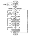
図2は、実施例1における中央制御部62の動作を説明する基本フローチャートである。フローは、システムへの給電が開始されるとスタートし、ステップS2でプリセット値が記憶されているか否かチェックする。そして記憶があればプリセット値をプリセット記憶部56から読み出し、ステップS6に移行する。一方、ステップS2プリセット値の記憶がなければステップS8に移行し、画像処理において補正を行わない旨のデフォルト値を読み出してステップS6に移行する。
FIG. 2 is a basic flowchart illustrating the operation of the
ステップS6では、右目画像用撮像素子22および左目画像用撮像素子26による撮像を開始し、ステップS10に進んで、所定の明るさを基準とした標準状態の表示制御およびこれに見合う標準状態の背景となるよう右目用可変透過率NDフィルタ32および左目用可変透過率NDフィルタ36の透過率制御を開始する。
In step S6, imaging by the right-eye
次いでステップS12では、プリセット値を設定する操作が行われたか否かチェックし、設定操作が行われたことが確認されるとステップS14に移行してプリセット値設定処理を行い、ステップS16に移行する。一方、ステップS12でプリセット値設定操作が確認されないときは直接ステップS16に移行する。ステップS14のプリセット値設定処理の詳細については後述する。 Next, in step S12, it is checked whether or not an operation for setting a preset value has been performed, and if it is confirmed that the setting operation has been performed, the process proceeds to step S14 to perform preset value setting processing, and proceeds to step S16. . On the other hand, when the preset value setting operation is not confirmed in step S12, the process directly proceeds to step S16. Details of the preset value setting process of step S14 will be described later.
ステップS16では、使用者に中心視野障害があることがプリセット値として記憶されているか否かチェックし、該当すればステップS16に進んで視線シフト処理を行いステップS20に移行する。一方、ステップS16で使用者が中心視野障害に該当しないことが確認されたときは、直接ステップS20に移行する。このときは、通常状態となり、上述のように右目用接眼光学系18および右目用接眼光学系20の光軸はそれぞれ右目用屈曲スームレンズ光学系24および左目用屈曲スームレンズ光学系26の入射光軸と一致することになる。
In step S16, it is checked whether the fact that the user has a central visual field disorder is stored as a preset value or not, and if it corresponds, the process proceeds to step S16 and eye gaze shift processing is performed to shift to step S20. On the other hand, when it is confirmed in step S16 that the user does not fall under the central visual field disorder, the process directly proceeds to step S20. In this case, the optical axes of the right-eye eyepiece
ステップS16では、環境光の明るさが変化したか否かチェックし、変化があれば、ステップS22の右目用表示変更処理、およびステップS24の右目用表示変更処理を順次実行してステップS26に至る。このように、右目用と左目用の表示変更処理はそれぞれ独立して行われる。ステップS26では、右目用背景変更処理が行われ、次いでステップS28の左目用背景変更処理が実行されてステップS30に至る。このように、右目用と左目用の背景変更処理についてもそれぞれ独立した処理が行われる。一方、ステップS20で環境光の変化がなかったときは直接ステップS30に移行する。 In step S16, it is checked whether the brightness of the ambient light has changed, and if there is a change, the processing for changing the display for the right eye in step S22 and the processing for changing the right eye display in step S24 are sequentially executed to reach step S26. . Thus, the display change processing for the right eye and the display for the left eye are independently performed. In step S26, a background change process for the right eye is performed, and then a background change process for the left eye in step S28 is performed, and the process proceeds to step S30. Thus, independent processing is performed for the background change processing for the right eye and the left eye. On the other hand, if there is no change in the ambient light in step S20, the process proceeds directly to step S30.
ステップS30では、白黒反転操作があったか否かチェックし、操作があればステップS32に移行して白黒反転表示を行うとともに背景については白黒反転表示の観察を妨げないよう遮光状態としてステップS34に移行する。一方、ステップS30で白黒反転操作がかくにんできないときには直接ステップS34に移行する。ステップS34では電源供給中か否かがチェックされ、供給中であればステップS12に戻って、以下、ステップS36で電源供給中であること確認される限りステップS12からステップS36を繰り返す。一方、ステップS36で電源供給中であることが確認されなければ直ちにフローを終了する。 In step S30, it is checked whether or not there is a black and white reversal operation, and if there is an operation, the flow proceeds to step S32 to perform black and white reversal display and as the light shielding state for the background, it shifts to step S34 as a light blocking state. . On the other hand, if it is determined in step S30 that the black and white reversal operation can not be performed, the process proceeds directly to step S34. In step S34, it is checked whether or not power is being supplied, and if it is being supplied, the process returns to step S12, and steps S12 to S36 are repeated as long as it is confirmed in step S36 that power is being supplied. On the other hand, if it is not confirmed in step S36 that power is being supplied, the flow is immediately ended.
図3は、図2のステップS22の右目用表示変更処理およびステップS24の左目用表示変更処理の詳細を示すフローチャートであり、両ステップに共通の内容であるが、図2に示すように右目用および左目用にそれぞれ実行される。フローがスタートすると、ステップS42に進み、図1のステップS20において検知された環境光の変化が表示変更処理用にあらかじめ定められた所定値以上か否かチェックする。そして変化が表示変更処理を必要としない所定値以下であれば直ちにフローを終了し、ステップS26に移行する。 FIG. 3 is a flowchart showing the details of the right-eye display change process of step S22 of FIG. 2 and the left-eye display change process of step S24. The contents are common to both steps, but as shown in FIG. And run for the left eye respectively. When the flow starts, the process proceeds to step S42, and it is checked whether or not the change of the ambient light detected in step S20 of FIG. 1 is equal to or more than a predetermined value predetermined for display change processing. If the change is equal to or less than the predetermined value that does not require the display change process, the flow is immediately ended, and the process proceeds to step S26.
一方、ステップS42で所定以上の変化が検知されるとステップS44に移行し、その変化により環境光が所定値よりも増加したか否かチェックする。ステップS44において環境光が所定値よりも増加したことが検知されるとステップS46で撮像素子のゲインをダウンしてステップS48に移行する。ステップS48では、使用者に明順応障害があるか否かチェックし、該当すればステップS50に進んで高輝度部分を圧縮するガンマ補正を行ってステップS52に進む。ステップS52ではさらに輪郭強調処理を行ってステップS54に移行する。一方ステップS44において環境光が所定値より増加したことが検知されない場合、またはステップS48において使用者が明順応障害であることが確認されない場合は、直接ステップS54に移行する。 On the other hand, when a change greater than or equal to a predetermined value is detected in step S42, the process proceeds to step S44, and it is checked whether ambient light has increased above a predetermined value due to the change. When it is detected in step S44 that the ambient light has increased above a predetermined value, the gain of the imaging device is decreased in step S46, and the process proceeds to step S48. In step S48, it is checked whether or not the user has a light adaptation failure, and if so, the process proceeds to step S50 to perform gamma correction to compress the high luminance portion, and the process proceeds to step S52. In step S52, contour enhancement processing is further performed, and the process proceeds to step S54. On the other hand, if it is not detected that the ambient light has increased above the predetermined value in step S44, or if it is not confirmed that the user is a light adaptation failure in step S48, the process proceeds directly to step S54.
ステップS54では、環境光が所定値よりも減少したか否かがチェックする。そして、環境光が所定値よりも減少したことが検知されるとステップS56で撮像素子のゲインをアップしてステップS58に移行する。ステップS58では、使用者に暗順応障害があるか否かチェックし、該当すれば60に進んで低輝度部分を持ち上げるガンマ補正を行ってステップS62に進む。ステップS62ではさらに輪郭強調処理を行ってステップS64に移行する。一方ステップS54において環境光が所定値より減少したことが検知されない場合、またはステップS58において使用者が暗順応障害であることが確認されない場合は、直接ステップS64に移行する。 In step S54, it is checked whether the ambient light has decreased below a predetermined value. When it is detected that the ambient light has decreased below a predetermined value, the gain of the imaging device is increased in step S56, and the process proceeds to step S58. In step S58, it is checked whether or not the user has a dark adaptation failure, and if so, the process proceeds to 60 to perform gamma correction to lift the low luminance portion, and the process proceeds to step S62. In step S62, contour enhancement processing is further performed, and the process proceeds to step S64. On the other hand, if it is not detected that the ambient light has decreased below the predetermined value in step S54, or if it is not confirmed that the user is a dark adaptation failure in step S58, the process proceeds directly to step S64.
ステップS54では、明るさの変化に瞳孔が反応する時間に応じた表示変更補正を行うためのカウンタをリセットしてスタートさせ、ステップS66に進む。ステップS66では、前回の明るさ変化に基づく瞳孔反応の補正中であるか否かチェックし、該当すればステップS68に進んで前回の瞳孔反応補正をキャンセルしてステップS70に進む。一方、ステップS66で前回瞳孔反応補正中であることが検知されなければ直接ステップS70に進む。ステップS70では瞳孔反応補正を開始させるとともにカウンタに基づき瞳孔反応が終了した時点で瞳孔反応補正を自動終了させる処理をスタートさせてフローを終了する。 In step S54, a counter for performing display change correction according to the time when the pupil responds to the change in brightness is reset and started, and the process proceeds to step S66. In step S66, it is checked whether or not the pupillary reaction is being corrected based on the previous brightness change. If so, the process proceeds to step S68 to cancel the previous pupillary reaction correction and proceeds to step S70. On the other hand, if it is not detected that the pupillary response is being corrected last time in step S66, the process proceeds directly to step S70. In step S70, the pupil response correction is started, and when the pupil response is ended based on the counter, processing for automatically ending the pupil response correction is started and the flow is ended.
図4は、図2のステップS26の右目用背景変更処理およびステップS28の左目用背景変更処理の詳細を示すフローチャートであり、両ステップに共通の内容であるが、図2に示すように右目用および左目用にそれぞれ実行される。フローがスタートすると、ステップS82に進み、図1のステップS20において検知された環境光の変化により環境光が所定値よりも増加したか否かチェックする。通常、図4のステップS82における所定値は、図3のステップS44における所定値よりもレベルが低い。 FIG. 4 is a flow chart showing the details of the right-eye background changing process of step S26 of FIG. 2 and the left-eye background changing process of step S28. The contents are common to both steps, but as shown in FIG. And run for the left eye respectively. When the flow starts, the process proceeds to step S82, and it is checked whether the ambient light has increased more than a predetermined value due to the change of the ambient light detected in step S20 of FIG. Usually, the predetermined value in step S82 of FIG. 4 is lower in level than the predetermined value in step S44 of FIG.
ステップS82において環境光が所定値よりも増加したことが検知されるとステップS84に進み、環境光の増加に対応して可変透過率NDフィルタの透過率を減少させてステップS86に移行する。ステップS86では、今回の環境光変化に基づいて表示部変更処理が行われたか否かチェックし、該当すればステップS88に進んで表示部変更に対応して可変透過率NDフィルタの透過率を変更してステップS90に至る。一方ステップS82において環境光が所定値より増加したことが検知されない場合、またはステップS86において表示部変更処理があったことが確認されない場合は、直接ステップS90に移行する。 If it is detected in step S82 that the ambient light has increased above the predetermined value, the process proceeds to step S84, the transmittance of the variable transmittance ND filter is decreased according to the increase of the ambient light, and the process proceeds to step S86. In step S86, it is checked whether or not display part change processing has been performed based on the current environmental light change, and if yes, processing proceeds to step S88 and changes the transmittance of the variable transmittance ND filter according to display part change. The process then goes to step S90. On the other hand, if it is not detected that the ambient light has increased beyond the predetermined value in step S82, or if it is not confirmed that the display portion change process has been performed in step S86, the process directly proceeds to step S90.
ステップS90では、図1のステップS20において検知された環境光の変化により環境光が所定値よりも減少したか否かチェックする。通常、図4のステップS90における所定値は、図3のステップS54における所定値よりもレベルが高い。ステップS90において環境光が所定値よりも減少したことが検知されるとステップS92に進み、可変透過率NDフィルタの透過率が既に最大になっているか否かチェックする。そして最大値でなければステップS94に進み、環境光の増加に対応して可変透過率NDフィルタの透過率を増加させてステップS96に移行する。但し、この増加は最大透過率が限度である。一方、ステップS92で可変透過率NDフィルタの透過率が既に最大になっていることが検知された場合は直接ステップS96に移行する。 In step S90, it is checked whether the ambient light has decreased below a predetermined value due to the change in the ambient light detected in step S20 of FIG. Usually, the predetermined value in step S90 of FIG. 4 is higher in level than the predetermined value in step S54 of FIG. If it is detected in step S90 that the ambient light has decreased below the predetermined value, the process proceeds to step S92, and it is checked whether the transmittance of the variable transmittance ND filter is already maximum. If it is not the maximum value, the process proceeds to step S94, the transmittance of the variable transmittance ND filter is increased according to the increase of ambient light, and the process proceeds to step S96. However, this increase is limited to the maximum transmittance. On the other hand, when it is detected in step S92 that the transmittance of the variable transmittance ND filter is already maximum, the process directly proceeds to step S96.
ステップS96では、今回の環境光変化に基づいて表示部変更処理が行われたか否かチェックし、該当すればステップS98に進んで表示部変更に対応して可変透過率NDフィルタの透過率を変更してステップS100に移行する。但し、この増加は最大透過率が限度である。一方ステップS90において環境光が所定値より減少したことが検知されない場合、またはステップS96において表示部変更処理があったことが確認されない場合は、直接ステップS90に移行する。 In step S96, it is checked whether or not display part change processing has been performed based on the current ambient light change, and if yes, the process proceeds to step S98 to change the transmittance of the variable transmittance ND filter according to display part change. Then, the process proceeds to step S100. However, this increase is limited to the maximum transmittance. On the other hand, if it is not detected that the ambient light has decreased below the predetermined value in step S90, or if it is not confirmed that the display portion change process has been performed in step S96, the process directly proceeds to step S90.
ステップS100では、図3において表示変更のためにスタートされた瞳孔反応補正処理があるか否かチェックし、該当すればステップS102に進んで対応する可変透過率NDフィルタの透過率補正を開始させるとともに表示変更のための動向反応補正に対応して補正を自動終了させる処理をスタートさせてフローを終了する。 In step S100, it is checked whether or not there is a pupil reaction correction process started to change the display in FIG. 3, and if so, the process proceeds to step S102 to start the transmittance correction of the corresponding variable transmittance ND filter. A process of automatically ending correction according to trend response correction for display change is started and the flow is ended.
図5は、図2のステップS34における画像急変緩和処理の詳細を示すフローチャートである。フローがスタートすると、ステップS112で表示倍率が等倍以上か否かチェックする。そしてこれに該当しない場合、すなわち、表示倍率が背景の倍率と等倍かまたはより低倍率であって顔の向きを変えた場合等における画像急変の緩和を必要としない場合は、直ちにフローを終了し、ステップS36に移行する。 FIG. 5 is a flowchart showing details of the sudden image change alleviation process in step S34 of FIG. When the flow starts, it is checked in step S112 whether or not the display magnification is equal to or greater than equal. If this is not the case, that is, if the display magnification is equal to or lower than the background magnification and the image orientation does not need to be mitigated, for example, if the face orientation is changed, the flow is immediately terminated. Then, the process proceeds to step S36.
これに対し、ステップS112で表示倍率が等倍以上であることが検知されるとステップS114に進み、顔の向きを変えたことに基づく加速度が検知されるか否か検知する。そして加速度が検知されるとステップS116に進み、右目用ディスプレイ12および左目用ディスプレイ14における前フレームの表示を維持し、ステップS118に進む。ステップS118では表示倍率に対応して予め決められている時間(例えば表示倍率2倍で3フレーム分の時間)が経過したか否かチェックする。そして時間経過がなければステップS116に戻り、以下、ステップS118で時間経過が検知されるまでステップS116およびステップS118を繰り返し、前フレームを維持する。一方、ステップS118で時間経過が検知されるとステップS120に進む。
On the other hand, if it is detected in step S112 that the display magnification is equal to or larger than one, the process proceeds to step S114, and it is detected whether an acceleration based on the change of the face direction is detected. When the acceleration is detected, the process proceeds to step S116, the display of the previous frame on the right-
ステップS120では、再度加速度検知を行い、顔の動きが止まることにより加速度が検知されなくなった場合はステップS122に進み、ステップS116で維持されたフレームの次のフレームを表示してステップS126に移行する。ステップS122の次フレーム表示は通常よりも早いフレームレートで行われる。ステップS126では現フレームの表示に追いついたかどうかチェックが行われ、まだ追いつかない場合はステップS120に戻る。以下ステップS120で新たな加速度が検知されずステップS126で現フレームに追いつかない限りステップS120からステップS126が繰り返され、通常フレームレートよりも早いフレームレートで現フレームへの復帰が行われる。そしてステップS126で現フレームが表示され鵜状態となったことが検知されるとフローを終了する。これにより、倍率が大きい状態で顔の向きを変えた場合の画像の急変が緩和され、画像の動きに遅延がかけられる。なおこの遅延は顔の動きが止まったときに速やかに取り戻される。一方、ステップS120で加速度が検知され、顔の動きが継続しているときは、ステップS124に進み、現フレームを表示してフローを終了する。従って顔の動きが継続しているときはフレームの間引かれる形で画像の急変が健和される。 In step S120, the acceleration detection is performed again, and if the acceleration is not detected because the movement of the face is stopped, the process proceeds to step S122, the frame following the frame maintained in step S116 is displayed, and the process proceeds to step S126. . The next frame display in step S122 is performed at a frame rate faster than normal. In step S126, it is checked whether it has caught up with the display of the current frame, and if it can not catch up yet, the process returns to step S120. Steps S120 to S126 are repeated unless a new acceleration is not detected in step S120 and the current frame is not caught in step S126, and the current frame is restored at a frame rate faster than the normal frame rate. Then, when it is detected in step S126 that the current frame is displayed and the camera is in the overwhelming state, the flow is ended. As a result, sudden changes in the image when the direction of the face is changed while the magnification is large are mitigated, and the movement of the image is delayed. This delay is quickly recovered when the movement of the face stops. On the other hand, when the acceleration is detected in step S120 and the movement of the face continues, the process proceeds to step S124, the current frame is displayed, and the flow is ended. Therefore, when the movement of the face is continuing, the sudden change of the image is recovered in the form of being skipped between frames.
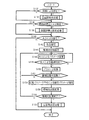
図6は、図2のステップS14におけるプリセット値設定処理の詳細を示すフローチャートである。フローがスタートすると、ステップS132で医師による設定か否かのチェックが行われる。該当すればステップS134に進み、医師設定処理を実行してステップS136に移行する。一方、ステップS132で医師による設定であることが検知されない場合は直接ステップS136に移行する。ステップS136では、視能訓練士による設定か否かのチェックが行われる。該当すればステップS138に進み、視能訓練士設定処理を実行してステップS140に移行する。一方、ステップS136で視能訓練士による設定であることが検知されない場合は直接ステップS140に移行する。 FIG. 6 is a flowchart showing the details of the preset value setting process in step S14 of FIG. When the flow starts, it is checked in step S132 whether or not the setting is made by the doctor. If it corresponds, it will progress to step S134, will perform doctor setting processing, and will transfer to step S136. On the other hand, when the setting by the doctor is not detected in step S132, the process directly proceeds to step S136. In step S136, a check is made as to whether or not the setting is performed by an orthoptist. If it corresponds, it will progress to step S138, will perform an ability training setting processing, and will transfer to step S140. On the other hand, if it is not detected in step S136 that the setting has been made by the occult trainer, the process proceeds directly to step S140.
ステップS140では、使用者本人による設定か否かがチェックされる。そして該当すればステップS142で右目設定をスタートしステップS144では環境光初期設定が行われる。本人設定は、実際に本人がHMD2を装着し、右目用ディスプレイ12を観察することで設定の適否を判断する。具体的には、ステップS146において本人による表示補正パラメータの変更が行われる。そしてステップS148において右目用ディスプレイ12により観察される画像が最適であるか否かについて本人の判断を求める。そして最適との判断ができなければステップS146に戻り、以下ステップS146とステップS148を繰り返すことでパラメータ変更と本人の判断が繰り返される。そしてステップS148において本人による最適判断なされて操作部58が操作されるとステップS150に進み、その状態におけるパラメータを記憶してステップS152に移行する。
In step S140, it is checked whether or not the setting is made by the user. Then, if it corresponds, the right eye setting is started in step S142, and the ambient light initialization is performed in step S144. In the personal setting, the user actually wears the
ステップS152では、上記のようにして記憶されるパラメータ蓄積記憶が所定回数に達したか否かチェックする。ステップS152において蓄積記憶が所定数に達していなければステップS146に戻り、以下蓄積記憶が所定数に達するまでステップS146からステップS152が繰り返される。一方、ステップS152において蓄積記憶が所定数に達するとステップS154に進み、記憶されたパラメータの平均による設定パラメータの確定を行う。 In step S152, it is checked whether or not the parameter storage stored as described above has reached a predetermined number of times. If it is determined in step S152 that the accumulated storage has not reached the predetermined number, the process returns to step S146, and steps S146 to S152 are repeated until the accumulated storage reaches the predetermined number. On the other hand, when the accumulated storage amount reaches a predetermined number in step S152, the process proceeds to step S154, and setting parameters are determined by averaging the stored parameters.
次いで、ステップS156では、設定の目的で環境光を自動変更してステップS158に進む。ステップS158では、環境光の変更処理が終了したか否かチェックする。変更処理が終了していなければステップS146に戻り、以下環境光変更が終了しない限りステップS146からステップS158を繰り返し、右目用設定が継続される。一方、ステップS158で環境光変更処理が終了するとステップS160の左目設定処理に移行する。ステップS160の左目設定処理の詳細は、ステップS146からステップS158における右目用設定処理と同じであるが、煩雑を避けるためステップS160にまとめて図示している。ステップS160の左目用設定処理が終了するとフローを終了し、図2のステップS16に移行する。一方ステップS140で本人による設定であることが検知されなければ、直ちにフローを終了する。 Next, in step S156, the ambient light is automatically changed for the purpose of setting, and the process proceeds to step S158. In step S158, it is checked whether the ambient light change process has ended. If the change process is not completed, the process returns to step S146, and steps S146 to S158 are repeated as long as the ambient light change is not completed, and the setting for the right eye is continued. On the other hand, when the ambient light change process ends in step S158, the process proceeds to the left eye setting process of step S160. The details of the left-eye setting process in step S160 are the same as the right-eye setting process in steps S146 to S158, but are collectively illustrated in step S160 in order to avoid complication. When the setting processing for the left eye in step S160 is completed, the flow is ended, and the process proceeds to step S16 in FIG. On the other hand, if it is not detected in step S140 that the setting is made by the user, the flow is immediately ended.
以上の実施例に示した種々の特徴の実施は、上記の実施例に限るものではなく、その利点を享受できる限り、他の実施例でも実施可能である。例えば、図3のフローでは、使用者に明順応障害がある場合に輪郭強調を行うとともに、使用者に暗順応障害がある場合にコントラスト強調を行うようにしているが、このような使い分けは任意であり、明順応障害がある場合でも暗順応障害がある場合でも、輪郭強調およびコントラスト強調を採用することが可能である。 The implementation of the various features shown in the above embodiments is not limited to the above embodiments, and other embodiments can be implemented as long as the advantages can be obtained. For example, in the flow of FIG. 3, while the contour enhancement is performed when the user has a light adaptation failure, the contrast enhancement is performed when the user has a dark adaptation failure, but such selective use is optional Contour enhancement and contrast enhancement can be employed whether there is a light adaptation failure or a dark adaptation failure.
本発明は、視覚補助システムおよび視覚補助装置に適用することができる。 The invention can be applied to vision aid systems and vision aid devices.
22、24、26、28 撮像部
50 画像処理部
12、18、14、20 表示部
32、36 光透過部
54 光透過部を制御する制御部
16 光軸をずらせる制御部
56 記憶部
22, 24, 26, 28
Claims (14)
Priority Applications (3)
| Application Number | Priority Date | Filing Date | Title |
|---|---|---|---|
| JP2014190160A JP6544901B2 (en) | 2014-09-18 | 2014-09-18 | Vision aid system and vision aid device |
| PCT/JP2015/076051 WO2016043165A1 (en) | 2014-09-18 | 2015-09-14 | Binocular display system |
| US15/508,655 US10426668B2 (en) | 2014-09-18 | 2015-09-14 | Binocular display apparatus |
Applications Claiming Priority (1)
| Application Number | Priority Date | Filing Date | Title |
|---|---|---|---|
| JP2014190160A JP6544901B2 (en) | 2014-09-18 | 2014-09-18 | Vision aid system and vision aid device |
Publications (3)
| Publication Number | Publication Date |
|---|---|
| JP2016059607A JP2016059607A (en) | 2016-04-25 |
| JP2016059607A5 JP2016059607A5 (en) | 2017-08-24 |
| JP6544901B2 true JP6544901B2 (en) | 2019-07-17 |
Family
ID=55796501
Family Applications (1)
| Application Number | Title | Priority Date | Filing Date |
|---|---|---|---|
| JP2014190160A Expired - Fee Related JP6544901B2 (en) | 2014-09-18 | 2014-09-18 | Vision aid system and vision aid device |
Country Status (1)
| Country | Link |
|---|---|
| JP (1) | JP6544901B2 (en) |
Families Citing this family (2)
| Publication number | Priority date | Publication date | Assignee | Title |
|---|---|---|---|---|
| JP2018081280A (en) * | 2016-11-18 | 2018-05-24 | 株式会社リコー | Image display unit |
| CN113284195B (en) * | 2021-07-08 | 2021-12-28 | 上海海栎创科技股份有限公司 | On-line compensation method and system for binocular stereoscopic vision imaging |
Family Cites Families (4)
| Publication number | Priority date | Publication date | Assignee | Title |
|---|---|---|---|---|
| JP2003287708A (en) * | 2002-03-28 | 2003-10-10 | Seiko Epson Corp | Vision expansion device and display system |
| JP2005172851A (en) * | 2003-12-05 | 2005-06-30 | Sony Corp | Image display apparatus |
| JP4600290B2 (en) * | 2004-01-29 | 2010-12-15 | コニカミノルタホールディングス株式会社 | Visual auxiliary display device |
| JP2010124191A (en) * | 2008-11-19 | 2010-06-03 | Canon Inc | Video image display device |
-
2014
- 2014-09-18 JP JP2014190160A patent/JP6544901B2/en not_active Expired - Fee Related
Also Published As
| Publication number | Publication date |
|---|---|
| JP2016059607A (en) | 2016-04-25 |
Similar Documents
| Publication | Publication Date | Title |
|---|---|---|
| US10426668B2 (en) | Binocular display apparatus | |
| JP4600290B2 (en) | Visual auxiliary display device | |
| TWI564590B (en) | Image can strengthen the structure of the glasses | |
| US20110234475A1 (en) | Head-mounted display device | |
| JP4635572B2 (en) | Video display device | |
| CN111373307B (en) | Stereoscopic glasses, method for designing glasses lenses used in stereoscopic glasses, and method for observing stereoscopic image | |
| CN104407438A (en) | Intelligent glasses | |
| WO2016169339A1 (en) | Image enhancing eyeglasses structure | |
| JP5078781B2 (en) | Image display device and imaging device | |
| KR101651995B1 (en) | Glasses-free 3d display | |
| US20170195667A1 (en) | Eyeglasses Structure Enabling Image Enhancement | |
| JP6544901B2 (en) | Vision aid system and vision aid device | |
| TWI635316B (en) | External near-eye display device | |
| CN109597210A (en) | Display device | |
| WO2018035842A1 (en) | Additional near-eye display apparatus | |
| TWI676048B (en) | Near-eye display structure | |
| CN108415167B (en) | Head-mounted virtual reality display device and automatic adjustment method | |
| JP2017037235A (en) | Binoculars display device | |
| JP6633269B2 (en) | Visual aid system | |
| CN204374515U (en) | A kind of head mounted display be convenient to ametropia patient and used | |
| CA2972856A1 (en) | An apparatus and method for displaying content | |
| WO2010098274A1 (en) | Head-mounted display | |
| CN111435195B (en) | Near-eye display structure | |
| JP2011158547A (en) | Video display device | |
| JP2010256657A (en) | Transmission type display device and display unit |
Legal Events
| Date | Code | Title | Description |
|---|---|---|---|
| A521 | Request for written amendment filed |
Free format text: JAPANESE INTERMEDIATE CODE: A523 Effective date: 20170713 |
|
| A621 | Written request for application examination |
Free format text: JAPANESE INTERMEDIATE CODE: A621 Effective date: 20170801 |
|
| A131 | Notification of reasons for refusal |
Free format text: JAPANESE INTERMEDIATE CODE: A131 Effective date: 20180911 |
|
| A521 | Request for written amendment filed |
Free format text: JAPANESE INTERMEDIATE CODE: A523 Effective date: 20180927 |
|
| A02 | Decision of refusal |
Free format text: JAPANESE INTERMEDIATE CODE: A02 Effective date: 20190305 |
|
| A521 | Request for written amendment filed |
Free format text: JAPANESE INTERMEDIATE CODE: A523 Effective date: 20190522 |
|
| A911 | Transfer to examiner for re-examination before appeal (zenchi) |
Free format text: JAPANESE INTERMEDIATE CODE: A911 Effective date: 20190531 |
|
| TRDD | Decision of grant or rejection written | ||
| A01 | Written decision to grant a patent or to grant a registration (utility model) |
Free format text: JAPANESE INTERMEDIATE CODE: A01 Effective date: 20190618 |
|
| A61 | First payment of annual fees (during grant procedure) |
Free format text: JAPANESE INTERMEDIATE CODE: A61 Effective date: 20190618 |
|
| R150 | Certificate of patent or registration of utility model |
Ref document number: 6544901 Country of ref document: JP Free format text: JAPANESE INTERMEDIATE CODE: R150 |
|
| R250 | Receipt of annual fees |
Free format text: JAPANESE INTERMEDIATE CODE: R250 |
|
| LAPS | Cancellation because of no payment of annual fees |