JP6542252B2 - System and method for off-screen display of instruments in a teleoperated medical system - Google Patents
System and method for off-screen display of instruments in a teleoperated medical system Download PDFInfo
- Publication number
- JP6542252B2 JP6542252B2 JP2016558114A JP2016558114A JP6542252B2 JP 6542252 B2 JP6542252 B2 JP 6542252B2 JP 2016558114 A JP2016558114 A JP 2016558114A JP 2016558114 A JP2016558114 A JP 2016558114A JP 6542252 B2 JP6542252 B2 JP 6542252B2
- Authority
- JP
- Japan
- Prior art keywords
- instrument
- field
- view
- tip
- imaging system
- Prior art date
- Legal status (The legal status is an assumption and is not a legal conclusion. Google has not performed a legal analysis and makes no representation as to the accuracy of the status listed.)
- Active
Links
- 238000000034 method Methods 0.000 title description 91
- 238000003384 imaging method Methods 0.000 claims description 92
- 238000002059 diagnostic imaging Methods 0.000 claims description 16
- 238000012545 processing Methods 0.000 claims description 13
- 230000033001 locomotion Effects 0.000 claims description 11
- 230000000007 visual effect Effects 0.000 claims description 5
- 230000002085 persistent effect Effects 0.000 claims 1
- 230000008569 process Effects 0.000 description 46
- 230000003287 optical effect Effects 0.000 description 9
- 238000003860 storage Methods 0.000 description 6
- 230000000694 effects Effects 0.000 description 5
- 238000003780 insertion Methods 0.000 description 5
- 230000037431 insertion Effects 0.000 description 5
- 230000008447 perception Effects 0.000 description 5
- 238000012360 testing method Methods 0.000 description 5
- 238000001356 surgical procedure Methods 0.000 description 4
- 210000003484 anatomy Anatomy 0.000 description 3
- 238000013459 approach Methods 0.000 description 3
- 238000001514 detection method Methods 0.000 description 3
- 230000004044 response Effects 0.000 description 3
- 239000004065 semiconductor Substances 0.000 description 3
- 230000000712 assembly Effects 0.000 description 2
- 238000000429 assembly Methods 0.000 description 2
- 230000005540 biological transmission Effects 0.000 description 2
- 238000004891 communication Methods 0.000 description 2
- 238000002405 diagnostic procedure Methods 0.000 description 2
- 238000013507 mapping Methods 0.000 description 2
- 239000013307 optical fiber Substances 0.000 description 2
- 230000036544 posture Effects 0.000 description 2
- 238000005096 rolling process Methods 0.000 description 2
- 208000002847 Surgical Wound Diseases 0.000 description 1
- 230000003213 activating effect Effects 0.000 description 1
- 230000002411 adverse Effects 0.000 description 1
- 230000004075 alteration Effects 0.000 description 1
- 230000008901 benefit Effects 0.000 description 1
- 230000008859 change Effects 0.000 description 1
- 230000000295 complement effect Effects 0.000 description 1
- 230000008602 contraction Effects 0.000 description 1
- 230000001186 cumulative effect Effects 0.000 description 1
- 230000003247 decreasing effect Effects 0.000 description 1
- 230000001419 dependent effect Effects 0.000 description 1
- 238000013461 design Methods 0.000 description 1
- 238000010586 diagram Methods 0.000 description 1
- 239000012636 effector Substances 0.000 description 1
- 238000001839 endoscopy Methods 0.000 description 1
- 230000006870 function Effects 0.000 description 1
- 238000005286 illumination Methods 0.000 description 1
- 238000003973 irrigation Methods 0.000 description 1
- 230000002262 irrigation Effects 0.000 description 1
- 238000004519 manufacturing process Methods 0.000 description 1
- 230000007246 mechanism Effects 0.000 description 1
- 229910044991 metal oxide Inorganic materials 0.000 description 1
- 150000004706 metal oxides Chemical class 0.000 description 1
- 238000012986 modification Methods 0.000 description 1
- 230000004048 modification Effects 0.000 description 1
- 230000001737 promoting effect Effects 0.000 description 1
- 238000011084 recovery Methods 0.000 description 1
- 230000035807 sensation Effects 0.000 description 1
- 230000035945 sensitivity Effects 0.000 description 1
- 230000009466 transformation Effects 0.000 description 1
- 230000001131 transforming effect Effects 0.000 description 1
- 238000012800 visualization Methods 0.000 description 1
Images


Classifications
-
- A—HUMAN NECESSITIES
- A61—MEDICAL OR VETERINARY SCIENCE; HYGIENE
- A61B—DIAGNOSIS; SURGERY; IDENTIFICATION
- A61B34/00—Computer-aided surgery; Manipulators or robots specially adapted for use in surgery
- A61B34/30—Surgical robots
- A61B34/35—Surgical robots for telesurgery
-
- A—HUMAN NECESSITIES
- A61—MEDICAL OR VETERINARY SCIENCE; HYGIENE
- A61B—DIAGNOSIS; SURGERY; IDENTIFICATION
- A61B34/00—Computer-aided surgery; Manipulators or robots specially adapted for use in surgery
- A61B34/30—Surgical robots
- A61B34/37—Master-slave robots
-
- A—HUMAN NECESSITIES
- A61—MEDICAL OR VETERINARY SCIENCE; HYGIENE
- A61B—DIAGNOSIS; SURGERY; IDENTIFICATION
- A61B90/00—Instruments, implements or accessories specially adapted for surgery or diagnosis and not covered by any of the groups A61B1/00 - A61B50/00, e.g. for luxation treatment or for protecting wound edges
- A61B90/36—Image-producing devices or illumination devices not otherwise provided for
- A61B90/37—Surgical systems with images on a monitor during operation
-
- A—HUMAN NECESSITIES
- A61—MEDICAL OR VETERINARY SCIENCE; HYGIENE
- A61B—DIAGNOSIS; SURGERY; IDENTIFICATION
- A61B17/00—Surgical instruments, devices or methods, e.g. tourniquets
- A61B2017/00017—Electrical control of surgical instruments
- A61B2017/00115—Electrical control of surgical instruments with audible or visual output
- A61B2017/00119—Electrical control of surgical instruments with audible or visual output alarm; indicating an abnormal situation
-
- A—HUMAN NECESSITIES
- A61—MEDICAL OR VETERINARY SCIENCE; HYGIENE
- A61B—DIAGNOSIS; SURGERY; IDENTIFICATION
- A61B90/00—Instruments, implements or accessories specially adapted for surgery or diagnosis and not covered by any of the groups A61B1/00 - A61B50/00, e.g. for luxation treatment or for protecting wound edges
- A61B90/08—Accessories or related features not otherwise provided for
- A61B2090/0807—Indication means
- A61B2090/0811—Indication means for the position of a particular part of an instrument with respect to the rest of the instrument, e.g. position of the anvil of a stapling instrument
-
- A—HUMAN NECESSITIES
- A61—MEDICAL OR VETERINARY SCIENCE; HYGIENE
- A61B—DIAGNOSIS; SURGERY; IDENTIFICATION
- A61B90/00—Instruments, implements or accessories specially adapted for surgery or diagnosis and not covered by any of the groups A61B1/00 - A61B50/00, e.g. for luxation treatment or for protecting wound edges
- A61B90/36—Image-producing devices or illumination devices not otherwise provided for
- A61B90/37—Surgical systems with images on a monitor during operation
- A61B2090/371—Surgical systems with images on a monitor during operation with simultaneous use of two cameras
Landscapes
- Health & Medical Sciences (AREA)
- Engineering & Computer Science (AREA)
- Surgery (AREA)
- Life Sciences & Earth Sciences (AREA)
- Nuclear Medicine, Radiotherapy & Molecular Imaging (AREA)
- Robotics (AREA)
- Molecular Biology (AREA)
- Biomedical Technology (AREA)
- Heart & Thoracic Surgery (AREA)
- Medical Informatics (AREA)
- Animal Behavior & Ethology (AREA)
- General Health & Medical Sciences (AREA)
- Public Health (AREA)
- Veterinary Medicine (AREA)
- Pathology (AREA)
- Oral & Maxillofacial Surgery (AREA)
- Radiology & Medical Imaging (AREA)
- Gynecology & Obstetrics (AREA)
- Endoscopes (AREA)
Description
(関連出願の参照)
この特許出願は、2014年3月17日に出願された「Systems and Methods for Offscreen Indication of Instruments in a Teleoperational Medical System」という名称の米国仮特許出願第61/954,442号の優先権及び利益を主張し、その全文をここに参照として援用する。
(Refer to related application)
This patent application claims priority and benefit from US Provisional Patent Application No. 61/954, 442, entitled "Systems and Methods for Offscreen Indication of Instruments in a Teleoperational Medical System," filed March 17, 2014. Claim, the entire text of which is incorporated herein by reference.
本開示は、遠隔操作医療処置を行うシステム及び方法に向けられており、より具体的には、内視鏡の視野の外側に位置する遠隔操作器具の場所の表示をもたらすシステム及び方法に向けられている。 The present disclosure is directed to systems and methods for performing teleoperated medical procedures, and more particularly to systems and methods that provide an indication of the location of a teleoperated instrument located outside the field of view of an endoscope. ing.
最小侵襲的な医療技法は、侵襲的な医療処置中に損傷させられる組織の量を減らし、それにより、患者の回復時間、不快感、及び有害な副作用を減らすことを意図する。そのような最小侵襲的な技法は、患者の解剖学的構造にある自然開口部を通じて或いは1つ又はそれよりも多くの外科的切開部を通じて行われることがある。これらの自然開口部又は切開部を通じて、臨床医は、標的組織場所に達するよう、医療ツールを挿入することがある。最小侵襲的な医療ツールは、診療器具、診断器具、手術器具のような、器具を含む。最小侵襲的な医療ツールは、内視鏡検査器具のような、撮像器具を含んでもよい。撮像器具は、使用者に患者の解剖学的構造内の視野を提供する。幾つかの最小侵襲的な医療ツール及び撮像器具は遠隔操作されることがあり或いはその他の方法においてコンピュータ支援されることがある。遠隔操作医療システムにおいて、器具は、撮像機器によって提供される視野において、使用者に見えない状態で制御されることがある。視野の外側の器具の不注意な動きは、安全リスクを生む。加えて、臨床医は、視野の外側に位置する器具を見失うことがある。 Minimally invasive medical techniques are intended to reduce the amount of tissue damaged during invasive medical procedures, thereby reducing patient recovery time, discomfort, and adverse side effects. Such minimally invasive techniques may be performed through a natural opening in the patient's anatomy or through one or more surgical incisions. Through these natural openings or incisions, the clinician may insert medical tools to reach the target tissue location. Minimally invasive medical tools include instruments such as medical instruments, diagnostic instruments, surgical instruments. Minimally invasive medical tools may include imaging tools, such as endoscopy tools. The imaging device provides the user with a view within the patient's anatomy. Some minimally invasive medical tools and imaging instruments may be remotely operated or otherwise computer assisted. In a teleoperated medical system, the instrument may be controlled blind to the user in the field of view provided by the imaging device. Careless movement of the instrument outside the field of view creates a safety risk. In addition, the clinician may lose sight of instruments located outside the field of view.
間違った表示の発生を最小にしながら、視野の外側の器具の場所の表示を臨床医にもたらす、システム及び方法が必要とされる。 There is a need for systems and methods that provide the clinician with an indication of the location of the instrument outside of the field of view while minimizing the occurrence of false indications.
本発明の実施態様は、以下に続く請求項によって要約される。 Embodiments of the invention are summarized by the claims that follow.
1つの実施態様において、医療撮像システムは、器具先端を含む医療器具の動きを制御するように構成される遠隔操作アセンブリと、1つ又はそれよりも多くのプロセッサを含む処理装置とを含む。処理装置は、器具先端位置を決定し且つ器具先端位置と関連付けられる位置誤差を決定するように構成される。処理装置は、位置誤差に基づき少なくとも1つの器具先端境界ボリュームを決定し且つ器具先端が撮像器具の視野内にあるか否かを決定するようにも構成される。 In one embodiment, a medical imaging system includes a teleoperated assembly configured to control movement of a medical instrument that includes an instrument tip and a processing unit that includes one or more processors. The processing device is configured to determine an instrument tip position and to determine a position error associated with the instrument tip position. The processor is also configured to determine at least one instrument tip boundary volume based on the position error and to determine if the instrument tip is within the field of view of the imaging instrument.
他の実施態様において、撮像方法は、遠隔操作アセンブリによって制御される医療器具についての器具先端位置を決定するステップと、器具先端位置と関連付けられる位置誤差を決定するステップとを含む。当該方法は、位置誤差に基づき少なくとも1つの器具先端境界ボリュームを決定するステップと、器具先端が撮像器具の視野内にあるか否かを決定するステップとを更に含む。 In another embodiment, the imaging method includes the steps of determining an instrument tip position for the medical instrument controlled by the telemetry assembly and determining a position error associated with the instrument tip position. The method further includes determining at least one instrument tip boundary volume based on the position error, and determining whether the instrument tip is within the field of view of the imaging instrument.
本開示の特徴は、添付の図面と共に読まれるとき、以下の詳細な記述から最良に理解される。当業界における慣行に従って様々な構成を原寸通りに描写していないことを強調する。実際には、議論の明瞭性のために、様々な構成の寸法は、任意に増大させられ或いは減少させられることがある。加えて、本開示は、様々な実施例において参照番号及び/又は文字を反復することがある。この反復は、単純性及び明瞭性の目的のためであり、それ自体は、議論する様々な実施態様及び/又は構成の間の関係を決定しない。 The features of the present disclosure are best understood from the following detailed description when read with the accompanying drawing figures. Emphasize that the various configurations are not drawn to scale in accordance with industry practice. In practice, the dimensions of the various configurations may be arbitrarily increased or decreased for clarity of discussion. In addition, the present disclosure may repeat reference numbers and / or letters in the various embodiments. This iteration is for the purpose of simplicity and clarity and as such does not determine the relationship between the various embodiments and / or configurations discussed.
本開示の原理の理解の促進の目的のために、図面に例示する実施態様を今や参照し、特定の言語を用いて実施態様を記載する。それにも拘わらず、本開示の限定を意図しないことが理解されるべきである。本発明の特徴の後続の詳細な記述では、開示する実施態様の網羅的な理解をもたらすために、様々な具体的な詳細を示す。しかしながら、この開示の実施態様はこれらの具体的な詳細がなくても実施される場合があることが当業者に明らかであろう。他の場合には、本は爪印お実施態様の特徴を不要に曖昧にしないよう、周知の方法、手順、構成部品(コンポーネント)、及び回路を詳細に記載しない。 DETAILED DESCRIPTION For the purposes of promoting an understanding of the principles of the present disclosure, reference will now be made to the embodiments illustrated in the drawings and the specific language will be used to describe the embodiments. It should nevertheless be understood that no limitation of the present disclosure is intended. In the following detailed description of the features of the present invention, numerous specific details are set forth in order to provide a thorough understanding of the disclosed embodiments. However, it will be apparent to one skilled in the art that the embodiments of the present disclosure may be practiced without these specific details. In other instances, the book does not describe well-known methods, procedures, components, and circuits so as not to unnecessarily obscure the features of the nail embodiment.
記載するデバイス、器具、方法に対するあらゆる変更及び更なる修正、並びに、本開示の原理のあらゆる更なる適用は、本開示が関係する当業者の心に通常思い浮かぶように完全に想定される。具体的には、1つの実施態様に関して記載する構成、構成部品、及び/又はステップを本開示の他の実施態様に関して記載する構成、構成部品、及び/又はステップと組み合わせてよいことが完全に想定される。加えて、ここにおいて提供される寸法は特定の実施例のためであり、異なる大きさ、寸法、及び/又は比率を利用して本開示の着想を実施してよいことが想定される。不要な記述の反復を避けるために、1つの例示的な実施態様に従って記載する1つ又はそれよりも多くの構成部品又は行為は、他の例示的な実施態様から適用可能なものであるとして用いられることができ、或いは省略されることができる。簡潔性のために、これらの組み合わせの数多くの反復は別個に記載されない。単純性のために、幾つかの場合には、図面を通じて同じ参照番号を用いて同一の又は類似の部品(parts)に言及する。 All changes and further modifications to the described devices, instruments, methods, as well as any further applications of the principles of the present disclosure, are fully contemplated as would normally occur to one of ordinary skill in the art to which the present disclosure pertains. In particular, it is perfectly assumed that the arrangements, components and / or steps described with respect to one embodiment may be combined with the arrangements, components and / or steps described with respect to the other embodiments of the disclosure. Be done. Additionally, the dimensions provided herein are for specific embodiments, and it is envisioned that different sizes, dimensions, and / or ratios may be used to implement the concepts of the present disclosure. In order to avoid unnecessary repetition of the description, one or more components or acts described according to one exemplary embodiment are used as applicable from the other exemplary embodiments. Can be omitted or omitted. For the sake of brevity, many iterations of these combinations are not described separately. For the sake of simplicity, in some cases, the same reference numerals are used throughout the drawings to refer to the same or similar parts.
以下の実施態様は、様々な器具及び器具の部分を、それらの三次元空間内の状態に関して記載する。ここにおいて用いるとき、「位置」(“position”)という用語は、三次元空間(例えば、デカルトX,Y,Z座標に沿う3つの並進自由度)内の物体(object)又は物体の部分の場所を指す。ここにおいて用いるとき、「向き」(“orientation”)という用語は、物体又は物体の部分の回転的な配置(3つの回転自由度−例えば、ロール、ピッチ、及びヨー)を指す。ここにおいて用いるとき、「姿勢」(“pose”)という用語は、少なくとも1つの並進自由度における物体又は物体の部分の位置を指し、且つ、少なくとも1つの回転自由度(最大で全部で6つの自由度)における物体又は物体の部分の向きを指す。ここにおいて用いるとき、「形状」(“shape”)という用語は、物体に沿って測定される一連の姿勢、位置、又は向きを指す。 The following embodiments describe various instruments and parts of the instruments in terms of their state in three-dimensional space. As used herein, the term "position" refers to the location of an object or portion of an object in three-dimensional space (eg, three translational degrees of freedom along Cartesian X, Y, Z coordinates) Point to As used herein, the term "orientation" refers to the rotational arrangement of an object or part of an object (three rotational degrees of freedom-eg roll, pitch and yaw). As used herein, the term "pose" refers to the position of an object or portion of an object in at least one translational degree of freedom, and at least one rotational degree of freedom (up to a total of six degrees of freedom) Refers to the orientation of the object or part of the object in degrees). As used herein, the term "shape" refers to a series of postures, positions, or orientations measured along an object.
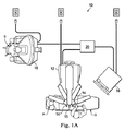
図面のうちの図1Aを参照すると、例えば、診断処置、診療処置、又は手術処置を含む、医療処置における使用のための遠隔操作医療システムが、参照番号10によって概ね示されている。記載するように、この開示の遠隔操作医療システムは、外科医の遠隔制御の下にある。代替的な実施態様において、遠隔操作医療システムは、処置又は下位処置(sub-procedure)を行うようにプログラムされるコンピュータの部分的な制御の下にあってよい。更に他の代替的な実施態様では、完全に自動化される医療システムが、処置又は下位処置を行うようにプログラムされるコンピュータの完全な制御の下で、処置又は下位処置を行うために用いられてよい。図1Aに示すように、遠隔操作医療システム10は、一般的に、患者Pを位置付ける手術台Oに又はその付近に取り付けられる遠隔操作アセンブリ12を含む。遠隔操作アセンブリ12を患者側カートと呼ぶことがある。医療器具システム14及び内視鏡撮像システム15が、遠隔操作アセンブリ12に動作可能に連結される。操作者入力システム16は、外科医又は他の種類の臨床医Sが、手術部位の又は手術部位を表す画像を見るのを可能にし、且つ、医療器具システム14及び/又は内視鏡撮像システム15の動作を制御するのを可能にする。
Referring to FIG. 1A of the drawings, a teleoperated medical system for use in medical procedures, including, for example, diagnostic procedures, medical procedures, or surgical procedures, is indicated generally by the
操作者入力システム16は、外科医コンソールに配置されてよく、外科医コンソールは、普通、手術台Oと同じ部屋内に配置される。しかしながら、外科医Sは、異なる部屋又は患者Pと全く異なる建物内に配置されてよい。操作者入力システム16は、一般的に、医療器具システム14を制御する1つ又はそれよりも多くの制御デバイスを含む。(複数の)制御デバイスは、握り(hand grips)、ジョイスティック(joysticks)、トラックボール(trackballs)、データグローブ(data gloves)、トリガーガン(trigger-guns)、手動コントローラ(hand-operated controllers)、音声認識デバイス(voice recognition devices)、タッチスクリーン(touch screens)、体の動き(body motion)又は存在センサ(presence sensors)、及び同等物のような、あらゆる数の様々な入力デバイスのうちの1つ又はそれよりも多くを含んでよい。幾つかの実施態様において、(複数の)制御デバイスは、遠隔操作アセンブリの医療器具と同じ自由度を備えて、外科医にテレプレゼンス、即ち、外科医が恰も手術部位に存在しているかのように器具を直接的に制御しているという強い感覚を有するよう、(複数の)制御デバイスが器具と一体であるという知覚をもたらす。他の実施態様において、(複数の)制御デバイスは、関連付けられる医療器具よりも多い又は少ない自由度を有して、外科医にテレプレゼンスを依然としてもたらしてよい。幾つかの実施態様において、(複数の)制御デバイスは、6つの自由度で動く手動入力デバイスであり、手動入力デバイスは、器具を作動させるための(例えば、把持ジョーを閉じるための、電極に電位を加えるための、医療治療を施すための、及び同等のことのための)、作動ハンドルを含んでもよい。
The
遠隔操作アセンブリ12は、外科医Sがコンソール16を通じて手術部位を見る間に、医療器具システム14を支持し且つ操縦する(manipulate)。遠隔操作アセンブリによって操縦して内視鏡を方向付け得る、立体視内視鏡のような、内視鏡撮像システム15によって、手術部位の画像を取得し得る。電子機器カート18を用いて、外科医コンソール16を通じた外科医Sへの更なる表示のために、手術部の画像を処理し得る。一度に用いられる医療器具システム14の数は、一般的には、数ある要因の中でも、診断又は手術処置及び手術室内の空間的な制約に依存する。遠隔操作アセンブリ12は、遠隔操作マニピュレータ及び1つ又はそれよりも多くの非サーボリンク(例えば、セットアップ構造と一般的に呼ぶ、所定の場所に手動で位置付けられ且つ係止されてよい1つ又はそれよりも多くのリンク)の運動学的構造を含んでよい。遠隔操作アセンブリ12は、医療器具システム14にある入力を駆動させる複数のモータを含む。これらのモータは、制御システム(例えば、制御システム20)からの命令に応答して動く。モータは、駆動システムを含み、駆動システムは、医療器具システム14に連結されるときに、医療器具を自然に又は外科的に創り出される解剖学的な開口部内に前進させてよい。他の電動駆動システムが、3つの程度の線形運動(例えば、X,Y,Zデカルト軸に沿う線形運動)及び3つの程度の回転運動(例えば、X,Y,Zデカルト軸についての回転)を含んでよい、多数の自由度において、医療器具の遠位端を動かしてよい。加えて、モータを用いて、生体デバイス又は同等物のジョーにおいて組織を把持する器具の関節作動可能なエンドエフェクタを作動させ得る。
The
遠隔操作医療デバイス10は、制御システム20も含む。制御システム20は、少なくとも1つのメモリと、少なくとも1つのプロセッサ(図示せず)とを含み、典型的には、医療器具システム14、操作者入力システム16、及び電子機器システム18との間の制御をもたらすための、複数のプロセッサを含む。制御システム20は、ここに開示する特徴に従って記載する方法の一部又は全部を実施するよう、プログラムされる指令(例えば、指令を格納するコンピュータ可読媒体)も含む。制御システム20は、図1Aの簡略図に単一のブロックとして示されているが、制御システム20は、2つ又はそれよりも多くのデータ処理回路を含んでよく、処理の1つの部分は任意的に遠隔操作アセンブリ1212で又はその付近で行われ、処理の他の部分は操作者入力システム16で行われ、且つ同等のことが行われる。多種多様な集中型又は分散型のデータ処理アーキテクチャのうちのいずれかが利用されてよい。同様に、プログラムされる指令は、多数の別個のプログラム又はサブルーチンとして実施されてよく、或いは、それらはここに記載する遠隔操作システムの多数の他の特徴に統合されてよい。1つの実施態様において、制御システム20は、Bluetooth、IrDA、HomeRF、IEEE 802.11、DECT、Wireless Telemetryのような、無線通信プロトコルをサポートする。
Teleoperated
幾つかの実施態様において、制御システム20は、医療器具システム14から力及び/又はトルクフィードバックを受信する、1つ又はそれよりも多くのサーボコントローラを含んでよい。フィードバックに応答して、サーボコントローラは、操作者入力システム16に信号を送信する。(複数の)サーボコントローラは、患者の体にある開口を介して体内の内部手術部位に延びる(複数の)医療器具システム14及び/又は内視鏡撮像システムを動かすことを遠隔操作アセンブリ12に指令する、信号を送信してよい。あらゆる適切な従来的な又は特殊なサーボコントローラが用いられてよい。サーボコントローラは、遠隔操作アセンブリ12と別個でよく、或いは遠隔操作アセンブリ12と一体的でよい。幾つかの実施態様において、サーボコントローラ及び遠隔操作アセンブリは、患者の体に隣接して位置付けられる遠隔操作アームカートの部分として提供される。
In some embodiments,
遠隔操作医療システム10は、照明システム(illumination systems)、操縦制御システム(steering control systems)、洗浄システム(irrigation systems)、及び/又は吸引システム(suction systems)のような、任意的な操作及び支持システム(図示せず)を更に含んでよい。代替的な実施態様において、遠隔操作システムは、1つよりも多くの遠隔操作アセンブリ及び/又は1つよりも多くの操作者入力システムを含んでよい。マニピュレータアセンブリの正確な数は、数ある要因の中でも、外科処置及び手術室内の空間的な制約に依存する。操作者入力システムは並置されてよく、或いはそれらは別個の場所に位置付けられてよい。多数の操作者入力システムは、1人よりも多くの操作者が様々な組み合わせにおいて1つ又はそれよりも多くのマニピュレータアセンブリを制御するのを可能にする。
The teleoperated
図1Bは、外科医コンソール16の斜視図である。外科医コンソール16は、深さ知覚を可能にする手術部位の協調立体像(coordinated stereo view)を外科医Sに提示するために左眼ディスプレイ32及び右眼ディスプレイ34を含む。外科医コンソール16は、1つ又はそれよりも多くの入力制御デバイス36を更に含み、次に、入力制御デバイス36は、遠隔操作アセンブリ12に1つ又はそれよりも多くの器具又は内視鏡撮像システムを操縦させる。入力制御デバイス36は、それらの関連付けられる器具14と同じ自由度を提供して、外科医Sにテレプレゼンス又は外科医が器具14を直接的に制御しているという強い感覚を有するよう入力制御デバイス36が器具14と一体であるという知覚をもたらし得る。これを達成するために、位置、力、及び触覚フィードバックセンサ(図示せず)を利用して、器具14からの位置、力、及び触覚刺激(tactile sensations)を、入力制御デバイス36を通じて外科医の両手に戻してよい。
FIG. 1B is a perspective view of the
図1Cは、電子機器カート18の斜視図である。電子機器カート18は、内視鏡15と連結され得るし、外科医コンソールにいる外科医への或いは局所的に及び/又は遠隔に配置される他の適切なディスプレイでのような、後続の表示のためにキャプチャ画像(取込み画像)を処理する、プロセッサを含み得る。例えば、立体視内視鏡が用いられる場合、電子機器カート18は、キャプチャ画像を処理して、手術部位の協調立体画像を外科医に提示し得る。そのような協調は、対向する画像の間の整列(アライメント)を含み得るし、立体視内視鏡の立体作動距離を調節することを含み得る。他の例として、画像処理は、光学収差のような、画像キャプチャデバイスの撮像誤差を補償するよう、従前に決定されたカメラ較正パラメータを使用することを含み得る。電子機器カート18は、ディスプレイモニタと、制御システム20の構成部品とを含んでもよい。
FIG. 1C is a perspective view of the
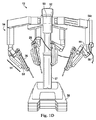
図1Dは、患者側カートと呼ぶことがある遠隔操作アセンブリ12の1つの実施態様の斜視図である。図示する患者側カート12は、3つの手術ツール26(例えば、器具システム14)及び処置部位の画像のキャプチャ(取込み)のために用いられる立体視内視鏡のような撮像デバイス28(例えば、内視鏡撮像システム15)の操縦をもたらす。撮像デバイスは、ケーブル56を通じて電子機器カート18に信号を送信してよい。操縦は多数の関節を有する遠隔操作機構によって提供される。運動学的な遠隔中心を切開部に維持して切開部の大きさを最小にするよう、撮像デバイス28及び手術ツール26を患者にある切開部を通じて位置付け且つ操縦し得る。手術部位の画像は、手術ツール26が撮像デバイス28の視野内に位置付けられるときの手術ツール26の遠位端の画像を含み得る。
FIG. 1D is a perspective view of one embodiment of the
患者側カート22は、駆動可能なベース58を含む。駆動可能なベース58は、入れ子式コラム57に接続され、入れ子式コラム57は、アーム54の高さの調節を可能にする。アーム54は、回転し且つ上下に動く回転する関節55を含んでよい。アーム54の各々は、配向プラットフォーム53(orienting platform)に接続されてよい。配向プラットフォーム53は、360度の回転が可能であってよい。患者側カート22は、配向プラットフォーム53を水平方向において動かす入れ子式の水平片持ち梁52も含んでよい。
The patient side cart 22 includes a
本実施例において、アーム54の各々は、マニピュレータアーム51に繋がる。マニピュレータアーム51は、マニピュレータスパー(manipulator spar)59を介して医療機器26に直接的に繋がってよい。マニピュレータアーム51は、遠隔操作可能であってよい。幾つかの実施例において、配向プラットフォームに繋がるアーム54は、遠隔操作可能でない。むしろ、そのようなアーム54は、外科医18が遠隔操作可能な構成部品で操作を開始する前に、記載されるように位置付けられる。
In the present embodiment, each of the arms 54 is linked to a manipulator arm 51. The manipulator arm 51 may be connected directly to the medical device 26 via a manipulator spar 59. The manipulator arm 51 may be remotely operable. In some embodiments, the arm 54 leading to the orienting platform is not remotely operable. Rather, such an arm 54 is positioned as described before the
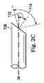
内視鏡撮像システム(例えば、システム15,28)が、剛性又はフレキシブル内視鏡を含む様々な構成において提供されてよい。剛性内視鏡は、画像を内視鏡の遠位端から近位端に伝える中継レンズシステムを収容する剛性チューブを含む。フレキシブル内視鏡は、1つ又はそれよりも多くのフレキシブルな光ファイバを用いて画像を伝える。内視鏡は、前方軸方向視認(forward axial viewing)のための0°の視角又は前方傾斜視認(forward oblique viewing)のための0〜90°間の視角を含む、異なる視角(viewing angle)を備えてよい。内視鏡に基づくデジタル画像は、1つ又はそれよりも多くの電荷結合デバイス(CCD)又は相補型金属酸化膜半導体(CMOS)デバイスのような遠位デジタルセンサが画像データを格納する、「チップ・オン・ザ・チップ」(“chip on the tip”)設計を有する。内視鏡撮像システムは、二次元又は三次元画像を視認者(viewer)に提供してよい。二次元画像は、限定的な深さ知覚を提供する。三次元立派委内視鏡画像は、より正確な深さ知覚を視認者に提供する。立体内視鏡器具は、立体カメラを利用して、患者の解剖学的構造の立体画像をキャプチャする。図2Aは、ハンドル102と、ハンドルに剛的に連結されるシャフト104とを含む、剛性軸外(off-axis)立体内視鏡撮像器具100を例示している。ロール運動アダプタ106が、シャフト104及び/又はハンドル102に回転可能に連結される。シャフト104は、遠位端108と、近位端110とを含み、遠位画像記憶装置、レンズ系、光ファイバ、又は他の立体画像キャプチャ及び送信構成部品(図示せず)を収容する。シャフト104は、光学軸OAに沿って延びる。図2Cに示すように、器具100は、視角112(angle of view)と、円錐光学視野114(conical optical field of view)とを有する。この実施態様において、視角は約30°であるが、光学軸OAに対して傾斜角視認(oblique angle viewing)に適したあらゆる角度であってよい。手動又は遠隔操作制御に応答して、遠隔操作アセンブリ(例えば、遠隔操作アセンブリ12)は、器具本体102とシャフト104とを含む撮像機器100を、光学軸OAについて回転させるよう作動させられてよい。図2Aは、光学軸OAに対して−30°の又は下向きの角度を備える撮像機器100を例示している。図2Bは、光学軸OAに対して+30°の又は上向きの角度を伴って180°回転させられた撮像器具100を例示している。「上」(“up”)、「下」(“down”)、「上向き」(“upward”)、及び「下向き」(“downward”)という用語は、概ね反対方向を名付けるために例示的な目的のために用いられているに過ぎず、限定的であることを意図しない。
Endoscopic imaging systems (e.g.,
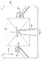
図3は、撮像器具204(例えば、撮像器具105,100)のための撮像器具視野202を取り囲む手術作業空間200を例示している。撮像器具204は、遠位端205を有する。2つの手術器具206,208(例えば、器具14)は、作業空間200内で動作可能である。この実施態様において、視野202は、三次元ピラミッド錐台(pyramidal frustum)形状を有する。撮像器具204が2つの撮像デバイスを備える立体視撮像器具であるならば、撮像器具の視野は、撮像器具の各撮像デバイスのための三次元ピラミッド錐台の結合ボリュームである。代替的な実施態様において、撮像器具又は撮像デバイスのための三次元視野は、円錐台(conical frustum)形状であってよい。医療器具206は、遠位器具先端210を含み、遠位器具先端210は、この実施態様において、近位先端部分212と、第1の遠位先端部分214と、第2の遠位先端部分216とを含む、二本指作動可能先端(two-finger actuatable tip)である。同様に、医療器具208は、遠位器具先端218を含み、遠位器具先端218は、この実施態様において、近位先端部分220と、第1の遠位先端部分222と、第2の遠位先端部分224とを含む、二本指作動可能先端である。
FIG. 3 illustrates a
図3の構成において、医療器具206,208は、撮像器具204の視野の外側にある。器具206,208が撮像器具204の視野の内側にあるのか或いは外側にあるのかの決定は、図7で更に詳細に記載するように、器具遠位先端210,218の計算される場所に基づく。図3の手術作業空間は、世界空間のための世界座標系(XW,YW,ZW)を有し、撮像器具の遠位端は、内視鏡空間のための撮像又は内視鏡座標系(XI,YI,ZI)を有する。
In the configuration of FIG. 3, the
図4Aは、手術作業空間200内の撮像器具204の視野231の表示画像230を例示している。器具206,208は、表示画像230内で見える。この構成において、器具206,208は、「オンスクリーン」(“on screen”)である、即ち、画像230を表示するディスプレイスクリーン上にあると考えられる。視野231は、境界232を有する。表示画像は、ディスプレイ又はスクリーン空間のためのディスプレイ又はスクリーン座標系(XS,YS,ZS)を有する。立体視撮像システムでは、左側スクリーン及び右側スクリーンの各々のために別個のスクリーン座標系があってよい。
FIG. 4A illustrates a
図4Bは、手術作業空間200内の撮像機器204の視野241の表示画像240を例示している。視野241は、境界242を有する。器具204の視野は、例えば、拡大する、縮小する、ピッチ運動において動く、ヨー運動において動く、或いは上向き視角と下向き視角との間でロール運動することによって、変更されてよい。器具206は、視野241内に留まっており、よって、表示画像240内で見える。よって、器具206は、オンスクリーンであると考えられる。器具208は、視野241内になく、よって、表示画像240内で見えない。よって、器具208は、オフスクリーンであると考えられる。
FIG. 4B illustrates a
器具206,208は、視野内で臨床医に見えないで遠隔操作式に制御されることがあるので、視野の外側の器具の不注意な動きは安全リスクを生む。加えて、臨床医は視野の外側に位置する器具を見失うことがある。これらのリスクを最小にするために、視野外器具インジケータを視覚的に又は可聴的に提示して、視野内で見えない器具の場所についての臨床医の認識(awareness)を増大させてよい。例えば、図4Bに示すように、視野外器具インジケータ244を視野241の境界242に沿って提供して、器具208がインジケータの一般的な方向において視野の外に位置することを表示する。この実施態様において、インジケータ244はグラフィックバーであるが、他の実施態様では、一連の点、アイコン(icon)、又は英数字インジケータであってよい。視覚的インジケータに加えて或いは視覚的インジケータの代わりに、ビープ音又は言語ベース指示のような可聴視野外インジケータが、器具208が視野外にあることを臨床医に警告してよい。可聴キュー(cue)が外科医コンソールの左側スピーカと右側スピーカとの間でパン(作動)(pan)して、眺望(view)に対する器具位置を強化してよい。代替的に、可聴キューは器具と関連付けられる左手側又は右手側の制御装置と対応する左側又は右側のスピーカから放出してよい。視覚的インジケータ244に加えて或いは視覚的インジケータ244の代わりに、視野外器具に関する文字情報246を提供して臨床医に警告し、且つ/或いは器具についての識別情報又は器具を視覚化せよという指令を提供してよい。
Because the
様々な実施態様において、視野外インジケータの使用は、臨床医の気を散らすようになるのを避けるように制約される。視野外インジケータの使用は、視野外インジケータが遠隔操作システムの特定の動作モードの間にのみ表示されてよいように、状況敏感(context-sensitive)であってよい。例えば、視野外インジケータは、操作者が撮像システムの動作を制御するシステムのモード、即ち、カメラ制御モードとして知られることがあるモードの間に表示されてよい。他の例として、視野外インジケータは、システムが関連付けられる器具を制御するために操作者からの入力を待つ間に表示されてよい。他の例として、視野外インジケータは、操作者が器具の動作を制御するシステムのモード、即ち、追従モードとして知られることがあるモードを開始した後に、数秒に亘って表示されてよい。更に他の代替的な実施態様において、視野外インジケータは、臨床医が視野外器具の場所について学習することを欲する時に無効にされ或いは選択的に有効にされてよい。幾つかの実施態様において、臨床医は、視野外器具の動作が有効にされる前に、器具先端が視野の外側にあることの承認(acknowledgement)を提供しなければならない。エネルギ放射デバイス、鋭利なデバイス、又は視覚化を伴わずに用いられるならば患者リスクの増大をもたらすデバイスのために、追加的な警告又は承認が用いられてよい。幾つかの実施態様において、視野外インジケータは、視野内にあるが閉塞組織(occluding tissue)又は他の構造の故に見えない器具のために提供されてよい。 In various embodiments, the use of out-of-field indicators is constrained to avoid becoming distracting to the clinician. The use of the out-of-field indicator may be context-sensitive, such that the out-of-field indicator may only be displayed during a particular mode of operation of the teleoperated system. For example, the out-of-field indicator may be displayed during a mode of the system in which the operator controls the operation of the imaging system, a mode that may be known as a camera control mode. As another example, the out-of-field indicator may be displayed while waiting for an input from the operator to control the instrument with which the system is associated. As another example, the out-of-field indicator may be displayed for several seconds after the operator has initiated a mode of the system that controls the operation of the instrument, a mode that may be known as a follow-up mode. In yet another alternative embodiment, the out of field indicator may be disabled or selectively enabled when the clinician wants to learn about the location of the out of field instrument. In some embodiments, the clinician must provide an acknowledgment that the instrument tip is outside the field of view before the out-of-field instrument operation is enabled. Additional alerts or approvals may be used for energy emitting devices, sharp devices, or devices that, if used without visualization, result in increased patient risk. In some embodiments, an out-of-field indicator may be provided for an instrument that is within the field of view but is invisible because of the occlusive tissue or other structures.
図4Cは、図4Bについての撮像器具204の位置又は向きから撮像器具204を動かした後の、手術作業空間200内の撮像器具204の視野251の表示画像250を例示している。視野251は、境界252を有する。器具206は、視野251内に留まっており、よって、表示画像250内で見える。器具208は、視野251外にあり、よって、表示画像250内で見えない。視野外インジケータ244は、撮像器具が動いた後の視野外器具の場所を反映するよう、境界252に沿って異なる場所に移動している。幾つかの実施態様において、インジケータ244の全長は、撮像器具が動くのと同じままである。代替的な実施態様において、インジケータは、視野からの視野外器具の距離を示すよう拡大縮小(scale)してよい。
FIG. 4C illustrates the displayed
図4Dは、撮像器具204が図4Cにおける撮像器具204の位置又は向きから移動した後の、手術作業空間200内の撮像器具204の視野261の表示画像260を例示している。視野261は、境界262を有する。器具206は、視野261内に留まっており、よって、表示画像260内で見える。器具208は、視野261外にあり、よって、表示画像260内で見えない。視野外インジケータ244は、撮像器具が動いた後の視野外器具の場所を反映するよう、境界262に沿って更に移動している。
FIG. 4D illustrates the displayed
図4Eは、図4Aにおける撮像器具204の視角上方構成から視角下方構成に撮像器具204をロール運動した後の、手術作業空間200内の撮像器具204の視野271の表示画像270を例示している。視野271は、境界272を有する。器具206及び208は、両方とも、視野271外にあり、よって、表示画像270内で見えない。視野外インジケータ244は、視野外器具208の一般的な方向を示しており、視野外インジケータ274は、視野外器具210の一般的な方向を示している。
FIG. 4E illustrates a
図4Fは、手術作業空間200内の撮像器具204の視野281の表示画像280を例示している。視野271は、境界282を有する。器具206及び208は、両方とも、視野281内にあり、よって、表示画像280内で見える。器具先端218が境界282に近づいていることを示すために、警告インジケータ284が提供されてよい。この実施態様において、警告インジケータ284は、リングであるが、代替的な実施態様では、他の種類のグラフィカルシンボル又は可聴インジケータであってよい。インジケータは、先端218が境界282のより近くに動くに応じて変化(例えば、点滅)してよい。警告インジケータ284は、器具先端のいずれかが境界282から所定の距離(例えば、1cm)内に動くときに、表示画像280内に現れてよい。
FIG. 4F illustrates a displayed
上で説明したように、器具206,208が撮像器具204の視野の内側にあるか或いは外側にあるかの決定は、器具遠位先端210,218の計算される場所に基づいてよい。遠隔操作システム、器具、及び/又は撮像システムと関連付けられる小さな誤差要因(error factors)の故に、撮像器具204に対する器具遠位先端210,218の場所の決定は、関連付けられる累積的な誤差要因を有する。偽陽性の視野外インジケータを提供するのを避けるために、器具先端が撮像システム視野の外にあるか否かの決定は、遠位先端についての可能な場所の範囲を推定し且つ遠位先端についての推定される可能な場所のいずれかの又は指定の割合が視野内にあるならば視野外インジケータを抑制することによって、バイアスがかけられ(biased)てよい。バイアス(bias)の感度は、偽陽性の視野外インジケータについての臨床医の許容範囲に基づき調節されてよい。
As discussed above, the determination of whether the
図5は、撮像器具204のための撮像器具視野を取り囲む手術作業空間200を例示している。この例示において、医療器具206,208の器具先端210,218と関連付けられる位置誤差は示されている。誤差境界ボリュームのセット(a set of error bounding volumes)が、各器具先端210,218と関連付けられている。誤差境界ボリュームは、先端部分の遠位端及び近位端の予測される場所を90〜99%のような高度の確実性内に提示することがある。誤差境界ボリューム290が、器具先端210の近位先端部分212の予測される場所を提示する。誤差境界ボリューム292が、器具先端210の遠位先端部分214,216の予測される場所を提示する。この構成において、遠位先端部分214,216は、遠位先端部分が互いに閉じられる、(例えば、先端部分の間の角度がほぼゼロである)把持閉塞構成(grip-closed configuration)において配置される。よって、単一の境界ボリューム292を用いて遠位先端部分214,216を近似してよい。遠位先端部分214,216が(例えば、先端部分の間の角度が実質的にゼロよりも大きい)把持開放構成(grip-open configuration)において配置されるならば、別個の境界ボリュームを用いて各遠位先端部分の場所を近似してよい。誤差境界ボリューム294が、器具先端218の近位先端部分220の予測される場所を提示する。誤差境界ボリューム296が、器具先端218の遠位先端部分222,224の予測される場所を提示する。境界ボリュームは、視野外インジケータを臨床医に提示するか否かの決定のためのバイアスとして用いられてよい。例えば、両方の境界ボリューム290,292が視野202の外側にあり、よって、視野外インジケータが器具206のために生成される。境界ボリューム294,296のうちの少なくとも一方が、視野202内にあり、よって、視野外インジケータが器具208のために生成されない。代替的な実施態様では、境界ボリュームは、視野の境界と関連付けられる誤差の認識において視野のために提供されてもよい。同様に、視野の境界ボリュームが器具の境界ボリュームと交差するならば、視野外インジケータは、臨床医に提示されない。
FIG. 5 illustrates a
図6は、器具が視野の外側にあるか否かを決定する方法300を例示している。プロセス302で、方法300は、図7において更に詳細に記載するように、内視鏡先端座標空間内の器具先端位置を評価することを含む。プロセス304で、方法300は、図8において更に詳細に記載するように、内視鏡の遠位先端に対する器具先端位置誤差を推定することを含む。プロセス306で、図9において更に記載するように、スクリーン座標空間内で器具境界ボリュームを決定することを含む。プロセス908で、方法300は、図10において更に詳細に記載するように、器具先端が内視鏡視野の外側にあるか否かを決定することを含む。撮像器具は図6−10において内視鏡として言及されるが、他の撮像器具が用いられてよい。
FIG. 6 illustrates a
図7は、内視鏡先端座標空間内の器具先端位置を評価する方法310を例示している。方法310では、内視鏡座標系内の、近位先端位置及び遠位先端位置のような器具先端上の目印(landmark)の位置を決定するために、遠隔操作システム及び医療器具の順運動学が評価される。評価は、順運動学及び剛性体転換(rigid body transformation)を用いる。プロセス312は、世界座標空間内のマニピュレータ(例えば、マニピュレータ51)及び器具(例えば、器具206,208)順運動学位置データを評価することを含む。プロセス314は、世界座標空間内のマニピュレータ及び内視鏡(例えば、撮像器具204)順運動学を評価することを含む。プロセス316は、器具先端位置データを内視鏡先端座標空間に転換することを含む。プロセス320は、遠位先端部分について把持角(遠位先端位置214,216の間の角度)を決定することを含む。プロセス322は、器具先端の長さ(例えば、近位先端部分212と遠位先端部分214,216との間の長さ)を決定することを含む。プロセス318で、把持角及び器具先端長さを用いて、近位器具先端地点及び遠位器具先端地点の位置を評価する。プロセス324で、内視鏡先端座標空間内で近位先端部分位置が決定される。プロセス326で、内視鏡先端座標空間内で第1の遠位先端部分(例えば、部分214)位置が決定される。プロセス328で、内視鏡先端座標空間内で第2の遠位先端部分(例えば、部分216)位置が決定される。
FIG. 7 illustrates a
図8は、内視鏡に対する器具先端位置誤差を推定する方法330を例示している。遠隔操作システムの運動学的連鎖における多数のリンク及び様々なマニピュレータ姿勢の故に、器具先端位置誤差は、例えば0.5cm〜2.0cmに亘る変化を伴う構成に大いに依存し得る。誤差の全体的な上方境界は、全ての構成において推定されることがあるが、この全体的なアプローチは、特定の構成についての推定と比べて、誤差を過大評価する恐れがある。方法330において、先端位置誤差は、運動学的連鎖の主要構成部分が寄与する誤差の合計としてモデル化される。例えば、器具が遠隔中心に近接して作動しているとき(即ち、小さな挿入深さ)、セットアップ関節が先端位置誤差の大部分に寄与することがあるのに対し、マニピュレータは誤差にほんの僅かしか寄与しない。
FIG. 8 illustrates a
方法330は、器具マニピュレータアーム遠隔中心位置誤差を決定するプロセス322と、内視鏡マニピュレータアーム遠隔中心位置誤差を決定するプロセス334とを含む。マニピュレータアームの遠隔中心位置は、そのセットアップ関節センサ及び遠隔操作アセンブリの運動学的連鎖のリンク間の固定的な機械的偏心(オフセット)によって決定される。製造及び組立てにおけるばらつき(variability)を考慮するために、端間(end-to-end)運動学的キャリブレーション(較正)手続きを行ってよい。結果としての位置誤差は、セットアップ関節センサにおける非直線性、センサの解像度(resolution)、及びキャリブレーション中のアセンブリの撓み(deflection)に起因することがある。マニピュレータアームの遠隔中心位置は、アームが装着された医療器具又は撮像器具を有するか否かと無関係である。マニピュレータアーム遠隔中心位置誤差は、2つのアームの間で相対的であり、それらの一方は器具を有し、それらの他方は撮像器具を有する。
方法330は、更に、器具マニピュレータアーム向き誤差を決定するプロセス336と、器具マニピュレータアーム向き誤差を決定するプロセス342とを含む。アーム向き誤差は、マニピュレータのヨー関節の外側ピッチの精度及び遠隔操作アセンブリのセットアップ構造へのマニピュレータの取付けにおけるあらゆる不整列による影響を受ける、マニピュレータスパーの指示方向(pointing direction)における誤差に関する。プロセス338で、器具アーム向き誤差は、挿入深さと組み合わせられる。プロセス340で、内視鏡アーム向き誤差が、内視鏡挿入深さと組み合わせられる。プロセス344で、器具アーム観測不能誤差が決定され、プロセス346で、内視鏡アーム観測不能誤差が決定される。観測不能誤差は、関節位置センサから観察し得ない誤差を考慮する。主要誤差は、患者体壁が受ける荷重に起因するセットアップ関節の撓みである。これは遠隔中心の位置に直接的に影響を与える。器具シャフトの撓みを考慮することがある他の誤差要因は、挿入深さの関数であることがある、コンプライアンス(compliance)である。プロセス348で、プロセス332〜346において決定される全ての誤差要因を組み合わせて、内視鏡に対する近位部分先端誤差を決定する。方法は、更に、器具リスト誤差を決定するプロセス350と、器具先端長さを決定するプロセス352とを含む。プロセス354で、プロセス350及び352からの誤差要因をプロセス348からの近位部分先端誤差と組み合わせて、内視鏡に対する遠位器具先端誤差を決定する。
図9は、スクリーン座標空間内の器具先端境界ボリュームを決定する方法360を例示している。方法360は、方法310からの器具先端位置を方法330からの推定位置誤差と組み合わせる。方法360において、位置誤差は、スクリーンにマッピングされ、視野試験のためのバイアスとして用いる誤差の量が決定される。位置誤差は、視野試験の内/外のためのバイアスを決定するための基礎である。よって、位置誤差は、器具先端が撮像器具視野の内側にあるか或いは外側にあるかを検出するときに、偽陽性及び偽陰性誤差のバランスに影響を及ぼすよう、器具先端部分の境界ボリュームを人工的に成長させ或いは縮小させ得る。
FIG. 9 illustrates a
方法360は、内視鏡先端空間内の器具先端部分位置を抽出するプロセス362と、較正立体カメラモデルを抽出するプロセス364と、内視鏡先端座標空間内の推定器具先端位置誤差を抽出するプロセス366とを含む。プロセス370で、先端位置誤差は、(例えば、立体カメラモデルからの)スクリーン−空間座標系位置誤差に投影される。プロセス372で、投影位置誤差は、バイアスにマッピングされる。バイアスがゼロのとき、システムは、偽陽性の報告(即ち、視野外インジケータを間違って報告すること)及び偽陽性(即ち、視野外インジケータが提示されるべきであったときに視野外インジケータが提示されないこと)の混合を報告する。バイアスが大きいとき(例えば、100%バイアスのとき)、システムは、器具が実質的に視野の外側にあるときに、器具が視野の外にあることを検出するだけである。推定位置誤差をバイアスにマッピングするプロセスは、無バイアスとフルバイアスとの間のトレードオフ(妥協)が調整されるのを可能にする。明白な偽陽性誤差を最小にすることは重要である。何故ならば、視野外インジケータは、器具先端が視野内で明らかに見えるときに存在するならば、気が散り、紛らわしいからである。多すぎる偽陽性誤差は、臨床医が後の正しい陽性の検出を無視するほどに、臨床医を警告に対して不感にさせ得る。器具先端が内視鏡先端に近づくとき(即ち、器具先端が視野の大きな部分を占めるとき)、先端位置誤差の大きさは、視野ボリュームの断面範囲(cross-sectional dimensions)に接近する。この構成では、バイアスを用いないならば、高い比率の偽陽性検出があるであろう。図11〜15は、バイアスの使用をより詳細に例示している。
プロセス368で、器具先端の挿入深さが決定される。プロセス374で、境界ボリューム(例えば、290,292,294,296,522,524)が器具先端地点の周りに創られる。プロセス376で、器具先端境界ボリュームがスクリーン空間座標系内で決定される。通常、境界ボリュームは使用者に表示されないが、それらは任意的に表示されてよい。
In process 368, the insertion depth of the instrument tip is determined. At process 374, bounding volumes (eg, 290, 292, 294, 296, 522, 524) are created around the instrument tip point. At
図10は、器具先端が撮像器具視野の外側にあるか否かを決定する方法である。プロセス382で、器具先端境界ボリュームは、左眼スクリーン座標空間のために抽出され、プロセス384で、器具先端境界ボリュームは、右眼スクリーン座標空間のために抽出される。プロセス386で、試験を行って、境界ボリュームが左眼視野の内側にあるか或いは外側にあるかを決定する。プロセス388で、試験を行って、境界ボリュームが右眼視野の内側にあるか或いは外側にあるかを決定する。プロセス390で、全ての境界ボリュームが視野の外側にあるならば、視野外インジケータを臨床医に提示する。
FIG. 10 is a method of determining whether the instrument tip is outside the imaging instrument field of view. At
図11は、ツール視野外インジケータをバイアスするために位置誤差のうちのどれぐらいを用いるかを決定するよう、投影位置誤差(projected position error)をバイアス係数(bias factor)にマッピングする、バイアスプロファイル400を例示している。バイアスプロファイル400は、位置誤差の識別できる大きさが大きいときに(例えば、位置誤差サイズがスクリーンサイズの20%以上であるときに)、全バイアス(バイアス係数=1)を適用する。これは器具先端が内視鏡先端に極めて近いときに概ね起こる。誤差の識別できる大きさが小さいときに(例えば、位置誤差サイズがスクリーンサイズの20%未満であるときに)、バイアスプロファイルはバイアスを減少させる(例えば、バイアス係数<1)。これは器具先端が内視鏡から遠いときに概ね起こる。このマッピング方法は、知覚される誤差に基づき視野外検出プロセスを調整する直接的な方法をもたらし、器具深さについての推定と無関係であってよい。
FIG. 11 maps a projected position error to a bias factor to determine how much of the position error to use to bias the tool out-of-field indicator. Is illustrated. The
図12〜15は、バイアスプロファイル400の使用を例示している。図12は、器具先端210の近位先端部分212についての位置誤差500を例示している。遠位先端部分214についての位置誤差502が示され、遠位先端部分216についての位置誤差504が示されている。位置誤差円500,502,504は、先端部分についての器具位置誤差の上方境界の推定を表している。誤差半径506も特定されている。寸法508はスクリーンサイズの10%であり、寸法510はスクリーンサイズの20%である。地点512,514,516は、それぞれ、地点212,214,216に対応し、内視鏡先端に対する器具先端位置のシステムの絶対的感覚のオーバーレイを表している。内視鏡先端から比較的遠い器具先端を備えるこの構成において、誤差半径506は、スクリーンサイズの10%よりも小さい。バイアスプロファイル400に基づき、バイアスは先端位置512〜516に加えられず、代わりに、位置512〜516が用いられる。接続セグメント自体は、器具先端が視野の内側にあるか或いは外側にあるかを決定する境界ボリュームとして用いられる。
12-15 illustrate the use of
図13は、内視鏡先端から中間距離にある器具先端210を例示している。この構成において、位置誤差の誤差半径520は、10%寸法508と20%寸法510との間にある。バイアスプロファイル400に基づき、境界ボリューム522が位置誤差全体の百分率(0%〜100%の間)として決定される。この境界ボリューム522を用いて、器具先端が視野の内側にあるか或いは外側にあるかを決定する。
FIG. 13 illustrates the
図14は、内視鏡先端から近い距離にある器具先端210を例示している。この構成において、誤差半径は、20%寸法510よりも大きい。バイアスプロファイル400に基づき、境界ボリューム524が、位置誤差全体であるよう決定される。この境界ボリューム524を用いて、器具先端が視野の内側にあるか或いは外側にあるかを決定する。図15に示すように、器具先端が視野の内側にあるか或いは外側にあるかを決定するために、地点512,514,516が用いられるならば、地点512,514,516が視野の外側にあるので、システムは視野外インジケータを誤って報告するであろう。内側/外側視野を試験するために、境界ボリューム524が用いられるとき、システムは、境界ボリューム524が視野の内側にあると決定し、よって、視野外インジケータを報告しない。
FIG. 14 illustrates the
本発明の実施態様における1つ又はそれよりも多くの要素は、制御処理システムのようなコンピュータシステムのプロセッサで実行するソフトウェアにおいて実施されてよい。ソフトウェアにおいて実施されるとき、本発明の実施態様の要素は、本質的に、所要のタスクを遂行するコードセグメントである。送信媒体又は通信リンクを通じて搬送波において具現されるコンピュータデータ信号を経由してダウンロードされてよい、プログラム又はコードセグメントを、プロセッサ可読記憶媒体又はデバイス内に格納し得る。プロセッサ可読記憶デバイスは、光媒体、半導体媒体、及び磁気媒体を含む、情報を格納し得るあらゆる媒体を含んでよい。プロセッサ可読格納デバイスの例は、電子回路、半導体デバイス、消去可能なプログラム可能読取り専用記憶装置(EPROM)、フロッピーディスケット、CD−ROM、光ディスク、ハードディスク、又は他の格納デバイスを含む。コードセグメントは、インターネット、イントラネット等のような、コンピュータネットワークを介してダウンロードされてよい。 One or more elements of the embodiments of the present invention may be implemented in software executing on a processor of a computer system such as a control processing system. When implemented in software, the elements of embodiments of the present invention are essentially code segments that perform the required tasks. The programs or code segments, which may be downloaded via computer data signals embodied in a carrier wave over a transmission medium or communication link, may be stored in a processor readable storage medium or device. The processor readable storage device may include any medium capable of storing information, including optical media, semiconductor media, and magnetic media. Examples of processor readable storage devices include electronic circuits, semiconductor devices, erasable programmable read only storage (EPROM), floppy diskettes, CD-ROMs, optical disks, hard disks, or other storage devices. The code segments may be downloaded via a computer network, such as the Internet, an intranet or the like.
提示するプロセス及びディスプレイは、本来的に、如何なる特定のコンピュータ又は他の装置に関連しない場合があることに留意のこと。様々な汎用システムが、ここにおける教示に従ったプログラムと共に用いられてよく、或いは、記載する動作を遂行するより専門化された装置を構築するのが便利であることが分かることがある。様々なこれらのシステムのための所要の構造は、請求項において要素として現れる。加えて、本発明の実施態様は、如何なる特定のプログラム言語を参照しても記載されていない。ここに記載するような本発明の教示を実施するために、様々なプログラム言語が用いられてよいことが理解されるであろう。 Note that the presented process and display may not be inherently related to any particular computer or other device. Various general purpose systems may be used with programs in accordance with the teachings herein, or it may prove convenient to construct more specialized devices to perform the described operations. The required structure for various of these systems appears as an element in the claims. In addition, embodiments of the present invention are not described with reference to any particular programming language. It will be appreciated that a variety of programming languages may be used to implement the teachings of the invention as described herein.
本発明の特定の例示的な実施態様が記載され且つ添付の図面に示されているが、そのような実施態様は広義の発明の単なる例示であり、広義の発明を限定しないこと、並びに、本発明の実施態様は、図示し且つ記載する特定の構造及び配置に限定されないことが理解されなければならない。何故ならば、様々な他の変形が当業者の心に思い浮かぶことがあるからである。 Although specific exemplary embodiments of the present invention are described and illustrated in the accompanying drawings, such embodiments are merely exemplary of the broad invention and do not limit the broad invention, and It should be understood that the embodiments of the invention are not limited to the specific structures and arrangements shown and described. Because various other variations may come to the mind of one skilled in the art.
Claims (15)
1つ又はそれよりも多くのプロセッサを含む処理装置とを含み、
該処理装置は、
器具先端位置を決定し、
該器具先端位置と関連付けられる位置誤差を決定し、
該位置誤差に基づき少なくとも1つの器具先端境界ボリュームを決定し、且つ
該少なくとも1つの器具先端境界ボリュームに基づき、前記器具先端が撮像器具の視野の外側にあるときを示す、
ように構成される、
医療撮像システム。 A remote control assembly configured to control movement of a medical instrument including the instrument tip;
A processing unit including one or more processors;
The processing device
Determine the tool tip position,
Determine a position error associated with the instrument tip position;
Determining at least one instrument tip boundary volume based on the position error and indicating when the instrument tip is outside the field of view of the imaging instrument based on the at least one instrument tip boundary volume;
Configured as
Medical imaging system.
前記器具先端が前記撮像器具の前記視野内にないならば、視野外器具インジケータの持続的な又は一時的な表示についての状況を認識する、
ように更に構成される、
請求項1に記載の医療撮像システム。 The processing unit
If the instrument tip is not within the field of view of the imaging device recognizes the status of persistent or temporary display of the visual field instrument indicator,
As further configured,
The medical imaging system according to claim 1.
前記器具先端が前記撮像器具の前記視野内にあり且つ前記視野の縁に対する所定の近傍内にあるならば警告インジケータを生成する、
ように更に構成される、
請求項1に記載の医療撮像システム。 The processing unit
Generating a warning indicator if the tool tip is within the field of view of the imaging tool and within a predetermined proximity to the edge of the field of view;
As further configured,
The medical imaging system according to claim 1.
Applications Claiming Priority (3)
| Application Number | Priority Date | Filing Date | Title |
|---|---|---|---|
| US201461954442P | 2014-03-17 | 2014-03-17 | |
| US61/954,442 | 2014-03-17 | ||
| PCT/US2015/021109 WO2015142956A1 (en) | 2014-03-17 | 2015-03-17 | Systems and methods for offscreen indication of instruments in a teleoperational medical system |
Related Child Applications (1)
| Application Number | Title | Priority Date | Filing Date |
|---|---|---|---|
| JP2019109394A Division JP6851427B2 (en) | 2014-03-17 | 2019-06-12 | Systems and methods for off-screen display of instruments in remote-controlled medical systems |
Publications (3)
| Publication Number | Publication Date |
|---|---|
| JP2017515523A JP2017515523A (en) | 2017-06-15 |
| JP2017515523A5 JP2017515523A5 (en) | 2018-04-19 |
| JP6542252B2 true JP6542252B2 (en) | 2019-07-10 |
Family
ID=54145247
Family Applications (3)
| Application Number | Title | Priority Date | Filing Date |
|---|---|---|---|
| JP2016558114A Active JP6542252B2 (en) | 2014-03-17 | 2015-03-17 | System and method for off-screen display of instruments in a teleoperated medical system |
| JP2019109394A Active JP6851427B2 (en) | 2014-03-17 | 2019-06-12 | Systems and methods for off-screen display of instruments in remote-controlled medical systems |
| JP2021004074A Active JP7295153B2 (en) | 2014-03-17 | 2021-01-14 | Systems and methods for off-screen display of instruments in telemedicine systems |
Family Applications After (2)
| Application Number | Title | Priority Date | Filing Date |
|---|---|---|---|
| JP2019109394A Active JP6851427B2 (en) | 2014-03-17 | 2019-06-12 | Systems and methods for off-screen display of instruments in remote-controlled medical systems |
| JP2021004074A Active JP7295153B2 (en) | 2014-03-17 | 2021-01-14 | Systems and methods for off-screen display of instruments in telemedicine systems |
Country Status (6)
| Country | Link |
|---|---|
| US (3) | US11317979B2 (en) |
| EP (2) | EP3119339B1 (en) |
| JP (3) | JP6542252B2 (en) |
| KR (1) | KR102363661B1 (en) |
| CN (2) | CN106470634B (en) |
| WO (1) | WO2015142956A1 (en) |
Families Citing this family (23)
| Publication number | Priority date | Publication date | Assignee | Title |
|---|---|---|---|---|
| WO2015142956A1 (en) | 2014-03-17 | 2015-09-24 | Intuitive Surgical Operations, Inc. | Systems and methods for offscreen indication of instruments in a teleoperational medical system |
| WO2016035406A1 (en) * | 2014-09-05 | 2016-03-10 | オリンパス株式会社 | Endoscope system |
| JP6766062B2 (en) | 2015-03-17 | 2020-10-07 | インテュイティブ サージカル オペレーションズ, インコーポレイテッド | Systems and methods for on-screen identification of instruments in remote-controlled medical systems |
| EP3628264B1 (en) | 2015-03-17 | 2024-10-16 | Intuitive Surgical Operations, Inc. | Systems and methods for rendering onscreen identification of instruments in a teleoperational medical system |
| CN113854933A (en) * | 2016-06-01 | 2021-12-31 | 恩达马斯特有限公司 | Endoscopic surgical instrument controller |
| JP7046912B2 (en) * | 2016-08-12 | 2022-04-04 | インテュイティブ サージカル オペレーションズ, インコーポレイテッド | Systems and methods for on-screen menus in remote-controlled medical systems |
| US11370113B2 (en) * | 2016-09-06 | 2022-06-28 | Verily Life Sciences Llc | Systems and methods for prevention of surgical mistakes |
| JP2020510474A (en) * | 2017-03-07 | 2020-04-09 | インテュイティブ サージカル オペレーションズ, インコーポレイテッド | System and method for controlling a tool having an articulatable distal portion |
| JP2018202032A (en) * | 2017-06-08 | 2018-12-27 | 株式会社メディカロイド | Remote control apparatus for medical equipment |
| CN110996825B (en) * | 2017-07-13 | 2023-12-05 | 直观外科手术操作公司 | System and method for switching control between multiple instrument arms |
| WO2019032450A1 (en) * | 2017-08-08 | 2019-02-14 | Intuitive Surgical Operations, Inc. | Systems and methods for rendering alerts in a display of a teleoperational system |
| EP3684280B1 (en) | 2017-11-10 | 2022-08-10 | Intuitive Surgical Operations, Inc. | Systems and methods for controlling a robotic manipulator or associated tool |
| US20200352657A1 (en) * | 2018-02-02 | 2020-11-12 | Intellijoint Surgical Inc. | Operating room remote monitoring |
| US10058396B1 (en) * | 2018-04-24 | 2018-08-28 | Titan Medical Inc. | System and apparatus for insertion of an instrument into a body cavity for performing a surgical procedure |
| US20210030497A1 (en) * | 2019-07-31 | 2021-02-04 | Auris Health, Inc. | Apparatus, systems, and methods to facilitate instrument visualization |
| EP3804630A1 (en) * | 2019-10-10 | 2021-04-14 | Koninklijke Philips N.V. | Ultrasound object zoom tracking |
| US11844497B2 (en) * | 2020-02-28 | 2023-12-19 | Covidien Lp | Systems and methods for object measurement in minimally invasive robotic surgery |
| CN114099005B (en) * | 2021-11-24 | 2023-09-15 | 重庆金山医疗机器人有限公司 | Method for judging whether instrument is in visual field or is shielded or not and energy display method |
| DE112021008246T5 (en) * | 2021-11-30 | 2024-07-04 | Olympus Corporation | ENDOSCOPE SYSTEM AND COORDINATE SYSTEM CORRECTION PROCEDURE |
| US20230210579A1 (en) * | 2021-12-30 | 2023-07-06 | Verb Surgical Inc. | Real-time surgical tool presence/absence detection in surgical videos |
| JP2023180371A (en) * | 2022-06-09 | 2023-12-21 | 株式会社メディカロイド | Surgery system |
| IT202200017103A1 (en) * | 2022-08-10 | 2024-02-10 | Medical Microinstruments Inc | Method for controlling a slave device, commanded by a master device in a robotic system for medical or surgical teleoperation, which takes into account the limitations of a field of vision, and related robotic system |
| WO2024141948A1 (en) * | 2022-12-29 | 2024-07-04 | Medical Microinstruments Inc. | Control method for the movement of a robotic surgical instrument exiting or entering the field of view of a viewing system, and related robotic system for surgery |
Family Cites Families (39)
| Publication number | Priority date | Publication date | Assignee | Title |
|---|---|---|---|---|
| US4150326A (en) * | 1977-09-19 | 1979-04-17 | Unimation, Inc. | Trajectory correlation and error detection method and apparatus |
| US6659939B2 (en) * | 1998-11-20 | 2003-12-09 | Intuitive Surgical, Inc. | Cooperative minimally invasive telesurgical system |
| AU2001292836A1 (en) | 2000-09-23 | 2002-04-02 | The Board Of Trustees Of The Leland Stanford Junior University | Endoscopic targeting method and system |
| US7607440B2 (en) * | 2001-06-07 | 2009-10-27 | Intuitive Surgical, Inc. | Methods and apparatus for surgical planning |
| JP4047567B2 (en) * | 2001-10-05 | 2008-02-13 | オリンパス株式会社 | Surgical system |
| US7170677B1 (en) * | 2002-01-25 | 2007-01-30 | Everest Vit | Stereo-measurement borescope with 3-D viewing |
| US7145478B2 (en) * | 2002-12-17 | 2006-12-05 | Evolution Robotics, Inc. | Systems and methods for controlling a density of visual landmarks in a visual simultaneous localization and mapping system |
| JP2005040205A (en) * | 2003-07-23 | 2005-02-17 | Olympus Corp | Three-dimensional endoscope apparatus |
| JP2005143918A (en) | 2003-11-17 | 2005-06-09 | Olympus Corp | Remote operation support system |
| US20050137751A1 (en) | 2003-12-05 | 2005-06-23 | Cox Damon K. | Auto-diagnostic method and apparatus |
| WO2005087128A1 (en) * | 2004-03-05 | 2005-09-22 | Hansen Medical, Inc. | Robotic catheter system |
| US7626569B2 (en) * | 2004-10-25 | 2009-12-01 | Graphics Properties Holdings, Inc. | Movable audio/video communication interface system |
| US9789608B2 (en) * | 2006-06-29 | 2017-10-17 | Intuitive Surgical Operations, Inc. | Synthetic representation of a surgical robot |
| US8073528B2 (en) * | 2007-09-30 | 2011-12-06 | Intuitive Surgical Operations, Inc. | Tool tracking systems, methods and computer products for image guided surgery |
| US8147503B2 (en) * | 2007-09-30 | 2012-04-03 | Intuitive Surgical Operations Inc. | Methods of locating and tracking robotic instruments in robotic surgical systems |
| US8398541B2 (en) * | 2006-06-06 | 2013-03-19 | Intuitive Surgical Operations, Inc. | Interactive user interfaces for robotic minimally invasive surgical systems |
| US20070005002A1 (en) * | 2005-06-30 | 2007-01-04 | Intuitive Surgical Inc. | Robotic surgical instruments for irrigation, aspiration, and blowing |
| EP1937176B1 (en) * | 2005-10-20 | 2019-04-17 | Intuitive Surgical Operations, Inc. | Auxiliary image display and manipulation on a computer display in a medical robotic system |
| US8190238B2 (en) * | 2005-12-09 | 2012-05-29 | Hansen Medical, Inc. | Robotic catheter system and methods |
| US8469945B2 (en) * | 2006-01-25 | 2013-06-25 | Intuitive Surgical Operations, Inc. | Center robotic arm with five-bar spherical linkage for endoscopic camera |
| US7841980B2 (en) * | 2006-05-11 | 2010-11-30 | Olympus Medical Systems Corp. | Treatment system, trocar, treatment method and calibration method |
| US9718190B2 (en) * | 2006-06-29 | 2017-08-01 | Intuitive Surgical Operations, Inc. | Tool position and identification indicator displayed in a boundary area of a computer display screen |
| US10008017B2 (en) * | 2006-06-29 | 2018-06-26 | Intuitive Surgical Operations, Inc. | Rendering tool information as graphic overlays on displayed images of tools |
| US20090192523A1 (en) | 2006-06-29 | 2009-07-30 | Intuitive Surgical, Inc. | Synthetic representation of a surgical instrument |
| US9089256B2 (en) * | 2008-06-27 | 2015-07-28 | Intuitive Surgical Operations, Inc. | Medical robotic system providing an auxiliary view including range of motion limitations for articulatable instruments extending out of a distal end of an entry guide |
| DE102007030907A1 (en) | 2007-07-03 | 2009-01-08 | Manroland Ag | Method for driving a paddle wheel and control device and drive device therefor |
| US8808164B2 (en) * | 2008-03-28 | 2014-08-19 | Intuitive Surgical Operations, Inc. | Controlling a robotic surgical tool with a display monitor |
| US8086026B2 (en) * | 2008-06-27 | 2011-12-27 | Waldean Schulz | Method and system for the determination of object positions in a volume |
| US8418073B2 (en) * | 2009-03-09 | 2013-04-09 | Intuitive Surgical Operations, Inc. | User interfaces for electrosurgical tools in robotic surgical systems |
| US8579012B2 (en) | 2009-03-27 | 2013-11-12 | Novelis Inc. | Continuous casting apparatus for casting strip of variable width |
| US8423186B2 (en) * | 2009-06-30 | 2013-04-16 | Intuitive Surgical Operations, Inc. | Ratcheting for master alignment of a teleoperated minimally-invasive surgical instrument |
| US8918211B2 (en) * | 2010-02-12 | 2014-12-23 | Intuitive Surgical Operations, Inc. | Medical robotic system providing sensory feedback indicating a difference between a commanded state and a preferred pose of an articulated instrument |
| US9125669B2 (en) * | 2011-02-14 | 2015-09-08 | Mako Surgical Corporation | Haptic volumes for reaming during arthroplasty |
| CN102909728B (en) * | 2011-08-05 | 2015-11-25 | 鸿富锦精密工业(深圳)有限公司 | The vision correction methods of robot tooling center points |
| EP2750620B1 (en) * | 2011-09-02 | 2017-04-26 | Stryker Corporation | Surgical instrument including a cutting accessory extending from a housing and actuators that establish the position of the cutting accessory relative to the housing |
| WO2013192598A1 (en) * | 2012-06-21 | 2013-12-27 | Excelsius Surgical, L.L.C. | Surgical robot platform |
| WO2015142956A1 (en) | 2014-03-17 | 2015-09-24 | Intuitive Surgical Operations, Inc. | Systems and methods for offscreen indication of instruments in a teleoperational medical system |
| CN111184577A (en) * | 2014-03-28 | 2020-05-22 | 直观外科手术操作公司 | Quantitative three-dimensional visualization of an instrument in a field of view |
| US11737663B2 (en) * | 2020-03-30 | 2023-08-29 | Auris Health, Inc. | Target anatomical feature localization |
-
2015
- 2015-03-17 WO PCT/US2015/021109 patent/WO2015142956A1/en active Application Filing
- 2015-03-17 CN CN201580025502.2A patent/CN106470634B/en active Active
- 2015-03-17 JP JP2016558114A patent/JP6542252B2/en active Active
- 2015-03-17 CN CN201910406219.4A patent/CN110236693B/en active Active
- 2015-03-17 EP EP15765724.8A patent/EP3119339B1/en active Active
- 2015-03-17 EP EP19181852.5A patent/EP3566672B1/en active Active
- 2015-03-17 KR KR1020167028341A patent/KR102363661B1/en active IP Right Grant
- 2015-03-17 US US15/262,867 patent/US11317979B2/en active Active
-
2019
- 2019-06-12 JP JP2019109394A patent/JP6851427B2/en active Active
-
2021
- 2021-01-14 JP JP2021004074A patent/JP7295153B2/en active Active
-
2022
- 2022-03-31 US US17/710,435 patent/US11903665B2/en active Active
-
2024
- 2024-01-11 US US18/410,861 patent/US20240261047A1/en active Pending
Also Published As
| Publication number | Publication date |
|---|---|
| CN106470634B (en) | 2019-06-14 |
| JP2019162511A (en) | 2019-09-26 |
| EP3566672B1 (en) | 2023-08-23 |
| JP6851427B2 (en) | 2021-03-31 |
| KR102363661B1 (en) | 2022-02-17 |
| EP3119339A1 (en) | 2017-01-25 |
| US20170165013A1 (en) | 2017-06-15 |
| US11317979B2 (en) | 2022-05-03 |
| JP2017515523A (en) | 2017-06-15 |
| WO2015142956A1 (en) | 2015-09-24 |
| CN106470634A (en) | 2017-03-01 |
| CN110236693B (en) | 2022-11-04 |
| CN110236693A (en) | 2019-09-17 |
| US11903665B2 (en) | 2024-02-20 |
| KR20160133515A (en) | 2016-11-22 |
| JP7295153B2 (en) | 2023-06-20 |
| EP3566672A1 (en) | 2019-11-13 |
| JP2021072900A (en) | 2021-05-13 |
| EP3119339A4 (en) | 2017-11-29 |
| EP3119339B1 (en) | 2019-08-28 |
| US20240261047A1 (en) | 2024-08-08 |
| US20220218426A1 (en) | 2022-07-14 |
Similar Documents
| Publication | Publication Date | Title |
|---|---|---|
| JP7295153B2 (en) | Systems and methods for off-screen display of instruments in telemedicine systems | |
| US10905506B2 (en) | Systems and methods for rendering onscreen identification of instruments in a teleoperational medical system | |
| US11872006B2 (en) | Systems and methods for onscreen identification of instruments in a teleoperational medical system | |
| KR102720969B1 (en) | Systems and methods for rendering onscreen identification of instruments in a teleoperational medical system |
Legal Events
| Date | Code | Title | Description |
|---|---|---|---|
| A521 | Request for written amendment filed |
Free format text: JAPANESE INTERMEDIATE CODE: A523 Effective date: 20180309 |
|
| A621 | Written request for application examination |
Free format text: JAPANESE INTERMEDIATE CODE: A621 Effective date: 20180309 |
|
| A131 | Notification of reasons for refusal |
Free format text: JAPANESE INTERMEDIATE CODE: A131 Effective date: 20181204 |
|
| A977 | Report on retrieval |
Free format text: JAPANESE INTERMEDIATE CODE: A971007 Effective date: 20181207 |
|
| A521 | Request for written amendment filed |
Free format text: JAPANESE INTERMEDIATE CODE: A523 Effective date: 20190227 |
|
| TRDD | Decision of grant or rejection written | ||
| A01 | Written decision to grant a patent or to grant a registration (utility model) |
Free format text: JAPANESE INTERMEDIATE CODE: A01 Effective date: 20190514 |
|
| A61 | First payment of annual fees (during grant procedure) |
Free format text: JAPANESE INTERMEDIATE CODE: A61 Effective date: 20190612 |
|
| R150 | Certificate of patent or registration of utility model |
Ref document number: 6542252 Country of ref document: JP Free format text: JAPANESE INTERMEDIATE CODE: R150 |
|
| R250 | Receipt of annual fees |
Free format text: JAPANESE INTERMEDIATE CODE: R250 |
|
| R250 | Receipt of annual fees |
Free format text: JAPANESE INTERMEDIATE CODE: R250 |
|
| R250 | Receipt of annual fees |
Free format text: JAPANESE INTERMEDIATE CODE: R250 |