JP6541501B2 - IMAGE PROCESSING APPARATUS, IMAGING APPARATUS, AND IMAGE PROCESSING METHOD - Google Patents
IMAGE PROCESSING APPARATUS, IMAGING APPARATUS, AND IMAGE PROCESSING METHOD Download PDFInfo
- Publication number
- JP6541501B2 JP6541501B2 JP2015157519A JP2015157519A JP6541501B2 JP 6541501 B2 JP6541501 B2 JP 6541501B2 JP 2015157519 A JP2015157519 A JP 2015157519A JP 2015157519 A JP2015157519 A JP 2015157519A JP 6541501 B2 JP6541501 B2 JP 6541501B2
- Authority
- JP
- Japan
- Prior art keywords
- image
- display
- evaluation value
- images
- photographed
- Prior art date
- Legal status (The legal status is an assumption and is not a legal conclusion. Google has not performed a legal analysis and makes no representation as to the accuracy of the status listed.)
- Expired - Fee Related
Links
Images


Landscapes
- Studio Devices (AREA)
Description
本発明は、撮影画像に対する画像処理を行う画像処理装置、画像を撮像する撮像装置、画像処理方法及びプログラムに関する。 The present invention relates to an image processing apparatus that performs image processing on a captured image, an imaging apparatus that captures an image, an image processing method, and a program.
近年、複数枚の画像を合成し、その合成画像を記録可能なデジタルカメラなどの撮像装置が数多く製品化されている。これらの撮像装置の中には、被写体の明るさが適正となる露出画像を撮像するための適正露出時間よりも、短い露出時間で撮像した画像(低露出画像とする)と、長い露出時間で撮像した画像(高露出画像とする)を合成する機能を備えた装置がある。この機能は、ハイダイナミックレンジ(HDR)機能と呼ばれており、低露出画像と高露出画像を合成することで、いわゆる白飛びや暗部のノイズの改善が可能となる。以下、HDRによる合成画像をHDR画像と表記する。 In recent years, many imaging devices such as digital cameras capable of combining a plurality of images and recording the combined image have been commercialized. Among these imaging devices, an image captured with a shorter exposure time (referred to as a low exposure image) and a longer exposure time than the appropriate exposure time for capturing an exposed image in which the brightness of the subject is appropriate There is an apparatus provided with a function of combining captured images (high exposure images). This function is called a high dynamic range (HDR) function, and by combining a low exposure image and a high exposure image, it is possible to improve so-called whiteout and dark part noise. Hereinafter, the composite image by HDR is described as an HDR image.
一般的に、撮像素子のダイナミックレンジは、自然界における明るさのダイナミックレンジよりも狭く、このため、例えば逆光シーンで撮影すると、白飛びが発生してしまう場合がある。一方で、適正露出時間よりも短い露出時間で撮影を行った場合、全体的に暗く撮像されるため、白飛びを抑制し易くはなるが、暗部のノイズが増加して画質は低下してしまう。逆に、適正露出時間よりも長い露出時間で撮影を行った場合、全体的に明るく撮像されるため、暗部のノイズは改善されるようになるが、白飛びが発生し易くなってしまう。これに対し、HDRによれば、明るい領域(白飛び等が発生している領域)については低露出画像に重みを掛け、逆に、暗い領域については高露出画像に重みを掛けて合成することにより、白飛びの抑制と暗部のノイズの改善が可能となる。 In general, the dynamic range of the imaging device is narrower than the dynamic range of brightness in the natural world, and for example, when shooting in a backlit scene, overexposure may occur. On the other hand, when shooting with an exposure time shorter than the proper exposure time, the entire image is captured dark, so it is easy to suppress overexposure, but the noise in the dark part increases and the image quality decreases . On the other hand, when shooting is performed with an exposure time longer than the proper exposure time, since the entire image is captured brightly, the noise in the dark part is improved, but overexposure easily occurs. On the other hand, according to the HDR, weighting is applied to a low-exposure image in a bright area (an area where whiteout or the like occurs), and conversely, in a dark area, a weight is applied to a high-exposure image. This makes it possible to suppress overexposure and improve the noise in the dark part.
また、特許文献1には、複数枚の撮像画像の中の画素等の輝度レベルを求めて評価値とし、その輝度レベルの評価値に基づいて、撮影画像とHDR画像の何れか一方を選択するような技術が開示されている。この特許文献1に記載の技術によれば、HDRによる合成によって白飛びや黒潰れの少ない画像を得る一方、画像の不自然さや擬似輪郭等を回避して、記録される画像の画質を改善可能となされている。
Further, in
さらに、被写体等の画像の撮影がなされた場合、ユーザは、例えば撮影直後に撮影画像の写り具合等を確認することが多く、HDR画像についても合成の効果等を確認することが多い。撮影画像やHDR画像の確認は、一般に、例えばサムネイル表示による確認やプレビュー表示により行われる。ただし、特に、HDR画像は、前述したように低露出画像と高露出画像のような複数枚の画像の合成処理により生成されるため、処理が完了して表示されるようになるまでに非常に長い時間が掛かってしまう。特に、撮影直後にHDR画像が生成されて表示されるような場合、ユーザは、HDRによる画像合成の効果を確認できるようになるまでに、長い時間待たなければならない。このような場合の解決策としては、撮影された複数枚の画像からそれぞれ縮小画像を生成し、それら複数枚の縮小画像を合成して表示用のHDR画像を作成することで処理時間を短縮するような方法が考えられる。 Furthermore, when an image of a subject or the like is photographed, the user often confirms, for example, the degree of appearance of the photographed image immediately after photographing, and often confirms the effect of the synthesis also on the HDR image. In general, confirmation of a photographed image or an HDR image is performed by, for example, confirmation by thumbnail display or preview display. However, in particular, since the HDR image is generated by combining processing of a plurality of images such as a low exposure image and a high exposure image as described above, it is very important that the processing is completed and displayed. It will take a long time. In particular, when an HDR image is generated and displayed immediately after shooting, the user has to wait for a long time before it becomes possible to confirm the effect of image composition by HDR. As a solution in such a case, a reduced image is generated from each of a plurality of photographed images, and the processing time is shortened by combining the plurality of reduced images to create an HDR image for display. A similar method is conceivable.
ところで、前述したようなHDRによる画像合成の効果を確認するような場合、その画像の全体だけでなく細部の確認も行われることが多く、細部の確認のためには表示画像を拡大する必要がある。ただし、前述のように縮小画像から生成した表示用のHDR画像を拡大表示した場合、元々の画像サイズが小さいために、拡大画像は荒く細部を確認できない。一方、縮小されていない画像から生成されたHDR画像であれば、拡大表示による細部確認は可能になるが、前述したように、縮小されていない画像からHDR画像を合成するには長い処理時間が必要になってしまう。 By the way, when confirming the effect of the image composition by HDR as mentioned above, not only the whole of the image but confirmation of details is often performed, and it is necessary to enlarge a display image for confirmation of details. is there. However, when the display HDR image generated from the reduced image is enlarged and displayed as described above, the enlarged image is rough and can not confirm details because the original image size is small. On the other hand, if it is an HDR image generated from an image that has not been reduced, detailed confirmation by enlarged display is possible, but as described above, it takes a long processing time to combine the HDR image from the image that has not been reduced It will be necessary.
なお、前述の特許文献1に記載の技術の場合、輝度レベルの評価値に基づいて、HDRによる合成処理の効果が小さいか、又は合成処理すると不自然さ等が目立つと判定されたときには、撮影画像が一枚選択されるため、表示画像の生成は短時間に行える。しかしながら、HDR画像が選択された場合には前述同様に長い処理時間が必要になってしまう。例えば処理時間の短縮のために縮小画像から表示用のHDR画像を生成することも考えられるが、この場合には前述同様に拡大表示による細部確認には対応できない。
In the case of the technique described in the above-mentioned
本発明はこのような問題点に鑑みてなされたものであり、HDRによる合成の効果をユーザが確認する場合に、長い処理時間を要せず、拡大表示による細部確認を可能とする画像処理装置、撮像装置、画像処理方法及びプログラムを提供することを目的とする。 The present invention has been made in view of such problems, and it is an image processing apparatus that enables confirmation of details by enlarged display without requiring a long processing time when the user confirms the effect of composition by HDR. It is an object of the present invention to provide an imaging device, an image processing method, and a program.
本発明の画像処理装置は、ハイダイナミックレンジ合成のために異なる露出値で撮影された複数の撮影画像を縮小して複数の縮小画像を生成する縮小手段と、前記複数の撮影画像の少なくとも明るさに基づいて、前記複数の縮小画像をハイダイナミックレンジ合成する際の画素の合成割合を表す合成評価値を生成する生成手段と、前記合成評価値に基づいて、前記複数の縮小画像を合成して表示用の合成画像を生成する合成手段と、前記表示用の合成画像に対する拡大指示が入力されたとき、前記拡大指示の入力位置と前記表示用の合成画像を生成した際の合成評価値とに基づいて、前記縮小される前の撮影画像を切り替え選択して表示用の拡大画像とする選択手段とを有することを特徴とする。 The image processing apparatus according to the present invention comprises: reduction means for reducing a plurality of photographed images photographed at different exposure values for high dynamic range synthesis to generate a plurality of reduced images; and at least the brightness of the plurality of photographed images And combining the plurality of reduced images based on the combined evaluation value, and generating means for generating a combined evaluation value representing a combination ratio of pixels when combining the plurality of reduced images in the high dynamic range According to the combining means for generating a composite image for display, and the input position of the enlargement command and the composite evaluation value at the time of generating the composite image for display when an enlargement instruction for the composite image for display is input. And selecting means for switching and selecting the photographed image before being reduced to obtain a magnified image for display.
本発明によれば、HDRによる合成の効果をユーザが確認する場合に、長い処理時間を要せず、また拡大表示による細部確認も可能となる。 ADVANTAGE OF THE INVENTION According to this invention, when a user confirms the effect of the synthesis | combination by HDR, long processing time is not required, and the detail confirmation by expansion display is also attained.
以下、実施形態の画像処理装置の一適用例として、撮像装置であるデジタルカメラを例に挙げて説明する。なお、本実施形態の画像処理装置は、デジタルカメラが撮影している撮影画像信号を例えばリアルタイムに受信し、その撮影画像信号に対して画像処理を行う、例えばタブレット端末やスマートフォン、パーソナルコンピュータ等の情報処理装置であってもよい。本実施形態の画像処理装置がそれら情報処理装置である場合、後述するような撮影画像信号に対する本実施形態に係る様々な画像処理は、情報処理装置内のCPU等が本実施形態に係る画像処理のコンピュータプログラムを実行することにより実現される。 Hereinafter, as an application example of the image processing apparatus according to the embodiment, a digital camera which is an imaging apparatus will be described as an example. The image processing apparatus according to the present embodiment receives, for example, in real time a captured image signal captured by a digital camera, and performs image processing on the captured image signal, such as a tablet terminal, a smartphone, or a personal computer. It may be an information processing apparatus. When the image processing apparatus according to the present embodiment is the information processing apparatus, various image processing according to the present embodiment for the captured image signal as described later is performed by the CPU or the like in the information processing apparatus according to the present embodiment. This is realized by executing a computer program of
<第1の実施形態>
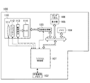
以下、図1を参照して、第1の実施形態のデジタルカメラ100の概略的な構成について説明する。図1のデジタルカメラ100において、本実施形態に係る画像処理装置は、画像処理部103とシステム制御部101に対応する。システム制御部101は、例えばCPUである。システム制御部101は、デジタルカメラ100が備える各部の動作を制御し、また各種の信号処理を行う。具体的には、システム制御部101は、例えば不揮発性メモリ102に記憶されている動作制御用のプログラムを実行してデジタルカメラ100が備える各部の動作を制御し、また信号処理用のプログラムを実行することで各種信号処理を実現する。不揮発性メモリ102は、例えばEEPROM等の電気的に消去・記録可能なメモリである。不揮発性メモリ102は、動作制御用のプログラムや信号処理用のプログラムに加え、各部の動作制御や信号処理において必要なパラメータ等も記憶している。
First Embodiment
Hereinafter, a schematic configuration of the
画像処理部103は、撮像ユニット110から出力された画像信号、又は、後述するメモリ104から読み出された画像信号に対し、種々の画像変換処理を行う。種々の画像変換処理には、所定の画素補間処理、画像縮小のためのリサイズ処理、色変換処理、ハイダイナミックレンジ合成(HDR合成)処理、表示部105の画面に表示される画像信号の生成処理等が含まれる。また、画像処理部103は、撮像素子113で撮像されてA/D変換部114でデジタル化された画像信号を用いた演算処理を実行して、システム制御部101が露出制御や測距制御を行う際に用いられる情報を生成する。画像処理部103による演算処理結果の情報は、システム制御部101に送られる。
The
システム制御部101は、画像処理部103による演算結果の情報に基づいて、不図示の駆動系を介して撮影レンズ111及びシャッタ112を動作させ、露出制御や測距制御を行い、また、EF(フラッシュプリ発光)処理等の動作を制御する。その他にも、システム制御部101は、メモリ104に対し、A/D変換部114から出力された画像信号、又は、画像処理部103による各種処理が行われた画像信号の書き込みと読み出しを制御する。
The
また、システム制御部101は、HDR合成処理する画像を取得するために、適正露出時間による適正露出画像の撮像の直前又は直後に、撮像ユニット110を制御して、適正露出時間とは異なる露出時間による複数の画像を撮像させる。本実施形態の場合、システム制御部101は、撮像ユニット110を制御することにより、例えば適正露出時間より短い露出時間による低露出画像の撮像と、適正露出時間より長い露出時間による高露光画像の撮像とを行わせる。そして、画像処理部103は、それらの各露出時間で撮像された複数の画像を用いてHDR画像を生成する。ただし、詳細については後述するが、本実施形態のデジタルカメラ100は、表示部105によるライブビュー表示やサムネイル表示のためにHDR画像を生成する場合には、表示部105の表示解像度に合うように縮小した画像を用いたHDR合成処理を行う。また、詳細については後述するが、本実施形態のデジタルカメラ100は、不図示の着脱可能なメモリ等への記録や外部へ出力等されるHDR画像を生成する場合には、撮像ユニット110で撮像された画像(本撮影による撮像画像)を用いたHDR合成処理を行う。なお、本撮影による撮像画像を用いたHDR合成処理は、本撮影による撮像画像のサイズが大きく、或る程度長い処理時間が必要になるため、例えば画像撮影が終了した後に行われることが望ましい。
In addition, the
メモリ104は、デジタルカメラ100の各部の動作制御用のプログラムや信号処理用のプログラムの展開領域として用いられるとともに、各部の動作や信号処理において生成された中間データ等を一時的に記憶する格納領域としても用いられる。また、メモリ104は、撮影された複数フレームの画像信号や表示用の画像信号に加え、撮影中の音声の情報も書き込まれるため、それら情報を格納するために十分な記憶容量を有するように設計されている。メモリ104に書き込まれた表示用の画像信号は、システム制御部101による制御の下、メモリ104から読み出されて表示部105に送られる。表示部105は、表示用の画像信号に基づく画像表示を行う。
A memory 104 is used as an expansion area of a program for operation control of each part of the
また、本実施形態のデジタルカメラ100は、表示部105の表示面上に、このカメラの使用者であるユーザの指やペン等による接触を検知可能なタッチパネル106が設けられている。システム制御部101は、タッチパネル106からの検知信号を受信することで、タッチパネル106に対する以下のユーザ操作等を検出できる。システム制御部101がタッチパネル106を介して検出可能なユーザ操作としては、例えば、タッチパネル106を指等で触れたときのタッチダウン操作、タッチパネル106を指等で触れている状態のタッチオン操作などが挙げられる。さらに、検出可能なユーザ操作としては、タッチパネルを指等で触れたまま移動するムーブ操作、タッチパネルに触れていた指等を離すタッチアップ操作、タッチパネルに何も触れていないタッチオフ操作などが挙げられる。
Further, in the
タッチパネル106は、これらの操作の検知信号と、タッチパネル106上に指等が触れている位置座標の情報を、システム制御部101に通知する。システム制御部101は、タッチパネル106から通知された情報に基づいて、タッチパネル106に対してどのような操作が行なわれたかを解析する。なお、システム制御部101は、ムーブ操作によりタッチパネル106上で移動する指等の移動方向については、(x,y)の位置座標の変化に基づいて、タッチパネル106上のx軸成分・y軸成分毎に判定できる。また、タッチパネル106上でタッチダウン操作から一定のムーブ操作を経てタッチアップ操作がなされたとき、システム制御部101は、指等によりストロークが描かれたと判定する。なお、素早くストロークを描く操作はフリック操作と呼ばれている。フリック操作は、タッチパネル106上に指等を触れたままある程度の距離だけ素早く動かして、そのまま離すといった操作であり、言い換えればタッチパネル106上を指ではじくように素早くなぞる操作である。所定距離以上を、所定速度以上でムーブ操作されたことが検出され、そのままタッチアップ操作が検出された場合、システム制御部101は、フリック操作が行なわれたと判定する。また、所定距離以上を、所定速度未満でムーブ操作されたことが検出された場合、システム制御部101は、ドラッグ操作が行なわれたと判定するものとする。
The
撮像ユニット110は、被写体等の光学像を撮像してデジタル画像信号を出力するユニットである。撮像ユニット110は、撮影レンズ111、シャッタ112、撮像素子113、及びA/D変換部114を有する。撮影レンズ111は、デジタルカメラ100が備える撮影レンズ群であり、フォーカスレンズやズームレンズ、カラーフィルタ等を含んでいる。撮影レンズ111は、絞り、NDフィルタ機能を備えるシャッタ112を介して、被写体等の光学像を撮像素子113に結像させる。撮像素子113は、例えばCCDやCMOSセンサ等の撮像素子であり、撮影レンズ111を介して結像された光学像をアナログ画像信号に変換してA/D変換部114に出力する。A/D変換部114は、撮像素子113から入力されたアナログ画像信号に対してA/D変換処理を行って、デジタル画像信号(フレーム画像信号)を生成する。
The
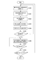
上述したような構成を有するデジタルカメラ100の各構成において、本実施形態に係る撮像と画像信号処理の流れを、図2のフローチャートを参照しながら具体的に説明する。なお、図2のフローチャートの処理は、例えばデジタルカメラ100に対してユーザから撮影の指示がなされた際に開始される。
In each configuration of the
先ず、図2のステップS200において、システム制御部101は、画像処理部103による前述した演算処理の結果を取得し、その演算処理結果に基づいて例えば適正な露出値とその適正露出値に対して異なる露出値とを決定する。露出値は、撮像ユニット110におけるシャッタスピード、絞りの開口量、及びISO感度設定を含む、露出制御に係る制御量である。さらに、システム制御部101は、決定した露出値を撮像ユニット110に設定し、撮像ユニット110を制御することにより、時系列的に連続して露出値の異なる複数枚の画像を撮像させて画像信号を取得させる。ステップS200において取得されて撮像ユニット110から出力された複数枚のデジタル画像信号は、システム制御部101による制御の下で、画像処理部103を介してメモリ104に記憶される。なお、撮像する画像の枚数は二枚以上であれば特に制限はない。ステップS200の後、デジタルカメラ100の処理はステップS201へ進む。
First, in step S200 in FIG. 2, the
ステップS201において、画像処理部103は、ステップS200で取得されてメモリ104に一旦記憶された複数枚のデジタル画像信号に対して、以下に説明するような明るさ合わせ処理を行う。例えば、画像処理部103は、それぞれ画像信号が取得された際の各露出値の比に応じて、ゲインやガンマを掛けて画像信号の明るさを合わせる処理を行う。そして、明るさ合わせがなれた後の画像信号は、メモリ104に記憶される。以下、露出値の比に応じて画像信号の明るさ合わせ処理について、図3を用いて詳しく説明する。
In step S201, the
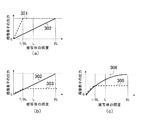
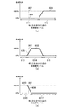
図3(a)〜図3(c)において、横軸は被写体の照度、縦軸は撮像素子113の出力レベルを示す。図3(a)において、入出力特性301は、撮像素子113の露光量を多くして撮像が行われた場合の画像信号(長い露出時間で撮像された高露出画像信号)の入出力特性を示している。また、図3(a)の入出力特性302は、撮像素子113の露光量を少なくして撮像が行われた場合の画像信号(短い露出時間で撮像された低露出画像信号)の入出力特性を示している。図3(a)に示した低露出画像信号の入出力特性302の場合、撮像素子113の出力レベルは、被写体の照度が高くなるまで飽和せずに、低照度から高照度まで略々リニアに変化している。このため、高露出画像信号よりも低露出画像信号の方が、より明るい被写体の照度まで、撮像素子113の出力レベルで表現可能であると考えられる。一方、図3(a)に示した高露出画像信号の入出力特性301の場合、撮像素子113の出力レベルは被写体の照度が或る程度低い段階で飽和してしまっている。ただし、高露出画像信号は、被写体が低照度のときでも撮像素子113の露光量が多いため、低露出画像信号と比べて低照度域でのSN比が良い。
In FIGS. 3A to 3C, the horizontal axis represents the illuminance of the subject, and the vertical axis represents the output level of the
このような入出力特性301,302を考慮して、本実施形態のデジタルカメラ100は、高露出画像信号と低露出画像信号の明るさを合わせる際には、高露出画像信号の明るさを調整して、低露出画像信号の明るさに合わせるようにする。具体的には、画像処理部103は、それら高露出画像信号と低露出画像信号が取得された際の露出値の比に応じたゲインやガンマカーブを、それら画像信号に掛けることにより、それらの画像信号の明るさを合わせるようにする。
In consideration of such input /
ここで、例えば、図3(a)において、或る基準となる被写体の照度をLとする。図3(a)の例の場合、入出力特性301では、被写体の照度が1/8Lで撮像素子113の出力レベルが飽和し、入出力特性301では、被写体の照度が8Lで撮像素子113の出力レベルが飽和している。このことから、入出力特性301において被写体の照度が1/8Lの時と、入出力特性302において被写体の照度が8Lの時に、撮像素子113の出力レベルがそれぞれ同じになることが判る。
Here, for example, in FIG. 3A, the illuminance of the subject serving as a certain reference is L. In the example of FIG. 3A, in the input /
したがって、例えば露出値の比に応じたゲインにより高露出画像信号と低露出画像信号の明るさを合わせるような場合には、画像処理部103は、入出力特性301の高露出画像信号の信号レベルを64で割るようにする。これにより、図3(a)に示した高露出画像信号の入出力特性301は、図3(b)に示すような入出力特性303になる。この図3(b)の高露出画像信号における入出力特性303は、1/8L以下の低輝度域において、低露出画像信号の入出力特性302と略々同じ特性となり、したがって、このときの高露出画像信号と低露出画像信号の明るさは略々合った状態となる。
Therefore, for example, when the brightness of the high exposure image signal and the low exposure image signal are matched by a gain corresponding to the ratio of the exposure value, the
また例えば、露出値の比に応じたガンマカーブにより高露出画像信号と低露出画像信号の明るさを合わせるような場合には、前述の1/8L以下の低輝度域において高露出画像信号と低露出画像信号の両入出力特性が略々同じようになるガンマカーブを設計する。そして、画像処理部103は、そのガンマカーブを用いて、図3(a)の入出力特性301の高露出画像信号と入出力特性302の低露出画像信号に対してそれぞれガンマ補正を行うことで明るさを調整する。これにより、図3(a)の入出力特性301は図3(c)のような入出力特性305になり、また、図3(a)の入出力特性302は図3(c)のような入出力特性306になる。この図3(c)の入出力特性305と入出力特性306は、1/8L以下の低輝度域において、それぞれ略々同じ特性となり、したがって、この場合の高露出画像信号と低露出画像信号の明るさは略々合った状態となる。
Also, for example, when the brightness of the high exposure image signal and the low exposure image signal are matched by the gamma curve according to the ratio of the exposure value, the high exposure image signal and low in the low luminance region of 1/8 L or less A gamma curve is designed in which both input and output characteristics of the exposed image signal are substantially the same. Then, the
本実施形態によれば、前述したような理由から、画像処理部103が、被写体の照度が1/8L以下の範囲において、高露出画像信号の明るさを低露出画像信号の明るさに合わせるようにしている。本実施形態では、低露出画像信号の方を明るさ合わせの基準にしているため、以下、明るさ合わせの基準となっている低露出画像を「基準画像」と呼び、一方、基準画像とは異なる露出で撮像された画像(この例では高露出画像)を「非基準画像」と呼ぶことにする。なお、本実施形態では、低露出画像信号の方に明るさを合わせる例を挙げているが、逆に、高露出画像信号の方に明るさを合わせるような場合には、高露出画像が基準画像となり、低露出画像が非基準画像となる。その他にも、例えば、低露出画像及び高露出画像とともに、前述した適正露出時間で撮像された適正露出画像が有り、その適正露出画像が基準画像として用いられるような場合には、低露出画像及び高露出画像が非基準画像となる。以下の実施形態の説明では、低露出画像が基準画像となり、高露出画像が非基準画像となった例のみを挙げることとする。
According to the present embodiment, for the reason described above, the
図2のフローチャートの説明に戻り、ステップS201の後、デジタルカメラ100の処理はステップS202へ進む。ステップS202において、画像処理部103は、ステップS201にて明るさ合わせの処理が行われた後の複数枚の画像(明るさ合わせ処理後の基準画像と非基準画像)をそれぞれ縮小して、複数枚の縮小画像を生成する。縮小画像は、後述するようにHDR合成処理されて表示部105に表示されることになる。このため、画像処理部103は、表示部105の表示解像度にあわせた画像サイズへの縮小処理を行う。以下、それぞれ表示解像度に合わせて縮小された基準画像及び非基準画像を「表示用の基準画像及び非基準画像」と呼ぶことにする。ステップS202の後、デジタルカメラ100の処理はステップS203へ進む。
Returning to the description of the flowchart in FIG. 2, after step S201, the process of the
ステップS203において、画像処理部103は、ステップS202でそれぞれ生成された表示用の基準画像と非基準画像を用いて、後述する合成評価値に基づいてHDRの合成処理を行って、表示解像度に合ったHDR画像を生成する。このHDR合成処理の際、画像処理部103は、表示用の基準画像と非基準画像から、それぞれ黒潰れや白飛びが生じている画像領域を判定する。具体的には、画像処理部103は、前述のステップS201で用いた撮像素子113の出力レベルに基づいて画像の明るさを判断することにより、表示用の基準画像と非基準画像について、黒潰れしている暗い画像領域や白飛びしている明るい画像領域を判定する。なお、黒潰れとは、画像の暗い領域の階調が失われて略々黒一色になってしまう状態であり、白飛びとは、画像の明るい領域の階調が失われて略々白一色になってしまう状態である。このため、以下の説明では、黒潰れや白飛びが生じて階調が失われている画像領域を「失階調領域」と表記し、一方、黒潰れや白飛びが生じておらず階調が失われていない画像領域を「有階調領域」と表記することにする。
In step S203, the
そして、画像処理部103は、表示用の基準画像に失階調領域があり、一方、非基準画像の中で、基準画像の失階調領域に対応した画像領域が有階調領域である場合、非基準画像の有階調領域により基準画像の失階調領域を置き換えるようなHDR合成処理を行う。具体的には、画像処理部103は、表示用の基準画像の失階調領域に対する合成割合を0%とし、一方、表示用の非基準画像の有階調領域に対する合成割合を100%としてそれらを合成する。すなわちこの場合、表示用の基準画像の失階調領域の各画素が、表示用の非基準画像の有階調領域の各画素により置き換えられるようなHDR合成処理が行われる。
Then, the
また、基準画像の失階調領域を非基準画像の有階調領域により置き換えた場合、置き換えが行われる画像領域と置き換えが行われていない画像領域との境界部分では、それら置き換えによる画像の切り替わりが目立ってしまう虞がある。このため、画像処理部103は、前述の境界部分では、その境界部分に係る画像領域の明るさに応じて、合成割合を変化させることにより、その境界部分での画像の切り替わりを目立たなくする。
In addition, when the gray level area of the reference image is replaced with the gray level area of the non-reference image, switching of the image by the replacement is performed at the boundary between the image area to be replaced and the image area not replaced. May be noticeable. For this reason, the
前述したように、画像処理部103は、表示用の基準画像と非基準画像の明るさに応じた合成割合を合成評価値として用いてHDR合成処理を行うことにより、ダイナミックレンジの拡大が実現されたHDR合成画像を生成する。なお、以下の説明では、前述のように表示用の基準画像と非基準画像を明るさに応じた合成評価値でHDR合成して生成された、表示部105の表示解像度に合ったHDR画像を、特に「表示用のHDR画像」と表記することにする。
As described above, the
ここで、本実施形態において、前述のような表示用のHDR画像を生成する際の、画像領域の明るさに応じた合成評価値は、例えば図4(a)と図4(b)に示すような明るさ比率マップに基づいて決められる。図4(a)と図4(b)のマップは、基準画像と非基準画像の一方の画像信号を基に、画素の合成割合を表す合成評価値として合成比率を決定するためのものである。本実施形態では、基準画像を基に合成比率が決定される例を挙げて説明する。 Here, in the present embodiment, the composite evaluation value according to the brightness of the image area when generating the above-described HDR image for display is shown, for example, in FIGS. 4A and 4B. It is determined based on the brightness ratio map. The maps of FIG. 4A and FIG. 4B are for determining the composition ratio as a composition evaluation value representing the composition ratio of pixels based on the image signal of one of the reference image and the non-reference image. . In the present embodiment, an example in which the synthesis ratio is determined based on the reference image will be described.
前述したように、本実施形態では、図2のステップS201において基準画像と非基準画像の明るさ合わせ処理が行われている。このため、画像処理部103は、ステップS201における明るさ合わせ処理の際に、基準画像と非基準画像の明るさに応じて、図4(a)と図4(b)の明るさ比率マップを生成しておく。そして、画像処理部103は、ステップS203において表示用のHDR画像を生成する際には、その明るさ比率マップから各画素について合成比率を参照し、その合成比率に基づいて基準画像と非基準画像を合成する。
As described above, in the present embodiment, the brightness adjustment processing of the reference image and the non-reference image is performed in step S201 of FIG. Therefore, the
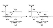
図4(a)と図4(b)に示した明るさ比率マップにおいて、横軸はHDR合成処理される画像信号のレベル(明るさ合わせ処理後の画像信号レベル)を示し、縦軸は合成比率を示している。図4(a)は、基準画像信号に対する明るさ比率マップを示しており、横軸方向のレベル領域407は黒潰れしている信号レベルの領域を表し、レベル領域408は黒潰れや白飛びしていない信号レベルの領域を表している。この図4(a)に例示した明るさ比率マップは、基準画像において黒潰れしている失階調領域を、非基準画像の黒潰れしていない有階調領域により置き換える際の明るさ比率マップとなっている。一方、図4(b)は、非基準画像信号に対する明るさ比率マップを示しており、横軸方向のレベル領域409は黒潰れや白飛びしていない信号レベルの領域を表し、レベル領域410は白飛びしている信号レベルの領域を表している。この図4(b)に例示した明るさ比率マップは、非基準画像において黒潰れ及び白飛びしていない有階調領域により、基準画像の黒潰れしている失階調領域を置き換える際の明るさ比率マップとなっている。
In the brightness ratio maps shown in FIGS. 4A and 4B, the horizontal axis represents the level of the image signal subjected to the HDR synthesis processing (the image signal level after the brightness adjustment processing), and the vertical axis represents the synthesis It shows the ratio. FIG. 4A shows a brightness ratio map with respect to the reference image signal, and the
より具体的に説明すると、図4(a)に示すように、基準画像信号におけるレベル領域407の信号は、黒潰れしている失階調領域の画像信号である。このため、HDR合成処理の際に、そのレベル領域407の画像信号が合成されるのを避けるために、図4(a)の明るさ比率マップでは、レベル領域407の合成比率401が0%となされている。一方、図4(b)に示すように、非基準画像信号におけるレベル領域409の信号は、黒潰れも白飛びもしていない有階調領域の画像信号である。このため、HDR合成処理の際に、そのレベル領域409の画像信号を合成に使用するために、図4(b)の明るさ比率マップでは、レベル領域409の合成比率404が100%となされている。このように、図4(a)のレベル領域407の合成比率401と図4(b)のレベル領域409の合成比率404は、基準画像で黒潰れしている失階調領域を、非基準画像で黒潰れも白飛びもしていない有階調領域で置き換えるための明るさ比率マップである。
More specifically, as shown in FIG. 4A, the signal of the
また、図4(b)のレベル領域410は、非基準画像信号の画素値が飽和して白飛びが発生している失階調領域の画像信号のレベル領域である。このため、HDR合成処理の際に、そのレベル領域410の画像信号が合成されるのを避けるために、図4(b)の明るさ比率マップでは、レベル領域410の合成比率406が0%となされている。一方、図4(a)のレベル領域408は、基準画像信号において黒潰れも白飛びも発生していない有階調領域の画像信号のレベル領域である。このため、HDR合成処理の際に、そのレベル領域408の画像信号が用いられるようにするために、図4(a)の明るさ比率マップでは、レベル領域408の合成比率403が100%となされている。このように、図4(a)のレベル領域408の合成比率403と図4(b)のレベル領域410の合成比率406は、基準画像で黒潰れも白飛びもしていない有階調領域を、非基準画像の画像領域で置き換えないようにするための明るさ比率マップとなっている。
Further, the
また、図4(a)の合成比率402と図4(b)の合成比率405は、基準画像と非基準画像の置き換えが行われるか又は行われないかが切り替わるような信号レベルの画像領域における合成比率である。このため、画像処理部103は、このような切り替わりの信号レベルの画像領域については、これら図4(a)の合成比率402と図4(b)の合成比率405による合成比率に応じて、基準画像と非基準画像を合成する割合を変化させて合成処理を行う。
Further, the
前述したように、本実施形態によれば、画像処理部103は、図4(a)と図4(b)に示した明るさ比率マップを生成し、その明るさ比率マップを用いて、基準画像と非基準画像を合成することにより、HDR画像を生成している。そして、画像処理部103によるHDR合成処理により生成された表示用のHDR画像は、図1のメモリ104に記憶される。
As described above, according to the present embodiment, the
表示用のHDR画像がメモリ104に記憶された後、システム制御部101は、ステップS204において、メモリ104の読み出しを制御して、表示用のHDR画像信号を表示部105へ出力させる。これにより、表示部105には、表示用のHDR画像が表示される。このときの表示用のHDR画像は、表示部105にライブビュー表示又はサムネイル表示される。ステップS204の後、システム制御部101は、処理をステップS205へ進める。
After the HDR image for display is stored in the memory 104, in step S204, the
ステップS205において、システム制御部101は、図1の表示部105に表示されている表示用のHDR画像に対して、例えばユーザから拡大表示の指示入力がなされたか否か判定する。例えば、ユーザによりタッチパネル106に対して拡大表示を指示するタッチ操作がなされた場合、システム制御部101は、タッチパネル106の出力信号から拡大表示の指示とその指示の入力位置に応じた拡大領域の中心位置を示す拡大指示信号を検出する。なお、ユーザが拡大表示の指示を入力するための手段は、拡大指示の入力とその入力位置(拡大領域の中心位置)等をシステム制御部101が検出できるのであれば、特にタッチパネル106に限定されない。システム制御部101は、ステップS205において、拡大指示入力がなされていないと判定した場合には、ステップS200へ処理を戻して前述のように露出値の異なる複数枚の画像を撮像する処理を行わせる。一方、システム制御部101は、ステップS205において、拡大指示入力がなされたと判定した場合には、ステップS206へ処理を進める。
In step S205, the
ステップS206において、システム制御部101は、拡大領域の中心位置と画像処理部103が表示用のHDR画像を生成する際に用いた合成評価値(明るさ比率マップ)とを基に、メモリ104から基準画像信号と非基準画像信号を切り替えて読み出す。そして、その読み出された画像信号が表示部105へ送られて表示される。このときメモリ104から切り替え選択されて読み出される基準画像信号又は非基準画像信号は、前述のステップS201において明るさ合わせ処理がなされた後の画像信号(低露出画像又は高露出画像の信号)である。以下の説明では、前述のステップS201で明るさ合わせ処理がなされた後の基準画像と非基準画像を、特に「本撮影の基準画像と非基準画像」と呼ぶことにする。
In step S206, based on the center position of the enlarged area and the combined evaluation value (brightness ratio map) used when the
このように、ステップS206では、本撮影の基準画像と非基準画像が選択的に切り替えられて表示部105に表示されることになる。本撮影の基準画像と非基準画像は、撮像ユニット110で撮像されたサイズの大きい画像信号であるため、このときの表示部105には、サイズの大きい画像信号の一部分のみが表示、つまり拡大表示されることになる。具体的には、表示部105には、拡大表示の中心位置が表示部105の画面中心となり、前述の合成評価値の明るさ比率マップに応じて基準画像又は非基準画像が切り替え選択された画像の一部分のみが拡大表示されることになる。なお、以下の説明では、合成評価値の明るさ比率マップに応じて本撮影の基準画像と非基準画像が切り替え選択された表示用の拡大画像を、「拡大用画像」と呼ぶことにする。
As described above, in step S206, the reference image and the non-reference image for main imaging are selectively switched and displayed on the display unit 105. Since the reference image and the non-reference image of the main imaging are image signals of large size captured by the
このように、本実施形態において、拡大用画像は、表示用のHDR画像の生成の際に用いられた明るさ比率マップである合成評価値に基づいて、本撮影の基準画像と非基準画像が切り替え選択された画像となされている。このため、表示用のHDR画像と拡大用画像とは、少なくとも同じ傾向の明るさ比率マップに基づいて生成された画像であるといえる。一方、本実施形態において、不図示の着脱可能なメモリ等への記録や外部出力等されるHDR画像は、表示用のHDR画像の生成の際に用いた明るさ比率マップに基づいて、本撮影の基準画像と非基準画像をHDR合成処理することで生成される。なお、以下の説明では、着脱可能なメモリ等への記録や外部へ出力等されるHDR画像を、「本撮影のHDR画像」と呼ぶことにする。これらのことから、前述の拡大用画像は、本撮影のHDR画像に近いダイナミックレンジや暗部のノイズを有した画像であると考えてよい。したがって、例えばライブビュー表示において、前述の拡大用画像を表示部105に表示すれば、ユーザは、本撮影のHDR画像のダイナミックレンジや暗部のノイズがどのようになるか(どのような傾向を有するか)を確認することが可能となる。また、拡大用画像は、本撮影の基準画像と非基準画像を切り替えた画像であるため、その処理に要する時間は非常に短い。したがって、ユーザは、拡大指示を入力して拡大表示がなされるまでに長い時間待つ必要がない。このように、本実施形態によれば、ユーザは、後に生成される本撮影のHDR画像に近いダイナミックレンジや暗部のノイズを有した拡大用画像を、ライブビュー表示により見ることで、画像の細部確認が可能となる。 As described above, in the present embodiment, the enlargement image includes the reference image and the non-reference image of the main shooting based on the combined evaluation value which is the brightness ratio map used in generating the HDR image for display. It is made with the image selected switching. For this reason, it can be said that the HDR image for display and the image for enlargement are images generated based on the brightness ratio map having at least the same tendency. On the other hand, in the present embodiment, the HDR image to be recorded in the removable memory (not shown) or the like, externally output, etc. is actually photographed based on the brightness ratio map used at the time of generation of the HDR image for display. The reference image and the non-reference image are generated by the HDR synthesis processing. In the following description, an HDR image that is recorded in a removable memory or the like, output to the outside, or the like will be referred to as a “HDR image for real shooting”. From these things, the above-mentioned image for enlargement may be considered as an image having a dynamic range close to the HDR image of the main shooting and noise in the dark part. Therefore, for example, in the live view display, if the above-described enlargement image is displayed on the display unit 105, the user is likely to see what the dynamic range of the HDR image of the main shooting and the noise of the dark part look like Can be confirmed. In addition, since the enlargement image is an image obtained by switching the reference image and the non-reference image of the main imaging, the time required for the processing is very short. Therefore, the user does not have to wait for a long time before inputting the enlargement instruction and displaying the enlargement. As described above, according to the present embodiment, the user can view details of the image by viewing the magnified image having the dynamic range close to the HDR image of the main shooting to be generated later and the noise of the dark part by live view display. Confirmation is possible.
以下、前述の図4(a)や図4(b)に示した明るさ比率マップを合成評価値とし、本撮影の基準画像と非基準画像の切り替え選択による拡大用画像の生成処理について、図5(a)〜図5(e)を参照しながら説明する。なお、合成評価値としては、前述の図4(a)の明るさ比率マップと図4(b)の明るさ比率マップの何れかを用いるが、ここでは図4(a)の明るさマップを用いた例を説明する。 Hereinafter, the brightness ratio map shown in FIG. 4A and FIG. 4B described above is used as a combined evaluation value, and a process of generating an enlargement image by switching between the reference image and the non-reference image for main imaging is illustrated. A description will be given with reference to 5 (a) to 5 (e). Although either of the brightness ratio map of FIG. 4 (a) and the brightness ratio map of FIG. 4 (b) is used as the composite evaluation value, the brightness map of FIG. 4 (a) is used here. An example used is described.
図5(a)は、前述した表示用のHDR画像511の一例であり、その表示用のHDR画像に対してユーザにより拡大指示の入力がなされた画像領域が、例えば領域501である場合を示した図である。以下、拡大指示の入力がなされた画像領域501を「拡大指示領域501」と表記する。また、図5(b)は表示用のHDR画像511に前述の図4(a)の明るさ比率マップが適用された画像例を示しており、図5(c)は表示用のHDR画像511の拡大指示領域501のみを拡大して示した図である。図5(c)の例では、拡大指示領域501の中心位置である中心座標503が示されている。
FIG. 5A is an example of the
本実施形態において、システム制御部101は、表示用のHDR画像に対して拡大指示の入力がなされた場合、拡大指示領域501の中心座標503に対応した合成比率に基づいて、本撮影の基準画像又は非基準画像の何れかを選択して拡大用画像とする。具体的には、拡大指示領域501の中心座標503において、表示用のHDR画像が生成された際に用いられた合成比率が、例えば図4(a)の100%の合成比率403であった場合、システム制御部101は、本撮影の基準画像を選択して拡大用画像とする。一方、拡大指示領域501の中心座標503において、表示用のHDR画像が生成された際に用いられた合成比率が、例えば図4(a)の0%の合成比率401であった場合、システム制御部101は、本撮影の非基準画像を選択して拡大用画像とする。
In the present embodiment, when the enlargement instruction is input to the HDR image for display, the
なお、拡大指示領域501に対して合成比率0%と100%の両方が混在して適用されていたような場合、システム制御部101は、例えば本撮影の基準画像のみを選択するようにしてもよい。例えば、拡大指示領域501に対して合成比率0%と100%の両方が混在しており、それら両方の合成比率に対応させて基準画像と非基準画像の両方を混在させて表示するようなことを行うと、非基準画像の画像領域には白飛びが発生することになる。したがって、システム制御部101は、拡大指示領域501に0%と100%の合成比率が混在している場合、本撮影の基準画像のみを選択して拡大用表示とする。これにより、ユーザは、その拡大用表示を見ることで、白飛びを抑制するHDRの効果を確認することが可能になると考えられる。
In the case where both the composition ratio of 0% and 100% are mixed and applied to the
ただし、0%と100%の合成比率が混在している場合に必ず本撮影の基準画像を選択したとすると、その選択は前述の明るさ比率マップ(合成評価値)に基づいた選択ではないため、拡大用画像のノイズは、本撮影のHDR画像のノイズとは多少異なる。したがって、システム制御部101は、具体的には以下のようにして、拡大指示領域501の中心座標503に対して適用された合成比率に基づいて、本撮影の基準画像と非基準画像の切り替え選択を行うようにしている。
However, assuming that the reference image for main shooting is always selected when the composite ratio of 0% and 100% is mixed, the selection is not based on the brightness ratio map (composite evaluation value) described above. The noise of the magnified image is somewhat different from the noise of the HDR image of the actual shooting. Therefore, the
図5(d)と図5(e)は、0%と100%の合成比率が混在している場合の拡大指示領域501を更に拡大して示す図である。図5(d)と図5(e)において、領域520は表示用の基準画像を100%(非基準画像を0%)とする合成比率が適用された領域であり、領域521は表示用の基準画像を0%(非基準画像を100%)とする合成比率が適用された領域であるとする。本実施形態においては、図5(d)に示したように、拡大指示領域501の中心座標503が領域520の中にある場合、システム制御部101は、前述した明るさあわせ処理後の本撮影の基準画像を拡大用画像とする。一方、図5(e)に示したように、拡大指示領域501の中心座標503が領域521の中にある場合、システム制御部101は、前述した明るさ合わせ処理後の本撮影の非基準画像を拡大用画像とする。なお、例えば図5(e)の場合、領域520では白飛びが発生している可能性はあるが、拡大用画像の中心座標503の周辺における画像のノイズ感は、本撮影のHDR画像のノイズ感と略々合ったものになると考えられる。したがって、ユーザは、この例の場合も、拡大用画像のライブビュー表示によりノイズを確認することが可能となる。なお、本実施形態のデジタルカメラ100は、このようなライブビュー表示によるノイズ確認機能(ノイズプレビュー表示機能)と通常のライブビュー表示(通常のプレビュー表示機能)とを、ユーザの指示に応じて切り替え可能となされている。
FIG. 5D and FIG. 5E are diagrams showing the
前述したような図2のステップS206の後、システム制御部101は、処理をステップS207へ進める。ステップS207では、システム制御部101は、タッチパネル106を介してユーザから拡大用画像の表示を終了する指示が入力されたか否か判断し、拡大用画像の表示終了の指示が入力されていない場合には出力206へ処理を戻す。一方、ステップS207において拡大用画像の表示を終了する指示が入力されたと判断した場合、システム制御部101は、処理をステップS208へ進める。
After step S206 in FIG. 2 as described above, the
ステップS208では、システム制御部101は、ライブビュー表示又はサムネイル表示として前述の表示用のHDR画像を表示する処理を終了する指示が、タッチパネル106を介してユーザから入力されたか否か判断する。そして、システム制御部101は、ステップS208において終了指示が入力されたと判断した場合にはこの図2のフローチャートの処理を終了し、一方、終了指示が入力されていない場合には処理をステップS200へ戻す。
In step S208, the
以上、第1の実施形態のデジタルカメラ100においては、ライブビュー表示又はサムネイル表示として表示用のHDR画像を表示しており、さらに拡大指示が入力された場合には、合成評価値に基づいて本撮影の基準画像と非基準画像を切り替え表示している。したがって、第1の実施形態によれば、本撮影のHDR画像の生成に長い時間がかかる場合であっても、表示用のHDR画像や拡大用画像については待ち時間なく直ぐに表示できる。
As described above, in the
<第2の実施形態>
第1の実施形態では、本撮影の基準画像と非基準画像の二枚の画像を用いて、表示用のHDR画像や拡大用画像を生成したが、表示用のHDR画像や拡大用画像は、基準画像を含めて三枚以上の露出の異なった画像から生成されてもよい。一例として、第2の実施形態では、本撮影の一枚の基準画像と二枚の非基準画像を切り替えて拡大用画像を生成する例について説明する。ここでは、説明を判り易くするために、最も短い露出時間で撮像された画像を基準画像とし、基準画像よりも長い露出時間で撮像された画像を第1の非基準画像とし、さらに第1の非基準画像よりも長い露出時間で撮像された画像を第2の非基準画像とする。
Second Embodiment
In the first embodiment, the HDR image for display and the enlargement image are generated using two images of the reference image for main shooting and the non-reference image, but the HDR image for display and the enlargement image are The reference image may be generated from three or more different exposure images. As an example, in the second embodiment, an example in which one reference image and two non-reference images of main imaging are switched to generate an enlargement image will be described. Here, in order to make the description easy to understand, an image captured with the shortest exposure time is used as a reference image, an image captured with an exposure time longer than the reference image is used as a first non-reference image, and the first An image captured with a longer exposure time than the non-reference image is taken as a second non-reference image.
以下、前述した図2のフローチャートを参照しながら、第2の実施形態における処理の流れを説明する。なお、図2のフローチャートにおいて、第1の実施形態の場合と同じ処理が行われるステップについては、その説明を省略する。 The flow of processing in the second embodiment will be described below with reference to the flowchart of FIG. 2 described above. In the flowchart of FIG. 2, the description of steps in which the same processing as that of the first embodiment is performed will be omitted.
第2の実施形態の場合、図2のフローチャートのステップS203で表示用のHDR画像を生成する際には、三枚の画像を合成するための明るさ比率マップが必要となる。図6(a)〜図6(c)には、第2の実施形態で用いる明るさ比率マップの一例を示す。図6(a)は表示解像度に合わせて縮小した表示用の基準画像のための明るさ比率マップの一例を示し、以下同様に、図6(b)は表示用の第1の非基準画像の明るさ比率マップ、図6(c)は表示用の第2の非基準画像の明るさ比率マップを示している。なお、前述した図4(a)と図4(b)の例と略々同様に、図6(a)〜図6(c)の横軸はHDR合成処理される画像信号のレベル(明るさ合わせ処理後の画像信号レベル)を示し、縦軸は合成比率を示している。図6(a)のレベル領域611は黒潰れしている信号レベルの領域を表し、レベル領域612は黒潰れや白飛びしていない信号レベルの領域を表しており、合成比率604は0%となされ、合成比率601は100%となされている。図6(b)のレベル領域613は黒潰れしている信号レベルの領域を表し、レベル領域614は黒潰れ及び白飛びしていない信号レベルの領域、レベル領域615は白飛びしている信号レベルの領域を表し、合成比率602は100%となされている。図6(c)のレベル領域616は黒潰れ及び白飛びしていない信号レベルの領域を表し、レベル領域617は白飛びしている信号レベルの領域を表し、合成比率603は100%となされている。
In the case of the second embodiment, when generating an HDR image for display in step S203 of the flowchart of FIG. 2, a brightness ratio map for combining three images is required. 6A to 6C show an example of the brightness ratio map used in the second embodiment. FIG. 6 (a) shows an example of a brightness ratio map for a reference image for display reduced according to the display resolution, and similarly FIG. 6 (b) shows a first non-reference image for display. FIG. 6C shows the brightness ratio map of the second non-reference image for display. Similar to the examples of FIG. 4A and FIG. 4B described above, the horizontal axes in FIG. 6A to FIG. The image signal level after the alignment processing is shown, and the vertical axis shows the composition ratio. The
そして、第2の実施形態の場合、ステップS203において、画像処理部103は、これら図6(a)〜図6(c)の明るさ比率マップに基づいて、前述の第1の実施形態の場合と同様にして表示用のHDR画像を生成する。 Then, in the case of the second embodiment, in the case of the above-described first embodiment based on the brightness ratio maps of FIGS. 6A to 6C in step S203. In the same manner as in, an HDR image for display is generated.
また、第2の実施形態の場合、ステップS206において、システム制御部101は、拡大用画像を生成する際には、前述の第1の実施形態と同様に、明るさ比率マップを合成評価値とし、本撮影の基準画像と第1,第2の非基準画像を切り替え選択する。すなわち、システム制御部101は、明るさ合わせ処理後の本撮影の基準画像と第1,第2の非基準画像のうち、拡大指示領域の中心座標における明るさ比率マップの合成比率をそれぞれ参照して切り替え選択を行う。具体的には、システム制御部101は、本撮影の基準画像についてはレベル領域612の100%の合成比率601に基づいて選択し、一方、第1,第2の非基準画像についてはそれぞれ0%の合成比率に基づいて選択しない。同様に、システム制御部101は、第1の非基準画像についてはレベル領域614の100%の合成比率602に基づいて選択し、第2の非基準画像についてはレベル領域616の100%の合成比率603に基づいて選択する。
Further, in the case of the second embodiment, in step S206, the
また、第2の実施形態において、拡大指示領域に対して合成比率の0%と100%の両方が混在しているような場合にも第1の実施形態の場合と略々同様にして画像の切り替え選択が行われる。例えば、図6(a)〜図6(c)のレベル607が、或る拡大指示領域の中心座標における画像信号レベル値であるする。この場合において、図6(a)ではレベル607の合成比率604が0%であるため基準画像は選択されない。一方、図6(b)のレベル607と図6(c)のレベル607は、それぞれ黒潰れ及び白飛びしていないレベル領域であるため、第1,第2の非基準画像の何れかが選択されることになる。この場合、システム制御部101は、表示用のHDR画像の生成に用いた明るさ比率マップの合成比率が高い方を選択する。図6(b)と図6(c)の例の場合、図6(b)のレベル607における合成比率605と、図6(c)のレベル607における合成比率606とでは、図6(c)の合成比率606のほうが高い値となっている。したがって、この場合、システム制御部101は、第1,第2の非基準画像のうち、合成比率の値が高い方である図6(c)に対応した第2の非基準画像を選択する。
Further, in the second embodiment, even when both 0% and 100% of the composition ratio are mixed with the enlargement instruction area, the image is displayed in substantially the same manner as in the first embodiment. A switch selection is made. For example,
以上のように、第2の実施形態によれば、基準画像と第1,第2の非基準画像が撮影された場合においても、表示用のHDR画像の生成と拡大用画像の生成が可能となされている。 As described above, according to the second embodiment, even when the reference image and the first and second non-reference images are captured, it is possible to generate an HDR image for display and an image for enlargement. It is done.
また、第2の実施形態において、例えばライブビュー表示によりノイズを確認するノイズプレビュー表示を行うような場合には、拡大指示領域の中心座標を含む領域から以下のようにして算出した値に基づいて拡大用画像とする画像を選択してもよい。例えば、拡大指示領域の中で中心座標を含む10%の画像領域の範囲において、明るさ比率マップの合成比率の平均値を算出し、その平均値を、基準画像と第1,第2の非基準画像の各合成比率と比較して、合成比率の高い方を拡大用画像として選択する。 In the second embodiment, for example, when performing noise preview display for confirming noise by live view display, based on a value calculated as follows from an area including the center coordinates of the enlargement instruction area An image to be an enlargement image may be selected. For example, the average value of the composition ratio of the brightness ratio map is calculated in the range of the 10% image area including the center coordinates in the enlargement designated area, and the average value is calculated as the reference image and the first and second non-standard images. The one with the higher composition ratio is selected as the enlargement image in comparison with each composition ratio of the reference image.
<第3の実施形態>
次に、第3の実施形態として、基準画像と非基準画像が撮像された際に、被写体が移動したことで、その被写体の画像領域(以下、動体領域とする。)の位置が、基準画像と非基準画像で異なる場合の、表示用のHDR画像と拡大用画像の生成について説明する。第3の実施形態では、基準画像と非基準画像から動体領域を検出し、その動体領域に対して画素の合成割合を決める。そして、第3の実施形態では、この動体領域に対する合成割合と前述した明るさ比率マップとを合成評価値として用いて、表示用のHDR画像の生成と拡大用画像の生成を行う。
Third Embodiment
Next, as the third embodiment, when the reference image and the non-reference image are captured, the position of the image area of the subject (hereinafter referred to as a moving body area) is the reference image when the subject is moved. The generation of the HDR image for display and the image for enlargement will be described in the case where the image and the non-reference image are different. In the third embodiment, a moving subject region is detected from the reference image and the non-reference image, and the composition ratio of pixels with respect to the moving subject region is determined. Then, in the third embodiment, generation of an HDR image for display and generation of an image for enlargement are performed using the combination ratio for the moving object region and the brightness ratio map described above as a combination evaluation value.
以下、前述した図2のフローチャートを参照しながら、第3の実施形態における処理の流れを説明する。なお、図2のフローチャートにおいて、第1の実施形態の場合と同じ処理が行われるステップについては、その説明を省略する。 The flow of processing in the third embodiment will be described below with reference to the flowchart of FIG. 2 described above. In the flowchart of FIG. 2, the description of steps in which the same processing as that of the first embodiment is performed will be omitted.
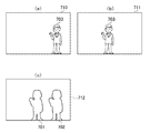
第3の実施形態の場合、図2のフローチャートのステップS203で表示用のHDR画像を生成する処理について、前述の図4(a)と図4(b)、及び図7(a)〜図7(c)を参照して説明する。図7(a)は図2のステップS202までの処理で作成された表示用の基準画像710を示し、図7(b)は同様に作成された表示用の非基準画像711を示している。これら図7(a)と図7(b)の例では、被写体703が移動したことで、表示用の基準画像710と非基準画像711において被写体703の位置が異なっている。
In the case of the third embodiment, the process of generating an HDR image for display in step S203 of the flowchart of FIG. 2 is described with reference to FIGS. 4A and 4B and FIGS. 7A to 7. This will be described with reference to (c). FIG. 7A shows a
第3の実施形態の場合、ステップS203において、画像処理部103は、図7(a)の表示用の基準画像710と図7(b)の表示用の非基準画像711との間のフレーム間差分を求める。さらに、画像処理部103は、そのフレーム間差分と所定の閾値とを比較し、閾値よりも大きい差分量となっている領域を動体領域の検出結果として求める。なお、動体域の検出結果とは、基準画像と非基準画像のフレーム間差分量に基づく画像の特徴量である。図7(c)には、表示用の基準画像710と非基準画像711のフレーム間差分を所定の閾値とを比較し、閾値よりも大きい差分量の領域を抽出した動体領域の検出結果712の一例を示す。図7(c)では、図7(a)の表示用の基準画像710の被写体703に対応した動体領域702と、図7(b)の表示用の非基準画像711の被写体703に対応した動体領域701とが、動体領域の検出結果712として得られている。
In the case of the third embodiment, in step S203, the
さらに、画像処理部103は、図4(a)と図4(b)に示したような明るさ比率マップと図7(c)の動体領域の検出結果712とを合成評価値として用い、表示用のHDR画像を生成する際の、表示用の基準画像710と非基準画像711の合成割合を決める。具体的には、画像処理部103は、表示用の基準画像710について明るさ比率マップの合成比率を求めた後、前述したフレーム間差分により図7(c)のような動体領域701,702かどうかを確認する。そして、画像処理部103は、図7(c)の動体領域701,702に含まれる画素については、明るさ比率マップの合成比率を参照した合成は行わず、代わりにそれらの画像領域については表示用の基準画像の合成割合を100%にする。なお、動体領域701,702に含まれない画素については、前述同様に明るさ比率マップの合成比率に基づいた表示用のHDR画像が生成される。このように、画像処理部103は、動体領域701,702については表示用のHDR画像に置き換えた表示用のHDR画像を生成する。
Furthermore, the
また、第3の実施形態において、図2のステップS206で拡大用画像を生成する際には、システム制御部101は、明るさ比率マップと動体領域の検出結果712に基づいて、本撮影の基準画像と非基準画像のいずれを拡大用画像として選択するかを決定する。具体的には、システム制御部101は、拡大用画像を生成する場合、拡大指示領域の中心座標の画素(又は拡大指示領域の中心座標から決められた範囲内の画素)が、図7(c)の動体領域701,702に含まれるか否か判断する。そして、システム制御部101は、拡大指示領域の中心座標の画素(中心座標から決められた範囲内の画素)が動体領域701,702に含まれると判断した場合には、本撮影の基準画像を拡大用画像として選択する。なお、拡大指示領域の中心座標の画素(又は中心座標を含む範囲内の画素)が動体領域701,702の中にない場合、システム制御部101は、前述同様に明るさ比率マップに基づく画像(本撮影の基準画像又は非基準画像)を拡大用画像として選択する。
In the third embodiment, when generating the enlargement image in step S206 of FIG. 2, the
以上のような処理を行うことにより、第3の実施形態においては、動体領域の検出結果を加味した表示用のHDR画像の生成と、拡大用画像の生成が可能となる。 By performing the above-described processing, in the third embodiment, it is possible to generate a display HDR image and an enlargement image in consideration of the detection result of the moving body region.
<第4の実施形態>
例えばいわゆる手持ち撮影等により表示用のHDR画像や拡大用画像に手振れ等が生じてしまうような場合には、第4の実施形態として、以下に説明するような画像の位置あわせ処理を行うことも可能である。なお、位置合わせ処理とは、手振れ等により基準画像に対して非基準画像の位置がずれている場合に、その位置ズレを補正する処理である。以下、一例として、図2のステップS202の処理の後に位置合わせ処理を行う場合について説明する。
Fourth Embodiment
For example, in the case where camera shake or the like occurs in a HDR image for display or an image for enlargement due to so-called hand-held photography etc., as the fourth embodiment, image alignment processing as described below is also performed. It is possible. The alignment process is a process of correcting the positional deviation when the position of the non-reference image is deviated from the reference image due to camera shake or the like. Hereinafter, as an example, the case where the alignment process is performed after the process of step S202 of FIG. 2 will be described.
画像処理部103は、図2のステップSS201の処理後の基準画像と非基準画像に対する位置合わせ処理を行う。この位置合わせ処理の際、画像処理部103は、基準画像と非基準画像との間で動きベクトルを求める。具体的には、画像処理部103は、基準画像から所定サイズのテンプレート画像を作成し、そのテンプレート画像と非基準画像との間の対応点を求めるテンプレートマッチングを行い、その対応点間の向きと大きさ(距離)を動きベクトルとして算出する。そして、画像処理部103は、その動きベクトルの向きと大きさを基に、変換係数を算出して、その変換係数に基づいて非基準画像を変形させる。このように動きベクトルに基づく変換係数により変形処理された非基準画像は、基準画像に対して位置ズレが補正された非基準画像、つまり基準画像に対して位置合わせ処理がなされた非基準画像となる。
The
その後、デジタルカメラ100は、基準画像とその基準画像に対して位置合わせ処理がなされた非基準画像とを用いて、前述したような図2のステップS203以降の処理を行う。これにより、第4の実施形態のデジタルカメラ100は、手持ち撮影により手振れ等が生じていた場合でも、ブレが補正された良好なライブビュー表示やサムネイル表示、拡大用画像の表示が可能となる。
After that, the
<第5の実施形態>
前述した各実施形態では、図2のステップS201で基準画像と非基準画像から作成した明るさ比率マップの合成比率に基づいて、表示用のHDR画像や拡大用画像の生成が行われている。これに対し、第5の実施形態では、表示用のHDR画像や拡大用画像を生成する際に、それ以前の過去に生成された明るさ比率マップを参照して、表示用のHDR画像や拡大用画像を生成する例を挙げる。
Fifth Embodiment
In each embodiment described above, generation of a display HDR image and an enlargement image is performed based on the combination ratio of the brightness ratio map created from the reference image and the non-reference image in step S201 of FIG. On the other hand, in the fifth embodiment, when generating the display HDR image and the enlargement image, the display HDR image and the enlargement are referred to by referring to the brightness ratio map generated in the past in the past. An example of generating an image for
第5の実施形態における表示用のHDR画像や拡大用画像の生成処理について、図8を参照しながら説明する。図8の横軸は各表示フレームN−3,N−2,N−1,N,N+1,N+2の時間順を表しており、横軸の右方向に進むにつれて時間的に新しくなっていることを表している。図8の縦軸は、表示用の基準画像の明るさ比率マップの合成比率を表わしている。また、図8中の入力808は、ユーザにより拡大指示の入力がなされたタイミングを表している。さらに、図8中の各丸印は、各表示フレームN−3,N−2,N−1,N,N+1,N+2における表示用の基準画像の各合成比率801〜807を表している。
A process of generating an HDR image for display and an image for enlargement in the fifth embodiment will be described with reference to FIG. The horizontal axis of FIG. 8 represents the time sequence of each display frame N-3, N-2, N-1, N, N + 1, N + 2, and it should be updated in time as it goes to the right of the horizontal axis. Represents The vertical axis in FIG. 8 represents the composition ratio of the brightness ratio map of the reference image for display. Further, an
ここで、デジタルカメラ100は、ライブビュー表示を行っているとする。例えば拡大指示の入力808がなされたとすると、本実施形態のデジタルカメラ100は、その拡大指示の入力808がなされた直後の現在の表示フレームNにおいて、前述の図2のステップS200〜S202の処理を行う。またこのとき、システム制御部101は、現在の表示フレームNよりも所定フレーム数前の表示フレームで生成した過去の明るさ比率マップの合成比率をメモリ104に保持させている。第5の実施形態の場合、画像処理部103は、ステップS203において、表示フレームNの明るさ比率マップの合成比率と過去の明るさ比率マップの合成比率とに大きな差異があるか否かを判定する。一例として、画像処理部103は、表示フレームNの明るさ比率マップの合成比率と過去の明るさ比率マップの合成比率との差異が、例えば予め決めた閾値より大きいか否か判定する。そして、それらの合成比率の差異が閾値より大きい場合、画像処理部103は、表示フレームNの合成比率を、所定フレーム数後の表示フレームの合成比率として設定する。またこのときの画像処理部103は、所定フレーム数前の表示フレームの合成比率を、表示フレームNの合成比率とし、その合成比率により、表示フレームNにおける表示用の基準画像と非基準画像から、表示用のHDR画像を生成する。
Here, it is assumed that the
一例として、所定フレーム数が2フレーム分である場合、画像処理部103は、表示フレームNにおける合成比率804と2フレーム前の表示フレームN−2で生成されて保持している合成比率802とを比較する。この例の場合、合成比率804と合成比率802との間には、閾値より大きな差異があり、したがって画像処理部103は、表示フレームNで求めた合成比率804を、2フレーム後の表示フレームN+2における合成比率807とする。また、このときの画像処理部103は、2フレーム前の表示フレームN−2の合成比率802を、表示フレームNの合成比率805とする。同様に、画像処理部103は、表示フレームN−1の合成比率803を、表示フレームN+1の合成比率806として設定する。これにより、画像処理部103は、表示フレームNでは合成比率805を用い、表示フレームN+1では合成比率806を用い、表示フレームN+2では合成比率807を用いて表示用の基準画像と非基準画像から表示用のHDR画像を生成することになる。
As an example, when the predetermined number of frames is two frames, the
また、このときのシステム制御部101は、拡大指示の入力808がなされているので、図2のステップS204〜S206の処理を行う。そして、図2のステップS206において、システム制御部101は、画像処理部103において参照された所定フレーム数前の明るさ比率マップの合成比率を基に、拡大用画像を生成する。前述したように所定フレーム数が2フレームである場合、システム制御部101は、表示フレームNについては合成比率805に基づいて本撮影画像の基準画像と非基準画像を切り替え選択して拡大用画像を生成する。同様に、システム制御部101は、表示フレームN+1では合成比率806に基づいて、また、表示フレームN+2では合成比率807に基づいて、本撮影画像の基準画像と非基準画像を切り替え選択して拡大用画像を生成することになる。
In addition, since the
第5の実施形態の場合、拡大指示の入力がなされた際に、例えば被写体等の明るさが急激に変わったような場合でも、明るさが急激に変化する前に生成された明るさ比率マップに基づいて表示用のHDR画像や拡大用画像が表示されることになる。したがって、第5の実施形態によれば、被写体等の明るさの急激な変化があった場合でも、明るさの急激な変化の発生が抑えられた違和感のない、表示用のHDR画像や拡大用画像を表示可能である。 In the case of the fifth embodiment, even when, for example, the brightness of an object or the like changes rapidly when the input of the enlargement instruction is made, the brightness ratio map generated before the brightness changes rapidly. The HDR image for display and the image for enlargement will be displayed based on. Therefore, according to the fifth embodiment, even when there is an abrupt change in the brightness of the subject or the like, the HDR image for display or for enlargement is free from the discomfort that the occurrence of the abrupt change in the brightness is suppressed. An image can be displayed.
<第6の実施形態>
第6の実施形態として、本撮影のHDR画像の生成処理が完了した場合、デジタルカメラ100は、例えばサムネイル表示や拡大用画像を表示する際には、その本撮影のHDR画像を用いる。例えば、本撮影のHDR画像の生成が完了した後、表示部105にサムネイル表示が行われる場合には、画像処理部103は、その本撮影のHDR画像からサムネイル画像を生成し、システム制御部101は、そのサムネイル画像を表示部105に表示させる。また、本撮影のHDR画像から生成したサムネイル画像表示がなされている場合において、ユーザから拡大指示が入力されたときには、システム制御部101は、その拡大指示の入力に応じて、本撮影のHDR画像をそのまま拡大用画像として用いる。
Sixth Embodiment
In the sixth embodiment, when the process of generating the HDR image of the main shooting is completed, the
また、例えば前述したような表示用のHDR画像の表示や拡大用画像の表示が行われている時に、本撮影のHDR画像の生成処理が完了した場合、画像処理部103は、システム制御部101に対して、本撮影のHDR画像の生成完了通知を出力する。例えば、システム制御部101は、表示用のHDR画像の表示が行われている時に、生成完了通知を受信した場合には、表示用のHDR画像を、本撮影のHDR画像を縮小したHDR画像に置き換えて表示させる。また例えば、システム制御部101は、前述した拡大用画像の表示が行われている時に、生成完了通知を受信した場合には、拡大用画像を本撮影のHDR画像に置き換えて表示させるようにする。
Further, for example, when the display of the HDR image for display or the display of the enlargement image is performed as described above, when the generation processing of the HDR image of the main shooting is completed, the
<その他の実施形態>
本発明は、上述の実施形態の1以上の機能を実現するプログラムを、ネットワーク又は記憶媒体を介してシステム又は装置に供給し、そのシステム又は装置のコンピュータにおける1つ以上のプロセッサーがプログラムを読出し実行する処理でも実現可能である。また、1以上の機能を実現する回路(例えば、ASIC)によっても実現可能である。
<Other Embodiments>
The present invention supplies a program that implements one or more functions of the above-described embodiments to a system or apparatus via a network or storage medium, and one or more processors in a computer of the system or apparatus read and execute the program. Can also be realized. It can also be implemented by a circuit (eg, an ASIC) that implements one or more functions.
上述の実施形態は、何れも本発明を実施するにあたっての具体化の例を示したものに過ぎず、これらによって本発明の技術的範囲が限定的に解釈されてはならないものである。即ち、本発明は、その技術思想、又はその主要な特徴から逸脱することなく、様々な形で実施することができる。 The above-described embodiments are merely examples of implementation for practicing the present invention, and the technical scope of the present invention should not be interpreted limitedly by these. That is, the present invention can be implemented in various forms without departing from the technical concept or the main features thereof.
100 デジタルカメラ、101 システム制御部、102 不揮発性メモリ、103 画像処理部、104 メモリ、106 タッチパネル、110 レンズユニット、111 撮影レンズ、112 シャッタ、113 撮像素子、114 A/D変換部
DESCRIPTION OF
Claims (12)
前記複数の撮影画像の少なくとも明るさに基づいて、前記複数の縮小画像をハイダイナミックレンジ合成する際の画素の合成割合を表す合成評価値を生成する生成手段と、
前記合成評価値に基づいて、前記複数の縮小画像を合成して表示用の合成画像を生成する合成手段と、
前記表示用の合成画像に対する拡大指示が入力されたとき、前記拡大指示の入力位置と前記表示用の合成画像を生成した際の合成評価値とに基づいて、前記縮小される前の複数の撮影画像を切り替え選択して表示用の拡大画像とする選択手段と
を有することを特徴とする画像処理装置。 Reducing means for reducing a plurality of photographed images photographed at different exposure values for high dynamic range synthesis to generate a plurality of reduced images;
Generation means for generating a synthesis evaluation value representing a synthesis ratio of pixels in high dynamic range synthesis of the plurality of reduced images based on at least the brightness of the plurality of photographed images;
Combining means for combining the plurality of reduced images based on the combined evaluation value to generate a combined image for display;
When an enlargement instruction for the composite image for display is input, a plurality of photographings before the reduction are performed based on the input position of the enlargement instruction and the composite evaluation value at the time of generating the composite image for display An image processing apparatus comprising: selection means for switching and selecting an image to form an enlarged image for display.
前記縮小手段は、前記明るさを合わせた後の前記複数の撮影画像を縮小して前記複数の縮小画像を生成し、
前記選択手段は、前記明るさを合わせた後の前記複数の撮影画像を前記切り替え選択して前記表示用の拡大画像とすることを特徴とする請求項1又は2に記載の画像処理装置。 And adjusting means for adjusting the brightness of another photographed image so as to match the brightness of the photographed image of the reference with one photographed image of the plurality of photographed images as a reference.
The reduction means reduces the plurality of photographed images after the brightness is adjusted to generate the plurality of reduced images.
3. The image processing apparatus according to claim 1, wherein the selection unit selects the plurality of photographed images after matching the brightness as the enlarged image for display by switching and selecting the plurality of photographed images.
前記選択手段は、前記表示用の合成画像に対する拡大指示の入力位置が前記動体の画像領域に含まれるとき、前記動体の画像領域に対して決定された合成評価値に基づいて、前記複数の撮影画像の切り替え選択を行うことを特徴とする請求項1〜3のいずれか1項に記載の画像処理装置。 The combining unit detects an image area of a moving object based on a difference between the plurality of reduced images, determines the combined evaluation value for the image area of the moving object, and detects the image of the moving object in the reduced image. For the area, synthesis is performed based on the determined synthetic evaluation value,
When the input position of the enlargement instruction for the composite image for display is included in the image area of the moving body, the selection means performs the plurality of photographing based on the composite evaluation value determined for the image area of the moving body. The image processing apparatus according to any one of claims 1 to 3, wherein switching selection of an image is performed.
前記選択手段は、前記表示用の合成画像に対する拡大指示の入力位置が前記動体の画像領域に含まれるとき、前記動体の画像領域に対して決定された合成評価値に基づいて、前記複数の撮影画像のうち基準となされた一つの撮影画像を選択することを特徴とする請求項4に記載の画像処理装置。 The combining means determines, as the combined evaluation value for the image area of the moving body, a combining ratio using only a reduced image obtained by reducing one of the plurality of captured images which has been made a reference.
When the input position of the enlargement instruction for the composite image for display is included in the image area of the moving body, the selection means performs the plurality of photographing based on the composite evaluation value determined for the image area of the moving body. 5. The image processing apparatus according to claim 4, wherein one photographed image which is set as a reference among the images is selected.
前記縮小手段は前記位置ズレが補正された後の前記複数の撮影画像から前記複数の縮小画像を生成し、
前記合成手段は、前記位置ズレが補正されて縮小された前記複数の縮小画像から前記表示用の合成画像を生成し、
前記選択手段は、前記位置ズレが補正された後の複数の撮影画像を用いて前記切り替え選択を行うことを特徴とする請求項1〜5のいずれか1項に記載の画像処理装置。 A correction unit configured to correct a positional deviation between the plurality of photographed images;
The reduction means generates the plurality of reduced images from the plurality of photographed images after the positional deviation is corrected,
The combining unit generates a combined image for display from the plurality of reduced images in which the positional deviation is corrected and reduced.
The image processing apparatus according to any one of claims 1 to 5, wherein the selection unit performs the switching selection using a plurality of photographed images after the positional deviation has been corrected.
前記縮小手段は、前記合成手段による前記複数の撮影画像のハイダイナミックレンジ合成が完了したときには、前記複数の撮影画像がハイダイナミックレンジ合成された画像を縮小した縮小画像を生成し、
前記合成手段は、前記複数の縮小画像を合成した表示用の合成画像を生成している際に、前記合成手段による前記複数の撮影画像のハイダイナミックレンジ合成が完了したときには、前記縮小手段による前記複数の撮影画像のハイダイナミックレンジ合成された画像の縮小画像を、前記表示用の合成画像に置き換え、
前記選択手段は、前記縮小される前の撮影画像を前記表示用の拡大画像として切り替え選択している際に、前記合成手段による前記複数の撮影画像のハイダイナミックレンジ合成が完了したときには、前記複数の撮影画像がハイダイナミックレンジ合成された画像を、前記表示用の拡大画像として切り替え選択することを特徴とする請求項1〜6のいずれか1項に記載の画像処理装置。 The combining means includes means for high dynamic range combining of the plurality of photographed images based on the combined evaluation value,
When the high dynamic range synthesis of the plurality of photographed images by the synthesizing unit is completed, the reduction unit generates a reduced image by reducing an image in which the plurality of photographed images are high dynamic range synthesized.
The combining means generates a composite image for display by combining the plurality of reduced images, and when high dynamic range combining of the plurality of photographed images by the combining means is completed, Replacing a reduced image of a high dynamic range composited image of a plurality of captured images with the composite image for display;
The selection unit, when switching between and selecting the photographed image before the reduction as the enlarged image for display, the high dynamic range synthesis of the plurality of photographed images by the synthesizing unit is completed, The image processing apparatus according to any one of claims 1 to 6, wherein an image obtained by high dynamic range synthesis of the photographed image is switched and selected as the enlarged image for display.
前記生成手段は、前記表示用の合成画像に対する拡大指示が入力されたときに、現在の撮影画像から生成した合成評価値と前記保持されている合成評価値との間に差異がある場合には、前記所定フレーム数前の過去に撮影された撮影画像から生成した合成評価値を、前記現在の撮影画像の合成評価値として設定することを特徴とする請求項1〜7のいずれか1項に記載の画像処理装置。 A control means for holding a synthetic evaluation value generated from a captured image captured in the past by a predetermined number of frames before the current captured image;
In the case where there is a difference between the synthetic evaluation value generated from the current captured image and the held synthetic evaluation value when the enlargement instruction to the synthetic image for display is input, the generation means The synthetic evaluation value generated from a photographed image photographed in the past before the predetermined number of frames is set as a synthetic evaluation value of the current photographed image. Image processing apparatus as described.
画像を表示するための表示手段と、
使用者からの少なくとも拡大指示の入力位置を取得する取得手段と、
請求項1〜9のいずれか1項に記載の画像処理装置の各手段と
を有する撮像装置。 Imaging means for imaging a plurality of images with different exposure values for high dynamic range synthesis;
Display means for displaying an image;
Acquisition means for acquiring an input position of at least an enlargement instruction from a user;
The imaging device which has each means of the image processing apparatus of any one of Claims 1-9.
生成手段が、前記複数の撮影画像の少なくとも明るさに基づいて、前記複数の縮小画像をハイダイナミックレンジ合成する際の画素の合成割合を表す合成評価値を生成するステップと、
合成手段が、前記合成評価値に基づいて、前記複数の縮小画像を合成して表示用の合成画像を生成するステップと、
選択手段が、前記表示用の合成画像に対する拡大指示が入力されたとき、前記拡大指示の入力位置と前記表示用の合成画像を生成した際の合成評価値とに基づいて、前記縮小される前の撮影画像を切り替え選択して表示用の拡大画像とするステップと
を含むことを特徴とする画像処理方法。 The reduction means reduces a plurality of photographed images photographed at different exposure values for high dynamic range synthesis to generate a plurality of reduced images;
Generating, based on at least the brightness of the plurality of photographed images, a synthesis evaluation value representing a synthesis ratio of pixels in high dynamic range synthesis of the plurality of reduced images;
Combining means for combining the plurality of reduced images based on the combined evaluation value to generate a combined image for display;
When the selection means receives an enlargement instruction for the composite image for display, the reduction means is reduced based on the input position of the enlargement instruction and the composite evaluation value at the time of generating the composite image for display. And switching the selected image to select an enlarged image for display.
Priority Applications (1)
| Application Number | Priority Date | Filing Date | Title |
|---|---|---|---|
| JP2015157519A JP6541501B2 (en) | 2015-08-07 | 2015-08-07 | IMAGE PROCESSING APPARATUS, IMAGING APPARATUS, AND IMAGE PROCESSING METHOD |
Applications Claiming Priority (1)
| Application Number | Priority Date | Filing Date | Title |
|---|---|---|---|
| JP2015157519A JP6541501B2 (en) | 2015-08-07 | 2015-08-07 | IMAGE PROCESSING APPARATUS, IMAGING APPARATUS, AND IMAGE PROCESSING METHOD |
Publications (2)
| Publication Number | Publication Date |
|---|---|
| JP2017038165A JP2017038165A (en) | 2017-02-16 |
| JP6541501B2 true JP6541501B2 (en) | 2019-07-10 |
Family
ID=58048748
Family Applications (1)
| Application Number | Title | Priority Date | Filing Date |
|---|---|---|---|
| JP2015157519A Expired - Fee Related JP6541501B2 (en) | 2015-08-07 | 2015-08-07 | IMAGE PROCESSING APPARATUS, IMAGING APPARATUS, AND IMAGE PROCESSING METHOD |
Country Status (1)
| Country | Link |
|---|---|
| JP (1) | JP6541501B2 (en) |
Families Citing this family (4)
| Publication number | Priority date | Publication date | Assignee | Title |
|---|---|---|---|---|
| CN107257452B (en) * | 2017-07-21 | 2019-03-26 | 浙江大华技术股份有限公司 | A kind of image processing method, device and calculate equipment |
| JP7135299B2 (en) | 2017-10-27 | 2022-09-13 | 株式会社リコー | Image processing device, display device, image processing method, program |
| JP7277321B2 (en) * | 2019-09-11 | 2023-05-18 | キヤノン株式会社 | Image processing device, image processing method, imaging device and program |
| JP7137544B2 (en) * | 2019-09-26 | 2022-09-14 | キヤノン株式会社 | Image processing device, image processing method, and program |
Family Cites Families (4)
| Publication number | Priority date | Publication date | Assignee | Title |
|---|---|---|---|---|
| JP3212357B2 (en) * | 1992-05-14 | 2001-09-25 | 株式会社トプコン | Image processing device |
| JP6046966B2 (en) * | 2012-04-19 | 2016-12-21 | キヤノン株式会社 | Image processing apparatus, image processing method, program, and storage medium |
| JP6082274B2 (en) * | 2012-06-08 | 2017-02-15 | キヤノン株式会社 | Imaging apparatus and control method thereof |
| JP6141066B2 (en) * | 2013-03-25 | 2017-06-07 | キヤノン株式会社 | Control apparatus, imaging control method, computer program, and imaging system |
-
2015
- 2015-08-07 JP JP2015157519A patent/JP6541501B2/en not_active Expired - Fee Related
Also Published As
| Publication number | Publication date |
|---|---|
| JP2017038165A (en) | 2017-02-16 |
Similar Documents
| Publication | Publication Date | Title |
|---|---|---|
| JP6157242B2 (en) | Image processing apparatus and image processing method | |
| JP6308748B2 (en) | Image processing apparatus, imaging apparatus, and image processing method | |
| KR101817657B1 (en) | Digital photographing apparatus splay apparatus and control method thereof | |
| US7671892B2 (en) | Image sensing apparatus, and control method, program, and storage medium of image sensing apparatus | |
| JP6261205B2 (en) | Image processing device | |
| JP2020107956A (en) | Imaging apparatus, imaging method, and program | |
| JP6541501B2 (en) | IMAGE PROCESSING APPARATUS, IMAGING APPARATUS, AND IMAGE PROCESSING METHOD | |
| WO2019124289A1 (en) | Device, control method, and storage medium | |
| KR20120002834A (en) | Image pickup device for providing a reference image and a reference image providing method thereof | |
| JP2011066827A (en) | Image processing apparatus, image processing method and program | |
| JP5882702B2 (en) | Imaging device | |
| JP6108680B2 (en) | Imaging apparatus, control method therefor, program, and storage medium | |
| US11206344B2 (en) | Image pickup apparatus and storage medium | |
| JP5413625B2 (en) | Image composition apparatus and program | |
| JP7458769B2 (en) | Image processing device, imaging device, image processing method, program and recording medium | |
| JP7442989B2 (en) | Imaging device, control method for the imaging device, and program | |
| JP2019047336A (en) | Image processing apparatus, imaging device, image processing method, and program | |
| JP2019047145A (en) | IMAGE PROCESSING APPARATUS, IMAGING APPARATUS, CONTROL METHOD OF IMAGE PROCESSING APPARATUS, AND PROGRAM | |
| JP6020904B2 (en) | Image processing apparatus and imaging apparatus | |
| JP2021097350A (en) | Image processing device, imaging device, image processing method, program, and recording medium | |
| JP6157274B2 (en) | Imaging apparatus, information processing method, and program | |
| JP5910613B2 (en) | Image composition apparatus and program | |
| JP6025555B2 (en) | Image processing apparatus, image processing method, and program | |
| JP5636660B2 (en) | Image processing apparatus, image processing method, and program | |
| JP5448799B2 (en) | Display control apparatus and display control method |
Legal Events
| Date | Code | Title | Description |
|---|---|---|---|
| A621 | Written request for application examination |
Free format text: JAPANESE INTERMEDIATE CODE: A621 Effective date: 20180724 |
|
| A977 | Report on retrieval |
Free format text: JAPANESE INTERMEDIATE CODE: A971007 Effective date: 20190418 |
|
| TRDD | Decision of grant or rejection written | ||
| A01 | Written decision to grant a patent or to grant a registration (utility model) |
Free format text: JAPANESE INTERMEDIATE CODE: A01 Effective date: 20190514 |
|
| A61 | First payment of annual fees (during grant procedure) |
Free format text: JAPANESE INTERMEDIATE CODE: A61 Effective date: 20190611 |
|
| R151 | Written notification of patent or utility model registration |
Ref document number: 6541501 Country of ref document: JP Free format text: JAPANESE INTERMEDIATE CODE: R151 |
|
| LAPS | Cancellation because of no payment of annual fees |