JP6540726B2 - Printing device - Google Patents

Printing device Download PDF

Info

Publication number
JP6540726B2
JP6540726B2 JP2017020095A JP2017020095A JP6540726B2 JP 6540726 B2 JP6540726 B2 JP 6540726B2 JP 2017020095 A JP2017020095 A JP 2017020095A JP 2017020095 A JP2017020095 A JP 2017020095A JP 6540726 B2 JP6540726 B2 JP 6540726B2
Authority
JP
Japan
Prior art keywords
frame
recess
wall
extending
cap
Prior art date
Legal status (The legal status is an assumption and is not a legal conclusion. Google has not performed a legal analysis and makes no representation as to the accuracy of the status listed.)
Active
Application number
JP2017020095A
Other languages
Japanese (ja)
Other versions
JP2017144726A (en
Inventor
西田 勝紀
勝紀 西田
Current Assignee (The listed assignees may be inaccurate. Google has not performed a legal analysis and makes no representation or warranty as to the accuracy of the list.)
Brother Industries Ltd
Original Assignee
Brother Industries Ltd
Priority date (The priority date is an assumption and is not a legal conclusion. Google has not performed a legal analysis and makes no representation as to the accuracy of the date listed.)
Filing date
Publication date
Application filed by Brother Industries Ltd filed Critical Brother Industries Ltd
Priority to US15/432,467 priority Critical patent/US9969170B2/en
Publication of JP2017144726A publication Critical patent/JP2017144726A/en
Application granted granted Critical
Publication of JP6540726B2 publication Critical patent/JP6540726B2/en
Active legal-status Critical Current
Anticipated expiration legal-status Critical

Links

Images

Description

本発明は、印刷装置に関する。   The present invention relates to a printing apparatus.

従来、ノズルが形成された吐出面に密着可能なキャップ部材を備えた印刷装置が知られている。例えば、特許文献1に開示の印刷装置は、ラインヘッド、キャップ部材、吸引ポンプ、及び流体回収部材を備える。ラインヘッドは、ノズル開口が設けられたノズル形成面を有する。キャップ部材は、ノズル開口を囲んでノズル形成面に密着可能な枠状のシール部を備える。シール部は、弾性体の一例であるエラストマーによって形成される。吸引ポンプは、キャップ部材に設けられた吸引口に接続する。流体回収部材は、キャップ部材に収容され、吸引口の上方に位置する。流体回収部材は、流体成分の一例であるインク成分を含浸する。ラインヘッドが、シール部に密着する位置まで下降することで、キャップ部材の内側は密封される。その後、吸引ポンプが、キャップ部材の内側空間の圧力を下げることによって、インクは、ノズル開口から強制的に排出され、吸引ポンプに吸引される。   BACKGROUND Conventionally, there is known a printing apparatus provided with a cap member that can be in close contact with a discharge surface on which a nozzle is formed. For example, the printing apparatus disclosed in Patent Document 1 includes a line head, a cap member, a suction pump, and a fluid recovery member. The line head has a nozzle forming surface provided with a nozzle opening. The cap member includes a frame-like seal portion which can be in close contact with the nozzle forming surface so as to surround the nozzle opening. The seal portion is formed of an elastomer which is an example of an elastic body. The suction pump is connected to a suction port provided in the cap member. The fluid recovery member is housed in the cap member and located above the suction port. The fluid recovery member impregnates an ink component which is an example of the fluid component. The inside of the cap member is sealed by lowering the line head to a position in close contact with the seal portion. Thereafter, the ink is forced to be expelled from the nozzle opening and sucked by the suction pump by the suction pump reducing the pressure in the inner space of the cap member.

特開2009−12389号公報JP, 2009-12389, A

キャップ部材の内側空間における圧力の低下に伴う、シール部の内側への変形を規制する規制部材を備えた印刷装置が考えられる。規制部材は、一例として、シール部の内端面と流体回収部材との間に配置された枠状であることが考えられる。   A printing apparatus may be considered that includes a regulating member that regulates the inward deformation of the seal portion as the pressure in the inner space of the cap member decreases. As an example, it is conceivable that the regulating member is in the form of a frame disposed between the inner end surface of the seal portion and the fluid recovery member.

滴が流体回収部材に生じる場合がある。この場合、ラインヘッドがシール部から上方に離隔してキャップ部材が開放された状態で、吸引ポンプが滴を吸引することが考えられる。しかしながら、内側空間のうちで吸引口から離隔する領域では、内側空間のうちで吸引口に近接する領域に比べ、吸引口へと向かう気流が発生しにくい可能性がある。従って、吸引ポンプは、流体回収部材に生じる滴を一様には吸引できない可能性がある。   Drops may form on the fluid recovery member. In this case, it is conceivable that the suction pump suctions a droplet in a state where the line head is separated upward from the seal portion and the cap member is opened. However, in the area separated from the suction port in the inner space, the air flow toward the suction port may be less likely to be generated as compared with the area in the inner space adjacent to the suction port. Thus, the suction pump may not be able to uniformly aspirate the droplets generated on the fluid recovery member.

本発明の目的は、キャップ内部における圧力の低下に伴うキャップの変形を発生しにくくし、且つ、キャップ内部で発生する滴を一様に吸引し易い印刷装置を提供することである。   An object of the present invention is to provide a printing apparatus which is less likely to cause deformation of the cap due to a drop in pressure inside the cap, and which is easy to uniformly suck droplets generated inside the cap.

本発明の一態様に係る印刷装置は、複数のノズルが形成され、所定方向を向く吐出面を有するヘッドと、弾性体によって形成される枠状壁部を有し、前記枠状壁部が前記吐出面に対して接離する方向に相対的に移動することにより、前記枠状壁部が前記複数のノズルを囲んで前記吐出面に接触可能に設けられたキャップと、前記枠状壁部に囲まれる位置の前記キャップに形成された吸引口を介して前記キャップ内部と接続した吸引手段と、前記枠状壁部に囲まれる位置に配置され、液体を吸収可能な吸収部材と、前記枠状壁部に囲まれる位置に配置される部材であって、前記枠状壁部の内端面に沿って延びる基部を有し、前記吸引口が前記基部の内側に設けられる板状部材と、前記基部に設けられ、前記所定方向を向く第一面と、前記基部に設けられ、前記所定方向とは反対方向を向く第二面と、前記基部に設けられ、前記枠状壁部の前記内端面に対向し、前記第一面と前記第二面とを接続する第三面と、前記基部に設けられ、前記吸収部材と対向し、前記第一面と前記第二面とを接続する第四面と、前記第三面と前記第四面との間に亘って、前記第一面において前記第二面に向けて凹む第一凹部と、前記第一面と前記第二面との間に亘って、前記第三面において前記第四面に向けて凹む第二凹部との少なくとも一方を含む凹部と、前記第一面に接続し、且つ、前記第三面から前記第四面へ向かう第三方向に向かうにつれて前記所定方向に延びる傾斜面とを備えたことを特徴とする。
本発明の第二態様に係る印刷装置は、前記板状部材に設けられ、前記所定方向を向く第一面と、前記板状部材に設けられ、前記所定方向とは反対方向を向く第二面と、前記板状部材に設けられ、前記枠状壁部の前記内端面に対向し、前記第一面と前記第二面とを接続する第三面と、前記板状部材に設けられ、前記吸収部材と対向し、前記第一面と前記第二面とを接続する第四面と、前記第三面と前記第四面との間に亘って、前記第一面において前記第二面に向けて凹む第一凹部と、前記第一面と前記第二面との間に亘って、前記第三面において前記第四面に向けて凹む第二凹部との少なくとも一方を含む凹部とを備え、前記吸収部材の中央部には、前記キャップを保持する保持部材の筒状突出部が挿通される挿通孔が形成され、前記内端面に形成され、前記挿通孔の軸線から遠ざかる方向に凹む溝部を備えることを特徴とする。
A printing apparatus according to a first aspect of the present invention includes a head having a plurality of nozzles and having a discharge surface facing a predetermined direction, and a frame-shaped wall formed of an elastic body, and the frame-shaped wall is The frame-shaped wall portion surrounds the plurality of nozzles by moving relatively with respect to the discharge surface in a direction of coming in and out of contact with the discharge surface, and the frame-shaped wall portion A suction means connected to the inside of the cap via a suction port formed in the cap, and an absorbing member which is disposed at a position surrounded by the frame-like wall and which can absorb liquid, the frame a member that will be disposed in a position surrounded by the like wall section, has a base extending along the inner end surface of the frame-shaped wall portion, and a plate-shaped member provided above the suction port to the inside of the base, the provided on the base, a first surface facing said predetermined direction, said base Provided, a second surface facing away from the predetermined direction, provided on said base, facing the inner end face of the frame-like wall portion, the connecting the second surface and the first surface Three surfaces, a fourth surface provided on the base , facing the absorbing member, and connecting between the first surface and the second surface, and between the third surface and the fourth surface A first recess recessed in the first surface toward the second surface, and a second recess recessed in the third surface toward the fourth surface, between the first surface and the second surface A recess including at least one of the recess and an inclined surface connected to the first surface and extending in the predetermined direction in a third direction from the third surface to the fourth surface It features.
The printing apparatus according to the second aspect of the present invention is provided on the plate-like member, and is provided on a first surface facing the predetermined direction, and provided on the plate-like member, and is a second surface facing the opposite direction to the predetermined direction. And a third surface provided on the plate-like member, facing the inner end face of the frame-like wall, and connecting the first surface and the second surface, and provided on the plate-like member, A fourth surface facing the absorbing member and connecting the first surface and the second surface, and between the third surface and the fourth surface, the second surface being the first surface And a recess including at least one of a first recess recessed toward the fourth surface and a second recess recessed toward the fourth surface on the third surface across the first surface and the second surface. An insertion hole is formed in a central portion of the absorbing member, through which a cylindrical protrusion of the holding member for holding the cap is inserted, and the inner end surface is formed. Made is characterized by comprising a groove which is recessed in a direction away from the axis of the insertion hole.

上記構成によれば、キャップの枠状壁部が、ヘッドの吐出面に接触した後に、吸引手段が、駆動した場合であっても、板状部材は、弾性部材によって形成される枠状壁部の内側への変形を規制する。よって、印刷装置は、パージ時のキャップ内部の気密性をより確保しやすくできる。また、枠状壁部が、吐出面から離隔した状態において、吸引手段が、吸収部材に生じた滴を吸引するために駆動した場合、凹部を経由して吸引口に向かう気流が生じる。この結果、吸収部材における吸引ムラの度合いが低減する。よって、印刷装置は、キャップ内部で発生する滴を一様に吸引し易い。   According to the above configuration, even if the suction unit is driven after the frame-like wall of the cap contacts the ejection surface of the head, the plate-like member is a frame-like wall formed of an elastic member Regulate the inward deformation of Therefore, the printing apparatus can more easily ensure the airtightness inside the cap at the time of purge. In addition, in a state where the frame-like wall portion is separated from the ejection surface, when the suction unit is driven to suction a droplet generated on the absorbing member, an air flow is generated toward the suction port via the concave portion. As a result, the degree of suction unevenness in the absorbing member is reduced. Thus, the printing apparatus is likely to uniformly suck drops generated inside the cap.

印刷装置1の斜視図である。FIG. 1 is a perspective view of a printing apparatus 1; 第一ヘッドユニット10の斜視図である。FIG. 2 is a perspective view of a first head unit 10; メンテナンス機構30の模式図である。5 is a schematic view of a maintenance mechanism 30. FIG. メンテナンス機構30の平面図である。5 is a plan view of the maintenance mechanism 30. FIG. 図4のA−A線矢指方向における、保持部材35及びキャップ40の断面図である。It is sectional drawing of the holding member 35 and the cap 40 in the AA arrow direction of FIG. 図4のB−B線矢指方向における、保持部材35及びキャップ40の断面図である。It is sectional drawing of the holding member 35 and the cap 40 in the BB line arrowhead direction of FIG. 板状部材50の斜視図である。FIG. 6 is a perspective view of a plate member 50. 吐出面11Aを密封するキャップ40の断面図である。It is a sectional view of cap 40 which seals discharge side 11A. パージが実行されるヘッド11の断面図である。It is sectional drawing of the head 11 in which purge is performed. キャップ40の内部で気流が生じる断面図である。FIG. 6 is a cross-sectional view in which an air flow is generated inside the cap 40. 図4のC−C線矢指方向における第二凹部81の断面図である。It is sectional drawing of the 2nd recessed part 81 in the CC line arrowhead direction of FIG.

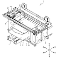
本発明の実施の形態について、図面を参照し説明する。図1を参照し、印刷装置1の概略構成について説明する。図1の上方、下方、右下方、左上方、左下方、及び右上方が、それぞれ、印刷装置1の上方、下方、右方、左方、前方、及び後方である。   Embodiments of the present invention will be described with reference to the drawings. The schematic configuration of the printing apparatus 1 will be described with reference to FIG. Upper, lower, lower right, upper left, lower left, and upper right in FIG. 1 are upper, lower, right, left, front, and rear of the printing apparatus 1, respectively.

印刷装置1は、被印刷媒体であるTシャツ等の布帛(図示外)の表面に対して、液体のインクを吐出することで印刷を行うインクジェットプリンタである。印刷装置1は、互いに異なる5種のインク(ホワイト、ブラック、シアン、マゼンタ、及びイエローのインク)を下方へ向けて吐出することで、被印刷媒体にカラー画像を印刷する。以下の説明では、5種のインクを総称する場合にはインクといい、ホワイトのインクを白インクといい、ブラック、シアン、マゼンタ、及びイエローの4色のインクを総称する場合はカラーインクという。印刷がなされた布帛が高い洗濯堅牢性を発揮できるよう、インクにはバインダー樹脂が含まれている。白インクには、顔料として例えば酸化チタンが含まれている。酸化チタンは比較的比重の高い無機顔料であり、高い沈降性を有する。よって、白インクは、カラーインクが含む成分よりも沈降性の高い成分を含む液体である。   The printing apparatus 1 is an ink jet printer that performs printing by discharging liquid ink on the surface of a cloth (not shown) such as a T-shirt that is a printing medium. The printing apparatus 1 prints a color image on a medium to be printed by discharging five different inks (white, black, cyan, magenta, and yellow inks) downward. In the following description, five types of ink are collectively referred to as ink, white ink as white ink, and four colors of black, cyan, magenta, and yellow as color ink. The ink contains a binder resin so that the printed fabric can exhibit high wash fastness. The white ink contains, for example, titanium oxide as a pigment. Titanium oxide is an inorganic pigment with a relatively high specific gravity and has high sedimentation. Thus, the white ink is a liquid containing a component having higher sedimentation than the component contained in the color ink.

白インクは、例えば地色が濃い色の布帛に画像が印刷される場合に下地として、カラーインクによる印刷の前に吐出される。印刷画像によっては、必ずしも白インクが吐出された後にカラーインクが吐出されなくてもよい。   The white ink is ejected, for example, as a base when printing an image on a fabric having a dark ground color, before printing with color ink. Depending on the print image, the color ink may not necessarily be ejected after the white ink is ejected.

図1に示すように、印刷装置1は、筐体2、プラテン機構3、キャリッジ15、及びメンテナンス機構30(図3参照)等を備える。筐体2の前面には、筐体2の内部と連通する開口部2Aが設けられている。   As shown in FIG. 1, the printing apparatus 1 includes a housing 2, a platen mechanism 3, a carriage 15, a maintenance mechanism 30 (see FIG. 3), and the like. An opening 2A communicating with the inside of the housing 2 is provided on the front surface of the housing 2.

プラテン機構3は、布帛(図示外)を前後方向に搬送するための機構であり、筐体2内側に設けられている。プラテン機構3はベース6、トレイ4、及びプラテン5等を備える。ベース6は、開口部2Aを通過して前後方向に延びる略箱状である。ベース6の内側には、前後方向に延びる一対のレール(図示外)が設けられている。   The platen mechanism 3 is a mechanism for conveying the cloth (not shown) in the front-rear direction, and is provided inside the housing 2. The platen mechanism 3 includes a base 6, a tray 4, a platen 5 and the like. The base 6 has a substantially box shape extending in the front-rear direction through the opening 2A. Inside the base 6, a pair of rails (not shown) extending in the front-rear direction are provided.

トレイ4は、ベース6の上側に設けられた平面視で略矩形状の板体である。トレイ4は、プラテン駆動モータ(図示外)の駆動に伴って、一対のレールに沿って移動可能である。プラテン5は、トレイ4の後端部から上方に立設された支柱(図示外)によって支持される平面視で略矩形状の板体である。プラテン5の上面には、布帛のうち印刷がなされる部分(例えば、Tシャツの前身頃等)を載置可能であり、トレイ4の上面には布帛のうち印刷がなされない部分(例えば、Tシャツの袖等)を載置可能である。プラテン5は、トレイ4と共に一対のレールに沿って移動可能である。   The tray 4 is a substantially rectangular plate provided in the upper side of the base 6 in a plan view. The tray 4 is movable along a pair of rails in accordance with driving of a platen drive motor (not shown). The platen 5 is a substantially rectangular plate in a plan view supported by a support (not shown) erected upward from the rear end of the tray 4. On the upper surface of the platen 5, a portion of the fabric to be printed (for example, the front body of a T-shirt etc.) can be placed, and on the upper surface of the tray 4 a portion of the fabric not to be printed (for example T It is possible to place the shirt sleeves etc.). The platen 5 is movable along with the tray 4 along a pair of rails.

筐体2の上端部には、図示外のガイドレール及びガイドシャフトが設けられている。ガイドレールは、後方から前方へ向かって突出する直方体状の部材である。ガイドシャフトは、前方に設けられ、左右方向に延びる。   A guide rail and a guide shaft (not shown) are provided at the upper end of the housing 2. The guide rail is a rectangular parallelepiped member that protrudes from the rear to the front. The guide shaft is provided forward and extends in the left-right direction.

キャリッジ15は、プラテン機構3の上側にて、ガイドレール及びガイドシャフトに沿って、左右方向に往復移動可能に設けられている。キャリッジ15は、キャリッジ駆動モータ(図示外)の駆動に伴って移動する。印刷装置1が印刷動作を行わない場合、キャリッジ15は移動可能な領域上で最も左側となる位置(以下、待機位置という)に配置される。図1に示すキャリッジ15は、待機位置に位置する。キャリッジ15には、白インクを吐出する第一ヘッドユニット10及びカラーインクを吐出する第二ヘッドユニット20が前後方向に並んで設けられている。第一ヘッドユニット10は第二ヘッドユニット20の後方に位置する。   The carriage 15 is provided on the upper side of the platen mechanism 3 so as to be reciprocally movable in the left-right direction along the guide rail and the guide shaft. The carriage 15 moves with the drive of a carriage drive motor (not shown). When the printing apparatus 1 does not perform the printing operation, the carriage 15 is disposed at the leftmost position on the movable area (hereinafter, referred to as a standby position). The carriage 15 shown in FIG. 1 is located at the standby position. On the carriage 15, a first head unit 10 for ejecting white ink and a second head unit 20 for ejecting color ink are provided side by side in the front-rear direction. The first head unit 10 is located behind the second head unit 20.

図2に示される第一ヘッドユニット10は、白インクを貯留する四つのメインタンク(図示外)に、四本の白インク供給チューブ(図示外)を介して接続している。第一ヘッドユニット10は、板状に形成されたヘッド11を有する。ヘッド11は、下方向を向く吐出面11Aを有する。吐出面11Aには、ノズル配列121〜124が形成される。ノズル配列121〜124は、左方から右方へ間隔を空けて順に並んでいる。ノズル配列121〜124は、それぞれ、複数のノズル列を有する。各ノズル列は、吐出面11Aにおいて前後方向に並ぶ複数のノズル111の列を有する。四つのメインタンクに貯留される白インクは、それぞれ、四本の白インク供給チューブを介して、第一ヘッドユニット10のノズル配列121〜124に供給される。   The first head unit 10 shown in FIG. 2 is connected to four main tanks (not shown) for storing white ink via four white ink supply tubes (not shown). The first head unit 10 has a head 11 formed in a plate shape. The head 11 has a discharge surface 11A facing downward. Nozzle arrays 121 to 124 are formed on the ejection surface 11A. The nozzle arrays 121 to 124 are arranged in order at intervals from the left to the right. The nozzle arrays 121 to 124 each have a plurality of nozzle arrays. Each nozzle row has a plurality of rows of nozzles 111 aligned in the front-rear direction on the ejection surface 11A. The white inks stored in the four main tanks are respectively supplied to the nozzle arrays 121 to 124 of the first head unit 10 via the four white ink supply tubes.

第二ヘッドユニット20は、第一ヘッドユニット10と同様の構成を有する。即ち、第二ヘッドユニット20は、ヘッド11を有する。第二ヘッドユニット20は、四本のカラーインク供給チューブ(図示略)を介して、四つのメインタンク(図示略)に接続している。四つのメインタンクには、互いに異なるカラーインクが貯留される。第二ヘッドユニット20の吐出面11Aに形成されたノズル配列121〜124には、それぞれ、互いに異なるカラーインクが供給される。   The second head unit 20 has the same configuration as the first head unit 10. That is, the second head unit 20 has the head 11. The second head unit 20 is connected to four main tanks (not shown) via four color ink supply tubes (not shown). Different color inks are stored in the four main tanks. Different color inks are supplied to the nozzle arrays 121 to 124 formed on the ejection surface 11A of the second head unit 20, respectively.

図3〜図7を参照し、メンテナンス機構30を説明する。図3では、図4で示される後述の保持部材35、及び板状部材50,80の図示を省略する。図3では、待機位置にあるキャリッジ15の第一ヘッドユニット10を図示する。メンテナンス機構30は、第一ヘッドユニット10と第二ヘッドユニット20のそれぞれに対して、メンテナンス動作を実行する機構である。以下、メンテナンス機構30の構成のうちで、第一ヘッドユニット10にメンテナンスがなされるための構成を説明する。   The maintenance mechanism 30 will be described with reference to FIGS. 3 to 7. In FIG. 3, illustration of the below-mentioned holding member 35 shown in FIG. 4 and the plate-like members 50 and 80 is abbreviate | omitted. In FIG. 3, the first head unit 10 of the carriage 15 in the standby position is illustrated. The maintenance mechanism 30 is a mechanism that performs a maintenance operation on each of the first head unit 10 and the second head unit 20. Hereinafter, among the configurations of the maintenance mechanism 30, a configuration for performing maintenance on the first head unit 10 will be described.

メンテナンス動作は、キャッピング、パージ、空吸引、及び洗浄を含む。キャッピングは、キャップ40によって、吐出面11A(図2参照)を密封する動作である。パージは、吐出面11A(図2参照)から、インクを吸引する動作である。空吸引は、キャップ40(図3参照)によって保持された液体を、吸引部29によって吸引する動作である。キャップ40によって保持された液体は、一例として、インク、洗浄液22A(図3参照)等の液体である。洗浄は、キャップ40によって保持された液体を、洗浄液22Aによって流し出す動作である。   Maintenance operations include capping, purging, empty suction, and cleaning. Capping is an operation of sealing the ejection surface 11A (see FIG. 2) by the cap 40. The purge is an operation of sucking the ink from the ejection surface 11A (see FIG. 2). The empty suction is an operation of suctioning the liquid held by the cap 40 (see FIG. 3) by the suction unit 29. The liquid held by the cap 40 is, for example, a liquid such as an ink and a cleaning liquid 22A (see FIG. 3). The washing is an operation in which the liquid held by the cap 40 is flushed out by the washing liquid 22A.

図3に示すように、メンテナンス機構30は、吸引部29及び保持部材35を備える。吸引部29は、キャリッジ15(図1参照)の待機位置の下方に設けられる。吸引部29は、例えば、公知のチューブポンプ式の吸引ポンプであり、廃液タンク16に接続される。   As shown in FIG. 3, the maintenance mechanism 30 includes a suction unit 29 and a holding member 35. The suction unit 29 is provided below the standby position of the carriage 15 (see FIG. 1). The suction unit 29 is, for example, a known tube pump suction pump, and is connected to the waste liquid tank 16.

保持部材35は、吸引部29の上方であって、且つキャリッジ15の待機位置の下方に設けられる。保持部材35は、上方に向けて開口する略箱状である。保持部材35は、筐体2(図1参照)の内部に設けられた上下動モータ21の駆動に伴って、上下方向に移動可能である。   The holding member 35 is provided above the suction portion 29 and below the standby position of the carriage 15. The holding member 35 has a substantially box shape opening upward. The holding member 35 is movable in the vertical direction along with the driving of the vertical movement motor 21 provided inside the housing 2 (see FIG. 1).

図4及び図6に示すように、保持部材35は、保持壁部36、右吸引路31、左吸引路32、右洗浄路33、左洗浄路34、及び筒状突出部39を備える。   As shown in FIGS. 4 and 6, the holding member 35 includes a holding wall portion 36, a right suction path 31, a left suction path 32, a right washing path 33, a left washing path 34, and a cylindrical protrusion 39.

保持壁部36は、平面視において前後方向と左右方向に延びる略矩形状である。右吸引路31及び左吸引路32は、保持壁部36の前部に設けられる。右吸引路31は保持壁部36の右部に設けられ、左吸引路32は保持壁部36の左部に設けられる。右吸引路31と左吸引路32は、保持壁部36を上下方向に貫通する円筒状である。右吸引路31と左吸引路32は、それぞれ、右チューブ23(図3参照)と左チューブ24(図3参照)を介して、吸引部29に接続する。右チューブ23と左チューブ24には、それぞれ、第一バルブ(図示略)が設けられる。第一バルブは、筐体2の内側に設けられた制御部(図示外)に、電気的に接続している。制御部は、第一バルブを、開放状態と遮断状態とに切り替える。右チューブ23において、対応する第一バルブが開放状態になると、右吸引路31と吸引部29は互いに連通し、対応する第一バルブが遮断状態になると、右吸引路31と吸引部29との連通は遮断される。同様に、左チューブ24においても、対応する第一バルブが、制御部によって、開放状態と遮断状態とに切り替えられることにより、左吸引路32と吸引部29との連通状態は、切り替わる。   The holding wall portion 36 has a substantially rectangular shape extending in the front-rear direction and the left-right direction in plan view. The right suction path 31 and the left suction path 32 are provided at the front of the holding wall portion 36. The right suction path 31 is provided on the right side of the holding wall portion 36, and the left suction path 32 is provided on the left side of the holding wall portion 36. The right suction path 31 and the left suction path 32 have a cylindrical shape penetrating the holding wall portion 36 in the vertical direction. The right suction path 31 and the left suction path 32 are connected to the suction unit 29 via the right tube 23 (see FIG. 3) and the left tube 24 (see FIG. 3), respectively. The right tube 23 and the left tube 24 are each provided with a first valve (not shown). The first valve is electrically connected to a control unit (not shown) provided inside the housing 2. The control unit switches the first valve between the open state and the shut off state. In the right tube 23, when the corresponding first valve is opened, the right suction passage 31 and the suction unit 29 communicate with each other, and when the corresponding first valve is closed, the right suction passage 31 and the suction unit 29 Communication is interrupted. Similarly, in the left tube 24 as well, the corresponding first valve is switched between the open state and the shut-off state by the control unit, whereby the communication state between the left suction passage 32 and the suction unit 29 is switched.

図4及び図5に示すように、右洗浄路33と左洗浄路34は、保持壁部36の後部に設けられる。右洗浄路33は保持壁部36の右部に設けられ、左洗浄路34は保持壁部36の左部に設けられる。右洗浄路33と左洗浄路34は、保持壁部36を上下方向に貫通する円筒状である。右洗浄路33は、右吸引路31の後方に位置し、左洗浄路34は、左吸引路32の後方に位置する。右洗浄路33と左洗浄路34は、それぞれ、右洗浄チューブ25(図3参照)と左洗浄チューブ26(図3参照)を介して、洗浄液タンク22(図3参照)に接続する。洗浄液タンク22には、メンテナンス機構30の洗浄に使用される洗浄液22Aが貯留される。   As shown in FIGS. 4 and 5, the right washing path 33 and the left washing path 34 are provided at the rear of the holding wall portion 36. The right washing path 33 is provided on the right of the holding wall 36, and the left washing path 34 is provided on the left of the holding wall 36. The right washing path 33 and the left washing path 34 have a cylindrical shape penetrating the holding wall portion 36 in the vertical direction. The right washing passage 33 is located behind the right suction passage 31, and the left washing passage 34 is located behind the left suction passage 32. The right washing passage 33 and the left washing passage 34 are connected to the washing solution tank 22 (see FIG. 3) via the right washing tube 25 (see FIG. 3) and the left washing tube 26 (see FIG. 3), respectively. The cleaning solution tank 22 stores a cleaning solution 22A used for cleaning the maintenance mechanism 30.

右洗浄チューブ25と左洗浄チューブ26は、それぞれ、第二バルブ(図示略)が設けられる。第二バルブは、上述した制御部(図示外)に、電気的に接続している。制御部は、第二バルブを、開放状態と遮断状態とに切り替える。右洗浄チューブ25において、対応する第二バルブが開放状態になると、右洗浄路33と洗浄液タンク22は互いに連通し、対応する第二バルブが遮断状態になると、右洗浄路33と洗浄液タンク22との連通は遮断される。同様に、左洗浄チューブ26においても、対応する第二バルブが、制御部によって、開放状態と遮断状態とに切り替えられることにより、左洗浄路34と洗浄液タンク22との連通状態は、切り替わる。   The right washing tube 25 and the left washing tube 26 are each provided with a second valve (not shown). The second valve is electrically connected to the control unit (not shown) described above. The control unit switches the second valve between the open state and the shut off state. In the right washing tube 25, when the corresponding second valve is opened, the right washing passage 33 and the washing solution tank 22 communicate with each other, and when the corresponding second valve is closed, the right washing passage 33 and the washing solution tank 22 Communication is blocked. Similarly, also in the left cleaning tube 26, the corresponding second valve is switched to the open state and the blocking state by the control unit, so that the communication state between the left cleaning path 34 and the cleaning liquid tank 22 is switched.

図4及び図5に示すように、筒状突出部39は、右吸引路31と右洗浄路33との間において、保持壁部36から上方に突出する。筒状突出部39の軸線39Aは、上下方向に延びる。筒状突出部39の上端部の周面には、軸線39Aに向けて凹む溝部39Bが形成される。溝部39Bは、軸線39Aを基準とした円周方向に亘って、筒状突出部39の周面に形成される。溝部39Bには、止め輪28が設けられる。   As shown in FIGS. 4 and 5, the cylindrical protrusion 39 protrudes upward from the holding wall 36 between the right suction passage 31 and the right washing passage 33. The axis 39A of the cylindrical protrusion 39 extends in the vertical direction. A groove 39B recessed toward the axis 39A is formed on the circumferential surface of the upper end of the cylindrical projection 39. The groove 39B is formed on the circumferential surface of the cylindrical projection 39 over the circumferential direction based on the axis 39A. A retaining ring 28 is provided in the groove 39B.

保持部材35の内側では、キャップ40が保持される。キャップ40は、上方に向けて開口する略箱状である。キャップ40は、弾性体の一例であるゴム材料によって形成される。キャップ40は、底壁部41及び接触壁部47を備える。底壁部41は、保持部材35の保持壁部36によって保持される壁部である。底壁部41の形状は、平面視において前後方向と左右方向に延びる略矩形状である。   The cap 40 is held inside the holding member 35. The cap 40 has a substantially box shape opening upward. The cap 40 is formed of a rubber material which is an example of an elastic body. The cap 40 comprises a bottom wall 41 and a contact wall 47. The bottom wall portion 41 is a wall portion held by the holding wall portion 36 of the holding member 35. The shape of the bottom wall portion 41 is a substantially rectangular shape extending in the front-rear direction and the left-right direction in a plan view.

底壁部41には、右吸引路31、左吸引路32、右洗浄路33、左洗浄路34、及び筒状突出部39のそれぞれに対応して、孔が設けられる。右洗浄路33、左洗浄路34、筒状突出部39は、底壁部41の孔を介して上方へ突出する。右吸引路31と左吸引路32に対応する底壁部41の孔は、それぞれ、吸引口42A,42Bである。筒状突出部39に対応する底壁部41の孔は、孔42Cである。孔42Cには、筒状突出部39が嵌っている。孔42Cは、平面視において、止め輪28よりも小さい。従って、キャップ40は、止め輪28によって、保持部材35の外側への移動を規制される。尚、筒状突出部39は、筒状に形成されたスペーサ(図示略)を介して、孔42Cに嵌ってもよい。   The bottom wall portion 41 is provided with a hole corresponding to each of the right suction passage 31, the left suction passage 32, the right washing passage 33, the left washing passage 34, and the cylindrical protrusion 39. The right washing passage 33, the left washing passage 34, and the cylindrical protrusion 39 project upward through the hole of the bottom wall 41. The holes of the bottom wall portion 41 corresponding to the right suction path 31 and the left suction path 32 are suction ports 42A and 42B, respectively. The hole of the bottom wall 41 corresponding to the cylindrical protrusion 39 is a hole 42C. The cylindrical protrusion 39 is fitted in the hole 42C. The hole 42C is smaller than the retaining ring 28 in a plan view. Accordingly, the cap 40 is restricted by the retaining ring 28 from moving the holding member 35 outward. The cylindrical protrusion 39 may be fitted into the hole 42C via a spacer (not shown) formed in a cylindrical shape.

接触壁部47は、底壁部41から上方に延びる壁部である。接触壁部47の上端部は、上方に向かうにつれて細くなる。保持部材35が、上下動モータ21(図3参照)の駆動に伴い上下動することにより、接触壁部47の上端部は、第一ヘッドユニット10の吐出面11Aに対して接離可能である。すなわち、接触壁部47は、いわゆるキャップリップである。   The contact wall 47 is a wall extending upward from the bottom wall 41. The upper end of the contact wall 47 is tapered toward the top. The upper end portion of the contact wall portion 47 is capable of coming into and coming out of contact with the discharge surface 11A of the first head unit 10 by the holding member 35 moving up and down with the drive of the vertical movement motor 21 (see FIG. 3). . That is, the contact wall 47 is a so-called cap lip.

図4に示すように、接触壁部47は、周壁部42及び仕切壁部45を含む。周壁部42は、底壁部41(図5参照)の周端部から上方に延びる。周壁部42の形状は、平面視において、矩形状且つ枠状である。周壁部42の上端部は、第一ヘッドユニット10の吐出面11A(図2参照)の周端部に対して、接離可能である。仕切壁部45は、右吸引路31と左吸引路32の間と、右洗浄路33と左洗浄路34との間とを通過して、前後方向に延びる。仕切壁部45は、周壁部42に接続する。従って、底壁部41と周壁部42とによって囲まれるキャップ40の内部の空間を、仕切壁部45は二つに仕切る。また、仕切壁部45の上端部は、第一ヘッドユニット10の吐出面11Aのうちで、図2に示すノズル配列121とノズル配列122との間にある部位に対して、接離可能である。   As shown in FIG. 4, the contact wall 47 includes a peripheral wall 42 and a partition 45. The circumferential wall portion 42 extends upward from the circumferential end of the bottom wall portion 41 (see FIG. 5). The shape of the peripheral wall portion 42 is rectangular and frame-shaped in plan view. The upper end portion of the peripheral wall portion 42 can be brought into contact with or separated from the peripheral end portion of the ejection surface 11A (see FIG. 2) of the first head unit 10. The partition wall 45 extends in the front-rear direction, passing between the right suction passage 31 and the left suction passage 32 and between the right washing passage 33 and the left washing passage 34. The partition wall 45 is connected to the peripheral wall 42. Therefore, the dividing wall 45 divides the space inside the cap 40 surrounded by the bottom wall 41 and the peripheral wall 42 into two. Further, the upper end portion of the partition wall portion 45 is capable of coming into and coming out of contact with a portion of the discharge surface 11A of the first head unit 10 between the nozzle array 121 and the nozzle array 122 shown in FIG. .

以下、仕切壁部45よりも右側にあるキャップ40内部の空間を、右空間40A(図3参照)といい、仕切壁部45よりも左側にあるキャップ40内部の空間を、左空間40B(図3参照)という。すなわち、右空間40Aは、第一ヘッドユニット10のノズル配列122〜124の下方にあり、左空間40Bは、ノズル配列121の下方にある。   Hereinafter, the space inside the cap 40 on the right side of the partition wall 45 is referred to as the right space 40A (see FIG. 3), and the space inside the cap 40 on the left side of the partition wall 45 is the left space 40B (see FIG. See 3). That is, the right space 40A is below the nozzle arrays 122 to 124 of the first head unit 10, and the left space 40B is below the nozzle array 121.

接触壁部47のうちで、右空間40Aを囲む部位を、第一枠状壁部47Aといい、左空間40Bを囲む部位を、第二枠状壁部47Bという。第一枠状壁部47A及び第二枠状壁部47Bは、底壁部41から上方に延びる。第一枠状壁部47Aと第二枠状壁部47Bの形状は、それぞれ、平面視において、矩形状且つ枠状である。第一枠状壁部47Aは、右吸引路31、吸引口42A、及び右洗浄路33を囲み、第二枠状壁部47Bは、左吸引路32、吸引口42B、及び左洗浄路34を囲む。また、第一枠状壁部47Aの内側の端面を、第一内端面47C(図6参照)といい、第二枠状壁部47Bの内側の端面を、第二内端面47D(図6参照)という。第一内端面47Cの下部において、第一溝部91(図6参照)が形成され、第二内端面47Dの下部において、第二溝部92(図6参照)が形成される。第一溝部91は、軸線39Aから遠ざかる方向に凹む。すなわち、右空間40Aは下側の方が広い。第二溝部92も、第一溝部91と同様に形成され、左空間40Bは、下側の方が広い。尚、図2では、接触壁部47が第一ヘッドユニット10の吐出面11Aに接触した場合における、第一枠状壁部47Aと第二枠状壁部47Bを、二点鎖線によって模式的に図示する。接触壁部47が吐出面11Aに接触した場合、第一枠状壁部47Aは、ノズル配列122〜124を囲み、第二枠状壁部47Bは、ノズル配列121を囲む。   In the contact wall portion 47, a portion surrounding the right space 40A is referred to as a first frame-shaped wall portion 47A, and a portion surrounding the left space 40B is referred to as a second frame-shaped wall portion 47B. The first frame-shaped wall 47A and the second frame-shaped wall 47B extend upward from the bottom wall 41. The shapes of the first frame-shaped wall 47A and the second frame-shaped wall 47B are respectively rectangular and frame-shaped in plan view. The first frame-shaped wall portion 47A surrounds the right suction path 31, the suction port 42A, and the right washing path 33, and the second frame-shaped wall portion 47B includes the left suction path 32, the suction port 42B, and the left washing path 34. Surround. The inner end surface of the first frame-shaped wall 47A is referred to as a first inner end surface 47C (see FIG. 6), and the inner end of the second frame-shaped wall 47B is referred to as a second inner end surface 47D (see FIG. 6). ). The first groove portion 91 (see FIG. 6) is formed in the lower portion of the first inner end surface 47C, and the second groove portion 92 (see FIG. 6) is formed in the lower portion of the second inner end surface 47D. The first groove 91 is recessed in a direction away from the axis 39A. That is, the lower side of the right space 40A is wider. The second groove 92 is also formed in the same manner as the first groove 91, and the left space 40B is wider at the lower side. In addition, in FIG. 2, when the contact wall 47 contacts the discharge surface 11A of the first head unit 10, the first frame-shaped wall 47A and the second frame-shaped wall 47B are schematically shown by a two-dot chain line. Shown. When the contact wall portion 47 contacts the ejection surface 11A, the first frame-shaped wall portion 47A surrounds the nozzle array 122 to 124, and the second frame-shaped wall portion 47B surrounds the nozzle array 121.

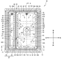
図4及び図6に示すように、右空間40Aには吸収部材48が収容され、左空間40Bには吸収部材49が収容される。吸収部材48は、第一枠状壁部47Aに囲まれる位置にて、キャップ40の底壁部41に載置され、吸収部材49は、第二枠状壁部47Bに囲まれる位置にて、底壁部41に載置される。吸収部材48,49の形状は、平面視で前後方向に延びる略矩形状である。吸収部材48,49は、それぞれ、保持部材35の右吸引路31と左吸引路32を上方から覆う。吸収部材48,49は、例えばスポンジなどの液体を保持可能な部材である。吸収部材48,49は、それぞれ、右空間40Aと左空間40Bの湿度を維持するための、洗浄液22Aなどの液体を吸収している。吸収部材48には、右洗浄路33を上方に露出させる露出孔48Aが形成され、吸収部材49には、左洗浄路34を上方に露出させる露出孔49Aが形成される。吸収部材48の中央部には、保持部材35の筒状突出部39が挿通される挿通孔48Bが形成される。挿通孔48Bは、キャップ40の孔42Cよりも上方に位置する。挿通孔48Bは、止め輪28を内側に収容する。   As shown in FIGS. 4 and 6, the absorbing member 48 is accommodated in the right space 40A, and the absorbing member 49 is accommodated in the left space 40B. The absorbing member 48 is placed on the bottom wall 41 of the cap 40 at a position surrounded by the first frame-shaped wall 47A, and the absorbing member 49 is surrounded by a second frame-shaped wall 47B, It is placed on the bottom wall 41. The shape of the absorbing members 48 and 49 is a substantially rectangular shape extending in the front-rear direction in a plan view. The absorbing members 48 and 49 respectively cover the right suction path 31 and the left suction path 32 of the holding member 35 from above. The absorbing members 48 and 49 are members capable of holding a liquid, such as a sponge, for example. The absorbing members 48 and 49 respectively absorb the liquid such as the cleaning liquid 22A for maintaining the humidity of the right space 40A and the left space 40B. The absorption member 48 is formed with an exposure hole 48A for exposing the right washing path 33 upward, and the absorption member 49 is formed with an exposure hole 49A for exposing the left washing path 34 upward. In the central portion of the absorbing member 48, an insertion hole 48B through which the cylindrical protrusion 39 of the holding member 35 is inserted is formed. The insertion hole 48B is located above the hole 42C of the cap 40. The insertion hole 48B accommodates the retaining ring 28 inside.

第一枠状壁部47Aと吸収部材48との間には、板状部材50が設けられ、第二枠状壁部47Bと吸収部材49との間には、板状部材80が設けられる。板状部材50,80は、上下方向に厚さを有する板状部材である。本例の板状部材50,80は、樹脂材料によって形成される。つまり、板状部材50,80を形成する材料の硬度は、キャップ40を形成する材料の硬度よりも高い。板状部材50,80は、互いに類似する構成を有するので、以下、板状部材50の構成を詳細に説明し、板状部材80の構成を簡略化して説明する。   A plate-like member 50 is provided between the first frame-like wall 47A and the absorbing member 48, and a plate-like member 80 is provided between the second frame-like wall 47B and the absorbing member 49. The plate-like members 50 and 80 are plate-like members having a thickness in the vertical direction. The plate-like members 50 and 80 of this example are formed of a resin material. That is, the hardness of the material forming the plate-like members 50 and 80 is higher than the hardness of the material forming the cap 40. Since the plate members 50 and 80 have configurations similar to each other, the configuration of the plate member 50 will be described in detail below, and the configuration of the plate member 80 will be simplified and described.

図4及び図7に示すように、板状部材50は、基部51を備える。基部51は、第一枠状壁部47Aによって囲まれ、且つ吸収部材48の周面と対向する位置に配置される。より詳細には、基部51は、第一枠状壁部47Aの第一内端面47Cに沿って延び、且つ、第一内端面47Cと、吸収部材48とを互いに仕切る。基部51は、平面視において矩形状となる枠である。また、基部51の一対の対角の中心位置は、平面視において、保持部材35の軸線39Aと略一致する。つまり、基部51の形状は、軸線39Aを基準に点対称となる枠である。   As shown in FIGS. 4 and 7, the plate-like member 50 includes a base 51. The base 51 is surrounded by the first frame-shaped wall 47A and disposed at a position facing the circumferential surface of the absorbing member 48. More specifically, the base 51 extends along the first inner end surface 47C of the first frame-shaped wall 47A, and divides the first inner end surface 47C and the absorbing member 48 from each other. The base 51 is a frame that is rectangular in plan view. Further, the center positions of the pair of diagonals of the base 51 substantially coincide with the axis 39A of the holding member 35 in a plan view. That is, the shape of the base 51 is a frame that is point-symmetrical with respect to the axis 39A.

図7に示すように、基部51には、第一面51A、第二面51B、第三面51C、及び第四面51Dが、設けられる。第一面51Aは、基部51の表面のうちで下方向を向く面である。第二面51Bは、基部51の表面のうちで上方向を向く面である。第三面51Cは、基部51の表面のうちで第一枠状壁部47A(図4参照)の第一内端面47Cに対向する面であり、第一面51Aと第二面51Bとを接続する。第四面51Dは、吸収部材48(図4参照)の周面と対向する面であり、第一面51Aと第二面51Bとを接続する。第四面51Dは、第三面51Cに対して、第一枠状壁部47Aの第一内端面47Cとは反対側に位置する。   As shown in FIG. 7, the base 51 is provided with a first surface 51A, a second surface 51B, a third surface 51C, and a fourth surface 51D. The first surface 51 </ b> A is a surface of the surface of the base 51 facing downward. The second surface 51 </ b> B is a surface facing upward in the surface of the base 51. The third surface 51C is a surface facing the first inner end surface 47C of the first frame-shaped wall 47A (see FIG. 4) in the surface of the base 51, and connects the first surface 51A and the second surface 51B. Do. The fourth surface 51D is a surface facing the circumferential surface of the absorbing member 48 (see FIG. 4), and connects the first surface 51A and the second surface 51B. The fourth surface 51D is located on the side opposite to the first inner end surface 47C of the first frame-shaped wall 47A with respect to the third surface 51C.

基部51は、一対の長手壁部52と、一対の短手壁部62とから形成される。一対の長手壁部52は、前後方向に延びる壁部である。一対の長手壁部52は、間を空けて左右方向に互いに対向する。一対の短手壁部62は、左右方向に延びる壁部である。一対の短手壁部62は、間を空けて前後方向に互いに対向する。短手壁部62の左右方向における長さは、長手壁部52の前後方向における長さよりも、短い。本例では、一対の長手壁部52と、一対の短手壁部62は、互いに一体的に形成される。   The base 51 is formed of a pair of longitudinal wall portions 52 and a pair of short side wall portions 62. The pair of longitudinal wall portions 52 is a wall portion extending in the front-rear direction. The pair of longitudinal wall portions 52 face each other in the left-right direction with an interval. The pair of short wall portions 62 are wall portions extending in the left-right direction. The pair of short wall portions 62 face each other in the front-rear direction with an interval. The length of the short wall 62 in the left-right direction is shorter than the length of the longitudinal wall 52 in the front-rear direction. In this example, the pair of longitudinal wall portions 52 and the pair of short side wall portions 62 are integrally formed with each other.

以下、基部51の第一面51Aのうちで、長手壁部52の表面となる部位を下端面52Aといい、短手壁部62の表面となる部位を下端面62Aという。また、基部51の第二面51Bのうちで、長手壁部52の表面となる部位を上端面52Bといい、短手壁部62の表面となる部位を上端面62Bという。また、基部51の第三面51Cのうちで、長手壁部52の表面となる部位を外側端面52Cといい、短手壁部62表面となる部位を外側端面62Cという。また、基部51の第四面51Dのうちで、長手壁部52の表面となる部位を内側端面52Dといい、短手壁部62の表面となる部位を内側端面62Dという。   Hereinafter, in the first surface 51A of the base 51, a portion to be the surface of the longitudinal wall 52 is referred to as a lower end surface 52A, and a portion to be the surface of the short wall 62 is referred to as a lower end surface 62A. Further, in the second surface 51B of the base 51, a portion to be the surface of the longitudinal wall 52 is called an upper end surface 52B, and a portion to be the surface of the short wall 62 is called an upper end surface 62B. Further, in the third surface 51C of the base 51, a portion to be a surface of the longitudinal wall 52 is called an outer end surface 52C, and a portion to be a surface of the short wall 62 is called an outer end surface 62C. Further, in the fourth surface 51D of the base 51, a portion to be the surface of the longitudinal wall 52 is called an inner end face 52D, and a portion to be the surface of the short wall 62 is called an inner end face 62D.

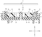
長手壁部52は、第一壁部53と、第一突出部57とを有する。第一壁部53は、第一枠状壁部47Aと吸収部材48(図4参照)との間に設けられる。第一壁部53は、第一枠状壁部47Aの第一内端面47Cに対向する。   The longitudinal wall 52 has a first wall 53 and a first projection 57. The first wall 53 is provided between the first frame-shaped wall 47A and the absorbing member 48 (see FIG. 4). The first wall 53 faces the first inner end surface 47C of the first frame-shaped wall 47A.

第一突出部57は、外側端面52Cから内側端面52Dに向かう方向へ、第一壁部53の上端部から突出する。第一突出部57は、吸収部材48の左右方向における端部の真上にあり、且つ、キャップ40の接触壁部47(図4参照)の上端部よりも下側にある。また、第一ヘッドユニット10が待機位置にある場合において、第一突出部57は、ノズル配列122(図2参照)の左端のノズル列、又は、ノズル配列124(図2参照)の右端のノズル列の下方にあってもよい。第一突出部57には、複数の特定凹部58が、前後方向に並んで設けられる。特定凹部58は、長手壁部52の上端面52Bにおいて、下端面52Aに向けて凹む。特定凹部58の底壁部には、第一突出部57を上下方向に貫通する孔部58Aが形成される。孔部58Aの形状は、平面視において、前後方向に長い長方形状である(図4参照)。孔部58Aは、第一突出部57の下方にある吸収部材48を、上方に向けて露出させる(図8参照)。   The first protrusion 57 protrudes from the upper end of the first wall 53 in the direction from the outer end surface 52C to the inner end surface 52D. The first projecting portion 57 is right above the end of the absorbing member 48 in the left-right direction and below the upper end of the contact wall 47 (see FIG. 4) of the cap 40. In addition, when the first head unit 10 is in the standby position, the first protrusion 57 is the nozzle row at the left end of the nozzle array 122 (see FIG. 2) or the nozzle at the right end of the nozzle array 124 (see FIG. 2). It may be below the row. A plurality of specific recesses 58 are provided in the first protrusion 57 side by side in the front-rear direction. The specific recess 58 is recessed toward the lower end surface 52A on the upper end surface 52B of the longitudinal wall 52. In the bottom wall portion of the specific recess 58, a hole 58A penetrating the first projecting portion 57 in the vertical direction is formed. The shape of the hole 58A is a rectangular shape that is long in the front-rear direction in plan view (see FIG. 4). The hole 58A exposes the absorbing member 48 located below the first protrusion 57 upward (see FIG. 8).

短手壁部62は、第二壁部63と、第二突出部67とを有する。第二壁部63は、第一枠状壁部47A(図4参照)と吸収部材48(図4参照)との間に設けられる。第二壁部63は、第一枠状壁部47Aの第一内端面47Cに対向する。第二突出部67は、短手壁部62の外側端面62Cから内側端面62Dに向かう方向へ、第二壁部63の上端部から突出する。   The short side wall 62 has a second wall 63 and a second protrusion 67. The second wall 63 is provided between the first frame-shaped wall 47A (see FIG. 4) and the absorbing member 48 (see FIG. 4). The second wall 63 faces the first inner end surface 47C of the first frame-shaped wall 47A. The second projecting portion 67 protrudes from the upper end portion of the second wall portion 63 in a direction from the outer end surface 62C of the short wall portion 62 toward the inner end surface 62D.

第二突出部67は、吸収部材48(図4参照)の前後方向における端部の真上にあり、且つ、キャップ40の接触壁部47(図4参照)の上端部よりも下側にある。第二突出部67の左右方向の両端部には、それぞれ、特定凹部68が設けられる。特定凹部68は、短手壁部62の上端面62Bにおいて、下端面62Aに向けて凹む。特定凹部68の底壁部には、第二突出部67を上下方向に貫通する孔部68A(図4参照)が形成される。孔部68Aの形状は、平面視において、左右方向に長い長方形状である(図4参照)。孔部68Aは、第二突出部67の下方にある吸収部材48を、上方に向けて露出させる(図4参照)。   The second protrusion 67 is directly above the end of the absorbing member 48 (see FIG. 4) in the front-rear direction, and is lower than the upper end of the contact wall 47 (see FIG. 4) of the cap 40. . At both end portions in the left-right direction of the second projecting portion 67, specific concave portions 68 are provided. The specific recess 68 is recessed toward the lower end surface 62A at the upper end surface 62B of the short wall portion 62. In the bottom wall portion of the specific recess 68, a hole 68A (see FIG. 4) penetrating the second protrusion 67 in the vertical direction is formed. The shape of the hole 68A is a rectangular shape that is long in the left-right direction in plan view (see FIG. 4). The hole 68A exposes the absorbing member 48 located below the second protrusion 67 upward (see FIG. 4).

第二突出部67の左右方向の中央部には、露出凹部69が設けられる。露出凹部69は、左右方向において、二つの孔部68Aの間に位置する。露出凹部69は、第二突出部67のうち、外側端面62Cから内側端面62Dに向かう方向の端部において、外側端面62Cに向けて凹む。露出凹部69は、吸収部材48の前後方向における端部を、上方に向けて露出させる。   An exposed concave portion 69 is provided at a central portion in the left-right direction of the second projecting portion 67. The exposed recess 69 is located between the two holes 68A in the left-right direction. The exposed recess 69 is recessed toward the outer end surface 62C at the end of the second protrusion 67 in the direction from the outer end surface 62C to the inner end surface 62D. The exposed recess 69 exposes the end of the absorbing member 48 in the front-rear direction upward.

図7を参照し、板状部材50の基部51に設けられる凹部100を説明する。凹部100は、一例として、第一凹部71,72、及び第二凹部81〜84を含む。第一凹部71は、一対の短手壁部62の一方に形成され、第一凹部72は、一対の短手壁部62の他方に形成される。第一凹部71,72の形状は、互いに同じである。第一凹部71,72は、それぞれ、短手壁部62の外側端面62Cと内側端面62Dとの間に亘って、下端面62Aにおいて上端面62Bに向けて凹む。第一凹部71,72は、軸線39A(図4参照)を基準に、互いに点対称となる位置にある。   With reference to FIG. 7, the recessed part 100 provided in the base 51 of the plate-shaped member 50 is demonstrated. The recess 100 includes, as an example, first recesses 71 and 72 and second recesses 81 to 84. The first recess 71 is formed in one of the pair of short wall portions 62, and the first recess 72 is formed in the other of the pair of short wall portions 62. The shapes of the first recesses 71 and 72 are the same as each other. The first recesses 71 and 72 are recessed toward the upper end surface 62B at the lower end surface 62A, respectively, between the outer end surface 62C and the inner end surface 62D of the short wall portion 62. The first recesses 71 and 72 are located in point symmetry with each other with respect to the axis 39A (see FIG. 4).

第一凹部71,72の内表面は、それぞれ、一対の対向面75と、底壁面76とによって形成される。一対の対向面75は、左右方向に間を空けて互いに対向する面であり、短手壁部62の下端面62Aと内側端面62Dとに接続する。対向面75は、左側面視において略Lの字状に形成される。底壁面76は、一対の対向面75を互いに接続する。   The inner surfaces of the first recesses 71 and 72 are each formed by a pair of opposing surfaces 75 and a bottom wall surface 76. The pair of facing surfaces 75 are surfaces facing each other with a space in the left-right direction, and are connected to the lower end surface 62A and the inner end surface 62D of the short wall portion 62. The opposing surface 75 is formed in a substantially L-shape in left side view. The bottom wall surface 76 connects the pair of opposing surfaces 75 to each other.

第二凹部81,82は、一対の長手壁部52の一方に形成され、第二凹部83,84は、一対の長手壁部52の他方に形成される。本例では、第二凹部81〜84の形状は、互いに同じである。第二凹部81〜84は、それぞれ、長手壁部52の下端面52Aから上端面52Bの間に亘って、外側端面52Cにおいて内側端面52Dに向けて凹む。   The second recesses 81 and 82 are formed in one of the pair of longitudinal walls 52, and the second recesses 83 and 84 are formed in the other of the pair of longitudinal walls 52. In the present example, the shapes of the second recesses 81 to 84 are the same as one another. The second recesses 81 to 84 are respectively recessed toward the inner end surface 52D at the outer end surface 52C from the lower end surface 52A of the longitudinal wall 52 to the upper end surface 52B.

第二凹部81,82は、複数の特定凹部58を間にして、前後方向に並んで設けられる。即ち、第二凹部81,82は、キャップ40の吸引口42A(図4参照)からの離隔距離が互いに異なる二つの位置に、それぞれ設けられる。図4で示される板状部材50においては、第二凹部81と吸引口42Aとの離隔距離は、第二凹部82と吸引口42Aとの離隔距離よりも短い。   The second recesses 81 and 82 are provided side by side in the front-rear direction with the plurality of specific recesses 58 interposed therebetween. That is, the second recesses 81 and 82 are respectively provided at two positions different in distance from the suction port 42A (see FIG. 4) of the cap 40. In the plate-like member 50 shown in FIG. 4, the separation distance between the second recess 81 and the suction port 42A is shorter than the separation distance between the second recess 82 and the suction port 42A.

同様に、第二凹部83,84は、複数の特定凹部58を間にして、前後方向に並んで設けられる。第二凹部83は、第二凹部81と同じ左右方向位置にあり、第二凹部84は、第二凹部82と同じ左右方向位置にある。以下、板状部材50によって囲まれる空間のうちで、第二凹部81,83の間にある領域を、第一領域43(図4参照)といい、第二凹部82,84の間にある領域を、第二領域44(図4参照)という。図4においては、第一領域43は、吸引口42Aに対して、第二領域44よりも近接する位置にある。   Similarly, the second recesses 83 and 84 are provided side by side in the front-rear direction with the plurality of specific recesses 58 interposed therebetween. The second recess 83 is in the same left-right direction position as the second recess 81, and the second recess 84 is in the same left-right direction position as the second recess 82. Hereinafter, in the space surrounded by the plate-like member 50, a region between the second recesses 81 and 83 is referred to as a first region 43 (see FIG. 4) and a region between the second recesses 82 and 84. Is referred to as a second area 44 (see FIG. 4). In FIG. 4, the first area 43 is located closer to the suction port 42 </ b> A than the second area 44.

第二凹部81,84は、軸線39Aを基準に互いに点対称となる位置にある。換言すると、一対の長手壁部52の一方に形成された第二凹部81の位置と、一対の長手壁部52の他方に形成された第二凹部84の位置とは、互いに対称である。同様に、第二凹部82,83は、軸線39Aを基準に互いに点対称となる位置にある。一対の長手壁部52の一方に形成された第二凹部82の位置と、一対の長手壁部52の他方に形成された第二凹部83の位置とは、互いに対称である。   The second recesses 81 and 84 are located in point symmetry with each other with respect to the axis 39A. In other words, the position of the second recess 81 formed in one of the pair of longitudinal walls 52 and the position of the second recess 84 formed in the other of the pair of longitudinal walls 52 are symmetrical to each other. Similarly, the second recesses 82 and 83 are located in point symmetry with each other with respect to the axis 39A. The position of the second recess 82 formed in one of the pair of longitudinal walls 52 and the position of the second recess 83 formed in the other of the pair of longitudinal walls 52 are symmetrical to each other.

第二凹部81〜84の内表面は、それぞれ、一対の延出面85、及び底面86によって形成される。一対の延出面85は、それぞれ、長手壁部52の外側端面52Cから内側端面52Dに向けて延びる。一対の延出面85は、内側端面52Dに向かうほど互いに近接するように、傾斜する。底面86は、一対の延出面85を互いに接続する。底面86は、延出面86Aと傾斜面86Bを含む(図11参照)。   The inner surfaces of the second recesses 81 to 84 are formed by the pair of extending surfaces 85 and the bottom surface 86, respectively. The pair of extending surfaces 85 respectively extend from the outer end surface 52C of the longitudinal wall 52 toward the inner end surface 52D. The pair of extending surfaces 85 are inclined so as to be closer to each other toward the inner end surface 52D. The bottom surface 86 connects the pair of extending surfaces 85 to each other. The bottom surface 86 includes an extending surface 86A and an inclined surface 86B (see FIG. 11).

図11に示すように、延出面86Aは、長手壁部52の上端面52Bから下方へ延びる。延出面86Aは、上下方向と平行に延びてもよいし、上下方向に対して傾斜していてもよい。傾斜面86Bは、延出面86Aと下端面52Aとを接続する。傾斜面86Bは、延出面86Aの下端から下側に延びる。傾斜面86Bは、下方向に延びるにつれて、長手壁部52の外側端面52Cから内側端面52Dに向かう。   As shown in FIG. 11, the extending surface 86 </ b> A extends downward from the upper end surface 52 </ b> B of the longitudinal wall 52. The extending surface 86A may extend in parallel with the vertical direction, or may be inclined with respect to the vertical direction. The inclined surface 86B connects the extending surface 86A and the lower end surface 52A. The inclined surface 86B extends downward from the lower end of the extending surface 86A. The inclined surface 86B extends from the outer end surface 52C of the longitudinal wall 52 to the inner end surface 52D as it extends downward.

図7に示される第二凹部81の深さは、寸法H1によって示される。第二凹部81の深さは、たとえば、第二凹部81の底面86のうちで長手壁部52の内側端面52Dに最も近接する部位と、長手壁部52の外側端面52Cとの、最短の距離をいう。第二凹部82〜84のそれぞれの深さも、第二凹部81の深さと同じ定義によって、規定される。また、第二凹部82の深さは、寸法H2によって示される。寸法H1と寸法H2は、互いに同じである。   The depth of the second recess 81 shown in FIG. 7 is indicated by the dimension H1. The depth of the second recess 81 is, for example, the shortest distance between a portion of the bottom surface 86 of the second recess 81 closest to the inner end face 52D of the longitudinal wall 52 and the outer end face 52C of the longitudinal wall 52 Say The depth of each of the second recesses 82-84 is also defined by the same definition as the depth of the second recess 81. Also, the depth of the second recess 82 is indicated by the dimension H2. The dimensions H1 and H2 are the same as each other.

図4を参照し、板状部材80の構成の概略を説明する。板状部材80は、基部87を備える。基部87は、第二枠状壁部47Bによって囲まれ、且つ吸収部材49の周面と対向する位置に配置される。より詳細には、基部87は、第二枠状壁部47Bの第二内端面47Dに沿って延び、且つ、第二内端面47Dと、吸収部材49とを互いに仕切る。基部87は、一対の長手壁部88と、一対の短手壁部89とによって形成される。長手壁部88は前後方向に延び、短手壁部89は左右方向に延びる。長手壁部88の形状は、板状部材50の長手壁部52と同じである。つまり、長手壁部88には、複数の特定凹部58、及び第二凹部81〜84が設けられる。一方、短手壁部89は、左右方向において、短手壁部62よりも短い。短手壁部89においては、第一凹部71,72は設けられている一方、特定凹部68及び露出凹部69は、いずれも設けられていない。   The outline of the configuration of the plate member 80 will be described with reference to FIG. The plate member 80 includes a base 87. The base 87 is surrounded by the second frame-like wall 47 B and disposed at a position facing the circumferential surface of the absorbing member 49. More specifically, the base portion 87 extends along the second inner end surface 47D of the second frame-shaped wall 47B, and partitions the second inner end surface 47D and the absorbing member 49 from each other. The base 87 is formed by a pair of longitudinal walls 88 and a pair of short walls 89. The longitudinal wall 88 extends in the longitudinal direction, and the short wall 89 extends in the lateral direction. The shape of the longitudinal wall 88 is the same as the longitudinal wall 52 of the plate member 50. That is, the longitudinal wall portion 88 is provided with a plurality of specific concave portions 58 and second concave portions 81 to 84. On the other hand, the short side wall 89 is shorter than the short side wall 62 in the left-right direction. In the short wall portion 89, while the first recesses 71 and 72 are provided, neither the specified recess 68 nor the exposed recess 69 is provided.

図3及び図8を参照し、メンテナンス機構30が第一ヘッドユニット10の吐出面11Aをキャッピングする動作を説明する。図8及び図9は、図4のB−B線矢指方向における断面を模式的に図示する。メンテナンス機構30がキャッピングを実行する前において、キャリッジ15は、待機位置にあり(図1参照)、キャップ40の接触壁部47は、吐出面11Aから下方に離隔し(図3参照)、第一バルブと第二バルブは、いずれも遮断状態にある。   The operation of the maintenance mechanism 30 capping the ejection surface 11A of the first head unit 10 will be described with reference to FIGS. 3 and 8. 8 and 9 schematically illustrate a cross section in the direction of the arrows and the arrows in FIG. Before the maintenance mechanism 30 performs capping, the carriage 15 is in the standby position (see FIG. 1), and the contact wall 47 of the cap 40 is spaced downward from the ejection surface 11A (see FIG. 3). Both the valve and the second valve are in the closed state.

上下動モータ21が駆動することにより、保持部材35は上方(図3の矢印K方向)へ移動する。保持部材35の移動に伴い、キャップ40は、吐出面11Aに向けて移動する。換言すると、キャップ40は、吐出面11Aに対して相対的に移動する。この結果、キャップ40の接触壁部47は、第一ヘッドユニット10の吐出面11Aに接触する(図8参照)。吐出面11Aに接触した接触壁部47の上端部は、下方に向けて弾性変形し、且つ吐出面11Aに密着する。第一枠状壁部47Aは、ノズル配列122〜124(図2参照)を囲み、第二枠状壁部47Bは、ノズル配列121を囲む。吐出面11Aは密封され、メンテナンス機構30はキャッピングを終了する。   By driving the vertical movement motor 21, the holding member 35 moves upward (in the direction of the arrow K in FIG. 3). As the holding member 35 moves, the cap 40 moves toward the discharge surface 11A. In other words, the cap 40 moves relative to the ejection surface 11A. As a result, the contact wall 47 of the cap 40 contacts the ejection surface 11A of the first head unit 10 (see FIG. 8). The upper end portion of the contact wall portion 47 in contact with the ejection surface 11A is elastically deformed downward and is in close contact with the ejection surface 11A. The first frame-shaped wall 47A surrounds the nozzle array 122 to 124 (see FIG. 2), and the second frame-shaped wall 47B surrounds the nozzle array 121. The ejection surface 11A is sealed, and the maintenance mechanism 30 ends the capping.

吐出面11Aが密封された状態において、液体を吸収した吸収部材48,49のそれぞれから、湿気が上方に向かう。図8で示される矢印Lが向く方向は、右空間40Aにおいて、湿気が向かう方向の一例である。右空間40Aにおいては、一対の長手壁部52のそれぞれの第一突出部57(図7参照)と、一対の短手壁部62のそれぞれの第二突出部67(図7参照)とによって囲まれる空間、露出凹部69、複数の孔部58A、及び複数の孔部68Aを介して、湿気は吐出面11Aへ向かう。   In the state where the discharge surface 11A is sealed, moisture is directed upward from each of the absorbing members 48 and 49 that have absorbed the liquid. The direction in which the arrow L shown in FIG. 8 is an example of the direction in which the moisture is directed in the right space 40A. In the right space 40A, it is surrounded by the first protrusions 57 (see FIG. 7) of the pair of longitudinal walls 52 and the second protrusions 67 (see FIG. 7) of the pair of short side walls 62. The moisture travels toward the discharge surface 11A through the space to be exposed, the exposed concave portion 69, the plurality of holes 58A, and the plurality of holes 68A.

特に、ノズル配列122(図2参照)の左端のノズル列は、左方にある長手壁部52の第一突出部57の上方に近接し、ノズル配列124(図2参照)の右端のノズル列は、右方にある長手壁部52の第一突出部57の上方に近接する。これにより、湿気は、左方にある長手壁部52に形成された複数の孔部58Aを介して、ノズル配列122の左端を形成するノズル列の複数のノズル111に前後方向に亘って行き渡りやすくなる。同様に、湿気は、右方にある長手壁部52に形成された複数の孔部58Aを介して、ノズル配列124の右端を形成するノズル列の複数のノズル111に前後方向に亘って行き渡りやすくなる。   In particular, the nozzle array at the left end of the nozzle array 122 (see FIG. 2) is adjacent to the top of the first projection 57 of the longitudinal wall 52 on the left side, and the nozzle array at the right end of the nozzle array 124 (see FIG. 2) Is close to the upper side of the first protrusion 57 of the longitudinal wall 52 which is on the right. Thus, the moisture is easily spread across the plurality of nozzles 111 in the nozzle row forming the left end of the nozzle array 122 through the plurality of holes 58A formed in the left longitudinal wall 52 in the front-rear direction. Become. Similarly, moisture is easily spread across the plurality of nozzles 111 in the nozzle row forming the right end of the nozzle array 124 through the plurality of holes 58A formed in the longitudinal wall 52 on the right side in the front-rear direction Become.

湿気が、吐出面11Aに向かうことで、ノズル配列122〜124は、乾燥しにくくなる。従って、印刷装置1は、ノズル配列122〜124のノズル111に形成される白インクのメニスカスが固化する可能性を低減できる。従って、印刷装置1は、ノズル配列122〜124から白インクが吐出されない不具合を生じにくくできる。同様に、左空間40Bにおいても、印刷装置1はノズル配列121を乾燥しにくくできる。   As the moisture travels to the discharge surface 11A, the nozzle arrays 122 to 124 become difficult to dry. Therefore, the printing apparatus 1 can reduce the possibility that the meniscus of the white ink formed on the nozzles 111 of the nozzle arrays 122 to 124 is solidified. Therefore, the printing apparatus 1 can not easily cause a problem that the white ink is not discharged from the nozzle arrays 122 to 124. Similarly, also in the left space 40B, the printing device 1 can make it difficult to dry the nozzle array 121.

本例においては、白インクはカラーインクよりも不吐出になりやすい。しかし、印刷装置1がキャッピングを実行した状態においては、吸収部材48,49から生じる湿気によって、白インクが不吐出になる可能性は、低減する。   In this example, the white ink is more likely to fail to discharge than the color ink. However, when the printing apparatus 1 performs capping, the possibility that the white ink is not ejected due to the moisture generated from the absorbing members 48 and 49 is reduced.

図3及び図9を参照し、メンテナンス機構30がノズル配列122〜124に対して実行するパージを説明する。メンテナンス機構30がパージを実行する前において、キャップ40の接触壁部47は、第一ヘッドユニット10の吐出面11Aに対して密着しており、第一バルブと第二バルブは、いずれも遮断状態にある。   With reference to FIG. 3 and FIG. 9, the purge which the maintenance mechanism 30 performs with respect to the nozzle arrangement 122-124 is demonstrated. Before the maintenance mechanism 30 executes the purge, the contact wall portion 47 of the cap 40 is in close contact with the discharge surface 11A of the first head unit 10, and both the first valve and the second valve are in the closed state It is in.

右チューブ23と左チューブ24のそれぞれに設けられた第一バルブのうち、右チューブ23の第一バルブは、制御部(図示外)によって、遮断状態から開放状態に切り替えられる。吸引部29が駆動し、キャップ40の右空間40Aの圧力は、低下する。これにより、ノズル配列122〜124(図2参照)の各ノズル111から、白インクが排出される(図9参照)。排出された白インクは、吸収部材48によって吸収される。白インクが、各ノズル111から排出された後、右洗浄チューブ25の第二バルブは、制御部(図示外)によって、遮断状態から開放状態に切り替えられる。これにより、洗浄液22Aは、右洗浄チューブ25及び右洗浄路33を介して右空間40Aに流入した後、右吸引路31を介して廃液タンク16へ向けて排出される。第二バルブは、制御部によって、開放状態から遮断状態に切り替えられる。その後、上下動モータ21が駆動することにより、保持部材35は下方に移動する。これにより、キャップ40の接触壁部47は、第一ヘッドユニット10の吐出面11Aから下方に離隔する。メンテナンス機構30は、パージを終了する。   Among the first valves provided in each of the right tube 23 and the left tube 24, the first valve of the right tube 23 is switched from the blocking state to the opening state by the control unit (not shown). The suction unit 29 is driven, and the pressure in the right space 40A of the cap 40 decreases. Thus, the white ink is discharged from each nozzle 111 of the nozzle array 122 (see FIG. 2) (see FIG. 9). The discharged white ink is absorbed by the absorbing member 48. After the white ink is discharged from the nozzles 111, the second valve of the right washing tube 25 is switched from the blocking state to the opening state by the control unit (not shown). Thus, the cleaning liquid 22A flows into the right space 40A through the right cleaning tube 25 and the right cleaning path 33, and is then discharged toward the waste liquid tank 16 through the right suction path 31. The second valve is switched from the open state to the shut off state by the control unit. Thereafter, the vertical movement motor 21 is driven to move the holding member 35 downward. Thereby, the contact wall 47 of the cap 40 is separated downward from the discharge surface 11A of the first head unit 10. The maintenance mechanism 30 ends the purge.

吸引部29が駆動する場合において、キャップ40の右空間40Aの圧力が、大気圧よりも低くなることにより、第一枠状壁部47Aは、内側へ付勢される。図9で示される矢印Mが向く方向は、第一枠状壁部47Aが付勢される方向の一例である。板状部材50の硬度は、第一枠状壁部47Aの硬度よりも高く、且つ、板状部材50は第一枠状壁部47Aの第一内端面47Cに対向する。従って、内側へ付勢された第一枠状壁部47Aは、板状部材50によって、内側へ向けた変形が規制される。よって、内側へ変形する第一枠状壁部47Aは、吐出面11Aから離隔しにくくなる。故に、印刷装置1は、パージを実行する場合であっても、キャップ40の右空間40Aの密封状態をより精度よく維持できる。   When the suction unit 29 is driven, the pressure of the right space 40A of the cap 40 is lower than the atmospheric pressure, whereby the first frame-shaped wall 47A is biased inward. The direction in which the arrow M shown in FIG. 9 is an example of the direction in which the first frame-like wall 47A is biased. The hardness of the plate-like member 50 is higher than the hardness of the first frame-like wall 47A, and the plate-like member 50 faces the first inner end face 47C of the first frame-like wall 47A. Therefore, the inward deformation of the first frame-like wall 47A is restricted by the plate member 50. Therefore, the first frame-shaped wall 47A that deforms inward is less likely to be separated from the ejection surface 11A. Therefore, the printing apparatus 1 can maintain the sealed state of the right space 40A of the cap 40 more accurately even when performing the purge.

また、本例では、右空間40Aの圧力が大気圧よりも低くなることにより、右空間40Aの下方にある底壁部41が、内側へ付勢される。図9で示される矢印Qが向く方向は、底壁部41が付勢される方向の一例である。右空間40Aの下方にある底壁部41が内側へ向けて変形することにより、板状部材50は底壁部41から上方へ浮き上がりやすくなる。尚、右空間40Aの圧力が、パージ実行前の圧力に戻ると、変形していた底壁部41は、元の形状に戻る。この際、板状部材50は、底壁部41から浮き上がった状態を維持する場合と、底壁部41に接触する位置まで下降する場合とがある。   Further, in the present example, when the pressure in the right space 40A is lower than the atmospheric pressure, the bottom wall portion 41 located below the right space 40A is urged inward. The direction in which the arrow Q shown in FIG. 9 faces is an example of the direction in which the bottom wall portion 41 is biased. The plate-like member 50 is easily lifted upward from the bottom wall portion 41 by the inward deformation of the bottom wall portion 41 located below the right space 40A. When the pressure in the right space 40A returns to the pressure before the purge is performed, the bottom wall portion 41 which has been deformed returns to the original shape. At this time, the plate member 50 may be maintained in a floating state from the bottom wall portion 41 or may be lowered to a position contacting the bottom wall portion 41.

詳細な説明は省略するが、メンテナンス機構30がノズル配列121に対して実行するパージは、上述したノズル配列122〜124に対して実行するパージと同様である。即ち、左チューブ24(図3参照)に設けられた第一バルブが開放状態に切り替わった後、吸引部29は、駆動する。左空間40Bの圧力が低下することにより、ノズル配列121から白インクが排出される。この場合、第二枠状壁部47Bと、左空間40Bの下方にある底壁部41は、それぞれ内側へ付勢される。第二枠状壁部47Bは、板状部材80によって、内側へ向けた変形が規制される。一方、付勢された底壁部41が、内側へ変形することにより、板状部材80は底壁部41から浮き上がる。尚、図9で示される矢印Nが向く方向は、第二枠状壁部47Bが付勢される方向の一例であり、矢印Rが向く方向は、左空間40Bの下方にある底壁部41が付勢される方向の一例である。   Although the detailed description is omitted, the purge that the maintenance mechanism 30 performs on the nozzle array 121 is the same as the purge that performs on the nozzle arrays 122 to 124 described above. That is, after the first valve provided on the left tube 24 (see FIG. 3) is switched to the open state, the suction unit 29 is driven. As the pressure in the left space 40B decreases, the white ink is discharged from the nozzle array 121. In this case, the second frame-shaped wall portion 47B and the bottom wall portion 41 located below the left space 40B are biased inward. The second frame-shaped wall portion 47B is restricted by the plate member 80 from being deformed inward. On the other hand, the plate-like member 80 is lifted from the bottom wall 41 by the inward deformation of the biased bottom wall 41. The direction in which the arrow N shown in FIG. 9 is directed is an example of the direction in which the second frame-shaped wall 47B is biased, and the direction in which the arrow R is directed is a bottom wall 41 located below the left space 40B. Is an example of the direction in which it is urged.

図4、図7、図10、及び図11を参照し、メンテナンス機構30が空吸引を実行する動作を説明する。メンテナンス機構30は、パージを実行した後に、空吸引を実行する。図10は、図4のA−A線の矢指方向における断面を、模式的に図示する。また、図10及び図11では、一例として、板状部材50が底壁部41に接触している状態を図示する。以下では、空吸引動作の一例として、吸収部材48に残留する滴を吸引する空吸引を説明する。吸収部材48に残留する滴は、一例として白インクの液滴、洗浄液22Aの液滴などが考えられる。メンテナンス機構30が空吸引を実行する前において、第一バルブと第二バルブは、いずれも遮断状態にある。   The operation of the maintenance mechanism 30 to perform the idle suction will be described with reference to FIGS. 4, 7, 10, and 11. After performing the purge, the maintenance mechanism 30 performs an empty suction. FIG. 10 schematically illustrates a cross section in the arrow direction of the line AA of FIG. 4. Moreover, in FIG.10 and FIG.11, the state which the plate-shaped member 50 contacts the bottom wall part 41 is illustrated as an example. In the following, as an example of the empty suction operation, empty suction for suctioning a droplet remaining on the absorbing member 48 will be described. The droplets remaining on the absorbing member 48 may be, for example, droplets of white ink, droplets of the cleaning liquid 22A, and the like. Before the maintenance mechanism 30 performs idle suction, the first valve and the second valve are both in the closed state.

右チューブ23(図3参照)の第二バルブが、制御部(図示外)によって、遮断状態から開放状態に切り替えられる。その後、吸引部29が駆動することにより、キャップ40の右空間40Aでは、吸引口42Aに向かう気流が生じる。図4、図7、図10、及び図11で示される矢印Pが向く方向は、右空間40Aの内部で生じる気流の向きの一例を示す。吸収部材48に吸収されていた滴は、右空間40Aの内部で生じる気流によって、吸引口42Aを経由して、右吸引路31へ向かう。右吸引路31まで移動させられた滴は、右チューブ23(図3参照)を介して吸引部29によって吸引された後、廃液タンク16(図3参照)に排出される。   The second valve of the right tube 23 (see FIG. 3) is switched from the blocking state to the opening state by the control unit (not shown). Thereafter, as the suction unit 29 is driven, an air flow toward the suction port 42A is generated in the right space 40A of the cap 40. The direction in which the arrow P shown in FIGS. 4, 7, 10, and 11 faces indicates an example of the direction of the air flow generated inside the right space 40A. The droplets absorbed by the absorbing member 48 travel toward the right suction path 31 via the suction port 42A by the air flow generated inside the right space 40A. The droplets moved to the right suction path 31 are sucked by the suction unit 29 via the right tube 23 (see FIG. 3) and then discharged to the waste liquid tank 16 (see FIG. 3).

右空間40Aの内部に生じる気流には、第一気流、第二気流、及び第三気流が含まれる。第一気流は、第一凹部71,72の内側で発生した気流であって、第一凹部71,72を経由して右吸引路31に向かう気流である(図4、図10参照)。第二気流は、第二凹部81〜84の内側にて発生した気流であって、第二凹部81〜84を経由して右吸引路31に向かう気流である(図4、図11参照)。第三気流は、第二凹部の81〜84の内側にて発生した気流であって、第一枠状壁部47Aの第一溝部91(図5、図6参照)と、第一凹部71とを順に経由して、右吸引路31に向かう気流である(図7参照)。従って、右空間40Aにおいて、気流が特定の領域に偏って発生する可能性は、板状部材50に凹部100が形成されていない場合に比べて、低くなる。   The air flow generated inside the right space 40A includes the first air flow, the second air flow, and the third air flow. The first air flow is an air flow generated inside the first recesses 71 and 72, and is an air flow directed to the right suction path 31 via the first recesses 71 and 72 (see FIGS. 4 and 10). The second air flow is an air flow generated inside the second recesses 81 to 84, and is an air flow directed to the right suction path 31 via the second recesses 81 to 84 (see FIGS. 4 and 11). The third air flow is an air flow generated inside 81 to 84 of the second concave portion, and the first groove portion 91 (see FIGS. 5 and 6) of the first frame-shaped wall portion 47A and the first concave portion 71 The air flow toward the right suction path 31 via the two in order (see FIG. 7). Therefore, in the right space 40A, the possibility that the air flow is biased to a specific region is lower than in the case where the concave portion 100 is not formed in the plate member 50.

第二気流は、板状部材50が底壁部41から浮き上がった状態を維持している場合において、発生し易い。また、板状部材50は、底壁部41に接触している状態であっても、メンテナンス機構30のパージの実行に伴い底壁部41から一旦浮き上がったり撓む。これにより、底壁部41と第二凹部81〜84との間には、僅かな隙間が生じ易い。従って、板状部材50が、底壁部41に接触している状態であっても、第二気流は、発生する。尚、板状部材50が底壁部41に接触している状態において、第二気流が発生しない場合がある。   The second air flow is likely to be generated when the plate member 50 is maintained in a floating state from the bottom wall portion 41. Further, even when the plate member 50 is in contact with the bottom wall portion 41, the plate member 50 once floats or bends from the bottom wall portion 41 as the maintenance mechanism 30 purges. Thereby, a slight gap is likely to be generated between the bottom wall portion 41 and the second concave portions 81 to 84. Therefore, even when the plate member 50 is in contact with the bottom wall portion 41, the second air flow is generated. When the plate member 50 is in contact with the bottom wall portion 41, the second air flow may not be generated.

また、第二気流には、一例として、第一領域43を経由して吸引口42Aに向かう気流と、第二領域44を経由して吸引口42Aに向かう気流とが、含まれる。吸引口42Aから第二領域44までの離隔距離は、吸引口42Aから第一領域43までの離隔距離よりも長い。従って、第二領域44においては、第一領域43に比べ、吸引口42Aに向かう気流が発生しにくい傾向、およびこの気流が発生しても弱くなる傾向がある。しかし、第二凹部82,84の深さは、第二凹部81,83の深さと同じである。これにより、第二領域44で生じる気流は、第一領域43で生じる気流よりも、弱くなりにくい。   Also, the second air flow includes, as an example, an air flow directed to the suction port 42A via the first area 43 and an air flow directed to the suction port 42A via the second area 44. The separation distance from the suction port 42A to the second area 44 is longer than the separation distance from the suction port 42A to the first area 43. Therefore, in the second area 44, the air flow toward the suction port 42A tends to be less likely to be generated than in the first area 43, and the air flow tends to be weak even if the air flow is generated. However, the depths of the second recesses 82 and 84 are the same as the depths of the second recesses 81 and 83. Thus, the air flow generated in the second area 44 is less likely to be weaker than the air flow generated in the first area 43.

詳細な説明は省略するが、吸収部材49に残留する滴を吸引するメンテナンス機構30の動作は、吸収部材48に残留する滴を吸引するメンテナンス機構30の上述の動作と同様である。即ち、左チューブ24(図3参照)に設けられた第一バルブが、制御部(図示外)によって開放状態に切り替えられた後、吸引部29は、駆動する。左空間40Bの内部において、吸引口42Bに向かう気流が発生する(図示略)。吸引部29は、吸収部材49に残留する滴を、吸引口42B、左吸引路32、及び左チューブ24を介して吸引する。左空間40Bの内部において、気流が特定の領域に偏って発生する可能性は、板状部材80の第一凹部71,72及び第二凹部81〜84が設けられていない場合に比べ、低くなる。   Although the detailed description is omitted, the operation of the maintenance mechanism 30 for sucking the droplets remaining on the absorbing member 49 is the same as the above-described operation of the maintenance mechanism 30 for sucking the droplets remaining on the absorbing member 48. That is, after the first valve provided to the left tube 24 (see FIG. 3) is switched to the open state by the control unit (not shown), the suction unit 29 is driven. Inside the left space 40B, an air flow toward the suction port 42B is generated (not shown). The suction unit 29 sucks the droplets remaining on the absorbing member 49 through the suction port 42 B, the left suction passage 32, and the left tube 24. In the left space 40B, the possibility that the air flow is biased to a specific area is lower than in the case where the first recesses 71 and 72 and the second recesses 81 to 84 of the plate member 80 are not provided. .

図4を参照し、板状部材50の保持部材35への配置方法の一例を説明する。以下の説明では、図4で示される板状部材50の軸線39Aを中心とした回転位置を、第一回転位置という。吸収部材48が、右空間40Aに配置された後、板状部材50は、右空間40Aに配置される。基部51の形状は、軸線39Aを基準に点対称な形状である。従って、板状部材50が、第一回転位置から軸線39Aを中心に180度回転した第二回転位置にある場合であっても、板状部材50は右空間40Aに配置可能である。   An example of a method of arranging the plate-like member 50 on the holding member 35 will be described with reference to FIG. In the following description, the rotational position around the axis 39A of the plate-like member 50 shown in FIG. 4 is referred to as a first rotational position. After the absorbing member 48 is disposed in the right space 40A, the plate-like member 50 is disposed in the right space 40A. The shape of the base 51 is point-symmetrical with respect to the axis 39A. Therefore, even when the plate member 50 is in the second rotation position rotated 180 degrees around the axis 39A from the first rotation position, the plate member 50 can be disposed in the right space 40A.

第一凹部71,72は、軸線39Aを基準に互いに点対称となる位置にある。同様に、第二凹部81,84は、軸線39Aを基準に互いに点対称となる位置にあり、第二凹部82,83は、軸線39Aを基準に互いに点対称となる位置にある。これにより、板状部材50が、第二回転位置にある場合であっても、第一凹部71,72の吸引口42Aに対する位置関係、及び第二凹部81〜84の吸引口42Aに対する位置関係は、変わらない。つまり、板状部材50が、第二回転位置にある状態で右空間40Aに配置された場合であっても、メンテナンス機構30の空吸引の実行に伴って、右空間40Aには吸引口42Aに向かう気流は、一様に発生し易い。以上より、右空間40Aに配置可能な板状部材50の回転位置には、第一回転位置と第二回転位置とが、含まれる。   The first recesses 71 and 72 are located at point symmetry with each other with respect to the axis 39A. Similarly, the second recesses 81 and 84 are in point symmetry with each other with respect to the axis 39A, and the second recesses 82 and 83 are in positions with respect to each other with respect to the axis 39A. Thus, even when the plate member 50 is in the second rotation position, the positional relationship of the first recesses 71 and 72 with respect to the suction port 42A and the positional relationship of the second recesses 81 to 84 with respect to the suction port 42A are ,does not change. That is, even when the plate member 50 is disposed in the right space 40A in the second rotational position, the suction opening 42A is formed in the right space 40A as the maintenance mechanism 30 performs the empty suction. An air flow is likely to occur uniformly. From the above, the first rotational position and the second rotational position are included in the rotational position of the plate-like member 50 that can be disposed in the right space 40A.

以上、説明したように、吸引部29は吸引口42Aを介してキャップ40の内部と接続する。吸引部29が、メンテナンス機構30のパージの実行に伴って駆動する場合において、板状部材50は、第一枠状壁部47Aの内側への変形を規制する。よって、印刷装置1は、パージが実行されるときのキャップ40内部の機密性をより確保し易くできる。また、吸引部29が、メンテナンス機構30の空吸引の実行に伴い駆動する場合において、キャップ40の内部では、第一気流、第二気流、及び第三気流のいずれかが生じやすくなる。この結果、吸収部材48における吸引ムラの度合いが低減する。よって、印刷装置1は、キャップ40内部で発生する滴を一様に吸引し易い。   As described above, the suction unit 29 is connected to the inside of the cap 40 via the suction port 42A. When the suction unit 29 is driven along with the execution of the purge of the maintenance mechanism 30, the plate-like member 50 regulates the deformation of the first frame-like wall 47A to the inside. Therefore, the printing apparatus 1 can more easily ensure the confidentiality inside the cap 40 when the purge is performed. Further, when the suction unit 29 is driven along with the execution of the empty suction of the maintenance mechanism 30, any one of the first air flow, the second air flow, and the third air flow is likely to be generated inside the cap 40. As a result, the degree of suction unevenness in the absorbing member 48 is reduced. Therefore, the printing apparatus 1 can easily suck the drops generated inside the cap 40 uniformly.

キャップ40内部で発生する滴が一様に吸収されることによって、キャップ40に残留する滴が、吐出面11Aに付着しにくくなる。これにより、印刷装置1は、ノズル111に形成される白インクのメニスカスに、滴が付着する可能性を低減できる。よって、印刷装置1は、ノズル111に形成される白インクのメニスカスを、維持し易い。   By uniformly absorbing the droplets generated inside the cap 40, the droplets remaining on the cap 40 are less likely to adhere to the ejection surface 11A. As a result, the printing apparatus 1 can reduce the possibility of the drop adhering to the meniscus of the white ink formed on the nozzle 111. Therefore, the printing apparatus 1 can easily maintain the meniscus of the white ink formed on the nozzle 111.

凹部100の第二凹部81〜84は、長手壁部52に形成される。長手壁部52は、短手壁部62よりも、第一枠状壁部47Aの第一内端面47Cに対向する部位を、多く有し易い。よって、第二凹部81〜84が形成されることにより板状部材50の剛性が低下する場合であっても、印刷装置1は、第一枠状壁部47Aの変形を規制し易い。また、長手壁部52には、複数の凹部である第二凹部81〜84が形成される。従って、メンテナンス機構30が空吸引を実行する場合において、吸引口42Aに向かう気流は、生じ易い。よって、印刷装置1は、吸収部材48に生じる滴を一様に更に吸収し易い。   The second recesses 81 to 84 of the recess 100 are formed in the longitudinal wall 52. The longitudinal wall 52 is more likely to have more portions facing the first inner end surface 47C of the first frame-shaped wall 47A than the short wall 62. Therefore, even if the rigidity of the plate-like member 50 is lowered by the formation of the second recesses 81 to 84, the printing apparatus 1 can easily restrict the deformation of the first frame-like wall 47A. Further, in the longitudinal wall portion 52, second concave portions 81 to 84 which are a plurality of concave portions are formed. Therefore, when the maintenance mechanism 30 executes idle suction, an air flow toward the suction port 42A is likely to occur. Therefore, the printing apparatus 1 can further easily absorb drops generated on the absorbing member 48 uniformly.

第二凹部82の深さは、第二凹部81の深さと同じであり、第二凹部81の深さよりも浅くない。同様に、第二凹部84の深さは、第二凹部83の深さよりも浅くない。従って、第二領域44で生じる気流は、第一領域43で生じる気流よりも、弱くなりにくい。よって、吸引部29がメンテナンス機構30の空吸引に伴って駆動する場合において、吸収部材48における吸引ムラの度合いは、更に低減する。   The depth of the second recess 82 is the same as the depth of the second recess 81 and is not shallower than the depth of the second recess 81. Similarly, the depth of the second recess 84 is not shallower than the depth of the second recess 83. Therefore, the air flow generated in the second area 44 is less likely to be weaker than the air flow generated in the first area 43. Therefore, when the suction unit 29 is driven in accordance with the idle suction of the maintenance mechanism 30, the degree of suction unevenness in the absorbing member 48 is further reduced.

第二凹部81〜84のそれぞれの傾斜面86Bは、下端面52Aから上側に延びる。各傾斜面86Bは、上方向に延びるにつれて、長手壁部52の内側端面52Dから外側端面62Cに向かう。メンテナンス機構30が空吸引を実行する場合において、第二気流は、傾斜面86Bに沿って、基部51の内側にある吸引口42Aに向かい易い。よって、メンテナンス機構30が空吸引を実行する場合において、吸収部材49における吸引ムラの度合いが更に低減する。   The inclined surface 86B of each of the second recesses 81 to 84 extends upward from the lower end surface 52A. Each inclined surface 86B extends from the inner end surface 52D of the longitudinal wall 52 to the outer end surface 62C as it extends upward. When the maintenance mechanism 30 performs empty suction, the second air flow tends to be directed to the suction port 42A inside the base 51 along the inclined surface 86B. Therefore, when the maintenance mechanism 30 performs idle suction, the degree of suction unevenness in the absorbing member 49 is further reduced.

第一凹部71,72は、それぞれ、短手壁部62に形成される。短手壁部62のうちで少なくとも上端部は、左右方向に亘って形成される。従って、前後方向における短手壁部62の剛性は、維持され易い。よって、印刷装置1は、短手壁部62の剛性を維持しつつ、吸収部材49における吸引ムラの度合いを低減できる。また、右空間40Aに配置可能な板状部材50の回転位置には、第一回転位置と第二回転位置とが、含まれる。従って、板状部材50の軸線39Aを中心とした回転位置が反転した場合であっても、板状部材50は、右空間40Aに配置可能となる。   The first recesses 71 and 72 are formed in the short wall portion 62, respectively. At least the upper end portion of the short wall portion 62 is formed in the left-right direction. Therefore, the rigidity of the short wall portion 62 in the front-rear direction is easily maintained. Therefore, the printing apparatus 1 can reduce the degree of suction unevenness in the absorbing member 49 while maintaining the rigidity of the short wall portion 62. The first rotational position and the second rotational position are included in the rotational position of the plate-like member 50 which can be disposed in the right space 40A. Therefore, even when the rotational position of the plate-like member 50 about the axis 39A is reversed, the plate-like member 50 can be disposed in the right space 40A.

上記実施例において、第一枠状壁部47A及び第二枠状壁部47Bは、本発明の「枠状壁部」の一例である。吸引部29は、本発明の「吸引手段」の一例である。第一内端面47C及び第二内端面47Dは、本発明の「内端面」の一例である。短手壁部62は、本発明の「第一延設部」の一例である。長手壁部52は、本発明の「第二延設部」の一例である。一対の延出面85は、それぞれ、本発明の「第一延出面」及び「第二延出面」の一例である。下方向は、本発明の「所定方向」の一例である。第一方向は、本発明の「左右方向」の一例である。第二方向は、本発明の「前後方向」の一例である。   In the said Example, 1st frame shaped wall part 47A and 2nd frame shaped wall part 47B are examples of "frame shaped wall part" of this invention. The suction unit 29 is an example of the "suction unit" in the present invention. The first inner end face 47C and the second inner end face 47D are examples of the “inner end face” in the present invention. The short wall portion 62 is an example of the "first extending portion" in the present invention. The longitudinal wall portion 52 is an example of the “second extending portion” in the present invention. The pair of extending surfaces 85 are examples of the “first extending surface” and the “second extending surface” in the present invention, respectively. The downward direction is an example of the "predetermined direction" in the present invention. The first direction is an example of the “left and right direction” in the present invention. The second direction is an example of the “front-rear direction” in the present invention.

尚、本発明は、上記実施形態に限定されず、種々の変形が可能である。例えば、第一ヘッドユニット10が白インクを吐出する代わりに、カラーインクを吐出してもよい。板状部材50は、樹脂材料によって形成される代わりに、例えば、キャップ40を形成するゴム材料よりも高い硬度を有するゴム材料によって、形成されてもよい。板状部材50の基部51は、複数の部材によって、枠状に形成されていてもよい。この場合、複数の部材の間に、隙間が生じていてもよい。また、キャップ40が上方に移動して吐出面11Aに密着する代わりに、第一ヘッドユニット10が下降して吐出面11Aが接触壁部47に密着してもよい。   The present invention is not limited to the above embodiment, and various modifications are possible. For example, color ink may be ejected instead of the first head unit 10 ejecting white ink. The plate-like member 50 may be formed of, for example, a rubber material having hardness higher than that of the rubber material forming the cap 40 instead of being formed of a resin material. The base 51 of the plate-like member 50 may be formed in a frame shape by a plurality of members. In this case, a gap may be generated between the plurality of members. Alternatively, instead of the cap 40 moving upward and adhering to the ejection surface 11A, the first head unit 10 may be lowered to adhere the ejection surface 11A to the contact wall 47.

第二領域44の左右方向の両側に設けられる第二凹部82,84のそれぞれの深さは、いずれも、第一領域43の左右両側に設けられる第二凹部81,83のそれぞれの深さよりも、深くてもよい。この場合、メンテナンス機構30が空吸引を実行する場合において、第二領域44を経由する気流は、発生し易くなる。また、第二領域44を経由する気流は、第一領域43を経由する気流よりも、更に弱くなりにくい。   The respective depths of the second recesses 82 and 84 provided on both sides in the left and right direction of the second region 44 are each greater than the depths of the second recesses 81 and 83 provided on the left and right sides of the first region 43. It may be deep. In this case, when the maintenance mechanism 30 performs idle suction, an air flow passing through the second area 44 is likely to be generated. In addition, the air flow passing through the second area 44 is less likely to be weaker than the air flow passing through the first area 43.

板状部材50の基部51には、複数の特定凹部58,68、及び、第一凹部71,72の少なくとも一つが設けられなくてもよい。以下、この変形例に係る板状部材を、第一板状部材という。第一板状部材の形状は、軸線39Aを中心に点対称となる形状であり、且つ、上下方向に対称となる形状となる。従って、第一板状部材の上下方向の一端面が、上方と下方のいずれの方向を向く場合であっても、第一板状部材は右空間40Aに配置可能となる。   The base 51 of the plate-like member 50 may not be provided with at least one of the plurality of specific recesses 58 and 68 and the first recesses 71 and 72. Hereinafter, the plate-like member which concerns on this modification is called 1st plate-like member. The shape of the first plate-like member is a shape that is point-symmetrical about the axis 39A, and is a shape that is symmetrical in the vertical direction. Therefore, even if one end face in the vertical direction of the first plate member faces either the upper or lower direction, the first plate member can be disposed in the right space 40A.

凹部100は、第一凹部72、及び第二凹部81〜84を含まず、第一凹部71のみを含んでいてもよい。この場合、第一凹部71は、短手壁部62に代えて長手壁部52に形成されてもよい。同様に、凹部100は、第一凹部71,72及び第二凹部82〜84を含まず、第二凹部81のみを含んでいてもよい。この場合、第二凹部81は長手壁部52に代えて短手壁部62に形成されてもよい。   The recess 100 may not include the first recess 72 and the second recesses 81 to 84 and may include only the first recess 71. In this case, the first recess 71 may be formed in the longitudinal wall 52 instead of the short wall 62. Similarly, the recess 100 may not include the first recesses 71 and 72 and the second recesses 82 to 84, and may include only the second recess 81. In this case, the second recess 81 may be formed in the short wall 62 instead of the long wall 52.

第二凹部81,82は、吸引口42Aからの離隔距離が互いに同じになる二つの位置に、それぞれ設けられてもよい。例えば、吸引口42Aが、板状部材50の基部51(図4参照)の一対の対角の中心位置に、設けられてもよい。この場合、吸引口42Aは、第二凹部81〜84のそれぞれに対して、同じ距離、離隔する。また、第二凹部81〜84の少なくとも一つは、傾斜面86Bを備えていなくてもよい。この場合、例えば、延出面86Aが、上端面52Bと下端面52Aを接続してもよい。   The second recesses 81 and 82 may be respectively provided at two positions at which the separation distance from the suction port 42A is the same. For example, the suction port 42A may be provided at the center position of a pair of diagonals of the base 51 (see FIG. 4) of the plate member 50. In this case, the suction port 42A is separated by the same distance with respect to each of the second recesses 81 to 84. Further, at least one of the second recesses 81 to 84 may not have the inclined surface 86B. In this case, for example, the extension surface 86A may connect the upper end surface 52B and the lower end surface 52A.

第一凹部71,72は、互いに同じ形状でなくてもよい。例えば、第一凹部72の左右方向の長さが、第一凹部71の左右方向の長さよりも、長くてもよい。この場合、第一凹部72は、吸引口42Aに対して、第一凹部71よりも離隔した位置に配置されてもよい。   The first recesses 71 and 72 may not have the same shape. For example, the length of the first recess 72 in the left-right direction may be longer than the length of the first recess 71 in the left-right direction. In this case, the first recess 72 may be disposed at a position more distant from the first recess 71 than the suction port 42A.

1 印刷装置
11 ヘッド
11A 吐出面
29 吸引部
40 キャップ
42A,42B 吸引口
47A 第一枠状壁部
47B 第二枠状壁部
47C 第一内端面
47D 第二内端面
48,49 吸収部材
50,80 板状部材
51A 第一面
51B 第二面
51C 第三面
51D 第四面
69 露出凹部
71,72 第一凹部
81〜84 第二凹部
85 延出面
86B 傾斜面
100 凹部
111 ノズル
DESCRIPTION OF SYMBOLS 1 printing apparatus 11 head 11A discharge surface 29 suction part 40 cap 42A, 42B suction port 47A first frame-shaped wall 47B second frame-shaped wall 47C first inner end face 47D second inner end face 48, 49 absorption member 50, 80 Plate-like member 51A first surface 51B second surface 51C third surface 51D fourth surface 69 exposed concave portions 71 and 72 first concave portions 81 to 84 second concave portion 85 extending surface 86B inclined surface 100 concave portion 111 nozzle

Claims (8)

複数のノズルが形成され、所定方向を向く吐出面を有するヘッドと、
弾性体によって形成される枠状壁部を有し、前記枠状壁部が前記吐出面に対して接離する方向に相対的に移動することにより、前記枠状壁部が前記複数のノズルを囲んで前記吐出面に接触可能に設けられたキャップと、
前記枠状壁部に囲まれる位置の前記キャップに形成された吸引口を介して前記キャップ内部と接続した吸引手段と、
前記枠状壁部に囲まれる位置に配置され、液体を吸収可能な吸収部材と、
前記枠状壁部に囲まれる位置に配置される部材であって、前記枠状壁部の内端面に沿って延びる基部を有し、前記吸引口が前記基部の内側に設けられる板状部材と、
前記基部に設けられ、前記所定方向を向く第一面と、
前記基部に設けられ、前記所定方向とは反対方向を向く第二面と、
前記基部に設けられ、前記枠状壁部の前記内端面に対向し、前記第一面と前記第二面とを接続する第三面と、
前記基部に設けられ、前記吸収部材と対向し、前記第一面と前記第二面とを接続する第四面と、
前記第三面と前記第四面との間に亘って、前記第一面において前記第二面に向けて凹む第一凹部と、前記第一面と前記第二面との間に亘って、前記第三面において前記第四面に向けて凹む第二凹部との少なくとも一方を含む凹部と
前記第一面に接続し、且つ、前記第三面から前記第四面へ向かう第三方向に向かうにつれて前記所定方向に延びる傾斜面と
を備えたことを特徴とする印刷装置。
A head having a plurality of nozzles formed thereon and having a discharge surface facing a predetermined direction;
The frame-shaped wall portion has a frame-shaped wall portion formed of an elastic body, and the frame-shaped wall portion is moved relative to the discharge surface in a direction in which the frame-shaped wall portion is in contact with and separated from the discharge surface. A cap provided so as to be in contact with the discharge surface;
Suction means connected to the inside of the cap via a suction port formed in the cap at a position surrounded by the frame-like wall;
An absorbent member disposed at a position surrounded by the frame-like wall and capable of absorbing a liquid;
A member that will be disposed in a position surrounded by the frame-like wall portions, has a base extending along the inner end surface of the frame-shaped wall portion, the suction opening is a plate member provided on the inner side of said base ,
A first surface provided on the base and facing the predetermined direction;
A second surface provided on the base and facing in a direction opposite to the predetermined direction;
A third surface provided on the base , facing the inner end surface of the frame-like wall, and connecting the first surface and the second surface;
A fourth surface provided on the base , facing the absorbing member, and connecting the first surface and the second surface;
Over the third surface and the fourth surface, over the first recess recessed toward the second surface in the first surface, and between the first surface and the second surface, A recess including at least one of a second recess recessed toward the fourth surface in the third surface ;
A printing apparatus comprising: an inclined surface connected to the first surface and extending in the predetermined direction in a third direction from the third surface to the fourth surface .
前記基部は、
前記所定方向と交差する第一方向に延びる第一延設部と、
前記所定方向と前記第一方向のそれぞれと交差する第二方向に延び、前記第二方向における長さが、前記第一延設部の前記第一方向における長さよりも長い第二延設部と
を備え、
前記凹部は、前記第二延設部に形成されたことを特徴とする請求項1に記載の印刷装置。
The base is
A first extending portion extending in a first direction intersecting the predetermined direction;
A second extending portion extending in a second direction intersecting each of the predetermined direction and the first direction, wherein a length in the second direction is longer than a length in the first direction of the first extending portion; Equipped with
The printing apparatus according to claim 1, wherein the concave portion is formed in the second extending portion.
前記凹部は、前記第二延設部に複数形成されたことを特徴とする請求項2に記載の印刷装置。   The printing apparatus according to claim 2, wherein a plurality of the concave portions are formed in the second extending portion. 前記凹部は、前記第二凹部を含み、
前記第二凹部は、前記吸引口からの離隔距離が互いに異なる二つの位置のそれぞれに設けられ、
前記二つの位置のうち前記離隔距離が長い方の位置である第一位置に設けられた前記第二凹部の深さは、前記二つの位置のうち前記離隔距離が短い方の位置である第二位置に設けられた前記第二凹部の深さ以上であることを特徴とする請求項1から3のいずれかに記載の印刷装置。
The recess includes the second recess,
The second recess is provided at each of two positions different in distance from the suction port.
The depth of the second recess provided at the first position, which is the position where the separation distance is longer, of the two positions is the second position where the separation distance is shorter than the two positions. The printing apparatus according to any one of claims 1 to 3, wherein the depth is equal to or greater than the depth of the second recess provided at a position.
前記凹部は、前記第二凹部を含み、
前記第二凹部は、
前記第三方向へ前記第三面から延出する第一延出面と、
前記第一延出面に対して隙間を空けて対向し、前記第三面から前記第三方向へ延出する第二延出面とを備え
前記傾斜面は、前記第一延出面、前記第二延出面、及び前記第一面に接続することを特徴とする請求項1から4のいずれかに記載の印刷装置。
The recess includes the second recess,
The second recess is
A first extended face extending from the front Symbol third surface to said third direction,
Opposed with a gap to the first extended face, and a second extended face extending to the third direction from said third surface,
The printing apparatus according to any one of claims 1 to 4 , wherein the inclined surface is connected to the first extending surface, the second extending surface, and the first surface.
前記凹部は、前記第一凹部を含み、
前記第一凹部は、前記第一延設部に形成されたことを特徴とする請求項2又は3に記載の印刷装置。
The recess includes the first recess,
Wherein the first recess, the printing apparatus according to claim 2 or 3, characterized in that formed in the first extending portion.
前記基部は、一対の前記第一延設部と、一対の前記第二延設部とから形成される枠であり、
前記凹部は、一対の前記第二延設部のそれぞれに形成され、
前記一対の第二延設部の一方に設けられた前記凹部の位置と、前記一対の第二延設部の他方に設けられた前記凹部の位置とは、互いに対称であることを特徴とする請求項2又は3に記載の印刷装置。
The base is a frame formed of a pair of the first extending portions and a pair of the second extending portions.
The recess is formed in each of the pair of second extending portions,
The position of the recess provided in one of the pair of second extending portions and the position of the recess provided in the other of the pair of second extending portions are symmetrical to each other. The printing apparatus according to claim 2.
複数のノズルが形成され、所定方向を向く吐出面を有するヘッドと、A head having a plurality of nozzles formed thereon and having a discharge surface facing a predetermined direction;
弾性体によって形成される枠状壁部を有し、前記枠状壁部が前記吐出面に対して接離する方向に相対的に移動することにより、前記枠状壁部が前記複数のノズルを囲んで前記吐出面に接触可能に設けられたキャップと、The frame-shaped wall portion has a frame-shaped wall portion formed of an elastic body, and the frame-shaped wall portion is moved relative to the discharge surface in a direction in which the frame-shaped wall portion is in contact with and separated from the discharge surface. A cap provided so as to be in contact with the discharge surface;
前記枠状壁部に囲まれる位置の前記キャップに形成された吸引口を介して前記キャップ内部と接続した吸引手段と、Suction means connected to the inside of the cap via a suction port formed in the cap at a position surrounded by the frame-like wall;
前記枠状壁部に囲まれる位置に配置され、液体を吸収可能な吸収部材と、An absorbent member disposed at a position surrounded by the frame-like wall and capable of absorbing a liquid;
前記枠状壁部に囲まれる位置に配置され、前記枠状壁部の内端面に沿って延びる板状部材と、A plate-like member disposed at a position surrounded by the frame-like wall and extending along the inner end face of the frame-like wall;
前記板状部材に設けられ、前記所定方向を向く第一面と、A first surface provided on the plate-like member and facing the predetermined direction;
前記板状部材に設けられ、前記所定方向とは反対方向を向く第二面と、A second surface provided on the plate-like member and facing in a direction opposite to the predetermined direction;
前記板状部材に設けられ、前記枠状壁部の前記内端面に対向し、前記第一面と前記第二面とを接続する第三面と、A third surface provided on the plate-like member, facing the inner end surface of the frame-like wall, and connecting the first surface and the second surface;
前記板状部材に設けられ、前記吸収部材と対向し、前記第一面と前記第二面とを接続する第四面と、A fourth surface provided on the plate-like member, facing the absorbing member, and connecting the first surface and the second surface;
前記第三面と前記第四面との間に亘って、前記第一面において前記第二面に向けて凹む第一凹部と、前記第一面と前記第二面との間に亘って、前記第三面において前記第四面に向けて凹む第二凹部との少なくとも一方を含む凹部とOver the third surface and the fourth surface, over the first recess recessed toward the second surface in the first surface, and between the first surface and the second surface, A recess including at least one of a second recess recessed toward the fourth surface in the third surface;
を備え、Equipped with
前記吸収部材の中央部には、前記キャップを保持する保持部材の筒状突出部が挿通される挿通孔が形成され、An insertion hole through which a cylindrical projection of a holding member for holding the cap is inserted is formed at a central portion of the absorption member,
前記内端面に形成され、前記挿通孔の軸線から遠ざかる方向に凹む溝部を備えることを特徴とする印刷装置。A printing apparatus comprising: a groove formed on the inner end surface and recessed in a direction away from the axis of the insertion hole.
JP2017020095A 2016-02-16 2017-02-07 Printing device Active JP6540726B2 (en)

Priority Applications (1)

Application Number Priority Date Filing Date Title
US15/432,467 US9969170B2 (en) 2016-02-16 2017-02-14 Print device having maintenance mechanism for head unit

Applications Claiming Priority (2)

Application Number Priority Date Filing Date Title
JP2016026780 2016-02-16

Publications (2)

Publication Number Publication Date
JP2017144726A JP2017144726A (en) 2017-08-24
JP6540726B2 true JP6540726B2 (en) 2019-07-10

Family

ID=59680582

Family Applications (1)

Application Number Title Priority Date Filing Date
JP2017020095A Active JP6540726B2 (en) 2016-02-16 2017-02-07 Printing device

Country Status (1)

Country Link
JP (1) JP6540726B2 (en)

Families Citing this family (4)

* Cited by examiner, † Cited by third party
Publication number Priority date Publication date Assignee Title
JP7028095B2 (en) 2018-07-26 2022-03-02 ブラザー工業株式会社 Image recording device
JP2020019200A (en) 2018-07-31 2020-02-06 ブラザー工業株式会社 Liquid discharge device and discharge control method
JP7035887B2 (en) 2018-07-31 2022-03-15 ブラザー工業株式会社 Image recording device
JP7334400B2 (en) 2018-08-30 2023-08-29 ブラザー工業株式会社 recording device

Family Cites Families (6)

* Cited by examiner, † Cited by third party
Publication number Priority date Publication date Assignee Title
JPH1034944A (en) * 1996-07-22 1998-02-10 Brother Ind Ltd Ink jet recorder
JPH10264402A (en) * 1997-03-26 1998-10-06 Seiko Epson Corp Capping device for ink jet type recording head
KR100542579B1 (en) * 2003-09-15 2006-01-11 삼성전자주식회사 Capping device for printhead of inkjet printer and inkjet printer having the same
JP5444843B2 (en) * 2009-05-26 2014-03-19 ブラザー工業株式会社 Inkjet recording device
JP5220070B2 (en) * 2010-08-31 2013-06-26 キヤノン株式会社 Inkjet recording device
JP2016221783A (en) * 2015-05-28 2016-12-28 キヤノン株式会社 Recording device and cap

Also Published As

Publication number Publication date
JP2017144726A (en) 2017-08-24

Similar Documents

Publication Publication Date Title
US9969170B2 (en) Print device having maintenance mechanism for head unit
JP6540726B2 (en) Printing device
JP4513337B2 (en) ink cartridge
CN109910440B (en) Tank and liquid ejecting apparatus
US20130033542A1 (en) Liquid jetting apparatus and cap member
JP2008221836A (en) Capping device and recovery device for ejection head
JP2007144634A (en) Inkjet recording device
JP6493784B2 (en) Printing device
JP4951911B2 (en) Transportation method of image recording apparatus
US9050810B2 (en) Image forming apparatus configured with recording head cap having plural release valves
JP5332887B2 (en) Fluid ejection device
JP6540727B2 (en) Printing device
US9931846B2 (en) Print device
JP4552505B2 (en) Inkjet printer
US9216579B2 (en) Waste liquid recovery apparatus and liquid ejecting apparatus
CN105383182B (en) Waste ink recovery unit, printer and waste ink recovery method
JP7472717B2 (en) Liquid tank, liquid injection device
JP7225336B2 (en) recording device
US11780236B2 (en) Liquid ejecting apparatus and control method of liquid ejecting apparatus
JP2017136802A (en) Liquid discharge device
JP2005161770A (en) Ink-jet printer
JP2007196612A (en) Cap and liquid jetting apparatus
US8651636B2 (en) Liquid droplet ejection apparatus
JP2022035548A (en) Liquid tank, liquid jet device
JP4403790B2 (en) Ink cartridge and ink jet recording apparatus

Legal Events

Date Code Title Description
A621 Written request for application examination

Free format text: JAPANESE INTERMEDIATE CODE: A621

Effective date: 20180323

A977 Report on retrieval

Free format text: JAPANESE INTERMEDIATE CODE: A971007

Effective date: 20181218

A131 Notification of reasons for refusal

Free format text: JAPANESE INTERMEDIATE CODE: A131

Effective date: 20190122

A521 Written amendment

Free format text: JAPANESE INTERMEDIATE CODE: A523

Effective date: 20190319

TRDD Decision of grant or rejection written
A01 Written decision to grant a patent or to grant a registration (utility model)

Free format text: JAPANESE INTERMEDIATE CODE: A01

Effective date: 20190514

A61 First payment of annual fees (during grant procedure)

Free format text: JAPANESE INTERMEDIATE CODE: A61

Effective date: 20190527

R150 Certificate of patent or registration of utility model

Ref document number: 6540726

Country of ref document: JP

Free format text: JAPANESE INTERMEDIATE CODE: R150