JP6538453B2 - Communication meter - Google Patents
Communication meter Download PDFInfo
- Publication number
- JP6538453B2 JP6538453B2 JP2015131467A JP2015131467A JP6538453B2 JP 6538453 B2 JP6538453 B2 JP 6538453B2 JP 2015131467 A JP2015131467 A JP 2015131467A JP 2015131467 A JP2015131467 A JP 2015131467A JP 6538453 B2 JP6538453 B2 JP 6538453B2
- Authority
- JP
- Japan
- Prior art keywords
- antenna
- disposed
- substrates
- communication function
- meter
- Prior art date
- Legal status (The legal status is an assumption and is not a legal conclusion. Google has not performed a legal analysis and makes no representation as to the accuracy of the status listed.)
- Active
Links
Images


Classifications
-
- G—PHYSICS
- G01—MEASURING; TESTING
- G01R—MEASURING ELECTRIC VARIABLES; MEASURING MAGNETIC VARIABLES
- G01R22/00—Arrangements for measuring time integral of electric power or current, e.g. electricity meters
- G01R22/06—Arrangements for measuring time integral of electric power or current, e.g. electricity meters by electronic methods
- G01R22/061—Details of electronic electricity meters
- G01R22/063—Details of electronic electricity meters related to remote communication
-
- G—PHYSICS
- G01—MEASURING; TESTING
- G01D—MEASURING NOT SPECIALLY ADAPTED FOR A SPECIFIC VARIABLE; ARRANGEMENTS FOR MEASURING TWO OR MORE VARIABLES NOT COVERED IN A SINGLE OTHER SUBCLASS; TARIFF METERING APPARATUS; MEASURING OR TESTING NOT OTHERWISE PROVIDED FOR
- G01D4/00—Tariff metering apparatus
- G01D4/002—Remote reading of utility meters
-
- Y—GENERAL TAGGING OF NEW TECHNOLOGICAL DEVELOPMENTS; GENERAL TAGGING OF CROSS-SECTIONAL TECHNOLOGIES SPANNING OVER SEVERAL SECTIONS OF THE IPC; TECHNICAL SUBJECTS COVERED BY FORMER USPC CROSS-REFERENCE ART COLLECTIONS [XRACs] AND DIGESTS
- Y02—TECHNOLOGIES OR APPLICATIONS FOR MITIGATION OR ADAPTATION AGAINST CLIMATE CHANGE
- Y02B—CLIMATE CHANGE MITIGATION TECHNOLOGIES RELATED TO BUILDINGS, e.g. HOUSING, HOUSE APPLIANCES OR RELATED END-USER APPLICATIONS
- Y02B90/00—Enabling technologies or technologies with a potential or indirect contribution to GHG emissions mitigation
- Y02B90/20—Smart grids as enabling technology in buildings sector
-
- Y—GENERAL TAGGING OF NEW TECHNOLOGICAL DEVELOPMENTS; GENERAL TAGGING OF CROSS-SECTIONAL TECHNOLOGIES SPANNING OVER SEVERAL SECTIONS OF THE IPC; TECHNICAL SUBJECTS COVERED BY FORMER USPC CROSS-REFERENCE ART COLLECTIONS [XRACs] AND DIGESTS
- Y04—INFORMATION OR COMMUNICATION TECHNOLOGIES HAVING AN IMPACT ON OTHER TECHNOLOGY AREAS
- Y04S—SYSTEMS INTEGRATING TECHNOLOGIES RELATED TO POWER NETWORK OPERATION, COMMUNICATION OR INFORMATION TECHNOLOGIES FOR IMPROVING THE ELECTRICAL POWER GENERATION, TRANSMISSION, DISTRIBUTION, MANAGEMENT OR USAGE, i.e. SMART GRIDS
- Y04S20/00—Management or operation of end-user stationary applications or the last stages of power distribution; Controlling, monitoring or operating thereof
- Y04S20/30—Smart metering, e.g. specially adapted for remote reading
Landscapes
- Physics & Mathematics (AREA)
- General Physics & Mathematics (AREA)
- Engineering & Computer Science (AREA)
- Power Engineering (AREA)
- Arrangements For Transmission Of Measured Signals (AREA)
- Details Of Aerials (AREA)
Description
本発明の実施形態は、消費した電力量などを計測して外部機器と通信する通信機能付メータに関する。 Embodiments of the present invention relate to a meter with a communication function that measures the amount of consumed power and the like and communicates with an external device.
需要家の消費電力量を計測する電力メータと、計測された電力量を通信データに変換してアンテナから送信する通信ユニットと、これらを覆う非導電性の保護カバーとを備える検針装置がある。アンテナは、保護カバーの内面に沿って配置され、端子台から離れる垂直方向へ延び、さらに電力量を表示する部分を覆わないように電力メータに被さるように端子台と平行な方向へ折れ曲がっている。 There is a meter-reading apparatus provided with the electric power meter which measures a consumer's power consumption, the communication unit which converts the measured electric energy into communication data, and transmits from an antenna, and the nonelectroconductive protective cover which covers these. The antenna is disposed along the inner surface of the protective cover, extends in the vertical direction away from the terminal block, and is bent in a direction parallel to the terminal block so as to cover the power meter so as not to cover the power display area. .
ところで、検針装置は、新設に限らず、既設の電力メータに代えて設置されることになるので、その設置場所や外形寸法などが電力会社の仕様によって決まっている。無線通信用のアンテナを検針装置に組み込む場合、検針装置内の回路基板から発生する高周波ノイズの影響をアンテナが受けやすい。 By the way, since a meter-reading apparatus will be installed in place of an existing power meter instead of an existing power meter, the installation place, the outside dimension, etc. are decided by the specification of a power company. When an antenna for wireless communication is incorporated into a meter reading device, the antenna is susceptible to high frequency noise generated from a circuit board in the meter reading device.
そこで、本発明は、性能を十分に発揮できるようにアンテナが組み込まれた通信機能付メータを提供する。 Therefore, the present invention provides a meter with a communication function in which an antenna is incorporated so as to fully exhibit its performance.
本発明に係る一実施形態の通信機能付メータは、電力メータと、前記電力メータで計測された使用電力量のデータを外部に送信する通信装置と、前記電力メータおよび前記通信装置のハウジングと連結し、その設置部に対して所定の位置に配置されて電力線が接続される端子台と、前記設置部から離れる方向へ間隔を空け前記端子台に重ねて配置された複数の基板と、を具備する。前記通信装置は、その全体が前記ハウジングで覆われ、前記複数の基板の1つとして組み込まれる通信基板と、前記通信基板に接続され、前記複数の基板と交差する向きに配置されたプレート基材に形成されたアンテナとを含む。前記アンテナは、前記設置部から離れる方向へ前記端子台に重ならない範囲に配置される。
A communication function-equipped meter according to an embodiment of the present invention includes a power meter, a communication device for transmitting data of the amount of used power measured by the power meter to the outside, the power meter, and a housing of the communication device. And a terminal block disposed at a predetermined position with respect to the installation portion to which a power line is connected, and a plurality of substrates arranged in an overlapping manner on the terminal block with a space in a direction away from the installation portion. Do. The communication device is entirely covered with the housing, and a communication substrate incorporated as one of the plurality of substrates, and a plate substrate connected to the communication substrate and disposed in a direction crossing the plurality of substrates And an antenna formed on the The antenna is disposed in a range not overlapping the terminal block in a direction away from the installation unit.
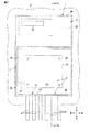
第1の実施形態の通信機能付メータ1について、図1から図3を参照して説明する。図1の通信機能付メータ1は、電力メータ2と通信装置3とを搭載しており、建屋の外壁や玄関先等の予め用意された設置部Eに取り付けられる。この通信機能付メータ1は、電力メータ2で使用電力量を計測及び表示するとともに、通信装置3でネットワークに無線接続して管轄の電力会社に計測データを送信する。図1に示す通信機能付メータ1の外観において、電力メータ2の表示部21は上側に配置されており、電力ケーブルAは下端から延びている。本明細書では説明の便宜上、通信機能付メータ1は設置部Eに固定された状態で、重力の作用する方向を基準に「上」、「下」をそれぞれ定義し、表示部21を見る観測者から見て右手側を「右」、左手側を「左」、観測者に近い側を「手前(前側)」、設置部Eに近い側を「奥(背側)」とそれぞれ言うことがある。
The communication function equipped
図1に示す通信機能付メータ1は、端子台11と、複数の基板22と、アンテナ31と、を備える。端子台11は、電力メータ2及び通信装置3のハウジング4(フロントカバー44)と連結されており、通信機能付きメータ1が設置部Eに取り付けられることによって、設置部Eに対して所定の位置に配置される。また、端子台11には、フロントカバー44を通して電力ケーブルAが下方から接続されている。電力ケーブルAは、電力会社から送電される電力の他に、太陽光発電などによってユーザ側で発電された電力がある場合はその電力ケーブルAも接続される。本実施形態において、複数の基板22は、電源基板、制御基板、及び通信基板の3枚を含む。これらの基板22は、設置部Eから離れる方向へ間隔を空けて端子台11に重ねて配置される。図2は、基板22が重なる方向に通信機能付メータ1を見た正面図であって、基板22の下側の一部が端子台11の下端111よりも下方へ張り出た状態である。基板22は、端子台11に組み付けられたケース41に収められている。
The meter with
図1から図3に示すように、ケース41は、端子台11に固定される底部42と、端子台11から離れる方向へ底部の外周から立ち上がる外周部43とを有し、非導電性部材の合成樹脂で、かつ、例えば温度変化など気候変化に対する耐久性に優れた材料で造られている。基板22は、図3に示すようにスタッド24で互いに間隔を空けて保持されている。電力メータ2は、消費電力量及び発電電力量をそれぞれ計測可能な計測部25と、この計測部25で計測された電力量を表示する表示部21とを備える。また、通信機能付メータ1は、表示部21を覗かせたフロントカバー44で全体が覆われている。ケース41とフロントカバー44は、ハウジング4に含まれる。
As shown in FIGS. 1 to 3, the
通信装置3は、基板22の1つとして組み込まれる通信基板と、この通信基板に同軸ケーブルで接続されたアンテナ31を含む。アンテナ31は、平坦なプレート基材310に形成されている。プレート基材310は、図2及び図3に示すように、基板22と交差する向きに配置されている。アンテナ31は、設置部Eから離れる方向へ端子台11に重ならない範囲、本実施形態では、基板22の下縁221よりもさらに下方に位置している。具体的には、ケース41の外周部43の内面に蟻溝状に形成された凹部45に、内面に沿う方向に差し込まれて保持されている。また、アンテナ31は、少なくとも2つの基板22の外周を板厚方向に横切って配置される。本実施形態の場合、図3に示すように、ケース41の底部42までアンテナ31のプレート基材310が差し込まれており、3枚の基板22をその板厚方向へ横切って配置されている。アンテナ31は、凹部45に差し込まれる代わりに、ケース41の内面に接着されていてもよい。
The
以上のように構成された通信機能付メータ1は、基板22が保持されている向きすなわち回路が形成されている面に対して、アンテナ31が保持されている向きすなわちアンテナ31が形成されている面が交差する配置である。本実施形態では、図2及び図3に示されるように、基板22が配置されている面に対して、垂直にアンテナ31のプレート基材310を配置している。このような配置にすることによって、基板22から発生する高周波ノイズの影響を受けにくく、アンテナ性能が低下することを抑えることができる。
In the communication function-equipped
また、端子台11は、金属製部品を含んでいることが多いため、設置部Eから離れる方向に端子台11に重ならない位置にアンテナ31が配置されている。つまり、アンテナ31が形成されたプレート基材310の面の延長上に金属製部品が配置されないので、アンテナ性能が低下することを抑制できる。
Moreover, since the
第2の実施形態の通信機能付メータ1について、図4から図6を参照して説明する。なお、第1の実施形態の通信機能付メータ1の構成と同じ機能を有する構成は、第2の実施形態の説明及び図において同じ符号を付して説明し、その詳細は第1の実施形態の対応する記載を参酌することとする。
A
第2の実施形態の通信機能付メータ1は、アンテナ31の形状及び配置の点が第1の実施形態の通信機能付メータ1と異なる。第2の実施形態の通信機能付メータ1は、アンテナ31として、マルチバンドアンテナ31Mとシングルバンドアンテナ31Sとを含んでいる。マルチバンドアンテナ31Mはいわゆる3G/LTEの通信周波数帯域に対応したアンテナであり、シングルバンドアンテナ31Sはマルチバンドアンテナ31Mの通信周波数帯域とは異なる通信周波数帯域で使用されるアンテナであって、例えばサブGHz帯域である920MHz帯の通信に使用される。
The communication function equipped
基板22は、設置部Eから離れる方向へ端子台11に重ならない少なくとも2つの角部、本実施形態では下方へ張り出した下縁221の2つの角部である第1の角部C1と第2の角部C2を有している。マルチバンドアンテナ31Mは、図4及び図5に示すように、この第1の角部C1と第2の角部C2の外側を囲う一対に設けられている。具体的には、マルチバンドアンテナ31Mは、四角形の箱型のケース41の下側の2つの角の内側に沿ってL字形にそれぞれ配置された一対に設けられる。
The
それぞれのマルチバンドアンテナ31Mは、第1のリジッド部311と第2のリジッド部312とフレキシブル部313とを含む。第1のリジッド部311は、基板22の外周を板厚方向に横切って配置される。本実施形態の場合、第1のリジッド部311は、図5に示すように、基板22の下縁221に沿う方向に基板22の下方に配置されている。第2のリジッド部312は、基板22の外周を板厚方向に横切りかつ第1のリジッド部311に交差する方向に配置される。本実施形態の場合、第2のリジッド部312は、図5に示すように、第1の角部C1及び第2の角部C2を第1のリジッド部311とともに挟むように基板22の左外側または右外側にそれぞれ配置される。フレキシブル部313は、第1のリジッド部311と第2のリジッド部312とを接続するように、第1のリジッド部311から第2のリジッド部312まで一続きに形成されている。
Each
また、シングルバンドアンテナ31Sは、マルチバンドアンテナ31Mが配置された第1の角部C1及び第2の角部C2とは反対側の基板22の第3の角部C3の外側を囲って配置される。本実施形態の場合、第3の角部C3は、図5に示すように通信機能付メータ1を正面から見て基板22の右上部分である。シングルバンドアンテナ31Sは、マルチバンドアンテナ31Mと同様に、第1のリジッド部311、第2のリジッド部312及びフレキシブル部313を含むL字形に形成されている。シングルバンドアンテナ31Sは、アンテナ31として一対に設けられたマルチバンドアンテナ31Mに加えて通信装置3のアンテナ31として設けられる第3のアンテナである。図5に示すようにシングルバンドアンテナ31Sの第1のリジッド部311は、基板22とその上方に配置された電力メータ2の計測部25との間に配置され、第2のリジッド部312は、基板22の右外側に配置されている。さらにシングルバンドアンテナ31Sの第2のリジッド部312は、設置部Eから離れる方向へ端子台11に重ならない位置に配置されている。
In addition, the
ケース41は、基板22の角部C1,C2,C3のそれぞれに対応する範囲の外周部43の内面に凹部45を有している。この凹部45は、それぞれのマルチバンドアンテナ31M及びシングルバンドアンテナ31Sを基板22の板厚方向に沿って手前側から差し込め、かつ、基板22側に脱落させない蟻溝状に形成されている。マルチバンドアンテナ31M及びシングルバンドアンテナ31Sは、図6に示すように、凹部45に差し込まれ、複数の基板22のうちの少なくとも2つの基板22の外周を板厚方向に横切って配置されている。
The
以上のように構成された第2の実施形態の通信機能付メータ1は、第1の実施形態の通信機能付メータ1と同様に、基板22が保持されている向きすなわち回路が形成されている面に対して、アンテナ31が保持されている向きすなわちマルチバンドアンテナ31M及びシングルバンドアンテナ31Sが形成されている面が交差する配置である。そして、第2の実施形態では、マルチバンドアンテナ31Mは一対に設けられ、それぞれの第1のリジッド部311に対して第2のリジッド部312が直交するように配置されている。したがって、それぞれのアンテナ31は、基板22から発生する高周波ノイズの影響を受けにくく、また、金属製部品を含む端子台11から離れているので、アンテナ性能を低下させることを抑えることができる。
The meter with
また、マルチバンドアンテナ31Mの通信周波数帯域と異なる通信周波数帯域で使用されるシングルバンドアンテナ31Sは、設置部Eに沿う方向に基板22を隔ててマルチバンドアンテナ31Mと反対側に配置されている。本実施形態では、マルチバンドアンテナ31Mを基板22の下縁221よりも下方となる位置に配置し、シングルバンドアンテナ31Sをその一部が基板22と計測部25との間に入る位置に配置しているので、マルチバンドアンテナ31Mとシングルバンドアンテナ31Sが互いに干渉することを軽減でき、それぞれのアンテナ性能を発揮させやすい。
The
なお、第2の実施形態において、アンテナ31としてのマルチバンドアンテナ31Mは、基板22の下縁221の角部(第1の角部C1及び第2の角部C2)の外側をそれぞれ囲うように一対に配置されているが、アンテナ31は、どちらか一方の角部の外側を囲うように配置してもよい。
In the second embodiment, the
第3の実施形態の通信機能付メータ1について、図7及び図8を参照して説明する。なお、第1の実施形態の通信機能付メータ1の構成と同じ機能を有する構成は、第3の実施形態の説明及び図において同じ符号を付して説明し、その詳細は第1の実施形態の対応する記載を参酌することとする。
A
第3の実施形態の通信機能付メータ1は、アンテナ31としてマルチバンドアンテナ31Mを備えている。本実施形態のマルチバンドアンテナ31Mの配置は、第2の実施形態における通信機能付メータ1を正面から見た図5のマルチバンドアンテナ31Mの配置と同じであり、側方から見たときの配置が第2の実施形態のマルチバンドアンテナ31Mの配置と異なっている。
The meter with
マルチバンドアンテナ31Mは、基板22の下縁221の2つの角部である第1の角部C1と第2の角部C2のそれぞれ外側を囲う一対に設けられている。通信機能付メータ1の電力メータ2の表示部(電力量表示部)21は、設置部Eに沿う方向へ基板22を隔ててこのマルチバンドアンテナ31Mと反対側に配置されている。マルチバンドアンテナ31Mは、第1のリジッド部311及び第2のリジッド部312を互いに連結するフレキシブル部313にアンテナ31のグランド部314とパターン部315とを備える。
The
グランド部314は、設置部Eから離れる方向へ端子台11に重ならない範囲で少なくとも2つの基板22の外周を板厚方向に横切って配置される。本実施形態では、図8に示すように、マルチバンドアンテナ31Mのプレート基材を構成する第1のリジッド部311、第2のリジッド部312及びフレキシブル部313が、ケース41の外周部43の内面に形成された凹部45に沿って奥まで、設置部Eに向かって、差し込まれており、3枚の基板22の外周を板厚方向に横切っている。
The
そして、本実施形態のマルチバンドアンテナ31Mは、図8に示すように、凹部45の奥まで差し込まれた状態でパターン部315の少なくとも一部が設置部Eから離れる方向へ表示部21よりも突出している。ケース41は、図7及び図8に示すように、アンテナ31であるマルチバンドアンテナ31Mが配置される位置に対応する範囲に外周部43を有しており、設置部Eから離れる方向へマルチバンドアンテナ31Mよりも小さい。つまり、通信機能付メータ1を正面から見て手前側にケース41の凹部45からマルチバンドアンテナ31Mが露出している。フロントカバー44は、突出したマルチバンドアンテナ31Mを保護するように手前側へ膨出している。
Then, as shown in FIG. 8, in the
なお、ケース41は、設置部Eから離れる方向にマルチバンドアンテナ31Mを越える位置まで形成されていてもよい。また、マルチバンドアンテナ31M(アンテナ31)のパターン部315は、設置部Eから離れる方向に重ねて配置された複数の基板22の内の最も手前側に配置された基板22よりもさらに手前側に突出していれば、表示部21よりも設置部E側に引っ込んでいてもよい。また、通信機能付メータ1は、第2の実施形態のようにシングルバンドアンテナ31Sを備えていてもよいし、第1の実施形態のように基板22の下縁221に沿う平坦なプレート形状であってもよい。
The
以上のように構成された第3の実施形態の通信機能付メータ1は、基板22が保持されている向きすなわち回路が形成されている面に対して、アンテナ31が保持されている向きすなわちマルチバンドアンテナ31Mが形成されている面が交差する配置であり、第3の実施形態では、第1及び第2の実施形態と同様に互いに直交する配置である。さらに、一対に設けられたマルチバンドアンテナ31Mのそれぞれは、第1のリジッド部311に対して第2のリジッド部312が直交するように配置されている。したがって、それぞれのアンテナ31は、基板22から発生する高周波ノイズの影響を受けにくく、また、端子台からも離れていることによって、アンテナ性能を低下させることを抑えることができる。
In the meter with
さらにアンテナ31のパターン部315の少なくとも一部が設置部Eから離れる方向へ表示部21よりも突出している、すなわち、この通信機能付メータ1が取り付けられた設置部Eに対してこの通信機能付メータ1の中で最もアンテナ31が突出しているので、アンテナ性能を発揮しやすくなる。また、アンテナ31のパターン部315は、プレート基材310の面内においてどの向きに形成されるかは、通信周波数帯域やその特性に応じて変更され得る。つまり、アンテナ31は、グランド部314及びパターン部315がある境界で明確に分けられるものに限定されない。したがって、アンテナ31の少なくとも一部が、設置部Eから離れる方向へ、表示部21よりも突出していることや最も手前側に位置する基板22よりも手前に突出していることも本実施形態の一部に含まれる。
Furthermore, at least a part of the
第1から第3の実施形態における通信機能付メータ1において、アンテナ(マルチバンドアンテナ31M及びシングルバンドアンテナ31S)31は、基板22を収納するケース41の外周部43の内面に保持されるように組み込まれる。したがって、組立やメンテナンスの際にフロントカバー44を取り外す場合でもアンテナ31の機能及び性能を維持できる。
In the communication function-equipped
本発明のいくつかの実施形態を説明した。これらの実施形態は、例として提示したものであり、発明の範囲を限定することを意図していない。これら新規な実施形態は、その他の様々な形態で実施されることが可能であり、発明の要旨を逸脱しない範囲で、種々の省略、置き換え、変更を行うことができる。これらの実施形態やその変形例は、発明の範囲や要旨に含まれるとともに、特許請求の範囲に記載された発明とその均等の範囲に含まれる。 Several embodiments of the present invention have been described. These embodiments are presented as examples and are not intended to limit the scope of the invention. These novel embodiments can be implemented in various other forms, and various omissions, substitutions, and modifications can be made without departing from the scope of the invention. These embodiments and modifications thereof are included in the scope and the gist of the invention, and are included in the invention described in the claims and the equivalent scope thereof.
1…通信機能付メータ、2…電力メータ、3…通信装置、11…端子台、21…表示部、22…基板、31…アンテナ、31M…マルチバンドアンテナ(アンテナ)、31S…シングルバンドアンテナ(第3のアンテナ)、310…プレート基材、311…第1のリジッド部(リジッド部)、312…第2のリジッド部(リジッド部)、313…フレキシブル部、314…グランド部、315…パターン部、E…設置部、C1…(第1の)角部、C2…(第2の)角部、C3…第3の角部。
DESCRIPTION OF
Claims (6)
前記電力メータで計測された使用電力量のデータを外部に送信する通信装置と、
前記電力メータおよび前記通信装置のハウジングと連結し、その設置部に対して所定の位置に配置されて電力線が接続される端子台と、
前記設置部から離れる方向へ間隔を空け前記端子台に重ねて配置された複数の基板と、を具備し、
前記通信装置は、その全体が前記ハウジングで覆われ、前記複数の基板の1つとして組み込まれる通信基板と、前記通信基板に接続され、前記複数の基板と交差する向きに配置されたプレート基材に形成されたアンテナとを含み、
前記アンテナは、前記設置部から離れる方向へ前記端子台に重ならない範囲に配置されることを特徴とする通信機能付メータ。 Power meter,
A communication device for transmitting data of the amount of used power measured by the power meter to the outside;
A terminal block connected to the power meter and the housing of the communication device and disposed at a predetermined position with respect to the installation portion to which a power line is connected;
A plurality of substrates spaced apart from each other in the direction away from the installation portion and disposed on the terminal block;
The communication device is entirely covered with the housing, and a communication substrate incorporated as one of the plurality of substrates, and a plate substrate connected to the communication substrate and disposed in a direction crossing the plurality of substrates and an antenna that is formed on only including,
The communication function meter , wherein the antenna is disposed in a range not overlapping the terminal block in a direction away from the installation portion .
前記複数の基板の外側を板厚方向に横切って配置される第1のリジッド部と、
前記複数の基板の外側を板厚方向に横切り、かつ前記第1のリジッド部に交差する方向に配置される第2のリジッド部と、
前記第1のリジッド部及び前記第2のリジッド部を接続するフレキシブル部と、
を含むことを特徴とする請求項1に記載された通信機能付メータ。 The antenna is
A first rigid portion disposed across the outside of the plurality of substrates in the thickness direction;
A second rigid portion disposed transversely to the outside of the plurality of substrates in the thickness direction and disposed in a direction intersecting the first rigid portion;
A flexible portion connecting the first rigid portion and the second rigid portion;
The communication function meter according to claim 1, further comprising:
前記アンテナは、2つの前記角部の外側をそれぞれ囲う第1のアンテナおよび第2のアンテナが一対設けられることを特徴とする請求項3に記載された通信機能付メータ。 The plurality of substrates have at least two corner portions that do not overlap the terminal block in a direction away from the installation portion,
The communication function meter according to claim 3 , wherein the antenna is provided with a pair of a first antenna and a second antenna respectively surrounding the outside of the two corner portions.
前記アンテナは、前記設置部から離れる方向へ前記端子台に重ならない範囲で少なくとも2つの前記基板の外側を板厚方向に横切って配置されるグランド部と、少なくとも一部が前記設置部から離れる方向へ前記電力量表示部よりも突出したパターン部と、を備える
ことを特徴とする請求項1に記載された通信機能付メータ。
The power amount display unit further includes a power amount display unit disposed on the opposite side of the antenna with the plurality of substrates separated in the direction along the installation unit.
The antenna is a ground part disposed across the outside of at least two of the substrates in a thickness direction in a range not overlapping the terminal block in a direction away from the installation part, and a direction in which at least a part is separated from the installation part The communication function meter according to claim 1, further comprising: a pattern portion protruding from the power amount display unit.
Priority Applications (2)
| Application Number | Priority Date | Filing Date | Title |
|---|---|---|---|
| JP2015131467A JP6538453B2 (en) | 2015-06-30 | 2015-06-30 | Communication meter |
| US15/057,527 US9939474B2 (en) | 2015-06-30 | 2016-03-01 | Meter with communication function |
Applications Claiming Priority (1)
| Application Number | Priority Date | Filing Date | Title |
|---|---|---|---|
| JP2015131467A JP6538453B2 (en) | 2015-06-30 | 2015-06-30 | Communication meter |
Publications (3)
| Publication Number | Publication Date |
|---|---|
| JP2017015517A JP2017015517A (en) | 2017-01-19 |
| JP2017015517A5 JP2017015517A5 (en) | 2018-04-19 |
| JP6538453B2 true JP6538453B2 (en) | 2019-07-03 |
Family
ID=57683552
Family Applications (1)
| Application Number | Title | Priority Date | Filing Date |
|---|---|---|---|
| JP2015131467A Active JP6538453B2 (en) | 2015-06-30 | 2015-06-30 | Communication meter |
Country Status (2)
| Country | Link |
|---|---|
| US (1) | US9939474B2 (en) |
| JP (1) | JP6538453B2 (en) |
Families Citing this family (8)
| Publication number | Priority date | Publication date | Assignee | Title |
|---|---|---|---|---|
| JP2017509245A (en) * | 2014-03-07 | 2017-03-30 | ゼネラル・エレクトリック・カンパニイ | Utility meter with insulated external antenna |
| CN106710192A (en) * | 2017-01-13 | 2017-05-24 | 成都中科慧源科技有限公司 | Internet-of-things meter based on 4G communication |
| US10950931B2 (en) | 2017-01-31 | 2021-03-16 | Panasonic Intellectual Property Management Co., Ltd. | Wireless communication device |
| JP6953174B2 (en) * | 2017-05-15 | 2021-10-27 | 河村電器産業株式会社 | cabinet |
| JP7334980B2 (en) * | 2018-04-25 | 2023-08-29 | 株式会社リンクジャパン | Imaging device and system |
| US11119133B2 (en) | 2019-02-20 | 2021-09-14 | Landis+Gyr Innovations, Inc. | Multiple antennas on meter enclosure |
| CN110568236B (en) * | 2019-07-24 | 2022-04-15 | 浙江华云信息科技有限公司 | Low-power-consumption intelligent electric energy meter communication bin |
| CN112162130B (en) * | 2020-09-25 | 2021-07-06 | 光亮电气有限公司 | Electrified meter-changing mechanism |
Family Cites Families (7)
| Publication number | Priority date | Publication date | Assignee | Title |
|---|---|---|---|---|
| WO1998010394A1 (en) * | 1996-09-06 | 1998-03-12 | Innovatec Corporation | Automatic meter reading data communication system |
| JP4070689B2 (en) | 2003-08-20 | 2008-04-02 | シャープ株式会社 | Wireless communication unit |
| WO2011032153A2 (en) * | 2009-09-14 | 2011-03-17 | World Products Llc | Optimized conformal-to-meter antennas |
| JP2011081518A (en) * | 2009-10-05 | 2011-04-21 | Panasonic Electric Works Co Ltd | Remote meter reading device |
| JP2012156657A (en) | 2011-01-24 | 2012-08-16 | Furukawa Electric Co Ltd:The | Radio communication device |
| WO2011152538A1 (en) | 2010-06-04 | 2011-12-08 | 古河電気工業株式会社 | Printed circuit board, antenna, wireless communication device and manufacturing methods thereof |
| KR101305518B1 (en) * | 2013-02-13 | 2013-09-06 | 주식회사 기가레인 | Terminal having high frequency transmission line using printed circuit board |
-
2015
- 2015-06-30 JP JP2015131467A patent/JP6538453B2/en active Active
-
2016
- 2016-03-01 US US15/057,527 patent/US9939474B2/en active Active
Also Published As
| Publication number | Publication date |
|---|---|
| US9939474B2 (en) | 2018-04-10 |
| JP2017015517A (en) | 2017-01-19 |
| US20170003331A1 (en) | 2017-01-05 |
Similar Documents
| Publication | Publication Date | Title |
|---|---|---|
| JP6538453B2 (en) | Communication meter | |
| CN109728437B (en) | Antenna structure and wireless communication device with same | |
| JP6524985B2 (en) | Antenna module | |
| US9203456B2 (en) | Mobile device | |
| TWI597892B (en) | Wireless communication device | |
| EP3149804B1 (en) | Electronic device and antenna of the same | |
| US20180083342A1 (en) | Wireless communication device having a slot antenna | |
| TWI581498B (en) | Antenna and wireless communication device using the same | |
| JP2017015517A5 (en) | ||
| JP6271480B2 (en) | Communication device, smart meter | |
| US20150192625A1 (en) | Remote meter reader | |
| JP2017034649A (en) | Mobile terminal device | |
| JP6703910B2 (en) | Information communication device | |
| US10411355B2 (en) | Antenna device | |
| JP6872684B2 (en) | Plate-shaped antenna and radio using it | |
| JP6806630B2 (en) | Electronics | |
| JP6340688B2 (en) | Antenna device | |
| TW201342709A (en) | Communication device | |
| US20180115052A1 (en) | Antenna Device and Mobile Terminal | |
| JP2014204442A (en) | Radio communication device | |
| CN110767980B (en) | Antenna structure and wireless communication device with same | |
| TWI573319B (en) | Wireless communication device | |
| JP5980571B2 (en) | Cubicle with wireless communication antenna | |
| US9642267B2 (en) | Portable wireless device | |
| JP7124097B2 (en) | Antenna extender and electronic device with antenna extender |
Legal Events
| Date | Code | Title | Description |
|---|---|---|---|
| A521 | Written amendment |
Free format text: JAPANESE INTERMEDIATE CODE: A523 Effective date: 20180309 |
|
| A621 | Written request for application examination |
Free format text: JAPANESE INTERMEDIATE CODE: A621 Effective date: 20180309 |
|
| A131 | Notification of reasons for refusal |
Free format text: JAPANESE INTERMEDIATE CODE: A131 Effective date: 20181218 |
|
| A977 | Report on retrieval |
Free format text: JAPANESE INTERMEDIATE CODE: A971007 Effective date: 20181219 |
|
| A521 | Written amendment |
Free format text: JAPANESE INTERMEDIATE CODE: A523 Effective date: 20190130 |
|
| TRDD | Decision of grant or rejection written | ||
| A01 | Written decision to grant a patent or to grant a registration (utility model) |
Free format text: JAPANESE INTERMEDIATE CODE: A01 Effective date: 20190507 |
|
| A61 | First payment of annual fees (during grant procedure) |
Free format text: JAPANESE INTERMEDIATE CODE: A61 Effective date: 20190606 |
|
| R151 | Written notification of patent or utility model registration |
Ref document number: 6538453 Country of ref document: JP Free format text: JAPANESE INTERMEDIATE CODE: R151 |