JP6537531B2 - Body fluid extraction device, applicator device and related method - Google Patents
Body fluid extraction device, applicator device and related method Download PDFInfo
- Publication number
- JP6537531B2 JP6537531B2 JP2016565577A JP2016565577A JP6537531B2 JP 6537531 B2 JP6537531 B2 JP 6537531B2 JP 2016565577 A JP2016565577 A JP 2016565577A JP 2016565577 A JP2016565577 A JP 2016565577A JP 6537531 B2 JP6537531 B2 JP 6537531B2
- Authority
- JP
- Japan
- Prior art keywords
- microneedle array
- microneedles
- hammer
- microneedle
- array
- Prior art date
- Legal status (The legal status is an assumption and is not a legal conclusion. Google has not performed a legal analysis and makes no representation as to the accuracy of the status listed.)
- Expired - Fee Related
Links
Images


Classifications
-
- A—HUMAN NECESSITIES
- A61—MEDICAL OR VETERINARY SCIENCE; HYGIENE
- A61B—DIAGNOSIS; SURGERY; IDENTIFICATION
- A61B5/00—Measuring for diagnostic purposes; Identification of persons
- A61B5/15—Devices for taking samples of blood
- A61B5/150977—Arrays of piercing elements for simultaneous piercing
- A61B5/150984—Microneedles or microblades
-
- A—HUMAN NECESSITIES
- A61—MEDICAL OR VETERINARY SCIENCE; HYGIENE
- A61B—DIAGNOSIS; SURGERY; IDENTIFICATION
- A61B5/00—Measuring for diagnostic purposes; Identification of persons
- A61B5/15—Devices for taking samples of blood
- A61B5/150007—Details
- A61B5/150015—Source of blood
- A61B5/150022—Source of blood for capillary blood or interstitial fluid
-
- A—HUMAN NECESSITIES
- A61—MEDICAL OR VETERINARY SCIENCE; HYGIENE
- A61B—DIAGNOSIS; SURGERY; IDENTIFICATION
- A61B5/00—Measuring for diagnostic purposes; Identification of persons
- A61B5/15—Devices for taking samples of blood
- A61B5/150007—Details
- A61B5/150053—Details for enhanced collection of blood or interstitial fluid at the sample site, e.g. by applying compression, heat, vibration, ultrasound, suction or vacuum to tissue; for reduction of pain or discomfort; Skin piercing elements, e.g. blades, needles, lancets or canulas, with adjustable piercing speed
- A61B5/150061—Means for enhancing collection
- A61B5/150099—Means for enhancing collection by negative pressure, other than vacuum extraction into a syringe by pulling on the piston rod or into pre-evacuated tubes
-
- A—HUMAN NECESSITIES
- A61—MEDICAL OR VETERINARY SCIENCE; HYGIENE
- A61B—DIAGNOSIS; SURGERY; IDENTIFICATION
- A61B5/00—Measuring for diagnostic purposes; Identification of persons
- A61B5/15—Devices for taking samples of blood
- A61B5/151—Devices specially adapted for taking samples of capillary blood, e.g. by lancets, needles or blades
- A61B5/15101—Details
- A61B5/15103—Piercing procedure
- A61B5/15107—Piercing being assisted by a triggering mechanism
- A61B5/15113—Manually triggered, i.e. the triggering requires a deliberate action by the user such as pressing a drive button
-
- A—HUMAN NECESSITIES
- A61—MEDICAL OR VETERINARY SCIENCE; HYGIENE
- A61B—DIAGNOSIS; SURGERY; IDENTIFICATION
- A61B5/00—Measuring for diagnostic purposes; Identification of persons
- A61B5/15—Devices for taking samples of blood
- A61B5/151—Devices specially adapted for taking samples of capillary blood, e.g. by lancets, needles or blades
- A61B5/15101—Details
- A61B5/15115—Driving means for propelling the piercing element to pierce the skin, e.g. comprising mechanisms based on shape memory alloys, magnetism, solenoids, piezoelectric effect, biased elements, resilient elements, vacuum or compressed fluids
- A61B5/15117—Driving means for propelling the piercing element to pierce the skin, e.g. comprising mechanisms based on shape memory alloys, magnetism, solenoids, piezoelectric effect, biased elements, resilient elements, vacuum or compressed fluids comprising biased elements, resilient elements or a spring, e.g. a helical spring, leaf spring, or elastic strap
-
- A—HUMAN NECESSITIES
- A61—MEDICAL OR VETERINARY SCIENCE; HYGIENE
- A61M—DEVICES FOR INTRODUCING MEDIA INTO, OR ONTO, THE BODY; DEVICES FOR TRANSDUCING BODY MEDIA OR FOR TAKING MEDIA FROM THE BODY; DEVICES FOR PRODUCING OR ENDING SLEEP OR STUPOR
- A61M1/00—Suction or pumping devices for medical purposes; Devices for carrying-off, for treatment of, or for carrying-over, body-liquids; Drainage systems
- A61M1/71—Suction drainage systems
- A61M1/76—Handpieces
-
- A—HUMAN NECESSITIES
- A61—MEDICAL OR VETERINARY SCIENCE; HYGIENE
- A61M—DEVICES FOR INTRODUCING MEDIA INTO, OR ONTO, THE BODY; DEVICES FOR TRANSDUCING BODY MEDIA OR FOR TAKING MEDIA FROM THE BODY; DEVICES FOR PRODUCING OR ENDING SLEEP OR STUPOR
- A61M1/00—Suction or pumping devices for medical purposes; Devices for carrying-off, for treatment of, or for carrying-over, body-liquids; Drainage systems
- A61M1/84—Drainage tubes; Aspiration tips
-
- A—HUMAN NECESSITIES
- A61—MEDICAL OR VETERINARY SCIENCE; HYGIENE
- A61B—DIAGNOSIS; SURGERY; IDENTIFICATION
- A61B10/00—Other methods or instruments for diagnosis, e.g. instruments for taking a cell sample, for biopsy, for vaccination diagnosis; Sex determination; Ovulation-period determination; Throat striking implements
- A61B10/0045—Devices for taking samples of body liquids
- A61B2010/008—Interstitial fluid
-
- A—HUMAN NECESSITIES
- A61—MEDICAL OR VETERINARY SCIENCE; HYGIENE
- A61B—DIAGNOSIS; SURGERY; IDENTIFICATION
- A61B5/00—Measuring for diagnostic purposes; Identification of persons
- A61B5/145—Measuring characteristics of blood in vivo, e.g. gas concentration, pH value; Measuring characteristics of body fluids or tissues, e.g. interstitial fluid, cerebral tissue
- A61B5/14507—Measuring characteristics of blood in vivo, e.g. gas concentration, pH value; Measuring characteristics of body fluids or tissues, e.g. interstitial fluid, cerebral tissue specially adapted for measuring characteristics of body fluids other than blood
- A61B5/1451—Measuring characteristics of blood in vivo, e.g. gas concentration, pH value; Measuring characteristics of body fluids or tissues, e.g. interstitial fluid, cerebral tissue specially adapted for measuring characteristics of body fluids other than blood for interstitial fluid
- A61B5/14514—Measuring characteristics of blood in vivo, e.g. gas concentration, pH value; Measuring characteristics of body fluids or tissues, e.g. interstitial fluid, cerebral tissue specially adapted for measuring characteristics of body fluids other than blood for interstitial fluid using means for aiding extraction of interstitial fluid, e.g. microneedles or suction
-
- A—HUMAN NECESSITIES
- A61—MEDICAL OR VETERINARY SCIENCE; HYGIENE
- A61B—DIAGNOSIS; SURGERY; IDENTIFICATION
- A61B5/00—Measuring for diagnostic purposes; Identification of persons
- A61B5/15—Devices for taking samples of blood
- A61B5/150007—Details
- A61B5/150374—Details of piercing elements or protective means for preventing accidental injuries by such piercing elements
- A61B5/150381—Design of piercing elements
- A61B5/150412—Pointed piercing elements, e.g. needles, lancets for piercing the skin
-
- A—HUMAN NECESSITIES
- A61—MEDICAL OR VETERINARY SCIENCE; HYGIENE
- A61M—DEVICES FOR INTRODUCING MEDIA INTO, OR ONTO, THE BODY; DEVICES FOR TRANSDUCING BODY MEDIA OR FOR TAKING MEDIA FROM THE BODY; DEVICES FOR PRODUCING OR ENDING SLEEP OR STUPOR
- A61M37/00—Other apparatus for introducing media into the body; Percutany, i.e. introducing medicines into the body by diffusion through the skin
- A61M37/0015—Other apparatus for introducing media into the body; Percutany, i.e. introducing medicines into the body by diffusion through the skin by using microneedles
Description
本発明は、身体から体液を取り出すための装置と、必要に応じて前記装置を使用して、身体から体液を取り出す方法とに関する。本発明は更に、マイクロニードルアレイを表面に適用するためのアプリケータに関する。装置と、関連する材料及び方法とは、医療分野において、特に、腎不全、心不全、深部静脈血栓症、及び癌などの状態に起因する体液過剰及び浮腫の治療に適用されてよいが、これらに限定されない。 The present invention relates to a device for removing body fluid from the body and, if necessary, to a method for removing body fluid from the body. The invention further relates to an applicator for applying a microneedle array to a surface. The device and related materials and methods may be applied in the medical field, in particular for the treatment of fluid overload and edema resulting from conditions such as renal failure, heart failure, deep vein thrombosis and cancer. It is not limited.
体内の腎臓は、膀胱で終端する、全身血管系から泌尿器系への体液の流れを排尿前に発生させる。この体液損失機能について広く知られており、非常に一般化された概観は、身体の有毒代謝廃棄物を取り除くことである。何故ならば、何らかの腎機能の欠如下では、体液過剰又は尿毒症による死が数日以内に結果として起こるからである。尿毒症は、腎機能が退化しており、さもなければ正常に除去していたであろう体液を含む物質を尿液に排出することに腎臓が失敗する医学的状態として定義される。この腎機能の喪失を患うことの結果として、過剰な体液及び尿毒性の滞留物、即ち、悪化した腎臓で十分に除去されなかった物質が蓄積する。 The kidneys of the body terminate in the bladder and generate fluid flow from the systemic vasculature to the urinary system prior to urination. A widely known and highly generalized view of this fluid loss function is to remove the body's toxic metabolic waste. Because, in the absence of any kidney function, death from fluid overload or uremia will result within a few days. Uremia is defined as a medical condition in which the kidneys fail to excrete substances, including fluid that would otherwise have normally been removed, into urinary fluid. As a result of suffering from this loss of renal function, excess fluid and urinary toxic remnants accumulate, i.e. substances that have not been sufficiently removed by the deteriorated kidney.
末期腎不全をもたらす腎機能の喪失は、主要な医学的問題であり、多種態様な原因による。英国では、37,000人を超える人々が、年間あたり15億ポンド(総NHS予算の2%)の費用で腎代替療法(RRT)を受けている。英国腎レジストリは、新たな追加が毎年5000人を超えることで、2020年までに患者数が60,000に上昇すると予想している。付随する(incident)患者の同様な増加は、米国及び欧州における発達した医療制度においても予期されている。発展途上国では、費用と訓練を受けた医療従事者の不足により、RTTは非常に制限されているか、行われていないので、腎不全は事実上、ほぼ死刑宣告となる。中国やインドの経済の発展により、それらの住民のために改善された健康管理をサポートすることを可能としており、現在利用できるものよりも低い技術的環境と安いコストで治療を提供できるならば更に2から3億人の人口の腎不全を治療する可能性がある。 Loss of renal function leading to end-stage renal failure is a major medical problem and is due to a variety of causes. In the United Kingdom, more than 37,000 people receive Renal Replacement Therapy (RRT) at a cost of £ 1.5 billion per year (2% of the total NHS budget). The UK Renal Registry expects the number of patients to rise to 60,000 by 2020, with more than 5,000 new additions each year. A similar increase in incident patients is also expected in the developed healthcare system in the United States and Europe. In developing countries, the cost and the lack of trained health workers make RTT virtually fatal or nearly sentenced to death, as RTT is either very limited or absent. The development of China and India's economy makes it possible to support improved health care for their residents, and if the treatment can be provided with a lower technical environment and lower costs than what is currently available. It may treat kidney failure in a population of 2-3 million people.
腎代替療法(RRT)のための現在の選択肢は、主に先進国の医療制度でのみ利用可能である。 Current options for renal replacement therapy (RRT) are mainly available only in the developed country's healthcare system.
第1の選択肢は腎臓移植である。移植は、より良い治療と生活の質を提供し、一年生存率は、透析の84%に比べて97%であるが、英国では、年あたり約1500の腎臓のみが利用可能であって、移植待ちリストは、5000を超えており、増加し続けている。移植を受けられる可能性がある者は、透析を受けている者(腹膜(透析)58歳、血液透析64歳)よりも若いことから(年齢の中央値は49歳であり、心血管及び他の既存疾患がほとんどない)、移植が現実的な選択肢ではない高齢者患者の人数は増大し続けている。 The first option is kidney transplantation. Transplantation provides better treatment and quality of life, with a one-year survival rate of 97% compared to 84% of dialysis, but in the UK only about 1500 kidneys per year are available, The porting list is over 5000 and continues to increase. Those who may receive transplants are younger (median age 49 years) than those who are undergoing dialysis (peritoneal (dialysis) 58 years, hemodialysis 64 years), and cardiovascular and other The number of elderly patients for whom transplantation is not a viable option continues to grow.
現在の透析設備は、血液透析又は腹膜透析の何れかである。血液透析は、外科的に構成された動静脈フィステル又はグラフトを介して、患者の血液循環を外部機械に接続すること含む。外部機械は、半透過性膜を横切る低分子代謝物及び水を除去して、「浄化された」血を患者に戻す。これは主に病院で提供され、週3日以上(少なくとも、3×4時間のセッション)来ることを患者に要求する。この療法の臨床上の大きな問題は、血管アクセスの失敗及び敗血症があり、患者は、心臓血管の健康状態をある程度満たしている必要がある。患者は、病院で週3日を過ごさなければならないので、生活の質が貧しくなる。頻繁な又は連続した透析によって患者のアウトカムが良くなるとの証拠が増えているが、これは、実行上の制約を有しており、現在の透析技術では不可能である。 Current dialysis facilities are either hemodialysis or peritoneal dialysis. Hemodialysis involves connecting the patient's blood circulation to an external machine via a surgically configured arteriovenous fistula or graft. The external machine removes low molecular weight metabolites and water across the semipermeable membrane, returning "cleansed" blood to the patient. It is mainly provided at the hospital and requires the patient to come 3 days a week or more (at least a 3x4 hour session). The major clinical problems with this therapy are vascular access failure and sepsis, and the patient needs to have some degree of cardiovascular health. Patients have to spend three days a week at the hospital, which leads to poor quality of life. There is growing evidence that frequent or continuous dialysis improves patient outcomes, but this has practical limitations and is not possible with current dialysis technology.
腹膜透析は、患者自身の腹膜(腹腔と内蔵器官を覆っている)を半透膜として使用する。常設された腹腔カテーテルにより2リットルの浸透液が腹膜に注入され、4時間の滞留期間の後、浸透液は排出される。低分子量の代謝物及び水が、滞留している透析液の浸透勾配によって、膜内の無数の毛細血管から運ばれる。このシーケンスは、24時間以内に3回又は4回繰り返される。この様式の自動化されたバージョンでは、腹膜腔の周期的な洗浄を提供する機械に患者を一晩接続させる。 Peritoneal dialysis uses the patient's own peritoneal membrane (covering the abdominal cavity and visceral organs) as a semipermeable membrane. Two liters of permeate are injected into the peritoneum by means of a permanently installed peritoneal catheter, and after a residence time of 4 hours, the permeate is drained. Low molecular weight metabolites and water are transported from the myriad capillaries in the membrane by the percolating gradient of the retained dialysate. This sequence is repeated three or four times within 24 hours. In this version of the automated version, the patient is connected overnight to a machine that provides periodic flushing of the peritoneal cavity.
この療法の臨床上の大きな問題は、膜の限外濾過機能の機能不全と過度の瘢痕であり、技術的な失敗につながる。 The major clinical problems with this therapy are dysfunction and excessive scarring of the membrane's ultrafiltration function, leading to technical failure.
うっ血性心不全(CHF)は、身体の要求を満たすのに十分な血流を維持する十分なポンプ吸引を心臓が提供できないことである。過剰な水及び塩が患者の身体(組織間質)に蓄積することによる体液過剰は、CHFの患者における重要な問題の1つであり、息切れ、重要臓器の機能低下、及び四肢の膨張を引き起こす。これら全ては、CHF患者の入院率の高さと、死のリスクの増加とにつながる。 Congestive heart failure (CHF) is the inability of the heart to provide sufficient pump aspiration to maintain sufficient blood flow to meet the body's needs. Fluid overload due to excess water and salt accumulating in the patient's body (tissue interstitials) is one of the key issues in patients with CHF, causing shortness of breath, loss of vital organs, and swelling of limbs . All these lead to high hospitalization rates for CHF patients and an increased risk of death.
CHFは、広く蔓延しており、コストのかかる疾病であって、それに冒されたものに大きな負担を強いる。世界的には、2600万人を超える人々がCHFに苦しんでおり、そして200万人の新たな症例が毎年診断されている。この数は、主として高齢化のため、毎年8%で増加すると予想されている。CHFの総経済的負担は、米国だけで2010年に39.2億ドルと推定された。 CHF is a widespread and costly disease that places a heavy burden on those affected. Globally, more than 26 million people suffer from CHF and 2 million new cases are diagnosed each year. This number is expected to increase by 8% annually, mainly due to aging. The total economic burden of CHF was estimated at $ 3.92 billion in 2010 in the United States alone.
心臓の働きを改善することに加えて、CHFの治療は、過剰な水及びナトリウム(塩)を身体から除去して体液バランス(正常な体液量(euvolemia))を達成し、症状を軽減し、患者の全体的な生活の質を改善することを目的とする。 In addition to improving heart function, treatment of CHF removes excess water and sodium (salt) from the body to achieve fluid balance (euvolemia) and alleviates symptoms, Intended to improve the overall quality of life of the patient.
低塩食、飲み物制限及び利尿薬は、体液量を減少させるために利用される。しかし、体液過剰を経験しているCHF患者の約30%は、利尿薬に反応しない。それにも拘わらず、多くの人が、大用量の利尿薬を処方されており、そして、難聴などの重篤な副作用に苦められ得る。その結果、多くの進行したCHF患者は、慢性的な体液鬱滞の状態で放置されており、このことは、死亡率や罹患率の増加につながり、入院が増加し、患者の病期を悪くし、薬物治療の必要性を増加させる結果となる。 A low salt diet, drink restriction and diuretics are used to reduce fluid volume. However, about 30% of CHF patients experiencing fluid overload do not respond to diuretics. Nevertheless, many people are prescribed large doses of diuretics and can suffer from serious side effects such as deafness. As a result, many advanced CHF patients are left with chronic fluid retention, which leads to increased mortality and morbidity, increased hospitalization and worse patient staging. , Which results in an increased need for drug treatment.
アクアフェレーシス(aquapheresis)/限外濾過は、2005年に導入された比較的新しい治療法であり、利尿剤に耐性のあるCHF患者における体液の除去のために設計されている。それは、基本的に血液透析を簡素化したものであって、未だに血液へのアクセスに依存する。2008年までに世界的に250の診療所において、この方法で治療を受けた15000人の患者がいたが、コストが高くなるなどの様々な要因が採用の障害となっている。 Aquapheresis / ultrafiltration is a relatively new treatment introduced in 2005 and is designed for the removal of fluid in CHF patients resistant to diuretics. It is basically a simplification of hemodialysis and still relies on access to blood. By 2008, there were 15,000 patients treated this way in 250 clinics worldwide, but various factors such as high cost have been obstacles to adoption.
浮腫は、間質内の体液の蓄積であり、その結果、観察可能な腫れになる。浮腫は最も一般的には、脚や足において発生し、それは、末梢浮腫と呼ばれる。浮腫の原因は多数あり、例えば心不全、腎不全、肝疾患、栄養失調、例えばコルチコステロイドのような様々な薬物、リンパ浮腫、深部静脈血栓及び癌などを含む。 Edema is the accumulation of fluid within the interstitium, resulting in an observable swelling. Edema most commonly occurs in the legs and feet, which is called peripheral edema. The causes of edema are numerous and include, for example, heart failure, renal failure, liver disease, malnutrition, various drugs such as corticosteroids, lymphedema, deep vein thrombosis and cancer.
リンパ浮腫は、体液過剰を介して組織の腫れをもたらす慢性疾患である。リンパ浮腫は、リンパ節又は血管の閉塞、損傷又は除去によって引き起こされる。このようなケースでは、体液が血管及びリンパ節を通過することができず、結果としてリンパ液を排出できなくなる。このことは、リンパ系を過負荷にし、通常四肢に体液の蓄積と慢性的な膨張をもたらす。リンパ浮腫は、英国では推定100,000人に影響を与えており、感染症やうつ病に対する脆弱性の増加をもたらし得る。 Lymphedema is a chronic disease that leads to tissue swelling via fluid overload. Lymphedema is caused by the obstruction, damage or removal of lymph nodes or blood vessels. In such a case, fluid can not pass through blood vessels and lymph nodes, resulting in the inability to drain the lymph fluid. This overloads the lymphatic system and usually results in fluid accumulation and chronic swelling in the extremities. Lymphedema affects an estimated 100,000 in the United Kingdom and can result in increased vulnerability to infection and depression.
多くのがん患者は、リンパ節の外科的除去又はリンパ系への損傷を引き起こす治療(例えば、放射線治療)後のリンパ浮腫に悩まされている。リンパ浮腫はまた,感染、損傷、外傷(二次的リンパ浮腫)又は遺伝的変異(原発性リンパ浮腫)によって引き起こされ得る。 Many cancer patients suffer from lymphedema after surgical removal of lymph nodes or treatment that causes damage to the lymphatic system (eg, radiation therapy). Lymphedema can also be caused by infection, injury, trauma (secondary lymphedema) or genetic mutations (primary lymphedema).
リンパ浮腫及び浮腫は、圧縮衣服、食事制限、軽い運動及びマッサージ(手動リンパ液排出)の使用を含む技術の組み合わせによって、現在では対処されている。しかし、改善された治療法が必要とされている。 Lymphedema and edema are currently addressed by a combination of techniques including the use of compression clothing, food restriction, light exercise and massage (manual lymph drainage). However, there is a need for improved treatments.
深部静脈血栓症(DVT)は、身体の、多くの場合は脚の深部静脈の一つにおいて発生する血栓である。周辺の腫れは、患者の3分の2まで発生し、一時的又は永久的であるだろう。 Deep vein thrombosis (DVT) is a thrombus that occurs in one of the deep veins of the body, often the legs. Peripheral swelling may occur up to two thirds of patients and may be temporary or permanent.
マイクロニードルの様々な医療目的での使用は、近年増加の兆候を示している。身体の表面を刺す複数のマイクロニードルの使用は、マイクロニードルは皮下毛細血管床を貫通しないので、従来のニードルの結果とは対照的に、貫入の痛みや外傷の軽減をもたらす。マイクロニードルは、(例えば医療従事者による)手動施用によって体表面に適用され得る。しかしながら、マイクロニードルのパフォーマンスを効果的にするためには、精度と再現性を伴って複数のマイクロニードルが皮膚を貫くことが重要である。幾つかの専用のマイクロニードルアプリケータ(例えば、マイクロニードルを施用するために患者又は医師によって押されるトリガボタンを含む装置)が市販されているが、マイクロニードルのより正確な位置決めとより信頼性が高い施用とを可能にし、誤った作動の危険を減らすことができるアプリケータが必要とされている。 The use of microneedles for various medical purposes has shown signs of increasing in recent years. The use of multiple microneedles to pierce the surface of the body results in relief of penetration pain and trauma as opposed to the results of conventional needles, as the microneedles do not penetrate the subcutaneous capillary bed. The microneedles can be applied to the body surface by manual application (e.g. by a healthcare worker). However, in order to make the performance of the microneedle effective, it is important that a plurality of microneedles penetrate the skin with accuracy and reproducibility. Several specialized microneedle applicators (eg, devices that include a trigger button pressed by the patient or physician to apply the microneedle) are commercially available, but more accurate positioning and more reliability of the microneedle There is a need for an applicator that can allow high application and reduce the risk of false operation.
本発明の目的は、上述の問題の1又は複数を防ぐこと又は軽減することである。 It is an object of the present invention to prevent or mitigate one or more of the above mentioned problems.
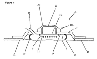
本発明の第1の態様は、身体から体液を取り出すための装置を提供する。当該装置は、
i)複数のマイクロニードルのアレイと
ii)1つのハウジングと、
を備えており、複数のマイクロニードルのアレイは前記ハウジング内に収納され、前記ハウジングはチャンバを画定しており、
前記複数のマイクロニードルは、解放位置と係合位置の間を移動可能であり、前記複数のマイクロニードルは、前記係合位置で使用されると、身体の表面を刺し、
前記チャンバは、前記係合位置において前記複数のマイクロニードルが刺す身体の表面を取り囲むように構成されており、
前記チャンバは、真空装置に接続されるように構成されており、負圧が前記チャンバに与えられる。
A first aspect of the invention provides an apparatus for removing body fluid from the body. The device is
i) an array of microneedles and ii) one housing,
An array of microneedles is contained within the housing, the housing defining a chamber,
The plurality of microneedles are movable between a release position and an engagement position, and the plurality of microneedles pierce the surface of the body when used in the engagement position,
The chamber is configured to surround the surface of the body pierced by the plurality of microneedles in the engaged position;
The chamber is configured to be connected to a vacuum device and a negative pressure is applied to the chamber.
体液は、好ましくは間質液であるが、本発明装置は、間質液の取出しのみに限定されない。マイクロニードルアレイは、中実の複数のマイクロニードルを含んでよく、身体の表面に複数の穴を生成する目的のためにマイクロニードルアレイを使用することは、従来の注射針の使用より好ましい。これは、皮下毛細血管床を貫通しないことによって、マイクロニードルのサイズによって、貫入プロセスにおける痛みや外傷が小さくされるからである。従って、マイクロニードルの高さは、約1000μm以下までで、好ましくは約700μm以下、好ましくは約500μm以下、又は350μmであるべきであり、約1000μmまでの穴を角質層に生成できるべきである。 The body fluid is preferably interstitial fluid, but the device according to the invention is not limited to the withdrawal of interstitial fluid only. The microneedle array may include a plurality of solid microneedles, and using the microneedle array for the purpose of creating a plurality of holes in the surface of the body is preferable to the use of a conventional injection needle. This is because by not penetrating the subcutaneous capillary bed, the size of the microneedles reduces pain and trauma in the penetration process. Thus, the height of the microneedles should be up to about 1000 μm or less, preferably about 700 μm or less, preferably about 500 μm or less, or 350 μm, and should be able to create holes up to about 1000 μm in the stratum corneum.
マイクロニードルアレイは、特定の用途に適合するように、所望の数の複数のマイクロニードルを含んでよい。アレイは、最大で約12000本のマイクロニードル、最大で約9000本のマイクロニードル、最大で約600本のマイクロニードル、或いは、最大で約400本のマイクロニードルを含んでよい。マイクロニードルアレイは、約5000本のマイクロニードルを含んでいるのが好ましい。 The microneedle array may include a desired number of multiple microneedles to suit a particular application. The array may include up to about 12000 microneedles, up to about 9000 microneedles, up to about 600 microneedles, or up to about 400 microneedles. The microneedle array preferably includes about 5000 microneedles.
マイクロニードルアレイの複数のニードルは、ほぼ対称的に、或いは非対称に配置されてよい。一例として100本のマイクロニードルよりなるアレイは、対称配置の10×10のニードルを、或いは、非対称配置の5×20のニードルを組み入れてよい。複数のニードルは、正方形、長方形又は円のような所望の形状のアレイに配置されてよい。例として、好ましい実施形態は、約5000本のマイクロニードルの直径3cmの円形アレイを採用しており、マイクロニードルの先端間の間隔は約390μmであって、1mm2当たり約7本のマイクロニードルを提供する。 The plurality of needles of the microneedle array may be arranged substantially symmetrically or asymmetrically. An array of 100 microneedles, as an example, may incorporate 10 × 10 needles in a symmetrical arrangement or 5 × 20 needles in an asymmetric arrangement. The plurality of needles may be arranged in an array of desired shape, such as square, rectangular or circular. By way of example, the preferred embodiment employs a 3 cm diameter circular array of about 5000 microneedles, the spacing between the tips of the microneedles is about 390 μm, and about 7 microneedles per mm 2 provide.
マイクロニードルアレイにおける隣接するニードル間の間隔は、アレイ全体に亘ってほぼ均一であってよく、又は、アレイ全体に亘って所望のように変化してよい。複数のニードルの対称的なアレイは、アレイ全体に亘って、隣接するニードル間の間隔が均一に、又は間隔が変化し得るように構成されてもよいことは理解されるべきである。複数のニードルが対称に配置されているということは、複数のニードル間の間隔を均一にすることを必要とはしないが、特定の実施形態においては好ましいかもしれない。 The spacing between adjacent needles in the microneedle array may be substantially uniform throughout the array, or may vary as desired across the array. It should be understood that the symmetrical array of needles may be configured such that the spacing between adjacent needles may be uniform or may vary throughout the array. The symmetrical arrangement of the plurality of needles does not require uniform spacing among the plurality of needles, but may be preferred in certain embodiments.
アレイにおける各マイクロニードルは、真っ直ぐなシャフト、適当なテーパーを有するシャフト、又はストレート部とテーパー部との組合せを有してよい。各マイクロニードルは、ほぼ円形又は非円形の断面を画定するシャフトを有してよい。 Each microneedle in the array may have a straight shaft, a shaft with a suitable taper, or a combination of straight and tapered portions. Each microneedle may have a shaft defining a generally circular or non-circular cross section.
本発明におけるマイクロニードルは、中空又は中実であってよい。マイクロニードルは中実であるのが好ましい。中実なマイクロニードルは更に、1又は複数の外部溝やチャネルなどを規定してよい。 The microneedles in the present invention may be hollow or solid. The microneedles are preferably solid. The solid microneedles may further define one or more external grooves, channels or the like.
アレイにおける少なくとも幾つかのニードルの基部の断面径は、約10nm乃至1mmであることが好ましく、より好ましくは約1μmから250μm、更に好ましくは約10μmから200μmである。好ましい実施形態では、アレイのニードルは、約160μmの基部直径を有する。 The cross-sectional diameter of the base of at least some of the needles in the array is preferably about 10 nm to 1 mm, more preferably about 1 μm to 250 μm, still more preferably about 10 μm to 200 μm. In a preferred embodiment, the needles of the array have a base diameter of about 160 μm.
各マイクロニードルは、シリコン、ガラス、金属又はプラスチックなどの適切な材料から製造でき、高精度に微細加工(micro-engineered)できる。複数のマイクロニードルのアレイは、タイプが異なる複数のマイクロニードルの組合せを含んでよい。例としては、複数のマイクロニードルのアレイは、高さ、内径及び/又は外形、断面形状及び隣接するマイクロニードル間の間隔が異なる複数のマイクロニードルを組み合わせてよい。 Each microneedle can be manufactured from suitable materials such as silicon, glass, metal or plastic and can be micro-engineered with high accuracy. The array of microneedles may comprise a combination of microneedles of different types. As an example, an array of microneedles may be combined with microneedles that differ in height, inner diameter and / or contour, cross-sectional shape and spacing between adjacent microneedles.
複数のマイクロニードルは、機械的に、電気的に、空気圧又は油圧で解放位置から係合位置へと駆動できるであろう。例えば、トリガの発動が電気スイッチを作動させて、その結果、ソレノイドが、マイクロニードルを解放位置から係合位置へ駆動してよい。 The plurality of microneedles could be driven mechanically, electrically, pneumatically or hydraulically from the released position to the engaged position. For example, actuation of a trigger may activate the electrical switch so that the solenoid drives the microneedle from the release position to the engagement position.
本発明の好ましい実施形態では、複数のマイクロニードルは、手動押圧操作部材によって駆動され、当該部材は、マイクロニードルアレイに機械的に接続できてよい。 In a preferred embodiment of the present invention, the plurality of microneedles may be driven by a manual pressing operating member, which may be mechanically connected to the microneedle array.
特定の実施形態では、複数のマイクロニードルを解放位置へ戻すことと、負圧がチャンバに印加された場合にマイクロニードルが係合位置に戻ることを(即ち、体表面を刺すことを)妨げることとが望まれるであろう。マイクロニードルを解放位置へ戻すための幾つかの機構は、当業者であれば想到し得るだろう。好ましい実施形態は、解放位置に向かって複数のマイクロニードルを付勢する弾性部材を利用する。 In certain embodiments, returning the plurality of microneedles to the release position and preventing the microneedles from returning to the engaged position when negative pressure is applied to the chamber (i.e., piercing the body surface) And would be desirable. Several mechanisms for returning the microneedles to the release position will be apparent to those skilled in the art. Preferred embodiments utilize an elastic member to bias the plurality of microneedles towards the release position.
好ましい実施形態では、装置は、複数の弾性部材を備えており、これら弾性部材は、例えば、ハウジングの下側ルーフと身体の表面の間に、マイクロニードルアレイの下面と身体の表面の間に、又は他の適切な位置に配置されてよい。これらの弾性部材が存在することで、係合位置への移動後に解放位置へ戻るように、マイクロニードルは解放位置に付勢される。弾性部材は、十分な固有の弾性を有しており、負圧がチャンバに印加される場合に、複数のマイクロニードルは、身体の表面を再び刺さない、即ち、係合位置に戻らない。弾性部材は、ばね(例えば、コイルばね、ねじりばね、板ばね(例えば、リビングヒンジ(living hinge))、竹の子ばね、又はガスばね)、エラストマ部材、又はその他の適切な手段であればよい。これらの実施形態において、操作部材は、マイクロニードルアレイに取り付けられてよい。或いは、操作部材は、マイクロニードルアレイに取り付けられていないが、力が操作部材に加えられると、マイクロニードルアレイに接続してよい。 In a preferred embodiment, the device comprises a plurality of elastic members, for example, between the lower roof of the housing and the surface of the body, between the lower surface of the microneedle array and the surface of the body, Or it may be arranged at other appropriate positions. The presence of these resilient members biases the microneedles to the release position so as to return to the release position after movement to the engaged position. The elastic member has sufficient inherent elasticity so that when a negative pressure is applied to the chamber, the plurality of microneedles do not pierce the surface of the body again, ie do not return to the engaged position. The resilient member may be a spring (eg, a coil spring, a torsion spring, a leaf spring (eg, a living hinge), a bamboo spring, or a gas spring), an elastomeric member, or any other suitable means. In these embodiments, the operating member may be attached to the microneedle array. Alternatively, the operating member may not be attached to the microneedle array, but may be connected to the microneedle array when a force is applied to the operating member.
他の実施形態では、力が操作手段に加わって、複数のマイクロニードルが係合位置に移動するまでは、マイクロニードルアレイは解放位置に付勢されなくてよい(係合後付勢(post-engagement biasing))。この係合後付勢は、当業者によって容易に理解されるであろう幾つかの方法によって発生し得る。例えば、係合後付勢は、マイクロニードルアレイが係合位置へ移動した後、弾性部材と結合されることにより発生できる。好適な複数の弾性部材は上述されている。 In other embodiments, the microneedle array may not be biased to the release position until a force is applied to the manipulation means to move the plurality of microneedles to the engagement position (engagement post bias engagement biasing)). This post-engagement bias can occur in several ways that would be readily understood by one skilled in the art. For example, the post-engagement biasing can be generated by coupling the elastic member after the microneedle array has been moved to the engaged position. Suitable resilient members are described above.
好ましい態様において、弾性部材は、操作部材の一部を形成してよい。この特定の実施形態では、操作部材に力が加わる前には結合していないマイクロニードルアレイと操作部材(弾性部材)とによって、係合後付勢が達成される。操作部材(弾性部材)は前記の力が加わった後のみ複数のマイクロニードルに結合してよい、この結合は、複数のコネクタによって達成されてよく、当該コネクタは、操作部材及び/又はマイクロニードルの対応する接触表面に配置される。操作部材及び/又はマイクロニードルは、それらの接触面に接着剤(例えば、感圧性接着剤)を有してよい。或いは、接触面は、例えば雄−雌コネクタ、締りばめコネクタ、又は他の好適な複数のコネクタなどの相補型(complementary)コネクタを含んでよい。具体的には、マイクロニードルアレイは、マイクロニードルアレイに関連付けられたコネクタと、弾性部材に関連付けられた又は動作可能にリンクした相補型コネクタとの係合を介して、弾性部材に結合してよい。操作部材の押下の後、コネクタが係合する。操作部材が解放されると、弾性部材は、マイクロニードルを解放位置に向けて付勢する。弾性部材は、十分な固有の弾性を有しており、体液を抽出するために負圧がチャンバに印加されると、マイクロニードルが身体の表面を再び刺さないように、即ち、係合位置に戻らないようにされる。代替的又は付加的に、適切な空間に負圧を印加することで、マイクロニードルは、解放位置に向けて付勢されて、皮膚の表面からマイクロニードルが引き抜かれてよい。 In a preferred embodiment, the elastic member may form part of the operating member. In this particular embodiment, post-engagement biasing is achieved by the microneedle array and the operating member (elastic member) not being coupled prior to the application of force to the operating member. The operating member (elastic member) may be coupled to the plurality of microneedles only after the application of said force, this coupling may be achieved by a plurality of connectors, said connector comprising the operating member and / or the microneedle It is arranged on the corresponding contact surface. The operating member and / or the microneedles may have an adhesive (e.g. a pressure sensitive adhesive) on their contact surface. Alternatively, the contact surface may comprise a complementary connector, such as, for example, a male-female connector, an interference fit connector, or other suitable plurality of connectors. In particular, the microneedle array may be coupled to the resilient member through engagement of a connector associated with the microneedle array with a complementary connector associated with or operatively linked to the resilient member. . After depression of the operating member, the connector is engaged. When the operating member is released, the resilient member biases the microneedle towards the release position. The elastic member has sufficient inherent elasticity so that when a negative pressure is applied to the chamber to extract body fluid, the microneedles will not pierce the surface of the body again, ie in the engaged position It is made not to return. Alternatively or additionally, by applying a negative pressure to the appropriate space, the microneedles may be biased towards the release position to withdraw the microneedles from the surface of the skin.
刺した後における解放位置への複数のマイクロニードルの戻りは、マイクロニードルはハウジング内に収納されるので安全機能として働き、その結果として、廃棄時の針刺のリスクは少なくなる。 The return of the plurality of microneedles to the release position after pricking acts as a safety feature as the microneedles are housed within the housing and as a result there is a reduced risk of needle pricking upon disposal.
解放位置から係合位置へのマイクロニードルの移動は、ハウジング全体の移動によって達成されてよい。これは、例えば、ハウジングを半可撓性(semi-flexible)材料で形成することによって達成できる。或いは、マイクロニードルは、ハウジングに対して相対的に係合位置へ移動してよい。 Movement of the microneedle from the release position to the engagement position may be accomplished by movement of the entire housing. This can be achieved, for example, by forming the housing from a semi-flexible material. Alternatively, the microneedles may be moved to an engaged position relative to the housing.
更なる実施形態では、チャンバに負圧を作用させるために、チャンバに接続された真空装置が設けられる。ハウジングは、ポート又は他の適切な手段が存在することで、真空装置と接続するように構成されてよい。真空装置は低圧ガスのタンクを含んでよく、その場合における真空装置の操作は、タンクとチャンバの間の弁を開くことを含んでよい。代わりに、真空装置は、ローブポンプ、スクリューポンプ、ピストンポンプ、インジェクタ−ジェットポンプ(例えば、ベンチュリポンプ)などのポンプを含んでよく、その場合における真空装置の操作はポンプを作動させることを含んでよい。好ましい実施形態では、真空装置は真空ポンプである。 In a further embodiment, a vacuum device connected to the chamber is provided to apply a negative pressure to the chamber. The housing may be configured to connect with the vacuum device in the presence of a port or other suitable means. The vacuum system may include a tank of low pressure gas, in which case operation of the vacuum system may include opening a valve between the tank and the chamber. Alternatively, the vacuum device may include a pump such as a lobe pump, screw pump, piston pump, injector-jet pump (eg, venturi pump), in which case operation of the vacuum device includes operating the pump. Good. In a preferred embodiment, the vacuum device is a vacuum pump.
身体から体液を取り出すためにチャンバに作用される好適な負圧は、本発明の第2の態様に関連して以下で説明される。 Suitable negative pressures exerted on the chamber to remove body fluid from the body are described below in connection with the second aspect of the invention.
ある実施形態では、ハウジングは、シーリング手段を備えており、ハウジングが身体の表面にシールされることを可能にする。これによって、チャンバが気密シールされて、チャンバが吸引装置に接続されると、マイクロニードルが刺す身体の表面を取り囲むチャンバ内に真空が形成される。要求される気密シールの程度は、関係する用途に依存しており、本実施形態を限定するものとして完全な気密であると解釈されるべきではない。しかしながら、気密シールの程度は、体液抽出の間、所望の圧力差を得ること及び維持するのに十分であるべきである。シーリング手段は、例えば、接着層(例えば、粘着層)又は弾性シーリングリムであってよい。 In one embodiment, the housing comprises sealing means, enabling the housing to be sealed to the surface of the body. This creates a vacuum in the chamber surrounding the surface of the body that the microneedle pierces when the chamber is hermetically sealed and the chamber is connected to the suction device. The degree of hermetic sealing required is dependent on the application involved and should not be construed as a complete hermeticity as a limitation of this embodiment. However, the degree of hermetic sealing should be sufficient to obtain and maintain the desired pressure differential during body fluid extraction. The sealing means may, for example, be an adhesive layer (e.g. an adhesive layer) or an elastic sealing rim.
ある実施形態では、装置は、負圧の印加前に体表面に配置される1又は複数の材料の層を含んでよい。例えば、材料の層は、マイクロニードルアレイの下側(即ち、身体と対向する側)に配置されてよく、マイクロニードルアレイを体表面に向けて押し下げると、1つの材料の層が、体表面と接触する。代わりに、材料の層は、ハウジングの下側に配置されてよく、装置が身体に配置されると、その材料の層が身体と接触する。この実施形態では、係合位置への移動の際に、マイクロニードルは材料の層を貫通できる。 In certain embodiments, the device may include a layer of one or more materials disposed on the body surface prior to the application of negative pressure. For example, a layer of material may be disposed on the lower side of the microneedle array (i.e., the side opposite the body), and when the microneedle array is pushed down to the body surface, one layer of material is Contact. Alternatively, the layer of material may be disposed below the housing, and when the device is placed on the body, the layer of material contacts the body. In this embodiment, upon transfer to the engaged position, the microneedles can penetrate the layer of material.
負圧の印加の際に材料の層が皮膚を保護する点、及び/又は、マイクロニードルアレイの挿入に起因する複数の貫入孔を介して身体からの体液の流れを促進する点において、材料の層は有用であろう。1又は複数の材料の層に使用できるであろう好適な材料は、ガーゼのような、貫入部への負圧の伝達を許容する目の粗い(open weave)材料を含む。他の適切な材料としては、発泡体、ポリマシート又はポリマ繊維、ヒドロゲルシート又はヒドロゲル繊維、セルロース、又は当業者に公知の他の天然素材の材料がある。複数の材料の層が設けられる場合、複数の層は、所望の結果を達成するために、同じ種類の材料で形成されてよく、又は異なる種類の材料で形成されてよいことが理解されよう。 Material in that the layer of material protects the skin upon application of negative pressure and / or promotes fluid flow from the body through the plurality of penetration holes resulting from the insertion of the microneedle array. Layers will be useful. Suitable materials that could be used for the layer or layers of materials include open weave materials, such as gauze, that allow the transfer of negative pressure to the penetration. Other suitable materials include foams, polymer sheets or fibers, hydrogel sheets or fibers, cellulose, or other naturally occurring materials known to those skilled in the art. It will be appreciated that where multiple layers of material are provided, the multiple layers may be formed of the same type of material or may be formed of different types of material to achieve the desired result.
本発明の第1の態様に係る装置は、使い捨て装置であってよい。例えば、マイクロニードルが解放位置から係合位置へと一度だけ移動できるように、装置が構成されてよい。これは、例えば、マイクロニードルアレイの解放位置への戻りがラッチ開放をもたらして、係合位置へのさらなる移動を防止することで達成できる。或いは、操作部材の一部又はマイクロニードルアレイの一部は、解放位置へのマイクロニードルアレイの戻りの後に壊れて、係合位置へのさらなる移動を防止してよい。 The device according to the first aspect of the invention may be a disposable device. For example, the device may be configured such that the microneedle can only be moved once from the release position to the engagement position. This can be achieved, for example, by the return of the microneedle array to the release position resulting in the latch release preventing further movement to the engaged position. Alternatively, a portion of the operating member or a portion of the microneedle array may be broken after the return of the microneedle array to the release position to prevent further movement to the engaged position.
代替的な実施形態では、装置は再使用可能であってよい。例えば、装置は、使用後に消毒されて、その後再使用されてよく、及び/又は、装置本体からマイクロニードルアレイが切り離されて、交換用のマイクロニードルアレイがハウジング内に配置されてよい。使用間においてマイクロニードルアレイの交換を伴うか否かに拘わらず、装置を再使用する能力は、マイクロニードルアレイが以前に適用されたのと同じ部位に再度マイクロニードルアレイを再適用することが必要となる場合には、特に有利であるだろう。このような場合は、例えば、装置が比較的長い周期の時間(例えば、4から5時間又はそれ以上)に亘って使用され、マイクロニードルの挿入によって皮膚に引き起こされた貫入孔の少なくとも幾つかが、それらの孔を介して体液が流れることが最早できない程度に閉じている状況下である。 In an alternative embodiment, the device may be reusable. For example, the device may be disinfected after use and then reused, and / or the microneedle array may be disconnected from the device body and a replacement microneedle array may be disposed within the housing. The ability to re-use the device, whether with or without the exchange of the microneedle array between uses, requires that the microneedle array be reapplied to the same site as the microneedle array was previously applied. It would be particularly advantageous if In such a case, for example, the device is used for a relatively long period of time (e.g., 4 to 5 hours or more) and at least some of the penetrations caused in the skin by the insertion of the microneedles are Under the condition of being closed to the extent that fluid can no longer flow through those holes.
1又は複数の特徴を本発明の装置に組み込んで、一回皮膚表面に適切に適用されたマイクロニードルアレイが再度押下されるのを防ぐことが望ましい場合があるだろう。そのような特徴を組み込んだ装置は、「使い捨て」バージョンの装置と表現されてよく、安全の観点から魅力的であるだろう。再利用可能な装置を提供すること、それが望まれる場合、接続/切り離しの手段、即ち上述したコネクタは、操作部材をマイクロニードルアレイに可逆的に接続するように設計されてよい。同様に、使い捨てバージョンの装置は不可逆的なコネクタを組み込んでよい。 It may be desirable to incorporate one or more features into the device of the present invention to prevent re-pressing of the microneedle array properly applied to the skin surface once. Devices incorporating such features may be described as "disposable" versions of the device and would be attractive from a safety point of view. Providing a reusable device, when it is desired, the means of connection / disconnection, ie the connector described above, may be designed to reversibly connect the operating member to the microneedle array. Similarly, the disposable version of the device may incorporate an irreversible connector.
身体は、好ましくは人の身体又は動物の身体である。本発明の装置のマイクロニードルアレイは、任意の所望の皮膚表面に適用され得る。好ましい実施形態では、マイクロニードルアレイは身体の下肢領域に適用される。装置に含まれるマイクロニードルアレイの大きさ、形状及び/又は構成は、特定の適用部位に適合するように選択されてよい。 The body is preferably a human body or an animal body. The microneedle array of the device of the invention may be applied to any desired skin surface. In a preferred embodiment, the microneedle array is applied to the lower limb area of the body. The size, shape and / or configuration of the microneedle array included in the device may be selected to fit the particular application site.
真空装置と複数のマイクロニードルからなるアレイの両者を単一の装置に与えることで扱いやすくなって、真空装置とマイクロニードルが正しく配置されることが保証され、その結果、装置は、医師の助けを借りずに適用できる。 Providing both the vacuum device and the array of microneedles in a single device makes it easier to handle and ensures that the vacuum device and the microneedles are properly positioned, so that the device helps the doctor It can apply without borrowing.
本発明の第2の態様は、身体から体液を取り出すための方法を提供する。当該方法は、
身体の表面を刺す工程と、
身体の表面の貫入領域に負圧を印加して、貫入された表面を介して身体から体液を取り出す工程と、を含む。
A second aspect of the invention provides a method for removing bodily fluid from the body. The method is
Piercing the surface of the body,
Applying negative pressure to the penetration area of the surface of the body to withdraw body fluid from the body through the penetration surface.
体液は、好ましくは、間質液であるが、本発明の方法は、間質液の取り出しのみに限定されるものではない。身体の表面を刺すための様々な機構が想定でき、例えば、1又は複数のマイクロニードルアレイ、1又は複数のマイクロニードルローラを適用することで、エレクトロポレーション、水力ジェット、レーザ、音波エネルギ、ガスジェット、発射体の適用又は他の任意の好適な手段の適用によって達成できる。本発明の好ましい実施形態では、身体の表面は、マイクロニードルアレイを適用することによって貫入される。 The body fluid is preferably an interstitial fluid, but the method of the present invention is not limited to only taking out the interstitial fluid. Various mechanisms for piercing the surface of the body can be envisaged, for example, by applying one or more microneedle arrays, one or more microneedle rollers, electroporation, hydraulic jet, laser, sonic energy, gas This can be achieved by the application of jets, projectiles or any other suitable means. In a preferred embodiment of the invention, the surface of the body is penetrated by applying a microneedle array.
マイクロニードルアレイは、中実の複数のマイクロニードルを含んでよく、身体の表面に複数の貫入孔を生成するためにマイクロニードルアレイを使用することは、従来の注射針を使用するよりも好ましい。マイクロニードルのサイズが、皮下毛細血管床を貫通しないことで、貫入プロセス中の痛み及び外傷を最小限に抑えるからである。従って、(マイクロニードルアレイ又はマイクロニードルローラにおける)マイクロニードルの高さは、約1000μm以下まで、好ましくは約700μm以下、好ましくは約500μm以下又は350μmであって、角質層に最大約1000ミクロンの穴を形成可能であるべきであろう。複数のマイクロニードルの高さは、患者に基づいて選択されてよい。例えば、比較的に高齢の又は比較的に若い患者に対しては短い複数のマイクロニードルを使用することが望ましいだろう。 The microneedle array may include a plurality of solid microneedles, and using the microneedle array to create a plurality of penetration holes in the surface of the body is preferable to using a conventional injection needle. Because the size of the microneedle does not penetrate the subcutaneous capillary bed, it minimizes pain and trauma during the penetration process. Thus, the height of the microneedles (in the microneedle array or microneedle roller) is up to about 1000 μm, preferably up to about 700 μm, preferably up to about 500 μm or 350 μm, and up to about 1000 micron holes in the stratum corneum Should be able to form The heights of the plurality of microneedles may be selected based on the patient. For example, it may be desirable to use short microneedles for relatively elderly or relatively young patients.
身体の表面の貫入は、少なくとも300mm2、より好ましくは500〜1500mm2、最も好ましくは565mm2の組織に触れるためになされてよい。このレベルの組織の露出は、上述したように、種々の方法を用いて達成され得る。本発明の第1の態様に関連して上述したように、このレベルの組織の接触を達成するために、種々のマイクロニードルの大きさ及び構成が使用されてよい。例えば、複数のマイクロニードルは、患者及び体液過剰のレベルに依存して密に又は広く間隔を開けて配置されてよい。ある実施形態では、約5000本のマイクロニードル(高さは、〜550μm)を持つ直径約3cmの中実マイクロニードルアレイが使用される。当業者は、接触した組織表面の面積を、以下に示す計算式を用いて簡単に計算できる。 Penetration of the surface of the body is at least 300 mm 2, more preferably 500~1500Mm 2, and most preferably may be made to touch the tissue 565 mm 2. This level of tissue exposure may be achieved using various methods, as described above. Various microneedle sizes and configurations may be used to achieve this level of tissue contact, as described above in relation to the first aspect of the invention. For example, the plurality of microneedles may be closely or widely spaced depending on the patient and level of fluid overload. In one embodiment, a solid microneedle array about 3 cm in diameter with about 5000 microneedles (̃550 μm in height) is used. One skilled in the art can easily calculate the area of the contacted tissue surface using the formula shown below.
単一のニードル(円錐形であると仮定)の側面積=πrl=πr・sqrt(r2+h2) Side area of single needle (assumed to be conical) = πrl = πr · sqrt (r 2 + h 2 )
約5000本の550μmのマイクロニードルで、ニードルの浸透率を約80%と仮定すると、接触した総組織面積は約565mm2である。 Assuming a needle penetration of about 80% with about 5000 550 μm microneedles, the total tissue area contacted is about 565 mm 2 .
好ましい実施形態では、複数のマイクロニードルは、負圧の印加前に身体の表面から除去される。 In a preferred embodiment, the plurality of microneedles are removed from the surface of the body prior to the application of negative pressure.
本発明の第2の態様の好ましい実施形態は、身体の表面を貫入して、負圧を印加することによって、かなりの量の体液が身体から取り出され得るという驚くべき発見に、部分的に基づいている。マイクロニードルの除去は、皮膚表面が再密封して、表面の複数の孔が迅速に閉鎖するので、取り出される体液の量には限度があると、当業者には予測されていたであろう。驚くべきことに、負圧が十分に高い場合、表面の複数の孔は1時間又は1日以上の長期のタイムスパンに亘って開いたままであって、体液の取り出しが可能であることが分かっている。 Preferred embodiments of the second aspect of the present invention are based in part on the surprising discovery that a significant amount of body fluid can be removed from the body by penetrating the surface of the body and applying negative pressure. ing. The removal of the microneedles would have been predicted by those skilled in the art as the amount of fluid withdrawn would be limited as the skin surface resealed and the surface pores would close rapidly. Surprisingly, it has been found that, if the negative pressure is high enough, the plurality of pores on the surface remain open over an extended time span of one hour or more, and it is possible to withdraw body fluid. There is.
ある実施形態では、本発明の方法は、複数のマイクロニードル(又は他の手段)によって貫入された身体の領域に真空装置を取り付ける工程を含んでいる。真空装置は、低圧ガスのタンクを備えてよく、その場合における真空装置の操作は、タンクとチャンバの間の弁を開く工程を含んでよい。代わりに、真空装置は、ローブポンプ、スクリューポンプ、ピストンポンプ、インジェクタ−ジェットポンプ(例えば、ベンチュリポンプ)などのポンプを備えてよく、その場合における真空装置の操作は、ポンプを作動させる工程を含んでよい。好ましい実施形態では、真空装置は真空ポンプである。 In one embodiment, the method of the present invention comprises attaching a vacuum device to the area of the body penetrated by the plurality of microneedles (or other means). The vacuum device may comprise a tank of low pressure gas, in which case operation of the vacuum device may include the step of opening a valve between the tank and the chamber. Alternatively, the vacuum device may comprise a pump such as a lobe pump, a screw pump, a piston pump, an injector-jet pump (e.g. a venturi pump), in which case the operation of the vacuum device comprises operating the pump. It is good. In a preferred embodiment, the vacuum device is a vacuum pump.
真空装置は、シーリング手段によって皮膚に取り付けられてよい。例えば、真空装置は、接着剤、例えば感圧性接着剤、又は弾性シーリングリムをその本体表面の接触面に備えており、真空装置が表面に気密シールされる。要求される気密シールの程度は、関係している用途に依存しており、本実施形態を限定するものとして完全な気密としてに解釈されるべきではない。しかしながら、気密シールの程度は、体液抽出の間、所望の圧力差を得ること及び維持するのに十分であるべきである。 The vacuum device may be attached to the skin by sealing means. For example, the vacuum device comprises an adhesive, such as a pressure sensitive adhesive, or an elastic sealing rim on the contact surface of its body surface, the vacuum device being hermetically sealed to the surface. The degree of hermetic sealing required is dependent on the application involved and should not be interpreted as a complete hermeticity as a limitation of this embodiment. However, the degree of hermetic sealing should be sufficient to obtain and maintain the desired pressure differential during body fluid extraction.
印加される負圧は、所望の体積の体液を身体から取り出すのに適したものであるべきである。負圧は、皮膚へのマイクロニードルの挿入によって作られた複数の貫入孔を介して、身体から体液が流出する期間に亘って継続的に又は断続的に印加されてよい。当業者であれば、負圧の適切な大きさと、負圧の継続的な印加と断続的な印加の何れが適切であるかとを、患者と体液過剰の重症度とに基づいて決定できるであろう。ある実施形態では、上記の負圧は、約25から約500mmHg、より好ましくは約50から約500mmHg、より好ましくは約100から約300mmHg、より好ましくは約200mmHgである。 The applied negative pressure should be suitable for removing the desired volume of body fluid from the body. Negative pressure may be applied continuously or intermittently over the period of fluid outflow from the body through the plurality of penetrations created by the insertion of the microneedles into the skin. One skilled in the art can determine the appropriate magnitude of negative pressure and whether continuous or intermittent application of negative pressure is appropriate based on the patient and the severity of fluid overload. I will. In one embodiment, the negative pressure is about 25 to about 500 mmHg, more preferably about 50 to about 500 mmHg, more preferably about 100 to about 300 mmHg, more preferably about 200 mmHg.
特定の患者についての体液取出しの適切な速度は、当業者に公知の多くの因子に依存するだろう。例えば最大で約2000ml/日、より好ましくは最大で1000ml/日又は約500ml/日の体液取出し速度が適切だろう。体液取出し速度の適切な下限は、少なくとも約10ml/日、より好ましくは約50ml/日、より好ましくは約100ml/日であろう。種々の治療用途について、体液取出し速度の好ましい下限は、約220ml/日である。当業者は、取り出される体液の特定の速度及び量は、身長、体重、過剰な体液の量、合併症などの患者特有の因子を考慮して決定されるべきことを理解できるであろう。 The appropriate rate of fluid removal for a particular patient will depend on many factors known to those skilled in the art. For example, a fluid removal rate of at most about 2000 ml / day, more preferably at most 1000 ml / day or about 500 ml / day would be appropriate. A suitable lower limit for fluid removal rate will be at least about 10 ml / day, more preferably about 50 ml / day, more preferably about 100 ml / day. For various therapeutic applications, the preferred lower limit of fluid removal rate is about 220 ml / day. One skilled in the art will appreciate that the particular rate and amount of fluid withdrawn should be determined in consideration of patient specific factors such as height, weight, excess fluid volume, complications and the like.
同様に、特定の患者についての体液の適切な流量は、当業者に公知の多くの因子に依存するだろう。適切な体液の流量は、約0.25〜約4ml/cm2/hr、より好ましくは約1〜約3ml/cm2/hr、より好ましくは、約2ml/cm2/hrであるだろう。 Similarly, the appropriate flow rate of bodily fluid for a particular patient will depend on many factors known to those skilled in the art. A suitable fluid flow rate will be about 0.25 to about 4 ml / cm 2 / hr, more preferably about 1 to about 3 ml / cm 2 / hr, more preferably about 2 ml / cm 2 / hr.
貫入のための身体における適切な位置は、当業者の公知である多くの因子に依存するだろう。例えば体液過剰の部位、患者の健康状態、複数のマイクロニードルの適用が意図されている皮膚の1又は複数の予定部位の健康状態、浮腫の部位、患者の姿勢などがある。例えば、患者が立っている場合又は座っている場合には下肢に適用され、患者が横たわっている場合には背中に適用される。 The appropriate location in the body for penetration will depend on many factors known to those skilled in the art. For example, the site of fluid excess, the health of the patient, the health of one or more predetermined sites of the skin to which the application of the microneedles is intended, the site of edema, the posture of the patient, etc. For example, when the patient is standing or sitting, it applies to the lower extremities, and when the patient is lying, it applies to the back.
本発明の方法は、任意の所望の体液を取り出すために使用できるが、体液は、間質液又はその少なくとも一成分であることが好ましい。例えば、間質液の少なくとも一つの成分は、水、尿毒症毒素、代謝産物、塩及びイオンからなる群から選択されるのが好ましい。 Although the method of the present invention can be used to remove any desired body fluid, it is preferred that the body fluid be interstitial fluid or at least one component thereof. For example, at least one component of the interstitial fluid is preferably selected from the group consisting of water, uremic toxins, metabolites, salts and ions.
本発明の方法は、真空装置を用いる前に、貫入された身体表面に材料の層を適用する工程を更に含んでよい。そのような材料の1又は複数の層が、真空装置の適用の前に、貫入された身体表面に適用されてよい。材料のこの層又は材料のこれらの層の適用は、本発明の方法に必須ではない。しかしながら、それは、真空装置の適用対象の皮膚を保護するのに役立ち、体液の流れを促進するであろう。使用され得る適切な材料は、ガーゼのように、貫入部位への負圧の伝達を可能にする目の粗い材料を含む。他の適切な材料には、発泡体、ポリマシート又はポリマ繊維、ヒドロゲルシート又はヒドロゲル繊維、セルロース、又は当業者に公知の他の天然素材の材料がある。材料の複数の層が提供される場合、複数の層は、所望の結果を達成するために、同じ種類の材料で形成されて、又は異なる種類の材料で形成されてよいことが理解されよう。 The method of the invention may further comprise the step of applying a layer of material to the penetrated body surface prior to using the vacuum device. One or more layers of such material may be applied to the penetrated body surface prior to application of the vacuum device. The application of this layer of material or these layers of material is not essential to the method of the invention. However, it will help protect the skin to which the vacuum device is applied and will promote fluid flow. Suitable materials that may be used include coarse materials, such as gauze, that allow for the transmission of negative pressure to the penetration site. Other suitable materials include foams, polymer sheets or fibers, hydrogel sheets or fibers, cellulose, or other naturally occurring materials known to those skilled in the art. It will be appreciated that where multiple layers of material are provided, the multiple layers may be formed of the same type of material or may be formed of different types of material to achieve the desired result.
ある実施形態では、方法は、本発明の第1の態様(及びにそれらについて本明細書に記載された任意の実施形態)による装置の使用を含んでいる。 In one embodiment, the method comprises the use of the device according to the first aspect of the invention (and any of the embodiments described herein for them).
体液過剰又は浮腫の治療方法が更に提供され、当該方法は、本発明の第2の態様の方法を含んでいる。前記の体液過剰又は浮腫は、腎臓/腎不全、心不全、リンパ浮腫、深部静脈血栓症及び癌などの様々な条件の結果であってよいが、これらに限定されない。 Further provided is a method of treating fluid overload or edema, the method comprising the method of the second aspect of the invention. Said fluid overload or edema may be the result of various conditions such as but not limited to kidney / renal failure, heart failure, lymphedema, deep vein thrombosis and cancer.
上述の方法を用いて身体からの体液を取り出すために、成功裏に利用された手順の一例を以下に示す。
1.適切な皮膚消毒薬が、患者の皮膚の挿入部位に塗布される。
2.マイクロニードルアレイが皮膚に適用される。これは、例えば手動挿入又はマイクロニードルアプリケータを用いるなどの種々の方法で達成され得る。
3.マイクロニードルが皮膚から除去され、破棄される。
4.マイクロニードルの挿入部位の上にガーゼが配置される。ガーゼは、皮膚に対する付加的な保護を与えるために、複数のマイクロニードルによって作られた複数の貫入孔の全てを覆うのに十分な大きさであるべきであり、そして真空アセンブリよりも大きくするべきである。
5.貫入部位の気密シールを確実にするために、真空チューブユニットが感圧性接着剤とともに、マイクロニードルの挿入部位へ適用される。
6.真空チューブは、50〜500mmHgに設定された真空ポンプと収集キャニスタに接続される。
7.真空チューブを通って体液が収集キャニスタに流れる。
8.工程2〜工程7が、必要に応じて繰り返される。
9.真空チューブが貫入部位から除去される。
10.適切な皮膚消毒薬が創傷部位に塗布される。
An example of a successfully utilized procedure is shown below for removing body fluid from the body using the method described above.
1. An appropriate skin antiseptic is applied to the insertion site of the patient's skin.
2. A microneedle array is applied to the skin. This can be accomplished in various ways, such as, for example, manual insertion or using a microneedle applicator.
3. The microneedles are removed from the skin and discarded.
4. Gauze is placed on the microneedle insertion site. The gauze should be large enough to cover all of the multiple penetrations created by the multiple microneedles to provide additional protection to the skin, and should be larger than the vacuum assembly It is.
5. A vacuum tube unit is applied along with the pressure sensitive adhesive to the insertion site of the microneedle to ensure an air tight seal at the penetration site.
6. The vacuum tube is connected to a vacuum pump and collection canister set at 50-500 mm Hg.
7. Body fluid flows through the vacuum tube to the collection canister.
8.
9. The vacuum tube is removed from the penetration site.
10. An appropriate skin antiseptic is applied to the wound site.
患者及び体液過剰の重症度に応じて、この基本的な手順の変更が当業者によって考えられてよい。例えば、以下の工程が変更されてよい。
・ガーゼは皮膚から除去されてよい。
・様々な真空圧が利用されてよい。及び/又は、
・マイクロニードルの数及び種類が変更されてよい。
Modifications of this basic procedure may be considered by those skilled in the art, depending on the patient and the severity of fluid overload. For example, the following steps may be modified.
The gauze may be removed from the skin.
-Various vacuum pressures may be used. And / or
The number and type of microneedles may be changed.
本発明の第2の態様の方法のインビトロ(in vitro)モデルによって、以下のデータが得られた。モデルは、膜親水性ポリウレタンの発泡体から構成されており、薄い疎水性ポリウレタン膜が、発泡体の表面に結合されている。発泡体の孔サイズは20から400μmであった。発泡体は、四肢の大きさ及び形状をシミュレートするためにプラスチックチューブに巻きつけられ、そして所定の位置に固定された。発泡体には、間質液を表現するためのウシ血清アルブミンを含む生理食塩水が注入された。マイクロニードルを使用して「皮膚」(膜)を貫通し、その後、上記の手順/手続きが用いられた。

研究試験が、心不全及び/又は腎不全に起因する「見える」浮腫又は原因不明の慢性末梢浮腫を患っている複数の患者よりなる1つのグループについて行われた。表皮間質液(ISF)にアクセスして抽出する試験を、83人の患者が受けた。合計144の処置がなされた。 Study studies were conducted on a group of patients suffering from "visible" edema due to heart failure and / or renal failure or chronic peripheral edema of unknown cause. Eighty-three patients received a trial to access and extract epidermal interstitial fluid (ISF). A total of 144 treatments were made.
2つのアクセス方法が試験された。中実マイクロニードルアレイと小さな中空の皮下注射針である。 Two access methods were tested. Solid microneedle arrays and small hollow hypodermic needles.
<マイクロニードルアレイ>
予め作製された中実ポリメチルメタクリレート(PMMA)マイクロニードルアレイが使用された。タイプが異なる2つのアレイが試験され、1つは550μmの高さ及び170μmのベースのマイクロニードルを有し、そして他方は30μmの高さ及び177μmのベースのマイクロニードルを有していた。550μmのアレイは、3cmの直径を有し、5491本のマイクロニードルを含む7.1cm2の活性表面積(active surface area)を有していた。350μmのアレイは、1.6cmの直径を有し、1316本のマイクロニードルを含む2cm2の活性表面積を有していた。
<Micro needle array>
A prefabricated solid polymethyl methacrylate (PMMA) microneedle array was used. Two arrays of different types were tested, one with a 550 μm height and a 170 μm base microneedle, and the other with a 30 μm height and a 177 μm base microneedle. The 550 μm array had a diameter of 3 cm and had an active surface area of 7.1 cm 2 containing 5491 microneedles. The 350 μm array had a diameter of 1.6 cm and had an active surface area of 2 cm 2 containing 1316 microneedles.
皮膚の消毒の後、複数のマイクロニードルが、目的に合うように設計されたマイクロニードル用ばね式アプリケータ(本発明のアプリケータに関連する以下の説明を参照)を用いて脚の甲又はすねの内側に適用された。 After disinfecting the skin, a plurality of microneedles are designed for the purpose using a spring applicator for the microneedle (see the description below in connection with the applicator of the invention) or the back of the leg Applied inside.
<皮下注射針>
22又は23ゲージの皮下注射針がISFへの代替アクセス手法として使用された。皮膚消毒及び1%リドカインの噴霧の後、針は30〜45°で約半分の長さ挿入された。
Hypodermic needle
A 22 or 23 gauge hypodermic needle was used as an alternative access method to ISF. After skin disinfection and spraying with 1% lidocaine, the needle was inserted about half the length at 30-45 °.
角質層を貫入して、表皮間質コンパートメントへのアクセスが得られると、複数のマイクロニードルを除去した直後に、KCIActiVAC(登録商標)負圧ユニットを用いてマイクロニードル適用領域への負圧を印加することで、体液の取出しが促進された。ActiVAC(登録商標)は、25乃至200mmHgの調整可能な負圧、即ち、−25乃至−200mmHgの圧力を供給し、抽出された体液は、300mlの容積の可変キャニスタにチューブを介して集められた。圧力は、最大200mmHgの目標負圧、即ち−200mmHgの圧力を達成するために徐々に大きくされて、それは、体液の抽出の間、維持された。体液の取出しは1〜4時間続けられ、セッションの終了時に、セッション中に取り出された間質液の体積が測定された。 Once the stratum corneum has been penetrated to gain access to the epidermal stromal compartment, apply a negative pressure to the microneedle application area using the KCI ActiVAC® negative pressure unit immediately after removing multiple microneedles By doing this, the removal of body fluid was promoted. ActiVAC® supplies an adjustable negative pressure of 25 to 200 mm Hg, ie a pressure of -25 to -200 mm Hg, and the extracted fluid is collected via tubing in a variable canister of 300 ml volume . The pressure was gradually increased to achieve a target negative pressure of up to 200 mm Hg, ie a pressure of -200 mm Hg, which was maintained during the extraction of the body fluid. Body fluid removal continued for 1 to 4 hours, and at the end of the session, the volume of interstitial fluid removed during the session was measured.
データは、GraphPad Prism(登録商標)6.04.を用いて分析された。パラメトリックデータ及び非パラメトリックデータは、平均±SD及び中央値と範囲又は四分位数範囲(IQR)としてそれぞれ表現された。スチューデントのt検定、フィッシャーの直接確率検定、マンホイットニー検定及びピアソン相関係数が、統計的に有意であると考えられる0.05以下の確率で、統計分析のために使用された。 The data are as per GraphPad Prism® 6.04. Was analyzed using Parametric and non-parametric data were expressed as mean ± SD and median and range or interquartile range (IQR), respectively. Student's t-test, Fisher's exact test, Mann-Whitney test and Pearson's correlation coefficient were used for statistical analysis with a probability of 0.05 or less considered statistically significant.
<成功したISF抽出>
144回のISF抽出において、49%において1ml以上のISFが抽出され、25%において5ml以上のISFが抽出され、14%において10ml以上のISFが抽出された。
<Successful ISF Extraction>
In 144 ISF extractions, 1% or more of ISF was extracted at 49%, 5% or more of ISF was extracted at 25%, and 10% or more of ISF was extracted at 14%.
<ISFの自発的な「意味のある流れ」>
ISFの自発的な(spontaneous)「意味のある流れ(meaningful flow)」(即ち、確実に回収及び測定できる十分な体積)を生じるという点で、マイクロニードルアクセスと非マイクロニードルアクセスの比較は、マイクロニードルが優れていることを示した。マイクロニードルアクセスは、ISFの自発的な「意味のある流れ」(即ち、確実に回収及び測定できる十分な体積)を、非マイクロニードルアクセスが10%のケースにおいてこれを達成したことと比較して、55%のケースにおいて達成した。高さが550μmであるマイクロニードルを持つ複数のマイクロニードルアレイは、高さが350μmであるマイクロニードルを持つものよりも有意に高い平均ISF体積を達成した(7±12ml対0.5±1ml:p<0.0001)。
<ISF's voluntary "meaningful flow">
A comparison of microneedle access and non-microneedle access is in that it produces ISF's "spontaneous""meaningfulflow" (ie, sufficient volume to be reliably recovered and measured). The needle showed that it was excellent. Microneedle access compares the spontaneous "meaningful flow" of ISF (i.e. sufficient volume that can be reliably recovered and measured) compared to that achieved with non-microneedle access in the 10% case. , Achieved in 55% of cases. Multiple microneedle arrays with microneedles that are 550 μm in height achieved significantly higher average ISF volumes than those with microneedles that were 350 μm in height (7 ± 12 ml vs. 0.5 ± 1 ml: p <0.0001).
<ISFの流れの強化:負圧>
負圧吸引装置の使用は、処置の27%において、5ml以上の体液をもたらした。これらの患者において抽出されたISFの平均体積は、−192mmHgの平均真空圧で1時間当たり、マイクロニードル毎に11mlの平均流量を与えた場合の2.3時間の平均を上回る24±9mlであった。加えられた負圧と合計ISFの間で、正の相関が観測された(r=0.42、p=0.03、図7)。
<ISF flow enhancement: negative pressure>
The use of a negative pressure aspiration device resulted in greater than 5 ml of fluid in 27% of the treatments. The mean volume of ISF extracted in these patients is 24 ± 9 ml above the mean of 2.3 hours given an average flow of 11 ml per microneedle per hour at an average vacuum pressure of -192 mmHg The A positive correlation was observed between the applied negative pressure and the total ISF (r = 0.42, p = 0.03, FIG. 7).
<ISF抽出の維持:時間>
抽出されたISFの体積はまた、抽出時間との線形相関を示した(r=0.24、p=0.008、図8)。
<Maintenance of ISF extraction: time>
The volume of ISF extracted also showed a linear correlation with the extraction time (r = 0.24, p = 0.008, FIG. 8).
<患者の特性>
浮腫のクラス(即ち、急性/亜急性対慢性)と抽出された体積の間に相関は観測されなかった(P=0.10)。同様に、臨床緊張(clinical tenseness)又は浮腫のコンプライアンスは、抽出された体積と相関を示さなかった(r=0.05;p=0.003)。
<Patient characteristics>
No correlation was observed between the edema class (ie acute / subacute versus chronic) and the volume extracted (P = 0.10). Similarly, compliance with clinical tension or edema did not correlate with the volume extracted (r = 0.05; p = 0.003).
<痛み、出血及び皮膚の完全性(integrity)>
抽出の間、全体的な機構についての「快適さ」の度合い(「快適」、「不快」又は「非常に不快」)だけでなく、0−10のアナログ疼痛質問がなされた。血液スポット及び皮膚紅斑も書き留められた。0−7の皮膚刺激スコアが、マイクロニードルを除去した直後、可能であるならば(即ち、入院患者の場合)1時間後及び24時間後になされた。
<Pain, bleeding and skin integrity>
During the extraction, 0-10 analog pain questions were asked as well as the degree of "comfort"("comfort","discomfort" or "very uncomfortable") for the overall mechanism. Blood spots and skin erythema were also noted. A skin irritation score of 0-7 was made immediately after removing the microneedles, 1 h and 24 h, if possible (i.e. for hospitalized patients).
82%のケースでは、マイクロニードルについて2以下の疼痛スコアを報告し、62%は、マイクロニードル挿入の全ての期間中に痛みがないことを報告した。マイクロニードルの平均疼痛スコアは1.1±2(中央値=0、IQR 0−2)であった。皮下注射針の平均疼痛スコアは、リドカインスプレーの使用後に挿入されたにも拘わらず、1.9±3(中央値=0、IQR 0−4)であった。マイクロニードルの挿入後、装置がその場所に残された後においても、96%のケースでは、それが「快適」又は「非常に快適」であると感じた。14%のケースにおいて、軽度の紅斑が存在した一方で、83%のケースでは、装置の除去後に目に見える皮膚刺激は無かった。2つのケースでは、装置の除去後に著しい紅斑が現れた(7のうち、それぞれ4及び5の刺激スコア)が発表された。1時間及び24時間後、3つのケースのみで装置適用の証拠が見られた。これら3人の患者は水泡を発生させたが、(この水泡は)72時間以内に合併症と伴うことなく解決された。マイクロニードルの適用後、蜂巣炎のケースが1つあり、これは抗生物質により解決された。 In 82% of cases, a pain score of 2 or less was reported for the microneedles, and 62% reported no pain during all periods of microneedle insertion. The mean pain score of the microneedles was 1.1 ± 2 (median = 0, IQR 0-2). The mean pain score of the hypodermic needle was 1.9 ± 3 (median = 0, IQR 0-4) despite being inserted after using lidocaine spray. After insertion of the microneedle, even after the device was left in place, in the 96% case it felt "comfortable" or "very comfortable". In 14% of cases there was mild erythema, while in 83% of cases there was no visible skin irritation after removal of the device. In two cases significant erythema appeared after removal of the device (stimulus scores of 4 and 5 respectively of 7) were announced. After 1 hour and 24 hours, evidence of device application was seen in only 3 cases. These three patients developed blisters, which were resolved within 72 hours without complications. After application of the microneedles, there was one case of cellulitis, which was resolved by antibiotics.
負圧及び高い生物学的合理性を伴うマイクロニードルアクセスは、10×10cmの皮膚表面を使用して、4時間かけて800mlに相当する2ml/cm2/hrのISF抽出速度を達成することができた。 Microneedle access with negative pressure and high biological rationality can achieve an ISF extraction rate of 2 ml / cm 2 / hr equivalent to 800 ml over 4 hours using a skin surface of 10 × 10 cm did it.
これらの結果は、過剰な体液蓄積をもたらす状態を患っている患者から体液を取り出すことについて、本発明の第1及び第2の態様の装置及び方法の有用性を実証している。 These results demonstrate the utility of the devices and methods of the first and second aspects of the present invention for removing fluid from a patient suffering from conditions resulting in excessive fluid accumulation.
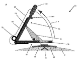
本発明の第3の態様は、表面にマイクロニードルアレイを適用するためのアプリケータを提供する。当該アプリケータは、
表面に適用されるマイクロニードルアレイと関連付けられた接触要素に接触する圧力要素と、
準備位置から衝突位置へ駆動されて、圧力要素又はマイクロニードルアレイに衝撃を加えるように構成されたハンマと、
を備えており、
圧力要素は、動作可能にハンマに接続されており、それによって、圧力要素に力が働くと、ハンマは、準備位置から衝突位置へと駆動される。
A third aspect of the invention provides an applicator for applying a microneedle array to a surface. The applicator is
A pressure element contacting the contact element associated with the microneedle array applied to the surface;
A hammer configured to drive from the preparation position to the impact position to impact the pressure element or microneedle array;
Equipped with
The pressure element is operatively connected to the hammer such that when force is exerted on the pressure element, the hammer is driven from the preparation position to the collision position.
アプリケータが単に「マイクロニードルアレイ」との使用に限定されないことは理解されるであろう。それは、任意のタイプの切断又は貫入要素を表面に適用するために、制御された、信頼性のある方法で使用されてよい。 It will be understood that the applicator is not limited to use solely with a "microneedle array". It may be used in a controlled, reliable manner to apply any type of cutting or penetrating element to a surface.
本発明の第3の態様の一実施形態では、接触要素はマイクロニードルアレイの背部である。 In one embodiment of the third aspect of the invention, the contact element is the back of the microneedle array.
本発明のさらなる態様では、表面にマイクロニードルアレイを適用するためのアプリケータが提供される。当該アプリケータは、
表面に適用されるマイクロニードルアレイと関連付けられた接触要素に接触する圧力要素と、
準備位置から衝突位置へ駆動されて、圧力要素に衝撃を加えるように構成されたハンマと、
を備えており、
圧力要素は、動作可能にハンマに接続されており、それによって、圧力要素に力が働くと、ハンマは、準備位置から衝突位置へと駆動される。
In a further aspect of the invention, an applicator for applying a microneedle array to a surface is provided. The applicator is
A pressure element contacting the contact element associated with the microneedle array applied to the surface;
A hammer driven from the preparation position to the impact position and configured to impact the pressure element;
Equipped with
The pressure element is operatively connected to the hammer such that when force is exerted on the pressure element, the hammer is driven from the preparation position to the collision position.
本発明の更に別の態様では、表面にマイクロニードルアレイを適用するためのアプリケータが提供される。当該アプリケータは、
表面に適用されるマイクロニードルアレイと関連付けられた接触要素に接触する圧力要素と、
準備位置から衝突位置へ駆動されて、マイクロニードルアレイに衝撃を加えるように構成されたハンマと、
を備えており、
圧力要素は、動作可能にハンマに接続されており、それによって、圧力要素に力が働くと、ハンマは、準備位置から衝突位置へと駆動される。
In yet another aspect of the invention, an applicator is provided for applying a microneedle array to a surface. The applicator is
A pressure element contacting the contact element associated with the microneedle array applied to the surface;
A hammer configured to drive from the preparation position to the impact position to impact the microneedle array;
Equipped with
The pressure element is operatively connected to the hammer such that when force is exerted on the pressure element, the hammer is driven from the preparation position to the collision position.
本発明のアプリケータの実施形態では、圧力要素は、マイクロニードルアレイに関連付けられた接触要素、例えばハウジングと接触する。マイクロニードルアレイは、ハウジング内に配置される。この構成の利点の1つは、ハウジングへの圧力要素の最初の接触が、意図せずにマイクロニードルを表面に適用する結果にならないことである。圧力要素は、マイクロニードルアレイに関連付けられた任意の好適な接触要素又は表面に接続してよく、当該接触要素又は表面は、アプリケータのトリガに続いて、マイクロニードルアレイ又は圧力要素に衝撃を加えることを当業者は理解するであろう。 In an embodiment of the applicator of the present invention, the pressure element contacts a contact element, such as a housing, associated with the microneedle array. The microneedle array is disposed within the housing. One of the advantages of this arrangement is that the initial contact of the pressure element to the housing does not result in the unintentional application of the microneedles to the surface. The pressure element may be connected to any suitable contact element or surface associated with the microneedle array, said contact element or surface impacting the microneedle array or pressure element following triggering of the applicator Those skilled in the art will understand.
ある実施形態では、ハンマは、衝突位置へと駆動されると、マイクロニードルアレイの背部に衝撃を直接伝えてよい。或いは、ハンマは、圧力要素を介してマイクロニードルアレイに衝撃を与えてよい。 In an embodiment, the hammer may transmit an impact directly to the back of the microneedle array when driven into the impact position. Alternatively, the hammer may impact the microneedle array via the pressure element.
本発明のアプリケータの好ましい実施形態では、ハンマは、衝突位置に向かって付勢され、ラッチ要素によって準備位置に保持可能である。圧力要素は、ラッチ要素を介してハンマに接続されてよい。好ましい実施形態では、圧力要素に力を加えると、ラッチ要素が動かされて、ハンマの解放をもたらす。 In a preferred embodiment of the applicator of the invention, the hammer is biased towards the collision position and can be held in the preparation position by the latching element. The pressure element may be connected to the hammer via the latch element. In a preferred embodiment, upon application of force to the pressure element, the latch element is moved resulting in the release of the hammer.
ハンマは、適切なやり方で衝突位置に向かって付勢されてよい。例えば、ハンマは、油圧又は空気圧シリンダ、ソレノイドのような電動リニアアクチュエータのようなアクティブアクチュエータによって付勢されてよい。代替的又は付加的に、ハンマは、ばね(例えば、コイルばね、ねじりばね、板ばね、竹の子ばね又はガスばね)又はエラストマ部材のような弾性要素によって付勢されてよい。 The hammer may be biased towards the collision position in an appropriate manner. For example, the hammer may be biased by an active actuator such as a hydraulic or pneumatic cylinder, an electric linear actuator such as a solenoid. Alternatively or additionally, the hammer may be biased by a resilient element such as a spring (e.g. a coil spring, a torsion spring, a leaf spring, a bamboo spring or a gas spring) or an elastomeric member.
ある実施形態では、圧力要素は、ラッチ要素と一体化している。或いは、圧力要素は、ラッチ要素とは別の物であってよく、ラッチ要素に接続されていてよい。 In one embodiment, the pressure element is integral with the latch element. Alternatively, the pressure element may be separate from the latch element and may be connected to the latch element.
ハンマは、弓状の経路に沿って準備位置から衝突位置へ移動してよい。或いは、ハンマは、直線経路に沿って、又は、マイクロニードルを表面に適用するのに十分な力を与えて、圧力要素又はマイクロニードルアレイに衝撃を付えることが可能な他の好適な経路に沿って、準備位置から衝突位置へ移動してよい。 The hammer may move from the preparation position to the collision position along an arcuate path. Alternatively, the hammer may be along a linear path or on any other suitable path capable of impacting the pressure element or microneedle array with sufficient force to apply the microneedles to the surface. Along the, it may move from the preparation position to the collision position.
アプリケータは、随意選択的に計数手段を含んでよく、アプリケータが作動された回数をユーザが決定することを可能にする。これは、装置の寿命の指標として有用であるだろう。これは、例えば、ハンマが衝突位置から準備位置へ移動されると、装置によって作動させられる単純な機械的なカウンタを組み込みことによって達成され得る。計数装置の存在は、アプリケータの使用を通じて達成されるマイクロニードル適用の質を維持することを許容する。 The applicator may optionally include counting means to allow the user to determine the number of times the applicator has been activated. This would be useful as an indicator of device lifetime. This may be achieved, for example, by incorporating a simple mechanical counter which is actuated by the device when the hammer is moved from the impact position to the preparation position. The presence of the counting device allows to maintain the quality of the microneedle application achieved through the use of the applicator.
本発明の一実施形態において、圧力要素は、マイクロニードルアレイ(又はそれに関連する接触要素)との相補的に係合するように構成されて、マイクロニードルアレイとの相補的な係合が達成された場合にのみアプリケータがトリガされる。これよって、正しい位置に配置されるまでハンマの駆動が妨げられるので、マイクロニードル適用の質及び/又は精度の改善がもたらされる。相補的な係合手段は、例えば、マイクロニードルアレイの背部の一部を含んでおり、ドーム状構造が、圧力要素における対応するドーム形状の凹部に係合する又はその反対とされてよい。他の相補的な形状又は適切な係合手段は、当業者によって容易に理解されるだろう。例えば、圧力要素及びマイクロニードルアレイ(又はそれに関連する接触要素)によって規定された一方又は両方の接触面には、接着剤が提供されて、圧力要素及びマイクロニードルアレイが互いに可逆的又は不可逆的に結合される。使用前において、接着剤は、装置を作動することが所望される場合にのみ除去される剥離紙の下で保護されてよい。 In one embodiment of the present invention, the pressure element is configured to complementarily engage with the microneedle array (or the contact element associated therewith) to achieve complementary engagement with the microneedle array The applicator is triggered only if This leads to an improvement in the quality and / or accuracy of the microneedle application, since the hammer is not driven until it is in the correct position. The complementary engagement means may, for example, comprise a portion of the back of the microneedle array, and the dome-like structure may engage or be opposite the corresponding dome-shaped recess in the pressure element. Other complementary shapes or suitable engagement means will be readily understood by those skilled in the art. For example, an adhesive is provided on one or both contact surfaces defined by the pressure element and the microneedle array (or the contact element associated therewith), so that the pressure element and the microneedle array reversibly or irreversibly with each other Combined. Before use, the adhesive may be protected under a release paper which is only removed when it is desired to operate the device.
本発明のさらなる態様は、
表面に適用されるマイクロニードルアレイに関連付けられた接触要素に接触する圧力要素と、
準備位置から衝突位置へ駆動されて、圧力要素又はマイクロニードルアレイに衝撃を加えるように構成されたハンマと、
を備えており、圧力要素はハンマに作動可能に接続されており、それによって圧力要素に力が働くと、準備位置から衝突位置へハンマが駆動されるアプリケータを、マイクロニードルアレイと組み合わせて含んでいる装置を含む。
A further aspect of the invention is
A pressure element contacting the contact element associated with the microneedle array applied to the surface;
A hammer configured to drive from the preparation position to the impact position to impact the pressure element or microneedle array;
And the pressure element is operatively connected to the hammer, thereby including an applicator, in combination with the microneedle array, in which the hammer is driven from the preparation position to the collision position when a force is exerted on the pressure element. Including devices that
本発明の上記の態様(及び本明細書に記載のそれらの任意の実施形態)のアプリケータは、アプリケータを含んでいる上記のような装置としての使用に極めて適しているであろう。 The applicator of the above aspect of the invention (and any of those embodiments described herein) would be highly suitable for use as a device as described above, including an applicator.
さらなる態様では、アプリケータを含んでいる装置が提供される。当該アプリケータは、
表面に適用されるマイクロニードルアレイに接触する圧力要素と、
準備位置から衝突位置へ駆動されて、圧力要素に衝撃を加えるように構成されたハンマと、
を含んでおり、圧力要素はハンマに作動可能に接続されており、それによって圧力要素に力が働くと、準備位置から衝突位置へハンマが駆動され、マイクロニードルアレイと組み合わされる。
In a further aspect, an apparatus is provided that includes an applicator. The applicator is
A pressure element contacting the microneedle array applied to the surface;
A hammer driven from the preparation position to the impact position and configured to impact the pressure element;
And the pressure element is operatively connected to the hammer such that when a force is exerted on the pressure element, the hammer is driven from the preparation position to the collision position and combined with the microneedle array.
アプリケータを含んでいる装置の一実施形態において、マイクロニードルアレイ(又はそれに関連する接触要素)及び圧力要素は、相補的に係合するように構成されてよい。ある実施形態では、マイクロニードルアレイの背部の一部は、アプリケータの圧力要素場の対応する突起と係合する凹部を含んでもよく、その逆であってもよい。上述したような他の相補的な形状又は適切な係合手段は、当業者によって容易に理解されるだろう。 In one embodiment of the device including the applicator, the microneedle array (or the contact element associated therewith) and the pressure element may be configured to engage in a complementary manner. In an embodiment, a portion of the back of the microneedle array may include a recess that engages a corresponding protrusion of the pressure element field of the applicator, or vice versa. Other complementary shapes or suitable engagement means as described above will be readily understood by those skilled in the art.
アプリケータを含んでいる装置の更なる実施形態では、マイクロニードルアレイは、本発明の第1の態様(及び本発明に記載のそれらの任意の実施形態)による装置を含んでよい。本発明の第1の態様による装置のマイクロニードルアレイ(又は、それに関連する接触要素)の背部とアプリケータの圧力要素とは、相補的に係合して、意図した場合と、マイクロニードルアレイとの相補的な係合が正しく達成された場合のみにアプリケータがトリガされるように構成されてよい。これによって、誤発射(mis-firing)と、マイクロニードルアレイと圧力要素の誤整列とを防止するフェールセーフ装置がもたらされる。 In a further embodiment of the device comprising an applicator, the microneedle array may comprise a device according to the first aspect of the invention (and any of those embodiments according to the invention). The back of the microneedle array (or the contact element associated therewith) of the device according to the first aspect of the present invention and the pressure element of the applicator are engaged in a complementary manner, as intended, with the microneedle array and The applicator may be configured to be triggered only if the complementary engagement of the is successfully achieved. This results in a fail-safe device that prevents mis-firing and misalignment of the microneedle array and the pressure element.
本発明のさらなる態様は、装置を用いて、マイクロニードルアレイを表面に適用する方法を提供する。当該装置は、
表面に適用されるマイクロニードルアレイに関連付けられた接触要素に接触する圧力要素と、
準備位置から衝突位置へ駆動されて、圧力要素又はマイクロニードルアレイに衝撃を加えるように構成されたハンマと、
を含んでおり、圧力要素は、ハンマに作動可能に接続されており、それによって圧力要素に力が働くと、準備位置から衝突位置へとハンマが駆動される。当該方法は、マイクロニードルアレイに関連付けられた接触要素に圧力要素を適用してハンマを解放して、マイクロニードルアレイ又は圧力要素に衝撃を加えて、それによって複数のマイクロニードルを表面に適用する工程を含む。
A further aspect of the invention provides a method of applying a microneedle array to a surface using an apparatus. The device is
A pressure element contacting the contact element associated with the microneedle array applied to the surface;
A hammer configured to drive from the preparation position to the impact position to impact the pressure element or microneedle array;
And the pressure element is operably connected to the hammer such that actuation of the pressure element drives the hammer from the ready position to the impact position. The method applies a pressure element to the contact element associated with the microneedle array to release the hammer and impact the microneedle array or the pressure element thereby applying the plurality of microneedles to the surface including.
一実施形態において、接触要素は、マイクロニードルアレイの背部である。 In one embodiment, the contact element is the back of the microneedle array.
さらなる態様は、装置を用いて、表面にマイクロニードルアレイを適用する方法を提供し、当該装置は、
表面に適用されるマイクロニードルアレイに接触する圧力要素と、
準備位置から衝突位置へ駆動されて圧力要素に衝撃を加えるように構成されたハンマと、
を含んでおり、
圧力要素はハンマに作動可能に接続されており、それによって圧力要素に力が働くと、準備位置から衝突位置へハンマが駆動される。当該方法は、マイクロニードルアレイに圧力要素を適用してハンマを解放して、圧力要素に衝撃を加えて、それにより複数のマイクロニードルを表面に適用する工程を含む。
A further aspect provides a method of applying a microneedle array to a surface using a device, the device comprising:
A pressure element contacting the microneedle array applied to the surface;
A hammer configured to be driven from the preparation position to the impact position to impact the pressure element;
Contains and
The pressure element is operatively connected to the hammer such that when force is exerted on the pressure element, the hammer is driven from the preparation position to the collision position. The method includes the steps of applying pressure elements to the microneedle array to release the hammer and impacting the pressure elements, thereby applying a plurality of microneedles to the surface.
別の実施形態では、圧力要素は、マイクロニードルアレイに関連付けられた接触要素、例えばハウジングに接触する。マイクロニードルアレイは、ハウジング内に配置される。この構成の利点の一つは、ハウジングへの圧力要素の最初の接触が、マイクロニードルの表面への適用を誤ってもたらさないことである。圧力要素が、マイクロニードルアレイに関連付けられた任意の好適な接触要素又は表面に接続し、当該接触要素又は表面によって、アプリケータのトリガに続いてマイクロニードルアレイ又は圧力要素に衝撃が加えられてよいことを、当業者は理解するであろう。 In another embodiment, the pressure element contacts a contact element, such as a housing, associated with the microneedle array. The microneedle array is disposed within the housing. One of the advantages of this arrangement is that the initial contact of the pressure element to the housing does not inadvertently lead to the application of the microneedle to the surface. A pressure element may be connected to any suitable contact element or surface associated with the microneedle array by which impact may be applied to the microneedle array or pressure element following triggering of the applicator Those skilled in the art will understand.
ある実施形態では、ハンマは、衝突位置へ駆動されると、マイクロニードルアレイの背部に衝撃を直接与えてよい。別の実施形態では、ハンマは。圧力要素を介してマイクロニードルアレイに衝撃を与えてよい。 In one embodiment, the hammer may impact the back of the microneedle array directly when driven into the impact position. In another embodiment, the hammer is. The microneedle array may be impacted via the pressure element.
本発明のアプリケータは、上記の方法における使用に極めて適しているであろう。 The applicator of the invention will be very suitable for use in the method described above.
本発明の実施形態は、添付の図面を参照して、単なる例として説明される。 Embodiments of the invention are described by way of example only with reference to the accompanying drawings.
図1を参照すると、本発明の第1の態様の好ましい態様に基づいており、身体から体液を取り出すために使用できる装置1が概略的に示されている。示された装置1は、人体(図示せず)の皮膚表面3上に配置されている。装置1は、皮膚表面3にほぼ平行に配置される、複数のマイクロニードルのアレイ5をハウジング7内に含んでおり、ハウジング7は、チャンバ9を画定する。アレイ5における各ニードル11の高さは、約550μmである。ハウジング7は、真空装置(図示せず)への接続のために構成されたポート13を規定しており、チャンバ9には負圧が印加される。ハウジング7の表面15と接触する皮膚上に接着剤(図示せず)が与えられることで、ハウジング7は、皮膚表面3に気密シールされる。装置1は、2つの弾性リビングヒンジ17を更に含んでおり、これらリビングヒンジ17は、ハウジング7の下面19と皮膚表面3の間に配置されている。操作部材又はボタン21は、マイクロニードルアレイ5の背面23に接続されており、後方に延びており、ボタン21の上部21Aは、ハウジング7より上にある。ダイヤフラム25は、ボタン21の上部の上側に配置されており、ボタン21の両側にてハウジング7に接続されている。
Referring to FIG. 1, there is schematically shown a device 1 according to a preferred embodiment of the first aspect of the present invention, which can be used to remove body fluid from the body. The device 1 shown is arranged on the
装置1の使用が望まれる場合、装置1が適用されるであろう皮膚表面3が、殺菌溶液で拭かれて、装置1は、皮膚表面3に対して配置される。真空装置(図示せず)は、チューブ(図示せず)によってポート13に取り付けられる。ボタン21に加えられた下向きの力(患者自身、医師、又は専用のマイクロニードルアプリケータ装置によって加えられるであろう)は、(図1に示されたような)解放位置から、係合位置へのマイクロニードルアレイ5の下方への移動をもたらす。係合位置にて、マイクロニードル11は皮膚3を刺す。図1の装置1は、半可撓性材料で作られており、ハウジング7の筐体全体が皮膚3の表面に向かって曲がることで、ボタン21の押下によってマイクロニードル11が皮膚表面3を刺す。ボタン21に加わった下向きの力は、2つのリビングヒンジ17を外に向かって曲がらせる。ボタン21からの下向きの力が無くなると、2つのリビングヒンジ17の弾性により、それらは元々の形状へ復帰し、皮膚表面3からマイクロニードルアレイ5を持ち上げ、図1に示された解放位置へとマイクロニードルアレイ5を戻す。真空装置が作動して、負圧がチャンバ9に印加される。リビングヒンジ17は、十分な固有の弾性を有しているので、チャンバ9への十分な負圧が印加されて、身体から体液が流されると(以下でより詳細に説明する)、マイクロニードルアレイ5は、ハウジング7の固有の可撓性にも拘わらず、皮膚表面3への係合位置へと落ちない。
If use of the device 1 is desired, the
チャンバ9への負圧の印加により、皮膚表面3を複数のマイクロニードル11で刺すことにより作られた穴を介して、身体から間質液が抽出される。体液は、ポート13及び真空チューブ(図示せず)を介して貯蔵キャニスタ(図示せず)へと送られる。十分な間質液が身体から取り出されると、真空装置は停止して、装置1は、皮膚3の表面から除去される。装置1全体は、廃棄されてよく、或いは、マイクロニードルアレイ5が装置から除去されて、装置1を引き続いて再使用するために新しいマイクロニードルアレイ5が適用されてよい。
By applying negative pressure to the chamber 9, interstitial fluid is extracted from the body through the holes made by piercing the
図2を参照すると、本発明の第1の態様の別の好ましい実施形態に基づいており、身体から間質液を取り出すために使用できる装置31が概略的に示されている。示された装置31は、人体(図示せず)の皮膚表面3上に配置されている。図1に示された装置1と同様に、装置31は、複数のマイクロニードルのアレイ5を組み込んでおり、アレイ5は、ハウジング7内に皮膚表面3にほぼ平行に配置される。ハウジング7はチャンバ9を画定する。アレイにおける各ニードル11の高さは、約550μmである。ハウジング7は、真空装置(図示せず)への接続のために構成されたポート13を規定しており、チャンバ9には負圧が印加される。接着剤(図示せず)がハウジング7の表面15と接触する皮膚上に与えられているので、ハウジング7は、皮膚表面3に気密シールされる。操作部材又はボタン21は、マイクロニードルアレイ5の上方に配置されて、上下方向に延びており、ボタン21の上部21Aは、ハウジング7の上方に位置している。ボタン21は、マイクロニードルアレイ5の上面23及びボタン21の下面37にそれぞれ設けられたコネクタ33、35によって、マイクロニードルアレイの背部23に接続可能である。ボタン21の上部21Bとダイヤフラム25との間に位置するのは、ばね39である。ダイヤフラム25は、ボタン21の上面21B及びばね39の上に配置され、ボタン21の両側にてハウジング7に接続されている。
Referring to FIG. 2, according to another preferred embodiment of the first aspect of the present invention, an
使用時に、装置31は、皮膚表面3の上に配置されて、それを通じて体液が抽出される。真空装置(図示せず)は、チューブ(図示せず)によってポート13に取り付けられる。ボタン21に加えられた下向きの力(患者自身、医師、又は専用のマイクロニードルアプリケータ装置によって加えられ得る)は、ハウジング7を介してボタン21をマイクロニードルアレイ5へ向かって移動させる。この移動により、コネクタ33、35を介して、ボタン21は、マイクロニードルアレイ5と接続する。ボタン21がマイクロニードルアレイ5に接続した後、マイクロニードルアレイ5は、(図2に示されたような)解放位置からマイクロニードル11が皮膚表面3を刺す係合位置へ移動する。図2の装置31は、硬い材料で作られており、ボタン21に下向きの力が加えられると、ボタン21は、ハウジング7を通って下向きに移動してマイクロニードアレイ5に接触し、次にマイクロニードルアレイ5を皮膚表面3に向かって駆動する。
In use, the
ボタン21に加えられた下向きの力により、ばね39が伸ばされる。ボタン21からの下向きの力が無くなると、ばね39はそれらの元々の形状に復帰する。これによって、ボタン21は、元々の位置に復帰し、マイクロニードルアレイ5は、コネクタ33,35を介してボタン21に接続されているので、(図2に示されたような)解放位置に復帰する。真空装置が作動して、負圧がチャンバ9に印加される。ばね39は、十分な固有の弾性を有しているので、チャンバ9への負圧の印加時に、マイクロニードルアレイ5は、マイクロニードル11は皮膚表面3を刺す係合位置に戻らない。
The downward force applied to the
チャンバ9への負圧の印加によって、皮膚表面3を複数のマイクロニードル11で貫入ことにより作られた穴を介して、身体から間質液が抽出される。間質液は、ポート13及び真空チューブ(図示せず)を介して貯蔵キャニスタ(図示せず)へ送られる。十分な間質液が身体から除去されると、真空装置は停止してよく、装置31は皮膚3の表面から除去される。装置31全体は廃棄されてよく、或いは、コネクタ33、35が解放され、そしてマイクロニードルアレイ5が装置31から除去されて、将来使用するために新たなマイクロニードルアレイ5と置き換えられてよい。
By applying negative pressure to the chamber 9, interstitial fluid is extracted from the body through the holes created by penetrating the
図3を参照すると、本発明の第1の態様の別の好ましい実施形態に基づいており、身体から間質液を取り出すために使用できる装置41が概略的に示されている。示された装置41は、人体(図示せず)の皮膚表面3上に配置されている。図1に示された装置1と同様に、装置41は、複数のマイクロニードルのアレイ5を含んでおり、アレイ5は、ハウジング7内にて皮膚表面3にほぼ平行に配置されている。ハウジング7は、チャンバ9を画定する。アレイにおける各ニードル11の高さは、約550μmである。ハウジング7は、チャンバ9に負圧が印加されるように、真空装置(図示せず)への接続のために構成されたポート13を規定しており、チャンバ9には負圧が印加される。ハウジング7の表面15と接触する皮膚上に接着剤(図示せず)が与えられており、ハウジング7は、皮膚表面3に気密シールされる。操作部材21は、マイクロニードルアレイ5の背面23に接続されて、後方に延びており、操作部材21の上部21Aはハウジング7よりも上にある。ダイヤフラム43は、操作部材21(この場合、操作部材21の上面21A)をハウジング7に接続する。ダイヤフラム43は、ハウジング7と操作部材21との境界を密封するために配置されており、真空にされている場合に境界からの漏れが防止される。
Referring to FIG. 3, according to another preferred embodiment of the first aspect of the present invention, there is schematically shown a
装置41の使用が望まれると、装置41が適用されるであろう皮膚表面3は、殺菌溶液で拭かれ、装置41が皮膚表面3に対して配置される。真空装置(図示せず)は、チューブ(図示せず)によってポート13に取り付けられる。操作部材21に下向きの力(患者自身、医師、又は専用のマイクロニードルアプリケータ装置によって加えられ得る)が加えられると、(図3に示されたような)解放位置から係合位置へとマイクロニードルアレイ5は下方に移動する。係合位置にて、マイクロニードル11は皮膚3に貫入する。
When the use of the
図3のダイヤフラム43は、可撓性を有する弾性材料で作られているので、操作部材21の下降によりダイヤフラム43が曲がって、皮膚3の表面に向かって操作部材21が移動する。操作部材21からの下向きの力は無くなると、ダイヤフラム43の弾性によって、操作部材21がその元々の位置へ戻って、皮膚表面3からマイクロニードルアレイ5を持ち上げて、図3に示すような解放位置へとマイクロニードルアレイ5を戻す。真空装置が作動して、負圧がチャンバ9に印加される。
Since the
操作部材21の直径は十分に小さいので、ダイヤフラム43の弾性と相まって、チャンバ9に十分な負圧が印加されて身体から体液が流されると(以下でより詳細に説明する)、マイクロニードルアレイ5は、皮膚表面3との係合位置へと落ちない。
Since the diameter of the
チャンバ9に負圧が印加されることで、皮膚表面3を複数のマイクロニードル11で貫入ことにより作られた穴を介して、身体から間質液が抽出される。体液は、ポート13及び真空チューブ(図示せず)を介して貯蔵キャニスタ(図示せず)へと送られる。十分な間質液が身体から除去されると、真空装置は停止し、装置41は皮膚3の表面から除去される。装置41全体は廃棄されてよく、或いは、マイクロニードルアレイ5が装置41から除去され、引き続いて装置41を再使用するために新しいマイクロニードルアレイ5が適用されてよい。
By applying a negative pressure to the chamber 9, interstitial fluid is extracted from the body through the holes created by penetrating the
図4A及び図4Bを参照すると、本発明のアプリケータの実施形態に基づいており、表面へのマイクロニードルの適用に使用できるアプリケータ装置51が概略的に示されている。示されている装置51は、人体の皮膚表面3の上方に配置されており、マイクロニードルアレイ51がその皮膚表面3に配置されている。装置51は、ハンマ55と、ベースプレート57と、圧力要素59と.ハウジング63内に配置されたラッチ61とを含んでいる。
Referring to FIGS. 4A and 4B, an
ハンマ55は、ベースプレート57に取り付けられている。ラッチ61の解放により、ハンマ55は、(図4Aに示される)準備位置と(図4Bに示される)衝突位置との間を移動することができる。衝突位置にて、それは圧力要素59とぶつかる。
The
ハンマ55は、細長いシャフト65と、衝突要素67とを備えており、衝突要素67は、ペースプレート57から遠い側のシャフト65の端部に位置する。また、操作ハンドル69と、ラッチ61と係合するノッチ73とは、ハンマ55の一部を形成する。ハンマ55は、衝突要素67が接続されて端部とは反対側にあるシャフトの端部にて、ベースプレート57に回動可能に接続されている。ハンマ55は、(図4Bに示されている)衝突位置にハンマ55を付勢するばね75を更に含む。
The
使用可能なように装置51を準備するために、ユーザは、ハンマ55をベースプレートから矢印Xの方向に後退させる。図4Aに示す準備位置に至ると、ラッチ61がノッチ73と係合し、準備位置にハンマ55を保持する。
In order to prepare the
ベースプレート57は、開口71を規定しており、開口71を通って、圧力要素59が突出して(又は、その中に圧力要素59が存在して)、下に横たわるマイクロニードルアレイ53と係合する。マイクロニードルアレイ53の上に置かれると、圧力要素59は、マイクロニードルアレイ53の背部の係合ボタン77と係合する。圧力要素59の係合ボタン77との係合により、ラッチ要素61は反時計回りに回転し、ラッチ要素61がノッチ73から解放されて、それによりハンマ55が解放される。そして、ばね75は、準備位置から衝突位置へとハンマ55を駆動する。
The
代替的な実施形態では、圧力要素は、マイクロニードルアレイに関連付けられた任意の好適な要素又は面と、例えばマイクロニードルアレイが中に配置されるハウジングと係合してよく、又は、マイクロニードルアレイの背部に直接接触してよいことを当業者は理解するだろう。 In alternative embodiments, the pressure element may be engaged with any suitable element or surface associated with the microneedle array, eg a housing in which the microneedle array is disposed, or the microneedle array One skilled in the art will appreciate that the back of the patient may be in direct contact.
準備位置から衝突位置へのハンマ55の移動の後、ハンマ55の衝撃部材67は、力を圧力要素59の背部に加える。その力は、係合ボタン77及びマイクロニードルアレイ53にその後伝えられ、それにより複数のマイクロニードルが皮膚表面3に適用される。
After the movement of the
図5A乃至Dを参照すると、本発明のアプリケータの実施形態に基づいており、表面へのマイクロニードルの適用に使用できるアプリケータ装置81が概略的に示されている。装置81は、A:供給時、B:準備時、C:トリガ時、D:衝突時の4つの構成にて示されている。本発明のアプリケータのこの実施形態では、装置81は、ハンマ85を含む細長い管状のハウジング83と、ラッチ87と、圧力要素89とを備えている。
Referring to FIGS. 5A-D, an
ハンマ85は、(図5Bに示されている)準備位置から(図5Dに示されている)衝突位置へとハウジング83内で移動可能であり、衝突位置にて、ハンマ85は圧力要素89とぶつかる(以下に詳述する)。
ハンマ85は、ハウジング83内に同軸状に配置され、そして、細長いシャフト91と、シャフト91の一端に位置する衝撃部材93と、シャフト91の反対側の端部に位置する操作ハンドル95と、ラッチ87と係合するノッチ97とを備えている。ハンマ85は、衝突位置へ向けてハンマ85を付勢するばね99を更に含む。衝突位置にて、衝撃部材93は、(図5Dに示すように)圧力要素89に接触する。
The
ハンマ85は、圧力要素89から離れて(図5Bに示された)準備位置へ向かって、ハウジング83に対して軸方向に移動可能である。準備位置にある場合、ラッチ87はノッチ97と係合し、ばね99の付勢力に抗して準備位置にハンマ85を保持する。ラッチ87の係合解除によってハンマ85が解放されて、ハンマ85は、ばね99によって衝突位置へ駆動される。
The
ラッチ87は、ハウジング83に回転可能に取り付けられており、内向きに突出するノブ101を規定する。ノブ101は、ハウジング83へと突出する。操作ハンドル95に力が加えられて、ハンマ85が準備位置に後退すると、ラッチ87が反時計回りに回転してノッチ97に係合し、それによりハンマ85が準備位置に維持される。ラッチ87は、ばね103によってノッチ97と係合する方向に付勢される。また、ラッチ87の回転により、ノブ101が圧力要素89に接触して、ハウジング83に対して圧力要素89を準備位置へと下方に移動させる(以下でより詳細に説明)。
The
圧力要素89は、マイクロニードルアレイ(図示せず)の背部に接触するドーム状の接触部105と、ハウジング83内に延びる細長い部分107とを備えている。当該部分107の上端は、ラッチ87のノブ101に接触する。ハンマ85が係合位置にある場合、ドーム状の接触部105は、衝撃部材93に近接するハウジング83の終端から突出する。圧力要素89は、(図5Aに示される)休止位置と(図5Bに示される)準備位置の間をハウジング83に対して軸方向に移動可能である。休止位置と準備位置の間のこの移動は、ハウジング83に対して上向きであるハンマ85の準備位置への移動に由来しており、これによって、ラッチ87が反時計回りに回転し、ノブ101が細長い部分107を押し下げることを可能となる。
The
圧力要素89のドーム状の接触部105は、マイクロニードルアレイ(図示せず)の背部と係合するように構成されている。接触部105がマイクロニードルアレイと接触すると、細長い部分107は、ハウジング83に対して軸方向に上向きに移動し、圧力要素89の細長い部分107がノブ101と接触して、ラッチ87が回転する。これによって、ハンマ85が解放され、ハンマ55は、その後、ばね99によって準備位置から衝突位置へ駆動される。衝突位置にあると、ハンマ85の衝撃部材93は、力を圧力要素89の背部に加える。その力はその後マイクロニードルアレイに伝えられ、それによって、皮膚にマイクロニードルが適用される。
The
使用時において、操作ハンドル95に適用される力が加わると、ハンマ85は、準備位置へ移動する。その力は、例えば患者又は医師によって加えられるであろう。その力の行使とその後のハンマ85の移動とによって、ラッチ87はノッチ97と係合し、それにより、力を続けて加えなくとも、ハンマ85は準備位置に維持される。装置81は、次に、身体(図示せず)の皮膚表面に適用されるマイクロニードルアレイ(図示せず)の領域に配置される。圧力要素89がマイクロニードルアレイの表面に適用されて、それにより、ラッチ87が回転して、ハンマ85が準備位置から解放される。ばね99は係合位置へ向けてハンマ85を駆動する。係合位置では、衝撃部材93は、圧力要素89の背部に力を加えて、その力はマイクロニードルアレイへ伝えられ、それによってマイクロニードルが皮膚へ適用される。
In use, when the force applied to the operation handle 95 is applied, the
図6A乃至Dを参照すると、本発明のアプリケータの実施形態に基づいており、表面への複数のマイクロニードルの適用に使用できるアプリケータ装置121が概略的に示されている。装置121は、A:供給時、B:準備時、C:トリガ時、D:衝突時の4つの構成にて示されている。本発明のアプリケータのこの実施形態は、図5A乃至Dに示された実施形態に類似している。故に、図5A乃至Dに示された実施形態における同じ機能に関連して、先に使用されていたものと同じ参照番号が、図6A乃至Dにおいて使用される。装置121は、ハンマ85を含む細長い管状ハウジング83と、ラッチ87と、圧力要素89とを含む。
Referring to FIGS. 6A-D, an
ハンマ85は、(図6Bに示されている)準備位置から(図6Dに示されている)衝突位置へとハウジング83内で移動可能である。衝突位置において、ハンマ85はマイクロニードルアレイ108とぶつかる(以下に詳述する)。
ハンマ85は、ハウジング83内に同軸状に配置されており、細長いシャフト91と、シャフト91の一端に位置する衝撃部材93と、シャフト91の反対側の端部に位置する操作ハンドル95と、ラッチ87と係合するノッチ97とを備えている。ハンマ85は、衝突位置へ向けてハンマ85を付勢するばね99を更に含む。衝突位置にでは、使用時にて、衝撃部材93がマイクロニードルアレイ108に接触する(図6Dに示されている)。
The
ハンマ85は、圧力要素89から離れて、(図6Bに示された)準備位置へ向かってハウジング83に対して軸方向に移動可能である。準備位置にある場合、ラッチ87はノッチ97と係合して、ばね99の付勢力に抗して準備位置にハンマ85を保持する。ラッチ87の係合解除によってハンマ85が解放されて、ばね99によって衝突位置へ駆動される。
The
ラッチ87は、ハウジング83に回転可能に取り付けられ、内側に突出するノブ1010を規定する。ノブ101は、ハウジング83へと突出する。操作ハンドル95に力が加えられて、ハンマ85が準備位置へ後退すると、ラッチ87が反時計回りに回転してノッチ97に係合し、それによってハンマ85が準備位置に維持される。ラッチ87は、ばね103によってノッチ97と係合する方向に付勢される。また、ラッチ87の回転により、ノブ101は圧力要素89に接触し、ハウジング83に対して下向きに圧力要素89を準備位置へと移動させる(以下でより詳細に説明)。
The
圧力要素89は、マイクロニードルアレイ108のハウジング109の背部に接触するドーム状の接触部10と、ハウジング83内に延びる細長い部分107とを備えている。当該部分107の上端は、ラッチ87のノブ101に接触する。ハンマ85が係合位置にある場合、ドーム状の接触部105は衝撃部材93に近接するハウジング83の終端から突出する。圧力要素89は、(図6Aに示される)休止位置と(図6Bに示される)準備位置の間をハウジング83に対して軸方向に移動可能である。休止位置と準備位置の間のこの移動は、ハウジング83に対して上向きであるハンマ85の準備位置への移動に由来しており、これによって、ラッチ87が反時計回りに回転し、ノブ101が細長い部分107を押し下げることを可能となる。
The
圧力要素89のドーム状の接触部105は、マイクロニードルアレイ108の背部と係合するように構成されている。接触部105がマイクロニードルアレイ108用のハウジン部109と接触すると、細長い部分107は、ハウジング83に対して軸方向に上向きに移動し、圧力要素89の細長い部分107がノブ101と接触して、ラッチ87が回転する。これによって、ハンマ85が解放され、ハンマ55は、その後、ばね99によって準備位置から衝突位置へ駆動される。衝突位置にあると、ハンマ85の衝撃部材93は、力をマイクロニードルアレイ108の背部に加える。その力は、皮膚110にマイクロニードルを適用する。
The
使用時において、操作ハンドル95に適用される力が加わると、ハンマ85は、準備位置へ移動する。その力は、例えば患者又は医師によって加えられるであろう。その力の行使とその後のハンマ85の移動とによって、ラッチ87はノッチ97と係合し、それにより、力を続けて加えなくとも、ハンマ85は準備位置に維持される。装置81は、次に、身体の皮膚表面110に適用される、ハウジング109内に配置されたマイクロニードルアレイ108の領域に配置される。圧力要素89がマイクロニードルアレイ108用のハウジング109に適用されて、それにより、ラッチ87が回転して、ハンマ85が準備位置から解放される。ばね99は係合位置へ向けてハンマ85を駆動する。係合位置では、衝撃部材93は、マイクロニードルアレイ108の背部に力を加えて、その力は、マイクロニードル1を皮膚110に適用する。
In use, when the force applied to the operation handle 95 is applied, the
図1乃至図6を参照して以上に説明された様々な実施形態の装置の新規な特徴は、上述のように個々に採用されてよく、又は任意の2つ以上の新規な特徴が同じ装置に一緒に採用されてもよいことは理解されるだろう。 The novel features of the devices of the various embodiments described above with reference to FIGS. 1 to 6 may be individually adopted as described above, or any two or more novel features are the same device It will be understood that they may be adopted together.
特定の方向及び向き(上面、背部、下方等)の参照は単に便宜のために使用されており、限定することを何ら意図していないことは理解されるだろう。 It will be understood that reference to particular directions and orientations (top, back, down, etc.) is used for convenience only and is not intended to be limiting in any way.
Claims (9)
i)複数のマイクロニードルのアレイと、
ii)前記複数のマイクロニードルのアレイが中に配置されており、チャンバを画定するハウジングと、
を備えており、
前記複数のマイクロニードルは、解放位置と係合位置との間を移動可能であり、前記係合位置における使用時に、前記複数のマイクロニードルが前記身体の表面に貫入し、
一旦前記マイクロニードルアレイが前記係合位置に移動すると、前記マイクロニードルアレイが一前記解放位置に向けて付勢され、
前記チャンバは、前記係合位置において前記複数のマイクロニードルが貫入する前記身体の表面を取り囲むよう構成されており、
前記チャンバは、真空装置に接続されるように構成されており、前記チャンバに負圧を印加できる装置。 In a device for removing body fluid from the body,
i) an array of microneedles,
ii) a housing, in which the array of microneedles is disposed, defining a chamber;
Equipped with
The plurality of microneedles are movable between a release position and an engagement position, and in use in the engagement position, the plurality of microneedles penetrate the surface of the body;
Once the microneedle array is moved to the engaged position, the microneedle array is biased towards one of the release positions,
The chamber is configured to surround a surface of the body through which the plurality of microneedles penetrate in the engaged position;
The device is configured to be connected to a vacuum device, and a device capable of applying a negative pressure to the chamber.
表面に適用されるマイクロニードルアレイに関連した接触要素に接触する圧力要素と、
準備位置から衝突位置へ駆動されて、前記圧力要素に衝撃を加えるように構成されたハンマと、
を備えており、
前記圧力要素は、動作可能に前記ハンマに接続されており、前記圧力要素に力が加わると、前記ハンマが準備位置から衝突位置へ駆動される、アプリケータ。 An applicator for applying a microneedle array to a surface, the applicator comprising:
A pressure element contacting the contact element associated with the microneedle array applied to the surface;
Is driven from the preparation position to the collision position, a hammer configured to apply an impact to the pressure element,
Equipped with
The applicator, wherein the pressure element is operatively connected to the hammer, wherein the force is driven from the preparation position to the collision position when a force is applied to the pressure element.
Applications Claiming Priority (3)
| Application Number | Priority Date | Filing Date | Title |
|---|---|---|---|
| GBGB1401133.2A GB201401133D0 (en) | 2014-01-23 | 2014-01-23 | Fluid extraction device, applicator device and associated methods |
| GB1401133.2 | 2014-01-23 | ||
| PCT/GB2015/050164 WO2015110833A1 (en) | 2014-01-23 | 2015-01-23 | Fluid extraction device, applicator device and associated methods |
Publications (3)
| Publication Number | Publication Date |
|---|---|
| JP2017509449A JP2017509449A (en) | 2017-04-06 |
| JP2017509449A5 JP2017509449A5 (en) | 2018-03-08 |
| JP6537531B2 true JP6537531B2 (en) | 2019-07-03 |
Family
ID=50287444
Family Applications (1)
| Application Number | Title | Priority Date | Filing Date |
|---|---|---|---|
| JP2016565577A Expired - Fee Related JP6537531B2 (en) | 2014-01-23 | 2015-01-23 | Body fluid extraction device, applicator device and related method |
Country Status (5)
| Country | Link |
|---|---|
| US (2) | US10441691B2 (en) |
| EP (1) | EP3096687B1 (en) |
| JP (1) | JP6537531B2 (en) |
| GB (1) | GB201401133D0 (en) |
| WO (1) | WO2015110833A1 (en) |
Families Citing this family (14)
| Publication number | Priority date | Publication date | Assignee | Title |
|---|---|---|---|---|
| EP3754011B1 (en) | 2015-09-09 | 2022-02-16 | Drawbridge Health, Inc. | Devices for sample collection, stabilization and preservation |
| CN105266852B (en) * | 2015-11-24 | 2017-12-01 | 贾爱娟 | A kind of medical inspection device |
| CN112089961B (en) * | 2015-12-21 | 2022-08-09 | 美德阿利克斯株式会社 | Microneedle patch applicator and housing therefor |
| JP1754773S (en) | 2017-01-10 | 2023-10-06 | sample collection equipment | |
| JPWO2019188907A1 (en) * | 2018-03-29 | 2021-04-08 | 富士フイルム株式会社 | Blood collection lancet and blood test kit |
| JP2021101749A (en) * | 2018-03-29 | 2021-07-15 | テルモ株式会社 | Medical device |
| CA3110730A1 (en) * | 2018-10-19 | 2020-04-23 | Kenota Inc. | Interstitial fluid extraction |
| WO2020146045A1 (en) * | 2019-01-11 | 2020-07-16 | University Of Cincinnati | Continuous extraction and sensing of interstitial fluid |
| JP7074714B2 (en) * | 2019-04-17 | 2022-05-24 | 富士フイルム株式会社 | Manufacturing method of storage container, microneedle unit, storage container group, and microneedle unit |
| US20210153848A1 (en) * | 2019-11-21 | 2021-05-27 | Imcomet B.V. | Skin cancer treatment |
| US11964121B2 (en) | 2021-10-13 | 2024-04-23 | Satio, Inc. | Mono dose dermal patch for pharmaceutical delivery |
| US11877848B2 (en) * | 2021-11-08 | 2024-01-23 | Satio, Inc. | Dermal patch for collecting a physiological sample |
| US11510602B1 (en) * | 2021-11-08 | 2022-11-29 | Satio, Inc. | Dermal patch for collecting a physiological sample |
| CN115644867A (en) * | 2022-12-02 | 2023-01-31 | 苏州纳通生物纳米技术有限公司 | Sampling device, sampler and sampling method |
Family Cites Families (12)
| Publication number | Priority date | Publication date | Assignee | Title |
|---|---|---|---|---|
| CA2394171A1 (en) * | 1999-12-16 | 2001-06-21 | Alza Corporation | Device for enhancing transdermal flux of sampled agents |
| AT409253B (en) | 2000-07-20 | 2002-07-25 | Innova Patent Gmbh | PLANT FOR TRANSPORTING PERSONS AND METHOD FOR OPERATING SUCH A PLANT |
| JP4490413B2 (en) | 2003-01-06 | 2010-06-23 | ネクター セラピューティクス アラバマ,コーポレイション | Thiol-selective water-soluble polymer derivatives |
| ATE539687T1 (en) * | 2003-10-31 | 2012-01-15 | Alza Corp | SELF-ACTUATED APPLICATOR FOR A MICROPROJECTION ARRANGEMENT |
| ES2650188T3 (en) * | 2004-06-10 | 2018-01-17 | 3M Innovative Properties Company | Device and patch application kit |
| GB0802447D0 (en) | 2008-02-09 | 2008-03-19 | Univ Manchester | Fluid extraction device, associated materials and methods |
| KR101712226B1 (en) * | 2009-07-31 | 2017-03-03 | 쓰리엠 이노베이티브 프로퍼티즈 컴파니 | Hollow microneedle arrays |
| US20110172645A1 (en) * | 2010-01-08 | 2011-07-14 | Ratio, Inc. | Wearable drug delivery device including integrated pumping and activation elements |
| KR101708966B1 (en) | 2010-03-17 | 2017-02-21 | 나노메드 디바이시즈, 인코포레이티드 | A built-in non-verbal instructional device integratable to applicators |
| ES2565805T3 (en) * | 2010-11-09 | 2016-04-07 | Seventh Sense Biosystems, Inc. | Systems and interfaces for blood sampling |
| EP2701598A1 (en) | 2011-04-29 | 2014-03-05 | Seventh Sense Biosystems, Inc. | Systems and methods for collecting fluid from a subject |
| KR102013466B1 (en) * | 2011-04-29 | 2019-08-22 | 세븐쓰 센스 바이오시스템즈, 인크. | Delivering and/or receiving fluids |
-
2014
- 2014-01-23 GB GBGB1401133.2A patent/GB201401133D0/en not_active Ceased
-
2015
- 2015-01-23 JP JP2016565577A patent/JP6537531B2/en not_active Expired - Fee Related
- 2015-01-23 EP EP15701415.0A patent/EP3096687B1/en active Active
- 2015-01-23 WO PCT/GB2015/050164 patent/WO2015110833A1/en active Application Filing
- 2015-01-23 US US15/113,249 patent/US10441691B2/en not_active Expired - Fee Related
-
2019
- 2019-09-30 US US16/587,857 patent/US20200101205A1/en not_active Abandoned
Also Published As
| Publication number | Publication date |
|---|---|
| EP3096687A1 (en) | 2016-11-30 |
| EP3096687B1 (en) | 2021-06-09 |
| WO2015110833A1 (en) | 2015-07-30 |
| US20170021067A1 (en) | 2017-01-26 |
| JP2017509449A (en) | 2017-04-06 |
| US20200101205A1 (en) | 2020-04-02 |
| US10441691B2 (en) | 2019-10-15 |
| GB201401133D0 (en) | 2014-03-12 |
Similar Documents
| Publication | Publication Date | Title |
|---|---|---|
| JP6537531B2 (en) | Body fluid extraction device, applicator device and related method | |
| US20150202418A1 (en) | Microneedle-based devices and methods for the removal of fluid from a body | |
| US20110137224A1 (en) | Manually operated disposable single-needle circuit for extracorporeal treatment of blood | |
| US9808377B2 (en) | Fluid extraction or filtration device, associated materials and methods | |
| US20110202014A1 (en) | Adapter device for application of small amounts of fat graft material by use of syringes | |
| JP2012513825A (en) | Vacuum wound treatment system and method using a microstrain-induced manifold | |
| CA3009853C (en) | Transdermal microneedle drug delivery device and method | |
| US8808754B2 (en) | Methods for the treatment of wounds | |
| US20100100119A1 (en) | Mechanical vein lifter | |
| EP2774135A1 (en) | Method and device for injecting a fluid into an artificial venous structure | |
| TWI566791B (en) | Device for draining lymph into vein | |
| RU2449753C2 (en) | Skin-puncturing device for achne treatment | |
| WO2012089627A1 (en) | Needle apparatus for the transdermal administration of drugs | |
| KR20110036405A (en) | Apparatus for fixing catheter comprising vertical fixing element | |
| CN209187893U (en) | Soft scab label apparatus | |
| CN104922791A (en) | Noninvasive acupuncture patch and preparation method thereof | |
| US20130218104A1 (en) | Devices and methods for delivery of agents to biological tissue | |
| CN211068627U (en) | Slice honeycomb duct fixing clip and drainage tube fixing assembly | |
| Marrow | Toward Hydrogel Microneedle Patches for The Passive Extraction of Subcutaneous Interstitial Fluid | |
| WO2014152468A1 (en) | Subcutaneous hydration system, method, and device | |
| CN114470346A (en) | Device for draining lymph fluid into a vein | |
| Bell et al. | Could hydrocephalus shunts have a role in the treatment of lymphoedema? | |
| JP2020531194A (en) | Methods and equipment used for the treatment of plantar fasciitis and fat transplantation | |
| CN1981712A (en) | Hollow sucking needle for cutting rotarily | |
| AU2014202446A1 (en) | Fluid extraction methods |
Legal Events
| Date | Code | Title | Description |
|---|---|---|---|
| A521 | Request for written amendment filed |
Free format text: JAPANESE INTERMEDIATE CODE: A523 Effective date: 20180123 |
|
| A621 | Written request for application examination |
Free format text: JAPANESE INTERMEDIATE CODE: A621 Effective date: 20180123 |
|
| A131 | Notification of reasons for refusal |
Free format text: JAPANESE INTERMEDIATE CODE: A131 Effective date: 20181030 |
|
| A977 | Report on retrieval |
Free format text: JAPANESE INTERMEDIATE CODE: A971007 Effective date: 20181031 |
|
| A521 | Request for written amendment filed |
Free format text: JAPANESE INTERMEDIATE CODE: A523 Effective date: 20190129 |
|
| TRDD | Decision of grant or rejection written | ||
| A01 | Written decision to grant a patent or to grant a registration (utility model) |
Free format text: JAPANESE INTERMEDIATE CODE: A01 Effective date: 20190507 |
|
| A61 | First payment of annual fees (during grant procedure) |
Free format text: JAPANESE INTERMEDIATE CODE: A61 Effective date: 20190604 |
|
| R150 | Certificate of patent or registration of utility model |
Ref document number: 6537531 Country of ref document: JP Free format text: JAPANESE INTERMEDIATE CODE: R150 |
|
| LAPS | Cancellation because of no payment of annual fees |