JP6536682B2 - Base station apparatus, terminal apparatus and communication system - Google Patents
Base station apparatus, terminal apparatus and communication system Download PDFInfo
- Publication number
- JP6536682B2 JP6536682B2 JP2017542724A JP2017542724A JP6536682B2 JP 6536682 B2 JP6536682 B2 JP 6536682B2 JP 2017542724 A JP2017542724 A JP 2017542724A JP 2017542724 A JP2017542724 A JP 2017542724A JP 6536682 B2 JP6536682 B2 JP 6536682B2
- Authority
- JP
- Japan
- Prior art keywords
- base station
- information
- station apparatus
- communication quality
- modulation
- Prior art date
- Legal status (The legal status is an assumption and is not a legal conclusion. Google has not performed a legal analysis and makes no representation as to the accuracy of the status listed.)
- Active
Links
Images


Classifications
-
- H—ELECTRICITY
- H04—ELECTRIC COMMUNICATION TECHNIQUE
- H04L—TRANSMISSION OF DIGITAL INFORMATION, e.g. TELEGRAPHIC COMMUNICATION
- H04L1/00—Arrangements for detecting or preventing errors in the information received
- H04L1/0001—Systems modifying transmission characteristics according to link quality, e.g. power backoff
- H04L1/0002—Systems modifying transmission characteristics according to link quality, e.g. power backoff by adapting the transmission rate
- H04L1/0003—Systems modifying transmission characteristics according to link quality, e.g. power backoff by adapting the transmission rate by switching between different modulation schemes
-
- H—ELECTRICITY
- H04—ELECTRIC COMMUNICATION TECHNIQUE
- H04L—TRANSMISSION OF DIGITAL INFORMATION, e.g. TELEGRAPHIC COMMUNICATION
- H04L1/00—Arrangements for detecting or preventing errors in the information received
-
- H—ELECTRICITY
- H04—ELECTRIC COMMUNICATION TECHNIQUE
- H04L—TRANSMISSION OF DIGITAL INFORMATION, e.g. TELEGRAPHIC COMMUNICATION
- H04L1/00—Arrangements for detecting or preventing errors in the information received
- H04L1/12—Arrangements for detecting or preventing errors in the information received by using return channel
- H04L1/16—Arrangements for detecting or preventing errors in the information received by using return channel in which the return channel carries supervisory signals, e.g. repetition request signals
- H04L1/18—Automatic repetition systems, e.g. Van Duuren systems
-
- H—ELECTRICITY
- H04—ELECTRIC COMMUNICATION TECHNIQUE
- H04L—TRANSMISSION OF DIGITAL INFORMATION, e.g. TELEGRAPHIC COMMUNICATION
- H04L27/00—Modulated-carrier systems
-
- H—ELECTRICITY
- H04—ELECTRIC COMMUNICATION TECHNIQUE
- H04W—WIRELESS COMMUNICATION NETWORKS
- H04W16/00—Network planning, e.g. coverage or traffic planning tools; Network deployment, e.g. resource partitioning or cells structures
- H04W16/24—Cell structures
- H04W16/32—Hierarchical cell structures
-
- H—ELECTRICITY
- H04—ELECTRIC COMMUNICATION TECHNIQUE
- H04W—WIRELESS COMMUNICATION NETWORKS
- H04W28/00—Network traffic management; Network resource management
- H04W28/02—Traffic management, e.g. flow control or congestion control
- H04W28/04—Error control
-
- H—ELECTRICITY
- H04—ELECTRIC COMMUNICATION TECHNIQUE
- H04W—WIRELESS COMMUNICATION NETWORKS
- H04W28/00—Network traffic management; Network resource management
- H04W28/16—Central resource management; Negotiation of resources or communication parameters, e.g. negotiating bandwidth or QoS [Quality of Service]
- H04W28/18—Negotiating wireless communication parameters
-
- H—ELECTRICITY
- H04—ELECTRIC COMMUNICATION TECHNIQUE
- H04W—WIRELESS COMMUNICATION NETWORKS
- H04W72/00—Local resource management
- H04W72/04—Wireless resource allocation
-
- H—ELECTRICITY
- H04—ELECTRIC COMMUNICATION TECHNIQUE
- H04L—TRANSMISSION OF DIGITAL INFORMATION, e.g. TELEGRAPHIC COMMUNICATION
- H04L1/00—Arrangements for detecting or preventing errors in the information received
- H04L1/12—Arrangements for detecting or preventing errors in the information received by using return channel
- H04L1/16—Arrangements for detecting or preventing errors in the information received by using return channel in which the return channel carries supervisory signals, e.g. repetition request signals
- H04L1/18—Automatic repetition systems, e.g. Van Duuren systems
- H04L1/1867—Arrangements specially adapted for the transmitter end
- H04L1/1887—Scheduling and prioritising arrangements
-
- H—ELECTRICITY
- H04—ELECTRIC COMMUNICATION TECHNIQUE
- H04L—TRANSMISSION OF DIGITAL INFORMATION, e.g. TELEGRAPHIC COMMUNICATION
- H04L27/00—Modulated-carrier systems
- H04L27/0008—Modulated-carrier systems arrangements for allowing a transmitter or receiver to use more than one type of modulation
-
- H—ELECTRICITY
- H04—ELECTRIC COMMUNICATION TECHNIQUE
- H04L—TRANSMISSION OF DIGITAL INFORMATION, e.g. TELEGRAPHIC COMMUNICATION
- H04L27/00—Modulated-carrier systems
- H04L27/32—Carrier systems characterised by combinations of two or more of the types covered by groups H04L27/02, H04L27/10, H04L27/18 or H04L27/26
- H04L27/34—Amplitude- and phase-modulated carrier systems, e.g. quadrature-amplitude modulated carrier systems
- H04L27/3405—Modifications of the signal space to increase the efficiency of transmission, e.g. reduction of the bit error rate, bandwidth, or average power
- H04L27/3416—Modifications of the signal space to increase the efficiency of transmission, e.g. reduction of the bit error rate, bandwidth, or average power in which the information is carried by both the individual signal points and the subset to which the individual points belong, e.g. using coset coding, lattice coding, or related schemes
-
- H—ELECTRICITY
- H04—ELECTRIC COMMUNICATION TECHNIQUE
- H04L—TRANSMISSION OF DIGITAL INFORMATION, e.g. TELEGRAPHIC COMMUNICATION
- H04L5/00—Arrangements affording multiple use of the transmission path
- H04L5/003—Arrangements for allocating sub-channels of the transmission path
- H04L5/0048—Allocation of pilot signals, i.e. of signals known to the receiver
- H04L5/0051—Allocation of pilot signals, i.e. of signals known to the receiver of dedicated pilots, i.e. pilots destined for a single user or terminal
-
- H—ELECTRICITY
- H04—ELECTRIC COMMUNICATION TECHNIQUE
- H04L—TRANSMISSION OF DIGITAL INFORMATION, e.g. TELEGRAPHIC COMMUNICATION
- H04L5/00—Arrangements affording multiple use of the transmission path
- H04L5/003—Arrangements for allocating sub-channels of the transmission path
- H04L5/0058—Allocation criteria
- H04L5/0073—Allocation arrangements that take into account other cell interferences
-
- H—ELECTRICITY
- H04—ELECTRIC COMMUNICATION TECHNIQUE
- H04W—WIRELESS COMMUNICATION NETWORKS
- H04W72/00—Local resource management
- H04W72/04—Wireless resource allocation
- H04W72/044—Wireless resource allocation based on the type of the allocated resource
- H04W72/0466—Wireless resource allocation based on the type of the allocated resource the resource being a scrambling code
Landscapes
- Engineering & Computer Science (AREA)
- Computer Networks & Wireless Communication (AREA)
- Signal Processing (AREA)
- Quality & Reliability (AREA)
- Mobile Radio Communication Systems (AREA)
- Detection And Prevention Of Errors In Transmission (AREA)
Description
本発明は、無線通信網における通信装置、通信システム、制御方法及び通信プログラムに関する。 The present invention relates to a communication apparatus, communication system, control method and communication program in a wireless communication network.
端末装置や基地局装置などの無線通信を行う装置は、通信環境に応じた変調符号化方式(例えば、MCS(Modulation and Coding Scheme))を用いて通信を行う。 A device that performs wireless communication, such as a terminal device or a base station device, performs communication using a modulation and coding scheme (for example, MCS (Modulation and Coding Scheme)) according to the communication environment.
例えば、特許文献1では、端末装置から送信される通信環境に関する通信環境情報を基地局装置が記憶し、エラーの発生状況に応じて、直近の複数個の通信環境情報を用いて変調クラス(CMC:Current Modulation Class)を決定する方法が開示されている。
For example, in
ところで、端末装置−基地局装置間の通信品質が悪いことなどが原因で、端末装置が送信した信号を、基地局装置が正しく受信できない場合がある。この場合、端末装置は、当該信号を再送する場合がある。端末装置は、ある信号をはじめて基地局装置に送信した際に用いた変調符号化方式と同じ変調符号化方式を、当該信号を再送する際にも使用する場合がある。端末装置が信号を再送する際の端末装置−基地局装置間の通信品質が、信号をはじめて基地局装置に送信する際の通信品質よりも悪い場合、基地局装置は再送された信号をも正しく受信できない可能性がある。そのため、繰り返し再送が行われ、無線リソースの無駄遣いや、信号を送信する装置の負荷増大につながる。 By the way, there are cases where the base station apparatus can not correctly receive the signal transmitted by the terminal apparatus due to poor communication quality between the terminal apparatus and the base station apparatus. In this case, the terminal device may retransmit the signal. The terminal apparatus may use the same modulation and coding scheme as that used when transmitting a certain signal to the base station apparatus for the first time, when retransmitting the signal. If the communication quality between the terminal device and the base station when the terminal retransmits the signal is worse than the communication quality when transmitting the signal to the base station for the first time, the base station corrects the retransmitted signal as well. There is a possibility that it can not be received. Therefore, retransmission is performed repeatedly, leading to wasting wireless resources and increasing the load on a device that transmits a signal.
しかし、特許文献1に開示された方法では、基地局装置が記憶した過去の通信環境情報に基づいて変調クラスが決定されており、信号を再送する際の通信環境を考慮して変調クラスを決定することはできない。そのため、特許文献1に開示された方法では、上述の問題が解決されない。
However, in the method disclosed in
そこで、本明細書に開示される実施形態が達成しようとする目的の1つは、信号を再送する際の通信品質を考慮して変調符号化方式を決定することである。 Therefore, one of the objects to be achieved by the embodiments disclosed herein is to determine the modulation and coding scheme in consideration of the communication quality when retransmitting a signal.
本実施形態の基地局装置は、第一のタイミングで信号が送信されるときの予測される第一の通信品質に関する情報と、第二のタイミングで前記信号が再送されるときの予測される第二の通信品質に関する情報とに基づき、前記信号に適用される第一の変調符号化方式を決定する制御部を有する。 The base station apparatus according to the present embodiment includes information on a first communication quality predicted when a signal is transmitted at a first timing, and a predicted second information when the signal is retransmitted at a second timing. The controller has a control unit that determines a first modulation and coding scheme to be applied to the signal based on information on the second communication quality.
本実施形態の端末装置は、第一のタイミングで信号が送信されるときの予測される第一の通信品質に関する第一の情報と、第二のタイミングで前記信号が再送されるときの予測される第二の通信品質に関する第二の情報とに基づき決定された第一の変調符号化方式に関する情報を基地局装置から受信する受信部と、前記第一の変調符号化方式に関する情報に基づき、前記基地局装置に前記信号を送信する送信部と、を有する。 The terminal apparatus according to the present embodiment is configured to predict the time when the signal is retransmitted at the second timing and the first information related to the predicted first communication quality when the signal is transmitted at the first timing. A receiver for receiving from the base station apparatus information on the first modulation and coding scheme determined based on the second information on the second communication quality, and based on the information on the first modulation and coding scheme, And a transmitter configured to transmit the signal to the base station apparatus.
上述の実施形態によれば、信号を再送する際の通信品質を考慮して変調符号化方式を決定することができる。 According to the above-described embodiment, it is possible to determine the modulation and coding scheme in consideration of the communication quality when retransmitting a signal.
以下では、具体的な実施形態について、図面を参照しながら詳細に説明する。各図面において、同一又は対応する要素には同一の符号が付されており、説明の明確化のため、必要に応じて重複説明は省略される。 Hereinafter, specific embodiments will be described in detail with reference to the drawings. In the drawings, the same or corresponding elements are denoted by the same reference numerals, and for the sake of clarity of the description, redundant description will be omitted as necessary.
以下に説明される複数の実施形態は、独立に実施されることもできるし、適宜組み合わせて実施されることもできる。これら複数の実施形態は、互いに異なる新規な特徴を有している。したがって、これら複数の実施形態は、互いに異なる目的又は課題を解決することに寄与し、互いに異なる効果を奏することに寄与する。 The plurality of embodiments described below can be implemented independently or in combination as appropriate. These embodiments have novel features that are different from one another. Therefore, the plurality of embodiments contribute to solving different objects or problems, and contribute to achieving different effects.
<第1の実施形態>
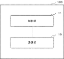
図1は、第1の実施形態における基地局装置100の構成の一例を示す。First Embodiment
FIG. 1 shows an example of the configuration of the
基地局装置100は、通信部10と制御部11を少なくとも有する。
The
通信部10は、種々の通信装置と通信を行う。
The
制御部11は、第一のタイミングで信号が送信されるときの予測される第一の通信品質に関する情報と、第二のタイミングで信号が再送されるときの予測される第二の通信品質に関する情報とに基づき、該信号に適用される変調符号化方式を決定する。
The
なお、制御部11が決定した変調符号化方式は、第一のタイミングで送信される信号、および、第二のタイミングで再送される信号の両方に適用される。
The modulation and coding scheme determined by the
第一の通信品質に関する情報や第二の通信品質に関する情報は、基地局装置と端末装置との間の通信品質を示す情報であれば良く、例えば、SINR(Signal to Interference Noise Ratio)である。 The information on the first communication quality and the information on the second communication quality may be any information indicating the communication quality between the base station apparatus and the terminal apparatus, and may be, for example, SINR (Signal to Interference Noise Ratio).
また、変調符号化方式は、MCSなど、1シンボル当たりで送信可能なビット数を示すものであれば良い。また、変調符号化方式は、MCS Indexであらわされる情報であっても良い。MCS Indexは、変調方式やデータレートを一意に示す。変調方式は、例えば、FSK(Frequency Shift Keying)、MSK(Minimum Shift Keying)、GMSK(Gaussian−filtered Minimum Shift Keying)、BPSK(Binary Phase Shift Keying)、QPSK(Quadrature Phase Shift Keying)、8PSK(Phase Shift Keying)、16QAM(Quadrature Amplitude Modulation)、64QAM、256QAMなどである。 Also, the modulation and coding scheme may be any one that indicates the number of bits that can be transmitted per symbol, such as MCS. Further, the modulation and coding scheme may be information represented by MCS index. The MCS index uniquely indicates the modulation scheme and data rate. The modulation method is, for example, frequency shift keying (FSK), minimum shift keying (MSK), Gaussian-filtered minimum shift keying (GMSK), binary phase shift keying (BPSK), quadrature phase shift keying (QPSK), or 8PSK (phase shift). Keying), 16 QAM (Quadrature Amplitude Modulation), 64 QAM, 256 QAM, and so on.
次に、本実施形態の基地局装置100の動作について、図2を用いて説明する。
Next, the operation of the
通信部10は、端末装置と通信を行う(ステップS10)。
The
制御部11は、第一のタイミングで信号が送信されるときの予測される第一の通信品質に関する情報と、第二のタイミングで信号が再送されるときの予測される第二の通信品質に関する情報とに基づき、該信号に適用される変調符号化方式を決定する(ステップS11)。
The
以上のようにして、本実施形態における基地局装置100は、第一のタイミングで信号が送信されるときの予測される第一の通信品質に関する情報と、第二のタイミングで信号が再送されるときの予測される第二の通信品質に関する情報とに基づき、該信号に適用される変調符号化方式を決定する。これにより、信号を再送する際の通信品質を考慮して変調符号化方式を決定することができる。
As described above, the
<第2の実施形態>
次に本発明の第2の実施形態における通信システムについて説明する。Second Embodiment
Next, a communication system in a second embodiment of the present invention will be described.
第1の実施形態では、基地局装置は、第一のタイミングで信号が送信されるときの予測される第一の通信品質に関する情報と、第二のタイミングで信号が再送されるときの予測される第二の通信品質に関する情報とを考慮して、該信号に適用される変調符号化方式を決定した。一方、本実施形態では、第一の通信品質と第二の通信品質のうち、より通信品質が悪い方の通信品質に関する情報に基づいて、該信号に適用される変調符号化方式を決定する。 In the first embodiment, the base station apparatus predicts when the signal is retransmitted at the second timing and information on the predicted first communication quality when the signal is transmitted at the first timing. And the information on the second communication quality was taken into consideration to determine the modulation and coding scheme to be applied to the signal. On the other hand, in the present embodiment, the modulation and coding scheme to be applied to the signal is determined based on the information related to the communication quality of the worse communication quality among the first communication quality and the second communication quality.
図3は、本実施形態における基地局装置200の構成の一例を示す。
FIG. 3 shows an example of the configuration of the
基地局装置200は、通信部10、制御部12を少なくとも有する。
The
通信部10は、第1の実施形態の通信部と同様である。
The
制御部12は、第一のタイミングで信号が送信されるときの予測される第一の通信品質に関する情報と第二のタイミングで信号が再送されるときの予測される第二の通信品質に関する情報の中から、通信品質が悪い方の通信品質に関する情報を選択する。さらに、制御部12は、選択した第一の通信品質に関する情報または第二の通信品質に関する情報に基づき、該信号に適用される変調符号化方式を決定する。
The
例えば、第二の通信品質が第一の通信品質よりも悪い場合、制御部12は、第二の通信品質に関する情報に基づいて、変調符号化方式を決定する。また、第一の通信品質が第二の通信品質よりも悪い場合、制御部12は、第一の通信品質に関する情報に基づいて、変調符号化方式を決定する。
For example, when the second communication quality is worse than the first communication quality, the
ここで、第一の通信品質に関する情報に基づいて決定される変調符号化方式を第一の変調符号化方式とし、第二の通信品質に関する情報に基づいて決定される変調符号化方式を第二の変調符号化方式とする。第二の通信品質が第一の通信品質よりも悪い場合、第二の変調符号化方式は、第一の変調符号化方式よりも1シンボル当たりで送信可能なビット数がより小さい変調符号化方式であれば良い。例えば、第二の通信品質が第一の通信品質よりも悪く、かつ、第一の変調符号化方式が示す変調方式が256QAMである場合、第二の変調符号化方式が示す変調方式は、例えば、FSK、MSK、GMSK、BPSK、QPSK、8PSK、16QAM、64QAM、のいずれかとなる。 Here, the modulation and coding scheme determined based on the information on the first communication quality is a first modulation and coding scheme, and the modulation and coding scheme determined on the basis of the information on the second communication quality is second Modulation coding scheme. When the second communication quality is worse than the first communication quality, the second modulation and coding scheme is a modulation and coding scheme in which the number of bits that can be transmitted per symbol is smaller than that of the first modulation and coding scheme. That's fine. For example, when the second communication quality is worse than the first communication quality, and the modulation scheme indicated by the first modulation and coding scheme is 256 QAM, the modulation scheme indicated by the second modulation and coding scheme is, for example, , FSK, MSK, GMSK, BPSK, QPSK, 8 PSK, 16 QAM, 64 QAM.
次に、本実施形態の基地局装置200の動作について、図4を用いて説明する。
Next, the operation of the
はじめに、制御部12は、第一のタイミングで信号が送信されるときの予測される第一の通信品質に関する情報と第二のタイミングで信号が再送されるときの予測される第二の通信品質に関する情報の中から、第一の通信品質と第二の通信品質のうち通信品質が悪い方の通信品質に関する情報を選択する(ステップS20)。
First, the
制御部12は、ステップS20で選択した第一の通信品質に関する情報または第二の通信品質に関する情報に基づき、変調符号化方式を決定する(ステップS21)。
The
本実施形態における基地局装置200は、第一のタイミングで信号が送信されるときの予測される通信品質と、第二のタイミングで信号が再送されるときの予測される通信品質の内、より通信品質が悪い通信品質に関する情報に基づき、変調符号化方式を決定する。
そのため、第一のタイミングで信号が送信されるときの予測される通信品質だけでなく、第二のタイミングで信号が再送されるときの予測される通信品質をも考慮し、該信号に適用される変調符号化方式を決定することができる。さらに、本実施形態における基地局装置200では、より悪い通信品質に対応した変調符号化方式が決定される。これにより、基地局装置と端末装置との間でより確実に信号を送受信することができ、信号が再送される回数を削減することができる。The
Therefore, not only the predicted communication quality when the signal is transmitted at the first timing but also the predicted communication quality when the signal is retransmitted at the second timing are considered, and applied to the signal. Modulation coding scheme can be determined. Furthermore, in the
<第3の実施形態>
次に、本発明における第3の実施形態における通信システムについて説明する。Third Embodiment
Next, a communication system according to a third embodiment of the present invention will be described.
本実施形態では、基地局装置は、第一のタイミングで信号が送信されるときの予測される第一の通信品質に関する情報が第一の値であり、第二のタイミングで信号が再送されるときの予測される第二の通信品質に関する情報が第二の値であるとする。そして、該第一の値と第二の値とを加重平均した情報に基づき、信号に適用される変調符号化方式を決定する。 In the present embodiment, in the base station apparatus, the information regarding the first communication quality predicted when the signal is transmitted at the first timing is the first value, and the signal is retransmitted at the second timing. It is assumed that the information on the second communication quality predicted at the time is the second value. Then, based on the information obtained by weighted averaging the first value and the second value, the modulation and coding scheme to be applied to the signal is determined.
以下では、第一の値を第一のSINR、第二の値を第二のSINRとして説明する。 Hereinafter, the first value will be described as a first SINR, and the second value as a second SINR.
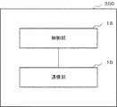
図5は、本実施形態における基地局装置300の構成の一例を示す。
FIG. 5 shows an example of the configuration of the
基地局装置300は、通信部10、制御部13を少なくとも有する。
The
通信部10は、第1の実施形態の通信部と同様である。
The
制御部13は、第一のSINRにαをかけた値と、第二のSINRにβをかけた値とに基づき、信号に適用される変調符号化方式を決定する。
The
なお、αおよびβは実数でも虚数でも良い。例えば、α=0.5、β=0.5である場合、制御部13は、第一のSINRと第二のSINRの平均値に基づき、変調符号化方式を決定することになる。また、例えば、αをβよりも大きな値にする場合、制御部13は、第二のSINRよりも第一のSINRをより考慮した変調符号化方式を決定することになる。
Note that α and β may be real numbers or imaginary numbers. For example, when α = 0.5 and β = 0.5, the
変調符号化方式を決定する際、第一のSINRと、第二のSINRのどちらをより考慮するかは、端末装置の種別に応じて決定または変更されても良いし、基地局装置−端末装置間の通信品質や、基地局装置と端末装置との間の距離に応じて決定または変更されても良い。あるいは、移動式の端末装置か固定式の端末装置かに基づき、αおよびβの値を決定または変更しても良い。また、端末装置がMTC(Machine Type Communications)のような機械端末であるか、ユーザーが操作する端末装置かに基づき、αおよびβの値を決定または変更しても良い。 When determining the modulation and coding scheme, which of the first SINR and the second SINR is considered more may be determined or changed according to the type of the terminal device, or the base station device-the terminal device It may be determined or changed according to the communication quality between the base station apparatus and the distance between the base station apparatus and the terminal apparatus. Alternatively, the values of α and β may be determined or changed based on whether the terminal is a mobile terminal or a fixed terminal. Further, the values of α and β may be determined or changed based on whether the terminal device is a machine terminal such as MTC (Machine Type Communications) or a terminal device operated by the user.
次に、本実施形態の基地局装置300の動作について、図6を用いて説明する。
Next, the operation of the
はじめに、制御部13は、第一のSINRにαをかける(ステップS30)。
First, the
制御部13は、第二のSINRにβをかける(ステップS31)。
The
制御部13は、第一のSINRにαをかけた値と、第二のSINRにβをかけた値とに基づき、信号に適用される変調符号化方式を決定する(ステップS32)。
The
本実施形態における基地局装置300は、第一のSINRだけでなく第二のSINRをも考慮して、信号に適用される変調符号化方式を決定することができる。さらに、本実施形態における基地局装置300は、第一のSINRと第二のSINRのどちらをより考慮するかを柔軟に変更することもできる。
The
<第4の実施形態>
次に、本発明の第4の実施形態について説明する。本実施形態における通信システムは、第1の実施形態における通信システムをより具体的にしたものである。Fourth Embodiment
Next, a fourth embodiment of the present invention will be described. The communication system in the present embodiment is more specific to the communication system in the first embodiment.
本実施形態では、第一のタイミングで信号が送信されるときの予測される第一の通信品質に関する情報が第一の値であり、第二のタイミングで信号が再送されるときの予測される第二の通信品質に関する情報が第二の値であるとする。 In this embodiment, the information regarding the first communication quality predicted when the signal is transmitted at the first timing is the first value, and the information is predicted when the signal is retransmitted at the second timing. The information on the second communication quality is assumed to be the second value.
以下では、第一の値を第一のSINR、第二の値を第二のSINRとして説明する。 Hereinafter, the first value will be described as a first SINR, and the second value as a second SINR.
図7は、本実施形態における基地局装置400の構成の一例を示す。
FIG. 7 shows an example of the configuration of the
基地局装置400は、通信部10、制御部14を少なくとも有する。
The
通信部10は、第1の実施形態の通信部と同様である。
The
制御部14は、第一のSINRと第二のSINRとの差に基づき、オフセット値を決定する。制御部14は、決定したオフセット値と、第一のSINRに基づき決定される変調符号化方式とに基づき、信号に適用される変調符号化方式を決定する。
The
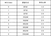
以下、制御部14が決定する変調符号化方式が、MCS Indexであらわされる情報であるとして、さらに具体的な例を説明する。MCS Indexと変調方式は、例えば、図8に示す表のような関係を有する。また、第一のSINRに基づいて決定されるMCS Indexは7であるとする。
A more specific example will be described below, assuming that the modulation and coding scheme determined by the
第一のSINRと第二のSINRとが異なる場合、制御部14は、MCS Indexのオフセット値を決定する。例えば、第一のSINRが第二のSINRよりも大きい場合のオフセット値はマイナスN(Nは自然数)とする。この場合、制御部14は、MCS Indexを、7からN差し引いた値とする。一方、第一のSINRが第二のSINRよりも小さい場合のオフセット値はプラスM(Mは自然数)とする。この場合、制御部14は、MCS Indexを、7にMを加えた値とする。
If the first SINR and the second SINR are different, the
なお、第一のSINRと第二のSINRとが同一である場合、制御部14はオフセット値をゼロとして、MCS Indexを決定しても良い。
When the first SINR and the second SINR are the same, the
また、オフセット値の大きさは、第一のSINRと第二のSINRとの差に基づいて決定されても良い。例えば、第一のSINRと第二のSINRとの差が大きい程、オフセット値が大きくなるように、オフセット値を設定しても良い。また、第一のSINRと第二のSINRとの差が小さい場合、オフセット値は小さい値(またはゼロ)であっても良い。 Also, the magnitude of the offset value may be determined based on the difference between the first SINR and the second SINR. For example, the offset value may be set such that the offset value increases as the difference between the first SINR and the second SINR increases. In addition, when the difference between the first SINR and the second SINR is small, the offset value may be a small value (or zero).
次に、本実施形態の基地局装置400の動作について、図9を用いて説明する。
Next, the operation of the
制御部14は、第一のSINRと第二のSINRとの差に基づき、オフセット値を決定する(ステップS40)。
The
制御部14は、決定したオフセット値と、第一のSINRに基づき決定される変調符号化方式とに基づき、変調符号化方式を決定する(ステップS41)。
The
本実施形態における基地局装置400は、第1の実施形態に記載した基地局装置と同様の効果を奏する。
The
次に、上述の第4の実施形態の変形例を説明する。 Next, a modified example of the above-described fourth embodiment will be described.
上述の第4の実施形態における基地局装置は、第一のSINRに基づき決定されるMCS Indexに、MCS Indexのオフセット値を加算(または減算)した。一方、次に述べる第4の実施形態の変形例における基地局装置は、第一のSINRと第二のSINRとの差に基づき決定されたSINRのオフセット値を、第一のSINRに加算(または減算)する。 The base station apparatus according to the fourth embodiment described above adds (or subtracts) the offset value of the MCS index to the MCS index determined based on the first SINR. On the other hand, the base station apparatus in the modification of the fourth embodiment to be described next adds the SINR offset value determined based on the difference between the first SINR and the second SINR to the first SINR (or To subtract.
図10は、第4の実施形態の変形例における基地局装置410の構成の一例を示す。
FIG. 10 shows an example of the configuration of a
基地局装置410は、通信部10、制御部15を少なくとも有する。
The
通信部10は、第1の実施形態の通信部と同様である。
The
制御部15は、第一のSINRと第二のSINRとの差に基づき、SINRのオフセット値を決定する。制御部15は、第一のSINRと決定したオフセット値とに基づき、変調符号化方式を決定する。
The
以下の具体例では、制御部15が決定する変調符号化方式は、MCS Indexであらわされる情報であるとする。
In the following specific example, it is assumed that the modulation and coding scheme determined by the
第一のSINRと第二のSINRとが異なる場合、制御部15は、SINRのオフセット値を決定する。例えば、第一のSINRが第二のSINRよりも大きい場合のオフセット値はマイナスP(Pは自然数)とする。この場合、制御部15は、第一のSINRからP差し引いた値を第三のSINRとし、第三のSINRに基づいてMCS Indexを決定する。一方、第一のSINRが第二のSINRよりも小さい場合のオフセット値はプラスQ(Qは自然数)であるとする。この場合、制御部15は、第一のSINRにQを加えた値を第三のSINRとし、第三のSINRに基づいてMCS Indexを決定する。
When the first SINR and the second SINR are different, the
なお、第一のSINRと第二のSINRとが同一である場合、制御部15はオフセット値をゼロとして、MCS Indexを決定しても良い。
When the first SINR and the second SINR are the same, the
また、オフセット値の大きさは、第一のSINRと第二のSINRとの差に基づいて決定されても良い。例えば、第一のSINRと第二のSINRとの差が大きい程、オフセット値が大きくなるように、オフセット値を設定しても良い。 Also, the magnitude of the offset value may be determined based on the difference between the first SINR and the second SINR. For example, the offset value may be set such that the offset value increases as the difference between the first SINR and the second SINR increases.
次に、本実施形態の基地局装置410の動作について、図11を用いて説明する。
Next, the operation of the
制御部15は、第一のSINRと第二のSINRとの差に基づき、SINRのオフセット値を決定する(ステップS42)。
The
制御部15は、第一のSINRと決定したオフセット値とに基づき、変調符号化方式を決定する(ステップS43)。
The
本実施形態における基地局装置410は、第1の実施形態に記載した基地局装置と同様の効果を奏する。
<第5の実施形態>
本発明における第5の実施形態においては、本発明をLTE方式の通信システムに適用した場合について説明する。The
Fifth Embodiment
In the fifth embodiment of the present invention, a case where the present invention is applied to a communication system of the LTE system will be described.
図12は、本実施形態に係る通信システムの構成例を示している。当該通信システムは通信サービス、例えば音声通信若しくはパケットデータ通信又はこれら両方を提供する。
図12を参照すると、当該通信システムは、基地局装置500と、基地局装置500の通信エリアであるマクロセル510と、基地局装置520と、基地局装置520の通信エリアであるスモールセル530と、基地局装置500と通信する端末装置540と、基地局装置520と通信する端末装置550を含む。FIG. 12 shows a configuration example of a communication system according to the present embodiment. The communication system provides communication services, such as voice communication and / or packet data communication.
12, the communication system includes a
LTE(Long Term Evolution)方式において、セル間干渉を低減するためにeICIC(Enhanced Inter Cell Interference Coordination)が採用されている。eICICでは、セル間干渉を低減するために、ABS(Almost Blanc Subframe)が規定されている。原則として、端末装置はABS Subframe以外でデータ送信を行い、ABS Subframeではデータ送信を行わない。 Enhanced Inter Cell Interference Coordination (eICIC) is employed in LTE (Long Term Evolution) to reduce inter-cell interference. In eICIC, ABS (Almost Blanc Subframe) is defined to reduce inter-cell interference. In principle, the terminal device transmits data except for ABS Subframe, and does not transmit data in ABS Subframe.
図13にABSパタンの一例を示す。Subframe#0、#3−#5、#9−#10、#13−#15、#20はABS subframe、その他のsubframeはNon ABS subframeに設定されている。ここで、マクロセル510とスモールセル530の間では、フレームタイミングの同期が取れているとする。マクロセル510には、図13に示すようなABSパタンが設定されている。
FIG. 13 shows an example of the ABS pattern.
以下では、端末装置が基地局装置に信号を送信するUL(Up Link)送信について説明を行うが、以下の動作は基地局装置から端末装置へのDL(Down Link)送信に当てはめても良い。 The following describes UL (Up Link) transmission in which the terminal device transmits a signal to the base station device, but the following operation may be applied to DL (Down Link) transmission from the base station device to the terminal device.
マクロセル510では、Non ABS subframeで端末装置540が基地局装置500へのUL送信を行う。マクロセル510がNon ABS subframeであるsubframeでは、基地局装置520と端末装置550との間の通信はマクロセル510からの干渉を受ける。一方、マクロセル510がABS subframeであるsubframeでは、基地局装置520と端末装置550との間の通信はマクロセル510からの干渉を受けない。
In the
基地局装置500や基地局装置520は、受信誤りが発生した場合にノンアダプティブ再送を行う機能を有する。ノンアダプティブ再送とは、基地局装置が端末装置に割り当てたリソースと同一のリソースに、再送信号が割り当てられる動作をいう。例えば、スモールセル530で、subframe#0において端末装置550がUL送信を行い、このUL送信を受信する基地局装置520で受信誤りが発生したとする。ノンアダプティブ再送が行われる場合、初送のsubframe#0は低干渉のsubframeであったが、再送タイミングであるsubframe#8(再送は初送の8subframe後であるとする)は高干渉のsubframeとなる。
図14に、本実施形態の基地局装置520の構成の一例を示す。
An example of a structure of the
基地局装置520は、通信部10、制御部16を少なくとも有する。
The
通信部10は、第1の実施形態の通信部と同様である。
The
制御部16は、図15に示すようにSINR算出部160と決定部161を少なくとも有する。
The
ABSパタン情報はそれぞれSINR算出部160と決定部161のそれぞれに入力される。ここでABSパタン情報は、マクロセル510で使用されるABSパタン情報である。端末装置550から基地局装置520へのUL送信信号は、SINR算出部160に入力される。
The ABS pattern information is input to the
SINR算出部160は、UL受信信号とABSパタン情報とに基づき、SINRを算出する。算出されたSINRは、SINR情報として決定部161へ出力される。
The
なお、UL受信信号は、CQI(Channel Quality Indicator)、RSRP(Reference Signal Received Power)、RSRQ(Reference Signal Received Quality)、パスロス(Pathloss)、SRS(Sounding Reference Signal)、DM−RS(Demodulation Reference Signal)などの品質に関する種々の情報であっても良い。 The UL received signal may be a channel quality indicator (CQI), a reference signal received power (RSRP), a reference signal received quality (RSRQ), a path loss, a sounding reference signal (SRS), or a demodulation reference signal (DM-RS). It may be various information about quality such as.
決定部161は、SINR情報とABSパタン情報とに基づき、MCSを決定する。決定されたMCSは、MCS情報として出力される。
The
図16は、SINR算出部160の詳細構成を示す。
FIG. 16 shows a detailed configuration of the
SINR算出部160は、S算出部1600、第一のI+N算出部1601、第二のI+N算出部1602、第一のSINR算出部1603、第二のSINR算出部1604を少なくとも有する。
The
S算出部1600は、UL受信信号に基づき、端末装置からの希望信号電力を算出して出力する。例えば、S算出部1600は、端末装置から送信されるSRSに基づき、希望信号電力を算出する。あるいは、S算出部1600は、端末装置から送信されるDM−RSに基づき、希望信号電力を算出しても良い。
The
第一のI+N算出部1601は、UL受信信号とABSパタン情報とに基づき、低干渉のsubframeでの干渉雑音電力を算出する。第二のI+N算出部1602は、UL受信信号とABSパタン情報とに基づき、高干渉のsubframeでの干渉雑音電力を算出する。第一のI+N算出部1601および第二のI+N算出部1602は、例えば、端末装置から送信されるDM−RSに基づき、干渉雑音電力を算出する。あるいは、第一のI+N算出部1601および第二のI+N算出部1602は、端末装置から送信されるSRSに基づき、干渉雑音電力を算出しても良い。なお、希望信号電力および干渉雑音電力は、複数のsubframeでの平均値として算出しても良い。
The first I +
第一のSINR算出部1603は、S算出部1600で算出された希望信号電力と、第一のI+N算出部1601で算出された低干渉のsubframeでの干渉雑音電力に基づき、第一のSINR情報を算出して出力する。
The first
第二のSINR算出部1604は、S算出部1600で算出された希望信号電力と、第二のI+N算出部1602で算出された高干渉のsubframeでの干渉雑音電力とに基づき、第二のSINR情報を算出して出力する。
The second
図17は、決定部161の詳細構成を示す。
FIG. 17 shows the detailed configuration of the
決定部161は、オフセット決定部1610とMCS決定部1611とを少なくとも有する。
The
オフセット決定部1610は、ABSパタン情報に基づいて、端末装置550の初送タイミングと再送タイミングのそれぞれが低干渉のsubframeか高干渉のsubframeかにより、第一のSINR情報または第二のSINR情報を選択する。例えば、オフセット決定部1610は、初送タイミングが低干渉のsubframeであれば、第一のSINR情報を選択する。また、オフセット決定部1610は、再送タイミングが高干渉のsubframeであれば第二のSINR情報を選択する。そして、初送タイミングのSINRと再送タイミングのSINRを比較して、再送タイミングのSINRの方が初送タイミングのSINRより小さい場合にはあらかじめ定められたオフセット値を出力する。一方、再送タイミングのSINRが初送タイミングのSINR以上の場合には0の値をMCS決定部1611へ出力する。
The offset
MCS決定部1611は、端末装置550の初送タイミングが低干渉のsubframeか高干渉のsubframeかに基づき、第一のSINR情報または第二のSINR情報の一方を選択し、選択したSINR情報に基づきMCSを決定する。さらに、MCS決定部1611は、オフセット決定部1610から出力されるオフセット値を、決定したMCSに加算して最終的なMCSを決定する。そして、MCS決定部1611は、該最終的なMCSをMCS情報として出力する。
The
次にMCS決定までの動作を図18に示すフローチャートを使用して説明する。 Next, the operation up to the determination of the MCS will be described using the flowchart shown in FIG.
S算出部1600は、UL受信信号に基づき、端末装置550からの希望信号電力を算出する(ステップS50)。
The
第一のI+N算出部1601は、UL受信信号とABSパタン情報とに基づき、低干渉のsubframeでの干渉雑音電力を算出する(ステップS51)。
The first I +
第二のI+N算出部1602は、UL受信信号とABSパタン情報とに基づき、高干渉のsubframeでの干渉雑音電力を算出する(ステップS52)。
The second I +
第一のSINR算出部1603は、希望信号電力と低干渉のsubframeでの干渉雑音電力とに基づき、第一のSINR情報を算出する(ステップS53)。
The first
第二のSINR算出部1604は、希望信号電力と高干渉のsubframeでの干渉雑音電力とに基づき、第二のSINR情報を算出する(ステップS54)。
The second
オフセット決定部1610は、ABSパタン情報に基づいて、端末装置550の初送タイミングと再送タイミングのそれぞれが低干渉のsubframeか高干渉のsubframeかにより、第一のSINR情報または第二のSINR情報を選択する(ステップS55)。
The offset
MCS決定部1611は、選択したSINR情報に基づきMCSを決定する(ステップS56)。
The
MCS決定部1611は、オフセット決定部1610から出力されるオフセット値を、決定したMCSに加算して最終的なMCSを決定する。そして、該最終的なMCSを、MCS情報として出力する(ステップS57)。
The
本実施形態における基地局装置520は、ABSパタン情報を用いて、初送と再送における通信品質を予測することができる。そして、予測した通信品質に基づき、MCSを決定することができる。そのため、ABSパタンが設定された環境下でも、信号を再送する回数を削減することができる。
The
<第6の実施形態>
本実施形態では、基地局装置は端末装置に対し、決定した変調符号化方式に関する情報を送信する機能を有する。Sixth Embodiment
In this embodiment, the base station apparatus has a function of transmitting information on the determined modulation and coding scheme to the terminal apparatus.
図19は、本実施形態における基地局装置600の構成の一例を示す。
FIG. 19 shows an example of the configuration of the
基地局装置600は、通信部17、制御部18を少なくとも有する。
The
通信部17は、制御部18が決定した変調符号化方式に関する情報を端末装置610に送信する。
The
制御部18は、上述の制御部11〜制御部16までの動作のいずれかを行う。
The
図20は、本実施形態における端末装置610の構成の一例を示す。
FIG. 20 shows an example of the configuration of the
端末装置610は、受信部20と送信部21を少なくとも有する。
The
受信部20は、基地局装置600から制御部18が決定した変調符号化方式に関する情報を受信する。
The receiving
送信部21は、受信部20が受信した変調符号化方式に関する情報に基づき、基地局600に信号を送信または再送する。
The
次に、本実施形態の基地局装置600の動作について、図21を用いて説明する。
Next, the operation of the
はじめに、制御部18は、上述の制御部11〜制御部16までの動作のいずれかを行う(ステップS60)。
First, the
通信部17は、制御部18が決定した変調符号化方式に関する情報を端末装置610に送信する(ステップS61)。
The
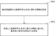
次に、本実施形態の端末装置610の動作について、図22を用いて説明する。
Next, the operation of the
はじめに、受信部20は、基地局装置600から制御部18が決定した変調符号化方式に関する情報を受信する(ステップS62)。
First, the receiving
送信部21は、受信部20が受信した変調符号化方式に関する情報に基づき、基地局600に信号を送信または再送する(ステップS63)。
The transmitting
本実施形態における基地局装置600は、決定した変調符号化方式に関する情報を端末装置に送信する。そのため、端末装置は当該変調符号化方式に関する情報に基づき、基地局装置に対しUL送信を行うことができる。
The
なお、上述の実施形態では、基地局装置600が決定した変調符号化方式に関する情報に基づいて、端末装置610がUL送信を行ったが、基地局装置600が決定した変調符号化方式に関する情報に基づいて、基地局装置600が端末装置610に対しDL送信を行っても良い。
In the above embodiment, although the
なお、上述の各実施形態では、制御部は、第一のタイミング(または初送)および第二のタイミング(または再送)の2つのタイミングにおける通信品質に関する情報を考慮したが、第Nのタイミング(Nは自然数)までの通信品質に関する情報を考慮しても良い。
例えば、Nは最大再送回数でも良い。また、制御部は、N回までの送信タイミングにおいて、高干渉のsubframeとなるsubframeの数(または高干渉のsubframeとなる割合)に基づき、オフセット値を設定しても良い。In each of the above-described embodiments, the control unit considers information on communication quality at two timings of the first timing (or first transmission) and the second timing (or retransmission). Information on communication quality up to N may be taken into consideration.
For example, N may be the maximum number of retransmissions. Also, the control unit may set the offset value based on the number of subframes (or the ratio of subframes of high interference) that are subframes of high interference at transmission timings up to N times.
また、上述した各実施形態の各処理は、ソフトウェアによって実行されてもよい。すなわち、各処理を行うためのコンピュータ・プログラムが、情報処理装置が備えるCPU(Central Processing Unit)によって読み込まれ、実行されてもよい。プログラムを用いて各処理を行っても、上述の実施形態の処理と同内容の処理を行うことができる。そして、上記のプログラムは、ROM(Read Only Memory)、RAM(Random Access Memory)、フラッシュメモリ等の半導体記憶装置、光ディスク、磁気ディスク、光磁気ディスク等、非一時的な媒体に格納されてもよい。 Moreover, each process of each embodiment mentioned above may be performed by software. That is, a computer program for performing each process may be read and executed by a central processing unit (CPU) included in the information processing apparatus. Even if each process is performed using a program, the process of the same content as the process of the above-mentioned embodiment can be performed. The above program may be stored in a non-temporary medium such as a ROM (Read Only Memory), a RAM (Random Access Memory), a semiconductor storage device such as a flash memory, an optical disc, a magnetic disc, a magneto-optical disc, etc. .
上記の各実施形態の一部又は全部は、以下の付記のようにも記載されうるが、以下には限られない。 Although a part or all of each above-mentioned embodiment may be described as the following additional remarks, it is not restricted to the following.
(付記1)第一のタイミングで信号が送信されるときの予測される第一の通信品質に関する情報と、第二のタイミングで前記信号が再送されるときの予測される第二の通信品質に関する情報とに基づき、前記信号に適用する第一の変調符号化方式を決定する制御部と、前記第一の変調符号化方式に関する情報に基づき、端末装置に前記信号を送信する送信部と、を有する、基地局装置。 (Supplementary Note 1) Information on the predicted first communication quality when the signal is transmitted at the first timing, and the predicted second communication quality when the signal is retransmitted at the second timing A control unit that determines a first modulation and coding scheme to be applied to the signal based on information; and a transmission unit that transmits the signal to a terminal device based on information on the first modulation and coding scheme Base station apparatus having.
(付記2)前記制御部は、前記第一の通信品質よりも前記第二の通信品質の方が悪い場合、前記第二の通信品質に関する情報に基づき、前記第一の変調符号化方式を決定する、付記1に記載の基地局装置。
(Supplementary Note 2) If the second communication quality is worse than the first communication quality, the control unit determines the first modulation and coding scheme based on the information on the second communication quality. The base station apparatus according to
(付記3)前記第一の通信品質に関する情報が第一の値であり、前記第二の通信品質の関する情報が第二の値である場合、前記制御部は前記第一の値と前記第二の値との平均値に基づいて、前記第一の変調符号化方式を決定する、付記1に記載の基地局装置。
(Supplementary Note 3) If the information on the first communication quality is a first value and the information on the second communication quality is a second value, the control unit may determine the first value and the second value. The base station apparatus according to
(付記4)前記第一の通信品質に関する情報が第一の値であり、前記第二の通信品質に関する情報が第二の値である場合、前記制御部は、第一の値と第二の値との差に基づいて決定されたオフセット値と、前記第一の値に基づいて決定される第二の変調符号化方式と、に基づいて、前記第一の変調符号化方式を決定する、付記1に記載の基地局装置。
(Supplementary Note 4) If the information on the first communication quality is a first value and the information on the second communication quality is a second value, the control unit may determine the first value and the second value. The first modulation and coding scheme is determined based on an offset value determined based on a difference between the values and a second modulation and coding scheme determined based on the first value. The base station apparatus according to
(付記5)前記第一の通信品質に関する情報が第一の値であり、前記第二の通信品質に関する情報が第二の値である場合、前記制御部は、前記第一の値に、前記第一の値と第二の値との差に基づいて決定されたオフセット値を加えた値に基づき、前記第一の変調符号化方式を決定する、付記1に記載の基地局装置。
(Supplementary Note 5) If the information on the first communication quality is a first value and the information on the second communication quality is a second value, the control unit may set the first value to the first value. The base station apparatus according to
(付記6)前記制御部は、前記第二の通信品質が前記第一の通信品質よりも悪い場合、前記第一の情報に基づいて決定される第二の変調符号化方式よりも1シンボル当たりで送信可能なビット数がより小さい変調符号方式を、前記第一の変調符号化方式とする、付記1〜5のいずれか1つに記載の基地局装置。
(Supplementary Note 6) If the second communication quality is worse than the first communication quality, the control unit performs one symbol per symbol more than the second modulation and coding scheme determined based on the first information. 5. The base station apparatus according to any one of
(付記7)前記基地局装置はスモールセル基地局装置であり、前記基地局装置に隣接する隣接基地局装置はマクロセル基地局装置であり、前記マクロセル基地局装置にはAlmost Blanc Subframe(ABS) subframeとNon ABS subframeとが設定されており、前記第一のタイミングは前記ABS subframeのタイミングであり、前記第二のタイミングは前記Non ABS subframeのタイミングであり、前記第一の通信品質に関する情報は、前記ABS subframeのタイミングに、端末装置と前記スモールセル基地局装置との間で前記信号が送信されるときの通信品質に関する情報であり、前記第二の通信品質に関する情報は、前記Non ABS subframeのタイミングに、前記端末装置と前記スモールセル基地局装置との間で前記信号が送信されるときの通信品質に関する情報である、付記1〜6のいずれか1つに記載の基地局装置。
(Supplementary Note 7) The base station apparatus is a small cell base station apparatus, the adjacent base station apparatus adjacent to the base station apparatus is a macro cell base station apparatus, and for the macro cell base station apparatus, Almost Blanc Subframe (ABS) subframe And the Non ABS subframe are set, the first timing is the timing of the ABS subframe, the second timing is the timing of the Non ABS subframe, and the information on the first communication quality is The information on the communication quality when the signal is transmitted between the terminal apparatus and the small cell base station apparatus at the timing of the ABS subframe, and the information on the second communication quality is the information on the Non ABS subframe. The The base station apparatus according to any one of
(付記8)前記第一の変調符号化方式に関する情報を前記端末装置に送信する送信部をさらに有する、付記1〜7のいずれか1つに記載の基地局装置。
(Supplementary note 8) The base station apparatus according to any one of
(付記9)基地局装置と端末装置からなる通信システムであって、前記基地局装置は、第一のタイミングで信号が送信されるときの予測される第一の通信品質に関する情報と、第二のタイミングで前記信号が再送されるときの予測される第二の通信品質に関する情報とに基づき、前記信号に適用する第一の変調符号化方式を決定する制御部と、前記第一の変調符号化方式に関する情報を、前記端末装置に送信する送信部とを有し、前記端末装置は、前記第一の変調符号化方式に関する情報を前記基地局装置から受信する受信部を有する、通信システム。 (Supplementary note 9) A communication system including a base station apparatus and a terminal apparatus, wherein the base station apparatus is configured to receive information on a first communication quality predicted when a signal is transmitted at a first timing, and A controller for determining a first modulation and coding scheme to be applied to the signal based on information on a predicted second communication quality when the signal is retransmitted at a timing of A communication system, comprising: a transmitter configured to transmit information related to a modulation scheme to the terminal apparatus, wherein the terminal apparatus includes a receiver configured to receive information related to the first modulation and coding scheme from the base station apparatus.
(付記10)第一のタイミングで信号が送信されるときの予測される第一の通信品質に関する情報と、第二のタイミングで前記信号が再送されるときの予測される第二の通信品質に関する情報とに基づき、前記信号に適用する第一の変調符号化方式を決定するステップを含む、制御方法。 (Supplementary note 10) Information on the predicted first communication quality when the signal is transmitted at the first timing and the predicted second communication quality when the signal is retransmitted at the second timing Determining a first modulation and coding scheme to apply to the signal based on the information.
(付記11)第一のタイミングで信号が送信されるときの予測される第一の通信品質に関する第一の情報と、第二のタイミングで前記信号が再送されるときの予測される第二の通信品質に関する第二の情報とに基づき決定された第一の変調符号化方式に関する情報を基地局装置から受信するステップと、前記第一の変調符号化方式に関する情報に基づき、前記基地局装置に前記信号を送信するステップとを含む、制御方法。 (Supplementary note 11) first information on predicted first communication quality when a signal is transmitted at a first timing, and second predicted information when the signal is retransmitted at a second timing Receiving, from the base station apparatus, information on a first modulation and coding scheme determined based on second information on communication quality, and, on the basis of the information on the first modulation and coding scheme, And transmitting the signal.
(付記12)コンピュータ上で実行された際に、第一のタイミングで信号が送信されるときの予測される第一の通信品質に関する情報と、第二のタイミングで前記信号が再送されるときの予測される第二の通信品質に関する情報とに基づき、前記信号に適用する第一の変調符号化方式を決定する工程を有する制御方法を実行することが可能なプログラムコードを有するプログラム。 (Supplementary note 12) Information on a first communication quality predicted when a signal is transmitted at a first timing when executed on a computer, and when the signal is retransmitted at a second timing A program comprising program code capable of executing a control method comprising the step of determining a first modulation and coding scheme to be applied to said signal based on information about a predicted second communication quality.
(付記13)コンピュータ上で実行された際に、第一のタイミングで信号が送信されるときの予測される第一の通信品質に関する第一の情報と、第二のタイミングで前記信号が再送されるときの予測される第二の通信品質に関する第二の情報とに基づき決定された第一の変調符号化方式に関する情報を基地局装置から受信する工程と、前記第一の変調符号化方式に関する情報に基づき、前記基地局装置に前記信号を送信する工程を有する制御方法を実行することが可能なプログラムコードを有するプログラム。 (Supplementary Note 13) When executed on a computer, the signal is retransmitted at a second timing with first information on a first communication quality predicted when the signal is transmitted at a first timing. Receiving from the base station apparatus information on a first modulation and coding scheme determined on the basis of second information on second communication quality predicted at the same time, and the first modulation and coding scheme A program having a program code capable of executing a control method comprising the step of transmitting the signal to the base station apparatus based on information.
(付記14)コンピュータに読み取り可能な情報記憶媒体であって、付記12に記載のプログラムを記憶する記憶媒体。
(Supplementary note 14) A computer-readable information storage medium storing the program according to
(付記15)コンピュータに読み取り可能な情報記憶媒体であって、付記13に記載のプログラムを記憶する記憶媒体。
(Supplementary note 15) A computer-readable information storage medium storing the program according to
(付記16)第一のタイミングで信号が送信されるときの予測される第一の通信品質に関する第一の情報と、第二のタイミングで前記信号が再送されるときの予測される第二の通信品質に関する第二の情報とに基づき決定された第一の変調符号化方式に関する情報を基地局装置から受信する受信部と、前記第一の変調符号化方式に関する情報に基づき、前記基地局装置に前記信号を送信する送信部と、を有する、端末装置。 (Supplementary note 16) first information on predicted first communication quality when a signal is transmitted at a first timing, and second predicted information when the signal is retransmitted at a second timing A receiving unit for receiving from the base station apparatus information on a first modulation and coding scheme determined based on second information on communication quality; and the base station apparatus based on information on the first modulation and coding scheme And a transmitter for transmitting the signal.
以上、実施形態を参照して本願発明を説明したが、本願発明は上記実施形態に限定されるものではない。本願発明の構成や詳細には、本願発明のスコープ内で当業者が理解し得る様々な変更をすることができる。 Although the present invention has been described above with reference to the embodiments, the present invention is not limited to the above embodiments. The configurations and details of the present invention can be modified in various ways that can be understood by those skilled in the art within the scope of the present invention.
この出願は、2015年9月30日に出願された日本出願特願2015−193436を基礎とする優先権を主張し、その開示の全てをここに取り込む。 This application claims priority based on Japanese Patent Application No. 2015-193436 filed on September 30, 2015, the entire disclosure of which is incorporated herein.
10、17 通信部
11、12、13、14、15、16、18 制御部
20 受信部
21 送信部
100、200、300、400、410、500、520、600 基地局装置
160 SINR算出部
161 決定部
510 マクロセル
530 スモールセル
540、550、610 端末装置
1600 S算出部
1601 第一のI+N算出部
1602 第二のI+N算出部
1603 第一のSINR算出部
1604 第二のSINR算出部
1610 オフセット決定部
1611 MCS決定部10, 17
Claims (9)
基地局装置。 Based on the information on the predicted first communication quality when the signal is transmitted at the first timing and the information on the predicted second communication quality when the signal is retransmitted at the second timing A controller configured to determine a first modulation and coding scheme to be applied to the signal;
Base station device.
請求項1に記載の基地局装置。 When the second communication quality is worse than the first communication quality, the control unit determines the first modulation and coding scheme based on information on the second communication quality.
The base station apparatus according to claim 1.
請求項1に記載の基地局装置。 When the information on the first communication quality is a first value and the information on the second communication quality is a second value, the control unit is configured to set the first value and the second value. Determining the first modulation and coding scheme based on an average value of
The base station apparatus according to claim 1.
前記制御部は、第一の値と第二の値との差に基づいて決定されたオフセット値と、前記第一の値に基づいて決定される第二の変調符号化方式と、に基づいて、前記第一の変調符号化方式を決定する、
請求項1に記載の基地局装置。 If the information on the first communication quality is a first value and the information on the second communication quality is a second value:
The control unit is configured to determine an offset value determined based on a difference between the first value and the second value, and a second modulation and coding scheme determined based on the first value. , Determining the first modulation and coding scheme,
The base station apparatus according to claim 1.
前記制御部は、前記第一の値に、前記第一の値と第二の値との差に基づいて決定されたオフセット値を加えた値に基づき、前記第一の変調符号化方式を決定する、
請求項1に記載の基地局装置。 If the information on the first communication quality is a first value and the information on the second communication quality is a second value:
The control unit determines the first modulation and coding scheme based on a value obtained by adding an offset value determined based on a difference between the first value and a second value to the first value. Do,
The base station apparatus according to claim 1.
請求項1〜5のいずれか1項に記載の基地局装置。 When the second communication quality is worse than the first communication quality, the control unit performs one symbol per symbol more than the second modulation and coding scheme determined based on the information on the first communication quality. Let a modulation coding scheme with a smaller number of transmittable bits be the first modulation coding scheme,
The base station apparatus according to any one of claims 1 to 5.
請求項1〜6のいずれか1項に記載の基地局装置。 Further comprising a transmitter for transmitting information relating to the first modulation and coding scheme to an end terminal device,
The base station apparatus of any one of Claims 1-6 .
前記マクロセル基地局装置にはAlmost Blanc Subframe(ABS) subframeとNon ABS subframeとが設定されており、
前記第一のタイミングは前記ABS subframeのタイミングであり、
前記第二のタイミングは前記Non ABS subframeのタイミングであり、
前記第一の通信品質に関する情報は、前記ABS subframeのタイミングに、前記端末装置と前記スモールセル基地局装置との間で前記信号が送信されるときの通信品質に関する情報であり、
前記第二の通信品質に関する情報は、前記Non ABS subframeのタイミングに、前記端末装置と前記スモールセル基地局装置との間で前記信号が送信されるときの通信品質に関する情報である
請求項7に記載の基地局装置。 The base station apparatus is a small cell base station apparatus, the adjacent base station apparatus adjacent to the base station apparatus is a macrocell base station apparatus,
Almost blank subframe (ABS) subframe and non ABS subframe are set in the macro cell base station device,
The first timing is the timing of the ABS subframe,
The second timing is the timing of the non ABS subframe,
Information relating to the first communication quality, the timing of the ABS subframe, is information about the communication quality when the signal is transmitted between the terminal apparatus and the small base station apparatus,
Information relating to the second communication quality, the timing of the Non ABS subframe, to claim 7, which is information about the communication quality when the signal is transmitted between the terminal apparatus and the small base station apparatus The base station apparatus as described.
前記基地局装置は、
第一のタイミングで信号が送信されるときの予測される第一の通信品質に関する情報と、第二のタイミングで前記信号が再送されるときの予測される第二の通信品質に関する情報とに基づき、前記信号に適用する第一の変調符号化方式を決定する制御部と、
前記第一の変調符号化方式に関する情報を、前記端末装置に送信する送信部とを有し、
前記端末装置は、
前記第一の変調符号化方式に関する情報を前記基地局装置から受信する受信部を有する、通信システム。 A communication system comprising a base station apparatus and a terminal apparatus,
The base station apparatus
Based on the information on the predicted first communication quality when the signal is transmitted at the first timing and the information on the predicted second communication quality when the signal is retransmitted at the second timing A control unit that determines a first modulation and coding scheme to be applied to the signal;
A transmitter configured to transmit information on the first modulation and coding scheme to the terminal device;
The terminal device is
The communication system which has a receiving part which receives the information regarding the said 1st modulation coding system from the said base station apparatus.
Applications Claiming Priority (3)
| Application Number | Priority Date | Filing Date | Title |
|---|---|---|---|
| JP2015193436 | 2015-09-30 | ||
| JP2015193436 | 2015-09-30 | ||
| PCT/JP2016/004264 WO2017056446A1 (en) | 2015-09-30 | 2016-09-20 | Communication device, communication system, control method, and communication program |
Publications (2)
| Publication Number | Publication Date |
|---|---|
| JPWO2017056446A1 JPWO2017056446A1 (en) | 2018-07-26 |
| JP6536682B2 true JP6536682B2 (en) | 2019-07-03 |
Family
ID=58422940
Family Applications (1)
| Application Number | Title | Priority Date | Filing Date |
|---|---|---|---|
| JP2017542724A Active JP6536682B2 (en) | 2015-09-30 | 2016-09-20 | Base station apparatus, terminal apparatus and communication system |
Country Status (5)
| Country | Link |
|---|---|
| US (1) | US10530521B2 (en) |
| EP (1) | EP3358769A4 (en) |
| JP (1) | JP6536682B2 (en) |
| CN (1) | CN108141313B (en) |
| WO (1) | WO2017056446A1 (en) |
Family Cites Families (16)
| Publication number | Priority date | Publication date | Assignee | Title |
|---|---|---|---|---|
| US20030039226A1 (en) * | 2001-08-24 | 2003-02-27 | Kwak Joseph A. | Physical layer automatic repeat request (ARQ) |
| JP4198921B2 (en) * | 2002-02-28 | 2008-12-17 | 株式会社エヌ・ティ・ティ・ドコモ | Adaptive radio parameter control method, QoS control device, base station, and radio communication system |
| JP4167485B2 (en) * | 2002-12-26 | 2008-10-15 | 松下電器産業株式会社 | Wireless communication system, communication terminal apparatus, and base station apparatus |
| US7385954B2 (en) * | 2003-07-16 | 2008-06-10 | Lucent Technologies Inc. | Method of transmitting or retransmitting packets in a communication system |
| JP4537296B2 (en) * | 2005-09-05 | 2010-09-01 | シャープ株式会社 | Communication control device and communication terminal device |
| JP4583319B2 (en) * | 2006-02-08 | 2010-11-17 | 株式会社エヌ・ティ・ティ・ドコモ | Mobile station and base station |
| JP5063387B2 (en) * | 2008-01-28 | 2012-10-31 | 京セラ株式会社 | Wireless communication system, transmitter, receiver, and wireless communication method |
| US8064333B2 (en) | 2008-03-11 | 2011-11-22 | Nec Laboratories America, Inc. | Systems and methods for adaptive hybrid automatic retransmission requests |
| JP4719247B2 (en) * | 2008-05-28 | 2011-07-06 | 京セラ株式会社 | Transmitting apparatus and wireless communication method |
| US8141285B2 (en) * | 2008-07-01 | 2012-03-27 | Adcor Industries, Inc. | Firearm including improved hand guard |
| CN102187610A (en) * | 2008-10-24 | 2011-09-14 | 富士通株式会社 | Transmitting device, receiving device, communication system, and communication method using adaptive hybrid-automatic retransmission request method |
| JP5808209B2 (en) * | 2011-09-15 | 2015-11-10 | 株式会社日立産機システム | Adaptive modulation coding method and apparatus |
| WO2013062456A1 (en) | 2011-10-27 | 2013-05-02 | Telefonaktiebolaget L M Ericsson (Publ) | Method and apparatus for handling the tdd tail problem for an abs pattern |
| WO2013146273A1 (en) | 2012-03-28 | 2013-10-03 | 日本電気株式会社 | Communication channel quality estimation method, wireless communication system, base station and program |
| JP2014216872A (en) | 2013-04-26 | 2014-11-17 | 京セラ株式会社 | Radio communication apparatus and modulation class selection method |
| CN104348584B (en) * | 2013-08-09 | 2017-12-19 | 上海贝尔股份有限公司 | A kind of method for realizing channel-quality feedback and prediction for ABS mechanism |
-
2016
- 2016-09-20 EP EP16850626.9A patent/EP3358769A4/en not_active Withdrawn
- 2016-09-20 US US15/763,175 patent/US10530521B2/en active Active
- 2016-09-20 JP JP2017542724A patent/JP6536682B2/en active Active
- 2016-09-20 CN CN201680057335.4A patent/CN108141313B/en active Active
- 2016-09-20 WO PCT/JP2016/004264 patent/WO2017056446A1/en active Application Filing
Also Published As
| Publication number | Publication date |
|---|---|
| CN108141313B (en) | 2020-12-18 |
| WO2017056446A1 (en) | 2017-04-06 |
| JPWO2017056446A1 (en) | 2018-07-26 |
| US20180287730A1 (en) | 2018-10-04 |
| US10530521B2 (en) | 2020-01-07 |
| EP3358769A1 (en) | 2018-08-08 |
| EP3358769A4 (en) | 2019-05-15 |
| CN108141313A (en) | 2018-06-08 |
Similar Documents
| Publication | Publication Date | Title |
|---|---|---|
| US10516464B2 (en) | Method and apparatus for receiving CQI information and method and apparatus for transmitting CQI information | |
| RU2485696C2 (en) | Alarm of uplink of adaptive transport format for data-unrelated control feedback signals | |
| JP3753698B2 (en) | Wireless transmission apparatus and transmission rate determination method | |
| AU2013373901B2 (en) | Modulation processing method and device | |
| JP4555866B2 (en) | Control channel information transmission method, and base station and terminal using the same | |
| EP3427422B1 (en) | Radio link adaptation in radio communication systems | |
| CN104579603A (en) | Downlink scheduling method and device based on HARQ (hybrid automatic repeat request) | |
| JP2010283698A (en) | Terminal device, and base station device | |
| EP3447946B1 (en) | Retransmission parameter determination | |
| EP3652984B1 (en) | Method and apparatus for link adaptation in a mixed traffic environment | |
| WO2017153819A1 (en) | Configuring transmission parameters in a cellular system | |
| JP6538207B2 (en) | Outer loop link adaptation using prediction of interference generated by CSI-RS | |
| CN105227265B (en) | The method and transmitting terminal of signal are sent in a kind of machine type communication MTC system | |
| JP6536682B2 (en) | Base station apparatus, terminal apparatus and communication system | |
| WO2015001797A1 (en) | Base station device, wireless communication system, inter-cell interference control method, and recording medium | |
| CN113890679B (en) | Signal modulation method, signal modulation device, electronic equipment and computer readable storage medium | |
| JP6536988B2 (en) | Transmitting terminal device, receiving terminal device, and power line communication system | |
| WO2004015891A1 (en) | Radio device and base station device | |
| WO2011052662A1 (en) | Wireless communication device and wireless communication method | |
| JP5498888B2 (en) | Wireless terminal and transmission rate calculation method | |
| JP6238036B2 (en) | Transmission terminal apparatus and communication system | |
| KR20170072269A (en) | Data transmission method and device | |
| CN103582148A (en) | Method and device for adjusting scheduling strategy and base station | |
| JP2015207877A (en) | Radio communication system, communication device and radio communication method |
Legal Events
| Date | Code | Title | Description |
|---|---|---|---|
| A521 | Written amendment |
Free format text: JAPANESE INTERMEDIATE CODE: A523 Effective date: 20180220 |
|
| A621 | Written request for application examination |
Free format text: JAPANESE INTERMEDIATE CODE: A621 Effective date: 20180220 |
|
| A131 | Notification of reasons for refusal |
Free format text: JAPANESE INTERMEDIATE CODE: A131 Effective date: 20181002 |
|
| A521 | Written amendment |
Free format text: JAPANESE INTERMEDIATE CODE: A523 Effective date: 20181121 |
|
| TRDD | Decision of grant or rejection written | ||
| A01 | Written decision to grant a patent or to grant a registration (utility model) |
Free format text: JAPANESE INTERMEDIATE CODE: A01 Effective date: 20190507 |
|
| A61 | First payment of annual fees (during grant procedure) |
Free format text: JAPANESE INTERMEDIATE CODE: A61 Effective date: 20190520 |
|
| R150 | Certificate of patent or registration of utility model |
Ref document number: 6536682 Country of ref document: JP Free format text: JAPANESE INTERMEDIATE CODE: R150 |