JP6536554B2 - Winker determination device and automatic driving system - Google Patents
Winker determination device and automatic driving system Download PDFInfo
- Publication number
- JP6536554B2 JP6536554B2 JP2016241399A JP2016241399A JP6536554B2 JP 6536554 B2 JP6536554 B2 JP 6536554B2 JP 2016241399 A JP2016241399 A JP 2016241399A JP 2016241399 A JP2016241399 A JP 2016241399A JP 6536554 B2 JP6536554 B2 JP 6536554B2
- Authority
- JP
- Japan
- Prior art keywords
- vehicle
- lane
- blinker
- target vehicle
- information
- Prior art date
- Legal status (The legal status is an assumption and is not a legal conclusion. Google has not performed a legal analysis and makes no representation as to the accuracy of the status listed.)
- Active
Links
- 230000008859 change Effects 0.000 claims description 33
- 238000003384 imaging method Methods 0.000 claims description 26
- 238000000034 method Methods 0.000 claims description 26
- 230000008569 process Effects 0.000 claims description 20
- 238000012545 processing Methods 0.000 claims description 10
- 238000010276 construction Methods 0.000 claims description 9
- 238000012790 confirmation Methods 0.000 claims description 4
- 238000001514 detection method Methods 0.000 description 28
- 238000004891 communication Methods 0.000 description 20
- 230000004397 blinking Effects 0.000 description 19
- 238000010586 diagram Methods 0.000 description 14
- 230000009471 action Effects 0.000 description 7
- 238000010191 image analysis Methods 0.000 description 7
- 230000006870 function Effects 0.000 description 6
- 238000013459 approach Methods 0.000 description 2
- 230000006872 improvement Effects 0.000 description 2
- 230000002093 peripheral effect Effects 0.000 description 2
- 230000001133 acceleration Effects 0.000 description 1
- 230000006399 behavior Effects 0.000 description 1
- 230000033228 biological regulation Effects 0.000 description 1
- 230000005540 biological transmission Effects 0.000 description 1
- 230000009194 climbing Effects 0.000 description 1
- 230000000052 comparative effect Effects 0.000 description 1
- 230000000694 effects Effects 0.000 description 1
- 238000005516 engineering process Methods 0.000 description 1
- 230000009467 reduction Effects 0.000 description 1
- 238000010200 validation analysis Methods 0.000 description 1
Images


Classifications
-
- G—PHYSICS
- G05—CONTROLLING; REGULATING
- G05D—SYSTEMS FOR CONTROLLING OR REGULATING NON-ELECTRIC VARIABLES
- G05D1/00—Control of position, course or altitude of land, water, air, or space vehicles, e.g. automatic pilot
- G05D1/0088—Control of position, course or altitude of land, water, air, or space vehicles, e.g. automatic pilot characterized by the autonomous decision making process, e.g. artificial intelligence, predefined behaviours
-
- G—PHYSICS
- G06—COMPUTING; CALCULATING OR COUNTING
- G06V—IMAGE OR VIDEO RECOGNITION OR UNDERSTANDING
- G06V20/00—Scenes; Scene-specific elements
- G06V20/50—Context or environment of the image
- G06V20/56—Context or environment of the image exterior to a vehicle by using sensors mounted on the vehicle
- G06V20/58—Recognition of moving objects or obstacles, e.g. vehicles or pedestrians; Recognition of traffic objects, e.g. traffic signs, traffic lights or roads
- G06V20/584—Recognition of moving objects or obstacles, e.g. vehicles or pedestrians; Recognition of traffic objects, e.g. traffic signs, traffic lights or roads of vehicle lights or traffic lights
-
- G—PHYSICS
- G08—SIGNALLING
- G08G—TRAFFIC CONTROL SYSTEMS
- G08G1/00—Traffic control systems for road vehicles
- G08G1/16—Anti-collision systems
- G08G1/161—Decentralised systems, e.g. inter-vehicle communication
- G08G1/162—Decentralised systems, e.g. inter-vehicle communication event-triggered
-
- G—PHYSICS
- G08—SIGNALLING
- G08G—TRAFFIC CONTROL SYSTEMS
- G08G1/00—Traffic control systems for road vehicles
- G08G1/16—Anti-collision systems
- G08G1/166—Anti-collision systems for active traffic, e.g. moving vehicles, pedestrians, bikes
-
- G—PHYSICS
- G08—SIGNALLING
- G08G—TRAFFIC CONTROL SYSTEMS
- G08G1/00—Traffic control systems for road vehicles
- G08G1/16—Anti-collision systems
- G08G1/167—Driving aids for lane monitoring, lane changing, e.g. blind spot detection
Description
本発明は、他車両のウィンカ点滅を判定するウィンカ判定装置、及びウィンカ判定装置を備える自動運転システムに関する。 The present invention relates to a blinker determination device that determines blinkers of other vehicles and an automatic driving system including the blinker determination device.
従来、他車両のウィンカ点滅は、カメラによって撮影された他車両の画像を解析することによって認識されていた(特許文献1、特許文献2参照)。
Conventionally, blinker blinks of another vehicle have been recognized by analyzing an image of the other vehicle captured by a camera (see
画像解析に基づくウィンカ点滅の認識の精度は、必ずしも高くない。よって、従来技術では、実際にはウィンカは点滅していないのに、ウィンカが点滅していると誤認識される可能性があった。 The accuracy of blinker blink recognition based on image analysis is not necessarily high. Therefore, in the prior art, although the blinker did not actually blink, there was a possibility that the blinker might be erroneously recognized as blinking.
本発明の1つの目的は、他車両のウィンカ点滅をより高精度に判定することができる技術を提供することにある。 An object of the present invention is to provide a technique capable of determining blinker blinks of other vehicles with higher accuracy.
第1の発明は、車両に搭載されるウィンカ判定装置を提供する。
そのウィンカ判定装置は、
車両の周辺の状況を示す周辺状況情報を取得する情報取得装置と、
周辺状況情報に基づいて、ウィンカ判定処理を行う制御装置と
を備える。
周辺状況情報は、カメラによって撮影された対象車両の撮像情報を含む。
ウィンカ判定処理は、
撮像情報に基づいて、対象車両のウィンカ点滅を認識する認識処理と、
ウィンカ点滅が認識された場合、周辺状況情報に基づいて、対象車両が車線変更を行う理由が存在するか否かを確認する妥当性確認処理と、
理由が存在しない場合、対象車両はウィンカ点滅を行っていないと判定し、理由が存在する場合、対象車両はウィンカ点滅を行っていると判定する判定処理と
を含む。
A first invention provides a winker determination device mounted on a vehicle.
The blinker determination device
An information acquisition device for acquiring surrounding situation information indicating the situation around the vehicle;
And a controller for performing winker determination processing based on the surrounding situation information.
The surrounding situation information includes imaging information of a target vehicle captured by a camera.
The blinker judgment process is
Recognition processing for recognizing blinkers of a target vehicle based on imaging information;
Validity confirmation processing for confirming whether there is a reason for the target vehicle to change lanes, based on the surrounding situation information, when blinker blinking is recognized;
If there is no reason, it is determined that the target vehicle does not blink the blinker, and if there is a reason, it is determined that the target vehicle has blinked the blinker.
第2の発明は、第1の発明において、次の特徴を有する。
上記の理由から期待される車線変更の方向は、認識処理によって認識されたウィンカ点滅の方向と一致する。
The second invention has the following features in the first invention.
The direction of the lane change expected for the above reasons coincides with the blinker blink direction recognized by the recognition process.
第3の発明は、第1あるいは第2の発明において、次の特徴を有する。
上記の理由は、対象車両の前方あるいは後方に存在する事象である。
The third invention has the following features in the first or second invention.
The above reason is an event that exists in front of or behind the target vehicle.
第4の発明は、第3の発明において、次の特徴を有する。
事象は、対象車両の前方に存在する車線増加、車線減少、交差点、分岐、合流、施設入口、施設出口、対象車両より遅い低速車両、障害物、工事区間、事故車両、及び渋滞のうち少なくとも1つを含む。
The fourth invention has the following features in the third invention.
The event is at least one of: lane increase, lane decrease, intersection, junction, junction, facility entrance, facility exit, low-speed vehicle slower than target vehicle, obstacle, construction section, accident vehicle, and traffic jam ahead of target vehicle. Contains one.
第5の発明は、第3の発明において、次の特徴を有する。
事象は、対象車両の後方に存在する車線増加、対象車両より速い高速車両、及び対象車両との距離が閾値以下である近接車両のうち少なくとも1つを含む。
The fifth invention has the following features in the third invention.
The event includes at least one of an increase in lane behind the target vehicle, a high-speed vehicle faster than the target vehicle, and a nearby vehicle whose distance to the target vehicle is less than or equal to a threshold.
第6の発明は、第1あるいは第2の発明において、次の特徴を有する。
上記の理由は、対象車両が追越車線あるいは登坂車線にいることである。
The sixth invention has the following features in the first or second invention.
The above reason is that the target vehicle is in the overtaking lane or the uphill lane.
第7の発明は、第1あるいは第2の発明において、次の特徴を有する。
対象車両は第1車線を走行している。
第1車線の隣りの車線は第2車線である。
上記の理由は、第1車線よりも第2車線の方が車両の流れが速いこと、あるいは、第1車線よりも第2車線の方が車両密度が低いことである。
The seventh invention has the following features in the first or second invention.
The target vehicle is traveling in the first lane.
The lane next to the first lane is the second lane.
The above reason is that the flow of vehicles is faster in the second lane than in the first lane, or the vehicle density is lower in the second lane than in the first lane.
第8の発明は、自動運転システムを提供する。
その自動運転システムは、第1乃至第7の発明のいずれか1つに係るウィンカ判定装置を備える。
制御装置は、ウィンカ判定装置による判定結果に基づいて、車両の自動運転を制御する。
An eighth invention provides an automatic driving system.
The automatic driving system includes the blinker determination device according to any one of the first to seventh inventions.
The control device controls the automatic driving of the vehicle based on the determination result by the blinker determination device.
本発明に係るウィンカ判定装置は、カメラによる撮像情報に基づいて、対象車両のウィンカ点滅を認識する。更に、ウィンカ判定装置は、周辺状況情報に基づいて、対象車両が車線変更を行う妥当な理由が存在するか否かを確認する。そして、妥当な理由が存在する場合のみ、ウィンカ判定装置は、対象車両がウィンカ点滅を行っていると判定する。これにより、実際にはウィンカは点滅していないのに、ウィンカが点滅していると誤判定される可能性が減る。言い換えれば、対象車両のウィンカ点滅をより高精度に判定することが可能となる。その結果、ウィンカ判定装置に対するドライバの信頼が向上する。 The blinker determination apparatus according to the present invention recognizes blinker blinking of a target vehicle based on imaging information obtained by a camera. Furthermore, the blinker determination device checks whether or not there is a valid reason for the target vehicle to change lanes based on the surrounding situation information. Then, only when a valid reason exists, the blinker determination device determines that the target vehicle is blinking. This reduces the possibility that the winker may not be erroneously determined to be flashing even though the winker is not actually flashing. In other words, it is possible to determine blinker blinking of the target vehicle with higher accuracy. As a result, the reliability of the driver for the blinker determination device is improved.
添付図面を参照して、本発明の実施の形態を説明する。 Embodiments of the present invention will be described with reference to the attached drawings.
1.概要
図1は、本発明の実施の形態に係るウィンカ判定装置10の概要を説明するための概念図である。ウィンカ判定装置10は、車両1に搭載されており、車両1の周辺に存在する周辺車両2のウィンカ点滅を判定する。判定の対象となる周辺車両2は、他の周辺車両2と区別するため、以下、特に「対象車両2t」と呼ばれる。
1. Overview FIG. 1 is a conceptual diagram for describing an overview of a
本実施の形態に係るウィンカ判定装置10は、車両1の周辺の状況を示す周辺状況情報を取得する情報取得装置を備えている。その情報取得装置は、周囲を撮影するカメラも含んでいる。周辺状況情報は、カメラによって撮影された周辺車両2(対象車両2t)の撮像情報も含んでいる。ウィンカ判定装置10は、その撮像情報を周知の手法で画像解析することによって、対象車両2tのウィンカ点滅を認識することができる。
The
しかしながら、撮像情報の画像解析に基づくウィンカ点滅の認識の精度は、必ずしも高くない。よって、実際にはウィンカは点滅していないのに、ウィンカが点滅していると誤認識される可能性がある。 However, the accuracy of blinker blink recognition based on image analysis of imaging information is not necessarily high. Therefore, although the blinker does not actually blink, there is a possibility that the blinker may be erroneously recognized as blinking.
例えば、図1において、車両1はレーンL1を走行しており、対象車両2tはレーンL1の右隣りのレーンL2を走行している。撮像情報の画像解析の結果、対象車両2tが左方向を指し示すウィンカを点滅させていることが認識されたとする。左方向のウィンカ点滅は、対象車両2tがレーンL2からレーンL1へ車線変更し、車両1の前方に割り込んでくることを示唆している。よって、ウィンカ判定装置10を利用するドライバあるいは自動運転システムは、対象車両2tの車線変更に備えて、車両1を減速させる。しかしながら、ウィンカ点滅の認識が誤りであったとすると、その減速が無駄となると同時に、ドライバは違和感及び不信感を抱く。このことは、ウィンカ判定装置10に対する信頼の低下につながる。
For example, in FIG. 1, the
そこで、本実施の形態に係るウィンカ判定装置10は、ウィンカ点滅が認識された場合、対象車両2tが車線変更(ウィンカ点滅)を行う“妥当な理由”が存在するか否かを確認する。ここで、車線変更とは、現在走行中の車線から離れる方向の車両動作を意味する。車線変更を行う妥当な理由の存在の確認に用いられるのが、上記の情報取得装置によって取得される周辺状況情報である。一例として、対象車両2tの前方においてレーンL2が消滅する場合、対象車両2tが車線変更を行うことは妥当である。他の例として、対象車両2tの前方に障害物が存在している場合、対象車両2tが車線変更を行うことは妥当である。
Therefore, when the blinker blink is recognized, the
妥当な理由が存在する場合、ウィンカ判定装置10は、撮像情報に基づくウィンカ点滅の認識は正しかったと判定する。つまり、ウィンカ判定装置10は、対象車両2tがウィンカ点滅を行っていると判定する。一方、妥当な理由が存在しない場合、ウィンカ判定装置10は、撮像情報に基づくウィンカ点滅の認識は誤っていたと判定する。つまり、ウィンカ判定装置10は、対象車両2tはウィンカ点滅を行っていないと判定する。
If a valid reason exists, the
このように、本実施の形態に係るウィンカ判定装置10は、カメラによる撮像情報に基づいて、対象車両2tのウィンカ点滅を認識する。更に、ウィンカ判定装置10は、周辺状況情報に基づいて、対象車両2tが車線変更(ウィンカ点滅)を行う妥当な理由が存在するか否かを確認する。そして、妥当な理由が存在する場合のみ、ウィンカ判定装置10は、対象車両2tがウィンカ点滅を行っていると判定する。これにより、実際にはウィンカは点滅していないのに、ウィンカが点滅していると誤判定される可能性が減る。言い換えれば、対象車両2tのウィンカ点滅をより高精度に判定することが可能となる。その結果、ウィンカ判定装置10に対するドライバの信頼が向上する。
As described above, the
本実施の形態に係るウィンカ判定装置10は、例えば、自動運転システムに適用可能である。その場合、自動運転システムは、ウィンカ判定装置10による判定結果に基づいて、対象車両2tの行動を予測し、車両1の自動運転を制御する。ウィンカ判定の精度が高まることは、対象車両2tの行動の予測精度が高まることを意味する。従って、より安全で高精度な自動運転を実現することが可能となる。このことは、自動運転システムに対する信頼の向上に寄与する。
The
尚、本実施の形態に係るウィンカ判定装置10は、自動運転システム以外にも適用可能である。例えば、本実施の形態に係るウィンカ判定装置10は、運転支援、周辺車両2の挙動に関する情報の収集、などに利用可能である。
The
以下、本実施の形態に係るウィンカ判定装置10について更に詳しく説明する。
Hereinafter, the
2.ウィンカ判定装置
2−1.構成例
図2は、本実施の形態に係るウィンカ判定装置10の構成例を示すブロック図である。ウィンカ判定装置10は、GPS(Global Positioning System)受信器20、地図データベース30、センサ群40、通信装置60、及び制御装置70を備えている。
2. Winker determination device 2-1. Configuration Example FIG. 2 is a block diagram showing a configuration example of the
GPS受信器20は、複数のGPS衛星から送信される信号を受信し、受信信号に基づいて車両1の位置及び姿勢(方位)を算出する。GPS受信器20は、算出した情報を制御装置70に送る。
The
地図データベース30には、地図上の各レーンの境界位置を示す情報があらかじめ記録されている。各レーンの境界位置は、例えば、複数の点あるいは線の集合で表される。地図データベース30には、更に、道路沿いの施設に関する情報があらかじめ記録されていてもよい。施設としては、駐車場、ガソリンスタンド、コンビニエンスストア、ショッピングセンター等が例示される。地図データベース30は、所定の記憶装置に格納されている。
In the
センサ群40は、車両1の周辺の状況や車両1の走行状態を検出する。センサ群40は、少なくとも、車両1の周辺の状況を撮影するカメラ50を含んでいる。その他、センサ群40としては、ライダー(LIDAR: Laser Imaging Detection and Ranging)、レーダー、車速センサ等が例示される。ライダーは、光を利用して車両1の周辺の物標を検出する。レーダーは、電波を利用して車両1の周辺の物標を検出する。車速センサは、車両1の速度を検出する。センサ群40は、検出した情報を制御装置70に送る。
The
通信装置60は、V2X通信(車車間通信および路車間通信)を行う。具体的には、通信装置60は、周辺車両2との間でV2V通信(車車間通信)を行う。また、通信装置60は、周囲のインフラとの間でV2I通信(路車間通信)を行う。V2X通信を通して、通信装置60は、車両1の周辺の状況に関する情報を取得することができる。通信装置60は、取得した情報を制御装置70に送る。
The
制御装置70は、車両1の運転を制御する。典型的には、制御装置70は、プロセッサ、メモリ、及び入出力インタフェースを備えるマイクロコンピュータである。制御装置70は、ECU(Electronic Control Unit)とも呼ばれる。制御装置70は、入出力インタフェースを通して各種情報を受け取る。そして、制御装置70は、受け取った情報に基づいて、車両1の運転制御を行う。
本実施の形態に係る制御装置70は、特に、周辺車両2(対象車両2t)のウィンカ点滅を判定する「ウィンカ判定処理」を行う。制御装置70は、ウィンカ判定処理に関連する機能ブロックとして、情報取得部71及びウィンカ判定部72を備えている。これら機能ブロックは、制御装置70のプロセッサがメモリに格納された制御プログラムを実行することにより実現される。制御プログラムは、コンピュータ読み取り可能な記録媒体に格納されていてもよい。
Particularly,
以下、本実施の形態における情報取得部71及びウィンカ判定部72のそれぞれの機能について詳しく説明する。
The functions of the
2−2.情報取得処理
図3は、制御装置70の情報取得部71の機能を説明するためのブロック図である。情報取得部71は、ウィンカ判定処理に必要な情報を取得する「情報取得処理」を行う。この情報取得処理は、一定サイクル毎に繰り返し実行される。
2-2. Information Acquisition Process FIG. 3 is a block diagram for explaining the function of the
より詳細には、情報取得部71は、GPS受信器20から、車両1の現在位置及び姿勢(方位)を示す位置姿勢情報82を取得する。
More specifically, the
また、情報取得部71は、地図データベース30からレーンに関する情報を読み出し、レーン情報83を生成する。レーン情報83は、地図上の各レーンの配置(位置、形状、傾き)を含んでいる。よって、レーン情報83に基づいて、交差点、レーンの増減、レーンの合流、レーンの分岐等を把握することができる。地図データベース30に道路沿いの施設に関する情報が記録されている場合、レーン情報83にもそれら施設に関する情報が含まれていてもよい。
The
また、情報取得部71は、センサ群40によって検出された情報に基づいて、センサ検出情報84を生成する。例えば、センサ検出情報84は、車速センサによって検出される車速を含んでいる。また、センサ検出情報84は、車両1の周囲の物標に関する物標情報を含んでいる。車両1の周囲の物標は、移動物標と静止物標を含む。移動物標としては、周辺車両2(図1参照)、バイク、自転車、歩行者などが例示される。移動物標に関する情報は、移動物標の位置、速度、及びサイズを含む。静止物標としては、交通標識(道路標識)、白線、信号、落下物、路側物などが例示される。静止物標に関する情報は、静止物標の位置及びサイズを含む。このような物標情報は、センサ群40(カメラ50、ライダー、レーダー等)によって得られる検出情報に基づき、周知の認識技術によって生成される。
The
センサ検出情報84は、カメラ50によって撮影された撮像情報85も含んでいる。撮像情報85は、周辺車両2(対象車両2t)の撮像情報も含んでいる。その撮像情報85を周知の手法で画像解析することによって、周辺車両2(対象車両2t)のウィンカ点滅を認識することができる。
The
また、情報取得部71は、通信装置60を通して各種情報を受け取る。通信装置60を通して受け取った情報が、受信情報86である。例えば、情報取得部71は、V2V通信を通して、周辺車両2から周辺車両提供情報を受け取る。周辺車両提供情報は、周辺車両2が検出した各種情報を含む。また、情報取得部71は、V2I通信を通して、インフラから配信情報を受け取る。配信情報としては、工事区間情報、事故情報、渋滞情報、交通規制情報などが例示される。受信情報86は、周辺車両提供情報及び配信情報を含んでいる。
Further, the
以上に例示された位置姿勢情報82、レーン情報83、センサ検出情報84、撮像情報85、及び受信情報86は全て、車両1の周辺の状況を示している。そのような車両1の周辺の状況を示す情報は、以下「周辺状況情報80」と呼ばれる。すなわち、周辺状況情報80は、位置姿勢情報82、レーン情報83、センサ検出情報84、撮像情報85、及び受信情報86を含んでいる。
The position and
制御装置70の情報取得部71は、周辺状況情報80を取得する機能を有していると言える。図3に示されるように、この情報取得部71は、GPS受信器20、地図データベース30、センサ群40、カメラ50、及び通信装置60と共に、「情報取得装置90」を構成している。情報取得装置90は、ウィンカ判定装置10の一部として、上述の情報取得処理を行う。
It can be said that the
2−3.ウィンカ判定処理
図4は、制御装置70のウィンカ判定部72の機能を説明するためのブロック図である。ウィンカ判定部72は、上述の周辺状況情報80に基づいて、対象車両2tのウィンカ点滅を判定する「ウィンカ判定処理」を行う。図5は、本実施の形態に係るウィンカ判定処理を示すフローチャートである。
2-3. Winker Determination Process FIG. 4 is a block diagram for explaining the function of the
ステップS1:
ウィンカ判定部72は、カメラ50によって撮影された対象車両2tの撮像情報85に基づいて、ウィンカ点滅を認識するための認識処理を行う。具体的には、ウィンカ判定部72は、対象車両2tの撮像情報85を周知の手法で画像解析することによって、対象車両2tがウィンカ点滅を行っているか否かを判断する。周知の手法として、特許文献1あるいは特許文献2に開示されている手法が用いられてもよい。
Step S1:
The
認識処理によって対象車両2tのウィンカ点滅が認識された場合(ステップS1;Yes)、処理はステップS2に進む。一方、認識処理によって対象車両2tのウィンカ点滅が認識されなかった場合(ステップS1;No)、処理はステップS4に進む。
When the blinker of the
ステップS2:
ウィンカ判定部72は、上述の周辺状況情報80に基づいて、妥当性確認処理を行う。具体的には、ウィンカ判定部72は、対象車両2tが車線変更(ウィンカ点滅)を行う“妥当な理由”が存在するか否かを確認する。妥当な理由としては、様々なものが考えられる。妥当な理由の様々な例は、後に詳しく説明される。
Step S2:
The
妥当な理由の内容は、あらかじめ決定され、制御装置70のメモリに記録される。記録される妥当な理由の種類は複数であってもよい。その場合、「妥当な理由が存在する」とは、複数種類の理由のうち少なくとも1つが存在することを意味する。ウィンカ判定部72は、メモリにあらかじめ記録された情報と周辺状況情報80とに基づいて、妥当な理由が存在するか否かを確認することができる。
The content of the appropriate reason is determined in advance and recorded in the memory of the
本ステップS2において、ウィンカ点滅の方向(左右)まで考慮されてもよい。説明のため、上記ステップS1において認識されたウィンカ点滅の方向を「認識方向」と呼ぶ。一方、車線変更を行う理由から期待される車線変更の方向を「期待方向」と呼ぶ。期待方向と認識方向が一致する場合、その理由は妥当である。このように、認識方向と期待方向との整合性まで考慮することにより、本ステップS2における妥当性確認処理の精度は更に高くなる。 In the present step S2, the direction (left and right) of blinkers may be considered. For the purpose of description, the blinker blink direction recognized in step S1 is referred to as "recognition direction". On the other hand, the direction of lane change expected from the reason of lane change is called "expected direction". If the expected direction and the recognition direction match, the reason is appropriate. Thus, the accuracy of the validation process in step S2 is further enhanced by considering the consistency between the recognition direction and the expected direction.
妥当な理由が存在する場合(ステップS2;Yes)、処理はステップS3に進む。一方、妥当な理由が存在しない場合(ステップS2;No)、処理はステップS4に進む。 If a valid reason exists (step S2; Yes), the process proceeds to step S3. On the other hand, when there is no valid reason (step S2; No), the process proceeds to step S4.
ステップS3:
ウィンカ判定部72は、ステップS1におけるウィンカ点滅の認識は正しかったと判定する。つまり、ウィンカ判定部72は、対象車両2tがウィンカ点滅を行っていると判定する。そして、ウィンカ判定部72は、判定結果として、「ウィンカ点滅:YES」を出力する。
Step S3:
The
ステップS4:
ウィンカ判定部72は、対象車両2tはウィンカ点滅を行っていないと判定する。そして、ウィンカ判定部72は、判定結果として、「ウィンカ点滅:NO」を出力する。
Step S4:
The
2−4.妥当な理由の様々な例
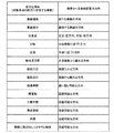
図6〜図8は、対象車両2tが車線変更(ウィンカ点滅)を行う妥当な理由の例を説明するための概念図である。ここで、車線変更とは、現在走行中の車線から離れる方向の車両動作を意味する。図6〜図8の各々には、妥当な理由と共に、期待方向(理由から期待される車線変更の方向)も示されている。上記のステップS2では、この期待方向と認識方向(ステップS1において認識されたウィンカ点滅の方向)との整合性まで考慮されてもよい。
2-4. Various Examples of Reasonable Reason FIGS. 6 to 8 are conceptual diagrams for explaining an example of the reasonable reason for the
妥当な理由の典型的な例は、対象車両2tが車線変更を行うような「事象(event)」が存在することである。図6は、そのような事象であって、特に対象車両2tの前方に存在する事象の例を示している。対象車両2tの前方に存在する事象は、以下「前方事象」と呼ばれる。
A typical example of a reasonable reason is that there is an "event" such that the
前方事象の1つの例は、「車線の増加」である。例えば、対象車両2tの前方において登坂車線が開始する場合、対象車両2tはその登坂車線に移る可能性がある。よって、車線の増加は、妥当な理由である。この場合の期待方向は、追加される新たな車線の方向である。車線の増加は、レーン情報83あるいはセンサ検出情報84(交通標識、白線等の認識結果)に基づいて検出することができる。
One example of a forward event is "increase lane". For example, when the uphill lane starts in front of the
前方事象の他の例は、「車線の減少」である。例えば、対象車両2tが登坂車線を走行しており、対象車両2tの前方において登坂車線が終了する場合、対象車両2tはその登坂車線から本線に戻る可能性が高い。よって、車線の減少は、妥当な理由である。この場合の期待方向は、継続する車線の方向である。車線の減少は、レーン情報83あるいはセンサ検出情報84(交通標識、白線等の認識結果)に基づいて検出することができる。
Another example of a forward event is "decrease lane". For example, when the
前方事象の更に他の例は、「交差点」である。対象車両2tは、交差点において右折あるいは左折する可能性がある。よって、交差点は、妥当な理由である。対象車両2tが左折車線を走行している場合、あるいは、対象車両2tが左折車線に近づく場合、期待方向は左方向である。一方、対象車両2tが右折車線を走行している場合、あるいは、対象車両2tが右折車線に近づく場合、期待方向は右方向である。交差点は、レーン情報83あるいはセンサ検出情報84(交通標識、信号等の認識結果)に基づいて検出することができる。
Yet another example of a forward event is an "intersection". The
前方事象の更に他の例は、「分岐」である。対象車両2tは、前方の分岐車線に入る可能性がある。あるいは、対象車両2tは、前方の分岐車線に入るために、分岐車線に隣接する車線に前もって車線変更する可能性がある。よって、分岐は、妥当な理由である。この場合の期待方向は、分岐車線に近づく方向である。分岐は、レーン情報83あるいはセンサ検出情報84(交通標識、白線等の認識結果)に基づいて検出することができる。
Yet another example of a forward event is a "branch". The
前方事象の更に他の例は、「合流」である。対象車両2tが走行している車線が前方において本線に合流する合流車線である場合、対象車両2tは本線に移る可能性が高い。よって、合流は、妥当な理由である。この場合の期待方向は、本線に近づく方向である。合流は、レーン情報83あるいはセンサ検出情報84(交通標識、白線等の認識結果)に基づいて検出することができる。
Yet another example of a forward event is "merging". If the lane in which the
前方事象の更に他の例は、「被合流区間」である。対象車両2tが本線を走行しており、対象車両2tの前方において合流車線が合流してくる場合を考える。この場合、対象車両2tは、合流してくる他車両を避けるために、合流車線から離れる方向に車線変更する可能性がある。よって、被合流区間は、妥当な理由である。この場合の期待方向は、合流車線から離れる方向である。被合流区間は、レーン情報83あるいはセンサ検出情報84(交通標識、白線等の認識結果)に基づいて検出することができる。
Yet another example of a forward event is a "joined section". A case is considered where the
前方事象の更に他の例は、「施設入口」である。施設としては、駐車場、ガソリンスタンド、コンビニエンスストア、ショッピングセンター等が例示される。対象車両2tは、そのような施設に入る可能性がある。よって、施設入口は、妥当な理由である。この場合の期待方向は、施設に入る方向である。施設入口は、レーン情報83(施設に関する情報)に基づいて検出することができる。
Yet another example of a forward event is the "facility entrance". As facilities, a parking lot, a gas station, a convenience store, a shopping center etc. are illustrated. The
前方事象の更に他の例は、「施設出口」である。施設としては、駐車場、ガソリンスタンド、コンビニエンスストア、ショッピングセンター等が例示される。対象車両2tは、施設から出てくる他車両を避けるために、施設から離れる方向に車線変更する可能性がある。よって、施設出口は、妥当な理由である。この場合の期待方向は、施設から離れる方向である。施設出口は、レーン情報83(施設に関する情報)に基づいて検出することができる。
Yet another example of a forward event is "facility exit". As facilities, a parking lot, a gas station, a convenience store, a shopping center etc. are illustrated. The
前方事象の更に他の例は、「低速車両」である。低速車両は、対象車両2tよりも遅い他車両である。対象車両2tは、低速車両を追い越すために車線変更を行う可能性がある。よって、低速車両は、妥当な理由である。この場合の期待方向は、追越可能な方向(典型的には、追越車線の方向)である。低速車両は、センサ検出情報84(周辺車両2の認識結果)あるいは受信情報86(周辺車両2から受信する周辺車両提供情報)に基づいて検出することができる。
Yet another example of a forward event is "low speed vehicle". The low-speed vehicle is another vehicle that is slower than the
前方事象の更に他の例は、「障害物」である。ここでの障害物とは、落下物だけでなく、停車車両、自転車、歩行者等も含む概念である。対象車両2tは、障害物を回避するために車線変更を行う可能性がある。よって、障害物は、妥当な理由である。この場合の期待方向は、障害物を回避可能な方向である。障害物は、センサ検出情報84(物標の認識結果)あるいは受信情報86(周辺車両2から受信する周辺車両提供情報)に基づいて検出することができる。
Yet another example of a forward event is an "obstacle". The obstacle here is a concept including not only falling objects but also stopped vehicles, bicycles, pedestrians and the like. The
前方事象の更に他の例は、「工事区間」である。対象車両2tは、工事区間を回避するために車線変更を行う可能性がある。よって、工事区間は、妥当な理由である。この場合の期待方向は、工事区間を回避可能な方向である。工事区間は、受信情報86(工事区間情報)あるいは撮像情報85に基づいて検出することができる。
Yet another example of a forward event is a "construction section". The
前方事象の更に他の例は、「事故車両」である。対象車両2tは、事故車両を回避するために車線変更を行う可能性がある。よって、事故車両は、妥当な理由である。この場合の期待方向は、事故車両を回避可能な方向である。事故車両は、受信情報86(事故情報)あるいは撮像情報85に基づいて検出することができる。
Yet another example of a forward event is an "accident vehicle". The
前方事象の更に他の例は、「渋滞」である。対象車両2tは、渋滞を回避するために車線変更を行う可能性がある。よって、渋滞は、妥当な理由である。この場合の期待方向は、渋滞を回避可能な方向である。渋滞は、受信情報86(渋滞情報)あるいはセンサ検出情報84(周辺車両2の認識結果)に基づいて検出することができる。
Yet another example of a forward event is "traffic jam". The
前方事象の更に他の例は、「車線に飛び出してきそうな物体」である。対象車両2tは、そのような物体を回避するために車線変更を行う可能性がある。よって、車線に飛び出してきそうな物体は、妥当な理由である。この場合の期待方向は、その物体を回避可能な方向である。車線に飛び出してきそうな物体は、センサ検出情報84(物標の認識結果)に基づいて検出することができる。
Yet another example of a forward event is "an object likely to jump into a lane". The
図7は、対象車両2tの後方に存在する事象の例を示している。対象車両2tの後方に存在する事象は、以下「後方事象」と呼ばれる。
FIG. 7 shows an example of an event existing behind the
後方事象の1つの例は、「車線の増加」である。例えば、登坂車線が開始した後に、対象車両2tのドライバは登坂車線に移ることを決める可能性がある。よって、車線の増加は、妥当な理由である。この場合の期待方向は、追加された新たな車線の方向である。車線の増加は、レーン情報83あるいはセンサ検出情報84(交通標識、白線等の認識結果)に基づいて検出することができる。
One example of a back event is "increase lane". For example, after the uphill lane starts, the driver of the
後方事象の他の例は、「高速車両」である。高速車両は、対象車両2tよりも速い他車両である。緊急車両も高速車両に含まれる。対象車両2tは、高速車両を回避する(高速車両を先に行かせる)ために車線変更を行う可能性がある。よって、高速車両は、妥当な理由である。この場合の期待方向は、高速車両を回避可能な方向である。高速車両は、センサ検出情報84(周辺車両2の認識結果)あるいは受信情報86(周辺車両2から受信する周辺車両提供情報)に基づいて検出することができる。
Another example of a back event is a "high speed vehicle". The high-speed vehicle is another vehicle faster than the
後方事象の更に他の例は、「近接車両」である。近接車両は、対象車両2tとの距離が閾値以下である他車両である。対象車両2tは、近接車両を回避する(近接車両を先に行かせる)ために車線変更を行う可能性がある。よって、近接車両は、妥当な理由である。この場合の期待方向は、近接車両を回避可能な方向である。近接車両は、センサ検出情報84(周辺車両2の認識結果)あるいは受信情報86(周辺車両2から受信する周辺車両提供情報)に基づいて検出することができる。
Yet another example of a rear end event is a "nearby vehicle". The proximity vehicle is another vehicle whose distance to the
妥当な理由は、上記のような事象の存在に限られない。図8は、妥当な理由の更に他の例を示している。 Reasonable reasons are not limited to the presence of such events. FIG. 8 shows yet another example of a reasonable reason.
妥当な理由の更に他の例は、対象車両2tが特定の車線にいることである。特定の車線とは、通常の走行車線とは異なる車線である。例えば、特定の車線として、追越車線、登坂車線等が挙げられる。特定の車線にいる対象車両2tは、通常の走行車線に戻ってくる可能性がある。よって、本理由は妥当である。この場合の期待方向は、特定の車線から抜ける方向である。本理由は、レーン情報83あるいはセンサ検出情報84(交通標識、白線等の認識結果)に基づいて検出することができる。
Yet another example of a reasonable reason is that the
妥当な理由の更に他の例は、対象車両2tが合流車線から本線に車線変更した直後であることである。そのような対象車両2tは、本線の中で更に車線変更を行う可能性がある。よって、本理由は妥当である。この場合の期待方向は、合流車線から離れる方向である。本理由は、レーン情報83及びセンサ検出情報84(対象車両2tの認識結果)に基づいて検出することができる。
Yet another example of a reasonable reason is that the
妥当な理由の更に他の例は、隣接車線の状態に関連する。説明のため、対象車両2tが走行中の車線を「第1車線」と呼び、第1車線の隣りの車線を「第2車線」と呼ぶ。妥当な理由の更に他の例は、第1車線よりも第2車線の方が車両(交通)の流れが速いことである。この場合、対象車両2tは、より流れの速い第2車線に移る可能性がある。よって、本理由は妥当である。この場合の期待方向は、第2車線の方向である。流れの速さは、周辺車両2の速度に基づいて算出可能である。よって、本理由は、レーン情報83及びセンサ検出情報84(周辺車両2の認識結果)に基づいて検出することができる。
Yet another example of valid reasons relates to the condition of adjacent lanes. For the sake of explanation, the lane in which the
妥当な理由の更に他の例は、第1車線よりも第2車線の方が車両密度が低いことである。この場合、対象車両2tは、より空いている第2車線に移る可能性がある。よって、本理由は妥当である。この場合の期待方向は、第2車線の方向である。車両密度は、周辺車両2の位置に基づいて算出可能である。よって、本理由は、レーン情報83及びセンサ検出情報84(周辺車両2の認識結果)に基づいて検出することができる。
Yet another example of a reasonable reason is that the second lane is less dense than the first lane. In this case, the
妥当な理由の更に他の例は、対象車両2tの位置近傍において複数の周辺車両2が同じ特定の方向に車線変更していることである。この場合、対象車両2tも同じ特定の方向に車線変更する可能性が高い。よって、本理由は妥当である。この場合の期待方向は、特定の方向である。本理由は、ウィンカ判定装置10による複数の周辺車両2に関するウィンカ判定結果に基づいて検出することができる。あるいは、本理由は、センサ検出情報84(周辺車両2の動きの認識結果)に基づいて検出することができる。あるいは、多数の車両の運転動作を記録し、配信する外部システムが存在する場合、本理由は、受信情報86(外部システムからの配信情報)に基づいて検出することができる。
Yet another example of a reasonable reason is that a plurality of
本実施の形態では、以上に例示された妥当な理由のうち少なくとも1つが用いられる。複数種類の理由が用いられてもよい。その場合、妥当な理由が存在するとは、複数種類の理由のうち少なくとも1つが存在することを意味する。 In the present embodiment, at least one of the valid reasons exemplified above is used. Multiple reasons may be used. In that case, the presence of a reasonable reason means that at least one of a plurality of reasons is present.
2−5.効果
以上に説明されたように、本実施の形態に係るウィンカ判定装置10は、カメラ50による撮像情報85に基づいて、対象車両2tのウィンカ点滅を認識する。更に、ウィンカ判定装置10は、周辺状況情報80に基づいて、対象車両2tが車線変更を行う妥当な理由が存在するか否かを確認する。そして、妥当な理由が存在する場合のみ、ウィンカ判定装置10は、対象車両2tがウィンカ点滅を行っていると判定する。これにより、実際にはウィンカは点滅していないのに、ウィンカが点滅していると誤判定される可能性が減る。言い換えれば、対象車両2tのウィンカ点滅をより高精度に判定することが可能となる。その結果、ウィンカ判定装置10に対するドライバの信頼が向上する。
2-5. Effects As described above, the
3.自動運転システム
図9は、本実施の形態に係るウィンカ判定装置10を備える自動運転システム100の構成例を示すブロック図である。自動運転システム100は、車両1に搭載され、車両1の自動運転を制御する。
3. Automatic Driving System FIG. 9 is a block diagram showing a configuration example of an
より詳細には、自動運転システム100は、既出の図2で示されたウィンカ判定装置10の構成に加えて、走行装置110を備えている。走行装置110は、操舵装置、駆動装置、制動装置、トランスミッション等を含んでいる。操舵装置は、車輪を転舵する。駆動装置は、駆動力を発生させる動力源である。駆動装置としては、エンジンや電動機が例示される。制動装置は、制動力を発生させる。
More specifically, the
また、制御装置70は、車両1の自動運転を制御する。そのために、制御装置70は、情報取得部71及びウィンカ判定部72に加えて、プランニング部73及び走行制御部74を備えている。これら機能ブロックは、制御装置70のプロセッサがメモリに格納された制御プログラムを実行することにより実現される。
Further, the
プランニング部73は、周辺状況情報80に基づいて、自動運転における車両1の走行計画を立案する。例えば、プランニング部73は、位置姿勢情報82(現在位置)及びレーン情報83に基づいて、走行ルートや車線変更ポイント等を含む走行計画を決める。また、プランニング部73は、センサ検出情報84に基づいて、車両1の前方の先行車両との相対距離及び相対速度をモニタする。そして、プランニング部73は、先行車両との衝突を回避するため回避行動を含む走行計画を立案する。この場合の回避行動は、減速あるいは車線変更である。
The
走行制御部74は、走行計画に沿って車両1が走行するように走行装置110を制御する。この走行装置110の制御には、操舵装置を制御する操舵制御、駆動装置を制御する加速制御、及び制動装置を制御する減速制御が含まれる。
The traveling
ここで、一例として、図1で示された状況を考える。図1において、車両1はレーンL1を走行しており、対象車両2tはレーンL1の右隣りのレーンL2を走行している。その対象車両2tが、左方向を指し示すウィンカを点滅させる。本実施の形態に係るウィンカ判定装置10は、対象車両2tのウィンカ点滅を精度良く判定する。そして、プランニング部73は、ウィンカ判定装置10による判定結果に基づいて、対象車両2tの行動を予測する。具体的には、プランニング部73は、左方向のウィンカ点滅から、対象車両2tがレーンL2からレーンL1へ車線変更する、つまり、車両1の前方に割り込んでくると予測する。そこで、プランニング部73は、対象車両2tとの衝突を避けるために、車両1の減速を行うことを計画する。そして、走行制御部74は、減速制御を行い、車両1を減速させる。
Here, as an example, consider the situation shown in FIG. In FIG. 1, the
比較例として、プランニング部73が、撮像情報85の画像解析に基づくウィンカ点滅の認識結果だけに基づいて、対象車両2tの行動を予測する場合を考える。撮像情報85の画像解析に基づくウィンカ点滅の認識の精度は、必ずしも高くない。よって、実際にはウィンカは点滅していないのに、ウィンカが点滅していると誤認識される可能性がある。このような誤認識が発生した場合、プランニング部73は、本来必要のない車両1の減速を計画する。そして、走行制御部74は、不必要な減速制御を行う。このような不必要な減速制御に対し、ドライバは違和感及び不信感を抱く。
As a comparative example, a case is considered where the
一方、本実施の形態に係る自動運転システム100は、ウィンカ判定装置10による高精度な判定結果に基づいて、対象車両2tの行動を予測し、車両1の自動運転を制御する。従って、より安全で高精度な自動運転を実現することが可能となる。このことは、自動運転システム100に対する信頼の向上に寄与する。
On the other hand, the
1 車両
2 周辺車両
2t 対象車両
10 ウィンカ判定装置
20 GPS受信器
30 地図データベース
40 センサ群
50 カメラ
60 通信装置
70 制御装置
71 情報取得部
72 ウィンカ判定部
73 プランニング部
74 走行制御部
80 周辺状況情報
82 位置姿勢情報
83 レーン情報
84 センサ検出情報
85 撮像情報
86 受信情報
90 情報取得装置
100 自動運転システム
110 走行装置
Claims (8)
前記車両の周辺の状況を示す周辺状況情報を取得する情報取得装置と、
前記周辺状況情報に基づいて、ウィンカ判定処理を行う制御装置と
を備え、
前記周辺状況情報は、カメラによって撮影された対象車両の撮像情報を含み、
前記ウィンカ判定処理は、
前記撮像情報に基づいて、前記対象車両のウィンカ点滅を認識する認識処理と、
前記ウィンカ点滅が認識された場合、前記周辺状況情報に基づいて、前記対象車両が車線変更を行う理由が存在するか否かを確認する妥当性確認処理と、
前記理由が存在しない場合、前記対象車両は前記ウィンカ点滅を行っていないと判定し、前記理由が存在する場合、前記対象車両は前記ウィンカ点滅を行っていると判定する判定処理と
を含む
ウィンカ判定装置。 A winker determination device mounted on a vehicle, wherein
An information acquisition device for acquiring surrounding situation information indicating the situation around the vehicle;
And a controller for performing a winker determination process based on the surrounding situation information.
The surrounding situation information includes imaging information of a target vehicle captured by a camera,
The winker determination process is
Recognition processing for recognizing blinkers of the target vehicle based on the imaging information;
Validity confirmation processing for confirming whether there is a reason for the target vehicle to change lanes, based on the surrounding situation information, when the blinker blink is recognized;
It is determined that the target vehicle does not blink the blinker if the reason does not exist, and the determination processing determines that the target vehicle blinks the blinker if the reason exists, apparatus.
前記理由から期待される前記車線変更の方向は、前記認識処理によって認識された前記ウィンカ点滅の方向と一致する
ウィンカ判定装置。 The winker determination apparatus according to claim 1, wherein
The direction of the said lane change expected from the said reason corresponds with the direction of the said blinker blink recognized by the said recognition process.
前記理由は、前記対象車両の前方あるいは後方に存在する事象である
ウィンカ判定装置。 The winker determination device according to claim 1 or 2, wherein
The said reason is an event which exists in the front or back of the said object vehicle.
前記事象は、前記対象車両の前方に存在する車線増加、車線減少、交差点、分岐、合流、施設入口、施設出口、前記対象車両より遅い低速車両、障害物、工事区間、事故車両、及び渋滞のうち少なくとも1つを含む
ウィンカ判定装置。 The winker determination apparatus according to claim 3, wherein
The event is an increase in lanes, a decrease in lanes, an intersection, a branch, a junction, a facility entrance, a facility exit, a low speed vehicle slower than the target vehicle, an obstacle, a construction section, an accident vehicle, and a traffic jam. A blinker determination device comprising at least one of:
前記事象は、前記対象車両の後方に存在する車線増加、前記対象車両より速い高速車両、及び前記対象車両との距離が閾値以下である近接車両のうち少なくとも1つを含む
ウィンカ判定装置。 The winker determination apparatus according to claim 3, wherein
The winker determination device includes at least one of an increase in a lane present behind the target vehicle, a high-speed vehicle faster than the target vehicle, and a nearby vehicle having a distance to the target vehicle equal to or less than a threshold.
前記理由は、前記対象車両が追越車線あるいは登坂車線にいることである
ウィンカ判定装置。 The winker determination device according to claim 1 or 2, wherein
The reason is that the target vehicle is in the overtaking lane or the uphill lane.
前記対象車両は第1車線を走行しており、
前記第1車線の隣りの車線は第2車線であり、
前記理由は、前記第1車線よりも前記第2車線の方が車両の流れが速いこと、あるいは、前記第1車線よりも前記第2車線の方が車両密度が低いことである
ウィンカ判定装置。 The winker determination device according to claim 1 or 2, wherein
The target vehicle is traveling in the first lane,
The lane next to the first lane is the second lane,
The blinker determination device is that the reason is that the flow of the vehicle is faster in the second lane than in the first lane, or the vehicle density is lower in the second lane than the first lane.
前記制御装置は、前記ウィンカ判定装置による判定結果に基づいて、前記車両の自動運転を制御する
自動運転システム。 A blinker determination device according to any one of claims 1 to 7, comprising:
The said control apparatus controls the automatic driving | operation of the said vehicle based on the determination result by the said blinker determination apparatus.
Priority Applications (3)
| Application Number | Priority Date | Filing Date | Title |
|---|---|---|---|
| JP2016241399A JP6536554B2 (en) | 2016-12-13 | 2016-12-13 | Winker determination device and automatic driving system |
| US15/826,307 US10691125B2 (en) | 2016-12-13 | 2017-11-29 | Blinker judgment device and autonomous driving system |
| US15/931,889 US10935976B2 (en) | 2016-12-13 | 2020-05-14 | Blinker judgment device and autonomous driving system |
Applications Claiming Priority (1)
| Application Number | Priority Date | Filing Date | Title |
|---|---|---|---|
| JP2016241399A JP6536554B2 (en) | 2016-12-13 | 2016-12-13 | Winker determination device and automatic driving system |
Publications (2)
| Publication Number | Publication Date |
|---|---|
| JP2018097599A JP2018097599A (en) | 2018-06-21 |
| JP6536554B2 true JP6536554B2 (en) | 2019-07-03 |
Family
ID=62490053
Family Applications (1)
| Application Number | Title | Priority Date | Filing Date |
|---|---|---|---|
| JP2016241399A Active JP6536554B2 (en) | 2016-12-13 | 2016-12-13 | Winker determination device and automatic driving system |
Country Status (2)
| Country | Link |
|---|---|
| US (2) | US10691125B2 (en) |
| JP (1) | JP6536554B2 (en) |
Families Citing this family (11)
| Publication number | Priority date | Publication date | Assignee | Title |
|---|---|---|---|---|
| DE102016208000A1 (en) * | 2016-05-10 | 2017-11-16 | Volkswagen Aktiengesellschaft | Motor vehicle control device and method for operating the control device for the autonomous guidance of a motor vehicle |
| KR102535540B1 (en) * | 2017-01-12 | 2023-05-23 | 모빌아이 비젼 테크놀로지스 엘티디. | Navigation based on vehicle activity |
| JP6676196B2 (en) * | 2017-01-24 | 2020-04-08 | 本田技研工業株式会社 | Vehicle control system, vehicle control method, and vehicle control program |
| US10133275B1 (en) | 2017-03-01 | 2018-11-20 | Zoox, Inc. | Trajectory generation using temporal logic and tree search |
| US10671076B1 (en) | 2017-03-01 | 2020-06-02 | Zoox, Inc. | Trajectory prediction of third-party objects using temporal logic and tree search |
| US10955851B2 (en) | 2018-02-14 | 2021-03-23 | Zoox, Inc. | Detecting blocking objects |
| US10414395B1 (en) | 2018-04-06 | 2019-09-17 | Zoox, Inc. | Feature-based prediction |
| US11126873B2 (en) * | 2018-05-17 | 2021-09-21 | Zoox, Inc. | Vehicle lighting state determination |
| KR20210057312A (en) * | 2019-11-12 | 2021-05-21 | 현대자동차주식회사 | Apparatus and method for identificating short cut-in target |
| JP2021105813A (en) * | 2019-12-26 | 2021-07-26 | ロベルト・ボッシュ・ゲゼルシャフト・ミト・ベシュレンクテル・ハフツングRobert Bosch Gmbh | Control device and control method |
| US11853069B2 (en) | 2021-03-12 | 2023-12-26 | Waymo Llc | Continuing lane driving prediction |
Family Cites Families (6)
| Publication number | Priority date | Publication date | Assignee | Title |
|---|---|---|---|---|
| EP1504276B1 (en) * | 2002-05-03 | 2012-08-08 | Donnelly Corporation | Object detection system for vehicle |
| JP4151890B2 (en) | 2002-11-22 | 2008-09-17 | 富士重工業株式会社 | Vehicle monitoring apparatus and vehicle monitoring method |
| JP4941059B2 (en) * | 2007-04-02 | 2012-05-30 | 株式会社豊田中央研究所 | Driving assistance device |
| JP2010105502A (en) | 2008-10-29 | 2010-05-13 | Toyota Motor Corp | Front monitoring device |
| JP2014201159A (en) * | 2013-04-03 | 2014-10-27 | トヨタ自動車株式会社 | Inter-vehicle distance control device and lane-change determination apparatus |
| US9487139B1 (en) * | 2015-05-15 | 2016-11-08 | Honda Motor Co., Ltd. | Determining a driver alert level for a vehicle alert system and method of use |
-
2016
- 2016-12-13 JP JP2016241399A patent/JP6536554B2/en active Active
-
2017
- 2017-11-29 US US15/826,307 patent/US10691125B2/en active Active
-
2020
- 2020-05-14 US US15/931,889 patent/US10935976B2/en active Active
Also Published As
| Publication number | Publication date |
|---|---|
| US10691125B2 (en) | 2020-06-23 |
| US20180164816A1 (en) | 2018-06-14 |
| US10935976B2 (en) | 2021-03-02 |
| JP2018097599A (en) | 2018-06-21 |
| US20200272147A1 (en) | 2020-08-27 |
Similar Documents
| Publication | Publication Date | Title |
|---|---|---|
| JP6536554B2 (en) | Winker determination device and automatic driving system | |
| CN107792066B (en) | Vehicle control device | |
| CN109760687B (en) | Vehicle control device, vehicle control method, and storage medium | |
| JP6916953B2 (en) | Vehicle control devices, vehicle control methods, and programs | |
| JP4933962B2 (en) | Branch entry judgment device | |
| CN110281920B (en) | Vehicle control device, vehicle control method, and storage medium | |
| CN107614349B (en) | Controller of vehicle and control method for vehicle | |
| CN110662683B (en) | Driving support device and driving support method | |
| CN110099833B (en) | Vehicle control system, vehicle control method, and storage medium | |
| CN110341704B (en) | Vehicle control device, vehicle control method, and storage medium | |
| JP2020163900A (en) | Vehicle control device, vehicle control method, and program | |
| JP7085371B2 (en) | Vehicle control devices, vehicle control methods, and programs | |
| CN111731296B (en) | Travel control device, travel control method, and storage medium storing program | |
| KR20210030975A (en) | Driving support method and driving support device | |
| JP5202741B2 (en) | Branch entry judgment device | |
| RU2755425C1 (en) | Method for assisting the movement of a vehicle and apparatus for assisting the movement of a vehicle | |
| US11541892B2 (en) | Vehicle control method and vehicle control device | |
| JP2019159427A (en) | Vehicle control device, vehicle control method, and program | |
| CN108064207B (en) | Vehicle control device | |
| CN109969191B (en) | Driving assistance system and method | |
| JP6365402B2 (en) | Travel control device | |
| KR20210057766A (en) | Vehicle control method and vehicle control device | |
| JP2019137263A (en) | Driving support device | |
| CN111301415B (en) | Vehicle control device, vehicle control method, and storage medium | |
| RU2771332C1 (en) | Vehicle control method and vehicle control device |
Legal Events
| Date | Code | Title | Description |
|---|---|---|---|
| A621 | Written request for application examination |
Free format text: JAPANESE INTERMEDIATE CODE: A621 Effective date: 20180622 |
|
| TRDD | Decision of grant or rejection written | ||
| A977 | Report on retrieval |
Free format text: JAPANESE INTERMEDIATE CODE: A971007 Effective date: 20190417 |
|
| A01 | Written decision to grant a patent or to grant a registration (utility model) |
Free format text: JAPANESE INTERMEDIATE CODE: A01 Effective date: 20190507 |
|
| A61 | First payment of annual fees (during grant procedure) |
Free format text: JAPANESE INTERMEDIATE CODE: A61 Effective date: 20190520 |
|
| R151 | Written notification of patent or utility model registration |
Ref document number: 6536554 Country of ref document: JP Free format text: JAPANESE INTERMEDIATE CODE: R151 |