JP6535343B2 - Skin treatment device using powerful pulsed light - Google Patents
Skin treatment device using powerful pulsed light Download PDFInfo
- Publication number
- JP6535343B2 JP6535343B2 JP2016557201A JP2016557201A JP6535343B2 JP 6535343 B2 JP6535343 B2 JP 6535343B2 JP 2016557201 A JP2016557201 A JP 2016557201A JP 2016557201 A JP2016557201 A JP 2016557201A JP 6535343 B2 JP6535343 B2 JP 6535343B2
- Authority
- JP
- Japan
- Prior art keywords
- skin
- energy
- charge storage
- control system
- skin treatment
- Prior art date
- Legal status (The legal status is an assumption and is not a legal conclusion. Google has not performed a legal analysis and makes no representation as to the accuracy of the status listed.)
- Active
Links
Images


Classifications
-
- A—HUMAN NECESSITIES
- A61—MEDICAL OR VETERINARY SCIENCE; HYGIENE
- A61N—ELECTROTHERAPY; MAGNETOTHERAPY; RADIATION THERAPY; ULTRASOUND THERAPY
- A61N5/00—Radiation therapy
- A61N5/06—Radiation therapy using light
- A61N5/0613—Apparatus adapted for a specific treatment
- A61N5/0616—Skin treatment other than tanning
- A61N5/0617—Hair treatment
-
- A—HUMAN NECESSITIES
- A61—MEDICAL OR VETERINARY SCIENCE; HYGIENE
- A61B—DIAGNOSIS; SURGERY; IDENTIFICATION
- A61B18/00—Surgical instruments, devices or methods for transferring non-mechanical forms of energy to or from the body
- A61B18/18—Surgical instruments, devices or methods for transferring non-mechanical forms of energy to or from the body by applying electromagnetic radiation, e.g. microwaves
- A61B18/20—Surgical instruments, devices or methods for transferring non-mechanical forms of energy to or from the body by applying electromagnetic radiation, e.g. microwaves using laser
- A61B18/203—Surgical instruments, devices or methods for transferring non-mechanical forms of energy to or from the body by applying electromagnetic radiation, e.g. microwaves using laser applying laser energy to the outside of the body
-
- A—HUMAN NECESSITIES
- A61—MEDICAL OR VETERINARY SCIENCE; HYGIENE
- A61N—ELECTROTHERAPY; MAGNETOTHERAPY; RADIATION THERAPY; ULTRASOUND THERAPY
- A61N5/00—Radiation therapy
- A61N5/06—Radiation therapy using light
- A61N5/0613—Apparatus adapted for a specific treatment
- A61N5/0614—Tanning
-
- A—HUMAN NECESSITIES
- A61—MEDICAL OR VETERINARY SCIENCE; HYGIENE
- A61N—ELECTROTHERAPY; MAGNETOTHERAPY; RADIATION THERAPY; ULTRASOUND THERAPY
- A61N5/00—Radiation therapy
- A61N5/06—Radiation therapy using light
- A61N5/0613—Apparatus adapted for a specific treatment
- A61N5/0616—Skin treatment other than tanning
-
- A—HUMAN NECESSITIES
- A61—MEDICAL OR VETERINARY SCIENCE; HYGIENE
- A61B—DIAGNOSIS; SURGERY; IDENTIFICATION
- A61B18/00—Surgical instruments, devices or methods for transferring non-mechanical forms of energy to or from the body
- A61B2018/00315—Surgical instruments, devices or methods for transferring non-mechanical forms of energy to or from the body for treatment of particular body parts
- A61B2018/00452—Skin
- A61B2018/00476—Hair follicles
-
- A—HUMAN NECESSITIES
- A61—MEDICAL OR VETERINARY SCIENCE; HYGIENE
- A61B—DIAGNOSIS; SURGERY; IDENTIFICATION
- A61B18/00—Surgical instruments, devices or methods for transferring non-mechanical forms of energy to or from the body
- A61B2018/00636—Sensing and controlling the application of energy
- A61B2018/00642—Sensing and controlling the application of energy with feedback, i.e. closed loop control
-
- A—HUMAN NECESSITIES
- A61—MEDICAL OR VETERINARY SCIENCE; HYGIENE
- A61B—DIAGNOSIS; SURGERY; IDENTIFICATION
- A61B18/00—Surgical instruments, devices or methods for transferring non-mechanical forms of energy to or from the body
- A61B2018/00636—Sensing and controlling the application of energy
- A61B2018/00696—Controlled or regulated parameters
- A61B2018/00702—Power or energy
- A61B2018/00708—Power or energy switching the power on or off
-
- A—HUMAN NECESSITIES
- A61—MEDICAL OR VETERINARY SCIENCE; HYGIENE
- A61B—DIAGNOSIS; SURGERY; IDENTIFICATION
- A61B18/00—Surgical instruments, devices or methods for transferring non-mechanical forms of energy to or from the body
- A61B2018/00636—Sensing and controlling the application of energy
- A61B2018/00773—Sensed parameters
- A61B2018/00779—Power or energy
- A61B2018/00785—Reflected power
-
- A—HUMAN NECESSITIES
- A61—MEDICAL OR VETERINARY SCIENCE; HYGIENE
- A61B—DIAGNOSIS; SURGERY; IDENTIFICATION
- A61B18/00—Surgical instruments, devices or methods for transferring non-mechanical forms of energy to or from the body
- A61B18/18—Surgical instruments, devices or methods for transferring non-mechanical forms of energy to or from the body by applying electromagnetic radiation, e.g. microwaves
- A61B2018/1807—Surgical instruments, devices or methods for transferring non-mechanical forms of energy to or from the body by applying electromagnetic radiation, e.g. microwaves using light other than laser radiation
-
- A—HUMAN NECESSITIES
- A61—MEDICAL OR VETERINARY SCIENCE; HYGIENE
- A61N—ELECTROTHERAPY; MAGNETOTHERAPY; RADIATION THERAPY; ULTRASOUND THERAPY
- A61N5/00—Radiation therapy
- A61N5/06—Radiation therapy using light
- A61N2005/0626—Monitoring, verifying, controlling systems and methods
-
- A—HUMAN NECESSITIES
- A61—MEDICAL OR VETERINARY SCIENCE; HYGIENE
- A61N—ELECTROTHERAPY; MAGNETOTHERAPY; RADIATION THERAPY; ULTRASOUND THERAPY
- A61N5/00—Radiation therapy
- A61N5/06—Radiation therapy using light
- A61N2005/0626—Monitoring, verifying, controlling systems and methods
- A61N2005/0627—Dose monitoring systems and methods
-
- A—HUMAN NECESSITIES
- A61—MEDICAL OR VETERINARY SCIENCE; HYGIENE
- A61N—ELECTROTHERAPY; MAGNETOTHERAPY; RADIATION THERAPY; ULTRASOUND THERAPY
- A61N5/00—Radiation therapy
- A61N5/06—Radiation therapy using light
- A61N2005/0635—Radiation therapy using light characterised by the body area to be irradiated
- A61N2005/0643—Applicators, probes irradiating specific body areas in close proximity
- A61N2005/0644—Handheld applicators
Description
本発明は、強力なパルス光(IPL)を使用して皮膚を治療する器具及びこのような器具を用いて強力なパルス光を使用して皮膚を治療する方法に関するものである。 The present invention relates to an apparatus for treating skin using intense pulsed light (IPL) and a method for treating skin using intense pulsed light using such an apparatus.
皮膚治療器具は、例えば、髪の脱毛、皮膚の傷の最小化又は皮膚の若返りの如き化粧目的の治療、及びニキビ又は酒さの如き皮膚の状態を皮膚科学的治療の目的で当業界では知られている。放射線が皮膚をターゲットにして照射され、エネルギー強度やパルス時間が制御される場合には、皮膚は、レーザー源や光源からの如き放射線の投与に晒される。髪の脱毛の場合には、放射線源がターゲットとされると、毛根部を死なせることになる毛根部の加熱を引き起こすことになる。 Skin treatment devices are known in the art for the purpose of dermatological treatment, for example for cosmetic purposes such as hair loss, skin wound minimization or skin rejuvenation and skin conditions such as acne or rosacea. It is done. When radiation is targeted to the skin and the energy intensity and pulse time are controlled, the skin is exposed to the administration of radiation, such as from a laser source or light source. In the case of hair loss, targeting the radiation source will cause heating of the hair root which will cause the hair root to die.
特に、強力なパルス光(IPL)を使用して皮膚を治療するのに使用される装置は、現在、非専門的な使用、即ち、消費者マーケットに次第に利用されている。従って、誤用によって皮膚の副作用に関連する危険がある。これは、やけど又は色素変更の影響によって、皮膚のかぶれ及び痛みの形態であることがある。 In particular, devices used to treat the skin using intense pulsed light (IPL) are now increasingly being used for non-professional use, ie the consumer market. Thus there is a risk associated with skin side effects due to misuse. It may be in the form of skin irritation and pain due to the effects of burns or pigment changes.
GB2496895号明細書は、光源と制御ユニットとベースユニットを含む装置を開示している。この制御ユニットは、ベースユニットから取り外し自在にドッキングしており、皮膚のトーンを検知することができるセンサーを含んでいる。従って、この制御ユニットは、皮膚上に配置され、皮膚のトーンを検知し、その後、ベースユニット内に位置換えされ、このベースユニットは、光源によって生成される放射線のパワーレベルを決定する。その後、ヘッドユニット(20)が皮膚のトーンが測定された皮膚の位置に位置替えされ、皮膚は、使用者がエネルギーレベル出力を選択する必要なく、光パルスで治療される。これは、使用者が光源から出力されるエネルギーを選択するステップが省かれ、使用者が装置を誤用するという潜在的な悪影響を減少することを意味する。 GB 2496895 discloses an apparatus comprising a light source, a control unit and a base unit. The control unit is removably docked from the base unit and includes a sensor capable of detecting skin tones. Thus, the control unit is placed on the skin to detect the skin tone and then relocated into the base unit, which determines the power level of the radiation generated by the light source. The head unit (20) is then relocated to the skin position where the skin tone was measured, and the skin is treated with light pulses without the user having to select an energy level output. This means that the step of the user selecting the energy output from the light source is omitted and the potential adverse effect of the user misusing the device is reduced.
WO02/085229号明細書も、レーザ光源の如き放射線パルスによって皮膚を治療するための装置を開示している。WO02/085229号明細書に開示された発明の目的は、これも、装置の誤用によって、皮膚のかぶれ及び痛みの如き皮膚上の望ましくない副作用を低減することである。これは、皮膚のトーン如き皮膚の生物物理学的特性を検知して達成される。この装置は、ポータブルで、治療すべき皮膚(7)上に配置するかこの皮膚上を移動するハウジング(3)を含んでいる。ハウジング(3)は、放射線源、特にレーザーダイオードの如きレーザー源(9)を収容している。ハウジングは、皮膚上に置かれ、出口開口(15)の前に直接位置している皮膚の部分にイメージが記録される髪毛(41)の毛根部(39)の位置が定められ、毛根部(39)が死滅するように毛根部を連続的に加熱するように、レーザー源(9)を操作する。しかし、一連のテストレーザに晒されることに基づいて、例えば、皮膚の温度を検出する検出器(43)を用いることによってレーザーパルスの許容できない過剰投与からの保護が達成される。この検出器は、最高温度を超過しないのを保証するために、各パルス毎に皮膚の温度を測定する。このようにして、レーザー源からエネルギーの許容可能な投与が制御される。 WO 02/085 529 also discloses a device for treating the skin with a pulse of radiation, such as a laser light source. The object of the invention disclosed in WO 02/085 529 is also to reduce unwanted side effects on the skin, such as skin irritation and pain, by misuse of the device. This is accomplished by sensing the biophysical properties of the skin, such as the tone of the skin. The device is portable and comprises a housing (3) which is placed on or moved over the skin (7) to be treated. The housing (3) contains a radiation source, in particular a laser source (9) such as a laser diode. The housing is placed on the skin and the hair root (39) of the hair (41) is located where the image is recorded on the part of the skin directly located in front of the outlet opening (15) Operate the laser source (9) so as to heat the hair root continuously so that (39) will die. However, based on exposure to a series of test lasers, protection from unacceptable overdosage of the laser pulse is achieved, for example, by using a detector (43) that detects the temperature of the skin. The detector measures the temperature of the skin for each pulse to ensure that the maximum temperature is not exceeded. In this way, acceptable dosing of energy from the laser source is controlled.
WO02/085229号明細書は、検出器を用いた他の実施例を開示しており、この検出器は、所定の波長の光で皮膚の散乱係数及び/又は吸収係数を測定し、パルス投与は、皮膚のこの散乱係数及び/又は吸収係数によって決定される。 WO 02/085 529 discloses another embodiment using a detector, which measures the scattering coefficient and / or the absorption coefficient of the skin with light of a predetermined wavelength, and the pulse administration is , Determined by the scattering coefficient and / or absorption coefficient of the skin.
これらの先行技術の装置に関連した幾つかの問題がある。GB2496895号は、皮膚トーンに依存して光エネルギーパルスを定めるが、使用者によっては、皮膚トーンを測定する正確な位置上に治療ヘッドの位置を変えることがある。正確に治療ヘッドのポジショニングすることは、正しくない出力エネルギーの可能性を与えるような検知器のポジショニングを反映しているように思われない。更に、皮膚トーンの検知と治療時間との間に大きな時間遅れがある。WO02/085229号は、温度の如き皮膚のパラメータ、散乱係数及び/又は吸収係数を検出し、この結果に依存して皮膚を治療する検出器を組み入れたヘッドを用いることによって治療ヘッドの不正確なポジショニングの問題を克服している。これは、レーザーパルスを利用する場合に可能であるが、レーザーパルスの使用に関連した別個の安全問題がある。 There are several issues associated with these prior art devices. GB 2496895 relies on skin tone to define light energy pulses, but some users may reposition the treatment head on the exact location where skin tone is to be measured. Accurate positioning of the treatment head does not appear to reflect the positioning of the detector which gives the possibility of incorrect output energy. Furthermore, there is a significant time delay between the detection of skin tone and the treatment time. WO 02/085 529 is an inaccurate treatment head by using a head incorporating a detector which detects skin parameters such as temperature, scattering coefficient and / or absorption coefficient and treats the skin depending on this result Overcoming the positioning problem. This is possible when using laser pulses, but there are separate safety issues associated with the use of laser pulses.
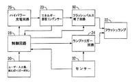
図1A乃至図1Cを参照すると、IPLシステムがどのように機能するかを示すブロック図として先行技術のシステムが概略的に示されている。図1Aは、先行技術システムにおける構成成分を示しており、典型的にはコンデンサーから成るエネルギー蓄積装置(20)を含み、これは、フラッシュランプ(22)にエネルギーを放出するようになっており、このフラッシュランプ(22)は、ランプトリガー回路(24)の動作の下で皮膚に光エネルギーのパルスを出力する。このエネルギー蓄積装置(20)は、充電回路(26)によって充電され、この充電回路(26)とランプトリガー回路(24)とは、制御回路(28)の動作を受ける。ユーザ入力部(30)は、トリガー部の如く設けられており、この入力部(30)を押すと、制御回路(28)は、ランプトリガー回路(24)を起動せしめることができてエネルギー蓄積装置(20)からフラッシュランプ(22)へのチャージを解放せしめる。エネルギー蓄積装置(20)によって蓄積されたエネルギーの値を制御するために、図1Aで示される如き皮膚トーンの如き皮膚パラメーターを測定するように構成されたセンサー(32)からか、あるいは、図1Bに関して詳細に述べるユーザによって選択された入力部によって制御回路(28)に入力が提供される。 Referring to FIGS. 1A-1C, a prior art system is schematically illustrated as a block diagram showing how an IPL system works. FIG. 1A shows the components in the prior art system and includes an energy storage device (20), typically consisting of a capacitor, which is adapted to release energy to the flash lamp (22) The flash lamp (22) outputs a pulse of light energy to the skin under the operation of the lamp trigger circuit (24). The energy storage device (20) is charged by the charging circuit (26), and the charging circuit (26) and the lamp trigger circuit (24) receive the operation of the control circuit (28). The user input unit (30) is provided like a trigger unit, and pressing this input unit (30) allows the control circuit (28) to activate the lamp trigger circuit (24), thus the energy storage device Release the charge from (20) to the flash lamp (22). From a sensor (32) configured to measure skin parameters such as a skin tone as shown in FIG. 1A to control the value of the energy stored by the energy storage device (20) or FIG. 1B An input is provided to the control circuit (28) by an input selected by the user which will be described in detail with respect to
光出力とユーザ入力とコンデンサー電圧とコンデンサー充電とが時間と共に変化する概略状態が図1Bに示されている。時間T1に先立って、ユーザは、装置をターンオンし、皮膚の治療に必要な出力パワーが決定される。大抵の先行技術のシステムでは、これは、ユーザがチャートに対して皮膚のトーンを可視的に比較し、パワーレベルを手動で選択することによって決定される。GB2496895号明細書では、これは、ユーザが既知のスケールで比較する必要性がないように、皮膚トーンに依存する好ましいパワー出力を決定するセンサーを有する制御ユニットによって決定される。時間T1では、制御回路(28)は、コンデンサーを充電するが、この充電中、T2に達するまで、コンデンサー電圧が増加する。T2とT3との間の時間は、ユーザがT3とT4の間でユーザ入力部(30)を動作するまで、コンデンサーが充電される時間を表す。時間T4では、コンデンサーの電荷は、フラッシュランプに解放され、T4とT5の間のカーブによって示されるように光パルスが皮膚上にリリースされる。このサイクルは、皮膚の別のエリアで必要に応じて繰り返される。 A schematic of the light output, user input, capacitor voltage and capacitor charge changing with time is shown in FIG. 1B. Prior to time T1, the user turns on the device and the output power required to treat the skin is determined. In most prior art systems, this is determined by the user visually comparing the skin tones against the chart and manually selecting the power level. In GB 2496895 this is determined by the control unit having a sensor that determines the preferred power output depending on the skin tone, so that the user does not have to compare on a known scale. At time T1, the control circuit (28) charges the capacitor but during this charge the capacitor voltage increases until it reaches T2. The time between T2 and T3 represents the time for which the capacitor is charged until the user actuates the user input (30) between T3 and T4. At time T4, the charge on the capacitor is released to the flash lamp and a light pulse is released on the skin as shown by the curve between T4 and T5. This cycle is repeated as needed in other areas of the skin.
図1Cは、所要のパワー出力に依存して時間に対する光強度の変化を示す。もし、センサー又は手動ユーザ入力部が7J/cm2のパワー出力を要求すると、コンデンサーは、400Vまで充電される。さもなければ、皮膚トーンが正常であるか明るい場合には、5J/cm2のエネルギー出力が一層適切であり、コンデンサーは、338Vの電圧まで充電される。 FIG. 1C shows the change in light intensity over time depending on the required power output. If the sensor or manual user input requires a power output of 7 J / cm 2 , the capacitor is charged to 400V. Otherwise, if the skin tone is normal or bright, an energy output of 5 J / cm 2 is more appropriate and the capacitor is charged to a voltage of 338V.
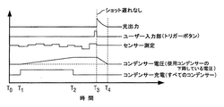
本出願人は、先行技術装置に関連した重大な制限があることに気付いた。皮膚トーンの如き皮膚パラメーターの検知と関連した重大な時間遅れは、皮膚トーンに基づいたコンデンサーの充電及びコンデンサーからのエネルギー放出を引き起こすことに引き続いて、ユーザに重大な遅れを付与して装置が実際に正しく動作しているか否かに関してユーザの心に不安感を生じさせ、更に、エネルギーパルスが放出される前に、装置が皮膚に対して実際に移動していることが可能かありそうであることを意味している。これは、装置が皮膚から取り外され、まだエネルギーを放出することができる安全性を意味することになる。従って、図2に示されているように、出願人は、皮膚トーンの読みが連続的に又は定期的に行われるように、測定されたセンサ出力の変化に基づいて、コンデンサー電圧を連続的に又は定期的な時間区間で充電するように定めている。これは、ユーザ入力部の起動前にユーザが装置を移動させることによる影響が緩和されることを意味する。これは、また、放電の準備のためにエネルギー蓄積装置により充電されたエネルギーが最新の皮膚トーンの読みに応じて連続的に調節(充電又は放電)されることになることを意味する。これは、センサーが皮膚を横切って異なる皮膚トーンを測定する方法を示す図2に表れている。 The applicant has realized that there are significant limitations associated with the prior art devices. The significant time delay associated with the detection of skin parameters such as skin tones may cause the user to significantly delay the user following the triggering of the capacitor charging based on the skin tone and the energy release from the capacitor. Cause anxiety in the user's mind as to whether or not they are working correctly, and it is likely that it is possible for the device to actually move relative to the skin before the energy pulse is emitted It means that. This would mean the safety with which the device can be removed from the skin and still release energy. Thus, as shown in FIG. 2, the applicant continuously applies the capacitor voltage based on changes in the measured sensor output so that skin tone readings are taken continuously or periodically. Alternatively, it is determined to charge at regular time intervals. This means that the influence of the user moving the device before the activation of the user input is mitigated. This also means that the energy charged by the energy storage device in preparation for the discharge will be continuously regulated (charged or discharged) in response to the latest skin tone reading. This appears in FIG. 2 which shows how the sensor measures different skin tones across the skin.
図2に示されるように、装置のスイッチが時間T0で入れられる時とその後有効なセンサーの測定が行われる時との間で連続的に(繰り返し又は定期的を意味する)センサーの測定がある。このセンサー測定に基づいて、コンデンサーの充電が時間Tlでスタートし、図示のように、時間T2でのセンサーの測定に応じてこの時間で電圧が達成されるまでコンデンサーの電圧が増加する。その後、フラッシュランプからのより低いエネルギー出力が必要であるとセンサー測定が認識すると、コンデンサーは、時間T2とT3との間で充電を停止し、この期間コンデンサーの残留電圧が解放されるので、コンデンサー電圧は減少することができる。時間T3とT4の間で、再び、センサー測定がより大きなエネルギー出力が必要であると認識すると、コンデンサーは充電されてコンデンサー電圧が増加する。その後、ユーザ入力部が時間T4で起動される。しかし、センサー測定は、時間T5で記録され、また、センサー測定は、所要のエネルギー出力がその時の蓄積エネルギー又はコンデンサーによって達成されるより少なくあるべきであると認識する。従って、時間T5で、コンデンサーの充電が停止し、コンデンサー電圧は減少する。T5とT6の間の時間中、ユーザ入力部が起動されるが、コンデンサー電圧は減少するはずである。これに関する問題は、現在のセンサー測定に対する所要の出力を反映するコンデンサー電圧の低下に、例えば、3〜10秒の間の相当な時間がかかるということである。これは、皮膚上での装置の更なる動きによって記録済みの更なるセンサー測定に更に遅れを発生して、装置が正確に機能していた時を知るのに再びユーザに障害を引き起こすことになるので、エネルギー出力がセンサー出力に依存している自動システムには望ましくない。 As shown in FIG. 2, there is a measurement of the sensor (meaning repetitive or periodic) continuously between when the device is switched on at time T0 and when a valid sensor measurement is taken thereafter . Based on this sensor measurement, charging of the capacitor starts at time T1 and, as shown, the voltage on the capacitor increases until voltage is achieved at this time in response to the sensor's measurement at time T2. Then, when the sensor measurement recognizes that a lower energy output from the flash lamp is needed, the capacitor stops charging between times T2 and T3 and the capacitor's residual voltage is released during this period, so The voltage can be reduced. Between times T3 and T4, once again the sensor measurement recognizes that a greater energy output is required, the capacitor is charged and the capacitor voltage is increased. Thereafter, the user input unit is activated at time T4. However, the sensor measurement is recorded at time T5, and the sensor measurement recognizes that the required energy output should be less than that achieved by the current stored energy or capacitor. Thus, at time T5, charging of the capacitor ceases and the capacitor voltage decreases. During the time between T5 and T6, the user input is activated but the capacitor voltage should decrease. The problem with this is that the drop in capacitor voltage, which reflects the required output for the current sensor measurement, takes a considerable amount of time, for example between 3 and 10 seconds. This will cause further movement of the device on the skin, causing further delays in the recorded further sensor measurements, which again cause the user to fail to know when the device was functioning properly As such, it is undesirable for automated systems where energy output is dependent on sensor output.
本発明は、上記した安全性の不安や困難性なく、早く有効な治療を保証して開業医でない個人によって使用することができる改善された装置を提供するものである。 The present invention provides an improved device that can be used by non-practitioners without the safety concerns and difficulties described above, assuring fast and effective treatment.
本発明の1つの態様によれば、
皮膚に光エネルギーを送るための発光素子とこの発光素子へのエネルギー投与量を放出するための電荷蓄積装置とを含む光源と、
皮膚のパラメーターを測定する少なくとも1つのセンサーと、
前記センサーの測定を用いて導き出され、供与すべき治療エネルギー投与量を決定するように構成された制御システムとから成り、
i)前記制御システムは、治療エネルギー投与量の供与時に前記電荷蓄積装置の放電を終了するように構成され、及び/又は
ii)前記電荷蓄積装置は、複数の独立した電荷蓄積素子から成り、且つ前記制御システムは、前記治療エネルギー投与量を供与するために前記複数の独立した電荷蓄積素子の放電を制御するように構成され、及び/又は
iii)前記制御システムは、2段以上の操作で前記電荷蓄積装置の充電を可能とするように構成され、且つ第1の段階では、中間エネルギーレベルまで充電され、第2の又はその後の段階では、治療エネルギー投与量を供与するのに十分なエネルギーレベルまで充電され、及び/又は
iV)前記制御システムは、前記治療エネルギー投与量を供与するために前記電荷蓄積装置の放電を緩和するように構成されている
皮膚治療器具が提供される。
According to one aspect of the invention:
A light source comprising a light emitting element for delivering light energy to the skin and a charge storage device for releasing an energy dose to the light emitting element;
At least one sensor that measures skin parameters,
A control system derived using the measurements of the sensor and configured to determine the therapeutic energy dose to be delivered,
i) the control system is configured to terminate the discharge of the charge storage device upon delivery of a therapeutic energy dose, and / or ii) the charge storage device comprises a plurality of independent charge storage elements, and The control system is configured to control the discharge of the plurality of independent charge storage elements to provide the therapeutic energy dose, and / or iii) the control system is configured to operate in two or more stages. A charge storage device configured to allow charging, and in a first phase, to an intermediate energy level, and in a second or subsequent phase, an energy level sufficient to deliver a therapeutic energy dose. And / or iV) the control system mitigates the discharge of the charge storage device to provide the therapeutic energy dose. Skin treatment instrument that is configured to is provided.
本発明(及び他の限定された複数の態様)は、各態様毎に、皮膚トーンの如き現在又は最近測定された皮膚パラメーターにのみ依存して電荷蓄積装置の充電又は放電に関連した望ましくない時間遅れの技術的問題が取り除かれる極めて有利なシステムを提供する。このスピードは、皮膚パラメーターの検知と治療の実行との間で装置の大きな動き可能性がほとんどないことを意味する。更に、ユーザが、治療と治療エネルギー投与とを生ずるユーザーの起動との間で時間遅れがほとんど零であるので、治療が生じたかどうかに関してユーザーが不確実性を有しないため、有用性が著しく改善される。 The present invention (and other limited aspects), in each aspect, depends not only on current or recently measured skin parameters such as skin tones, but also on undesired times associated with charge or discharge of the charge storage device. It provides a very advantageous system in which the technical problems of delay are eliminated. This speed means that there is little potential for movement of the device between the detection of skin parameters and the execution of the treatment. Furthermore, the utility is significantly improved as the user has no uncertainty as to whether treatment has occurred as the user has almost zero time delay between activation of the user to generate treatment and therapeutic energy delivery. Be done.
1つの態様では、この装置は、髪脱毛装置であるのが好ましい。 In one aspect, the device is preferably a hair removal device.
1つの態様では、制御システムは、治療エネルギー投与量の供与時及び/又は放電の完了前に電荷蓄積装置の放電を終了するように構成されている。治療エネルギー投与量のみを供与するのに必要なときに、放電を終了することができるので、これは有利である。これは、更に、治療領域のセンサー測定とは独立して電荷蓄積装置を充電することができることを意味する。従って、皮膚へのエネルギー供給の制御は、リリース時に有効に制御される。このようにして、これは、電荷蓄積装置へエネルギーが供給される際に制御されることではなくなる。このようにして、電荷蓄積装置の充電は急速に完了することができ、また、蓄積エネルギーが高すぎるために、電荷蓄積装置から電荷を放出する必要性がなくなる。 In one aspect, the control system is configured to terminate the discharge of the charge storage device upon delivery of the therapeutic energy dose and / or prior to completion of the discharge. This is advantageous as the discharge can be terminated when it is necessary to deliver only the therapeutic energy dose. This further means that the charge storage device can be charged independently of the sensor measurement of the treatment area. Thus, control of the energy supply to the skin is effectively controlled at the time of release. In this way, this is not to be controlled as energy is supplied to the charge storage device. In this way, charging of the charge storage device can be completed rapidly, and because the stored energy is too high, there is no need to release the charge from the charge storage device.
電荷蓄積装置は、装置が使用される毎に、同じ電圧に充電することができる。 The charge storage device can be charged to the same voltage each time the device is used.
治療エネルギー投与量が電荷蓄積装置からのリリースに基づいて制御され、従って、治療エネルギー投与量は、電荷蓄積装置の自由な放電及び/又は治療期間を延長する調整された放電であることは理解されることと思う。これは、皮膚と接触する実際の光の強度を制御することができることを意味する。もし、ユーザのための強度を減少することが必要であれば、光出力は、延長された時間枠を越えて供与される。 It is understood that the therapeutic energy dose is controlled based on the release from the charge storage device, so that the therapeutic energy dose is a regulated discharge that extends the free discharge and / or treatment period of the charge storage device. I think. This means that the intensity of the actual light in contact with the skin can be controlled. If it is necessary to reduce the intensity for the user, light output is provided beyond the extended time frame.
治療エネルギー投与量は、例えば、ユーザ入力部を経て放電前に操作することができ、それによって、例えば、治療エネルギー投与量を増加したり減少したりすることができる。しかし、単にセンサー測定に基づいて治療エネルギー投与量を決定することができる場合、一旦治療エネルギー投与量が供与されると、制御システムが電荷蓄積装置の放電を終了し、又は特定のユーザに改善された効能を付与するためにユーザ入力部の如き追加の入力部を含むことは理解されることと思う。 The therapeutic energy dose can, for example, be manipulated prior to discharge via the user input, whereby, for example, the therapeutic energy dose can be increased or decreased. However, if the therapeutic energy dose can be determined based solely on sensor measurements, once the therapeutic energy dose has been delivered, the control system will terminate the discharge of the charge storage device or be improved for the particular user. It will be appreciated that additional inputs such as user inputs may be included to provide additional benefits.
1つの態様では、電荷蓄積装置は、複数の独立した電荷蓄積素子を含み、制御システムは、治療エネルギー投与量を供与するために、複数の独立した電荷蓄積素子の放電を制御するように構成されている。制御システムは、有利には、治療エネルギー投与量を供与する複数の電荷蓄積素子のうちの1つ以上を選択的に放電するように構成されている。これは、1つ以上の独立した電荷蓄積素子が他の独立した電荷蓄積素子とは独立して作動し、好ましくは放電することができることを意味する。例えば、2つの独立した充電素子が設けられているとすると、1つの充電素子は、他の充電素子とは独立して放電することができる。例えば、3つの充電素子があるとすると、2つの充電素子が同時に又は順次放電することができ、他の充電素子は充電されたままであり、あるいは、例えば、すべての3つの充電素子は、エネルギー治療投与量に依存して、また、同時に、順次に又はその組み合わせで放電することができる。また、これは、ユーザーが装置を作動し、皮膚にエネルギーを放出することの要求を入力することに関連して遅れがなく、これが実際に生ずることに利点を提供する。そのため、皮膚へのエネルギー出力の制御は、1つ以上の独立した電荷蓄積素子の放電を介して達成される。複数の電荷蓄積素子は、これもまた、好ましくは、センサー測定とは独立して充電され、これは、時間遅れなく所要の治療強度に出力エネルギーを調節することができることを意味する。皮膚への所望のエネルギー出力を達成するために、2つ以上の独立した電荷蓄積素子が異なる電圧に充電されることは有利である。この制御システムは、複数の電荷蓄積素子からのエネルギーの放電を調整するように構成されていることが更に理解されることと思う。 In one aspect, the charge storage device includes a plurality of independent charge storage elements, and the control system is configured to control the discharge of the plurality of independent charge storage elements to provide a therapeutic energy dose. ing. The control system is advantageously configured to selectively discharge one or more of the plurality of charge storage elements providing a therapeutic energy dose. This means that one or more independent charge storage elements can operate independently of, preferably, discharge, other independent charge storage elements. For example, if two independent charging elements are provided, one charging element can be discharged independently of the other charging elements. For example, if there are three charging elements, then two charging elements can be discharged simultaneously or sequentially while the other charging elements remain charged, or, for example, all three charging elements are energy therapy Depending on the dose, it can also be discharged simultaneously, sequentially or in combination. Also, this provides an advantage that there is no delay associated with the user entering the request to operate the device and release energy to the skin, which actually occurs. As such, control of energy output to the skin is achieved through the discharge of one or more independent charge storage elements. The plurality of charge storage elements are also preferably charged independently of the sensor measurement, which means that the output energy can be adjusted to the required therapeutic intensity without time delay. It is advantageous for the two or more independent charge storage elements to be charged to different voltages in order to achieve the desired energy output to the skin. It will be further understood that the control system is configured to regulate the discharge of energy from the plurality of charge storage elements.
更に他の態様では、制御システムは、2段階以上の動作で電荷蓄積素子を充電することができるように構成され、第1段の充電は、中間のエネルギーレベルまでであり、第2段又はそれ以上の段階は、治療エネルギー投与量を供与するのに十分なエネルギーレベルまでである。従って、この電荷蓄積装置は、皮膚に供給された複数のエネルギー投与量の間で最小の電圧に有効に充電することができ、また、電荷蓄積装置は、センサー測定に基づいて、有効に充分に「トップアップ」される。このような実施例では、供給されている治療エネルギー投与量まで装置をユーザーが作動している間、小さな時間遅れがあってもよい。このような実施例では、制御システムは、センサー測定に依存して電荷蓄積装置を部分充電するように構成される。 In yet another aspect, the control system is configured to be able to charge the charge storage element in two or more stages of operation, wherein the first stage charging is to an intermediate energy level, the second stage or the second stage The above steps are to an energy level sufficient to deliver a therapeutic energy dose. Thus, the charge storage device can effectively charge to the minimum voltage between multiple energy doses delivered to the skin, and the charge storage device can be sufficiently effective based on sensor measurements. "Top up". In such embodiments, there may be a small time delay while the user is operating the device to the therapeutic energy dose being delivered. In such an embodiment, the control system is configured to partially charge the charge storage device in dependence on the sensor measurement.
1つの態様では、制御システムは、治療エネルギー投与量を供与するために電荷蓄積装置の放電を調整するように構成されている。これは、正しい治療エネルギー投与量がセンサー測定の使用に由来して、発光素子に、次いでユーザに供与されるのを保証する更に他の手段を提供する。発光素子への治療エネルギー投与量の供給を調整するためにエネルギー調整装置が設けられるのが有利である。この調整装置は、Mosfetの如き電子スイッチを含むのが有利である。パルス幅調整又はパルス幅変調を用いて電荷蓄積装置の放電を制御することができ、これは、発光素子からの出力光を操作することができることを意味する。これは、ユーザの皮膚に当る光の強度が制御され、時間とともに変化することができることを意味する。パルス化されたスイッチ調整を用いると、電荷蓄積装置の放電は、「オフ」から「オン」に有効に切り替えられ、スイッチがオフ期間に比べ長くオンしていると、発光素子に供給されるエネルギーは、高くなり、これは、ユーザに送られる光の強度が増加することを意味している。これは、また、センサーの読みの受取後に電荷蓄積装置を充電することが不要であることを意味する。皮膚トーンの如き現在測定された皮膚パラメーターへの依存がなくなると、電荷蓄積装置の充電や放電に関連した望ましくない時間遅れがなくなる。 In one aspect, the control system is configured to regulate the discharge of the charge storage device to provide a therapeutic energy dose. This provides yet another means of ensuring that the correct therapeutic energy dose comes from the use of sensor measurements and is then delivered to the light emitting element and then to the user. Advantageously, an energy conditioning device is provided to regulate the delivery of the therapeutic energy dose to the light emitting element. The adjustment device advantageously comprises an electronic switch such as Mosfet. Pulse width adjustment or pulse width modulation can be used to control the discharge of the charge storage device, which means that the output light from the light emitting element can be manipulated. This means that the intensity of the light striking the user's skin can be controlled and can change over time. With pulsed switch adjustment, the discharge of the charge storage device is effectively switched from "off" to "on" and when the switch is on longer than the off period, the energy supplied to the light emitting element Is higher, which means that the intensity of the light sent to the user is increased. This also means that it is not necessary to charge the charge storage device after receiving the sensor readings. The elimination of the reliance on currently measured skin parameters such as skin tones eliminates the undesirable time delay associated with charge storage device charging and discharging.
本装置は、発光素子とセンサーを収納するようにしたハウジングを更に含んでいるのが好ましい。これは、治療される皮膚の実際のエリアに関して検知された皮膚パラメーターの正確性が維持されることを意味する。ハウジングによって囲まれるように、発光素子とセンサーとは相互に固定された位置にあるのが好ましい。 Preferably the apparatus further comprises a housing adapted to receive the light emitting element and the sensor. This means that the accuracy of the detected skin parameters with respect to the actual area of the skin to be treated is maintained. Preferably the light emitting element and the sensor are in a fixed position relative to one another so as to be surrounded by the housing.
この装置は、センサー測定及び/又は治療エネルギー投与量に関する情報の提供のための指示器を含んでいるのが好ましい。この指示器はディスプレイであるのが好ましい。これは、ユーザにセンサー測定及び/又は治療エネルギー投与量の指示を付与し、これは、その指示が厳しく危険であると思われると、装置の動作を止めることができることを意味する点で安全チェックを提供する。 The device preferably includes an indicator for providing information on sensor measurements and / or therapeutic energy dose. Preferably the indicator is a display. This gives the user an indication of the sensor measurement and / or therapeutic energy dose, which means that the safety check in that the operation of the device can be stopped if the indication is deemed to be severe and dangerous I will provide a.
この制御システムは、治療エネルギーの投与量の決定前及び/又は同時に、電荷蓄積装置の充電を制御するように構成されているのが有利である。これは、皮膚のパラメーターの測定を行ない、その後電荷蓄積装置を充電することに関連した時間遅れがないことを意味する。この制御システムは、電荷蓄積装置及び/又は1つ以上の独立した電荷蓄積素子を所定の電圧に充電するのを可能にするように構成されているのが有利である。 The control system is advantageously configured to control the charging of the charge storage device before and / or simultaneously with the determination of the dose of therapeutic energy. This means that there is no time delay associated with measuring skin parameters and then charging the charge storage device. The control system is advantageously arranged to enable the charge storage device and / or one or more independent charge storage elements to be charged to a predetermined voltage.
動作において、センサーは、治療エネルギー投与量の決定に先立って多数の皮膚パラメーター測定を記録するように構成されているのが有利である。これは、センサーの読みが記録される実際の又は正確な皮膚治療領域が、例えば、ユーザが偶然に装置を動かす場合に、処理される。 In operation, the sensor is advantageously configured to record a number of skin parameter measurements prior to the determination of the therapeutic energy dose. This is processed if the actual or correct skin treatment area where the sensor readings are recorded is, for example, the user accidentally moves the device.
本制御システムは、複数の多段皮膚パラメーター測定に基づいて治療エネルギー投与量を決定するように構成されるのが有利である。その結果、制御システムは、装置が配置される正確な位置で必要な出力治療エネルギー投与量を連続的に決定することができる。 The control system is advantageously configured to determine the therapeutic energy dose based on the plurality of multi-step skin parameter measurements. As a result, the control system can continuously determine the required output therapeutic energy dose at the exact location where the device is located.
この制御システムは、発光素子への治療エネルギー投与量の供給を制御するように構成されているのが有利である。発光素子への治療エネルギー投与量のこの制御された供給は、種々の形態とすることができ、この制御された供給は、エネルギーパルスが調整されるということで調節されてもよい。発光素子への治療エネルギー投与量の供給を調整するように構成されたエネルギー調整装置が設けられるのが有利である。従って、出力エネルギー治療は、形状に関して制御することができ、これは、例えば、正方形のエネルギーパルスを出力して、光強度を制御し、ユーザに接触し、及び/又は放電期間を変更することができ、例えば、増加することができる。 The control system is advantageously configured to control the delivery of a therapeutic energy dose to the light emitting element. The controlled delivery of the therapeutic energy dose to the light emitting element can be in various forms, and the controlled delivery may be adjusted in that the energy pulse is adjusted. Advantageously, an energy conditioning device is provided which is arranged to regulate the supply of therapeutic energy dose to the light emitting element. Thus, the output energy therapy can be controlled with respect to shape, which can output, for example, square energy pulses to control the light intensity, touch the user and / or change the discharge period Can, for example, be increased.
放電制御素子は、電荷蓄積装置からのエネルギーの供給を終了するようにして設けられるのが有利である。これは、一旦治療エネルギー投与量に到達すると、作動されるのが有利である。これは、大きな利点を付与する。電荷蓄積装置は、治療エネルギー投与量に実際に必要であるというのではなく、潜在的に大きなエネルギー出力が放出されることを可能にする電圧まで充電することができる。これは、予め定められていて常に同じ電圧とすることができ、これは、一旦所定のエネルギーが放出されると、電荷蓄積装置からのエネルギーの供給が放電制御素子を設けることによって終了することができるので、その時点での皮膚の治療のためのセンサ出力に依存する必要性がなくなることを意味する。残余の電荷は、電荷蓄積装置に残すことができる。この放電制御素子は、MOsfetスイッチの如き電子スイッチから成るスイッチを含んでいるのが有利である。このスイッチは、制御システムによって制御されるのが有利である。 The discharge control element is advantageously provided to end the supply of energy from the charge storage device. This is advantageously activated once the therapeutic energy dose has been reached. This gives a great advantage. The charge storage device can be charged to a voltage that allows potentially large energy output to be released rather than being actually needed for a therapeutic energy dose. This can be predetermined and always the same voltage, which can be terminated by providing the discharge control element with the energy from the charge storage device once the predetermined energy has been released. It means that there is no need to rely on sensor output for treatment of the skin at that time. Residual charge can be left in the charge storage device. The discharge control element advantageously comprises a switch consisting of an electronic switch such as a MOsfet switch. This switch is advantageously controlled by the control system.
この制御システムは、更に、放電パラメーターを測定するように構成されているのが有利であり、またこの制御システムは、放電パラメーターに関する情報をフィードバックして治療エネルギー投与量を決定するように構成されるのが有利である。これは、発光素子からエネルギー出力治療投与量の如き放電パラメータがある点で有利であり、これは、実際の出力エネルギー投与量を計算されたエネルギー治療投与量と比較することができ、エラーを保証することができることを意味する。この放電パラメーターは、例えば、出力電流又は電荷蓄積装置の最終電圧とすることができる。これは、実際のエネルギー出力の正確性を改善し、これは、装置が有効に自動調整することを意味する。 The control system is further advantageously configured to measure the discharge parameter, and the control system is configured to feedback information on the discharge parameter to determine the therapeutic energy dose. Is advantageous. This is advantageous in that there are discharge parameters such as light output to energy output treatment dose, which can compare the actual output energy dose with the calculated energy treatment dose, guaranteeing an error It means that you can do it. This discharge parameter can be, for example, the output current or the final voltage of the charge storage device. This improves the accuracy of the actual energy output, which means that the device effectively adjusts itself.
この制御システムは、複数の個々の電荷蓄積素子を設置する場合には、これらの個々の電荷蓄積素子の各々の放電を独立して制御するように構成されている。 The control system is configured to independently control the discharge of each of the individual charge storage elements when installing a plurality of individual charge storage elements.
一実施例では、制御システムは、複数の電荷蓄積素子からのエネルギーの放出を順次可能にするように構成されている。それに代えて、制御システムは、複数の電荷蓄積素子からのエネルギーの放出を実質的に同時に可能にするように構成されていてもよい。 In one embodiment, the control system is configured to sequentially allow the release of energy from the plurality of charge storage elements. Alternatively, the control system may be configured to allow the discharge of energy from the plurality of charge storage elements substantially simultaneously.
制御システムは、装置の少なくとも1つの先の作動パラメーター(例えば、治療エネルギー投与量)に由来した電圧の如き充電量まで電荷蓄積装置を少なくとも部分的に充電するように構成されるのが有利である。これは、治療の間で電荷蓄積装置を充電することができるかもしれない最小の電圧が装置の先の動作に依存せしめられることを意味することになる。例えば、電荷蓄積装置は、先の測定から決定された最小の電圧まで充電される。この最小の電圧は、最後の10の治療で測定された最小の皮膚トーンに相応し、それによって電荷蓄積装置が次の治療に必要な電圧を反映するのに必要な付加的な充電を減少する。 The control system is advantageously configured to at least partially charge the charge storage device to a charge such as a voltage derived from at least one previous operating parameter of the device (e.g. a therapeutic energy dose) . This will mean that the minimum voltage that may be able to charge the charge storage device during treatment will be dependent on the previous operation of the device. For example, the charge storage device is charged to the minimum voltage determined from the previous measurement. This minimum voltage corresponds to the minimum skin tone measured in the last 10 treatments, thereby reducing the additional charge required for the charge storage device to reflect the voltage needed for the next treatment .
制御システムは、発光素子への複数の治療エネルギー投与量の出力を記録するように構成されたメモリを備えているのが有利であり、このシステムは、最低の治療エネルギー出力投与を決定するように構成されたプロセッサーを更に含んでいる。この制御システムは、更に、電荷蓄積装置を最低のエネルギー出力投与量まで充電するように構成されている。 The control system advantageously comprises a memory configured to record the output of the plurality of therapeutic energy doses to the light emitting element, which system is adapted to determine the lowest therapeutic energy output dose. It further includes a configured processor. The control system is further configured to charge the charge storage device to the lowest energy output dose.
検知された皮膚パラメーターに基づいて自動的に装置によってセットする治療エネルギーを決定すると、ユーザが皮膚トーン(又は他の物理的パラメーター)を決定するか治療過程での余分なステップを行う必要性がなくなる。しかし、ユーザがある程度のレベルで自動選択によって制御したいと思うことが可能である。出力のどんな自動選択も大多数のユーザにとって適切であるように予め定められることがある。しかし、ユーザの中には、治療が痛いか(さもなければ強すぎるか)効果的でないと感じてある程度手動制御を望む人がいるかもしれない。これは、ユーザが自動選択の他の範囲を選択することを許すことによって自動選択と同時に達成することができることになる。従って、装置は、治療エネルギー投与量を変更するユーザ入力部を更に含んでいるのが有利である。このユーザ入力部は、決定された治療エネルギー投与量に対するオーバーライド(上書き)機能を含んでいるのが好ましい。この治療エネルギー投与量は、増減される。治療エネルギー投与量の変化は、予め定められているのが好ましい。 Determining the therapeutic energy to be automatically set by the device based on the detected skin parameters eliminates the need for the user to determine skin tone (or other physical parameters) or perform extra steps in the treatment process . However, it is possible that the user wants to control at some level by automatic selection. Any automatic selection of output may be predetermined as appropriate for the majority of users. However, some users may desire some degree of manual control by feeling that the treatment is painful (or otherwise too strong) and not effective. This will be achieved simultaneously with the automatic selection by allowing the user to select another range of automatic selection. Thus, the device advantageously further comprises a user input for changing the therapeutic energy dose. The user input preferably includes an override function for the determined therapeutic energy dose. The therapeutic energy dose is increased or decreased. Preferably, the change in therapeutic energy dose is predetermined.
ユーザは、「温和」モードを選択することができ、このモードは、所定量だけ治療エネルギー投与量を減少し、例えば、定められた治療エネルギー投与量の固定値又はこの投与量の所定の範囲に亘る割合だけ治療エネルギー投与量を減少することができる。さもなければ、治療エネルギー投与量の最大値を制限してもよい。 The user can select the "mild" mode, which reduces the therapeutic energy dose by a predetermined amount, for example to a fixed value of a defined therapeutic energy dose or to a predetermined range of this dose The therapeutic energy dose can be reduced by a proportion over time. Otherwise, the maximum therapeutic energy dose may be limited.
さもなければ、ユーザは、「強力」モードを選択してもよく、このモードは、定められた治療エネルギー投与量の出力を所定量増加し、例えば、エネルギー投与量は、定められた治療エネルギー投与量の固定値又はこの投与量の範囲に亘る割合だけ増加してもよい。 Otherwise, the user may select the "strong" mode, which increases the output of the defined therapeutic energy dose by a predetermined amount, for example, the energy dose is determined the prescribed therapeutic energy administration It may be increased by a fixed amount of quantity or by a proportion over this dosage range.
治療エネルギー投与量は、身体パラメーターを含むユーザによって選択された入力パラメーターに基づいて変えてもよい。これは、例えば、身体位置、髪の色、髪の太さ等とすることができる。治療エネルギー投与量の範囲は、個々のユーザに対する適性を改善するために変えてもよい。 The therapeutic energy dose may be varied based on input parameters selected by the user, including physical parameters. This can be, for example, body position, hair color, hair thickness etc. The range of therapeutic energy doses may be varied to improve the fitness for the individual user.
ユーザ入力部は、エネルギー投与量の長さ又はパルス波形の如き他の出力治療パラメーターを変えることができる。 The user input may change other output treatment parameters, such as energy dose length or pulse shape.
治療エネルギー投与量を変更するためにユーザ入力部を利用する際に、指示器によって表示されるのが有利であり、この指示器は、光バーが表示する可視ディスプレーであるのが好ましく、又はセンサー測定及び/又はユーザ入力部が起動されると変化する治療エネルギー投与量の画像を表示してもよい。 In utilizing the user input to change the therapeutic energy dose, it is advantageously displayed by the indicator, which is preferably a visible display displayed by a light bar, or a sensor An image of the therapeutic energy dose may be displayed that changes when the measurement and / or user input is activated.
本発明は、また、発光素子から皮膚に光エネルギーを送ることによって皮膚を治療する方法であって、
少なくとも1つのセンサーで皮膚のパラメーターを測定する工程と、
センサー測定を用いて、電荷蓄積装置から発光素子に供与されるべき治療エネルギー投与量を決定する制御システムを構成する工程と、
発光素子から光エネルギーを放出せしめるため、電荷蓄積装置から発光素子へ治療エネルギー投与量を放出する工程とを備え、且つ
i)一旦治療エネルギー投与量が供与されると、及び/又は放電が完了する前に、電荷蓄積装置の放電を終了し、及び/又は
ii)複数の独立した電荷蓄積素子を設け、且つ治療エネルギー投与量を供与するために、これらの複数の独立した電荷蓄積素子の1つ以上の放電を制御し、及び/又は
iii)1段以上の動作で電荷蓄積装置を充電し、第1の段階は、中間エネルギーレベルまでであり、第2段は、治療エネルギー投与量を供与するのに十分なエネルギーレベルまでであり、及び/又は
iv)治療エネルギー投与量を供与するために電荷蓄積装置の放電を調整する
皮膚を治療する方法まで広げることができる。
The invention also relates to a method of treating skin by delivering light energy from the light emitting element to the skin,
Measuring skin parameters with at least one sensor;
Configuring a control system to determine a therapeutic energy dose to be delivered from the charge storage device to the light emitting device using sensor measurements;
Releasing the therapeutic energy dose from the charge storage device to the light emitting device to release light energy from the light emitting device, and i) once the therapeutic energy dose has been delivered, and / or the discharge is complete Before termination of the charge storage device discharge and / or ii) providing a plurality of independent charge storage elements and delivering a therapeutic energy dose, one of these plurality of independent charge storage elements Control the discharge and / or iii) charge the charge storage device in one or more stages, the first stage up to the intermediate energy level and the second stage delivering the therapeutic energy dose And / or iv) extending the method of treating the skin to adjust the discharge of the charge storage device to provide a therapeutic energy dose. Kill.
皮膚を治療する方法が医者でない実行者によって実行され、化粧用の皮膚治療の目的で、特に、髪の脱毛において、家庭で使用するのに特にふさわしいことが認識されることと思う。 It will be appreciated that the method of treating the skin is performed by a non-doctoral practitioner and is particularly suited for home use, for cosmetic skin treatment purposes, in particular hair loss.
本発明は、上記したように、化粧目的でとして皮膚を治療する方法まで広げることができる。 The invention can be extended to methods of treating the skin for cosmetic purposes, as described above.
本発明は、また、上記したように、化粧用の髪の脱毛方法まで広げることができる。 The invention can also be extended to methods for removing hair for cosmetic use, as described above.
本発明において、皮膚トーンの如き皮膚パラメーターを決定する場合、どんなエラーも不運な事故になるので、健全な方法と装置を用いることが重要であり、この不運な事故は、装置が人の目にエネルギーを潜在的に打ち込み、及び/又は、正しくないエネルギー投与が皮膚に施されることを意味する。その結果、人の眼に重大な損傷を与える。さもなければ、過剰治療エネルギー投与量によって皮膚への損傷が生じ、又は、低すぎるエネルギー投与量が投与され、これは、治療が効果的でないことを意味する。 In the present invention, when determining skin parameters such as skin tone, it is important to use sound methods and devices, as any errors result in an unfortunate accident. It means that energy is potentially injected and / or incorrect energy delivery is applied to the skin. The result is serious damage to the human eye. Otherwise, the excess therapeutic energy dose results in damage to the skin or an energy dose that is too low is administered, which means that the treatment is not effective.
本発明の第2の態様によれば、
皮膚にエネルギー投与量を送るための光源と、
それぞれ独立して皮膚パラメータを測定することができる少なくとも第1と第2のセンサーと、
第1と第2のセンサー測定に基づいて光源の動作を制御するように構成された
治療装置が提供される。
According to a second aspect of the invention,
A light source for delivering an energy dose to the skin,
At least first and second sensors each capable of measuring skin parameters independently;
A treatment device is provided that is configured to control the operation of the light source based on the first and second sensor measurements.
このような装置は、皮膚トーンの如き皮膚パラメーターを決定する単純であるが有効な方法を提供する。第1と第2のセンサーからの結果を一緒に用いて、エラーを少なくして一層正確な皮膚パラメーターを決定し、従って、治療エネルギー投与量の正確性と効能とを確保することができる。 Such devices provide a simple but effective method of determining skin parameters such as skin tone. The results from the first and second sensors can be used together to reduce errors and determine more accurate skin parameters, thus ensuring the accuracy and efficacy of the therapeutic energy dose.
この装置は、光源を収納するハウジングを更に含んでいるのが有利であり、このハウジングは、エネルギー投与量の送り用の送り窓を有している。このハウジングは、第1と第2のセンサー収納するように構成されているのが有利であり、このハウジングは、少なくとも1つのセンサー窓を含んでいる。従って、送り窓とセンサー窓との相対的位置は固定している。第1のセンサー用の第1のセンサー窓が設けられ、第2のセンサー用の第2のセンサー窓が設けられるのが有利である。 The apparatus advantageously further comprises a housing containing the light source, the housing having a transmission window for the delivery of the energy dose. The housing is advantageously configured to receive the first and second sensors, the housing including at least one sensor window. Thus, the relative position of the feed window and the sensor window is fixed. Advantageously, a first sensor window for the first sensor is provided and a second sensor window for the second sensor is provided.
第1と第2のセンサーは、送り窓から間隔をあけて配置されているのが有利である。治療すべき皮膚の正確なエリア上の皮膚パラメーターを決定することは可能であると考えられるが、これは、所要の光が複雑であることと、測定システムが高エネルギー光治療投与量に抵抗性を有しなければならないこととによって、達成するのに困難である。そのため、第1と第2のセンサー窓は、送り窓から間隔をあけて配置されている。従って、各々独立して皮膚パラメーターを測定することができる少なくとも2つの検知領域が設けられる。皮膚パラメーターは、通常、皮膚トーンであり、また、これは、皮膚に検知用放射線を送り、皮膚表面から反射する放射線を受け取ることにより達成される。受信放射線の強度は、皮膚トーンを表している。 Advantageously, the first and second sensors are spaced from the feed window. While it may be possible to determine skin parameters on the exact area of skin to be treated, this is due to the complexity of the required light and the measurement system being resistant to high energy light treatment doses It is difficult to achieve by having to have Thus, the first and second sensor windows are spaced apart from the feed window. Thus, at least two sensing areas are provided, each of which can measure skin parameters independently. Skin parameters are usually skin tones, and this is achieved by sending sensing radiation to the skin and receiving radiation reflected from the skin surface. The intensity of the received radiation represents the skin tone.
ハウジングは、送り窓と第1及び第2のセンサー窓とを囲むユーザ接触素子を含んでいるのが有利であり、第1と第2のセンサーは、送り窓に隣接してユーザ接触素子内に配置されている。ユーザ接触素子は、プレートから成っている。このプレートは、平面的であってもよいし、形状が曲がっていてもよい。送り窓は、ユーザ接触素子の開口から成っていてもよい。皮膚と光源との中間でハウジングに透明窓が設けられている。しかし、これが必須でないことは理解されることと思う。送り窓は、ハウジングの周端縁によって形成されてハウジング内に設けられた凹部によって形成されてもよい。 The housing advantageously includes user contact elements surrounding the feed window and the first and second sensor windows, the first and second sensors being adjacent to the feed window and in the user contact element. It is arranged. The user contact element comprises a plate. The plate may be planar or curved in shape. The feed window may consist of an opening of the user contact element. A transparent window is provided in the housing intermediate the skin and the light source. However, I think that it is understood that this is not essential. The feed window may be formed by a recess formed in the housing formed by the peripheral edge of the housing.
送り窓は、第1と第2のセンサー窓の間で線状の分離を部分的に橋架けするのが有利である。従って、第1と第2のセンサーは、窓のいずれかの側に配置されるのが有利である。橋架けの残りは、ハウジング部から構成され、特に、送り窓及び第1と第2のセンサーを囲むハウジングの周端部から構成されていてもよい。この橋架けは、治療領域の代表的な皮膚パラメーターに関する正確性を改善するために最小にされる。 Advantageously, the feed window partially bridges the linear separation between the first and second sensor windows. Thus, the first and second sensors are advantageously arranged on either side of the window. The remainder of the bridging may consist of a housing part, in particular of the peripheral end of the housing surrounding the feed window and the first and second sensors. This bridging is minimized to improve the accuracy of representative skin parameters of the treatment area.
制御システムは、第1と第2のセンサー測定から治療エネルギー出力を計算するように構成されたプロセッサーを含んでいるのが有利である。 The control system advantageously includes a processor configured to calculate a therapeutic energy output from the first and second sensor measurements.
制御システムは、有効な皮膚パラメータの読みを決定するように構成されているのが有利である。これは、所定の閾値である2つのセンサー測定間の差によって決定される。 The control system is advantageously configured to determine a valid skin parameter reading. This is determined by the difference between the two sensor measurements which is a predetermined threshold.
1つの実施例では、プロセッサーは、使用されるべき最も安全か最良の治療の設定であると定められる皮膚パラメーター測定を決定するように構成される。例えば、最も安全な治療エネルギーの設定は、2つのセンサーからの最低の皮膚パラメーター測定によることになる。さもなければ、最も高い測定、平均的又は他の計算を使用することもできる。 In one embodiment, the processor is configured to determine a skin parameter measurement that is determined to be the safest or best treatment setting to be used. For example, the safest treatment energy setting will come from the lowest skin parameter measurement from the two sensors. Otherwise, the highest measurement, average or other calculation can also be used.
皮膚治療装置の分野、特に国内市場に使用されるべき装置の分野では、装置は使用するのに安全であり、且つ例えば、ユーザの目に向けてエネルギーのパルスを放出するように偶然にもトリガーすることができないことが重要である。このような動作を防止すれば、安全な使用を保証することができる。 In the field of skin treatment devices, in particular in the field of devices to be used in the domestic market, the device is safe to use and, for example, accidentally triggers to emit a pulse of energy towards the user's eyes It is important that you can not do. If such an operation is prevented, safe use can be guaranteed.
WO02/078559号明細書は、この問題の解決手段を提供しており、それによって波長の所定のスペクトルの光に対する皮膚の反射率を各々測定する複数の検知器が設けられている。人間の皮膚内の血液、水、細胞、ケラチン及びメラニンの存在により、光は、その波長の機能として人間の皮膚によって反射される特徴を有している。このようにして、光の反射スペクトルを用いると、皮膚が装置の出口の前で実際に存在するか否かがある程度の確信を持って決定される。しかし、この開示において、出口の前である程度の確信を持って皮膚を認識するために、光のスペクトルを伝送し、受信することは重要である。 WO 02/078559 provides a solution to this problem, whereby a plurality of detectors are provided which each measure the reflectance of the skin for light of a given spectrum of wavelengths. Due to the presence of blood, water, cells, keratin and melanin in human skin, light has the characteristic of being reflected by human skin as a function of its wavelength. In this way, using the reflection spectrum of light, it can be determined with certainty whether skin actually exists in front of the exit of the device. However, in this disclosure, it is important to transmit and receive the spectrum of light in order to recognize the skin with a degree of certainty before the exit.
しかし、皮膚によって反射される光は、皮膚トーンによって影響されることが解っている。そのため、光の反射が悪い黒い皮膚や著しく多くの光を反射する白い皮膚によって、皮膚トーンに依存する光の反射特性の大きな変化がある。これは、出口の前の媒体が皮膚であると非常に困難であるという確信的な判断を行い、またWO02/078559号明細書の装置が特に有効ではないことを意味する。 However, it has been found that the light reflected by the skin is influenced by the skin tone. As such, with black skin with poor light reflection and white skin that reflects a significant amount of light, there is a large change in the light reflectance characteristics that is dependent on skin tone. This makes a convulsive judgment that the medium in front of the outlet is very difficult to be skin, and means that the device of WO 02/078559 is not particularly effective.
本発明の第3の態様は、皮膚治療装置の安全な操作を保証するための単純化された装置を提供するものである。 A third aspect of the invention is to provide a simplified device for ensuring the safe operation of the skin treatment device.
本発明のこの第3の態様によれば、皮膚にエネルギー投与量を送る光源を収納するハウジングと、皮膚に光を放射するエミッターと皮膚から反射された光の強度を測定するように構成されたレシーバーとから成る少なくとも1つのセンサーを備えた皮膚治療器具が提供され、制御システムは、皮膚から反射された光と皮膚に放射された光との間の比較から皮膚のトーンを決定するように構成されており、最小の閾値の皮膚トーンが決定されると、光源を起動して皮膚へのエネルギー投与量を放射する。 According to this third aspect of the invention, a housing containing a light source for delivering an energy dose to the skin, and an emitter for emitting light to the skin and configured to measure the intensity of light reflected from the skin There is provided a skin treatment apparatus comprising at least one sensor comprising a receiver, the control system being configured to determine skin tone from a comparison between light reflected from the skin and light emitted to the skin Once the minimum threshold skin tone is determined, the light source is activated to emit an energy dose to the skin.
本発明のこの態様は、皮膚トーンの決定が、好ましくは、電荷蓄積装置と発光素子とを含む光源からのエネルギー投与量の移送を許すのに有効でるという重大な利点を付与する。従って、エネルギー投与量を放出するために、反射光の強度の結果として制御システムによって有効な最小の皮膚トーンを決定しなければならない。WO02/078559号明細書では、装置は、出口の開口の前に皮膚が存在することを保証するように設計されている。皮膚が特に暗いシナリオでは、WO02/078559号の装置は、エネルギーパルスを放出すると、潜在的に有害である場合にエネルギーを放出することになるが、本発明は、皮膚トーンを決定することができるので、皮膚トーンに基づいて装置を起動せしめる。本発明のこの態様は、反射光の強度を測定し、有効な皮膚トーンを表す光強度が測定されなければ、光源が起動するのを防止する。これは、光源の放射線上にある媒体が皮膚であり、他の媒体が単一の波長の同じ反射能力を有するか否かを絶対的な確実性で決定することができないことを有効に意味するが、これは、安全操作を達成するためには必須ではない。しかし、これが装置の前の媒体を認識する際に、有効な測定が記録されることは重要であり、これは、単純化され、しかも安全な操作の皮膚治療器具を提供する。このように測定された光強度は、皮膚トーンを表す。 This aspect of the invention provides the significant advantage that determination of skin tone is effective to allow transfer of energy doses from a light source, which preferably includes a charge storage device and a light emitting element. Therefore, in order to release the energy dose, the minimum skin tone that is effective as a result of the intensity of the reflected light must be determined. In WO 02/078559, the device is designed to ensure that the skin is present before the opening of the outlet. In scenarios where the skin is particularly dark, the device of WO 02/078559 will release energy pulses when it is potentially harmful when releasing energy pulses, but the present invention can determine skin tone So, activate the device based on skin tone. This aspect of the invention measures the intensity of the reflected light and prevents the light source from activating if the light intensity representing an effective skin tone is not measured. This effectively means that the medium present on the radiation of the light source is skin and it can not be determined with absolute certainty whether the other medium has the same reflection capacity of a single wavelength. However, this is not essential to achieve a safe operation. However, when it recognizes the medium in front of the device, it is important that an effective measurement be recorded, which provides a simplistic yet safe to operate skin treatment device. The light intensity thus measured represents the skin tone.
測定された光強度が低すぎると、最小の閾値の皮膚トーンが決定されることがなく、これは、皮膚への接近が要求されることを意味する。 If the measured light intensity is too low, the lowest threshold skin tone can not be determined, which means that access to the skin is required.
本発明のこの態様の利点は、装置と皮膚との間の接触がエネルギーパルスを発射することができるのに不可欠ではないということであることが更に認識されることと思う。しかし、本発明のこの態様は、皮膚の接近を確保するように動作している。このため、何らの接触センサーの必要性もなくなり、また、少なくとも1つのセンサーが近接センサーとして作動している。しかし、制御システムがエネルギーの発射を可能にするために有効な皮膚トーンの読みを決定することがなお必要であることは理解されることと思う。 It will be further recognized that the advantage of this aspect of the invention is that the contact between the device and the skin is not essential to be able to emit energy pulses. However, this aspect of the invention is operative to ensure access of the skin. This eliminates the need for any contact sensor, and at least one sensor is operating as a proximity sensor. However, it will be appreciated that it is still necessary to determine an effective skin tone reading to enable the control system to emit energy.
この制御システムは、更に、皮膚から反射された被測定光強度に基づいてエネルギー投与量の値を決定するように構成されているのが好ましい。これは、1つ以上のセンサーが装置の危険な動作を防止する2重の機能を付与し、また最適のエネルギー投与量が皮膚トーンの結果として放射されるのを可能にするために使用されることを意味する。これは、安全で、有効な単純化された装置を提供する。治療用の所要のエネルギーの決定工程と光源の起動工程との間で装置を移動することは不必要である。これは、エネルギー投与量が既に皮膚トーンが決定されている皮膚に供給されるのを保証し、また、このエネルギー投与量の値がその皮膚トーンに適切で安全であることも保証する。皮膚トーンに基づいて施されるエネルギー投与量を制御すると、装置が皮膚に接していないで有効な皮膚トーン測定が反射光強度に基づいて制御システムによって決定されていれば、エネルギー出力は、減少した反射光が検知されることによって減少するのを保証する。従って、装置は皮膚から離れるように移動すると、センサーは、反射光の受け取りが一層少なくなり、このため、制御システムは、一層暗い皮膚トーンを決定するという効果がある。このため、エネルギー出力が低下する。このようにして、エネルギーが関連して低下して、装置からの一定距離のところでエネルギー強度が減少するので、装置は、改善された安全性を可能にする。 Preferably, the control system is further configured to determine an energy dose value based on the measured light intensity reflected from the skin. This is used to provide one or more sensors with the dual function of preventing dangerous operation of the device and also to allow an optimal energy dose to be emitted as a result of skin tone It means that. This provides a safe and effective simplified device. It is not necessary to move the device between the determination of the required energy for treatment and the activation of the light source. This ensures that the energy dose is delivered to the skin where the skin tone has already been determined, and also ensures that this energy dose value is appropriate and safe for the skin tone. Controlling the applied energy dose based on skin tone reduced energy output if the device was not in contact with the skin and valid skin tone measurement was determined by the control system based on the reflected light intensity Ensure that the reflected light is reduced by being detected. Thus, as the device moves away from the skin, the sensor receives less of the reflected light, which has the effect that the control system determines a darker skin tone. Thus, the energy output is reduced. In this way, the device enables improved safety as the energy is correspondingly reduced and the energy intensity decreases at a certain distance from the device.
少なくとも1つのセンサーは、皮膚から反射された光強度を独立して放射して測定することができる少なくとも第1と第2のセンサーを含んでいるのが好ましく、制御システムは、皮膚から反射された光と、第1と第2のセンサーの各々に対して皮膚に放射された光との間の比較からの皮膚トーンを決定するように構成されており、またこの制御システムは、更に、第1と第2とセンサー測定からの制御システムによって決定された皮膚トーン間の差が所定の範囲を超えない場合に、光源の起動を許すように構成されている。 Preferably the at least one sensor comprises at least a first and a second sensor capable of independently emitting and measuring the light intensity reflected from the skin, the control system being reflected from the skin The control system is further configured to determine a skin tone from a comparison between the light and the light emitted to the skin for each of the first and second sensors, and the control system further comprises: And second and sensor measurements are configured to allow activation of the light source if the difference between the skin tones determined by the control system does not exceed a predetermined range.
エミッターは、本質的に単一の波長の光を放射するように構成されているのが好ましく、この放射光は、反射されて測定された光の波長と実質的に同じ波長である。 The emitter is preferably configured to emit light of essentially a single wavelength, which is substantially the same wavelength as the wavelength of the reflected and measured light.
このように放射されて測定された本質的に単一の波長は、350-850nmの範囲であるのが好ましい。この範囲では、光の反射特性と暗い皮膚との間に適切な差があり、従って、出力エネルギー投与量は、異なる皮膚トーンに対して適切に決定することができる。 The essentially single wavelength emitted and measured in this way is preferably in the range 350-850 nm. In this range, there is a suitable difference between the light reflection properties and the dark skin, so the output energy dose can be properly determined for different skin tones.
本質的に単一の放射波長は、400-500nmの範囲にあるのが好ましい。 The essentially single emission wavelength is preferably in the range of 400-500 nm.
本質的に単一の放射波長は、実質的に465nmであるのが有利である。青色発光LEDは、適切なエミッターである。受光器は、フォトダイオードとすることができる。 The essentially single emission wavelength is advantageously substantially 465 nm. Blue emitting LEDs are suitable emitters. The light receiver can be a photodiode.
ハウジングは、エネルギー投与量の送り用の送り窓を含んでおり、光源は、導光管によって送り窓から間隔をあけて配置されている。送り窓は、透明な材料の如きカバーを含んでいるか、開口としてもよいことは理解されることと思う。光源が送り窓から間隔をあけて配置され、ハウジング内に有効に隠されることは有利なことである。従って、導光管は、放射エネルギー投与量が送り窓の正面から放射されるのを保証するのに役立ち、ビームの分岐を最小限にする。 The housing includes a feed window for the delivery of the energy dose, the light source being spaced from the feed window by a light guide. It will be appreciated that the feed window may include a cover such as a transparent material or may be an aperture. It is advantageous that the light source be spaced from the feed window and effectively concealed in the housing. Thus, the light guide helps to ensure that the radiant energy dose is emitted from the front of the feed window, minimizing beam divergence.
ハウジングは、手持ち型であるように構成されているのが好ましく、取手部を含んでいるのが好ましい。 The housing is preferably configured to be hand-held and preferably includes a handle.
本発明の異なる態様が単一の装置に具体化することができ、本発明の1つの態様に関して上記した特徴は、例えばハウジング、光源、エネルギー制御及びセンサーの構成の如き本発明の他の態様にも有益である。 The different aspects of the present invention can be embodied in a single device, the features described above with respect to one aspect of the present invention being in other aspects of the invention such as, for example, a housing, light source, energy control and sensor configuration. Is also beneficial.
本発明の種々の態様は、添付図面に関して例示的のみであるが以下に述べる。
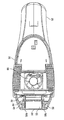
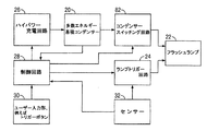
図3A乃至3Cに示される本発明の実施例によれば、センサーと放電ランプの如き発光素子との両方が配置されたハウジングが示されている。図3A乃至3Cを参照すると、皮膚の不調(皮膚病)や体調の治療に使用され、一層有利には髪の脱毛の如き化粧の目的に好適な本発明の典型的な実施例によれば、ハウジング(50)を含む皮膚治療器具が提供される。このハウジング(50)は、放電ランプ又はフラッシュランプの如きハウジングによって収納される発光素子(22)を含んでいる。放電ランプは、光の放射の高い強度のパルスを生成するように構成されている。ハウジング(50)は、ハンドル(52)を含んでおり、これは、ユーザに適切に配置されるようにハウジング(50)を操作することができることを意味する。ハウジング(50)は、使用時に、ユーザの皮膚に接近するか、好ましくは、皮膚上にして位置するように配置される皮膚接触素子(54)を含んでいる。この皮膚接触素子(54)は、光出力孔(56)即ち送り窓を含んでいて光放射の高い強度のパルスをこの送り窓を通して通過することができるようにし、この送り窓では、光出力孔/送り窓(56)と発光素子(22)との間に形成された導光管(55)がある。光出力孔/送り窓(56)の横断面積は、有益には、治療面積である。光導波路と称することができる導光管(55)を設けると、光出力孔/送り窓(56)からの光を焦点合わせすることになる。光出力孔/送り窓(56)を通る光の反射を補助するために少なくとも導光管(55)の壁の一部を形成する反射器(図示せず)が含まれているのが好ましい。発光素子(22)は、光出力孔/送り窓(56)に対して引っ込んでいる。導光管(55)を設けることの効果は、皮膚に向けて装置を出る光が分岐するのを少なくすることによって安全性を改善することである。 According to the embodiment of the invention shown in FIGS. 3A to 3C, a housing is shown in which both the sensor and the light emitting element, such as a discharge lamp, are arranged. Referring to FIGS. 3A-3C, according to an exemplary embodiment of the present invention used for the treatment of skin disorders (skin diseases) and physical conditions, and more advantageously suitable for cosmetic purposes such as hair loss. A skin treatment device is provided that includes a housing (50). The housing (50) comprises light emitting elements (22) housed by a housing such as a discharge lamp or a flash lamp. The discharge lamp is configured to generate high intensity pulses of light emission. The housing (50) includes a handle (52), which means that the housing (50) can be manipulated to be properly positioned by the user. The housing (50) comprises a skin contact element (54) which, in use, is arranged to approach or preferably be located on the skin of the user. The skin contact element (54) includes a light output hole (56) or transmission window to allow high intensity pulses of light radiation to pass through the transmission window, in which the light output hole is There is a light guide (55) formed between the feed window (56) and the light emitting element (22). The cross-sectional area of the light output hole / feed window (56) is advantageously a treatment area. The provision of a light guide (55), which may be referred to as a light guide, will focus the light from the light output hole / feed window (56). A reflector (not shown) is preferably included that forms at least a portion of the wall of the light guide (55) to assist in the reflection of light through the light output hole / send window (56). The light emitting element (22) is recessed relative to the light output hole / feed window (56). The effect of providing a light guide (55) is to improve the safety by reducing the divergence of the light leaving the device towards the skin.
皮膚接触素子(54)は、皮膚トーンの如き皮膚のパラメーターを決定する第1と第2のセンサー窓(58a、58b)を更に含んでいる。この皮膚接触素子(54)は、皮膚接触素子(54)に向けて内向きにテーパとなっているヘッド(60)上に設けられている。アクチュエーター(62)は、ユーザがトリガーの形態とすることができるコンデンサの如き電荷蓄積装置からエネルギを放出せしめ、フラッシュランプ(22)から光学放射のパルスを放出せしめるために設けられている。可視的な指示器(64)は、皮膚が受けるべき相対的なパワーレベルをユーザに示すために設けられている。 The skin contact element (54) further includes first and second sensor windows (58a, 58b) for determining skin parameters such as skin tone. The skin contact element (54) is provided on a head (60) which tapers inwardly towards the skin contact element (54). An actuator (62) is provided to release energy from the charge storage device, such as a capacitor which can be in the form of a trigger by the user, and to emit a pulse of optical radiation from the flash lamp (22). A visual indicator (64) is provided to indicate to the user the relative power level that the skin should receive.
図3Bを参照すると、ハウジング(50)の横断面が表れており、ハンドル(52)と光出力孔(56)とセンサー窓(58a、58b)を示している。更に、主のプリント回路板上の制御回路(28)を冷却するファン(66)が示されている。図3Bは、ランプ(22)がハウジング(50)内に固定されているのを示している。フィルタ(68)は、紫外線がランプ(22)から皮膚に移送するのを遮るために設けられている。ランプ(22)によって発生する治療光パルスは、このフィルタと、光出力孔(56)とを経てユーザの皮膚まで通過する。 Referring to FIG. 3B, a cross-section of the housing (50) appears, showing the handle (52), the light output hole (56) and the sensor window (58a, 58b). In addition, a fan (66) is shown cooling the control circuit (28) on the main printed circuit board. FIG. 3B shows that the lamp (22) is fixed in the housing (50). A filter (68) is provided to block the transfer of UV radiation from the lamp (22) to the skin. The therapeutic light pulse generated by the lamp (22) passes through the filter and the light output hole (56) to the skin of the user.
特に、図3Cを参照すると、図3Bの視面に実質的に垂直な軸線上で得られる断面で見られる。充電回路(26)とプリント回路板上にマウントされた制御回路(28)とランプ(22)とフィルタ(68)と光出力孔(56)とが図3Cに示されている。光の放射パルスを反射する反射器(70)が更に示され、またハウジング(50)の取手部(52)内に、コンデンサー(20)を含むエネルギー蓄積装置が収納されている。このハンドルは、主電力入力用の開口部(72)を形成している。ハウジング(50)は、全体としてドッキングステーション上に格納されるか、または図示しないが、適切に支持される。 In particular, referring to FIG. 3C, it can be seen in a cross section taken on an axis substantially perpendicular to the view plane of FIG. 3B. The charging circuit (26), the control circuit (28) mounted on the printed circuit board, the lamp (22), the filter (68) and the light output hole (56) are shown in FIG. 3C. Also shown is a reflector (70) that reflects the radiation pulse of light, and also housed in the handle (52) of the housing (50) an energy storage device comprising a capacitor (20). This handle forms an opening (72) for the main power input. The housing (50) is stored on the docking station as a whole or, although not shown, suitably supported.
本装置は、2つのモード、即ち、検知モードと治療モードとで有効に機能し、また、制御回路(28)は、この2つのモード間の切り替えを可能にするように構成される。スタンバイ又は準備のユーザ操作入力部(74)は、検知モードでユーザのために装置を準備するために設けられている。例えば、図3Bに示されるように、治療すべき皮膚のトーンとか色の如き測定可能な皮膚パラメータを検知するために、センサー(59)が設けられている。他の又は追加の皮膚パラメーターを検知してもよい。このセンサー(59)は、治療すべき皮膚にセンサー窓(58a、58b)を経て検知用放射線を送るように構成された発信器を含んでいる。このセンサー(59)は、皮膚表面から反射される放射線を受信するように構成された光ダイオードの如き受信器を更に含んでいる。受信放射線の強度は、皮膚のトーンを表すことが解っており、例えば、明るい皮膚トーンは、暗い皮膚トーンよりも多く反射する。受信放射線の強度は、プロセッサーを用いて制御回路(28)によって処理することができ、この制御回路は、この強度を強度測定の測定セットと比較して検知された皮膚トーンに依存し、従って最適な治療を確保する。
The device works effectively in two modes, namely the detection mode and the treatment mode, and the control circuit (28) is configured to allow switching between the two modes. A standby or preparation
指示器(64)は、センサー測定及び/又は治療エネルギー投与量を表す可視的なディスプレイの形態で設けられるのが好ましい。これは、光の数が出力すべきエネルギーの強度を表す場合に、点灯される複数の光指示器の形態とすることができる。 The indicator (64) is preferably provided in the form of a visible display that represents a sensor measurement and / or therapeutic energy dose. This can be in the form of a plurality of light indicators that are illuminated when the number of lights represents the intensity of the energy to be output.
本装置の重要な特徴は、ユーザがセンサー測定に基づいて決定された治療エネルギー投与量を手動で無視することができることである。これは、ユーザがその治療が痛いと感じるか非効率的であると感じ、従って、ある手動制御を望む場合に重要である。従って、制御システムによって実行されるのが好ましい所定の治療エネルギー投与量に対して調節を行わせるユーザー入力部が設けられるのが有利である。これは、増減する治療エネルギー投与量を有効に変更する。増減は、自動的に決定されてもよいし、位置の如き身体パラメータに依存して選択してもよく、ユーザ入力部を起動すると、治療エネルギーを固定値又は固定割合だけ減少し、さもなければ、治療エネルギー投与量の最大値を制限してもよい。他の例では、ユーザは、所定量だけ、定められた治療エネルギー投与量の出力を増加する強力モードを選択してもよい。装置に設けられた指示器(64)は、選択された動作モードを指示するのが有利であり、これは、可視的に有利な表示は、強力か、温和かのモードのいずれの動作モードが選択されているかを示していることを意味している。 An important feature of the device is that the user can manually ignore the therapeutic energy dose determined based on sensor measurements. This is important if the user feels that the treatment is painful or inefficient and thus desires some manual control. Accordingly, it is advantageous to provide a user input that allows adjustments to be made to a predetermined therapeutic energy dose that is preferably implemented by the control system. This effectively alters the therapeutic energy dose to be increased or decreased. The increase or decrease may be determined automatically or may be selected depending on the physical parameter such as position, activating the user input reduces the treatment energy by a fixed value or percentage, otherwise The maximum therapeutic energy dose may be limited. In another example, the user may select a power mode that increases the output of a defined therapeutic energy dose by a predetermined amount. An indicator (64) provided on the device is advantageously used to indicate the selected operating mode, which means that the visually advantageous display has either a strong or a mild operating mode. It is meant to indicate that it is selected.
図3A乃至図3Cを参照すると、本発明の1つの態様では、治療領域に対応する皮膚トーンの検知に改良された精度を付与する皮膚治療器具が提供されることは理解されることと思う。1つ以上のセンサー(59)を設けると、クロスチェックして、センサー機能の正確性があり、更に治療領域とその皮膚トーンがセンサーによって決定された皮膚トーンに正確に反映されるのを確実にするという利点が付与される。このセンサーは、光出力孔(56)に隣接して設けられ、これは、センサーが高エネルギーパルス化光治療によって妨害されないし影響もされないことを意味する。センサー(59)は、皮膚接触素子(54)の光出力孔(56)のいずれかの側に配置され、各センサー(59)は、独立して皮膚トーンを記録する。制御回路のプロセッサーは、有効な皮膚トーンの読みが達成されたか否かを判断するように構成されている。これは、1つの実施例では、所定の閾値以下である2つの皮膚トーン測定の間の差によって決定される。2つの皮膚トーン測定は、使用されるべき最も安全か最良の治療セッテイングを決定するのに使用することもできる。例えば、最も安全な治療セッティングは、2つのセンサーからの最低の皮膚トーン測定に基づくことになる。さもなければ、最も高い測定、平均の計算又はその他の計算を使用することもできる。治療領域の定められた皮膚トーンの正確性を改善するために、付加的なセンサーを設けてもよいことは、更に理解されることと思う。 With reference to FIGS. 3A-3C, it will be appreciated that in one aspect of the present invention, there is provided a skin treatment device that provides improved accuracy in the detection of skin tones corresponding to a treatment area. Having one or more sensors (59) cross-checks to ensure that the sensor function is accurate and that the treatment area and its skin tone are accurately reflected in the skin tone determined by the sensor. The advantage of This sensor is provided adjacent to the light output hole (56), which means that the sensor is not disturbed or affected by high energy pulsed light treatment. Sensors (59) are placed on either side of the light output holes (56) of the skin contact element (54), and each sensor (59) independently records the skin tone. The processor of the control circuit is configured to determine if a valid skin tone reading has been achieved. This is determined in one embodiment by the difference between two skin tone measurements that are below a predetermined threshold. Two skin tone measurements can also be used to determine the safest or best treatment setting to be used. For example, the safest treatment setting will be based on the lowest skin tone measurement from the two sensors. Otherwise, the highest measurement, average calculation or other calculations can be used. It will be further understood that additional sensors may be provided to improve the accuracy of the defined skin tone of the treatment area.
図4A乃至図4Cを参照すると、図4Aは、本発明の第1の実施例を用いたブロックダイヤグラム形式の構成成分を示している。この図は、図1Aと同様であり、類似する構成成分は、同じ参照符号で示されている。しかし、注目すべきことであるが、この実施例では、電子スイッチ(例えば、Mosfet)の如き放電制御素子(80)の追加の構成成分があり、この構成成分は、 ブロック図で示されているフラッシュパルス終了回路に設けられており、この回路は、エネルギー蓄積装置(20)からフラッシュランプ(22)への放電エネルギーを終了するように構成されている。フラッシュパルス終了回路(80)内に放電制御素子(80)を設けることの効果は、所望のエネルギー出力を達成するために、図4Cに示されるような光出力パルス波形を終了することができるということである。これは、エネルギー蓄積装置の初期電圧に関係ないことが認識されることと思う。図4Cにおいて、エネルギー蓄積装置の電圧は330Vであるが、3つの光出力パルス波形の各々のエネルギー出力は、エネルギー蓄積装置(20)からのエネルギー出力が時間と共にいつ終了するかに依存して異なる。第1のグラフは、エネルギー蓄積装置(20)からのエネルギーの終了を表わさないで、そのため、300Vのコンデンサー電圧用の6J/cm2のエネルギー出力が最大化されている。しかし、第2のグラフは、エネルギー蓄積装置(20)から伝送されるエネルギーの終了を示し、これは、4.5J/cm2の縮小されたエネルギー出力があることを意味する。第3のグラフは、エネルギーが3.6J/cm2である早い終了を示している。再び説明すると、エネルギー蓄積装置(20)の初期電圧に関係なくエネルギー出力が制御されていることは重要である。これは、センサー(単数又は複数)の出力と無関係にエネルギー蓄積装置(20)を充電することができ、従ってセンサー(単数又は複数)が皮膚トーンを記録すると同時に充電することができることを意味する。電荷蓄積装置(20)に対する充電を減少する必要はないので、それに関連する時間遅れはない。 Referring to FIGS. 4A-4C, FIG. 4A shows the components in block diagram form using the first embodiment of the present invention. This figure is similar to FIG. 1A, and similar components are indicated with the same reference numerals. However, it should be noted that in this embodiment there is an additional component of the discharge control element (80) such as an electronic switch (eg Mosfet), which is shown in the block diagram Provided in the flash pulse termination circuit, which is configured to terminate the discharge energy from the energy storage device (20) to the flash lamp (22). The effect of providing the discharge control element (80) in the flash pulse end circuit (80) is that the light output pulse waveform as shown in FIG. 4C can be terminated to achieve the desired energy output It is. It will be appreciated that this is not related to the initial voltage of the energy storage device. In FIG. 4C, the voltage of the energy storage device is 330 V, but the energy output of each of the three light output pulse waveforms is different depending on when the energy output from the energy storage device (20) ends with time . The first graph does not show the end of the energy from the energy storage device (20), so the energy output of 6 J / cm 2 for a capacitor voltage of 300 V is maximized. However, the second graph shows the end of the energy transmitted from the energy storage device (20), which means that there is a reduced energy output of 4.5 J / cm 2 . The third graph shows an early termination with energy of 3.6 J / cm 2 . Again, it is important that the energy output be controlled regardless of the initial voltage of the energy storage device (20). This means that the energy storage device (20) can be charged independently of the output of the sensor (s), so that the sensor (s) can be charged while recording the skin tone. As there is no need to reduce the charge to the charge storage device (20), there is no time delay associated with it.
図4Bには、光出力、ユーザ入力部、センサー測定、コンデンサー電圧及びコンデンサー充電が時間に対して表わされている。時間T0では、装置は、スイッチオンされ、時間T1では、ユーザ入力部(75)が押されて、装置は、センサー測定がT0で開始する起動モードに入るようにせしめられる。時間T1では、制御システムは、コンデンサーを充電し、従ってコンデンサー電圧は、時間T1とT2との間で増加する。この時間の間、繰り返しのセンサー測定が行なわれ、皮膚トーンの読みが定期的な間隔ごとに記録される。これは、皮膚上を装置が僅かに移動することによって引き起こされる。時間T2では、コンデンサーは、図4Cに示されるように、例えば、300Vの如き最大出力電圧に充電されている。このコンデンサー電圧は、センサーによって記録された皮膚トーンの変化に関係なく、時間T2とT3との間でこの電圧で維持される。例えば、トリガーから成っているユーザ入力部が起動され、ユーザによるこのトリガーの入力で発光体からの即時の光出力がある。これは、装置のユーザによる起動と被測定治療エネルギー投与量との間に時間遅れがないことを意味して、重要であり、ユーザーは、治療が行われており、装置の動きがある間時間遅れがないことに気付く。従って、エネルギーが放電ランプに出力されているので、コンデンサー電圧は減少するが、コンデンサーを出るエネルギーが所望のエネルギー投与量が解放された時間に終了するので、電荷は、残留電圧を保持し、繰り返しの使用に備える。その後、この装置は、皮膚の適当な他の部分上に配置換えされ、プロセスが繰り返される。その結果、エネルギー出力は、センサーからの受け取る情報に基づいて制御回路を経て決定することができるが、エネルギー出力の制御は、エネルギー蓄積装置(20)から放出されたエネルギーの制御を通して行われる。従って、エネルギー蓄積装置及びその電荷は、センサー入力に依存しない。 In FIG. 4B, the light output, the user input, the sensor measurement, the capacitor voltage and the capacitor charge are plotted against time. At time T0, the device is switched on, and at time T1, the user input (75) is pressed, causing the device to enter an activation mode where sensor measurements start at T0. At time T1, the control system charges the capacitor so that the capacitor voltage increases between times T1 and T2. During this time, repeated sensor measurements are taken and skin tone readings are recorded at regular intervals. This is caused by a slight movement of the device on the skin. At time T2, the capacitor is charged to a maximum output voltage, such as 300 V, as shown in FIG. 4C. This capacitor voltage is maintained at this voltage between times T2 and T3 regardless of the change in skin tone recorded by the sensor. For example, a user input comprising a trigger is activated and there is an immediate light output from the light emitter at the input of this trigger by the user. This is important, which means that there is no time delay between activation by the user of the device and the measured therapeutic energy dose, and the user has time while treatment is taking place and there is movement of the device I notice that there is no delay. Thus, as energy is being output to the discharge lamp, the capacitor voltage will decrease, but the energy leaving the capacitor will end at the time the desired energy dose has been released, so the charge will retain the residual voltage and repeatedly Prepare for the use of The device is then relocated onto the appropriate other part of the skin and the process is repeated. As a result, the energy output can be determined via the control circuit based on the information received from the sensor, but the control of the energy output is through the control of the energy emitted from the energy storage device (20). Thus, the energy storage device and its charge do not depend on the sensor input.
放電制御素子を設けることによるフラッシュパルス終了回路に加えて、コンデンサー放電を制御する効果があるパルス幅を調整するように構成された放電制御素子を設けてもよい。これは、Mosfetスイッチの如き電子スイッチからも達成することができる。これは、エネルギー出力が提供される時間を増加する効果がある。 In addition to the flash pulse termination circuit by providing a discharge control element, a discharge control element configured to adjust a pulse width having an effect of controlling capacitor discharge may be provided. This can also be achieved from electronic switches such as Mosfet switches. This has the effect of increasing the time over which energy output is provided.
本発明の第2の実施例では、エネルギー蓄積装置は、個々のコンデンサーの如き複数の個々の蓄積装置素子を含んでいてもよい。制御回路(28)は、複数の個々の電荷蓄積素子の放電を制御するように構成され、個々の電荷蓄積素子の各々の放電を独立して制御することができる。電荷蓄積素子からのリリースは、制御システムによって順次又は同時に可能である。これは、コンデンサースイッチング(切替え)回路と称することができるエネルギー蓄積装置スイッチング(切替え)回路(82)を設けることによって達成することができる。センサー(32)からの入力の結果として多数エネルギー蓄積コンデンサーを充電する必要なく、制御回路(28)へのセンサー入力に依存して所要のように図5Cで認識されるエネルギー出力を操作することができる。図5Cで表わされるように、多段エネルギー蓄積コンデンサーは、例えば400Vまで充電することができる。全エネルギー出力は、多くのコンデンサーが放電する方法を選択的に決めることにより調節することができる。例えば、2つのコンデンサーを備えた2つのエネルギーパルスシステムに対しては、コンデンサーの一方のみ又は両方を用いて、エネルギー全体を急速に半分にするか又は倍にすることができる。より多くのコンデンサーを用いることによってより高い解像度を達成することができる。さもなければ、個々のコンデンサーパルスのリリース間の時間は、治療強度を調節するのに利用してもよい。互いに接近しているパルスは、一層強力であり、その結果、一層離れたパルスに比べて皮膚と髪との温度が一層高くなり、従って、エネルギー出力が操作されることを意味する。図5Cのグラフで表わされるように、エネルギー出力は、合計キャパシタンス(全静電容量)に依存して調節することができる。個々のコンデンサーは、適切な治療エネルギー投与量が達成されることができるようにするため、異なる電圧に充電するか、充電していることができることは、更に理解されることと思う。 In a second embodiment of the invention, the energy storage device may comprise a plurality of individual storage device elements, such as individual capacitors. The control circuit (28) is configured to control the discharge of the plurality of individual charge storage elements, and can independently control the discharge of each of the individual charge storage elements. Release from the charge storage elements is possible sequentially or simultaneously by the control system. This can be achieved by providing an energy storage device switching circuit (82), which can be referred to as a capacitor switching circuit. Depending on the sensor input to the control circuit (28) it is possible to manipulate the energy output recognized in FIG. 5C as required without charging the multiple energy storage capacitors as a result of the input from the sensor (32) it can. As illustrated in FIG. 5C, the multi-stage energy storage capacitor can be charged to, for example, 400V. The total energy output can be adjusted by selectively determining how many capacitors discharge. For example, for a two energy pulse system with two capacitors, only one or both of the capacitors can be used to rapidly halve or double the overall energy. Higher resolution can be achieved by using more capacitors. Otherwise, the time between release of individual condenser pulses may be used to adjust the therapeutic intensity. The pulses approaching one another are more powerful, which results in higher temperatures of the skin and the hair as compared to the more distant pulses, meaning that the energy output is manipulated. As represented by the graph in FIG. 5C, the energy output can be adjusted depending on the total capacitance (total capacitance). It will be further understood that the individual capacitors can be charged or charged to different voltages in order to be able to achieve an appropriate therapeutic energy dose.
図5Bを参照すると、時間T0で、装置が切り替えられ、時間T1でユーザがユーザ入力部によって装置が動作状態に入りたいことを装置に入力する。時間T1で、有効なセンサー測定が記録され、これは、多数コンデンサーのコンデンサー電圧がT1とT2の間に増加することを意味する。この時間の間、センサー測定は、記録された皮膚トーンに基づいて変化している。ユーザトリガー入力部が起動され、時間T3で即時の光出力がある。時間T3とT4との間で、光は出力され、使用されているコンデンサーの電圧は、初期レベルまで下降し、一方使用されていないコンデンサーは、先の電圧を保持している。 Referring to FIG. 5B, at time T0, the device is switched, and at time T1, the user inputs to the device that he / she wishes to enter the operating state by means of the user input. At time T1, a valid sensor measurement is recorded, which means that the capacitor voltage of the multiple capacitors increases between T1 and T2. During this time, sensor measurements are changing based on the recorded skin tone. The user trigger input is activated and there is an immediate light output at time T3. Between times T3 and T4, light is output and the voltage of the used capacitor drops to the initial level, while the unused capacitor holds the previous voltage.
図6A乃至図6Cを参照すると、本発明の第3の典型的な実施例が示されており、同様の構成成分は、同じ参照符号で示されている。本発明の1つの実施例では、ユーザ入力部と装置及び実際の光出力を活性化したいとする要望との間の時間遅れを最小にするために、エネルギー蓄積装置(20)を中間値まで充電することができる。これは、センサー(32)の入力からは独立している。充電は、所定の中間電圧まで行なわれ、この電圧は、ユーザが入力部を起動する時にセンサーによって決定された皮膚トーンに基づいて有効にトップアップすることができる。従って、この実施例では、エネルギー蓄積装置(20)は、センサー入力とは独立して、例えば300Vの電圧まで充電され、この電圧は、皮膚トーン測定に依存して上昇することができる。図6Bで示される時間TOで装置がスイチイオンされ、時間T1でユーザ入力部は、装置を活性化せしめる。センサー測定が記録され、時間T1で、エネルギー蓄積装置(20)は、所定の最小電圧に充電される。これは、トリガーボタンを介してユーザ入力装置を始動するまで、時間T2で維持される。時間T3でこの入力とセンサー測定とに基づいて、エネルギー蓄積装置の電圧を上げ、この時、電圧が増加し、エネルギー蓄積装置が充電される。従って、時間T4では、光がパルスとして出力し、エネルギー蓄積装置(20)の電圧が下降する。テストを通して、およそ200ミリ秒で中間電圧から所要の最大出力電圧までエネルギー蓄積装置を充電することができることが定められている。しかし、これを達成するために、非常に高いパワー充電器が必要であることが認識されることと思う。 Referring to FIGS. 6A-6C, a third exemplary embodiment of the present invention is shown, where like components are indicated with the same reference numerals. In one embodiment of the present invention, the energy storage device (20) is charged to an intermediate value to minimize the time delay between the user input and the device and the desire to activate the actual light output. can do. This is independent of the input of the sensor (32). Charging takes place to a predetermined intermediate voltage, which can be effectively top-up based on the skin tone determined by the sensor when the user activates the input. Thus, in this embodiment, the energy storage device (20) is charged to a voltage of, for example, 300 V independently of the sensor input, which voltage can be increased depending on the skin tone measurement. At time T0, shown in FIG. 6B, the device is switched ion and at time T1, the user input activates the device. The sensor measurements are recorded and at time T1, the energy storage device (20) is charged to a predetermined minimum voltage. This is maintained at time T2 until the user input device is triggered via the trigger button. At time T3, based on this input and the sensor measurement, the voltage of the energy storage device is increased, at which time the voltage is increased and the energy storage device is charged. Accordingly, at time T4, light is output as a pulse, and the voltage of the energy storage device (20) drops. Through testing, it has been determined that the energy storage device can be charged from the intermediate voltage to the required maximum output voltage in approximately 200 milliseconds. However, it will be appreciated that a very high power charger is needed to achieve this.
この実施例の変形例として、一般に、人の皮膚トーンは、フィッツパトリックの如き6等級システム上の1つ以上又は2つの等級だけ変化しないことは注目される。これは、例えば、脚上の通常の治療ゾーン内にある。従って、制御システムは、前の測定から決定された複数の使用間でエネルギー蓄積装置が充電される最小電圧で先の皮膚トーン測定を記憶してもよい。例えば、最小電圧は、最後の10回の使用中に測定された最小の皮膚トーンに相当することができる。 As a variation of this embodiment, it is noted that, generally, human skin tones do not change by one or more or two grades on a six grade system such as Fitzpatrick. This is, for example, within the normal treatment zone on the leg. Thus, the control system may store the previous skin tone measurement at the lowest voltage at which the energy storage device is charged among the plurality of uses determined from the previous measurement. For example, the minimum voltage can correspond to the minimum skin tone measured during the last 10 uses.
本発明の第4の実施例では、制御システムは、エネルギー蓄積装置の放電を調整して治療エネルギー投与量を供与するように構成されている。これは、MOsfetの如き電子スイッチを使用して、パルス幅調整(PWM)回路を介して放電を行うことを通して達成される。これは、エネルギーパルス波形を制御する効果があり、その結果、エネルギーパルスを変更することができ、これは、発光素子への出力が「一層遅い」ように制御されることを意味し、これは、また、光が一層長く活性化され続けることを意味し、従って皮膚上の光の強度は減少する。出力エネルギーは、多数の他のパルス波形を提供するように操作される。これは、有効に、エネルギー出力が同じに維持されることができることを意味するが、エネルギーが供給される期間が延長され、その結果、ユーザの皮膚上の強度は減少する。これは、電荷蓄積装置からのエネルギーの放出が調整されて所定の治療エネルギー投与量を達成し、その結果、電荷蓄積装置は、現在のセンサー読み取りに依存して、調節する必要がないことを意味する。 In a fourth embodiment of the present invention, the control system is configured to adjust the discharge of the energy storage device to provide a therapeutic energy dose. This is achieved through discharging through a pulse width adjustment (PWM) circuit using an electronic switch such as MOsfet. This has the effect of controlling the energy pulse waveform so that the energy pulse can be changed, which means that the output to the light emitting element is controlled to be "slower", which is Also, it means that the light continues to be activated longer, so the intensity of the light on the skin is reduced. The output energy is manipulated to provide a number of other pulse waveforms. This effectively means that the energy output can be kept the same, but the period of energy delivery is extended, as a result of which the intensity on the skin of the user is reduced. This means that the release of energy from the charge storage device is adjusted to achieve a predetermined therapeutic energy dose, so that the charge storage device does not have to be adjusted depending on the current sensor reading. Do.
制御システムは、いずれの実施例でも電荷蓄積装置の放電を所望のように調整してもよいことが認識されることと思う。 It will be appreciated that the control system may adjust the discharge of the charge storage device as desired in any of the embodiments.
本発明の幾つかの態様を例示的にのみ説明したが、特許請求の範囲によって与えられた保護の範囲から逸脱することなく、種々の変形を行うことができることは、当業者によって理解されるであろう。
While some aspects of the present invention have been described by way of example only, it will be understood by those skilled in the art that various modifications can be made without departing from the scope of protection given by the claims. I will.
Claims (21)
皮膚のパラメーターを測定する少なくとも1つのセンサーと、
前記センサーの測定を用いて導き出され、供与すべき治療エネルギー投与量を決定するように構成された制御システムとから成り、
i)前記制御システムは、治療エネルギー投与量の供与時及び/又は放電の完了前に前記電荷蓄積装置の放電を終了するように構成され、及び/又は
ii)前記電荷蓄積装置は、複数の個々の電荷蓄積素子から成り、且つ前記制御システムは、前記治療エネルギー投与量を供与するために前記複数の独立電荷蓄積素子の放電を制御するように構成され、及び/又は
iii)前記制御システムは、2段以上の操作で前記電荷蓄積装置の充電を可能とするように構成され、且つ第1の段階では、中間エネルギーレベルまで充電され、第2の又はその後の段階では、治療エネルギー投与量を供与するのに十分なエネルギーレベルまで充電され、及び/又は
iV)前記制御システムは、前記治療エネルギー投与量を供与するために前記電荷蓄積装置の放電を緩和するように構成されている
皮膚治療器具。 A light source comprising a light emitting element for delivering light energy to the skin and a charge storage device for releasing an energy dose to the light emitting element;
At least one sensor that measures skin parameters,
A control system derived using the measurements of the sensor and configured to determine the therapeutic energy dose to be delivered,
i) the control system is configured to terminate the discharge of the charge storage device upon delivery of a therapeutic energy dose and / or before completion of the discharge, and / or ii) the charge storage device comprises a plurality of individual A charge storage element, and the control system is configured to control the discharge of the plurality of independent charge storage elements to provide the therapeutic energy dose, and / or iii) the control system Configured to allow charging of the charge storage device in two or more stages of operation, and in a first stage charging to an intermediate energy level and in a second or subsequent stage delivering a therapeutic energy dose The control system is charged to an energy level sufficient to perform the treatment and / or the iV) of the charge storage device to provide the therapeutic energy dose. Skin treatment instrument that is configured to mitigate electricity.
Applications Claiming Priority (3)
| Application Number | Priority Date | Filing Date | Title |
|---|---|---|---|
| GB1321382.2A GB2526764B (en) | 2013-12-04 | 2013-12-04 | Skin treatment apparatus utilising intense pulsed light (IPL) |
| GB1321382.2 | 2013-12-04 | ||
| PCT/GB2014/053609 WO2015082928A2 (en) | 2013-12-04 | 2014-12-04 | Skin treatment apparatus utilising intense pulsed light (ipl) |
Publications (3)
| Publication Number | Publication Date |
|---|---|
| JP2016539777A JP2016539777A (en) | 2016-12-22 |
| JP2016539777A5 JP2016539777A5 (en) | 2018-01-18 |
| JP6535343B2 true JP6535343B2 (en) | 2019-06-26 |
Family
ID=49979769
Family Applications (1)
| Application Number | Title | Priority Date | Filing Date |
|---|---|---|---|
| JP2016557201A Active JP6535343B2 (en) | 2013-12-04 | 2014-12-04 | Skin treatment device using powerful pulsed light |
Country Status (5)
| Country | Link |
|---|---|
| US (2) | US10595939B2 (en) |
| EP (3) | EP3348223B1 (en) |
| JP (1) | JP6535343B2 (en) |
| GB (2) | GB2526764B (en) |
| WO (1) | WO2015082928A2 (en) |
Families Citing this family (17)
| Publication number | Priority date | Publication date | Assignee | Title |
|---|---|---|---|---|
| WO2016025468A2 (en) | 2014-08-11 | 2016-02-18 | The Board Of Trustees Of The University Of Illinois | Devices and related methods for epidermal characterization of biofluids |
| USD901028S1 (en) * | 2016-06-11 | 2020-11-03 | Advino Technologies Llp | Laser therapy device |
| US10653342B2 (en) * | 2016-06-17 | 2020-05-19 | The Board Of Trustees Of The University Of Illinois | Soft, wearable microfluidic systems capable of capture, storage, and sensing of biofluids |
| CN106345066B (en) * | 2016-10-11 | 2019-05-21 | 深圳可思美科技有限公司 | IPL depilatory apparatus |
| KR101951468B1 (en) * | 2016-11-14 | 2019-02-22 | (주)미린트 | rhinitis therapeutic device and method for controlling the rhinitis therapeutic device |
| USD791336S1 (en) * | 2016-11-30 | 2017-07-04 | Shenzhen Peninsula Medical Co., Ltd. | Ultraviolet treatment apparatus |
| USD812745S1 (en) * | 2017-01-19 | 2018-03-13 | Tweezerman International, Llc | Dermaplaner |
| EP3437696B1 (en) | 2017-08-01 | 2021-02-24 | Braun GmbH | Light-based epilation device and method of cosmetic hair removal |
| KR20190044560A (en) | 2017-10-20 | 2019-04-30 | 주식회사 씨엠랩 | High intensity LED device |
| CN109157747A (en) * | 2017-10-30 | 2019-01-08 | 武汉奇致激光技术股份有限公司 | A kind of train of pulse output control method of intensive pulsed light machine |
| CN108650757B (en) * | 2018-03-28 | 2019-08-20 | 深圳可思美科技有限公司 | A kind of depilatory apparatus |
| EP3613376A1 (en) | 2018-08-21 | 2020-02-26 | Koninklijke Philips N.V. | A handheld device for performing a treatment operation on skin |
| CN109603012A (en) * | 2018-11-23 | 2019-04-12 | 北京镭特医疗科技有限公司 | A method of IPL and E light is used in combination and carries out beauty |
| CN110368594A (en) * | 2019-06-26 | 2019-10-25 | 木马电器科技(东莞)有限责任公司 | A kind of hand-held light nti-freckle equipment and nti-freckle method |
| GB2604876A (en) * | 2021-03-15 | 2022-09-21 | Ipulse Ltd | Skin treatment device |
| CN113398490B (en) * | 2021-06-24 | 2022-08-02 | 赣南医学院第一附属医院 | Pulse laser beauty therapeutic instrument |
| CN114343838A (en) * | 2021-12-31 | 2022-04-15 | 广州星际悦动股份有限公司 | Pulse light control method, circuit and equipment of depilating instrument and depilating instrument |
Family Cites Families (24)
| Publication number | Priority date | Publication date | Assignee | Title |
|---|---|---|---|---|
| DE3612164A1 (en) | 1986-04-11 | 1987-10-15 | Urs Zeltner | LUMINAIRES AND FLASH DEVICE |
| US5720772A (en) | 1992-10-20 | 1998-02-24 | Esc Medical Systems Ltd. | Method and apparatus for therapeutic electromagnetic treatment |
| KR100376650B1 (en) | 1996-04-09 | 2003-08-25 | 싸이노슈어, 인코포레이티드 | Alexander laser system for the treatment of skin pathological specimens |
| EP0885629A3 (en) | 1997-06-16 | 1999-07-21 | Danish Dermatologic Development A/S | Light pulse generating apparatus and cosmetic and therapeutic phototreatment |
| US5885274A (en) | 1997-06-24 | 1999-03-23 | New Star Lasers, Inc. | Filament lamp for dermatological treatment |
| IL122840A (en) | 1997-12-31 | 2002-04-21 | Radiancy Inc | Apparatus and methods for removing hair |
| JP4141260B2 (en) | 2001-03-30 | 2008-08-27 | コーニンクレッカ フィリップス エレクトロニクス エヌ ヴィ | Skin treatment device with protected radiation output opening |
| JP2004529705A (en) | 2001-04-20 | 2004-09-30 | コーニンクレッカ フィリップス エレクトロニクス エヌ ヴィ | Skin treatment device with protection against overdose of radiation pulses |
| GB2381752A (en) * | 2001-11-06 | 2003-05-14 | Ezio Panzeri | Laser skin treatment device with control means dependent on a sensed property of the skin to be treated |
| WO2004075681A2 (en) * | 2003-02-25 | 2004-09-10 | Spectragenics, Inc. | Self-contained, eye-safe hair-regrowth-inhibition apparatus and method |
| DE602004030455D1 (en) * | 2003-08-12 | 2011-01-20 | Lumenis Ltd | SYSTEM FOR OPERATING PULSE INKOHAERENTES LIGHT |
| PL1658113T3 (en) | 2003-08-18 | 2013-06-28 | Koninl Philips Electronics Nv | Device for low intensity optical hair growth control |
| US20070239144A1 (en) | 2006-04-06 | 2007-10-11 | Lite Touch Ltd. | Methods of photothermolysis |
| US20080058782A1 (en) * | 2006-08-29 | 2008-03-06 | Reliant Technologies, Inc. | Method and apparatus for monitoring and controlling density of fractional tissue treatments |
| US20080140164A1 (en) * | 2006-12-06 | 2008-06-12 | Clrs Technology Corporation | Light emitting therapeutic devices and methods |
| EP2194899A4 (en) * | 2007-08-08 | 2012-11-28 | Tria Beauty Inc | Capacitive sensing method and device for detecting skin |
| RU2497478C2 (en) * | 2008-03-21 | 2013-11-10 | Конинклейке Филипс Электроникс Н.В. | System and method of depilation |
| KR101727095B1 (en) * | 2009-07-20 | 2017-05-02 | 코닌클리케 필립스 엔.브이. | Light application apparatus for applying light to an object |
| JP5852661B2 (en) | 2010-10-25 | 2016-02-03 | コーニンクレッカ フィリップス エヌ ヴェKoninklijke Philips N.V. | Skin treatment system |
| KR102011298B1 (en) | 2011-02-03 | 2019-10-14 | 트리아 뷰티, 인코포레이티드 | Radiation-based dermatological devices and methods |
| EP2499985A1 (en) * | 2011-03-14 | 2012-09-19 | Koninklijke Philips Electronics N.V. | Light based skin care device with controllable fluency level |
| GB2496895A (en) * | 2011-11-25 | 2013-05-29 | Cyden Ltd | Skin treatment apparatus |
| JP6437181B2 (en) * | 2012-03-19 | 2018-12-12 | 株式会社ジェイ クラフト | Hair control and hair removal equipment |
| US20140039473A1 (en) * | 2012-05-15 | 2014-02-06 | Tria Beauty, Inc. | Dermatological Treatment Device With Real-Time Energy Control |
-
2013
- 2013-12-04 GB GB1321382.2A patent/GB2526764B/en active Active
- 2013-12-04 GB GB2012396.4A patent/GB2583683B/en active Active
-
2014
- 2014-12-04 EP EP18154104.6A patent/EP3348223B1/en active Active
- 2014-12-04 EP EP20208207.9A patent/EP3799820B1/en active Active
- 2014-12-04 JP JP2016557201A patent/JP6535343B2/en active Active
- 2014-12-04 WO PCT/GB2014/053609 patent/WO2015082928A2/en active Application Filing
- 2014-12-04 US US15/101,102 patent/US10595939B2/en active Active
- 2014-12-04 EP EP14809688.6A patent/EP3076890B1/en active Active
-
2020
- 2020-02-18 US US16/793,517 patent/US11337754B2/en active Active
Also Published As
| Publication number | Publication date |
|---|---|
| EP3348223A2 (en) | 2018-07-18 |
| EP3076890A2 (en) | 2016-10-12 |
| GB2526764B (en) | 2020-10-07 |
| WO2015082928A2 (en) | 2015-06-11 |
| EP3348223B1 (en) | 2020-12-16 |
| GB202012396D0 (en) | 2020-09-23 |
| JP2016539777A (en) | 2016-12-22 |
| EP3799820B1 (en) | 2022-06-08 |
| US10595939B2 (en) | 2020-03-24 |
| GB2583683A (en) | 2020-11-04 |
| EP3348223A3 (en) | 2018-11-14 |
| EP3799820A1 (en) | 2021-04-07 |
| US20160374758A1 (en) | 2016-12-29 |
| GB2583683B (en) | 2021-03-31 |
| EP3076890B1 (en) | 2018-01-31 |
| GB201321382D0 (en) | 2014-01-15 |
| GB2526764A (en) | 2015-12-09 |
| US11337754B2 (en) | 2022-05-24 |
| US20200179048A1 (en) | 2020-06-11 |
| WO2015082928A3 (en) | 2015-07-30 |
Similar Documents
| Publication | Publication Date | Title |
|---|---|---|
| JP6535343B2 (en) | Skin treatment device using powerful pulsed light | |
| JP7420789B2 (en) | Handheld device that performs therapeutic movements on the skin | |
| US7780652B2 (en) | System and method for flexible architecture for dermatologic treatments utilizing multiple light sources | |
| JP6076368B2 (en) | Skin treatment equipment | |
| KR101789131B1 (en) | Power supply for light-based dermatologic treatment device | |
| US9005262B2 (en) | Radiation-based dermatological devices and methods | |
| US20140039473A1 (en) | Dermatological Treatment Device With Real-Time Energy Control | |
| RU2406548C1 (en) | Device for hair growth regulation | |
| KR101811830B1 (en) | Light pen dispenser | |
| EP2499985A1 (en) | Light based skin care device with controllable fluency level | |
| GB2580571A (en) | Skin treatment apparatus utilsing intense pulsed light (IPL) | |
| US20070239145A1 (en) | System and method to assist in the treatment of skin conditions |
Legal Events
| Date | Code | Title | Description |
|---|---|---|---|
| A521 | Request for written amendment filed |
Free format text: JAPANESE INTERMEDIATE CODE: A821 Effective date: 20160620 |
|
| RD01 | Notification of change of attorney |
Free format text: JAPANESE INTERMEDIATE CODE: A7426 Effective date: 20160620 |
|
| A521 | Request for written amendment filed |
Free format text: JAPANESE INTERMEDIATE CODE: A523 Effective date: 20171204 |
|
| A621 | Written request for application examination |
Free format text: JAPANESE INTERMEDIATE CODE: A621 Effective date: 20171204 |
|
| A977 | Report on retrieval |
Free format text: JAPANESE INTERMEDIATE CODE: A971007 Effective date: 20180822 |
|
| A131 | Notification of reasons for refusal |
Free format text: JAPANESE INTERMEDIATE CODE: A131 Effective date: 20180828 |
|
| A601 | Written request for extension of time |
Free format text: JAPANESE INTERMEDIATE CODE: A601 Effective date: 20181126 |
|
| A521 | Request for written amendment filed |
Free format text: JAPANESE INTERMEDIATE CODE: A523 Effective date: 20190128 |
|
| TRDD | Decision of grant or rejection written | ||
| A01 | Written decision to grant a patent or to grant a registration (utility model) |
Free format text: JAPANESE INTERMEDIATE CODE: A01 Effective date: 20190514 |
|
| A61 | First payment of annual fees (during grant procedure) |
Free format text: JAPANESE INTERMEDIATE CODE: A61 Effective date: 20190531 |
|
| R150 | Certificate of patent or registration of utility model |
Ref document number: 6535343 Country of ref document: JP Free format text: JAPANESE INTERMEDIATE CODE: R150 |
|
| R250 | Receipt of annual fees |
Free format text: JAPANESE INTERMEDIATE CODE: R250 |
|
| R250 | Receipt of annual fees |
Free format text: JAPANESE INTERMEDIATE CODE: R250 |