[1.パチンコ機の全体構造]
本発明の一実施形態であるパチンコ機1について、図面を参照して詳細に説明する。まず、図1乃至図10を参照して本実施形態のパチンコ機1の全体構成について説明する。図1は本発明の一実施形態であるパチンコ機の正面図である。図2はパチンコ機の右側面図であり、図3はパチンコ機の左側面図であり、図4はパチンコ機の背面図である。図5はパチンコ機を右前から見た斜視図であり、図6はパチンコ機を左前から見た斜視図であり、図7はパチンコ機を後ろから見た斜視図である。また、図8は本体枠から扉枠を開放させると共に、外枠から本体枠を開放させた状態で前から見たパチンコ機の斜視図である。図9はパチンコ機を扉枠、遊技盤、本体枠、及び外枠に分解して前から見た分解斜視図であり、図10はパチンコ機を扉枠、遊技盤、本体枠、及び外枠に分解して後ろから見た分解斜視図である。
[1. Overall structure of pachinko machine]
A pachinko machine 1 according to an embodiment of the present invention will be described in detail with reference to the drawings. First, an entire configuration of a pachinko machine 1 according to the present embodiment will be described with reference to FIGS. 1 to 10. FIG. 1 is a front view of a pachinko machine which is an embodiment of the present invention. FIG. 2 is a right side view of the pachinko machine, FIG. 3 is a left side view of the pachinko machine, and FIG. 4 is a rear view of the pachinko machine. FIG. 5 is a perspective view of the pachinko machine as viewed from the right front, FIG. 6 is a perspective view of the pachinko machine as viewed from the left front, and FIG. 7 is a perspective view of the pachinko machine as viewed from the rear. Moreover, FIG. 8 is a perspective view of the pachinko machine seen from the front in a state in which the door frame is opened from the main body frame and the main body frame is opened from the outer frame. FIG. 9 is an exploded perspective view of a pachinko machine disassembled into a door frame, a game board, a main body frame, and an outer frame and seen from the front, and FIG. It is the disassembled perspective view which disassembled and was seen from back.
本実施形態のパチンコ機1は、遊技ホールの島設備(図示しない)に設置される枠状の外枠2と、外枠2の前面を開閉可能に閉鎖する扉枠3と、扉枠3を開閉可能に支持していると共に外枠2に開閉可能に取付けられている本体枠4と、本体枠4に前側から着脱可能に取付けられると共に扉枠3を通して遊技者側から視認可能とされ遊技者によって遊技球が打込まれる遊技領域5aを有した遊技盤5と、を備えている。
The pachinko machine 1 of this embodiment includes a frame-shaped outer frame 2 installed on an island facility (not shown) of a game hall, a door frame 3 for closing the front of the outer frame 2 so as to be openable and closable, A main unit frame 4 supported so as to be openable and closable, and removably attached to the main unit frame 4 from the front side, is made visible from the player side through the door frame 3. And a game board 5 having a game area 5a into which game balls are hit.
パチンコ機1の外枠2は、図9及び図10等に示すように、上下に離間しており左右に延びている上枠部材10及び下枠部材20と、上枠部材10及び下枠部材20の両端同士を連結しており上下に延びている左枠部材30及び右枠部材40と、を備えている。上枠部材10、下枠部材20、左枠部材30、及び右枠部材40は、前後の幅が同じ幅に形成されている。また、上枠部材10及び下枠部材20の左右の長さに対して、左枠部材30及び右枠部材40の上下の長さが、長く形成されている。
The outer frame 2 of the pachinko machine 1 is, as shown in FIG. 9 and FIG. 10, an upper frame member 10 and a lower frame member 20 which are vertically separated and extend laterally, an upper frame member 10 and a lower frame member The left frame member 30 and the right frame member 40 which connect the both ends of 20 and extend vertically are provided. The upper frame member 10, the lower frame member 20, the left frame member 30, and the right frame member 40 have the same front and rear width. Further, the upper and lower lengths of the left frame member 30 and the right frame member 40 are formed longer than the left and right lengths of the upper frame member 10 and the lower frame member 20.
また、外枠2は、左枠部材30及び右枠部材40の下端同士を連結し下枠部材20の前側に取付けられる幕板部材50と、上枠部材10の正面視左端部側に取付けられている外枠側上ヒンジ部材60と、幕板部材50の正面視左端側上部と左枠部材30とに取付けられている外枠側下ヒンジ部材70と、を備えている。外枠2の外枠側上ヒンジ部材60と外枠側下ヒンジ部材70とによって、本体枠4及び扉枠3が開閉可能に取付けられている。
Further, the outer frame 2 is attached to the curtain plate member 50 which is attached to the front side of the lower frame member 20 by connecting the lower ends of the left frame member 30 and the right frame member 40 and to the left end side of the upper frame member 10 in front view The outer frame side upper hinge member 60, and the outer frame side lower hinge member 70 attached to the left frame member 30 on the left end side in front view of the curtain plate member 50 are provided. The main frame 4 and the door frame 3 are attached to be openable and closable by the outer frame side upper hinge member 60 and the outer frame side lower hinge member 70 of the outer frame 2.
パチンコ機1の扉枠3は、正面視の外形が上下に延びた四角形で前後に貫通している貫通口111を有した枠状の扉枠ベースユニット100と、扉枠ベースユニット100の貫通口111よりも下側で前面右下隅に取付けられており遊技球を遊技盤5の遊技領域5a内へ打込むために遊技者が操作可能なハンドルユニット300と、扉枠ベースユニット100の貫通口111よりも下側で前面下部に取付けられている皿ユニット320と、皿ユニット320の中央に取付けられており遊技領域5a内に遊技球が打込まれることで変化する遊技状態に応じて遊技者に参加型の演出を提示することが可能な演出操作ユニット400と、皿ユニット320の上側で扉枠ベースユニット100における貫通口111よりも左側の前面左部に取付けられている扉枠左サイドユニット530と、皿ユニット320の上側で扉枠ベースユニット100における貫通口111よりも右側の前面右部に取付けられている扉枠右サイドユニット550と、扉枠左サイドユニット530及び扉枠右サイドユニット550の上側で扉枠ベースユニット100における貫通口111よりも上側の前面上部に取付けられている扉枠トップユニット570と、を備えている。
The door frame 3 of the pachinko machine 1 is a quadrangle in which the external shape of the front view extends vertically and which has a frame-shaped door frame base unit 100 having a through hole 111 which penetrates back and forth, and a through hole of the door frame base unit 100. A handle unit 300 attached to the front lower right corner below the side 111 and operable by the player to drive the game ball into the game area 5a of the game board 5, and the through hole 111 of the door frame base unit 100. The player is attached to the player according to the game state which is changed by the game unit being attached to the center of the dish unit 320 and the dish unit 320 which are attached to the lower front on the lower side and the dish unit 320 It is attached to the front left part on the left side of the through hole 111 in the door frame base unit 100 above the plate unit 320 and the presentation operation unit 400 capable of presenting participatory effects. A door frame left side unit 530, a door frame right side unit 550 mounted on the front right side on the right side of the through hole 111 in the door frame base unit 100 above the plate unit 320, and a door frame left side unit 530 And a door frame top unit 570 attached to a front upper portion above the through hole 111 in the door frame base unit 100 on the upper side of the door frame right side unit 550.
パチンコ機1の本体枠4は、一部が外枠2の枠内に挿入可能とされると共に遊技盤5の外周を支持可能とされた枠状の本体枠ベース600と、本体枠ベース600の正面視左側の上下両端に取付けられ外枠2の外枠側上ヒンジ部材60及び外枠側下ヒンジ部材70に夫々回転可能に取付けられると共に扉枠3の扉枠側上ヒンジ部材140及び扉枠側下ヒンジ部材150が夫々回転可能に取付けられる本体枠側上ヒンジ部材620及び本体枠側下ヒンジ部材640と、本体枠ベース600の正面視左側面に取付けられる補強フレーム660と、本体枠ベース600の前面下部に取付けられており遊技盤5の遊技領域5a内に遊技球を打込むための球発射装置680と、本体枠ベース600の正面視右側面に取付けられており外枠2と本体枠4、及び扉枠3と本体枠4の間を施錠する施錠ユニット700と、本体枠ベース600の正面視上辺及び左辺に沿って後側に取付けられており遊技者側へ遊技球を払出す逆L字状の払出ユニット800と、本体枠ベース600の後面下部に取付けられている基板ユニット900と、本体枠ベース600の後側に開閉可能に取付けられ本体枠ベース600に取付けられた遊技盤5の後側を覆う裏カバー980と、を備えている。
The main frame 4 of the pachinko machine 1 has a frame-like main frame base 600 which is partially insertable into the outer frame 2 and is capable of supporting the outer periphery of the game board 5, and of the main frame base 600. It is attached to upper and lower ends of the left side of the front view and is rotatably attached to the outer frame side upper hinge member 60 and the outer frame side lower hinge member 70 of the outer frame 2 and the door frame upper hinge member 140 of the door frame 3 and the door frame A body frame side upper hinge member 620 and a body frame side lower hinge member 640 to which the side lower hinge members 150 are rotatably attached, a reinforcing frame 660 attached to the left side surface of the body frame base 600 in a front view, and a body frame base 600 The ball launcher 680 is attached to the lower front of the front and is for hitting a game ball into the game area 5a of the game board 5, and is attached to the right side of the main frame base 600 in a front view. 4, A lock unit 700 for locking between the door frame 3 and the main body frame 4 and a reverse L-shaped character attached to the rear side along the front view upper side and the left side of the main body frame base 600 to pay out the game ball to the player -Like payout unit 800, a base board unit 900 attached to the lower part of the rear surface of the main body frame base 600, and a rear of the game board 5 attached to the rear side of the main body frame base 600 openably and closably And a back cover 980 covering the side.
本体枠4の払出ユニット800は、本体枠ベース600の後側に取付けられる逆L字状の払出ユニットベース801と、払出ユニットベース801の上部に取付けられており上方へ開放された左右に延びた箱状で図示しない島設備から供給される遊技球を貯留する球タンク802と、球タンク802の下側で払出ユニットベース801に取付けられており球タンク802内の遊技球を正面視左方向へ誘導する左右に延びたタンクレール803と、払出ユニットベース801における正面視左側上部の後面に取付けられタンクレール803からの遊技球を蛇行状に下方へ誘導する球誘導ユニット820と、球誘導ユニット820の下側で払出ユニットベース801から着脱可能に取付けられており球誘導ユニット820により誘導された遊技球を払出制御基板ボックス950に収容された払出制御基板951からの指示に基づいて一つずつ払出す払出装置830と、払出ユニットベース801の後面に取付けられ払出装置830によって払出された遊技球を下方へ誘導すると共に皿ユニット320における上皿321での遊技球の貯留状態に応じて遊技球を通常放出口850d又は満タン放出口850eの何れかから放出させる上部満タン球経路ユニット850と、払出ユニットベース801の下端に取付けられ上部満タン球経路ユニット850の通常放出口850dから放出された遊技球を前方へ誘導して前端から扉枠3の貫通球通路273へ誘導する通常誘導路861及び満タン放出口850eから放出された遊技球を前方へ誘導して前端から扉枠3の満タン球受口274へ誘導する満タン誘導路862を有した下部満タン球経路ユニット860と、を備えている。
Dispensing unit 800 of body frame 4 is an inverted L-shaped dispensing unit base 801 attached to the rear side of body frame base 600 and attached to the top of dispensing unit base 801 and extends upward and leftwardly. A ball tank 802 for storing gaming balls supplied from a not-shown island facility in a box shape, and attached to the payout unit base 801 below the ball tank 802, and the gaming balls in the ball tank 802 are left as viewed from the front A tank guide 803 extending to the left and right, a ball guiding unit 820 attached to the rear surface of the payout unit base 801 at the upper left side in a front view and guiding the gaming ball from the tank rail 803 downward in a meandering manner; Gaming balls which are detachably mounted on the lower side of the payout unit base 801 and guided by the ball guiding unit 820 A payout device 830 which pays out one by one based on an instruction from the payout control substrate 951 accommodated in the payout control substrate box 950 and a gaming ball attached to the rear surface of the payout unit base 801 and paid out by the payout device 830 downward An upper full-ball path unit 850 which causes the game balls to be released from either the normal outlet 850d or the full tank outlet 850e according to the storage state of the gaming balls in the upper plate 321 in the tray unit 320 and the payout unit A normal guiding path 861 and a full guiding path 861 attached to the lower end of the base 801 and guiding the gaming ball discharged from the normal discharge port 850d of the upper full tank path unit 850 forward to the penetrating ball passage 273 of the door frame 3 from the front end. The game ball released from the tongue outlet 850e is guided forward and guided from the front end to the full tank receptacle 274 of the door frame 3. A lower full sphere path unit 860 having a RuMitsurutan taxiway 862, and a.
本体枠4の基板ユニット900は、本体枠ベース600の後側に取付けられる基板ユニットベース910と、基板ユニットベース910の正面視左側で本体枠ベース600の後側に取付けられ内部に低音用のスピーカ921を有したスピーカユニット920と、基板ユニットベース910の後側で正面視右側に取付けられ内部に電源基板が収容されている電源基板ボックス930と、スピーカユニット920の後側に取付けられており内部にインターフェイス制御基板が収容されているインターフェイス制御基板ボックス940と、電源基板ボックス930及びインターフェイス制御基板ボックス940に跨って取付けられており内部に遊技球の払出しを制御する払出制御基板951が収容された払出制御基板ボックス950と、を備えている。
The substrate unit 900 of the main body frame 4 is attached to the rear side of the main body frame base 600 on the left side of the main body frame base 600 attached to the rear side of the main body frame base 600 and the speaker for bass A speaker unit 920 having a 921. A power supply substrate box 930 mounted on the right side in front view on the rear side of the substrate unit base 910 and having a power supply substrate housed therein, and attached to the rear side of the speaker unit 920. An interface control board box 940 in which the interface control board is housed, and a payout control board 951 mounted across the power supply board box 930 and the interface control board box 940 and controlling the payout of gaming balls. And a delivery control board box 950. .
パチンコ機1の遊技盤5は、図9及び図10等に示すように、遊技球が打込まれる遊技領域5aの外周を区画し球発射装置680から発射された遊技球を遊技領域5aの上部に案内する外レール1001及び内レール1002を有した前構成部材1000と、前構成部材1000の後側に取付けられると共に遊技領域5aの後端を区画する平板状の遊技パネル1100と、を備えている。
As shown in FIGS. 9 and 10, etc., the game board 5 of the pachinko machine 1 divides the outer periphery of the game area 5a into which the game balls are hit, and the game balls fired from the ball launcher 680 are the top of the game area 5a. A front component 1000 having an outer rail 1001 and an inner rail 1002 for guiding the game, and a flat game panel 1100 attached to the rear of the front component 1000 and defining the rear end of the game area 5a There is.
本実施形態のパチンコ機1は、上皿321に遊技球を貯留した状態で、遊技者がハンドル302を回転操作すると、球発射装置680によってハンドル302の回転角度に応じた強さで遊技球が遊技盤5の遊技領域5a内へ打込まれる。そして、遊技領域5a内に打込まれた遊技球が、入賞口に受入れられると、受入れられた入賞口に応じて、所定数の遊技球が払出装置830によって上皿321に払出される。この遊技球の払出しによって遊技者の興趣を高めることができるため、上皿321内の遊技球を遊技領域5a内へ打込ませることができ、遊技者に遊技を楽しませることができる。
In the pachinko machine 1 of the present embodiment, when the player rotates the handle 302 in a state where the gaming ball is stored in the upper plate 321, the game ball has a strength according to the rotation angle of the handle 302 by the ball launcher 680. It is driven into the game area 5 a of the game board 5. Then, when the gaming balls driven into the gaming area 5a are received by the winning opening, a predetermined number of gaming balls are paid out by the payout device 830 to the upper tray 321 according to the accepted winning openings. Since the interest of the player can be enhanced by the payout of the game balls, the game balls in the upper plate 321 can be driven into the game area 5a, and the player can enjoy the game.
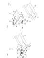
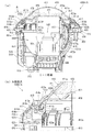
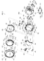
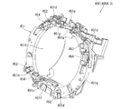
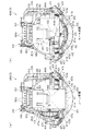
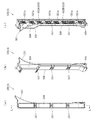
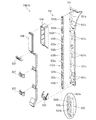
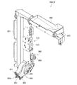
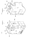
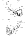
[2.外枠の全体構成]
パチンコ機1の外枠2について、図11乃至図16を参照して説明する。図11はパチンコ機における外枠の正面図であり、図12は外枠の右側面図である。また、図13は外枠を前から見た斜視図であり、図14は外枠を後ろから見た斜視図である。図15は、外枠を分解して前から見た分解斜視図である。図16(a)は外枠における外枠側上ヒンジ部材の部位を、左枠部材を省略して下側から見た斜視図であり、(b)は(a)を分解して示す分解斜視図である。外枠2は、遊技ホール等のパチンコ機1が設置される島設備(図示は省略)に取付けられるものである。
[2. Overall configuration of outer frame]
The outer frame 2 of the pachinko machine 1 will be described with reference to FIGS. 11 to 16. FIG. 11 is a front view of an outer frame in a pachinko machine, and FIG. 12 is a right side view of the outer frame. FIG. 13 is a perspective view of the outer frame as viewed from the front, and FIG. 14 is a perspective view of the outer frame as viewed from the back. FIG. 15 is an exploded perspective view of the outer frame as viewed from the front. FIG. 16 (a) is a perspective view of the portion of the outer frame side upper hinge member in the outer frame, viewed from the lower side without the left frame member, and FIG. FIG. The outer frame 2 is attached to an island facility (not shown) on which the pachinko machine 1 such as a game hall is installed.
外枠2は、図示するように、上下に離間しており左右に延びている上枠部材10及び下枠部材20と、上枠部材10及び下枠部材20の両端同士を連結しており上下に延びている左枠部材30及び右枠部材40と、を備えている。上枠部材10、下枠部材20、左枠部材30、及び右枠部材40は、前後の幅が同じ幅に形成されている。また、上枠部材10及び下枠部材20の左右の長さに対して、左枠部材30及び右枠部材40の上下の長さが、長く形成されている。また、外枠2は、上枠部材10及び下枠部材20の左右両端面と、左枠部材30及び右枠部材40の左右方向の外側を向いた側面とが、同一面となるように組立てられている。
As illustrated, the outer frame 2 connects the upper frame member 10 and the lower frame member 20 which are vertically separated and extends in the left and right direction, and both ends of the upper frame member 10 and the lower frame member 20. And the left frame member 30 and the right frame member 40 which are extended in The upper frame member 10, the lower frame member 20, the left frame member 30, and the right frame member 40 have the same front and rear width. Further, the upper and lower lengths of the left frame member 30 and the right frame member 40 are formed longer than the left and right lengths of the upper frame member 10 and the lower frame member 20. Further, the outer frame 2 is assembled such that the left and right end faces of the upper frame member 10 and the lower frame member 20 and the side faces of the left frame member 30 and the right frame member 40 facing outward in the left and right direction are the same surface. It is done.
また、外枠2は、上枠部材10の正面視左端部側に取付けられている外枠側上ヒンジ部材60と、外枠側上ヒンジ部材60の下面に取付けられているロック部材66と、幕板部材50の正面視左端側上部と左枠部材30とに取付けられている外枠側下ヒンジ部材70と、を備えている。外枠2の外枠側上ヒンジ部材60と外枠側下ヒンジ部材70とによって、本体枠4及び扉枠3を開閉可能に取付けることができる。
Further, the outer frame 2 includes an outer frame side upper hinge member 60 attached to the front end left side of the upper frame member 10 and a lock member 66 attached to the lower surface of the outer frame side upper hinge member 60; An outer frame side lower hinge member 70 attached to the left end upper portion of the curtain plate member 50 in front view and the left frame member 30 is provided. The outer frame side upper hinge member 60 and the outer frame side lower hinge member 70 of the outer frame 2 can attach the main body frame 4 and the door frame 3 so as to be able to open and close.
また、外枠2は、左枠部材30及び右枠部材40の下端同士を連結し下枠部材20の前側に取付けられる幕板部材50と、幕板部材50の後側に取付けられていると共に両端が左枠部材30及び右枠部材40に夫々取付けられる幕板補強部材80と、幕板部材50の上面における左右中央から左寄りの位置に取付けられている平板状の左滑り部材81と、幕板部材50の上面における右端付近の位置に取付けられている平板状の右滑り部材82と、を備えている。幕板補強部材80は、中実の部材(例えば、木材、合板、等)によって形成されており、下枠部材20、左枠部材30、及び右枠部材40に、取付けられている。
Further, the outer frame 2 is mounted on the rear side of the curtain plate member 50 and the curtain plate member 50 attached to the front side of the lower frame member 20 by connecting the lower ends of the left frame member 30 and the right frame member 40. A curtain plate reinforcing member 80 whose both ends are attached to the left frame member 30 and the right frame member 40, a flat left sliding member 81 attached at a position from the left to right center of the upper surface of the curtain plate member 50 And a flat right sliding member 82 mounted at a position near the right end of the upper surface of the plate member 50. The curtain plate reinforcing member 80 is formed of a solid member (for example, wood, plywood, etc.), and is attached to the lower frame member 20, the left frame member 30, and the right frame member 40.
更に、外枠2は、上枠部材10と左枠部材30、上枠部材10と右枠部材40、下枠部材20と左枠部材30、及び下枠部材20と右枠部材40を、夫々連結している連結部材85を備えている。また、外枠2は、右枠部材40の内側(左側面側)に取付けられており後述する施錠ユニット700の外枠用鉤703が係止される上鉤掛部材90及び下鉤掛部材91を、備えている。
Furthermore, the outer frame 2 includes the upper frame member 10 and the left frame member 30, the upper frame member 10 and the right frame member 40, the lower frame member 20 and the left frame member 30, and the lower frame member 20 and the right frame member 40, respectively. It has a connecting member 85 connected. The outer frame 2 is attached to the inner side (left side) of the right frame member 40, and the upper hooking member 90 and the lower hooking member 91 are engaged with the outer frame hook 703 of the locking unit 700 described later. , Equipped.
[2−1.上枠部材]
外枠2の上枠部材10は、所定厚さの無垢(中実)の材料(例えば、木材、合板、等)によって形成されている。この上枠部材10は、左右両端における前後方向の中央に、上下に貫通しており左右方向中央側へ窪んだ係合切欠部11を備えている。この係合切欠部11内には、連結部材85の後述する左上連結部材85A及び右上連結部材85Bの上横固定部87が取付けられる。また、上枠部材10は、正面視左側端部の上面と前面に、一般面よりも窪んだ取付段部12を備えている。この取付段部12には、外枠側上ヒンジ部材60が取付けられる。
[2-1. Upper frame member]
The upper frame member 10 of the outer frame 2 is formed of a solid (solid) material (for example, wood, plywood, etc.) of a predetermined thickness. The upper frame member 10 is provided with an engagement notch 11 which penetrates up and down and is recessed toward the center in the left-right direction at the center in the front-rear direction at both left and right ends. An upper horizontal fixing portion 87 of an upper left connecting member 85A and an upper right connecting member 85B, which will be described later, of the connecting member 85 is attached to the inside of the engagement notch 11. Moreover, the upper frame member 10 is equipped with the mounting step part 12 which was depressed rather than the general surface in the upper surface and front surface of a front view left side edge part. The outer frame side upper hinge member 60 is attached to the attachment step 12.
[2−2.下枠部材]
外枠2の下枠部材20は、所定厚さの無垢(中実)の材料(例えば、木材、合板、等)によって形成されている。この下枠部材20は、左右の長さ及び上下の厚さが、上枠部材10の左右の長さ及び上下の厚さと同じ寸法に形成されていると共に、前後の幅が、上枠部材10の前後の幅よりも長く形成されている。下枠部材20は、左右両端における前後方向の中央よりも後側寄りの位置に、上下に貫通しており左右方向中央側へ窪んだ係合切欠部21を備えている。この係合切欠部21内には、連結部材85の後述する左下連結部材85C及び右下連結部材85Dの下横固定部88が取付けられる。
[2-2. Lower frame member]
The lower frame member 20 of the outer frame 2 is formed of a solid (solid) material (for example, wood, plywood, etc.) of a predetermined thickness. The lower frame member 20 is formed in the same dimensions as the left and right lengths and the upper and lower lengths of the upper frame member 10, and the front and rear widths of the lower frame member 20 are equal to those of the upper frame member 10. It is formed longer than the front and rear width of the. The lower frame member 20 is provided with an engagement notch 21 which penetrates up and down and is recessed toward the center in the left-right direction at a position closer to the rear side than the center in the front-rear direction at both left and right ends. A lower left fixing member 88 of the connecting member 85, which will be described later, and a lower horizontal fixing portion 88 of the lower right connecting member 85D are mounted in the engagement notch 21.
また、下枠部材20は、左右両端の前面から後方へ窪んだ前端切欠部22を備えている。下枠部材20において、前端切欠部22の後端から下枠部材20の後面までの前後方向の幅が、上枠部材10の前後方向の幅と同じ寸法に形成されている。この下枠部材20は、外枠2に組立てた状態で、左右の前端切欠部22同士の間の部位が、幕板部材50内に挿入される。
Further, the lower frame member 20 is provided with a front end notch 22 which is recessed rearward from the front surface of both left and right ends. In the lower frame member 20, the width in the front-rear direction from the rear end of the front end notch 22 to the rear surface of the lower frame member 20 is formed to the same dimension as the width in the front-rear direction of the upper frame member 10. When the lower frame member 20 is assembled to the outer frame 2, a portion between the left and right front end notches 22 is inserted into the curtain plate member 50.
[2−3.左枠部材及び右枠部材]
外枠2の左枠部材30及び右枠部材40は、一定の断面形状で上下に延びており、アルミ合金等の金属の押出形材によって形成されている。左枠部材30及び右枠部材40は、平面視において互いに対称の形状に形成されている。左枠部材30及び右枠部材40は、外枠2として組立てた時に、左右方向の外側となる側面において、前後方向中央に対して後寄りの位置から後端付近までの間に、内側へ窪んだ凹部31,41と、凹部31,41の反対側の側面から膨出しており内部が空洞に形成されている突出部32,42と、を備えている。この左枠部材30及び右枠部材40は、突出部32,42によって、強度・剛性が高められている。また、突出部32,42内には、連結部材85の後述する左上連結部材85A及び右上連結部材85Bの後側の下横固定部88が挿入されて取付けられる。
[2-3. Left frame member and right frame member]
The left frame member 30 and the right frame member 40 of the outer frame 2 extend up and down with a constant cross-sectional shape, and are formed of an extruded shape of a metal such as an aluminum alloy. The left frame member 30 and the right frame member 40 are formed in symmetrical shapes in plan view. When assembled as the outer frame 2, the left frame member 30 and the right frame member 40 are recessed inward between the position near the rear with respect to the center in the front-rear direction and the vicinity of the rear end It has the convex recessed parts 31 and 41, and the protrusion parts 32 and 42 which bulged from the side surface on the opposite side of the recessed parts 31 and 41, and the inside is formed in the cavity. The left frame member 30 and the right frame member 40 are enhanced in strength and rigidity by the protrusions 32 and 42. Further, in the projecting portions 32 and 42, an upper left connecting member 85A and a rear lower lower fixing portion 88 of the upper right connecting member 85B of the connecting member 85 are inserted and attached.
また、左枠部材30及び右枠部材40は、表面に上下に延びた複数の溝が形成されている。この複数の溝によって、パチンコ機1を遊技ホール等の島設備に設置したり運搬したりする等の際に、作業者の指掛りとなってパチンコ機1を持ち易くすることができると共に、パチンコ機1の外観の意匠性を高めることとができる。
Further, the left frame member 30 and the right frame member 40 have a plurality of grooves extending in the vertical direction on the surface. The plurality of grooves make it easy for the operator to hold the pachinko machine 1 while holding the pachinko machine 1 in place when carrying or installing the pachinko machine 1 on an island facility such as a game hall or the like. The design of the appearance of the machine 1 can be enhanced.
[2−4.幕板部材]
外枠2の幕板部材50は、後側が開放された箱状に形成されている。幕板部材50は、上面における正面視左端付近に後方へ平板状に延出している後方延出部51と、後方延出部51の左端から遊技球が通過可能な大きさでU字状に切欠かれており上下に貫通している左排出孔52と、後方延出部51における左排出孔52の右側において遊技球が通過可能な大きさで上下に貫通している右排出孔53と、後方延出部51の後端を含む幕板部材50の上面の後端から上方へ平板状に延出している立壁部54と、立壁部54の上端付近から前方へ膨出しており前面が上方へ向かうに従って後方へ向かうように傾斜している返し部55と、を備えている。
[2-4. Curtain plate member]
The curtain plate member 50 of the outer frame 2 is formed in a box shape whose rear side is open. The curtain plate member 50 is U-shaped in such a size that the game ball can pass from the left end of the rear extension 51 and the rear extension 51 extending in the form of a flat plate to the rear near the left end in front view on the upper surface A left discharge hole 52 which is notched and penetrates up and down, and a right discharge hole 53 which penetrates up and down with a size which allows the game ball to pass on the right side of the left discharge hole 52 in the rear extension 51; A standing wall 54 extending flatly upward from the rear end of the upper surface of the curtain plate member 50 including the rear end of the rear extension 51 and a front side bulging forward from near the upper end of the standing wall 54 And a return portion 55 which is inclined so as to move rearward toward the rear.
幕板部材50は、後方延出部51の前側の上面と、後方延出部51の上面とに、外枠側下ヒンジ部材70が載置されるように、外枠側下ヒンジ部材70の後述する水平部71が取付けられる。また、幕板部材50の左排出孔52は、外枠2に組立てた状態で外枠側下ヒンジ部材70の後述する排出孔74と一致する位置に形成されている。また、右排出孔53は、外枠2に組立てた状態で外枠側下ヒンジ部材70よりも右側となる位置に形成されている。右排出孔53は、左排出孔52よりも大きく形成されている。
The curtain plate member 50 is provided on the outer frame side lower hinge member 70 so that the outer frame side lower hinge member 70 is placed on the front upper surface of the rear extension portion 51 and the upper surface of the rear extension portion 51. The horizontal part 71 mentioned later is attached. Further, the left discharge hole 52 of the curtain plate member 50 is formed at a position coincident with a discharge hole 74 described later of the outer frame side lower hinge member 70 in a state of being assembled to the outer frame 2. Further, the right discharge hole 53 is formed at a position on the right side of the outer frame side lower hinge member 70 in a state of being assembled to the outer frame 2. The right discharge hole 53 is formed larger than the left discharge hole 52.
また、幕板部材50は、後方延出部51よりも右側の上面が、前端側が低くなるように傾斜している。また、幕板部材50は、上面における後方延出部51よりも右側の部位に左滑り部材81を取付けるための左取付部56と、上面における右端付近に右滑り部材82を取付けるための右取付部57と、を備えている。幕板部材50は、上面に、左滑り部材81及び右滑り部材82を介して本体枠4の下面が載置される。
Further, the upper surface of the curtain plate member 50 on the right side of the rear extension portion 51 is inclined so that the front end side is lower. In addition, the curtain plate member 50 has a left mounting portion 56 for mounting the left sliding member 81 at a position on the right side of the rear extension 51 at the upper surface and a right mounting for mounting the right sliding member 82 near the right end at the upper surface And a unit 57. The lower surface of the main body frame 4 is placed on the upper surface of the curtain plate member 50 via the left slide member 81 and the right slide member 82.
この幕板部材50は、図示するように、前面に浅いレリーフ状の装飾が形成されている。また、幕板部材50は、図示は省略するが、箱状の内部が複数のリブによって格子状に仕切られており、強度・剛性が高められている。また、幕板部材50は、幕板補強部材80の前側半分を、内部に収容可能に形成されている。
As shown, the curtain plate member 50 has a shallow relief-like decoration formed on the front surface. Further, although the illustration is omitted, the curtain plate member 50 has a box-like interior divided into a grid by a plurality of ribs, and the strength and rigidity are enhanced. Further, the curtain plate member 50 is formed so that the front half of the curtain plate reinforcing member 80 can be accommodated inside.
[2−5.外枠側上ヒンジ部材]
外枠2の外枠側上ヒンジ部材60は、図示するように、水平に延びた平板状で外形が四角形の上固定部61と、上固定部61の前端から前方へ延出している平板状の前方延出部62と、前方延出部62の右端から前方へ向かうに従って前方延出部62の左右中央へ延びており上下に貫通している軸受溝63と、上固定部61の平面視左辺から下方へ延びている平板状の横固定部64と、前方延出部62の左端から前端を周って軸受溝63が開口している部位までの端辺から下方へ延びており横固定部64と連続している平板状の垂下部65と、を備えている(図16(b)等を参照)。
[2-5. Outer frame side upper hinge member]
The outer frame side upper hinge member 60 of the outer frame 2 is a flat plate extending horizontally and having a rectangular outer shape fixed to the upper fixing portion 61 and a flat shape extending forward from the front end of the upper fixing portion 61 as illustrated. Of the front extension 62, a bearing groove 63 extending to the left and right center of the front extension 62 as going forward from the right end of the front extension 62, and penetrating vertically, and a plan view of the upper fixing portion 61 A flat horizontal fixing portion 64 extending downward from the left side, and a lower side extending from the end of the front extension 62 from the left end to the portion where the bearing groove 63 is open from the left end to the horizontal fixing A flat plate-like hanging portion 65 continuous with the portion 64 is provided (see FIG. 16 (b) and the like).
外枠側上ヒンジ部材60は、外枠2が組立てられた状態で、上固定部61が、上枠部材10の取付段部12の上面に載置されており、図示しないビスによって固定されている。また、前方延出部62は、上枠部材10の前端よりも前方へ延出している。また、横固定部64は、左枠部材30の外側側面の凹部31内に上側から挿入された状態で、ビスによって左枠部材30に固定されている。
In the outer frame side upper hinge member 60, the upper fixing portion 61 is placed on the upper surface of the mounting stepped portion 12 of the upper frame member 10 in a state where the outer frame 2 is assembled, and fixed by screws not shown. There is. Further, the front extension portion 62 extends forward of the front end of the upper frame member 10. Further, the horizontal fixing portion 64 is fixed to the left frame member 30 by a screw in a state of being inserted from the upper side into the recess 31 of the outer side surface of the left frame member 30.
この外枠側上ヒンジ部材60は、軸受溝63内に本体枠側上ヒンジ部材620の本体枠上ヒンジピン622を挿入させることで、外枠側下ヒンジ部材70と協働して本体枠4を開閉可能に支持することができる。この外枠側上ヒンジ部材60は、金属板をプレス成型により屈曲させて形成されている。
The outer frame side upper hinge member 60 cooperates with the outer frame side lower hinge member 70 to insert the main frame 4 by inserting the main frame upper hinge pin 622 of the main frame upper hinge member 620 into the bearing groove 63. It can be supported openable and closable. The outer frame side upper hinge member 60 is formed by bending a metal plate by press molding.
[2−6.ロック部材]
外枠2のロック部材66は、図16に示すように、左右が所定幅で前後に延びている帯板状のロック本体66aと、ロック本体66aの後端から右方へ突出している操作部66bと、ロック本体66aの後端から左方へ延びた後に斜め左前方へ延びている弾性変形可能な棒状の弾性部66cと、ロック本体66aの後端付近で上下に貫通している取付孔66dと、を備えている。このロック部材66は、合成樹脂によって形成されている。ロック部材66は、取付ビス67によって、外枠側上ヒンジ部材60における前方延出部62の下面に回動可能に取付けられる。
[2-6. Lock member]
The lock member 66 of the outer frame 2 is, as shown in FIG. 16, a band-plate shaped lock main body 66a having a predetermined width on the left and right and extending back and forth, and an operation portion projecting rightward from the rear end 66b, a resiliently deformable rod-like elastic portion 66c extending diagonally forward to the left after extending from the rear end of the lock main body 66a, and an attachment hole vertically penetrating near the rear end of the lock main body 66a And 66d. The lock member 66 is formed of synthetic resin. The lock member 66 is rotatably attached to the lower surface of the front extension portion 62 of the outer frame side upper hinge member 60 by a mounting screw 67.
このロック部材66は、取付孔66dを通して、ロック本体66aの後端が、外枠側上ヒンジ部材60の前方延出部62における軸受溝63よりも後側の位置に取付けられる。また、ロック部材66を外枠側上ヒンジ部材60に取付けた状態では、ロック本体66aが、平面視で軸受溝63を遮ることができると共に、前端付近の右側面が、外枠側上ヒンジ部材60の垂下部65における軸受溝63の開口まで延びている部位と当接可能となるように前方へ延びている(図18を参照)。
The rear end of the lock body 66a is attached to a position rearward of the bearing groove 63 in the front extension 62 of the outer frame side upper hinge member 60 through the attachment hole 66d. Further, in a state where the lock member 66 is attached to the outer frame side upper hinge member 60, the lock main body 66a can block the bearing groove 63 in plan view, and the right side near the front end is the outer frame side upper hinge member It extends forward so as to be in contact with a portion of the hanging portion 65 extending to the opening of the bearing groove 63 (see FIG. 18).
また、ロック本体66aの後端から左方へ延びている弾性部66cの先端は、外枠側上ヒンジ部材60における垂下部65の内周面に当接している。このロック部材66は、弾性部66cの付勢力によって取付孔66dを中心に、前端が左方へ回動する方向に付勢されている。従って、通常の状態では、ロック部材66のロック本体66aの前端付近の右側面が、垂下部65に当接している(図18を参照)。この状態では、軸受溝63におけるロック本体66aよりも前側の部位に、本体枠側上ヒンジ部材620の後述する本体枠上ヒンジピン622を収容可能な空間が形成される。
Further, the tip end of the elastic portion 66c extending leftward from the rear end of the lock main body 66a is in contact with the inner peripheral surface of the hanging portion 65 of the outer frame side upper hinge member 60. The lock member 66 is biased in a direction such that the front end pivots to the left around the mounting hole 66d by the biasing force of the elastic portion 66c. Therefore, in the normal state, the right side surface near the front end of the lock body 66a of the lock member 66 is in contact with the hanging portion 65 (see FIG. 18). In this state, a space capable of accommodating a main frame upper hinge pin 622 (described later) of the main frame upper upper hinge member 620 is formed in a portion of the bearing groove 63 on the front side of the lock main body 66a.
このロック部材66は、操作部66bを操作することで、弾性部66cの付勢力に抗してロック本体66aを回動させることができる。そして、操作部66bの操作によって、ロック本体66aを、その前端が左方へ移動する方向へ回動させることで、平面視において軸受溝63からロック本体66aを後退させることができ、軸受溝63が全通している状態とすることができる。これにより、軸受溝63内に本体枠上ヒンジピン622を挿入したり、軸受溝63内から本体枠上ヒンジピン622を外したりすることができる。
The lock member 66 can rotate the lock main body 66a against the biasing force of the elastic portion 66c by operating the operation portion 66b. Then, the lock main body 66a can be retracted from the bearing groove 63 in plan view by rotating the lock main body 66a in the direction in which the front end moves to the left by the operation of the operation portion 66b. Can be completely through. Thus, the main frame upper hinge pin 622 can be inserted into the bearing groove 63 or the main frame upper hinge pin 622 can be removed from the bearing groove 63.
[2−7.外枠側下ヒンジ部材]
外枠2の外枠側下ヒンジ部材70は、図示するように、水平に延びている平板状の水平部71と、水平部71の左辺において前後方向中央よりも後側の部位から上方へ立上っている平板状の立上り部72と、水平部71の前端付近から上方へ突出している外枠下ヒンジピン73と、水平部71を上下に貫通しており遊技球が一つのみ通過可能な大きさの排出孔74と、を備えている。この外枠側下ヒンジ部材70は、金属板をプレス成型により屈曲させて形成されている。
[2-7. Outer frame side lower hinge member]
As shown in the figure, the outer frame side lower hinge member 70 of the outer frame 2 stands upward from a portion behind the center in the front-rear direction on the left side of the horizontally extending flat horizontal portion 71 and the horizontal portion 71. A flat plate-like rising portion 72, an outer frame lower hinge pin 73 protruding upward from near the front end of the horizontal portion 71, and a horizontal portion 71 are vertically penetrated, and only one game ball can pass through. And a discharge hole 74 of a size. The outer frame side lower hinge member 70 is formed by bending a metal plate by press molding.
外枠側下ヒンジ部材70の水平部71は、平面視において、左辺を底辺とした台形に形成されている。外枠下ヒンジピン73は、円柱状で、上下方向中央よりも上部が、上端が窄まった円錐台状に形成されている。この外枠下ヒンジピン73は、水平部71の前端付近における左寄りの位置に取付けられている。排出孔74は、水平部71において、立上り部72の前後方向中央の部位と接し、水平部71の左辺から右方へ逆U字状に延びるように形成されている。この排出孔74は、幕板部材50の左排出孔52と、略同じ大きさに形成されている。
The horizontal portion 71 of the outer frame side lower hinge member 70 is formed in a trapezoidal shape whose left side is a base in a plan view. The outer frame lower hinge pin 73 has a cylindrical shape and is formed in a truncated cone shape whose upper end is narrowed at the upper end than the center in the vertical direction. The outer frame lower hinge pin 73 is attached at a position near the front end of the horizontal portion 71 to the left. The discharge hole 74 is formed in the horizontal portion 71 so as to be in contact with a central portion of the rising portion 72 in the front-rear direction, and extends from the left side of the horizontal portion 71 to the right in an inverted U shape. The discharge hole 74 is formed in substantially the same size as the left discharge hole 52 of the curtain plate member 50.
外枠側下ヒンジ部材70は、外枠2が組立てられた状態では、水平部71が、幕板部材50の左端付近の上面と後方延出部51上に載置されており、水平部71が、幕板部材50の上面を貫通する図示しないビスによって幕板補強部材80に固定されている。また、外枠2が組立てられた状態では、立上り部72が、左枠部材30の内側側面における突出部32よりも前側の部位に、図示しないビスによって取付けられている。この外枠側下ヒンジ部材70は、外枠下ヒンジピン73を、本体枠4の本体枠側下ヒンジ部材640における本体枠用下ヒンジ孔(図示は省略)に挿通させることで、外枠側上ヒンジ部材60と協働して本体枠4を開閉可能に取付けることができる。
In the outer frame side lower hinge member 70, when the outer frame 2 is assembled, the horizontal portion 71 is placed on the upper surface near the left end of the curtain plate member 50 and on the rear extension portion 51. Is fixed to the curtain plate reinforcing member 80 by a screw (not shown) penetrating the upper surface of the curtain plate member 50. Further, in a state where the outer frame 2 is assembled, the rising portion 72 is attached to a portion on the front side of the projecting portion 32 on the inner side surface of the left frame member 30 by a screw (not shown). The outer frame side lower hinge member 70 is inserted into the main frame lower lower hinge member (not shown) in the main frame side lower hinge member 640 of the main body frame 4, whereby the outer frame lower upper hinge pin 70 is inserted. The main body frame 4 can be attached so as to be able to open and close in cooperation with the hinge member 60.
また、外枠2が組立てられた状態では、排出孔74が、幕板部材50の左排出孔52と一致している。これにより、水平部71上の遊技球を、排出孔74及び左排出孔52を通して、幕板部材50の後側へ落下(排出)させることができる。詳述すると、外枠2に対して本体枠4を閉じる時に、外枠2と本体枠4との間に落下した遊技球が、本体枠4が閉じられるのに従って、外枠2と本体枠4との間が徐々に狭くなることから、間隔が広い後方側へ転動とすることとなり、排出孔74から排出させることができる。この際に、排出孔74が、パチンコ機1に組立てた状態で、外枠2に対して本体枠4を閉じた時に、本体枠4の後端と略同じとなる位置に形成されているため、外枠2と本体枠4との間に落下した遊技球を、排出孔74から排出させることで本体枠4よりも後側へ転動するのを阻止し易くすることができ、外枠側下ヒンジ部材70の部位に遊技球が留まり難くすることができる。
Further, in the state where the outer frame 2 is assembled, the discharge hole 74 matches the left discharge hole 52 of the curtain plate member 50. Thereby, the gaming ball on the horizontal portion 71 can be dropped (discharged) to the rear side of the curtain plate member 50 through the discharge hole 74 and the left discharge hole 52. Specifically, when the main frame 4 is closed with respect to the outer frame 2, the game ball dropped between the outer frame 2 and the main frame 4 is closed as the main frame 4 is closed. Since the gap between the two gradually narrows, the space is rolled backward and can be discharged from the discharge hole 74. At this time, the discharge hole 74 is formed at a position substantially the same as the rear end of the main body frame 4 when the main body frame 4 is closed to the outer frame 2 in a state assembled to the pachinko machine 1 By discharging the game balls dropped between the outer frame 2 and the main frame 4 from the discharge holes 74, it is possible to easily prevent the game frame 4 from rolling to the rear side, the outer frame side It is possible to make it difficult for the gaming ball to stay at the portion of the lower hinge member 70.
[2−8.連結部材]
外枠2の連結部材85は、上枠部材10と左枠部材30とを連結する左上連結部材85Aと、上枠部材10と右枠部材40とを連結する右上連結部材85Bと、下枠部材20と左枠部材30とを連結する左下連結部材85Cと、下枠部材20と右枠部材40とを連結する右下連結部材85Dと、がある。
[2-8. Connection member]
The connecting member 85 of the outer frame 2 includes an upper left connecting member 85A connecting the upper frame member 10 and the left frame member 30, an upper right connecting member 85B connecting the upper frame member 10 and the right frame member 40, and a lower frame member 20 and a left lower connecting member 85C connecting the left frame member 30 and a lower right connecting member 85D connecting the lower frame member 20 and the right frame member 40.
連結部材85は、水平に延びた平板状の水平固定部86と、水平固定部86の左右側辺の何れか一方から上方へ延出している平板状の上横固定部87と、水平固定部86における上横固定部87が延出している部位と同じ側から下方へ延出している平板状の下横固定部88と、を備えている。この連結部材85は、平板状の金属板を屈曲させて形成されている。
The connecting member 85 includes a horizontally extending flat horizontal fixing portion 86, a flat upper horizontal fixing portion 87 extending upward from either the left or right side of the horizontal fixing portion 86, and a horizontal fixing portion. And 86 a flat lower lower fixing portion 88 extending downward from the same side as the portion where the upper horizontal fixing portion 87 extends. The connection member 85 is formed by bending a flat metal plate.
左上連結部材85A及び右上連結部材85Bでは、水平固定部86の前後方向の中央から上横固定部87が上方へ延出していると共に、上横固定部87の前後両側から下横固定部88が下方へ延出している。つまり、左上連結部材85A及び右上連結部材85Bでは、下横固定部88が前後に離間して二つ備えられている。左上連結部材85A及び右上連結部材85Bの水平固定部86は、上枠部材10の下面に当接した状態で上枠部材10に固定される。また、左上連結部材85A及び右上連結部材85Bの上横固定部87は、上枠部材10の係合切欠部21内に挿入されて、上枠部材10の左右方向の端部に固定される。また、左上連結部材85A及び右上連結部材85Bの前側の下横固定部88は、左枠部材30及び右枠部材40の突出部32,42よりも前側の内側側面に夫々固定される。更に、左上連結部材85A及び右上連結部材85Bの後側の下横固定部88は、左枠部材30及び右枠部材40の突出部32,42内に挿入されて外側側面から捩じ込まれるビスにより左枠部材30及び右枠部材40に夫々固定される。
In the upper left connecting member 85A and the upper right connecting member 85B, the upper horizontal fixing portion 87 extends upward from the center in the front-rear direction of the horizontal fixing portion 86, and the lower horizontal fixing portion 88 from the front and rear both sides of the upper horizontal fixing portion 87. It extends downward. That is, in the upper left connecting member 85A and the upper right connecting member 85B, two lower horizontal fixing portions 88 are provided separately in the front-rear direction. The horizontal fixing portions 86 of the upper left connecting member 85A and the upper right connecting member 85B are fixed to the upper frame member 10 in a state of being in contact with the lower surface of the upper frame member 10. The upper horizontal fixing portion 87 of the upper left connecting member 85A and the upper right connecting member 85B is inserted into the engagement cutout portion 21 of the upper frame member 10 and fixed to the end of the upper frame member 10 in the left-right direction. The lower horizontal fixing portions 88 on the front side of the upper left connecting member 85A and the upper right connecting member 85B are respectively fixed to the inner side surfaces on the front side of the projecting portions 32 and 42 of the left frame member 30 and the right frame member 40. Furthermore, the lower horizontal fixing portion 88 on the rear side of the upper left connecting member 85A and the upper right connecting member 85B is inserted into the projecting portions 32 and 42 of the left frame member 30 and the right frame member 40 and screwed from the outer side surface. As a result, it is fixed to the left frame member 30 and the right frame member 40 respectively.
左下連結部材85C及び右下連結部材85Dでは、上横固定部87の後端が、水平固定部86の後端よりも後方へ突出していると共に、上横固定部87の水平固定部86よりも後方へ突出している部位の下端から下横固定部88が水平固定部86よりも下方へ延出している。また、左下連結部材85C及び右下連結部材85Dでは、上横固定部87の後端から水平固定部86と同じ側へ突出している屈曲部89を更に備えている。左下連結部材85C及び右下連結部材85Dの水平固定部86は、下枠部材20の上面に当接した状態で固定される。また、左下連結部材85C及び右下連結部材85Dの上横固定部87は、左枠部材30及び右枠部材40の突出部32,42よりも前側の内側側面に夫々固定される。更に、左下連結部材85C及び右下連結部材85Dの下横固定部88は、下枠部材20の係合切欠部21内に挿入されて下枠部材20の左右方向の端部面に夫々固定される。
In the lower left connecting member 85C and the lower right connecting member 85D, the rear end of the upper horizontal fixing portion 87 protrudes rearward more than the rear end of the horizontal fixing portion 86 and the horizontal fixing portion 86 of the upper horizontal fixing portion 87. A lower horizontal fixing portion 88 extends downward from the horizontal fixing portion 86 from the lower end of the portion projecting rearward. The lower left connecting member 85C and the lower right connecting member 85D further include a bent portion 89 projecting from the rear end of the upper horizontal fixing portion 87 to the same side as the horizontal fixing portion 86. The horizontal fixing portions 86 of the lower left connecting member 85C and the lower right connecting member 85D are fixed in contact with the upper surface of the lower frame member 20. Further, the upper horizontal fixing portions 87 of the lower left connecting member 85C and the lower right connecting member 85D are fixed to the inner side surface on the front side of the protruding portions 32, 42 of the left frame member 30 and the right frame member 40, respectively. Furthermore, the lower horizontal fixing portion 88 of the lower left connecting member 85C and the lower right connecting member 85D is inserted into the engagement cutout portion 21 of the lower frame member 20 and fixed to the end surface of the lower frame member 20 in the left-right direction. Ru.
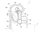
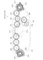
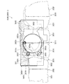
[2−9.外枠側上ヒンジ部材のロック機構]
次に、本実施形態のパチンコ機1の外枠2において、外枠側上ヒンジ部材60におけるロック部材66による本体枠4の本体枠側上ヒンジ部材620に対するロック機構について、図17及び図18を参照して説明する。図17(a)は外枠の外枠側上ヒンジ部材に対して本体枠の本体枠側上ヒンジ部材が取外されている状態を拡大して示す斜視図であり、(b)は外側上ヒンジ部材に本体側上ヒンジ部材が取付けられている状態を拡大して示す斜視図である。図18は、外枠におけるロック部材の作用を示す説明図である。
[2-9. Locking mechanism of outer frame side upper hinge member]
Next, in the outer frame 2 of the pachinko machine 1 of the present embodiment, a lock mechanism for the main frame side upper hinge member 620 of the main body frame 4 by the lock member 66 in the outer frame side upper hinge member 60 will be described with reference to FIGS. Refer to the description. Fig.17 (a) is a perspective view which expands and shows the state by which the main frame side upper hinge member of the main body frame is removed with respect to the outer frame side upper hinge member of an outer frame, (b) is an outer upper side. It is a perspective view which expands and shows the state in which the main body side upper hinge member is attached to the hinge member. FIG. 18 is an explanatory view showing the operation of the lock member in the outer frame.
外枠2におけるロック部材66は、外枠側上ヒンジ部材60の前方延出部62に取付けた状態(通常の状態)では、弾性部66cの先端が垂下部65の内周面と当接しており、ロック本体66aがく字状に屈曲した軸受溝63の一部を閉塞するようになっていると共に、ロック本体66aの先端部分が、軸受溝63の最深部分を閉塞した状態とはならず、軸受溝63の最深部分に本体枠4の本体枠側上ヒンジ部材620の本体枠上ヒンジピン622を挿入可能な空間が形成された状態となっている。
When the lock member 66 in the outer frame 2 is attached to the front extension portion 62 of the outer frame-side upper hinge member 60 (normal state), the tip of the elastic portion 66c abuts on the inner circumferential surface of the hanging portion 65 The lock main body 66a is configured to close a part of the bearing groove 63 bent in a V-shape, and the tip end portion of the lock main body 66a does not close the deepest part of the bearing groove 63, A space in which the main frame upper hinge pin 622 of the main frame side upper hinge member 620 of the main body frame 4 can be inserted is formed at the deepest portion of the bearing groove 63.
本実施形態における外枠側上ヒンジ部材60とロック部材66とを用いた本体枠上ヒンジピン622の支持機構は、本体枠上ヒンジピン622が軸受溝63の最深部分に挿入されてロック本体66aの前端の右側面が、右側の垂下部65と接近している状態(この状態ではロック本体66aの前端の右側面と右側の垂下部65との間に僅かな隙間があり当接した状態となっていない)である通常の軸支状態においては、屈曲している軸受溝63の最深部分に位置する本体枠上ヒンジピン622とロック本体66aの前端面との夫々の中心が斜め方向にずれて対向した状態となっている。
In the supporting mechanism of the main frame upper hinge pin 622 using the outer frame side upper hinge member 60 and the lock member 66 in the present embodiment, the main frame upper hinge pin 622 is inserted into the deepest portion of the bearing groove 63 and the front end of the lock main body 66a The right side face of the lock body 66 is in close proximity to the right hanging portion 65 (in this state, there is a slight gap between the right side face of the front end of the lock main body 66a and the right hanging In the normal pivotally supported state, the respective centers of the main frame upper hinge pin 622 located at the deepest part of the bent bearing groove 63 and the front end face of the lock main body 66a are diagonally offset and opposed It is in the state.
そして、この通常の軸支状態においては、重量のある本体枠4を軸支している本体枠上ヒンジピン622が軸受溝63の前端部分に当接した状態となっているので、本体枠上ヒンジピン622からロック本体66aの前端面への負荷がほとんどかかっていない。つまり、ロック部材66の弾性部66cに対し負荷がかかっていない状態となっている。なお、ロック本体66aの前端面が円弧状に形成されているため、ロック部材66を回動させるために操作部66bを回動操作した時に、ロック部材66がスムーズに回動するようになっている。また、図示では、ロック本体66aの前端面の円弧中心が、取付孔66dの中心(ロック部材66の回転中心)とされている。
And, in this normal support state, since the main frame upper hinge pin 622 supporting the heavy main body frame 4 is in contact with the front end portion of the bearing groove 63, the main frame upper hinge pin There is almost no load from 622 on the front end face of the lock body 66a. That is, no load is applied to the elastic portion 66c of the lock member 66. In addition, since the front end face of the lock main body 66a is formed in a circular arc shape, when the operation portion 66b is turned to turn the lock member 66, the lock member 66 is smoothly turned. There is. Further, in the drawing, the arc center of the front end face of the lock main body 66a is taken as the center of the mounting hole 66d (the rotation center of the lock member 66).
従って、本体枠上ヒンジピン622がく字状に形成された軸受溝63の傾斜に沿って抜ける方向に作用力Fがかかって、ロック本体66aの円弧状の前端面に当接したとき、その作用力Fを、本体枠上ヒンジピン622と円弧状の前端面との当接部分に作用する分力F1(ロック本体66aの前端面の円弧の法線方向)と、本体枠上ヒンジピン622と軸受溝63の一側内面との当接部分に作用する分力F2と、に分けたときに、分力F1の方向が取付孔66d(取付ビス67)の中心(ロック部材66の回転中心)を向くため、ロック部材66のロック本体66aの前端が、右側の垂下部65から離れる方向に回転させるモーメントが働かず、本体枠上ヒンジピン622がロック部材66のロック本体66aの前端部と軸受溝63の一側内面との間に挟持された状態が保持される。
Therefore, when the acting force F is applied in the direction in which the hinge pin 622 on the main body frame comes out along the slope of the bearing groove 63 formed in the V shape and abuts on the arc-shaped front end face of the lock body 66a, the acting force A component force F1 (a normal direction of an arc of a front end face of the lock main body 66a) acting on a contact portion between the body frame upper hinge pin 622 and the arc shaped front end face, a body frame upper hinge pin 622 and a bearing groove 63 The component force F1 is directed to the center (rotation center of the lock member 66) of the mounting hole 66d (mounting screw 67) when divided into the component force F2 acting on the contact portion with the inner surface on one side The moment that the front end of the lock body 66a of the lock member 66 rotates in the direction away from the hanging portion 65 on the right does not work, and the hinge pin 622 of the main body frame is one of the front end portion of the lock body 66a of the lock member 66 and the bearing groove 63. Inside Clamped state is maintained between the.
このため、通常の軸支状態、或は、本体枠上ヒンジピン622の作用力がロック部材66にかかった状態でも、ロック部材66の弾性部66cに常時負荷がかからず、合成樹脂で一体形成される弾性部66cのクリープによる塑性変形を防止し、長期間に亘って本体枠上ヒンジピン622の軸受溝63からの脱落を防止することができる。なお、仮に無理な力がかかってロック部材66のロック本体66aの前端部が右方へ移動する方向へ回転させられても、ロック本体66aの前端右側面が垂下部65に当接してそれ以上回転しないので、ロック部材66が前方延出部62の外側にはみ出ないようになっている。
For this reason, even in a normal pivotally supported state or a state where the action force of the main frame upper hinge pin 622 is applied to the lock member 66, no load is always applied to the elastic portion 66c of the lock member 66, and integrally formed of synthetic resin. It is possible to prevent plastic deformation due to creep of the elastic portion 66c, and to prevent the main frame upper hinge pin 622 from coming off from the bearing groove 63 for a long period of time. Even if an excessive force is applied and the front end of the lock body 66a of the lock member 66 is rotated in the direction to move to the right, the front right side of the lock main body 66a abuts on the hanging portion 65 to further Since it does not rotate, the lock member 66 does not protrude outside the front extension 62.
なお、ロック本体66aの前端面の形状は円弧状でなくても、上記した分力F1の作用により回転モーメントが生じない位置又はロック部材66をその前端部が前方延出部62の外側に向って回転させる回転モーメントが生ずる位置にロック部材66の回転中心(取付ビス67により固定される軸)を位置させることにより、常時ロック部材66の弾性部66cに対しても負荷がかかることはないし、ロック部材66が回転してもロック本体66aの前端の右側面が垂下部65に当接するだけであるため、ロック部材66が前方延出部62の外側にはみ出ることもない。
Note that even if the shape of the front end face of the lock main body 66a is not arc-shaped, the position where the rotational moment is not generated by the action of the component force F1 described above or the front end portion of the lock member 66 faces the outside of the forward extension portion 62. By placing the rotation center of the lock member 66 (the shaft fixed by the mounting screw 67) at a position where a rotational moment to rotate is generated, no load is always applied to the elastic portion 66c of the lock member 66, Even when the lock member 66 rotates, the right side surface of the front end of the lock body 66 a just abuts on the hanging portion 65, and therefore the lock member 66 does not protrude outside the front extension portion 62.
外枠側上ヒンジ部材60の軸受溝63に、本体枠側上ヒンジ部材620の本体枠上ヒンジピン622を支持させる場合は、軸受溝63の開放されている側から軸受溝63内に本体枠上ヒンジピン622を挿入する。軸受溝63内に本体枠上ヒンジピン622を挿入すると、ロック部材66のロック本体66aの右側面に本体枠上ヒンジピン622が当接し、弾性部66cの付勢力に抗してロック本体66aの前端が左方へ移動するようにロック部材66が取付ビス67を中心に回動する。これにより、軸受溝63を閉鎖していたロック本体66aが後退して軸受溝63が開放され、軸受溝63の最深部(前端)へ本体枠上ヒンジピン622を移動させることができるようになる。
When the main frame upper hinge pin 622 of the main frame upper hinge member 620 is supported by the bearing groove 63 of the outer frame side upper hinge member 60, the upper side of the main frame in the bearing groove 63 from the open side of the bearing groove 63 Insert the hinge pin 622. When the main frame upper hinge pin 622 is inserted into the bearing groove 63, the main frame upper hinge pin 622 abuts on the right side surface of the lock main body 66a of the lock member 66 and the front end of the lock main body 66a resists the biasing force of the elastic portion 66c. The lock member 66 pivots around the mounting screw 67 so as to move to the left. As a result, the lock main body 66a closing the bearing groove 63 retracts to open the bearing groove 63, and the main frame upper hinge pin 622 can be moved to the deepest portion (front end) of the bearing groove 63.
そして、軸受溝63の最深部に本体枠上ヒンジピン622を移動させると、本体枠上ヒンジピン622とロック部材66のロック本体66aとの当接が解除され、弾性部66cの付勢力によってロック本体66aの前端が右方へ移動するようにロック部材66が回動し、ロック部材66が通常の状態に復帰する。これにより、本体枠上ヒンジピン622が、軸受溝63内におけるロック本体66aの前端よりも前側の空間に収容された状態となり、本体枠上ヒンジピン622が、軸受溝63の最深部において回動可能な状態で保持(ロック)された状態となる。
Then, when the main frame upper hinge pin 622 is moved to the deepest part of the bearing groove 63, the contact between the main frame upper hinge pin 622 and the lock main body 66a of the lock member 66 is released, and the lock main body 66a is moved by the biasing force of the elastic portion 66c. The lock member 66 is pivoted so that the front end of the arm moves to the right, and the lock member 66 returns to the normal state. As a result, the body frame upper hinge pin 622 is accommodated in the space on the front side of the front end of the lock main body 66 a in the bearing groove 63, and the body frame upper hinge pin 622 can rotate at the deepest portion of the bearing groove 63. It is held (locked) in the state.
軸受溝63内から本体枠上ヒンジピン622を取外す場合は、ロック部材66の操作部66bを操作して、ロック本体66aの前端が左方へ移動するようにロック部材66を回動させ、弾性部66cの付勢力に抗して軸受溝63からロック本体66aを後退させる。これにより、軸受溝63の最深部と開口部とが連通した状態となり、軸受溝63から本体枠上ヒンジピン622を取外すことができる。
When removing the main frame upper hinge pin 622 from the inside of the bearing groove 63, the operating portion 66b of the locking member 66 is operated to turn the locking member 66 so that the front end of the lock main body 66a moves to the left. The lock main body 66a is retracted from the bearing groove 63 against the biasing force of 66c. As a result, the deepest portion of the bearing groove 63 and the opening communicate with each other, and the hinge pin 622 on the main body frame can be removed from the bearing groove 63.
[2−10.外枠側下ヒンジ部材の部位における防犯機構と球噛み防止機構]
本実施形態のパチンコ機1における外枠2の外枠側下ヒンジ部材70の部位における防犯機構と外枠2と本体枠4との間に遊技球が挟まれるのを防止するための球噛み防止機構について説明する。
[2-10. Security mechanism and ball biting prevention mechanism at the portion of the outer frame side lower hinge member]
Ball catching prevention for preventing the game ball from being caught between the crime prevention mechanism and the outer frame 2 and the main body frame 4 at the portion of the outer frame side lower hinge member 70 of the outer frame 2 in the pachinko machine 1 of the present embodiment The mechanism will be described.
外枠2は、組立てた状態では、幕板部材50の上面における正面視左端部に外枠側下ヒンジ部材70が取付けられている。外枠側下ヒンジ部材70の水平部71は、幕板部材50の上面の左端付近と後方延出部51の上面とに載置された状態で取付けられている。この幕板部材50には、上面の後端から上方へ立上っている立壁部54を備えている。これにより、外枠側下ヒンジ部材70と本体枠側下ヒンジ部材640との間の隙間を通して、本体枠4(パチンコ機1)の後側へピアノ線等の不正な工具を侵入させようとしても、不正な工具の先端が幕板部材50の上面の後端から上方へ延出している立壁部54に当接するため、不正な工具がこれ以上後側へ挿入されるのを阻止することができ、外枠側下ヒンジ部材70の部位を介して不正行為が行われるのを防止することができる。
In the assembled state, the outer frame side lower hinge member 70 is attached to the outer frame 2 at the left end in the front view on the upper surface of the curtain plate member 50. The horizontal portion 71 of the outer frame side lower hinge member 70 is mounted in a state of being placed near the left end of the upper surface of the curtain plate member 50 and the upper surface of the rear extension portion 51. The curtain plate member 50 includes an upright wall portion 54 rising upward from the rear end of the upper surface. Thus, even if an unauthorized tool such as a piano wire is made to enter the rear side of the main frame 4 (pachinko machine 1) through the gap between the outer frame side lower hinge member 70 and the main frame side lower hinge member 640. Since the tip of the incorrect tool abuts on the upstanding wall portion 54 extending upward from the rear end of the upper surface of the curtain plate member 50, it is possible to prevent the incorrect tool from being inserted further backward. Thus, it is possible to prevent a fraud from being conducted through the portion of the outer frame side lower hinge member 70.
また、立壁部54の上端に、前方へ延出している返し部55を備えているため、立壁部54に当接した不正な工具が上方へ曲がった場合、返し部55によって不正な工具の先端を更に前方へ折返させることができるため、本体枠4の後側に不正な工具が侵入させられるのを阻止することができ、外枠側下ヒンジ部材70の部位を介して不正行為が行われるのを確実に阻止することができる。
In addition, since the upper end of the standing wall portion 54 is provided with the return portion 55 extending forward, when the incorrect tool in contact with the upper wall portion 54 is bent upward, the end of the incorrect tool by the return portion 55 Can be further folded forward, so that an unauthorized tool can be prevented from invading the rear side of the main body frame 4, and cheating is performed through the portion of the outer frame side lower hinge member 70. Can be reliably blocked.
ところで、幕板部材50の上面の後端に上方へ延出している立壁部54を備えるようにした場合、外枠2に対して本体枠4を開いている状態で、遊技球が外枠側下ヒンジ部材70(水平部71)上に落下した場合、水平部71上の遊技球が、立壁部54の存在によって水平部71の後端から後方へ排出されないため、外枠2と本体枠4との間に挟まれてしまう虞がある。これに対して、本実施形態では、外枠側下ヒンジ部材70の水平部71と、幕板部材50の後方延出部51とに、遊技球が通過可能な排出孔74、左排出孔52、及び右排出孔53を備えているため、外枠側下ヒンジ部材70の水平部71上の遊技球を、排出孔74等から下方へ排出することができ、外枠2と本体枠4との間に遊技球が挟まれるのを低減させることができる。
By the way, when the standing wall portion 54 extending upward is provided at the rear end of the upper surface of the curtain plate member 50, the gaming ball is on the outer frame side with the main body frame 4 open to the outer frame 2. When dropped onto the lower hinge member 70 (horizontal portion 71), the gaming ball on the horizontal portion 71 is not discharged rearward from the rear end of the horizontal portion 71 due to the presence of the standing wall portion 54. There is a risk of being caught between On the other hand, in the present embodiment, the discharge hole 74 and the left discharge hole 52 through which the game ball can pass through the horizontal portion 71 of the outer frame side lower hinge member 70 and the rear extension portion 51 of the curtain plate member 50. Because the right discharge hole 53 is provided, the gaming balls on the horizontal portion 71 of the outer frame side lower hinge member 70 can be discharged downward from the discharge hole 74 or the like, and the outer frame 2 and the body frame 4 Between the game ball and the game ball can be reduced.
従って、外枠2と本体枠4との間に遊技球が挟まれることで、外枠側下ヒンジ部材70の周りが破損したり、本体枠4が正常な状態で閉まらずに外枠2と本体枠4との間に隙間ができてしまい、その隙間を使って不正行為が行われてしまったりするのを防止することができる。
Therefore, by the game ball being pinched between the outer frame 2 and the main body frame 4, the outer frame side lower hinge member 70 may be damaged or the main frame 4 may not be closed in a normal state. A gap is created between the main unit frame 4 and the gap, which can be used to prevent fraudulent acts.
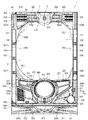
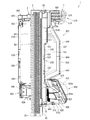
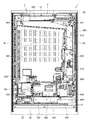
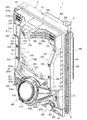
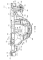
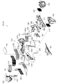
[3.扉枠の全体構成]
パチンコ機1の扉枠3について、図19乃至図30を参照して説明する。図19はパチンコ機における扉枠の正面図であり、図20は扉枠の右側面図であり、図21は扉枠の左側面図であり、図22は扉枠の背面図である。図23は扉枠を右前から見た斜視図であり、図24は扉枠を左前から見た斜視図であり、図25は扉枠を後ろから見た斜視図である。図26は図19におけるA−A線で切断した断面図であり、図27は図19におけるB−B線で切断した断面図であり、図28は図19におけるC−C線で切断した断面図である。図29は扉枠を主な部材毎に分解して前から見た分解斜視図であり、図30は扉枠を主な部材毎に分解して後ろから見た分解斜視図である。
[3. Overall configuration of the door frame]
The door frame 3 of the pachinko machine 1 will be described with reference to FIGS. 19 to 30. 19 is a front view of a door frame in a pachinko machine, FIG. 20 is a right side view of the door frame, FIG. 21 is a left side view of the door frame, and FIG. 22 is a rear view of the door frame. FIG. 23 is a perspective view of the door frame as viewed from the front right, FIG. 24 is a perspective view of the door frame as viewed from the front left, and FIG. 25 is a perspective view of the door frame as viewed from the rear. 26 is a cross-sectional view taken along the line A-A in FIG. 19, FIG. 27 is a cross-sectional view taken along the line B-B in FIG. 19, and FIG. 28 is a cross section taken along the line C-C in FIG. FIG. FIG. 29 is an exploded perspective view of the door frame disassembled into main members and viewed from the front, and FIG. 30 is an exploded perspective view of the door frame disassembled into main members and viewed from the rear.
扉枠3は、図29及び図30等に示すように、正面視の外形が上下に延びた四角形で枠状の扉枠ベースユニット100と、扉枠ベースユニット100の前面右下隅に取付けられているハンドルユニット300と、扉枠ベースユニット100の前面下部に取付けられている皿ユニット320と、皿ユニット320の中央に取付けられている演出操作ユニット400と、皿ユニット320の上側で扉枠ベースユニット100の前面左部に取付けられている扉枠左サイドユニット530と、皿ユニット320の上側で扉枠ベースユニット100の前面右部に取付けられている扉枠右サイドユニット550と、扉枠左サイドユニット530及び扉枠右サイドユニット550の上側で扉枠ベースユニット100の前面上部に取付けられている扉枠トップユニット570と、を備えている。
As shown in FIG. 29 and FIG. 30, etc., the door frame 3 is attached to the frame-shaped door frame base unit 100 having a rectangular shape with the outline of the front view extending vertically and the front lower right corner of the door frame base unit 100 The handle unit 300, the dish unit 320 attached to the lower front of the door frame base unit 100, the rendering operation unit 400 attached to the center of the dish unit 320, and the door frame base unit above the dish unit 320 A door frame left side unit 530 attached to the front left of the 100, a door frame right side unit 550 attached to the front right of the door frame base unit 100 above the plate unit 320, and a door frame left side Door frame top attached to the upper front of the door frame base unit 100 above the unit 530 and the door frame right side unit 550 Is provided with a knit 570, a.
扉枠3の扉枠ベースユニット100は、詳細は後述するが、正面視の外形が上下に延びた長方形(四角形)で前後に貫通している貫通口111を有した板状の扉枠ベース110と、扉枠ベース110の後側に取付けられている枠状の補強ユニット130と、補強ユニット130の正面視左端側の上下両端に取付けられており本体枠4に対してヒンジ回転可能に取付けられる扉枠側上ヒンジ部材140及び扉枠側下ヒンジ部材150と、扉枠ベース110の後面に取付けられ貫通口111を閉鎖するガラスユニット190と、ガラスユニット190の後面下部を覆う防犯カバー200と、扉枠ベース110の後面に扉枠ベース110を貫通して前方に突出するように取付けられ開閉可能とされている扉枠3と本体枠4、及び本体枠4と外枠2との間を施錠するための開閉シリンダユニット210と、扉枠ベース110の後面下部に取付けられ遊技球を球発射装置680に送るための球送りユニット250と、扉枠ベース110の後面下部に取付けられ球発射装置680により発射されて遊技領域5a内に到達しなかった遊技球を受けて下皿322へ排出させるファールカバーユニット270と、を備えている。
Although details will be described later, the door frame base unit 100 of the door frame 3 is a plate-like door frame base 110 having a through hole 111 penetrating in the front and back in a rectangular shape (square shape) whose outer shape in front view extends vertically. The frame-shaped reinforcing unit 130 attached to the rear side of the door frame base 110 and the upper and lower ends of the reinforcing unit 130 on the left end side in a front view are hinge-rotatably attached to the main body frame 4 A door frame side upper hinge member 140 and a door frame side lower hinge member 150, a glass unit 190 attached to the rear surface of the door frame base 110 and closing the through hole 111, a crime prevention cover 200 covering the lower rear surface of the glass unit 190; A door frame 3 and a main body frame 4 which are attached to the rear surface of the door frame base 110 so as to protrude forward through the door frame base 110 and can be opened and closed, and a main body frame 4 and an outer frame 2 An open / close cylinder unit 210 for locking the space, a ball feed unit 250 attached to the lower part of the rear surface of the door frame base 110 for sending gaming balls to the ball launcher 680, and a ball attached to the lower surface of the door frame base 110 And a fall cover unit 270 for receiving the game balls which have been fired by the launch device 680 and have not reached the game area 5a and discharged to the lower tray 322.
扉枠3のハンドルユニット300は、詳細は後述するが、回転可能なハンドル302を遊技者が回転操作することで、上皿321内に貯留されている遊技球を、ハンドル302の回転角度に応じた強さで遊技盤5の遊技領域5a内に打込むことができるものである。
The details of the handle unit 300 of the door frame 3 will be described later, but the game ball stored in the upper plate 321 can be adjusted according to the rotation angle of the handle 302 by the player turning the rotatable handle 302. It is possible to drive into the game area 5a of the game board 5 with an extra strength.
扉枠3の皿ユニット320は、詳細は後述するが、扉枠ベースユニット100における扉枠ベース110の前面において貫通口111の下側の部位に取付けられ、前面が前方へ膨出していると共に、左右方向中央の前端に演出操作ユニット400が取付けられる。皿ユニット320は、遊技領域5a内に打込むための遊技球を貯留する上皿321と、上皿321の下側に配置されており上皿321やファールカバーユニット270から供給される遊技球を貯留可能な下皿322と、上皿321に貯留されている遊技球を下皿322へ抜くための上皿球抜きボタン327と、球貸機に投入した現金やプリペイドカードの残金の範囲内で遊技者に遊技球を貸し出すための球貸ボタン328と、球貸機から貸出された遊技球の分を差し引いた現金やプリペイドカードを返却させるための返却ボタン329と、球貸機に投入した現金やプリペイドカードの残数等を表示する球貸返却表示部330と、演出提示時に遊技者の操作が受付可能とされている演出選択左ボタン331及び演出選択右ボタン332と、下皿322内の遊技球を皿ユニット320の下方へ排出するための下皿球抜きボタン333と、を備えている。
The plate unit 320 of the door frame 3 is attached to the lower portion of the through hole 111 on the front surface of the door frame base 110 of the door frame base unit 100, and the front surface bulges forward. The rendering operation unit 400 is attached to the front end in the center in the left-right direction. The dish unit 320 is provided with an upper dish 321 for storing gaming balls to be driven into the game area 5a, and gaming balls provided under the upper dish 321 and supplied from the upper dish 321 and the far cover unit 270. The lower plate 322 that can be stored, the upper plate ball removal button 327 for extracting the gaming balls stored in the upper plate 321 to the lower plate 322, and the remaining amount of cash or prepaid card inserted into the ball lending machine A ball lending button 328 for lending a game ball to a player, a cash obtained by subtracting a game ball loaned from a ball lending machine or a return button 329 for returning a prepaid card, a cash inserted into the ball lending machine And a ball loan return display unit 330 for displaying the number of remaining prepaid cards and the like, a production selection left button 331 and a production selection right button 332, which allow reception of the player's operation at the time of presentation, and a lower tray Game balls in 22 and lower tray ball vent button 333 for discharging downwardly the dish unit 320, and a.
扉枠3の演出操作ユニット400は、皿ユニット320の正面視左右方向中央の前部に取付けられるものであり、遊技者が押圧操作することができると共に、遊技者に対して演出画像を提示することができるものである。この演出操作ユニット400は、詳細は後述するが、遊技者が操作可能な大型の操作ボタン410と、操作ボタン410内に遊技者側から視認可能に配置され演出画像を表示可能な扉枠側演出表示装置460と、を備えている。
The effect operation unit 400 of the door frame 3 is attached to the front of the plate unit 320 in the center in the left-right direction of the front view, and can be pressed by the player and presents the effect image to the player It can be done. Although this effect operation unit 400 will be described in detail later, a door frame side effect capable of displaying the effect image, which is disposed so as to be visible from the player side in the operation button 410 and the large operation button 410 operable by the player And a display device 460.
扉枠3の扉枠左サイドユニット530は、詳細な内容は後述するが、皿ユニット320の上側で扉枠ベースユニット100における貫通口111よりも左側の前面左部に取付けられ、貫通口111(遊技領域5a)の左外側を装飾するものである。扉枠左サイドユニット530は、発光装飾可能な左ユニット装飾レンズ部材(図示は省略)を備えている。
The door frame left side unit 530 of the door frame 3 is attached to the front left portion on the left side of the through hole 111 in the door frame base unit 100 at the upper side of the plate unit 320, though the detailed contents will be described later. It decorates the left outside of the game area 5a). The door frame left side unit 530 includes a left unit decorative lens member (not shown) capable of emitting light.
扉枠3の扉枠右サイドユニット550は、詳細な内容は後述するが、皿ユニット320の上側で扉枠ベースユニット100における貫通口111よりも右側の前面右部に取付けられ、貫通口111(遊技領域5a)の右外側を装飾するものである。この扉枠右サイドユニット550は、扉枠左サイドユニット530よりも前方へ大きく突出しており、左右両面側に備えられている右ユニット左装飾部材554及び右ユニット右装飾部材557と、前端に備えられている右ユニット装飾レンズ部材561と、を備えている。扉枠右サイドユニット550は、右ユニット左装飾部材554、右ユニット右装飾部材557、及び右ユニット装飾レンズ部材561を発光装飾させることができる。
The door frame right side unit 550 of the door frame 3 is attached to the front right portion on the right side of the through hole 111 in the door frame base unit 100 on the upper side of the plate unit 320, though the detailed contents will be described later. It decorates the right outside of the game area 5a). The door frame right side unit 550 protrudes to the front more largely than the door frame left side unit 530, and is provided at the front end with the right unit left decoration member 554 and the right unit right decoration member 557 provided on both right and left sides. And a right unit decorative lens member 561. The door frame right side unit 550 can emit and decorate the right unit left decoration member 554, the right unit right decoration member 557, and the right unit decoration lens member 561.
扉枠3の扉枠トップユニット570は、扉枠左サイドユニット530及び扉枠右サイドユニット550の上側で扉枠ベースユニット100の扉枠ベース110の前面における貫通口111の上側に取付けられ、扉枠3の上部を装飾するものである。扉枠トップユニット570は、詳細な内容は後述するが、左右に離間した一対の上部スピーカ573と、前面中央で前方へ突出しているトップ中装飾部材576と、トップ中装飾部材576の左右両側を装飾しているトップ左装飾レンズ部材579及びトップ右装飾レンズ部材580と、を備えている。扉枠トップユニット570は、トップ中装飾部材576、トップ左装飾レンズ部材579、及びトップ右装飾レンズ部材580を発光装飾させることができる。
The door frame top unit 570 of the door frame 3 is attached to the upper side of the through hole 111 in the front of the door frame base 110 of the door frame base unit 100 above the door frame left side unit 530 and the door frame right side unit 550 It decorates the upper part of the frame 3. The details of the door frame top unit 570 will be described later, but the left and right sides of the pair of upper speakers 573 spaced apart to the left and right, the top middle decoration member 576 projecting forward at the front center, and the top middle decoration member 576 A top left decorative lens member 579 and a top right decorative lens member 580 are provided. The door frame top unit 570 can emit and decorate the top middle decoration member 576, the top left decoration lens member 579, and the top right decoration lens member 580.
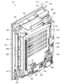
[3−1.扉枠ベースユニットの全体構成]
扉枠3の扉枠ベースユニット100について、図31乃至図33を参照して詳細に説明する。図31(a)は扉枠における扉枠ベースユニットを前から見た斜視図であり、(b)は扉枠ベースユニットを後ろから見た斜視図である。図32は扉枠ベースユニットを主な部材毎に分解して前から見た分解斜視図であり、図33は扉枠ベースユニットを主な部材毎に分解して後ろから見た分解斜視図である。
[3-1. Overall configuration of door frame base unit]
The door frame base unit 100 of the door frame 3 will be described in detail with reference to FIGS. 31 to 33. FIG. 31 (a) is a perspective view of the door frame base unit in the door frame as viewed from the front, and FIG. 31 (b) is a perspective view of the door frame base unit as viewed from the rear. FIG. 32 is an exploded perspective view of the door frame base unit disassembled into main members and viewed from the front, and FIG. 33 is an exploded perspective view of the door frame base unit disassembled into main members and viewed from the rear is there.
扉枠ベースユニット100は、正面視左辺側が本体枠4の前面を閉鎖するように本体枠4に対して開閉可能(ヒンジ回転可能)に取付けられるものである。扉枠ベースユニット100は、前面下隅にハンドルユニット300が、貫通口111の下側前面に演出操作ユニット400が取付けられる皿ユニット320が、貫通口111の左外側前面に扉枠左サイドユニット530が、貫通口111の右外側前面に扉枠右サイドユニット550が、貫通口111の上外側前面に扉枠トップユニット570が、夫々取付けられるものである。
The door frame base unit 100 is attached to the main body frame 4 so as to be openable / closable (hinge rotatable) so that the left side in a front view closes the front surface of the main body frame 4. In the door frame base unit 100, the handle unit 300 is attached to the front lower corner, and the plate unit 320 to which the rendering operation unit 400 is attached to the lower front of the through hole 111. The door frame right side unit 550 is attached to the right outer front surface of the through hole 111, and the door frame top unit 570 is attached to the upper outer front surface of the through hole 111, respectively.
扉枠ベースユニット100は、図32及び図33に等に示すように、正面視の外形が上下に延びた長方形で前後に貫通している貫通口111を有した板状の扉枠ベース110と、扉枠ベース110の後側に取付けられている枠状の補強ユニット130と、補強ユニット130の正面視左端側の上下両端に取付けられており扉枠ベース110から前方へ突出して本体枠4の本体枠側上ヒンジ部材620及び本体枠側下ヒンジ部材640に回転可能に取付けられる扉枠側上ヒンジ部材140及び扉枠側下ヒンジ部材150と、扉枠ベース110の前面で貫通口111の正面視左側に取付けられており前面に複数のLEDが実装されている扉枠左サイド装飾基板160と、扉枠ベース110の後側に回動可能に取付けられておりガラスユニット190を着脱可能に取付けるためのガラスユニット取付部材170と、を備えている。
The door frame base unit 100 is, as shown in FIGS. 32 and 33, a plate-like door frame base 110 having a through-hole 111 which has a rectangular shape whose front view outline extends vertically and which penetrates back and forth. The frame-shaped reinforcing unit 130 attached to the rear side of the door frame base 110 and the upper and lower ends of the reinforcing unit 130 on the left end side of the reinforcing unit 130 are projected forward from the door frame base 110. A door frame upper hinge member 140 and a door frame lower hinge member 150 rotatably attached to the body frame upper hinge member 620 and the body frame lower hinge member 640, and a front face of the through hole 111 on the front surface of the door frame base 110 A door frame left side decoration substrate 160 mounted on the left side and having a plurality of LEDs mounted on the front, and a glass unit 19 rotatably mounted on the rear side of the door frame base 110 The glass unit mounting member 170 for mounting the detachably, and a.
また、扉枠ベースユニット100は、扉枠ベース110の前面で正面視右下隅に取付けられておりハンドルユニット300を取付けるための筒状のハンドル取付部材180と、扉枠ベース110の後面に取付けられ貫通口111を閉鎖するガラスユニット190と、ガラスユニット190の後面下部を覆う防犯カバー200と、扉枠ベース110の後面に扉枠ベース110を貫通して前方に突出するように取付けられる開閉シリンダユニット210と、扉枠ベース110の後面下部に取付けられる球送りユニット250と、扉枠ベース110の後面下部に取付けられるファールカバーユニット270と、を備えている。
Further, the door frame base unit 100 is attached to the front lower right corner of the door frame base 110 in front view and is attached to the cylindrical handle attachment member 180 for attaching the handle unit 300 and the rear surface of the door frame base 110. A glass unit 190 for closing the through hole 111, a crime prevention cover 200 for covering a lower rear surface of the glass unit 190, and an open / close cylinder unit attached to the rear surface of the door frame base 110 so as to project forward through the door frame base 110. 210, a ball feed unit 250 attached to the lower rear surface of the door frame base 110, and a rear cover unit 270 attached to the lower rear surface of the door frame base 110.
更に、扉枠ベースユニット100は、図示は省略するが、扉枠3に備えられている各種の装飾基板、球送ソレノイド255、ハンドル回転検知センサ307、ハンドルタッチセンサ310、単発ボタン操作センサ312、球貸ボタン328、返却ボタン329、球貸返却表示部330、演出選択左ボタン331、演出選択右ボタン332、振動モータ424、押圧検知センサ440、扉枠側演出表示装置460(液晶表示装置461)、上部スピーカ573、等と、本体枠4における基板ユニット900の扉枠用中継基板911との接続を中継するための扉本体中継基板を備えている。
Further, although not shown, the door frame base unit 100 includes various decoration substrates provided in the door frame 3, a ball feeding solenoid 255, a handle rotation detection sensor 307, a handle touch sensor 310, a single button operation sensor 312, Ball lending button 328, return button 329, ball lending display portion 330, effect selection left button 331, effect selection right button 332, vibration motor 424, press detection sensor 440, door frame side effect display device 460 (liquid crystal display device 461) And a door main body relay board for relaying the connection between the upper speakers 573 and the like and the door frame relay board 911 of the board unit 900 in the main body frame 4.
[3−1a.扉枠ベース]
扉枠3における扉枠ベースユニット100の扉枠ベース110について、主に図31乃至図33を参照して詳細に説明する。扉枠ベース110は、正面視の外形が上下に延びた四角形(長方形)に形成されている。扉枠ベース110は、前後に貫通しており、正面視における内周形状が上下に延びた略四角形に形成された貫通口111を備えている。貫通口111は、内周を形成している上辺及び左右両辺が、扉枠ベース110の外周辺に夫々接近しており、内周を形成している下辺が、扉枠ベース110の下端から上下方向の約1/3の高さに位置している。従って、扉枠ベース110は、前後に貫通している貫通口111により全体が枠状に形成されている。この扉枠ベース110は、合成樹脂により一体成形されている。
3-1a. Door frame base]
The door frame base 110 of the door frame base unit 100 in the door frame 3 will be described in detail mainly with reference to FIG. 31 to FIG. The door frame base 110 is formed in a quadrangle (rectangle) in which the outer shape in a front view extends vertically. The door frame base 110 is penetrated back and forth, and is provided with the penetration opening 111 formed in the substantially rectangular shape which the inner peripheral shape in the plain view extended up and down. The upper side and the left and right sides forming the inner periphery of the through hole 111 approach the outer periphery of the door frame base 110 respectively, and the lower side forming the inner periphery is from the lower end of the door frame base 110 vertically It is located at a height of about 1/3 of the direction. Therefore, the door frame base 110 is formed in a frame shape as a whole by the through holes 111 penetrating in the front and rear direction. The door frame base 110 is integrally formed of synthetic resin.
扉枠ベース110は、前面における正面視右下隅に形成されており左端側が右端側よりも前方へやや突出するように傾斜しているハンドル取付座面112と、ハンドル取付座面112と貫通口111との間で正面視右端付近に後面から前方へ向かって窪み、開閉シリンダユニット210のシリンダ取付板金213が取付けられるシリンダ取付部113と、シリンダ取付部113において前後に貫通しており開閉シリンダユニット210のシリンダ錠211が挿通されるシリンダ挿通孔114と、シリンダ挿通孔114及びハンドル取付座面112の正面視左側で前後に貫通しており球送りユニット250の進入口251a及び球抜口251bを前方に臨ませるための球送り開口115と、を備えている。
The door frame base 110 is formed at the lower right corner in the front view of the front view, and is inclined so that the left end side protrudes slightly more forward than the right end side, the handle mounting surface 112, and the through hole 111. The cylinder mounting portion 113 to which the cylinder mounting plate metal 213 of the opening and closing cylinder unit 210 is attached is recessed toward the front from the rear surface in the vicinity of the right end in front view, and the cylinder mounting portion 113 penetrates back and forth The cylinder lock 211 is inserted through the cylinder insertion hole 114, the cylinder insertion hole 114, and the handle mounting surface 112 in a front view on the left side, and penetrates the entrance 251a and the ball outlet 251b of the ball feed unit 250 forward. And a ball feed opening 115 for facing the
また、扉枠ベース110は、扉枠ベース110の左右方向中央より左寄りで且つハンドル取付座面112と略同じ高さで前後に貫通しておりファールカバーユニット270の球放出口276を前方に臨ませる下皿用通過口116と、扉枠ベース110の正面視左端付近で貫通口111の下辺に隣接するように前後に貫通しておりファールカバーユニット270の貫通球通路273を前方に臨ませる上皿用通過口117と、貫通口111の内周に沿って後面から前方へ向かって窪み、ガラスユニット190のガラス枠191が挿入されるガラスユニット取付部118と、扉枠ベース110の左右両上隅において前後に貫通しており扉枠トップユニット570の上部スピーカ573の後端が挿通されるスピーカ挿通口119と、を備えている。
Further, the door frame base 110 penetrates back and forth at substantially the same height as the handle mounting seat surface 112 to the left from the center of the door frame base 110 in the left-right direction, The lower plate passage port 116 and the front side of the door frame base 110 are penetrated forward and backward so as to be adjacent to the lower side of the through hole 111 in the vicinity of the left end, and the through ball passage 273 of the far cover unit 270 is faced forward A recess for the plate 117, a recess from the rear to the front along the inner circumference of the through hole 111, a glass unit attachment portion 118 into which the glass frame 191 of the glass unit 190 is inserted, and left and right on the door frame base 110 It has the speaker insertion port 119 which penetrates back and forth in the corner and into which the rear end of the upper speaker 573 of the door frame top unit 570 is inserted.
[3−1b.補強ユニット]
扉枠ベースユニット100の補強ユニット130について、図31及び図33等を参照して詳細に説明する。補強ユニット130は、扉枠ベース110の後側に取付けられることで扉枠ベース110を補強して、扉枠ベース110(扉枠3)の強度剛性を高めている。補強ユニット130は、扉枠ベース110の後面における上辺に沿って取付けられる左右に延びた上補強板金131と、扉枠ベース110の後面における貫通口111の下側に取付けられる左右に延びた中補強板金132と、扉枠ベース110の後面における正面視左辺に沿って取付けられる上下に延びた左補強板金133と、扉枠ベース110の後面における正面視右辺に沿って取付けられる上下に延びた右補強板金134と、右補強板金134の後面に取付けられており施錠ユニット700の扉枠用鉤702が係止される施錠係止部135と、を備えている。
[3-1 b. Reinforcement unit]
The reinforcing unit 130 of the door frame base unit 100 will be described in detail with reference to FIGS. 31 and 33 and the like. The reinforcing unit 130 is attached to the rear side of the door frame base 110 to reinforce the door frame base 110, thereby enhancing the strength and rigidity of the door frame base 110 (the door frame 3). The reinforcing unit 130 includes a left and right extending upper reinforcing sheet metal 131 attached along the upper side of the rear surface of the door frame base 110, and a laterally extending middle reinforcement attached below the through hole 111 on the rear surface of the door frame base 110. A sheet metal 132, a vertically extending left reinforcing sheet metal 133 attached along the left side in a front view on the rear surface of the door frame base 110, and a vertically extending right reinforcement attached along the right side in the front surface on the rear surface of the door frame base 110 It has a sheet metal 134 and a locking / locking portion 135 attached to the rear surface of the right reinforcing sheet metal 134 and to which the door frame wedge 702 of the locking unit 700 is locked.
補強ユニット130は、上補強板金131の左右両端が左補強板金133及び右補強板金134の夫々の上端にビスによって連結固定されており、中補強板金132の左端が左補強板金133にビスによって連結固定されている。中補強板金132の右端は、後述する開閉シリンダユニット210のシリンダ取付板金213を介して右補強板金134に連結固定されている。従って、補強ユニット130は、上補強板金131、中補強板金132、左補強板金133、及び右補強板金134等によって、枠状に形成されている。
The left and right ends of the upper reinforcing sheet metal 131 are connected and fixed to the upper ends of the left reinforcing sheet metal 133 and the right reinforcing sheet metal 134 by screws, and the left end of the middle reinforcing sheet metal 132 is connected to the left reinforcing sheet metal 133 by screws. It is fixed. The right end of the middle reinforcing sheet metal 132 is connected and fixed to the right reinforcing sheet metal 134 via a cylinder mounting sheet metal 213 of the opening / closing cylinder unit 210 described later. Therefore, the reinforcing unit 130 is formed in a frame shape by the upper reinforcing sheet metal 131, the middle reinforcing sheet metal 132, the left reinforcing sheet metal 133, the right reinforcing sheet metal 134, and the like.
補強ユニット130の上補強板金131、中補強板金132、左補強板金133、右補強板金134、及び施錠係止部135は、夫々金属板を適宜屈曲させて形成されている。中補強板金132は、扉枠ベース110の上皿用通過口117と対応する位置に、前後に貫通した切欠部132aが形成されている。
The upper reinforcing sheet metal 131, the middle reinforcing sheet metal 132, the left reinforcing sheet metal 133, the right reinforcing sheet metal 134, and the locking / locking portion 135 of the reinforcing unit 130 are formed by appropriately bending a metal sheet. The middle reinforcing sheet metal 132 is formed with a notch 132 a penetrating in the front and rear direction at a position corresponding to the upper plate passage port 117 of the door frame base 110.
補強ユニット130は、詳細な図示は省略するが、各上補強板金131、中補強板金132、左補強板金133、及び右補強板金134において、夫々前後方向に屈曲された部位を有しており、その部位によって、強度剛性が高められていると共に、外部からのピアノ線やマイナスドライバー等の不正な工具の侵入を防止している。
Although not shown in detail, the reinforcing unit 130 has portions of the upper reinforcing sheet metal 131, the middle reinforcing sheet metal 132, the left reinforcing sheet metal 133, and the right reinforcing sheet metal 134 which are bent in the front-rear direction, The strength and rigidity are enhanced by the portion, and the intrusion of unauthorized tools such as a piano wire and a screwdriver from the outside is prevented.
[3−1c.扉枠側上ヒンジ部材]
扉枠ベースユニット100の扉枠側上ヒンジ部材140について、主に図31乃至図33等を参照して詳細に説明する。扉枠側上ヒンジ部材140は、扉枠ベース110に取付けられ上下に離間している一対の突出片141aを有した扉枠上ヒンジ軸ブラケット141と、扉枠上ヒンジ軸ブラケット141の一対の突出片141aを貫通しており、上端が本体枠側上ヒンジ部材620の扉枠用上ヒンジ孔623に挿入される円柱状の扉枠上ヒンジピン142と、扉枠上ヒンジピン142における一対の突出片141aの間の位置に取付けられている円盤状の鍔部材143と、鍔部材143と一対の突出片141aのうちの下側の突出片141aとの間に介装されていると共に扉枠上ヒンジピン142が挿通されており、扉枠上ヒンジピン142を上方へ付勢しているロックバネ144と、を備えている。
[3-1 c. Door frame side upper hinge member]
The door frame side upper hinge member 140 of the door frame base unit 100 will be described in detail mainly with reference to FIGS. 31 to 33 and the like. The door frame upper hinge member 140 is a door frame upper hinge shaft bracket 141 having a pair of projecting pieces 141 a attached to the door frame base 110 and separated vertically, and a pair of protrusions of the door frame upper hinge shaft bracket 141 A cylindrical door frame upper hinge pin 142 which penetrates the piece 141a and whose upper end is inserted into the door frame upper hinge hole 623 of the main frame side upper hinge member 620, and a pair of projecting pieces 141a of the door frame upper hinge pin 142 Between the wedge member 143 and the lower projecting piece 141a of the pair of projecting pieces 141a, and the door frame upper hinge pin 142 And a lock spring 144 urging the door frame upper hinge pin 142 upward.
扉枠上ヒンジ軸ブラケット141は、図示は省略するが一対の突出片141aの後端同士を連結している平板状の取付片を有しており、側面視の形状が前方へ開放されたコ字状に形成されている。扉枠上ヒンジ軸ブラケット141は、一対の突出片141a同士を連結している取付片が、ビスによって扉枠ベース110の後面に取付けられている。
The door frame upper hinge shaft bracket 141 has a flat plate-like mounting piece connecting the rear ends of a pair of projecting pieces 141a although not shown, and the shape of the side view is opened forward. It is formed in a letter shape. In the door frame upper hinge shaft bracket 141, mounting pieces connecting the pair of projecting pieces 141a are attached to the rear surface of the door frame base 110 by screws.
扉枠上ヒンジピン142は、上側の突出片141aよりも上方に突出している部位(上端)が、本体枠側上ヒンジ部材620の扉枠用上ヒンジ孔623に対して回転可能に挿入される。また、扉枠上ヒンジピン142は、図示は省略するが、下側の突出片141aよりも下方に突出している部位が水平方向に屈曲している。この屈曲している部位が下側の突出片141aの下面に当接することで、扉枠上ヒンジピン142の上方への移動を規制している。
A portion (upper end) of the door frame upper hinge pin 142 projecting upward from the upper projecting piece 141 a is rotatably inserted into the door frame upper hinge hole 623 of the main frame side upper hinge member 620. Moreover, although illustration is abbreviate | omitted, the site | part which protrudes below rather than the lower side piece 141a of the door frame upper hinge pin 142 is bent in the horizontal direction. The bent portion abuts on the lower surface of the lower protruding piece 141a, thereby restricting the upward movement of the door frame upper hinge pin 142.
鍔部材143は、Eリングとされており、扉枠上ヒンジピン142の外周に形成されている溝内に挿入保持されている。ロックバネ144は、扉枠上ヒンジピン142を挿通可能なコイルスプリングとされており、上端が鍔部材143に当接していると共に、下端が下側の突出片141aに当接している。このロックバネ144は、鍔部材143と下側の突出片141aとの間に、圧縮された状態で介装されており、鍔部材143を介して扉枠上ヒンジピン142を上方へ付勢している。
The wedge member 143 is an E-ring, and is inserted and held in a groove formed on the outer periphery of the door frame upper hinge pin 142. The lock spring 144 is a coil spring through which the door frame upper hinge pin 142 can be inserted. The upper end is in contact with the wedge member 143, and the lower end is in contact with the lower projecting piece 141a. The lock spring 144 is interposed between the wedge member 143 and the lower projecting piece 141 a in a compressed state, and biases the door frame upper hinge pin 142 upward through the wedge member 143. .
扉枠側上ヒンジ部材140は、扉枠上ヒンジピン142がロックバネ144により上方へ付勢された状態となっており、扉枠上ヒンジピン142における下端の水平に屈曲している部位が下側の突出片141aの下面に当接することで、これ以上の上方への移動が規制されている。この状態では、扉枠上ヒンジピン142の上端が、上側の突出片141aの上面よりも所定量上方に突出している。
The door frame upper hinge member 140 is in a state in which the door frame upper hinge pin 142 is biased upward by the lock spring 144, and the horizontally bent portion of the lower end of the door frame upper hinge pin 142 protrudes downward. By coming into contact with the lower surface of the piece 141a, further upward movement is restricted. In this state, the upper end of the door frame upper hinge pin 142 protrudes upward by a predetermined amount than the upper surface of the upper protruding piece 141a.
扉枠側上ヒンジ部材140は、扉枠上ヒンジピン142における下端の水平に屈曲している部位を作業者が持って、ロックバネ144の付勢力に抗してその部位を下方へ引っ張ると、扉枠上ヒンジピン142を全体的に下方へ移動させることができ、扉枠上ヒンジピン142の上端を、上側の突出片141aの上面よりも下方へ没入させることができる。従って、扉枠側上ヒンジ部材140は、扉枠上ヒンジピン142の上端を、本体枠側上ヒンジ部材620の扉枠用上ヒンジ孔623に対して下方から挿入させたり、下方へ抜いたりすることができる。これにより、扉枠側上ヒンジ部材140の扉枠上ヒンジピン142の上端を、本体枠側上ヒンジ部材620の扉枠用上ヒンジ孔623に挿入させることで、扉枠3の正面視上部左端を、本体枠4に対してヒンジ回転可能に支持させることができる。
The door frame side upper hinge member 140 holds the horizontally bent portion of the lower end of the door frame upper hinge pin 142, and pulls the portion downward against the biasing force of the lock spring 144 to open the door frame. The upper hinge pin 142 can be moved entirely downward, and the upper end of the door frame upper hinge pin 142 can be recessed below the upper surface of the upper projecting piece 141a. Therefore, the door frame side upper hinge member 140 inserts the upper end of the door frame upper hinge pin 142 into the door frame upper hinge hole 623 of the main frame side upper hinge member 620 from below or pulls it down. Can. Thereby, the upper end of the door frame upper hinge pin 142 of the door frame side upper hinge member 140 is inserted into the door frame upper hinge hole 623 of the main frame side upper hinge member 620, whereby the front left upper end of the door frame 3 is obtained. , And can be rotatably supported relative to the body frame 4.
また、扉枠側上ヒンジ部材140は、扉枠上ヒンジピン142における扉枠上ヒンジ軸ブラケット141の一対の突出片141aにより支持されている部位が、後述する扉枠側下ヒンジ部材150の扉枠下ヒンジピン152と同軸上に支持されている。これにより、扉枠側上ヒンジ部材140と扉枠側下ヒンジ部材150とによって、扉枠3を本体枠4に対して良好な状態でヒンジ回転させることができる。
Further, in the door frame side upper hinge member 140, a portion of the door frame upper hinge pin 142 supported by the pair of projecting pieces 141a of the door frame upper hinge shaft bracket 141 is a door frame of the door frame lower lower hinge member 150 described later. It is coaxially supported with the lower hinge pin 152. Thus, the door frame 3 can be hinge-rotated in a good state with respect to the main body frame 4 by the door frame side upper hinge member 140 and the door frame side lower hinge member 150.
[3−1d.扉枠側下ヒンジ部材]
扉枠ベースユニット100の扉枠側下ヒンジ部材150について、主に図31及び図32等を参照して詳細に説明する。扉枠側下ヒンジ部材150は、扉枠ベース110に取付けられ前方に延出している平板状の延出片151aを有している扉枠下ヒンジ軸ブラケット151と、扉枠下ヒンジ軸ブラケットにおける延出片151aの前端部付近から下方に突出している円柱状の扉枠下ヒンジピン152(図21及び図22を参照)と、を備えている。
[3-1 d. Door frame side lower hinge member]
The door frame side lower hinge member 150 of the door frame base unit 100 will be described in detail mainly with reference to FIGS. 31 and 32 and the like. The door frame lower hinge member 150 includes a door frame lower hinge shaft bracket 151 having a flat extending piece 151a attached to the door frame base 110 and extending forward, and a door frame lower hinge shaft bracket And a cylindrical door frame lower hinge pin 152 (see FIGS. 21 and 22) projecting downward from the vicinity of the front end of the extension piece 151a.
扉枠下ヒンジ軸ブラケット151は、水平に延びた平板状の延出片151aの後端から上方に延出した平板状の取付片(図示は省略)を有しており、側面視の全体形状が略L字状に形成されている。この扉枠下ヒンジ軸ブラケット151は、図示しない取付片がビスによって扉枠ベース110の後面に取付けられている。
The lower door frame hinge shaft bracket 151 has a flat attachment piece (not shown) extending upward from the rear end of the flat extension piece 151a extending horizontally, and the overall shape of the side view Is formed in a substantially L shape. A mounting piece (not shown) of the lower door frame hinge shaft bracket 151 is attached to the rear surface of the door frame base 110 by a screw.
扉枠下ヒンジピン152は、下端部が、下方へ向かうほど窄まる円錐台状に形成されている。この扉枠下ヒンジピン152は、後述する本体枠4における本体枠側下ヒンジ部材640の扉枠用ヒンジ孔644に、上方から回転可能に挿入される。扉枠下ヒンジピン152は、扉枠側上ヒンジ部材140の扉枠上ヒンジピン142と同軸上に配置されている。
The lower end of the lower door frame hinge pin 152 is formed in a truncated cone shape in which the lower end portion is narrowed toward the lower side. The door frame lower hinge pin 152 is rotatably inserted from above into the door frame hinge hole 644 of the main frame side lower hinge member 640 in the main body frame 4 described later. The door frame lower hinge pin 152 is disposed coaxially with the door frame upper hinge pin 142 of the door frame side upper hinge member 140.
この扉枠側下ヒンジ部材150は、扉枠下ヒンジピン152が本体枠側下ヒンジ部材640の扉枠用ヒンジ孔644に挿入されることで、扉枠3を本体枠4に対してヒンジ回転可能に支持することができる。
The door frame lower hinge member 150 can rotate the door frame 3 relative to the body frame 4 by inserting the door frame lower hinge pin 152 into the door frame hinge hole 644 of the body frame lower hinge member 640. Support.
[3−1e.扉枠左サイド装飾基板]
扉枠ベースユニット100の扉枠左サイド装飾基板160について、主に図31及び図32等を参照して詳細に説明する。扉枠左サイド装飾基板160は、扉枠ベース110の前面において、貫通口111の正面視左側に取付けられている。扉枠左サイド装飾基板160は、扉枠ベース110における正面視左側のスピーカ挿通口119よりも下側の位置の高さから貫通口111の上下方向の中央付近の高さまで上下に延びている扉枠左サイド上装飾基板161と、扉枠左サイド上装飾基板161の下側の位置の高さから上皿用通過口117の下端と略同じ高さまで上下に延びている扉枠左サイド下装飾基板162と、を備えている。
[3-1 e. Door frame left side decoration board]
The door frame left side decorative substrate 160 of the door frame base unit 100 will be described in detail with reference mainly to FIGS. 31 and 32 and the like. The door frame left side decorative substrate 160 is attached to the front of the door frame base 110 on the left side in a front view of the through hole 111. The door frame left side decorative substrate 160 extends vertically from the height at a position lower than the speaker insertion opening 119 on the left side in the front view of the door frame base 110 to a height near the center in the vertical direction of the through opening 111 A door frame left side lower decoration extending vertically from the height at the lower position of the frame left side upper decorative substrate 161 and the door frame left side upper decorative substrate 161 to substantially the same height as the lower end of the upper plate passage 117 And a substrate 162.
扉枠左サイド装飾基板160の扉枠左サイド上装飾基板161及び扉枠左サイド下装飾基板162は、夫々前面に、前方へ光を照射可能な複数のLED161a,162aを備えている。これらLED161a,162aは、フルカラーLEDとされている。
The door frame left side upper decoration substrate 161 of the door frame left side decoration substrate 160 and the door frame left side lower decoration substrate 162 are respectively provided with a plurality of LEDs 161 a and 162 a capable of emitting light forward on the front surface. The LEDs 161a and 162a are full color LEDs.
扉枠左サイド装飾基板160は、扉枠3を組立てた状態で、後述する扉枠左サイドユニット530の後方に位置しており、前面に備えられた(実装された)複数のLED161a,162aを適宜発光させることで、扉枠左サイドユニット530の左ユニット装飾レンズ部材を発光装飾させることができる。
The door frame left side decorative substrate 160 is located behind the door frame left side unit 530 described later in a state where the door frame 3 is assembled, and a plurality of (mounted) LEDs 161 a and 162 a provided on the front surface By appropriately emitting light, the left unit decorative lens member of the door frame left side unit 530 can be lighted and decorated.
[3−1f.ガラスユニット取付部材]
扉枠ベースユニット100のガラスユニット取付部材170について、主に図31(b)等を参照して詳細に説明する。ガラスユニット取付部材170は、扉枠ベース110の後側に回動可能に取付けられておりガラスユニット190を着脱可能に取付けるためのものである。ガラスユニット取付部材170は、扉枠ベース110の後側で前後に延びた軸線周りに対して回転可能に取付けられる円盤状の基部171と、基部171から回転軸線に対して直角方向へ棒状に突出している突出部172と、を有している。
[3-1 f. Glass unit mounting member]
The glass unit attachment member 170 of the door frame base unit 100 will be described in detail mainly with reference to FIG. 31 (b) and the like. The glass unit attachment member 170 is rotatably attached to the rear side of the door frame base 110 and is for detachably attaching the glass unit 190. The glass unit attachment member 170 has a disk-like base 171 rotatably mounted about an axis extending back and forth on the rear side of the door frame base 110, and a bar-like projection from the base 171 in a direction perpendicular to the rotation axis. And a protruding portion 172.
ガラスユニット取付部材170は、扉枠ベース110の後面における一対のスピーカ挿通口119の下側で、ガラスユニット取付部118よりも外側の部位に、夫々回転可能に取付けられている。
The glass unit attachment member 170 is rotatably attached to a portion outside the glass unit attachment portion 118 below the pair of speaker insertion holes 119 in the rear surface of the door frame base 110.
ガラスユニット取付部材170は、突出部172が基部171から上方へ突出するように回転させた状態とすることで、背面視において扉枠ベース110のガラスユニット取付部118よりも突出部172が外側に位置した状態となり、扉枠ベース110のガラスユニット取付部118に対してガラスユニット190を挿入したり、ガラスユニット取付部118からガラスユニット190を取外したりすることができる。
By setting the glass unit attachment member 170 to rotate so that the protrusion 172 protrudes upward from the base 171, the protrusion 172 is more outward than the glass unit attachment portion 118 of the door frame base 110 in a rear view. In the state of being positioned, the glass unit 190 can be inserted into the glass unit attachment portion 118 of the door frame base 110 or the glass unit 190 can be removed from the glass unit attachment portion 118.
ガラスユニット取付部材170は、ガラスユニット190を扉枠ベース110のガラスユニット取付部118に挿入させた状態で、突出部172が基部171から下方へ突出するように回転させると、突出部172がガラスユニット190の取付片191aの後側と当接し、ガラスユニット190上部の後方への移動を規制した状態となり、ガラスユニット190を扉枠ベース110に取付けることができる。
When the glass unit mounting member 170 is rotated so that the protruding portion 172 protrudes downward from the base portion 171 with the glass unit 190 inserted in the glass unit mounting portion 118 of the door frame base 110, the protruding portion 172 is glass The rear side of the mounting piece 191 a of the unit 190 abuts against the rear side of the upper part of the glass unit 190, and the glass unit 190 can be attached to the door frame base 110.
ガラスユニット取付部材170は、扉枠ベース110に回転可能に取付けられる円盤状の基部171から突出部172が突出しているため、ガラスユニット取付部材170の重心位置が突出部172内に位置している。このことから、ガラスユニット取付部材170が自由に回転できる状態では、突出部172が基部171から下方へ突出した状態で安定することとなる。そして、ガラスユニット取付部材170では、突出部172が基部171から下方へ突出している回転位置の時に、突出部172によりガラスユニット190の後方への移動を規制させるようにしているため、ガラスユニット取付部材170に振動等が作用しても、突出部172が基部171から上方へ突出するように全体が回転することはなく、ガラスユニット190の後方への移動の規制が自然に解除されることはない。
In the glass unit attachment member 170, the projection 172 projects from the disk-like base 171 rotatably attached to the door frame base 110, so the center of gravity of the glass unit attachment member 170 is located in the projection 172 . From this, in the state where the glass unit attachment member 170 can freely rotate, the protrusion 172 is stabilized in the state of protruding downward from the base 171. And, in the glass unit attachment member 170, since the projection 172 restricts the backward movement of the glass unit 190 at the rotational position where the projection 172 projects downward from the base 171, the glass unit attachment Even if vibration or the like acts on the member 170, the whole does not rotate so that the projecting portion 172 protrudes upward from the base portion 171, and the restriction on the backward movement of the glass unit 190 is naturally released. Absent.
なお、扉枠ベース110からガラスユニット190を取外す場合は、ガラスユニット取付部材170を、突出部172が基部171から上方へ突出するように回転させて、突出部172をガラスユニット190の取付片191aよりも外側へ移動させることで、ガラスユニット190の上部側を後方へ移動させることができるようになり、扉枠ベース110からガラスユニット190を取外すことができる。
When the glass unit 190 is removed from the door frame base 110, the glass unit attachment member 170 is rotated so that the projection 172 protrudes upward from the base 171, and the projection 172 is attached to the attachment piece 191a of the glass unit 190. By moving the glass unit 190 further outward, the upper side of the glass unit 190 can be moved backward, and the glass unit 190 can be removed from the door frame base 110.
[3−1g.ハンドル取付部材]
扉枠ベースユニット100のハンドル取付部材180について、主に図31乃至図33等を参照して詳細に説明する。ハンドル取付部材180は、扉枠ベース110の前面にハンドルユニット300を取付けるためのものである。ハンドル取付部材180は、図32及び図33等に示すように、前後方向へ延びた円筒状の筒部181と、筒部181の後端から筒部181の軸に対して直角方向外方へ延びた円環状のフランジ部182と、筒部181内に突出していると共に筒部181の軸方向全長に亘って延びており筒部181の周方向に対して不等間隔に配置された複数(本例では三つ)の突条183と、筒部181の外周面とフランジ部182の前面とを繋ぎ、筒部181の周方向に対して複数配置された補強リブ184と、を備えている。
[3-1 g. Handle mounting member]
The handle attachment member 180 of the door frame base unit 100 will be described in detail with reference mainly to FIGS. 31 to 33 and the like. The handle attachment member 180 is for attaching the handle unit 300 to the front of the door frame base 110. As shown in FIGS. 32 and 33, the handle mounting member 180 extends outward in a direction perpendicular to the axis of the cylindrical portion 181 from the rear end of the cylindrical cylindrical portion 181 extending in the front-rear direction and the rear end of the cylindrical portion 181. A plurality of annular flanges 182 extending, and a plurality of protruding into the cylindrical portion 181 and extending over the entire axial length of the cylindrical portion 181 and disposed at unequal intervals in the circumferential direction of the cylindrical portion 181 ( In this example, the three protruding ridges 183 are provided, and the outer peripheral surface of the cylindrical portion 181 and the front surface of the flange portion 182 are connected to each other, and a plurality of reinforcing ribs 184 arranged in the circumferential direction of the cylindrical portion 181 .
ハンドル取付部材180は、フランジ部182の後面を、扉枠ベース110におけるハンドル取付座面112の前面に当接させた状態で、ビスによってハンドル取付座面112に取付けられる。
The handle attachment member 180 is attached to the handle attachment surface 112 with a screw in a state where the rear surface of the flange portion 182 is in contact with the front surface of the handle attachment surface 112 of the door frame base 110.
筒部181は、内径がハンドルユニット300におけるハンドルベース301の基部301aの外径よりも若干大きく形成されている。三つの突条183は、一つが筒部181内の上側に備えられており、残り二つが筒部181内の下側に備えられている。これら三つの突条183は、ハンドルベース301における三つの溝部301cと対応する位置に形成されている。従って、ハンドル取付部材180は、三つの突条183と、ハンドルベース301の三つの溝部301cとを一致させた状態でのみ、筒部181内にハンドルベース301の基部301aを挿入させることができ、扉枠ベース110に対してハンドルベース301(ハンドルユニット300)の回転位置を規制することができる。
The cylindrical portion 181 is formed to have an inner diameter slightly larger than the outer diameter of the base portion 301 a of the handle base 301 in the handle unit 300. One of the three protrusions 183 is provided on the upper side in the cylindrical portion 181, and the remaining two are provided on the lower side in the cylindrical portion 181. The three protrusions 183 are formed at positions corresponding to the three grooves 301 c in the handle base 301. Therefore, the handle attachment member 180 can insert the base portion 301a of the handle base 301 into the cylindrical portion 181 only in a state where the three protrusions 183 and the three groove portions 301c of the handle base 301 coincide with each other. The rotational position of the handle base 301 (handle unit 300) can be regulated with respect to the door frame base 110.
なお、ハンドル取付部材180は、フランジ部182の後面に対して、筒部181の軸線が垂直に延びていることから、扉枠ベース110の傾斜したハンドル取付座面112に取付けることで、筒部181の軸線が右前方へ延びるように傾いた状態となり、ハンドルユニット300を同様に傾いた状態で扉枠ベース110に取付けることができる。
The handle mounting member 180 is mounted on the inclined handle mounting surface 112 of the door frame base 110 because the axis of the cylindrical portion 181 extends perpendicularly to the rear surface of the flange portion 182. The axis 181 is inclined so as to extend to the right front, and the handle unit 300 can be attached to the door frame base 110 in the same inclined state.
[3−1h.ガラスユニット]
扉枠ベースユニット100のガラスユニット190について、主に図31乃至図33等を参照して詳細に説明する。ガラスユニット190は、扉枠ベース110の貫通口111を、前方から後方が視認できるように閉鎖するものである。ガラスユニット190は、扉枠ベース110の貫通口111の内周形状よりも大きくガラスユニット取付部118に取付可能な枠状のガラス枠191と、ガラス枠191の枠内を閉鎖し外周がガラス枠191に取付けられている透明な二つのガラス板192と、を備えている。二つのガラス板192は、ガラス枠191の前端側と後端側とに夫々取付けられており、互いの間に空間が形成されるように前後に離間している(図26等を参照)。
[3-1 h. Glass unit]
The glass unit 190 of the door frame base unit 100 will be described in detail mainly with reference to FIGS. 31 to 33 and the like. The glass unit 190 is for closing the through hole 111 of the door frame base 110 so that the rear can be seen from the front. The glass unit 190 has a frame-like glass frame 191 attachable to the glass unit attachment portion 118 larger than the inner peripheral shape of the through hole 111 of the door frame base 110, and the inside of the glass frame 191 closed. And two transparent glass plates 192 attached to 191. The two glass plates 192 are attached to the front end side and the rear end side of the glass frame 191, respectively, and are separated in the front and back direction so as to form a space between each other (see FIG. 26 etc.).
ガラス枠191は、正面視左右上隅よりも下側の位置から外方へ平板状に延出している一対の取付片191aと、下端から下方へ突出していると共に下辺に沿って延びている帯板状の係止片191bと、を有している。ガラス枠191の取付片191aは、ガラスユニット取付部材170の突出部172と当接可能とされている。係止片191bは、扉枠ベース110と補強ユニット130の中補強板金132との間の空間内に挿入可能とされている(図26を参照)。
The glass frame 191 has a pair of mounting pieces 191a extending flatly outward from a position lower than the front left and right upper corners, and a band projecting downward from the lower end and extending along the lower side And a plate-like locking piece 191b. The mounting piece 191 a of the glass frame 191 can be in contact with the projecting portion 172 of the glass unit mounting member 170. The locking piece 191 b is insertable into the space between the door frame base 110 and the middle reinforcing sheet metal 132 of the reinforcing unit 130 (see FIG. 26).
このガラスユニット190は、扉枠ベース110の後側から、ガラス枠191の係止片191bを、扉枠ベース110と補強ユニット130の中補強板金132との間の隙間に上方から挿入した上で、ガラス枠191の前端を扉枠ベース110のガラスユニット取付部118の後面に当接させ、ガラスユニット取付部材170を回転させてガラスユニット取付部材170の突出部172をガラス枠191の取付片191aの後面と当接させることで、扉枠ベース110に取付けられる。
The glass unit 190 is inserted from above from the rear side of the door frame base 110 into the gap between the door frame base 110 and the middle reinforcing sheet metal 132 of the reinforcing unit 130 from above. The front end of the glass frame 191 is brought into contact with the rear surface of the glass unit mounting portion 118 of the door frame base 110, and the glass unit mounting member 170 is rotated to make the projection 172 of the glass unit mounting member 170 a mounting piece 191a of the glass frame 191 It is attached to the door frame base 110 by bringing it into contact with the rear surface of the door frame.
ガラスユニット190を扉枠ベース110から取外す場合は、上記と逆の手順により、取外すことができる。これにより、ガラスユニット190は、扉枠ベース110に対して着脱可能となっている。
When the glass unit 190 is removed from the door frame base 110, it can be removed in the reverse procedure to the above. Thereby, the glass unit 190 is detachable with respect to the door frame base 110.
[3−1i.防犯カバー]
扉枠ベースユニット100の防犯カバー200について、主に図31乃至図33等を参照して詳細に説明する。防犯カバー200は、ガラスユニット190の後面下部を覆うように扉枠ベース110の後側に取付けられ、透明な合成樹脂により形成されている。防犯カバー200は、外周が所定形状に形成された平板状の本体部201と、本体部201の外周縁に沿って後方へ短く突出した平板状の後方突片202と、左右に離間して配置され本体部201よりも前方に突出し、扉枠ベース110の後側に係止可能とされている一対の係止片203と、を備えている。
[3-1 i. Security cover]
The crime prevention cover 200 of the door frame base unit 100 will be described in detail mainly with reference to FIGS. 31 to 33 and the like. The crime prevention cover 200 is attached to the rear side of the door frame base 110 so as to cover the lower part of the rear surface of the glass unit 190, and is formed of a transparent synthetic resin. Security cover 200 is disposed with a flat main body portion 201 whose outer periphery is formed in a predetermined shape, a flat rear projection piece 202 which protrudes backwards short along the outer peripheral edge of main body portion 201, and is separated left and right And a pair of locking pieces 203 that project forward relative to the main body 201 and are lockable on the rear side of the door frame base 110.
防犯カバー200の本体部201は、扉枠ベース110に取付けた状態で下端がガラスユニット190の下端よりも下方へ突出するように形成されている。また、本体部201は、上端が、パチンコ機1に組立てた状態で、遊技盤5における遊技領域5aの下端に沿った形状に形成されている。詳述すると、本体部201の上端は、後述する前構成部材1000の内レール1002の一部、アウト誘導部1003、右下レール1004の一部、及び右レール1005に沿った形状に形成されており、パチンコ機1に組立てた状態で遊技領域5a内に突出しないように形成されている。
The main body portion 201 of the crime prevention cover 200 is formed so that the lower end thereof protrudes downward more than the lower end of the glass unit 190 in a state of being attached to the door frame base 110. Further, the main body portion 201 is formed in a shape along the lower end of the game area 5 a in the game board 5 in a state where the upper end is assembled to the pachinko machine 1. More specifically, the upper end of the main body portion 201 is formed in a shape along a part of the inner rail 1002 of the front component 1000 described later, the out guiding part 1003, a part of the lower right rail 1004, and the right rail 1005 It is formed so as not to protrude into the game area 5 a in a state where it is assembled in the pachinko machine 1.
後方突片202は、本体部201の外周縁の略全周に亘って形成されている。従って、防犯カバー200は、本体部201と後方突片202とによって、後方へ開放された浅い箱状に形成されており、強度・剛性が高くなっている。また、後方突片202は、図33に示すように、本体部201の外周縁とは異なる本体部201の後面の一部からも後方に突出している。この本体部201の後面の一部から後方に突出している後方突片202は、パチンコ機1に組立てた状態で遊技盤5の前構成部材1000における外レール1001の一部と沿うように形成されている。
The rear protrusion 202 is formed over substantially the entire outer periphery of the main body portion 201. Therefore, the crime prevention cover 200 is formed in the shape of a shallow box opened rearward by the main body portion 201 and the rear projecting piece 202, and the strength and the rigidity are high. Further, as shown in FIG. 33, the rear protrusion 202 also protrudes rearward from a part of the rear surface of the main body 201 which is different from the outer peripheral edge of the main body 201. A rear projection 202 projecting rearward from a part of the rear surface of the main body 201 is formed along a part of the outer rail 1001 of the front component 1000 of the game board 5 in a state assembled in the pachinko machine 1 ing.
なお、後方突片202は、パチンコ機1に組立てた状態で、遊技盤5における外レール1001と内レール1002との間に位置する部位には形成されていない。これにより、外レール1001と内レール1002との間を通る遊技球(球発射装置680により発射された遊技球)が、防犯カバー200の後方突片202に当接することはなく、遊技領域5a内への遊技球の打込みを阻害することはない。
The rear projection 202 is not formed at a portion of the game board 5 located between the outer rail 1001 and the inner rail 1002 in the state of being assembled in the pachinko machine 1. As a result, the gaming ball passing between the outer rail 1001 and the inner rail 1002 (the gaming ball launched by the ball launching device 680) does not abut the rear projection 202 of the security cover 200, and the inside of the gaming area 5a There is no impediment to hitting the game ball into.
一対の係止片203は、扉枠ベース110の後側に弾性係止される。これにより、防犯カバー200は、扉枠ベース110に対して容易に着脱することができる。
The pair of locking pieces 203 is elastically locked to the rear side of the door frame base 110. Thereby, the crime prevention cover 200 can be easily attached to and detached from the door frame base 110.
防犯カバー200は、パチンコ機1に組立てた状態で、本体部201の前面がガラスユニット190の後面(ガラス枠191の後端)と当接し、本体部201の下辺から後方へ突出している部位を除いた後方突片202が、後述する前構成部材1000の防犯凹部1008内に挿入された状態となる。また、防犯カバー200は、本体部201の下辺から後方に突出している後方突片202が、前構成部材1000の下面と接するように前構成部材1000の前面よりも後方へ突出している状態となる。これにより、防犯カバー200と遊技盤5(前構成部材1000)との間が、防犯カバー200の後方突片202と前構成部材1000の防犯凹部1008とによって複雑に屈曲した状態となるため、遊技盤5の前面下方より防犯カバー200と前構成部材1000との間を通してピアノ線等の不正な工具を遊技領域5a内に侵入させようとしても、後方突片202や防犯凹部1008に阻まれることとなり、遊技領域5a内への不正な工具の侵入を阻止することができる。
In the state where the crime prevention cover 200 is assembled in the pachinko machine 1, the front surface of the main body portion 201 is in contact with the rear surface of the glass unit 190 (the rear end of the glass frame 191). The removed rear projection 202 is inserted into the security recess 1008 of the front component 1000 described later. In addition, the security cover 200 has a state in which the rear projection 202 protruding rearward from the lower side of the main body 201 protrudes rearward more than the front surface of the front component 1000 so as to contact the lower surface of the front component 1000. . As a result, the space between the crime prevention cover 200 and the game board 5 (the front component 1000) is intricately bent by the rear projection 202 of the crime prevention cover 200 and the crime prevention recess 1008 of the front component 1000. Even if an unauthorized tool such as a piano wire is made to enter the game area 5a from below the front of the board 5 between the crime prevention cover 200 and the front component 1000, it will be blocked by the rear projection 202 and the crime prevention recess 1008. , And can prevent unauthorized tools from entering the gaming area 5a.
[3−1j.開閉シリンダユニット]
扉枠ベースユニット100の開閉シリンダユニット210について、主に図31乃至図33等を参照して説明する。開閉シリンダユニット210は、正面視において扉枠ベース110の右端付近で貫通口111とハンドル取付座面112との間の位置のシリンダ取付部113に後側から取付けられ、後述する施錠ユニット700と協働して、扉枠3と本体枠4との開閉、及び、外枠2と本体枠4との開閉に使用されるものである。
[3-1 j. Open / close cylinder unit]
The opening / closing cylinder unit 210 of the door frame base unit 100 will be described mainly with reference to FIGS. 31 to 33 and the like. The opening / closing cylinder unit 210 is attached from the rear side to the cylinder attachment portion 113 at a position between the through hole 111 and the handle attachment seat surface 112 near the right end of the door frame base 110 in front view, and cooperates with a locking unit 700 described later. It is used to open and close the door frame 3 and the main body frame 4 and to open and close the outer frame 2 and the main body frame 4.
開閉シリンダユニット210は、前面に鍵穴211aを有し前後に延びた円筒状のシリンダ錠211と、シリンダ錠211の後端に取付けられており鍵穴211aに挿入された鍵の回動操作を施錠ユニット700の鍵シリンダ710に伝達させる回転伝達部材212と、シリンダ錠211を扉枠ベース110(補強ユニット130)に取付けるシリンダ取付板金213と、を備えている。
The opening / closing cylinder unit 210 has a keyhole 211a on the front surface and a cylindrical cylinder lock 211 extending in the front and rear direction, and a lock unit attached to the rear end of the cylinder lock 211 and locking operation of a key inserted in the keyhole 211a. A rotation transmitting member 212 to be transmitted to the key cylinder 710 of 700 and a cylinder mounting plate 213 for mounting the cylinder lock 211 to the door frame base 110 (reinforcement unit 130) are provided.
シリンダ錠211は、対応する鍵(図示は省略)を鍵穴211aに差し込むことで、鍵を回転させることができるものであり、対応する鍵であれば、正面視において時計回り及び反時計回りの何れの方向へも所定角度回転させることができる。
The cylinder lock 211 can rotate a key by inserting a corresponding key (not shown) into the key hole 211a. If the key is a corresponding key, either clockwise or counterclockwise in front view Can also be rotated by a predetermined angle in the direction of.
回転伝達部材212は、後方が開放された円筒状(詳しくは、後方へ向かうに従って直径が大きくなる円錐筒状)に形成されており、中心軸を挟んで対向した位置に後端から前方へ向かって切欠かれた一対の切欠部212aを有している。この回転伝達部材212は、本体枠4における施錠ユニット700の鍵シリンダ710が後方から挿入されるように形成されており、施錠ユニット700の鍵シリンダ710の突起が一対の切欠部212a内に挿入されることで、回転伝達部材212(シリンダ錠211の鍵穴211aに挿入された鍵)の回転を、施錠ユニット700の鍵シリンダ710に伝達させて鍵シリンダ710を回転させることができる。
The rotation transmission member 212 is formed in a cylindrical shape (specifically, a conical cylindrical shape whose diameter increases toward the rear) opened at the rear, and is directed from the rear end to the front at a position opposite to sandwich the central axis. And a pair of notched portions 212a. The rotation transmitting member 212 is formed such that the key cylinder 710 of the locking unit 700 in the main body frame 4 is inserted from the rear, and the projection of the key cylinder 710 of the locking unit 700 is inserted into the pair of cutouts 212a. Thus, the rotation of the rotation transmitting member 212 (a key inserted into the key hole 211 a of the cylinder lock 211) can be transmitted to the key cylinder 710 of the locking unit 700 and the key cylinder 710 can be rotated.
シリンダ取付板金213は、一枚の金属板を屈曲させて形成されており、平面視の形状が前方へ突出している凸形状に形成されている。詳述すると、シリンダ取付板金213は、正面視において上下に延びた長方形で平板状の前板部213aと、前板部213aの左右両辺から後方へ平板状に延出している一対の側板部213bと、一対の側板部213bの夫々の後辺から互いに遠ざかる方向へ平板状に延出している一対の取付板部213cと、を備えている。シリンダ取付板金213の前板部213aは、上下方向略中央の位置で後方からシリンダ錠211が貫通し、前板部213aの後面にシリンダ錠211の後端が取付けられる。シリンダ取付板金213の一対の取付板部213cは、正面視左側の取付板部213cが補強ユニット130の中補強板金132の右端部に取付けられ、正面視右側の取付板部213cが補強ユニット130の右補強板金134に取付けられる。これにより、シリンダ取付板金213によって、補強ユニット130の中補強板金132と右補強板金134とが連結される。
The cylinder mounting plate metal 213 is formed by bending a single metal plate, and is formed in a convex shape in which the shape in plan view is projected forward. More specifically, the cylinder mounting plate 213 has a rectangular plate-like front plate portion 213a that extends vertically in a front view, and a pair of side plate portions 213b that extend in a flat plate shape rearward from both left and right sides of the front plate portion 213a. And a pair of mounting plate portions 213c extending in the form of a flat plate in the direction away from each other from the rear sides of the pair of side plate portions 213b. In the front plate portion 213a of the cylinder mounting plate 213, the cylinder lock 211 penetrates from the rear at a substantially central position in the vertical direction, and the rear end of the cylinder lock 211 is attached to the rear surface of the front plate portion 213a. In the pair of mounting plate portions 213c of the cylinder mounting plate 213, the mounting plate portion 213c on the left in front view is attached to the right end of the middle reinforcing plate 132 of the reinforcing unit 130, and the mounting plate portion 213c on the right in front view is of the reinforcing unit 130 It is attached to the right reinforcing sheet metal 134. Thereby, the middle reinforcing sheet metal 132 of the reinforcing unit 130 and the right reinforcing sheet metal 134 are connected by the cylinder mounting sheet metal 213.
開閉シリンダユニット210は、扉枠ベースユニット100に組立てた状態では、シリンダ取付板金213の前板部213aから前方に突出しているシリンダ錠211の前端が、扉枠ベース110の後側からシリンダ挿通孔114に挿通されて扉枠ベース110の前方へ突出していると共に、シリンダ取付板金213の前板部213a及び一対の側板部213bが後方へ開放されている箱状のシリンダ取付部113内に収容されている。
In the open / close cylinder unit 210 assembled to the door frame base unit 100, the front end of the cylinder lock 211 projecting forward from the front plate portion 213a of the cylinder mounting plate 213 is the cylinder insertion hole from the rear side of the door frame base 110. The front plate portion 213a and the pair of side plate portions 213b of the cylinder mounting plate metal 213 are accommodated in a box-like cylinder mounting portion 113 which is inserted into the housing 114 and protrudes forward of the door frame base 110. ing.
[3−1k.球送りユニット]
扉枠ベースユニット100の球送りユニット250について、主に図34及び図35を参照して詳細に説明する。図34(a)は扉枠ベースユニットの球送りユニットを前から見た斜視図であり、(b)は球送りユニットを後ろから見た斜視図である。図35(a)は球送りユニットを分解して前から見た分解斜視図であり、(b)は球送りユニットの後ケースと不正防止部材を外して後から見た分解斜視図である。球送りユニット250は、皿ユニット320の上皿321から供給される遊技球を一つずつ球発射装置680へ供給することができると共に、上皿321内に貯留された遊技球を、上皿球抜きボタン327の操作によって下皿へ抜くことができるものである。
[3-1 k. Ball feed unit]
The ball feeding unit 250 of the door frame base unit 100 will be described in detail mainly with reference to FIGS. 34 and 35. FIG. 34 (a) is a perspective view of the ball feeding unit of the door frame base unit as viewed from the front, and FIG. 34 (b) is a perspective view of the ball feeding unit as viewed from the rear. FIG. 35 (a) is an exploded perspective view of the ball feeding unit disassembled and viewed from the front, and FIG. 35 (b) is an exploded perspective view of the ball feeding unit with the back case removed and the tamperproof member removed. The ball feed unit 250 can supply the game balls supplied from the upper plate 321 of the plate unit 320 to the ball launcher 680 one by one, and the game balls stored in the upper plate 321 can be It can be pulled out to the lower plate by the operation of the removal button 327.
球送りユニット250は、皿ユニット320の上皿321に貯留された遊技球が、皿ユニットベース323の上皿球送り口323d及び扉枠ベース110の球送り開口115を通して供給され前後方向に貫通した進入口251a、及び進入口251aの下側に開口する球抜口251bを有し後方が開放された箱状の前カバー251と、前カバー251の後端を閉鎖すると共に前方が開放された箱状で、前後方向に貫通している前カバー251の進入口251aから進入した遊技球を球発射装置680へ供給するための打球供給口252aを有した後カバー252と、後カバー252及び前カバー251の間で前後方向へ延びた軸周りに回動可能に軸支され前カバー251の後側で進入口251aと球抜口251bとの間を仕切る仕切部253aを有した球抜き部材253と、球抜き部材253の仕切部253a上の遊技球を一つずつ後カバー252の打球供給口252aへ送り、前カバー251と後カバー252との間で上下方向へ延びた軸周りに回動可能に支持された球送り部材254と、球送り部材254を回動させる球送ソレノイド255と、を備えている。
In the ball feed unit 250, the gaming balls stored in the upper plate 321 of the plate unit 320 are supplied through the upper plate ball feed port 323d of the plate unit base 323 and the ball feed opening 115 of the door frame base 110 and penetrated in the front and back direction An entrance 251a, and a box-like front cover 251 having a ball outlet 251b opened to the lower side of the entrance 251a and opened at the rear, and a box closing the rear end of the front cover 251 and opening the front And a rear cover 252 having a striking ball supply port 252a for supplying to the ball launcher 680 the gaming ball which has entered from the entrance 251a of the front cover 251 penetrating in the front and rear direction, the rear cover 252 and the front cover A partition 253 for pivotally supported around an axis extending in the front-rear direction between 251 and for partitioning between the entrance 251 a and the ball outlet 251 b on the rear side of the front cover 251 The game balls on the separating portion 253a of the ball removing member 253 are sent one by one to the ball hitting supply port 252a of the back cover 252, and between the front cover 251 and the rear cover 252 in the vertical direction A ball feeding member 254 rotatably supported about an extended axis, and a ball feeding solenoid 255 for turning the ball feeding member 254 are provided.
この球送りユニット250は、図示するように、正面視で、球送り部材254が進入口251aの右側に配置されており、球送り部材254の左側に球抜き部材253が、球送り部材254の右側に球送ソレノイド255が夫々配置されている。
As shown in the figure, the ball feeding unit 250 is arranged such that the ball feeding member 254 is disposed on the right side of the entrance 251 a in a front view, the ball removing member 253 on the left side of the ball feeding member 254 The ball feeding solenoids 255 are respectively disposed on the right side.
球送りユニット250の前カバー251は、正面視で球抜口251bの左側に、球抜き部材253の回転中心に対して同心円状に形成された円弧状のスリット251cを備えており、このスリット251cから後述する球抜き部材253の作動棹253cが前方へ延びだすようになっている。また、前カバー251は、進入口251aの上縁から上側が上方へ延びだしており、扉枠3を組立てた際に、皿ユニットベース323の球送り誘導路323e及び球抜き誘導路323fの上流端側の後方へ開放されている部位を後側から閉鎖するように形成されている。
The front cover 251 of the ball feeding unit 250 is provided with an arc-shaped slit 251 c concentrically formed with respect to the rotation center of the ball removing member 253 on the left side of the ball outlet 251 b in front view. The actuating rod 253c of the ball removing member 253, which will be described later, is designed to extend forward. Further, the front cover 251 extends upward from the upper edge of the entrance 251a, and when the door frame 3 is assembled, the ball feed guiding path 323e of the pan unit base 323 and the upstream side of the ball removing guiding path 323f. It is formed so as to close from the rear side a site which is open to the rear at the end side.
球抜き部材253は、進入口251aよりも下側で進入口251aと球抜口251bとの間を仕切り上面が球送り部材254の方向へ向かって低くなる仕切部253aと、仕切部253aの球送り部材254とは反対側の端部から下方へ延出すると共に上下方向の中間付近から球抜口251bの下側中央へ向かってく字状に屈曲し下端が前後方向へ延びた軸周りに回動可能に支持される回動棹部253bと、回動棹部253bの上端から前方へ向かって突出する棒状の作動棹253cと、作動棹253cよりも下側で回動棹部253bの側面から仕切部253aとは反対側へ突出した錘部253dと、を備えている。球抜き部材253の作動棹253cは、前カバー251に形成された円弧状のスリット251cを通して前方へ突出するように形成されている(図34(a)を参照)。作動棹253cは、扉枠ベース110の球送り開口115を介して皿ユニット320の上皿球抜きボタン327の押圧操作によって動作する作動伝達部327aの上端と当接する。
The ball removing member 253 divides the space between the inlet 251 a and the ball outlet 251 b below the inlet 251 a and divides the lower surface in the direction of the ball feeding member 254, and the ball of the partition 253 a It extends downward from the end opposite to the feed member 254 and is bent in a V shape toward the lower center of the ball outlet 251b from near the middle in the vertical direction, and the lower end is rotated about an axis extending in the front and rear direction From the side surface of the pivoting rod 253b below the actuating rod 253c, the pivoting rod 253b supported movably, the rod-like operating rod 253c projecting forward from the upper end of the pivoting rod 253b, and the operating rod 253c And a weight portion 253d protruding to the opposite side to the partition portion 253a. The operating rod 253 c of the ball removing member 253 is formed to project forward through an arc-shaped slit 251 c formed in the front cover 251 (see FIG. 34A). The actuating rod 253 c abuts on the upper end of the actuating transmission portion 327 a operated by the pressing operation of the upper disc ball release button 327 of the disc unit 320 via the ball feed opening 115 of the door frame base 110.
球送り部材254は、進入口251a及び球抜き部材253の仕切部253aの方を向き上下方向へ延びた回転軸芯を中心とした平面視が扇状の遮断部254aと、遮断部254aの後端から回転軸芯側へ円弧状に窪んだ球保持部254bと、球保持部254bの後端から下方へ延出する棒状の棹部254cと、を備えている。球送り部材254における遮断部254aと球保持部254bは、夫々回転軸芯を中心とした約180゜の角度範囲内に隣接して形成されている。また、球送り部材254の球保持部254bは、一つの遊技球を保持可能な大きさとされている。球送り部材254は、球送ソレノイド255の駆動によって回転軸芯と偏芯した位置に配置された棹部254cが左右方向へ移動させられることで、回転軸芯周りに回動する。
The ball feed member 254 is directed toward the entrance 251a and the partitioning portion 253a of the ball removing member 253, and has a blocking portion 254a having a fan-like plan view centering on a rotation axis extending in the vertical direction, and a rear end of the blocking portion 254a. The ball holding portion 254b is recessed in an arc shape toward the rotation axis, and a rod-shaped collar portion 254c extending downward from the rear end of the ball holding portion 254b. The blocking portion 254a and the ball holding portion 254b of the ball feeding member 254 are formed adjacent to each other within an angle range of about 180 ° around the rotation axis. Further, the ball holding portion 254b of the ball feeding member 254 is sized to be able to hold one gaming ball. The ball feed member 254 is pivoted about the axis of rotation by moving the collar portion 254 c disposed at a position eccentric to the axis of rotation by driving the ball feed solenoid 255 in the left-right direction.
この球送り部材254は、遮断部254aが仕切部253aの方向を向くと同時に球保持部254bが打球供給口252aと連通した方向を向いた供給位置と、球保持部254bが仕切部253aの方向へ向いた保持位置との間で回動するようになっている。球送り部材254が供給位置の時には、球保持部254bに保持された遊技球が、打球供給口252aから球発射装置680へ供給されると共に、進入口251aから仕切部253a上に進入した遊技球が、遮断部254aによって球保持部254b(打球供給口252a)側への移動が遮断されて仕切部253a上に留まった状態となる。一方、球送り部材254が保持位置へ回動すると、球保持部254bが仕切部253aの方向を向くと共に、球保持部254bの棹部254c側の端部が打球供給口252aを閉鎖した状態となり、仕切部253a上の遊技球が一つだけ球保持部254b内に保持される。
The ball feed member 254 has a supply position in which the ball holding portion 254b is in communication with the ball hitting supply port 252a at the same time as the blocking portion 254a faces the partition portion 253a, and the ball holding portion 254b faces the partition portion 253a. It is pivoted between the holding position facing it. When the ball feed member 254 is at the supply position, the gaming ball held by the ball holding portion 254b is supplied from the ball striking supply port 252a to the ball firing device 680, and the gaming ball entered into the partition portion 253a from the entrance 251a. However, the movement toward the ball holding portion 254b (ball hitting supply port 252a) is blocked by the blocking portion 254a, and the movement of the ball holding portion 254b remains on the partition portion 253a. On the other hand, when the ball feed member 254 is turned to the holding position, the ball holding portion 254b faces the partition portion 253a, and the end portion of the ball holding portion 254b on the flange portion 254c side closes the hitting supply port 252a. The game ball on the partition part 253a is held in the ball holding part 254b by only one.
また、球送りユニット250は、球送ソレノイド255の駆動(通電)によって先端が上下方向へ揺動する球送り作動桿256と、球送り作動桿256における上下方向へ揺動する先端の動きによって前後方向へ延びた軸周りに回動すると共に、球送り部材254を上下方向へ延びた軸周りに回動させる球送りクランク257と、を備えている。球送りクランク257は、球送り作動桿256の上下動する先端と係合可能とされ左右方向へ延びた係合部257aと、係合部257aの球送り作動桿256と係合する側とは反対側に配置され前カバー251と後カバー252との間で前後方向へ延びた軸周りに回動可能に軸支される軸部257bと、軸部257bから上方へ延出しており、球送り部材254における回動中心に対して偏芯した位置から下方へ突出する棒状の棹部254c(図35(b)を参照)と係合する伝達部257cと、を備えている。
In addition, the ball feed unit 250 has a ball feed operating rod 256 whose tip is swung in the vertical direction by driving (energization) of a ball feed solenoid 255, and back and forth by the movement of the tip of the ball feed rod 256 moving in the vertical direction. And a ball feed crank 257 for pivoting the ball feed member 254 around the vertically extending axis while pivoting about the axially extending axis. The ball feed crank 257 is engageable with the vertically moving tip of the ball feed operating rod 256 and extends in the left and right direction from an engaging portion 257a and a side engaged with the ball feed operating rod 256 of the engaging portion 257a A shaft portion 257b disposed on the opposite side and pivotally supported about an axis extending in the front-rear direction between the front cover 251 and the rear cover 252 and extending upward from the shaft portion 257b And a transmission portion 257c engaged with a rod-like collar portion 254c (see FIG. 35B) protruding downward from a position eccentric to the rotation center of the member 254.
この球送りユニット250は、球送り作動桿256及び球送りクランク257によって、上下方向へ進退する球送ソレノイド255の駆動により揺動する球送り作動桿256の動きを伝達させて球送り部材254を回動させることができる。なお、球送ソレノイド255の非駆動時(通常時)では、球送り作動桿256が球送ソレノイド255の下端から離れて先端が下方へ位置した状態となり、この状態では球送り部材254が供給位置に位置した状態となる。また、球送ソレノイド255の駆動時では、球送り作動桿256が球送ソレノイド255の下端に吸引されて先端が上方へ位置した状態となり、球送り部材254が保持位置へ回動する。つまり、球送ソレノイド255が駆動される(ONの状態)と、球送り部材254が遊技球を一つ受入れ、球送ソレノイド255の駆動が解除される(OFFの状態)と、球送り部材254が受入れた遊技球を球発射装置680側へ送る(供給する)ことができる。この球送りユニット250における球送ソレノイド255の駆動は、払出制御基板951の発射制御部(図示は省略)により発射ソレノイド682の駆動制御と同期して制御される。
The ball feed unit 250 transmits the movement of the ball feed actuating rod 256 which is rocked by the driving of the ball feed solenoid 255 which is advanced and retracted in the vertical direction by the ball feed actuating rod 256 and the ball feeding crank 257 It can be turned. When the ball feed solenoid 255 is not driven (normal time), the ball feed operating rod 256 is separated from the lower end of the ball feed solenoid 255 and the tip end is positioned downward. In this state, the ball feed member 254 is at the supply position. It will be located in Further, when the ball feed solenoid 255 is driven, the ball feed operating rod 256 is attracted to the lower end of the ball feed solenoid 255 so that the tip is positioned upward, and the ball feed member 254 pivots to the holding position. That is, when the ball feed solenoid 255 is driven (ON state), the ball feed member 254 receives one gaming ball and the drive of the ball feed solenoid 255 is released (OFF state), the ball feed member 254 Can be sent (supplied) to the ball launch device 680 side. The driving of the ball feeding solenoid 255 in the ball feeding unit 250 is controlled by the firing control unit (not shown) of the payout control board 951 in synchronization with the drive control of the firing solenoid 682.
また、球送りユニット250における回動可能に軸支された球抜き部材253は、錘部253dによって正面視反時計周りの方向へ回転するようなモーメントがかかるようになっているが、前方へ突出した作動棹253cが皿ユニット320の上皿球抜きボタン327の押圧操作によって動作する作動伝達部327aの上端と当接することで、その回動が規制されるため、通常時では、球抜き部材253の仕切部253aが進入口251aと球抜口251bとの間を仕切っており、球抜口251b側へ遊技球が侵入することはない。
In addition, the ball extraction member 253 rotatably supported on the ball feeding unit 250 is configured such that a moment is applied by the weight portion 253 d so as to rotate in a counterclockwise direction in a front view, but it protrudes forward The rotation of the actuating rod 253c is restricted by the contact of the actuating rod 253c with the upper end of the actuating transmission portion 327a which is operated by the pressing operation of the upper disc ball releasing button 327 of the disc unit 320. The parting part 253a of the part separates the entrance 251a and the ball outlet 251b, and the game ball does not enter the ball outlet 251b side.
そして、遊技者が、皿ユニット320の上皿球抜きボタン327を下方へ押圧操作すると、上皿球抜きスライダ327bが作動伝達部327aと共に下方へスライドして、作動伝達部327aの下方への移動に伴って作動棹253cも相対的に下方へ移動することとなる。作動伝達部327aと共に作動棹253cが下方へ移動すると、球抜き部材253が正面視反時計周りの方向へ回動し、仕切部253aによる進入口251aと球抜口251bとの間の仕切りが解除される。これにより、進入口251aから進入した遊技球が、球抜口251bから皿ユニット320の球抜き誘導路323fへと排出され、下皿球供給口323cを介して下皿322へ排出(供給)させることができる。
Then, when the player presses the upper bowl ball release button 327 of the tray unit 320 downward, the upper bowl ball removal slider 327b slides downward with the operation transmission portion 327a to move the operation transmission portion 327a downward. Accordingly, the operating rod 253c is also moved relatively downward. When the actuating rod 253c moves downward together with the actuating transmission portion 327a, the ball removing member 253 rotates in the counterclockwise direction in a front view, and the partition between the entrance 251a and the ball outlet 251b by the partitioning portion 253a is released. Be done. Thereby, the game ball entered from the entrance 251a is discharged from the ball outlet 251b to the ball removal guiding path 323f of the plate unit 320, and is discharged (supplied) to the lower plate 322 via the lower plate ball supply port 323c. be able to.
なお、球抜き部材253の作動棹253cが当接する作動伝達部327aが形成されている上皿球抜きスライダ327bは、上皿球抜きバネ327cによって上方へ付勢されているので、仕切部253a上に遊技球が勢い良く供給されても、その衝撃を、作動棹253cを介して上皿球抜きバネ327cによって吸収させることができ、球抜き部材253等が破損するのを防止することができると共に、遊技球が仕切部253aで跳ね返るのを防止することができる。
The upper disc ball removal slider 327b in which the operation transmission portion 327a with which the actuating rod 253c of the ball removal member 253 abuts is biased upward by the upper disc ball removal spring 327c. Even if the game ball is vigorously supplied, the impact can be absorbed by the upper disc ball release spring 327c through the actuating rod 253c, and breakage of the ball removal member 253 and the like can be prevented. The game ball can be prevented from bouncing back at the partition portion 253a.
また、球送りユニット250は、後カバー252における打球供給口252aの背面視で右上に前方へ窪んだ矩形状の取付凹部252b(図35(b)等を参照)が形成されていると共に、その取付凹部252b内に不正防止部材260が取付けられている。球送りユニット250の不正防止部材260は、工具鋼やステンレス等の硬質の金属板により形成されており、後カバー252の取付凹部252b内に対して後側から脱着可能に取付けられている。
Further, the ball feeding unit 250 is provided with a rectangular attachment recess 252b (see FIG. 35 (b) etc.) recessed forward in the upper right in the back view of the hitting supply port 252a in the rear cover 252. The fraud prevention member 260 is mounted in the mounting recess 252b. The fraud preventing member 260 of the ball feeding unit 250 is formed of a hard metal plate such as tool steel or stainless steel, and is detachably attached to the inside of the mounting recess 252 b of the rear cover 252 from the rear side.
不正防止部材260は、正面視の外形が左右に延びた長方形状に形成されており、右辺から左方へ所定距離の間において、上下方向略中央で上下に分離している上片部261及び下片部262と、上片部261及び下片部262の互いに対向している辺の先端側(正面視右端側)でC面取り状に夫々形成されている傾斜部263と、を備えている。不正防止部材260の上片部261は、不正防止部材260の一般面に対して、正面視右端が後方へ突出するように屈曲させられている。下片部262は、不正防止部材260の一般面と同一面上に延びている。これにより、平面視において、上片部261と下片部262とによって、右方に向かうに従って広がるV字状の溝を形成している。
The fraud prevention member 260 is formed in a rectangular shape in which the outer shape in a front view extends in the left and right direction, and is separated vertically at a substantially central position in the vertical direction between predetermined distances from the right side to the left. A lower piece portion 262, and an inclined portion 263 each formed in a C-chamfered shape on the tip end side (right end side in front view) of sides of the upper piece portion 261 and the lower piece portion 262 facing each other . The upper piece portion 261 of the tamper-proof member 260 is bent with respect to the general surface of the tamper-proof member 260 so that the right end in the front view protrudes rearward. The lower piece portion 262 extends in the same plane as the general surface of the tamperproof member 260. Thus, in the plan view, the upper piece portion 261 and the lower piece portion 262 form a V-shaped groove which spreads as it goes to the right.
不正防止部材260は、後カバー252の取付凹部252bに取付けられることで、上片部261と下片部262とで形成されるV字状の溝が、打球供給口252a内と連通した状態となる。
The fraud prevention member 260 is attached to the attachment recess 252b of the rear cover 252 so that the V-shaped groove formed by the upper piece portion 261 and the lower piece portion 262 is in communication with the inside of the bat striking hole supply port 252a. Become.
この不正防止部材260によれば、紐を取付けた不正な遊技球を、上皿321から球送りユニット250を介して球発射装置680により遊技領域5a内に打込み、不正な遊技球に取付けられた紐を操作して、不正な遊技球を第一始動口2002等に出し入れさせるような不正行為が行われる際に、球発射装置680により発射(打球)された不正な遊技球の勢いによって、不正な遊技球に取付けられた紐を、上片部261と下片部262との間に挿入させた上で、上片部261と下片部262とによって形成されたV字状の狭くなった部位により切断させることができ、紐を取付けた不正な遊技球を用いた不正行為が行われるのを防止することができる。
According to this fraud preventing member 260, the illegal gaming ball attached with the string is driven from the upper plate 321 through the ball feeding unit 250 into the game area 5a by the ball launching device 680 and attached to the illegal gaming ball When a cheating operation is performed such that an illegal game ball is moved into and out of the first starting opening 2002 etc. by operating the string, the force of the illegal game ball fired (hit ball) by the ball launching device 680 causes an illegal action. The string attached to the game ball is inserted between the upper piece part 261 and the lower piece part 262, and then V-shaped narrow formed by the upper piece part 261 and the lower piece part 262 It can be cut off by a part, and it can prevent that the fraudulent act using the illegal game ball which attached the string is performed.
[3−1l.ファールカバーユニット]
扉枠ベースユニット100のファールカバーユニット270について、図36乃至図38を参照して詳細に説明する。図36(a)は扉枠ベースユニットのファールカバーユニットを前から見た斜視図であり、(b)はファールカバーユニットを後ろから見た斜視図である。また、図37(a)はファールカバーユニットを蓋部材を外して前から見た分解斜視図であり、(b)はファールカバーユニットを蓋部材を外して後ろから見た分解斜視図である。更に、図38は、蓋部材を外した状態のファールカバーユニットの正面図である。
[3-1 l. Foul cover unit]
The fowl cover unit 270 of the door frame base unit 100 will be described in detail with reference to FIGS. 36 to 38. FIG. 36 (a) is a perspective view of a front cover unit of the door frame base unit as viewed from the front, and FIG. 36 (b) is a perspective view of the rear cover unit as viewed from the rear. FIG. 37 (a) is an exploded perspective view of the fall cover unit with the lid removed and seen from the front, and FIG. 37 (b) is an exploded perspective view of the fall cover with the lid removed and seen from the rear. Furthermore, FIG. 38 is a front view of the foul cover unit with the lid removed.
ファールカバーユニット270は、図示するように、扉枠ベース110の後側に取付けられ前側が開放された浅い箱状のユニット本体271と、ユニット本体271の前面に取付けられている平板状の蓋部材272と、を備えている。ファールカバーユニット270は、正面視左上隅において前後に貫通しており本体枠4の下部満タン球経路ユニット860の通常誘導路861と皿ユニット320の上皿球供給口323aとを連通させる貫通球通路273と、貫通球通路273の正面視右下側で後方へ向かって開口しており本体枠4の下部満タン球経路ユニット860の満タン誘導路862と連通可能な満タン球受口274と、を備えている。
As shown in the figure, the fool cover unit 270 is a shallow box-shaped unit body 271 attached to the rear side of the door frame base 110 and opened on the front side, and a flat cover member attached to the front of the unit body 271 272, and. The foul cover unit 270 penetrates back and forth at the upper left corner in a front view and connects the normal guiding path 861 of the lower full-ball passage unit 860 of the main body frame 4 and the upper ball supply port 323a of the plate unit 320 A channel 273 and a full tank receptacle 274 which is opened rearward on the lower right side in a front view of the through ball channel 273 and which can communicate with the full channel guide 862 of the lower full tank path unit 860 of the main body frame 4 And have.
また、ファールカバーユニット270は、満タン球受口274の正面視右側で上方へ向かって開口しており本体枠4の球発射装置680により発射されにも関わらず遊技領域5a内へ到達しなかった遊技球(ファール球)を受けるファール球受口275と、正面視右下隅付近で前方へ向かって開口しており満タン球受口274及びファール球受口275に受入れられた遊技球を前方へ放出すると共に皿ユニット320の下皿球供給口323cと連通する球放出口276と、を備えている。
Further, the foul cover unit 270 is opened upward on the right side in front view of the full tank receptacle 274 and does not reach the game area 5a despite being fired by the ball launcher 680 of the main frame 4 The ball ball receptacle 275 for receiving the game ball (far ball) and the game ball which is opened forward in the vicinity of the lower right corner of the front view and received by the full tank ball receptacle 274 and the ball ball receptacle 275 And a ball outlet 276 communicating with the lower ball feed port 323c of the tray unit 320.
更に、ファールカバーユニット270は、ユニット本体271及び蓋部材272によって、満タン球受口274及びファール球受口275と球放出口276との間に形成されており所定量の遊技球を貯留可能な広さを有している貯留通路277と、貯留通路277の内壁の一部を構成しており下端が回動可能にユニット本体271に取付けられている平板状の可動片278と、可動片278の貯留通路277から遠ざかる方向への回動を検知する満タン検知センサ279と、可動片278を貯留通路277の中心側へ付勢しているバネ280と、を備えている。
Further, the foul cover unit 270 is formed between the full ball receptacle 274 and the far ball receptacle 275 and the ball outlet 276 by the unit main body 271 and the lid member 272, and can store a predetermined amount of gaming balls. The storage passage 277 having a wide width, the flat plate-like movable piece 278 which constitutes a part of the inner wall of the storage passage 277 and whose lower end is rotatably attached to the unit main body 271, and the movable piece A full tank detection sensor 279 for detecting a rotation in a direction away from the storage passage 277 and a spring 280 biasing the movable piece 278 toward the center of the storage passage 277 are provided.
このファールカバーユニット270は、皿ユニット320の下皿322内が遊技球で一杯になって、球放出口276から遊技球が下皿322側へ放出されなくなると、貯留通路277内にある程度の数の遊技球を貯留することができる。そして、貯留通路277内にある程度の数の遊技球が貯留されると、遊技球の重さによって可動片278の上端がバネ280の付勢力に抗して貯留通路277から遠ざかる方向へ移動するように可動片278が回動し、その回動が満タン検知センサ279によって検知される。これにより、下皿322が遊技球で満タンになっていると判断することができるため、満タン検知センサ279により満タンが検知されると、これ以上の遊技球の払出しを停止させると共に、その旨を遊技者や遊技ホールの係員等に報知して、下皿322の満タンを解消させるように促すことができる。
In the far cover unit 270, when the lower plate 322 of the plate unit 320 is filled with gaming balls and the gaming balls are not released from the ball outlet 276 to the lower plate 322 side, a certain number of them are stored in the storage passage 277 Game balls can be stored. Then, when a certain number of game balls are stored in the storage passage 277, the upper end of the movable piece 278 moves away from the storage passage 277 against the biasing force of the spring 280 by the weight of the game balls. The movable piece 278 rotates, and the rotation is detected by the full tank detection sensor 279. As a result, it can be determined that the lower plate 322 is full of gaming balls, so that when full is detected by the full detection sensor 279, the payout of more gaming balls is stopped, This can be notified to the player or a person in charge at the game hall to urge that the lower tray 322 be completely filled.
また、ファールカバーユニット270は、ユニット本体271の後側で貫通球通路273の下側に取付けられており、本体枠4の後述する払出ユニット800における下部満タン球経路ユニット860の誘導路開閉扉863の作動突部863eが当接可能な扉開閉当接部281を備えている(図112を参照)。扉開閉当接部281は、後面が下方へ向かうに従って前方へ移動するように傾斜している。この扉開閉当接部281は、本体枠4に対して扉枠3を閉じると、誘導路開閉扉863の作動突部863eが当接するように形成されている。この扉開閉当接部281に誘導路開閉扉863の作動突部863eが当接することで、誘導路開閉扉863が回動して通常誘導路861及び満タン誘導路862の下流端(前側開口)を開放させることができる。
Further, the foul cover unit 270 is attached to the lower side of the through ball passage 273 on the rear side of the unit main body 271, and a door opening / closing door of a lower full ball passage unit 860 in a dispensing unit 800 described later of the main body frame 4. A door opening and closing contact portion 281 capable of being in contact with the operation projection 863 e of 863 is provided (see FIG. 112). The door opening and closing contact portion 281 is inclined so as to move forward as the rear surface goes downward. When the door frame 3 is closed with respect to the main body frame 4, the door opening / closing abutment portion 281 is formed such that the operation projection 863 e of the guideway opening / closing door 863 abuts. When the actuating projection 863e of the guideway opening / closing door 863 abuts on the door opening / closing abutment portion 281, the guideway opening / closing door 863 is rotated and the downstream ends of the normal guideway 861 and the full induction passage 862 (front opening ) Can be released.
[3−2.ハンドルユニット]
扉枠3のハンドルユニット300について、主に図39及び図40を参照して詳細に説明する。図39(a)は扉枠におけるハンドルユニットの正面図であり、(b)はハンドルユニットを前から見た斜視図であり、(b)はハンドルユニットを後ろから見た斜視図である。また、図40(a)はハンドルユニットを分解して前から見た分解斜視図であり、(b)はハンドルユニットを分解して後ろから見た分解斜視図である。ハンドルユニット300は、扉枠ベースユニット100のハンドル取付部材180に取付けられ、遊技者が操作することで、上皿321内の遊技球を遊技盤5の遊技領域5a内に打込むことができるものである。
[3-2. Handle unit]
The handle unit 300 of the door frame 3 will be described in detail with reference mainly to FIGS. 39 and 40. 39A is a front view of the handle unit in the door frame, FIG. 39B is a perspective view of the handle unit as viewed from the front, and FIG. 39B is a perspective view of the handle unit as viewed from the back. FIG. 40 (a) is an exploded perspective view of the handle unit disassembled and viewed from the front, and FIG. 40 (b) is an exploded perspective view of the handle unit disassembled and viewed from the rear. The handle unit 300 is attached to the handle attachment member 180 of the door frame base unit 100, and operated by the player so that the game ball in the upper plate 321 can be driven into the game area 5a of the game board 5 It is.
ハンドルユニット300は、扉枠ベースユニット100におけるハンドル取付部材180の筒部181に取付けられるハンドルベース301と、ハンドルベース301の前端に回転可能に取付けられるハンドル302と、ハンドル302の前端側を覆うようにハンドルベース301に取付けられるハンドルカバー303と、を備えている。
The handle unit 300 covers the handle base 301 attached to the cylindrical portion 181 of the handle attachment member 180 in the door frame base unit 100, the handle 302 rotatably attached to the front end of the handle base 301, and the front end side of the handle 302. And a handle cover 303 attached to the handle base 301.
また、ハンドルユニット300は、ハンドル302の後側でハンドルベース301の前面に取付けられるインナーベース304と、前端にハンドル302が取付けられると共にインナーベース304とハンドルベース301とによって回転可能に取付けられ外周に駆動ギア部305aを有している軸部材305と、軸部材305の駆動ギア部305aと噛合している伝達ギア306と、伝達ギア306と一体回転する検知軸307aを有しハンドルベース301とインナーベースとの間に挟持されているハンドル回転検知センサ307と、を備えている。
Further, the handle unit 300 has an inner base 304 attached to the front of the handle base 301 on the rear side of the handle 302 and a handle 302 attached to the front end and rotatably attached by the inner base 304 and the handle base 301 It has a shaft member 305 having a drive gear portion 305a, a transmission gear 306 meshing with the drive gear portion 305a of the shaft member 305, and a detection shaft 307a that rotates integrally with the transmission gear 306. And a handle rotation detection sensor 307 held between the base and the steering wheel.
更に、ハンドルユニット300は、一端側がハンドルベース301に取付けられると共に他端側がハンドル302に取付けられハンドル302を初期回転位置(正面視で反時計周りの方向への回転端)へ復帰させるように付勢しているハンドル復帰バネ308と、一端側がインナーベース304に取付けられると共に他端側が伝達ギア306に取付けられ伝達ギア306を介してハンドル回転検知センサ307の検知軸307aを正面視で時計回りの方向へ付勢している補助バネ309と、インナーベース304の後方でハンドルベース301に取付けられているハンドルタッチセンサ310と、先端側がハンドルベース301の前端外周面の正面視おける左側から外方に突出していると共に基端側がインナーベース304の後方でハンドルベース301に前後に延びた軸周りに回転可能に取付けられている単発ボタン311と、単発ボタン311の押圧操作を検知しハンドルベース301に取付けられている単発ボタン操作センサ312と、を備えている。
Furthermore, the handle unit 300 has one end attached to the handle base 301 and the other end attached to the handle 302 to return the handle 302 to the initial rotational position (rotation end in the counterclockwise direction in front view). One end side is attached to the inner base 304, the other end side is attached to the transmission gear 306, and the detection shaft 307a of the handle rotation detection sensor 307 is clockwise viewed from the front through the transmission gear 306. Auxiliary spring 309 biased in the direction, handle touch sensor 310 attached to handle base 301 at the rear of inner base 304, tip end is outward from the left side in front view of the front end outer peripheral surface of handle base 301 Protruding and handle on the rear side of inner base 304 with proximal end A single-shot button 311 rotatably mounted on a shaft 301 and a single-shot button operation sensor 312 attached to the handle base 301 for detecting a pressing operation of the single-shot button 311; There is.
ハンドルユニット300のハンドルベース301は、前後に延びた円筒状の基部301aと、基部301aの前端から半径方向へ突出している円盤状の前端部301bと、円筒状の基部301aの外周面から窪んでいると共に軸方向に延びており周方向へ不等間隔で三つ形成されている溝部301cと、を備えている。ハンドルベース301の基部301aは、外径がハンドル取付部材180の筒部181の内径よりも若干小さく形成されている。また、三つの溝部301cは、ハンドル取付部材180における筒部181の三つの突条183と対応した位置に形成されている。従って、三つの溝部301cを三つの突条183と一致させた状態で、基部301aをハンドル取付部材180の筒部181内に挿入させることができると共に、三つの溝部301c内に夫々突条183が挿入されることで、ハンドルベース301がハンドル取付部材180に対して相対回転不能な状態となる。
The handle base 301 of the handle unit 300 is recessed from the outer peripheral surface of a cylindrical base 301a extending in the front and rear direction, a disk-like front end 301b radially projecting from the front end of the base 301a, and a cylindrical base 301a. And three grooves 301c extending in the axial direction and formed at irregular intervals in the circumferential direction. The outer diameter of the base portion 301 a of the handle base 301 is formed to be slightly smaller than the inner diameter of the cylindrical portion 181 of the handle attachment member 180. Further, the three groove portions 301 c are formed at positions corresponding to the three ridges 183 of the cylindrical portion 181 of the handle attachment member 180. Therefore, the base 301a can be inserted into the cylindrical portion 181 of the handle mounting member 180 in a state in which the three grooves 301c coincide with the three ridges 183, and the ridges 183 are respectively inserted in the three grooves 301c. By being inserted, the handle base 301 can not be rotated relative to the handle attachment member 180.
ハンドル302は、外周面から周方向に離れて外方へ突出している四つの第一突起302a、第二突起302b、第三突起302c、及び第四突起302dと、回転軸(軸部材305)を中心として円弧状に延びていると共に前後方向に貫通している二つのスリット302eと、スリット302eよりも回転中心に対して内側の位置から後方に突出しておりハンドル復帰バネ308の他端側が係止される係止突部302fと、を備えている。
The handle 302 includes four first protrusions 302a, second protrusions 302b, third protrusions 302c, and fourth protrusions 302d, which protrude outward in a circumferential direction away from the outer peripheral surface, and a rotation shaft (shaft member 305). Two slits 302e extending in a circular arc shape as a center and penetrating in the front-rear direction, and projecting backward from a position inside with respect to the rotation center with respect to the slit 302e, the other end side of the handle return spring 308 is locked And a locking projection 302f.
四つの第一突起302a、第二突起302b、第三突起302c、及び第四突起302dは、正面視において時計回りの方向に順番に備えられている。詳述すると、第一突起302aは、ハンドル302の一般外周面から最も突出した部位の正面視時計回りの方向の側面が、外側へ膨らむように膨出しており、反対側である反都決周りの方向の側面が、内側へ湾曲するように凹んでいる(抉れている)。第二突起302bは、ハンドル302の一般外周面から最も突出した部位が、第一突起302aの最も突出した部位から時計回りの方向へ約85度の回転角度で離れており、第一突起302aよりはやや低く突出している。この第二突起302bは、最も突出した部位の正面視時計回りの方向の側面が、外側へ膨らむように膨出しており、反対側である反都決周りの方向の側面が、内側へ湾曲するように凹んでおり、第一突起302aと相似した形状に形成されている。
The four first protrusions 302a, the second protrusions 302b, the third protrusions 302c, and the fourth protrusions 302d are sequentially provided in the clockwise direction in front view. More specifically, the first protrusion 302a has a side in the clockwise direction of the portion of the handle 302 that protrudes most from the general outer peripheral surface of the handle 302 in a clockwise direction, and bulges outward. The side in the direction of is concaved (curved) to curve inward. The portion of the second protrusion 302b most projecting from the general outer peripheral surface of the handle 302 is separated from the most projecting portion of the first protrusion 302a in the clockwise direction by about a 85 degree rotation angle. Is slightly lower. In the second protrusion 302b, the side surface in the clockwise direction in the front view clockwise bulges so as to expand outward, and the side surface in the direction around the opposite side is curved inward. It is concaved and formed in a shape similar to the first protrusion 302a.
第三突起302cは、ハンドル302の一般外周面から最も突出した部位が、第二突起302bの最も突出した部位から時計回りの方向へ約70度の回転角度で離れており、第一突起302aの約半分の高さで突出している。この第三突起302cは、両側の側面が略直線状に傾斜しており、時計回りの方向の側面が反対側である反時計回りの方向の側面よりもなだらかに傾斜している。第四突起302dは、ハンドル302の一般外周面から最も突出した部位が、第三突起302cの最も突出した部位から時計回りの方向へ約55度の回転角度で離れており、第一突起302aよりもやや高く突出している。この第四突起302dは、両側の側面が略直線状に傾斜しており、略二等辺三角形に形成されている。
The third protrusion 302c is located at the most projecting part from the general outer peripheral surface of the handle 302 at a rotation angle of about 70 degrees in the clockwise direction from the most projecting part of the second protrusion 302b. It protrudes at about half height. The side surfaces on both sides of the third protrusion 302c are inclined substantially linearly, and the side surface in the clockwise direction is inclined more gently than the side surface in the counterclockwise direction which is the opposite side. In the fourth protrusion 302d, the most protruding part from the general outer peripheral surface of the handle 302 is separated from the most protruding part of the third protrusion 302c in the clockwise direction at a rotation angle of about 55 degrees from the first protrusion 302a It also protrudes slightly high. The fourth protrusions 302 d are formed in a substantially isosceles triangle, with the side surfaces on both sides inclined in a substantially linear manner.
ハンドルカバー303は、前面の中心が丸く前方へ膨出しており、後方へ突出している三つの取付ボス303aを備えている。三つの取付ボス303aは、ハンドル302のスリット302eを前方から貫通してハンドルベース301の前面に取付けられる。ハンドルカバー303の取付ボス303aが、ハンドル302のスリット302eを貫通していることから、取付ボス303aがスリット302eの周方向端部に当接することとなり、ハンドル302の回転角度を規制している。本例では、ハンドル302を、約120度の回転角度の範囲内で回転させることができる。
The handle cover 303 has three round mounting bosses 303 a that are rounded forward on the front and bulge forward. The three mounting bosses 303 a are attached to the front of the handle base 301 by penetrating the slit 302 e of the handle 302 from the front. Since the mounting boss 303a of the handle cover 303 passes through the slit 302e of the handle 302, the mounting boss 303a abuts on the circumferential end of the slit 302e, thereby restricting the rotation angle of the handle 302. In this example, the handle 302 can be rotated within a range of approximately 120 degrees of rotation.
このハンドルユニット300は、扉枠ベース110のハンドル取付座面112に対して、ハンドル取付部材180を介して取付けられる。この扉枠ベース110のハンドル取付座面112は、平面視において、右端側が左端側よりも後方に位置するように傾斜しており、外側(開放側)を向いているため、ハンドル取付部材180を介して取付けられるハンドルユニット300も平面視で外側に傾斜(換言すると、パチンコ機1の前面に直交する線に対してその先端部がパチンコ機1の外側に向かうように傾斜している。)して扉枠3に取付固定される。これにより、遊技者がハンドルユニット300のハンドル302が握り易く、違和感がなく回動操作を行わせることができる。
The handle unit 300 is attached to the handle attachment seat surface 112 of the door frame base 110 via the handle attachment member 180. The handle attachment seat surface 112 of the door frame base 110 is inclined so that the right end is positioned more rearward than the left end in plan view and faces the outside (open side). The handle unit 300 to be attached via is also inclined outward in plan view (in other words, its tip is inclined toward the outside of the pachinko machine 1 with respect to a line perpendicular to the front of the pachinko machine 1). It is attached and fixed to the door frame 3. As a result, the player can easily hold the handle 302 of the handle unit 300, and can make the user perform the turning operation without feeling a sense of discomfort.
ハンドルユニット300のハンドル回転検知センサ307は、可変抵抗器とされており、ハンドル302を回転させると、軸部材305及び伝達ギア306を介してハンドル回転検知センサ307の検知軸307aが回転する。この検知軸307aの回転角度に応じてハンドル回転検知センサ307の内部抵抗が変化し、ハンドル回転検知センサ307の内部抵抗に応じて後述する球発射装置680における発射ソレノイド682の駆動力が変化して、ハンドル302の回転角度に応じた強さで遊技球が遊技領域5a内へ打込まれる。
The handle rotation detection sensor 307 of the handle unit 300 is a variable resistor, and when the handle 302 is rotated, the detection shaft 307 a of the handle rotation detection sensor 307 is rotated via the shaft member 305 and the transmission gear 306. The internal resistance of the handle rotation detection sensor 307 changes according to the rotation angle of the detection shaft 307a, and the driving force of the emission solenoid 682 in the ball emission device 680 described later changes according to the internal resistance of the handle rotation detection sensor 307. The game ball is driven into the game area 5a with a strength corresponding to the rotation angle of the handle 302.
ハンドル302やハンドルカバー303の外周表面は、導電性のメッキが施されており、遊技者がハンドル302等に接触することでハンドルタッチセンサ310が接触を検出する。そして、ハンドルタッチセンサ310が遊技者の接触を検出している時に、ハンドル302を回動させると、ハンドル回転検知センサ307の検知が受付けられ、ハンドル302の回転角度に応じた強さで発射ソレノイド682の駆動が制御されて、遊技球を打込むことができる。つまり、遊技者がハンドル302に触れずに、何らかの方法でハンドル302を回転させて遊技球を遊技領域5a内に打込もうとしても、発射ソレノイド682は駆動されず、遊技球を打込むことができないようになっている。これにより、遊技者が本来とは異なる方法でハンドル302を回転させて遊技が行われるのを防止することができ、パチンコ機1を設置する遊技ホールに係る負荷(負担)を軽減させることができる。
The outer peripheral surface of the handle 302 and the handle cover 303 is plated with conductive, and the handle touch sensor 310 detects the contact when the player contacts the handle 302 or the like. Then, when the handle touch sensor 310 detects the player's touch, when the handle 302 is turned, the detection of the handle rotation detection sensor 307 is accepted, and the emission solenoid is generated with a strength according to the rotation angle of the handle 302. The drive of 682 is controlled, and a game ball can be hit. That is, even if the player tries to hit the game ball into the game area 5a by rotating the handle 302 in some way without touching the handle 302, the firing solenoid 682 is not driven and the game ball can be hit. It can not be done. Thereby, it is possible to prevent the player from playing the game by rotating the handle 302 in a method different from the original method, and it is possible to reduce the load (burden) associated with the gaming hall where the pachinko machine 1 is installed. .
また、ハンドルユニット300は、遊技者がハンドル302を回転操作中に、単発ボタン311を押圧すると、単発ボタン操作センサ312が単発ボタン311の操作を検知し、払出制御基板951の発射制御部(図示は省略)によって発射ソレノイド682の回転駆動が停止させられる。これにより、ハンドル302の回転操作を戻さなくても、遊技球の発射を一時的に停止させることができると共に、単発ボタン311の押圧操作を解除することで、単発ボタン311を操作する前の打込み強さで再び遊技球を遊技領域5a内に打込むことができる。
In the handle unit 300, when the player presses the one-shot button 311 while rotating the handle 302, the one-shot button operation sensor 312 detects the operation of the one-shot button 311, and the discharge control unit of the payout control board 951 (shown Is omitted to stop the rotational drive of the firing solenoid 682. As a result, it is possible to temporarily stop the firing of the game ball without returning the rotation operation of the handle 302 and, by releasing the pressing operation of the one-shot button 311, the driving before the one-shot button 311 is operated. The game ball can be reentered into the game area 5a by the strength.
更に、ハンドルユニット300は、ハンドル302に、四つの第一突起302a、第二突起302b、第三突起302c、及び第四突起302dを備えており、ハンドル302を正面視時計回りの方向へ最も回転させて、遊技球を最も強く遊技領域5a内に打込むようにした(所謂、「右打ち」した)時に、第四突起302dが、ハンドル302を回転させていない時の第一突起302aの位置と、略同じ位置となるため、第四突起302dを第一突起302aとしてハンドル302を持ち替えることで、遊技者が楽な状態で「右打ち」の位置でハンドル302を維持させることができ、遊技者の疲労感を軽減させて遊技に対する興趣の低下を抑制させることができる。
Furthermore, the handle unit 300 includes, in the handle 302, four first protrusions 302a, second protrusions 302b, third protrusions 302c, and fourth protrusions 302d, and the handle 302 is rotated most in a clockwise direction as viewed from the front. The fourth protrusion 302d positions the first protrusion 302a when the fourth protrusion 302d does not rotate the handle 302 when the game ball is most strongly hit into the game area 5a (so-called "right hit"). Since the fourth protrusion 302d is used as the first protrusion 302a, the player can maintain the handle 302 at the “right-handed” position in a comfortable state by replacing the fourth protrusion 302d with the first protrusion 302a. It is possible to reduce the feeling of fatigue of the person and to suppress the decrease in interest for the game.
[3−3.皿ユニットの全体構成]
扉枠3における皿ユニット320について、主に図41乃至図45を参照して詳細に説明する。図41(a)は扉枠の皿ユニットを右前から見た斜視図であり、(b)は皿ユニットを左前から見た斜視図である。また、図42(a)は皿ユニットを右上後ろから見た斜視図であり、(b)は皿ユニットを左下後から見た斜視図である。図43は皿ユニットを主な部材毎に分解して前から見た分解斜視図であり、図44は皿ユニットを主な部材毎に分解して後ろから見た分解斜視図である。図45は、図28の断面図において下皿カバーを外した状態で下皿の部位を拡大して示す説明図である。皿ユニット320は、扉枠ベースユニット100における扉枠ベース110の前面において貫通口111の下側の部位に取付けられ、前面が前方へ膨出している。皿ユニット320の前面には、後述する演出操作ユニット400が取付けられる。
[3-3. Overall configuration of dish unit]
The plate unit 320 in the door frame 3 will be described in detail mainly with reference to FIGS. 41 to 45. FIG. 41 (a) is a perspective view of the plate unit of the door frame as viewed from the front right, and FIG. 41 (b) is a perspective view of the plate unit as viewed from the left front. FIG. 42 (a) is a perspective view of the pan unit as viewed from the upper right rear, and FIG. 42 (b) is a perspective view of the pan unit as viewed from the lower left rear. FIG. 43 is an exploded perspective view of the plate unit disassembled into main members and viewed from the front, and FIG. 44 is an exploded perspective view of the plate unit disassembled into main members and viewed from the rear. FIG. 45 is an enlarged explanatory view of a portion of the lower plate with the lower plate cover removed in the cross-sectional view of FIG. 28. The plate unit 320 is attached to the lower portion of the through hole 111 on the front surface of the door frame base 110 of the door frame base unit 100, and the front surface bulges forward. On the front surface of the plate unit 320, a rendering operation unit 400 described later is attached.
皿ユニット320は、遊技領域5a内に打込むための遊技球を貯留する上皿321と、上皿321の下側に配置されており上皿321やファールカバーユニット270から供給される遊技球を貯留可能な下皿322と、を備えている。
The dish unit 320 is provided with an upper dish 321 for storing gaming balls to be driven into the game area 5a, and gaming balls provided under the upper dish 321 and supplied from the upper dish 321 and the far cover unit 270. And a lower plate 322 which can be stored.
皿ユニット320は、扉枠ベースユニット100の扉枠ベース110に取付けられる平板状の皿ユニットベース323と、皿ユニットベース323の前面上部に取付けられると共に左右中央より左側が前方へ大きく膨出しており上皿321を形成している上皿本体324と、皿ユニットベース323の前面下部で左右中央よりも左側に取付けられると共に前方へ大きく膨出しており下皿322を形成している下皿本体325と、上皿本体324及び下皿本体325の前側を覆うように皿ユニットベース323の前面に取付けられている皿ユニットカバー326と、を備えている。
The plate unit 320 is attached to a flat plate unit base 323 attached to the door frame base 110 of the door frame base unit 100 and to the upper front of the plate unit base 323, and the left side greatly protrudes forward from the left and right center An upper plate main body 324 forming the upper plate 321, and a lower plate main body 325 attached to the left side of the front lower portion of the plate unit base 323 further to the left than the center in the left and right direction And a pan unit cover 326 attached to the front of the pan unit base 323 so as to cover the front sides of the upper pan body 324 and the lower pan body 325.
また、皿ユニット320は、皿ユニットカバー326の上面における上皿321の正面視右方で上方から押圧操作可能に取付けられている上皿球抜きボタン327と、上皿球抜きボタン327の正面視右方で皿ユニットカバー326の上面に取付けられている球貸ボタン328と、球貸ボタン328の正面視右方で皿ユニットカバー326の上面に取付けられている返却ボタン329と、球貸ボタン328及び返却ボタン329の後方で皿ユニットカバー326の上面に取付けられている球貸返却表示部330と、上皿321の前方で皿ユニットカバー326の前面における皿前上装飾部326bに取付けられている演出選択左ボタン331及び演出選択右ボタン332と、下皿322の前方で皿ユニットカバー326の前面から前方に突出しており前方から押圧操作可能に取付けられている下皿球抜きボタン333と、を備えている。
Further, the dish unit 320 is provided with an upper disc ball removing button 327 mounted so as to be capable of pressing from above in the front view right side of the upper disc 321 on the upper surface of the disc unit cover 326; A ball lending button 328 mounted on the upper surface of the dish unit cover 326 on the right side, a return button 329 attached on the upper surface of the dish unit cover 326 on the right side in a front view of the ball lending button 328, and a ball lending button 328 Ball return indicator 330 attached to the upper surface of the plate unit cover 326 behind the and return button 329, and attached to the plate front decoration 326b on the front of the plate unit cover 326 in front of the upper plate 321 Projected forward from the front of the pan unit cover 326 in front of the production selection left button 331 and the production selection right button 332 and the lower tray 322 And it has and a, a lower tray ball vent button 333 which is mounted for pressing from the front.
[3−3a.上皿]
皿ユニット320の上皿321について、主に図41及び図44等を参照して詳細に説明する。皿ユニット320の上皿321は、皿ユニットベース323と上皿本体324とによって形成されており、正面視左右の中央より左側の方が大きく前方へ膨出し、上方へ開放された容器状に形成されている。上皿321(上皿本体324)は、扉枠3の左右方向の幅に対して左端から右方へ約1/3の部位が最も前方に膨出している。上皿321は、最も膨出した部位から正面視右方へ向かうに従って、前端が後方へ後退しており、前後方向の奥行が遊技球の外径よりも若干大きい誘導通路部321aが形成されている。上皿321は、誘導通路部321aを含む底面の全体が、右端側が低くなるように傾斜しており、誘導通路部321aの正面視右端側が、皿ユニットカバー326の上面(上皿球抜きボタン327)の下方へ潜り込んでいる(図44を参照)。
[3-3a. Upper plate]
The upper plate 321 of the plate unit 320 will be described in detail with reference mainly to FIGS. 41 and 44 and the like. The upper plate 321 of the plate unit 320 is formed by the plate unit base 323 and the upper plate main body 324, and the left side largely bulges forward from the center on the left and right in a front view, and is formed into a container shape opened upward. It is done. In the upper tray 321 (upper tray main body 324), a portion about 1/3 of the width from the left end to the right with respect to the width in the left-right direction of the door frame 3 bulges forward most. The upper plate 321 has a front end receding to the rear as it goes to the right in a front view from the most bulging part, and an induction passage portion 321a is formed in which the depth in the front-rear direction is slightly larger than the outer diameter There is. The upper plate 321 is inclined such that the entire bottom surface including the induction passage portion 321 a is lowered at the right end side, and the right end side of the induction passage portion 321 a in a front view (See FIG. 44).
上皿321は、皿ユニットベース323に組立てた状態で、その底面が、皿ユニットベース323の上皿球供給口323aよりも下側の位置から上皿球送り口323dの上端に対して遊技球の外径よりも若干下側の位置へ向かって低くなるように傾斜している。これにより、上皿球供給口323aから前方へ放出された遊技球が、上皿321内に受けられて貯留させることができると共に、受けられた遊技球を誘導通路部321aの右端側から上皿球送り口323dへ供給させることができる。
The upper plate 321 is assembled to the plate unit base 323, and the bottom surface of the upper plate 321 is placed below the upper plate ball supply port 323a of the plate unit base 323, against the upper end of the upper plate ball feed opening 323d. It is inclined to be lower towards the position slightly lower than the outer diameter of. As a result, the gaming balls discharged forward from the upper ball dispensing opening 323a can be received and stored in the upper tray 321, and the received gaming balls can be received from the right end side of the guiding passage portion 321a. The ball feed port 323d can be supplied.
上皿321は、上述したように、前後方向の奥行が狭くなる誘導通路部321aにおいて、その底面が下方へ向かって低くなるように形成されている。つまり、上皿321の一部が、後述する演出操作ユニット400(第二演出操作ユニット400A)が取付けられる皿ユニットカバー326の取付空間326j内へ、上方から突出している。従って、上皿321において、遊技球の貯留量を十分に確保することができるようになっている。なお、上皿321(上皿本体324)は、皿ユニットカバー326の取付空間326j内へ、演出操作ユニット400(第二演出操作ユニット400A)と接触しないように突出している。
As described above, the upper plate 321 is formed such that the bottom surface of the upper portion 321 is lowered downward in the guide passage portion 321a in which the depth in the front-rear direction becomes narrow. That is, a part of the upper tray 321 protrudes from above into the mounting space 326j of the tray unit cover 326 to which the rendering operation unit 400 (second rendering operation unit 400A) described later is attached. Therefore, in the upper tray 321, a sufficient storage amount of gaming balls can be secured. The upper tray 321 (upper tray main body 324) protrudes into the mounting space 326j of the tray unit cover 326 so as not to contact with the rendering operation unit 400 (second rendering operation unit 400A).
なお、誘導通路部321aには、パチンコ機1において電気的に接地(アース)されている金属製のアース金具321bが備えられており、遊技球が接触(転動)することで、遊技球に帯電した静電気を除去させることができる。
The induction passage portion 321a is provided with a metal grounding member 321b electrically grounded (earthed) in the pachinko machine 1, and the game ball contacts (rolls) to make the game ball It can remove charged static electricity.
[3−3b.下皿]
皿ユニット320の下皿322について、主に図41乃至図45等を参照して詳細に説明する。下皿322は、上皿321の下方で、正面視おいて皿ユニット320(扉枠3)の左右方向中央よりも左側に配置されている。下皿322は、遊技球を貯留可能な容器状に形成されており、底壁部325aに上下に貫通し遊技球を排出可能とされた下皿球抜き孔322aと、皿ユニットカバー326に取付けられた演出操作ユニット400(第二演出操作ユニット400A)との接触を回避させるための逃し部322bと、を備えている。下皿322の逃し部322bは、右前隅が、後方へ向かって円弧状に窪むように形成されている。
[3-3b. Lower plate]
The lower plate 322 of the plate unit 320 will be described in detail with reference mainly to FIGS. 41 to 45 and the like. The lower plate 322 is disposed below the upper plate 321 and to the left of the center in the left-right direction of the plate unit 320 (door frame 3) in a front view. The lower plate 322 is formed in a container shape capable of storing game balls, and is attached to the lower plate ball removing hole 322a which penetrates the bottom wall 325a vertically and can discharge the game balls, and the plate unit cover 326 And a relief unit 322b for avoiding contact with the selected rendering operation unit 400 (second rendering operation unit 400A). The relief portion 322 b of the lower plate 322 is formed such that the right front corner thereof is recessed in an arc shape toward the rear.
下皿322は、上方及び後方が開放されている下皿本体325と、下皿本体325の左端側から上方を覆っている皿ユニットカバー326の下皿カバー部326kと、下皿本体325の開放されている後方を閉鎖している皿ユニットベース323と、下皿本体325における演出操作ユニット取付部326a内に突出している部位の上側を覆う下皿カバー340とによって、形成されており、皿ユニットカバー326の下皿開口部326dから外方に臨んでいる。下皿322は、図28及び図45に示すように、平面視の外周形状が、左右に延びた四角形と、その四角形の前辺を底辺とし底辺よりも短い上辺が前方側に配置された台形と、を組合せたような形状に形成されており、台形の斜めに延びた左右の辺が後方へ凹むように湾曲している。この下皿322は、平面視において、前方から後方へ向かうに従って、左右方向の幅が大きくなるように形成されている。
The lower tray 322 includes a lower tray main body 325 which is open at the upper side and a rear side, a lower tray cover portion 326k of the lower plate body cover 326 which covers the upper side from the left end side of the lower plate main body 325 The tray unit is formed by the tray unit base 323 closing the back and the lower tray cover 340 covering the upper side of the portion of the lower tray main body 325 projecting into the rendering operation unit attachment portion 326a, It faces outward from the lower plate opening 326d of the cover 326. As shown in FIGS. 28 and 45, the lower plate 322 has a quadrangular shape extending in the right and left directions in a plan view, and a trapezoidal shape whose upper side shorter than the base is disposed on the front side. And the right and left sides of the trapezoidal shape are curved so as to be recessed rearward. The lower plate 322 is formed such that the width in the left-right direction increases as it goes from the front to the rear in plan view.
下皿本体325は、図43及び図44等に示すように、上方及び後方が開放された容器状に形成されている。下皿本体325は、平板状の底壁部325aと、底壁部325aの後端辺を除いた外周端から上方へ延出している本体立壁部325bと、底壁部325aを遊技球が通過可能な大きさで上下に貫通している下皿球抜き孔322aと、を備えている。底壁部325aの外周形状は、左右に延びた四角形と、その四角形の前辺を底辺とし底辺よりも短い上辺が前方側に配置され斜めに延びた左右の辺が後方へ凹むように湾曲した台形と、を組合せたような形状に形成されている。底壁部325a(の上面)は、下皿球抜き孔322aへ向かって低くなるように傾斜している。本体立壁部325bは、底壁部325aから上方へ、遊技球の直径の2倍〜5倍の高さで立上っている。下皿球抜き孔322aは、下皿本体325(底壁部325a)の左右方向中央よりも右寄りの位置に形成されている。下皿本体325では、底壁部325a及び本体立壁部325bにおける正面視右前隅の湾曲している部位が、逃し部322bに相当している。
As shown in FIGS. 43 and 44, the lower tray main body 325 is formed in the shape of a container whose upper and rear portions are open. The lower bowl body 325 has a flat bottom wall portion 325a, a main body standing wall portion 325b extending upward from the outer peripheral end excluding the rear end side of the bottom wall portion 325a, and the bottom wall portion 325a. And a lower countersink hole 322a penetrating up and down with a possible size. The outer peripheral shape of the bottom wall portion 325a is curved so that the left and right sides of the quadrilateral extending in the left and right directions are disposed on the front side with the upper side shorter than the base and the rectangular side extending to the left and right. It is formed in the shape which combined the trapezoid and. The bottom wall 325a (the upper surface thereof) is inclined so as to be lower toward the lower countersink hole 322a. The main body standing wall portion 325b rises upward from the bottom wall portion 325a at a height twice to five times the diameter of the gaming ball. The lower countersink ball removal hole 322a is formed at a position closer to the right than the center in the left-right direction of the lower disk main body 325 (bottom wall portion 325a). In the lower tray main body 325, the curved portion of the bottom front wall portion 325a and the main body vertical wall portion 325b in the front right-hand front corner corresponds to the relief portion 322b.
下皿カバー340は、下皿本体325の上方のおよそ右半部を覆うように形成されている。下皿カバー340は、図43及び図44等に示すように、下皿本体325の本体立壁部325bの上端から上方へ立上っているカバー立壁部340aと、カバー立壁部340aの上端から略水平に延びている天井部340bと、を備えている。カバー立壁部340aは、下皿本体325の本体立壁部325bにおける前辺側の一部から右辺の後端までの部位から立上っている。下皿カバー340は、皿ユニット320に組立てた状態で、カバー立壁部340a及び天井部340bの後端が、皿ユニットベース323の前面に当接している。また、カバー立壁部340aの前端(前辺における左端側)が、皿ユニットカバー326の下皿開口部326dの右端辺と当接している。更に、天井部340bの左端が、皿ユニットカバー326の下皿カバー部326kの右端に当接している。この下皿カバー340では、カバー立壁部340aにおける湾曲面状の部位と、その後側においてカバー立壁部340aと天井部340bとの間で斜めに延びている部位とが、逃し部322bに相当している。
The lower tray cover 340 is formed to cover the upper right half of the lower tray main body 325. The lower cover 340 is, as shown in FIGS. 43 and 44, substantially formed from a cover upright wall 340a rising upward from the upper end of the main body upright wall 325b of the lower tray main body 325 and an upper end of the cover upright wall 340a. And a ceiling portion 340b extending horizontally. The cover upright wall 340a rises from a portion from the part on the front side of the main body upright wall 325b of the lower tray main body 325 to the rear end of the right side. When the lower tray cover 340 is assembled to the tray unit 320, the rear ends of the cover upright wall portion 340a and the ceiling portion 340b are in contact with the front surface of the tray unit base 323. Further, the front end (the left end side of the front side) of the cover upright wall portion 340 a is in contact with the right end side of the lower plate opening portion 326 d of the plate unit cover 326. Furthermore, the left end of the ceiling portion 340 b is in contact with the right end of the lower plate cover portion 326 k of the plate unit cover 326. In the lower cover 340, a curved surface portion of the cover upright wall portion 340a and a portion obliquely extending between the cover upright wall portion 340a and the ceiling portion 340b on the rear side correspond to the relief portion 322b. There is.
下皿322は、前端側の左右に短く延びている部位の正面視左端付近から右側が、皿ユニットカバー326(演出操作ユニット400)によって覆われており、正面視において半分以上が演出操作ユニット400の後方に位置している。つまり、下皿322は、右半分が、演出操作ユニット400の後方へ回り込むように形成されている。従って、下皿322は、図45に示すように、後述する皿ユニットカバー326の下皿開口部326dの後方に位置する下皿第一領域A1(図45においてクロスハッチの領域)と、下皿開口部326dよりも右側(演出操作ユニット400、皿ユニットカバー326における演出操作ユニット取付部326a、及び下皿カバー340の前端側)の後方に位置する下皿第二領域A2(図45において網掛けの領域)と、を有している。換言すると、下皿322は、遊技球を貯留可能な貯留領域(平面視における貯留面積に相当し、下皿第一領域A1と下皿第二領域A2とを合せた領域)の半分以上が、演出操作ユニット400の後方に位置している。なお、図45において点線ハッチの領域は、皿ユニットカバー326における取付空間326jの残りの空間(領域)である。
The lower plate 322 is covered with a plate unit cover 326 (rendering operation unit 400) from the vicinity of the left end in the front view near the left end of a portion extending short to the left and right with the front end side. Located behind the. That is, the lower plate 322 is formed such that the right half thereof turns to the rear of the rendering operation unit 400. Therefore, as shown in FIG. 45, the lower tray 322 is a lower tray first area A1 (a cross hatch area in FIG. 45) located behind the lower tray opening 326d of the tray unit cover 326 described later Lower tray second area A2 (shaded in FIG. 45) located behind the right side of the opening 326 d (on the front end side of the rendering operation unit 400, the rendering operation unit attachment portion 326a of the pan unit cover 326, and the lower pan cover 340) Region of and). In other words, the lower plate 322 is half or more of the storage area (the area obtained by combining the lower plate first area A1 and the lower plate second area A2 corresponding to the storage area in plan view). It is located to the rear of the rendering operation unit 400. In FIG. 45, the area of the dotted hatching is the remaining space (area) of the mounting space 326j in the pan unit cover 326.
下皿322は、後壁を形成している皿ユニットベース323の下皿球供給口323cが、後壁の正面視左右方向中央よりも右側に開口している。更に詳述すると、下皿322の下皿球供給口323cは、演出操作ユニット400、皿ユニットカバー326における演出操作ユニット取付部326a(下皿開口部326dの右外側)、下皿カバー340の前端側、等の後方となる下皿第二領域A2に配置されている。これにより、扉枠3を正面から見た時に、下皿球供給口323cが下皿開口部326dを通して遊技者側から見えないようになっている(図19等を参照)。従って、下皿322は、前方に膨出している皿ユニット320(皿ユニットカバー326)の左側面の下皿開口部326dから演出操作ユニット400の後方へ向かって抉れるように形成されており、正面から見える範囲よりも遊技球の貯留容積が大きく形成されている。換言すると、下皿322は、下皿第一領域A1よりも下皿第二領域A2の方が大きく形成されている。これにより、外側(遊技者側)から下皿322を見た時に、見た目以上に下皿322内に多くの遊技球を貯留させることができる。
In the lower tray 322, the lower bowl ball supply port 323c of the tray unit base 323 forming the rear wall opens to the right of the center of the rear wall in the front view left-right direction. More specifically, the lower tray ball supply port 323c of the lower tray 322 is the effect operation unit 400, the effect operation unit attachment portion 326a (right outer side of the lower tray opening 326d) in the tray unit cover 326, and the front end of the lower tray cover 340. It is disposed in the lower tray second area A2 which is the rear of the side, etc. As a result, when the door frame 3 is viewed from the front, the lower ball and ball supply port 323c can not be seen from the player through the lower plate opening 326d (see FIG. 19 and the like). Therefore, the lower tray 322 is formed so as to turn from the lower tray opening 326 d on the left side surface of the tray unit 320 (the tray unit cover 326) bulging forward to the rear of the rendering operation unit 400, The storage volume of the game ball is formed larger than the range viewed from the front. In other words, the lower tray 322 is formed larger in the lower tray second region A2 than in the lower tray first region A1. As a result, when the lower plate 322 is viewed from the outside (player side), it is possible to store more gaming balls in the lower plate 322 more than it looks.
下皿322は、下皿本体325の左右方向の右側半分(下皿第二領域A2)が、図41(a)に示すように、皿ユニットカバー326の演出操作ユニット取付部326a(取付空間326j)内に突出しており、下皿本体325における演出操作ユニット取付部326a内に突出している部位の上側を、下皿カバー340が覆っている。この下皿カバー340により、下皿開口部326dから下皿322内に遊技者が手指を挿入した時に、その指先が演出操作ユニット400(第二演出操作ユニット400A)の後側に触れるのを阻止することができる。
In the lower tray 322, as shown in FIG. 41 (a), the right half (lower tray second area A2) of the lower tray main body 325 in the right and left direction is a rendering operation unit attachment portion 326a (attachment space 326j) of the tray unit cover 326. The lower plate cover 340 covers the upper side of the portion of the lower plate main body 325 projecting into the effect operation unit attachment portion 326a. The lower plate cover 340 prevents the finger of the player from touching the rear side of the effect operation unit 400 (second effect operation unit 400A) when the player inserts a finger into the lower plate 322 from the lower plate opening 326d can do.
下皿322は、下皿第二領域A2内である下皿球供給口323cの真正面に、上下に貫通している下皿球抜き孔322aを備えている。下皿322の底面は、下皿球抜き孔322aへ向かって低くなるように傾斜している。下皿322の下皿球抜き孔322aは、下皿球抜きボタン333の押圧操作によって動作する蓋部材334によって開閉可能に閉鎖されている。下皿322は、通常の状態では、下皿球抜き孔322aが蓋部材334によって閉鎖されており、下皿322内に遊技球を貯留させることができる。そして、下皿球抜きボタン333を押圧操作して蓋部材334を開動作させると、下皿322内の遊技球を、下皿球抜き孔322aから皿ユニット320の下方へ排出させることができる。
The lower plate 322 is provided with a lower plate ball extraction hole 322a penetrating vertically in the front of the lower plate ball supply port 323c in the lower plate second area A2. The bottom surface of the lower plate 322 is inclined to be lower toward the lower plate ball removal hole 322a. The lower ball ball extraction hole 322 a of the lower plate 322 is closed in an openable / closable manner by a lid member 334 operated by pressing the lower ball ball extraction button 333. Under the normal condition, the lower tray 322 is closed by the cover member 334 and the gaming ball can be stored in the lower tray 322. Then, when the lower bowl ball removal button 333 is pressed to open the lid member 334, the gaming balls in the lower plate 322 can be discharged from the lower bowl ball removal hole 322a to the lower side of the plate unit 320.
下皿322の下皿球抜き孔322aは、下皿322の後壁を形成している皿ユニットベース323の下皿球供給口323cの前方(真正面)に配置されている。従って、扉枠3に組立てた状態では、下皿球抜き孔322aが、皿ユニットカバー326の下皿開口部326dよりも右側で演出操作ユニット400におけるフレームユニット415の後方に位置しているため、遊技者(正面)側からは見えないようになっている。
The lower countersink hole 322a of the lower tray 322 is disposed in front (directly in front of) the lower countersink supply port 323c of the tray unit base 323 which forms the rear wall of the lower tray 322. Therefore, in the state assembled to the door frame 3, the lower countersink hole 322a is located on the right side of the lower end opening 326d of the tray unit cover 326 and behind the frame unit 415 in the rendering operation unit 400, It can not be seen from the player (front) side.
この下皿322は、上述したように、外周形状が、左右に延びた四角形の前側に、前方側が窄まった台形を組合せた形状に形成されていると共に、底面が、下皿球抜き孔322aへ向かって低くなるように傾斜している。従って、蓋部材334が開いて下皿球抜き孔322aが開放されている状態で、下皿球供給口323cから下皿322内へ供給された遊技球は、下皿球供給口323cの真正面に開口している下皿球抜き孔322aから即座に下方へ排出される。この下皿球抜き孔322aの左端は、下皿球供給口323cの左端よりも若干左方に位置していることから、下皿球抜き孔322aが開放されている状態では、下皿球供給口323cから下皿322へ供給された遊技球が、下皿322内における下皿球抜き孔322aよりも左側の領域へ直接流通することはなく、下皿球抜き孔322aから排出されることとなる。
As described above, the lower plate 322 is formed such that the outer peripheral shape is a combination of a trapezoid whose front side is narrowed on the front side of the rectangular shape extending to the left and right, It inclines to become lower toward the head. Therefore, with the lid 334 open and the lower countersink hole 322a open, the gaming balls supplied from the lower countersink supply opening 323c into the lower tray 322 are directly in front of the lower countersink supply opening 323c. It is immediately discharged downward from the opened lower countersink hole 322a. The lower end of the lower ball ball extraction hole 322a is located slightly to the left of the left end of the lower ball ball supply port 323c, so the lower ball ball supply hole 322a is open. The gaming ball supplied from the mouth 323c to the lower plate 322 does not flow directly to the area on the left side of the lower plate ball removal hole 322a in the lower plate 322, and is discharged from the lower plate ball removal hole 322a. Become.
一方、下皿球抜き孔322aの右端は、下皿球供給口323cの右端よりも左方に位置していることから、下皿球供給口323cの右端付近から下皿322へ供給された遊技球が、本体立壁部325bにおける下皿322の右側の立壁を形成している部位に当接することとなる。この下皿322の右側の立壁は、下皿球抜き孔322aの方向を向くように前後方向に対して斜めに湾曲しているため、下皿球供給口323cから供給された遊技球が、この傾斜している部位に当接すると、下皿球抜き孔322aの方向へ反射することとなり、下皿球抜き孔322aよりも左側の領域へ行くことなく、下皿球抜き孔322aから排出される(図45を参照)。
On the other hand, since the right end of the lower ball ball extraction hole 322a is located on the left of the right end of the lower ball ball supply port 323c, the game is supplied to the lower plate 322 from near the right end of the lower ball ball supply port 323c. The ball comes in contact with the portion of the main body standing wall portion 325b that forms the right standing wall of the lower plate 322. The right standing wall of the lower plate 322 is curved obliquely with respect to the front-back direction so as to face the lower plate ball removal hole 322a, so the game ball supplied from the lower plate ball supply port 323c is When it abuts on a sloped part, the light is reflected in the direction of the lower ball open hole 322a, and is discharged from the lower ball open hole 322a without going to the area on the left side of the lower ball open hole 322a. (See Figure 45).
このように、本実施形態の下皿322は、下皿球供給口323cから供給された遊技球を、下皿球抜き孔322aへ誘導するように形成しているため、下皿球抜き孔322aが開放されている状態では、下皿球供給口323cから供給された遊技球を、下皿322における下皿球抜き孔322aの左側の領域へ侵入させることなく、直ちに下皿球抜き孔322aから下方(ドル箱)へ排出させることができる。これにより、下皿球抜き孔322aを開いたままの状態とすると、遊技者側からは下皿322上を流通している遊技球が見えないため、上皿321や払出装置830から払出された遊技球等が、直接ドル箱へ排出されているように錯覚させることができ、遊技球が下皿322を通る煩わしさを感じさせ難くすることで、遊技者を遊技(遊技球の打込操作や演出画像等)に専念させて興趣の低下を抑制させることができる。
As described above, the lower plate 322 of the present embodiment is formed to guide the gaming balls supplied from the lower plate ball supply port 323c to the lower plate ball extraction hole 322a. In the open state, the game ball supplied from the lower ball supply opening 323c is immediately penetrated from the lower ball removal hole 322a without entering the area to the left of the lower ball removal hole 322a in the lower plate 322 It can be discharged downward (dollar box). As a result, when the lower ball ball removing hole 322a is kept open, the player can not see the game balls circulating on the lower plate 322, and the player is paid out from the upper plate 321 or the payout device 830. The player can play the game by making it difficult for the game balls, etc. to be discharged directly into the dollar box and making it difficult for the game balls to feel annoyance passing through the lower plate 322. And the effect image etc.) to suppress the decrease in interest.
また、本実施形態の下皿322は、下皿本体325の本体立壁部325bと、本体立壁部325bの上端から上方へ延出した下皿カバー340,340Aとを備えているため、下皿322内に供給され遊技球が、下皿322内で跳ねて飛び上がっても、下皿322内から取付空間326j側へ遊技球が侵入するのを防止することができ、下皿322内の遊技球が演出操作ユニット400(第二演出操作ユニット400A)の後側に接触するのを阻止することができる。従って、下皿322内に供給された遊技球や下皿322に貯留されている遊技球が、演出操作ユニット400(第二演出操作ユニット400A)の後側に当接したり押圧したりするのを防止することができ、遊技球によって演出操作ユニット400(第二演出操作ユニット400A)の後側が破損するのを防止することができる。
Further, the lower plate 322 of the present embodiment includes the main body standing wall portion 325b of the lower tray main body 325 and the lower plate covers 340 and 340A extended upward from the upper end of the main body standing wall portion 325b. Even if the game ball is supplied to the inside and jumps up in the lower plate 322, the game ball can be prevented from intruding from the lower plate 322 into the mounting space 326j side, and the game ball in the lower plate 322 is Contact with the rear side of the rendering operation unit 400 (second rendering operation unit 400A) can be prevented. Therefore, it is possible that the gaming balls supplied in the lower plate 322 and the gaming balls stored in the lower plate 322 contact or press the rear side of the rendering operation unit 400 (second rendering operation unit 400A). It can prevent and it can prevent that the back side of the rendering operation unit 400 (2nd rendering operation unit 400A) is damaged by the game ball.
更に、下皿322において、下皿球供給口323cの前方に下皿球抜き孔322aを備えていることから、下皿球抜き孔322aが開いている状態では、下皿球供給口323cから放出された遊技球をそのまま下皿球抜き孔322aに進入させて下方(ドル箱)へ排出させることができるため、遊技球を下皿本体325の本体立壁部325bの前端側に到達し難くすることができる。また、下皿322の前端付近の下皿本体325の底壁部325aが、前方へ向かうほど高くなっているため、下皿本体325の本体立壁部325bの前端側へ向かう遊技球が、傾斜した底面を登ることとなり、遊技球の移動速度を減衰させることができる。従って、下皿球供給口323cから下皿322内に放出された遊技球が、下皿カバー340,340Aや本体立壁部325bに当接した時の衝撃を小さくすることができ、それらを破損し難くすることができる。
Furthermore, since the lower disc ball supply hole 323a is provided in front of the lower disc ball supply port 323c in the lower plate 322, the lower disc ball supply port 323c is released from the lower disc ball supply port 323c. The game ball can be made to reach the front end side of the main body standing wall portion 325b of the lower plate main body 325 because it can be made to enter the lower plate ball removal hole 322a and be discharged downward (dollar box) as it is Can. In addition, since the bottom wall 325a of the lower tray main body 325 near the front end of the lower tray 322 is higher toward the front, the gaming ball toward the front end side of the main body standing wall 325b of the lower tray main body 325 is inclined The bottom surface is to be climbed, and the movement speed of the game ball can be attenuated. Therefore, the game ball released from the lower ball supply opening 323c into the lower plate 322 can reduce the impact when it abuts on the lower cover 340, 340A or the main body standing wall portion 325b, and they are broken. It can be difficult.
なお、本実施形態では、上皿球抜きボタン327に対して、下皿球抜き孔322aを閉鎖している蓋部材334を連動させるようにしても良い。これにより、上皿球抜きボタン327を操作すると、蓋部材334も可動して下皿球抜き孔322aが開くため、上皿321から下皿322へ排出された遊技球が、更に下皿球抜き孔322aから下方のドル箱へ排出されることとなる。つまり、上皿321から遊技球を抜くために上皿球抜きボタン327を操作すると、下皿球抜きボタン333を操作していないにも関わらず、上皿321の遊技球がドル箱に排出されるため、遊技者に対して上皿321の遊技球が直接ドル箱に排出されているように強く錯覚させることができ、上述した作用効果をより一層発揮させることができる。なお、上皿321及び下皿322の球抜きの同時開放は、モータやソレノイド等の駆動源の駆動による同時開放であっても良いし、機械的なリンク機構による同時開放であっても良い。
Note that, in the present embodiment, a lid member 334 that closes the lower disc ball extraction hole 322 a may be interlocked with the upper disc ball extraction button 327. As a result, when the upper disc ball extraction button 327 is operated, the lid member 334 is also moved and the lower disc ball extraction hole 322a is opened, so the gaming balls discharged from the upper plate 321 to the lower plate 322 are further removed. It will be discharged from the hole 322a to the lower dollar box. That is, when the upper bowl sphere removing button 327 is operated to pull out the gaming bowl from the upper plate 321, the gaming sphere of the upper plate 321 is discharged to the dollar box even though the lower bowl sphere extracting button 333 is not operated. As a result, the player can be strongly illusoryed as if the gaming balls of the upper plate 321 are directly discharged to the dollar box, and the above-described effects can be further exhibited. The simultaneous release of the upper tray 321 and the lower tray 322 may be simultaneous release by driving a drive source such as a motor or a solenoid, or may be simultaneous release by a mechanical link mechanism.
また、本実施形態では、下皿322を構成している下皿本体325と下皿カバー340とが分解可能な別体のものを示したが、下皿本体325と下皿カバー340とが分解不能な一体のものとしても良い。また、下皿カバー340のカバー立壁部340aが、下皿本体325の本体立壁部325bの上端から立上った例を示したが、下皿本体325の底壁部325aから下皿カバー340のカバー立壁部340aが立上っていても良い。また、下皿カバー340の天井部340bが、カバー立壁部340aの上端から略水平に延びた例を示したが、下皿カバー340の天井部340bが、下皿本体325の本体立壁部325bの上端から略水平に延びるようにしても良い。
Further, in the present embodiment, the lower tray main body 325 and the lower tray cover 340 constituting the lower tray 322 are shown as separate parts which can be disassembled, but the lower tray main body 325 and the lower tray cover 340 are disassembled. It may be an impossible one. Also, although an example is shown in which the cover upright wall 340a of the lower tray cover 340 rises from the upper end of the main body upright wall 325b of the lower tray main body 325, the bottom wall 325a of the lower tray main body 325 The cover upright wall 340a may rise. In the example, the ceiling 340b of the lower cover 340 extends substantially horizontally from the upper end of the cover upright wall 340a. It may be extended substantially horizontally from the upper end.
更に、本実施形態では、下皿322の演出操作ユニット400(第二演出操作ユニット400A)との接触を回避させるための逃し部322bを備えた例を示したが、逃し部322bを備えていない下皿322としても良い。
Furthermore, in the present embodiment, an example has been described in which the relief portion 322 b for avoiding the contact of the lower tray 322 with the rendering operation unit 400 (second rendering operation unit 400 A) is provided, but the release portion 322 b is not provided. The lower plate 322 may be used.
また、本実施形態では、下皿322(下皿本体325や下皿カバー340等)として、貫通した孔の無い一様な面状のものを示したが、遊技球が通過不能な複数の貫通した孔を有するものであっても良い。具体的には、下皿322の底壁部325a、本体立壁部325b、カバー立壁部340a、天井部340b等の少なくとも一部を、遊技球が通過不能な隙間を有した、柵状に形成したものや網状に形成したものとしても良い。なお、皿ユニットカバー326(取付空間326j)内に、LED等の発光体を配置し、下皿322の柵状や網状の隙間を通して下皿322内を照らす(発光装飾させる)ようにしても良い。
Further, although the lower plate 322 (the lower plate main body 325, the lower plate cover 340, etc.) in this embodiment is a uniform flat plate without holes penetrating, a plurality of through holes through which the game ball can not pass It may have a hole. Specifically, at least a part of the bottom wall 325a, the main body standing wall 325b, the cover standing wall 340a, the ceiling 340b, etc. of the lower plate 322 is formed in a fence shape having a gap where game balls can not pass It is good also as what was formed in thing or mesh shape. A light emitter such as an LED may be disposed in the plate unit cover 326 (attachment space 326j), and the inside of the lower plate 322 may be illuminated (or decorated with light) through the fence-like or net-like gap of the lower plate 322 .
なお、本実施形態では、夫々別体に形成された下皿本体325、下皿カバー340、皿ユニットベース323、及び皿ユニットカバー326(下皿カバー部326k)によって、下皿322を形成したものを示したが、それら四つの部材が適宜の組合せで一体とされて下皿322を形成するようにしても良い。具体的には、下皿カバー340と下皿本体325とが一体とされたもの、下皿カバー340と皿ユニットカバー326とが一体とされたもの、下皿本体325と皿ユニットカバー326とが一体とされたもの、下皿カバー340と皿ユニットベース323とが一体とされたもの、下皿本体325と皿ユニットベース323とが一体とされたもの、皿ユニットベース323と皿ユニットカバー326とが一体とされたもの、下皿本体325と下皿カバー340と皿ユニットベース323とが一体とされたもの、下皿本体325と下皿カバー340と皿ユニットカバー326とが一体とされたもの、下皿カバー340と皿ユニットベース323と皿ユニットカバー326とが一体とされたもの、下皿本体325と皿ユニットベース323と皿ユニットカバー326とが一体とされたもの、下皿本体325と下皿カバー340と皿ユニットベース323と皿ユニットカバー326とが一体とされたもの、等としても良い。
In the present embodiment, the lower plate 322 is formed by the lower plate main body 325, the lower plate cover 340, the plate unit base 323, and the plate unit cover 326 (lower plate cover portion 326k) which are separately formed. However, the four members may be united in an appropriate combination to form the lower plate 322. Specifically, the lower plate cover 340 and the lower plate body 325 are integrated, the lower plate cover 340 and the plate unit cover 326 are integrated, and the lower plate body 325 and the plate unit cover 326 are One united, one in which the lower plate cover 340 and the plate unit base 323 are integrated, one in which the lower plate main body 325 and the plate unit base 323 are integrally formed, the plate unit base 323 and the plate unit cover 326 The lower plate body 325, the lower plate cover 340, and the plate unit base 323 are integrated, or the lower plate body 325, the lower plate cover 340, and the plate unit cover 326 are integrally formed. A lower plate cover 340, a plate unit base 323 and a plate unit cover 326 integrated with each other; a lower plate body 325; a plate unit base 323; That the Tokaba 326 are integrated, that a lower tray body 325 and Shitasara cover 340 and tray unit base 323 and dish unit cover 326 is integrated, it may be like.
[3−3b−1.下皿の球誘導部]
皿ユニット320の下皿322において、下皿球供給口323cから下皿球抜き孔322aへ遊技球を誘導する球誘導部322c等を備えた実施形態について、図46を参照して詳細に説明する。図46(a)は下皿に球誘導部を備えた例を概略で示す説明図であり、(b)は下皿に(a)とは異なる球誘導部を備えた例を概略で示す説明図であり、(c)は更に異なる球誘導部を備えた例を概略で示す説明図である。図46では、上記と同じ構成については、同一の符号を付してある。
[3-3b-1. Ball guide part of lower plate]
An embodiment including a ball guiding portion 322c or the like for guiding the gaming ball from the lower ball feeding opening 323c to the lower ball dropping hole 322a in the lower plate 322 of the plate unit 320 will be described in detail with reference to FIG. . FIG. 46 (a) is an explanatory view schematically showing an example in which a lower plate is provided with a ball guiding portion, and (b) is a description schematically showing an example in which a lower plate is provided with a ball guiding portion different from (a). It is a figure and (c) is an explanatory view showing roughly an example provided with still another different ball guidance part. In FIG. 46, the same components as those described above are denoted by the same reference numerals.
図46(a)の下皿322の例は、下皿322の底面における下皿球供給口323cと下皿球抜き孔322aとの間の部位に、下皿球抜き孔322aの直径と略同じ距離で左右に離間して配置された一対の球誘導部322cを備えている。一対の球誘導部322cは、下皿322の底面から突出した状態で前後に延びたレール状(突条)に形成されている。また、下皿322は、底面が下皿球抜き孔322aへ向かって低くなるように傾斜している。従って、下皿球供給口323cから下皿322内へ供給された遊技球は、球誘導部322cを乗り越えることなく、一対の球誘導部322cにより下皿球抜き孔322aへ誘導され、下皿球抜き孔322aから下方(ドル箱)へ排出される。
An example of the lower plate 322 in FIG. 46 (a) is substantially the same as the diameter of the lower plate spherical hole 322a at the portion between the lower circular plate feed port 323c and the lower plate spherical hole 322a at the bottom of the lower plate 322. It has a pair of ball guiding parts 322c which are disposed to be separated left and right by a distance. The pair of ball guiding portions 322 c is formed in a rail shape (protrusion) extending back and forth in a state of protruding from the bottom surface of the lower plate 322. Also, the lower plate 322 is inclined so that the bottom surface is lowered toward the lower plate ball removal hole 322a. Therefore, the gaming ball supplied from the lower ball supply opening 323c into the lower plate 322 is guided to the lower ball removal hole 322a by the pair of ball guiding portions 322c without crossing over the ball guiding portion 322c. It is discharged downward (dollar box) from the hole 322a.
そして、この例の下皿322は、上記と同様に、皿ユニットカバー326の下皿開口部326dよりも右側の後方(下皿第二領域A2)に、下皿球供給口323cと下皿球抜き孔322aとが前後方向へ直線状に並んで配置されている。従って、下皿球供給口323c及び下皿球抜き孔322aは、演出操作ユニット400、皿ユニットカバー326における演出操作ユニット取付部326a、及び下皿カバー340の前端側等の被覆壁の後方に位置しており、正面からは見えないようになっている。
Then, the lower tray 322 of this example is, similarly to the above, in the rear (lower tray second area A2) on the right side of the lower tray opening 326d of the tray unit cover 326, the lower tray ball supply port 323c and the lower tray ball The through holes 322a are arranged in a straight line in the front-rear direction. Therefore, the lower disc ball supply port 323c and the lower disc ball extraction hole 322a are located behind the covering wall such as the front end side of the lower disc cover 340 and the effect operation unit attachment portion 326a of the effect unit 400, the disc unit cover 326 They are not visible from the front.
このように、本例の下皿322は、一対の球誘導部322cを備えているため、下皿球抜き孔322aが開放されている状態では、下皿球供給口323cから供給された遊技球を、下皿322における下皿球抜き孔322aの左側の領域へ侵入させることなく、直ちに下皿球抜き孔322aから下方(ドル箱)へ排出させることができる。そして、遊技者側からは下皿322上を流通している遊技球が見えないため、上皿321や払出装置830から払出された遊技球等が、直接ドル箱へ排出されているように錯覚させることができ、遊技球が下皿322を通る煩わしさを感じさせ難くすることで、遊技者を遊技(遊技球の打込操作や演出画像等)に専念させて興趣の低下を抑制させることができる。
As described above, since the lower tray 322 of the present embodiment is provided with the pair of ball guiding portions 322c, the gaming ball supplied from the lower peripheral ball supply port 323c in the state where the lower counterball opening 322a is opened. Can be discharged from the lower countersink opening 322a downward (dollar box) immediately without entering the area on the left side of the lower countersink opening 322a in the lower tray 322. Then, since the gaming ball circulating on the lower plate 322 can not be seen from the player side, the gaming ball etc. paid out from the upper plate 321 and the payout device 830 is illusive as being directly discharged to the dollar box It is possible to make it difficult for the player to concentrate on the game (such as the operation for hitting the game ball and the effect image) by making it difficult for the game ball to feel annoyance passing through the lower plate 322 and to suppress the decline in interest Can.
この図46(a)の例では、球誘導部322cとして、レール状のものを示したが、これに限らず、下皿球抜き孔322aへ向かって延びた溝のように、遊技球を下皿球抜き孔322aへ誘導できるものであれば良い。
In the example shown in FIG. 46 (a), the ball guiding portion 322c is shown as a rail, but the invention is not limited to this, and the gaming ball may be lowered like a groove extending toward the lower ball ball opening 322a. Any guide can be used as long as it can be guided to the countersink hole 322a.
次に、図46(b)の下皿322の例は、下皿322における下皿球抜き孔322aの右側の壁部を、下皿球供給口323cから右斜め前方へ放出された遊技球が、下皿球抜き孔322aの方向へ反射するような形状に形成していると共に、遊技球が当接する部位に緩衝部322dを備えるようにしたものである。この緩衝部322dは、ゴムや発泡体等で形成されている。
Next, in the example of the lower plate 322 shown in FIG. 46 (b), the gaming ball released to the right of the lower wall of the lower plate ball opening 322a in the lower plate 322 is diagonally forward right from the lower plate ball supply port 323c. In addition to being shaped in such a way as to reflect in the direction of the lower ball ball opening hole 322a, the buffer portion 322d is provided at a portion where the gaming ball abuts. The buffer portion 322 d is formed of rubber, foam or the like.
本例の下皿322も上記と同様に、下皿球供給口323cの真正面に下皿球抜き孔322aが配置されていると共に、下皿322の底面が下皿球抜き孔322aへ向かって低くなるように傾斜している。従って。下皿球供給口323cから真直ぐに前方へ放出された遊技球は、そのまま下皿球抜き孔322aから下方(ドル箱)へ排出される。一方、下皿球供給口323cから右前方へ放出された遊技球は、緩衝部322dで下皿球抜き孔322aの方向へ反射して、下皿球抜き孔322aから下方(ドル箱)へ排出される。この際に、遊技球が緩衝部322dに当接して反射するため、反射時の衝突音が低減される。
Similarly to the above, the lower plate 322 of this example has the lower plate ball removal hole 322a just in front of the lower plate ball supply port 323c, and the bottom surface of the lower plate 322 is lower toward the lower plate ball removal hole 322a. It is inclined to become. Therefore. The game balls discharged straight forward from the lower ball supply opening 323c are discharged from the lower ball removal hole 322a downward (dollar box). On the other hand, the gaming ball discharged to the right front from the lower ball supply opening 323c is reflected by the buffer portion 322d in the direction of the lower ball removal hole 322a, and is discharged downward (dollar box) from the lower plate removal hole 322a. Be done. At this time, since the gaming ball abuts and reflects on the buffer portion 322d, the collision sound at the time of reflection is reduced.
更に、この例の下皿322も上記と同様に、皿ユニットカバー326の下皿開口部326dよりも右側の後方(下皿第二領域A2である演出操作ユニット400、皿ユニットカバー326における演出操作ユニット取付部326a、及び下皿カバー340の前端側等の被覆壁の後方)に配置されており、正面からは見えないようになっている。
Furthermore, the lower tray 322 in this example is also disposed at the rear of the lower right tray opening 326d of the lower tray unit cover 326 in the same manner as described above It is arrange | positioned at the unit mounting part 326a and the back of the covering wall of the front end side etc. of the lower saucer cover 340, and it can not be seen from the front.
このように、本例の下皿322は、遊技球を反射させる壁部に緩衝部322dを備えているため、下皿球供給口323cから遊技球が真直ぐに前方へ放出されなかった場合でも、緩衝部322dにより音もなく下皿球抜き孔322aの方向へ反射させて下方(ドル箱)へ排出させることができる。従って、上皿321や払出装置830から払出された遊技球等がドル箱へ排出される際に、下皿322から遊技球の衝突音が聞こえないため、恰も直接ドル箱へ排出されているように錯覚させることができ、遊技球が下皿322を通る煩わしさを感じさせ難くすることで、遊技者を遊技(遊技球の打込操作や演出画像等)に専念させて興趣の低下を抑制させることができる。
As described above, since the lower plate 322 in this example is provided with the buffer portion 322d on the wall that reflects the game balls, even if the game balls are not released forward from the lower ball supply opening 323c, By the buffer portion 322d, it can be reflected in the direction of the lower countersink hole 322a without sound and can be discharged downward (dollar box). Therefore, when the game balls and the like paid out from the upper plate 321 and the payout device 830 are discharged to the dollar box, the clash is also directly discharged to the dollar box because the collision sound of the game balls is not heard from the lower plate 322 By making it difficult for the game ball to feel annoyance passing through the lower plate 322, it is possible to concentrate the player on the game (such as the operation for hitting the game ball and the effect image, etc.) and to suppress the decline in interest. It can be done.
続いて、図46(c)の下皿322の例は、下皿322の底面(底壁部325a)における下皿球抜き孔322aを間にして下皿球供給口323cとは反対側の部位から上方へ突出し、下皿球抜き孔322aを飛び越えた遊技球を下皿球抜き孔322a側へ反射させる返し部322eを備えたものである。なお、返し部322eは、下皿322を形成している素材と同じ素材を用いても良いし、ゴムや発泡体等の反射時の衝突音を緩和させる緩衝材を用いても良い。また、返し部322eは、下皿322の側壁を構成していないものとしても良いし、下皿322の側壁(本体立壁部325b)の一部を構成するものとしても良い。
Subsequently, in the example of the lower plate 322 of FIG. 46 (c), the lower surface of the lower surface 322 (bottom wall portion 325a) is a portion on the opposite side to the lower surface ball supply port 323c with the lower surface ball opening 322a interposed therebetween. , And a return portion 322e for reflecting the gaming ball having jumped over the lower ball ball release hole 322a to the lower ball ball release hole 322a side. In addition, the return part 322e may use the same material as the material forming the lower plate 322, or may use a shock absorbing material such as rubber or foam that reduces the collision noise at the time of reflection. Further, the return part 322e may not constitute the side wall of the lower tray 322, or may constitute a part of the side wall (main body standing wall portion 325b) of the lower tray 322.
この下皿322では、下皿球供給口323c、下皿球抜き孔322a、及び返し部322eが、後方から前方へ向かって順番に直線上に配置されていると共に、皿ユニットカバー326の下皿開口部326dよりも右側の後方(下皿第二領域A2である演出操作ユニット400、皿ユニットカバー326における演出操作ユニット取付部326a、及び下皿カバー340の前端側等の被覆壁の後方)に配置されており、正面からは見えないようになっている。この下皿322では、下皿球供給口323cから下皿球抜き孔322aへ流通する遊技球が、万が一、下皿球抜き孔322aを飛び越えても、返し部322eにより下皿球抜き孔322a側へ反射させて、下皿球抜き孔322aから下方(ドル箱)へ排出させることができる。従って、上記と同様の作用効果を奏することができる。
In the lower plate 322, the lower plate ball supply port 323c, the lower plate ball extraction hole 322a, and the return portion 322e are arranged in a straight line sequentially from the rear to the front, and the lower plate of the plate unit cover 326 Rearward on the right side of the opening 326d (at the rear of the covering wall such as the front end side of the lower operation cover 400, the operation operation unit 400 in the lower operation second area A2, the effect operation unit attachment portion 326a in the lower unit cover 326) It is placed and invisible from the front. In this lower plate 322, even if the gaming ball flowing from the lower plate ball supply opening 323c to the lower plate ball extraction hole 322a jumps over the lower plate ball extraction hole 322a, the lower plate ball extraction hole 322a side is made by the return part 322e. It can be reflected and discharged downward (dollar box) from the lower countersink hole 322a. Therefore, the same effect as the above can be achieved.
なお、本実施形態では、下皿322に対して、上記の球誘導部322cと緩衝部322dとを、適宜に組合せても良い。これにより、上記と同様の作用効果を奏することができる。
In the present embodiment, the ball guiding portion 322c and the buffer portion 322d may be appropriately combined with the lower plate 322. Thereby, the same effect as the above can be exhibited.
[3−3b−2.下皿の別の実施形態]
皿ユニット320の下皿322の別の実施形態について、図47を参照して説明する。図47(a)は分割可能とした下皿を概略で示す説明図であり、(b)は演出操作ユニットの後方の空間の大きさに応じて下皿の貯留領域を拡張した状態を概略で示す説明図であり、(c)は(b)の下皿を概略の斜視図で示す説明図である。図47に示す下皿322は、下皿本体325が下皿第二領域A2内に配置された分割線PLを境に分割可能とされているものである。なお、図47において点線ハッチで示す領域は、取付空間326jの残りの空間を示している。
[3-3b-2. Another embodiment of the lower plate]
Another embodiment of the lower tray 322 of the tray unit 320 will be described with reference to FIG. FIG. 47 (a) is an explanatory view schematically showing the lower tray made dividable, and FIG. 47 (b) is a schematic view showing a state where the storage area of the lower tray is expanded according to the size of the space behind the rendering operation unit. It is explanatory drawing which shows, (c) is explanatory drawing which shows the lower tray of (b) by a schematic perspective view. The lower plate 322 shown in FIG. 47 is configured such that the lower plate main body 325 can be divided at a dividing line PL arranged in the lower plate second area A2. The region indicated by the dotted hatching in FIG. 47 indicates the remaining space of the mounting space 326j.
まず、図47(a)に示す下皿本体325(下皿322)は、下皿第一領域A1及び下皿第二領域A2の一部を構成し下皿球抜き孔322aを有している本体部325Aと、本体部325Aの右側に取付けられており下皿第二領域A2の残りの領域を構成している第一増設部325Bとを備えている。第一増設部325Bは、本体部325Aよりも更に、演出操作ユニット400(第二演出操作ユニット400A)が収容される取付空間326jの残りの空間(演出操作ユニット400や第二演出操作ユニット400Aの後方の空間)内へ突出している。この第一増設部325Bは、図示するように、前方から後方へ向かうに従って、左右方向の幅が大きくなるように形成されている。また、第一増設部325Bは、右前隅に、第二演出操作ユニット400Aとの接触を回避させるための逃し部322bが形成されている。
First, the lower tray main body 325 (lower tray 322) shown in FIG. 47 (a) constitutes a part of the lower tray first area A1 and the lower tray second area A2 and has the lower countersink hole 322a. A main body portion 325A and a first extension portion 325B attached to the right of the main body portion 325A and constituting the remaining area of the lower tray second area A2 are provided. The first extension unit 325B is the remaining space of the mounting space 326j in which the rendering operation unit 400 (the second rendering operation unit 400A) is accommodated further than the main body portion 325A (the rendering operation unit 400 and the second rendering operation unit 400A It projects into the rear space). As shown in the figure, the first extension portion 325B is formed such that the width in the left-right direction increases as it goes from the front to the rear. Further, in the first extension portion 325B, a relief portion 322b for avoiding contact with the second effect operation unit 400A is formed at the right front corner.
次に、図47(b)及び図47(c)の例は、演出操作ユニット400の後端が、下皿322の前端よりも後方へ突出しておらず、図47(a)の例よりも、演出操作ユニット400の後方の空間(取付空間326jの残りの空間)が広くなっている。そして、この下皿本体325(下皿322)は、下皿第一領域A1及び下皿第二領域A2の一部を構成し下皿球抜き孔322aを有している本体部325Aと、本体部325Aの右側に取付けられていると共に下皿第二領域A2の残りの領域を構成しており第一増設部325Bよりも大きい第二増設部325Cとを備えている。この第二増設部325Cは、図示するように、前端から後端までの左右方向の幅が一定に形成されており、第一増設部325Bよりも遊技球の貯留領域が大きく形成されている。また、この下皿322は、第二増設部325Cの形状と対応した形状の下皿カバー340Aが取付けられている(図47(c)を参照)。
Next, in the examples of FIGS. 47 (b) and 47 (c), the rear end of the effect operation unit 400 does not protrude rearward from the front end of the lower plate 322, and is more than the example of FIG. 47 (a). The space behind the rendering operation unit 400 (the remaining space of the mounting space 326j) is wide. The lower tray main body 325 (lower tray 322) is a part of the lower tray first area A1 and the lower tray second area A2 and has a lower disc ball opening 322a, and a main body It is attached to the right side of the part 325A, constitutes the remaining area of the lower tray second area A2, and has a second extension part 325C larger than the first extension part 325B. As illustrated, the second extension portion 325C has a constant width in the left-right direction from the front end to the rear end, and a storage area of gaming balls is formed larger than the first extension portion 325B. Further, the lower plate 322 is attached with a lower plate cover 340A having a shape corresponding to the shape of the second extension portion 325C (see FIG. 47 (c)).
図47に示した例では、本体部325Aに第一増設部325Bや第二増設部325Cを取付けることで、夫々の遊技球の貯留領域同士が連続(連通)した状態となり、遊技球の貯留領域が拡大する。また、本体部325Aと、第一増設部325Bや第二増設部325Cとの境が、分割線PLとなっている。また、下皿本体325における第一増設部325B及び第二増設部325Cは、演出操作ユニット400や第二演出操作ユニット400Aの後面との間に、所定の隙間(取付空間326jと連通している空間)が生じるように形成されている。
In the example shown in FIG. 47, by attaching the first extension part 325B and the second extension part 325C to the main body part 325A, the storage areas of the respective game balls become continuous (connected), and the storage areas of the game balls are stored. Will expand. Further, the boundary between the main body portion 325A and the first extension portion 325B and the second extension portion 325C is a dividing line PL. In addition, the first expansion portion 325B and the second expansion portion 325C in the lower tray main body 325 are in a predetermined gap (connected to the mounting space 326j) with the rear surface of the rendering operation unit 400 or the second rendering operation unit 400A. Space) is formed.
このように、上記の例では、下皿本体325(下皿322)を分割可能な構成とすると共に、分割された部材の少なくとも一方を交換可能としていることから、下皿322内における遊技球の貯留領域を、必要に応じて、大きくしたり、小さくしたりすることができる。また、下皿本体325(下皿322)を分割可能な構成としているため、皿ユニットカバー326に取付けられる演出操作ユニット400(第二演出操作ユニット400A)の後方(取付空間326j内)への突出量に応じた大きさの増設部(第一増設部325B又は第二増設部325C)を取付けることができる。
As described above, in the above example, the lower tray main body 325 (lower tray 322) is configured to be splittable, and at least one of the divided members is replaceable. The reservoir area can be made larger or smaller as needed. Further, since the lower tray main body 325 (lower tray 322) is configured to be split, the projection operation unit 400 (second presentation operation unit 400A) attached to the tray unit cover 326 protrudes backward (in the mounting space 326j) An expansion unit (a first expansion unit 325B or a second expansion unit 325C) of a size corresponding to the amount can be attached.
なお、上記の実施形態では、演出操作ユニット400(第二演出操作ユニット400A)の後方となる下皿第二領域A2内に分割線PLを配置したものを示したが、分割線PLを、下皿第一領域A1と下皿第二領域A2との境界線上に配置しても良いし、下皿第一領域A1内に配置しても良い。
In the above embodiment, the lower tray second area A2 located behind the effect operation unit 400 (the second effect operation unit 400A) has been described as having the dividing line PL arranged, but the dividing line PL is not It may be disposed on the boundary between the first dish area A1 and the lower dish second area A2, or may be arranged in the lower dish first area A1.
また、上記の実施形態では、下皿本体325(下皿322)における本体部325Aに、下皿球抜き孔322aを備えたものを示したが、第一増設部325Bや第二増設部325Cに下皿球抜き孔322aを備えるようにしても良い。
In the above embodiment, the lower disc body 325 (the lower disc 322) is provided with the lower disc ball extraction hole 322a in the main body part 325A, but the first expanded part 325B and the second expanded part 325C are shown. The lower countersink hole 322a may be provided.
また、上記の実施形態では、下皿本体325の本体部325Aの右側に、第一増設部325Bや第二増設部325Cを取付けたものを示したが、本体部325Aの右側に、遊技球の貯留領域を有しない、平板状の閉鎖部材を取付けるようにしても良い。
In the above embodiment, the first extension 325B and the second extension 325C are attached on the right side of the main body 325A of the lower tray main body 325, but on the right side of the main body 325A A flat plate-like closing member without a storage area may be attached.
更に、上記の実施形態では、下皿322における下皿本体325について説明したが、下皿カバー340についても、下皿本体325と同様に分割可能としたり、第一増設部325Bや第二増設部325Cの大きさに合せた形状としたりしても良い。
Furthermore, although the lower plate main body 325 in the lower plate 322 has been described in the above embodiment, the lower plate cover 340 can be divided similarly to the lower plate main body 325, or the first extension portion 325B and the second extension portion It may be shaped according to the size of 325C.
[3−3c.皿ユニットベース]
皿ユニット320の皿ユニットベース323について、主に図41乃至図44等を参照して詳細に説明する。皿ユニットベース323は、扉枠ベースユニット100の扉枠ベース110の前面における貫通口111の下側に取付けられ、扉枠ベース110の全幅に亘って左右に延びた平板状(後方が開放された浅い箱状)に形成されている。
[3-3 c. Dish unit base]
The plate unit base 323 of the plate unit 320 will be described in detail with reference mainly to FIGS. 41 to 44 and the like. The plate unit base 323 is attached below the through hole 111 in the front surface of the door frame base 110 of the door frame base unit 100, and extends flat across the entire width of the door frame base 110 (the rear is opened) It is formed in a shallow box shape).
皿ユニットベース323は、正面視左上隅付近で前後に貫通していると共に後方へ筒状に延びている上皿球供給口323aと、上皿球供給口323aの下側で前後に貫通していると共に上下に延びている複数の長穴からなるスピーカスリット323bと、正面視左右中央から左寄りの下部において前後に貫通していると共に後方へ筒状に延びている下皿球供給口323cと、下皿球供給口323cの正面視右上側で前後に貫通していると共に上下に延びており上部が上皿本体324の右端に位置する上皿球送り口323dと、を備えている。
The pan unit base 323 penetrates forward and backward in the vicinity of the upper left corner in a front view, and penetrates back and forth under the upper pan and ball supply port 323a, which extends cylindrically rearward. A speaker slit 323b having a plurality of elongated holes extending vertically and vertically, and a lower circular sphere supply port 323c penetrating longitudinally in the lower part on the left side from the left and right center of the front view and cylindrically extending backward; The lower disc ball supply port 323c has an upper disc ball feed port 323d which penetrates forward and backward in a front view upper right side of the lower disc ball supply port 323c and which extends vertically and whose upper part is positioned at the right end of the upper disc body 324.
また、皿ユニットベース323は、上皿球送り口323dを通って皿ユニットベース323の後側に送られた遊技球を球送りユニット250の進入口251aへ誘導する球送り誘導路323eと、球送り誘導路323eの下側から垂下した後に下皿球供給口323cの筒状の正面視右側面へ向かって低くなるように略L字状に延びており球送りユニット250の球抜口251bから放出された遊技球を下皿球供給口323cへ誘導する球抜き誘導路323fと、球送り誘導路323eの正面視左方で且つ球送り誘導路323eの下端と球抜き誘導路323fの上端との間の高さの位置で前後に貫通しており球送りユニット250の作動棹253cと当接し上皿球抜きボタン327により動作する作動伝達部327aが後方へ臨むように突出する開口部323gと、を備えている。球抜き誘導路323fは、下流端が下皿球供給口323cにおける筒状の部位内に開口している。
Further, the bowl unit base 323 guides the gaming balls sent to the rear side of the bowl unit base 323 through the upper bowl ball feed port 323d and guides the ball to the entrance 251a of the ball feed unit 250; It extends in a substantially L shape so as to become lower toward the cylindrical right side view of the lower ball and ball supply port 323c after hanging down from the lower side of the feed guide path 323e, and from the ball outlet 251b of the ball feed unit 250. A ball extraction guide path 323f for guiding the released gaming ball to the lower ball supply port 323c, and a lower end of the ball feed guide path 323e and an upper end of the ball extraction guide path 323f in front view left of the ball feed guide path 323e And an operation transmitting portion 327a which abuts against the actuating rod 253c of the ball feeding unit 250 and which is operated by the upper disc ball removing button 327 so as to face the rear. And it includes an opening 323 g, a. The ball removal guide path 323f has a downstream end opening into a cylindrical portion of the lower ball feed port 323c.
更に、皿ユニットベース323は、正面視右下隅で前後に貫通しており扉枠ベースユニット100のハンドル取付部材180の筒部181が挿通されるハンドル挿通口323hと、正面視右隅付近で前後に貫通しており開閉シリンダユニット210のシリンダ錠211が挿通されるシリンダ挿通口323iと、を備えている。
Furthermore, the plate unit base 323 penetrates back and forth at the lower right corner in a front view, and the handle insertion opening 323 h through which the cylindrical portion 181 of the handle mounting member 180 of the door frame base unit 100 is inserted And a cylinder insertion opening 323i through which the cylinder lock 211 of the open / close cylinder unit 210 is inserted.
皿ユニットベース323の上皿球供給口323aは、扉枠3に組立てた状態で、前端が上皿321の後壁に開口し、筒状の後端が扉枠ベース110の上皿用通過口117を前側から貫通してファールカバーユニット270の貫通球通路273の前端と接続している。これにより、払出ユニット800から払出された遊技球が、上皿球供給口323aを通って上皿321内に供給(払出)される。
The upper bowl ball supply port 323a of the pan unit base 323 is assembled to the door frame 3, and the front end is opened to the rear wall of the upper pan 321, and the cylindrical rear end is an upper pan passage port for the door frame base 110 A front end of the through hole 117 is connected to the front end of the through ball passage 273 of the far cover unit 270. As a result, the gaming balls paid out from the payout unit 800 are supplied (paid out) into the upper tray 321 through the upper counterspin supply port 323a.
下皿球供給口323cは、扉枠3に組立てた状態で、前端が下皿322の後壁に開口し、筒状の後端が扉枠ベース110の下皿用通過口116を前側から貫通してファールカバーユニット270の球放出口276の前端と接続している。これにより、ファールカバーユニット270の貯留通路277内を流通する遊技球が、下皿球供給口323cを通って下皿322内に供給される。この下皿球供給口323cは、演出操作ユニット400、皿ユニットカバー326における演出操作ユニット取付部326a(下皿開口部326dの右外側)、下皿カバー340の前端側、等の後方に配置されており、扉枠3を正面から見た時に、下皿開口部326dを通して遊技者側から見えないようになっている。
The lower disc ball supply port 323 c is assembled to the door frame 3, and the front end opens to the rear wall of the lower disc 322, and the cylindrical rear end penetrates the lower disc passage port 116 of the door frame base 110 from the front side And the front end of the ball outlet 276 of the far cover unit 270. As a result, the game balls circulating in the storage passage 277 of the far cover unit 270 are supplied into the lower plate 322 through the lower ball supply port 323c. The lower bowl ball supply port 323c is disposed at the rear of the stage operation unit 400, the stage operation unit attachment portion 326a (right outside of the lower plate opening portion 326d) in the plate unit cover 326, the front end side of the lower plate cover 340, etc. When the door frame 3 is viewed from the front, the player can not see through the lower plate opening 326d.
[3−3d.皿ユニットカバー]
皿ユニット320の皿ユニットカバー326について、主に図41乃至図44等を参照して詳細に説明する。皿ユニットカバー326は、上皿本体324及び下皿本体325の前側を覆うように皿ユニットベース323の前面に取付けられる。皿ユニットカバー326は、左右方向中央が前方へ膨出しており左右方向中央に前方へ大きく開口し演出操作ユニット400が取付けられる演出操作ユニット取付部326aと、演出操作ユニット取付部326aの左右両側における上皿321と略同じ高さに形成されている皿前上装飾部326bと、左右の皿前上装飾部326bの夫々の下側に形成されている皿前下装飾部326cと、を備えている。
[3-3 d. Dish unit cover]
The plate unit cover 326 of the plate unit 320 will be described in detail with reference mainly to FIGS. 41 to 44 and the like. The pan unit cover 326 is attached to the front of the pan unit base 323 so as to cover the front sides of the upper pan body 324 and the lower pan body 325. The pan unit cover 326 bulges forward at the center in the left-right direction and opens largely at the center in the left-right direction, and the presentation operation unit attachment portion 326a to which the presentation operation unit 400 is attached A plate front upper decoration portion 326b formed substantially at the same height as the upper plate 321, and a plate front lower decoration portion 326c formed on the lower side of each of the left and right plate front upper decoration portions 326b There is.
演出操作ユニット取付部326aは、左右方向が皿ユニット320の左右方向の全幅に対して約1/3の大きさに形成されていると共に、上下方向が皿ユニット320の上下方向の高さと略同じ高さに形成されている。また、演出操作ユニット取付部326aは、前端が上方へ向かうに従って後方へ移動するように傾斜している。詳しくは、演出操作ユニット取付部326aの前端は、垂直線に対して27度の角度で傾斜している。
The rendering operation unit attachment portion 326 a is formed to have a size of about 1/3 the width in the left-right direction of the pan unit 320 in the left-right direction, and the vertical direction is substantially the same as the height of the pan unit 320 in the vertical direction It is formed in height. In addition, the rendering operation unit attachment portion 326a is inclined so as to move rearward as the front end goes upward. Specifically, the front end of the rendering operation unit attachment portion 326a is inclined at an angle of 27 degrees with respect to the vertical line.
皿前上装飾部326bは、前面が、皿ユニットカバー326の左右方向中央側から左右両端側へ向かうに従って後方へ移動しており、皿ユニットカバー326の左右方向中央側の端部と左右両端側の端部とを結んだ平面に対して、中間部が前方へやや膨出した湾曲面状に形成されている。また、皿前上装飾部326bは、下端が、皿ユニットカバー326の左右方向中央側から左右両端側へ向かうに従って上方へ移動するように傾斜しており、皿ユニットカバー326の左右方向中央側(演出操作ユニット取付部326a側)から左右両端側へ向かって上下方向が窄まるように形成されている。皿ユニットカバー326は、正面視左側の皿前上装飾部326bに、演出選択左ボタン331及び演出選択右ボタン332が取付けられている。
The front portion of the plate front upper decorative portion 326b moves rearward from the center in the left and right direction of the plate unit cover 326 toward the left and right ends, and the end and the left and right sides of the plate unit cover 326 in the left and right direction The middle portion is formed in a curved surface shape slightly bulging forward with respect to a plane connecting the end portion of The lower front end of the plate front upper decorative portion 326b is inclined to move upward from the center of the plate unit cover 326 in the left-right direction toward the left and right sides. It is formed so that the up-down direction may be narrowed toward the left and right both end sides from the effect operation unit mounting portion 326a side). The dish unit cover 326 has the effect selection left button 331 and the effect selection right button 332 attached to the plate front upper decorative portion 326b on the left in front view.
皿前下装飾部326cは、前面が、皿ユニットカバー326の左右方向中央側から左右両端側へ向かうに従って後方へ移動しており、皿ユニットカバー326の左右方向中央側の端部と左右両端側の端部とを結んだ平面に対して、中間部が後方へ窪むような湾曲面状に形成されている。
The lower front portion of the dish lower decorative portion 326c moves rearward from the center in the left-right direction of the dish unit cover 326 toward the left and right ends, and the end in the left-right direction of the dish unit cover 326 and the left and right ends The intermediate portion is formed in a curved surface shape that is recessed rearward with respect to a plane connecting the end portion of
正面視左側の皿前下装飾部326cには、前後に貫通している下皿開口部326dが形成されており、下皿開口部326dから下皿322が前方に臨んでいる。正面視左側の皿前下装飾部326cでは、下皿開口部326dの下側前面から下皿球抜きボタン333が前方へ突出している。また、正面視左側の皿前下装飾部326cにおける下皿開口部326dの左側には、パンチングメタルからなる下スピーカ口326eが形成されている。下スピーカ口326eは、皿ユニット320に組立てた状態で、皿ユニットベース323のスピーカスリット323bの前方に位置している。
A lower plate opening portion 326d penetrating in the front and rear direction is formed in the lower plate front decoration portion 326c on the left side in a front view, and the lower plate 322 faces the front from the lower plate opening portion 326d. In the lower front dished decorative portion 326c on the left side in a front view, a lower circular ball release button 333 protrudes forward from the lower front surface of the lower lower plate opening 326d. Further, a lower speaker port 326e made of punching metal is formed on the left side of the lower plate opening portion 326d in the lower plate front decoration portion 326c on the left side in a front view. The lower speaker port 326 e is located in front of the speaker slit 323 b of the dish unit base 323 in a state of being assembled to the dish unit 320.
正面視右側の皿前下装飾部326cには、正面視右下隅で前後に貫通しており扉枠ベースユニット100のハンドル取付部材180の筒部181が挿通されるハンドル挿通口326fと、正面視右隅付近におけるハンドル挿通口326fの上側で前後に貫通しており開閉シリンダユニット210のシリンダ錠211が挿通されるシリンダ挿通口326gと、が形成されている。
The handle insertion opening 326f which penetrates the back and forth in the lower right corner of the front view and into which the cylindrical portion 181 of the handle attachment member 180 of the door frame base unit 100 is inserted A cylinder insertion port 326g is formed which penetrates back and forth on the upper side of the handle insertion port 326f near the right corner and through which the cylinder lock 211 of the open / close cylinder unit 210 is inserted.
皿ユニットカバー326は、正面視右側の皿前上装飾部326bの上端から皿ユニットベース323の前端まで延びた板状の天板部326hを有しており、天板部326hにより上皿321の右側上方を覆っている。この天板部326hに、上皿球抜きボタン327、球貸ボタン328、返却ボタン329、及び球貸返却表示部330が取付けられている。
The plate unit cover 326 has a plate-like top plate portion 326h extending from the upper end of the plate front upper decorative portion 326b on the right side in front view to the front end of the plate unit base 323, and the top plate portion 326h It covers the upper right side. An upper bowl ball release button 327, a ball loan button 328, a return button 329, and a ball loan return display unit 330 are attached to the top plate portion 326h.
皿ユニットカバー326は、皿前下装飾部326cの下端から皿ユニットベース323の前面まで延びている平板状の底板部326iを備えている。この底板部326iにより皿ユニット320の下側が閉鎖されている。なお、底板部326iは、下皿322の下方に位置する部位が下方から上方へ凹むように段状に形成されており、その部位に後述する下皿球抜きベース335が取付けられている。また、底板部326iには、下皿322の下皿球抜き孔322aと対応した位置に、上下に貫通した孔が形成されている。
The pan unit cover 326 includes a flat plate-like bottom plate portion 326i extending from the lower end of the pan front lower decoration portion 326c to the front surface of the pan unit base 323. The lower side of the tray unit 320 is closed by the bottom plate portion 326i. The bottom plate portion 326i is formed in a step-like shape so that a portion located below the lower plate 322 is recessed downward from below, and a lower-disc bowling base 335 described later is attached to the portion. Further, in the bottom plate portion 326i, a hole penetrating vertically is formed at a position corresponding to the lower countersink hole 322a of the lower tray 322.
皿ユニットカバー326は、演出操作ユニット取付部326aの部位で前方へ開口しており演出操作ユニット400(第二演出操作ユニット400A)の後側が挿入(収容)される取付空間326jを備えている。また、皿ユニットカバー326は、下皿開口部326dの左辺及び上辺から後方へ平板状に延出しており、下皿322を覆っている下皿カバー部326kを備えている(図44を参照)。下皿カバー部326kは、左端に、下皿本体325における本体立壁部325bの左辺の上端が当接していると共に、右端に、下皿カバー340における天井部340bの左端が当接するようになっている。
The pan unit cover 326 has a mounting space 326j which is opened forward at a portion of the rendering operation unit attachment portion 326a and into which the rear side of the rendering operation unit 400 (second rendering operation unit 400A) is inserted (accommodated). Further, the pan unit cover 326 extends in a plate shape rearward from the left side and the upper side of the lower pan opening 326 d, and includes a lower pan cover 326 k covering the lower pan 322 (see FIG. 44). . The lower end cover portion 326k is in contact with the left end at the upper end of the left side of the main body standing wall portion 325b in the lower end body 325, and the right end is in contact with the left end of the ceiling portion 340b in the lower end cover 340. There is.
[3−3e.上皿球抜きボタン]
皿ユニット320の上皿球抜きボタン327について、主に図41乃至図44等を参照して詳細に説明する。上皿球抜きボタン327は、上皿321の正面視右側で、皿ユニットカバー326の天板部326hに取付けられており、押圧操作することで、上皿321内の遊技球を下皿322へ抜くことができるものである。上皿球抜きボタン327は、詳細な図示は省略するが、皿ユニットカバー326の天板部326hの下側に取付けられている球抜きボタンホルダによって、天板部326hの下方で後端側が左右に延びた軸周りに回転可能に取付けられている。上皿球抜きボタン327は、その前端下面に、上下に延びている球抜きレバーの上端が当接している。この球抜きレバーは、上皿球抜きボタン327の下方で皿ユニットベース323の前面に取付けられている球抜きベースによって上下方向へスライド可能に取付けられている。
[3-3 e. Upper bowl ball release button]
The upper bowl and ball withdrawal button 327 of the bowl unit 320 will be described in detail with reference mainly to FIGS. 41 to 44 and the like. The upper plate ball removal button 327 is attached to the top plate portion 326h of the plate unit cover 326 on the right side of the upper plate 321 in a front view, and pressing the game ball in the upper plate 321 to the lower plate 322 by pressing. It can be pulled out. Although the detailed illustration of the upper disc ball extraction button 327 is omitted, the rear end side is below the top board portion 326 h by the ball extraction button holder attached to the lower side of the top board portion 326 h of the dish unit cover 326. It is rotatably mounted around an axis extending to. An upper end of the ball-drawing lever which extends vertically is in contact with the lower surface of the front end of the upper disc ball-extracting button 327. The ball release lever is slidably mounted in the vertical direction by a ball removal base attached to the front of the plate unit base 323 below the upper plate ball release button 327.
そして、上皿球抜きボタン327の前端下面に上端が当接している球抜きレバーは、皿ユニットベース323によって上下にスライド可能に取付けられている上皿球抜きスライダ327bの上部に上側から当接している。この上皿球抜きスライダ327bは、後面から後方に突出している作動伝達部327aを備えており、扉枠3を組立てた状態で、この作動伝達部327aが、皿ユニットベース323における開口部323gから臨むように後方に突出すると共に、球送りユニット250における球抜き部材253の作動棹253cに下方から当接する。なお、上皿球抜きスライダ327bは、上皿球抜きバネ327cにより上方へ付勢されており、この上皿球抜きバネ327cの付勢力により、上皿球抜きスライダ327b及び球抜きレバーを介して上皿球抜きボタン327が上昇端に位置している。
The ball release lever whose upper end is in contact with the lower surface of the front end of the upper ball ball extraction button 327 is in contact with the upper portion of the upper ball ball extraction slider 327b slidably mounted vertically by the disk unit base 323 from above. ing. The upper disc ball removal slider 327 b includes an operation transmission portion 327 a projecting rearward from the rear surface, and in a state where the door frame 3 is assembled, the operation transmission portion 327 a passes through the opening 323 g in the pan unit base 323. It projects rearward so as to face, and abuts on the operating rod 253c of the ball removing member 253 in the ball feeding unit 250 from below. The upper disc ball removal slider 327b is urged upward by the upper disc ball release spring 327c, and the biasing force of the upper disc ball release spring 327c is via the upper disc ball removal slider 327b and the ball extraction lever. The upper bowl ball release button 327 is located at the rising end.
従って、上皿球抜きボタン327を、上皿球抜きバネ327cの付勢力に抗して下方へ押圧すると、上皿球抜きスライダ327bの作動伝達部327aが下方へ移動し、作動伝達部327aの上端側に当接している球抜き部材253の作動棹253cも相対的に下方へ移動することとなるため、球抜き部材253が正面視反時計周りの方向へ回動し、仕切部253aによる進入口251aと球抜口251bとの間の仕切りが解除され、それらが互いに連通した状態となる。これにより、上皿321内の遊技球が、球送りユニット250の球抜口251bから皿ユニット320の球抜き誘導路323fへと排出され、下皿球供給口323cを介して下皿322へ排出(供給)させることができる。
Therefore, when the upper disc ball extraction button 327 is pressed downward against the biasing force of the upper disc ball extraction spring 327 c, the operation transmission portion 327 a of the upper disc ball extraction slider 327 b moves downward, and the operation transmission portion 327 a Since the actuating rod 253c of the ball removing member 253 in contact with the upper end side also moves relatively downward, the ball removing member 253 rotates in a counterclockwise direction in front view, and enters by the partition portion 253a. The partition between the opening 251a and the ball outlet 251b is released, and they are in communication with each other. As a result, the gaming balls in the upper tray 321 are discharged from the ball outlet 251b of the ball feed unit 250 to the ball outlet guiding path 323f of the tray unit 320, and are discharged to the lower tray 322 through the lower ball inlet 323c. It can be (supplied).
なお、上皿球抜きボタン327を操作すると、下皿球抜き孔322aを閉鎖している蓋部材334が連動して可動するようにしても良い。これにより、上皿球抜きボタン327を操作すると、蓋部材334も可動して下皿球抜き孔322aが開くため、上皿321から下皿322へ排出された遊技球が、更に下皿球抜き孔322aから下方のドル箱へ排出されることとなる。つまり、上皿321から遊技球を抜くために上皿球抜きボタン327を操作すると、下皿球抜きボタン333を操作していないにも関わらず、上皿321の遊技球がドル箱に排出されるため、遊技者に対して上皿321の遊技球が直接ドル箱に排出されているように強く錯覚させることができ、遊技球が下皿322を通る煩わしさを感じさせ難くすることで、遊技者を遊技(遊技球の打込操作や演出画像等)に専念させて興趣の低下を抑制させることができる。なお、上皿321及び下皿322の球抜きの同時開放は、モータやソレノイド等の駆動源の駆動による同時開放であっても良いし、機械的なリンク機構による同時開放であっても良い。
In addition, when the upper disc ball extraction button 327 is operated, the lid member 334 closing the lower disc ball extraction hole 322a may be moved in an interlocking manner. As a result, when the upper disc ball extraction button 327 is operated, the lid member 334 is also moved and the lower disc ball extraction hole 322a is opened, so the gaming balls discharged from the upper plate 321 to the lower plate 322 are further removed. It will be discharged from the hole 322a to the lower dollar box. That is, when the upper bowl sphere removing button 327 is operated to pull out the gaming bowl from the upper plate 321, the gaming sphere of the upper plate 321 is discharged to the dollar box even though the lower bowl sphere extracting button 333 is not operated. Therefore, it is possible to make the player feel strongly that the game balls on the upper plate 321 are discharged directly to the dollar box, making it difficult for the game balls to feel annoyance passing through the lower plate 322. A decrease in interest can be suppressed by concentrating the player on a game (such as a game ball hitting operation and an effect image). The simultaneous release of the upper tray 321 and the lower tray 322 may be simultaneous release by driving a drive source such as a motor or a solenoid, or may be simultaneous release by a mechanical link mechanism.
[3−3f.球貸ボタン、返却ボタン、及び球貸返却表示部]
皿ユニット320の球貸ボタン328、返却ボタン329、及び球貸返却表示部330について、主に図41を参照して詳細に説明する。球貸ボタン328、返却ボタン329、及び球貸返却表示部330は、図示するように、皿ユニットカバー326の天板部326hにおける上皿球抜きボタン327の正面視右側で、円形状の装飾内に取付けられている。
[3-3 f. Ball loan button, return button, and ball loan return display section]
The ball lending button 328, the return button 329, and the ball lending return display unit 330 of the tray unit 320 will be described in detail with reference mainly to FIG. As shown in the figure, the ball lending button 328, the return button 329, and the ball lending display portion 330 have a circular decoration on the right side of the upper plate ball removing button 327 in the top plate portion 326h of the plate unit cover 326. Is attached to
球貸ボタン328は、パチンコ機1に隣接して設けられた球貸機(図示は省略)に対して現金やプリペイドカードを投入した上で、押圧操作することで、所定数の遊技球を皿ユニット320の上皿321内へ貸出す(払出す)ものである。返却ボタン329は、球貸機に投入された現金やプリペイドカードを投入した状態で押圧操作すると、貸出された遊技球の分を差し引いた上で、現金やプリペイドカードを返却するものである。
The ball lending button 328 inserts a predetermined number of gaming balls by inserting cash or a prepaid card into a ball lending machine (not shown) provided adjacent to the pachinko machine 1 and pressing it. The unit 320 is to be lent (dispensed) into the upper plate 321 of the unit 320. When the return button 329 is pressed in a state in which cash or a prepaid card inserted into the ball lending machine is inserted, the cash or the prepaid card is returned after subtracting the portion of the game ball which has been lent out.
球貸返却表示部330は、図示は省略するが、透明な表面の下側に三桁の7セグメントLEDが配置されており、球貸機に投入した現金やプリペイドカードの残数、或は、球貸機が故障した時のエラーコード等、を表示するものである。
The ball rental return display unit 330, though not shown, has a 3-digit 7-segment LED arranged on the lower side of the transparent surface, and the remaining number of cash and prepaid cards inserted into the ball rental machine, or It displays an error code etc. when the ball lending machine breaks down.
[3−3g.演出選択左ボタン及び演出選択右ボタン]
皿ユニット320の演出選択左ボタン331及び演出選択右ボタン332について、主に図41等を参照して詳細に説明する。演出選択左ボタン331及び演出選択右ボタン332は、図示するように、皿ユニットカバー326における正面視左側の皿前上装飾部326bにおける演出操作ユニット取付部326aに近い右端付近に取付けられている。演出選択左ボタン331は、一つの頂点を左方へ向けた三角形状に形成されている。演出選択右ボタン332は、演出選択左ボタン331の右方で一つの頂点を右方へ向けた三角形状に形成されている。
[3-3 g. Effect selection left button and effect selection right button]
The effect selection left button 331 and the effect selection right button 332 of the dish unit 320 will be described in detail with reference mainly to FIG. The effect selection left button 331 and the effect selection right button 332 are attached near the right end close to the effect operation unit attachment portion 326a in the plate front upper decorative portion 326b on the left in front view in the plate unit cover 326 as illustrated. The presentation selection left button 331 is formed in a triangular shape with one vertex directed to the left. The presentation selection right button 332 is formed in a triangular shape in which one vertex is directed to the right on the right side of the presentation selection left button 331.
演出選択左ボタン331及び演出選択右ボタン332は、正面視において遊技領域5a内に配置された遊技盤側演出表示装置1600や演出操作ユニット400の扉枠側演出表示装置460等において、遊技者に対して選択を促す演出画像が表示されると、押圧操作が受付可能となり、所定時間内に演出選択左ボタン331や演出選択右ボタン332を操作して所望の選択肢を選択するためのものである。
The production selection left button 331 and the production selection right button 332 are provided to the player in the game board side effect display device 1600 and the door frame side effect display device 460 of the effect operation unit 400 arranged in the game area 5a in front view. On the other hand, when an effect image prompting selection is displayed, the pressing operation can be accepted, and the desired selection is selected by operating the effect selection left button 331 or the effect selection right button 332 within a predetermined time. .
[3−3h.下皿球抜きボタン]
皿ユニット320の下皿球抜きボタン333について、主に図41乃至図44等を参照して詳細に説明する。下皿球抜きボタン333は、下皿322の前方となる皿ユニットカバー326における下皿開口部326dの下側で、正面視左側の皿前下装飾部326cの前面下端から前方に突出している。この下皿球抜きボタン333は、押圧操作することで、下皿322の下皿球抜き孔322aを閉鎖している蓋部材334を回動させることができ、蓋部材334が回動することで下皿球抜き孔322aが開放されて、下皿322内に貯留されている遊技球を、皿ユニット320の下方へ排出させることができる。
[3-3 h. Lower bowl ball release button]
The lower bowl sphere removing button 333 of the bowl unit 320 will be described in detail with reference mainly to FIGS. 41 to 44 and the like. The lower tray ball withdrawal button 333 projects forward from the lower end of the front of the lower tray decoration part 326c on the left side in a front view on the lower side of the lower tray opening 326d in the tray unit cover 326 in front of the lower plate 322. The lower disc ball extraction button 333 can be pressed to operate the lid member 334 closing the lower disc ball outlet hole 322a of the lower disc 322, and the lid member 334 is rotated. The lower bowl ball removal hole 322a is opened, and the gaming balls stored in the lower plate 322 can be discharged to the lower side of the bowl unit 320.
下皿球抜きボタン333は、下皿本体325の下側で皿ユニットカバー326の底板部326iに取付けられている下皿球抜きベース335(図42(b)を参照)によって前後方向へスライド可能に取付けられている。下皿球抜きボタン333は、下皿322の下皿球抜き孔322aに対して左方に配置されている(図28等を参照)。
The lower disc ball release button 333 can slide in the front-rear direction by the lower disc ball removal base 335 (see FIG. 42B) attached to the bottom plate portion 326i of the lower plate body 325 below the lower disc body 325. Is attached to The lower disc ball extraction button 333 is disposed on the left with respect to the lower disc ball extraction hole 322 a of the lower disc 322 (see FIG. 28 and the like).
下皿球抜きベース335には、皿ユニットカバー326の底板部326iにおいて、下皿322の下方の位置で下方から上方へ凹むように段状に形成されている部位に収容されるように、底板部326iに取付けられている。下皿球抜きベース335は、下皿322の下皿球抜き孔322aの直下となる位置に、下皿球抜き孔322aと同じ大きさで上下に貫通している排出口335aが形成されている。蓋部材334は、詳細な図示は省略するが、下皿本体325と下皿球抜きベース335との間に配置されている。これにより、下皿322の下皿球抜き孔322aを閉鎖している蓋部材334を開くと、下皿球抜きベース335の排出口335aも開くこととなり、下皿球抜き孔322aと排出口335aとが互いに連通した状態となる。
The bottom plate ball withdrawal base 335 is a bottom plate so that the bottom plate portion 326i of the plate unit cover 326 is housed in a step formed in a step shape so as to be recessed downward from below the lower plate 322. It is attached to the part 326i. The lower countersinking base 335 has a discharge port 335a, which has the same size as the lower countersink opening 322a and is vertically penetrated, at a position immediately below the lower countersink opening 322a for the lower tray 322. . The lid member 334 is disposed between the lower disc main body 325 and the lower disc ball removing base 335, although the detailed illustration is omitted. As a result, when the lid member 334 closing the lower disc ball opening hole 322a of the lower plate 322 is opened, the discharge port 335a of the lower ball ball sink base 335 is also opened, and the lower ball ball outlet hole 322a and the discharge port 335a And are in communication with each other.
蓋部材334は、図示は省略するが、平面視において、下皿球抜きボタン333よりも左方の位置を中心として回動可能に下皿球抜きベース335に取付けられている。下皿球抜きボタン333には、蓋部材334における下皿球抜き孔322aを閉鎖する部位と、下皿球抜きベース335により回動可能に取付けられる部位との間の部位が連結されている。これにより、下皿球抜きボタン333を前後方向へ移動させると、蓋部材334が上下に延びた軸周りに回動し、下皿球抜き孔322a(排出口335a)を開閉させることができる。
Although not shown, the lid member 334 is attached to the lower countersink base 335 so as to be rotatable about a position on the left side of the lower countersink button 333 in plan view. The lower disc ball withdrawal button 333 is connected to a part between the part for closing the lower disc ball withdrawal hole 322 a in the lid member 334 and the part to which the lower disc ball withdrawal base 335 is rotatably attached. As a result, when the lower countersunk ball release button 333 is moved in the front-rear direction, the lid member 334 can pivot around an axis extending in the vertical direction to open and close the lower countersink spherical opening 322a (discharge port 335a).
下皿球抜きベース335には、図示は省略するが、下皿球抜きボタン333を後方へ押圧して移動させた時に、下皿球抜きボタン333を保持する保持装置と、下皿球抜きボタン333を前方へ付勢している下皿球抜きバネと、が取付けられている。下皿球抜きボタン333が前方に突出して下皿球抜き孔322aを蓋部材334により閉鎖している状態で、下皿球抜きボタン333を押圧して後方へ移動させると、蓋部材334が回動して下皿球抜き孔322aが開くと共に、下皿球抜きボタン333が保持装置に保持されて、後方へ移動したままの状態となる。この状態で、下皿球抜きボタン333の押圧を放しても、下皿球抜きボタン333が前方へ移動することはなく、下皿球抜き孔322aが開いたままの状態で維持され、下皿322内の遊技球を下皿球抜き孔322a及び排出口335aを通して皿ユニット320の下方へ排出させることができる。
Although not shown, the holding device for holding the lower tray ball withdrawal button 333 when the lower bowl ball withdrawal button 333 is pressed and moved to the lower disc ball withdrawal base 335, and the lower bowl ball withdrawal button A lower ball ball release spring biasing the 333 forward is attached. With the lower disc ball release button 333 projecting forward and closing the lower disc ball release hole 322a with the lid member 334, when the lower disc ball outlet button 333 is pressed and moved backward, the lid member 334 is rotated. The lower ball ball extraction hole 322a is opened to move, and the lower ball ball extraction button 333 is held by the holding device so as to be moved backward. In this state, even if the lower disc ball release button 333 is released, the lower disc ball release button 333 does not move forward, and the lower disc ball out hole 322a is maintained in the open state, and the lower disc The game balls in the ball 322 can be discharged to the lower side of the dish unit 320 through the lower ball ball removal hole 322a and the discharge port 335a.
そして、下皿球抜きボタン333が保持装置に保持されて下皿球抜き孔322aが開いている状態で、下皿球抜きボタン333を後方へ押圧すると、保持装置による保持が解除される。この状態で、下皿球抜きボタン333の押圧を放すと、下皿球抜きボタン333が下皿球抜きバネの付勢力により前方へ移動し、突出した状態に復帰すると共に、蓋部材334が回動して下皿球抜き孔322a(排出口335a)が閉鎖された状態となる。これにより、下皿322内に遊技球を貯留させることができる。
Then, when the lower disk ball extraction button 333 is held in the holding device and the lower disk ball extraction hole 322a is open, when the lower disk ball extraction button 333 is pressed backward, the holding by the holding device is released. In this state, when the pressing of the lower ball releasing button 333 is released, the lower ball removing button 333 moves forward by the biasing force of the lower ball removing spring and returns to the protruded state, and the cover member 334 is rotated. The lower ball ball removal hole 322a (discharge port 335a) is closed to move. Thereby, the gaming balls can be stored in the lower plate 322.
なお、下皿球抜きボタン333の押圧操作とは別に、上皿球抜きボタン327の押圧操作によっても、下皿球抜き孔322a(排出口335a)を閉鎖している蓋部材334が可動して下皿球抜き孔322aが開くようにしても良い。これにより、上皿321に貯留された遊技球を皿ユニット320の下方に配置されたドル箱に排出させたい時に、上皿球抜きボタン327を操作するだけで、下皿322を介してドル箱に排出させることができ、球抜きに係る手間を簡素化することができる。なお、上皿321及び下皿322の球抜きの同時開放は、モータやソレノイド等の駆動源の駆動による同時開放であっても良いし、機械的なリンク機構による同時開放であっても良い。
In addition, separately from the pressing operation of the lower disc ball extracting button 333, the lid member 334 closing the lower disc ball extracting hole 322 a (discharge port 335 a) is also moved by the pressing operation of the upper disc ball extracting button 327. The lower countersink hole 322a may be opened. Thus, when it is desired to discharge the gaming balls stored in the upper tray 321 into the dollar box disposed below the tray unit 320, the dollar box via the lower tray 322 can be operated simply by operating the upper tray ball release button 327. Can be discharged to simplify the labor involved in ball removal. The simultaneous release of the upper tray 321 and the lower tray 322 may be simultaneous release by driving a drive source such as a motor or a solenoid, or may be simultaneous release by a mechanical link mechanism.
[3−4.演出操作ユニットの全体構成]
扉枠3における演出操作ユニット400の全体構成について、主に図48乃至図55等を参照して詳細に説明する。図48(a)は扉枠における演出操作ユニットの正面図であり、(b)は演出操作ユニットの右側面図である。また、図49(a)は演出操作ユニットを前から見た斜視図であり、(b)は演出操作ユニットを後ろから見た斜視図である。図50は、演出操作ユニットを操作ボタンの中心軸の延びている方向から見た説明図である。図51は図48(a)におけるD−D線で切断した断面図であり、図52は図48(b)におけるE−E線で切断した断面図である。図53(a)は図48(b)におけるF−F線で切断した断面図であり、(b)は(a)におけるA部の拡大図である。図54は演出操作ユニットを主な部材毎に分解して前から見た分解斜視図であり、図55は演出操作ユニットを主な部材毎に分解して後ろから見た分解斜視図である。演出操作ユニット400は、皿ユニット320の正面視左右方向中央の前部に取付けられるものであり、遊技者が押圧操作することができると共に、遊技者に対して演出画像を提示することができるものである。
[3-4. Overall Configuration of Production Operation Unit]
The entire configuration of the effect operation unit 400 in the door frame 3 will be described in detail mainly with reference to FIGS. 48 to 55 and the like. FIG. 48 (a) is a front view of the effect operation unit in the door frame, and FIG. 48 (b) is a right side view of the effect operation unit. FIG. 49 (a) is a perspective view of the effect operation unit as viewed from the front, and FIG. 49 (b) is a perspective view of the effect operation unit as viewed from the back. FIG. 50 is an explanatory view of the effect operation unit as viewed from the extending direction of the central axis of the operation button. FIG. 51 is a cross-sectional view taken along the line D-D in FIG. 48 (a), and FIG. 52 is a cross-sectional view taken along the line E-E in FIG. 48 (b). Fig.53 (a) is sectional drawing cut | disconnected by the FF line in FIG.48 (b), (b) is an enlarged view of the A section in (a). FIG. 54 is an exploded perspective view of the effect operation unit disassembled into main members and viewed from the front, and FIG. 55 is an exploded perspective view of the effect operation unit disassembled into main members and viewed from the rear. The rendering operation unit 400 is attached to the front of the plate unit 320 in the center in the left-right direction of the front view, and can be pressed by the player and can present a rendering image to the player It is.
演出操作ユニット400は、外形が円形で外周縁を除いた中央側が透明に形成されており遊技者が押圧操作可能な操作ボタン410と、操作ボタン410の外周を囲み皿ユニットカバー326の演出操作ユニット取付部326aに取付けられる枠状のフレームユニット415と、操作ボタン410よりも後方に配置されており操作ボタン410の外周縁及びフレームユニット415を発光装飾させることが可能な装飾基板ユニット420と、フレームユニット415の後側に取付けられており操作ボタン410及び装飾基板ユニット420が前面に取付けられているベースユニット430と、操作ボタン410を通して遊技者側から視認可能にベースユニット430に取付けられており演出画像を表示可能な扉枠側演出表示装置460と、を備えている。
The effect operation unit 400 has a circular outer shape and is formed transparent at the center side excluding the outer peripheral edge, and the operation button 410 which the player can press and operate, and the outer periphery of the operation button 410 surrounds the operation unit of the dish unit cover 326 A frame-shaped frame unit 415 attached to the attachment portion 326a, a decorative substrate unit 420 disposed behind the operation button 410 and capable of emitting and decorating the outer peripheral edge of the operation button 410 and the frame unit 415; The base unit 430 attached to the rear side of the unit 415 and having the operation button 410 and the decoration board unit 420 attached to the front, and attached to the base unit 430 so as to be visible from the player side through the operation button 410 A door frame side effect display device 460 capable of displaying an image; Eteiru.
[3−4a.操作ボタン]
演出操作ユニット400の操作ボタン410について、主に図53乃至図56等を参照して詳細に説明する。図56(a)は操作ボタンを分解して前から見た分解斜視図であり、(b)は操作ボタンを分解して後ろから見た分解斜視図である。操作ボタン410は、外形が皿ユニット320の上下方向の高さよりも若干小さい直径の円形に形成されており、外周縁を除いた中央側が透明に形成されている。操作ボタン410は、外周が円形で中央側が前方へ膨出するように湾曲面状(球面の一部の形状)に形成されている透明なボタンレンズ411と、ボタンレンズ411の外周縁の前側に取付けられている円環状のボタンフレーム412と、ボタンフレーム412の後側にボタンレンズ411の外周縁を挟持するように取付けられている円筒状のボタンベース413と、を備えている。ボタンフレーム412及びボタンベース413は、光を通し難い部材によって形成されている。
[3-4a. Manual operation button]
The operation buttons 410 of the effect operation unit 400 will be described in detail with reference mainly to FIGS. 53 to 56 and the like. Fig. 56 (a) is an exploded perspective view of the operating button disassembled and viewed from the front, and (b) is an exploded perspective view of the operating button disassembled and viewed from the rear. The operation button 410 is formed in a circular shape whose outer diameter is slightly smaller than the height in the vertical direction of the pan unit 320, and the central side excluding the outer peripheral edge is formed transparent. The operation button 410 is formed on the front side of the outer periphery of the transparent button lens 411 and the outer periphery of the button lens 411, which are formed in a curved surface (a part of the spherical surface) so that the outer periphery is circular and the center side bulges forward. An annular button frame 412 is attached, and a cylindrical button base 413 attached to the rear side of the button frame 412 so as to sandwich the outer peripheral edge of the button lens 411. The button frame 412 and the button base 413 are formed of members that are difficult to pass light.
ボタンレンズ411は、全体が略一定の厚さに形成されている。また、ボタンレンズ411は、表面側が凹凸の無い滑らかな湾曲面状に形成されている。ボタンレンズ411は、ボタンフレーム412の内周側となる位置に裏面から断面W字状に窪んだ状態で中央側(内側)へ所定長さで延びていると共に周方向に列設されている第一ボタン装飾部411aと、第一ボタン装飾部411aよりも外周側の位置に裏面から断面円弧状に窪んだ状態で中央側へ向かう軸線上に延びていると共に周方向に所定角度範囲内で列設されている複数(六つ)の第二ボタン装飾部411bと、を備えている。
The button lens 411 is formed to have a substantially constant thickness as a whole. Further, the button lens 411 is formed in a smooth curved surface having no unevenness on the surface side. The button lens 411 is extended in a predetermined length to the center side (inner side) in a state of being recessed in a W shape in cross section from the back surface at a position on the inner peripheral side of the button frame 412 and The first button decorative portion 411a and an outer circumferential side of the first button decorative portion 411a are recessed in a circular arc shape in cross section and extend on an axis toward the central side and in a row within a predetermined angle range in the circumferential direction And a plurality of (six) second button decoration parts 411b provided.
ボタンレンズ411の第一ボタン装飾部411aは、図示するように、操作ボタン410に組立てた状態では、ボタンフレーム412の内周から中央側へ延びており、左右両側の一群が、上下両側の一群よりも中央側へ長く延びている。
The first button decorative portion 411a of the button lens 411 extends from the inner periphery to the center side of the button frame 412 in the assembled state to the operation button 410 as shown, and a group of both right and left sides is a group of upper and lower sides It extends longer than the center.
ボタンレンズ411の複数の第二ボタン装飾部411bは、夫々が同一の円周上において円弧状に延びており、左右両側に夫々三つずつ形成されている。これらの第二ボタン装飾部411bは、ボタンフレーム412のフレーム開口部412aから臨むように形成されていると共に、前面側がボタンフレーム412の前面と略同一面上となるように前方へ突出している。
The plurality of second button decorative portions 411 b of the button lens 411 each extend in an arc shape on the same circumference, and are formed three by three on each of the left and right sides. The second button decorative portion 411 b is formed to face the frame opening 412 a of the button frame 412, and protrudes forward so that the front side is substantially flush with the front surface of the button frame 412.
ボタンレンズ411は、第一ボタン装飾部411a及び第二ボタン装飾部411bの部位において、裏面に形成されている断面W字状や断面円弧状の凹凸により、光が屈折するレンズ効果が発揮されるため、後側が明瞭に見えないようになっている。
The button lens 411 exerts a lens effect that light is refracted by the W-shaped cross section and the arc-shaped cross section formed on the back surface at the portions of the first button decorative portion 411a and the second button decorative portion 411b. Therefore, the rear side is not clearly seen.
ボタンフレーム412は、円環状に形成されており、前後方向に貫通し周方向へ所定長さで円弧状に延びた複数(六つ)のフレーム開口部412aを備えている。六つのフレーム開口部412aは、左右両側に夫々三つずつ備えられており、ボタンレンズ411の六つの第二ボタン装飾部411bと対応している。このボタンフレーム412は、表面に金属光沢を有したメッキ層を備えている。
The button frame 412 is formed in an annular shape, and includes a plurality of (six) frame openings 412 a penetrating in the front-rear direction and extending in a circular arc shape with a predetermined length in the circumferential direction. The six frame openings 412 a are provided three each on the left and right sides, and correspond to the six second button decoration parts 411 b of the button lens 411. The button frame 412 is provided with a plated layer having a metallic gloss on the surface.
ボタンベース413は、前後方向に短く延びた略円筒状の本体部413aと、本体部413aの前端から外方へ突出している円環状のフランジ部413bと、フランジ部413bの後側から本体部413aの外周に沿って後方へ円柱状に突出しており周方向に略等間隔で複数(四つ)配置されているガイドボス部413cと、フランジ部413bの後側から本体部413aの外周に沿って後方へ帯板状に突出しており周方向に複数(三つ)配置されている検知片413dと、本体部413aよりも外側でフランジ部413bを前後に貫通していると共に外周に沿って所定長さで延びており周方向に複数(六つ)形成されているベース開口部413eと、本体部413aの前端から前方へ筒状に延出しており前端側がボタンレンズ411の内面に沿うように内側(中央側)へ窄まっている内側延出部413fと、を備えている。
The button base 413 has a substantially cylindrical main body portion 413a that extends short in the front-rear direction, an annular flange portion 413b protruding outward from the front end of the main body portion 413a, and the main body portion 413a from the rear side of the flange portion 413b. Along the outer periphery of the main body 413a, and a plurality of (four) guide bosses 413c protruding rearward in a cylindrical shape along the outer periphery of the body and arranged at substantially equal intervals in the circumferential direction; A plurality of (three) detection pieces 413d projecting in the shape of a band plate to the rear and arranged in the circumferential direction and penetrating the flange portion 413b on the outer side than the main body portion 413a and having a predetermined length along the outer periphery And a plurality of (six) base openings 413e extending in the circumferential direction, and cylindrically extending forward from the front end of the main body 413a, and the front end is the inner surface of the button lens 411. And a, an inner extending portion 413f are narrowed inward (central side) along.
ボタンベース413における内側延出部413fの外周面と、フランジ部413bの前面とにボタンレンズ411の外周縁及びボタンフレーム412が取付けられる。四つのガイドボス部413cは、本体部413aの周方向に対して、上下左右の四隅に相当する部位に夫々配置されている。これら四つのガイドボス部413cは、ベースユニット430におけるユニットベース431の保持孔431b内に夫々摺動可能に挿入される。三つの検知片413dは、本体部413aの周方向に対して、上側に二つ、下側に一つ、配されるように、周方向へ略等間隔に配置されている。これら三つの検知片413dは、操作ボタン410が押圧されると、ベースユニット430の押圧検知センサ440により検知される。
The outer periphery of the button lens 411 and the button frame 412 are attached to the outer peripheral surface of the inner extension portion 413 f of the button base 413 and the front surface of the flange portion 413 b. The four guide bosses 413c are disposed at positions corresponding to the four corners in the upper, lower, left, and right directions with respect to the circumferential direction of the main body 413a. The four guide bosses 413 c are respectively slidably inserted into the holding holes 431 b of the unit base 431 in the base unit 430. The three detection pieces 413d are arranged at substantially equal intervals in the circumferential direction so as to be disposed two on the upper side and one on the lower side with respect to the circumferential direction of the main body portion 413a. These three detection pieces 413 d are detected by the pressure detection sensor 440 of the base unit 430 when the operation button 410 is pressed.
六つのベース開口部413eは、左右両側に夫々三つずつ備えられており、ボタンレンズ411の第二ボタン装飾部411b及びボタンフレーム412のフレーム開口部412aと対応している。ボタンベース413におけるベース開口部413eの部位では、本体部413a及び内側延出部413fの一部が、外周側から内側へ窪んでいる。内側延出部413fは、内側へ窄まっている前端の内径が、ボタンフレーム412の内径と略一致している。
The six base openings 413 e are provided three each on the left and right sides, respectively, and correspond to the second button decorative portion 411 b of the button lens 411 and the frame opening 412 a of the button frame 412. In the region of the base opening 413 e in the button base 413, parts of the main body 413 a and the inner extension 413 f are recessed inward from the outer peripheral side. The inner diameter of the front end of the inner extension portion 413 f which is narrowed inward substantially matches the inner diameter of the button frame 412.
この操作ボタン410は、前面が前方へ湾曲面状(略球面の一部の形状)に膨出していると共に、透明に形成されており、後側に配置されている扉枠側演出表示装置460の表示画面を前方から視認することができる。操作ボタン410は、四つのガイドボス部413cがベースユニット430におけるユニットベース431の保持孔431bに摺動可能に挿入されていると共に、ユニットベース431の保持孔に431bに挿入されている操作ボタンバネ438により前方へ付勢されている。操作ボタン410は、ベースユニット430の操作ボタンバネ438の付勢力により、外周縁の前面側がフレームユニット415に当接することで、前方へのこれ以上の移動が規制されており、操作ボタンバネ438の付勢力に抗して押圧操作することで、後端がベースユニット430の前面に当接するまで後方へ移動する。操作ボタン410は、押圧操作して後方へ移動させると、三つの検知片413dの少なくとも一つがベースユニット430の押圧検知センサ440に検知される。この押圧検知センサ440による検知片413dの検知によって、操作ボタン410が操作されたこととなる。
The operation button 410 has a front surface bulging forward in a curved surface shape (a shape of a part of a substantially spherical surface) and is formed transparent, and the door frame side effect display device 460 disposed on the rear side The display screen of can be viewed from the front. The operation button 410 is an operation button spring 438 in which four guide bosses 413 c are slidably inserted into the holding holes 431 b of the unit base 431 in the base unit 430 and are inserted into the holding holes of the unit base 431. Is biased forward by the Since the front side of the outer peripheral edge of the operation button 410 is in contact with the frame unit 415 by the urging force of the operation button spring 438 of the base unit 430, the further movement to the front is restricted. The rear end is moved backward until it abuts on the front surface of the base unit 430 by pressing against it. When the operation button 410 is pressed and moved backward, at least one of the three detection pieces 413 d is detected by the pressure detection sensor 440 of the base unit 430. The operation button 410 is operated by the detection of the detection piece 413d by the pressure detection sensor 440.
また、操作ボタン410は、演出操作ユニット400を組立てた状態で、透明なボタンレンズ411におけるボタンフレーム412の内周端から中央側へ延びるように全周に亘って形成されている第一ボタン装飾部411aによって、ボタンベース413の内周面と、ベースユニット430の操作ボタン内装飾部材432との間の隙間を、遊技者側から見え難くすることができる。
In addition, the operation button 410 is a first button decoration formed over the entire circumference so as to extend from the inner peripheral end of the button frame 412 in the transparent button lens 411 to the center side in the assembled state of the rendering operation unit 400 The gap between the inner peripheral surface of the button base 413 and the in-operation button decorative member 432 of the base unit 430 can be made less visible to the player by the portion 411a.
更に、操作ボタン410は、円筒状のボタンベース413の前端開口を、ボタンレンズ411とボタンフレーム412とで閉鎖しており、ボタンレンズ411の外周縁に取付けられているボタンフレーム412により、操作ボタン410の外径に対して、後方が視認可能な透明な部分が、外周から内側へ窄まったように形成されている。このボタンフレーム412の存在によっても、ボタンベース413の内周面と、ベースユニット430の操作ボタン内装飾部材432との間の隙間を、遊技者側から見え難くしている。
Furthermore, the operation button 410 closes the front end opening of the cylindrical button base 413 by the button lens 411 and the button frame 412, and the operation button is operated by the button frame 412 attached to the outer peripheral edge of the button lens 411. With respect to the outer diameter of 410, a transparent portion visible in the rear is formed so as to be narrowed inward from the outer periphery. The presence of the button frame 412 also makes it difficult for the player to see the gap between the inner peripheral surface of the button base 413 and the decoration member 432 in the operation button of the base unit 430.
また、操作ボタン410は、演出操作ユニット400に組立てた状態では、筒状のボタンベース413(本体部413a)の後端が、装飾基板ユニット420の内周側を通して装飾基板ユニット420の前面よりも後方へ突出した状態となる。これにより、装飾基板ユニット420の操作ボタン左外装飾基板422及び操作ボタン右外装飾基板423に夫々実装されている第一LED422a,423a及び第二LED422b,423bから前方へ照射された光が、ボタンベース413の外側から内側へ漏れるのを防止することができると共に、ベースユニット430の操作ボタン左内装飾基板433、操作ボタン右内装飾基板434、操作ボタン上内装飾基板435、及び操作ボタン下内装飾基板436に実装されたLEDから前方へ照射された光がボタンベース413の内側から外側へ漏れるのを防止することができる。従って、装飾基板ユニット420の第一LED422a,423a及び第二LED422b,423bやベースユニット430の操作ボタン左内装飾基板433、操作ボタン右内装飾基板434、操作ボタン上内装飾基板435、及び操作ボタン下内装飾基板436に実装されたLEDが、発光装飾対象としている部位以外が発光装飾されてしまうのを防止することができ、見栄え良く発光装飾を行うことができる。
Further, in a state where the operation button 410 is assembled to the rendering operation unit 400, the rear end of the cylindrical button base 413 (main body portion 413 a) passes through the inner peripheral side of the decorative substrate unit 420 than the front surface of the decorative substrate unit 420. It will be in the state where it projected backward. Thus, the light emitted forward from the first LEDs 422a and 423a and the second LEDs 422b and 423b mounted on the operation button left outer decoration substrate 422 and the operation button right outer decoration substrate 42 of the decoration substrate unit 420 is a button The inside of the base 413 can be prevented from leaking inward, and the operation button left inner decoration substrate 433 of the base unit 430, the operation button right inner decoration substrate 434, the operation button upper inner decoration substrate 435, and the operation button lower area Light emitted forward from the LED mounted on the decorative substrate 436 can be prevented from leaking from the inside to the outside of the button base 413. Therefore, the first LED 422a, 423a and the second LED 422b, 423b of the decoration substrate unit 420 and the operation button left inner decoration substrate 433 of the base unit 430, the operation button right inner decoration substrate 434, the operation button upper decoration substrate 435, and the operation button It is possible to prevent the LED mounted on the lower inner decorative substrate 436 from being light emitting decorated other than the light emitting decoration target part, and the light emitting decoration can be performed with good appearance.
[3−4b.フレームユニット]
演出操作ユニット400のフレームユニット415について、主に図53乃至図55等を参照して詳細に説明する。フレームユニット415は、操作ボタン410の前方側から外周を囲むように、皿ユニット320における皿ユニットカバー326の演出操作ユニット取付部326aに前側から取付けられ、操作ボタン410の外側を装飾している。フレームユニット415は、外形が演出操作ユニット取付部326aの前端側に合せた形状に形成されている。
[3-4 b. Frame unit]
The frame unit 415 of the effect operation unit 400 will be described in detail with reference mainly to FIGS. 53 to 55 and the like. The frame unit 415 is attached from the front to the effect operation unit attachment portion 326 a of the dish unit cover 326 of the dish unit 320 so as to surround the outer periphery from the front side of the operation button 410 and decorates the outside of the operation button 410. The frame unit 415 is formed in an outer shape that matches the front end side of the rendering operation unit attachment portion 326a.
フレームユニット415は、皿ユニット320における皿ユニットカバー326の演出操作ユニット取付部326aに取付けられ円形の中央開口部416aを有する枠状のフレーム本体416と、中央開口部416aの左右両側でフレーム本体416に後側から取付けられる透光性を有した一対のフレームサイドレンズ417と、中央開口部416aの上側でフレーム本体416に前側から取付けられる透光性を有したフレームトップレンズ418と、を備えている。
The frame unit 415 is attached to the effect operation unit attaching portion 326a of the dish unit cover 326 in the dish unit 320 and has a frame-shaped frame main body 416 having a circular central opening 416a, and a frame main body 416 on both left and right sides of the central opening 416a. A pair of translucent frame side lenses 417 attached from the rear side, and a translucent frame top lens 418 attached from the front to the frame main body 416 above the central opening 416a. There is.
フレーム本体416は、操作ボタン410の外径よりも小径で前後に貫通している円形の中央開口部416aと、中央開口部416aよりも左右両外側で前後に貫通していると共に中央開口部416aの周縁に沿って円弧状に延びており周方向に列設されている複数(六つ)の外周開口部416bと、中央開口部416aの上側前面において所定幅で切欠かれている切欠部416cと、を備えている。中央開口部416aは、操作ボタン410におけるボタンフレーム412のフレーム開口部412aの外周側の直径と略同じ大きさに形成されている。これにより、フレーム開口部412aの外周後側に操作ボタン410におけるボタンベース413のフランジ部413bの前端側が当接できるようになっている。
The frame main body 416 has a circular central opening 416a which is smaller in diameter than the outer diameter of the operation button 410 and which penetrates back and forth, and which penetrates back and forth on both left and right sides of the central opening 416a. And a plurality of (six) peripheral opening portions 416b extending in an arc shape along the peripheral edge of the frame, and notches 416c cut out with a predetermined width on the upper front surface of the central opening portion 416a And. The central opening 416 a is formed to have substantially the same size as the diameter of the outer periphery of the frame opening 412 a of the button frame 412 in the operation button 410. Thus, the front end side of the flange portion 413b of the button base 413 of the operation button 410 can be in contact with the outer peripheral rear side of the frame opening 412a.
六つの外周開口部416bは、中央開口部416aの左右両外側に、夫々三つずつ備えられており、後側からフレームサイドレンズ417によって閉鎖されている。切欠部416cは、前後方向にも貫通しており、前側からフレームトップレンズ418が嵌込まれている。
Six outer peripheral openings 416 b are provided three each on the left and right outer sides of the central opening 416 a, and are closed by a frame side lens 417 from the rear side. The notch portion 416 c also penetrates in the front-rear direction, and the frame top lens 418 is fitted from the front side.
また、フレーム本体416は、中央開口部416aの周縁よりも若干外側の位置から後方へ延出している略筒状の内側筒部416dを備えている。内側筒部416dは、中央開口部416aと外周開口部416bとの間の位置から後方へ延出しており、切欠部416cと対応している部位が切欠かれている。内側筒部416dは、演出操作ユニット400を組立てた状態では、装飾基板ユニット420の操作ボタン左外装飾基板422及び操作ボタン右外装飾基板423における夫々の第一LED422a,423aと第二LED422b,423bとの間に位置しており、第一LED422a,423aと第二LED422b,423bとの間を仕切っている(図52を参照)。
In addition, the frame main body 416 includes a substantially cylindrical inner cylindrical portion 416d that extends rearward from a position slightly outside the peripheral edge of the central opening 416a. The inner cylindrical portion 416d extends rearward from a position between the central opening 416a and the outer peripheral opening 416b, and a portion corresponding to the notch 416c is cut away. The inner cylindrical portion 416d, when the effect operation unit 400 is assembled, the first LED 422a and 423a and the second LED 422b and 423b on the operation button left outer decoration substrate 422 and the operation button right outer decoration substrate 423 of the decoration substrate unit 420. And between the first LEDs 422a and 423a and the second LEDs 422b and 423b (see FIG. 52).
更に、フレーム本体416は、外周の左右両側上部において夫々外方へ延出しており、皿ユニット320の皿ユニットカバー326の演出操作ユニット取付部326aに取付けられる一対の取付部416eを備えている。フレーム本体416(演出操作ユニット400)は、一対の取付部416eと切欠部416cの左右両側の部位が、皿ユニット320における皿ユニットカバー326の演出操作ユニット取付部326aに取付けられる。
Furthermore, the frame main body 416 extends outward at the left and right upper portions of the outer periphery, and includes a pair of attachment portions 416e attached to the rendering operation unit attachment portion 326a of the plate unit cover 326 of the plate unit 320. In the frame main body 416 (rendering operation unit 400), the left and right sides of the pair of attaching portions 416e and the notch portion 416c are attached to the effect operating unit attaching portion 326a of the plate unit cover 326 in the plate unit 320.
フレーム本体416は、中央開口部416aを間にして切欠部416c側(フレームトップレンズ418が取付けられる側)とは反対側で切欠部416cと同じ幅の部位を除いて、表面の略全体に金属光沢を有したメッキ層が形成されている。
The frame main body 416 is substantially entirely metal on the entire surface except for a portion having the same width as the cutout 416c on the side opposite to the cutout 416c (the side on which the frame top lens 418 is attached) with the central opening 416a interposed therebetween. A shiny plating layer is formed.
フレームサイドレンズ417は、フレーム本体416の左右に夫々三つずつ形成されている外周開口部416bを後側から閉鎖している。フレームサイドレンズ417は、前面側が凹凸の無い滑らかな面に形成されており、後面側に中央開口部416aの周縁に沿った複数の凹凸が形成されている(図53及び図63を参照)。これら複数の凹凸によって光が屈折することで、フレームサイドレンズ417の後側が見えないようになっている。
The frame side lens 417 closes, from the rear side, outer peripheral openings 416 b formed three on each side of the frame main body 416. The frame side lens 417 is formed to have a smooth surface without irregularities on the front side, and a plurality of irregularities are formed on the rear surface side along the periphery of the central opening 416a (see FIGS. 53 and 63). The light is refracted by the plurality of irregularities so that the rear side of the frame side lens 417 can not be seen.
フレームトップレンズ418は、フレーム本体416の切欠部416cに前側から嵌込まれるように、外形が略四角形に形成されている。フレームトップレンズ418は、前面側が滑らかに形成されている。また、フレームトップレンズ418は、後面側に中央開口部416aの周縁に沿ってジグザグ状に延びた複数の凹凸が中央開口部416aの半径方向に複数列設されている(図51及び図63を参照)。これら複数の凹凸によって光が屈折することで、フレームトップレンズ418の後側が見えないようになっている。
The frame top lens 418 has a substantially rectangular outer shape so as to be fitted into the cutout 416 c of the frame main body 416 from the front side. The frame top lens 418 is formed to be smooth on the front side. Further, in the frame top lens 418, a plurality of irregularities extending in a zigzag shape along the periphery of the central opening 416a on the rear surface side are arranged in a plurality of rows in the radial direction of the central opening 416a (see FIGS. 51 and 63). reference). The light is refracted by the plurality of irregularities so that the rear side of the frame top lens 418 can not be seen.
フレームユニット415は、演出操作ユニット400を組立てた状態で、一対のフレームサイドレンズ417が装飾基板ユニット420の操作ボタン左外装飾基板422及び操作ボタン右外装飾基板423における夫々の第二LED422b,423bの前方に位置すると共に、フレームトップレンズ418がベースユニット430のフレームトップレンズ装飾基板437の前方に位置し、それらに実装されている第二LED422b,423b等によって夫々が発光装飾可能となっている。
In the frame unit 415, in a state where the effect operation unit 400 is assembled, the pair of frame side lenses 417 are the second outer LEDs 422b and 423b of the operation button left outer decoration substrate 422 and the operation button right outer decoration substrate 423 of the decoration substrate unit 420. And the frame top lens 418 is located in front of the frame top lens decoration substrate 437 of the base unit 430, and the light emitting decoration is possible by the second LEDs 422b, 423b, etc. mounted on them. .
[3−4c.装飾基板ユニット]
演出操作ユニット400の装飾基板ユニット420について、主に図53乃至図57等を参照して詳細に説明する。図57は、演出操作ユニットの装飾基板ユニットを分解して前から見た分解斜視図である。装飾基板ユニット420は、フレームユニット415の下方でベースユニット430の前面に取付けられ、操作ボタン410の第二ボタン装飾部411b及びフレームユニット415のフレームサイドレンズ417を発光装飾させることができると共に、演出操作ユニット400に振動を付与させることができるものである。
[3-4 c. Decorative substrate unit]
The decoration substrate unit 420 of the rendering operation unit 400 will be described in detail mainly with reference to FIGS. 53 to 57 and the like. FIG. 57 is an exploded perspective view of the decorative substrate unit of the effect operation unit as viewed from the front. The decorative substrate unit 420 is attached to the front surface of the base unit 430 below the frame unit 415, and can emit and decorate the second button decoration portion 411b of the operation button 410 and the frame side lens 417 of the frame unit 415. The operation unit 400 can be vibrated.
装飾基板ユニット420は、上方側が開放されたC字状の基板ベース421と、基板ベース421における左右両側の前面に夫々取付けられている操作ボタン左外装飾基板422及び操作ボタン右外装飾基板423と、基板ベース421の前面下部に取付けられている振動モータ424と、振動モータ424の前側を覆うように基板ベース421の前面に取付けられているモータカバー425と、を備えている。
The decorative substrate unit 420 includes a C-shaped substrate base 421 whose upper side is opened, and an operation button left outer decoration substrate 422 and an operation button right outer decoration substrate 423 attached to the front of the left and right sides of the substrate base 421, respectively. And a motor cover 425 attached to the front of the substrate base 421 so as to cover the front side of the vibration motor 424.
基板ベース421は、内周側が操作ボタン410のボタンベース413における筒状の本体部413aの外径よりも若干大きく形成されていると共に、外周側がボタンベース413におけるフランジ部413bの外径よりも大きく且つフレームユニット415の外径よりも小さく形成されている。
The substrate base 421 is formed such that the inner peripheral side is slightly larger than the outer diameter of the cylindrical main portion 413 a of the button base 413 of the operation button 410, and the outer peripheral side is larger than the outer diameter of the flange portion 413 b of the button base 413. And, it is formed smaller than the outer diameter of the frame unit 415.
操作ボタン左外装飾基板422は、基板ベース421の前面に沿って円弧状に延びている。操作ボタン左外装飾基板422は、前面側に、基板ベース421の内周に沿って実装された複数の第一LED422aと、複数の第一LED422aよりも半径方向外側で基板ベース421の内周に沿って実装された複数の第二LED422bと、を備えている。操作ボタン右外装飾基板423は、基板ベース421の前面に沿って円弧状に延びている。操作ボタン右外装飾基板423は、前面側に、基板ベース421の内周に沿って実装された複数の第一LED423aと、複数の第一LED423aよりも半径方向外側で基板ベース421の内周に沿って実装された複数の第二LED423bと、を備えている。これら操作ボタン左外装飾基板422及び操作ボタン右外装飾基板423は、前後両面が白色とされている。
The operation button left outer decorative substrate 422 extends in a circular arc along the front surface of the substrate base 421. The operation button left outer decorative substrate 422 is formed on the inner periphery of the substrate base 421 radially outward of the plurality of first LEDs 422 a mounted along the inner periphery of the substrate base 421 on the front side and the plurality of first LEDs 422 a And a plurality of second LEDs 422b mounted along. The operation button right outer decoration substrate 423 extends in a circular arc along the front surface of the substrate base 421. The operation button right outer decorative substrate 423 is formed on the inner periphery of the substrate base 421 radially outward of the plurality of first LEDs 423 a mounted along the inner periphery of the substrate base 421 on the front side and the plurality of first LEDs 423 a And a plurality of second LEDs 423b mounted along the same. Both the front and rear surfaces of the operation button left outer decoration substrate 422 and the operation button right outer decoration substrate 423 are white.
振動モータ424は、回転軸に偏芯した錘424aが取付けられており、この錘424aを回転させることで振動を発生させることができる。
The vibration motor 424 has a weight 424a eccentrically attached to the rotation shaft, and can generate vibration by rotating the weight 424a.
装飾基板ユニット420は、演出操作ユニット400に組立てた状態では、基板ベース421の内側に、操作ボタン410におけるボタンベース413の筒状の本体部413a後端側が挿入されている。また、装飾基板ユニット420は、操作ボタン左外装飾基板422及び操作ボタン右外装飾基板423における夫々の第一LED422a,423aが操作ボタン410の第二ボタン装飾部411bの後方に位置し、夫々の第二LED422b,423bがフレームユニット415のフレームサイドレンズ417の後方に位置している。また、演出操作ユニット400に組立てた状態では、操作ボタン左外装飾基板422及び操作ボタン右外装飾基板423の夫々の第一LED422a,423aと、夫々の第二LED422b,423bとの間に、フレームユニット415の内側筒部416dが位置している(図52を参照)。
When the decorative substrate unit 420 is assembled in the rendering operation unit 400, the rear end side of the cylindrical main body portion 413 a of the button base 413 in the operation button 410 is inserted inside the substrate base 421. In the decoration board unit 420, the first LEDs 422a and 423a of the operation button left outside decoration board 422 and the operation button right outside decoration board 423 are positioned behind the second button decoration portion 411b of the operation button 410, respectively. The second LEDs 422 b and 423 b are located behind the frame side lens 417 of the frame unit 415. Moreover, in the state assembled in the rendering operation unit 400, a frame is formed between the respective first LEDs 422a and 423a of the operation button left outer decoration substrate 422 and the operation button right outer decoration substrate 423 and the respective second LEDs 422b and 423b. The inner cylindrical portion 416d of the unit 415 is located (see FIG. 52).
従って、装飾基板ユニット420は、操作ボタン左外装飾基板422及び操作ボタン右外装飾基板423における夫々の第一LED422a,423aからの光によって操作ボタン410の第二ボタン装飾部411bのみを発光装飾させることができると共に、夫々の第二LED422b,423bからの光によってフレームユニット415のフレームサイドレンズ417のみを発光装飾させることができる。
Therefore, the decorative substrate unit 420 causes only the second button decorative portion 411b of the operation button 410 to emit light and decorate by the light from the respective first LEDs 422a and 423a in the operation button left outer decoration substrate 422 and the operation button right outer decoration substrate 423. It is possible to emit and decorate only the frame side lens 417 of the frame unit 415 by the light from each of the second LEDs 422b and 423b.
また、装飾基板ユニット420は、振動モータ424の錘424aを回転させることで、振動を発生させて、演出操作ユニット400全体を振動させることができる。
In addition, by rotating the weight 424 a of the vibration motor 424, the decoration substrate unit 420 can generate vibration to vibrate the entire rendering operation unit 400.
[3−4d.ベースユニット]
演出操作ユニット400のベースユニット430について、主に図58乃至図60等を参照して詳細に説明する。図58(a)は演出操作ユニットのベースユニットを前から見た斜視図であり、(b)は演出操作ユニットのベースユニットを後ろから見た斜視図である。図59は、演出操作ユニットのベースユニットを分解して前から見た分解斜視図である。また、図60は、演出操作ユニットのベースユニットを分解して後ろから見た分解斜視図である。演出操作ユニット400のベースユニット430は、操作ボタン410を前後方向へ進退可能に取付けていると共に、フレームユニット415の後側に取付けられるものである。
[3-4 d. Base unit]
The base unit 430 of the effect operation unit 400 will be described in detail with reference mainly to FIGS. 58 to 60 and the like. FIG. 58 (a) is a perspective view of the base unit of the effect operation unit as viewed from the front, and FIG. 58 (b) is a perspective view of the base unit of the effect operation unit as viewed from the rear. FIG. 59 is an exploded perspective view of the base unit of the effect operation unit as disassembled and viewed from the front. Further, FIG. 60 is an exploded perspective view of the base unit of the effect operation unit as disassembled and viewed from the rear. The base unit 430 of the effect operation unit 400 is attached to the rear side of the frame unit 415 while the operation button 410 is mounted so as to be movable back and forth.
ベースユニット430は、フレームユニット415の後側に取付けられ中央部において上下に延びた略四角形に貫通している貫通孔431a、及び貫通孔431aの外側で前方に開放された止り孔からなる四つの保持孔431bを有する環状のユニットベース431と、ユニットベース431の前面で貫通孔431aを覆うように取付けられており前後に短く筒状延びた透光性を有する操作ボタン内装飾部材432と、操作ボタン内装飾部材432の後方でユニットベース431の前面における貫通孔431aの左右両側に夫々取付けられている操作ボタン左内装飾基板433及び操作ボタン右内装飾基板434と、操作ボタン内装飾部材432の後方でユニットベース431の前面における貫通孔431aの上下両側に取付けられている操作ボタン上内装飾基板435及び操作ボタン下内装飾基板436と、ユニットベース431の前面上部に取付けられているフレームトップレンズ装飾基板437と、を備えている。
The base unit 430 includes four through holes 431 a attached to the rear side of the frame unit 415 and penetrating in a substantially rectangular shape extending vertically at the central portion, and a blind hole opened forward outside the through hole 431 a. An annular unit base 431 having a holding hole 431b, an operation button inner decorative member 432 attached so as to cover the through hole 431a on the front surface of the unit base 431 and having a short cylindrical extension in the longitudinal direction Of the operation button left inner decoration substrate 433 and the operation button right inner decoration substrate 434 which are respectively attached to the left and right sides of the through hole 431 a in the front of the unit base 431 behind the button inner decoration member 432 Manipulations attached to the upper and lower sides of the through hole 431a at the front of the unit base 431 at the rear A button on the decorative substrate 435 and the operation buttons under the decorative substrate 436, and a frame top lens decorative board 437 attached to the upper front portion of the unit base 431, a.
また、ベースユニット430は、ユニットベース431の四つの保持孔431b内に夫々挿入されている四つの操作ボタンバネ438と、ユニットベース431の前面に取付けられている三つのセンサホルダ439と、各センサホルダ439に夫々取付けられており操作ボタン410の押圧操作を検知する三つの押圧検知センサ440と、ユニットベース431の後側に取付けられている演出操作ユニット中継基板441と、演出操作ユニット中継基板441の後側を覆うようにユニットベース431の後側に取付けられている中継基板カバー442と、を備えている。
Further, the base unit 430 includes four operation button springs 438 respectively inserted into the four holding holes 431 b of the unit base 431, three sensor holders 439 attached to the front surface of the unit base 431, and each sensor holder Three pressing detection sensors 440 attached to 439 respectively for detecting pressing operation of the operation button 410, a rendering operation unit relay board 441 mounted on the rear side of the unit base 431, and a rendering operation unit relay board 441. And a relay substrate cover 442 attached to the rear side of the unit base 431 so as to cover the rear side.
ユニットベース431は、外形が略円形状で、フレームユニット415の外形よりも若干小さく形成されている。ユニットベース431は、中央において前後に貫通しており、上下に延びた略四角形の貫通孔431aが形成されている。この貫通孔431aは、操作ボタン410のボタンベース413における筒状の本体部413a内に収まる大きさで、扉枠側演出表示装置460の表示画面が挿通可能な大きさに形成されている。このユニットベース431の後側に扉枠側演出表示装置460が取付けられる。
The unit base 431 has a substantially circular outer shape and is formed slightly smaller than the outer shape of the frame unit 415. The unit base 431 penetrates back and forth at the center, and a substantially square through hole 431 a extending vertically is formed. The through hole 431 a has a size that fits in the cylindrical main body portion 413 a of the button base 413 of the operation button 410, and is formed in a size that allows the display screen of the door frame side effect display device 460 to be inserted. The door frame side effect display device 460 is attached to the rear side of the unit base 431.
ユニットベース431の四つの保持孔431bは、貫通孔431aの外側の上下左右の四隅で、操作ボタン410におけるボタンベース413の四つのガイドボス部413cと対応する位置に形成されている。これら保持孔431bは、内径がガイドボス部413cの外径よりも若干大きく形成されており、ガイドボス部413cを摺動可能に挿入させることができる。
The four holding holes 431 b of the unit base 431 are formed at four corners on the upper, lower, left, and right sides of the through hole 431 a at positions corresponding to the four guide bosses 413 c of the button base 413 in the operation button 410. The inner diameter of each of the holding holes 431b is formed to be slightly larger than the outer diameter of the guide boss portion 413c, and the guide boss portion 413c can be inserted slidably.
更に詳述すると、四つの保持孔431bのうちの左上側の保持孔431bは、ユニットベース431の中心(操作ボタン410の中心)を通る上下に延びた中心線から、ユニットベース431の中心に対して反時計周りの方向へ約30度回転した位置に形成されている。また、四つの保持孔431bのうちの右上側の保持孔431bは、ユニットベース431の中心(操作ボタン410の中心)を通る上下に延びた中心線から、ユニットベース431の中心に対して時計周りの方向へ約47度回転した位置に形成されている。一方、四つの保持孔431bのうちの下側に配置されている二つの保持孔431bは、上側の二つの保持孔431bに対してユニットベース431の中心の反対側の位置に夫々形成されている。
More specifically, the upper left holding hole 431b of the four holding holes 431b extends from the vertically extending center line passing through the center of the unit base 431 (center of the operation button 410) to the center of the unit base 431. It is formed at a position rotated about 30 degrees in the counterclockwise direction. Further, the holding hole 431b on the upper right side of the four holding holes 431b is clockwise with respect to the center of the unit base 431 from the vertically extending center line passing through the center of the unit base 431 (center of the operation button 410). It is formed at a position rotated about 47 degrees in the direction of. On the other hand, the two holding holes 431b disposed at the lower side of the four holding holes 431b are respectively formed at positions opposite to the center of the unit base 431 with respect to the upper two holding holes 431b. .
また、ユニットベース431は、前面上部において、操作ボタン上内装飾基板435が取付けられる部位と、フレームトップレンズ装飾基板437が取付けられる部位との間から平板状に前方へ突出している遮光壁部431cを備えている。この遮光壁部431cにより、フレームトップレンズ装飾基板437のみによってフレームトップレンズ418を発光装飾させることができる。
The unit base 431 is a light shielding wall portion 431 c projecting forward in the form of a flat plate from the portion on the upper front surface where the operation button inner decorative substrate 435 is attached and the portion on which the frame top lens decorative substrate 437 is attached. Is equipped. The light shielding wall portion 431 c allows the light emitting decoration of the frame top lens 418 to be performed only by the frame top lens decoration substrate 437.
操作ボタン内装飾部材432は、前後方向へ短く延びた略円筒状の周壁部432aと、周壁部432aの前端側を閉鎖しており中央が前方へ突出するように湾曲面状に形成されている前板部432bと、前板部432bを前後に貫通しており上下延びた四角形状の開口部432cと、周壁部432aの後端から外方へ延出しているフランジ部432dと、フランジ部432dから後方へ突出しておりユニットベース431に取付けられる複数の取付ボス432eと、を備えている。
The operation button inner decorative member 432 is formed in a curved surface shape so as to close the front end side of the substantially cylindrical peripheral wall portion 432a which extends in the front and rear direction and the peripheral wall portion 432a. A front plate portion 432b, a rectangular opening portion 432c penetrating the front plate portion 432b back and forth and extending vertically, a flange portion 432d extending outward from a rear end of the peripheral wall portion 432a, and a flange portion 432d And a plurality of mounting bosses 432 e that project rearward from the rear and are attached to the unit base 431.
操作ボタン内装飾部材432の周壁部432aは、外径が操作ボタン410におけるボタンフレーム412の内径と略同じ大きさに形成されている。前板部432bを貫通している開口部432cは、扉枠側演出表示装置460の表示画面と略同じ大きさに形成されている。
An outer diameter of the peripheral wall portion 432 a of the operation button inner decoration member 432 is formed to have substantially the same size as an inner diameter of the button frame 412 of the operation button 410. The opening 432 c penetrating the front plate 432 b is formed to have substantially the same size as the display screen of the door frame side effect display device 460.
操作ボタン内装飾部材432は、周壁部432aの外周面と、前板部432bの前面が、凹凸のない滑らかな面に形成されている。
In the operation button inner decoration member 432, the outer peripheral surface of the peripheral wall portion 432a and the front surface of the front plate portion 432b are formed in a smooth surface without unevenness.
操作ボタン内装飾部材432は、周壁部432aの内周面に形成されており、円弧状に窪んでいると共に前後方向へ延びており、周方向に複数備えられた第一ボタン内装飾部432fと、前板部432bの後面に形成されており、円弧状に膨出し、前板部432bの中央を中心とするような変八角形状に延びていると共に、前板部432bの中央を中心として同心円状に複数備えられている第二ボタン内装飾部432g(図63を参照)と、を備えている。第二ボタン内装飾部432gは、開口部432cの四つの内周辺と平行に延びている部位を有するように形成されている。
The operation button inner decoration member 432 is formed on the inner peripheral surface of the peripheral wall portion 432a, is depressed in an arc shape and extends in the front-rear direction, and a plurality of first button inner decoration portions 432f provided in the circumferential direction , Formed on the rear surface of the front plate portion 432b and bulging in an arc shape, extending in an octagonal shape centered on the center of the front plate portion 432b, and concentrically centered on the center of the front plate portion 432b And a second in-button decorative portion 432g (see FIG. 63). The second in-button decoration 432 g is formed to have a portion extending in parallel with the four inner peripheries of the opening 432 c.
操作ボタン内装飾部材432は、透明な部材によって形成されている。操作ボタン内装飾部材432は、周壁部432aの第一ボタン内装飾部432fと、前板部432bの第二ボタン内装飾部432gとによるレンズ効果により、後方が明瞭に視認できないようになっている。
The operation button inner decoration member 432 is formed of a transparent member. The rear end of the operation button inner decoration member 432 can not be clearly seen behind by the lens effect of the first button inner decoration portion 432f of the peripheral wall portion 432a and the second button inner decoration portion 432g of the front plate portion 432b. .
操作ボタン左内装飾基板433、操作ボタン右内装飾基板434、操作ボタン上内装飾基板435、及び操作ボタン下内装飾基板436は、夫々前面側に複数のLEDが実装されており、それらLEDを発光させることで操作ボタン内装飾部材432を発光装飾させることができる。この操作ボタン内装飾部材432を発光装飾させることで、操作ボタン410内や扉枠側演出表示装置460の外側を発光装飾させることができる。
The operation button left inner decoration substrate 433, the operation button right inner decoration substrate 434, the operation button upper inner decoration substrate 435, and the operation button lower inner decoration substrate 436 each have a plurality of LEDs mounted on the front side. By emitting light, the decoration member 432 in the operation button can be decorated to emit light. By emitting and decorating the operation button inner decoration member 432, it is possible to cause the inside of the operation button 410 and the outside of the door frame side effect display device 460 to emit light and decorate.
フレームトップレンズ装飾基板437は、前面に複数のLEDが実装されており、それらLEDを発光させることで、フレームユニット415におけるフレームトップレンズ418を発光装飾させることができる。
A plurality of LEDs are mounted on the front surface of the frame top lens decoration substrate 437, and by emitting the LEDs, the frame top lens 418 in the frame unit 415 can be decorated to emit light.
操作ボタン左内装飾基板433、操作ボタン右内装飾基板434、操作ボタン上内装飾基板435、操作ボタン下内装飾基板436、及びフレームトップレンズ装飾基板437に実装されているLEDは、夫々フルカラーLEDとされている。また、操作ボタン左内装飾基板433、操作ボタン右内装飾基板434、操作ボタン上内装飾基板435、操作ボタン下内装飾基板436、及びフレームトップレンズ装飾基板437は、前面が白色とされている。
The LEDs mounted on the operation button left inner decoration substrate 433, the operation button right inner decoration substrate 434, the operation button upper inner decoration substrate 435, the operation button lower inner decoration substrate 436, and the frame top lens decoration substrate 437 are each full color LED It is assumed. Also, the front of the operation button left inner decoration substrate 433, the operation button right inner decoration substrate 434, the operation button inner inner decoration substrate 435, the operation button lower inner decoration substrate 436, and the frame top lens decoration substrate 437 are white. .
操作ボタンバネ438は、コイルバネとされており、ユニットベース431における四つの保持孔431b内に前方から挿入されている。操作ボタンバネ438は、演出操作ユニット400に組立てた状態では、後端が保持孔431bの底面に当接しており、前端が操作ボタン410におけるボタンベース413の本体部413aから後方へ突出しているガイドボス部413cの後端に当接している。これら操作ボタンバネ438により、操作ボタン410を前方へ付勢している。
The operation button spring 438 is a coil spring, and is inserted from the front into the four holding holes 431 b in the unit base 431. The guide button spring 438 is a guide boss whose rear end is in contact with the bottom surface of the holding hole 431 b in a state assembled to the rendering operation unit 400 and whose front end protrudes rearward from the main portion 413 a of the button base 413 in the operation button 410 It is in contact with the rear end of the portion 413c. The operating button spring 438 biases the operating button 410 forward.
三つの押圧検知センサ440は、操作ボタン410におけるボタンベース413の三つの検知片413dと対応している位置に配置されている。詳述すると、三つの押圧検知センサ440は、ユニットベース431の前面において、一つが左上の保持孔431bの左下側に、もう一つが右上の保持孔431bの右下側に、残りの一つが左下の保持孔431bの右下側に夫々センサホルダ439を介して取付けられている。三つの押圧検知センサ440は、ユニットベース431の中央を中心として周方向へ略等間隔に取付けられている。これら三つの押圧検知センサ440は、操作ボタン410の三つの検知片413dを検知することができる。
The three pressure detection sensors 440 are disposed at positions corresponding to the three detection pieces 413 d of the button base 413 in the operation button 410. More specifically, in the front of the unit base 431, one of the three pressure detection sensors 440 is on the lower left side of the upper left holding hole 431b, and the other is on the lower right side of the upper right holding hole 431b, and the remaining one is lower left The sensor holder 439 is attached to the lower right side of the holding hole 431b. The three pressure detection sensors 440 are attached at substantially equal intervals in the circumferential direction centering on the center of the unit base 431. The three pressure detection sensors 440 can detect three detection strips 413 d of the operation button 410.
演出操作ユニット中継基板441は、ユニットベース431の後側において、背面視で貫通孔431aの左側(正面視右側)に取付けられている。演出操作ユニット中継基板441は、操作ボタン左外装飾基板422、操作ボタン右外装飾基板423、振動モータ424、操作ボタン左内装飾基板433、操作ボタン右内装飾基板434、操作ボタン上内装飾基板435、操作ボタン下内装飾基板436、フレームトップレンズ装飾基板437、押圧検知センサ440、及び扉枠側演出表示装置460と、扉枠ベースユニット100の扉本体中継基板との接続を中継するためのものである。
The effect operation unit relay substrate 441 is attached to the left side (right side in front view) of the through hole 431 a in rear view on the rear side of the unit base 431. The effect operation unit relay substrate 441 includes an operation button left outer decoration substrate 422, an operation button right outer decoration substrate 423, a vibration motor 424, an operation button left inner decoration substrate 433, an operation button right inner decoration substrate 434, an operation button inner decoration substrate 435, for relaying the connection between the operation button lower inner decoration substrate 436, the frame top lens decoration substrate 437, the press detection sensor 440, and the door frame side effect display device 460 and the door main body relay substrate of the door frame base unit 100 It is a thing.
中継基板カバー442は、演出操作ユニット中継基板441の後側を覆う部位の下端から正面視左方に延びており、ユニットベース431の後面下部に取付けられる脚部442aを備えている。中継基板カバー442の脚部442aは、扉枠3に組立てた状態では、下面が略水平に延びていると共に、皿ユニット320における皿ユニットカバー326の底面を形成している底板部326iとの間で僅かな隙間を形成している(図26を参照)。これにより、操作ボタン410やフレームユニット415を強く下方へ押圧したり叩いたりした時に、脚部442aの下面が皿ユニットカバー326の底板部326iの上面に当接するまでの間では、フレームユニット415の取付部416eや皿ユニットカバー326の演出操作ユニット取付部326a等が下方へ撓むことで衝撃を吸収することができる。そして、脚部442aの下面が底板部326iの上面に当接した後では、演出操作ユニット400の下方へ移動が規制され、フレームユニット415の取付部416eや皿ユニットカバー326の演出操作ユニット取付部326a等に無理な力が作用するのを回避させて、それらの破損を防止することができる。
The relay substrate cover 442 extends from the lower end of the portion covering the rear side of the effect operation unit relay substrate 441 to the left in front view, and includes a leg 442 a attached to the lower portion of the rear surface of the unit base 431. The leg portion 442a of the relay substrate cover 442 has a lower surface extending substantially horizontally when assembled to the door frame 3, and between the bottom plate portion 326i forming the bottom surface of the plate unit cover 326 in the plate unit 320. Form a slight gap (see FIG. 26). Thus, when the operation button 410 or the frame unit 415 is strongly pressed downward or hit, the bottom surface of the leg portion 442a is in contact with the top surface of the bottom plate portion 326i of the plate unit cover 326. The impact can be absorbed by bending the mounting portion 416e and the rendering operation unit mounting portion 326a of the plate unit cover 326 downward. Then, after the lower surface of the leg portion 442a abuts on the upper surface of the bottom plate portion 326i, the movement of the effect operation unit 400 is restricted downward, and the attachment portion 416e of the frame unit 415 and the effect operation unit attachment portion of the plate unit cover 326 Unreasonable force can be avoided from acting on 326a and the like to prevent their breakage.
[3−4e.扉枠側演出表示装置]
演出操作ユニット400の扉枠側演出表示装置460について、主に図54及び図55等を参照して詳細に説明する。扉枠側演出表示装置460は、表示画面がベースユニット430における操作ボタン内装飾部材432の開口部432cから前方へ臨むようにユニットベース431の後側に取付けられており、操作ボタン410の透明な中央部分を通して前方側(遊技者側)から表示画面を視認することができると共に、表示画面に演出画像を表示させることができるものである。
[3-4 e. Door frame side effect display device]
The door frame side effect display device 460 of the effect operation unit 400 will be described in detail with reference mainly to FIGS. 54 and 55 and the like. The door frame side effect display device 460 is attached to the rear side of the unit base 431 so that the display screen faces forward from the opening 432 c of the decoration member 432 in the operation button in the base unit 430. While being able to visually recognize a display screen from the front side (player side) through a center part, an effect image can be displayed on a display screen.
扉枠側演出表示装置460は、前面に四角形の表示画面を有した液晶表示装置461と、液晶表示装置461の後側に取付けられていると共に、ベースユニット430のユニットベース431の後側に取付けられる有底角筒状の取付ブラケット462と、を備えている。液晶表示装置461は、縦横の比が、16:9で、対角線の長さが、約4.3inchの市販のカラー液晶ディスプレイである。取付ブラケット462は、外周が液晶表示装置461の外周と同じ形状に形成されており、有底筒状の底部が液晶表示装置461の後面と当接するように取付けられている。
The door frame side effect display device 460 is attached to the liquid crystal display device 461 having a square display screen on the front and to the rear side of the liquid crystal display device 461 and to the rear side of the unit base 431 of the base unit 430. And a bottomed square cylindrical mounting bracket 462. The liquid crystal display device 461 is a commercially available color liquid crystal display having an aspect ratio of 16: 9 and a diagonal length of about 4.3 inches. The mounting bracket 462 is formed so that the outer periphery thereof has the same shape as the outer periphery of the liquid crystal display device 461, and is attached so that the bottom of the bottomed cylindrical shape abuts on the rear surface of the liquid crystal display device 461.
扉枠側演出表示装置460は、演出操作ユニット400に組立てた状態では、液晶表示装置461がユニットベース431の貫通孔431aを後側から貫通して、操作ボタン内装飾部材432の周壁部432a内に突出している(図51を参照)。液晶表示装置461の前面(表示画面)は、操作ボタン内装飾部材432の周壁部432aの前端付近に位置しており、前板部432bを貫通している開口部432cから前方に臨んでいる。
When the door frame side effect display device 460 is assembled in the effect operation unit 400, the liquid crystal display device 461 penetrates the through hole 431a of the unit base 431 from the rear side, and the inside of the peripheral wall portion 432a of the decoration member 432 in the operation button (See Figure 51). The front surface (display screen) of the liquid crystal display device 461 is located in the vicinity of the front end of the peripheral wall 432a of the in-operation button decorative member 432 and faces forward from the opening 432c penetrating the front plate 432b.
扉枠側演出表示装置460は、液晶表示装置461において周辺制御基板1510からの制御信号に基づいた所定の演出画像を表示することができる。
The door frame side effect display device 460 can display a predetermined effect image based on the control signal from the periphery control board 1510 in the liquid crystal display device 461.
[3−4f.演出操作ユニットの作用効果]
演出操作ユニット400の作用効果について、主に図61乃至図63等を参照して詳細に説明する。図61は、図51の演出操作ユニットの断面図において操作ボタンを押圧した状態を示す説明図である。図62(a)は演出操作ユニットを操作ボタンの中心軸の延びている方向から見た図において操作ボタンの一部を切欠いて操作ボタンの第一ボタン装飾部やボタンフレーム等によって隠そうとしている部位を示す説明図であり、(b)は演出操作ユニットの断面図において操作ボタンの第一ボタン装飾部やボタンフレーム等によって隠そうとしている部位を示す説明図である。図63(a)は演出操作ユニットの外観を前から見た斜視図で示す説明図であり、(b)は演出操作ユニットの外観を操作ボタンの中心軸の延びている方向から見た説明図である。
[3-4 f. Operation effect of production operation unit]
The effects of the effect operation unit 400 will be described in detail with reference mainly to FIGS. 61 to 63 and the like. FIG. 61 is an explanatory view showing a state in which the operation button is pressed in the cross-sectional view of the effect operation unit of FIG. 51. FIG. 62 (a) is a view of the rendering operation unit as viewed from the direction in which the central axis of the operation button extends, in which part of the operation button is cut away to hide it by the first button decoration portion of the operation button or the button frame It is explanatory drawing which shows a site | part, (b) is explanatory drawing which shows the site | part which it is going to hide by the 1st button decoration part of an operation button, a button frame, etc. in sectional drawing of a rendering operation unit. FIG. 63 (a) is an explanatory view showing a perspective view of the appearance of the effect operation unit seen from the front, and FIG. 63 (b) is an explanatory view of the appearance of the effect operation unit seen from the direction in which the central axis of the operation button extends It is.
本実施形態の演出操作ユニット400は、遊技盤5の遊技領域5a内に遊技球が打込まれることで変化する遊技状態に応じて演出画像を遊技者に見せることができると共に、遊技者に操作ボタン410の操作をさせて遊技者に提示した演出に遊技者を参加させて楽しませることができるものである。
The effect operation unit 400 according to the present embodiment can show the effect image to the player according to the game state which is changed by the game ball being hit into the game area 5a of the game board 5, and the player is operated. The player can be made to participate in the effect presented to the player by operating the button 410 and the player can be entertained.
演出操作ユニット400は、全高が、扉枠3の扉枠ベースユニット100における扉枠ベース110の貫通口111の下側の部位の高さと略同じ高さに形成されている。また、演出操作ユニット400は、全幅が、扉枠3の全幅の1/3よりも若干大きく形成されている。演出操作ユニット400は、正面視において、遊技領域5a(扉枠ベース110の貫通口111)の下側で左右方向の中央に配置されている。
The rendering operation unit 400 is formed to have a height substantially equal to the height of the lower portion of the through hole 111 of the door frame base 110 in the door frame base unit 100 of the door frame 3. In addition, the full width of the effect operation unit 400 is formed to be slightly larger than 1/3 of the full width of the door frame 3. The rendering operation unit 400 is disposed at the center in the left-right direction below the gaming area 5a (the through hole 111 of the door frame base 110) in a front view.
演出操作ユニット400は、フレームユニット415のフレーム本体416の上部が、皿ユニット320における皿ユニットカバー326の演出操作ユニット取付部326aに取付けられている。演出操作ユニット400は、皿ユニット320に取付けた状態で、底面となる中継基板カバー442の脚部442aの下面が、皿ユニット320の皿ユニットカバー326における底板部326iの上面との間に、隙間が形成されている。つまり、演出操作ユニット400は、皿ユニット320に対して上部のみが取付けられており、吊下げられた状態に取付けられている。
In the effect operation unit 400, the upper portion of the frame main body 416 of the frame unit 415 is attached to the effect operation unit attachment portion 326 a of the dish unit cover 326 in the dish unit 320. In the effect operation unit 400, the lower surface of the leg portion 442a of the relay substrate cover 442 serving as the bottom surface in a state attached to the dish unit 320 is a gap between the lower surface of the leg portion 442a of the relay substrate cover 442 and the upper surface of the bottom plate portion 326i in the dish unit cover 326 of the dish unit 320. Is formed. That is, only the upper part of the effect operation unit 400 is attached to the dish unit 320 and is attached in a suspended state.
また、演出操作ユニット400は、フレームユニット415の前面(フレーム本体416の中央開口部416aの前端内周により形成される面)が、演出操作ユニット取付部326aの前端開口の傾斜面と平行になるように取付けられている。これにより、演出操作ユニット400は、湾曲面状(略球面の一部の形状)に前方へ膨出している透明な操作ボタン410の中心軸線CLが、垂直線に対して63度の角度で、前方へ向かうに従って上方へ移動するように傾斜している。これにより、本パチンコ機1を用いて遊技を行うために本パチンコ機1の前で遊技者が着座すると、遊技者の頭部が皿ユニット320(演出操作ユニット400)の上方に配置されている遊技盤5における遊技領域5aの中央の前方に位置するため、操作ボタン410の中心軸線CLが、遊技者の頭部付近を通ることとなる。従って、遊技者が遊技領域5aから演出操作ユニット400(操作ボタン410)に視線を落すと、操作ボタン410がその正面視(中心軸線CLと平行な方向からの投影視)に可及的に近い状態で見えることとなり、操作ボタン410や操作ボタン410内の扉枠側演出表示装置460等を良好な状態で視認することができる。
Further, in the effect operation unit 400, the front surface of the frame unit 415 (the surface formed by the inner periphery of the front end of the central opening 416a of the frame main body 416) is parallel to the inclined surface of the front end opening of the effect operation unit attachment portion 326a. As attached. Thus, in the effect operation unit 400, the central axis line CL of the transparent operation button 410 bulging forward in a curved surface shape (a shape of a part of a substantially spherical surface) is at an angle of 63 degrees with respect to the vertical line It is inclined to move upward as it goes forward. Thus, when the player is seated in front of the pachinko machine 1 to play a game using the pachinko machine 1, the head of the player is disposed above the dish unit 320 (rendering operation unit 400) The central axis CL of the operation button 410 passes near the head of the player, because the central axis CL of the operation button 410 is located in front of the center of the game area 5a in the game board 5. Therefore, when the player drops his eyes from the game area 5a to the rendering operation unit 400 (the operation button 410), the operation button 410 is as close as possible to the front view (the projection from the direction parallel to the central axis CL). The operation button 410 and the door frame side effect display device 460 or the like in the operation button 410 can be viewed in a good state.
演出操作ユニット400は、操作ボタン410の四つのガイドボス部413cがベースユニット430の四つの保持孔431bに夫々摺動可能に挿入されていると共に、操作ボタンバネ438により前方へ付勢されている。演出操作ユニット400は、通常の状態(操作ボタン410を押圧操作していない状態)では、操作ボタンバネ438の付勢力によって、操作ボタン410のボタンベース413のフランジ部413bの前端が、フレームユニット415のフレーム本体416の後面における中央開口部416a付近の部位に当接している。
In the effect operation unit 400, the four guide bosses 413 c of the operation button 410 are slidably inserted into the four holding holes 431 b of the base unit 430, respectively, and are urged forward by the operation button spring 438. In the normal state (when the operation button 410 is not pressed), the effect operation unit 400 has the front end of the flange portion 413 b of the button base 413 of the operation button 410 by the biasing force of the operation button spring 438. It abuts on a portion near the central opening 416 a in the rear surface of the frame main body 416.
演出操作ユニット400は、通常の状態では、操作ボタン410におけるボタンフレーム412の内周付近から中央側(中心軸線CL側)が、フレームユニット415におけるフレーム本体416の中央開口部416aから前方へ突出している。換言すると、操作ボタン410における湾曲面状(略球面の一部の形状)に前方へ膨出している透明なボタンレンズ411において、ボタンフレーム412の内周(内側)から前方へ突出している部位が、フレームユニット415のフレーム本体416の中央開口部416aから前方へ突出している(図51等を参照)。
In the normal state, the effect operation unit 400 projects forward from the central opening 416 a of the frame main body 416 of the frame unit 415 to the center side (central axis line CL side) from the inner periphery of the button frame 412 in the operation button 410. There is. In other words, in the transparent button lens 411 bulging forward in a curved surface (a part of the shape of a substantially spherical surface) of the operation button 410, the portion projecting forward from the inner periphery (inner side) of the button frame 412 is , And protrudes forward from the central opening 416a of the frame main body 416 of the frame unit 415 (see FIG. 51 and the like).
因みに、本実施形態では、フレームユニット415におけるフレーム本体416の中央開口部416aの直径が約15cmとされており、操作ボタン410の中心軸線CL方向に対してボタンレンズ411(の前端)がフレームユニット415の前面から約4cm前方へ突出している。
Incidentally, in the present embodiment, the diameter of the central opening 416a of the frame main body 416 in the frame unit 415 is about 15 cm, and (the front end of) the button lens 411 is the frame unit with respect to the central axis CL direction of the operation button 410. It projects about 4 cm forward from the front of 415.
通常の状態において、遊技者が演出操作ユニット400の操作ボタン410を押圧操作すると、操作ボタン410は操作ボタンバネ438の付勢力に抗して中心軸線CLに沿って後方へ移動する。そして、操作ボタン410の後端がベースユニット430のユニットベース431の前面に当接すると、後方への移動が規制されて操作ボタン410の後方への移動が停止する。遊技者が操作ボタン410を押圧操作する時には、湾曲面状(略球面の一部の形状)に前方へ膨出しているボタンレンズ411を押圧する。
In the normal state, when the player presses the operation button 410 of the effect operation unit 400, the operation button 410 moves backward along the central axis CL against the biasing force of the operation button spring 438. Then, when the rear end of the operation button 410 abuts on the front surface of the unit base 431 of the base unit 430, the backward movement is restricted and the backward movement of the operation button 410 is stopped. When the player presses the operation button 410, the button lens 411 which is bulging forward in a curved surface shape (a shape of a part of a substantially spherical surface) is pressed.
この操作ボタン410は、従来のパチンコ機に備えられている演出用の操作ボタンと比較して、外径が非常に大きく形成されているため、ボタンレンズ411の中央部分から離れた周縁付近が押圧される可能性が高い。詳述すると、従来のパチンコ機における演出用の操作ボタンは、その中心軸線が垂直線と略平行に延びるように取付けられているのに対して、本実施形態の演出操作ユニット400の操作ボタン410は、中心軸線CLが垂直線に対して傾いて取付けられているため、遊技者が従来のパチンコ機と同様に上方から操作ボタン410を押圧すると、図61において白抜きの矢印で示すように、操作ボタン410の中心軸線CLから離れた部位を押圧することとなる。
The operation button 410 is formed so that the outer diameter is very large compared to the operation button for effect provided in the conventional pachinko machine, and therefore the peripheral edge away from the central portion of the button lens 411 is pressed It is likely to be More specifically, the operation button for effect in the conventional pachinko machine is attached such that its central axis extends substantially parallel to the vertical line, while the operation button 410 of the effect operation unit 400 of this embodiment is attached. Since the central axis CL is attached to be inclined with respect to the vertical line, when the player presses the operation button 410 from the upper side as in the conventional pachinko machine, as shown by the white arrow in FIG. The part away from the central axis line CL of the operation button 410 is pressed.
ところで、従来のパチンコ機における演出用の操作ボタンは、遊技者が押圧操作する面が平坦な面に形成されていることから、押圧操作する部位を平坦な面としたまま操作ボタンを大きくした場合、操作ボタンの中央から外れた部位を押圧すると、その押圧された部位が先に後退するように押圧操作する面が傾いてしまい、操作ボタンが真直ぐに後退することができなくなって、操作ボタンを押圧操作することができなくなる虞がある。
By the way, since the operation button for effect in the conventional pachinko machine is formed on a flat surface on which the player performs the pressing operation, the operation button is enlarged while the portion to be pressed is made flat. When pressing a part out of the center of the operation button, the surface to be pressed is inclined so that the pressed part retreats first, and the operation button can not recede straight, and the operation button There is a possibility that the pressing operation can not be performed.
これに対して、本実施形態の演出操作ユニット400の操作ボタン410は、遊技者が押圧操作する部位(ボタンレンズ411)が、前方へ膨出した湾曲面状(略球面の一部の形状)としているため、操作ボタン410の中央から離れた位置を押圧操作した場合、その力が操作ボタン410の全体に分散されて操作ボタン410が傾き難くなり、操作ボタン410が真直ぐに後方へ移動することができる。従って、操作ボタン410の前面側のどの位置を押圧操作しても、操作ボタン410が傾くことなくスムーズに後退することができるため、押圧操作を確実に検知させることができ、操作ボタン410を押圧操作する演出を十分に楽しませることができる。
On the other hand, in the operation button 410 of the effect operation unit 400 of the present embodiment, a portion (button lens 411) pressed by the player has a curved surface (a shape of a part of a substantially spherical surface) bulging forward. Therefore, when a position away from the center of the operation button 410 is pressed, the force is dispersed to the entire operation button 410 and the operation button 410 becomes difficult to tilt, and the operation button 410 moves straight backward. Can. Therefore, even if any position on the front side of the operation button 410 is pressed, the operation button 410 can be smoothly retracted without being tilted, so that the pressing operation can be reliably detected, and the operation button 410 is pressed. It is possible to fully enjoy the effects of operation.
また、演出操作ユニット400は、装飾基板ユニット420における基板ベース421の前面下部に振動モータ424が取付けられている上で、上述したように、演出操作ユニット400が吊下げられるように上部のみが皿ユニットカバー326の演出操作ユニット取付部326aに取付けられているため、振動モータ424により錘424aを回転させて振動を発生させると、取付けられている部位から最も離れた部位で振動が発生することから、演出操作ユニット400全体を大きく(強く)振動させることができ、演出操作ユニット400に触れている遊技者に対して振動を伝達させることができる。また、振動モータ424を、比較的遊技者が押圧操作し易い位置(図61において白抜きの矢印の位置)の直下に配置しているため、操作ボタン410を押圧操作している遊技者に対して強い振動を伝達させることができ、遊技者を驚かせて演出を楽しませることができる。
Further, in the effect operation unit 400, the vibration motor 424 is attached to the lower front of the substrate base 421 in the decoration substrate unit 420, and as described above, only the upper portion is dished so that the effect operation unit 400 can be suspended. Because it is attached to the effect operation unit attachment portion 326a of the unit cover 326, when the weight 424a is rotated by the vibration motor 424 to generate a vibration, the vibration is generated at the most distant part from the attached portion The whole of the rendering operation unit 400 can be vibrated largely (strongly), and the vibration can be transmitted to the player touching the rendering operation unit 400. In addition, since the vibration motor 424 is disposed immediately below the position where the player can easily perform the pressing operation (the position of the white arrow in FIG. 61), for the player pressing the operation button 410 The strong vibration can be transmitted to surprise the player and enjoy the presentation.
更に、演出操作ユニット400は、吊下げられたような状態で皿ユニットカバー326に取付けられていると共に、下面を形成している中継基板カバー442の脚部442aの下面と皿ユニットカバー326の底板部326iの上面との間に隙間が形成されているため、操作ボタン410を強く下方へ押圧したり叩いたりした時に、脚部442aの下面が底板部326iの上面に当接するまでの間、フレームユニット415の取付部416eや皿ユニットカバー326の演出操作ユニット取付部326a等が下方へ撓むことで衝撃を吸収することができる。また、脚部442aの下面が底板部326iの上面に当接した後では、演出操作ユニット400の下方への移動を規制し、フレームユニット415の取付部416eや皿ユニットカバー326の演出操作ユニット取付部326a等に無理な力が作用するのを回避させることができ、演出操作ユニット400等の破損を防止することができる。従って、演出操作ユニット400の操作ボタン410を押圧操作する演出を遊技者に提示した時等に、強い力で操作ボタン410が押圧操作されたり叩かれたりしても、操作ボタン410や演出操作ユニット400等が破損することはないため、破損による遊技の中断を回避させることができ、遊技者の興趣の低下を抑制させることができると共に、破損し難くすることで遊技ホール側の負担の増加を抑制させることができる。
Furthermore, the rendering operation unit 400 is attached to the pan unit cover 326 in a suspended state, and the bottom surface of the leg portion 442a of the relay board cover 442 forming the bottom surface and the bottom plate of the pan unit cover 326 Since a gap is formed between the upper surface of the portion 326i and the lower surface of the leg portion 442a when the operation button 410 is strongly pressed downward or struck down, the frame is held between the abutment of the lower surface of the leg portion 442a with the upper surface of the bottom plate portion 326i. The impact can be absorbed by bending downward the attachment portion 416e of the unit 415, the effect operation unit attachment portion 326a of the plate unit cover 326, and the like. In addition, after the lower surface of the leg portion 442a abuts on the upper surface of the bottom plate portion 326i, the downward movement of the rendering operation unit 400 is restricted, and the mounting portion 416e of the frame unit 415 and the mounting of the tray unit cover 326 Unreasonable force can be prevented from acting on the part 326a and the like, and damage to the rendering operation unit 400 and the like can be prevented. Therefore, even when the player presses the operation button 410 with a strong force or when the player depresses the operation button 410, the operation button 410 or the effect operation unit is presented when an effect of pressing the operation button 410 of the operation unit 400 is presented to the player. Since 400 etc. will not be damaged, interruption of the game due to the breakage can be avoided, and a decrease in interest of the player can be suppressed, and the burden on the game hall side is increased by making the breakage difficult. It can be suppressed.
なお、上述したように、遊技者が押圧操作する操作ボタン410のボタンレンズ411を、前方へ突出している湾曲面状(略球面の一部の形状)に形成しているため、平板状とした場合と比較して強度・剛性が高くなっていると共に、強く叩かれても、その衝撃をボタンレンズ411全体へ分散させることができ、破損し難くなっている。
As described above, since the button lens 411 of the operation button 410 pressed by the player is formed in a curved surface (a part of the shape of a substantially spherical surface) projecting forward, it is flat. The strength and rigidity are higher than in the case, and the impact can be dispersed to the entire button lens 411 even if it is strongly hit, making it difficult to break.
また、演出操作ユニット400は、図63に示すように、ボタンレンズ411、フレームサイドレンズ417、フレームトップレンズ418、及び操作ボタン内装飾部材432が、透明な部材で構成されているため、それらの裏面側に形成されている第一ボタン装飾部411a、第二ボタン装飾部411b、第一ボタン内装飾部432f、及び第二ボタン内装飾部432g等の凹凸による装飾が、前方側(遊技者側)から視認することができる。また、それら凹凸の装飾が形成されている部位では、板厚が変化していることら光が複雑に屈折するため、凹凸の装飾が形成されている部位を通しては後側が視認し難くなっている。
Further, as shown in FIG. 63, since the button lens 411, the frame side lens 417, the frame top lens 418, and the operation member in the operation button 432 are made of transparent members, the effect operation unit 400 is composed of The decoration by unevenness such as the first button decoration 411a, the second button decoration 411b, the first button inner decoration 432f, and the second button inner decoration 432g formed on the back side is the front side (the player side Can be viewed from In addition, since the plate thickness is changed and light is complicatedly refracted at the portion where the decoration of the unevenness is formed, it is difficult to visually recognize the rear side through the portion where the decoration of the unevenness is formed .
演出操作ユニット400は、操作ボタン410のボタンレンズ411におけるボタンフレーム412の内周から中央側へ延びている第一ボタン装飾部411aを備えているため、この第一ボタン装飾部411aの凹凸の装飾によりボタンレンズ411の内側となる部位の外周縁の部位において後方を見え辛くすることができる。第一ボタン装飾部411aが形成されている部位の後方(中心軸線CL方向の後方)には、操作ボタン410のボタンベース413の本体部413aの内周面と操作ボタン内装飾部材432の周壁部432aの外周面との間の隙間が位置しているが、その隙間の前方に位置する第一ボタン装飾部411aによって前方側(遊技者側)から、操作ボタン内装飾部材432の外周の隙間を見え難くすることができる。これにより、押圧操作可能な操作ボタン410内に、位置が固定されている操作ボタン内装飾部材432を備えても、操作ボタン410の見栄えの悪化を防止することができ、操作ボタン410を見た遊技者が不快感を抱くのを防止することができると共に、透明な操作ボタン410内に操作ボタン内装飾部材432を問題なく配置することができ、操作ボタン410の見栄えを良くすることができる。
Since the rendering operation unit 400 includes the first button decoration portion 411a extending from the inner periphery to the center side of the button frame 412 of the button lens 411 of the operation button 410, the decoration of the unevenness of the first button decoration portion 411a Thus, it is possible to make it difficult to view the rear at a portion of the outer peripheral edge of the portion to be the inside of the button lens 411. Behind the portion where the first button decorative portion 411a is formed (rearward in the central axis line CL direction), the inner circumferential surface of the main portion 413a of the button base 413 of the operation button 410 and the peripheral wall portion of the operation member inner decoration member 432 There is a gap between the outer peripheral surface of the operation button 432a and the outer periphery of the operation button inner decoration member 432 from the front side (player's side) by the first button decoration portion 411a located in front of the gap. It can be hard to see. As a result, even if the operation button in-operation decoration member 432 whose position is fixed is provided in the depressible operation button 410, the appearance of the operation button 410 can be prevented from being deteriorated, and the operation button 410 is seen. While being able to prevent the player from having a sense of discomfort, the decorative member 432 in the operation button can be disposed within the transparent operation button 410 without any problem, and the appearance of the operation button 410 can be improved.
詳述すると、演出操作ユニット400は、操作ボタン410におけるボタンレンズ411の第一ボタン装飾部411a、第二ボタン装飾部411b、及びボタンフレーム412によって、ベースユニット430の操作ボタン内装飾部材432の外周よりも外側で後方側(奥側)にあるユニットベース431や装飾基板ユニット420等が、透明なボタンレンズ411を通して遊技者側から見えないように形成されている。具体的には、図62において、一点鎖線で囲んだクロスハッチの部位が、遊技者側から見えないようにしている。このように、操作ボタン410に第一ボタン装飾部411a、第二ボタン装飾部411b、及びボタンフレーム412等を備えているため、操作ボタン内装飾部材432の外側や奥側を見え難くして隠すことができ、操作ボタン410、ひいては、演出操作ユニット400全体の見栄えを良くすることができる。
More specifically, in the rendering operation unit 400, the outer periphery of the in-operation button decoration member 432 of the base unit 430 is formed by the first button decoration portion 411 a, the second button decoration portion 411 b and the button frame 412 of the button lens 411 in the operation button 410. A unit base 431 and a decoration board unit 420, etc., which are on the rear side (rear side) outside the unit, are formed so as to be invisible to the player through the transparent button lens 411. Specifically, in FIG. 62, the portion of the cross hatch surrounded by the alternate long and short dash line is made invisible from the player side. As described above, since the operation button 410 includes the first button decoration portion 411a, the second button decoration portion 411b, the button frame 412, and the like, the outside and the back side of the operation button inner decoration member 432 are hidden and concealed It is possible to improve the appearance of the operation button 410 and, consequently, the entire rendering operation unit 400.
また、演出操作ユニット400は、操作ボタン410におけるボタンレンズ411の第一ボタン装飾部411aが、操作ボタン410の中心軸線CLへ向かうように延びていると共に周方向に列設されているのに対して、操作ボタン410の内側後方に配置されている操作ボタン内装飾部材432の前板部432bに形成されている第二ボタン内装飾部432gが中心軸線CLを中心とした変八角形状に延びていると共に同心円状に列設されているため、図63に示すように、第一ボタン装飾部411aの凹凸線と第二ボタン内装飾部432gの凹凸線とが交差することとなり、幾何学的な装飾を遊技者に見せることができる。
Further, in the effect operation unit 400, the first button decorative portion 411a of the button lens 411 in the operation button 410 extends toward the central axis line CL of the operation button 410 and is arranged in a row in the circumferential direction. The second button inner decorative portion 432g formed on the front plate portion 432b of the operation button inner decorative member 432 disposed on the inner rear side of the operation button 410 extends in an octagonal shape centered on the central axis CL In addition, as shown in FIG. 63, the concavo-convex line of the first button decorative part 411a and the concavo-convex line of the second in-button decorative part 432g intersect with each other, as shown in FIG. The decoration can be shown to the player.
また、演出操作ユニット400は、第一ボタン装飾部411aと第二ボタン内装飾部432gとが、前後方向(中心軸線CLの延びている方向)に離れているため、第一ボタン装飾部411aと第二ボタン内装飾部432gとによって奥行のある立体的な感じの幾何学模様を遊技者に見せることができ、操作ボタン410内を含む装飾を楽しませることができる。
Further, in the effect operation unit 400, since the first button decorative portion 411a and the second in-button decorative portion 432g are separated in the front-rear direction (the direction in which the central axis CL extends), the first button decorative portion 411a and The second button inner decoration portion 432 g can show the player a geometrical pattern with a deep three-dimensional feel, and can enjoy the decoration including the inside of the operation button 410.
更に、演出操作ユニット400では、第一ボタン装飾部411aと第二ボタン内装飾部432gとが前後方向に離れているため、遊技者の目の位置が移動すると、第一ボタン装飾部411aの凹凸線と、第二ボタン内装飾部432gの凹凸線との重なり具合が変化するため、動きのある装飾を遊技者に見せることができ、遊技者を楽しませることができる。
Furthermore, in the effect operation unit 400, since the first button decorative portion 411a and the second in-button decorative portion 432g are separated in the front-rear direction, the unevenness of the first button decorative portion 411a occurs when the player's eyes move. Since the degree of overlap between the line and the concavo-convex line of the second button inner decorative portion 432g changes, it is possible to show the player a moving decoration, and the player can be entertained.
このように、演出操作ユニット400は、操作ボタン410の第一ボタン装飾部411aと操作ボタン内装飾部材432の第二ボタン内装飾部432gとによって、動きがあり立体感のある装飾を遊技者に見せることができるため、遊技者の関心を強く引付けることができ、訴求力の高いパチンコ機1とすることができる。
As described above, the effect operation unit 400 allows the player to have a three-dimensional decoration with movement by the first button decoration portion 411a of the operation button 410 and the second button decoration portion 432g of the operation button inner decoration member 432. Since it can be shown, the player's interest can be strongly attracted, and the pachinko machine 1 with high appeal can be obtained.
また、演出操作ユニット400は、操作ボタン410内(ボタンフレーム412の内側)で、操作ボタン内装飾部材432の後方には、操作ボタン左内装飾基板433、操作ボタン右内装飾基板434、操作ボタン上内装飾基板435、及び操作ボタン下内装飾基板436が配置されており、それらの前面に実装されている複数のLEDを発光させることで、操作ボタン410内の操作ボタン内装飾部材432を発光装飾させることができる。つまり、操作ボタン左内装飾基板433、操作ボタン右内装飾基板434、操作ボタン上内装飾基板435、及び操作ボタン下内装飾基板436によって、操作ボタン410内を発光装飾させることができる。これら操作ボタン左内装飾基板433、操作ボタン右内装飾基板434、操作ボタン上内装飾基板435、及び操作ボタン下内装飾基板436の前面に実装されているLEDは、図52に示すように、中心軸線CLの延びている方向から見て、操作ボタン410のボタンベース413における筒状の本体部413aの内側に配置されているため、それらからの光が本体部413aの外側に漏れることはなく、操作ボタン410内のみを良好に発光装飾させることができる。
In addition, the rendering operation unit 400 is located in the operation button 410 (inside of the button frame 412) and behind the in-operation button decoration member 432, the operation button left inward decoration substrate 433, the operation button right inward decoration substrate 434, the operation button The upper inner decorative substrate 435 and the lower operating button inner decorative substrate 436 are disposed, and the plurality of LEDs mounted on the front surfaces of the upper and lower decorative substrates 435 emit light, thereby emitting the inner decorative member 432 in the operating button 410 It can be decorated. That is, the inside of the operation button 410 can be lighted and decorated by the operation button left inner decoration substrate 433, the operation button right inner decoration substrate 434, the operation button upper inner decoration substrate 435, and the operation button lower inner decoration substrate 436. As shown in FIG. 52, the LEDs mounted on the front of the operation button left inner decoration substrate 433, the operation button right inner decoration substrate 434, the operation button upper inner decoration substrate 435, and the operation button lower inner decoration substrate 436, As viewed from the direction in which the central axis CL extends, the light is transmitted from the light to the outside of the main portion 413a because it is disposed inside the cylindrical main portion 413a of the button base 413 of the operation button 410. The light emission decoration can be performed well only in the operation button 410.
また、演出操作ユニット400は、操作ボタン410の外周付近に位置するボタンフレーム412のフレーム開口部412aから臨む第二ボタン装飾部411bの後方に、装飾基板ユニット420における操作ボタン左外装飾基板422の第一LED422a及び操作ボタン右外装飾基板423の第一LED423aが配置されており、それら第一LED422a,423aを発光させることで、操作ボタン410の六つの第二ボタン装飾部411bを発光装飾させることができる。操作ボタン左外装飾基板422の第一LED422a及び操作ボタン右外装飾基板423の第一LED423aは、図52に示すように、操作ボタン410のボタンベース413における筒状の本体部413aと、フレームユニット415のフレーム本体416における筒状の内側筒部416dとの間に位置しており、第一LED422a,423aからの光が本体部413aの内側や内側筒部416dの外側へ漏れることはなく、操作ボタン410の第二ボタン装飾部411bのみを良好に発光装飾させることができる。
In addition, the rendering operation unit 400 is located behind the second button decoration portion 411b facing from the frame opening 412a of the button frame 412 located near the outer periphery of the operation button 410, of the operation button left outside decoration substrate 422 in the decoration substrate unit 420. The first LEDs 423a of the first LED 422a and the operation button right outer decorative substrate 423 are disposed, and the six second button decorative portions 411b of the operation button 410 are lighted by emitting the first LEDs 422a and 423a. Can. As shown in FIG. 52, the first LED 422a of the operation button left outer decorative substrate 422 and the first LED 423a of the operation button right outer decorative substrate 423 have a cylindrical main portion 413a of the button base 413 of the operation button 410 and a frame unit Since the light from the first LED 422a, 423a does not leak to the inner side of the main body portion 413a or the outer side of the inner cylindrical portion 416d, it is located between the cylindrical inner cylindrical portion 416d in the frame main body 416 of Only the second button decoration portion 411b of the button 410 can be lighted and decorated favorably.
更に、演出操作ユニット400は、フレームユニット415におけるフレーム本体416の六つの外周開口部416bから臨むフレームサイドレンズ417の後方に、操作ボタン左外装飾基板422の第二LED422b及び操作ボタン右外装飾基板423の第二LED423bが配置されており、それら第二LED422b,423bを発光させることでフレームサイドレンズ417を発光装飾させることができる。操作ボタン左外装飾基板422の第二LED422b及び操作ボタン右外装飾基板423の第二LED423bは、フレームユニット415のフレーム本体416における筒状の内側筒部416dとフレーム本体416の外周との間に位置しており、第二LED422b,423bからの光が内側筒部416dの内側やフレーム本体416の外側へ漏れることはなく、フレームユニット415のフレームサイドレンズ417のみを良好に発光装飾させることができる。
Furthermore, the rendering operation unit 400 has a second LED 422b of the operation button left outer decoration substrate 422 and an operation button right outer decoration substrate behind the frame side lens 417 facing from the six outer peripheral openings 416b of the frame main body 416 in the frame unit 415. A second LED 423 b of 423 is disposed, and the frame side lens 417 can be decorated to emit light by emitting the second LEDs 422 b and 423 b. The second LED 422b of the operation button left outer decorative substrate 422 and the second LED 423b of the operation button right outer decorative substrate 423 are between the cylindrical inner cylindrical portion 416d of the frame main body 416 of the frame unit 415 and the outer periphery of the frame main body 416 It is located, and the light from the second LED 422b, 423b does not leak to the inside of the inner cylindrical portion 416d or the outside of the frame main body 416, and only the frame side lens 417 of the frame unit 415 can be well decorated. .
また、演出操作ユニット400は、フレームユニット415のフレームトップレンズ418の後方に、ベースユニット430におけるフレームトップレンズ装飾基板437が配置されており、フレームトップレンズ装飾基板437の前面に実装されている複数のLEDを発光させることで、フレームトップレンズ418を発光装飾させることができる。ベースユニット430におけるユニットベース431のフレームトップレンズ装飾基板437が取付けられている部位の下側からは、フレームトップレンズ418の下端後方付近まで平板状の遮光壁部431cが前方へ突出しており、フレームトップレンズ装飾基板437のLEDからの光が操作ボタン410やフレームサイドレンズ417側へ漏れることはなく、フレームユニット415のフレームトップレンズ418のみを良好に発光装飾させることができる。
Further, in the effect operation unit 400, a plurality of frame top lens decoration substrates 437 in the base unit 430 are disposed behind the frame top lenses 418 of the frame unit 415, and a plurality of them are mounted on the front surface of the frame top lens decoration substrates 437 The frame top lens 418 can be decorated to emit light by emitting the LED of From the lower side of the portion of the base unit 430 to which the frame top lens decoration substrate 437 of the unit base 431 is attached, the flat light shielding wall portion 431 c protrudes forward to the rear lower end of the frame top lens 418 The light from the LED of the top lens decorative substrate 437 does not leak to the operation button 410 or the frame side lens 417 side, and only the frame top lens 418 of the frame unit 415 can be favorably decorated by light emission.
[3−4g.演出操作ユニットの第二実施形態の全体構成]
次に、上記の演出操作ユニット400の第二実施形態である第二演出操作ユニット400Aについて、主に図64乃至図71等を参照して詳細に説明する。図64(a)は図48乃至図63の演出操作ユニットとは実施形態の異なる第二演出操作ユニットの正面図であり、(b)は第二演出操作ユニットの右側面図である。図65(a)は第二演出操作ユニットを前から見た斜視図であり、(b)は第二演出操作ユニットを後ろから見た斜視図である。図66は、第二演出操作ユニットを操作ボタンの中心軸の延びている方向から見た説明図である。図67は、図64(a)におけるG−G線で切断した断面図である。図68は、図64(b)におけるH−H線で切断した断面図である。図69(a)は図64(b)におけるI−I線で切断した断面図であり、(b)は(a)におけるA部の拡大図である。図70は第二演出操作ユニットを主な部材毎に分解して前から見た分解斜視図であり、図71は第二演出操作ユニットを主な部材毎に分解して後ろから見た分解斜視図である。
[3-4 g. Overall configuration of second embodiment of rendering operation unit]
Next, the second effect operation unit 400A, which is the second embodiment of the effect operation unit 400 described above, will be described in detail mainly with reference to FIGS. FIG. 64 (a) is a front view of a second effect operation unit different from the effect operation unit of FIGS. 48 to 63 in the embodiment, and FIG. 64 (b) is a right side view of the second effect operation unit. FIG. 65A is a perspective view of the second effect operation unit as viewed from the front, and FIG. 65B is a perspective view of the second effect operation unit as viewed from the back. FIG. 66 is an explanatory view of the second effect operation unit as viewed from the extending direction of the central axis of the operation button. FIG. 67 is a cross-sectional view taken along the line G-G in FIG. FIG. 68 is a cross-sectional view taken along line HH in FIG. 64 (b). 69 (a) is a cross-sectional view taken along the line II in FIG. 64 (b), and FIG. 69 (b) is an enlarged view of a portion A in (a). FIG. 70 is an exploded perspective view of the second effect operation unit disassembled into main members and viewed from the front, and FIG. 71 is an exploded perspective view of the second effect operation unit disassembled into main members and viewed from the rear FIG.
第二演出操作ユニット400Aは、上記の演出操作ユニット400に替えて皿ユニット320の演出操作ユニット取付部326aに取付けることができるものである。この第二演出操作ユニット400Aは、演出操作ユニット400と同様に、遊技者が押圧操作することができると共に、遊技者に対して演出画像を提示することができるものである。以下では、第二演出操作ユニット400Aにおいて、演出操作ユニット400と同一の構成部材については、同一の符号を付して説明する。
The second effect operation unit 400A can be attached to the effect operation unit attachment portion 326a of the dish unit 320 instead of the effect operation unit 400 described above. The second effect operation unit 400A, like the effect operation unit 400, allows the player to perform a pressing operation and can present an effect image to the player. Hereinafter, in the second effect operation unit 400A, the same components as those of the effect operation unit 400 will be described with the same reference numerals.
第二演出操作ユニット400Aは、外形が円形で外周縁を除いた中央側が透明に形成されており遊技者が押圧操作可能な操作ボタン410と、操作ボタン410の外周を囲み皿ユニットカバー326の演出操作ユニット取付部326aに取付けられる枠状のフレームユニット415と、操作ボタン410よりも後方に配置されており操作ボタン410の外周縁及びフレームユニット415を発光装飾させることが可能な装飾基板ユニット420と、フレームユニット415の後側に取付けられており操作ボタン410及び装飾基板ユニット420が前面に取付けられている第二ベースユニット450と、操作ボタン410を通して遊技者側から視認可能に第二ベースユニット450に取付けられており演出画像を表示可能な扉枠側第二演出表示装置460Aと、扉枠側第二演出表示装置460Aの下面に取付けられている緩衝ユニット510と、を備えている。
The second effect operation unit 400A has a circular outer shape and is formed transparent at the center side excluding the outer peripheral edge, and the operation button 410 which the player can press and operate, and the outer periphery of the operation button 410 surrounds the dish unit cover 326 A frame-shaped frame unit 415 attached to the operation unit attachment portion 326a; a decoration substrate unit 420 disposed behind the operation button 410 and capable of emitting and decorating the outer peripheral edge of the operation button 410 and the frame unit 415 , The second base unit 450 attached to the rear side of the frame unit 415 and the operation button 410 and the decoration board unit 420 attached to the front, and the second base unit 450 visible from the player side through the operation button 410. The door frame side second effect table that can be displayed on the screen and can display effect images And apparatus 460A, a buffer unit 510 which is attached to the lower surface of the second performance display device 460A door frame side, and a.
また、第二演出操作ユニット400Aは、扉枠側第二演出表示装置460Aの正面視右側面に取付けられている第二演出操作ユニット中継基板515と、第二演出操作ユニット中継基板515の表面を覆うように扉枠側第二演出表示装置460Aの正面視右側面に取付けられている中継基板カバー516と、を備えている。第二演出操作ユニット中継基板515及び中継基板カバー516は、扉枠側第二演出表示装置460Aにおけるプロジェクタ取付部材505の正面視右側面に取付けられている。
In addition, the second effect operation unit 400A has a surface of the second effect operation unit relay board 515 attached to the right side surface of the door frame side second effect display device 460A in front view, and the surface of the second effect operation unit relay board 515 And a relay board cover 516 attached to the right side surface of the door frame side second effect display device 460A in a front view so as to cover the door frame side second effect display device 460A. The second effect operation unit relay substrate 515 and the relay substrate cover 516 are attached to the right side surface of the projector attachment member 505 in the door frame side second effect display device 460A.
第二演出操作ユニット中継基板515は、操作ボタン左外装飾基板422、操作ボタン右外装飾基板423、振動モータ424、押圧検知センサ454、フレームトップレンズ装飾基板482、切替駆動モータ492、プロジェクタ500、及び回転検知センサ507と、扉枠ベースユニット100の扉本体中継基板との接続を中継するためのものである。
The second effect operation unit relay substrate 515 includes an operation button left outer decoration substrate 422, an operation button right outer decoration substrate 423, a vibration motor 424, a pressure detection sensor 454, a frame top lens decoration substrate 482, a switching drive motor 492, a projector 500, And, it is for relaying the connection between the rotation detection sensor 507 and the door main body relay board of the door frame base unit 100.
[3−4g−1.操作ボタン]
第二演出操作ユニット400Aの操作ボタン410について、主に図69乃至図72等を参照して詳細に説明する。図72(a)は第二演出操作ユニットの操作ボタンを分解して前から見た分解斜視図であり、(b)は第二演出操作ユニットの操作ボタンを分解して後ろから見た分解斜視図である。第二演出操作ユニット400Aの操作ボタン410は、外形が皿ユニット320の上下方向の高さよりも若干小さい直径の円形に形成されており、外周縁を除いた中央側が透明に形成されている。この操作ボタン410は、外周が円形で中央側が前方へ膨出するように湾曲面状(略球面の一部の形状)に形成されている透明なボタンレンズ411と、ボタンレンズ411の外周縁の前側に取付けられている円環状のボタンフレーム412と、ボタンフレーム412の後側にボタンレンズ411の外周縁を挟持するように取付けられている円筒状のボタンベース413と、を備えており、演出操作ユニット400の操作ボタン410と略同一の構成である。
[3-4 g-1. Manual operation button]
The operation button 410 of the second effect operation unit 400A will be described in detail mainly with reference to FIGS. 69 to 72 and the like. FIG. 72 (a) is an exploded perspective view of the operation button of the second effect operation unit disassembled and viewed from the front, and (b) is an exploded perspective view of the operation button of the second effect operation unit disassembled and viewed from the back FIG. The operation button 410 of the second effect operation unit 400A is formed in a circular shape whose diameter is slightly smaller than the height of the dish unit 320 in the vertical direction, and the center side excluding the outer peripheral edge is formed transparent. The operation button 410 has a transparent button lens 411 which is formed in a curved surface (a part of a substantially spherical surface) so that the outer periphery is circular and the center side bulges forward, and the outer peripheral edge of the button lens 411 It has an annular button frame 412 attached to the front side, and a cylindrical button base 413 attached to the rear side of the button frame 412 so as to sandwich the outer peripheral edge of the button lens 411. The configuration is substantially the same as that of the operation button 410 of the operation unit 400.
具体的な相違点は、第二演出操作ユニット400Aの操作ボタン410と、演出操作ユニット400の操作ボタン410とでは、ボタンレンズ411の第一ボタン装飾部411aの模様と、ボタンベース413のガイドボス部413cの形状が異なっている。
Specifically, the difference between the operation button 410 of the second effect operation unit 400A and the operation button 410 of the effect operation unit 400 is the pattern of the first button decorative portion 411a of the button lens 411 and the guide boss of the button base 413. The shape of the portion 413c is different.
詳述すると、図示するように、第二演出操作ユニット400Aにおける操作ボタン410の第一ボタン装飾部411aは、ボタンフレーム412の内周と接する部位に、ボタンレンズ411の中央側へ一つの頂点を向けた三角形と、中央とは反対側へ一つの頂点を向けた三角形とが、周方向へ交互に全周に亘って複数列設されたトラス状の模様と、トラス状の模様におけるボタンレンズ411の中央側を向いている底辺と、その底辺の両端からボタンレンズ411の中央側へ延びた辺と、その辺の先端から底辺の中央へ延びている斜辺とで構成された直角三角形状の模様と、直角三角形状の模様の斜辺と、トラス状の模様の三角形の底辺の中央からボタンレンズ411の中央側へ直角三角形状の模様よりも長く延びた辺と、その辺の先端から直角三角形状の模様の斜辺の先端へ延びた辺とで構成された変二等辺三角形状の模様と、で形成されている。
Describing in detail, as shown in the figure, the first button decoration portion 411a of the operation button 410 in the second effect operation unit 400A has one vertex on the center side of the button lens 411 in a portion in contact with the inner periphery of the button frame 412. A truss-like pattern in which a plurality of triangles facing one another and a triangle whose one apex is on the opposite side to the center are alternately arranged in the circumferential direction over the entire circumference, and the button lens 411 in the truss-like pattern A rectangular triangle-shaped pattern consisting of a base facing to the center side, a side extending from both ends of the base to the center of the button lens 411, and an oblique side extending from the tip of the side to the center of the base , The hypotenuse of the right triangle pattern, the side extending longer than the right triangle pattern from the center of the base of the truss shaped triangle to the center side of the button lens 411, and the tip of that side And varying isosceles triangle pattern constituted by the side extending to the tip of the hypotenuse of each triangle-shaped pattern, in which is formed.
つまり、この第一ボタン装飾部411aは、複数の三角形の組合せによって構成されている。なお、図示は省略するが、第一ボタン装飾部411aを構成している各三角形は、夫々の面が異なる方向を向いており、多面体状に形成されている。これにより、ボタンレンズ411の表面側が滑らかな湾曲面状に形成されているのに対して、裏面側が第一ボタン装飾部411aの部位において多面体状に形成されているため、第一ボタン装飾部411aの部位では、ボタンレンズ411の板厚が複雑に変化しており、この部位を通る光が乱屈折することとなる。従って、第一ボタン装飾部411aの部位では、複数の三角形が組合わされた幾何学模様を遊技者に見せることができると同時に、乱屈折により後側の部材を見え難くすることができる。
That is, the first button decoration portion 411a is configured by a combination of a plurality of triangles. In addition, although illustration is abbreviate | omitted, each triangle which comprises the 1st button decoration part 411a has faced the direction from which each surface differs, and is formed in polyhedron shape. Thus, the front surface side of the button lens 411 is formed in a smooth curved surface, while the back surface side is formed in a polyhedron at the portion of the first button decorative portion 411 a, so the first button decorative portion 411 a The thickness of the button lens 411 changes intricately at the part of the point of, and the light passing through this part will be irregularly refracted. Therefore, at the portion of the first button decoration portion 411a, it is possible to show the player a geometrical pattern in which a plurality of triangles are combined, and at the same time, it is possible to make the rear member difficult to see by irregular refraction.
第二演出操作ユニット400Aのボタンベース413におけるガイドボス部413cは、後方が開放されている円筒状に形成されている。このガイドボス部413cは、第二ベースユニット450の保持孔451d内に挿入されると共に、筒状の内部に第二ベースユニット450におけるユニットベース451の保持孔451d内に保持されているボタンシャフト452が摺動可能に挿入される。本例では、操作ボタン410が、ガイドボス部413c内に後方から挿入される第二ベースユニット450のボタンシャフト452によって前後方向へ進退可能に取付けられる。
The guide boss portion 413c of the button base 413 of the second effect operation unit 400A is formed in a cylindrical shape whose rear is open. The guide boss portion 413 c is inserted into the holding hole 451 d of the second base unit 450, and is a button shaft 452 held in the holding hole 451 d of the unit base 451 of the second base unit 450 inside the cylindrical shape. Is slidably inserted. In the present example, the operation button 410 is mounted so as to be movable back and forth in the front-rear direction by the button shaft 452 of the second base unit 450 inserted from behind into the guide boss portion 413c.
[3−4g−2.フレームユニット]
第二演出操作ユニット400Aのフレームユニット415について、主に図69乃至図71等を参照して説明する。フレームユニット415は、操作ボタン410の前方側から外周を囲むように、皿ユニット320における皿ユニットカバー326の演出操作ユニット取付部326aに前側から取付けられ、操作ボタン410の外側を装飾している。フレームユニット415は、外形が演出操作ユニット取付部326aの前端側に合せた形状に形成されている。
[3-4 g-2. Frame unit]
The frame unit 415 of the second effect operation unit 400A will be described mainly with reference to FIGS. 69 to 71 and the like. The frame unit 415 is attached from the front to the effect operation unit attachment portion 326 a of the dish unit cover 326 of the dish unit 320 so as to surround the outer periphery from the front side of the operation button 410 and decorates the outside of the operation button 410. The frame unit 415 is formed in an outer shape that matches the front end side of the rendering operation unit attachment portion 326a.
第二演出操作ユニット400Aのフレームユニット415は、演出操作ユニット400のフレームユニット415と同一の構成であり、同一の符号を付すと共に、詳細な説明は省略する。
The frame unit 415 of the second effect operation unit 400A has the same configuration as that of the frame unit 415 of the effect operation unit 400, and the same reference numerals are given thereto and detailed description will be omitted.
[3−4g−3.装飾基板ユニット]
第二演出操作ユニット400Aの装飾基板ユニット420について、主に図57、図69乃至図71等を参照して説明する。装飾基板ユニット420は、フレームユニット415の下方で第二ベースユニット450の前面に取付けられ、操作ボタン410の第二ボタン装飾部411b及びフレームユニット415のフレームサイドレンズ417を発光装飾させることができると共に、第二演出操作ユニット400Aに振動を付与させることができるものである。
[3-4 g-3. Decorative substrate unit]
The decoration substrate unit 420 of the second effect operation unit 400A will be described mainly with reference to FIG. 57, FIG. 69 to FIG. 71 and the like. The decorative substrate unit 420 is attached to the front surface of the second base unit 450 below the frame unit 415, and can emit and decorate the second button decorative portion 411b of the operation button 410 and the frame side lens 417 of the frame unit 415. The second effect operation unit 400A can be vibrated.
装飾基板ユニット420は、上方側が開放されたC字状の基板ベース421と、基板ベース421における左右両側の前面に夫々取付けられている操作ボタン左外装飾基板422及び操作ボタン右外装飾基板423と、基板ベース421の前面下部に取付けられている振動モータ424と、振動モータ424の前側を覆うように基板ベース421の前面に取付けられているモータカバー425と、を備えている。
The decorative substrate unit 420 includes a C-shaped substrate base 421 whose upper side is opened, and an operation button left outer decoration substrate 422 and an operation button right outer decoration substrate 423 attached to the front of the left and right sides of the substrate base 421, respectively. And a motor cover 425 attached to the front of the substrate base 421 so as to cover the front side of the vibration motor 424.
第二演出操作ユニット400Aの装飾基板ユニット420は、演出操作ユニット400の装飾基板ユニット420と同一の構成であり、同一の符号を付すと共に、詳細な説明は省略する。
The decoration substrate unit 420 of the second effect operation unit 400A has the same configuration as the decoration substrate unit 420 of the effect operation unit 400, and the same reference numerals are given and detailed description will be omitted.
[3−4g−4.第二ベースユニット]
第二演出操作ユニット400Aの第二ベースユニット450について、主に図73等を参照して詳細に説明する。図73は、第二演出操作ユニットの第二ベースユニットを前から見た斜視図である。第二演出操作ユニット400Aの第二ベースユニット450は、操作ボタン410を前後方向へ進退可能に取付けていると共に、扉枠側第二演出表示装置460Aが取付けられ、フレームユニット415の後側に取付けられるものである。
[3-4 g-4. Second base unit]
The second base unit 450 of the second effect operation unit 400A will be described in detail with reference mainly to FIG. 73 and the like. FIG. 73 is a perspective view of the second base unit of the second rendering operation unit as viewed from the front. The second base unit 450 of the second effect operation unit 400A has the operation button 410 mounted so as to be able to move back and forth, and the door frame side second effect display device 460A is attached and mounted on the rear side of the frame unit 415 It is
第二ベースユニット450は、フレームユニット415の後側に取付けられるユニットベース451と、ユニットベース451の前面から突出しており操作ボタン410のボタンベース413における円筒状の四つのガイドボス部413c内に後方から摺動可能に夫々挿入される円柱状の四つのボタンシャフト452と、四つのボタンシャフト452の夫々が挿通され操作ボタン410のガイドボス部413cの後端を前方へ付勢している操作ボタンバネ(図示は省略)と、ユニットベース451の前面に取付けられており、操作ボタン410におけるボタンベース413の三つの検知片413dを夫々検知する三つの押圧検知センサ454と、を備えている。
The second base unit 450 has a unit base 451 attached to the rear side of the frame unit 415 and a cylindrical guide boss portion 413c projecting from the front surface of the unit base 451 on the button base 413 of the operation button 410 Operation button spring which inserts four cylindrical cylindrical button shafts 452 which are respectively slidably inserted from the inside and four button shafts 452 are inserted to urge the rear end of the guide boss portion 413c of the operation button 410 forward. (Not shown) and three pressing detection sensors 454 attached to the front of the unit base 451 and detecting three detection pieces 413 d of the button base 413 of the operation button 410.
第二ベースユニット450のユニットベース451は、円環状の本体部451aと、本体部451aの内周縁から後方へ半球状に突出しているカバー部451bと、本体部451aの前面に対して垂直方向から見た時に上下に延びた略四角形でカバー部451bを前後に貫通している貫通口451cと、本体部451aの前面から後方へ止り孔状に窪んでいる四つの保持孔451dと、本体部451aの上部において前面から後方へ向かって半円状(U字状)に窪んでいる上軸受部451eと、本体部451aの下部において前面から後方へ向かって上軸受部451eと同軸上で半円状(U字状)に窪んでいる下軸受部451fと、本体部451aの上部前面で上軸受部451eの左右両側に形成されておりスクリーンユニット470の回動を規制する一対の回動規制部451gと、を備えている。
The unit base 451 of the second base unit 450 includes an annular main body 451a, a cover 451b which protrudes hemispherically from the inner peripheral edge of the main body 451a, and a vertical direction with respect to the front surface of the main body 451a. A through hole 451c which penetrates the cover portion 451b back and forth in a substantially rectangular shape extending up and down when viewed, four holding holes 451d which are recessed backward from the front surface of the main portion 451a, and a main portion 451a An upper bearing 451e recessed in a semicircle (U-shape) from the front to the rear in the upper part of the upper part, and a semicircle coaxial with the upper bearing 451e from the front to the rear in the lower part of the main body 451a The lower bearing portion 451f recessed in a (U-shape) and the upper front surface of the main body portion 451a are formed on the left and right sides of the upper bearing portion 451e, and the screen unit 470 rotates And a, a pair of rotation restricting portion 451g to regulate.
ユニットベース451の円環状の本体部451aは、内周と外周とが、C字状に形成されている装飾基板ユニット420の基板ベース421と略同じ大きさに形成されている。この本体部451aの前面に装飾基板ユニット420が取付けられる。カバー部451bは、上軸受部451e及び下軸受部451fにより回転可能に取付けられる扉枠側第二演出表示装置460Aのスクリーンユニット470が回転した時に接触せずに収容可能な大きさに形成されている。貫通口451cは、扉枠側第二演出表示装置460Aのプロジェクタ500が後方から通過可能な大きさに形成されている。
The annular main body portion 451a of the unit base 451 is formed to have substantially the same size as the substrate base 421 of the decorative substrate unit 420 in which the inner circumference and the outer circumference are formed in a C-shape. The decorative substrate unit 420 is attached to the front of the main body 451a. Cover portion 451b is formed in a size that can be accommodated without contact when screen unit 470 of door frame side second effect display device 460A rotatably attached by upper bearing portion 451e and lower bearing portion 451f rotates. There is. The through hole 451 c is formed in a size that allows the projector 500 of the door frame side second effect display device 460 </ b> A to pass from the rear.
ユニットベース451の四つの保持孔451dは、本体部451aの前面の上下左右の四隅で、操作ボタン410におけるボタンベース413の四つのガイドボス部413cと対応する位置に形成されている。これら保持孔451dは、内径がガイドボス部413cの外径よりも大きく形成されており、ガイドボス部413cを挿入させることができる。これら四つの保持孔451d内には、その中心軸と同軸上にボタンシャフト452が取付けられている。保持孔451dに取付けられたボタンシャフト452の前端は、本体部451aの前面よりも前方へ突出している。保持孔451dに取付けられたボタンシャフト452が操作ボタン410の筒状のガイドボス部413c内に挿入されることで、ガイドボス部413cを介して操作ボタン410を前後方向へ摺動可能に取付けることができる。
The four holding holes 451 d of the unit base 451 are formed at four corners on the top, bottom, left, and right of the front surface of the main body 451 a at positions corresponding to the four guide bosses 413 c of the button base 413 of the operation button 410. The inner diameter of the holding hole 451d is larger than the outer diameter of the guide boss portion 413c, and the guide boss portion 413c can be inserted. In the four holding holes 451 d, a button shaft 452 is attached coaxially with the central axis. The front end of the button shaft 452 attached to the holding hole 451 d protrudes more forward than the front surface of the main body 451 a. By inserting the button shaft 452 attached to the holding hole 451d into the cylindrical guide boss portion 413c of the operation button 410, the operation button 410 can be attached slidably in the front-rear direction via the guide boss portion 413c. Can.
四つの保持孔451dのうちの左上側の保持孔451dは、ユニットベース451の中心(操作ボタン410の中心)を通る上下に延びた中心線から、ユニットベース451の中心に対して反時計周りの方向へ約30度回転した位置に形成されている。また、四つの保持孔451dのうちの右上側の保持孔451dは、ユニットベース451の中心(操作ボタン410の中心)を通る上下に延びた中心線から、ユニットベース451の中心に対して時計周りの方向へ約47度回転した位置に形成されている。一方、四つの保持孔451dのうちの下側に配置されている二つの保持孔451dは、上側の二つの保持孔451dに対してユニットベース451の中心の反対側の位置に夫々形成されている。
The upper left holding hole 451 d of the four holding holes 451 d is counterclockwise around the center of the unit base 451 from the vertically extending center line passing through the center of the unit base 451 (the center of the operation button 410). It is formed at a position rotated about 30 degrees in the direction. The holding hole 451 d on the upper right side of the four holding holes 451 d is clockwise with respect to the center of the unit base 451 from the vertically extending center line passing through the center of the unit base 451 (center of the operation button 410). It is formed at a position rotated about 47 degrees in the direction of. On the other hand, among the four holding holes 451 d, the two holding holes 451 d disposed on the lower side are respectively formed at positions opposite to the center of the unit base 451 with respect to the upper two holding holes 451 d. .
また、四つの保持孔451d内には、図示しない操作ボタンバネが夫々挿入されており、これら操作ボタンバネの前端がガイドボス部413cの後端に当接することで、ガイドボス部413cを介して操作ボタン410を前方へ付勢している。
In addition, operation button springs (not shown) are respectively inserted into the four holding holes 451 d, and the front ends of these operation button springs abut on the rear ends of the guide boss portions 413 c, whereby the operation buttons are formed via the guide boss portions 413 c. The 410 is urged forward.
ユニットベース451の上軸受部451e及び下軸受部451fは、前方が開放されて後方へ延びたU字状に形成されている。上軸受部451e及び下軸受部451fは、半円弧状に延びている部位の中心が同軸上に位置している。上軸受部451e及び下軸受部451fは、前方から扉枠側第二演出表示装置460Aの上軸部材473及び下軸部材474が挿入されたうえで、前側から上部軸受部材480及び下部軸受部材485が本体部451aの前面に取付けられることで、扉枠側第二演出表示装置460Aのスクリーンユニット470を回転可能に支持することができる。
The upper bearing portion 451 e and the lower bearing portion 451 f of the unit base 451 are formed in a U-shape in which the front is opened and the rear extends. The upper bearing portion 451 e and the lower bearing portion 451 f are coaxially located at the center of the portion extending in a semicircular arc shape. The upper bearing portion 451 e and the lower bearing portion 451 f are inserted with the upper shaft member 473 and the lower shaft member 474 of the door frame side second effect display device 460 A from the front, and then the upper bearing member 480 and the lower bearing member 485 from the front side. Can be rotatably supported on the screen unit 470 of the door frame side second effect display device 460A by being attached to the front surface of the main body 451a.
ユニットベース451の一対の回動規制部451gは、夫々の前面が、その延長線(面)が、U字状に後方へ窪んでいる上軸受部451eにおける半円形状の部位の中心軸を通るように形成されており、中心軸を中心として所定角度周方向へ離反している。これら一対の回動規制部451gは、第二演出操作ユニット400Aに組立てた状態で、スクリーンユニット470における作動ギア部材475のストッパ475bが当接することで、スクリーンユニット470の回動範囲を規制している。本実施形態では、一対の回動規制部451gによりスクリーンユニット470の回動範囲を、90度の角度範囲に規制している。
The front surface of each of the pair of rotation restricting portions 451g of the unit base 451 passes through the central axis of the semicircular portion of the upper bearing portion 451e whose extension line (face) is recessed rearward in a U shape. It is formed in the same manner, and is separated in the circumferential direction at a predetermined angle around the central axis. The pair of rotation restricting portions 451 g restricts the rotation range of the screen unit 470 by the abutment of the stopper 475 b of the operating gear member 475 in the screen unit 470 in a state assembled to the second effect operation unit 400A. There is. In the present embodiment, the rotation range of the screen unit 470 is restricted to an angle range of 90 degrees by the pair of rotation restricting portions 451g.
なお、図示は省略するが、一対の回動規制部451g内には、夫々磁石が埋設されており、ストッパ475bに取付けられている鉄板と磁着することで、回動規制部451gに当接しているストッパ475bを回動規制部451gから離れ難くしている。従って、回動規制部451g内の磁石と、ストッパ475bの鉄板とによって、スクリーンユニット470において、メインスクリーン471を前方へ向けた第一位置の状態、或いは、サブスクリーン472を前方へ向けた第二位置の状態、の何れかにスクリーンユニット470を保持することができ、操作ボタン410の押圧操作や振動モータ424等による振動によって、スクリーンユニット470が回動しようとする動きを抑制して扉枠側第二演出表示装置460Aによる演出画像を良好な状態で楽しませることができる。
Although not shown, magnets are embedded in the pair of rotation restricting portions 451g and magnetically contact the iron plate attached to the stopper 475b to abut the rotation restricting portions 451g. The stopper 475b is made difficult to separate from the rotation restricting portion 451g. Therefore, in the screen unit 470, the magnet in the rotation restricting portion 451g and the iron plate of the stopper 475b cause the main screen 471 to face forward or the sub screen 472 to face forward. The screen unit 470 can be held in any of the position states, and the movement by which the screen unit 470 tries to rotate is suppressed by the pressing operation of the operation button 410 or the vibration by the vibration motor 424 etc. The effect image by the second effect display device 460A can be enjoyed in a good state.
三つの押圧検知センサ454は、ユニットベース451の本体部451aの前面において、操作ボタン410におけるボタンベース413の三つの検知片413dと対応している位置に取付けられている。詳述すると、三つの押圧検知センサ454は、ユニットベース451の本体部451aの前面において、一つが左上の保持孔451dの左下側に、もう一つが右上の保持孔451dの右下側に、残りの一つが左下の保持孔451dの右下側に夫々取付けられている。三つの押圧検知センサ454は、ユニットベース451の中央を中心として周方向へ略等間隔に取付けられている。これら三つの押圧検知センサ454は、操作ボタン410の三つの検知片413dを検知することができる。
The three pressing detection sensors 454 are attached to the front surface of the main body 451 a of the unit base 451 at a position corresponding to the three detection pieces 413 d of the button base 413 in the operation button 410. More specifically, in the front of the main body 451a of the unit base 451, one of the three pressure detection sensors 454 remains on the lower left side of the upper left holding hole 451d and the other on the lower right side of the upper right holding hole 451d One of them is attached to the lower right side of the lower left holding hole 451d. The three pressure detection sensors 454 are attached at substantially equal intervals circumferentially around the center of the unit base 451. These three pressure detection sensors 454 can detect three detection strips 413 d of the operation button 410.
[3−4g−5.扉枠側第二演出表示装置]
第二演出操作ユニット400Aの扉枠側第二演出表示装置460Aについて、主に図70及び図71等を参照視して詳細に説明する。扉枠側第二演出表示装置460Aは、第二ベースユニット450に取付けられており操作ボタン410の透明な部位を通して遊技者に演出画像を見せることができるものである。扉枠側第二演出表示装置460Aは、第二ベースユニット450の上軸受部451e及び下軸受部451fにより上下に延びた軸線周りを回動可能に取付けられているスクリーンユニット470と、第二ベースユニット450の前面上部に取付けられておりスクリーンユニット470の上部側を第二ベースユニット450と協働して回転可能に取付けている上部軸受部材480と、第二ベースユニット450の前面下部に取付けられておりスクリーンユニット470の下部側を第二ベースユニット450と協働して回転可能に取付けている下部軸受部材485と、を備えている。
[3-4 g-5. Door frame side second effect display device]
The door frame side second effect display device 460A of the second effect operation unit 400A will be described in detail mainly with reference to FIG. 70, FIG. 71 and the like. The door frame side second effect display device 460A is attached to the second base unit 450 and can show the effect image to the player through the transparent portion of the operation button 410. The door frame side second effect display device 460A has a screen unit 470 rotatably mounted around an axis extending vertically by the upper bearing 451e and the lower bearing 451f of the second base unit 450, and a second base An upper bearing member 480 attached to the upper front surface of the unit 450 and rotatably mounted on the upper side of the screen unit 470 in cooperation with the second base unit 450; and attached to the lower front surface of the second base unit 450 And a lower bearing member 485 rotatably mounted on the lower side of the screen unit 470 in cooperation with the second base unit 450.
また、扉枠側第二演出表示装置460Aは、スクリーンユニット470を回転駆動させ第二ベースユニット450の上部に取付けられている回動駆動ユニット490と、第二ベースユニット450のカバー部451b内に配置され後方からスクリーンユニット470に演出画像を投影表示可能なプロジェクタ500と、プロジェクタ500が取付けられていると共に第二ベースユニット450のカバー部451bを後側から覆うようにユニットベース451の後面取付けられており前方が開放されている箱状のプロジェクタ取付部材505と、第二ベースユニット450の上部における回動駆動ユニット490の正面視左側でスクリーンユニット470の作動ギア部材475を上方から覆うように取付けられている上部カバー506と、上部カバー506に取付けられておりスクリーンユニット470の回動位置(回転位置)を検知する二つの回転検知センサ507と、を備えている。
In the door frame side second effect display device 460A, the screen unit 470 is rotationally driven, and the rotation drive unit 490 attached to the upper part of the second base unit 450 and the cover portion 451b of the second base unit 450. A projector 500 capable of projecting and displaying an effect image on the screen unit 470 from behind and mounted is mounted on the rear surface of the unit base 451 so as to cover the cover portion 451b of the second base unit 450 from the rear side. Mounted so as to cover the actuating gear member 475 of the screen unit 470 from the top on the left side in a front view of the box-like projector mounting member 505 open at the front and the rotary drive unit 490 at the top of the second base unit 450 Top cover 506 and the top And two rotation detecting sensor 507 for detecting the rotational position of the screen unit 470 is attached to the bar 506 (rotational position), and a.
[3−4g−5a.スクリーンユニット]
扉枠側第二演出表示装置460Aのスクリーンユニット470について、主に図70及び図71等を参照して詳細に説明する。扉枠側第二演出表示装置460Aのスクリーンユニット470は、第二ベースユニット450に上下に延びた軸周りに対して回転可能に取付けられており、プロジェクタ500から演出画像が投射されることで、その演出画像を遊技者から視認可能に表示(投影表示)することができるものである。
[3-4 g-5 a. Screen unit]
The screen unit 470 of the door frame side second effect display device 460A will be described in detail with reference mainly to FIG. 70, FIG. 71 and the like. The screen unit 470 of the door frame side second effect display device 460A is rotatably attached to the second base unit 450 about an axis extending up and down, and the effect image is projected from the projector 500, The effect image can be displayed (projected) so as to be visible from the player.
スクリーンユニット470は、半円筒状に形成されており乳白色で透光性を有しているメインスクリーン471と、メインスクリーン471の軸方向一端側を外周の一部としている円盤状で中央部が軸方向外方へ膨出するように湾曲しており乳白色で透光性を有しているサブスクリーン472と、メインスクリーン471の両端部の軸方向中央から軸直角方向外方へ夫々円柱状に突出している上軸部材473及び下軸部材474と、上軸部材473の先端に取付けられており外周の略半周に亘ってギア歯475aが形成されている作動ギア部材475と、サブスクリーン472を貫通する透明で所定のキャラクタ(ドクロ)を模したレリーフ状に形成されているサブスクリーン装飾部材476(図74及び図75等を参照)と、サブスクリーン472の裏面側に取付けられておりサブスクリーン472と対向する面に複数のLED477aが実装されているサブスクリーン装飾基板477(図75等を参照)と、メインスクリーン471のサブスクリーン472とは反対側の端部からメインスクリーン471の中心軸へ向かって短く延びている半円弧状の周縁装飾部材478と、を備えている。
The screen unit 470 is formed in a semi-cylindrical shape, and has a milky white light transmitting main screen 471 and a disk shape whose one end side in the axial direction of the main screen 471 is a part of the outer periphery, and the central portion is an axis A milky-white, translucent sub-screen 472 that curves to bulge outward in a direction, and a cylindrical shape that protrudes outward in a direction perpendicular to the axial direction from the axial center of both ends of the main screen 471 The upper shaft member 473 and the lower shaft member 474, and the actuating gear member 475 attached to the tip of the upper shaft member 473 and having gear teeth 475a formed over substantially a half of the outer periphery, and the subscreen 472 Sub-screen decoration member 476 (see FIG. 74 and FIG. 75 etc.) which is formed in the shape of a relief that imitates a predetermined character (dot) to be The sub screen decoration substrate 477 (see FIG. 75 etc.) mounted on the back side of the 472 and having a plurality of LEDs 477a mounted on the side facing the sub screen 472 and the side opposite to the sub screen 472 of the main screen 471 And a semicircular arc-shaped peripheral decoration member 478 extending short from the end of the main screen 471 toward the central axis of the main screen 471.
スクリーンユニット470の半円筒状のメインスクリーン471は、半径が第二ベースユニット450のユニットベース451における円環状の本体部451aの内径よりも小さい大きさに形成されている。メインスクリーン471は、軸方向の長さが、半円筒状の半径の約4/3倍の大きさに形成されている。メインスクリーン471は、軸方向の両端が、サブスクリーン472の周縁装飾部472aと周縁装飾部材478とによって、縁取られるように装飾されている。
The semi-cylindrical main screen 471 of the screen unit 470 has a radius smaller than the inner diameter of the annular main body 451 a of the unit base 451 of the second base unit 450. The main screen 471 is formed such that its axial length is about 4/3 times as large as the semi-cylindrical radius. The main screen 471 is decorated so that both axial ends are bordered by the peripheral decoration 472 a of the sub screen 472 and the peripheral decoration member 478.
サブスクリーン472は、その中心軸が延びている方向から見た時に、外形が半円筒状のメインスクリーン471の半径と一致している円形状に形成されている(図74(b)を参照)。サブスクリーン472は、外周から中心側へ所定幅で円環状に形成されており四角錘状の凹凸が周方向に複数列設されている周縁装飾部472aと、周縁装飾部472aの内側を閉鎖している湾曲面状のスクリーン一般部472bと、を備えている。サブスクリーン472の周縁装飾部472aは、内周側がメインスクリーン471から遠ざかる方向へ突出するように全体が円錐台状に形成されている。スクリーン一般部472bは、メインスクリーン471から遠ざかる方向へ、半円筒状のメインスクリーン471の半径よりも大きい半径の球面状に膨出している。サブスクリーン472のスクリーン一般部472bには、貫通した穴が形成されており、その穴を閉鎖するようにサブスクリーン装飾部材476が取付けられている。
The sub screen 472 is formed in a circular shape whose outer shape matches the radius of the semi-cylindrical main screen 471 when viewed from the direction in which the central axis extends (see FIG. 74 (b)). . The sub screen 472 is formed in an annular shape with a predetermined width from the outer periphery to the center side, and closes the inside of the peripheral decorative portion 472a and the peripheral decorative portion 472a in which a plurality of quadrangular pyramidal concavities and convexities are arranged in the circumferential direction. And a curved surface general screen portion 472b. The peripheral decoration portion 472a of the sub screen 472 is formed in a truncated cone shape so that the inner peripheral side protrudes in a direction away from the main screen 471. The screen general portion 472 b bulges in a spherical shape having a radius larger than the radius of the semi-cylindrical main screen 471 in a direction away from the main screen 471. The screen general portion 472b of the sub screen 472 is formed with a through hole, and the sub screen decoration member 476 is attached to close the hole.
上軸部材473及び下軸部材474は、夫々第二ベースユニット450におけるユニットベース451の上軸受部451e及び下軸受部451f内に夫々前方から挿入されて回転可能に取付けられる。
The upper shaft member 473 and the lower shaft member 474 are rotatably inserted from the front into the upper bearing 451 e and the lower bearing 451 f of the unit base 451 of the second base unit 450, respectively.
作動ギア部材475は、回動駆動ユニット490の第二伝達ギア495と噛合し略半周に亘って形成されているギア歯475aと、ギア歯475aの周方向端部の一方から外方へ突出しているストッパ475bと、ギア歯475aの周方向端部のストッパ475bとは反対側から外方へ平板状に突出している検知片475cと、を備えている。作動ギア部材475のストッパ475bは、第二演出操作ユニット400Aに組立てた状態で、上軸部材473の軸芯を中心として円弧状に窪んでいる上部軸受部材480の凹部481a内に位置しており、凹部481a内の両端部に位置している第二ベースユニット450におけるユニットベース451の一対の回動規制部451gに当接することでスクリーンユニット470の回動範囲が規制される。
The actuating gear member 475 is engaged with the second transmission gear 495 of the rotational drive unit 490 and protrudes outward from one of the gear teeth 475a formed substantially along the circumference and the circumferential end of the gear tooth 475a. A stopper 475b is provided, and a detection piece 475c projecting outward in the form of a flat plate from the side opposite to the stopper 475b at the circumferential end of the gear tooth 475a. The stopper 475 b of the operation gear member 475 is located in the recess 481 a of the upper bearing member 480 which is recessed in a circular arc centering on the axis of the upper shaft member 473 in the state assembled to the second rendering operation unit 400A. The rotation range of the screen unit 470 is restricted by coming into contact with the pair of rotation restriction parts 451g of the unit base 451 of the second base unit 450 located at both ends in the concave part 481a.
なお、詳細な図示は省略するが、ストッパ475bにおける回動規制部451gと当接する部位には、鉄板が取付けられており、この鉄板が回動規制部451gに埋設されている磁石と磁着できるようになっている。
Although not shown in detail, an iron plate is attached to a portion of the stopper 475b in contact with the rotation restricting portion 451g, and the iron plate can be magnetically attached to a magnet embedded in the rotation restricting portion 451g. It is supposed to be.
このスクリーンユニット470は、メインスクリーン471を前方へ向けた第一位置と、サブスクリーン472を前方へ向けた第二位置との間で回動することができる。検知片475cは、上部カバー506に取付けられている回転検知センサ507により検知される。
The screen unit 470 can be pivoted between a first position where the main screen 471 is directed forward and a second position where the sub screen 472 is directed forward. The detection piece 475 c is detected by a rotation detection sensor 507 attached to the upper cover 506.
サブスクリーン装飾部材476は、サブスクリーン472におけるスクリーン一般部472bに取付けられている。サブスクリーン装飾部材476は、透明な部材によりドクロを模したレリーフ状に形成されており、その板厚が複雑に変化していることから、透過する光が複雑に乱屈折し、後方が視認し難くなっている。なお、詳細な図示は省略するが、サブスクリーン装飾部材476は、ドクロを模したレリーフ内に「PUSH」の文字が形成されている。
The sub screen decoration member 476 is attached to the screen general portion 472 b of the sub screen 472. The sub screen decoration member 476 is formed in a relief shape imitating a skull by a transparent member, and since the plate thickness is complexly changed, transmitted light is irregularly refracted in a complex manner, and the rear is viewed It is difficult. In addition, although detailed illustration is abbreviate | omitted, the character of "PUSH" is formed in the relief which imitated the subscreen decorative member 476.
サブスクリーン装飾基板477は、サブスクリーン472の裏面側に、サブスクリーン472との間に隙間が形成されるように取付けられており、前面側(サブスクリーン472を向いている側)に複数のLED477aが実装されている。サブスクリーン装飾基板477は、外形がサブスクリーン装飾部材476よりも小さく形成されており、表面が白色とされている。このサブスクリーン装飾基板477のLED477aを発光させることで、サブスクリーン装飾部材476及びサブスクリーン472を発光装飾させることができる。詳述すると、サブスクリーン装飾基板477は、LED477aを発光させることで、ドクロの「目」の部分と「PUSH」の文字の部分とを、強く発光装飾させることができる。
The sub screen decoration substrate 477 is attached on the back side of the sub screen 472 so that a gap is formed between the sub screen 472 and the sub screen 472, and a plurality of LEDs 477 a are provided on the front side (the side facing the sub screen 472). Has been implemented. The outer surface of the sub screen decorative substrate 477 is smaller than that of the sub screen decorative member 476, and its surface is white. By emitting the LED 477a of the sub screen decoration substrate 477, the sub screen decoration member 476 and the sub screen 472 can be lighted and decorated. More specifically, the sub-screen decorative substrate 477 can cause the LED 477a to emit light, thereby strongly emitting and decorating the "eye" portion of the skull and the character portion of "PUSH".
また、サブスクリーン装飾基板477は、サブスクリーン472に対して比較的接近させて配置していると共に、サブスクリーン472との間に光を拡散させる部材を備えていないことから、LED477aを発光させると、LED477aの点光源を遊技者が認識することができるようになっている。更に、サブスクリーン装飾基板477は、プロジェクタ500からの光を遮ることができる。従って、プロジェクタ500によって、サブスクリーン472にサブスクリーン装飾基板477の影を投影させることができる。
Further, since the sub-screen decorative substrate 477 is disposed relatively close to the sub-screen 472 and does not have a member for diffusing light between the sub-screen 472 and the sub-screen 472, the LED 477 a emits light. , And the point light source of the LED 477a can be recognized by the player. Further, the sub screen decoration substrate 477 can block the light from the projector 500. Therefore, the projector 500 can cause the sub screen 472 to project the shadow of the sub screen decoration substrate 477.
周縁装飾部材478は、サブスクリーン472の周縁装飾部472aの一部と同じ形状に形成されており、周縁装飾部472aと同様に四角錘状の凹凸が円弧の周方向に複数列設されている。
The peripheral decorative member 478 is formed in the same shape as a part of the peripheral decorative portion 472a of the sub screen 472. Similar to the peripheral decorative portion 472a, a plurality of quadrangular pyramidal concavities and convexities are arranged in the circumferential direction of the arc. .
上述したように、スクリーンユニット470は、メインスクリーン471とサブスクリーン472のように、互いに異なる二つのスクリーンを備えている。メインスクリーン471は、プロジェクタ500から演出画像が半円筒状の全面に亘って投影され、プロジェクタ500からの投影により遊技者に注目される演出画像の表示を目的としている。一方、サブスクリーン472は、プロジェクタ500からの演出画像が、裏側中央のサブスクリーン装飾基板477の存在により、中央のサブスクリーン装飾部材476の周囲を形成している狭い範囲(メインスクリーン471よりも狭い範囲)に投影され、サブスクリーン装飾部材476の周囲を華やかに彩る演出画像の表示を目的としていると共に、LED477aを用いたサブスクリーン装飾部材476の発光装飾による遊技者への操作ボタン410の押圧操作の促しを目的としている。
As described above, the screen unit 470 includes two different screens such as the main screen 471 and the sub screen 472. The main screen 471 is for projecting the effect image from the projector 500 over the entire surface of the semi-cylindrical shape, and is intended to display the effect image which is noticed by the player by the projection from the projector 500. On the other hand, the subscreen 472 is a narrow area where the effect image from the projector 500 forms the periphery of the central subscreen decoration member 476 by the presence of the subscreen decoration substrate 477 in the center on the back side (narrower than the main screen 471). Of the subscreen decoration member 476 and pressing the operation button 410 to the player by the light emission decoration of the subscreen decoration member 476 using the LED 477a. The purpose is to
[3−4g−5b.上部軸受部材及び下部軸受部材]
扉枠側第二演出表示装置460Aの上部軸受部材480及び下部軸受部材485について、主に図70及び図71を参照して詳細に説明する。上部軸受部材480及び下部軸受部材485は、第二ベースユニット450のユニットベース451における前方へ開放されている上軸受部451e及び下軸受部451fの前側を閉鎖するように、ユニットベース451の本体部451aの前面に取付けられるものである。また、上部軸受部材480及び下部軸受部材485は、ユニットベース451の上軸受部451e及び下軸受部451fに、スクリーンユニット470の上軸部材473及び下軸部材474を夫々前方から挿入させた状態で、ユニットベース451の前面に取付けることで、上軸部材473及び下軸部材474を第二ベースユニット450に対して回転可能に取付けることができる。
[3-4 g-5 b. Upper bearing member and lower bearing member]
The upper bearing member 480 and the lower bearing member 485 of the door frame side second effect display device 460A will be described in detail with reference mainly to FIGS. 70 and 71. The upper bearing member 480 and the lower bearing member 485 close the front side of the upper bearing portion 451 e and the lower bearing portion 451 f which are open forward of the unit base 451 of the second base unit 450. It is attached to the front of 451a. In the state where the upper shaft member 473 and the lower shaft member 474 of the screen unit 470 are inserted from the front into the upper bearing portion 451 e and the lower bearing portion 451 f of the unit base 451 The upper shaft member 473 and the lower shaft member 474 can be rotatably attached to the second base unit 450 by being attached to the front surface of the unit base 451.
上部軸受部材480は、第二ベースユニット450のユニットベース451の本体部451aの上部に、前方側が開放されている上軸受部451eの前方側を閉鎖するように取付けられる軸受部材481と、軸受部材481の上部前面に取付けられるフレームトップレンズ装飾基板482と、を備えている。軸受部材481は、左右方向中央が最も深くなるように、後面から前方へ向かって円弧状に窪んでいる凹部481aを有している。上部軸受部材480における軸受部材481の凹部481aは、第二演出操作ユニット400Aに組立てた状態で、スクリーンユニット470の上軸部材473の軸芯を中心とした円弧状に窪んでおり、内部にスクリーンユニット470における作動ギア部材475のストッパ475bが挿入配置されていると共に、凹部481aの円弧の両端にユニットベース451の一対の回動規制部451gが位置している。この円弧状に窪んだ凹部481aにより、作動ギア部材475のストッパ475bが、一対の回動規制部451gの間で良好に回動することができる。
The upper bearing member 480 is mounted on the upper portion of the main body 451a of the unit base 451 of the second base unit 450 so as to close the front side of the upper bearing portion 451e whose front side is open, and a bearing member And a frame top lens decoration substrate 482 attached to the upper front surface of 481. The bearing member 481 has a recessed portion 481 a which is recessed in a circular arc shape from the rear surface to the front so that the center in the left-right direction is deepest. The recessed portion 481a of the bearing member 481 in the upper bearing member 480 is recessed in an arc shape centered on the axis of the upper shaft member 473 of the screen unit 470 in a state assembled to the second rendering operation unit 400A. The stopper 475b of the actuating gear member 475 in the unit 470 is inserted and disposed, and the pair of rotation restricting portions 451g of the unit base 451 is located at both ends of the arc of the recess 481a. The arc-shaped recessed portion 481a allows the stopper 475b of the actuating gear member 475 to rotate favorably between the pair of rotation restricting portions 451g.
上部軸受部材480のフレームトップレンズ装飾基板482は、表面側に複数のLEDが実装されており、第二演出操作ユニット400Aに組立てた状態で、フレームユニット415のフレームトップレンズ418の後方に位置している。これにより、フレームトップレンズ装飾基板482のLEDを発光させることで、フレームトップレンズ418を発光装飾させることができる。
The frame top lens decorative substrate 482 of the upper bearing member 480 has a plurality of LEDs mounted on the surface side, and is located behind the frame top lens 418 of the frame unit 415 in a state assembled to the second rendering operation unit 400A ing. Thus, by emitting the LED of the frame top lens decoration substrate 482, the frame top lens 418 can be decorated to emit light.
下部軸受部材485は、略平板状に形成されており、第二ベースユニット450のユニットベース451における本体部451aの前面に、下軸受部451fの前方を閉鎖するように取付けられる。スクリーンユニット470の下軸部材474を、第二ベースユニット450におけるユニットベース451の下軸受部451fに挿入させた状態で、下部軸受部材485をユニットベース451の前面に取付けることで、下軸部材474を回転可能に取付けることができる。
The lower bearing member 485 is formed substantially in a flat plate shape, and is attached to the front surface of the main body 451 a of the unit base 451 of the second base unit 450 so as to close the front of the lower bearing portion 451 f. The lower shaft member 474 is attached to the front surface of the unit base 451 by inserting the lower shaft member 474 of the screen unit 470 into the lower bearing portion 451 f of the unit base 451 of the second base unit 450. It can be mounted rotatably.
[3−4g−5c.回動駆動ユニット]
扉枠側第二演出表示装置460Aの回動駆動ユニット490について、主に図70及び図71を参照して詳細に説明する。回動駆動ユニット490は第二ベースユニット450のユニットベース451の上面に取付けられ、スクリーンユニット470を回動駆動させることができるものである。回動駆動ユニット490は、ユニットベース451の上面に取付けられ内部が中空のユニットケース491と、ユニットケース491の下面に取付けられており回転軸がユニットケース491内に突出している切替駆動モータ492と、切替駆動モータの回転軸に固定されている平歯車状の駆動ギア(図示は省略)と、駆動ギアと噛合しておりユニットケース491内に回転可能に取付けられている平歯車状の第一伝達ギア(図示は省略)と、第一伝達ギアと噛合していると共にスクリーンユニット470における作動ギア部材475のギア歯475aと噛合可能とされておりユニットケース491内に回転可能に取付けられている平歯車状の第二伝達ギア495と、を備えている。
[3-4 g-5 c. Rotary drive unit]
The pivot drive unit 490 of the door frame side second effect display device 460A will be described in detail with reference mainly to FIGS. 70 and 71. The rotation drive unit 490 is attached to the upper surface of the unit base 451 of the second base unit 450, and can rotate the screen unit 470. The rotary drive unit 490 is mounted on the upper surface of the unit base 451 and has a hollow unit case 491 inside, and the switching drive motor 492 mounted on the lower surface of the unit case 491 and having a rotary shaft protruding into the unit case 491 A spur gear-like drive gear (not shown) fixed to the rotation shaft of the switching drive motor, and a spur gear-like first gear engaged with the drive gear and rotatably mounted in the unit case 491 The transmission gear (not shown) and the first transmission gear are meshed with the gear teeth 475a of the operation gear member 475 of the screen unit 470 and rotatably mounted in the unit case 491. And a second transmission gear 495 in the form of a spur gear.
回動駆動ユニット490は、第二演出操作ユニット400Aに組立てた状態で、第二伝達ギア495が、スクリーンユニット470における作動ギア部材475のギア歯475aと噛合している。回動駆動ユニット490は、切替駆動モータ492を回転駆動させることで、駆動ギア、第一伝達ギア、第二伝達ギア495、及びギア歯475aを介してスクリーンユニット470を前後に延びた軸周りに回動させることができる。
The second transmission gear 495 meshes with the gear teeth 475 a of the actuating gear member 475 in the screen unit 470 in a state where the rotational drive unit 490 is assembled to the second rendering operation unit 400A. The rotational drive unit 490 rotates the switching drive motor 492 to rotate the screen unit 470 back and forth around the axis via the drive gear, the first transmission gear, the second transmission gear 495, and the gear teeth 475a. It can be turned.
[3−4g−5d.プロジェクタ]
扉枠側第二演出表示装置460Aのプロジェクタ500について、主に図70及び図71等を参照して詳細に説明する。プロジェクタ500は、第二ベースユニット450におけるユニットベース451の半球状のカバー部451b内に配置されており、プロジェクタ取付部材505を介してユニットベース451の後側に取付けられている。プロジェクタ500は、スクリーンユニット470のメインスクリーン471又はサブスクリーン472へ向かって演出画像を照射することで、メインスクリーン471又はサブスクリーン472に演出画像を投影表示させることができる。
[3-4 g-5 d. projector]
The projector 500 of the door frame side second effect display device 460A will be described in detail with reference mainly to FIG. 70, FIG. 71 and the like. The projector 500 is disposed in the hemispherical cover portion 451 b of the unit base 451 in the second base unit 450, and is attached to the rear side of the unit base 451 via the projector attachment member 505. The projector 500 can project and display the effect image on the main screen 471 or the sub screen 472 by emitting the effect image toward the main screen 471 or the sub screen 472 of the screen unit 470.
プロジェクタ500は、プロジェクタ取付部材505に取付けられる立方体状のプロジェクタ本体501と、プロジェクタ本体501から円柱状に前方へ突出しており前端から演出画像を前方へ照射するレンズ部502と、を備えている。
The projector 500 includes a cube-shaped projector main body 501 attached to the projector attachment member 505, and a lens portion 502 projecting forward in a cylindrical shape from the projector main body 501 and irradiating the effect image forward from the front end.
このプロジェクタ500は、プロジェクタ本体501の後部がプロジェクタ取付部材505に取付けられ、レンズ部502及びプロジェクタ本体501が、ユニットベース451の貫通口451cを後側から通って、カバー部451b内に配置されるように取付けられる。
In the projector 500, the rear portion of the projector main body 501 is attached to the projector attachment member 505, and the lens portion 502 and the projector main body 501 pass through the through hole 451c of the unit base 451 from the rear side and are disposed in the cover portion 451b. Mounted as.
プロジェクタ500は、スクリーンユニット470のメインスクリーン471やサブスクリーン472の略前面に亘って演出画像を投影させることができ、演出画像として、静止画や動画を投影表示させることができる。このプロジェクタ500は、市販の液晶型プロジェクタとされており、自動焦点機能を有している。
The projector 500 can project the effect image over substantially the front of the main screen 471 or the sub screen 472 of the screen unit 470, and can project and display a still image or a moving image as the effect image. The projector 500 is a commercially available liquid crystal projector and has an autofocus function.
[3−4g−5e.プロジェクタ取付部材]
扉枠側第二演出表示装置460Aのプロジェクタ取付部材505について、主に図70及び図71等を参照して詳細に説明する。プロジェクタ取付部材505は、前方が開放された箱状に形成されており、内部にプロジェクタ500が取付けられると共に、第二ベースユニット450のユニットベース451の後側に取付けられるものである。このプロジェクタ取付部材505は、第二ベースユニット450のユニットベース451の後側に取付けられることで、ユニットベース451のカバー部451b及びプロジェクタ500の後側を覆うことができる。
[3-4 g-5 e. Projector mounting member]
The projector attachment member 505 of the door frame side second effect display device 460A will be described in detail mainly with reference to FIG. 70, FIG. 71 and the like. The projector attachment member 505 is formed in a box shape with an open front, and the projector 500 is attached to the inside and attached to the rear side of the unit base 451 of the second base unit 450. The projector attachment member 505 can be attached to the rear side of the unit base 451 of the second base unit 450, thereby covering the cover portion 451b of the unit base 451 and the rear side of the projector 500.
プロジェクタ取付部材505は、底壁が水平方向に延びていると共に、後壁が垂直方向に延びており、プロジェクタ500を、操作ボタン410の傾きと一致するように傾斜させた状態で取付けることができる。プロジェクタ取付部材505の後壁には、前後に貫通している複数のスリット505aが形成されており、プロジェクタ500から放出される熱を、スリット505aを通して外部へ排出させることができる。
The projector mounting member 505 has a bottom wall extending in the horizontal direction and a rear wall extending in the vertical direction, and the projector 500 can be mounted in an inclined state so as to coincide with the inclination of the operation button 410 . The rear wall of the projector attachment member 505 is formed with a plurality of slits 505 a penetrating in the front and rear direction, and the heat released from the projector 500 can be discharged to the outside through the slits 505 a.
プロジェクタ取付部材505の正面視右側面には、第二演出操作ユニット中継基板515及び中継基板カバー516が取付けられる。
A second effect operation unit relay substrate 515 and a relay substrate cover 516 are attached to the right side surface of the projector attachment member 505 in a front view.
[3−4g−5f.上部カバー及び回転検知センサ]
扉枠側第二演出表示装置460Aの上部カバー506及び回転検知センサ507について、主に図70及び図71等を参照して詳細に説明する。上部カバー506は、スクリーンユニット470の作動ギア部材475の上方を覆うように、第二ベースユニット450におけるユニットベース451の本体部451aの上面に取付けられている。回転検知センサ507は、スクリーンユニット470の回転位置を検知するためのものであり、上部カバー506の下面に、互いに離間している状態で二つ取付けられている。
[3-4 g-5 f. Upper cover and rotation detection sensor]
The upper cover 506 and the rotation detection sensor 507 of the door frame side second effect display device 460A will be described in detail with reference mainly to FIG. 70, FIG. 71, and the like. The upper cover 506 is attached to the upper surface of the main body 451 a of the unit base 451 of the second base unit 450 so as to cover the upper side of the operation gear member 475 of the screen unit 470. The rotation detection sensor 507 is for detecting the rotation position of the screen unit 470, and two rotation detection sensors 507 are attached to the lower surface of the upper cover 506 in a state of being separated from each other.
二つの回転検知センサ507は、詳細な図示は省略するが、スクリーンユニット470の回転軸を中心にして周方向へ互いに90度の回転角度離れた位置に取付けられており、スクリーンユニット470における作動ギア部材475の検知片475cを検知することができる。具体的には、二つの回転検知センサ507は、スクリーンユニット470のメインスクリーン471が前方を向いている第一位置の時の検知片475cと、サブスクリーン472が前方を向いている第二位置の時の検知片475cと、を夫々検知することができる。これら二つの回転検知センサ507による検知片475cの検知信号に基づいて、回動駆動ユニット490の切替駆動モータ492の回転駆動が制御されている。
Although not shown in detail, the two rotation detection sensors 507 are mounted at positions separated by a rotational angle of 90 degrees in the circumferential direction around the rotation axis of the screen unit 470, and the operating gear in the screen unit 470 The detection piece 475c of the member 475 can be detected. Specifically, the two rotation detection sensors 507 have a detection piece 475c at a first position where the main screen 471 of the screen unit 470 faces the front, and a second position where the sub screen 472 faces the front. The time detection piece 475c can be detected. The rotational drive of the switching drive motor 492 of the rotational drive unit 490 is controlled based on the detection signal of the detection piece 475 c by these two rotation detection sensors 507.
[3−4g−6.緩衝ユニット]
第二演出操作ユニット400Aの緩衝ユニット510について、主に図70及び図71等を参照して詳細に説明する。緩衝ユニット510は、扉枠側第二演出表示装置460Aの下面に取付けられており、上方から第二演出操作ユニット400Aが叩かれたりした時の衝撃を緩和させて、皿ユニット320における皿ユニットカバー326の底板部326iに伝達させるものである。
[3-4 g-6. Buffer unit]
The buffer unit 510 of the second effect operation unit 400A will be described in detail with reference mainly to FIGS. 70 and 71. The buffer unit 510 is attached to the lower surface of the door frame side second effect display device 460A, and mitigates an impact when the second effect operation unit 400A is hit from above, and the plate unit cover in the plate unit 320 It is transmitted to the bottom plate portion 326i of 326.
緩衝ユニット510は、上面が扉枠側第二演出表示装置460Aにおけるプロジェクタ取付部材505の下面に接触している弾性変形可能な平板状の緩衝部材511と、緩衝部材511の下面に当接しておりプロジェクタ取付部材505の下面に対して相対的に接近可能に取付けられている緩衝ベース512と、を備えている。
The buffer unit 510 is in contact with the elastically deformable flat buffer member 511 which is in contact with the lower surface of the projector attachment member 505 in the door frame side second effect display device 460A, and the lower surface of the buffer member 511. And a buffer base 512 mounted so as to be relatively close to the lower surface of the projector mounting member 505.
緩衝ユニット510の緩衝ベース512は、緩衝部材511の下面と当接する平板状の本体部512aと、本体部512aの正面視左右両端辺から下方へ突出していると共に前後方向に延びている脚片部512bと、を備えている。緩衝ベース512の脚片部512bは、扉枠3に組立てた状態で、皿ユニット320における皿ユニットカバー326の底板部326iの上面に接触している。
The buffer base 512 of the buffer unit 510 has a flat plate-like main body portion 512a that abuts on the lower surface of the buffer member 511, and leg portions protruding downward from both left and right sides of the main body portion 512a in a front view And 512b. The leg portion 512 b of the buffer base 512 is in contact with the upper surface of the bottom plate portion 326 i of the pan unit cover 326 in the pan unit 320 when assembled to the door frame 3.
この緩衝ユニット510は、操作ボタン410やフレームユニット415を強く下方へ押圧したり叩いたりした時に、ベースユニット430に取付けられているプロジェクタ取付部材505が、緩衝ユニット510における緩衝部材511を圧縮するように下方へ移動する。この緩衝部材511が圧縮されることで衝撃が吸収される。そして、プロジェクタ取付部材505が更に下方へ移動した場合、プロジェクタ取付部材505の下面が緩衝ベース512の本体部512aの上面側に当接する。この本体部512aは、左右の脚片部512bによって、皿ユニットカバー326の底板部326iの上面との間に隙間が形成されているため、本体部512aの上面側に当接しているプロジェクタ取付部材505が更に下方へ移動すると、平板状の本体部512aが撓むこととなり、本体部512aの撓みによっても衝撃を吸収することができる。更に、プロジェクタ取付部材505が下方へ移動した場合、下方へ撓んでいる本体部512aの下面が、皿ユニットカバー326の底板部326iの上面に当接し、本体部512aのこれ以上の撓みが規制され、衝撃が皿ユニットカバー326に伝達されることとなる。このように、操作ボタン410やフレームユニット415を上方から強く叩かれた時に、その衝撃を多段階で吸収させることができ、フレームユニット415の取付部416eや皿ユニットカバー326の演出操作ユニット取付部326a等に無理な力が作用するのを回避させて、それらの破損を防止することができる。
In the buffer unit 510, the projector mounting member 505 attached to the base unit 430 compresses the buffer member 511 in the buffer unit 510 when the operation button 410 and the frame unit 415 are strongly pressed downward or hit down. Move down to The shock absorbing member 511 is compressed to absorb an impact. Then, when the projector mounting member 505 is further moved downward, the lower surface of the projector mounting member 505 abuts on the upper surface side of the main body 512 a of the buffer base 512. Since a gap is formed between the main body portion 512a and the upper surface of the bottom plate portion 326i of the plate unit cover 326 by the left and right leg pieces 512b, the projector attachment member in contact with the upper surface side of the main body portion 512a When the 505 further moves downward, the flat plate-like body portion 512a is bent, and the impact can be absorbed also by the bending of the body portion 512a. Furthermore, when the projector mounting member 505 moves downward, the lower surface of the downwardly bent main body portion 512a abuts the upper surface of the bottom plate portion 326i of the pan unit cover 326, and further bending of the body portion 512a is restricted. The impact is transmitted to the dish unit cover 326. Thus, when the operation button 410 and the frame unit 415 are strongly hit from the upper side, the impact can be absorbed in multiple steps, and the attaching portion 416 e of the frame unit 415 and the effect operation unit attaching portion of the plate unit cover 326 Unreasonable force can be avoided from acting on 326a and the like to prevent their breakage.
[3−4g−7.第二演出操作ユニットの作用効果]
第二演出操作ユニット400Aの作用効果について、主に図74乃至図77等を参照して詳細に説明する。図74(a)はスクリーンユニットのメインスクリーンを前方へ向けた状態で操作ボタンの中心軸が延びている方向から第二演出操作ユニットを見た説明図であり、(b)はスクリーンユニットのサブスクリーンを前方へ向けた状態で操作ボタンの中心軸が延びている方向から第二演出操作ユニットを見た説明図である。また、図75(a)は図74(a)におけるJ−J線で切断した断面図であり、(b)は図74(b)におけるK−K線で切断した断面図である。図76(a)はメインスクリーンを前方へ向けた状態で第二演出操作ユニットを操作ボタンの中心軸の延びている方向から見た図において操作ボタンの第一ボタン装飾部やボタンフレーム等によって隠そうとしている部位を示す説明図であり、(b)は(a)の状態の第二演出操作ユニットの断面図において操作ボタンの第一ボタン装飾部やボタンフレーム等によって隠そうとしている部位を示す説明図である。図77(a)はサブスクリーンを前方へ向けた状態で第二演出操作ユニットを操作ボタンの中心軸の延びている方向から見た図において操作ボタンの第一ボタン装飾部やボタンフレーム等によって隠そうとしている部位を示す説明図であり、(b)は(a)の状態の第二演出操作ユニットの断面図において操作ボタンの第一ボタン装飾部やボタンフレーム等によって隠そうとしている部位を示す説明図である。
[3-4 g-7. Operation effect of the second rendering operation unit]
The effects of the second effect operation unit 400A will be described in detail with reference mainly to FIGS. 74 to 77 and the like. FIG. 74 (a) is an explanatory view of the second rendering operation unit viewed from the direction in which the central axis of the operation button extends in a state in which the main screen of the screen unit is directed forward; (b) is a sub of the screen unit It is explanatory drawing which looked at the 2nd rendering operation unit from the direction in which the central axis of the operation button is extended in the state which turned the screen forward. FIG. 75 (a) is a cross-sectional view taken along the line JJ in FIG. 74 (a), and FIG. 75 (b) is a cross-sectional view taken along the line K-K in FIG. FIG. 76 (a) is a view of the second effect operation unit as viewed from the direction in which the central axis of the operation button extends with the main screen directed forward and is hidden by the first button decoration portion or button frame of the operation button. It is explanatory drawing which shows the site | part which is going, and (b) shows the site | part which it is going to hide by the 1st button decoration part of an operation button, button frame, etc. in sectional drawing of the 2nd rendering operation unit of the state of (a). FIG. FIG. 77 (a) is a view of the second effect operation unit as viewed from the direction in which the central axis of the operation button extends with the sub screen directed forward and is hidden by the first button decoration portion or button frame of the operation button. It is explanatory drawing which shows the site | part which is going, and (b) shows the site | part which it is going to hide by the 1st button decoration part of an operation button, button frame, etc. in sectional drawing of the 2nd rendering operation unit of the state of (a). FIG.
本実施形態の第二演出操作ユニット400Aは、遊技盤5の遊技領域5a内に遊技球が打込まれることで変化する遊技状態に応じて、操作ボタン410内の装飾を変化させたり、操作ボタン410内に演出画像を表示させたりして遊技者を楽しませることができると共に、遊技者に操作ボタン410の操作をさせて、遊技者に提示した演出に遊技者を参加させることができるものである。
The second effect operation unit 400A of the present embodiment changes the decoration in the operation button 410, the operation button, or the like in accordance with the game state which changes as the game ball is hit into the game area 5a of the game board 5. The effect image can be displayed in 410 to entertain the player, and the player can operate the operation button 410 to cause the player to participate in the effect presented to the player. is there.
第二演出操作ユニット400Aは、全高が、扉枠3の扉枠ベースユニット100における扉枠ベース110の貫通口111の下側の部位の高さと略同じ高さに形成されている。また、第二演出操作ユニット400Aは、全幅が、扉枠3の全幅の1/3よりも若干大きく形成されている。第二演出操作ユニット400Aは、正面視において、遊技領域5a(扉枠ベース110の貫通口111)の下側で左右方向の中央に配置されている。
The second effect operation unit 400A is formed such that the entire height thereof is substantially the same as the height of the lower portion of the through hole 111 of the door frame base 110 in the door frame base unit 100 of the door frame 3. In addition, the entire width of the second effect operation unit 400 </ b> A is formed to be slightly larger than 1⁄3 of the entire width of the door frame 3. The second effect operation unit 400A is disposed at the center in the left-right direction below the game area 5a (the through hole 111 of the door frame base 110) in a front view.
第二演出操作ユニット400Aは、フレームユニット415のフレーム本体416の上部が、皿ユニット320における皿ユニットカバー326の演出操作ユニット取付部326aに取付けられている。第二演出操作ユニット400Aは、皿ユニット320に取付けた状態で、緩衝ユニット510の緩衝ベース512の脚片部512bの下端と、皿ユニット320の皿ユニットカバー326における底板部326iの上面との間に、隙間が形成されている。つまり、第二演出操作ユニット400Aは、皿ユニット320に対して上部のみが取付けられており、吊下げられた状態に取付けられている。
In the second effect operation unit 400A, the upper portion of the frame main body 416 of the frame unit 415 is attached to the effect operation unit attachment portion 326a of the dish unit cover 326 in the dish unit 320. The second effect operation unit 400A, when attached to the dish unit 320, is between the lower end of the leg portion 512b of the buffer base 512 of the buffer unit 510 and the upper surface of the bottom plate 326i of the dish unit cover 326 of the dish unit 320. There is a gap in the That is, only the upper part of the second effect operation unit 400A is attached to the plate unit 320, and is attached in a suspended state.
また、第二演出操作ユニット400Aは、フレームユニット415の前面(フレーム本体416の中央開口部416aの前端内周により形成される面)が、演出操作ユニット取付部326aの前端開口の傾斜面と平行になるように取付けられている。これにより、第二演出操作ユニット400Aは、湾曲面状(略球面の一部の形状)に前方へ膨出している透明な操作ボタン410の中心軸線CL(図67を参照)が、垂直線に対して63度の角度で、前方へ向かうに従って上方へ移動するように傾斜している。これにより、本パチンコ機1を用いて遊技を行うために本パチンコ機1の前で遊技者が着座すると、遊技者の頭部が皿ユニット320(第二演出操作ユニット400A)の上方に配置されている遊技盤5における遊技領域5aの中央の前方に位置するため、操作ボタン410の中心軸線CLが、遊技者の頭部付近を通ることとなる。従って、遊技者が遊技領域5aから第二演出操作ユニット400A(操作ボタン410)に視線を落すと、操作ボタン410がその正面視(中心軸線CLと平行な方向からの投影視)に可及的に近い状態で見えることとなり、操作ボタン410や操作ボタン410内の扉枠側第二演出表示装置460A等を良好な状態で視認することができる。
Further, in the second effect operation unit 400A, the front surface of the frame unit 415 (the surface formed by the inner periphery of the front end of the central opening 416a of the frame main body 416) is parallel to the inclined surface of the front end opening of the effect operation unit attachment portion 326a It is attached to become. Thereby, in the second effect operation unit 400A, the central axis line CL (see FIG. 67) of the transparent operation button 410 bulging forward in a curved surface shape (a shape of a part of a substantially spherical surface) is a vertical line. At an angle of 63 degrees, it is inclined to move upward as it goes forward. Thus, when the player is seated in front of the pachinko machine 1 to play a game using the pachinko machine 1, the head of the player is disposed above the plate unit 320 (second effect operation unit 400A) The central axis line CL of the operation button 410 passes near the head of the player, because the central axis CL of the operation button 410 is located in front of the center of the game area 5a in the game board 5 being played. Therefore, when the player drops his / her line of sight from the game area 5a to the second effect operation unit 400A (the operation button 410), the operation button 410 is as close as possible to the front view (the projection from the direction parallel to the central axis CL). The door frame side second effect display device 460A or the like in the operation button 410 or the operation button 410 can be visually recognized in a good state.
第二演出操作ユニット400Aは、操作ボタン410の四つの筒状のガイドボス部413cに、第二ベースユニット450におけるユニットベース451の四つの保持孔451d内に保持されているボタンシャフト452が夫々摺動可能に挿入されていると共に、図示しない操作ボタンバネにより前方へ付勢されている。第二演出操作ユニット400Aは、通常の状態(操作ボタン410を押圧操作していない状態)では、操作ボタンバネの付勢力によって、操作ボタン410のボタンベース413のフランジ部413bの前端が、フレームユニット415のフレーム本体416の後面における中央開口部416a付近の部位に当接している。
In the second effect operation unit 400A, the button shafts 452 held in the four holding holes 451d of the unit base 451 of the second base unit 450 slide on the four cylindrical guide bosses 413c of the operation button 410, respectively. It is inserted in a movable manner and biased forward by an operation button spring (not shown). In the second effect operation unit 400A, in the normal state (the state in which the operation button 410 is not pressed), the front end of the flange portion 413b of the button base 413 of the operation button 410 is the frame unit 415 by the biasing force of the operation button spring. A portion of the rear surface of the frame main body 416 near the central opening 416a.
第二演出操作ユニット400Aは、通常の状態では、操作ボタン410におけるボタンフレーム412の内周付近から中央側(中心軸線CL側)が、フレームユニット415におけるフレーム本体416の中央開口部416aから前方へ突出している。換言すると、操作ボタン410における湾曲面状(略球面の一部の形状)に前方へ膨出している透明なボタンレンズ411において、ボタンフレーム412の内周(内側)から前方へ突出している部位が、フレームユニット415のフレーム本体416の中央開口部416aから前方へ突出している(図67等を参照)。
In the second effect operation unit 400A, in the normal state, the center side (center axis line CL side) of the inner periphery of the button frame 412 in the operation button 410 goes forward from the central opening 416a of the frame main body 416 in the frame unit 415. It protrudes. In other words, in the transparent button lens 411 bulging forward in a curved surface (a part of the shape of a substantially spherical surface) of the operation button 410, the portion projecting forward from the inner periphery (inner side) of the button frame 412 is , And protrudes forward from the central opening 416a of the frame main body 416 of the frame unit 415 (see FIG. 67 and the like).
因みに、本実施形態では、フレームユニット415におけるフレーム本体416の中央開口部416aの直径が約15cmとされており、操作ボタン410の中心軸線CL方向に対してボタンレンズ411(の前端)がフレームユニット415の前面から約4cm前方へ突出している。
Incidentally, in the present embodiment, the diameter of the central opening 416a of the frame main body 416 in the frame unit 415 is about 15 cm, and (the front end of) the button lens 411 is the frame unit with respect to the central axis CL direction of the operation button 410. It projects about 4 cm forward from the front of 415.
通常の状態において、遊技者が第二演出操作ユニット400Aの操作ボタン410を押圧操作すると、操作ボタン410は操作ボタンバネの付勢力に抗して中心軸線CLに沿って後方へ移動する。そして、操作ボタン410の後端が第二ベースユニット450のユニットベース451における本体部451aの前面に当接すると、後方への移動が規制されて操作ボタン410の後方への移動が停止する。遊技者が操作ボタン410を押圧操作する時には、湾曲面状(略球面の一部の形状)に前方へ膨出しているボタンレンズ411を押圧する。
In the normal state, when the player depresses the operation button 410 of the second effect operation unit 400A, the operation button 410 moves rearward along the central axis CL against the biasing force of the operation button spring. When the rear end of the operation button 410 abuts on the front surface of the main body 451a of the unit base 451 of the second base unit 450, the backward movement is restricted and the backward movement of the operation button 410 is stopped. When the player presses the operation button 410, the button lens 411 which is bulging forward in a curved surface shape (a shape of a part of a substantially spherical surface) is pressed.
この操作ボタン410は、従来のパチンコ機に備えられている演出用の操作ボタンと比較して、外径が非常に大きく形成されているため、ボタンレンズ411の中央部分から離れた周縁付近が押圧される可能性が高い。詳述すると、従来のパチンコ機における演出用の操作ボタンは、その中心軸線が垂直線と略平行に延びるように取付けられているのに対して、本実施形態の第二演出操作ユニット400Aの操作ボタン410は、中心軸線CLが垂直線に対して傾いて取付けられているため、遊技者が従来のパチンコ機と同様に上方から操作ボタン410を押圧すると、操作ボタン410の中心軸線CLから離れた部位を押圧することとなる(図61を参照)。
The operation button 410 is formed so that the outer diameter is very large compared to the operation button for effect provided in the conventional pachinko machine, and therefore the peripheral edge away from the central portion of the button lens 411 is pressed It is likely to be More specifically, the operation button for effect in the conventional pachinko machine is attached such that the central axis extends substantially parallel to the vertical line, while the operation of the second effect operation unit 400A of this embodiment is performed. Since the central axis CL of the button 410 is attached to be inclined with respect to the vertical line, when the player presses the operation button 410 from the upper side as in the conventional pachinko machine, the button 410 is separated from the central axis CL of the operation button 410 The region will be pressed (see FIG. 61).
ところで、従来のパチンコ機における演出用の操作ボタンは、遊技者が押圧操作する面が平坦な面に形成されていることから、押圧操作する部位を平坦な面としたまま操作ボタンを大きくした場合、操作ボタンの中央から外れた部位を押圧すると、その押圧された部位が先に後退するように押圧操作する面が傾いてしまい、操作ボタンが真直ぐに後退することができなくなって、操作ボタンを押圧操作することができなくなる虞がある。
By the way, since the operation button for effect in the conventional pachinko machine is formed on a flat surface on which the player performs the pressing operation, the operation button is enlarged while the portion to be pressed is made flat. When pressing a part out of the center of the operation button, the surface to be pressed is inclined so that the pressed part retreats first, and the operation button can not recede straight, and the operation button There is a possibility that the pressing operation can not be performed.
これに対して、本実施形態の第二演出操作ユニット400Aの操作ボタン410は、遊技者が押圧操作する部位(ボタンレンズ411)が、前方へ膨出した湾曲面状(略球面の一部の形状)としているため、操作ボタン410の中央から離れた位置を押圧操作した場合、その力が操作ボタン410の全体に分散されて操作ボタン410が傾き難くなり、操作ボタン410が真直ぐに後方へ移動することができる。従って、操作ボタン410の前面側のどの位置を押圧操作しても、操作ボタン410が傾くことなくスムーズに後退することができるため、押圧操作を確実に検知させることができ、操作ボタン410を押圧操作する演出を十分に楽しませることができる。
On the other hand, in the operation button 410 of the second effect operation unit 400A of the present embodiment, the portion (button lens 411) pressed and operated by the player has a curved surface (a part of a substantially spherical surface) Because the shape of the operation button 410 is pushed away from the center of the operation button 410, the force is dispersed to the entire operation button 410 and the operation button 410 becomes difficult to tilt, and the operation button 410 moves straight backward. can do. Therefore, even if any position on the front side of the operation button 410 is pressed, the operation button 410 can be smoothly retracted without being tilted, so that the pressing operation can be reliably detected, and the operation button 410 is pressed. It is possible to fully enjoy the effects of operation.
また、第二演出操作ユニット400Aは、装飾基板ユニット420における基板ベース421の前面下部に振動モータ424が取付けられている上で、上述したように、第二演出操作ユニット400Aが吊下げられるように上部のみが皿ユニットカバー326の演出操作ユニット取付部326aに取付けられているため、振動モータ424により錘424aを回転させて振動を発生させると、取付けられている部位から最も離れた部位で振動が発生することから、第二演出操作ユニット400A全体を大きく(強く)振動させることができ、第二演出操作ユニット400Aに触れている遊技者に対して振動を伝達させることができる。また、振動モータ424を、比較的遊技者が押圧操作し易い位置(操作ボタン410の上部付近)の直下に配置しているため、操作ボタン410を押圧操作している遊技者に対して強い振動を伝達させることができ、遊技者を驚かせて演出を楽しませることができる。
In addition, in the second effect operation unit 400A, the vibration motor 424 is attached to the lower part of the front surface of the substrate base 421 in the decoration substrate unit 420, and as described above, the second effect operation unit 400A is suspended. Since only the upper part is attached to the effect operation unit attachment portion 326a of the pan unit cover 326, when the weight 424a is rotated by the vibration motor 424 to generate a vibration, the vibration is generated at the part farthest from the attached part Since it generate | occur | produces, the whole 2nd rendering operation unit 400A can be vibrated large (strongly), and a vibration can be transmitted to the player touching the 2nd rendering operation unit 400A. In addition, since the vibration motor 424 is disposed immediately below the position where the player can easily perform the pressing operation (near the upper portion of the operation button 410), the vibration is strong against the player pressing the operation button 410 Can be transmitted to surprise the player and enjoy the presentation.
更に、第二演出操作ユニット400Aは、吊下げられたような状態で皿ユニットカバー326に取付けられていると共に、扉枠側第二演出表示装置460Aのプロジェクタ取付部材505と皿ユニットカバー326の底板部326iの上面との間に、緩衝ユニット510を配置している。この緩衝ユニット510は、弾性変形可能な緩衝部材511を備えていると共に、緩衝部材511が上面に当接している本体部512aと皿ユニットカバー326の底板部326iとの間に隙間を形成しているため、操作ボタン410やフレームユニット415を強く下方へ押圧したり叩いたりした時に、その衝撃を緩衝部材511の弾性変形(圧縮)や、緩衝ベース512の本体部512aの撓み等によって多段階に吸収することができ、フレームユニット415の取付部416eや皿ユニットカバー326の演出操作ユニット取付部326a等に無理な力が作用するのを回避させることができ、第二演出操作ユニット400A等の破損を防止することができる。従って、第二演出操作ユニット400Aの操作ボタン410を押圧操作する演出を遊技者に提示した時等に、強い力で操作ボタン410やフレームユニット415が押圧操作されたり叩かれたりしても、操作ボタン410や第二演出操作ユニット400A等が破損することはないため、破損による遊技の中断を回避させることができ、遊技者の興趣の低下を抑制させることができると共に、破損し難くすることで遊技ホール側の負担の増加を抑制させることができる。
Furthermore, the second effect operation unit 400A is attached to the plate unit cover 326 in a suspended state, and the bottom plate of the projector attachment member 505 and the plate unit cover 326 of the door frame side second effect display device 460A. A buffer unit 510 is disposed between the upper surface of the portion 326i. The buffer unit 510 includes an elastically deformable buffer member 511, and a gap is formed between the main body 512a with which the buffer member 511 is in contact with the upper surface and the bottom plate 326i of the plate unit cover 326. Therefore, when the operation button 410 or the frame unit 415 is strongly pressed or hit downward, the impact is multistaged by elastic deformation (compression) of the buffer member 511, bending of the main portion 512a of the buffer base 512, or the like. It can be absorbed, and it can be avoided that an unreasonable force acts on the mounting portion 416e of the frame unit 415, the rendering operation unit mounting portion 326a of the plate unit cover 326, etc., and breakage of the second rendering operation unit 400A Can be prevented. Therefore, even when the player presses the operation button 410 or the frame unit 415 with a strong force or the like when the player is presented with the effect of pressing the operation button 410 of the second effect operation unit 400A, the operation is performed. Since the button 410 and the second effect operation unit 400A and the like are not damaged, interruption of the game due to the breakage can be avoided, and a decrease in the player's interest can be suppressed, and it is difficult to damage it. It is possible to suppress an increase in the burden on the gaming hall side.
なお、遊技者が押圧操作する操作ボタン410のボタンレンズ411を、前方へ突出している湾曲面状(略球面の一部の形状)に形成しているため、平板状とした場合と比較して強度・剛性が高くなっていると共に、強く叩かれても、その衝撃をボタンレンズ411全体へ分散させることができ、破損し難くなっている。
In addition, since the button lens 411 of the operation button 410 pressed and operated by the player is formed in a curved surface (a part of the shape of a substantially spherical surface) projecting forward, compared with the case where it is flat. The strength and the rigidity are high, and even if struck strongly, the impact can be dispersed to the whole button lens 411, and the breakage is difficult.
また、第二演出操作ユニット400Aは、ボタンレンズ411、フレームサイドレンズ417、及びフレームトップレンズ418が、透明な部材で構成されているため、それらの裏面側に形成されている第一ボタン装飾部411a、及び第二ボタン装飾部411b等の凹凸による装飾が、前方側(遊技者側)から視認することができる(図63を参照)。また、それら凹凸の装飾が形成されている部位では、板厚が変化していることら光が複雑に屈折するため、凹凸の装飾が形成されている部位を通しては後側が視認し難くなっている。
Further, in the second effect operation unit 400A, since the button lens 411, the frame side lens 417, and the frame top lens 418 are made of transparent members, the first button decorative portion formed on the back side thereof Decoration by unevenness such as 411a and the second button decoration portion 411b can be visually recognized from the front side (player side) (see FIG. 63). In addition, since the plate thickness is changed and light is complicatedly refracted at the portion where the decoration of the unevenness is formed, it is difficult to visually recognize the rear side through the portion where the decoration of the unevenness is formed .
第二演出操作ユニット400Aは、操作ボタン410のボタンレンズ411におけるボタンフレーム412の内周から中央側へ延びている第一ボタン装飾部411aを備えているため、この第一ボタン装飾部411aの複数の三角形を組合せた凹凸の装飾によりボタンレンズ411の内側となる部位の外周縁の部位において後方を見え辛くすることができる。第一ボタン装飾部411aが形成されている部位の後方(中心軸線CL方向の後方)には、操作ボタン410のボタンベース413の本体部413aの内周面と、扉枠側第二演出表示装置460Aのスクリーンユニット470の外周との間の隙間が位置しているが、その隙間の前方に位置する第一ボタン装飾部411aによって前方側(遊技者側)から、スクリーンユニット470の外側や後側の部材を見え難くすることができる。これにより、押圧操作可能な操作ボタン410内に、扉枠側第二演出表示装置460Aを備えても、操作ボタン410の見栄えの悪化を防止することができ、操作ボタン410を見た遊技者が不快感を抱くのを防止することができると共に、透明な操作ボタン410内に扉枠側第二演出表示装置460Aを問題なく配置することができ、操作ボタン410の見栄えを良くすることができる。
Since the second effect operation unit 400A includes the first button decoration portion 411a extending from the inner periphery to the center side of the button frame 412 of the button lens 411 of the operation button 410, a plurality of first button decoration portions 411a It is possible to make the rear difficult to look at the outer peripheral portion of the portion to be the inner side of the button lens 411 by the decoration of the concavities and convexities in which the triangles are combined. Behind the portion where the first button decorative portion 411a is formed (rearward in the central axis line CL direction), the inner peripheral surface of the main portion 413a of the button base 413 of the operation button 410 and the door frame side second effect display device A gap between the screen unit 470 and the outer periphery of the screen unit 470 is located, but the outer side or the back side of the screen unit 470 is viewed from the front side (player's side) by the first button decoration portion 411a located in front of the space. Can be obscured. Thereby, even if the door frame side second effect display device 460A is provided in the operation button 410 capable of pressing, deterioration in the appearance of the operation button 410 can be prevented, and the player who saw the operation button 410 can While being able to prevent having a sense of discomfort, the door frame side second effect display device 460A can be disposed without problems in the transparent operation button 410, and the appearance of the operation button 410 can be improved.
詳述すると、第二演出操作ユニット400Aは、操作ボタン410におけるボタンレンズ411の第一ボタン装飾部411a、第二ボタン装飾部411b、及びボタンフレーム412によって、扉枠側第二演出表示装置460Aにおけるメインスクリーン471やサブスクリーン472等の外周よりも外側で後方側(奥側)にある第二ベースユニット450、上軸部材473及び下軸部材474等が、透明なボタンレンズ411を通して遊技者側から見えないように形成されている。具体的には、スクリーンユニット470のメインスクリーン471を前方へ向けた第一位置の状態では、メインスクリーン471の上下外側、サブスクリーン472の周縁装飾部472aの左外側、及び周縁装飾部材478の右外側の部位(図76において、一点鎖線で囲んだクロスハッチの部位)が、遊技者側から見えないようにしている。
More specifically, the second effect operation unit 400A uses the first button decoration portion 411a, the second button decoration portion 411b, and the button frame 412 of the button lens 411 in the operation button 410 in the door frame side second effect display device 460A. The second base unit 450, the upper shaft member 473, the lower shaft member 474, and the like located on the rear side (back side) outside the outer periphery of the main screen 471, the sub screen 472, etc. It is shaped to be invisible. Specifically, in the first position with the main screen 471 of the screen unit 470 directed forward, the upper and lower outer sides of the main screen 471, the outer left of the peripheral decoration portion 472a of the sub screen 472 and the right of the peripheral decoration member 478 The outer part (in FIG. 76, the part of the cross hatch surrounded by an alternate long and short dash line) is made invisible from the player side.
一方、スクリーンユニット470のサブスクリーン472を前方へ向けた第二位置の状態では、サブスクリーン472の円環状の周縁装飾部472aの外側の部位(図76において、一点鎖線で囲んだクロスハッチの部位)が、遊技者側から見えないようにしている。このように、操作ボタン410に第一ボタン装飾部411a、第二ボタン装飾部411b、及びボタンフレーム412等を備えているため、メインスクリーン471やサブスクリーン472の外側や奥側を見え難くして隠すことができ、操作ボタン410、ひいては、第二演出操作ユニット400A全体の見栄えを良くすることができる。
On the other hand, in the second position in which the sub screen 472 of the screen unit 470 is directed forward, the portion outside the annular peripheral decoration 472 a of the sub screen 472 (the portion of the cross hatch surrounded by the alternate long and short dash line in FIG. ) But from the player side. As described above, since the operation button 410 includes the first button decoration portion 411a, the second button decoration portion 411b, the button frame 412, and the like, it is difficult to see the outside and the back side of the main screen 471 and the sub screen 472. It can be hidden, and the appearance of the operation button 410 and hence the entire second rendering operation unit 400A can be improved.
また、メインスクリーン471が前方を向いている第一位置の状態では、ボタンレンズ411の第一ボタン装飾部411a、第二ボタン装飾部411b、及びボタンフレーム412等によって、サブスクリーン472のスクリーン一般部472b及びサブスクリーン装飾部材476や、上軸部材473及び下軸部材474が、見え難くなっている(図76を参照)。これにより、遊技者が、サブスクリーン472の存在や、メインスクリーン471が回転可能であること等に、気付き難くなるため、スクリーンユニット470を回転させてメインスクリーン471からサブスクリーン472に切替えると、操作ボタン410内において遊技者の予想を超えた動きが行われることで遊技者に強いインパクトを与えることができ、遊技者を楽しませて興趣の低下を抑制させることができる。
In the first position where the main screen 471 faces forward, the screen general part of the sub screen 472 is formed by the first button decorative part 411a of the button lens 411, the second button decorative part 411b, the button frame 412, and the like. 472b and the sub screen decoration member 476, and the upper shaft member 473 and the lower shaft member 474 are obscured (see FIG. 76). As a result, it becomes difficult for the player to notice that the sub screen 472 exists, the main screen 471 can be rotated, etc. Therefore, when the screen unit 470 is rotated and switched from the main screen 471 to the sub screen 472, the operation is performed. A movement beyond the player's expectation in the button 410 can be made to have a strong impact on the player, and the player can be entertained to suppress the decrease in interest.
更に、サブスクリーン472が前方を向いている第二位置の状態では、ボタンレンズ411の第一ボタン装飾部411a、第二ボタン装飾部411b、及びボタンフレーム412等によって、上軸部材473及び下軸部材474が見え難くなっている(図77を参照)。これにより、遊技者が、サブスクリーン472(サブスクリーン装飾部材476)が回転可能であることに気付き難くなるため、サブスクリーン472(スクリーンユニット470)を回転させた時のインパクトを高めることができ、遊技者を楽しませることができる。
Furthermore, in the second position where the sub screen 472 faces forward, the upper shaft member 473 and the lower shaft are formed by the first button decoration 411a, the second button decoration 411b, the button frame 412, etc. of the button lens 411. The member 474 is obscured (see FIG. 77). This makes it difficult for the player to notice that the sub screen 472 (the sub screen decoration member 476) can be rotated, thereby increasing the impact when the sub screen 472 (the screen unit 470) is rotated, The player can be entertained.
また、第二演出操作ユニット400Aは、操作ボタン410における後側に配置されている扉枠側第二演出表示装置460Aを視認することができるボタンレンズ411において、ボタンフレーム412の内周から中心側へ所定幅の範囲内に、複数の三角形状の面を組合せた多面体状の第一ボタン装飾部411aを備えていると共に、操作ボタン410の内側後方に配置されている扉枠側第二演出表示装置460Aに、複数の四角錘を列設したサブスクリーン472の周縁装飾部472aや、周縁装飾部材478を備えている。これにより、前側に配置された三角形からなる装飾(第一ボタン装飾部411a)と後側に配置された四角形からなる装飾(周縁装飾部472a及び周縁装飾部材478)とが、交差するように重なって見えることとなり、複雑な幾何学模様を遊技者に見せることができ、見栄えを良くして遊技者の興趣の低下を抑制させることができる。
In addition, the second effect operation unit 400A is a button lens 411 that can visually recognize the door frame side second effect display device 460A disposed on the rear side of the operation button 410. The door frame side second effect display disposed inside the rear of the operation button 410 while having a polyhedral first button decorative portion 411a combining a plurality of triangular surfaces within a predetermined width range The apparatus 460A is provided with a peripheral decoration portion 472a of a sub screen 472 in which a plurality of square weights are arranged, and a peripheral decoration member 478. Thus, the triangular decoration (first button decoration 411a) disposed on the front side and the quadrilateral decoration (peripheral decoration 472a and the peripheral decoration member 478) disposed on the rear side overlap so as to intersect with each other. This makes it possible to show a complicated geometric pattern to the player, improve the appearance, and suppress the deterioration of the player's interest.
また、上述したように、三角形を主体とした第一ボタン装飾部411aと、四角形を主体とした周縁装飾部472a及び周縁装飾部材478とが、前後方向に離れているため、遊技者の目の位置が移動すると、それらの重なり具合が変化するため、重なって見える幾何学模様が変化して動きのある装飾を遊技者に見せることができると共に、奥行きのある立体的な感じの装飾を遊技者に見せることができ、遊技者を楽しませることができる。
Further, as described above, since the first button decoration 411a mainly composed of a triangle, and the peripheral decoration 472a mainly consisting of a square and the peripheral decoration member 478 are separated in the front-rear direction, the eyes of the player When the position moves, the degree of overlapping of them changes, so that the geometric pattern that is seen overlapping changes, and it is possible for the player to show the decoration with motion, and the player to make the decoration with a three-dimensional feeling with depth. The player can be entertained.
更に、操作ボタン410の内側後方に配置されている扉枠側第二演出表示装置460Aでは、切替駆動モータ492の駆動によりスクリーンユニット470を回動させてメインスクリーン471を前方へ向けたり、サブスクリーン472を前方へ向けたりすることができ、複数の四角形からなる装飾を変化させることができる。詳述すると、メインスクリーン471を前方へ向けた状態では、図74(a)に示すように、周縁装飾部472a及び周縁装飾部材478が左右に離間して上下に延びている状態となり、上下に列設された複数の四角錘からなる装飾が、ボタンレンズ411における第一ボタン装飾部411aの円環状に列設された複数の三角形からなる装飾を縦断しているような幾何学模様の装飾を遊技者に見せることができる。一方、サブスクリーン472を前方へ向けた状態では、図74(b)に示すように、周縁装飾部472aが円環状の延びている状態となり、環状に列設された複数の四角錘からなる装飾が、ボタンレンズ411における第一ボタン装飾部411aの円環状に列設された複数の三角形からなる装飾と重なった幾何学模様の装飾を遊技者に見せることができる。従って、スクリーンユニット470を回動させることで、操作ボタン410の装飾(物理的な装飾)を変化させることができるため、装飾の変化によって遊技者の関心を操作ボタン410に引付けたり、装飾の変化によって遊技者にチャンスの到来等を示唆させたりすることができ、遊技者を楽しませて興趣の低下を抑制させることができる。
Furthermore, in the door frame side second effect display device 460A disposed behind the inside of the operation button 410, the screen unit 470 is rotated by driving the switching drive motor 492 to direct the main screen 471 forward, or a sub screen 472 can be directed forward, and the decoration consisting of a plurality of squares can be changed. More specifically, in the state where the main screen 471 is directed forward, as shown in FIG. 74 (a), the peripheral decorative portion 472a and the peripheral decorative member 478 are separated vertically and extend vertically. The decoration of the geometric pattern is such that the decoration consisting of a plurality of square weights arranged in a row crosses the decoration consisting of a plurality of triangles arranged in an annular ring of the first button decoration part 411a of the button lens 411 It can be shown to the player. On the other hand, when the sub-screen 472 is directed forward, as shown in FIG. 74 (b), the peripheral decoration portion 472a extends in an annular shape, and a decoration consisting of a plurality of square weights arranged in an annular shape. However, it is possible to show the player the decoration of the geometric pattern overlapped with the decoration consisting of a plurality of triangles arranged in an annular shape of the first button decoration portion 411a of the button lens 411. Therefore, by rotating the screen unit 470, the decoration (physical decoration) of the operation button 410 can be changed, so that the player's attention is drawn to the operation button 410 by the change of the decoration, or The change can cause the player to suggest the arrival of a chance or the like, and the player can be entertained to suppress the decrease in interest.
また、第二演出操作ユニット400Aは、操作ボタン410内に備えられている扉枠側第二演出表示装置460Aに、切替可能な形態の異なるスクリーン(メインスクリーン471及びサブスクリーン472)を有したスクリーンユニット470と、スクリーンユニット470に演出画像を投影表示させるプロジェクタ500と、を備えているため、液晶表示装置による演出画像の表示とは全く異なる演出画像を表示させることができ、遊技者に強いインパクトを与えて楽しませることができる。詳述すると、スクリーンユニット470は、半円筒状のメインスクリーン471と、円盤状で中央にレリーフ状のサブスクリーン装飾部材476を有するサブスクリーン472とが、上軸部材473及び下軸部材474の中心軸を中心として90度の回転角度周方向へ離間して備えられている。
Further, the second effect operation unit 400A has a screen (main screen 471 and sub screen 472) having different switchable forms on the door frame side second effect display device 460A provided in the operation button 410. Since the unit 470 and the projector 500 for projecting and displaying the effect image on the screen unit 470 are provided, it is possible to display an effect image which is completely different from the display of the effect image by the liquid crystal display device, and a strong impact on the player Can be entertained. More specifically, the screen unit 470 includes a semi-cylindrical main screen 471 and a disc-shaped sub screen 472 having a sub-screen decorative member 476 in the center in the center, and the centers of the upper shaft member 473 and the lower shaft member 474. It is provided separately in the circumferential direction of the rotation angle of 90 degrees around the axis.
そして、扉枠側第二演出表示装置460Aにおいて、スクリーンユニット470のメインスクリーン471を前方へ向けた第一位置の状態では、半円筒状の中心軸が左右方向へ延びるように位置しており、正面から見ると上下に延びた四角形(長方形)に見える(図74(a)を参照)。このメインスクリーン471の後方に配置されているプロジェクタ500から演出画像を前方へ照射すると、その演出画像がメインスクリーン471の後面に投影され(図75(a)を参照)、透光性を有する乳白色のメインスクリーン471を通して、前方側から投影された演出画像を視認することができる。このメインスクリーン471は、表面が滑らかな半円筒状に形成されていることから、演出画像が表示画面も半円筒状に湾曲している。これにより、一般的な液晶表示装置の表示画面が平面であるのに対して、メインスクリーン471の表示画面が半円筒状に湾曲しているため、遊技者に対して一見して従来の表示画面とは異なるものであることを認識させることができ、遊技者を驚かせることができると共に、遊技者をメインスクリーン471に注目させることができ、メインスクリーン471に投影表示される演出画像を楽しませることができる。
Then, in the first position where the main screen 471 of the screen unit 470 is directed forward in the door frame side second effect display device 460A, the semi-cylindrical central axis is positioned to extend in the left-right direction, When viewed from the front, it looks like a rectangle (rectangle) extending vertically (see FIG. 74 (a)). When the effect image is irradiated forward from the projector 500 disposed behind the main screen 471, the effect image is projected on the rear surface of the main screen 471 (see FIG. 75A), and the milky white light transmitting property is obtained. The effect image projected from the front side can be visually recognized through the main screen 471 of FIG. Since the main screen 471 is formed in a semi-cylindrical shape with a smooth surface, the effect image is also curved in a semi-cylindrical shape on the display screen. Thus, while the display screen of the general liquid crystal display device is flat, the display screen of the main screen 471 is curved in a semi-cylindrical shape, so that the conventional display screen appears to the player And the player can be surprised, the player can be made to pay attention to the main screen 471, and the effect image projected and displayed on the main screen 471 can be entertained. be able to.
一方、スクリーンユニット470のサブスクリーン472を前方へ向けた第二位置の状態では、円盤状の中心軸が操作ボタン410の中心軸と略一致しており、正面から見ると円形の操作ボタン410の中央にドクロを模したサブスクリーン装飾部材476が位置した状態に見える(図74(b)を参照)。この状態で後方に配置されているプロジェクタ500から前方へ演出画像を照射すると、その演出画像がサブスクリーン472の後面に投影される。ところで、サブスクリーン472の後側には平板状で不透光性のサブスクリーン装飾基板477が取付けられているため、このサブスクリーン装飾基板477の部位ではプロジェクタ500から照射された演出画像(光)が遮られることとなり、サブスクリーン472の後面の中央部分には、サブスクリーン装飾基板477の影が投影されることとなる(図75(b)を参照)。従って、サブスクリーン472では、サブスクリーン装飾基板477の影が投影される中央部分を除いた外周の部分に、プロジェクタ500からの演出画像が投影表示される。この際に、サブスクリーン装飾基板477の前面に実装されているLED477aを発光させると、その光によってサブスクリーン472の中央部分を発光装飾させることができ、サブスクリーン472の中央に備えられているサブスクリーン装飾部材476を発光装飾させることができる。また、サブスクリーン装飾基板477のLED477aを発光させることで、プロジェクタ500からの光によりサブスクリーン472の後面に投影されるサブスクリーン装飾基板477の影を見え難くすることができ、サブスクリーン472の前面側全体を明るく発光装飾させることができる。
On the other hand, in the second position where the sub screen 472 of the screen unit 470 is directed forward, the disk-like central axis substantially coincides with the central axis of the operation button 410, and the circular operation button 410 It appears that the sub screen decoration member 476 imitating a skull is located at the center (see FIG. 74 (b)). In this state, when the effect image is irradiated forward from the projector 500 disposed behind, the effect image is projected on the rear surface of the sub screen 472. By the way, since a flat and opaque subscreen decoration substrate 477 is attached to the back side of the subscreen 472, the effect image (light) emitted from the projector 500 at the portion of the subscreen decoration substrate 477 And the shadow of the subscreen decorative substrate 477 is projected on the central part of the rear surface of the subscreen 472 (see FIG. 75 (b)). Therefore, in the sub screen 472, the effect image from the projector 500 is projected and displayed on the outer peripheral portion excluding the central portion on which the shadow of the sub screen decorative substrate 477 is projected. At this time, when the LED 477a mounted on the front surface of the sub screen decoration substrate 477 is made to emit light, the central portion of the sub screen 472 can be made to emit light by the light, and the sub provided in the center of the sub screen 472 The screen decoration member 476 can be lighted and decorated. In addition, by making the LED 477a of the sub screen decoration substrate 477 emit light, the shadow of the sub screen decoration substrate 477 projected on the rear surface of the sub screen 472 can be obscured by the light from the projector 500. The entire side can be brightly decorated.
この扉枠側第二演出表示装置460Aは、スクリーンユニット470のサブスクリーン472を前方へ向けた状態で、サブスクリーン装飾基板477のLED477aを発光させると共に、プロジェクタ500から前方へ演出画像(動画)を照射させると、サブスクリーン472におけるサブスクリーン装飾基板477の影が投影されていない部位、つまり、ドクロを模した装飾からなるサブスクリーン装飾部材476の外側の部位に、演出画像が表示され、演出画像の内側となるサブスクリーン装飾部材476がサブスクリーン装飾基板477のLED477aによって発光装飾される。この状態では、固定されたサブスクリーン装飾部材476の発光装飾の外側が、演出画像(動画)によって装飾されることとなり、これまでのパチンコ機における装飾部材の発光装飾とは全く異なった装飾演出を遊技者に見せることができ、遊技者に強いインパクトを与えることができると共に、サブスクリーン472に対して遊技者を強く注目させることができる。また、この状態では、演出画像の内側において、LED477aの光が、演出画像の明るさよりも明るく(高輝度で)輝くため、従来の液晶表示装置では成し得ない部分的に高輝度な演出画像を表示させることができ、遊技者の関心を強く引付けることができると共に、遊技者をより楽しませられる演出画像を表示させることができる。
The door frame side second effect display device 460A emits the LED 477a of the sub screen decoration substrate 477 with the sub screen 472 of the screen unit 470 directed forward, and the effect image (moving image) forward from the projector 500. When illuminated, the effect image is displayed on the portion of the sub screen 472 where the shadow of the sub screen decoration substrate 477 is not projected, that is, the portion outside the sub screen decoration member 476 consisting of the decoration imitating a skull The sub screen decoration member 476 which becomes the inner side of the light emitting decoration is emitted by the LED 477 a of the sub screen decoration substrate 477. In this state, the outside of the light emission decoration of the fixed sub screen decoration member 476 is decorated by the effect image (moving image), and a decoration effect which is completely different from the light emission decoration of the decoration member in the conventional pachinko machine While being able to show to a player and giving a strong impact to a player, a player can be made to pay attention to the subscreen 472 strongly. Further, in this state, the light of the LED 477a is brighter (at high brightness) than the brightness of the effect image inside the effect image, and thus a partially high-intensity effect image which can not be achieved by the conventional liquid crystal display device Can be displayed, and the player's interest can be strongly attracted and, at the same time, it is possible to display an effect image that can further entertain the player.
また、扉枠側第二演出表示装置460Aでは、プロジェクタ500から前方へ演出画像を照射させた状態で、前方へ向いているスクリーンを適宜方向へ回転させて、メインスクリーン471からサブスクリーン472に変更したり、サブスクリーン472からメインスクリーン471に変更したりすると、メインスクリーン471及びサブスクリーン472が回転している途中では、メインスクリーン471及びサブスクリーン472におけるプロジェクタ500の投影範囲に位置している部位に、演出画像が投影表示される。つまり、演出画像が、メインスクリーン471とサブスクリーン472とに跨るように表示される。従って、メインスクリーン471からサブスクリーン472にゆっくり変更させると、プロジェクタ500から投影されている演出画像上に、周縁装飾部472aやサブスクリーン装飾部材476が回転移動してくるような不思議な視覚演出を遊技者に見せることができ、遊技者を楽しませることができる。
Further, in the door frame side second effect display device 460A, the screen directed to the front is appropriately rotated in a state in which the effect image is irradiated from the projector 500 forward, and the main screen 471 is changed to the sub screen 472 When the main screen 471 and the sub screen 472 are rotated, the portion located in the projection range of the projector 500 in the main screen 471 and the sub screen 472 is changed. The effect image is projected and displayed. That is, the effect image is displayed so as to straddle the main screen 471 and the sub screen 472. Therefore, when the main screen 471 is slowly changed to the sub screen 472, such a strange visual effect that the peripheral edge decoration portion 472 a and the sub screen decoration member 476 rotate and move on the effect image projected from the projector 500 is It can be shown to the player and can entertain the player.
このように、第二演出操作ユニット400Aは、操作ボタン410の第一ボタン装飾部411aと扉枠側第二演出表示装置460Aにおけるスクリーンユニット470の装飾(周縁装飾部472a及び周縁装飾部材478)とによって、動きがあり立体感のある装飾を遊技者に見せることができるため、遊技者の関心を強く引付けることができ、訴求力の高いパチンコ機1とすることができる。
Thus, the second effect operation unit 400A includes the first button decoration portion 411a of the operation button 410 and the decoration (the peripheral decoration portion 472a and the peripheral decoration member 478) of the screen unit 470 in the door frame side second effect display device 460A. Since the player can show the player a decoration with a three-dimensional effect by the movement, the player's interest can be strongly attracted and the pachinko machine 1 with high appeal can be obtained.
また、第二演出操作ユニット400Aは、操作ボタン410内(ボタンフレーム412の内側)の後方には、前面にLED477aが実装されているサブスクリーン装飾基板477や前方へ演出画像等の光を照射可能なプロジェクタ500を有する扉枠側第二演出表示装置460Aを備えており、扉枠側第二演出表示装置460Aによって操作ボタン410内を良好に発光装飾させることができる。
In addition, the second effect operation unit 400A can emit light such as an effect image or the like to the front of the sub screen decoration substrate 477 on the front surface of which the LED 477a is mounted in the back of the operation button 410 (inside the button frame 412) The door frame side second effect display device 460A having the projector 500 is provided, and the inside of the operation button 410 can be favorably decorated by the door frame side second effect display device 460A.
また、第二演出操作ユニット400A、操作ボタン410の外周付近に位置するボタンフレーム412のフレーム開口部412aから臨む第二ボタン装飾部411bの後方に、装飾基板ユニット420における操作ボタン左外装飾基板422の第一LED422a及び操作ボタン右外装飾基板423の第一LED423aが配置されており、それら第一LED422a,423aを発光させることで、操作ボタン410の六つの第二ボタン装飾部411bを発光装飾させることができる。操作ボタン左外装飾基板422の第一LED422a及び操作ボタン右外装飾基板423の第一LED423aは、図68に示すように、操作ボタン410のボタンベース413における筒状の本体部413aと、フレームユニット415のフレーム本体416における筒状の内側筒部416dとの間に位置しており、第一LED422a,423aからの光が本体部413aの内側や内側筒部416dの外側へ漏れることはなく、操作ボタン410の第二ボタン装飾部411bのみを良好に発光装飾させることができる。
Further, behind the second button decoration portion 411b facing from the frame opening 412a of the button frame 412 located near the outer periphery of the second effect operation unit 400A and the operation button 410, the operation button left outer decoration substrate 422 in the decoration substrate unit 420 The first LEDs 422a of the first operation button and the first LEDs 423a of the operation button right outer decoration substrate 423 are arranged, and the six second button decoration portions 411b of the operation button 410 are caused to emit light by emitting the first LEDs 422a and 423a. be able to. As shown in FIG. 68, the first LED 422a of the operation button left outer decorative substrate 422 and the first LED 423a of the operation button right outer decorative substrate 423 have a cylindrical main portion 413a of the button base 413 of the operation button 410 and a frame unit Since the light from the first LED 422a, 423a does not leak to the inner side of the main body portion 413a or the outer side of the inner cylindrical portion 416d, it is located between the cylindrical inner cylindrical portion 416d in the frame main body 416 of Only the second button decoration portion 411b of the button 410 can be lighted and decorated favorably.
更に、第二演出操作ユニット400Aは、フレームユニット415におけるフレーム本体416の六つの外周開口部416bから臨むフレームサイドレンズ417の後方に、操作ボタン左外装飾基板422の第二LED422b及び操作ボタン右外装飾基板423の第二LED423bが配置されており、それら第二LED422b,423bを発光させることでフレームサイドレンズ417を発光装飾させることができる。操作ボタン左外装飾基板422の第二LED422b及び操作ボタン右外装飾基板423の第二LED423bは、フレームユニット415のフレーム本体416における筒状の内側筒部416dとフレーム本体416の外周との間に位置しており、第二LED422b,423bからの光が内側筒部416dの内側やフレーム本体416の外側へ漏れることはなく、フレームユニット415のフレームサイドレンズ417のみを良好に発光装飾させることができる。
Furthermore, the second effect operation unit 400A is located behind the frame side lens 417 facing from the six outer peripheral openings 416b of the frame main body 416 in the frame unit 415, the second LED 422b of the operation button left outer decorative substrate 422 and the operation button right outside The second LEDs 423 b of the decorative substrate 423 are disposed, and the frame side lens 417 can be decorated to emit light by causing the second LEDs 422 b and 423 b to emit light. The second LED 422b of the operation button left outer decorative substrate 422 and the second LED 423b of the operation button right outer decorative substrate 423 are between the cylindrical inner cylindrical portion 416d of the frame main body 416 of the frame unit 415 and the outer periphery of the frame main body 416 It is located, and the light from the second LED 422b, 423b does not leak to the inside of the inner cylindrical portion 416d or the outside of the frame main body 416, and only the frame side lens 417 of the frame unit 415 can be well decorated. .
また、第二演出操作ユニット400Aは、フレームユニット415のフレームトップレンズ418の後方に、扉枠側第二演出表示装置460Aにおける上部軸受部材480のフレームトップレンズ装飾基板482が配置されており、フレームトップレンズ装飾基板482の前面に実装されている複数のLEDを発光させることで、フレームトップレンズ418を良好に発光装飾させることができる。
In the second effect operation unit 400A, the frame top lens decorative substrate 482 of the upper bearing member 480 in the door frame side second effect display device 460A is disposed behind the frame top lens 418 of the frame unit 415. By emitting a plurality of LEDs mounted on the front surface of the top lens decorative substrate 482, the frame top lens 418 can be favorably decorated with light emission.
また、第二演出操作ユニット400Aは、操作ボタン410の内側後方に配置されている扉枠側第二演出表示装置460Aのスクリーンユニット470を回動させることで、互いに形態の異なる表示画面を有したメインスクリーン471又はサブスクリーン472に切替えて演出画像を表示させることができ、表示画面の形状が変化する(切替わる)と言う従来のパチンコ機で有りえない演出を遊技者に提示することができ、遊技者に強いインパクトを与えて楽しませることができる。
Further, the second effect operation unit 400A has display screens different in form from each other by rotating the screen unit 470 of the door frame side second effect display device 460A disposed behind the inside of the operation button 410. The effect image can be displayed by switching to the main screen 471 or the sub screen 472, and the player can be presented with an effect that can not be realized with a conventional pachinko machine in which the shape of the display screen changes (is switched). Can give the player a strong impact and enjoy it.
[3−5.扉枠左サイドユニット]
扉枠3の扉枠左サイドユニット530について、主に図78乃至図81を参照して詳細に説明する。図78(a)は扉枠における扉枠左サイドユニットの正面図であり、(b)は扉枠左サイドユニットを前から見た斜視図であり、(c)は扉枠左サイドユニットを後ろから見た斜視図である。図79は扉枠左サイドユニットを分解して前から見た分解斜視図であり、図80は扉枠左サイドユニットを分解して後ろから見た分解斜視図である。図81は図78(a)におけるL−L線で切断した断面図である。扉枠左サイドユニット530は、皿ユニット320の上側で扉枠左サイド上装飾基板161及び扉枠左サイド下装飾基板162(扉枠左サイド装飾基板160)の前側を覆うように扉枠ベースユニット100における貫通口111よりも左側の前面左部に取付けられるものである。扉枠左サイドユニット530は、扉枠ベース110の貫通口111の正面視左側を装飾するためのものである。
[3-5. Door frame left side unit]
The door frame left side unit 530 of the door frame 3 will be described in detail with reference mainly to FIGS. 78 to 81. Fig. 78 (a) is a front view of the door frame left side unit in the door frame, (b) is a perspective view of the door frame left side unit as viewed from the front, and (c) is a rear view It is the perspective view seen from. FIG. 79 is an exploded perspective view of the door frame left side unit as viewed from the front, and FIG. 80 is an exploded perspective view of the door frame left side unit as viewed from the rear. FIG. 81 is a cross-sectional view taken along the line L-L in FIG. 78 (a). The door frame left side unit 530 is a door frame base unit so as to cover the front side of the door frame upper left side decoration substrate 161 and the door frame left side lower decoration substrate 162 (door frame left side decoration substrate 160) above the plate unit 320 It is attached to the front left portion on the left side of the through hole 111 at 100. The door frame left side unit 530 is for decorating the left side of the through hole 111 of the door frame base 110 in a front view.
扉枠左サイドユニット530は、扉枠ベースユニット100における扉枠ベース110の前面で貫通口111の正面視左側に取付けられる上下に延びた帯板状の左ユニットベース531と、左ユニットベース531の前面に取付けられている透明な帯板状の左ユニット拡散レンズ部材532と、左ユニット拡散レンズ部材532の前方に配置されており前端部に多面体状の装飾を有している透光性を有する左ユニット装飾レンズ部材(図示は省略)と、左ユニット装飾レンズ部材の前側から左ユニットベース531の前面上部に取付けられており前方へ筒枠状に突出していると共に上下に延びている左ユニット上装飾ベース534と、左ユニット装飾レンズ部材の前側から左ユニットベース531の前面下部に取付けられており左ユニット上装飾ベース534よりも短く前方へ枠状に突出している左ユニット下装飾ベース535と、左ユニット上装飾ベース534及び左ユニット下装飾ベース535の前側から左ユニット装飾レンズ部材の前端側を覆うように左ユニットベース531の前側に取付けられている透明な左ユニット装飾カバー536と、左ユニット装飾カバー536の前側に取付けられている複数の飾り部材537と、を備えている。
The door frame left side unit 530 includes a vertically extending strip-shaped left unit base 531 attached to the front of the door frame base 110 of the door frame base unit 100 and a left unit base 531. A transparent strip-shaped left unit diffusion lens member 532 attached to the front, and a translucent unit disposed in front of the left unit diffusion lens member 532 and having a polyhedral decoration at the front end A left unit decorative lens member (not shown) and a left unit mounted on the front upper portion of the left unit base 531 from the front side of the left unit decorative lens member and projecting like a cylindrical frame to the front and extending vertically It is attached to the lower part of the front of the left unit base 531 from the front side of the decorative base 534 and the left unit decorative lens member, and it is on the left unit. To cover the front end side of the left unit decorative lens member from the front side of the left unit upper decoration base 534 and the left unit upper decoration base 534 and the left unit lower decoration base 535 projecting forward in a frame shape shorter than the decoration base 534 A transparent left unit decorative cover 536 mounted on the front side of the left unit base 531 and a plurality of decorative members 537 mounted on the front side of the left unit decorative cover 536.
扉枠左サイドユニット530の左ユニットベース531は、後側が開放された浅い箱状に形成されており、前面に前後に貫通している複数の開口部531aを有している。複数の開口部531aは、図示するように、円形状の穴と、上下に延びた四角形状の穴とがある。左ユニットベース531は、扉枠左サイド装飾基板160(扉枠左サイド上装飾基板161及び扉枠左サイド下装飾基板162)の前面に実装されているLED161a,162aが、複数の開口部531aから前方へ臨むように、扉枠ベース110の前面左側に取付けられる。左ユニットベース531の各開口部531aは、扉枠3に組立てた時に、扉枠左サイド装飾基板160の各LED161a,162aが上下方向の略中央に位置するように夫々形成されている。この左ユニットベース531は、不透光性の部材によって形成されている。
The left unit base 531 of the door frame left side unit 530 is formed in a shallow box shape whose rear side is opened, and has a plurality of openings 531 a penetrating in the front and rear directions on the front surface. The plurality of openings 531a have circular holes and rectangular holes extending vertically as shown. The left unit base 531 includes the LEDs 161a and 162a mounted on the front of the door frame left side decorative substrate 160 (the door frame left side upper decorative substrate 161 and the door frame left side lower decorative substrate 162) from the plurality of openings 531a. It is attached to the front left side of the door frame base 110 so as to face the front. Each of the openings 531a of the left unit base 531 is formed such that the respective LEDs 161a and 162a of the door frame left side decorative substrate 160 are positioned substantially at the center in the vertical direction when assembled to the door frame 3. The left unit base 531 is formed of an opaque member.
左ユニット拡散レンズ部材532は、透明な部材によって形成されており、上拡散レンズ部材532Aと下拡散レンズ部材532Bとに上下に分割されている。左ユニット拡散レンズ部材532は、左ユニットベース531における円形状の開口部531aと対応している正面視円形の円形レンズ部532aと、四角形状の開口部531aと対応している正面視四角形の角形レンズ部532bと、を備えている。扉枠左サイドユニット530は、扉枠3に組立てた状態で、円形レンズ部532a及び角形レンズ部532bの中央の直後に、扉枠左サイド装飾基板160の夫々のLED161a,162aが位置するように形成されている。
The left unit diffusion lens member 532 is formed of a transparent member, and is divided up and down into an upper diffusion lens member 532A and a lower diffusion lens member 532B. The left unit diffusion lens member 532 has a square lens 532a in a front view, which corresponds to the circular opening 531a in the left unit base 531, and a square in a front view, which corresponds to a square opening 531a. And a lens unit 532b. In the state where the door frame left side unit 530 is assembled to the door frame 3, the respective LEDs 161a and 162a of the door frame left side decoration substrate 160 are positioned immediately after the centers of the circular lens portion 532a and the square lens portion 532b. It is formed.
左ユニット拡散レンズ部材532の円形レンズ部532aは、前面及び後面が滑らかな凸レンズ状に形成されている。この円形レンズ部532aによって、後方に配置されているLED161a,162aからの光を、点状のまま前方へ照射させることができる。この円形レンズ部532aから前方へ照射された光によって、左ユニット装飾レンズ部材の円形装飾部を発光装飾させることができる。
The circular lens portion 532a of the left unit diffusion lens member 532 is formed in a convex lens shape with smooth front and rear surfaces. The light from the LEDs 161a and 162a disposed at the rear can be emitted forward in a point-like manner by the circular lens portion 532a. The circular decorative portion of the left unit decorative lens member can be illuminated and decorated by the light irradiated forward from the circular lens portion 532a.
左ユニット拡散レンズ部材532の角形レンズ部532bは、前面中央において円錐状に後方へ窪んだ中央拡散反射部532cと、前面における中央拡散反射部532cの外側に形成されている前面拡散レンズ部532dと、後面中央(中央拡散反射部532cの直後)において湾曲面状に後方へ膨出している入力レンズ部532eと、後面における入力レンズ部532eの外側で全体的に入力レンズ部532eから遠ざかるに従って前方へ移動するように傾斜している前方反射部532fと、を備えている。
The square lens portion 532b of the left unit diffusion lens member 532 includes: a central diffuse reflection portion 532c which is recessed rearward in a conical shape at the center of the front surface; and a front diffusion lens portion 532d formed outside the central diffusion reflection portion 532c at the front surface , The input lens portion 532e bulging backward in the form of a curved surface at the center of the rear surface (immediately after the central diffusive reflection portion 532c), and as it moves away from the input lens portion 532e on the outer surface of the rear surface And a front reflector 532 f inclined to move.
角形レンズ部532bの前面拡散レンズ部532dは、中央拡散反射部532cを中心にした放射状に延びている線により周方向へ分割されている同心円弧状の複数の溝により形成されている。更に詳述すると、前面拡散レンズ部532dは、半径方向に沿って切断した時の断面形状に、溝の部分が後方へ円弧状に窪んでおり、溝と溝の間の山の部分が前方へ円弧状に膨出しており、前面が滑らかな波状に形成されている。また、前面拡散レンズ部532dは、周方向へ分割している放射状に延びた線を境に、溝の部分と山の部分とが周方向へ交互に位置するように形成されている。
The front diffusion lens portion 532d of the rectangular lens portion 532b is formed of a plurality of concentric arc-shaped grooves divided in the circumferential direction by a line extending radially around the central diffusion reflection portion 532c. More specifically, in the front surface diffusing lens portion 532d, the groove portion is concaved in a circular arc shape to the rear in the cross-sectional shape when cut along the radial direction, and the mountain portion between the grooves is forward It bulges in an arc shape, and the front surface is formed in a smooth wave shape. Further, the front diffusion lens portion 532d is formed so that the groove portion and the mountain portion are alternately positioned in the circumferential direction, with the radially extending line divided in the circumferential direction as a boundary.
角形レンズ部532bの前方反射部532fは、入力レンズ部532eを中心にした放射状に延びている線により周方向へ分割されている同心円弧状の複数の溝により形成されている。これら複数の溝は、後方から前方へ向かってV字状に窪んでおり、最深部が円弧状に形成されている。前方反射部532fは、半径方向に沿って切断した時の断面形状が、溝と溝との間の山の部分が後方へ尖った三角形状に形成されており、鋸状に形成されている。前方反射部532fは、中心から遠ざかるに従って溝及び山の部分が前方へ移動するように形成されている。また、前方反射部532fは、周方向へ分割している放射状に延びた線を境に、溝の部分と山の部分とが周方向へ交互に位置するように形成されている。この周方向へ分割している放射状に延びた線は、前面拡散レンズ部532dにおける放射状に延びた分割線と一致している。
The front reflection portion 532f of the rectangular lens portion 532b is formed of a plurality of concentric arc-shaped grooves divided in the circumferential direction by a line extending radially around the input lens portion 532e. The plurality of grooves are recessed in a V shape from the rear to the front, and the deepest portion is formed in an arc shape. The front reflection portion 532 f is formed in a sawtooth shape in which a cross-sectional shape when cut along the radial direction is formed into a triangular shape in which a mountain portion between the grooves is pointed rearwardly. The front reflection portion 532 f is formed such that the groove and the mountain portion move forward as the distance from the center is increased. Further, the front reflection portion 532 f is formed so that the groove portion and the mountain portion are alternately positioned in the circumferential direction, with the radially extending line divided in the circumferential direction as a boundary. The circumferentially dividing radially extending lines coincide with the radially extending dividing lines in the front diffusion lens portion 532 d.
この角形レンズ部532bは、扉枠3に組立てた状態で、入力レンズ部532eの直後に、扉枠左サイド装飾基板160の対応しているLED161a,162aが位置している。
In the square lens portion 532b, in a state of being assembled to the door frame 3, the corresponding LEDs 161a and 162a of the door frame left side decoration substrate 160 are located immediately after the input lens portion 532e.
角形レンズ部532bは、LED161a,162aから前方へ照射された光が、入力レンズ部532eから角形レンズ部532b内に入力される。この入力レンズ部532eは、後方へ湾曲面状(凸レンズ状)に膨出していることから、LED161a,162aから前方へ広がる光を、前方へ平行に進むように屈折させて、入力された光の略全てを円錐状の中央拡散反射部532cへ導くことができる。そして、中央拡散反射部532cへ導かれた光は、中央拡散反射部532cの傾斜している円錐面により、前後に延びた軸線に対して直角方向(扉枠左サイド装飾基板160の前面と平行な方向)へ拡散するように反射させられ、角形レンズ部532b内をその前面に沿って中央側から外側へ向かって進むこととなる。また、中央拡散反射部532cで反射した光は、角形レンズ部532bの前後方向の厚さ全体に亘って、中央側から外側(中央拡散反射部532cの中心線から遠ざかる方向)へ進む。
In the rectangular lens portion 532b, light irradiated forward from the LEDs 161a and 162a is input from the input lens portion 532e into the rectangular lens portion 532b. Since this input lens portion 532 e is bulging back in a curved surface (convex lens shape), the light spreading forward from the LEDs 161 a and 162 a is refracted so as to advance in parallel in the forward direction. Substantially all can be directed to the conical central diffuse reflector 532c. The light guided to the central diffusive reflector 532c is perpendicular to the axis extending back and forth (parallel to the front surface of the door frame left side decorative substrate 160) by the inclined conical surface of the central diffusive reflector 532c. In the square lens portion 532b, and travels from the center side to the outer side along the front surface. The light reflected by the central diffusive reflector 532c travels from the center side to the outside (in a direction away from the center line of the central diffusive reflector 532c) over the entire thickness in the front-rear direction of the square lens 532b.
角形レンズ部532b内を扉枠左サイド装飾基板160の前面と略平行に中央側から外側へ向かって反射した光が、鋸状の前方反射部532fに到達すると、前方反射部532fの面により前方側へ反射する。この際に、前方反射部532fは、後面が中央拡散反射部532cから遠ざかるに従って前方へ移動するように傾斜していることから、角形レンズ部532bの前後方向の厚が、中央から遠ざかるに従って薄くなっている(図81を参照)。これにより、中央拡散反射部532cにおいて角形レンズ部532bの前後方向の厚さ全体に亘って外側へ向かって反射している光を、中心側から外側へ向かうに従って、前方反射部532fにより順次前方へ反射させることができる。
When light reflected inside the square lens portion 532b from the center side to the outside substantially parallel to the front surface of the door frame left side decoration substrate 160 reaches the saw-like front reflection portion 532f, the front reflection portion 532f faces the front Reflect to the side. At this time, since the front reflection portion 532f is inclined so that the rear surface moves forward as the rear surface moves away from the central diffuse reflection portion 532c, the thickness of the square lens portion 532b in the front-rear direction becomes thinner (See Figure 81). As a result, light reflected toward the outside over the entire thickness in the front-rear direction of the square lens portion 532b in the central diffuse reflection portion 532c is sequentially moved forward by the front reflection portion 532f as it goes from the center side to the outside. It can be reflected.
そして、前方反射部532fにより前方へ向かって反射させられた光は、前面拡散レンズ部532dを通って角形レンズ部532bから前方へ照射される。この際に、前面拡散レンズ部532dは、断面が波状に形成されているため、前方反射部532fで前方へ向かって反射させられた光を様々な方向へ拡散させることができ、角形レンズ部532bの前面から略均一に光を前方(左ユニット装飾レンズ部材の後面)へ照射させることができる。
Then, the light reflected forward by the front reflection portion 532 f is irradiated forward from the square lens portion 532 b through the front diffusion lens portion 532 d. At this time, since the front surface diffusing lens portion 532 d is formed to have a wave-like cross section, it can diffuse light reflected forward by the front reflecting portion 532 f in various directions, and the prismatic lens portion 532 b Light can be emitted to the front (the rear surface of the left unit decorative lens member) substantially uniformly from the front surface of the lens.
この角形レンズ部532bは、前面拡散レンズ部532d及び前方反射部532fでは、同心円状の複数の溝を放射状に延びた複数の線で分割した上で、分割線を境に同心円弧状の複数の溝を半径方向へずらして、同心円弧状の溝を周方向において交互に配置するようにしているため、角形レンズ部532bの前面から前方へ照射される光が、同心円状の縞模様の濃淡を有した光となるのを回避させることができ、より濃淡の均一な光を前方へ照射させることができる。これにより、左ユニット装飾レンズ部材における角形レンズ部532bの前方の多面装飾部を略均一に発光装飾させることができる。
The square lens portion 532b is divided into a plurality of concentrically extending grooves by a plurality of radially extending grooves in the front diffusion lens portion 532d and the front reflecting portion 532f, and then a plurality of concentric arc-shaped grooves bordering the dividing line. Of the circular arc-shaped grooves are alternately arranged in the circumferential direction, so that light irradiated forward from the front surface of the square lens portion 532b has concentric stripes of light and shade. Light can be avoided, and more uniform light can be emitted forward. Thereby, the multi-faced decorative part in front of the square lens part 532b in the left unit decorative lens member can be lighted and decorated substantially uniformly.
図示しない左ユニット装飾レンズ部材は、左ユニット装飾カバー536の前面に沿うように形成されている。左ユニット装飾レンズ部材は、左ユニット拡散レンズ部材532の円形レンズ部532aの前方の位置する部位に形成されている円形装飾部と、左ユニット拡散レンズ部材532の角形レンズ部532bの前方に位置する部位に形成されている多面装飾部と、を備えている。円形装飾部は、前面が窪み前後に短く延びた円柱状の部位の外周に三角形のリブを周方向に複数備えた形状に形成されている。多面装飾部は、上下に延びた直方体の前面に四角錘状の部位が上下方向に複数列設されていると共に、直方体の部位の左右両側に複数の三角形からなる多面体が上下方向に複数列設したような形状に形成されている。円形装飾部及び多面装飾部は、扉枠右サイドユニット550における右ユニット装飾レンズ部材561の円形装飾部561a及び多面装飾部561bと、同じ形状に形成されている。
The left unit decorative lens member (not shown) is formed along the front surface of the left unit decorative cover 536. The left unit decorative lens member is located in front of the circular decorative portion formed in the front position of the circular lens portion 532 a of the left unit diffusion lens member 532 and the front of the square lens portion 532 b of the left unit diffusion lens member 532 And a multifaceted decorative part formed on the part. The circular decorative portion is formed in a shape in which a plurality of triangular ribs are provided in the circumferential direction on the outer periphery of a cylindrical portion whose front surface is depressed and which extends short in the front and back direction. In the multifaceted decorative part, a plurality of quadrangular pyramidal parts are arranged in the vertical direction on the front of a rectangular solid extending in the vertical direction, and a plurality of triangular polyhedrons are arranged in the vertical direction on the left and right sides of the rectangular solid. It is formed in the same shape. The circular decorative portion and the multi-sided decorative portion are formed in the same shape as the circular decorative portion 561 a and the multi-sided decorative portion 561 b of the right unit decorative lens member 561 in the door frame right side unit 550.
左ユニット装飾レンズ部材は、透明な左ユニット装飾カバー536を通して前方側(遊技者側)から視認することができる。また、左ユニット装飾レンズ部材は、円形装飾部が左ユニット拡散レンズ部材532の円形レンズ部532aから前方へ照射された光により、多面装飾部が左ユニット拡散レンズ部材532の角形レンズ部532bから前方へ照射された光により、夫々発光装飾させられる。
The left unit decorative lens member can be viewed from the front side (player's side) through the transparent left unit decorative cover 536. In the left unit decorative lens member, the multi-faced decorative portion is moved forward from the square lens portion 532 b of the left unit diffusion lens member 532 by the light irradiated forward from the circular lens portion 532 a of the left unit diffusion lens member 532. Each of the lights is decorated by light emitted.
左ユニット上装飾ベース534は、正面視の形状が上下に延びた四角形で、前後に延びた角筒状に形成されている。左ユニット上装飾ベース534は、外周における下面を構成する部位が、前端側から後端側へ向かうに従って下方へ突出するように傾斜していおり、その部位の下部が前後に貫通している。この左ユニット上装飾ベース534は、不透光性の部材によって形成されている。
The left unit upper decoration base 534 is a rectangular shape extending in the vertical direction in a front view, and is formed in a square tube shape extending in the front and rear direction. In the left unit upper decoration base 534, a portion constituting the lower surface in the outer periphery is inclined so as to protrude downward as going from the front end side to the rear end side, and the lower portion of the portion penetrates forward and backward. The left unit upper decoration base 534 is formed of an opaque member.
左ユニット下装飾ベース535は、正面視の形状が、上方へ開放されているコ字状に形成されている。左ユニット下装飾ベース535は、前端における上下方向略中央から上側が、上方へ向かうに従って後方へ移動するように後端まで傾斜している。この左ユニット下装飾ベース535は、不透光性の部材によって形成されている。
The left unit lower decorative base 535 is formed in a U-shape which is opened upward in a front view. The left unit lower decoration base 535 is inclined from the substantially vertical center at the front end to the rear end so that the upper side moves upward as it goes upward. The left unit lower decoration base 535 is formed of an opaque member.
左ユニット装飾カバー536は、扉枠左サイドユニット530の全高に亘って上下に延びている。左ユニット装飾カバー536は、上下方向の中間部が後方へ凹むように屈曲しており、左ユニット上装飾ベース534の前端に沿うように下部が後方へ折れ曲がっているく字状の部位と、左ユニット下装飾ベース535の前端に沿うように上部が後方へ折れ曲がっているく字状の部位と、上側のく字状の部位の下端と下側のく字状の部位の上端とを結んでいる直線状の部位と、で構成されている。
The left unit decorative cover 536 extends up and down over the entire height of the door frame left side unit 530. The left unit decorative cover 536 is bent so that the middle portion in the vertical direction is recessed rearward, and the lower portion of the left unit upper decorative base 534 is bent backward along the front end of the left unit upper decorative base 534; A V-shaped portion whose upper part is bent backward along the front end of the unit lower decorative base 535 and a lower end of the upper V-shaped portion and an upper end of the lower V-shaped portion are connected And a linear portion.
左ユニット装飾カバー536は、上下両端が左ユニット上装飾ベース534の前面と、左ユニット下装飾ベース535の前面とに夫々取付けられる。この左ユニット装飾カバー536は、透明な部材によって形成されており、後側に配置されている左ユニット装飾レンズ部材を前方側から視認することができる。
The left unit decorative cover 536 is attached at the upper and lower ends to the front surface of the left unit upper decorative base 534 and the front surface of the left unit lower decorative base 535, respectively. The left unit decorative cover 536 is formed of a transparent member, and can visually recognize the left unit decorative lens member disposed on the rear side from the front side.
飾り部材537は、上下に短く延びており、上下方向へ所定間隔で左ユニット装飾カバー536の前面に取付けられている。飾り部材537は、不透光性の部材によって形成されている。
The decoration member 537 extends vertically short and is attached to the front of the left unit decorative cover 536 at predetermined intervals in the vertical direction. The decoration member 537 is formed of an opaque member.
[3−6.扉枠右サイドユニット]
扉枠3の扉枠右サイドユニット550について、主に図82乃至図86等を参照して詳細に説明する。図82(a)は扉枠における扉枠右サイドユニットの正面図であり、(b)は扉枠右サイドユニットを前から見た斜視図であり、(c)は扉枠右サイドユニットを後ろから見た斜視図である。図83は扉枠右サイドユニットを分解して前から見た分解斜視図であり、図84は扉枠右サイドユニットを分解して後ろから見た分解斜視図である。図85は、図82(a)におけるM−M線で切断した断面図である。図86(a)は図82(a)におけるN−N線で切断した断面図であり、(b)は図82(a)におけるO−O線で切断した断面図である。扉枠右サイドユニット550は、皿ユニット320の上側で扉枠ベースユニット100の扉枠ベース110の前面における貫通口111の右側に取付けられるものである。
[3-6. Door frame right side unit]
The door frame right side unit 550 of the door frame 3 will be described in detail with reference mainly to FIGS. 82 to 86 and the like. Fig.82 (a) is a front view of the door frame right side unit in the door frame, (b) is a perspective view of the door frame right side unit seen from the front, and (c) is a rear view of the door frame right side unit It is the perspective view seen from. FIG. 83 is an exploded perspective view of the door frame right side unit as viewed from the front, and FIG. 84 is an exploded perspective view of the door frame right side unit as viewed from the rear. FIG. 85 is a cross-sectional view taken along the line M-M in FIG. FIG. 86 (a) is a cross-sectional view cut along the line NN in FIG. 82 (a), and FIG. 86 (b) is a cross-sectional view cut along the line O-O in FIG. 82 (a). The door frame right side unit 550 is attached to the right side of the through hole 111 on the front surface of the door frame base 110 of the door frame base unit 100 above the plate unit 320.
扉枠右サイドユニット550は、扉枠ベースユニット100における扉枠ベース110の前面で貫通口111の正面視右側に取付けられる上下に延びた箱状の右ユニットベース551と、右ユニットベース551の前面に取付けられている扉枠右サイド装飾基板552と、扉枠右サイド装飾基板552の前側で右ユニットベース551の前面における正面視中央より左側に取付けられており上下方向及び前後方向に延びている透明平板状の右ユニット左拡散レンズ部材553と、右ユニット左拡散レンズ部材553の左側面に取付けられており装飾が施されているシート状の右ユニット左装飾部材554と、右ユニット左装飾部材554の左側を覆うように右ユニット左拡散レンズ部材553に取付けられている透明平板状の右ユニット左カバー555と、を備えている。
The door frame right side unit 550 is a box-shaped right unit base 551 mounted on the front of the door frame base 110 of the door frame base unit 100 on the right side of the through hole 111 in a front view and a front surface of the right unit base 551. Is mounted on the front of the right unit base 551 on the front side of the door frame right side decorative substrate 552 attached to the front of the door frame right side decorative substrate 552 and extends in the vertical and longitudinal directions A transparent flat right unit left diffusion lens member 553, a sheet-like right unit left decoration member 554 attached to the left side of the right unit left diffusion lens member 553 and being decorated, a right unit left decoration member A transparent flat right unit left cover mounted on the right unit left diffusion lens member 553 so as to cover the left side of the 554. Includes a over 555, the.
また、扉枠右サイドユニット550は、扉枠右サイド装飾基板552の前側且つ右ユニット左拡散レンズ部材553の正面視右側で右ユニットベース551の前面における正面視中央より右側と右ユニット左拡散レンズ部材553とに取付けられており上下方向及び前後方向に延びている透明平板状の右ユニット右拡散レンズ部材556と、右ユニット右拡散レンズ部材556の右側面に取付けられており装飾が施されているシート状の右ユニット右装飾部材557と、右ユニット右装飾部材557の右側を覆うように右ユニット右拡散レンズ部材556に取付けられている透明平板状の右ユニット右カバーと558、を備えている。
Further, the door frame right side unit 550 is a front side of the door frame right side decoration substrate 552 and a right side and a right unit left diffusion lens from a front view center on a front surface of the right unit base 551 in front view right side A transparent flat light unit right diffusion lens member 556 attached to the member 553 and extending in the vertical and longitudinal directions and a right unit side of the right unit right diffusion lens member 556 are decorated and decorated A sheet-shaped right unit right decoration member 557, and a transparent flat plate right unit right cover and 558 attached to the right unit right diffusion lens member 556 so as to cover the right side of the right unit right decoration member 557; There is.
更に、扉枠右サイドユニット550は、右ユニット左拡散レンズ部材553と右ユニット右拡散レンズ部材556との間に配置されており前方及び右方が開放された上下方向及び前後方向に延びた浅い箱状で不透光性の右ユニット左遮光部材559と、右ユニット右拡散レンズ部材556の左側で右ユニット左遮光部材559の開放されている右側を閉鎖するように取付けられている不透光性で平板状の右ユニット右遮光部材560と、を備えている。
Further, the door frame right side unit 550 is disposed between the right unit left diffusion lens member 553 and the right unit right diffusion lens member 556, and extends vertically and longitudinally with the front and right opened. A box-shaped non-light transmitting right unit left light shielding member 559 and a light shielding attached to the left side of the right unit right diffusion lens member 556 so as to close the open right side of the right unit left light shielding member 559 And a right unit right light shielding member 560 in the form of a flat plate.
また、扉枠右サイドユニット550は、右ユニット左拡散レンズ部材553及び右ユニット右拡散レンズ部材556の前端に取付けられており前端部に多面体状の装飾を有している透光性を有する右ユニット装飾レンズ部材561と、右ユニット装飾レンズ部材561の左右両側と右ユニット左拡散レンズ部材553及び右ユニット右拡散レンズ部材556の前端側を覆うように右ユニットベース551の前面に取付けられている前後に貫通した枠状の右ユニット装飾ベース562と、右ユニット装飾ベース562の前端開口を閉鎖するように右ユニット装飾ベース562の前側に取付けられている透明な右ユニットカバー563と、右ユニットカバー563の前側に取付けられている複数の飾り部材564と、を備えている。なお、図示は省略するが、扉枠右サイドユニット550は、右ユニットベース551を上下に貫通するように取付けられ、扉枠ベースユニット100の扉本体中継基板と、扉枠トップユニット570の扉枠トップユニット中継基板589とを接続するための接続ケーブルを備えている。
In addition, the door frame right side unit 550 is attached to the front end of the right unit left diffusion lens member 553 and the right unit right diffusion lens member 556, and has a polyhedral decoration at the front end. The unit decorative lens member 561 is attached to the front of the right unit base 551 so as to cover the left and right sides of the right unit decorative lens member 561 and the front end sides of the right unit left diffusion lens member 553 and the right unit right diffusion lens member 556 A frame-shaped right unit decorative base 562 penetrating back and forth, a transparent right unit cover 563 mounted on the front side of the right unit decorative base 562 to close the front end opening of the right unit decorative base 562, a right unit cover And a plurality of decorative members 564 mounted on the front side of 563. Although not shown, the door frame right side unit 550 is attached to penetrate the right unit base 551 up and down, and the door body relay board of the door frame base unit 100 and the door frame of the door frame top unit 570 A connection cable for connecting the top unit relay substrate 589 is provided.
扉枠右サイドユニット550の右ユニットベース551は、正面視の形状が上下に長く延びた四角形で、前後に短く角筒状に延びており、前後方向の中央付近が閉鎖された箱状に形成されている。この右ユニットベース551は、不透光性の部材によって形成されている。
The right unit base 551 of the door frame right side unit 550 is a rectangular shape which is elongated in the vertical direction in a front view, extends in a short and short rectangular tube shape, and is formed in a box shape closed near the center in the longitudinal direction. It is done. The right unit base 551 is formed of an opaque member.
扉枠右サイド装飾基板552は、上下に延びた帯板状に形成されている。扉枠右サイド装飾基板552は、前面における左右方向中央より左側に実装されている複数の左LED552aと、前面における左右方向中央より右側に実装されている右LED552bと、前面における左右方向中央に実装されている複数の中LED552cと、を備えている。扉枠右サイド装飾基板552の左LED552aは、右ユニット左拡散レンズ部材553を介して右ユニット左装飾部材554を発光装飾させためのものである。また、右LED552bは、右ユニット右拡散レンズ部材556を介して右ユニット右装飾部材557を発光装飾させるためのものである。中LED552cは、右ユニット装飾レンズ部材561を発光装飾させるためのものである。
The door frame right side decorative substrate 552 is formed in the shape of a vertically extending band plate. The door frame right side decorative substrate 552 is mounted at the center in the left-right direction at the front in the left-right direction with a plurality of left LEDs 552a mounted on the left from the center in the left-right direction at the front And a plurality of middle LEDs 552c. The left LED 552 a of the door frame right side decoration substrate 552 is for emitting and decorating the right unit left decoration member 554 via the right unit left diffusion lens member 553. The right LED 552 b is for emitting and decorating the right unit right decoration member 557 through the right unit right diffusion lens member 556. The middle LED 552 c is for emitting and decorating the right unit decorative lens member 561.
扉枠右サイド装飾基板552は、前後両面が白色に形成されている。扉枠右サイド装飾基板552は、上側の扉枠右サイド上装飾基板552Aと、下側の扉枠右サイド下装飾基板552Bとに上下に分割されている。図示は省略するが、扉枠右サイド下装飾基板552Bは、扉枠ベースユニット100の扉本体中継基板に接続されており、扉枠右サイド上装飾基板552Aは、扉枠右サイド下装飾基板552Bに接続されている。
Both front and rear sides of the door frame right side decorative substrate 552 are formed in white. The door frame right side decorative substrate 552 is divided up and down into an upper door frame right side upper decorative substrate 552A and a lower door frame right side lower decorative substrate 552B. Although illustration is omitted, the door frame right side lower decorative substrate 552B is connected to the door main body relay substrate of the door frame base unit 100, and the door frame right side upper decorative substrate 552A is a door frame right side lower decorative substrate 552B It is connected to the.
右ユニット左拡散レンズ部材553は、上下方向及び前後方向に延びた平板状の本体部553aと、本体部553aの後辺から正面視右方へ短く平板状に突出している後壁部553bと、後壁部553bの正面視右端側から左方へ四角形状に切欠かれており上下方向に所定間隔で複数形成されている切欠部553cと、本体部553aの正面視左面側において右ユニット左装飾部材554を収容可能に浅く窪んでいる収容凹部553dと、本体部553aの後端面から後方へ突出しており上下方向に複数備えられている入力レンズ部553eと、本体部553aの正面視右面側において各入力レンズ部553eが上下方向の中央となるように上下方向に複数配置されている側面反射部553fと、を備えている。
The right unit left diffusion lens member 553 includes: a flat main body portion 553a extending in the vertical direction and the front and rear direction; and a rear wall portion 553b projecting short from the rear side of the main body portion 553a to the right The right unit left decorative member is notched in a rectangular shape from the right end side in the front view of the rear wall portion 553b to the left, and is formed in plural in the vertical direction at predetermined intervals An accommodation recess 553d which is recessed so as to be able to accommodate 554, an input lens portion 553e which protrudes rearward from the rear end face of the main body portion 553a and which is provided in plural in the vertical direction, and each of And a plurality of side reflectors 553f arranged in the vertical direction so that the input lens portion 553e is at the center in the vertical direction.
右ユニット左拡散レンズ部材553の本体部553aは、側面視の形状が、上下に延びた四角形の前端側の上隅がC面取り状に斜めに切欠かれていると共に、下辺が前方へ向かうに従って上方へ移動するように傾斜している形状に形成されている。また、本体部553aは、図86に示すように、後端側から前方へ向かうに従って、正面視右方へ移動するように全体が、扉枠右サイド装飾基板552の前面の垂直線に対して僅かに傾斜している。本体部553aの前端は、扉枠3に組立てた状態で、扉枠左サイドユニット530の前端よりも大きく前方へ突出している。
The main portion 553a of the right unit left diffusion lens member 553 has a shape in a side view in which the upper corner on the front end side of the rectangular shape extending vertically is notched obliquely in a C-chamfered shape, and the lower side goes upward as it goes forward It is formed in the shape which inclines so that it may move to. Further, as shown in FIG. 86, the whole of the main body portion 553a moves with respect to the vertical line on the front surface of the door frame right side decorative substrate 552 so as to move to the right in front view from the rear end side. Slightly inclined. The front end of the main body portion 553a protrudes forward more than the front end of the door frame left side unit 530 in a state of being assembled to the door frame 3.
後壁部553bは、扉枠右サイドユニット550に組立てた状態で、その右端が、右ユニットベース551の左右方向略中央まで延びている。この後壁部553bの右端には、右ユニット右拡散レンズ部材556の後壁部556bの左端が当接する。
The rear wall portion 553 b is assembled to the door frame right side unit 550, and the right end thereof extends to approximately the center of the right unit base 551 in the left-right direction. The left end of the rear wall 556b of the right unit right diffusion lens member 556 abuts on the right end of the rear wall 553b.
複数の切欠部553cは、上下方向へ所定間隔で複数形成されており、一部が扉枠右サイド装飾基板552の中LED552cと対応している。扉枠右サイドユニット550に組立てた状態では、複数の切欠部553cから扉枠右サイド装飾基板552の中LED552cが前方に臨んでおり、複数の中LED552cによって右ユニット装飾レンズ部材561を良好に発光装飾させることができる。
The plurality of notch portions 553c are formed at predetermined intervals in the vertical direction, and a portion thereof corresponds to the middle LED 552c of the door frame right side decorative substrate 552. When assembled to the door frame right side unit 550, the middle LED 552c of the door frame right side decoration substrate 552 faces forward from the plurality of cutouts 553c, and the plurality of middle LEDs 552 c favorably emit the right unit decoration lens member 561 It can be decorated.
収容凹部553dは、底面が平坦面に形成されており、外周の形状が右ユニット左装飾部材554の外形形状に略一致している。これにより、右ユニット左装飾部材554を収容することができる。
The bottom of the accommodation recess 553 d is formed to be a flat surface, and the shape of the outer periphery substantially matches the outer shape of the right unit left decorative member 554. Thereby, the right unit left decoration member 554 can be accommodated.
複数の入力レンズ部553eは、本体部553aの後端面から上下方向へ所定間隔で後方へ突出している。具体的には、右ユニット左拡散レンズ部材553を上下方向へ6等分した時の夫々の上下方向略中央に形成されている。入力レンズ部553eは、詳細な図示は省略するが、上下に延びた四角形が後方へ突出した直方体の部位と、その直方体の部位の後面から球面状に湾曲するように前方へ向かって窪んでいる部位と、を有している。これら入力レンズ部553eは、扉枠右サイドユニット550に組立てた状態で、扉枠右サイド装飾基板552の左LED552aの直前に夫々位置している。これにより、左LED552aからの光を、本体部553a内で広く拡散されるように入力させることができる。
The plurality of input lens portions 553 e are projected rearward from the rear end surface of the main body portion 553 a at predetermined intervals in the vertical direction. Specifically, they are formed substantially at the center in the vertical direction when the right unit left diffusion lens member 553 is equally divided into six in the vertical direction. The input lens portion 553 e is, although not shown in detail, recessed toward the front so as to be curved in a spherical shape from the rear surface of the rectangular parallelepiped portion where the vertically extending quadrilateral protrudes backward and the rectangular parallelepiped portion. There is a site. The input lens portions 553 e are respectively located immediately in front of the left LED 552 a of the door frame right side decorative substrate 552 in a state assembled to the door frame right side unit 550. Thereby, the light from the left LED 552a can be input so as to be widely diffused in the main body 553a.
側面反射部553fは、上下方向に複数(六つ)備えられている。各側面反射部553fは、入力レンズ部553eを中心にした放射状に延びている線により周方向へ分割されている同心円弧状の複数の溝により形成されている。これら同心円弧状の複数の溝は、夫々の溝において、入力レンズ部553eに近い側の面が本体部553aの面に対して傾斜していると共に、入力レンズ部553eから遠い側の面が本体部553aの面に対して垂直に延びており、最深部が円弧状に形成されている。側面反射部553fは、入力レンズ部553eを中心とした半径方向に切断した時に断面形状が、溝と溝との間の山の部分が中心側へ向くような尖った三角形状に形成されており、全体が鋸状に形成されている。また、側面反射部553fは、複数の同心円弧状の溝を周方向に分割している放射状の線を境に、溝の部分と山の部分とが周方向へ交互に配置されるように形成されている。
A plurality of (six) side surface reflecting portions 553 f are provided in the vertical direction. Each side surface reflection portion 553f is formed of a plurality of concentric arc-shaped grooves divided in the circumferential direction by radially extending lines centering on the input lens portion 553e. In each of the plurality of concentric circular arc grooves, the surface closer to the input lens portion 553e is inclined with respect to the surface of the main body portion 553a, and the surface farther from the input lens portion 553e is the main body portion It extends perpendicularly to the plane of the surface 553a, and the deepest portion is formed in an arc shape. The side surface reflection portion 553f is formed in a triangular shape whose cross-sectional shape is sharp when cut in the radial direction centering on the input lens portion 553e, with the mountain portion between the grooves facing the center side. , The whole is formed in a saw shape. Further, the side surface reflection portion 553f is formed so that the groove portion and the mountain portion are alternately arranged in the circumferential direction, with the radial lines dividing the plurality of concentric arc-shaped grooves in the circumferential direction as boundaries. ing.
この右ユニット左拡散レンズ部材553は、扉枠右サイド装飾基板552の左LED552aから前方へ照射された光が、入力レンズ部553eの後面から右ユニット左拡散レンズ部材553の本体部553a内へと入射される。この入力レンズ部553eの後端は、前方へ向かって湾曲状に窪んでいることから、その湾曲面により左LED552aからの光が広がるように屈折し、本体部553a内において、各入力レンズ部553eを中心として前方へ向かって放射状に拡散することとなる。
In the right unit left diffusion lens member 553, light emitted forward from the left LED 552 a of the door frame right side decoration substrate 552 enters the main portion 553 a of the right unit left diffusion lens member 553 from the rear surface of the input lens portion 553 e. It is incident. Since the rear end of the input lens portion 553e is curved in a curved shape toward the front, the light from the left LED 552a is refracted so as to be spread by the curved surface, and in the main portion 553a, each input lens portion 553e It spreads radially toward the front centering on the
本体部553aは、全体が前方へ向かうに従って正面視右方へ移動するように、扉枠右サイド装飾基板552の前面から垂直に延びている線に対して僅かに傾斜しているため、扉枠右サイド装飾基板552の前面に実装されている左LED552aから照射されて入力レンズ部553eから本体部553a内に入射された光が、本体部553a内の平坦な左面に当ることとなる。しかしながら、左LED552aからの直接光は、本体部553aの左面に対する入射角度の関係で、本体部553aの左面から外部へ放射されることはなく、左面の内面で側面反射部553f側へ反射することとなる。
The main body portion 553a is slightly inclined with respect to a line extending perpendicularly from the front surface of the door frame right side decorative substrate 552 so that the whole moves toward the right in front view as it goes forward, the door frame The light emitted from the left LED 552a mounted on the front surface of the right side decorative substrate 552 and incident from the input lens portion 553e into the main portion 553a strikes the flat left surface in the main portion 553a. However, direct light from the left LED 552a is not radiated to the outside from the left surface of the main portion 553a due to the incident angle with respect to the left surface of the main portion 553a, but is reflected to the side surface reflecting portion 553f on the inner surface of the left surface. It becomes.
そして、入力レンズ部553eから本体部553a内に前方へ向かって入射された光は、鋸状の側面反射部553fに当ることで正面視左方へ反射し、本体部553aの左面から外方へ照射されることとなる。なお、本体部553aの右面(側面反射部553f)からも外方(正面視右方)へ光が照射されるが、本体部553aの右側に配置されている右ユニット左遮光部材559が白色の部材とされているため、右ユニット左遮光部材559の左面が明るく照らされることとなり、右ユニット左遮光部材559で反射した間接光が本体部553aを通って左方側へ照射されることとなる。従って、本体部553aの左面からは、本体部553a内において側面反射部553fにより左方へ反射された光と、側面反射部553fから右方へ照射されて右ユニット左遮光部材559の左面で左方へ反射して本体部553aを通過した光とが、左方へ照射されるため、本体部553aの左側に取付けられている右ユニット左装飾部材554を良好な明るさで発光装飾させることができる。
Then, light incident forward from the input lens portion 553e into the main body portion 553a is reflected leftward in a front view by striking the saw-like side reflection portion 553f, and outward from the left surface of the main body portion 553a. It will be irradiated. Although light is emitted outward (right side in front view) from the right surface (side surface reflection portion 553f) of the main body portion 553a, the right unit left light shielding member 559 disposed on the right side of the main body portion 553a is white. Since it is a member, the left surface of the right unit left light shielding member 559 is brightly illuminated, and indirect light reflected by the right unit left light shielding member 559 is irradiated to the left through the main body portion 553a. . Therefore, from the left surface of the main body portion 553a, the light reflected to the left by the side surface reflection portion 553f in the main body portion 553a and the light emitted from the side surface reflection portion 553f to the right side are left at the left surface of the right unit left light blocking member 559 The light reflected to the left and transmitted through the main body portion 553a is irradiated to the left, so that the right unit left decorative member 554 attached to the left side of the main body portion 553a emits light and decorates with good brightness. it can.
また、側面反射部553fでは、同心円状の複数の溝を放射状に延びた複数の線で分割した上で、分割線を境に同心円弧状の複数の溝を半径方向へずらして、同心円弧状の溝を周方向において交互に配置するようにしているため、本体部553aの左面から外方(左方)へ照射される光が、同心円状の縞模様の濃淡を有した光となるのを回避させることができ、より濃淡の均一な光を左方へ照射させることができる。これにより、本体部553aの左面の収容凹部553dに収容されている右ユニット左装飾部材554を、略均一に発光装飾させることができる。
Further, in the side surface reflection portion 553f, the concentric circular grooves are divided into a plurality of radially extending grooves, and then the concentric circular arc grooves are shifted in the radial direction with the dividing line as a boundary. Are alternately arranged in the circumferential direction, so that light irradiated to the outside (left) from the left surface of the main body portion 553a is prevented from becoming light having concentric stripes and shading. It is possible to irradiate the left with more uniform light. Thus, the right unit left decoration member 554 housed in the housing recess 553 d on the left surface of the main body portion 553 a can emit and decorate substantially uniformly.
なお、右ユニット左拡散レンズ部材553は、透明な部材により形成されているため、本体部553aの正面視左側(収容凹部553dが形成されている側)から、反対側に形成されている側面反射部553fの複数の同心円弧状の溝と放射状に延びている線とからなる模様を視認することができる。従って、右ユニット左装飾部材554において、透明な部分を形成した場合、その透明な部分を通して右ユニット左拡散レンズ部材553の側面反射部553fの模様が視認できることとなり、右ユニット左装飾部材554における透明な部分を側面反射部553fによって装飾することができる。
In addition, since the right unit left diffusion lens member 553 is formed of a transparent member, the side surface reflection formed on the opposite side from the left side in the front view of the main body portion 553a (the side on which the accommodation recess 553d is formed) A pattern consisting of a plurality of concentric arc-shaped grooves in the portion 553f and radially extending lines can be visually recognized. Therefore, when a transparent portion is formed in the right unit left decorative member 554, the pattern of the side reflection portion 553f of the right unit left diffusion lens member 553 can be visually recognized through the transparent portion. The side portion can be decorated by the side reflection portion 553f.
右ユニット左装飾部材554は、薄いシート状に形成されており、パチンコ機1のメーカーロゴや、遊技盤5において遊技者に提示する演出のコンセプトに沿ったロゴ、等の装飾が、透光性を有するように施されている。右ユニット左カバー555は、扉枠右サイドユニット550に組立てた状態で、右ユニット左装飾部材554の外面を保護している。
The right unit left decoration member 554 is formed in a thin sheet shape, and the decoration such as the maker logo of the pachinko machine 1 or the logo along the concept of the presentation presented to the player on the game board 5 is translucent Is applied to have. The right unit left cover 555 protects the outer surface of the right unit left decoration member 554 when assembled to the door frame right side unit 550.
右ユニット右拡散レンズ部材556は、右ユニット左拡散レンズ部材553とは略左右対称に形成されており、同じような構成を備えている。詳述すると、右ユニット右拡散レンズ部材556は、上下方向及び前後方向に延びた平板状の本体部556aと、本体部556aの後辺から正面視左方へ短く平板状に突出している後壁部556bと、後壁部556bの正面視左端側から右方へ四角形状に切欠かれており上下方向に所定間隔で複数形成されている切欠部556cと、本体部556aの正面視右面側において右ユニット右装飾部材557を収容可能に浅く窪んでいる収容凹部556dと、本体部556aの後端面から後方へ突出しており上下方向に複数備えられている入力レンズ部556eと、本体部556aの正面視左面側において各入力レンズ部556eが上下方向の中央となるように上下方向に複数配置されている側面反射部556fと、を備えている。
The right unit right diffusion lens member 556 is formed substantially symmetrically with the right unit left diffusion lens member 553 and has the same configuration. More specifically, the right unit right diffusion lens member 556 has a flat main body portion 556a extending in the vertical and longitudinal directions, and a rear wall short in a plan view left from the rear side of the main body portion 556a. A portion 556b and a plurality of notches 556c which are cut out in a square shape from the left end side in the front view of the rear wall portion 556b to the right and are formed at predetermined intervals in the vertical direction A front view of the main body portion 556a, an accommodation concave portion 556d recessed so as to be able to accommodate the unit right decorative member 557, an input lens portion 556e projecting backward from the rear end surface of the main body portion 556a A plurality of side surface reflecting portions 556f are disposed in the vertical direction so that each input lens portion 556e is at the center in the vertical direction on the left side.
右ユニット右拡散レンズ部材556の本体部556aは、側面視の形状が、上下に延びた四角形の前端側の上隅がC面取り状に斜めに切欠かれていると共に、下辺が前方へ向かうに従って上方へ移動するように傾斜している形状に形成されており、右ユニット左拡散レンズ部材553の本体部553aと外形が略同じ形状に形成されている。また、本体部556aは、図86に示すように、後端側から前方へ向かうに従って、正面視左方へ移動するように全体が、扉枠右サイド装飾基板552の前面の垂直線に対して僅かに傾斜している。本体部556aの前端は、扉枠3に組立てた状態で、扉枠左サイドユニット530の前端よりも大きく前方へ突出している。
The main portion 556a of the right unit right diffusion lens member 556 has a shape in a side view, with the upper corner of the front end side of the rectangular shape extending up and down being beveled in a C-chamfered shape and the lower side going upward as it goes forward The outer shape of the right unit left diffusion lens member 553 is substantially the same as that of the main body portion 553a. Further, as shown in FIG. 86, the whole of the main body portion 556a moves with respect to the vertical line of the front surface of the door frame right side decoration substrate 552 so as to move to the left in front view Slightly inclined. The front end of the main body portion 556 a protrudes forward more than the front end of the door frame left side unit 530 in a state of being assembled to the door frame 3.
後壁部556bは、扉枠右サイドユニット550に組立てた状態で、その左端が、右ユニットベース551の左右方向略中央まで延びている。この後壁部556bの左端には、右ユニット左拡散レンズ部材553の後壁部553bの右端が当接する。
The rear wall portion 556 b is assembled with the door frame right side unit 550, and the left end thereof extends to approximately the center of the right unit base 551 in the left-right direction. The right end of the rear wall portion 553b of the right unit left diffusion lens member 553 abuts on the left end of the rear wall portion 556b.
複数の切欠部556cは、上下方向へ所定間隔で複数形成されており、一部が扉枠右サイド装飾基板552の中LED552cと対応している。これら複数の切欠部556cは、右ユニット左拡散レンズ部材553の複数の切欠部553cと対応した位置に形成されている。従って、扉枠右サイドユニット550に組立てた状態では、右ユニット左拡散レンズ部材553の切欠部553cと、右ユニット右拡散レンズ部材556の切欠部556cとで、前後に貫通している四角い開口部が形成され、その開口部から扉枠右サイド装飾基板552の中LED552cが前方に臨み、複数の中LED552cによって右ユニット装飾レンズ部材561を良好に発光装飾させることができる。
The plurality of cutouts 556c are formed at predetermined intervals in the vertical direction, and a part thereof corresponds to the middle LED 552c of the door frame right side decorative substrate 552. The plurality of cutouts 556 c are formed at positions corresponding to the plurality of cutouts 553 c of the right unit left diffusion lens member 553. Therefore, in the state assembled to the door frame right side unit 550, a square opening which is penetrated back and forth by the notch 553c of the right unit left diffusion lens member 553 and the notch 556c of the right unit right diffusion lens member 556 The inner LED 552c of the door frame right side decoration substrate 552 faces forward from the opening, and the plurality of middle LEDs 552c can favorably emit and decorate the right unit decoration lens member 561.
収容凹部556dは、底面が平坦面に形成されており、外周の形状が右ユニット右装飾部材557の外形形状に略一致している。これにより、右ユニット右装飾部材557を収容することができる。
The bottom surface of the accommodation recess 556 d is formed to be a flat surface, and the shape of the outer periphery substantially matches the outer shape of the right unit right decoration member 557. Thereby, the right unit right decoration member 557 can be accommodated.
複数の入力レンズ部556eは、本体部556aの後端面から上下方向へ所定間隔で後方へ突出している。具体的には、右ユニット右拡散レンズ部材556を上下方向へ6等分した時の夫々の上下方向略中央に形成されている。入力レンズ部556eは、詳細な図示は省略するが、上下に延びた四角形が後方へ突出した直方体の部位と、その直方体の部位の後面から球面状に湾曲するように前方へ向かって窪んでいる部位と、を有している。これら入力レンズ部556eは、扉枠右サイドユニット550に組立てた状態で、扉枠右サイド装飾基板552の右LED552bの直前に夫々位置している。これにより、右LED552bからの光を、本体部556a内で広く拡散されるように入力させることができる。
The plurality of input lens portions 556 e project rearward from the rear end surface of the main body portion 556 a at predetermined intervals in the vertical direction. Specifically, they are formed substantially at the center in the vertical direction when the right unit right diffusion lens member 556 is equally divided into six in the vertical direction. The input lens portion 556 e is, although not shown in detail, recessed toward the front so as to be curved in a spherical shape from the rear surface of the rectangular parallelepiped portion where the vertically extending quadrilateral protrudes backward and the rectangular parallelepiped portion There is a site. These input lens portions 556 e are respectively located immediately in front of the right LED 552 b of the door frame right side decoration substrate 552 in a state assembled to the door frame right side unit 550. Thereby, the light from the right LED 552b can be input so as to be widely diffused in the main body portion 556a.
側面反射部556fは、上下方向に複数(六つ)備えられている。各側面反射部556fは、入力レンズ部556eを中心にした放射状に延びている線により周方向へ分割されている同心円弧状の複数の溝により形成されている。これら同心円弧状の複数の溝は、夫々の溝において、入力レンズ部556eに近い側の面が本体部556aの面に対して傾斜していると共に、入力レンズ部556eから遠い側の面が本体部556aの面に対して垂直に延びており、最深部が円弧状に形成されている。側面反射部556fは、入力レンズ部556eを中心とした半径方向に切断した時に断面形状が、溝と溝との間の山の部分が中心側へ向くような尖った三角形状に形成されており、全体が鋸状に形成されている。また、側面反射部556fは、複数の同心円弧状の溝を周方向に分割している放射状の線を境に、溝の部分と山の部分とが周方向へ交互に配置されるように形成されている。
A plurality of (six) side reflectors 556 f are provided in the vertical direction. Each side reflecting portion 556f is formed by a plurality of concentric arc-shaped grooves divided in the circumferential direction by a line extending radially around the input lens portion 556e. In each of the plurality of concentric arc-shaped grooves, the surface closer to the input lens portion 556e is inclined with respect to the surface of the main portion 556a in each groove, and the surface remote from the input lens portion 556e is the main portion It extends perpendicularly to the surface of 556a, and the deepest portion is formed in an arc shape. The side surface reflecting portion 556f is formed in a triangular shape whose cross-sectional shape is sharp when cut in the radial direction centering on the input lens portion 556e such that a mountain portion between the groove and the groove is directed to the center side. , The whole is formed in a saw shape. In addition, the side surface reflecting portion 556f is formed so that the groove portion and the mountain portion are alternately arranged in the circumferential direction, with radial lines dividing the plurality of concentric arc-shaped grooves in the circumferential direction. ing.
この右ユニット右拡散レンズ部材556は、扉枠右サイド装飾基板552の右LED552bから前方へ照射された光が、入力レンズ部556eの後面から右ユニット右拡散レンズ部材556の本体部556a内へと入射される。この入力レンズ部556eの後端は、前方へ向かって湾曲状に窪んでいることから、その湾曲面により右LED552bからの光が広がるように屈折し、本体部556a内において、各入力レンズ部556eを中心として前方へ向かって放射状に拡散することとなる。
In the right unit right diffusion lens member 556, light emitted forward from the right LED 552b of the door frame right side decoration substrate 552 enters the main portion 556a of the right unit right diffusion lens member 556 from the rear surface of the input lens portion 556e. It is incident. Since the rear end of the input lens portion 556e is curved in a curved shape toward the front, the light from the right LED 552b is refracted so as to be spread by the curved surface, and each input lens portion 556e is formed in the main portion 556a. It spreads radially toward the front centering on the
本体部556aは、全体が前方へ向かうに従って正面視左方へ移動するように、扉枠右サイド装飾基板552の前面から垂直に延びている線に対して僅かに傾斜しているため、扉枠右サイド装飾基板552の前面に実装されている右LED552bから照射されて入力レンズ部556eから本体部556a内に入射された光が、本体部556a内の平坦な右面に当ることとなる。しかしながら、右LED552bからの直接光は、本体部556aの右面に対する入射角度の関係で、本体部556aの左面から外部へ放射されることはなく、右面の内面で側面反射部556f側へ反射することとなる。
The main body portion 556a is slightly inclined with respect to a line extending perpendicularly from the front surface of the door frame right side decorative substrate 552 so that the entire body moves to the left in front view as it goes forward, the door frame The light emitted from the right LED 552b mounted on the front surface of the right side decorative substrate 552 and incident from the input lens portion 556e into the main portion 556a strikes the flat right surface in the main portion 556a. However, direct light from the right LED 552b is not radiated from the left surface of the main body 556a to the outside due to the incident angle with respect to the right surface of the main body 556a, but is reflected to the side surface reflecting portion 556f on the inner surface of the right surface. It becomes.
そして、入力レンズ部556eから本体部556a内に前方へ向かって入射された光は、鋸状の側面反射部556fに当ることで正面視右方へ反射し、本体部556aの右面から外方へ照射されることとなる。なお、本体部556aの右面(側面反射部556f)からも外方(正面視左方)へ光が照射されるが、本体部556aの左側に配置されている右ユニット右遮光部材560が白色の部材とされているため、右ユニット右遮光部材560の右面が明るく照らされることとなり、右ユニット右遮光部材560で反射した間接光が本体部556aを通って右方側へ照射されることとなる。従って、本体部556aの右面からは、本体部556a内において側面反射部556fにより右方へ反射された光と、側面反射部556fから左方へ照射されて右ユニット右遮光部材560の右面で右方へ反射して本体部556aを通過した光とが、右方へ照射されるため、本体部556aの右側に取付けられている右ユニット右装飾部材557を良好な明るさで発光装飾させることができる。
Then, light incident forward from the input lens portion 556e into the main body portion 556a is reflected to the right in front view by striking the saw-like side reflection portion 556f, and outward from the right surface of the main body portion 556a. It will be irradiated. Although light is emitted outward (left in front view) from the right surface (side surface reflection portion 556f) of the main body portion 556a, the right unit right light shielding member 560 disposed on the left side of the main body portion 556a is white. Since it is a member, the right surface of the right unit right light shielding member 560 is brightly illuminated, and indirect light reflected by the right unit right light shielding member 560 is irradiated to the right through the main body portion 556a. . Therefore, from the right surface of the main body portion 556a, the light reflected to the right by the side surface reflection portion 556f in the main body portion 556a and the light emitted from the side surface reflection portion 556f to the left side Since the light reflected toward and transmitted through the main body portion 556a is irradiated to the right, the right unit right decorative member 557 mounted on the right side of the main body portion 556a can be illuminated and decorated with good brightness. it can.
また、側面反射部556fでは、同心円状の複数の溝を放射状に延びた複数の線で分割した上で、分割線を境に同心円弧状の複数の溝を半径方向へずらして、同心円弧状の溝を周方向において交互に配置するようにしているため、本体部556aの右面から外方(右方)へ照射される光が、同心円状の縞模様の濃淡を有した光となるのを回避させることができ、より濃淡の均一な光を右方へ照射させることができる。これにより、本体部556aの右面の収容凹部556dに収容されている右ユニット右装飾部材557を、略均一に発光装飾させることができる。
Further, in the side surface reflecting portion 556f, the concentric circular grooves are divided by the radially extending plural lines, and then the concentric circular arc grooves are shifted in the radial direction with the dividing line as a boundary to form concentric circular arc grooves. Are alternately arranged in the circumferential direction, so that light irradiated outward (rightward) from the right surface of the main body portion 556a is prevented from becoming light having concentric stripes and shading. Can be emitted to the right with more uniform light. As a result, the right unit right decoration member 557 housed in the housing recess 556 d on the right surface of the main body portion 556 a can be illuminated and decorated substantially uniformly.
なお、右ユニット右拡散レンズ部材556は、透明な部材により形成されているため、本体部556aの正面視右側(収容凹部556dが形成されている側)から、反対側に形成されている側面反射部556fの複数の同心円弧状の溝と放射状に延びている線とからなる模様を視認することができる。従って、右ユニット右装飾部材557において、透明な部分を形成した場合、その透明な部分を通して右ユニット右拡散レンズ部材556の側面反射部556fの模様が視認できることとなり、右ユニット右装飾部材557における透明な部分を側面反射部556fによって装飾することができる。
In addition, since the right unit right diffusion lens member 556 is formed of a transparent member, the side surface reflection formed on the opposite side from the right side in the front view of the main body portion 556a (the side on which the accommodation recess 556d is formed) A pattern consisting of a plurality of concentric arc-shaped grooves in the portion 556f and radially extending lines can be visually recognized. Therefore, when a transparent portion is formed in the right unit right decoration member 557, the pattern of the side reflection portion 556f of the right unit right diffusion lens member 556 can be seen through the transparent portion, and the transparent in the right unit right decoration member 557 Parts can be decorated by the side reflectors 556f.
右ユニット右装飾部材557は、薄いシート状に形成されており、パチンコ機1のメーカーロゴや、遊技盤5において遊技者に提示する演出のコンセプトに沿ったロゴ、等の装飾が、透光性を有するように施されている。右ユニット右カバー558は、扉枠右サイドユニット550に組立てた状態で、右ユニット右装飾部材557の外面を保護している。右ユニット右装飾部材557及び右ユニット右カバー558は、右ユニット左装飾部材554及び右ユニット左カバー555とは、略左右対称に形成されている。また、右ユニット左装飾部材554と右ユニット右装飾部材557とに施される装飾は、同じ装飾であっても良いし、異なる装飾であっても良い。
The right unit right decoration member 557 is formed in a thin sheet shape, and the decoration such as the maker logo of the pachinko machine 1 or the logo along the concept of the presentation presented to the player on the game board 5 is translucent. Is applied to have. The right unit right cover 558 protects the outer surface of the right unit right decoration member 557 in the state assembled to the door frame right side unit 550. The right unit right decoration member 557 and the right unit right cover 558 are formed substantially symmetrically with the right unit left decoration member 554 and the right unit left cover 555. Further, the decorations provided to the right unit left decoration member 554 and the right unit right decoration member 557 may be the same decoration or different decorations.
右ユニット左遮光部材559は、側面視の形状が右ユニット左拡散レンズ部材553及び右ユニット右拡散レンズ部材556の側面視の形状と、略同じ形状に形成されている。右ユニット左遮光部材559は、前方及び右方が開放された浅い箱状に形成されている。右ユニット左遮光部材559は、上下方向及び前後方向に延びた平板状の本体部559aと、本体部559aの後辺から正面視右方へ短く平板状に突出している後壁部559bと、後壁部559bの正面視右端側から左方へ四角形状に切欠かれており上下方向に所定間隔で複数形成されている切欠部559cと、本体部559aの右面から右方へ延出していると共に後壁部559bから本体部559aの前端まで延びている平板状の複数の補強部559dと、を備えている。
The right unit left light shielding member 559 is formed in substantially the same shape as the side unit of the right unit left diffusion lens member 553 and the right unit right diffusion lens member 556 in side view. The right unit left light blocking member 559 is formed in a shallow box shape whose front and right sides are open. The right unit left light shielding member 559 has a flat main body 559a extending in the vertical direction and the front and rear direction, a rear wall 559b short in a plan view right from the rear side of the main body 559a, and a rear A plurality of notches 559c which are cut in a rectangular shape from the right end side in the front view of the wall 559b to the left and are formed at predetermined intervals in the vertical direction and extend from the right surface of the main body 559a to the right And a plurality of flat plate-like reinforcements 559 d extending from the wall 559 b to the front end of the main body 559 a.
右ユニット左遮光部材559の本体部559aは、側面視の形状が、上下に延びた四角形の前端側の上隅がC面取り状に斜めに切欠かれていると共に、下辺が前方へ向かうに従って上方へ移動するように傾斜している形状に形成されており、右ユニット左拡散レンズ部材553及び右ユニット右拡散レンズ部材556の本体部553a,556aと外形が略同じ形状に形成されている。
The main unit 559a of the right unit left light shielding member 559 has a shape in a side view in which the upper corner on the front end side of the vertically extending rectangular is notched obliquely in a C-chamfered shape, and the lower side goes upward It is formed in a shape inclined so as to move, and its outer shape is formed in substantially the same shape as the right unit left diffusion lens member 553 and the main body portions 553a and 556a of the right unit right diffusion lens member 556.
後壁部559bは、扉枠右サイドユニット550に組立てた状態で、その左端が、右ユニットベース551の左右方向略中央よりも右側へ延出している。この後壁部559bの右端には、右ユニット右遮光部材560の左面が当接する。
The left end of the rear wall 559 b extends to the right more than the approximate center of the right unit base 551 in the left-right direction when assembled in the door frame right side unit 550. The left surface of the right unit right light shielding member 560 abuts on the right end of the rear wall portion 559b.
複数の切欠部559cは、上下方向へ所定間隔で複数形成されており、一部が扉枠右サイド装飾基板552の中LED552cと対応している。これら複数の切欠部559cは、右ユニット左拡散レンズ部材553及び右ユニット右拡散レンズ部材556の複数の切欠部553c,556cと対応した位置に形成されている。従って、扉枠右サイドユニット550に組立てた状態では、複数の切欠部559cから扉枠右サイド装飾基板552の中LED552cが前方に臨み、複数の中LED552cによって右ユニット装飾レンズ部材561を良好に発光装飾させることができる。
The plurality of cutouts 559c are formed at predetermined intervals in the vertical direction, and a part thereof corresponds to the middle LED 552c of the door frame right side decorative substrate 552. The plurality of cutouts 559 c are formed at positions corresponding to the plurality of cutouts 553 c and 556 c of the right unit left diffusion lens member 553 and the right unit right diffusion lens member 556. Therefore, when assembled in the door frame right side unit 550, the middle LED 552c of the door frame right side decorative substrate 552 faces forward from the plurality of notches 559c, and the plurality of middle LEDs 552 c favorably emits the right unit decorative lens member 561. It can be decorated.
複数の補強部559dは、左右の幅と略同じ高さで上下方向に離間している一対の補強部559dを一組として、上下方向へ所定距離離間して三組備えられている。各組の補強部559dは、右ユニットカバー563に取付けられる飾り部材564の後方となる位置に夫々形成されている。これら複数の補強部559dによって、扉枠右サイドユニット550の全体の強度・剛性を高めている。
The plurality of reinforcing portions 559d are provided in a pair at a height substantially the same as the width of the left and right, and three pairs of the reinforcing portions 559d are spaced apart by a predetermined distance in the vertical direction. Each set of reinforcing portions 559 d is formed at a position behind the decorative member 564 attached to the right unit cover 563. The plurality of reinforcing portions 559d enhance the overall strength and rigidity of the door frame right side unit 550.
右ユニット右遮光部材560は、側面視の形状が、上下に延びた四角形の前端側の上隅がC面取り状に斜めに切欠かれていると共に、下辺が前方へ向かうに従って上方へ移動するように傾斜している形状に形成されており、右ユニット左遮光部材559における本体部559aと略同じ形状に形成されている。右ユニット右遮光部材560は、扉枠右サイドユニット550に組立てた状態で、浅い箱状に形成されている右ユニット左遮光部材559の右方へ開放されている右側開口を閉鎖している。
The right unit right light shielding member 560 has a shape in a side view such that the upper corner on the front end side of the vertically extending square is notched like a C-chamfer and the lower side moves upward as it goes forward It is formed in the shape which inclines, and is formed in the substantially same shape as the main-body part 559a in the right unit left light-shielding member 559. As shown in FIG. The right unit right light shielding member 560, when assembled to the door frame right side unit 550, closes the right opening opened to the right of the right unit left light shielding member 559 formed in a shallow box shape.
右ユニット左遮光部材559及び右ユニット右遮光部材560は、白色の部材によって夫々形成されている。右ユニット左遮光部材559及び右ユニット右遮光部材560は、図86に示すように、扉枠右サイドユニット550に組立てた状態で、夫々の本体部559a及び右ユニット右遮光部材560が、右ユニット左拡散レンズ部材553及び右ユニット右拡散レンズ部材556の本体部553a,556aと近接するように配置されている。これにより、右ユニット左遮光部材559の本体部559a及び右ユニット右遮光部材560同士が左右方向に離間しており、左右方向に所定幅で上下方向及び前後方向に延びた空間を形成している。この右ユニット左遮光部材559の本体部559a及び右ユニット右遮光部材560同士の間に形成された空間を通して、扉枠右サイド装飾基板552の中LED552cから前方へ放射された光が、右ユニット装飾レンズ部材561の後側に照射される。
The right unit left light shielding member 559 and the right unit right light shielding member 560 are each formed of a white member. The right unit left light shielding member 559 and the right unit right light shielding member 560 are assembled to the door frame right side unit 550 as shown in FIG. 86, and the main unit 559a and the right unit right light shielding member 560 The left diffusion lens member 553 and the main body portions 553a and 556a of the right unit right diffusion lens member 556 are disposed in proximity to each other. Thus, the main unit 559a of the right unit left light shielding member 559 and the right unit right light shielding member 560 are separated in the left-right direction, and form a space extending in the vertical direction and the front-back direction with a predetermined width in the left-right direction. . The light emitted forward from the middle LED 552c of the door frame right side decoration substrate 552 through the space formed between the main unit 559a of the right unit left light shielding member 559 and the right unit right light shielding member 560 is the right unit decoration The light is irradiated to the rear side of the lens member 561.
また、右ユニット左遮光部材559及び右ユニット右遮光部材560は、不透光性の部材によって形成されており、扉枠右サイド装飾基板552における左LED552a、中LED552c、右LED552bから夫々前方へ照射される光が、互いに干渉するのを防止しており、右ユニット左装飾部材554、右ユニット右装飾部材557、及び右ユニット装飾レンズ部材561を、夫々対応している左LED552a、右LED552b、及び中LED552cによってのみ発光装飾させることができる。
In addition, the right unit left light shielding member 559 and the right unit right light shielding member 560 are formed of non-light transmitting members, and are emitted forward from the left LED 552a, the middle LED 552c, and the right LED 552b in the door frame right side decoration substrate 552 respectively. Left light 552a, right LED 552b, and the right unit left decoration member 554, the right unit right decoration member 557, and the right unit decoration lens member 561, respectively. The light emission decoration can be performed only by the middle LED 552c.
更に、右ユニット左遮光部材559及び右ユニット右遮光部材560は、三組の補強部559dによって内部空間が上下方向へ四つに分割されているため、分割された夫々の空間の後側に配置されている扉枠右サイド装飾基板552の中LED552cによって、各空間同士の間で光が干渉しないようにすることができ、右ユニット装飾レンズ部材561の各空間の前方に位置している部位を、夫々独立して発光装飾させることができる。つまり、扉枠右サイドユニット550の前端側において、上下方向へ複数(四つ)の領域に分割して夫々を独立して発光装飾させることができる。
Furthermore, the right unit left light shielding member 559 and the right unit right light shielding member 560 are arranged behind the respective divided spaces because the internal space is divided into four in the vertical direction by the three sets of reinforcing portions 559 d. The light can be prevented from interfering between the spaces by the middle LED 552c of the door frame right side decoration substrate 552 which is located, and a portion located in front of each space of the right unit decoration lens member 561 is , Each can be decorated independently luminous. That is, on the front end side of the door frame right side unit 550, it is possible to divide into plural (four) areas in the vertical direction and emit and decorate each of them independently.
右ユニット装飾レンズ部材561は、右ユニット左拡散レンズ部材553及び右ユニット右拡散レンズ部材556の前端形状に沿った形状に形成されている。右ユニット装飾レンズ部材561は、正面視において円形状に形成されている円形装飾部561aと、上下に延びており複数の多面体が形成されている多面装飾部561bと、を備えている。円形装飾部561aは、前面が窪み前後に短く延びた円柱状の部位の外周に三角形のリブを周方向に複数備えた形状に形成されている。多面装飾部561bは、上下に延びた直方体の前面に四角錘状の部位が上下方向に複数列設されていると共に、直方体の部位の左右両側に複数の三角形からなる多面体が上下方向に複数列設したような形状に形成されている。
The right unit decorative lens member 561 is formed along the front end of the right unit left diffusion lens member 553 and the right unit right diffusion lens member 556. The right unit decorative lens member 561 includes a circular decorative portion 561a formed in a circular shape in a front view, and a polyhedral decorative portion 561b extending vertically and having a plurality of polyhedrons formed thereon. The circular decorative portion 561a is formed in a shape in which a plurality of triangular ribs are provided in the circumferential direction on the outer periphery of a cylindrical portion whose front surface is depressed and extends short back and forth. In the multifaceted decorative part 561b, a plurality of quadrangular pyramidal parts are vertically arrayed on the front face of a rectangular solid extending vertically, and a plurality of polyhedrons consisting of a plurality of triangles are vertically arranged on both left and right sides of the rectangular solid part. It is formed in the shape as it was set.
詳述すると、右ユニット装飾レンズ部材561は、複数の円形装飾部561a及び多面装飾部561bが、右ユニット左遮光部材559における三組の補強部559dによって四つに分割されている夫々の空間の前方に位置する部位において、上から三つの部位では、上下方向の中央に配置された円形装飾部561aの上下両側に一つずつ多面装飾部561bが配置され、最も下側の部位では、多面装飾部561bのみが配置されるように形成されている。
More specifically, the right unit decorative lens member 561 has a plurality of circular decorative portions 561 a and multi-faced decorative portions 561 b respectively divided into four spaces by three reinforcing portions 559 d of the right unit left light shielding member 559. In the part located forward, in the three parts from the top, the multifaceted decorative part 561b is disposed one by one on each of the upper and lower sides of the circular decorative part 561a disposed at the center in the vertical direction. Only the portion 561 b is formed.
右ユニット装飾レンズ部材561は、右ユニット左拡散レンズ部材553及び右ユニット右拡散レンズ部材556の前端に取付けられている。右ユニット装飾レンズ部材561は、透明な右ユニットカバー563を通して前方側(遊技者側)から視認することができる。この右ユニット装飾レンズ部材561は、後方に配置されている扉枠右サイド装飾基板552の中LED552cによって、発光装飾させられる。
The right unit decorative lens member 561 is attached to the front end of the right unit left diffusion lens member 553 and the right unit right diffusion lens member 556. The right unit decorative lens member 561 can be viewed from the front side (player side) through the transparent right unit cover 563. The right unit decorative lens member 561 is decorated to emit light by the inner LED 552 c of the door frame right side decorative substrate 552 disposed at the rear.
右ユニット装飾ベース562は、前後方向に貫通している筒枠状に形成されている。右ユニット装飾ベース562は、右ユニット左拡散レンズ部材553及び右ユニット右拡散レンズ部材556の前端及び上端の形状に沿った形状に形成されている。右ユニット装飾ベース562は、右ユニット左拡散レンズ部材553及び右ユニット右拡散レンズ部材556における前端付近の左右両外側と、右ユニット装飾レンズ部材561の左右両側を被覆可能に形成されている。扉枠右サイドユニット550に組立てた状態で、右ユニット装飾ベース562の前端よりも、右ユニット装飾レンズ部材561の前端が、僅かに前方へ突出している。この右ユニット装飾ベース562は、不透光性の部材によって形成されている。
The right unit decoration base 562 is formed in the shape of a cylindrical frame penetrating in the front-rear direction. The right unit decorative base 562 is formed in a shape following the shapes of the front end and the upper end of the right unit left diffusion lens member 553 and the right unit right diffusion lens member 556. The right unit decorative base 562 is formed so as to be able to cover the left and right outer sides near the front end of the right unit left diffusion lens member 553 and the right unit right diffusion lens member 556 and the left and right sides of the right unit decoration lens member 561. When assembled to the door frame right side unit 550, the front end of the right unit decorative lens member 561 slightly protrudes forward from the front end of the right unit decorative base 562. The right unit decorative base 562 is formed of an opaque member.
右ユニットカバー563は、右ユニット装飾ベース562の前端開口を閉鎖可能に形成されている。この右ユニットカバー563は、透明な部材によって形成されており、後側に配置されている右ユニット装飾レンズ部材561を前方側から視認することができる。
The right unit cover 563 is formed to be able to close the front end opening of the right unit decorative base 562. The right unit cover 563 is formed of a transparent member, and can visually recognize the right unit decorative lens member 561 disposed on the rear side from the front side.
飾り部材564は、上下に短く延びており、上下方向へ所定間隔で右ユニットカバー563の前面に取付けられている。飾り部材564は、不透光性の部材によって形成されている。三つの飾り部材564は、右ユニットカバー563(右ユニット装飾レンズ部材561)を上下方向へ四つに分割している。
The decoration member 564 extends vertically short and is attached to the front surface of the right unit cover 563 at predetermined intervals in the vertical direction. The decoration member 564 is formed of an opaque member. The three decorative members 564 divide the right unit cover 563 (right unit decorative lens member 561) into four in the vertical direction.
扉枠右サイドユニット550は、扉枠3に組立てた状態で、扉枠左サイドユニット530よりも前方へ大きく板状に突出しており、皿ユニット320の上皿321前端よりも若干前方へ突出している。扉枠右サイドユニット550は、突出した左右両面側に備えられている右ユニット左装飾部材554及び右ユニット右装飾部材557と、前端に備えられている右ユニット装飾レンズ部材561と、を夫々独立して発光装飾させることができる。
The door frame right side unit 550, when assembled to the door frame 3, projects largely in the form of a plate to the front beyond the door frame left side unit 530, and projects slightly to the front from the front end of the upper plate 321 of the pan unit 320. There is. The door frame right side unit 550 independently separates the right unit left decoration member 554 and the right unit right decoration member 557 provided on the left and right both sides which are protruded and the right unit decoration lens member 561 provided at the front end. Can be made to emit light.
扉枠右サイドユニット550は、板状で前方へ大きく突出していることから、本パチンコ機1を遊技ホールの島設備に設置すると、扉枠右サイドユニット550が右側に隣接しているパチンコ機との間で仕切りのような作用効果を発揮することができる。これにより、本パチンコ機1で遊技する遊技者に対して、個室で遊技しているように錯覚させることができ、周りの他の遊技者に気兼ねすることなくリラックスした雰囲気で遊技を行わせることができる。
Since the door frame right side unit 550 is plate-shaped and largely protrudes forward, when the pachinko machine 1 is installed on the island facility of the game hall, the door frame right side unit 550 is adjacent to the right with the pachinko machine Can exert an effect like a partition. In this way, it is possible for the player playing a game with the pachinko machine 1 to feel as if playing in the private room, and to play the game in a relaxed atmosphere without disturbing other players around. Can.
また、扉枠右サイドユニット550は、前方へ大きく突出していることから、パチンコ機1が並んだ状態で設置される遊技ホールでは、本パチンコ機1の前方に位置していなくても、島設備に沿った横方向からでも視認することができ、多数のパチンコ機が列設されている遊技ホール内において本パチンコ機1を目立たせることができる。従って、扉枠右サイドユニット550の左右両面側の右ユニット左装飾部材554や右ユニット右装飾部材557を発光装飾させると、本パチンコ機1の前方近辺に位置していなくても、遠くから本パチンコ機1の存在を知らせることができ、遊技者に対する訴求力の高いパチンコ機1とすることができる。
In addition, since the door frame right side unit 550 largely protrudes forward, in the game hall where the pachinko machines 1 are installed side by side, even if it is not located in front of the pachinko machine 1, an island facility The pachinko machine 1 can be made visible in the game hall in which a large number of pachinko machines are arranged in a row. Therefore, when the right unit left decoration member 554 and the right unit right decoration member 557 on the left and right sides of the door frame right side unit 550 are lighted and decorated, the present from a distance even if not positioned near the front of the pachinko machine 1 The presence of the pachinko machine 1 can be notified, and the pachinko machine 1 can be made highly appealing to the player.
更に、扉枠右サイドユニット550において、本パチンコ機1で球詰りやエラー等の不具合が発生した時に、左右両面側の右ユニット左装飾部材554や右ユニット右装飾部材557、及び右ユニット装飾レンズ部材561等を特有な態様で発光装飾させるようにすることで、遊技ホールの係員に対して、不具合の発生を直ち知らせて認識させることができ、不具合に対して素早い対応ができるようになることから、遊技者の遊技の中断を早期に解決させることができ、遊技者が苛立ちを覚えて遊技に対する興趣の低下を抑制させることができる。
Furthermore, in the door frame right side unit 550, when a problem such as ball clogging or an error occurs in the pachinko machine 1, the right unit left decorative member 554, the right unit right decorative member 557, and the right unit decorative lens By making the members 561 and the like emit light and decorate in a unique manner, it is possible to immediately notify the staff in the game hall of the occurrence of the problem and make it possible to quickly respond to the problem. As a result, the interruption of the game by the player can be solved at an early stage, and the player can feel frustrated and suppress the decrease in the interest for the game.
[3−7.扉枠トップユニット]
扉枠3の扉枠トップユニット570について、主に図87乃至図90等を参照して詳細に説明する。図87(a)は扉枠における扉枠トップユニットの正面図であり、(b)は扉枠トップユニットを前から見た斜視図であり、(c)は扉枠トップユニットを後ろから見た斜視図である。図88は扉枠トップユニットを分解して前から見た分解斜視図であり、図89は扉枠トップユニットを分解して後ろから見た分解斜視図である。図90は、図87におけるP−P線で切断した断面図である。扉枠トップユニット570は、扉枠左サイドユニット530及び扉枠右サイドユニット550の上側で扉枠ベースユニット100の扉枠ベース110の前面における貫通口111の上側に取付けられるものである。
[3-7. Door frame top unit]
The door frame top unit 570 of the door frame 3 will be described in detail with reference mainly to FIGS. 87 to 90 and the like. Fig. 87 (a) is a front view of the door frame top unit in the door frame, (b) is a perspective view of the door frame top unit as viewed from the front, and (c) is a door frame top unit as viewed from the back It is a perspective view. FIG. 88 is an exploded perspective view of the door frame top unit as viewed from the front, and FIG. 89 is an exploded perspective view of the door frame top unit as viewed from the rear. 90 is a cross-sectional view of FIG. 87 taken along the line PP. The door frame top unit 570 is attached to the upper side of the through hole 111 on the front surface of the door frame base 110 of the door frame base unit 100 above the door frame left side unit 530 and the door frame right side unit 550.
扉枠トップユニット570は、扉枠ベースユニット100の扉枠ベース110の前面における貫通口111の上側で左右方向の中央に取付けられる中央ベース571と、中央ベース571の左右両側に取付けられていると共に扉枠ベース110の前面に取付けられる一対のサイドベース572と、一対のサイドベース572の前面に夫々取付けられている一対の上部スピーカ573と、左右に延びていると共に左右方向中央が前方へ突出しており後方が開放されている箱状で一対の上部スピーカ573の前方位置で前後に夫々貫通している一対の開口部574a、及び一対の開口部574aよりも左右方向中央寄りの位置から中央付近まで夫々延びていると共に前後方向に夫々貫通しており上下に離間している複数(左右夫々三つ)のスリット574bを有しており中央ベース571及び一対のサイドベース572の前側に取付けられているユニット本体574と、一対の上部スピーカ573の前側に夫々配置されており一対の開口部574aを閉鎖するようにユニット本体574の後側に取付けられているパンチングメタルからなるスピーカカバー575と、を備えている。
The door frame top unit 570 is mounted on the left and right sides of the central base 571 at the center of the door frame base 110 of the door frame base unit 100, which is attached to the center of the through hole 111 above the through hole 111 A pair of side bases 572 attached to the front of the door frame base 110, a pair of upper speakers 573 attached respectively to the fronts of the pair of side bases 572 A pair of openings 574a penetrating in the front and back at a front position of a pair of upper speakers 573 in a box shape having an open rear, and from a position closer to the center in the lateral direction than the pair of openings 574a A plurality of (three on the left and three on the left and three on the left and right sides) which extend in the longitudinal direction and penetrate in the front-rear direction and are separated vertically. A unit body 574 having a pair 574b and attached to the front of the center base 571 and the pair of side bases 572 and a pair of upper speakers 573 are disposed on the front side and close the pair of openings 574a. And a speaker cover 575 made of punching metal mounted on the rear side of the unit body 574.
また、扉枠トップユニット570は、ユニット本体574の左右方向中央の前面に取付けられており透光性を有しているトップ中装飾部材576と、トップ中装飾部材576の後側に取付けられており前面に複数のLEDが実装されている扉枠トップ中装飾基板577と、ユニット本体574の前面に夫々取付けられており複数のスリット574bを夫々閉鎖していると共にトップ中装飾部材576の左右両端付近から開口部574aを跨いでユニット本体574の左右両端付近まで夫々延びている透明平板状の複数(左右夫々三つ)の導光部材578と、ユニット本体574の前面におけるトップ中装飾部材576の左右両側に夫々取付けられており複数(三つ)の導光部材578の前面を夫々覆っているトップ左装飾レンズ部材579及びトップ右装飾レンズ部材580と、トップ左装飾レンズ部材579及びトップ右装飾レンズ部材580の夫々の前方側からユニット本体574の前面に夫々取付けられておりトップ中装飾部材576の左右両側から開口部574aの中央側端部付近まで夫々延びているトップ中左装飾部材581及びトップ中右装飾部材582と、を備えている。
Further, the door frame top unit 570 is attached to the front surface of the unit main body 574 at the center in the lateral direction of the unit main body 574 and is attached to the top middle decorative member 576 having translucency and the rear side of the top middle decorative member 576 A door frame top middle decorative substrate 577 on which a plurality of LEDs are mounted on the front of the cage, and a plurality of slits 574b respectively attached to the front of the unit main body 574 and both left and right ends of the top middle decorative member 576 A plurality of transparent plate-shaped light guide members 578 (three each in the left and right directions) extending from near the opening 574a to near the left and right ends of the unit body 574 and the top middle decoration member 576 in the front of the unit body 574 Top left decorative lens member 579 attached to the left and right sides respectively and covering the front surface of the plurality (three) of light guide members 578 The top right decorative lens member 580 and the top left decorative lens member 579 and the top right decorative lens member 580 are respectively attached to the front of the unit body 574 from the front side and the opening 574a from the left and right sides of the top middle decorative member 576 The top middle left decoration member 581 and the top middle right decoration member 582 extend to near the center side end portion of
更に、扉枠トップユニット570は、ユニット本体574における左右両側面の内側に夫々取付けられており複数(三つ)の導光部材578における左右方向外側端部と対面する部位にLEDが夫々実装されている扉枠トップ左装飾基板583及び扉枠トップ右装飾基板584と、ユニット本体574の後側における左右方向中央の左右両側に夫々形成されている複数(三つの)スリット574bが貫通している部位に夫々取付けられている一対の基板ベース585と、一対の基板ベース585の前面に夫々取付けられておりユニット本体574のスリット574bの後方となる位置に複数のLED586a,587aが実装されている扉枠トップ中左装飾基板586及び扉枠トップ中右装飾基板587と、扉枠トップ中左装飾基板586及び扉枠トップ中右装飾基板587の前側でユニット本体574の後側に夫々取付けられている一対の遮光部材588と、を備えている。
Furthermore, the door frame top unit 570 is attached to the inner side of the left and right sides of the unit body 574, and the LEDs are mounted on the plurality of (three) light guide members 578 at locations facing the lateral outer end. The door frame top left decorative substrate 583 and the door frame top right decorative substrate 584, and a plurality of (three) slits 574b formed respectively on the left and right sides of the center of the unit main body 574 in the left and right direction A door with a pair of substrate bases 585 attached to the respective portions and a front face of the pair of substrate bases 585 with a plurality of LEDs 586a and 587a mounted at positions behind the slits 574b of the unit body 574 Frame top middle left decorative substrate 586 and door frame top middle right decorative substrate 587, and door frame top middle left decorative substrate 586 And a, a pair of light blocking members 588 which are respectively attached to the rear side of the unit body 574 at the front side of the door frame top right in decorative substrate 587.
また、扉枠トップユニット570は、ユニット本体574内で中央ベース571の前面に取付けられている扉枠トップユニット中継基板589と、扉枠トップユニット中継基板589の前面を覆うように中央ベース571に取付けられている中継基板カバー590と、ユニット本体574の上開口部574cを閉鎖するようにユニット本体574に取付けられている上カバー591と、ユニット本体574の下開口部574dを閉鎖するようにユニット本体574に取付けられている下カバー592と、を備えている。
Further, the door frame top unit 570 is provided on the center base 571 so as to cover the front surface of the door frame top unit relay substrate 589 attached to the front surface of the center base 571 in the unit body 574 and the door frame top unit relay substrate 589. The relay board cover 590 attached, the upper cover 591 attached to the unit body 574 so as to close the upper opening 574c of the unit body 574, and the unit so as to close the lower opening 574d of the unit body 574 And a lower cover 592 attached to the main body 574.
扉枠トップユニット570の中央ベース571は、正面視の形状が左右に延びた四角形に形成されている。中央ベース571は、後方へ開放された箱状に形成されており、前面に複数の凹凸を備えている。一対のサイドベース572は、中央ベース571の左右両端に夫々取付けられる。一対の上部スピーカ573は、各サイドベース572の前面に夫々取付けられる。一対の上部スピーカ573は、扉枠トップユニット570に組立てた状態で、夫々の前面が、扉枠トップユニット570の左右方向中央に近い側が後方へ移動するように斜めに取付けられている。一対の上部スピーカ573は、広い周波数帯域で音を出力可能なフルレンジのコーン型スピーカである。
The central base 571 of the door frame top unit 570 is formed in a rectangular shape extending in the left and right direction in a front view. The central base 571 is formed in a box shape opened rearward, and has a plurality of asperities on the front surface. The pair of side bases 572 are respectively attached to the left and right ends of the center base 571. A pair of upper speakers 573 are attached to the front of each side base 572 respectively. When assembled in the door frame top unit 570, the pair of upper speakers 573 are attached obliquely such that the front sides of the pair of upper speakers 573 move rearward in the side near the center of the door frame top unit 570 in the left-right direction. The pair of upper speakers 573 are full-range cone-shaped speakers capable of outputting sound in a wide frequency band.
ユニット本体574は、正面視の形状が、左右に延びた四角形の左右両端付近の下部が下方へ膨出したような形状に形成されている。換言すると、ユニット本体574は、正面視の形状が、左右に延びた四角形を、下端辺側から上方へ窄まった台形で切欠いたような形状に形成されている。ユニット本体574は、平面視の形状が、左右に延びた四角形と、その四角形の前端辺側における左右方向中央を中心にして全幅(左右方向の長さ)の約1/2の部位を底辺とする前方へ突出した台形と、その台形の前端辺を長辺として前方へ短く突出した四角形と、を組合せた形状に形成されている。従って、ユニット本体574は、前面における左右方向中央で前方へ突出した部位の両側が、ユニット本体574の左右方向の端部と、前方へ突出した部位の前端の左右方向端部とを結んだ線よりも後方に位置している(窪んでいる)。
The unit main body 574 is formed in a shape as viewed from the front, such that the lower part in the vicinity of the left and right ends of the square extending in the left and right direction bulges downward. In other words, the unit main body 574 is formed in a front view such that it has a rectangular shape extending left and right, which is cut away in a trapezoidal shape that is narrowed upward from the lower end side. The unit main body 574 has a square shape extending in the left and right direction, and a half of the entire width (length in the left-right direction) around the center in the left-right direction on the front end side of the quadrilateral It is formed in the shape which combined the trapezoid which protruded forward, and the quadrangle which protruded short for the front by making the front end side of the trapezoid into a long side. Therefore, in the unit body 574, a line connecting the left and right ends of the unit body 574 with the left and right ends of the front end of the portion projecting forward on both sides of the portion projecting forward in the left and right direction center in the front surface It is located more backward (is recessed).
ユニット本体574は、前面における左右方向両端から前方へ突出している部位よりも外側の位置までの部位に、夫々前後に貫通している開口部574aが形成されている。また、ユニット本体574は、前面における前方へ台形に突出している部位の斜めに延びている部位に、上下方向に所定の高さで左右に延びていると共に前後方向に貫通している複数のスリット574bが形成されている。複数のスリット574bは、ユニット本体574の前面における前方へ斜めに延びている部位の前端付近から、開口部574a付近まで左右に延びている。また、複数のスリット574bは、ユニット本体574の左右方向中央の両側に、夫々三つずつ上下に離間して形成されている。
In the unit main body 574, openings 574a penetrating in the front and back direction are respectively formed in a portion from the left and right direction both ends in the front surface to a position outside the portion projecting forward. The unit body 574 is a plurality of slits extending in the vertical direction at a predetermined height in the vertical direction and penetrating in the front-rear direction at a diagonally extending portion of the front side projecting in a trapezoidal shape in the front 574b is formed. The plurality of slits 574 b extend from the vicinity of the front end of the portion of the front surface of the unit body 574 obliquely forward to the vicinity of the opening 574 a. In addition, the plurality of slits 574 b are formed on the both sides at the center in the left-right direction of the unit body 574 so as to be separated vertically three by three respectively.
また、ユニット本体574は、上面における左右方向中央に後端から前方へ向かって四角く切欠かれた上開口部574cと、下面における左右方向に後端から前方へ向かって切欠かれた下開口部574dと、を備えている。ユニット本体574の上開口部574cは、上カバー591によって閉鎖される。また、下開口部574dは、下カバー592によって閉鎖される。
Further, the unit body 574 has an upper opening 574c which is notched toward the front from the rear end in the lateral center on the upper surface and a lower opening 574d which is notched forward from the rear end in the horizontal direction on the lower surface. And. The upper opening 574 c of the unit body 574 is closed by the upper cover 591. The lower opening 574 d is closed by the lower cover 592.
また、ユニット本体574は、左右両端に上下に延びたトップ左装飾部574e及びトップ右装飾部574fを備えている。トップ左装飾部574eは、その前面が、開口部574aの形成されている部位の前面と、前後方向が略同じ位置に形成されている。トップ右装飾部574fは、その前面が、開口部574aの形成されている部位の前面よりも前方へ位置するように形成されている。このユニット本体574は、不透光性の部材によって形成されている。
The unit body 574 also includes a top left decorative portion 574e and a top right decorative portion 574f extending vertically at the left and right ends. The front surface of the top left decorative portion 574e is formed at substantially the same position as the front surface of the portion where the opening 574a is formed. The top right decoration 574f is formed such that its front surface is located forward of the front surface of the portion where the opening 574a is formed. The unit body 574 is formed of an opaque member.
トップ中装飾部材576は、ユニット本体574の前面における左右方向中央において前方へ突出している部位の前端に取付けられる。トップ中装飾部材576は、正面視の形状が、略正方形の下辺の左右方向中央部が下方へ位置するように折れ曲がった変五角形と、変五角形の左右の辺の上端から左右方向外側へ延出した辺の先端と辺五角形の左右の辺の下端とを結んだ略直角三角形と、を組合せたような形状に形成されている。トップ中装飾部材576は、前面の変五角形の部位が、下方へ向かうに従って後方へ移動するように傾斜している。このトップ中装飾部材576は、全体が立体的な形状に形成されており、透光性を有している。
The top middle decoration member 576 is attached to the front end of a portion of the front surface of the unit main body 574 that protrudes forward in the lateral center. The top middle decoration member 576 extends outward in the left and right direction from the upper end of the left and right sides of the metapentagon in which the shape of the front view is bent so that the left and right direction central portion of the lower side of the substantially square is positioned downward. It is formed in the shape which combined the substantially right-angled triangle which connected the front-end | tip of the edge and the lower end of the right and left of a side pentagon. The top middle decoration member 576 is inclined such that the front pentagonal portion moves backward as it goes downward. The top middle decorative member 576 is formed in a three-dimensional shape as a whole, and has translucency.
扉枠トップ中装飾基板577は、前面が、トップ中装飾部材576の変五角形の部位の前面と沿うように、下方へ向かうに従って後方へ移動するように傾斜した状態でトップ中装飾部材576の後側に取付けられる。扉枠トップ中装飾基板577は、前面に複数のLEDが実装されており、それらLEDを発光させることで、トップ中装飾部材576を発光装飾させることができる。
In the door frame top middle decoration substrate 577, after the top middle decoration member 576, the front surface is inclined to move backward as it goes downward so as to be along the front surface of the irregular pentagonal portion of the top middle decoration member 576. Attached to the side. A plurality of LEDs are mounted on the front surface of the door frame top middle decoration substrate 577, and by making the LEDs emit light, it is possible to make the top middle decoration member 576 emit light and decorate.
導光部材578は、透明な部材によって形成されている。導光部材578は、ユニット本体574の前面における前方へ突出した部位の前端よりも左右両外側の形状に沿った形状に形成されている。ユニット本体574の左右方向両端部に近い側を端部側、中央に近い側を中央側として説明すると、導光部材578は、端部側から中央側へ向かって左右に真っすぐに延びた直部578aと、直部578aの中央側の端部側から中央側へ向かうに従って前方へ移動するように半径の大きい円弧状に延びた円弧部578bと、で構成されている。導光部材578は、直部578aでは前後方向の奥行きが上下方向の高さよりも小さく形成されており、円弧部578bでは前後方向の奥行きが上下方向の高さよりも大きく形成されている。また、導光部材578は、直部578aでは上下方向の高さが一定に形成されており、円弧部578bでは上下方向の高さが中央側へ向かうに従って小さくなるように形成されている。導光部材578は、扉枠トップユニット570に組立てた状態で、直部578aがユニット本体574の開口部574aの直前に位置し、円弧部578bがユニット本体574のスリット574bを前方から閉鎖している。
The light guide member 578 is formed of a transparent member. The light guide member 578 is formed in a shape that follows the shape of both the left and right sides of the front end of the front projecting portion of the front surface of the unit body 574. When the side close to both ends in the lateral direction of the unit body 574 is described as the end side, and the side close to the center is described as the center side, the light guide member 578 is a straight portion extending straight from the end side toward the center side. A straight portion 578a and an arc portion 578b extending in the form of a large radius arc so as to move forward from the end portion on the center side of the straight portion 578a to the center side. The light guide member 578 is formed such that the depth in the front-rear direction is smaller than the height in the vertical direction at the straight portion 578a, and the depth in the front-rear direction is formed larger than the height in the vertical direction at the arc portion 578b. The light guide member 578 is formed such that the height in the vertical direction is constant in the straight portion 578a, and the height in the vertical direction of the arc portion 578b is formed to be smaller toward the center. In the light guide member 578 assembled in the door frame top unit 570, the straight portion 578a is located immediately in front of the opening 574a of the unit body 574, and the arc portion 578b closes the slit 574b of the unit body 574 from the front. There is.
導光部材578は、直部578aの後面に形成されている鋸状の凹凸からなる拡散反射部578cと、円弧部578bの後面側に形成されている複数の凹凸からなる拡散入力部578dと、を備えている。
The light guide member 578 includes a diffuse reflection portion 578c having saw-like unevenness formed on the rear surface of the straight portion 578a, and a diffusion input portion 578d having a plurality of unevenness formed on the rear surface side of the arc portion 578b. Is equipped.
導光部材578は、扉枠トップユニット570に組立てた状態で、左右方向両外側の端部が、扉枠トップ左装飾基板583又は扉枠トップ右装飾基板584のLED583a,584aと対面していると共に、拡散入力部578dが扉枠トップ中左装飾基板586又は扉枠トップ中右装飾基板587のLED586a,587aと対面している。この導光部材578は、左右方向両外側の端部から、扉枠トップ左装飾基板583又は扉枠トップ右装飾基板584のLED583a,584aからの光が入射されると、その光が直部578a内を中央側へ進むと共に、直部578aの後面に形成されている拡散反射部578cにより端部側から順次前方へ反射され、直部578aの前面全体から光が前方へ照射される。導光部材578の前方にはトップ左装飾レンズ部材579又はトップ右装飾レンズ部材580が配置されており、それらのうちの直部578aの前方となる部位が発光装飾させられる。
In the light guide member 578 assembled to the door frame top unit 570, the end portions on both outer sides in the left-right direction face the LED frame 583a and 584a of the door frame top left decorative substrate 583 or the door frame top right decorative substrate 584 At the same time, the diffusion input unit 578d faces the left decoration substrate 586 in the door frame top or the LEDs 586a and 587a of the right decoration substrate 587 in the door frame top. When light from the LEDs 583a and 584a of the door frame top left decorative substrate 583 or the door frame top right decorative substrate 584 is incident from the end portions in the left and right direction on the light guide member 578, the light is a straight portion 578a The light travels from the end to the front side sequentially by the diffuse reflection portion 578c formed on the rear surface of the straight portion 578a, and light is emitted forward from the entire front surface of the straight portion 578a. The top left decorative lens member 579 or the top right decorative lens member 580 is disposed in front of the light guide member 578, and the portion in front of the straight portion 578a of these members is illuminated and decorated.
また、導光部材578は、円弧部578bの後面に形成されている拡散入力部578dから、扉枠トップ中左装飾基板586又は扉枠トップ中右装飾基板587のLED586a,587aからの光が入射されると、その光が拡散入力部578dの凹凸により円弧部578b内へ広く拡散され、円弧部578bの前面全体から光が前方へ照射される。これにより、トップ左装飾レンズ部材579又はトップ右装飾レンズ部材580における円弧部578bの前方に位置している部位を発光装飾させることができる。
In the light guide member 578, light from the LEDs 586a and 587a of the left decorative substrate 586 in the door frame top or the right decorative substrate 587 in the door frame top is incident from the diffusion input portion 578d formed on the rear surface of the arc portion 578b. Then, the light is widely diffused into the arc portion 578b by the unevenness of the diffusion input portion 578d, and the light is emitted forward from the entire front surface of the arc portion 578b. Thus, the portion located in front of the circular arc portion 578 b in the top left decorative lens member 579 or the top right decorative lens member 580 can be illuminated and decorated.
このように、導光部材578は、扉枠トップ左装飾基板583及び扉枠トップ中左装飾基板586のLED583a,586a、又は、扉枠トップ右装飾基板584及び扉枠トップ中右装飾基板587のLED584a,587a、からの光を導いて、前方に配置されているトップ左装飾レンズ部材579又はトップ右装飾レンズ部材580の全体を良好(均一)な状態で発光装飾させることができる。
As described above, the light guide member 578 includes the door frame top left decoration substrate 583 and the LEDs 583 a and 586 a of the door frame top middle left decoration substrate 586 or the door frame top right decoration substrate 584 and the door frame top middle decoration substrate 587. The light from the LEDs 584a and 587a can be guided to emit and decorate the entire top left decorative lens member 579 or the top right decorative lens member 580 disposed in the front in a good (uniform) state.
トップ左装飾レンズ部材579は、ユニット本体574の前面における左右方向中央より左側に配置される三つの導光部材578の前方を覆うように、ユニット本体574の前面に取付けられる。トップ左装飾レンズ部材579は、三つの導光部材578を夫々独立して前方から収容する三つの装飾レンズ部579aを有している。トップ左装飾レンズ部材579の装飾レンズ部579aは、導光部材578に倣った形状に形成されており、導光部材578の前面及び上下両面を被覆している。各装飾レンズ部579aの前面には、前方へ突出した四角錘台の凹凸が左右に列設されている。
The top left decorative lens member 579 is attached to the front of the unit body 574 so as to cover the front of the three light guiding members 578 disposed on the left side of the center of the front surface of the unit body 574 in the lateral direction. The top left decorative lens member 579 has three decorative lens portions 579a each accommodating the three light guide members 578 independently from the front. The decorative lens portion 579a of the top left decorative lens member 579 is formed in a shape following the light guide member 578, and covers the front surface and upper and lower surfaces of the light guide member 578. On the front surface of each of the decorative lens portions 579a, the concavities and convexities of the quadrangular pyramid projecting forward are arranged in a row on the left and right.
トップ左装飾レンズ部材579は、扉枠トップユニット570におけるトップ中装飾部材576の左端から、ユニット本体574のトップ左装飾部574eの右端まで延びている。つまり、トップ左装飾レンズ部材579は、扉枠トップユニット570におけるトップ中装飾部材576よりも左側の略全体を装飾している。このトップ左装飾レンズ部材579は、三つの導光部材578を介して扉枠トップ左装飾基板583及び扉枠トップ中左装飾基板586のLED583a,586aによって発光装飾させられる。
The top left decorative lens member 579 extends from the left end of the top middle decoration member 576 of the door frame top unit 570 to the right end of the top left decoration portion 574 e of the unit body 574. That is, the top left decorative lens member 579 decorates substantially the entire left side of the top middle decorative member 576 in the door frame top unit 570. The top left decorative lens member 579 is lighted and decorated by the door frame top left decorative substrate 583 and the LEDs 583a and 586a of the door frame top middle left decorative substrate 586 via the three light guide members 578.
トップ右装飾レンズ部材580は、ユニット本体574の前面における左右方向中央より右側に配置される三つの導光部材578の前方を覆うように、ユニット本体574の前面に取付けられる。トップ右装飾レンズ部材580は、三つの導光部材578を夫々独立して前方から収容する三つの装飾レンズ部580aを有している。トップ右装飾レンズ部材580の装飾レンズ部580aは、導光部材578に倣った形状に形成されており、導光部材578の前面及び上下両面を被覆している。各装飾レンズ部580aの前面には、前方へ突出した四角錘台の凹凸が左右に列設されている。
The top right decorative lens member 580 is attached to the front of the unit body 574 so as to cover the front of the three light guide members 578 disposed on the right side of the front of the unit body 574 in the lateral direction. The top right decorative lens member 580 has three decorative lens portions 580a each accommodating three light guiding members 578 independently from the front. The decorative lens portion 580a of the top right decorative lens member 580 is formed in a shape following the light guide member 578, and covers the front surface and upper and lower surfaces of the light guide member 578. On the front surface of each of the decorative lens portions 580a, the concavities and convexities of the quadrangular pyramid projecting forward are arranged in a row on the left and right.
トップ右装飾レンズ部材580は、扉枠トップユニット570におけるトップ中装飾部材576の右端から、ユニット本体574のトップ右装飾部574fの左端まで延びている。つまり、トップ右装飾レンズ部材580は、扉枠トップユニット570におけるトップ中装飾部材576よりも右側の略全体を装飾している。このトップ右装飾レンズ部材580は、三つの導光部材578を介して扉枠トップ右装飾基板584及び扉枠トップ中右装飾基板587のLED584a,587aによって発光装飾させられる。
The top right decorative lens member 580 extends from the right end of the top middle decoration member 576 in the door frame top unit 570 to the left end of the top right decoration portion 574f of the unit body 574. That is, the top right decorative lens member 580 decorates substantially the entire right side of the top middle decorative member 576 in the door frame top unit 570. The top right decorative lens member 580 is lighted and decorated by the door frame top right decorative substrate 584 and the LEDs 584 a and 587 a of the right decorative substrate 587 in the door frame top via the three light guiding members 578.
トップ中左装飾部材581は、ユニット本体574の前面における左側の開口部574aとトップ中装飾部材576との間で、トップ左装飾レンズ部材579の前方からユニット本体574の前面に取付けられる。トップ中左装飾部材581は、扉枠トップユニット570に組立てた状態で、トップ左装飾レンズ部材579の三つの装飾レンズ部579aの間を埋めるように取付けられており、前面の中央寄りがトップ左装飾レンズ部材579の前面よりも前方に突出している。このトップ中左装飾部材581は、不透光性の部材によって形成されている。
The top middle left decoration member 581 is attached to the front of the unit body 574 from the front of the top left decoration lens member 579 between the left opening 574a in the front of the unit body 574 and the top middle decoration member 576. The top middle left decorative member 581 is mounted so as to fill the space between the three decorative lens portions 579a of the top left decorative lens member 579 when assembled to the door frame top unit 570, and the center of the front surface is the top left It projects further forward than the front surface of the decorative lens member 579. The top middle left decoration member 581 is formed of an opaque member.
トップ中右装飾部材582は、ユニット本体574の前面における右側の開口部574aとトップ中装飾部材576との間で、トップ右装飾レンズ部材580の前方からユニット本体574の前面に取付けられる。トップ中右装飾部材582は、扉枠トップユニット570に組立てた状態で、トップ右装飾レンズ部材580の三つの装飾レンズ部580aの間を埋めるように取付けられており、前面の中央寄りがトップ右装飾レンズ部材580の前面よりも前方に突出している。このトップ中右装飾部材582は、不透光性の部材によって形成されている。
The top middle right decoration member 582 is attached to the front of the unit body 574 from the front of the top right decoration lens member 580 between the right opening 574a in the front of the unit body 574 and the top middle decoration member 576. The top middle right decoration member 582 is mounted so as to fill the space between the three decoration lens portions 580a of the top right decoration lens member 580 when assembled to the door frame top unit 570, and the center of the front side is the top right It projects further forward than the front surface of the decorative lens member 580. The top middle right decoration member 582 is formed of an opaque member.
扉枠トップ左装飾基板583は、ユニット本体574内における左側面(トップ左装飾部574e)の内側に、LED583aが実装されている面を右方へ向けて取付けられている。扉枠トップ左装飾基板583は、ユニット本体574の左右方向中央より左側の前面に取付けられている三つの導光部材578の左端面と対向する位置にLED583aが実装されている(図90を参照)。三つのLED583aは、夫々独立して発光させることができる。扉枠トップ左装飾基板583のLED583aにより、三つの導光部材578の直部578aを介して、トップ左装飾レンズ部材579におけるユニット本体574の左側の開口部574aの前方に位置している部位を発光装飾させることができる。
The door frame top left decorative substrate 583 is attached to the inside of the left side surface (top left decorative portion 574e) in the unit main body 574 with the surface on which the LED 583a is mounted facing right. In the door frame top left decorative substrate 583, the LED 583a is mounted at a position facing the left end faces of the three light guide members 578 attached to the front on the left side of the center of the unit main body 574 (see FIG. 90) ). Each of the three LEDs 583a can emit light independently. A portion of the top left decorative lens member 579 located in front of the opening 574a on the left side of the unit main body 574 through the straight portions 578a of the three light guiding members 578 by the LED 583a of the door frame top left decorative substrate 583 It can be decorated to emit light.
扉枠トップ右装飾基板584は、ユニット本体574内における右側面(トップ右装飾部574f)の内側に、LED584aが実装されている面を左方へ向けて取付けられている。扉枠トップ右装飾基板584は、ユニット本体574の左右方向中央より右側の前面に取付けられている三つの導光部材578の右端面と対向する位置にLED584aが実装されている(図90を参照)。三つのLED584aは、夫々独立して発光させることができる。扉枠トップ右装飾基板584のLED584aにより、三つの導光部材578の直部578aを介して、トップ右装飾レンズ部材580におけるユニット本体574の右側の開口部574aの前方に位置している部位を発光装飾させることができる。
The door frame top right decoration substrate 584 is attached to the inside of the right side surface (top right decoration portion 574f) in the unit body 574 with the surface on which the LED 584a is mounted facing left. In the door frame top right decorative substrate 584, the LED 584a is mounted at a position facing the right end face of the three light guide members 578 mounted on the front on the right side of the center of the unit body 574 in the lateral direction (see FIG. 90). ). The three LEDs 584a can emit light independently of one another. A portion of the top right decorative lens member 580 located in front of the opening 574a on the right side of the unit body 574 through the straight portions 578a of the three light guiding members 578 by the LED 584a of the door frame top right decorative substrate 584 It can be decorated to emit light.
一対の基板ベース585は、ユニット本体574内における複数のスリット574bが形成されている部位の後側に取付けられるものである。一対の基板ベース585は、互いが略左右対称に形成されている。基板ベース585は、上下及び前後に延びた辺を有する側面視略正方形の側壁と、側壁の後辺から直角に左右方向外方へ延びた正面視四角形の後壁と、側壁の上辺の前端から側壁の上辺途中までを結んだ線を斜辺として側壁と後壁の上辺同士を結んでいる略直角三角形の上壁と、上壁とは反対側で側壁と後壁の下辺同士を結んでいる略直角三角形の下壁と、を備え、上下の斜辺同士の間が開放された三角柱状の箱状に形成されている。基板ベース585は、開放されている部位が、ユニット本体574によって閉鎖されるようにユニット本体574に取付けられる。この基板ベース585は、開放されている部位が閉鎖されるように、扉枠トップ中左装飾基板586又は扉枠トップ中右装飾基板587が取付けられる。
The pair of substrate bases 585 is attached to the rear side of the unit main body 574 in which the plurality of slits 574 b are formed. The pair of substrate bases 585 are formed so as to be substantially symmetrical to each other. The substrate base 585 has a side wall having a substantially square side view having sides extending up and down and back and forth, a rear wall of a front view rectangular shape extending outward at right angles from the rear side of the side wall, and the front end of the upper side of the side wall The upper wall of a substantially right triangle with the upper side of the side wall and the rear wall connecting the upper side of the side wall as the hypotenuse and the lower side of the side wall with the lower wall The lower wall of the right triangle is formed in the shape of a triangular prism box in which the upper and lower oblique sides are open. The substrate base 585 is attached to the unit body 574 such that the portion that is open is closed by the unit body 574. In the substrate base 585, the left decoration substrate 586 in the door frame top or the right decoration substrate 587 in the door frame top is attached such that the opened portion is closed.
扉枠トップ中左装飾基板586は、ユニット本体574における左右中央より左側の後側に取付けられる基板ベース585において、箱状の開放されている部位を前方から閉鎖するように、基板ベース585に取付けられる。扉枠トップ中左装飾基板586は、基板ベース585の前面に取付けられることで、前面が、ユニット本体574の左右方向中央側へ向かうに従って前方へ移動するように、左右に延びた面に対して傾斜した状態となる。これにより、扉枠トップ中左装飾基板586は、扉枠トップユニット570に組立てた状態で、その前面が、ユニット本体574の左右方向中央より左側の三つのスリット574bが形成されている部位の面と略平行な状態となる。
The door frame top middle left decorative substrate 586 is attached to the substrate base 585 so as to close the box-like open part from the front in the substrate base 585 attached to the rear side on the left side from the left and right center in the unit body 574 Be The door frame top middle left decorative substrate 586 is attached to the front surface of the substrate base 585 so that the front surface moves toward the center side in the left-right direction of the unit main body 574 with respect to the laterally extending surface It will be in the inclined state. Thus, in the state where the left decorative substrate 586 in the door frame top is assembled to the door frame top unit 570, the front surface is a surface of a portion where three slits 574b on the left side from the center of the unit body 574 in the left and right direction are formed. Approximately parallel to the
扉枠トップ中左装飾基板586は、ユニット本体574の三つのスリット574bと対応している位置に、複数のLED586aが実装されている。これにより、扉枠トップ中左装飾基板586は、扉枠トップユニット570に組立てた状態で、ユニット本体574の中央より左側の三つのスリット574bから、複数のLED586aが前方に臨んだ状態となる。扉枠トップ中左装飾基板586は、複数のLED586aを発光させることで、導光部材578の円弧部578bを介して、トップ左装飾レンズ部材579のトップ中装飾部材576に近い部位を発光装飾させることができる。
A plurality of LEDs 586 a are mounted at positions corresponding to the three slits 574 b of the unit body 574 on the door frame top middle left decorative substrate 586. Thereby, in the state where the left decorative substrate 586 in the door frame top is assembled to the door frame top unit 570, the plurality of LEDs 586a face forward from the three slits 574b on the left side from the center of the unit body 574. The door frame top middle left decorative substrate 586 causes the plurality of LEDs 586 a to emit light, thereby allowing the portion near the top middle decoration member 576 to emit light and decorate via the arc portion 578 b of the light guide member 578. be able to.
扉枠トップ中右装飾基板587は、ユニット本体574における左右中央より右側の後側に取付けられる基板ベース585において、箱状の開放されている部位を前方から閉鎖するように、基板ベース585に取付けられる。扉枠トップ中右装飾基板587は、基板ベース585の前面に取付けられることで、前面が、ユニット本体574の左右方向中央側へ向かうに従って前方へ移動するように、左右に延びた面に対して傾斜した状態となる。これにより、扉枠トップ中右装飾基板587は、扉枠トップユニット570に組立てた状態で、その前面が、ユニット本体574の左右方向中央より右側の三つのスリット574bが形成されている部位の面と略平行な状態となる。
The right decoration substrate 587 in the door frame top is attached to the substrate base 585 so as to close the box-like open part from the front in the substrate base 585 attached on the rear side on the right of the right and left center in the unit body 574 Be The right decoration substrate 587 is attached to the front surface of the substrate base 585 in the door frame top, so that the front surface moves toward the center side in the left-right direction of the unit body 574 with respect to the horizontally extending surface It will be in the inclined state. Thereby, in the state where the right decorative substrate 587 in the door frame top is assembled to the door frame top unit 570, the front surface is a surface of a portion where three slits 574b right of the center of the unit body 574 in the left and right direction are formed. Approximately parallel to the
扉枠トップ中右装飾基板587は、ユニット本体574の三つのスリット574bと対応している位置に、複数のLED587aが実装されている。これにより、扉枠トップ中右装飾基板587は、扉枠トップユニット570に組立てた状態で、ユニット本体574の中央より右側の三つのスリット574bから、複数のLED587aが前方に臨んだ状態となる。扉枠トップ中右装飾基板587は、複数のLED587aを発光させることで、導光部材578の円弧部578bを介して、トップ右装飾レンズ部材580のトップ中装飾部材576に近い部位を発光装飾させることができる。
A plurality of LEDs 587a are mounted at positions corresponding to the three slits 574b of the unit main body 574 of the door frame top middle right decorative substrate 587. Thereby, in the state where the right decorative substrate 587 in the door frame top is assembled to the door frame top unit 570, the plurality of LEDs 587a face forward from the three slits 574b on the right side from the center of the unit body 574. The door frame top middle right decoration substrate 587 causes the plurality of LEDs 587a to emit light, and thereby causes a portion near the middle middle decoration member 576 of the top right decoration lens member 580 to emit light and decorate via the arc portion 578b of the light guide member 578. be able to.
一対の遮光部材588は、扉枠トップ中左装飾基板586及び扉枠トップ中右装飾基板587とユニット本体574との間の位置で、ユニット本体574の前面後側に取付けられるものである。一対の遮光部材588は、不透光性の部材によって、互いが略左右対称に形成されている。遮光部材588は、ユニット本体574における三つのスリット574bと対応して列設されている扉枠トップ中左装飾基板586及び扉枠トップ中右装飾基板587の複数のLED586a,587aの上下の間を仕切っている。この遮光部材588により、各導光部材578の直後に位置しているLED586a,587aによってのみ、その導光部材578により光を前方へ誘導させることができ、トップ左装飾レンズ部材579及びトップ右装飾レンズ部材580の夫々の装飾レンズ部579a,580aを夫々独立させた状態で良好に発光装飾させることができる。
The pair of light shielding members 588 is attached to the front rear side of the unit body 574 at a position between the door frame top middle left decoration substrate 586 and the door frame top middle decoration member 587 and the unit body 574. The pair of light shielding members 588 are formed substantially in left-right symmetry with each other by an opaque member. A light shielding member 588 is provided between the upper and lower sides of a plurality of LEDs 586 a and 587 a of a left decorative substrate 586 in the door frame top and a plurality of right decorative substrates 587 in the door frame top arranged in a row corresponding to three slits 574 I am divided. With this light shielding member 588, light can be guided forward by the light guiding member 578 only by the LEDs 586a and 587a located immediately after each light guiding member 578, and the top left decorative lens member 579 and the top right decoration Luminescent decoration can be performed in a state where the respective decorative lens portions 579a and 580a of the lens member 580 are independent of each other.
扉枠トップユニット中継基板589は、中央ベース571の前面に取付けられている。扉枠トップユニット中継基板589は、一対の上部スピーカ573、扉枠トップ中装飾基板577、扉枠トップ左装飾基板583、扉枠トップ右装飾基板584、扉枠トップ中左装飾基板586、及び扉枠トップ中右装飾基板587と、扉枠ベースユニット100の扉本体中継基板との接続を中継している。扉枠トップユニット中継基板589は、扉枠右サイドユニット550に備えられている図示しない接続ケーブルを介して、扉本体中継基板と接続されている。この扉枠トップユニット中継基板589は、前側が中継基板カバー590によって覆われている。
The door frame top unit relay substrate 589 is attached to the front of the center base 571. The door frame top unit relay substrate 589 includes a pair of upper speakers 573, a door frame top middle decoration substrate 577, a door frame top left decoration substrate 583, a door frame top right decoration substrate 584, a door frame top middle left decoration substrate 586, and a door The connection between the frame top middle right decorative substrate 587 and the door main body relay substrate of the door frame base unit 100 is relayed. The door frame top unit relay substrate 589 is connected to the door main body relay substrate via a connection cable (not shown) provided in the door frame right side unit 550. The front side of the door frame top unit relay substrate 589 is covered by a relay substrate cover 590.
この扉枠トップユニット570は、左右方向中央において前方へ突出したトップ中装飾部材576を備えていると共に、トップ中装飾部材576の左右両側の前面が後方へ抉れているように湾曲しているため、トップ中装飾部材576のみが前方へ大きく突出しているように遊技者を錯覚させることができ、遊技者の関心を本パチンコ機1に対して強く引付けさせることができる。
The door frame top unit 570 includes a top middle decoration member 576 projecting forward at the center in the left-right direction, and is curved such that the front surfaces on the left and right sides of the top middle decoration member 576 turn to the rear. Therefore, it is possible to make the player illusion that only the top middle decorative member 576 protrudes largely forward, and the player's interest can be strongly attracted to the pachinko machine 1.
また、扉枠トップユニット570は、中央に配置されているトップ中装飾部材576の左右両側を装飾しているトップ左装飾レンズ部材579及びトップ右装飾レンズ部材580を、トップ中装飾部材576の左右両側から、ユニット本体574の左右両端に形成されているトップ左装飾部574e及びトップ右装飾部574fまで延びるように形成している。これにより、扉枠トップユニット570によって、扉枠3の前面上部を全体的に装飾することができる。
In addition, the door frame top unit 570 is provided with a top left decorative lens member 579 and a top right decorative lens member 580 which decorate the left and right sides of the top middle decoration member 576 disposed at the center, It is formed to extend from the both sides to the top left decoration portion 574e and the top right decoration portion 574f formed on the left and right ends of the unit body 574. Thereby, the front upper portion of the door frame 3 can be totally decorated by the door frame top unit 570.
この際に、扉枠トップユニット570では、トップ左装飾レンズ部材579及びトップ右装飾レンズ部材580が配置されている左右方向両端付近の夫々の後方に、パンチングメタルからなるスピーカカバー575により前面が保護された上部スピーカ573を備え、トップ左装飾レンズ部材579及びトップ右装飾レンズ部材580の上下に離間している三つの装飾レンズ部579a,580aの間からスピーカカバー575が前方へ臨むようにしているため、左右の上部スピーカ573から出力されるサウンドを、良好な状態で遊技者に聴かせることができ、良質なステレオサウンドを楽しませることができる。
At this time, in the door frame top unit 570, a front surface is protected by a speaker cover 575 made of punching metal at the rear of each of both left and right direction both ends where the top left decorative lens member 579 and the top right decorative lens member 580 are disposed. The speaker cover 575 is provided so as to face forward from between the three decorative lens portions 579a and 580a spaced apart above and below the top left decorative lens member 579 and the top right decorative lens member 580. The sound output from the left and right upper speakers 573 can be made to be heard by the player in a good state, and a good stereo sound can be enjoyed.
また、扉枠トップユニット570は、トップ左装飾レンズ部材579及びトップ右装飾レンズ部材580の後側に備えられた複数の導光部材578により、扉枠トップ左装飾基板583、扉枠トップ右装飾基板584、扉枠トップ中左装飾基板586、及び扉枠トップ中右装飾基板587からの光を、トップ左装飾レンズ部材579及びトップ右装飾レンズ部材580に導くことができ、トップ左装飾レンズ部材579及びトップ右装飾レンズ部材580の前面全体を良好に発光装飾させることができる。従って、扉枠トップユニット570は、左右の上部スピーカ573の前方を含む扉枠3の上部の前面全体を発光装飾させることができる。
Further, the door frame top unit 570 is a door frame top left decoration substrate 583 and a door frame top right decoration by a plurality of light guide members 578 provided on the rear side of the top left decoration lens member 579 and the top right decoration lens member 580 The light from the substrate 584, the door frame top middle left decoration substrate 586, and the door frame top middle right decoration substrate 587 can be guided to the top left decoration lens member 579 and the top right decoration lens member 580, and the top left decoration lens member The entire front surface of the lens 579 and the top right decorative lens member 580 can be well decorated. Therefore, the door frame top unit 570 can emit and decorate the entire front surface of the upper portion of the door frame 3 including the front of the left and right upper speakers 573.
[3−8.扉枠の作用効果]
扉枠3の作用効果について説明する。本実施形態のパチンコ機1における扉枠3は、扉枠ベースユニット100における扉枠ベース110の前後に貫通している貫通口111を、従来のパチンコ機よりは上下及び左右方向へ大きくしており、貫通口111の拡大に合せて、皿ユニット320及び扉枠トップユニット570の上下方向の高さを小さくしていると共に、扉枠左サイドユニット530及び扉枠右サイドユニット550の左右方向の幅を小さくしている。これにより、貫通口111(ガラスユニット190)を通して、本体枠4に取付けられた遊技盤5(遊技領域5a)の前面を、可及的に広く遊技者(前方)から見えるようにすることができ、遊技領域5aの広い遊技盤5に対応している。
[3-8. Operation effect of door frame]
The operation and effect of the door frame 3 will be described. The door frame 3 in the pachinko machine 1 of the present embodiment has the through holes 111 penetrating the front and rear of the door frame base 110 in the door frame base unit 100 larger in the vertical and horizontal directions than in the conventional pachinko machine. The heights of the plate unit 320 and the door frame top unit 570 in the vertical direction are reduced according to the enlargement of the through hole 111, and the width of the door frame left side unit 530 and the door frame right side unit 550 in the left and right direction. Is made smaller. Thereby, the front of the game board 5 (game area 5a) attached to the main body frame 4 can be made as wide as possible visible to the player (forward) through the through hole 111 (glass unit 190). , Corresponds to the large game board 5 of the game area 5a.
扉枠3は、貫通口111の下側において、前方へ膨出している皿ユニット320の左右方向中央に大きな半球面状の操作ボタン410を有した演出操作ユニット400(第二演出操作ユニット400A)を備え、演出操作ユニット400の左右両側における下半分(上皿321よりも下側の部分)の前面(皿前下装飾部326cの前面)を、後方へ抉れるように窪んだ形状(皿ユニット320の左右両端の前端と、演出操作ユニット400の左右両端の前端とを結んだ直線よりも、演出操作ユニット400の左右両側の前面が後方へ位置するように凹状に湾曲した形状)に形成されている。これにより、皿ユニット320の左右方向中央の前面に取付けられている演出操作ユニット400が前方へ大きく突出しているように見えるため、遊技者に対して演出操作ユニット400を目立たせて強調して見せることができ、演出操作ユニット400に強く注目させることができる。
The door frame 3 has a large hemispherical operation button 410 at the center in the left-right direction of the plate unit 320 bulging forward on the lower side of the through hole 111 (second effect operation unit 400A) And the front half of the lower half (the lower part of the upper plate 321) on the left and right sides of the rendering operation unit 400 (the front of the lower front decoration part 326c) is recessed to turn backward (dish unit The front surface of both left and right sides of the rendering operation unit 400 is formed in a concave shape so that the front surfaces of the left and right sides of the rendering operation unit 400 are positioned backward from the straight line connecting the front ends of the left and right ends of 320 and the front ends of the left and right ends of the rendering operation unit 400 ing. As a result, the rendering operation unit 400 attached to the front in the center in the left-right direction of the plate unit 320 appears to be largely protruded forward, so that the rendering operation unit 400 is highlighted and emphasized for the player. It can be made to pay attention to the rendering operation unit 400 strongly.
扉枠3は、貫通口111よりも下側の皿ユニット320の前面に配置されている演出操作ユニット400を、大きな半球面状の透明な操作ボタン410が、斜め上前方を向くように傾けた状態で取付けているため、本パチンコ機1の前で遊技者が着座すると、操作ボタン410が遊技者の頭部(顔)を向いた状態となり、遊技者が視線を落として演出操作ユニット400を見ると、操作ボタン410が略正面に近い状態で見えることとなり、大きくて丸い操作ボタン410を強烈に視認させることができ、操作ボタン410を用いた演出に対して期待感を高めさせることができると共に、透明な操作ボタン410内に配置されている扉枠側演出表示装置460に表示される演出画像を良好な状態で視認させることができ、演出画像を十分に楽しませることができる。
In the door frame 3, the rendering operation unit 400 disposed on the front surface of the plate unit 320 below the through hole 111 is inclined so that the large hemispherical transparent operation button 410 faces obliquely upward and forward. Because the player is seated in front of the pachinko machine 1 because it is attached in the state, the operation button 410 faces the player's head (face), and the player loses his sight and effects operation unit 400. When viewed, the operation button 410 can be seen almost in front, and the large and round operation button 410 can be strongly viewed, and the sense of expectation for the effect using the operation button 410 can be enhanced. In addition, the effect image displayed on the door frame side effect display device 460 disposed in the transparent operation button 410 can be visually recognized in a good state, and the effect image is sufficiently facilitated. Maseru can be.
また、扉枠3は、皿ユニット320の全高と略同じ直径の大きくて前方へ丸く膨出した操作ボタン410を備えているため、操作ボタン410を操作する際に、短い距離の手の移動で操作ボタン410の何れかの部位に触れることができ、操作ボタン410の「早押し」を比較的容易に行うことができる。また、大径で前方へ丸く膨出した操作ボタン410を、傾けた状態で取付けているため、従来のパチンコ機の操作ボタンのように上から押圧操作することができるだけでなく、左方や右方、或いは、前方からでも良好に操作することができ、操作性の良い操作ボタン410によって操作ボタン410を用いた演出をより楽しませることができる。
In addition, since the door frame 3 has the operation button 410 having a diameter substantially the same as the entire height of the plate unit 320 and bulging forward, the operation of the operation button 410 requires a short distance of hand movement. It is possible to touch any part of the operation button 410, and "early pressing" of the operation button 410 can be performed relatively easily. In addition, since the operation button 410, which has a large diameter and bulges forward, is attached in an inclined state, it can not only be pressed from the top like the operation button of a conventional pachinko machine, but also it can be operated left or right The operation can be performed well even from the front, and the operation using the operation button 410 can be more enjoyable by the operation button 410 having a good operability.
また、扉枠3は、皿ユニット320によって演出操作ユニット400を、吊り下げたような状態で取付けていると共に、演出操作ユニット400の下部に振動を発生させる振動モータ424を備えているため、遊技状態に応じて振動モータ424を回転させて振動を発生させると、操作ボタン410の上部に触れている遊技者の手に対して、強い振動を伝達させることができ、遊技者を驚かせて操作ボタン410を用いた演出をより一層楽しませることができる。
In addition, the door frame 3 is attached to the effect operation unit 400 by the plate unit 320 in a suspended state, and is provided with the vibration motor 424 for generating vibration in the lower part of the effect operation unit 400. According to the state, when the vibration motor 424 is rotated to generate vibration, a strong vibration can be transmitted to the player's hand touching the upper portion of the operation button 410, and the player is surprised by the operation button The presentation using the 410 can be further enjoyed.
更に、扉枠3は、皿ユニット320の前面中央に、皿ユニット320の全高に亘る大きな操作ボタン410(演出操作ユニット400)を備えていることから、従来のパチンコ機と比較して上皿321の下にある下皿322が目立ち難くなるため、従来のパチンコ機を見慣れた遊技者に対して、明らかに異なっていると認識させ易くすることができ、遊技者の関心を強く引付けられる訴求力の高いパチンコ機1とすることができる。
Furthermore, since the door frame 3 is provided with a large operation button 410 (rendering operation unit 400) across the entire height of the plate unit 320 at the front center of the plate unit 320, the upper plate 321 is compared with a conventional pachinko machine. Since the lower plate 322 below is not noticeable, it can be made easy to make the player who is familiar with the conventional pachinko machine clearly recognize that it is clearly different, and the player's attention is strongly attracted It can be a high power pachinko machine 1.
また、扉枠3は、皿ユニット320の前面における演出操作ユニット400の左側に開口している下皿開口部326dに対して、下皿322を、演出操作ユニット400の後側へ回り込むように形成しているため、下皿開口部326dの大きさに対して、下皿322の容積を大きくすることができ、下皿322での遊技球の貯留数を十分に確保することができる。また、下皿322の後部が演出操作ユニット400の後側へ回り込んでいることから、遊技者が下皿322内に左手を入れたり、下皿開口部326dに左手の指を掛けたりした時に、指先が下皿322の後の壁に触れ難くなるため、遊技者に対して違和感を与え難くすることができ、遊技に対する興趣の低下を抑制させることができると共に、下皿開口部326dの大きさに比べて下皿322の容積が大きいことを触覚でも認識させることができる。
Further, the lower frame 322 is formed so as to wrap around the rear side of the effect operation unit 400 with respect to the lower plate opening portion 326 d opened on the left side of the effect operation unit 400 in the front surface of the plate unit 320 Therefore, the volume of the lower plate 322 can be increased relative to the size of the lower plate opening portion 326d, and the number of game balls stored in the lower plate 322 can be sufficiently secured. In addition, since the rear of the lower plate 322 turns to the rear side of the effect operation unit 400, when the player puts the left hand in the lower plate 322 or places the left finger on the lower plate opening 326d. Since it is difficult for the fingertip to touch the wall behind the lower plate 322, it is possible to make it difficult for the player to feel discomfort, and it is possible to suppress a decrease in interest for the game, and at the same time It can also be recognized that the volume of the lower plate 322 is larger than the height by touch.
更に、扉枠3は、上皿321からの遊技球が下皿322に放出される下皿球供給口323cと下皿322の遊技球を皿ユニット320の下方のドル箱等に抜くための下皿球抜き孔322aとを、前後に直線状に配置すると共に、正面視において下皿開口部326dの右外側(演出操作ユニット400のフレームユニット415の左端よりも右側)に配置している。つまり、下皿球供給口323c及び下皿球抜き孔322aを、演出操作ユニット400、皿ユニットカバー326における演出操作ユニット取付部326a(下皿開口部326dの右外側)、下皿カバー340の前端側、等の後方に配置しているため、遊技者側から下皿球供給口323cや下皿球抜き孔322aが見えず、皿ユニット320(パチンコ機1)の外観をスッキリさせることができ、パチンコ機1の見栄えを良くすることができる。
Further, the door frame 3 is a lower portion for pulling out the gaming balls of the lower tray ball supply port 323c and the lower tray 322 from the upper tray 321 to the lower tray 322 into the lower portion of the tray unit 320 or the like. The countersink holes 322a are arranged linearly in the front and rear direction, and are arranged on the right outside (right side of the left end of the frame unit 415 of the rendering operation unit 400) of the lower plate opening 326d in front view. That is, the lower bowl ball supply port 323c and the lower bowl ball extraction hole 322a, the effect operation unit mounting portion 326a (right outer side of the lower plate opening portion 326d) in the effect operation unit 400 and the plate unit cover 326, the front end of the lower plate cover 340 Since the player is disposed behind the side, etc., the player can not see the lower ball supply port 323c and the lower ball removal hole 322a, and the appearance of the plate unit 320 (pachinko machine 1) can be refreshed. The appearance of the pachinko machine 1 can be improved.
また、扉枠3は、下皿322において、下皿球供給口323cの前方(真正面)の下方に下皿球抜き孔322aを配置しているため、下皿球抜き孔322aを開いた状態とすると、上皿321等から下皿322へ放出された遊技球が、下皿322に入ると直ぐに下皿球抜き孔322aから下方のドル箱等へ排出されることとなる。この際に、遊技者側からは、下皿球供給口323cや下皿球抜き孔322aが見えないため、上皿321等から下皿322を通ってドル箱へ排出される遊技球の流れも見ることができない。これにより、遊技者に対して上皿321の遊技球や上皿321が満タンな状態で払出装置830から払出された遊技球等が、直接ドル箱へ排出されているように錯覚させることができるため、遊技球が下皿322を通る煩わしさを感じさせ難くすることができ、遊技者を遊技(遊技球の打込操作や演出画像等)に専念させて興趣の低下を抑制させることができる。
Further, in the lower frame 322, since the lower countersink hole 322a is disposed below (in front of) the lower plate ball supply port 323c in the lower tray 322, the lower frame ball opening 322a is opened. Then, the gaming balls discharged from the upper plate 321 or the like to the lower plate 322 are immediately discharged from the lower plate ball removal hole 322a to the lower dollar box or the like when they enter the lower plate 322. At this time, since the lower bowl ball supply port 323c and the lower bowl ball removal hole 322a can not be seen from the player side, the flow of gaming balls discharged from the upper plate 321 or the like through the lower plate 322 to the dollar box is also I can not see it. In this way, it is possible to give the illusion that the game balls and the like paid out from the payout device 830 in a state that the game balls of the upper plate 321 and the upper plate 321 are full for the player are directly discharged to the dollar box. Since it is possible to make it difficult for the game ball to feel the troublesomeness of passing through the lower plate 322, it is possible to concentrate the player on the game (such as the operation to hit the game ball and the effect image) and to suppress the decrease in interest. it can.
また、扉枠3は、下皿322において、下皿球供給口323cの前方左寄りの位置に下皿球抜き孔322aを配置すると共に、下皿球抜き孔322aよりも右側の下皿322の立上った壁部を下皿球抜き孔322aの方向を向くように斜めに湾曲させているため、下皿球供給口323cから下皿322へ供給された遊技球を、直接的に下皿球抜き孔322aへ誘導したり、右側の壁部に反射させて間接的に下皿球抜き孔322aへ誘導したりすることができる。これにより、下皿球抜き孔322aが開いたままの状態では、下皿球供給口323cから下皿322に供給された遊技球が、下皿322における下皿球抜き孔322aよりも左側の領域(下皿第一領域A1)へ侵入することなく、下皿球抜き孔322aから下方へ排出させることができるため、下皿322内を流通する遊技球を遊技者に見せることなく下皿322の下方(ドル箱)へ遊技球を排出させることができ、上述と同様の作用効果を奏することができる。
Further, in the lower frame 322, the door frame 3 has the lower flat ball opening hole 322a at the front left position of the lower flat ball supply opening 323c, and the lower plate 322 stands upright on the right side of the lower flat ball opening 322a. Since the upper wall portion is bent obliquely so as to face the lower ball ball extraction hole 322a, the gaming ball supplied from the lower ball ball supply port 323c to the lower plate 322 is directly moved to the lower ball ball. The light can be guided to the hole 322a, or can be reflected to the right side wall and indirectly guided to the lower circular ball hole 322a. Thus, in the state where the lower ball ball extraction hole 322a is open, the gaming ball supplied from the lower ball ball supply port 323c to the lower plate 322 is a region on the lower plate 322 on the left side of the lower ball ball extraction hole 322a. (The lower plate first area A1) can be discharged downward from the lower plate ball removal hole 322a without entering the lower plate 322 without showing the gaming balls circulating in the lower plate 322 to the player. The game ball can be discharged downward (dollar box), and the same effect as described above can be exhibited.
また、扉枠3は、下皿322が前方へ臨む皿ユニットカバー326の下皿開口部326dを、演出操作ユニット取付部326a(演出操作ユニット400)と下スピーカ口326eとの間に備えているため、遊技者が下皿開口部326dに手を掛けたり、下皿322に手を入れたりしても、下スピーカ口326eの前方が遊技者の手によって遮られることはないため、本体枠4の基板ユニット900におけるスピーカ921からのサウンドを、良好に前方へ出力させることができ、本パチンコ機1によるサウンドを楽しませることができる。また、遊技者が下皿322に手を入れたり近付けたりすると、下スピーカ口326eから前方へ出力されるスピーカ921からの重低音による振動を、遊技者に触覚的に感じさせることができ、遊技者を楽しませて興趣の低下を抑制させることができる。
Further, the door frame 3 is provided with the lower plate opening portion 326d of the plate unit cover 326 with the lower plate 322 facing forward, between the effect operation unit attachment portion 326a (effect operation unit 400) and the lower speaker opening 326e. Therefore, even if the player puts his hand on the lower plate opening 326d or puts his hand on the lower plate 322, the front of the lower speaker opening 326e is not blocked by the player's hand. The sound from the speaker 921 in the board unit 900 can be output forward well, and the sound by the pachinko machine 1 can be enjoyed. In addition, when the player places a hand on the lower plate 322 or moves close to it, the player can tactilely feel the vibration due to the deep bass from the speaker 921 which is output forward from the lower speaker port 326e. Can entertain people and control the decline in interest.
また、扉枠3は、貫通口111の右側から板状で前方へ大きく突出している扉枠右サイドユニット550を備えていることから、本パチンコ機1を遊技ホールの島設備に設置すると、扉枠右サイドユニット550が右側に隣接しているパチンコ機との間で仕切りのような作用効果を発揮することができるため、本パチンコ機1で遊技する遊技者に対して、個室で遊技しているような感じに錯覚させることができ、周りの他の遊技者に気兼ねすることなくリラックスした雰囲気で遊技を行わせることができる。
In addition, since the door frame 3 is provided with the door frame right side unit 550 which is plate-shaped and protrudes forward largely from the right side of the through hole 111, when the pachinko machine 1 is installed on the island facility of the game hall, the door Since the frame right side unit 550 can exert an operation effect such as a partition between the pachinko machine adjacent to the right side, the player playing a game with this pachinko machine 1 can play a game in a private room It is possible to give an illusion of a feeling of being present, and to play the game in a relaxed atmosphere without hesitation to other players around.
更に、扉枠3は、板状で前方へ大きく突出している扉枠右サイドユニット550の前端や左右両面を、発光装飾させることができるため、パチンコ機1が並んだ状態で設置される遊技ホール内において、本パチンコ機1の前方に位置していなくても、島設備に沿った横方向から等の遠くからでも本パチンコ機1の存在を知らせることができ、遊技者に対する訴求力の高いパチンコ機1とすることができる。
Furthermore, since the door frame 3 can emit light and decorate the front end and both the left and right sides of the door frame right side unit 550 that is plate-shaped and largely protrudes forward, the game hall installed with the pachinko machines 1 lined up Even if the pachinko machine 1 is not located in front of the pachinko machine, the pachinko machine 1 can be informed of the presence of the pachinko machine even from a distance from the side along the island facility, and the pachinko machine has a high appeal for the player. It can be machine 1.
また、扉枠3は、貫通口111の上側の扉枠トップユニット570において、左右方向中央で前方へ突出しているトップ中装飾部材576を備えると共に、トップ中装飾部材576の左右両側の前面を、後方へ抉れるように窪んだ形状(扉枠トップユニット570の左右両端の前端と、トップ中装飾部材576の左右両端の前端とを結んだ直線よりも、扉枠トップユニット570におけるトップ中装飾部材576の左右両側の前面が後方へ位置するように凹状に湾曲した形状)に形成されている。これにより、扉枠トップユニット570のトップ中装飾部材576のみが前方へ大きく突出しているように見えるため、遊技者に対してトップ中装飾部材576を目立たせて強調して見せることができ、トップ中装飾部材576に強く注目させることができる。
In the door frame top unit 570 on the upper side of the through hole 111, the door frame 3 includes a top middle decorative member 576 projecting forward at the center in the left-right direction, and front surfaces on both left and right sides of the top middle decoration member 576 A shape recessed so as to be turned backwards (A top middle decoration member in the door frame top unit 570 than a straight line connecting the front ends of the left and right ends of the door frame top unit 570 and the front ends of the left and right ends of the top middle decoration member 576 The front surfaces of the left and right sides of the 576 are formed in a concavely curved shape so as to be positioned rearward. As a result, only the decorative member 576 at the top of the door frame top unit 570 appears to be projected forward largely, so that the decorative member 576 can be made to be highlighted and highlighted to the player, The inner decorative member 576 can be strongly noticed.
ところで、従来のパチンコ機における扉枠の上部には、左右に離間した一対の上部スピーカが備えられており二つの上部スピーカが目立っていた。これに対して、本実施形態の扉枠3は、貫通口111の上側に取付けられている扉枠トップユニット570において、左右両端にパンチングメタルからなるスピーカカバー575により前面が保護された一対の上部スピーカ573を備えた上で、中央のトップ中装飾部材576の左右両側からスピーカカバー575の前を通って左右方向両端まで延びたトップ左装飾レンズ部材579及びトップ右装飾レンズ部材580を備え、トップ左装飾レンズ部材579及びトップ右装飾レンズ部材580の前面全体を、発光装飾できるようにしている。これにより、扉枠3の前面上部を全体的に装飾することができるため、扉枠3の上部において、一対の上部スピーカ573が目立たなくなり、従来のパチンコ機とは明らかに異なる装飾が施されていることを一見して遊技者に認識させることができ、遊技者に対する訴求力の高いパチンコ機1とすることができると共に、一対の上部スピーカ573により良質なステレオサウンドを遊技者に楽しませることができる。
By the way, on the upper part of the door frame in the conventional pachinko machine, a pair of upper speakers separated to the left and right are provided, and two upper speakers are conspicuous. On the other hand, in the door frame top unit 570 attached to the upper side of the through hole 111, the door frame 3 of the present embodiment has a pair of upper portions whose front surfaces are protected by the speaker cover 575 made of punching metal at the left and right ends. A top left decorative lens member 579 and a top right decorative lens member 580 extending from the left and right sides of the central top middle decorative member 576 to the left and right direction ends are provided with the speaker 573, The entire front face of the left decorative lens member 579 and the top right decorative lens member 580 can be decorated with light emission. As a result, since the front upper portion of the door frame 3 can be entirely decorated, the pair of upper speakers 573 becomes inconspicuous at the upper portion of the door frame 3, and a decoration distinctly different from conventional pachinko machines is provided It is possible to make the player recognize at a glance that it is present, and it is possible to make the pachinko machine 1 with high appeal to the player, and to entertain the player with high-quality stereo sound by the pair of upper speakers 573. it can.
このように、本実施形態の扉枠3は、貫通口111より下側と上側において、皿ユニット320に取付けられている演出操作ユニット400と、扉枠トップユニット570のトップ中装飾部材576とが、夫々左右方向の中央で前方へ大きく突出しているため、左右方向中央を通る仮想線が目立つような上下において統一感のある装飾を遊技者に見せることができると共に、洗練された感じの装飾により他のパチンコ機よりも目立たせることができ、訴求力の高いパチンコ機1とすることができる。
As described above, in the door frame 3 of this embodiment, the rendering operation unit 400 attached to the plate unit 320 and the top middle decorative member 576 of the door frame top unit 570 are provided below and above the through hole 111. Because each of the left and right direction is largely projected forward, it is possible to show the player a decoration having a sense of unity in the upper and lower sides where the virtual line passing through the left and right direction center is noticeable, and by the refined decoration. The pachinko machine 1 can be made more prominent than other pachinko machines and has a high appeal.
また、扉枠3は、左右方向の中央において上下に配置されている扉枠トップユニット570のトップ中装飾部材576と演出操作ユニット400とを、前方へ突出させているため、トップ中装飾部材576及び演出操作ユニット400を発光装飾させると、扉枠3の前面の左右方向中央で上下に延びたような発光ラインを遊技者に見せることができ、遊技者の視線を左右方向中央に配置された演出操作ユニット400の操作ボタン410等に誘導させることができる。
In addition, since the door frame 3 causes the top middle decorative member 576 and the rendering operation unit 400 of the door frame top unit 570 disposed vertically at the center in the left-right direction to project forward, the top middle decorative member 576 When the light emitting decoration of the effect operation unit 400 is performed, the light emission line extending vertically at the center in the left and right direction of the front surface of the door frame 3 can be shown to the player, and the line of sight of the player is arranged at the center in the left and right direction. It can be guided to the operation button 410 or the like of the effect operation unit 400.
[4.本体枠の全体構成]
本実施形態のパチンコ機1における本体枠4について、図91乃至図94を参照して説明する。図91は本体枠を前から見た斜視図であり、図92は本体枠を後ろから見た斜視図である。また、図93は本体枠を主な部材毎に分解して前から見た分解斜視図であり、図94は本体枠を主な部材毎に分解して後ろから見た分解斜視図である。本実施形態の本体枠4は、図示するように、前方が開放された箱状に形成されており、内部に遊技盤5が着脱可能に収容される。この本体枠4は、正面左辺側前端の上下において、遊技ホールの島設備に取付けられる枠状の外枠2に開閉可能に取付けられると共に、開放された前面側が閉鎖されるように扉枠3が開閉可能に取付けられるものである。
[4. Overall configuration of body frame]
The main body frame 4 in the pachinko machine 1 of the present embodiment will be described with reference to FIGS. 91 to 94. FIG. 91 is a perspective view of the main body frame as viewed from the front, and FIG. 92 is a perspective view of the main body frame as viewed from the back. FIG. 93 is an exploded perspective view of the main body frame disassembled into main members and viewed from the front, and FIG. 94 is an exploded perspective view of the main body frame disassembled into main members and viewed from the rear. As shown in the figure, the main body frame 4 of the present embodiment is formed in a box shape whose front is open, and the game board 5 is removably accommodated therein. The body frame 4 is attached to the frame-like outer frame 2 attached to the island facility of the game hall so as to be openable and closable at the upper and lower ends of the front left side and the door frame 3 is closed It is attached openably and closably.
本実施形態の本体枠4は、一部が外枠2の枠内に挿入可能とされると共に遊技盤5の外周を支持可能とされた枠状の本体枠ベース600と、本体枠ベース600の正面視左側の上下両端に取付けられ外枠2の外枠側上ヒンジ部材60及び外枠側下ヒンジ部材70に夫々回転可能に取付けられると共に扉枠3の扉枠側上ヒンジ部材140及び扉枠側下ヒンジ部材150が夫々回転可能に取付けられる本体枠側上ヒンジ部材620及び本体枠側下ヒンジ部材640と、本体枠ベース600の正面視左側面に取付けられる補強フレーム660と、を備えている。
The main body frame 4 of the present embodiment has a frame-like main body frame base 600 which is partially insertable into the outer frame 2 and is capable of supporting the outer periphery of the game board 5, and of the main body frame base 600. It is attached to the upper and lower ends of the left side of the front view and is rotatably attached to the outer frame side upper hinge member 60 and the outer frame side lower hinge member 70 of the outer frame 2 and the door frame upper hinge member 140 and door frame The lower side hinge member 150 comprises a body frame upper hinge member 620 and a body frame lower hinge member 640 rotatably mounted, and a reinforcing frame 660 attached to the left side of the body frame base 600 in a front view. .
また、本体枠4は、本体枠ベース600の前面下部に取付けられており遊技盤5の遊技領域5a内に遊技球を打込むための球発射装置680と、本体枠ベース600の正面視右側面に取付けられており外枠2と本体枠4、及び扉枠3と本体枠4の間を施錠する施錠ユニット700と、本体枠ベース600の正面視上辺及び左辺に沿って後側に取付けられており遊技者側へ遊技球を払出す逆L字状の払出ユニット800と、本体枠ベース600の後面下部に取付けられている基板ユニット900と、本体枠ベース600の後側に開閉可能に取付けられ本体枠ベース600に取付けられた遊技盤5の後側を覆う裏カバー980と、を備えている。
In addition, the main unit frame 4 is attached to the lower front of the main unit frame base 600, and a ball launcher 680 for hitting a game ball into the game area 5a of the game board 5; And a locking unit 700 for locking between the outer frame 2 and the main body frame 4 and the door frame 3 and the main body frame 4 and is attached to the rear side along the front view upper side and left side of the main body frame base 600 A reverse L-shaped payout unit 800 for paying out gaming balls to the cage player side, a substrate unit 900 attached to the lower portion of the rear surface of the main body frame base 600, and an openable / closable attached to the rear side of the main body frame base 600 And a back cover 980 covering the rear side of the game board 5 attached to the main body frame base 600.
[4−1.本体枠ベース]
本実施形態における本体枠4の本体枠ベース600は、図91乃至図94に示すように、正面視の形状が上下に延びた長方形に形成されている。この本体枠ベース600は、上端よりやや下側の位置から全高の約3/4の高さの範囲で前後に貫通しており遊技盤5が前側から挿入される遊技盤挿入口601と、遊技盤挿入口601の下辺を形成しており遊技盤5が載置される遊技盤載置部602と、遊技盤載置部602の左右方向中央から上方へ突出しており遊技盤5の下端の左右及び後方への移動を規制する遊技盤規制部603と、を備えている。
[4-1. Body frame base]
As shown in FIGS. 91 to 94, the main body frame base 600 of the main body frame 4 in the present embodiment is formed in a rectangular shape in which the shape in front view extends vertically. The body frame base 600 penetrates back and forth in a range of about 3/4 of the height from a position slightly lower than the upper end, and the game board insertion slot 601 in which the game board 5 is inserted from the front side The lower side of the board insertion slot 601 is formed, and the game board placement unit 602 on which the game board 5 is placed and the upper side of the game board placement unit 602 project upward from the left and right direction And a game board control unit 603 for restricting the backward movement.
また、本体枠ベース600は、遊技盤載置部602の正面視右下側に形成されている球発射装置680を取付けるための発射装置取付部604と、発射装置取付部604の正面視右側で前後に貫通しており施錠ユニット700の鍵シリンダ710が挿通されるシリンダ挿通口605と、遊技盤載置部602の正面視左右中央から左寄り下側で前後に貫通しており基板ユニット900の扉枠用中継基板911を前方へ臨ませる接続用開口部606と、遊技盤載置部602の正面視左下側で前後に貫通しており基板ユニット900におけるスピーカユニット920を前方へ臨ませる円形状のスピーカ用開口部607と、を備えている。
In addition, the main unit frame base 600 is a launch device attachment portion 604 for attaching the ball launch device 680 formed on the lower right side of the game board placement portion 602 in front view, and a front view right side of the launch device attachment portion 604 The cylinder insertion port 605 which penetrates back and forth and into which the key cylinder 710 of the locking unit 700 is inserted, and penetrates back and forth from the left and right center from the front left and right center of the game board mounting portion 602 A circular opening which penetrates the front and rear of the game board mounting portion 602 in the front opening left side of the game board mounting portion 602 and which has the speaker unit 920 of the board unit 900 facing forward. And a speaker opening 607.
更に、本体枠ベース600は、遊技盤挿入口601の正面視右辺から後方へ板状に延出しており、右側面に施錠ユニット700が取付けられると共に、後端に裏カバー980が回動可能に取付けられる後方延出部608を備えている。また、本体枠4の本体枠ベース600は、後面における正面視左端の上下両端部付近に形成されており、本体枠側上ヒンジ部材620及び本体枠側下ヒンジ部材640を取付けるための上ヒンジ取付部609及び下ヒンジ取付部610を備えている。
Furthermore, the main body frame base 600 extends rearward in a plate shape from the right side in a front view of the game board slot 601, the locking unit 700 is attached to the right side, and the back cover 980 is pivotable at the rear end. A rear extension 608 is provided for attachment. The body frame base 600 of the body frame 4 is formed in the vicinity of the upper and lower end portions of the left end in front view on the rear surface, and the upper hinge attachment for attaching the body frame upper hinge member 620 and the body frame lower hinge member 640 A portion 609 and a lower hinge attachment portion 610 are provided.
また、本体枠ベース600は、接続用開口部606を開閉可能に閉鎖する開口カバー615と、遊技盤載置部602の正面視左右中央より左側でやや下側の位置に回動可能に取付けられ、遊技盤挿入口601に挿通された遊技盤5の前方への移動を規制可能な遊技盤ロック部材616と、を備えている。
In addition, the main frame base 600 is rotatably attached at a position slightly lower on the left side than the front left and right center of the game board mounting portion 602 in an opening cover 615 closing the opening for connection 606 openably and closably. And a game board lock member 616 capable of restricting the forward movement of the game board 5 inserted into the game board insertion slot 601.
[4−2.本体枠側上ヒンジ部材及び本体枠側下ヒンジ部材]
本実施形態における本体枠4の本体枠側上ヒンジ部材620と本体枠側下ヒンジ部材640について、図91乃至図94を参照して説明する。この本体枠側上ヒンジ部材620及び本体枠側下ヒンジ部材640は、本体枠ベース600の上ヒンジ取付部609及び下ヒンジ取付部610に取付けられるものである。
[4-2. Body frame upper hinge member and body frame lower hinge member]
The main frame side upper hinge member 620 and the main frame side lower hinge member 640 of the main body frame 4 in the present embodiment will be described with reference to FIG. 91 to FIG. The body frame upper hinge member 620 and the body frame lower hinge member 640 are attached to the upper hinge attachment portion 609 and the lower hinge attachment portion 610 of the body frame base 600.
本体枠側上ヒンジ部材620は、水平に延びた平板状の板材の後部が下方へL字状に折り曲げられている上ヒンジ本体621と、上ヒンジ本体621の前端から上方へ円柱状に突出しており外枠側上ヒンジ部材60に軸支される本体枠上ヒンジピン622と、本体枠上ヒンジピン622の正面視左側で上ヒンジ本体621を貫通しており扉枠側上ヒンジ部材140を軸支するための扉枠用上ヒンジ孔623と、を備えている。本体枠側上ヒンジ部材620は、上ヒンジ本体621における下方へ折り曲げられた部位が、本体枠ベース600の上ヒンジ取付部609に取付けられる。
An upper hinge main body 621 in which a rear portion of a horizontally extending flat plate member is bent in an L shape downward, and a cylindrical shape projecting upward from a front end of the upper hinge main body 621 A body frame upper hinge pin 622 pivotally supported by the cage outer frame side upper hinge member 60 and an upper hinge main body 621 in front view left side of the body frame hinge pin 622 penetrate the door frame side upper hinge member 140 And an upper hinge hole 623 for a door frame. A portion of the upper hinge main body 621 that is bent downward is attached to the upper hinge attachment portion 609 of the main frame base 600.
本体枠側下ヒンジ部材640は、水平に延びた平板状の板材の後部が上方へL字状に折り曲げられている下ヒンジ第一本体641と、下ヒンジ第一本体641の前端で上下に貫通しており外枠2の外枠側下ヒンジ部材70に軸支される外枠用下ヒンジ孔(図示は省略)と、下ヒンジ第一本体641の上側に配置されており水平に延びた平板状の板材の後部が上方へL字状に折り曲げられている下ヒンジ第二本体643と、下ヒンジ第二本体643の前端で上下に貫通しており扉枠3の扉枠側下ヒンジ部材150を軸支するための扉枠用ヒンジ孔644と、下ヒンジ第二本体643の水平に延びている部位における扉枠用ヒンジ孔644よりも後側で左端から上方へ延出しており扉枠3の回動範囲を規制するための規制片645と、を備えている。
The lower hinge member 640 on the body frame side vertically penetrates at the front end of the lower hinge first main body 641 and the lower hinge first main body 641 in which the rear portion of the plate material extending horizontally is bent upward in an L shape. And an outer frame lower hinge hole (not shown) supported by the outer frame side lower hinge member 70 of the outer frame 2 and a horizontally extending flat plate disposed on the upper side of the lower hinge first main body 641 The lower hinge second main body 643 in which the rear portion of the plate material is bent upward in an L shape, and the upper end of the lower hinge second main body 643 vertically penetrate and the door frame lower lower hinge member 150 of the door frame 3 The door frame 3 extends upward from the left end on the rear side of the door frame hinge hole 644 for pivotally supporting the door frame and the door frame hinge hole 644 at the horizontally extending portion of the lower hinge second main body 643. And a restriction piece 645 for restricting the rotation range of the .
下ヒンジ第二本体643は、水平に延びた部位が、下ヒンジ第一本体641の水平に延びた部位の上側に一定の間隔を開けた状態で、上方へ折り曲げられた部位が下ヒンジ第一本体641の上方へ折り曲げられた部位の前面に当接している。この本体枠側下ヒンジ部材640は、下ヒンジ第一本体641及び下ヒンジ第二本体643の上方へ折り曲げられた部位が、本体枠ベース600の下ヒンジ取付部610に取付けられる。
The lower hinge second body 643 has a horizontally extending portion spaced upward from the horizontally extending portion of the lower hinge first body 641 and a portion bent upward is a first lower hinge first body. It is in contact with the front surface of a portion of the main body 641 that is bent upward. The main frame side lower hinge member 640 is attached to the lower hinge attachment portion 610 of the main frame base 600 by bending the lower hinge first main body 641 and the lower hinge second main body 643 upward.
[4−3.補強フレーム]
本実施形態における本体枠4の補強フレーム660について、図91乃至図94を参照して説明する。補強フレーム660は、本体枠ベース600の左側面に取付けられるものである。この補強フレーム660は、平面視の断面形状が、右側が開放されたコ字状に形成されており、一定の断面形状で上下に延びている。また、補強フレーム660には、前端から右方へ延びている部位の後側に、本体枠ベース600の遊技盤挿入口601に挿入された遊技盤5が前方及び上下に移動するのを規制する左位置決め部材661が、上下に離間して一組取付けられている。
[4-3. Reinforcement frame]
The reinforcing frame 660 of the main body frame 4 in the present embodiment will be described with reference to FIGS. 91 to 94. The reinforcing frame 660 is attached to the left side surface of the main body frame base 600. The cross section of the reinforcing frame 660 in plan view is formed in a U shape whose right side is open, and extends vertically with a constant cross section. In addition, the reinforcing frame 660 restricts movement of the game board 5 inserted in the game board insertion slot 601 of the main body frame base 600 to the front and up and down to the rear side of the part extending rightward from the front end. The left positioning member 661 is mounted in a pair at vertically spaced positions.
この補強フレーム660によって本体枠ベース600のヒンジ側(正面視左側)を補強することができると共に、外枠2と本体枠4の間を通した左側からの本体枠4内(遊技盤5)への不正な工具の差し込みを防止することができる。
The hinge side (left side in front view) of the main frame base 600 can be reinforced by the reinforcing frame 660, and the inside of the main frame 4 (game board 5) from the left passing between the outer frame 2 and the main frame 4 It is possible to prevent incorrect insertion of tools.
[4−4.球発射装置]
本実施形態における本体枠4の球発射装置680について、図91、図93及び図94を参照して説明する。球発射装置680は、皿ユニット320の上皿321に貯留されている遊技球を、本体枠4に取付けられた遊技盤5の遊技領域5a内に打込むための装置である。この球発射装置680は、扉枠3の前面右下隅のハンドルユニット300のハンドル302の回動角度に応じて、遊技球の打込強さが変化する。
[4-4. Ball launcher]
The ball firing device 680 of the main body frame 4 in the present embodiment will be described with reference to FIGS. 91, 93 and 94. The ball launcher 680 is a device for driving the game balls stored in the upper plate 321 of the plate unit 320 into the game area 5 a of the game board 5 attached to the main unit frame 4. In this ball launcher 680, the hitting strength of the gaming ball changes in accordance with the pivot angle of the handle 302 of the handle unit 300 in the front lower right corner of the door frame 3.
球発射装置680は、本体枠ベース600の発射装置取付部604に取付けられる平板状の発射ベース681と、発射ベース681の正面視右部の後面に取付けられており回動軸が発射ベース681を貫通して前方へ延出しているロータリーソレノイドからなる発射ソレノイド682と、発射ソレノイド682の回転軸に基端が取付けられている打球槌683と、打球槌683の先端付近から左斜め上方へ延出するように発射ベース681の前面に取付けられており遊技球が転動可能な発射レール684と、を備えている。
The ball launcher 680 is attached to a flat launch base 681 attached to the launcher attachment portion 604 of the main body frame base 600 and to the rear surface of the right side of the launch base 681 in a front view. A firing solenoid 682 formed of a rotary solenoid extending forward and penetrating, a hitting ball 683 having a base end attached to the rotation shaft of the firing solenoid 682 and a tip end extending diagonally upward from the tip of the hitting ball 683 And a launch rail 684 mounted on the front of the launch base 681 so that the game balls can roll.
この球発射装置680は、扉枠3の球送りユニット250から遊技球が発射レール684の上面右端に供給されるようになっており、発射レール684の上面右端に遊技球が供給されている状態で、ハンドル302を回動操作すると、その回動操作角度に応じた強さで発射ソレノイド682が駆動して、打球槌683により遊技球を打球する。そして、打球槌683により打たれた遊技球は、発射レール684を通って遊技盤5の外レール1001及び内レール1002に案内されて遊技領域5a内に打込まれる。
In this ball launcher 680, gaming balls are supplied from the ball feed unit 250 of the door frame 3 to the upper right end of the launch rail 684, and the gaming balls are supplied to the upper right end of the launch rail 684 Then, when the handle 302 is turned, the firing solenoid 682 is driven with a strength corresponding to the turning angle, and the game ball is hit by the hit ball 683. Then, the game ball hit by the hitting ball 683 is guided by the outer rail 1001 and the inner rail 1002 of the game board 5 through the launch rail 684 and driven into the game area 5a.
なお、遊技球の打込強さ等の関係で、打球した遊技球が遊技領域5a内に到達しなかった場合は、発射レール684と遊技盤5(外レール1001及び内レール1002)との間から、下方のファールカバーユニット270のファール球受口275へ落下し、ファールカバーユニット270内を通って下皿322に排出される。
In the case where the hit game ball does not reach the game area 5a due to the impact strength of the game ball, etc., between the firing rail 684 and the game board 5 (the outer rail 1001 and the inner rail 1002) Then, it falls to the ball receptacle 275 of the lower far cover unit 270 and is discharged into the lower tray 322 through the inside of the far cover unit 270.
[4−5.施錠ユニット]
本実施形態における本体枠4の施錠ユニット700について、図91乃至図94を参照して説明する。本実施形態の施錠ユニット700は、本体枠4の本体枠ベース600に取付けられ、本体枠4と扉枠3、本体枠4と外枠2、との間を施錠することができる。施錠ユニット700は、本体枠ベース600の後方延出部608の右側面に取付けられ上下に延びているユニットベース701と、ユニットベース701から前方へ突出しており扉枠3と係止可能な複数の扉枠用鉤702と、ユニットベース701から後方へ突出しており外枠2と係止可能な複数の外枠用鉤703と、ユニットベース701の下部にから前方に円柱状に突出していると共に、前端部から軸直角方向へ突起が突出しており、扉枠3の開閉シリンダユニット210の回転伝達部材212と係合することでシリンダ錠211の回転が伝達され、鍵の回動方向に応じて扉枠用鉤702又は外枠用鉤703の何れかの係止を開錠させる鍵シリンダ710と、を備えている。
[4-5. Locking unit]
The locking unit 700 of the main body frame 4 in the present embodiment will be described with reference to FIGS. 91 to 94. The locking unit 700 of the present embodiment is attached to the main body frame base 600 of the main body frame 4 and can lock between the main body frame 4 and the door frame 3 and between the main body frame 4 and the outer frame 2. The locking unit 700 is attached to the right side surface of the rear extension 608 of the main body frame base 600 and extends vertically, and a plurality of lockable units with the door frame 3 that project forward from the unit base 701. A door frame ridge 702, a plurality of outer frame ridges 703 projecting rearward from the unit base 701 and capable of locking with the outer frame 2, and projecting cylindrically forward from a lower portion of the unit base 701, A protrusion protrudes from the front end in a direction perpendicular to the axis, and by engaging with the rotation transmission member 212 of the opening / closing cylinder unit 210 of the door frame 3, the rotation of the cylinder lock 211 is transmitted, and the door is rotated according to the rotation direction of the key. And a key cylinder 710 for unlocking the locking of either the frame wedge 702 or the outer frame wedge 703.
[4−6.払出ユニット]
本実施形態における本体枠4の払出ユニット800について、図95乃至図113を参照して説明する。図95は払出ユニットを前から見た斜視図であり、図96は払出ユニットを後ろから見た斜視図である。また、図97は払出ユニットを主な構成毎に分解して前から見た分解斜視図であり、図98は払出ユニットを主な構成毎に分解して後ろから見た分解斜視図である。また、図99(a)は払出ユニットの球誘導ユニットを前から見た斜視図であり、(b)は球誘導ユニットを後ろから見た斜視図である。更に、図100は、球誘導ユニットの分解斜視図である。また、図101(a)は払出ユニットの払出装置を前から見た斜視図であり、(b)は払出装置を後ろから見た斜視図である。また、図102は払出装置を分解して前から見た分解斜視図であり、図103は払出装置を分解して後ろから見た分解斜視図である。更に、図104(a)は払出装置の正面図であり、(b)は(a)におけるQ−Q線で切断した断面図である。また、図105(a)は払出装置において球抜き可動片により球抜き通路を閉鎖した状態を示す説明図であり、(b)は球抜き可動片により球抜き通路を開放した状態を示す説明図である。
[4-6. Disbursement unit]
The dispensing unit 800 of the main body frame 4 in the present embodiment will be described with reference to FIGS. 95 to 113. FIG. 95 is a perspective view of the dispensing unit as viewed from the front, and FIG. 96 is a perspective view of the dispensing unit as viewed from the rear. FIG. 97 is an exploded perspective view of the dispensing unit disassembled into main components and viewed from the front, and FIG. 98 is an exploded perspective view of the dispensing unit disassembled into main components and viewed from the rear. FIG. 99 (a) is a perspective view of the ball guiding unit of the dispensing unit as viewed from the front, and FIG. 99 (b) is a perspective view of the ball guiding unit as viewed from the rear. Furthermore, FIG. 100 is an exploded perspective view of the ball guiding unit. FIG. 101 (a) is a perspective view of the dispensing device of the dispensing unit as viewed from the front, and FIG. 101 (b) is a perspective view of the dispensing device as viewed from the rear. FIG. 102 is an exploded perspective view of the dispensing device as viewed from the front, and FIG. 103 is an exploded perspective view of the dispensing device as viewed from the rear. Further, FIG. 104 (a) is a front view of the dispensing device, and FIG. 104 (b) is a cross-sectional view taken along the line QQ in FIG. FIG. 105 (a) is an explanatory view showing a state in which the ball drawing passage is closed by the ball drawing movable piece in the dispensing device, and FIG. 105 (b) is an explanatory view showing a state in which the ball drawing passage is opened by the ball drawing movable piece. It is.
また、図106(a)は払出ユニットにおける上部満タン球経路ユニットを前から見た斜視図であり、(b)は上部満タン球経路ユニットを後ろから見た斜視図である。また、図107(a)は上部満タン球経路ユニットを分解して前から見た分解斜視図であり、(b)は上部満タン球経路ユニットを分解して後ろから見た分解斜視図である。更に、図108(a)は払出ユニットにおける下部満タン球経路ユニットを前から見た斜視図であり、(b)は下部満タン球経路ユニットを後ろから見た斜視図である。また、図109は下部満タン球経路ユニットを分解して前から見た分解斜視図であり、図110は下部満タン球経路ユニットを分解して後ろから見た分解斜視図である。更に、図111(a)は下部満タン球経路ユニットにおいて誘導路開閉扉が閉じている状態を示す説明図であり、(b)は誘導路開閉扉が開いている状態を示す説明図である。また、図112は、扉枠のファールカバーユニットと下部満タン球経路ユニットとの関係を示す説明図である。図113は、払出ユニットにおける遊技球の流れを示す説明図である。
FIG. 106 (a) is a front perspective view of the upper full ball passage unit in the dispensing unit, and FIG. 106 (b) is a rear perspective view of the upper full ball passage unit. FIG. 107 (a) is an exploded perspective view of the upper full tank path unit disassembled and viewed from the front, and FIG. 107 (b) is an exploded perspective view of the upper full tank path unit disassembled and viewed from the rear is there. Further, FIG. 108 (a) is a front perspective view of the lower full ball passage unit in the dispensing unit, and FIG. 108 (b) is a rear perspective view of the lower full ball passage unit. Further, FIG. 109 is an exploded perspective view of the lower full tank passage unit as viewed from the front, and FIG. 110 is an exploded perspective view of the lower full cylinder passage unit as viewed from the rear. Further, FIG. 111 (a) is an explanatory view showing a state in which the guideway opening / closing door is closed in the lower full tank route unit, and (b) is an explanatory view showing a state where the guideway opening / closing door is open. . FIG. 112 is an explanatory view showing the relationship between the door cover full cover unit and the lower full ball unit. FIG. 113 is an explanatory view showing a flow of gaming balls in the payout unit.
本実施形態の払出ユニット800は、図95及び図96等に示すように、本体枠ベース600の後側に取付けられる逆L字状の払出ユニットベース801と、払出ユニットベース801の上部に取付けられており上方へ開放された左右に延びた箱状で図示しない遊技ホールの島設備から供給される遊技球を貯留する球タンク802と、球タンク802の下側で払出ユニットベース801に取付けられており球タンク802内の遊技球を正面視左方向へ誘導する左右に延びたタンクレール803と、を備えている。タンクレール803内では、遊技球を左方へ誘導させながら、上方から揺動可能に垂下している球均し部材804(図113を参照)によって、前後二列に整列させる。
As shown in FIGS. 95 and 96, etc., the dispensing unit 800 of this embodiment is attached to the inverted L-shaped dispensing unit base 801 attached to the rear side of the main body frame base 600 and the top of the dispensing unit base 801. Ball tank 802 for storing gaming balls supplied from an island facility of a game hall (not shown) in a box shape extending upward and downward and attached to the payout unit base 801 below the ball tank 802 A tank rail 803 extends to the left and right for guiding the gaming ball in the ball tank 802 in a left direction in a front view. Within the tank rail 803, the game balls are aligned in the front and rear two rows by a ball leveling member 804 (see FIG. 113) swingably suspended from above while guiding the game balls to the left.
また、払出ユニット800は、払出ユニットベース801における正面視左側上部の後面に取付けられタンクレール803からの遊技球を蛇行状に下方へ誘導する球誘導ユニット820と、球誘導ユニット820の下側で払出ユニットベース801から着脱可能に取付けられており球誘導ユニット820により誘導された遊技球を払出制御基板ボックス950に収容された払出制御基板951からの指示に基づいて一つずつ払出す払出装置830と、を備えている。タンクレール803から払出装置830までは、遊技球が二列で流通し、払出装置830からは、遊技球が一つずつ払出される。
In addition, the payout unit 800 is attached to the rear surface of the top left side of the payout unit base 801 in front view and guides the gaming balls from the tank rail 803 downward in a meandering manner; A payout device 830 which dispenses the gaming balls removably attached from the payout unit base 801 and guided by the ball induction unit 820 one by one based on an instruction from the payout control substrate 951 accommodated in the payout control substrate box 950. And have. From the tank rail 803 to the payout device 830, gaming balls are distributed in two rows, and from the payout device 830, the gaming balls are paid out one by one.
更に、払出ユニット800は、払出ユニットベース801の後面に取付けられ払出装置830によって払出された遊技球を下方へ誘導すると共に皿ユニット320における上皿321での遊技球の貯留状態に応じて遊技球を通常放出口850d又は満タン放出口850eの何れかから放出させる上部満タン球経路ユニット850と、払出ユニットベース801の下端に取付けられ上部満タン球経路ユニット850の通常放出口850dから放出された遊技球を前方へ誘導して前端から扉枠3の貫通球通路273へ誘導する通常誘導路861、満タン放出口850eから放出された遊技球を前方へ誘導して前端から扉枠3の満タン球受口274へ誘導する満タン誘導路862、及び通常誘導路861及び満タン誘導路862の前端開口を本体枠4に対する扉枠3の開閉に応じて開閉する誘導路開閉扉863、を有した下部満タン球経路ユニット860と、を備えている。
Furthermore, the payout unit 800 is attached to the rear surface of the payout unit base 801 and guides the gaming balls paid out by the payout device 830 downward, and according to the storage state of the gaming balls on the upper tray 321 in the tray unit 320 The upper full ball passage unit 850 for releasing the water from either the normal discharge hole 850 d or the full discharge hole 850 e, and the normal discharge hole 850 d of the upper full ball passage unit 850 attached to the lower end of the discharge unit base 801 The guide ball 861 guides the game ball forward and guides it from the front end to the through ball passage 273 of the door frame 3. The game ball released from the full tank outlet 850e is guided forward from the front end of the door frame 3. The main frame of the full opening guide channel 862 leading to the full tank receiving hole 274, and the front end opening of the normal guide passage 861 and the full guidance channel 862 And a, a lower full sphere path unit 860 having a taxiway door 863 to be opened or closed in response to opening and closing of the door frame 3 against.
[4−6a.球誘導ユニット]
本実施形態における払出ユニット800の球誘導ユニット820について、図99及び図100を参照して説明する。球誘導ユニット820は、上下に延びており後側が開放された箱状の前ケース821と、前ケース821の後側に取付けられており前側が開放された箱状の後ケース822と、前ケース821と後ケース822との間に取付けられており前ケース821と後ケース822と間を仕切る平板状の仕切板823と、仕切板823を貫通して前後両端が前ケース821及び後ケース822に取付けられている棒状の軸部材824と、軸部材824によって回動可能に取付けられており前ケース821内及び後ケース822内に夫々配置されている一対の可動片部材前825及び可動片部材後826と、前ケース821内に取付けられており一対の可動片部材前825及び可動片部材後826の回動位置を検知可能な球切れ検知センサ827と、を備えている。
[4-6a. Ball guidance unit]
The ball guiding unit 820 of the dispensing unit 800 in the present embodiment will be described with reference to FIGS. 99 and 100. The ball guiding unit 820 extends vertically and has a box-like front case 821 open at the rear side, a box-like rear case 822 attached to the rear side of the front case 821 and the front side open, and the front case A flat plate-like partition plate 823 attached between the 821 and the rear case 822 and separating the front case 821 and the rear case 822 and the front and rear ends through the partition plate 823 to the front case 821 and the rear case 822 A pair of movable piece fronts 825 and movable piece members that are rotatably attached by the rod-like shaft member 824 attached and the shaft member 824 and disposed in the front case 821 and the rear case 822 respectively 826, and a ball breakage detection sensor 827 mounted in the front case 821 and capable of detecting the rotational position of the pair of movable piece front 825 and movable piece rear 826. To have.
前ケース821は、右側面の上部において遊技球が通過可能に開口している球誘導入口821aと、底面の左右方向中央よりも右寄りの位置で遊技球が通過可能に開口している球誘導出口821bと、球誘導入口821aと球誘導出口821bとを連通しており遊技球が流通可能な誘導通路821cと、を備えている。誘導通路821cは、球誘導入口821aから左端付近まで水平に対して小さい角度で低くなるように斜めに延びている導入部821dと、導入部821dから前ケース821の左辺に沿って高さの中央付近まで下方へ真っ直ぐ延びている検知部821eと、検知部821eから前ケース821の左右の幅で蛇行状に延びている蛇行部821fと、で構成されている。また、前ケース821は、誘導通路821cにおける検知部821eの正面視右側の壁に切欠部821gを備えている。
The front case 821 has a ball guiding inlet 821a at the upper right side where game balls are open for passage and a ball induction outlet where game balls are open at a position closer to the right than the center of the bottom in the left-right direction. 821 b, and a guiding passage 821 c which communicates the ball guiding inlet 821 a with the ball guiding outlet 821 b and through which the game balls can flow. The guide passage 821c has an introduction portion 821d obliquely extending at a small angle with respect to the horizontal from the ball induction inlet 821a to the vicinity of the left end, and the center of height along the left side of the front case 821 from the introduction portion 821d The detection unit 821e extends straight downward to the vicinity, and a meandering unit 821f extends in a meandering manner from the detection unit 821e to the left and right of the front case 821. Further, the front case 821 is provided with a notch 821g on the wall on the right side in a front view of the detection portion 821e in the guiding passage 821c.
後ケース822は、右側面の上部において遊技球が通過可能に開口している球誘導入口822aと、底面の左右方向中央よりも右寄りの位置で遊技球が通過可能に開口している球誘導出口822bと、球誘導入口822aと球誘導出口822bとを連通しており遊技球が流通可能な誘導通路822cと、を備えている。誘導通路822cは、球誘導入口822aから左端付近まで水平に対して小さい角度で低くなるように斜めに延びている導入部822dと、導入部822dから後ケース822の左辺に沿って高さの中央付近まで下方へ真っ直ぐ延びている検知部822eと、検知部822eから後ケース822の左右の幅で蛇行状に延びている蛇行部822fと、で構成されている。また、後ケース822は、誘導通路822cにおける検知部822eの正面視右側の壁に切欠部822gを備えている。
The rear case 822 has a ball guiding inlet 822a at the upper right side where game balls are open for passage, and a ball induction outlet where game balls are open at a position closer to the right than the center of the bottom in the left-right direction. A guide passage 822c is provided, which communicates the ball guiding inlet 822a with the ball guiding outlet 822b and through which the game balls can flow. The guiding passage 822c has an introduction portion 822d obliquely extending at a small angle with respect to the horizontal from the ball induction inlet 822a to the vicinity of the left end, and the center of height along the left side of the rear case 822 from the introduction portion 822d The detection unit 822e extends straight downward to the vicinity, and a meandering portion 822f extends in a meandering manner from the detection unit 822e to the left and right width of the rear case 822. Further, the rear case 822 is provided with a notch 822g on the right side wall of the detection portion 822e in the guiding passage 822c in a front view.
この後ケース822は、前ケース821に対して左右に略対称に形成されており、球誘導ユニット820に組立てた状態で、誘導通路821cと誘導通路822cとが前後に一致するように形成されている。
The rear case 822 is formed substantially symmetrical to the left and right with respect to the front case 821. The guide passage 821c and the guide passage 822c are formed so as to coincide with each other in the front and rear direction when assembled in the ball guide unit 820. There is.
軸部材824は、前ケース821及び後ケース822における切欠部821g,822gの上端の下側且つ誘導通路821c,822cの外側の位置に前後の端部が取付けられている。
The front and rear ends of the shaft member 824 are attached to positions below the upper ends of the notches 821g and 822g in the front case 821 and the rear case 822 and outside the induction passages 821c and 822c.
可動片部材前825は、上下に延びた平板状の可動片825aと、可動片825aの右側の面の上端で前後に貫通しており軸部材824が挿通される軸孔825bと、可動片825aの上端から可動片825aの右面に対して直角に右方向へ延びている延出部825cと、延出部825cと可動片825aとを連結しており軸孔825bを中心に扇状に延びている連結部825dと、延出部825cの上部及び連結部825dの外周の中央付近から外方へ夫々突出しており前後に貫通している貫通孔を有した錘取付部825eと、延出部825cの右側先端から外方へ平板状に延出しており球切れ検知センサ827により検知可能な検知片825fと、連結部825dの外周における可動片825aに近い位置から外方へ平板状に延出しているストッパ片825gと、を備えている。
The movable piece member front 825 is a flat movable piece 825a extending vertically, a shaft hole 825b which penetrates back and forth at the upper end of the right side surface of the movable piece 825a, and the movable piece 825a into which the shaft member 824 is inserted An extending portion 825c extending rightward from the upper end of the movable piece 825a at a right angle with respect to the right surface of the movable piece 825a; an extending portion 825c and the movable piece 825a; and fanning around the shaft hole 825b A connecting portion 825d, a weight attaching portion 825e having a through hole which protrudes outward from around the center of the upper portion of the extending portion 825c and the outer periphery of the connecting portion 825d and which penetrates back and forth, and an extending portion 825c A detection piece 825f extending outward from the right end in a flat plate shape and detectable by the broken ball detection sensor 827 and extending outward from a position near the movable piece 825a on the outer periphery of the connecting portion 825d Is provided with a stopper piece 825g, the.
この可動片部材前825は、軸孔825bに軸部材824を通すと、その自重によって、連結部825dの外周から突出している錘取付部825eが、軸孔825bの直下に位置するように回動し、可動片825aが軸孔825bの部位から斜め下方へ延出した状態となる。従って、球誘導ユニット820を組立てた状態では、連結部825dが前ケース821の切欠部821gに挿通されて、可動片825aの下端が誘導通路821c内に突出した状態となると共に、ストッパ片825gが誘導通路821c(検知部821e)の外壁に当接した状態となる。このストッパ片825gが誘導通路821cの外壁に当接することで、可動片825aの下端が、誘導通路821c内へ突出する方向(正面視左方向)へこれ以上回動するのが規制される。また、可動片部材前825は、可動片825aの下端を、誘導通路821cの壁に接近させる方向(正面視右方向)へ回動させると、可動片825aの左側の面が、誘導通路821cの内面と一致する。この状態では、可動片部材前825の検知片825fは、球切れ検知センサ827に対して非検知の状態となる。つまり、誘導通路821c内に遊技球がある時は、球切れ検知センサ827が非検知となる。
When the shaft member 824 passes through the shaft hole 825b, the movable piece front 825 rotates so that the weight attachment portion 825e protruding from the outer periphery of the connecting portion 825d is positioned directly below the shaft hole 825b by its own weight. The movable piece 825a extends obliquely downward from the portion of the shaft hole 825b. Therefore, in the assembled state of the ball guiding unit 820, the connecting portion 825d is inserted through the notch 821g of the front case 821, and the lower end of the movable piece 825a protrudes into the guiding passage 821c, and the stopper piece 825g It will be in the state contact | abutted to the outer wall of the guidance channel | path 821c (detection part 821e). When the stopper piece 825g abuts on the outer wall of the guiding passage 821c, the lower end of the movable piece 825a is restricted from further rotation in the direction (left direction in front view) projecting into the guiding passage 821c. In addition, when the movable piece member front 825 rotates the lower end of the movable piece 825a in a direction (right direction in front view) approaching the wall of the guiding passage 821c, the left side surface of the movable piece 825a becomes the guiding passage 821c. I agree with the inside. In this state, the detection piece 825f of the movable piece front 825 is in a non-detection state with respect to the out-of-ball detection sensor 827. That is, when the gaming ball is in the guiding passage 821c, the out-of-ball detection sensor 827 is not detected.
可動片部材後826は、上下に延びた平板状の可動片826aと、可動片826aの右側の面の上端で前後に貫通しており軸部材824が挿通される軸孔826bと、可動片826aの上端から可動片826aの右面に対して直角に右方向へ延びている延出部826cと、延出部826cと可動片826aとを連結しており軸孔826bを中心に扇状に延びている連結部826dと、延出部826cの上部及び連結部826dの外周の中央付近から外方へ夫々突出しており前後に貫通している貫通孔を有した錘取付部826eと、延出部826cの右側先端から外方へ平板状に延出しており球切れ検知センサ827により検知可能な検知片826fと、連結部826dの外周における可動片826aに近い位置から外方へ平板状に延出しているストッパ片826gと、を備えている。
The movable piece member back 826 is a flat plate-like movable piece 826a extending vertically and a shaft hole 826b which is penetrated back and forth at the upper end of the right side surface of the movable piece 826a and through which the shaft member 824 is inserted, and the movable piece 826a Extending from the upper end of the movable piece 826a to the right surface of the movable piece 826a at right angles with the extending portion 826c and the movable piece 826a, and fan-shapedly extending around the shaft hole 826b A connecting portion 826d, a weight attaching portion 826e having a through hole which protrudes outward from around the center of the upper portion of the extending portion 826c and the outer periphery of the connecting portion 826d, and which penetrates back and forth A detection piece 826f which extends outward in a flat plate shape from the right end and can be detected by the broken ball detection sensor 827, and extends outward in a flat plate shape from a position near the movable piece 826a on the outer periphery of the connecting portion 826d. Is provided with a stopper piece 826g, the.
この可動片部材後826は、軸孔826bに軸部材824を通すと、その自重によって、連結部826dの外周から突出している錘取付部826eが、軸孔826bの直下に位置するように回動し、可動片826aが軸孔826bの部位から斜め下方へ延出した状態となる。従って、球誘導ユニット820を組立てた状態では、連結部826dが後ケース822の切欠部822gに挿通されて、可動片826aの下端が誘導通路822c内に突出した状態となると共に、ストッパ片826gが誘導通路822c(検知部822e)の外壁に当接した状態となる。このストッパ片826gが誘導通路822cの外壁に当接することで、可動片826aの下端が、誘導通路822c内へ突出する方向(正面視左方向)へこれ以上回動するのが規制される。また、可動片部材後826は、可動片826aの下端を、誘導通路822cの壁に接近させる方向(正面視右方向)へ回動させると、可動片826aの左側の面が、誘導通路822cの内面と一致する。この状態では、可動片部材後826の検知片826fは、球切れ検知センサ827に対して非検知の状態となる。つまり、誘導通路822c内に遊技球がある時は、球切れ検知センサ827が非検知となる。
When the movable piece member 826 passes the shaft member 824 through the shaft hole 826b, the weight attachment portion 826e protruding from the outer periphery of the connecting portion 826d is pivoted so as to be positioned directly below the shaft hole 826b by its own weight. The movable piece 826a extends obliquely downward from the portion of the shaft hole 826b. Accordingly, in the assembled state of the ball guiding unit 820, the connecting portion 826d is inserted into the notch portion 822g of the rear case 822 and the lower end of the movable piece 826a protrudes into the guiding passage 822c, and the stopper piece 826g It will be in the state contact | abutted to the outer wall of the induction | guidance | derivation passage 822c (detection part 822e). When the stopper piece 826g abuts on the outer wall of the guiding passage 822c, the lower end of the movable piece 826a is restricted from further rotation in the direction (left direction in front view) projecting into the guiding passage 822c. In addition, when the movable piece member 826 rotates the lower end of the movable piece 826a in a direction (right direction in front view) approaching the wall of the guide passage 822c, the left surface of the movable piece 826a becomes the guide passage 822c. I agree with the inside. In this state, the detection piece 826f after the movable piece member 826 is in a non-detection state with respect to the out-of-ball detection sensor 827. That is, when there is a game ball in the induction passage 822c, the out-of-ball detection sensor 827 is not detected.
本実施形態の球誘導ユニット820は、タンクレール803によって複数の遊技球が前後に夫々一列で並ばされた状態で供給され、複数の遊技球が一列に並んだ状態で、前ケース821及び後ケース822によって、前後に二列の状態で下方の払出装置830へ誘導することができる(図113を参照)。この際に、前ケース821と後ケース822とは仕切板823によって仕切られているため、夫々の誘導通路821c,822cを流通する遊技球が、互いに干渉し合うことはなく、良好に流通することができる。
In the ball guiding unit 820 of the present embodiment, a plurality of gaming balls are supplied in a row in the back and forth direction by the tank rail 803, respectively, and the front case 821 and the rear case are arranged 822 can lead to the lower dispensing device 830 in two rows back and forth (see FIG. 113). At this time, since the front case 821 and the rear case 822 are separated by the partition plate 823, the gaming balls flowing through the respective guide passages 821c, 822c do not interfere with each other, and are well distributed. Can.
また、球誘導ユニット820の誘導通路821c,822c内を遊技球が流通すると、遊技球が可動片部材前825及び可動片部材後826の可動片825a,826aに当接し、可動片825a,826aが誘導通路821c,822cの壁面と一致する方向へ可動片部材前825及び可動片部材後826が回動する。これにより、可動片部材前825及び可動片部材後826の検知片825f,826fが球切れ検知センサ827に対して非検知の状態となり、誘導通路821c,822c内に遊技球があることが判る。
In addition, when the game ball circulates in the guide passages 821c and 822c of the ball guidance unit 820, the game ball abuts on the movable piece 825a and 826a of the movable piece front 825 and the movable piece back 826, and the movable piece 825a and 826a The movable piece front 825 and the movable piece back 826 rotate in a direction coincident with the wall surfaces of the guide passages 821 c and 822 c. Thereby, the detection pieces 825f and 826f of the movable piece front 825 and the movable piece back 826 are in a non-detection state with respect to the out-of-ball detection sensor 827, and it can be seen that gaming balls are present in the guide paths 821c and 822c.
そして、球誘導ユニット820の下流側の払出装置830により遊技球の払出し等が行われると、誘導通路821c,822c内の遊技球が下流へ流れることとなる。誘導通路821c,822c内を遊技球が流れると、導入部821d,822dを流れる遊技球の勢いが強くなり、導入部821d,822dを流れた遊技球が、検知部821e,822eの上部で可動片825a,826a側へ跳ね返り、可動片825a,826aに当接することとなる。この遊技球の当接により、可動片825a,826aが振動することとなるため、その振動により可動片825a,826aと誘導通路821c,822cの切欠部821g,822gとの間に挟まれたり侵入したりした埃やゴミ等を除去することができ、自重等によって可動片825a,826aが良好に回動できるようになる。
When the payout device 830 on the downstream side of the ball guidance unit 820 pays out the game balls, the game balls in the guide paths 821c and 822c flow downstream. When the game ball flows in the guide passage 821c, 822c, the momentum of the game ball flowing in the introduction portion 821d, 822d becomes stronger, and the game ball flowing in the introduction portion 821d, 822d is the movable piece at the upper portion of the detection portion 821e, 822e It will rebound to the 825a, 826a side, and will abut on the movable piece 825a, 826a. Since the movable pieces 825a and 826a vibrate due to the contact of the game balls, they are pinched or invaded between the movable pieces 825a and 826a and the notches 821g and 822g of the guide paths 821c and 822c by the vibration. Dust and dirt can be removed, and the movable pieces 825a and 826a can be favorably rotated by their own weight and the like.
また、球誘導ユニット820は、各誘導通路821c,822c内を流通する遊技球を夫々別々の可動片部材前825及び可動片部材後826によって検知するようにしていると共に、可動片部材前825及び可動片部材後826の夫々の検知片825f,826fを一つの球切れ検知センサ827で検知するようにしているため、何れかの誘導通路821c,822c内の遊技球がなくなると、可動片部材前825又は可動片部材後826の可動片825a,826aが誘導通路821c,822c内へ突出するように回動し、遊技球のなくなった側の検知片825f,826fが球切れ検知センサ827で検知される。従って、遊技球の球切れを早期に検知することができるため、速やかに遊技球を補充させることができ、遊技が中断する時間を可及的に短くすることで、遊技者の興趣の低下を抑制することができる。
In addition, the ball guiding unit 820 detects the game balls circulating in the guiding passages 821c and 822c by means of the movable piece front 825 and the movable piece back 826 respectively, and the movable piece front 825 and Since each detection piece 825f, 826f of the movable piece member 826 is detected by one ball breakage detection sensor 827, when the game ball in any of the guide paths 821c, 822c disappears, the movable piece member front is removed. The movable pieces 825a and 826a of the back 825 or movable piece member 826 rotate so as to protrude into the guiding passages 821c and 822c, and the detection pieces 825f and 826f on the side where the game ball is lost are detected by the out-of-ball detection sensor 827 Ru. Therefore, the game balls can be detected early, so that the game balls can be quickly replenished, and by reducing the time for interrupting the game as much as possible, the player's interest can be reduced. It can be suppressed.
更に、可動片部材前825及び可動片部材後826の錘取付部825e,826eに、錘として金属ビスを捩じ込んで取付けることで、可動片部材前825及び可動片部材後826と錘の重量とによって、可動片825a,826aの下端側を、誘導通路821c,822c内に突出する方向へ回動させ易くすることができる。また、可動片825a,826aの上端を誘導通路821c,822cの外側で回動可能に取付けて、下端側が誘導通路821c,822c内に突出するようにしているため、誘導通路821c,822c内の埃やゴミ等が、可動片825a,826aの上端や下端に付着することがない。従って、可動片825a,826aが誘導通路821c,822cの壁側に回動しても、可動片825a,826aの下端と壁との間に埃やゴミ等が噛み込むことはないため、自重等によって良好に回動することができ、可動片825a,826aが回動しなくなるような不具合の発生を抑制することができる。
Furthermore, the weight of the movable piece front 825 and the movable piece back 826 and the weight can be obtained by screwing in and attaching a metal screw as a weight to the weight attachment portions 825e and 826e of the movable piece front 825 and the movable piece back 826. As a result, the lower end sides of the movable pieces 825a and 826a can be easily turned in the direction of projecting into the guide passages 821c and 822c. In addition, the upper end of the movable piece 825a, 826a is rotatably attached outside the induction passage 821c, 822c, and the lower end side protrudes in the induction passage 821c, 822c, so dust in the induction passage 821c, 822c No dust or the like adheres to the upper end or the lower end of the movable pieces 825a, 826a. Therefore, even if the movable pieces 825a, 826a turn to the wall side of the guide passage 821c, 822c, dust and dirt do not get caught between the lower ends of the movable pieces 825a, 826a and the wall, so their own weight etc. Thus, the rotation of the movable pieces 825a and 826a can be suppressed.
このように、本実施形態の球誘導ユニット820は、自重によって下端側が遊技球の流通する誘導通路821c,822c内へ突出する可動片部材前825及び可動片部材後826の可動片825a,826aにおいて、遊技球と当接する面の反対側の錘取付部825e,826eに金属ビスからなる錘を取付けることで、可動片部材前825及び可動片部材後826の自重と錘の重量とによって、可動片825a,826aの下端側を誘導通路821c,822c内に回動(突出)させ易くすることができる。また、可動片825a,826aの上端を誘導通路821c,822cの外側で回動可能に取付けて、下端側が誘導通路821c,822c内に突出するようにしているため、誘導通路821c,822c内の埃やゴミ等が、可動片825a,826aの上端や下端に付着することがない。従って、可動片825a,826aが誘導通路821c,822cの壁側に回動しても、可動片825a,826aの下端と壁との間に埃やゴミ等が噛み込むことはないため、自重等によって良好に回動することができ、可動片825a,826a(可動片部材前825及び可動片部材後826)が回動しなくなるような不具合の発生を抑制することができる。
As described above, in the ball guiding unit 820 of the present embodiment, the movable piece 825a, 826a at the lower end side of the movable piece 825a, 826a after the movable piece 825 and 826 after the lower end side protrudes into the guiding passage 821c, 822c By attaching weights made of metal screws to the weight attachment portions 825e and 826e on the opposite side of the surface in contact with the game ball, the movable piece front 825 and the movable piece back 826 by their own weight and weight of the weight The lower end sides of 825a and 826a can be easily rotated (projected) into the guide passages 821c and 822c. In addition, the upper end of the movable piece 825a, 826a is rotatably attached outside the induction passage 821c, 822c, and the lower end side protrudes in the induction passage 821c, 822c, so dust in the induction passage 821c, 822c No dust or the like adheres to the upper end or the lower end of the movable pieces 825a, 826a. Therefore, even if the movable pieces 825a, 826a turn to the wall side of the guide passage 821c, 822c, dust and dirt do not get caught between the lower ends of the movable pieces 825a, 826a and the wall, so their own weight etc. Accordingly, the movable pieces 825a and 826a (the movable piece members 825 and 826) can be prevented from rotating.
また、錘としての金属ビスを、貫通孔とされた錘取付部825e,826eに捩じ込んで取付けるため、可動片部材前825及び可動片部材後826が頻繁に回動しても、錘が可動片部材前825及び可動片部材後826(錘取付部825e,826e)から外れることがなく、長期に亘って可動片部材前825及び可動片部材後826を良好な状態に維持することができる。また、錘取付部825e,826eに金属ビスを捩じ込むだけで、可動片部材前825及び可動片部材後826に錘を容易に取付けることができるため、錘の取付けの手間を簡略化することができ、パチンコ機1の組立てに係るコストを低減させることができる。
In addition, in order to screw and attach a metal screw as a weight to weight attachment portions 825e and 826e as through holes, the weight is fixed even if the front of movable piece 825 and the rear of movable piece 826 rotate frequently. The movable piece front 825 and the movable piece back 826 can be maintained in a good state for a long time without coming off from the movable piece front 825 and the movable piece back 826 (weight attachment parts 825 e, 826 e) . In addition, since the weight can be easily attached to the movable piece front 825 and the movable piece back 826 simply by screwing a metal screw into the weight attachment portions 825 e and 826 e, the process of attaching the weight can be simplified. The cost of assembling the pachinko machine 1 can be reduced.
更に、誘導通路821c,822c内において可動片825a,826aが内部に突出する部位よりも上流側に、可動片825a,826aへ向かって遊技球を誘導させる導入部821d,822dを備えていることから、誘導通路821c,822c内を遊技球が流れることで、遊技球が可動片825a,826aに当接するため、遊技球の当接によって可動片825a,826aを振動させることができる。従って、可動片825a,826aの振動により、可動片825a,826aと誘導通路821c,822cの壁との間に挟まれたり侵入したりした埃やゴミ等を除去することができ、自重等によって可動片部材前825及び可動片部材後826が良好に回動するようにできる。
Furthermore, since the introduction portions 821d and 822d for guiding the game balls toward the movable pieces 825a and 826a are provided on the upstream side of the portion where the movable pieces 825a and 826a project inward in the guide passages 821c and 822c. Since the gaming ball flows in the guiding passage 821c, 822c, the gaming ball contacts the movable piece 825a, 826a, so that the movable piece 825a, 826a can be vibrated by the abutment of the gaming ball. Accordingly, dust, dirt and the like which are pinched or intruded between the movable pieces 825a, 826a and the walls of the induction passages 821c, 822c can be removed by the vibration of the movable pieces 825a, 826a, and movable by their own weight etc. The front member 825 and the rear movable member 826 can be rotated well.
従って、可動片部材前825及び可動片部材後826を良好に回動させることができるため、誘導通路821c,822c内の遊技球の状態(有無)を確実に検知させることができ、遊技球の誤検知等による不具合の発生を抑制させることができる。また、払出装置830へ供給される遊技球が誘導通路821c,822c内からなくなっても、可動片825a,826aを介して確実に誘導通路821c,822c内の有無を検知することができるため、速やかに遊技球を補充させることができ、遊技が中断する時間を可及的に短くすることで、遊技者の興趣の低下を抑制することができる。
Therefore, since the movable piece front 825 and the movable piece back 826 can be favorably rotated, the state (presence or absence) of the gaming ball in the guiding path 821c, 822c can be detected reliably, and It is possible to suppress the occurrence of a defect due to a false detection or the like. In addition, even if the game ball supplied to the payout device 830 disappears from the inside of the guide passage 821c, 822c, the presence or absence in the guide passage 821c, 822c can be reliably detected through the movable pieces 825a, 826a. The game ball can be replenished to the game ball, and by reducing the time for interrupting the game as much as possible, it is possible to suppress the decrease in the player's interest.
[4−6b.払出装置]
本実施形態における払出ユニット800の払出装置830について、図101乃至図105を参照して説明する。払出装置830は、後側が開放されている箱状で、上面における左右方向中央に遊技球が通過可能に開口している払出入口831a、底面における正面視左端付近で遊技球が通過可能に開口している払出出口831b、底面における正面視右端付近で遊技球が通過可能に開口している球抜き出口831c、払出入口831aと払出出口831bとを連通しており遊技球が流通可能な払出通路831d、及び払出通路831dの途中から分岐して球抜き出口831cと連通しており遊技球が流通可能な球抜き通路831e、を有している前箱831と、前箱831の後側に取付けられており前側が開放されている箱状で、上面における左右方向中央に遊技球が通過可能に開口している払出入口832a、底面における正面視左端付近で遊技球が通過可能に開口している払出出口832b、底面における正面視右端付近で遊技球が通過可能に開口している球抜き出口832c、払出入口832aと払出出口832bとを連通しており遊技球が流通可能な払出通路832d、及び払出通路832dの途中から分岐して球抜き出口832cと連通しており遊技球が流通可能な球抜き通路832e、を有している後箱832、を備えている。
[4-6 b. Dispensing device]
The dispensing device 830 of the dispensing unit 800 in this embodiment will be described with reference to FIGS. 101 to 105. The payout device 830 has a box shape whose rear side is open, and the payout opening 831a where the gaming ball is open at the center in the left-right direction on the upper surface, and the gaming ball is open near the left end in front view Payout outlet 831b, ball outlet outlet 831c where gaming balls are open for passage near the right end of the front view in the bottom surface, payout opening 831a and payout outlet 831b are communicated and the payout passage 831d through which gaming balls can flow , And a dispensing passage 831 d branched from the middle and communicated with the ball outlet 831 c and has a ball out passage 831 e through which gaming balls can flow, and is attached to the back side of the front box 831 The game ball is open near the left end of the top view in the bottom view in the bottom of the payout opening 832a where the game ball is open so that the game ball can pass in the center in the left-right direction on the upper surface. A payout opening 832b which is overly open, a ball outlet 832c which allows gaming balls to pass in the vicinity of the right end in the front view on the bottom, a payout opening 832a and a payout outlet 832b are communicated, and the gaming balls are distributed It has a possible payout passage 832d and a rear box 832 branched from the middle of the payout passage 832d and communicating with the ball removal outlet 832c and having a ball removal passage 832e through which game balls can flow.
また、払出装置830は、前箱831の前側に取付けられており後側が開放されている浅い箱状の前カバー833と、前箱831内に取付けられており回転軸が前箱831を貫通して前カバー833内に延出している払出モータ834と、払出モータ834の回転軸に取付けられている駆動ギア835と、駆動ギア835と噛合しており前箱831と前カバー833とで回転可能に取付けられている平歯車状の中間ギア836と、中間ギア836と噛合している従動ギア837と、従動ギア837が回転可能に貫通しており前端が前カバー833に取付けられていると共に後端が前箱831を貫通して後箱832に取付けられている軸部材838と、軸部材838を貫通して回転可能に取付けられていると共に前箱831及び後箱832の払出通路831d,832d内に配置されており従動ギア837と一体回転する払出羽根839と、前箱831と後箱832との間に取付けられており払出羽根839の回転を検知する羽根回転検知センサ840と、を備えている。
Further, the dispensing device 830 is mounted on the front side of the front box 831 and has a shallow box-like front cover 833 open on the rear side, and is mounted in the front box 831 and the rotation shaft passes through the front box 831 The delivery motor 834 extending into the front cover 833, the drive gear 835 attached to the rotation shaft of the delivery motor 834, and the drive gear 835 are meshed and can be rotated by the front box 831 and the front cover 833 The intermediate gear 836 in the form of a spur gear attached to the gear, a driven gear 837 meshing with the intermediate gear 836, and a driven gear 837 rotatably penetrated, the front end being attached to the front cover 833 and the rear The shaft member 838, the end of which passes through the front box 831 and is attached to the rear box 832, and is rotatably attached through the shaft member 838, and the front box 831 and the rear box 832 are dispelled. A blade rotation detection sensor 840 disposed in the passages 831 d and 832 d and disposed between the front box 831 and the rear box 832 and detecting a rotation of the discharge blade 839. And have.
更に、払出装置830は、前箱831と後箱832の間に取付けられており前箱831の払出通路831dと後箱832の払出通路832dとを仕切る平板状の仕切板841と、前箱831と後箱832との間に取付けられており払出羽根839の回転により払出されて払出出口831b,832bから放出される遊技球を検知する払出検知センサ842と、払出通路831d,832dと球抜き通路831e,832eとが分岐している部位で前箱831と後箱832とによって回動可能に取付けられており球抜き通路831e,832eを閉鎖可能な球抜き可動片843と、前箱831及び後箱832の正面視右側面上部で上下にスライド可能に取付けられており球抜き可動片843を回動可能又は回動不能とする球抜きレバー844と、を備えている。
Furthermore, the dispensing device 830 is a flat-plate-like partition plate 841 attached between the front box 831 and the rear box 832 to separate the dispensing passage 831 d of the front box 831 and the dispensing passage 832 d of the rear box 832; And a rear box 832, and a payout detection sensor 842 for detecting a gaming ball discharged from the payout outlets 831b and 832b by the rotation of the payout blade 839, the payout passage 831d and 832d, and the ball release passage 831e, 832e is a portion where it is bifurcated and is rotatably attached by the front box 831 and the rear box 832, and it is possible to close the ball removal passage 831e, 832e, the ball extraction movable piece 843, the front box 831 and the rear And a ball pulling lever 844 slidably mounted up and down on the upper right side surface of the box 832 so as to make the ball pulling movable piece 843 pivotable or non-rotatable It is equipped with a.
前箱831の払出通路831dは、払出入口831aから球抜き出口831cへ向かうように正面視右下へ斜めに延び、前箱831の全高に対して上面から約1/3の高さのところで下方へ垂直に延びるように折れ曲がり、全高の中央付近で左方へ略水平に延びるように曲がった後に、前箱831の左右の幅に対して左端から約1/3のところで再び下方へ垂直に延びるように折れ曲がっており、前箱831の全高に対して底面から約1/4の高さのところで払出出口831bの直上へ位置するようにクランク状に折れ曲がって払出出口831bへ垂直に延びている。払出通路831d内のクランク状に折れ曲がっている部位に払出羽根839が配置される。
The dispensing passage 831d of the front box 831 obliquely extends from the dispensing inlet 831a toward the ball removing outlet 831c to the lower right of the front view, and descends at a height of about 1/3 from the upper surface to the entire height of the front box 831 To extend vertically to the left, and bend to extend substantially horizontally to the left near the center of the height, then extend vertically downward again approximately 1/3 from the left end of the width of the front box 831 It is bent in a crank shape and extends vertically to the discharge outlet 831b so as to be positioned just above the discharge outlet 831b at a height of about 1/4 from the bottom with respect to the entire height of the front box 831. The delivery blade 839 is disposed at a cranked portion in the delivery passage 831d.
一方、球抜き通路831eは、払出通路831dにおいて払出入口831aから右下へ斜めに延びている部位を更に延長する形態で、前箱831の全高に対して上面から約1/3の高さから中央付近の高さまでの間で分岐している。
On the other hand, the ball removal passage 831 e is a form further extending a portion obliquely extending from the discharge inlet 831 a to the lower right in the discharge passage 831 d, and has a height of about 1/3 from the upper surface to the entire height of the front box 831. It branches between the heights near the center.
また、前箱831は、払出通路831d内の払出出口831bへ向かって垂直に延びている部位において下方へ向かうに従って後方へ突出している誘導棚831fと、正面視右側面の上部に形成されており球抜きレバー844を上下にスライド可能に取付けるためのレバー取付部831gと、を備えている。
Further, the front box 831 is formed at the upper part of the right side surface of the front view right side with a guide shelf 831 f projecting backward as it goes downward at a portion extending vertically toward the discharge outlet 831 b in the discharge passage 831 d. And a lever attaching portion 831g for slidably attaching the ball removing lever 844 up and down.
後箱832の払出通路832dは、払出入口832aから球抜き出口832cへ向かうように正面視右下へ斜めに延び、後箱832の全高に対して上面から約1/3の高さのところで下方へ垂直に延びるように折れ曲がり、全高の中央付近で左方へ略水平に延びるように曲がった後に、後箱832の左右の幅に対して左端から約1/3のところで再び下方へ垂直に延びるように折れ曲がっており、後箱832の全高に対して底面から約1/4の高さのところで払出出口832bの直上へ位置するようにクランク状に折れ曲がって払出出口832bへ垂直に延びている。払出通路832d内のクランク状に折れ曲がっている部位に払出羽根839が配置される。
The discharge passage 832d of the rear box 832 obliquely extends from the discharge port 832a toward the ball removal outlet 832c to the lower right in front view, and is lower at a height of about 1/3 from the upper surface with respect to the entire height of the rear box 832 And bend to extend substantially horizontally to the left near the center of the height, then extend vertically downward again approximately 1/3 from the left end of the width of the rear box 832 It is bent in a crank shape and extends vertically to the discharge outlet 832b so as to be positioned just above the discharge outlet 832b at a height of about 1/4 from the bottom with respect to the entire height of the rear box 832. The delivery blade 839 is disposed at a cranked portion in the delivery passage 832d.
一方、球抜き通路832eは、払出通路832dにおいて払出入口832aから右下へ斜めに延びている部位を更に延長する形態で、後箱832の全高に対して上面から約1/3の高さから中央付近の高さまでの間で分岐している。
On the other hand, the ball removal passage 832e is a form further extending a portion obliquely extending from the discharge port 832a to the lower right in the discharge passage 832d, and is about 1/3 height from the upper surface to the entire height of the rear box 832 It branches between the heights near the center.
また、後箱832は、払出通路832d内の払出出口832bへ向かって垂直に延びている部位において下方へ向かうに従って前方へ突出している誘導棚832fと、正面視右側面の上部に形成されており球抜きレバー844を上下にスライド可能に取付けるためのレバー取付部832gと、を備えている。
Further, the rear box 832 is formed at the upper part of the right side surface in a front view and a guiding shelf 832f projecting forward as it goes downward at a portion extending vertically toward the dispensing outlet 832b in the dispensing passage 832d. And a lever mounting portion 832g for slidably mounting the ball release lever 844 in the vertical direction.
前箱831及び後箱832の払出通路831d,832dと球抜き通路831e,832eは、同じ形状に形成されている。払出通路831d,832dは、払出羽根839が配置されている部位の上流までが仕切板841によって仕切られている。また、誘導棚831f,832fと払出出口831b,832bとの間に、払出検知センサ842が取付けられている。つまり、前箱831の払出通路831dを流通した遊技球と、後箱832の払出通路832dを流通した遊技球とは、夫々の誘導棚831f,832fによって前箱831と後箱832との前後の境界付近に寄せられて、一つの払出検知センサ842により検知される。
The delivery passages 831 d and 832 d and the ball removal passages 831 e and 832 e of the front box 831 and the rear box 832 are formed in the same shape. The dispensing passages 831 d and 832 d are partitioned by the partition plate 841 up to the upstream of the portion where the dispensing blade 839 is disposed. Further, a payout detection sensor 842 is attached between the guide racks 831 f and 832 f and the payout outlets 831 b and 832 b. That is, the gaming balls distributed in the dispensing passage 831d of the front box 831 and the gaming balls distributed in the dispensing passage 832d of the rear box 832 are front and rear of the front box 831 and the rear box 832 by the respective guide shelves 831f and 832f It is brought close to the boundary and detected by one payout detection sensor 842.
従動ギア837は、中間ギア836と噛合する平歯車状のギア部837aと、ギア部837aの後面から周方向へ60度の角度の間隔で放射状に突出しており羽根回転検知センサ840によって検知可能な複数の検知片837bと、ギア部837aの中心から後方へ円筒状に突出していると共に後端の周面に凹凸が形成されており払出羽根839と連結可能な連結部837cと、を備えている。
The driven gear 837 radially protrudes from the rear surface of the gear portion 837a in the circumferential direction at an angle of 60 degrees from the rear surface of the spur gear shape that meshes with the intermediate gear 836 and can be detected by the blade rotation detection sensor 840 A plurality of detection pieces 837b, and a connection portion 837c which protrudes cylindrically from the center of the gear portion 837a and has projections and depressions formed on the peripheral surface of the rear end and which can be connected to the discharge blade 839 .
払出羽根839は、前後に円筒状に延びており軸部材838が挿通されるベース筒部839aと、ベース筒部839aの前端から周方向に一定間隔でベース筒部839aの軸直角方向へ突出している複数(三つ)の前羽根839bと、ベース筒部839aの後端から前羽根839bとは互い違いとなるように周方向に一定間隔でベース筒部839aの軸直角方向へ突出している複数(三つ)の後羽根839cと、ベース筒部839aの前端から前方へ筒状に突出していると共に前端の周面に従動ギア837の連結部837cと連結可能な凹凸が形成されている被連結部839dと、を備えている。
The delivery blade 839 extends in a cylindrical shape from the front to the back, and projects in a direction perpendicular to the axis of the base cylinder 839a at regular intervals from the front end of the base cylinder 839a into which the shaft member 838 is inserted and the front end of the base cylinder 839a. (A plurality of (three) front blades 839b, and a plurality of (three) projecting from the rear end of the base cylindrical portion 839a in a direction perpendicular to the axial direction of the base cylindrical portion 839a at regular intervals in the circumferential direction so as to alternate with the front blades 839b The third part of the rear blade 839c, and a connected part projecting cylindrically forward from the front end of the base cylindrical part 839a and having projections and depressions that can be connected to the connecting part 837c of the driven gear 837 on the peripheral surface of the front end And 839 d.
払出羽根839の前羽根839b及び後羽根839cは、周方向へ120度の角度の間隔で夫々三つずつ備えられており、互い違いとなるように、前羽根839bに対して後羽根839cが、周方向へ60度の角度でオフセットして外方へ延出している。本実施形態の払出羽根839は、三つの前羽根839b(後羽根839c)同士の間が中心側へ窪んだ円弧によって結ばれており、その円弧の直径が遊技球の直径と同じか若干大きい。これにより、前羽根839b(後羽根839c)同士の間には、遊技球が一つのみ収容することが可能な球収容部839eが形成されている。
The front blade 839b and the rear blade 839c of the discharge blade 839 are respectively provided three by three at an angular interval of 120 degrees in the circumferential direction, and the rear blade 839c is circumferentially opposed to the front blade 839b so as to be staggered. It is extended outward at an angle of 60 degrees in the direction. In the payout blade 839 of the present embodiment, three front blades 839 b (rear blades 839 c) are connected by a circular arc recessed toward the center, and the diameter of the circular arc is the same as or slightly larger than the diameter of the gaming ball. As a result, between the front wings 839b (rear wings 839c), a ball accommodating portion 839e capable of accommodating only one game ball is formed.
また、三つの前羽根839b及び後羽根839cは、ベース筒部839aの軸を中心としたそれらの外周の直径D1が、遊技球の外径の1〜1.4倍に形成されている。また、前羽根839b(後羽根839c)同士の間の円弧の部位(球収容部839e)におけるベース筒部839aの軸に最も接近した部位までの、ベース筒部839aの軸を中心とした直径D2は、遊技球の外径の約0.3〜0.4倍に形成されている。つまり、前羽根839b及び後羽根839cの外周から球収容部839eの最も凹んだ部位までの深さ[(直径D1−直径D2)/2]が、遊技球の外径の0.1〜0.4倍とされている。
Further, the diameter D1 of the outer circumference of the three front blades 839b and the rear blades 839c with respect to the axis of the base cylindrical portion 839a is formed to be 1 to 1.4 times the outer diameter of the gaming ball. In addition, the diameter D2 centered on the axis of the base cylindrical portion 839a to the portion closest to the axis of the base cylindrical portion 839a in the portion (ball housing portion 839e) of the arc between the front blades 839b (rear blades 839c) Is formed about 0.3 to 0.4 times the outer diameter of the gaming ball. That is, the depth [(diameter D1-diameter D2) / 2] from the outer periphery of the front blade 839b and the rear blade 839c to the most recessed portion of the ball housing portion 839e is 0.1 to 0. It is supposed to be four times.
従って、前羽根839b(後羽根839c)同士の間の円弧の部位(球収容部839e)により、遊技球の外周の約3/10(1/4〜1/3の間)を保持することができる。換言すると、遊技球の外径の約1/5(1/7〜1/4)の深さを収容することができる。これにより、払出通路831d,832d内の遊技球を、速やかに前羽根839b(後羽根839c)同士の間(球収容部839e)に収容することができる。
Therefore, about 3/10 (between 1/4 and 1/3) of the outer circumference of the gaming ball may be held by the portion (ball housing portion 839e) of the arc between the front blades 839b (the rear blades 839c). it can. In other words, a depth of about 1/5 (1/7 to 1/4) of the outer diameter of the gaming ball can be accommodated. As a result, the gaming balls in the payout paths 831d and 832d can be quickly stored in the space (ball housing portion 839e) between the front blades 839b (rear blades 839c).
本実施形態の払出羽根839は、払出装置830を組立てた状態で、前羽根839bが前箱831の払出通路831d内に、後羽根839cが後箱832の払出通路832d内に位置し、夫々の払出通路831d,832d内の遊技球を、夫々払出すことができる。また、払出羽根839は、払出通路831d,832dにおいて、前箱831及び後箱832の全高の中央よりも下側でクランク状に折れ曲がっている部位に配置されている。詳しくは、払出通路831d,832dにおいて、前箱831及び後箱832の全高の中央付近から下方へ垂直に延びている部位の直下に、払出羽根839の回転中心が位置している。そして、払出通路831d,832dのクランク状に折れ曲がっている部位では、払出羽根839から遠い側の壁(内壁)が、払出羽根839の回転中心を中心とし、前羽根839b及び後羽根839cの外周から遊技球の外径よりも小さい距離Sだけ離れた円弧状に形成されている。なお、本実施形態では、距離Sが、遊技球の外径の0.7〜0.9倍とされている。換言すると、球収容部839eの最も凹んだ部位から払出通路831d,832dの円弧状に形成されている部位までの距離が、遊技球の外径の1.03〜1.1倍とされている。
In the delivery blade 839 of this embodiment, the front blade 839b is located in the delivery passage 831d of the front box 831 and the rear blade 839c is located in the delivery passage 832d of the rear box 832 in the assembled state of the delivery device 830. The game balls in the payout paths 831 d and 832 d can be paid out respectively. Further, the delivery blade 839 is disposed at a location where the delivery passage 831d, 832d is bent in a crank shape below the center of the entire height of the front box 831 and the rear box 832. Specifically, in the dispensing passages 831d and 832d, the center of rotation of the dispensing blade 839 is located immediately below the portion vertically extending downward from near the center of the entire height of the front box 831 and the rear box 832. In the crank-shaped portion of the dispensing passages 831d and 832d, the wall (inner wall) far from the dispensing blade 839 is centered on the rotation center of the dispensing blade 839 and from the outer periphery of the front blade 839b and the rear blade 839c. It is formed in an arc shape separated by a distance S smaller than the outer diameter of the game ball. In the present embodiment, the distance S is 0.7 to 0.9 times the outer diameter of the gaming ball. In other words, the distance from the most recessed portion of the ball housing portion 839e to the portion formed in the arc shape of the payout paths 831d and 832d is 1.03 to 1.1 times the outer diameter of the gaming ball. .
これにより、払出装置830は、払出羽根839上に流下してきた遊技球が、前羽根839b及び後羽根839cの外周に当接すると、払出通路831d,832dのクランク状に折れ曲がっている部位を通ることができず、払出出口831b,832bから下方へ放出されることはない。一方、遊技球が、球収容部839eに収容されると、払出羽根839の回転と共に移動し、払出通路831d,832dのクランク状に折れ曲がっている部位を通ることができ、払出出口831b,832bから下方へ放出される。
Thus, the payout device 830 passes the crank-shaped portions of the payout passages 831 d and 832 d when the gaming balls having flowed down onto the payout blades 839 abut the outer periphery of the front blade 839 b and the rear blade 839 c. And can not be discharged downward from the delivery outlets 831 b and 832 b. On the other hand, when the gaming ball is housed in the ball housing portion 839e, it moves along with the rotation of the payout blade 839, and can pass through the cranked portion of the payout passage 831d, 832d, and from the payout outlet 831b, 832b It is discharged downward.
また、払出装置830では、前羽根839b及び後羽根839cの直径D1を、遊技球の外径の約1.2〜1.4倍とすると共に、球収容部839eにより遊技球の外径の1/7〜1/4の深さを収容するようにしているため、払出羽根839の外径を可及的に小さくしつつ、遊技球の収容にかかる時間を短くすることができる。これにより、払出羽根839を速く回転させても、球収容部839eに遊技球を収容させて、払出出口831b,832b側へ送ることができる。従って、従来よりも単位時間当りの遊技球の払出数を多くすることができ、遊技球の払出しにかかる時間を短縮することができる。
Further, in the payout device 830, the diameter D1 of the front wing 839b and the rear wing 839c is set to about 1.2 to 1.4 times the outer diameter of the gaming ball, and the outer diameter of the gaming ball is 1 by the ball accommodating portion 839e. Since the depth of 1⁄7 to 1⁄4 is accommodated, it is possible to shorten the time taken to accommodate the gaming balls while reducing the outer diameter of the payout blade 839 as much as possible. Thereby, even if the payout wing 839 is rotated fast, the gaming ball can be housed in the ball housing portion 839e and sent to the payout outlet 831b, 832b side. Therefore, the number of game balls paid out per unit time can be increased more than in the past, and the time taken to pay out the game balls can be shortened.
球抜き可動片843は、上下及び前後に板状に延びており下部が折れ曲がって正面視く字状に形成されている本体部843aと、本体部843aの上端で前後に筒状に延びており両端が夫々前箱831及び後箱832に回動可能に取付けられる軸筒部843bと、本体部843aのく字状に折れ曲がっている外側面の上部から突出している突出部843cと、本体部843aのく字状に折れ曲がっている下部において前後に貫通している貫通孔からなる錘取付部843d(図105を参照)と、を備えている。
The ball removal movable piece 843 extends in a plate shape in the top and bottom and front and back, and the lower portion is bent to extend in a tubular shape in the front and back at the upper end of the main portion 843a formed in a V shape. A cylindrical portion 843b rotatably attached at its both ends to the front box 831 and the rear box 832, a projecting portion 843c projecting from an upper portion of the V-shaped outer surface of the main portion 843a, and a main portion 843a And a weight attaching portion 843d (see FIG. 105) formed of a through hole penetrating in the front and back direction in a lower part bent in a V-shape.
球抜き可動片843は、払出装置830を組立てた状態では、本体部843aの下部が正面視斜め左下へ延びるような向きで、上端の軸筒部843bが、前箱831及び後箱832の払出通路831d,832dにおいて、払出入口831a,832aから正面視右下へ斜めに延びている部位で、且つ、下方へ折れ曲がる部位よりもやや上側の正面視右側の壁の外側の位置で、回動可能に取付けられている。
In the assembled state of the dispensing device 830, the ball removal movable piece 843 is oriented such that the lower portion of the main body 843a extends obliquely to the lower left in front view, In the passages 831d and 832d, it is possible to turn at a position obliquely extending from the delivery port 831a and 832a to the lower right in the front view and at a position outside the wall on the right side in the front view Is attached to
本実施形態の払出装置830は、通常の状態では、球抜きレバー844を下方へスライドさせた状態としており、球抜きレバー844の下部が球抜き可動片843の突出部843cに正面視右側から当接している。これにより、球抜き可動片843は、正面視反時計回りへの回動が規制されている(図105(a)を参照)。
In the normal state, the dispensing device 830 according to the present embodiment slides the ball release lever 844 downward, and the lower portion of the ball release lever 844 is in contact with the protrusion 843 c of the ball release movable piece 843 from the right in front view. I am in touch. Thereby, the pivoting movable piece 843 is restricted from turning counterclockwise in a front view (see FIG. 105A).
この通常の状態では、球抜き可動片843のく字状に折れ曲がっている本体部843aにおいて、曲がっている部位よりも上側が垂直に延びていると共に、曲がっている部位の下側が正面視斜め左下へ延びている。そして、本体部843aの下端は、払出通路831d,832dと球抜き通路831e,832eとが分岐している部位の近傍に位置している。従って、球抜き可動片843(本体部843a)によって、球抜き通路831e,832eを閉鎖していると共に、本体部843aの左側を向いた面が、払出通路831d,832dの一部の壁を形成している。
In this normal state, in the main portion 843a of the ball-extracting movable piece 843 bent in the V-shape, the upper side of the bent portion extends vertically, and the lower side of the bent portion is a front left lower left It extends to The lower end of the main body 843a is located in the vicinity of a portion where the dispensing passages 831d and 832d and the ball removing passages 831e and 832e are branched. Therefore, while the ball removal passages 831e and 832e are closed by the ball removal movable piece 843 (the main body portion 843a), the surface of the main body portion 843a facing the left forms a part of the walls of the discharge passages 831d and 832d. doing.
本実施形態の球抜き可動片843は、通常の状態において、球抜き可動片843の重心が、軸筒部843bの中心を通る垂直線の正面視左側に位置するように形成されており、自重によって正面視反時計回りに回転させようとする力が作用しているが、球抜きレバー844によって反時計回りへの回動が規制されているため、通常の状態が維持される。
The unrolling movable piece 843 of this embodiment is formed so that the center of gravity of the unpunching movable piece 843 is located on the left side in a front view of a vertical line passing through the center of the axial cylinder portion 843b in a normal state. Thus, a force is exerted to try to rotate counterclockwise in a front view, but since the counterclockwise rotation is restricted by the ball release lever 844, the normal state is maintained.
通常の状態から、球抜きレバー844を上方へスライドさせると、球抜きレバー844の下部が、球抜き可動片843の突出部843cから離れ、球抜き可動片843の正面視反時計回りへの回動の規制が解除される。従って、球抜き可動片843は、重心が軸筒部843bの直下へ位置するように、自重によって反時計回りへ回動することとなる。なお、球抜き可動片843は、本体部843aの下部の右側側面が、前箱831及び後箱832の右側面を形成している部材の左面に当接するまで、反時計回りに回動することができる(図105(b)を参照)。これにより、球抜き通路831e,832eが開放された状態となり、払出入口831a,832aから進入した遊技球が、払出通路831d,832dの途中で、球抜き可動片843の本体部843aに当接して球抜き可動片843を正面視反時計回りへ回動させて球抜き通路831e,832eを開放し、開放された球抜き通路831e,832eを流通して球抜き出口831c,832cから下方へ放出されることとなる。
When the ball extracting lever 844 is slid upward from the normal state, the lower part of the ball extracting lever 844 is separated from the projecting portion 843 c of the ball extracting movable member 843 and the counterclockwise movement of the ball extracting movable member 843 is counterclockwise. Motion restrictions are lifted. Therefore, the ball removing movable piece 843 is pivoted counterclockwise by its own weight so that the center of gravity is positioned immediately below the shaft cylinder portion 843 b. The ball removal movable piece 843 rotates counterclockwise until the lower right side surface of the main body 843a abuts on the left surface of the member forming the right side surface of the front box 831 and the rear box 832. (See FIG. 105 (b)). As a result, the ball removal passages 831e and 832e are opened, and the gaming balls entering from the payout openings 831a and 832a contact the main body 843a of the ball removal movable piece 843 in the middle of the payout passages 831d and 832d. The ball removing movable piece 843 is pivoted counterclockwise in a front view to open the ball removing passages 831e and 832e, and flows through the opened ball removing passages 831e and 832e and discharged downward from the ball removing outlets 831c and 832c. The Rukoto.
本実施形態では、球抜き可動片843に錘取付部843dを備えているため、この錘取付部843dに金属ビスからなる錘を捩じ込んで取付けることで、球抜きレバー844を上方へスライドさせて、正面視反時計回りへの回動の規制を解除した時に、球抜き可動片843の自重と錘の重量とによって、球抜き可動片843の下端を球抜き通路831e,832e内へ突出する方向へ(正面視反時計回りに)回動させ易くすることができる。
In this embodiment, since the ball removing movable piece 843 is provided with a weight attaching portion 843d, the ball removing lever 844 is slid upward by screwing in and attaching a weight made of a metal screw to the weight attaching portion 843d. And when the restriction of the pivoting in the counterclockwise direction in the front view is released, the lower end of the deballing movable piece 843 is projected into the deballing passage 831e, 832e by the weight of the deballing movable piece 843 and the weight of the weight. It can be made easy to turn in the direction (counterclockwise in front view).
また、球抜きレバー844を下方へスライドさせて球抜き通路831e,832eを閉鎖している通常の状態において、払出入口831a,832aから進入した遊技球が、球抜き可動片843の本体部843aに当接するようにしているため、遊技球の当接によって球抜き可動片843を振動させることができる。従って、球抜き可動片843の下端と球抜き通路831e,832eの内面との間に挟まれたり侵入したりした埃やゴミ等を、球抜き可動片843の振動によって除去することができ、埃やゴミ等を噛み込んで球抜き可動片843が回動できなくなるのを防止することができる。
Further, in a normal state in which the ball extracting lever 844 is slid downward to close the ball extracting passages 831e and 832e, the gaming ball entering from the payout opening 831a and 832a is attached to the main body 843a of the ball releasing movable piece 843 Since the contact is made, it is possible to vibrate the ball removing movable piece 843 by the contact of the game ball. Therefore, dust, dirt, etc. which are pinched or invaded between the lower end of the ball removing movable piece 843 and the inner surface of the ball removing passage 831e, 832e can be removed by the vibration of the ball removing movable piece 843. It is possible to prevent the ball removal movable piece 843 from being unable to rotate by biting in dust or the like.
また、錘としての金属ビスを、貫通孔とされた錘取付部843dに捩じ込んで取付けることができるため、球抜き可動片843が頻繁に回動しても、錘が球抜き可動片843(錘取付部843d)から外れることがなく、長期に亘って球抜き可動片843を良好な状態に維持することができる。また、錘取付部843dに金属ビスを捩じ込むだけで、球抜き可動片843に錘を容易に取付けることができるため、錘の取付けの手間を簡略化することができ、パチンコ機1の組立てに係るコストを低減させることができる。
In addition, since the metal screw as the weight can be screwed into and attached to the weight attachment portion 843d formed as the through hole, the weight can be removed from the movable member 843 even if the movable member 843 rotates frequently The ball removal movable piece 843 can be maintained in a good state for a long time without being detached from the (weight attachment portion 843d). In addition, since the weight can be easily attached to the ball removal movable piece 843 simply by screwing the metal screw into the weight attachment portion 843d, the time and effort for attaching the weight can be simplified. Cost can be reduced.
ところで、球抜き可動片843によって球抜き通路831e,832eを長期に亘って閉鎖していると、球抜き可動片843の回転軸に微細な埃が付着したり回転軸が錆びたりして、球抜き可動片843が回動し辛くなることがある。これに対して、本実施形態では、払出入口831a,832aから進入した遊技球が、球抜き可動片843の本体部843aに当接するようにしているため、球抜き可動片843により球抜き通路831e,832eを閉鎖している状態から、閉鎖を解除する球抜きレバー844を上方へスライドさせてロックを外した時に、遊技球が球抜き可動片843に当接することで、その当接の衝撃によって球抜き可動片843を回動させることができ、球抜き通路831e,832eを確実に開放させることができる。
By the way, when the ball removing passage 843e closes the ball removing passages 831e and 832e for a long period of time, fine dust adheres to the rotating shaft of the ball removing movable member 843 and the rotating shaft is rusted. The removal movable piece 843 may be difficult to rotate. On the other hand, in the present embodiment, since the game balls entered from the payout opening 831a and 832a are in contact with the main body 843a of the ball removing movable piece 843, the ball removing movable piece 843 is used to remove the ball removing passage 831e. , 832e from the closed state, when the ball release lever 844 for releasing the lock is slid upward to release the lock, the game ball comes into contact with the ball release movable piece 843, thereby causing an impact of the contact. The ball removal movable piece 843 can be rotated, and the ball removal passages 831 e and 832 e can be reliably opened.
従って、球抜きレバー844を操作して球抜き通路831e,832eを開放させる際に、球抜き可動片843が良好に回動することができるため、遊技球の抜取り作業を確実に行うことができ、メンテナンス等の際の作業性を良くすることができる。
Therefore, when the ball releasing lever 844 is operated to open the ball releasing passages 831 e and 832 e, the ball releasing movable piece 843 can be favorably rotated, so that the game ball removing operation can be surely performed. Workability at the time of maintenance can be improved.
[4−6c.上部満タン球経路ユニット]
本実施形態における払出ユニット800の上部満タン球経路ユニット850について、図106及び図107を参照して詳細に説明する。上部満タン球経路ユニット850は、払出ユニットベース801において、払出装置830の下側の位置に取付けられるものである。この上部満タン球経路ユニット850は、払出ユニットベース801に取付けられ後側が開放された箱状の上部満タンベース851と、上部満タンベース851の後側に取付けられており前側が開放された箱状の上部満タンカバー852と、上部満タンカバー852の後側に回転可能に取付けられており払出装置830を上方へ押圧可能な払出装置押圧部材853と、を備えている。
[4-6 c. Upper full tank path unit]
The upper full tank path unit 850 of the dispensing unit 800 in the present embodiment will be described in detail with reference to FIGS. 106 and 107. The upper full tank path unit 850 is attached to the lower side of the dispensing device 830 in the dispensing unit base 801. The upper full tank path unit 850 is attached to the dispensing unit base 801 and has a box-like upper full tank base 851 open at the rear side, and is attached to the rear side of the upper full tank base 851 and the front side is open. A box-like upper full tank cover 852 and a dispensing apparatus pressing member 853 rotatably mounted on the rear side of the upper full tank cover 852 and capable of pressing the dispensing apparatus 830 upward are provided.
また、上部満タン球経路ユニット850は、上面における正面視左右中央から左側の部位で遊技球が通過可能に上方へ開口している上部払出球受口850aと、上面における正面視左右中央から右側の部位で遊技球が通過可能に上方へ開口している上部球抜き入口850bと、上部満タンベース851と上部満タンカバー852との間に形成されており上部払出球受口850aに受けられた遊技球が流通する所定広さの上部球貯留通路850cと、上部球貯留通路850cの下端における上部払出球受口850aの直下の部位で下方へ開口している通常放出口850dと、上部球貯留通路850cの下端における通常放出口850dを除いた部位で下方へ開口している満タン放出口850eと、通常放出口850dと満タン放出口850eとの間から上方へ突出しており上部球貯留通路850c内の下部を左右に仕切っている仕切片850fと、を備えている。
Also, the upper full-ball-path unit 850 has an upper outlet ball socket 850a which is open upwards so that gaming balls can pass upward in a region from the left-right center to the left in front view on the upper surface, and Is formed between the upper ball-out opening 850b which is open upward to allow the game ball to pass through at the part of the upper part, the upper full tank base 851 and the upper full tank cover 852 and received by the upper dispensing ball receptacle 850a An upper ball storage passage 850c of a predetermined size through which gaming balls circulate, a normal discharge port 850d opened downward at a lower portion of the upper ball discharge passage 850a at the lower end of the upper ball storage passage 850c, and an upper ball storage At the lower end of the passage 850c, a full tank outlet 850e opened downward at a site excluding the normal outlet 850d, a normal outlet 850d and a full tank outlet 850e And a, and a partition piece 850f, which partitions the lower portion to the left and right in the upper sphere reservoir passage 850c protrudes upward from between.
また、上部満タン球経路ユニット850は、上部球抜き入口850bから進入した遊技球を下方へ誘導する上部球抜き通路850gと、上部球抜き通路850gの下端で下方へ向かって開口している上部球抜き出口850hと、を備えている。この上部満タン球経路ユニット850は、正面視で左側から、通常放出口850d、満タン放出口850e、上部球抜き出口850hが順に並んで下方へ開口している。また、上部満タン球経路ユニット850は、上部満タンベース851の右端に裏カバー980を取付けるための裏カバー取付部854を備えている。
Also, the upper full-tan ball path unit 850 is an upper upper ball-opening passage 850g for guiding the gaming ball entering from the upper ball-opening inlet 850b downward, and an upper portion opened downward at the lower end of the upper ball-opening passage 850g. And a ball outlet 850h. In the upper full tank passage unit 850, the normal outlet 850d, the full tank outlet 850e, and the upper ball outlet 850h are sequentially opened downward from the left side in front view. In addition, the upper full tank path unit 850 includes a back cover attachment portion 854 for attaching the back cover 980 to the right end of the upper full tank base 851.
この上部満タン球経路ユニット850は、払出ユニット800に組立てた状態で、上部払出球受口850aが、払出装置830の払出出口831b,832bの直下に位置していると共に、上部球抜き入口850bが、払出装置830の球抜き出口831c,832cの直下に位置している。また、上部満タン球経路ユニット850は、払出ユニット800に組立てた状態で、通常放出口850d、満タン放出口850e、及び上部球抜き出口850hは、下部満タン球経路ユニット860の通常誘導路861、満タン誘導路862、及び下部球抜き誘導路865の夫々後端開口の直上に夫々開口している(図113を参照)。
The upper full ball passage unit 850 is assembled in the discharge unit 800, and the upper discharge ball socket 850a is located directly below the discharge outlets 831b and 832b of the discharge device 830, and the upper ball removal inlet 850b. Are located directly below the ball removal outlets 831 c and 832 c of the dispensing device 830. Also, when the upper full-tank passage unit 850 is assembled to the delivery unit 800, the normal outlet 850d, the full-tank outlet 850e, and the upper ball outlet 850h are normally guided paths of the lower full-tank passage unit 860. Openings 861, a full tank guide passage 862, and a lower ball removal guide passage 865 are respectively directly above the rear end opening (see FIG. 113).
上部満タン球経路ユニット850は、払出装置830によって払出されて払出出口831b,832bから下方へ放出された遊技球が、上部払出球受口850aから上部球貯留通路850c内へ進入する。上部球貯留通路850cの下端の通常放出口850dが閉鎖されていない状態では、上部払出球受口850aから上部球貯留通路850c内へ進入した遊技球が、上部払出球受口850aの直下に開口している通常放出口850dから放出される。
In the upper full tank path unit 850, the gaming balls dispensed by the dispensing device 830 and discharged downward from the dispensing outlets 831b and 832b enter the upper ball storage passage 850c from the upper dispensed ball receptacle 850a. In a state where the normal discharge port 850d at the lower end of the upper ball storage passage 850c is not closed, the gaming ball that has entered into the upper ball storage passage 850c from the upper discharge ball socket 850a opens immediately below the upper discharge ball socket 850a. The normal outlet 850d is released.
扉枠3の上皿321内が遊技球で満たされて遊技球を貯留させることができなくなり、更に、下部満タン球経路ユニット860の通常誘導路861内が遊技球で満たされると、通常放出口850dが閉鎖された状態となる。この状態で上部球貯留通路850c内に遊技球が進入すると、通常放出口850dの上側に貯留される。そして、通常放出口850dの上側に貯留されている遊技球の量が、仕切片850fよりも高くなると、新たに上部球貯留通路850c内に進入してきた遊技球は、仕切片850fを乗り越えて満タン放出口850eから下方へ放出されることとなり、下部満タン球経路ユニット860の満タン誘導路862を通って下皿322に送られることとなる。
When the inside of the upper tray 321 of the door frame 3 is filled with gaming balls and the gaming balls can not be stored, and furthermore, the inside of the normal guiding path 861 of the lower full ball path unit 860 is filled with gaming balls The outlet 850d is in a closed state. When the gaming ball enters into the upper ball storage passage 850c in this state, it is normally stored above the discharge port 850d. When the amount of gaming balls stored above the normal discharge port 850d becomes higher than that of the dividing pieces 850f, the gaming balls that have newly entered the upper ball storage passage 850c overcome the dividing pieces 850f and become full. It is discharged downward from the tongue discharge port 850e, and is sent to the lower tray 322 through the filling channel 862 of the lower filling channel unit 860.
このように、上部満タン球経路ユニット850は、払出装置830から払出された遊技球を、扉枠3における上皿321での遊技球の貯留量に応じて、自動的に上皿321から下皿322へ振分けることができる。
In this manner, the upper full-tan ball path unit 850 automatically lowers the gaming balls paid out from the payout device 830 from the upper tray 321 according to the storage amount of the gaming balls in the upper tray 321 in the door frame 3. It can be distributed to the plate 322.
[4−6d.下部満タン球経路ユニット]
本実施形態における払出ユニット800の下部満タン球経路ユニット860について、図108乃至図112を参照して詳細に説明する。下部満タン球経路ユニット860は、払出ユニットベース801における上部満タン球経路ユニット850の下側に取付けられるものである。下部満タン球経路ユニット860は、上部満タン球経路ユニット850の通常放出口850dから放出された遊技球を前方へ誘導して前端から扉枠3の貫通球通路273へ誘導する通常誘導路861と、上部満タン球経路ユニット850の満タン放出口850eから放出された遊技球を前方へ誘導して前端から扉枠3の満タン球受口274へ誘導する満タン誘導路862と、通常誘導路861及び満タン誘導路862の前端開口を本体枠4に対する扉枠3の開閉に応じて開閉する誘導路開閉扉863と、誘導路開閉扉863を通常誘導路861及び満タン誘導路862の前端開口を閉鎖する方向へ付勢している閉鎖バネ864と、を備えている。
[4-6 d. Lower full tank path unit]
The lower full tank path unit 860 of the dispensing unit 800 in the present embodiment will be described in detail with reference to FIGS. 108 to 112. The lower full tank path unit 860 is attached to the lower side of the upper full ball channel unit 850 in the dispensing unit base 801. The lower full-tan ball path unit 860 guides the gaming ball discharged from the normal outlet 850 d of the upper full-tan ball path unit 850 forward to guide it from the front end to the through ball passage 273 of the door frame 3. And a full induction channel 862 for guiding game balls discharged from the full tank outlet 850e of the upper full tank path unit 850 forward to the full tank receptacle 274 of the door frame 3 from the front end, A guideway opening / closing door 863 for opening and closing the front end opening of the induction passage 861 and the full induction passage 862 according to the opening / closing of the door frame 3 with respect to the main frame 4 And a closing spring 864 urging the front end opening of the
また、下部満タン球経路ユニット860は、上部満タン球経路ユニット850の上部球抜き出口850hから放出された遊技球を前方へ誘導し前後方向の中央右端から基板ユニット900の基板ユニットベース910上へ放出する下部球抜き誘導路865を、備えている。
In addition, the lower full-tan ball path unit 860 guides the gaming balls discharged from the upper ball outlet 850h of the upper full-tan ball path unit 850 forward and from above the center right end in the front-rear direction on the substrate unit base 910 of the substrate unit 900. A lower ball out guideway 865 is provided for release into.
下部満タン球経路ユニット860は、通常誘導路861、満タン誘導路862、及び下部球抜き誘導路865が、正面視において、左側から順に右側へ並んでいる。これら通常誘導路861、満タン誘導路862、及び下部球抜き誘導路865は、後端が上方へ向かって開口している。また、通常誘導路861、及び満タン誘導路862は、左右に遊技球が複数並ぶ幅で、前端側が低くなるように本体枠4の前端付近まで前方へ延びている。更に、満タン誘導路862は、通常誘導路861よりも低い位置で前方へ延びている。これら通常誘導路861、満タン誘導路862、及び下部球抜き誘導路865は、図示するように、上下に分割可能な上ケース866及び下ケース867によって形成されている。
In the lower full-tan ball route unit 860, the normal guide path 861, the full-tan guide path 862, and the lower open ball guide path 865 are arranged in order from the left side to the right side in front view. The rear ends of the normal guide path 861, the full guide path 862, and the lower ball removal guide path 865 open upward. The normal guiding path 861 and the full guiding path 862 extend forward to the vicinity of the front end of the main body frame 4 so that the front end side is lower than the width at which the game balls are arranged side by side. Furthermore, the full induction passage 862 usually extends forward at a lower position than the induction passage 861. The normal induction passage 861, the full induction passage 862, and the lower ball out induction passage 865 are formed by an upper case 866 and a lower case 867 which can be divided up and down as shown in the drawing.
誘導路開閉扉863は、下ケース867の前端における通常誘導路861と満タン誘導路862との間の部位に、回動可能に取付けられており、閉鎖バネ864によって正面視時計回りの方向へ付勢されている。更に詳述すると、下部満タン球経路ユニット860の前端において、正面視で通常誘導路861の前端開口の右側に開口している満タン誘導路862は、通常誘導路861に対して一つの遊技球の高さ分低い位置に配置されている。そして、誘導路開閉扉863は、通常誘導路861の下側で、且つ、満タン誘導路862の左側の位置で、前後に延びた軸周りに対して回動可能に取付けられている。
The guideway opening / closing door 863 is rotatably attached at a front end of the lower case 867 between the normal guideway 861 and the full induction way 862 and is closed by a closing spring 864 in a clockwise direction as viewed from the front. It is energized. More specifically, at the front end of the lower full tank path unit 860, the full induction channel 862, which is open to the right of the front end opening of the normal induction channel 861 in a front view, normally It is placed at a lower position by the height of the ball. And, the guideway opening / closing door 863 is attached rotatably around an axis extending in the front and rear direction, generally at a position below the guideway 861 and at the left side of the full induction passage 862.
誘導路開閉扉863は、回転可能に取付けられる円盤状の基部863aと、基部863aから斜め左上側に平板状に延びており通常誘導路861の前端開口を閉鎖可能な第一扉板部863bと、基部863aから右側に平板状に延びており満タン誘導路862の前端開口を閉鎖可能な第二扉板部863cと、基部863aから斜め左下側に平板状に延びている延出部863dと、延出部863dの先端部前面から前方へ突出しており扉枠3におけるファールカバーユニット270の扉開閉当接部281と当接可能な作動突部863eと、を備えている。
The guideway opening / closing door 863 has a disk-like base 863a rotatably mounted, and a first door plate 863b which extends in a flat plate shape obliquely from the base 863a to the upper left and can normally close the front end opening of the guideway 861. A second door plate 863c extending flatly to the right from the base 863a and capable of closing the front end opening of the full induction channel 862; and an extension 863d extending flatly from the base 863a to the lower left side The operation projection 863 e protrudes forward from the front end of the extension 863 d and can contact the door opening / closing contact portion 281 of the door cover 3 with the door opening / closing contact portion 281.
ここで、通常誘導路861及び満タン誘導路862の前端開口を閉鎖するとは、開口を密閉する必要はなく、遊技球が通過不能となれば良いことである。作動突部863eは、正面視の形状が、基部863aを中心とした短い円弧状に形成されており、前端面が、反時計回りの方向の端部側へ近付くに従って前方へ突出するように傾斜している。
Here, closing the front end openings of the normal induction passage 861 and the full induction passage 862 does not have to close the openings, as long as the game balls can not pass. The actuating projection 863e is formed in a short arc shape centered on the base 863a in a front view shape, and is inclined so that the front end surface projects forward as it approaches the end in the counterclockwise direction. doing.
誘導路開閉扉863は、閉鎖バネ864によって正面視時計回りの方向へ付勢されており、第二扉板部863cが、下ケース867の前端における満タン誘導路862の前端開口の下側から前方へ突出しているボス部867aに当接することで、時計回りの方向への回動が規制される。
The guideway opening / closing door 863 is biased in a clockwise direction as viewed from the front by a closing spring 864, and the second door plate portion 863c is from the lower side of the front end opening of the full induction path 862 at the front end of the lower case 867. By being in contact with the boss portion 867a protruding forward, rotation in the clockwise direction is restricted.
本実施形態の下部満タン球経路ユニット860は、パチンコ機1を組立てた状態で、前端が、扉枠3のファールカバーユニット270における貫通球通路273、満タン球受口274、及び扉開閉当接部281と対向する位置に取付けられている(図112を参照)。そして、誘導路開閉扉863は、本体枠4に対して扉枠3が開いている状態では、作動突部863eに何も当接していないため、誘導路開閉扉863は閉鎖バネ864の付勢力によって、正面視時計回りの方向へ回動させられ、第二扉板部863cが下ケース867のボス部867aに当接した状態で停止する。この状態では、第一扉板部863bと第二扉板部863cが、通常誘導路861と満タン誘導路862の前端開口の前面に位置しており、前端開口を閉鎖している(図111(a)を参照)。従って、この状態では、通常誘導路861及び満タン誘導路862内の遊技球が、前端開口から前方へ移動することができず、扉枠3を開けても、通常誘導路861や満タン誘導路862から遊技球がこぼれることはない。
In the lower full tank passage unit 860 of the present embodiment, in the state where the pachinko machine 1 is assembled, the front end is the ball passing passage 273 in the far cover unit 270 of the door frame 3, the full tank reception 274 and the door opening / closing It is attached to the position which opposes the contact part 281 (refer FIG. 112). And, in the state where the doorway 3 is open with respect to the main body frame 4, nothing is in contact with the operation projection 863e in the state where the doorway 3 is open to the body frame 4. Thus, the second door plate 863 c is rotated in the clockwise direction as viewed from the front, and is stopped in a state in which the second door plate 863 c is in contact with the boss 867 a of the lower case 867. In this state, the first door plate portion 863b and the second door plate portion 863c are located at the front of the front end opening of the normal guide path 861 and the full guide path 862 and close the front end opening (FIG. 111). See (a)). Therefore, in this state, the gaming balls in the normal induction passage 861 and the full induction passage 862 can not move forward from the front end opening, and even when the door frame 3 is opened, the normal induction passage 861 and full induction There are no spills of gaming balls from the road 862.
そして、本体枠4に対して扉枠3を閉じると、誘導路開閉扉863の作動突部863eの前端面に、扉枠3におけるファールカバーユニット270の扉開閉当接部281が当接し、作動突部863eの前端面の傾斜によって、閉鎖バネ864の付勢力に抗して誘導路開閉扉863を正面視反時計回りの方向へ回動させようとする力が作用する。これにより、通常誘導路861及び満タン誘導路862の前端開口を閉鎖していた第一扉板部863bと第二扉板部863cが、前端開口から離れる方向へ回動し、通常誘導路861及び満タン誘導路862の前端開口が開放された状態となる(図111(b)を参照)。この状態では、図示するように、第一扉板部863bが通常誘導路861の前端開口の下側に、第二扉板部863cが満タン誘導路862の前端開口の上側に位置している。
Then, when the door frame 3 is closed with respect to the main body frame 4, the door open / close contact portion 281 of the far cover unit 270 in the door frame 3 abuts on the front end face of the operation projection 863e of the guideway opening / closing door 863 The inclination of the front end face of the projection 863 e acts on the urging force of the closing spring 864 to turn the guide path opening / closing door 863 in the counterclockwise direction in a front view. As a result, the first door plate 863 b and the second door plate 863 c that normally closed the front end opening of the induction passage 861 and the full induction passage 862 rotate in the direction away from the front end opening. The front end opening of the full tank induction passage 862 is in an open state (see FIG. 111 (b)). In this state, as shown in the figure, the first door plate 863 b is located below the front end opening of the normal guide passage 861, and the second door plate 863 c is located above the front end opening of the full induction passage 862. .
この通常誘導路861及び満タン誘導路862の前端開口を開放させた状態では、本体枠4に対して扉枠3が完全に閉じられた状態となっていると共に、通常誘導路861及び満タン誘導路862の前端開口の前側に、扉枠3におけるファールカバーユニット270の貫通球通路273及び満タン球受口274が位置しており、通常誘導路861及び満タン誘導路862側から、貫通球通路273及び満タン球受口274側へ遊技球を受渡すことができる。
In the state where the front end opening of the normal induction passage 861 and the full induction passage 862 is opened, the door frame 3 is completely closed with respect to the main body frame 4, and the normal induction passage 861 and the full The through ball passage 273 and the full ball receiving hole 274 of the far cover unit 270 in the door frame 3 are located on the front side of the front end opening of the guide passage 862 and penetrated from the side of the normal guide passage 861 and the full guide passage 862 The game ball can be delivered to the ball passage 273 and the full tank ball receptacle 274 side.
このように、通常誘導路861及び満タン誘導路862の前端開口を上下方向に異ならせると共に、誘導路開閉扉863を回動させることで通常誘導路861及び満タン誘導路862の前端開口を開閉させるようにしているため、誘導路開閉扉863の動作範囲を可及的に狭くすることができ、通常誘導路861及び満タン誘導路862の開閉機構を小型化することができる。従って、相対的に他の部材のためのスペースを広くすることができ、パチンコ機1の内部空間をより有効活用することができる。
In this manner, the front end openings of the normal induction passage 861 and the full induction passage 862 are made different by vertically varying the front end openings of the normal induction passage 861 and the full induction passage 862 and rotating the induction passage opening / closing door 863. Since the opening and closing of the induction passage opening / closing door 863 can be made as narrow as possible, the opening / closing mechanism of the normal passage 861 and the full induction passage 862 can be miniaturized. Therefore, the space for other members can be relatively enlarged, and the internal space of the pachinko machine 1 can be used more effectively.
本実施形態の払出ユニット800は、扉枠3の上皿321が遊技球で一杯になり、上皿321へ遊技球を放出することができなくなった状態で、払出装置830から更に多くの遊技球が払出されると、下部満タン球経路ユニット860の通常誘導路861内が遊技球で一杯になるまで遊技球を貯留することができる。そして、通常誘導路861が遊技球で一杯になった状態で払出装置830から更に遊技球が払出されると、上部満タン球経路ユニット850の上部球貯留通路850c内において、遊技球が通常放出口850dよりも上側に留って仕切片850fを超えると、満タン放出口850e側へ流通するようになり、満タン放出口850eから、下部満タン球経路ユニット860の満タン誘導路862、ファールカバーユニット270を通って下皿322へ遊技球の払出しが自動的に切換えられる。その後、払出装置830から更に遊技球が払出されて、上皿321に加えて下皿322も遊技球で一杯になって下皿322へ遊技球を供給することができなくなると、ファールカバーユニット270の貯留通路277内に遊技球が貯留される。そして、貯留通路277内に遊技球が貯留されることで可動片278が回動して満タン検知センサ279により検知されると、上皿321及び下皿322が遊技球で満タンであることが報知されると共に、満タン検知センサ279による可動片278の検知が解除されるまで払出装置830による遊技球の払出しが一時的に停止される。
In the payout unit 800 of the present embodiment, more gaming balls from the payout device 830 in a state where the upper tray 321 of the door frame 3 is full of gaming balls and can not release the gaming balls to the upper tray 321. When the player pays out, the game balls can be stored until the inside of the normal guiding path 861 of the lower full-tan ball path unit 860 is full of game balls. Then, when the game ball is further paid out from the payout device 830 in a state where the normal guide path 861 is full of game balls, the game ball is normally released in the upper ball storage passage 850c of the upper full tank path unit 850. If it stays above the outlet 850d and exceeds the partition piece 850f, it flows to the full tank outlet 850e side, and the full tank channel 862 of the lower full tank path unit 860 from the full tank outlet 850e, The payout of the game ball is automatically switched to the lower plate 322 through the foul cover unit 270. Thereafter, when the game ball is further paid out from the payout device 830 and the lower plate 322 is full of the game ball in addition to the upper plate 321 and the game ball can not be supplied to the lower plate 322, the fall cover unit 270 The game ball is stored in the storage passage 277 of The upper plate 321 and the lower plate 322 are filled with gaming balls when the movable piece 278 is rotated by the storing passage in the storage passage 277 and detected by the full detection sensor 279. Is notified, and the payout of the gaming ball by the payout device 830 is temporarily stopped until the detection of the movable piece 278 by the full tank detection sensor 279 is cancelled.
なお、満タン検知センサ279による可動片278の検知に対する払出装置830による遊技球の払出しの停止を、例えば、ファールカバーユニット270の貯留通路277内に可動片278が検知されるまで遊技球が貯留されている状態で、その上流側の貯留通路277、下部満タン球経路ユニット860の満タン誘導路862、及び上部満タン球経路ユニット850の上部球貯留通路850c内を満たすことが可能な数の遊技球が払出されると、払出装置830による遊技球の払出しを停止させるようにしても良い。これにより、従来のパチンコ機よりも多くの遊技球を貯留することができるため、大当り遊技中等の多くの遊技球が払出される遊技状態において、遊技球の払出しによって上皿321や下皿322が遊技球で一杯になることに対して気に掛ける必要を低減させることができ、遊技者を大当り遊技に専念させて楽しませることができる。
The game ball is stored until the movable piece 278 is detected in the storage passage 277 of the far cover unit 270, for example, when the payout device 830 stops the payout of the game ball in response to the detection of the movable piece 278 by the full tank detection sensor 279. In the upstream storage passage 277, the full tank induction passage 862 of the lower full tank passage unit 860, and the upper ball storage passage 850 c of the upper full tank passage unit 850. When the game ball of the above is paid out, the payout of the game ball by the payout device 830 may be stopped. As a result, since it is possible to store more gaming balls than conventional pachinko machines, in the gaming state in which many gaming balls are paid out, such as during a big hit, the upper tray 321 and the lower tray 322 It is possible to reduce the need to be concerned about being filled with gaming balls, and to allow the player to concentrate on and play a big hit game.
[4−7.基板ユニット]
本実施形態における本体枠4の基板ユニット900について、図91乃至図94を参照して説明する。本体枠4の基板ユニット900は、本体枠ベース600の後側に取付けられる基板ユニットベース910と、基板ユニットベース910の正面視左側で本体枠ベース600の後側に取付けられ内部に低音用のスピーカ921を有したスピーカユニット920と、基板ユニットベース910の後側で正面視右側に取付けられ内部に電源基板が収容されている電源基板ボックス930と、スピーカユニット920の後側に取付けられており内部にインターフェイス制御基板が収容されているインターフェイス制御基板ボックス940と、電源基板ボックス930及びインターフェイス制御基板ボックス940に跨って取付けられており内部に遊技球の払出しを制御する払出制御基板951が収容された払出制御基板ボックス950と、を備えている。
[4-7. Substrate unit]
The board | substrate unit 900 of the main body frame 4 in this embodiment is demonstrated with reference to FIG. 91 thru | or FIG. The substrate unit 900 of the main body frame 4 is attached to the rear side of the main body frame base 600 on the left side of the main body frame base 600 attached to the rear side of the main body frame base 600 and the speaker for bass A speaker unit 920 having a 921. A power supply substrate box 930 mounted on the right side in front view on the rear side of the substrate unit base 910 and having a power supply substrate housed therein, and attached to the rear side of the speaker unit 920. An interface control board box 940 in which the interface control board is housed, and a payout control board 951 mounted across the power supply board box 930 and the interface control board box 940 and controlling the payout of gaming balls. And a delivery control board box 950. .
基板ユニット900は、基板ユニットベース910の前面で、本体枠ベース600の接続用開口部606から前方へ臨むように取付けられている扉枠用中継基板911を備えている。この扉枠用中継基板911は、払出制御基板951、主制御基板1310、及び周辺制御基板1510と、扉枠3の扉枠ベースユニット100に取付けられている扉本体中継基板との接続を中継するためのものである。払出制御基板ボックス950内に収容された払出制御基板951によって、払出装置830が制御されている。
The board unit 900 includes a door frame relay board 911 mounted on the front surface of the board unit base 910 so as to face forward from the connection opening 606 of the main body frame base 600. The door frame relay board 911 relays the connection between the payout control board 951, the main control board 1310, and the peripheral control board 1510 and the door main body relay board attached to the door frame base unit 100 of the door frame 3. It is for. The dispensing device 830 is controlled by the dispensing control substrate 951 accommodated in the dispensing control substrate box 950.
[5.遊技盤の全体構成]
次に、パチンコ機1の遊技盤5の全体構成について、主に図114乃至図123を参照して詳細に説明する。図114は、遊技パネルのパネル板を不透明な状態とした遊技盤の正面図である。図115は図114の状態の遊技盤を右前から見た斜視図であり、図116は図114の状態の遊技盤を左前から見た斜視図であり、図117は遊技盤を後ろから見た斜視図である。また、図118は図114におけるR−R線で切断した断面図であり、図119は図114におけるS−S線で切断した断面図である。更に、図120は、遊技盤における表ユニットを遊技領域内の前後方向の略中央で切断した正面図である。また、図121は、遊技パネルのパネル板を透明な状態とした遊技盤の正面図である。また、図122は遊技盤を主な構成毎に分解して前から見た分解斜視図であり、図123は遊技盤を主な構成毎に分解して後ろから見た分解斜視図である。
[5. Overall configuration of the game board]
Next, the entire configuration of the game board 5 of the pachinko machine 1 will be described in detail mainly with reference to FIGS. 114 to 123. FIG. 114 is a front view of the gaming board in which the panel board of the gaming panel is in an opaque state. FIG. 115 is a perspective view of the game board in the state of FIG. 114 as viewed from the right front, FIG. 116 is a perspective view of the game board in the state of FIG. It is a perspective view. FIG. 118 is a cross-sectional view taken along the line R-R in FIG. 114, and FIG. 119 is a cross-sectional view taken along the line S-S in FIG. Further, FIG. 120 is a front view of a front unit of the game board, cut at substantially the center in the front-rear direction in the game area. FIG. 121 is a front view of the game board in which the panel board of the game panel is in a transparent state. FIG. 122 is an exploded perspective view of the game board disassembled into main components and viewed from the front, and FIG. 123 is an exploded perspective view of the game board disassembled into main components and viewed from the rear.
遊技盤5は、遊技者がハンドルユニット300のハンドル302を操作することで遊技球が打込まれる遊技領域5aを有している。また、遊技盤5は、遊技領域5aの外周を区画し外形が正面視略四角形状とされた前構成部材1000と、前構成部材1000の後側に取付けられており遊技領域5aの後端を区画する板状の遊技パネル1100と、遊技パネル1100の後側下部に取付けられている基板ホルダ1200と、基板ホルダ1200の後面に取付けられており遊技球を遊技領域5a内へ打込むことで行われる遊技内容を制御する主制御基板1310を有している主制御ユニット1300と、を備えている。遊技パネル1100の前面において遊技領域5a内となる部位には、遊技球と当接する複数の障害釘が所定のゲージ配列で植設されている(図示は省略)。
The game board 5 has a game area 5a in which a game ball is hit when the player operates the handle 302 of the handle unit 300. In addition, the game board 5 is attached to the front component 1000 which divides the outer periphery of the game area 5a and the outer shape is substantially square in a front view, and is attached to the rear side of the front component 1000. Rows are attached by inserting a game ball into the game area 5a, which is attached to the plate-shaped game panel 1100 to be partitioned, the substrate holder 1200 attached to the lower rear side of the game panel 1100, and the rear surface of the substrate holder 1200. And a main control unit 1300 having a main control board 1310 for controlling the game contents to be played. A plurality of obstacle nails in contact with the game balls are implanted in a predetermined gauge array (not shown) at a portion in the game area 5a on the front surface of the game panel 1100.
また、遊技盤5は、主制御基板1310からの制御信号に基づいて遊技状況を表示し前構成部材1000の左下隅に遊技者側へ視認可能に取付けられている機能表示ユニット1400と、遊技パネル1100の後側に取付けられている周辺制御ユニット1500と、正面視において遊技領域5aの中央に配置されており所定の演出画像を表示可能な遊技盤側演出表示装置1600と、遊技パネル1100の前面に取付けられる表ユニット2000と、遊技パネル1100の後面に取付けられる裏ユニット3000と、を更に備えている。裏ユニット3000の後面に遊技盤側演出表示装置1600が取付けられていると共に、遊技盤側演出表示装置1600の後面に周辺制御ユニット1500が取付けられている。
In addition, the game board 5 displays the game situation based on the control signal from the main control board 1310, and the function display unit 1400 attached to the player side in the lower left corner of the front component 1000 so as to be visible to the player A peripheral control unit 1500 attached to the rear side of the 1100, a game board side effect display device 1600 arranged in the center of the game area 5a in front view and capable of displaying a predetermined effect image, and a front face of the game panel 1100 And a back unit 3000 attached to the rear surface of the game panel 1100. While the game board side effect display device 1600 is attached to the back surface of the back unit 3000, the peripheral control unit 1500 is attached to the back surface of the game board side effect display device 1600.
遊技パネル1100は、外周が枠状の前構成部材1000の内周よりもやや大きく形成されていると共に透明な平板状のパネル板1110と、パネル板1110の外周を保持しており前構成部材1000の後側に取付けられると共に後面に裏ユニット3000が取付けられる枠状のパネルホルダ1120と、を備えている。
The outer periphery of the game panel 1100 is formed slightly larger than the inner periphery of the frame-shaped front component member 1000, and the outer periphery of the transparent flat panel plate 1110 and the panel plate 1110 is held. And a frame-like panel holder 1120 to which the back unit 3000 is attached on the rear surface.
表ユニット2000は、遊技領域5a内に打込まれた遊技球を受入可能に常時開口している複数の一般入賞口2001と、複数の一般入賞口2001とは遊技領域5a内の異なる位置で遊技球を受入可能に常時開口している第一始動口2002と、遊技領域5a内の所定位置に取付けられており遊技球の通過を検知するゲート部2003と、遊技球がゲート部2003を通過することにより抽選される普通抽選結果に応じて遊技球の受入れが可能となる第二始動口2004と、第一始動口2002又は第二始動口2004への遊技球の受入れにより抽選される第一特別抽選結果又は第二特別抽選結果に応じて何れかにおいて遊技球の受入れが可能となる第一大入賞口2005及び第二大入賞口2006と、を備えている。
The front unit 2000 has a plurality of general winning openings 2001 always open to accept the game balls driven into the game area 5a and a plurality of general winning openings 2001 at different positions in the game area 5a. A first start port 2002 always openable to receive the ball, a gate unit 2003 attached to a predetermined position in the game area 5a for detecting passage of the game ball, and the game ball pass the gate unit 2003 In accordance with the result of the regular lottery that is drawn by the second game, it is possible to receive the game ball according to the result of the second lottery, and the first special game lottery by receiving the game ball to the first game opening 2002 or the second game machine 2004 A first large winning opening 2005 and a second large winning opening 2006 are provided which allow the game ball to be accepted in any of the two according to the lottery result or the second special lottery result.
また、表ユニット2000は、遊技領域5a内の左右方向中央でアウト口1126の直上に取付けられており第一始動口2002を有している始動口ユニット2100と、始動口ユニット2100の正面視左方で内レール1002に沿うように取付けられており複数(ここでは三つ)の一般入賞口2001を有しているサイドユニット2200と、サイドユニット2200の正面視左端上方に取付けられているサイドスロープ2300と、遊技領域5a内の正面視右下隅となる始動口ユニット2100の正面視右方に取付けられており一つの一般入賞口2001、ゲート部2003、第二始動口2004、第一大入賞口2005、及び第二大入賞口2006を有しているアタッカユニット2400と、始動口ユニット2100及びサイドユニット2200よりも上方で、遊技領域5a内の正面視略中央やや上寄りに取付けられている枠状のセンター役物2500と、を備えている。
Further, the front unit 2000 is mounted right above the out port 1126 at the center in the left-right direction in the game area 5a, and has a starting port unit 2100 having a first starting port 2002 and a front view left of the starting port unit 2100 Side unit 2200 which is attached along the inner rail 1002 and has a plurality of (three in this case) general winning openings 2001, and a side slope attached to the upper left end of the side unit 2200 in a front view 2300 and a front view right side of a starting opening unit 2100 which is a front view lower right corner in the game area 5a are attached to one general winning opening 2001, a gate portion 2003, a second starting opening 2004, a first large winning opening Attacker unit 2400 having the 2005 and the second big winning opening 2006, the starting opening unit 2100 and the side uni In above the bets 2200, and a frame-shaped center won game 2500 is attached to the front view substantially central slightly above closer in the game area 5a, a.
裏ユニット3000は、パネルホルダ1120の後面に取付けられ前方が開放されている箱状で後壁に四角い開口部3010aを有している裏箱3010と、裏箱3010の後面に取付けられており遊技盤側演出表示装置1600を着脱可能に取付けるためのロック機構3020と、裏箱3010の後面で開口部3010aの下側に取付けられている演出駆動基板3031と、裏箱3010の後面で演出駆動基板3031の背面視右側に取付けられているパネル中継基板3032と、裏箱3010の後面でパネル中継基板3032の背面視右側に取付けられている左下中継基板3033と、裏箱3010の後面で演出駆動基板3031の背面視左側に取付けられている右下中継基板3034と、を備えている。
The back unit 3000 is attached to the back surface of the panel holder 1120 and has a box shape open at the front and is attached to the back surface of the back box 3010 and the back box 3010 having a square opening 3010 a in the back wall. A lock mechanism 3020 for removably attaching the panel side effect display device 1600, an effect drive substrate 3031 attached to the lower surface of the opening 3010a on the rear surface of the back box 3010, and an effect drive substrate on the rear surface of the back box 3010 A panel relay substrate 3032 mounted on the right side of the rear view of the panel 3031, a lower left relay substrate 3033 mounted on the right side of the panel relay substrate 3032 on the rear surface of the back box 3010, and an effect drive substrate on the rear surface of the rear box 3010 And a lower right relay substrate 3034 attached to the left side in a rear view of 3031.
更に、裏ユニット3000は、裏箱3010の前端で正面視左辺側と下辺側とにかけて取付けられている裏前飾りユニット3100と、裏箱3010内において開口部3010aを囲むように取付けられている裏中可動演出ユニット3200と、裏箱3010内において開口部3010aの左右両側に夫々取付けられている裏左可動演出ユニット3300及び裏右可動演出ユニット3400と、裏箱3010内において開口部3010aの上側に取付けられている裏上可動演出ユニット3500と、裏箱3010内において開口部3010aの下側に取付けられている裏下可動演出ユニット3700と、を備えている。
Furthermore, back unit 3000 is a back front decoration unit 3100 attached from the front end of back box 3010 to the left side and the lower side in a front view, and the back mounted to surround opening 3010 a in back box 3010. Inside the middle movable effect unit 3200, the back left movable effect unit 3300 and the back right movable effect unit 3400 mounted on the left and right sides of the opening 3010a in the back box 3010, and above the opening 3010a in the back box 3010 The back-up movable effect unit 3500 is mounted, and the back-down movable effect unit 3700 mounted on the lower side of the opening 3010 a in the back box 3010.
[5−1.前構成部材]
次に、前構成部材1000について、主に図124を参照して説明する。図124(a)は遊技盤における前構成部材と遊技パネルとを前から見た斜視図であり、(b)は(a)を後ろから見た斜視図である。前構成部材1000は、正面視の外形が略正方形とされ、内形が略円形状に前後方向へ貫通しており、内形の内周によって遊技領域5aの外周を区画している。この前構成部材1000は、正面視で左右方向中央から左寄りの下端から時計回りの周方向へ沿って円弧状に延び正面視左右方向中央上端を通り過ぎて右斜め上部まで延びた外レール1001と、外レール1001に略沿って前構成部材1000の内側に配置され正面視左右方向中央下部から正面視左斜め上部まで円弧状に延びた内レール1002と、内レール1002の下端の正面視右側で遊技領域5aの最も低くなった位置に形成されており後方へ向かって低くなるように傾斜しているアウト誘導部1003と、を備えている。
[5-1. Front component]
Next, the front component 1000 will be described mainly with reference to FIG. FIG. 124 (a) is a perspective view of the front component and the game panel in the game board as viewed from the front, and (b) is a perspective view of (a) as viewed from the back. The front component 1000 has a substantially square outer shape in a front view, an inner shape penetrating in a substantially circular shape in the front-rear direction, and the outer periphery of the game area 5a is divided by the inner shape of the inner shape. The front component 1000 is an outer rail 1001 which extends in an arc shape along the circumferential direction clockwise from the lower end on the left side to the left side in front view and extends to the upper right oblique side passing through the upper end in the left and right direction in front view; The inner rail 1002 disposed inside the front component 1000 substantially along the outer rail 1001 and extending in an arc shape from the center lower portion in the front view left-right direction to the upper left diagonal upper part And an out guiding portion 1003 which is formed at the lowest position of the region 5a and is inclined to be lower toward the rear.
また、前構成部材1000は、アウト誘導部1003の正面視右端から前構成部材1000の右辺付近まで右端側が僅かに高くなるように直線状に傾斜している右下レール1004と、右下レール1004の右端から前構成部材1000の右辺に沿って外レール1001の上端の下側まで延びており上部が前構成部材1000の内側へ湾曲している右レール1005と、右レール1005の上端と外レール1001の上端とを繋いでおり外レール1001に沿って転動して来た遊技球が当接する衝止部1006と、を備えている。
Further, the front component 1000 includes a lower right rail 1004 and a lower right rail 1004 which are linearly inclined such that the right end is slightly higher from the right end in front view of the out guiding portion 1003 to the vicinity of the right side of the front component 1000. The right rail 1005 extends from the right end of the front component 1000 along the right side of the front component 1000 to the lower side of the upper end of the outer rail 1001, and the upper portion is curved inward of the front component 1000; A stop portion 1006 is connected to the upper end of the base 1001 and is in contact with the game ball rolled along the outer rail 1001.
また、前構成部材1000は、内レール1002の上端に回動可能に軸支され、外レール1001との間を閉鎖するように内レール1002の上端から上方へ延出した閉鎖位置と正面視時計回りの方向へ回動して外レール1001との間を開放した開放位置との間でのみ回動可能とされると共に閉鎖位置側へ復帰するように図示しないバネによって付勢された逆流防止部材1007を、備えている。
Also, the front component 1000 is pivotally supported at the upper end of the inner rail 1002 and has a closed position and a front view clock extending upward from the upper end of the inner rail 1002 so as to close the space with the outer rail 1001. A backflow preventing member (not shown) which is pivotable in the direction of rotation to be pivotable only between the open position where it and the outer rail 1001 are open and to return to the closed position side. It has 1007.
更に、前構成部材1000は、外レール1001及び内レール1002における下端から略垂直に延びた付近の部位の外側、アウト誘導部1003及び右下レール1004の下側、及び右レール1005の外側、の夫々の部位において、前端から後方へ窪んだ防犯凹部1008を備えている。この防犯凹部1008は、遊技盤5を本体枠4に取付けて、本体枠4に対して扉枠3を閉じた状態とすると、扉枠3における防犯カバー200の後方へ突出した後方突片202が挿入された状態となる。これにより、防犯カバー200と遊技盤5(前構成部材1000)との間が、防犯カバー200の後方突片202と前構成部材1000の防犯凹部1008とによって複雑に屈曲した状態となるため、遊技盤5の前面下方より防犯カバー200と前構成部材1000との間を通してピアノ線等の不正な工具を遊技領域5a内に侵入させようとしても、後方突片202や防犯凹部1008に阻まれることとなり、遊技領域5a内への不正な工具の侵入を阻止することができる。
Furthermore, the front component 1000 is located outside the portion of the outer rail 1001 and the inner rail 1002 which extends substantially perpendicularly from the lower end, the lower side of the out guiding portion 1003 and the lower right rail 1004, and the outer side of the right rail 1005, In each part, it has a crime prevention recess 1008 recessed rearward from the front end. When the game board 5 is attached to the main body frame 4 and the door frame 3 is closed with respect to the main body frame 4, the crime prevention recess 1008 has a rear projection 202 protruding to the rear of the crime prevention cover 200 in the door frame 3. It will be in the inserted state. As a result, the space between the crime prevention cover 200 and the game board 5 (the front component 1000) is intricately bent by the rear projection 202 of the crime prevention cover 200 and the crime prevention recess 1008 of the front component 1000. Even if an unauthorized tool such as a piano wire is made to enter the game area 5a from below the front of the board 5 between the crime prevention cover 200 and the front component 1000, it will be blocked by the rear projection 202 and the crime prevention recess 1008. , And can prevent unauthorized tools from entering the gaming area 5a.
また、前構成部材1000は、図示は省略するが、内レール1002の後端から後方へ突出している複数の位置決め突起を備えている。これら位置決め突起は、遊技パネル1100におけるパネル板1110に形成されている内レール固定孔に挿入させることで、内レール1002をパネル板1110の前面に位置決め固定することができる。
Further, although not shown, the front component 1000 includes a plurality of positioning projections that project rearward from the rear end of the inner rail 1002. These positioning projections can be positioned and fixed to the front surface of the panel plate 1110 by inserting the positioning projections into the inner rail fixing holes formed in the panel plate 1110 of the game panel 1100.
更に、前構成部材1000は、図示は省略するが、後面から後方へ突出している複数の取付ボスを備えている。複数の取付ボスは、遊技パネル1100におけるパネルホルダ1120の取付孔(図示は省略)に挿入されることで、パネルホルダ1120(遊技パネル1100)との間を位置決めすることができる。
Further, although not shown, the front component 1000 includes a plurality of mounting bosses that project rearward from the rear surface. The plurality of mounting bosses can be positioned between the panel holder 1120 (game panel 1100) by being inserted into the mounting holes (not shown) of the panel holder 1120 in the game panel 1100.
また、前構成部材1000は、正面視左下隅において下端から上方へ切欠かれている切欠部1011を備えている。この切欠部1011は、遊技パネル1100におけるパネルホルダ1120の切欠部1127と一致しており、遊技盤5を本体枠4に取付けた時に、これら切欠部1011,1127を貫通して下部満タン球経路ユニット860の通常誘導路861及び満タン誘導路862の前端開口が前方へ臨むようになっている。
In addition, the front component 1000 includes a notch 1011 that is cut away from the lower end in the lower left corner in a front view. The notch portion 1011 corresponds to the notch portion 1127 of the panel holder 1120 in the game panel 1100, and when the game board 5 is attached to the main body frame 4, the notch portion 1011 and 1127 are penetrated to lower full ball path The front end openings of the normal guideway 861 and the full guideway 862 of the unit 860 are adapted to face forward.
[5−2.遊技パネル]
次に、遊技パネル1100について、主に図124を参照して説明する。遊技パネル1100は、外周が枠状の前構成部材1000の内周よりもやや大きく形成されていると共に透明な合成樹脂で形成されている平板状のパネル板1110と、パネル板1110の外周を保持しており前構成部材1000の後側に取付けられると共に後面に裏ユニット3000が取付けられる枠状のパネルホルダ1120と、を備えている。
5-2. Game panel]
Next, the game panel 1100 will be described mainly with reference to FIG. The game panel 1100 holds the outer periphery of a flat panel panel 1110 formed of a transparent synthetic resin and the outer periphery of which is formed slightly larger than the inner periphery of the frame-shaped front component 1000. And a frame-like panel holder 1120 attached to the rear side of the front component 1000 and to which the back unit 3000 is attached on the rear surface.
遊技パネル1100のパネル板1110は、アクリル樹脂、ポリカーボネイト樹脂、ポリアリレート樹脂、メタクリル樹脂等の合成樹脂板や、ガラスや金属等の無機質板により形成されている。このパネル板1110の板厚は、パネルホルダ1120よりも薄く、障害釘を前面に植設したり表ユニット2000を取付けたりしても十分に保持可能な必要最低限の厚さ(8〜10mm)とされている。なお、本例では、透明な合成樹脂板によってパネル板1110が形成されている。
The panel plate 1110 of the game panel 1100 is formed of a synthetic resin plate such as acrylic resin, polycarbonate resin, polyarylate resin, and methacrylic resin, or an inorganic plate such as glass or metal. The panel thickness of this panel board 1110 is thinner than the panel holder 1120, and the minimum necessary thickness (8 to 10 mm) which can be sufficiently retained even if an obstacle nail is planted on the front or the front unit 2000 is attached. It is assumed. In this example, the panel board 1110 is formed of a transparent synthetic resin board.
パネル板1110は、遊技領域5a内において最も低い位置となる部位に下端から上方へ窪んだアウト凹部1111が形成されている。また、パネル板1110には、前後に貫通しており表ユニット2000を取付けるための開口部1112が複数形成されている。
The panel board 1110 is provided with an out-concave portion 1111 which is recessed upward from the lower end at a portion which becomes the lowest position in the game area 5a. In addition, a plurality of openings 1112 are formed in the panel plate 1110 so as to penetrate front and back and to attach the front unit 2000.
また、パネル板1110は、図示は省略するが、外周近傍に配置され前後方向に貫通する丸孔からなる複数の嵌合孔と、左下部の外周近傍に配置され前後方向に貫通し上下方向に延びる長孔と、を備えている。これら嵌合孔及び長孔は、遊技領域5aよりも外側に配置されており、パネルホルダ1120との位置決めを行うものである。また、パネル板1110は、上辺の両端と下辺の両端に、前側が窪んだ段状の係合段部が夫々備えられている。これら係合段部は、パネル板1110の板厚の略半分まで切欠いた形態とされると共に、嵌合孔及び長孔と同様に、遊技領域5aよりも外側に配置されており、パネル板1110をパネルホルダ1120へ係合固定するためのものである。
Further, although not shown, panel plate 1110 is arranged in the vicinity of the outer periphery and has a plurality of fitting holes consisting of round holes penetrating in the front-rear direction, and is arranged in the vicinity of the outer periphery of the lower left part and penetrates in the front-rear direction And a long hole extending. The fitting holes and the long holes are disposed outside the game area 5a, and are positioned with the panel holder 1120. Further, the panel plate 1110 is provided with stepped engagement steps having a front side recessed at both ends of the upper side and both ends of the lower side. These engagement steps are notched up to about half of the thickness of the panel plate 1110, and are disposed outside the game area 5a, similarly to the fitting holes and the long holes, and the panel plate 1110 Is engaged and fixed to the panel holder 1120.
また、パネル板1110は、図示は省略するが、所定位置に内レール固定孔が複数備えられている。この内レール固定孔に内レール1002の後側から突出する位置決め突起(図示は省略)を嵌合固定させることで、内レール1002を所定の位置に固定することができる。
Further, although not shown, the panel plate 1110 is provided with a plurality of inner rail fixing holes at predetermined positions. The inner rail 1002 can be fixed at a predetermined position by fitting and fixing a positioning projection (not shown) projecting from the rear side of the inner rail 1002 to the inner rail fixing hole.
遊技パネル1100のパネルホルダ1120は、パネル板1110を包含する大きさで外形が略四角形状とされ、パネル板1110よりも厚く(本例では、約20mm)形成されている。パネルホルダ1120は、合成樹脂(例えば、熱可塑性合成樹脂)により形成されている。このパネルホルダ1120は、パネル板1110を着脱可能に保持し前面側から後方側に向かって凹んだ保持段部(図示は省略)と、保持段部の内側において略遊技領域5aと同等の大きさで前後方向に貫通する貫通口1122と、を備えている。
The panel holder 1120 of the game panel 1100 has a size including the panel plate 1110 and a substantially square outer shape, and is formed thicker (about 20 mm in this example) than the panel plate 1110. The panel holder 1120 is formed of a synthetic resin (for example, a thermoplastic synthetic resin). The panel holder 1120 detachably holds the panel plate 1110 and has a holding step (not shown) recessed from the front side toward the rear side, and a size substantially equal to that of the game area 5a inside the holding step And a through hole 1122 penetrating in the front-rear direction.
パネルホルダ1120の保持段部は、前面からの深さがパネル板1110の厚さと略同じ深さとされており、保持段部内に保持されたパネル板1110の前面が、パネルホルダ1120の前面と略同一面となる。また、保持段部は、その前側内周面が、パネル板1110の外周面に対して所定量のクリアランスが形成される大きさに形成されている。このクリアランスにより、温度変化や経時変化により相対的にパネル板1110が伸縮しても、その伸縮を吸収できるようになっている。
The depth of the holding step of the panel holder 1120 is substantially the same as the thickness of the panel plate 1110 from the front, and the front of the panel 1110 held in the holding step is substantially the same as the front of the panel holder 1120 It becomes the same side. Further, the front inner circumferential surface of the holding step portion is formed in a size such that a predetermined amount of clearance is formed with respect to the outer circumferential surface of the panel plate 1110. By this clearance, even if the panel board 1110 relatively expands and contracts due to a temperature change and a temporal change, the expansion and contraction can be absorbed.
また、パネルホルダ1120は、図示は省略するが、保持段部に保持されるパネル板1110に形成されている嵌合孔及び長孔と対応する位置に配置され、保持段部の前面から前方に向かって延びており、パネル板1110の嵌合孔及び長孔に嵌合及び挿通可能な複数の突出ピンを備えている。これらの突出ピンをパネル板1110の嵌合孔及び長孔に嵌合及び挿通することで、パネルホルダ1120とパネル板1110とを互いに位置決めすることができる。
Further, although not shown, panel holder 1120 is disposed at a position corresponding to the fitting hole and the long hole formed in panel plate 1110 held by the holding step, from the front surface of the holding step to the front. It has a plurality of projecting pins which extend toward and which can be fitted and inserted into the fitting holes and the long holes of the panel plate 1110. By fitting and inserting these projecting pins into the fitting holes and the long holes of the panel plate 1110, the panel holder 1120 and the panel plate 1110 can be positioned to each other.
更に、パネルホルダ1120は、図示は省略するが、パネル板1110の係合段部と対応する位置に、係合段部と係合する係合爪及び係合片を備えている。詳述すると、係合爪は、パネルホルダ1120の保持段部の上部に配置されており、パネル板1110における上側の係合段部と対応し、保持段部の前面から前方に向かって突出し、係合段部と弾性係合するようになっている。この係合爪は、先端がパネルホルダ1120の前面から突出しない大きさとされている。
Further, although not shown, the panel holder 1120 is provided with an engagement claw and an engagement piece which engage with the engagement step at a position corresponding to the engagement step of the panel plate 1110. More specifically, the engaging claws are disposed on the upper side of the holding step of the panel holder 1120, correspond to the upper engaging step on the panel plate 1110, and project forward from the front of the holding step, It resiliently engages with the engagement step. The engagement claws are sized so as not to protrude from the front surface of the panel holder 1120.
パネルホルダ1120の係合片は、パネルホルダ1120の保持段部の下部に配置され、パネル板1110における下側の係合段部と対応している。この係合片は、保持段部の前面との間にパネル板1110の係合段部が挿入可能な大きさの隙間を形成した状態で、パネルホルダの前面に沿って上側(中心側)に向かって所定量延びている。これら係合爪及び係合片にパネル板1110の係合段部を係合させることで、パネル板1110がパネルホルダ1120に対して着脱可能に保持される。
The engagement piece of the panel holder 1120 is disposed below the holding step of the panel holder 1120 and corresponds to the lower engagement step of the panel plate 1110. The engagement piece is formed on the upper side (center side) along the front surface of the panel holder, with a gap of a size that allows the insertion step of the panel plate 1110 to be inserted between the engagement piece and the front surface of the holding step. A predetermined amount extends toward the end. The panel plate 1110 is detachably held to the panel holder 1120 by engaging the engagement steps of the panel plate 1110 with the engagement claws and the engagement pieces.
また、パネルホルダ1120は、遊技領域5a内において最も低い位置となる部位に前後に貫通しているアウト口1126を備えている。パネルホルダ1120は、アウト口1126の後面下側が、アウト口1126と同じ幅で下端まで前方へ窪んでいる。
In addition, the panel holder 1120 is provided with an out port 1126 penetrating in the front and back direction at a position which is the lowest position in the game area 5a. In the panel holder 1120, the lower side of the rear surface of the out port 1126 is recessed forward to the lower end with the same width as the out port 1126.
更に、パネルホルダ1120は、正面視左下隅において下端から上方へ切欠かれている切欠部1127を備えている。この切欠部1127は、前構成部材1000の切欠部1011と一致しており、遊技盤5を本体枠4に取付けた時に、これら切欠部1011,1127を貫通して下部満タン球経路ユニット860の通常誘導路861及び満タン誘導路862の前端開口が前方へ臨むようになっている。
Furthermore, the panel holder 1120 is provided with the notch part 1127 which is notched upward from the lower end in a front view lower left corner. This notch portion 1127 is coincident with the notch portion 1011 of the front component 1000, and when the game board 5 is attached to the main frame 4, these notch portions 1011 and 1127 are penetrated and the lower full ball passage unit 860 is The front end openings of the normal induction passage 861 and the full induction passage 862 face forward.
また、パネルホルダ1120は、図示は省略するが、前構成部材1000における複数の取付ボス(図示は省略)と対応している位置に、前後に貫通した複数の取付孔を備えている。これら複数の取付孔に、前構成部材1000の取付ボスを挿入することで、パネルホルダ1120を前構成部材1000の後側に取付けることができると共に、前構成部材1000との間でパネルホルダ1120(遊技パネル1100)を位置決めすることができる。
Further, although not shown, panel holder 1120 is provided with a plurality of mounting holes penetrating in the front and back direction at positions corresponding to a plurality of mounting bosses (not shown) in front component member 1000. By inserting the mounting bosses of the front component 1000 into the plurality of mounting holes, the panel holder 1120 can be attached to the rear side of the front component 1000, and the panel holder 1120 (with the front component 1000) The game panel 1100) can be positioned.
また、パネルホルダ1120は、切欠部1127の上側で前後方向に貫通している四角い挿通孔1129を備えている。この挿通孔1129は、機能表示ユニット1400の後端が挿通される。
Further, the panel holder 1120 is provided with a square insertion hole 1129 penetrating in the front-rear direction above the cutout 1127. The rear end of the function display unit 1400 is inserted through the insertion hole 1129.
遊技パネル1100は、前構成部材1000の後側に取付けた状態では、前構成部材1000のアウト誘導部1003の後側にパネルホルダ1120のアウト口1126が開口した状態となる。これにより、遊技領域5aの下端へ流下した遊技球が、アウト誘導部1003によって後側のアウト口1126へ誘導され、アウト口1126を通って遊技パネル1100の後側へ排出される。
When the gaming panel 1100 is attached to the rear side of the front component member 1000, the out port 1126 of the panel holder 1120 is opened on the rear side of the out guiding portion 1003 of the front component member 1000. As a result, the gaming balls having flowed down to the lower end of the gaming area 5a are guided by the out guiding portion 1003 to the out port 1126 on the rear side, and are discharged to the back side of the gaming panel 1100 through the out port 1126.
[5−3.基板ホルダ]
次に、基板ホルダ1200について、主に図122及び図123を参照して説明する。基板ホルダ1200は、上方及び前方が開放された横長の箱状に形成されており、底面が左右方向中央へ向かって低くなるように傾斜している。この基板ホルダ1200は、遊技盤5に組立てた状態で、遊技パネル1100の後側に取付けられている裏ユニット3000の下部を下側から覆うことができる。これにより、アウト口1126を通って遊技パネル1100の後側へ排出された遊技球、及び、表ユニット2000及び裏ユニット3000から下方へ排出された遊技球、を全て受けることができ、底面に形成された排出部1201から下方へ排出させることができる。
[5-3. Substrate holder]
Next, the substrate holder 1200 will be described mainly with reference to FIGS. 122 and 123. The substrate holder 1200 is formed in a horizontally long box shape whose upper and front sides are open, and the bottom surface is inclined so as to be lower toward the center in the left-right direction. The substrate holder 1200 can cover the lower part of the back unit 3000 attached to the rear side of the game panel 1100 from the lower side in the assembled state to the game board 5. Thus, the game balls discharged to the rear side of the game panel 1100 through the out port 1126 and the game balls discharged downward from the front unit 2000 and the back unit 3000 can all be received and formed on the bottom surface It is possible to discharge downward from the discharged portion 1201.
[5−4.主制御基板ユニット]
次に、主制御ユニット1300について、主に図122及び図123を参照して説明する。主制御ユニット1300は、基板ホルダ1200の後面に着脱可能に取付けられている。この主制御ユニット1300は、遊技内容及び遊技球の払出し等を制御する主制御基板1310(図118を参照)と、主制御基板1310を収容しており基板ホルダ1200に取付けられる主制御基板ボックス1320と、を備えている。
5-4. Main control board unit]
Next, the main control unit 1300 will be described mainly with reference to FIGS. 122 and 123. Main control unit 1300 is removably attached to the rear surface of substrate holder 1200. The main control unit 1300 includes a main control board 1310 (see FIG. 118) for controlling game contents and payout of game balls, and a main control board box 1320 that accommodates the main control board 1310 and is attached to the board holder 1200. And have.
主制御基板ボックス1320は、複数の封印機構を備えており、一つの封印機構を用いて主制御基板ボックス1320を閉じると、次に、主制御基板ボックス1320を開けるためにはその封印機構を破壊する必要があり、主制御基板ボックス1320の開閉の痕跡を残すことができる。従って、開閉の痕跡を見ることで、主制御基板ボックス1320の不正な開閉を発見することができ、主制御基板1310への不正行為に対する抑止力が高められている。
The main control board box 1320 is provided with a plurality of sealing mechanisms, and when the main control board box 1320 is closed using one sealing mechanism, the sealing mechanism is broken next to open the main control board box 1320. It is necessary to leave a trace of the opening and closing of the main control board box 1320. Therefore, by looking at the trace of the opening and closing, it is possible to detect the improper opening and closing of the main control board box 1320, and the deterrence against the tampering with the main control board 1310 is enhanced.
主制御ユニット1300の主制御基板1310は、払出制御基板951、及び周辺制御基板1510と、接続されている。また、主制御基板1310は、パネル中継基板3032を介して、機能表示ユニット1400、ゲートセンサ2401、第一始動口センサ3112、第二始動口センサ4004、磁気検出センサ4024、第一大入賞口センサ4005、第二大入賞口センサ2402、第一受入口センサ2434、第二受入口センサ2435、一般入賞口センサ3111、ゲートセンサ2401、始動口ソレノイド2107、第一アタッカソレノイド2108、第二アタッカソレノイド2109、振分ソレノイド2110と接続されている。
The main control board 1310 of the main control unit 1300 is connected to the payout control board 951 and the peripheral control board 1510. Further, the main control board 1310 is provided with a function display unit 1400, a gate sensor 2401, a first starting opening sensor 3112, a second starting opening sensor 4004, a magnetic detection sensor 4024, a first special winning opening sensor via a panel relay substrate 3032. 4005, second large winning opening sensor 2402, first receiving sensor 2434, second receiving sensor 2435, general winning hole sensor 3111, gate sensor 2401, start opening solenoid 2107, first attack solenoid 2108, second attack solenoid 2109 , And the distribution solenoid 2110.
[5−5.機能表示ユニット]
次に、機能表示ユニット1400について、主に図114等を参照して説明する。機能表示ユニット1400は、図示するように、遊技領域5aの外側で前構成部材1000の左下隅に取付けられている。機能表示ユニット1400は、遊技盤5をパチンコ機1に組立てた状態で、扉枠3の貫通口111を通して前方(遊技者側)から視認することができる(図181を参照)。この機能表示ユニット1400は、主制御基板1310からの制御信号に基づき複数のLEDを用いて、遊技状態(遊技状況)や、普通抽選結果や特別抽選結果等を表示するものである。
[5-5. Function Display Unit]
Next, the function display unit 1400 will be described mainly with reference to FIG. The function display unit 1400 is attached to the lower left corner of the front component 1000 outside the gaming area 5a, as shown. The function display unit 1400 can be viewed from the front (player side) through the through hole 111 of the door frame 3 in a state where the gaming board 5 is assembled to the pachinko machine 1 (see FIG. 181). The function display unit 1400 uses a plurality of LEDs based on a control signal from the main control board 1310 to display a gaming state (playing status), an ordinary lottery result, a special lottery result, and the like.
機能表示ユニット1400は、図示するように、遊技状態を表示する一つのLEDからなる状態表示器1401と、ゲート部2003に対する遊技球の通過により抽選される普通抽選結果を表示する四つのLEDからなる普通図柄表示器1402と、ゲート部2003に対する遊技球の通過に係る保留数を表示する二つのLEDからなる普通保留表示器1408と、第一始動口2002への遊技球の受入れにより抽選された第一特別抽選結果を表示する八つのLEDからなる第一特別図柄表示器1403と、第一始動口2002への遊技球の受入れに係る保留数を表示する二つのLEDからなる第一特別保留数表示器1404と、第二始動口2004への遊技球の受入れにより抽選された第二特別抽選結果を表示する八つのLEDからなる第二特別図柄表示器1405と、第二始動口2004への遊技球の受入れに係る保留数を表示する二つのLEDからなる第二特別保留数表示器1406と、第一特別抽選結果又は第二特別抽選結果が「大当り」等の時に、第一大入賞口2005及び第二大入賞口2006の開閉パターンの繰返し回数(ラウンド数)を表示する三つのLEDからなるラウンド表示器1407と、を主に備えている。
As shown, the function display unit 1400 comprises a state indicator 1401 consisting of one LED for displaying the gaming state, and four LEDs for displaying the result of the ordinary lottery that is drawn by passing the game ball to the gate portion 2003. A normal symbol display 1402, a normal hold indicator 1408 consisting of two LEDs for displaying the number of reservations pertaining to the passage of the game ball to the gate unit 2003, and a number drawn by receiving the game ball to the first start opening 2002 A first special symbol display 1403 consisting of eight LEDs for displaying a special lottery result, and a first special reservation number display consisting of two LEDs for displaying the number of reservations pertaining to the reception of the game ball to the first starting opening 2002 The second special lottery result selected by the receipt of the game ball to the second start port 2004 A special symbol display 1405, a second special number-of-retentions display 1406 consisting of two LEDs for displaying the number of reservations pertaining to the acceptance of the game ball to the second start port 2004, the first special lottery result or the second special lottery When the result is a "big hit" etc., it mainly has a round indicator 1407 consisting of three LEDs for displaying the number of repetitions (the number of rounds) of the opening and closing pattern of the first large winning opening 2005 and the second large winning opening 2006. ing.
この機能表示ユニット1400では、備えられているLEDを、適宜、点灯、消灯、及び、点滅、等させることにより、保留数や図柄等を表示することができる。
The function display unit 1400 can display the number of holdings, a symbol, and the like by appropriately turning on, off, and blinking the provided LEDs.
[5−6.周辺制御ユニット]
次に、周辺制御ユニット1500について、主に図117及び図123等を参照して説明する。周辺制御ユニット1500は、裏ユニット3000の裏箱3010の後面に取付けられる遊技盤側演出表示装置1600の後側に取付けられている。周辺制御ユニット1500は、主制御基板1310からの制御信号に基いて遊技者に提示する演出を制御する周辺制御基板1510(図118を参照)と、周辺制御基板1510を収容している周辺制御基板ボックス1520と、を備えている。周辺制御基板1510は、図示は省略するが、発光演出、サウンド演出、及び可動演出、等を制御するための周辺制御部と、演出画像を制御するための演出表示制御部と、を備えている。
[5-6. Peripheral control unit]
Next, the peripheral control unit 1500 will be described mainly with reference to FIGS. 117 and 123 and the like. The peripheral control unit 1500 is attached to the rear side of the game board side effect display device 1600 attached to the rear surface of the back box 3010 of the back unit 3000. Peripheral control unit 1500 controls peripheral control board 1510 (see FIG. 118) for controlling effects to be presented to the player based on control signals from main control board 1310, and peripheral control board housing peripheral control board 1510. And a box 1520. Although not shown, the peripheral control board 1510 includes a peripheral control unit for controlling a light emission effect, a sound effect, a movable effect, and the like, and an effect display control unit for controlling an effect image. .
周辺制御ユニット1500の周辺制御基板1510は、主制御基板1310、演出操作ユニット400、扉枠3側の各種装飾基板、遊技盤側演出表示装置1600、演出駆動基板3031、等と接続されている。
The peripheral control board 1510 of the peripheral control unit 1500 is connected to the main control board 1310, the rendering operation unit 400, various decoration boards on the door frame 3 side, the game board side rendering display device 1600, the rendering drive board 3031, and the like.
[5−7.遊技盤側演出表示装置]
次に、遊技盤側演出表示装置1600について、主に図122及び図123を参照して説明する。遊技盤側演出表示装置1600は、正面視において遊技領域5aの中央に配置されており、遊技パネル1100の後側に、裏ユニット3000の裏箱3010を介して取付けられている。詳述すると、遊技盤側演出表示装置1600は、裏箱3010の後壁の略中央の後面に対して、着脱可能に取付けられている。この遊技盤側演出表示装置1600は、遊技盤5を組立てた状態で、枠状のセンター役物2500の枠内を通して、前側(遊技者側)から視認することができる。遊技盤側演出表示装置1600は、白色LEDをバックライトとしたフルカラーの液晶表示装置である。遊技盤側演出表示装置1600は、周辺制御基板1510に接続されており、所定の静止画像や動画を表示することができる。
[5-7. Game board side effect display device]
Next, the game board side effect display device 1600 will be described mainly with reference to FIG. 122 and FIG. The game board side effect display device 1600 is disposed at the center of the game area 5a in a front view, and is attached to the rear side of the game panel 1100 via the back box 3010 of the back unit 3000. More specifically, the game board side effect display device 1600 is detachably attached to the rear surface of the rear wall of the back box 3010 substantially at the center. The gaming board side effect display device 1600 can be viewed from the front side (the player side) through the frame of the center character 2500 in the assembled state of the gaming board 5. The game board side effect display device 1600 is a full color liquid crystal display device using a white LED as a backlight. The game board side effect display device 1600 is connected to the peripheral control board 1510, and can display a predetermined still image or a moving image.
遊技盤側演出表示装置1600は、正面視左側面から外方へ突出している二つの左固定片1601と、正面視右側面から外方へ突出している右固定片1602と、を備えている。この遊技盤側演出表示装置1600は、液晶画面を前方へ向けた状態で、後述する裏箱3010の枠状の液晶取付部3010b内の正面視左内周面に開口している二つの固定溝3010cに、裏箱3010の斜め後方から二つの左固定片1601を挿入した上で、右固定片1602側を前方へ移動させて、右固定片1602をロック機構3020の開口部内に挿入し、ロック機構3020を下方へスライドさせることにより、裏箱3010に取付けられる。
The game board side effect display device 1600 includes two left fixed pieces 1601 projecting outward from the left side in a front view, and a right fixed piece 1602 projecting outward from the right side in the front view. The game board side effect display device 1600 has two fixed grooves opened on the left inner circumferential surface in a front view left side in a frame-like liquid crystal mounting portion 3010 b of the back box 3010 described later with the liquid crystal screen directed to the front. After inserting the two left fixing pieces 1601 obliquely from the rear of the back box 3010 into the 3010 c, move the right fixing piece 1602 side forward, insert the right fixing piece 1602 into the opening of the locking mechanism 3020, and lock It is attached to the back box 3010 by sliding the mechanism 3020 downward.
[5−8.表ユニットの全体構成]
次に、表ユニット2000の全体構成について、主に図122及び図123を参照して説明する。遊技盤5の表ユニット2000は、遊技パネル1100のパネル板1110に、前方から取付けられており、前端がパネル板1110の前面よりも前方へ突出していると共に、後端が開口部1112を貫通してパネル板1110の後面よりも後方へ突出している。
[5-8. Overall configuration of table unit]
Next, the overall configuration of the table unit 2000 will be described mainly with reference to FIGS. 122 and 123. The front unit 2000 of the game board 5 is attached to the panel plate 1110 of the game panel 1100 from the front, the front end protrudes forward more than the front surface of the panel board 1110 and the rear end penetrates the opening 1112 It projects rearward than the rear surface of the panel plate 1110.
本実施形態の表ユニット2000は、遊技領域5a内に打込まれた遊技球を受入可能としており常時開口している複数の一般入賞口2001と、複数の一般入賞口2001とは遊技領域5a内の異なる位置で遊技球を受入可能に常時開口している第一始動口2002と、遊技領域5a内の所定位置に取付けられており遊技球の通過を検知するゲート部2003と、遊技球がゲート部2003を通過することにより抽選される普通抽選結果に応じて遊技球の受入れが可能となる第二始動口2004と、第一始動口2002又は第二始動口2004への遊技球の受入れにより抽選される第一特別抽選結果又は第二特別抽選結果に応じて何れかにおいて遊技球の受入れが可能となる第一大入賞口2005及び第二大入賞口2006と、を備えている。
The front unit 2000 of the present embodiment is capable of receiving the game balls driven into the game area 5a, and has a plurality of general winning openings 2001 always open and a plurality of general winning openings 2001 in the game area 5a. The first start port 2002, which is always open to accept game balls at different positions, the gate unit 2003 attached to a predetermined position in the game area 5a for detecting passage of the game balls, and the game balls as gates Lottery by receiving the game ball to the second start port 2004 and the first start port 2002 or the second start port 2004 that can receive the game ball according to the result of the normal lottery that is drawn by passing the part 2003 The first special winning opening 2005 and the second large winning opening 2006, which can receive game balls in any of the first special lottery results or the second special lottery results
複数(ここでは四つ)の一般入賞口2001は、遊技領域5a内の下部に配置されおり、左右方向中央に対して左側に三つ、右側に一つ夫々配置されている。第一始動口2002は、遊技領域5a内の左右方向中央でアウト口1126の直上に配置されている。ゲート部2003は、遊技領域5a内における正面視右端付近で上下方向中央の下寄りに配置されている。第二始動口2004は、ゲート部2003の直下に配置されている。第一大入賞口2005は、左右方向中央より右側の一般入賞口2001の右方で当該一般入賞口2001と第一始動口2002との間の高さに配置されている。第二大入賞口2006は、第二始動口2004と第一大入賞口2005との間に配置されている。
A plurality of (four in this case) general winning openings 2001 are arranged at the lower part in the game area 5a, three on the left side and one on the right side with respect to the center in the horizontal direction. The first start port 2002 is disposed right above the out port 1126 at the center in the left-right direction in the game area 5a. The gate portion 2003 is disposed near the lower end in the vertical direction near the right end in the front view in the game area 5a. The second start port 2004 is disposed immediately below the gate unit 2003. The first large winning opening 2005 is disposed at the height between the general winning opening 2001 and the first starting opening 2002 on the right side of the general winning opening 2001 on the right side from the center in the left-right direction. The second large winning opening 2006 is disposed between the second starting opening 2004 and the first large winning opening 2005.
また、表ユニット2000は、第一大入賞口2005と第二大入賞口2006との間に、遊技球を遊技領域5a内から排出するサブアウト口2007を備えている。
Further, the front unit 2000 is provided with a sub-out port 2007 between the first large winning opening 2005 and the second large winning opening 2006 for discharging game balls from the inside of the gaming area 5a.
更に、表ユニット2000は、遊技領域5a内の左右方向中央でアウト口1126の直上に取付けられており第一始動口2002を有している始動口ユニット2100と、始動口ユニット2100の正面視左方で内レール1002に沿うように取付けられており三つの一般入賞口2001を有しているサイドユニット2200と、サイドユニット2200の正面視左端上方に取付けられているサイドスロープ2300と、始動口ユニット2100の正面視右方に取付けられており一つの一般入賞口2001、ゲート部2003、第二始動口2004、第一大入賞口2005、及び第二大入賞口2006を有しているアタッカユニット2400と、遊技領域5a内の略中央に取付けられている枠状のセンター役物2500と、を備えている。
Furthermore, the front unit 2000 is mounted right above the out port 1126 at the center in the left-right direction in the game area 5a, and has a start port unit 2100 having a first start port 2002, and a front view left of the start port unit 2100. Side unit 2200 mounted along the inner rail 1002 and having three general winning openings 2001, a side slope 2300 mounted above the left end of the side unit 2200 in a front view, and a starting opening unit Attacker unit 2400 that is attached to the right side of the front view of the 2100 and has one general winning opening 2001, gate part 2003, second starting opening 2004, first large winning opening 2005, and second large winning opening 2006. And a frame-shaped center character 2500 attached substantially at the center of the game area 5a.
[5−8a.始動口ユニット]
次に、表ユニット2000の始動口ユニット2100について、主に図125を参照して説明する。図125(a)は遊技盤の表ユニットにおける始動口ユニット、サイドユニット、サイドスロープ、及びアタッカユニットを前から見た斜視図であり、(b)は(a)を後ろから見た斜視図である。始動口ユニット2100は、遊技領域5a内において、左右方向中央の下端部付近でアウト口1126の直上に配置されており、パネル板1110に前方から取付けられている。この始動口ユニット2100は、最上部において、第一始動口2002が、遊技球を一度に一つのみ受入可能な大きさで上方に向かって常時開口している。
[5-8a. Starting port unit]
Next, start port unit 2100 of front unit 2000 will be described mainly with reference to FIG. FIG. 125 (a) is a perspective view of the starting opening unit, the side unit, the side slope, and the attacker unit in the front unit of the game board, viewed from the front, and FIG. 125 (b) is a perspective view of is there. The starting opening unit 2100 is disposed immediately above the out port 1126 near the lower end in the middle in the left-right direction in the gaming area 5a, and is attached to the panel plate 1110 from the front. At the top of the starting opening unit 2100, the first starting opening 2002 is always open upward at a size that can receive only one game ball at a time.
始動口ユニット2100は、第一始動口2002が形成されており遊技パネル1100のパネル板1110に前方から取付けられる透光性を有したユニット本体2101と、ユニット本体2101の後側に取付けられており前面に複数のLEDが実装されている始動口装飾基板2102(図120を参照)と、を備えている。この始動口ユニット2100は、始動口装飾基板2102のLEDを発光させることで、第一始動口2002の下側を発光装飾させることができる。
The starting opening unit 2100 has a first starting opening 2002 and is attached to the light transmitting unit main body 2101 attached from the front to the panel plate 1110 of the game panel 1100 and to the rear side of the unit main body 2101. And a start-up decorative substrate 2102 (see FIG. 120) on which a plurality of LEDs are mounted on the front surface. The starting opening unit 2100 can emit light and decorate the lower side of the first starting opening 2002 by causing the LED of the starting opening decorative substrate 2102 to emit light.
始動口ユニット2100は、パネル板1110に取付けることで、第一始動口2002がパネル板1110の前面よりも前方に突出した上で、上方へ開放された状態となり、第一始動口2002が後述するセンター役物2500のステージ2530におけるチャンス出口2536の直下に位置している。従って、ステージ2530のチャンス出口2536から下方へ遊技球が放出されると、極めて高い確率で第一始動口2002に受入れられる。この始動口ユニット2100は、第一始動口2002に受入れられた遊技球を、パネル板1110の後方へ誘導し、後述する裏ユニット3000における裏前飾りユニット3100の中央受渡口3135に受け渡すことができる。
When the starting opening unit 2100 is attached to the panel plate 1110, the first starting opening 2002 projects forward from the front surface of the panel plate 1110 and then is opened upward, and the first starting opening 2002 will be described later. It is located directly below the chance exit 2536 in the stage 2530 of the center work 2500. Therefore, when the gaming ball is released downward from the chance outlet 2536 of the stage 2530, it is accepted by the first starting opening 2002 with a very high probability. The starting opening unit 2100 guides the gaming ball received in the first starting opening 2002 to the rear of the panel board 1110 and delivers it to the center delivery opening 3135 of the back front decoration unit 3100 in the back unit 3000 described later. it can.
[5−8b.サイドユニット]
次に、表ユニット2000のサイドユニット2200について、主に図125を参照して詳細に説明する。サイドユニット2200は、遊技領域5a内において、始動口ユニット2100の左方で内レール1002に沿うように円弧状に延びており、パネル板1110に前方から取付けられている。サイドユニット2200は、上方へ向かって常時開口している三つの一般入賞口2001を有している。
[5-8b. Side unit]
Next, the side unit 2200 of the table unit 2000 will be described in detail mainly with reference to FIG. The side unit 2200 extends in an arc shape along the inner rail 1002 on the left side of the starting opening unit 2100 in the game area 5a, and is attached to the panel plate 1110 from the front. The side unit 2200 has three general winning openings 2001 which are always open upward.
サイドユニット2200は、三つの一般入賞口2001が左右に列設された状態で備えられていると共に、三つの一般入賞口2001が正面視左方へ向かうほど高くなるように備えられている。
The side unit 2200 is provided with three general winning openings 2001 arranged side by side, and the three general winning openings 2001 are arranged to be higher toward the left in front view.
サイドユニット2200は、パネル板1110に取付けることで、三つの一般入賞口2001が、パネル板1110の前面よりも前方へ突出した状態となると共に、第一始動口2002よりも下方で、且つ、始動口ユニット2100とサイドスロープ2300との間に配置された状態となる。サイドユニット2200は、各一般入賞口2001に受入れられた遊技球を、パネル板1110の後方へ誘導し、後述する裏ユニット3000の裏前飾りユニット3100における球誘導ユニット3150の受渡口3151に受け渡すことができる。
When the side unit 2200 is attached to the panel plate 1110, the three general winning openings 2001 project forward from the front surface of the panel plate 1110, and also below the first start opening 2002 and at the start It will be in the state arrange | positioned between the mouth unit 2100 and the side slope 2300. FIG. Side unit 2200 guides the game ball received in each general winning opening 2001 to the rear of panel plate 1110 and delivers it to delivery opening 3151 of ball guiding unit 3150 in back decoration unit 3100 of back unit 3000 described later. be able to.
[5−8c.サイドスロープ]
次に、表ユニット2000のサイドスロープ2300について、主に図125を参照して詳細に説明する。サイドスロープ2300は、遊技領域5a内において、サイドユニット2200の正面視左上方で上下方向中央からやや下寄りに前方からパネル板1110に取付けられる。サイドスロープ2300は、前方に突出していると共に正面視右端側が低くなるように左右に延びている棚部2301を備えている。
5-8 c. Side slope]
Next, the side slopes 2300 of the table unit 2000 will be described in detail mainly with reference to FIG. The side slope 2300 is attached to the panel plate 1110 from the front slightly lower than the center in the vertical direction in the upper left of the front view of the side unit 2200 in the game area 5a. The side slope 2300 includes a shelf 2301 that protrudes forward and extends in the left and right direction so that the right end in the front view is lowered.
サイドスロープ2300は、パネル板1110の前面に取付けた状態で、棚部2301の左端が内レール1002に接近していると共に、棚部2301の右端がサイドユニット2200の最も左側の一般入賞口2001よりも左方に位置している。また、サイドスロープ2300は、パネル板1110に取付けた状態で、棚部2301が、始動口ユニット2100の第一始動口2002よりも上方に位置している。これにより、サイドスロープ2300は、内レール1002に沿って流下してきた遊技球を、棚部2301により右方(遊技領域5aの左右方向中央)へ誘導させることができ、始動口ユニット2100の第一始動口2002、及びサイドユニット2200の三つの一般入賞口2001の何れかに遊技球が受入れられる可能性がある。
With the side slope 2300 attached to the front of the panel plate 1110, the left end of the shelf 2301 approaches the inner rail 1002, and the right end of the shelf 2301 is from the leftmost general winning opening 2001 of the side unit 2200. Is also located on the left. Further, the shelf 2301 is positioned above the first starting opening 2002 of the starting opening unit 2100 in a state where the side slope 2300 is attached to the panel plate 1110. Thereby, the side slope 2300 can guide the gaming ball having flowed down along the inner rail 1002 to the right (the center in the left-right direction of the game area 5a) by the shelf 2301. A game ball may be accepted in any of the starting opening 2002 and the three general winning openings 2001 of the side unit 2200.
[5−8d.アタッカユニット]
次に、表ユニット2000のアタッカユニット2400について、主に図125及び図126を参照して詳細に説明する。図126は、表ユニットにおけるアタッカユニットを遊技領域内の前後方向の略中央で切断して正面から示した説明図である。アタッカユニット2400は、遊技領域5a内において、正面視右下隅となる始動口ユニット2100の正面視右方に配置されており、パネル板1110の前面に前方から取付けられている。このアタッカユニット2400は、四つの一般入賞口2001のうちの一つの一般入賞口2001、ゲート部2003、第二始動口2004、第一大入賞口2005、第二大入賞口2006、及びサブアウト口2007を備えている。
[5-8 d. Attacker unit]
Next, the attacker unit 2400 of the table unit 2000 will be described in detail mainly with reference to FIGS. 125 and 126. FIG. 126 is an explanatory view showing the attacker unit in the front unit cut from the front and back in the approximate center of the game area. The attacker unit 2400 is disposed on the right in front view of the starting opening unit 2100 which is the lower right corner in front view in the game area 5a, and is attached to the front of the panel plate 1110 from the front. The attacker unit 2400 has one general winning opening 2001 among four general winning openings 2001, a gate section 2003, a second starting opening 2004, a first large winning opening 2005, a second large winning opening 2006, and a sub-out opening 2007. Is equipped.
アタッカユニット2400は、図126等に示すように、正面視における外形形状が、右端がやや上方に位置するように傾斜した底辺と、底辺の右端から略垂直に立ち上がった右辺と、右辺の上端と底辺の左端とを結ぶように斜めに延びた斜辺と、を有するような略三角形に形成されている。このアタッカユニット2400は、右上隅に遊技球が上下に流通(通過)するゲート部2003が配置されていると共に、ゲート部2003の直下に前方へ開口可能な第二始動口2004が配置されている。また、アタッカユニット2400は、第二始動口2004の左下に上方へ開口可能な第二大入賞口2006が配置されていると共に、第二大入賞口2006の左下に左方へ常時開口しているサブアウト口2007が配置されている。更に、アタッカユニット2400は、サブアウト口2007のやや下側の左方に上方へ開口可能な第一大入賞口2005が配置されている共に、第一大入賞口2005の左下に上方へ常時開口している一般入賞口2001が配置されている。
As shown in FIG. 126 and the like, the outer shape of the attacker unit 2400 in a front view has a base inclined such that the right end is positioned slightly upward, a right side rising substantially perpendicularly from the right end of the base, and an upper end of the right side. It is formed in a substantially triangular shape having an oblique side extending obliquely so as to connect with the left end of the bottom side. In the attacker unit 2400, a gate unit 2003 through which gaming balls flow up and down is disposed at the upper right corner, and a second starting opening 2004 which can be opened forward is disposed directly under the gate unit 2003. . In addition, the second large winning opening 2006 which can be opened upward is arranged at the lower left of the second starting opening 2004, and the attacker unit 2400 always opens left at the lower left of the second large winning opening 2006 The sub out port 2007 is arranged. Furthermore, while the first large winning opening 2005 which can be opened upward is disposed on the left slightly below the sub-out opening 2007, the attacker unit 2400 is always open upward at the lower left of the first large winning opening 2005. The general prize winning slot 2001 is arranged.
アタッカユニット2400は、ゲート部2003を通過する遊技球を検知するゲートセンサ2401と、第二始動口2004に受入れられた遊技球を検知する第二始動口センサ4004と、第一大入賞口2005に受入れられた遊技球を検知する第一大入賞口センサ4005と、第二大入賞口2006に受入れられた遊技球を検知する第二大入賞口センサ2402と、を備えている。
The attacker unit 2400 has a gate sensor 2401 for detecting gaming balls passing through the gate portion 2003, a second starting opening sensor 4004 for detecting gaming balls received by the second starting opening 2004, and a first large winning opening 2005. A first large winning opening sensor 4005 for detecting the accepted gaming ball and a second large winning opening sensor 2402 for detecting the gaming ball accepted by the second large winning opening 2006 are provided.
アタッカユニット2400は、ゲート部2003の遊技球の通過により抽選される普通抽選結果に応じて第二始動口2004を開閉する第二始動口扉2411と、第一始動口2002又は第二始動口2004への遊技球の受入れにより抽選される第一特別抽選結果又は第二特別抽選結果に応じて第一大入賞口2005を開閉する第一大入賞口扉2412と、第一始動口2002又は第二始動口2004への遊技球の受入れにより抽選される第一特別抽選結果又は第二特別抽選結果に応じて第二大入賞口2006を開閉する第二大入賞口扉2413と、を備えている。
The attacking unit 2400 has a second starting opening door 2411 that opens and closes the second starting opening 2004 according to the result of the normal drawing drawn by passing the gaming balls of the gate unit 2003, the first starting opening 2002 or the second starting opening 2004 The first special winning opening door 2412 that opens and closes the first special winning opening 2005 according to the first special lottery result or the second special drawing result that is drawn by the acceptance of gaming balls to the first start opening 2002 or the second starting opening 2002 The second special winning opening door 2413 opens and closes the second special winning opening 2006 according to the first special drawing result or the second special drawing result drawn by drawing the game ball to the starting opening 2004.
アタッカユニット2400は、正面視において右上隅で上下に延びており遊技球が流通可能なゲート通路2420と、ゲート通路2420の左側で上下に延びており遊技球が流通可能な左サイド通路2421と、ゲート通路2420の右側で上下に延びており遊技球が流通可能な右サイド通路2422と、ゲート通路2420、左サイド通路2421、及び右サイド通路2422の下方で右サイド通路2422の下方から左端側が低くなるように左サイド通路2421よりも左方へ延びており遊技球が流通可能なアタッカ通路2423と、アタッカ通路2423の左側の下方で左端側が低くなるように左方へ延びており遊技球を誘導可能なアタッカ棚部2424と、を備えている。
The attacker unit 2400 extends vertically at the upper right corner in a front view and can circulate game balls, and a left side passage 2421 extends vertically at the left side of the gate passages 2420 and can circulate game balls. The right side passage 2422 which extends vertically up and down on the right side of the gate passage 2420 and through which gaming balls can flow, the gate passage 2420, the left side passage 2421 and the right side passage 2422 The attacking passage 2423 extends leftward than the left side passage 2421 and allows the game ball to flow, and extends leftward so that the left end becomes lower below the left side of the attacking passage 2423 and guides the game ball And a possible attachment shelf 2424.
ゲート通路2420は、上部付近にゲート部2003が配置されていると共に、下部に第二始動口2004が配置されている。このゲート通路2420は、ゲート部2003と第二始動口2004との間において、左サイド通路2421及び右サイド通路2422と夫々連通するように左右両壁が貫通している。ゲート通路2420は、遊技球の外径よりも若干広い幅で上下に延びている。
In the gate passage 2420, the gate portion 2003 is disposed in the vicinity of the upper portion, and the second start port 2004 is disposed in the lower portion. The left and right walls of the gate passage 2420 pass through so as to communicate with the left side passage 2421 and the right side passage 2422 between the gate portion 2003 and the second starting port 2004, respectively. The gate passage 2420 extends up and down with a width slightly larger than the outer diameter of the gaming ball.
アタッカ通路2423は、左サイド通路2421よりも左方における底壁に、第二大入賞口2006が開口している。このアタッカ通路2423は、第二大入賞口2006を開閉可能に閉鎖する第二大入賞口扉2413が、底壁の一部を形成している。また、アタッカ通路2423は、最も低くなっている左端側が、下方へ向かって開口している。第二大入賞口2006は、遊技球の外径の約1.5倍の幅で開口している。
The second passage winning opening 2006 is opened on the bottom wall on the left side of the left side passage 2421 in the attacking passage 2423. In the attacker passage 2423, a second large winning opening door 2413 which closes the second large winning opening 2006 so as to be able to open and close forms a part of the bottom wall. In addition, the lowermost left end side of the attachment passage 2423 opens downward. The second large winning opening 2006 is opened about 1.5 times the outer diameter of the gaming ball.
アタッカ棚部2424は、第一大入賞口2005が開口しており、第一大入賞口2005を開閉可能に閉鎖している第一大入賞口扉2412が一部を形成している。第一大入賞口2005は、遊技球の外径の約3倍の幅で開口している。アタッカ棚部2424の右端において、サブアウト口2007が開口している。また、アタッカ棚部2424の左端よりも左下において、一つの一般入賞口2001が開口している。
The first large winning opening 2005 is opened, and the first large winning opening door 2412 which closes the first large winning opening 2005 so as to be openable and closable forms a part of the attachment shelf 2424. The first large winning opening 2005 is opened about three times as wide as the outer diameter of the gaming ball. At the right end of the attachment shelf 2424, a sub out port 2007 is open. Further, one general winning opening 2001 is opened at the lower left than the left end of the attachment shelf 2424.
第二始動口扉2411は、前方へ開口している第二始動口2004を、前方から閉鎖可能としており、第二始動口2004の下端付近において、下辺が左右に延びた軸周りに回転可能に取付けられている。この第二始動口扉2411は、上辺が前方へ移動するように回転(回動)することで、第二始動口2004を開放すると共に、ゲート通路2420を閉鎖し、ゲート通路2420内を流下してきた遊技球を、第二始動口2004側へ誘導して、第二始動口2004へ受入れさせることができる。第二始動口扉2411は、始動口ソレノイド2107の駆動によって回動するように形成されており、始動口ソレノイド2107がOFF(非通電時)の時は第二始動口2004を閉鎖し、始動口ソレノイド2107がON(通電時)の時は第二始動口2004を開放させる。
The second start opening door 2411 is capable of closing the second start opening 2004 opened forward from the front, and in the vicinity of the lower end of the second start opening 2004, the lower side is rotatable about an axis extending leftward and rightward It is attached. The second start opening door 2411 is rotated (turned) so that the upper side moves forward, thereby opening the second start opening 2004 and closing the gate passage 2420 and flowing down the gate passage 2420. The game ball can be guided to the second start opening 2004 side and received into the second start opening 2004. The second start opening door 2411 is formed to rotate by the drive of the start opening solenoid 2107, and closes the second start opening 2004 when the start opening solenoid 2107 is OFF (during non-energization), and the start opening When the solenoid 2107 is ON (during energization), the second start port 2004 is opened.
第一大入賞口扉2412は、前後に延びていると共に、左端が低くなるように左右に延びている板状に形成されており、前後に進退することで上方へ開口している第一大入賞口2005を閉鎖可能としている。第一大入賞口扉2412は、前進することで第一大入賞口2005を閉鎖すると共に、アタッカ棚部2424の一部を形成し、アタッカ棚部2424上に流下してきた遊技球を、左方へ誘導してアタッカ棚部2424の左端から下方へ放出する。また、第一大入賞口扉2412は、後退することで第一大入賞口2005を開放し、アタッカ通路2423等を介してアタッカ棚部2424上に流下してきた遊技球を、第一大入賞口2005に受入れさせることができる。この第一大入賞口扉2412は、第一アタッカソレノイド2108の駆動によって進退するように形成されており、第一アタッカソレノイド2108がOFF(非通電時)の時は第一大入賞口2005を閉鎖し、第一アタッカソレノイド2108がON(通電時)の時は第一大入賞口2005を開放させる。
The first large winning opening door 2412 is formed in a plate shape extending in the front and back direction and extending left and right so that the left end is low, and the first large opening by moving forward and backward The winning opening 2005 can be closed. The first large winning opening door 2412 closes the first large winning opening 2005 by moving forward, forms a part of the attachment shelf 2424 and forms the left of the game ball which has flowed down onto the attachment shelf 2424. It is guided to the bottom and discharged downward from the left end of the attachment shelf 2424. In addition, the first large winning opening door 2412 opens the first large winning opening 2005 by retreating, and the gaming ball that has flowed down onto the attachment shelf 2424 through the attachment passage 2423 or the like is the first large winning opening. May be accepted in 2005. The first big winning opening door 2412 is formed to advance and retreat by the driving of the first attachment solenoid 2108, and closes the first big winning opening 2005 when the first attachment solenoid 2108 is OFF (during non-energization). When the first attachment solenoid 2108 is ON (during energization), the first large winning opening 2005 is opened.
第二大入賞口扉2413は、前後に延びていると共に、左端が低くなるように左右に延びている板状に形成されており、前後に進退することで上方へ開口している第二大入賞口2006を閉鎖可能としている。第二大入賞口扉2413は、前進することで第二大入賞口2006を閉鎖すると共に、アタッカ通路2423の底壁の一部を形成し、ゲート通路2420、左サイド通路2421、及び右サイド通路2422の何れかを通過した遊技球を、左方へ誘導して、アタッカ通路2423の左端から下方へ放出する。また、第二大入賞口扉2413は、後退することで第二大入賞口2006を開放し、アタッカ通路2423に進入してきた遊技球を、高い確率で第二大入賞口2006に受入れさせることができる。この第二大入賞口扉2413は、第二アタッカソレノイド2109の駆動によって進退するように形成されており、第二アタッカソレノイド2109がOFF(非通電時)の時は第二大入賞口2006を閉鎖し、第二アタッカソレノイド2109がON(通電時)の時は第二大入賞口2006を開放させる。
The second large winning opening door 2413 is formed in a plate shape extending in the front and back direction and extending left and right so that the left end is low, and the second large opening by moving forward and backward The winning opening 2006 can be closed. The second large winning opening door 2413 closes the second large winning opening 2006 by moving forward and forms a part of the bottom wall of the attacking passage 2423, and the gate passage 2420, the left side passage 2421 and the right side passage The gaming ball which has passed any of 2422 is guided to the left and discharged downward from the left end of the attack path 2423. In addition, the second large winning opening door 2413, by moving backward to open the second large winning opening 2006, to allow the second large winning opening 2006 to accept the game ball that has entered the attack passage 2423 with high probability it can. The second large winning opening door 2413 is formed to move forward and backward by the drive of the second attachment solenoid 2109, and closes the second large winning opening 2006 when the second attachment solenoid 2109 is OFF (during non-energization). When the second attachment solenoid 2109 is ON (during energization), the second large winning opening 2006 is opened.
また、アタッカユニット2400は、第二大入賞口2006に受入れられた遊技球が流通可能な内部通路2430と、内部通路2430の底部に開口している第一受入口(第一球通路)2431及び第二受入口(第二球通路)2432と、内部通路2430において遊技球を第一受入口2431又は第二受入口2432の何れかに振り分ける振分片2433と、第一受入口2431に受入れられた遊技球を検知する第一受入口センサ2434と、第二受入口2432に受入れられた遊技球を検知する第二受入口センサ2435と、を備えている。
In addition, the attacker unit 2400 has an inner passage 2430 through which gaming balls received in the second big winning opening 2006 can flow, a first receiving port (first ball passage) 2431 opened at the bottom of the inner passage 2430, and Received in a second receiving port (second ball passage) 2432, a distributing piece 2433 for distributing gaming balls to either the first receiving port 2431 or the second receiving port 2432 in the inner path 2430, and the first receiving port 2431 And a second receiving sensor 2435 for detecting the gaming ball received by the second receiving port 2432.
内部通路2430は、第二大入賞口センサ2402の下流側に形成されている。第一受入口2431は、第二大入賞口センサ2402における遊技球が通過する部位の直下に配置されており、第二受入口2432は、第一受入口2431の正面視右側に配置されている。振分片2433は、内部通路2430内における第一受入口2431と第二受入口2432との間に配置されており、下辺が前後に延びた軸周りに回転可能に取付けられている。振分片2433は、垂直に立上って第二大入賞口2006と第一受入口2431とを連通させた状態と、上辺が正面視左方へ移動して内部通路2430の左側の側壁に当接(或いは、接近)して第二大入賞口2006と第二受入口2432とを連通させた状態との間で回転するように取付けられている。この振分片2433は、振分ソレノイド2110の駆動によって回転するように形成されており、振分ソレノイド2110がOFF(非通電時)の時は第一受入口2431へ遊技球を振り分け、振分ソレノイド2110がON(通電時)の時は第二受入口2432へ遊技球を振り分ける。
The inner passage 2430 is formed on the downstream side of the second big winning opening sensor 2402. The first receiving port 2431 is disposed immediately below the portion of the second large winning opening sensor 2402 through which the game ball passes, and the second receiving port 2432 is disposed on the right side of the first receiving port 2431 in a front view . The distribution piece 2433 is disposed between the first receiving port 2431 and the second receiving port 2432 in the inner passage 2430, and the lower side thereof is rotatably mounted around an axis extending in the front-rear direction. In the distribution piece 2433, a state where the second large winning hole 2006 and the first receiving port 2431 are in communication with each other by rising vertically, the upper side moves leftward in a front view, and the side wall on the left side of the internal passage 2430 It is attached so as to rotate in a state in which the second big winning opening 2006 and the second receiving port 2432 are in communication with each other in an abutting (or approaching) manner. The distribution piece 2433 is formed to rotate by the drive of the distribution solenoid 2110, and when the distribution solenoid 2110 is OFF (during non-energization), the game ball is distributed to the first receiving port 2431 and distribution is performed. When the solenoid 2110 is ON (during energization), the game ball is distributed to the second receiving port 2432.
このアタッカユニット2400は、パネル板1110の前面に取付けた状態で、ゲート通路2420が、後述するセンター役物2500における右案内通路2540の下流側の開口部の直下に位置していると共に、ゲート部2003がセンター役物2500のステージ2530よりも上方に位置している。また、第一大入賞口2005と一般入賞口2001とが、始動口ユニット2100の第一始動口2002よりも下方に位置している。
In the attached state on the front surface of the panel plate 1110, the gate passage 2420 is located immediately below the opening on the downstream side of the right guide passage 2540 in the center member 2500 described later, and the gate portion 2003 is located above the stage 2530 of the center character 2500. Further, the first large winning opening 2005 and the general winning opening 2001 are located below the first starting opening 2002 of the starting opening unit 2100.
続いて、アタッカユニット2400における遊技球の流れについて説明する。遊技盤5に組立てた状態で、アタッカユニット2400のゲート部2003が、センター役物2500のステージ2530よりも上方に位置していることから、ステージ2530から遊技球が放出されてもゲート部2003を通過することはない。従って、センター役物2500の右側を流下した遊技球のみゲート部2003を通過する可能がある。ゲート部2003が配置されているゲート通路2420の上端開口は、センター役物2500における右案内通路2540の下流側の開口の直下で上方へ向けて開口していることから、センター役物2500の右側を流下した遊技球は、高い確率でゲート通路2420に進入し、ゲート部2003を通過することとなる。
Subsequently, the flow of gaming balls in the attacker unit 2400 will be described. Since the gate unit 2003 of the attacker unit 2400 is located above the stage 2530 of the center character 2500 in the assembled state on the game board 5, the gate unit 2003 is held even if the game ball is released from the stage 2530. There is no passing through. Therefore, only the gaming balls having flowed down the right side of the center character 2500 may pass through the gate unit 2003. The upper end opening of the gate passage 2420 in which the gate portion 2003 is disposed is opened right below the opening on the downstream side of the right guiding passage 2540 in the center character 2500, so the right side of the center character 2500 The game ball having flowed down enters the gate passage 2420 with high probability and passes through the gate section 2003.
そして、ゲート部2003を通過した遊技球は、その直下の第二始動口2004を閉鎖している第二始動口扉2411の前方を通って、ゲート通路2420からアタッカ通路2423へ放出される。この際に、第二始動口扉2411が前方へ回動して開位置の状態となっていると、ゲート部2003を通過した遊技球が第二始動口扉2411の裏面に当接して第二始動口2004側へ誘導され、第二始動口2004に受入れられることとなる。第二始動口扉2411は、ゲート部2003を遊技球が通過する(ゲートセンサ2401より遊技球が検知される)ことで抽選される普通抽選結果に応じて(普通抽選結果が「普通当り」の時に)駆動させられるため、普通抽選結果の抽選時間や第二始動口扉2411の開閉タイミング等を適宜設定することで、「普通当り」を抽選した遊技球そのものを第二始動口2004へ受入れさせることができる。
Then, the gaming ball having passed through the gate portion 2003 is discharged from the gate passage 2420 to the attacker passage 2423 through the front of the second starting opening door 2411 closing the second starting opening 2004 immediately below. At this time, when the second start opening door 2411 is turned forward and is in the open position, the gaming ball having passed through the gate portion 2003 abuts on the back surface of the second start opening door 2411 and the second It is guided to the starting opening 2004 side and is accepted by the second starting opening 2004. The second starting opening door 2411 is based on the result of the normal lottery that is selected by the game ball passing through the gate portion 2003 (the game ball is detected by the gate sensor 2401) (the normal lottery result is “normal hit” At the same time, the game ball itself that has drawn the “normal hit” is accepted by the second starting opening 2004 by appropriately setting the drawing time of the normal drawing result, the opening / closing timing of the second starting opening door 2411 and the like. be able to.
第二始動口2004に受入れられた遊技球は、第二始動口センサにより検知された後、遊技パネル1100の後側において下方(基板ホルダ1200上)へ排出される。
The gaming balls received in the second starting opening 2004 are detected by the second starting opening sensor, and then discharged downward (on the substrate holder 1200) on the rear side of the gaming panel 1100.
なお、ゲート通路2420では、ゲート部2003と第二始動口2004との間の部位の左右両側が、左サイド通路2421や右サイド通路2422と連通していることから、ゲート部2003を通過した遊技球が、稀に連通している部位を通って左サイド通路2421や右サイド通路2422側へ進入することがある。つまり、ゲート部2003を通過した遊技球は、第二始動口扉2411の前方を必ずしも通過するとは限らない。
In the gate passage 2420, since the left and right sides of the portion between the gate portion 2003 and the second start opening 2004 communicate with the left side passage 2421 and the right side passage 2422, the game passed through the gate portion 2003 A ball may enter the left side passage 2421 or the right side passage 2422 through a portion which rarely communicates. That is, the gaming ball having passed through the gate unit 2003 does not necessarily pass in front of the second starting opening door 2411.
センター役物2500の右側を流下した遊技球が、ゲート通路2420に進入しなかった場合は、ゲート通路2420の左右両側に配置された左サイド通路2421又は右サイド通路2422の何れかに進入し、左サイド通路2421又は右サイド通路2422を通ってアタッカ通路2423へ放出される。
If the gaming ball which has flowed down the right side of the center character 2500 does not enter the gate passage 2420, it enters either the left side passage 2421 or the right side passage 2422 disposed on the left and right sides of the gate passage 2420, It is discharged to the attacker passage 2423 through the left side passage 2421 or the right side passage 2422.
ゲート通路2420、左サイド通路2421、及び右サイド通路2422の何れかからアタッカ通路2423に放出された遊技球は、アタッカ通路2423の傾斜に沿って左方へ誘導され、アタッカ通路2423の左端から下方へ放出される。この際に、第二大入賞口2006を閉鎖している第二大入賞口扉2413が後退して第二大入賞口2006が開いていると、アタッカ通路2423内に放出された遊技球が、高い確率で第二大入賞口2006に受入れられる。第二大入賞口2006に受入れられた遊技球は、第二大入賞口センサ2402に検知された後、内部通路2430に送られ、振分片2433によって第一受入口2431又は第二受入口2432の何れかに振り分けられる。
The gaming ball released from the gate passage 2420, the left side passage 2421 or the right side passage 2422 to the attacher passage 2423 is guided leftward along the slope of the attacher passage 2423, and downward from the left end of the attacher passage 2423. Released into At this time, when the second large winning opening door 2413 closing the second large winning opening 2006 is retreated and the second large winning opening 2006 is opened, the gaming ball released into the attack passage 2423 is It is highly likely to be accepted in the second large winning opening 2006. The game ball received in the second large winning opening 2006 is detected by the second large winning opening sensor 2402 and is then sent to the inner passage 2430, and the first receiving port 2431 or the second receiving port 2432 by the distribution piece 2433 It is distributed to any of.
第一受入口2431又は第二受入口2432に受入れられた遊技球は、第一受入口センサ2434又は第二受入口センサ2435により検知された上で、遊技パネル1100の後側において下方(基板ホルダ1200上)へ排出される。
The gaming balls received in the first receiving port 2431 or the second receiving port 2432 are detected by the first receiving port sensor 2434 or the second receiving port sensor 2435, and then the lower side of the game panel 1100 (substrate holder Discharged on the
なお、第二大入賞口2006は、左右の幅が遊技球の外径の約1.5倍とされていることから、第二大入賞口扉2413が後退して第二大入賞口2006が開いていても、アタッカ通路2423を流通している遊技球の速度や挙動等によっては、遊技球が第二大入賞口2006を飛び越えてしまい、第二大入賞口2006に受入れられないことがある。
The second large winning opening 2006 has a width of about 1.5 times the outer diameter of the game ball, so the second large winning opening door 2413 recedes and the second large winning opening 2006 Even if it is open, the game ball may jump over the second large winning opening 2006 and may not be accepted by the second large winning opening 2006, depending on the speed, behavior, etc. of the gaming balls circulating in the attack path 2423. .
アタッカ通路2423から放出された遊技球は、アタッカ棚部2424上に流下し、アタッカ棚部2424に誘導されて、アタッカ棚部2424の左端から下方へ放出される。この際に、第一大入賞口扉2412が後退して第一大入賞口2005が開いていると、アタッカ通路2423から放出された遊技球が、第一大入賞口2005に受入れられることとなる。従って、第一大入賞口2005が開いている時に、センター役物2500の右側を流通するように遊技球を遊技領域5a内に打込むと、高い確率で第一大入賞口2005に遊技球を受入させることができる。
The gaming ball discharged from the adjacency passage 2423 flows down onto the adjacency shelf 2424, is guided to the adjacency shelf 2424, and is discharged downward from the left end of the adjacency shelf 2424. At this time, when the first large winning opening door 2412 is retreated and the first large winning opening 2005 is opened, the game ball released from the attacker passage 2423 will be accepted by the first large winning opening 2005. . Therefore, when the first big winning opening 2005 is open, if you hit the gaming ball into the gaming area 5a so as to circulate the right side of the center role 2500, the gaming ball in the first big winning opening 2005 with high probability It can be accepted.
第一大入賞口2005に受入れられた遊技球は、第一大入賞口センサ4005に検知された後、遊技パネル1100の後側において下方(基板ホルダ1200上)へ排出される。
The game balls received in the first large winning opening 2005 are detected by the first large winning opening sensor 4005, and then discharged downward (on the substrate holder 1200) on the rear side of the gaming panel 1100.
アタッカ棚部2424から下方へ放出された遊技球は、下方に配置されている一つの一般入賞口2001に受入れられる可能性がある。アタッカユニット2400の一般入賞口2001に受入れられた遊技球は、パネル板1110の後側へ誘導された後に、裏ユニット3000における裏前飾りユニット3100の右受渡口3136に受け渡される。一方、一般入賞口2001に受入れられなかった遊技球は、遊技領域5a下端のアウト口1126を通り、遊技パネル1100の後側において下方(基板ホルダ1200上)へ排出される。
The gaming balls discharged downward from the attachment shelf 2424 may be accepted by one general winning opening 2001 disposed below. The gaming balls received in the general winning opening 2001 of the attacker unit 2400 are guided to the rear side of the panel board 1110 and then delivered to the right delivery port 3136 of the back front decoration unit 3100 in the back unit 3000. On the other hand, the game balls not accepted by the general winning opening 2001 pass through the out port 1126 at the lower end of the game area 5a and are discharged downward (on the substrate holder 1200) on the back side of the game panel 1100.
[5−8e.センター役物]
次に、表ユニット2000のセンター役物2500について、主に図127を参照して詳細に説明する。図127(a)は表ユニットにおけるセンター役物を前から見た斜視図であり、(b)はセンター役物を後ろから見た斜視図である。センター役物2500は、遊技領域5a内において、始動口ユニット2100、及びサイドユニット2200よりも上方で、正面視略中央やや上寄りに配置されており、遊技パネル1100のパネル板1110の前面に取付けられている。センター役物2500は、枠状に形成されており、枠内を通して遊技パネル1100の後方に配置された遊技盤側演出表示装置1600や裏ユニット3000に備えられている演出ユニット等を前方から視認することができる。
5-8 e. Center feature]
Next, the center product 2500 of the table unit 2000 will be described in detail with reference mainly to FIG. FIG. 127 (a) is a perspective view of the center part in the front unit as viewed from the front, and FIG. 127 (b) is a perspective view of the center part from the rear. The center character 2500 is disposed slightly above the center of the game area 5a, above the starting opening unit 2100 and the side unit 2200, and slightly above the center of the front view, and is attached to the front of the panel plate 1110 of the game panel 1100. It is done. The center character 2500 is formed in a frame shape, and visually recognizes from the front the effect units and the like provided in the game board side effect display device 1600 and the back unit 3000 disposed behind the game panel 1100 through the frame. be able to.
枠状のセンター役物2500は、下辺を除いた全周が、遊技パネル1100のパネル板1110の前面よりも前方へ突出しており、遊技領域5a内に打込まれた遊技球が、枠内に侵入できないようになっている。
In the frame-shaped center character 2500, the entire circumference excluding the lower side protrudes forward more than the front surface of the panel board 1110 of the game panel 1100, and the game ball hit into the game area 5a is in the frame It can not be invaded.
センター役物2500は、正面視左側の外周面に、遊技領域5a内の遊技球が進入可能に開口しているワープ入口2520と、ワープ入口2520に進入した遊技球を放出可能とされ枠内に開口しているワープ出口2522と、ワープ出口2522から放出された遊技球を左右方向に転動させた後に遊技領域5a内へ放出可能なステージ2530と、を備えている(図120等を参照)。
The center character 2500 is capable of releasing the warp ball 2520 having the game ball in the game area 5a open to the outer peripheral surface on the left side of the front view and the game ball having entered the warp ball 2520 within the frame. It has a warp outlet 2522 that is open, and a stage 2530 that can be released into the game area 5a after rolling the gaming ball discharged from the warp outlet 2522 in the left-right direction (see FIG. 120 etc.) .
センター役物2500のステージ2530は、左右方向の中央側が窪んだ湾曲状で、始動口ユニット2100の第一始動口2002の直上と対応した位置、つまり、センター役物2500を遊技パネル1100(パネル板1110)に取付けた状態で左右方向の略中央の位置が、その左右両側よりも若干高くなるような波状に形成されている。このステージ2530は、波状に形成されている中央両側の最も低くなっている部位から、遊技球を遊技領域5a内へ放出させることができる。
The stage 2530 of the center character 2500 is a curved shape in which the center side in the left-right direction is recessed and corresponds to a position directly above the first starting opening 2002 of the starting opening unit 2100, that is, the center character 2500 is In the state of being attached to 1110), the substantially central position in the left-right direction is formed in a wave shape so as to be slightly higher than the left and right sides. This stage 2530 can release the game balls into the game area 5a from the lowermost portions on both sides of the center formed in a wave shape.
センター役物2500は、ステージ2530における中央の若干高くなっている部位の最も高い位置において前方へ向かって開口しており遊技球が進入可能なチャンス入口2535と、チャンス入口2535に進入した遊技球をステージ2530よりも下方で遊技領域5a内へ放出するチャンス出口2536と、を備えている。チャンス出口2536は、センター役物2500を遊技盤5に組立てた状態で、始動口ユニット2100の第一始動口2002の直上に位置している。これにより、遊技球がチャンス出口2536から放出されると、極めて高い確率で第一始動口2002に受入れられる。
The center character 2500 is opened forward at the highest position of the central slightly elevated part of the stage 2530, and the gaming ball enters the chance entrance 2535 where the game ball can enter and the chance entrance 2535. And a chance outlet 2536 for discharging into the game area 5a below the stage 2530. The chance exit 2536 is located immediately above the first starting opening 2002 of the starting opening unit 2100 in a state where the center product 2500 is assembled on the game board 5. As a result, when the gaming ball is released from the chance outlet 2536, it is accepted by the first starting opening 2002 with extremely high probability.
また、センター役物2500は、正面視右側の外周面に沿って流下してきた遊技球を、やや左方へ誘導した後に下方へ放出する右案内通路2540を備えている。この右案内通路2540は、センター役物2500を遊技盤5に組立てた状態で、右案内通路2540における下流端が、アタッカユニット2400におけるゲート通路2420(ゲート部2003)の直上に位置するように形成されている。
In addition, the center product 2500 includes a right guiding passage 2540 that guides the gaming ball, which has flowed down along the outer peripheral surface on the right side in a front view, to a slight left and then releases the gaming ball downward. The right guide passage 2540 is formed such that the downstream end of the right guide passage 2540 is located immediately above the gate passage 2420 (gate portion 2003) of the attacker unit 2400 when the center product 2500 is assembled on the game board 5. It is done.
このセンター役物2500は、遊技盤5に組立てた状態で、右側の外周面が、前構成部材1000における右レール1005から遊技球の外径よりも若干大きい離れるように形成されている。従って、遊技球がセンター役物2500の右側を流通すると、センター役物2500の右側の外周面に沿って流通することとなり、センター役物2500の右側を流通する遊技球は全て右案内通路2540に進入して案内される。これにより、遊技球がセンター役物2500の右側を流通するように遊技領域5a内に打込む(所謂、右打ちする)と、極めて高い確率でゲート部2003に対して遊技球を通過させることができる。
The center accessory 2500 is formed such that the outer peripheral surface on the right side is separated from the right rail 1005 of the front component 1000 slightly larger than the outer diameter of the gaming ball when assembled on the game board 5. Therefore, when the gaming ball circulates on the right side of the center character 2500, it circulates along the outer peripheral surface on the right side of the center character 2500, and all gaming balls circulating on the right side of the center character 2500 are in the right guiding passage 2540. It is approached and guided. As a result, when the game ball is driven into the game area 5a so that the game ball circulates on the right side of the center character 2500 (so-called right-handed), the game ball can pass through the gate portion 2003 with a very high probability. it can.
[5−9.裏ユニットの全体構成]
次に、遊技盤5における裏ユニット3000の全体構成について、主に図128乃至図131を参照して詳細に説明する。図128は遊技盤の裏ユニットを前から見た斜視図であり、図129は裏ユニットを後ろから見た斜視図である。また、図130は裏ユニットを主な構成部材毎に分解して前から見た分解斜視図であり、図131は裏ユニットを主な構成部材毎に分解して後から見た分解斜視図である。裏ユニット3000は、遊技パネル1100におけるパネルホルダ1120の後面に取付けられている。また、裏ユニット3000の後側に遊技盤側演出表示装置1600及び周辺制御ユニット1500が取付けられている。
[5-9. Overall configuration of back unit]
Next, the entire configuration of the back unit 3000 in the game board 5 will be described in detail with reference mainly to FIGS. 128 to 131. FIG. 128 is a perspective view of the back unit of the game board as viewed from the front, and FIG. 129 is a perspective view of the back unit as viewed from the back. FIG. 130 is an exploded perspective view of the back unit disassembled into main components and seen from the front, and FIG. 131 is an exploded perspective view of the back unit disassembled into main components and viewed from the back is there. The back unit 3000 is attached to the rear surface of the panel holder 1120 in the game panel 1100. Further, on the rear side of the back unit 3000, the game board side effect display device 1600 and the peripheral control unit 1500 are attached.
裏ユニット3000は、パネルホルダ1120の後面に取付けられ前方が開放されている箱状で後壁に四角い開口部3010aを有している裏箱3010と、裏箱3010の後面に取付けられており遊技盤側演出表示装置1600を着脱可能に取付けるためのロック機構3020と、裏箱3010の後面で開口部3010aの下側に取付けられている演出駆動基板3031と、裏箱3010の後面で演出駆動基板3031の背面視右側に取付けられているパネル中継基板3032と、裏箱3010の後面でパネル中継基板3032の背面視右側に取付けられている左下中継基板3033と、裏箱3010の後面で演出駆動基板3031の背面視左側に取付けられている右下中継基板3034と、を備えている。
The back unit 3000 is attached to the back surface of the panel holder 1120 and has a box shape open at the front and is attached to the back surface of the back box 3010 and the back box 3010 having a square opening 3010 a in the back wall. A lock mechanism 3020 for removably attaching the panel side effect display device 1600, an effect drive substrate 3031 attached to the lower surface of the opening 3010a on the rear surface of the back box 3010, and an effect drive substrate on the rear surface of the back box 3010 A panel relay substrate 3032 mounted on the right side of the rear view of the panel 3031, a lower left relay substrate 3033 mounted on the right side of the panel relay substrate 3032 on the rear surface of the back box 3010, and an effect drive substrate on the rear surface of the rear box 3010 And a lower right relay substrate 3034 attached to the left side in a rear view of 3031.
演出駆動基板3031は、周辺制御基板1510からの制御信号に基づいて、裏前飾りユニット3100、裏中可動演出ユニット3200、裏左可動演出ユニット3300、裏右可動演出ユニット3400、裏上可動演出ユニット3500、及び裏下可動演出ユニット3700、に備えられている装飾基板や駆動モータ等を制御している。パネル中継基板3032は、主制御基板1310と、機能表示ユニット1400、ゲートセンサ2401、第一始動口センサ3112、第二始動口センサ4004、磁気検出センサ4024、第一大入賞口センサ4005、第二大入賞口センサ2402、第一受入口センサ2434、第二受入口センサ2435、一般入賞口センサ3111、ゲートセンサ2401、始動口ソレノイド2107、第一アタッカソレノイド2108、第二アタッカソレノイド2109、振分ソレノイド2110との接続を中継している。
The effect drive board 3031 is based on the control signal from the peripheral control board 1510, the back front decoration unit 3100, the back inside movable effect unit 3200, the back left movable effect unit 3300, the back right movable effect unit 3400, the back upper movable effect unit A decoration substrate, a drive motor, and the like provided in the 3500 and the under-the-back movable effect unit 3700 are controlled. The panel relay board 3032 includes a main control board 1310, a function display unit 1400, a gate sensor 2401, a first start port sensor 3112, a second start port sensor 4004, a magnetic detection sensor 4024, a first special winning port sensor 4005, a second Large winning opening sensor 2402, first reception sensor 2434, second reception sensor 2435, general winning opening sensor 3111, gate sensor 2401, start opening solenoid 2107, first attachment solenoid 2108, second attachment solenoid 2109, distribution solenoid It relays the connection with 2110.
左下中継基板3033は、演出駆動基板3031と、裏左可動演出ユニット3300との接続を中継している。右下中継基板3034は、演出駆動基板3031と、裏前飾りユニット3100、裏中可動演出ユニット3200、裏右可動演出ユニット3400、裏上可動演出ユニット3500、及び裏下可動演出ユニット3700との接続を中継している。
The lower left relay substrate 3033 relays the connection between the effect drive substrate 3031 and the back left movable effect unit 3300. The lower right relay substrate 3034 is connected to the effect driving substrate 3031 with the back front decoration unit 3100, the back inside movable effect unit 3200, the back right movable effect unit 3400, the back upper movable effect unit 3500, and the back lower movable effect unit 3700 Are relayed.
また、裏ユニット3000は、演出駆動基板3031、パネル中継基板3032、左下中継基板3033、及び右下中継基板3034の夫々の後側を夫々覆うように裏箱3010の後面に取付けられている演出駆動基板カバー3035、パネル中継基板カバー3036、左下中継基板カバー3037、及び右下中継基板カバー3038を備えている。
In addition, the back unit 3000 is attached to the rear surface of the back box 3010 so as to cover the rear sides of the effect drive substrate 3031, the panel relay substrate 3032, the lower left relay substrate 3033, and the lower right relay substrate 3034 respectively. A substrate cover 3035, a panel relay substrate cover 3036, a lower left relay substrate cover 3037, and a lower right relay substrate cover 3038 are provided.
また、裏ユニット3000は、裏箱3010の前端で正面視左辺側と下辺側とにかけて取付けられている裏前飾りユニット3100と、裏箱3010内において開口部3010aを囲むように取付けられている裏中可動演出ユニット3200と、裏箱3010内において開口部3010aの左右両側に夫々取付けられている裏左可動演出ユニット3300及び裏右可動演出ユニット3400と、裏箱3010内において開口部3010aの上側に取付けられている裏上可動演出ユニット3500と、裏箱3010内において開口部3010aの下側に取付けられている裏下可動演出ユニット3700と、を備えている。
In addition, back unit 3000 is a back front decoration unit 3100 attached from the front end of back box 3010 to the left side and the lower side in a front view, and the back attached to surround opening 3010 a in back box 3010. Inside the middle movable effect unit 3200, the back left movable effect unit 3300 and the back right movable effect unit 3400 mounted on the left and right sides of the opening 3010a in the back box 3010, and above the opening 3010a in the back box 3010 The back-up movable effect unit 3500 is mounted, and the back-down movable effect unit 3700 mounted on the lower side of the opening 3010 a in the back box 3010.
[5−9a.裏箱]
次に、裏ユニット3000の裏箱3010について、主に図128乃至図131を参照して詳細に説明する。裏ユニット3000の裏箱3010は、前方が開放されている箱状で後壁に四角く貫通している開口部3010aと、開口部3010aの周縁から間隔を開けて後方へ突出している平板枠状の液晶取付部3010bと、液晶取付部3010bにおける背面視右辺において枠内の内側から外方へ向かって窪んでおり遊技盤側演出表示装置1600の左固定片1601が挿入される二つの固定溝3010cと、液晶取付部3010bの背面視左辺の上下方向中央において後端から裏箱3010の後壁まで切欠かれロック機構3020が取付けられる切欠部3010dと、を備えている。
[5-9a. Back box]
Next, the back box 3010 of the back unit 3000 will be described in detail with reference mainly to FIGS. 128 to 131. The back box 3010 of the back unit 3000 has a box shape open at the front, an opening 3010 a which is squarely penetrated to the back wall, and a flat frame which protrudes backward from the periphery of the opening 3010 a. A liquid crystal mounting portion 3010b, and two fixing grooves 3010c which are recessed outward from the inside of the frame in the rear view right side in the liquid crystal mounting portion 3010b and into which the left fixed piece 1601 of the game board side effect display device 1600 is inserted And a notch 3010d to which a lock mechanism 3020 is attached from the rear end to the rear wall of the back box 3010 at the center in the vertical direction of the left side of the liquid crystal mounting portion 3010b in the back view.
裏箱3010の開口部3010aは、遊技盤側演出表示装置1600の表示画面と略同じ大きさに形成されている。また、液晶取付部3010bは、枠内に遊技盤側演出表示装置1600を嵌め込むことが可能な大きさに形成されている。裏箱3010は、後面における切欠部3010dの背面視左側にロック機構3020が上下にスライド可能に取付けられる。
The opening 3010 a of the back box 3010 is formed to have substantially the same size as the display screen of the game board side effect display device 1600. In addition, the liquid crystal mounting portion 3010 b is formed in a size in which the game board side effect display device 1600 can be fitted into the frame. In the back box 3010, the lock mechanism 3020 is slidably mounted vertically on the left side of the rear surface of the cutout 3010d in the rear surface.
また、裏箱3010は、前端から外方へ延出している平板状の固定片部3010eを備えている。この固定片部3010eは、前面が遊技パネル1100のパネルホルダ1120の後面に当接した状態で、パネルホルダ1120に取付けられる。裏箱3010は、各可動演出ユニット等を取付けるためのボスや取付孔等が適宜位置に形成されている。
In addition, the back box 3010 includes a flat fixing piece 3010 e extending outward from the front end. The fixed piece portion 3010 e is attached to the panel holder 1120 with the front surface in contact with the rear surface of the panel holder 1120 of the game panel 1100. In the back box 3010, bosses, mounting holes and the like for mounting the movable effect units and the like are formed at appropriate positions.
[5−9b.裏前飾りユニット]
次に、裏ユニット3000の裏前飾りユニット3100について、主に図128乃至図132を参照して詳細に説明する。図132(a)は裏ユニットにおける裏前飾りユニットの正面図であり、(b)は(a)におけるT−T線で切断して拡大した拡大断面図である。裏前飾りユニット3100は、裏箱3010における前端の正面視左辺側から下辺側にかかるように取付けられている。
[5-9b. Back front decoration unit]
Next, the back front decoration unit 3100 of the back unit 3000 will be described in detail mainly with reference to FIGS. 128 to 132. FIG. 132 (a) is a front view of the back decoration unit in the back unit, and FIG. 132 (b) is an enlarged sectional view taken along line T-T in FIG. The back front decoration unit 3100 is attached so as to extend from the front side left side to the lower side of the front end of the back box 3010.
裏前飾りユニット3100は、裏箱3010の前端における左辺側と下辺側とに沿うようにL字型(三日月型)に形成されており裏箱3010の前端に取付けられる透明なユニットベース3110と、表ユニット2000の一般入賞口2001に受入れられた遊技球を検知する一般入賞口センサ3111と、表ユニット2000の第一始動口2002に受入れられた遊技球を検知する第一始動口センサ3112と、遊技領域5a内に外部から作用させられた不正な磁気を検知可能な磁気検出センサ4024と、を備えている。
The back front decoration unit 3100 is formed in an L shape (crescent type) along the left side and the lower side of the front end of the back box 3010, and is a transparent unit base 3110 attached to the front end of the back box 3010; A general winning opening sensor 3111 for detecting gaming balls received in the general winning openings 2001 of the front unit 2000, and a first starting opening sensor 3112 for detecting gaming balls received in the first starting openings 2002 of the front unit 2000; The game area 5a is provided with a magnetic detection sensor 4024 capable of detecting improper magnetism that has been acted from the outside.
また、裏前飾りユニット3100は、裏箱3010の左辺に沿うよう上下に延びておりユニットベース3110の前面に取付けられている裏前左飾りユニット3120と、裏前左飾りユニット3120の下端から裏箱3010の辺に沿うように左右に延びておりユニットベース3110の前面に取付けられている裏前下飾りユニット3130と、裏前下飾りユニット3130の正面視左側の下部に配置されておりユニットベース3110の前面に取付けられている球誘導ユニット3150と、を備えている。
Also, the back front decoration unit 3100 extends up and down along the left side of the back box 3010 and is attached to the front of the unit base 3110 and the back front left decoration unit 3120 and the back front left decoration unit 3120 from the bottom A back front lower decoration unit 3130 extending left and right along the side of the box 3010 and attached to the front of the unit base 3110, and a lower part of the back front lower decoration unit 3130 in front view, a unit base And a ball guiding unit 3150 attached to the front of the 3110.
裏前飾りユニット3100の裏前左飾りユニット3120は、図示するように、「ドドドド」の文字の装飾を有した透光性を有する平板状の裏前左飾り装飾体3121と、裏前左飾り装飾体3121の後側に取付けられている透明で平板状の裏前左導光レンズ3122と、裏前左導光レンズ3122の左側面に向かって光を照射可能な複数のLED3123aが実装された裏前左装飾基板3123と、を備えている(図132(b)を参照)。
As shown in the figure, the back front left decoration unit 3120 of the back front decoration unit 3100 is a light transmitting flat plate back front left decoration decoration body 3121 having a decoration of characters of "dodododo" and a back front left decoration A transparent flat flat back left light guiding lens 3122 mounted on the rear side of the decorative body 3121 and a plurality of LEDs 3123 a capable of emitting light toward the left side of the back front left light guiding lens 3122 are mounted A back front left decorative substrate 3123 is provided (see FIG. 132 (b)).
裏前左導光レンズ3122は、裏前左飾り装飾体3121における「ド」の字の装飾の後方となる後面に、円錐状に形成された複数の反射部3122aを有している。裏前左導光レンズ3122の左側面から内部に入射された光は、複数の反射部3122aによって前方へ反射させられ、裏前左導光レンズ3122の前方に配置された裏前左飾り装飾体3121を面状に発光装飾させることができる。
The back front left light guiding lens 3122 has a plurality of conically formed reflecting portions 3122 a on the rear face behind the decoration of the letter “D” in the back front left decoration 3121. The light incident on the inside from the left side surface of the back front left light guiding lens 3122 is reflected forward by the plurality of reflecting portions 3122 a, and the back front left decoration decoration body disposed in front of the back front left light guiding lens 3122 The 3121 can be illuminated and decorated in a plane.
裏前飾りユニット3100の裏前下飾りユニット3130は、遊技領域5aの左右方向中央と対応するように配置されており前面に所定の立体的な装飾が形成されている裏前下中央レンズ3131と、裏前下中央レンズ3131の左右両側に夫々配置されており前面に所定の立体的な装飾が形成されている裏前下左レンズ3132及び裏前下右レンズ3133と、裏前下中央レンズ3131、裏前下左レンズ3132、及び裏前下右レンズ3133の後側に配置されており前面に複数のLEDが実装されている裏前下装飾基板3134と、を備えている。裏前下装飾基板のLEDを適宜発光させることで、裏前下中央レンズ3131、裏前下左レンズ3132、及び裏前下右レンズ3133を、夫々独立させた状態で発光装飾させることができる。
The back front and bottom decoration unit 3130 of the back front decoration unit 3100 is disposed to correspond to the center of the game area 5a in the left and right direction, and has a back front bottom central lens 3131 on which a predetermined three-dimensional decoration is formed on the front. The back front lower left lens 3132 and the back front lower right lens 3133 which are disposed on the left and right sides of the back front lower center lens 3131 and on which the predetermined three-dimensional decoration is formed on the front, and the back front lower center lens 3131 , A back front lower left lens 3132, and a back front lower decoration substrate 3134 disposed on the back side of the back front lower right lens 3133 and having a plurality of LEDs mounted on the front surface. By appropriately emitting the LEDs of the back front lower decoration substrate, the back front lower central lens 3131, the back front lower left lens 3132, and the back front lower right lens 3133 can be made to emit light in an independent state.
また、裏前下飾りユニット3130は、裏前下中央レンズ3131の上部中央において前方へ向かって開口しており始動口ユニット2100の第一始動口2002に受入れられて後方へ誘導された遊技球が進入可能な中央受渡口3135と、裏前下中央レンズ3131の下部の右外側において前方へ向かって開口しておりアタッカユニット2400の一般入賞口2001に受入れられて後方へ誘導された遊技球が進入可能な左受渡口3137と、を備えている。中央受渡口3135に進入した遊技球は、第一始動口センサ3112に検知された後に、下方(基板ホルダ1200上)へ排出される。また、右受渡口3136に進入した遊技球は、一般入賞口センサ3111に検知された後に、下方(基板ホルダ1200上)へ排出される。
In addition, the back front lower decoration unit 3130 is opened toward the front at the upper center of the back front lower central lens 3131 and is received by the first starting opening 2002 of the starting opening unit 2100 and is guided backward. The game ball which is opened forward from the center delivery port 3135 which can enter and the lower right of the lower back of the central lens 3131 and is received by the general winning opening 2001 of the attacker unit 2400 and entered to the rear enters And a possible left delivery port 3137. The gaming ball having entered the central delivery opening 3135 is discharged downward (on the substrate holder 1200) after being detected by the first starting opening sensor 3112. Further, the gaming ball having entered the right delivery opening 3136 is discharged downward (on the substrate holder 1200) after being detected by the general winning opening sensor 3111.
裏前飾りユニット3100の球誘導ユニット3150は、裏前下飾りユニット3130における裏前下左レンズ3132の下方に配置されるようにユニットベース3110に取付けられている。球誘導ユニット3150は、全体が箱状に形成されており、サイドユニット2200における三つの一般入賞口2001と対応した位置で前方へ向かって開口しており遊技球が進入可能な三つの受渡口3151と、受渡口3151から内部に進入した遊技球を下方(基板ホルダ1200上)へ排出する排出口(図示は省略)と、を備えている。受渡口3151から内部に進入した遊技球は、一般入賞口センサ3111に検知された後に、排出口から下方へ排出される。
The ball guiding unit 3150 of the back front decoration unit 3100 is attached to the unit base 3110 so as to be disposed below the back front lower left lens 3132 in the back front lower decoration unit 3130. The ball guiding unit 3150 is formed in a box shape as a whole, and is opened forward at a position corresponding to the three general winning openings 2001 in the side unit 2200, and three delivery openings 3151 into which game balls can enter. And a discharge port (not shown) for discharging the gaming ball having entered from the delivery port 3151 downward (on the substrate holder 1200). The game ball entering the inside from the delivery port 3151 is discharged downward from the discharge port after being detected by the general winning opening sensor 3111.
[5−9c.裏中可動演出ユニット]
次に、裏ユニット3000における裏中可動演出ユニット3200について、主に図130及び図131を参照して詳細に説明する。裏中可動演出ユニット3200は、裏箱3010内の後壁に、開口部3010aを囲むように取付けられる。裏中可動演出ユニット3200は、正面視において左側に配置され裏箱3010の開口部3010aの高さよりも高く上下に延びており所定の装飾を有している裏中左装飾体3210と、正面視において右側に配置され裏箱3010の開口部3010aの高さよりも高く上下に延びており所定の装飾を有している裏中右装飾体3220と、裏箱3010内の後壁における開口部3010aの上下両外側に取付けられ裏中左装飾体3210及び裏中右装飾体3220を左右方向へ移動させる裏中駆動ユニット3250と、を備えている。
[5-9c. Back-to-back movable production unit]
Next, the back inside movable effect unit 3200 in the back unit 3000 will be described in detail mainly with reference to FIGS. 130 and 131. The back middle movable effect unit 3200 is attached to the back wall in the back box 3010 so as to surround the opening 3010 a. The back middle movable effect unit 3200 is disposed on the left side in front view, extends up and down higher than the height of the opening 3010 a of the back box 3010 and has a predetermined decoration in the back middle left decoration body 3210, And the right inner body 3220 of the back middle which extends vertically upwards and higher than the height of the opening 3010 a of the back box 3010 and has a predetermined decoration, and the opening 3010 a of the back wall in the back box 3010 A back middle drive unit 3250 is mounted on the upper and lower outer sides and moves the back middle left decoration 3210 and the middle back right decoration 3220 in the left-right direction.
裏中左装飾体3210は、前面にレリーフ状の装飾が形成された透光性を有する平板状の裏中左装飾レンズ3211と、裏中左装飾レンズ3211の後側に配置されており前面に複数のLEDが実装されている裏中左装飾基板(図示は省略)と、裏中左装飾基板の後面を覆うように裏中左装飾レンズ3211の後側に取付けられている平板状の裏中左装飾体ベース3212と、を備えている。裏中左装飾体ベース3212は、図示は省略するが、下端に、左右へ延びていると共にギア歯が上方へ向けて形成されているラックギアを備えている。この裏中左装飾体3210は、裏中左装飾基板のLEDを発光させることで、裏中左装飾レンズ3211を発光装飾させることができる。
The back decoration left-handling body 3210 is disposed on the front side of the light-transmissive plate-like back-left decoration lens 3211 having a relief-like decoration formed on the front, and the back decoration center-left decoration lens 3211 A back-to-back left decorative substrate (not shown) on which a plurality of LEDs are mounted, and a flat back-to-back mounted on the back side of the back-to-left decorative lens 3211 to cover the back surface of the back-to-back left decorative substrate And a left decoration base 3212. The back decoration center left decoration base 3212 is provided with a rack gear (not shown) at the lower end, which extends to the left and right and has gear teeth formed upward. The back middle left decoration body 3210 can make the back middle left decoration lens 3211 emit light and decorate by emitting the LED of the back middle left decoration substrate.
裏中右装飾体3220は、前面にレリーフ状の装飾が形成された透光性を有する平板状の裏中右装飾レンズ3221と、裏中右装飾レンズ3221の後側に配置されており前面に複数のLEDが実装されている裏中右装飾基板(図示は省略)と、裏中右装飾基板の後面を覆うように裏中右装飾レンズ3221の後側に取付けられている平板状の裏中右装飾体ベース3222と、を備えている。裏中右装飾体ベース3222は、図示は省略するが、下端に、左右へ延びていると共にギア歯が下方へ向けて形成されているラックギアを備えている。この裏中右装飾体3220は、裏中右装飾基板のLEDを発光させることで、裏中右装飾レンズ3221を発光装飾させることができる。
The back right decoration 3220 is disposed on the front side of the translucent back flat right back decoration lens 3221 having a relief-like decoration formed on the front, and the back back right decoration lens 3221 on the front. A back-to-back right decorative substrate (not shown) on which a plurality of LEDs are mounted, and a flat back-to-back mounted on the back side of the right decorative lens 3221 to cover the back surface of the back-to-right decorative substrate And a right decoration base 3222. Although the illustration is omitted, the back decoration right decoration base 3222 is provided at the lower end with a rack gear which extends to the left and right and the gear teeth are formed downward. The back-right decorative body 3220 can emit light to decorate the back-right decorative lens 3221 by causing the LEDs of the back-right decorative substrate to emit light.
裏中左装飾体3210及び裏中右装飾体3220の裏中左装飾レンズ3211及び裏中右装飾レンズ3221は、互いが左右対称の形状に形成されており、上下方向の略中央において、遊技盤5の左右方向中央に近い側が抉れたような形状に形成されている。
The back decoration center left decoration lens 3211 and the back decoration center right decoration lens 3221 of the back decoration left decoration body 3210 and the back middle right decoration body 3220 are formed in the shape of left-right symmetry mutually, in the approximate center of the up-down direction The side close to the center in the left-right direction of 5 is formed in a shape in which it curls up.
裏中駆動ユニット3250は、裏箱3010内における開口部3010aの上側に取付けられ裏中左装飾体3210及び裏中右装飾体3220の上端を左右方向へスライド可能に支持する上レール3251と、裏中左装飾体3210及び裏中右装飾体3220の下端を左右方向へスライド可能に支持する平板状のユニットベース3252と、ユニットベース3252の後側に取付けられており裏箱3010内における開口部3010aの下側に取付けられる平板状の取付ベース3253と、取付ベース3253とユニットベース3252の間に回転軸が突出するようにユニットベース3252の前面に取付けられている裏中駆動モータ3254と、裏中駆動モータ3254の回転が伝達されると共に取付ベース3253の前面において回転可能に取付けられており上下から挟まれるように裏中左装飾体3210のラックギアと裏中右装飾体3220のラックギアとが噛合しているピニオンギア(図示は省略)と、を備えている。
The back middle drive unit 3250 is attached to the upper side of the opening 3010 a in the back box 3010 and supports the top of the back middle left decoration 3210 and the top back of the middle back right decoration 3220 so as to be slidable in the lateral direction. A flat unit base 3252 slidably supporting the lower ends of the middle left decoration 3210 and the back middle right decoration 3220 in the left and right direction, and an opening 3010 a attached to the rear side of the unit base 3252 in the back box 3010 And a back-to-back drive motor 3254 mounted on the front of the unit base 3252 so that the rotary shaft protrudes between the mounting base 3253 and the unit base 3252; The rotation of the drive motor 3254 is transmitted and the front surface of the mounting base 3253 can be rotated. Attached to and pinion gear rack and is engaged in the rack gear and the back in the right decorations 3220 of the back in the left ornamental body 3210 so as to be sandwiched from above and below (not shown) in which it provided with a.
裏中可動演出ユニット3200は、通常の状態では、左右の裏中左装飾体3210及び裏中右装飾体3220が、互いに最も離反した退避位置の状態となっている。この状態では、裏中左装飾体3210及び裏中右装飾体3220が、センター役物2500の枠内を通して僅かに見えるようになっている(図114等を参照)。通常の状態から裏中駆動モータ3254の駆動によりピニオンギアを正面視反時計回りの方向へ回転させると、ピニオンギアに噛合している裏中左装飾体3210のラックギアと裏中右装飾体3220のラックギアとにより、裏中左装飾体3210が右方へ移動すると共に裏中右装飾体3220が左方へ移動することとなる。
In the back-to-back movable effect unit 3200, in the normal state, the left back and right back decoration 3210 and the back and right back decoration 3220 are in the state of the retracted position where they are most apart from each other. In this state, the back center left decoration 3210 and the back center right decoration 3220 are slightly visible through the frame of the center character 2500 (see FIG. 114 and the like). When the pinion gear is rotated counterclockwise from the normal state by driving the back-to-back drive motor 3254 in a front view counterclockwise direction, the rack gear of the back-to-back left decorative body 3210 and the back-to-back right decorative body 3220 meshing with the pinion gear By the rack gear, the back center left decoration 3210 moves to the right and the back center right decoration 3220 moves to the left.
これにより、互いに離反していた裏中左装飾体3210と裏中右装飾体3220とが互いに接近するように移動し、互いに当接する直前で移動が停止する。この状態では、裏中左装飾体3210と裏中右装飾体3220とが、遊技盤側演出表示装置1600の前面側の略中央(出現位置)に位置した状態となり、裏中左装飾体3210と裏中右装飾体3220との装飾が合体して、一つの大きな装飾(桜の花弁を模した装飾)を形成した状態となる(図170を参照)。
As a result, the back-rear left decoration 3210 and the back-middle right decoration 3220 which are separated from each other move so as to approach each other, and the movement is stopped immediately before they abut each other. In this state, the back middle left decoration 3210 and the back middle right decoration 3220 are positioned approximately at the center (appearing position) of the front side of the game board side effect display device 1600, and the back middle left decoration 3210 In the back, the decorations with the right decoration 3220 unite to form a single large decoration (a decoration imitating a cherry petal) (see FIG. 170).
[5−9d.裏左可動演出ユニット]
次に、裏ユニット3000の裏左可動演出ユニット3300について、主に図130及び図131を参照して詳細に説明する。裏左可動演出ユニット3300は、裏箱3010内における開口部3010aの正面視左外側に取付けられている。裏左可動演出ユニット3300は、裏箱3010内の開口部3010aを間にして、裏右可動演出ユニット3400に対して略左右対称に形成されている。
[5-9 d. Back left movable production unit]
Next, the back left movable effect unit 3300 of the back unit 3000 will be described in detail with reference mainly to FIGS. 130 and 131. The back left movable effect unit 3300 is mounted on the left outside in a front view of the opening 3010 a in the back box 3010. The back left movable effect unit 3300 is formed substantially symmetrically with respect to the back right movable effect unit 3400 with the opening 3010 a in the back box 3010 interposed therebetween.
裏左可動演出ユニット3300は、三角柱状に形成されている裏左装飾体3310と、裏左装飾体3310を上下に延びた軸線周りに回転させる裏左回転駆動ユニット3330と、裏箱3010内に取付けられ裏左回転駆動ユニット3330の上端側を左右方向へ移動させる裏左移動駆動ユニット3350と、裏箱3010内に取付けられ裏左回転駆動ユニット3330の下端側を左右方向へ移動可能に案内している裏左下案内レール3370と、裏左移動駆動ユニット3350の前側に取付けられており所定の装飾を有している裏左上装飾体3390と、を備えている。
The back left movable effect unit 3300 includes a back left decoration 3310 formed in a triangular column shape, a back left rotation drive unit 3330 for rotating the back left decoration 3310 around an axis extending up and down, and a back box 3010. A back left moving drive unit 3350 attached to move the upper end side of the back left rotation driving unit 3330 in the left and right direction, and mounted in a back box 3010 guide the lower end side of the back left rotation driving unit 3330 in the left and right direction A lower left guide rail 3370, and a rear upper left decoration 3390 attached to the front side of the back left movement drive unit 3350 and having a predetermined decoration.
裏左装飾体3310は、上下に延びた三角柱状に形成されており、裏箱3010における開口部3010aの上下の高さよりも短く延びている。裏左装飾体3310は、仁王像のレリーフが形成されている第一装飾面3311と、所定の文字の装飾が形成されている第二装飾面3312と、第二装飾面3312とは異なる文字の装飾が形成されている第三装飾面3313と、を備えている。裏左装飾体3310は、透光性を有するように形成されている。また、裏左装飾体3310は、図示は省略するが、下端に円筒状の軸部を備えている。
The back left decorative body 3310 is formed in a triangular prism extending vertically, and extends shorter than the height of the opening 3010 a in the back box 3010. The back left decoration body 3310 has a first decoration surface 3311 on which a relief of a statue of Nioh is formed, a second decoration surface 3312 on which a decoration of a predetermined character is formed, and a character different from the second decoration surface 3312 And a third decorative surface 3313 on which the decoration is formed. The back left decorative body 3310 is formed to have a light transmitting property. Moreover, although the back left decoration body 3310 abbreviate | omits illustration, it equips the lower end with the cylindrical axial part.
裏左回転駆動ユニット3330は、裏左移動駆動ユニット3350により左右方向へ移動可能に取付けられる上下延びた移動ベース3331と、前方へ突出するように移動ベース3331の下部に取付けられており裏左装飾体3310の下端を回転可能に支持している下回転ベース3332と、裏左装飾体3310の上側へ突出するように移動ベース3331の上部に取付けられている上回転ベース(図示は省略)と、上回転ベースに回転軸が下方へ突出するように取付けられており、上回転ベースを貫通した回転軸が裏左装飾体3310の上端に取付けられている裏左回転駆動モータ(図示は省略)と、裏左回転駆動モータの外周を覆うように移動ベース3331に取付けられているモータカバー3333と、裏左装飾体3310の内部に配置されていると共に下端が下回転ベース3332に取付けられており前面に複数のLEDが実装されている裏左装飾基板3334(図119を参照)と、を備えている。
The back left rotation drive unit 3330 is attached to the lower part of the movement base 3331 so as to project forward and the movement base 3331 extended vertically so as to be movable in the left and right direction by the back left movement drive unit 3350. A lower rotation base 3332 rotatably supporting a lower end of the body 3310, and an upper rotation base (not shown) attached to an upper portion of the movement base 3331 so as to protrude upward of the back left decoration 3310; A back left rotation drive motor (not shown) whose rotation axis is attached to the upper rotation base so as to project downward, and the rotation axis which penetrates the upper rotation base is attached to the upper end of the back left decoration 3310 , The motor cover 3333 attached to the movement base 3331 so as to cover the outer periphery of the back left rotation drive motor, and the inside of the back left decoration 3310 The lower end with being location includes a Urahidari decorative substrate 3334 in which a plurality of LED on the front is attached to the lower rotary base 3332 is mounted (see FIG. 119), the.
移動ベース3331は、図示は省略するが、上端に左右へ延びたラックギアを備えている。下回転ベース3332は、裏左装飾体3310の円筒状の軸部の外周面に対して回転可能に支持している。この下回転ベース3332は、図示は省略するが、下面から下方へ突出し、裏左下案内レール3370に案内される突起を有している。
The movement base 3331 is provided with a rack gear extending to the left and right at the upper end, although not shown. The lower rotation base 3332 is rotatably supported on the outer peripheral surface of the cylindrical shaft portion of the back left decoration 3310. Although not shown, the lower rotation base 3332 has a protrusion which protrudes downward from the lower surface and is guided to the back lower left guide rail 3370.
裏左装飾基板3334は、円筒状の軸部内を通して裏左装飾体3310の内部に配置されている。この裏左装飾基板3334は、図示は省略するが、上端側が裏左装飾体3310の上端の下側において、相対的に回転可能に支持されている。これにより、裏左回転駆動モータの駆動によって裏左装飾体3310のみが回転するように形成されている。また、裏左装飾基板3334のLEDは常に前方を向いており、裏左装飾体3310における裏左装飾基板3334の前方に位置した部位(つまり、前方を向いている装飾面)のみを発光装飾させることができる。
The back left decoration substrate 3334 is disposed inside the back left decoration 3310 through the inside of the cylindrical shaft. Although the illustration of the back left decorative substrate 3334 is omitted, the upper end side is supported relatively rotatably at the lower side of the upper end of the back left decorative body 3310. Thereby, only the back left decoration body 3310 is formed to rotate by the drive of the back left rotation drive motor. In addition, the LEDs of the back left decorative substrate 3334 always face forward, and only the portion of the back left decorative body 3310 located in front of the back left decorative substrate 3334 (that is, the decorative surface facing forward) is made to emit light be able to.
裏左移動駆動ユニット3350は、裏箱3010内である後壁の前面における開口部3010aより上側の左上隅に取付けられるユニットベース3351と、ユニットベース3351を貫通して回転軸が後方へ突出するようにユニットベース3351の前面に取付けられている裏左移動駆動モータ3352と、裏左移動駆動モータ3352の回転軸に取付けられている駆動ギア3353と、駆動ギア3353と噛合していると共に裏左回転駆動ユニット3330のラックギアと噛合しておりユニットベース3351に回転可能に取付けられているピニオンギア(図示は省略)と、ユニットベース3351の前面下部に取付けられており裏左回転駆動ユニット3330の移動ベース3331を左右方向へ移動可能に取付けているスライドレール(図示は省略)と、を備えている。
The back left moving drive unit 3350 has a unit base 3351 attached to the upper left corner above the opening 3010 a on the front surface of the rear wall which is inside the back box 3010 and a rotation axis projecting backward through the unit base 3351 The rear left movement drive motor 3352 attached to the front of the unit base 3351, the drive gear 3353 attached to the rotation shaft of the back left movement drive motor 3352, and the drive gear 3353 mesh with the back left rotation A pinion gear (not shown) engaged with the rack gear of the drive unit 3330 and rotatably attached to the unit base 3351 and a movement base of the back left rotation drive unit 3330 attached to the lower front of the unit base 3351 Slide rail that mounts 3331 movably to the left and right Shown is provided with abbreviated).
裏左移動駆動ユニット3350は、裏左移動駆動モータ3352により駆動ギア3353を介してピニオンギアを正面視において反時計回りの方向へ回転させると、ピニオンギアに噛合しているラックギアにより裏左回転駆動ユニット3330(裏左装飾体3310)を右方へ移動させることができる。
When the back left movement drive unit 3350 rotates the pinion gear in a counterclockwise direction in a front view through the drive gear 3353 by the back left movement drive motor 3352, back left rotation drive is performed by the rack gear engaged with the pinion gear. The unit 3330 (back left decoration 3310) can be moved to the right.
裏左下案内レール3370は、裏箱3010の後壁の前面における開口部3010aの下側で左端付近に取付けられる。裏左下案内レール3370は、左右に延びており、上面が開口した箱状に形成されている。この裏左下案内レール3370は、上面の開口に、裏左回転駆動ユニット3330の下回転ベース3332の下面から突出している突起を挿入することで、その突起を左右方向へ摺動可能に案内することができる。
The lower left lower guide rail 3370 is attached to the front of the rear wall of the back box 3010 below the opening 3010 a and near the left end. The lower left lower guide rail 3370 extends in the left and right direction, and is formed in a box shape whose upper surface is open. The back left lower guide rail 3370 guides the projection slidably in the left and right direction by inserting the projection projecting from the lower surface of the lower rotation base 3332 of the back left rotation drive unit 3330 into the opening of the upper surface. Can.
裏左上装飾体3390は、所定の装飾が形成された透光性を有する裏左上装飾レンズ3391と、裏左上装飾レンズ3391の後側に取付けられており裏左移動駆動ユニット3350のユニットベース3351の前面に取付けられる装飾体ベース3392と、装飾体ベース3392と裏左上装飾レンズ3391との間に取付けられており前面に複数のLEDが実装された裏左上装飾基板(図示は省略)と、を備えている。この裏左上装飾体3390は、裏左上装飾基板のLEDを発光させることで、裏左上装飾レンズ3391を発光装飾させることができる。
The back upper left decorative body 3390 is attached to the back upper left decorative lens 3391 having a light transmitting property on which a predetermined decoration is formed, and the back left upper back decorative lens 3391 of the unit base 3351 of the back left moving drive unit 3350. It is equipped with a decoration base 3392 attached to the front, and a back left decoration substrate (not shown) mounted between the decoration base 3392 and the back left top decoration lens 3391 and having a plurality of LEDs mounted on the front side. ing. The back upper left decorative body 3390 can emit light and decorate the back upper left decorative lens 3391 by causing the LED of the back upper left decorative substrate to emit light.
この裏左可動演出ユニット3300は、通常の状態では、裏左移動駆動ユニット3350により裏左回転駆動ユニット3330(裏左装飾体3310)が、最も左側へ移動した位置(退避位置)の状態となっている。この通常の状態では、裏左装飾体3310が、裏前飾りユニット3100における裏前左飾りユニット3120の後方に位置しており、裏前左飾りユニット3120に遮られて前方から殆ど視認することができない(図114等を参照)。
In the normal state, the back left movable effect unit 3300 is in the state (back position) where the back left rotary drive unit 3330 (back left decoration body 3310) is moved to the most left by the back left movable drive unit 3350. ing. In this normal state, the back left decoration body 3310 is located behind the back front left decoration unit 3120 in the back front decoration unit 3100, and is blocked by the back front left decoration unit 3120 and can be seen almost from the front Not possible (see Figure 114 etc.).
この通常の状態において、裏左移動駆動ユニット3350の裏左移動駆動モータ3352を駆動させることで、裏左回転駆動ユニット3330を介して裏左装飾体3310を右方へ移動させることができ、裏左移動駆動ユニット3350のスライドレールの右端位置(出現位置)に到達すると、移動が停止する。この出現位置の状態では、裏左回転駆動ユニット3330を介して裏左装飾体3310が、裏前飾りユニット3100における裏前左飾りユニット3120よりも右側に位置していると共に、遊技盤側演出表示装置1600の前面における左端付近に位置しており、センター役物2500の枠内を通して視認可能な状態となっている(図171乃至図173を参照)。
In this normal state, by driving the back left movement drive motor 3352 of the back left movement drive unit 3350, the back left decoration 3310 can be moved to the right via the back left rotation drive unit 3330, When the right end position (appearing position) of the slide rail of the left movement drive unit 3350 is reached, the movement is stopped. In the state of this appearance position, the back left decoration 3310 is positioned to the right of the back front left decoration unit 3120 in the back front decoration unit 3100 via the back left rotation drive unit 3330, and the game board side effect display It is located near the left end of the front of the device 1600 and is visible through the frame of the center piece 2500 (see FIGS. 171 to 173).
また、裏左可動演出ユニット3300は、裏左回転駆動ユニット3330の裏左回転駆動モータにより裏左装飾体3310をグルグルと回転させたり、裏左装飾体3310の第一装飾面3311、第二装飾面3312、及び第三装飾面3313の何れかが前方を向くように回転停止させたり、することができる。裏左装飾体3310は、退避位置、及び出現位置、の何れの位置においても回転させることができる。
In addition, the back left movable effect unit 3300 rotates the back left decoration body 3310 with the back left rotation drive motor of the back left rotation drive unit 3330, or the first decoration surface 3311 of the back left decoration body 3310, the second decoration The rotation can be stopped so that any of the surface 3312 and the third decorative surface 3313 faces forward. The back left decoration 3310 can be rotated at any position of the retracted position and the appearance position.
[5−9e.裏右可動演出ユニット]
次に、裏ユニット3000の裏右可動演出ユニット3400について、主に図130及び図131を参照して詳細に説明する。裏右可動演出ユニット3400は、裏箱3010内における開口部3010aの正面視右外側に取付けられている。裏右可動演出ユニット3400は、裏箱3010内の開口部3010aを間にして、裏左可動演出ユニット3300に対して略左右対称に形成されている。
5-9 e. Back right movable production unit]
Next, the back right movable effect unit 3400 of the back unit 3000 will be described in detail with reference mainly to FIGS. 130 and 131. The back right movable effect unit 3400 is attached to the right outside of the opening 3010 a in the back box 3010 in a front view. The back right movable effect unit 3400 is formed substantially symmetrically with respect to the back left movable effect unit 3300 with the opening 3010 a in the back box 3010 interposed therebetween.
裏右可動演出ユニット3400は、三角柱状に形成されている裏右装飾体3410と、裏右装飾体3410を上下に延びた軸線周りに回転させる裏右回転駆動ユニット3430と、裏箱3010内に取付けられ裏右回転駆動ユニット3430の上端側を左右方向へ移動させる裏右移動駆動ユニット3450と、裏箱3010内に取付けられ裏右回転駆動ユニット3430の下端側を左右方向へ移動可能に案内している裏右下案内レール3470と、裏右移動駆動ユニット3450の前側に取付けられており所定の装飾を有している裏右上装飾体3490と、を備えている。
The back right movable effect unit 3400 includes a back right decoration 3410 formed in a triangular column shape, a back right rotation drive unit 3430 for rotating the back right decoration 3410 around an axis extending up and down, and a back box 3010. A back right movement drive unit 3450 is attached and moves the upper end side of the back right rotation drive unit 3430 in the left and right direction, and is mounted in the back box 3010 and movably guides the lower end side of the back right rotation drive unit 3430 in the left and right direction. And a rear upper right decoration 3490 attached to the front side of the rear right movement drive unit 3450 and having a predetermined decoration.
裏右装飾体3410は、上下に延びた三角柱状に形成されており、裏箱3010における開口部3010aの上下の高さよりも短く延びている。裏右装飾体3410は、仁王像のレリーフが形成されている第一装飾面3411と、所定の文字の装飾が形成されている第二装飾面3412と、第二装飾面3412とは異なる文字の装飾が形成されている第三装飾面3413と、を備えている。裏右装飾体3410は、透光性を有するように形成されている。また、裏右装飾体3410は、図示は省略するが、下端に円筒状の軸部を備えている。
The back right decoration 3410 is formed in a triangular prism extending vertically, and extends shorter than the height of the opening 3010 a in the back box 3010. The back right decoration 3410 has a first decoration surface 3411 on which a relief of a statue of Nioh is formed, a second decoration surface 3412 on which a decoration of a predetermined character is formed, and a character different from the second decoration surface 3412 And a third decorative surface 3413 on which the decoration is formed. The back right decoration 3410 is formed to have a light transmitting property. The back right decoration 3410 is provided with a cylindrical shaft at its lower end, although the illustration is omitted.
裏右回転駆動ユニット3430は、裏右移動駆動ユニット3450により左右方向へ移動可能に取付けられる上下延びた移動ベース3431と、前方へ突出するように移動ベース3431の下部に取付けられており裏右装飾体3410の下端を回転可能に支持している下回転ベース3432と、裏右装飾体3410の上側へ突出するように移動ベース3431の上部に取付けられている上回転ベース(図示は省略)と、上回転ベースに回転軸が下方へ突出するように取付けられており、上回転ベースを貫通した回転軸が裏右装飾体3410の上端に取付けられている裏右回転駆動モータ(図示は省略)と、裏右回転駆動モータの外周を覆うように移動ベース3431に取付けられているモータカバー3433と、裏右装飾体3410の内部に配置されていると共に下端が下回転ベース3432に取付けられており前面に複数のLEDが実装されている裏右装飾基板3434(図119を参照)と、を備えている。
The back right rotation drive unit 3430 is attached to the lower part of the movement base 3431 so as to protrude forward and the movement base 3431 extended vertically movably mounted in the left and right direction by the back right movement drive unit 3450 and back right decoration A lower rotation base 3432 rotatably supporting a lower end of the body 3410, and an upper rotation base (not shown) attached to an upper portion of the movement base 3431 so as to protrude upward of the back right decoration 3410; A back right rotation drive motor (not shown) is mounted on the upper rotation base so that the rotation axis protrudes downward, and the rotation axis passing through the upper rotation base is attached to the upper end of the back right decoration 3410 The motor cover 3433 attached to the moving base 3431 so as to cover the outer periphery of the back right rotation drive motor, and the inside of the back right decoration 3410 The lower end with being location includes a back right decorative substrate 3434 in which a plurality of LED on the front is attached to the lower rotary base 3432 is mounted (see FIG. 119), the.
移動ベース3431は、図示は省略するが、上端に左右へ延びたラックギアを備えている。下回転ベース3432は、裏右装飾体3410の円筒状の軸部の外周面に対して回転可能に支持している。この下回転ベース3432は、図示は省略するが、下面から下方へ突出し、裏右下案内レール3470に案内される突起を有している。
The moving base 3431 is provided with a rack gear extending to the left and right at the upper end, although not shown. The lower rotation base 3432 is rotatably supported on the outer peripheral surface of the cylindrical shaft portion of the back right decoration 3410. Although not shown, the lower rotation base 3432 has a protrusion which protrudes downward from the lower surface and is guided to the back lower right guide rail 3470.
裏右装飾基板3434は、円筒状の軸部内を通して裏右装飾体3410の内部に配置されている。この裏右装飾基板3434は、図示は省略するが、上端側が裏右装飾体3410の上端の下側において、相対的に回転可能に支持されている。これにより、裏右回転駆動モータの駆動によって裏右装飾体3410のみが回転するように形成されている。また、裏右装飾基板3434のLEDは常に前方を向いており、裏右装飾体3410における裏右装飾基板3434の前方に位置した部位(つまり、前方を向いている装飾面)のみを発光装飾させることができる。
The back right decoration substrate 3434 is disposed inside the back right decoration 3410 through the inside of the cylindrical shaft. The back right decorative substrate 3434 is, although not shown, relatively rotatably supported at the upper end side below the upper end of the back right decoration 3410. Thereby, only the back right decoration body 3410 is formed to rotate by the drive of the back right rotation drive motor. In addition, the LEDs of the back right decoration substrate 3434 always face forward, and only the portion of the back right decoration 3410 located in front of the back right decoration substrate 3434 (that is, the decoration surface facing forward) is made to emit light be able to.
裏右移動駆動ユニット3450は、裏箱3010内である後壁の前面における開口部3010aより上側の右上隅に取付けられるユニットベース3451と、ユニットベース3451を貫通して回転軸が後方へ突出するようにユニットベース3451の前面に取付けられている裏右移動駆動モータ3452と、裏右移動駆動モータ3452の回転軸に取付けられている駆動ギア3453と、駆動ギア3453と噛合していると共に裏右回転駆動ユニット3430のラックギアと噛合しておりユニットベース3451に回転可能に取付けられているピニオンギア(図示は省略)と、ユニットベース3451の前面下部に取付けられており裏右回転駆動ユニット3430の移動ベース3431を左右方向へ移動可能に取付けているスライドレール(図示は省略)と、を備えている。
The back right movement drive unit 3450 has a unit base 3451 attached to the upper right corner above the opening 3010 a on the front surface of the rear wall which is inside the back box 3010 and a rotation axis projecting backward through the unit base 3451 The rear right movement drive motor 3452 attached to the front of the unit base 3451, the drive gear 3453 attached to the rotation shaft of the back right movement drive motor 3452, and the drive gear 3453 mesh with the rear right rotation A pinion gear (not shown) engaged with the rack gear of the drive unit 3430 and rotatably mounted to the unit base 3451 and a movement base of the back right rotation drive unit 3430 mounted on the lower front of the unit base 3451 Slide rail that mounts the 3431 movably to the left and right Shown is provided with abbreviated).
裏右移動駆動ユニット3450は、裏右移動駆動モータ3452により駆動ギア3453を介してピニオンギアを正面視において時計回りの方向へ回転させると、ピニオンギアに噛合しているラックギアにより裏右回転駆動ユニット3430(裏右装飾体3410)を左方へ移動させることができる。
When the back right movement drive unit 3450 rotates the pinion gear in a clockwise direction in a front view through the drive gear 3453 by the back right movement drive motor 3452, the back right rotation drive unit is engaged by the rack gear engaged with the pinion gear. 3430 (back right decoration 3410) can be moved to the left.
裏右下案内レール3470は、裏箱3010の後壁の前面における開口部3010aの下側で右端付近に取付けられる。裏右下案内レール3470は、左右に延びており、上面が開口した箱状に形成されている。この裏右下案内レール3470は、上面の開口に、裏右回転駆動ユニット3430の下回転ベース3432の下面から突出している突起を挿入することで、その突起を左右方向へ摺動可能に案内することができる。
The back lower right guide rail 3470 is attached to the front of the rear wall of the back box 3010 below the opening 3010 a and near the right end. The back lower right guide rail 3470 extends in the left and right direction, and is formed in a box shape whose upper surface is open. The back lower right guiding rail 3470 guides the projection in the lateral direction by inserting the projection projecting from the lower surface of the lower rotation base 3432 of the back right rotation drive unit 3430 into the opening of the upper surface. be able to.
裏右上装飾体3490は、所定の装飾が形成された透光性を有する裏右上装飾レンズ3491と、裏右上装飾レンズ3491の後側に取付けられており裏右移動駆動ユニット3450のユニットベース3451の前面に取付けられる装飾体ベース3492と、装飾体ベース3492と裏右上装飾レンズ3491との間に取付けられており前面に複数のLEDが実装された裏右上装飾基板(図示は省略)と、を備えている。この裏右上装飾体3490は、裏右上装飾基板のLEDを発光させることで、裏右上装飾レンズ3491を発光装飾させることができる。
The back upper right decoration body 3490 is attached to the back right side of the back right upper decoration lens 3491 having a light transmitting property on which the predetermined decoration is formed and the back right upper decoration lens 3491 and of the unit base 3451 of the back right movement drive unit 3450 It has a decoration base 3492 attached to the front, and a back right decoration substrate (not shown) attached between the decoration base 3492 and the back right upper decoration lens 3491 and mounted with a plurality of LEDs on the front side. ing. The back upper right decoration body 3490 can emit light and decorate the back upper right decoration lens 3491 by emitting the LED of the back upper right decoration substrate.
この裏右可動演出ユニット3400は、通常の状態では、裏右移動駆動ユニット3450により裏右回転駆動ユニット3430(裏右装飾体3410)が、最も右側へ移動した位置(退避位置)の状態となっている。この通常の状態では、裏右装飾体3410が、センター役物2500における右辺側の後方に位置しており、一部を、センター役物2500の枠内を通して視認することができる(図114等を参照)。
In the normal state, this back right movable effect unit 3400 is in the state (back position) where the back right rotation drive unit 3430 (back right decoration 3410) has moved to the most right by the back right movement drive unit 3450. ing. In this normal state, the back right decoration 3410 is located behind the right side of the center character 2500, and a part can be viewed through the frame of the center character 2500 (see FIG. 114, etc.). reference).
この通常の状態において、裏右移動駆動ユニット3450の裏右移動駆動モータ3452を駆動させることで、裏右回転駆動ユニット3430を介して裏右装飾体3410を右方へ移動させることができ、裏右移動駆動ユニット3450のスライドレールの左端位置(出現位置)に到達すると、移動が停止する。この出現位置の状態では、裏右回転駆動ユニット3430を介して裏右装飾体3410が、センター役物2500における右辺側よりも左側に位置していると共に、遊技盤側演出表示装置1600の前面における右端付近に位置しており、センター役物2500の枠内を通して全体が視認可能な状態となっている(図171乃至図173を参照)。
In this normal state, by driving the back right movement drive motor 3452 of the back right movement drive unit 3450, the back right decoration 3410 can be moved to the right via the back right rotation drive unit 3430. When the left end position (appearing position) of the slide rail of the right moving drive unit 3450 is reached, the movement is stopped. In the state of this appearance position, the back right decoration 3410 is positioned on the left side of the right side in the center character 2500 via the back right rotation drive unit 3430 and at the front of the game board side effect display device 1600. It is located in the vicinity of the right end, and the whole is visible in the frame of the center character 2500 (see FIGS. 171 to 173).
また、裏右可動演出ユニット3400は、裏右回転駆動ユニット3430の裏右回転駆動モータにより裏右装飾体3410をグルグルと回転させたり、裏右装飾体3410の第一装飾面3411、第二装飾面3412、及び第三装飾面3413の何れかが前方を向くように回転停止させたり、することができる。裏右装飾体3410は、退避位置、及び出現位置、の何れの位置においても回転させることができる。
In addition, the back right movable effect unit 3400 rotates the back right decoration 3410 in a loop by the back right rotation drive motor of the back right rotation drive unit 3430, or the first decoration surface 3411 of the back right decoration 3410, the second decoration It is possible to stop the rotation so that any of the surface 3412 and the third decorative surface 3413 faces forward. The back right decoration 3410 can be rotated at any position of the retracted position and the appearance position.
[5−9f.裏上可動演出ユニットの全体構成]
次に、裏ユニット3000における裏上可動演出ユニット3500の全体構成について、主に図133乃至図158を参照して詳細に説明する。図133(a)は裏ユニットにおける裏上可動演出ユニットを前から見た斜視図であり、(b)は裏上可動演出ユニットを後ろから見た斜視図である。図134は裏上可動演出ニットを主に構成ユニット毎に分解して前から見た分解斜視図であり、図135は裏上可動演出ユニットを主な構成ユニット毎に分解して後ろから見た分解斜視図である。裏上可動演出ユニット3500は、裏箱3010内において、後壁の前面で開口部3010aの上側に取付けられる。
[5-9 f. Overall configuration of back-to-back movable effect unit]
Next, the overall configuration of the back-up movable effect unit 3500 in the back unit 3000 will be described in detail mainly with reference to FIGS. 133 to 158. FIG. 133 (a) is a perspective view of the back up movable effect unit in the back unit as viewed from the front, and FIG. 133 (b) is a perspective view of the back up movable effect unit as viewed from the back. FIG. 134 is an exploded perspective view of the back-side movable effect knit unit mainly disassembled into each constituent unit and seen from the front, and FIG. 135 is an exploded back-side movable effect unit as the main constituent units viewed from the back It is a disassembled perspective view. In the back box 3010, the back-up movable effect unit 3500 is attached to the upper side of the opening 3010 a at the front of the back wall.
裏上可動演出ユニット3500は、所定の文字の装飾を有した裏上第一装飾体ユニット3510と、裏上第一装飾体ユニット3510とは異なる文字の装飾を有した裏上第二装飾体ユニット3530と、裏上第一装飾体ユニット3510及び裏上第二装飾体ユニット3530とは異なる文字の装飾を有した裏上第三装飾体ユニット3550と、長手方向の中央において裏上第一装飾体ユニット3510が前後に延びた軸線周りに対して相対的に回転可能に取付けられると共に、長手方向の両端付近において裏上第二装飾体ユニット3530及び裏上第三装飾体ユニット3550が夫々前後に延びた軸線周りに対して相対的に回転可能に取付けられている裏上回転ベースユニット3570と、裏上回転ベースユニット3570を貫通して裏上第一装飾体ユニット3510を回転不能に取付けていると共に、裏上第一装飾体ユニット3510と裏上回転ベースユニット3570とを昇降させ、裏箱3010内に取付けられる裏上昇降ユニット3600と、を備えている。
The back top movable effect unit 3500 has a back top first decoration unit 3510 having a decoration of a predetermined character and a back top second decoration unit having a decoration of a character different from the back top first decoration unit 3510. A back top third decoration unit 3550 having a different character decoration than the back top first decoration unit 3510 and the back top second decoration unit 3530, and the back top first decoration at the center in the longitudinal direction The unit 3510 is mounted rotatably relative to the back and forth extending axis, and the back upper second decoration unit 3530 and the back upper third decoration unit 3550 extend back and forth respectively near the longitudinal ends. The back upper rotation base unit 3570, which is mounted rotatably relative to the axis of rotation, and the back While the decoration unit 3510 is mounted non-rotatably, the back top first decoration unit 3510 and the back top rotation base unit 3570 are raised and lowered, and a back top lifting unit 3600 mounted in the back box 3010 is provided. There is.
[5−9f−1.裏上第一装飾体ユニット]
次に、裏上可動演出ユニット3500における裏上第一装飾体ユニット3510について、主に図136乃至図139を参照して詳細に説明する。図136(a)は裏上可動演出ユニットにおける裏上第一装飾体ユニットを前から見た斜視図であり、(b)は裏上第一装飾体ユニットを後ろから見斜視図である。図137は裏上第一装飾体ユニットを分解して前から見た分解斜視図であり、図138は裏上第一装飾体ユニットを分解して後ろから見た分解斜視図である。図139(a)は裏上第一装飾体ユニットが閉位置の時の駆動系を正面から示す説明図であり、(b)は裏上第一装飾体ユニットが開位置の時の駆動系を正面から示す説明図である。裏上可動演出ユニット3500の裏上第一装飾体ユニット3510は、後端が、裏上昇降ユニット3600における可動側ユニット3610の前面に回転不能に取付けられている。
5-9 f-1. Back side first decoration unit]
Next, the back first decoration unit 3510 in the back movable effect unit 3500 will be described in detail with reference mainly to FIGS. 136 to 139. FIG. 136 (a) is a front perspective view of the back top first decoration unit in the back top movable effect unit, and FIG. 136 (b) is a back perspective view of the back top first decoration unit. FIG. 137 is an exploded perspective view of the back decoration first decoration unit as viewed from the front, and FIG. 138 is an exploded perspective view of the back decoration first decoration unit as viewed from the rear. FIG. 139 (a) is an explanatory view showing the drive system from the front when the back top first decoration unit is in the closed position, and FIG. 139 (b) is a drive system when the back top first decoration unit is in the open position It is an explanatory view shown from the front. The back first decoration unit 3510 of the back up movable effect unit 3500 has its rear end non-rotatably attached to the front of the movable side unit 3610 in the back up lift unit 3600.
裏上第一装飾体ユニット3510は、一対一組で所定の文字となるような装飾が形成されており透光性を有する第一左可動装飾レンズ3511及び第一右可動装飾レンズ3512と、第一左可動装飾レンズ3511及び第一右可動装飾レンズ3512の後側に配置されており所定の装飾が形成された透光性を有する第一固定装飾レンズ3513と、第一固定装飾レンズ3513の後側に配置されており前面に複数のLEDが実装されている裏上第一装飾基板3514と、裏上第一装飾基板3514の後面を覆うように第一固定装飾レンズ3513の後側に取付けられている平板状の第一装飾体ベース3515と、を備えている。なお、第一固定装飾レンズ3513には、稲妻を模したような装飾が形成されている。
The first decorative unit 3510 has a first character and a second character, and a first left movable decorative lens 3511 and a first right movable decorative lens 3512 each having a light transmitting property. A light transmitting first fixed decorative lens 3513 disposed on the rear side of the one left movable decorative lens 3511 and the first right movable decorative lens 3512 and having a predetermined decoration formed thereon, and a back of the first fixed decorative lens 3513 It is attached to the back side of the first fixed decorative lens 3513 so as to cover the back surface of the back top first decoration substrate 3514 disposed on the side and having a plurality of LEDs mounted on the front surface and the back surface of the back top first decoration substrate 3514 And a first decorative base 3515 in the form of a flat plate. In the first fixed decorative lens 3513, a decoration imitating lightning is formed.
また、裏上第一装飾体ユニット3510は、第一装飾体ベース3515の後側の下部において左右方向へ延びていると共に左端が第一装飾体ベース3515の左外側で第一左可動装飾レンズ3511の後側に取付けられており、上辺に左右に延びたラックギア3516a、及びラックギア3516aの下側で前後に貫通し左右に延びているスリット3516bを有する第一下アーム3516と、第一下アーム3516のスリット3516bを通して第一装飾体ベース3515の後側に取付けられており第一装飾体ベース3515と協働して第一下アーム3516を左右方向へスライド可能に取付けている下アーム押え3517と、を備えている。
In addition, the back top first decorative body unit 3510 extends in the left and right direction at the lower portion on the rear side of the first decorative body base 3515 and the left end is the first left movable decorative lens 3511 at the left outside of the first decorative body base 3515 And a first lower arm 3516 having a rack gear 3516a extending to the left and right on the upper side, and a slit 3516b extending in the front and rear direction on the lower side of the rack gear 3516a, and a first lower arm 3516 A lower arm presser 3517 which is attached to the rear side of the first decorative body base 3515 through the slit 3516b of the first decorative body 3515 so as to slide the first lower arm 3516 in the lateral direction in cooperation with the first decorative body base 3515; Is equipped.
また、裏上第一装飾体ユニット3510は、第一装飾体ベース3515の後側の上部において左右方向へ延びていると共に右端が第一装飾体ベース3515の右外側で第一右可動装飾レンズ3512の後側に取付けられており、下辺に左右に延びたラックギア3518a、及びラックギア3518aの上側で前後に貫通し左右に延びているスリット3518bを有する第一上アーム3518と、第一上アーム3518のスリット3518bを通して第一装飾体ベース3515の後側に取付けられており第一装飾体ベース3515と協働して第一上アーム3518を左右方向へスライド可能に取付けている上アーム押え3519と、を備えている。
In addition, the back top first decorative body unit 3510 extends in the left-right direction at the upper part on the rear side of the first decorative body base 3515 and the right end is the first right movable decorative lens 3512 at the right outside of the first decorative body base 3515 Of the first upper arm 3518 having a rack gear 3518a extending to the left and right at the lower side, and a slit 3518b extending leftward and rightward through the upper side of the rack gear 3518a, and a first upper arm 3518 An upper arm presser 3519 attached to the rear side of the first decorative body base 3515 through the slit 3518b and slidably mounting the first upper arm 3518 in the left-right direction in cooperation with the first decorative body base 3515; Have.
更に、裏上第一装飾体ユニット3510は、第一下アーム3516のラックギア3516aと第一上アーム3518のラックギア3518aとに夫々噛合する大径の伝達ギア部3520a、及び伝達ギア部3520aの後面に一体的に形成されている小径の駆動ギア部3520bを有し、第一装飾体ベース3515の後側に回転可能に取付けられている第一開閉ギア部材3520を、備えている。
Furthermore, the rear upper first decorative body unit 3510 is provided on the rear surface of the large-diameter transmission gear portion 3520a and the transmission gear portion 3520a that respectively mesh with the rack gear 3516a of the first lower arm 3516 and the rack gear 3518a of the first upper arm 3518. A first opening / closing gear member 3520 having a small-diameter drive gear portion 3520b integrally formed and rotatably mounted on the rear side of the first decorative body base 3515 is provided.
また、裏上第一装飾体ユニット3510は、第一装飾体ベース3515の後側における第一開閉ギア部材3520の正面視左側において平板状で上下方向へ延びており、右辺に第一開閉ギア部材3520の駆動ギア部3520bと噛合する上下に延びた駆動ラックギア3521a、後面の下部から後方へ円柱状に突出している受ボス3521b、及び左辺付近において前後に貫通し上下に延びているスリット3521cを有する第一開閉アーム3521と、第一開閉アーム3521のスリット3521cを通して第一装飾体ベース3515の後側に取付けられており第一装飾体ベース3515と協働して第一開閉アーム3521を上下方向へスライド可能に取付けている開閉アーム押え3522と、を備えている。
Further, the back top first decorative body unit 3510 extends in a flat plate shape in the front view left side of the first open / close gear member 3520 on the rear side of the first decorative body base 3515, and extends vertically on the right side. A drive rack gear 3521a extending in the vertical direction and a receiving boss 3521b protruding in a cylindrical shape from the lower part of the rear surface in mesh with the drive gear portion 3520b of 3520, and a slit 3521c penetrating vertically in the vicinity of the left side It is attached to the back of the first decorative body base 3515 through the first opening and closing arm 3521 and the slit 3521 c of the first opening and closing arm 3521 and cooperates with the first decorative body base 3515 to make the first opening and closing arm 3521 vertically An open / close arm presser 3522 slidably mounted.
更に、裏上第一装飾体ユニット3510は、左端が第一装飾体ベース3515の後側に取付けられていると共に右端が第一上アーム3518に取付けられており第一上アーム3518を正面視左方へ移動するように付勢している第一開閉バネ3523と、第一開閉ギア部材3520の後側を覆うように第一装飾体ベース3515の後側に取付けられている第一取付ベース3524と、第一取付ベース3524の後側に取付けられており、右側の外周面に開口している水平ロック孔3525a、前後方向が水平ロック孔3525aと同じ位置に形成されており下側の外周面に開口している垂直ロック孔3525b、及び垂直ロック孔3525bよりも後側において円筒状に後方へ突出している取付軸部3525cを有し、取付軸部3525cの後端が裏上昇降ユニット3600における可動側ユニット3610の前面に取付けられる第一取付軸部材3525と、を備えている。
Furthermore, the rear upper first decorative body unit 3510 has a left end attached to the rear side of the first decorative body base 3515 and a right end attached to the first upper arm 3518, and the first upper arm 3518 is viewed from the front And a first mounting base 3524 attached to the rear side of the first decorative body base 3515 so as to cover the rear side of the first opening and closing gear member 3520. And the horizontal lock hole 3525a attached to the rear side of the first mounting base 3524 and opened in the outer peripheral surface on the right side, the front-rear direction is formed at the same position as the horizontal lock hole 3525a, and the outer peripheral surface on the lower side A vertical lock hole 3525b which opens in the back, and a mounting shaft 3525c which protrudes cylindrically rearward on the rear side of the vertical lock hole 3525b. End and a, a first mounting shaft member 3525 attached to the front surface of the movable unit 3610 in the back on the lift unit 3600.
続いて、裏上第一装飾体ユニット3510の動きについて詳述する。裏上第一装飾体ユニット3510は、左右の第一左可動装飾レンズ3511と第一右可動装飾レンズ3512とが、互いに接近して当接した閉位置と、互いに離反した開位置との間で左右方向へスライドするように形成されている。
Subsequently, the movement of the back top first decoration unit 3510 will be described in detail. The back top first decorative unit 3510 is located between a closed position where the left and right first left movable decorative lenses 3511 and the first right movable decorative lens 3512 come close to each other and in contact with each other, and an open position where they are separated from each other. It is formed to slide in the left and right direction.
裏上第一装飾体ユニット3510は、第一左可動装飾レンズ3511が取付けられている第一下アーム3516の上方に、第一右可動装飾レンズ3512が取付けられている第一上アーム3518が配置されており、夫々が左右方向へスライド可能に取付けられている。第一下アーム3516では、左右に延びたラックギア3516aが上方へ向けて備えられていると共に、第一上アーム3518では、左右に延びたラックギア3518aが下方へ向けて備えられており、第一下アーム3516のラックギア3516aと第一上アーム3518のラックギア3518aとが互いに対向している。そして、第一下アーム3516と第一上アーム3518との間において、第一開閉ギア部材3520の伝達ギア部3520aが、第一下アーム3516のラックギア3516aと第一上アーム3518のラックギア3518aとに夫々噛合している。これにより、第一開閉ギア部材3520(伝達ギア部3520a)を回転させると、第一下アーム3516と第一上アーム3518とを互いに左右方向の異なる方向へスライドさせることができる。
In the back top first decorative unit 3510, the first upper arm 3518 having the first right movable decorative lens 3512 mounted thereon is disposed above the first lower arm 3516 to which the first left movable decorative lens 3511 is mounted. Each is mounted slidably in the left-right direction. The first lower arm 3516 is provided with the rack gear 3516a extending in the left and right direction, and the first upper arm 3518 is provided with the rack gear 3518a extending in the left and right direction downward. The rack gear 3516 a of the arm 3516 and the rack gear 3518 a of the first upper arm 3518 face each other. Then, between the first lower arm 3516 and the first upper arm 3518, the transmission gear portion 3520a of the first open / close gear member 3520 is a rack gear 3516a of the first lower arm 3516 and a rack gear 3518a of the first upper arm 3518. They are engaged with each other. Thus, when the first open / close gear member 3520 (transmission gear portion 3520a) is rotated, the first lower arm 3516 and the first upper arm 3518 can be slid in directions different from each other in the left-right direction.
従って、第一開閉ギア部材3520を正面視において反時計回りの方向へ回転させると、第一下アーム3516及び第一上アーム3518を介して、第一左可動装飾レンズ3511と第一右可動装飾レンズ3512とを互いに接近する方向(閉位置の方向)へスライドさせることができ、第一開閉ギア部材3520を正面視時計回りの方向へ回転させると、第一下アーム3516及び第一上アーム3518を介して、第一左可動装飾レンズ3511と第一右可動装飾レンズ3512とを互いに離反する方向(開位置の方向)へスライドさせることができる。
Therefore, when the first opening and closing gear member 3520 is rotated in a counterclockwise direction in a front view, the first left movable decorative lens 3511 and the first right movable decoration via the first lower arm 3516 and the first upper arm 3518 When the first open / close gear member 3520 is rotated clockwise as viewed from the front, the first lower arm 3516 and the first upper arm 3518 can be slid in a direction in which the lens 3512 approaches each other (the direction of the closed position). The first left movable decorative lens 3511 and the first right movable decorative lens 3512 can be slid in a direction (direction of open position) away from each other.
また、裏上第一装飾体ユニット3510では、第一開閉ギア部材3520に、伝達ギア部3520aと一体回転する駆動ギア部3520bを有していると共に、駆動ギア部3520bと噛合する上下に延びた駆動ラックギア3521aを有した第一開閉アーム3521を備えている。この第一開閉アーム3521は、上下方向へスライド可能に取付けられていることから、第一開閉ギア部材3520が回転すると、上下方向へスライドすることとなる。そして、第一開閉アーム3521は、第一開閉ギア部材3520の正面視左側に配置されていることから、第一開閉ギア部材3520を正面視反時計回りの方向へ回転させると下方へスライドし、第一開閉ギア部材3520を正面視時計周りの方向へ回転させると上方へスライドする。
Further, in the back top first decorative body unit 3510, the first open / close gear member 3520 has a drive gear portion 3520b that rotates integrally with the transmission gear portion 3520a, and extends vertically to mesh with the drive gear portion 3520b. A first open / close arm 3521 having a drive rack gear 3521a is provided. Since the first opening and closing arm 3521 is mounted slidably in the vertical direction, when the first opening and closing gear member 3520 rotates, it slides in the vertical direction. Since the first opening / closing arm 3521 is disposed on the left side of the first opening / closing gear member 3520 in a front view, the first opening / closing arm 3521 slides downward when the first opening / closing gear member 3520 is rotated in a counterclockwise direction. When the first open / close gear member 3520 is rotated clockwise as viewed from the front, it slides upward.
換言すると、第一開閉アーム3521を下方へスライドさせると、第一開閉ギア部材3520が正面視反時計回りの方向へ回転して、第一左可動装飾レンズ3511と第一右可動装飾レンズ3512とを互いに接近する方向(閉位置の方向)へスライドさせることができる。一方、第一開閉アーム3521を上方へスライドさせると、第一開閉ギア部材3520が正面視時計回りの方向へ回転して、第一左可動装飾レンズ3511と第一右可動装飾レンズ3512とを互いに離反する方向(開位置の方向)へスライドさせることができる。
In other words, when the first opening and closing arm 3521 is slid downward, the first opening and closing gear member 3520 rotates in the counterclockwise direction as viewed from the front, and the first left movable decorative lens 3511 and the first right movable decorative lens 3512 Can be slid toward each other (in the direction of the closed position). On the other hand, when the first opening and closing arm 3521 is slid upward, the first opening and closing gear member 3520 is rotated clockwise as viewed from the front, and the first left movable decorative lens 3511 and the first right movable decorative lens 3512 are mutually moved. It can be slid in the direction of separation (the direction of the open position).
この裏上第一装飾体ユニット3510は、第一上アーム3518が左方へ移動するように付勢している第一開閉バネ3523を有しているため、第一開閉アーム3521に力が作用していない時(通常の状態の時)には、第一開閉バネ3523の付勢力により、第一上アーム3518が左方へスライドさせられ、第一左可動装飾レンズ3511と第一右可動装飾レンズ3512とが互いに当接した閉位置の状態となる。この閉位置の状態では、第一開閉ギア部材3520の伝達ギア部3520aが、第一下アーム3516におけるラックギア3516aの左端付近と噛合していると共に、第一上アーム3518におけるラックギア3518aの右端付近と噛合している。また、この状態では、第一開閉ギア部材3520の駆動ギア部3520bが、第一開閉アーム3521における駆動ラックギア3521aの上端付近と噛合している(図139(a)を参照)。
The back top first decoration unit 3510 has a first open / close spring 3523 urging the first upper arm 3518 to move leftward, so that a force acts on the first open / close arm 3521 When not moving (in the normal state), the first upper arm 3518 is slid to the left by the biasing force of the first opening and closing spring 3523, and the first left movable decorative lens 3511 and the first right movable decoration It will be in the state of the closed position where the lens 3512 abutted mutually. In the closed position, the transmission gear portion 3520a of the first open / close gear member 3520 meshes with the vicinity of the left end of the rack gear 3516a of the first lower arm 3516, and the vicinity of the right end of the rack gear 3518a of the first upper arm 3518 I am engaged. Further, in this state, the drive gear portion 3520b of the first open / close gear member 3520 is engaged with the vicinity of the upper end of the drive rack gear 3521a in the first open / close arm 3521 (see FIG. 139 (a)).
この閉位置の状態から、第一開閉バネ3523の付勢力に抗するように第一開閉アーム3521を上方へスライドさせると、第一開閉ギア部材3520が正面視時計回りの方向へ回転し、第一下アーム3516及び第一上アーム3518を介して、第一左可動装飾レンズ3511と第一右可動装飾レンズ3512とが互いに離反する方向へスライドする。そして、第一左可動装飾レンズ3511と第一右可動装飾レンズ3512とが開位置に到達すると、スライドが停止する(図139(b)を参照)。この開位置でのスライドの停止は、第一下アーム3516のスリット3516b、第一上アーム3518のスリット3518b、及び第一開閉アーム3521のスリット3521c、の少なくとも一つにおいて長孔の端部に、下アーム押え3517、上アーム押え3519、及び開閉アーム押え3522、が当接することでスライドが規制される。
When the first opening and closing arm 3521 is slid upward to resist the biasing force of the first opening and closing spring 3523 from the state of the closed position, the first opening and closing gear member 3520 is rotated clockwise as viewed from the front. The first left movable decorative lens 3511 and the first right movable decorative lens 3512 slide away from each other via the lower arm 3516 and the first upper arm 3518. Then, when the first left movable decorative lens 3511 and the first right movable decorative lens 3512 reach the open position, the slide is stopped (see FIG. 139 (b)). The stop of the slide in the open position is at the end of the elongated hole in at least one of the slit 3516b of the first lower arm 3516, the slit 3518b of the first upper arm 3518, and the slit 3521c of the first opening and closing arm 3521 The lower arm presser 3517, the upper arm presser 3519, and the open / close arm presser 3522 contact each other to restrict the slide.
従って、裏上第一装飾体ユニット3510は、第一左可動装飾レンズ3511と第一右可動装飾レンズ3512とが閉位置の時には、第一左可動装飾レンズ3511と第一右可動装飾レンズ3512とが第一固定装飾レンズ3513の前方に位置し、第一固定装飾レンズ3513が前方から殆ど見えない状態となると共に、第一左可動装飾レンズ3511と第一右可動装飾レンズ3512とにより所定の文字の装飾が見える状態となる。一方、第一左可動装飾レンズ3511と第一右可動装飾レンズ3512とが開位置の時には、第一左可動装飾レンズ3511と第一右可動装飾レンズ3512とが離反してそれらの間から第一固定装飾レンズ3513の装飾が見える状態となる。
Therefore, when the first left movable decorative lens 3511 and the first right movable decorative lens 3512 are in the closed position, the back upper first decorative unit 3510 and the first left movable decorative lens 3511 and the first right movable decorative lens 3512 Is positioned in front of the first fixed decorative lens 3513 so that the first fixed decorative lens 3513 is hardly visible from the front, and a predetermined character is formed by the first left movable decoration lens 3511 and the first right movable decoration lens 3512 You can see the decoration of. On the other hand, when the first left movable decorative lens 3511 and the first right movable decorative lens 3512 are in the open position, the first left movable decorative lens 3511 and the first right movable decorative lens 3512 are separated, and The decoration of the fixed decorative lens 3513 can be seen.
また、裏上第一装飾体ユニット3510は、裏上第一装飾基板3514のLEDを適宜発光させることで、第一左可動装飾レンズ3511、第一右可動装飾レンズ3512、及び第一固定装飾レンズ3513を、適宜発光装飾させることができる。具体的には、第一左可動装飾レンズ3511と第一右可動装飾レンズ3512とが閉位置の時に、裏上第一装飾基板3514のLEDを発光させると、第一固定装飾レンズ3513を介して第一左可動装飾レンズ3511と第一右可動装飾レンズ3512と発光装飾させることができる。一方、第一左可動装飾レンズ3511と第一右可動装飾レンズ3512とが開位置の時に、裏上第一装飾基板3514のLEDを発光させると、第一左可動装飾レンズ3511と第一右可動装飾レンズ3512との間から臨む第一固定装飾レンズ3513のみを発光装飾させることができる。
In addition, the back first decoration unit 3510 appropriately emits the LED of the back first decoration substrate 3514 to allow the first left movable decoration lens 3511, the first right movable decoration lens 3512, and the first fixed decoration lens. The 3513 can be illuminated and decorated accordingly. Specifically, when the LED of the back top first decoration substrate 3514 is made to emit light when the first left movable decoration lens 3511 and the first right movable decoration lens 3512 are in the closed position, the first fixed decoration lens 3513 is used. The light emitting decoration can be performed with the first left movable decorative lens 3511 and the first right movable decorative lens 3512. On the other hand, when the first left movable decorative lens 3511 and the first right movable decorative lens 3512 are in the open position, when the LED of the back first decorative substrate 3514 is made to emit light, the first left movable decorative lens 3511 and the first right movable Only the first fixed decorative lens 3513 facing from the decorative lens 3512 can be illuminated and decorated.
[5−9f−2.裏上第二装飾体ユニット]
次に、裏上可動演出ユニット3500における裏上第二装飾体ユニット3530について、主に図140乃至図143を参照して詳細に説明する。図140(a)は裏上可動演出ユニットにおける裏上第二装飾体ユニットを前から見た斜視図であり、(b)は裏上第二装飾体ユニットを後ろから見斜視図である。図141は裏上第二装飾体ユニットを分解して前から見た分解斜視図であり、図142は裏上第二装飾体ユニットを分解して後ろから見た分解斜視図である。図143(a)は裏上第二装飾体ユニットが閉位置の時の駆動系を正面から示す説明図であり、(b)は裏上第二装飾体ユニットが開位置の時の駆動系を正面から示す説明図である。裏上可動演出ユニット3500の裏上第二装飾体ユニット3530は、後端が、裏上回転ベースユニット3570の長手方向の一方の端部付近(水平位置の時の右端部付近)に、前後方向へ延びた軸周りに回転可能に取付けられている。
5-9 f-2. Back side second decoration unit]
Next, the second back decoration unit 3530 in the second back movable effect unit 3500 will be described in detail with reference mainly to FIG. 140 to FIG. FIG. 140 (a) is a perspective view of the back upper second decoration unit in the back up movable presentation unit as viewed from the front, and FIG. 140 (b) is a perspective view of the back top second decoration unit from the back. FIG. 141 is an exploded perspective view of the back upper second decoration unit as viewed from the front, and FIG. 142 is an exploded perspective view of the back upper second decoration unit as viewed from the back. FIG. 143 (a) is an explanatory view showing the drive system from the front when the back upper second decoration unit is in the closed position, and FIG. 143 (b) is a drive system when the back upper second decoration unit is in the open position It is an explanatory view shown from the front. The back end of the back second decoration unit 3530 of the back top movable effect unit 3500 is in the front-rear direction near one end of the back top rotation base unit 3570 in the longitudinal direction (near the right end at the time of horizontal position) It is rotatably mounted about an axis extending to it.
裏上第二装飾体ユニット3530は、一対一組で所定の文字となるような装飾が形成されており透光性を有する第二左可動装飾レンズ3531及び第二右可動装飾レンズ3532と、第二左可動装飾レンズ3531及び第二右可動装飾レンズ3532の後側に配置されており所定の装飾が形成された透光性を有する第二固定装飾レンズ3533と、第二固定装飾レンズ3533の後側に配置されており前面に複数のLEDが実装されている裏上第二装飾基板3534と、裏上第二装飾基板3534の後面を覆うように第二固定装飾レンズ3533の後側に取付けられている平板状の第二装飾体ベース3535と、を備えている。なお、第二固定装飾レンズ3533には、稲妻を模したような装飾が形成されている。
A second left movable decorative lens 3531 and a second right movable decorative lens 3532 having a light transmitting property are formed by forming a decoration that forms a predetermined character in a pair on the back upper second decoration unit 3530; A translucent second fixed decorative lens 3533 disposed behind the second left movable decorative lens 3531 and the second right movable decorative lens 3532 and having a predetermined decoration formed thereon, and a back of the second fixed decorative lens 3533 It is attached to the back side of the second fixed decorative lens 3533 so as to cover the back surface of the back upper second decoration substrate 3534 disposed on the side and having a plurality of LEDs mounted on the front surface And a second decoration base 3535. The second fixed decorative lens 3533 is formed with a decoration imitating lightning.
また、裏上第二装飾体ユニット3530は、第二装飾体ベース3535の後側の下部において左右方向へ延びていると共に左端が第二装飾体ベース3535の左外側で第二左可動装飾レンズ3531の後側に取付けられており、上辺に左右に延びたラックギア3536a、及びラックギア3536aの下側で前後に貫通し左右に延びているスリット3536bを有する第二下アーム3536と、第二下アーム3536のスリット3536bを通して第二装飾体ベース3535の後側に取付けられており第二装飾体ベース3535と協働して第二下アーム3536を左右方向へスライド可能に取付けている下アーム押え3537と、を備えている。
In addition, the back upper second decoration unit 3530 extends in the left and right direction at the lower portion on the rear side of the second decoration base 3535 and the left end is the second left movable decoration lens 3531 at the left outside of the second decoration base 3535. And a second lower arm 3536 having a rack gear 3536a extending laterally to the upper side, and a slit 3536b extending leftward and rightward through the lower side of the rack gear 3536a, and a second lower arm 3536 A lower arm presser 3537 which is attached to the rear side of the second decoration base 3535 through the slit 3536b of the second arm and which slidably mounts the second lower arm 3536 in the left-right direction in cooperation with the second decoration base 3535; Is equipped.
また、裏上第二装飾体ユニット3530は、第二装飾体ベース3535の後側の上部において左右方向へ延びていると共に右端が第二装飾体ベース3535の右外側で第二右可動装飾レンズ3532の後側に取付けられており、下辺に左右に延びたラックギア3538a、及びラックギア3538aの上側で前後に貫通し左右に延びているスリット3538bを有する第二上アーム3538と、第二上アーム3538のスリット3538bを通して第二装飾体ベース3535の後側に取付けられており第二装飾体ベース3535と協働して第二上アーム3538を左右方向へスライド可能に取付けている上アーム押え3539と、を備えている。
In addition, the back upper second decoration unit 3530 extends in the left-right direction at the upper portion on the rear side of the second decoration base 3535 and the right end is the second right movable decoration lens 3532 at the right outside of the second decoration base 3535. And a second upper arm 3538 having a rack gear 3538a extending to the lower side and a slit 3538b extending leftward and rightward through the upper side of the rack gear 3538a, and a second upper arm 3538 An upper arm presser 3539 attached to the rear side of the second decorative body base 3535 through the slit 3538b and slidably mounting the second upper arm 3538 in the lateral direction in cooperation with the second decorative body base 3535; Have.
更に、裏上第二装飾体ユニット3530は、第二下アーム3536のラックギア3536aと第二上アーム3538のラックギア3538aとに夫々噛合する大径の伝達ギア部3540a、及び伝達ギア部3540aの後面に一体的に形成されている小径の駆動ギア部3540bを有し、第二装飾体ベース3535の後側に回転可能に取付けられている第二開閉ギア部材3540を、備えている。
Furthermore, the rear upper second decorative body unit 3530 is provided on the rear surface of the large diameter transmission gear portion 3540a and the transmission gear portion 3540a that respectively mesh with the rack gear 3536a of the second lower arm 3536 and the rack gear 3538a of the second upper arm 3538. A second open / close gear member 3540 having a small diameter drive gear portion 3540b integrally formed and rotatably mounted on the rear side of the second decorative body base 3535 is provided.
また、裏上第二装飾体ユニット3530は、第二装飾体ベース3535の後側における第二開閉ギア部材3540の正面視左側において平板状で上下方向へ延びており、右辺に第二開閉ギア部材3540の駆動ギア部3540bと噛合する上下に延びた駆動ラックギア3541a、後面の上端部付近から後方へ円柱状に突出している受ボス3541b、及び左辺付近において前後に貫通し上下に延びているスリット3541cを有する第二開閉アーム3541と、第二開閉アーム3541のスリット3541cを通して第二装飾体ベース3535の後側に取付けられており第二装飾体ベース3535と協働して第二開閉アーム3541を上下方向へスライド可能に取付けている開閉アーム押え3542と、を備えている。
In addition, the back upper second decorative body unit 3530 extends in a flat plate shape in the front view left side of the second open / close gear member 3540 on the rear side of the second decorative body base 3535 and extends vertically on the right side. A drive rack gear 3541a extending in the vertical direction, which engages with the 3540 drive gear portion 3540b, a receiving boss 3541b cylindrically projecting rearward from the vicinity of the upper end of the rear surface, and a slit 3541c penetrating vertically in the vicinity of the left side Is attached to the rear side of the second decorative body base 3535 through the second opening / closing arm 3541 having the second opening / closing arm 3541 and the slit 3541 c of the second opening / closing arm 3541 and cooperates with the second decoration base 3535 to move up and down the second opening / closing arm 3541 And an open / close arm presser 3542 mounted slidably in the direction.
更に、裏上第二装飾体ユニット3530は、左端が第二下アーム3536に取付けられていると共に右端が第二装飾体ベース3535の後側に取付けられており第二下アーム3536を正面視右方へ移動するように付勢している第二開閉バネ3543と、第二開閉ギア部材3540の後側を覆うように第二装飾体ベース3535の後側に取付けられている第二取付ベース3544と、を備えている。第二取付ベース3544は、後述する裏上回転ベースユニット3570の第二用駆動リンクギア部材3573に取付けられている。
Furthermore, the back upper second decoration unit 3530 has its left end attached to the second lower arm 3536 and its right end attached to the rear side of the second decoration base 3535, so that the second lower arm 3536 can be viewed from the front right And a second mounting base 3544 attached to the rear side of the second decorative body base 3535 so as to cover the rear side of the second opening / closing gear member 3540. And have. The second attachment base 3544 is attached to a second drive link gear member 3573 of the back-up rotation base unit 3570 described later.
続いて、裏上第二装飾体ユニット3530の動きについて詳述する。裏上第二装飾体ユニット3530は、左右の第二左可動装飾レンズ3531と第二右可動装飾レンズ3532とが、互いに接近して当接した閉位置と、互いに離反した開位置との間で左右方向へスライドするように形成されている。
Subsequently, the movement of the back upper second decoration unit 3530 will be described in detail. The back upper second decorative body unit 3530 is located between a closed position where the left and right second left movable decorative lenses 3531 and the second right movable decorative lens 3532 abut each other, and an open position where they are separated from each other. It is formed to slide in the left and right direction.
裏上第二装飾体ユニット3530は、第二左可動装飾レンズ3531が取付けられている第二下アーム3536の上方に、第二右可動装飾レンズ3532が取付けられている第二上アーム3538が配置されており、夫々が左右方向へスライド可能に取付けられている。第二下アーム3536では、左右に延びたラックギア3536aが上方へ向けて備えられていると共に、第二上アーム3538では、左右に延びたラックギア3538aが下方へ向けて備えられており、第二下アーム3536のラックギア3536aと第二上アーム3538のラックギア3538aとが互いに対向している。そして、第二下アーム3536と第二上アーム3538との間において、第二開閉ギア部材3540の伝達ギア部3540aが、第二下アーム3536のラックギア3536aと第二上アーム3538のラックギア3538aとに夫々噛合している。これにより、第二開閉ギア部材3540(伝達ギア部3540a)を回転させると、第二下アーム3536と第二上アーム3538とを互いに左右方向の異なる方向へスライドさせることができる。
In the back upper second decoration unit 3530, a second upper arm 3538 to which a second right movable decorative lens 3532 is attached is disposed above the second lower arm 3536 to which the second left movable decorative lens 3531 is attached. Each is mounted slidably in the left-right direction. The second lower arm 3536 is provided with the rack gear 3536a extending in the left and right direction, and the second upper arm 3538 is provided with the rack gear 3538a extending in the left and right direction downward. The rack gear 3536a of the arm 3536 and the rack gear 3538a of the second upper arm 3538 are opposed to each other. Then, between the second lower arm 3536 and the second upper arm 3538, the transmission gear portion 3540 a of the second open / close gear member 3540 is a rack gear 3536 a of the second lower arm 3536 and a rack gear 3538 a of the second upper arm 3538. They are engaged with each other. Accordingly, when the second open / close gear member 3540 (transmission gear portion 3540a) is rotated, the second lower arm 3536 and the second upper arm 3538 can be slid in directions different from each other in the left-right direction.
従って、第二開閉ギア部材3540を正面視において反時計回りの方向へ回転させると、第二下アーム3536及び第二上アーム3538を介して、第二左可動装飾レンズ3531と第二右可動装飾レンズ3532とを互いに接近する方向(閉位置の方向)へスライドさせることができ、第二開閉ギア部材3540を正面視時計回りの方向へ回転させると、第二下アーム3536及び第二上アーム3538を介して、第二左可動装飾レンズ3531と第二右可動装飾レンズ3532とを互いに離反する方向(開位置の方向)へスライドさせることができる。
Therefore, when the second opening / closing gear member 3540 is rotated in a counterclockwise direction in a front view, the second left movable decorative lens 3531 and the second right movable decoration via the second lower arm 3536 and the second upper arm 3538 When the second open / close gear member 3540 is rotated clockwise as viewed from the front, the second lower arm 3536 and the second upper arm 3538 can be slid in a direction in which the lenses 3532 approach each other (the direction of the closed position). The second left movable decorative lens 3531 and the second right movable decorative lens 3532 can be slid in a direction (direction of open position) away from each other.
また、裏上第二装飾体ユニット3530では、第二開閉ギア部材3540に、伝達ギア部3540aと一体回転する駆動ギア部3540bを有していると共に、駆動ギア部3540bと噛合する上下に延びた駆動ラックギア3541aを有した第二開閉アーム3541を備えている。この第二開閉アーム3541は、上下方向へスライド可能に取付けられていることから、第二開閉ギア部材3540が回転すると、上下方向へスライドすることとなる。そして、第二開閉アーム3541は、第二開閉ギア部材3540の正面視左側に配置されていることから、第二開閉ギア部材3540を正面視反時計回りの方向へ回転させると下方へスライドし、第二開閉ギア部材3540を正面視時計周りの方向へ回転させると上方へスライドする。
Further, in the back upper second decorative body unit 3530, the second open / close gear member 3540 has a drive gear portion 3540b integrally rotating with the transmission gear portion 3540a, and extends up and down meshing with the drive gear portion 3540b A second open / close arm 3541 having a drive rack gear 3541a is provided. Since the second opening / closing arm 3541 is mounted slidably in the vertical direction, when the second opening / closing gear member 3540 rotates, it slides in the vertical direction. Since the second opening / closing arm 3541 is disposed on the left side of the second opening / closing gear member 3540 in a front view, the second opening / closing arm 3541 slides downward when the second opening / closing gear member 3540 is rotated in a counterclockwise direction. When the second open / close gear member 3540 is rotated clockwise as viewed from the front, it slides upward.
換言すると、第二開閉アーム3541を下方へスライドさせると、第二開閉ギア部材3540が正面視反時計回りの方向へ回転して、第二左可動装飾レンズ3531と第二右可動装飾レンズ3532とを互いに接近する方向(閉位置の方向)へスライドさせることができる。一方、第二開閉アーム3541を上方へスライドさせると、第二開閉ギア部材3540が正面視時計回りの方向へ回転して、第二左可動装飾レンズ3531と第二右可動装飾レンズ3532とを互いに離反する方向(開位置の方向)へスライドさせることができる。
In other words, when the second opening / closing arm 3541 is slid downward, the second opening / closing gear member 3540 is rotated in the counterclockwise direction as viewed from the front, and the second left movable decorative lens 3531 and the second right movable decorative lens 3532 Can be slid toward each other (in the direction of the closed position). On the other hand, when the second opening and closing arm 3541 is slid upward, the second opening and closing gear member 3540 is rotated clockwise as viewed from the front, and the second left movable decorative lens 3531 and the second right movable decorative lens 3532 are mutually moved. It can be slid in the direction of separation (the direction of the open position).
この裏上第二装飾体ユニット3530は、第二下アーム3536が右方へ移動するように付勢している第二開閉バネ3543を有しているため、第二開閉アーム3541に力が作用していない時(通常の状態の時)には、第二開閉バネ3543の付勢力により、第二下アーム3536が右方へスライドさせられ、第二左可動装飾レンズ3531と第二右可動装飾レンズ3532とが互いに当接した閉位置の状態となる。この閉位置の状態では、第二開閉ギア部材3540の伝達ギア部3540aが、第二下アーム3536におけるラックギア3536aの左端付近と噛合していると共に、第二上アーム3538におけるラックギア3538aの右端付近と噛合している。また、この状態では、第二開閉ギア部材3540の駆動ギア部3540bが、第二開閉アーム3541における駆動ラックギア3541aの上端付近と噛合している(図143(a)を参照)。
Since the back upper second decoration unit 3530 has the second open / close spring 3543 urging the second lower arm 3536 to move rightward, a force acts on the second open / close arm 3541. When not moving (in the normal state), the second lower arm 3536 is slid to the right by the biasing force of the second opening and closing spring 3543, and the second left movable decorative lens 3531 and the second right movable decoration It will be in the state of the closed position where the lens 3532 abutted mutually. In this closed position, the transmission gear portion 3540a of the second open / close gear member 3540 meshes with the vicinity of the left end of the rack gear 3536a of the second lower arm 3536, and near the right end of the rack gear 3538a of the second upper arm 3538 I am engaged. Further, in this state, the drive gear portion 3540b of the second open / close gear member 3540 is engaged with the vicinity of the upper end of the drive rack gear 3541a in the second open / close arm 3541 (see FIG. 143A).
この閉位置の状態から、第二開閉バネ3543の付勢力に抗するように第二開閉アーム3541を上方へスライドさせると、第二開閉ギア部材3540が正面視時計回りの方向へ回転し、第二下アーム3536及び第二上アーム3538を介して、第二左可動装飾レンズ3531と第二右可動装飾レンズ3532とが互いに離反する方向へスライドする。そして、第二左可動装飾レンズ3531と第二右可動装飾レンズ3532とが開位置に到達すると、スライドが停止する(図143(b)を参照)。この開位置でのスライドの停止は、第二下アーム3536のスリット3536b、第二上アーム3538のスリット3538b、及び第二開閉アーム3541のスリット3541c、の少なくとも一つにおいて長孔の端部に、下アーム押え3537、上アーム押え3539、及び開閉アーム押え3542、が当接することでスライドが規制される。
When the second opening / closing arm 3541 is slid upward against the urging force of the second opening / closing spring 3543 from the state of the closed position, the second opening / closing gear member 3540 is rotated clockwise as viewed from the front, The second left movable decorative lens 3531 and the second right movable decorative lens 3532 slide away from each other via the second lower arm 3536 and the second upper arm 3538. Then, when the second left movable decorative lens 3531 and the second right movable decorative lens 3532 reach the open position, the slide is stopped (see FIG. 143 (b)). The stop of the slide in the open position is at the end of the elongated hole in at least one of the slit 3536b of the second lower arm 3536, the slit 3538b of the second upper arm 3538, and the slit 3541c of the second opening and closing arm The lower arm presser 3537, the upper arm presser 3539, and the open / close arm presser 3542 contact each other to restrict the slide.
従って、裏上第二装飾体ユニット3530は、第二左可動装飾レンズ3531と第二右可動装飾レンズ3532とが閉位置の時には、第二左可動装飾レンズ3531と第二右可動装飾レンズ3532とが第二固定装飾レンズ3533の前方に位置し、第二固定装飾レンズ3533が前方から殆ど見えない状態となると共に、第二左可動装飾レンズ3531と第二右可動装飾レンズ3532とにより所定の文字の装飾が見える状態となる。一方、第二左可動装飾レンズ3531と第二右可動装飾レンズ3532とが開位置の時には、第二左可動装飾レンズ3531と第二右可動装飾レンズ3532とが離反してそれらの間から第二固定装飾レンズ3533の装飾が見える状態となる。
Therefore, when the second left movable decorative lens 3531 and the second right movable decorative lens 3532 are in the closed position, the second back movable decorative lens 3531 and the second right movable decorative lens 3532 Is positioned in front of the second fixed decorative lens 3533 so that the second fixed decorative lens 3533 is hardly visible from the front, and a predetermined character is formed by the second left movable decoration lens 3531 and the second right movable decoration lens 3532 You can see the decoration of. On the other hand, when the second left movable decorative lens 3531 and the second right movable decorative lens 3532 are in the open position, the second left movable decorative lens 3531 and the second right movable decorative lens 3532 are separated from each other, The decoration of the fixed decorative lens 3533 can be seen.
また、裏上第二装飾体ユニット3530は、裏上第二装飾基板3534のLEDを適宜発光させることで、第二左可動装飾レンズ3531、第二右可動装飾レンズ3532、及び第二固定装飾レンズ3533を、適宜発光装飾させることができる。具体的には、第二左可動装飾レンズ3531と第二右可動装飾レンズ3532とが閉位置の時に、裏上第二装飾基板3534のLEDを発光させると、第二固定装飾レンズ3533を介して第二左可動装飾レンズ3531と第二右可動装飾レンズ3532と発光装飾させることができる。一方、第二左可動装飾レンズ3531と第二右可動装飾レンズ3532とが開位置の時に、裏上第二装飾基板3534のLEDを発光させると、第二左可動装飾レンズ3531と第二右可動装飾レンズ3532との間から臨む第二固定装飾レンズ3533のみを発光装飾させることができる。
In addition, the back upper second decoration unit 3530 appropriately emits the LED of the back upper second decoration substrate 3534 to allow the second left movable decoration lens 3531, the second right movable decoration lens 3532, and the second fixed decoration lens. The 3533 can be illuminated and decorated accordingly. Specifically, when the second left movable decorative lens 3531 and the second right movable decorative lens 3532 are in the closed position, when the LED of the back upper second decorative substrate 3534 is made to emit light, through the second fixed decorative lens 3533 The second left movable decorative lens 3531 and the second right movable decorative lens 3532 can emit light. On the other hand, when the second left movable decorative lens 3531 and the second right movable decorative lens 3532 are in the open position, when the LED of the back upper second decorative substrate 3534 is made to emit light, the second left movable decorative lens 3531 and the second right movable Only the second fixed decorative lens 3533 which faces from between the decorative lens 3532 can be illuminated and decorated.
[5−9f−3.裏上第三装飾体ユニット]
次に、裏上可動演出ユニット3500における裏上第三装飾体ユニット3550について、主に図144乃至図147を参照して詳細に説明する。図144(a)は裏上可動演出ユニットにおける裏上第三装飾体ユニットを前から見た斜視図であり、(b)は裏上第三装飾体ユニットを後ろから見斜視図である。図145は裏上第三装飾体ユニットを分解して前から見た分解斜視図であり、図146は裏上第三装飾体ユニットを分解して後ろから見た分解斜視図である。図147(a)は裏上第三装飾体ユニットが閉位置の時の駆動系を正面から示す説明図であり、(b)は裏上第三装飾体ユニットが開位置の時の駆動系を正面から示す説明図である。裏上可動演出ユニット3500の裏上第三装飾体ユニット3550は、後端が、裏上回転ベースユニット3570の長手方向の裏上第二装飾体ユニット3530とは反対側の端部付近(水平位置の時の左端部付近)に、前後方向へ延びた軸周りに回転可能に取付けられている。
5-9 f-3. Back side third decoration unit]
Next, the back third decoration unit 3550 in the back movable effect unit 3500 will be described in detail with reference mainly to FIGS. 144 to 147. FIG. 144 (a) is a front perspective view of the back top third decoration unit in the back top movable effect unit, and FIG. 144 (b) is a back perspective view of the back top third decoration unit. FIG. 145 is an exploded perspective view of the back-top third decoration unit as viewed from the front, and FIG. 146 is an exploded perspective view of the back-top third decoration unit as viewed from the rear. FIG. 147 (a) is an explanatory view showing the drive system from the front when the back upper third decoration unit is in the closed position, and FIG. It is an explanatory view shown from the front. The rear end of the rear upper third decoration unit 3550 of the rear upper movable presentation unit 3500 is near the end opposite to the rear upper second decoration unit 3530 in the longitudinal direction of the rear upper rotation base unit 3570 (horizontal position Is attached rotatably around an axis extending in the front-rear direction.
裏上第三装飾体ユニット3550は、一対一組で所定の文字となるような装飾が形成されており透光性を有する第三左可動装飾レンズ3551及び第三右可動装飾レンズ3552と、第三左可動装飾レンズ3551及び第三右可動装飾レンズ3552の後側に配置されており所定の装飾が形成された透光性を有する第三固定装飾レンズ3553と、第三固定装飾レンズ3553の後側に配置されており前面に複数のLEDが実装されている裏上第三装飾基板3554と、裏上第三装飾基板3554の後面を覆うように第三固定装飾レンズ3553の後側に取付けられている平板状の第三装飾体ベース3555と、を備えている。なお、第三固定装飾レンズ3553には、稲妻を模したような装飾が形成されている。
The back third decoration unit 3550 has a light emitting third left movable decoration lens 3551 and a third right movable decoration lens 3552, each of which has a decoration forming a predetermined character as a pair. A light transmitting third fixed decorative lens 3553 disposed on the rear side of the three left movable decorative lens 3551 and the third right movable decorative lens 3552 and having a predetermined decoration formed thereon, and the back of the third fixed decorative lens 3553 It is attached to the back side of the third fixed decorative lens 3553 so as to cover the back surface of the back top third decoration substrate 3554 disposed on the side and having a plurality of LEDs mounted on the front surface and the back surface of the back top third decoration substrate 3554 And a plate-like third decoration base 3555. A decoration imitating lightning is formed on the third fixed decorative lens 3553.
また、裏上第三装飾体ユニット3550は、第三装飾体ベース3555の後側の下部において左右方向へ延びていると共に左端が第三装飾体ベース3555の左外側で第三左可動装飾レンズ3551の後側に取付けられており、上辺に左右に延びたラックギア3556a、及びラックギア3556aの下側で前後に貫通し左右に延びているスリット3556bを有する第三下アーム3556と、第三下アーム3556のスリット3556bを通して第三装飾体ベース3555の後側に取付けられており第三装飾体ベース3555と協働して第三下アーム3556を左右方向へスライド可能に取付けている下アーム押え3557と、を備えている。
In addition, the back top third decoration unit 3550 extends in the left and right direction at the lower portion on the rear side of the third decoration base 3555 and the left end is the third left movable decoration lens 3551 at the left outside of the third decoration base 3555 And a third lower arm 3556 having a rack gear 3556a extending leftward and rightward at the upper side, and a slit 3556b extending leftward and rightward through the lower side of the rack gear 3556a, and a third lower arm 3556 A lower arm presser 3557 attached to the rear side of the third decoration base 3555 through the slit 3556b and slidably mounting the third lower arm 3556 in the lateral direction in cooperation with the third decoration base 3555; Is equipped.
また、裏上第三装飾体ユニット3550は、第三装飾体ベース3555の後側の上部において左右方向へ延びていると共に右端が第三装飾体ベース3555の右外側で第三右可動装飾レンズ3552の後側に取付けられており、下辺に左右に延びたラックギア3558a、及びラックギア3558aの上側で前後に貫通し左右に延びているスリット3558bを有する第三上アーム3558と、第三上アーム3558のスリット3558bを通して第三装飾体ベース3555の後側に取付けられており第三装飾体ベース3555と協働して第三上アーム3558を左右方向へスライド可能に取付けている上アーム押え3559と、を備えている。
In addition, the back top third decoration unit 3550 extends in the left-right direction at the upper part on the rear side of the third decoration base 3555 and the right end is the third right movable decoration lens 3552 at the right outside of the third decoration base 3555 A third upper arm 3558 having a rack gear 3558a extending laterally from the lower side and a slit 3558b extending leftward and rightward through the upper side of the rack gear 3558a, and a third upper arm 3558 An upper arm presser 3559 attached to the rear side of the third decoration base 3555 through the slit 3558b and slidably mounting the third upper arm 3558 in the left-right direction in cooperation with the third decoration base 3555; Have.
更に、裏上第三装飾体ユニット3550は、第三下アーム3556のラックギア3556aと第三上アーム3558のラックギア3558aとに夫々噛合する大径の伝達ギア部3560a、及び伝達ギア部3560aの後面に一体的に形成されている小径の駆動ギア部3560bを有し、第三装飾体ベース3555の後側に回転可能に取付けられている第三開閉ギア部材3560を、備えている。
Furthermore, the back upper third decorative body unit 3550 is provided on the rear surface of the large diameter transmission gear portion 3560a and the transmission gear portion 3560a which are respectively meshed with the rack gear 3556a of the third lower arm 3556 and the rack gear 3558a of the third upper arm 3558. It has a third opening / closing gear member 3560 having a small-diameter drive gear portion 3560b integrally formed and rotatably mounted on the rear side of the third decorative body base 3555.
また、裏上第三装飾体ユニット3550は、第三装飾体ベース3555の後側における第三開閉ギア部材3560の正面視左側において平板状で上下方向へ延びており、右辺に第三開閉ギア部材3560の駆動ギア部3560bと噛合する上下に延びた駆動ラックギア3561a、及び左辺付近において前後に貫通し上下に延びているスリット3561cを有する第三開閉アーム3561と、第三開閉アーム3561のスリット3561cを通して第三装飾体ベース3555の後側に取付けられており第三装飾体ベース3555と協働して第三開閉アーム3561を上下方向へスライド可能に取付けている開閉アーム押え3562と、を備えている。
In addition, the back-top third decoration unit 3550 extends in a flat plate shape vertically on the left side of the third opening / closing gear member 3560 on the rear side of the third decoration body base 3555, and on the right side is the third opening / closing gear member A third openable arm 3561 having a vertically extending drive rack gear 3561a engaged with the 3560 drive gear portion 3560b, and a slit 3561c penetrating vertically in the vicinity of the left side, and a slit 3561c of the third openable arm 3561 An open / close arm presser 3562 attached to the rear side of the third decoration base 3555 and slidably mounting the third opening / closing arm 3561 in the vertical direction in cooperation with the third decoration base 3555 .
更に、裏上第三装飾体ユニット3550は、左端が第三下アーム3556に取付けられていると共に右端が第三装飾体ベース3555の後側に取付けられており第三下アーム3556を正面視右方へ移動するように付勢している第三開閉バネ3563と、第三開閉ギア部材3560の後側を覆うように第三装飾体ベース3555の後側に取付けられている第三取付ベース3564と、を備えている。第三取付ベース3564は、後述する裏上回転ベースユニット3570の第三用駆動リンクギア部材3578に取付けられている。
Furthermore, the back upper third decoration unit 3550 has its left end attached to the third lower arm 3556 and its right end attached to the rear side of the third decoration base 3555, and the third lower arm 3556 is viewed from the front And a third mounting base 3564 attached to the rear side of the third decorative body base 3555 so as to cover the rear side of the third opening / closing gear member 3560 and the third opening / closing spring 3563 biased to move toward the And have. The third mounting base 3564 is attached to a third drive link gear member 3578 of the back upper rotation base unit 3570 described later.
続いて、裏上第三装飾体ユニット3550の動きについて詳述する。裏上第三装飾体ユニット3550は、左右の第三左可動装飾レンズ3551と第三右可動装飾レンズ3552とが、互いに接近して当接した閉位置と、互いに離反した開位置との間で左右方向へスライドするように形成されている。
Subsequently, the movement of the back top third decoration unit 3550 will be described in detail. The back third third body unit 3550 is located between the closed position where the left and right third left movable decorative lenses 3551 and the third right movable decorative lens 3552 approach each other and the open positions where they are separated from each other. It is formed to slide in the left and right direction.
裏上第三装飾体ユニット3550は、第三左可動装飾レンズ3551が取付けられている第三下アーム3556の上方に、第三右可動装飾レンズ3552が取付けられている第三上アーム3558が配置されており、夫々が左右方向へスライド可能に取付けられている。第三下アーム3556では、左右に延びたラックギア3556aが上方へ向けて備えられていると共に、第三上アーム3558では、左右に延びたラックギア3558aが下方へ向けて備えられており、第三下アーム3556のラックギア3556aと第三上アーム3558のラックギア3558aとが互いに対向している。そして、第三下アーム3556と第三上アーム3558との間において、第三開閉ギア部材3560の伝達ギア部3560aが、第三下アーム3556のラックギア3556aと第三上アーム3558のラックギア3558aとに夫々噛合している。これにより、第三開閉ギア部材3560(伝達ギア部3560a)を回転させると、第三下アーム3556と第三上アーム3558とを互いに左右方向の異なる方向へスライドさせることができる。
In the back upper third decoration unit 3550, the third upper arm 3558 to which the third right movable decoration lens 3552 is attached is disposed above the third lower arm 3556 to which the third left movable decoration lens 3551 is attached. Each is mounted slidably in the left-right direction. The third lower arm 3556 is provided with a rack gear 3556a extending leftward and rightward, and the third upper arm 3558 is provided with a rack gear 3558a extending leftward and rightward and is provided with a third lower arm The rack gear 3556a of the arm 3556 and the rack gear 3558a of the third upper arm 3558 are opposed to each other. Then, between the third lower arm 3556 and the third upper arm 3558, the transmission gear portion 3560a of the third open / close gear member 3560 is a rack gear 3556a of the third lower arm 3556 and a rack gear 3558a of the third upper arm 3558. They are engaged with each other. Thus, when the third open / close gear member 3560 (transmission gear portion 3560a) is rotated, the third lower arm 3556 and the third upper arm 3558 can be slid in directions different from each other in the left-right direction.
従って、第三開閉ギア部材3560を正面視において反時計回りの方向へ回転させると、第三下アーム3556及び第三上アーム3558を介して、第三左可動装飾レンズ3551と第三右可動装飾レンズ3552とを互いに接近する方向(閉位置の方向)へスライドさせることができ、第三開閉ギア部材3560を正面視時計回りの方向へ回転させると、第三下アーム3556及び第三上アーム3558を介して、第三左可動装飾レンズ3551と第三右可動装飾レンズ3552とを互いに離反する方向(開位置の方向)へスライドさせることができる。
Therefore, when the third open / close gear member 3560 is rotated in a counterclockwise direction in a front view, the third left movable decorative lens 3551 and the third right movable decoration via the third lower arm 3556 and the third upper arm 3558 When the third open / close gear member 3560 is rotated clockwise as viewed from the front, the third lower arm 3556 and the third upper arm 3558 can be slid in a direction in which the lens 3552 approaches each other (the direction of the closed position). The third left movable decorative lens 3551 and the third right movable decorative lens 3552 can be slid in a direction (direction of open position) apart from each other.
また、裏上第三装飾体ユニット3550では、第三開閉ギア部材3560に、伝達ギア部3560aと一体回転する駆動ギア部3560bを有していると共に、駆動ギア部3560bと噛合する上下に延びた駆動ラックギア3561aを有した第三開閉アーム3561を備えている。この第三開閉アーム3561は、上下方向へスライド可能に取付けられていることから、第三開閉ギア部材3560が回転すると、上下方向へスライドすることとなる。そして、第三開閉アーム3561は、第三開閉ギア部材3560の正面視左側に配置されていることから、第三開閉ギア部材3560を正面視反時計回りの方向へ回転させると下方へスライドし、第三開閉ギア部材3560を正面視時計周りの方向へ回転させると上方へスライドする。
Further, in the back upper third decorative body unit 3550, the third open / close gear member 3560 has a drive gear portion 3560b that rotates integrally with the transmission gear portion 3560a, and extends vertically to mesh with the drive gear portion 3560b. A third open / close arm 3561 having a drive rack gear 3561a is provided. Since the third opening / closing arm 3561 is mounted slidably in the vertical direction, when the third opening / closing gear member 3560 rotates, it slides in the vertical direction. Since the third opening / closing arm 3561 is disposed on the left side of the third opening / closing gear member 3560 in a front view, it slides downward when the third opening / closing gear member 3560 is rotated in a counterclockwise direction. When the third open / close gear member 3560 is rotated clockwise as viewed from the front, it slides upward.
換言すると、第三開閉アーム3561を下方へスライドさせると、第三開閉ギア部材3560が正面視反時計回りの方向へ回転して、第三左可動装飾レンズ3551と第三右可動装飾レンズ3552とを互いに接近する方向(閉位置の方向)へスライドさせることができる。一方、第三開閉アーム3561を上方へスライドさせると、第三開閉ギア部材3560が正面視時計回りの方向へ回転して、第三左可動装飾レンズ3551と第三右可動装飾レンズ3552とを互いに離反する方向(開位置の方向)へスライドさせることができる。
In other words, when the third opening / closing arm 3561 is slid downward, the third opening / closing gear member 3560 is rotated in the counterclockwise direction in front view, and the third left movable decorative lens 3551 and the third right movable decorative lens 3552 Can be slid toward each other (in the direction of the closed position). On the other hand, when the third opening and closing arm 3561 is slid upward, the third opening and closing gear member 3560 is rotated clockwise as viewed from the front, and the third left movable decorative lens 3551 and the third right movable decorative lens 3552 are mutually moved. It can be slid in the direction of separation (the direction of the open position).
この裏上第三装飾体ユニット3550は、第三下アーム3556が右方へ移動するように付勢している第三開閉バネ3563を有しているため、第三開閉アーム3561に力が作用していない時(通常の状態の時)には、第三開閉バネ3563の付勢力により、第三下アーム3556が右方へスライドさせられ、第三左可動装飾レンズ3551と第三右可動装飾レンズ3552とが互いに当接した閉位置の状態となる。この閉位置の状態では、第三開閉ギア部材3560の伝達ギア部3560aが、第三下アーム3556におけるラックギア3556aの左端付近と噛合していると共に、第三上アーム3558におけるラックギア3558aの右端付近と噛合している。また、この状態では、第三開閉ギア部材3560の駆動ギア部3560bが、第三開閉アーム3561における駆動ラックギア3561aの上端付近と噛合している(図147(a)を参照)。
Since the back upper third decoration unit 3550 has the third open / close spring 3563 urging the third lower arm 3556 to move to the right, a force acts on the third open / close arm 3561 When not moving (in the normal state), the third lower arm 3556 is slid to the right by the biasing force of the third opening and closing spring 3563, and the third left movable decorative lens 3551 and the third right movable decoration It will be in the state of the closed position which the lens 3552 contact | abutted mutually. In this closed position, the transmission gear portion 3560a of the third open / close gear member 3560 meshes with the vicinity of the left end of the rack gear 3556a of the third lower arm 3556, and near the right end of the rack gear 3558a of the third upper arm 3558. I am engaged. Further, in this state, the drive gear portion 3560b of the third open / close gear member 3560 is engaged with the vicinity of the upper end of the drive rack gear 3561a in the third open / close arm 3561 (see FIG. 147A).
この閉位置の状態から、第三開閉バネ3563の付勢力に抗するように第三開閉アーム3561を上方へスライドさせると、第三開閉ギア部材3560が正面視時計回りの方向へ回転し、第三下アーム3556及び第三上アーム3558を介して、第三左可動装飾レンズ3551と第三右可動装飾レンズ3552とが互いに離反する方向へスライドする。そして、第三左可動装飾レンズ3551と第三右可動装飾レンズ3552とが開位置に到達すると、スライドが停止する(図147(b)を参照)。この開位置でのスライドの停止は、第三下アーム3556のスリット3556b、第三上アーム3558のスリット3558b、及び第三開閉アーム3561のスリット3561c、の少なくとも一つにおいて長孔の端部に、下アーム押え3557、上アーム押え3559、及び開閉アーム押え3562、が当接することでスライドが規制される。
When the third opening / closing arm 3561 is slid upward against the urging force of the third opening / closing spring 3563 from this state of the closed position, the third opening / closing gear member 3560 is rotated clockwise as viewed from the front, The third left movable decorative lens 3551 and the third right movable decorative lens 3552 slide away from each other through the third lower arm 3556 and the third upper arm 3558. Then, when the third left movable decorative lens 3551 and the third right movable decorative lens 3552 reach the open position, the slide is stopped (see FIG. 147 (b)). The stop of the slide in the open position is at the end of the elongated hole in at least one of the slit 3556b of the third lower arm 3556, the slit 3558b of the third upper arm 3558, and the slit 3561c of the third open / close arm 3561 The lower arm presser 3557, the upper arm presser 3559, and the open / close arm presser 3562 contact each other to restrict the slide.
従って、裏上第三装飾体ユニット3550は、第三左可動装飾レンズ3551と第三右可動装飾レンズ3552とが閉位置の時には、第三左可動装飾レンズ3551と第三右可動装飾レンズ3552とが第三固定装飾レンズ3553の前方に位置し、第三固定装飾レンズ3553が前方から殆ど見えない状態となると共に、第三左可動装飾レンズ3551と第三右可動装飾レンズ3552とにより所定の文字の装飾が見える状態となる。一方、第三左可動装飾レンズ3551と第三右可動装飾レンズ3552とが開位置の時には、第三左可動装飾レンズ3551と第三右可動装飾レンズ3552とが離反してそれらの間から第三固定装飾レンズ3553の装飾が見える状態となる。
Therefore, when the third left movable decorative lens 3551 and the third right movable decorative lens 3552 are in the closed position, the back upper third decorative unit 3550 is combined with the third left movable decorative lens 3551 and the third right movable decorative lens 3552. Is located in front of the third fixed decorative lens 3553 so that the third fixed decorative lens 3553 is hardly visible from the front, and a predetermined character is formed by the third left movable decorative lens 3551 and the third right movable decorative lens 3552 You can see the decoration of. On the other hand, when the third left movable decorative lens 3551 and the third right movable decorative lens 3552 are in the open position, the third left movable decorative lens 3551 and the third right movable decorative lens 3552 are separated and a third of them is separated The decoration of the fixed decorative lens 3553 can be seen.
また、裏上第三装飾体ユニット3550は、裏上第三装飾基板3554のLEDを適宜発光させることで、第三左可動装飾レンズ3551、第三右可動装飾レンズ3552、及び第三固定装飾レンズ3553を、適宜発光装飾させることができる。具体的には、第三左可動装飾レンズ3551と第三右可動装飾レンズ3552とが閉位置の時に、裏上第三装飾基板3554のLEDを発光させると、第三固定装飾レンズ3553を介して第三左可動装飾レンズ3551と第三右可動装飾レンズ3552と発光装飾させることができる。一方、第三左可動装飾レンズ3551と第三右可動装飾レンズ3552とが開位置の時に、裏上第三装飾基板3554のLEDを発光させると、第三左可動装飾レンズ3551と第三右可動装飾レンズ3552との間から臨む第三固定装飾レンズ3553のみを発光装飾させることができる。
In addition, the back third decoration unit 3550 appropriately emits the LEDs of the back third decoration substrate 3554 to allow the third left movable decoration lens 3551, the third right movable decoration lens 3552, and the third fixed decoration lens. The 3553 can be illuminated and decorated accordingly. Specifically, when the third left movable decorative lens 3551 and the third right movable decorative lens 3552 are in the closed position, and the LED of the back third third decorative substrate 3554 is made to emit light, through the third fixed decorative lens 3553 The third left movable decorative lens 3551 and the third right movable decorative lens 3552 can be made to emit light. On the other hand, when the third left movable decorative lens 3551 and the third right movable decorative lens 3552 are in the open position and the LED of the back third third decorative substrate 3554 is made to emit light, the third left movable decorative lens 3551 and the third right movable Only the third fixed decorative lens 3553 facing from the decorative lens 3552 can be illuminated and decorated.
[5−9f−4.裏上回転ベースユニット]
次に、裏上可動演出ユニット3500の裏上回転ベースユニット3570について、主に図148乃至図152を参照して詳細に説明する。図148(a)は裏上可動演出ユニットにおける裏上回転ベースユニットを前から見た斜視図であり、(b)は裏上回転ベースユニットを後ろから見た斜視図である。図149は裏上回転ベースユニットを分解して前から見た分解斜視図であり、図150は裏上回転ベースユニットを分解して後ろから見た分解斜視図である。図151は、裏上回転ベースユニットにおけるギア構成を正面から示す説明図である。図152(a)は裏上回転ベースユニットにおける作用レバーが作用位置の状態を正面から示す説明図であり、(b)は作用レバーが非作用位置の状態を正面から示す説明図である。
5-9 f-4. Back-up rotation base unit]
Next, the back-up rotation base unit 3570 of the back-up movable effect unit 3500 will be described in detail with reference mainly to FIGS. 148 to 152. FIG. 148 (a) is a perspective view of the back-up rotation base unit in the back-up movable presentation unit as viewed from the front, and FIG. 148 (b) is a perspective view of the back-up rotation base unit as viewed from the back. FIG. 149 is an exploded perspective view of the back-up rotation base unit as viewed from the front, and FIG. 150 is an exploded perspective view of the back-up rotation base unit as viewed from the rear. FIG. 151 is an explanatory view showing the gear configuration of the back-to-back rotation base unit from the front. FIG. 152 (a) is an explanatory view showing from the front the state of the action lever in the back-up rotation base unit from the front, and FIG. 152 (b) is an explanatory view showing the state from the front of the action lever.
裏上可動演出ユニット3500の裏上回転ベースユニット3570は、裏上昇降ユニットにおける可動側ユニットの前面に、前後に延びた軸周りに回転可能に取付けられていると共に、長手方向の両端に裏上第二装飾体ユニット3530及び裏上第三装飾体ユニット3550を、夫々前後に延びた軸周りに対して相対的に回転可能に取付けている。
The back-up rotation base unit 3570 of the back-up movable rendering unit 3500 is rotatably mounted on the front of the movable side unit of the back-up lifting unit around an axis extending in the front and back direction, and back up at both longitudinal ends. The second decoration unit 3530 and the back top third decoration unit 3550 are rotatably mounted relative to the front and rear extending axes, respectively.
裏上回転ベースユニット3570は、前後方向へ延びた軸線に直交する面に対して平行に延びており、長手方向中央に前後に貫通している第一孔3571a、長手方向の両端付近において夫々前後に貫通している第二孔3571b及び第三孔3571c、及び第一孔3571aの外周から後方へ円筒状に突出しており裏上昇降ユニット3600の可動側ユニット3610に回転可能に取付けられる取付筒部3571dを有している裏上回転ベースを備えている。第一孔3571a(取付筒部3571dの内径)は、裏上第一装飾体ユニット3510における第一取付軸部材3525の取付軸部3525cが通過可能な大きさに形成されている。第二孔3571b及び第三孔3571cは、第一孔3571aよりも若干小さく形成されていると共に、互いに同じ大きさに形成されている。また、第二孔3571b及び第三孔3571cは、裏上回転ベース3571を水平に延びた状態とした時(水平位置の時)に、正面視において、右端付近と左端付近とに夫々形成されている。なお、以下では、裏上回転ベース3571が水平に延びている状態で説明する。
The back-up rotation base unit 3570 extends parallel to a plane orthogonal to the axis extending in the front-rear direction, and has a first hole 3571a penetrating in the front-rear direction at the center in the longitudinal direction A mounting cylindrical portion which cylindrically protrudes rearward from the outer periphery of the second hole 3571b and the third hole 3571c which pass through and the first hole 3571a and is rotatably attached to the movable side unit 3610 of the rear upper lifting unit 3600 It has a back-up rotation base having 3571d. The first hole 3571a (inner diameter of the mounting cylinder portion 3571d) is formed in such a size that the mounting shaft portion 3525c of the first mounting shaft member 3525 in the back top first decoration unit 3510 can pass. The second hole 3571b and the third hole 3571c are formed slightly smaller than the first hole 3571a, and are formed to have the same size. The second hole 3571b and the third hole 3571c are formed in the vicinity of the right end and in the vicinity of the left end in front view when the back-upper rotation base 3571 extends horizontally (at the time of horizontal position) There is. In the following description, the back-up rotation base 3571 is described as extending horizontally.
また、裏上回転ベースユニット3570は、裏上回転ベース3571の後側に取付けられており第一孔3571aの中心と同心上で半円弧状に延びた回転ベース被駆動ギア3572を備えている。回転ベース被駆動ギア3572は、中心軸を前後に延ばした状態の円環に対して、上半分の形態に形成されており、外周面にギア歯が形成されている。回転ベース被駆動ギア3572は、取付筒部3571dの上側の外周面との間で、隙間が形成されるように取付けられている。この回転ベース被駆動ギア3572は、後述する裏上昇降ユニット3600の可動側ユニット3610における回転ベース駆動ギア3614と噛合する。
Further, the back top rotation base unit 3570 is provided with a rotation base driven gear 3572 attached to the back side of the back top rotation base 3571 and extending in a semicircular shape concentrically with the center of the first hole 3571a. The rotary base driven gear 3572 is formed in an upper half shape with respect to the annular ring in a state in which the central axis is extended in the front and back direction, and gear teeth are formed on the outer peripheral surface. The rotation base driven gear 3752 is mounted such that a gap is formed between the rotation base driven gear 3752 and the outer peripheral surface on the upper side of the mounting cylindrical portion 3571 d. The rotation base driven gear 3752 engages with the rotation base drive gear 3614 in the movable unit 3610 of the back-up lifting unit 3600 described later.
また、裏上回転ベースユニット3570は、裏上回転ベース3571の第二孔3571bに対して前方から回転可能に挿入される円環状の軸部3573a、及び軸部3573aの前端から同心円状で扇形に形成された第二用リンクギア部3573bを有しており、前面に裏上第二装飾体ユニット3530の第二取付ベース3544の後面が取付けられる第二用駆動リンクギア部材3573と、裏上回転ベース3571の後側から第二用駆動リンクギア部材3573の後側に取付けられており第二孔3571bよりも大径の押え部材3574と、を備えている。第二用駆動リンクギア部材3573は、第二用リンクギア部3573bが、第二孔3571bよりも大径に形成されている。また、第二用リンクギア部3573bは、裏上昇降ユニット3600の可動側ユニット3610における可動側ベース3611の中央リンクギア3611bと、同径で同じピッチに形成されている。この第二用駆動リンクギア部材3573は、第二孔3571bに挿入した軸部3573aの後側に、押え部材3574が取付けられることで、第二孔3571bに対して前後への移動が規制された状態で回転可能に取付けられる。
In addition, the back-up rotation base unit 3570 is fan-shaped concentrically from the front end of the annular shaft portion 3573a and the shaft portion 3573a which are rotatably inserted from the front into the second hole 3571b of the back-up rotation base 3571 The second drive link gear member 3573 to which the formed second link gear portion 3573b is attached and the rear surface of the second mounting base 3544 of the back upper second decoration unit 3530 is attached to the front surface, and the back top rotation A pressing member 3574 attached to the rear side of the second drive link gear member 3573 from the rear side of the base 3571 and having a diameter larger than that of the second hole 3571 b is provided. The second link gear portion 3573b of the second drive link gear member 3573 is formed to have a diameter larger than that of the second hole 3571b. Further, the second link gear portion 3573 b is formed to have the same diameter and the same pitch as the central link gear 3611 b of the movable side base 3611 in the movable side unit 3610 of the back-up raising and lowering unit 3600. In the second drive link gear member 3573, the pressing member 3574 is attached to the rear side of the shaft portion 3573a inserted into the second hole 3571b, thereby restricting the movement of the second hole 3571b in the back and forth direction. It is rotatably mounted in the condition.
更に、裏上回転ベースユニット3570は、第二孔3571bの正面視左側で裏上回転ベース3571の後側に回転可能に取付けられており第二用駆動リンクギア部材3573の第二用リンクギア部3573bと噛合している平歯車状の第二用第一リンクギア3575と、第二用第一リンクギア3575の正面視左側で裏上回転ベース3571の後側に回転可能に取付けられており第二用第一リンクギア3575と噛合している平歯車状の第二用第二リンクギア3576と、第二用第二リンクギア3576の正面視左側で裏上回転ベース3571の後側に回転可能に取付けられており第二用第二リンクギア3576と噛合している平歯車状の第二用第三リンクギア3577と、を備えている。
Furthermore, the back-up rotation base unit 3570 is rotatably attached to the back side of the back-up rotation base 3571 on the left side of the second hole 3571b in a front view, and the second link gear portion of the second drive link gear member 3573 The first link gear 3575 for spur gear meshing with 3573b and the second link gear 3575 are rotatably mounted on the rear side of the back upper rotation base 3571 on the left side in a front view. The second link gear 3576 in the form of a spur gear meshing with the first link gear 3575 for the second and the second link gear 3576 can be rotated to the rear side of the back upper rotation base 3571 in front view left side The second link gear 3576 attached to the second link gear 3576 is engaged with the second link gear 3576.
第二用駆動リンクギア部材3573の第二用リンクギア部3573bと、第二用第一リンクギア3575とは、裏上回転ベース3571に形成されている開口部を通して互いに噛合している。第二用第三リンクギア3577は、左端側が裏上回転ベース3571における取付筒部3571dの右側の外周面に接近している。この第二用第三リンクギア3577は、後述する裏上昇降ユニット3600の可動側ユニット3610における可動側ベース3611の中央リンクギア3611bと噛合する。
The second link gear portion 3573 b of the second drive link gear member 3573 and the second link gear 3575 are engaged with each other through an opening formed in the upper rear rotation base 3571. The left end side of the second link gear 3577 approaches the outer peripheral surface on the right side of the mounting cylinder 3571 d of the back upper rotation base 3571. The second third link gear 3577 meshes with the central link gear 3611 b of the movable base 3611 in the movable unit 3610 of the back raising / lowering unit 3600 described later.
また、裏上回転ベースユニット3570は、裏上回転ベース3571の第三孔3571cに対して前方から回転可能に挿入される円環状の軸部3578a、及び軸部3578aの前端から同心円状で扇形に形成された第三用リンクギア部3578bを有しており、前面に裏上第三装飾体ユニット3550の第三取付ベース3564の後面が取付けられる第三用駆動リンクギア部材3578と、裏上回転ベース3571の後側から第三用駆動リンクギア部材3578の後側に取付けられており第三孔3571cよりも大径の押え部材3579と、を備えている。第三用駆動リンクギア部材3578は、第三用リンクギア部3578bが、第三孔3571cよりも大径に形成されている。また、第三用リンクギア部3578bは、裏上昇降ユニット3600の可動側ユニット3610における可動側ベース3611の中央リンクギア3611bと、同径で同じピッチに形成されている。この第三用駆動リンクギア部材3578は、第三孔3571cに挿入した軸部3578aの後側に、押え部材3579が取付けられることで、第三孔3571cに対して前後への移動が規制された状態で回転可能に取付けられる。
Also, the back-up rotation base unit 3570 is fan-shaped concentrically from the front end of the annular shaft portion 3578a and the shaft portion 3578a which are rotatably inserted from the front into the third hole 3571c of the back-up rotation base 3571 A third drive link gear member 3578 to which the formed third link gear portion 3578b is attached and the back surface of the third mounting base 3564 of the back top third decorative unit 3550 is attached to the front surface, and the back top rotation A pressing member 3579 attached to the rear side of the third drive link gear member 3578 from the rear side of the base 3571 and having a diameter larger than that of the third hole 3571 c is provided. In the third drive link gear member 3578, the third link gear portion 3578b is formed to have a diameter larger than that of the third hole 3571c. The third link gear portion 3578 b has the same diameter and the same pitch as the central link gear 3611 b of the movable base 3611 in the movable unit 3610 of the back-up raising and lowering unit 3600. In the third drive link gear member 3578, the pressing member 3579 is attached to the rear side of the shaft portion 3578a inserted into the third hole 3571c, whereby the movement of the third drive link gear member 3578 against the third hole 3571c is restricted. It is rotatably mounted in the condition.
更に、裏上回転ベースユニット3570は、第三孔3571cの正面視右側で裏上回転ベース3571の前側に回転可能に取付けられており第三用駆動リンクギア部材3578の第三用リンクギア部3578bと噛合している平歯車状の第三用第一リンクギア3580と、第三用第一リンクギア3580の正面視右側で裏上回転ベース3571の後側に回転可能に取付けられており第三用第一リンクギア3580と噛合している平歯車状の第三用第二リンクギア3581と、第三用第二リンクギア3581の正面視右側で裏上回転ベース3571の後側に回転可能に取付けられており第三用第二リンクギア3581と噛合している平歯車状の第三用第三リンクギア3582と、を備えている。
Furthermore, the back-up rotation base unit 3570 is rotatably mounted on the front side of the back-up rotation base 3571 on the right side in a front view of the third hole 3571c, and the third link gear portion 3578b of the third drive link gear member 3578 And a third link gear 3580 for meshing with the first link gear 3580 and the first link gear 3580 for the third link gear 3580 and is rotatably attached to the rear side of the back upper rotation base 3571 in a front view right side The second link gear 3581 in the form of a spur gear meshing with the first link gear 3580 and the second link gear 3581 in a front view right side rotatably on the back side of the back upper rotation base 3571 And a spur gear-like third link gear 3582 attached and engaged with the third link gear 3581.
第三用第一リンクギア3580と、第三用第二リンクギア3581とは、裏上回転ベース3571に形成されている開口部を通して互いに噛合している。第三用第三リンクギア3582は、右端側が裏上回転ベース3571における取付筒部3571dの左側の外周面に接近している。この第三用第三リンクギア3582は、後述する裏上昇降ユニット3600の可動側ユニット3610における可動側ベース3611の中央リンクギア3611bと噛合する。
The third first link gear 3580 and the third second link gear 3581 mesh with each other through an opening formed in the back-upper rotation base 3571. The right end side of the third link gear 3582 approaches the outer peripheral surface on the left side of the mounting cylinder portion 3571 d of the back upper rotation base 3571. The third link gear 3582 meshes with the central link gear 3611 b of the movable base 3611 in the movable unit 3610 of the back-up lifting unit 3600 described later.
また、裏上回転ベースユニット3570は、裏上回転ベース3571における第一孔3571aと第二孔3571bとの間の下部の後側に取付けられており回転軸が裏上回転ベース3571を貫通して前方へ突出している作用レバー駆動モータ3583と、作用レバー駆動モータ3583の回転軸に取付けられている平歯車状の作用レバー駆動ギア3584と、作用レバー駆動ギア3584と噛合しており裏上回転ベース3571の前面に回転可能に取付けられている平歯車状の作用レバーピニオンギア3585と、作用レバーピニオンギア3585に対して上方から噛合しており左右に延びている作用レバーラックギア3586aを有し裏上回転ベース3571の前面に左右方向へスライド可能に取付けられている作用レバー3586と、作用レバー3586の前方への移動を規制しており裏上回転ベース3571の前面に取付けられている作用レバー押え3587と、裏上回転ベース3571の前面に取付けられており作用レバー3586の左右方向への移動を検知する作用レバー移動検知センサ3588と、を備えている。
In addition, the back upper rotation base unit 3570 is attached to the rear side of the lower portion between the first hole 3571 a and the second hole 3571 b in the back upper rotation base 3571, and the rotation axis passes through the back upper rotation base 3571 Working lever drive motor 3583 protruding forward, spur gear-like working lever drive gear 3584 attached to the rotation shaft of working lever drive motor 3583, and working lever drive gear 3584 are meshed with each other, and the back upper rotary base It has a spur gear-like working lever pinion gear 3585 rotatably mounted on the front face of 3571, and a working lever rack gear 3586a meshing with the working lever pinion gear 3585 from above and extending leftward and rightward. An operation lever 3586 slidably mounted in the left and right direction on the front surface of the rotation base 3571; For controlling the forward movement of the lever 3586 and attached to the front of the back upper rotation base 3571 and to the front of the back upper rotation base 3571 in the left-right direction of the operation lever 3586 And an operation lever movement detection sensor 3588 for detecting movement of the lens.
作用レバー3586は、下辺に作用レバーラックギア3586aが形成されている横長四角形の本体部3586bと、本体部3586bの上辺と接続されていると共に本体部3586bよりも左方へ帯板状に延びており裏上回転ベース3571の前面上部に左右方向へスライド可能に取付けられるスライド取付部3586cと、本体部3586bの左辺から左方へ突出しており裏上第一装飾体ユニット3510における第一取付軸部材3525の水平ロック孔3525a及び垂直ロック孔3525bに挿入可能なロック片3586dと、本体部3586bから下方へ延びているる第一延出部3586eと、第一延出部3586eの下端からロック片3586dよりも左方へ突出している第一用作用部3586fと、本体部3586bの上辺の右端付近と接続されており右方へ延びている第二右延出部3586gと、第二右延出部3586gの右端から第一用作用部3586fよりも若干高い位置まで下方へ延びている第二下延出部3586hと、第二下延出部3586hの左辺の下端付近から左方に延びている第二用作用部3586iと、スライド取付部3586cの左端から第一延出部3586eの下端と略同じ高さまで下方へ延びている第三延出部3586jと、第三延出部3586jの左辺の下端付近から左方に延びている第三用作用部3586kと、を備えている(図152を参照)。
The action lever 3586 is connected to a horizontally long rectangular main body 3586b having an action lever rack gear 3586a at its lower side, and connected to the upper side of the main body 3586b, and extends like a band plate to the left beyond the main body 3586b. A slide mounting portion 3586c slidably attached to the front upper portion of the back upper rotation base 3571 and a first mounting shaft member 3525 projecting leftward from the left side of the main body portion 3586b in the back upper first decoration unit 3510 The lock piece 3586d which can be inserted into the horizontal lock hole 3525a and the vertical lock hole 3525b, the first extension 3586e extending downward from the main body 3586b, and the lock piece 3586d from the lower end of the first extension 3586e The first working portion 3586f protruding leftward and the upper side of the main portion 3586b A second right extension 3586g connected to the vicinity of the end and extending rightward, and a second extension extending downward from the right end of the second right extension 3586g to a position slightly higher than the first working portion 3586f The second working portion 3586i extending leftward from near the lower end of the second lower extending portion 3586h and the lower end of the second lower extending portion 3586h, and the lower end of the first extending portion 3586e from the left end of the slide mounting portion 3586c And a third working portion 3586k extending leftward from the vicinity of the lower end of the left side of the third extending portion 3586j (see FIG. See 152).
また、裏上回転ベースユニット3570は、作用レバー駆動ギア3584及び作用レバーピニオンギア3585の前面を覆うように裏上回転ベース3571の前面に取付けられている前ギアカバー3589と、裏上回転ベース3571の前面で第一孔3571aの下側に取付けられており裏上回転ベースユニット3570の回転位置を検知する裏上回転ベースユニット回転検知センサ3590と、裏上回転ベースユニット回転検知センサ3590の前側を覆うように裏上回転ベース3571の前面に取付けられている裏上回転ベース中継基板3591と、裏上回転ベース中継基板3591の前面を覆うように裏上回転ベース3571の前面に取付けられている基板カバー3592と、を備えている。
Also, the back-up rotation base unit 3570 includes a front gear cover 3589 attached to the front of the back-up rotation base 3571 so as to cover the front of the action lever drive gear 3584 and the action lever pinion gear 3585; Of the back upper rotation base unit rotation detection sensor 3590 which is attached to the front of the first hole 3571a below the first hole 3571a and detects the rotational position of the back upper rotation base unit 3570, and the front side of the back upper rotation base unit rotation detection sensor 3590 A back top rotation base relay substrate 3591 attached to the front of the back top rotation base 3571 to cover, and a substrate mounted to the front top of the back top rotation base 3571 to cover the front surface of the back top rotation base relay substrate 3591 And a cover 3592.
裏上回転ベースユニット回転検知センサ3590は、裏上昇降ユニット3600の可動側ユニット3610における可動側ベース3611の回転検知片3611dを検知することで、裏上回転ベースユニット3570の回転位置を検知するものである。裏上回転ベース中継基板3591は、裏上昇降ユニット3600における可動側ユニット3610の裏上回転駆動モータ3612と、裏上第二装飾基板3534、裏上第三装飾基板3554、作用レバー駆動モータ3583、作用レバー移動検知センサ3588、及び裏上回転ベースユニット回転検知センサ3590との接続を中継している。
The back up rotation base unit rotation detection sensor 3590 detects the rotation position of the back up rotation base unit 3570 by detecting the rotation detection piece 3611 d of the movable side base 3611 in the movable side unit 3610 of the back up lifting unit 3600 It is. The back upper rotation base relay substrate 3591 includes the back up rotation drive motor 3612 of the movable side unit 3610 in the back up lifting unit 3600, the back up second decoration board 3534, the back up third decoration board 3554, the action lever drive motor 3583, The connection with the action lever movement detection sensor 3588 and the back rotation base unit rotation detection sensor 3590 is relayed.
更に、裏上回転ベースユニット3570は、第二用第一リンクギア3575、第二用第二リンクギア3576、及び第二用第三リンクギア3577の後側を覆うように裏上回転ベース3571の後側に取付けられている後右ギアカバー3593と、第三用第二リンクギア3581、及び第三用第三リンクギア3582の後側を覆うように裏上回転ベース3571の後側に取付けられている後左ギアカバー3594と、作用レバー駆動モータ3583の下側を覆うように裏上回転ベース3571の後側に取付けられているモータカバー3595と、を備えている。
Furthermore, the back upper rotation base unit 3570 is configured to cover the back side of the second first link gear 3575, the second second link gear 3576, and the second third link gear 3577. It is attached to the rear side of the back upper rotation base 3571 so as to cover the rear side of the rear right gear cover 3593 attached to the rear side, the third link gear 3581 and the third link gear 3582. And a motor cover 3595 mounted on the rear side of the back upper rotation base 3571 so as to cover the lower side of the operation lever drive motor 3583.
続いて、裏上回転ベースユニット3570の動きについて説明する。この裏上回転ベースユニット3570は、裏上回転ベース3571の後方へ突出している取付筒部3571dが、裏上昇降ユニット3600の可動側ユニット3610における可動側ベース3611の軸筒部3611a内に挿入されることで、可動側ユニット3610の前面において前後に延びた軸周りに回転するように取付けられる。なお、裏上回転ベースユニット3570は、取付筒部3571dを前方から貫通して可動側ユニットの前面に取付けられる裏上第一装飾体ユニット3510の第一取付軸部材3525によって前方への移動が規制される。また、裏上回転ベースユニット3570は、裏上回転ベース3571の第二孔3571bに回転可能に取付けられている第二用駆動リンクギア部材3573の前面に、裏上第二装飾体ユニット3530における第二取付ベース3544の後面を取付けることで、裏上第二装飾体ユニット3530を裏上回転ベース3571に対して相対的に回転可能に取付けることができる。更に、裏上回転ベースユニット3570は、裏上回転ベース3571の第三孔3571cに回転可能に取付けられている第三用駆動リンクギア部材3578の前面に、裏上第三装飾体ユニット3550における第三取付ベース3564の後面を取付けることで、裏上第三装飾体ユニット3550を裏上回転ベース3571に対して相対的に回転可能に取付けることができる。
Subsequently, the movement of the back-up rotation base unit 3570 will be described. In the back-up rotation base unit 3570, a mounting cylindrical portion 3571d projecting to the rear of the back-up rotation base 3571 is inserted into the barrel portion 3611a of the movable side base 3611 in the movable side unit 3610 of the back-up raising / lowering unit 3600. Thus, the front surface of the movable unit 3610 is mounted to rotate about an axis extending back and forth. In addition, the movement to the front is restricted by the first mounting shaft member 3525 of the back upper first decorative body unit 3510 which is attached to the front surface of the movable side unit by penetrating the mounting cylinder portion 3571 d from the front and attaching the back upper rotation base unit 3570 Be done. Also, the back upper rotation base unit 3570 is mounted on the front surface of the second drive link gear member 3573 rotatably mounted in the second hole 3571 b of the back upper rotation base 3571, By mounting the rear surface of the second mounting base 3544, the back upper second decoration unit 3530 can be rotatably mounted relative to the back top rotation base 3571. Furthermore, the back top rotation base unit 3570 is mounted on the front surface of the third drive link gear member 3578 rotatably mounted in the third hole 3571 c of the back top rotation base 3571, By mounting the rear surface of the three mounting base 3564, the back upper third decoration unit 3550 can be rotatably mounted relative to the back top rotation base 3571.
この裏上回転ベースユニット3570は、裏上昇降ユニット3600における可動側ユニット3610の前面に取付けた状態で、回転ベース被駆動ギア3572が、可動側ユニット3610の回転ベース駆動ギア3614と噛合していると共に、第二用第三リンクギア3577及び第三用第三リンクギア3582が、可動側ユニット3610の可動側ベース3611における中央リンクギア3611bと噛合している(図163を参照)。そして、可動側ユニット3610の裏上回転駆動モータ3612の駆動により回転ベース駆動ギア3614を回転させると、回転ベース被駆動ギア3572を介して、裏上回転ベースユニット3570が、第一孔3571a(取付筒部3571d)の軸芯を中心として前後に延びた軸周りに回転する。そして、裏上回転ベースユニット3570は、長手方向(第一孔3571a、第二孔3571b、及び第三孔3571cが並んでいる方向)が水平に延びている水平位置と、垂直に延びている垂直位置との間で、90度回転することができる。水平位置の状態では、第一孔3571aの右方に第二孔3571bが位置し、垂直位置の状態では、第一孔3571aの下方に第二孔3571bが位置している。この水平位置の時に、裏上回転ベースユニット回転検知センサ3590が、裏上昇降ユニット3600における可動側ユニット3610の回転検知片3611dを検知している。
The rotary base driven gear 3572 meshes with the rotary base drive gear 3614 of the movable unit 3610 in a state where the rear rotary unit 3570 is attached to the front of the movable unit 3610 in the rear lift unit 3600. The second link gear 3577 and the third link gear 3582 mesh with the central link gear 3611 b of the movable base 3611 of the movable unit 3610 (see FIG. 163). Then, when the rotation base drive gear 3614 is rotated by the drive of the back up rotation drive motor 3612 of the movable side unit 3610, the back up rotation base unit 3570 is inserted into the first hole 3571a (mounted through the rotation base driven gear 3572). It rotates around the axis | shaft extended back and front centering on the axial center of cylinder part 3571 d). The back-up rotation base unit 3570 has a horizontal position in which the longitudinal direction (the direction in which the first hole 3571a, the second hole 3571b, and the third hole 3571c are aligned) extends horizontally, and a vertically extending vertical position. It can rotate 90 degrees between its position. In the state of the horizontal position, the second hole 3571b is positioned to the right of the first hole 3571a, and in the state of the vertical position, the second hole 3571b is positioned below the first hole 3571a. At the horizontal position, the back up rotation base unit rotation detection sensor 3590 detects the rotation detection piece 3611 d of the movable side unit 3610 in the back up lifting unit 3600.
裏上回転ベースユニット3570は、第一孔3571aを中心に水平位置と垂直位置との間で回転すると、第二用第三リンクギア3577及び第三用第三リンクギア3582が、可動側ユニット3610の中央リンクギア3611bの周りを公転するように移動する。この際に、第二用第三リンクギア3577及び第三用第三リンクギア3582は、中央リンクギア3611bと噛合しているため、中央リンクギア3611bの周りを公転すると、第二用第三リンクギア3577及び第三用第三リンクギア3582が夫々自転し、夫々が裏上回転ベース3571に対して相対的に回転することとなる。
When the back-up rotation base unit 3570 rotates between the horizontal position and the vertical position around the first hole 3571 a, the second link gear 3577 and the third link gear 3582 move the movable unit 3610. To revolve around the central link gear 3611b. At this time, since the second third link gear 3577 and the third third link gear 3582 are in mesh with the central link gear 3611 b, when revolving around the central link gear 3611 b, the second third link The gear 3577 and the third link gear 3582 rotate respectively, and each rotates relative to the back top rotation base 3571.
そして、第二用第三リンクギア3577及び第三用第三リンクギア3582が回転すると、それらの回転が、第二用第三リンクギア3577からは、第二用第二リンクギア3576、及び第二用第一リンクギア3575を介して第二用リンクギア部3573bに伝達され、第二用駆動リンクギア部材3573が第二用第三リンクギア3577とは反対方向へ回転し、第三用第三リンクギア3582からは、第三用第二リンクギア3581、及び第三用第一リンクギア3580を介して第三用リンクギア部3578bに伝達され、第三用駆動リンクギア部材3578が第三用第三リンクギア3582とは反対方向へ回転する。
Then, when the second link gear 3577 and the third link gear 3582 rotate, the rotation of the second link gear 3577 and the second link gear 3576 from the second link gear 3577 can be performed. The second drive link gear member 3573 is transmitted to the second link gear portion 3573b via the second link gear 3575, and the second drive link gear member 3573 rotates in the opposite direction to the second third link gear 3577. The third link gear portion 3578 b is transmitted from the third link gear 3582 to the third link gear portion 3578 b via the third second link gear 3581 and the third first link gear 3580, and the third drive link gear member 3578 is third It rotates in the opposite direction to the third link gear 3582.
この際に、第二用リンクギア部3573b及び第三用リンクギア部3578bは、可動側ユニット3610の中央リンクギア3611bと同じ径であるため、裏上回転ベース3571と中央リンクギア3611bとの回転角度と、裏上回転ベース3571と第二用リンクギア部3573b及び第三用リンクギア部3578bとの回転角度とが同じとなる。この可動側ユニット3610の中央リンクギア3611bは、回転不能に取付けられていることから、裏上回転ベース3571が回転すると、第二用リンクギア部3573b及び第三用リンクギア部3578bが、前後に延びた軸周りに対して回転することなく、中央リンクギア3611bの周りを公転することとなる。つまり、裏上回転ベースユニット3570は、裏上第二装飾体ユニット3530と裏上第三装飾体ユニット3550とを、その上下方向の向きを一定に保った状態で、第一孔3571a(可動側ユニット3610の中央リンクギア3611b)を中心に公転させることができる。
At this time, since the second link gear portion 3573b and the third link gear portion 3578b have the same diameter as the central link gear 3611b of the movable unit 3610, the rotation of the back upper rotation base 3571 and the central link gear 3611b is performed. The angle is the same as the rotation angle of the back-up rotation base 3571 and the second link gear portion 3573 b and the third link gear portion 3578 b. Since the center link gear 3611b of the movable unit 3610 is non-rotatably mounted, the second link gear portion 3573b and the third link gear portion 3578b move back and forth when the back upper rotation base 3571 rotates. It will revolve around the central link gear 3611 b without rotating around the extended axis. That is, the back-up rotation base unit 3570 is configured such that the first hole 3571 a (movable side) is maintained with the back-up second decoration unit 3530 and back-up third decoration unit 3550 kept in a constant vertical direction. The central link gear 3611 b) of the unit 3610 can be revolved.
また、裏上回転ベースユニット3570は、作用レバー駆動モータ3583により作用レバーピニオンギア3585を正面視反時計回りの方向へ回転させると、作用レバーラックギア3586aを介して作用レバー3586を左方へ移動させることができ、作用レバーピニオンギア3585を正面視時計回りの方向へ回転させると、作用レバーラックギア3586aを介して作用レバー3586を右方へ移動させることができる。
Also, when the back lever rotation base unit 3570 rotates the action lever pinion gear 3585 in the counterclockwise direction in a front view by the action lever drive motor 3583, the action lever 3586 is moved leftward via the action lever rack gear 3586a. When the acting lever pinion gear 3585 is rotated clockwise in a front view, the acting lever 3586 can be moved rightward via the acting lever rack gear 3586a.
詳述すると、作用レバー3586は、裏上回転ベースユニット3570に組立てた状態で、本体部3586bが、正面視において裏上回転ベース3571における第一孔3571aの右側に位置している。作用レバー3586のスライド取付部3586cは、第一孔3571aの上外側を跨ぐように第三孔3571c付近まで左方へ延びている。第一用作用部3586fは、第一孔3571aよりも下側に位置している。第二右延出部3586gは、第二孔3571bよりも上側で第二孔3571b付近まで延びている。第二下延出部3586hは、下端が第二孔3571bよりも下側に位置するように延びている。第二用作用部3586iは、第二孔3571bの下部付近の高さに位置している。第三延出部3586jは、第三孔3571cよりも下側に下端が延びている。従って、第三用作用部3586kは、第三孔3571cよりも下側に位置している。
More specifically, the main body 3586b is located on the right side of the first hole 3571a in the back upper rotation base 3571 in a front view in a state where the action lever 3586 is assembled to the back up rotation base unit 3570. The slide attachment portion 3586c of the action lever 3586 extends leftward to the vicinity of the third hole 3571c so as to straddle the upper outside of the first hole 3571a. The first working portion 3586f is located below the first hole 3571a. The second right extension 3586 g extends to the vicinity of the second hole 3571 b above the second hole 3571 b. The second lower extending portion 3586 h extends such that the lower end is located below the second hole 3571 b. The second application portion 3586i is located at a height near the lower portion of the second hole 3571b. The lower end of the third extending portion 3586 j extends below the third hole 3571 c. Therefore, the third working portion 3586k is located below the third hole 3571c.
この作用レバー3586は、図152(a)に示すように、最も左方へ移動させた状態(作用位置の状態)では、正面視において本体部3586bの左辺から左方へ突出しているロック片3586dが、第一孔3571a内へ突出した状態となっている。また、この状態では、第一用作用部3586fの左端が第一孔3571aの中心よりもやや左方に位置している。また、第二用作用部3586iの左端は、第二孔3571bよりも左方に位置している。更に、第三用作用部3586kの左端は、第三孔3571cの右端付近に位置している。また、この状態では、作用レバー3586の第三延出部3586jの下端が、作用レバー移動検知センサ3588により検知されている。
When the action lever 3586 is moved to the leftmost position (state of action position) as shown in FIG. 152 (a), the lock piece 3586d protrudes leftward from the left side of the main body 3586b in a front view. Is projected into the first hole 3571a. Further, in this state, the left end of the first working portion 3586f is located slightly to the left of the center of the first hole 3571a. In addition, the left end of the second operation portion 3586i is located to the left of the second hole 3571b. Furthermore, the left end of the third working portion 3586k is located near the right end of the third hole 3571c. Further, in this state, the lower end of the third extending portion 3586 j of the action lever 3586 is detected by the action lever movement detection sensor 3588.
一方、作用レバー3586を、最も右方へ移動させた状態(非作用位置の状態)では、ロック片3586d及び第一用作用部3586fが、第一孔3571aよりも右方に位置している。また、第二用作用部3586iの左端は、第二孔3571bの中心に対して若干左寄りに位置している。更に、第三用作用部3586kの左端は、第三孔3571cよりも右方に位置している。この状態では、作用レバー3586の第三延出部3586jの下端が、作用レバー移動検知センサ3588から離れており、非検知の状態となっている。
On the other hand, in the state in which the action lever 3586 is moved to the most right (state in the non-action position), the lock piece 3586 d and the first action portion 3586 f are located to the right of the first hole 3571 a. Further, the left end of the second operation portion 3586i is positioned slightly leftward with respect to the center of the second hole 3571b. Furthermore, the left end of the third working portion 3586k is located to the right of the third hole 3571c. In this state, the lower end of the third extending portion 3586j of the action lever 3586 is separated from the action lever movement detection sensor 3588 and is in a non-detection state.
作用レバー3586は、詳細は後述するが、作用位置へ移動させて、ロック片3586dを、裏上第一装飾体ユニット3510の第一取付軸部材3525における水平ロック孔3525a又は垂直ロック孔3525bに挿入させることで、裏上昇降ユニット3600の可動側ユニット3610に対する裏上回転ベースユニット3570の回転を規制(ロック)することができる。従って、作用レバー3586を非作用位置へ移動させると、ロック片3586dが、水平ロック孔3525a又は垂直ロック孔3525bから抜けた状態となり、裏上昇降ユニット3600の可動側ユニット3610に対して裏上回転ベースユニット3570を回転させることができるようになる。
The action lever 3586, which will be described in detail later, is moved to the action position, and the lock piece 3586d is inserted into the horizontal lock hole 3525a or the vertical lock hole 3525b in the first mounting shaft member 3525 of the back top first decoration unit 3510 By doing this, the rotation of the back up rotation base unit 3570 with respect to the movable side unit 3610 of the back up lifting unit 3600 can be restricted (locked). Therefore, when the operating lever 3586 is moved to the non-operating position, the lock piece 3586d comes out from the horizontal lock hole 3525a or the vertical lock hole 3525b, and rotates back to the movable side unit 3610 of the back raising / lowering unit 3600. The base unit 3570 can be rotated.
また、作用レバー3586は、第一用作用部3586f、第二用作用部3586i、及び第三用作用部3586kの夫々の左端が、裏上第一装飾体ユニット3510の第一開閉アーム3521、裏上第二装飾体ユニット3530の第二開閉アーム3541、及び裏上第三装飾体ユニット3550の第三開閉アーム3561と、当接可能とされている。従って、裏上回転ベースユニット3570を回転させて垂直に延びた状態に位置させた時に、作用レバー3586を作用位置へ移動させると、第一開閉アーム3521、第二開閉アーム3541、及び第三開閉アーム3561を、上方へスライドさせることができる。
In the action lever 3586, the left end of each of the first action portion 3586f, the second action portion 3586i, and the third action portion 3586k is the first opening / closing arm 3521 of the back first decoration unit 3510, the back. The second opening / closing arm 3541 of the upper second decoration unit 3530 and the third opening / closing arm 3561 of the back third decoration unit 3550 can be brought into contact with each other. Therefore, when the back-up rotation base unit 3570 is rotated and positioned in the vertically extended state, when the action lever 3586 is moved to the action position, the first opening / closing arm 3521, the second opening / closing arm 3541, and the third opening / closing arm The arm 3561 can be slid upwards.
[5−9f−5.裏上昇降ユニット]
次に、裏上可動演出ユニット3500の裏上昇降ユニット3600について、主に図153乃至図158を参照して詳細に説明する。図153(a)は裏上可動演出ユニットにおける裏上昇降ユニットを前から見た斜視図であり、(b)は裏上昇降ユニットを後ろから見た斜視図である。図154(a)は裏上昇降ユニットを可動側ユニットと固定側ユニットとに分解して前から見た分解斜視図であり、(b)は裏上昇降ユニットを可動側ユニットと固定側ユニットとに分解して後ろから見た分解斜視図である。図155(a)は裏上昇降ユニットの可動側ユニットを分解して前から見た分解斜視図であり、(b)は可動側ユニットを分解して後ろから見た分解斜視図である。図156は裏上昇降ユニットの固定側ユニットを分解して前から見た分解斜視図であり、図157は裏上昇降ユニットの固定側ユニットを分解して後ろから見た分解斜視図である。図158(a)は裏上昇降ユニットの可動側ユニットが上昇位置の時の駆動系を正面から示す説明図であり、(b)は裏上昇降ユニットの可動側ユニットが下降位置の時の駆動系を正面から示す説明図である。
5-9 f-5. Back lift unit]
Next, the back-up lifting unit 3600 of the back-up movable rendering unit 3500 will be described in detail with reference mainly to FIG. 153 to FIG. FIG. 153 (a) is a perspective view from the front of the back-up lift unit in the back-up movable effect unit, and FIG. 153 (b) is a perspective view from the back of the back lift unit. FIG. 154 (a) is an exploded perspective view of the back raising and lowering unit disassembled into a movable unit and a fixed unit and seen from the front, and FIG. 154 (b) is a back raising and lowering unit as a movable unit and a fixed unit It is the disassembled perspective view which disassembled and was seen from back. FIG. 155 (a) is an exploded perspective view of the movable side unit of the back-up raising and lowering unit as viewed from the front, and FIG. 155 (b) is an exploded perspective view of the movable side unit as viewed from the rear. FIG. 156 is an exploded perspective view of the fixed side unit of the back-up lift unit as viewed from the front, and FIG. 157 is an exploded perspective view of the fixed side unit of the back up lift unit as viewed from the rear. FIG. 158 (a) is an explanatory view showing the drive system from the front when the movable side unit of the back-up elevating unit is at the ascending position, and FIG. 158 (b) is a drive when the movable side unit of the back-up elevating unit is at the descent position It is an explanatory view showing a system from the front.
裏上昇降ユニット3600は、裏箱3010の後壁の前面における開口部3010aの上側で、裏左可動演出ユニット3300と裏右可動演出ユニット3400との間に取付けられる。裏上昇降ユニット3600は、前面に裏上第一装飾体ユニット3510及び裏上回転ベースユニット3570が取付けられる可動側ユニット3610と、可動側ユニット3610を昇降させ裏箱3010a内に取付けられる固定側ユニット3650と、を備えている。
The back up lift unit 3600 is attached between the back left movable effect unit 3300 and the back right movable effect unit 3400 on the upper side of the opening 3010 a in the front surface of the back wall of the back box 3010. The back up lift unit 3600 has a movable side unit 3610 to which the back up first decoration unit 3510 and the back up rotation base unit 3570 are attached on the front, and a fixed side unit up and down the moveable unit 3610 to be mounted in the back box 3010a. And 3650.
まず、裏上昇降ユニット3600の可動側ユニット3610は、図155に示すように、正面視において左右に延びた略四角形の可動側ベース3611と、可動側ベース3611の前面における右上隅に取付けられており回転軸が可動側ベース3611を貫通して後方へ突出している裏上回転駆動モータ3612と、裏上回転駆動モータ3612の回転軸に取付けられている回転駆動ギア3613と、回転駆動ギア3613と噛合していると共に裏上回転ベースユニット3570の回転ベース被駆動ギア3572と噛合し、可動側ベース3611の前面に回転可能に取付けられている回転ベース駆動ギア3614と、を備えている。
First, as shown in FIG. 155, the movable unit 3610 of the back-up raising and lowering unit 3600 is attached to the substantially rectangular movable side base 3611 extending left and right in front view and the upper right corner of the front side of the movable side base 3611 A back-up rotation drive motor 3612 with a pivoting rotation shaft projecting rearward through the movable side base 3611, a rotation drive gear 3613 attached to the rotation shaft of the back-up rotation drive motor 3612, and a rotation drive gear 3613 And a rotation base drive gear 3614 meshed with the rotation base driven gear 3572 of the back top rotation base unit 3570 and rotatably mounted on the front surface of the movable side base 3611.
また、可動側ユニット3610は、裏上回転駆動モータ3612を覆うように可動側ベース3611の前面に取付けられているモータカバー3615と、可動側ベース3611の後側に取付けられている平板状のベースカバー3616と、ベースカバー3616の前面に取付けられている可動側中継基板3617と、を備えている。
Movable side unit 3610 has a motor cover 3615 attached to the front of movable base 3611 so as to cover back-up rotational drive motor 3612, and a flat base attached to the rear of movable base 3611. A cover 3616 and a movable side relay board 3617 attached to the front of the base cover 3616 are provided.
可動側ユニット3610の可動側ベース3611は、前面における左右方向中央の下部から前方へ円筒状に突出している軸筒部3611aと、軸筒部3611aの外周面の前端に形成されており裏上回転ベースユニット3570の第二用第三リンクギア3577及び第三用第三リンクギア3582と噛合する中央リンクギア3611bと、上部における左右方向中央から左寄りの位置で前後に貫通していると共に左右に延びている長孔状の昇降スリット3611cと、前面における軸筒部3611aの下側に取付けられており裏上回転ベースユニット3570の裏上回転ベースユニット回転検知センサ3590により検知される回転検知片3611d(図158を参照)と、を備えている。
The movable side base 3611 of the movable side unit 3610 is formed at the front end of the outer peripheral surface of the barrel portion 3611a and the barrel portion 3611a, which cylindrically protrudes forward from the lower portion at the center in the left and right direction on the front surface. A central link gear 3611b which meshes with the second link third link gear 3577 and the third link gear 3582 of the base unit 3570, and penetrates back and forth at a position from the center in the left-right direction at the top to the left A rotation detection piece 3611d attached to the long hole-like elevation slit 3611c and the lower surface of the shaft cylinder portion 3611a on the front surface and detected by the back upper rotation base unit rotation detection sensor 3590 of the back upper rotation base unit 3570 See FIG. 158)).
可動側ベース3611の軸筒部3611aは、内径が、裏上回転ベースユニット3570における裏上回転ベース3571の取付筒部3571dの外径よりも若干大径に形成されており取付筒部3571dを回転可能に挿入させることができる。中央リンクギア3611bは、裏上回転ベースユニット3570における第二用駆動リンクギア部材3573の第二用リンクギア部3573b及び第三用駆動リンクギア部材3578の第三用リンクギア部3578bと、同径で同じピッチに形成されている。
The axial cylindrical portion 3611a of the movable side base 3611 is formed to have a slightly larger diameter than the outer diameter of the mounting cylindrical portion 3571d of the rear upper rotation base unit 3571 in the rear upper rotation base unit 3570, and rotates the mounting cylindrical portion 3571d. It can be inserted as possible. The center link gear 3611 b has the same diameter as the second link gear portion 3573 b of the second drive link gear member 3573 in the upper back rotation base unit 3570 and the third link gear portion 3578 b of the third drive link gear member 3578. Are formed at the same pitch.
可動側中継基板3617は、固定側ユニット3650の裏上中継基板3659と、裏上第一装飾体ユニット3510の裏上第一装飾基板3514、裏上回転ベースユニット3570の裏上回転ベース中継基板3591、及び裏上回転駆動モータ3612との接続を中継している。ベースカバー3617は、後面における左右両端に固定側ユニット3650の昇降スライドレール3656が取付けられる。また、ベースカバー3617の後側には、固定側ユニット3650の昇降バネ3657の下端が取付けられる。
The movable side relay substrate 3617 includes the back upper relay substrate 3659 of the fixed side unit 3650, the first back decoration substrate 3514 of the first back decoration unit 3510, and the second back rotation base relay substrate 3591 of the second rotation base unit 3570. The connection with the back rotation drive motor 3612 is relayed. The base cover 3617 has the lifting slide rails 3656 of the fixed unit 3650 attached to the left and right ends of the rear surface. Further, the lower end of the elevating spring 3657 of the fixed unit 3650 is attached to the rear side of the base cover 3617.
裏上昇降ユニット3600の固定側ユニット3650は、図156及び図157等に示すように、裏箱3010内に取付けられ正面視において左右に延びた略四角形の固定側ベース3651と、固定側ベース3651の前面中央で前後に延びた軸周りに回転可能に取付けられている平歯車状の昇降ギア部3652a、昇降ギア部3652aの前面における外周付近から前方へ円柱状に突出しており可動側ユニット3610における可動側ベース3611の昇降スリット3611c内に摺動可能に挿入される昇降駆動ピン3652b、及び昇降ギア部3652aから外方へ扇状の延出している昇降検知片3652cを有した昇降用回転体3652と、昇降用回転体3652の昇降ギア部3652aと噛合する昇降駆動ギア3653と、昇降駆動ギア3653が回転軸に取付けられており固定側ベース3651の後面に取付けられている裏上昇降駆動モータ3654と、を備えている。
As shown in FIGS. 156 and 157, etc., the fixed side unit 3650 of the back-up raising and lowering unit 3600 is a substantially square fixed side base 3651 mounted in the back box 3010 and extending left and right in front view; In the movable gear unit 3610, a spur gear-like elevation gear portion 3652a rotatably mounted around a front and back axis in the front center of the front face and a column shape projecting forward from near the outer periphery of the front face of the elevation gear portion 3652a A lifting rotary body 3652 having a lifting drive pin 3652b slidably inserted in the lifting slit 3611c of the movable side base 3611, and a lifting detection piece 3652c fan-shaped extending outward from the lifting gear portion 3652a An elevation drive gear 3653 engaged with the elevation gear portion 3652a of the elevation rotary body 3652, and an elevation drive A 3653 is provided with a backing on elevation drive motor 3654 attached to the rear surface of which the fixed-side base 3651 attached to the rotating shaft.
また、固定側ユニット3650は、固定側ベース3651の前面に取付けられており昇降用回転体3652の検知片3652cを検知する昇降検知センサ3655と、固定側ベース3651の前面における左右両側付近に取付けられると共に前面に可動側ユニット3610のベースカバー3616が取付けられ、上下に伸縮可能な一対の昇降スライドレール3656と、一対の昇降スライドレール3656よりも外側で固定側ベース3651の前面の下部における左右両端側に上端側が取付けられると共に、下端側が可動側ユニット3610の可動側ベース3611に取付けられ可動側ベース3611が上方へ移動するように付勢している一対の昇降バネ3657と、を備えている。
The fixed unit 3650 is attached to the front of the fixed base 3651 and is attached to the elevation detection sensor 3655 for detecting the detection piece 3652 c of the lifting rotary body 3652 and to both the left and right sides of the front The base cover 3616 of the movable unit 3610 is attached to the front, and the left and right end sides of the lower part of the front of the fixed base 3651 outside the pair of lifting slide rails 3656 and the pair of lifting slide rails 3656 The upper end side is attached, and the lower end side is attached to the movable side base 3611 of the movable side unit 3610, and the movable side base 3611 is biased to move upward, and includes a pair of elevating springs 3657.
更に、固定側ユニット3650は、前後に貫通していると共に半円弧状に延びており昇降用回転体3652の昇降駆動ピン3652bが通過可能な挿通スリット3658aを有しており、一対の昇降スライドレール3656の間において昇降用回転体3652の前面を覆うように固定側ベース3651の前面に取付けられている固定側前カバー3658と、固定側ベース3651の後面に取付けられており、可動側ユニット3610の可動側中継基板3617、裏上昇降駆動モータ3654、及び昇降検知センサ3655と、右下中継基板3034とを接続している裏上中継基板3659と、裏上中継基板3659の後側を覆うように固定側ベース3651の後側に取付けられている基板カバー3660と、を備えている。
Furthermore, the fixed side unit 3650 has a penetrating slit 3658a which penetrates back and forth and extends in a semicircular arc shape through which the elevation drive pin 3652b of the elevation rotary body 3652 can pass, and a pair of elevation slide rails The fixed front cover 3658 is attached to the front of the fixed base 3651 so as to cover the front of the raising / lowering rotating body 3652 between 3656 and the back of the fixed base 3651. To cover the back side of the back upper relay board 3659 connecting the movable side relay board 3617, the back up and down drive motor 3654, and the lift detection sensor 3655, and the lower right relay board 3034, and the back side of the back upper relay board 3659 And a substrate cover 3660 attached to the rear side of the fixed side base 3651.
続いて、裏上昇降ユニット3600の動作について説明する。裏上昇降ユニット3600は、可動側ユニット3610における可動側ベース3611の軸筒部3611a内に、裏上回転ベースユニット3570における裏上回転ベース3571の取付筒部3571dが回転可能に挿入されると共に、裏上回転ベース3571の取付筒部3571dを通して可動側ベース3611の前面に裏上第一装飾体ユニット3510の第一取付軸部材3525の後端が取付けられる。これにより、可動側ユニット3610は、裏上回転ベースユニット3570を、前方へ移動不能な状態で、軸筒部3611a(第一孔3571a)を中心とした前後に延びた軸周りに回転可能に取付けることができる。
Subsequently, the operation of the back-up lifting unit 3600 will be described. In the back-up raising / lowering unit 3600, the mounting cylinder part 3571d of the back-upper rotation base 3571 in the back-up rotation base unit 3570 is rotatably inserted into the barrel portion 3611a of the movable side base 3611 in the movable side unit 3610. The rear end of the first mounting shaft member 3525 of the back top first decorative body unit 3510 is attached to the front surface of the movable side base 3611 through the mounting cylindrical portion 3571 d of the back top rotation base 3571. Thus, the movable side unit 3610 rotatably mounts the back up rotation base unit 3570 in a state where it can not move forward, around an axis extending back and forth centering on the axial cylindrical portion 3611a (first hole 3571a) be able to.
可動側ユニット3610の可動側ベース3611に裏上回転ベースユニット3570を取付けた状態では、回転ベース駆動ギア3614が裏上回転ベースユニット3570の回転ベース被駆動ギア3572と噛合している状態となる。従って、裏上回転駆動モータ3612の駆動により回転駆動ギア3613を介して回転ベース駆動ギア3614を回転させると、裏上回転ベースユニット3570を、軸筒部3611a(第一孔3571a)を中心に回転させることができる。この可動側ユニット3610は、裏上回転ベースユニット3570を、水平に延びた水平位置の状態と、垂直に延びた垂直位置の状態との間で、90度回転させることができる。なお、可動側ユニット3610における可動側ベース3611の回転検知片3611dは、裏上回転ベースユニット3570が水平位置の時に、裏上回転ベースユニット3570の裏上回転ベースユニット回転検知センサ3590により検知される。
When the back upper rotation base unit 3570 is attached to the movable side base 3611 of the movable side unit 3610, the rotation base drive gear 3614 is engaged with the rotation base driven gear 3752 of the back upper rotation base unit 3570. Therefore, when the rotation base drive gear 3614 is rotated through the rotation drive gear 3613 by the drive of the back up rotation drive motor 3612, the back up rotation base unit 3570 is rotated about the barrel portion 3611a (first hole 3571a). It can be done. The movable side unit 3610 can rotate the back-up rotation base unit 3570 90 degrees between the horizontally extended horizontal position and the vertically extended vertical position. The rotation detection piece 3611 d of the movable base 3611 in the movable unit 3610 is detected by the back upper rotation base unit rotation detection sensor 3590 of the back upper rotation base unit 3570 when the back upper rotation base unit 3570 is in the horizontal position. .
また、裏上昇降ユニット3600は、組立てた状態では、固定側ユニット3650の一対の昇降スライドレール3656によって可動側ユニット3610が固定側ユニット3650に対して上下方向へのみ移動可能(昇降可能)となっている。可動側ユニット3610は、可動側ベース3611の昇降スリット3611c内に固定側ユニット3650における昇降用回転体3652の昇降駆動ピン3652bが左右方向へ摺動可能に挿入されている。従って、可動側ユニット3610は、昇降用回転体3652における昇降駆動ピン3652bの高さ位置によって、上下方向の位置が規制されている。また、可動側ユニット3610は、一対の昇降バネ3657によって、上方へ移動するように付勢されている。
Further, in the assembled state, the back-up lifting unit 3600 can move (lifts) only the movable unit 3610 up and down with respect to the fixed unit 3650 by the pair of lifting slide rails 3656 of the fixed unit 3650 ing. In the movable unit 3610, the elevation drive pin 3652b of the elevation rotary member 3652 in the fixed unit 3650 is slidably inserted in the elevation slit 3611c of the movable base 3611 in the left-right direction. Therefore, the position of the movable unit 3610 in the vertical direction is restricted by the height position of the elevation drive pin 3652 b in the elevation rotary member 3652. The movable unit 3610 is biased to move upward by a pair of elevating springs 3657.
この裏上昇降ユニット3600は、通常の状態では、図158(a)に示すように、昇降用回転体3652の回転により公転する昇降駆動ピン3652bが、昇降用回転体3652の回転中心の直上に対してやや右寄りに位置しており、昇降駆動ピン3652bにより可動側ユニット3610が最も上側に位置した上昇位置の状態となっている。この状態では、昇降用回転体3652の検知片3652cが、昇降検知センサ3655に検知されている。また、この状態では、昇降駆動ピン3652bが、可動側ユニット3610における可動側ベース3611の左右に延びた昇降スリット3611c内の右端に当接している。
In the back-up lift unit 3600, as shown in FIG. 158 (a), in the normal state, the lift drive pin 3652b, which revolves by the rotation of the lift rotary body 3652, is directly above the rotation center of the lift rotary body 3652. On the other hand, the movable unit 3610 is positioned at the uppermost position by the elevation drive pin 3652b. In this state, the detection piece 3652 c of the lifting and lowering rotary body 3652 is detected by the lifting and lowering detection sensor 3655. Further, in this state, the elevation drive pin 3652 b is in contact with the right end in the elevation slit 3611 c extending to the left and right of the movable base 3611 in the movable unit 3610.
従って、可動側ユニット3610側の重量が昇降駆動ピン3652bに作用することで、昇降駆動ピン3652bを介して昇降用回転体3652が正面視時計回りの方向へ回転しようとしても、昇降駆動ピン3652bが昇降スリット3611cの右端に当接しているため、昇降用回転体3652がこれ以上正面視時計回りの方向へ回転することができず、可動側ユニット3610の下方への移動が阻止された状態となっている。つまり、可動側ユニット3610が、上昇位置でロックされた状態となっている。これにより、可動側ユニット3610側からの重量(荷重)が、昇降用回転体3652の昇降ギア部3652a、及び昇降駆動ギア3653を介して、裏上昇降駆動モータ3654に作用することはなく、裏上昇降駆動モータ3654に負荷がかからないようになっている。
Therefore, the weight on the movable side unit 3610 acts on the lift drive pin 3652b, and even if the lift rotary body 3652 tries to rotate clockwise in a front view through the lift drive pin 3652b, the lift drive pin 3652b Since it is in contact with the right end of the elevation slit 3611c, the elevation rotary body 3652 can not rotate in the clockwise direction as viewed from the front, and the downward movement of the movable unit 3610 is blocked. ing. That is, the movable side unit 3610 is locked at the raised position. Thus, the weight (load) from the movable unit 3610 does not act on the back up and down drive motor 3554 via the up and down gear portion 3652 a of the up and down rotating body 3652 and the up and down drive gear 3653. The load is not applied to the upper and lower drive motor 3554.
この上昇位置の状態から、裏上昇降駆動モータ3654により昇降用回転体3652を正面視反時計回りの方向へ回転させると、昇降用回転体3652の昇降駆動ピン3652bが、左方へ移動しつつ下方へ移動するように公転することとなり、昇降駆動ピン3652bが昇降スリット3611c内を左方へ摺動しつつ、昇降スリット3611cを介して可動側ユニット3610が、一対の昇降バネ3657の付勢力に抗して下方へ移動することとなる。昇降用回転体3652が、反時計回りに回転することで公転する昇降駆動ピン3652bが、昇降用回転体3652の回転中心と同じ高さを越えて下方へ公転すると、昇降駆動ピン3652bの左右方向の移動の向きが変わって、右方へ移動しつつ下方へ移動することとなり、昇降スリット3611c内を右方へ摺動することとなる。
When the lifting and lowering rotary body 3652 is rotated counterclockwise in a front view by the back-up lifting and lowering drive motor 365 from the state of the lifting position, the lifting and lowering drive pin 3652 b of the lifting and lowering rotary body 3652 moves leftward. The movable unit 3610 moves to the biasing force of the pair of lift springs 3657 via the lift slit 3611 c while the lift drive pin 3652 b slides leftward in the lift slit 3611 c. It will move downward against it. The lift drive pin 3652b, which revolves by rotating the lift rotating body 365 counterclockwise, revolves downward below the same height as the rotation center of the lift rotating body 3652, the left-right direction of the lift drive pin 3652b The direction of movement is changed to move downward while moving rightward, and it slides rightward in the inside of the elevation slit 3611c.
そして、昇降駆動ピン3652bが、昇降用回転体3652の中心の直下に位置すると、昇降用回転体3652の回転が停止すると同時に、可動側ユニット3610の下方への移動が停止し、可動側ユニット3610が最も下降した下降位置の状態となる(図158(b)を参照)。なお、可動側ユニット3610を下降位置から上昇位置へ移動させる場合は、裏上昇降駆動モータ3654を上記とは逆方向へ駆動して昇降用回転体3652を正面視時計回りの方向へ回転させることで、上昇位置へ復帰させることができる。この際に、可動側ユニット3610の上方への移動が、一対の昇降バネ3657の付勢力によってアシストされ、裏上昇降駆動モータ3654にかかる負荷が軽減されている。
When the elevation drive pin 3652 b is positioned directly below the center of the elevation rotator 3652, the rotation of the elevation rotator 3652 is stopped, and at the same time, the downward movement of the movable unit 3610 is stopped. Is the state of the lowered position where it has lowered most (see FIG. 158 (b)). When moving the movable unit 3610 from the lowered position to the raised position, the back-up lift drive motor 3554 is driven in the opposite direction to rotate the lift rotary body 3652 clockwise in a front view. Can be returned to the raised position. At this time, the upward movement of the movable unit 3610 is assisted by the biasing force of the pair of lift springs 3657, and the load on the back-up lift drive motor 3654 is reduced.
このように、裏上昇降ユニット3600は、可動側ユニット3610を介して、裏上第一装飾体ユニット3510、裏上第二装飾体ユニット3530、裏上第三装飾体ユニット3550、及び裏上回転ベースユニット3570を、上昇位置と下降位置との間で上下に移動(昇降)させることができる。
As described above, the back-up lift unit 3600 rotates the back-up first decoration unit 3510, the back-up second decoration unit 3530, the back-up third decoration unit 3550, and the back-up rotation via the movable side unit 3610. The base unit 3570 can be moved (lifted) up and down between the raised position and the lowered position.
[5−9f−6.裏上可動演出ユニットの動作]
次に、裏上可動演出ユニット3500の動作について、主に図159乃至図168を参照して詳細に説明する。図159は裏上可動演出ユニットにおいて裏上昇降ユニットの可動側ユニットが上昇位置の時の昇降用の駆動系を示す説明図であり、図160は裏上可動演出ユニットにおいて裏上昇降ユニットの可動側ユニットが下降位置の時の昇降用の駆動系を示す説明図である。図161は裏上可動演出ユニットにおいて可動側ユニットが下降位置で裏上回転ベースユニットが水平位置の時に、作用レバーが作用位置の状態を示す説明図であり、図162は裏上可動演出ユニットにおいて可動側ユニットが下降位置で裏上回転ベースユニットが水平位置の時に、作用レバーが非作用位置の状態を示す説明図である。図163は裏上可動演出ユニットにおいて可動側ユニットが下降位置で裏上回転ベースユニットが水平位置の時の裏上回転ベースユニットの駆動系を示す説明図であり、図164は裏上可動演出ユニットにおいて可動側ユニットが下降位置で裏上回転ベースユニットが水平位置から時計回りに45度回転したの時の裏上回転ベースユニットの駆動系を示す説明図であり、図165は裏上可動演出ユニットにおいて可動側ユニットが下降位置で裏上回転ベースユニットが垂直位置の時の裏上回転ベースユニットの駆動系を示す説明図である。
5-9 f-6. Operation of back-to-back movable effect unit]
Next, the operation of the back-up movable effect unit 3500 will be described in detail with reference mainly to FIGS. 159 to 168. FIG. 159 is an explanatory view showing a drive system for lifting and lowering when the movable side unit of the lifting and lowering unit in the lifting and lowering unit in the lifting and lowering unit in the lifting and lowering unit in the lifting and lowering unit and FIG. It is explanatory drawing which shows the drive system for raising / lowering when the side unit is a fall position. FIG. 161 is an explanatory view showing the state of the action lever in the acting position when the movable side unit is at the lowered position and the back rotation base unit is at the horizontal position in the back movable effect unit, and FIG. It is an explanatory view showing a state of an operation lever in a non-operating position when the movable side unit is at the lowered position and the back up rotation base unit is at the horizontal position. FIG. 163 is an explanatory view showing a drive system of the back-up rotation base unit when the movable-side unit is at the lowered position and the back-up rotation base unit is at the horizontal position in the back-up movable effect unit. FIG. 165 is an explanatory view showing a drive system of the back-up rotation base unit when the movable-side unit is at the lowered position and the back-up rotation base unit is rotated 45 degrees clockwise from the horizontal position. It is explanatory drawing which shows the drive system of a back up rotation base unit when a back movement rotation base unit is a vertical position in a movable side unit in a descent | fall position.
また、図166は裏上可動演出ユニットにおいて可動側ユニットが下降位置で裏上回転ベースユニットが垂直位置の時に、作用レバーが非作用位置の状態を示す説明図であり、図167は裏上可動演出ユニットにおいて可動側ユニットが下降位置で裏上回転ベースユニットが垂直位置の時に、作用レバーが作用位置で回転を規制している状態を示す説明図であり、図168は裏上可動演出ユニットにおいて可動側ユニットが下降位置で裏上回転ベースユニットが垂直位置の時に、作用レバーが作用位置で裏上第一装飾体ユニット、裏上第二装飾体ユニット、及び裏上第三装飾体ユニットに作用を及ぼしている状態を示す説明図である。
Further, FIG. 166 is an explanatory view showing a state in which the action lever is in the non-operating position when the movable unit is in the lowered position and the back rotation base unit is in the vertical position in the back movable effect unit, and FIG. FIG. 168 is an explanatory view showing a state in which the action lever regulates the rotation at the action position when the movable side unit is at the lowered position and the back up rotation base unit is at the vertical position in the effect unit; When the movable side unit is in the lowered position and the back top rotation base unit is in the vertical position, the action lever acts on the back top first decoration unit, the back top second decoration unit, and the back top third decoration unit in the action position It is explanatory drawing which shows the state which is giving.
裏上可動演出ユニット3500は、通常の状態では、図159等に示すように、裏上昇降ユニット3600の可動側ユニット3610が最も上昇した上昇位置の状態となっていると共に、裏上回転ベースユニット3570が水平に延びた水平位置の状態となっている。この状態では、裏上第一装飾体ユニット3510を中央にして、裏上第二装飾体ユニット3530と裏上第三装飾体ユニット3550とが左右両側に並んでいる。また、裏上第一装飾体ユニット3510の第一左可動装飾レンズ3511及び第一右可動装飾レンズ3512、裏上第二装飾体ユニット3530の第二左可動装飾レンズ3531及び第二右可動装飾レンズ3532、及び、裏上第三装飾体ユニット3550の第三左可動装飾レンズ3551及び第三右可動装飾レンズ3552は、夫々第一開閉バネ3523、第二開閉バネ3543、及び第三開閉バネ3563の付勢力により、夫々互いに当接した閉位置の状態となっている。
In the normal condition, as shown in FIG. 159, etc., the back-up movable effect unit 3500 has the movable side unit 3610 of the back-up / lifting unit 3600 in the most raised position and the back-up rotation base unit The 3570 is in a horizontally extended horizontal position. In this state, with the back top first decoration unit 3510 at the center, the back top second decoration unit 3530 and the back top third decoration unit 3550 are arranged on the left and right sides. In addition, the first left movable decorative lens 3511 and the first right movable decorative lens 3512 of the back upper first decoration unit 3510, and the second left movable decorative lens 3531 and the second right movable decoration lens of the back upper second decoration unit 3530 3532 and the third left movable decorative lens 3551 and the third right movable decorative lens 3552 of the back top third decorative unit 3550 are respectively the first open / close spring 3523, the second open / close spring 3543, and the third open / close spring 3563 Due to the biasing force, they are in the closed position where they are in contact with each other.
この通常の状態では、図159に示すように、裏上昇降ユニット3600における固定側ユニット3650の公転する昇降駆動ピン3652bが、昇降用回転体3652の回転中心の直上に対してやや右寄りに位置して、可動側ベース3611の左右に延びた昇降スリット3611c内の右端に当接している。これにより、可動側ユニット3610の昇降スリット3611cを介して、昇降駆動ピン3652bに、裏上第一装飾体ユニット3510、裏上第二装飾体ユニット3530、裏上第三装飾体ユニット3550、裏上回転ベースユニット3570、及び可動側ユニット3610の重量(荷重)が作用しても、昇降駆動ピン3652bが、これ以上正面視時計回りの方向へ公転することができず、可動側ユニット3610の下方への移動が規制され、上昇位置でロックされた状態となっている。
In this normal state, as shown in FIG. 159, the elevation drive pin 3652b for revolving the fixed unit 3650 in the back elevation unit 3600 is positioned slightly to the right with respect to the center of rotation of the elevation rotator 3652. And the right end in the raising / lowering slit 3611c extended to the left and right of the movable side base 3611. As a result, through the elevating slit 3611c of the movable unit 3610, the raising / lowering driving pin 3652b, the back first decoration unit 3510, the back second decoration unit 3530, the back third decoration unit 3550, the back Even if the weight (load) of the rotation base unit 3570 and the movable unit 3610 acts, the elevation drive pin 3652b can not revolve further clockwise in a front view direction, and is moved downward of the movable unit 3610. Movement is restricted and locked in the raised position.
従って、通常の状態では、裏上第一装飾体ユニット3510、裏上第二装飾体ユニット3530、裏上第三装飾体ユニット3550、裏上回転ベースユニット3570、及び可動側ユニット3610、の荷重が、裏上昇降駆動モータ3654に作用することはなく、裏上昇降駆動モータ3654に負荷がかからないようになっている。また、通常の状態では、昇降駆動ピン3652bを公転させる昇降用回転体3652の検知片3652cが、昇降検知センサ3655に検知されている。
Therefore, in the normal state, the loads of the first back decoration unit 3510, the second back decoration unit 3530, the third back decoration unit 3550, the second rotation base unit 3570, and the movable side unit 3610 The back up and down drive motor 3554 is not acted on, and no load is applied to the back up and down drive motor 3554. Further, in the normal state, a detection piece 3652 c of the lifting and lowering rotary body 3652 which revolves the lifting and lowering drive pin 3652 b is detected by the lifting and lowering detection sensor 3655.
この通常の状態から、裏上昇降駆動モータ3654を駆動して昇降用回転体3652の昇降駆動ピン3652bを、正面視反時計回りの方向へ公転させると、昇降駆動ピン3652bが昇降スリット3611c内を摺動しつつ下降することとなり、昇降駆動ピン3652bの下降に伴って可動側ユニット3610が下方へ移動し、昇降駆動ピン3652bが、最も下降した位置に到達すると、昇降駆動ピン3652bの公転が停止して、可動側ユニット3610が下降位置に位置することとなる(図160を参照)。
From this normal state, when the lifting drive pin 3652b of the lifting rotary body 3652 is revolved in the counterclockwise direction in front view by driving the back-up lifting drive motor 3654, the lifting drive pin 3652b is moved in the lifting slit 3611c. The movable unit 3610 moves downward as the elevation drive pin 3652b descends, and when the elevation drive pin 3652b reaches the most lowered position, the revolution of the elevation drive pin 3652b is stopped. As a result, the movable unit 3610 is positioned at the lowered position (see FIG. 160).
裏上可動演出ユニット3500は、裏上昇降ユニット3600の可動側ユニット3610を下降位置に移動させることで、裏上第一装飾体ユニット3510、裏上第二装飾体ユニット3530、裏上第三装飾体ユニット3550、及び裏上回転ベースユニット3570を、遊技盤側演出表示装置1600の前面側の上部に位置させることができる(図174を参照)。
The back-up movable effect unit 3500 moves the movable side unit 3610 of the back-up lifting unit 3600 to the lowered position, whereby the back-up first decoration unit 3510, the back-up second decoration unit 3530, the back-up third decoration The body unit 3550 and the back top rotation base unit 3570 can be positioned at the top of the front side of the game board side effect display device 1600 (see FIG. 174).
裏上可動演出ユニット3500は、裏上昇降ユニット3600の可動側ユニット3610を、上昇位置と下降位置との間で移動させる時には、裏上回転ベースユニット3570の作用レバー3586を作用位置に移動させている。作用レバー3586は、作用レバー駆動モータ3583の駆動により左方の作用位置に移動している状態では、図161に示すように、作用レバー3586のロック片3586dが、裏上第一装飾体ユニット3510における第一取付軸部材3525の水平ロック孔3525aに挿入された状態となっている。これにより、作用レバー3586が、第一取付軸部材3525の周りに回転することができなくなるため、作用レバー3586が取付けられている裏上回転ベースユニット3570が、第一取付軸部材3525(可動側ユニット3610の軸筒部3611a)に対して回転がロックされた状態となる。つまり、裏上回転ベースユニット3570が、水平位置で回転がロックされた状態となる。
When moving the movable-side unit 3610 of the back-up lift unit 3600 between the raised position and the lowered position, the back-up movable effect unit 3500 moves the action lever 3586 of the back-up rotation base unit 3570 to the acting position. There is. In a state where the operating lever 3586 is moved to the left operating position by the driving of the operating lever drive motor 3583, as shown in FIG. It is in the state of being inserted into the horizontal lock hole 3525a of the first mounting shaft member 3525. As a result, the action lever 3586 can not rotate around the first attachment shaft member 3525, so the back upper rotation base unit 3570 to which the action lever 3586 is attached is the first attachment shaft member 3525 (movable side The rotation is locked with respect to the barrel portion 3611 a) of the unit 3610. That is, the rotation of the back-up rotation base unit 3570 is locked at the horizontal position.
なお、作用レバー3586のロック片3586dは、先端がテーパー状に形成されているため、裏上回転ベースユニット3570が水平位置に対して多少ずれていても、第一取付軸部材3525の水平ロック孔3525aに挿入させることで、裏上回転ベースユニット3570を水平位置に移動させて、回転をロックさせることができる。
In addition, since the lock piece 3586 d of the action lever 3586 has a tapered tip, the horizontal lock hole of the first mounting shaft member 3525 even if the back upper rotation base unit 3570 is slightly displaced from the horizontal position By inserting the back up rotation base unit 3570, the back up rotation base unit 3570 can be moved to the horizontal position and the rotation can be locked.
この作用レバー3586においては、図示は省略するが、作用レバー3586の第二右延出部3586gが、裏上第二装飾体ユニット3530における第二開閉アーム3541の受ボス3541bに上方から当接していると共に、作用レバー3586の第三延出部3586j(スライド取付部3586cの左端)が、裏上第三装飾体ユニット3550における第三上アーム3558の所定位置に右方から当接している。これにより、作用レバー3586によって、裏上第二装飾体ユニット3530における裏上回転ベース3571の第二孔3571bを中心とした軸線周りへの回転と、裏上第三装飾体ユニット3550における裏上回転ベース3571の第三孔3571cを中心とした軸線周りへの回転とを、阻止している。従って、裏上昇降ユニット3600の可動側ユニット3610を上下方向へ移動(昇降)させることで、裏上第二装飾体ユニット3530、裏上第三装飾体ユニット3550、及び裏上回転ベースユニット3570に振動が作用しても、作用位置に位置した作用レバー3586の作用により、裏上第二装飾体ユニット3530、裏上第三装飾体ユニット3550、及び裏上回転ベースユニット3570が揺れないようになっている。
In the action lever 3586, although not shown, the second right extension 3586g of the action lever 3586 abuts on the receiving boss 3541b of the second opening / closing arm 3541 in the back upper second decoration unit 3530 from above. The third extending portion 3586j (the left end of the slide attaching portion 3586c) of the action lever 3586 is in contact with the predetermined position of the third upper arm 3558 in the back upper third decorative body unit 3550 from the right. Thus, by the action lever 3586, rotation of the back upper rotation base 3571 in the back upper second decoration unit 3530 around the axis about the second hole 3571 b and rotation of the back upper third decoration unit 3550 in the back upper direction. Rotation about an axis about the third hole 3571 c of the base 3571 is blocked. Therefore, by moving (raising and lowering) the movable side unit 3610 of the back-up and-down elevating unit 3600 in the vertical direction, the back-up second decoration unit 3530, the back-side third decoration unit 3550, and the back-up rotation base unit 3570 are Even if vibration acts, the back upper second decoration unit 3530, the back upper third decoration unit 3550, and the back top rotation base unit 3570 do not swing by the action of the action lever 3586 located at the action position. ing.
裏上昇降ユニット3600の可動側ユニット3610を介して、裏上第一装飾体ユニット3510、裏上第二装飾体ユニット3530、裏上第三装飾体ユニット3550、及び裏上回転ベースユニット3570を、下降位置に位置させた状態で、作用レバー駆動モータ3583により作用レバー駆動ギア3584を介して作用レバーピニオンギア3585を正面視時計回りの方向へ回転させると、作用レバーピニオンギア3585に噛合している作用レバーラックギア3586aにより水平状態の作用レバー3586が右方の非作用位置へ移動し、第一取付軸部材3525の水平ロック孔3525aからロック片3586dが抜けた状態となる(図162を参照)。これにより、裏上回転ベースユニット3570が、第一取付軸部材3525の取付軸部3525c(裏上回転ベース3571の第一孔3571a、可動側ベース3611の軸筒部3611a)を中心として回転することができるようになる。
The back top first decoration unit 3510, the back top second decoration unit 3530, the back top third decoration unit 3550, and the back top rotation base unit 3570 are provided via the movable side unit 3610 of the back top lifting unit 3600, When the operating lever pinion gear 3585 is rotated clockwise in a front view by the operating lever drive motor 3583 via the operating lever drive gear 3584 while in the lowered position, the motor is engaged with the operating lever pinion gear 3585 The operating lever 3586 in the horizontal state is moved to the right non-operating position by the operating lever rack gear 3586a, and the lock piece 3586d is removed from the horizontal lock hole 3525a of the first mounting shaft member 3525 (see FIG. 162). As a result, the back-up rotation base unit 3570 rotates about the mounting shaft portion 3525c of the first mounting shaft member 3525 (the first hole 3571a of the back-up rotation base 3571, and the barrel portion 3611a of the movable side base 3611). Will be able to
裏上可動演出ユニット3500の裏上回転ベースユニット3570では、図163に示すように、回転ベース被駆動ギア3572が、可動側ユニット3610における回転ベース駆動ギア3614と噛合していると共に、第二用第三リンクギア3577及び第三用第三リンクギア3582が、可動側ユニット3610の可動側ベース3611における中央リンクギア3611bと噛合している。
In the back-up rotation base unit 3570 of the back-up movable effect unit 3500, as shown in FIG. 163, the rotation base driven gear 3572 meshes with the rotation base drive gear 3614 in the movable unit 3610, and The third link gear 3577 and the third link gear 3582 are in mesh with the central link gear 3611 b of the movable base 3611 of the movable unit 3610.
そして、裏上回転ベースユニット3570を水平位置とすると共に、作用レバー3586を非作用位置とした状態で、可動側ユニット3610の裏上回転駆動モータ3612を駆動して回転ベース駆動ギア3614を正面視反時計周りの方向へ回転させると、回転ベース駆動ギア3614と噛合している回転ベース被駆動ギア3572を介して、裏上回転ベースユニット3570が、中央リンクギア3611b(第一孔3571a、取付筒部3571d)の軸芯を中心として正面視時計回りの方向へ回転することとなる(図164を参照)。この際に、裏上第一装飾体ユニット3510は、裏上回転ベースユニット3570の回転中心である第一孔3571aを貫通して可動側ユニット3610の前面に取付けられているため、裏上回転ベースユニット3570と一緒に回転することはない。
Then, with the back-up rotation base unit 3570 in the horizontal position and the action lever 3586 in the non-action position, the back-up rotation drive motor 3612 of the movable unit 3610 is driven to view the rotation base drive gear 3614 from the front. When rotated in the counterclockwise direction, the back upper rotation base unit 3570 is rotated by the center link gear 3611 b (first hole 3571 a, mounting cylinder) via the rotation base driven gear 3752 engaged with the rotation base drive gear 3614. It rotates in a clockwise direction as viewed from the front about the axis of the portion 3571 d) (see FIG. 164). At this time, since the back top first decorative body unit 3510 is attached to the front surface of the movable side unit 3610 through the first hole 3571a which is the rotation center of the back top rotation base unit 3570, the back top rotation base It does not rotate with the unit 3570.
裏上可動演出ユニット3500は、裏上回転ベースユニット3570が、中央リンクギア3611bを中心にして回転すると、中央リンクギア3611bと噛合している第二用第三リンクギア3577及び第三用第三リンクギア3582が、中央リンクギア3611bの周りを公転しながら自転することとなり、裏上回転ベース3571に対して時計回りの方向へ夫々回転することとなる。これら第二用第三リンクギア3577及び第三用第三リンクギア3582が回転すると、それらの回転が、第二用リンクギア部3573b及び第三用リンクギア部3578bに伝達され、第二用駆動リンクギア部材3573及び第三用駆動リンクギア部材3578が、裏上回転ベース3571に対して反時計回りの方向へ夫々回転することとなる。つまり、裏上回転ベースユニット3570を正面視時計回りの方向へ回転させると、裏上回転ベース3571の長手方向両端の第二孔3571b及び第三孔3571cに夫々回転可能に取付けられている第二用駆動リンクギア部材3573及び第三用駆動リンクギア部材3578が、第一孔3571aを中心に時計回りの方向へ公転すると共に、第二用駆動リンクギア部材3573及び第三用駆動リンクギア部材3578が、裏上回転ベース3571の第二孔3571b及び第三孔3571cにおいて夫々反時計回りの方向へ回転(自転)する。
When the back-up rotation base unit 3570 rotates around the center link gear 3611 b, the back-up movable effect unit 3500 meshes with the second link gear 3577 and the third third gear for meshing with the center link gear 3611 b. The link gear 3582 will rotate while revolving around the center link gear 3611 b, and will rotate in the clockwise direction with respect to the back top rotation base 3571, respectively. When the second link gear 3577 and the third link gear 3582 are rotated, their rotation is transmitted to the second link gear portion 3573 b and the third link gear portion 3578 b, and the second drive is driven. The link gear member 3573 and the third drive link gear member 3578 rotate in the counterclockwise direction with respect to the back top rotation base 3571. That is, when the back-up rotation base unit 3570 is rotated in a clockwise direction as viewed from the front, the second hole 3571 b and the third hole 3571 c are rotatably attached to both ends in the longitudinal direction of the back-up rotation base 3571. The drive link gear member 3573 and the third drive link gear member 3578 revolve clockwise around the first hole 3571a, and the second drive link gear member 3573 and the third drive link gear member 3578 However, each of the second hole 3571 b and the third hole 3571 c of the back-up rotation base 3571 rotates in a counterclockwise direction (rotation).
第二用駆動リンクギア部材3573の第二用リンクギア部3573b及び第三用駆動リンクギア部材3578の第三用リンクギア部3578bは、可動側ユニット3610の中央リンクギア3611bと同じ径であるため、裏上回転ベース3571と中央リンクギア3611bとの回転角度と、裏上回転ベース3571と第二用リンクギア部3573b及び第三用リンクギア部3578bとの回転角度とが同じとなる。裏上回転ベース3571を、中央リンクギア3611bを中心にして回転させると、第二用駆動リンクギア部材3573及び第三用駆動リンクギア部材3578が、その回転向きを一定に保ったまま中央リンクギア3611bの周りを公転する(図164及び図165を参照)。そして、第二用駆動リンクギア部材3573及び第三用駆動リンクギア部材3578の前面には、裏上第二装飾体ユニット3530及び裏上第三装飾体ユニット3550が夫々取付けられていることから、裏上回転ベース3571を回転させると、裏上第二装飾体ユニット3530及び裏上第三装飾体ユニット3550が、その上下の向きを一定に保った状態で、裏上第一装飾体ユニット3510の周りを公転することとなる。
Because the second link gear portion 3573 b of the second drive link gear member 3573 and the third link gear portion 3578 b of the third drive link gear member 3578 have the same diameter as the central link gear 3611 b of the movable unit 3610 The rotation angles of the back upper rotation base 3571 and the center link gear 3611 b and the rotation angles of the back upper rotation base 3571, the second link gear portion 3573 b, and the third link gear portion 3578 b are the same. When the back upper rotation base 3571 is rotated about the center link gear 3611 b, the second drive link gear member 3573 and the third drive link gear member 3578 maintain the rotation direction constant while maintaining the center link gear. It revolves around 3611 b (see FIGS. 164 and 165). Since the back second decoration unit 3530 and the back third decoration unit 3550 are attached to the front surfaces of the second drive link gear member 3573 and the third drive link gear member 3578, respectively When the back top rotation base 3571 is rotated, the back top second decoration unit 3530 and the back top third decoration unit 3550 keep the top and bottom orientation constant, and the back top first decoration unit 3510 is It will revolve around.
この裏上可動演出ユニット3500は、裏上回転ベースユニット3570が水平位置の時に、裏上第一装飾体ユニット3510の右側に裏上第二装飾体ユニット3530が配置されていると共に、裏上第一装飾体ユニット3510の左側に裏上第三装飾体ユニット3550が配置されているため、裏上回転ベースユニット3570を正面視時計回りの方向へ回転させて垂直位置の状態とすると、裏上第二装飾体ユニット3530及び裏上第三装飾体ユニット3550が、その上下の向きをそのままにして、裏上第一装飾体ユニット3510の下側と上側とに夫々配置された状態となる(図165を参照)。従って、裏上回転ベースユニット3570が垂直位置の時には、裏上第三装飾体ユニット3550、裏上第一装飾体ユニット3510、及び裏上第二装飾体ユニット3530の順に上から並んだ状態となる。この状態では、裏上第一装飾体ユニット3510、裏上第二装飾体ユニット3530、及び裏上第三装飾体ユニット3550が、夫々閉位置の状態で、遊技領域5aの左右方向中央で、センター役物2500の枠内の略全高に亘って縦断するように位置している(図176を参照)。
The back-up movable effect unit 3500 has the back-up second decoration unit 3530 disposed on the right side of the back-up first decoration unit 3510 when the back-up rotation base unit 3570 is in the horizontal position. Since the back upper third decoration unit 3550 is disposed on the left side of the first decoration unit 3510, when the back up rotation base unit 3570 is rotated clockwise as viewed from the front, it is in the vertical position. The two decoration units 3530 and the back third decoration unit 3550 are arranged on the lower side and the upper side of the first back decoration unit 3510, respectively, with their top and bottom orientations unchanged (FIG. 165). See). Accordingly, when the back-up rotation base unit 3570 is in the vertical position, the back-up third decoration unit 3550, the back-up first decoration unit 3510, and the back-up second decoration unit 3530 are arranged in order from the top . In this state, the first back decoration unit 3510, the second back decoration unit 3530, and the third back decoration unit 3550 are at the center in the left-right direction of the game area 5a in the closed position, respectively. It is positioned so as to traverse substantially the entire height within the frame of the accessory 2500 (see FIG. 176).
この裏上回転ベースユニット3570を、水平位置から垂直位置へ回転させた状態では、図166に示すように、非作用位置に位置している裏上回転ベースユニット3570の作用レバー3586が、ロック片3586dを上方へ向けた状態となっている。この状態で、作用レバー駆動モータ3583の駆動により作用レバーピニオンギア3585を正面視反時計回りの方向へ回転させて、作用レバー3586を上方へ移動させて非作用位置から作用位置へ移動させると、作用レバー3586のロック片3586dが、第一取付軸部材3525の垂直ロック孔3525bに挿入された状態となる(図167を参照)。これにより、裏上回転ベースユニット3570が、垂直位置で回転がロックされた状態となる。
In a state where the back-up rotation base unit 3570 is rotated from the horizontal position to the vertical position, as shown in FIG. 166, the action lever 3586 of the back-up rotation base unit 3570 located in the inoperative position is a lock piece. The 3586 d is directed upward. In this state, when the operation lever pinion motor 3583 is driven to rotate the operation lever pinion gear 3585 in the counterclockwise direction in a front view, and the operation lever 3586 is moved upward from the non-operation position to the operation position The lock piece 3586 d of the action lever 3586 is inserted into the vertical lock hole 3525 b of the first attachment shaft member 3525 (see FIG. 167). As a result, the rotation of the back-up rotation base unit 3570 is locked at the vertical position.
裏上可動演出ユニット3500は、裏上回転ベースユニット3570が垂直位置の状態で、作用レバー3586を非作用位置から作用位置へ移動させると、作用レバー3586の上方への移動に伴って、作用レバー3586の第一用作用部3586f、第二用作用部3586i、及び第三用作用部3586k、の夫々の先端(上端)が、裏上第一装飾体ユニット3510における第一開閉アーム3521の受ボス3521b、裏上第二装飾体ユニット3530における第二開閉アーム3541の受ボス3541b、及び裏上第三装飾体ユニット3550における第三開閉アーム3561の下端、に夫々下方から当接して、第一開閉アーム3521、第二開閉アーム3541、及び第三開閉アーム3561、を上方へ移動させる。
In the back-up movable presentation unit 3500, when the back-up rotation base unit 3570 is in the vertical position and the action lever 3586 is moved from the non-action position to the action position, the action lever 3586 moves with the upward movement. The tip (upper end) of each of the first working portion 3586f, the second working portion 3586i, and the third working portion 3586k of 3586 is a receiving boss of the first opening and closing arm 3521 in the back first decoration unit 3510. 3521b, the receiving boss 3541b of the second opening / closing arm 3541 in the back upper second decoration unit 3530, and the lower end of the third opening / closing arm 3561 in the back upper third decoration unit 3550 from below respectively The arm 3521, the second opening and closing arm 3541, and the third opening and closing arm 3561 are moved upward.
そして、第一開閉アーム3521、第二開閉アーム3541、及び第三開閉アーム3561が、夫々上方へ移動すると、夫々閉位置の状態となっていた裏上第一装飾体ユニット3510の第一左可動装飾レンズ3511と第一右可動装飾レンズ3512、裏上第二装飾体ユニット3530の第二左可動装飾レンズ3531と第二右可動装飾レンズ3532、及び裏上第三装飾体ユニット3550の第三左可動装飾レンズ3551と第三右可動装飾レンズ3552、が夫々互いに離反するように左右方向外方へ移動して開位置の状態となる(図168を参照)。
Then, when the first opening / closing arm 3521, the second opening / closing arm 3541, and the third opening / closing arm 3561 move upward, respectively, the first left movable of the back top first decoration unit 3510 which has been in the closed position. The third left of the decorative lens 3511 and the first right movable decorative lens 3512, the second left movable decorative lens 3531 and the second right movable decorative lens 3532 of the second back decoration unit 3530, and the third left third decoration unit of the back third The movable decorative lens 3551 and the third right movable decorative lens 3552 move outward in the left-right direction so as to be separated from each other to be in the open position (see FIG. 168).
これにより、裏上第三装飾体ユニット3550における第三左可動装飾レンズ3551と第三右可動装飾レンズ3552との間から臨んだ第三固定装飾レンズ3553、裏上第一装飾体ユニット3510における第一左可動装飾レンズ3511と第一右可動装飾レンズ3512との間から臨んだ第一固定装飾レンズ3513、及び裏上第二装飾体ユニット3530における第二左可動装飾レンズ3531と第二右可動装飾レンズ3532との間から臨んだ第二固定装飾レンズ3533が、上から下へ順に一直線に並んだ状態となる。この状態では、裏上第一装飾体ユニット3510、裏上第二装飾体ユニット3530、及び裏上第三装飾体ユニット3550が、夫々開位置の状態で、遊技領域5aの左右方向中央で、センター役物2500の枠内の略全高に亘って縦断するように位置しており、第一固定装飾レンズ3513、第二固定装飾レンズ3533、及び第三固定装飾レンズ3553が、裏前飾りユニット3100における裏前下中央レンズ3131と連続するように略同じ幅で上下に並んでいる(図177を参照)。
Thus, the third fixed decorative lens 3553 facing from between the third left movable decorative lens 3551 and the third right movable decorative lens 3552 in the back upper third decorative body unit 3550, the first in the back upper first decorative body unit 3510 A first fixed decorative lens 3513 facing from between one left movable decorative lens 3511 and a first right movable decorative lens 3512, and a second left movable decorative lens 3531 and a second right movable decoration in the back upper second decorative unit 3530 The second fixed decorative lens 3533 facing from between the lens 3532 and the lens 3532 is in a straight line from top to bottom. In this state, when the first back decoration unit 3510, the second back decoration unit 3530, and the third back decoration unit 3550 are in the open position, respectively, the center of the game area 5a in the left-right direction The first fixed decorative lens 3513, the second fixed decorative lens 3533, and the third fixed decorative lens 3553 in the back front decoration unit 3100 are positioned so as to be cut across substantially the entire height within the frame of the character 2500. They are lined up and down with approximately the same width so as to be continuous with the back front lower central lens 3131 (see FIG. 177).
なお、裏上可動演出ユニット3500を、通常の状態に戻すには、上記と逆の動作をさせることで、通常の状態に復帰させることができる。
Note that, in order to return the back-up movable effect unit 3500 to the normal state, it is possible to return to the normal state by performing the operation reverse to the above.
また、裏上可動演出ユニット3500は、裏上第一装飾体ユニット3510の第一左可動装飾レンズ3511及び第一右可動装飾レンズ3512、裏上第二装飾体ユニット3530の第二左可動装飾レンズ3531及び第二右可動装飾レンズ3532、及び、裏上第三装飾体ユニット3550の第三左可動装飾レンズ3551及び第三右可動装飾レンズ3552、が夫々互いに当接した閉位置の状態では、夫々が異なる文字の装飾を見せることができ、左から右へ裏上第三装飾体ユニット3550、裏上第一装飾体ユニット3510、及び裏上第二装飾体ユニット3530が、並んだ状態では、三つの文字が、パチンコ機1のコンセプトに沿った所定のロゴを横書きとした状態となり、遊技者に対して本パチンコ機1のコンセプトを認識させることができる。なお、裏上回転ベースユニット3570を垂直位置とすることで上から下へ裏上第三装飾体ユニット3550、裏上第一装飾体ユニット3510、及び裏上第二装飾体ユニット3530が並ぶと、パチンコ機1のコンセプトに沿ったロゴが縦書きの状態となり、この状態でも遊技者に対してロゴを認識させることができる。
In addition, the back-up movable effect unit 3500 includes the first left movable decoration lens 3511 and the first right movable decoration lens 3512 of the back-up first decoration unit 3510 and the second left movable decoration lens of the back-up second decoration unit 3530 In the closed position in which the 3531 and the second right movable decorative lens 3532 and the third left movable decorative lens 3551 and the third right movable decorative lens 3552 of the back upper third decorative unit 3550 respectively abut each other, Show different decorations from left to right, with the third decoration unit 3550 on the back, the first decoration unit 3510 on the back, and the second decoration unit 3530 on the back side by side, One letter is in a state where a predetermined logo along the concept of the pachinko machine 1 is written horizontally, and the player is made to recognize the concept of the pachinko machine 1 It is possible. When the back top rotation base unit 3570 is in the vertical position and the back top third decoration unit 3550, the back top first decoration unit 3510, and the back top second decoration unit 3530 are arranged from the top to the bottom, The logo in accordance with the concept of the pachinko machine 1 is in the state of vertical writing, and even in this state, the logo can be recognized by the player.
このように、裏上可動演出ユニット3500によれば、裏上第一装飾体ユニット3510、裏上第二装飾体ユニット3530、及び裏上第三装飾体ユニット3550に対する裏上回転ベースユニット3570の相対的な回転位置(水平位置又は垂直位置)によって、作用位置と非作用位置との間で移動する作用レバー3586により、裏上第一装飾体ユニット3510、裏上第二装飾体ユニット3530、及び裏上第三装飾体ユニット3550に回転ロック(第一作用)と開位置への移動(第二作用)の別の作用を及ぼして異なる演出を遊技者に見せることができ、多彩な演出により遊技者を飽き難くさせることができると共に、遊技者を楽しませることができ、遊技者の遊技に対する興趣の低下を抑制させることができる。
Thus, according to the back-up movable rendering unit 3500, the relative positions of the back-upper rotation base unit 3570 with respect to the back-up first decoration unit 3510, the back-up second decoration unit 3530, and the back-up third decoration unit 3550 The back decoration first decoration unit 3510, the back decoration second decoration unit 3530, and the back by the action lever 3586 which moves between the action position and the non-action position according to the rotational position (horizontal position or vertical position). It is possible to show different effects to the player by exerting another action of the rotation lock (first action) and the movement to the open position (second action) to the upper third decoration body unit 3550, so that the player can be varied by various effects. As a result, it is possible to make the player hard to get bored, to entertain the player, and to suppress a drop in interest for the player's game.
[5−9g.裏下可動演出ユニット]
次に、裏ユニット3000の裏下可動演出ユニット3700について、主に図169等を参照して詳細に説明する。図169(a)は裏ユニットの裏下可動演出ユニットの正面図であり、(b)は裏下可動演出ユニットの背面図であり、(c)は裏下可動演出ユニットにおいて裏下可動装飾体ユニットを上昇させた状態で示す背面図である。裏下可動演出ユニット3700は、裏箱3010内における後壁の前面の左右方向中央で開口部3010aの下側に取付けられている。裏下可動演出ユニット3700は、所定の立体的な装飾を有している裏下可動装飾体ユニット3710と、裏箱3010内に取付けられており裏下可動装飾体ユニット3710を上下に移動させる裏下駆動ユニット3750と、を備えている。
[5-9 g. Back and forth movable production unit]
Next, the back and bottom movable effect unit 3700 of the back unit 3000 will be described in detail with reference mainly to FIG. Fig. 169 (a) is a front view of the back-to-back movable effect unit of the back unit, (b) is a back view of the back-to-back movable effect unit, (c) is a back-to-back movable decorative member in the back-to-back movable effect unit It is a rear view shown in the state which raised the unit. The lower back movable effect unit 3700 is attached to the lower side of the opening 3010 a at the center in the left-right direction of the front surface of the rear wall in the back box 3010. Back-to-back movable effect unit 3700 is mounted in back-to-back movable decoration unit 3710 having a predetermined three-dimensional decoration and back box 3010 to move back-to-back movable decoration unit 3710 up and down. And a lower drive unit 3750.
裏下可動装飾体ユニット3710は、左右に延びた屋根の下に複数の門を左右に列設した立体的な装飾が形成されており各門の部位が前後に貫通している裏下装飾体本体3711と、裏下装飾体本体3711における各門の部位に対して二つ一組で前方へ観音開き状に開閉するように取付けられている複数の裏下扉部材3712と、裏下扉部材3712よりも後方で裏下装飾体本体3711の後側に取付けられており左右に延びている裏下装飾体ベース3713と、裏下装飾体ベース3713の前面下部において左右方向へスライド可能に取付けられており二つ一組の複数の裏下扉部材3712における正面視左側の裏下扉部材3712をヒンジ回転させる下開閉スライダ3714と、裏下装飾体ベース3713の前面上部において左右方向へスライド可能に取付けられており二つ一組の複数の裏下扉部材3712における正面視右側の裏下扉部材3712をヒンジ回転させる上開閉スライダ3715と、を備えている。
Under the back movable decoration unit 3710, a three-dimensional decoration in which a plurality of gates are arranged side by side is formed under the roof extending to the left and right, and the part of each gate penetrates back and forth A plurality of back lower door members 3712 attached to the main body 3711 and the back lower decorative body main body 3711 so as to open and close in the form of a double door in pairs as a pair, and a back lower door member 3712 It is attached to the back lower side of the lower back decoration body main body 3711 more back than the lower back decoration base base 3713 which is attached to the right and left so that it can slide horizontally in the front lower part of the lower back decoration base 3713 A lower opening / closing slider 3714 for hinge-rotating the back lower door member 3712 on the left side in a front view of a plurality of back lower door members 3712 in the pair, and the left-right direction at the front upper portion of the back lower decoration base 3713 Slidably the back under the door member 3712 viewed from the front right side in mounted and are pairwise multiple subplantar door member 3712 comprises a, opening and closing the slider 3715 on which the hinge rotates.
また、裏下可動装飾体ユニット3710は、裏下装飾体ベース3713の後側に回転可能に取付けられており下開閉スライダ3714及び上開閉スライダ3715を左右方向の互いに異なる方向へスライドさせる開閉用回転体3716と、開閉用回転体3716の上端に一端側が取付けられていると共に裏下装飾体ベース3713に他端側が取付けられており下開閉スライダ3714及び上開閉スライダ3715を介して各裏下扉部材3712が閉じる方向へヒンジ回転するように開閉用回転体3716を付勢している扉閉鎖バネ3717と、を備えている。扉閉鎖バネ3717は、開閉用回転体3716が、背面視において反時計回りの方向へ回転するように付勢している。
In addition, the back bottom movable decoration unit 3710 is rotatably attached to the back side of the back bottom decoration base 3713, and is used for opening and closing rotation to slide the lower opening and closing slider 3714 and the upper opening and closing slider 3715 in different directions in the left and right direction. One end is attached to the upper end of the body 3716 and the opening / closing rotating body 3716 and the other end is attached to the back lower decoration base 3713 via the lower opening / closing slider 3714 and the upper opening / closing slider 3715 And a door closing spring 3717 biasing the opening and closing rotary body 3716 so that the door 3712 rotates in the closing direction. The door closing spring 3717 biases the opening and closing rotary body 3716 to rotate in the counterclockwise direction in the rear view.
更に、裏下可動装飾体ユニット3710は、裏下装飾体本体3712の後側に取付けられている裏下装飾レンズ3718(図179を参照)と、裏下装飾レンズ3718の後側に配置されており前面に複数のLEDが実装されている裏下装飾基板3719と、裏下装飾体ベース3713の後側に取付けられており裏下装飾基板3719と裏下中継基板3757とを接続する配線ケーブル3701を誘導可能な上配線カバー3720と、を備えている。配線ケーブル3701は、フレキシブルフラットケーブルとされている。上配線カバー3720は、裏下装飾体ベース3713に取付けることで、配線ケーブル3701を収容可能な下方に開口した空間を形成する。また、上配線カバー3720は、背面視において、右端側に、配線ケーブル3701を誘導するための湾曲した上誘導部3720aを有している。
Furthermore, the back rear movable decoration unit 3710 is disposed on the back side of the back bottom decoration lens 3718 (see FIG. 179) attached to the back side of the back bottom decoration body 3712 and the back side of the back bottom decoration lens 3718 Wiring cable 3701 which is attached to the underside decorative substrate 3719 having a plurality of LEDs mounted on the front and the back side decorative substrate 3719 attached to the underside decorative body base 3713 and connects the underside decorative substrate 3719 and the underside relay substrate 3757 And an upper wiring cover 3720 that can be guided. The wiring cable 3701 is a flexible flat cable. The upper wiring cover 3720 is attached to the lower back decoration base 3713 to form a space opened downward that can accommodate the wiring cable 3701. Further, the upper wiring cover 3720 has a curved upper guiding portion 3720a for guiding the wiring cable 3701 on the right end side in rear view.
裏下駆動ユニット3750は、裏箱3010の後壁の前面における左右方向中央で開口部3010aの下側に取付けられ、正面視左上隅に前後に貫通し左右に延びていると共に右端から上方へ短く延びているリンクスリット3751aを有している裏下駆動ベース3751と、裏下駆動ベース3751の前面において上下に移動可能に取付けられていると共に上部に裏下装飾体ユニット3710が取付けられている裏下昇降ベース3752と、裏下駆動ベース3751の前面における左右両端付近に夫々回転可能に取付けられており裏下昇降ベース3752を上下に移動させる一対の昇降アーム3753と、裏下駆動ベース3751の後側に取付けられている裏下駆動モータ3754と、裏下駆動モータ3754の回転を伝達して一対の昇降アーム3753を互いに異なる方向へ回転させる複数の伝達ギア3755と、を備えている。
The lower back drive unit 3750 is mounted on the lower side of the opening 3010a at the center in the left-right direction of the front wall of the back box 3010, penetrates back and forth to the upper left corner in front view, and is short from the right end An under-back drive base 3751 having an extending link slit 3751 a, and an under-back support unit 3710 mounted on the top and movably mounted on the front of the under-back drive base 3751. A lower elevating base 3752, a pair of elevating arms 3753 rotatably mounted respectively near the left and right ends of the front of the back lower drive base 3751 and moving the back lower elevating base 3752 up and down, and a rear lower drive base 3751 behind The lower back drive motor 3754 attached to the side and the lower back drive motor 3754 transmit the rotation to move the pair up and down A plurality of transmission gears 3755 to rotate the over arm 3753 directions different from each other, and a.
また、裏下駆動ユニット3750は、下端側が裏下駆動ベース3751のリンクスリット3751a内に摺動可能に取付けられていると共に上端側が裏下装飾体ユニット3710の開閉用回転体3716に回転可能に取付けられている棒状のリンクアーム3756を備えている。リンクアーム3756の上端は、開閉用回転体3716における回転中心よりも背面視右側の部位に回転可能に取付けられている。これにより、リンクアーム3756を下方へ引っ張ると、扉閉鎖バネ3717の付勢力に抗して開閉用回転体3716が背面視時計周りの方向へ回転する。
Also, the lower back drive unit 3750 is slidably mounted in the link slit 3751a of the lower back drive base 3751 at the lower end side and rotatably mounted at the upper end side to the opening / closing rotating body 3716 of the lower back decoration unit 3710. The rod-like link arm 3756 is provided. The upper end of the link arm 3756 is rotatably attached at a position on the right side in a rear view with respect to the rotation center of the opening / closing rotary body 3716. As a result, when the link arm 3756 is pulled downward, the opening / closing rotary body 3716 rotates in a clockwise direction as viewed from the rear against the biasing force of the door closing spring 3717.
更に、裏下駆動ユニット3750は、裏下駆動ベース3751の後側に取付けられており裏下装飾基板3719及び裏下駆動モータ3754と右下中継基板3034との接続を中継している裏下中継基板3757と、裏下駆動ベース3751の後側における裏下中継基板3757の上方に取付けられており裏下中継基板3757と裏下装飾基板3719とを接続している配線ケーブル3701を誘導可能な下配線カバー3758と、を備えている。下配線カバー3758は、裏下駆動ベース3751に取付けることで、配線ケーブル3701を収容可能な上方に開口した空間を形成する。また、下配線カバー3758は、背面視において、右端側に、配線ケーブル3701を誘導するための湾曲した下誘導部3758aを有している。
Furthermore, the back bottom drive unit 3750 is attached to the back side of the back bottom drive base 3751 and relays the connection between the back bottom decorative substrate 3719 and the back bottom drive motor 3754 and the lower right relay substrate 3034. A lower portion of the substrate 3757 which can be guided through the wiring cable 3701 attached above the lower rear relay substrate 3757 on the rear side of the lower rear drive base 3751 and connecting the lower rear relay substrate 3757 and the lower rear decoration substrate 3719 And a wiring cover 3758. The lower wiring cover 3758 is attached to the lower back driving base 3751 to form an upwardly open space capable of accommodating the wiring cable 3701. The lower wiring cover 3758 has a curved lower guiding portion 3758 a for guiding the wiring cable 3701 on the right end side in rear view.
続いて、裏下可動演出ユニット3700の動作について説明する。裏下可動演出ユニット3700は、通常の状態では、裏下可動装飾体ユニット3710が、最も下降した状態となっている(図169(a)及び(b)を参照)。この状態では、扉閉鎖バネ3717の付勢力により、開閉用回転体3716、下開閉スライダ3714及び上開閉スライダ3715により、複数の裏下扉部材3712が閉状態となっており、裏下装飾体本体3711の複数の門の扉(裏下扉部材3712)が閉じられた状態となっている。また、この状態では、枠状のセンター役物2500における下辺を形成している部位の上端よりも下側に位置しており、正面からは殆ど見ることができない(図114等を参照)。
Subsequently, the operation of the lower back movable effect unit 3700 will be described. In the back downward movable effect unit 3700, in the normal state, the back downward movable decorative unit 3710 is in the most lowered state (see FIGS. 169A and 169B). In this state, a plurality of back lower door members 3712 are closed by the opening / closing rotary body 3716, the lower opening / closing slider 3714 and the upper opening / closing slider 3715 by the biasing force of the door closing spring 3717. A plurality of doors 3711 (back and bottom door members 3712) are in a closed state. Moreover, in this state, it is located below the upper end of the part which forms the lower side in the frame-shaped center character 2500, and can hardly be seen from the front (see FIG. 114 etc.).
この通常の状態において、裏下駆動モータ3754を駆動して一対の昇降アーム3753を、夫々を向いた側が上方へ移動するように回転させると、裏下昇降ベース3752が上方へ移動し、裏下昇降ベース3752に取付けられている裏下可動装飾体ユニット3710が上昇する。
In this normal state, when the back lower drive motor 3754 is driven to rotate the pair of lift arms 3753 so that the side facing each moves upward, the back lower lift base 3752 moves upward, and the back lower An under-back movable decoration unit 3710 attached to the lifting base 3752 is lifted.
この際に、リンクアーム3756は、上端側が裏下可動装飾体ユニット3710における開閉用回転体3716に上端が取付けられているため、裏下可動装飾体ユニット3710と共に上昇することとなり、下端側が裏下駆動ベース3751におけるリンクスリット3751a内を上方(背面視左方)へ向かって摺動することとなる。
At this time, since the upper end of the link arm 3756 is attached to the opening / closing rotating body 3716 in the lower back movable decoration unit 3710, the link arm 3756 is lifted together with the lower back movable decoration unit 3710. The link slit 3751a in the drive base 3751 is slid upward (left in rear view).
そして、裏下可動装飾体ユニット3710が上昇することで、リンクアーム3756の下端側がリンクスリット3751aの上端に到達すると、リンクアーム3756がこれ以上上方へ移動することができなくなる。裏下可動演出ユニット3700は、この位置(第一上昇位置)で、裏下可動装飾体ユニット3710の上下方向の移動を一旦停止させることができる。この状態では、裏下装飾体本体3711の複数の門の部位が、センター役物2500における下辺(ステージ2530)よりも上側に位置した状態となり、センター役物2500の枠内を通して、扉が閉じた状態の複数の門を視認することができる(図178を参照)。
When the lower back side of the link arm 3756 reaches the upper end of the link slit 3751a as the back bottom movable decorative body unit 3710 ascends, the link arm 3756 can not move further upward. At this position (first rising position), the back downward movable effect unit 3700 can temporarily stop the vertical movement of the back downward movable decorative unit 3710. In this state, the plurality of gate parts of the back bottom decoration body 3711 are positioned above the lower side (stage 2530) of the center character 2500, and the door is closed through the frame of the center character 2500. Multiple gates of the condition can be viewed (see FIG. 178).
この第一昇降位置の状態で、裏下可動装飾体ユニット3710が更に上昇すると、リンクアーム3756がリンクスリット3751aにより裏下可動装飾体ユニット3710に対して相対的に下方へ引っ張られる状態となり、リンクアーム3752の上端側が取付けられている開閉用回転体3716が、扉閉鎖バネ3717の付勢力に抗して背面視時計回りの方向へ回転することとなる(図169(c)を参照)。この開閉用回転体3716が背面視時計回りの方向へ回転すると、下開閉スライダ3714及び上開閉スライダ3715が複数の裏下扉部材3712を開かせる方向へスライドし、裏下装飾体本体3711における複数の門の扉(裏下扉部材3712)が開いた状態となって上昇が停止する。裏下扉部材3712が開いた位置(第二上昇位置)の状態では、裏下装飾体本体3711の複数の門を通して後側に配置された裏下装飾レンズ3718が視認できるようになる(図179を参照)。この状態で、裏下装飾基板3719のLEDを発光させることで、開いた門を発光装飾させることができる。
In the state of the first elevation position, when the back bottom movable decoration unit 3710 is further raised, the link arm 3756 is pulled downward relative to the back bottom movable decoration unit 3710 by the link slit 3751a, and the link The opening / closing rotary body 3716, to which the upper end side of the arm 3752 is attached, rotates in a clockwise direction as viewed from the rear against the biasing force of the door closing spring 3717 (see FIG. 169 (c)). When the opening / closing rotary body 3716 rotates clockwise in a rear view, the lower opening / closing slider 3714 and the upper opening / closing slider 3715 slide in the direction of opening the plurality of back lower door members 3712. As the door of the gate (back lower door member 3712) is opened, the lift is stopped. In the state in which the lower back door member 3712 is in the open position (second raised position), the lower back decoration lens 3718 disposed on the rear side can be viewed through the plurality of gates of the lower back decoration body 3711 (FIG. 179). See). In this state, the light emission decoration of the open gate can be performed by making the LED of the back bottom decoration substrate 3719 emit light.
この裏下可動演出ユニット3700は、裏下可動装飾体ユニット3710の裏下装飾基板3719と、裏下駆動ユニット3750の裏下中継基板3757とを接続している配線ケーブル3701が、上配線カバー3720と下配線カバー3758とによって支持されている。上配線カバー3720は、上辺と背面視右辺との間が湾曲し右辺の下端が下方へ延出している上誘導部3720aを有している。下配線カバー3758は、下辺と背面視右辺との間が湾曲し右辺の上端が上方へ延出している下誘導部3758aを有している。
In the back-to-back movable effect unit 3700, the wiring cable 3701 connecting the back-to-back decorative substrate 3719 of the back-to-back movable decorative unit 3710 and the back-to-back relay substrate 3757 of the back-to-back drive unit 3750 is the upper wiring cover 3720. And the lower wiring cover 3758. The upper wiring cover 3720 includes an upper guiding portion 3720a which is curved between the upper side and the right side in the rear view and the lower end of the right side extends downward. The lower wiring cover 3758 has a lower guiding portion 3758 a which is curved between the lower side and the right side in the rear view and the upper end of the right side extends upward.
裏下装飾基板3719と裏下中継基板3757とを接続している配線ケーブル3701は、裏下可動装飾体ユニット3710側では上配線カバー3720の上辺における背面視左端において背面視右方へ延びるように取付けられており、裏下駆動ユニット3750側では下配線カバーの下辺における背面視左端において背面視右方へ延びるように取付けられている。これにより、裏下可動装飾体ユニット3710が最も下降した通常位置の状態では、配線ケーブル3701は、上誘導部3720a及び下誘導部3758aに沿うように湾曲して延びており、極端に折れ曲がることなく裏下装飾基板3719と裏下中継基板3757とを良好に接続している(図169(b)を参照)。
The wiring cable 3701 connecting the back bottom decorative substrate 3719 and the back bottom relay substrate 3757 extends rightward in the back view at the left end in the back view on the upper side of the upper wiring cover 3720 on the back bottom movable decoration unit 3710 side. It is attached so that it extends to the right in the rear view at the rear end on the lower side of the lower wiring cover on the lower rear drive unit 3750 side. Thus, in the normal position where the back-bottom movable decorative unit 3710 is lowered most, the wiring cable 3701 is curved and extends along the upper guiding portion 3720a and the lower guiding portion 3758a without extremely bending. The under-back decorative substrate 3719 and the under-back relay substrate 3757 are well connected (see FIG. 169 (b)).
一方、裏下可動装飾体ユニット3710が上昇した状態では、図169(c)に示すように、配線ケーブル3701は、上配線カバー3720の上辺及び背面視右辺(上誘導部3720a)、及び下配線カバー3758の下辺及び背面視右辺(下誘導部3758a)、から夫々離れた状態で裏下装飾基板3719と裏下中継基板3757とを接続している。そして、裏下可動装飾体ユニット3710が上昇した状態から下降する際に、上誘導部3720a及び下誘導部3758aに夫々誘導されることで、折れ曲がることなくスムーズに湾曲し、上配線カバー3720及び下配線カバー3758に収容されることとなる。従って、裏下可動演出ユニット3700は、裏下可動装飾体ユニット3710と裏下駆動ユニット3750とを接続している配線ケーブル3701を、裏下可動装飾体ユニット3710の昇降を繰返しても、極端に折れ曲がるのを阻止することができ、配線ケーブル3701の断線を防止することができる。
On the other hand, in a state where the back bottom movable decorative body unit 3710 is lifted, as shown in FIG. 169 (c), the wiring cable 3701 has the upper side of the upper wiring cover 3720 and the right side in a rear view (upper guiding portion 3720a) and the lower wiring. The under-back decorative substrate 3719 and the under-back relay substrate 3757 are connected in a state of being separated respectively from the lower side of the cover 3758 and the right side (lower guide portion 3758 a) in a rear view. Then, when the lower back movable decorative unit 3710 descends from the elevated state, it is smoothly bent without being bent by being guided to the upper guiding portion 3720a and the lower guiding portion 3758a, respectively, and the upper wiring cover 3720 and the lower It will be accommodated in the wiring cover 3758. Therefore, even if the wiring cable 3701 connecting the back bottom movable decoration unit 3710 and the back bottom drive unit 3750 is repeatedly raised and lowered by the back bottom movable decoration unit 3710, Bending can be prevented, and disconnection of the wiring cable 3701 can be prevented.
[5−10.遊技盤における演出]
次に、遊技盤5における主な可動演出について、主に図170乃至図179を参照して詳細に説明する。図170は、裏ユニットにおける裏中可動演出ユニットの裏中左装飾体及び裏中右装飾体を中央側の出現位置へ移動させた状態で示す遊技盤の正面図である。図171は裏ユニットにおける裏左可動演出ユニット及び裏右可動演出ユニットの裏左装飾体及び裏右装飾体を中央寄りの出現位置へ移動させた上で、夫々の第一装飾面を前方へ向けた状態で示す遊技盤の正面図であり、図172は図171の状態から左可動演出ユニット及び裏右可動演出ユニットの裏左装飾体及び裏右装飾体を回転させて夫々の第二装飾面を前方へ向けた状態で示す遊技盤の正面図であり、図173は図171の状態から左可動演出ユニット及び裏右可動演出ユニットの裏左装飾体及び裏右装飾体を回転させて夫々の第三装飾面を前方へ向けた状態で示す遊技盤の正面図である。
[5-10. Effects on the game board]
Next, main movable effects in the game board 5 will be described in detail mainly with reference to FIG. 170 to FIG. FIG. 170 is a front view of the game board showing the back middle left decoration and the middle back right decoration of the back middle movable effect unit in the back unit moved to the center side appearance position. In FIG. 171, after moving the back left decoration body and the back right decoration body of the back left movable effect unit and the back right movable effect unit in the back unit to the appearance position closer to the center, each first decoration surface is directed forward 172 is a front view of the game board shown in a broken state, and FIG. 172 shows the second movable face of each of the left movable effect unit and the back right movable effect unit by rotating the back left decoration and back right decoration from the state of FIG. FIG. 173 is a front view of the game board showing a state in which the left and right movable bodies are rotated from the state shown in FIG. 171 by turning the back left decoration and the back right decoration of the left and right movable effect units. It is a front view of the game board which shows the 3rd decoration side in the state which turned to the front.
図174は裏ユニットにおける裏上可動演出ユニットにおいて裏上第一装飾体ユニットの第一左可動装飾レンズ及び第一右可動装飾レンズ、裏上第二装飾体ユニットの第二左可動装飾レンズ及び第二右可動装飾レンズ、及び裏上第三装飾体ユニットの第三左可動装飾レンズ及び第三右可動装飾レンズ、を夫々閉位置の状態とした上で、裏上第一装飾体ユニット、裏上第二装飾体ユニット、及び裏上第三装飾体ユニットが水平に並ぶように裏上回転ベースユニットを水平位置の状態としたまま下降位置へ移動させた状態で示す遊技盤の正面図であり、図175は図174の状態から裏上回転ベースユニットを正面視時計回りの方向へ45度回転させて裏上第一装飾体ユニット、裏上第二装飾体ユニット、及び裏上第三装飾体ユニットが斜めに並んだ状態で示す遊技盤の正面図であり、図176は図175の状態から裏上回転ベースユニットを正面視時計回りの方向へ更に45度回転させて垂直位置の状態として裏上第一装飾体ユニット、裏上第二装飾体ユニット、及び裏上第三装飾体ユニットが垂直に並んだ状態で示す遊技盤の正面図であり、図177は図176の状態から裏上第一装飾体ユニットの第一左可動装飾レンズ及び第一右可動装飾レンズ、裏上第二装飾体ユニットの第二左可動装飾レンズ及び第二右可動装飾レンズ、及び裏上第三装飾体ユニットの第三左可動装飾レンズ及び第三右可動装飾レンズ、を夫々開位置の状態として夫々の第一固定装飾レンズ、第二固定装飾レンズ、及び第三固定装飾レンズを視認可能とした状態で示す遊技盤の正面図である。
FIG. 174 shows the first left movable decorative lens and the first right movable decorative lens of the first rear decorative unit, the second left movable decorative lens of the second rear decorative unit, and the second With the two right movable decorative lenses and the third left movable decorative lens and the third right movable decorative lens of the back upper third decoration unit in the closed position, respectively, the back upper first decoration unit, the back upper It is a front view of the game board shown in a state where it is moved to the lowered position while the back top rotation base unit is in the horizontal position so that the second decoration unit and the back top third decoration unit are arranged horizontally, In the state of FIG. 174, the back top rotation base unit is rotated 45 degrees in the clockwise direction from the state of FIG. 174 and the back top first decoration unit, the back top second decoration unit, and the back top third decoration unit Diagonally FIG. 176 is a front view of the gaming board in the state shown in FIG. 175 by rotating the back-up rotation base unit further 45 degrees clockwise as viewed from the state of FIG. 175 from the state of FIG. 175; FIG. 177 is a front view of the game board showing the unit, the back second decoration unit, and the back third decoration unit vertically aligned, and FIG. 177 is a view from the state of FIG. 176 of the first decoration unit. First left movable decorative lens and first right movable decorative lens, second left movable decorative lens of second back movable unit and second right movable decorative lens, and third left movable decoration of second back movable unit In the front view of the game board which shows the first fixed decorative lens, the second fixed decorative lens, and the third fixed decorative lens in a state where the lens and the third right movable decorative lens are respectively in the open position. is there.
図178は裏ユニットにおける裏下可動演出ユニットの裏下可動装飾体ユニットを第一上昇位置へ移動させた状態で示す遊技盤の正面図であり、図179は図178の状態から裏下可動装飾体ユニットを更に上昇させて第二上昇位置へ移動させた状態で示す遊技盤の正面図である。
FIG. 178 is a front view of the game board showing the back downward movable decorative unit of the back downward movable effect unit in the back unit moved to the first raised position, and FIG. 179 is the back downward movable decoration from the state of FIG. It is a front view of the game board shown in the state which raised the body unit further and moved it to the 2nd raising position.
遊技盤5は、通常の状態では、図114及び図121等に示すように、センター役物2500の枠内を通して裏ユニット3000の後側に取付けられている遊技盤側演出表示装置1600の表示画面を、遊技者側(前方)から良好に視認することができる。裏中可動演出ユニット3200では、左右の裏中左装飾体3210及び裏中右装飾体3220が、退避位置の裏左装飾体3310及び裏右装飾体3410の後方となる互いに最も離反した退避位置の状態となっており、センター役物2500の枠内を通して裏中左装飾体3210及び裏中右装飾体3220の一部が僅かに見えている。裏左可動演出ユニット3300では、裏左装飾体3310が、最も左側へ移動した退避位置の状態となっており、裏前飾りユニット3100における裏前左飾りユニット3120の後方に位置して前方から殆ど見えない。裏右可動演出ユニット3400では、裏右装飾体3410が、最も右側へ移動した退避位置の状態となっており、センター役物2500における右辺側において一部がセンター役物2500の枠内を通して見えている。
In the normal state, as shown in FIG. 114 and FIG. 121 etc., the game board 5 is a display screen of the game board side effect display device 1600 attached to the rear side of the back unit 3000 through the frame of the center character 2500. Can be visually recognized well from the player side (forward). In the back-to-back movable effect unit 3200, the left and right back middle left decoration 3210 and the back middle right decoration 3220 are located at the back of the back left decoration 3310 and the back right decoration 3410 at the retracted position. It is in the state, and a part of the back middle left decoration 3210 and the back middle right decoration 3220 is slightly visible through the frame of the center character 2500. In the back left movable effect unit 3300, the back left decoration body 3310 is in the retracted position where it has moved to the leftmost position, and is positioned behind the back front left decoration unit 3120 in the back front decoration unit 3100 can not see. In the back right movable effect unit 3400, the back right decoration body 3410 is in the state of the retracted position where it has moved to the rightmost, and a part is visible through the frame of the center work 2500 on the right side of the center work 2500 There is.
また、通常の状態において、裏上可動演出ユニット3500では、裏上昇降ユニット3600の可動側ユニット3610が最も上昇した上昇位置の状態となっていると共に、裏上回転ベースユニット3570が水平に延びた水平位置の状態となっている。また、裏上第一装飾体ユニット3510を中央にして、裏上第二装飾体ユニット3530が右側に、裏上第三装飾体ユニット3550が左側に並んでいる。そして、裏上第一装飾体ユニット3510の第一左可動装飾レンズ3511及び第一右可動装飾レンズ3512、裏上第二装飾体ユニット3530の第二左可動装飾レンズ3531及び第二右可動装飾レンズ3532、及び、裏上第三装飾体ユニット3550の第三左可動装飾レンズ3551及び第三右可動装飾レンズ3552は、夫々第一開閉バネ3523、第二開閉バネ3543、及び第三開閉バネ3563の付勢力によって夫々互いに当接した閉位置の状態となっており、夫々において所定の文字の装飾を形成している。裏上可動演出ユニット3500は、左から右へ裏上第三装飾体ユニット3550、裏上第一装飾体ユニット3510、及び裏上第二装飾体ユニット3530が、並んだ状態となることで、三つの文字によりパチンコ機1のコンセプトに沿った所定のロゴを横書きで見せることができ、遊技盤側演出表示装置1600の上部よりも上側でセンター役物2500の枠内の上部において、所定のロゴが遊技者側(前方)から見えている。
Further, in the normal state, in the back-up movable effect unit 3500, the movable side unit 3610 of the back-up elevating unit 3600 is in the state of the most raised position, and the back up rotation base unit 3570 extends horizontally. It is in the horizontal position. Also, with the first back decoration unit 3510 at the center, the second back decoration unit 3530 is on the right and the third back decoration unit 3550 is on the left. Then, the first left movable decorative lens 3511 and the first right movable decorative lens 3512 of the back upper first decoration unit 3510, and the second left movable decorative lens 3531 and the second right movable decoration lens of the back upper second decoration unit 3530 3532 and the third left movable decorative lens 3551 and the third right movable decorative lens 3552 of the back top third decorative unit 3550 are respectively the first open / close spring 3523, the second open / close spring 3543, and the third open / close spring 3563. It is in the state of the closed position which mutually abutted by the energizing force, and forms the decoration of the predetermined character in each. In the back-to-back movable effect unit 3500, the third to third decoration unit 3550, the first to back decoration unit 3510, and the second to back decoration unit 3530 are arranged side by side from left to right. A predetermined logo along the concept of the pachinko machine 1 can be shown horizontally by one letter, and the predetermined logo is in the upper part in the frame of the center character 2500 above the upper part of the game board side effect display device 1600 It is visible from the player side (forward).
遊技盤5は、第一始動口2002や第二始動口2004に遊技球が受入れられることで抽選される第一特別抽選結果や第二特別抽選結果に応じて、裏ユニット3000の裏前飾りユニット3100、裏中可動演出ユニット3200、裏左可動演出ユニット3300、裏右可動演出ユニット3400、裏上可動演出ユニット3500、及び裏下可動演出ユニット3700が、所定の演出(可動演出や発光演出)を行う。
The game board 5 has the back front decoration unit of the back unit 3000 according to the first special lottery result and the second special lottery result which are drawn by receiving the game balls in the first start opening 2002 and the second start opening 2004. 3100, back-to-back movable effect unit 3200, back-to-left movable effect unit 3300, back-to-right movable effect unit 3400, back-to-back movable effect unit 3500, and back-to-back movable effect unit 3700, perform predetermined effects (movable effect and light emission effect) Do.
具体的には、例えば、裏ユニット3000の裏中可動演出ユニット3200を用いた演出として、裏中駆動モータ3254の駆動により、互いに左右へ離反している裏中左装飾体3210と裏中右装飾体3220とを、互いに接近するように移動させて、略中央の出現位置に移動させる(図170を参照)。これにより、裏中左装飾体3210と裏中右装飾体3220とが、遊技盤側演出表示装置1600の前面側の略中央に位置した状態となり、裏中左装飾体3210と裏中右装飾体3220との装飾が合体した状態となる。この出現位置の状態では、裏中左装飾体3210と裏中右装飾体3220とが、遊技盤側演出表示装置1600に表示されている演出画像を遮ることとなり、遊技者の関心を強く引付けさせることができると共に、合体することで一つの大きな装飾(桜の花弁を模した装飾)を形成するため、遊技者に対して何か良いことがあるのではないかと思わせて遊技に対する期待感を高めさせることができる。
Specifically, for example, as effects using the back-to-back movable effect unit 3200 of the back unit 3000, the back-to-back left decorative body 3210 and the back-to-back right decoration that are separated from each other to the left and right by driving the back-to-back drive motor 3254 The body 3220 is moved closer to one another and moved to a generally central emerging position (see FIG. 170). As a result, the back middle left decoration 3210 and the back middle right decoration 3220 are positioned approximately at the center of the front side of the game board side effect display device 1600, and the back middle left decoration 3210 and the back middle right decoration The decoration with 3220 will be in the state of uniting. In the state of this appearance position, the back middle left decoration body 3210 and the back middle right decoration body 3220 interrupt the effect image displayed on the game board side effect display device 1600, attracting the player's interest strongly In addition to being able to make it possible to form one big decoration (decoration that imitates the petals of a cherry tree) by uniting, it is assumed that there may be something good for the player and there is a sense of expectation for the game. It can be enhanced.
また、裏ユニット3000の裏左可動演出ユニット3300及び裏右可動演出ユニット3400を用いた演出として、例えば、裏左移動駆動ユニット3350及び裏右移動駆動ユニット3450の裏左移動駆動モータ3352及び裏右移動駆動モータ3452を駆動することで、裏左回転駆動ユニット3330裏右回転駆動ユニット3430を介して裏左装飾体3310及び裏右装飾体3410を左右方向の中央側の出現位置に移動させる。これにより、裏左装飾体3310及び裏右装飾体3410が、枠状のセンター役物2500において、左辺側及び右辺側に接近した中央寄りの位置の状態となる。換言すると、センター役物2500の枠内において、遊技盤側演出表示装置1600の前面における左右両端付近に位置している(図171乃至図173を参照)。
Further, as effects using the back left movable effect unit 3300 and the back right movable effect unit 3400 of the back unit 3000, for example, the back left movement drive motor 3352 and the back right of the back left movement drive unit 3350 and the back right movement drive unit 3450 By driving the moving drive motor 3452, the back left decoration 3310 and the back right decoration 3410 are moved to the center-side appearing position in the left-right direction via the back left rotation drive unit 3330. As a result, the back left decorative body 3310 and the back right decorative body 3410 are positioned closer to the center closer to the left side and the right side in the frame-shaped center character 2500. In other words, it is located near the left and right ends of the front surface of the game board side effect display device 1600 within the frame of the center character 2500 (see FIGS. 171 to 173).
これにより、裏左装飾体3310及び裏右装飾体3410が見えるようになることで、遊技者を驚かせることができ、遊技者の関心を裏左装飾体3310及び裏右装飾体3410に引付けさせることができる。この際に、裏左装飾基板3334及び裏右装飾基板3434のLEDを発光させることで、裏左装飾体3310及び裏右装飾体3410を発光装飾させることができ、遊技者の関心を更に引付けさせることができる。また、この状態では、裏左装飾体3310と裏右装飾体3410との間から遊技盤側演出表示装置1600の表示画面が見えるため、演出画像とコラボレートした演出も楽しませることができる。
This makes it possible to surprise the player by making the back left decoration 3310 and the back right decoration 3410 visible, and attracting the player's attention to the back left decoration 3310 and the back right decoration 3410 It can be done. At this time, the back left decoration body 3310 and the back right decoration body 3410 can be made to emit light by emitting the LEDs of the back left decoration substrate 3334 and the back right decoration substrate 3434 to further attract the interest of the player. It can be done. Further, in this state, since the display screen of the game board side effect display device 1600 can be seen from between the back left decoration 3310 and the back right decoration 3410, the effect collaborating with the effect image can also be enjoyed.
そして、裏左装飾体3310及び裏右装飾体3410を出現位置に移動させた状態で、裏左回転駆動ユニット3330及び裏右回転駆動ユニット3430の図示しない裏左回転駆動モータ及び裏右回転駆動モータにより、裏左装飾体3310及び裏右装飾体3410を上下に延びた軸線周りにグルグルと回転させることで、遊技者を楽しませることができる。回転させている裏左装飾体3310及び裏右装飾体3410を停止させる際に、裏左装飾体3310及び裏右装飾体3410の第一装飾面3311,3411が前方を向くように停止させたり(図171を参照)、第二装飾面3312,3412が前方を向くように停止させたり(図172を参照)、第三装飾面3313,3413が前方を向くように停止させたり(図173を参照)することができる。裏左装飾体3310及び裏右装飾体3410の回転を停止させる向きによって装飾が変わるため、遊技者に変化する装飾を楽しませることができると共に、所望の装飾で裏左装飾体3310及び裏右装飾体3410が停止するか否かでハラハラ・ドキドキさせることができ、遊技者の興趣を高めさせることができる。
Then, with the back left decoration 3310 and the back right decoration 3410 moved to the appearance position, the back left rotation drive motor and the back right rotation drive motor (not shown) of the back left rotation drive unit 3330 and the back right rotation drive unit 3430 Thus, the player can be entertained by rotating the back left decoration 3310 and the back right decoration 3410 around the axis extending up and down. When stopping the rotating back left decoration 3310 and the back right decoration 3410, the first decoration surface 3311, 3141 of the back left decoration 3310 and the back right decoration 3410 may be stopped so as to face forward ( 171, stop the second decorative surface 3312, 3412 facing forward (see FIG. 172), or stop the third decorative surface 3313, 3341 facing forward (see FIG. 173) )can do. Since the decoration changes depending on the direction in which the back left decoration 3310 and the back right decoration 3410 are stopped, the player can enjoy the changing decoration and the back decoration 3310 and the back right decoration with the desired decoration. Whether the body 3410 is stopped or not can cause harahara or pounding, which can enhance the player's interest.
なお、裏左可動演出ユニット3300及び裏右可動演出ユニット3400は、夫々独立して可動させることができるため、何れか一方のみを可動させるようにしても良いし、裏左装飾体3310及び裏右装飾体3410の回転を停止させた時に、前方を向いている装飾面が異なっているようにしても良い。これにより、より多彩な演出を遊技者に提示することができ、遊技者を飽きさせ難くすることができる。
In addition, since the back left movable effect unit 3300 and the back right movable effect unit 3400 can be moved independently of each other, only one of them may be moved, or the back left decorative body 3310 and the back right When the rotation of the decorative body 3410 is stopped, the decorative surface facing forward may be different. As a result, more various effects can be presented to the player, making it difficult for the player to get bored.
裏ユニット3000の裏上可動演出ユニット3500を用いた演出として、例えば、通常の位置の状態において、裏上回転ベースユニット3570を水平位置とすると共に、作用レバー3586を作用位置とした状態で、裏上昇降駆動モータ3654により昇降駆動ピン3652bを、正面視反時計回りの方向へ公転させると、昇降駆動ピン3652bの公転に伴って可動側ユニット3610が下方へ移動し、可動側ユニット3610に取付けられている裏上第一装飾体ユニット3510、裏上第二装飾体ユニット3530、及び裏上第三装飾体ユニット3550が下降する。そして、昇降駆動ピン3652bが、最も下降した位置に到達して公転が停止すると、可動側ユニット3610を介して裏上第一装飾体ユニット3510、裏上第二装飾体ユニット3530、及び裏上第三装飾体ユニット3550が、左右(水平)に並んで下降位置に位置することとなる(図174を参照)。
As an effect using the back-up movable presentation unit 3500 of the back unit 3000, for example, with the back-up rotation base unit 3570 in the horizontal position and the action lever 3586 in the action position in the normal position, the back When the elevation drive pin 3652b is revolved counterclockwise in a front view by the upper elevation drive motor 3554, the movable unit 3610 moves downward and is attached to the movable unit 3610 along with the revolution of the elevation drive pin 3652b. The first back decoration unit 3510, the second back decoration unit 3530, and the third back decoration unit 3550 are lowered. Then, when the elevation drive pin 3652b reaches the most lowered position and the revolution stops, the back top first decoration unit 3510, the back top second decoration unit 3530, and the back top via the movable side unit 3610 The three decoration units 3550 are positioned at the lowered position side by side (horizontally) (see FIG. 174).
この状態では、裏上第一装飾体ユニット3510、裏上第二装飾体ユニット3530、及び裏上第三装飾体ユニット3550が、センター役物2500の枠内における上下方向中央から上寄りに位置し、遊技盤側演出表示装置1600の前面の上半分を覆ったような状態となる。これにより、裏上第一装飾体ユニット3510、裏上第二装飾体ユニット3530、及び裏上第三装飾体ユニット3550の三つで形成される所定のロゴが、遊技盤側演出表示装置1600に表示されている演出画像の一部を遮るように中央側へ下降するため、遊技者に対して何か良いことがあるのではないかと思わせることができ、遊技者の遊技に対する期待感を高めさせることができる。
In this state, the first back decoration unit 3510, the second back decoration unit 3530, and the third back decoration unit 3550 are located above the center in the vertical direction of the center character 2500 and above the center. The upper half of the front of the game board side effect display device 1600 is covered. As a result, predetermined logos formed by three of the first back decoration unit 3510, the second back decoration unit 3530, and the third back decoration unit 3550 are displayed on the game board side effect display device 1600. Since it descends to the center side so as to block a part of the effect image being displayed, it can make the player think that something good may have happened, raising the player's expectation for the game It can be done.
図174の状態で、作用レバー駆動モータ3583により作用レバーピニオンギア3585を正面視時計回りの方向へ回転させて作用レバー3586を作用位置からが右方の非作用位置へ移動させると、第一取付軸部材3525の水平ロック孔3525aに挿入されていたロック片3586dが、水平ロック孔3525aから抜けた状態となり、裏上回転ベースユニット3570の回転ロックが解除された状態となる。
In the state shown in FIG. 174, when the operating lever pinion gear 3585 is rotated clockwise in a front view by the operating lever drive motor 3583 to move the operating lever 3586 from the operating position to the non-operating position to the right, the first mounting The lock piece 3586d inserted in the horizontal lock hole 3525a of the shaft member 3525 is in a state of coming out of the horizontal lock hole 3525a, and the rotation lock of the back upper rotation base unit 3570 is released.
作用レバー3586による裏上回転ベースユニット3570の回転ロックを解除した状態で、可動側ユニット3610の裏上回転駆動モータ3612により回転ベース駆動ギア3614を正面視反時計周りの方向へ回転させると、回転ベース駆動ギア3614と噛合している回転ベース被駆動ギア3572を介して、裏上回転ベースユニット3570が、中央リンクギア3611bを中心として正面視時計回りの方向へ回転することとなる。この際に、裏上第一装飾体ユニット3510は、裏上回転ベースユニット3570の回転中心である第一孔3571aを貫通して可動側ユニット3610の前面に取付けられているため、裏上回転ベースユニット3570と一緒に回転することはない。
When the rotation lock of the back-up rotation base unit 3570 is released by the action lever 3586 and the back-up rotation drive motor 3612 of the movable unit 3610 rotates the rotation base drive gear 3614 in a counterclockwise direction as viewed from the front, The back-up rotation base unit 3570 rotates clockwise in a front view centering on the center link gear 3611 b through the rotation base driven gear 3752 meshing with the base drive gear 3614. At this time, since the back top first decorative body unit 3510 is attached to the front surface of the movable side unit 3610 through the first hole 3571a which is the rotation center of the back top rotation base unit 3570, the back top rotation base It does not rotate with the unit 3570.
裏上回転ベースユニット3570が、中央リンクギア3611bを中心にして回転すると、中央リンクギア3611bと噛合している第二用第三リンクギア3577及び第三用第三リンクギア3582が、中央リンクギア3611bの周りを公転しながら自転し、それらの回転が第二用駆動リンクギア部材3573及び第三用駆動リンクギア部材3578に伝達され、第二用駆動リンクギア部材3573及び第三用駆動リンクギア部材3578が、裏上回転ベース3571に対して反時計回りの方向へ夫々回転する。従って、裏上回転ベース3571を回転させると、裏上第二装飾体ユニット3530及び裏上第三装飾体ユニット3550が、その上下の向きを一定に保ったままの状態で、裏上第一装飾体ユニット3510の周りを公転する(図175及び図176を参照)。
When the back top rotation base unit 3570 rotates around the center link gear 3611 b, the second third link gear 3577 and the third third link gear 3582 meshing with the center link gear 3611 b form the center link gear. It rotates while revolving around 3611b, and their rotation is transmitted to the second drive link gear member 3573 and the third drive link gear member 3578, and the second drive link gear member 3573 and the third drive link gear The members 3578 rotate in the counterclockwise direction with respect to the back-up rotation base 3571, respectively. Therefore, when the back-up rotation base 3571 is rotated, the back-up second decoration unit 3530 and the back-up third decoration unit 3550 keep the vertical direction constant, and the back-up first decoration is maintained. It revolves around the body unit 3510 (see FIGS. 175 and 176).
この裏上回転ベースユニット3570の回転により、裏上第二装飾体ユニット3530及び裏上第三装飾体ユニット3550が、裏上第一装飾体ユニット3510の周りを公転する際に、裏上第二装飾体ユニット3530及び裏上第三装飾体ユニット3550の上下の向きが保たれていることから、三つの装飾の文字による所定のロゴを遊技者に対して十分に認識させることができるため、横書きのロゴが縦書きのロゴに変化する動きを楽しませることができる。
When the back second rotating base unit 3570 rotates, the back second second decoration unit 3530 and the back third decoration unit 3550 orbit around the first back decoration unit 3510. Since the upper and lower orientations of the decoration unit 3530 and the back top third decoration unit 3550 are maintained, it is possible to allow the player to sufficiently recognize a predetermined logo by three decoration characters. You can enjoy the changing movement of the logo into a vertical logo.
裏上回転ベースユニット3570が、水平位置から正面視時計回りの方向へ90度回転すると、垂直位置に到達しその回転が停止する。この状態では、上から下へ順に、裏上第三装飾体ユニット3550、裏上第一装飾体ユニット3510、及び裏上第二装飾体ユニット3530が並んだ状態となる(図176を参照)。これにより、裏上第一装飾体ユニット3510、裏上第二装飾体ユニット3530、及び裏上第三装飾体ユニット3550によって形成されるロゴが、センター役物2500の枠内の中央において、その枠内の略全高に亘って縦断するように見えるため、遊技者に強いインパクトを与えることができ、遊技者の興趣を高めさせることができる。
When the back-up rotation base unit 3570 rotates 90 degrees in a clockwise direction in a front view from the horizontal position, the vertical position is reached and the rotation stops. In this state, the back top third decoration unit 3550, the back top first decoration unit 3510, and the back top second decoration unit 3530 are arranged in order from top to bottom (see FIG. 176). Thereby, the logo formed by the first back decoration unit 3510, the second back decoration unit 3530, and the third back decoration unit 3550 has its frame at the center of the center character 2500 frame. Since it looks like it goes through substantially the entire height of the inside, it is possible to give a strong impact to the player and to enhance the player's interest.
そして、裏上回転ベースユニット3570を、垂直位置へ回転させて、裏上第三装飾体ユニット3550、裏上第一装飾体ユニット3510、及び裏上第二装飾体ユニット3530を、上下に並べた状態で、作用レバー駆動モータ3583により作用レバーピニオンギア3585を正面視反時計回りの方向へ回転させて、非作用位置の作用レバー3586を上方へ移動させて作用位置へ移動させると、作用レバー3586のロック片3586dが、第一取付軸部材3525の垂直ロック孔3525bに挿入されることとなり、裏上回転ベースユニット3570が、垂直位置で回転ロックされた状態となる。
Then, the back top rotation base unit 3570 is rotated to the vertical position, and the back top third decoration unit 3550, the back top first decoration unit 3510, and the back top second decoration unit 3530 are vertically arranged. In the state, the action lever drive motor 3583 rotates the action lever pinion gear 3585 in a counterclockwise direction as viewed from the front, and the action lever 3586 in the non-action position is moved upward to the action position. The lock piece 3586d is inserted into the vertical lock hole 3525b of the first mounting shaft member 3525, and the back upper rotation base unit 3570 is rotationally locked in the vertical position.
この作用レバー3586が、非作用位置から作用位置へ移動(上昇)する時に、作用レバー3586の第一用作用部3586f、第二用作用部3586i、及び第三用作用部3586k、の夫々の先端(上端)が、裏上第一装飾体ユニット3510における第一開閉アーム3521の受ボス3521b、裏上第二装飾体ユニット3530における第二開閉アーム3541の受ボス3541b、及び裏上第三装飾体ユニット3550における第三開閉アーム3561の下端、に夫々下方から当接し、第一開閉アーム3521、第二開閉アーム3541、及び第三開閉アーム3561、を夫々上方へ移動させる。従って、閉位置の状態となっていた裏上第一装飾体ユニット3510の第一左可動装飾レンズ3511及び第一右可動装飾レンズ3512、裏上第二装飾体ユニット3530の第二左可動装飾レンズ3531及び第二右可動装飾レンズ3532、及び、裏上第三装飾体ユニット3550の第三左可動装飾レンズ3551及び第三右可動装飾レンズ3552、が夫々互いに離反するように左右方向外方へ移動して開位置の状態となる(図177を参照)。
When the action lever 3586 moves (rises) from the non-action position to the action position, the tips of the first action portion 3586f, the second action portion 3586i, and the third action portion 3586k of the action lever 3586 (Upper end) is the receiving boss 3521b of the first opening / closing arm 3521 in the back upper first decoration unit 3510, the receiving boss 3541 b of the second opening / closing arm 3541 in the back upper second decoration unit 3530, and the back upper third decoration The lower end of the third opening / closing arm 3561 in the unit 3550 is brought into contact with the lower end, and the first opening / closing arm 3521, the second opening / closing arm 3541, and the third opening / closing arm 3561 are moved upward. Therefore, the first left movable decorative lens 3511 and the first right movable decorative lens 3512 of the back top first decorative unit 3510 and the second left movable decorative lens of the back top second decorative unit 3530 are in the closed position. 3531 and the second right movable decorative lens 3532, and the third left movable decorative lens 3551 and the third right movable decorative lens 3552 of the back top third decorative unit 3550 move outward in the left-right direction so as to be separated from each other And the open position (see FIG. 177).
これにより、遊技領域5a内の左右中央を縦断するように、第三左可動装飾レンズ3551と第三右可動装飾レンズ3552との間から臨んだ第三固定装飾レンズ3553と、第一左可動装飾レンズ3511と第一右可動装飾レンズ3512との間から臨んだ第一固定装飾レンズ3513と、第二左可動装飾レンズ3531と第二右可動装飾レンズ3532との間から臨んだ第二固定装飾レンズ3533と、裏前飾りユニット3100の裏前下中央レンズ3131とが、上から下へに一直線に並んだ状態となり、遊技者に対して強いインパクトを与えることができ、遊技者の関心を強く引付けさせることができる。
Thus, the third fixed decorative lens 3553 facing from between the third left movable decorative lens 3551 and the third right movable decorative lens 3552 and the first left movable decoration so as to vertically cross the left and right center in the game area 5a The first fixed decorative lens 3513 facing from between the lens 3511 and the first right movable decorative lens 3512 and the second fixed decorative lens facing from between the second left movable decorative lens 3531 and the second right movable decorative lens 3532 The 3533 and the back front lower central lens 3131 of the back front decoration unit 3100 are aligned straight from top to bottom, which can give a strong impact to the player and strongly attract the interest of the player. It can be attached.
そして、この状態で、裏上第三装飾基板3554、裏上第一装飾基板3514、裏上第二装飾基板3534、及び裏前下装飾基板3134、に実装されているLEDを適宜発光させて、第三固定装飾レンズ3553、第一固定装飾レンズ3513、第二固定装飾レンズ3533、及び裏前下中央レンズ3131を、順次発光装飾させることで、遊技者の視線を、上方や下方に誘導させることができ、遊技者を楽しませることができる。なお、第三固定装飾レンズ3553、第一固定装飾レンズ3513、第二固定装飾レンズ3533、及び裏前下中央レンズ3131は、演出操作ユニット400における扉枠側演出表示装置460と略同じ幅に形成されているため、第三固定装飾レンズ3553、第一固定装飾レンズ3513、第二固定装飾レンズ3533、裏前下中央レンズ3131、及び扉枠側演出表示装置460により、パチンコ機1の左右方向中央を縦断するような発光演出を遊技者に見せることができる(図181を参照)。
Then, in this state, the LEDs mounted on the back upper third decoration substrate 3554, the back upper first decoration substrate 3514, the back upper second decoration substrate 3534, and the back front lower decoration substrate 3134 are appropriately caused to emit light, The third fixed decoration lens 3553, the first fixed decoration lens 3513, the second fixed decoration lens 3533, and the back front lower central lens 3131 are sequentially light emitting and decorated to guide the player's line of sight upward or downward. And can entertain the player. The third fixed decorative lens 3553, the first fixed decorative lens 3513, the second fixed decorative lens 3533, and the back front lower central lens 3131 are formed to have substantially the same width as the door frame side effect display device 460 in the effect operation unit 400. Because the third fixed decorative lens 3553, the first fixed decorative lens 3513, the second fixed decorative lens 3533, the back front lower central lens 3131, and the door frame side effect display device 460, the left and right direction center of the pachinko machine 1 Can be shown to the player (see FIG. 181).
裏ユニット3000の裏下可動演出ユニット3700を用いた演出として、例えば、通常の状態から、裏下駆動モータ3754により裏下可動装飾体ユニット3710を第一昇降位置へ移動させると、裏下装飾体本体3711がセンター役物2500におけるステージ2530の上側に位置した状態となり、センター役物2500の枠内を通して見えることとなる。これにより、裏下装飾体本体3711が見えるようになることで、遊技者の関心を強く引付けさせることができる(図178を参照)。この第一昇降位置の状態では、裏下装飾体本体3711の複数の門が、複数の裏下扉部材3712によって閉じられている。
As an effect using the lower back movable effect unit 3700 of the lower unit 3000, for example, when the lower back movable decoration unit 3710 is moved to the first elevation position from the normal state by the lower back drive motor 3754, the lower back decoration The main body 3711 is positioned above the stage 2530 of the center character 2500 and can be seen through the frame of the center character 2500. As a result, the back bottom decoration body main body 3711 can be seen to attract the player's interest strongly (see FIG. 178). In the state of the first elevation position, the plurality of gates of the back bottom decoration body 3711 are closed by the plurality of back bottom door members 3712.
そして、裏下可動装飾体ユニット3710が、第一昇降位置から第二昇降位置へ僅かに上昇すると、複数の裏下扉部材3712がヒンジ回転して裏下装飾体本体3711の複数の門が開いた状態となる(図179を参照)。この門(裏下扉部材3712)が開く動作をすることで、遊技者に対して何か良いことがあるのではないかと思わせることができ、遊技に対する期待感を高めさせることができる。そして、この状態で、裏下装飾基板3719のLEDを発光させて開いた門を発光装飾させると、遊技者に対してチャンスの到来を確信させることができ、遊技者の興趣をより高めさせることができる。
Then, when the back bottom movable decoration unit 3710 slightly rises from the first elevation position to the second elevation position, the plurality of back bottom door members 3712 are hinged to open the plurality of gates of the bottom back decoration main body 3711 State (see FIG. 179). By opening the gate (the lower back door member 3712), it is possible to make the player think that something is good or not, and the expectation for the game can be enhanced. Then, in this state, if the LED of the back bottom decorative substrate 3719 is made to emit light to make the open gate emit light, it is possible to convince the player of the arrival of a chance, and to make the player's interest more enhanced. Can.
このように、本実施形態の遊技盤5では、裏前飾りユニット3100、裏中可動演出ユニット3200、裏左可動演出ユニット3300、裏右可動演出ユニット3400、裏上可動演出ユニット3500、及び裏下可動演出ユニット3700、等を適宜用いて、発光演出、可動演出、表示演出、等を行うことが可能であり、各種の演出によって遊技者を楽しませることができ、遊技者の遊技に対する興趣が低下するのを抑制することができる。
As described above, in the gaming board 5 of the present embodiment, the back decoration unit 3100, the back inside movable effect unit 3200, the back left movable effect unit 3300, the back right movable effect unit 3400, the back upper movable effect unit 3500, and the back down It is possible to perform light emitting effects, moving effects, display effects, etc. by appropriately using the movable effect unit 3700, etc., and it is possible to entertain the player by various effects, and the interest for the player's game decreases. Can be suppressed.
[5−11.遊技盤における異なる実施形態]
次に、遊技盤5における上記とは異なる実施形態について、図180を参照して詳細に説明する。図180は、遊技盤の別の実施形態として、裏ユニットの裏上可動演出ユニットに、センター役物のステージや裏前飾りユニットの裏前下中央レンズを発光装飾させるためのLEDを備えた例を示す説明図である。図180の実施形態は、裏上可動演出ユニット3500における裏上第二装飾体ユニット3530の裏上第二装飾基板3534に、下方へ光を照射可能な複数の下部LED3534aを備えるようにしたものである。
[5-11. Different Embodiments of the Game Board]
Next, a different embodiment of the game board 5 will be described in detail with reference to FIG. FIG. 180 shows another embodiment of the game board in which the back-side movable presentation unit of the back unit is provided with an LED for emitting and decorating the back front and bottom center lens of the center character stage and the back front decoration unit. FIG. In the embodiment of FIG. 180, a plurality of lower LEDs 3534a capable of emitting light downward are provided on the back second decoration substrate 3534 of the second back decoration unit 3530 in the second back movable effect unit 3500. is there.
これにより、裏上回転ベースユニット3570を垂直位置に回転させることで、裏上第二装飾体ユニット3530の下端が、センター役物2500のステージ2530の中央(チャンス入口2535付近)や、裏前飾りユニット3100の裏前下中央レンズ3131の上端と、接近した状態となり、この状態で下部LED3534aを発光させることで、ステージ2530の中央や、裏前下中央レンズ3131の上部を発光装飾させることができる。従って、後方にLEDを備えた装飾基板を配置することができない部位でも、外側(ここでは上側)から光を供給して発光装飾させることができ、遊技者の関心を強く引付けることが可能な発光演出を行うことができる。
Thus, by rotating the back-up rotation base unit 3570 to the vertical position, the lower end of the back-up second decoration unit 3530 is in the center of the stage 2530 of the center character 2500 (near the chance entrance 2535) or the back front decoration With the lower LED 3534a emitting light in this state, the center of the stage 2530 and the upper part of the lower back central lens 3131 can be decorated by emitting light by bringing the lower LED 3534a into light emission in this state. . Therefore, even at a portion where the decorative substrate provided with the LED can not be arranged at the back, light can be supplied from the outside (here, the upper side) to emit light and decoration, and the player's interest can be strongly attracted A light emission can be performed.
[5−12.扉枠と遊技盤とによる演出]
次に、扉枠3と遊技盤5とを用いた演出について、主に図181を参照して説明する。図181は、遊技盤の裏ユニットにおける裏上可動演出ユニットにおいて、裏上回転ベースユニットを垂直位置の状態とすると共に、裏上第一装飾体ユニットの第一左可動装飾レンズ及び第一右可動装飾レンズ、裏上第二装飾体ユニットの第二左可動装飾レンズ及び第二右可動装飾レンズ、及び裏上第三装飾体ユニットの第三左可動装飾レンズ及び第三右可動装飾レンズ、を夫々開位置の状態として夫々の第一固定装飾レンズ、第二固定装飾レンズ、及び第三固定装飾レンズを視認可能とした状態で示すパチンコ機の正面図である。
5-12. Effects by door frame and game board]
Next, effects using the door frame 3 and the game board 5 will be described mainly with reference to FIG. FIG. 181 shows that in the back up movable effect unit in the back unit of the game board, the back up rotation base unit is in the vertical position, and the first left movable decorative lens of the back up first decoration unit and the first right move The decorative lens, the second left movable decorative lens and the second right movable decorative lens of the back upper second decorative unit, and the third left movable decorative lens and the third right movable decorative lens of the back upper third decorative unit, respectively It is a front view of a pachinko machine shown in the state which enabled visual recognition of each 1st fixed decoration lens, the 2nd fixed decoration lens, and the 3rd fixed decoration lens as a state of an open position.
扉枠3と遊技盤5とによる演出として、例えば、扉枠3における演出操作ユニット400と、遊技盤5における裏ユニット3000の裏上可動演出ユニット3500と、を用いた演出がある。具体的には、遊技盤5の裏ユニット3000における裏上可動演出ユニット3500において、裏上昇降ユニット3600の可動側ユニット3610を下降位置に移動させた状態で、裏上回転ベースユニット3570を垂直位置の状態に回転し、作用レバー3586を非作用位置から作用位置へ移動させて、裏上第一装飾体ユニットの第一左可動装飾レンズ及び第一右可動装飾レンズ、裏上第二装飾体ユニットの第二左可動装飾レンズ及び第二右可動装飾レンズ、及び裏上第三装飾体ユニットの第三左可動装飾レンズ及び第三右可動装飾レンズ、を夫々開位置の状態とする。
As effects by the door frame 3 and the game board 5, for example, there are effects using the effect operation unit 400 in the door frame 3 and the back up movable effect unit 3500 of the back unit 3000 in the game board 5. Specifically, in the back up movable effect unit 3500 of the back unit 3000 of the game board 5, the back up rotation base unit 3570 is vertically positioned with the movable side unit 3610 of the back up lifting unit 3600 moved to the lowered position. , And move the operation lever 3586 from the non-operating position to the operating position, so that the first left movable decorative lens and the first right movable decorative lens of the back top first decoration unit, the back top second decoration unit The second left movable decorative lens and the second right movable decorative lens, and the third left movable decorative lens and the third right movable decorative lens of the back top third decorative unit are in the open position.
この状態では、図181に示すように、パチンコ機1の左右方向中央において、略同じ幅に形成された、第三固定装飾レンズ3553、第一固定装飾レンズ3513、第二固定装飾レンズ3533、裏前下中央レンズ3131、及び扉枠側演出表示装置460が、上から下へ並んだ状態となり、遊技者を驚かせて強いインパクトを与えることができる。そして、この状態で、裏上第三装飾基板3554、裏上第一装飾基板3514、裏上第二装飾基板3534、及び裏前下装飾基板3134により、第三固定装飾レンズ3553、第一固定装飾レンズ3513、第二固定装飾レンズ3533、及び裏前下中央レンズ3131を、上から順次発光装飾させることで、遊技者の視線を、扉枠3における演出操作ユニット400の扉枠側演出表示装置460へ誘導させることができ、扉枠側演出表示装置460に表示された演出画像を楽しませることができると共に、演出操作ユニット400の操作ボタン410を操作させて、遊技者参加型演出を確実に楽しませることができる。
In this state, as shown in FIG. 181, the third fixed decorative lens 3553, the first fixed decorative lens 3513, the second fixed decorative lens 3533, and the back formed at substantially the same width at the center in the left-right direction of the pachinko machine 1. The front lower central lens 3131 and the door frame side effect display device 460 are aligned from the top to the bottom, which can surprise the player and give a strong impact. Then, in this state, a third fixed decorative lens 3553, a first fixed decoration, is formed by the third back decoration substrate 3554, the first back decoration substrate 3514, the second back decoration substrate 3534, and the second back decoration substrate 3134. By making the lens 3513, the second fixed decorative lens 3533, and the back front lower central lens 3131 emit light sequentially from above, the line of sight of the player can be displayed on the door frame side effect display device 460 of the effect operation unit 400 in the door frame 3. The player image can be guided to the door frame side, and the effect image displayed on the door frame side effect display device 460 can be enjoyed, and the operation button 410 of the effect operation unit 400 is operated to surely enjoy the player participation type effect. Can not.
[6.本実施形態の特徴的な作用効果]
このように、本実施形態のパチンコ機1によると、通常の状態では、裏ユニット3000の裏上可動演出ユニット3500における裏上昇降ユニット3600の可動側ユニット3610(可動側ベース3611)を、遊技領域5aの正面視中央から離れた上方の上方位置に位置させると共に、可動側ベース3611に回転可能に取付けられている裏上回転ベースユニット3570を水平位置に位置させた状態とし、裏上回転ベースユニット3570の前面に備えられている裏上第一装飾体ユニット3510、裏上第二装飾体ユニット3530、及び裏上第三装飾体ユニット3550が、左右方向へ列設された状態で視認可能となっている。この際に、裏上第一装飾体ユニット3510、裏上第二装飾体ユニット3530、及び裏上第三装飾体ユニット3550では、夫々一対を一組とした、第一左可動装飾レンズ3511及び第一右可動装飾レンズ3512、第二左可動装飾レンズ3531及び第二右可動装飾レンズ3532、及び、第三左可動装飾レンズ3551及び第三右可動装飾レンズ3552が、夫々第一開閉バネ3523、第二開閉バネ3543、及び第三開閉バネ3563の付勢力によって閉位置に位置しているため、裏上第一装飾体ユニット3510、裏上第二装飾体ユニット3530、及び裏上第三装飾体ユニット3550の、第一固定装飾レンズ3513、第二固定装飾レンズ3533、及び第三固定装飾レンズ3553が、第一左可動装飾レンズ3511及び第一右可動装飾レンズ3512、第二左可動装飾レンズ3531及び第二右可動装飾レンズ3532、及び、第三左可動装飾レンズ3551及び第三右可動装飾レンズ3552によって夫々視認不能に隠された状態となっている。このため、各裏上第一装飾体ユニット3510、裏上第二装飾体ユニット3530、及び裏上第三装飾体ユニット3550では、閉位置の状態の第一左可動装飾レンズ3511及び第一右可動装飾レンズ3512、第二左可動装飾レンズ3531及び第二右可動装飾レンズ3532、及び、第三左可動装飾レンズ3551及び第三右可動装飾レンズ3552によって形成される文字による所定のロゴの装飾のみを遊技者に楽しませることができる。
[6. Characteristic effects of the present embodiment]
As described above, according to the pachinko machine 1 of the present embodiment, in the normal state, the movable side unit 3610 (the movable side base 3611) of the back up raising and lowering unit 3600 in the back up movable rendering unit 3500 of the back unit 3000 The back-up rotation base unit 3570, which is positioned at the upper position away from the center of the front view 5a and is rotatably attached to the movable base 3611, is positioned at the horizontal position, and the back-up rotation base unit The first back decoration unit 3510, the second back decoration unit 3530, and the third back decoration unit 3550 provided on the front of the 3570 are visible in a row in the left-right direction. ing. At this time, the first left movable decorative lens 3511 and the second movable first decorative unit 3510, the second rear decorative unit 3530, and the third rear decoration unit 3550 have a pair as one set. The first right movable decorative lens 3512, the second left movable decorative lens 3531 and the second right movable decorative lens 3532, and the third left movable decorative lens 3551 and the third right movable decorative lens 3552 are respectively a first open / close spring 3523 and a third Since the second opening spring 3543 and the third opening spring 3563 are in the closed position by the biasing force, the back first decoration unit 3510, the back second decoration unit 3530, and the back third decoration unit The 3550 first fixed decorative lens 3513, the second fixed decorative lens 3533, and the third fixed decorative lens 3553 are the first left movable decorative lens 3511 and A state in which the first right movable decorative lens 3512, the second left movable decorative lens 3531 and the second right movable decorative lens 3532, and the third left movable decorative lens 3551 and the third right movable decorative lens 3552 are hidden by the invisible. It has become. Therefore, the first left movable decorative lens 3511 in the closed position and the first right movable in each of the back top first decoration unit 3510, the back top second decoration unit 3530, and the back top third decoration unit 3550 Only the decoration of the predetermined logo by the character formed by the decoration lens 3512, the second left movable decoration lens 3531 and the second right movable decoration lens 3532, and the third left movable decoration lens 3551 and the third right movable decoration lens 3552 It can be entertained to the player.
そして、可動側ユニット3610を、上昇位置から下降位置へ移動させると、可動側ユニット3610に取付けられている裏上回転ベースユニット3570や、裏上第一装飾体ユニット3510、裏上第二装飾体ユニット3530、及び裏上第三装飾体ユニット3550が、遊技領域5aの正面視中央に接近した状態となるため、裏上第一装飾体ユニット3510、裏上第二装飾体ユニット3530、及び裏上第三装飾体ユニット3550を目立たせることができ、遊技者の関心を裏上第一装飾体ユニット3510、裏上第二装飾体ユニット3530、及び裏上第三装飾体ユニット3550に強く引付けさせることができる。
When the movable unit 3610 is moved from the raised position to the lowered position, the back upper rotation base unit 3570 attached to the movable unit 3610, the first back decoration unit 3510, the second back decoration are provided. Since the unit 3530 and the back upper third decoration unit 3550 are close to the center of the game area 5a as viewed from the front, the first back decoration unit 3510, the second back decoration unit 3530, and the back upper unit are displayed. The third decoration unit 3550 can be highlighted, and the player's interest is strongly attracted to the first decoration unit 3510, the second decoration unit 3530, and the third decoration unit 3550. be able to.
裏上回転ベースユニット3570が上昇位置の時や、上昇位置から下降位置へ移動させる時に、作用レバー3586を裏上回転ベースユニット3570における裏上回転ベース3571に沿って非作用位置から上方の作用位置へ移動させて、各裏上第一装飾体ユニット3510、裏上第二装飾体ユニット3530、及び裏上第三装飾体ユニット3550に、作用レバー3586に第一作用を及ぼすと、裏上第一装飾体ユニット3510、裏上第二装飾体ユニット3530、及び裏上第三装飾体ユニット3550と裏上回転ベースユニット3570との相対的な回転が規制(ロック)された状態となり、振動や慣性力等によって、裏上第一装飾体ユニット3510、裏上第二装飾体ユニット3530、及び裏上第三装飾体ユニット3550が揺れ動いたり移動したりするのを防止することができ、裏上第一装飾体ユニット3510、裏上第二装飾体ユニット3530、及び裏上第三装飾体ユニット3550の装飾を見栄え良く楽しませることができる。
When the back-up rotation base unit 3570 is at the rising position or when it is moved from the rising position to the lowering position, the action lever 3586 is operated along the back-up rotation base 3571 in the back-up rotation base unit 3570 from the non-operating position to the upper position When the operation lever 3586 exerts the first action on each of the back top first decoration unit 3510, back top second decoration unit 3530, and back top third decoration unit 3550, The relative rotation between the decoration unit 3510, the back second decoration unit 3530, the back third decoration unit 3550, and the back rotation base unit 3570 is restricted (locked), and vibration or inertia force is generated. And the like, the first back decoration unit 3510, the second back decoration unit 3530, and the third back decoration unit 3550 are shaken. It is possible to prevent movement and movement, and make the decoration of the first decoration unit 3510, the second decoration unit 3530, and the third decoration unit 3550 possible. it can.
この裏上回転ベースユニット3570を下降位置へ移動させると共に、作用レバー3586を非作用位置へ移動させた状態で、裏上回転ベースユニット3570を前後に延びた軸線周りに回転させて、水平位置から垂直位置へ回転移動させると、裏上回転ベースユニット3570の長手方向両端に備えられている裏上第二装飾体ユニット3530と裏上第三装飾体ユニット3550とが、上下の向きを保ったままで裏上回転ベースユニット3570に対して夫々相対的に回転すると共に、裏上第一装飾体ユニット3510の周りを公転し、水平位置の時とは異なる垂直方向へ列設された状態となり、裏上第一装飾体ユニット3510、裏上第二装飾体ユニット3530、及び裏上第三装飾体ユニット3550の並んだ方向が変化する演出を遊技者に見せて楽しませることができる。
While the back-up rotation base unit 3570 is moved to the lowered position and the action lever 3586 is moved to the non-operation position, the back-up rotation base unit 3570 is rotated about an axis extending back and forth to start from the horizontal position. When the rotational movement is performed to the vertical position, the second back decoration unit 3530 and the third back decoration unit 3550 provided at both ends of the back rotation base unit 3570 in the longitudinal direction maintain the vertical orientation. Each rotates relative to the back-up rotation base unit 3570, and revolves around the back-up first decoration unit 3510, and is arranged in a vertical direction different from that in the horizontal position, The effect of changing the direction in which the first decoration unit 3510, the back second decoration unit 3530, and the back third decoration unit 3550 are changed is It is possible to entertain show in person.
裏上回転ベースユニット3570を垂直位置へ回転させた状態で、作用レバー3586を非作用位置から作用位置へ裏上回転ベース3571に沿って上方へ移動させて、各裏上第一装飾体ユニット3510、裏上第二装飾体ユニット3530、及び裏上第三装飾体ユニット3550に第二作用を及ぼすようにすると、裏上第一装飾体ユニット3510、裏上第二装飾体ユニット3530、及び裏上第三装飾体ユニット3550では、第一開閉バネ3523、第二開閉バネ3543、及び第三開閉バネ3563の付勢力に抗して第一左可動装飾レンズ3511及び第一右可動装飾レンズ3512、第二左可動装飾レンズ3531及び第二右可動装飾レンズ3532、及び、第三左可動装飾レンズ3551及び第三右可動装飾レンズ3552が閉位置から開位置へ移動し、第一左可動装飾レンズ3511及び第一右可動装飾レンズ3512、第二左可動装飾レンズ3531及び第二右可動装飾レンズ3532、及び、第三左可動装飾レンズ3551及び第三右可動装飾レンズ3552の間から第一固定装飾レンズ3513、第二固定装飾レンズ3533、及び第三固定装飾レンズ3553が視認可能となるため、第一固定装飾レンズ3513、第二固定装飾レンズ3533、及び第三固定装飾レンズ3553が見えるようになることで遊技者に対して何か良いことがあるのではないかと思わせることができると共に、遊技者に対し、第一左可動装飾レンズ3511及び第一右可動装飾レンズ3512、第二左可動装飾レンズ3531及び第二右可動装飾レンズ3532、及び、第三左可動装飾レンズ3551及び第三右可動装飾レンズ3552が開いて、第一固定装飾レンズ3513、第二固定装飾レンズ3533、及び第三固定装飾レンズ3553が視認可能となる演出にプレミアム感を付与することができ、遊技者の遊技に対する期待感を高めさせることができる。
With the back-up rotation base unit 3570 rotated to the vertical position, the action lever 3586 is moved upward along the back-up rotation base 3571 from the non-operating position to the operating position, and each back-upper first decoration unit 3510 When the second function is applied to the second back decoration unit 3530 and the third back decoration unit 3550, the first back decoration unit 3510, the second back decoration unit 3530, and the second back are provided. In the third decoration unit 3550, the first left movable decorative lens 3511 and the first right movable decorative lens 3512 against the biasing force of the first opening and closing spring 3523, the second opening and closing spring 3543, and the third opening and closing spring 3563 The two left movable decorative lens 3531 and the second right movable decorative lens 3532 and the third left movable decorative lens 3551 and the third right movable decorative lens 3552 are closed. The first left movable decorative lens 3511 and the first right movable decorative lens 3512, the second left movable decorative lens 3531 and the second right movable decorative lens 3532, and the third left movable decorative lens 3551 Since the first fixed decorative lens 3513, the second fixed decorative lens 3533, and the third fixed decorative lens 3553 can be viewed from between the third right movable decorative lens 3552, the first fixed decorative lens 3513, the second fixed decorative lens By making the 3533 and the third fixed decorative lens 3553 visible, it may make the player think that something may be good, and the first left movable decorative lens 3511 for the player. And a first right movable decorative lens 3512, a second left movable decorative lens 3531, a second right movable decorative lens 3532, and a third left movable lens Providing a sense of premium to an effect in which the decorative lens 3551 and the third right movable decorative lens 3552 are opened and the first fixed decorative lens 3513, the second fixed decorative lens 3533, and the third fixed decorative lens 3553 can be visually recognized This can increase the player's expectation for the game.
従って、裏上第一装飾体ユニット3510、裏上第二装飾体ユニット3530、及び裏上第三装飾体ユニット3550に対する裏上回転ベースユニット3570の相対的な回転位置(水平位置又は垂直位置)によって、作用位置と非作用位置との間で移動する作用レバー3586により、裏上第一装飾体ユニット3510、裏上第二装飾体ユニット3530、及び裏上第三装飾体ユニット3550に回転ロック(第一作用)と開位置への移動(第二作用)の別の作用を及ぼして異なる演出を遊技者に見せることができ、多彩な演出により遊技者を飽き難くさせることができると共に、遊技者を楽しませることができ、遊技者の遊技に対する興趣の低下を抑制させることができる。
Therefore, depending on the relative rotational position (horizontal position or vertical position) of the back-up rotation base unit 3570 with respect to the back-up first decoration unit 3510, the back-up second decoration unit 3530, and the back-up third decoration unit 3550 , The rotation lock (the first decoration unit 3510, the second decoration unit 3530, and the third decoration unit 3550) by the action lever 3586 which moves between the action position and the non-action position. It is possible to show different effects to the player by exerting another effect of movement (first action) and movement to the open position (second action), and it is possible to make the player less likely to get bored by various effects and It can be entertained, and a drop in interest for the player's game can be suppressed.
また、上述したように、通常の状態から、裏上第一装飾体ユニット3510、裏上第二装飾体ユニット3530、及び裏上第三装飾体ユニット3550における第一左可動装飾レンズ3511及び第一右可動装飾レンズ3512、第二左可動装飾レンズ3531及び第二右可動装飾レンズ3532、及び、第三左可動装飾レンズ3551及び第三右可動装飾レンズ3552が開位置へ移動して、第一固定装飾レンズ3513、第二固定装飾レンズ3533、及び第三固定装飾レンズ3553が視認可能となるまでに、多段階の動き(演出)があることから、各段階において、次の段階に移るか否かで遊技者をドキドキ・ワクワクさせることができるため、遊技者に裏上第一装飾体ユニット3510、裏上第二装飾体ユニット3530、及び裏上第三装飾体ユニット3550による一連の動き(演出)を楽しませることができ、遊技者の遊技に対する興趣の低下を抑制させることができる。
In addition, as described above, from the normal state, the first left movable decorative lens 3511 and the first in the first back decoration unit 3510, the second back decoration unit 3530, and the third back decoration unit 3550. The right movable decorative lens 3512, the second left movable decorative lens 3531 and the second right movable decorative lens 3532, and the third left movable decorative lens 3551 and the third right movable decorative lens 3552 are moved to the open position and fixed to the first position. Since there are multiple stages of movement (rendering) before the decorative lens 3513, the second fixed decorative lens 3533, and the third fixed decorative lens 3553 can be viewed, whether or not to move to the next step in each step The first decoration unit 3510 on the back, the second decoration unit 3300 on the back, and the back are displayed on the back of the player. Third decorative body unit 3550 series of moves by (directed) can entertain, a reduction in the interest in the game of the player can be suppressed.
更に、裏上回転ベースユニット3570を、前後に延びた軸線周りに回転させることで、水平位置と垂直位置との間で回転して移動するようにしていることから、裏上第一装飾体ユニット3510、裏上第二装飾体ユニット3530、及び裏上第三装飾体ユニット3550に対する裏上回転ベースユニット3570の向きが変化することとなるため、水平位置と垂直位置との時では、裏上第一装飾体ユニット3510、裏上第二装飾体ユニット3530、及び裏上第三装飾体ユニット3550に対して作用レバー3586の向きも異なることとなり、作用レバー3586を非作用位置から作用位置へ移動させた時に、水平位置と垂直位置とでは作用レバー3586から裏上第一装飾体ユニット3510、裏上第二装飾体ユニット3530、及び裏上第三装飾体ユニット3550に作用する向き(方向)が異なることとなる。従って、水平位置と垂直位置とでは第一作用と第二作用とが異なる方向へ作用することから、第一作用と第二作用とで裏上第一装飾体ユニット3510、裏上第二装飾体ユニット3530、及び裏上第三装飾体ユニット3550に及ぼされる作用を容易に異ならせることができるため、上述したように、回転ロックする第一作用と、開位置へ移動させる第二作用とを作用させる機構を比較的簡単な構成とすることができ、上述した作用効果を奏するパチンコ機1を具現化し易くすることができる。
Furthermore, by rotating the back-up rotation base unit 3570 about an axis extending in the back and forth direction, it is rotated and moved between the horizontal position and the vertical position, so that the back-up first decoration unit Since the orientation of the back-to-back rotation base unit 3570 with respect to 3510, the back-to-back second decoration unit 3530, and the back-to-back third decoration unit 3550 changes, in the horizontal position and the vertical position, The orientation of the operating lever 3586 also differs with respect to the one decoration unit 3510, the back second decoration unit 3530, and the back third decoration unit 3550, and the operation lever 3586 is moved from the non-operating position to the operating position. In the horizontal position and the vertical position, from the operation lever 3586 to the back decoration first decoration unit 3510, the back decoration second decoration unit 3530, and Direction acting on the back on the third decorative body unit 3550 (direction) becomes different. Therefore, since the first action and the second action act in different directions in the horizontal position and the vertical position, the first decoration unit 3510, the second decoration, and the second decoration are performed by the first action and the second action. As the actions exerted on the unit 3530 and the back top third decoration unit 3550 can be easily made different, as described above, the first action to lock the rotation and the second action to move to the open position act The mechanism to be driven can be made to be a relatively simple configuration, and the pachinko machine 1 having the above-described effects can be easily embodied.
また、非作用位置と作用位置との間で作用レバー3586を裏上回転ベースユニット3570の裏上回転ベース3571に沿って直線的に移動(スライド)させるようにしているため、作用レバー3586を回転させる場合と比較して、非作用位置と作用位置との間の距離を長くし易くすることができ、作用レバー3586により裏上第一装飾体ユニット3510、裏上第二装飾体ユニット3530、及び裏上第三装飾体ユニット3550に十分な作用を及ぼして所望の演出を行い易くすることができる。
In addition, since the action lever 3586 is linearly moved (slided) along the back top rotation base 3571 of the back top rotation base unit 3570 between the non-action position and the action position, the action lever 3586 is rotated. The distance between the non-operating position and the operating position can be made longer as compared with the case where the back-up first decoration unit 3510, the back second decoration unit 3530, and the operation lever 3586 can be made easier. A sufficient effect can be exerted on the back top third decoration unit 3550 to facilitate desired rendering.
また、裏上第一装飾体ユニット3510、裏上第二装飾体ユニット3530、及び裏上第三装飾体ユニット3550において、第一左可動装飾レンズ3511及び第一右可動装飾レンズ3512、第二左可動装飾レンズ3531及び第二右可動装飾レンズ3532、及び、第三左可動装飾レンズ3551及び第三右可動装飾レンズ3552を、第一開閉バネ3523、第二開閉バネ3543、及び第三開閉バネ3563により閉位置へ付勢するようにしていることから、裏上第一装飾体ユニット3510、裏上第二装飾体ユニット3530、及び裏上第三装飾体ユニット3550が移動したり振動したりすることで、意図せずに第一左可動装飾レンズ3511及び第一右可動装飾レンズ3512、第二左可動装飾レンズ3531及び第二右可動装飾レンズ3532、及び、第三左可動装飾レンズ3551及び第三右可動装飾レンズ3552が開位置へ移動して、第一固定装飾レンズ3513、第二固定装飾レンズ3533、及び第三固定装飾レンズ3553が視認可能となるのを阻止することができる。これにより、裏上第一装飾体ユニット3510、裏上第二装飾体ユニット3530、及び裏上第三装飾体ユニット3550に第二作用が及ぼされた時のみ第一左可動装飾レンズ3511及び第一右可動装飾レンズ3512、第二左可動装飾レンズ3531及び第二右可動装飾レンズ3532、及び、第三左可動装飾レンズ3551及び第三右可動装飾レンズ3552を移動させて、第一固定装飾レンズ3513、第二固定装飾レンズ3533、及び第三固定装飾レンズ3553を視認可能とすることができ、第一固定装飾レンズ3513、第二固定装飾レンズ3533、及び第三固定装飾レンズ3553を視認可能とする演出効果をより高めさせることができる。
Further, in the first back decoration unit 3510, the second back decoration unit 3530, and the third back decoration unit 3550, the first left movable decoration lens 3511 and the first right movable decoration lens 3512, the second left The movable decorative lens 3531 and the second right movable decorative lens 3532, and the third left movable decorative lens 3551 and the third right movable decorative lens 3552, the first opening spring 3523, the second opening spring 3543, and the third opening spring 3563 That the back top first decoration unit 3510, the back top second decoration unit 3530, and the back top third decoration unit 3550 move or vibrate. In the first left movable decorative lens 3511 and the first right movable decorative lens 3512, the second left movable decorative lens 3531 and the second right The decorative lens 3532 and the third left movable decorative lens 3551 and the third right movable decorative lens 3552 are moved to the open position, and the first fixed decorative lens 3513, the second fixed decorative lens 3533, and the third fixed decorative lens 3553 are moved. Can be prevented from becoming visible. Thus, the first left movable decorative lens 3511 and the first movable decorative lens 3511 are only when the second function is exerted on the back first decoration unit 3510, the back second decoration unit 3530, and the back third decoration unit 3550. The first fixed decorative lens 3513 is moved by moving the right movable decorative lens 3512, the second left movable decorative lens 3531 and the second right movable decorative lens 3532, and the third left movable decorative lens 3551 and the third right movable decorative lens 3552. , The second fixed decorative lens 3533, and the third fixed decorative lens 3553 can be made visible, and the first fixed decorative lens 3513, the second fixed decorative lens 3533, and the third fixed decorative lens 3553 can be made visible. It is possible to further enhance the rendering effect.
更に、可動側ユニット3610により裏上第一装飾体ユニット3510、裏上第二装飾体ユニット3530、及び裏上第三装飾体ユニット3550や、裏上回転ベースユニット3570を、遊技領域5aの正面視中央に近い下降位置へ移動させることができることから、裏上第一装飾体ユニット3510、裏上第二装飾体ユニット3530、及び裏上第三装飾体ユニット3550や、裏上回転ベースユニット3570を下降位置へ移動させると、裏上第二装飾体ユニット3530、裏上第三装飾体ユニット3550、及び裏上回転ベースユニット3570を回転させるためのスペースが確保し易くなり、水平位置と垂直位置との間で回転移動する裏上回転ベースユニット3570の移動範囲をより大きくすることができるため、裏上第二装飾体ユニット3530及び裏上第三装飾体ユニット3550が大きく公転することで遊技者を驚かせてより楽しませることができ、遊技者の遊技に対する興趣の低下を抑制させることができる。
Furthermore, the movable upper unit 3610 displays the first back decoration unit 3510, the second back decoration unit 3530, the third back decoration unit 3550, and the second rotation base unit 3570 as viewed from the front of the game area 5a. Since it can be moved to a lowered position close to the center, the first back decoration unit 3510, the second back decoration unit 3530, the third back decoration unit 3550, and the second back rotation base unit 3570 are lowered. When moved to the position, it becomes easy to secure a space for rotating the back top second decoration unit 3530, the back top third decoration unit 3550, and the back top rotation base unit 3570, and the horizontal position and the vertical position can be obtained. Since the range of movement of the back-up rotation base unit 3570 that rotates and moves between can be made larger, the back-up second decoration Surprised player by unit 3530 and the back on the third decorative body unit 3550 revolves largely can entertain more, the lowering of interest on the game player's can be suppressed.
また、上記の実施形態では、裏上可動演出ユニット3500において、裏上回転ベースユニット3570が垂直位置の時に、非作用位置から作用位置へ移動させることで作用レバー3586により及ぼされる作用(第二作用)として、裏上第一装飾体ユニット3510の第一左可動装飾レンズ3511及び第一右可動装飾レンズ3512、裏上第二装飾体ユニット3530の第二左可動装飾レンズ3531及び第二右可動装飾レンズ3532、及び、裏上第三装飾体ユニット3550の第三左可動装飾レンズ3551及び第三右可動装飾レンズ3552を、閉位置から開位置へ移動させるものを示したが、これに限定するものではなく、例えば、それらを開位置から閉位置へ移動させるようにしたり、裏上第一装飾体ユニット3510、裏上第二装飾体ユニット3530、及び裏上第三装飾体ユニット3550を前後に延びた軸周りに回転させるようにしたりしても良い。
In the above embodiment, when the back-up rotation base unit 3570 is in the vertical position in the back-up movable effect unit 3500, the action exerted by the action lever 3586 by moving from the non-action position to the action position (second action ), The first left movable decorative lens 3511 and the first right movable decorative lens 3512 of the back upper first decoration unit 3510, the second left movable decorative lens 3531 of the back upper second decoration unit 3530, and the second right movable decoration Although the lens 3532 and the third left movable decorative lens 3551 and the third right movable decorative lens 3552 of the back top third decorative unit 3550 are shown to be moved from the closed position to the open position, the invention is limited thereto For example, they may be moved from the open position to the closed position, or the back top first decoration unit 3510, the back top Two decorative body unit 3530, and the back on the third decorative body unit 3550 may be or so as to rotate around an axis extending in front and rear.
[7.主制御基板、払出制御基板及び周辺制御基板]
次に、パチンコ機1の各種制御を行う制御基板について、図182〜図187を参照して説明する。図182は主制御基板、払出制御基板及び周辺制御基板のブロック図であり、図183は図182のつづきを示すブロック図であり、図184は主基板を構成する払出制御基板とCRユニット及び度数表示板との電気的な接続を中継する遊技球等貸出装置接続端子板に入出力される各種検出信号の概略図であり、図185は図182のつづきを示すブロック図であり、図186は周辺制御MPUの概略を示すブロック図であり、図187は液晶表示制御部における音源内蔵VDP周辺のブロック図である。
[7. Main control board, payout control board and peripheral control board]
Next, a control board for performing various controls of the pachinko machine 1 will be described with reference to FIGS. FIG. 182 is a block diagram of the main control board, the payout control board and the peripheral control board, FIG. 183 is a block diagram showing the continuation of FIG. 182, and FIG. FIG. 185 is a block diagram showing the continuation of FIG. 182, and FIG. 186 is a schematic view of various detection signals input to and output from the game apparatus connection terminal board for gaming balls etc. relaying the electrical connection with the display board FIG. 187 is a block diagram showing an outline of a peripheral control MPU, and FIG. 187 is a block diagram of the periphery of a sound source built-in VDP in a liquid crystal display control unit.
パチンコ機1の制御構成は、図123に示すように、主制御基板1310、払出制御基板951及び周辺制御基板1510から主として構成されており、各種制御が分担されている。まず、主制御基板1310について説明し、続いて払出制御基板951、電源基板931、そして周辺制御基板1510について説明する。
As shown in FIG. 123, the control configuration of the pachinko machine 1 mainly comprises a main control board 1310, a payout control board 951, and a peripheral control board 1510, and various controls are shared. First, the main control board 1310 will be described, and then the payout control board 951, the power supply board 931, and the peripheral control board 1510 will be described.
[7−1.主制御基板]
遊技の進行を制御する主制御基板1310は、図182に示すように、電源投入時に実行される電源投入時処理を制御するとともに電源投入時から所定時間が経過した後に実行されるとともに遊技動作を制御するメイン制御プログラムなどの各種制御プログラムや各種コマンドを記憶するROMや一時的にデータを記憶するRAM等が内蔵されるマイクロプロセッサである主制御MPU1310aと、各種検出スイッチからの検出信号が入力される主制御入力回路1310bと、各種信号を外部の基板等へ出力するための主制御出力回路1310cと、各種ソレノイドを駆動するための主制御ソレノイド駆動回路1310dと、予め定めた電圧の停電又は瞬停の兆候を監視する停電監視回路1310eと、を主として備えている。
7-1. Main control board]
As shown in FIG. 182, the main control board 1310 for controlling the progress of the game controls the power-on process executed when the power is turned on and is executed after a predetermined time has elapsed from the time the power is turned on and performs the game operation. Main control MPU 1310a, which is a microprocessor incorporating various control programs such as main control program to control and ROM storing various commands and RAM temporarily storing data, and detection signals from various detection switches are input. Main control input circuit 1310b, a main control output circuit 1310c for outputting various signals to an external substrate etc., a main control solenoid drive circuit 1310d for driving various solenoids, and a power failure or blink of a predetermined voltage. It mainly includes a power failure monitoring circuit 1310 e that monitors a sign of a stop.
主制御MPU1310aには、その内蔵されているRAM(以下、「主制御内蔵RAM」と記載する。)や、その内蔵されているROM(以下、「主制御内蔵ROM」と記載する。)のほかに、その動作(システム)を監視するウォッチドックタイマ1310af(以下、「主制御内蔵WDT1310af」と記載する。)や不正を防止するための機能等も内蔵されている。
In addition to the built-in RAM (hereinafter referred to as “main control built-in RAM”) and the built-in ROM (hereinafter referred to as “main control built-in ROM”), the main control MPU 1310 a In addition, a watchdog timer 1310af (hereinafter referred to as "main control built-in WDT 1310af") for monitoring the operation (system), a function for preventing fraud, and the like are also incorporated.
また、主制御MPU1310aは、不揮発性のRAMが内蔵されている。この不揮発性のRAMには、主制御MPU1310aを製造したメーカによって個体を識別するためのユニークな符号(世界で1つしか存在しない符号)が付された固有のIDコードが予め記憶されている。この一度付されたIDコードは、不揮発性のRAMに記憶されるため、外部装置を用いても書き換えることができない。主制御MPU1310aは、不揮発性のRAMからIDコードを取り出して参照することができるようになっている。
In addition, the main control MPU 1310a incorporates a non-volatile RAM. In this non-volatile RAM, a unique ID code to which a unique code (a code that exists only one in the world) for identifying an individual is attached by a maker who manufactured the main control MPU 1310a is stored in advance. Since this once assigned ID code is stored in the non-volatile RAM, it can not be rewritten even using an external device. The main control MPU 1310a can extract an ID code from a non-volatile RAM and can refer to it.
また、主制御MPU1310aは、遊技に関する各種乱数のうち、大当り遊技状態を発生させるか否かの決定に用いるための大当り判定用乱数をハードウェアにより更新するハード乱数回路1310an(以下、「主制御内蔵ハード乱数回路1310an」と記載する。)が内蔵されている。この主制御内蔵ハード乱数回路1310anは、予め定めた数値範囲(本実施形態では、最小値として値0〜最大値として値32767という数値範囲が予め設定されている。)内において乱数を生成し、初期値として予め定めた値が固定されておらず(つまり、初期値が固定されておらず)、主制御MPU1310aがリセットされるごとに異なる値がセットされるように回路構成されている。具体的には、主制御内蔵ハード乱数回路1310anは、主制御MPU1310aがリセットされると、まず、予め定めた数値範囲内における一の値を初期値として、主制御MPU1310aに入力されるクロック信号(後述する主制御水晶発振器から出力されるクロック信号)に基づいて高速に予め定めた数値範囲内における他の値を重複することなく次々に抽出し、予め定めた数値範囲内におけるすべての値を抽出し終えると、再び、予め定めた数値範囲内における一の値を抽出して、主制御MPU1310aに入力されるクロック信号に基づいて高速に予め定めた数値範囲内における他の値を重複することなく次々に抽出する。このような高速な抽選を主制御内蔵ハード乱数回路1310anが繰り返し行い、主制御MPU1310aは、主制御内蔵ハード乱数回路1310anから値を取得する時点における主制御内蔵ハード乱数回路1310anが抽出した値を大当り判定用乱数としてセットするようになっている。
In addition, the main control MPU 1310a is a hardware random number circuit 1310an (hereinafter referred to as “main control built-in” that updates the jackpot determination random number for use in determining whether to generate a jackpot gaming state among various random numbers related to gaming. Hard random number circuit 1310 an ′ ′) is incorporated. The main control built-in hard random number circuit 1310 an generates a random number within a predetermined numerical range (in the present embodiment, a numerical range of a value 0 to a value 32767 as a minimum value is preset). The circuit is configured such that a predetermined value as an initial value is not fixed (that is, the initial value is not fixed), and a different value is set each time the main control MPU 1310 a is reset. Specifically, when the main control MPU 1310 a is reset, the main control built-in hard random number circuit 1310 an first uses a clock signal input to the main control MPU 1310 a, with one value in a predetermined numerical range as an initial value. Based on a clock signal output from a main control crystal oscillator described later, other values within a predetermined numerical range are extracted at high speed one after another without overlapping, and all values within a predetermined numerical range are extracted Then, one value within the predetermined numerical range is extracted again, and other values within the predetermined numerical range are determined at high speed based on the clock signal input to the main control MPU 1310a without overlapping. Extract one after another. The main control built-in hard random number circuit 1310 an repeatedly performs such high-speed lottery, and the main control MPU 1310 a performs a big hit on the value extracted by the main control built-in hard random number circuit 1310 an at the time of obtaining the value from the main control built-in hard random number circuit 1310 an It is set as a judgment random number.
主制御入力回路1310bは、その各種入力端子に各種検出スイッチからの検出信号がそれぞれ入力された情報を強制的にリセットするためのリセット端子が設けられず、リセット機能を有していない。このため、主制御入力回路1310bは、後述する主制御システムリセットからのシステムリセット信号が入力されない回路として構成されている。つまり、主制御入力回路1310bは、その各種入力端子に入力されている各種検出スイッチからの検出信号に基づく情報が後述する主制御システムリセットによりリセットされないことによって、その情報に基づく各種信号がその各種出力端子から出力される回路として構成されている。
The main control input circuit 1310 b is not provided with a reset terminal for forcibly resetting information to which detection signals from various detection switches are input to its various input terminals, and has no reset function. Therefore, the main control input circuit 1310 b is configured as a circuit to which a system reset signal from a main control system reset described later is not input. That is, the main control input circuit 1310b does not reset information based on detection signals from various detection switches inputted to its various input terminals by a main control system reset described later, so that various signals based on the information are variously It is configured as a circuit output from the output terminal.
主制御出力回路1310cは、エミッタ端子がグランド(GND)と接地されたオープンコレクタ出力タイプとして回路構成されており、その各種入力端子に各種信号を外部の基板等へ出力するための各種信号が入力された情報を強制的にリセットするためのリセット端子が設けられるリセット機能を有するリセット機能付き主制御出力回路1310caと、リセット端子が設けられていないリセット機能を有しないリセット機能なし主制御出力回路1310cbと、から構成されている。リセット機能付き主制御出力回路1310caは、後述する主制御システムリセットからのシステムリセット信号が入力される回路として構成されている。つまり、リセット機能付き主制御出力回路1310caは、その各種入力端子に入力されている各種信号を外部の基板等へ出力するための情報が後述する主制御システムリセットによりリセットされることによって、その情報に基づく信号がその各種出力端子から全く出力されない回路として構成されている。これに対して、リセット機能なし主制御出力回路1310cbは、後述する主制御システムリセットからのシステムリセット信号が入力されない回路として構成されている。つまり、リセット機能なし主制御出力回路1310cbは、その各種入力端子に入力されている各種信号を外部の基板等へ出力するための情報が後述する主制御システムリセットによりリセットされないことによって、その情報に基づく信号がその各種出力端子から出力される回路として構成されている。
The main control output circuit 1310 c is configured as an open collector output type in which the emitter terminal is grounded to the ground (GND), and various signals for outputting various signals to an external substrate or the like are input to the various input terminals. The main control output circuit with reset function 1310 ca having a reset function provided with a reset terminal for forcing reset of the stored information, and the reset function main control output circuit 1310 cb not having a reset function not provided with a reset terminal And consists of. The main control output circuit with reset function 1310 ca is configured as a circuit to which a system reset signal from a main control system reset described later is input. That is, the main control output circuit with reset function 1310 ca has information for outputting various signals input to its various input terminals to an external substrate etc. by being reset by a main control system reset described later. Are constructed as a circuit in which the signals based on are not output at all from the various output terminals. On the other hand, the main control output circuit without reset function 1310cb is configured as a circuit to which the system reset signal from the main control system reset described later is not input. That is, the main control output circuit without reset function 1310cb has the information for outputting the various signals inputted to its various input terminals to the external substrate etc. not reset by the main control system reset described later. It is configured as a circuit in which a signal based on the signal is output from its various output terminals.
図114に示した、第一始動口2002に入球した遊技球を検出する第一始動口センサ3112、第二始動口2004に入球した遊技球を検出する第二始動口センサ4004、及び一般入賞口2001に入球した遊技球を検出する一般入賞口センサ3111からの検出信号や停電監視回路1310eからの信号は、主制御入力回路1310bを介して主制御MPU1310aの所定の入力ポートの入力端子に入力されている。また、図114に示した、ゲート部2003を通過した遊技球を検出するゲートセンサ2401、第一大入賞口2005に入球した遊技球を検出する第一大入賞口センサ4005、第二大入賞口2006に入球した遊技球を検出する第二大入賞口センサ2402、及び図9に示した裏ユニット3000に取り付けられて磁石を用いた不正行為を検出する磁気検出センサ4024からの検出信号は、遊技盤5に取り付けられたパネル中継基板3032、そして主制御入力回路1310bを介して主制御MPU1310aの所定の入力ポートの入力端子に入力されている。
A first starting opening sensor 3112 for detecting gaming balls entering the first starting opening 2002, a second starting opening sensor 4004 for detecting gaming balls entering the second starting opening 2004, and so on shown in FIG. A detection signal from the general winning opening sensor 3111 for detecting the game ball entering the winning opening 2001 and a signal from the power failure monitoring circuit 1310 e are input terminals of a predetermined input port of the main control MPU 1310 a through the main control input circuit 1310 b. Has been entered. In addition, as shown in FIG. 114, a gate sensor 2401 for detecting gaming balls having passed through the gate portion 2003, a first special winning opening sensor 4005 for detecting gaming balls having entered the first large winning opening 2005, a second large winning combination The detection signal from the second large winning opening sensor 2402 for detecting gaming balls entering the mouth 2006 and the magnetic detection sensor 4024 for detecting fraudulent activity attached to the back unit 3000 shown in FIG. , And the input terminal of the predetermined input port of the main control MPU 1310 a through the panel relay board 3032 attached to the game board 5 and the main control input circuit 1310 b.
主制御MPU1310aは、これらの各スイッチからの検出信号に基づいて、その所定の出力ポートの出力端子からリセット機能付き主制御出力回路1310caに駆動信号を出力することにより、リセット機能付き主制御出力回路1310caから主制御ソレノイド駆動回路1310dに制御信号を出力し、主制御ソレノイド駆動回路1310dからパネル中継基板3032を介して始動口ソレノイド2107、第一アタッカソレノイド2108、第二アタッカソレノイド2109及び振分ソレノイド2110に駆動信号を出力したり、その所定の出力ポートの出力端子からリセット機能付き主制御出力回路1310caに駆動信号を出力することにより、リセット機能付き主制御出力回路1310caからパネル中継基板3032、そして機能表示ユニット1400を介して第一特別図柄表示器1403、第二特別図柄表示器1405、第一特別保留数表示器1404、第二特別保留数表示器1406、普通図柄表示器1402、状態表示器1401、及びラウンド表示器1407に駆動信号を出力したりする。
The main control MPU 1310 a outputs a drive signal to the main control output circuit with reset function 1310 ca from the output terminal of the predetermined output port based on the detection signal from each of these switches, thereby the main control output circuit with reset function. A control signal is output from 1310ca to the main control solenoid drive circuit 1310d, and the start control solenoid 2107, the first attack solenoid 2108, the second attack solenoid 2109, and the distribution solenoid 2110 from the main control solenoid drive circuit 1310d via the panel relay board 3032. The main control output circuit with reset function 1310 ca outputs the drive signal to the main control output circuit with reset function 1310 ca from the output terminal of the predetermined output port, and the panel relay board 3032, and First special symbol display 1403, second special symbol display 1405, first special hold number indicator 1404, second special hold number indicator 1406, normal symbol indicator 1402, status indicator via function display unit 1400 A drive signal is output to 1401 and round indicator 1407.
また、主制御MPU1310aは、その所定の出力ポートの出力端子からリセット機能付き主制御出力回路1310caに遊技に関する各種情報(遊技情報)を出力することにより、リセット機能付き主制御出力回路1310caから払出制御基板951に遊技に関する各種情報(遊技情報)を出力したり、その所定の出力ポートの出力端子からリセット機能付き主制御出力回路1310caに信号(停電クリア信号)を出力することにより、リセット機能付き主制御出力回路1310caから停電監視回路1310eに信号(停電クリア信号)を出力したりする。
Further, the main control MPU 1310a outputs various information (game information) about the game from the output terminal of the predetermined output port to the main control output circuit with reset function 1310ca, thereby controlling the payout from the main control output circuit with reset function 1310ca. By outputting various information (game information) about the game to the substrate 951 or outputting a signal (power failure clear signal) to the main control output circuit with reset function 1310 ca from the output terminal of the predetermined output port, the main function with reset function A signal (power failure clear signal) is output from the control output circuit 1310 ca to the power failure monitoring circuit 1310 e.
なお、本実施形態おいて、第一始動口センサ3112、第二始動口センサ4004、ゲートセンサ2401、第一大入賞口センサ4005、第二大入賞口センサ2402、第一受入口センサ2434及び第二受入口センサ2435には、非接触タイプの電磁式の近接スイッチを用いているのに対して、一般入賞口センサ3111には、接触タイプのON/OFF動作式のメカニカルスイッチを用いている。これは、遊技球が第一始動口2002や第二始動口2004に頻繁に入球するし、ゲート部2003を頻繁に通過するため、第一始動口センサ3112、第二始動口センサ4004、及びゲートセンサ2401による遊技球の検出も頻繁に発生する。このため、第一始動口センサ3112、第二始動口センサ4004、及びゲートセンサ2401には、寿命の長い近接スイッチを用いている。また、遊技者にとって有利となる大当り遊技状態が発生すると、第一大入賞口2005及び第二大入賞口2006が開放されて遊技球が頻繁に入球するし、第二大入賞口2006に入球した遊技球が第一受入口2431又は第二受入口2432の何れかに振り分けられるため、第一大入賞口センサ4005、第二大入賞口センサ2402、第一受入口センサ2434及び第二受入口センサ2435による遊技球の検出も頻繁に発生する。このため、第一大入賞口センサ4005、第二大入賞口センサ2402、第一受入口センサ2434及び第二受入口センサ2435にも、寿命の長い近接スイッチを用いている。これに対して、遊技球が頻繁に入球しない一般入賞口2001には、一般入賞口センサ3111による検出も頻繁に発生しない。このため、一般入賞口センサ3111には、近接スイッチより寿命が短いメカニカルスイッチを用いている。
In the present embodiment, the first starting opening sensor 3112, the second starting opening sensor 4004, the gate sensor 2401, the first large winning opening sensor 4005, the second large winning opening sensor 2402, the first receiving sensor 2434 and the second While a non-contact type electromagnetic proximity switch is used as the second inlet sensor 2435, a contact type ON / OFF mechanical switch is used as the general winning opening sensor 3111. This is because the game ball frequently enters the first starting opening 2002 and the second starting opening 2004 and frequently passes through the gate portion 2003, so the first starting opening sensor 3112, the second starting opening sensor 4004, and The detection of the game ball by the gate sensor 2401 also frequently occurs. Therefore, proximity switches with a long lifetime are used as the first start opening sensor 3112, the second start opening sensor 4004, and the gate sensor 2401. In addition, when the big hit game state which becomes advantageous for the player occurs, the 1st large winning a prize opening 2005 and the 2nd large winning a prize opening 2006 is opened, the game ball entering frequently, entering the 2nd large winning a prize opening 2006 Because the game ball which is the ball is distributed to either 1st entrance 2431 or 2nd entrance 2432, 1st large winning a prize opening sensor 4005, 2nd large winning a prize opening sensor 2402, the 1st entrance sensor 2434 and the 2nd reception The detection of the game ball by the entrance sensor 2435 also frequently occurs. Therefore, a proximity switch with a long life is also used for the first large winning opening sensor 4005, the second large winning opening sensor 2402, the first receiving sensor 2434, and the second receiving sensor 2435. On the other hand, detection by the general winning opening sensor 3111 does not frequently occur in the general winning opening 2001 where the gaming balls do not enter frequently. Therefore, a mechanical switch whose life is shorter than the proximity switch is used as the general winning opening sensor 3111.
また、主制御MPU1310aは、その所定のシリアル出力ポートの出力端子からリセット機能なし主制御出力回路1310cbに払い出しに関する各種コマンドをシリアルデータとして送信することにより、リセット機能なし主制御出力回路1310cbから払出制御基板951に各種コマンドをシリアルデータとして送信する。払出制御基板951は、主制御基板1310からの各種コマンドをシリアルデータとして正常受信完了すると、その旨を伝える信号(払主ACK信号)を主制御基板1310に出力する。この信号(払主ACK信号)が主制御入力回路1310bを介して主制御MPU1310aの所定の入力ポートの入力端子に入力されるようになっている。
Also, the main control MPU 1310a transmits various commands relating to the payout as serial data from the output terminal of the predetermined serial output port to the main control output circuit 1310cb without reset function, thereby controlling the payout from the main control output circuit 1310cb without reset function. Various commands are transmitted to the substrate 951 as serial data. The payout control board 951 outputs a signal (payout ACK signal) to that effect to the main control board 1310 when normal reception of various commands from the main control board 1310 is completed as serial data. This signal (payment ACK signal) is input to an input terminal of a predetermined input port of the main control MPU 1310 a through the main control input circuit 1310 b.
また、主制御MPU1310aは、払出制御基板951からのパチンコ機1の状態に関する各種コマンドをシリアルデータとして主制御入力回路1310bで受信することにより、主制御入力回路1310bからその所定のシリアル入力ポートの入力端子で各種コマンドをシリアルデータとして受信する。主制御MPU1310aは、払出制御基板951からの各種コマンドをシリアルデータとして正常受信完了すると、その旨を伝える信号(主払ACK信号)を、その所定の出力ポートの出力端子からリセット機能付き主制御出力回路1310caに出力し、リセット機能付き主制御出力回路1310caから払出制御基板951に信号(主払ACK信号)を出力する。
Further, the main control MPU 1310a receives various commands related to the state of the pachinko machine 1 from the payout control board 951 as serial data by the main control input circuit 1310b, thereby inputting the predetermined serial input port from the main control input circuit 1310b The terminal receives various commands as serial data. Main control MPU 1310a, upon completion of normal reception of various commands from payout control board 951 as serial data, main control output with reset function from the output terminal of the predetermined output port (a main payment ACK signal) notifying that. The signal is output to the circuit 1310 ca, and a signal (main payment ACK signal) is output from the main control output circuit with reset function 1310 ca to the payout control board 951.
また、主制御MPU1310aは、その所定のシリアル出力ポートの出力端子からリセット機能なし主制御出力回路1310cbに遊技演出の制御に関する各種コマンド及びパチンコ機1の状態に関する各種コマンドをシリアルデータとして送信することにより、リセット機能なし主制御出力回路1310cbから周辺制御基板1510に各種コマンドをシリアルデータとして送信する。
Further, the main control MPU 1310a transmits various commands related to control of the game effect and various commands related to the state of the pachinko machine 1 as serial data from the output terminal of the predetermined serial output port to the main control output circuit 1310cb without reset function. There is no reset function, and various commands are transmitted as serial data from the main control output circuit 1310 cb to the peripheral control board 1510.
ここで、周辺制御基板1510へ各種コマンドをシリアルデータとして送信する主周シリアル送信ポートについて簡単に説明する。主制御MPU1310aは、主制御CPUコア1310aaを中心として構成されており、主制御内蔵RAMのほかに、主制御各種シリアルI/Oポートの1つである主周シリアル送信ポート1310ae等がバス1310ahを介して回路接続されている(図133を参照)。主周シリアル送信ポート1310aeは、周辺制御基板1510へ各種コマンドを主周シリアルデータとして送信するものであり、送信シフトレジスタ1310aea、送信バッファレジスタ1310aeb、シリアル管理部1310aec等を主として構成されている(図133を参照)。主制御CPUコア1310aaは、コマンドを送信バッファレジスタ1310aebにセットして送信開始信号をシリアル管理部1310aecに出力すると、このシリアル管理部1310aecが送信バッファレジスタ1310aebにセットされたコマンドを送信バッファレジスタ1310aebから送信シフトレジスタ1310aeaに転送して主周シリアルデータとして周辺制御基板1510に送信開始する。本実施形態では、送信バッファレジスタ1310aebの記憶容量として32バイトを有している。主制御CPUコア1310aaは、送信バッファレジスタ1310aebに複数のコマンドをセットした後にシリアル管理部1310aecに送信開始信号を出力することによって複数のコマンドを連続的に周辺制御基板1510に送信している。
Here, the main cycle serial transmission port for transmitting various commands as serial data to the peripheral control board 1510 will be briefly described. The main control MPU 1310a is mainly configured of the main control CPU core 1310aa, and in addition to the main control built-in RAM, the main cycle serial transmission port 1310ae etc., which is one of various main control serial I / O ports, It is connected via a circuit (see FIG. 133). The main rotation serial transmission port 1310 ae transmits various commands to the peripheral control board 1510 as main rotation serial data, and mainly includes a transmission shift register 1310 aea, a transmission buffer register 1310 aeb, and a serial management unit 1310 aec (see FIG. See 133). When the main control CPU core 1310 aa sets a command in the transmission buffer register 1310 aeb and outputs a transmission start signal to the serial management unit 1310 aec, the serial management unit 1310 a ec sets the command set in the transmission buffer register 1310 aeb from the transmission buffer register 1310 aeb The data is transferred to the transmission shift register 1310 aea to start transmission to the peripheral control board 1510 as main cycle serial data. In the present embodiment, 32 bytes are provided as the storage capacity of the transmission buffer register 1310 aeb. After setting a plurality of commands in the transmission buffer register 1310 aeb, the main control CPU core 1310 aa continuously transmits a plurality of commands to the peripheral control board 1510 by outputting a transmission start signal to the serial management unit 1310 aec.
なお、主制御基板1310に各種電圧を供給する電源基板931は、電源遮断時にでも所定時間、主制御基板1310に電力を供給するためのバックアップ電源としての電気二重層キャパシタ(以下、単に「キャパシタ」と記載する。)BC0(図129を参照)を備えている。このキャパシタBC0により主制御MPU1310aは、電源遮断時にでも電源断時処理において各種情報を主制御内蔵RAMに記憶することができるようになっている。主制御内蔵RAMに記憶される各種情報は、電源投入時から予め定めた期間内に後述する払出制御基板951の操作スイッチ954が操作されると、操作スイッチ954からの操作信号(RAMクリア信号)が払出制御基板951から出力され、主制御入力回路1310bを介して、主制御MPU1310aの所定の入力ポートの入力端子に入力され、これを契機として、主制御MPU1310aによって主制御内蔵RAMから完全に消去(クリア)されるようになっている。
The power supply substrate 931 for supplying various voltages to the main control substrate 1310 is an electric double layer capacitor (hereinafter simply referred to as “capacitor”) as a backup power supply for supplying power to the main control substrate 1310 for a predetermined time even when power is shut off. And BCO (see FIG. 129). The main control MPU 1310 can store various information in the main control built-in RAM in the power-off process even when the power is shut off by the capacitor BC0. Various information stored in the main control built-in RAM is an operation signal (RAM clear signal) from the operation switch 954 when the operation switch 954 of the payout control board 951 described later is operated within a predetermined period after power-on. Is output from the payout control board 951 and input to the input terminal of a predetermined input port of the main control MPU 1310a via the main control input circuit 1310b, and the main control MPU 1310a causes the main control MPU 1310a to completely erase from the main control built-in RAM. It is supposed to be (cleared).
[7−2.払出制御基板]
遊技球の払い出し等を制御する払出制御基板951は、図183に示すように、払い出しに関する各種制御を行う払出制御部952と、各種機能を兼用する操作スイッチ954と、パチンコ機1の状態を表示するエラーLED表示器860bと、を備えている。また、RAMクリアスイッチとしての機能を兼ね備える操作スイッチ954は、操作されることによって出力された検出信号に基づいて、主制御MPU1310aに内蔵されているRAM(以下、「主制御内蔵RAM」と記載する。)に記憶された情報を完全に消去するためのRAMクリア信号を出力する。
7-2. Disbursement control board]
As shown in FIG. 183, the payout control board 951 for controlling the payout and the like of the gaming balls displays a payout control unit 952 which performs various control relating to the payout, an operation switch 954 having various functions and the state of the pachinko machine 1 And an error LED indicator 860b. Further, the operation switch 954 having a function as a RAM clear switch is described as a RAM (hereinafter, referred to as “main control built-in RAM”) built in the main control MPU 1310 a based on a detection signal outputted by being operated. Outputs a RAM clear signal for completely erasing the information stored in ..).
[7−2−1.払出制御部]
払い出しに関する各種制御を行う払出制御部952は、図183に示すように、電源投入時に実行される電源投入時処理を制御するとともに電源投入時から所定時間が経過した後に実行される遊技媒体の払出動作を制御する払出制御プログラムを含む各種制御プログラムや各種コマンドを記憶するROMや一時的にデータを記憶するRAM等が内蔵されるマイクロプロセッサである払出制御MPU952aと、払い出しに関する各種検出スイッチからの検出信号が入力される払出制御入力回路952bと、各種信号を外部の基板等へ出力するための払出制御出力回路952cと、図103に示した払出装置830の払出モータ834に駆動信号を出力するための払出モータ駆動回路952dと、CRユニット6との各種信号をやり取りするためのCRユニット入出力回路952eと、を備えている。払出制御MPU952aには、その内蔵されているRAM(以下、「払出制御内蔵RAM」と記載する。)や、その内蔵されているROM(以下、「払出制御内蔵ROM」と記載する。)のほかに、その動作(システム)を監視するウォッチドックタイマや不正を防止するための機能等も内蔵されている。
7-2-1. Payout control section]
As shown in FIG. 183, the payout control unit 952 that performs various controls related to payout controls the power-on process executed at the time of power-on, and the payout of gaming media executed after a predetermined time has elapsed from the time of power-on. A payout control MPU 952a, which is a microprocessor incorporating various control programs including a payout control program for controlling the operation and a ROM storing various commands and a ROM temporarily storing various commands, and detection from various detection switches related to payout In order to output a drive signal to a payout control input circuit 952b to which a signal is input, a payout control output circuit 952c for outputting various signals to an external substrate or the like, and a payout motor 834 of the payout device 830 shown in FIG. Exchange various signals between the payout motor drive circuit 952 d and the CR unit 6 It includes a CR unit output circuit 952e of the. In addition to the built-in RAM (hereinafter referred to as “payment control built-in RAM”) and the built-in ROM (hereinafter referred to as “payment control built-in ROM”), the payout control MPU 952 a In addition, a watchdog timer for monitoring the operation (system) and a function for preventing fraud are incorporated.
払出制御プログラムは、払出制御MPU952aの制御によって、主制御基板1310からの遊技に関する各種情報(遊技情報)及び払い出しに関する各種コマンドをそれぞれ払出制御入力回路952bを介して主払シリアルデータ受信信号としてシリアル方式でシリアルデータを受信する。また、払出制御プログラムは、遊技球の払出動作にエラーが発生したことを契機として枠状態1コマンド(第1のエラー発生コマンドに相当)を生成したり、エラー解除部としての操作スイッチ954の操作信号(検出信号)に基づいて16ビット(2バイト)のエラー解除ナビコマンド(第1のエラー解除コマンドに相当)を作成し、これらエラー発生コマンド及びエラー解除ナビコマンドをそれぞれ、払主シリアルデータ送信信号としてシリアル方式のシリアルデータとして、払出制御I/Oポート952bを介して主制御基板1310の受信ポートに対して出力する(コマンド送信手段)。また、この払出制御プログラムは、電源投入時から所定時間が経過した後、即ち、払出制御部メイン処理が実行されたり払出制御部タイマ割り込み処理が実行されて払出制御が開始された後に、その払出動作に関してエラーが発生した場合、操作スイッチ954の操作に伴って発生した検出信号に基づいて当該エラーを解除するとともに当該エラーに応じた警告情報の出力などを停止させる(エラー解除制御手段)。
The payout control program serializes a variety of game information from the main control board 1310 and various commands relating to payout from the main control board 1310 through the payout control input circuit 952b under control of the payout control MPU 952a. To receive serial data. Further, the payout control program generates a frame state 1 command (corresponding to a first error occurrence command) triggered by the occurrence of an error in the payout operation of the gaming ball, or operates the operation switch 954 as an error release unit. Based on the signal (detection signal), a 16-bit (2-byte) error cancellation navigation command (corresponding to the first error cancellation command) is created, and these error generation command and error cancellation navigation command are transmitted to the serial serial data of the payer. The signal is output as serial data of the serial system to the reception port of the main control board 1310 via the payout control I / O port 952b (command transmission means). In addition, the payout control program pays out after a predetermined time has elapsed since the power was turned on, that is, after the payout control unit main processing is executed or the payout control unit timer interrupt processing is executed and the payout control is started. When an error occurs in the operation, the error is canceled based on the detection signal generated in response to the operation of the operation switch 954, and the output of the warning information corresponding to the error is stopped (error cancellation control means).
また、この払出制御プログラムは、扉枠開放スイッチ618からその開放操作に伴う検出信号(扉枠開放検出信号)が入力されると扉枠開放コマンドの(第1の扉開放コマンド)を出力するともに、本体枠開放スイッチ619からその開放操作に伴う検出信号(本体枠開放検出信号)が入力されると本体枠開放コマンド(第1の本体枠開放コマンド)を出力する。一方、また、この払出制御プログラムは、扉枠開放スイッチ618からその閉鎖操作に伴う検出信号(扉枠閉鎖検出信号)が入力されると扉枠閉鎖コマンド(第1の扉枠閉鎖コマンド)のを出力するともに、本体枠開放スイッチ619からその閉鎖操作に伴う検出信号(本体枠閉鎖検出信号)が入力されると本体枠閉鎖コマンド(第1の本体枠閉鎖コマンド)を出力する。
Further, the payout control program outputs (first door opening command) of a door frame opening command when a detection signal (door frame opening detection signal) is input from the door frame opening switch 618 in response to the opening operation. When a detection signal (body frame opening detection signal) accompanying the opening operation is input from the body frame opening switch 619, a body frame opening command (first body frame opening command) is output. On the other hand, the payout control program also receives the door frame closing command (first door frame closing command) when the detection signal (the door frame closing detection signal) is input from the door frame opening switch 618 according to the closing operation. While outputting, when the detection signal (main frame closing detection signal) accompanying the closing operation is input from the main frame opening switch 619, the main frame closing command (first main frame closing command) is output.
払出制御入力回路952bは、その各種入力端子に各種検出スイッチからの検出信号がそれぞれ入力された情報を強制的にリセットするためのリセット端子が設けられず、リセット機能を有していない。このため、払出制御入力回路952bは、後述する払出制御システムリセットからのシステムリセット信号が入力されない回路として構成されている。つまり、払出制御入力回路952bは、その各種入力端子に入力されている各種検出スイッチからの検出信号に基づく情報が後述する払出制御システムリセットによりリセットされないことによって、その情報に基づく各種信号がその各種出力端子から出力される回路として構成されている。
The payout control input circuit 952b is not provided with a reset terminal for forcibly resetting information to which detection signals from various detection switches are respectively input to the various input terminals, and does not have a reset function. For this reason, the payout control input circuit 952 b is configured as a circuit to which a system reset signal from a payout control system reset described later is not input. That is, the payout control input circuit 952b does not reset information based on detection signals from the various detection switches inputted to the various input terminals by the payout control system reset described later, so that various signals based on the information are variously reset. It is configured as a circuit output from the output terminal.
払出制御出力回路952cは、エミッタ端子がグランド(GND)と接地されたオープンコレクタ出力タイプとして回路構成されており、その各種入力端子に各種信号を外部の基板等へ出力するための各種信号が入力された情報を強制的にリセットするためのリセット端子が設けられるリセット機能を有するリセット機能付き払出制御出力回路952caと、リセット端子が設けられていないリセット機能を有しないリセット機能なし払出制御出力回路952cbと、から構成されている。リセット機能付き払出制御出力回路952caは、後述する払出制御システムリセットからのシステムリセット信号が入力される回路として構成されている。つまり、リセット機能付き払出制御出力回路952caは、その各種入力端子に入力されている各種信号を外部の基板等へ出力するための情報が後述する払出制御システムリセットによりリセットされることによって、その情報に基づく信号がその各種出力端子から全く出力されない回路として構成されている。これに対して、リセット機能なし払出制御出力回路952cbは、後述する払出制御システムリセットからのシステムリセット信号が入力されない回路として構成されている。つまり、リセット機能なし払出制御出力回路952cbは、その各種入力端子に入力されている各種信号を外部の基板等へ出力するための情報が後述する払出制御システムリセットによりリセットされないことによって、その情報に基づく信号がその各種出力端子から出力される回路として構成されている。
The payout control output circuit 952c is configured as an open collector output type in which the emitter terminal is grounded to the ground (GND), and various signals for outputting various signals to an external substrate or the like are input to the various input terminals. And a reset function dispensing control output circuit 952 ca having a reset function provided with a reset terminal for forcibly resetting the stored information and a reset function non-dispense control output circuit 952 cb not having a reset function and not provided with a reset terminal And consists of. The payout control output circuit 952 ca with a reset function is configured as a circuit to which a system reset signal from a payout control system reset described later is input. That is, the payout control output circuit with reset function 952ca has information for outputting various signals input to its various input terminals to an external substrate etc. by being reset by a payout control system reset described later. Are constructed as a circuit in which the signals based on are not output at all from the various output terminals. On the other hand, the non-resetting function dispensing control output circuit 952 cb is configured as a circuit to which a system reset signal from a dispensing control system reset described later is not input. That is, since the information for outputting the various signals input to the various input terminals to the external substrate etc. is not reset by the later-described payout control system reset, the payout function-free payout control output circuit 952cb does not reset the information. It is configured as a circuit in which a signal based on the signal is output from its various output terminals.
払出ユニット800の球誘導ユニット820の供給通路内の遊技球の球切れを検知する球切れ検知センサ827、及び払出装置830の払出出口831b,832bから放出される遊技球を検知する払出検知センサ842、払出羽根839の回転を検知する羽根回転検知センサ840からの検出信号は、払出制御入力回路952bを介して払出制御MPU952aの所定の入力ポートの入力端子に入力されている。なお、後述の説明上、羽根回転検知センサ840を、この明細書において単に回転検知センサ840ということにする。
Out-of-balls detection sensor 827 for detecting out-of-balls of gaming balls in the supply passage of ball induction unit 820 of payout unit 800, and payout detection sensor 842 for detecting gaming balls discharged from payout outlets 831b and 832b of payout device 830. A detection signal from a blade rotation detection sensor 840 for detecting the rotation of the delivery blade 839 is input to an input terminal of a predetermined input port of the delivery control MPU 952a via the delivery control input circuit 952b. In the following description, the blade rotation detection sensor 840 is simply referred to as a rotation detection sensor 840 in this specification.
また、本体枠4に対する扉枠3の開放を検出する扉枠開放スイッチ618、及び外枠2に対する本体枠4の開放を検出する本体枠開放スイッチ619からの検出信号は、払出制御入力回路952bを介して払出制御MPU952aの所定の入力ポートの入力端子に入力されている。
Further, a detection signal from a door frame opening switch 618 for detecting the opening of the door frame 3 with respect to the main body frame 4 and a main frame opening switch 619 for detecting the opening of the main body frame 4 with respect to the outer frame 2 It is input to the input terminal of the predetermined input port of the payout control MPU 952a.
また、図1に示したファールカバーユニット270の収容空間が貯留された遊技球で満タンであるか否かを検出する満タン検知センサ279からの検出信号は、まずハンドル中継端子板315、電源基板931、そして払出制御入力回路952bを介して払出制御MPU952aの所定の入力ポートの入力端子に入力されている。
In addition, the detection signal from the full tank detection sensor 279, which detects whether or not the storage space of the fal cover unit 270 shown in FIG. The signal is input to the input terminal of the predetermined input port of the payout control MPU 952a via the substrate 931 and the payout control input circuit 952b.
払出制御MPU952aは、主制御基板1310からの払い出しに関する各種コマンドを、払出制御入力回路952bを介して、そのシリアル入力ポートの入力端子でシリアルデータ方式で受信したり、操作スイッチ954の操作信号(検出信号)を払出制御入力回路952bを介して主制御基板1310に対して出力する。払出制御MPU952aは、主制御基板1310からの各種コマンドをシリアルデータとして正常受信完了すると、その旨を伝える信号(払主ACK信号)を、その所定の出力ポートの出力端子からリセット機能付き払出制御出力回路952caに出力することにより、リセット機能付き払出制御出力回路952caから主制御基板1310に信号(払主ACK信号)を出力する。
The payout control MPU 952a receives various commands related to the payout from the main control board 1310 via the payout control input circuit 952b at the input terminal of the serial input port in the serial data mode, or operates the operation signal of the operation switch 952 (detection Signal) to the main control board 1310 via the payout control input circuit 952b. Upon completion of normal reception of various commands from the main control board 1310 as serial data, the payout control MPU 952a outputs a signal (payer ACK signal) to that effect, and a payout control output with a reset function from the output terminal of the predetermined output port. By outputting to the circuit 952 ca, a signal (payout ACK signal) is outputted from the payout control output circuit with reset function 952 ca to the main control board 1310.
また、払出制御MPU952aは、そのシリアル出力ポートの出力端子から、パチンコ機1の状態を示すための各種コマンドをシリアルデータとしてリセット機能なし払出制御出力回路952cbに送信することにより、リセット機能なし払出制御出力回路952cbから主制御基板1310に各種コマンドをシリアルデータとして送信する。
主制御基板1310は、払出制御基板951からの各種コマンドをシリアルデータとして正常受信完了すると、その旨を伝える信号(主払ACK信号)を払出制御基板951に出力する。この信号(主払ACK信号)が払出制御入力回路952bを介して払出制御MPU952aの所定の入力ポートの入力端子に入力されるようになっている。
Further, the payout control MPU 952a transmits various commands for indicating the state of the pachinko machine 1 as serial data to the reset function-free payout control output circuit 952cb from the output terminal of the serial output port, whereby the payout function-free payout control is performed. Various commands are transmitted as serial data from the output circuit 952 cb to the main control board 1310.
When normal reception of various commands from the payout control substrate 951 as serial data is completed, the main control substrate 1310 outputs a signal (main payment ACK signal) to that effect to the payout control substrate 951. This signal (main payment ACK signal) is input to an input terminal of a predetermined input port of the payout control MPU 952a via the payout control input circuit 952b.
また、払出制御MPU952aは、その所定の出力ポートの出力端子から、払出モータ834を駆動するための駆動信号をリセット機能付き払出制御出力回路952caに出力することにより、リセット機能付き払出制御出力回路952caから駆動信号を払出モータ駆動回路952dに出力し、払出モータ駆動回路952dから駆動信号を払出モータ834に出力したり、その所定の出力ポートの出力端子から、パチンコ機1の状態をエラーLED表示器860bに表示するための駆動信号をリセット機能付き払出制御出力回路952caに出力することにより、リセット機能付き払出制御出力回路952caから駆動信号をエラーLED表示器860bに出力したりする。
Further, the payout control MPU 952a outputs a drive signal for driving the payout motor 834 to the payout control output circuit with reset function 952ca from the output terminal of the predetermined output port, whereby the payout control output circuit with reset function 952ca The drive signal is output to the payout motor drive circuit 952d from this, and the drive signal is output to the payout motor 834 from the payout motor drive circuit 952d, or the state of the pachinko machine 1 is displayed as an error LED indicator from the output terminal of the predetermined output port. By outputting a drive signal for displaying on 860b to the payout control output circuit 952ca with reset function, the drive signal is output from the reset control payout control output circuit 952ca to the error LED indicator 860b.
エラーLED表示器860bは、セグメント表示器であり、英数字や図形等を表示してパチンコ機1の状態を表示している。エラーLED表示器860bが表示して報知する内容としては、次のようなものがある。例えば、図形「−」が表示されているときには「正常」である旨を報知し、数字「0」が表示されているときには「接続異常」である旨(具体的には、主制御基板1310と払出制御基板951との基板間において電気的な接続に異常が生じている旨)を報知し、数字「1」が表示されているときには「球切れ」である旨(具体的には、球切れ検知センサ827からの検出信号に基づいて払出装置830の供給通路内に遊技球がない旨)を報知し、数字「2」が表示されているときには「球がみ」である旨(具体的には、回転検知センサ840からの検出信号に基づいて払出装置830の供給通路と連通する振分空間の入り口において払出回転体と遊技球とがその入り口近傍でかみ合って払出回転体が回転困難となっている旨)を報知し、数字「3」が表示されているときには「払出検知センサエラー」である旨(具体的には、払出検知センサ842からの検出信号に基づいて払出検知センサ842に不具合が生じている旨)を報知し、数字「5」が表示されているときには「リトライエラー」である旨(具体的には、払い出し動作のリトライ回数が予め設定された上限値に達した旨)を報知し、数字「6」が表示されているときには「満タン」である旨(具体的には、満タン検知センサ279からの検出信号に基づいてファールカバーユニット270の収容空間が貯留された遊技球で満タンである旨)を報知し、数字「7」が表示されているときには「CR未接続」である旨(払出制御基板951からCRユニット6までに亘るいずれかにおいて電気的な接続が切断されている旨)を報知し、数字「9」が表示されているときには「ストック中(賞球ストック(未払出)あり)」である旨(具体的には、まだ払い出していない遊技球の球数が予め定めた球数に達している旨)を報知している。
The error LED indicator 860b is a segment indicator, and displays the state of the pachinko machine 1 by displaying alphanumeric characters, figures, and the like. The contents that the error LED display 860b displays and notifies include the following. For example, when the figure "-" is displayed, it indicates that "normal" is displayed, and when the number "0" is displayed, it indicates that "connection abnormal" (specifically, the main control board 1310 and Informing that there is an abnormality in the electrical connection between the board with the payout control board 951), and when the number “1” is displayed, it means “ball out” (specifically, the ball is out) Informing that there is no gaming ball in the supply passage of the payout device 830 based on the detection signal from the detection sensor 827, and when the number "2" is displayed, it indicates that "the ball is seen" (specifically The payout rotary body and the game ball are engaged in the vicinity of the entrance of the distribution space communicating with the supply passage of the payout device 830 based on the detection signal from the rotation detection sensor 840, and the payout rotary body becomes difficult to rotate. To notify that When “3” is displayed, it notifies that “disbursement detection sensor error” (specifically, it indicates that a malfunction has occurred in the payout detection sensor 842 based on the detection signal from the payout detection sensor 842). When the number "5" is displayed, it notifies that "retry error" (specifically, it indicates that the number of retries for the payout operation has reached the preset upper limit value), and the number "6" When it is displayed, it indicates that it is "full" (specifically, it indicates that the storage space of the fal cover unit 270 is full using the stored storage space based on the detection signal from the full detection sensor 279) And when the number “7” is displayed, it indicates that “CR not connected” (the electric connection is disconnected in any of the areas from the payout control board 951 to the CR unit 6 Is notified, and when the number "9" is displayed, it means "in stock (there is a prize ball stock (unpaid))" (specifically, the number of balls of gaming balls not yet paid out is predetermined Informing that it has reached the number of balls).
また、払出制御MPU952aは、その所定の出力ポートの出力端子から、実際に払い出した遊技球の球数等をリセット機能付き払出制御出力回路952caに出力することにより、リセット機能付き払出制御出力回路952caから図示しない抵抗を介して外部端子板784に実際に払い出した遊技球の球数等を出力したりする。
Further, the payout control MPU 952a outputs the number of balls of the gaming ball actually paid out, etc. to the payout control output circuit with reset function 952ca from the output terminal of the predetermined output port, whereby the payout control output circuit with reset function 952ca The ball number etc. of the game ball actually paid out are outputted to the external terminal board 784 through the resistance which is not shown.
また、払出制御基板951は、主制御基板1310からの遊技に関する各種情報(遊技情報)を図示しない抵抗を介して外部端子板784に出力している。外部端子板784は、図示しない複数のフォトカプラ(赤外LEDとフォトICとが内蔵されて構成されている。)が設けられており、これらの複数のフォトカプラを介して、遊技場(ホール)に設置されたホールコンピュータに遊技球の球数等及び各種情報(遊技情報、遊技球の払出動作に関するエラー内容或いはエラーがあった旨)をそれぞれ伝えるようになっている。
外部端子板784とホールコンピュータとは、複数のフォトカプラにより電気的に絶縁された状態となっており、パチンコ機1の外部端子板784を経由してホールコンピュータへ異常な電圧が印加されてホールコンピュータが誤動作したり故障したりしないようになっているし、ホールコンピュータからパチンコ機1の外部端子板784を経由して遊技を進行する主制御基板1310や払出等を制御する払出制御基板951に異常な電圧が印加されて誤動作したり故障したりしなしようになっている。ホールコンピュータは、パチンコ機1が払い出した遊技球の球数等やパチンコ機1の遊技情報を把握することにより遊技者の遊技を監視している。
Further, the payout control board 951 outputs various information (game information) about the game from the main control board 1310 to the external terminal board 784 through a resistor (not shown). The external terminal plate 784 is provided with a plurality of photocouplers (not shown) (including an infrared LED and a photo IC built in), and the game arcade (hall) is provided via the plurality of photocouplers. The number of balls of the game ball, etc. and various information (game information, details of errors or errors relating to the payout operation of the game ball) are transmitted to the hall computer installed in.
The external terminal board 784 and the hall computer are electrically insulated by a plurality of photo couplers, and an abnormal voltage is applied to the hall computer via the external terminal board 784 of the pachinko machine 1 and the hall The main control board 1310 which advances the game from the hall computer via the external terminal board 784 of the pachinko machine 1 and the payout control board 951 for controlling the payout etc. An abnormal voltage is applied to prevent malfunction or failure. The hall computer monitors the game of the player by grasping the number of balls of the gaming balls paid out by the pachinko machine 1 and the game information of the pachinko machine 1.
球貸ボタン328からの遊技球の球貸要求信号、及び返却ボタン329からのプリペイドカードの返却要求信号は、まず度数表示板365、主扉中継端子板880、そして遊技球等貸出装置接続端子板869を介してCRユニット6に入力されるようになっている。CRユニット6は、球貸要求信号に従って貸し出す遊技球の球数を指定した信号を、遊技球等貸出装置接続端子板869を介して払出制御基板951にシリアル方式で送信し、この信号がCRユニット入出力回路952eを介して払出制御MPU952aの所定の入力ポートの入力端子に入力されるようになっている。また、CRユニット6は、貸し出した遊技球の球数に応じて挿入されたプリペイドカードの残度を更新するとともに、その残度を球貸返却表示部330に表示するための信号を、遊技球等貸出装置接続端子板869、主扉中継端子板880、そして度数表示板365に出力し、この信号が球貸返却表示部330に入力されるようになっている。また、球貸返却表示部330に隣接するCRユニットランプ365dは、CRユニット6からの供給電圧が遊技球等貸出装置接続端子板869そして主扉中継端子板880を介して入力されるようになっている。
The ball lending request signal of the game ball from the ball lending button 328 and the return request signal of the prepaid card from the return button 329 are firstly the frequency display board 365, the main door relay terminal board 880, and the game ball lending device connection terminal board It is input to the CR unit 6 via 869. The CR unit 6 transmits a signal specifying the number of gaming balls to be lent according to the ball lending request signal in a serial manner to the payout control board 951 via the gaming ball lending device connection terminal plate 869, and this signal is a CR unit The data is input to an input terminal of a predetermined input port of the payout control MPU 952a through the input / output circuit 952e. In addition, the CR unit 6 updates the remaining degree of the prepaid card inserted according to the number of the lent game balls, and at the same time, the game ball displays a signal for displaying the remaining degree on the ball rental return display unit 330. The signal is output to the ball lending return display unit 330 by outputting the signal to the lending device connection terminal plate 869, the main door relay terminal plate 880, and the frequency display plate 365. In addition, the CR unit lamp 365d adjacent to the ball rental return display unit 330 is configured such that the supply voltage from the CR unit 6 is input through the game ball connection device connection terminal board 869 and the main door relay terminal board 880. ing.
なお、払出制御基板951に各種電圧を供給する電源基板931は、電源遮断時にでも所定時間、払出制御基板951に電力を供給するためのバックアップ電源としてのキャパシタBC1(図129を参照)を備えている。このキャパシタBC1により払出制御MPU952aは、電源遮断時にでも電源断時処理において各種情報を払出制御内蔵RAM(払出記憶部)に記憶することができるようになっている。払出制御内蔵RAMに記憶される各種情報は、電源投入時から予め定めた期間内に操作スイッチ954が操作されると、その操作信号が払出制御入力回路952bを介して、払出制御MPU952aの所定の入力ポートの入力端子に入力され、払出制御MPU952aは払出制御内蔵RAMに記憶された情報を完全に消去するためのRAMクリア信号として判断し、これを契機として、払出制御MPU952aによって払出制御内蔵RAMから完全に消去(クリア)されるようになっている。この操作信号(RAMクリア信号)は、リセット機能なし払出制御出力回路952cbに出力され、リセット機能なし払出制御出力回路952cbから主制御基板1310に出力されるようにもなっている。
The power supply substrate 931 for supplying various voltages to the payout control substrate 951 has a capacitor BC1 (see FIG. 129) as a backup power supply for supplying power to the payout control substrate 951 for a predetermined time even when the power is shut off. There is. With this capacitor BC1, the payout control MPU 952a can store various information in the payout control built-in RAM (payout storage unit) in the power-off process even when the power is shut off. The various information stored in the payout control internal RAM, when the operation switch 954 is operated within a predetermined period from when the power is turned on, the operation signal thereof is given via the payout control input circuit 952b to a predetermined value of the payout control MPU 952a. The payout control MPU 952a is input to the input terminal of the input port, and the payout control MPU 952a determines it as a RAM clear signal for completely erasing the information stored in the payout control built-in RAM. It is supposed to be completely erased (cleared). The operation signal (RAM clear signal) is output to the non-resetting function dispensing control output circuit 952 cb, and is also output from the non-resetting function dispensing control output circuit 952 cb to the main control board 1310.
[7−2−2.遊技球等貸出装置接続端子板との各種信号のやり取り]
ここで、払出制御部952とCRユニット6とにおける各種信号のやり取り、及びCRユニット6と度数表示板365とにおける各種信号のやり取りについて、図184に基づいて説明する。遊技球等貸出装置接続端子板869は、図184に示すように、CRユニット6と払出制御基板951との基板間の電気的な接続を中継するほかに、CRユニット6と度数表示板365との基板間の電気的な接続も中継している(正確には、遊技球等貸出装置接続端子板869は、主扉中継端子板880を介して度数表示板365と電気的に接続されており、CRユニット6と遊技球等貸出装置接続端子板869とが電気的に接続され、遊技球等貸出装置接続端子板869と主扉中継端子板880とが電気的に接続され、そして主扉中継端子板880と度数表示板365とが電気的に接続されている)。CRユニット6と遊技球等貸出装置接続端子板869との基板間、遊技球等貸出装置接続端子板869と払出制御基板951との基板間、遊技球等貸出装置接続端子板869と主扉中継端子板880との基板間、及び遊技球等貸出装置接続端子板869と度数表示板365との基板間は、各配線(ハーネス)によって電気的にそれぞれ接続されている。また、電源基板931からの後述するAC24Vが遊技球等貸出装置接続端子板869を介してCRユニット6に供給されている。CRユニット6は、この供給されたAC24Vから所定電圧VL(本実施形態では、直流+12V(DC+12V、以下「+12V」記載する。))を、内蔵する図示しない電圧作成回路により作成してグランドLGとともに、遊技球等貸出装置接続端子板869を介して払出制御基板951に供給する一方、遊技球等貸出装置接続端子板869そして主扉中継端子板880を介して度数表示板365に供給している。
7-2-2. Exchange of various signals with the game device connection terminal board for game balls, etc.]
Here, exchange of various signals between the payout control unit 952 and the CR unit 6 and exchange of various signals between the CR unit 6 and the frequency display plate 365 will be described based on FIG. In addition to relaying the electrical connection between the CR unit 6 and the payout control board 951 as shown in FIG. 184, the gaming ball lending device connection terminal board 869 also includes the CR unit 6 and the frequency display board 365 It also relays the electrical connection between the boards (precisely, the game ball connection device board 869 is electrically connected with the frequency display board 365 via the main door relay board 880 , CR unit 6 and the game ball connection device board 869 are electrically connected, the game ball connection device board 869 and the main door relay terminal board 880 are electrically connected, and the main door relay Terminal plate 880 and frequency display plate 365 are electrically connected). Between the substrate of CR unit 6 and the game device connection terminal board 869, between the game device connection terminal board 869 and the payout control substrate 951, the game device connection terminal board 869 and main door relay Wirings (harnesses) are used to electrically connect between the board with the terminal board 880 and between the game ball and the like, and the board of the lending device connection terminal board 869 and the frequency display board 365, respectively. Further, an AC 24 V described later from the power supply substrate 931 is supplied to the CR unit 6 through the game ball and the like lending device connection terminal plate 869. The CR unit 6 is generated from the supplied AC 24 V to a predetermined voltage VL (in the embodiment, DC +12 V (DC +12 V, hereinafter referred to as “+12 V”)) by a built-in voltage generation circuit (not shown). The game balls are supplied to the payout control board 951 through the loan device connection terminal plate 869, while the game balls are supplied to the frequency display plate 365 through the game device connection terminal plate 869 and the main door relay terminal plate 880 .
度数表示板365は、その部品面に、の球貸ボタン328と対応する位置に押ボタンスイッチである球貸ボタン328が実装され、貸球ユニット360の返却ボタン329と対応する位置に押ボタンスイッチである返却ボタン329が実装され、貸球ユニット360の貸出残表示部363と対応する位置にセグメント表示器である球貸返却表示部330が実装されている。
On the part surface of the frequency display plate 365, the ball lending button 328 which is a push button switch is mounted at a position corresponding to the ball lending button 328, and a push button switch at a position corresponding to the return button 329 A return button 329, which is a segment display unit, is mounted at a position corresponding to the remaining lending display portion 363 of the rental ball unit 360.
球貸ボタン328及び返却ボタン329は、CRユニット6からのグランドLGが遊技球等貸出装置接続端子板869そして主扉中継端子板880を介して電気的に接続されている。球貸ボタン328は、球貸ボタン328が押圧操作されると、球貸ボタン328のスイッチが入り(ONし)、球貸ボタン328からの球貸操作信号TDSが主扉中継端子板880そして遊技球等貸出装置接続端子板869を介してCRユニット6に入力されるようになっている。返却ボタン329は、返却ボタン329が押圧操作されると、返却ボタン329のスイッチが入り(ONし)、返却ボタン329からの返却操作信号RESが主扉中継端子板880そして遊技球等貸出装置接続端子板869を介してCRユニット6に入力されるようになっている。
The ball lending button 328 and the return button 329 are electrically connected via the ground LG from the CR unit 6 via the game ball and the like lending device connection terminal plate 869 and the main door relay terminal plate 880. When the ball lending button 328 is pressed, the ball lending button 328 is switched on (turned on), and the ball lending operation signal TDS from the ball lending button 328 is the main door relay terminal board 880 and the game The input is made to the CR unit 6 through the ball lending device connection terminal plate 869. When the return button 329 is pressed, the switch of the return button 329 is turned on (turned on), the return operation signal RES from the return button 329 is connected to the main door relay terminal board 880 and the game ball connection device It is input to the CR unit 6 through the terminal plate 869.
球貸返却表示部330は、セグメント表示器が3個一列に並設されたものであり、これら3桁のセグメント表示器のうち1桁のセグメント表示器ずつ順次駆動する、いわゆるダイナミック点灯方式によって3桁のセグメント表示器が点灯制御されるようになっている。このような点灯制御によって、球貸返却表示部330は、CRユニット6に挿入されたプリペイドカードの残額を表示したり、CRユニット6のエラーを表示したりする。球貸返却表示部330は、3桁のセグメント表示器のうち1桁のセグメント表示器を指定するためのデジット信号DG0〜DG2(計3本の信号)と、この指定した1桁のセグメント表示器を点灯させて表示させる内容を指定するためのセグメント駆動信号SEG−A〜SEG−G(計7本の信号)と、がCRユニット6から遊技球等貸出装置接続端子板869そして主扉中継端子板880を介して入力されると、この入力された、デジット信号DG0〜DG2及びセグメント駆動信号SEG−A〜SEG−Gに従って1桁のセグメント表示器が順次発光され、これらの3桁のセグメント表示器の発光による内容が貸出残表示部363を通して視認することができるようになっている。
The ball rental return display unit 330 is a so-called dynamic lighting system in which three segment displays are arranged in a row, and one of the three-digit segment displays is sequentially driven one by one. The segment display of the digit is controlled to be lit. By such lighting control, the sphere rental return display unit 330 displays the remaining amount of the prepaid card inserted in the CR unit 6 or displays an error of the CR unit 6. Ball loan return display unit 330 has digit signals DG0 to DG2 (a total of three signals) for specifying one-digit segment display among three-digit segment displays, and the specified one-digit segment display Segment drive signals SEG-A to SEG-G (a total of 7 signals) for designating the content to be displayed by lighting up the game unit connection terminal board 869 from the CR unit 6 and the main door relay terminal When input through the plate 880, the 1-digit segment indicators are sequentially illuminated according to the input digit signals DG0 to DG2 and the segment drive signals SEG-A to SEG-G, and these 3-digit segment displays It is possible to visually recognize the content due to the light emission of the device through the loan remaining display portion 363.
なお、球貸返却表示部330に隣接してCRユニットランプ365dが度数表示板365に実装されている。このCRユニットランプ365dは、CRユニット6からの所定電圧VLが遊技球等貸出装置接続端子板869そして主扉中継端子板880を介して入力されている。所定電圧VLは、CRユニットランプ365dを介して遊技球等貸出装置接続端子板869に実装された電流制限抵抗を通って球貸可能信号TDLとしてCRユニット6に入力されている。CRユニット6は、内蔵する電圧作成回路で電源基板931から供給されたAC24Vから所定電圧VLを作成しており、球貸ボタン328及び返却ボタン329が有効である球貸可能な状態である場合には球貸可能信号TDLの論理を制御してCRユニットランプ365dを発光させ、この発光が貸出残表示部363を通して視認することができるようになっている。また、セグメント駆動信号SEG−A〜SEG−Gは、遊技球等貸出装置接続端子板869に実装された電流制限抵抗を通って球貸返却表示部330に入力されている。
A CR unit lamp 365 d is mounted on the frequency display plate 365 adjacent to the ball rental return display unit 330. In the CR unit lamp 365d, a predetermined voltage VL from the CR unit 6 is input via the game ball and the like lending device connection terminal plate 869 and the main door relay terminal plate 880. The predetermined voltage VL is input to the CR unit 6 as a ball lending enable signal TDL through a current limiting resistor mounted on a gaming apparatus such as a gaming ball and the like via the CR unit lamp 365d. The CR unit 6 generates a predetermined voltage VL from AC 24 V supplied from the power supply substrate 931 by the built-in voltage generation circuit, and is in a ball lendable state where the ball lending button 328 and the return button 329 are valid. Controls the logic of the ball lending enable signal TDL to make the CR unit lamp 365d emit light, and this luminescence can be viewed through the lending residual display unit 363. The segment drive signals SEG-A to SEG-G are input to the ball rental return display unit 330 through the current limiting resistances mounted on the game ball rental device connection terminal plate 869.
CRユニット6は、球貸ボタン328が押圧操作されて球貸ボタン328からの球貸操作信号TDSが度数表示板365から主扉中継端子板880そして遊技球等貸出装置接続端子板869を介して入力されると、貸球要求信号であるBRDYを、遊技球等貸出装置接続端子板869を介して、払出制御基板951(払出制御MPU952a)に出力するようになっている。そしてCRユニット6は、1回の払出動作で所定の貸球数(本実施形態では、25球であり、金額として100円に相当する。)を払い出すための1回の払出動作開始要求信号であるBRQを、遊技球等貸出装置接続端子板869を介して、払出制御基板951(払出制御MPU952a)に出力するようになっている。BRDY及びBRQが入力される払出制御基板951(払出制御MPU952a)は、1回の払出動作を開始した旨又は終了した旨を伝えるための信号であるEXSを、遊技球等貸出装置接続端子板869を介して、CRユニット6に出力したり、貸球を払い出すための払出動作が可能である旨又は不可能である旨を伝えるための信号であるPRDYを、遊技球等貸出装置接続端子板869を介して、CRユニット6に出力したりする。なお、例えば、球貸ボタン328が押圧操作されると、200円分の遊技球が払い出されるように、ホールの店員等がCRユニット6に予め設定している場合には、1回の払出動作が連続して2回行われるようになっており、100円分の25球が払い出されると、続けて100円分の25球が払い出され、計200円分の50球が払い出されることとなる。
In the CR unit 6, the ball lending button 328 is pressed and the ball lending operation signal TDS from the ball lending button 328 is from the frequency display plate 365 through the main door relay terminal plate 880 and the game ball etc. lending device connection terminal plate 869. When it is input, it is configured to output BRDY, which is a rental ball request signal, to the payout control board 951 (the payout control MPU 952a) via the gaming ball rental device connection terminal plate 869. And CR unit 6 is a single payout operation start request signal to pay out a predetermined number of balls to be rented (in this embodiment, it is 25 balls and corresponds to 100 yen as the amount of money) in one payout operation. Is output to the payout control board 951 (the payout control MPU 952a) through the game ball lending device connection terminal plate 869. The payout control board 951 (the payout control MPU 952a), to which BRDY and BRQ are input, sends EXS, which is a signal for notifying that one payout operation has started or ended, to the game ball lending device connection terminal board 869. , A signal indicating that it is possible or impossible to output to the CR unit 6 or that a payout operation for paying out a rental ball is possible, such as a gaming ball lending device connection terminal board 869 to the CR unit 6 or the like. In addition, for example, when a store clerk or the like in the hall sets in advance in the CR unit 6 that the gaming ball for 200 yen is paid out when the ball rental button 328 is pressed, one payout operation Will be performed twice in a row, and if 25 balls for 100 yen are paid out, then 25 balls for 100 yen will be paid out continuously, and 50 balls for a total of 200 yen will be paid out Become.
CRユニット6は、返却ボタン329が押圧操作されて返却ボタン329からの返却操作信号RESが度数表示板365から主扉中継端子板880そして遊技球等貸出装置接続端子板869を介して入力されると、プリペイドカードを図示しない挿入口から排出して返却するようになっている。この返却されたプリペイドカードは、球貸ボタン328が押圧操作された結果、払い出された遊技球の球数に相当する金額が減算された残額が記憶されている。
In the CR unit 6, the return button 329 is pressed and the return operation signal RES from the return button 329 is input from the frequency display board 365 via the main door relay terminal board 880 and the game ball connection device board 869. And, the prepaid card is discharged from the insertion slot (not shown) and returned. The returned prepaid card stores the remaining amount obtained by subtracting the amount corresponding to the number of balls of the game balls paid out as a result of the ball lending button 328 being pressed.
[7−3.電源基板931]
次に、電源基板931について簡単に説明する。電源基板931は、パチンコ島設備から供給され交流24ボルト(AC24V)を電気的に接続したり、電気的に遮断したりすることができる電源スイッチ934と、各種電源を生成する電源制御部935と、図5に示した打球発射装置650の発射ソレノイド682による発射制御及び図1に示した球送りユニット250の球送ソレノイド255による球送制御を行う発射制御部953と、を備えている。
7-3. Power supply board 931]
Next, the power supply substrate 931 will be briefly described. The power supply substrate 931 is supplied with power from the pachinko island facility and can be electrically connected or disconnected from the AC 24 V (AC 24 V), and a power control unit 935 that generates various power supplies. A launch control unit 953 performs launch control by the launch solenoid 682 of the striking launch device 650 shown in FIG. 5 and sphere feeding control by the ball feed solenoid 255 of the ball feed unit 250 shown in FIG. 1.
[7−3−1.電源制御部]
電源制御部935は、電源スイッチ934が操作されてパチンコ島設備から供給される交流24ボルト(AC24V)を整流する同期整流回路935aと、同期整流回路935aで整流された電力の力率を改善する力率改善回路935bと、力率改善回路935bで力率が改善された電力を平滑化する平滑化回路935cと、平滑化回路935cで平滑化された電力から各種基板に供給するための各種直流電源を作成する電源作成回路935dと、を備えている。
[7-3-1. Power supply controller]
The power supply control unit 935 improves the power factor of the power rectified by the synchronous rectification circuit 935 a and the synchronous rectification circuit 935 a that rectifies the AC 24 V (AC 24 V) supplied from the pachinko island facility by operating the power switch 934. A power factor correction circuit 935b, a smoothing circuit 935c for smoothing power whose power factor is improved by the power factor correction circuit 935b, and various DCs for supplying power smoothed by the smoothing circuit 935c to various substrates And a power supply generation circuit 935 d for generating a power supply.
[7−3−2.発射制御部]
発射ソレノイド682による発射制御と、球送ソレノイド255による球送制御と、を行う発射制御部953は、発射制御回路953aを主として構成されている。発射制御回路953aは、ハンドル302の回転位置に応じて遊技球を遊技領域5aに向かって打ち出す強度(発射強度)を電気的に調節するハンドル回転検知センサ307からの操作信号と、ハンドル302に手のひらや指が触れているか否かを検出するハンドルタッチセンサ310からの検出信号と、遊技者の意志によって遊技球の打ち出し(発射)を強制的に停止するか否かを検出する単発ボタン操作センサ312からの検出信号と、がハンドル中継端子板315を介して、入力されている。また、発射制御回路953aは、CRユニット6と遊技球等貸出装置接続端子板869とが電気的に接続されると、その旨を伝えるCR接続信号が払出制御基板951を介して入力されている。
7-3-2. Launch control unit]
The launch control unit 953 that performs launch control by the launch solenoid 682 and ball feed control by the ball feed solenoid 255 mainly includes a launch control circuit 953a. The firing control circuit 953a operates the signal from the handle rotation detection sensor 307 which electrically adjusts the strength (launch strength) to launch the gaming ball toward the gaming area 5a in accordance with the rotational position of the handle 302, and the palm of the handle 302 And a detection signal from the handle touch sensor 310 for detecting whether or not a finger is touched, and a one-shot button operation sensor 312 for detecting whether or not to forcibly stop launch of the gaming ball according to the intention of the player. And the detection signal from the signal is input via the handle relay terminal plate 315. In addition, when the CR unit 6 and the game apparatus connection terminal plate 869 are electrically connected to each other, the release control circuit 953a receives a CR connection signal to that effect via the payout control board 951. .
発射制御回路953aは、ハンドル回転検知センサ307からの操作信号に基づいて遊技球を遊技領域5aに向かって打ち出す(発射する)ための駆動電流を調整して発射ソレノイド682に出力する制御を行っている一方、ハンドル中継端子板315を介して球送ソレノイド255に一定電流を出力することにより球送りユニット250の球送部材が皿ユニット320の上皿321に貯留された遊技球を1球受け入れ、球送部材が受け入れた遊技球を打球発射装置650側へ送る制御を行っている。
The firing control circuit 953a adjusts the driving current for launching (playing) the gaming ball toward the gaming area 5a based on the operation signal from the handle rotation detection sensor 307 and performs control to output to the firing solenoid 682 While the ball feed member of the ball feed unit 250 receives one ball stored in the upper plate 321 of the dish unit 320 by outputting a constant current to the ball feed solenoid 255 via the handle relay terminal plate 315; Control is performed to send the game balls received by the ball transport member to the ball striking device 650 side.
[7−4.周辺制御基板]
周辺制御基板1510は、図185に示すように、主制御基板1310からの各種コマンドに基づいて演出制御を行い、かつ、図19に示す扉枠側演出表示装置460の表示領域の描画を行う演出表示駆動基板4450と制御コマンドや各種情報(各種データ)をやり取りする周辺制御部1511と、遊技盤側演出表示装置1600及び扉枠側演出表示装置460の描画制御を行う一方、スピーカ921及び上部スピーカ573から流れる音楽や効果音等の音制御を行う液晶表示制御部1512と、年月日を特定するカレンダー情報と時分秒を特定する時刻情報とを保持するリアルタイムクロック(以下、「RTC」と記載する。)制御部4165と、スピーカ921及び上部スピーカ573から流れる音楽や効果音等の音量をつまみ部を回動操作することにより調節する音量調整ボリューム1510aと、を備えている。
7-4. Peripheral control board]
As shown in FIG. 185, the peripheral control substrate 1510 performs effect control based on various commands from the main control substrate 1310, and effects that the display area of the door frame side effect display device 460 shown in FIG. 19 is drawn. A peripheral control unit 1511 that exchanges control commands and various information (various data) with the display drive board 4450, and drawing control of the game board side effect display device 1600 and the door frame side effect display device 460 while the speaker 921 and the upper speaker A liquid crystal display control unit 1512 that performs sound control such as music and sound effects flowing from 573, and a real time clock (hereinafter referred to as “RTC” that holds calendar information specifying the date and time information specifying Describe the volume of music, sound effects, etc. flowing from the control unit 4165, the speaker 921 and the upper Operation and a, and volume adjustment volume 1510a be adjusted by.
[7−4−1.周辺制御部]
演出制御を行う周辺制御部1511は、図185に示すように、マイクロプロセッサとしての周辺制御MPU1511aと、電源投入時に実行される電源投入時処理を制御するとともに電源投入時から所定時間が経過した後に実行されるとともに演出動作を制御するサブ制御プログラムなどの各種制御プログラム、各種データ、各種制御データ及び各種スケジュールデータを記憶する周辺制御ROM1511bと、後述する液晶表示制御部1512の音源内蔵VDP1512aからのVブランク信号が入力されるごとに実行される周辺制御部定常処理をまたいで継続される各種情報(例えば、遊技盤側演出表示装置1600に描画する画面を規定するスケジュールデータや各種LED等の発光態様を規定するスケジュールデータなどを管理するための情報など)を記憶する周辺制御RAM1511cと、日をまたいで継続される各種情報(例えば、大当り遊技状態が発生した履歴を管理するための情報や特別な演出フラグの管理するための情報など)を記憶する周辺制御SRAM1511dと、周辺制御MPU1511aが正常に動作しているか否かを監視するための周辺制御外部ウォッチドックタイマ1511e(以下、「周辺制御外部WDT1511e」と記載する。)と、を備えている。
7-4-1. Peripheral control unit]
As shown in FIG. 185, the peripheral control unit 1511 which performs effect control controls the peripheral control MPU 1511a as a microprocessor and the power-on process executed when the power is turned on, and also after a predetermined time has elapsed since the power was turned on. Peripheral control ROM 1511b that stores various control programs such as sub control programs that are executed and controls rendering operation, various data, various control data, and various schedule data, and V from sound source built-in VDP 1512a of liquid crystal display control unit Various information (for example, schedule data defining a screen to be drawn on the game board side effect display device 1600, light emission modes such as various LEDs, etc. continued across peripheral control unit steady processing executed each time a blank signal is input) Manage schedule data that defines Peripheral control RAM 1511c for storing information for the game etc., and various information continued over the day (for example, information for managing the history of occurrence of the big hit gaming state, information for managing the special effect flag, etc. And a peripheral control external watchdog timer 1511 e (hereinafter referred to as “peripheral control external WDT 1511 e”) for monitoring whether or not the peripheral control MPU 1511 a is operating normally. Have.
周辺制御RAM1511cは、瞬停が発生して電力がすぐ復帰する程度の時間しか記憶された内容を保持することができず、電力が長時間遮断された状態(長時間の電断が発生した場合)ではその内容を失うのに対して、周辺制御SRAM1511dは、電源基板931に設けられた図示しない大容量の電解コンデンサ(以下、「SRAM用電解コンデンサ」と記載する。)によりバックアップ電源が供給されることにより、記憶された内容を50時間程度、保持することができるようになっている。電源基板931にSRAM用電解コンデンサが設けられることにより、遊技盤5をパチンコ機1から取り外した場合には、周辺制御SRAM1511dにバックアップ電源が供給されなくなるため、周辺制御SRAM1511dは、記憶された内容を保持することができなくなってその内容を失う。
The peripheral control RAM 1511c can not hold the stored content only for the time when the instantaneous power failure occurs and the power is restored immediately, and the power is cut off for a long time (when a long time power interruption occurs In the peripheral control SRAM 1511d, the backup power is supplied by the large capacity electrolytic capacitor (hereinafter referred to as "electrolytic capacitor for SRAM") (not shown) provided on the power supply substrate 931. By this, it is possible to hold the stored content for about 50 hours. By providing the electrolytic capacitor for SRAM on the power supply substrate 931, when the gaming board 5 is removed from the pachinko machine 1, the backup power is not supplied to the peripheral control SRAM 1511d, so the peripheral control SRAM 1511d stores the stored contents. You can not hold it and lose its contents.
周辺制御外部WDT1511eは、周辺制御MPU1511aのシステムが暴走していないかを監視するためのタイマであり、このタイマがタイマアップすると、ハードウェア的にリセットをかけるようになっている。つまり、周辺制御MPU1511aは、一定期間内(タイマがタイマアップするまで)に周辺制御外部WDT1511eのタイマをクリアするクリア信号を周辺制御外部WDT1511eに出力しないときには、リセットがかかることとなる。周辺制御MPU1511aは、一定期間内にクリア信号を周辺制御外部WDT1511eに出力するときには、周辺制御外部WDT1511eのタイマカウントを再スタートさせることができるため、リセットがかからない。
The peripheral control external WDT 1511 e is a timer for monitoring whether or not the system of the peripheral control MPU 1511 a is out of control. When the timer is up, the hardware is reset. That is, when the peripheral control MPU 1511a does not output a clear signal for clearing the timer of the peripheral control external WDT 1511e to the peripheral control external WDT 1511e within a predetermined period (until the timer is up), the peripheral control MPU 1511a is reset. Since the peripheral control MPU 1511a can restart the timer count of the peripheral control external WDT 1511e when outputting a clear signal to the peripheral control external WDT 1511e within a certain period, the reset is not triggered.
周辺制御MPU1511aは、パラレルI/Oポート、シリアルI/Oポート等を複数内蔵しており、主制御基板1310からの各種コマンドを受信すると、この各種コマンドに基づいて、遊技盤5の各装飾基板に設けた複数のLED等への点灯信号、点滅信号又は階調点灯信号を出力するための遊技盤側発光データをランプ駆動基板用シリアルI/Oポートから図示しない周辺制御出力回路を介してランプ駆動基板4170に送信したり、遊技盤5に設けた各種可動体を作動させるモータやソレノイド等の電気的駆動源への駆動信号を出力するための遊技盤側モータ駆動データをモータ駆動基板用シリアルI/Oポートから周辺制御出力回路を介してモータ駆動基板4180に送信したり、扉枠3に設けたダイヤル駆動モータ414等の電気的駆動源への駆動信号を出力するための扉側モータ駆動データを枠装飾駆動アンプ基板モータ用シリアルI/Oポートから周辺制御出力回路、枠周辺中継端子板868、そして周辺扉中継端子板882を介して枠装飾駆動アンプ基板194に送信したり、扉枠3の各装飾基板に設けた複数のLED等への点灯信号、点滅信号又は階調点灯信号を出力するための扉側発光データを枠装飾駆動アンプ基板LED用シリアルI/Oポートから周辺制御出力回路、枠周辺中継端子板868、そして周辺扉中継端子板882を介して枠装飾駆動アンプ基板194に送信したりする。
The peripheral control MPU 1511a incorporates a plurality of parallel I / O ports, serial I / O ports and the like, and upon receiving various commands from the main control board 1310, based on the various commands, each decoration board of the game board 5 The game board side light emission data for outputting lighting signals, flashing signals or gradation lighting signals to a plurality of LEDs etc. provided in the lamp from the lamp drive board serial I / O port through the peripheral control output circuit (not shown) Game board motor drive data for transmitting drive signals to drive boards 4170 and outputting drive signals to electric drive sources such as motors and solenoids for operating various movable bodies provided on the game board 5 serial for motor drive boards It is transmitted to the motor drive board 4180 from the I / O port through the peripheral control output circuit, or the electric -Side motor drive data for outputting drive signals to specific drive sources from frame I / O port for frame decoration drive amplifier board motor to peripheral control output circuit, frame peripheral relay terminal board 868, and peripheral door relay terminal board 882 The door side light emission data for outputting lighting signals, flashing signals or gradation lighting signals to a plurality of LEDs or the like provided on each decoration substrate of the door frame 3 or transmitted to the frame decoration drive amplifier substrate 194 via It transmits to the frame decoration drive amplifier board 194 via the peripheral control output circuit, the frame peripheral relay terminal board 868, and the peripheral door relay terminal board 882 from the frame I / O port for frame decoration drive amplifier board LED.
主制御基板1310からの各種コマンドは、図示しない周辺制御入力回路を介して、周辺制御MPU1511aの主制御基板用シリアルI/Oポートに入力されている。また、演出操作ユニット400に設けられた、ダイヤル操作部401の回転(回転方向)を検出するための回転検出スイッチからの検出信号、及び押圧操作部405の操作を検出するための押圧検出スイッチからの検出信号は、枠装飾駆動アンプ基板194に設けた図示しない扉側シリアル送信回路でシリアル化され、このシリアル化された演出操作ユニット検出データが扉側シリアル送信回路から、周辺扉中継端子板882、枠周辺中継端子板868、そして周辺制御入力回路を介して、周辺制御MPU1511aの演出操作ユニット検出用シリアルI/Oポートに入力されている。
Various commands from the main control board 1310 are input to the main control board serial I / O port of the peripheral control MPU 1511 a via a peripheral control input circuit (not shown). Also, from the detection signal from the rotation detection switch for detecting the rotation (rotation direction) of the dial operation unit 401 provided in the rendering operation unit 400 and the press detection switch for detecting the operation of the pressing operation unit 405 This detection signal is serialized by the door side serial transmission circuit (not shown) provided on the frame decoration drive amplifier substrate 194, and this serialized rendering operation unit detection data is transmitted from the door side serial transmission circuit to the peripheral door relay terminal board 882. The frame I / O port for detecting a rendering operation unit of the peripheral control MPU 1511 a is input through the frame peripheral relay terminal board 868 and the peripheral control input circuit.
遊技盤5に設けた各種可動体の原位置や可動位置等を検出するための各種検出スイッチ(例えば、フォトセンサなど。)からの検出信号は、モータ駆動基板4180に設けた図示しない遊技盤側シリアル送信回路でシリアル化され、このシリアル化された可動体検出データが遊技盤側シリアル送信回路から周辺制御入力回路を介して、周辺制御MPU1511aのモータ駆動基板用シリアルI/Oポートに入力されている。周辺制御MPU1511aは、モータ駆動基板用シリアルI/Oポートの入出力を切り替えることにより周辺制御基板1510とモータ駆動基板4180との基板間における各種データのやり取りを行うようになっている。
Detection signals from various detection switches (for example, a photo sensor etc.) for detecting the original position and movable position of various movable bodies provided on the game board 5 are provided on the motor drive board 4180 (not shown) The serialized movable body detection data serialized by the serial transmission circuit is input from the gaming board side serial transmission circuit to the motor control board serial I / O port of the peripheral control MPU 1511a through the peripheral control input circuit. There is. The peripheral control MPU 1511a exchanges various data between the peripheral control board 1510 and the motor drive board 4180 by switching the input / output of the motor drive board serial I / O port.
なお、周辺制御MPU1511aは、ウォッチドックタイマを内蔵(以下、「周辺制御内蔵WDT」と記載する。)しており、周辺制御内蔵WDTと周辺制御外部WDT1511eとを併用して自身のシステムが暴走しているか否かを診断している。
Peripheral control MPU 1511a has a built-in watchdog timer (hereinafter referred to as "peripheral control built-in WDT"), and the system runs away using peripheral control built-in WDT and peripheral control external WDT 1511e in combination. It is diagnosed whether it is
[7−4−1a.周辺制御MPU]
次に、マイクロコンピュータである周辺制御MPU1511aについて説明する。周辺制御MPU1511aは、図186に示すように、周辺制御CPUコア1511aaを中心として、周辺制御内蔵RAM1511ab、周辺制御DMA(Direct Memory Accessの略)コントローラ1511ac、周辺制御バスコントローラ1511ad、周辺制御各種シリアルI/Oポート1511ae、周辺制御内蔵WDT1511af、周辺制御各種パラレルI/Oポート1511ag、及び周辺制御アナログ/デジタルコンバータ(以下、周辺制御A/Dコンバータと記載する)1511ak等から構成されている。
7-4-1a. Peripheral control MPU]
Next, the peripheral control MPU 1511a which is a microcomputer will be described. As shown in FIG. 186, peripheral control MPU 1511a has peripheral control built-in RAM 1511ab, peripheral control DMA (abbreviated as Direct Memory Access) controller 1511ac, peripheral control bus controller 1511ad, peripheral control various serial I, centering on peripheral control CPU core 1511aa It comprises an / O port 1511 ae, peripheral control built-in WDT 1511 af, peripheral control various parallel I / O ports 1511 ag, and peripheral control analog / digital converter (hereinafter referred to as peripheral control A / D converter) 1511 ak.
周辺制御CPUコア1511aaは、周辺制御内蔵RAM1511ab、周辺制御DMAコントローラ1511acに対して、内部バス1511ahを介して、各種データを読み書きする一方、周辺制御各種シリアルI/Oポート1511ae、周辺制御内蔵WDT1511af、周辺制御各種パラレルI/Oポート1511ag、及び周辺制御A/Dコンバータ1511akに対して、内部バス1511ah、周辺制御バスコントローラ1511ad、そして周辺バス1511aiを介して、各種データを読み書きする。
The peripheral control CPU core 1511 aa reads and writes various data from / to the peripheral control built-in RAM 1511 ab and the peripheral control DMA controller 1511 ac via the internal bus 1511 ah while the peripheral control various serial I / O port 1511 ae and the peripheral control built-in WDT 1511 af, Various data are read from and written to peripheral control various parallel I / O port 1511 ag and peripheral control A / D converter 1511 ak via internal bus 1511 ah, peripheral control bus controller 1511 ad, and peripheral bus 1511 ai.
また、周辺制御CPUコア1511aaは、周辺制御ROM1511bに対して、内部バス1511ah、周辺制御バスコントローラ1511ad、そして外部バス1511hを介して、各種データを読み込む一方、周辺制御RAM1511c、及び周辺制御SRAM1511dに対して、内部バス1511ah、周辺制御バスコントローラ1511ad、そして外部バス1511hを介して、各種データを読み書きする。
The peripheral control CPU core 1511 aa reads various data from the peripheral control ROM 1511 b via the internal bus 1511 ah, the peripheral control bus controller 1511 ad, and the external bus 1511 h, while the peripheral control RAM 1511 c and the peripheral control SRAM 1511 d. It reads and writes various data via the internal bus 1511 ah, the peripheral control bus controller 1511 ad, and the external bus 1511 h.
周辺制御DMAコントローラ1511acは、周辺制御内蔵RAM1511ab、周辺制御ROM1511b、周辺制御RAM1511c、及び周辺制御SRAM1511d等の記憶装置と、周辺制御各種シリアルI/Oポート1511ae、周辺制御内蔵WDT1511af、周辺制御各種パラレルI/Oポート1511ag、及び周辺制御A/Dコンバータ1511ak等の入出力装置と、の装置間において、周辺制御CPUコア1511aaを介すことなく、独立してデータ転送を行う専用のコントローラであり、DMA0〜DMA3という4つのチャンネルを有している。
The peripheral control DMA controller 1511ac includes storage devices such as peripheral control built-in RAM 1511ab, peripheral control ROM 1511b, peripheral control RAM 1511c, and peripheral control SRAM 1511d, peripheral control various serial I / O ports 1511ae, peripheral control built-in WDT 1511af, peripheral control various parallel I DMA0 is a dedicated controller that performs data transfer independently between peripheral devices such as I / O port 1511ag and peripheral control A / D converter 1511ak without using peripheral control CPU core 1511aa. It has four channels of ~ DMA3.
具体的には、周辺制御DMAコントローラ1511acは、周辺制御MPU1511aに内蔵される周辺制御内蔵RAM1511abの記憶装置と、周辺制御MPU1511aに内蔵される、周辺制御各種シリアルI/Oポート1511ae、周辺制御内蔵WDT1511af、周辺制御各種パラレルI/Oポート1511ag、及び周辺制御A/Dコンバータ1511ak等の入出力装置と、の装置間において、周辺制御CPUコア1511aaを介すことなく、独立してデータ転送を行うために、周辺制御内蔵RAM1511abの記憶装置に対して、内部バス1511ahを介して、読み書きする一方、周辺制御各種シリアルI/Oポート1511ae、周辺制御内蔵WDT1511af、周辺制御各種パラレルI/Oポート1511ag、及び周辺制御A/Dコンバータ1511ak等の入出力装置に対して、周辺制御バスコントローラ1511ad及び周辺バス1511aiを介して、読み書きする。
Specifically, peripheral control DMA controller 1511 ac is a storage device of peripheral control built-in RAM 1511 ab built in peripheral control MPU 1511 a, peripheral control various serial I / O ports 1511 ae built in peripheral control MPU 1511 a, and WDT 1511 af To perform data transfer independently between peripheral control various parallel I / O port 1511ag and input / output devices such as peripheral control A / D converter 1511ak without using peripheral control CPU core 1511aa The peripheral control built-in RAM 1511 ab reads and writes via the internal bus 1511 ah while peripheral control various serial I / O port 1511 ae, peripheral control built-in WDT 1511 af, peripheral control various parallel I / O port 1511 g, and the peripheral control A / D converter input and output devices such as 1511Ak, via the peripheral control bus controller 1511ad and peripheral bus 1511Ai, reading and writing.
また、周辺制御DMAコントローラ1511acは、周辺制御MPU1511aに外付けされる、周辺制御ROM1511b、周辺制御RAM1511c、及び周辺制御SRAM1511d等の記憶装置と、周辺制御MPU1511aに内蔵される、周辺制御各種シリアルI/Oポート1511ae、周辺制御内蔵WDT1511af、周辺制御各種パラレルI/Oポート1511ag、及び周辺制御A/Dコンバータ1511ak等の入出力装置と、の装置間において、周辺制御CPUコア1511aaを介すことなく、独立してデータ転送を行うために、周辺制御ROM1511b、周辺制御RAM1511c、及び周辺制御SRAM1511d等の記憶装置に対して、周辺制御バスコントローラ1511ad及び外部バス1511hを介して、読み書きする一方、周辺制御各種シリアルI/Oポート1511ae、周辺制御内蔵WDT1511af、周辺制御各種パラレルI/Oポート1511ag、及び周辺制御A/Dコンバータ1511ak等の入出力装置に対して、周辺制御バスコントローラ1511ad及び周辺バス1511aiを介して、読み書きする。
The peripheral control DMA controller 1511 ac is a peripheral control various types of serial I / s built in the peripheral control MPU 1511 a and storage devices such as the peripheral control ROM 1511 b, the peripheral control RAM 1511 c, and the peripheral control SRAM 1511 d externally attached to the peripheral control MPU 1511 a. Between devices with input / output devices such as O port 1511 ae, peripheral control built-in WDT 1511 af, peripheral control various parallel I / O port 1511 ag, and peripheral control A / D converter 1511 ak, without using peripheral control CPU core 1511 aa In order to perform data transfer independently, peripheral control bus controller 1511 ad and external bus 1511 h are provided to storage devices such as peripheral control ROM 1511 b, peripheral control RAM 1511 c, and peripheral control SRAM 1511 d. And read / write, peripherals for input / output devices such as peripheral control various serial I / O port 1511 ae, peripheral control built-in WDT 1511 af, peripheral control various parallel I / O port 1511 ag, and peripheral control A / D converter 1511 ak Reading and writing are performed via the control bus controller 1511 ad and the peripheral bus 1511 ai.
周辺制御バスコントローラ1511adは、内部バス1511ah、周辺バス1511ai、及び外部バス1511hをコントロールして周辺制御MPUコア1511aaの中央処理装置と、周辺制御内蔵RAM1511ab、周辺制御ROM1511b、周辺制御RAM1511c、及び周辺制御SRAM1511d等の記憶装置と、周辺制御各種シリアルI/Oポート1511ae、周辺制御内蔵WDT1511af、周辺制御各種パラレルI/Oポート1511ag、及び周辺制御A/Dコンバータ1511ak等の入出力装置と、の各種装置間において、各種データのやり取りを行う専用のコントローラである。
Peripheral control bus controller 1511 ad controls internal bus 1511 ah, peripheral bus 1511 ai, and external bus 1511 h to control the central processing unit of peripheral control MPU core 1511 aa, peripheral control built-in RAM 1511 ab, peripheral control ROM 1511 b, peripheral control RAM 1511 c, and peripheral control Various devices such as storage devices such as SRAM 1511 d, peripheral control various serial I / O ports 1511 ae, peripheral control built-in WDT 1511 af, peripheral control various parallel I / O ports 1511 ag, and peripheral control A / D converter 1511 ak etc It is a dedicated controller that exchanges various data between them.
周辺制御各種シリアルI/Oポート1511aeは、ランプ駆動基板用シリアルI/Oポート、モータ駆動基板用シリアルI/Oポート、枠装飾駆動アンプ基板モータ用シリアルI/Oポート、枠装飾駆動アンプ基板LED用シリアルI/Oポート、枠装飾駆動アンプ基板モータ用シリアルI/Oポート、主制御基板用シリアルI/Oポート、演出操作ユニット情報取得用シリアルI/Oポートを有している。
Peripheral control various serial I / O port 1511ae: serial I / O port for lamp drive board, serial I / O port for motor drive board, serial I / O port for frame decoration drive amplifier board motor, frame decoration drive amplifier board LED It has a serial I / O port for a frame, a serial I / O port for a frame decoration drive amplifier substrate motor, a serial I / O port for a main control substrate, and a serial I / O port for obtaining presentation operation unit information.
周辺制御内蔵ウォッチドックタイマ(周辺制御内蔵WDT)1511afは、周辺制御MPU1511aのシステムが暴走していないかを監視するためのタイマであり、このタイマがタイマアップすると、ハードウェア的にリセットをかけるようになっている。つまり、周辺制御CPUコア1511aaは、ウォッチドックタイマをスタートさせた場合には、一定期間内(タイマがタイマアップするまで)にそのタイマをクリアするクリア信号を周辺制御内蔵WDT1511afに出力しないときには、リセットがかかることとなる。周辺制御CPUコア1511aaは、ウォッチドックタイマをスタートさせて一定期間内にクリア信号を周辺制御内蔵WDT1511afに出力するときには、タイマカウントを再スタートさせることができるため、リセットがかからない。
The peripheral control built-in watchdog timer (peripheral control built-in WDT) 1511af is a timer for monitoring whether or not the system of peripheral control MPU 1511a is out of control, and this timer is reset by hardware when it runs up. It has become. That is, the peripheral control CPU core 1511 aa is reset when the watchdog timer is started and the clear signal for clearing the timer is not output to the peripheral control built-in WDT 1511 af within a predetermined period (until the timer is up). It will take When the peripheral control CPU core 1511 aa starts the watchdog timer and outputs a clear signal to the peripheral control built-in WDT 1511 af within a certain period, the timer count can be restarted, so that the reset does not occur.
周辺制御各種パラレルI/Oポート1511agは、遊技盤側モータ駆動ラッチ信号、扉側モータ駆動発光ラッチ信号等の各種ラッチ信号を出力するほかに、周辺制御外部WDT1511eにクリア信号を出力したり、遊技盤5に設けた各種可動体の原位置や可動位置等を検出するための各種検出スイッチからの検出信号をモータ駆動基板4180に設けた図示しない遊技盤側シリアル送信回路でシリアル化して、このシリアル化された可動体検出データを遊技盤側シリアル送信回路から周辺制御MPU1511aのモータ駆動基板用シリアルI/Oポートで受信するための可動体情報取得ラッチ信号を出力したりする。このLEDは、高輝度の白色LEDであり、大当り遊技状態の発生が確定している旨を伝えるための確定告知ランプとなっている。本実施形態では、LEDと周辺制御各種パラレルI/Oポート1511agとが電気的に直接接続された構成を採用することにより、LEDと周辺制御各種パラレルI/Oポート1511agとの経路を短くすることで遊技上重量な意味を持つLEDの点灯制御についてノイズ対策を講ずることができる。なお、LEDの点灯制御については、後述する周辺制御部1msタイマ割り込み処理において実行されるようになっており、このLEDを除く他のLED等は、後述する周辺制御部定常処理において実行されるようになっている。
Peripheral control Various parallel I / O port 1511ag outputs various latch signals such as game board side motor drive latch signal, door side motor drive light emission latch signal etc. In addition, it outputs clear signal to peripheral control external WDT 1511 e, The detection signals from the various detection switches for detecting the original position and the movable position of the various movable bodies provided on the board 5 are serialized by the game board side serial transmission circuit (not shown) provided on the motor drive board 4180. A movable body information acquisition latch signal for receiving the integrated movable body detection data from the gaming board side serial transmission circuit by the motor drive board serial I / O port of the peripheral control MPU 1511a is output. This LED is a high-intensity white LED, and is a confirmation notification lamp for notifying that the occurrence of the jackpot gaming state is determined. In this embodiment, the route between the LED and the peripheral control various parallel I / O port 1511ag is shortened by adopting a configuration in which the LED and the peripheral control various parallel I / O port 1511ag are electrically connected directly. The noise measures can be taken for the lighting control of the LED which has the meaning of weight on the game. In addition, about lighting control of LED, it is performed in peripheral control part 1 ms timer interrupt processing mentioned later, and other LEDs etc. except this LED are performed in peripheral control part steady processing mentioned later It has become.
周辺制御A/Dコンバータ1511akは、音量調整ボリューム1510aと電気的に接続されており、音量調整ボリューム1510aのつまみ部が回動操作されることにより抵抗値が可変し、つまみ部の回転位置における抵抗値により分圧された電圧を、アナログ値からデジタル値に変換して、値0〜値1023までの1024段階の値に変換している。本実施形態では、1024段階の値を7つに分割して基板ボリューム0〜6として管理している。基板ボリューム0では消音、基板ボリューム6では最大音量に設定されており、基板ボリューム0から基板ボリューム6に向かって音量が大きくなるようにそれぞれ設定されている。基板ボリューム0〜6に設定された音量となるように液晶表示制御部1512(後述する音源内蔵VDP1512a)を制御してスピーカ921及び上部スピーカ573から音楽や効果音が流れるようになっている。このように、つまみ部の回動操作に基づく音量調整によりスピーカ921及び上部スピーカ573から音楽や効果音が流れるようになっている。
The peripheral control A / D converter 1511 ak is electrically connected to the volume adjustment volume 1510 a, and the knob of the volume adjustment volume 1510 a is rotated to change the resistance value, and the resistance at the rotation position of the knob is The voltage divided by the value is converted from an analog value to a digital value and converted into 1024 steps of values from 0 to 1023. In the present embodiment, the values of 1024 stages are divided into seven and managed as substrate volumes 0-6. Mute is set for substrate volume 0, and maximum volume is set for substrate volume 6, and the volume is set to increase from substrate volume 0 to substrate volume 6. The liquid crystal display control unit 1512 (a sound source built-in VDP 1512a to be described later) is controlled so that the volume set to the substrate volume 0 to 6 is obtained, and music and sound effects flow from the speaker 921 and the upper speaker 573. As described above, music and sound effects are made to flow from the speaker 921 and the upper speaker 573 by the sound volume adjustment based on the turning operation of the knob portion.
なお、本実施形態では、音楽や効果音のほかに、パチンコ機1の不具合の発生やパチンコ機1に対する不正行為をホールの店員等に報知するための報知音や、遊技演出に関する内容等を告知する(例えば、遊技盤側演出表示装置1600に繰り広げられている画面をより迫力あるものとして演出したり、遊技者にとって有利な遊技状態に移行する可能性が高いこと告知したりする等。)ための告知音もスピーカ921及び上部スピーカ573から流れるが、報知音や告知音は、つまみ部の回動操作に基づく音量調整に全く依存されずに流れる仕組みとなっており、消音から最大音量までの音量をプログラムにより液晶表示制御部1512(後述する音源内蔵VDP1512a)を制御して調整することができるようになっている。このプログラムにより調整される音量は、上述した7段階に分けられた基板ボリュームと異なり、消音から最大音量までを滑らかに変化させることができるようになっている。
これにより、例えば、ホールの店員等が音量調整ボリューム1510aのつまみ部を回動操作して音量を小さく設定した場合であっても、スピーカ921及び上部スピーカ573から流れる音楽や効果音等の演出音が小さくなるものの、パチンコ機1に不具合が発生しているときや遊技者が不正行為を行っているときには大音量(本実施形態では、最大音量)に設定した報知音を流すことができる。したがって、演出音の音量を小さくしても、報知音によりホールの店員等が不具合の発生や遊技者の不正行為を気付き難くなることを防止することができる。また、つまみ部の回動操作に基づく音量調整により設定されている現在の基板ボリュームに基づいて、広告音を流す音量を小さくして音楽や効果音の妨げとならないようにしたりする一方、広告音を流す音量を大きくして音楽や効果音に加えて遊技盤側演出表示装置1600で繰り広げられている画面をより迫力あるものとして演出したり、遊技者にとって有利な遊技状態に移行する可能性が高いこと告知したりすることもできる。
In the present embodiment, in addition to music and sound effects, notification sounds for notifying the store clerks in the hall of occurrences of malfunctions of the pachinko machine 1 and cheating against the pachinko machine 1 and contents concerning a game effect and the like are notified. (Eg, to render the screen developed on the game board side effect display device 1600 as more powerful, to notify that the player is likely to shift to an advantageous gaming state, etc.) The notification sound also flows from the speaker 921 and the upper speaker 573, but the notification sound and the notification sound flow without depending on the volume adjustment based on the turning operation of the knob at all, and from the mute to the maximum volume The volume can be adjusted by controlling the liquid crystal display control unit 1512 (a sound source built-in VDP 1512 a described later) by a program. The volume adjusted by this program can be changed smoothly from the muffling to the maximum volume, unlike the substrate volume divided into the seven steps described above.
Thereby, for example, even when a store clerk or the like in a hall operates the knob portion of the volume adjustment volume 1510a to set the volume small, effect sound such as music or sound effect flowing from the speaker 921 and the upper speaker 573 Is small, but when the pachinko machine 1 is in trouble or when the player is cheating, a notification sound set to a large volume (in the present embodiment, the maximum volume) can be made to flow. Therefore, even if the volume of the effect sound is reduced, it is possible to prevent the clerk or the like in the hall from becoming aware of the occurrence of a malfunction or the player's fraudulent act by the notification sound. Also, based on the current substrate volume set by the volume adjustment based on the turning operation of the knob portion, the volume of the advertisement sound is reduced to prevent interference with music and sound effects. There is a possibility to increase the volume to play the music and to add to music and sound effects to render the screen developed in the game board side effect display device 1600 as more powerful or to shift to a gaming state advantageous to the player. It can also be announced that it is expensive.
[7−4−1b.周辺制御ROM]
周辺制御ROM1511bは、周辺制御部1511、液晶表示制御部1512、RTC制御部4165等を制御する各種制御プログラム、各種データ、各種制御データ、及び各種スケジュールデータを予め記憶されている。各種スケジュールデータには、遊技盤側演出表示装置1600及び扉枠側演出表示装置460に描画する画面を生成する画面生成用スケジュールデータ、各種LEDの発光態様を生成する発光態様生成用スケジュールデータ、音楽や効果音等を生成する音生成用スケジュールデータ、及びモータやソレノイド等の電気的駆動源の駆動態様を生成する電気的駆動源スケジュールデータ等がある。画面生成用スケジュールデータは、画面の構成を規定する画面データが時系列に配列されて構成されており、遊技盤側演出表示装置1600及び扉枠側演出表示装置460に描画する画面の順序が規定されている。発光態様生成用スケジュールデータは、各種LEDの発光態様を規定する発光データが時系列に配列されて構成されている。音生成用スケジュールデータは、音指令データが時系列に配列されて構成されており、音楽や効果音が流れる順番が規定されている。この音指令データには、後述する液晶表示制御部1512の音源内蔵VDP1512aの内蔵音源における複数の出力チャンネルのうち、どの出力チャンネルを使用するのかを指示するための出力チャンネル番号と、音源内蔵VDP1512aの内蔵音源における複数のトラックのうち、どのトラックに音楽及び効果音等の音データを組み込むのかを指示するためのトラック番号と、が規定されている。電気的駆動源スケジュールデータは、モータやソレノイド等の電気的駆動源の駆動データが時系列に配列されて構成されており、モータやソレノイド等の電気的駆動源の動作が規定されている。
7-4-1 b. Peripheral control ROM]
The peripheral control ROM 1511 b stores in advance various control programs for controlling the peripheral control unit 1511, liquid crystal display control unit 1512, RTC control unit 4165 and the like, various data, various control data, and various schedule data. Various schedule data includes screen generation schedule data for generating screens to be drawn on the game board side effect display device 1600 and the door frame side effect display device 460, light emission mode generation schedule data for generating light emission modes of various LEDs, music There are sound generation schedule data for generating sound effects and the like, and electric drive source schedule data and the like for generating a drive mode of an electric drive source such as a motor and a solenoid. The screen generation schedule data is configured by arranging screen data defining the configuration of the screen in time series, and the order of the screen drawn on the game board side effect display device 1600 and the door frame side effect display device 460 is specified. It is done. The light emission aspect generation schedule data is configured by arranging light emission data defining the light emission aspect of various LEDs in time series. The sound generation schedule data is configured by arranging sound command data in time series, and defines the order in which music and sound effects flow. The sound command data includes an output channel number for instructing which output channel is to be used among a plurality of output channels of the sound source built-in VDP 1512 a of the liquid crystal display control unit 1512 described later, and Of the plurality of tracks in the built-in sound source, track numbers for specifying which track to incorporate sound data such as music and sound effects are defined. The electrical drive source schedule data is configured by arranging drive data of an electrical drive source such as a motor or a solenoid in time series, and defines the operation of the electrical drive source such as a motor or a solenoid.
なお、周辺制御ROM1511bに記憶されている各種制御プログラムは、周辺制御ROM1511bから直接読み出されて実行されるものもあれば、後述する周辺制御RAM1511cの各種制御プログラムコピーエリアに電源投入時等においてコピーされたものが読み出されて実行されるものもある。また周辺制御ROM1511bに記憶されている、各種データ、各種制御データ及び各種スケジュールデータも、周辺制御ROM1511bから直接読み出されるものもあれば、後述する周辺制御RAM1511cの各種制御データコピーエリアに電源投入時等においてコピーされたものが読み出されるものもある。
The various control programs stored in the peripheral control ROM 1511b may be read out directly from the peripheral control ROM 1511b and executed, and copied when the power is turned on in various control program copy areas of the peripheral control RAM 1511c described later. Some are read and executed. When various data, various control data and various schedule data stored in peripheral control ROM 1511b are also directly read from peripheral control ROM 1511b, when power is turned on to various control data copy areas of peripheral control RAM 1511c described later, etc. In some cases, the copied one is read out.
また、周辺制御ROM1511bには、RTC制御部4165を制御する各種制御プログラムの1つとして、遊技盤側演出表示装置1600の使用時間に応じて遊技盤側演出表示装置1600の輝度を補正するための輝度補正プログラムが含まれている。この輝度補正プログラムは、遊技盤側演出表示装置1600のバックライトがLEDタイプのものが装着されている場合には、遊技盤側演出表示装置1600の経年変化にともなう輝度低下を補正するものであり、後述するRTC制御部4165の内蔵RAMから遊技盤側演出表示装置1600を最初に電源投入した日時、現在の日時、輝度設定情報等を取得して、この取得した輝度設定情報を補正情報に基づいて補正する。この補正情報は、周辺制御ROM1511bに予め記憶されている。輝度設定情報は、後述するように、遊技盤側演出表示装置1600のバックライトであるLEDの輝度が100%〜70%までに亘る範囲を5%刻みで調節するための輝度調節情報と、現在設定されている遊技盤側演出表示装置1600のバックライトであるLEDの輝度と、が含まれているものであり、例えば、遊技盤側演出表示装置1600を最初に電源投入した日時と現在の日時とから、遊技盤側演出表示装置1600を最初に電源投入した日時からすでに6月を経過している場合には、周辺制御ROM1511bから対応する補正情報(例えば、5%)を取得するとともに、輝度設定情報に含まれるLEDの輝度が75%で遊技盤側演出表示装置1600のバックライトを点灯するときには、この75%に対して取得した補正情報である5%だけさらに上乗せした80%の輝度となるように、輝度設定情報に含まれる輝度調節情報に基づいて遊技盤側演出表示装置1600のバックライトの輝度を調節して点灯し、遊技盤側演出表示装置1600を最初に電源投入した日時からすでに12月を経過している場合には、周辺制御ROM1511bから対応する補正情報(例えば、10%)を取得するとともに、輝度設定情報に含まれるLEDの輝度が75%で遊技盤側演出表示装置1600のバックライトを点灯するときには、この75%に対して取得した補正情報である10%だけさらに上乗せした85%の輝度となるように、輝度設定情報に含まれる輝度調節情報に基づいて遊技盤側演出表示装置1600のバックライトの輝度を調節して点灯する。
In addition, the peripheral control ROM 1511 b is used to correct the luminance of the game board side effect display device 1600 according to the usage time of the game board side effect display device 1600 as one of various control programs for controlling the RTC control unit 4165. A brightness correction program is included. This brightness correction program is for correcting the decrease in brightness due to the secular change of the game board side effect display device 1600 when the backlight of the game board side effect display device 1600 is equipped with an LED type. The date and time when the game board side effect display device 1600 is first powered on, the current date and time, the brightness setting information, etc. are acquired from the built-in RAM of the RTC control unit 4165 described later, and the acquired brightness setting information is based on the correction information. To correct. The correction information is stored in advance in the peripheral control ROM 1511 b. The luminance setting information is, as described later, luminance adjustment information for adjusting the range over which the luminance of the LED of the game board side effect display device 1600 is 100% to 70% in 5% steps, and the present The brightness of the LED which is the backlight of the game board side effect display device 1600 being set is included, for example, the date and time when the game board side effect display device 1600 was first powered on and the current date and time Therefore, when June has already passed from the date when the game board side effect display device 1600 is first powered on, the corresponding correction information (for example, 5%) is acquired from the peripheral control ROM 1511 b and the brightness is obtained. When the brightness of the LED included in the setting information is 75% and the backlight of the game board side effect display device 1600 is turned on, the correction information acquired for this 75% is used. To adjust the brightness of the backlight of the game board side effect display device 1600 based on the brightness adjustment information included in the brightness setting information so that the brightness of 80% is further added by 5%. When December has already passed since the date when the effect display device 1600 was first powered on, the corresponding correction information (for example, 10%) is acquired from the peripheral control ROM 1511 b, and the LED included in the luminance setting information When the backlight of the game board side effect display device 1600 is turned on at a luminance of 75%, the luminance is set to 85%, which is an additional 10% of the correction information acquired with respect to the 75%. Based on the brightness adjustment information included in the information, the brightness of the backlight of the game board side effect display device 1600 is adjusted and lighted.
[7−4−1c.周辺制御RAM]
周辺制御MPU1511aに外付けされる周辺制御RAM1511cは、図186に示すように、各種制御プログラムが実行されることにより更新される各種情報のうち、バックアップ対象となっているものを専用に記憶するバックアップ管理対象ワークエリア1511caと、このバックアップ管理対象ワークエリア1511caに記憶されている各種情報がコピーされたものを専用に記憶するバックアップ第1エリア1511cb及びバックアップ第2エリア1511ccと、周辺制御ROM1511bに記憶されている各種制御プログラムがコピーされたものを専用に記憶する各種制御プログラムコピーエリア1511cdと、周辺制御ROM1511bに記憶されている、各種データ、各種制御データ、及び各種スケジュールデータ等がコピーされたものを専用に記憶する各種制御データコピーエリア1511ceと、各種制御プログラムが実行されることにより更新される各種情報のうち、バックアップ対象となっていないものを専用に記憶するバックアップ非管理対象ワークエリア1511cfと、が設けられている。
7-4-1 c. Peripheral control RAM]
As shown in FIG. 186, the peripheral control RAM 1511c externally attached to the peripheral control MPU 1511a is a backup that exclusively stores the information to be backed up among various information updated by execution of various control programs. A management target work area 1511ca, a backup first area 1511cb and a backup second area 1511cc that exclusively store the copy of various information stored in the backup management target work area 1511ca, and the peripheral control ROM 1511b Various control program copy areas 1511 cd for storing exclusively the copied various control programs and various data, various control data, and various schedule data stored in the peripheral control ROM 1511 b Control data copy area 1511ce exclusively storing the copied data, and backup non-management which exclusively stores the information not to be backed up among the various information updated by the execution of the various control programs A target work area 1511 cf is provided.
なお、パチンコ機1の電源投入時(瞬停や停電による復電時も含む。)には、バックアップ非管理対象ワークエリア1511cfに対して値0が強制的に書き込まれてゼロクリアされる一方、バックアップ管理対象ワークエリア1511ca、バックアップ第1エリア1511cb、及びバックアップ第2エリア1511ccについては、パチンコ機1の電源投入時に主制御基板1310からの電源投入時状態コマンド(図143を参照)がRAMクリア演出開始及び遊技状態を指示するものである(例えば、電源投入時から予め定めた期間内に図182に示した操作スイッチ954が操作された時における演出の開始を指示したりするものである)であるときにはゼロクリアされる。
When the pachinko machine 1 is powered on (including a momentary power failure or a power failure due to a power failure), the value 0 is forcibly written into the backup unmanaged object work area 1511 cf and cleared to zero, while the backup is performed. With regard to the management target work area 1511ca, backup first area 1511cb, and backup second area 1511cc, the power on state command (see FIG. 143) from the main control board 1310 at the time of power on of the pachinko machine 1 starts RAM clear effect And the game state (for example, it instructs the start of the effect when the operation switch 954 shown in FIG. 182 is operated within a predetermined period from when the power is turned on) Sometimes it is cleared to zero.
バックアップ管理対象ワークエリア1511caは、後述する液晶表示制御部1512の音源内蔵VDP1512aからのVブランク信号が入力されるごとに実行される周辺制御部定常処理において更新される各種情報である演出情報(1fr)をバックアップ対象として専用に記憶するBank0(1fr)と、後述する1msタイマ割り込みが発生するごとに実行される周辺制御部1msタイマ割り込み処理において更新される各種情報である演出情報(1ms)をバックアップ対象として専用に記憶するBank0(1ms)と、から構成されている。ここで、Bank0(1fr)及びBank0(1ms)の名称について簡単に説明すると、「Bank」とは、各種情報を記憶するための記憶領域の大きさを表す最小管理単位であり、「Bank」に続く「0」は、各種制御プログラムが実行されることにより更新される各種情報を記憶するための通常使用する記憶領域であることを意味している。つまり「Bank0」とは、通常使用する記憶領域の大きさを最小管理単位としているという意味である。そして、後述するバックアップ第1エリア1511cbからバックアップ第2エリア1511ccに亘るエリアに設けられる、「Bank1」、「Bank2」、「Bank3」、及び「Bank4」とは、「Bank0」と同一の記憶領域の大きさを有していることを意味している。「(1fr)」は、後述するように、音源内蔵VDP1512aが1画面分(1フレーム分)の描画データを遊技盤側演出表示装置1600及び扉枠側演出表示装置460に出力すると、周辺制御MPU1511aからの画面データを受け入れることができる状態である旨を伝えるVブランク信号を周辺制御MPU1511aに出力するようになっているため、Vブランク信号が入力されるごとに、換言すると、1フレーム(1frame)ごとに周辺制御部定常処理が実行されるところから、「Bank0」、「Bank1」、「Bank2」、「Bank3」、及び「Bank4」にそれぞれ付記されている(演出情報(1fr)や後述する演出バックアップ情報(1fr)についても、同一の意味で用いる)。「(1ms)」は、後述するように、1msタイマ割り込みが発生するごとに周辺制御部1msタイマ割り込み処理が実行されるところから、「Bank0」、「Bank1」、「Bank2」、「Bank3」、及び「Bank4」にそれぞれ付記されている(演出情報(1ms)や後述する演出バックアップ情報(1ms)についても、同一の意味で用いる)。
The backup management target work area 1511ca is effect information (1fr) which is various information updated in peripheral control unit steady processing executed each time a V blank signal from the sound source built-in VDP 1512a of the liquid crystal display control unit 1512 described later is input. ) Bank0 (1fr), which is exclusively stored as a backup target, and peripheral information (1 ms), which is various information updated in the peripheral control unit 1 ms timer interrupt process executed each time a 1 ms timer interrupt described later occurs It is comprised from Bank0 (1 ms) which memorize | stores exclusively as object. Here, the names of Bank 0 (1 fr) and Bank 0 (1 ms) will be briefly described. “Bank” is a minimum management unit representing the size of a storage area for storing various types of information. The following “0” means that the storage area is normally used to store various information updated by execution of various control programs. That is, "Bank 0" means that the size of the storage area normally used is taken as the minimum management unit. Then, “Bank 1”, “Bank 2”, “Bank 3”, and “Bank 4” provided in the area ranging from backup first area 1511 cb described later to backup second area 1511 cc are the same storage areas as “Bank 0”. It means that it has a size. As will be described later, when “(1fr)” outputs drawing data of one screen (one frame) to the game board side effect display device 1600 and the door frame side effect display device 460 as described later, the peripheral control MPU 1511a The V blank signal is transmitted to the peripheral control MPU 1511 a to indicate that it can receive screen data from the frame, so every time the V blank signal is input, in other words, one frame (1 frame) Since peripheral control unit steady processing is executed every time, “Bank 0”, “Bank 1”, “Bank 2”, “Bank 3”, and “Bank 4” are additionally described (effect information (1 fr) and effects to be described later) The backup information (1fr) is also used in the same meaning). “(1 ms)” is, as will be described later, “Bank 0”, “Bank 1”, “Bank 2”, “Bank 3”, etc., since peripheral control unit 1 ms timer interrupt processing is executed each time a 1 ms timer interrupt occurs. And “Bank 4” respectively (The same applies to effect information (1 ms) and effect backup information (1 ms) to be described later).
Bank0(1fr)には、ランプ駆動基板側送信データ記憶領域1511caa、枠装飾駆動アンプ基板側LED用送信データ記憶領域1511cab、受信コマンド記憶領域1511cac、RTC情報取得記憶領域1511cad、及びスケジュールデータ記憶領域1511cae等が設けられている。ランプ駆動基板側送信データ記憶領域1511caaには、遊技盤5の各装飾基板に設けた複数のLEDへの点灯信号、点滅信号又は階調点灯信号を出力するための遊技盤側発光データSL−DATがセットされる記憶領域であり、枠装飾駆動アンプ基板側LED用送信データ記憶領域1511cabには、扉枠3の各装飾基板に設けた複数のLED等への点灯信号、点滅信号又は階調点灯信号を出力するための扉側発光データSTL−DATがセットされる記憶領域であり、受信コマンド記憶領域1511cacには、主制御基板1310から送信される各種コマンドを受信してその受信した各種コマンドがセットされる記憶領域であり、RTC情報取得記憶領域1511cadには、RTC制御部4165(後述するRTC4165aのRTC内蔵RAM4165aa)から取得した各種情報がセットされる記憶領域であり、スケジュールデータ記憶領域1511caeには、主制御基板1310(主制御MPU1310a)から受信したコマンドに基づいて、この受信したコマンドと対応する各種スケジュールデータがセットされる記憶領域である。スケジュールデータ記憶領域1511caeには、周辺制御ROM1511bから各種制御データコピーエリア1511ceにコピーされた各種スケジュールデータが読み出されてセットされるものもあれば、周辺制御ROM1511bから各種スケジュールデータが直接読み出されてセットされるものもある。
Bank 0 (1fr) includes a lamp drive substrate side transmission data storage area 1511 caa, a frame decoration drive amplifier substrate side LED transmission data storage area 1511 cab, a reception command storage area 1511 cac, an RTC information acquisition storage area 1511 cad, and a schedule data storage area 1511 cae Etc. are provided. In the lamp drive board side transmission data storage area 1511caa, game board side light emission data SL-DAT for outputting lighting signals, blinking signals or gradation lighting signals to a plurality of LEDs provided on each decoration board of the game board 5 In the frame decoration drive amplifier substrate side LED transmission data storage area 1511cab, lighting signals, blink signals or gradation lighting to a plurality of LEDs etc. provided on each decoration substrate of the door frame 3 are set. It is a storage area in which door side light emission data STL-DAT for outputting a signal is set, and the received command storage area 1511cac receives various commands transmitted from the main control board 1310, and the received various commands are received. It is a storage area to be set, and an RTC information acquisition storage area 1511 cad includes an RTC control unit 4165 (an RTC information storage A storage area in which various information acquired from the TC built-in RAM 4165aa) is set, and the schedule data storage area 1511cae corresponds to the received command based on the command received from the main control board 1310 (main control MPU 1310a). It is a storage area in which various schedule data are set. In the schedule data storage area 1511 cae, various schedule data copied from the peripheral control ROM 1511 b to various control data copy areas 1511 ce may be read and set, and various schedule data may be directly read from the peripheral control ROM 1511 b. Some are set.
Bank0(1ms)には、枠装飾駆動アンプ基板側モータ用送信データ記憶領域1511caf、モータ駆動基板側送信データ記憶領域1511cag、可動体情報取得記憶領域1511cah、及び演出操作ユニット情報取得記憶領域1511cai、及び描画状態情報取得記憶領域1511cak等が設けられている。枠装飾駆動アンプ基板側モータ用送信データ記憶領域1511cafには、扉枠3に設けたダイヤル駆動モータ414等の電気的駆動源への駆動信号を出力するための扉側モータ駆動データSTM−DATがセットされる記憶領域であり、モータ駆動基板側送信データ記憶領域1511cagには、遊技盤5に設けた各種可動体を作動させるモータやソレノイド等の電気的駆動源への駆動信号を出力するための遊技盤側モータ駆動データSM−DATがセットされる記憶領域であり、可動体情報取得記憶領域1511cahには、遊技盤5に設けた各種検出スイッチからの検出信号に基づいて遊技盤5に設けた各種可動体の原位置や可動位置等を取得した各種情報がセットされる記憶領域であり、演出操作ユニット情報取得記憶領域1511caiには、演出操作ユニット400に設けられた各種検出スイッチからの検出信号に基づいてダイヤル操作部401の回転(回転方向)及び押圧操作部405の操作等を取得した各種情報(例えば、演出操作ユニット400に設けられた各種検出スイッチからの検出信号に基づいて作成するダイヤル操作部401の回転(回転方向)履歴情報、及び押圧操作部405の操作履歴情報など。)がセットされる記憶領域であり、描画状態情報取得記憶領域1511cakには、演出表示駆動基板4450が周辺制御基板1510の音源内蔵VDP1512aからの描画データを受信し、この受信した描画データが異常なデータであると判断すると、その旨を伝えるために出力する後述するLOCKN信号に基づいて周辺制御基板1510と演出表示駆動基板4450との接続間における不具合の頻度や不具合の発生状態を取得した各種情報がセットされる記憶領域である。
Bank 0 (1 ms) includes a frame decoration drive amplifier substrate side motor transmission data storage area 1511 caf, a motor drive substrate side transmission data storage area 1511 cag, a movable object information acquisition storage area 1511 cah, and a rendering operation unit information acquisition storage area 1511 cai, A drawing state information acquisition storage area 1511 cak and the like are provided. In the frame decoration drive amplifier substrate side motor transmission data storage area 1511 caf, door side motor drive data STM-DAT for outputting a drive signal to an electrical drive source such as the dial drive motor 414 provided in the door frame 3 is provided. It is a storage area to be set, and is for outputting a drive signal to an electric drive source such as a motor or a solenoid for operating various movable bodies provided on the game board 5 in the motor drive board side transmission data storage area 1511 cag. It is a storage area in which the game board motor drive data SM-DAT is set, and the movable body information acquisition storage area 1511 cah is provided in the game board 5 based on detection signals from various detection switches provided in the game board 5. It is a storage area in which various information acquired from the original position and the movable position of various movable bodies is set, and a rendering operation unit information acquisition storage area 1511 In ai, various information (for example, effect operation) in which the rotation (rotation direction) of the dial operation unit 401 and the operation of the pressing operation unit 405 are acquired based on detection signals from various detection switches provided in the effect operation unit 400 Storage area where rotation (rotation direction) history information of the dial operation unit 401 and operation history information of the pressing operation unit 405 etc. created based on detection signals from various detection switches provided in the unit 400 are set. If the effect display drive substrate 4450 receives drawing data from the sound source built-in VDP 1512a of the peripheral control substrate 1510 in the drawing state information acquisition storage area 1511cak, and determines that the received drawing data is abnormal data, Peripheral control board 1510 and effects based on the LOCKN signal to be output later to convey the effect A storage area in which various information acquired defect frequency and bug occurrence between connection of the shown drive substrate 4450 is set.
なお、Bank0(1fr)のランプ駆動基板側送信データ記憶領域1511caa及び枠装飾駆動アンプ基板側LED用送信データ記憶領域1511cabと、Bank0(1ms)の枠装飾駆動アンプ基板側モータ用送信データ記憶領域1511caf及びモータ駆動基板側送信データ記憶領域1511cagとは、第1領域及び第2領域という2つの領域にそれぞれ分割されている。
The lamp drive board side transmission data storage area 1511 caa of Bank 0 (1 fr) and the frame decoration drive amplifier board side LED transmission data storage area 1511 cab, and the frame decoration drive amplifier board side motor transmission data storage area 1511 caf of Bank 0 (1 ms) The motor drive substrate side transmission data storage area 1511 cag is divided into two areas of a first area and a second area.
ランプ駆動基板側送信データ記憶領域1511caaは、後述する周辺制御部定常処理が実行されると、ランプ駆動基板側送信データ記憶領域1511caaの第1領域に、遊技盤側発光データSL−DATがセットされ、次の周辺制御部定常処理が実行されると、ランプ駆動基板側送信データ記憶領域1511caaの第2領域に遊技盤側発光データSL−DATがセットされるようになっており、周辺制御部定常処理が実行されるごとに、ランプ駆動基板側送信データ記憶領域1511caaの第1領域、第2領域に遊技盤側発光データSL−DATが交互にセットされる。周辺制御部定常処理が実行され、例えば、今回の周辺制御部定常処理においてランプ駆動基板側送信データ記憶領域1511caaの第2領域に遊技盤側発光データSL−DATがセットされるときには、前回の周辺制御部定常処理が実行された際に、ランプ駆動基板側送信データ記憶領域1511caaの第1領域にセットした遊技盤側発光データSL−DATに基づいて処理を進行するようになっている。
In the lamp drive substrate side transmission data storage area 1511caa, when peripheral control unit steady processing described later is executed, the game board side emission data SL-DAT is set in the first area of the lamp drive substrate transmission data storage area 1511caa When the next peripheral control unit steady processing is executed, the game board side light emission data SL-DAT is set in the second area of the lamp drive substrate side transmission data storage area 1511caa, and the peripheral control unit steady state is set. Every time the processing is executed, the game board side light emission data SL-DAT is alternately set in the first area and the second area of the lamp drive substrate side transmission data storage area 1511caa. When the peripheral control unit steady processing is executed, for example, when the game board side light emission data SL-DAT is set in the second area of the lamp drive substrate side transmission data storage area 1511caa in the present peripheral control unit steady processing, When the control unit steady process is executed, the process proceeds based on the game board side light emission data SL-DAT set in the first area of the lamp drive board side transmission data storage area 1511caa.
枠装飾駆動アンプ基板側LED用送信データ記憶領域1511cabは、周辺制御部定常処理が実行されると、枠装飾駆動アンプ基板側LED用送信データ記憶領域1511cabの第1領域に、扉側発光データSTL−DATがセットされ、次の周辺制御部定常処理が実行されると、枠装飾駆動アンプ基板側LED用送信データ記憶領域1511cabの第2領域に扉側発光データSTL−DATがセットされるようになっており、周辺制御部定常処理が実行されるごとに、枠装飾駆動アンプ基板側LED用送信データ記憶領域1511cabの第1領域、第2領域に扉側発光データSTL−DATが交互にセットされる。周辺制御部定常処理が実行され、例えば、今回の周辺制御部定常処理において枠装飾駆動アンプ基板側LED用送信データ記憶領域1511cabの第2領域に扉側発光データSTL−DATがセットされるときには、前回の周辺制御部定常処理が実行された際に、枠装飾駆動アンプ基板側LED用送信データ記憶領域1511cabの第1領域にセットした扉側発光データSTL−DATに基づいて処理を進行するようになっている。
In the frame decoration drive amplifier substrate side LED transmission data storage area 1511cab, when the peripheral control unit steady processing is executed, the door side emission data STL is stored in the first area of the frame decoration drive amplifier substrate side LED transmission data storage area 1511cab. When the DAT is set and the next peripheral control unit steady processing is executed, the door-side light emission data STL-DAT is set in the second area of the frame decoration drive amplifier substrate side LED transmission data storage area 1511 cab. The door-side light emission data STL-DAT is alternately set in the first area and the second area of the frame decoration drive amplifier substrate side LED transmission data storage area 1511 cab each time the peripheral control unit steady process is executed. Ru. When peripheral control unit steady processing is executed, for example, when door side light emission data STL-DAT is set in the second area of the frame decoration drive amplifier substrate side LED transmission data storage area 1511cab in the present peripheral control unit steady processing, When the previous peripheral control unit steady process is executed, the process proceeds based on the door side light emission data STL-DAT set in the first area of the frame decoration drive amplifier substrate side LED transmission data storage area 1511cab. It has become.
枠装飾駆動アンプ基板側モータ用送信データ記憶領域1511cafは、後述する周辺制御部1msタイマ割り込み処理が実行されると、枠装飾駆動アンプ基板側モータ用送信データ記憶領域1511cafの第1領域に、扉側モータ駆動データSTM−DATがセットされ、次の周辺制御部1msタイマ割り込み処理が実行されると、枠装飾駆動アンプ基板側モータ用送信データ記憶領域1511cafの第2領域に扉側モータ駆動データSTM−DATがセットされるようになっており、周辺制御部1msタイマ割り込み処理が実行されるごとに、枠装飾駆動アンプ基板側モータ用送信データ記憶領域1511cafの第1領域、第2領域に扉側モータ駆動データSTM−DATが交互にセットされる。周辺制御部1msタイマ割り込み処理が実行され、例えば、今回の周辺制御部1msタイマ割り込み処理において枠装飾駆動アンプ基板側モータ用送信データ記憶領域1511cafの第2領域に扉側モータ駆動データSTM−DATがセットされるときには、前回の周辺制御部1msタイマ割り込み処理が実行された際に、枠装飾駆動アンプ基板側モータ用送信データ記憶領域1511cafの第1領域にセットした扉側モータ駆動データSTM−DATに基づいて処理を進行するようになっている。
When the peripheral control unit 1 ms timer interrupt process described later is executed, the frame decoration drive amplifier substrate side motor transmission data storage area 1511 caf opens to the first area of the frame decoration drive amplifier substrate side transmission data storage area 1511 caf. When the side motor drive data STM-DAT is set and the next peripheral control unit 1 ms timer interrupt processing is executed, the door side motor drive data STM is stored in the second area of the frame decoration drive amplifier substrate side motor transmission data storage area 1511 caf. -DAT is set, and each time the peripheral control unit 1 ms timer interrupt processing is executed, the door decoration is applied to the first area and the second area of the frame decoration drive amplifier board side motor transmission data storage area 1511 caf. Motor drive data STM-DAT are alternately set. The peripheral control unit 1 ms timer interrupt processing is executed, for example, the door side motor drive data STM-DAT is stored in the second area of the frame decoration drive amplifier substrate side motor transmission data storage area 1511 caf in the peripheral control unit 1 ms timer interrupt processing. When set, the door-side motor drive data STM-DAT set in the first area of the frame decoration drive amplifier board-side motor transmission data storage area 1511caf when the previous peripheral control unit 1 ms timer interrupt process is executed It is designed to proceed with the process based on it.
モータ駆動基板側送信データ記憶領域1511cagは、周辺制御部1msタイマ割り込み処理が実行されると、モータ駆動基板側送信データ記憶領域1511cagの第1領域に、遊技盤側モータ駆動データSM−DATがセットされ、次の周辺制御部1msタイマ割り込み処理が実行されると、モータ駆動基板側送信データ記憶領域1511cagの第2領域に遊技盤側モータ駆動データSM−DATがセットされるようになっており、周辺制御部1msタイマ割り込み処理が実行されるごとに、モータ駆動基板側送信データ記憶領域1511cagの第1領域、第2領域に遊技盤側モータ駆動データSM−DATが交互にセットされる。周辺制御部1msタイマ割り込み処理が実行され、例えば、今回の周辺制御部1msタイマ割り込み処理においてモータ駆動基板側送信データ記憶領域1511cagの第2領域に遊技盤側モータ駆動データSM−DATがセットされるときには、前回の周辺制御部1msタイマ割り込み処理が実行された際に、モータ駆動基板側送信データ記憶領域1511cagの第1領域にセットした遊技盤側モータ駆動データSM−DATに基づいて処理を進行するようになっている。
In the motor drive board side transmission data storage area 1511 cag, when the peripheral control unit 1 ms timer interrupt processing is executed, the game board side motor drive data SM-DAT is set in the first area of the motor drive board transmission data storage area 1511 cag When the next peripheral control unit 1 ms timer interrupt processing is executed, the game board side motor drive data SM-DAT is set in the second area of the motor drive board side transmission data storage area 1511 cag, Each time the peripheral control unit 1 ms timer interrupt process is executed, the game board motor drive data SM-DAT is alternately set in the first area and the second area of the motor drive board side transmission data storage area 1511 cag. Peripheral control unit 1 ms timer interrupt processing is executed, for example, game board side motor drive data SM-DAT is set in the second region of motor drive substrate side transmission data storage area 1511 cag in the current peripheral control unit 1 ms timer interrupt processing At the time, when the previous peripheral control unit 1 ms timer interrupt process is executed, the process proceeds based on the game board motor drive data SM-DAT set in the first area of the motor drive board side transmission data storage area 1511 cag. It is supposed to be.
次に、バックアップ管理対象ワークエリア1511caに記憶されている各種情報である演出情報がコピーされたものを専用に記憶するバックアップ第1エリア1511cb及びバックアップ第2エリア1511ccについて説明する。バックアップ第1エリア1511cb及びバックアップ第2エリア1511ccは、2つのバンクを1ペアとする2ペアが1ページとして管理されている。通常使用する記憶領域であるBank0(1fr)に記憶される内容である演出情報(1fr)は、演出バックアップ情報(1fr)として、1フレーム(1frame)ごとに周辺制御部定常処理が実行されるごとに、バックアップ第1エリア1511cb及びバックアップ第2エリア1511ccに周辺制御DMAコントローラ1511acにより高速にコピーされるとともに、通常使用する記憶領域であるBank0(1ms)に記憶される内容である演出情報(1ms)は、演出バックアップ情報(1ms)として、1msタイマ割り込みが発生するごとに周辺制御部1msタイマ割り込み処理が実行されるごとに、バックアップ第1エリア1511cb及びバックアップ第2エリア1511ccに周辺制御DMAコントローラ1511acにより高速にコピーされる。1ページの整合性は、そのページを構成する2つのバンクの内容が一致しているか否かにより行う。
Next, a backup first area 1511 cb and a backup second area 1511 cc will be described which exclusively stores the copy of the effect information which is various information stored in the backup management target work area 1511 ca. In the backup first area 1511 cb and the backup second area 1511 cc, two pairs of two banks as one pair are managed as one page. The effect information (1 fr), which is the content stored in Bank 0 (1 fr), which is a storage area normally used, is used as effect backup information (1 fr) each time peripheral control unit steady processing is executed every one frame (1 frame) The effect information (1 ms) which is the content to be copied to the backup first area 1511 cb and the backup second area 1511 cc at a high speed by the peripheral control DMA controller 1511 ac and stored in the normally used storage area Bank 0 (1 ms) Each time a 1 ms timer interrupt is generated as effect backup information (1 ms), the peripheral control unit 1 ms timer interrupt process is executed to execute the peripheral control DMA controller 15 in the backup first area 1511 cb and the backup second area 1511 cc. It is copied to the high speed by 1ac. The consistency of one page is determined depending on whether or not the contents of the two banks making up the page match.
具体的には、バックアップ第1エリア1511cbは、Bank1(1fr)及びBank2(1fr)を1ペアとし、Bank1(1ms)及びBank2(1ms)を1ペアとする、計2ペアが1ページとして管理されている。通常使用する記憶領域であるBank0(1fr)に記憶される内容は、1フレーム(1frame)ごとに周辺制御部定常処理が実行されるごとに、Bank1(1fr)及びBank2(1fr)に周辺制御DMAコントローラ1511acにより高速にコピーされるとともに、通常使用する記憶領域であるBank0(1ms)に記憶される記憶は、1msタイマ割り込みが発生するごとに周辺制御部1msタイマ割り込み処理が実行されるごとに、Bank1(1ms)及びBank2(1ms)に周辺制御DMAコントローラ1511acにより高速にコピーされ、このページの整合性は、Bank1(1fr)及びBank2(1fr)の内容が一致しているか否かにより行うとともに、Bank1(1ms)及びBank2(1ms)の内容が一致しているか否かにより行う。
Specifically, in the backup first area 1511 cb, two pairs are managed as one page, with Bank 1 (1 fr) and Bank 2 (1 fr) as one pair and Bank 1 (1 ms) and Bank 2 (1 ms) as one pair. ing. The contents stored in Bank0 (1fr), which is a storage area normally used, are peripheral control DMAs in Bank1 (1fr) and Bank2 (1fr) each time peripheral control unit steady processing is executed for each frame (1 frame). The memory copied at high speed by the controller 1511 ac and stored in the normally used storage area Bank 0 (1 ms) is stored each time the peripheral control unit 1 ms timer interrupt processing is executed each time a 1 ms timer interrupt occurs. The page is copied at high speed to Bank 1 (1 ms) and Bank 2 (1 ms) by the peripheral control DMA controller 1511 ac, and the consistency of this page is performed depending on whether the contents of Bank 1 (1 fr) and Bank 2 (1 fr) match or not. Bank 1 (1 ms) and Bank 2 ( It carried out by whether or not the contents of the ms) are the same.
また、バックアップ第2エリア1511ccは、Bank3(1fr)及びBank4(1fr)を1ペアとし、Bank3(1ms)及びBank4(1ms)を1ペアとする、計2ペアが1ページとして管理されている。通常使用する記憶領域であるBank0(1fr)に記憶される内容は、1フレーム(1frame)ごとに周辺制御部定常処理が実行されるごとに、Bank3(1fr)及びBank4(1fr)に周辺制御DMAコントローラ1511acにより高速にコピーされるとともに、通常使用する記憶領域であるBank0(1ms)に記憶される記憶は、1msタイマ割り込みが発生するごとに周辺制御部1msタイマ割り込み処理が実行されるごとに、Bank3(1ms)及びBank4(1ms)に周辺制御DMAコントローラ1511acにより高速にコピーされ、このページの整合性は、Bank3(1fr)及びBank4(1fr)の内容が一致しているか否かにより行うとともに、Bank3(1ms)及びBank4(1ms)の内容が一致しているか否かにより行う。
Also, in the backup second area 1511 cc, a total of 2 pairs are managed as one page, with Bank 3 (1 fr) and Bank 4 (1 fr) as one pair and Bank 3 (1 ms) and Bank 4 (1 ms) as one pair. The contents stored in Bank 0 (1fr), which is a storage area normally used, are peripheral control DMAs in Bank 3 (1fr) and Bank 4 (1fr) each time peripheral control unit steady processing is executed for each frame (1 frame). The memory copied at high speed by the controller 1511 ac and stored in the normally used storage area Bank 0 (1 ms) is stored each time the peripheral control unit 1 ms timer interrupt processing is executed each time a 1 ms timer interrupt occurs. The contents are copied at high speed to Bank 3 (1 ms) and Bank 4 (1 ms) by the peripheral control DMA controller 1511 ac, and the consistency of this page is performed depending on whether the contents of Bank 3 (1 fr) and Bank 4 (1 fr) match or not. Bank 3 (1 ms) and Bank 4 ( It carried out by whether or not the contents of the ms) are the same.
このように、本実施形態では、バックアップ第1エリア1511cbは、Bank1(1fr)及びBank2(1fr)を1ペアとし、Bank1(1ms)及びBank2(1ms)を1ペアとする、計2ペアを1ページとして管理するためのエリアであり、バックアップ第2エリア1511ccは、Bank3(1fr)及びBank4(1fr)を1ペアとし、Bank3(1ms)及びBank4(1ms)を1ペアとする、計2ペアを1ページとして管理するためのエリアである。各ページの先頭と終端とには、つまりバックアップ第1エリア1511cb及びバックアップ第2エリア1511ccの先頭と終端とには、それぞれ異なるIDコートが記憶されるようになっている。
As described above, in the present embodiment, the backup first area 1511 cb has a total of two pairs, one pair of Bank 1 (1 fr) and Bank 2 (1 fr) and one pair of Bank 1 (1 ms) and Bank 2 (1 ms). It is an area for managing as a page, and backup 2nd area 1511 cc makes Bank 3 (1 fr) and Bank 4 (1 fr) as one pair, Bank 3 (1 ms) and Bank 4 (1 ms) as one pair in total. It is an area for managing as one page. Different ID codes are stored at the beginning and end of each page, that is, at the beginning and end of the first backup area 1511 cb and the second backup area 1511 cc.
また、本実施形態では、通常使用する記憶領域であるBank0(1fr)に記憶される内容である演出情報(1fr)は、演出バックアップ情報(1fr)として、1フレーム(1frame)ごとに周辺制御部定常処理が実行されるごとに、バックアップ第1エリア1511cb及びバックアップ第2エリア1511ccに周辺制御DMAコントローラ1511acにより高速にコピーされるとともに、通常使用する記憶領域であるBank0(1ms)に記憶される内容である演出情報(1ms)は、演出バックアップ情報(1ms)として、1msタイマ割り込みが発生するごとに周辺制御部1msタイマ割り込み処理が実行されるごとに、バックアップ第1エリア1511cb及びバックアップ第2エリア1511ccに周辺制御DMAコントローラ1511acにより高速にコピーされるようになっているが、これらの周辺制御DMAコントローラ1511acによる高速コピーを実行するプログラムは共通化されている。つまり本実施形態では、演出情報(1fr)、演出情報(1ms)を、共通の管理手法(共通のプログラムの実行)で情報を管理している。
Further, in the present embodiment, the effect information (1fr), which is the content stored in Bank 0 (1fr), which is a storage area normally used, is used as effect backup information (1fr) for each peripheral control unit for each frame (1 frame) Contents that are copied at high speed to the backup first area 1511 cb and backup second area 1511 cc by the peripheral control DMA controller 1511 ac and stored in Bank 0 (1 ms), which is a storage area normally used, every time steady-state processing is executed The effect information (1 ms) is the effect backup information (1 ms), and whenever the 1 ms timer interrupt is generated, the peripheral control unit 1 ms timer interrupt processing is executed, the backup first area 1511 cb and the backup second area 1511 cc Peripheral control Although designed to be copied at a high speed by the MA controller 1511Ac, a program for executing a fast copy from these peripheral control DMA controller 1511Ac are common. That is, in the present embodiment, the effect information (1 fr) and the effect information (1 ms) are managed by a common management method (execution of a common program).
[7−4−1d.周辺制御SRAM]
周辺制御MPU1511aに外付けされる周辺制御SRAM1511dは、各種制御プログラムが実行されることにより更新される各種情報のうち、バックアップ対象となっているものを専用に記憶するバックアップ管理対象ワークエリア1511daと、このバックアップ管理対象ワークエリア1511daに記憶されている各種情報がコピーされたものを専用に記憶するバックアップ第1エリア1511db及びバックアップ第2エリア1511dcと、が設けられている。なお、周辺制御SRAM1511dに記憶された内容は、パチンコ機1の電源投入時(瞬停や停電による復電時も含む。)に主制御基板1310からの電源投入時状態コマンド(図143を参照)がRAMクリア演出開始及び遊技状態を指示するものである(例えば、電源投入時から予め定めた期間内に図182に示した操作スイッチ954が操作された時における演出の開始を指示したりするものである)ときにおいても、ゼロクリアされない。この点については、上述した周辺制御RAM1511cのバックアップ管理対象ワークエリア1511ca、バックアップ第1エリア1511cb、及びバックアップ第2エリア1511ccがゼロクリアされる点と、全く異なる。また、パチンコ機1の電源投入後、所定時間内において、演出操作ユニット400のダイヤル操作部401や押圧操作部405を操作すると、設定モードを行うための画面が遊技盤側演出表示装置1600に表示されるようになっている。この設定モードの画面に従って演出操作ユニット400のダイヤル操作部401や押圧操作部405を操作することで、周辺制御SRAM1511dに記憶されている内容(項目)ごとに(例えば、大当り遊技状態が発生した履歴など。)クリアすることができる一方、周辺制御RAM1511cに記憶されている内容(項目)については、全く表示されず、設定モードにおいてクリアすることができないようになっている。この点についても、周辺制御RAM1511cと周辺制御SRAM1511dとで全く異なる。
7-4-1 d. Peripheral control SRAM]
The peripheral control SRAM 1511 d externally attached to the peripheral control MPU 1511 a includes a backup management target work area 1511 da for storing exclusively information to be backed up among various information updated by execution of various control programs; A first backup area 1511 db and a second backup area 1511 dc for exclusively storing the copy of various information stored in the backup management target work area 1511 da are provided. The content stored in the peripheral control SRAM 1511 d is a power on state command from the main control board 1310 when the pachinko machine 1 is powered on (including a momentary power failure or a power failure due to a power failure) (see FIG. 143). Is an instruction to start the RAM clear effect and the game state (for example, to instruct start of effect when the operation switch 954 shown in FIG. 182 is operated within a predetermined period from when the power is turned on) Even when it is not zero cleared. This point is completely different from the point that the backup management target work area 1511 ca, the backup first area 1511 cb, and the backup second area 1511 cc of the peripheral control RAM 1511 c described above are cleared to zero. In addition, after the pachinko machine 1 is turned on, when the dial operation unit 401 or the press operation unit 405 of the effect operation unit 400 is operated within a predetermined time, a screen for performing the setting mode is displayed on the game board side effect display device 1600 It is supposed to be By operating the dial operation unit 401 and the press operation unit 405 of the effect operation unit 400 according to the screen of this setting mode, for each content (item) stored in the peripheral control SRAM 1511 d (for example, history of occurrence of the big hit gaming state) Etc.) While the contents (items) stored in the peripheral control RAM 1511c can be cleared, the contents (items) are not displayed at all and can not be cleared in the setting mode. Also in this point, the peripheral control RAM 1511 c and the peripheral control SRAM 1511 d are completely different.
バックアップ管理対象ワークエリア1511daは、日をまたいで継続される各種情報である演出情報(SRAM)(例えば、大当り遊技状態が発生した履歴を管理するための情報や特別な演出フラグの管理するための情報など)をバックアップ対象として専用に記憶するBank0(SRAM)から構成されている。ここで、Bank0(SRAM)の名称について簡単に説明すると、「Bank」とは、上述したように、各種情報を記憶するための記憶領域の大きさを表す最小管理単位であり、「Bank」に続く「0」は、各種制御プログラムが実行されることにより更新される各種情報を記憶するための通常使用する記憶領域であることを意味している。つまり「Bank0」とは、通常使用する記憶領域の大きさを最小管理単位としているという意味である。そして、後述するバックアップ第1エリア1511dbからバックアップ第2エリア1511dcに亘るエリアに設けられる、「Bank1」、「Bank2」、「Bank3」、及び「Bank4」とは、「Bank0」と同一の記憶領域の大きさを有していることを意味している。「(SRAM)」は、周辺制御MPU1511aに外付けされる周辺制御SRAM1511dに記憶されている各種情報がバックアップ対象となっていることから、「Bank0」、「Bank1」、「Bank2」、「Bank3」、及び「Bank4」にそれぞれ付記されている(演出情報(SRAM)や後述する演出バックアップ情報(SRAM)についても、同一の意味で用いる)。
The backup management target work area 1511da is effect information (SRAM) which is various information continued across the day (for example, information for managing the history of occurrence of the big hit gaming state, and for managing a special effect flag It is comprised from Bank0 (SRAM) which memorize | stores information etc. for backup object exclusively. Here, to briefly describe the name of Bank 0 (SRAM), “Bank” is a minimum management unit representing the size of a storage area for storing various information, as described above, and “Bank” The following “0” means that the storage area is normally used to store various information updated by execution of various control programs. That is, "Bank 0" means that the size of the storage area normally used is taken as the minimum management unit. Then, “Bank 1”, “Bank 2”, “Bank 3”, and “Bank 4”, which are provided in an area ranging from backup first area 1511 db to backup second area 15 11 dc described later, have the same storage area as “Bank 0”. It means that it has a size. The “(SRAM)” is backed up by various information stored in the peripheral control SRAM 1511 d externally attached to the peripheral control MPU 1511 a, so “Bank 0”, “Bank 1”, “Bank 2”, “Bank 3” , And “Bank 4” (also used for the effect information (SRAM) and effect backup information (SRAM) described later have the same meaning).
次に、バックアップ管理対象ワークエリア1511daに記憶されている各種情報である演出情報(SRAM)がコピーされたものを専用に記憶するバックアップ第1エリア1511db及びバックアップ第2エリア1511dcについて説明する。バックアップ第1エリア1511db及びバックアップ第2エリア1511dcは、2つのバンクを1ペアとする、この1ペアを1ページとして管理されている。通常使用する記憶領域であるBank0(SRAM)に記憶される内容である演出情報(SRAM)は、演出バックアップ情報(SRAM)として、1フレーム(1frame)ごとに周辺制御部定常処理が実行されるごとに、バックアップ第1エリア1511db及びバックアップ第2エリア1511dcに周辺制御DMAコントローラ1511acにより高速にコピーされる。1ページの整合性は、そのページを構成する2つのバンクの内容が一致しているか否かにより行う。
Next, a first backup area 1511 db and a second backup area 1511 dc for exclusively storing the copy of the effect information (SRAM) which is various information stored in the backup management target work area 1511 da will be described. The backup first area 1511 db and the backup second area 1511 dc are managed as one page, in which two banks form one pair. The effect information (SRAM), which is the content stored in Bank 0 (SRAM), which is a storage area normally used, is used as effect backup information (SRAM) each time peripheral control unit steady processing is executed for each frame (1 frame). The data is copied at a high speed by the peripheral control DMA controller 1511 ac to the backup first area 1511 db and the backup second area 1511 dc. The consistency of one page is determined depending on whether or not the contents of the two banks making up the page match.
具体的には、バックアップ第1エリア1511dbは、Bank1(SRAM)及びBank2(SRAM)を1ペアとする、この1ペアが1ページとして管理されている。通常使用する記憶領域であるBank0(SRAM)に記憶される内容は、1フレーム(1frame)ごとに周辺制御部定常処理が実行されるごとに、Bank1(SRAM)及びBank2(SRAM)に周辺制御DMAコントローラ1511acにより高速にコピーされ、このページの整合性は、Bank1(SRAM)及びBank2(SRAM)の内容が一致しているか否かにより行う。
Specifically, in the backup first area 1511 db, one pair of Bank 1 (SRAM) and Bank 2 (SRAM) is managed, and this one pair is managed as one page. The contents stored in Bank 0 (SRAM), which is a storage area normally used, are peripheral control DMAs to Bank 1 (SRAM) and Bank 2 (SRAM) each time peripheral control unit steady processing is executed for each frame (1 frame). The copy is performed at high speed by the controller 1511 ac, and the consistency of this page is performed depending on whether the contents of Bank 1 (SRAM) and Bank 2 (SRAM) match.
また、バックアップ第2エリア1511dcは、Bank3(SRAM)及びBank4(SRAM)を1ペアとする、この1ペアが1ページとして管理されている。通常使用する記憶領域であるBank0(SRAM)に記憶される内容は、1フレーム(1frame)ごとに周辺制御部定常処理が実行されるごとに、Bank3(SRAM)及びBank4(SRAM)に周辺制御DMAコントローラ1511acにより高速にコピーされ、このページの整合性は、Bank3(SRAM)及びBank4(SRAM)の内容が一致しているか否かにより行う。
Further, in the backup second area 1511dc, one pair is made up of Bank 3 (SRAM) and Bank 4 (SRAM), and this one pair is managed as one page. The contents stored in Bank 0 (SRAM), which is a storage area normally used, are peripheral control DMAs to Bank 3 (SRAM) and Bank 4 (SRAM) each time peripheral control unit steady processing is executed for each frame (1 frame). The copy is performed at high speed by the controller 1511 ac, and the consistency of this page is performed depending on whether the contents of Bank 3 (SRAM) and Bank 4 (SRAM) match.
このように、本実施形態では、バックアップ第1エリア1511dbは、Bank1(SRAM)及びBank2(SRAM)を1ペアとする、この1ペアを1ページとして管理するためのエリアであり、バックアップ第2エリア1511dcは、Bank3(SRAM)及びBank4(SRAM)を1ペアとする、この1ペアを1ページとして管理するためのエリアである。各ページの先頭と終端とには、つまりバックアップ第1エリア1511db及びバックアップ第2エリア1511dcの先頭と終端とには、それぞれ異なるIDコートが記憶されるようになっている。
As described above, in this embodiment, the backup first area 1511 db is an area for managing one pair as one page, in which Bank 1 (SRAM) and Bank 2 (SRAM) form one pair, and the backup second area An area 1511 dc is an area for managing one pair as one page, in which Bank 3 (SRAM) and Bank 4 (SRAM) form one pair. Different ID codes are stored at the beginning and the end of each page, that is, at the beginning and the end of the backup first area 1511 db and the backup second area 1511 dc.
[7−4−2.液晶表示制御部]
遊技盤側演出表示装置1600及び扉枠側演出表示装置460の描画制御とスピーカ921及び上部スピーカ573から流れる音楽や効果音等の音制御とを行う液晶表示制御部1512は、図185に示すように、音楽や効果音等の音制御を行うための音源が内蔵(以下、「内蔵音源」と記載する。)されるとともに遊技盤側演出表示装置1600及び扉枠側演出表示装置460の描画制御を行う音源内蔵VDP(Video Display Processorの略)1512aと、遊技盤側演出表示装置1600及び扉枠側演出表示装置460に表示される画面の各種キャラクタデータに加えて音楽や効果音等の各種音データを記憶する液晶及び音制御ROM1512bと、シリアル化された音楽や効果音等をオーディオデータとして枠装飾駆動アンプ基板194に向かって送信するオーディオデータ送信IC1512cと、扉枠側演出表示装置460へシリアル化された描画データを扉枠3の皿ユニット320の右側に取り付けられている扉枠側演出表示装置460の下方近傍に配置されて皿ユニット320内に収納される演出表示駆動基板4450へ向かって送信する扉枠側演出用トランスミッタIC1512dと、周辺制御部1511の周辺制御MPU1511aから出力されるシリアルデータであるLOCKN信号出力要求データをプラス信号とマイナス信号とに差動化する差動化回路1512eと、扉枠側演出用トランスミッタIC1512dから出力される信号のほかに、差動化回路1512eからの信号が入力されるとともに、差動化回路1512eからの信号が入力されているときには、この信号を伝送するように回路接続する一方、差動化回路1512eからの信号が入力されていないときには、扉枠側演出用トランスミッタIC1512dから出力される信号を伝送するように回路接続する強制切替回路1512fと、を備えている。この液晶及び音制御ROM1512bには、後述する画面や画像の表示に用いるスプライトデータとして、例えばリング状表示物(環状の表示物)の表示に用いる環状画像データ、後述する操作メニュー背景画像の表示に用いる操作メニュー背景画像データ、後述する少なくとも1つの選択表示物の表示に用いる選択表示物画像データ、後述するボリュームスケールを含む音量調整画面の表示に用いる音調調整背景画像データ、後述する音量調整アイコンの表示に用いる音量設定アイコン画像データ等の他、遊技者から見て本体枠4の背面における各部位の位置が視認可能な本体枠背面画像の表示に用いる本体枠背面画像データ、サービスモード画面の表示に用いるサービスモード画面画像データ、休憩タイマー設定画面の表示に用いる休憩タイマー設定画面画像データ、及び、休憩中画面の表示に用いる休憩中画面画像データが格納されている。なお、液晶及び音制御ROM1512bは、演出操作ユニット400の押圧操作部405(操作部)を操作すべき旨を促すための示唆表示物の表示に用いる示唆表示物画像データをも格納している。
7-4-2. Liquid Crystal Display Controller]
As shown in FIG. 185, the liquid crystal display control unit 1512 for performing drawing control of the game board side effect display device 1600 and the door frame side effect display device 460 and sound control of music and sound effects flowing from the speaker 921 and the upper speaker 573. And a sound source for performing sound control such as music and sound effects (hereinafter referred to as "built-in sound source") and drawing control of the game board side effect display device 1600 and the door frame side effect display device 460 Sound source built-in VDP (abbreviation of Video Display Processor) 1512a, various character data such as music and sound effects in addition to various character data of the screen displayed on the game board side effect display device 1600 and the door frame side effect display device 460 Liquid crystal and sound control ROM 1512b for storing data, and serialized music and sound effects as audio data The door frame side effect display attached to the right side of the plate unit 320 of the door frame 3 with the audio data transmission IC 1512 c transmitted toward the decoration drive amplifier substrate 194 and the drawing data serialized to the door frame side effect display device 460 A transmitter IC 1512 d for door frame side effect that is disposed near the lower side of the device 460 and transmitted toward the effect display drive board 4450 housed in the dish unit 320, and serial data output from the peripheral control MPU 1511 a of the peripheral control unit 1511 A signal from the differential circuit 1512e, in addition to the signal output from the differential circuit 1512e that differentiates the LOCKN signal output request data into a positive signal and a negative signal, and the transmitter IC 1512d for door frame side rendering Is input, and the signal from the differential circuit 1512e is When the signal is input, the circuit is connected to transmit this signal, while when the signal from the differential circuit 1512 e is not input, the signal output from the door frame side rendering transmitter IC 1512 d is transmitted. And a forced switching circuit 1512 f for circuit connection. The liquid crystal and sound control ROM 1512 b displays, for example, ring image data used for displaying a ring-shaped display (ring display) as sprite data used for displaying a screen or image described later, and display of an operation menu background image described later. Operation menu background image data to be used, selection display object image data to be used to display at least one selection display object to be described later, tonal adjustment background image data to be used to display a volume adjustment screen including a volume scale to be described later In addition to the sound volume setting icon image data and the like used for display, the display of the main body frame rear surface image data and the service mode screen used for displaying the main body frame rear surface image where the position of each part on the rear surface of the main body frame 4 can be viewed Mode screen image data used for the break, break used to display the break timer setting screen Timer setting screen image data, and, during breaks screen image data used for displaying the break in the screen is stored. The liquid crystal and sound control ROM 1512 b also stores suggestion display object image data used for displaying a suggestion display for prompting that the pressing operation unit 405 (operation unit) of the rendering operation unit 400 should be operated.
周辺制御部1511の周辺制御MPU1511aは、主制御基板1310からのコマンドと対応する画面生成用スケジュールデータを、周辺制御部1511の周辺制御ROM1511b又は周辺制御RAM1511cの各種制御データコピーエリア1511ceから抽出して周辺制御RAM1511cのスケジュールデータ記憶領域に1511caeにセットし、このスケジュールデータ記憶領域1511caeにセットされた画面生成用スケジュールデータの先頭の画面データを、周辺制御部1511の周辺制御ROM1511b又は周辺制御RAM1511cの各種制御データコピーエリア1511ceから抽出して音源内蔵VDP1512aに出力した後に、後述するVブランク信号が入力されたことを契機として、スケジュールデータ記憶領域1511caeにセットされた画面生成用スケジュールデータに従って先頭の画面データに続く次の画面データを、周辺制御部1511の周辺制御ROM1511b又は周辺制御RAM1511cの各種制御データコピーエリア1511ceから抽出して音源内蔵VDP1512aに出力する。このように、周辺制御MPU1511aは、スケジュールデータ記憶領域1511caeにセットされた画面生成用スケジュールデータに従って、この画面生成用スケジュールデータに時系列に配列された画面データを、Vブランク信号が入力されるごとに、先頭の画面データから1つずつ音源内蔵VDP1512aに出力する。
Peripheral control MPU 1511a of peripheral control unit 1511 extracts screen generation schedule data corresponding to the command from main control board 1310 from peripheral control ROM 1511b of peripheral control unit 1511 or various control data copy areas 1511ce of peripheral control RAM 1511c. The screen data at the top of the screen generation schedule data set in the schedule data storage area of the peripheral control RAM 1511c and set in the schedule data storage area 1511cae, various types of peripheral control ROM 1511b or peripheral control RAM 1511c of the peripheral control unit 1511 After extracted from the control data copy area 1511ce and output to the VDP 1512a with built-in sound source, the schedule data is triggered by the input of a V blank signal described later. The next screen data following the top screen data is extracted from the various control data copy areas 1511ce of the peripheral control ROM 1511b of the peripheral control unit 1511 or the peripheral control RAM 1511c according to the screen generation schedule data set in the storage area 1511cae Output to VDP1512a. In this manner, the peripheral control MPU 1511a receives the V blank signal every time the screen data arranged in time series in the screen generation schedule data is input according to the screen generation schedule data set in the schedule data storage area 1511 cae. The VDP 1512a with built-in sound source is output one by one from the top screen data.
また、周辺制御MPU1511aは、主制御基板1310からのコマンドと対応する音生成用スケジュールデータの先頭の音指令データを、周辺制御部1511の周辺制御ROM1511b又は周辺制御RAM1511cの各種制御データコピーエリア1511ceから抽出して周辺制御RAM1511cのスケジュールデータ記憶領域に1511caeにセットし、このスケジュールデータ記憶領域1511caeにセットされた音生成用スケジュールデータの先頭の音指令データを、周辺制御部1511の周辺制御ROM1511b又は周辺制御RAM1511cの各種制御データコピーエリア1511ceから抽出して音源内蔵VDP1512aに出力した後に、Vブランク信号が入力されたことを契機として、スケジュールデータ記憶領域1511caeにセットされた音生成用スケジュールデータに従って先頭の音指令データに続く次の音指令データを、周辺制御部1511の周辺制御ROM1511b又は周辺制御RAM1511cの各種制御データコピーエリア1511ceから抽出して音源内蔵VDP1512aに出力する。このように、周辺制御MPU1511aは、スケジュールデータ記憶領域1511caeにセットされた音生成用スケジュールデータに従って、この音生成用スケジュールデータに時系列に配列された音指令データを、Vブランク信号が入力されるごとに、先頭の音指令データから1つずつ音源内蔵VDP1512aに出力する。
In addition, peripheral control MPU 1511a receives from the peripheral control ROM 1511b of peripheral control unit 1511 or various control data copy areas 1511ce of peripheral control RAM 1511c the sound command data at the top of the sound generation schedule data corresponding to the command from main control board 1310. The sound command data of the sound generation schedule data set in the schedule data storage area of the peripheral control RAM 1511c and extracted in the schedule data storage area 1511cae is stored in the peripheral control ROM 1511b of the peripheral control unit 1511 or peripheral After being extracted from the various control data copy areas 1511ce of the control RAM 1511c and output to the VDP 1512a with built-in sound source, the schedule data is recorded in response to the V blank signal being input. The next sound command data following the first sound command data according to the sound generation schedule data set in the area 1511 cae is extracted from the various control data copy areas 1511 ce of the peripheral control ROM 1511 b of the peripheral control unit 1511 or the peripheral control RAM 1511 c Output to the built-in VDP1512a. Thus, according to the sound generation schedule data set in the schedule data storage area 1511 cae, the peripheral control MPU 1511 a receives the V blank signal as sound instruction data arranged in time series in the sound generation schedule data. Each time, the sound command data at the head is output to the built-in VDP 1512a one by one.
[7−4−2a.音源内蔵VDP]
音源内蔵VDP1512aは、上述した内蔵音源のほかに、周辺制御MPU1511aから画面データが入力されると、この入力された画面データに基づいて、図187に示すように、液晶及び音制御ROM1512bから遊技盤側キャラクタデータ及び上皿側キャラクタデータを抽出してスプライトデータを作成して遊技盤側演出表示装置1600及び扉枠側演出表示装置460に表示する1画面分(1フレーム分)の描画データを生成するためのVRAMも内蔵(以下、「内蔵VRAM」と記載する。)している。音源内蔵VDP1512aは、内蔵VRAM上に生成した描画データのうち、遊技盤側演出表示装置1600に対する描画データをチャンネルCH1から遊技盤側演出表示装置1600に出力するとともに、扉枠側演出表示装置460に対する描画データをチャンネルCH2から、図示しない周辺制御出力回路、枠周辺中継端子板868、周辺扉中継端子板882、そして扉枠3の皿ユニット320内に収納される演出表示駆動基板4450を介して、扉枠側演出表示装置460に出力(送信)することで、遊技盤側演出表示装置1600と扉枠側演出表示装置460との同期化を図っている。
7-4-2a. Sound source built-in VDP]
The sound source built-in VDP 1512a receives the screen data from the peripheral control MPU 1511a in addition to the above-mentioned built-in sound source, and based on the input screen data, as shown in FIG. Extract side character data and upper dish character data to create sprite data and generate drawing data of one screen (one frame) to be displayed on game board side effect display device 1600 and door frame side effect display device 460 The VRAM for this purpose is also built-in (hereinafter referred to as "built-in VRAM"). Of the drawing data generated on the built-in VRAM, the sound source built-in VDP 1512a outputs drawing data for the game board side effect display device 1600 from the channel CH1 to the game board side effect display device 1600 and Drawing data from channel CH2 through peripheral control output circuit (not shown), frame peripheral relay terminal board 868, peripheral door relay terminal board 882, and effect display drive board 4450 housed in plate unit 320 of door frame 3. By outputting (transmitting) the door frame side effect display device 460, synchronization between the game board side effect display device 1600 and the door frame side effect display device 460 is achieved.
チャンネルCH1から出力される描画データは、周辺制御基板1510から遊技盤側演出表示装置1600に出力されるのに対して、チャンネルCH2から出力される描画データは、周辺制御基板1510から、枠周辺中継端子板868、周辺扉中継端子板882、そして扉枠3の皿ユニット320の右側に取り付けられている扉枠側演出表示装置460の下方近傍に配置されて皿ユニット320内に収納される演出表示駆動基板4450を介して扉枠側演出表示装置460に出力(送信)される。このように、チャンネルCH1から出力される描画データは、上述したように、周辺制御基板1510から遊技盤側演出表示装置1600に出力されるため、周辺制御基板1510及び遊技盤側演出表示装置1600は遊技盤5にそれぞれ取り付けられていることによりチャンネルCH1から遊技盤側演出表示装置1600までの経路に要する配線の長さが短いものの、チャンネルCH2から出力される描画データは、上述したように、周辺制御基板1510から扉枠3の皿ユニット320内に収納される演出表示駆動基板4450を介して扉枠側演出表示装置460に出力されるため、周辺制御基板1510は遊技盤5に取り付けられているのに対して、演出表示駆動基板4450は扉枠3の皿ユニット320内に収納されていることによりチャンネルCH2から枠周辺中継端子板868、周辺扉中継端子板882、そして演出表示駆動基板4450までの経路に要する配線の長さがチャンネルCH1と比べて極めて長くなることでノイズの影響を極めて受けやすくなる。このため、描画データを送るための配線の長さがチャンネルCH1と比べて極めて長くなるというチャンネルCH2に対しては、扉枠側演出用トランスミッタIC1512dにおいてザインエレクトロニクス株式会社の「V−by−One(登録商標)」というディファレンシャル方式の通信を採用することにより、ノイズの影響を受け難い仕組みとなっている。
The drawing data output from the channel CH1 is output from the peripheral control board 1510 to the game board side effect display device 1600, whereas the drawing data output from the channel CH2 is relayed from the peripheral control board 1510 to the frame peripheral relay A terminal board 868, a peripheral door relay terminal board 882, and a display on the lower side of the door frame side effect display device 460 mounted on the right side of the dish unit 320 of the door frame 3 and stored in the dish unit 320 It is output (sent) to the door frame side effect display device 460 via the drive substrate 4450. As described above, since the drawing data output from the channel CH1 is output from the peripheral control board 1510 to the game board side effect display device 1600 as described above, the peripheral control board 1510 and the game board side effect display device 1600 Although the wiring length required for the route from the channel CH1 to the game board side effect display device 1600 is short because they are respectively attached to the game board 5, the drawing data output from the channel CH2 is the periphery as described above. The peripheral control board 1510 is attached to the game board 5 because it is output from the control board 1510 to the door frame side effect display device 460 via the effect display driving board 4450 housed in the dish unit 320 of the door frame 3. Whereas the effect display drive board 4450 is housed in the plate unit 320 of the door frame 3. The wiring length from the channel CH2 to the frame peripheral relay terminal board 868, the peripheral door relay terminal board 882, and the effect display drive board 4450 is extremely long compared to the channel CH1 and thus is extremely susceptible to noise. Become. Therefore, for channel CH2 in which the length of the wiring for sending drawing data is extremely long compared to channel CH1, in the door frame side rendering transmitter IC 1512d, “V-by-One (Sine Electronics Co., Ltd.) By adopting the differential type communication called “registered trademark”, the system is less susceptible to the influence of noise.
チャンネルCH1は、LVDS(Low Voltage Differential
Signaling)というシリアル方式による差動インターフェースを使用しているのに対して、チャンネルCH2は、パラレル方式によるインターフェースを使用している。チャンネルCH2から出力される描画データは、赤色映像信号、緑色映像信号、及び青色映像信号という3つの映像信号と、水平同期信号、垂直同期信号、及びクロック信号という3つの同期信号と、から構成されており、扉枠側演出用トランスミッタIC4610dでシリアル化されて、図示しない周辺制御出力回路、枠周辺中継端子板868、周辺扉中継端子板882、そして扉枠3の皿ユニット320内に収納される演出表示駆動基板4450に送信される。そして、このシリアル化された各種信号は、演出表示駆動基板4450においてパラレル信号に復元されて扉枠側演出表示装置460に出力されるようになっている。
Channel CH1 is LVDS (Low Voltage Differential)
The channel CH2 uses an interface according to the parallel method, while the serial interface according to the Signaling method is used. The drawing data output from the channel CH2 is composed of three video signals of a red video signal, a green video signal and a blue video signal, and three synchronization signals of a horizontal synchronization signal, a vertical synchronization signal and a clock signal. It is serialized by the door frame side effect transmitter IC 4610d and stored in the peripheral control output circuit, the frame peripheral relay terminal board 868, the peripheral door relay terminal board 882, and the plate unit 320 of the door frame 3 (not shown). It is transmitted to the effect display drive substrate 4450. Then, the serialized various signals are restored to parallel signals in the effect display drive substrate 4450 and output to the door frame side effect display device 460.
このように、周辺制御MPU1511aが遊技盤側演出表示装置1600及び扉枠側演出表示装置460に表示する1画面分(1フレーム分)の画面データを音源内蔵VDP1512aに出力すると、音源内蔵VDP1512aは、この入力された画面データに基づいて液晶及び音制御ROM1512bからキャラクタデータを抽出してスプライトデータを作成して遊技盤側演出表示装置1600及び扉枠側演出表示装置460に表示する1画面分(1フレーム分)の描画データを内蔵VRAM上で生成し、この生成した描画データうち、遊技盤側演出表示装置1600に対する画像データをチャンネルCH1から遊技盤側演出表示装置1600に出力するとともに、扉枠側演出表示装置460に対する画像データをチャンネルCH2から図示しない周辺制御出力回路、枠周辺中継端子板868、周辺扉中継端子板882、そして扉枠3の皿ユニット320内に収納される演出表示駆動基板4450を介して扉枠側演出表示装置460に出力(送信)する。つまり、「1画面分(1フレーム分)の画面データ」とは、遊技盤側演出表示装置1600及び扉枠側演出表示装置460に表示する1画面分(1フレーム分)の描画データを内蔵VRAM上で生成するためのデータのことである。
Thus, when the peripheral control MPU 1511a outputs screen data of one screen (one frame) displayed on the game board side effect display device 1600 and the door frame side effect display device 460 to the sound source built-in VDP 1512a, the sound source built-in VDP 1512a The character data is extracted from the liquid crystal and sound control ROM 1512b based on the input screen data to create sprite data and displayed on the game board side effect display device 1600 and the door frame side effect display device 460 (1 The drawing data of the frame) is generated on the built-in VRAM, and of the generated drawing data, the image data for the game board side effect display device 1600 is output from the channel CH1 to the game board side effect display device 1600 and Image data for effect display 460 from channel CH2 Output to the door frame side effect display device 460 through the peripheral control output circuit, the frame peripheral relay terminal board 868, the peripheral door relay terminal board 882, and the effect display drive board 4450 housed in the plate unit 320 of the door frame 3. (Send. In other words, “screen data for one screen (one frame)” is a built-in VRAM for drawing data for one screen (one frame) displayed on the game board side effect display device 1600 and the door frame side effect display device 460. It is the data to generate above.
また、音源内蔵VDP1512aは、1画面分(1フレーム分)の描画データを、チャンネルCH1から遊技盤側演出表示装置1600に出力するとともに、扉枠側演出表示装置460に対する画像データをチャンネルCH2から図示しない周辺制御出力回路、枠周辺中継端子板868、周辺扉中継端子板882、そして扉枠3の皿ユニット320内に収納される演出表示駆動基板4450を介して扉枠側演出表示装置460に出力(送信)すると、周辺制御MPU1511aからの画面データを受け入れることができる状態である旨を伝えるVブランク信号を周辺制御MPU1511aに出力する。本実施形態では、遊技盤側演出表示装置1600及び扉枠側演出表示装置460のフレーム周波数(1秒間あたりの画面更新回数)として概ね秒間30fpsに設定しているため、Vブランク信号が出力される間隔は、約33.3ms(=1000ms÷30fps)となっている。周辺制御MPU1511aは、このVブランク信号が入力されたことを契機として、後述する周辺制御部Vブランク信号割り込み処理を実行するようになっている。ここで、Vブランク信号が出力される間隔は、遊技盤側演出表示装置1600及び扉枠側演出表示装置460の液晶サイズによって多少変化する。また、周辺制御MPU1511aと音源内蔵VDP1512aとが実装された周辺制御基板1510の製造ロットにおいてもVブランク信号が出力される間隔が多少変化する場合がある。
In addition, the sound source built-in VDP 1512a outputs drawing data for one screen (one frame) from the channel CH1 to the game board side effect display device 1600, and also displays image data for the door frame side effect display device 460 from the channel CH2. Output to the door frame side effect display device 460 through the peripheral control output circuit, the frame peripheral relay terminal board 868, the peripheral door relay terminal board 882, and the effect display drive board 4450 housed in the plate unit 320 of the door frame 3. After (transmission), a V-blank signal is transmitted to the peripheral control MPU 1511a to indicate that the screen data from the peripheral control MPU 1511a can be received. In this embodiment, since the frame frequency (the number of screen updates per second) of the game board side effect display device 1600 and the door frame side effect display device 460 is set to approximately 30 fps, a V blank signal is output. The interval is approximately 33.3 ms (= 1000 ms ÷ 30 fps). The peripheral control MPU 1511a is configured to execute peripheral control unit V blank signal interrupt processing, which will be described later, in response to the V blank signal being input. Here, the interval at which the V blank signal is output changes somewhat depending on the liquid crystal size of the game board side effect display device 1600 and the door frame side effect display device 460. In addition, even in the manufacturing lot of the peripheral control board 1510 on which the peripheral control MPU 1511a and the sound source built-in VDP 1512a are mounted, the interval at which the V blank signal is output may change somewhat.
なお、音源内蔵VDP1512aは、フレームバッファ方式が採用されている。この「フレームバッファ方式」とは、遊技盤側演出表示装置1600及び扉枠側演出表示装置460の画面に描画する1画面分(1フレーム分)の描画データをフレームバッファ(内蔵VRAM)に保持し、このフレームバッファ(内蔵VRAM)に保持した1画面分(1フレーム分)の描画データを、遊技盤側演出表示装置1600及び扉枠側演出表示装置460に出力する方式である。
The sound source built-in VDP 1512a adopts a frame buffer method. In this "frame buffer method", drawing data of one screen (one frame) to be drawn on the screens of the game board side effect display device 1600 and the door frame side effect display device 460 is held in a frame buffer (built-in VRAM) The drawing data of one screen (one frame) held in the frame buffer (built-in VRAM) is output to the game board side effect display device 1600 and the door frame side effect display device 460.
また、音源内蔵VDP1512aは、主制御基板1310からのコマンドに基づいて周辺制御MPU1511aから上述した音指令データが入力されると、図187に示すように、液晶及び音制御ROM1512bに記憶されている音楽や効果音等の音データを抽出して内蔵音源を制御することにより、音指令データに規定された、トラック番号に従って音楽及び効果音等の音データをトラックに組み込むとともに、出力チャンネル番号に従って使用する出力チャンネルを設定してスピーカ921及び上部スピーカ573から流れる音楽や効果音等をシリアル化してオーディオデータとしてオーディオデータ送信IC1512cに出力する。
Also, when the sound command data described above is input from peripheral control MPU 1511a based on a command from main control board 1310, sound source built-in VDP 1512a stores the music stored in liquid crystal and sound control ROM 1512b as shown in FIG. And sound data such as sound effects are extracted and the built-in sound source is controlled to incorporate sound data such as music and sound effects into the track according to the track number specified in the sound command data, and used according to the output channel number The output channel is set, the music and sound effects flowing from the speaker 921 and the upper speaker 573 are serialized and output as audio data to the audio data transmission IC 1512 c.
なお、音指令データには、音データを組み込むトラックの音量を調節するためのサブボリューム値も含まれており、音源内蔵VDP1512aの内蔵音源における複数のトラックには、音楽や効果音等の演出音の音データとその音量を調節するサブボリューム値のほかに、パチンコ機1の不具合の発生やパチンコ機1に対する不正行為をホールの店員等に報知するための報知音の音データとその音量を調節するサブボリューム値が組み込まれる。具体的には、演出音に対しては、上述した、音量調整ボリューム1510aのつまみ部が回動操作されて調節された基板ボリュームがサブボリューム値として設定され、報知音に対しては、音量調整ボリューム1510aのつまみ部の回動操作に基づく音量調整に全く依存されず最大音量がサブボリューム値として設定されるようになっている。
演出音のサブボリューム値は、演出操作ユニット400のダイヤル操作部401や押圧操作部405を操作することで後述する設定モードへ移行して調節することができるようになっている。
Note that the sound command data also includes sub-volume values for adjusting the volume of the track into which the sound data is to be incorporated, and the plurality of tracks in the built-in sound source of the built-in sound source VDP 1512a include effects such as music and sound effects. In addition to the sound data and the sub-volume value to adjust the volume, adjust the sound data of the notification sound and its volume to notify the store clerk etc. of the occurrence of the trouble of the pachinko machine 1 or the cheating on the pachinko machine 1 Subvolume values are incorporated. Specifically, for the effect sound, the substrate volume adjusted by rotating the knob portion of the volume adjustment volume 1510a described above is set as the sub volume value, and for the notification sound, the volume adjustment is performed. The maximum volume is set as the sub volume value without depending on the volume adjustment based on the turning operation of the knob portion of the volume 1510a.
The sub-volume value of the effect sound can be shifted to a setting mode to be described later and adjusted by operating the dial operation unit 401 and the press operation unit 405 of the effect operation unit 400.
また、音指定データには、出力するチャンネルの音量を調節するためのマスターボリューム値も含まれており、音源内蔵VDP1512aの内蔵音源における複数の出力チャンネルには、音源内蔵VDP1512aの内蔵音源における複数のトラックうち、使用するトラックに組み込まれた演出音の音データと、使用するトラックに組み込まれた演出音の音量を調節するサブボリューム値と、を合成して、この合成した演出音の音量を、実際に、スピーカ921及び上部スピーカ573から流れる音量となるマスターボリューム値まで増幅し、この増幅した演出音をシリアル化してオーディオデータとしてオーディオデータ送信IC1512cに出力するようになっている。
The sound designation data also includes a master volume value for adjusting the volume of the channel to be output, and a plurality of output channels in the built-in sound source of the built-in sound source VDP 1512a include a plurality of output channels in the built-in sound source Of the tracks, the sound data of the effect sound incorporated into the used track and the sub-volume value for adjusting the volume of the effect sound incorporated into the track used are synthesized, and the volume of this synthesized effect sound is In practice, the master volume value that is the volume flowing from the speaker 921 and the upper speaker 573 is amplified, and the amplified effect sound is serialized and output as audio data to the audio data transmission IC 1512 c.
本実施形態では、マスターボリューム値は一定値に設定されており、合成した演出音の音量が最大音量であるときに、マスターボリューム値まで増幅されることにより、スピーカ921及び上部スピーカ573から流れる音量が許容最大音量となるように設定されている。具体的には、演出音に対しては、複数のトラックのうち、使用するトラックに組み込まれた演出音の音データと、使用するトラックに組み込まれた演出音の音量を調節するサブボリューム値として設定された音量調整ボリューム1510aのつまみ部が回動操作されて調節された基板ボリュームと、を合成して、この合成した演出音の音量を、実際に、スピーカ921及び上部スピーカ573から流れる音量となるマスターボリューム値まで増幅し、この増幅した演出音をシリアル化してオーディオデータとしてオーディオデータ送信IC1512cに出力し、報知音に対しては、使用するトラックに組み込まれた報知音の音データと、使用するトラックに組み込まれた報知音の音量を調節するサブボリューム値として設定された音量調整ボリューム1510aのつまみ部の回動操作に基づく音量調整に全く依存されず最大音量と、を合成して、この合成した報知音の音量を、実際に、スピーカ921及び上部スピーカ573から流れる音量となるマスターボリューム値まで増幅し、この増幅した報知音をシリアル化してオーディオデータとしてオーディオデータ送信IC1512cに出力する。
In the present embodiment, the master volume value is set to a fixed value, and when the volume of the synthesized effect sound is the maximum volume, the volume flowing through the speaker 921 and the upper speaker 573 is amplified by amplifying to the master volume value. Is set to be the maximum allowable volume. Specifically, for the effect sound, as a sub volume value for adjusting the volume of the effect sound incorporated into the used track and the sound data of the effect incorporated into the used track among a plurality of tracks The knob portion of the set volume adjusting volume 1510a is rotated to adjust the adjusted substrate volume, and the volume of the synthesized effect sound is actually the volume flowing from the speaker 921 and the upper speaker 573. The amplified effect sound is amplified and serialized and output as audio data to the audio data transmission IC 1512 c. For the notification sound, sound data of the notification sound incorporated in the track to be used and Volume control set as a sub volume value to adjust the volume of the notification sound incorporated in the track The volume of the synthesized notification sound is actually the volume flowing from the speaker 921 and the upper speaker 573 by combining the maximum volume and the maximum volume without depending on the volume adjustment based on the rotation operation of the knob portion of the volume 1510a. It amplifies up to a master volume value, serializes this amplified alerting sound, and outputs it as audio data to an audio data transmission IC 1512c.
ここで、演出音がスピーカ921及び上部スピーカ573から流れている場合に、パチンコ機1の不具合の発生やパチンコ機1に対する不正行為をホールの店員等に報知するため報知音を流す制御について簡単に説明すると、まず演出音が組み込まれているトラックのサブボリューム値を強制的に消音に設定し、この演出音が組み込まれたトラックの音データと、その消音に設定したサブボリューム値と、報知音が組み込まれたトラックの音データと、報知音の音量が最大音量に設定されたサブボリューム値と、を合成し、この合成した演出音の音量と報知音の音量とを、実際に、スピーカ921及び上部スピーカ573から流れる音量となるマスターボリューム値まで増幅し、この増幅した演出音及び報知音をシリアル化してオーディオデータとしてオーディオデータ送信IC1512cに出力する。
Here, when the presentation sound is flowing from the speaker 921 and the upper speaker 573, the control of the notification sound is simplified to notify the store clerk or the like of the occurrence of the malfunction of the pachinko machine 1 or the cheating on the pachinko machine 1 To explain, first, the sub-volume value of the track into which the effect sound is incorporated is forcibly set to mute, and the sound data of the track into which the effect sound is incorporated, the sub-volume value set to the mute, and the notification sound The sound data of the track into which the sound is incorporated and the sub-volume value at which the volume of the notification sound is set to the maximum volume are synthesized, and the volume of the synthesized effect sound and the volume of the notification sound are actually the speaker 921 And amplified to the master volume value that is the volume flowing from the upper speaker 573, and the amplified effect sound and the notification sound are serialized to And it outputs the audio data transmitted IC1512c as data.
つまり、実際に、スピーカ921及び上部スピーカ573から流れる音は、最大音量の報知音だけが流れることとなる。このとき、演出音は消音となっているため、スピーカ921及び上部スピーカ573から流れないものの、演出音は、上述した音生成用スケジュールデータに従って進行している。本実施形態では、報知音は所定期間(例えば、90秒)だけスピーカ921及び上部スピーカ573から流れるようになっており、この所定期間経過すると、これまで消音に強制的に設定された音生成用スケジュールデータに従って進行している演出音の音量が、音量調整ボリューム1510aのつまみ部が回動操作されて調節された基板ボリュームがサブボリューム値として再び設定され(このとき、演出操作ユニット400のダイヤル操作部401や押圧操作部405を操作することで設定モードへ移行して調節されている場合には、その調節された演出音のサブボリューム値に設定され)、スピーカ921及び上部スピーカ573から流れるようになっている。
That is, in actuality, only the notification sound of the maximum volume flows from the speaker 921 and the upper speaker 573. At this time, since the effect sound is muffled, although it does not flow from the speaker 921 and the upper speaker 573, the effect sound proceeds in accordance with the above-described sound generation schedule data. In this embodiment, the notification sound is made to flow from the speaker 921 and the upper speaker 573 for a predetermined period (for example, 90 seconds), and after this predetermined period, for sound generation forcibly set to mute so far The volume of the effect sound proceeding according to the schedule data is again set as the sub volume value by adjusting the substrate volume adjusted by turning the knob portion of the volume adjustment volume 1510 a (at this time, the dial operation of the effect operation unit 400 When the mode is shifted to the setting mode and adjusted by operating the section 401 or the pressing operation section 405, the sub volume value of the adjusted effect sound is set), and the signal flows from the speaker 921 and the upper speaker 573. It has become.
このように、演出音がスピーカ921及び上部スピーカ573から流れている場合に、パチンコ機1の不具合の発生やパチンコ機1に対する不正行為をホールの店員等に報知するため報知音が流れるときには、演出音の音量が消音になって報知音がスピーカ921及び上部スピーカ573から流れるものの、この消音となった演出音は、音生成用スケジュールデータに従って進行しているため、報知音が所定期間経過してスピーカ921及び上部スピーカ573から流れなくなると、演出音は、報知音が流れ始めたところから再び流れ始めるのではなく、報知音が流れ始めて所定期間経過した時点まで音生成用スケジュールデータに従って進行したところから再び流れ始めるようになっている。
Thus, when the notification sound flows to notify the store clerk or the like in the hall of the occurrence of a malfunction of the pachinko machine 1 or the fraudulent action against the pachinko machine 1 when the presentation sound is flowing from the speaker 921 and the upper speaker 573, Although the volume of the sound is muffled and the notification sound flows from the speaker 921 and the upper speaker 573, this muffled effect sound is progressing according to the sound generation schedule data, so the notification sound has passed for a predetermined period. When no sound flows from the speaker 921 and the upper speaker 573, the effect sound does not start to flow again from the point where the notification sound starts to flow, but proceeds according to the sound generation schedule data until the predetermined time elapses after the notification sound starts to flow. It starts to flow again from.
[7−4−2b.液晶及び音制御ROM]
液晶及び音制御ROM1512bは、図187に示すように、遊技盤側演出表示装置1600の表示領域に描画するための遊技盤側キャラクタデータと、扉枠側演出表示装置460の表示領域に描画するための上皿側キャラクタデータと、が予め記憶されるとともに、音楽、効果音、報知音、及び告知音等の各種の音データも予め記憶されている。
7-4-2 b. Liquid Crystal and Sound Control ROM]
As shown in FIG. 187, the liquid crystal and sound control ROM 1512b draws on the game board side character data for drawing on the display area of the game board side effect display device 1600 and on the display area of the door frame side effect display device 460. While upper character character data is stored in advance, various sound data such as music, sound effects, notification sounds, and notification sounds are also stored in advance.
[7−4−2c.オーディオデータ送信IC]
オーディオデータ送信IC1512cは、音源内蔵VDP1512aからのシリアル化したオーディオデータが入力されると、右側オーディオデータをプラス信号、マイナス信号とする差分方式のシリアルデータとして、図示しない周辺制御出力回路、枠周辺中継端子板868、そして周辺扉中継端子板882を介して、枠装飾駆動アンプ基板194に送信するとともに、左側オーディオデータをプラス信号、マイナス信号とする差分方式のシリアルデータとして、図示しない周辺制御出力回路、枠周辺中継端子板868、そして周辺扉中継端子板882を介して、枠装飾駆動アンプ基板194に送信する。これにより、スピーカ921及び上部スピーカ573から各種演出に合わせた音楽や効果音等がステレオ再生されるようになっている。
7-4-2 c. Audio data transmission IC]
The audio data transmission IC 1512 c is a peripheral control output circuit (not shown) and a frame peripheral relay as a serial data of a difference system in which the right audio data is made a plus signal and a minus signal when serialized audio data is input from the VDP 1512 a with built-in sound source. A peripheral control output circuit (not shown) as differential serial data that transmits left audio data as a plus signal and a minus signal while transmitting to the frame decoration drive amplifier board 194 via the terminal plate 868 and the peripheral door relay terminal plate 882. , Frame peripheral relay terminal board 868 and the peripheral door relay terminal board 882 to the frame decoration drive amplifier substrate 194. Thus, music, sound effects and the like adapted to various effects are reproduced in stereo from the speaker 921 and the upper speaker 573.
なお、オーディオデータ送信IC1512cは、周辺制御基板1510から枠装飾駆動アンプ基板194に亘る基板間を、左右それぞれ差分方式のシリアルデータとしてオーディオデータを出力することにより、例えば、左側オーディオデータのプラス信号、マイナス信号にノイズの影響を受けても、プラス信号に乗ったノイズ成分と、マイナス信号に乗ったノイズ成分と、を枠装飾駆動アンプ基板194で合成して1つの左側オーディオデータにする際に、互いにキャンセルし合ってノイズ成分が除去されるようになっているため、ノイズ対策を講じることができる。
Note that the audio data transmission IC 1512c outputs audio data as serial data of the difference system between the left and right, respectively, between the substrates ranging from the peripheral control substrate 1510 to the frame decoration drive amplifier substrate 194, for example, When combining the noise component on the positive signal and the noise component on the negative signal by the frame decoration drive amplifier substrate 194 into one left audio data, even if the negative signal is affected by noise, Since noise components are canceled by canceling each other, noise countermeasures can be taken.
[7−4−2d.扉枠側演出用トランスミッタIC]
扉枠側演出用トランスミッタIC1512dは、図187に示すように、音源内蔵VDP1512aのチャンネルCH2から出力される描画データが入力されている。チャンネルCH2は、上述したように、パラレル方式によるインターフェースが使用されている。描画データは、赤色映像信号、緑色映像信号、及び青色映像信号という3つの映像信号と、水平同期信号、垂直同期信号、及びクロック信号という3つの同期信号と、から構成されており、赤色映像信号、緑色映像信号、及び青色映像信号がそれぞれ8ビット、計24ビットで構成されている。本実施形態では、扉枠側演出用トランスミッタIC1512dに入力可能な赤色映像信号、緑色映像信号、及び青色映像信号がそれぞれ6ビット、計18ビットであるため、各映像信号における上位6ビットが扉枠側演出用トランスミッタIC1512dに入力されている。下位2ビットは、人間の目にとって判別困難な極めて微弱な色情報であるため、音源内蔵VDP1512aから出力されているものの、微弱な色情報を含む下位2ビットを無効化している。
7-4-2 d. Transmitter IC for door frame side effect]
As shown in FIG. 187, the door frame side effect transmitter IC 1512 d receives drawing data output from the channel CH2 of the VDP 1512 a with a built-in sound source. As described above, the channel CH2 uses a parallel interface. The drawing data is composed of three video signals of a red video signal, a green video signal and a blue video signal, and three synchronization signals of a horizontal synchronization signal, a vertical synchronization signal and a clock signal, and the red video signal The green video signal and the blue video signal are each composed of 8 bits, for a total of 24 bits. In the present embodiment, since the red video signal, the green video signal, and the blue video signal that can be input to the door-frame-side effect transmitter IC 1512 d are each 6 bits, for a total of 18 bits, the upper 6 bits in each video signal are It is input to the transmitter IC 1512 d for side effect. Since the lower 2 bits are extremely weak color information which is difficult to distinguish for human eyes, the lower 2 bits including weak color information are invalidated although they are outputted from the VDP 1512a with built-in sound source.
音源内蔵VDP1512aのチャンネルCH2から出力される描画データである、赤色映像信号、緑色映像信号、及び青色映像信号という3つの映像信号と、水平同期信号、垂直同期信号、及びクロック信号という3つの同期信号と、が扉枠側演出用トランスミッタIC1512dに入力されると、扉枠側演出用トランスミッタIC1512dは、赤色映像信号、緑色映像信号、及び青色映像信号という3つの映像信号と、水平同期信号、垂直同期信号、及びクロック信号という3つの同期信号と、がザインエレクトロニクス株式会社の「V−by−One(登録商標)」というディファレンシャル方式のシリアル信号(シリアルデータ)にシリアル化して差動1ペアケーブルのみでこれらの各種信号を、周辺制御基板1510から枠周辺中継端子板868、周辺扉中継端子板882、そして扉枠3の皿ユニット320内に収納される演出表示駆動基板4450に送信する。
Three synchronization signals, a red video signal, a green video signal, and a blue video signal, which are drawing data output from the channel CH2 of the VDP 1512a with a built-in sound source, and three synchronization signals, a horizontal synchronization signal, a vertical synchronization signal, and a clock signal Is input to the door frame side effect transmitter IC 1512 d, the door frame side effect transmitter IC 1512 d receives three video signals of a red video signal, a green video signal, and a blue video signal, a horizontal synchronization signal, and a vertical synchronization. Three synchronization signals, signals and clock signals, are serialized into a differential serial signal (serial data) called "V-by-One (registered trademark)" of Zine Electronics Co., Ltd. and only one differential pair cable These various signals are sent from the peripheral control board 1510 around the frame. Terminal plate 868, near the door relay terminal plate 882, and transmitted to effect display driving board 4450 housed in the dish unit 320 of the door frame 3.
上述したように、音源内蔵VDP1512aのチャンネルCH1から出力される描画データは、周辺制御基板1510から遊技盤側演出表示装置1600に出力されるため、チャンネルCH1から遊技盤側演出表示装置1600までの経路(第1経路)に要する配線の長さが短いものの、音源内蔵VDP1512aのチャンネルCH2から出力される描画データは、周辺制御基板1510から枠周辺中継端子板868、周辺扉中継端子板882、そして扉枠3の皿ユニット320内に収納される演出表示駆動基板4450を介して扉枠側演出表示装置460に出力(送信)されるため、チャンネルCH2から扉枠側演出表示装置460までの経路(第2経路)に要する配線の長さが第1経路に要する配線の長さより極めて長くなることによりノイズの影響を極めて受けやすくなる。
As described above, the drawing data output from the channel CH1 of the VDP 1512a with built-in sound source is output from the peripheral control board 1510 to the game board side effect display device 1600, so the path from the channel CH1 to the game board side effect display device 1600 The drawing data output from channel CH2 of VDP 1512a with built-in sound source is from peripheral control board 1510 to frame peripheral relay terminal board 868, peripheral door relay terminal board 882, and door although the length of wiring required for (first path) is short. Since it is output (sent) to the door frame side effect display device 460 via the effect display drive substrate 4450 housed in the plate unit 320 of the frame 3, a path from the channel CH2 to the door frame side effect display device 460 2) because the length of the wiring required for 2) is much longer than the length of the wiring required for the 1 The effect of the noise is extremely susceptible.
具体的には、図1に示した本体枠4に対して開閉自在に扉枠3が軸支されているため、本体枠4の開放側辺に沿って図5に示した施錠ユニット700の反対側である閉塞側に、例えば本体枠4に装着される遊技盤5に備える周辺制御基板1510から扉枠3に備える皿ユニット320に収納される演出表示駆動基板4450などの、本体枠4側に備える各種基板と扉枠3側に備える各種基板とを電気的に接続する各種配線を通す必要がある。ところが、本体枠4の閉塞側には、払出装置830のほかに、この払出装置830によって払出された遊技球を、皿ユニット320の上皿321へ誘導することができると共に上皿321が遊技球で満タンになると払出された遊技球を下皿322側へ分岐誘導することができる満タン分岐ユニット770が配置されている。また、本体枠4の下側には、パチンコ島設備から電源が供給される図6に示した電源基板931等を一纏めにしてユニット化した図5に示した払出ユニット800が配置されている。このように、本体枠4側に備える各種基板と扉枠3側に備える各種基板とを電気的に接続する各種配線は、払出装置830、満タン分岐ユニット770、電源基板931等の近傍に引き回されることとなり、払出装置830に備える払出モータ834が駆動されることによるノイズのほかに、遊技球による静電放電によるノイズやパチンコ機1が設置されるパチンコ島設備から供給される電源ラインに侵入したノイズ等を受ける環境下にある。
Specifically, since the door frame 3 is pivotally supported openably and closably with respect to the main body frame 4 shown in FIG. 1, the opposite of the locking unit 700 shown in FIG. For example, from the peripheral control board 1510 provided on the game board 5 mounted on the main body frame 4 to the closing side which is the side, the effect display drive board 4450 etc. housed in the pan unit 320 provided on the door frame 3 It is necessary to pass through various wirings which electrically connect the various substrates provided and the various substrates provided on the door frame 3 side. However, on the closed side of the main frame 4, in addition to the payout device 830, the gaming balls paid out by the payout device 830 can be guided to the upper tray 321 of the tray unit 320 and the upper tray 321 is a gaming ball. A full tank branching unit 770 is disposed which can branch and guide the game balls dispensed to the lower plate 322 when the tank is full. Further, below the main body frame 4, a payout unit 800 shown in FIG. 5, which is a unitized power source board 931 and the like shown in FIG. 6 to which power is supplied from the pachinko island facility, is disposed. As described above, the various wirings for electrically connecting the various substrates provided on the main body frame 4 and the various substrates provided on the door frame 3 are drawn near the dispensing device 830, the full branch unit 770, the power supply substrate 931 and the like. In addition to the noise caused by driving the payout motor 834 provided in the payout device 830, the power supply line supplied from the pachinko island facility where the noise due to electrostatic discharge by the game ball and the pachinko machine 1 are installed It is in the environment which receives the noise etc. which invaded.
このため、描画データを送るための配線の長さがチャンネルCH1と比べて極めて長くなるというチャンネルCH2に対しては、周辺制御基板1510に備える扉枠側演出用トランスミッタIC1512dにおいてザインエレクトロニクス株式会社の「V−by−One(登録商標)」というディファレンシャル方式の通信を採用することにより、ノイズの影響を受け難い仕組みとなっている。本実施形態では、周辺制御基板1510に備える扉枠側演出用トランスミッタIC1512dと、扉枠3の皿ユニット320内に収納される演出表示駆動基板4450に備える後述する扉枠側演出用レシーバICSDIC0と、の接続間、つまりトランスミッタとレシーバとの間を電気的に接続するための配線として、上述したように、差動1ペアケーブルを用いているが、この差動1ペアケーブルは、2本の配線が単に平行に設けられる平行線ではなく、ツイストペアケーブルである。このツイストペアケーブルは、2本の配線を撚り合わせたケーブルであって、撚り対線とも呼ばれるものである。
Therefore, for channel CH2 in which the length of the wiring for sending drawing data is extremely long compared to channel CH1, the transmitter IC 1512d for door frame side effect provided in peripheral control board 1510 By adopting the differential communication of V-by-One (registered trademark), the system is less susceptible to noise. In the present embodiment, a door frame side effect transmitter IC 1512 d provided in the peripheral control board 1510 and a door frame side effect receiver ICSDIC 0 described later provided in the effect display drive board 4450 housed in the dish unit 320 of the door frame 3; As described above, the differential 1 pair cable is used as a wire for electrically connecting between the connection of the transmitter, that is, between the transmitter and the receiver, but this differential 1 pair cable has two wires Is not a parallel line merely provided in parallel but a twisted pair cable. The twisted pair cable is a cable in which two wires are twisted together and is also called a twisted pair wire.
ここで、トランスミッタとレシーバとの間を電気的に接続する差動1ペアケーブルとして平行線を採用した場合について簡単に説明する。描画データを送るための配線の長さが音源内蔵VDP1512aのチャンネルCH1と比べて極めて長くなるという音源内蔵VDP1512aのチャンネルCH2に対して、周辺制御基板1510に備える扉枠側演出用トランスミッタIC1512dにおいてザインエレクトロニクス株式会社の「V−by−One(登録商標)」というディファレンシャル方式の通信を採用してノイズの影響を受け難い仕組みとしても、このようなハードウェアによる構成だけでは、遊技球の静電放電によるノイズ、パチンコ機1が設置されるパチンコ島設備から供給される電源ラインに侵入したノイズ等により、平行線におけるシリアルデータが影響を受けると、扉枠3の皿ユニット320内に収納される演出表示駆動基板4450に備える扉枠側演出用レシーバICSDIC0で受信する際にそのノイズがキャンセル(除去)されないため、シリアルデータが影響を受けた状態のまま扉枠側演出用レシーバICSDIC0で受信されることとなり、音源内蔵VDP1512aのチャンネルCH2から出力される描画データが正規なものと異なる乱れたものとして扉枠側演出用レシーバICSDIC0で受信され、扉枠側演出表示装置460の表示領域では、いわゆる砂嵐のような画像が表示されて何の画像であるのかを全く認識することができなくなるという問題がある。
Here, the case where a parallel line is adopted as a differential one pair cable electrically connecting between the transmitter and the receiver will be briefly described. In contrast to the channel CH2 of the VDP 1512a with built-in sound source in which the wiring length for sending drawing data becomes extremely long compared to the channel CH1 of the VDP 1512a with built-in sound source Even if a differential-type communication system called "V-by-One (registered trademark)" of the corporation is adopted to make it hard to be affected by noise, the configuration by such hardware alone is due to electrostatic discharge of the game ball When serial data in a parallel line is affected by noise, noise entering a power supply line supplied from a pachinko machine with pachinko machine 1 installed, effect display stored in the tray unit 320 of the door frame 3 For the door frame side effect provided in the drive substrate 4450 Since the noise is not canceled (removed) when received by Shiba ICSDIC0, it will be received by the door frame side effect receiver ICSDIC0 with the serial data affected, and output from channel CH2 of VDP1512a with built-in sound source Image data is received from the door frame side effect receiver ICSDIC0 as a disordered one different from the normal one, and in the display area of the door frame side effect display device 460, an image like a so-called sandstorm is displayed to indicate what image There is a problem that it can not be recognized at all.
そこで、本実施形態では、描画データを送るための配線の長さが音源内蔵VDP1512aのチャンネルCH1と比べて極めて長くなるという音源内蔵VDP1512aのチャンネルCH2に対して、周辺制御基板1510に備える扉枠側演出用トランスミッタIC1512dにおいてザインエレクトロニクス株式会社の「V−by−One(登録商標)」というディファレンシャル方式の通信を採用してノイズの影響を受け難い仕組みとするとともに、このようなハードウェアによる構成に加えて、ディファレンシャル方式によるシリアルデータが配線に侵入したノイズの影響を受けたとしても受信側においてそのノイズをキャンセル(除去)することができるツイストペアケーブルを、トランスミッタとレシーバとの間を電気的に接続する差動1ペアケーブルとして採用した。これにより、遊技球の静電放電によるノイズ、パチンコ機1が設置されるパチンコ島設備から供給される電源ラインに侵入したノイズ等により、ツイストペアケーブルにおいてシリアルデータが影響を受けたとしても、扉枠3の皿ユニット320内に収納される演出表示駆動基板4450に備える扉枠側演出用レシーバICSDIC0で受信する際にそのノイズがキャンセル(除去)されるようになっているため、音源内蔵VDP1512aのチャンネルCH2から出力される描画データは、扉枠3の皿ユニット320内に収納される演出表示駆動基板4450に備える扉枠側演出用レシーバICSDIC0で確実に受信されて扉枠側演出表示装置460に出力されることにより、扉枠側演出表示装置460において、液晶表示制御部1512の音源内蔵VDP1512aが生成した画像を確実に表示することができる。ノイズをキャンセル(除去)することにより、砂嵐のような何の画像であるのかを全く認識することができなくなるような画像が扉枠側演出表示装置460で表示されることを防止することができるため、遊技者の遊技意欲の低下を抑制することができる。したがって、ノイズの影響による遊技者の遊技意欲の低下を抑制することができる。
Therefore, in the present embodiment, the door frame side provided in the peripheral control board 1510 with respect to the channel CH2 of the VDP 1512a with built-in sound source that the wiring length for sending drawing data becomes extremely long compared to the channel CH1 with VDP 1512a with built-in sound source In addition to the configuration using such hardware, while adopting a differential system communication called “V-by-One (registered trademark)” of Sine Electronics Co., Ltd. in the transmitter IC 1512 d for effect, the system is less susceptible to noise The transmitter and receiver are electrically connected to each other through a twisted pair cable capable of canceling (eliminating) the noise on the receiving side even if differential serial data is affected by the noise that has entered the wiring. It was adopted as a differential 1 pair cable. As a result, even if serial data is affected in the twisted pair cable by noise due to electrostatic discharge of the game ball, noise entering the power supply line supplied from the pachinko island facility where the pachinko machine 1 is installed, etc., the door frame The noise is canceled (removed) when received by the door frame side effect receiver ICSDIC0 provided on the effect display drive substrate 4450 housed in the dish unit 320 of 3 and thus the channel of the VDP 1512a with built-in sound source The drawing data output from CH2 is reliably received by the door frame side effect receiver ICSDIC0 provided on the effect display drive substrate 4450 housed in the dish unit 320 of the door frame 3, and is output to the door frame side effect display device 460 Liquid crystal display control unit 151 in door frame side effect display device 460. Image source built VDP1512a has generated a can be reliably displayed. By canceling (removing) the noise, it is possible to prevent the door frame side effect display device 460 from displaying an image that can not be recognized at all what the image is like sandstorm. Therefore, it is possible to suppress a decrease in the player's willingness to play. Therefore, it is possible to suppress a decrease in the player's willingness to play due to the influence of noise.
なお、本実施形態では、周辺制御基板1510に備える扉枠側演出用トランスミッタIC1512dと、扉枠3の皿ユニット320内に収納される演出表示駆動基板4450に備える後述する扉枠側演出用レシーバICSDIC0と、の接続間、つまりトランスミッタとレシーバとの間においては、枠周辺中継端子板868、そして周辺扉中継端子板882が介在している。これは、本体枠4と扉枠3とが一体的に構成されるものではなく、別々に組み立てられたものを、本体枠4に扉枠3を取り付けるという構造を採用しているため、本体枠4に扉枠3を取り付ける作業のあとに、扉枠3側に備える各種基板からのハーネスやツイストケーブルなどの各種配線を本体枠4側に備える周辺扉中継端子板882に電気的に接続することによって、本体枠4側に備える各種基板と、扉枠3側に備える各種基板と、を電気的に接続することができるようになっている。このような構成により、本体枠4から扉枠3を開放して各種配線を取り外す作業を行ったあとに、本体枠4から扉枠3を取り外すことで、本体枠4や扉枠3のメンテナンスを行うことができるし、扉枠3に生じた不具合が解消することができない場合には、この不具合のある扉枠3に替えて他の扉枠3’を本体枠4に取り付けて、扉枠3’側に備える各種基板からの各種配線を本体枠4側に備える周辺扉中継端子板882に電気的に接続することによって、本体枠4側に備える各種基板と、扉枠3’側に備える各種基板と、を電気的に接続することができる。
In the present embodiment, a door frame side effect transmitter IC 1512 d provided in the peripheral control board 1510 and a door frame side effect receiver ICSDIC 0 described later provided in the effect display drive board 4450 housed in the plate unit 320 of the door frame 3. A frame peripheral relay terminal board 868 and a peripheral door relay terminal board 882 intervene between the connection of, and between the transmitter and the receiver. This is because the main body frame 4 and the door frame 3 are not integrally configured, but the separately assembled frame is mounted on the main body frame 4 so that the door frame 3 is attached. After the work of attaching the door frame 3 to 4, electrically connect various wiring such as harnesses and twist cables from various boards provided on the door frame 3 side to the peripheral door relay terminal board 882 provided on the main body frame 4 side. Thus, various substrates provided on the main body frame 4 side and various substrates provided on the door frame 3 side can be electrically connected. With such a configuration, after the door frame 3 is opened from the main body frame 4 and the various wiring is removed, maintenance of the main body frame 4 and the door frame 3 can be performed by removing the door frame 3 from the main body frame 4 If it is impossible to solve the problem that occurs in the door frame 3, the door frame 3 may be replaced with the other door frame 3 and the door frame 3 may be attached to the door frame 3. By electrically connecting various wiring from various substrates provided on the side to the peripheral door relay terminal board 882 provided on the main body frame 4 side, various substrates provided on the main body frame 4 side and various types provided on the door frame 3 'side The substrate can be electrically connected.
また、本実施形態では、上述したように、周辺制御基板1510に備える扉枠側演出用トランスミッタIC1512dにおいてザインエレクトロニクス株式会社の「V−by−One(登録商標)」というディファレンシャル方式の通信を採用してノイズの影響を受け難い仕組みとするとともに、このようなハードウェアによる構成に加えて、ディファレンシャル方式によるシリアルデータが配線に侵入したノイズの影響を受けたとしても受信側においてそのノイズをキャンセル(除去)することができるツイストペアケーブルを、トランスミッタとレシーバとの間を電気的に接続する差動1ペアケーブルとして採用した。具体的には、周辺制御基板1510と枠周辺中継端子板868との基板間、枠周辺中継端子板868と周辺扉中継端子板882との基板間、そして周辺扉中継端子板882と演出表示駆動基板4450との基板間においては、それぞれツイストペアケーブルにより電気的に接続されているのに対して、電源配線やその他の各種信号を伝える配線においては、それぞれハーネスにより電気的に接続されている。これにより、枠周辺中継端子板868と周辺扉中継端子板882とには、扉枠側演出用トランスミッタIC1512dにより送信されるディファレンシャル方式によるシリアルデータを伝送するための映像伝送用配線パターンのほかに、電源用配線パターンやその他の各種信号を伝送するための各種信号用配線パターンと、が混在している。このため、枠周辺中継端子板868、及び周辺扉中継端子板882には、電源用配線パターンや各種信号用配線パターンから所定寸法だけ離して上述した映像伝送用配線パターンがそれぞれ形成されている。トランスミッタからレシーバまでの経路には、枠周辺中継端子板868、及び周辺扉中継端子板882という複数の中継端子板をまたぐこととなるため、これらの複数の中継端子板に形成される映像伝送用配線パターンの入出力間において、扉枠側演出用トランスミッタIC1512dにより送信されるディファレンシャル方式によるシリアルデータを伝送する信号の一部が反射されてノイズとなったり、その信号の出力レベルが低下するという問題が生ずる。そこで、本実施形態では、これらの複数の中継端子板に形成される映像伝送用配線パターンには、インピーダンス整合が施されている。
Further, in the present embodiment, as described above, in the transmitter IC 1512d for door frame side effect provided in the peripheral control substrate 1510, the differential communication of “V-by-One (registered trademark)” of Sine Electronics Co., Ltd. is adopted. In addition to the structure that is not easily affected by noise, in addition to the configuration using such hardware, even if the serial data by the differential method is affected by the noise that has invaded the wiring, that noise is canceled (removed ) Can be employed as a differential one pair cable to electrically connect between the transmitter and the receiver. Specifically, between the boards of peripheral control board 1510 and frame peripheral relay terminal board 868, between the frame peripheral frame of relay terminal board 868 and the board of peripheral door relay terminal board 882, and with peripheral door relay terminal board 882 and effect display driving The substrate and the substrate 4450 are electrically connected to each other by a twisted pair cable, while the power supply wiring and other various signals are electrically connected to each other by a harness. As a result, in addition to the video transmission wiring pattern for transmitting the serial data by the differential method transmitted by the door frame side rendering transmitter IC 1512 d to the frame peripheral relay terminal board 868 and the peripheral door relay terminal board 882, A power supply wiring pattern and various signal wiring patterns for transmitting various other signals are mixed. Therefore, the video transmission wiring patterns described above are formed on the frame peripheral relay terminal board 868 and the peripheral door relay terminal board 882 apart from the power supply wiring pattern and the various signal wiring patterns by a predetermined dimension. A plurality of relay terminal boards such as a frame peripheral relay terminal board 868 and a peripheral door relay terminal board 882 are straddled along the route from the transmitter to the receiver. Between the input and output of the wiring pattern, a part of the signal transmitting the serial data according to the differential system transmitted by the door frame side effect transmitter IC 1512d is reflected to become noise, or the output level of the signal decreases. Will occur. Therefore, in the present embodiment, impedance matching is performed on the video transmission wiring patterns formed on the plurality of relay terminal boards.
また、本実施形態では、上述したように、周辺制御基板1510と枠周辺中継端子板868との基板間、枠周辺中継端子板868と周辺扉中継端子板882との基板間、そして周辺扉中継端子板882と演出表示駆動基板4450との基板間においては、それぞれツイストペアケーブルにより電気的に接続されているのに対して、電源配線やその他の各種信号を伝える配線においては、それぞれハーネスにより電気的に接続されているが、ツイストペアケーブルのうち、一方の配線を赤色とし、他方の配線を灰色とするとともに、ハーネスのうち、電源を供給する配線を赤色とし、他の複数の配線を灰色としている。なお、電源を供給する配線を赤色とせず、黄色としてもよい。
Further, in the present embodiment, as described above, the space between the peripheral control board 1510 and the frame peripheral relay terminal plate 868, the space between the frame peripheral relay terminal plate 868 and the peripheral door relay terminal plate 882, and the peripheral door relay While electrical connection is made between the terminal plate 882 and the effect display drive substrate 4450 by means of a twisted pair cable, wiring for transmitting power supply lines and other various signals is electrically conducted by means of a harness. In the twisted pair cable, one of the wires is red and the other is gray, and the wire for supplying power is red and the other wires are gray. . Note that the wiring for supplying power may be yellow instead of red.
[7−4−2e.強制切替回路、差動化回路]
扉枠側演出用トランスミッタIC1512dから出力される信号は、強制切替回路1512f、図示しない周辺制御出力回路、枠周辺中継端子板868、周辺扉中継端子板882、そして扉枠3の皿ユニット320内に収納される演出表示駆動基板4450に送信されるようになっている。この強制切替回路1512fには、扉枠側演出用トランスミッタIC1512dから出力される信号のほかに、周辺制御基板1510の周辺制御部1511の周辺制御MPU1511aから出力されるシリアルデータであるLOCKN信号出力要求データが差動化回路1512eにおいてプラス信号とマイナス信号とに差動化されて入力されている。この差動化回路1512eでは、LOCKN信号出力要求データをディファレンシャル方式のシリアル信号(シリアルデータ)にシリアル化している。このLOCKN信号出力要求データは、パチンコ機1の電源投入時における起動画面を遊技盤側演出表示装置1600に表示している期間や、客待ち状態となって遊技盤側演出表示装置1600によるデモンストレーションを行っている期間において、周辺制御基板1510に備える扉枠側演出用トランスミッタIC1512dと、扉枠3の皿ユニット320内に収納される演出表示駆動基板4450に備える後述する扉枠側演出用レシーバICSDIC0と、の接続間、つまりトランスミッタとレシーバとの間の接続に不具合が発生しているか否かを確認するために、扉枠側演出表示装置460の動作確認要求として送信されるものである。強制切替回路1512fは、差動化回路1512eにおいてプラス信号とマイナス信号とに差動化された2つの信号が入力されているときには、この2つの信号を伝送するように回路接続する一方、差動化回路1512eにおいてプラス信号とマイナス信号とに差動化された2つの信号が入力されていないときには、扉枠側演出用トランスミッタIC1512dから出力される信号を伝送するように回路接続するように回路構成されている。これにより、差動化回路1512eにおいてプラス信号とマイナス信号とに差動化された2つの信号が入力されているときには、その2つの信号を伝送するように回路接続するため、その2つの信号が、周辺制御基板1510から枠周辺中継端子板868、周辺扉中継端子板882、そして扉枠3の皿ユニット320内に収納される演出表示駆動基板4450に送信される一方、差動化回路1512eにおいてプラス信号とマイナス信号とに差動化された2つの信号が入力されていないときには、扉枠側演出用トランスミッタIC1512dから出力される信号を伝送するように回路接続するため、扉枠側演出用トランスミッタIC1512dから出力される信号が、周辺制御基板1510から枠周辺中継端子板868、周辺扉中継端子板882、そして扉枠3の皿ユニット320内に収納される演出表示駆動基板4450に送信される。周辺制御MPU1511aは、パチンコ機1の電源投入時における起動画面を遊技盤側演出表示装置1600に表示している期間や、客待ち状態となって遊技盤側演出表示装置1600によるデモンストレーションを行っている期間において、LOCKN信号出力要求データを、扉枠3の皿ユニット320内に収納される演出表示駆動基板4450(実際には、周辺制御基板1510に備える差動化回路1512e)に向かって送信する。
7-4-2 e. Forced switching circuit, differential circuit]
Signals output from the door frame side effect transmitter IC 1512 d are output to the forced switching circuit 1512 f, the peripheral control output circuit (not shown), the frame peripheral relay terminal board 868, the peripheral door relay terminal board 882, and the plate unit 320 of the door frame 3. It is transmitted to the effect display drive board 4450 to be stored. In this forced switching circuit 1512f, in addition to the signal output from the door frame side rendering transmitter IC 1512d, LOCKN signal output request data, which is serial data output from the peripheral control MPU 1511a of the peripheral control unit 1511 of the peripheral control board 1510 Are differentially input into the plus signal and the minus signal in the differential circuit 1512e. The differential circuit 1512e serializes the LOCKN signal output request data into a differential serial signal (serial data). The LOCKN signal output request data is a period during which the game board side effect display device 1600 displays a start screen when the pachinko machine 1 is powered on, or becomes a customer wait state for a demonstration by the game board side effect display device 1600. During the period, the door frame side effect transmitter IC 1512 d provided on the peripheral control board 1510 and the door frame side effect receiver ICSDIC 0 to be described later provided on the effect display drive board 4450 housed in the plate unit 320 of the door frame 3 , And is transmitted as a request for confirming the operation of the door-frame-side effect display device 460 in order to confirm whether or not there is a problem in the connection between the transmitter and the receiver. When two signals differentiated into a plus signal and a minus signal are input in the differentiation circuit 1512 e, the forcible switching circuit 1512 f performs circuit connection so as to transmit these two signals, while the difference is generated. When two signals differentiated into plus signal and minus signal are not input in the inverter circuit 1512e, the circuit configuration is made such that the signal output from the door frame side rendering transmitter IC 1512d is transmitted. It is done. Thus, when two signals differentiated into a plus signal and a minus signal are input in the differential circuit 1512 e, the two signals are connected in order to transmit the two signals, and thus the two signals are While transmitted from the peripheral control board 1510 to the frame peripheral relay terminal board 868, the peripheral door relay terminal board 882, and the effect display drive board 4450 housed in the plate unit 320 of the door frame 3, in the differential circuit 1512e When two signals differentiated into plus signal and minus signal are not input, the door frame side effect transmitter is connected to transmit the signal output from the door frame side effect transmitter IC 1512 d A signal output from the IC 1512 d is transmitted from the peripheral control board 1510 to the frame peripheral relay terminal board 868, peripheral door relay terminal board 8. 2, and transmitted to the effect display driving board 4450 housed in the dish unit 320 of the door frame 3. The peripheral control MPU 1511a performs a demonstration with the game board side effect display device 1600 in a period during which the game board side effect display device 1600 displays the start screen when the power of the pachinko machine 1 is turned on, or in waiting for customers. During the period, the LOCKN signal output request data is transmitted to the effect display drive board 4450 (in fact, the differentiation circuit 1512e provided in the peripheral control board 1510) housed in the plate unit 320 of the door frame 3.
扉枠3の皿ユニット320内に収納される演出表示駆動基板4450は、周辺制御基板1510からのシリアル信号(シリアルデータ)を後述する扉枠側演出用レシーバICSDIC0で受信すると、シリアル化された各種信号をパラレル信号に復元して扉枠側演出表示装置460に出力する液晶モジュール回路4450Vと、から主として構成されている。
The effect display drive board 4450 housed in the plate unit 320 of the door frame 3 receives various serial signals (serial data) from the peripheral control board 1510 by the door frame side effect receiver ICSDIC0 described later, and various serialized A liquid crystal module circuit 4450 V that restores a signal to a parallel signal and outputs the signal to the door frame side effect display device 460 is mainly configured.
扉枠側演出用レシーバICSDIC0は、音源内蔵VDP1512aからの描画データを受信し、この受信した描画データが異常なデータであると判断すると、その旨を伝える後述するLOCKN信号を周辺扉中継端子板882、そして枠周辺中継端子板868を介して、周辺制御基板1510に出力する。このLOCKN信号は、周辺制御基板1510の図示しない周辺制御入力回路を介して、周辺制御基板1510の周辺制御部1511の周辺制御MPU1511aに入力される。周辺制御MPU1511aは、入力されるLOCKN信号に基づいて、所定の条件が成立すると、その旨を伝えるための画像を音源内蔵VDP1512aを制御して生成して遊技盤側演出表示装置1600に出力することにより遊技盤側演出表示装置1600の表示領域に表示して報知する。
The door frame side effect receiver ICSDIC0 receives the drawing data from the sound source built-in VDP 1512a, and if it is determined that the received drawing data is abnormal data, the LOCKN signal described later is transmitted to the peripheral door relay terminal board 882. Then, the frame is output to the peripheral control board 1510 via the frame peripheral relay terminal plate 868. The LOCKN signal is input to the peripheral control MPU 1511 a of the peripheral control unit 1511 of the peripheral control board 1510 via the peripheral control input circuit (not shown) of the peripheral control board 1510. When a predetermined condition is satisfied based on the LOCKN signal input, the peripheral control MPU 1511a controls the sound source built-in VDP 1512a to generate an image for notifying that effect and outputs the image to the game board side effect display device 1600 The information is displayed and notified on the display area of the game board side effect display device 1600 according to the above.
また、扉枠側演出用レシーバICSDIC0は、受信したその2つの信号がLOCKN信号出力要求データであると判断したときには、後述するLOCKN信号を周辺扉中継端子板882、そして枠周辺中継端子板868を介して、周辺制御基板1510に出力する。このLOCKN信号は、周辺制御基板1510の図示しない周辺制御入力回路を介して、周辺制御基板1510の周辺制御部1511の周辺制御MPU1511aに入力される。これにより、周辺制御MPU1511aは、LOCKN信号出力要求データの送信に対する応答信号として、LOCKN信号が入力されているときにはトランスミッタとレシーバとの間の接続に不具合が発生していないとして扉枠3の皿ユニット320内に収納される演出表示駆動基板4450に不具合が発生していないと判断することができる一方、LOCKN信号が入力されていないときにはトランスミッタとレシーバとの間の接続に不具合が発生しているとして扉枠3の皿ユニット320内に収納される演出表示駆動基板4450に不具合が発生していると判断して、その旨を伝える報知画像(例えば、「上皿側液晶表示装置に不具合が発生しました。店員をお呼びください。」)を、音源内蔵VDP1512aを制御して遊技盤側演出表示装置1600に出力するとともに、その旨を伝える報知音(例えば、「上皿側液晶表示装置に不具合が発生しています。」)を、音源内蔵VDP1512aを制御してオーディオデータ送信IC1512cに出力することにより扉枠3に設けたスピーカから報知音が流れる。これにより、遊技盤側演出表示装置1600の表示領域に表示される報知画像と、扉枠3に設けたスピーカ等から繰り返し流れる報知音と、により報知を行うことができるようになっている。このとき、扉枠3に備える発光装飾用のLEDや遊技盤5に備える各種装飾基板に実装される各種LEDをすべて点灯してもよい。
When the door frame side effect receiver ICSDIC0 determines that the two received signals are LOCKN signal output request data, the LOCKN signal described later is transmitted to the peripheral door relay terminal board 882 and the frame peripheral relay terminal board 868. It is output to the peripheral control board 1510 via The LOCKN signal is input to the peripheral control MPU 1511 a of the peripheral control unit 1511 of the peripheral control board 1510 via the peripheral control input circuit (not shown) of the peripheral control board 1510. As a result, the peripheral control MPU 1511a does not have a problem with the connection between the transmitter and the receiver when the LOCKN signal is input as a response signal to the transmission of the LOCKN signal output request data. It can be determined that no problem has occurred in the effect display drive substrate 4450 housed in the 320, but a failure has occurred in the connection between the transmitter and the receiver when the LOCKN signal is not input. It is determined that a malfunction has occurred in the effect display drive substrate 4450 housed in the dish unit 320 of the door frame 3, and a notification image for notifying that effect (for example, “a malfunction occurs in the upper-dish liquid crystal display device Please call the store clerk. "), The sound source built-in VDP1512a is controlled by the game board side While outputting to the display device 1600, an alarm sound (for example, "a problem has occurred in the upper liquid crystal display device") to that effect is output to the audio data transmission IC 1512c by controlling the sound source built-in VDP 1512a. An announcement sound flows from the speaker provided in the door frame 3 by this. Thereby, notification can be performed by the notification image displayed in the display area of the game board side effect display device 1600 and the notification sound repeatedly flowing from the speaker or the like provided in the door frame 3. At this time, all of the LEDs for light emission decoration provided in the door frame 3 and the various LEDs mounted on various decoration substrates provided in the game board 5 may be lighted.
[7−4−3.RTC制御部]
年月日を特定するカレンダー情報と時分秒を特定する時刻情報とを保持するRTC制御部4165は、図185に示すように、RTC4165aを中心として構成されている。このRTC4165aには、カレンダー情報と時刻情報とが保持されるRAM4165aaが内蔵(以下、「RTC内蔵RAM4165aa」と記載する。)されている。RTC4165aは、駆動用電源及びRTC内蔵RAM4165aaのバックアップ用電源として電池4165b(本実施形態では、ボタン電池を採用している。)から電力が供給されるようになっている。つまりRTC4165aは、周辺制御基板1510(パチンコ機1)からの電力が全く供給されずに、周辺制御基板1510(パチンコ機1)と独立して電池4165bから電力が供給されている。これにより、RTC4165aは、パチンコ機1の電力が遮断されても、電池4165bからの電力供給により、カレンダー情報や時刻情報を更新保持することができるようになっている。
7-4-3. RTC control unit]
As shown in FIG. 185, the RTC control unit 4165 that holds calendar information that specifies a date and time information that specifies an hour, minute, and second is configured around an RTC 4165a. In this RTC 4165a, a RAM 4165aa in which calendar information and time information are held is built in (hereinafter, described as "RTC built-in RAM 4165aa"). The RTC 4165a is configured to be supplied with power from a battery 4165b (in the present embodiment, a button battery is adopted) as a driving power supply and a backup power supply of the RTC built-in RAM 4165aa. That is, the RTC 4165a is supplied with power from the battery 4165b independently of the peripheral control board 1510 (pachinko machine 1) without any supply of power from the peripheral control board 1510 (pachinko machine 1). As a result, even if the power of the pachinko machine 1 is cut off, the RTC 4165a can update and hold calendar information and time information by the power supply from the battery 4165b.
周辺制御部1511の周辺制御MPU1511aは、RTC4165aのRTC内蔵RAM4165aaからカレンダー情報や時刻情報を取得して上述した周辺制御RAM1511cのRTC情報取得記憶領域1511cadにセットし、この取得したカレンダー情報や時刻情報に基づく演出を遊技盤側演出表示装置1600及び扉枠側演出表示装置460で繰り広げることができるようになっている。このような演出としては、例えば、12月25日であればクリスマスツリーやトナカイの画面が遊技盤側演出表示装置1600及び扉枠側演出表示装置460で繰り広げられたり、大晦日であれば新年カウントダウンを実行する画面が遊技盤側演出表示装置1600及び扉枠側演出表示装置460で繰り広げられたりする等を挙げることができる。カレンダー情報や時刻情報は、工場出荷時に設定される。
The peripheral control MPU 1511a of the peripheral control unit 1511 acquires calendar information and time information from the RTC built-in RAM 4165aa of the RTC 4165a, sets it in the above-mentioned RTC information acquisition storage area 1511cad of the peripheral control RAM 1511c, and acquires this acquired calendar information and time information Based effects can be developed on the game board side effect display device 1600 and the door frame side effect display device 460. As such an effect, for example, the screen of a Christmas tree or reindeer is unfolded by the game board side effect display device 1600 and the door frame side effect display device 460 for December 25th, and if it is New Year's Eve, the New Year countdown A screen to be executed may be expanded on the game board side effect display device 1600 and the door frame side effect display device 460. Calendar information and time information are set at the time of factory shipment.
なお、RTC内蔵RAM4165aaには、カレンダー情報や時刻情報のほかに、遊技盤側演出表示装置1600のバックライトがLEDタイプのものが装着されている場合にはLEDの輝度設定情報が記憶保持されている。周辺制御MPU1511aは、遊技盤側演出表示装置1600のバックライトがLEDタイプのものが装着されている場合には、RTC内蔵RAM4165aaから輝度設定情報を取得してバックライトの輝度調整をPWM制御により行う。輝度設定情報は、遊技盤側演出表示装置1600のバックライトであるLEDの輝度が100%〜70%までに亘る範囲を5%刻みで調節するための輝度調節情報と、現在設定されている遊技盤側演出表示装置1600及び扉枠側演出表示装置460のバックライトであるLEDの輝度と、が含まれている。
In addition to calendar information and time information, when the backlight of the game board side effect display device 1600 is of LED type, the brightness setting information of the LED is stored and held in the RTC built-in RAM 4165aa. There is. When the backlight of the game board side effect display device 1600 is equipped with an LED type, the peripheral control MPU 1511a acquires luminance setting information from the RTC built-in RAM 4165aa and performs the luminance adjustment of the backlight by PWM control. . The brightness setting information includes brightness adjustment information for adjusting the range of the brightness of the LED of the game board side effect display device 1600, which is the backlight of the game board side, from 100% to 70% in 5% steps, and the currently set game. The brightness of the LED which is the backlight of the board side effect display device 1600 and the door frame side effect display device 460 is included.
また、RTC内蔵RAM4165aaには、カレンダー情報、時刻情報や輝度設定情報のほかに、カレンダー情報、時刻情報、及び輝度設定情報をRTC内蔵RAM4165aaに最初に記憶した年月日及び時分秒の情報として入力日時情報も記憶されている。
In addition to calendar information, time information and brightness setting information, calendar information, time information, and brightness setting information are first stored in the RTC built-in RAM 4165 aa in the RTC built-in RAM 4165 aa as information on the date and time Input date and time information is also stored.
周辺制御MPU1511aは、遊技盤側演出表示装置1600及び扉枠側演出表示装置460のバックライトが冷陰極管タイプのものが装着されている場合には、バックライトのON/OFF制御もしくはONのみとするようになっている。
When the backlights of the game board side effect display device 1600 and the door frame side effect display device 460 are attached with a cold cathode tube type, the peripheral control MPU 1511a turns ON / OFF control of the backlight or ON only. It is supposed to
RTC内蔵RAM4165aaに記憶される、カレンダー情報、時刻情報、輝度設定情報、及び入力日時情報等の各種情報は、遊技機メーカの製造ラインにおいて設定される。製造ラインにおいては、例えば遊技盤側演出表示装置1600の表示テスト等の各種テストを行うため、遊技盤側演出表示装置1600を最初に電源投入した日時として入力日時情報が製造ラインで入力された年月日及び時分秒である製造日時に設定される。
Various types of information such as calendar information, time information, brightness setting information, and input date and time information stored in the RTC built-in RAM 4165aa are set in the manufacturing line of the gaming machine maker. In the manufacturing line, for example, in order to perform various tests such as a display test of the game board side effect display device 1600, the year when the input date and time information is input in the manufacturing line as the date and time when the game board side effect display device 1600 is first powered on. It is set to the date of manufacture, which is the date of the month and the hour, minute and second.
このように、RTC内蔵RAM4165aaには、カレンダー情報や時刻情報のほかに、遊技盤側演出表示装置1600のバックライトがLEDタイプのものが装着されている場合における輝度設定情報、及び入力日時情報等、パチンコ機1の機種情報(例えば、低確率や高確率における大当り遊技状態が発生する確率など)とは独立して維持が必要な情報を記憶保持することができるようになっている。
As described above, in addition to calendar information and time information, brightness setting information when the backlight of the game board side effect display device 1600 is attached to the LED type, input date information, etc. , It is possible to store and hold information that needs to be maintained independently of model information of the pachinko machine 1 (for example, the probability of occurrence of a big hit gaming state with low probability and high probability).
また、RTC内蔵RAM4165aaに記憶保持される輝度設定情報等は、パチンコ機1が設置されるホールの環境によっては製造日時に設定された遊技盤側演出表示装置1600のバックライトの輝度では明るすぎたり、暗すぎたりする場合もある。そこで、演出操作ユニット400のダイヤル操作部401や押圧操作部405を操作することで設定モードへ移行してバックライトの輝度を所定の輝度に調節することができるようになっている。パチンコ機1の電源投入後、所定時間内において、演出操作ユニット400のダイヤル操作部401や押圧操作部405を操作すると、設定モードを行うための画面が遊技盤側演出表示装置1600に表示されるほかに、客待ち状態となって遊技盤側演出表示装置1600によるデモンストレーションが行われている期間内において、演出操作ユニット400のダイヤル操作部401や押圧操作部405を操作すると、設定モードを行うための画面が遊技盤側演出表示装置1600に表示されるようになっている。この設定モードの画面に従って演出操作ユニット400のダイヤル操作部401や押圧操作部405を操作することでカレンダー情報、時刻情報を再設定したり、遊技盤側演出表示装置1600のバックライトの輝度を所望の輝度に調節したりすることができる。この調節された遊技盤側演出表示装置1600のバックライトの所望の輝度は、輝度設定情報に記憶されるLEDの輝度としてそれぞれ上書き(更新記憶)されるようになっている。
In addition, the brightness setting information and the like stored and held in the RTC built-in RAM 4165aa may be too bright for the brightness of the backlight of the game board side effect display device 1600 set as the manufacturing date depending on the environment of the hall where the pachinko machine 1 is installed. Sometimes it is too dark. Therefore, by operating the dial operation unit 401 and the pressing operation unit 405 of the effect operation unit 400, it is possible to shift to the setting mode and adjust the brightness of the backlight to a predetermined brightness. After turning on the power of the pachinko machine 1, when the dial operation unit 401 or the press operation unit 405 of the effect operation unit 400 is operated within a predetermined time, a screen for performing the setting mode is displayed on the game board side effect display device 1600 In addition, when the dial operation unit 401 or the pressing operation unit 405 of the rendering operation unit 400 is operated during a demonstration in which the gaming board side effect display device 1600 is in a waiting state, the setting mode is performed. Is displayed on the game board side effect display device 1600. Calendar information and time information are reset by operating the dial operation unit 401 and the press operation unit 405 of the effect operation unit 400 according to the screen of this setting mode, and the brightness of the backlight of the game board side effect display device 1600 is desired. It can be adjusted to the brightness of the The adjusted desired brightness of the backlight of the game board side effect display device 1600 is overwritten (updated and stored) as the brightness of the LED stored in the brightness setting information.
なお、設定モードでは、周辺制御MPU1511aは、上述した輝度補正プログラムを実行することにより、遊技盤側演出表示装置1600のバックライトがLEDタイプのものが装着されている場合には、遊技盤側演出表示装置1600の経年変化にともなう輝度低下を補正する。周辺制御MPU1511aは、RTC制御部4165のRTC内蔵RAM4165aaから、入力日時情報を取得して遊技盤側演出表示装置1600を最初に電源投入した日時を特定し、年月日を特定するカレンダー情報と時分秒を特定する時刻情報とを取得して現在の日時を特定し、遊技盤側演出表示装置1600のバックライトであるLEDの輝度が100%〜70%までに亘る範囲を5%刻みで調節するための輝度調節情報と現在設定されている遊技盤側演出表示装置1600のバックライトであるLEDの輝度とを有する輝度設定情報を取得する。この取得した輝度設定情報を周辺制御ROM1511bに予め記憶されている補正情報に基づいて補正する。
In the setting mode, the peripheral control MPU 1511a executes the brightness correction program described above, thereby providing a game board side effect when the backlight of the game board side effect display device 1600 is equipped with an LED type. The decrease in luminance due to the secular change of the display device 1600 is corrected. The peripheral control MPU 1511a acquires input date and time information from the RTC built-in RAM 4165aa of the RTC control unit 4165, identifies the date and time when the gaming board side effect display device 1600 is first powered on, and specifies calendar information and date. Acquire the time information to specify minutes and seconds to specify the current date and time, adjust the range over which the brightness of the LED of the game board side effect display device 1600 is 100% to 70% in 5% steps Luminance setting information having luminance adjustment information to be used and the luminance of the LED which is the backlight of the game board side effect display device 1600 currently set is acquired. The acquired luminance setting information is corrected based on the correction information stored in advance in the peripheral control ROM 1511 b.
例えば、遊技盤側演出表示装置1600を最初に電源投入した日時と現在の日時とから、遊技盤側演出表示装置1600を最初に電源投入した日時からすでに6月を経過している場合には、周辺制御ROM1511bから対応する補正情報(例えば、5%)を取得するとともに、輝度設定情報に含まれるLEDの輝度が75%で遊技盤側演出表示装置1600のバックライトを点灯するときには、この75%に対して取得した補正情報である5%だけさらに上乗せした80%の輝度となるように、輝度設定情報に含まれる輝度調節情報に基づいて遊技盤側演出表示装置1600のバックライトの輝度を調節して点灯し、遊技盤側演出表示装置1600を最初に電源投入した日時からすでに12月を経過している場合には、周辺制御ROM1511bから対応する補正情報(例えば、10%)を取得するとともに、輝度設定情報に含まれるLEDの輝度が75%で遊技盤側演出表示装置1600のバックライトを点灯するときには、この75%に対して取得した補正情報である10%だけさらに上乗せした85%の輝度となるように、輝度設定情報に含まれる輝度調節情報に基づいて遊技盤側演出表示装置1600のバックライトの輝度を調節して点灯する。
For example, if June has already passed from the date when the game board side effect display device 1600 is first powered on from the date when the game board side effect display device 1600 is first powered on and the current date and time, When the corresponding correction information (for example, 5%) is acquired from the peripheral control ROM 1511b and the backlight of the game board side effect display device 1600 is turned on with the luminance of the LED included in the luminance setting information being 75%, this 75% The brightness of the backlight of the game board side effect display device 1600 is adjusted based on the brightness adjustment information included in the brightness setting information so that the brightness of 80% is further added by 5% which is correction information acquired for the image. If it is already 12 months since the date when the game board side effect display device 1600 was first turned on, the peripheral control ROM 15 has been turned on. When acquiring the corresponding correction information (for example, 10%) from 1b and when the brightness of the LED included in the brightness setting information is 75% and the backlight of the game board side effect display device 1600 is turned on, 75% The brightness of the backlight of the game board side effect display device 1600 is adjusted based on the brightness adjustment information included in the brightness setting information so that the brightness of 85% is further added by 10% which is correction information acquired Light.
なお、RTC制御部4165のRTC内蔵RAM4165aaから、直接、年月日を特定するカレンダー情報と時分秒を特定する時刻情報とを取得して現在の日時を特定してもいいし、後述する周辺制御部電源投入時処理におけるステップS1002の現在時刻情報取得処理において周辺制御RAM1511cのRTC情報取得記憶領域1511cadにおける、カレンダー情報記憶部にセットされて周辺制御基板1510のシステムにより更新される現在のカレンダー情報と、時刻情報記憶部にセットされて周辺制御基板1510のシステムにより更新される現在の時刻情報と、を取得して現在の日時を特定してもいい。
The current date and time may be specified by directly acquiring calendar information for specifying the date and time information for specifying the hour, minute, and second from the RTC built-in RAM 4165aa of the RTC control unit 4165. Current calendar information set in the calendar information storage unit in the RTC information acquisition storage area 1511 cad of the peripheral control RAM 1511 c and updated by the system of the peripheral control board 1510 in the current time information acquisition processing of step S 1002 in the control unit power on processing. And current time information set in the time information storage unit and updated by the system of the peripheral control board 1510 may be acquired to specify the current date and time.
[7−4−4.音量調整ボリューム]
音量調整ボリューム1510aは、上述したように、スピーカ921及び上部スピーカ573から流れる音楽や効果音等の音量をつまみ部を回動操作することにより調節することができるようになっている。音量調整ボリューム1510aは、上述したように、そのつまみ部が回動操作されることにより抵抗値が可変するようになっており、電気的に接続された周辺制御A/Dコンバータ1511akがつまみ部の回転位置における抵抗値により分圧された電圧を、アナログ値からデジタル値に変換して、値0〜値1023までの1024段階の値に変換している。本実施形態では、上述したように、1024段階の値を7つに分割して基板ボリューム0〜6として管理している。基板ボリューム0では消音、基板ボリューム6では最大音量に設定されており、基板ボリューム0から基板ボリューム6に向かって音量が大きくなるようにそれぞれ設定されている。基板ボリューム0〜6に設定された音量となるように液晶表示制御部1512(音源内蔵VDP1512a)を制御してスピーカ921及び上部スピーカ573から音楽や効果音が流れるようになっている。
7-4-4. Volume adjustment volume]
As described above, the volume adjustment volume 1510 a can adjust the volume of music and sound effects flowing from the speaker 921 and the upper speaker 573 by turning the knob. As described above, the volume adjustment volume 1510a is configured such that the resistance value can be varied by turning the knob portion, and the electrically connected peripheral control A / D converter 1511ak is a portion of the knob portion. The voltage divided by the resistance value at the rotational position is converted from an analog value to a digital value, and converted into 1024 steps of values from 0 to 1023. In the present embodiment, as described above, the values of 1024 steps are divided into seven and managed as substrate volumes 0 to 6. Mute is set for substrate volume 0, and maximum volume is set for substrate volume 6, and the volume is set to increase from substrate volume 0 to substrate volume 6. The liquid crystal display control unit 1512 (with built-in sound source VDP 1512 a) is controlled so that the volume set to the substrate volume 0 to 6 is obtained, and music and sound effects are made to flow from the speaker 921 and the upper speaker 573.
このように、つまみ部の回動操作に基づく音量調整によりスピーカ921及び上部スピーカ573から音楽や効果音が流れるようになっている。また、本実施形態では、上述したように、音楽や効果音のほかに、パチンコ機1の不具合の発生やパチンコ機1に対する不正行為をホールの店員等に報知するための報知音や、遊技演出に関する内容等を告知する(例えば、遊技盤側演出表示装置1600に繰り広げられている画面をより迫力あるものとして演出したり、遊技者にとって有利な遊技状態に移行する可能性が高いこと告知したり等。)ための告知音もスピーカ921及び上部スピーカ573から流れるが、報知音や告知音は、つまみ部の回動操作に基づく音量調整に全く依存されずに流れる仕組みとなっており、消音から最大音量までの音量をプログラムにより液晶表示制御部1512(音源内蔵VDP1512a)を制御して調整することができるようになっている。
As described above, music and sound effects are made to flow from the speaker 921 and the upper speaker 573 by the sound volume adjustment based on the turning operation of the knob portion. Further, in the present embodiment, as described above, in addition to music and sound effects, notification sounds for notifying a store clerk or the like in the hall of an occurrence of a problem with the pachinko machine 1 or cheating against the pachinko machine 1, (For example, the screen developed on the game board side effect display device 1600 is displayed as more powerful, or it is notified that there is a high possibility of transition to an advantageous gaming state for the player. Etc.) also flows from the speaker 921 and the upper speaker 573, but the notification sound and the notification sound flow without depending on the volume adjustment based on the turning operation of the knob at all, The volume up to the maximum volume can be adjusted by controlling the liquid crystal display control unit 1512 (with built-in sound source VDP 1512a) by a program.
このプログラムにより調整される音量は、上述した7段階に分けられた基板ボリュームと異なり、消音から最大音量までを滑らかに変化させることができるようになっている。これにより、例えば、ホールの店員等が音量調整ボリューム1510aのつまみ部を回動操作して音量を小さく設定した場合であっても、スピーカ921及び上部スピーカ573から流れる音楽や効果音等の演出音が小さくなるものの、パチンコ機1に不具合が発生しているときや遊技者が不正行為を行っているときには大音量(本実施形態では、最大音量)に設定した報知音を流すことができる。したがって、演出音の音量を小さくしても、報知音によりホールの店員等が不具合の発生や遊技者の不正行為を気付き難くなることを防止することができる。
The volume adjusted by this program can be changed smoothly from the muffling to the maximum volume, unlike the substrate volume divided into the seven steps described above. Thereby, for example, even when a store clerk or the like in a hall operates the knob portion of the volume adjustment volume 1510a to set the volume small, effect sound such as music or sound effect flowing from the speaker 921 and the upper speaker 573 Is small, but when the pachinko machine 1 is in trouble or when the player is cheating, a notification sound set to a large volume (in the present embodiment, the maximum volume) can be made to flow. Therefore, even if the volume of the effect sound is reduced, it is possible to prevent the clerk or the like in the hall from becoming aware of the occurrence of a malfunction or the player's fraudulent act by the notification sound.
また、つまみ部の回動操作に基づく音量調整により設定されている現在の基板ボリュームに基づいて、広告音を流す音量を小さくして音楽や効果音の妨げとならないようにしたりする一方、広告音を流す音量を大きくして音楽や効果音に加えて遊技盤側演出表示装置1600及び扉枠側演出表示装置460で繰り広げられている画面をより迫力あるものとして演出したり、遊技者にとって有利な遊技状態に移行する可能性が高いこと告知したりすることもできる。
Also, based on the current substrate volume set by the volume adjustment based on the turning operation of the knob portion, the volume of the advertisement sound is reduced to prevent interference with music and sound effects. To increase the volume of the sound to make the screen being displayed on the game board side effect display device 1600 and the door frame side effect display device 460 more powerful in addition to music and sound effects, or advantageous for the player It can also be notified that there is a high possibility of transition to the gaming state.
なお、本実施形態では、音量調整ボリューム1510aのつまみ部を回動操作することにより音楽や効果音の音量を調節するようになっていることに加えて、演出操作ユニット400のダイヤル操作部401や押圧操作部405を操作することで設定モードへ移行して音楽や効果音の音量を調節することができるようになっている。パチンコ機1の電源投入後、所定時間内において、演出操作ユニット400のダイヤル操作部401や押圧操作部405を操作すると、設定モードを行うための画面が遊技盤側演出表示装置1600に表示されるほかに、客待ち状態となって遊技盤側演出表示装置1600によるデモンストレーションが行われている期間内において、演出操作ユニット400のダイヤル操作部401や押圧操作部405を操作すると、設定モードを行うための画面が遊技盤側演出表示装置1600に表示されるようになっている。この設定モードの画面に従って演出操作ユニット400のダイヤル操作部401や押圧操作部405を操作することで音楽や効果音の音量を所望の音量に調節することができる。具体的には、音量調整ボリューム1510aのつまみ部の回転位置における抵抗値により分圧された電圧を、周辺制御A/Dコンバータ1511akがアナログ値からデジタル値に変換して、この変換した値に対して、演出操作ユニット400のダイヤル操作部401や押圧操作部405の操作に応じて所定値を加算又は減算することによって、基板ボリュームの値を増やしたり、又は減らしたりすることができるようになっている。この調節された音量は、音源内蔵VDP1512aの内蔵音源における複数のトラックのうち、音楽や効果音等の演出音の音データが組み込まれたトラックに対して、サブボリューム値として設定更新されて演出音の音量の調節に反映されるものの、上述した報知音や告知音の音量に調節に反映されないようになっている。
In this embodiment, in addition to adjusting the volume of music and sound effects by turning the knob of the volume adjustment volume 1510a, the dial operation unit 401 of the rendering operation unit 400 and the like. By operating the pressing operation unit 405, it is possible to shift to the setting mode and adjust the volume of music and sound effects. After turning on the power of the pachinko machine 1, when the dial operation unit 401 or the press operation unit 405 of the effect operation unit 400 is operated within a predetermined time, a screen for performing the setting mode is displayed on the game board side effect display device 1600 In addition, when the dial operation unit 401 or the pressing operation unit 405 of the rendering operation unit 400 is operated during a demonstration in which the gaming board side effect display device 1600 is in a waiting state, the setting mode is performed. Is displayed on the game board side effect display device 1600. By operating the dial operation unit 401 or the press operation unit 405 of the effect operation unit 400 in accordance with the screen of the setting mode, the volume of music or sound effects can be adjusted to a desired volume. Specifically, the peripheral control A / D converter 1511ak converts the voltage divided by the resistance value at the rotational position of the knob portion of the volume adjustment volume 1510a from an analog value to a digital value, and the converted value is obtained. The value of the substrate volume can be increased or decreased by adding or subtracting a predetermined value in accordance with the operation of the dial operation unit 401 or the pressing operation unit 405 of the rendering operation unit 400. There is. The adjusted volume is set and updated as a sub-volume value for a track incorporating sound data of a rendering sound such as music or sound among a plurality of tracks in the built-in sound source of the VDP 1512a with built-in sound source. Although it is reflected in the adjustment of the volume of the above, it is not reflected in the adjustment in the volume of the notification sound and the notification sound described above.
このように、本実施形態では、音量調整ボリューム1510aのつまみ部を直接回動操作することにより音楽や効果音の音量を調節する場合と、演出操作ユニット400のダイヤル操作部401や押圧操作部405の操作に応じて所定値を加算又は減算することによって、基板ボリュームの値を増やしたり、又は減らしたりすることにより音楽や効果音の音量を調節する場合と、の2つの方法がある。音量調整ボリューム1510aは、周辺制御基板1510に実装されているため、本体枠4を外枠2から必ず開放した状態にする必要がある。そうすると、音量調整ボリューム1510aのつまみ部を回動操作することができるのは、ホールの店員となる。ところが、ホールの店員が調節した音量では、遊技者にとって小さく感じて音楽や効果音を聞き取り難い場合もあるし、遊技者にとって大きく感じて音楽や効果音をうるさく感じる場合もある。そこで、パチンコ機1の電源投入後、所定時間内において、演出操作ユニット400のダイヤル操作部401や押圧操作部405を操作したり、客待ち状態となって遊技盤側演出表示装置1600によるデモンストレーションが行われている期間内において、演出操作ユニット400のダイヤル操作部401や押圧操作部405を操作したりした場合には、設定モードを行うための画面が遊技盤側演出表示装置1600に表示され、この設定モードの画面に従って演出操作ユニット400のダイヤル操作部401や押圧操作部405を操作することで音楽や効果音の音量を所望の音量に調節することができるようになっている。これにより、遊技者は所望の音量に音楽や効果音の音量を調節することができるため、ホールの店員が調節した音量を小さく感じて音楽や効果音を聞き取り難い場合には、演出操作ユニット400のダイヤル操作部401や押圧操作部405を操作して所望の音量まで大きくすることができるし、ホールの店員が調節した音量を大きく感じて音楽や効果音をうるさく感じる場合には、演出操作ユニット400のダイヤル操作部401や押圧操作部405を操作して所望の音量まで小さくすることができる。
As described above, in the present embodiment, when the volume of music or sound effects is adjusted by directly turning the knob of the volume adjustment volume 1510 a, the dial operation unit 401 of the effect operation unit 400 or the pressing operation unit 405. There are two methods of adjusting the volume of music and sound effects by increasing or decreasing the value of the substrate volume by adding or subtracting a predetermined value according to the operation of. Since the volume control volume 1510 a is mounted on the peripheral control substrate 1510, it is necessary to make the main body frame 4 always open from the outer frame 2. Then, it is the store clerk in the hall that can turn the knob portion of the volume adjustment volume 1510a. However, at the volume adjusted by the store clerk in the hall, the player may feel small and may not be able to hear music and sound effects, or the player may feel large and feel loud music and sound effects. Therefore, after the pachinko machine 1 is powered on, the dial operation unit 401 and the press operation unit 405 of the effect operation unit 400 are operated within a predetermined time, or a wait by customer becomes a demonstration by the game board side effect display device 1600. When the dial operation unit 401 or the press operation unit 405 of the effect operation unit 400 is operated within the period being performed, a screen for performing the setting mode is displayed on the game board side effect display device 1600, By operating the dial operation unit 401 and the press operation unit 405 of the effect operation unit 400 in accordance with the screen of the setting mode, the volume of music and sound effects can be adjusted to a desired volume. As a result, the player can adjust the volume of music and sound effects to a desired volume, so if it is difficult for the store clerk in the hall to feel the volume adjusted and the music and sound effects are difficult to hear, the effect operation unit 400. The volume operation unit can be increased to a desired volume by operating the dial operation unit 401 or the press operation unit 405, or when the volume clerk adjusted by the hall feels loud and feels loud with music or sound effects, the rendering operation unit A desired sound volume can be reduced by operating the dial operation unit 401 or the press operation unit 405 of 400.
また、本実施形態では、パチンコ機1において遊技が行われていない状態が所定時間継続され、客待ち状態となって遊技盤側演出表示装置1600によるデモンストレーションが繰り返し行われると(例えば、10回)、前回、パチンコ機1の前面に着座して遊技を行っていた遊技者が調節した音量がキャンセルされて、音量が初期化されるようになっている。この音量の初期化では、ホールの店員が調節した音量、つまりホールの店員が音量調整ボリューム1510aのつまみ部を直接回動操作して調節した音量となるようになっている。これにより、前回、パチンコ機1の前面に着座して遊技を行っていた遊技者が調節した音量を小さく感じて音楽や効果音を聞き取り難い場合には、今回、パチンコ機1の前面に着座して遊技を行う遊技者が演出操作ユニット400のダイヤル操作部401や押圧操作部405を操作して所望の音量まで大きくすることができるし、前回、パチンコ機1の前面に着座して遊技を行っていた遊技者が調節した音量を大きく感じて音楽や効果音をうるさく感じる場合には、今回、パチンコ機1の前面に着座して遊技を行う遊技者が演出操作ユニット400のダイヤル操作部401や押圧操作部405を操作して所望の音量まで小さくすることができる。
Further, in the present embodiment, the state in which the pachinko machine 1 is not playing a game is continued for a predetermined time, and when waiting for a customer and the demonstration by the game board side effect display device 1600 is repeatedly performed (for example, 10 times) The volume adjusted by the player who was sitting on the front of the pachinko machine 1 and was playing a game last time is canceled, and the volume is initialized. In this initialization of the volume, the volume adjusted by the store clerk in the hall, that is, the volume adjusted by the store clerk in the hall directly rotating the knob portion of the volume adjustment volume 1510a is adjusted. As a result, when it is difficult for the player who was sitting on the front of the pachinko machine 1 to feel the volume adjusted by the player who was playing the game, and to hear the music and sound effects, this time, he sits on the front of the pachinko machine 1 The player who plays the game can operate the dial operation unit 401 and the press operation unit 405 of the effect operation unit 400 to increase the volume to a desired volume, and play the game by sitting on the front of the pachinko machine 1 last time If the player who is playing feels loud and the music and sound effects are felt loudly, the player who is sitting on the front of the pachinko machine 1 and plays the game plays the dial operation unit 401 of the effect operation unit 400 or The pressing operation unit 405 can be operated to reduce the volume to a desired level.
[8.遊技内容]
次に、本実施形態のパチンコ機1による遊技内容について、図120等を参照して説明する。本実施形態のパチンコ機1は、扉枠3の前面右下隅に配置されたハンドルユニット300のハンドル302を遊技者が回転操作することで、皿ユニット320の上皿321に貯留された遊技球が、遊技盤5における外レール1001と内レール1002との間を通って遊技領域5a内の上部へと打ち込まれて、遊技球による遊技が開始される。遊技領域5a内の上部へ打ち込まれた遊技球は、その打込強さによってセンター役物2500の左側、或いは、右側の何れかを流下する。なお、遊技球の打込み強さは、ハンドル302の回転量によって調整することができ、時計回りの方向へ回転させるほど強く打込むことができ、連続で一分間に最大100個の遊技球、つまり、0.6秒間隔で遊技球を打込むことができる。
[8. Game content]
Next, the game contents by the pachinko machine 1 of the present embodiment will be described with reference to FIG. In the pachinko machine 1 of the present embodiment, the player rotates the handle 302 of the handle unit 300 disposed at the front lower right corner of the door frame 3, so that the gaming balls stored in the upper plate 321 of the plate unit 320 , The space between the outer rail 1001 and the inner rail 1002 in the game board 5 is driven into the upper part in the game area 5a, and the game by the game ball is started. The game ball driven into the upper part in the game area 5a flows either the left side or the right side of the center character 2500 depending on the driving strength. In addition, the hitting strength of the game ball can be adjusted by the amount of rotation of the handle 302, and can be hit more strongly as it is rotated in the clockwise direction, and a maximum of 100 game balls in one minute continuously, that is, , The game ball can be hit at intervals of 0.6 seconds.
また、遊技領域5a内には、適宜位置に所定のゲージ配列で複数の障害釘(図示は省略)が遊技パネル1100(パネル板1110)の前面に植設されており、遊技球が障害釘に当接することで、遊技球の流下速度が抑制されると共に、遊技球に様々な動きが付与されて、その動きを楽しませられるようになっている。また、遊技領域5a内には、障害釘の他に、遊技球の当接により回転する風車(図示は省略)が適宜位置に備えられている。
Further, in the game area 5a, a plurality of obstacle nails (not shown) are implanted in the front of the game panel 1100 (panel board 1110) in a predetermined gauge array at an appropriate position, and the game balls are obstacle nails. By the contact, the flow-down speed of the gaming ball is suppressed, and various movements are given to the gaming ball, and the movement can be enjoyed. Further, in the game area 5a, in addition to the obstacle nail, a windmill (not shown) rotated by the contact of the game ball is provided at a suitable position.
センター役物2500の上部へ打込まれた遊技球は、センター役物2500の外周面のうち、最も高くなった部位よりも正面視左側へ進入すると、図示しない複数の障害釘に当接しながら、センター役物2500よりも左側の領域を流下することとなる。そして、センター役物2500の左側の領域を流下する遊技球が、センター役物2500の外周面に開口しているワープ入口2520に進入すると、ワープ出口2522からステージ2530に供給される。
The gaming ball driven into the upper part of the center character 2500 contacts a plurality of obstacle nails (not shown) when entering the left side in a front view than the highest part of the outer peripheral surface of the center character 2500, The region to the left of the center character 2500 will flow down. Then, when the gaming ball flowing down the area on the left side of the center character 2500 enters the warp inlet 2520 opened on the outer peripheral surface of the center character 2500, it is supplied from the warp outlet 2522 to the stage 2530.
ステージ2530に供給された遊技球は、ステージ2530上を転動して左右に行ったり来たりして前方へ放出される。ステージ2530の中央のチャンス入口2535に遊技球が進入してチャンス出口2536から遊技領域5a内に放出されと、チャンス出口2536が第一始動口2002の直上に位置していることから、高い確率で第一始動口2002に受入れられる。この第一始動口2002に遊技球が受入れられると、主制御基板1310及び払出制御基板951を介して払出装置830から所定数(例えば、3個)の遊技球が、上皿321に払出される。
The game balls supplied to the stage 2530 roll on the stage 2530 and move back and forth and are discharged forward. When the gaming ball enters the central chance entrance 2535 at the center of the stage 2530 and is released from the chance exit 2536 into the gaming area 5a, the chance exit 2536 is located immediately above the first start opening 2002, so there is a high probability Accepted at the first starting port 2002. When a game ball is received in the first start opening 2002, a predetermined number (for example, three) of game balls are paid out to the upper tray 321 from the payout device 830 through the main control substrate 1310 and the payout control substrate 951. .
ステージ2530を転動している遊技球が、中央以外から遊技領域5a内に放出されと、始動口ユニット2100へ向かって流下する。センター役物2500のステージ2530から遊技領域5a内に放出された遊技球は、始動口ユニット2100の第一始動口2002、サイドユニット2200やアタッカユニット2400の一般入賞口2001、及びアタッカユニット2400における開状態の第一大入賞口2005等、に受入れられる可能性がある。
When the gaming ball rolling on the stage 2530 is released from outside the center into the gaming area 5a, it flows down toward the starting opening unit 2100. The game balls released from the stage 2530 of the center role 2500 into the game area 5a are opened in the first start opening 2002 of the start opening unit 2100, the general winning opening 2001 of the side unit 2200 and the attacker unit 2400, and the attack unit 2400. There is a possibility that it will be accepted by the state's first big winning opening 2005 and so on.
ところで、センター役物2500の左側へ流下した遊技球が、ワープ入口2520に進入しなかった場合、サイドスロープ2300の棚部2301により左右方向中央側へ寄せられ、サイドユニット2200の一般入賞口2001や、始動口ユニット2100の第一始動口2002等、に受入れられる可能性がある。そして、一般入賞口2001に遊技球が受入れられると、主制御基板1310及び払出制御基板951を介して払出装置830から所定数(例えば、10個)の遊技球が、上皿321に払出される。
By the way, when the gaming ball which has flowed down to the left side of the center character 2500 does not enter the warp inlet 2520, it is brought closer to the center in the left-right direction by the shelf 2301 of the side slope 2300. , And may be received by the first starting port 2002 of the starting port unit 2100 or the like. Then, when the game ball is received in the general winning opening 2001, a predetermined number (for example, 10) of game balls are paid out to the upper tray 321 from the payout device 830 through the main control substrate 1310 and the payout control substrate 951. .
一方、遊技領域5a内においてセンター役物2500の上部に打込まれた遊技球が、センター役物2500の外周面の最も高くなった部位よりも右側に進入する(所謂、右打ちする)と、センター役物2500の右案内通路2540からアタッカユニット2400の上部へ放出される。右案内通路2540の下流端の直下には、アタッカユニット2400におけるゲート部2003と第二始動口2004とが備えられたゲート通路2420が配置されており、高い確率で遊技球がゲート通路2420へ進入する。
On the other hand, when the game ball hit in the upper part of the center character 2500 in the game area 5a enters the right side of the highest part of the outer peripheral surface of the center character 2500 (so-called right strike), It is discharged from the right guide passage 2540 of the center work 2500 to the top of the attacker unit 2400. Just below the downstream end of the right guiding passage 2540, the gate passage 2420 provided with the gate portion 2003 and the second start port 2004 of the attacker unit 2400 is disposed, and the gaming ball enters the gate passage 2420 with high probability. Do.
そして、右打した遊技球が、ゲート通路2420に進入してゲート部2003を通過すると、主制御基板1310において普通抽選が行われ、抽選された普通抽選結果が「普通当り」の場合、第二始動口2004を閉鎖している第二始動口扉2411が所定時間(例えば、0.3〜10秒)の間、開状態となり、第二始動口2004への遊技球の受入れが可能となる。そして、第二始動口2004に遊技球が受入れられると、主制御基板1310及び払出制御基板951を介して払出装置830から所定数(例えば、4個)の遊技球が、上皿321に払出される。
Then, when the game ball hit to the right enters the gate passage 2420 and passes through the gate section 2003, a normal lottery is performed on the main control board 1310, and if the lottery result of the ordinary lottery is "normal hit", the second The second starting opening door 2411 closing the starting opening 2004 is opened for a predetermined time (for example, 0.3 to 10 seconds), and the game ball can be received in the second starting opening 2004. Then, when a game ball is received in the second start port 2004, a predetermined number (for example, four) of game balls are paid out to the upper tray 321 from the payout device 830 through the main control board 1310 and the payout control board 951. Ru.
本実施形態では、ゲート部2003を遊技球が通過することで行われる普通抽選において、普通抽選を開始してから普通抽選結果を示唆するまでにある程度の時間を設定している(例えば、0.01〜60秒、普通変動時間とも称す)。この普通抽選結果の示唆は、遊技盤5の機能表示ユニット1400に表示される。第二始動口2004では、普通変動時間の経過後に開状態となる。この普通変動時間が短いほど、ゲート部2003において「普通当り」を抽選した遊技球が、第二始動口2004に受入れられるようになる。
In this embodiment, in the normal lottery performed by the game ball passing through the gate portion 2003, a certain amount of time is set from the start of the normal lottery until the normal lottery result is suggested (for example, 0. 0. 01 to 60 seconds, also commonly referred to as fluctuation time). The suggestion of the normal lottery result is displayed on the function display unit 1400 of the game board 5. The second start port 2004 normally opens after the fluctuation time has elapsed. As the normal fluctuation time is shorter, the game ball for which the “normal hit” is drawn at the gate unit 2003 is accepted by the second start port 2004.
なお、遊技球がゲート部2003を通過してから普通抽選結果が示唆されるまでの間に、遊技球がゲート部2003を通過すると、普通抽選結果の示唆を開始することができないため、普通抽選結果の示唆の開始を、先の普通抽選結果の示唆が終了するまで保留するようにしている。また、普通抽選結果の保留数は、4つまでを上限とし、それ以上については、ゲート部2003を遊技球が通過しても、保留せずに破棄している。これにより、保留が貯まることで遊技ホール側の負担の増加を抑制している。
It should be noted that if the game ball passes through the gate unit 2003 during the period after the game ball passes through the gate unit 2003 until the normal lottery result is suggested, the normal lottery result can not be started, so the normal lottery The start of the suggestion of the result is put on hold until the suggestion of the previous regular lottery result is finished. In addition, the number of reserved normal lottery results has an upper limit of up to four, and more than that, even if the game ball passes through the gate section 2003, it is discarded without being suspended. Thereby, the increase in the burden on the game hall side is suppressed by the accumulation of the suspension.
本実施形態のパチンコ機1は、第一始動口2002及び第二始動口2004に遊技球が受入れられると、主制御基板1310において、遊技者に有利な有利遊技状態(例えば、「大当り」、「中当り」、「小当り」、「確率変動当り」、「時間短縮当り」、等)を発生させる特別抽選結果の抽選が行われる。そして、抽選された特別抽選結果を、所定時間(例えば、0.1〜360秒、特別変動時間とも称す)かけて遊技者に示唆する。なお、第一始動口2002及び第二始動口2004に遊技球が受入れられることで抽選される特別抽選結果には、「ハズレ」、「15R大当りA」、「15R大当りB」、等がある。
In the pachinko machine 1 of the present embodiment, when the gaming ball is received in the first start opening 2002 and the second start opening 2004, an advantageous gaming state (for example, "big hit", " A drawing of a special drawing result is generated which generates a middle hit, a small hit, a probability change, a time reduction, and the like. Then, the selected special lottery result is suggested to the player over a predetermined time (for example, 0.1 to 360 seconds, also referred to as a special fluctuation time). The special lottery results obtained by receiving the game balls in the first starting opening 2002 and the second starting opening 2004 include "lost", "15R big hit A", "15R big hit B" and the like.
第一始動口2002及び第二始動口2004への遊技球の受入れにより抽選された特別抽選結果(第一特別抽選結果及び第二特別抽選結果)が、有利遊技状態を発生させる特別抽選結果の場合、特別変動時間の経過後に、第一大入賞口2005及び第二大入賞口2006が所定の開閉パターンで遊技球の受入れが可能な状態となる。第一大入賞口2005が開状態の時に、第一大入賞口2005に遊技球が受入れられると、主制御基板1310及び払出基板によって払出装置830から所定数(例えば、10個、又は、13個)の遊技球が、上皿321に払出される。一方、第二大入賞口2006が開状態の時に、第二大入賞口2006に遊技球が受入れられると、主制御基板1310及び払出基板によって払出装置830から所定数(例えば、3個)の遊技球が、上皿321に払出される。従って、第一大入賞口2005及び第二大入賞口2006が遊技球を受入可能としている時に、第一大入賞口2005又は第二大入賞口2006に遊技球を受入れさせることで、多くの遊技球を払出させることができ、遊技者を楽しませることができる。
In the case of the special lottery result that the special lottery result (the first special lottery result and the second special lottery result) drawn by the reception of the game ball to the first starting opening 2002 and the second starting opening 2004 causes the advantageous gaming state After the elapse of the special fluctuation time, the first large winning opening 2005 and the second large winning opening 2006 can receive the game balls in a predetermined opening / closing pattern. When the game ball is received in the first large winning opening 2005 when the first large winning opening 2005 is open, a predetermined number (for example, 10 or 13) from the payout device 830 is determined by the main control substrate 1310 and the payout substrate. ) Is paid out to the upper plate 321. On the other hand, when the game ball is received in the second big winning hole 2006 when the second big winning hole 2006 is open, a predetermined number (for example, three) of games from the payout device 830 by the main control board 1310 and the payout board A ball is dispensed onto the upper plate 321. Therefore, when the first large winning opening 2005 and the second large winning opening 2006 allow the game ball to be received, many games can be made by causing the first large winning opening 2005 or the second large winning opening 2006 to receive the game balls. The balls can be paid out and the player can be entertained.
特別抽選結果が「大当り」の場合、所定のラウンドを複数回発生させる大当り遊技状態が発生する。本実施例の大当り遊技状態は、各ラウンド中に、遊技球を受入可能に開閉する開閉パターン(1回の開閉を有する開閉パターン、または、複数回の開閉を有する開閉パターン)にしたがって第一大入賞口2005または第二大入賞口2006が動作する。詳しくは後述するが、本実施例では、例えば「15R大当り」であれば、1〜3ラウンド目で第二大入賞口2006を開閉させ、4〜15ラウンド目で第一大入賞口2005を開閉させる「15R大当り遊技状態」が発生する。
When the special lottery result is "big hit", a big hit gaming state occurs in which a predetermined round is generated multiple times. The big hit gaming state of the present embodiment is the first large according to the opening and closing pattern (opening and closing pattern having one opening and closing pattern, or opening and closing pattern having a plurality of opening and closing) for opening and closing the game ball in each round. The winning opening 2005 or the second large winning opening 2006 operates. Although it will be described in detail later, in the present embodiment, for example, in the case of "15R big hit", the second large winning opening 2006 is opened and closed in the first to third rounds, and the first large winning opening 2005 is opened and closed in the fourth to fifteenth rounds. "15R big hit gaming state" to occur is generated.
なお、「大当り」では、大当り遊技状態によって第二大入賞口2006が開状態の時に、第二大入賞口2006に受入れられた遊技球が、振分片2433によって第二受入口2432に振り分けられると、大当り遊技状態の終了後に、「大当り」等の特別抽選結果が抽選される確率を変更(「確変当り」)したり、特別抽選結果を示唆する演出画像の表示時間を変更(「時短当り」)したりする。
In the "big hit", when the second big winning opening 2006 is open due to the big hitting gaming state, the gaming balls received in the second big winning opening 2006 are distributed to the second receiving opening 2432 by the distribution piece 2433. And, after the end of the jackpot gaming state, change the probability that a special lottery result such as "big hit" will be drawn ("perform variation"), or change the display time of the effect image that suggests the special lottery result (" ") Do.
本実施形態では、第一始動口2002及び第二始動口2004への遊技球の受入れにより特別抽選の開始から抽選された特別抽選結果が示唆されるまでの間に、第一始動口2002及び第二始動口2004に遊技球が受入れられると、特別抽選結果の示唆を開始することができないため、先に抽選された特別抽選結果の示唆が完了するまで、特別抽選結果の示唆の開始が保留される。この保留される特別抽選結果の保留数は、第一始動口2002及び第二始動口2004に対して、夫々4つまでを上限とし、それ以上については、第一始動口2002及び第二始動口2004に遊技球が受入れられても特別抽選結果を保留せずに、破棄している。これにより、保留が貯まることで遊技ホール側の負担の増加を抑制している。
In this embodiment, the first starting opening 2002 and the second starting opening 2002 are until the special drawing result drawn from the start of the special drawing is suggested by the reception of the game balls to the first starting opening 2002 and the second starting opening 2004. Since the suggestion of the special lottery result can not be started when the game ball is accepted in the second starting port 2004, the start of the suggestion of the special lottery result is suspended until the suggestion of the special lottery result drawn earlier is completed. Ru. The number of pending special lottery results is limited to four for each of the first starting opening 2002 and the second starting opening 2004, and for more than that, the first starting opening 2002 and the second starting opening Even if the game ball is accepted in 2004, the special lottery result is discarded without being put on hold. Thereby, the increase in the burden on the game hall side is suppressed by the accumulation of the suspension.
この特別抽選結果の示唆は、機能表示ユニット1400と遊技盤側演出表示装置1600とで行われる。機能表示ユニット1400では、主制御基板1310によって直接制御されて特別抽選結果の示唆が行われる。機能表示ユニット1400での特別抽選結果の示唆は、複数のLEDを、点灯・消灯を繰返して所定時間点滅させ、その後に、点灯しているLEDの組合せによって特別抽選結果を示唆する。
The suggestion of the special lottery result is performed by the function display unit 1400 and the game board side effect display device 1600. The function display unit 1400 is directly controlled by the main control board 1310 to suggest a special lottery result. The suggestion of the special lottery result in the function display unit 1400 causes the plurality of LEDs to blink for a predetermined time by repeatedly turning on and off, and thereafter suggests the special lottery result by the combination of the lit LEDs.
一方、遊技盤側演出表示装置1600では、主制御基板1310からの制御信号に基いて、周辺制御基板1510によって間接的に制御され演出画像として特別抽選結果の示唆が行われる。遊技盤側演出表示装置1600での特別抽選結果を示唆する演出画像は、複数の図柄からなる図柄列を、左右方向へ三つ並べて表示した状態で、各図柄列を変動させ、変動表示されている図柄列を順次停止表示させ、停止表示される三つの図柄列の図柄が、特別抽選結果と対応した組合せとなるように夫々の図柄列が停止表示される。特別抽選結果が「ハズレ」以外の場合は、三つの図柄列が停止して各図柄が停止表示された後に、特別抽選結果を示唆する確定画像が遊技盤側演出表示装置1600に表示されて、抽選された特別抽選結果に応じた有利遊技状態(例えば、大当り遊技状態A、大当り遊技状態B、等)が発生する。
On the other hand, in the game board side effect display device 1600, based on the control signal from the main control board 1310, it is indirectly controlled by the peripheral control board 1510, and the special lottery result is suggested as an effect image. The effect image that suggests the special lottery result on the game board side effect display device 1600 is such that each symbol row is fluctuated and fluctuated in a state where three symbol rows consisting of a plurality of symbols are arranged side by side in the horizontal direction. Each symbol row is stopped and displayed so that the symbol rows in the symbol row are sequentially stopped and displayed, and the symbols of the three symbol rows displayed in a stopped state become a combination corresponding to the special lottery result. If the special lottery result is other than "loss", after the three symbol rows are stopped and each symbol is stopped and displayed, a finalized image indicating the special lottery result is displayed on the game board side effect display device 1600, An advantageous gaming state (for example, a big hit gaming state A, a big hit gaming state B, etc.) corresponding to the special lottery result that has been drawn is generated.
なお、機能表示ユニット1400での特別抽選結果を示唆する時間(LEDの点滅時間(変動時間))と、遊技盤側演出表示装置1600での特別抽選結果を示唆する時間(図柄列が変動して確定画像が表示されるまでの時間)とは、異なっており、機能表示ユニット1400の方が長い時間に設定されている。
In addition, the time which suggests the special lottery result in function display unit 1400 (flashing time of LED (variation time)), and the time which suggests the special lottery result in game board side effect display device 1600 (the symbol row fluctuates, The time until the finalized image is displayed is different, and the function display unit 1400 is set to a longer time.
また、周辺制御基板1510では、遊技盤側演出表示装置1600による特別抽選結果を示唆するための演出画像の表示の他に、抽選された特別抽選結果に応じて、扉枠3における演出操作ユニット400の操作ボタン410や扉枠側演出表示装置460、裏ユニット3000の裏前飾りユニット3100、裏中可動演出ユニット3200、裏左可動演出ユニット3300、裏右可動演出ユニット3400、裏上可動演出ユニット3500、及び裏下可動演出ユニット3700、等を適宜用いて、発光演出、可動演出、表示演出、等を行うことが可能であり、各種の演出によっても遊技者を楽しませることができ、遊技者の遊技に対する興趣が低下するのを抑制することができる。
In addition, on peripheral control board 1510, in addition to the display of the effect image for suggesting the special lottery result by gaming board side effect display device 1600, effect operation unit 400 in door frame 3 according to the selected special lottery result. , The door frame side effect display device 460, the back unit 3000 of the back unit 3000, the back effect unit 3200, the back left operation effect unit 3300, the back right operation effect unit 3400, the back operation effect unit 3500 It is possible to perform light emitting effects, movable effects, display effects, etc. by appropriately using the rear effect movable effect unit 3700 etc., and it is possible to entertain the player by various effects, and it is possible for the player to It is possible to suppress the decrease in interest for the game.
[9.主制御基板の制御処理]
次に、主制御基板1310(特に主制御MPU1310a)で実行される制御処理の例について説明する。図188(a)は、当該パチンコ機1に電源が投入されたとき、上記主制御基板1310の主制御MPU1310aによって行われる制御処理の手順を示すフローチャートである。
[9. Control processing of main control board]
Next, an example of control processing executed by the main control board 1310 (in particular, the main control MPU 1310a) will be described. FIG. 188 (a) is a flow chart showing the procedure of control processing performed by the main control MPU 1310a of the main control board 1310 when the pachinko machine 1 is powered on.
同図188(a)に示されるように、この実施の形態にかかる主制御基板1310はまず、RAMクリアスイッチとしての機能を兼ね備える操作スイッチ954が操作されていることを条件にステップS1の処理として、各種のレジスタやRAMに格納されているデータを初期化する。操作スイッチ954はパチンコ機1の背面側に設けられ、本体枠4が開放されなければ操作できないようになっている。また、操作スイッチ954は電源投入から所定期間(例えば1秒)が経過する以前の操作に応じてクリア信号を主制御基板1310に出力し、電源投入時に主制御MPU1310aがクリア信号を入力されていると判断した場合に初期化処理(ステップS1)を実行して各種のレジスタや主制御MPU1310aのRAMに格納されているデータを初期化するようになっている。
As shown in FIG. 188 (a), the main control board 1310 according to this embodiment is first subjected to the process of step S1 on the condition that the operation switch 954 having a function as a RAM clear switch is operated. , Initialize data stored in various registers and RAM. The operation switch 954 is provided on the back side of the pachinko machine 1 and can not be operated unless the main body frame 4 is opened. Further, the operation switch 954 outputs a clear signal to the main control board 1310 according to an operation before a predetermined period (for example, one second) elapses from the power on, and the main control MPU 1310 a receives the clear signal at the time of power on. When it is determined that the data is stored, the initialization process (step S1) is executed to initialize data stored in various registers and the RAM of the main control MPU 1310a.
なお、図示していないがこの例では、パチンコ機1への電源を遮断するときには遊技の進行状況を示す情報(例えば各種フラグ等)を主制御MPU1310aのRAMに保存するバックアップ処理を実行する。そしてパチンコ機1への電源を投入したときに操作スイッチ954が操作されていなければ、初期化処理(ステップS1)を実行することなくバックアップ処理で主制御MPU1310aのRAMに保存された情報を参照し、該情報に応じた状態に復旧させる復旧処理を実行する。また、パチンコ機1への電源投入時に操作スイッチ954を操作した場合には、復旧処理を実行することなく初期化処理を実行してパチンコ機1を初期状態に設定するようになっている。
Although not illustrated, in this example, when the power to the pachinko machine 1 is shut off, backup processing is performed to save information (for example, various flags) indicating the progress of the game in the RAM of the main control MPU 1310a. Then, if the operation switch 954 is not operated when the pachinko machine 1 is powered on, the information stored in the RAM of the main control MPU 1310a in the backup process is referred to without performing the initialization process (step S1). And executing recovery processing to recover the state according to the information. Further, when the operation switch 954 is operated when the pachinko machine 1 is powered on, the initialization process is performed without executing the recovery process to set the pachinko machine 1 in the initial state.
次いで、ステップS2の処理として、予め定められた数値範囲内で更新される数である乱数の更新を行う。すなわち、この実施の形態にかかる主制御基板1310では、上記特別図柄の変動表示停止時における表示態様についての抽選処理に供される特別乱数(第一特別乱数、第二特別乱数)、上記特別図柄の変動表示制御に要する所定の時間(変動時間)についての抽選処理に供される変動乱数、上記特別図柄の変動表示に対応して演出表示装置1600で実行される装飾図柄の変動表示にてリーチ(左装飾図柄と右装飾図柄を同一図柄で停止表示して中装飾図柄を未だ停止表示していない状態や、左・中・右の装飾図柄を全て同一図柄となるように同期して変動表示する状態)するか否かの抽選処理に供されるリーチ乱数、上記特別乱数に基づいて大当りとすると判定された場合に大当りの種類を決定するための抽選処理に供される図柄乱数(第一図柄乱数、第二図柄乱数)、上記第二始動口扉2411の動作契機となる当りの当落にかかる抽選処理に供される乱数(普通乱数)等々、といった乱数を保持する乱数カウンタを備えている。
Next, as the process of step S2, the update of the random number which is the number updated within a predetermined numerical range is performed. That is, in the main control board 1310 according to this embodiment, the special random number (first special random number, second special random number) to be subjected to the lottery process for the display mode at the time of the variable display stop of the special symbol Reaching in the fluctuation display of the decorative symbol performed by the effect display device 1600 corresponding to the fluctuation display of the special symbol and the fluctuation random number provided for the lottery process for the predetermined time (the fluctuation time) required for the fluctuation display control of (A state in which the left decorative symbol and the right decorative symbol are stopped and displayed with the same symbol, and the middle decorative symbol is not displayed in a stopped state, or the left, middle and right decorative symbols are all synchronized to be the same symbol Reach random number provided for the lottery process whether or not to be selected, and a random number for the lottery process for determining the type of the big hit when it is determined to be a big hit based on the special random number A random number counter for holding random numbers such as one symbol random number, second symbol random number), random number (normal random number) to be provided for lottery processing according to the hit of the second start opening door 2411 There is.
なお、本例では第一特別図柄と第二特別図柄とで共通のリーチ乱数を用いるように、すなわち第一始動口2002に始動入賞した場合であっても、第二始動口2004に始動入賞した場合であっても、リーチ乱数を更新する同一のカウンタからリーチ乱数を取得するように構成しているが、リーチ乱数を更新する乱数の範囲が異なるカウンタから取得することによりリーチ演出の実行割合を異ならせるようにしてもよいし、取得したリーチ乱数と比較するリーチ判定テーブルとして第一特別図柄に対応する第一リーチ判定テーブルと、第二特別図柄と対応し、第一リーチ判定テーブルとは異なる判定値が設定される第二リーチ判定テーブルとを備えることによりリーチ演出の実行割合を異ならせるようにしてもよい。
In this example, the first random symbol common to the first special symbol and the second special symbol is used, that is, even when the first start opening 2002 is started, the second start opening 2004 is started. Even if the reach random number is configured to be acquired from the same counter that updates reach random numbers, the reach randomization execution ratio can be obtained by acquiring from different counters where the range of random numbers to update reach random numbers is different. The first reach determination table corresponding to the first special symbol may be different as the reach determination table to be compared with the acquired reach random number, and may be different from the first reach determination table corresponding to the second special symbol. The execution ratio of the reach effect may be made different by providing a second reach determination table in which the determination value is set.
このステップS2の処理では、これら乱数のうちの当落に関わらない乱数(変動乱数)のみが更新されるかたちで当該乱数カウンタのカウンタ操作が行われることとなる。なお、こうしてステップS1及びS2の処理が行われた後は、上記ステップS2の処理のみが基本的に繰り返し行われる。ただし、この実施の形態では、例えば4ms毎に以下のタイマ割込制御が行われる。
In the process of step S2, the counter operation of the random number counter is performed in such a manner that only the random number (variation random number) which is not related to the drop of the random number is updated. After the processes of steps S1 and S2 are performed, only the process of step S2 is basically repeated. However, in this embodiment, the following timer interrupt control is performed, for example, every 4 ms.
図188(b)は、上記主制御基板1310の主制御MPU1310aによって定期的に行われるタイマ割込制御についてその処理手順を示すフローチャートである。
FIG. 188 (b) is a flow chart showing a processing procedure of timer interrupt control periodically performed by the main control MPU 1310 a of the main control board 1310.
同図188(b)に示されるように、この割込制御ではまず、ステップS11の処理として、レジスタの退避処理が行われる。次いで、ステップS12の処理として、上記ゲートセンサ2401、上記第一始動口センサ3112、上記第二始動口センサ4004、上記第一大入賞口センサ4005、上記第二大入賞口センサ2402、上記第一受入口センサ2434、上記第二受入口センサ2435、上記一般入賞口センサ3111など、各種のスイッチからの検出信号が入力される。そして次に、ステップS13の処理として、上記乱数を発生させる乱数カウンタの値を更新するための乱数更新処理が行われる。なお、このステップS13の処理では、上述の乱数のうち、上記特別図柄及び上記普通図柄の変動表示停止時における表示態様に関わる乱数(特別乱数、普通乱数)が更新されるかたちで上記乱数カウンタのカウンタ操作が行われる。
As shown in FIG. 188 (b), in this interrupt control, first, a register save process is performed as the process of step S11. Next, as the process of step S12, the gate sensor 2401, the first starting opening sensor 3112, the second starting opening sensor 4004, the first large winning opening sensor 4005, the second large winning opening sensor 2402, the first Detection signals from various switches such as the inlet sensor 2434, the second inlet sensor 2435, and the general winning opening sensor 3111 are input. Then, next, in step S13, random number update processing for updating the value of the random number counter that generates the random number is performed. In the process of step S13, among the above-mentioned random numbers, random numbers (special random numbers, ordinary random numbers) relating to the display mode at the time of the stop of the fluctuation display of the special symbol and the ordinary symbol are updated Counter operation is performed.
そして、こうして乱数の更新が行われた後、当該主制御基板1310の主制御MPU1310aは、ステップS14の処理として、上記特別図柄の変動表示停止時における表示態様にかかる抽選処理を含む特別図柄プロセス処理を実行する。なお、この特別図柄プロセス処理については後述するが、ここでは、基本的に、上記主制御MPU1310aのRAMに格納されている遊技の進行状況を示す特別図柄プロセスフラグ(第一特別図柄プロセスフラグ、第二特別図柄プロセスフラグ)に基づいて該当する処理が選択的に実行されることとなる。
And after updating the random numbers in this way, the main control MPU 1310a of the main control board 1310 performs a special symbol process process including a lottery process according to the display mode at the time of the stop of the fluctuation display of the special symbol as the process of step S14. Run. In addition, although this special symbol process processing will be described later, here, basically, a special symbol process flag (a first special symbol process flag, a first special symbol process flag, a first flag indicating the progress of the game stored in the RAM of the main control MPU 1310a) Corresponding processing will be selectively executed based on (2) special symbol process flag).
そして次に、同主制御基板1310の主制御MPU1310aは、ステップS15の処理として、上記第二始動口扉2411の動作契機となる当りの当落にかかる抽選処理を含む普通図柄プロセス処理を実行する。なお、この普通図柄プロセス処理でも、基本的に、遊技の進行状況を示す普通図柄プロセスフラグに従って該当する処理が選択的に実行されることとなる。また、上記主制御基板1310の主制御MPU1310aは、大当り遊技状態の終了後の所定期間内は、上記第二始動口扉2411の駆動頻度がより高くなるように当該抽選処理を実行する構成となっている(いわゆる時短状態)。なお、この実施の形態では、上記大当り遊技状態の終了後の所定期間内だけ上記普通図柄の当選確率を高くするとともに、上記普通図柄の変動表示制御に要する時間を短縮し、上記普通図柄の抽選結果が当りとなったときには、上記第二始動口扉2411の開放時間を延長することによって、こうした時短状態を実現するようにしている。
Then, the main control MPU 1310a of the main control board 1310 executes, as the processing of step S15, a normal symbol process process including a lottery process according to the hit which becomes the operation trigger of the second start opening door 2411. Also in this normal symbol process processing, basically, the corresponding processing is selectively executed in accordance with the normal symbol process flag indicating the progress of the game. Further, the main control MPU 1310a of the main control board 1310 is configured to execute the lottery process so that the drive frequency of the second start opening door 2411 is higher in a predetermined period after the end of the big hit gaming state. (So-called short time state). In this embodiment, the winning probability of the normal symbol is increased only within a predetermined period after the end of the big hit gaming state, and the time required for the variable display control of the normal symbol is shortened, and the lottery of the normal symbol is drawn. When the result is hit, such a short time state is realized by extending the opening time of the second start opening door 2411.
また、上記特別図柄プロセス処理(ステップS14)及び普通図柄プロセス処理(ステップS15)が行われると、上記主制御基板1310の主制御MPU1310aは、次にステップS16の処理として、同特別図柄プロセス処理にて主制御MPU1310aのRAMの所定の領域に設定されたコマンドを上記周辺制御基板1510などに送信する処理を行う。次いで、ステップS17の処理として、上記普通図柄プロセス処理にて同じくRAMの所定の領域に設定されたコマンドを例えば上記周辺制御基板1510などに送信する処理を行う。
When the special symbol process process (step S14) and the normal symbol process process (step S15) are performed, the main control MPU 1310a of the main control board 1310 next performs the special symbol process process as the process of step S16. A command set in a predetermined area of the RAM of the main control MPU 1310a is transmitted to the peripheral control board 1510 or the like. Next, as the process of step S17, a process of transmitting a command set in a predetermined area of the RAM in the normal symbol process process to, for example, the peripheral control board 1510 is performed.
また、同主制御基板1310の主制御MPU1310aは、次にステップS18の処理として、例えばホール管理用コンピュータに供給される当り情報(15R大当りA、15R大当りB)などのデータを出力する情報出力処理を行う。
In addition, the main control MPU 1310a of the main control board 1310 is, next, information output processing for outputting data such as contact information (15R big hit A, 15R big hit B) and the like supplied to the hole management computer as processing of step S18. I do.
そして次に、同主制御基板1310の主制御MPU1310aは、ステップS19の処理として、上記第一始動口センサ3112、上記第二始動口センサ4004、上記第一大入賞口センサ4005、上記第二大入賞口センサ2402、上記一般入賞口センサ3111などの検出信号がオン状態にあるときは、それら信号に応じた賞球が遊技者に払い出されるよう上記払出制御基板951に払出制御コマンドを出力する。これにより、上記払出制御基板951に搭載される払出制御MPU952aは、払出モータ駆動回路952dから払出モータ834に駆動信号を出力し、遊技者に賞球を払い出すようになる。
Then, next, the main control MPU 1310a of the main control board 1310, as the processing of step S19, the first starting opening sensor 3112, the second starting opening sensor 4004, the first big winning opening sensor 4005, the second large When the detection signals from the winning opening sensor 2402 and the general winning opening sensor 3111 are in the on state, the payout control command is output to the payout control board 951 so that the winning balls corresponding to those signals are paid out to the player. As a result, the payout control MPU 952a mounted on the payout control board 951 outputs a drive signal from the payout motor drive circuit 952d to the payout motor 834 so as to pay out the prize balls to the player.
また、同主制御基板1310の主制御MPU1310aは、次にステップS20の処理として、始動記憶数の増減をチェックする記憶処理を実行する。次いで、ステップS21の処理として、パチンコ機1の制御状態を遊技機外部で確認できるようにするための試験信号を出力する処理である試験端子処理を実行する。そしてその後、常時動作するアクチュエータの駆動制御を行うとともに(ステップS22)、上記レジスタの内容を復帰させ(ステップS23)、割込許可状態に設定した時点で(ステップS24)、この制御が終了することとなる。
In addition, the main control MPU 1310a of the main control board 1310 next executes a storage process of checking the increase and decrease of the number of starting memories as the process of step S20. Next, test terminal processing, which is processing of outputting a test signal for enabling the control state of the pachinko machine 1 to be confirmed outside the gaming machine, is executed as the process of step S21. After that, while performing drive control of the actuator which always operates (step S22), the contents of the above register are restored (step S23), and when the interrupt enabled state is set (step S24), this control ends. It becomes.
以上の制御によって、この実施の形態では、遊技制御処理は4ms毎に起動されることになる。なお、この実施の形態では、タイマによる割込処理によって遊技制御処理を実行することとしたが、当該割込処理では例えば割り込みが発生したことを示すフラグのセットのみを行うようにしてもよい。ただしこの場合、遊技制御処理をメイン処理にて実行することとなる。
By the above control, in this embodiment, the game control process is activated every 4 ms. In this embodiment, the game control process is executed by the interrupt process by the timer, but in the interrupt process, for example, only a flag may be set to indicate that an interrupt has occurred. However, in this case, the game control process is executed in the main process.
図189は、上記特別図柄プロセス処理(ステップS14)についてその手順を示すフローチャートである。
FIG. 189 is a flow chart showing the procedure of the special symbol process (step S14).
いま、各種の抽選処理に供される乱数が更新されたとすると(ステップS13)、同図189に示されるように、この主制御基板1310の主制御MPU1310aはまず、上記第一始動口センサ3112による検出信号がオン状態(第一始動口2002への入球あり)にあることを条件に(ステップS31)、第一特別図柄の第一特別乱数を上記乱数カウンタから取得してこれをRAMの第一特別図柄保留記憶領域に格納するなどの第一始動口通過処理を実行する(ステップS32)。また、上記第二始動口センサ4004による検出信号がオン状態(第二始動口2004への入球あり)にあることを条件に(ステップS33)、第二特別図柄の第二特別乱数を上記乱数カウンタから取得してこれをRAMの第二特別図柄保留記憶領域に格納するなどの第二始動口通過処理を実行する(ステップS34)。
Now, assuming that random numbers provided for various lottery processes are updated (step S13), as shown in FIG. 189, the main control MPU 1310a of the main control board 1310 is firstly controlled by the first starting opening sensor 3112. Under the condition that the detection signal is in the on state (with the ball entering the first starting opening 2002) (step S31), the first special random number of the first special symbol is acquired from the above random number counter A first starting opening passage process such as storing in one special symbol hold storage area is executed (step S32). In addition, the second special random number of the second special symbol is the random number on condition that the detection signal by the second starting opening sensor 4004 is in the on state (there is entering the second starting opening 2004) (step S33) The second starting opening passage processing such as acquiring from the counter and storing it in the second special symbol hold storage area of the RAM is executed (step S34).
次いで、大当り遊技状態に制御している旨を示す大当り実行中フラグがセットされているか否かを判別し(ステップS35)、大当り実行中フラグがセットされていれば、大当り遊技状態の制御を行う大当り制御処理(ステップS39)を実行する。なお、大当り制御処理では、特別図柄(第一特別図柄、第二特別図柄)の変動表示停止時における表示態様についての抽選処理の結果が「15R大当りA」を示唆する態様となったときに、15R大当り遊技状態Aに応じて第一大入賞口2005及び第二大入賞口2006を開閉制御し、第二大入賞口2006に受け入れられた遊技球を第一受入口2431または第二受入口2432のいずれかに振り分ける振分片2433を駆動制御し、第二大入賞口2006の開放時に特別状態または非特別状態のいずれかに設定する処理を実行する。また、「15R大当りB」を示唆する態様となったときに、15R大当り遊技状態Bに応じて第一大入賞口2005及び第二大入賞口2006を開閉制御し、第二大入賞口2006に受け入れられた遊技球を第一受入口2431または第二受入口2432のいずれかに振り分ける振分片2433を駆動制御し、第二大入賞口2006の開放時に特別状態または非特別状態のいずれかに設定する処理を実行する。
Next, it is determined whether or not the big hit execution flag indicating that the big hit game state is being controlled is set (step S35), and if the big hit execution flag is set, control of the big hit game state is performed A big hit control process (step S39) is performed. In the big hit control process, when the result of the lottery process for the display mode at the time of the stop of the change display of the special symbol (first special symbol, the second special symbol) becomes the mode that suggests "15R big hit A", The first large winning opening 2005 and the second large winning opening 2006 are controlled to open and close according to the 15R big hit gaming state A, and the gaming ball accepted by the second large winning opening 2006 can be received by the first receiving port 2431 or the second receiving port 2432 The distribution piece 2433 distributed to any of the above is controlled to be driven, and processing is performed to set either the special state or the non-special state when the second large winning opening 2006 is opened. In addition, when it becomes the mode which suggests "15R big hit B", according to 15R big hit game state B, it controls opening and closing the 1st large winning a prize opening 2005 and the 2nd large winning a prize opening 2006, 2nd large winning a prize opening 2006 It controls to drive the distribution piece 2433 which distributes the accepted game ball to either the first receiving port 2431 or the second receiving port 2432, and in the special state or the non special state when the second big winning opening 2006 is opened. Execute the process to set.
ここで、「特別状態」及び「非特別状態」について説明する。先ず、本実施形態では、第二受入口2432に遊技球が受け入れられるときの状態として、「特別状態」と「非特別状態」の2つの状態を有している。ここで、「特別状態」は、第二受入口2432に遊技球が受け入れられることにより大当り遊技状態の終了後に高確率状態に制御することが許容される(有効化される)状態である。よって、「特別状態」で第二受入口2432に遊技球が受け入れられることによって、大当り遊技状態の終了後に高確率状態に制御されることととなる。また、「非特別状態」は、第二受入口2432に遊技球が受け入れられたとしても大当り遊技状態の終了後に高確率状態に制御することが許容されない(無効化される)状態である。よって、「非特別状態」で第二受入口2432に遊技球が受け入れられても、大当り遊技状態の終了後に高確率状態に制御されることはない。また、「非特別状態」は、第二受入口2432に遊技球が受け入れられても大当り遊技状態の終了後に高確率状態に制御されることはないものの、大当り遊技状態にて第二受入口2432に遊技球が受け入れられることに基づく演出を実行可能とするため、第二受入口2432に遊技球が受け入れられたか否かについて監視される期間とされている。また、本実施形態では、第二受入口2432に遊技球が受け入れられることがない状態として、「特別状態」及び「非特別状態」とは異なる「無効状態」を有している。ここで、「無効状態」は、第一大入賞口2005を開放する4〜15ラウンド目など、原則として第二受入口2432に遊技球が受け入れられることがない状態であり、仮に第二受入口2432に遊技球が受け入れられたとしても大当り遊技状態の終了後に高確率状態に制御することが許容されない(無効化される)状態である。よって、「無効状態」で第二受入口2432に遊技球が受け入れられても、大当り遊技状態の終了後に高確率状態に制御されることはない。また、「無効状態」は、不正行為などの異常が発生することにより第二受入口2432に遊技球が受け入れられた場合において、そのような異常発生に関する情報をホール管理側に通知可能とするため、第二受入口2432に遊技球が受け入れられたか否かについて監視される期間とされている。
Here, the "special state" and the "non-special state" will be described. First, in the present embodiment, there are two states, "special state" and "non-special state", as the states when the gaming ball is received in the second receiving port 2432. Here, the “special state” is a state where it is permitted (enabled) to control to the high probability state after the end of the big hit gaming state by the gaming ball being received in the second receiving port 2432. Therefore, the game ball is received in the second receiving port 2432 in the "special state", and therefore, it is controlled to the high probability state after the end of the big hit gaming state. Also, the “non-special state” is a state where control to a high probability state is not allowed (canceled) after the end of the big hit gaming state even if the gaming ball is received in the second receiving port 2432. Therefore, even if the game ball is received in the second receiving port 2432 in the "non-special state", it is not controlled to the high probability state after the end of the big hit gaming state. Moreover, although the "non-special state" is not controlled to the high probability state after the end of the big hit gaming state even if the game ball is received in the second receiving port 2432, the second receive port 2432 in the big hit gaming state In order to be able to execute an effect based on the fact that the game ball is accepted, it is a period during which it is monitored whether or not the game ball is accepted in the second receiving port 2432. Further, in the present embodiment, as a state in which the game ball is not received in the second receiving port 2432, the "inactive state" different from the "special state" and the "non-special state" is provided. Here, the "ineffective state" is a state in which the game ball can not be accepted in the second receiving port 2432 in principle, such as the 4th to 15th rounds of opening the first large winning opening 2005, temporarily the second receiving port Even if the gaming ball is accepted in 2432, it is not permitted (disabled) to control to the high probability state after the end of the big hit gaming state. Therefore, even if the game ball is received in the second receiving port 2432 in the "inactive state", the game is not controlled to the high probability state after the end of the big hit gaming state. In addition, in the case where the game ball is accepted in the second receiving port 2432 due to the occurrence of an abnormality such as a fraudulent action, the "ineffective state" can notify the hole management side of information related to such an abnormality occurrence. The second receiving port 2432 is a period during which it is monitored whether or not the gaming ball has been accepted.
また、大当り制御処理(ステップS41)では、第一大入賞口2005及び第二大入賞口2006の開放制御を行った後、高確率フラグ、時短フラグ、及び時短回数カウンタの各セット処理を実行する。高確率フラグは、高確率状態であることを示すフラグである。大当り(15R大当りA、15R大当りB)に基づいた大当り遊技状態の実行中において、特別状態中に第二受入口2432に遊技球が受け入れられた場合には、大当り遊技状態の終了後に高確率状態(高確率時短状態)に制御することから高確率フラグがセットされるが、特別状態中に第二受入口2432に遊技球が受け入れられなかった場合(非特別状態中に第二受入口2432に遊技球が受け入れられた場合など)には、大当り遊技状態の終了後に高確率状態(高確率時短状態)に制御しないことから高確率フラグがセットされない。そして、高確率フラグがセットされた場合には、次に大当りとなったとき、又は時短回数カウンタのカウンタ値が「0」になったときに後述する図126に示す第一特別図柄停止処理又は図示しない第二特別図柄停止処理で高確率フラグがリセットされる。
Also, in the big hit control process (step S41), after performing the opening control of the first large winning opening 2005 and the second large winning opening 2006, each set processing of high probability flag, time saving flag, and time saving number counter . The high probability flag is a flag indicating that the state is a high probability state. If a game ball is received in the second receiving port 2432 during the special state during execution of the big hit gaming state based on the big hit (15 R big hit A, 15 R big hit B), the high probability state after the end of the big hit gaming state When the high probability flag is set from the control to (high probability time short state), but the gaming ball is not accepted in the second receiving port 2432 during the special state (in the second receiving port 2432 during the non special state If the gaming ball is accepted, etc.), the high probability flag is not set because control is not made to the high probability state (high probability / short state) after the end of the big hit gaming state. Then, when the high probability flag is set, or when the next big hit, or when the counter value of the time reduction counter becomes “0” first special symbol stop processing shown in FIG. 126 described later or A high probability flag is reset by the 2nd special symbol stop processing which is not illustrated.
また、時短フラグは、時短状態であることを示すフラグであり、大当り遊技状態の終了後に時短状態(高確率時短状態、低確率時短状態)に制御する大当り(15R大当りA、15R大当りB)に基づいた大当り遊技状態を終了するときにセットされる。そして、時短フラグは、次に大当りとなったとき、又は時短回数カウンタのカウンタ値が「0」になったときに後述する図126に示す第一特別図柄停止処理又は図示しない第二特別図柄停止処理でリセットされる。
In addition, the time saving flag is a flag indicating that it is a time saving state, and the big hit (15R big hit A, 15R big hit B) which is controlled to the time short status (high probability time short status, low probability time short status) after the big hit gaming state ends. It is set when ending the jackpot gaming state based on. Then, the time saving flag is the next big hit, or when the count value of the time saving counter becomes “0”, the first special symbol stop processing shown in FIG. 126 described later or the second special symbol not shown shown in FIG. It is reset by processing.
また、時短回数カウンタは、時短状態の継続回数としての特別図柄(第一特別図柄及び第二特別図柄)の変動表示の残り回数を示すカウンタであり、大当り遊技状態の終了後に時短状態(高確率時短状態、低確率時短状態)に制御する大当り(15R大当りA、15R大当りB)に基づいた大当り遊技状態を終了するときに、その時短状態の継続回数がセットされる、そして、時短回数カウンタは、そのカウンタ値が「0」になるまで特別図柄の変動表示を実行するごとにカウントダウンされるが、カウンタ値が「0」になるよりも前に次の大当りとなったときには、後述する図126に示す第一特別図柄停止処理又は図示しない第二特別図柄停止処理でリセットされる(カウンタ値を「0」に戻す)。
In addition, the time reduction counter is a counter that indicates the remaining number of fluctuation display of the special symbol (first special symbol and second special symbol) as the number of continuations of the time reduction state, and the time reduction state (high probability) after the end of the big hit gaming state When ending the big hit gaming state based on the big hit (15R big hit A, 15R big hit B) to control to the short time state, low probability time short state), the number of continuation times of the short state is set, and the short time counter The countdown is performed each time the variable display of the special symbol is executed until the counter value becomes “0”, but when the next big hit is reached before the counter value becomes “0”, FIG. 126 described later It is reset by the first special symbol stop process shown in or the second special symbol stop process (not shown) (the counter value is returned to "0").
また、大当り実行中フラグがセットされていなければ、第二特別図柄保留記憶領域に記憶される第二特別乱数の個数を示す第二特別保留数カウンタの値が「0」であることを条件に(ステップS36)、第一特別図柄の変動表示停止時における表示態様にかかる抽選処理を含む第一特別図柄プロセス処理を実行し(ステップS37)、第二特別図柄保留記憶領域に記憶される第二特別乱数の個数を示す第二特別保留数カウンタの値が「0」でないことを条件に(ステップS36)、第二特別図柄の変動表示停止時における表示態様にかかる抽選処理を含む第二特別図柄プロセス処理を実行する(ステップS38)。このようにこの例では、第二特別保留数カウンタの値が「0」でないときには第二特別図柄の変動表示を優先的に実行するように構成されている。
In addition, if the big hit execution flag is not set, the condition that the value of the second special hold number counter indicating the number of second special random numbers stored in the second special symbol hold storage area is "0" (Step S36), the first special symbol process processing including the lottery process according to the display mode at the time of the variable display stop of the first special symbol is executed (step S37), and the second special symbol stored in the second special symbol storage area The second special symbol including the lottery process according to the display mode at the time of the variable display stop of the second special symbol condition that the value of the second special reserve number counter showing the number of special random numbers is not "0" (step S36) Process processing is performed (step S38). Thus, in this example, the variable display of the second special symbol is preferentially executed when the value of the second special hold number counter is not "0".
図190は、上記第一始動口通過処理(ステップS32)についてその手順を示すフローチャートである。
FIG. 190 is a flowchart showing the procedure of the first starting opening passage process (step S32).
いま、上記ステップS31の処理において、上記第一始動口センサ3112がオン状態にあり、上記第一始動口2002への遊技球の入球があったと判断されたとすると、同図190に示されるように、上記主制御基板1310の主制御MPU1310aは、ステップS41の処理として、まず、上記第一特別保留数カウンタによるカウンタ値を主制御MPU1310aのRAMから取得する。そして、このカウンタ値に基づいて上述の第一特別図柄の保留数がその最大値である「4」であるか否かの判断を行う。
Now, if it is determined in the process of step S31 that the first starting opening sensor 3112 is in the on state and it is determined that the game ball has entered the first starting opening 2002, as shown in FIG. 190. In step S41, the main control MPU 1310a of the main control board 1310 first acquires the counter value by the first special hold number counter from the RAM of the main control MPU 1310a. And based on this counter value, it is judged whether the number of holdings of the above-mentioned first special symbol is "4" which is the maximum value.
このステップS41の処理において、上記第一特別図柄の保留数がその最大値でないと判断された場合には、上記第一特別図柄の変動表示制御を新たに保留の状態とすべく、以下のステップS42〜S44の処理を行うこととなる。すなわち、まず、上記ステップS42の処理として、上記第一特別保留数カウンタをカウントアップ(1加算)する。次いで、ステップS43の処理として、上記第一特別乱数、上記リーチ乱数、上記第一図柄乱数、上記変動乱数を上記乱数カウンタから取得する。そして次に、ステップS44の処理として、こうして取得された各乱数を、上記主制御MPU1310aのRAMの記憶領域のうちの上記第一特別保留数カウンタによるカウンタ値に対応する第一特別図柄保留記憶領域に格納する。
In the process of step S41, when it is determined that the number of reservations of the first special symbol is not the maximum value, the following steps are performed to newly put variable display control of the first special symbol into a state of suspension Processing of S42 to S44 will be performed. That is, first, as the process of step S42, the first special hold number counter is counted up (one added). Next, as the process of step S43, the first special random number, the reach random number, the first symbol random number, and the variable random number are acquired from the random number counter. Then, next, as the process of step S44, the first special symbol hold storage area corresponding to the counter value by the first special hold number counter in the storage area of the RAM of the main control MPU 1310a as each random number acquired in this way Store in
ただし、上記ステップS41の処理において、上記第一特別図柄の保留数がその最大値であると判断された場合には、上記第一特別図柄の変動表示制御は新たに保留されない。すなわち、ステップS42〜ステップS44の処理を実行することなく処理を終了することで、上記第一特別図柄の変動表示制御を新たに保留の状態としない。
However, when it is determined in the process of step S41 that the number of reservations of the first special symbol is the maximum value, the variable display control of the first special symbol is not newly suspended. That is, the variation display control of the first special symbol is not newly put on hold by terminating the process without executing the process of steps S42 to S44.
図191は、上記第二始動口通過処理(ステップS34)についてその手順を示すフローチャートである。
FIG. 191 is a flowchart showing the procedure of the second start port passing process (step S34).
いま、上記ステップS33の処理において、上記第二始動口センサ2593がオン状態にあり、上記第二始動口2004への遊技球の入球があったと判断されたとすると、同図191に示されるように、上記主制御基板1310の主制御MPU1310aは、ステップS51の処理として、まず、上記第二特別保留数カウンタによるカウンタ値を主制御MPU1310aのRAMから取得する。そして、このカウンタ値に基づいて上述の第二特別図柄の保留数がその最大値である「4」であるか否かの判断を行う。
Now, if it is determined in the process of step S33 that the second starting opening sensor 2593 is in the on state and it is determined that the game ball has entered the second starting opening 2004, as shown in FIG. 191. In step S51, the main control MPU 1310a of the main control board 1310 first acquires the counter value by the second special hold number counter from the RAM of the main control MPU 1310a. And based on this counter value, it is judged whether the number of reservations of the above-mentioned 2nd special symbol is "4" which is the maximum value.
このステップS51の処理において、上記第二特別図柄の保留数がその最大値でないと判断された場合には、上記第二特別図柄の変動表示制御を新たに保留の状態とすべく、以下のステップS52〜S54の処理を行うこととなる。すなわち、まず、上記ステップS52の処理として、上記第二特別保留数カウンタをカウントアップ(1加算)する。次いで、ステップS53の処理として、上記第二特別乱数、上記リーチ乱数、上記第二図柄乱数、上記変動乱数を上記乱数カウンタから取得する。そして次に、ステップS54の処理として、こうして取得された各乱数を、上記主制御MPU1310aのRAMの記憶領域のうちの上記第二特別保留数カウンタによるカウンタ値に対応する第二特別図柄保留記憶領域に格納する。
In the process of step S51, when it is determined that the number of reservations of the second special symbol is not the maximum value, the following steps are performed to newly put the variable display control of the second special symbol into a state of suspension Processing of S52 to S54 will be performed. That is, first, in the process of step S52, the second special hold number counter is counted up (one added). Next, as the process of step S53, the second special random number, the reach random number, the second symbol random number, and the variable random number are acquired from the random number counter. Then, next, as the process of step S54, the second special symbol hold storage area corresponding to the counter value by the second special hold number counter in the memory area of the main control MPU 1310a in the respective random numbers thus acquired Store in
ただし、上記ステップS51の処理において、上記第二特別図柄の保留数がその最大値であると判断された場合には、上記第二特別図柄の変動表示制御は新たに保留されない。すなわち、ステップS52〜ステップS54の処理を実行することなく処理を終了することで、上記第二特別図柄の変動表示制御を新たに保留の状態としない。
However, if it is determined in the process of step S51 that the number of reservations of the second special symbol is the maximum value, the variable display control of the second special symbol is not newly suspended. That is, the variable display control of the second special symbol is not newly put on hold by terminating the process without executing the process of steps S52 to S54.
図192は、第一特別図柄プロセス処理(ステップS37)についてその手順を示すフローチャートである。なお、特別図柄プロセス処理のステップS37で実行される第一特別図柄プロセス処理と特別図柄プロセス処理のステップS38で実行される第二特別図柄プロセス処理とは同様のプログラムモジュールであり、判定に用いる乱数やテーブルが異なるだけであるため、ここでは特別図柄プロセス処理のステップS37で実行される第一特別図柄プロセス処理についてのみ説明する。第一特別図柄プロセス処理では、上述の第一特別図柄プロセスフラグに応じて、以下の5つのプロセス処理の1つを選択的に実行することとなる。
FIG. 192 is a flow chart showing the procedure of the first special symbol process (step S37). The first special symbol process process executed in step S37 of the special symbol process process and the second special symbol process process executed in step S38 of the special symbol process process are similar program modules, and are random numbers used for determination. Since the tables are different, only the first special symbol process processing executed in step S37 of the special symbol process processing will be described here. In the first special symbol process processing, one of the following five process treatments will be selectively executed in accordance with the above-mentioned first special symbol process flag.
1.主制御MPU1310aのRAMに格納されている第一特別乱数を読み出し、読み出した第一特別乱数に基づいて上記第一特別図柄の変動制御停止時における表示態様についての抽選処理などが行われる第一特別図柄通常処理(ステップS80)
2.第一特別図柄の変動制御停止時における表示態様についての抽選処理の結果に基づいて第一特別図柄の変動制御停止時の態様の決定処理などが行われる第一特別図柄停止図柄設定処理(ステップS81)
3.変動乱数に基づいて上記第一特別図柄表示器1403に表示される第一特別図柄の変動態様や、上記演出表示装置1600に特別図柄に対応して実行される演出表示の変動態様についての抽選処理などが行われる第一変動パターン設定処理(ステップS82)
4.第一特別図柄表示器1403における上記第一特別図柄の変動表示が停止されるまで待機する第一特別図柄変動処理(ステップS83)
5.第一特別図柄の変動制御停止時における表示態様についての抽選処理の結果に基づいて決定された第一特別図柄の変動制御停止時の態様が上記第一特別図柄表示器1403に表示されるように上記第一特別図柄の変動表示を停止させる第一特別図柄停止処理(ステップS84)
1. The first special random number stored in the RAM of the main control MPU 1310a is read, and based on the read first special random number, the first special symbol is subjected to lottery processing and the like at the time of stopping the variation control of the first special symbol. Symbol normal processing (step S80)
2. The first special symbol stop symbol setting process in which the determination process of the mode at the time of the variation control stop of the first special symbol is performed based on the result of the lottery process for the display mode at the time of the variation control stop of the first special symbol (step S81 )
3. A lottery process for the variation mode of the first special symbol displayed on the first special symbol display 1403 based on the variation random number, and the variation mode of the effect display executed on the effect display device 1600 corresponding to the special symbol First variation pattern setting process (step S82)
4. First special symbol variation processing to wait until the variation display of the first special symbol on the first special symbol display 1403 is stopped (step S83)
5. The first special symbol display mode 1403 is displayed on the first special symbol display unit 1403 as the first special symbol display mode is determined based on the result of the lottery process for the display mode at the time of the variation control stop of the first special symbol. First special symbol stop processing to stop the variation display of the first special symbol (step S84)
なお、上記第一特別図柄プロセスフラグは、上述のステップS1の処理(図188参照)において、上記第一特別図柄通常処理(ステップS80)を行うべき旨を示すよう操作されている。
The first special symbol process flag is operated to indicate that the first special symbol normal processing (step S80) should be performed in the above-mentioned processing of step S1 (see FIG. 188).
図193は、上記第一特別図柄通常処理(ステップS80)についてその手順を示すフローチャートである。
FIG. 193 is a flowchart showing the procedure of the first special symbol normal processing (step S80).
上記第一特別図柄プロセスフラグが当該第一特別図柄通常処理を行うべき旨を示しているときは、同図193に示されるように、上記主制御基板1310の主制御MPU1310aは、まず、ステップS101の処理として、上記第一特別保留数カウンタによるカウンタ値に基づいて保留の状態にある第一特別図柄の変動表示制御があるか否かの判断を行う。この結果、保留の状態にある第一特別図柄の変動表示制御があると判断された場合には、次にステップS102の処理として、上記主制御MPU1310aのRAMの第一特別図柄保留記憶領域に格納されている第一特別図柄の表示態様に関わる乱数(例えば、第一特別乱数、第一図柄乱数、リーチ乱数、変動乱数)のうちの最先の記憶領域に格納された乱数を同RAMから読み出す。そして次に、ステップS103及びS104の処理として、上記第一特別保留数カウンタをカウントダウンするとともに、上記主制御MPU1310aのRAMの第一特別図柄保留記憶領域の各記憶領域に格納されている上記第一特別図柄の変動表示停止時における表示態様に関わる乱数(第一特別乱数、第一図柄乱数、リーチ乱数、変動乱数)を先入れ先出し(First−In First−Out)の態様にてシフト操作する。
When the first special symbol process flag indicates that the first special symbol normal processing should be performed, as shown in FIG. 193, the main control MPU 1310a of the main control board 1310 first performs step S101. As processing of, it is judged whether there is fluctuation display control of the first special symbol in the state of suspension based on the counter value by the first special suspension number counter. As a result, if it is determined that there is variable display control of the first special symbol in the state of suspension, then it is stored in the first special symbol suspension storage area of the RAM of the main control MPU 1310a as the processing of step S102. The random number stored in the first storage area of the random numbers (for example, the first special random number, the first symbol random number, the reach random number, the variable random number) related to the display mode of the first special symbol . Then, as the processing of steps S103 and S104, the first special holding number counter is counted down and the first special symbol storage area of the first special symbol holding storage area of the RAM of the main control MPU 1310a is stored. A shift operation is performed on a random number (first special random number, first symbol random number, reach random number, variable random number) related to the display mode at the time of the variable display stop of the special symbol in a first-in first-out mode.
具体的には、第一特別図柄保留記憶領域は1〜4の4つの記憶領域を有し、始動入賞の発生に応じて抽出した乱数を1番目(最先)の領域から順に記憶する。そして、n番目(n=1〜3)の記憶領域に乱数が記憶されている場合に始動入賞が発生するとn+1番目(n=1〜3)の記憶領域に抽出した乱数を記憶し、1番目の記憶領域に格納された乱数に基づく変動表示の開始条件が成立すると1番目の記憶領域に記憶されている各種乱数を読み出すとともにN番目(N=2〜4)の記憶領域に記憶されている各種乱数をN−1番目(N=2〜4)番目の記憶領域に移動させる。これにより、上記第一特別図柄の変動表示制御の保留が発生した順序を特定可能に記憶されるとともに最先の保留(最も先に発生した保留)から順に変動表示制御の保留が解除されるようになる。
Specifically, the first special symbol hold storage area has four storage areas of 1 to 4, and stores the random numbers extracted according to the occurrence of the start winning from the first (first) area in order. Then, when a random number is stored in the nth (n = 1 to 3) storage area, when the start winning is generated, the extracted random number is stored in the n + 1th (n = 1 to 3) storage area, and the first When the variable display start condition based on the random numbers stored in the storage area of is satisfied, various random numbers stored in the first storage area are read out and stored in the Nth (N = 2 to 4) storage area Various random numbers are moved to the (N-1) -th (N = 2 to 4) -th storage area. Thus, the order in which the suspension of the variable display control of the first special symbol occurs is stored so as to be identifiable, and the suspension of the variable display control is released in order from the earliest suspension (the suspension occurring first). become.
そしてその後、ステップS105の処理として、上記読み出された第一特別図柄の第一特別乱数に基づいて上記大当りの当落についての抽選処理である大当り判定処理を行う。その後、上記第一特別図柄停止図柄設定処理(ステップS81)にプロセス移行されるよう上述の第一特別図柄プロセスフラグが更新された時点で(ステップS106)、この処理を終了する。
After that, as the process of step S105, the big hit determination process which is a lottery process for the above big hit is performed based on the read first special random number of the first special symbol. Thereafter, when the above first special symbol process flag is updated so that the process is shifted to the above first special symbol stop symbol setting processing (step S81), this processing is ended.
図194は、上記大当り判定処理(ステップS105)についてその手順を示すフローチャートである。
FIG. 194 is a flowchart showing the procedure of the big hit determination process (step S105).
上記主制御基板1310の主制御MPU1310aは、現在の遊技状態が高確率状態(高確率時短状態、高確率非時短状態)であれば(ステップS111)、図195(A)に示す高確率時の大当り判定テーブルを選択し(ステップS112)、現在の遊技状態が低確率状態であれば(ステップS111)、図195(A)に示す低確率時の大当り判定テーブルを選択し(ステップS113)、選択した大当り判定テーブルと第一特別図柄通常処理のステップS102で読み出した第一特別乱数とを比較する(ステップS114)。
The main control MPU 1310a of the main control board 1310 is in the high probability state shown in FIG. 195A if the current gaming state is the high probability state (high probability time short status, high probability non-short status) (step S111) The jackpot determination table is selected (step S112), and if the current gaming state is a low probability state (step S111), the jackpot determination table for low probability shown in FIG. 195 (A) is selected (step S113). The determined big hit determination table is compared with the first special random number read in step S102 of the first special symbol normal processing (step S114).
図195(A)に示す大当り判定テーブルは、上記主制御MPU1310aのROM4100dに記憶され、遊技状態が低確率時(通常状態(低確率非時短状態)及び時短状態(低確率時短状態))の場合に使用する低確率時の大当り判定テーブルと、遊技状態が高確率時(高確率時短状態)の場合に使用する高確率時の大当り判定テーブルと、を備えている。そして、低確率時の大当り判定テーブルでは、1種類の第一特別乱数が大当りに当選したことを示す大当り判定値と一致し、299種類の第一特別乱数が上記はずれであることを示すはずれ判定値と一致するように上記第一特別乱数がそれぞれ関連付けされている(低確率時の大当り確率:300分の1)。なお、特別図柄プロセス処理のステップS38で実行される第二特別図柄プロセス処理内において、第二特別乱数と比較するために参照される低確率時の大当り判定テーブルでは、第一特別乱数と比較するために参照される低確率時の大当り判定テーブルと同様に、1種類の第二特別乱数が大当りに当選したことを示す大当り判定値と一致し、299種類の第二特別乱数が上記はずれであることを示すはずれ判定値と一致するように上記第二特別乱数がそれぞれ関連付けされている(低確率時の大当り確率:300分の1)。
The big hit determination table shown in FIG. 195 (A) is stored in the ROM 4100 d of the main control MPU 1310 a, and the gaming state is low probability (normal state (low probability non-short state) and short time state (low probability time short state)) And a high probability big hit determination table used when the gaming state is high probability (high probability time reduction state). And, in the big hit judgment table at low probability, it matches with the big hit judgment value which shows that one kind of first special random number is won in the big hit, and it is out of line judgment that 299 kinds of first special random numbers show the above deviation. The first special random numbers are associated with each other so as to match the value (big hit probability at low probability: 1/300). In the second special symbol process process executed in step S38 of the special symbol process process, in the jackpot determination table at low probability referred to compare with the second special random number, it is compared with the first special random number In the same way as with the big hit judgment table at low probability to be referenced, it matches with the big hit judgment value indicating that one kind of second special random number is won in the big hit, and 299 kinds of second special random numbers deviate from the above The second special random numbers are associated with each other so as to coincide with the out-of-range determination value indicating that (the big hit probability at low probability: 1/300).
また、高確率時の大当り判定テーブルでは、低確率時の大当り判定テーブルに設定される第一特別乱数と同一の第一特別乱数を含む10種類の第一特別乱数が大当り判定値と一致し、290種類の第一特別乱数がはずれ判定値と一致するように上記第一特別乱数がそれぞれ関連付けされている(高確率時の大当り確率:30分の1)。このように、この実施の形態では、高確率状態(高確率時短状態)では、大当りに当選したことを示す大当り判定値が低確率時(通常状態(低確率非時短状態)及び時短状態(低確率時短状態))の10倍に高められる。なお、特別図柄プロセス処理のステップS38で実行される第二特別図柄プロセス処理内において、第二特別乱数と比較するために参照される高確率時の大当り判定テーブルでは、第一特別乱数と比較するために参照される高確率時の大当り判定テーブルと同様に、低確率時の大当り判定テーブルに設定される第二特別乱数と同一の第二特別乱数を含む10種類の第二特別乱数が大当りに当選したことを示す大当り判定値と一致し、290種類の第二特別乱数が上記はずれであることを示すはずれ判定値と一致するように上記第二特別乱数がそれぞれ関連付けされている(高確率時の大当り確率:30分の1)。
In the high probability big hit determination table, 10 types of first special random numbers including the same first special random number as the first special random number set in the low probability big hit determination table coincide with the big hit determination value, The first special random numbers are associated with each other so that the 290 first special random numbers coincide with the disconnection determination value (big hit probability at high probability: 1/30). As described above, in this embodiment, in the high probability state (high probability and short state), the big hit determination value indicating that the big hit is won is low probability (normal state (low probability non-short state) and short time state (low It is raised to 10 times probability) In the second special symbol process process executed in step S38 of the special symbol process process, the high probability big hit judgment table to be referred to compare with the second special random number is compared with the first special random number In order to make a big hit, 10 kinds of second special random numbers including the same second special random number as the second special random number set in the big hit judgment table at low probability as well as the big hit judgment table at high probability to be referred to The second special random numbers are associated with each other so as to coincide with the jackpot determination value indicating that the player has won, and to match the outlier determination value indicating that the 290 types of second special random numbers are the above-mentioned deviations (at high probability) Jackpot probability: 1/30).
上記主制御基板1310の主制御MPU1310aは、選択した大当り判定テーブルと第一特別図柄通常処理のステップS102で読み出した第一特別乱数との比較の結果、大当りとすると判定した場合には(ステップS115)、当該変動が大当りに当選していることを示す大当りフラグをセットして処理を終了し(ステップS116)、選択した大当り判定テーブルと第一特別図柄通常処理のステップS102で読み出した第一特別乱数との比較の結果、はずれとすると判定した場合には、図示しないリーチ判定テーブルとステップS102で読み出したリーチ乱数とを比較する(ステップS117)。そして、リーチ判定テーブルとステップS102で読み出したリーチ乱数との比較の結果、リーチはずれとすると判定した場合には(ステップS118)、当該変動がリーチとなることを示すリーチフラグをセットして処理を終了する(ステップS119)。
If the main control MPU 1310a of the main control board 1310 compares the selected big hit determination table with the first special random number read in step S102 of the first special symbol normal processing, it determines that it is a big hit (step S115) ), The big hit flag which shows that the particular fluctuation is hit big is set, it ends processing (step S116), the 1st special read out at step S102 of the selected big hit judgment table and the 1st special symbol normal processing As a result of the comparison with the random number, when it is determined to be out, the reach determination table (not shown) is compared with the reach random number read out in step S102 (step S117). Then, as a result of comparison between the reach determination table and the reach random numbers read in step S102, when it is determined that the reach is out (step S118), the reach flag indicating that the change becomes reach is set and processing is performed. The process ends (step S119).
図196は、上記第一特別図柄停止図柄設定処理(ステップS81)についてその手順を示すフローチャートである。
FIG. 196 is a flow chart showing the procedure of the first special symbol stop symbol setting process (step S81).
上記第一特別図柄プロセスフラグが当該第一特別図柄停止図柄設定処理を行うべき旨を示しているときは、同図196に示されるように、上記主制御基板1310の主制御MPU1310aは、まず、第一特別図柄の変動表示停止時における表示態様の抽選処理の結果、すなわち上記大当り判定処理(ステップS105)の結果を判別する。抽選処理結果の判別は、大当りフラグがセットされているか否か(ステップS121)を判別することにより行う。
When the first special symbol process flag indicates that the first special symbol stop symbol setting process should be performed, the main control MPU 1310a of the main control board 1310 first, as shown in FIG. 196, The result of the lottery process of the display mode at the time of the variable display stop of the first special symbol, that is, the result of the above-mentioned big hit determination process (step S105) is determined. The determination of the lottery process result is performed by determining whether or not the big hit flag is set (step S121).
主制御MPU1310aは、ステップS121で大当りフラグがセットされていれば、第一特別図柄通常処理のステップS102で読み出した第一図柄乱数と図195(B)に示す図柄決定テーブルとを比較することにより(ステップS122)、大当りの種類を決定し、該決定した大当りの種類に対応する第一特別図柄の変動制御停止時の態様(第一特別図柄の停止図柄)を決定する(ステップS123)。一方、ステップS121で大当りフラグがセットされていなければ、第一特別図柄の変動停止時の態様としてはずれ図柄に決定する(ステップS124)。
If the big hit flag is set in step S121, the main control MPU 1310a compares the first symbol random number read out in step S102 of the first special symbol normal processing with the symbol determination table shown in FIG. 195 (B). (Step S122) The type of the big hit is determined, and the mode (stop symbol of the first special symbol) at the time of the variation control stop of the first special symbol corresponding to the determined type of the big hit is determined (step S123). On the other hand, if the big hit flag is not set in step S121, it is determined that the first special symbol is out of pattern as the variation stop state (step S124).
図195(B)に示すように、図柄決定テーブルには、判定結果毎(15R大当りA、15R大当りB、15R大当りC)に図柄乱数(第一図柄乱数、第二図柄乱数)が関連付けされるかたちで記憶されている。主制御基板1310の主制御MPU1310aでは、取得した図柄乱数に対応して関連付けされている判定結果を特定することにより、大当りの種類を決定する。なお、本例の図柄決定テーブルでは、第一図柄乱数に基づいて決定される大当りの種類の決定確率と第二図柄乱数に基づいて決定される大当りの種類の決定確率とが異なるように設定している。
As shown in FIG. 195 (B), in the symbol determination table, symbol random numbers (first symbol random number, second symbol random number) are associated with each determination result (15R big hit A, 15R big hit B, 15R big hit C) It is memorized in the form. The main control MPU 1310 a of the main control board 1310 determines the type of the jackpot by specifying the determination result associated with the acquired symbol random number. In the symbol determination table of this example, the determination probability of the type of jackpot determined based on the first symbol random number and the determination probability of the type of jackpot determined based on the second symbol random number are set to be different ing.
具体的には、
1.15R大当り遊技状態Aに応じて第一大入賞口2005及び第二大入賞口2006を開閉制御するものであって、13〜15ラウンド目での第二大入賞口2006の開放時のうち13ラウンド目に特別状態(第二受入口2432に遊技球が受け入れられることにより大当り遊技状態の終了後に高確率状態に制御することとなる状態)に設定するとともに、その特別状態中に第二受入口2432に遊技球が受け入られる確率を高くし、特別状態中に第二受入口2432に遊技球が受け入れられた場合には、大当り遊技状態の終了後に特別図柄(第一特別図柄及び第二特別図柄)の変動表示が100回実行されるまで高確率時短状態に制御する一方、特別状態中に第二受入口2432に遊技球が受け入れられなかった場合には、大当り遊技状態の終了後に特別図柄(第一特別図柄及び第二特別図柄)の変動表示が100回実行されるまで低確率時短状態に制御する15R大当りA
2.15R大当り遊技状態Aに応じて第一大入賞口2005及び第二大入賞口2006を開閉制御するものであって、13〜15ラウンド目での第二大入賞口2006の開放時のうち13ラウンド目に特別状態(第二受入口2432に遊技球が受け入れられることにより大当り遊技状態の終了後に高確率状態に制御することとなる状態)に設定するとともに、その特別状態中に第二受入口2432に遊技球が受け入られる確率を低くする一方、14ラウンド目に非特別状態(第二受入口2432に遊技球が受け入れられたとしても大当り遊技状態の終了後に高確率状態に制御しないこととなる状態)に設定するとともに、その非特別状態中に第二受入口2432に遊技球が受け入れられる確率を高くし、特別状態中に第二受入口2432に遊技球が受け入れられた場合には、大当り遊技状態の終了後に特別図柄(第一特別図柄及び第二特別図柄)の変動表示が100回実行されるまで高確率時短状態に制御する一方、特別状態中に第二受入口2432に遊技球が受け入れられなかった場合には、大当り遊技状態の終了後に特別図柄(第一特別図柄及び第二特別図柄)の変動表示が100回実行されるまで低確率時短状態に制御する15R大当りB
3.15R大当り遊技状態Aに応じて第一大入賞口2005及び第二大入賞口2006を開閉制御するものであって、13〜15ラウンド目での第二大入賞口2006の開放時のうち13ラウンド目に特別状態(第二受入口2432に遊技球が受け入れられることにより大当り遊技状態の終了後に高確率状態に制御することとなる状態)に設定するとともに、その特別状態中に第二受入口2432に遊技球が受け入られる確率を低くし、特別状態中に第二受入口2432に遊技球が受け入れられた場合には、大当り遊技状態の終了後に特別図柄(第一特別図柄及び第二特別図柄)の変動表示が100回実行されるまで高確率非時短状態に制御する一方、特別状態中に第二受入口2432に遊技球が受け入れられなかった場合には、大当り遊技状態の終了後に低確率非時短状態(通常状態)に制御する15R大当りC、の3種類の大当りの中からいずれかの大当りに決定する。
In particular,
It controls opening and closing of the first large winning opening 2005 and the second large winning opening 2006 according to the 1.15R jackpot gaming state A, and in the opening of the second large winning opening 2006 in the 13th to 15th rounds. It is set to a special state (a state where it will be controlled to a high probability state after the end of the big hit gaming state by the game ball being received in the second receiving port 2432) in the 13th round, and the second receiving during the special state If the probability that the game ball can be received at the entrance 2432 is increased and the game ball is received at the second receiving port 2432 during the special state, the special symbol (the first special symbol and the second game symbol after the end of the jackpot game state) If the game ball is not accepted in the second receiving port 2432 during the special state, the jackpot gaming letters while controlling the high probability time short state until the variable display of the special symbol is executed 100 times. 15R jackpot A which variation display of the special symbol after the completion of (the first special symbol and the second special symbol) is controlled to a low probability time reduction until it is executed 100 times
2.15R The opening and closing control of the first large winning opening 2005 and the second large winning opening 2006 according to the gaming state A, and in the opening of the second large winning opening 2006 in the 13th to 15th round It is set to a special state (a state where it will be controlled to a high probability state after the end of the big hit gaming state by the game ball being received in the second receiving port 2432) in the 13th round, and the second receiving during the special state While reducing the probability that the game ball will be accepted at the entrance 2432, it is not controlled to the high probability state after the end of the jackpot game state even if the game ball is accepted at the second entrance 2432 in the non special state in the 14th round And the probability that the game ball will be accepted in the second inlet 2432 during the non-special state is increased, and the second inlet 2432 is played in the special state. If the ball is accepted, while it is controlled to high probability time short state until the variable display of special symbols (first special symbol and second special symbol) is executed 100 times after the end of the big hit gaming state, while in special state If the game ball is not accepted in the second entrance 2432, after the end of the jackpot gaming state special symbol (first special symbol and second special symbol) until the variable display of 100 times is executed low probability time 15R big hit B to control the state
3.15R The opening and closing control of the first large winning opening 2005 and the second large winning opening 2006 according to the jackpot gaming state A, among the opening time of the second large winning opening 2006 in the 13th to 15th round It is set to a special state (a state where it will be controlled to a high probability state after the end of the big hit gaming state by the game ball being received in the second receiving port 2432) in the 13th round, and the second receiving during the special state If the probability that the game ball can be received at the entrance 2432 is reduced and the game ball is received at the second receiving port 2432 during the special state, the special symbol (first special symbol and the second game symbol after the end of the jackpot game state) The game is controlled to the high probability non-short state until the variable display of the special symbol is executed 100 times, while the game ball is not accepted in the second receiving port 2432 during the special state, the big hit game 15R jackpot controlled after the end of the state to the low probability non time reduction state (normal state) C, determined in any of the jackpot from the three types of jackpot.
本例では、第一特別図柄に対応する図柄決定テーブルと、第二特別図柄に対応する図柄決定テーブルとを備えている。そして、第二特別図柄に対応する図柄決定テーブルでは、第一特別図柄に対応する図柄決定テーブルと比べて判定値の振分けが異なるように設定されており、各々の大当りの決定割合が異なるようにしている。具体的には、図195(B)に示すように、第一特別図柄に対応する図柄決定テーブルにおいて、15R大当りA〜Cのうち、遊技者に比較的有利な15R大当りA(特別状態中に第二受入口2432に遊技球が受け入れられる確率が高く、大当り遊技状態の終了後に高確率状態に制御する確率が高い大当り)に対して50個の判定値の振分けが設定されているのに対し、遊技者に比較的不利な15R大当りB(特別状態中に第二受入口2432に遊技球が受け入れられる確率が低く、大当り遊技状態の終了後に高確率状態に制御する確率が低い大当り)に対して40個の判定値の振分けが設定され、同じく遊技者に比較的不利な15R大当りC(特別状態中に第二受入口2432に遊技球が受け入れられる確率が低く、大当り遊技状態の終了後に高確率状態に制御する確率が低い大当り)に対して10個の判定値の振分けが設定されている。一方、第二特別図柄に対応する図柄決定テーブルにおいては、15R大当りA〜Cのうち、遊技者に比較的有利な15R大当りAに対してのみ判定値の振分けが設定されている。このように、第一特別図柄側の大当り時には、遊技者の有利度合いが異なる15R大当りA〜Cのいずれかを決定することから、初大当り時にどのような大当りの種類が決定されるかに注目させることができる。また、大当り遊技状態の終了後に時短状態に制御されたときには、第二特別図柄側の遊技(第二始動口2004への遊技球の入球を可能とする遊技)が行われるが、第二特別図柄側の大当り時には、必ず15R大当りA(15R大当り遊技A)に決定することから、連荘時にどの程度の賞球量を獲得することができるかだけに注目させることができる。したがって、初大当り時と連荘時とでゲーム性が変化するため、遊技が単調とはならない。
In this example, a symbol determination table corresponding to the first special symbol and a symbol determination table corresponding to the second special symbol are provided. And, in the symbol determination table corresponding to the second special symbol, the distribution of the determination value is set to be different compared to the symbol determination table corresponding to the first special symbol, so that the determination ratio of each big hit is different ing. Specifically, as shown in FIG. 195 (B), in the symbol determination table corresponding to the first special symbol, of the 15R jackpots A to C, the 15R jackpot A (which is particularly advantageous to the player) is advantageous to the player. While the probability that the game ball will be accepted in the second receiving port 2432 is high, and the distribution of 50 judgment values is set for the big hit), which has a high probability of being controlled to the high probability state after the big hit gaming state ends. , 15R big hit B that is relatively disadvantageous to the player (a big hit with a low probability that the game ball is accepted in the second receiving port 2432 during the special state, and a high probability of controlling the high hit state after the end of the big hit game state) Distribution of 40 judgment values is set, the 15R big hit C which is also relatively disadvantageous to the player (The probability that the game ball will be accepted in the second receiving port 2432 during the special state is low, the end of the big hit gaming state Distribution of ten discriminants values for the probability of controlling the high-probability state is lower jackpot) is set later. On the other hand, in the symbol determination table corresponding to the second special symbol, the distribution of the determination value is set only for the 15R big hit A which is relatively advantageous to the player among the 15 R big hits A to C. In this way, when the jackpot on the side of the first special symbol side, it is determined which kind of jackpot is determined at the time of the first jackpot since the player's degree of advantage is determined by one of the 15R jackpots A to C different from each other. It can be done. In addition, when it is controlled to time saving state after the end of the big hit game state, the game of the second special symbol side (the game which enables the entry of the game ball to the 2nd starting opening 2004) is done, but the second special At the time of the big hit on the symbol side, it is decided to be 15R big hit A (15 R big hit game A), so it can be made to focus only on how much the prize ball amount can be obtained at the time of consecutive units. Therefore, the game does not become monotonous because the game nature changes between the first big hit time and the consecutive time time.
また、大当りの種類を決定すると大当りの種類に応じた停止図柄を第一特別図柄の停止時の態様として決定する。具体的には、15R大当りAに決定した場合には大当り図柄として15R大当りA図柄に決定し、15R大当りBに決定した場合には大当り図柄として15R大当りB図柄に決定し、15R大当りCに決定した場合には大当り図柄として15R大当り図柄Cに決定する。なお、図示しない第二特別図柄停止図柄設定処理において、15R大当りAに決定した場合には大当り図柄として15R大当りA図柄に決定する。
Moreover, if the kind of big hit is determined, the stop design according to the kind of big hit will be determined as a mode at the time of the stop of the first special symbol. Specifically, if it is decided that 15R big hit A, it is decided as 15R big hit A symbol as big hit symbol, and if 15R big hit B is decided as big hit symbol it is decided as 15R big hit B symbol and it is decided 15R big hit C When it is decided, it is decided to 15R big hit design C as big hit design. In addition, in the 2nd special symbol stop symbol setting processing which is not illustrated, when it is decided to be 15R big hit A, it is decided to be 15 R big hit A symbol as a big hit symbol.
そして、こうして停止図柄についての決定処理が行われた後は、ステップS125の処理として、これら抽選結果(大当りの種類、リーチはずれ、はずれのいずれかを指示(第一特別図柄の停止図柄の態様を指示するものであってもよい))が上記周辺制御基板1510に送信されるよう抽選結果それぞれに応じた判定結果通知コマンドをセットする。そしてその後は、ステップS126の処理として、上記第一変動パターン設定処理(ステップS82)にプロセス移行されるよう上述の第一特別図柄プロセスフラグを更新した時点で、この処理を終了する。周辺制御MPU1511aは、受信した判定結果通知コマンド及び変動パターンコマンドに基づいて左・中・右の装飾図柄の変動表示を開始し、左装飾図柄→右装飾図柄→中装飾図柄の順序で停止表示するように演出表示装置1600を表示制御する。
And after the decision processing about the stop design is done in this way, as the processing of step S125, these drawing results (the kind of big hit, reach out indication, either of the out indication (the form of the stop special pattern of the first special symbol A determination result notification command corresponding to each lottery result is set so that the instruction may be sent to the peripheral control board 1510). And after that, this process is complete | finished when the above-mentioned 1st special symbol process flag is updated so that a process may be transfered to said 1st fluctuation pattern setting process (step S82) as a process of step S126. Peripheral control MPU 1511a starts fluctuating display of the left, middle and right decorative symbols based on the received judgment result notification command and fluctuation pattern command, and stops and displays them in the order of left decorative symbol → right decorative symbol → middle decorative symbol Thus, the display control of the effect display device 1600 is performed.
具体的には、周辺制御MPU1511aは、演出表示装置1600に表示される装飾図柄の変動停止時の態様(停止図柄)として、受信した判定結果通知コマンドから第一特別図柄に関連した大当りのうち15R大当りAを特定した場合には15R大当りA図柄(同一の装飾図柄の組合せ)に決定し、15R大当りBを特定した場合には15R大当りB図柄(15R大当りA図柄と共通)に決定し、15R大当りCを特定した場合には15R大当りC図柄(15R大当りA図柄と共通)に決定し、変動パターンコマンドから特定される変動時間の経過時(リーチ演出の終了時)においてその決定された停止図柄を演出表示装置1600に表示制御する。このように、演出表示装置1600に表示される装飾図柄が15R大当りA図柄、15R大当りB図柄または15R大当りC図柄のいずれかで変動停止されたときには、その装飾図柄の停止図柄から大当りであることを判別することができるが、15R大当りA図柄、15R大当りB図柄及び15R大当りC図柄として共通の図柄を用いているため、15R大当りA、15R大当りBまたは15R大当りC図柄のいずれかを判別することができない。
Specifically, the peripheral control MPU 1511a is 15R of the big hit related to the first special symbol from the received determination result notification command as a mode (stop symbol) at the time of the variation stop of the decorative symbol displayed on the effect display device 1600. When the big hit A is specified, it is decided on the 15R big hit A symbol (combination of the same decorative symbols), and when the 15R big hit B is identified, it is decided on the 15R big hit B symbol (common to 15R big hit A symbol), 15R When the big hit C is specified, it is decided on the 15R big hit C symbol (common to the 15R big hit A symbol), and the decided stop symbol at the time of lapse of the fluctuation time specified from the fluctuation pattern command (at the end of reach effect) Are controlled to be displayed on the effect display device 1600. In this way, when the decorative symbol displayed on the effect display device 1600 is stopped changing at either 15R big hit A symbol, 15R big hit B symbol or 15 R big hit C symbol, it is a big hit from the stop symbol of the decorative symbol The 15R big hit A symbol, the 15R big hit B symbol and the 15R big hit C symbol are used as the same symbol, so it is possible to identify either the 15R big hit A, the 15R big hit B or the 15R big hit C symbol I can not do it.
また、周辺制御MPU1511aは、演出表示装置1600に表示される装飾図柄の変動停止時の態様(停止図柄)として、受信した判定結果通知コマンドからリーチはずれを特定した場合にはリーチを伴ったはずれ図柄(同一とはならない装飾図柄の組合せ。ただし左右の装飾図柄が同一)に決定し、はずれを特定した場合にはリーチを伴わないはずれ図柄(同一とはならない装飾図柄の組合せ。ただし左右の装飾図柄が非同一)に決定し、変動パターンコマンドから特定される変動時間の経過時(遊技演出の終了時)においてその決定された停止図柄を演出表示装置1600に表示制御する。
In addition, peripheral control MPU 1511a, when it specifies reach out of the received judgment result notification command as a mode (stop symbol) at the time of variation stop of the decorative symbol displayed on effect display device 1600, the out pattern with reach (A combination of decorative designs that are not identical, but the left and right decorative designs are the same.) A combination of non-identical outlying designs (not identical), but with left and right decorations Is determined to be non-identical, and display control of the determined stop symbol is performed on the effect display device 1600 when the fluctuation time specified from the fluctuation pattern command has elapsed (when the game effect is ended).
図197は、上記第一変動パターン設定処理(ステップS82)についてその手順を示すフローチャートである。
FIG. 197 is a flowchart showing the procedure of the first variation pattern setting process (step S82).
上記第一特別図柄プロセスフラグが当該第一変動パターン設定処理を行うべき旨を示しているときは、同図197に示されるように、上記主制御基板1310の主制御MPU1310aは、大当りフラグがセットされていれば(ステップS141)、現在の遊技状態、及び第二受入口通過フラグの有無に応じた大当り時の変動パターンテーブル(図示しない)を選択し(ステップS142)、リーチフラグがセットされていれば(ステップS143)、現在の遊技状態、及び第二受入口通過フラグの有無に応じたリーチ時の変動パターンテーブル(図示しない)を選択し(ステップS144)、大当りフラグとリーチフラグとのいずれもセットされていない場合、すなわち通常のはずれ(リーチ演出を実行しないはずれ)となる場合には、現在の遊技状態、及び第二受入口通過フラグの有無に応じたはずれ時の変動パターンテーブル(図示しない)を選択する(ステップS145)。
When the first special symbol process flag indicates that the first variation pattern setting process should be performed, as shown in FIG. 197, the main control MPU 1310a of the main control board 1310 sets the big hit flag. If it is (step S141), the fluctuation pattern table (not shown) at the time of big hit according to the current gaming state and the presence or absence of the second receiving port passing flag is selected (step S142), and the reach flag is set. (Step S143), select a fluctuation pattern table (not shown) at the time of reach according to the current gaming state and the presence or absence of the second receiving port passing flag (step S144), and either the big hit flag or the reach flag If it is not set, that is, if it is normal release (a reach effect is not performed), the current Gaming state, and pattern table (not shown) fluctuations during off according to the presence or absence of the second receiving port passage flag selecting (step S145).
そして、選択した変動パターンテーブルと第一特別図柄通常処理のステップS102で読み出した変動乱数とを比較することにより実行する変動パターンを決定し(ステップS146)、決定した変動パターンを開始することを周辺制御基板1510に通知する変動パターンコマンドをセットして第一特別図柄表示器1403に表示される第一特別図柄の変動表示を開始する(ステップS147)。また、主制御MPU1310aは、変動パターンを決定すると決定した変動パターンに対応して設定されている変動時間を変動タイマに設定する(ステップS148)。これにより、こうして決定された変動時間だけ第一特別図柄表示器1403及び上記演出表示装置1600にて演出制御が行われるようになる。
Then, the variation pattern to be executed is determined by comparing the selected variation pattern table with the variation random number read out in step S102 of the first special symbol normal processing (step S146), and starting the determined variation pattern A variation pattern command to be notified to the control board 1510 is set, and variation display of the first special symbol displayed on the first special symbol display 1403 is started (step S147). Further, the main control MPU 1310a sets the fluctuation time set corresponding to the fluctuation pattern determined to determine the fluctuation pattern in the fluctuation timer (step S148). As a result, effect control is performed by the first special symbol display 1403 and the effect display device 1600 only during the thus determined fluctuation time.
なお、本例の変動パターンテーブルは、特別乱数(第一特別乱数、第二特別乱数)及び図柄乱数(第一図柄乱数、第二図柄乱数)に基づく判定結果毎に複数種類設けられている。また、各変動パターンテーブルに設定される変動パターンには上記特別図柄(第一特別図柄、第二特別図柄)の変動表示制御に要する所定の時間(変動時間)を示す複数の変動時間情報が上記変動乱数にそれぞれ対応して関連付けされるかたちで記憶されている。しかして、主制御MPU1310aは、特別乱数及び図柄乱数に基づく判定結果に応じた複数種類の変動パターンテーブルのうち、選択した変動パターンテーブルと第一特別図柄通常処理のステップS102で読み出した変動乱数とを比較し、上記読み出した変動乱数に関連付けされている変動時間情報をこのテーブルから取得することで、上記特別図柄(第一特別図柄、第二特別図柄)の変動パターンを決定する。これにより、上記特別図柄(第一特別図柄、第二特別図柄)の変動パターンについての抽選処理が行われるようになる。なお、上記変動パターンテーブルは、上記主制御MPU1310aのROMに記憶されている。
The variation pattern table of this example is provided with a plurality of types for each determination result based on the special random number (first special random number, second special random number) and the symbol random number (first symbol random number, second symbol random number). In addition, in the fluctuation patterns set in each fluctuation pattern table, a plurality of fluctuation time information indicating a predetermined time (variation time) required for fluctuation display control of the above special symbol (first special symbol, second special symbol) is It is stored in a form associated with each of the variable random numbers. Thus, main control MPU 1310a selects a variation pattern table selected from among a plurality of variation pattern tables according to the determination result based on the special random number and the symbol random number, and the variation random number read out in step S102 of the first special symbol normal processing. Are compared, and fluctuation time information associated with the read fluctuation random number is acquired from this table to determine the fluctuation pattern of the special symbol (first special symbol, second special symbol). Thereby, the lottery process for the variation pattern of the special symbol (first special symbol, second special symbol) is performed. The variation pattern table is stored in the ROM of the main control MPU 1310a.
また、本例の大当り時の変動パターンテーブル、リーチ時の変動パターンテーブル、及びはずれ時の変動パターンテーブルには、それぞれ、現在の遊技状態、及び第二受入口通過フラグの有無に応じた変動パターンテーブルが用意されている。具体的には、それぞれ、現在の遊技状態が非時短時(低確率非時短状態(通常状態)、高確率非時短状態)の変動パターンテーブル、現在の遊技状態が時短時(低確率時短状態、高確率時短状態)であり、且つ、後述する第二受入口通過フラグのセット時の変動パターンテーブル、現在の遊技状態が時短時(低確率時短状態、高確率時短状態)であり、且つ、後述する第二受入口非通過フラグのセット時の変動パターンテーブルが用意されている。すなわち、現在の遊技状態が非時短時には、非時短時の変動パターンテーブルが用いられるが、現在の遊技状態が時短時には、その時短状態に制御する契機となった15R大当りAまたは15R大当りBに基づく大当り遊技状態において、第二受入口2432に遊技球が受け入れられたか否か(後述する第二受入口通過フラグがセットされているか否か)に応じて、用いられる変動パターンテーブルを異ならせている。このように、15R大当りAまたは15R大当りBに基づく大当り遊技状態において、第二受入口2432に遊技球が受け入れられた後には、第二受入口通過フラグのセット時の変動パターンテーブルを用いるようにし、第二受入口2432に遊技球が受け入れられた場合における専用の演出を実行することで、第二受入口2432に遊技球が受け入れられたことにより高確率状態に制御されているかのように見せて(実際には、特別状態中に第二受入口2432に遊技球が受け入れられていなければ高確率状態に制御されていない)、次回の大当り遊技状態に対する遊技者の期待が高まるようにしている。一方、15R大当りAまたは15R大当りBに基づく大当り遊技状態において、第二受入口2432に遊技球が受け入れられなかった後には、第二受入口非通過フラグのセット時の変動パターンテーブルを用いるようにし、第二受入口2432に遊技球が受け入れられなかった場合における専用の演出を実行することで、第二受入口2432に遊技球が受け入れられなかったことにより高確率状態に制御されていないかのように見せている(実際、特別状態中に第二受入口2432に遊技球が受け入れられていないので高確率状態に制御されていない)。なお、15R大当りCに基づく大当り遊技状態の終了後には、非時短状態に制御することから、非時短時の変動パターンテーブルが用いられることとなる。
In addition, the fluctuation pattern table at the time of the big hit of this example, the fluctuation pattern table at the time of reach, and the fluctuation pattern table at the time of the loss, the fluctuation pattern according to the present gaming state and the presence or absence of the second reception passage flag respectively A table is provided. Specifically, the variation pattern table when the current gaming state is non-short time (low probability non-short state (normal state), high probability non-short state), the current gaming state is short time (low probability time short state, It is a high probability time short state), and a fluctuation pattern table at the time of setting of the second reception port passing flag described later, the current gaming state is short time (low probability time short state, high probability time short state), and A variation pattern table at the time of setting of the second reception non-passing flag is prepared. That is, when the current gaming state is non-short, the variation pattern table of non-short time is used, but when the current gaming state is short, based on the 15R big hit A or 15R big hit B that triggered the control to be short then. In the jackpot gaming state, the variation pattern table to be used is made different depending on whether or not the game ball is received in the second receiving port 2432 (the second receiving port passing flag described later is set or not). . As described above, in the big hit gaming state based on 15 R big hit A or 15 R big hit B, after the game ball is received in the second receiving port 2432, the variation pattern table at the time of setting the second receiving port passing flag is used By performing a dedicated effect when the game ball is received in the second receiving port 2432, it appears as if it is controlled to a high probability state by the game ball being received in the second receiving port 2432 (In fact, if the game ball is not accepted in the second entrance 2432 during the special state, it is not controlled to the high probability state), and the player's expectation for the next big hit game state is made to increase . On the other hand, in the big hit gaming state based on 15 R big hit A or 15 R big hit B, after the game ball is not accepted in the second receiving port 2432, use the fluctuation pattern table at the time of setting the second receiving non-passing flag Is it not controlled to a high probability state by not having received the game ball in the second receiving port 2432 by executing a dedicated effect when the game ball is not received in the second receiving port 2432? It looks like (in fact, it is not controlled to the high probability state because the gaming ball is not received in the second receiving port 2432 during the special state). In addition, after the end of the big hit gaming state based on the 15R big hit C, since the non-short time state is controlled, the non-short time variation pattern table is used.
また、本例のリーチ時の変動パターンテーブルでは、いずれのリーチ演出を実行するかを示す判定値と変動乱数とを比較することにより実行するリーチ演出の態様種別を決定するように設定されている。例えば、リーチ演出のうちスーパーリーチ演出は、ノーマルリーチ演出よりも大当り期待度が高く、スーパーリーチ演出が実行されたときには、大当り遊技状態に対する遊技者の期待度が高まるようになっている。
Further, in the variation pattern table at the time of reach in the present example, it is set so as to determine the type type of reach effect to be executed by comparing the determination value indicating which reach effect is to be performed with the change random number. . For example, among the reach effects, the super reach effect has a higher expectation for a big hit than the normal reach effect, and when the super reach effect is executed, the player's expectation for the big hit gaming state is increased.
また、第一特別図柄の変動表示制御が開始されると、次にステップS149の処理として、上記第一特別図柄変動処理(ステップS83)にプロセス移行されるよう上述の第一特別図柄プロセスフラグを更新した時点で、この処理を終了する。
In addition, when the variable display control of the first special symbol is started, the first special symbol process flag described above is transferred to the first special symbol variation processing (step S83) as the processing of step S149 next. When updated, this processing ends.
本例では、はずれ時の変動パターンテーブルにおいて、時短時には1秒程度に設定された特別図柄の変動時間情報が上記特別図柄乱数(第一特別図柄、第二特別図柄)に関連付けされる一方、非時短時には12秒程度に設定された特別図柄の変動時間情報が上記特別図柄乱数(第一特別図柄、第二特別図柄)に関連付けされるかたちで、特別図柄の変動パターンが設定されている。すなわち、時短時に選択されるはずれ時の変動パターンには、非時短時に選択されるはずれ時の変動パターンと比べると、上記特別図柄の変動表示制御に要する時間が極めて短時間となるよう、上記特別図柄の変動時間情報が設定されている。
In this example, in the variation pattern table at the time of disconnection, the variation time information of the special symbol set to about 1 second at the time of short is associated with the above special symbol random number (first special symbol, second special symbol). When the time is short, the variation time information of the special symbol set to about 12 seconds is associated with the special symbol random number (first special symbol, second special symbol), and the variation pattern of the special symbol is set. That is, as compared with the variation pattern at the time of non-short time, the variation pattern at the time of short time selected as the time-short can be extremely short in time required for the variable display control of the special symbol. The fluctuation time information of the symbol is set.
図198は、上記第一特別図柄変動処理(ステップS83)についてその手順を示すフローチャートである。
FIG. 198 is a flowchart showing the procedure of the first special symbol variation process (step S83).
上記第一特別図柄プロセスフラグが当該第一特別図柄変動処理を行うべき旨を示しているときは、同図198に示されるように、上記主制御基板1310の主制御MPU1310aは、まず、ステップS171の処理として、上記変動パターンについての抽選処理(ステップS82)で決定した変動パターンに応じた変動時間が設定される変動タイマを1減算する。そして、変動時間タイマが0、すなわち、上記抽選された変動時間が経過したと判断されると(ステップS172)、次にステップS173の処理に移行する。すなわち、このステップS173の処理において、上記第一特別図柄停止処理(ステップS84)にプロセス移行されるよう上述の第一特別図柄プロセスフラグを更新した時点で、この処理を終了する。
When the first special symbol process flag indicates that the first special symbol variation process should be performed, as shown in FIG. 198, the main control MPU 1310a of the main control board 1310 first performs step S171. As a process of (1), the fluctuation timer for which the fluctuation time corresponding to the fluctuation pattern determined in the lottery process (step S82) for the fluctuation pattern is set is decremented by one. Then, if it is determined that the fluctuation time timer is 0, that is, the above-mentioned lottery fluctuation time has elapsed (step S172), the process proceeds to step S173. That is, when the above-mentioned first special symbol process flag is updated so that the process proceeds to the above-mentioned first special symbol stop processing (step S84) in the processing of step S173, this processing is ended.
図199は、上記第一特別図柄停止処理(ステップS84)についてその手順を示すフローチャートである。
FIG. 199 is a flowchart showing the procedure of the first special symbol stop process (step S84).
上記第一特別図柄プロセスフラグが当該第一特別図柄停止処理を行うべき旨を示しているときは、同図199に示されるように、上記主制御基板1310の主制御MPU1310aは、まず、ステップS181の処理として、上記第一特別図柄停止図柄設定処理にて決定された停止図柄を上記第一特別図柄表示器1403に表示させるための表示制御を行うとともに、上記演出表示装置1600に第一特別図柄の停止図柄に応じた装飾図柄の表示結果の導出表示を指示する停止表示コマンドを上記周辺制御基板1510へのコマンドとしてセットする(ステップS182)。
When the first special symbol process flag indicates that the first special symbol stop process should be performed, as shown in FIG. 199, the main control MPU 1310a of the main control board 1310 first performs step S181. The display control for causing the first special symbol display 1403 to display the stop symbol determined in the first special symbol stop symbol setting processing as the processing of the first special symbol, and the first special symbol in the effect display device 1600 A stop display command for instructing derivation and display of the display result of the decorative symbol according to the stop symbol of is set as a command to the peripheral control board 1510 (step S182).
次いで、上記主制御基板1310の主制御MPU1310aは、上記時短フラグがセットされているとともに、時短状態の継続回数がセットされる時短回数カウンタのカウンタ値が「0」であるか否かを判断する(ステップS183)。そして、このカウンタ値が「0」でなければ、該時短回数カウンタをカウントダウンした後(ステップS184)、同時短回数カウンタのカウンタ値が「0」であるか否かをさらに判断する(ステップS185)。そしてこの結果、同カウンタ値が「0」であれば、上記時短フラグをリセットし、上記高確率フラグがセットされている場合には該高確率フラグをリセットし、さらに時短時には第二受入口通過フラグまたは第二受入口非通過フラグのいずれかがセットされていることから該セットされているフラグをリセットする(ステップS186)。なお、上記ステップS183の処理にて時短回数カウンタのカウンタ値が「0」であると判断された場合や、上記ステップS185の処理にて時短回数カウンタが「0」でないと判断された場合には、その時点でステップS187の処理に移行する。
Next, the main control MPU 1310a of the main control board 1310 determines whether the count value of the time counter is "0" while the time reduction flag is set and the number of continuation times of the time reduction state is set. (Step S183). Then, if this counter value is not "0", after counting down the time counter (step S184), it is further determined whether the counter value of the simultaneous short counter is "0" (step S185). . As a result, if the same counter value is “0”, the time-shortening flag is reset, and if the high-probability flag is set, the high-probability flag is reset. Since either the flag or the second reception non-passing flag is set, the set flag is reset (step S186). If it is determined that the counter value of the time reduction counter is "0" in the process of step S183, or if it is determined that the time reduction counter is not "0" in the process of step S185. At that time, the process proceeds to step S187.
また、上記大当りフラグがセットされているときは(ステップS187)、大当り遊技状態を開始することを示す大当り開始コマンドをセットし(ステップS188)、大当り遊技状態を開始(大当りラウンド開始コマンドをセット)するまでの待機時間(大当り遊技状態を開始する旨の表示等を行う期間)をインターバルタイマにセットする(ステップS189)。そして次に、上記高確率フラグがセットされている場合には該高確率フラグをリセットし、上記時短フラグがセットされている場合には該時短フラグをリセットし、時短回数カウンタのカウンタ値が「0」でない場合には同カウンタ値をリセット(「0」に戻す)し、さらに第二受入口通過フラグまたは第二受入口非通過フラグのいずれかがセットされている場合には該セットされているフラグをリセットした後、大当り遊技状態の実行中であることを示す大当り実行中フラグをセットし(ステップS190)、第一特別図柄プロセスフラグを初期値である第一特別図柄通常処理にプロセス移行されるように更新した時点で(ステップS191)、この処理を終了する。
When the big hit flag is set (step S187), a big hit start command indicating that the big hit gaming state is started is set (step S188), and the big hit gaming state is started (big hit round start command is set) The standby time (period for displaying a message to start the big hit gaming state, etc.) until it is set is set in the interval timer (step S189). Then, next, when the high probability flag is set, the high probability flag is reset, and when the time reduction flag is set, the time reduction flag is reset, and the counter value of the time reduction counter is If it is not "0", the counter value is reset (returned to "0"), and if either the second inlet passing flag or the second inlet non passing flag is set, the flag is set. Reset the flag, set the big hit running flag showing that the big hit gaming state is being executed (step S190), and shift the process to the first special symbol normal processing which is the initial value of the first special symbol process flag When the update is performed as described above (step S191), this process ends.
なお、大当り開始コマンドは、周辺制御基板1510に送信されるコマンドであり、大当りの種類(15R大当りA、15R大当りB、15R大当りC)に応じて個々に用意されている。ステップS188では、大当りの種類に応じた大当り開始コマンド(15R大当りA開始コマンド、15R大当りB開始コマンド、15R大当りC開始コマンド)をセットする。これにより、大当り開始コマンドによって指示された大当りの種類に応じた演出が演出表示装置1600、ランプ・LED及びスピーカ等により実行される。
The jackpot start command is a command transmitted to the peripheral control board 1510, and is individually prepared according to the type of jackpot (15R jackpot A, 15R jackpot B, 15R jackpot C). In step S188, a big hit start command (15 R big hit A start command, 15 R big hit B start command, 15 R big hit C start command) according to the type of big hit is set. As a result, the effect corresponding to the type of the big hit instructed by the big hit start command is executed by the effect display device 1600, the lamp / LED, the speaker, and the like.
図200は、上記大当り制御処理(ステップS39)についてその手順を示すフローチャートである。
FIG. 200 is a flowchart showing the procedure of the big hit control process (step S39).
上記ステップS189では、大当り遊技状態を開始するまでの待機時間をインターバルタイマにセットしているが、ステップS401の処理において、このインターバルタイマにセットされた待機時間を経過した後には、同図200に示されるように、上記主制御基板1310の主制御MPU1310aは、第一大入賞口2005及び第二大入賞口2006を開閉制御するとともに、第二大入賞口2006の開放時に特別状態(第二受入口2432に遊技球が受け入れられることにより大当り遊技状態の終了後に高確率状態に制御することとなる状態)または非特別状態(第二受入口2432に遊技球が受け入れられたとしても大当り遊技状態の終了後に高確率状態に制御しないこととなる状態)のいずれかに設定可能とする大入賞口開閉処理(ステップS402)と、第二大入賞口2006に受け入れられた遊技球を第二受入口2432に振り分けることが可能な振分片2433を駆動制御するとともに、第二受入口2432に遊技球が受け入れられたか否かや、その第二受入口2432に遊技球が受け入れられたタイミングが特別状態中であるか否かを監視する第二受入口開閉処理(ステップS403)と、を順に実行する。
In the above step S189, the waiting time until the big hit gaming state starts is set in the interval timer, but after the waiting time set in this interval timer has passed in the process of step S401, the same figure 200 is drawn. As shown, the main control MPU 1310a of the main control board 1310 controls the opening and closing of the first large winning opening 2005 and the second large winning opening 2006, and when the second large winning opening 2006 is opened, the special state (second reception In the state where it will be controlled to the high probability state after the end of the big hit gaming state by the game ball being received in the entrance 2432) or non-special state (even if the game ball is received in the second receiving port 2432 The big winning opening opening and closing process which can be set to any of the following two conditions). (Step S402) The drive control of the distributing piece 2433 capable of distributing the gaming ball received in the second large winning opening 2006 to the second receiving port 2432 and the gaming ball receiving in the second receiving port 2432 And a second receiving opening / closing process (step S403) for monitoring whether or not the timing at which the gaming ball is received in the second receiving port 2432 is in a special state.
図201は、上記大入賞口開閉処理(ステップS402)についてその手順を示すフローチャートである。
FIG. 201 is a flowchart showing the procedure of the special winning opening / closing process (step S402).
いま、ステップS411の処理において、上記第一大入賞口2005又は上記第二大入賞口2006が開放状態にあると判断されるとすると、同図201に示されるように、上記主制御基板1310の主制御MPU1310aは、後述する上記第一大入賞口2005及び上記第二大入賞口2006の動作スケジュールに従って、上記第一大入賞口2005又は上記第二大入賞口2006の開放状態から所定時間(例えば、長時間開放のときに20秒、短時間開放のときに0.5秒)が経過したとき(ステップS412)、あるいは、開放状態の上記第一大入賞口2005又は上記第二大入賞口2006に遊技球が最大入賞数(例えば、9個)入賞したときには(ステップS413)、開放状態の上記第一大入賞口2005又は上記第二大入賞口2006を閉鎖状態に制御する(ステップS414)。そして、上記第一大入賞口2005又は上記第二大入賞口2006を閉鎖状態に制御することにより現在のラウンドを終了すると判断された場合には(ステップS415)、周辺制御基板1510に送信されるコマンドとして大当りの種類及び現在のラウンド数に応じた大当りラウンド終了コマンドをセットした時点で(ステップS416)、この処理を終了する。
Now, if it is determined in the process of step S411 that the first big winning hole 2005 or the second big winning hole 2006 is in the open state, as shown in FIG. 201, the main control board 1310 can be used. The main control MPU 1310 a takes a predetermined time (eg, for example, from the open state of the first large winning opening 2005 or the second large winning opening 2006 according to the operation schedule of the first large winning opening 2005 and the second large winning opening 2006 described later) Or, when 20 seconds open for a long time, 0.5 seconds when open for a short time (step S 412), or the first big winning opening 2005 or the second big winning opening 2006 When the game ball has won the maximum number of winnings (for example, nine) (step S413), the first big winning opening 2005 or the second big winning in the open state 2006 is controlled in a closed state (step S414). When it is determined that the current round is to be ended by controlling the first big winning opening 2005 or the second big winning opening 2006 in the closed state (step S 415), the game is sent to the peripheral control board 1510. When the big hit round end command according to the big hit type and the current number of rounds is set as the command (step S416), this process is finished.
また、ステップS411の処理において、上記第一大入賞口2005又は上記第二大入賞口2006が閉鎖状態にあると判断されるとすると、同図201に示されるように、上記主制御基板1310の主制御MPU1310aは、後述する上記第一大入賞口2005及び上記第二大入賞口2006の動作スケジュールに従って、上記第一大入賞口2005又は上記第二大入賞口2006を開放状態とするタイミングになったときには(ステップS417)、上記第一大入賞口2005又は上記第二大入賞口2006を開放状態に制御することにより新たなラウンドを開始すると判断された場合には(ステップS418)、周辺制御基板1510に送信されるコマンドとして大当りの種類及び新たなラウンド数に応じた大当りラウンド開始コマンドをセットする(ステップS419)。そして、特別状態フラグまたは非特別状態フラグをセットするタイミングであると判断された場合、すなわち、上記第二大入賞口2006の開放時のうち後述するV開放ラウンド(第二大入賞口2006の開放時に第二受入口2432に遊技球が受け入れられることが可能なラウンド)の開始時である場合には(ステップS420)、後述する第二受入口2432の状態設定スケジュールに従って、特別状態フラグまたは非特別状態フラグをセットする(ステップS421)。なお、既に特別状態フラグがセットされている場合に特別状態フラグを再セットする必要はなく、同様に、既に非特別状態フラグがセットされている場合に非特別状態フラグを再セットする必要はない。そして、閉鎖状態の上記第一大入賞口2005又は上記第二大入賞口2006を開放状態に制御した時点で(ステップS422)、この処理を終了する。なお、上記第一大入賞口2005又は上記第二大入賞口2006を開放状態に制御することにより新たなラウンドを開始することにならない(同じラウンド内における2回目の開放など)と判断された場合(ステップS418)、あるいは、特別状態フラグまたは非特別状態フラグをセットするタイミングでないと判断された場合(上記第一大入賞口2005の開放時や、上記第二大入賞口2006の開放時のうち後述するV開放ラウンド以外の開放時である場合)には(ステップS420)、閉鎖状態の上記第一大入賞口2005又は上記第二大入賞口2006を開放状態に制御した時点で(ステップS422)、この処理を終了する。これにより、大当りラウンド開始コマンド及び大当りラウンド終了コマンドによって指示された大当りの種類及び現在のラウンド数に応じた演出を演出表示装置1600、ランプ・LED及びスピーカ等により実行することができる。
また、ステップS417の処理において、上記第一大入賞口2005又は上記第二大入賞口2006を開放状態とするタイミングではないと判断されるとすると、同図201に示されるように、上記主制御基板1310の主制御MPU1310aは、上記第一大入賞口2005又は上記第二大入賞口2006の開放状態と閉鎖状態とを繰り返すことにより全てのラウンド数を終了したときには(ステップS423)、大当り実行中フラグをリセットするとともに大当り終了コマンドをセットする(ステップS424)。なお、大当り終了コマンドは周辺制御基板1510に送信され、周辺制御基板1510では大当り終了コマンドを受信すると大当り遊技状態を終了することや大当り遊技状態終了後の遊技状態等に関わる演出を演出表示装置1600、ランプ・LED及びスピーカ等により実行する。そして、後述する第二受入口通過フラグがセットされていると判断された場合には(ステップS425)、高確率フラグをセットするとともに第二受入口通過フラグをリセットし(ステップS426)、さらに時短フラグをセットして時短回数カウンタのカウンタ値に時短状態の継続回数として初期値(例えば、100回)をセットした時点で(ステップS427)、この処理を終了する。
Also, if it is determined in the process of step S411 that the first big winning opening 2005 or the second big winning opening 2006 is in the closed state, as shown in FIG. 201, the main control board 1310 is The main control MPU 1310 a comes to the timing to open the first large winning opening 2005 or the second large winning opening 2006 according to the operation schedule of the first large winning opening 2005 and the second large winning opening 2006 described later. (Step S417), when it is determined to start a new round by controlling the first big winning opening 2005 or the second big winning opening 2006 to an open state (step S418), the peripheral control board Big hit round start frame according to big hit type and new number of rounds as command sent to 1510 To set the de (step S419). Then, when it is determined that it is the timing to set the special status flag or the non-special status flag, that is, the V release round described later in the opening of the second large winning opening 2006 (opening of the second large winning opening 2006). When it is the start of the round when gaming balls can be accepted in the second receiving port 2432 (step S420), the special status flag or non-special according to the status setting schedule of the second receiving port 2432 described later The status flag is set (step S421). It should be noted that there is no need to reset the special status flag if the special status flag has already been set, and likewise it is not necessary to reset the non special status flag if the non special status flag has already been set. . Then, when the first big winning opening 2005 or the second big winning opening 2006 in the closed state is controlled to the open state (step S422), this process is ended. In addition, when it is judged that it will not start a new round by controlling the said 1st big winning opening 2005 or the said 2nd big winning opening 2006 in an open state (the 2nd opening etc. in the same round) (Step S418) or when it is determined that it is not the timing to set the special status flag or the non-special status flag (when the first large winning opening 2005 is opened or the second large winning opening 2006 is opened). When it is time of opening other than V opening round which will be described later (step S420), when the first large winning opening 2005 or the second large winning opening 2006 in the closed state is controlled to the open state (step S422) End this process. As a result, the effect display device 1600, the lamp / LED, the speaker, etc. can execute effects according to the type of the big hit instructed by the big hit round start command and the big hit round end command and the current number of rounds.
In addition, if it is determined that it is not the timing to open the first big winning opening 2005 or the second big winning opening 2006 in the process of step S417, as shown in FIG. 201, the main control When the main control MPU 1310a of the substrate 1310 finishes all the rounds by repeating the open state and the closed state of the first large winning opening 2005 or the second large winning opening 2006 (step S423), a big hit is in progress. The flag is reset and a big hit end command is set (step S424). The big hit end command is transmitted to the peripheral control board 1510, and the peripheral control board 1510 receives the big hit end command, and ends the big hit gaming state, and effects related to the gaming state after the big hit gaming state ends, etc. , Lamps, LEDs, and speakers. Then, when it is determined that the second reception passage passing flag described later is set (step S425), the high probability flag is set and the second reception passage passing flag is reset (step S426). When the flag is set and an initial value (for example, 100 times) is set as the number of continuations of the short time state to the counter value of the short time number counter (step S427), this processing is ended.
なお、特別状態フラグは、特別状態(第二受入口2432に遊技球が受け入れられることにより大当り遊技状態の終了後に高確率状態に制御することとなる状態)に設定された状態であることを示すフラグであり、非特別状態フラグは、非特別状態(第二受入口2432に遊技球が受け入れられたとしても大当り遊技状態の終了後に高確率状態に制御しないこととなる状態)に設定された状態であることを示すフラグである。上記第二大入賞口2006を開放する13〜15ラウンド目のうち、後述する第二受入口開閉処理(ステップS403)で第二大入賞口2006に受け入れられた遊技球を第一受入口2431または第二受入口2432のいずれかに振り分ける振分片2433を駆動制御することにより第二受入口2432に遊技球を受け入れ可能にするラウンドでは、特別状態又は非特別状態のいずれかに設定されている。
In addition, the special state flag indicates that the special state (the state in which the game ball is received in the second receiving port 2432 and the state is to be controlled to the high probability state after the end of the big hit gaming state) is set. It is a flag, and the non-special status flag is set to the non-special status (a status where it will not be controlled to the high probability status after the big hit gaming status is ended even if the gaming ball is accepted in the second inlet 2432) It is a flag which shows that it is. Among the 13th to 15th rounds of opening the second large winning opening 2006, the gaming ball received by the second large winning opening 2006 in the second opening opening and closing process (step S403) described later is the first receiving opening 2431 or In the round where the game ball can be received in the second receiving port 2432 by controlling the distribution piece 2433 distributed to any of the second receiving port 2432, it is set to either the special state or the non-special state .
また、ステップS417の処理において、上記第一大入賞口2005又は上記第二大入賞口2006を開放状態とするタイミングではないと判断されるとすると、同図201に示されるように、上記主制御基板1310の主制御MPU1310aは、上記第一大入賞口2005又は上記第二大入賞口2006の開放状態と閉鎖状態とを繰り返すことにより全てのラウンド数を終了したときには(ステップS423)、大当り実行中フラグをリセットするとともに大当り終了コマンドをセットする(ステップS424)。なお、大当り終了コマンドは周辺制御基板1510に送信され、周辺制御基板1510では大当り終了コマンドを受信すると大当り遊技状態を終了することや大当り遊技状態終了後の遊技状態等に関わる演出を演出表示装置1600、ランプ・LED及びスピーカ等により実行する。そして、後述する特別状態中通過フラグがセットされていると判断された場合には(ステップS425)、該特別状態中通過フラグをリセットするとともに高確率フラグをセットする(ステップS426)。また、15R大当りA〜Cのうち時短状態に制御することとなる大当り(15R大当りA、15R大当りB)であった場合には(ステップS427)、時短フラグをセットするとともに時短回数カウンタのカウンタ値に時短状態の継続回数として初期値(例えば、100回)をセットし(ステップS428)、後述する第二受入口通過フラグがセットされていない場合には(ステップS429)、上記第二受入口2432に遊技球が受け入れられなかったことを示す第二受入口非通過フラグをセットした時点で(ステップS430)、この処理を終了する。このように、15R大当りA〜Cのうち15R大当りAまたは15R大当りBであり、特別状態中通過フラグがセットされている(特別状態中に第二受入口2432に遊技球が受け入れられた)と判断された場合には、高確率フラグ及び時短フラグをセットし、高確率時短状態に制御するが、特別状態中通過フラグがセットされていない(特別状態中に第二受入口2432に遊技球が受け入れられなかった)と判断された場合には、高確率フラグをセットすることなく、時短フラグのみをセットし、低確率時短状態に制御する。一方、15R大当りA〜Cのうち15R大当りCであり、特別状態中通過フラグがセットされている(特別状態中に第二受入口2432に遊技球が受け入れられた)と判断された場合には、時短フラグをセットすることなく、高確率フラグをセットし、高確率非時短状態に制御するが、特別状態中通過フラグがセットされていない(特別状態中に第二受入口2432に遊技球が受け入れられなかった)と判断された場合には、高確率フラグ及び時短フラグをセットすることなく、低確率非時短状態(通常状態)に制御する。
In addition, if it is determined that it is not the timing to open the first big winning opening 2005 or the second big winning opening 2006 in the process of step S417, as shown in FIG. 201, the main control When the main control MPU 1310a of the substrate 1310 finishes all the rounds by repeating the open state and the closed state of the first large winning opening 2005 or the second large winning opening 2006 (step S423), a big hit is in progress. The flag is reset and a big hit end command is set (step S424). The big hit end command is transmitted to the peripheral control board 1510, and the peripheral control board 1510 receives the big hit end command, and ends the big hit gaming state, and effects related to the gaming state after the big hit gaming state ends, etc. , Lamps, LEDs, and speakers. If it is determined that the special state in-pass flag is set (step S425), the special state in-pass flag is reset and the high probability flag is set (step S426). Also, if it is a big hit (15R big hit A, 15R big hit B) to be controlled to a short time state among 15R big hit A to C (step S 427), the time short flag is set and the counter value of the time shorting counter The initial value (for example, 100 times) is set as the number of continuation times of the time saving state (step S428), and the second receiving port 2432 is not used if the second receiving port passing flag described later is not set (step S429). When the second receiving port non-passing flag indicating that the game ball has not been accepted is set (step S430), this processing is ended. Thus, the 15R big hit A to C is 15R big hit A or 15R big hit B, and the special state middle passage flag is set (the game ball is received in the second receiving port 2432 during the special state) If it is determined, the high probability flag and the short time flag are set, and the high probability time short state is controlled, but the special state in-transit flag is not set (the gaming ball is in the second receiving port 2432 during the special state) If it is determined that the time is not accepted, only the short time flag is set without setting the high probability flag, and the low probability time short state is controlled. On the other hand, when it is determined that the 15R jackpot among the 15R jackpots A to C is the 15R jackpot and the special state passage flag is set (the gaming ball is received in the second receiving port 2432 during the special state) The high probability flag is set without setting the short time flag, and the high probability non-short state is controlled, but the special state passage flag is not set (the gaming ball is in the second receiving port 2432 during the special state) If it is determined that the condition is not accepted, control is made to the low probability non-time-short state (normal state) without setting the high probability flag and the short time flag.
図202は、上記第二受入口開閉処理(ステップS403)についてその手順を示すフローチャートである。
FIG. 202 is a flowchart showing the procedure of the second inlet opening / closing process (step S403).
いま、ステップS431の処理において、上記第二受入口2432が開放状態(振分片2433により第二受入口2432側に遊技球が振り分けられる状態)にあると判断されるとすると、同図202に示されるように、上記主制御基板1310の主制御MPU1310aは、後述する上記振分片2433の動作スケジュールに従って、上記第二受入口2432の開放状態から所定時間(例えば、長時間開放のときに10秒、短時間開放のときに0.2秒)が経過したとき(ステップS423)、あるいは、上記第一大入賞口2005又は上記第二大入賞口2006を閉鎖状態に制御することにより現在のラウンドを終了するときには(ステップS433)、開放状態の上記第二受入口2432を閉鎖状態(振分片2433により第一受入口2431側に遊技球が振り分けられる状態)に制御する(ステップS434)。
If it is determined in the process of step S431 that the second receiving port 2432 is in the open state (the state where the gaming ball is distributed to the second receiving port 2432 by the distributing piece 2433), as shown in FIG. As shown, the main control MPU 1310a of the main control board 1310 follows the operation schedule of the distribution piece 2433, which will be described later, for a predetermined time from the open state of the second receiving port 2432 (e.g. Second, when 0.2 seconds when opening for a short time has elapsed (step S 423), or by controlling the first large winning opening 2005 or the second large winning opening 2006 in the closed state, the current round (Step S433), the second inlet 2432 in the open state is closed (the first inlet by the distribution piece 2433). Game ball is controlled to a state) that is distributed to 431 side (step S434).
また、ステップS431の処理において、上記第二受入口2432が閉鎖状態にあると判断されるとすると、同図202に示されるように、上記主制御基板1310の主制御MPU1310aは、後述する上記振分片2433の動作スケジュールに従って、上記第二受入口2432を開放状態とするタイミングになったときには(ステップS435)、閉鎖状態の上記第二受入口2432を開放状態に制御する(ステップS436)。
If it is determined in the process of step S431 that the second receiving port 2432 is in the closed state, the main control MPU 1310a of the main control board 1310, as shown in FIG. When it is time to put the second receiving port 2432 in the open state according to the operation schedule of the piece 2433 (step S435), the second receiving port 2432 in the closed state is controlled to the open state (step S436).
次に、ステップS437の処理において、開放状態の上記第二受入口2432に遊技球が受け入れられたと判断されるとすると、同図202に示されるように、上記主制御基板1310の主制御MPU1310aは、特別状態フラグのセット中で、特別状態中に上記第二受入口2432に遊技球が受け入れられたか(ステップS438)、あるいは、非特別状態フラグのセット中で、非特別状態中に上記第二受入口2432に遊技球が受け入れられたか(ステップS441)、を判断する。このとき、特別状態中に上記第二受入口2432に遊技球が受け入れられたと判断された場合には(ステップS438)、その特別状態中に上記第二受入口2432に遊技球が受け入れられたことを示す特別状態中通過フラグがセットされていない場合に(ステップS439)、該特別状態中通過フラグをセットする(ステップS440)。そして、特別状態中に上記第二受入口2432に遊技球が受け入れられたと判断された場合(ステップS438)、あるいは、非特別状態中に上記第二受入口2432に遊技球が受け入れられたと判断された場合(ステップS441)、のいずれの場合にも、15R大当りA〜Cのうち時短状態に制御することとなる大当り(15R大当りA、15R大当りB)であり(ステップS442)、且つ、上記第二受入口2432に遊技球が受け入れられたことを示す第二受入口通過フラグがセットされていない場合に(ステップS443)、該第二受入口通過フラグをセットし、周辺制御基板1510に送信されるコマンドとして第二受入口通過コマンドをセットした時点で(ステップS444)、この処理を終了する。このように、15R大当りA〜Cのうち15R大当りAまたは15R大当りBであり、第二受入口通過フラグがセットされている(第二受入口2432に遊技球が受け入れられた)と判断された場合には、特別状態または非特別状態のいずれで上記第二受入口2432に遊技球が受け入れられたかに関わらず、周辺制御基板1510に共通の第二受入口通過コマンドを送信し、上記第二受入口2432に遊技球が受け入れられたことに応じた演出を演出表示装置1600、ランプ・LED及びスピーカ等により実行することができる。また、15R大当りA〜Cのうち15R大当りAまたは15R大当りBであり、第二受入口通過フラグがセットされている(第二受入口2432に遊技球が受け入れられた)と判断された場合には、大当り遊技状態の終了後での特別図柄の変動パターンを決定する際に、第二受入口通過フラグに応じた変動パターンテーブルを用いるようにし、大当り遊技状態の終了後の演出として、上記第二受入口2432に遊技球が受け入れられたことに応じた演出を演出表示装置1600、ランプ・LED及びスピーカ等により実行するようにしている。一方、15R大当りA〜Cのうち15R大当りAまたは15R大当りBであり、第二受入口通過フラグがセットされていない(第二受入口2432に遊技球が受け入れられなかった)と判断された場合には、大入賞口開閉処理のステップS430で第二受入口非通過フラグがセットされ、大当り遊技状態の終了後での特別図柄の変動パターンを決定する際に、第二受入口非通過フラグに応じた変動パターンテーブルを用いるようにし、大当り遊技状態の終了後の演出として、上記第二受入口2432に遊技球が受け入れられなかったことに応じた演出を演出表示装置1600、ランプ・LED及びスピーカ等により実行するようにしている。
Next, in step S437, if it is determined that the gaming ball is received in the second receiving port 2432 in the open state, as shown in FIG. 202, the main control MPU 1310a of the main control board 1310 The game ball is accepted in the second inlet 2432 during the special state while setting the special state flag (step S 438), or the second during the non-special state while setting the non-special state flag It is determined whether the gaming ball has been received in the receiving port 2432 (step S441). At this time, when it is determined that the game ball is received in the second receiving port 2432 during the special state (step S438), the game ball is received in the second receiving port 2432 during the special state. If the special state in-transit flag indicating "1" is not set (step S439), the special state in-pass flag is set (step S440). When it is determined that the game ball is received in the second receiving port 2432 during the special state (step S438), or it is determined that the game ball is received in the second receiving port 2432 during the non-special state. In any case (step S441), the big hit (15R big hit A, 15R big hit B) which will be controlled to the short time state among the 15R big hit A to C (step S442), and If the second receiving port passing flag indicating that the game ball has been received in the second receiving port 2432 is not set (step S443), the second receiving port pass flag is set and transmitted to the peripheral control board 1510 When the second reception port passing command is set as the command (step S444), this processing ends. As described above, it is determined that the second receiving port passing flag is set (the game ball is received at the second receiving port 2432), which is the 15R big impact A or the 15R big impact B among the 15R big hits A to C. In this case, regardless of whether the gaming ball is received in the second receiving port 2432 in the special state or the non-special state, a common second receiving port passing command is transmitted to the peripheral control board 1510, and the second The effect display device 1600, the lamp / LED, the speaker, and the like can execute an effect corresponding to the reception of the game ball in the reception port 2432. In addition, when it is judged that 15R big hit A or 15R big hit A or 15R big hit B among 15R big hit A to C, and the second reception passage passing flag is set (the game ball is received at the second reception 2432) In order to determine the variation pattern of the special symbol after the end of the jackpot gaming state, use the fluctuation pattern table according to the second reception passage passing flag, as the effect after the end of the jackpot gaming state, the above The effect display device 1600, the lamp / LED, the speaker, and the like execute an effect corresponding to the game ball being received in the second receiving port 2432. On the other hand, if it is determined that the 15R jackpot A to 15R jackpot A or the 15R jackpot B among the 15R jackpots A to C and the second reception passage passing flag is not set (the game ball is not accepted in the second reception opening 2432) , The second entrance non-passing flag is set in step S430 of the big winning opening opening and closing processing, when determining the variation pattern of the special symbol after the end of the jackpot gaming state, the second entrance non-passing flag In accordance with the variation pattern table according to, as the effect after the end of the jackpot gaming state, the effect display device 1600, the lamp · LED and the speaker according to that the game ball was not accepted in the second receiving port 2432 It is made to execute by etc.
図203は、上記普通図柄プロセス処理(ステップS15)についてその手順を示すフローチャートである。
FIG. 203 is a flow chart showing the procedure of the ordinary symbol process (step S15).
いま、ステップS801の処理において、上記ゲートセンサ2401による検出信号がオン状態にあり、上記ゲート部2003への遊技球の通過があったと判断されたとすると、同図203に示されるように、上記主制御基板1310の主制御MPU1310aは、ステップS802の処理として、まず、普通図柄の普通乱数を上記乱数カウンタから取得してこれをRAMの普通図柄保留記憶領域に格納するなどのゲート部通過処理を実行する。
Now, if it is determined that the detection signal by the gate sensor 2401 is in the on state in the process of step S801 and it is determined that the game ball has passed to the gate unit 2003, as shown in FIG. 203, the main The main control MPU 1310a of the control board 1310 first executes gate part passing processing such as acquiring an ordinary random number of an ordinary symbol from the random number counter and storing it in the ordinary symbol holding storage area of the RAM as the processing of step S802. Do.
次いで、普通図柄プロセス処理では、普通図柄プロセスフラグに応じて、以下の5つのプロセス処理の1つを選択的に実行する。
Then, in the normal symbol process processing, one of the following five process operations is selectively executed according to the normal symbol process flag.
1.主制御MPU1310aのRAMに格納されている普通乱数を読み出し、読み出した普通乱数に基づいて上記普通図柄の変動制御停止時における表示態様についての抽選処理などが行われる普通図柄通常処理(ステップS803)
2.普図変動乱数に基づいて上記普通図柄表示器1402に表示される普通図柄の変動態様(変動時間)についての抽選処理などが行われる普通図柄変動時間決定処理(ステップS804)
3.普通図柄表示器1402における上記普通図柄の変動表示が停止されるまで待機する普通図柄変動処理(ステップS805)
4.普通図柄の変動制御停止時における表示態様についての抽選処理の結果に基づいて決定された普通図柄の変動制御停止時の態様が上記普通図柄表示器1402に表示されるように上記普通図柄の変動表示を停止させる普通図柄停止処理(ステップS806)
5.普通図柄の変動制御停止時の態様についての抽選処理の結果が「普図当り」を示唆する態様となったとき、上記第二始動口扉2411が回動して第二始動口2004への遊技球の受入れを可能に制御する処理を実行する普通電動役物開放処理(ステップS807)
1. Normal symbol normal processing in which the normal random number stored in the RAM of the main control MPU 1310a is read out and the lottery processing for the display mode at the time of the fluctuation control stop of the normal symbol is performed based on the read normal random number (step S803)
2. Normal symbol fluctuation time determination processing in which lottery processing or the like for the fluctuation pattern (variation time) of the normal symbol displayed on the above-mentioned normal symbol display 1402 is performed based on the common pattern fluctuation random number (step S804)
3. Normal symbol variation processing to stand by until the variation display of the above normal symbol in the normal symbol display 1402 is stopped (step S805)
4. The pattern at the time of the variation control stop of the normal symbol determined based on the result of the lottery process about the display mode at the time of the variation control stop of the normal symbol is displayed on the above-mentioned normal symbol display 1402 as the mode at the time of the variation control stop Normal symbol stop processing to stop the key (step S806)
5. When the result of the lottery process about the mode at the time of change control stop of the normal symbol becomes the mode which suggests “per common figure”, the second starting opening door 2411 is rotated and the game to the second starting opening 2004 Normal electric part opening process which executes the process which controls the acceptance of the ball (step S807)
なお、上記普通図柄プロセスフラグは、上述のステップS1の処理(図188参照)において、上記普通図柄通常処理(ステップS803)を行うべき旨を示すよう操作されている。
The normal symbol process flag is operated to indicate that the normal symbol normal processing (step S803) should be performed in the process of step S1 described above (see FIG. 188).
図204は、上記ゲート部通過処理(ステップS802)についてその手順を示すフローチャートである。
FIG. 204 is a flowchart showing the procedure of the gate part passing process (step S802).
いま、上記ステップS801の処理において、上記ゲートセンサ2401による検出信号がオン状態にあり、上記ゲート部2003への遊技球の通過があったと判断されたとすると、同図204に示されるように、上記主制御基板1310の主制御MPU1310aは、ステップS811の処理として、まず、上記普通保留数カウンタによるカウンタ値を主制御MPU1310aのRAMから取得する。そして、このカウンタ値に基づいて普通図柄の保留数がその最大値である「4」であるか否かの判断を行う。
Now, if it is determined that the detection signal from the gate sensor 2401 is in the on state in the process of the step S801 and it is determined that the game ball has passed to the gate portion 2003, as shown in FIG. 204, The main control MPU 1310a of the main control board 1310 first acquires the counter value by the above-mentioned normal hold number counter from the RAM of the main control MPU 1310a as the process of step S811. And based on this counter value, it is judged whether the number of holdings of a normal symbol is "4" which is the maximum value.
このステップS811の処理において、上記普通図柄の保留数がその最大値でないと判断された場合には、上記普通図柄の変動表示制御を新たに保留の状態とすべく、以下のステップS812〜S814の処理を行うこととなる。すなわち、まず、上記ステップS812の処理として、上記普通保留数カウンタをカウントアップ(1加算)する。次いで、ステップS813の処理として、上記普通乱数、上記普図変動乱数を上記乱数カウンタから取得する。そして次に、ステップS814の処理として、こうして取得された各乱数を、上記主制御MPU1310aのRAMの記憶領域のうちの上記普通保留数カウンタによるカウンタ値に対応する普通図柄保留記憶領域に格納する。
If it is determined in the process of step S811 that the number of reserved normal symbols is not the maximum value, the following steps S812 to S814 are performed in order to newly put the variable symbol display control of the normal symbols on hold status. It will process. That is, first, as the process of the step S812, the normal number-of-holds counter is incremented (one added). Next, as the process of step S813, the above-mentioned ordinary random number and the above-mentioned common-mode fluctuation random number are acquired from the above-mentioned random number counter. Then, next, in the process of step S 814, each random number acquired in this way is stored in the normal symbol holding storage area corresponding to the counter value by the normal holding number counter among the storage areas of the RAM of the main control MPU 1310 a.
ただし、上記ステップS811の処理において、上記普通図柄の保留数がその最大値であると判断された場合には、上記普通図柄の変動表示制御は新たに保留されない。すなわち、ステップS812〜ステップS814の処理を実行しないことで、上記普通図柄の変動表示制御を新たに保留の状態としない。
However, if it is determined in the process of step S811 that the number of reserved normal symbols is the maximum value, the variable display control of the normal symbols is not newly suspended. That is, by not executing the processing of step S812 to step S814, the variable display control of the normal symbol is not newly put on hold.
図205は、上記普通図柄通常処理(ステップS803)についてその手順を示すフローチャートである。
FIG. 205 is a flowchart showing the procedure of the normal symbol normal processing (step S803).
上記普通図柄プロセスフラグが当該普通図柄通常処理を行うべき旨を示しているときは、同図205に示されるように、上記主制御基板1310の主制御MPU1310aは、まず、ステップS821の処理として、上記普通保留数カウンタによるカウンタ値に基づいて保留の状態にある普通図柄の変動表示制御があるか否かの判断を行う。この結果、保留の状態にある普通図柄の変動表示制御があると判断された場合には、次にステップS822の処理として、上記主制御MPU1310aのRAMの普通図柄保留記憶領域に格納されている普通図柄の表示態様に関わる乱数(例えば、普通乱数、普図変動乱数)のうちの最先の記憶領域に格納された乱数を同RAMから読み出す。そして次に、ステップS823及びS824の処理として、上記普通保留数カウンタをカウントダウンするとともに、上記主制御MPU1310aのRAMの普通保留記憶領域の各記憶領域に格納されている上記普通図柄の変動表示停止時における表示態様に関わる乱数(普通乱数、普図変動乱数)を先入れ先出し(First−In First−Out)の態様にてシフト操作する。
When the normal symbol process flag indicates that the normal symbol normal processing should be performed, as shown in FIG. 205, the main control MPU 1310a of the main control board 1310 first performs the processing in step S821. Based on the counter value by the normal holding number counter, it is determined whether or not there is fluctuation display control of the normal symbol in the holding state. As a result, when it is determined that there is fluctuation display control of the normal symbol in the state of suspension, next, as the processing of step S822, the normal stored in the regular symbol storage area of the RAM of the main control MPU 1310a. The random number stored in the first storage area of the random numbers (for example, ordinary random number, common drawing random number) related to the display mode of the symbol is read from the same RAM. Then, next, as the processing of steps S823 and S824, while counting down the above-mentioned normal number-of-holds counter, at the time of the fluctuation display stop of the above-mentioned normal symbol stored in each storage area of the ordinary storage area of RAM of the main control MPU 1310a. The shift operation is performed in a first-in first-out mode for random numbers (normal random numbers, common drawing random numbers) related to the display mode in.
具体的には、普通図柄保留記憶領域は1〜4の4つの記憶領域を有し、上記ゲート部2003への遊技球の通過に応じて抽出した乱数を1番目(最先)の領域から順に記憶する。そして、n番目(n=1〜3)の記憶領域に乱数が記憶されている場合に上記ゲート部2003に遊技球が通過するとn+1番目(n=1〜3)の記憶領域に抽出した乱数を記憶し、1番目の記憶領域に格納された乱数に基づく変動表示の開始条件が成立すると1番目の記憶領域に記憶されている各種乱数を読み出すとともにN番目(N=2〜4)の記憶領域に記憶されている各種乱数をN−1番目(N=2〜4)番目の記憶領域に移動させる。これにより、上記普通図柄の変動表示制御の保留が発生した順序を特定可能に記憶されるとともに最先の保留(最も先に発生した保留)から順に変動表示制御の保留が解除されるようになる。
Specifically, the normal symbol storage area has four storage areas 1 to 4, and the random numbers extracted according to the passage of the game ball to the gate unit 2003 are sequentially from the first (first) area Remember. Then, when a random number is stored in the n-th (n = 1 to 3) storage area, when the game ball passes through the gate section 2003, the random number extracted to the n + 1-th (n = 1 to 3) storage area is When the variable display start condition stored based on the random number stored and stored in the first storage area is satisfied, various random numbers stored in the first storage area are read out and the Nth (N = 2 to 4) storage area Are moved to the (N-1) -th (N = 2 to 4) -th storage area. As a result, the order in which the suspension of the variable display control of the normal symbol occurs is stored so as to be identifiable, and the suspension of the variable display control is released in order from the earliest suspension (the suspension occurring first). .
次いで、上記主制御基板1310の主制御MPU1310aは、現在の遊技状態が時短状態(低確率時短状態、高確率時短状態)であれば(ステップS826)、時短時の普図当り判定テーブル(図示しない)を選択し(ステップS826)、現在の遊技状態が非時短状態(低確率非時短状態)であれば(ステップS825)、非時短時の普図当り判定テーブル(図示しない)を選択し(ステップS827)、選択した普図当り判定テーブルと普通図柄通常処理のステップS822で読み出した普通乱数とを比較する(ステップS828)。
Next, if the current gaming state is the short time state (low probability time short state, high probability time short state) (step S826), the main control MPU 1310a of the main control board 1310 determines the spread table per time judgment table (not shown) ) Is selected (step S826), and if the current gaming state is the non-short time state (low probability non-short state) (step S825), the non-short time per common drawing determination table (not shown) is selected (step S8) S827), the selected common drawing determination table and the ordinary random number read out in step S822 of the ordinary symbol normal processing are compared (step S828).
なお、普図当り判定テーブルは、上記主制御MPU1310aのROMに記憶され、遊技状態が時短時(低確率時短状態、高確率時短状態)の場合に使用する時短時の普図当り判定テーブルと、遊技状態が非時短時(低確率非時短状態)の場合に使用する非時短時の普図当り判定テーブルと、を備えている。そして、普通乱数と比較するために参照される時短時の普図当り判定テーブルでは、251種類の全ての普通乱数が普図当りに当選したことを示す普図当り判定値と一致し、普図はずれであることを示す普図はずれ判定値と一致することがないように上記普通乱数がそれぞれ関連付けされている。このように、時短時では、上記ゲート部2003への遊技球の通過があったとき、普図当りに必ず当選し、上記第二始動口扉2411が回動して第二始動口2004への遊技球の受入れを可能に制御している。
It should be noted that the determination table for the common drawing is stored in the ROM of the main control MPU 1310a, and the determination table for the common drawing during the time reduction to be used when the gaming state is short (time low state, high probability short state) The game has a non-time-shorting common drawing determination table used when the gaming state is non-time-short (a low probability non-time-short state). Then, in the common time-per-diagram determination table referred to for comparison with the normal random number, the 251 common random numbers correspond to the common-per-diagram determination value indicating that all the common random numbers were selected per common diagram, The above-mentioned ordinary random numbers are associated with each other so as not to be matched with the deviation judgment value which is a deviation. As described above, when the game ball passes to the gate unit 2003 in the time saving mode, the player always wins the flat figure, and the second start opening door 2411 rotates to the second start opening 2004. It is possible to control the reception of the game ball.
また、普通乱数と比較するために参照される非時短時の普図当り判定テーブルでは、251種類の全ての普通乱数が普図当りに当選したことを示す普図当り判定値と一致することがなく、普図はずれであることを示す普図はずれ判定値と一致するように上記普通乱数がそれぞれ関連付けされている。このように、非時短時では、上記ゲート部2003への遊技球の通過があったとしても、普図当りに当選することがないため、上記第二始動口扉2411が回動して第二始動口2004への遊技球の受入れを可能に制御することがない。
In addition, in the non-short time common drawing determination table referred to for comparison with the normal random numbers, it is possible that all 251 kinds of the normal random numbers coincide with the common drawing determination value indicating that the common drawing is won. Instead, the above-mentioned ordinary random numbers are respectively associated with each other so as to coincide with the deviation judgment value. As described above, in the short time, even if the game ball passes to the gate unit 2003, the second start opening door 2411 is rotated because the win is not won per common drawing. There is no possibility to control the reception of the game ball to the starting opening 2004.
上記主制御基板1310の主制御MPU1310aは、選択した普図当り判定テーブルと普通図柄通常処理のステップS822で読み出した普通乱数との比較の結果、普図当りとすると判定した場合には(ステップS829)、当該変動が普図当りに当選していることを示す普図当りフラグをセットした後(ステップS830)、普通図柄の変動制御停止時の態様(普通図柄の停止図柄)としての普図当り図柄を決定する(ステップS831)、一方、選択した普図当り判定テーブルと普通図柄通常処理のステップS822で読み出した普通乱数との比較の結果、はずれとすると判定した場合には、普通図柄の変動制御停止時の態様(普通図柄の停止図柄)としての普図はずれ図柄を決定する(ステップS832)。そしてその後、上記普通図柄変動時間決定処理(ステップS804)にプロセス移行されるよう上述の普通図柄プロセスフラグが更新された時点で(ステップS833)、この処理を終了する。
When the main control MPU 1310a of the main control board 1310 determines that the selected common drawing is the common drawing as a result of comparison between the selected common drawing determination table and the ordinary random number read in step S822 of the normal symbol normal processing (step S829). ), After setting the flag per common drawing showing that the fluctuation is won per common drawing (step S 830), per common drawing as a mode (stop symbol of normal design) at the time of change control stop of the normal symbol The symbol is determined (step S831). On the other hand, as a result of comparison between the selected common drawing determination table and the ordinary random number read out in step S822 of the ordinary symbol normal processing, the fluctuation of the ordinary symbol when it is determined to be out of place. A common figure as a mode (stop symbol of a normal symbol) at the time of control stop determines a misaligned symbol (step S832). After that, when the above-mentioned normal symbol process flag is updated so that the process is shifted to the above-mentioned normal symbol variation time determination processing (step S804), this processing is ended.
本例では、上記時短状態の制御において、上記普通図柄の当選確率を251/251に設定し、上記普通図柄の抽選結果が常に当りとなるとともに、上記普通図柄の変動表示制御に要する時間を極端に短い所定時間(例えば、0.3秒)に短縮している。そして、上記普通図柄の抽選結果が当りとなったときには、上記第二始動口2004を極端に長い所定時間(例えば、5.5秒)の間、開状態として閉鎖する開閉パターンで制御している。つまり、上記時短状態の制御中には、上記普通図柄の抽選結果が当りとなる確率が極めて高く、上記普通図柄の変動表示制御に要する時間が一定で短く、上記第二始動口2004の開状態の時間が長いこと等により、上記第二始動口2004へ遊技球を入賞させることを格段に容易とし、上記第一始動口2002よりも上記第二始動口2004を狙ったほうが効率良く遊技球を入賞させることができる。なお、上記非時短状態の制御においては、上記普通図柄の当選確率を0/251に設定し、上記普通図柄の抽選結果が常に当りとなることがなく、上記第二始動口2004を狙ったとしても上記第二始動口2004に遊技球を入賞させることができない。
In this example, in the control of the time saving state, the winning probability of the normal symbol is set to 251/251, and the lottery result of the normal symbol always becomes a hit, and the time required for the variable display control of the normal symbol is extreme. Is shortened to a predetermined short time (for example, 0.3 seconds). And when the lottery result of the above-mentioned normal design becomes a hit, it controls with the opening and closing pattern which closes the above-mentioned 2nd starting opening 2004 as an open state for a very long predetermined time (for example, 5.5 seconds) . That is, during the control of the time saving state, the probability of the lottery result of the normal symbol being hit is extremely high, and the time required for the variable display control of the normal symbol is constant and short. The game ball is much easier to win in the second start hole 2004 because of the long time of the game, etc., and it is more efficient to aim the second start hole 2004 than the first start hole 2002 more efficiently. You can win a prize. In the control of the non-short time state, the winning probability of the above normal symbol is set to 0/251, and the lottery result of the above normal symbol does not always hit, and it is assumed that the second starting port 2004 is targeted. Also, the game ball can not be won in the second start port 2004.
上記したように、上記非時短状態の制御中には、上記第二始動口2004を狙ったとしても上記第二始動口2004に遊技球を入賞させることができないため、上記第一始動口2002に遊技球が入賞するように、上記センター役物2500の左側を狙って遊技球を発射(いわゆる「左打ち」)しなければならない。また、上記センター役物2500の左側の遊技領域5a内には、適宜位置に所定のゲージ配列で複数の障害釘が遊技パネル1100の前面に植設されており、遊技球がその障害釘に当接することで、遊技球に様々な動きが付与されて流下するようになっている。このため、上記第一始動口2002を狙って上記センター役物2500の左側に遊技球を打ち込んだとしても、上記第一始動口2002に入賞するとは限らず、上記第一始動口2002に入賞しなかった遊技球は、遊技領域5aの左右方向中央下端に設けられたアウト口1126から外部に排出される。
As described above, during the control of the non-short time state, the game ball can not be won in the second start opening 2004 even if the second start opening 2004 is aimed, so the first start opening 2002 In order to win the game ball, it is necessary to aim at the left side of the center character 2500 and fire the game ball (so-called "left-hand"). Further, in the game area 5a on the left side of the center character 2500, a plurality of obstacle nails are implanted in the front of the game panel 1100 with a predetermined gauge arrangement at an appropriate position, and the game ball is placed on the obstacle nails. By touching, various movements are given to the game ball and it flows down. Therefore, even if the game ball is hit on the left side of the center role 2500 aiming at the first start opening 2002, the first start opening 2002 does not necessarily win, but the first start opening 2002 wins. The game balls that were not present are discharged to the outside from an out port 1126 provided at the lower end in the left-right direction center of the game area 5a.
一方、上記時短状態の制御中には、上記第一始動口2002よりも上記第二始動口2004を狙ったほうが効率良く遊技球を入賞させることができるため、上記第二始動口2004に遊技球が入賞するように、上記センター役物2500の右側を狙って遊技球を発射(いわゆる「右打ち」)しなければならない。また、遊技盤5の構造上、上記第二始動口2004を開放したときに、上記第二始動口2004を狙って上記センター役物2500の右側に遊技球を打ち込むと、上記ゲート部2003を通過した遊技球が、上記第二始動口2004に極めて高い確率で入賞するようになっている。このため、上記時短状態の制御中では、上記センター役物2500の右側に打ち込んだ遊技球が無駄となる(アウト口1126またはサブアウト口2007から外部に排出される)ことが殆どなく、上記非時短状態の制御中における上記第一始動口2002と比べて、遊技球が極めて効率良く上記第二始動口2004に入賞するようになる。
On the other hand, during control of the time saving state, it is more efficient to aim the game ball at the second start port 2004 than at the first start port 2002, so the game ball can be played at the second start port 2004. In order for the player to win a prize, he must aim at the right side of the center character 2500 and fire the game ball (so-called "right-handed"). In addition, when the second start port 2004 is opened due to the structure of the game board 5, when the game ball is hit to the right of the center role 2500 aiming at the second start port 2004, the gate section 2003 is passed. The game ball, which has been played, will win the second starting opening 2004 with a very high probability. For this reason, during control of the time saving state, the game ball struck on the right side of the center character 2500 is hardly wasted (discharged to the outside from the out port 1126 or the sub out port 2007), and the non time saving As compared with the first start opening 2002 during control of the state, the gaming ball comes to win the second start opening 2004 extremely efficiently.
また、上記時短状態の制御中には、遊技盤5の構造に加え、上記ゲート部2003を通過したときに、上記普通図柄の抽選結果が当りとなる確率が極めて高く、上記普通図柄の変動表示制御に要する時間が一定で短く、上記第二始動口2004の開放状態の時間が長いこと等により、上記第二始動口2004へ遊技球が入賞しやすく、さらに、上記第二始動口2004へ遊技球が入賞したときに、上記特別図柄の変動表示制御に要する時間を1秒程度とし、上記非時短状態の制御中における10〜120秒の範囲と比べて極めて短くなるため、短時間で上記特別図柄の変動表示制御(上記特別図柄の変動表示制御の保留)を消化することができる。すなわち、大当り遊技状態の終了後に上記時短状態に制御した場合には、上記第二始動口2004を狙って上記センター役物2500の右側に遊技球を打ち込むことで、短時間で再び大当りとなって大当り遊技状態に制御し、多くの遊技球の獲得を期待することができる。なお、上記したように本実施形態では、上記第二始動口2004への遊技球の入賞により払出される遊技球の数を、1個としているので、上記第二始動口2004への遊技球の入賞が頻繁に起きたとしても、遊技者の興趣を高めつつ遊技ホール側の負担を軽減させることができる。
Further, during the control of the time saving state, in addition to the structure of the game board 5, when passing through the gate part 2003, the probability that the lottery result of the normal symbol will hit is extremely high, and the fluctuation display of the normal symbol It is easy for the game ball to win the second start port 2004 because the time required for the control is constant and short, and the open state time of the second start port 2004 is long, etc. When the ball wins, the time required for the variable display control of the special symbol is about 1 second, which is extremely short compared to the range of 10 to 120 seconds during the control of the non-short time state, so the special It is possible to digest the fluctuation display control of the symbol (the suspension of the fluctuation display control of the above special symbol). In other words, if the time reduction state is controlled after the end of the big hit gaming state, hitting the game ball on the right side of the center role 2500 aiming at the second start port 2004 results in a big hit again in a short time It can be controlled to the jackpot gaming state, it can be expected to obtain many gaming balls. As described above, in the present embodiment, since the number of gaming balls paid out by the winning of the gaming balls to the second starting opening 2004 is one, the number of gaming balls to the second starting opening 2004 is Even if a prize occurs frequently, it is possible to reduce the burden on the game hall side while enhancing the interest of the player.
[10.周辺制御基板の制御処理]
次に、周辺制御基板1510に搭載される周辺制御MPU1511aによって実行される処理について説明する。図206は、当該パチンコ機1に電源が投入されるとき、上記周辺制御基板1510に搭載される周辺制御MPU1511aによって行われる制御についてその処理手順を示すフローチャートである。
[10. Control processing of peripheral control board]
Next, processing executed by the peripheral control MPU 1511 a mounted on the peripheral control board 1510 will be described. FIG. 206 is a flowchart showing a process procedure of control performed by the peripheral control MPU 1511 a mounted on the peripheral control board 1510 when the pachinko machine 1 is powered on.
図206に示すように、パチンコ機1への電力供給が開始されると、周辺制御MPU1511aは、初期設定処理を行う(ステップS501)。この初期設定処理は、周辺制御基板1510に搭載される周辺制御MPU1511aのRAMをクリアする処理等が行われる。なお、この初期設定処理中では割込禁止となっており、初期設定処理のあと割込許可となる。初期設定処理(ステップS501)が終了すると、16ms経過フラグTがセットされたか否かを監視するループ処理を開始する(ステップS502)。
As shown in FIG. 206, when the power supply to the pachinko machine 1 is started, the peripheral control MPU 1511a performs an initial setting process (step S501). In this initial setting process, a process of clearing the RAM of the peripheral control MPU 1511 a mounted on the peripheral control board 1510 is performed. Note that interrupts are disabled during this initialization process, and interrupts are enabled after the initialization process. When the initial setting process (step S501) is completed, a loop process of monitoring whether the 16 ms elapsed flag T has been set or not is started (step S502).
この実施の形態では、周辺制御MPU1511aは、2ms経過毎に割込を発生させ、2ms定常処理を実行する。2ms定常処理では、16ms経過監視カウンタをカウントアップする(16ms経過監視カウンタを1加算する)処理が実行され、16ms経過監視カウンタの値が8になったとき、すなわち、16ms経過したときに16ms経過フラグTをセットするとともに、16ms経過監視カウンタをリセット(0にする)処理が実行される。このように、16ms経過フラグTは、2ms定常処理にて16ms毎に「1」に設定(セット)され、通常は「0」に設定(リセット)されている。ステップS502で16ms経過フラグがセットされている(16ms経過フラグTが「1」)ときには、16ms経過フラグをリセットした後(ステップS503)、16ms定常処理を行う(ステップS504)。
In this embodiment, the peripheral control MPU 1511a generates an interrupt every 2 ms and executes 2 ms steady processing. In the 2 ms steady process, a process to count up the 16 ms elapsed monitoring counter (1 ms added to the 16 ms elapsed monitoring counter) is executed, and when the value of the 16 ms elapsed monitoring counter becomes 8, that is, 16 ms elapsed. While the flag T is set, processing for resetting (setting to 0) the 16 ms lapse monitoring counter is executed. Thus, the 16 ms elapsed flag T is set (set) to "1" every 16 ms in 2 ms steady processing, and is normally set (reset) to "0". When the 16 ms elapsed flag is set in step S502 (16 ms elapsed flag T is "1"), the 16 ms elapsed flag is reset (step S503), and the 16 ms steady process is performed (step S504).
この16ms定常処理では、主制御基板1310から受信したコマンドにもとづいて演出表示装置1600、ランプ・LED及びスピーカ等を制御する処理が実行される。16ms定常処理を終了すると、再びステップS502に戻り、16ms経過フラグTがセットされる毎に、つまり16ms毎に上述したステップS503〜ステップS504を繰り返し行う。一方、ステップS502で16ms経過フラグTがセットされていない(16ms経過フラグTが「0」)ときには、16ms経過フラグTがセットされるまでループ処理を行う。
In the 16 ms steady process, a process of controlling the effect display device 1600, the lamp / LED, the speaker and the like is executed based on the command received from the main control board 1310. When the 16 ms steady process is completed, the process returns to step S502 again, and the above-described steps S503 to S504 are repeated every time the 16 ms elapsed flag T is set, that is, every 16 ms. On the other hand, when the 16 ms elapsed flag T is not set in step S502 (16 ms elapsed flag T is "0"), loop processing is performed until the 16 ms elapsed flag T is set.
図207は、サブメイン処理にて16ms毎に実行される16ms定常処理の一例を示すフローチャートである。16ms定常処理において、周辺制御MPU1511aは、ステップS601〜ステップS606の処理を実行する。ステップS601のコマンド解析処理では、主制御基板1310から受信したコマンドを解析する。ステップS602の演出制御処理では、変動パターン設定処理(第一変動パターン設定処理のステップS147、第二特別図柄プロセス処理の第一変動パターン設定処理に対応する処理(第二変動パターン設定処理))でセットされることにより送信された変動パターンコマンドを受信したことにもとづいて演出表示装置1600に関わる制御処理を実行する。
FIG. 207 is a flow chart showing an example of the 16 ms steady process executed every 16 ms in the sub main process. In the 16 ms steady process, the peripheral control MPU 1511a executes the processes of step S601 to step S606. In the command analysis process of step S601, the command received from the main control board 1310 is analyzed. In the effect control process of step S602, the variation pattern setting process (step S147 of the first variation pattern setting process, the process corresponding to the first variation pattern setting process of the second special symbol process process (second variation pattern setting process)) Based on the reception of the variation pattern command transmitted by being set, the control processing related to the effect display device 1600 is executed.
また、ステップS603の音制御処理では、スピーカ等に関わる制御処理を実行する。ステップS604のランプ制御処理では、パチンコ機1に設けられたランプ・LEDに関わる制御処理を実行する。ステップS605の情報出力処理では、ランプ駆動基板4017にランプ・LEDの点灯信号を送信する処理などを実行する。ステップS606の乱数更新処理では、演出制御処理(ステップS602)で各種設定に用いられる乱数(例えば先読み乱数)を更新する処理を実行する。
In addition, in the sound control processing of step S603, control processing related to a speaker or the like is executed. In the lamp control process of step S604, control processes related to the lamp and LED provided in the pachinko machine 1 are performed. In the information output process of step S605, a process of transmitting a lamp / LED lighting signal to the lamp driving board 4017 is executed. In the random number update process of step S606, a process of updating random numbers (for example, pre-read random numbers) used for various settings in the effect control process (step S602) is executed.
なお、16ms定常処理におけるステップS601〜ステップS606の処理は16ms以内に終了する。仮に、16ms定常処理を開始してから当該16ms定常処理の終了までに16ms以上かかったとしても、16ms定常処理を開始してから16ms経過したときに直ぐに16ms定常処理を最初から(ステップS601のコマンド解析処理から)実行しない。すなわち、16ms定常処理の実行中に16ms経過したときには、16ms経過フラグのセットのみを行い、当該16ms定常処理の終了後にステップS502で16ms経過フラグがセットされていると判定されたときに16ms定常処理を開始する。
The process of steps S601 to S606 in the 16 ms steady process ends within 16 ms. Even if it takes 16 ms or more from the start of the 16 ms steady process to the end of the 16 ms steady process, the 16 ms steady process starts immediately after the 16 ms elapses from the start of the 16 ms steady process (the command in step S601 Do not execute (from analysis processing). That is, when 16 ms has elapsed during execution of the 16 ms steady process, only the 16 ms elapsed flag is set, and after it is determined that the 16 ms elapsed flag is set in step S502 after the 16 ms steady process is completed, the 16 ms steady process is performed. To start.
また、この実施の形態では、16ms定常処理にて乱数更新処理(ステップS606)を実行して各種乱数を更新するように構成しているが、各種乱数を更新する時期(タイミング)はこれに限られるものではない。例えば、サブメイン処理におけるループ処理および16ms定常処理のいずれか一方または両方にて各種乱数を更新するように構成してもよい。
Further, in this embodiment, the random number updating process (step S606) is performed in the 16 ms steady process to update various random numbers, but the timing (timing) for updating the various random numbers is limited to this. It is not something that can be done. For example, various random numbers may be updated in one or both of loop processing in the sub main processing and 16 ms stationary processing.
[11.本実施形態の大当り遊技状態について]
本実施形態では、内部に第一受入口2431及び第二受入口2432を有する第二大入賞口2006を備え、第二大入賞口2005を開放する所定のラウンドで第二受入口2432を開放状態(振分片2433により第二受入口2432側に遊技球が振り分けられる状態)とし、第二大入賞口2006の開放時に第二受入口2432に遊技球が振り分けられる(受け入れられる)かどうかの遊技を行っている。また、第二受入口2432を開放状態とする所定のラウンドでは、特別状態(第二受入口2432に遊技球が受け入れられることにより大当り遊技状態の終了後に高確率状態に制御することとなる状態)または非特別状態(第二受入口2432に遊技球が受け入れられたとしても大当り遊技状態の終了後に高確率状態に制御しないこととなる状態)のいずれかに設定しているが、特別状態または非特別状態のいずれの期間に設定されているかについては、遊技者に通知していない。このため、第二受入口2432に遊技球が振り分けられた(受け入れられた)だけでは、大当り遊技状態の終了後に高確率状態に制御するか又は高確率状態に制御しないかを判別することができない。このような第二大入賞口2006の開放時に第二受入口2432に遊技球が振り分けられる(受け入れられる)かどうかの遊技例について、図208乃至図211を参照して説明する。
[11. About the jackpot gaming state of this embodiment]
In the present embodiment, the second large winning opening 2006 having the first receiving opening 2431 and the second receiving opening 2432 therein is opened, and the second receiving opening 2432 is opened in a predetermined round of opening the second large winning opening 2005. (A state where game balls are distributed to the second receiving port 2432 side by the distribution piece 2433) Whether the game balls are distributed (accepted) to the second receiving port 2432 when the second large winning opening 2006 is opened It is carried out. In addition, in a predetermined round in which the second receiving port 2432 is in the open state, the special state (a state in which the game ball is received in the second receiving port 2432 and the state is controlled to the high probability state after the end of the big hit gaming state) Or in a non-special state (a state where it will not be controlled to the high probability state after the end of the big hit gaming state even if the game ball is received in the second receiving port 2432), but the special state or non The player is not notified as to which period of the special state is set. For this reason, it is not possible to determine whether control is made to the high probability state or not to the high probability state after the end of the big hit gaming state only by the gaming balls being distributed (accepted) to the second receiving port 2432 . A game example as to whether or not the game ball is distributed (accepted) to the second receiving port 2432 when the second large winning opening 2006 is opened will be described with reference to FIGS. 208 to 211.
図208(A)は、上記第二受入口2432の閉鎖状態(振分片2433により第一受入口2431側に遊技球が振り分けられる状態)を示す図であり、図208(B)は、上記第二受入口2432の開放状態(振分片2433により第二受入口2432側に遊技球が振り分けられる状態)を示す図である。
FIG. 208 (A) is a view showing a closed state of the second receiving port 2432 (a state where gaming balls are distributed to the first receiving port 2431 side by the distribution piece 2433), and FIG. 208 (B) is the above It is a figure which shows the open state (The state to which a game ball is distributed to the 2nd receiving port 2432 side by the distribution piece 2433) of the 2nd receiving port 2432. FIG.
上記したようにアタッカユニット2400は、第二大入賞口2006と、第二大入賞口2006を開閉する第二大入賞口扉2413と、第二大入賞口2006に受入れられた遊技球を検知する第二大入賞口センサ2402と、を備えている。この第二大入賞口扉2413は、第二アタッカソレノイド2109の駆動によって進退するように形成されており、第二アタッカソレノイド2109がOFF(非通電時)のときに第二大入賞口2006を閉鎖し、第二アタッカソレノイド2109がON(通電時)のときに第二大入賞口2006を開放させる。
As described above, the attacker unit 2400 detects the second large winning opening 2006, the second large winning opening door 2413 for opening and closing the second large winning opening 2006, and the gaming ball received by the second large winning opening 2006. And a second large winning opening sensor 2402. The second large winning opening door 2413 is formed to move forward and backward by driving the second attachment solenoid 2109, and closes the second large winning opening 2006 when the second attachment solenoid 2109 is OFF (during non-energization). When the second attack solenoid 2109 is ON (during energization), the second large winning opening 2006 is opened.
また、アタッカユニット2400は、第二大入賞口2006に受入れられた遊技球が流通可能な内部通路2430と、内部通路2430の底部に開口している第一受入口2431及び第二受入口2432と、内部通路2430において遊技球を第一受入口2431又は第二受入口2432の何れかに振り分ける振分片2433と、第一受入口2431に受入れられた遊技球を検知する第一受入口センサ2434と、第二受入口2432に受入れられた遊技球を検知する第二受入口センサ2435と、を備えている。この振分片2433は、振分ソレノイド2110の駆動によって回転するように形成されている。図208(A)に示すように、振分ソレノイド2110がOFF(非作動時)のときには、振分片2433が垂直に立上って第二大入賞口2006と第一受入口2431とを連通させた状態となり、第二大入賞口2006に受け入れられた遊技球が第一受入口2431側に振り分けられる。一方、図208(B)に示すように、振分ソレノイド2110がON(作動時)のときには、振分片2433の上辺が正面視左方へ移動して内部通路2430の左側の側壁に当接(或いは、接近)して第二大入賞口2006と第二受入口2432とを連通させた状態となり、第二大入賞口2006に受け入れられた遊技球が第二受入口2432側に振り分けられる。
In addition, the attacker unit 2400 has an inner passage 2430 through which gaming balls received in the second big winning opening 2006 can flow, and a first inlet 2431 and a second inlet 2432 opened at the bottom of the inner passage 2430. The first receiving sensor 2434 detects the game ball received by the first receiving port 2431 and the distributing piece 2433 which distributes the gaming ball to either the first receiving port 2431 or the second receiving port 2432 in the inner passage 2430. And a second receiving sensor 2435 for detecting a game ball received by the second receiving port 2432. The distribution piece 2433 is formed to rotate by the drive of the distribution solenoid 2110. As shown in FIG. 208 (A), when the distribution solenoid 2110 is OFF (during non-operation), the distribution piece 2433 rises vertically to establish communication between the second big winning hole 2006 and the first receiving port 2431. In this state, the gaming balls accepted by the second large winning opening 2006 are distributed to the first receiving port 2431 side. On the other hand, as shown in FIG. 208 (B), when the distribution solenoid 2110 is ON (during operation), the upper side of the distribution piece 2433 moves leftward in front view and abuts on the left side wall of the internal passage 2430 The second big winning opening 2006 and the second receiving port 2432 are communicated with each other (or approached), and the gaming ball received by the second big winning port 2006 is distributed to the second receiving port 2432 side.
図209(A)に示す15R大当り遊技状態A時の実行テーブル、図209(B)に示す15R大当り遊技状態B時の実行テーブル、及び図209(C)に示す15R大当り遊技状態C時の実行テーブルは、それぞれ、上記主制御MPU1310aのROM4100dに記憶され、1〜15ラウンド目における第一大入賞口2005及び第二大入賞口2006の動作スケジュールと、振分片2433の動作スケジュールと、第二受入口2432の状態設定スケジュールと、がそれぞれ関連付けされている。図210(A)は、15R大当り遊技状態A時の実行テーブルに従って実行される12〜15ラウンド目のタイミングチャートであり、図210(B)は、15R大当り遊技状態B時の実行テーブルに従って実行される12〜15ラウンド目のタイミングチャートであり、図211(C)は、15R大当り遊技状態C時の実行テーブルに従って実行される12〜15ラウンド目のタイミングチャートである。
The execution table of 15R big hit gaming state A shown in FIG. 209 (A), the execution table of 15 R big hit gaming state B shown in FIG. 209 (B), and the execution of 15 R big hit gaming state C shown in FIG. 209 (C) The table is stored in the ROM 4100 d of the main control MPU 1310 a, and the operation schedule of the first large winning opening 2005 and the second large winning opening 2006 in the first to fifteenth rounds, the operation schedule of the distribution piece 2433, and the second The status setting schedule of the reception port 2432 is associated with each other. FIG. 210 (A) is a timing chart for the 12th to 15th rounds executed according to the execution table in the 15R big hit gaming state A, and FIG. 210 (B) is executed according to the execution table in the 15R big hit gaming state B FIG. 211 (C) is a timing chart of the twelfth to fifteenth rounds executed according to the execution table at the time of the 15R big hit gaming state C.
まず、図209(A)〜(C)に示すように、15R大当り遊技状態A〜Cでは、1〜12ラウンド目の各々のラウンドにおける第一大入賞口2005及び第二大入賞口2006の動作スケジュールとして、第一大入賞口2005を長時間開放(30秒)するように設定されている。このように、15R大当り遊技状態A〜Cのいずれも1〜12ラウンド目では、単純に、第一大入賞口2005の開放時に遊技球が受け入れられるかどうかの遊技を行うこととなる。そして、1〜12ラウンド目の各々のラウンドにおける第一大入賞口2005の開放時間は、後述する13〜15ラウンド目の各々のラウンドにおける第二大入賞口2006の開放時間よりも長く、また、1〜12ラウンド目における第一大入賞口2005の開放により獲得することが可能な賞球量は、後述する13〜15ラウンド目における第二大入賞口2006の開放により獲得することが可能な賞球量よりも多いことから、1〜12ラウンド目における遊技を遊技者が安心してゆったりと行うことができるようになっている。一方、15R大当り遊技状態A〜Cのいずれも13〜15ラウンド目では、第二大入賞口2006の開放時に第二受入口2432に遊技球が振り分けられる(受け入れられる)かどうかの遊技を行っている。
First, as shown in FIGS. 209A to 209C, in the 15R big hit gaming state A to C, the operation of the first large winning opening 2005 and the second large winning opening 2006 in each round of the first to twelfth rounds As a schedule, it is set to open the first big winning opening 2005 for a long time (30 seconds). As described above, in the 1st to 12th rounds of the 15R big hit gaming states A to C, a game is simply performed to determine whether the game ball can be accepted when the first big winning opening 2005 is opened. And the opening time of the 1st big winning a prize mouth 2005 in each round of the 1st-12th round is longer than the opening time of the 2nd big winning a prize mouth 2006 in each of the 13th-15th round mentioned later, and, The award amount that can be obtained by opening the first big winning opening 2005 in the first to twelfth rounds is an award that can be obtained by opening the second big winning opening 2006 in the thirteenth to fifteenth rounds described later Since it is larger than the ball size, the player can play the game in the first to twelfth rounds with ease and at ease. On the other hand, in the 13th to 15th rounds of 15R big hit gaming states A to C, the game ball is distributed (accepted) to the second receiving port 2432 when the second large winning opening 2006 is opened. There is.
図209(A)に示すように、15R大当り遊技状態Aでは、13ラウンド目における第一大入賞口2005及び第二大入賞口2006の動作スケジュールとして、第二大入賞口2006を短時間開放(0.5秒)し、ラウンド内インターバル時間として所定時間(4.5秒)が経過した後に第二大入賞口2006を長時間開放(20秒)するように設定されている。また、13ラウンド目における振分片2433の動作スケジュールとして、第二大入賞口2006を短時間開放(0.5秒)するときに振分片2433を短時間作動(0.2秒)し、第二大入賞口2006を長時間開放(20秒)するときに振分片2433を長時間作動(10秒)するように設定されている。また、13ラウンド目における第二受入口2432の状態設定スケジュールとして、特別状態(第二受入口2432に遊技球が受け入れられることにより大当り遊技状態の終了後に高確率状態に制御することとなる状態)に設定されている。
As shown in FIG. 209A, in the 15R big hit gaming state A, the second big winning opening 2006 is opened for a short time as the operation schedule of the first big winning opening 2005 and the second big winning opening 2006 in the 13th round The second large winning opening 2006 is set to be opened for a long time (20 seconds) after a predetermined time (4.5 seconds) has elapsed as the in-round interval time. In addition, as the operation schedule of the distribution piece 2433 in the 13th round, when the second large winning opening 2006 is opened for a short time (0.5 seconds), the distribution piece 2433 is operated for a short time (0.2 seconds), The distribution piece 2433 is set to operate for a long time (10 seconds) when the second large winning opening 2006 is opened for a long time (20 seconds). In addition, as a state setting schedule of the second receiving port 2432 in the 13th round, special state (the state that will be controlled to the high probability state after the end of the big hit gaming state by the game ball is received in the second receiving port 2432) It is set to.
また、15R大当り遊技状態Aでは、14ラウンド目における第一大入賞口2005及び第二大入賞口2006の動作スケジュールとして、第二大入賞口2006を短時間開放(0.5秒)するように設定されている。また、14ラウンド目における振分片2433の動作スケジュールとして、振分片2433を作動しないように設定されている。また、14ラウンド目における第二受入口2432の状態設定スケジュールとして、無効状態(原則として第二受入口2432に遊技球が受け入れられることがなく、大当り遊技状態の終了後に高確率状態に制御しないこととなる状態)に設定されている。
In addition, in the 15R jackpot gaming state A, as the operation schedule of the first large winning opening 2005 and the second large winning opening 2006 in the 14th round, to open the second large winning opening 2006 for a short time (0.5 seconds) It is set. Further, as the operation schedule of the distribution piece 2433 in the 14th round, it is set so as not to operate the distribution piece 2433. In addition, as the state setting schedule of the second receiving port 2432 in the 14th round, invalid state (in principle, the game ball is not accepted in the second receiving port 2432 and it is not controlled to the high probability state after the end of the big hit gaming state State) is set.
また、15R大当り遊技状態Aでは、15ラウンド目における第一大入賞口2005及び第二大入賞口2006の動作スケジュールとして、第二大入賞口2006を長時間開放(20秒)するように設定されている。また、15ラウンド目における振分片2433の動作スケジュールとして、振分片2433を作動しないように設定されている。また、15ラウンド目における第二受入口2432の状態設定スケジュールとして、無効状態(原則として第二受入口2432に遊技球が受け入れられることがなく、大当り遊技状態の終了後に高確率状態に制御しないこととなる状態)に設定されている。
In addition, in the 15R big hit gaming state A, it is set to open the second large winning opening 2006 for a long time (20 seconds) as an operation schedule of the first large winning opening 2005 and the second large winning opening 2006 in the 15th round. ing. Further, as the operation schedule of the distribution piece 2433 in the 15th round, it is set so as not to operate the distribution piece 2433. In addition, as the state setting schedule of the second receiving port 2432 in the 15th round, invalid state (in principle no game ball is accepted in the second receiving port 2432, and it is not controlled to the high probability state after the end of the big hit gaming state State) is set.
図209(B)に示すように、15R大当り遊技状態Bでは、13ラウンド目における第一大入賞口2005及び第二大入賞口2006の動作スケジュールとして、第二大入賞口2006を短時間開放(0.5秒)するように設定されている。また、13ラウンド目における振分片2433の動作スケジュールとして、第二大入賞口2006を短時間開放(0.5秒)するときに振分片2433を短時間作動(0.2秒)するように設定されている。また、13ラウンド目における第二受入口2432の状態設定スケジュールとして、特別状態(第二受入口2432に遊技球が受け入れられることにより大当り遊技状態の終了後に高確率状態に制御することとなる状態)に設定されている。
As shown in FIG. 209B, in the 15R big hit gaming state B, the second big winning opening 2006 is opened for a short time as the operation schedule of the first big winning opening 2005 and the second big winning opening 2006 in the 13th round ( 0.5 seconds) is set. In addition, as the operation schedule of the distribution piece 2433 in the 13th round, when the second large winning opening 2006 is opened for a short time (0.5 seconds), the distribution piece 2433 is operated for a short time (0.2 seconds) It is set to. In addition, as a state setting schedule of the second receiving port 2432 in the 13th round, special state (the state that will be controlled to the high probability state after the end of the big hit gaming state by the game ball is received in the second receiving port 2432) It is set to.
また、15R大当り遊技状態Bでは、14ラウンド目における第一大入賞口2005及び第二大入賞口2006の動作スケジュールとして、第二大入賞口2006を長時間開放(20秒)するように設定されている。また、14ラウンド目における振分片2433の動作スケジュールとして、第二大入賞口2006を長時間開放(20秒)するときに振分片2433を短時間作動(0.2秒)し、所定時間(4.8秒)が経過した後に長時間作動(10秒)するように設定されている。また、14ラウンド目における第二受入口2432の状態設定スケジュールとして、非特別状態(第二受入口2432に遊技球が受け入れられたとしても大当り遊技状態の終了後に高確率状態に制御しないこととなる状態)に設定されている。
In addition, in the 15R jackpot gaming state B, as the operation schedule of the first large winning opening 2005 and the second large winning opening 2006 in the 14th round, it is set to open the second large winning opening 2006 for a long time (20 seconds) ing. Also, as the operation schedule of the distribution piece 2433 in the 14th round, when the second large winning opening 2006 is opened for a long time (20 seconds), the distribution piece 2433 is operated for a short time (0.2 seconds), and the predetermined time It is set to operate for a long time (10 seconds) after (4.8 seconds) has elapsed. Also, as the state setting schedule of the second receiving port 2432 in the 14th round, it will not be controlled to the high probability state after the end of the big hit gaming state even if the game ball is accepted in the second receiving port 2432 State) is set.
また、15R大当り遊技状態Bでは、15ラウンド目における第一大入賞口2005及び第二大入賞口2006の動作スケジュールとして、第二大入賞口2006を短時間開放(0.5秒)し、ラウンド内インターバル時間として所定時間(4.5秒)が経過した後に第二大入賞口2006を長時間開放(20秒)するように設定されている。また、15ラウンド目における振分片2433の動作スケジュールとして、振分片2433を作動しないように設定されている。また、15ラウンド目における第二受入口2432の状態設定スケジュールとして、無効状態(原則として第二受入口2432に遊技球が受け入れられることがなく、大当り遊技状態の終了後に高確率状態に制御しないこととなる状態)に設定されている。
In addition, in the 15R jackpot gaming state B, the second large winning opening 2006 is opened for a short time (0.5 seconds) as the operation schedule of the first large winning opening 2005 and the second large winning opening 2006 in the 15th round. The second large winning opening 2006 is set to be opened for a long time (20 seconds) after a predetermined time (4.5 seconds) has elapsed as an inner interval time. Further, as the operation schedule of the distribution piece 2433 in the 15th round, it is set so as not to operate the distribution piece 2433. In addition, as the state setting schedule of the second receiving port 2432 in the 15th round, invalid state (in principle no game ball is accepted in the second receiving port 2432, and it is not controlled to the high probability state after the end of the big hit gaming state State) is set.
図209(C)に示すように、15R大当り遊技状態Cでは、13ラウンド目における第一大入賞口2005及び第二大入賞口2006の動作スケジュールとして、第二大入賞口2006を短時間開放(0.5秒)するように設定されている。また、13ラウンド目における振分片2433の動作スケジュールとして、第二大入賞口2006を短時間開放(0.5秒)するときに振分片2433を短時間作動(0.2秒)するように設定されている。また、13ラウンド目における第二受入口2432の状態設定スケジュールとして、特別状態(第二受入口2432に遊技球が受け入れられることにより大当り遊技状態の終了後に高確率状態に制御することとなる状態)に設定されている。
As shown in FIG. 209C, in the 15R big hit gaming state C, the second big winning opening 2006 is opened for a short time as the operation schedule of the first big winning opening 2005 and the second big winning opening 2006 in the 13th round 0.5 seconds) is set. In addition, as the operation schedule of the distribution piece 2433 in the 13th round, when the second large winning opening 2006 is opened for a short time (0.5 seconds), the distribution piece 2433 is operated for a short time (0.2 seconds) It is set to. In addition, as a state setting schedule of the second receiving port 2432 in the 13th round, special state (the state that will be controlled to the high probability state after the end of the big hit gaming state by the game ball is received in the second receiving port 2432) It is set to.
また、15R大当り遊技状態Cでは、14ラウンド目及び15ラウンド目における第一大入賞口2005及び第二大入賞口2006の動作スケジュールとして、それぞれ、第二大入賞口2006を短時間開放(0.5秒)するように設定されている。また、14ラウンド目及び15ラウンド目における振分片2433の動作スケジュールとして、それぞれ、振分片2433を作動しないように設定されている。また、14ラウンド目及び15ラウンド目における第二受入口2432の状態設定スケジュールとして、それぞれ、無効状態(原則として第二受入口2432に遊技球が受け入れられることがなく、大当り遊技状態の終了後に高確率状態に制御しないこととなる状態)に設定されている。
In addition, in the 15R jackpot gaming state C, as the operation schedule of the first large winning opening 2005 and the second large winning opening 2006 in the 14th round and the 15th round, respectively, open the second large winning opening 2006 for a short time (0. 5 seconds) is set. Also, as the operation schedule of the distribution piece 2433 in the 14th round and the 15th round, it is set such that the distribution piece 2433 is not operated. In addition, as the state setting schedule of the second entrance 2432 in the 14th round and the 15th round, each invalid state (in principle no game ball is accepted in the second entrance 2432, it is high after the end of the big hit gaming state It is set to the state which will not control to a probability state.
図210(A)及び図210(B)に示すように、15R大当り遊技状態A及び15R大当り遊技状態Bでは、13〜15ラウンド目の全体として、第二大入賞口2006の開放時間及び開放回数、開放タイミングが全て同じとなっている。また、15R大当り遊技状態A及び15R大当り遊技状態Bでは、13〜15ラウンド目の各々のラウンドにおける第二大入賞口2006の開放時間及び開放回数を異ならせているが、実行中のラウンド数については遊技者に通知していない。このように、15R大当り遊技状態A及び15R大当り遊技状態Bでは、13〜15ラウンド目の全体として、第二大入賞口2006の開放パターンを同じにしているため、振分片2433の作動パターン(振分片2433の作動時間や作動タイミング)が一部で異なるものの、15R大当り遊技状態Aであるか又は15R大当り遊技状態Bであるかを遊技者が判別困難となっている。
As shown in FIGS. 210 (A) and 210 (B), in the 15R big hit gaming state A and 15 R big hit gaming state B, the opening time and number of times of the second big winning opening 2006 as a whole of the 13th to 15th rounds The release timings are all the same. In addition, in 15R big hit gaming state A and 15R big hit gaming state B, although opening time and opening frequency of the 2nd big winning a prize mouth 2006 in each round of the 13th-15th round are made different, concerning the number of rounds under execution Has not notified the player. As described above, in the 15R big hit gaming state A and the 15R big hit gaming state B, the opening pattern of the second big winning opening 2006 is made the same as the whole of the 13th to 15th rounds, so the operation pattern of the split piece 2433 ( Although the operation time and operation timing of the distribution piece 2433 are partially different, it is difficult for the player to determine whether it is 15R big hit gaming state A or 15R big hit gaming state B.
本実施形態では、15R大当り遊技状態A〜Cのいずれも13ラウンド目に特別状態(第二受入口2432に遊技球が受け入れられることにより大当り遊技状態の終了後に高確率状態に制御することとなる状態)に設定されているが、15R大当り遊技状態Aでは、13ラウンド目における第二大入賞口2006の2回目の開放時に長時間開放(20秒)するため、第二大入賞口2006に遊技球が受け入れられることが極めて容易であり、さらに第二大入賞口2006を長時間開放(20秒)する期間中に振分片2433を長時間作動(10秒)するため、第二大入賞口2006に受け入れられた遊技球が第二受入口2432に振り分けられる(受け入れられる)ことが極めて容易となっている。このように、15R大当り遊技状態Aでは、特別状態に設定された13ラウンド目で第二受入口2432に遊技球が受け入れられる確率が極めて高いため、大当り遊技状態の終了後に高確率状態に制御する確率も極めて高くなっている。一方、15R大当り遊技状態B及び15R大当り遊技状態Cでは、13ラウンド目に第二大入賞口2006を短時間開放(0.5秒)しかしないため、第二大入賞口2006に遊技球が受け入れられることが極めて困難であり、さらに第二大入賞口2006を短時間開放(0.5秒)する期間中に振分片2433を短時間作動(0.2秒)しかしないため、第二大入賞口2006に受け入れられた遊技球が第二受入口2432に振り分けられる(受け入れられる)ことが極めて困難となっている。このように、15R大当り遊技状態B及び15R大当り遊技状態Cでは、特別状態に設定された13ラウンド目で第二受入口2432に遊技球が受け入れられる確率が極めて低いため、大当り遊技状態の終了後に高確率状態に制御する確率も極めて低くなっている。
In the present embodiment, any of the 15R big hit gaming states A to C is controlled to the high probability state after the big hit gaming state is ended by receiving the gaming ball in the second receiving port 2432 in the special state in the 13th round In the 15R jackpot gaming state A, it is open in the second opening of the second large winning opening 2006 in the 13th round, but it is set to the state), so it is open for a long time (20 seconds). It is extremely easy for the ball to be accepted, and furthermore, the second big winning opening is to operate the split piece 2433 for a long time (10 seconds) while opening the second big winning opening 2006 for a long time (20 seconds). It is extremely easy for the game ball accepted in 2006 to be distributed (accepted) to the second receiving port 2432. As described above, in the 15R big hit gaming state A, since the probability that the game ball is accepted in the second receiving port 2432 in the 13th round set to the special state is extremely high, the state is controlled to the high probability state after the big hit gaming state ends. The probability is also very high. On the other hand, in the 15R big hit gaming state B and 15 R big hit gaming state C, the game ball is accepted in the second big winning hole 2006 because the second big winning hole 2006 is opened for a short time (0.5 second) in the 13th round It is extremely difficult for the second large winning opening 2006 to be opened for a short time (0.5 seconds), and the distributing piece 2433 is operated for a short time (0.2 seconds). It is extremely difficult for the game balls received in the winning opening 2006 to be distributed (accepted) to the second receiving port 2432. As described above, in the 15R big hit gaming state B and 15 R big hit gaming state C, since the probability that the game ball is accepted in the second receiving port 2432 in the 13th round set to the special state is extremely low, after the big hit gaming state ends The probability of controlling to a high probability state is also extremely low.
また、本実施形態では、15R大当り遊技状態A〜Cのいずれも第二大入賞口2006の1回目の開放時に短時間開放(0.5秒)しかしないため、第二大入賞口2006の1回目の開放時には、第二大入賞口2006に遊技球が受け入れられることが極めて困難であり、さらに第二大入賞口2006を短時間開放(0.5秒)する期間中に振分片2433を短時間作動(0.2秒)しかしないため、第二大入賞口2006に受け入れられた遊技球が第二受入口2432に振り分けられる(受け入れられる)ことが極めて困難となっている。これに対し、15R大当り遊技状態A〜Cのうち15R大当り遊技状態A及び15R大当り遊技状態Bでは、いずれも第二大入賞口2006の2回目の開放時に長時間開放(20秒)するため、第二大入賞口2006の2回目の開放時には、第二大入賞口2006に遊技球が受け入れられることが極めて容易であり、さらに第二大入賞口2006を長時間開放(20秒)する期間中に振分片2433を長時間作動(10秒)するため、第二大入賞口2006に受け入れられた遊技球が第二受入口2432に振り分けられる(受け入れられる)ことが極めて容易となっている。ただし、15R大当り遊技状態Aでは、第二大入賞口2006の2回目の開放時が13ラウンド目に相当し、特別状態(第二受入口2432に遊技球が受け入れられることにより大当り遊技状態の終了後に高確率状態に制御することとなる状態)に設定されているが、15R大当り遊技状態Bでは、第二大入賞口2006の2回目の開放時が14ラウンド目に相当し、非特別状態(第二受入口2432に遊技球が受け入れられたとしても大当り遊技状態の終了後に高確率状態に制御しないこととなる状態)に設定されている。また、少なくとも15R大当り遊技状態A及び15R大当り遊技状態Bでは、第二大入賞口2006の2回目の開放時が何ラウンド目であるのか、加えて、特別状態に設定されているか又は非特別状態に設定されているかについては、遊技者に通知していない。このため、第二大入賞口2006の2回目の開放時に、第二大入賞口2006に受け入れられた遊技球が第二受入口2432に振り分けられた(受け入れられた)としても、大当り遊技状態の終了後に高確率状態に制御するか又は高確率状態に制御しないかを遊技者が判別困難となっている。
In addition, in the present embodiment, all of the 15R big hit gaming states A to C are opened for a short time (0.5 seconds) when the second large winning opening 2006 is opened for the first time, so 1 of the second large winning opening 2006 It is extremely difficult for the game ball to be accepted in the second large winning opening 2006 at the time of opening the second time, and the distributing piece 2433 is further opened during a short period (0.5 second) of opening the second large winning opening 2006. Since only a short time operation (0.2 seconds) is required, it is extremely difficult for the gaming balls received in the second big winning opening 2006 to be distributed (accepted) to the second receiving port 2432. On the other hand, in 15R big hit gaming state A and 15 R big hit gaming state B among 15 R big hit gaming states A to C, both open for a long time (20 seconds) at the second opening of the second big winning opening 2006, During the second opening of the second large winning opening 2006, it is extremely easy for the game ball to be accepted in the second large winning opening 2006, and further during a long period (20 seconds) of opening the second large winning opening 2006. In order to operate the distributing piece 2433 for a long time (10 seconds), it is extremely easy for the game ball received by the second large winning opening 2006 to be distributed (accepted) to the second receiving port 2432. However, in the 15R big hit gaming state A, the second opening time of the second big winning opening 2006 corresponds to the 13th round, the special state (the end of the big hit gaming state by the game ball being accepted in the second receiving port 2432 In the 15R big hit gaming state B, the second opening time of the second big winning opening 2006 corresponds to the 14th round, but it is set to the state to be controlled to the high probability state later, and it is not special state ( Even if the game ball is received in the second receiving port 2432, it is set to a state where it will not be controlled to the high probability state after the end of the big hit game state. In addition, in at least 15R big hit gaming state A and 15R big hit gaming state B, what round is the second opening time of the second big winning opening 2006 is, in addition, it is set to special state or non special state The player is not notified as to whether it is set to. Therefore, even when the game ball received in the second large winning hole 2006 is distributed (accepted) to the second receiving port 2432 at the second opening of the second large winning hole 2006, the state of the big hit gaming state It is difficult for the player to determine whether to control to the high probability state or not to control the high probability state after the end.
一方、図211(C)に示すように、15R大当り遊技状態A〜Cのうち15R大当り遊技状態Cでは、13ラウンド目に相当する第二大入賞口2006の1回目の開放時に加えて、14ラウンド目及び15ラウンド目に相当する第二大入賞口2006の2回目及び3回目の開放時にも短時間開放(0.5秒)しかしないため、第二大入賞口2006の2回目及び3回目の開放時には、第二大入賞口2006に遊技球が受け入れられることが極めて困難であり、さらに第二大入賞口2006を短時間開放(0.5秒)する期間中に振分片2433を作動しないようにし、第二大入賞口2006に受け入れられた遊技球が第二受入口2432に振り分けられる(受け入れられる)ことがないようにしている。また、15R大当り遊技状態Cでは、第二大入賞口2006の開放時において、その旨を通知しておらず、第二大入賞口2006が開放しているかどうか自体を遊技者に気付き難くしている。このように、15R大当り遊技状態Cでは、15R大当り遊技状態A及び15R大当り遊技状態Bとは異なり、そもそも第二大入賞口2006に遊技球が受け入れられることを極めて困難とし、13ラウンド目での振分片2433の作動時に第二受入口2432に遊技球が受け入れられることも殆どないため、第二受入口2432に遊技球が受け入れられないことにより大当り遊技状態の終了後に高確率状態に制御しないことを遊技者が判別できるようになっている。
On the other hand, as shown in FIG. 211 (C), in the 15R big hit gaming state C of the 15 R big hit gaming states A to C, in addition to the opening time of the second big winning opening 2006 corresponding to the 13th round, 14 The second and third opening of the second winning opening 2006 because there is only a short opening time (0.5 seconds) at the time of opening the second and third opening of the second winning opening 2006 corresponding to the round and the 15th round. It is extremely difficult for the game ball to be accepted in the second large winning opening 2006 at the time of opening of the second, and further operates the distributing piece 2433 during a period in which the second large winning opening 2006 is opened for a short time (0.5 seconds) The game ball received in the second big winning opening 2006 is not distributed (accepted) to the second receiving port 2432. In addition, in the 15R big hit gaming state C, at the time of opening of the second big winning opening 2006, it does not notify that effect, it is difficult to notice the player whether or not the second big winning opening 2006 is open There is. As described above, in the 15R big hit gaming state C, unlike the 15 R big hit gaming state A and the 15 R big hit gaming state B, it is extremely difficult for the game ball to be accepted in the second big winning opening 2006 in the first place. Since the game ball is hardly received in the second receiving port 2432 when the distribution piece 2433 is activated, the game ball is not received in the second receiving port 2432 so that the state is not controlled to the high probability state after the big hit gaming state is over It is possible for the player to determine that.
なお、本実施形態では、15R大当り遊技状態A〜Cにおける13ラウンド目、及び15R大当り遊技状態Bにおける14ラウンド目において、第二大入賞口2006の開放を開始するときに振分片2433の作動を開始するようにしているが、第二大入賞口2006を閉鎖するよりも前に振分片2433の作動を終了するようにしている。また、15R大当り遊技状態A〜Cにおける13ラウンド目、及び15R大当り遊技状態Bにおける14ラウンド目では、第二大入賞口2006の開放を開始するときに特別状態(第二受入口2432に遊技球が受け入れられることにより大当り遊技状態の終了後に高確率状態に制御することとなる状態)又は非特別状態(第二受入口2432に遊技球が受け入れられたとしても大当り遊技状態の終了後に高確率状態に制御しないこととなる状態)のいずれかに設定し、第二大入賞口2006を閉鎖した後に次のラウンドを開始するまで、その設定した特別状態又は非特別状態のいずれかを継続するようにしている。このため、振分片2433が作動することにより第二受入口2432に振り分けられた(受け入れられた)遊技球が、第二大入賞口2006が閉鎖した後(振分片2433の作動が終了した後)に第二受入口センサ2433に到達した場合であっても、特別状態又は非特別状態のいずれの期間に第二受入口2432に遊技球が受け入れられたかを判別できるようになっている。なお、15R大当り遊技状態A〜Cにおける13ラウンド目、及び15R大当り遊技状態Bにおける14ラウンド目では、特別状態又は非特別状態のいずれに設定されているが、それ以外の期間、例えば、15R大当り遊技状態A〜Cにおける14〜15ラウンド目(15R大当り遊技状態Bにおける14ラウンド目を除く)では、振分片2433が作動しないため、原則として第二受入口2432に遊技球が受け入れられる(振り分けられる)ことがなく、特別状態及び非特別状態とは異なる無効状態に設定されている。
In the present embodiment, when the opening of the second big winning opening 2006 is started in the 13th round in the 15R big hit gaming state A to C and in the 14th round in the 15R big hit gaming state B, the operation of the distribution piece 2433 However, the operation of the split piece 2433 is finished before closing the second big winning opening 2006. In addition, in the 13th round in 15R big hit gaming state A-C, and in the 14th round in 15R big hit gaming state B, when opening the second big winning opening 2006 starts special state (the second game slot 2432 game ball State will be controlled to the high probability state after the end of the big hit gaming state by being accepted) or non-special state (even if the game ball is accepted in the second receiving port 2432 high probability state after the end of the big hit gaming state Set to one of the states not to be controlled, and continue either the set special state or non-special state until the next round is started after closing the second large winning opening 2006. ing. Therefore, after the game ball distributed (accepted) to the second receiving port 2432 by the operation of the distributing piece 2433 closes the second large winning opening 2006 (the operation of the distributing piece 2433 is finished) Even when the second inlet sensor 2433 is reached afterward, it is possible to determine whether the gaming ball has been received in the second inlet 2432 during the special state or the non-special state period. In addition, in the 13th round in 15R big hit gaming state A-C, and 14 round in 15R big hit gaming state B, it is set to either special state or non special state, but for other period, for example, 15R big hit In the 14th to 15th rounds in the gaming states A to C (except the 14th round in the 15R big hit gaming state B), since the distributing piece 2433 does not operate, the gaming ball is accepted in principle in the second receiving port 2432 (sorting It is set to an invalid state different from the special state and the non-special state.
また、本実施形態では、15R大当り遊技状態A〜Cにおける各々のラウンド(13〜15ラウンド目)では、第二大入賞口2006の開放時間が経過するよりも前であっても、開放状態の第二大入賞口2006に遊技球が最大入賞数(例えば、9個)入賞したときには、開放状態の第二大入賞口2006を閉鎖状態に制御するようにしている。そして、第二大入賞口2006の開放時間が経過するよりも前に第二大入賞口2006を閉鎖状態にするときには、振分片2433の作動中であれば振分片2433を非作動とするようにしている。ただし、特別状態(第二受入口2432に遊技球が受け入れられることにより大当り遊技状態の終了後に高確率状態に制御することとなる状態)又は非特別状態(第二受入口2432に遊技球が受け入れられたとしても大当り遊技状態の終了後に高確率状態に制御しないこととなる状態)の設定については、第二大入賞口2006の開放時間が経過するよりも前に第二大入賞口2006を閉鎖状態にした場合であっても、次のラウンドを開始するまでは、その設定した特別状態又は非特別状態のいずれかを継続するようにしている。
Further, in the present embodiment, in each round (13th to 15th rounds) in the 15R big hit gaming state A to C, the open state even before the open time of the second big winning opening 2006 has passed. When the game ball wins the maximum winning number (for example, nine) in the second large winning opening 2006, the second large winning opening 2006 in the open state is controlled to be in the closed state. When the second large winning opening 2006 is closed before the opening time of the second large winning opening 2006 elapses, the distributing piece 2433 is deactivated if the distribution piece 2433 is in operation. It is like that. However, the special state (the state where it will be controlled to the high probability state after the end of the big hit gaming state by receiving the gaming ball in the second receiving port 2432) or the non special state (the gaming ball is received in the second receiving port 2432 For the setting of the state that will not be controlled to the high probability state after the end of the jackpot gaming state, even if it has been closed, the second large winning opening 2006 is closed before the opening time of the second large winning opening 2006 elapses Even in the state, until the next round is started, either the set special state or the non-special state is continued.
また、本実施形態では、振分片2433の動作スケジュールとして、振分片2433を短時間作動(0.2秒)し、所定時間(4.8秒)が経過した後に振分片2433を長時間開放(10秒)するように設定されている単一の動作スケジュールを有しており、15R大当り遊技状態A〜Cにおける13ラウンド目、及び15R大当り遊技状態Bにおける14ラウンド目を開始するごとに、そのような振分片2433の動作スケジュールを開始するようにしている。このように、振分片2433の動作スケジュールを単一の動作スケジュールとすることで、振分片2433の動作スケジュールに関するデータ量を極力増加させないようにしている。
Further, in this embodiment, as the operation schedule of the distribution piece 2433, the distribution piece 2433 is operated for a short time (0.2 seconds), and after a predetermined time (4.8 seconds) has elapsed, the distribution piece 2433 is lengthened. It has a single operation schedule set to open time (10 seconds), and every 13th round of 15R big hit gaming state A to C and 14 round of 15 R big hit gaming state B In addition, the operation schedule of such a distribution piece 2433 is started. As described above, by setting the operation schedule of the distribution piece 2433 as a single operation schedule, the amount of data concerning the operation schedule of the distribution piece 2433 is not increased as much as possible.
なお、第一実施形態では、15R大当り遊技状態A及び15R大当り遊技状態Bにおける各々のラウンドで、第二大入賞口2006を2回開放する場合には、第二大入賞口2006の1回目の開放時と2回目の開放時との間に、ラウンド内インターバルとして、4.5秒が設定されている。一方、ラウンド内の第二大入賞口2006の開放を終了したときに当該ラウンドを終了するようにし、その第二大入賞口2006の開放を終了してから次回のラウンドを開始するまでの間に、ラウンド間インターバル時間として、4.5秒が設定されている。このように、ラウンド内インターバル時間と、ラウンド間インターバル時間と、を同じ時間(4.5秒)に設定することで、15R大当り遊技状態A及び15R大当り遊技状態Bの13〜15ラウンドの発生期間における第二大入賞口2006の一連の開放パターン(動作パターン)を、15R大当り遊技状態A及び15R大当り遊技状態Bで近似させることが可能となっている。
In the first embodiment, when the second large winning opening 2006 is opened twice in each round in the 15R large hitting gaming state A and 15R large hitting gaming state B, the first of the second large winning opening 2006 Between the opening time and the second opening time, 4.5 seconds is set as an intra-round interval. On the other hand, when the opening of the second large winning opening 2006 in the round is ended, the round is ended, and between the opening of the second large winning opening 2006 and the start of the next round The interval time between rounds is set to 4.5 seconds. Thus, by setting the intra-round interval time and the inter-round interval time to the same time (4.5 seconds), the generation period of 13 to 15 rounds of 15R big hit gaming state A and 15 R big hit gaming state B It is possible to approximate a series of opening patterns (operation patterns) of the second big winning opening 2006 in the 15R big hit gaming state A and 15 R big hit gaming state B.
次に、演出表示装置1600における15R大当り遊技状態A〜Cの実行時の具体的な演出例について、図212及び図213を参照して説明する。本実施形態では、少なくとも15R大当り遊技状態A及び15R大当り遊技状態BのV開放ラウンド(第二大入賞口2006の開放時に第二受入口2432に遊技球が受け入れられることが可能なラウンド)で、演出表示装置1600にて共通の演出を実行することで、演出からは、15R大当り遊技状態A及び15R大当り遊技状態Bのいずれかを判別困難とし、さらにV開放ラウンド以降において、第二受入口2432に遊技球が受け入れられたか否かに応じた共通の演出を実行するようにしている。
Next, a specific effect example when executing the 15R big hit gaming states A to C in the effect display device 1600 will be described with reference to FIG. 212 and FIG. In the present embodiment, at least a 15R big hit gaming state A and a 15R big hit gaming state B V open round (a round where the game ball can be received in the second receiving port 2432 when the second big winning opening 2006 is opened), By executing a common effect in the effect display device 1600, it is difficult to determine which of the 15R big hit gaming state A and 15 R big hit gaming state B from the production, and further, after the V opening round, the second receiving port 2432 A common effect depending on whether or not the game ball has been accepted is executed.
なお、V開放ラウンドとは、第二大入賞口2006の開放時に第二受入口2432に遊技球が受け入れられることが可能なラウンドであり、15R大当り遊技状態Aでは、特別状態(第二受入口2432に遊技球が受け入れられることにより大当り遊技状態の終了後に高確率状態に制御することとなる状態)に設定された13ラウンド目に相当し、15R大当り遊技状態Bでは、特別状態に設定された13ラウンド目及び非特別状態(第二受入口2432に遊技球が受け入れられたとしても大当り遊技状態の終了後に高確率状態に制御しないこととなる状態)に設定された14ラウンド目に相当している。上記したように、15R大当り遊技状態A及び15R大当り遊技状態Bのいずれの場合にも、第二大入賞口2006を長時間開放(20秒)するとともに振分片2433を長時間作動(10秒)して第二受入口2432を長時間開放することから、V開放ラウンドにおいて、第二大入賞口2006の開放時に第二受入口2432に遊技球が受け入れられることが容易となっている。
In addition, V opening round is the round where it is possible for the game ball to be accepted to the 2nd entrance 2432 when the 2nd big winning a prize opening 2006 is opened, in 15R big hit game state A, special state (the 2nd entrance It corresponds to the 13th round that is set to be controlled to the high probability state after the end of the big hit gaming state by the acceptance of the game ball in 2432), and is set to the special state in the 15R big hit gaming state B It corresponds to the 14th round and the 14th round set to the non special state (the state that will not be controlled to the high probability state after the big hit gaming state even if the game ball is received in the second receiving port 2432) There is. As described above, in any of the 15R big hit gaming state A and 15R big hit gaming state B, the second large winning opening 2006 is opened for a long time (20 seconds) and the sorting piece 2433 is operated for a long time (10 seconds Since the second receiving port 2432 is opened for a long time, it is easy for the game ball to be received in the second receiving port 2432 when the second large winning opening 2006 is opened in the V-opening round.
まず、演出表示装置1600では、周辺制御基板1510が受信した判定結果通知コマンド及び変動パターンコマンドに基づいて左・中・右の装飾図柄の変動表示を開始し、左装飾図柄→右装飾図柄→中装飾図柄の順序で停止表示するように表示制御されるが、装飾図柄の変動停止時の態様(停止図柄)として、受信した判定結果通知コマンドから第一特別図柄に関連した大当りのうち15R大当りAを特定した場合には15R大当りA図柄(同一の装飾図柄の組合せ)に決定し、15R大当りBを特定した場合には15R大当りB図柄(15R大当りA図柄と共通)に決定し、15R大当りCを特定した場合には15R大当りC図柄(15R大当りA図柄と共通)に決定し、変動パターンコマンドから特定される変動時間の経過時(リーチ演出の終了時)においてその決定された停止図柄を演出表示装置1600に表示制御するようにしている。このように、15R大当りA〜Cのいずれに決定した場合にも、演出表示装置1600に装飾図柄の停止図柄として共通の停止図柄を表示制御することで、装飾図柄の停止図柄からは15R大当りA〜Cのいずれかを判別することができない。
First, in the effect display device 1600, based on the judgment result notification command and the fluctuation pattern command received by the peripheral control board 1510, the fluctuation display of the left, middle and right decorative symbols is started, and the left decorative symbol → right decorative symbol → middle Display is controlled to stop display in the order of decorative symbols, but as a mode (stop symbol) at the time of fluctuation stop of decorative symbols, 15R big hit A among the big hit related to the first special symbol from the received judgment result notification command If you specify the 15R big hit A design (the combination of the same decorative pattern) is determined, if 15R big hit B is specified 15 R big hit B design (15R big hit A common pattern and design), 15R big hit C If you specify the 15R big hit C symbol (15R big hit A symbol and the same) is determined, when the variation time specified from the variation pattern command elapses (reach The determined stop symbols at the output at the end) to the effect display device 1600 is configured to display control. As described above, even when any of 15R big hit A to C is determined, the stop symbol common to the stop display of the decorative symbol is controlled and displayed on the effect display device 1600 so that the 15R big hit A from the stop symbol of the decorative symbol It is not possible to determine one of ~ C.
次に、周辺制御基板1510が1ラウンド目の大当りラウンド開始コマンド(1ラウンドA開始コマンド、1ラウンドB開始コマンド、1ラウンドC開始コマンド)を受信した後、15R大当り遊技状態A〜Cの1〜13ラウンド目の間には、単純に、第一大入賞口2005の開放時に遊技球が受け入れられるかどうかの遊技が行われるが、そのうち1〜12ラウンド目の間には、その遊技の期間中を楽しませるための大当り遊技中演出を実行している。具体的には、演出表示装置1600において、1〜12ラウンド目の各々で実行されているラウンド数を表示したり、その他にも、大当り遊技状態以外で表示されることがない特典映像、第一大入賞口2005の開放時に受け入れられた遊技球の個数や、第一大入賞口2005に遊技球が受け入れられたことに基づいて払い出される遊技球の個数(トータルの賞球数)などを表示したりしている。
Next, after the peripheral control board 1510 receives the first round big hit round start command (1 round A start command, 1 round B start command, 1 round C start command), 1 to 15 R of big hit gaming states A to C During the 13th round, a game is performed whether or not the game ball is accepted when the first big winning opening 2005 is opened, but during the 1st to 12th rounds, during the period of the game Perform a big hit during the production to entertain you. Specifically, in the effect display device 1600, the number of rounds executed in each of the first to twelfth rounds is displayed, and in addition, a bonus video which is not displayed except in the big hit gaming state, the first Display the number of gaming balls accepted when opening the big winning opening 2005, the number of gaming balls to be paid out based on the acceptance of gaming balls in the first large winning opening 2005 (total number of winning balls), etc. It is
次に、周辺制御基板1510が12ラウンド目の大当り開始コマンド(12ラウンドA開始コマンド、12ラウンドB開始コマンド、12ラウンドC開始コマンド)を受信してから12ラウンド目の大当り終了コマンド(12ラウンドA終了コマンド、12ラウンドB終了コマンド、12ラウンドC開始コマンド)を受信するまでの間、すなわち、15R大当り遊技状態A〜Cの12ラウンド目には、V開放ラウンド(第二大入賞口2006の開放時に第二受入口2432に遊技球が受け入れられることが可能なラウンド)を実行するかどうかを通知するV開放ラウンド獲得演出(予告演出)を実行している。V開放ラウンド獲得演出では、演出表示装置1600において、まず、図212(A)に示すように、「V開放ラウンドの獲得なるか?」というメッセージを遊技者に通知した後、図212(B)に示すように、「獲得」及び「失敗」の表示内容をルーレット態様で表示し、「獲得」及び「失敗」のうち選択する表示内容が順次移動するように表示している。そして、15R大当り遊技状態A〜Cのうち15R大当り遊技状態A及び15R大当り遊技状態Bであるとき、すなわち、周辺制御基板1510が12ラウンドA開始コマンドまたは12ラウンドB開始コマンドを受信しているときには、図212(C)に示すように、演出表示装置1600において、「獲得」の表示内容を最終的に選択するように表示している。一方、15R大当り遊技状態Cであるとき、すなわち、周辺制御基板1510が12ラウンドC開始コマンドを受信しているときには、図212(D)に示すように、演出表示装置1600において、「失敗」の表示内容を最終的に選択するように表示している。これにより、V開放ラウンド獲得演出の結果として「獲得」の表示内容が選択された場合には、次回のラウンドからV開放ラウンドが開始されることを認識し、第二受入口2432に遊技球が受け入れられることにより大当り遊技状態の終了後に高確率状態に制御することとなるチャンスが生じることを遊技者に理解させることができる。
Next, after the peripheral control board 1510 receives the big hit start command (12 round A start command, 12 round B start command, 12 round C start command) for the 12th round, the big hit end command for the 12th round (12 round A Until the end command, 12 round B end command, 12 round C start command) is received, ie, in the 12th round of the 15R jackpot gaming states A to C, the V open round (the opening of the second large winning opening 2006) Sometimes, the V opening round acquisition effect (notice effect) is executed to notify the second receiving port 2432 whether or not to execute a round where the game ball can be accepted. In the V open round acquisition effect, in the effect display device 1600, first, as shown in FIG. 212 (A), the player is notified of a message “Can I obtain the V open round?”, And then FIG. 212 (B) As shown in, the display contents of "acquisition" and "failure" are displayed in the roulette mode, and the display contents to be selected among "acquisition" and "failure" are displayed to be sequentially moved. And, when it is 15R big hit gaming state A and 15 R big hit gaming state B among 15R big hit game states A-C, that is, when peripheral control board 1510 receives 12 round A start command or 12 round B start command As shown in FIG. 212C, in the effect display device 1600, the display content of "acquisition" is displayed so as to be finally selected. On the other hand, when it is 15R big hit gaming state C, that is, when the peripheral control board 1510 receives a 12 round C start command, as shown in FIG. 212 (D), in the effect display device 1600, “failed” The display content is displayed to be selected finally. Thereby, when the display content of "acquisition" is selected as a result of V opening round acquisition presentation, it recognizes that V opening round is started from the next round, and the game ball is in the 2nd entrance 2432 It is possible to make the player understand that there is a chance of being controlled to the high probability state after the end of the big hit gaming state by being accepted.
一方、V開放ラウンド獲得演出の結果として「失敗」の表示内容が選択された場合には、V開放ラウンド(第二大入賞口2006の開放時に第二受入口2432に遊技球が受け入れられることが可能なラウンド)が獲得できなかったことを認識し、大当り遊技状態の終了後に高確率状態に制御することとなるチャンスが得られなかったことを遊技者に理解させることができる。なお、15R大当り遊技状態Cでは、13〜15ラウンド目で、それぞれ、第二大入賞口2006を短時間開放(0.5秒)し、そのうち13ラウンド目では、振分片2433を短時間作動(0.5秒)するが、その13〜15ラウンド目の期間においては、後述するV開放ラウンドで第二受入口2432に遊技球が受け入れられなかった場合と同じく、演出表示装置1600に「残念」という表示が行われる残念演出を実行している。このように、15R大当り遊技状態Cの13〜15ラウンド目の期間においては、第二大入賞口2006の開放時である旨を通知しておらず、第二大入賞口2006が開放しているかどうか自体を遊技者に気付き難くしている。
On the other hand, when the display content of "failure" is selected as a result of V opening round winning production, V opening round (the game ball is accepted in the 2nd entrance 2432 at the time of opening of 2nd large winning a prize opening 2006) It is possible to recognize that the possible rounds have not been won, and to let the player understand that the chance to be controlled to the high probability state is not obtained after the end of the big hit gaming state. In addition, in the 15R big hit game state C, the second large winning a prize mouth 2006 is opened for a short time (0.5 second) in the 13th to 15th round respectively, and the distribution piece 2433 is operated for a short time in the 13th round among them (0.5 seconds), but in the period of the 13th to 15th rounds, as in the case where the gaming ball is not accepted in the second receiving port 2432 in the V opening round described later, “Sorry It is disappointing that the display of "is performed" is performed. In this way, in the period of the 13th to 15th round of the 15R big hit gaming state C, it is not notified that it is the opening time of the second large winning opening 2006, but is the second large winning opening 2006 open? It is difficult to notice the player.
次に、V開放ラウンド獲得演出の結果として「獲得」の表示内容が選択された場合において、周辺制御基板1510が13ラウンド目の大当り開始コマンド(13ラウンドA開始コマンド、13ラウンドB開始コマンド)を受信した後、すなわち、15R大当り遊技状態A及び15R大当り遊技状態Bの13ラウンド目を開始した後には、V開放ラウンド(第二大入賞口2006の開放時に第二受入口2432に遊技球が受け入れられることが可能なラウンド)の開始に伴い、第二受入口2432に遊技球が受け入れられるように第二受入口2432の開放時(振分片2433の作動時)を狙うべき旨を示す標的指示演出を実行している。具体的には、図213(E)に示すように、演出表示装置1600において、「V開放ラウンド開始!ココを狙え!」というメッセージを遊技者に通知し、第二大入賞口2006や第二受入口2432、振分片2433などが含まれるアタッカユニット2400を模写した画像とともに、遊技者が狙うべき第二受入口2432の場所を示す画像を表示している。これにより、V開放ラウンドにおいて、第二大入賞口2006の開放中に第二受入口2432に遊技球が受け入れられるためには、遊技領域5a上のどこを狙えばよいのかを明確に知ることができる。
Next, when the display content of “acquired” is selected as a result of the V open round acquisition effect, the peripheral control board 1510 receives a big hit start command (13 round A start command, 13 round B start command) for the 13th round. After receiving it, that is, after starting the 13th round of 15R big hit gaming state A and 15 R big hit gaming state B, V opening round (the game ball receives in the second entrance 2432 when the second big winning opening 2006 is opened) Target indication indicating that the opening of the second receiving port 2432 should be aimed (the operating time of the distribution piece 2433) so that the game ball can be received in the second receiving port 2432 with the start of the possible round). I am performing the production. Specifically, as shown in FIG. 213E, in the effect display device 1600, the player is notified of the message "V open round start! Target here!" An image showing the location of the second receiving port 2432 to be aimed by the player is displayed together with an image obtained by copying the attacker unit 2400 including the receiving port 2432 and the distribution pieces 2433 and the like. Thereby, in the V opening round, in order to receive the game ball in the second receiving port 2432 while the second big winning opening 2006 is open, it is necessary to clearly know where on the game area 5a to aim. it can.
本実施形態では、第二大入賞口2006や第二受入口2432、振分片2433などが含まれるアタッカユニット2400の前面側には、カバー部材が設けられているが、そのカバー部材が透明であることから、第二大入賞口2006に遊技球が受け入れられたか否かや、振分片2433が作動しているか否か(第二受入口2432が開放状態であるか否か)、第二受入口2432に遊技球が受け入れられた(振り分けられた)か否かが視認し易くなっている。また、15R大当り遊技状態A及び15R大当り遊技状態BのV開放ラウンド(第二大入賞口2006の開放時に第二受入口2432に遊技球が受け入れられることが可能なラウンド)では、演出表示装置1600にて遊技者が狙うべき第二受入口2432の場所を示す画像を表示するだけでなく、第二大入賞口2006や第二受入口2432、振分片2433などが含まれるアタッカユニット2400の背面側からLEDによって照射するようにし、第二大入賞口2006や第二受入口2432、振分片2433などの遊技者が狙うべき場所を際立たせるようにしている。一方、第二大入賞口2006や第二受入口2432、振分片2433などが含まれるアタッカユニット2400を除いては、遊技領域5aの全体が暗くなるようにLEDなどを発光制御することで、第二大入賞口2006や第二受入口2432、振分片2433などの遊技者が狙うべき場所を相対的に際立たせるようにしている。これにより、V開放ラウンドにおいて、第二大入賞口2006の開放中に第二受入口2432に遊技球が受け入れられるためには、遊技領域5a上のどこを狙えばよいのかを容易に把握することができる。なお、15R大当り遊技状態A及び15R大当り遊技状態BのV開放ラウンドでは、遊技盤5の構成上、実際に第二受入口2432に遊技球が受け入れられたか否かを遊技者が視認できるようになっているが、第二受入口2432に遊技球が受け入れられる際にも、第二大入賞口2006や第二受入口2432、振分片2433などが含まれるアタッカユニット2400の背面側からLEDによって照射されていることで、そのような第二受入口2432に遊技球が受け入れられたか否かの遊技者の視認がより容易となるようになっている。
In the present embodiment, a cover member is provided on the front side of the attacker unit 2400 including the second large winning opening 2006, the second receiving port 2432, the distribution piece 2433, etc., but the cover member is transparent. Since there is a game ball is accepted in the second large winning opening 2006, whether the distribution piece 2433 is activated (the second receiving port 2432 is open), the second It is easy to visually recognize whether or not the game ball has been received (distributed) in the receiving port 2432. In addition, in the V opening round of 15R big hit gaming state A and 15R big hit gaming state B (round where the game ball can be received in the second receiving port 2432 when the second large winning opening 2006 is opened), the effect display device 1600 In addition to displaying an image showing the location of the second inlet 2432 that the player should aim at, the back of the attacker unit 2400 that includes the second large winning opening 2006, the second inlet 2432, the distribution piece 2433, etc. It is made to irradiate with LED from the side, and it is made to highlight the place which players, such as the 2nd big prize winning opening 2006 and the 2nd receiving port 2432 and the distribution piece 2433, should aim for. On the other hand, except for the attacker unit 2400 including the second big winning opening 2006, the second receiving port 2432, the distribution piece 2433, etc., by controlling the light emission of the LED or the like so that the entire game area 5a becomes dark, The locations such as the second large winning opening 2006, the second receiving port 2432, the distribution pieces 2433, etc. should be relatively highlighted. Thereby, in the V opening round, in order to receive the game ball in the second receiving port 2432 while the second big winning opening 2006 is open, it is easy to grasp where on the game area 5a to aim. Can. In addition, in the V opening round of 15R big hit gaming state A and 15 R big hit gaming state B, the player can visually recognize whether or not the game ball is actually accepted in the second receiving port 2432 due to the configuration of the game board 5 However, even when the game ball is received in the second receiving port 2432, the LED is used from the back side of the attacker unit 2400 including the second large winning opening 2006, the second receiving port 2432, the distribution piece 2433, etc. The irradiation makes it easier for the player to visually recognize whether or not the game ball has been received in such a second receiving port 2432.
なお、第二大入賞口2006や第二受入口2432、振分片2433を遊技者に識別容易に際立たせる手法の別例として以下のようにしてもよい。例えば、「第二大入賞口2006を開閉動作の識別が容易な構造(例えば、電チュー型や、開閉扉が前方傾斜する開放型など)としておくこと」、「第二大入賞口2006の開口面積を第一大入賞口2005の開口面積よりも大きくしておくこと」等が例示できる。
In addition, the following may be performed as another example of the method of making the player easily distinguish the second big winning opening 2006, the second receiving port 2432, and the distributing piece 2433. For example, “set the second large winning opening 2006 to a structure that makes it easy to identify the opening / closing operation (for example, a power-chu type or an open type in which the opening / closing door tilts forward)”, “opening of the second large winning opening 2006 Making the area larger than the opening area of the first large winning opening 2005 can be exemplified.
次に、15R大当り遊技状態A及び15R大当り遊技状態BのV開放ラウンド(第二大入賞口2006の開放時に第二受入口2432に遊技球が受け入れられることが可能なラウンド)以降においては、第二受入口2432に遊技球が受け入れられたか否かに応じた演出として、祝福演出または残念演出のいずれかを実行している。まず、15R大当り遊技状態A及び15R大当り遊技状態BのV開放ラウンドにおいて、周辺制御基板1510が第二受入口通過コマンドを受信したとき、すなわち、特別状態または非特別状態のいずれかの期間内に第二受入口2432に遊技球が受け入れられたときには、その第二受入口2432に遊技球が受け入れられたことを祝福する祝福演出を実行している。具体的には、特別状態または非特別状態のいずれの期間内であるかに関わらず、第二受入口2432に遊技球が受け入れられたときに、第二受入口通過コマンドをセットすることに基づいて、図213(F)に示すように、演出表示装置1600において、「おめでとう!」というメッセージを遊技者に通知している。なお、特別状態または非特別状態のいずれかの期間内に第二受入口2432に2個目以降の遊技球が受け入れられたときには、再び第二受入口通過コマンドをセットしないため、初めて第二受入口2432に遊技球が受け入れられたときのみ、祝福演出が実行されるようになっている。
Next, after the V opening round of 15R big hit gaming state A and 15 R big hit gaming state B (round where the game ball can be accepted in the second receiving port 2432 when the second big winning opening 2006 is opened), the second As an effect depending on whether or not the game ball is accepted in the second receiving port 2432, either a bless effect or a disappointing effect is being executed. First, in the V open round of 15R big hit gaming state A and 15 R big hit gaming state B, when the peripheral control board 1510 receives the second receiving port passing command, that is, within the period of either the special state or the non special state. When the game ball is received in the second receiving port 2432, a bless effect is performed to congratulate the game ball in the second receiving port 2432. Specifically, regardless of whether the special state or the non-special state period, based on setting the second receiving passage passing command when the gaming ball is received in the second receiving port 2432 As shown in FIG. 213F, in the effect display device 1600, the player is notified of the message “Congratulations!”. If the second receiving slot 2432 receives a second or subsequent gaming ball within the special status or non-special status, the second receiving port passing command is not set again, so the second receiving port is not received for the first time. Blessing effect is performed only when the game ball is received at the entrance 2432.
本実施形態では、第二受入口2432に遊技球が受け入れられた場合において、15R大当り遊技状態Aでは、そのタイミングが特別状態(第二受入口2432に遊技球が受け入れられることにより大当り遊技状態の終了後に高確率状態に制御することとなる状態)であり、大当り遊技状態の終了後に高確率状態に制御することとなる。一方、15R大当り遊技状態Bでは、特別状態中に第二受入口2432に遊技球が受け入られる確率が極めて低いため、第二受入口2432に遊技球が受け入れられたタイミングが非特別状態(第二受入口2432に遊技球が受け入れられたとしても大当り遊技状態の終了後に高確率状態に制御しないこととなる状態)である確率が極めて高く、大当り遊技状態の終了後に極めて高い確率で低確率状態に制御することとなる。このように、第二受入口2432に遊技球が受け入れられたタイミングが特別状態または非特別状態のいずれの期間内かによって、大当り遊技状態の終了後の遊技状態を異ならせながらも、第二受入口2432に遊技球が受け入れられたことに応じて祝福演出を実行することで、祝福演出が実行されたときには、従来の遊技機(V入賞(第二受入口2432に遊技球が受け入れられることに相当)することに基づいて高確率状態に制御する遊技機)のように、第二受入口2432に遊技球が受け入れられることにより高確率状態が得られたかのように見せることができる。結果、次回の大当り遊技状態に対する遊技者の期待を高めることができる。
In the present embodiment, when the gaming ball is received in the second receiving port 2432, in the 15R big hit gaming state A, the timing is a special state (the game ball is received in the second receiving port 2432 in the big hit gaming state) It is a state which will be controlled to the high probability state after the end), and will be controlled to the high probability state after the end of the big hit gaming state. On the other hand, in the 15R big hit gaming state B, since the probability that the game ball is received in the second receiving port 2432 during the special state is extremely low, the timing at which the game ball is received in the second receiving port 2432 is non-special state (second Even if the game ball is received in the second receiving port 2432, the probability that it will not be controlled to the high probability state after the end of the big hit gaming state is very high probability, very low probability state after the end of the big hit gaming state Control. In this way, depending on whether the timing when the gaming ball is received in the second receiving port 2432 is in the special state or the non-special state, the second receiving is performed while the gaming state after the end of the big hit gaming state is different. By performing a blessing effect in response to the game ball being accepted at the entrance 2432, when the bless effect is executed, the conventional gaming machine (V winning (the second receiving port 2432 receives the game ball is accepted It can be seen as if a high probability state is obtained by the game ball being received in the second receiving port 2432 like a gaming machine that controls to a high probability state based on the equivalent). As a result, it is possible to increase the player's expectation for the next big hit gaming state.
一方、15R大当り遊技状態A及び15R大当り遊技状態BのV開放ラウンド(第二大入賞口2006の開放時に第二受入口2432に遊技球が受け入れられることが可能なラウンド)が終了するまでの間に、周辺制御基板1510が第二受入口通過コマンドを受信しなかったとき、すなわち、第二受入口2432に遊技球が受け入れられなかったときには、その第二受入口2432に遊技球が受け入れられなかったことを知らせる残念演出を実行している。具体的には、第二受入口2432に遊技球が受け入れられることなく、15R大当り遊技状態A及び15R大当り遊技状態BのV開放ラウンドが終了したときに、図213(G)に示すように、演出表示装置1600において、「残念」というメッセージを遊技者に通知している。
On the other hand, until the end of the V opening round of 15R big hit gaming state A and 15 R big hit gaming state B (round where the game ball can be accepted in the second receiving port 2432 when the second big winning opening 2006 is opened) When the peripheral control board 1510 does not receive the second receiving port passing command, that is, when the gaming ball is not received in the second receiving port 2432, the gaming ball is not received in the second receiving port 2432 I am executing a disappointing production to inform Specifically, as shown in FIG. 213 (G), when the V opening round of 15R big hit gaming state A and 15 R big hit gaming state B ends without the gaming ball being received in the second receiving port 2432, In the effect display device 1600, the player is notified of a message of "sorry".
本実施形態では、15R大当り遊技状態A及び15R大当り遊技状態BのV開放ラウンド(第二大入賞口2006の開放時に第二受入口2432に遊技球が受け入れられることが可能なラウンド)において、第二受入口2432に遊技球が受け入れられなかった場合には、大当り遊技状態の終了後に低確率状態に制御することとなる。このように、大当り遊技状態の終了後に低確率状態に制御する場合において、第二受入口2432に遊技球が受け入れられなかったことに応じて残念演出を実行することで、残念演出が実行されたときには、第二受入口2432に遊技球が受け入れられなかったことにより高確率状態が得られなかったかのように見せることができる。
In the present embodiment, the 15R big hit gaming state A and the 15R big hit gaming state B V opening round (a round where the game ball can be received in the second receiving port 2432 when the second large winning opening 2006 is opened), If the game ball is not accepted in the second receiving port 2432, it is controlled to the low probability state after the end of the jackpot gaming state. In this way, when controlling to the low probability state after the end of the jackpot gaming state, disappointing effects are executed by executing disappointing effects in response to the game ball not being accepted in the second receiving port 2432 Occasionally, it may appear as if a high probability state could not be obtained due to the game ball not being received in the second receiving port 2432.
次に、15R大当り遊技状態A及び15R大当り遊技状態Bの終了後には、特別図柄(第一特別図柄及び第二特別図柄)の変動表示が100回実行されるまでの間、少なくとも時短状態(高確率時短状態、低確率時短状態)に制御し、再び大当り遊技状態が得られるかどうかの遊技が行われるが、その時短状態に制御する期間には、大当り遊技状態の実行中に第二受入口2432に遊技球が受け入れられたか否かに応じた演出として、有利モード中演出または不利モード中演出のいずれかを実行している。まず、15R大当り遊技状態A及び15R大当り遊技状態BのV開放ラウンドで第二受入口2432に遊技球が受け入れられた場合において、その大当り遊技状態の終了時には、図213(H)に示すように、演出表示装置1600に「有利モード開始」というメッセージを表示し、有利モード中演出が開始される旨を遊技者に通知している。また、上記のように第二受入口2432に遊技球が受け入れられた場合には、主制御基板1310側で第二受入口通過フラグをセットし、大当り遊技状態の終了後には、第二受入口通過フラグのセット時の変動パターンテーブルを用いるようにし、その変動パターンテーブルから特別図柄(第一特別図柄及び第二特別図柄)の変動パターンを決定することで、第二受入口2432に遊技球が受け入れられた場合における専用の演出として、有利モード中演出を実行するようにしている。
Next, after the end of the 15R big hit gaming state A and 15R big hit gaming state B, at least a short time until the variable display of the special symbol (first special symbol and second special symbol) is executed 100 times (high The game is controlled to control the probability time short state, the low probability time short state) and whether or not the big hit game state is obtained again, but during the time to control the short time state, the second receiver during the execution of the big hit game state As an effect corresponding to whether or not the game ball is accepted in 2432, either an effect mode effect effect or an advantage mode effect effect is executed. First, when the gaming ball is received in the second receiving port 2432 in the V opening round of the 15R big hit gaming state A and 15 R big hit gaming state B, as shown in FIG. 213 (H) at the end of the big hit gaming state. A message of "advantage mode start" is displayed on the effect display device 1600, and the player is notified that the effect is started during the advantageous mode. Also, as described above, when the gaming ball is received in the second receiving port 2432, the second receiving port passing flag is set on the main control board 1310 side, and after the big hit gaming state is over, the second receiving port By using the variation pattern table when setting the passage flag, and by determining the variation pattern of the special symbol (the first special symbol and the second special symbol) from the variation pattern table, the gaming ball is in the second receiving port 2432 As an exclusive effect in the case of being accepted, an effect during the advantageous mode is performed.
本実施形態では、第二受入口2432に遊技球が受け入れられた場合において、15R大当り遊技状態Aでは、そのタイミングが特別状態(第二受入口2432に遊技球が受け入れられることにより大当り遊技状態の終了後に高確率状態に制御することとなる状態)であり、大当り遊技状態の終了後に高確率状態に制御することとなる。一方、15R大当り遊技状態Bでは、特別状態中に第二受入口2432に遊技球が受け入られる確率が極めて低いため、第二受入口2432に遊技球が受け入れられたタイミングが非特別状態(第二受入口2432に遊技球が受け入れられたとしても大当り遊技状態の終了後に高確率状態に制御しないこととなる状態)である確率が極めて高く、大当り遊技状態の終了後に極めて高い確率で低確率状態に制御することとなる。このように、第二受入口2432に遊技球が受け入れられたタイミングが特別状態または非特別状態のいずれの期間内かによって、大当り遊技状態の終了後の遊技状態を異ならせながらも、大当り遊技状態の終了後には、第二受入口2432に遊技球が受け入れられたことに応じて有利モード中演出を実行することで、有利モード中演出が実行されたときには、従来の遊技機(V入賞(第二受入口2432に遊技球が受け入れられることに相当)することに基づいて高確率状態に制御する遊技機)のように、第二受入口2432に遊技球が受け入れられることにより高確率状態に制御されているかのように見せることができる。結果、次回の大当り遊技状態に対する遊技者の期待を高めることができる。
In the present embodiment, when the gaming ball is received in the second receiving port 2432, in the 15R big hit gaming state A, the timing is a special state (the game ball is received in the second receiving port 2432 in the big hit gaming state) It is a state which will be controlled to the high probability state after the end), and will be controlled to the high probability state after the end of the big hit gaming state. On the other hand, in the 15R big hit gaming state B, since the probability that the game ball is received in the second receiving port 2432 during the special state is extremely low, the timing at which the game ball is received in the second receiving port 2432 is non-special state (second Even if the game ball is received in the second receiving port 2432, the probability that it will not be controlled to the high probability state after the end of the big hit gaming state is very high probability, very low probability state after the end of the big hit gaming state Control. Thus, depending on whether the timing when the gaming ball is received in the second receiving port 2432 is in the special state or the non-special state period, the jackpot gaming state while varying the gaming state after the jackpot gaming state is over After completion of the game, the effect during the advantageous mode is executed by performing the effect during the advantageous mode in response to the game ball being received in the second receiving port 2432, and when the effect during the advantageous mode is executed, the conventional gaming machine Control to a high probability state by the game ball being received in the second receiving port 2432 like a gaming machine that controls to a high probability state based on the game ball being received in the second receiving port 2432) It can appear as if it were being done. As a result, it is possible to increase the player's expectation for the next big hit gaming state.
一方、15R大当り遊技状態A及び15R大当り遊技状態BのV開放ラウンド(第二大入賞口2006の開放時に第二受入口2432に遊技球が受け入れられることが可能なラウンド)で第二受入口2432に遊技球が受け入れられなかった場合において、その大当り遊技状態の終了時には、図213(I)に示すように、演出表示装置1600に「不利モード開始」というメッセージを表示し、不利モード中演出が開始される旨を遊技者に通知している。また、上記のように第二受入口2432に遊技球が受け入れられなかった場合には、大当り遊技状態の終了時に主制御基板1310側で第二受入口非通過フラグをセットし、大当り遊技状態の終了後には、第二受入口非通過フラグのセット時の変動パターンテーブルを用いるようにし、その変動パターンテーブルから特別図柄(第一特別図柄及び第二特別図柄)の変動パターンを決定することで、第二受入口2432に遊技球が受け入れられなかった場合における専用の演出として、不利モード中演出を実行するようにしている。
On the other hand, the second opening 2432 in the V opening round of 15R big hit gaming state A and 15R big hit gaming state B (round where game balls can be received in the second receiving slot 2432 when the second large winning opening 2006 is opened) When the game ball is not accepted at the end of the big hit gaming state, as shown in FIG. The player is notified that it is to be started. Further, as described above, when the game ball is not accepted in the second receiving port 2432, the second control port non-passing flag is set on the main control board 1310 at the end of the big hit gaming state, and the big hit gaming state After completion, use the fluctuation pattern table when setting the second entrance non-passing flag, and determine the fluctuation pattern of the special symbol (first special symbol and second special symbol) from the fluctuation pattern table. As an exclusive effect in the case where the game ball is not accepted in the second receiving port 2432, an effect during the adverse mode is performed.
本実施形態では、15R大当り遊技状態A及び15R大当り遊技状態BのV開放ラウンド(第二大入賞口2006の開放時に第二受入口2432に遊技球が受け入れられることが可能なラウンド)において、第二受入口2432に遊技球が受け入れられなかった場合には、大当り遊技状態の終了後に低確率状態に制御することとなる。このように、大当り遊技状態の終了後に低確率状態に制御する場合において、大当り遊技状態の終了後には、第二受入口2432に遊技球が受け入れられなかったことに応じて不利モード演出を実行することで、不利モード演出が実行されたときには、第二受入口2432に遊技球が受け入れられなかったことにより高確率状態に制御されていないかのように見せることができる。
In the present embodiment, the 15R big hit gaming state A and the 15R big hit gaming state B V opening round (a round where the game ball can be received in the second receiving port 2432 when the second large winning opening 2006 is opened), If the game ball is not accepted in the second receiving port 2432, it is controlled to the low probability state after the end of the jackpot gaming state. As described above, when controlling to the low probability state after the end of the big hit gaming state, after the end of the big hit gaming state, the disadvantageous mode effect is executed in response to the game ball not being accepted in the second receiving port 2432 In this way, when the disadvantage mode effect is executed, it can appear as if it is not controlled to the high probability state by the fact that the game ball is not accepted in the second receiving port 2432.
なお、本実施形態では、15R大当り遊技状態A及び15R大当り遊技状態Bの終了後から特別図柄(第一特別図柄及び第二特別図柄)の変動表示が100回実行されるまでの間、時短状態(高確率時短状態、低確率時短状態)に制御するとともに、大当り遊技状態の実行中に第二受入口2432に遊技球が受け入れられたか否かに応じた演出として、有利モード中演出または不利モード中演出のいずれかを実行している。このような有利モード中演出の実行中には、第二受入口2432に遊技球が受け入れられることにより高確率状態に制御されているかのように見せているため、再び大当りとなったときには、高確率時短状態の制御中に大当りとなったのか、低確率時短状態の制御中に大当りとなったのか、を判別困難としながらも、高確率状態に制御されていたから再び大当りを得られたと遊技者に思わせることができる。また、15R大当り遊技状態A及び15R大当り遊技状態Bの終了後に再び大当りとなることなく、特別図柄(第一特別図柄及び第二特別図柄)の変動表示が100回実行された場合には、低確率非時短状態(通常状態)に戻すとともに、実行されている有利モード中演出または不利モード中演出を終了するが、有利モード中演出の実行後には、高確率時短状態であったのか、低確率時短状態であったのか、を判別困難としながらも、高確率状態の制御が終了してしまったと遊技者に思わせることができる。
In the present embodiment, the time saving state is performed from when the 15R big hit gaming state A and 15R big hit gaming state B ends until the variable display of the special symbol (first special symbol and second special symbol) is executed 100 times. As an effect according to whether or not the game ball is accepted in the second entrance 2432 during execution of the big hit gaming state, while controlling to (high probability time short state, low probability time short state), during the advantageous mode production or disadvantage mode You are performing one of the middle effects. During the execution of such advantageous mode during production, it appears as if the second receiving port 2432 is controlled to a high probability state by receiving gaming balls, so when it is a big hit again, it is high It is difficult to determine whether it is a big hit during control of the probability time reduction state or a big hit during control of the low probability time reduction state, but since it is controlled to the high probability state, the player is notified that the big hit is obtained again It can make you think. In addition, 15R big hit game state A and 15R big hit again after the end of game state B, if the fluctuation display of special symbol (first special symbol and second special symbol) is executed 100 times, it is low While returning to the probability non-short time state (normal state), the advantageous mode in progress mode or the adverse mode in progress being executed is ended, but after the execution of the advantageous mode in progress mode, whether it was a high probability time short state or low probability It is possible to make the player think that the control of the high probability state has ended while making it difficult to determine whether it is a short time state or not.
また、本実施形態では、15R大当りAは、特別状態中に第二受入口2432に遊技球が受け入れられる確率が極めて高いため、実質的に、大当り遊技状態の終了後に高確率状態に制御する大当りであるのに対し、15R大当りB及び15R大当りCは、特別状態中に第二受入口2432に遊技球が受け入れられる確率が極めて低いため、実質的に、大当り遊技状態の終了後に低確率状態に制御する大当りである。そして、第一特別図柄に対応する図柄決定テーブルを用いて大当りの種別を決定する際に、15R大当りAを50%の割合で決定するのに対し、15R大当りB及び15R大当りCを合計で50%の割合で決定することから、初大当り時には、実質的に、大当り遊技状態の終了後に50%の割合で高確率状態に制御するのに対し、50%の割合で低確率状態に制御するものである。一方、15R大当りA及び15R大当りBでは、V開放ラウンド(第二大入賞口2006の開放時に第二受入口2432に遊技球が受け入れられることが可能なラウンド)で第二受入口2432に遊技球が受け入れられる確率が極めて高いため、V開放ラウンドで祝福演出が実行されるとともに、大当り遊技状態の終了後に有利モード中演出に突入する確率が極めて高く、殆どの場合で、第二受入口2432に遊技球が受け入れられることにより高確率状態に制御されているかのように見せることができる。すなわち、15R大当りA及び15R大当りBを合計で90%の割合で決定することから、初大当り時には、実質的に、大当り遊技状態の終了後に50%の割合で高確率状態に制御する仕様でありながらも、大当り遊技状態の終了後に90%の割合で高確率状態に制御されているかのように見せることができる。
Further, in the present embodiment, since the probability that the gaming ball is received in the second receiving port 2432 during the special state is extremely high in the 15R big hit A, the big hit is controlled to the high probability state after the end of the big hit gaming state On the other hand, 15R big hit B and 15R big hit C are in a low probability state after the end of the big hit gaming state because the probability that the game ball is accepted in the second receiving port 2432 during the special state is extremely low. It is a big hit to control. And when deciding the type of the big hit using the symbol determination table corresponding to the first special symbol, 15R big hit B and 15R big hit B and 15R big hit C in total while it is decided at the ratio of 50%. Since it determines by the ratio of%, it controls to the low probability state by the ratio of 50% to controlling to the high probability state by the ratio of 50% after the end of the big hit gaming state substantially at the time of the first big hit It is. On the other hand, in the 15R big hit A and 15R big hit B, the game ball in the second receiving port 2432 in the V opening round (round where the game ball can be received in the second receiving port 2432 when the second large winning opening 2006 is opened) As the probability of being accepted is extremely high, the blessing effect is executed in the V open round, and the probability of rushing into the effect mode during the advantageous mode after the end of the big hit gaming state is extremely high, and in most cases, in the second entrance 2432 By accepting the game ball, it can appear as if it is controlled to a high probability state. That is, since the 15R big hit A and the 15R big hit B are determined at a rate of 90% in total, it is a specification that controls the high probability state at 50% rate after the end of the big hit gaming state. However, after the end of the jackpot gaming state can be seen as if being controlled to a high probability state at a rate of 90%.
なお、本実施形態では、15R大当り遊技状態A〜Cの12ラウンド目に、V開放ラウンド(第二大入賞口2006の開放時に第二受入口2432に遊技球が受け入れられることが可能なラウンド)を実行するかどうかを通知するV開放ラウンド獲得演出(予告演出)を実行しているが、V開放ラウンドの開始可能なタイミング(13ラウンド目)よりも前に、複数のラウンドにまたがってV開放ラウンド獲得演出を実行してもよい。例えば、11ラウンド目で、V開放ラウンド獲得演出を開始することにより「獲得」及び「失敗」の表示内容をルーレット態様で表示し、次の12ラウンド目で、V開放ラウンド獲得演出の結果として「獲得」及び「失敗」のいずれかの表示内容を選択するように表示してもよい。これによれば、第一大入賞口2005に遊技球が最大入賞数(例えば、9個)入賞し、早期に第一大入賞口2005が閉鎖状態になった場合であっても、V開放ラウンド獲得演出の結果をゆったりと確実に遊技者に見せることができるようになる。
In the present embodiment, in the 12th round of the 15R big hit gaming state A to C, the V opening round (a round where the game ball can be received in the second receiving port 2432 when the second large winning opening 2006 is opened) The V opening round acquisition presentation (notice effect) is performed to notify whether or not to execute, but V opening across multiple rounds before the start timing of the V opening round (13th round) You may perform round acquisition presentation. For example, in the 11th round, the display contents of "acquire" and "failure" are displayed in the roulette mode by starting the V open round acquisition effect, and as the result of the V open round acquisition effect in the next 12 rounds Display may be made to select one of the display contents of "acquisition" and "failure". According to this, even if the game ball wins the maximum winning number (for example, nine) in the first large winning opening 2005 and the first large winning opening 2005 is closed early, V opening round It becomes possible to show the player the result of the winning presentation surely and loosely.
また、本実施形態では、15R大当り遊技状態A〜Cの12ラウンド目に、V開放ラウンド(第二大入賞口2006の開放時に第二受入口2432に遊技球が受け入れられることが可能なラウンド)を実行するかどうかを通知するV開放ラウンド獲得演出(予告演出)を実行しているが、V開放ラウンドの開始可能なタイミング(13ラウンド目)よりも前に実行すればよく、例えば、第一大入賞口2005を開放する1〜12ラウンド目のいずれのラウンドで実行してもよい。また、V開放ラウンドの開始可能なタイミング(13ラウンド目)に至るまでの間、すなわち1〜12ラウンド目の間に、複数回のV開放ラウンド獲得演出を実行可能とし、「獲得」または「失敗」からいずれかの演出内容を選択する演出を複数回にわたって見せるようにしてもよい。例えば、1〜12ラウンド目の各々のラウンドでV開放ラウンド獲得演出を実行可能とした場合において、V開放ラウンドを開始しない15R大当り遊技状態Cが決定されている場合には、全てのラウンドで、V開放ラウンド獲得演出の結果として「失敗」の表示内容が選択されることとする。一方、V開放ラウンドを開始することとなる15R大当り遊技状態A及び15R大当り遊技状態Bが決定されている場合には、1〜12ラウンド目のうち、V開放ラウンド獲得演出の結果として「獲得」の表示内容が選択されるラウンド(獲得通知ラウンド)を事前に決定し、その獲得通知ラウンドに至るまでのラウンドでは、V開放ラウンド獲得演出の結果として「失敗」の表示内容が選択されることとする。このように、複数回のV開放ラウンド獲得演出を実行可能とすることで、V開放ラウンドの開始可能なタイミング(13ラウンド目)に至るまでの間、V開放ラウンドの開始に対する期待をもって遊技を行うことができる。また、上記のように、15R大当り遊技状態A及び15R大当り遊技状態Bが決定されている場合において、1〜12ラウンド目のうち、V開放ラウンド獲得演出の結果として「獲得」の表示内容が選択されるラウンド(獲得通知ラウンド)を決定する際には、15R大当り遊技状態Aと15R大当り遊技状態Bとで、決定される獲得通知ラウンドに差を設けていない。すなわち、15R大当り遊技状態A及び15R大当り遊技状態Bのいずれが決定されている場合にも、獲得通知ラウンドの決定用のテーブルとして共通のテーブルを用いるようにし、所定のラウンドが獲得通知ラウンドとなる確率が、15R大当り遊技状態Aと15R大当り遊技状態Bとで変わらないようにしている。これにより、V開放ラウンドの開始可能なタイミング(13ラウンド目)よりも前には、V開放ラウンド獲得演出(予告演出)の実行によりV開放ラウンドを実行するかどうかを通知しても、15R大当り遊技状態A及び15R大当り遊技状態Bのいずれであるかは示唆しないようにしている。また、V開放ラウンドの開始可能なタイミング(13ラウンド目)よりも前に、V開放ラウンド獲得演出以外の一般的な予告演出(例えば、V開放ラウンドの開放を示唆する演出)を実行する場合においても、その予告演出の決定用のテーブルとして共通のテーブルを用いることで、15R大当り遊技状態A及び15R大当り遊技状態Bのいずれであるかを示唆しないようにしている。なお、上記したV開放ラウンド獲得演出は、1〜12ラウンド目のうち全てのラウンドで実行可能としているが、1〜12ラウンド目のうちいくつかの所定のラウンドで実行可能としてもよく、また、第一大入賞口2005の閉鎖時間(ラウンド間インターバル時間やラウンド内インターバル時間)に実行可能としてもよい。
Also, in the present embodiment, the V opening round (round where the game ball can be received in the second receiving port 2432 when the second large winning opening 2006 is opened) in the 12th round of the 15R big hit gaming state A to C. The V opening round acquisition effect (notice effect effect) to notify whether or not to execute is executed, but it may be performed before the timing (the 13th round) when the V opening round can start, for example, It may be executed in any of the first to twelfth rounds of opening the special winning opening 2005. In addition, it is possible to execute a plurality of V open round acquisition effects during the period until the start timing of the V open round (the 13th round), that is, between 1st to 12th rounds, "acquired" or "failed" The effect of selecting any of the effect contents from "" may be shown for a plurality of times. For example, in the case where it is possible to execute the V release round acquisition effect in each of the 1st to 12th rounds, in the case where the 15R big hit gaming state C which does not start the V release round is determined, in all the rounds, It is assumed that the display content of "failure" is selected as a result of the V open round acquisition effect. On the other hand, when 15R big hit gaming state A and 15 R big hit gaming state B which will start V opening round is decided, as a result of V opening round winning presentation among 1st 12 rounds, it is acquired Determine in advance the round (acquisition notification round) in which the display content is selected, and in the rounds leading to the acquisition notification round, the display content of “failure” is selected as a result of the V release round acquisition presentation Do. As described above, by enabling execution of the V open round acquisition effect for a plurality of times, the game is performed with expectation for the start of the V open round until reaching the timing (the 13th round) at which the V open round can be started. be able to. Also, as described above, when the 15R big hit gaming state A and the 15R big hit gaming state B are determined, the display content of "acquired" is selected as a result of the V open round winning presentation among the 1st to 12th rounds. When determining the round to be won (acquisition notification round), there is no difference in the acquisition notification round determined between the 15R jackpot gaming state A and the 15R jackpot gaming state B. That is, regardless of which of 15R big hit gaming state A and 15 R big hit gaming state B is determined, a common table is used as a table for determination of an acquisition notification round, and a predetermined round becomes an acquisition notification round The probability does not change between the 15R jackpot gaming state A and the 15R jackpot gaming state B. As a result, even before the start timing of the V release round (13th round), even if it is notified whether the V release round is to be executed by execution of the V release round acquisition effect (preliminary effect), the 15R big hit The game state A and the 15R big hit game state B are not indicated. In addition, in the case where a general advance notice effect other than the V open round acquisition effect (for example, an effect that suggests the open of the V open round) is executed before the start timing of the V open round (the 13th round) Also, by using a common table as a table for determining the advance effect, it is not suggested which of 15R big hit gaming state A and 15 R big hit gaming state B. Although the V open round acquisition effect described above is executable in all rounds among the 1st to 12th rounds, it may be executable in some predetermined rounds among the 1st to 12th rounds, and It may be possible to execute at the closing time (inter-round interval time or in-round interval time) of the first large winning opening 2005.
以上、本実施形態によれば、15R大当り遊技状態A及び15R大当り遊技状態BのV開放ラウンド(第二大入賞口2006の開放時に第二受入口2432に遊技球が受け入れられることが可能なラウンド)に特別状態及び非特別状態のいずれかを設定することで、第二受入口2432に遊技球が受け入れられた(振り分けられた)としても、大当り遊技状態の終了後に高確率状態に制御するか又は高確率状態に制御しないかを遊技者が判別困難となる。これにより、第二受入口2432に遊技球が受け入れられたとしても遊技者に安心感を与えず、高確率状態に制御するか又は高確率状態に制御しないかの期待感や緊張感を遊技者に与えたまま大当り遊技を継続させることが可能となる。
As described above, according to the present embodiment, the V opening round of 15R big hit gaming state A and 15 R big hit gaming state B (round that the game ball can be accepted in the second receiving port 2432 when the second big winning opening 2006 is opened) Whether or not the game ball is accepted (distributed) to the second entrance 2432 by setting either the special state or the non-special state to the high probability state after the end of the jackpot gaming state It is difficult for the player to determine whether or not to control to the high probability state. Thereby, even if the game ball is received in the second receiving port 2432, the player does not give a sense of security to the player, and the player feels the expectation or tension of controlling in a high probability state or not controlling in a high probability state. It is possible to continue the big hit game while giving to.
また、本実施形態によれば、15R大当り遊技状態A及び15R大当り遊技状態Bの13〜15ラウンドの発生期間(第二受入口2432を有する第二大入賞口2006が複数回開放する期間)のうち「特別状態に設定されている割合(特別状態に滞在する割合)」を大当り遊技状態ごと(15R大当り遊技状態A、15R大当り遊技状態B)に異ならせている。すなわち、特別状態に設定されている割合(特別状態に滞在する割合)が相対的に多い15R大当り遊技状態Aでは、特別状態に設定されている割合(特別状態に滞在する割合)が相対的に少ない15R大当り遊技状態Bに比べて、特別状態中に第二受入口2432に遊技球が受け入れられる可能性が高められ、第二受入口2432に遊技球が受け入れられた際に高確率状態が発生する可能性が高くなる。これにより、第二受入口2432に遊技球が受け入れられた際に高確率状態が付与される可能性の高い大当り遊技状態(15R大当り遊技状態A)と、第二受入口2432に遊技球が受け入れられた際に高確率状態が付与される可能性の低い大当り遊技状態(15R大当り遊技状態B)とにより遊技にメリハリを与え、従来の予め定められた時期(特定のラウンド)でV入賞(第二受入口2432に遊技球が受け入れられることに相当)可能に大入賞口が長時間開放するだけの遊技機に比べて、遊技が単調になることを防止することができる。
Further, according to the present embodiment, the generation period of 13 to 15 rounds of 15R big hit gaming state A and 15 R big hit gaming state B (period in which the second large winning opening 2006 having the second receiving port 2432 is opened a plurality of times) Among them, "the ratio set in the special state (the ratio to stay in the special state)" is different for each big hit gaming state (15 R big hit gaming state A, 15 R big hit gaming state B). That is, in the 15R big hit gaming state A in which the proportion set in the special state (the proportion to stay in the special state) is relatively large, the proportion set to the special state (the proportion to stay in the special state) is relatively Compared to the smaller 15R big hit gaming state B, the possibility of the game ball being received in the second receiving port 2432 during the special state is increased, and a high probability state occurs when the game ball is received in the second receiving port 2432 You are more likely to As a result, the jackpot gaming state (15R jackpot gaming state A) that is highly likely to be given a high probability state when the gaming ball is received in the second receiving port 2432 and the gaming ball is received in the second receiving port 2432 A big hit game state (15R big hit game state B) which is unlikely to be given a high probability state when being played gives a clear picture to the game, and V prize winning (the first time in a specific round) The game can be prevented from becoming monotonous as compared with a gaming machine in which the big winning opening is open for a long time, which is equivalent to the game ball being received in the second receiving port 2432).
また、本実施形態によれば、前述したように、第二受入口2432に遊技球が受け入れられた際に高確率状態が付与される可能性の高い大当り遊技状態(15R大当り遊技状態A)と、第二受入口2432に遊技球が受け入れられた際に高確率状態が付与される可能性の低い大当り遊技状態(15R大当り遊技状態B)とを設けることで、「今回の大当り遊技状態が特別状態の発生割合が多い大当り遊技状態であること」に遊技者を期待、注目させるゲームを実現することができる。
Further, according to the present embodiment, as described above, the jackpot gaming state (15R big hit gaming state A) is highly likely to be given a high probability state when the game ball is received in the second receiving port 2432 By setting the jackpot gaming state (15R jackpot gaming state B) which is less likely to be given a high probability state when the gaming ball is received in the second receiving port 2432, “this jackpot gaming state is special It is possible to realize a game in which the player is expected to pay attention to the fact that the player is in the jackpot gaming state in which the state generation ratio is large.
また、本実施形態によれば、15R大当り遊技状態A及び15R大当り遊技状態Bの13〜15ラウンドの発生期間(第二受入口2432を有する第二大入賞口2006が複数回開放する期間)のうち13ラウンド目(特定のラウンド)に特別状態を発生させるようにし、15R大当り遊技状態Aの13ラウンド目における第二大入賞口2006の開閉態様(開放時間や開放回数、開放タイミングなど)と、15R大当り遊技状態Bの13ラウンド目及び14ラウンド目(非特別状態を発生させる非特定のラウンド)にまたがる第二大入賞口2006の開閉態様と、を同じにしている。これにより、15R大当り遊技状態A及び15R大当り遊技状態Bの13〜15ラウンドの発生期間のうち13ラウンド目に特別状態を発生させるにも関わらず、第二大入賞口2006の開閉態様から13ラウンド目であるか否かを判別困難にでき、上述したゲーム性をより効果的に実現することができる。
Further, according to the present embodiment, the generation period of 13 to 15 rounds of 15R big hit gaming state A and 15 R big hit gaming state B (period in which the second large winning opening 2006 having the second receiving port 2432 is opened a plurality of times) The special status is generated in the 13th round (specific round), and the opening and closing mode (opening time, number of times of opening, opening timing, etc.) of the second big winning opening 2006 in the 13th round of 15R big hit gaming state A, The opening and closing mode of the second big winning opening 2006 spanning the 13th round and the 14th round of the 15R big hit gaming state B (a non-specific round generating a non-special state) is the same. Thus, although the special condition is generated in the 13th round of the generation period of 13 to 15 rounds of 15R big hit gaming state A and 15 R big hit gaming state B, 13 rounds from the opening and closing mode of the second big winning opening 2006 It can be difficult to determine whether or not it is an eye, and the above-described game characteristics can be realized more effectively.
また、本実施形態によれば、15R大当り遊技状態A及び15R大当り遊技状態Bの13〜15ラウンドの発生期間(第二受入口2432を有する第二大入賞口2006が複数回開放する期間)のうち13ラウンド目(特定のラウンド)に特別状態を発生させるようにし、15R大当り遊技状態A及び15R大当り遊技状態Bの13ラウンド目における第二大入賞口2006の開放回数を異ならせつつ(15R大当り遊技状態Aでは2回、15R大当り遊技状態Bでは1回)、14〜15ラウンド目における第二大入賞口2006の開放回数を異ならせている(15R大当り遊技状態Aでは合計2回、15R大当り遊技状態Bでは合計3回)。その際、15R大当り遊技状態A及び15R大当り遊技状態Bでは、13ラウンド目における第二大入賞口2006の開放回数を異ならせながらも、13〜15ラウンドの発生期間における第二大入賞口2006の総開放回数が同じとなるように、14〜15ラウンド目における第二大入賞口2006の開放回数を設定することで、13〜15ラウンドの発生期間のうち13ラウンド目に特別状態を発生させるにも関わらず、第二大入賞口2006の開閉動作から何ラウンド目が行われているかを判別困難にでき、上述したゲーム性をより効果的に実現することができる。
Further, according to the present embodiment, the generation period of 13 to 15 rounds of 15R big hit gaming state A and 15 R big hit gaming state B (period in which the second large winning opening 2006 having the second receiving port 2432 is opened a plurality of times) The special status is generated in the 13th round (specific round), and the opening number of the second big winning opening 2006 in the 13th round of 15R big hit gaming state A and 15 R big hit gaming state B is made different (15 R big hit The number of opening times of the second large winning opening 2006 in the 14th and 15th rounds is different in the gaming state A twice, once in the 15R big hit gaming state B) (totally twice in the 15R big hit gaming state A, 15R big hit In gaming state B, a total of three times). At that time, in the 15R big hit gaming state A and 15R big hit gaming state B, while making the opening number of the second big winning opening 2006 different in the 13th round, the second big winning opening 2006 in the generation period of 13 to 15 rounds By setting the number of times of opening of the second big winning opening 2006 in the 14th to 15th rounds so that the total number of times of opening will be the same, to generate a special status in the 13th round of the generation period of the 13th to 15th rounds Regardless, it can be difficult to determine how many rounds are being performed from the opening and closing operation of the second large winning opening 2006, and the above-described game characteristics can be realized more effectively.
また、本実施形態によれば、15R大当り遊技状態A及び15R大当り遊技状態Bの13〜15ラウンドの発生期間(第二受入口2432を有する第二大入賞口2006が複数回開放する期間)における第二大入賞口2006の一連の開閉態様を、15R大当り遊技状態A及び15R大当り遊技状態Bで同じにすることで、第二大入賞口2006の開放動作を見ても特別状態に設定されているか又は非特別状態に設定されているかを判別困難(または判別不能)にでき、上述したゲーム性をより効果的に実現することができる。
Further, according to the present embodiment, the occurrence period of 13 to 15 rounds of 15R big hit gaming state A and 15 R big hit gaming state B (period in which the second big winning opening 2006 having the second receiving port 2432 is opened a plurality of times) By making the series of opening and closing modes of the second large winning opening 2006 the same in the 15R large hitting gaming state A and 15R large hitting gaming state B, it is set to a special state even when looking at the opening operation of the second large winning opening 2006 It can be made difficult (or impossible to determine) whether it is set or not set to the non-special state, and the above-described game feature can be realized more effectively.
また、15R大当り遊技状態A及び15R大当り遊技状態Bの13〜15ラウンドの発生期間(第二受入口2432を有する第二大入賞口2006が複数回開放する期間)における第二大入賞口2006の一連の開閉態様の一部を近似する程度であれば異なるように構成してもよい。例えば、15R大当り遊技状態A及び15R大当り遊技状態Bの13〜15ラウンドの発生期間における第二大入賞口2006の複数回の開放動作のうち一部の開放動作における開放時間や開放タイミング、或いは第二大入賞口2006の開放回数を近似する程度に異ならせることが例示できる。こうした形態の第1の例としては、本実施形態の15R大当り遊技状態Bの13〜15ラウンドの発生期間における第二大入賞口2006の一連の開閉態様として、本実施形態の15R大当り遊技状態Aと同様に「短開放→長開放→短開放→長開放」という大まかな開閉パターンを共通としながらも、第二大入賞口2006の1回目の開放時間を「0.5秒」でなく「0.8秒」に変更したもの(若干長い時間に変更したもの)や、第二大入賞口2006の2回目の開放時間を「20秒」でなく「19秒」に変更したもの(若干短い時間に変更したもの)が例示できる。なお、15R大当り遊技状態Aと相違する開放時間の差分は、遊技者が判別困難な程度であればよく、前述したものに限るものではない。第2の例としては、本実施形態の15R大当り遊技状態Bの13〜15ラウンドの発生期間における第二大入賞口2006の一連の開閉態様として、本実施形態の15R大当り遊技状態Aと同様に「短開放→長開放→短開放→長開放」という大まかな開閉パターンを共通としながらも、第二大入賞口2006の1回目の開放と2回目の開放の間の閉鎖時間(ラウンド間インターバルやラウンド内インターバル)を「4.5秒」でなく「4.7秒」に変更して開放タイミングを若干遅延させたものや「4.2秒」に変更して開放タイミングを若干早めたものが例示できる。なお、15R大当り遊技状態Aと相違する閉鎖時間の差分は、遊技者が判別困難な程度であればよく、前述したものに限るものではない。第3の例としては、本実施形態の15R大当り遊技状態Bの13〜15ラウンドの発生期間における第二大入賞口2006の一連の開閉態様として、本実施形態の15R大当り遊技状態Aと同様の「短開放→長開放」という大まかな開閉パターンを有しながらも、その開閉パターンの前後に別の短開放(例えば第二大入賞口2006を0.5秒で1回開放させる)を加えて開放回数を若干増やしたものや、第一実施形態の15R大当り遊技状態Aの「短開放→長開放→短開放→長開放」という大まかな開閉パターンのうち、2回目の短開放を除いて開放回数を若干減らしたものが例示できる。なお、15R大当り遊技状態Aと相違する開放回数の差分は、遊技者が判別困難な程度であればよく、前述したものに限るものではない。これらのように、15R大当り遊技状態A及び15R大当り遊技状態Bの13〜15ラウンドの発生期間における第二大入賞口2006の一連の開閉態様を、15R大当り遊技状態A及び15R大当り遊技状態Bで近似する程度の変更とすることで、第二大入賞口2006の開放動作を見ても特別状態に設定されているか又は非特別状態に設定されているかを判別困難にでき、上述したゲーム性と同等のゲーム性を実現することができる。
In addition, the second large winning opening 2006 in the occurrence period of 13 to 15 rounds of 15 R big hit gaming state A and 15 R big hit gaming state B (period in which the second large winning opening 2006 having the second receiving port 2432 is opened a plurality of times) It may be configured to be different as long as it approximates a part of the series of opening and closing modes. For example, the opening time or opening timing in the opening operation of a part of the opening operation of the second large winning opening 2006 in the generation period of 13 to 15 rounds of 15R big hit gaming state A and 15R big hit gaming state B, or It can be illustrated that the opening number of the second big winning opening 2006 is made different to approximate. As a first example of such a mode, the 15R big hit gaming state A of the present embodiment as a series of opening and closing modes of the second big winning opening 2006 in the generation period of 13 to 15 rounds of the 15 R big hit gaming state B of the present embodiment. Similarly to the above, the first opening time of the second large winning opening 2006 is not “0.5 seconds” but “0 seconds”, while sharing the rough opening and closing pattern “short opening → long opening → short opening → long opening” in common. Changed to .8 seconds (changed to a slightly longer time) or changed the second opening time of the second big winning prize port 2006 to "19 seconds" instead of "20 seconds" (slightly short time Can be exemplified. It should be noted that the difference of the opening time different from the 15R big hit gaming state A may be a degree that makes it difficult for the player to determine, and is not limited to the above. As a second example, as a series of opening and closing modes of the second large winning opening 2006 in the generation period of 13 to 15 rounds of the 15R big hit gaming state B of this embodiment, similar to the 15R big hit gaming state A of this embodiment The closing time between the first opening and the second opening of the second large winning opening 2006 (the interval between rounds and the like) while sharing the rough opening and closing pattern of “short opening → long opening → short opening → long opening” Change the interval in the round to "4.7 seconds" instead of "4.5 seconds" and slightly delay the release timing or change it to "4.2 seconds" and slightly advance the release timing It can be illustrated. The difference between the closing times different from the 15R big hit gaming state A may be any level that makes it difficult for the player to determine, and is not limited to the above. As a third example, as a series of opening and closing modes of the second large winning opening 2006 in the generation period of 13 to 15 rounds of the 15R big hit gaming state B of this embodiment, the same as the 15R big hit gaming state A of this embodiment Add another short opening (for example, open the second big winning opening 2006 once in 0.5 seconds) before and after the opening and closing pattern, even though it has a rough opening and closing pattern of "short opening → long opening" Among the rough open / close patterns of “short open → long open → short open → long open” in the 15R big hit gaming state A of the first embodiment, except for the second short open, the open state is slightly open. It can be illustrated by reducing the number slightly. Note that the difference in the number of opening times different from the 15R big hit gaming state A may be a degree that makes it difficult for the player to determine, and is not limited to the above. As described above, the 15R big hit gaming state A and the 15R big hit gaming state A and the 15R big hit gaming state B in the series of opening and closing modes of the second big winning opening 2006 in the generation period of 13 to 15 rounds of the 15R big hit gaming state A and 15R big hit gaming state B By changing to an approximate degree, it can be difficult to determine whether the special operation is set or not set even if the opening operation of the second big winning opening 2006 is seen, and the above-mentioned game characteristics and Equivalent game characteristics can be realized.
また、第二大入賞口2006の一連の開閉態様には、第二大入賞口2006内に設けられた振分片2433の作動態様が含まれてもよく、15R大当り遊技状態A及び15R大当り遊技状態Bの13〜15ラウンドの発生期間における振分片2433の作動時間や作動回数、作動タイミングを一部で異ならせているものの、振分片2433の作動態様が含まれる第二大入賞口2006の一連の開閉態様を、15R大当り遊技状態A及び15R大当り遊技状態Bで近似させており、このように近似させた場合にも、第二大入賞口2006の開放動作及び振分片2433の動作を見ても特別状態に設定されているか又は非特別状態に設定されているかを判別困難にでき、上述したゲーム性と同等のゲーム性を実現することができる。ただし、15R大当り遊技状態A及び15R大当り遊技状態Bの13〜15ラウンドの発生期間における振分片2433の作動時間や作動回数、作動タイミングを同じにし、振分片2433の作動態様が含まれる第二大入賞口2006の一連の開閉態様を、15R大当り遊技状態A及び15R大当り遊技状態Bで同じにしてもよく、このように同じとした場合にも、第二大入賞口2006の開放動作及び振分片2433の動作を見ても特別状態に設定されているか又は非特別状態に設定されているかを判別困難(または判別不能)にでき、上述したゲーム性をより効果的に実現することができる。
Further, the series of opening and closing modes of the second big winning opening 2006 may include the operation mode of the distribution piece 2433 provided in the second big winning opening 2006, and the 15R big hit gaming state A and 15 R big hit gaming The second big winning opening 2006 that includes the operation mode of the distribution piece 2433 although the operation time and operation number of the distribution piece 2433 and the operation timing are partially different in the generation period of the 13th to 15th rounds of the state B A series of opening and closing modes are approximated by the 15R big hit gaming state A and the 15R big hit gaming state B, and even when they are made like this, the opening operation of the second big winning opening 2006 and the operation of the split piece 2433 Even if it sees, it can be difficult to determine whether it is set to the special state or the non-special state, and the game property equivalent to the game property described above can be realized. However, the activation time, the number of times of operation, and the operation timing of the distribution piece 2433 in the generation period of 13 to 15 rounds of the 15R big hit gaming state A and 15 R big hit gaming state B are made the same, A series of opening and closing modes of the two big winning prize opening 2006 may be the same in the 15R big hit gaming state A and the 15R big hitting gaming state B, and even in such a case, the opening operation of the second big prize winning port 2006 and It can be difficult (or impossible to determine) whether it is set to the special state or the non-special state even if the operation of the distribution piece 2433 is seen, and the above-mentioned game characteristic can be realized more effectively. it can.
また、本実施形態によれば、15R大当り遊技状態A及び15R大当り遊技状態Bの13〜15ラウンドの発生期間(第二受入口2432を有する第二大入賞口2006が複数回開放する期間)のうち振分片2433の作動時には、第二受入口2432の状態設定スケジュールに従って、特別状態又は非特別状態のいずれかが設定されている。このため、上記したように第二大入賞口2006の開放動作を見ても特別状態又は非特別状態のいずれに設定されているかが判別困難であるものの、15R大当り遊技状態A及び15R大当り遊技状態Bのいずれに制御されているかを予測するとともに、第二大入賞口2006の何回目の開放が特別状態に設定されているかを予測しながら、第二受入口2432に遊技球が受け入れられる(振り分けられる)かどうかの遊技を楽しませることができる。
Further, according to the present embodiment, the generation period of 13 to 15 rounds of 15R big hit gaming state A and 15 R big hit gaming state B (period in which the second large winning opening 2006 having the second receiving port 2432 is opened a plurality of times) Among them, at the time of operation of the distribution piece 2433, either the special state or the non-special state is set in accordance with the state setting schedule of the second receiving port 2432. Therefore, although it is difficult to determine whether the special opening state or the non-special state is set even if the opening operation of the second big winning opening 2006 is seen as described above, the 15R big hit gaming state A and 15R big hit gaming state The game ball is accepted in the second receiving port 2432 while predicting which of the second big winning opening 2006 is set to the special state while predicting which of the B is controlled to be. ) Can be entertained.
また、本実施形態のように、各大当り遊技状態にて特別状態および非特別状態を設定して第二受入口2432に遊技球を受け入れ可能にすることで、「各当り遊技状態における高確率状態の発生難易」、「各当り遊技状態における高確率状態の発生契機となる第二受入口2432への遊技球の受入可能時期、あるいは、高確率状態の発生契機とならない第二受入口2432への遊技球の受入可能時期」を遊技設計者の意図を反映するかたちで制御できる。よって、遊技設計者の意図しない高確率状態が発生すること等を抑制して、上述のゲーム性を確実に実現できる。
Also, as in the present embodiment, by setting the special state and the non-special state in each big hit gaming state and enabling the second receiving port 2432 to accept the gaming balls, the “high probability state in each hit gaming state The difficulty of occurrence of ", the time when the game ball can be accepted to the second entrance 2432 that triggers the occurrence of the high probability state in each gaming state, or the second entrance 2432 that does not become the occurrence of the high probability state The game ball can be controlled in a form that reflects the intention of the game designer. Therefore, the above-mentioned game characteristic can be realized with certainty by suppressing the occurrence of a high probability state unintended by the game designer.
また、本実施形態によれば、従来に比して以下のような遊技効果も奏することができる。すなわち、従来の「V入賞(第二受入口2432に遊技球が受け入れられることに相当)することに基づいて高確率状態に制御する遊技機」では、大入賞口内に入球容易な態様(例えば長時間開放)で大入賞口を開放する有利な大当り遊技状態と、大入賞口内に入球困難な態様(例えば短時間開放)で大入賞口を開放する不利な大当り遊技状態とを設け、遊技設計者によってあらかじめ設定された各大当り遊技状態の発生率に基づいて、実質的に高確率状態の発生有無(発生難易)を制御していた。しかしながら、こうした従来の遊技機では、大当り遊技状態にて入球容易な態様で大入賞口が開放するか否かによって、一見して高確率状態の発生有無(発生難易)が遊技者に認識されてしまてしまう問題があった。例えば、有利な大当り遊技状態では、入球容易な態様で大入賞口が開放されることで高確率状態に制御される可能性が高いことが認識されてしまい、その時点で遊技者に安心感を与えてしまう場合がある。この場合、大入賞口への入球およびV入賞を生ずるための遊技球の発射操作が単なる作業となってしまい、発射された遊技球の挙動に注目させる遊技機本来の面白みが損なわれ、遊技興趣の低下を招く虞があった。また、不利な大当り遊技状態では、入球困難な態様で大入賞口が開放されることで、高確率状態に制御される可能性が低いことが認識されてしまい、その時点で遊技者に残念感を与えてしまうことがある。この場合にも、遊技意欲を減退させてしまう可能性があり、遊技興趣の低下を招く虞があった。これに対し、本実施形態によれば、V入賞(第二受入口2432に遊技球が受け入れられることに相当)することに基づいて高確率状態に制御する従来の基本構成を有しつつも、各大当り遊技状態(15R大当り遊技状態A、15R大当り遊技状態B)にて入球容易な態様で第二大入賞口2006を開放可能としつつ、第二大入賞口2006が開放するなかで特別状態(第二受入口2432に遊技球が受け入れられることにより大当り遊技状態の終了後に高確率状態に制御することとなる状態)および非特別状態(第二受入口2432に遊技球が受け入れられたとしても大当り遊技状態の終了後に高確率状態に制御しないこととなる状態)を判別困難に発生させることとしている。これにより、遊技設計者によって予め設定された各大当り遊技状態の発生率に基づいて高確率状態の発生有無(発生難易)を制御可能としながらも、大当り遊技状態の終了後に高確率状態に制御される可能性を第二大入賞口2006の動作から判別不能にでき、各大当り遊技状態中に第二大入賞口2006および第二受入口2432に積極的に遊技球を入球させる遊技意欲を遊技者に与え続けるとともに、発射された遊技球が第二大入賞口2006および第二受入口2432に入球するかの挙動に注目させる遊技機本来の面白みを付与することが可能となる。結果、大当り遊技状態中に遊技興趣の低下を招くことを抑制することが可能となる。
Further, according to the present embodiment, the following game effects can be exhibited as compared with the prior art. That is, in the conventional "game machine controlled to a high probability state based on the V winning (equivalent to the game ball being received in the second receiving port 2432)", an aspect (for example The game is provided with an advantageous big hit gaming state in which the big winning opening is opened in a long time opening) and a disadvantageous big hit gaming state in which the big winning opening is opened in a difficult-to-enter state (for example, short opening) Based on the generation rate of each big hit gaming state set in advance by the designer, the occurrence of the high probability state is controlled substantially. However, in such a conventional gaming machine, the presence or absence (occurrence difficulty) of the high probability state is recognized by the player at first glance depending on whether or not the big winning opening is opened in the easy entry mode in the big hit gaming state. There was a problem that For example, in the advantageous big hit gaming state, it is recognized that there is a high possibility of being controlled to the high probability state by opening the big winning opening in an easy entry mode, and at that time the player feels relieved May be given. In this case, entering the large winning opening and firing operation of the gaming ball for generating V winning become mere work, the original fun of the gaming machine to notice the behavior of the launched gaming ball is lost, the game There was a risk that the interest would decline. Further, in the disadvantageous big hit gaming state, it is recognized that the possibility of being controlled to the high probability state is low by opening the big winning opening in a difficult-to-enter mode, and the player is disappointed at that time. Sometimes it gives a feeling. Also in this case, there is a possibility that the game intention may be reduced, and there is a possibility that the game interest may be lowered. On the other hand, according to the present embodiment, while having the conventional basic configuration of controlling to the high probability state based on the V winning (equivalent to the game ball being received in the second receiving port 2432), It is possible to open the second large winning opening 2006 in an easy-to-enter mode in the easy to enter the ball in each big hit gaming state (15R big hit gaming state A, 15R big hit gaming state B), a special state in the second big winning opening 2006 open (A state where it will be controlled to a high probability state after the end of the big hit gaming state by the game ball being received in the second receiving port 2432) and non-special state (even if the game ball is received in the second receiving port 2432 It is determined that it is difficult to determine that the state is not controlled to the high probability state after the end of the jackpot gaming state. As a result, while it is possible to control whether or not the occurrence of the high probability state (occurrence difficulty) is possible based on the occurrence rate of each big hit gaming state preset by the game designer, it is controlled to the high probability state after the big hit gaming state ends. Can be made indistinguishable from the operation of the second large winning opening 2006, and the game willingness to positively enter the game ball into the second large winning opening 2006 and the second receiving port 2432 during each big hit gaming state is played It is possible to give an entertainer an original fun of the gaming machine, which allows the player to pay attention to the behavior of the shot game ball entering the second big winning hole 2006 and the second receiving port 2432 while continuing to give to the player. As a result, it is possible to suppress a decrease in the game interest during the big hit gaming state.
また、本実施形態によれば、「特別状態」は、第二受入口2432に遊技球が受け入れられることにより大当り遊技状態の終了後に高確率状態に制御することが許容される(有効化される)状態であり、「非特別状態」は、第二受入口2432に遊技球が受け入れられたとしても大当り遊技状態の終了後に高確率状態に制御することが許容されない(無効化される)状態である。これにより、「特別状態」で第二受入口2432に遊技球が受け入れられたときには必ず、大当り遊技状態の終了後に高確率状態に制御し、一方、「非特別状態」で第二受入口2432に遊技球が受け入れられたとしても、大当り遊技状態の終了後に高確率状態に制御しないこととしている。これに対し、「特別状態」及び「非特別状態」で第二受入口2432に遊技球が受け入れられたときにそれぞれ大当り遊技状態の終了後に高確率状態に制御するか否かの抽選を行い、その抽選の結果に基づいて大当り遊技状態の終了後に高確率状態に制御するようにし、さらに「特別状態」では大当り遊技状態の終了後に高確率状態に制御することとなる抽選の結果を導出する割合が「非特別状態」に比べて高くなるようにしてもよい。具体的には、「大当り遊技状態の終了後に高確率状態に制御する割合が高くなるように設定された特別状態用の確率テーブル」と、「大当り遊技状態の終了後に高確率状態に制御する割合が特別状態用の確率テーブルに比べて低くなるように設定された非特別状態用の確率テーブル」とを有し、「特別状態」で第二受入口2432に遊技球が受け入れられたときには、主制御MPU1310aが所定の抽選用乱数(0〜99の乱数値)を取得するとともに、その取得した抽選用乱数を「特別状態用の確率テーブル(複数個の当り値が設定される)」を用いて当り値と一致するか否かの判定(抽選)を行うことで、抽選の結果、大当り遊技状態の終了後に高確率状態に制御することとなる割合を高くすることができる。一方、「非特別状態」で第二受入口2432に遊技球が受け入れられたときには、主制御MPU1310aが所定の抽選用乱数(0〜99の乱数値)を取得するとともに、その取得した抽選用乱数を「非特別状態用の確率テーブル(特別状態用の確率テーブルよりも少ない個数の当り値が設定される)」を用いて当り値と一致するか否かの判定(抽選)を行うことで、抽選の結果、大当り遊技状態の終了後に高確率状態に制御することとなる割合を「非特別状態」に比べて低くすることができる。そして、例えば、「特別状態用の確率テーブル」で大当り遊技状態の終了後に高確率状態に制御することなる結果を導出する割合を、90/100程度に設定することで、「特別状態」中に複数個の遊技球が受け入れられることにより殆どの場合で、大当り遊技状態の終了後に高確率状態に制御するようにすることができる。また、「非特別状態用の確率テーブル」で大当り遊技状態の終了後に刻確率状態に制御することとなる割合を、1/100程度に設定することで、「非特別状態」中に複数個の遊技球が受け入れられたとしても殆どの場合で、大当り遊技状態の終了後に高確率状態に制御しないようにすることができる。このような場合にも、第二大入賞口2006が開放するなかで「特別状態」及び「非特別状態」のいずれかを第二大入賞口2006の動作から判別困難とすることで、各大当り遊技状態中に第二大入賞口2006および第二受入口2432に積極的に遊技球を入球させる遊技意欲を遊技者に与え続けるとともに、発射された遊技球が第二大入賞口2006および第二受入口2432に入球するかの挙動に注目させる遊技機本来の面白みを付与することが可能となる。結果、大当り遊技状態中に遊技興趣の低下を招くことを抑制することが可能となる。
Further, according to the present embodiment, the “special state” is permitted to be controlled to the high probability state after the end of the big hit gaming state by the game ball being received in the second receiving port 2432 (activated ) In the "non-special state" state, even if the game ball is received in the second inlet 2432, it is not permitted (disabled) to control to the high probability state after the end of the big hit gaming state is there. Thereby, whenever gaming balls are received in the second receiving port 2432 in the "special state", the game is controlled to the high probability state after the end of the big hit gaming state, while on the second receiving port 2432 in the "non-special state". Even if the gaming ball is accepted, it is not controlled to the high probability state after the end of the jackpot gaming state. On the other hand, when the game ball is received in the second receiving port 2432 in the "special state" and the "non-special state", a lottery is performed to determine whether to control to the high probability state after the end of the big hit gaming state, respectively Ratio to derive the result of the lottery that will be controlled to the high probability state after the end of the big hit gaming state in the "special state" to be controlled to the high probability state after the end of the big hit gaming state based on the result of the lottery May be higher than in the “non-special state”. Specifically, "a special state probability table set so that the proportion of controlling the high probability state after the big hit gaming state is high" and "the proportion of controlling the high probability state after the big hit gaming state is over" Is set to be lower than the probability table for the special condition, and when the gaming ball is accepted in the second inlet 2432 in the "special condition", the main The control MPU 1310a acquires a predetermined random number for lottery (random number value of 0 to 99), and uses the acquired random number for lottery using the “probability table for special state (a plurality of hit values are set)”. By performing determination (lottery drawing) whether or not the coin value matches the hit value, it is possible to increase the ratio of controlling to the high probability state after the end of the big hit gaming state as a result of the drawing. On the other hand, when the gaming ball is received in the second receiving port 2432 in the "non-special state", the main control MPU 1310a acquires a predetermined random number for drawing (random number value of 0 to 99), and the acquired random number for drawing It is judged (lottery) whether or not it matches with the hit value by using “probability table for non-special condition (the number of hits for which the number is smaller than the probability table for special condition is set)”. As a result of the lottery, it is possible to lower the ratio to be controlled to the high probability state after the end of the jackpot gaming state compared to the "non-special state". Then, for example, during the "special state", by setting the ratio for deriving the result of controlling the high probability state after the end of the big hit gaming state in the "probability table for the special state", to about 90/100. In most cases, the game can be controlled to the high probability state after the end of the big hit game state by receiving a plurality of game balls. In addition, by setting the ratio that will be controlled to the clocking probability state after the end of the big hit gaming state in the "probability table for non-special state", a plurality of "non-special state" during the "non-special state" In most cases, even if the gaming ball is accepted, it can be controlled not to be in a high probability state after the end of the jackpot gaming state. Even in such a case, each big hit is made by making it difficult to distinguish either “special status” or “non-special status” from the operation of the second large winning opening 2006 while the second large winning opening 2006 is opened. While continuing to give the player the game willingness to make the game ball actively enter the second big winning opening 2006 and the second receiving port 2432 during the gaming state, the launched game ball is the second big winning opening 2006 and the second It becomes possible to impart the original fun of the gaming machine to notice the behavior of entering the second entrance 2432 or not. As a result, it is possible to suppress a decrease in the game interest during the big hit gaming state.
また、上記では、「特別状態」及び「非特別状態」のいずれの場合にも、第二受入口2432に遊技球が受け入れられたときに、それぞれ大当り遊技状態の終了後に高確率状態に制御するか否かの抽選を行うようにしているが、「特別状態」で第二受入口2432に遊技球が受け入れられたときには、この抽選を行うことなく(例えば、抽選用乱数を取得しない)本実施形態と同様の処理で大当り遊技状態の終了後に高確率状態に制御することとし、「非特別状態」で第二受入口2432に遊技球が受け入れられたときには、この抽選を行うことによって大当り遊技状態の終了後に高確率状態に制御するか否かを決定するようにしてもよい。このような場合には、「非特別状態」で抽選が行われることにより大当り遊技状態の終了後に高確率状態に制御することとなる割合が「特別状態」に比べて低くなるものの、「非特別状態」でも大当り遊技状態の終了後に高確率状態に制御される可能性が残されることから、各大当り遊技状態中に第二大入賞口2006および第二受入口2432に期待をもって遊技球を入球させることができるとともに、上記と同様の効果を奏することができる。一方、「特別状態」で第二受入口2432に遊技球が受け入れられたときには、抽選を行うことによって大当り遊技状態の終了後に高確率状態に制御するか否かを決定することとし、「非特別状態」で第二受入口2432に遊技球が受け入れられたときには、抽選を行うことなく(例えば、抽選用乱数を取得しない)本実施形態と同様の処理で大当り遊技状態の終了後に高確率状態に制御しないようにしてもよい。このような場合には、「特別状態」で抽選が行われることにより大当り遊技状態の終了後に高確率状態に制御することとなる割合が「非特別状態」に比べて高くなるものの、「特別状態」で第二受入口2432に遊技球が受け入れられたとしても大当り遊技状態の終了後に高確率状態に制御することが確定しないことから、各大当り遊技状態中に遊技者に安心感を与えることなく、第二大入賞口2006および第二受入口2432への遊技球の入球を継続させることができるとともに、上記と同様の効果を奏することができる。
Also, in the above, when the gaming ball is received in the second receiving port 2432 in any of the “special state” and the “non-special state”, respectively control to the high probability state after the end of the jackpot gaming state If a game ball is accepted in the second receiving port 2432 in the "special state", the actual implementation is performed without performing this lottery (for example, the random number for lottery is not acquired). In the same process as in the form, the game is controlled to the high probability state after the end of the big hit gaming state, and when the gaming ball is received in the second receiving port 2432 in the "non-special state", the lottery wins the big hit gaming state It may be determined whether or not to control to the high probability state after the end of. In such a case, although the percentage that will be controlled to the high probability state after the end of the big hit gaming state by the lottery in the "non-special state" will be lower than "special state", "non-special" Even in the state, since the possibility of being controlled to the high probability state after the end of the big hit gaming state is left, the game ball is entered with expectation in the second big winning opening 2006 and the second receiving port 2432 during each big hit gaming state While being able to make it do, the same effect as the above can be produced. On the other hand, when the gaming ball is received in the second receiving port 2432 in the "special state", it is decided to determine whether or not to control to the high probability state after the end of the big hit gaming state by performing lottery. When the gaming ball is received in the second receiving port 2432 in the state, the lottery is not performed (for example, the random number for drawing is not obtained) and the same process as the present embodiment makes the high probability state after the big hit gaming state ends. The control may not be performed. In such a case, although the percentage that will be controlled to the high probability state after the end of the big hit gaming state by the lottery in the "special state" will be higher than the "non-special state", "special state" Even if the game ball is received in the second receiving port 2432, it is not decided to control to the high probability state after the end of the big hit gaming state, so the player is not given a sense of security during each big hit gaming state The game ball can continue to enter the second large winning opening 2006 and the second receiving port 2432 and the same effect as described above can be exhibited.
以上、本発明について好適な実施形態を挙げて説明したが、本発明はこれらの実施形態に限定されるものではなく、以下に示すように、本発明の要旨を逸脱しない範囲において、種々の改良及び設計の変更が可能である。
Although the present invention has been described above by way of preferred embodiments, the present invention is not limited to these embodiments, and as described below, various improvements can be made without departing from the scope of the present invention. And design changes are possible.
すなわち、上記の実施形態では、遊技機としてパチンコ機1に適用したものを示したが、これに限定するものではなく、パチスロ機や、パチンコ機とパチスロ機とを融合させてなる遊技機に、適用しても良く、この場合でも、上記と同様の作用効果を奏することができる。
That is, in the above embodiment, although what was applied to the pachinko machine 1 as a game machine was shown, it is not limited to this, and a pachislot machine or a gaming machine formed by combining a pachinko machine and a pachislot machine It may be applied, and even in this case, the same operation and effect as described above can be exhibited.