JP6532939B2 - Stand-alone wireless lighting application - Google Patents
Stand-alone wireless lighting application Download PDFInfo
- Publication number
- JP6532939B2 JP6532939B2 JP2017512648A JP2017512648A JP6532939B2 JP 6532939 B2 JP6532939 B2 JP 6532939B2 JP 2017512648 A JP2017512648 A JP 2017512648A JP 2017512648 A JP2017512648 A JP 2017512648A JP 6532939 B2 JP6532939 B2 JP 6532939B2
- Authority
- JP
- Japan
- Prior art keywords
- wireless
- lighting
- settings
- updated
- interface
- Prior art date
- Legal status (The legal status is an assumption and is not a legal conclusion. Google has not performed a legal analysis and makes no representation as to the accuracy of the status listed.)
- Active
Links
Images


Classifications
-
- G—PHYSICS
- G08—SIGNALLING
- G08C—TRANSMISSION SYSTEMS FOR MEASURED VALUES, CONTROL OR SIMILAR SIGNALS
- G08C17/00—Arrangements for transmitting signals characterised by the use of a wireless electrical link
- G08C17/02—Arrangements for transmitting signals characterised by the use of a wireless electrical link using a radio link
-
- H—ELECTRICITY
- H05—ELECTRIC TECHNIQUES NOT OTHERWISE PROVIDED FOR
- H05B—ELECTRIC HEATING; ELECTRIC LIGHT SOURCES NOT OTHERWISE PROVIDED FOR; CIRCUIT ARRANGEMENTS FOR ELECTRIC LIGHT SOURCES, IN GENERAL
- H05B47/00—Circuit arrangements for operating light sources in general, i.e. where the type of light source is not relevant
- H05B47/10—Controlling the light source
- H05B47/175—Controlling the light source by remote control
- H05B47/18—Controlling the light source by remote control via data-bus transmission
-
- H—ELECTRICITY
- H05—ELECTRIC TECHNIQUES NOT OTHERWISE PROVIDED FOR
- H05B—ELECTRIC HEATING; ELECTRIC LIGHT SOURCES NOT OTHERWISE PROVIDED FOR; CIRCUIT ARRANGEMENTS FOR ELECTRIC LIGHT SOURCES, IN GENERAL
- H05B47/00—Circuit arrangements for operating light sources in general, i.e. where the type of light source is not relevant
- H05B47/10—Controlling the light source
- H05B47/175—Controlling the light source by remote control
- H05B47/19—Controlling the light source by remote control via wireless transmission
-
- G—PHYSICS
- G08—SIGNALLING
- G08C—TRANSMISSION SYSTEMS FOR MEASURED VALUES, CONTROL OR SIMILAR SIGNALS
- G08C2201/00—Transmission systems of control signals via wireless link
- G08C2201/20—Binding and programming of remote control devices
-
- G—PHYSICS
- G08—SIGNALLING
- G08C—TRANSMISSION SYSTEMS FOR MEASURED VALUES, CONTROL OR SIMILAR SIGNALS
- G08C2201/00—Transmission systems of control signals via wireless link
- G08C2201/30—User interface
-
- G—PHYSICS
- G08—SIGNALLING
- G08C—TRANSMISSION SYSTEMS FOR MEASURED VALUES, CONTROL OR SIMILAR SIGNALS
- G08C2201/00—Transmission systems of control signals via wireless link
- G08C2201/90—Additional features
- G08C2201/93—Remote control using other portable devices, e.g. mobile phone, PDA, laptop
Description
本開示は、一般にホームオートメーションシステムに関し、特にWi-Fi対応の照明制御システム等のワイヤレスホームオートメーションシステムの設定に関するものである。 The present disclosure relates generally to home automation systems, and more particularly to configuring wireless home automation systems such as Wi-Fi enabled lighting control systems.
ホームオートメーションシステムは、住居用建造物及び商用建造物の両方で次第に一般的なものとなりつつある。特定のタイプのホームオートメーションシステムとして、照明制御システムが挙げられる。該照明制御システムでは、1つ以上の照明コントローラが、複数のユーザインタフェイス装置や複数の調光及び/又は切替装置と協働して、構造物(例えば、自宅や商用建造物など)の周辺(例えば、内側又は外側)に分布する様々な照明負荷(lighting loads)を制御する。かかる照明制御システムを使用することにより、ユーザは、従来の機械式の壁面スイッチを使用する場合に一般に可能となるものよりも一層複雑な態様で照明負荷を制御して複雑な照明効果を生じさせることが可能となる。かかるシステムの潜在能力は、最高級(high-end)住宅建築及び商用環境でのますますの普及に通ずるものとなった。 Home automation systems are becoming increasingly common in both residential and commercial buildings. A particular type of home automation system is a lighting control system. In the lighting control system, one or more lighting controllers cooperate with a plurality of user interface devices and a plurality of dimming and / or switching devices to surround a structure (eg, a home, a commercial building, etc.) Control various lighting loads (eg, inside or outside) distributed. By using such a lighting control system, the user controls the lighting load in a more complex manner than is generally possible when using conventional mechanical wall switches to create complex lighting effects It becomes possible. The potential of such systems has become increasingly prevalent in high-end home building and commercial environments.
しかし、予算が制約された住宅建築、住居用及び商用のレトロフィット用途、及びその他のタイプの用途でのかかるシステムの使用の妨げとなってきた多数の欠点が存在する。 However, there are a number of drawbacks that have hindered the use of such systems in budget-constrained home building, residential and commercial retrofit applications, and other types of applications.
例えば、ホームオートメーションシステム、より詳細には照明制御システムは、配線にアクセスすることが困難な古い建造物でのレトロフィット用途にはあまり適さない場合が多かった。ホームオートメーションシステム、より詳細には照明制御システムの中には、照明コントローラに関連する集中(centralized)パネルへと戻る別個のホームラン(home runs)として照明負荷が有線接続されていることを必要とするものがある。更に、システムによっては、該集中パネル及び/又は照明コントローラ自体からユーザインタフェイス装置(例えば、キーパッド)へと延びる更なる低電圧配線(例えば、Cat5配線)を必要とするものがある。かかる配線の必要性は、既存の建造物の高価な再配線を必要とし得るものである。 For example, home automation systems, and more particularly lighting control systems, were often not well suited for retrofit applications in old buildings where it is difficult to access wiring. Some home automation systems, and more particularly lighting control systems, require that the lighting load be wired as a separate home run back to the centralized panel associated with the lighting controller. There is something. Furthermore, some systems may require additional low voltage wiring (eg, Cat 5 wiring) extending from the centralized panel and / or the lighting controller itself to a user interface device (eg, keypad). Such wiring needs may require expensive rewiring of existing structures.
更に、ホームオートメーションシステム、より詳細には照明制御システムによっては、最初に使用する前に複雑な(及びこのため費用のかかる)設定(及びシステムを更新する度に再設定)を必要とする。かかる設定は、一般に、技術的に複雑なものであり、及び、有資格の設置業者のスキル並びに特殊なソフトウェア及びハードウェア機器を必要とするものである。このため、かかる設定は、一般に住宅所有者その他の素人の能力を越えたものであった。 Furthermore, some home automation systems, and more particularly lighting control systems, require complex (and therefore expensive) setups (and reconfigurations each time the system is updated) before first use. Such settings are generally technically complex and require qualified installer skills and specialized software and hardware equipment. For this reason, such settings generally exceeded the abilities of homeowners and other laymen.
したがって、ホームオートメーションシステム、より詳細には照明制御システムの操作及び設定を行うための改善された技術が必要とされている。 Accordingly, there is a need for improved techniques for operating and configuring home automation systems, and more particularly lighting control systems.
一実施形態では、ワイヤレスホームオートメーションシステム、より詳細にはワイヤレス(例えば、Wi-Fi対応)照明制御システムは、1つ以上の照明コントローラ(例えば、従来の2連結壁埋込型電気ボックス(2-gang in-wall electrical boxes)内に収まるよう設計されたWi-Fi対応の壁埋込型コントローラキーパッド)、キーパッド(例えば、従来の1連結(1-gang)壁埋込型電気ボックス内に収まるよう設計されたWi-Fi対応キーパッド)、及び/又はランプモジュール(例えば、Wi-Fi対応ランプモジュール)を用いて、建造物の周囲の照明負荷の調光及び/又は切替を行う。包括的に、照明コントローラ(例えば、コントローラキーパッド)、キーパッド、及びランプモジュールを「複数のワイヤレス照明制御装置」と称することが可能である。該複数のワイヤレス照明制御装置は、それぞれ、取り付けられている照明負荷の調光及び/又は切替を行うよう調光及び/又は切替回路(例えば、調光器及び/又はリレー)を含むことが可能である。更に、該複数のワイヤレス照明制御装置のうちの少なくとも幾つかが、複数のプログラマブルボタンを含むことが可能である。該複数のワイヤレス照明制御装置は、スタンドアロンワイヤレス照明アプリケーションを実行する1つ以上のモバイル装置から(設定操作を介して)設定することが可能である。設定の後、該複数のプログラマブルボタン、又はスタンドアロンワイヤレス照明アプリケーション自体を使用してワイヤレス照明制御システムを制御して、特定の照明効果を生成することが可能である。 In one embodiment, a wireless home automation system, more specifically a wireless (eg, Wi-Fi enabled) lighting control system, may include one or more lighting controllers (eg, a conventional two-link wall embedded electrical box (2- Wi-Fi enabled wall recessed controller keypad designed to fit within gang in-wall electrical boxes), keypad (eg, within a conventional 1-gang wall recessed electrical box) The dimming load and / or switching of the ambient lighting load of the building is performed using a Wi-Fi compatible keypad and / or a lamp module (for example, a Wi-Fi compatible lamp module) designed to fit. In general, it is possible to refer to the lighting controller (eg, controller keypad), keypad, and lamp module as "multiple wireless lighting control devices". The plurality of wireless lighting control devices may each include dimming and / or switching circuitry (e.g., a dimmer and / or relay) to dim and / or switch attached lighting loads. It is. Furthermore, at least some of the plurality of wireless lighting control devices can include a plurality of programmable buttons. The plurality of wireless lighting control devices can be configured (via a setup operation) from one or more mobile devices executing a stand-alone wireless lighting application. After setup, the plurality of programmable buttons or the stand-alone wireless lighting application itself may be used to control a wireless lighting control system to generate a specific lighting effect.
動作時には、ワイヤレス照明制御システムを設定するために、モバイル装置と複数のワイヤレス照明制御装置(例えば、コントローラキーパッド、キーパッド等)との間で接続が確立される。該接続は、アクセスポイント(AP)として働く前記複数のワイヤレス照明制御装置のうちの1つにより提供されるワイヤレスネットワーク(例えば、Wi-Fiネットワーク)又は別個の家庭内APにより提供されるワイヤレスネットワークを介したものとすることが可能である。代替的に、該接続は、モバイル装置のシリアル通信インタフェイスをワイヤレス照明制御装置のシリアル通信インタフェイスに接続する接続装置を介した有線接続とすることが可能である。 In operation, a connection is established between the mobile device and a plurality of wireless lighting control devices (e.g., a controller keypad, keypad, etc.) to set up the wireless lighting control system. The connection may be provided by a wireless network (eg, a Wi-Fi network) provided by one of the plurality of wireless lighting control devices acting as an access point (AP) or a wireless network provided by a separate in-home AP. It is possible to make it through. Alternatively, the connection may be a wired connection via a connection device connecting the serial communication interface of the mobile device to the serial communication interface of the wireless lighting control device.
前記ワイヤレス照明アプリケーションは、モバイル装置のタッチセンサ式スクリーン上にグラフィカルユーザインタフェイス(GUI)を提示することが可能である。該GUIにおけるユーザ入力に応じて、該ワイヤレス照明アプリケーションは、取り付けられている照明負荷に負荷名称を少なくとも関連づけることにより、及び随意選択的に該照明負荷を他の照明負荷と編成して「部屋」及び/又は「グループ」を作成することにより、ワイヤレス照明制御装置、及び全般的に照明制御システムを設定することが可能である。該ワイヤレス照明アプリケーションはまた、ユーザ入力に応じて、選択された照明レベルに設定された1つ以上の照明負荷により生成される所定の照明効果を表す複数の照明シーンを定義することが可能である。更に、該ワイヤレス照明アプリケーションは、ユーザ入力に応じて、複数のプログラマブルボタンに該複数の照明シーンを割り当てて、1つのプログラマブルボタンの押下に応じて該ワイヤレス照明制御システムが前記所定の照明効果を生成するようにすることが可能である。その後、ユーザは、該プログラマブルボタンを押下することにより、又はワイヤレス照明アプリケーションを制御の役割で使用して個々の照明負荷、部屋、グループ、又は照明シーンを制御することにより、照明を制御することが可能である。課題を解決するための手段の欄で説明したものとは異なる様々な更なる特徴及び代替的な実施形態を実施することが可能であることが理解されよう。課題を解決するための手段の欄は、読者に対する単なる簡単な紹介を意図したものであり、本書で言及する実施形態が本開示の全ての特徴を網羅すること又は該実施形態が本開示の必須の又は本質的な特徴であることを示し又は示唆するものではない。 The wireless lighting application can present a graphical user interface (GUI) on a touch sensitive screen of a mobile device. In response to user input in the GUI, the wireless lighting application "rooms" by at least associating load names with attached lighting loads and optionally organizing the lighting loads with other lighting loads By creating and / or creating "groups" it is possible to set up the wireless lighting control and, generally, the lighting control system. The wireless lighting application may also define, in response to user input, a plurality of lighting scenes representing a predetermined lighting effect generated by one or more lighting loads set to a selected lighting level. . Furthermore, the wireless lighting application assigns the plurality of lighting scenes to a plurality of programmable buttons in response to user input, and the wireless lighting control system generates the predetermined lighting effect in response to depression of one programmable button It is possible to do. The user may then control the lighting by pressing the programmable button or by using the wireless lighting application in control role to control individual lighting loads, rooms, groups or lighting scenes It is possible. It will be appreciated that various additional features and alternative embodiments may be implemented that are different than those described in the Summary of the Invention section. The column of means for solving the problems is intended for a simple brief introduction to the reader, and the embodiments referred to herein cover all features of the present disclosure or the embodiments are essential for the present disclosure. It does not indicate or suggest that it is or is an essential feature.
・システムアーキテクチャ
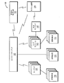
図1は、例示的なワイヤレスホームオートメーションシステム、より詳細には、該システムの複数の装置間でのWi-Fi信号の交換に応じて建造物の周囲に分布する複数の照明負荷の切替及び/又は調光を行うことができるWi-Fiベースの照明制御システム100のブロック図である。本実施形態及びその他の実施形態ではWi-Fiベースのシステムを用いるが、本技術は、他のワイヤレス技術(例えば、Bluetooth、ZigBee、Insteonなど)に容易に適用することが可能であることが理解されよう。本書で用いる場合、用語「Wi-Fi」とは、複数のIEEE802.11規格のうちの1つに基づくワイヤレスローカルエリアネットワーク(WLAN)通信を称するものである。
System Architecture FIG. 1 illustrates an exemplary wireless home automation system, and more particularly, of a plurality of lighting loads distributed around a building in response to the exchange of Wi-Fi signals between the plurality of devices of the system. FIG. 1 is a block diagram of a Wi-Fi based
照明負荷110は、照明器具、ランプ、又は白熱、発光ダイオード(LED)、ハロゲン、蛍光、若しくはその他の照明技術に基づく他のタイプの照明装置とすることが可能である。Wi-Fiベースの照明制御システム100は、照明のみを操作するスタンドアロンシステムとして示されているが、該システム100は、他のタイプのホームオートメーション装置を制御するよう適応させることが可能であり、又は他のタイプの複数のホームオートメーション装置を制御する一層大規模なホームオートメーションシステムの一部とすることが可能であることが理解されよう。例えば、本発明のシステムは、様々なタイプの電子装置、モータ駆動式装置、及び/又は他のタイプの装置の間で制御及び/又はデータ交換を行うことが可能である。該電子装置は、ディスプレイスクリーン(例えば、テレビ)、オーディオ/ビデオ(A/V)装置、コンピュータ装置、又は電子装置を用いる他のタイプの装置を含むことが可能である。前記モータ駆動式装置は、自動ブラインド、自動ドア、電動式テレビ昇降機、又はモータにより駆動される他のタイプの装置を含むことが可能である。同様に、前記他のタイプの装置は、冷暖房空調設備(HVAC)装置、セキュリティ装置、又は様々な他のあらゆるタイプの環境制御又は監視装置を含むことが可能である。
The
Wi-Fiベースの照明制御システム100は、少なくとも1つのWi-Fi対応照明制御装置を有することが可能であり、該Wi-Fi対応照明制御装置は、Wi-Fi対応壁埋込型コントローラキーパッド120という形をとることが可能である。一実施形態では、該コントローラキーパッド120は、改装工事を簡素化するために2連結壁埋込型電気ボックス内に収まるよう設計されたフォームファクタを有するものとなる。該コントローラキーパッド120はWi-Fiインタフェイスを含むことが可能であり、該Wi-Fiインタフェイスは、アクセスポイント(AP)モードで動作することによりWi-Fiネットワークを形成すること、又は、APモードで動作している他のWi-Fi対応照明制御装置もしくは別個の家庭内Wi-Fi AP 150により提供される既存の家庭内Wi-Fiネットワークに参加することが可能なものである。該Wi-Fiネットワークを介して、コントローラキーパッド120は、Wi-Fiベースの照明制御システム100の他の複数のWi-Fi対応照明制御装置と通信し、かかる複数のWi-Fi対応照明制御装置は、任意の他の複数のコントローラキーパッド(図示せず)、複数のキーパッド130、及び/又は複数のランプモジュール140(これらを包括的にWi-Fi対応照明制御装置と称す)、並びにモバイル装置200等の複数のモバイル装置を含む。
The Wi-Fi based
コントローラキーパッド120は、それ自体を(例えば、壁に埋め込まれた配線を介して)複数の照明負荷へ接続するために使用される複数の端子(例えば、対をなす端子セット)を含むことが可能である。更に、該接続された照明負荷の調光及び/又は切替を行うために調光及び/又は切替回路(例えば、一対の調光器又は一対のリレー)を配設することが可能である。以下で一層詳細に説明するように、コントローラキーパッド120は、調光及び/又は切替が行われる各照明負荷に負荷名称を関連づけるように、及び随意選択的に、複数の「部屋」及び/又は複数の「グループ」を形成するよう各照明負荷を他の照明負荷と編成するように、(設定操作を介して)設定することが可能である。ここで、「部屋」とは、互いに物理的に近接している(例えば、同一の物理的な部屋内、又は所与の建造物に関する他の所定の空間内にある)複数の照明負荷を集めたものを称するものである。同様に、「グループ」とは、互いに属性を共有する複数の照明負荷を称するものであり、かかる複数の照明負荷は、互いに物理的に近接していても近接していなくても良い。場合によっては、「グループ」は、複数の「部屋」を集めたものから構成することが可能である。別の場合には、「グループ」は、「部屋」とは全く関係のないものとすることが可能であり、例えば、共通のタイプ又は機能を共有する複数の照明負荷を集めたものから構成することが可能である。また、以下で一層詳細に説明するように、1つ以上の選択された照明負荷、部屋、及び/又はグループを、所定の複数の照明効果を表す複数の「照明シーン」を生成するための選択された複数の照明レベルに関連付けることが可能であり、該複数の照明効果は、選択された複数の照明レベルに設定された1つ以上の照明負荷により生成されるものである。「照明シーン」を参照することにより、構成要素となる複数の照明負荷、部屋、及び/又はグループの個々の調節を行うことなく照明効果を指定することが可能である。 The controller keypad 120 may include a plurality of terminals (eg, a pair of terminal sets) used to connect itself to a plurality of lighting loads (eg, via wires embedded in a wall) It is possible. Furthermore, it is possible to arrange a dimming and / or switching circuit (for example, a pair of dimmers or a pair of relays) to perform dimming and / or switching of the connected lighting load. As will be described in more detail below, the controller keypad 120 may optionally associate a plurality of "rooms" and / or to associate a load name with each lighting load to be dimmed and / or switched. Each lighting load can be configured (via a setup operation) to be organized with other lighting loads to form a plurality of "groups". Here, a "room" is a collection of lighting loads that are physically close to one another (e.g., in the same physical room or in another predetermined space for a given building) It refers to the Similarly, a "group" refers to a plurality of lighting loads that share attributes with each other, and the plurality of lighting loads may or may not be physically close to each other. In some cases, a "group" can consist of a collection of "rooms". In other cases, the "group" may be completely unrelated to the "room", eg consisting of a collection of lighting loads sharing a common type or function It is possible. Also, as will be described in more detail below, one or more selected lighting loads, rooms, and / or groups are selected to generate a plurality of "lighting scenes" representing a predetermined plurality of lighting effects. The plurality of illumination levels may be associated with the plurality of illumination levels, the plurality of illumination effects being generated by one or more illumination loads set to the plurality of illumination levels selected. By referring to the "lighting scene" it is possible to specify lighting effects without making individual adjustments of the component lighting loads, rooms and / or groups.
コントローラキーパッド120は、複数のプログラマブルボタン(例えば、2個、4個、又は6個のボタン)を含むことが可能であり、該複数のプログラマブルボタンは、それぞれ1つの照明シーンに関連付けることが可能なものである。該複数のプログラマブルボタンのうちの1つのユーザによる押下に応じて、コントローラキーパッド120は、その内部の調光器及び/又はリレーを制御することにより、及び/又は、他の複数のコントローラキーパッド(図示せず)、複数のキーパッド130、及び/又は複数のランプモジュール140へWi-Fi信号を送信してそれらにそれらの調光器及び/又はリレーを制御させて照明シーンにより定義される所定の照明効果を生じさせることにより、照明シーンの状態を変更する(例えば、電源オンにし、電源オフにし、電源オン/オフを切り替え、以前の状態にプリセットし、設定されたレベルに調光し、タイマーをセットする)ことが可能である。
The controller keypad 120 can include a plurality of programmable buttons (e.g., two, four, or six buttons), which can each be associated with one lighting scene It is a thing. In response to the user pressing one of the plurality of programmable buttons, the controller keypad 120 controls the dimmer and / or relays therein and / or other controller keypads (Not shown), send Wi-Fi signals to
更に、コントローラキーパッド120は、有線シリアル通信インタフェイス(例えば、Micro USB(universal serial bus)インタフェイス)、及び、Wi-Fiネットワーク上でコントローラキーパッドにより使用されるIP(Internet Protocol)アドレスをリセットするよう動作するIPリセットボタン、接続された照明負荷をテストするためのテストボタン、診断情報を表示する発光ダイオード(LED)、テスト及びサービス操作を可能にすべくコントローラキーパッド120及び照明負荷から電源を切断するよう動作するサービススイッチ、並びにその他の設定制御手段といった、設定制御手段を含むことが可能である。 Furthermore, the controller keypad 120 resets the wired serial communication interface (e.g. Micro USB (universal serial bus) interface) and the IP (Internet Protocol) address used by the controller keypad over the Wi-Fi network. Reset button to operate, test button to test the connected lighting load, light emitting diode (LED) to display diagnostic information, power from the controller keypad 120 and lighting load to enable test and service operation It is possible to include setting control means, such as a service switch that operates to cut off, as well as other setting control means.
上述のように、コントローラキーパッド120は、複数のWi-Fi信号を介して複数のキーパッド130と通信することが可能である。かかる複数のキーパッド130は、コントローラキーパッド120の幾つかの特徴を共有することが可能であるが、通常はコントローラキーパッド120よりも少ない機能を有するものとなる。一実施形態では、複数のキーパッド130の各々は、改装工事を簡素化するために1連結壁埋込型電気ボックス内に収まるよう設計されたフォームファクタを有するものとなる。各キーパッド130は、Wi-Fiネットワークインタフェイスを含むことが可能であり、該Wi-Fiネットワークインタフェイスは、Wi-Fi APとして動作することによりWi-Fiネットワークを形成すること、又は、他のWi-Fi対応照明制御装置もしくは別個の家庭内Wi-Fi AP 150により提供される既存の家庭内Wi-Fiネットワークに参加することが可能なものである。コントローラキーパッド120の場合と同様に、各キーパッド130は、それ自体を(例えば、壁に埋め込まれた配線を介して)複数の照明負荷に接続するために使用される複数の端子(例えば、1組の端子)を含むことが可能である。更に、該接続された照明負荷の調光及び/又は切替を行うために調光及び/又は切替回路(例えば、調光器又はリレー)を配設することが可能である。コントローラキーパッド120の場合と同様に、各キーパッド130は、調光及び/又は切替が行われる各照明負荷に負荷名称を関連づけるように、及び随意選択的に、複数の部屋及び/又は複数のグループを形成するよう各照明負荷を他の照明負荷と編成するように、(設定操作を介して)設定することが可能である。
As mentioned above, controller keypad 120 can communicate with
各キーパッド130は、複数のプログラマブルボタン(例えば、1個、2個、又は3個のボタン)を含むことが可能である。更に、コントローラキーパッド120の場合と同様に、各プログラマブルボタンに(更なる設定操作を介して)照明シーンを関連付けることが可能である。プログラマブルボタンのユーザによる押下に応じて、キーパッド130は、その調光器及び/又はリレーを制御することにより、及び/又は、コントローラキーパッド120へWi-Fi信号を送信して該コントローラキーパッド120にその調光器及び/又はリレーを制御させ及び/又は該コントローラキーパッド120に他の複数のキーパッド130及び/又は複数のランプモジュール140へ信号を送信させてそれらにそれらの調光器及び/又はリレーを制御させて照明シーンの所定の照明効果を生じさせることにより、照明シーンの状態を変更することが可能である。更に、各キーパッド130は、有線シリアル通信インタフェイス(例えば、Micro USBインタフェイス)並びに設定制御手段(例えば、テストボタン、LED、サービススイッチ、及びその他の設定制御手段)を含むことが可能である。
Each
更に、上述のように、コントローラキーパッド120は、Wi-Fi信号を介してランプモジュール140と通信することが可能である。各ランプモジュール140は、壁コンセントに接続するための壁に面するプラグ(wall-facing plug)と、ランプ又はその他の照明負荷の電気コードを受容するための1つ以上のランプに面するコンセント(lamp-facing outlet)を含むことが可能である。接続された照明負荷の調光及び/又は切替を行うために調光及び/又は切替回路(例えば、調光器及び/又はリレー)を配設することが可能である。コントローラキーパッド120及びキーパッド130の場合と同様に、各ランプモジュール140は、調光及び/又は切替が行われる各照明負荷に負荷名称を関連づけるように、及び随意選択的に、複数の部屋及び/又は複数のグループを形成するよう各照明負荷を他の照明負荷と編成するように、(設定操作を介して)設定することが可能である。該調光及び/又は切替回路は、Wi-Fiネットワークインタフェイスを介して受信したWi-Fi信号に応じて制御することが可能である。該Wi-Fiネットワークインタフェイスは、Wi-Fi APとして動作することによりWi-Fiネットワークを形成すること、又は、他のWi-Fi対応照明制御装置もしくは別個の家庭内Wi-Fi AP 150により提供される既存の家庭内Wi-Fiネットワークに参加することが可能なものである。更に、ランプモジュール140は、有線シリアル通信インタフェイス(例えば、Micro USBインタフェイス)並びに設定制御手段(例えば、テストボタン、LED、サービススイッチ、及びその他の設定制御手段)を含むことが可能である。ランプモジュール140は、プログラマブルボタンを有さないことが可能である。しかし、複数のプログラマブルボタン(例えば、3個のボタン)を含む卓上キーパッド145又はその他の装置をランプモジュール140に(例えば、有線接続を介して)接続することが可能である。他のプログラマブルボタンの場合と同様に、該プログラマブルボタンは(設定操作を介して)照明シーンに関連付けることが可能である。
Furthermore, as mentioned above, controller keypad 120 can communicate with lamp module 140 via a Wi-Fi signal. Each lamp module 140 has a wall-facing plug for connection to a wall outlet, and an outlet facing one or more lamps for receiving a lamp or other lighting load electrical cord. It is possible to include a lamp-facing outlet). It is possible to arrange a dimming and / or switching circuit (eg, a dimmer and / or a relay) in order to dim and / or switch the connected lighting load. As with the controller keypad 120 and the
Wi-Fi対応照明制御装置120,130,140は、モバイル装置200等のモバイル装置と通信することが可能である。本書で用いる場合、用語「モバイル装置」とは、身に着けて運ばれるよう構成され、及びワイヤレス通信インタフェイス及びタッチセンサ式スクリーンを含む、電子装置を称するものである。タブレットコンピュータ(例えば、Apple, Inc.から入手可能なiPad(登録商標)タブレット)、スマートフォン(例えば、Apple, Inc.から入手可能なiPhone(登録商標)スマートフォン、及び様々なベンダから入手可能なAndroid(登録商標)スマートフォン)、及び特定のポータブルメディアプレーヤ(例えば、Apple, Inc.から入手可能なiPod(登録商標)touch)は、モバイル装置とみなされる。デスクトップコンピュータは一般にモバイル装置とはみなさない。
The Wi-Fi enabled
モバイル装置200は、Wi-Fi対応照明制御装置(例えば、コントローラキーパッド120、キーパッド130、及びランプモジュール140)を設定するための、設定の役割で使用することが可能である。同様に、モバイル装置は、既に設定されているシステムの、個々の照明負荷、部屋、グループ、又は照明シーンを制御するために、制御の役割で使用することが可能である。設定の役割で使用される場合、モバイル装置200は、(Wi-Fi AP として動作しているWi-Fi対応照明制御装置により提供されるワイヤレスネットワークを介して交換される)Wi-Fi信号を介して、又は有線接続を介して、Wi-Fi対応照明制御装置と通信することが可能である。一実施形態では、該有線接続は、モバイル装置200のシリアル通信インタフェイス(例えば、Lightningインタフェイス又はUSBインタフェイス)をWi-Fi対応照明制御装置のシリアル通信インタフェイス(例えば、Micro USB インタフェイス)に接続する接続装置により提供することが可能である。利用することができる特定のタイプの接続装置に関する更なる詳細は、2013年6月21日出願の「A Configuration Connection Device」と題するMadonnnaらの米国特許出願第13/923,826号で開示されている。
制御の役割で使用される場合、モバイル装置200は、典型的には(例えば、コントローラキーパッド120を介して)Wi-Fi対応照明制御装置と通信し、及び所望の状態の変化を個々の照明負荷、部屋、グループ、又はシーンへ伝達する。これに応じて、Wi-Fi対応照明制御装置は、指示された照明効果を実施することが可能である。
When used in a control role, the
図2は、ワイヤレスホームオートメーションシステム(より詳細には、Wi-Fiベースの照明制御システム100)の設定及び制御を行うために使用することができる例示的なモバイル装置200のブロック図である。該モバイル装置200は、プロセッサ210、メモリ220、ワイヤレスネットワークインタフェイス230、タッチセンサ式スクリーン240、シリアル通信インタフェイス250、並びにその他のハードウェアを含む。プロセッサ210は、ソフトウェアの実行及びデータ構造からのデータの操作を行うよう構成されたロジックを含む。メモリ220は、該ソフトウェア及び該データ構造を格納するための複数の格納場所を含む。ワイヤレスネットワークインタフェイス230は、1つ以上のワイヤレスネットワーク(例えば、Wi-Fiネットワーク、4Gモバイル通信ネットワーク、及び/又はその他のタイプのネットワーク)を介した通信を容易化する。タッチセンサ式スクリーン240は、ユーザからジェスチャ(例えば、タッチ、スワイプ、マルチタッチジェスチャ等)という形でユーザ入力を受信することが可能である。シリアル通信インタフェイス250は、30ピンDockインタフェイス、USBインタフェイス、又はその他のタイプのインタフェイスとすることが可能である。
FIG. 2 is a block diagram of an example
オペレーティングシステム260は、その一部がメモリ220上に常駐し、モバイル装置200を機能的に編成する。オペレーティングシステム260は、Apple, Inc.から入手可能なIOS(登録商標)オペレーティングシステム、Google, Inc.から入手可能なAndroid(登録商標)オペレーティングシステム、又はモバイル装置上での使用に適したその他のタイプのオペレーティングシステムとすることが可能である。グラフィカルユーザインターフェイス(GUI)を含むスタンドアロンワイヤレス照明アプリケーション270をオペレーティングシステム260と連携して実行することにより、モバイル装置200を設定の役割と制御の役割の両方でWi-Fiベースの照明制御システムと共に使用することが可能となる。
●システム構成
図3は、例示的なワイヤレスホームオートメーションシステム(一層詳細には、Wi-Fi対応照明制御装置100)を設定するために実行することができる例示的な一連のステップ300を示すフローチャートである。該ステップは、特定の順序で示されているが、1つのステップと他のステップとの間に明示的に説明した依存性が存在しない限り、それらステップは様々な異なる相対的な順序で実行することが可能である、ということが理解されよう。
A portion of operating system 260 resides on
System Configuration FIG. 3 is a flowchart illustrating an exemplary series of
ステップ310で、ワイヤレス照明アプリケーション270がモバイル装置200のプロセッサ210により実行される。ステップ320で、モバイル装置200とWi-Fi対応照明制御装置(例えば、コントローラキーパッド)との間で接続が確立される。既述のように、該接続は、(例えば、Wi-Fiネットワークを介した)ワイヤレス接続又は(例えば、接続装置を介した)有線接続とすることが可能である。ステップ320で、ワイヤレス照明アプリケーション270のGUIにおけるユーザ入力に応じて、該ワイヤレス照明アプリケーション270は、接続された照明負荷に負荷名称を少なくとも関連づけし、及び随意選択的に該照明負荷を他の照明負荷と共に編成して部屋及び/又はグループを形成することにより、Wi-Fi対応照明制御装置の設定を行う。ステップ340で、ワイヤレス照明アプリケーション270は、該GUIにおけるユーザ入力に応じて、選択された照明レベルに設定された1つ以上の照明負荷により生成される所定の照明効果を表す照明シーンを定義する。該定義された照明シーンに関する情報は、コントローラキーパッド120上またはWi-Fiベースの照明制御システム100内の他の場所に維持することが可能である。ステップ350で、ワイヤレス照明アプリケーション270は、GUIにおけるユーザ入力に応じて、プログラマブルボタンに照明シーンを割り当て、これにより、該プログラマブルボタンの押下に応じて、選択された照明負荷に接続されている1つ以上のWi-Fi対応照明制御装置が、所望の照明効果を生成する態様で該照明負荷の調光又は切替を行うようにする。ステップ330〜350の一部又は全部を繰り返して、更なるWi-Fi対応照明制御装置を設定し、更なる照明シーンを定義し、及び/又は更なる照明シーンを更なるプログラマブルボタンに割り当てることが可能であり、Wi-Fi照明制御システム100が完全に設定されるまでかかる設定を繰り返すことが可能である。次いで、一連のステップ300が終了する。その後、ユーザは、プログラマブルボタンを押下し又はモバイル装置200上のワイヤレス照明アプリケーション270を制御の役割で使用することにより、照明を自由に制御することが可能である。
At
図4A−4Cは、モバイル装置200のタッチセンサ式スクリーン240上に表示される例示的なワイヤレス照明アプリケーション270のGUIを示す一連のスクリーンショットであり、ワイヤレス接続の確立を示しいてる。スクリーン405-415には、コントローラキーパッド120及びキーパッド130及び/又はランプモジュール140の設定方法を説明する指示が表示されている。スクリーン420-425には、コントローラキーパッドへの接続方法を説明する指示が表示されており、該接続を開始するためのインタフェイス要素が提供される。該コントローラキーパッドは、デフォルトでWi-Fi APとして動作するよう構成することが可能である。図10を参照して以下で説明するように、更新技術(図4A−4Cには図示せず)を使用して、複数のWi-Fi対応照明制御装置の各々を複数のWi-Fi設定(例えば、SSID(Service Set Identifier)及びセキュリティ設定)で一斉に更新して、該複数のWi-Fi対応照明制御装置がコントローラキーパッドと同一のWi-Fiネットワーク上で動作する(例えば、特定のWi-Fi対応照明制御装置又は別個の家庭内Wi-Fi AP 150により提供されるネットワークを使用する)ようにすることが可能である。
FIGS. 4A-4C are a series of screen shots illustrating a GUI of an exemplary wireless lighting application 270 displayed on the touch-
スクリーン430には、発見された複数のWi-Fi対応照明制御装置が表示されている。該複数のWi-Fi対応照明制御装置は、同一のWi-Fiネットワーク上で動作しているコントローラキーパッド120とその他のWi-Fi対応照明制御装置との間の対話によって決定される。スクリーン435-450では、家庭内Wi-Fi AP 150により提供されるWi-Fiネットワークに切り替えるためのインタフェイス要素が提供される。かかるオプションが選択された場合には、図10に関して後述するものと同様の更新技術を使用して、複数のWi-Fi対応照明制御装置を新しいWi-Fi設定で一斉に更新させることが可能である。更に、スクリーン455-460では、ユーザは未設定のWi-Fi対応照明制御装置を選択するよう促される。2つの代替的な方法を提供することが可能である。第1の方法では、Wi-Fi対応照明制御装置上のプログラマブルボタンを押下するようユーザに促し、かかるボタンの押下をワイヤレス照明アプリケーション270に通報として伝達し、これにより未設定のWi-Fi対応照明制御装置を選択することが可能である。代替的に、第2の方法では、GUIに表示されたリストからWi-Fi対応照明制御装置を選択するようユーザに促す。
The
図5は、モバイル装置200のタッチセンサ式スクリーン240上に表示される例示的なワイヤレス照明アプリケーション270のGUIを示す一連のスクリーンショットであり、有線接続の確立が示されている。スクリーン505-510で、モバイル装置200のシリアル通信インタフェイスをコントローラキーパッド120のシリアル通信インタフェイスに接続する接続装置を使用してモバイル装置200をコントローラキーパッド120に接続する方法を説明する指示が表示されている。該接続の使用を開始させるためにインタフェイス要素が提供される。スクリーン515で、Wi-Fi対応照明制御装置の個数が表示される。このステージまでにコントローラキーパッド及びその他のWi-Fi対応照明制御装置が同一のWi-Fi設定(例えば、SSID及びセキュリティ設定)を使用するよう更新されており互いに同一のネットワーク上で通信することができるようになっていることを前提とする。図10に示したものと同様の更新技術を使用することが可能である。
FIG. 5 is a series of screen shots illustrating a GUI of an exemplary wireless lighting application 270 displayed on the touch-
モバイル装置200が最初に結合されるコントローラキーパッド120を設定のために選択することが可能である。その設定の後、別の未設定のWi-Fi対応照明制御装置を選択するようユーザに促すスクリーン520-525が表示される。2つの代替的な方法を提供することが可能である。第1の方法では、接続装置を介してモバイル装置200と該未設定のWi-Fi対応照明制御装置との間の有線接続を確立するようユーザに促す。代替的に、第2の方法では、図4B−4Cのスクリーン455-460に関して上述したものと同様に、Wi-Fi対応照明制御装置をワイヤレスに選択するようユーザに促す。
The controller keypad 120 to which the
図6は、モバイル装置200のタッチセンサ式スクリーン240上に表示される例示的なワイヤレス照明アプリケーション270のGUIの一連のスクリーンショットであり、Wi-Fi対応照明制御装置の設定を示している。異なるタイプのWi-Fi対応照明制御装置(例えば、キーパッド130又はランプモジュール140と比較した場合のコントローラキーパッド120)の設定には特定の差異が存在するが、該一連のスクリーンショットは、一般的な場合を表したものである。スクリーン605で、未設定の複数のWi-Fi対応照明制御装置のリストから1つの未設定のWi-Fi対応照明制御装置を選択するようユーザに促す。各々の未設定の装置毎に、該装置のタイプ(例えば、コントローラキーパッド、キーパッド、又はランプモジュール)をアイコンが表示することが可能である。代替的に、ユーザは、Wi-Fi対応照明制御装置上のプログラマブルボタンを押下することにより、該Wi-Fi対応照明制御装置を選択することが可能である。かかる場合には、該ボタンの押下がワイヤレス照明アプリケーション270に通報として伝達され、スクリーン610に示すように、該未設定のWi-Fi対応照明制御装置の選択を確認するようユーザに促す。スクリーン615で、インタフェイス要素620を使用して入力を行って(接続されている照明負荷に負荷名称を少なくとも関連付けることにより)Wi-Fi対応照明制御装置を設定するようユーザに促す。単一の照明負荷が接続されているキーパッド130(又はランプモジュール140)の場合、負荷名称は、装置全体の装置名(例えば、キーパッド名)という形をとることが可能である。複数の照明負荷が接続されているコントローラキーパッド120の場合には、負荷名称は、それぞれの照明負荷に関連付けられた第1の負荷名称又は第2の負荷名称という形をとることが可能である。設定の一部として、ユーザは、インタフェイス要素625を使用して入力を行って照明負荷をグループに関連付けること、又はインタフェイス要素630により照明負荷を部屋に関連付けることことも可能である。更に、カメラインタフェイス要素640が表示され、ユーザは、該カメラインタフェイス要素640を使用してモバイル装置に部屋又はグループの写真を撮影させることが可能である。
FIG. 6 is a series of screen shots of a GUI of an exemplary wireless lighting application 270 displayed on the touch-
図7は、モバイル装置200のタッチセンサ式スクリーン240上に表示される例示的なワイヤレス照明アプリケーション270のGUIの一連のスクリーンショットであり、複数の部屋又はグループの編集を示している。スクリーン705-715には、階層をなす複数のグループ、複数の部屋、及び個々の照明負荷の開かれた又は閉じられたビューが示されている。例えば、スクリーン705,710では、「第1フロア」なる名称のグループが「ダイニングルーム」なる名称の部屋を含み、該部屋が「スコンス」及び「シャンデリア」なる名称の照明負荷を含むことが分かる。スクリーン720で、更なる部屋及び/又はグループを追加するためのインタフェイス要素722がユーザに提示される。同様に、スクリーン725で、部屋及び/又はグループを削除するためのインタフェイス要素727がユーザに提示される。
FIG. 7 is a series of screen shots of a GUI of an exemplary wireless lighting application 270 displayed on the touch-
図8は、モバイル装置200のタッチセンサ式スクリーン240上に表示される例示的なワイヤレス照明アプリケーション270のGUIの一連のスクリーンショットであり、照明シーンを定義するための1つの方法が示されている。スクリーン805で、既存の照明シーンがグリッドビューで表示される。インタフェイス要素807を選択して照明シーンの編集を可能にすることが可能である。スクリーン810で、既存の照明シーンがリストビューで表示される。新たな照明シーンを追加するために選択することが可能なインタフェイス要素812が提供される。既存の照明シーンを削除するため又は既存の照明シーンを変更するための更なるインタフェイス要素814が提供される。スクリーン815-825で、新たな照明シーンに名称を割り当てるため、及び所定の照明レベルに予め設定された個々の照明負荷、部屋、又はグループを該新たな照明シーンに割り当てるためのインタフェイス要素が提供される。例えば、スクリーン815中の「プール庭」グループのインタフェイス要素817を選択して、照明レベル制御手段(例えば、スライダ)を調整することにより、該グループ(その構成要素となる照明負荷が選択された照明レベルに設定されたもの)が新たな照明シーンに追加される。同様に、スクリーン825中の「窓照明」照明負荷のインタフェイス要素827を選択して、照明レベル制御手段(例えば、スライダ)を調整することにより、該個々の照明負荷(選択された照明レベルに設定されたもの)が新たな照明シーンに追加される。
FIG. 8 is a series of screen shots of a GUI of an exemplary wireless lighting application 270 displayed on a touch-
図9は、モバイル装置200のタッチセンサ式スクリーン240上に表示される例示的なワイヤレス照明アプリケーション270のGUIの一連のスクリーンショットであり、複数のWi-Fi対応照明制御装置のうちの1つのプログラマブルボタンに対する照明シーンの割り当てを示している。スクリーン905で、照明シーンを選択するためのインタフェイス要素が提供される。例えば、図8に関して上述した「プール庭」照明シーンを選択することが可能である。スクリーン910-920で、複数のWi-Fi対応照明制御装置のうちの1つのプログラマブルボタンを選択するためのインタフェイス要素が提供される。該インタフェイス要素を階層的な態様で配置して、ユーザが最初にグループ(例えば、「第2フロア」と称するグループ912)、Wi-Fi対応照明制御装置(例えば、「Jennの部屋」なる名称のキーパッド917)、及びWi-Fi対応照明制御装置上の個々のプログラマブルボタン(例えば、一番上のボタン922)を選択するようにすることが可能である。その後、ワイヤレス照明アプリケーション270は、該プログラマブルボタン(データ構造における関係を定義するもの)に該照明シーンを割り当て、該ボタンの押下時に該Wi-Fi対応照明制御装置100がトリガされて該照明シーンにより指示された照明効果を生成するようにすることが可能である。
●ワイヤレスバディ(Buddy)更新プロセス
上述のように、ワイヤレスホームオートメーションシステム(例えば、WiFiベースの照明制御システム)の複数の装置のワイヤレス設定(例えば、SSID及びセキュリティ設定等のWi-Fi設定)を一斉に更新させるのが望ましい。かかる更新は、例えば、全ての(又は少なくともその所望のサブセットの)ワイヤレス装置(例えば、Wi-Fi対応装置)を新たに選択されたワイヤレス(例えば、Wi-Fi)ネットワーク上で動作させることが可能である。
FIG. 9 is a series of screen shots of a GUI of an exemplary wireless lighting application 270 displayed on a touch-
Wireless Buddy Update Process As described above, the wireless settings (eg, Wi-Fi settings such as SSID and security settings) of multiple devices of a wireless home automation system (eg, WiFi based lighting control system) are broadcast simultaneously It is desirable to have Such updates can, for example, allow all (or at least a desired subset thereof) wireless devices (eg, Wi-Fi enabled devices) to operate on the newly selected wireless (eg, Wi-Fi) network It is.
一例としてのWi-Fi対応照明制御装置について考察すると、実施形態によっては、該装置は、デフォルトで(例えば、最初のスタートアップ時又はリセット時に)共通のWi-Fiネットワークを使用するよう設定することが可能であり、これは、更新のための開始ポイントとして働くことが可能である。例えば、Wi-Fi対応照明制御装置は、共通の所定のSSID及びそれに関連するセキュリティ設定を使用するよう構成することが可能である。幾つかのタイプの装置(例えば、コントローラキーパッド120)は、そのWi-FiインタフェイスをデフォルトでAPモードにするよう構成することが可能であり、他のタイプの装置(例えば、キーパッド130及びランプモジュール140)は、そのWi-Fiインタフェイスをデフォルトでクライアントモードにするよう構成することが可能である。この開始ポイントから、更新されたWi-Fi設定を、共通のWi-Fiネットワークを介して1つのWi-Fi対応照明制御装置(例えば、コントローラキーパッド120)から他のWi-Fi対応照明制御装置へ、Wi-Fiパラメータメッセージを送信することにより「プッシュ」することが可能である。例えば、図4Bのスクリーン445-450におけるユーザ入力に応じて、モバイル装置200は、Wi-Fi AP 150として動作しているコントローラキーパッド120に新たなWi-Fi設定を設定することが可能であり、該新たなWi-Fi設定は次いで共通のWi-Fiネットワークを介して、クライアントとして動作しているキーパッド130及びランプモジュール140へプッシュされる。
Considering an exemplary Wi-Fi enabled lighting control device, in some embodiments the device may be configured to use a common Wi-Fi network by default (eg, at first start-up or reset) It is possible that this can serve as a starting point for the update. For example, a Wi-Fi enabled lighting control can be configured to use a common predetermined SSID and its associated security settings. Some types of devices (eg, controller keypad 120) can be configured to put their Wi-Fi interface into AP mode by default, and other types of devices (eg,
かかる技術は、実施形態によっては十分に機能するが、実施形態によっては問題が生じることが分かっている。例えば、一般に使用されているWi-Fiチップセットは、AP能力が限られたものであり、クライアントとして動作している限られた個数の装置(例えば、8個のクライアント)にしか接続できないものである。このため、例えば、クライアントとして動作している数ダースのキーパッド130及びランプモジュール140が存在する場合に、Wi-Fi APとして動作しているコントローラキーパッド120が限られたAP能力を有するチップセットを使用している場合には、それら全てのクライアントが該コントローラキーパッド120に容易に接続することはできない。
Such techniques work well in some embodiments but have been found to cause problems in some embodiments. For example, commonly used Wi-Fi chipsets have limited AP capabilities and can only connect to a limited number of devices (eg, 8 clients) operating as clients. is there. Thus, for example, when there are several dozens of
このため、実施形態によっては、複数のWi-Fi対応照明制御装置は、更新のための開始ポイントとして働くことができる別個のWi-Fiネットワークをデフォルトで(例えば、最初のスタートアップ時又はリセット時に)使用するよう設定することが可能である。例えば、複数のWi-Fi対応照明制御装置は、それぞれのWi-Fiインタフェイスが一意のSSIDをデフォルトで使用し及びデフォルトでAPモードで動作するよう構成することが可能であり、これにより、少なくとも最初はWi-Fiネットワークの数がWi-Fi対応照明制御装置の数と等しくなるようにすることが可能である。該一意のSSIDは、標準文字列(a standard string)(例えば、標準接頭辞(a standard prefix))と特定のWi-Fi対応照明制御装置の一意識別子(UID:Unique identifier)(例えば、該装置のMAC(Media Access Control)アドレス又はその一部)との連結により生成することが可能である。この一意のSSIDにおける標準文字列の使用により、照明制御システム100の一部として装置の識別を行うことが可能となる。この開始ポイントから、更新されたWi-Fi設定を「バディ更新」を使用して分配することが可能である。かかる「バディ更新」の使用により、最初のWi-Fi対応照明制御装置から一連の連続するペアワイズ交換(pair-wise exchanges)を介して複数のWi-Fi対応照明制御装置の全て(又は少なくともその所望のサブセット)へとWi-Fi設定を伝達することが可能となる。
Thus, in some embodiments, multiple Wi-Fi enabled lighting control devices default to a separate Wi-Fi network that can serve as a starting point for updating (eg, at first start-up or reset) It is possible to set it for use. For example, multiple Wi-Fi enabled lighting control devices can be configured such that each Wi-Fi interface uses a unique SSID by default and operates in AP mode by default, thereby at least Initially it is possible to make the number of Wi-Fi networks equal to the number of Wi-Fi enabled lighting control devices. The unique SSID may be a standard string (e.g., a standard prefix) and a unique identifier (UID) of a particular Wi-Fi enabled lighting control device (e.g., the device). It is possible to generate by linking with the MAC (Media Access Control) address (or part of it). The use of standard character strings in this unique SSID allows for device identification as part of the
図10は、それぞれ別個のWi-Fiネットワークを使用し及びかかるネットワークのAPとして働くよう最初に構成された複数のWi-Fi対応照明制御装置へ複数の更新されたWi-Fi設定(例えば、SSID及びセキュリティ設定)を一斉に伝達するための例示的な一連のステップ1000を示すフローチャートである。該一連のステップ1000は、第1のWi-Fi対応照明制御装置上で実行されいてるソフトウェアプロセスにより行うことが可能であり、又は複数の装置上で実行されている複数のプロセス間で分割することが可能である。ステップ1010で、更新されたWi-Fi設定(例えば、SSID及びセキュリティ設定)が第1のWi-Fi対応照明制御装置において受信される。該更新されたWi-Fi設定は、ワイヤレス照明アプリケーション270を実行しているモバイル装置200に対して確立された接続(例えば、ワイヤレス接続又は有線接続)を介して受信することが可能であり、及び(例えば、図4Bに示すスクリーン445-450を介して)ユーザから受信した設定を表すものとすることが可能である。代替的に、Wi-Fi設定は、(例えば、受信したWi-Fiパラメータメッセージを介して)別のWi-Fi対応照明制御装置から受信することが可能である。
FIG. 10 illustrates a plurality of updated Wi-Fi settings (eg, SSIDs) to a plurality of Wi-Fi enabled lighting control devices initially configured to use separate Wi-Fi networks and to serve as APs of such networks. And security settings) at the same time. The sequence of
ステップ1020で、第1のWi-Fi対応照明制御装置は、そのWi-Fiインタフェイスにクライアントモードで動作するよう命令する。ステップ1030で、第1のWi-Fi対応照明制御装置は、Wi-FiインタフェイスがAPモードで動作している未更新のWi-Fi対応照明制御装置をスキャンする。複数のWi-Fi対応照明制御装置は、それぞれのSSIDにおいて標準文字列(例えば、標準接頭辞)を使用することにより、他のタイプの装置と区別することが可能である。ステップ1040で、第1のWi-Fi対応照明制御装置は、Wi-FiインタフェイスがAPモードで動作している未更新のWi-Fi対応照明制御装置が残っているか否かを判定する。Wi-FiインタフェイスがAPモードで動作している少なくとも1つの未更新のWi-Fi対応照明制御装置が残っている場合には、ステップ1050へと進み、第1のWi-Fi対応照明制御装置が、かかる残っている装置から第2のWi-Fi対応照明制御装置を選択して、それに(例えば、該装置のSSIDを使用して)クライアントとして接続する。ステップ1060で、第1のWi-Fi対応照明制御装置が、該第2のWi-Fi対応照明制御装置へWi-Fiパラメータメッセージを送信して、そのWi-Fi設定を更新させるよう命令する。その後、実行はステップ1030に戻る。ステップ1040で、Wi-FiインタフェイスがAPモードで動作している未更新のWi-Fi対応照明制御装置が残っていない場合には、実行はステップ1070へと進み、第1のWi-Fi対応照明制御装置が前記更新されたWi-Fi設定を実施する。該一連のステップ1000は、第1のWi-Fi対応照明制御装置の役割を担って前記Wi-Fi設定を伝達させる第2のWi-Fi対応照明制御装置の各々で繰り返すことが可能である、ということが理解されよう。このようにして、複数の装置の全て(又は少なくともその所望のサブセット)が更新されるまで、Wi-Fiベースの照明制御システム100の複数の装置間でWi-Fi設定をペアワイズに(例えば、「バディ」から「バディ」へ)伝達することが可能となる。
At
要するに、上記説明は、ワイヤレスホームオートメーションシステム(又はより詳細にはWi-Fiベースの照明制御システム)を設定するための例示的な技術について詳述したものである。本書で説明した実施形態の思想及び範囲内で様々な応用及び修正を実施することが可能である、ということが理解されよう。本開示の実施形態の多くは、Wi-Fiベースの照明制御を伴うものであるが、かかる技術の多くはWi-Fi又は照明制御に限られたものでは全くなく、様々な他のタイプのワイヤレス技術、及び照明に影響を与えることができないシステムを含む他のタイプのホームオートメーションシステムと共に使用することが可能である、ということが理解されよう。コントローラキーパッド120、キーパッド130、及びランプモジュール140について言及したが、他のタイプのコントローラ、ユーザインタフェイス装置、及び装置制御モジュールに容易に置換することが可能である、ということが理解されよう。同様に、コントローラキーパッド120、キーパッド130、及びランプモジュール140は、他のタイプの「負荷」を切り替え又は制御するよう適応させることが可能である。該「負荷」は、起動時に建造物に関する所定の機能を実行する電気的又は電子的な装置を表すことが可能なものである。例えば、「負荷」は、建造物の窓にある電動ブラインドとすることが可能である。同様に、「負荷」は、建造物内のドアの電子ドアロックとすることが可能である。このように、本書で説明する技術は、照明以外の物を制御することができる様々なタイプのホームオートメーションシステムに適用することが可能なものである。
In summary, the above description details an exemplary technique for configuring a wireless home automation system (or more particularly a Wi-Fi based lighting control system). It will be understood that various applications and modifications can be made within the spirit and scope of the embodiments described herein. Although many of the embodiments of the present disclosure involve Wi-Fi based lighting control, many of such techniques are not limited to Wi-Fi or lighting control at all, and various other types of wireless It will be appreciated that it can be used with other types of home automation systems, including technologies and systems that can not affect lighting. Although the controller keypad 120,
更に、上述した技術の少なくとも幾つかの部分は、ソフトウェア、ハードウェア、又はそれの組み合わせで実施することが可能である、ということが理解されよう。ソフトウェアによる実施形態として、揮発性又は不揮発性メモリ、ハードディスク、コンパクトディスク(CD)、又はその他の有形の媒体といった、持続性マシン読取り可能媒体(例えば、持続性コンピュータ読取り可能媒体)に格納されたマシン実行可能命令(例えば、コンピュータ実行可能命令)が挙げられる。ハードウェアによる実施形態として、設定されたプロセッサ、論理回路、特定用途向け集積回路(ASIC)、及び/又はその他のタイプのハードウェア要素が挙げられる。更に、ソフトウェアによる実施形態とハードウェアによる実施形態の組み合わせとして、持続性コンピュータ読取り可能媒体に格納されたコンピュータ実行可能命令並びに1つ以上のハードウェア要素(例えば、プロセッサ、メモリ等)の両方が挙げられる。したがって、上記説明は例示のみを意図したものである、ということが理解されよう。 Furthermore, it will be appreciated that at least some parts of the above described techniques may be implemented in software, hardware or a combination thereof. In a software embodiment, a machine stored on a non-transitory machine-readable medium (eg, non-transitory computer-readable medium), such as volatile or non-volatile memory, hard disk, compact disc (CD), or other tangible medium Executable instructions (eg, computer executable instructions). Hardware embodiments may include configured processors, logic circuits, application specific integrated circuits (ASICs), and / or other types of hardware elements. Further, a combination of software and hardware embodiments lists both computer-executable instructions stored in non-transitory computer-readable media and one or more hardware elements (eg, processor, memory, etc.). Be Accordingly, it will be understood that the above description is intended to be illustrative only.
Claims (15)
前記複数のワイヤレス装置の各々のワイヤレスインタフェイスを、一意のワイヤレス設定を使用し及びアクセスポイントモードで動作するよう設定し、
更新されたワイヤレス設定を前記複数のワイヤレス装置のうちの第1のワイヤレス装置で受信し、
該更新されたワイヤレス設定を該第1のワイヤレス装置で受信したことに応じて更新プロセスを開始し、該更新プロセスが、
前記第1のワイヤレス装置のワイヤレスインタフェイスをクライアントモードで動作するよう変更し、
ワイヤレスインタフェイスがアクセスポイントモードで動作している未更新のワイヤレス装置をスキャンし、
ワイヤレスインタフェイスがアクセスポイントモードで動作している少なくとも1つの未更新のワイヤレス装置が存在する場合に、該少なくとも1つの未更新のワイヤレス装置から選択された第2のワイヤレス装置へ前記第1のワイヤレス装置によりクライアントとして接続し、
前記更新されたワイヤレス設定を含むパラメータメッセージを前記第2のワイヤレス装置へ前記第1のワイヤレス装置により送信し、及び、
ワイヤレスインタフェイスがアクセスポイントモードで動作している未更新のワイヤレス装置が存在しなくなるまで、前記未更新のワイヤレス装置の前記スキャン、前記第2のワイヤレス装置の前記選択、及び前記パラメータメッセージの前記送信を繰り返す
ことを含む、複数のワイヤレス装置を含むワイヤレスホームオートメーションシステムにおけるワイヤレス設定を更新させる方法。 A method of updating wireless settings in a wireless home automation system including multiple wireless devices, the method comprising:
Configuring the wireless interface of each of the plurality of wireless devices to use a unique wireless setting and to operate in an access point mode;
Receiving the updated wireless settings at a first wireless device of the plurality of wireless devices;
Initiating an update process in response to receiving the updated wireless configuration at the first wireless device, the update process including
Changing the wireless interface of the first wireless device to operate in client mode;
The wireless interface scans for unupdated wireless devices operating in access point mode,
Said first wireless device from the at least one unupdated wireless device to a second wireless device selected when there is at least one unupdated wireless device operating in an access point mode of wireless interface Connect as a client by the device,
Transmitting, by the first wireless device, a parameter message including the updated wireless settings to the second wireless device;
The scan of the unupdated wireless device, the selection of the second wireless device, and the transmission of the parameter message until there are no updated wireless devices operating in the access point mode of the wireless interface. A method of updating wireless settings in a wireless home automation system including a plurality of wireless devices, comprising repeating.
前記複数のワイヤレス装置のうちの第1のワイヤレス装置であって、デフォルトで第1の一意のワイヤレス設定を使用するように及びデフォルトでアクセスポイントモードで動作するように設定されたワイヤレスインタフェイスを有する、第1のワイヤレス装置と、
前記複数のワイヤレス装置のうちの第2のワイヤレス装置であって、デフォルトで第2の一意のワイヤレス設定を使用するように及びデフォルトでアクセスポイントモードで動作するように設定されたワイヤレスインタフェイスを有する、第2のワイヤレス装置と、
前記第1のワイヤレス装置上で実行されている第1のソフトウェアプロセスであって、更新されたワイヤレス設定の受信に応じて、
前記第1のワイヤレス装置の前記ワイヤレスインタフェイスをクライアントモードで動作するよう変更し、
ワイヤレスインタフェイスがアクセスポイントモードで動作している未更新のワイヤレス装置を前記第1のワイヤレス装置の前記ワイヤレスインタフェイスを使用してスキャンし、
ワイヤレスインタフェイスがアクセスポイントモードで動作している未更新のワイヤレス装置として前記第2のワイヤレス装置を選択し、
該第2のワイヤレス装置にクライアントとして接続し、及び、
前記更新されたワイヤレス設定を含むワイヤレスパラメータメッセージを前記第1のワイヤレス装置の前記ワイヤレスインタフェイスを介して前記第2のワイヤレス装置へ送信する
よう構成されている、第1のソフトウェアプロセスとを備えている、複数のワイヤレス装置を含むワイヤレスホームオートメーションシステム。 A wireless home automation system comprising a plurality of wireless devices, comprising:
The first wireless device of the plurality of wireless devices having a wireless interface configured to use a first unique wireless setting by default and to operate in an access point mode by default , First wireless device,
A second wireless device of the plurality of wireless devices having a wireless interface configured to use a second unique wireless setting by default and to operate in an access point mode by default , A second wireless device,
A first software process running on the first wireless device, in response to receiving an updated wireless configuration.
Changing the wireless interface of the first wireless device to operate in client mode;
The wireless interface scans for unupdated wireless devices operating in access point mode using the wireless interface of the first wireless device,
The wireless interface selects the second wireless device as an unupdated wireless device operating in access point mode,
Connect as a client to the second wireless device;
A first software process configured to transmit a wireless parameter message including the updated wireless settings to the second wireless device via the wireless interface of the first wireless device. A wireless home automation system that includes multiple wireless devices.
前記第2のワイヤレス装置上で実行されている第2のソフトウェアプロセスであって、更新されたワイヤレス設定の受信に応じて、
前記第2のワイヤレス装置の前記ワイヤレスインタフェイスをクライアントモードで動作するよう変更し、
ワイヤレスインタフェイスがアクセスポイントモードで動作している未更新のワイヤレス装置を前記第2のワイヤレス装置の前記ワイヤレスインタフェイスを使用してスキャンし、
ワイヤレスインタフェイスがアクセスポイントモードで動作している未更新のワイヤレス装置として前記第3のワイヤレス装置を選択し、
該第3のワイヤレス装置にクライアントとして接続し、及び、
前記更新されたワイヤレス設定を含むパラメータメッセージを前記第2のワイヤレス装置の前記ワイヤレスインタフェイスを介して前記第3のワイヤレス装置へ送信する
よう構成されている、第2のソフトウェアプロセスと
を更に備えている、請求項9に記載のワイヤレスホームオートメーションシステム。 A third wireless device of the plurality of wireless devices using a third unique wireless setting by default and having a wireless interface configured to operate in access point mode by default;
A second software process running on the second wireless device, in response to receiving the updated wireless settings.
Changing the wireless interface of the second wireless device to operate in client mode;
The wireless interface scans for unupdated wireless devices operating in access point mode using the wireless interface of the second wireless device,
The wireless interface selects the third wireless device as an unupdated wireless device operating in access point mode,
Connect as a client to the third wireless device;
And a second software process configured to transmit a parameter message including the updated wireless settings to the third wireless device via the wireless interface of the second wireless device. A wireless home automation system according to claim 9 , wherein:
Applications Claiming Priority (3)
| Application Number | Priority Date | Filing Date | Title |
|---|---|---|---|
| US14/278,385 US10032364B2 (en) | 2014-05-15 | 2014-05-15 | Standalone wireless lighting application |
| US14/278,385 | 2014-05-15 | ||
| PCT/US2015/030115 WO2015175394A2 (en) | 2014-05-15 | 2015-05-11 | Standalone wireless lighting application |
Publications (3)
| Publication Number | Publication Date |
|---|---|
| JP2017519346A JP2017519346A (en) | 2017-07-13 |
| JP2017519346A5 JP2017519346A5 (en) | 2018-03-01 |
| JP6532939B2 true JP6532939B2 (en) | 2019-06-19 |
Family
ID=53268891
Family Applications (1)
| Application Number | Title | Priority Date | Filing Date |
|---|---|---|---|
| JP2017512648A Active JP6532939B2 (en) | 2014-05-15 | 2015-05-11 | Stand-alone wireless lighting application |
Country Status (11)
| Country | Link |
|---|---|
| US (1) | US10032364B2 (en) |
| EP (1) | EP3143841B1 (en) |
| JP (1) | JP6532939B2 (en) |
| KR (1) | KR102305360B1 (en) |
| CN (1) | CN106471553B (en) |
| AU (1) | AU2015259484B2 (en) |
| BR (1) | BR112016026515B1 (en) |
| CA (1) | CA2949063C (en) |
| ES (1) | ES2724952T3 (en) |
| IL (1) | IL248971B (en) |
| WO (1) | WO2015175394A2 (en) |
Families Citing this family (33)
| Publication number | Priority date | Publication date | Assignee | Title |
|---|---|---|---|---|
| EP3038427B1 (en) | 2013-06-18 | 2019-12-11 | Samsung Electronics Co., Ltd. | User terminal apparatus and management method of home network thereof |
| US10564813B2 (en) * | 2013-06-18 | 2020-02-18 | Samsung Electronics Co., Ltd. | User terminal apparatus and management method of home network thereof |
| CN105474580B (en) | 2013-06-18 | 2019-02-15 | 三星电子株式会社 | The management method of subscriber terminal equipment and its home network |
| US10531545B2 (en) | 2014-08-11 | 2020-01-07 | RAB Lighting Inc. | Commissioning a configurable user control device for a lighting control system |
| US10039174B2 (en) | 2014-08-11 | 2018-07-31 | RAB Lighting Inc. | Systems and methods for acknowledging broadcast messages in a wireless lighting control network |
| US10085328B2 (en) | 2014-08-11 | 2018-09-25 | RAB Lighting Inc. | Wireless lighting control systems and methods |
| US10042336B2 (en) * | 2014-09-09 | 2018-08-07 | Savant Systems, Llc | User-defined scenes for home automation |
| TWI526867B (en) * | 2014-09-11 | 2016-03-21 | 普易科技股份有限公司 | Electronic device and information updating control module thereof |
| CN104837154B (en) * | 2015-03-31 | 2018-09-04 | 小米科技有限责任公司 | The control method and device of wireless access points |
| US10009983B2 (en) * | 2015-06-24 | 2018-06-26 | Abl Ip Holding Llc | Networking groups of photocontrol devices |
| JP6485254B2 (en) * | 2015-06-30 | 2019-03-20 | 株式会社リコー | Wireless communication system |
| CN105094900A (en) * | 2015-07-13 | 2015-11-25 | 小米科技有限责任公司 | Method and apparatus for downloading control program |
| CN107069840B (en) * | 2016-02-10 | 2022-05-27 | 松下知识产权经营株式会社 | Power storage device, method for controlling power storage device, charging device, method for controlling charging device, and wireless connection setting system |
| WO2017156013A1 (en) * | 2016-03-07 | 2017-09-14 | Lark Jr William | Intelligent lighting control apparatuses, systems, and methods |
| US10057966B2 (en) * | 2016-04-05 | 2018-08-21 | Ilumisys, Inc. | Connected lighting system |
| US10588202B1 (en) * | 2016-05-02 | 2020-03-10 | Technology For Humankind Llc | Communicative lighting systems |
| DK179594B1 (en) | 2016-06-12 | 2019-02-25 | Apple Inc. | User interface for managing controllable external devices |
| WO2018007450A1 (en) | 2016-07-08 | 2018-01-11 | Philips Lighting Holding B.V. | Programming rules for controlling lighting |
| US10379514B2 (en) * | 2016-07-27 | 2019-08-13 | Ademco Inc. | Systems and methods for controlling a home automation system based on identifying a user location via a wi-fi fingerprint |
| CN117676955A (en) * | 2016-09-14 | 2024-03-08 | 路创技术有限责任公司 | Lighting system for controlling color temperature as a function of brightness |
| USD848405S1 (en) | 2017-02-06 | 2019-05-14 | Hunter Douglas Inc. | Wireless repeater |
| JP6854468B2 (en) * | 2017-02-23 | 2021-04-07 | パナソニックIpマネジメント株式会社 | Lighting control device, lighting control system and control program |
| CN110709787B (en) * | 2017-03-15 | 2023-07-14 | 路创技术有限责任公司 | Configuring a load control system |
| US10485079B1 (en) * | 2017-09-29 | 2019-11-19 | Douglas Lighting Controls | Centralized controller interface, system, and method for configuring devices in a lighting control system |
| US10524328B1 (en) | 2018-03-30 | 2019-12-31 | Douglas Lighting Controls | Fixture mount sensor with remote energy usage reporting |
| US10904628B2 (en) | 2018-05-07 | 2021-01-26 | Apple Inc. | User interfaces for viewing live video feeds and recorded video |
| US10798801B2 (en) * | 2018-06-26 | 2020-10-06 | Charter Communications Operating, Llc | Universal smart switch management |
| US20220053230A1 (en) * | 2018-09-07 | 2022-02-17 | 7Hugs Labs | System and method for smart remote scene creation |
| CN110121232A (en) * | 2019-05-08 | 2019-08-13 | 中山易能智达电子有限公司 | A kind of lamp light control method and its system based on place judgement |
| US10904029B2 (en) | 2019-05-31 | 2021-01-26 | Apple Inc. | User interfaces for managing controllable external devices |
| US11363071B2 (en) | 2019-05-31 | 2022-06-14 | Apple Inc. | User interfaces for managing a local network |
| DE102020100399A1 (en) * | 2020-01-10 | 2021-07-15 | Zumtobel Lighting Gmbh | Luminaire with integrated self-test |
| US11079913B1 (en) | 2020-05-11 | 2021-08-03 | Apple Inc. | User interface for status indicators |
Family Cites Families (58)
| Publication number | Priority date | Publication date | Assignee | Title |
|---|---|---|---|---|
| US5243430A (en) * | 1991-07-24 | 1993-09-07 | Mitsubishi Electronics America, Inc. | Remote control apparatus and method for omnidirectional signal transmission |
| US5614914A (en) * | 1994-09-06 | 1997-03-25 | Interdigital Technology Corporation | Wireless telephone distribution system with time and space diversity transmission for determining receiver location |
| US6124804A (en) * | 1994-11-10 | 2000-09-26 | Matsushita Electric Industrial Co., Ltd. | Remote controller, remote control interface, and remote control system including a remote controller and a remote control interface |
| US5933763A (en) * | 1996-12-11 | 1999-08-03 | Ericsson Inc | Circuitry and method for improved signal reception acknowledgment in a radio communication system |
| FR2800894B1 (en) * | 1999-11-08 | 2003-05-02 | Commissariat Energie Atomique | METHOD AND SYSTEM FOR EXCHANGING INFORMATION BETWEEN A INTERROGATION DEVICE AND ANSWERING DEVICES TAKING INTO ACCOUNT OF THE SURROUNDING NOISE LEVEL |
| US8106828B1 (en) * | 2005-11-22 | 2012-01-31 | Trueposition, Inc. | Location identification using broadcast wireless signal signatures |
| US7417556B2 (en) * | 2001-04-24 | 2008-08-26 | Koninklijke Philips Electronics N.V. | Wireless addressable lighting method and apparatus |
| US6879806B2 (en) | 2001-06-01 | 2005-04-12 | Zensys A/S | System and a method for building routing tables and for routing signals in an automation system |
| US6655817B2 (en) * | 2001-12-10 | 2003-12-02 | Tom Devlin | Remote controlled lighting apparatus and method |
| EP1506535A2 (en) | 2002-05-06 | 2005-02-16 | Koninklijke Philips Electronics N.V. | Binding procedure in a remote control system |
| US20040176877A1 (en) * | 2003-03-05 | 2004-09-09 | Scott Hesse | Building automation system and method |
| US6918368B2 (en) * | 2003-05-16 | 2005-07-19 | Lear Corporation | Remote start assembly with confirmation |
| US6895288B1 (en) * | 2004-01-13 | 2005-05-17 | Wei Hong Shen | Device for controlling track lamps |
| US20060076908A1 (en) * | 2004-09-10 | 2006-04-13 | Color Kinetics Incorporated | Lighting zone control methods and apparatus |
| CN101228812B (en) * | 2005-03-12 | 2011-06-15 | 路创电子公司 | Handheld program controller for lighting control system |
| EP1989925A1 (en) * | 2006-02-23 | 2008-11-12 | TIR Technology LP | System and method for light source identification |
| JP4827626B2 (en) * | 2006-06-14 | 2011-11-30 | キヤノン株式会社 | CONTROLLED DEVICE, REMOTE CONTROL SYSTEM, REMOTE CONTROL SYSTEM CONTROL METHOD, PROGRAM |
| US7737893B1 (en) * | 2006-06-28 | 2010-06-15 | Rosum Corporation | Positioning in a single-frequency network |
| US8289137B1 (en) * | 2006-08-10 | 2012-10-16 | David S. Labuda | Fault tolerant distributed execution of residential device control |
| US7677753B1 (en) * | 2006-10-18 | 2010-03-16 | Wills Michael H | Programmable remote control electrical light operating system |
| KR100845666B1 (en) * | 2006-10-19 | 2008-07-10 | 한국정보통신대학교 산학협력단 | Bi-slotted tree based anti-collision protocols for fast tag identification in rfid systems |
| JP4337886B2 (en) * | 2007-02-20 | 2009-09-30 | ソニー株式会社 | Remote control device and remote control method |
| US9746981B2 (en) * | 2007-03-29 | 2017-08-29 | Microsoft Technology Licensing, Llc | System and method for multiple object detection on a digitizer system |
| US8442403B2 (en) * | 2008-03-02 | 2013-05-14 | Lumenetix, Inc. | Lighting and control systems and methods |
| EP2308197A4 (en) | 2008-07-31 | 2014-04-16 | Inovus Solar Inc | Wireless autonomous solar-powered outdoor lighting and energy and information management network |
| RU2510809C2 (en) * | 2008-08-13 | 2014-04-10 | Конинклейке Филипс Электроникс Н.В. | Updating scenes in remote controllers of home control system |
| US8258721B2 (en) * | 2008-09-16 | 2012-09-04 | Evolution Lighting, Llc | Remotely controllable track lighting system |
| US20100138007A1 (en) | 2008-11-21 | 2010-06-03 | Qwebl, Inc. | Apparatus and method for integration and setup of home automation |
| KR20110139310A (en) * | 2009-04-08 | 2011-12-28 | 코닌클리즈케 필립스 일렉트로닉스 엔.브이. | Wireless remote controlled device selection system and method |
| CN101930660A (en) * | 2009-06-25 | 2010-12-29 | 骏升科技(扬州)有限公司 | RF remote control device capable of remotely controlling multiple kinds of IR equipment and remote control method thereof |
| US8471779B2 (en) * | 2010-05-17 | 2013-06-25 | Lutron Electronics Co., Inc. | Wireless battery-powered remote control with label serving as antenna element |
| EP3709109B1 (en) * | 2010-06-25 | 2023-08-23 | Signify Holding B.V. | Controlling the access to a user interface for atmosphere control with an atmosphere creation system |
| US20130073431A1 (en) * | 2011-03-18 | 2013-03-21 | Lutron Electronics Co., Inc. | Product Display For Wireless Load Control Devices |
| CN102209417A (en) * | 2011-06-23 | 2011-10-05 | 李娟� | Wireless illumination control system |
| WO2013003813A1 (en) * | 2011-06-30 | 2013-01-03 | Lutron Electronics Co., Inc. | Device and method of optically transmitting digital information from a smart phone to a load control device |
| WO2013012547A1 (en) | 2011-06-30 | 2013-01-24 | Lutron Electronics Co., Inc. | Load control device having internet connectivity, and method of programming the same using a smart phone |
| US20130068832A1 (en) * | 2011-09-21 | 2013-03-21 | Ligitek Electronics Co., Ltd. | Method for wirelessly controlling electronic device with quick response code and electronic device product utilizing the same |
| KR20140099897A (en) | 2011-11-07 | 2014-08-13 | 코르테크 인더스트리스 피티와이 리미티드 | Adaptable wireless power, light and automation system |
| KR101265650B1 (en) * | 2011-12-01 | 2013-05-22 | 엘지전자 주식회사 | Lighting apparatus and method of controlling the lighting apparatus using a remote controller |
| US8963705B2 (en) | 2011-12-15 | 2015-02-24 | Code 3, Inc. | Wireless control and coordination of light bar and siren |
| US9820359B2 (en) * | 2012-03-08 | 2017-11-14 | Philips Lighting Holding B.V. | Methods and apparatus for configuration of control devices |
| US9215779B2 (en) * | 2012-03-30 | 2015-12-15 | Cooper Technologies Company | Light switch and control device having a touch screen interface |
| US8665744B2 (en) | 2012-05-18 | 2014-03-04 | Gainspan Corporation | Convenient provisioning of embedded devices with WiFi capability |
| TWI471064B (en) * | 2012-07-27 | 2015-01-21 | Artilect Green Co Ltd | Light adjusting system and operation method thereof |
| US9596741B2 (en) * | 2012-09-05 | 2017-03-14 | Legrand North America, LLC | Dimming control including an adjustable output response |
| JP2014056670A (en) * | 2012-09-11 | 2014-03-27 | Panasonic Corp | Lighting control system |
| US9155173B2 (en) * | 2012-10-01 | 2015-10-06 | Creston Electronics, Inc. | Dual-mode dimmable receptacle |
| US10019047B2 (en) * | 2012-12-21 | 2018-07-10 | Lutron Electronics Co., Inc. | Operational coordination of load control devices for control of electrical loads |
| US20140254477A1 (en) * | 2013-03-11 | 2014-09-11 | Lutron Electronics Co., Inc. | Method for adding a device to a wireless network |
| US10135629B2 (en) * | 2013-03-15 | 2018-11-20 | Lutron Electronics Co., Inc. | Load control device user interface and database management using near field communication (NFC) |
| JP6388643B2 (en) * | 2013-05-08 | 2018-09-12 | フィリップス ライティング ホールディング ビー ヴィ | Method and apparatus for controlling lighting based on user operation of mobile computing device |
| WO2014184700A1 (en) * | 2013-05-13 | 2014-11-20 | Koninklijke Philips N.V. | Device with a graphical user interface for controlling lighting properties |
| US9736616B2 (en) * | 2013-06-21 | 2017-08-15 | Savant Systems, Llc | Configuration connection device |
| US9867260B2 (en) * | 2013-06-26 | 2018-01-09 | Savant Systems, Llc | Lighting controller |
| CN103442025A (en) * | 2013-07-03 | 2013-12-11 | 华清科盛(北京)信息技术有限公司 | Wireless network cloud platform system based on lighting nodes |
| CN103338565B (en) * | 2013-07-18 | 2016-03-02 | 重庆邮电大学 | Based on intelligent lighting system and the method for wireless sensor network |
| US9907148B2 (en) * | 2014-03-10 | 2018-02-27 | Dynotron, Inc. | LED lighting system having at least one heat sink and a power adjustment module for modifying current flowing through the LEDs |
| US9204524B2 (en) * | 2014-03-10 | 2015-12-01 | Dynotron, Inc. | Variable lumen output and color spectrum for LED lighting |
-
2014
- 2014-05-15 US US14/278,385 patent/US10032364B2/en active Active
-
2015
- 2015-05-11 AU AU2015259484A patent/AU2015259484B2/en active Active
- 2015-05-11 ES ES15725166T patent/ES2724952T3/en active Active
- 2015-05-11 EP EP15725166.1A patent/EP3143841B1/en active Active
- 2015-05-11 WO PCT/US2015/030115 patent/WO2015175394A2/en active Application Filing
- 2015-05-11 CA CA2949063A patent/CA2949063C/en active Active
- 2015-05-11 BR BR112016026515-7A patent/BR112016026515B1/en active IP Right Grant
- 2015-05-11 CN CN201580038205.1A patent/CN106471553B/en active Active
- 2015-05-11 KR KR1020167035097A patent/KR102305360B1/en active IP Right Grant
- 2015-05-11 JP JP2017512648A patent/JP6532939B2/en active Active
-
2016
- 2016-11-14 IL IL248971A patent/IL248971B/en active IP Right Grant
Also Published As
| Publication number | Publication date |
|---|---|
| WO2015175394A3 (en) | 2016-03-24 |
| IL248971B (en) | 2020-11-30 |
| IL248971A0 (en) | 2017-01-31 |
| BR112016026515A2 (en) | 2017-08-15 |
| KR102305360B1 (en) | 2021-09-24 |
| AU2015259484B2 (en) | 2019-01-17 |
| CA2949063A1 (en) | 2015-11-19 |
| EP3143841B1 (en) | 2019-04-17 |
| JP2017519346A (en) | 2017-07-13 |
| WO2015175394A2 (en) | 2015-11-19 |
| BR112016026515B1 (en) | 2022-12-27 |
| AU2015259484A1 (en) | 2016-12-01 |
| US20150332586A1 (en) | 2015-11-19 |
| EP3143841A2 (en) | 2017-03-22 |
| CN106471553B (en) | 2020-05-12 |
| CA2949063C (en) | 2023-03-28 |
| KR20170007800A (en) | 2017-01-20 |
| ES2724952T3 (en) | 2019-09-18 |
| US10032364B2 (en) | 2018-07-24 |
| CN106471553A (en) | 2017-03-01 |
Similar Documents
| Publication | Publication Date | Title |
|---|---|---|
| JP6532939B2 (en) | Stand-alone wireless lighting application | |
| AU2014303010B2 (en) | Lighting controller | |
| US8878451B2 (en) | Lighting system and method for controlling the same | |
| AU2014231732B2 (en) | Wireless light pairing, dimming and control | |
| US10285247B2 (en) | Control installation for a lighting system and method for configuring and putting into service said control installation | |
| KR102225408B1 (en) | A configuration connection device | |
| CN109196955B (en) | System and method for operation of multiple lighting units within a building | |
| JP7405753B2 (en) | Commissioning method and apparatus with controlled participation mode | |
| US20230161307A1 (en) | Configuration and deployment of a building control system | |
| EP3175586B1 (en) | Residential automation system, equipment and process that is easy to install, configure and use | |
| Stepanova | EnOcean antenna, KNX DALI and IKEA TRÅDFRI gateway interconnection and communication possibilities through Wiser for KNX |
Legal Events
| Date | Code | Title | Description |
|---|---|---|---|
| A521 | Request for written amendment filed |
Free format text: JAPANESE INTERMEDIATE CODE: A523 Effective date: 20180119 |
|
| A621 | Written request for application examination |
Free format text: JAPANESE INTERMEDIATE CODE: A621 Effective date: 20180119 |
|
| A977 | Report on retrieval |
Free format text: JAPANESE INTERMEDIATE CODE: A971007 Effective date: 20181011 |
|
| A131 | Notification of reasons for refusal |
Free format text: JAPANESE INTERMEDIATE CODE: A131 Effective date: 20181016 |
|
| A521 | Request for written amendment filed |
Free format text: JAPANESE INTERMEDIATE CODE: A523 Effective date: 20190109 |
|
| TRDD | Decision of grant or rejection written | ||
| A01 | Written decision to grant a patent or to grant a registration (utility model) |
Free format text: JAPANESE INTERMEDIATE CODE: A01 Effective date: 20190507 |
|
| A61 | First payment of annual fees (during grant procedure) |
Free format text: JAPANESE INTERMEDIATE CODE: A61 Effective date: 20190522 |
|
| R150 | Certificate of patent or registration of utility model |
Ref document number: 6532939 Country of ref document: JP Free format text: JAPANESE INTERMEDIATE CODE: R150 |
|
| S111 | Request for change of ownership or part of ownership |
Free format text: JAPANESE INTERMEDIATE CODE: R313111 |
|
| R360 | Written notification for declining of transfer of rights |
Free format text: JAPANESE INTERMEDIATE CODE: R360 |
|
| R360 | Written notification for declining of transfer of rights |
Free format text: JAPANESE INTERMEDIATE CODE: R360 |
|
| R371 | Transfer withdrawn |
Free format text: JAPANESE INTERMEDIATE CODE: R371 |
|
| S111 | Request for change of ownership or part of ownership |
Free format text: JAPANESE INTERMEDIATE CODE: R313111 |
|
| R350 | Written notification of registration of transfer |
Free format text: JAPANESE INTERMEDIATE CODE: R350 |
|
| R250 | Receipt of annual fees |
Free format text: JAPANESE INTERMEDIATE CODE: R250 |
|
| R250 | Receipt of annual fees |
Free format text: JAPANESE INTERMEDIATE CODE: R250 |