JP6532784B2 - Inside stoppered container - Google Patents
Inside stoppered container Download PDFInfo
- Publication number
- JP6532784B2 JP6532784B2 JP2015147251A JP2015147251A JP6532784B2 JP 6532784 B2 JP6532784 B2 JP 6532784B2 JP 2015147251 A JP2015147251 A JP 2015147251A JP 2015147251 A JP2015147251 A JP 2015147251A JP 6532784 B2 JP6532784 B2 JP 6532784B2
- Authority
- JP
- Japan
- Prior art keywords
- container
- screwing
- upper lid
- screw
- separation
- Prior art date
- Legal status (The legal status is an assumption and is not a legal conclusion. Google has not performed a legal analysis and makes no representation as to the accuracy of the status listed.)
- Active
Links
Images


Description
本発明は、中栓付き容器に関するものであり、詳しくは、開栓後に分離した中栓の一部を上蓋に保持させる中栓付き容器に関するものである。 TECHNICAL FIELD The present invention relates to a stoppered container, and more particularly to a stoppered container in which a part of the stopper in a closed state is held by the upper lid.
中栓付き容器に用いられている公知の蓋構造として、例えば、中央に分離部分を有する中栓と、その中栓を覆うようにして容器に螺合させる上蓋とを備え、中栓を容器の開口部に係止するとともに、中栓の分離部分を上蓋の内側に係合させているものが存在する(例えば、特許文献1の図1,2参照)。 As a known lid structure used for a stoppered container, for example, a stopper having a separated portion in the center, and an upper lid screwed to the container so as to cover the stopper therein, the stopper being a container There is one that is locked to the opening and engages the separated portion of the inside plug with the inside of the upper lid (see, for example, FIGS. 1 and 2 of Patent Document 1).
この容器では、予め上蓋を中栓の分離部分に例えば逆ねじによって係合(螺合)させてあり、開栓時に容器の口部(順ねじ)から上蓋を外すようにねじ戻すことによって中栓の分離部分が上蓋の連結部にねじ付けられ、それによって中栓の本体部分から分離部分を剪断によって分離するとともに、その分離部分を上蓋に保持させる。中栓の本体部分と分離部分との間には、分離を容易にするため、肉薄のスコアーが形成されている。この中栓付き容器によれば、上蓋を緩めるだけで簡単に開栓を行うことができ、分離された分離部分は上蓋に保持されるため、いわゆるゴミとなることがなく、しかも、分離部分をシールとして機能させることができる。 In this container, the upper lid is previously engaged (screwed) with the separated portion of the inner plug, for example, by a reverse screw, and the inner lid is unscrewed so as to remove the upper lid from the mouth (forward screw) of the container at the time of opening. The separating part of the is screwed onto the connection of the upper lid, whereby the separating part is separated by shearing from the body part of the inner plug and it is held on the upper lid. A thin score is formed between the body portion of the plug and the separation portion to facilitate separation. According to the inside-plugged container, the opening can be easily performed simply by loosening the upper lid, and the separated separated portion is held by the upper lid, so that it does not become so-called dust, and the separated portion It can function as a seal.
ところで、開栓に際して中栓の分離部分が本体部分から剪断によって分離されたことは、クリック感及びトルクによって確認することになる。そこで、剪断の認識を容易にするため、中栓の材質の硬度やスコアーの厚みその他の形状を調整しているが、結果的に、開栓のため上蓋をねじ戻して外すときに、多少大きな力を必要とする傾向が生じる。 By the way, it is confirmed by the click feeling and the torque that the separation part of the inside plug is separated from the main body part by shearing at the time of opening. Therefore, the hardness of the material of the inner plug and the thickness and other shapes of the core plug are adjusted to facilitate recognition of shear, but as a result, when unscrewing the upper lid for opening, it is somewhat large It tends to require force.
本発明は、上記背景技術に鑑みてなされたものであり、中栓からの分離部分の分離に要する力を低減できる中栓付き容器を提供することを目的とする。 The present invention has been made in view of the above background art, and an object of the present invention is to provide a stoppered container which can reduce the force required to separate the separation portion from the stopper.
上記課題を解決するため、本発明に係る中栓付き容器は、(a)分離して開口を形成する分離部分を有する中栓と、当該中栓を覆うように容器に装着される上蓋とを備え、(b)上蓋は、開栓に際して分離部分を捕捉して当該分離部分を中栓から分離する支持部を有し、(c)分離部分と支持部との間に設けられた第1螺合部によって分離部分と支持部とが連結され、(d)第1螺合部のうち支持部側に設けられたねじ山のリードと、第1螺合部のうち分離部分側に設けられたねじ山のリードとが異なる。 In order to solve the above problems, a container with a stopper according to the present invention comprises: (a) a stopper having a separated portion which is separated to form an opening, and an upper lid attached to the container so as to cover the stopper. (B) The upper lid has a support portion for capturing the separated portion upon opening and separating the separated portion from the inner plug, and (c) a first screw provided between the separated portion and the support portion The separation portion and the support portion are connected by the joint portion, and (d) a thread lead provided on the support portion side of the first screw portion and a separation portion side of the first screw portion Thread leads are different.
上記中栓付き容器によれば、第1螺合部を構成する一対のねじ山のリードが異なるので、中栓の開栓に際して、第1螺合部の係合状態に偏りが生じて分離部分の周方向における一部が優先的に持ち上げられ、そこに剪断応力が集中されるため、比較的小さな力で分離部分を本体側から分離することができる。 According to the above-mentioned stoppered container, since the lead of the pair of screw threads constituting the first screwing portion is different, the engagement state of the first screwing portion is biased when opening the stopper, and the separated portion Since a part in the circumferential direction of the is preferentially lifted and the shear stress is concentrated there, the separation part can be separated from the main body side with a relatively small force.
また、本発明の具体的な側面によれば、上記中栓付き容器において、第1螺合部を構成する一対のねじ山は、1条ネジである。この場合、1条のネジ山のリードを調整すれば足り、複数条のネジ山間でリードや配置を調整する必要がなく、第1螺合部を簡単な構造とできる。なお、1条ネジは、全周に沿って形成されたものに限らず、例えば複数に分割されたものであってもよい。 Moreover, according to the specific side surface of this invention, a pair of screw thread which comprises a 1st screwing part is a single thread screw in the said container with a stopper. In this case, it is sufficient to adjust the lead of one thread, and it is not necessary to adjust the lead and the arrangement among the plural threads, and the first screwing portion can be made into a simple structure. The single-threaded screw is not limited to one formed along the entire circumference, and may be divided into, for example, a plurality of pieces.
また、本発明の別の側面によれば、1条ネジは、360度以上の範囲に亘って形成されている。この場合、第1螺合部が全周に亘って存在することになり、開栓に際して支持部による分離部分の保持が確実になり分離部分の分離を確実にすることができる。 Further, according to another aspect of the present invention, the single thread screw is formed over a range of 360 degrees or more. In this case, the first screwing portion is present over the entire circumference, and when the plugging is performed, the holding of the separation portion by the support portion is ensured, and the separation of the separation portion can be made reliable.
本発明のさらに別の側面によれば、第1螺合部を構成する一対のねじ山が巻き数mのn条ネジであり、大きい方のリードをP1(mm)、小さい方のリードをP2(mm)とし、ねじ山幅をW(mm)とした場合に、リード差ΔP=P1−P2(mm)は、
ΔP≦P1/(m・n)−2W/m
で与えられる。
According to still another aspect of the present invention, the pair of screw threads constituting the first screwing part is an n-slot screw with a number m of turns, the larger lead being P1 (mm) and the smaller lead being P2 When the screw thread width is W (mm), the lead difference ΔP = P1-P2 (mm) is
ΔP ≦ P1 / (m · n) −2 W / m
Given by
本発明のさらに別の側面によれば、上蓋と容器又は中栓との間に設けられた第2螺合部によって、上蓋の着脱を可能にし、第2螺合部は、第1螺合部に対して逆のねじ螺合関係にある。この場合、第2螺合部を緩めることで第1螺合部を締め込むことができ、或いは、第2螺合部を締め込むことで第1螺合部を緩めることができ、いずれにしても分離部分を本体部分から分離することができる。 According to still another aspect of the present invention, the second screwing portion provided between the upper lid and the container or the inner plug enables the upper lid to be detached, and the second screwing portion is the first screwing portion. The screwing relationship is reverse to that of. In this case, the first screwing portion can be tightened by loosening the second screwing portion, or the first screwing portion can be loosened by tightening the second screwing portion. Also the separation part can be separated from the body part.
本発明のさらに別の側面によれば、第1螺合部を構成する一対のねじの山は、分離部分を支持部から引き抜くよりも分離部分を支持部に押し込むことを容易にするかえり形状に形成されている。例えば第2螺合部が上蓋と容器との間に設けられている場合、予め中栓を容器に固定し、その後上蓋を中栓及び容器に組み付けることが考えられる。この際、第2螺合部を機能させて中栓を上蓋にねじ込むことにより、逆の螺進関係にある第1螺合部のかえり形状が、分離部分及び支持部のいずれか一方を他方に押し込むことを許容し、支持部と分離部分との強制的な螺合によって支持部に分離部分を係合させ固定することができる。また、開栓に際しては、通常上蓋をねじ戻すように回転させて第2螺合部を緩めることになるが、第1螺合部については、すでにこれ以上締め込むことができない状態にあるため、第2螺合部の回転と同時に、第1螺合部を構成する支持部と分離部分がともに回転し、分離部分がねじ切られる。たとえ、上蓋と中栓の組み付け時、第1螺合部の締め込みが不十分であったとしても、上蓋によって第2螺合部を緩めることで、第1螺合部は食い込むように締め付けが行われ、分離部分が支持部に引き込まれ、分離部分を中栓の本体部分から迅速に分離することができる。
なお、以上のように、第1螺合部を構成する一対のねじの山がかえり形状であることに加え、これらのねじ山のリードが異なるため、ねじ山を乗り越える際に一度にすべての山を乗り越えるのではなく、徐々に山を乗り越えることになり、支持部に分離部分を係合させる際の負荷が少ない。
According to still another aspect of the present invention, the ridges of the pair of screws constituting the first screwing portion have a burr shape which facilitates pushing the separated portion into the support rather than pulling out the separated portion from the support. It is formed. For example, when the second screwing portion is provided between the upper lid and the container, it is conceivable to fix the inner plug to the container in advance and then assemble the upper lid to the inner plug and the container. Under the present circumstances, by making a 2nd screwing part function and screwing a plug inside to an upper lid, the bar-like shape of the 1st screwing part in reverse screwing relation makes either the separation part or the support part the other. The separated portion can be engaged and fixed to the support by means of allowing it to be pushed in and forced screwing of the support and the separated portion. Also, at the time of opening the plug, usually the upper lid is turned back so as to loosen the second screwed part, but the first screwed part can not be tightened any more. At the same time as the rotation of the second screwing portion, the support portion and the separation portion that constitute the first screwing portion rotate together, and the separation portion is threaded. Even if the tightening of the first screwing portion is insufficient when assembling the upper lid and the inner plug, the second screwing portion is loosened by the upper lid, and the first screwing portion is tightened so as to bite. As a result, the separating part can be pulled into the support and the separating part can be separated quickly from the body part of the plug.
As mentioned above, in addition to the ridges of the pair of screws constituting the first screwing portion being in a bent shape, since the leads of these screw threads are different, all the mountains at one time when crossing over the screw threads And gradually go over the mountain, and there is less load when engaging the separated portion with the support portion.
本発明のさらに別の側面によれば、分離部分と支持部とが、第1螺合部以外の箇所で弾性的に嵌合する。この場合、開栓に際して分離部分の傾斜が可能になるとともに、開栓後は分離部分の姿勢が安定して上蓋と分離部分とのシールが確実になる。 According to still another aspect of the present invention, the separation portion and the support portion are elastically fitted at places other than the first screwing portion. In this case, the separation portion can be inclined at the time of opening, and after opening, the posture of the separation portion is stable, and the seal between the upper lid and the separation portion becomes reliable.
本発明のさらに別の側面によれば、支持部は、上蓋の天井壁の下面から下方に延びる第1筒部を有し、分離部分は、中栓の本体部分に連結された封止体から上方に延び第1筒部を周囲から囲む第2筒部を有し、第2筒部と第1筒部とが第1螺合部以外の部分で当接することによって、分離部分と支持部とが嵌合する。この場合、第1螺合部以外の部分(具体的には第1筒部や第2筒部の先端や基部)で分離部分と支持部とが嵌合するので、支持部による分離部分の保持が安定しシール効果も向上する。 According to still another aspect of the present invention, the support portion has a first cylindrical portion extending downward from the lower surface of the ceiling wall of the upper lid, and the separated portion is from the sealing body connected to the main body portion of the inner plug A separated portion and a support portion are provided by having a second cylindrical portion extending upward and surrounding the first cylindrical portion from the periphery, and the second cylindrical portion and the first cylindrical portion abut on a portion other than the first screw portion. Will fit. In this case, since the separation portion and the support portion are fitted at a portion other than the first screw portion (specifically, the tip and the base of the first and second cylindrical portions), holding of the separation portion by the support portion Is stable and the sealing effect is also improved.
本発明のさらに別の側面によれば、上蓋は、第2筒部の外側に、上蓋を容器に装着させた状態で第2筒部を周囲から囲む第3筒部を有し、第3筒部の先端は、上蓋を容器に装着させた状態で、中栓の筒状の本体部分と分離部分との連結部の少なくとも一部に当接する。この場合、上蓋を容器に装着させた状態で上蓋の第3筒部が中栓の本体部分の連結部に当接し、シール効果がより大きくなる。
According to still another aspect of the present invention, the upper lid has, outside the second tubular portion, a third tubular portion surrounding the second tubular portion from the periphery in a state where the upper lid is attached to the container, the third tubular The tip of the portion abuts on at least a part of the connecting portion between the cylindrical main body portion of the inside plug and the separation portion in a state where the upper lid is attached to the container. In this case, with the upper lid attached to the container, the third cylindrical portion of the upper lid abuts on the connecting portion of the main body portion of the inner plug, and the sealing effect is further enhanced .
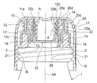
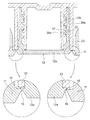
図1は、本発明に係る中栓付き容器の一実施形態を示している。なお、以下の実施形態では、容器の軸芯を鉛直に立てた状態で、上下等の位置関係を説明する。 FIG. 1 shows an embodiment of a stoppered container according to the present invention. In the following embodiment, the positional relationship of the upper and lower sides etc. is explained in a state where the axial center of the container is set vertically.
図1に示した中栓付き容器100は、内容物を収納する容器1と、容器1を封止する蓋組立体(アッセンブリ)3とを備える。蓋組立体3は、容器1の口部1aに嵌着等によって係止又は固定される中栓10と、中栓10を覆うようにして容器1の口部1aに螺着される上蓋20とによって構成されている。
The stoppered
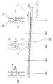
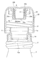
蓋組立体3のうち中栓10は、樹脂製の一体成形品であり、容器1の口部1aに嵌着される本体部分11と、開栓に際して分離される分離部分12とを備えている。この中栓10は、図2に示すように、容器1内に内容物を収容させた後に、その本体部分11が容器1の口部1aに嵌め込むように係止される。そして、図3に示すように、上蓋20を容器1の口部1aに螺合させることによって、中栓10の分離部分12が上蓋20の支持部28に係合される。
The
図2に示すように、中栓10の本体部分11は、容器1の内容物の抽出口である開口10aを形成するもので、筒状基部11aと、当該筒状基部11aの中間部外周面から半径方向外方に張り出すフランジ部11bと、フランジ部11bの外端から下方に延びる環状壁部11cとを有している。これらの筒状基部11aとフランジ部11bと環状壁部11cとによって、容器1の口部1aと嵌合する環状凹部13が画成されている。また、筒状基部11aの上端には、外側に拡がるリップ部14が形成されている。
As shown in FIG. 2, the
中栓10の分離部分12は、底部に配置された円板状の封止体12aと、この封止体12aの外縁から上方に延びる円筒状の部材である連結筒部12bとを備えている。後者の連結筒部12bは、蓋組立体3を構成する第2筒部である。封止体12aの外縁と連結筒部12bの下部との外周側境界部は、環状に延びる連結部15によって中栓10の本体部分11に連結されている。環状の連結部15の下面には、半径方向の断面がV溝状のノッチ16が形成されている。このノッチ16は、開栓時に切断されるスコアーとなっている。連結筒部12bは、本体部分11側の筒状基部11aの同芯内部に離間して配置されている。連結筒部12bの内周面には、雌ねじ17が形成されている。この雌ねじ17は、後述する上蓋20の支持部28に設けられた雄ねじ22と螺合する。
なお、図示の例では、ノッチ16を連結部15の下面に形成しているが、ノッチ16を連結部15の上面又は上下両面に形成することもできる。
The
Although the
図2等に示すように、上蓋20は、樹脂製の一体成形品であり、外観を形成する部分として円筒状の周壁部20aと円形の天井壁20fとを備える。上蓋20は、その内部に周壁部20aと同芯の内部に配置される円筒状の支持部28を備え、周壁部20aと支持部28との間に、大径筒部20cと、中径筒部20dと、小径筒部20eとを備えている。これらの支持部28及び筒部20c,20d,20eは、天井壁20fの下面から下方に延びており、天井壁20fによって上端で支持されることによって同芯状に連設されている。最も内側の支持部28は、蓋組立体3を構成する第1筒部20bであり、その次に内側の小径筒部20eは、蓋組立体3を構成する第3筒部である。
上蓋20において、最外周の周壁部20aの下端内周面には、雌ねじ21が形成されている。この雌ねじ21は、容器1の口部1aの外周面に形成された雄ねじ2と螺合する。また、支持部28又は第1筒部20bの外周面には、雄ねじ22が形成されている。この雄ねじ22は、中栓10の分離部分12に形成された雌ねじ17と螺合する。
As shown in FIG. 2 etc., the
In the
図3を参照して、中栓10の分離部分12に形成された雌ねじ17と、上蓋20の支持部28に形成された雄ねじ22とは、中栓10の分離部分12を上蓋20の支持部28に締め付けて固定するための第1螺合部Aを構成している。また、上蓋20の周壁部20aの雌ねじ21と、容器1の口部1aの雄ねじ2とは、上蓋20の容器1に対する着脱を可能にする第2螺合部Bを構成している。
Referring to FIG. 3, the
これら第1及び第2螺合部A,Bは、互いに逆の螺進関係にある。すなわち、上蓋20の周壁部20aを上から見て反時計方向に回転させることで第2螺合部Bが緩むようにねじ戻される場合、上蓋20の支持部28又は第1筒部20bを反時計方向に回転させることになって第1螺合部Aが締め込まれる。この際、分離部分12にとっては、連結筒部12bの軸心AXに沿った上側が、支持部28又は第1筒部20bに対して下から見て反時計方向の回転によってねじ込みを行う螺進方向になっている。なお、分離部分12にとって、軸心AXに沿った下側は、支持部28又は第1筒部20bに対して下から見て時計方向の回転によってねじ戻しを行う反螺進方向になっている。
上記第1螺合部Aと上記第2螺合部Bとを組み合わせたものは、蓋組立体3が未開封状態にあるとき、上蓋20を容器1に対して緩める方向に回転させることによって分離部分12を本体部分11から離反させて開栓する開栓機構部分として機能する。
The first and second screwing parts A and B are in an opposite screwing relation to each other. That is, when the second screwing portion B is unscrewed so that the second screwing portion B is loosened by rotating the
The combination of the first screwing portion A and the second screwing portion B is separated by rotating the
なお、第1螺合部A、すなわち中栓10の分離部分12に形成される雌ねじ17と、それに噛合する上蓋20の支持部28又は第1筒部20bに形成される雄ねじ22とは、分離部分12を支持部28から引き抜くよりも分離部分12を支持部28に押し込むことを容易にするかえり形状となっている。
具体的には、図4に示すように、第1螺合部Aにおいて雄ねじ22及び雌ねじ17の変形を容易にして連結筒部12bに対して支持部28の嵌め込みを容易にするために、それらのねじ山の基部17b,22bの幅W1をねじ山の頂部17a,22aの幅W2よりも広くするとともに、隣接するねじ山の基部17b,22b間の幅W3をねじ山の頂部の幅W2よりも十分に広くしている。さらに、雄ねじ22及び雌ねじ17のねじ山をかえり形状としている。具体的には、第1螺合部Aを構成する雌ねじ17において、分離部分12を上方に変位させる際の雄ねじ22との螺進側の側面S1が、頂部17a又は中栓10の半径方向内方に向けて下方へ傾斜させて形成され、雌ねじ17の基部17bを基準とする側面S1の傾斜量αは、頂部17aを挟んだ反対側の側面S2の傾斜量βに比較して大きくなっている。言い換えれば、分離部分12の雌ねじ17は、ねじ山の基部17bを基準として中栓10の軸心AXに沿った反螺進方向又は下方向に向けて全体として傾いたような状態となっている。同様に、支持部28の雄ねじ22は、ねじ山の基部22bを基準として軸心AXに沿った反螺進方向又は上方向に向けて全体として傾いたような状態となっている。これにより、組み立て時に第2螺合部Bを機能させて上蓋20を中栓10と接続する際に、逆の螺進関係にある第1螺合部Aのかえり形状が、分離部分12及び支持部28のいずれか一方を他方に押し込むことを許容し、支持部28と分離部分12との強制的な螺合によって支持部28に分離部分12を係合させ固定することができる。また、開栓に際しては、上蓋20をねじ戻すように回転させて第2螺合部Bを緩めることになるが、第1螺合部Aについては、かえり形状が食い込む方向に作用して噛み合うように第1螺合部Aの締め付けが行われるので、分離部分12が支持部28に確実に保持され、分離部分12を中栓10の本体部分11から分離することが簡易かつ迅速になる。
The first screwing portion A, that is, the
Specifically, as shown in FIG. 4, in order to facilitate the deformation of the
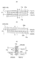
図5は、第1螺合部Aを周方向に展開した概念面であり、図6(a)〜6(c)は、第1螺合部Aの一部を拡大して説明する図である。図5において、角度は、雄ねじ22の下端を基準としたものとなっている。
図示のように、本実施形態において、第1螺合部Aは、360度以上(具体的には720度程度)の範囲に亘って形成されている。この第1螺合部Aでは、中栓10又は分離部分12に設けた雌ねじ17のリードP1が、上蓋20又は支持部28に設けた雄ねじ22のリードP2よりも大きくなるように形成されている。ただし、これらのリードP1,P2の関係は、周回のどの位置でも上蓋20側の雄ねじ22のねじ山22iが、中栓10側の雌ねじ17の隣接する上下のねじ山17j,17k間、つまり雌ねじ17の谷又は溝に収まるように設定される(図6(a)及び6(c)等参照)。結果的に、雌ねじ17のねじ山17jは、上蓋20側の雄ねじ22の隣接する上下のねじ山22h,22i間に収まることとなる(図6(b)等参照)。
具体的に説明すると、雌ねじ17及び雄ねじ22を構成する一対のねじ山が1条ネジ(n=1)であり、ねじの巻き数がmであり、大きい方のリードをP1(mm)、小さい方のリードをP2(mm)とし、ねじ山幅をW(mm)とする。具体的には、雌ねじ17のリードがP1であり、雄ねじ22のリードがP2である。また、ねじ山幅Wは、平均的な値を示しており、ねじ山が直線的な斜面を有する場合、ねじ山の半分の高さにおける山幅を意味する。また、雌ねじ17及び雄ねじ22のねじ山形状が同じ場合、W=SW1=SW2となるが、これらのねじ山形状又はねじ山幅が異なる場合、これらのうちリードの大きな方の第1ねじ山幅をSW1(mm)とし、リードの小さな方の第2ねじ山幅をSW2(mm)としたとき、平均値すなわちW=(SW1+SW2)/2となる。雌ねじ17及び雄ねじ22間のねじの切り始めからねじの切り終わりまでの進み量に関する最大差PMは、リード差ΔP=P1−P2(mm)からPM=m×ΔPで与えられ、ねじ溝幅からねじ山幅を引いた値が上限なので、
PM=m×ΔP≦P1/n−2W
となり、結果的に、リード差ΔPは、
ΔP≦P1/(n・m)−2W/m
で与えられる。なお、雌ねじ17及び雄ねじ22のねじ山形状又はねじ山幅が異なる場合、リード差ΔPは、より詳細には、
ΔP≦P1/(n・m)−(SW1+SW2)/m
で与えられる。
このように、中栓10の分離部分12に設けた雌ねじ17のリードP1に対して、上蓋20の支持部28に設けた雄ねじ22のリードP2が小さくなるように形成することで、中栓10の開栓に際して、第1螺合部Aの係合状態に偏りが生じて分離部分12の周方向における一部が優先的に持ち上げられ、分離部分12を強制的に若干傾けた状態とできる。これにより、分離部分12の周囲のスコアー(ノッチ)16のうち優先的に持ち上げられた部分に剪断応力が集中することになり、この部分から剪断が開始しやすく分離部分12の分離も容易になる。つまり、開栓に際して、比較的小さな力で分離部分12を本体部分11から分離することができる。
以上のリード差ΔPをある程度以上大きく確保することにより、分離部分12を周囲の一箇所で確実に持ち上げることができ、剪断の開始を容易にできる。
FIG. 5 is a conceptual surface in which the first screwing portion A is expanded in the circumferential direction, and FIGS. 6A to 6C are views for explaining a part of the first screwing portion A in an enlarged manner. is there. In FIG. 5, the angle is based on the lower end of the
As illustrated, in the present embodiment, the first screwing portion A is formed over a range of 360 degrees or more (specifically, about 720 degrees). In the first screwing portion A, the lead P1 of the
Specifically, the pair of screw threads constituting the
PM = m × ΔP ≦ P1 / n−2W
As a result, the lead difference ΔP is
ΔP ≦ P1 / (n · m) -2 W / m
Given by In addition, in the case where thread shapes or thread widths of the
ΔP ≦ P1 / (n · m) − (SW1 + SW2) / m
Given by
Thus, the
By securing the above lead difference ΔP to a certain degree or more, the
このように構成された中栓10及び上蓋20は以下のように容器1に組み付けられる。
The
容器1内に内容物を収容した後に、図2に示したように、中栓10の環状凹部13を容器1の口部1aに嵌合させることによって中栓10を容器1に係止させる。この状態では、中栓10によって容器1の口部1aが完全に密封される。
After the contents are accommodated in the
次いで、上蓋20を容器1にねじ付ける。つまり、上蓋20の雌ねじ21を容器1の雄ねじ2に螺合させる。すると、上蓋20は回転(時計方向の回転)しながら降下し、図3に示すように、中径筒部20dの外周面に中栓10のリップ部14の内側が摺接しながら、上蓋20の周壁部20aに設けた雌ねじ21が容器1の口部1aに設けた雄ねじ2に螺合する。
The
その際、上蓋20における第1筒部20bの雄ねじ22が中栓10における連結筒部12bの雌ねじ17に強制的に係合されることになり、第1螺合部Aの組み上げが行われるが、上蓋20における第1筒部20bの雄ねじ22と中栓10における連結筒部12bの雌ねじ17との螺合関係(つまり、第1螺合部Aの逆方向螺合)は、上蓋20における周壁部20aの雌ねじ21と容器1における口部1aの雄ねじ2との螺合関係(つまり、第2螺合部Bの順方向螺合)に対して、逆の螺進関係にあるため、雄ねじ22が雌ねじ17を乗り越えるようにして、すなわち、雄ねじ22のねじ山及び/又は雌ねじ17のねじ山を変形させながら、上蓋20及び第1筒部20bが連結筒部12bに対して降下される。この際、図4を参照して説明したように、第1螺合部Aにおいて雄ねじ22及び雌ねじ17をかえり形状にしてこれらの変形を容易にしてはめ込みを容易にしている。さらに、雄ねじ22及び雌ねじ17のリードが異なるため、ねじ山を乗り越える際に一度にすべての山を乗り越えるのではなく、徐々に山を乗り越えることになり、支持部28に分離部分12を係合させる際の負荷が少なくなる。
At that time, the
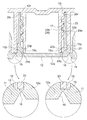
上記のような上蓋20の容器1へのねじ付けにより、第1螺合部Aにおいて雄ねじ22が雌ねじ17を乗り越えたタイミングで、分離部分12の連結筒部(第2筒部)12bの基部内周面12qと、支持部28又は第1筒部20bの先端外周面28qとが当接するとともに、連結筒部(第2筒部)12bの先端内周面12rと、支持部28又は第1筒部20bの基部外周面28rとが当接することによって、分離部分12と支持部28とが弾性的に嵌合する(図3、7等参照)。この結果、分離部分12のうち連結筒部(第2筒部)12bの基部及び先端で分離部分12と支持部28とが嵌合するので、支持部28による分離部分12の保持が安定しシール効果も向上する。
上記と並行して、第1螺合部Aにおいて雄ねじ22が雌ねじ17を乗り越えたタイミングで、上蓋20における小径筒部20eの下端の先端部23が、中栓10の連結筒部12bと連結部15によって画成される凹部18に挿嵌される。上蓋20における小径筒部20eの先端部23が中栓10の凹部18に挿嵌されると、先端部23の先端内周面23pが連結筒部12bの基部外周面12pに当接される。
By screwing the
At the same time as the above, at the timing when the
このようにして中栓10が容器1の口部1aに完全に嵌着され、上蓋20の雌ねじ21が容器1の雄ねじ2に螺合されて、上蓋20の小径筒部20eの先端部23が連結部15に当接した状態になる(図7等参照)。そして、上蓋20が容器1に対して所定のセット位置に締め込まれた状態で商品が流通される。
Thus, the
中栓付き容器100の購入者又は利用者が行う開栓は、上蓋20を容器に対して緩めるように回転(反時計方向の回転)することによって行われる。
The opening or closing performed by the purchaser or user of the stoppered
上蓋20を緩める方向、すなわち反時計回りに回転させると、第2螺合部Bが機能し、上蓋20は容器1の雄ねじ2に沿って上動され、それに伴って、中栓10の分離部分12が、支持部28に対して相対的に反時計方向に回転されるとともに上動される。この際、第1螺合部Aについてはすでにこれ以上締め込むことができない状態にあるため、上蓋20の第1筒部20bと中栓10の分離部分12とが一体的に回転等する。なお、上蓋20と中栓10との組み付け時に、第1螺合部Aの締め込みが不十分であったとしても、上蓋20によって第2螺合部Bを緩めることで、第1螺合部Aが食い込むとともに分離部分12が上蓋20内に引き込まれるようして第1螺合部Aの締め付けが行われ、上蓋20の第1筒部20bと中栓10の分離部分12とが一体的に回転等する。
When the
ところで、本実施形態では、中栓10の雌ねじ17のリードP1が上蓋20の雄ねじ22のリードP2よりも大きくなるように形成されているため、図5に示すように、上蓋20の雄ねじ22の下端の上側面が中栓10の雌ねじ17下端の下側面に当接する。すなわち、その当接部で上蓋20の雄ねじ22下端が中栓10の雌ねじ17の一部分に片当たりする。さらに、上蓋20を回転させると、中栓10の本体部分11が容器1に係止されているために、図8に示すように、分離部分12は本体部分11からスコアー(ノッチ)16の周方向の一部において剪断され、分離部分12が若干傾斜した状態になるとともに上蓋20の回転に伴ってスコアー(ノッチ)16が周方向に向かって順次剪断される。図9に示すように、完全に剪断された分離部分12は、若干傾斜した状態から傾いていない状態に戻されるとともに上蓋20と一体的に上動される。つまり、中栓10に開口10aが形成され容器1又は中栓10が開栓される。
By the way, in the present embodiment, since the lead P1 of the
上記の開栓に際しては、スコアー(ノッチ)16の剪断又は破断の開始及び拡大に伴ってパキンという音が発生し、また、上蓋20の回転に必要なトルクが急激に減少するため、明確な開封感を生じさせることができる。
At the time of the above-mentioned opening, a noise is generated with the start and expansion of the shearing or breaking of the score (notch) 16, and the torque necessary for the rotation of the
その後は、図10に示すように、中栓10の分離部分12は、上蓋20に係止された状態で容器1から離反され、容器1に残された中栓10の本体部分11の開口10aは、完全に開放される。それによって容器1内の内容物を注ぐことができるようになる。
Thereafter, as shown in FIG. 10, the separated
開栓後の分離部分12は、上蓋20の雄ねじ22と分離部分12の雌ねじ17との螺合と、連結筒部12bが第1筒部20b及び小径筒部20eによって挟持されることとによって緩みが防止され、上蓋20に確実に保持される。
この点についてより詳細に説明すると、第1螺合部Aにおいて、雄ねじ22のリードP2と雌ねじ17のリードP1とが異なるために、分離部分12と支持部28が嵌合した後も、分離部分12が支持部28の中で傾きやすく、ガタツキやすく、緩みやすいという傾向が生じる。そこで、図7に示すように、分離部分12の基部外周面12pと基部内周面12qとを、支持部28の先端外周面28q及び小径筒部20e側の先端内周面23pとで挟み込む構造とすることにより、分離部分12を支持部28と小径筒部20eとの間にがっちりと固定することができる。
The separated
Explaining this point in more detail, because the lead P2 of the
内容物の部分的な使用後に容器1を閉じるために、上蓋20を容器1の口部1aに締結すると、上蓋20の小径筒部20eの先端部23が中栓10の本体部分11の筒状基部11aから内方に張出す連結部15の剪断残部に当接し、さらに、筒状基部11aのリップ部14が上蓋20の中径筒部20dの外周面、さらには天井壁20fの下面に当接して、容器1内の内容物に対する密封が図られる。
When the
なお、上記実施形態では、容器1がペットボトル又はその他のボトル状であることを前提としているが、容器1は、他の合成樹脂,ガラス,金属であってもよく、また、フィルムからなる袋状の部材に口部を設けたものとすることができ、或いは多面体その他の紙パックとすることもできる。
In the above embodiment, it is assumed that the
また、上記実施形態では、上蓋20を容器1に螺合させているが、上蓋20を中栓10の本体部分11の外周に螺合させてもよい。つまり、容器1の口部1aの雄ねじ2に代えて本体部分11の外周に雄ねじを設け、この中栓10側の雄ねじと、周壁部20aの雌ねじ21とによって第2螺合部Bを構成することができる。
Further, although the
上記実施形態では、容器1に中栓10を組み付けた後に、上蓋20を容器1にねじ付けているが、上蓋20に中栓10をねじ付けた後に、上蓋20及び中栓10の組立体を容器1の口部1aに嵌合させることもできる。
In the above embodiment, the
上記実施形態では、購入者が中栓付き容器100を開栓する際に、上蓋20を容器に対して緩めるように回転(反時計方向の回転)するとしているが、中栓付き容器100を開栓する際に、上蓋20を容器に対して締めるように回転(時計方向の回転)させこともでき、この場合、第1螺合部Aが緩む方に動作し、中栓10の分離部分12が上蓋20に対して強制的に押し下げられる。この際、雌ねじ17や雄ねじ22をかえり形状とする必要はなく、雌ねじ17のリードP1が上蓋20の雄ねじ22のリードP2よりも大きくなるように形成することで、雄ねじ22の上端が雌ねじ17に一部分に片当たりする。これにより、分離部分12はスコアー16の周方向の一部において剪断され、上蓋20の回転に伴ってスコアー16が周方向に沿って順次剪断され、完全的に剪断された分離部分12は、上蓋20と一体的に上動され、中栓10が開栓される。
In the above embodiment, when the purchaser opens the stoppered
上記実施形態では、中栓10の雌ねじ17のリードP1に対して、上蓋20の雄ねじ22のリードP2が小さくなるように形成しているが、リードP1に対してリードP2が大きくなるように形成してもよい。この場合には、図5において、ねじ22の上端がねじ17に当接するとともに、ねじ22の下端がねじ17から離間することになる。
In the above embodiment, the lead P2 of the
上記実施形態では、第1螺合部Aを構成する雌ねじ17と雄ねじ22とが1条ねじであるとしたが、雌ねじ17や雄ねじ22は、2条ねじ、或いは3条以上のねじとすることができる。
例えば雌ねじ17及び雄ねじ22を3条以上のねじ山とした場合、雌ねじ17及び雄ねじ22の一方のリードを他方のリードと異なるものとする。この際、例えば雌ねじ17のリードを単に相対的に大きくするのではなく、雌ねじ17を構成する3条以上のねじ山の各下端位置を調整することで、分離部分12の周囲の一箇所で雌ねじ17と雄ねじ22とが片当たりするように調整する。
In the above embodiment, although the
For example, in the case where the
上記実施形態では、第1螺合部Aを構成する雌ねじ17と雄ねじ22とが連続するねじ山からなるものとしたが、雌ねじ17又は雄ねじ22の一方を、複数の山部分に分割されたものとすることもできる。さらに、雌ねじ17や雄ねじ22の長さ又は角度は、両者が噛み合った初期段階で略一周以上の重なりがあることが望ましいが、このようなねじ山の重なりは、用途や角度に応じて適宜調整することができる。
In the above embodiment, although the
1…容器、 1a…口部、 2…雄ねじ、 3…蓋組立体、 10…中栓、 10a…開口、 11…本体部分、 11a…筒状基部、 11b…フランジ部、 11c…環状壁部、 12…分離部分、 12a…封止体、 12b…連結筒部、12c…フランジ、 13…環状凹部、 14…リップ部、 15…連結部、 16…ノッチ(スコアー)、 17…雌ねじ、 18…凹部、 20…上蓋、 20a…周壁部、 20b…第1筒部、 20c…大径筒部、 20d…中径筒部、 20e…小径筒部、 20f…天井壁、 21…雌ねじ、 22…雄ねじ、 23…先端部、 28…支持部、 100…中栓付き容器、 A…第1螺合部、 B…第2螺合部
DESCRIPTION OF
Claims (9)
前記上蓋は、開栓に際して前記分離部分を捕捉して当該分離部分を前記中栓から分離する支持部を有し、
前記分離部分と前記支持部との間に設けられた第1螺合部によって前記分離部分と前記支持部とが連結され、
前記第1螺合部のうち支持部側に設けられたねじ山のリードと、前記第1螺合部のうち前記分離部分側に設けられたねじ山のリードとが異なることを特徴とする中栓付き容器。 And an upper lid attached to the container so as to cover the inner plug.
The upper lid has a support that captures the separated portion upon opening and separates the separated portion from the inner plug,
The separation portion and the support portion are connected by a first screwing portion provided between the separation portion and the support portion,
The lead of the thread provided on the support side of the first screwing portion and the lead of the thread provided on the separation portion side of the first screwing portion are different. Stopper container.
ΔP≦P1/(m・n)−2W/m
で与えられることを特徴とする請求項1〜3のいずれか一項に記載の中栓付き容器。 When the pair of screw threads constituting the first screwing part is an n-slot screw with a number m of turns, the larger lead is P1, the smaller lead is P2, and the screw thread width is W, lead The difference ΔP = P1-P2 is
ΔP ≦ P1 / (m · n) −2 W / m
A stoppered container according to any one of the preceding claims, characterized in that
第2螺合部は、前記第1螺合部に対して逆のねじ螺合関係にあることを特徴とする請求項1〜4のいずれか一項に記載の中栓付き容器。 The second screwing portion provided between the upper lid and the container or the inner plug enables the upper lid to be attached and detached.
The container with a stopper according to any one of claims 1 to 4, wherein the second screwing portion is in a reverse screwing relationship with the first screwing portion.
前記分離部分は、前記中栓の本体部分に連結された封止体から上方に延び前記第1筒部を周囲から囲む第2筒部を有し、
前記第2筒部と前記第1筒部とが前記第1螺合部以外の部分で当接することによって、前記分離部分と前記支持部とが嵌合することを特徴とする請求項7に記載の中栓付き容器。 The support portion has a first cylindrical portion extending downward from the lower surface of the ceiling wall of the upper lid,
The separation portion has a second cylindrical portion extending upward from a sealing body connected to the main body portion of the inner plug and surrounding the first cylindrical portion from the periphery;
The separation portion and the support portion are fitted together by the second cylindrical portion and the first cylindrical portion being in contact with each other at a portion other than the first screwing portion. Inside the container with a stopper.
前記第3筒部の先端は、前記上蓋を前記容器に装着させた状態で、前記中栓の筒状の本体部分と前記分離部分との連結部の少なくとも一部に当接することを特徴とする請求項8に記載の中栓付き容器。 The upper lid has, outside the second tubular portion, a third tubular portion surrounding the second tubular portion from the periphery in a state where the upper lid is attached to the container,
The tip end of the third cylindrical portion abuts on at least a part of a connecting portion between the cylindrical main body portion of the inner plug and the separation portion in a state where the upper lid is attached to the container. A container with an inner stopper according to claim 8.
Priority Applications (1)
| Application Number | Priority Date | Filing Date | Title |
|---|---|---|---|
| JP2015147251A JP6532784B2 (en) | 2015-07-24 | 2015-07-24 | Inside stoppered container |
Applications Claiming Priority (1)
| Application Number | Priority Date | Filing Date | Title |
|---|---|---|---|
| JP2015147251A JP6532784B2 (en) | 2015-07-24 | 2015-07-24 | Inside stoppered container |
Related Child Applications (1)
| Application Number | Title | Priority Date | Filing Date |
|---|---|---|---|
| JP2019015247A Division JP2019069822A (en) | 2019-01-31 | 2019-01-31 | Container with inside plug |
Publications (3)
| Publication Number | Publication Date |
|---|---|
| JP2017024773A JP2017024773A (en) | 2017-02-02 |
| JP2017024773A5 JP2017024773A5 (en) | 2017-06-01 |
| JP6532784B2 true JP6532784B2 (en) | 2019-06-19 |
Family
ID=57945226
Family Applications (1)
| Application Number | Title | Priority Date | Filing Date |
|---|---|---|---|
| JP2015147251A Active JP6532784B2 (en) | 2015-07-24 | 2015-07-24 | Inside stoppered container |
Country Status (1)
| Country | Link |
|---|---|
| JP (1) | JP6532784B2 (en) |
Families Citing this family (4)
| Publication number | Priority date | Publication date | Assignee | Title |
|---|---|---|---|---|
| JP6875892B2 (en) * | 2017-03-17 | 2021-05-26 | 東罐興業株式会社 | Sealing device |
| JP6875893B2 (en) * | 2017-03-17 | 2021-05-26 | 東罐興業株式会社 | Sealing device |
| JP6875894B2 (en) * | 2017-03-17 | 2021-05-26 | 東罐興業株式会社 | Sealing device |
| JP7134117B2 (en) * | 2019-02-28 | 2022-09-09 | 株式会社吉野工業所 | cap |
Family Cites Families (3)
| Publication number | Priority date | Publication date | Assignee | Title |
|---|---|---|---|---|
| JPS56141154U (en) * | 1980-03-27 | 1981-10-24 | ||
| JP5159614B2 (en) * | 2006-04-28 | 2013-03-06 | 東罐興業株式会社 | Container with cap and lid |
| WO2015083724A1 (en) * | 2013-12-06 | 2015-06-11 | 東罐興業株式会社 | Container sealing device |
-
2015
- 2015-07-24 JP JP2015147251A patent/JP6532784B2/en active Active
Also Published As
| Publication number | Publication date |
|---|---|
| JP2017024773A (en) | 2017-02-02 |
Similar Documents
| Publication | Publication Date | Title |
|---|---|---|
| JP6509741B2 (en) | Container sealing device | |
| JP6532784B2 (en) | Inside stoppered container | |
| JP6474870B2 (en) | Container sealing device | |
| US6227391B1 (en) | Closure assembly for pressurized containers | |
| JP4938462B2 (en) | Anti-tamper closure with anti-tamper mode | |
| AU2007211943A1 (en) | Audible closing feature for a threaded container and lid | |
| CN109562877A (en) | Closure member with tamper-evident band | |
| US11292643B2 (en) | Closure for a spout of a flexible thin-walled package | |
| JP2019069822A (en) | Container with inside plug | |
| JP6177677B2 (en) | Container sealing device | |
| JP5492392B2 (en) | container | |
| JP2008280048A (en) | Bottle cap | |
| JP6835515B2 (en) | Container sealing device | |
| JP2009029445A (en) | Bottle cap | |
| JP2007153420A (en) | Cap with pilfer-proof band | |
| JP2009126527A (en) | Bottle cap | |
| JP2005075427A (en) | Cap for pet bottle | |
| JP2019059532A (en) | Sealing device | |
| JP5995479B2 (en) | Container lid | |
| JP4502200B2 (en) | Sealing cap | |
| JP6910117B2 (en) | Synthetic resin cap | |
| JPH072421Y2 (en) | Container | |
| JP2019059533A (en) | Sealing device | |
| JP4538080B1 (en) | Fastening member | |
| JP2007118967A (en) | Pilfer-proof cap made of metallic plate |
Legal Events
| Date | Code | Title | Description |
|---|---|---|---|
| A521 | Written amendment |
Free format text: JAPANESE INTERMEDIATE CODE: A523 Effective date: 20170414 |
|
| A625 | Written request for application examination (by other person) |
Free format text: JAPANESE INTERMEDIATE CODE: A625 Effective date: 20180213 |
|
| A977 | Report on retrieval |
Free format text: JAPANESE INTERMEDIATE CODE: A971007 Effective date: 20181108 |
|
| A131 | Notification of reasons for refusal |
Free format text: JAPANESE INTERMEDIATE CODE: A131 Effective date: 20181204 |
|
| A521 | Written amendment |
Free format text: JAPANESE INTERMEDIATE CODE: A523 Effective date: 20190131 |
|
| TRDD | Decision of grant or rejection written | ||
| A01 | Written decision to grant a patent or to grant a registration (utility model) |
Free format text: JAPANESE INTERMEDIATE CODE: A01 Effective date: 20190507 |
|
| A61 | First payment of annual fees (during grant procedure) |
Free format text: JAPANESE INTERMEDIATE CODE: A61 Effective date: 20190522 |
|
| R150 | Certificate of patent or registration of utility model |
Ref document number: 6532784 Country of ref document: JP Free format text: JAPANESE INTERMEDIATE CODE: R150 |