JP6531053B2 - PRINTING APPARATUS, ITS CONTROL METHOD, AND PROGRAM - Google Patents
PRINTING APPARATUS, ITS CONTROL METHOD, AND PROGRAM Download PDFInfo
- Publication number
- JP6531053B2 JP6531053B2 JP2016051284A JP2016051284A JP6531053B2 JP 6531053 B2 JP6531053 B2 JP 6531053B2 JP 2016051284 A JP2016051284 A JP 2016051284A JP 2016051284 A JP2016051284 A JP 2016051284A JP 6531053 B2 JP6531053 B2 JP 6531053B2
- Authority
- JP
- Japan
- Prior art keywords
- stamp
- nozzle
- ink
- sheet
- image defect
- Prior art date
- Legal status (The legal status is an assumption and is not a legal conclusion. Google has not performed a legal analysis and makes no representation as to the accuracy of the status listed.)
- Active
Links
Images


Classifications
-
- B—PERFORMING OPERATIONS; TRANSPORTING
- B41—PRINTING; LINING MACHINES; TYPEWRITERS; STAMPS
- B41J—TYPEWRITERS; SELECTIVE PRINTING MECHANISMS, i.e. MECHANISMS PRINTING OTHERWISE THAN FROM A FORME; CORRECTION OF TYPOGRAPHICAL ERRORS
- B41J2/00—Typewriters or selective printing mechanisms characterised by the printing or marking process for which they are designed
- B41J2/005—Typewriters or selective printing mechanisms characterised by the printing or marking process for which they are designed characterised by bringing liquid or particles selectively into contact with a printing material
- B41J2/01—Ink jet
- B41J2/015—Ink jet characterised by the jet generation process
- B41J2/04—Ink jet characterised by the jet generation process generating single droplets or particles on demand
- B41J2/045—Ink jet characterised by the jet generation process generating single droplets or particles on demand by pressure, e.g. electromechanical transducers
- B41J2/04501—Control methods or devices therefor, e.g. driver circuits, control circuits
- B41J2/04558—Control methods or devices therefor, e.g. driver circuits, control circuits detecting presence or properties of a dot on paper
-
- B—PERFORMING OPERATIONS; TRANSPORTING
- B41—PRINTING; LINING MACHINES; TYPEWRITERS; STAMPS
- B41J—TYPEWRITERS; SELECTIVE PRINTING MECHANISMS, i.e. MECHANISMS PRINTING OTHERWISE THAN FROM A FORME; CORRECTION OF TYPOGRAPHICAL ERRORS
- B41J2/00—Typewriters or selective printing mechanisms characterised by the printing or marking process for which they are designed
- B41J2/005—Typewriters or selective printing mechanisms characterised by the printing or marking process for which they are designed characterised by bringing liquid or particles selectively into contact with a printing material
- B41J2/01—Ink jet
- B41J2/015—Ink jet characterised by the jet generation process
- B41J2/04—Ink jet characterised by the jet generation process generating single droplets or particles on demand
- B41J2/045—Ink jet characterised by the jet generation process generating single droplets or particles on demand by pressure, e.g. electromechanical transducers
- B41J2/04501—Control methods or devices therefor, e.g. driver circuits, control circuits
- B41J2/0451—Control methods or devices therefor, e.g. driver circuits, control circuits for detecting failure, e.g. clogging, malfunctioning actuator
-
- B—PERFORMING OPERATIONS; TRANSPORTING
- B41—PRINTING; LINING MACHINES; TYPEWRITERS; STAMPS
- B41J—TYPEWRITERS; SELECTIVE PRINTING MECHANISMS, i.e. MECHANISMS PRINTING OTHERWISE THAN FROM A FORME; CORRECTION OF TYPOGRAPHICAL ERRORS
- B41J2/00—Typewriters or selective printing mechanisms characterised by the printing or marking process for which they are designed
- B41J2/005—Typewriters or selective printing mechanisms characterised by the printing or marking process for which they are designed characterised by bringing liquid or particles selectively into contact with a printing material
- B41J2/01—Ink jet
- B41J2/015—Ink jet characterised by the jet generation process
- B41J2/04—Ink jet characterised by the jet generation process generating single droplets or particles on demand
- B41J2/045—Ink jet characterised by the jet generation process generating single droplets or particles on demand by pressure, e.g. electromechanical transducers
- B41J2/04501—Control methods or devices therefor, e.g. driver circuits, control circuits
- B41J2/04586—Control methods or devices therefor, e.g. driver circuits, control circuits controlling heads of a type not covered by groups B41J2/04575 - B41J2/04585, or of an undefined type
-
- B—PERFORMING OPERATIONS; TRANSPORTING
- B41—PRINTING; LINING MACHINES; TYPEWRITERS; STAMPS
- B41J—TYPEWRITERS; SELECTIVE PRINTING MECHANISMS, i.e. MECHANISMS PRINTING OTHERWISE THAN FROM A FORME; CORRECTION OF TYPOGRAPHICAL ERRORS
- B41J2/00—Typewriters or selective printing mechanisms characterised by the printing or marking process for which they are designed
- B41J2/005—Typewriters or selective printing mechanisms characterised by the printing or marking process for which they are designed characterised by bringing liquid or particles selectively into contact with a printing material
- B41J2/01—Ink jet
- B41J2/21—Ink jet for multi-colour printing
- B41J2/2132—Print quality control characterised by dot disposition, e.g. for reducing white stripes or banding
- B41J2/2135—Alignment of dots
-
- B—PERFORMING OPERATIONS; TRANSPORTING
- B41—PRINTING; LINING MACHINES; TYPEWRITERS; STAMPS
- B41J—TYPEWRITERS; SELECTIVE PRINTING MECHANISMS, i.e. MECHANISMS PRINTING OTHERWISE THAN FROM A FORME; CORRECTION OF TYPOGRAPHICAL ERRORS
- B41J2/00—Typewriters or selective printing mechanisms characterised by the printing or marking process for which they are designed
- B41J2/005—Typewriters or selective printing mechanisms characterised by the printing or marking process for which they are designed characterised by bringing liquid or particles selectively into contact with a printing material
- B41J2/01—Ink jet
- B41J2/21—Ink jet for multi-colour printing
- B41J2/2132—Print quality control characterised by dot disposition, e.g. for reducing white stripes or banding
- B41J2/2142—Detection of malfunctioning nozzles
-
- B—PERFORMING OPERATIONS; TRANSPORTING
- B41—PRINTING; LINING MACHINES; TYPEWRITERS; STAMPS
- B41J—TYPEWRITERS; SELECTIVE PRINTING MECHANISMS, i.e. MECHANISMS PRINTING OTHERWISE THAN FROM A FORME; CORRECTION OF TYPOGRAPHICAL ERRORS
- B41J2/00—Typewriters or selective printing mechanisms characterised by the printing or marking process for which they are designed
- B41J2/005—Typewriters or selective printing mechanisms characterised by the printing or marking process for which they are designed characterised by bringing liquid or particles selectively into contact with a printing material
- B41J2/01—Ink jet
- B41J2/21—Ink jet for multi-colour printing
- B41J2/2132—Print quality control characterised by dot disposition, e.g. for reducing white stripes or banding
- B41J2/2146—Print quality control characterised by dot disposition, e.g. for reducing white stripes or banding for line print heads
-
- B—PERFORMING OPERATIONS; TRANSPORTING
- B41—PRINTING; LINING MACHINES; TYPEWRITERS; STAMPS
- B41J—TYPEWRITERS; SELECTIVE PRINTING MECHANISMS, i.e. MECHANISMS PRINTING OTHERWISE THAN FROM A FORME; CORRECTION OF TYPOGRAPHICAL ERRORS
- B41J29/00—Details of, or accessories for, typewriters or selective printing mechanisms not otherwise provided for
- B41J29/38—Drives, motors, controls or automatic cut-off devices for the entire printing mechanism
Description
本発明は印刷装置及びその制御方法並びにプログラムに係り、特に印刷後の記録メディア(印刷用紙)から印刷不良を検出するための印刷装置及びその制御方法並びにプログラムに関する。 The present invention relates to a printing apparatus and its control method and program, and more particularly to a printing apparatus for detecting a printing defect from a recording medium (printing paper) after printing, and its control method and program.
印刷装置によって画像等が印刷された記録メディア(印刷用紙)から不良が検出された場合に、不良が検出された印刷物にスタンプ等を付与することが提案されている。 It has been proposed that, when a defect is detected from a recording medium (printing paper) on which an image or the like is printed by a printing apparatus, a stamp or the like is attached to a printed matter in which the defect is detected.
特許文献1には、第1のスタンパー装置及び第2のスタンパー装置を備えたインクジェット記録装置が開示されている。第1のスタンパー装置は、インラインセンサ58の読取結果に基づき画像不良が発生していると判定された用紙の先端エッジにインクを付着させ、第2のスタンパー装置は、予め設定された仕分け部数に基づいて、仕分け区分に該当する用紙の先端エッジにインクを付着させる(特許文献1の段落[0140]から[0142])。
Patent Document 1 discloses an inkjet recording apparatus provided with a first stamper device and a second stamper device. The first stamper device causes ink to adhere to the leading edge of the sheet determined to have an image defect based on the reading result of the in-
特許文献2には、ミス印刷をした用紙の反対面に必要な印刷を行う場合に、自動的にミス印刷面を明示する「裏面マーク」を付す裏面マーク付与手段を備えたインクジェット印刷装置が開示されている(特許文献2の段落[0002]から[0004]、[0028]及び[0032])。 Patent Document 2 discloses an ink jet printing apparatus provided with a back surface mark applying means for adding a "back surface mark" that automatically specifies a misprinted surface when performing printing required on the opposite surface of a misprinted sheet. (Paragraphs [0002] to [0004], [0028] and [0032] of Patent Document 2).
特許文献3には、検査部と、不良印刷マーキング部とを有する印刷部(表印刷部及び裏印刷部)を備えた印刷システムが開示されている。検査部は、印刷イメージデータと検査イメージデータとに基づいて、印刷状態が適切か否かを判定する(特許文献3の段落[0015]及び[0033])。不良印刷マーキング部は、検査部で印刷結果が不良印刷物であると判定された場合に、その印刷物の所定の領域に既に印刷されている内容を塗り潰して識別不能にし、一見して不良品であることが判り、その印刷物がもはや元の印刷物として使用され得ないようにする塗り潰し用印刷ヘッドを有している(特許文献3の段落[0045]及び[0046])。 Patent Document 3 discloses a printing system provided with a printing unit (front printing unit and back printing unit) having an inspection unit and a defective printing marking unit. The inspection unit determines whether the printing state is appropriate based on the print image data and the inspection image data (paragraphs [0015] and [0033] of Patent Document 3). When the inspection unit determines that the printed result is a defective printed matter, the defective print marking unit fills in the content already printed in a predetermined area of the printed matter to make it unidentifiable, and is apparently a defective product It has been found that it has a fill print head which makes it possible that the printed material can no longer be used as the original printed material (paragraphs [0045] and [0046] of patent document 3).
特許文献1に記載の技術では、不良が検出された場合に印刷用紙に付与(押印)されるスタンプは一種類だけであった。このため、印刷用紙にスタンプを押印した後に、オペレータが印刷用紙の不良の程度を検査して印刷用紙の仕分けを行う場合、オペレータは、スタンプの有無によって不良の検出の有無を確認することしかできなかった。この場合、不良の検知感度を高く設定するほど、スタンプが付与される印刷用紙の枚数が増加する。この結果、オペレータによる検査作業の負荷が増大するという問題があった。また、不良の検知感度を低く設定するほど、スタンプが付与される印刷用紙の枚数が減少する。この結果、軽微な不良が見過ごされてしまい、不良がある印刷用紙が適切に検出されず、不良印刷用紙がエンドユーザーに流出するおそれがあった。 In the technique described in Patent Document 1, only one type of stamp is applied (imprinted) to a printing sheet when a defect is detected. For this reason, when the operator inspects the degree of defect of the printing paper and seals the printing paper after imprinting the stamp on the printing paper, the operator can only confirm the presence or absence of the detection of the defect by the presence or absence of the stamp. It was not. In this case, as the defect detection sensitivity is set higher, the number of printing sheets to which the stamp is applied increases. As a result, there is a problem that the load of the inspection work by the operator increases. Further, as the defect detection sensitivity is set to be lower, the number of printing sheets to which the stamp is applied is reduced. As a result, a minor defect may be overlooked, and a defective print sheet may not be properly detected, and the defective print sheet may flow out to the end user.
特許文献2に記載の技術は、いわゆる裏紙を再利用する場合に、ミス印刷面に裏面マークを付与するものであり、オペレータによる不良印刷用紙の仕分け作業を支援するためのものではなかった。 The technology described in Patent Document 2 applies a back surface mark to the misprinted surface when reusing a so-called backing sheet, and is not for supporting an operator's sorting operation of defective printing sheets.
特許文献3に記載の技術は、宛名付きの請求書などの場合には宛名部分を塗り潰し、証券又は金券などの場合にはその券の金額部分などを塗り潰して使用不能と判るようにするものであり、オペレータによる不良印刷用紙の仕分け作業を支援するためのものではなかった。 In the technology described in Patent Document 3, the address portion is filled in the case of a bill with an address, etc., and in the case of securities or cash vouchers, the amount portion of the ticket is covered to make it possible to recognize that it can not be used. Yes, it was not intended to assist the operator in sorting defective print sheets.
本発明はこのような事情に鑑みてなされたもので、印刷不良が検出された記録メディア(印刷用紙)の仕分け作業を支援するための印刷装置及びその制御方法並びにプログラムを提供することを目的とする。 The present invention has been made in view of such circumstances, and it is an object of the present invention to provide a printing apparatus for supporting the sorting operation of recording media (printing paper) in which a printing defect is detected, a control method thereof and a program. Do.
上記課題を解決するために、本発明の第1の態様に係る印刷装置は、複数のノズルからインクを吐出して記録メディアの表面に画像を記録するインクジェットヘッドを備える画像記録部と、表面に画像が記録された記録メディアからインクジェットヘッドのノズルの吐出曲がり量と画像不良を検出する画像不良検出部と、画像不良が検出された場合に、記録メディアに画像不良の存在を示すスタンプを付与するスタンパー装置と、ノズルの吐出曲がり量の大きさに応じて、スタンパー装置によるスタンプの付与の態様を異ならせるスタンプ制御部とを備える。 In order to solve the above-mentioned subject, a printing device concerning the 1st mode of the present invention discharges ink from a plurality of nozzles, and has an image recording part provided with an ink jet head which records an image on the surface of recording media, An image defect detection unit that detects an ejection deflection amount of an ink jet head nozzle and an image defect from a recording medium on which an image is recorded, and a stamp indicating an image defect is provided to the recording medium when an image defect is detected. A stamp control unit is provided, which makes the stamp application by the stamper device different according to the size of the discharge bending amount of the nozzle.
第1の態様によれば、ノズルに起因する画像不良(スジ)が検出された場合に、そのスジの程度に応じてスタンプの種類を変えることができる。これにより、オペレータは、スタンプからスジの程度を認識することが可能になるので、本実施形態によれば、オペレータによる検品作業を支援し、検品作業の効率化を実現することが可能になる。 According to the first aspect, when an image defect (line) caused by a nozzle is detected, the type of stamp can be changed according to the degree of the line. Thus, the operator can recognize the degree of streaks from the stamp. Therefore, according to the present embodiment, the inspection work by the operator can be supported, and the efficiency of the inspection work can be realized.
本発明の第2の態様に係る印刷装置は、第1の態様において、画像不良検出部が、インクの色ごとに画像不良の検出を行い、かつ、画像不良として検出するノズルの吐出曲がり量の閾値を異ならせるようにしたものである。 In the printing device according to the second aspect of the present invention, in the first aspect, the image defect detection unit detects an image defect for each color of ink and detects the amount of ejection bending of the nozzle detected as an image defect. The threshold is made different.
第2の態様によれば、インクの色ごとに画像不良の視認性が異なることに考慮して、閾値を調整することにより、画像不良の検出を適切に行うことが可能になる。 According to the second aspect, it is possible to appropriately detect an image defect by adjusting the threshold value in consideration of the fact that the visibility of the image defect differs depending on the color of the ink.
本発明の第3の態様に係る印刷装置は、第1又は第2の態様において、インクジェットヘッドが、少なくとも黒のインクを吐出し、画像不良検出部が、インクの色ごとに画像不良の検出を行い、かつ、黒のインクによる画像不良の検出を、ほかの色のインクによる画像不良の検出よりも前に行うようにしたものである。 In the printing apparatus according to the third aspect of the present invention, in the first or second aspect, the ink jet head discharges at least black ink, and the image defect detection unit detects image defects for each color of ink. In addition, the detection of the image defect by the black ink is performed before the detection of the image defect by the ink of the other color.
本発明の第4の態様に係る印刷装置は、第1から第3のいずれかの態様において、インクジェットヘッドが、少なくとも黒のインクを吐出し、画像不良検出部が、インクの色ごとに画像不良の検出を行い、かつ、黒のインクについて画像不良の検出に用いるノズルの吐出曲がり量の閾値を、ほかの色のインクについて画像不良の検出に用いるノズルの吐出曲がり量の閾値よりも小さくするようにしたものである。 In the printing apparatus according to the fourth aspect of the present invention, in any of the first to third aspects, the inkjet head discharges at least black ink, and the image defect detection unit detects an image defect for each color of ink. To make the threshold value of the discharge deflection amount of the nozzle used for detecting the image defect for black ink smaller than the threshold value of the discharge deflection amount of the nozzle used for detecting the image defect for ink of other colors The
第4の態様によれば、スジの視認性が比較的高い黒のインクに対して、厳格な画像不良の検出を行うことが可能になる。なお、スジの視認性が比較的低いインクについては、ノズルの曲がりの検出を行わないようにすることも可能である。 According to the fourth aspect, it is possible to perform severe image defect detection for black ink having relatively high visibility of streaks. In addition, it is also possible not to detect the bending of a nozzle about the ink whose visibility of a streak is comparatively low.
本発明の第5の態様に係る印刷装置は、第3又は第4の態様において、インクジェットヘッドが、黄のインクを吐出し、画像不良検出部が、黄のインクについて画像不良の検出に用いるノズルの吐出曲がり量の閾値を、ほかの色のインクについて画像不良の検出に用いるノズルの吐出曲がり量の閾値よりも大きくするようにしたものである。 The printing apparatus according to the fifth aspect of the present invention is the nozzle according to the third or fourth aspect, wherein the ink jet head ejects yellow ink, and the image defect detection unit detects the image defect of the yellow ink. The threshold value of the ejection bending amount is set to be larger than the threshold value of the ejection bending amount of the nozzle used to detect the image defect for the ink of the other color.
第5の態様によれば、スジの視認性が比較的低い黄のインクに対して、画像不良の検出の精度を低くすることが可能になる。 According to the fifth aspect, it is possible to lower the accuracy of the detection of the image defect with respect to the yellow ink whose visibility of the streak is relatively low.
本発明の第6の態様に係る印刷装置は、第1から第5のいずれかの態様において、スタンプ制御部が、ノズルの吐出曲がり量に応じて、スタンパー装置によって付与されるスタンプの色、数及び位置の少なくとも1つを異ならせるようにしたものである。 In the printing apparatus according to the sixth aspect of the present invention, in any one of the first to fifth aspects, the stamp control unit controls the color, the number of the stamp applied by the stamper device according to the discharge bending amount of the nozzle. And at least one of the positions are made different.
本発明の第7の態様に係る印刷装置は、第6の態様において、スタンパー装置が、スタンプの色、数及び位置の少なくとも1つが異なる複数種類のスタンプを付与するために複数設けられるようにしたものである。 In a printing apparatus according to a seventh aspect of the present invention, in the sixth aspect, a plurality of stamper devices are provided to apply a plurality of types of stamps different in at least one of the color, the number, and the position of the stamp. It is a thing.
本発明の第8の態様に係る印刷装置は、第6の態様において、スタンパー装置が、インクジェットヘッドのインクの色ごとに、ノズルの吐出曲がり量に応じて異なる複数種類のスタンプを付与するために複数設けられるようにしたものである。 In the printing apparatus according to the eighth aspect of the present invention, in the sixth aspect, the stamper device applies a plurality of different types of stamps according to the discharge bending amount of the nozzle for each ink color of the inkjet head. It is intended to provide a plurality.
本発明の第9の態様に係る印刷装置は、第1から第8のいずれかの態様において、オペレータの操作入力を受け付けて、スタンプの付与条件を設定するための操作部を更に備える。 The printing apparatus according to the ninth aspect of the present invention further includes an operation unit for receiving a user's operation input and setting a stamp application condition in any of the first to eighth aspects.
本発明の第10の態様に係る印刷装置は、第1から第9のいずれかの態様において、ノズルの吐出曲がり量の大きさに応じて、記録メディアを異なる場所に排出するようにしたものである。 A printing apparatus according to a tenth aspect of the present invention is the printing apparatus according to any one of the first to ninth aspects, wherein the recording medium is discharged to different places according to the size of the discharge bending amount of the nozzle. is there.
本発明の第11の態様に係る印刷装置の制御方法は、複数のノズルを有するインクジェットヘッドを備えた画像記録部によって表面に画像が記録された記録メディアからインクジェットヘッドのノズルの吐出曲がり量と画像不良を検出する画像不良検出工程と、画像不良が検出された場合に、記録メディアに画像不良の存在を示すスタンプをスタンパー装置によって付与するスタンプ工程であって、ノズルの吐出曲がり量の大きさに応じて、スタンパー装置によるスタンプの付与の態様を異ならせるスタンプ工程とを備える。 According to an eleventh aspect of the present invention, there is provided a control method of a printing apparatus, comprising: a recording medium on which an image is recorded on a surface by an image recording unit having an ink jet head having a plurality of nozzles; The image defect detection step of detecting a defect and the stamp step of applying a stamp indicating the presence of the image defect to the recording medium by the stamper device when the image defect is detected In response, a stamping step is performed to make the manner of applying the stamp by the stamper device different.
本発明の第12の態様に係る印刷装置制御プログラムは、複数のノズルを有するインクジェットヘッドを備えた画像記録部によって表面に画像が記録された記録メディアからインクジェットヘッドのノズルの吐出曲がり量と画像不良を検出する画像不良検出機能と、画像不良が検出された場合に、記録メディアに画像不良の存在を示すスタンプをスタンパー装置によって付与するスタンプ機能であって、ノズルの吐出曲がり量の大きさに応じて、スタンパー装置によるスタンプの付与の態様を異ならせるスタンプ機能とをコンピュータに実現させる。 A printing apparatus control program according to a twelfth aspect of the present invention is a recording medium having an image recorded on the surface thereof by an image recording unit having an ink jet head having a plurality of nozzles, and an ejection defect amount of an ink jet head nozzle and an image defect The image defect detection function to detect the mark, and the stamp function to give a stamp indicating the presence of the image defect to the recording medium by the stamper device when the image defect is detected. Thus, the computer realizes a stamp function that makes the manner of applying a stamp by the stamper device different.
本発明によれば、ノズルに起因する画像不良(スジ)が検出された場合に、そのスジの程度に応じてスタンプの種類を変えることができる。これにより、オペレータは、スタンプからスジの程度を認識することが可能になるので、オペレータによる検品作業を支援し、検品作業の効率化を実現することが可能になる。 According to the present invention, when an image defect (streak) caused by a nozzle is detected, the type of stamp can be changed according to the degree of the streak. As a result, the operator can recognize the degree of streaks from the stamp, thereby supporting the inspection work by the operator and realizing the efficiency of the inspection work.
以下、添付図面に従って本発明に係る印刷装置及びその制御方法並びにプログラムの実施の形態について説明する。なお、本実施の形態では、凝集処理液が使用され、水性顔料インクが使用される例について説明するが、本発明は、凝集処理液が使用されない場合及び油性インクが使用される場合にも適用できる。 Hereinafter, embodiments of a printing apparatus, a control method thereof, and a program according to the present invention will be described according to the attached drawings. In the present embodiment, an example in which an aggregation treatment liquid is used and an aqueous pigment ink is used will be described, but the present invention is also applied to cases where an aggregation treatment liquid is not used and an oil-based ink is used. it can.
《装置構成》
図1は、本発明に係るインクジェット記録装置の一実施形態を示す全体構成図である。
"Device configuration"
FIG. 1 is a whole block diagram showing an embodiment of an ink jet recording apparatus according to the present invention.
本実施形態に係るインクジェット記録装置10は、枚葉の用紙(記録メディア)Pに水性顔料インク(水性溶媒に着色剤の顔料を分布させたインク)を用いてインクジェット方式で画像を記録する。図1に示すように、インクジェット記録装置10は、用紙Pを給紙する給紙部12と、給紙部12から給紙された用紙Pの表面(画像記録面)に所定の処理液を付与する処理液付与部14と、処理液付与部14において処理液が付与された用紙Pの乾燥処理を行う処理液乾燥処理部16と、処理液乾燥処理部16において乾燥処理が施された用紙Pの表面に水性顔料インクを用いてインクジェット方式により画像を記録する画像記録部18と、画像記録部18において画像が記録された用紙Pの乾燥処理を行うインク乾燥処理部20と、用紙Pにインクを付着させるスタンパー処理部200と、全ての処理を終えて排紙される用紙Pが積載される排紙部24とを備える。そして、給紙部12から排紙部24への用紙Pの搬送は、下記に説明するドラム型の搬送手段及びチェーングリッパ型の搬送手段とで構成される搬送部によって行われる。
The
〈給紙部〉
給紙部12は、給紙台30に積載された用紙Pを1枚ずつ処理液付与部14に給紙する。給紙部12は、給紙台30と、サッカー装置32と、給紙ローラ対34と、フィーダボード36と、前当て38と、給紙ドラム40とを備える。
<Paper Feeder>
The
用紙Pは、多数枚が積層された束の状態で給紙台30に載置される。給紙台30は、図示しない給紙台昇降装置によって昇降可能に設けられる。給紙台昇降装置は、給紙台30に積載された用紙Pの増減に連動して、その駆動が制御され、束の最上位に位置する用紙Pが常に一定の高さに位置するように、給紙台30を昇降させる。 The sheets of paper P are placed on the paper feed table 30 in the form of a bundle of many stacked sheets. The sheet feeding table 30 is provided so as to be vertically movable by a sheet feeding table elevating device (not shown). The drive of the sheet feeding table lifting device is controlled in conjunction with the increase and decrease of the sheets P stacked on the sheet feeding table 30 so that the sheet P located at the top of the bundle is always positioned at a constant height. , Raise and lower the sheet feeding table 30.
記録メディアとしての用紙Pは、特に限定されないが、一般のオフセット印刷などで使用される汎用の印刷用紙(いわゆる上質紙、コート紙、アート紙などのセルロースを主体とする用紙)を用いることができる。本例では塗工紙が用いられる。塗工紙は、一般に表面処理されていない上質紙や中性紙等の表面にコート材を塗布してコート層を設けたものである。具体的には、アート紙、コート紙、軽量コート紙、微塗工紙などが好適に用いられる。 The paper P as a recording medium is not particularly limited, but general-purpose printing paper used in general offset printing (so-called high quality paper, coated paper, paper mainly composed of cellulose such as art paper, etc.) can be used . Coated paper is used in this example. The coated paper is generally obtained by applying a coating material to the surface of non-surface-treated high-quality paper, neutral paper, etc. to provide a coating layer. Specifically, art paper, coated paper, lightweight coated paper, finely coated paper, etc. are suitably used.
サッカー装置32は、給紙台30に積載されている用紙Pを上から順に1枚ずつ取り上げて、給紙ローラ対34に給紙する。サッカー装置32は、昇降自在かつ揺動自在に設けられたサクションフット32Aを備え、このサクションフット32Aによって用紙Pの上面を吸着保持して、用紙Pを給紙台30から給紙ローラ対34に移送する。この際、サクションフット32Aは、束の最上位に位置する用紙Pの先端側の上面を吸着保持して、用紙Pを引き上げ、引き上げた用紙Pの先端を、給紙ローラ対34を構成する一対のローラ34A、34Bの間に挿入する。
The
給紙ローラ対34は、互いに押圧当接された上下一対のローラ34A、34Bで構成される。上下一対のローラ34A、34Bは、一方が駆動ローラ(ローラ34A)、他方が従動ローラ(ローラ34B)とされ、駆動ローラ(ローラ34A)は、図示しないモータに駆動されて回転する。モータは、用紙Pの給紙に連動して駆動され、サッカー装置32から用紙Pが給紙されると、そのタイミングに合わせて駆動ローラ(ローラ34A)を回転させる。上下一対のローラ34A、34Bの間に挿入された用紙Pは、このローラ34A、34Bにニップされて、ローラ34A、34Bの回転方向(フィーダボード36の設置方向)に送り出される。
The sheet
フィーダボード36は、用紙幅に対応して形成され、給紙ローラ対34から送り出された用紙Pを受けて、前当て38までガイドする。このフィーダボード36は、先端側が下方に向けて傾斜して設置され、その搬送面の上に載置された用紙Pを搬送面に沿って滑らせて前当て38までガイドする。
The
フィーダボード36には、用紙Pを搬送するためのテープフィーダ36Aが幅方向に間隔をおいて複数設置される。テープフィーダ36Aは、無端状に形成され、図示しないモータに駆動されて回転する。フィーダボード36の搬送面に載置された用紙Pは、このテープフィーダ36Aによってフィーダボード36の上を搬送される。
On the
また、フィーダボード36の上には、リテーナ36Bとコロ36Cとが設置される。
Further, on the
リテーナ36Bは、用紙Pの搬送面に沿って前後に縦列して複数配置される(本例では2つ)。このリテーナ36Bは、用紙幅に対応した幅を有する板バネを含んでおり、この板バネは、フィーダボード36の搬送面に押圧当接されている。テープフィーダ36Aによってフィーダボード36の上を搬送される用紙Pは、このリテーナ36Bを通過することにより、凹凸が矯正される。なお、リテーナ36Bは、フィーダボード36との間に用紙Pを導入しやすくするため、後端部がフィーダボード36の搬送面とは反対側にカールしている。
A plurality of
コロ36Cは、前後のリテーナ36Bの間に配設される。このコロ36Cは、用紙Pの搬送面に押圧当接されて設置される。前後のリテーナ36Bの間を搬送される用紙Pは、このコロ36Cによって上面が抑えられながら搬送される。
The
前当て38は、用紙Pの姿勢を矯正する。この前当て38は、板状に形成され、用紙Pの搬送方向と直交して配置される。また、図示しないモータにより駆動されて、揺動可能に設けられる。フィーダボード36の上を搬送された用紙Pは、その先端が前当て38に当接されて、姿勢が矯正される(いわゆる、スキュー防止)。前当て38は、給紙ドラム40への用紙の給紙に連動して揺動し、姿勢を矯正した用紙Pを給紙ドラム40に受け渡す。
The
給紙ドラム40は、前当て38を介してフィーダボード36から給紙される用紙Pを受け取り、処理液付与部14へと搬送する。給紙ドラム40は、円筒状に形成され、図示しないモータに駆動されて回転する。給紙ドラム40の外周面上には、グリッパ40Aが備えられ、このグリッパ40Aによって用紙Pの先端が把持される。給紙ドラム40は、グリッパ40Aによって用紙Pの先端を把持して回転することにより、用紙Pを周面に巻き掛けながら、処理液付与部14へと用紙Pを搬送する。
The
給紙部12は、以上のように構成される。この構成により、給紙台30の上に積載された用紙Pは、サッカー装置32によって上から順に1枚ずつ引き上げられて、給紙ローラ対34に給紙される。給紙ローラ対34に給紙された用紙Pは、その給紙ローラ対34を構成する上下一対のローラ34A、34Bによって前方に送り出され、フィーダボード36の上に載置される。フィーダボード36の上に載置された用紙Pは、フィーダボード36の搬送面に設けられたテープフィーダ36Aによって搬送される。そして、その搬送過程でリテーナ36Bによってフィーダボード36の搬送面に押し付けられ、凹凸が矯正される。フィーダボード36によって搬送された用紙Pは、先端が前当て38に当接されることにより、傾きが矯正され、その後、給紙ドラム40に受け渡される。そして、その給紙ドラム40によって処理液付与部14へと搬送される。
The
〈処理液付与部〉
処理液付与部14は、用紙Pの表面(画像記録面)に所定の処理液を付与する。この処理液付与部14は、用紙Pを搬送する処理液付与ドラム42と、処理液付与ドラム42によって搬送される用紙Pの印刷面に所定の処理液を付与する処理液付与ユニット44とを備える。
<Treatment liquid application part>
The treatment
処理液付与ドラム42は、給紙部12の給紙ドラム40から用紙Pを受け取り、処理液乾燥処理部16へと用紙Pを搬送する。処理液付与ドラム42は、円筒状に形成され、図示しないモータに駆動されて回転する。処理液付与ドラム42の外周面上には、グリッパ42Aが備えられ、このグリッパ42Aによって用紙Pの先端が把持される。処理液付与ドラム42は、このグリッパ42Aによって用紙Pの先端を把持して回転することにより、用紙Pを周面に巻き掛けながら、処理液乾燥処理部16へと用紙Pを搬送する(1回転で1枚の用紙Pを搬送する。)。処理液付与ドラム42と給紙ドラム40は、互いの用紙Pの受け取りと受け渡しのタイミングが合うように、回転が制御される。すなわち、同じ周速度となるように駆動されるとともに、互いのグリッパの位置が合うように駆動される。
The treatment
処理液付与ユニット44は、処理液付与ドラム42によって搬送される用紙Pの表面に処理液をローラ塗布する。この処理液付与ユニット44は、用紙Pに処理液を塗布する塗布ローラ44Aと、処理液が貯留される処理液槽44Bと、処理液槽44Bに貯留された処理液を汲み上げて、塗布ローラ44Aに供給する汲み上げローラ44Cとを備える。汲み上げローラ44Cは、塗布ローラ44Aに押圧当接して設置されており、汲み上げローラ44Cの一部は処理液槽44Bに貯留された処理液に浸漬される。この汲み上げローラ44Cは、処理液を計量して汲み上げ、塗布ローラ44Aの周面に一定の厚さで処理液を付与する。塗布ローラ44Aは、用紙幅に対応して設けられ、用紙Pに押圧当接されて、その周面に付与された処理液を用紙Pに塗布する。塗布ローラ44Aは、図示しない当接離間機構に駆動されて、処理液付与ドラム42の周面に当接する当接位置と、処理液付与ドラム42の周面から離間する離間位置との間を移動する。当接離間機構は、用紙Pの通過タイミングに合わせて、塗布ローラ44Aを移動させ、処理液付与ドラム42によって搬送される用紙Pの表面に処理液を塗布する。
The treatment
なお、本例では、処理液をローラ塗布する構成としているが、処理液を付与する方法は、これに限定されるものではない。この他、インクジェットヘッドを用いて付与する構成やスプレーにより付与する構成を採用することもできる。 In addition, although it is set as the structure which carries out the roller application of the process liquid in this example, the method of providing a process liquid is not limited to this. In addition to this, it is also possible to adopt a configuration of applying using an inkjet head and a configuration of applying by spraying.
処理液付与部14は、以上のように構成される。この構成により、給紙部12の給紙ドラム40から受け渡された用紙Pは、処理液付与ドラム42で受け取られる。処理液付与ドラム42は、用紙Pの先端をグリッパ42Aで把持して、回転することにより、用紙Pを周面に巻き掛けて搬送する。この搬送過程で塗布ローラ44Aが用紙Pの表面に押圧当接され、用紙Pの表面に処理液が塗布される。
The treatment
ここで、この用紙Pの表面に塗布する処理液は、後段の画像記録部18で用紙Pに打滴する水性顔料インク中の色材を凝集させる機能を有する処理液が塗布される。このような処理液を用紙Pの表面に塗布して水性顔料インクを打滴することにより、汎用の印刷用紙を用いた場合であっても、着弾干渉等を起こすことなく、高品位な印刷を行うことができる。
Here, the processing liquid to be applied to the surface of the sheet P is coated with the processing liquid having a function of aggregating the coloring material in the aqueous pigment ink to be deposited on the sheet P by the
〈処理液乾燥処理部〉
処理液乾燥処理部16は、表面に処理液が付与された用紙Pを乾燥処理する。この処理液乾燥処理部16は、用紙Pを搬送する処理液乾燥処理ドラム46と、用紙搬送ガイド48と、処理液乾燥処理ドラム46によって搬送される用紙Pの印刷面に熱風を吹き当てて乾燥させる処理液乾燥処理ユニット50とを備える。
<Processing solution drying processing unit>
The treatment liquid
処理液乾燥処理ドラム46は、処理液付与部14の処理液付与ドラム42から用紙Pを受け取り、画像記録部18へと用紙Pを搬送する。処理液乾燥処理ドラム46は、円筒状に組んだ枠体で構成され、図示しないモータに駆動されて回転する。処理液乾燥処理ドラム46の外周面上には、グリッパ46Aが備えられ、このグリッパ46Aによって用紙Pの先端が把持される。処理液乾燥処理ドラム46は、このグリッパ46Aによって用紙Pの先端を把持して回転することにより、画像記録部18へと用紙Pを搬送する。
The treatment liquid drying
なお、本例の処理液乾燥処理ドラム46は、その外周面上の2か所に配設されたグリッパ42Aを備えており、1回の回転で2枚の用紙Pが搬送できるように構成されている。処理液乾燥処理ドラム46と処理液付与ドラム42は、互いの用紙Pの受け取りと受け渡しのタイミングが合うように、回転が制御される。すなわち、同じ周速度となるように駆動されるとともに、互いのグリッパ42Aの位置が合うように駆動される。
Incidentally, the processing liquid
用紙搬送ガイド48は、処理液乾燥処理ドラム46による用紙Pの搬送経路に沿って配設され、用紙Pの搬送をガイドする。
The
処理液乾燥処理ユニット50は、処理液乾燥処理ドラム46の内側に設置され、処理液乾燥処理ドラム46によって搬送される用紙Pの表面に向けて、環境温度以上に加熱された空気(熱風)を吹き当てて乾燥処理する。本例では、2台の処理液乾燥処理ユニット50が、処理液乾燥処理ドラム内に配設され、処理液乾燥処理ドラム46によって搬送される用紙Pの表面に向けて熱風を吹き当てる構成とされている。
The processing liquid
処理液乾燥処理部16は、以上のように構成される。この構成により、処理液付与部14の処理液付与ドラム42から受け渡された用紙Pは、処理液乾燥処理ドラム46で受け取られる。処理液乾燥処理ドラム46は、用紙Pの先端をグリッパ46Aで把持して、回転することにより、用紙Pを搬送する。この際、処理液乾燥処理ドラム46は、用紙Pの表面(処理液が塗布された面)を内側に向けて搬送する。用紙Pは、処理液乾燥処理ドラム46によって搬送される過程で処理液乾燥処理ドラム46の内側に設置された処理液乾燥処理ユニット50から熱風が表面に吹き当てられて、乾燥処理される。これにより、処理液中の溶媒成分が除去され、用紙Pの表面にインク凝集層が形成される。
The treatment liquid
〈画像記録部〉
画像記録部18は、用紙Pの印刷面にC(Cyan)、M(Magenta)、Y(Yellow)、K(Black (Key Plate))の各色のインク(水性顔料インク)の液滴を打滴して、用紙Pの印刷面にカラー画像を描画する。この画像記録部18は、用紙Pを搬送する画像記録ドラム52と、画像記録ドラム52によって搬送される用紙Pを押圧して、用紙Pを画像記録ドラム52の周面に密着させる用紙押さえローラ54と、用紙PにC、M、Y、Kの各色のインク滴を吐出するインクジェットヘッド56C、56M、56Y及び56Kと、用紙Pに記録された画像を読み取るインラインセンサ58と、インクミストを捕捉するミストフィルタ60と、ドラム冷却ユニット62とを備える。
<Image recording section>
The
画像記録ドラム52は、処理液乾燥処理部16の処理液乾燥処理ドラム46から用紙Pを受け取り、インク乾燥処理部20へと用紙Pを搬送する。画像記録ドラム52は、円筒状に形成され、図示しないモータに駆動されて回転する。画像記録ドラム52の外周面上には、グリッパ52Aが備えられ、このグリッパ52Aによって用紙Pの先端が把持される。画像記録ドラム52は、このグリッパ52Aによって用紙Pの先端を把持して回転することにより、用紙Pを周面に巻き掛けながら、インク乾燥処理部20へと用紙Pを搬送する。また、画像記録ドラム52は、その周面に多数の吸引穴(図示せず)が所定のパターンで形成される。画像記録ドラム52の周面に巻き掛けられた用紙Pは、この吸引穴から吸引されることにより、画像記録ドラム52の周面に吸着保持されながら搬送される。これにより、高い平坦性をもって用紙Pを搬送することができる。
The
なお、この吸引穴からの吸引は一定の範囲でのみ作用し、所定の吸引開始位置から所定の吸引終了位置との間で作用する。吸引開始位置は、用紙押さえローラ54の設置位置に設定され、吸引終了位置は、インラインセンサ58の設置位置の下流側に設定される(例えば、インク乾燥処理部20に用紙を受け渡す位置に設定される。)。すなわち、少なくともインクジェットヘッド56C、56M、56Y及び56Kの設置位置(画像記録位置)とインラインセンサ58の設置位置(画像読取位置)では、用紙Pが画像記録ドラム52の周面に吸着保持されるように設定される。
The suction from the suction hole acts only within a certain range, and acts between a predetermined suction start position and a predetermined suction end position. The suction start position is set to the installation position of the
なお、用紙Pを画像記録ドラム52の周面に吸着保持させる機構は、上記の負圧による吸着方法に限らず、静電吸着による方法を採用することもできる。
The mechanism for attracting and holding the sheet P on the circumferential surface of the
また、本例の画像記録ドラム52は、外周面上の2か所にグリッパ52Aが配設され、1回の回転で2枚の用紙Pが搬送できるように構成されている。画像記録ドラム52と処理液乾燥処理ドラム46は、互いの用紙Pの受け取りと受け渡しのタイミングが合うように、回転が制御される。すなわち、同じ周速度となるように駆動され、かつ、互いのグリッパの位置が合うように駆動される。
Further, in the
用紙押さえローラ54は、画像記録ドラム52の用紙受取位置(処理液乾燥処理ドラム46から用紙Pを受け取る位置)の近傍に配設される。この用紙押さえローラ54は、ゴムローラによって構成され、画像記録ドラム52の周面に押圧当接させて設置される。処理液乾燥処理ドラム46から画像記録ドラム52受け渡された用紙Pは、この用紙押さえローラ54を通過することによりニップされ、画像記録ドラム52の周面に密着させられる。
The
4台のインクジェットヘッド56C、56M、56Y及び56Kは、画像記録ドラム52による用紙Pの搬送経路に沿って一定の間隔をもって配置される。このインクジェットヘッド56C、56M、56Y及び56Kは、用紙幅に対応したラインヘッドで構成され、ノズル面が画像記録ドラム52の周面に対向するように配置される。各インクジェットヘッド56C、56M、56Y及び56Kは、ノズル面に形成されたノズル列から、画像記録ドラム52に向けてインクの液滴を吐出することにより、画像記録ドラム52によって搬送される用紙Pに画像を記録する。
The four
なお、上記のように、各インクジェットヘッド56C、56M、56Y及び56Kから吐出させるインクは、水性顔料インクが用いられる。水性顔料インクを処理液付与部14によって付与された処理液と凝集反応させることで、水性顔料インク中の着色剤の顔料を凝集させることができる。
As described above, an aqueous pigment ink is used as the ink ejected from each of the inkjet heads 56C, 56M, 56Y, and 56K. The aggregation reaction of the aqueous pigment ink with the treatment liquid applied by the treatment
インラインセンサ58は、画像記録ドラム52による用紙Pの搬送方向に対して、最後尾のインクジェットヘッド56Kの下流側に設置され、インクジェットヘッド56C、56M、56Y及び56Kで記録された画像を読み取る。このインラインセンサ58は、例えば、ラインスキャナで構成され、画像記録ドラム52によって搬送される用紙Pからインクジェットヘッド56C、56M、56Y及び56Kによって記録された画像を読み取る。
The
インラインセンサ58の撮像結果に基づいて、画像不良検出部(図1中不図示、図4に符号136を付して図示)によって画像不良が検出される。ここでいう「画像不良」としては、インクジェットヘッド56C、56M、56Y及び56Kの吐出異常に起因するもの、例えば、インクジェットヘッドからのインクの吐出曲がりに起因するスジが考えられる。また、画像不良としては、色ずれによるもの、インクミストなどの異物の付着に起因するものが挙げられる。
Based on the imaging result of the in-
なお、画像不良は、インラインセンサ58の撮像結果から把握しうる用紙P上の異常であればよく、上記に列挙したものに限定されない。インラインセンサ58と併用して、又はインラインセンサ58に代わり、用紙Pの汚れを検出するセンサ(汚れ検出部)などを別に備えてもよい。
The image defect may be any abnormality on the sheet P which can be grasped from the imaging result of the in-
本例では不良検出手段としてラインスキャナから構成されるインラインセンサ58の撮像結果を利用する形態を例示したが、本発明はこれに限定されるものではなく、他の構成、方法を不良検出部、汚れ検出部に適用してもよい。
In this example, although the form which utilizes the image pick-up result of in-
例えば、インラインセンサ58に加えて、インクジェットヘッド56C、56M、56Y及び56Kのインクの吐出状態を直接撮像する撮像手段(ハイスピードカメラ)を備える態様も可能である。
For example, in addition to the in-
インラインセンサ58の下流側には、インラインセンサ58に近接して接触防止板59が設置される。この接触防止板59は、搬送の不具合等によって用紙Pに浮きが生じた場合に、用紙Pがインラインセンサ58に接触するのを防止する。
On the downstream side of the
ミストフィルタ60は、最後尾のインクジェットヘッド56Kとインラインセンサ58との間に配設され、画像記録ドラム52の周辺の空気を吸引してインクミストを捕捉する。このように、画像記録ドラム52の周辺の空気を吸引してインクミストを捕捉することにより、インラインセンサ58へのインクミストの進入を防止でき、読み取り不良等の発生を防止できる。
The mist filter 60 is disposed between the
ドラム冷却ユニット62は、温度調整された空気(冷風)を画像記録ドラム52に吹き当てて、画像記録ドラム52を冷却する。このドラム冷却ユニット62は、エアコン(図示せず)と、そのエアコンから供給される冷気を画像記録ドラム52の周面に吹き当てるダクト62Aとを備える。ダクト62Aは、画像記録ドラム52に対して、用紙Pの搬送領域以外の領域に冷気を吹き当てて、画像記録ドラム52を冷却する。本例では、画像記録ドラム52のほぼ上側半分の円弧面に沿って用紙Pが搬送されるので、ダクト62Aは、画像記録ドラム52のほぼ下側半分の領域に冷気を吹き当てて、画像記録ドラム52を冷却する構成とされている。具体的には、ダクト62Aの吹出口が、画像記録ドラム52のほぼ下側半分を覆うように円弧状に形成され、画像記録ドラム52のほぼ下側半分の領域に冷気が吹き当てられる構成とされている。
The
ここで、画像記録ドラム52を冷却する温度は、インクジェットヘッド56C、56M、56Y及び56Kの温度(特にノズル面の温度)との関係で定まり、インクジェットヘッド56C、56M、56Y及び56Kの温度よりも低い温度となるように冷却される。これにより、インクジェットヘッド56C、56M、56Y及び56Kに結露が生じるのを防止することができる。すなわち、インクジェットヘッド56C、56M、56Y及び56Kよりも画像記録ドラム52の温度を低くすることにより、画像記録ドラム側に結露を誘発することができ、インクジェットヘッド56C、56M、56Y及び56Kに生じる結露(特にノズル面に生じる結露)を防止することができる。
Here, the temperature for cooling the
画像記録部18は、以上のように構成される。この構成により、処理液乾燥処理部16の処理液乾燥処理ドラム46から受け渡された用紙Pは、画像記録ドラム52で受け取られる。画像記録ドラム52は、用紙Pの先端をグリッパ52Aで把持して、回転することにより、用紙Pを搬送する。画像記録ドラム52に受け渡された用紙Pは、まず、用紙押さえローラ54を通過することにより、画像記録ドラム52の周面に密着される。これと同時に画像記録ドラム52の吸着穴から吸引されて、画像記録ドラム52の外周面上に吸着保持される。用紙Pは、この状態で搬送されて、各インクジェットヘッド56C、56M、56Y及び56Kを通過する。そして、その通過時に各インクジェットヘッド56C、56M、56Y及び56KからC、M、Y、Kの各色のインクの液滴が表面に打滴されて、表面にカラー画像が描画される。用紙Pの表面にはインク凝集層が形成されているので、フェザリングやブリーディング等を起こすことなく、高品位な画像を記録することができる。
The
インクジェットヘッド56C、56M、56Y及び56Kによって画像が記録された用紙Pは、次いで、インラインセンサ58を通過する。そして、そのインラインセンサ58の通過時に表面に記録された画像が読み取られる。この記録画像の読み取りは全ての用紙Pについて行われる。読み取りを行う際は、画像記録ドラム52に吸着保持された状態で読み取りが行われるので、高精度に読み取りを行うことができる。また、画像記録直後に読み取りが行われるので、例えば、吐出不良等の異常を直ちに検出することができ、その対応を迅速に行うことができる。これにより、無駄な記録を防止できるとともに、損紙の発生を最小限に抑えることができる。
The sheet P on which an image has been recorded by the inkjet heads 56C, 56M, 56Y, and 56K then passes through the in-
この後、用紙Pは、吸着が解除された後、インク乾燥処理部20へと受け渡される。
Thereafter, the sheet P is delivered to the ink drying
〈インク乾燥処理部〉
インク乾燥処理部20は、画像記録後の用紙Pを乾燥処理し、用紙Pの表面に残存する液体成分を除去する。インク乾燥処理部20は、画像が記録された用紙Pを搬送するチェーングリッパ64と、チェーングリッパ64によって搬送される用紙Pにバックテンションを付与するバックテンション付与機構66と、チェーングリッパ64によって搬送される用紙Pを乾燥処理するインク乾燥処理ユニット68とを備える。
<Ink drying processing unit>
The ink
チェーングリッパ64は、インク乾燥処理部20、スタンパー処理部200、及び排紙部24において共通して使用される用紙搬送機構であり、画像記録部18から受け渡された用紙Pを受け取って、排紙部24まで搬送する。
The
このチェーングリッパ64は、画像記録ドラム52に近接して配置される第1スプロケット64Aと、排紙部24に設置される第2スプロケット64Bと、第1スプロケット64Aと第2スプロケット64Bとに巻き掛けられる無端状のチェーン64Cと、チェーン64Cの走行をガイドする複数のチェーンガイド(図示せず)と、チェーン64Cに一定の間隔をもって取り付けられる複数のグリッパ64Dとを備える。第1スプロケット64Aと、第2スプロケット64Bと、チェーン64Cと、チェーンガイドとは、それぞれ一対で構成され、用紙Pの幅方向の両側に配設される。グリッパ64Dは、一対のチェーン64Cの間に複数設けられ、用紙Pの先端エッジ(図2にP1を付して図示)の両端部を複数のグリッパ64Dで把持する。
The
第1スプロケット64Aは、画像記録ドラム52から受け渡される用紙Pを複数のグリッパ64Dで受け取ることができるように、画像記録ドラム52に近接して設置される。この第1スプロケット64Aは、図示しない軸受に軸支されて、回転自在に設けられるとともに、図示しないモータが連結される。第1スプロケット64A及び第2スプロケット64Bに巻き掛けられるチェーン64Cは、このモータを駆動することにより走行する。
The
第2スプロケット64Bは、画像記録ドラム52から受け取った用紙Pを排紙部24で回収できるように、排紙部24に設置される。すなわち、この第2スプロケット64Bの設置位置が、チェーングリッパ64による用紙Pの搬送経路の終端とされる。この第2スプロケット64Bは、図示しない軸受に軸支されて、回転自在に設けられる。
The
チェーン64Cは、無端状に形成され、第1スプロケット64Aと第2スプロケット64Bとに巻き掛けられる。
The
チェーンガイドは、所定位置に配置されて、チェーン64Cが所定の経路を走行するようにガイドする(=用紙Pが所定の搬送経路を走行して搬送されるようにガイドする。)。本例のインクジェット記録装置10では、第2スプロケット64Bが第1スプロケット64Aよりも高い位置に配設される。このため、チェーン64Cが、途中で傾斜するような走行経路が形成される。具体的には、この走行経路は、第1水平搬送経路70Aと、傾斜搬送経路70Bと、第2水平搬送経路70Cとを含んでいる。
The chain guide is disposed at a predetermined position to guide the
第1水平搬送経路70Aは、第1スプロケット64Aと同じ高さに設定され、第1スプロケット64Aに巻き掛けられたチェーン64Cが、水平に走行するように設定される。
The first
第2水平搬送経路70Cは、第2スプロケット64Bと同じ高さに設定され、第2スプロケット64Bに巻き掛けられたチェーン64Cが、水平に走行するように設定される。
The second
傾斜搬送経路70Bは、第1水平搬送経路70Aと第2水平搬送経路70Cとの間に設定され、第1水平搬送経路70Aと第2水平搬送経路70Cとの間を結ぶように設定される。
The
チェーンガイドは、この第1水平搬送経路70Aと、傾斜搬送経路70Bと、第2水平搬送経路70Cとを形成するように配設される。具体的には、少なくとも第1水平搬送経路70Aと傾斜搬送経路70Bとの接合ポイント、及び、傾斜搬送経路70Bと第2水平搬送経路70Cとの接合ポイントに配設される。
The chain guide is disposed to form the first
一対のグリッパ64Dは、チェーン64Cに一定の間隔をもって複数取り付けられる。このグリッパ64Dの取り付け間隔は、画像記録ドラム52からの用紙Pの受け取り間隔に合わせて設定される。すなわち、画像記録ドラム52から順次受け渡される用紙Pを、タイミングを合わせて画像記録ドラム52から受け取ることができるように、画像記録ドラム52からの用紙Pの受け取り間隔に合わせて設定される。
A plurality of
チェーングリッパ64は、以上のように構成される。この構成によって、上記のように、第1スプロケット64Aに接続されたモータ(図示せず)を駆動すると、チェーン64Cが走行する。チェーン64Cは、画像記録ドラム52の周速度と同じ速度で走行する。また、画像記録ドラム52から受け渡される用紙Pが、各グリッパ64Dで受け取れるようにタイミングが合わせられる。
The
バックテンション付与機構66は、チェーングリッパ64によって先端を把持されながら搬送される用紙Pにバックテンションを付与する。このバックテンション付与機構66は、ガイドプレート72と、そのガイドプレート72に形成される吸引穴(図示せず)から空気を吸引する吸引機構(図示せず)とを備える。
The back
ガイドプレート72は、用紙幅に対応した幅を有する中空状のボックスプレートで構成される。このガイドプレート72は、チェーングリッパ64による用紙Pの搬送経路(=チェーンの走行経路)に沿って配設される。具体的には、第1水平搬送経路70Aと傾斜搬送経路70Bとを走行するチェーン64Cに沿って配設され、チェーン64Cから所定距離離間して配設される。チェーングリッパ64によって搬送される用紙Pは、その裏面(画像が記録されていない側の面)が、このガイドプレート72の上面(チェーン64Cと対向する面:摺接面)の上を摺接しながら搬送される。
The
ガイドプレート72の摺接面(上面)には、多数の吸引穴(図示せず)が所定のパターンで多数形成される。上記のように、ガイドプレート72は、中空のボックスプレートで形成される。吸引機構(図示せず)は、このガイドプレート72の中空部(内部)を吸引する。これにより、摺接面に形成された吸引穴から空気が吸引される。
A large number of suction holes (not shown) are formed in a predetermined pattern on the sliding contact surface (upper surface) of the
ガイドプレート72の吸引穴から空気が吸引されることにより、チェーングリッパ64によって搬送される用紙Pの裏面が吸引穴に吸引される。これにより、チェーングリッパ64によって搬送される用紙Pにバックテンションが付与される。
By suctioning air from the suction holes of the
上記のように、ガイドプレート72は、第1水平搬送経路70Aと傾斜搬送経路70Bとを走行するチェーン64Cに沿って配設されるので、第1水平搬送経路70Aと傾斜搬送経路70Bとを搬送されている間、バックテンションが付与される。
As described above, since the
インク乾燥処理ユニット68は、チェーングリッパ64の内部(特に第1水平搬送経路70Aを構成する部位)に設置され、第1水平搬送経路70Aを搬送される用紙Pに対して乾燥処理を施す。このインク乾燥処理ユニット68は、第1水平搬送経路70Aを搬送される用紙Pの表面に熱風を吹き当てて乾燥処理する。インク乾燥処理ユニット68は、第1水平搬送経路70Aに沿って複数台配置される。この設置数は、インク乾燥処理ユニット68の処理能力や用紙Pの搬送速度(=印刷速度)等に応じて設定される。すなわち、画像記録部18から受け取った用紙Pが第1水平搬送経路70Aを搬送されている間に乾燥させることができるように設定される。したがって、第1水平搬送経路70Aの長さも、このインク乾燥処理ユニット68の能力を考慮して設定される。
The ink
なお、乾燥処理を行うことにより、インク乾燥処理部20の湿度が上がる。湿度が上がると、効率よく乾燥処理することができなくなるので、インク乾燥処理部20には、インク乾燥処理ユニット68と共に排気手段を設置し、乾燥処理によって発生する湿り空気を強制的に排気することが好ましい。排気手段は、例えば、排気ダクトをインク乾燥処理部20に設置し、この排気ダクトによってインク乾燥処理部20の空気を排気する構成とすることができる。
The humidity of the
インク乾燥処理部20は、以上のように構成される。この構成によって、画像記録部18の画像記録ドラム52から受け渡された用紙Pは、チェーングリッパ64で受け取られる。チェーングリッパ64は、用紙Pの先端をグリッパ64Dで把持して、平面状のガイドプレート72に沿わせて用紙Pを搬送する。チェーングリッパ64に受け渡された用紙Pは、まず、第1水平搬送経路70Aを搬送される。この第1水平搬送経路70Aを搬送される過程で用紙Pは、チェーングリッパ64の内部に設置されたインク乾燥処理ユニット68によって乾燥処理が施される。すなわち、表面(画像記録面)に熱風が吹き当てられて、乾燥処理が施される。この際、用紙Pは、バックテンション付与機構66によってバックテンションが付与されながら乾燥処理が施される。これにより、用紙Pの変形を抑えながら乾燥処理することができる。
The ink
〈スタンパー処理部〉
スタンパー処理部200は、用紙Pの搬送方向においてインク乾燥処理部20の下流側にあり、同方向における排紙部24の上流側に設けられ、画像不良が発生した用紙Pの先端エッジP1(図2参照)、あるいは仕分け部数に該当する用紙Pの先端エッジP1にインクを付着させる。これにより、排紙部24に積載される用紙Pの中から不良な用紙Pの特定や、仕分け部数を管理する仕分け区分の特定を行う。
<Stamper processing unit>
The
なお、本実施の形態では、スタンパー処理部200をインク乾燥処理部20の下流側に設けたが、画像記録部18の下流側であればよく、スタンパー処理部200を配設できるような搬送部の構造であれば配置可能である(詳細後述)。
In the present embodiment, the
〈排紙部〉
排紙部24は、一連の画像記録処理が行われた用紙Pを回収する。この排紙部24は、用紙Pを搬送するチェーングリッパ64と、用紙Pを積み重ねて回収する排紙台76とを備える。
<Paper output unit>
The
上記のように、チェーングリッパ64は、インク乾燥処理部20及びスタンパー処理部200と共に共通して使用される。チェーングリッパ64は、排紙台76の上で用紙Pを開放し、排紙台76の上に用紙Pをスタックさせる。
As described above, the
排紙台76は、チェーングリッパ64から開放された用紙Pを積み重ねて回収する。この排紙台76には、用紙Pが整然と積み重ねられるように、用紙当て(前用紙当て、後用紙当て、横用紙当て等)が備えられる(図示せず)。
The
また、排紙台76は、図示しない排紙台昇降装置によって昇降可能に設けられる。排紙台昇降装置は、排紙台76にスタックされる用紙Pの増減に連動して、その駆動が制御され、最上位に位置する用紙Pが常に一定の高さに位置するように、排紙台76を昇降させる。
Further, the
《スタンパー処理部の詳細な説明》
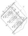
図2は、スタンパー処理部200の配置例を示す斜視図であり、図3は、スタンパー処理部200を構成する第1、第2及び第3のスタンパー装置202A、202B、202Cの全体構成図である。なお、図2では、図示の都合上、第1のスタンパー装置202、第2のスタンパー装置204の構成を示す符号が省略されている。
<< Detailed Description of Stamper Processing Unit >>
FIG. 2 is a perspective view showing an arrangement example of the
図2に示すように、スタンパー処理部200は、第1のスタンパー装置202A、第2のスタンパー装置202B及び第3のスタンパー装置202Cを備える。第1のスタンパー装置202A、第2のスタンパー装置202B及び第3のスタンパー装置202Cは、上面がチェーングリッパ64の傾斜搬送経路70Bに沿って斜めに開口されたケーシング206A、206B及び206C(破線により図示)にそれぞれ収納され、このケーシング206A、206B及び206Cが傾斜搬送経路70Bの下方位置に配置される。
As shown in FIG. 2, the
ケーシング206A、206B及び206Cのそれぞれ幅を足し合わせた長さは、複数のチェーングリッパ64の配置幅未満とされる。これにより、第1のスタンパー装置202A、第2のスタンパー装置202B及び第3のスタンパー装置202Cは、一対のチェーン64Cの間に配置されることになる。また、第1のスタンパー装置202A、第2のスタンパー装置202B及び第3のスタンパー装置202Cは、用紙Pの幅方向についてグリッパ間に配置される。
The total length of the
第1のスタンパー装置202A、第2のスタンパー装置202B及び第3のスタンパー装置202Cは、用紙Pへのスタンプ位置が用紙Pの搬送方向における同一位置となる配置が採用される。第1のスタンパー装置202A、第2のスタンパー装置202B及び第3のスタンパー装置202Cは、用紙Pの搬送方向にずらして配置することも可能である。
The
なお、ここでいう「同一位置」は、同一の作用効果を得ることができる「実質的に同一の位置」が含まれる。 In addition, "the same position" here includes the "substantially the same position" which can obtain the same effect.
第1のスタンパー装置202A、第2のスタンパー装置202B及び第3のスタンパー装置202Cは、用紙Pの搬送方向と直交する用紙Pの幅方向については異なる位置に配置されるので、用紙Pの幅方向におけるインク付着位置が重ならない。
The
なお、本明細書における「直交」とは、90°未満又は90°を超える角度で交差するもののうち、実質的に直交するものが含まれる。 In the present specification, "orthogonal" includes those which cross at substantially right angles among those intersecting at an angle of less than 90 ° or more than 90 °.
第1のスタンパー装置202A、第2のスタンパー装置202B及び第3のスタンパー装置202Cは、スタンプ制御部(図2及び図3中不図示、図4に符号208を付して図示)から送出された指令信号に基づいて、インラインセンサ58(図1参照)の読取結果に基づき画像不良が発生していると判定された用紙Pの先端エッジP1にインクを付着させる。
The
次に、図2及び図3を用いて第1のスタンパー装置202A、第2のスタンパー装置202B及び第3のスタンパー装置202Cの構造について説明する。なお、第1のスタンパー装置202A、第2のスタンパー装置202B及び第3のスタンパー装置202Cは、同一の構成を適用することができる。以下の説明では、第1のスタンパー装置202A、第2のスタンパー装置202B及び第3のスタンパー装置202Cを代表して第1のスタンパー装置202Aについて説明する。
Next, the structures of the
図2及び図3に示すように、第1のスタンパー装置202Aは、インクが含浸されたスタンプローラ210(スタンプ部)と、スタンプローラ210をチェーングリッパ64に対して出没させる出没機構212とを備える。
As shown in FIGS. 2 and 3, the
スタンプローラ210は、スタンプ容器214内に回転自在に支持され、このスタンプ容器214が出没機構212に支持される。
The
出没機構212は、スタンプ容器214を先端部に支持するアーム216と(スタンプ移動部)、回動軸218を介してアーム216を回動自在に支持する支持板220と(スタンプ移動部)、回動軸218を中心にアーム216を回転させて、スタンプ容器214を待機位置Xとスタンプ位置Yと間で移動させるソレノイドアクチュエータ222と(スタンプ移動部)を備える。
The retracting mechanism 212 includes an
図2及び図3では、待機位置Xに位置する、ケーシング206A、206B及び206Cの開口からスタンプ容器214が突出しない没状態のスタンプ容器214等を2点鎖線で図示し、スタンプ位置Yに位置する、ケーシング206A、206B及び206Cの開口からスタンプ容器214が突出している出状態のスタンプ容器214等を実線で図示した。
In FIG. 2 and FIG. 3, the stamped
第1のスタンパー装置202Aにおけるアーム216、支持板220及びソレノイドアクチュエータ222の関係は、アーム216が支持板220に回動自在に支持され、支持板220がソレノイドアクチュエータ222の外枠部224に支持され、外枠部224がケーシング206Aの底面に固定されることで互いの支持構造が形成される。
The relationship between the
なお、ソレノイドの磁力に対して吸着可能な金属以外の樹脂等の磁力で吸着しない部材でアーム216を形成する場合には、アーム216の基端部に吸着用の金属板を貼り付ける。
When the
そして、ソレノイドアクチュエータ222は、スタンプ制御部(図4参照)から送出される指令信号に基づいてオンオフが制御される。すなわち、ソレノイドアクチュエータ222がオンになると、ソレノイドアクチュエータ222内の不図示のコイルに励磁電流が流れ励磁電流による磁界が発生し、この磁界の作用によってソレノイドアクチュエータ222へアーム216の基端部が引きつけられる。
The
そうすると、傾斜状態で待機していたアーム216が起立して、アーム216の先端部に支持されるスタンプ容器214が待機位置Xからスタンプ位置Yへ移動し、スタンプ容器214がチェーングリッパ64の下方から上方に(ケーシング206Aの開口から)出現する。
Then, the
第1のスタンパー装置202Aは、一度起立させたアーム216の状態を保持するラッチ機構を具備しているので、ソレノイドアクチュエータ222のコイルに流れる励磁電流をオフして磁界を消失させた後も、アーム216の起立状態が保持される。
Since the
スタンプ容器214は、出没機構212と連動して開閉し、スタンプ容器214からスタンプローラ210のスタンプ面を露出させ、又はスタンプローラ210を密閉する開閉蓋225が設けられている。開閉蓋225の開閉機構は、アーム216の基端部位置(ホームポジション)を検出する光学センサー226と(位置検出部)、光学センサー226の検出結果に基づいて開閉蓋225を開閉する開閉アクチュエータ(図示せず)とを備える。
The
すなわち、アーム216がスタンプ位置Yへ移動して、アーム216の基端部が光学センサー226で検出されなくなると(オフ状態)、開閉アクチュエータが駆動して開閉蓋225が開かれる。
That is, when the
また、アーム216が待機位置Xへ移動して、アーム216の基端部が光学センサー226で検出されると(オン状態)、開閉アクチュエータが駆動して開閉蓋225が閉じられる。換言すると、アーム216の回動に伴うスタンプ容器214の出没に連動して開閉蓋225が開閉する機構になっている。
When the
なお、開閉蓋225の開閉機構の一例としては、開閉蓋225をスタンプ容器214に回動ピン228を介して支持アーム230に支持し、この回動ピン228をモータで回動させると開閉蓋225が開閉する方式を採用することができる。
As an example of the opening / closing mechanism of the opening /
そして、用紙Pが図2に白抜き矢印線で示す方向に搬送され、スタンプ位置Yに位置するスタンプローラ210(スタンプ容器の開閉蓋は開放状態)に用紙Pの先端エッジP1に当接することによって先端エッジP1にインクが付着する。
Then, the sheet P is conveyed in the direction indicated by the white arrow in FIG. 2 and abuts against the leading edge P1 of the sheet P at the
用紙Pがスタンプローラ210に当接する直前にソレノイドアクチュエータ222がオフされて、用紙Pがスタンプ容器214へ当接する勢いでアーム216が倒れる。これにより、スタンプ容器214がチェーングリッパ64の下方に没するので(ケーシング206Aの中へ収納されるので)、後続して搬送される正常な用紙Pの搬送が阻害されない。
The
第1のスタンパー装置202は、アーム216を待機位置Xで停止させるストッパ機構(不図示)が具備されている。
The first stamper device 202 is provided with a stopper mechanism (not shown) for stopping the
なお、本実施の形態では、スタンプ容器214の出没機構として、アームが回動してアームを起伏させることにより、スタンプローラ210がチェーングリッパ64に対して出没するように構成したが、同様の動作が可能であればこの方式に限定するものではない。
In the present embodiment, as the advancing and retracting mechanism of the
《制御系》
図4は、本実施の形態のインクジェット記録装置10の制御系の概略構成を示すブロック図である。
Control system
FIG. 4 is a block diagram showing a schematic configuration of a control system of the
同図に示すように、インクジェット記録装置10は、システムコントローラ100、通信部102、画像メモリ104、搬送制御部110、給紙制御部112、処理液付与制御部114、処理液乾燥制御部116、画像記録制御部118、インク乾燥制御部120、スタンプ制御部208(第1のスタンプ制御部、第2のスタンプ制御部)、排紙制御部124、操作部130、表示部132及び用紙カウンター134を備える。
As shown in the figure, the
システムコントローラ100は、インクジェット記録装置10の各部を統括制御する制御手段、及び各種演算処理を行う演算手段として機能する。このシステムコントローラ100は、CPU(Central Processing Unit)、ROM(Read Only Memory)、RAM(Random Access Memory)を備える。システムコントローラ100は、所定の制御プログラムに従って動作し、操作部130を介してオペレータからの操作入力を受け付けてインクジェット記録装置10の各部を制御する。ROMには、このシステムコントローラ100が、実行する制御プログラム、及び、制御に必要な各種データが格納される。
The
操作部130は、所要の操作手段(例えば、操作ボタンやキーボード、タッチパネル等)を備え、その操作手段から入力された操作情報をシステムコントローラ100に出力する。
The
通信部102は、所要の通信インターフェースを備え、その通信インターフェースと接続されたホストコンピュータとの間でデータの送受信を行う。
The
画像メモリ104は、画像データを含む各種データの一時記憶手段として機能し、システムコントローラ100を通じてデータの読み書きが行われる。通信部102を介してホストコンピュータから取り込まれた画像データは、この画像メモリ104に格納される。
The
搬送制御部110は、インクジェット記録装置10における用紙Pの搬送部11を制御する。すなわち、給紙部12におけるテープフィーダ36A、前当て38、給紙ドラム40の駆動を制御し、かつ、処理液付与部14における処理液付与ドラム42、処理液乾燥処理部16における処理液乾燥処理ドラム46、画像記録部18における画像記録ドラム52の駆動を制御する。また、インク乾燥処理部20及び排紙部24で共通して用いられるチェーングリッパ64及びバックテンション付与機構66の駆動を制御する。
The
搬送制御部110は、システムコントローラ100からの指令に応じて、搬送部11を制御し、給紙部12から排紙部24まで滞りなく用紙Pが搬送されるように制御する。
The
給紙制御部112は、システムコントローラ100からの指令に応じて給紙部12を制御する。具体的には、サッカー装置32及び給紙台昇降機構等の駆動を制御して、給紙台30に積載された用紙Pが、重なることなく1枚ずつ順に給紙されるように制御する。
The sheet
処理液付与制御部114は、システムコントローラ100からの指令に応じて処理液付与部14を制御する。具体的には、処理液付与ドラム42によって搬送される用紙Pに処理液が塗布されるように、処理液付与ユニット44の駆動を制御する。
The treatment liquid
処理液乾燥制御部116は、システムコントローラ100からの指令に応じて処理液乾燥処理部16を制御する。具体的には、処理液乾燥処理ドラム46によって搬送される用紙Pが乾燥処理されるように、処理液乾燥処理ユニット50の駆動を制御する。
The treatment liquid
画像記録制御部118は、システムコントローラ100からの指令に応じて画像記録部18を制御する。具体的には、画像記録ドラム52によって搬送される用紙Pに所定の画像が記録されるように、インクジェットヘッド56C、56M、56Y及び56Kの駆動を制御する。また、画像記録制御部118は、記録された画像が読み取られるように、インラインセンサ58の動作を制御する。
The image
インク乾燥制御部120は、システムコントローラ100からの指令に応じてインク乾燥処理部20を制御する。具体的には、チェーングリッパ64によって搬送される用紙Pに熱風が送風されるようにインク乾燥処理ユニット68の駆動を制御する。
The ink
スタンプ制御部208は、システムコントローラ100からの指令に応じて、スタンパー処理部200(図2及び図3に図示した第1、第2及び第3のスタンパー装置202A、202B及び202C)及びブザー201の動作を制御する。
The
排紙制御部124は、システムコントローラ100からの指令に応じて排紙部24を制御する。具体的には、排紙台昇降機構等の駆動を制御して、排紙台76に用紙Pがスタック(積載)されるように制御する。
The paper
例えば、排紙部24に積載される用紙Pを100枚ごとに部数を仕分ける場合、操作部130から仕分け部数を入力する。入力された仕分け部数は、仕分け部数設定値として記憶される。仕分け部数設定値はスタンプ制御部208へ読み出され、スタンパー処理部200の制御に適用される。
For example, in the case where the number of copies of the sheets P stacked on the
図4に図示した設定部138は、仕分け部数の設定等の各種設定を行うブロックであり、設定を取得する設定値取得部、取得された設定値を記憶する設定値記憶部、設定値記憶部への設定値の書き込み、読み出しを制御する記憶制御部を含んで構成される。
The
表示部132は、所要の表示装置(例えば、LCD(Liquid Crystal Display)パネル等)を備え、システムコントローラ100からの指令に応じて所要の情報を表示装置に表示させる。
The
用紙カウンター134は、給紙部12から給紙された用紙Pの枚数を計測する手段である。用紙カウンター134から得られた用紙Pの枚数情報は、システムコントローラ100を介してスタンプ制御部208へ送出され、スタンパー処理部200の制御に適用される。
The
画像不良検出部136は、用紙Pに形成される画像に不良が発生しているか否かを検出する。画像不良の有無は、インラインセンサ58の撮像結果に基づいて判断される。検出結果はシステムコントローラ100を介してスタンプ制御部208へ送出され、スタンパー処理部200の制御に適用される。なお、先に説明したように、用紙Pの汚れを検出する汚れ検出部を備え、用紙Pの汚れを画像不良と判断してもよい。
The image
ブザー201は、第1のスタンパー装置202によるスタンプ実施条件が成立した場合に、スタンプ制御部208の制御に基づいて一定期間警報を鳴らす手段である。なお、ブザー201に代わり、またこれと併用して、ランプの点灯、点滅、消灯及び表示部への文字情報による表示のうちの少なくとも1つを適用することも可能である。
The
《画像記録の説明》
用紙に記録する画像データは、ホストコンピュータから通信部102を介してインクジェット記録装置10に取り込まれる。取り込まれた画像データは、画像メモリ104に格納される。
<< Description of image recording >>
Image data to be recorded on a sheet is taken into the
システムコントローラ100は、この画像メモリ104に格納された画像データに所要の信号処理を施してドットデータを生成する。そして、生成したドットデータに従って画像記録部18の各インクジェットヘッド56C、56M、56Y及び56Kの駆動を制御し、その画像データが表す画像を用紙に記録する。
The
ドットデータは、一般に画像データに対して色変換処理、ハーフトーン処理を行って生成される。色変換処理は、sRGB(standard RGB)などで表現された画像データ(例えば、RGB8ビットの画像データ)をインクジェット記録装置10で使用するインクの各色のインク量データに変換する処理である(本例では、C、M、Y及びKの各色のインク量データに変換する。)。ハーフトーン処理は、色変換処理により生成された各色のインク量データに対して誤差拡散等の処理で各色のドットデータに変換する処理である。 Dot data is generally generated by performing color conversion processing and halftone processing on image data. The color conversion processing is processing for converting image data (for example, RGB 8-bit image data) represented by sRGB (standard RGB) or the like into ink amount data of each color of ink used in the inkjet recording apparatus 10 (this example) Convert the ink amount data of each color of C, M, Y and K). The halftone process is a process of converting the ink amount data of each color generated by the color conversion process into dot data of each color by a process such as error diffusion.
システムコントローラ100は、画像データに対して色変換処理、ハーフトーン処理を行って各色のドットデータを生成する。そして、生成した各色のドットデータに従って、対応するインクジェットヘッドの駆動を制御することにより、画像データが表す画像を用紙Pに記録する。
The
また、本実施の形態では、ソレノイドアクチュエータ222によるスタンプ容器214の出没動作に連動して、スタンプ容器214の開閉蓋225を開閉するようにしたので、スタンプを実施していない待機中に、スタンプローラ210のインクが乾くことを防止できる。
Further, in the present embodiment, the opening /
この場合、第1、第2及び第3のスタンパー装置202A、202B及び202Cに使用されるインク(スタンパーインク)を高保水性材料で形成するようにすれば、スタンプローラ210のインクの乾燥を一層防止できる。
In this case, if the inks (stamper inks) used for the first, second and
本例では、第1、第2及び第3のスタンパー装置202A、202B及び202Cがケーシング206A、206B及び206Cにそれぞれ収納され、第1、第2及び第3のスタンパー装置202A、202B及び202Cの動作を制御する手段が共通化されたユニット形式を例示したが、第1、第2及び第3のスタンパー装置202A、202B及び202Cの動作を制御する手段を別々に具備することも可能である。また、第1、第2及び第3のスタンパー装置202A、202B及び202Cの動作を制御する手段の一部を共通化してもよい。
In this example, the first, second and
本例では、第1、第2及び第3のスタンパー装置202A、202B及び202Cの出没動作として、アーム216の回動動作を例示したが、スタンプ容器214を上下動させる態様も可能である。
In this example, the pivoting operation of the
本例では、用紙Pとして塗工紙が適用されるインクジェット記録装置10を例示したが、本発明は、樹脂シート(基板)、金属シート(基板)、ガラス基板などの紙以外のシート状部材、基板を用紙Pとして適用することができる。
In the present example, the
また、本発明の適用範囲は、グラフィック用途の画像形成装置(印刷装置)に限定されない。例えば、基板上に配線パターン、マスクパターンを形成するパターン形成装置等の工業用途の画像形成装置に広く適用することができる。 Further, the scope of application of the present invention is not limited to an image forming apparatus (printing apparatus) for graphic applications. For example, the present invention can be widely applied to an image forming apparatus for industrial use such as a pattern forming apparatus for forming a wiring pattern and a mask pattern on a substrate.
[スタンプ押印処理]
図5は、第1、第2及び第3のスタンパー装置と印刷用紙を模式的に示す斜視図であり、図6は、用紙にスタンプが押印された例を示す斜視図である。なお、図5及び図6における矢印は、用紙Pの搬送方向を示している。
[Stamp seal processing]
FIG. 5 is a perspective view schematically showing the first, second and third stamper devices and the printing sheet, and FIG. 6 is a perspective view showing an example in which a stamp is stamped on the sheet. Arrows in FIGS. 5 and 6 indicate the conveyance direction of the sheet P.
図5に示すように、第1のスタンパー装置202A、第2のスタンパー装置202B及び第3のスタンパー装置202Cによって相互に異なる色のスタンプを異なる位置に付与することが可能となっている。本実施形態では、第1のスタンパー装置202A、第2のスタンパー装置202B及び第3のスタンパー装置202Cによってそれぞれ色A、B及びCのスタンプが付与されるものとする。
As shown in FIG. 5, it is possible to apply stamps of different colors to different positions by the
画像不良検出部136は、インラインセンサ58から出力された検査対象(測定対象)の用紙Pの画像から、ノズルの吐出曲がり量(ドット位置の誤差)を測定する。そして、画像不良検出部136は、ノズルの吐出曲がり量の測定結果をシステムコントローラ100に出力する。ここで、ノズルの吐出曲がり量(ドット位置の誤差)は、例えば、特開2011−079257号公報(段落[0092]以下)に記載されているドット位置測定方法を用いて測定することが可能である。
The image
なお、本実施形態では、ノズルの吐出曲がり量だけでなく、不吐出に起因するスジについても検出可能である。例えば、不吐出は、ノズルの吐出曲がり量が最大の場合とみなして検出することが可能である。 In the present embodiment, not only the discharge bending amount of the nozzle but also streaks resulting from the non-discharge can be detected. For example, the non-ejection can be detected by regarding it as the case where the ejection bending amount of the nozzle is maximum.
システムコントローラ100は、画像不良検出部136から入力されたノズルの吐出曲がり量の測定結果のデータに応じて、スタンプ制御部208を制御して、ノズルの吐出曲がり量の測定結果のデータに応じたスタンプを検査対象の用紙Pに押印させる。例えば、ノズルの吐出曲がり量xが、x>17μmの場合には、第1のスタンパー装置202Aにより色Aのスタンプが押印され、13μm<x≦17μmの場合には、第2のスタンパー装置202Bにより色Bのスタンプが押印され、7μm≦x≦13μmの場合には、第3のスタンパー装置202Cにより色Cのスタンプが押印されるようにする。これにより、オペレータは、スタンプの色により、ノズルの吐出曲がり量を視認することが可能になる。
The
なお、吐出曲がり量の測定結果がノズルごとに異なることが考えられる。例えば、ノズルiのノズルの吐出曲がり量の測定結果xiがxi>17μm(スタンプ色Aを押印すべき場合)、ノズルjのノズルの吐出曲がり量の測定結果xjが13μm<xj≦17μm(スタンプ色Bを押印すべき場合)、ノズルkのノズルの吐出曲がり量の測定結果xkが7μm≦xk≦13μm(スタンプ色Cを押印すべき場合)であったとする。 In addition, it is possible that the measurement result of the amount of discharge bending differs for every nozzle. For example, the measurement result x i of the discharge bending amount of the nozzle of the nozzle i is x i > 17 μm (when the stamp color A is to be imprinted), and the measurement result x j of the discharge bending amount of the nozzle of the nozzle j is 13 μm <x j ≦ It is assumed that 17 μm (when stamp color B is to be imprinted) and measurement result x k of the discharge bending amount of the nozzle of nozzle k is 7 μm ≦ x k ≦ 13 μm (when stamp color C is to be imprinted).
上記のような場合には、ノズルの吐出曲がり量の測定結果が最大のものに対応するスタンプ(上記の例では、スタンプA)を押印するようにすることが考えられる(スタンプ条件1)。スタンプ条件1の場合、検査対象の用紙Pにおけるノズルの吐出曲がり量が最大のものに対応するスタンプが押印されるので、オペレータは、検査対象の用紙Pにおいて、最も視認性が高いスジの程度をスタンプの色により確認することができる。これにより、オペレータは、視認性が比較的高いスジのみを効率的に検品することが可能になる。 In the above case, it is conceivable to stamp a stamp (in the above example, the stamp A) corresponding to the largest measurement result of the discharge bending amount of the nozzle (stamp condition 1). In the case of the stamp condition 1, since the stamp corresponding to the one having the largest discharge bending amount of the nozzle on the sheet P to be inspected is imprinted, the operator can check the degree of streaks having the highest visibility on the sheet P to be inspected. It can be confirmed by the color of the stamp. This enables the operator to efficiently inspect only streaks with relatively high visibility.
また、上記のような場合には、ノズルの吐出曲がり量の測定結果が最小のものに対応するスタンプ(上記の例では、スタンプC)を押印するようにすることが考えられる(スタンプ条件2)。スタンプ条件2の場合、検査対象の用紙Pにおけるノズルの吐出曲がり量が最小のものに対応するスタンプが押印されるので、オペレータは、検査対象の用紙Pにおいて、最も視認性が低いスジの程度をスタンプの色により確認することができる。これにより、オペレータは、視認性が比較的低いスジについて厳格な検品を実施することが可能になる。 Further, in the above case, it is conceivable to stamp the stamp (in the above example, the stamp C) corresponding to the one in which the measurement result of the discharge bending amount of the nozzle is the smallest (stamp condition 2) . In the case of the stamp condition 2, since the stamp corresponding to the one having the smallest discharge bending amount of the nozzle on the sheet P to be inspected is imprinted, the operator can check the degree of streak having the lowest visibility on the sheet P to be inspected. It can be confirmed by the color of the stamp. This enables the operator to carry out strict inspection for streaks with relatively low visibility.
本実施形態では、スタンプ条件は、操作部130により変更可能となっており、オペレータは、検査対象の用紙Pの種類に応じて、例えば、検査対象の用紙Pの数が多数であって、検品の要求精度が比較的低い場合には、スタンプ条件1を、検査対象の用紙Pの数が少数の場合、又は検品の要求精度が比較的高い場合には、スタンプ条件2を選択することが可能になる。
In the present embodiment, the stamp condition can be changed by the
また、スタンプを押印するか否か、及びどの色のスタンプを押印するかを判定する閾値については、色ごとの視認性に鑑みて、表1のように色ごとに閾値を変えることが好ましい。 Further, with regard to the threshold for determining whether or not to stamp a stamp and which color stamp is to be stamped, it is preferable to change the threshold for each color as shown in Table 1 in view of visibility for each color.

一般に、Kインクのスジが最も視認性が高く、Yインクのスジが最も視認性が低い。そして、Cインク及びMインクのスジの視認性はKとYの中間である。表1に示す例では、色ごとの視認性の違いに鑑みて、Kインクの判定に用いられる閾値が最小となり(検出精度が最高)、Yインクの判定に用いられる閾値が最大(検出精度が最低)となるように設定されている。 In general, the streaks of the K ink are the highest in visibility, and the streaks of the Y ink are the lowest in visibility. The visibility of the C ink and M ink streaks is intermediate between K and Y. In the example shown in Table 1, in view of the difference in visibility for each color, the threshold used for determination of K ink is the smallest (detection accuracy is the highest), and the threshold used for determination of Y ink is the maximum (detection accuracy is It is set to be the lowest).
なお、Yインクについては視認性が低いことに鑑み、スジの検出を行わないようにすることも可能である。 In view of the low visibility of the Y ink, it is possible not to detect streaks.
また、スジの視認性が最も高いKインクに対するスジの検出を最初に行い、Cインク又はMインクに対するスジの検出を次に行い、スジの視認性が最も低いYインクに対するスジの検出を最後に行うようにしてもよい。 In addition, detection of streaks for K ink having the highest visibility of streaks is first performed, followed by detection of streaks for C ink or M ink, and finally detection of streaks for Y ink having the lowest visibility of streaks. You may do so.
表1に示す例では、Kインクの場合には、ノズルの吐出曲がり量の測定結果xが、x>17μm(低)の場合には、第1のスタンパー装置202Aにより色Aのスタンプが押印され、13μm<x≦17μm(中)の場合には、第2のスタンパー装置202Bにより色Bのスタンプが押印され、7μm≦x≦13μm(高)の場合には、第3のスタンパー装置202Cにより色Cのスタンプが押印される。
In the example shown in Table 1, in the case of the K ink, when the measurement result x of the discharge deflection amount of the nozzle is x> 17 μm (low), the stamp of the color A is imprinted by the
Cインク及びMインクの場合には、ノズルの吐出曲がり量の測定結果xが、x>17μm(低)の場合には、第1のスタンパー装置202Aにより色Aのスタンプが押印され、13μm<x≦17μm(中)の場合には、第2のスタンパー装置202Bにより色Bのスタンプが押印され、10μm≦x≦13μm(高)の場合には、第3のスタンパー装置202Cにより色Cのスタンプが押印される。
In the case of C ink and M ink, when the measurement result x of the discharge deflection amount of the nozzle is x> 17 μm (low), the stamp of the color A is imprinted by the
Yインクの場合には、ノズルの吐出曲がり量の測定結果xが、x>19μm(低)の場合には、第1のスタンパー装置202Aにより色Aのスタンプが押印され、17μm<x≦19μm(中)の場合には、第2のスタンパー装置202Bにより色Bのスタンプが押印され、15μm≦x≦17μm(高)の場合には、第3のスタンパー装置202Cにより色Cのスタンプが押印される。
In the case of Y ink, when the measurement result x of the discharge deflection amount of the nozzle is x> 19 μm (low), the stamp of the color A is imprinted by the
なお、表1に示す例では、不良ノズルの判定に用いる閾値を3つとして、不良ノズルの不良の程度(スジの評価)を「高」、「中」、「低」及び「スタンプなし(OFF)」の4段階としたが、本発明はこれに限定されるものではない。 In the example shown in Table 1, the threshold value used for the determination of the defective nozzle is three, and the degree of the defect of the defective nozzle (the evaluation of the streak) is "high", "medium", "low" and "no stamp (OFF) 4), but the present invention is not limited thereto.
表1に示す例において、例えば、Kインクのノズルの判定結果が「低」、Cインクのノズルの判定結果が「高」、Yインクのノズルの判定結果が「高」であった場合、判定結果に対応するすべてのスタンプ(上記の例では、スタンプA及びC)を押すことが考えられる(スタンプ条件3)。 In the example shown in Table 1, for example, when the determination result of the K ink nozzle is “low”, the determination result of the C ink nozzle is “high”, and the determination result of the Y ink nozzle is “high”, the determination is It is conceivable to press all stamps (stamps A and C in the above example) corresponding to the result (stamp condition 3).
また、上記のような場合には、ノズルの吐出曲がり量の結果が最も低いものに対応するスタンプ(上記の例では、スタンプA)を押印するようにすることが考えられる(スタンプ条件4)。スタンプ条件4の場合、検査対象の用紙Pにおけるノズルの吐出曲がり量が最大のものに対応するスタンプが押印されるので、オペレータは、検査対象の用紙Pにおいて、最も視認性が高いスジの程度をスタンプの色により確認することができる。これにより、オペレータは、視認性が比較的高いスジのみを効率的に検品することが可能になる。 In the above case, it may be considered to stamp the stamp (in the above example, the stamp A) corresponding to the one with the lowest result of the discharge bending amount of the nozzle (stamp condition 4). In the case of the stamp condition 4, since the stamp corresponding to the one having the largest discharge bending amount of the nozzle on the sheet P to be inspected is imprinted, the operator can check the degree of streaks having the highest visibility on the sheet P to be inspected. It can be confirmed by the color of the stamp. This enables the operator to efficiently inspect only streaks with relatively high visibility.
また、上記のような場合には、ノズルの吐出曲がり量の判定結果が最も高いものに対応するスタンプ(上記の例では、スタンプC)を押印するようにすることが考えられる(スタンプ条件5)。スタンプ条件5の場合、検査対象の用紙Pにおけるノズルの吐出曲がり量が最小のものに対応するスタンプが押印されるので、オペレータは、検査対象の用紙Pにおいて、最も視認性が低いスジの程度をスタンプの色により確認することができる。これにより、オペレータは、視認性が比較的低いスジについて厳格な検品を実施することが可能になる。 Further, in the above case, it is conceivable to stamp a stamp (in the above example, the stamp C) corresponding to the highest determination result of the discharge bending amount of the nozzle (stamp condition 5) . In the case of the stamp condition 5, since the stamp corresponding to the one having the smallest discharge bending amount of the nozzle on the sheet P to be inspected is imprinted, the operator can check the degree of streak having the lowest visibility on the sheet P to be inspected. It can be confirmed by the color of the stamp. This enables the operator to carry out strict inspection for streaks with relatively low visibility.
上記のように、色ごとに判定の閾値を変えるか否か、及び色ごとに判定の閾値を変える場合のスタンプ条件についても、オペレータが選択可能となっている。 As described above, the operator can also select whether to change the determination threshold for each color and whether to change the determination threshold for each color.
以下に、スタンプの付与の方法について具体的に説明する。曲がりが検出されたノズル(不良ノズル、補正対象のノズル)が1つだけの場合、そのノズルの吐出曲がり量に対応するスタンプを押印する。すなわち、Kのi番目のノズルの吐出曲がり量が20μm(低)の場合、スタンプAが押印され、Cのj番目のノズルの吐出曲がり量が15μm(中)の場合、スタンプBが押印され、Yのk番目のノズルの吐出曲がり量が16μm(高)の場合、スタンプCが押印される。 Below, the method of giving a stamp is demonstrated concretely. If there is only one nozzle (defective nozzle, nozzle to be corrected) for which bending has been detected, a stamp corresponding to the discharge bending amount of that nozzle is imprinted. That is, if the ejection bending amount of the i-th nozzle of K is 20 μm (low), the stamp A is imprinted, and if the ejection bending amount of the j-th nozzle of C is 15 μm (medium), the stamp B is imprinted. When the discharge bending amount of the kth nozzle of Y is 16 μm (high), the stamp C is stamped.
スタンプ条件3では、曲がりが検出されたノズルが複数ある場合、各不良ノズルの吐出曲がり量に対応するスタンプをすべて押印する。この場合、Kのi番目のノズルの吐出曲がり量が20μm(低)、j番目のノズルの吐出曲がり量が15μm(中)、k番目のノズルの吐出曲がり量が10μm(高)の場合、スタンプA、B及びCが押印される。また、Kのi番目のノズルの吐出曲がり量が20μm(低)、Cのj番目のノズルの吐出曲がり量が15μm(中)の場合には、スタンプA及びBが押印される。また、Kのi番目のノズルの吐出曲がり量が20μm(低)、Cのj番目のノズルの吐出曲がり量が15μm(中)、Yのk番目のノズルの吐出曲がり量が16μm(高)の場合、スタンプA、B及びCが押印される。 In the stamp condition 3, when there are a plurality of nozzles in which a bend is detected, all stamps corresponding to the discharge bending amount of each defective nozzle are sealed. In this case, if the ejection bending amount of the i-th nozzle of K is 20 μm (low), the ejection bending amount of the j-th nozzle is 15 μm (medium), and the ejection bending amount of the k-th nozzle is 10 μm (high), the stamp A, B and C are sealed. Further, when the ejection bending amount of the i-th nozzle of K is 20 μm (low) and the ejection bending amount of the j-th nozzle of C is 15 μm (middle), the stamps A and B are stamped. In addition, the amount of ejection bending of the i-th nozzle of K is 20 μm (low), the amount of ejection bending of the j-th nozzle of C is 15 μm (medium), and the amount of ejection bending of the k-th nozzle of Y is 16 μm (high) In the case, stamps A, B and C are stamped.
スタンプ条件4では、曲がりが検出されたノズルが複数ある場合、検知閾値の判定レベルが最低のものに対応するスタンプだけを押印する。この場合、Kのi番目のノズルの吐出曲がり量が20μm(低)、j番目のノズルの吐出曲がり量が15μm(中)、k番目のノズルの吐出曲がり量が10μm(高)の場合、スタンプAが押印される。また、Kのi番目のノズルの吐出曲がり量が20μm(低)、Cのj番目のノズルの吐出曲がり量が15μm(中)の場合には、スタンプAが押印される。また、Kのi番目のノズルの吐出曲がり量が20μm(低)、Cのj番目のノズルの吐出曲がり量が15μm(中)、Yのk番目のノズルの吐出曲がり量が16μm(高)の場合、スタンプAが押印される。 In the stamp condition 4, when there are a plurality of nozzles in which a curve is detected, only the stamp corresponding to the one with the lowest determination level of the detection threshold is sealed. In this case, if the ejection bending amount of the i-th nozzle of K is 20 μm (low), the ejection bending amount of the j-th nozzle is 15 μm (medium), and the ejection bending amount of the k-th nozzle is 10 μm (high), the stamp A is sealed. Further, when the ejection bending amount of the i-th nozzle of K is 20 μm (low) and the ejection bending amount of the j-th nozzle of C is 15 μm (middle), the stamp A is stamped. In addition, the amount of ejection bending of the i-th nozzle of K is 20 μm (low), the amount of ejection bending of the j-th nozzle of C is 15 μm (medium), and the amount of ejection bending of the k-th nozzle of Y is 16 μm (high) In the case, the stamp A is stamped.
スタンプ条件5では、曲がりが検出されたノズルが複数ある場合、検知閾値の判定レベルが最高のものに対応するスタンプだけを押印する。この場合、Kのi番目のノズルの吐出曲がり量が20μm(低)、j番目のノズルの吐出曲がり量が15μm(中)、k番目のノズルの吐出曲がり量が10μm(高)の場合、スタンプCが押印される。また、Kのi番目のノズルの吐出曲がり量が20μm(低)、Cのj番目のノズルの吐出曲がり量が15μm(中)の場合には、スタンプBが押印される。また、Kのi番目のノズルの吐出曲がり量が20μm(低)、Cのj番目のノズルの吐出曲がり量が15μm(中)、Yのk番目のノズルの吐出曲がり量が16μm(高)の場合、スタンプCが押印される。 Under the stamp condition 5, when there are a plurality of nozzles in which a curve is detected, only the stamp corresponding to the highest detection threshold determination level is sealed. In this case, if the ejection bending amount of the i-th nozzle of K is 20 μm (low), the ejection bending amount of the j-th nozzle is 15 μm (medium), and the ejection bending amount of the k-th nozzle is 10 μm (high), the stamp C is sealed. In addition, when the ejection bending amount of the i-th nozzle of K is 20 μm (low) and the ejection bending amount of the j-th nozzle of C is 15 μm (medium), the stamp B is stamped. Also, the amount of discharge bending of the i-th nozzle of K is 20 μm (low), the amount of discharge bending of the j-th nozzle of C is 15 μm (medium), and the amount of discharge bending of the k-th nozzle of Y is 16 μm (high) In the case, the stamp C is stamped.
上記のように、色ごとに判定の閾値を異ならせ、かつ、判定レベルごとにスタンプ条件を変更可能とすることにより、オペレータは、用紙Pへの印刷内容に応じた検品を容易に行うことが可能になる。 As described above, the operator can easily perform inspection according to the print content on the sheet P by changing the threshold of determination for each color and changing the stamp condition for each determination level. It will be possible.
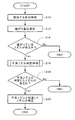
図7は、本発明の一実施形態に係る不良ノズル判定処理を示すフローチャートである。図7の処理は、検査対象の用紙P1枚ずつに対して繰り返し実施されるものである。 FIG. 7 is a flowchart showing a defective nozzle determination process according to an embodiment of the present invention. The process of FIG. 7 is repeatedly performed for each sheet P1 to be inspected.
まず、画像不良検出部136は、インラインセンサ58から検査対象の用紙Pの画像を取得し、検知するインクの色の判定を行う(インク色判定工程:ステップS10)。
First, the image
次に、画像不良検出部136は、例えば、特開2011−079257号公報(段落[0092]以下)に記載されているドット位置測定方法を用いて、ノズルの吐出曲がり量(ドット位置の誤差)を測定する(測定工程:ステップS12)。
Next, the image
次に、ステップS12において、曲がっているノズルが検出された場合には(ステップS14のYes)、不良ノズル判定処理を行う(画像不良検出工程:ステップS16)。ステップS16では、例えば、表1に示すように、色ごとに設定された、「高」、「中」及び「低」の3種類の閾値を用いて不良ノズルの判定が行われる。ステップS16において、画像不良検出部136は、例えば、(1)1回の印刷につきノズルの曲がりが累積2回検知された場合に、そのノズルを不良ノズルと判定するようにしてもよいし、又は、(2)ノズルの曲がりが連続2回検知された場合に、そのノズルを不吐補正すると判定するようにしてもよい。なお、不良ノズルと判定する基準は、上記(1)及び(2)に限定されるものではない。例えば、オペレータが、上記基準における曲がりの検知回数を増減可能としてもよい。
Next, when a bent nozzle is detected in step S12 (Yes in step S14), defective nozzle determination processing is performed (image defect detection step: step S16). In step S16, for example, as shown in Table 1, determination of a defective nozzle is performed using three types of threshold values "high", "medium" and "low" set for each color. In step S16, the image
次に、画像不良検出部136が不良ノズルと判定したノズルがある場合には(ステップS18のYes)、システムコントローラ100は、不良ノズルと判定したノズルの補正を行う(ステップS20)。ステップS20では、例えば、特開2011−161646号公報に記載の不良記録素子補正工程を適用することが可能である。
Next, when there is a nozzle determined as a defective nozzle by the image defect detection unit 136 (Yes in step S18), the
システムコントローラ100は、ステップS16における判定の結果に基づいて、用紙Pにスタンプを押印するか否か、及び用紙Pに押印するスタンプの種類及び個数を決定して、スタンプフラグFn,i,jをオンにする。そして、システムコントローラ100は、スタンプ制御部208を制御して、不良ノズルの補正が完了するまで、用紙Pへのスタンプの押印を継続する。
The
システムコントローラ100は、ステップS20の補正が終了した場合に、スタンプフラグFn,i,jをオフにする。ここで、スタンプフラグFn,i,jは、n枚目の用紙Pにおいて検地されたi色(i=C,M,Y,K)のノズルの補正が終了したか否かを示すものである。jはインク色ごとに押印されるスタンプの種類を示すパラメータであり、例えば、「低」のスタンプAを押印する場合に、j=1、「中」のスタンプBを押印する場合に、j=2、「高」のスタンプCを押印する場合に、j=3、「低」及び「中」のスタンプA及びBを押印する場合に、j=4、…のように設定される。
When the correction in step S20 is completed, the
図8は、補正完了の監視処理を示すフローチャートである。図8に示すように、n枚目の用紙Pにおいて検地されたi色(i=C,M,Y,K)のノズルの補正が終了したか否かが判定され(ステップS30)、補正終了の場合には、Fn,i,jがオフに設定される一方(ステップS32)、補正未了の場合には、Fn,i,jがオンに維持される(ステップS34)。 FIG. 8 is a flowchart showing monitoring processing of correction completion. As shown in FIG. 8, it is determined whether the correction of the nozzle of i color (i = C, M, Y, K) detected on the nth sheet P is completed (step S30), and the correction is completed In this case, F n, i, j is set to be off (step S32), while when the correction is not completed, F n, i, j is kept on (step S34).
図9は、スタンプ押印判定処理を示すフローチャートである。 FIG. 9 is a flowchart showing stamp seal determination processing.
上記のように、スタンプフラグFn,i,jは、用紙Pごとに、インク色(i色(i=C,M,Y,K))ごとにオンとオフが設定される。このようにして設定されたスタンプフラグFn,i,jの中にオンに設定されているものが1つ以上ある場合(ステップS50のYes)、すなわち、補正が終了していないノズルがある場合に、オペレータによって設定されたスタンプ条件にしたがって用紙Pにスタンプが押印される(スタンプ工程:ステップS52)。一方、スタンプフラグがすべてオフの場合には(ステップS50のNo)、スタンプの押印は行われない(ステップS54)。 As described above, the stamp flag F n, i, j is set to on and off for each ink color (i color (i = C, M, Y, K)) for each sheet P. If one or more of the stamp flags F n, i, j set in this way are set to ON (Yes in step S 50), that is, if there is a nozzle for which the correction has not been completed A stamp is stamped on the sheet P in accordance with the stamp condition set by the operator (stamping step: step S52). On the other hand, when all the stamp flags are off (No in step S50), the stamp is not sealed (step S54).
本実施形態によれば、ノズルに起因するスジが検出された場合に、そのスジの程度に応じてスタンプの種類を変えることができる。これにより、オペレータは、スタンプからスジの程度を認識することが可能になるので、オペレータによる検品作業を支援し、検品作業の効率化を実現することが可能になる。 According to the present embodiment, when a streak caused by a nozzle is detected, the type of stamp can be changed according to the degree of the streak. As a result, the operator can recognize the degree of streaks from the stamp, thereby supporting the inspection work by the operator and realizing the efficiency of the inspection work.
さらに、本実施形態によれば、インクの色ごとの視認性に対応して、不良ノズル(スジ)の判定に用いる閾値を変えたり、不良ノズルが複数の場合に、スタンプ条件を設定することができる。これにより、オペレータは、印刷用紙の用途、要求精度等に応じて、スタンプの付与の仕方を設定でき、オペレータにより検品作業を容易にすることが可能になる。 Furthermore, according to the present embodiment, it is possible to change the threshold value used for the determination of the defective nozzle (stripe) or set the stamp condition when there are a plurality of defective nozzles, corresponding to the visibility for each color of ink. it can. As a result, the operator can set the method of applying the stamp in accordance with the application of the printing paper, the required accuracy, and the like, and the operator can facilitate the inspection work.
[スタンプ押印処理の別の実施形態]
次に、スタンプ押印処理の別の実施形態について、図10及び図11を参照して説明する。なお、上記の実施形態と同一又は類似する構成については、同一の符号を付して説明を省略する。
[Another Embodiment of Stamp Sealing Process]
Next, another embodiment of the stamp press mark processing will be described with reference to FIGS. 10 and 11. In addition, about the structure which is the same as that of said embodiment, or similar, the same code | symbol is attached | subjected and description is abbreviate | omitted.
本実施形態に係るインクジェット記録装置10は、スタンパー装置(K用のスタンパー装置202Ak、202Bk及び202Ck、C用のスタンパー装置202AC、202BC及び202CC、M用のスタンパー装置202AM、202BM及び202CM、Y用のスタンパー装置202AY、202BY及び202CY)を備えており、インク色(CMYK)ごとに3つのスタンプが押印可能となっている。なお、各色用のスタンパー装置によって押印されるスタンプA、B及びCの色は種類ごとに相互に異なるものとするが、CMYKの各色について、同種のスタンプA、B及びCの色はそれぞれ同じであってもよい。
The
図10は、本発明の別の実施形態に係るスタンパー装置と印刷用紙を模式的に示す斜視図であり、図11は、用紙にスタンプが押印された例を示す斜視図である。なお、図10及び図11における矢印は、用紙Pの搬送方向を示している。 FIG. 10 is a perspective view schematically showing a stamper device and a printing sheet according to another embodiment of the present invention, and FIG. 11 is a perspective view showing an example in which a stamp is stamped on the sheet. The arrows in FIGS. 10 and 11 indicate the transport direction of the sheet P.
曲がりが検出されたノズル(不良ノズル、補正対象のノズル)が1つだけの場合、そのノズルの吐出曲がり量に対応するスタンプを押印する。すなわち、Kのi番目のノズルの吐出曲がり量が20μm(低)の場合、K用のスタンパー装置202AkによってK用のスタンプAが押印される。また、Cのj番目のノズルの吐出曲がり量が15μm(中)の場合、C用のスタンパー装置202BCによってC用のスタンプBが押印される。また、Yのk番目のノズルの吐出曲がり量が16μm(高)の場合、Y用のスタンパー装置202CYによってY用のスタンプCが押印される。
If there is only one nozzle (defective nozzle, nozzle to be corrected) for which bending has been detected, a stamp corresponding to the discharge bending amount of that nozzle is imprinted. That is, when the discharge amount of bend of the i-th nozzle of K is 20μm (low), the stamp A for K is stamped by a
スタンプ条件3では、曲がりが検出されたノズルが複数ある場合、各不良ノズルの吐出曲がり量に対応するスタンプをすべて押印する。この場合、Kのi番目のノズルの吐出曲がり量が20μm(高)、j番目のノズルの吐出曲がり量が15μm(中)、k番目のノズルの吐出曲がり量が10μm(低)の場合には、K用のスタンパー装置202Ak、202Bk及び202CkによってK用のスタンプA、B及びCがそれぞれ押印される。また、Kのi番目のノズルの吐出曲がり量が20μm(高)、Cのj番目のノズルの吐出曲がり量が15μm(中)、Cのk番目のノズルの吐出曲がり量が11μm(低)の場合には、K用のスタンプA、C用のスタンプB及びC用のスタンプCが押印される。また、Kのi番目のノズルの吐出曲がり量が20μm(高)、Cのj番目のノズルの吐出曲がり量が15μm(中)、Yのk番目のノズルの吐出曲がり量が16μm(低)の場合には、K用のスタンプA、C用のスタンプB及びY用のスタンプCが押印される。
In the stamp condition 3, when there are a plurality of nozzles in which a bend is detected, all stamps corresponding to the discharge bending amount of each defective nozzle are sealed. In this case, if the ejection bending amount of the i-th nozzle of K is 20 μm (high), the ejection bending amount of the j-th nozzle is 15 μm (medium), and the ejection bending amount of the k-th nozzle is 10 μm (low) , K stampers A, B, and C are stamped by
スタンプ条件4では、曲がりが検出されたノズルが複数ある場合、検知閾値の判定レベルが最低のものに対応するスタンプだけを押印する。この場合、Kのi番目のノズルの吐出曲がり量が20μm(高)、j番目のノズルの吐出曲がり量が15μm(中)、k番目のノズルの吐出曲がり量が10μm(低)の場合には、K用のスタンプAのみが押印される。また、Kのi番目のノズルの吐出曲がり量が20μm(高)、Cのj番目のノズルの吐出曲がり量が15μm(中)、Cのk番目のノズルの吐出曲がり量が15μm(中)の場合には、K用のスタンプA及びC用のスタンプBが押印される。また、Kのi番目のノズルの吐出曲がり量が20μm(低)、Kのj番目のノズルの吐出曲がり量が15μm(中)、Cのj番目のノズルの吐出曲がり量が15μm(中)、Yのk番目のノズルの吐出曲がり量が16μm(高)の場合には、K用のスタンプA、C用のスタンプB及びY用のスタンプCが押印される。 In the stamp condition 4, when there are a plurality of nozzles in which a curve is detected, only the stamp corresponding to the one with the lowest determination level of the detection threshold is sealed. In this case, if the ejection bending amount of the i-th nozzle of K is 20 μm (high), the ejection bending amount of the j-th nozzle is 15 μm (medium), and the ejection bending amount of the k-th nozzle is 10 μm (low) , K only the stamp A is sealed. Also, the amount of discharge bending of the i-th nozzle of K is 20 μm (high), the amount of discharge bending of the j-th nozzle of C is 15 μm (medium), and the amount of discharge bending of the k-th nozzle of C is 15 μm (medium) In the case, a stamp A for K and a stamp B for C are imprinted. In addition, the discharge bending amount of the i-th nozzle of K is 20 μm (low), the discharge bending amount of the j-th nozzle of K is 15 μm (medium), and the discharge bending amount of the j-th nozzle of C is 15 μm (medium), When the ejection bending amount of the kth nozzle of Y is 16 μm (high), the stamp A for K, the stamp B for C, and the stamp C for Y are imprinted.
スタンプ条件5では、曲がりが検出されたノズルが複数ある場合、検知閾値の判定レベルが最高のものに対応するスタンプだけを押印する。この場合、Kのi番目のノズルの吐出曲がり量が20μm(高)、j番目のノズルの吐出曲がり量が15μm(中)、k番目のノズルの吐出曲がり量が10μm(低)の場合には、K用のスタンプCのみが押印される。また、Kのi番目のノズルの吐出曲がり量が20μm(高)、Cのj番目のノズルの吐出曲がり量が15μm(中)、Cのk番目のノズルの吐出曲がり量が15μm(中)の場合には、K用のスタンプB及びC用のスタンプBが押印される。また、Kのi番目のノズルの吐出曲がり量が20μm(低)、Kのj番目のノズルの吐出曲がり量が15μm(中)、Cのj番目のノズルの吐出曲がり量が15μm(中)、Yのk番目のノズルの吐出曲がり量が16μm(高)の場合には、K用のスタンプB、C用のスタンプB及びY用のスタンプCが押印される。 Under the stamp condition 5, when there are a plurality of nozzles in which a curve is detected, only the stamp corresponding to the highest detection threshold determination level is sealed. In this case, if the ejection bending amount of the i-th nozzle of K is 20 μm (high), the ejection bending amount of the j-th nozzle is 15 μm (medium), and the ejection bending amount of the k-th nozzle is 10 μm (low) , K only the stamp C is sealed. Also, the amount of discharge bending of the i-th nozzle of K is 20 μm (high), the amount of discharge bending of the j-th nozzle of C is 15 μm (medium), and the amount of discharge bending of the k-th nozzle of C is 15 μm (medium) In this case, stamps B for K and stamps B for C are stamped. In addition, the discharge bending amount of the i-th nozzle of K is 20 μm (low), the discharge bending amount of the j-th nozzle of K is 15 μm (medium), and the discharge bending amount of the j-th nozzle of C is 15 μm (medium), When the discharge bending amount of the kth nozzle of Y is 16 μm (high), the stamp B for K, the stamp B for C, and the stamp C for Y are imprinted.
また、曲がりが検出されたノズルが複数ある場合、色ごとに、検知閾値の判定レベルが最低のものに対応するスタンプだけを押印することも可能である(スタンプ条件6)。この場合、Kのi番目のノズルの吐出曲がり量が20μm(高)、j番目のノズルの吐出曲がり量が15μm(中)、k番目のノズルの吐出曲がり量が10μm(低)の場合には、K用のスタンプAが押印される。また、Kのi番目のノズルの吐出曲がり量が20μm(高)、Cのj番目のノズルの吐出曲がり量が15μm(中)、Cのk番目のノズルの吐出曲がり量が15μm(中)の場合には、K用のスタンプA及びC用のスタンプBが押印される。また、Kのi番目のノズルの吐出曲がり量が20μm(低)、Kのj番目のノズルの吐出曲がり量が15μm(中)、Cのj番目のノズルの吐出曲がり量が15μm(中)、Yのk番目のノズルの吐出曲がり量が16μm(高)の場合には、K用のスタンプA、C用のスタンプB及びY用のスタンプCが押印される。 In addition, when there are a plurality of nozzles in which a curve is detected, it is also possible to seal only the stamp corresponding to the one with the lowest determination level of the detection threshold for each color (stamp condition 6). In this case, if the ejection bending amount of the i-th nozzle of K is 20 μm (high), the ejection bending amount of the j-th nozzle is 15 μm (medium), and the ejection bending amount of the k-th nozzle is 10 μm (low) , And a stamp A for K are sealed. Also, the amount of discharge bending of the i-th nozzle of K is 20 μm (high), the amount of discharge bending of the j-th nozzle of C is 15 μm (medium), and the amount of discharge bending of the k-th nozzle of C is 15 μm (medium) In the case, a stamp A for K and a stamp B for C are imprinted. In addition, the discharge bending amount of the i-th nozzle of K is 20 μm (low), the discharge bending amount of the j-th nozzle of K is 15 μm (medium), and the discharge bending amount of the j-th nozzle of C is 15 μm (medium), When the ejection bending amount of the kth nozzle of Y is 16 μm (high), the stamp A for K, the stamp B for C, and the stamp C for Y are imprinted.
なお、本実施形態では、ノズルの吐出曲がり量の大きさに応じて、用紙Pを異なる場所に排出するようにしてもよい。例えば、排紙部を複数設けてもよいし、排紙部において、用紙Pが排出される位置を、用紙Pの搬送方向と直交する方向に対して異ならせてもよく、例えば、「高」、「中」、「低」、「OFF」の順に排出されるようにしてもよい。 In the present embodiment, the sheet P may be discharged to different places according to the size of the discharge bending amount of the nozzle. For example, a plurality of sheet discharge units may be provided, or in the sheet discharge unit, the position to which the sheet P is discharged may be different with respect to the direction orthogonal to the conveyance direction of the sheet P. For example, “high” , “Medium”, “low”, and “off” may be discharged in this order.
なお、本発明は、コンピュータに上記の処理を実現させるプログラム(印刷装置の制御プログラム)、または、このようなプログラムを格納した非一時的な記録媒体またはプログラムプロダクトとして実現することも可能である。このようなプログラムをコンピュータに適用することにより、コンピュータの演算手段等を、画像不良検出機能及びスタンプ機能として機能させることが可能になる。 The present invention can also be realized as a program (a control program of a printing apparatus) for causing a computer to realize the above-described processing, or as a non-transitory recording medium or program product storing such a program. By applying such a program to a computer, it becomes possible to cause the computing means of the computer to function as an image defect detection function and a stamp function.
10 印刷装置(インクジェット記録装置)
11 搬送部
12 給紙部
14 処理液付与部
16 処理液乾燥処理部
18 画像記録部
20 インク乾燥処理部
24 排紙部
30 給紙台
32 サッカー装置
32A サクションフット
34 給紙ローラ対
34A、34B ローラ
36 フィーダボード
36A テープフィーダ
36B リテーナ
36C コロ
38 前当て
40 給紙ドラム
40A グリッパ
42 処理液付与ドラム
42A グリッパ
44 処理液付与ユニット
44A 塗布ローラ
44B 処理液槽
44C 汲み上げローラ
46 処理液乾燥処理ドラム
46A グリッパ
48 用紙搬送ガイド
50 処理液乾燥処理ユニット
52 画像記録ドラム
52A グリッパ
54 用紙押さえローラ
56C、56M、56Y、56K インクジェットヘッド
58 インラインセンサ
59 接触防止板
60 ミストフィルタ
62 ドラム冷却ユニット
62A ダクト
64 チェーングリッパ
64A 第1スプロケット
64B 第2スプロケット
64C チェーン
64D グリッパ
66 バックテンション付与機構
68 インク乾燥処理ユニット
70A 第1水平搬送経路
70B 傾斜搬送経路
70C 第2水平搬送経路
100 システムコントローラ
102 通信部
104 画像メモリ
110 搬送制御部
112 給紙制御部
114 処理液付与制御部
116 処理液乾燥制御部
118 画像記録制御部
120 インク乾燥制御部
124 排紙制御部
130 操作部
132 表示部
134 用紙カウンター
136 画像不良検出部
138 設定部
200 スタンパー処理部
202A 第1のスタンパー装置
202B 第2のスタンパー装置
202C 第3のスタンパー装置
206A、206B、206C ケーシング
208 スタンプ制御部
210 スタンプローラ(スタンプ部)
212 出没機構
214 スタンプ容器
216 アーム
218 回動軸
220 支持板
222 ソレノイドアクチュエータ
224 外枠部
225 開閉蓋
226 光学センサー
228 回動ピン
230 支持アーム
P 用紙
P1 先端エッジ
X 待機位置
Y スタンプ位置
202Ak、202Bk、202Ck K用のスタンパー装置
202AC、202BC、202CC C用のスタンパー装置
202AM、202BM、202CM M用のスタンパー装置
202AY、202BY、202CY Y用のスタンパー装置
A、Ak、CC、BY スタンプ
S10〜S20 不良ノズル判定処理の各工程
S30〜S34 補正完了の監視処理の各工程
S50〜S54 スタンプ押印判定処理
10 Printing device (ink jet recording device)
11 transport unit 12 paper feeding unit 14 processing liquid deposition unit 16 processing liquid drying processing unit 18 image recording unit 20 ink drying processing unit 24 paper discharging unit 30 paper feeding table 32 soccer device 32A suction foot 34 paper feeding roller pair 34A, 34B roller 36 feeder board 36A tape feeder 36B retainer 36C roller 38 front contact 40 feed drum 40A gripper 42 treatment liquid application drum 42A gripper 44 treatment liquid application unit 44A application roller 44B treatment liquid tank 44C pick up roller 46 treatment liquid drying processing drum 46A gripper 48 Paper transport guide 50 Processing liquid drying processing unit 52 Image recording drum 52A Gripper 54 Paper pressing roller 56C, 56M, 56Y, 56K Ink jet head 58 In-line sensor 59 Contact prevention plate 60 Mist Filter 62 drum cooling unit 62A duct 64 chain gripper 64A first sprocket 64B second sprocket 64C chain 64D gripper 66 back tensioning mechanism 68 ink drying processing unit 70A first horizontal conveyance path 70B inclined conveyance path 70C second horizontal conveyance path 100 system Controller 102 Communication unit 104 Image memory 110 Transport control unit 112 Feed control unit 114 Treatment liquid deposition control unit 116 Treatment liquid drying control unit 118 Image recording control unit 120 Ink drying control unit 124 Discharge control unit 130 Operation unit 132 Display unit 134 Paper counter 136 Image defect detection unit 138 Setting unit 200 Stamper processing unit 202A First stamper device 202B Second stamper device 202C Third stamper device 206 A, 206 B, 206 C Casing 208 Stamp control unit 210 Stamp roller (stamp unit)
212
Claims (12)
前記表面に画像が記録された記録メディアから前記インクジェットヘッドのノズルの吐出曲がり量と画像不良を検出する画像不良検出部と、
前記画像不良が検出された場合に、前記記録メディアに画像不良の存在を示すスタンプを付与するスタンパー装置と、
オペレータの操作入力を受け付けて、前記スタンプの付与条件を設定するための操作部と、
前記ノズルの吐出曲がり量の大きさに応じて、前記スタンパー装置によるスタンプの付与の態様を異ならせるスタンプ制御部であって、前記スタンプの付与条件が第1のスタンプ条件の場合に、前記複数のノズルのうち前記吐出曲がり量が最大のノズルに対応する態様のスタンプだけを前記記録メディアに付与し、前記スタンプの付与条件が第2のスタンプ条件の場合に、前記複数のノズルのうち前記吐出曲がり量が最小のノズルに対応する態様のスタンプだけを前記記録メディアに付与するスタンプ制御部と、
を備える印刷装置。 An image recording unit including an ink jet head that discharges ink from a plurality of nozzles to record an image on the surface of a recording medium;
An image defect detection unit configured to detect an ejection bending amount of a nozzle of the inkjet head and an image defect from a recording medium on which an image is recorded on the surface;
A stamper device that applies a stamp indicating presence of an image defect to the recording medium when the image defect is detected;
An operation unit for receiving an operation input of an operator and setting a condition for applying the stamp;
A stamp control unit which makes a mode of applying a stamp by the stamper device different according to a size of an ejection bending amount of the nozzle, and the plurality of stamp conditions when the applying condition of the stamp is a first stamp condition. Of the nozzles, only the stamp in a mode corresponding to the nozzle having the largest discharge curve amount is applied to the recording medium, and the discharge curve among the plurality of nozzles when the stamp application condition is the second stamp condition. A stamp control unit that applies only the stamp of the mode corresponding to the nozzle with the smallest amount to the recording medium ;
A printing device comprising:
前記画像不良検出部が、前記インクの色ごとに画像不良の検出を行い、かつ、前記黒のインクについて前記画像不良の検出に用いる前記ノズルの吐出曲がり量の閾値を、ほかの色のインクについて前記画像不良の検出に用いる前記ノズルの吐出曲がり量の閾値よりも小さくする、請求項2記載の印刷装置。 The inkjet head includes a nozzle for ejecting black ink ,
The image defect detection unit detects an image defect for each color of the ink, and uses the threshold value of the discharge bending amount of the nozzle used to detect the image defect for the black ink, for ink of other colors The printing apparatus according to claim 2 , wherein the threshold value of the discharge bending amount of the nozzle used for the detection of the image defect is made smaller.
前記画像不良検出部が、前記インクの色ごとに画像不良の検出を行い、かつ、前記黄のインクについて前記画像不良の検出に用いる前記ノズルの吐出曲がり量の閾値を、ほかの色のインクについて前記画像不良の検出に用いる前記ノズルの吐出曲がり量の閾値よりも大きくする、請求項2又は3記載の印刷装置。 The inkjet head includes a nozzle for ejecting yellow ink ,
The image defect detection unit detects an image defect for each color of the ink, and uses the threshold value of the discharge deflection amount of the nozzle used to detect the image defect for the yellow ink, for inks of other colors The printing apparatus according to claim 2 , wherein the threshold value of the discharge bending amount of the nozzle used for the detection of the image defect is set larger.
前記画像不良検出部は、前記インクの色ごとに、前記ノズルの吐出曲がり量を検出し、 The image defect detection unit detects an ejection bending amount of the nozzle for each color of the ink,
前記スタンプ制御部は、前記スタンプの付与条件が第1のスタンプ条件の場合に、前記インクの各色について、前記複数のノズルのうち前記吐出曲がり量が最大のノズルに対応する態様のスタンプだけを前記記録メディアに付与し、前記スタンプの付与条件が第2のスタンプ条件の場合に、前記インクの各色について、前記複数のノズルのうち前記吐出曲がり量が最小のノズルに対応する態様のスタンプだけを前記記録メディアに付与する、 The stamp control unit, when the application condition of the stamp is the first stamp condition, only the stamp of the aspect corresponding to the nozzle having the largest discharge bending amount among the plurality of nozzles for each color of the ink. When the application condition of the stamp is the second stamp condition, the stamp having only the aspect corresponding to the nozzle with the smallest discharge bending amount among the plurality of nozzles is applied to the recording medium and the second stamp condition. Grant to recording media,
請求項2から4のいずれか1項記載の印刷装置。 The printing apparatus according to any one of claims 2 to 4.
前記画像不良検出部が、前記インクの色ごとに画像不良の検出を行い、かつ、前記黒のインクによる前記画像不良の検出を、ほかの色のインクによる前記画像不良の検出よりも前に行う、請求項1記載の印刷装置。 The inkjet head includes a nozzle for ejecting black ink ,
The image defect detection unit detects an image defect for each color of the ink, and performs detection of the image defect with the black ink before detection of the image defect with inks of other colors. The printing apparatus according to claim 1.
操作部を介してオペレータの操作入力を受け付け、スタンプの付与条件を設定する工程と、
前記画像不良が検出された場合に、前記記録メディアに画像不良の存在を示すスタンプをスタンパー装置によって付与し、かつ、前記ノズルの吐出曲がり量の大きさに応じて、前記スタンパー装置によるスタンプの付与の態様を異ならせるスタンプ工程であって、前記スタンプの付与条件が第1のスタンプ条件の場合に、前記複数のノズルのうち前記吐出曲がり量が最大のノズルに対応する態様のスタンプだけを前記記録メディアに付与し、前記スタンプの付与条件が第2のスタンプ条件の場合に、前記複数のノズルのうち前記吐出曲がり量が最小のノズルに対応する態様のスタンプだけを前記記録メディアに付与するスタンプ工程と、
を備える印刷装置の制御方法。 An image defect detection step of detecting an ejection bending amount of the nozzle of the inkjet head and an image defect from a recording medium having an image recorded on the surface by an image recording unit provided with an inkjet head having a plurality of nozzles;
Receiving an operator's operation input through the operation unit and setting a stamp application condition;
When the image defect is detected, a stamp indicating the presence of the image defect is applied to the recording medium by the stamper device , and the stamp application by the stamper device is performed according to the size of the discharge bending amount of the nozzle. The stamp process in which the aspect of the invention is different, and in the case where the application condition of the stamp is the first stamp condition, only the stamp of the aspect corresponding to the nozzle having the largest discharge bending amount among the plurality of nozzles is recorded. Stamping step of applying to the recording medium, and applying only the stamp of the aspect corresponding to the nozzle with the smallest discharge bending amount among the plurality of nozzles when the application condition of the stamp is the second stamp condition. When,
And controlling the printing apparatus.
前記画像不良検出工程では、前記インクの色ごとに、前記ノズルの吐出曲がり量を検出し、 In the image defect detection step, the discharge bending amount of the nozzle is detected for each color of the ink,
前記スタンプ工程では、前記スタンプの付与条件が第1のスタンプ条件の場合に、前記インクの各色について、前記複数のノズルのうち前記吐出曲がり量が最大のノズルに対応する態様のスタンプだけを前記記録メディアに付与し、前記スタンプの付与条件が第2のスタンプ条件の場合に、前記インクの各色について、前記複数のノズルのうち前記吐出曲がり量が最小のノズルに対応する態様のスタンプだけを前記記録メディアに付与する、 In the stamp process, when the application condition of the stamp is a first stamp condition, for each color of the ink, only the stamp of the aspect corresponding to the nozzle having the largest discharge bending amount among the plurality of nozzles is recorded When the application condition of the stamp is the second stamp condition, the stamp of the aspect corresponding to the nozzle having the smallest discharge bending amount among the plurality of nozzles is applied to the medium, and the recording is performed for the color of the ink. Give to media,
請求項9記載の印刷装置の制御方法。 The control method of the printing apparatus according to claim 9.
操作部を介してオペレータの操作入力を受け付け、スタンプの付与条件を設定する機能と、
前記画像不良が検出された場合に、前記記録メディアに画像不良の存在を示すスタンプをスタンパー装置によって付与し、かつ、前記ノズルの吐出曲がり量の大きさに応じて、前記スタンパー装置によるスタンプの付与の態様を異ならせるスタンプ機能であって、前記スタンプの付与条件が第1のスタンプ条件の場合に、前記複数のノズルのうち前記吐出曲がり量が最大のノズルに対応する態様のスタンプだけを前記記録メディアに付与し、前記スタンプの付与条件が第2のスタンプ条件の場合に、前記複数のノズルのうち前記吐出曲がり量が最小のノズルに対応する態様のスタンプだけを前記記録メディアに付与するスタンプ機能と、
をコンピュータに実現させる印刷装置の制御プログラム。 An image defect detection function of detecting an ejection bending amount of a nozzle of the inkjet head and an image defect from a recording medium on which an image is recorded on the surface by an image recording unit provided with an inkjet head having a plurality of nozzles;
A function of receiving an operator's operation input via the operation unit and setting a stamp application condition;
When the image defect is detected, a stamp indicating the presence of the image defect is applied to the recording medium by the stamper device , and the stamp application by the stamper device is performed according to the size of the discharge bending amount of the nozzle. The stamp function of making the aspect of the invention different, and in the case where the application condition of the stamp is the first stamp condition, only the stamp of the aspect corresponding to the nozzle with the largest discharge bending amount among the plurality of nozzles is recorded A stamp function which applies to a recording medium, and applies only a stamp of an aspect corresponding to a nozzle having the smallest discharge bending amount among the plurality of nozzles when the application condition of the stamp is the second stamp condition. When,
A control program of a printing apparatus for realizing a computer.
前記画像不良検出機能は、前記インクの色ごとに、前記ノズルの吐出曲がり量を検出し、 The image defect detection function detects the discharge bending amount of the nozzle for each color of the ink,
前記スタンプ機能は、前記スタンプの付与条件が第1のスタンプ条件の場合に、前記インクの各色について、前記複数のノズルのうち前記吐出曲がり量が最大のノズルに対応する態様のスタンプだけを前記記録メディアに付与し、前記スタンプの付与条件が第2のスタンプ条件の場合に、前記インクの各色について、前記複数のノズルのうち前記吐出曲がり量が最小のノズルに対応する態様のスタンプだけを前記記録メディアに付与する、 The stamp function records, for each color of the ink, the stamp having only the aspect corresponding to the nozzle having the largest discharge bending amount among the plurality of nozzles when the stamp application condition is the first stamp condition. When the application condition of the stamp is the second stamp condition, the stamp of the aspect corresponding to the nozzle having the smallest discharge bending amount among the plurality of nozzles is applied to the medium, and the recording is performed for the color of the ink. Give to media,
請求項11記載の印刷装置の制御プログラム。 The control program of the printing apparatus according to claim 11.
Priority Applications (2)
| Application Number | Priority Date | Filing Date | Title |
|---|---|---|---|
| JP2016051284A JP6531053B2 (en) | 2016-03-15 | 2016-03-15 | PRINTING APPARATUS, ITS CONTROL METHOD, AND PROGRAM |
| US15/456,579 US9834021B2 (en) | 2016-03-15 | 2017-03-13 | Printing apparatus and control method thereof |
Applications Claiming Priority (1)
| Application Number | Priority Date | Filing Date | Title |
|---|---|---|---|
| JP2016051284A JP6531053B2 (en) | 2016-03-15 | 2016-03-15 | PRINTING APPARATUS, ITS CONTROL METHOD, AND PROGRAM |
Publications (3)
| Publication Number | Publication Date |
|---|---|
| JP2017164949A JP2017164949A (en) | 2017-09-21 |
| JP2017164949A5 JP2017164949A5 (en) | 2018-05-10 |
| JP6531053B2 true JP6531053B2 (en) | 2019-06-12 |
Family
ID=59848282
Family Applications (1)
| Application Number | Title | Priority Date | Filing Date |
|---|---|---|---|
| JP2016051284A Active JP6531053B2 (en) | 2016-03-15 | 2016-03-15 | PRINTING APPARATUS, ITS CONTROL METHOD, AND PROGRAM |
Country Status (2)
| Country | Link |
|---|---|
| US (1) | US9834021B2 (en) |
| JP (1) | JP6531053B2 (en) |
Families Citing this family (3)
| Publication number | Priority date | Publication date | Assignee | Title |
|---|---|---|---|---|
| JP6859978B2 (en) * | 2018-04-06 | 2021-04-14 | 京セラドキュメントソリューションズ株式会社 | Inkjet recording device and printing method |
| JP7152886B2 (en) * | 2018-06-26 | 2022-10-13 | サトーホールディングス株式会社 | Inspection device and inspection method |
| JP7423259B2 (en) | 2019-10-31 | 2024-01-29 | キヤノン株式会社 | Inkjet recording device, control device, and program |
Family Cites Families (12)
| Publication number | Priority date | Publication date | Assignee | Title |
|---|---|---|---|---|
| US5438351A (en) * | 1993-05-27 | 1995-08-01 | Xerox Corporation | Vacuum priming diagnostic cartridge |
| JP2931784B2 (en) * | 1995-09-11 | 1999-08-09 | エヌオーケーイージーアンドジーオプトエレクトロニクス株式会社 | Printer device |
| JP2866340B2 (en) | 1996-03-08 | 1999-03-08 | エヌオーケーイージーアンドジーオプトエレクトロニクス株式会社 | Printer device and print processing device |
| JP3758024B2 (en) | 2000-08-18 | 2006-03-22 | セイコーエプソン株式会社 | Double-sided printing device capable of applying back mark |
| JP4266583B2 (en) * | 2002-07-16 | 2009-05-20 | キヤノン株式会社 | Inkjet recording apparatus, inkjet recording system, and control method of inkjet recording apparatus |
| US7380899B2 (en) * | 2004-10-22 | 2008-06-03 | Konica Minolta Holdings, Inc. | Inkjet printer |
| JP5228975B2 (en) * | 2008-03-26 | 2013-07-03 | セイコーエプソン株式会社 | Printing invalid indication printing method, inkjet printer, printer driver, and printing invalidity notification method |
| JP2010082837A (en) * | 2008-09-29 | 2010-04-15 | Brother Ind Ltd | Printing apparatus |
| WO2010071644A1 (en) * | 2008-12-17 | 2010-06-24 | Hewlett-Packard Development Company, L.P. | Print head array |
| JP5468058B2 (en) * | 2011-12-21 | 2014-04-09 | 富士フイルム株式会社 | Image forming apparatus and image forming method |
| JP6126933B2 (en) | 2013-08-02 | 2017-05-10 | 富士フイルム株式会社 | Printing device |
| JP6037463B2 (en) * | 2014-05-26 | 2016-12-07 | 富士フイルム株式会社 | Ink jet recording apparatus and ejector abnormality detection method |
-
2016
- 2016-03-15 JP JP2016051284A patent/JP6531053B2/en active Active
-
2017
- 2017-03-13 US US15/456,579 patent/US9834021B2/en active Active
Also Published As
| Publication number | Publication date |
|---|---|
| JP2017164949A (en) | 2017-09-21 |
| US9834021B2 (en) | 2017-12-05 |
| US20170267005A1 (en) | 2017-09-21 |
Similar Documents
| Publication | Publication Date | Title |
|---|---|---|
| JP5762220B2 (en) | Conveying apparatus and image forming apparatus | |
| JP5363539B2 (en) | Inkjet recording device | |
| JP5543988B2 (en) | Paper transport apparatus and ink jet recording apparatus | |
| JP6472083B2 (en) | Inkjet printing apparatus and inkjet head ejection performance evaluation method | |
| WO2014132788A1 (en) | Paper transporting device and image forming device | |
| JP5995929B2 (en) | Image recording apparatus and method | |
| JP6531053B2 (en) | PRINTING APPARATUS, ITS CONTROL METHOD, AND PROGRAM | |
| JP2017094523A (en) | Ink jet printer and ink jet head discharge performance evaluation method | |
| US20110193902A1 (en) | Inkjet printing apparatus and inkjet printing method | |
| JP6333765B2 (en) | Inkjet recording device | |
| JP2013237251A (en) | Image reading method and image recording apparatus | |
| JP6082170B2 (en) | Image reading apparatus and printing apparatus | |
| JP5783965B2 (en) | Media holding device, media transport device, and inkjet recording device | |
| US9463656B2 (en) | Printing device | |
| JP5634365B2 (en) | Inkjet recording device | |
| JP6074549B2 (en) | Recording head, recording head adjustment system, and recording head adjustment method | |
| JP6104632B2 (en) | Quality inspection apparatus and method, rotary printing press, and sheet-fed printing press | |
| WO2010095474A1 (en) | Perfecting press | |
| US20230202209A1 (en) | Quality Control In A Digital Printing System | |
| WO2018116873A1 (en) | Drying device and image forming device | |
| JP2014051067A (en) | Inkjet recorder | |
| JP2010173149A (en) | Image forming method and apparatus | |
| JP6898279B2 (en) | Image forming device, image forming method, and drying device | |
| JP2016189523A (en) | Image reading apparatus and method of setting illumination for the same, and image recording apparatus | |
| JP2018149724A (en) | Image recording method and apparatus |
Legal Events
| Date | Code | Title | Description |
|---|---|---|---|
| A621 | Written request for application examination |
Free format text: JAPANESE INTERMEDIATE CODE: A621 Effective date: 20180314 |
|
| A521 | Request for written amendment filed |
Free format text: JAPANESE INTERMEDIATE CODE: A523 Effective date: 20180315 |
|
| A977 | Report on retrieval |
Free format text: JAPANESE INTERMEDIATE CODE: A971007 Effective date: 20181226 |
|
| A131 | Notification of reasons for refusal |
Free format text: JAPANESE INTERMEDIATE CODE: A131 Effective date: 20190128 |
|
| A521 | Request for written amendment filed |
Free format text: JAPANESE INTERMEDIATE CODE: A523 Effective date: 20190327 |
|
| TRDD | Decision of grant or rejection written | ||
| A01 | Written decision to grant a patent or to grant a registration (utility model) |
Free format text: JAPANESE INTERMEDIATE CODE: A01 Effective date: 20190509 |
|
| A61 | First payment of annual fees (during grant procedure) |
Free format text: JAPANESE INTERMEDIATE CODE: A61 Effective date: 20190520 |
|
| R150 | Certificate of patent or registration of utility model |
Ref document number: 6531053 Country of ref document: JP Free format text: JAPANESE INTERMEDIATE CODE: R150 |
|
| R250 | Receipt of annual fees |
Free format text: JAPANESE INTERMEDIATE CODE: R250 |
|
| R250 | Receipt of annual fees |
Free format text: JAPANESE INTERMEDIATE CODE: R250 |