JP6530046B2 - Low frequency assisted method for beamforming, timing and frequency offset in mm wave access system - Google Patents
Low frequency assisted method for beamforming, timing and frequency offset in mm wave access system Download PDFInfo
- Publication number
- JP6530046B2 JP6530046B2 JP2017502095A JP2017502095A JP6530046B2 JP 6530046 B2 JP6530046 B2 JP 6530046B2 JP 2017502095 A JP2017502095 A JP 2017502095A JP 2017502095 A JP2017502095 A JP 2017502095A JP 6530046 B2 JP6530046 B2 JP 6530046B2
- Authority
- JP
- Japan
- Prior art keywords
- network
- beamforming
- communication link
- mmw
- antennas
- Prior art date
- Legal status (The legal status is an assumption and is not a legal conclusion. Google has not performed a legal analysis and makes no representation as to the accuracy of the status listed.)
- Expired - Fee Related
Links
- 238000000034 method Methods 0.000 title claims description 42
- 238000004891 communication Methods 0.000 claims description 135
- 238000012544 monitoring process Methods 0.000 claims description 10
- 238000012545 processing Methods 0.000 description 26
- 238000010586 diagram Methods 0.000 description 25
- 230000005540 biological transmission Effects 0.000 description 15
- 230000006870 function Effects 0.000 description 14
- 238000004422 calculation algorithm Methods 0.000 description 11
- 239000000969 carrier Substances 0.000 description 10
- 230000011664 signaling Effects 0.000 description 10
- 238000003491 array Methods 0.000 description 8
- 238000004590 computer program Methods 0.000 description 8
- 238000005516 engineering process Methods 0.000 description 8
- 230000008569 process Effects 0.000 description 8
- 230000006835 compression Effects 0.000 description 4
- 238000007906 compression Methods 0.000 description 4
- 238000013461 design Methods 0.000 description 4
- 238000007726 management method Methods 0.000 description 4
- 239000011159 matrix material Substances 0.000 description 4
- 238000013459 approach Methods 0.000 description 3
- 230000001413 cellular effect Effects 0.000 description 3
- 125000004122 cyclic group Chemical group 0.000 description 3
- 230000011218 segmentation Effects 0.000 description 3
- 238000001228 spectrum Methods 0.000 description 3
- 238000007792 addition Methods 0.000 description 2
- 230000008901 benefit Effects 0.000 description 2
- 230000008859 change Effects 0.000 description 2
- 238000001514 detection method Methods 0.000 description 2
- 230000000694 effects Effects 0.000 description 2
- 230000035515 penetration Effects 0.000 description 2
- 230000010363 phase shift Effects 0.000 description 2
- 230000001360 synchronised effect Effects 0.000 description 2
- 238000010521 absorption reaction Methods 0.000 description 1
- 238000004364 calculation method Methods 0.000 description 1
- 230000010267 cellular communication Effects 0.000 description 1
- 239000003795 chemical substances by application Substances 0.000 description 1
- 239000012141 concentrate Substances 0.000 description 1
- 238000012937 correction Methods 0.000 description 1
- 230000007423 decrease Effects 0.000 description 1
- 239000000284 extract Substances 0.000 description 1
- 230000000977 initiatory effect Effects 0.000 description 1
- 238000012804 iterative process Methods 0.000 description 1
- 230000007774 longterm Effects 0.000 description 1
- 238000013507 mapping Methods 0.000 description 1
- 238000010295 mobile communication Methods 0.000 description 1
- 238000012986 modification Methods 0.000 description 1
- 230000004048 modification Effects 0.000 description 1
- 230000003287 optical effect Effects 0.000 description 1
- 230000002093 peripheral effect Effects 0.000 description 1
- 238000011084 recovery Methods 0.000 description 1
- 238000013468 resource allocation Methods 0.000 description 1
- 238000012549 training Methods 0.000 description 1
- 238000012384 transportation and delivery Methods 0.000 description 1
Images


Classifications
-
- H—ELECTRICITY
- H04—ELECTRIC COMMUNICATION TECHNIQUE
- H04B—TRANSMISSION
- H04B7/00—Radio transmission systems, i.e. using radiation field
- H04B7/02—Diversity systems; Multi-antenna system, i.e. transmission or reception using multiple antennas
- H04B7/04—Diversity systems; Multi-antenna system, i.e. transmission or reception using multiple antennas using two or more spaced independent antennas
- H04B7/06—Diversity systems; Multi-antenna system, i.e. transmission or reception using multiple antennas using two or more spaced independent antennas at the transmitting station
- H04B7/0613—Diversity systems; Multi-antenna system, i.e. transmission or reception using multiple antennas using two or more spaced independent antennas at the transmitting station using simultaneous transmission
- H04B7/0615—Diversity systems; Multi-antenna system, i.e. transmission or reception using multiple antennas using two or more spaced independent antennas at the transmitting station using simultaneous transmission of weighted versions of same signal
- H04B7/0617—Diversity systems; Multi-antenna system, i.e. transmission or reception using multiple antennas using two or more spaced independent antennas at the transmitting station using simultaneous transmission of weighted versions of same signal for beam forming
-
- H—ELECTRICITY
- H04—ELECTRIC COMMUNICATION TECHNIQUE
- H04B—TRANSMISSION
- H04B1/00—Details of transmission systems, not covered by a single one of groups H04B3/00 - H04B13/00; Details of transmission systems not characterised by the medium used for transmission
- H04B1/005—Details of transmission systems, not covered by a single one of groups H04B3/00 - H04B13/00; Details of transmission systems not characterised by the medium used for transmission adapting radio receivers, transmitters andtransceivers for operation on two or more bands, i.e. frequency ranges
-
- H—ELECTRICITY
- H04—ELECTRIC COMMUNICATION TECHNIQUE
- H04L—TRANSMISSION OF DIGITAL INFORMATION, e.g. TELEGRAPHIC COMMUNICATION
- H04L5/00—Arrangements affording multiple use of the transmission path
- H04L5/0001—Arrangements for dividing the transmission path
- H04L5/0014—Three-dimensional division
- H04L5/0023—Time-frequency-space
-
- H—ELECTRICITY
- H04—ELECTRIC COMMUNICATION TECHNIQUE
- H04L—TRANSMISSION OF DIGITAL INFORMATION, e.g. TELEGRAPHIC COMMUNICATION
- H04L5/00—Arrangements affording multiple use of the transmission path
- H04L5/003—Arrangements for allocating sub-channels of the transmission path
- H04L5/0058—Allocation criteria
- H04L5/006—Quality of the received signal, e.g. BER, SNR, water filling
-
- H—ELECTRICITY
- H04—ELECTRIC COMMUNICATION TECHNIQUE
- H04W—WIRELESS COMMUNICATION NETWORKS
- H04W24/00—Supervisory, monitoring or testing arrangements
- H04W24/08—Testing, supervising or monitoring using real traffic
-
- H—ELECTRICITY
- H04—ELECTRIC COMMUNICATION TECHNIQUE
- H04W—WIRELESS COMMUNICATION NETWORKS
- H04W76/00—Connection management
- H04W76/10—Connection setup
-
- H—ELECTRICITY
- H04—ELECTRIC COMMUNICATION TECHNIQUE
- H04W—WIRELESS COMMUNICATION NETWORKS
- H04W88/00—Devices specially adapted for wireless communication networks, e.g. terminals, base stations or access point devices
- H04W88/08—Access point devices
-
- H—ELECTRICITY
- H04—ELECTRIC COMMUNICATION TECHNIQUE
- H04W—WIRELESS COMMUNICATION NETWORKS
- H04W56/00—Synchronisation arrangements
- H04W56/0035—Synchronisation arrangements detecting errors in frequency or phase
-
- H—ELECTRICITY
- H04—ELECTRIC COMMUNICATION TECHNIQUE
- H04W—WIRELESS COMMUNICATION NETWORKS
- H04W56/00—Synchronisation arrangements
- H04W56/004—Synchronisation arrangements compensating for timing error of reception due to propagation delay
Description
[0001] 本出願は、「LOW-FREQUENCY ASSISTED METHODS FOR BEAMFORMING, TIMING AND FREQUENCY OFFSET IN MM-WAVE ACCESS SYSTEMS」と題され、2014年7月16日に出願された米国特許出願第14/333,449号の利益を主張し、それは、その全体が参照によって本明細書に明示的に組み込まれている。 [0001] This application is related to US patent application Ser. No. 14 / 333,449, filed on Jul. 16, 2014, entitled “LOW-FREQUENCY ASSISTED METHODS FOR BEAMFORMING, TIMING AND FREQUENCY OFFSET IN MM-WAVE ACCESS SYSTEMS”. Claims the benefit of which is expressly incorporated herein by reference in its entirety.
[0002] 本開示は、一般に通信システムに関し、より具体的には、ミリ波(mmW)アクセスシステムにおけるビームフォーミング、およびタイミングおよび周波数オフセット推定のための低周波数により支援された方法(low-frequency assisted methods)に関する。 FIELD [0002] The present disclosure relates generally to communication systems, and more specifically, to beamforming in millimeter wave (mmW) access systems, and low-frequency assisted methods for timing and frequency offset estimation. methods).
[0003] ワイヤレス通信システムは、電話通信、ビデオ、データ、メッセージング、およびブロードキャスト等の様々な電気通信サービスを提供するために広く展開されている。典型的なワイヤレス通信システムは、利用可能なシステムリソース(例えば、帯域幅、送信電力)を共有することによって複数のユーザとの通信をサポートすることが可能な多元接続技術を用い得る。このような多元接続技術の例は、符号分割多元接続(CDMA)システム、時分割多元接続(TDMA)システム、周波数分割多元接続(FDMA)システム、直交周波数分割多元接続(OFDMA)システム、シングルキャリア周波数分割多元接続(SC−FDMA)システム、および時分割同期符号分割多元接続(TD−SCDMA)システムを含む。 Wireless communication systems are widely deployed to provide various telecommunication services such as telephony, video, data, messaging, and broadcasting. A typical wireless communication system may use multiple access technology that can support communication with multiple users by sharing available system resources (eg, bandwidth, transmit power). Examples of such multiple access techniques are code division multiple access (CDMA) systems, time division multiple access (TDMA) systems, frequency division multiple access (FDMA) systems, orthogonal frequency division multiple access (OFDMA) systems, single carrier frequencies It includes a division multiple access (SC-FDMA) system and a time division synchronous code division multiple access (TD-SCDMA) system.
[0004] これらの多元接続技術は、異なるワイヤレスデバイスが、都市、国家、地域、さらには地球規模で通信することを可能にする共通プロトコルを提供するために、様々な電気通信規格において採用されてきた。新興の電気通信規格の例が、ロングタームエボリューション(LTE(登録商標))である。LTEは、第3世代パートナーシッププロジェクト(3GPP(登録商標))によって公表されたユニバーサルモバイル電気通信システム(UMTS)モバイル規格の拡張セットである。LTEは、スペクトル効率を改善することと、コストを下げることと、サービスを改善することと、新たなスペクトラムを利用することと、下りリンク(DL)にはOFDMAを、上りリンク(UL)にはSC−FDMAを用い、且つ多入力多出力(MIMO)アンテナ技術を使用して、より適切に他のオープンスタンダードに組み込むこととによって、モバイルブロードバンドインターネットアクセスをより快適にサポートするように設計されている。しかしながら、モバイルブロードバンドアクセスに対する需要が増大し続けるにつれて、LTE技術におけるさらなる改善の必要性が存在する。望ましくは、これらの改善は、これらの技術を用いる他の多重アクセス技術および電気通信規格に適用可能であるべきである。 [0004] These multiple access technologies have been adopted in various telecommunications standards to provide a common protocol that allows different wireless devices to communicate on a city, national, regional, or even global scale. The An example of an emerging telecommunications standard is Long Term Evolution (LTE). LTE is an expanded set of Universal Mobile Telecommunications System (UMTS) mobile standards, published by the 3rd Generation Partnership Project (3GPP (R)). LTE improves spectrum efficiency, lowers cost, improves service, utilizes new spectrum, OFDMA for downlink (DL), uplink (UL) Designed to support Mobile Broadband Internet Access more comfortably by using SC-FDMA, and using Multiple Input Multiple Output (MIMO) antenna technology to better incorporate into other open standards . However, as the demand for mobile broadband access continues to increase, there is a need for further improvements in LTE technology. Desirably, these improvements should be applicable to other multiple access technologies and telecommunications standards that use these technologies.
[0005] 本開示のある態様では、方法、コンピュータプログラム製品および装置が提供される。この装置は、第1のネットワークにおける基地局(BS)と通信するための第1のセットのビームフォーミング方向を決定し、決定された第1のセットのビームフォーミング方向に基づいて、mmW−BSと通信するための第2のセットのビームフォーミング方向におけるビームを監視し、ここで第2のセットのビームフォーミング方向は第1のセットのビームフォーミング方向を含み、mmW−BSは第1のネットワークよりも高いキャリア周波数を有する第2のネットワークにあり、第2のセットのビームフォーミング方向における1つのビームフォーミング方向に基づいて、mmW−BSとの通信リンクを確立する。 [0005] In an aspect of the present disclosure, a method, computer program product and apparatus are provided. The apparatus determines a first set of beamforming directions for communicating with a base station (BS) in the first network and, based on the determined first set of beamforming directions, The beams in the second set of beamforming directions for communication are monitored, where the second set of beamforming directions includes the first set of beamforming directions, and mmW-BS is more than the first network. In the second network with high carrier frequency, establish a communication link with the mmW-BS based on one beamforming direction in the second set of beamforming directions.
[0019] 添付図面に関して以下に記載される詳細な説明は、様々な構成の説明として意図したものであり、ここに説明される概念が実施され得るのはこれらの構成のみにおいてである、ということを表すように意図したものではない。詳細な説明は、様々な概念の徹底的な理解を提供することを目的として特定の詳細を含む。しかしながら、これらの概念がこれらの特定の詳細なしに実施され得ることは、当業者に明らかであるだろう。いくつかの例では、そのような概念をあいまいにすることを避けるために、周知の構造およびコンポーネントが、ブロック図の形態で示される。 [0019] The detailed description set forth below with reference to the accompanying drawings is intended as a description of various configurations, and it is only in these configurations that the concepts described herein may be practiced. It is not intended to represent. The detailed description includes specific details for the purpose of providing a thorough understanding of the various concepts. However, it will be apparent to one skilled in the art that these concepts can be practiced without these specific details. In some instances, well-known structures and components are shown in block diagram form in order to avoid obscuring such concepts.
[0020] 電気通信システムのいくつかの態様が、これから様々な装置および方法に関連して提示される。これらの装置および方法は、続く詳細な説明において説明され、(「要素」と総称される)様々なブロック、モジュール、コンポーネント、回路、ステップ、プロセス、アルゴリズムなどによって、添付図面に例示される。これらの要素は、電子ハードウェア、コンピュータソフトウェア、またはこれらの任意の組み合わせを使用してインプリメントされ得る。このような要素が、ハードウェアとしてインプリメントされるか、あるいはソフトウェアとしてインプリメントされるかは、特定の用途およびシステム全体に課せられる設計制約に依存する。 [0020] Several aspects of the telecommunication system will now be presented in connection with various apparatuses and methods. These devices and methods are described in the following detailed description and are illustrated in the accompanying drawings by various blocks (collectively referred to as "elements"), modules, components, circuits, steps, processes, algorithms and the like. These elements may be implemented using electronic hardware, computer software, or any combination thereof. Whether such elements are implemented as hardware or software depends upon the particular application and design constraints imposed on the overall system.
[0021] 例として、要素、またはある要素の任意の部分、または複数の要素の任意の組み合わせは、1つまたは複数のプロセッサを含む「処理システム」を用いてインプリメントされ得る。プロセッサの例は、マイクロプロセッサ、マイクロコントローラ、デジタルシグナルプロセッサ(DSP)、フィールドプログラマブルゲートアレイ(FPGA)、プログラマブル論理デバイス(PLD)、ステートマシン、ゲート論理、ディスクリートハードウェア回路、および本開示全体にわたって説明される様々な機能性(functionality)を実行するように構成された他の好適なハードウェアを含む。処理システムにおける1つまたは複数のプロセッサは、ソフトウェアを実行し得る。ソフトウェアは、ソフトウェア、ファームウェア、ミドルウェア、マイクロコード、ハードウェア記述言語などの名称に関わらず、命令、命令セット、コード、コードセグメント、プログラムコード、プログラム、サブプログラム、ソフトウェアモジュール、アプリケーション、ソフトウェアアプリケーション、ソフトウェアパッケージ、ルーチン、サブルーチン、オブジェクト、実行ファイル、実行スレッド、プロシージャ、関数などを意味すると広く解釈されるべきである。 [0021] As an example, an element, or any part of an element, or any combination of elements may be implemented with a "processing system" that includes one or more processors. Examples of processors are described throughout microprocessors, microcontrollers, digital signal processors (DSPs), field programmable gate arrays (FPGAs), programmable logic devices (PLDs), state machines, gate logic, discrete hardware circuits, and this disclosure. And other suitable hardware configured to perform the various functionalities that are performed. One or more processors in the processing system may execute software. Software, regardless of the name of software, firmware, middleware, microcode, hardware description language, etc., instructions, instruction set, code, code segment, program code, program, subprogram, software module, application, software application, software It should be interpreted broadly to mean packages, routines, subroutines, objects, executables, threads of execution, procedures, functions etc.
[0022] 結果的に、1つまたは複数の例示的な実施形態では、説明される機能は、ハードウェア、ソフトウェア、ファームウェア、またはそれらの任意の組み合わせでインプリメントされ得る。ソフトウェアでインプリメントされる場合、これら機能は、コンピュータ読み取り可能な媒体上で、1つまたは複数の命令またはコードとして記憶または符号化され得る。コンピュータ読み取り可能な媒体は、コンピュータ記憶媒体を含む。記憶媒体は、コンピュータによってアクセスされることができる任意の利用可能な媒体であり得る。限定ではなく例として、このようなコンピュータ読み取り可能な媒体は、ランダムアクセスメモリ(RAM)、読み取り専用メモリ(ROM)、電気的消去可能プログラマブルROM(EEPROM(登録商標))、コンパクトディスクROM(CD−ROM)または他の光ディスク記憶装置、磁気ディスク記憶装置または他の磁気記憶デバイス、あるいは、データ構造または命令の形式で所望のプログラムコードを搬送または記憶するために使用されることができ、かつコンピュータによってアクセスされることができる任意の他の媒体を備えることができる。上記の組み合わせもまた、コンピュータ読み取り可能な媒体の範囲内に含まれるべきである。 Consequently, in one or more exemplary embodiments, the functions described may be implemented in hardware, software, firmware, or any combination thereof. When implemented in software, these functions may be stored or encoded as one or more instructions or code on a computer readable medium. Computer-readable media includes computer storage media. A storage media may be any available media that can be accessed by a computer. By way of example and not limitation, such computer readable media may be random access memory (RAM), read only memory (ROM), electrically erasable programmable ROM (EEPROM), compact disc ROM (CD-). ROM) or other optical disk storage device, magnetic disk storage device or other magnetic storage device, or can be used to carry or store the desired program code in the form of data structures or instructions, and by a computer It can comprise any other medium that can be accessed. Combinations of the above should also be included within the scope of computer readable media.
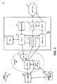
[0023] 図1は、LTEネットワークアーキテクチャ100を例示する図である。LTEネットワークアーキテクチャ100は、発展型パケットシステム(EPS:Evolved Packet System)100と称され得る。EPS100は、1つまたは複数のユーザ装置(UE)102、発展型UMTS地上無線アクセスネットワーク(E−UTRAN)104、発展型パケットコア(EPC)110、およびオペレータのインターネットプロトコル(IP)サービス122を含み得る。EPSは、他のアクセスネットワークと相互接続することができるが、簡潔さのために、それらのエンティティ/インタフェースは示されていない。示されているように、EPSは、パケット交換サービスを提供するが、当業者が容易に理解することになるように、本開示の全体にわたって提示される様々な概念は、回線交換サービスを提供するネットワークに拡張され得る。
FIG. 1 is a diagram illustrating an
[0024] E−UTRANは、発展型NodeB(eNB)106および他のeNB108を含み、およびマルチキャスト協調エンティティ(MCE:Multicast Coordination Entity)128を含み得る。eNB106は、UE102に対して、ユーザおよび制御プレーンプロトコル終端を提供する。eNB106は、バックホール(例えば、X2インタフェース)を介して、他のeNB108に接続され得る。MCE128は、発展型マルチメディアブロードキャストマルチキャストサービス(MBMS)(eMBMS)についての時間/周波数無線リソースを割り振り、eMBMSのための無線構成(例えば、変調およびコーディングスキーム(MCS))を決定する。MCE128は、別個のエンティティまたはeNB106の一部であり得る。eNB106は、基地局、ノードB、アクセスポイント、トランシーバ基地局、無線基地局、無線トランシーバ、トランシーバ機能、基本サービスセット(BSS:basic service set)、拡張サービスセット(ESS:extended service set)、または何らかの他の好適な用語でも呼ばれ得る。eNB106は、UE102にEPC110へのアクセスポイントを提供する。UE102の例は、セルラ電話、スマートフォン、セッション開始プロトコル(SIP)電話、ラップトップ、携帯情報端末(PDA)、衛星無線機(satellite radio)、全地球測位システム、マルチメディアデバイス、ビデオデバイス、デジタルオーディオプレーヤ(例えば、MP3プレーヤ)、カメラ、ゲーム機、タブレット、または任意の他の同様に機能するデバイスを含む。UE102はまた、当業者によって、モバイル局、加入者局、モバイルユニット、加入者ユニット、ワイヤレスユニット、遠隔ユニット、モバイルデバイス、ワイヤレスデバイス、ワイヤレス通信デバイス、遠隔デバイス、モバイル加入者局、アクセス端末、モバイル端末、ワイヤレス端末、遠隔端末、ハンドセット、ユーザエージェント、モバイルクライアント、クライアント、または何らかの他の好適な用語でも呼ばれ得る。
The E-UTRAN includes an evolved Node B (eNB) 106 and other eNBs 108, and may include a Multicast Coordination Entity (MCE) 128. The eNB 106 provides the UE 102 with user and control plane protocol termination. The eNBs 106 may be connected to other eNBs 108 via a backhaul (eg, X2 interface).
[0025] eNB106は、EPC110に接続される。EPC110は、モビリティ管理エンティティ(MME)112、ホーム加入者サーバ(HSS)120、他のMME114、サービングゲートウェイ116、マルチメディアブロードキャストマルチキャストサービス(MBMS)ゲートウェイ124、ブロードキャストマルチキャストサービスセンタ(BM−SC)126、およびパケットデータネットワーク(PDN)ゲートウェイ118を含み得る。MME112は、UE102とEPC110の間のシグナリングを処理する制御ノードである。一般に、MME112は、ベアラおよび接続管理を提供する。すべてのユーザIPパケットは、それ自体がPDNゲートウェイ118に接続されたサービングゲートウェイ116を通じて転送される。PDNゲートウェイ118は、UE IPアドレス割り振り、ならびに他の機能を提供する。PDNゲートウェイ118およびBM−SC126は、IPサービス122に接続される。IPサービス122は、インターネット、イントラネット、IPマルチメディアサブシステム(IMS:IP Multimedia Subsystem)、PSストリーミングサービス(PSS:PS Streaming Service)、および/または他のIPサービスを含み得る。BM−SC126は、MBMSユーザサービスプロビジョニングおよび配信(delivery)のための機能を提供し得る。BM−SC126は、コンテンツプロバイダMBMS送信のためのエントリポイントとしての役目を果たし得、PLMN内のMBMSベアラサービスを認可(authorize)および開始するために使用され得、MBMS送信をスケジュールおよび配信するために使用され得る。MBMSゲートウェイ124は、特定のサービスをブロードキャストするマルチキャストブロードキャスト単一周波数ネットワーク(MBSFN)エリアに属するeNB(例えば、106、108)にMBMSトラフィックを分配するために使用され得、セッション管理(開始/停止)とeMBMS関連課金情報を集めることとを担い得る。
The
[0026] ある態様では、UE102は、LTEネットワークおよびmmWシステムを介して信号を通信することが可能である。したがって、UE102は、LTEリンク上でeNB106および/または他のeNB108と通信し得る。加えて、UE102は、mmWリンク上で、接続ポイント(CP)、基地局(BS)(mmWシステム通信が可能である)、またはミリ波基地局(mmW−BS)130と通信し得る。
[0026] In an aspect,
[0027] さらなる態様において、他のeNB108のうちの少なくとも1つは、LTEネットワークおよびmmWシステムを介して信号を通信することが可能であり得る。したがって、eNB108は、LTE+mmW eNBと称され得る。別の態様では、CP/BS/mmW−BS130は、LTEネットワークおよびmmWシステムを介して信号を通信することが可能であり得る。したがって、CP/BS/mmW−BS130は、LTE+mmW CP/BS/mmW−BSと称され得る。UE102は、LTEリンク上で、ならびにmmWリンク上で他のeNB108と通信し得る。
[0027] In a further aspect, at least one of the
[0028] さらに別の態様では、他のeNB108は、LTEネットワークおよびmmWシステムを介して信号を通信することが可能であり得、一方でCP/BS/mmW−BS130は、mmWシステムを介してのみ信号を通信することが可能である。したがって、LTEネットワークを介して他のeNB108にシグナリングすることができないCP/BS/mmW−BS130は、mmWバックホールリンク上で他のeNB108と通信し得る。
[0028] In yet another aspect, the
[0029] 図2は、LTEネットワークアーキテクチャにおけるアクセスネットワーク200の例を例示する図である。この例では、アクセスネットワーク200は、いくつかのセルラ領域(セル)202に分割されている。1つまたは複数の、より低い電力クラスのeNB208は、セル202のうちの1つまたは複数とオーバーラップするセルラ領域210を有し得る。より低い電力クラスのeNB208は、フェムトセル(例えば、ホームeNB(HeNB))、ピコセル、マイクロセル、または遠隔無線ヘッド(RRH)であり得る。マクロeNB204は各々、それぞれのセル202に割り当てられ、複数のセル202中のすべてのUE206のためにEPC110へのアクセスポイントを提供するよう構成される。アクセスネットワーク200のこの例には集中型(centralized)コントローラは存在しないが、代替の構成では、集中型コントローラが使用され得る。eNB204は、無線ベアラ制御、アドミッション制御、モビリティ制御、スケジューリング、セキュリティ、およびサービングゲートウェイ116への接続性を含む、すべての無線に関連する機能(radio related function)を担う。eNBは、(セクタとも呼ばれる)1つまたは複数(例えば、3つ)のセルをサポートし得る。「セル」という用語は、特定のカバレッジエリアをサービスしているeNBサブシステムおよび/またはeNBの最小のカバレッジエリアを指すことができる。さらに、「eNB」、「基地局」、および「セル」という用語は、ここで交換可能に使用され得る。
[0029] FIG. 2 is a diagram illustrating an example of the
[0030] ある態様では、UE206は、LTEネットワークおよびmmWシステムを介して信号を通信し得る。したがって、UE206は、LTEリンク上でeNB204と通信し得、およびmmWリンク上でCPまたはBS212(mmWシステム通信が可能である)と通信し得る。さらなる態様において、eNB204およびCP/BS/mmW−BS212は、LTEネットワークおよびmmWシステムを介して信号を通信し得る。したがって、UE206は、LTEリンクおよびmmWリンク(eNB204がmmWシステム通信が可能であるとき)上でeNB204と通信し得るか、またはmmWリンクおよびLTEリンク(CP/BS/mmW−BS212がLTEネットワーク通信が可能であるとき)上でCP/BS/mmW−BS212と通信し得る。さらに別の態様では、eNB204は、LTEネットワークおよびmmWシステムを介して信号を通信し、一方でCP/BS/mmW−BS212は、mmWシステムを介してのみ信号を通信する。したがって、LTEネットワークを介してeNB204にシグナリングすることができないCP/BS/mmW−BS212は、mmWバックホールリンク上でeNB204と通信し得る。
[0030] In an aspect,
[0031] アクセスネットワーク200によって用いられる変調および多元接続スキームは、展開されている特定の電気通信規格に応じて異なり得る。LTEアプリケーションでは、OFDMがDLで使用され、SC−FDMAがULで使用されて、周波数分割複信(FDD)および時分割複信(TDD)の両方をサポートする。以下に続く詳細な説明から当業者が容易に理解するように、ここに提示される様々な概念は、LTEアプリケーションによく適している。しかしながら、これらの概念は、他の変調および多元接続技法を用いる他の電気通信規格に容易に拡張され得る。例として、これらの概念は、エボリューションデータオプティマイズド(EV−DO:Evolution-Data Optimized)またはウルトラモバイルブロードバンド(UMB:Ultra Mobile Broadband)に拡張され得る。EV−DOおよびUMBは、CDMA2000規格ファミリの一部として、3世代パートナーシッププロジェクト2(3GPP2)によって公表されたエアインターフェース規格であり、モバイル局にブロードバンドインターネットアクセスを提供するためにCDMAを用いる。これらの概念はまた、広帯域CDMA(W−CDMA(登録商標))およびTD−SCDMAのようなCDMAの他の変形例を用いるユニバーサル地上無線アクセス(UTRA)、TDMAを用いるモバイル通信のためのグローバルシステム(GSM(登録商標))、およびOFDMAを用いるフラッシュOFDM、IEEE802.20、IEEE802.16(WiMAX)、IEEE802.11(Wi−Fi)、および発展型UTRA(E−UTRA)にも拡張され得る。UTRA、E−UTRA、UMTS、LTE、およびGSMは、3GPP団体からの文書に説明されている。CDMA2000およびUMBは、3GPP2団体からの文書に説明されている。用いられる実際のワイヤレス通信規格および多元接続技術は、特定の用途およびシステムに課せられる全体的な設計制約に依存するだろう。
[0031] The modulation and multiple access schemes used by
[0032] eNB204は、MIMO技術をサポートする複数のアンテナを有し得る。MIMO技術の使用は、eNB204が、空間多重化、ビームフォーミング、および送信ダイバーシティをサポートするために空間領域を活用することを可能にする。空間多重化は、異なるデータストリームを同一の周波数で同時に送信するために使用され得る。データストリームは、データレートを増加させるために単一のUE206に、または、全体的なシステム容量を増加させるために複数のUE206に、送信され得る。これは、各データストリームを空間的にプリコーディングし(すなわち、振幅および位相のスケーリングを適用し)、その後、DL上で複数の送信アンテナを通して、各空間的にプリコーディングされたストリームを送信することによって、達成される。空間的にプリコーディングされたデータストリームは、異なる空間シグネチャとともにUE206(1つまたは複数の)へと到達し、これにより、UE206(1つまたは複数の)の各々がそのUE206を宛先とする1つまたは複数のデータストリームを復元(recover)することが可能になる。ULにおいて、各UE206は、空間的にプリコーディングされたデータストリームを送信し、これにより、eNB204が各空間的にプリコーディングされたデータストリームのソースを識別することが可能になる。
The
[0033] 空間多重化は、一般にチャネル状態が良好な場合に使用される。チャネル状態が良好とは言えないときには、1つまたは複数の方向に送信エネルギーを集中させるためにビームフォーミングが使用され得る。これは、複数のアンテナを通じた送信のためにデータを空間的にプリコーディングすることによって達成され得る。セルのエッジにおいて優れたカバレッジを達成するために、シングルストリームビームフォーミング送信が、送信ダイバーシティと組み合わせて使用され得る。 [0033] Spatial multiplexing is generally used when channel conditions are good. When the channel conditions are not good, beamforming may be used to concentrate the transmit energy in one or more directions. This may be achieved by spatially precoding data for transmission through multiple antennas. Single stream beamforming transmission may be used in combination with transmit diversity to achieve good coverage at the edge of the cell.
[0034] 以下の詳細な説明では、アクセスネットワークの様々な態様が、DL上でOFDMをサポートするMIMOシステムに関連して説明されることになる。OFDMは、OFDMシンボル内のいくつかのサブキャリアにわたってデータを変調する技法である。これらサブキャリアは、正確な周波数で間隔を空けて配置される。この間隔を空けること(spacing)は、受信機がこれらサブキャリアからのデータを復元することを可能にする「直交性」を提供する。時間領域では、OFDMシンボル間干渉に対抗するために、各OFDMシンボルにガードインターバル(例えば、サイクリックプリフィックス)が追加され得る。ULは、高いピーク対平均電力比(PAPR)を補償する(compensate for)ために、DFT拡散OFDM信号(a DFT-spread OFDM signal)の形態でSC−FDMAを使用し得る。 [0034] In the following detailed description, various aspects of the access network will be described in connection with a MIMO system that supports OFDM over DL. OFDM is a technique for modulating data over several subcarriers in an OFDM symbol. These subcarriers are spaced apart at the correct frequency. This spacing provides "orthogonality" which allows the receiver to recover data from these subcarriers. In the time domain, guard intervals (eg, cyclic prefixes) may be added to each OFDM symbol to combat OFDM inter-symbol interference. The UL may use SC-FDMA in the form of a DFT-spread OFDM signal to compensate for high peak to average power ratio (PAPR).
[0035] 図3は、LTEにおけるDLフレーム構造の例を例示する図300である。フレーム(10ms)は、10個の等しいサイズのサブフレームに分割され得る。各サブフレームは、2つの連続したタイムスロットを含み得る。1つのリソースグリッドが2つのタイムスロットを表すために使用され得、各タイムスロットは、1つのリソースブロックを含む。リソースグリッドは、複数のリソース要素に分割される。LTEでは、通常のサイクリックプリフィックスの場合、1つのリソースブロックは、周波数領域における12個の連続したサブキャリアと時間領域における7個の連続したOFDMシンボルの合計84個のリソース要素を含む。拡張されたサイクリックプリフィックスの場合、1つのリソースブロックは、周波数領域における12個の連続したサブキャリアと時間領域における6個の連続したOFDMシンボルの合計72個のリソース要素を含む。R302、304として示される、複数のリソース要素のうちのいくつかは、DL基準信号(DL−RS)を含む。DL−RSは、(共通RSと呼ばれることもある)セル固有RS(CRS)302およびUE固有RS(UE−RS)304を含む。UE−RS304は、対応する物理DL共有チャネル(PDSCH)がマッピングされるリソースブロック上でのみ送信される。各リソース要素によって搬送されるビット数は、変調スキームに依存する。したがって、UEが受信するリソースブロックが多いほど、および、変調スキームが高いほど、UEのためのデータレートはより高くなる。
[0035] FIG. 3 is a diagram 300 illustrating an example of a DL frame structure in LTE. A frame (10 ms) may be divided into 10 equally sized subframes. Each subframe may include two consecutive time slots. One resource grid may be used to represent two time slots, each time slot including one resource block. A resource grid is divided into a plurality of resource elements. In LTE, in the case of a normal cyclic prefix, one resource block includes a total of 84 resource elements: 12 consecutive subcarriers in the frequency domain and 7 consecutive OFDM symbols in the time domain. In the case of extended cyclic prefix, one resource block includes a total of 72 resource elements: 12 consecutive subcarriers in the frequency domain and 6 consecutive OFDM symbols in the time domain. Some of the plurality of resource elements, shown as
[0036] 図4は、LTEにおけるULフレーム構造の例を例示する図400である。ULのために利用可能なリソースブロックは、データセクションと制御セクションとに区分され得る。制御セクションは、システム帯域幅の2つのエッジに形成され得、設定可能なサイズを有し得る。制御セクションにおけるリソースブロックは、制御情報の送信のためにUEに割り当てられ得る。データセクションは、制御セクションに含まれないすべてのリソースブロックを含み得る。このULフレーム構造は、連続的なサブキャリアを含むデータセクションをもたらし、それは単一のUEがデータセクションにおける連続的なサブキャリアのすべてを割り当てられることを可能にし得る。 [0036] FIG. 4 is a diagram 400 illustrating an example of a UL frame structure in LTE. Resource blocks available for UL may be partitioned into data sections and control sections. The control section may be formed at two edges of the system bandwidth and may have a configurable size. Resource blocks in the control section may be assigned to the UE for transmission of control information. The data section may include all resource blocks not included in the control section. This UL frame structure results in a data section that includes contiguous subcarriers, which may allow a single UE to be assigned all of the contiguous subcarriers in the data section.
[0037] UEは、eNBに制御情報を送信するために、制御セクションにおけるリソースブロック410a、410bを割り当てられ得る。UEはまた、eNBにデータを送信するために、データセクションにおけるリソースブロック420a、420bを割り当てられ得る。UEは、制御セクションにおける割り当てられたリソースブロック上の物理UL制御チャネル(PUCCH)において制御情報を送信し得る。UEは、データセクション中の割り当てられたリソースブロック上の物理UL共有チャネル(PUSCH)において、データのみ、またはデータと制御情報の両方を送信し得る。UL送信は、サブフレームの両方のスロットにまたがり得(span)、周波数にわたってホッピングし得る。
[0037] The UE may be assigned
[0038] リソースブロックのあるセットが、最初のシステムアクセスを実行し、物理ランダムアクセスチャネル(PRACH)430においてUL同期を達成するために、使用され得る。PRACH430は、ランダムシーケンスを搬送するが、何れのULデータ/シグナリングも搬送することはできない。各ランダムアクセスプリアンブルは、6個の連続したリソースブロックに対応する帯域幅を占有する。開始周波数(starting frequency)は、ネットワークによって規定される。すなわち、ランダムアクセスプリアンブルの送信は、ある特定の時間および周波数リソースに制限される。PRACHについては周波数ホッピングは存在しない。PRACH試行(PRACH attempt)は、単一のサブフレーム(1ms)において、または少数の連続的なサブフレームのシーケンスにおいて搬送され、UEは、1フレーム(10ms)ごとに単一のPRACH試行だけを行うことができる。
[0038] A set of resource blocks may be used to perform initial system access and to achieve UL synchronization on physical random access channel (PRACH) 430. The
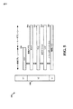
[0039] 図5は、LTEにおけるユーザおよび制御プレーンのための無線プロトコルアーキテクチャの例を例示する図500である。UEおよびeNBのための無線プロトコルアーキテクチャは、レイヤ1、レイヤ2、およびレイヤ3の3つのレイヤで示される。レイヤ1(L1レイヤ)は、最下位のレイヤであり、様々な物理レイヤ信号処理機能をインプリメントする。L1レイヤは、ここで物理レイヤ506と呼ばれることになる。レイヤ2(L2レイヤ)508は、物理レイヤ506より上位にあり、物理レイヤ506を介したUEとeNBとの間のリンクを担う。
[0039] FIG. 5 is a diagram 500 illustrating an example of a radio protocol architecture for users and control planes in LTE. The radio protocol architecture for UE and eNB is shown in three layers:
[0040] ユーザプレーンにおいて、L2レイヤ508は、媒体アクセス制御(MAC)サブレイヤ510、無線リンク制御(RLC)サブレイヤ512、およびパケットデータコンバージェンスプロトコル(PDCP)514サブレイヤを含み、これらは、ネットワーク側のeNBにおいて終端される。示されていないが、UEは、ネットワーク側のPDNゲートウェイ118において終端されるネットワークレイヤ(例えば、IPレイヤ)と、接続の他端(例えば、遠端の(far end)UE、サーバなど)において終端されるアプリケーションレイヤとを含む、L2レイヤ508より上位のいくつかの上位レイヤを有し得る。
In the user plane, the
[0041] PDCPサブレイヤ514は、異なる無線ベアラと論理チャネルとの間の多重化を提供する。PDCPサブレイヤ514はまた、無線送信オーバヘッドを低減するための上位レイヤデータパケットのためのヘッダ圧縮、データパケットを暗号化することによるセキュリティ、およびeNB間でのUEに対するハンドオーバサポートを提供する。RLCサブレイヤ512は、上位レイヤデータパケットのセグメンテーションおよび再組立て(reassembly)と、損失データパケットの再送信と、ハイブリッド自動再送要求(HARQ:hybrid automatic repeat request)による、順序の狂った受信を補正(compensate for)するデータパケットの並べ替えとを提供する。MACサブレイヤ510は、論理チャネルとトランスポートチャネルの間の多重化を提供する。MACサブレイヤ510はまた、複数のUEの間で1つのセルにおける様々な無線リソース(例えば、リソースブロック)を割り振ることを担う。MACサブレイヤ510はまた、HARQ動作を担う。
[0041] The
[0042] 制御プレーンでは、eNBおよびUEのための無線プロトコルアーキテクチャは、制御プレーンについてはヘッダ圧縮機能がないことを除いて、物理レイヤ506およびL2レイヤ508については実質的に同じである。制御プレーンはまた、レイヤ3(L3レイヤ)に無線リソース制御(RRC)サブレイヤ516を含む。RRCサブレイヤ516は、無線リソース(例えば、無線ベアラ)を取得することと、eNBとUEとの間でRRCシグナリングを使用して下位レイヤを構成することとを担う。
In the control plane, the radio protocol architecture for eNB and UE is substantially the same for
[0043] 図6は、アクセスネットワークにおいてUE650と通信している基地局610のブロック図である。基地局610は、例えば、LTEシステムのeNB、mmWシステムの接続ポイント(CP:connection point)/アクセスポイント/基地局、LTEシステムおよびmmWシステムを介して信号を通信することが可能であるeNB、または、LTEシステムおよびmmWシステムを介して信号を通信することが可能である接続ポイント(CP)/アクセスポイント/基地局であり得る。UE650は、LTEシステムおよび/またはmmWシステムを介して信号を通信することが可能であり得る。DLでは、コアネットワークからの上位レイヤパケットが、コントローラ/プロセッサ675に提供される。コントローラ/プロセッサ675は、L2レイヤの機能性をインプリメントする。DLでは、コントローラ/プロセッサ675は、様々な優先順位メトリック(priority metrics)に基づいて、UE650への無線リソースの割り振り、論理チャネルとトランスポートチャネルとの間の多重化、パケットのセグメンテーションおよび並べ替え、暗号化、およびヘッダ圧縮を提供する。コントローラ/プロセッサ675はまた、HARQ動作、損失パケットの再送信、およびUE650へのシグナリングを担う。
[0043] FIG. 6 is a block diagram of a
[0044] 送信(TX)プロセッサ616は、L1レイヤ(すなわち、物理レイヤ)に関する様々な信号処理機能をインプリメントする。信号処理機能は、UE650における前方誤り訂正(FEC:forward error correction)を容易にするためにコーディングおよびインタリーブすることと、様々な変調スキーム(例えば、2相位相シフトキーイング(BPSK:binary phase-shift keying)、4相位相シフトキーイング(QPSK:quadrature phase-shift keying)、M相位相シフトキーイング(M−PSK:M-phase-shift keying)、M値直交振幅変調(M−QAM:M-quadrature amplitude modulation))に基づいて信号コンステレーション(signal constellation)へマッピングすることと、を含む。その後、コーディングおよび変調されたシンボルは、並列ストリーム(parallel streams)に分けられる。その後、各ストリームは、OFDMサブキャリアにマッピングされ、時間および/または周波数領域において基準信号(例えば、パイロット)と多重化され、その後、逆高速フーリエ変換(IFFT:Inverse Fast Fourier Transform)を使用して組み合わされ、時間領域OFDMシンボルストリームを搬送する物理チャネルを作り出す。OFDMストリームは、複数の空間ストリームを作り出すために空間的にプリコーディングされる。チャネル推定器674からのチャネル推定値は、コーディングおよび変調スキームを決定するため、ならびに空間処理のために使用され得る。チャネル推定値は、UE650によって送信されたチャネル状態フィードバックおよび/または基準信号から導出され得る。そして、各空間ストリームは、別個の送信機618TXを介して異なるアンテナ620に提供され得る。各送信機618TXは、送信のためにそれぞれの空間ストリームでRFキャリアを変調し得る。
[0044] A transmit (TX)
[0045] UE650において、各受信機654RXは、そのそれぞれのアンテナ652を通じて信号を受信する。各受信機654RXは、RFキャリア上に変調された情報を復元し、受信(RX)プロセッサ656にこの情報を提供する。RXプロセッサ656は、L1レイヤの様々な信号処理機能をインプリメントする。RXプロセッサ656は、UE650を宛先とする任意の空間ストリームを復元するために、この情報に対して空間処理を実行し得る。複数の空間ストリームがUE650を宛先とする場合、それらは、RXプロセッサ656によって単一のOFDMシンボルストリームに組み合わされ得る。その後、RXプロセッサ656は、高速フーリエ変換(FFT)を使用して、OFDMシンボルストリームを時間領域から周波数領域に変換する。周波数領域信号は、OFDM信号の各サブキャリアについて別個のOFDMシンボルストリームを備える。各サブキャリア上のシンボル、および基準信号は、基地局610によって送信された最も可能性の高い(most likely)信号コンステレーションポイントを決定することによって復元および復調される。これらの軟判定(soft decision)は、チャネル推定器658によって計算されるチャネル推定値に基づき得る。その後、軟判定は、物理チャネル上で基地局610によって本来送信された制御信号およびデータを復元するために、復号およびデインタリーブされる。その後、データおよび制御信号は、コントローラ/プロセッサ659に提供される。
At
[0046] コントローラ/プロセッサ659は、L2レイヤをインプリメントする。コントローラ/プロセッサは、プログラムコードおよびデータを記憶するメモリ660に関連付けられることができる。メモリ660は、コンピュータ読み取り可能な媒体と呼ばれ得る。DLでは、コントローラ/プロセッサ659は、コアネットワークからの上位レイヤパケットを復元するために、トランスポートチャネルと論理チャネルの間の逆多重化、パケットの再組立て、暗号解読(deciphering)、ヘッダ復元(header decompression)、制御信号処理を提供する。その後、上位レイヤパケットはデータシンク662に提供され、それはL2レイヤより上位のすべてのプロトコルレイヤを表す。様々な制御信号もまた、L3処理のためにデータシンク662に提供され得る。コントローラ/プロセッサ659はまた、HARQ動作をサポートするために、肯定応答(ACK)および/または否定応答(NACK)プロトコルを使用した誤り検出を担う。
The controller /
[0047] ULでは、データソース667は、コントローラ/プロセッサ659に上位レイヤパケットを提供するために使用される。データソース667は、L2レイヤより上位のすべてのプロトコルレイヤを表す。基地局610によるDL送信に関して説明された機能性と同様に、コントローラ/プロセッサ659は、基地局610による無線リソース割り振りに基づいた論理チャネルとトランスポートチャネルの間の多重化、パケットセグメンテーションおよび並べ替え、暗号化、およびヘッダ圧縮を提供することによって、ユーザプレーンおよび制御プレーンのためのL2レイヤをインプリメントする。コントローラ/プロセッサ659はまた、HARQ動作、損失パケットの再送信、および基地局610へのシグナリングを担う。
In UL,
[0048] 基地局610によって送信されたフィードバックまたは基準信号からチャネル推定器658によって導出されたチャネル推定値は、TXプロセッサ668によって、適切なコーディングおよび変調スキームを選択し、および空間処理を容易にするために使用され得る。TXプロセッサ668によって生成された空間ストリームは、別個の送信機654TXを介して異なるアンテナ652に提供され得る。各送信機654TXは、送信のためにそれぞれの空間ストリームでRFキャリアを変調し得る。
[0048] Channel estimates derived by
[0049] UL送信は、UE650における受信機機能に関して説明されたものと同様の方法で基地局610において処理される。各受信機618RXは、それのそれぞれのアンテナ620を通じて信号を受信する。各受信機618RXは、RFキャリア上に変調された情報を復元し、RXプロセッサ670にこの情報を提供する。RXプロセッサ670は、L1レイヤをインプリメントし得る。
UL transmissions are processed at
[0050] コントローラ/プロセッサ675は、L2レイヤをインプリメントする。コントローラ/プロセッサ675は、プログラムコードおよびデータを記憶するメモリ676に関連付けられることができる。メモリ676は、コンピュータ読み取り可能な媒体と呼ばれ得る。ULでは、コントロール/プロセッサ675は、UE650からの上位レイヤパケットを復元するために、トランスポートチャネルと論理チャネルの間の逆多重化、パケットの再組立て、暗号解読、ヘッダ復元、制御信号処理を提供する。コントローラ/プロセッサ675からの上位レイヤパケットは、コアネットワークに提供され得る。コントローラ/プロセッサ675はまた、HARQ動作をサポートするために、ACKおよび/またはNACKプロトコルを使用した誤り検出を担う。
The controller /
[0051] 図7は、デバイスツーデバイス通信システム700の図である。デバイスツーデバイス通信システム700は、複数のワイヤレスデバイス704、706、708、710を含む。デバイスツーデバイス通信システム700は、例えば、ワイヤレス広域ネットワーク(WWAN)のようなセルラ通信システムとオーバーラップし得る。ワイヤレスデバイス704、706、708、710のうちのいくつかは、DL/UL WWANスペクトルを使用してデバイスツーデバイス通信で互いに通信し得、またいくつかは基地局702と通信し得、またその両方を行い得るものもある。例えば、図7に示すように、ワイヤレスデバイス708、710がデバイスツーデバイス通信状態にあり、ワイヤレスデバイス704、706がデバイスツーデバイス通信状態にある。ワイヤレスデバイス704、706はまた、基地局702とも通信している。
FIG. 7 is a diagram of a device to
[0052] 以下に説明される例示的な方法および装置は、例えば、IEEE802.11規格に基づくWi−Fi、ZigBee、Bluetooth(登録商標)、WiMedia、またはFlashLinQに基づいたワイヤレスデバイスツーデバイス通信システムのような、様々なワイヤレスデバイスツーデバイス通信システムの何れにも適用可能である。説明を簡潔にするために、例示的な方法および装置は、LTEの文脈の中で説明される。しかしながら、当業者は、例示的な方法および装置が、より広く様々な他のワイヤレスデバイスツーデバイス通信システムに適用可能であることを理解するだろう。 [0052] The exemplary methods and apparatus described below are, for example, wireless device-to-device communication systems based on Wi-Fi, ZigBee, Bluetooth (registered trademark), WiMedia, or FlashLinQ based on the IEEE 802.11 standard. Such is applicable to any of a variety of wireless device-to-device communication systems. For the sake of brevity, exemplary methods and apparatus are described in the context of LTE. However, one skilled in the art will appreciate that the exemplary methods and apparatus are applicable to a wider variety of other wireless device-to-device communication systems.
[0053] 高いデータレートシグナリングをインプリメントするmmWシステムは、高い伝播および侵入損失(high propagation and penetration losses)を被り得る。これらの損失のかなりの部分は、例えば位相配列(a phased array)の形式の、マルチプルアンテナの使用によって克服され得る。キャリア波長は、より高い周波数において実質的により短いので、高周波数ワイヤレス通信システム(例えば、10.0GHzから300.0GHzの周波数範囲におけるキャリアを使用するmmWワイヤレス通信システム)においては、同じ開口/エリア(the same aperture/area)内に、低周波数ワイヤレス通信システム(例えば、6GHzを下回る周波数を有するキャリアを使用するLTEネットワーク)におけるよりも多くのアンテナがパック(packed within)され得る。mmWシステムにおけるシグナリングのための1つのアプローチは、送信機および受信機の両方における物理的に誘導されたアレイステアリング(physically-motivated array steering)であり、それは、アレイ/ビームフォーミング利得の利点を取得することによってリンクマージンの改善を可能にする。アレイステアリングベクトルの半電波強度ビーム幅(the half-power beam width)は位相配列におけるアンテナの数の増加とともに減少するので、物理的に誘導されたアレイステアリングは、シグナリングの極めて指向性のある性質(the highly directional nature)により高い周波数再使用を可能にする。 [0053] mmW systems that implement high data rate signaling may suffer high propagation and penetration losses. A significant portion of these losses can be overcome by the use of multiple antennas, for example in the form of a phased array. Since the carrier wavelength is substantially shorter at higher frequencies, the same aperture / area (eg, in a mmW wireless communication system using carriers in the frequency range of 10.0 GHz to 300.0 GHz), as in high frequency wireless communication systems Within the same aperture / area), more antennas may be packed within than in low frequency wireless communication systems (e.g., LTE networks using carriers with frequencies below 6 GHz). One approach for signaling in mmW systems is physically-motivated array steering at both the transmitter and the receiver, which takes advantage of the array / beamforming gain Enables to improve the link margin. Since the half-power beam width of the array steering vector decreases with the increase of the number of antennas in the phase alignment, physically induced array steering is an extremely directional nature of the signaling ( Allows high frequency reuse with the highly directional nature).
[0054] mmWシステムにおける物理的に誘導されたアレイステアリングは、現在ならびに過去の世代のワイヤレス標準化活動においてビームフォーミングプロトコルが低周波数キャリアシステムのために設計されてきた方法とは異なる。そのような標準化活動では、コードブックベースのまたは非コードブックベースのプリコーディングスキームのようなアプローチが通常使用される。 [0054] Physically derived array steering in the mmW system differs from the way in which beamforming protocols have been designed for low frequency carrier systems in current and past generations of wireless standardization activities. In such standardization activities, approaches such as codebook based or non-codebook based precoding schemes are usually used.
[0055] 物理的に誘導されたアレイステアリングは、ワイヤレスチャネル中の主要なマルチパス(the dominant multipath)の角度情報の発見によって達成され得る。例えば、角度情報は、方位角(azimuth)および迎角(elevation)における放射角(angle of departure)、および/または、方位角および迎角における到来角(angle of arrival)を含み得る。ある態様では、mmWシステムのような高周波数キャリアシステムは、LTEネットワークのような低周波数キャリアシステムと共存し得る。そのような態様では、低周波数キャリアシステムが送信機と受信機との間の通信リンクを確立するために使用されないとき、低周波数キャリアシステムは、mmWリンク確立プロセスに活用され得る。 [0055] Physically derived array steering may be achieved by finding angular information of the dominant multipath in the wireless channel. For example, the angle information may include an azimuth and an angle of departure at elevation, and / or an angle of arrival at azimuth and angle of attack. In an aspect, a high frequency carrier system such as a mmW system may co-exist with a low frequency carrier system such as an LTE network. In such an aspect, when the low frequency carrier system is not used to establish a communication link between the transmitter and the receiver, the low frequency carrier system may be leveraged for the mmW link establishment process.
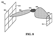
[0056] 図8は、低周波数ワイヤレス通信システム(例えば、LTE)におけるビームフォーミングの例を例示する図800である。図8は、アンテナアレイ802および804を含む。ある態様では、アンテナアレイ802は、グリッドパターン(例えば、平面アレイ)に配列されたいくつかのアンテナ要素(例えば、アンテナ要素812)を含み得、BSに位置し得る。そのような態様では、アンテナアレイ804は、グリッドパターンに配列されたいくつかのアンテナ要素(例えば、アンテナ要素814)を含み得、UEに位置し得る。図8に示されるように、アンテナアレイ802はビーム806を送信し得、アンテナアレイ804はビーム808を介して受信し得る。ある態様では、ビーム806および808は、エリア810に位置するクラスタを介して反射(reflect)、散乱(scatter)および/または回折(diffract)し得る。
FIG. 8 is a diagram 800 illustrating an example of beamforming in a low frequency wireless communication system (eg, LTE). FIG. 8 includes
[0057] 図9は、高周波数ワイヤレス通信システム(例えば、mmWシステム)におけるビームフォーミングを例示する図900である。図9は、アンテナアレイ902および904を含む。ある態様では、アンテナアレイ902は、グリッドパターンに配列されたいくつかのアンテナ要素(例えば、アンテナ要素912)を含み得、mmW−BSに位置し得る。そのような態様では、アンテナアレイ904は、グリッドパターンに配列されたいくつかのアンテナ要素(例えば、アンテナ要素914)を含み得、UEに位置し得る。図9に示されるように、アンテナアレイ902は、ビーム906を送信し得、アンテナアレイ904は、ビーム908を介して受信し得る。ある態様では、ビーム906および908は、エリア910に位置するクラスタを介して反射、散乱および/または回折し得る。
FIG. 9 is a diagram 900 illustrating beamforming in a high frequency wireless communication system (eg, a mmW system). FIG. 9 includes
[0058] 図9におけるアンテナアレイ902は、図8におけるアンテナアレイ802より多くの数のアンテナ要素を含むこと、および図9におけるアンテナアレイ904は、図8におけるアンテナアレイ804より多くの数のアンテナ要素を含むことに留意されたい。前者の状況において(後者に比べて)より多くの数のアンテナがある原因は、同じ開口/エリア内により多くの数のアンテナの配置(deployment)を可能にする、より短い波長に対応するより大きなキャリア周波数である。アンテナアレイ902および904におけるより多くの数のアンテナ要素によって、ビーム906および908が、アンテナアレイ802および804からのビーム806および808に比べて高い角度分解能(a high angular resolution)を提供(offering)する狭い半電波強度ビーム幅を有することが可能になる。故に、低周波数ワイヤレス通信システムにおけるアンテナアレイ802および804におけるより少ない数のアンテナ要素は、mmWシステムにおけるよりもより良いリンクマージンを提供すると同時に、より広い角度分解能をもたらし得る。
[0059] スタンドアロンのmmWワイヤレス通信システムにおいて、(侵入(penetration)、回折(diffraction)、反射等に起因する)高いリンク損失は、マルチパスの角度情報の発見を妨げ得る。対照的に、低周波数ワイヤレス通信システムは、スタンドアロンのmmWワイヤレス通信システムにおけるリンクよりもより高い品質を有するリンク(例えば、より高いSNRを有するリンク)を提供し得る。低周波数ワイヤレス通信システムのこのより高いSNRと、低周波数とスタンドアロンのmmWワイヤレス通信システムとの共存とは、ビームフォーミングスキームに関する角度情報および/または相対経路利得(relative path gains)を決定するために活用され得る。ビームフォーミングスキームに関する角度情報および/または相対経路利得は、送信機、受信機、および散乱体(scatterers)の相対的なジオメトリ(relative geometries)によってのみ決定されるので、そのような角度情報および/または相対経路利得は一般に、スタンドアロンのmmWおよび低周波数ワイヤレス通信システムの両方において変わらない(invariant)。経路の(優位性(dominance)の)順位付けが、(例えば、異なる周波数における吸収損失(absorption losses)および/または回折散乱(differential scattering)に起因して)キャリア周波数の変化に伴って変化し得る状況が存在する一方で、ほとんどの場合には、そのような順位付けは変化しないであろう。 [0059] In stand-alone mmW wireless communication systems, high link loss (due to penetration, diffraction, reflection, etc.) may prevent the discovery of multipath angle information. In contrast, low frequency wireless communication systems may provide links with higher quality (eg, links with higher SNR) than links in stand-alone mmW wireless communication systems. This higher SNR of the low frequency wireless communication system and the coexistence of the low frequency and stand-alone mmW wireless communication system is exploited to determine the angular information and / or relative path gains for the beamforming scheme. It can be done. The angular information and / or relative path gain for the beamforming scheme is determined only by the relative geometry of the transmitters, receivers and scatterers, such angular information and / or Relative path gain is generally invariant in both stand-alone mmW and low frequency wireless communication systems. The ranking of the paths (of dominance) may change with changes in carrier frequency (eg due to absorption losses and / or differential scattering at different frequencies) While the situation exists, in most cases such ranking will not change.
[0060] ある態様では、高いSNRで成功したビームの到来角および放射角の学習の方法は、低周波数ワイヤレス通信システムにおいてビームの到来角および放射角を学習するために使用され得る。そのような方法は、MUSIC(MUltiple SIgnal Classification)、ESPRIT(Estimation of Signal Parameters via Rotation Invariant Techniques)、SAGE(Space-Alternating Generalized Expectation-maximization)アルゴリズム等を含み得る。いくつかの状況では、低周波数ワイヤレス通信システムにおける低周波数送信の広いビーム幅は、不良角度精度(poor angular precision)もたらし得る。1つの態様では、低周波数ワイヤレス通信システムに関して学習された角度(angle)は、mmWワイヤレス通信システムにおけるビームフォーミングのために必要とされる(角度情報とも呼ばれる)角度に関する粗い推定値として機能し得る。mmWワイヤレス通信システムに関する角度情報の精密推定値は、低周波数ワイヤレス通信システムを介して取得された粗い角度推定値を、初期値(シード値とも呼ばれる)として使用して、決定され得る。例えば、精密推定値は、ビームの微調整(fine-beam tuning)または制約されたMUSIC(constrained MUSIC)のようなアルゴリズムを使用して決定され得る。 [0060] In an aspect, the high SNR successful beam arrival and emission angle learning method may be used to learn beam arrival and emission angles in a low frequency wireless communication system. Such methods may include MUSIC (MUltiple SIgnal Classification), ESPRIT (Estimation of Signal Parameters via Rotation Invariant Techniques), SAGE (Space-Alternating Generalized Expectation-maximization) algorithms, and the like. In some situations, the wide beamwidth of low frequency transmission in low frequency wireless communication systems can result in poor angular precision. In one aspect, the learned angle for a low frequency wireless communication system may serve as a rough estimate for the angle (also referred to as angle information) needed for beamforming in a mmW wireless communication system. A precise estimate of the angle information for the mmW wireless communication system may be determined using the coarse angle estimate obtained via the low frequency wireless communication system as an initial value (also called a seed value). For example, the precision estimate may be determined using an algorithm such as fine-beam tuning or constrained MUSIC.
[0061] ある態様では、mmWワイヤレス通信システムに関する初期発見および同期プロシージャ、ビームフォーミングプロセス、および/またはリンク確立に関連するレイテンシは、低周波数ワイヤレス通信システムにおける粗い角度推定とそれに続くmmWワイヤレス通信システムにおけるビームの微調整との反復される組み合わせ(an iterated combination)を使用して、低減され得る。ある態様では、そのような反復的なプロセスは、様々な量の推定値の品質を改善するための、低周波数ワイヤレス通信システムとそれに続くmmWワイヤレス通信システムの繰り返される使用を含み得る。 [0061] In an aspect, latency associated with initial discovery and synchronization procedures, beamforming processes, and / or link establishment for a mmW wireless communication system may be coarse angle estimation followed by a subsequent low frequency wireless communication system in the mmW wireless communication system. It can be reduced using an repeated combination with beam fine tuning. In an aspect, such an iterative process may include repeated use of a low frequency wireless communication system followed by a mmW wireless communication system to improve the quality of various amounts of estimates.
[0062] ある態様では、mmWワイヤレス通信システムと低周波数ワイヤレス通信システムとの間の非対称の能力は、mmWワイヤレス通信システムおよび低周波数ワイヤレス通信システムをインプリメントするために使用されるアルゴリズムの複雑性を低減するために活用され得る。例えば、低周波数ワイヤレス通信システムは、mmWワイヤレス通信システムより少ない数のアンテナを使用し得る。そのような、アンテナの数における非対称性は、MUSIC、ESPRITおよび/またはSAGEのようなアルゴリズムにおいて可能性のある信号方向を推定するために活用され得る。任意のそのようなアルゴリズム(例えば、MUSIC、ESPRIT、および/またはSAGE)を用いて可能性のある信号方向を推定することは、信号共分散行列(the signal covariance matrix)の正確な推定値を取得することに基づくことに留意されたい。例えば、信号共分散行列の正確な推定は、より大規模な(larger dimensional)システムの場合と比較してより小さいアンテナシステムの場合に、より少ない数のトレーニングサンプル(またはより短い共分散行列取得および角度学習期間)を使用して、且つより低い計算コスト(より少ない数の乗算および加算、ならびにより小規模(smaller dimension)の行列反転)で、達成され得る。 [0062] In an aspect, the ability of the asymmetry between the mmW wireless communication system and the low frequency wireless communication system reduces the complexity of the algorithms used to implement the mmW wireless communication system and the low frequency wireless communication system. Can be used to For example, low frequency wireless communication systems may use fewer antennas than mmW wireless communication systems. Such asymmetry in the number of antennas may be exploited to estimate the potential signal direction in algorithms such as MUSIC, ESPRIT and / or SAGE. Estimating possible signal directions using any such algorithm (eg, MUSIC, ESPRIT, and / or SAGE) obtains an accurate estimate of the signal covariance matrix Note that it is based on For example, accurate estimation of the signal covariance matrix may result in a smaller number of training samples (or shorter covariance matrix acquisitions and in the case of smaller antenna systems compared to larger dimensional systems). It can be achieved using angle learning periods) and with lower computational costs (less number of multiplications and additions, and smaller dimension matrix inversion).
[0063] ある態様では、送信機と受信機との間の非対称の能力は、mmWワイヤレス通信システムよりも、低周波数ワイヤレス通信システムにおける角度決定のために、より多くのリソースを比例的に割り振るために、活用され得る。例えば、非対称の能力は、送信機および受信機における異なる数のアンテナ、送信機と受信機との間の異なるビームフォーミング能力(例えば、デジタルビームフォーミング能力またはRFビームフォーミング能力)、および/または受信機におけるより低い電力を含み得る。 [0063] In an aspect, the ability of asymmetry between the transmitter and the receiver proportionally allocates more resources for angle determination in low frequency wireless communication systems than in mmW wireless communication systems. Can be utilized. For example, the asymmetric capability may be different numbers of antennas at the transmitter and receiver, different beamforming capabilities between the transmitter and the receiver (eg, digital beamforming or RF beamforming capabilities), and / or the receiver. May include lower power at
[0064] ある態様では、低周波数ワイヤレス通信システムから取得されたセルフレームおよびOFDMシンボルタイミング情報は、mmWワイヤレス通信システムを用いたさらなる精密化(refinement)のための初期値として使用され得る。低周波数ワイヤレス通信システムは一般にmmWワイヤレス通信システムより良いSNRを提供するので、そのような態様では、これらの量は、より高い周波数(例えば、10.0GHZから300.0GHzの間の周波数)におけるよりも、より低い周波数(例えば、6.0GHzを下回る)において、より確実に推定され得る。ある態様では、セルフレームおよび/またはOFDMシンボルタイミング情報は、UEがセルと同期すること、およびセルフレームタイミング、キャリア周波数オフセット、OFDMシンボルタイミング、および/またはセルアイデンティフィケーション(ID)のような関心量(quantities of interest)を検出することを可能にする、同期信号(例えば、プライマリ同期信号(PSS)およびセカンダリ同期信号(SSS))を使用して、決定され得る。 [0064] In an aspect, cell frames and OFDM symbol timing information obtained from a low frequency wireless communication system may be used as initial values for further refinement with a mmW wireless communication system. As low frequency wireless communication systems generally provide better SNR than mmW wireless communication systems, in such aspects these quantities are better than at higher frequencies (eg, frequencies between 10.0 GHZ and 300.0 GHz) Also, it can be estimated more reliably at lower frequencies (e.g. below 6.0 GHz). In an aspect, the cell frame and / or OFDM symbol timing information may be such that the UE is synchronized with the cell and cell frame timing, carrier frequency offset, OFDM symbol timing, and / or cell identification (ID). It may be determined using synchronization signals (eg, primary synchronization signal (PSS) and secondary synchronization signal (SSS)), which allow to detect quantities of interest.
[0065] ある態様では、mmWワイヤレス通信システムに関するキャリア周波数オフセットは、低周波数ワイヤレス通信システムによって提供された推定値前後に微調整された後に(after fine-tuning around the estimate)、推定され得る。例えば、この微調整は、より少ない数の周波数仮説(frequency hypotheses)を用いて実行され得る。故に、低周波数の支援は、レイテンシに関してmmWプロトコルのパフォーマンスを著しく向上させ、同じパフォーマンスについてのSNR要件を下げ、および/または計算コストを下げ得る。 In an aspect, the carrier frequency offset for the mmW wireless communication system may be estimated after fine-tuning around the estimate provided by the low frequency wireless communication system. For example, this fine tuning may be performed using a smaller number of frequency hypotheses. Thus, low frequency support may significantly improve the performance of the mmW protocol in terms of latency, reduce SNR requirements for the same performance, and / or reduce computational costs.
[0066] 図10は、通信システム1000の例を例示する図である。ある態様では、通信システム1000は、低周波数通信システム(例えば、LTEのような6.0GHzを下回る周波数で動作する通信システム)および、高周波数通信システム(例えば、10.0GHZから300.0GHzの間のmmW周波数で動作する通信システム)の両方をインプリメントし得る。図10に示されるように、通信システム1000は、基地局1002およびUE1004を含む。ある態様では、基地局1002は、アンテナ要素1026および1028のようないくつかのアンテナ要素を有するアンテナアレイ1006を含む。ある態様では、アンテナアレイ1006におけるアンテナ要素は、アンテナサブアレイ1008および1010のような1つまたは複数のアンテナサブアレイを形成するようにグループ化され得る。ある態様では、アンテナアレイ1006におけるアンテナ要素は、低周波数キャリアおよび/または高周波数キャリアを使用して送信および/または受信するように構成され得る。例えば、アンテナ要素1026は、低周波数または高周波数キャリアの何れか(「L/H」と示される)を使用して送信および/または受信するように基地局1002によって構成され得、一方でアンテナ要素1028は、高周波数キャリア(「H」と示される)を使用して送信および/または受信するように基地局1002によって構成され得る。
FIG. 10 is a diagram illustrating an example of the
[0067] ある態様では、UE1004は、アンテナ要素1030および1032のようないくつかのアンテナ要素を有するアンテナアレイ1012を含む。ある態様では、アンテナアレイ1012におけるアンテナ要素は、アンテナサブアレイ1014および1016のような1つまたは複数のアンテナサブアレイを形成するようにグループ化され得る。ある態様では、アンテナアレイ1012におけるアンテナ要素は、低周波数および/または高周波数キャリアを使用してトランジットおよび/または受信するように構成され得る。例えば、アンテナ要素1030は、低周波数または高周波数キャリアの何れか(「L/H」と示される)を使用して送信および/または受信するようにUE1004によって構成され得、一方でアンテナ要素1032は、高周波数キャリア(「H」と示される)を使用して送信および/または受信するようにUE1004によって構成され得る。
[0067] In an aspect, the
[0068] ある態様では、BS1002および/またはUE1004は、低周波数キャリアを使用して形成されるビームのビームフォーミング方向を決定し得る。ある態様では、低周波数キャリアを使用して形成されるビームは、BS1002およびUE1004の間の低周波数通信リンク(例えば、6.0GHzを下回る周波数におけるLTE規格を使用して確立されたワイヤレス通信リンク)を確立するために、BS1002および/またはUE1004によって使用され得る。
[0068] In an aspect,
[0069] ある態様では、BS1002および/またはUE1004は、基地局1002とUE1004との間の主要な散乱経路のすべてまたはサブセットの相対利得および/または到来角および放射角の推定値を決定するために、低周波数ワイヤレス通信システムにおける物理的に誘導されたアンテナアレイステアリングを使用し得る。例えば、図10を参照すると、基地局1002は、低周波数キャリアビーム1018(図10に点線で示される)に関連する経路の相対利得および/または到来角および放射角を決定し得、およびUE1004は、低周波数キャリアビーム1020(図10に点線で示される)に関連する経路の相対利得および/または到来角および放射角を決定し得る。ある態様では、基地局1002およびUE1004は、低周波数キャリアビーム1018および1020に関連する経路の相対利得および/または到来角および放射角を交換し得る。
[0069] In an aspect,
[0070] ある態様では、基地局1002および/またはUE1004は、高周波数キャリア(例えば、10.0GHzから300.0GHzのmmW周波数範囲におけるキャリア)を使用したシグナリングのために角度および経路利得を精密化(refine)するための初期値(シード値とも呼ばれる)として、低周波数キャリアビーム1018および1020の推定された値を使用し得る。例えば、基地局1002は、高周波数キャリアビーム1022(図10に網掛けの領域で示される)を生成するために使用される角度および経路利得のための初期値として、推定された値の少なくとも一部を使用し得、UE1004は、高周波数キャリアビーム1024(図10に網掛けの領域で示される)を生成するために使用される角度および経路利得のための初期値として、推定された値の少なくとも一部を使用し得る。ある態様では、低周波数キャリアビーム1018および1020の推定された値は、高周波数キャリアを使用したシグナリングのために精密化され得るマルチビームを生成するために、基地局1002および/またはUE1004によって使用され得る。ある態様では、低周波数キャリアビーム1018および1020の推定された値は、推定アルゴリズム(例えば、MUSIC、ESPRIT、またはSAGE)における計算(乗算および加算の数)を単純化することによって角度および経路利得を推定するために、基地局1002および/またはUE1004によって使用され得る。
[0070] In an aspect,
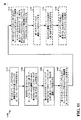
[0071] 図11は、ワイヤレス通信の方法のフローチャート1100である。この方法は、UE(例えば、UE1004、UEである装置1202/1202’)によって実行され得る。図11に点線で示されるステップは、オプションのステップを表すことは理解されるべきである。
FIG. 11 is a
[0072] ステップ1102において、UEは、第1のネットワークにおけるBS(例えば、BS1002)と通信するための第1のセットのビームフォーミング方向を決定する。ある態様では、第1のネットワークは、6.0GHzを下回る周波数を有するキャリアを使用したLTEネットワークであり得る。例えば、第1のセットのビームフォーミング方向は、ビーム1018および/または1020の各々に関する、方位角および迎角における放射角、および/または、方位角および迎角における到来角を含み得る。ある態様では、UEは、MUSIC(MUltiple SIgnal Classification)、ESPRIT(Estimation of Signal Parameters via Rotation Invariant Techniques)、SAGE(Space-Alternating Generalized Expectation-maximization)アルゴリズムのような方法を使用して、第1のセットのビームフォーミング方向を決定し得る。
[0072] At
[0073] ステップ1104において、UEは、決定された第1のセットのビームフォーミング方向に基づいて、mmW−BSと通信するための第2のセットのビームフォーミング方向におけるビームを監視する。ある態様では、第2のセットのビームフォーミング方向は、第1のセットのビームフォーミング方向を含み得、およびmmW−BSは、第1のネットワークよりも高いキャリア周波数を有する第2のネットワークにあり得る。ある態様において、および図10を参照して、第1のネットワークのBSおよび第2のネットワークのmmW−BSは、例えばBS1002のような単一の基地局中に配置され得る(collocated in)。例えば、第2のセットのビームフォーミング方向は、ビーム1022および/または1024に関連する方向に対応し得る。
[0073] In
[0074] ステップ1106において、UEは、第2のセットのビームフォーミング方向における1つのビームフォーミング方向に基づいて、mmW−BSとの通信リンクを確立する。ある態様では、第1のセットのビームフォーミング方向は、第1のセットのアンテナに対応し、第2のセットのビームフォーミング方向は、第2のセットのアンテナに対応する。ある態様では、第1のセットのアンテナは、第2のセットのアンテナのサブセットである。
[0074] In
[0075] ステップ1108において、UEは、第1のネットワークのシンボルおよびフレームタイミングまたはキャリア周波数オフセットのうちの少なくとも1つを決定する。
[0075] At
[0076] ステップ1110において、UEは、第1のネットワークのシンボルおよびフレームタイミングまたはキャリア周波数オフセットのうちの少なくとも1つに基づいて、第2のネットワークに関する第2のシンボルおよびフレームタイミングまたは第2のキャリア周波数オフセットのうちの少なくとも1つを決定する。
[0076] In
[0077] ステップ1112において、UEは、第1のネットワークとの通信リンクをクローズする。
[0077] At
[0078] ステップ1114において、UEは、確立された通信リンクの品質がしきい値を下回ることを決定する。
[0078] At
[0079] 最後に、ステップ1116において、UEは、第1のネットワークを通して通信することを要求する情報をネットワークコントローラに送る。
[0079] Finally, in
[0080] 図12は、例示的な装置1202における異なるモジュール/手段/コンポーネント間のデータフローを例示する概念的なデータフロー図1200である。この装置は、UEであり得る。この装置は、1つまたは複数の基地局(例えば、基地局1250)からビームを受信するモジュール1204と、第1のネットワークにおけるBSと通信するための第1のセットのビームフォーミング方向を決定するモジュール1206と、決定された第1のセットのビームフォーミング方向に基づいて、mmW−BSと通信するための第2のセットのビームフォーミング方向におけるビームを監視するモジュール1208と、ここで第2のセットのビームフォーミング方向は第1のセットのビームフォーミング方向を含み、mmW−BSは第1のネットワークよりも高いキャリア周波数を有する第2のネットワークにあり、第2のセットのビームフォーミング方向における1つのビームフォーミング方向に基づいて、mmW−BSとの通信リンクを確立するモジュール1210と、第1のネットワークとの通信リンクをクローズするモジュール1212と、確立された通信リンクの品質がしきい値を下回ることを決定するモジュール1214と、第1のネットワークのシンボルおよびフレームタイミングを決定するモジュール1216と、第1のネットワークのキャリア周波数オフセットを決定するモジュール1218と、第1のネットワークを通して通信することを要求する情報をネットワークコントローラに送るモジュール1220とを含む。
FIG. 12 is a conceptual data flow diagram 1200 that illustrates data flow between different modules / means / components in the
[0081] この装置は、図11の前述のフローチャートにおけるアルゴリズムのステップの各々を実行する追加のモジュールを含み得る。したがって、図11の前述のフローチャートにおける各ステップは、あるモジュールによって実行され得、この装置は、これらのモジュールのうちの1つまたは複数を含み得る。これらモジュールは、述べられたプロセス/アルゴリズムを実行するように特に構成された1つまたは複数のハードウェアコンポーネントであるか、述べられたプロセス/アルゴリズムを実行するよう構成されたプロセッサによってインプリメントされるか、プロセッサによるインプリメンテーションのためにコンピュータ読み取り可能な媒体内に記憶されるか、またはこれらの何らかの組み合わせであり得る。 The apparatus may include additional modules that perform each of the steps of the algorithm in the aforementioned flow chart of FIG. Thus, each step in the above-described flow chart of FIG. 11 may be performed by a module, and the apparatus may include one or more of these modules. Are these modules one or more hardware components specifically configured to execute the described process / algorithm, or are they implemented by a processor configured to execute the described process / algorithm? , May be stored in computer readable medium for implementation by a processor, or some combination thereof.
[0082] 図13は、処理システム1314を用いる装置1202’についてのハードウェアインプリメンテーションの例を例示する図1300である。処理システム1314は、概してバス1324によって表されるバスアーキテクチャを用いてインプリメントされ得る。バス1324は、処理システム1314の特定の用途および全体的な設計制約に応じて、相互接続バスおよびブリッジをいくつでも含み得る。バス1324は、プロセッサ1304、モジュール1204、1206、1208、1210、1212、1214、1216、1218、1220、およびコンピュータ読み取り可能な媒体/メモリ1306によって表される、1つまたは複数のプロセッサおよび/またはハードウェアモジュールを含む様々な回路を互いにリンクする。バス1324はまた、タイミングソース、周辺機器、電圧レギュレータ、および電力管理回路のような、様々な他の回路もリンクさせ得るが、これらは当該技術で周知であるため、これ以上説明されることはない。
FIG. 13 is a diagram 1300 illustrating an example of a hardware implementation for an
[0083] 処理システム1314は、トランシーバ1310に結合され得る。トランシーバ1310は、1つまたは複数のアンテナ1320に結合される。トランシーバ1310は、送信媒体を介して様々な他の装置と通信するための手段を提供する。トランシーバ1310は、1つまたは複数のアンテナ1320から信号を受信し、受信された信号から情報を抽出し、抽出された情報を処理システム1314に、特に受信モジュール1204に、提供する。加えて、トランシーバ1310は、処理システム1314、特に送信モジュール1220から情報を受信し、その受信された情報に基づいて、1つまたは複数のアンテナ1320に適用される信号を生成する。処理システム1314は、コンピュータ読み取り可能な媒体/メモリ1306に結合されたプロセッサ1304を含む。プロセッサ1304は、コンピュータ読み取り可能な媒体/メモリ1306に記憶されたソフトウェアの実行を含む一般的な処理を担う。ソフトウェアは、プロセッサ1304によって実行されたとき、処理システム1314に、任意の特定の装置に関して上記に説明した様々な機能を実行させる。コンピュータ読み取り可能な媒体/メモリ1306はまた、ソフトウェアを実行する際にプロセッサ1304によって操作されるデータを記憶するために使用され得る。処理システムはさらに、モジュール1204、1206、1208、1210、1212、1214、1216、1218および1220のうちの少なくとも1つを含む。これらのモジュールは、プロセッサ1304上で動作するかコンピュータ読み取り可能な媒体/メモリ1306に存在/記憶されたソフトウェアモジュールか、プロセッサ1304に結合された1つまたは複数のハードウェアモジュールか、またはそれらの何らかの組み合わせであり得る。処理システム1314は、UE650のコンポーネントであり得、メモリ660および/またはTXプロセッサ668、RXプロセッサ656、およびコントローラ/プロセッサ659のうちの少なくとも1つを含み得る。
[0084] 1つの構成では、ワイヤレス通信のためのこの装置1202/1202’は、第1のネットワークにおけるBSと通信するための第1のセットのビームフォーミング方向を決定するための手段と、決定された第1のセットのビームフォーミング方向に基づいて、mmW−BSと通信するための第2のセットのビームフォーミング方向におけるビームを監視するための手段と、ここで第2のセットのビームフォーミング方向は第1のセットのビームフォーミング方向を含み、mmW−BSは第1のネットワークよりも高いキャリア周波数を有する第2のネットワークにあり、第2のセットのビームフォーミング方向における1つのビームフォーミング方向に基づいて、mmW−BSとの通信リンクを確立するための手段と、第1のネットワークとの通信リンクをクローズするための手段と、確立された通信リンクの品質がしきい値を下回ることを決定するための手段と、第1のネットワークを通して通信することを要求する情報をネットワークコントローラに送るための手段と、第1のネットワークのシンボルおよびフレームタイミングまたはキャリア周波数オフセットのうちの少なくとも1つを決定するための手段と、第1のネットワークのシンボルおよびフレームタイミングまたはキャリア周波数オフセットのうちの少なくとも1つに基づいて、第2のネットワークのための第2のシンボルおよびフレームタイミングまたは第2のキャリア周波数オフセットのうちの少なくとも1つを決定するための手段とを含む。前述の手段は、前述の手段によって記載された機能を実行するように構成された装置1202’の処理システム1314および/または装置1202の前述のモジュールのうちの1つまたは複数であり得る。上に説明されたように、処理システム1314は、TXプロセッサ668、RXプロセッサ656、およびコントローラ/プロセッサ659を含み得る。したがって、1つの構成では、前述の手段は、前述の手段によって記載された機能を実行するよう構成されたTXプロセッサ668、RXプロセッサ656、およびコントローラ/プロセッサ659であり得る。
[0084] In one configuration, this device 1202/1202 'for wireless communication is determined with means for determining a first set of beamforming directions for communicating with a BS in a first network Means for monitoring beams in a second set of beamforming directions for communicating with the mmW-BS based on the first set of beamforming directions, wherein the second set of beamforming directions is The mmW-BS is in a second network with a higher carrier frequency than the first network, including a first set of beamforming directions, based on one beamforming direction in the second set of beamforming directions , Means for establishing a communication link with mmW-BS, and a first net Means for closing a communication link with the network, means for determining that the quality of the established communication link falls below a threshold, and information network requesting information to communicate through the first network Means for sending to a controller, means for determining at least one of a first network symbol and frame timing or carrier frequency offset, and a first network symbol and frame timing or carrier frequency offset And means for determining at least one of a second symbol and a frame timing or a second carrier frequency offset for the second network based on at least one of: The aforementioned means may be one or more of the processing system 1314 of the apparatus 1202 'and / or the aforementioned modules of the apparatus 1202 configured to perform the functions described by the aforementioned means. As described above,
[0085] 開示されたプロセス/フローチャートにおけるステップの特定の順序または階層は、例示的なアプローチの一例であるということは理解される。設計の選好に基づいて、これらのプロセス/フローチャートにおけるステップの特定の順序または階層は並べ換えられ得ることは理解される。さらに、いくつかのステップは、組み合わせられ得るか、または省略され得る。添付の方法の請求項は、様々なステップの要素をサンプルの順序で提示するが、それらは提示された特定の順序または階層に限定されることを意味していない。 It is understood that the specific order or hierarchy of steps in the disclosed processes / flowcharts is an example of exemplary approaches. It is understood that, based on design preferences, the particular order or hierarchy of steps in these processes / flowcharts may be rearranged. Furthermore, some steps may be combined or omitted. The appended method claims present elements of the various steps in a sample order, but they are not meant to be limited to the specific order or hierarchy presented.
[0086] 先の説明は、当業者が、ここに説明された様々な態様を実施することができるように提供されている。これらの態様に対する様々な変更は、当業者に容易に理解されるものであり、ここに定義された一般的な原理は、他の態様に適用され得る。したがって、特許請求の範囲は、ここに示される態様に限定されるようには意図されておらず、請求項の文言と一致する最大の範囲を認められるべきであり、ここで、ある要素への単数形での言及は、そのように明確に述べられていない限りは、「1つおよび1つのみ」を意味するのではなく、「1つまたは複数」を意味するように意図されている。「例示的な(exemplary)」という用語は、ここで「例、実例、または例示としての役割を果たす」という意味で使用される。「例示的」であるとここで説明された何れの態様も、必ずしも、他の態様よりも好ましいまたは有利であると解釈されるべきではない。そうでないとの明確な記載がない限り、「何らかの(some)」という用語は、1つまたは複数を意味する。「A、B、またはCのうちの少なくとも1つ」、「A、B、およびCのうちの少なくとも1つ」、および「A、B、C、またはそれらの任意の組み合わせ」のような組み合わせは、A、B、および/またはCの何れの組み合わせも含み、複数のA、複数のB、または複数のCを含み得る。具体的には、「A、B、またはCのうちの少なくとも1つ」、「A、B、およびCのうちの少なくとも1つ」、および「A、B、C、またはそれらの任意の組み合わせ」のような組み合わせは、Aのみ、Bのみ、Cのみ、AとB、AとC、BとC、またはAとBとCであり得、ここで、任意のこのような組み合わせは、A、B、またはCの1つまたは複数のメンバーを含み得る。当業者に知られている、あるいは後に知られることになる本開示全体にわたって説明された様々な態様の要素に対するすべての構造的および機能的な同等物は、参照によってここに明確に組み込まれ、特許請求の範囲に包含されるように意図されている。さらに、本明細書における如何なる開示も、そのような開示が特許請求の範囲に明確に記載されているか否かに関わらず、公に捧げられることを意図したものではない。要素が「〜のための手段」という表現を使用して明記されていない限り、請求項の何れの要素もミーンズプラスファンクションとして解釈されるべきではない。
以下に本願の出願当初の特許請求の範囲に記載された発明を付記する。
[C1] ワイヤレス通信の方法であって、
第1のネットワークにおける基地局(BS)と通信するための第1のセットのビームフォーミング方向を決定することと、
前記決定された第1のセットのビームフォーミング方向に基づいて、ミリ波基地局(mmW−BS)と通信するための第2のセットのビームフォーミング方向におけるビームを監視することと、前記第2のセットのビームフォーミング方向は前記第1のセットのビームフォーミング方向を含み、前記mmW−BSは前記第1のネットワークよりも高いキャリア周波数を有する第2のネットワークにあり、
前記第2のセットのビームフォーミング方向における1つのビームフォーミング方向に基づいて、前記mmW−BSとの通信リンクを確立することと
を備える、方法。
[C2] 前記第1のセットのビームフォーミング方向は、第1のセットのアンテナに対応し、および前記第2のセットのビームフォーミング方向は、第2のセットのアンテナに対応する、C1に記載の方法。
[C3] 前記第1のセットのアンテナは、前記第2のセットのアンテナのサブセットである、C2に記載の方法。
[C4] 前記第1のネットワークとの通信リンクをクローズすることと、
前記確立された通信リンクの品質がしきい値を下回ることを決定することと、
ネットワークコントローラに前記第1のネットワークを通して通信することを要求する情報を送ることと
をさらに備える、C1に記載の方法。
[C5] 前記第1のネットワークのシンボルおよびフレームタイミングまたはキャリア周波数オフセットのうちの少なくとも1つを決定することと、
前記第1のネットワークのシンボルおよびフレームタイミングまたはキャリア周波数オフセットのうちの前記少なくとも1つに基づいて、前記第2のネットワークに関する第2のシンボルおよびフレームタイミングまたは第2のキャリア周波数オフセットのうちの少なくとも1つを決定することと
をさらに備える、C1に記載の方法。
[C6] ワイヤレス通信のための装置であって、
第1のネットワークにおける基地局(BS)と通信するための第1のセットのビームフォーミング方向を決定するための手段と、
前記決定された第1のセットのビームフォーミング方向に基づいて、ミリ波基地局(mmW−BS)と通信するための第2のセットのビームフォーミング方向におけるビームを監視するための手段と、前記第2のセットのビームフォーミング方向は前記第1のセットのビームフォーミング方向を含み、前記mmW−BSは前記第1のネットワークよりも高いキャリア周波数を有する第2のネットワークにあり、
前記第2のセットのビームフォーミング方向における1つのビームフォーミング方向に基づいて、前記mmW−BSとの通信リンクを確立するための手段と
を備える、装置。
[C7] 前記第1のセットのビームフォーミング方向は、第1のセットのアンテナに対応し、および前記第2のセットのビームフォーミング方向は、第2のセットのアンテナに対応する、C6に記載の装置。
[C8] 前記第1のセットのアンテナは、前記第2のセットのアンテナのサブセットである、C7に記載の装置。
[C9] 前記第1のネットワークとの通信リンクをクローズするための手段と、
前記確立された通信リンクの品質がしきい値を下回ることを決定するための手段と、
ネットワークコントローラに前記第1のネットワークを通して通信することを要求する情報を送るための手段と
をさらに備える、C6に記載の装置。
[C10] 前記第1のネットワークのシンボルおよびフレームタイミングまたはキャリア周波数オフセットのうちの少なくとも1つを決定するための手段と、
前記第1のネットワークのシンボルおよびフレームタイミングまたはキャリア周波数オフセットのうちの前記少なくとも1つに基づいて、前記第2のネットワークに関する第2のシンボルおよびフレームタイミングまたは第2のキャリア周波数オフセットのうちの少なくとも1つを決定するための手段と
をさらに備える、C6に記載の装置。
[C11] ワイヤレス通信のための装置であって、
メモリと、
前記メモリに結合された少なくとも1つのプロセッサと
を備え、前記少なくとも1つのプロセッサは、
第1のネットワークにおける基地局(BS)と通信するための第1のセットのビームフォーミング方向を決定することと、
前記決定された第1のセットのビームフォーミング方向に基づいて、ミリ波基地局(mmW−BS)と通信するための第2のセットのビームフォーミング方向におけるビームを監視することと、前記第2のセットのビームフォーミング方向は前記第1のセットのビームフォーミング方向を含み、前記mmW−BSは前記第1のネットワークよりも高いキャリア周波数を有する第2のネットワークにあり、
前記第2のセットのビームフォーミング方向における1つのビームフォーミング方向に基づいて、前記mmW−BSとの通信リンクを確立することと
を行うように構成される、装置。
[C12] 前記第1のセットのビームフォーミング方向は、第1のセットのアンテナに対応し、および前記第2のセットのビームフォーミング方向は、第2のセットのアンテナに対応する、C11に記載の装置。
[C13] 前記第1のセットのアンテナは、前記第2のセットのアンテナのサブセットである、C12に記載の装置。
[C14] 前記少なくとも1つのプロセッサは、
前記第1のネットワークとの通信リンクをクローズすることと、
前記確立された通信リンクの品質がしきい値を下回ることを決定することと、
ネットワークコントローラに前記第1のネットワークを通して通信することを要求する情報を送ることと
を行うようにさらに構成される、C11に記載の装置。
[C15] 前記少なくとも1つのプロセッサは、
前記第1のネットワークのシンボルおよびフレームタイミングまたはキャリア周波数オフセットのうちの少なくとも1つを決定することと、
前記第1のネットワークのシンボルおよびフレームタイミングまたはキャリア周波数オフセットのうちの前記少なくとも1つに基づいて、前記第2のネットワークに関する第2のシンボルおよびフレームタイミングまたは第2のキャリア周波数オフセットのうちの少なくとも1つを決定することと
を行うようにさらに構成される、C11に記載の装置。
[C16] コンピュータ読み取り可能な媒体上に記憶されたコンピュータプログラム製品であって、少なくとも1つのプロセッサ上で実行されると、前記少なくとも1つのプロセッサに、
第1のネットワークにおける基地局(BS)と通信するための第1のセットのビームフォーミング方向を決定することと、
前記決定された第1のセットのビームフォーミング方向に基づいて、ミリ波基地局(mmW−BS)と通信するための第2のセットのビームフォーミング方向におけるビームを監視することと、前記第2のセットのビームフォーミング方向は前記第1のセットのビームフォーミング方向を含み、前記mmW−BSは前記第1のネットワークよりも高いキャリア周波数を有する第2のネットワークにあり、
前記第2のセットのビームフォーミング方向における1つのビームフォーミング方向に基づいて、前記mmW−BSとの通信リンクを確立することと
を行わせるコードを備える、コンピュータプログラム製品。
[C17] 前記第1のセットのビームフォーミング方向は、第1のセットのアンテナに対応し、および前記第2のセットのビームフォーミング方向は、第2のセットのアンテナに対応する、C16に記載のコンピュータプログラム製品。
[C18] 前記第1のセットのアンテナは、前記第2のセットのアンテナのサブセットである、C17に記載のコンピュータプログラム製品。
[C19] 少なくとも1つのプロセッサ上で実行されると、前記少なくとも1つのプロセッサに、
前記第1のネットワークとの通信リンクをクローズすることと、
前記確立された通信リンクの品質がしきい値を下回ることを決定することと、
ネットワークコントローラに前記第1のネットワークを通して通信することを要求する情報を送ることと
を行わせるコードをさらに備える、C16に記載のコンピュータプログラム製品。
[C20] 少なくとも1つのプロセッサ上で実行されると、前記少なくとも1つのプロセッサに、
前記第1のネットワークのシンボルおよびフレームタイミングまたはキャリア周波数オフセットのうちの少なくとも1つを決定することと、
前記第1のネットワークのシンボルおよびフレームタイミングまたはキャリア周波数オフセットのうちの前記少なくとも1つに基づいて、前記第2のネットワークに関する第2のシンボルおよびフレームタイミングまたは第2のキャリア周波数オフセットのうちの少なくとも1つを決定することと
を行わせるコードをさらに備える、C16に記載のコンピュータプログラム製品。
The previous description is provided to enable any person skilled in the art to practice the various aspects described herein. Various modifications to these aspects will be readily apparent to those skilled in the art, and the general principles defined herein may be applied to other aspects. Thus, the claims are not intended to be limited to the embodiments shown herein, but should be allowed the widest scope consistent with the wording of the claims, where to certain elements Reference in the singular is not intended to mean "one and only one", but is intended to mean "one or more" unless explicitly stated otherwise. The term "exemplary" is used herein to mean "serving as an example, instance, or illustration." Any aspect described herein as "exemplary" is not necessarily to be construed as preferred or advantageous over other aspects. Unless expressly stated otherwise, the term "some" means one or more. Combinations such as “at least one of A, B, or C”, “at least one of A, B, and C”, and “A, B, C, or any combination thereof” are , A, B, and / or C, and may include multiple A, multiple B, or multiple C. Specifically, "at least one of A, B, or C", "at least one of A, B, and C", and "A, B, C, or any combination thereof" Such combinations may be A only, B only, C only, A and B, A and C, B and C, or A and B and C, where any such combination is A, It may comprise B or one or more members of C. All structural and functional equivalents to the elements of the various embodiments described throughout the disclosure, which are known to a person skilled in the art or will be known later, are hereby expressly incorporated by reference and patent It is intended to be included within the scope of the claims. Furthermore, any disclosure herein is not intended to be dedicated to the public, regardless of whether such disclosure is explicitly recited in the claims. No element in the claims should be construed as means-plus-function unless the element is specified using the phrase "means for."
The invention described in the claims at the beginning of the application of the present application is appended below.
[C1] A method of wireless communication,
Determining a first set of beamforming directions for communicating with a base station (BS) in the first network;
Monitoring a beam in a second set of beamforming directions for communicating with a millimeter wave base station (mmW-BS) based on the determined first set of beamforming directions; The beamforming direction of the set comprises the beamforming direction of the first set, the mmW-BS is in a second network having a higher carrier frequency than the first network,
Establishing a communication link with the mmW-BS based on one beamforming direction in the second set of beamforming directions;
A method comprising.
[C2] The beamforming direction of the first set corresponds to a first set of antennas, and the beamforming direction of the second set corresponds to a second set of antennas according to C1, Method.
[C3] The method according to C2, wherein the first set of antennas is a subset of the second set of antennas.
[C4] closing a communication link with the first network;
Determining that the quality of the established communication link is below a threshold;
Sending information to a network controller requesting communication through said first network
The method of C1, further comprising
[C5] determining at least one of a symbol and frame timing or carrier frequency offset of the first network;
At least one of a second symbol and frame timing or second carrier frequency offset for the second network based on the at least one of the first network symbol and frame timing or carrier frequency offset To determine
The method of C1, further comprising
[C6] A device for wireless communication,
Means for determining a first set of beamforming directions for communicating with a base station (BS) in the first network;
Means for monitoring a beam in a second set of beamforming directions for communicating with a millimeter wave base station (mmW-BS) based on the determined first set of beamforming directions; The second set of beamforming directions includes the first set of beamforming directions, and the mmW-BS is in a second network having a higher carrier frequency than the first network,
Means for establishing a communication link with the mmW-BS based on one beamforming direction in the second set of beamforming directions;
An apparatus comprising:
[C7] The beamforming direction of the first set corresponds to a first set of antennas, and the beamforming direction of the second set corresponds to a second set of antennas according to C6 apparatus.
[C8] The apparatus according to C7, wherein the first set of antennas is a subset of the second set of antennas.
[C9] a means for closing a communication link with the first network;
Means for determining that the quality of the established communication link is below a threshold;
Means for sending information to a network controller requesting communication through said first network
The device of C6, further comprising:
[C10] a means for determining at least one of symbols and frame timing or carrier frequency offset of the first network;
At least one of a second symbol and frame timing or second carrier frequency offset for the second network based on the at least one of the first network symbol and frame timing or carrier frequency offset Means for determining
The device of C6, further comprising:
[C11] A device for wireless communication,
With memory
At least one processor coupled to the memory
Said at least one processor is
Determining a first set of beamforming directions for communicating with a base station (BS) in the first network;
Monitoring a beam in a second set of beamforming directions for communicating with a millimeter wave base station (mmW-BS) based on the determined first set of beamforming directions; The beamforming direction of the set comprises the beamforming direction of the first set, the mmW-BS is in a second network having a higher carrier frequency than the first network,
Establishing a communication link with the mmW-BS based on one beamforming direction in the second set of beamforming directions;
A device that is configured to
[C12] The beamforming direction of the first set corresponds to a first set of antennas, and the beamforming direction of the second set corresponds to a second set of antennas according to C11 apparatus.
[C13] The apparatus according to C12, wherein the first set of antennas is a subset of the second set of antennas.
[C14] The at least one processor is
Closing a communication link with the first network;
Determining that the quality of the established communication link is below a threshold;
Sending information to a network controller requesting communication through said first network
The device of C11, further configured to:
[C15] The at least one processor is
Determining at least one of the symbols and frame timing or carrier frequency offset of the first network;
At least one of a second symbol and frame timing or second carrier frequency offset for the second network based on the at least one of the first network symbol and frame timing or carrier frequency offset To determine
The device of C11, further configured to:
[C16] A computer program product stored on a computer readable medium, said computer program product being executed on at least one processor, said at least one processor comprising
Determining a first set of beamforming directions for communicating with a base station (BS) in the first network;
Monitoring a beam in a second set of beamforming directions for communicating with a millimeter wave base station (mmW-BS) based on the determined first set of beamforming directions; The beamforming direction of the set comprises the beamforming direction of the first set, the mmW-BS is in a second network having a higher carrier frequency than the first network,
Establishing a communication link with the mmW-BS based on one beamforming direction in the second set of beamforming directions;
A computer program product, comprising code for performing.
[C17] The beamforming direction of the first set corresponds to a first set of antennas, and the beamforming direction of the second set corresponds to a second set of antennas according to C16, Computer program product.
[C18] The computer program product of C17, wherein the first set of antennas is a subset of the second set of antennas.
[C19] The at least one processor when executed on the at least one processor,
Closing a communication link with the first network;
Determining that the quality of the established communication link is below a threshold;
Sending information to a network controller requesting communication through said first network
The computer program product of C16, further comprising code to:
[C20] said at least one processor when executed on at least one processor,
Determining at least one of the symbols and frame timing or carrier frequency offset of the first network;
At least one of a second symbol and frame timing or second carrier frequency offset for the second network based on the at least one of the first network symbol and frame timing or carrier frequency offset To determine
The computer program product of C16, further comprising code to:
Claims (12)
第1のネットワークにおける基地局(BS)と通信するための第1のセットのビームフォーミング方向を決定することと、
前記決定された第1のセットのビームフォーミング方向に基づいて、ミリ波基地局(mmW−BS)と通信するための第2のセットのビームフォーミング方向におけるビームを監視することと、前記第2のセットのビームフォーミング方向は前記第1のセットのビームフォーミング方向を含み、前記mmW−BSは前記第1のネットワークよりも高いキャリア周波数を有する第2のネットワークにあり、
前記第2のセットのビームフォーミング方向における1つのビームフォーミング方向に基づいて、前記第2のネットワークを通して前記mmW−BSとの通信リンクを確立することと、
前記確立された通信リンクの品質に基づいて、前記第1のネットワークを通して通信することを要求する情報をネットワークコントローラに送ることと
を備え、前記第1のセットのビームフォーミング方向は、第1のセットのアンテナに対応し、および前記第2のセットのビームフォーミング方向は、第2のセットのアンテナに対応し、前記第1のセットのアンテナは、前記第2のセットのアンテナのサブセットである、方法。 A method of wireless communication,
Determining a first set of beamforming directions for communicating with a base station (BS) in the first network;
Monitoring a beam in a second set of beamforming directions for communicating with a millimeter wave base station (mmW-BS) based on the determined first set of beamforming directions; The beamforming direction of the set comprises the beamforming direction of the first set, the mmW-BS is in a second network having a higher carrier frequency than the first network,
Establishing a communication link with the mmW-BS through the second network based on one beamforming direction in the second set of beamforming directions;
Sending to the network controller information requesting to communicate through the first network based on the quality of the established communication link , the beamforming direction of the first set being a first set A second set of beamforming directions corresponding to a second set of antennas, the first set of antennas being a subset of the second set of antennas, .
前記確立された通信リンクの品質がしきい値を下回ることを決定することと、ここにおいて、前記ネットワークコントローラに前記情報を前記送ることは、前記確立された通信リンクの前記品質がしきい値を下回ることを前記決定することに基づく、
をさらに備える、請求項1に記載の方法。 Closing the communication link with the first network after establishing the communication link through the second network;
Determining that the quality of the established communication link is below a threshold, and wherein sending the information to the network controller, wherein the quality of the established communication link is thresholded Based on said determining to be below
The method of claim 1, further comprising:
前記第1のネットワークのシンボルおよびフレームタイミングまたはキャリア周波数オフセットのうちの前記少なくとも1つに基づいて、前記第2のネットワークに関する第2のシンボルおよびフレームタイミングまたは第2のキャリア周波数オフセットのうちの少なくとも1つを決定することと
をさらに備える、請求項1に記載の方法。 Determining at least one of the symbols and frame timing or carrier frequency offset of the first network;
At least one of a second symbol and frame timing or second carrier frequency offset for the second network based on the at least one of the first network symbol and frame timing or carrier frequency offset The method of claim 1, further comprising: determining one.
第1のネットワークにおける基地局(BS)と通信するための第1のセットのビームフォーミング方向を決定するための手段と、
前記決定された第1のセットのビームフォーミング方向に基づいて、ミリ波基地局(mmW−BS)と通信するための第2のセットのビームフォーミング方向におけるビームを監視するための手段と、前記第2のセットのビームフォーミング方向は前記第1のセットのビームフォーミング方向を含み、前記mmW−BSは前記第1のネットワークよりも高いキャリア周波数を有する第2のネットワークにあり、
前記第2のセットのビームフォーミング方向における1つのビームフォーミング方向に基づいて、前記mmW−BSとの通信リンクを確立するための手段と、
前記確立された通信リンクの品質に基づいて、前記第1のネットワークを通して通信することを要求する情報をネットワークコントローラに送るための手段と
を備え、前記第1のセットのビームフォーミング方向は、第1のセットのアンテナに対応し、および前記第2のセットのビームフォーミング方向は、第2のセットのアンテナに対応し、前記第1のセットのアンテナは、前記第2のセットのアンテナのサブセットである、装置。 A device for wireless communication,
Means for determining a first set of beamforming directions for communicating with a base station (BS) in the first network;
Means for monitoring a beam in a second set of beamforming directions for communicating with a millimeter wave base station (mmW-BS) based on the determined first set of beamforming directions; The second set of beamforming directions includes the first set of beamforming directions, and the mmW-BS is in a second network having a higher carrier frequency than the first network,
Means for establishing a communication link with the mmW-BS based on one beamforming direction in the second set of beamforming directions;
Means for sending to the network controller information requesting to communicate through the first network based on the quality of the established communication link, the beam forming direction of the first set being And the beamforming directions of the second set correspond to the antennas of the second set, and the antennas of the first set are a subset of the antennas of the second set , Equipment.
前記確立された通信リンクの品質がしきい値を下回ることを決定するための手段と、ここにおいて、前記ネットワークコントローラに前記情報を前記送るための手段は、前記確立された通信リンクの前記品質が前記しきい値を下回ることを決定することに基づいて、前記情報を送るように構成される、
をさらに備える、請求項4に記載の装置。 Means for closing the communication link with the first network after establishing the communication link through the second network;
Means for determining that the quality of the established communication link is below a threshold, and wherein the means for sending the information to the network controller comprises the quality of the established communication link being Configured to send the information based on determining to fall below the threshold,
The apparatus of claim 4 , further comprising:
前記第1のネットワークのシンボルおよびフレームタイミングまたはキャリア周波数オフセットのうちの前記少なくとも1つに基づいて、前記第2のネットワークに関する第2のシンボルおよびフレームタイミングまたは第2のキャリア周波数オフセットのうちの少なくとも1つを決定するための手段と
をさらに備える、請求項4に記載の装置。 Means for determining at least one of the symbols and frame timing or carrier frequency offset of the first network;
At least one of a second symbol and frame timing or second carrier frequency offset for the second network based on the at least one of the first network symbol and frame timing or carrier frequency offset The apparatus of claim 4 , further comprising: means for determining one.
メモリと、
前記メモリに結合された少なくとも1つのプロセッサと
を備え、前記少なくとも1つのプロセッサは、
第1のネットワークにおける基地局(BS)と通信するための第1のセットのビームフォーミング方向を決定することと、
前記決定された第1のセットのビームフォーミング方向に基づいて、ミリ波基地局(mmW−BS)と通信するための第2のセットのビームフォーミング方向におけるビームを監視することと、前記第2のセットのビームフォーミング方向は前記第1のセットのビームフォーミング方向を含み、前記mmW−BSは前記第1のネットワークよりも高いキャリア周波数を有する第2のネットワークにあり、
前記第2のセットのビームフォーミング方向における1つのビームフォーミング方向に基づいて、前記mmW−BSとの通信リンクを確立することと、
前記確立された通信リンクの品質に基づいて、前記第1のネットワークを通して通信することを要求する情報をネットワークコントローラに送ることと
を行うように構成され、前記第1のセットのビームフォーミング方向は、第1のセットのアンテナに対応し、および前記第2のセットのビームフォーミング方向は、第2のセットのアンテナに対応し、前記第1のセットのアンテナは、前記第2のセットのアンテナのサブセットである、装置。 A device for wireless communication,
With memory
At least one processor coupled to the memory, the at least one processor including:
Determining a first set of beamforming directions for communicating with a base station (BS) in the first network;
Monitoring a beam in a second set of beamforming directions for communicating with a millimeter wave base station (mmW-BS) based on the determined first set of beamforming directions; The beamforming direction of the set comprises the beamforming direction of the first set, the mmW-BS is in a second network having a higher carrier frequency than the first network,
Establishing a communication link with the mmW-BS based on one beamforming direction in the second set of beamforming directions;
Sending to the network controller information requesting to communicate through the first network based on the quality of the established communication link, the beamforming direction of the first set being: The first set of antennas corresponds to, and the beamforming direction of the second set corresponds to the antennas of the second set, the antennas of the first set being a subset of the antennas of the second set Is the device.
前記第2のネットワークを通した前記通信リンクの前記確立の後に、前記第1のネットワークとの通信リンクをクローズすることと、
前記確立された通信リンクの品質がしきい値を下回ることを決定することと、ここにおいて、前記情報は、前記確立された通信リンクの前記品質がしきい値を下回るという前記決定に基づいて、前記ネットワークコントローラに送られる、
を行うようにさらに構成される、請求項7に記載の装置。 The at least one processor is
Closing the communication link with the first network after the establishment of the communication link through the second network;
Determining that the quality of the established communication link is below a threshold, and wherein the information is based on the determination that the quality of the established communication link is below a threshold Sent to the network controller,
The apparatus of claim 7 , further configured to:
前記第1のネットワークのシンボルおよびフレームタイミングまたはキャリア周波数オフセットのうちの少なくとも1つを決定することと、
前記第1のネットワークのシンボルおよびフレームタイミングまたはキャリア周波数オフセットのうちの前記少なくとも1つに基づいて、前記第2のネットワークに関する第2のシンボルおよびフレームタイミングまたは第2のキャリア周波数オフセットのうちの少なくとも1つを決定することと
を行うようにさらに構成される、請求項7に記載の装置。 The at least one processor is
Determining at least one of the symbols and frame timing or carrier frequency offset of the first network;
At least one of a second symbol and frame timing or second carrier frequency offset for the second network based on the at least one of the first network symbol and frame timing or carrier frequency offset The apparatus of claim 7 , further configured to:
第1のネットワークにおける基地局(BS)と通信するための第1のセットのビームフォーミング方向を決定することと、
前記決定された第1のセットのビームフォーミング方向に基づいて、ミリ波基地局(mmW−BS)と通信するための第2のセットのビームフォーミング方向におけるビームを監視することと、前記第2のセットのビームフォーミング方向は前記第1のセットのビームフォーミング方向を含み、前記mmW−BSは前記第1のネットワークよりも高いキャリア周波数を有する第2のネットワークにあり、
前記第2のセットのビームフォーミング方向における1つのビームフォーミング方向に基づいて、前記mmW−BSとの通信リンクを確立することと、
前記確立された通信リンクの品質に基づいて、前記第1のネットワークを通して通信することを要求する情報をネットワークコントローラに送ることと
を行うためのコードを備え、前記第1のセットのビームフォーミング方向は、第1のセットのアンテナに対応し、および前記第2のセットのビームフォーミング方向は、第2のセットのアンテナに対応し、前記第1のセットのアンテナは、前記第2のセットのアンテナのサブセットである、コンピュータ読み取り可能な媒体。 A non-transitory computer readable medium having computer executable code stored thereon for wireless communication, the computer readable code comprising:
Determining a first set of beamforming directions for communicating with a base station (BS) in the first network;
Monitoring a beam in a second set of beamforming directions for communicating with a millimeter wave base station (mmW-BS) based on the determined first set of beamforming directions; The beamforming direction of the set comprises the beamforming direction of the first set, the mmW-BS is in a second network having a higher carrier frequency than the first network,
Establishing a communication link with the mmW-BS based on one beamforming direction in the second set of beamforming directions;
Sending code to the network controller requesting information to communicate through the first network based on the quality of the established communication link, the beamforming direction of the first set being: , Corresponding to the first set of antennas, and the beam forming direction of the second set corresponds to the second set of antennas, the first set of antennas being of the second set of antennas A computer readable medium that is a subset .
前記確立された通信リンクの品質がしきい値を下回ることを決定することと、ここにおいて、前記情報は、前記確立された通信リンクの前記品質がしきい値を下回るという前記決定に基づいて、前記ネットワークコントローラに送られる、
を行うためのコードをさらに備える、請求項10に記載のコンピュータ読み取り可能な媒体。 Closing the communication link with the first network after the establishment of the communication link through the second network;
Determining that the quality of the established communication link is below a threshold, and wherein the information is based on the determination that the quality of the established communication link is below a threshold Sent to the network controller,
The computer readable medium of claim 10 , further comprising code for performing.
前記第1のネットワークのシンボルおよびフレームタイミングまたはキャリア周波数オフセットのうちの前記少なくとも1つに基づいて、前記第2のネットワークに関する第2のシンボルおよびフレームタイミングまたは第2のキャリア周波数オフセットのうちの少なくとも1つを決定することと
を行うためのコードをさらに備える、請求項10に記載のコンピュータ読み取り可能な媒体。 Determining at least one of the symbols and frame timing or carrier frequency offset of the first network;
At least one of a second symbol and frame timing or second carrier frequency offset for the second network based on the at least one of the first network symbol and frame timing or carrier frequency offset 11. The computer readable medium according to claim 10 , further comprising code for:
Applications Claiming Priority (3)
| Application Number | Priority Date | Filing Date | Title |
|---|---|---|---|
| US14/333,449 US9337969B2 (en) | 2014-07-16 | 2014-07-16 | Low-frequency assisted methods for beamforming, timing and frequency offset in mm-wave access systems |
| US14/333,449 | 2014-07-16 | ||
| PCT/US2015/037002 WO2016010683A1 (en) | 2014-07-16 | 2015-06-22 | Low-frequency assisted methods for beamforming, timing and frequency offset in mm-wave access systems |
Related Child Applications (1)
| Application Number | Title | Priority Date | Filing Date |
|---|---|---|---|
| JP2018013663A Division JP2018107810A (en) | 2014-07-16 | 2018-01-30 | LOW-FREQUENCY ASSISTED METHODS FOR BEAMFORMING, TIMING AND FREQUENCY OFFSET IN mm-WAVE ACCESS SYSTEMS |
Publications (2)
| Publication Number | Publication Date |
|---|---|
| JP2017530575A JP2017530575A (en) | 2017-10-12 |
| JP6530046B2 true JP6530046B2 (en) | 2019-06-12 |
Family
ID=53546714
Family Applications (2)
| Application Number | Title | Priority Date | Filing Date |
|---|---|---|---|
| JP2017502095A Expired - Fee Related JP6530046B2 (en) | 2014-07-16 | 2015-06-22 | Low frequency assisted method for beamforming, timing and frequency offset in mm wave access system |
| JP2018013663A Pending JP2018107810A (en) | 2014-07-16 | 2018-01-30 | LOW-FREQUENCY ASSISTED METHODS FOR BEAMFORMING, TIMING AND FREQUENCY OFFSET IN mm-WAVE ACCESS SYSTEMS |
Family Applications After (1)
| Application Number | Title | Priority Date | Filing Date |
|---|---|---|---|
| JP2018013663A Pending JP2018107810A (en) | 2014-07-16 | 2018-01-30 | LOW-FREQUENCY ASSISTED METHODS FOR BEAMFORMING, TIMING AND FREQUENCY OFFSET IN mm-WAVE ACCESS SYSTEMS |
Country Status (7)
| Country | Link |
|---|---|
| US (1) | US9337969B2 (en) |
| EP (1) | EP3170270A1 (en) |
| JP (2) | JP6530046B2 (en) |
| KR (2) | KR102219153B1 (en) |
| CN (2) | CN111970038A (en) |
| BR (1) | BR112017000266A2 (en) |
| WO (1) | WO2016010683A1 (en) |
Families Citing this family (35)
| Publication number | Priority date | Publication date | Assignee | Title |
|---|---|---|---|---|
| US9888450B2 (en) * | 2014-12-16 | 2018-02-06 | Lg Electronics Inc. | Method and apparatus for detecting synchronization signal in wireless communication system |
| US10251046B2 (en) * | 2015-06-01 | 2019-04-02 | Huawei Technologies Co., Ltd. | System and method for efficient link discovery in wireless networks |
| US20170086080A1 (en) * | 2015-09-18 | 2017-03-23 | Huawei Technologies Co., Ltd. | System and Method for Fast Beamforming Setup |
| US10362493B2 (en) | 2015-12-17 | 2019-07-23 | Legba, Inc. | High-bandwidth beamforming LTE Base Station |
| US10411777B2 (en) * | 2016-08-24 | 2019-09-10 | Qualcomm Incorporated | Mapping between a control beam and a data channel beam |
| US10536914B2 (en) | 2016-09-22 | 2020-01-14 | Qualcomm Incorporated | Synchronizing a 5G communication channel using a 4G timing synchronization parameter |
| US10863474B2 (en) * | 2016-10-21 | 2020-12-08 | Qualcomm Incorporated | Millimeter-wavelength network map for use in a beamforming procedure |
| US10313070B2 (en) * | 2016-11-03 | 2019-06-04 | Futurewei Technologies, Inc. | Fast millimeter-wave cell acquisition |
| US10582397B2 (en) * | 2016-11-09 | 2020-03-03 | Qualcomm Incorporated | Beam refinement reference signal transmissions during control symbol |
| US10601494B2 (en) * | 2016-12-08 | 2020-03-24 | At&T Intellectual Property I, L.P. | Dual-band communication device and method for use therewith |
| US10637709B2 (en) * | 2017-01-16 | 2020-04-28 | Qualcomm Incorporated | Signaling methods for frequency offset estimation using reference signals |
| KR102026137B1 (en) | 2017-03-15 | 2019-09-27 | 한국전자통신연구원 | Operation method of communication node in communication system based on millimeter wave |
| CN110402548B (en) * | 2017-03-20 | 2021-05-04 | 华为技术有限公司 | Device for configuring reference signal beam based on positioning accuracy of user equipment |
| US10716013B2 (en) * | 2017-03-24 | 2020-07-14 | Qualcomm Incorporated | Beam refinement for millimeter wave (MMW) system |
| WO2018197709A1 (en) * | 2017-04-28 | 2018-11-01 | Telefonaktiebolaget Lm Ericsson (Publ) | Base transceiver station interference cancellation for reuse of terrestrial carrier in air-to-ground communication |
| CN110582949B (en) * | 2017-05-10 | 2023-08-08 | 瑞典爱立信有限公司 | Angle of arrival estimation in a radio communications network |
| CN109392089B (en) | 2017-08-11 | 2021-10-22 | 华为技术有限公司 | Method and device for positioning |
| US10244408B1 (en) | 2017-10-19 | 2019-03-26 | At&T Intellectual Property I, L.P. | Dual mode communications device with null steering and methods for use therewith |
| WO2019050762A1 (en) * | 2017-09-05 | 2019-03-14 | At&T Intellectual Property I, L.P. | Dual mode communications device with null steering and methods for use therewith |
| US10714831B2 (en) | 2017-10-19 | 2020-07-14 | At&T Intellectual Property I, L.P. | Dual mode communications device with remote radio head and methods for use therewith |
| US10638482B2 (en) * | 2017-12-15 | 2020-04-28 | Qualcomm Incorporated | Methods and apparatuses for dynamic beam pair determination |
| US10548147B2 (en) * | 2018-01-31 | 2020-01-28 | Hewlett Packard Enterprise Development Lp | Access point beam strength rankings |
| KR102495557B1 (en) | 2018-07-02 | 2023-02-06 | 삼성전자주식회사 | a method for beamforming in a wireless ccommunication system and an apparatus thereof |
| US10979874B2 (en) * | 2018-08-10 | 2021-04-13 | At&T Intellectual Property I, L.P. | Multi-connectivity based vehicle-to-everything communications in a wireless network |
| US10972886B2 (en) * | 2018-12-04 | 2021-04-06 | Cypress Semiconductor Corporation | Dynamic antenna array pattern switching in wireless systems |
| DE102020100056A1 (en) | 2019-03-06 | 2020-09-10 | Samsung Electronics Co., Ltd. | Wireless communication device for correcting an offset between a base station and the wireless communication device and a method of operating the same |
| KR102287500B1 (en) * | 2019-10-21 | 2021-08-09 | 에스케이텔레콤 주식회사 | Beamforming controller and beamforming control method |
| US11856570B2 (en) | 2020-01-27 | 2023-12-26 | Qualcomm Incorporated | Dynamic mixed mode beam correspondence in upper millimeter wave bands |
| US11831383B2 (en) | 2020-01-27 | 2023-11-28 | Qualcomm Incorporated | Beam failure recovery assistance in upper band millimeter wave wireless communications |
| US20210234597A1 (en) * | 2020-01-27 | 2021-07-29 | Qualcomm Incorporated | Asymmetric uplink-downlink beam training in frequency bands |
| US11616563B2 (en) | 2020-04-06 | 2023-03-28 | Samsung Electronics Co., Ltd. | Systems and methods for updating beamforming codebooks for angle-of-arrival estimation using compressive sensing in wireless communications |
| US11832115B2 (en) * | 2020-05-04 | 2023-11-28 | Qualcomm Incorporated | Estimating features of a radio frequency band based on an inter-band reference signal |
| US11856568B2 (en) | 2020-11-18 | 2023-12-26 | Qualcomm Incorporated | Assisted beam management between frequency bands |
| WO2023112094A1 (en) * | 2021-12-13 | 2023-06-22 | 日本電信電話株式会社 | Radio communication system, radio communication method, radio communication processing device, and radio communication processing program |
| US11870522B2 (en) | 2022-06-13 | 2024-01-09 | Nanning Fulian Fugui Precision Industrial Co., Ltd. | Beam tracking method for mmWave communication and electronic device, electronic device and computer readable storage medium |
Family Cites Families (12)
| Publication number | Priority date | Publication date | Assignee | Title |
|---|---|---|---|---|
| US6845238B1 (en) | 1999-09-15 | 2005-01-18 | Telefonaktiebolaget Lm Ericsson (Publ) | Inter-frequency measurement and handover for wireless communications |
| US7652624B2 (en) * | 2007-03-06 | 2010-01-26 | Intel Corporation | Millimeter-wave communication stations with directional antennas and methods for fast link recovery |
| US8639270B2 (en) * | 2010-08-06 | 2014-01-28 | Golba Llc | Method and system for device positioning utilizing distributed transceivers with array processing |
| US9179373B2 (en) | 2009-07-23 | 2015-11-03 | Qualcomm Incorporated | Method and apparatus that facilitates redirecting wireless terminals between wireless networks |
| CN102752032B (en) * | 2011-04-22 | 2015-04-22 | 艾利森电话股份有限公司 | Same frequency load balance method and device thereof |
| CN103988551A (en) | 2011-12-08 | 2014-08-13 | 交互数字专利控股公司 | Method and apparatus for millimeter wave communication system |
| US20130301563A1 (en) | 2012-05-11 | 2013-11-14 | Samsung Electronics Co., Ltd | Pilot design for millimeter wave broadband |
| US9935699B2 (en) * | 2012-06-22 | 2018-04-03 | Samsung Electronics Co., Ltd. | Communication method and apparatus using beamforming in a wireless communication system |
| US9439096B2 (en) | 2012-08-13 | 2016-09-06 | Samsung Electronics Co., Ltd. | Method and apparatus to support channel refinement and multi-stream transmission in millimeter wave systems |
| CN104509148A (en) | 2012-08-29 | 2015-04-08 | 英特尔公司 | Device, system and method of wireless communication utilizing one or more antenna arrays |
| WO2014038830A1 (en) | 2012-09-07 | 2014-03-13 | Samsung Electronics Co., Ltd. | Method and system for signalling resource allocation information in an asymmetric multicarrier communication network |
| US9692459B2 (en) | 2012-11-28 | 2017-06-27 | Intel Corporation | Using multiple frequency bands with beamforming assistance in a wireless network |
-
2014
- 2014-07-16 US US14/333,449 patent/US9337969B2/en active Active
-
2015
- 2015-06-22 EP EP15738182.3A patent/EP3170270A1/en not_active Ceased
- 2015-06-22 BR BR112017000266A patent/BR112017000266A2/en active Search and Examination
- 2015-06-22 KR KR1020177037144A patent/KR102219153B1/en active IP Right Grant
- 2015-06-22 KR KR1020177000861A patent/KR20170007863A/en active Application Filing
- 2015-06-22 JP JP2017502095A patent/JP6530046B2/en not_active Expired - Fee Related
- 2015-06-22 CN CN202010843926.2A patent/CN111970038A/en active Pending
- 2015-06-22 WO PCT/US2015/037002 patent/WO2016010683A1/en active Application Filing
- 2015-06-22 CN CN201580038289.9A patent/CN106537807A/en active Pending
-
2018
- 2018-01-30 JP JP2018013663A patent/JP2018107810A/en active Pending
Also Published As
| Publication number | Publication date |
|---|---|
| WO2016010683A1 (en) | 2016-01-21 |
| BR112017000266A2 (en) | 2017-10-31 |
| CN111970038A (en) | 2020-11-20 |
| US9337969B2 (en) | 2016-05-10 |
| JP2018107810A (en) | 2018-07-05 |
| KR20170007863A (en) | 2017-01-20 |
| CN106537807A (en) | 2017-03-22 |
| KR20180000751A (en) | 2018-01-03 |
| US20160020876A1 (en) | 2016-01-21 |
| KR102219153B1 (en) | 2021-02-22 |
| EP3170270A1 (en) | 2017-05-24 |
| JP2017530575A (en) | 2017-10-12 |
Similar Documents
| Publication | Publication Date | Title |
|---|---|---|
| JP6530046B2 (en) | Low frequency assisted method for beamforming, timing and frequency offset in mm wave access system | |
| JP6370931B2 (en) | UE-initiated discovery in assisted millimeter-wave radio access networks | |
| EP3170271B1 (en) | Methods and apparatus for beam search and tracking in mm-wave access systems | |
| JP6538080B2 (en) | Cooperative technique between lower frequency carrier and millimeter wave channel for discovery and synchronization and beamforming | |
| JP6585091B2 (en) | Beamforming scheduling based on UE directivity | |
| CN106537804B (en) | Asymmetric capability driving method and apparatus for beam tracking in millimeter wave access system | |
| US9681309B2 (en) | Methods exploiting asymmetric capabilities for contention-based random access in mm-wave access systems | |
| CN110784252A (en) | Method and apparatus for lightweight messaging during initial synchronization, discovery, and association in directional wireless systems | |
| KR20170002648A (en) | Method and apparatus for connection point discovery and association in a directional wireless network | |
| KR20170007338A (en) | Method and apparatus for synchronizing and propagating state information in wireless downlink/uplink | |
| CN106664126B (en) | Method and apparatus for beam tracking based zone scheduling |
Legal Events
| Date | Code | Title | Description |
|---|---|---|---|
| A521 | Request for written amendment filed |
Free format text: JAPANESE INTERMEDIATE CODE: A523 Effective date: 20170906 |
|
| A02 | Decision of refusal |
Free format text: JAPANESE INTERMEDIATE CODE: A02 Effective date: 20171114 |
|
| A61 | First payment of annual fees (during grant procedure) |
Free format text: JAPANESE INTERMEDIATE CODE: A61 Effective date: 20190515 |
|
| R150 | Certificate of patent or registration of utility model |
Ref document number: 6530046 Country of ref document: JP Free format text: JAPANESE INTERMEDIATE CODE: R150 |
|
| R250 | Receipt of annual fees |
Free format text: JAPANESE INTERMEDIATE CODE: R250 |
|
| LAPS | Cancellation because of no payment of annual fees |