JP6529268B2 - Drive transmission device and image forming apparatus - Google Patents
Drive transmission device and image forming apparatus Download PDFInfo
- Publication number
- JP6529268B2 JP6529268B2 JP2015012025A JP2015012025A JP6529268B2 JP 6529268 B2 JP6529268 B2 JP 6529268B2 JP 2015012025 A JP2015012025 A JP 2015012025A JP 2015012025 A JP2015012025 A JP 2015012025A JP 6529268 B2 JP6529268 B2 JP 6529268B2
- Authority
- JP
- Japan
- Prior art keywords
- output gear
- drive
- drive transmission
- gear
- intermediate body
- Prior art date
- Legal status (The legal status is an assumption and is not a legal conclusion. Google has not performed a legal analysis and makes no representation as to the accuracy of the status listed.)
- Active
Links
Images


Classifications
-
- G—PHYSICS
- G03—PHOTOGRAPHY; CINEMATOGRAPHY; ANALOGOUS TECHNIQUES USING WAVES OTHER THAN OPTICAL WAVES; ELECTROGRAPHY; HOLOGRAPHY
- G03G—ELECTROGRAPHY; ELECTROPHOTOGRAPHY; MAGNETOGRAPHY
- G03G15/00—Apparatus for electrographic processes using a charge pattern
- G03G15/14—Apparatus for electrographic processes using a charge pattern for transferring a pattern to a second base
- G03G15/16—Apparatus for electrographic processes using a charge pattern for transferring a pattern to a second base of a toner pattern, e.g. a powder pattern, e.g. magnetic transfer
- G03G15/1605—Apparatus for electrographic processes using a charge pattern for transferring a pattern to a second base of a toner pattern, e.g. a powder pattern, e.g. magnetic transfer using at least one intermediate support
- G03G15/1615—Apparatus for electrographic processes using a charge pattern for transferring a pattern to a second base of a toner pattern, e.g. a powder pattern, e.g. magnetic transfer using at least one intermediate support relating to the driving mechanism for the intermediate support, e.g. gears, couplings, belt tensioning
-
- B—PERFORMING OPERATIONS; TRANSPORTING
- B65—CONVEYING; PACKING; STORING; HANDLING THIN OR FILAMENTARY MATERIAL
- B65H—HANDLING THIN OR FILAMENTARY MATERIAL, e.g. SHEETS, WEBS, CABLES
- B65H29/00—Delivering or advancing articles from machines; Advancing articles to or into piles
- B65H29/12—Delivering or advancing articles from machines; Advancing articles to or into piles by means of the nip between two, or between two sets of, moving tapes or bands or rollers
- B65H29/125—Delivering or advancing articles from machines; Advancing articles to or into piles by means of the nip between two, or between two sets of, moving tapes or bands or rollers between two sets of rollers
-
- B—PERFORMING OPERATIONS; TRANSPORTING
- B65—CONVEYING; PACKING; STORING; HANDLING THIN OR FILAMENTARY MATERIAL
- B65H—HANDLING THIN OR FILAMENTARY MATERIAL, e.g. SHEETS, WEBS, CABLES
- B65H5/00—Feeding articles separated from piles; Feeding articles to machines
- B65H5/06—Feeding articles separated from piles; Feeding articles to machines by rollers or balls, e.g. between rollers
- B65H5/062—Feeding articles separated from piles; Feeding articles to machines by rollers or balls, e.g. between rollers between rollers or balls
-
- G—PHYSICS
- G03—PHOTOGRAPHY; CINEMATOGRAPHY; ANALOGOUS TECHNIQUES USING WAVES OTHER THAN OPTICAL WAVES; ELECTROGRAPHY; HOLOGRAPHY
- G03G—ELECTROGRAPHY; ELECTROPHOTOGRAPHY; MAGNETOGRAPHY
- G03G21/00—Arrangements not provided for by groups G03G13/00 - G03G19/00, e.g. cleaning, elimination of residual charge
- G03G21/16—Mechanical means for facilitating the maintenance of the apparatus, e.g. modular arrangements
- G03G21/1642—Mechanical means for facilitating the maintenance of the apparatus, e.g. modular arrangements for connecting the different parts of the apparatus
- G03G21/1647—Mechanical connection means
-
- B—PERFORMING OPERATIONS; TRANSPORTING
- B65—CONVEYING; PACKING; STORING; HANDLING THIN OR FILAMENTARY MATERIAL
- B65H—HANDLING THIN OR FILAMENTARY MATERIAL, e.g. SHEETS, WEBS, CABLES
- B65H2403/00—Power transmission; Driving means
- B65H2403/40—Toothed gearings
- B65H2403/42—Spur gearing
-
- B—PERFORMING OPERATIONS; TRANSPORTING
- B65—CONVEYING; PACKING; STORING; HANDLING THIN OR FILAMENTARY MATERIAL
- B65H—HANDLING THIN OR FILAMENTARY MATERIAL, e.g. SHEETS, WEBS, CABLES
- B65H2403/00—Power transmission; Driving means
- B65H2403/40—Toothed gearings
- B65H2403/47—Ratchet
-
- B—PERFORMING OPERATIONS; TRANSPORTING
- B65—CONVEYING; PACKING; STORING; HANDLING THIN OR FILAMENTARY MATERIAL
- B65H—HANDLING THIN OR FILAMENTARY MATERIAL, e.g. SHEETS, WEBS, CABLES
- B65H2403/00—Power transmission; Driving means
- B65H2403/70—Clutches; Couplings
- B65H2403/72—Clutches, brakes, e.g. one-way clutch +F204
- B65H2403/721—Positive-contact clutches, jaw clutches
-
- B—PERFORMING OPERATIONS; TRANSPORTING
- B65—CONVEYING; PACKING; STORING; HANDLING THIN OR FILAMENTARY MATERIAL
- B65H—HANDLING THIN OR FILAMENTARY MATERIAL, e.g. SHEETS, WEBS, CABLES
- B65H2403/00—Power transmission; Driving means
- B65H2403/90—Machine drive
- B65H2403/94—Other features of machine drive
- B65H2403/942—Bidirectional powered handling device
-
- B—PERFORMING OPERATIONS; TRANSPORTING
- B65—CONVEYING; PACKING; STORING; HANDLING THIN OR FILAMENTARY MATERIAL
- B65H—HANDLING THIN OR FILAMENTARY MATERIAL, e.g. SHEETS, WEBS, CABLES
- B65H2404/00—Parts for transporting or guiding the handled material
- B65H2404/10—Rollers
- B65H2404/14—Roller pairs
- B65H2404/144—Roller pairs with relative movement of the rollers to / from each other
- B65H2404/1441—Roller pairs with relative movement of the rollers to / from each other involving controlled actuator
-
- B—PERFORMING OPERATIONS; TRANSPORTING
- B65—CONVEYING; PACKING; STORING; HANDLING THIN OR FILAMENTARY MATERIAL
- B65H—HANDLING THIN OR FILAMENTARY MATERIAL, e.g. SHEETS, WEBS, CABLES
- B65H2511/00—Dimensions; Position; Numbers; Identification; Occurrences
- B65H2511/20—Location in space
- B65H2511/22—Distance
- B65H2511/224—Nip between rollers, between belts or between rollers and belts
-
- B—PERFORMING OPERATIONS; TRANSPORTING
- B65—CONVEYING; PACKING; STORING; HANDLING THIN OR FILAMENTARY MATERIAL
- B65H—HANDLING THIN OR FILAMENTARY MATERIAL, e.g. SHEETS, WEBS, CABLES
- B65H2511/00—Dimensions; Position; Numbers; Identification; Occurrences
- B65H2511/50—Occurence
- B65H2511/51—Presence
-
- B—PERFORMING OPERATIONS; TRANSPORTING
- B65—CONVEYING; PACKING; STORING; HANDLING THIN OR FILAMENTARY MATERIAL
- B65H—HANDLING THIN OR FILAMENTARY MATERIAL, e.g. SHEETS, WEBS, CABLES
- B65H2511/00—Dimensions; Position; Numbers; Identification; Occurrences
- B65H2511/50—Occurence
- B65H2511/515—Absence
-
- B—PERFORMING OPERATIONS; TRANSPORTING
- B65—CONVEYING; PACKING; STORING; HANDLING THIN OR FILAMENTARY MATERIAL
- B65H—HANDLING THIN OR FILAMENTARY MATERIAL, e.g. SHEETS, WEBS, CABLES
- B65H2511/00—Dimensions; Position; Numbers; Identification; Occurrences
- B65H2511/50—Occurence
- B65H2511/52—Defective operating conditions
- B65H2511/528—Jam
-
- B—PERFORMING OPERATIONS; TRANSPORTING
- B65—CONVEYING; PACKING; STORING; HANDLING THIN OR FILAMENTARY MATERIAL
- B65H—HANDLING THIN OR FILAMENTARY MATERIAL, e.g. SHEETS, WEBS, CABLES
- B65H2601/00—Problem to be solved or advantage achieved
- B65H2601/10—Ensuring correct operation
- B65H2601/11—Clearing faulty handling, e.g. jams
-
- G—PHYSICS
- G03—PHOTOGRAPHY; CINEMATOGRAPHY; ANALOGOUS TECHNIQUES USING WAVES OTHER THAN OPTICAL WAVES; ELECTROGRAPHY; HOLOGRAPHY
- G03G—ELECTROGRAPHY; ELECTROPHOTOGRAPHY; MAGNETOGRAPHY
- G03G15/00—Apparatus for electrographic processes using a charge pattern
- G03G15/20—Apparatus for electrographic processes using a charge pattern for fixing, e.g. by using heat
- G03G15/2003—Apparatus for electrographic processes using a charge pattern for fixing, e.g. by using heat using heat
- G03G15/2014—Apparatus for electrographic processes using a charge pattern for fixing, e.g. by using heat using heat using contact heat
- G03G15/2017—Structural details of the fixing unit in general, e.g. cooling means, heat shielding means
- G03G15/2032—Retractable heating or pressure unit
-
- G—PHYSICS
- G03—PHOTOGRAPHY; CINEMATOGRAPHY; ANALOGOUS TECHNIQUES USING WAVES OTHER THAN OPTICAL WAVES; ELECTROGRAPHY; HOLOGRAPHY
- G03G—ELECTROGRAPHY; ELECTROPHOTOGRAPHY; MAGNETOGRAPHY
- G03G15/00—Apparatus for electrographic processes using a charge pattern
- G03G15/20—Apparatus for electrographic processes using a charge pattern for fixing, e.g. by using heat
- G03G15/2003—Apparatus for electrographic processes using a charge pattern for fixing, e.g. by using heat using heat
- G03G15/2014—Apparatus for electrographic processes using a charge pattern for fixing, e.g. by using heat using heat using contact heat
- G03G15/2053—Structural details of heat elements, e.g. structure of roller or belt, eddy current, induction heating
-
- G—PHYSICS
- G03—PHOTOGRAPHY; CINEMATOGRAPHY; ANALOGOUS TECHNIQUES USING WAVES OTHER THAN OPTICAL WAVES; ELECTROGRAPHY; HOLOGRAPHY
- G03G—ELECTROGRAPHY; ELECTROPHOTOGRAPHY; MAGNETOGRAPHY
- G03G15/00—Apparatus for electrographic processes using a charge pattern
- G03G15/70—Detecting malfunctions relating to paper handling, e.g. jams
-
- G—PHYSICS
- G03—PHOTOGRAPHY; CINEMATOGRAPHY; ANALOGOUS TECHNIQUES USING WAVES OTHER THAN OPTICAL WAVES; ELECTROGRAPHY; HOLOGRAPHY
- G03G—ELECTROGRAPHY; ELECTROPHOTOGRAPHY; MAGNETOGRAPHY
- G03G2221/00—Processes not provided for by group G03G2215/00, e.g. cleaning or residual charge elimination
- G03G2221/16—Mechanical means for facilitating the maintenance of the apparatus, e.g. modular arrangements and complete machine concepts
- G03G2221/1651—Mechanical means for facilitating the maintenance of the apparatus, e.g. modular arrangements and complete machine concepts for connecting the different parts
- G03G2221/1657—Mechanical means for facilitating the maintenance of the apparatus, e.g. modular arrangements and complete machine concepts for connecting the different parts transmitting mechanical drive power
-
- Y—GENERAL TAGGING OF NEW TECHNOLOGICAL DEVELOPMENTS; GENERAL TAGGING OF CROSS-SECTIONAL TECHNOLOGIES SPANNING OVER SEVERAL SECTIONS OF THE IPC; TECHNICAL SUBJECTS COVERED BY FORMER USPC CROSS-REFERENCE ART COLLECTIONS [XRACs] AND DIGESTS
- Y10—TECHNICAL SUBJECTS COVERED BY FORMER USPC
- Y10T—TECHNICAL SUBJECTS COVERED BY FORMER US CLASSIFICATION
- Y10T74/00—Machine element or mechanism
- Y10T74/19—Gearing
- Y10T74/19023—Plural power paths to and/or from gearing
- Y10T74/19074—Single drive plural driven
- Y10T74/19079—Parallel
Description
本発明は、駆動源から被駆動部に選択的に駆動を伝達、遮断する駆動伝達装置、及びこれを用いた画像形成装置に関するものである。 The present invention relates to a drive transmission apparatus for selectively transmitting and blocking a drive from a drive source to a driven unit, and an image forming apparatus using the same.
プリンタ、ファクシミリ装置、コピー機等の画像形成装置、或いは、それらを一体的に組み合わせた複合画像形成装置においては、装置の小型化、或いは、低コスト化のために駆動源として一つのモータを使用する。一つのモータにより例えば、搬送ローラや現像スリーブ等の複数の被駆動装置を駆動する。 In an image forming apparatus such as a printer, a facsimile machine, and a copier, or in a composite image forming apparatus integrally combining them, one motor is used as a driving source to miniaturize the apparatus or reduce cost. Do. For example, a plurality of driven devices such as a conveyance roller and a developing sleeve are driven by one motor.
画像形成装置において一つのモータにより複数の被駆動装置を駆動する場合、複数の被駆動装置を選択的に駆動する必要がある。そこで、各被駆動装置とモータとの間にクラッチ装置を配置し、該クラッチ装置によりモータの駆動力伝達のON、OFFを切り替える。 When driving a plurality of driven devices by one motor in an image forming apparatus, it is necessary to selectively drive the plurality of driven devices. Therefore, a clutch device is disposed between each driven device and the motor, and the clutch device switches ON and OFF of driving force transmission of the motor.
クラッチ装置として電磁クラッチを用いた場合、電磁クラッチ及び該電磁クラッチを駆動制御するための電気部品が必要となり、装置の大型化やコスト高を招く。 When an electromagnetic clutch is used as the clutch device, an electromagnetic clutch and an electrical component for controlling the drive of the electromagnetic clutch are required, resulting in an increase in the size of the device and the cost.
特許文献1では、一つのモータから被駆動装置に至る駆動伝達経路にワンウェイクラッチを配置し、モータを正逆回転させることにより二つの被駆動装置を選択的に駆動することが記載されている。特許文献1では、装置本体に設置された駆動ユニットの作像ユニットへの駆動を伝達するギアの軸をワンウェイクラッチで保持している。 Patent Document 1 describes that a one-way clutch is disposed in a drive transmission path from one motor to a driven device, and the two driven devices are selectively driven by rotating the motor forward and reverse. In Patent Document 1, the shaft of the gear for transmitting the drive to the image forming unit of the drive unit installed in the apparatus main body is held by a one-way clutch.
特許文献2では、一つのモータの正逆回転で二つの被駆動装置を選択的に駆動する手段として、それぞれ独立したワンウェイ機構を備えたことが記載されている。 Patent Document 2 describes that as a means for selectively driving two driven devices by forward and reverse rotation of one motor, each has an independent one-way mechanism.
一方、プリンタ、ファクシミリ装置、コピー機等の画像形成装置、或いは、それらを一体的に組み合わせた複合画像形成装置において、トナーを定着させ難い厚紙やグロス紙等の記録材にプリントする。その際にはモータの回転数を例えば通常の1/2や1/3程度まで遅くし、記録材の種類に応じて記録材の搬送速度を遅くして定着させる対応が一般的である。 On the other hand, in an image forming apparatus such as a printer, a facsimile machine, and a copier, or in a composite image forming apparatus integrally combining them, printing is performed on a recording material such as thick paper or gloss paper which is difficult to fix toner. In this case, it is common to slow the rotational speed of the motor to, for example, about 1/2 or 1/3 of the normal speed, and to slow down the conveyance speed of the recording material according to the type of the recording material for fixing.
しかしながら、記録材の種類に応じて一つのモータを異なる回転数で使用する場合、全ての速度域でトルク、振動、耐久性等を満足する必要があり、高価なモータを使用する必要が生じる。 However, when one motor is used at different rotational speeds according to the type of recording material, it is necessary to satisfy torque, vibration, durability, etc. in all speed ranges, and it becomes necessary to use an expensive motor.
特許文献3では、モータの正逆回転でコピー機の被駆動部のギア比を変えることでモータの回転数の幅を減らす手段として、二つのギア間をスイングするスイングギアを用いた構成が記載されている。 Patent Document 3 describes a configuration using a swing gear swinging between two gears as a means for reducing the width of the number of rotations of the motor by changing the gear ratio of the driven part of the copying machine by forward and reverse rotation of the motor. It is done.
しかしながら、特許文献1のワンウェイクラッチは、部品点数も多く、構造が複雑であり、小型のものは、特に高価である。 However, the one-way clutch of Patent Document 1 has a large number of parts, a complicated structure, and a small one is particularly expensive.
画像形成装置においてモータから被駆動装置に至る駆動伝達経路の占有空間は限られており、画像形成装置は、量産されるため駆動伝達経路は部品点数が少なく、構造が簡単でありながら、確実に回転駆動の一方向伝達を行うことができることが要求される。 Since the space occupied by the drive transmission path from the motor to the driven device in the image forming apparatus is limited, and the image forming apparatus is mass-produced, the drive transmission path has a small number of parts and a simple structure while ensuring reliability. It is required that one-way transmission of rotational drive can be performed.
特許文献2のように独立したワンウェイ機構を備えた場合、装置が大型化し、部品点数が増えるため構造が複雑になり個々の部品に高い精度が求められる。 When an independent one-way mechanism is provided as in Patent Document 2, the size of the apparatus increases and the number of parts increases, so that the structure becomes complicated, and high precision is required for each part.
また、ラチェット歯の駆動連結が解除された状態においてもラチェット歯の歯先以上に距離を離すことができず、ラチェット歯の歯先が衝突する騒音が発生する。 In addition, even in a state where the drive connection of the ratchet teeth is released, the distance can not be increased beyond the tips of the ratchet teeth, and noise is generated in which the tips of the ratchet teeth collide.
特許文献3のスイングギアを用いた場合、装置が大型化し、高トルク時のスイングギアの支持部での倒れや強度の問題が生じる。 When the swing gear of Patent Document 3 is used, the device becomes large, and there is a problem of falling or strength at the support portion of the swing gear at high torque.
本発明は前記課題を解決するものであり、その目的とするところは、少ない部品点数でかつ簡単な構成を有し、被駆動部に選択的に駆動を伝達、遮断する駆動伝達装置を提供するものである。 The present invention solves the above-mentioned problems, and an object of the present invention is to provide a drive transmission device having a simple structure with a small number of parts and selectively transmitting and blocking a drive to a driven part. It is a thing.
前記目的を達成するための本発明に係る駆動伝達装置の代表的な構成は、駆動源からの回転駆動が伝達される入力ギアと、前記入力ギアに設けられ、外周面にリブが設けられた回転軸と、前記回転軸周りを回転可能な第一の出力ギアと第二の出力ギアと、前記回転軸方向に関して前記第一の出力ギアと前記第一の出力ギアとは外径が異なる前記第二の出力ギアとの間に配置され、内周面に前記リブと係合可能な溝部が設けられた中間体と、を有し、前記中間体は、前記回転軸が回転すると、前記リブが前記溝部の壁面に係止されて前記回転軸から駆動が伝達され、前記中間体は、前記駆動源が第1方向に回転した際に第1の回転軸方向に移動して前記第一の出力ギアに噛み合って回転し、前記駆動源が前記第1方向と逆の第2方向に回転した際に前記第1の回転軸方向と逆の第2の回転軸方向に移動して前記第二の出力ギアに噛み合って回転することを特徴とする。 A representative configuration of a drive transmission device according to the present invention for achieving the above object is an input gear to which rotational drive from a drive source is transmitted, and the input gear provided with a rib on an outer peripheral surface a rotary shaft, an outer diameter is different from said first output gear around the rotational axis being rotatable and the second output gear, the said first output gear with respect to the previous SL rotation axis direction first output gear And an intermediate body disposed between the second output gear and the inner circumferential surface and provided with a groove portion engageable with the rib, and the intermediate body rotates when the rotation shaft rotates. The rib is engaged with the wall surface of the groove and the drive is transmitted from the rotation shaft , and the intermediate moves in the first rotation shaft direction when the drive source rotates in the first direction, and the first member Meshing with the output gear of the motor and rotating the drive source in a second direction opposite to the first direction. Wherein by moving the first of the second rotation shaft direction of the rotation shaft direction opposite to said rotating meshing with the second output gear.
上記構成によれば、少ない部品点数でかつ簡単な構成を有し、被駆動部に選択的に駆動を伝達、遮断する駆動伝達装置を提供することが出来る。 According to the above configuration, it is possible to provide a drive transmission device which has a small number of parts and a simple configuration, and selectively transmits and blocks the drive to the driven portion.
図により本発明に係る駆動伝達装置を備えた画像形成装置の一実施形態を具体的に説明する。 An embodiment of an image forming apparatus provided with a drive transmission device according to the present invention will be specifically described with reference to the drawings.
[第1実施形態]
先ず、図1〜図9を用いて本発明に係る駆動伝達装置を備えた画像形成装置の第1実施形態の構成について説明する。図1は本発明に係る駆動伝達装置を備えた画像形成装置の構成を示す断面説明図である。図2は本発明に係る駆動伝達装置の構成を示す斜視説明図である。
First Embodiment
First, the configuration of a first embodiment of an image forming apparatus provided with a drive transmission device according to the present invention will be described using FIGS. 1 to 9. FIG. 1 is a cross-sectional view showing the configuration of an image forming apparatus provided with a drive transmission device according to the present invention. FIG. 2 is a perspective explanatory view showing the configuration of a drive transmission device according to the present invention.
<画像形成装置>
図1及び図2に示すように、画像形成装置600は、イエローY、マゼンタM、シアンC、ブラックKの各色のトナー画像を形成する画像形成部13Y,13M,13C,13Kを有する。画像形成部13Y,13M,13C,13Kにより記録材としてのシートSにトナー画像が形成される。そのトナー画像をシートSに定着する定着手段となる定着装置604に加圧回転体としての加圧ローラ604bが設けられる。
<Image forming apparatus>
As shown in FIGS. 1 and 2, the
本実施形態の駆動伝達装置100は、加圧ローラ604bの回転駆動と非駆動とを一つの正逆回転可能な駆動源となるモータ22の正回転で第一の出力ギア101に伝達された駆動力により行なう。
The
また、定着装置604に設けられる加熱回転体となる定着ローラ604aを加圧ローラ604bに対して接離する接離動作を行なう接離手段となる定着圧解除カム26が設けられる。定着圧解除カム26の回転駆動と非駆動とをモータ22の逆回転で第二の出力ギア102に伝達された駆動力により行なう。
Further, a fixing
本実施形態の駆動伝達装置100は、一つのモータ22の正回転と逆回転とを切り替えることにより、被駆動手段となる加圧ローラ604bの回転駆動と、定着ローラ604aと加圧ローラ604bとの接離動作とを選択的に切り替える。
The
図1に示すように、イエローY、マゼンタM、シアンC、ブラックKの各色のトナー画像を形成する画像形成部13Y,13M,13C,13Kは、画像形成装置600本体内に図1の左側から右側に向かって順に並列に配置されている。尚、説明の都合上、画像形成部13Y,13M,13C,13Kを代表して単に画像形成部13を用いて説明する。他の画像形成プロセス手段についても同様である。
As shown in FIG. 1, the
各画像形成部13は、図1の時計回り方向にそれぞれ所定の速度で回転駆動される像担持体となる感光ドラム1Y,1M,1C,1K、帯電手段となる帯電ローラ2Y,2M,2C,2Kを有する。更に、現像手段となる現像装置3Y,3M,3C,3K、像露光手段となるレーザスキャナ4等の各種の電子写真プロセス機器を有している。
Each image forming unit 13 is a
画像形成部13は、それぞれ感光ドラム1の表面上にフルカラートナー画像の色分解成分色であるイエローYのトナー画像、マゼンタMのトナー画像、シアンCのトナー画像、ブラックKのトナー画像を所定の作像タイミングで形成する。フルカラートナー画像の作像原理及び画像形成プロセスは公知であるので詳しい説明は省略する。 The image forming unit 13 sets a toner image of yellow Y, a toner image of magenta M, a toner image of cyan C, and a toner image of black K on the surface of the photosensitive drum 1, respectively. Form at the imaging timing. The image formation principle and image formation process of a full color toner image are known, and thus the detailed description is omitted.
画像形成部13の図1の上側に配置した中間転写ベルト601は、画像形成部13Y側に配置した従動ローラ5と、画像形成部13K側に配置した駆動ローラ6と、駆動ローラ6の上方に配設した二次転写対向ローラ602Tとにより回転可能に張架されている。中間転写ベルト601は駆動ローラ6の駆動力により各画像形成部13の感光ドラム1の回転速度と略同じ速度で図1の矢印m方向に回動駆動される。
The
中間転写ベルト601の外側で二次転写対向ローラ602Tに対向して二次転写ローラ602が設けられている。二次転写ローラ602は二次転写対向ローラ602Tに対して中間転写ベルト601を介して所定の押圧力で当接されている。これにより中間転写ベルト601と二次転写ローラ602とで二次転写ニップ部T2が形成される。二次転写ローラ602は中間転写ベルト601の図1の矢印m方向で示す回転方向に順方向で中間転写ベルト601と略同じ速度で回転駆動される。
A
定着装置604は定着ローラ604aと加圧ローラ604bとからなる圧接ローラ対が同じ速度で回転駆動される。定着ローラ604aは内蔵されたヒータにより加熱されて所定の定着温度に温調制御される。
In the
画像形成装置600は制御手段となる制御部605により制御される。モータ22は制御部605により制御されて正回転または逆回転する。制御部605は画像形成装置600の作像機器や各種駆動部を制御してプリント動作を実行する。制御部605はプリントスタート信号に基づいて画像形成装置600の作像機器を制御する。
The
先ず、帯電ローラ2により感光ドラム1の表面を一様に帯電し、レーザスキャナ4から画像情報に応じたレーザ光4aを感光ドラム1の表面に露光して静電潜像を形成する。そして、現像装置3により感光ドラム1の表面に形成された静電潜像にトナーを供給してトナー像を形成する。
First, the surface of the photosensitive drum 1 is uniformly charged by the charging roller 2, and the surface of the photosensitive drum 1 is exposed with the
そして、各感光ドラム1に対向して中間転写ベルト601の内周面側に一次転写手段となる一次転写ローラ7Y,7M,7C,7Kが設けられる。一次転写ローラ7Y,7M,7C,7Kに印加される所定の一次転写バイアス電圧によって各感光ドラム1の表面から中間転写ベルト601の外周面に未定着のトナー画像(鏡像)を順次一次転写して重畳する。これによりフルカラートナー画像として形成される。
Further,
一次転写後に感光ドラム1の表面に残留したトナーはクリーニング手段となるクリーニング装置15Y,15M,15C,15Kにより除去されて清浄化され、繰り返し作像に提供される。中間転写ベルト601の外周面上に一次転写されたトナー画像は該中間転写ベルト601の回転により二次転写ニップ部T2へ移動していく。
The toner remaining on the surface of the photosensitive drum 1 after the primary transfer is removed and cleaned by the
一方、給送カセット9内に積載収容されたシートSは、給送ローラ10の回転駆動により繰り出され、リタードローラ14により分離されて一枚ずつ給送される。そして、搬送パスを通ってレジストローラ11へ搬送される。その後、中間転写ベルト601に形成された未定着のトナー画像の先端部が二次転写ニップ部T2に到達したとき、レジストローラ11によりシートSの先端部も二次転写ニップ部T2に到達するように搬送される。
On the other hand, the sheets S stacked and contained in the feeding cassette 9 are fed out by the rotational drive of the feeding
二次転写ニップ部T2に搬送されたシートSは、二次転写ニップ部T2で挟持搬送される。その間に二次転写ローラ602に印加される所定の二次転写バイアス電圧によって中間転写ベルト601の外周面に転写された未定着トナー画像がシートS上に静電的に二次転写される。
The sheet S conveyed to the secondary transfer nip portion T2 is nipped and conveyed by the secondary transfer nip portion T2. Meanwhile, the unfixed toner image transferred to the outer peripheral surface of the
二次転写ニップ部T2を通過したシートSは、中間転写ベルト601の外周面から曲率分離して定着装置604に搬送されていく。シートSが分離した後の中間転写ベルト601の外周面に残留したトナーはクリーニング手段となるクリーニング装置603により除去されて清浄化され、繰り返し作像に提供される。
The sheet S having passed through the secondary transfer nip portion T2 is separated from the outer peripheral surface of the
二次転写ニップ部T2から定着装置604へ搬送されたシートSは、定着ローラ604aと加圧ローラ604bとが圧接された定着ニップ部Nで挟持搬送される間に加熱及び加圧されて未定着トナー画像がシートSへ定着される。
The sheet S conveyed from the secondary transfer nip portion T2 to the
<駆動伝達装置>
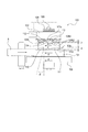
次に図2〜図9を用いて一つのモータ22の正逆回転により加圧ローラ604bの回転駆動と、定着ローラ604aと加圧ローラ604bとの接離動作とを選択的に切り替える駆動伝達装置100の構成について説明する。図2及び図3は駆動伝達装置100の構成を示す斜視説明図及び分解斜視図である。図4は駆動伝達装置100の構成を示す断面説明図、図5は正逆回転可能なモータ22からの回転駆動を受けて支持軸109の周りに回転する中間体104の構成を示す平面説明図である。
<Drive transmission device>
Next, referring to FIGS. 2 to 9, a drive transmission device selectively switching the rotational driving of the
図2〜図4に示すように、駆動伝達装置100は、図4に示す支持軸109を中心に回転自在に設けられた入力ギア106を有する。入力ギア106はモータ22の駆動軸に固定された駆動ギア16に噛合して設けられ、モータ22からの回転駆動を中間体104に伝達する。図3に示すように、入力ギア106に一体的に設けられた環状部106aの外周面にはリブ106bが突設されており、図5に示す中間体104の中央部に設けられた貫通穴104aの一部にはリブ106bに対応する溝部104a1が形成されている。
As shown in FIGS. 2 to 4, the
入力ギア106のギア面に対して軸方向に立設された環状部106aの外周に中間体104の貫通穴104aが挿通される。そして、該環状部106aの外周面に突設されたリブ106bが、中間体104の貫通穴104aの一部に設けられた溝部104a1内に嵌入されて係止される。
The through
これにより、中間体104は入力ギア106と回転方向(支持軸109の周方向)で係合して駆動伝達される。中間体104は入力ギア106の環状部106aの外周面上を軸方向に移動自在に設けられている。
Thereby, the
支持軸109の周りで入力ギア106の環状部106aの外周に第一の出力ギア101の貫通穴101bが挿通されて回転自在に保持されている。更に、支持軸109の周りで入力ギア106の環状部106aの外周に第二の出力ギア102の貫通穴102bが挿通されて回転自在に保持されている。
The through
図2に示すように、第一の出力ギア101と第二の出力ギア102とは中間体104を挟んで同じ支持軸109の周り(回転軸周り)を回転可能に配置されている。また、入力ギア106と、第一の出力ギア101と、中間体104と、第二の出力ギア102とは同軸上に配置される。
As shown in FIG. 2, is rotatably arranged around the same supporting
図3に示すように、入力ギア106の環状部106aの外周面に突設されたリブ106bが、図5に示す中間体104の貫通穴104aの溝部104a1に係合することで、入力ギア106から中間体104に回転駆動力が伝達される。
As shown in FIG. 3, the
入力ギア106に設けられた環状部106aは、第一の出力ギア101が回転自在に挿通される大径部106a1が設けられている。更に、中間体104が軸方向に移動自在に挿通される中径部106a2と、第二の出力ギア102が回転自在に挿通される小径部106a3とが設けられている。
An
第二の出力ギア102は、一端が装置フレーム17に当接した付勢手段となるコイルバネ108の付勢力により支持軸109に沿って入力ギア106側に付勢される。そして、環状部106aの小径部106a3と中径部106a2との間に形成される段部からなる突き当て部114に当接して位置決めされる。
The
図4に示すように、第二の出力ギア102は、支持軸109の方向(回転軸方向)に関して、付勢手段となるコイルバネ108の伸長力により所定の位置に向かって付勢されている。そして、第二の出力ギア102は、コイルバネ108の付勢力に抗して前記所定の位置から第2の回転軸方向(コイルバネ108の伸長力と反対方向)に移動可能である。
As shown in FIG. 4, the
中間体104は、第一の出力ギア101に噛み合って駆動を伝達する第一のラチェット面104c1と、中間体104を第二の出力ギア102側に軸方向に移動させる第二のラチェット面104c2とを備えた第一のラチェット歯104cを有する。
The
更に、中間体104は、第二のラチェット歯104bを有する。第二のラチェット歯104bは、第二の出力ギア102に噛み合って駆動を伝達する第三のラチェット面104b1を有する。更に、中間体104を第一の出力ギア101側(第一の出力ギア側)に軸方向に移動させる第四のラチェット面104b2とを備える。
Furthermore, the
図6及び図7に示すように、第一のラチェット面104c1と、第三のラチェット面104b1とは駆動伝達時に引き込み力が生じるように中間体104の軸方向(図6及び図7の上下方向)に対して所定の傾斜角度θを有して構成される。 As shown in FIGS. 6 and 7, the axial direction of the intermediate member 104 (vertical direction in FIGS. 6 and 7) such that a drawing force is generated between the first ratchet surface 104c1 and the third ratchet surface 104b1 during drive transmission. With a predetermined inclination angle θ.
第一の出力ギア101の軸方向で中間体104側には該中間体104の軸方向に設けられた第一のラチェット歯104cに対応するラチェット歯101aが設けられている。ラチェット歯101aはラチェット面110,111を有する。
On the side of the
第二の出力ギア102の軸方向で中間体104側には該中間体104の軸方向に設けられた第二のラチェット歯104bに対応するラチェット歯102aが設けられている。ラチェット歯102aはラチェット面112,113を有する。
On the side of the
ここで、ラチェット歯とは、図3〜図9に示すように、鋸歯を有し、逆回転止めの爪と組み合わせて一方向にしか回らないように構成された歯車をいう。 Here, as shown in FIGS. 3-9, a ratchet tooth means a gear which has a saw-tooth and is comprised so that it may rotate only in one direction combining with the claw of reverse rotation stop.
<駆動伝達装置の駆動伝達経路>
次に図2、図5、図6及び図7を用いて本実施形態の駆動伝達装置100の駆動伝達経路について説明する。図2に示すように、画像形成装置600のプリント時には駆動伝達装置100における一つの駆動源としてのモータ22が図2の実線で示す矢印i方向(第1方向)に正回転する。
<Drive Transmission Path of Drive Transmission Device>
Next, the drive transmission path of the
モータ22の駆動軸に固定された駆動ギア16に噛合する入力ギア106が図6の矢印d方向に回転する。そして、入力ギア106の環状部106aに設けられたリブ106bが中間体104の内周面に設けられた溝部104a1に嵌合して係止されて中間体104が入力ギア106と一体的に図6の矢印d方向に回転する。
The
中間体104が図6の矢印d方向に回転することにより該中間体104を支持軸109に沿って第一の出力ギア101側(第一の出力ギア側)に移動させる第四のラチェット面104b2がラチェット面113に当接摺動する。これにより中間体104が支持軸109に沿って第一の出力ギア101側(第1の回転軸方向)に移動する。
A fourth ratchet surface 104b2 for moving the intermediate 104 along the
これにより、中間体104の第一のラチェット歯104cが第一の出力ギア101のラチェット歯101aに噛合する。そして、中間体104から第一の出力ギア101へ回転方向への駆動を伝達する第一のラチェット面104c1とラチェット面110とが当接係合して中間体104から第一の出力ギア101へ回転駆動力が伝達される。
Thereby, the
図2に示すように、第一の出力ギア101からアイドラギア8を介して更に下流側のギア列24に回転駆動力が順次伝達される。そして、加圧ローラ604bの回転軸に固定された駆動ギア18にギア列24からの回転駆動力が伝達されて加圧ローラ604bが回転駆動される。
As shown in FIG. 2, rotational drive force is sequentially transmitted from the
一方、画像形成装置600の定着装置604の定着ニップ部NでシートSのジャムが発生すると、シート検知手段となるシートセンサ19により定着ニップ部NにシートSが残留していることを検知する。すると、シートセンサ19の検知情報に基づいて制御部605はモータ22を図2の点線で示す矢印j方向(第2方向)に逆回転させる。
On the other hand, when a jam of the sheet S occurs in the fixing nip N of the fixing
モータ22の駆動軸に固定された駆動ギア16に噛合する入力ギア106が図7の矢印e方向に回転する。そして、入力ギア106の環状部106aに設けられたリブ106bが中間体104の内周面に設けられた溝部104a1に嵌合して係止されて中間体104が入力ギア106と一体的に図7の矢印e方向に回転する。
The
中間体104が図7の矢印e方向に回転することにより該中間体104を支持軸109に沿って第二の出力ギア102側(第二の出力ギア側)に移動させる第二のラチェット面104c2がラチェット面111に当接摺動する。これにより中間体104が支持軸109に沿って第二の出力ギア102側(第2の回転軸方向)に移動する。
A second ratchet surface 104c2 for moving the intermediate 104 along the
これにより図7に示すように、中間体104の第二のラチェット歯104bが第二の出力ギア102のラチェット歯102aに噛合する。そして、中間体104から第二の出力ギア102へ回転方向への駆動を伝達する第三のラチェット面104b1とラチェット面112とが当接係合して中間体104から第二の出力ギア102へ回転駆動力が伝達される。
As a result, as shown in FIG. 7, the
図2に示すように、第二の出力ギア102からアイドラギア23を介して定着圧解除カム26が設けられたカム軸27に固定された駆動ギア25に回転駆動力が伝達されて定着圧解除カム26が図2の点線で示す矢印n方向に回転駆動される。
As shown in FIG. 2, the rotational driving force is transmitted from the
定着圧解除カム26に対向して図示しない加圧アーム軸を中心に回動可能な加圧アーム20が設けられており、加圧アーム20は付勢手段となるコイルバネ21により定着圧解除カム26に向けて付勢されている。
A
定着圧解除カム26が図2の点線で示す矢印n方向に回転駆動されると、定着圧解除カム26の押圧部がコイルバネ21の付勢力に抗して加圧アーム20を図示しない加圧アーム軸を中心に回動させて図2の左方向に押し下げる。これにより加圧アーム20に回転可能に軸支された定着ローラ604aが加圧ローラ604bから離間する。
When the fixing
本実施形態では、定着圧解除カム26の回転角度を検知することで、定着ローラ604aと加圧ローラ604bとの離間状態を検知する検知手段となる離間センサ28が設けられている。そして、定着圧解除カム26がカム軸27を中心に所定の角度まで回転する。すると、離間センサ28により定着ローラ(第1回転体)604aが加圧ローラ(第2回転体)604bから離間したことを検知する。そして、離間センサ28の検知情報に基づいて制御部605によりモータ22の逆回転を停止する。
In the present embodiment, the
このように定着圧解除カム26を回転させることで、定着ローラ604aと加圧ローラ604bとの接触圧を変化させることができる。
By rotating the fixing
画像形成装置600の定着装置604の定着ニップ部NでシートSのジャムが発生した場合には、シートセンサ19の検知情報に基づいて制御部605がモータ22を逆回転させて定着ローラ604aを加圧ローラ604bから離間する(接触圧は0)。これにより定着装置604の定着ニップ部NでジャムしたシートSのジャム処理を容易に行うことができる。
When a jam of the sheet S occurs in the fixing nip portion N of the fixing
定着装置604の定着ニップ部NでジャムしたシートSのジャム処理を行うと、シートセンサ19により定着ニップ部NにシートSが無いことが検知される。制御部605はシートセンサ19の検知情報に基づいてモータ22を更に図2の点線で示す矢印j方向に逆回転し、定着圧解除カム26を更に図2の矢印n方向に回転させる。その結果、定着圧解除カム26の押圧部が加圧アーム20から離れる。このため加圧アーム20はコイルバネ21により付勢されて加圧アーム軸を中心に回動し、定着ローラ604aを加圧ローラ604bに圧接して定着ニップ部Nを加圧状態に戻す。
When the jam processing of the sheet S jammed at the fixing nip portion N of the fixing
図6及び図7は本実施形態の駆動伝達装置100において、一つのモータ22の正逆回転を切り替える。これにより加圧ローラ604bの回転駆動と、定着ローラ604aを加圧ローラ604bに接離する接離動作との駆動伝達を選択的に切り替える様子を示す図である。
6 and 7 switch forward and reverse rotation of one
尚、図6及び図7では簡略化のために歯面形状は省略している。図6はモータ22を正回転したときの駆動伝達装置100の動作を示す側面説明図であり、図7はモータ22を逆回転したときの駆動伝達装置100の動作を示す側面説明図である。
The tooth flank shape is omitted in FIGS. 6 and 7 for the sake of simplicity. FIG. 6 is a side view showing the operation of the
モータ22が図2の実線で示す矢印i方向に正回転すると、モータ22の駆動軸に固定された駆動ギア16に噛合する入力ギア106が図6の実線で示す矢印d方向に回転する。入力ギア106に一体的に設けられた環状部106aの中径部106a2の外周面に突出したリブ106bと、中間体104の内周面に形成された溝部104a1とが嵌合して係合される。そして、入力ギア106の回転力が中間体104に伝達されて該中間体104は入力ギア106と同じ方向となる図6の実線で示す矢印d方向に回転する。
When the
中間体104が図6の矢印d方向に回転する。すると、中間体104の図6の上部に設けられたラチェット歯104bのラチェット面104b2が、第二の出力ギア102のラチェット歯102aのラチェット面113に当接摺動する。これにより中間体104は第二の出力ギア102を介して支持軸109に沿って図6の第一の出力ギア101側(第1の回転軸方向)に移動する。
中間体104のラチェット歯104bのラチェット面104b2が第二の出力ギア102のラチェット歯102aのラチェット面113に当接摺動する。その際に、第二の出力ギア102が中間体104と連れ回りしないように、第二の出力ギア102の下流側にはアイドラギア23を介して定着圧解除カム26のカム軸27に固定された駆動ギア25が繋がっている。これにより回転抵抗を付与して第二の出力ギア102が中間体104と連れ回りしないように構成される。
The
第一の出力ギア101のラチェット歯101aのラチェット面110と、中間体104のラチェット歯104cのラチェット面104c1とは駆動伝達時に引き込み力が生じるように軸方向に対して所定の傾斜角度θが設けられている。これにより中間体104のラチェット歯104cのラチェット面104c1と、第一の出力ギア101のラチェット歯101aのラチェット面110とが噛み合い始めると、第一の出力ギア101と中間体104とが軸方向に互いに引き込み合う。
The
このため中間体104が軸方向(図6の上下方向)において第一の出力ギア101に接触した段階では、図6に示すように、中間体104と第二の出力ギア102とは軸方向(図6の上下方向)において隙間bが空くような位置関係に設定されている。
Therefore, when the
一方、モータ22が図2の点線で示す矢印j方向に逆回転すると、モータ22の駆動軸に固定された駆動ギア16に噛合する入力ギア106が図7の破線で示す矢印e方向に回転する。入力ギア106に一体的に設けられた環状部106aの中径部106a2の外周面に突出したリブ106bと、中間体104の内周面に形成された溝部104a1とが嵌合して係合される。そして、入力ギア106の回転力が中間体104に伝達されて該中間体104は入力ギア106と同じ方向となる図7の破線で示す矢印e方向に回転する。
On the other hand, when the
中間体104が図7の矢印e方向に回転すると、中間体104の図7の下部に設けられたラチェット歯104cのラチェット面104c2が、第一の出力ギア101のラチェット歯101aのラチェット面111に当接摺動する。これにより中間体104は支持軸109に沿って図7の第二の出力ギア102側(第2の回転軸方向)に移動する。
When the intermediate 104 rotates in the direction of arrow e in FIG. 7, the
中間体104のラチェット歯104cのラチェット面104c2が、第一の出力ギア101のラチェット歯101aのラチェット面111に当接摺動する。その際に、第一の出力ギア101が中間体104と連れ回りしないように、第一の出力ギア101の下流側にはアイドラギア8、ギア列24を介して加圧ローラ604bの回転軸に固定された駆動ギア18が繋がっている。これにより回転抵抗を付与して第一の出力ギア101が中間体104と連れ回りしないように構成される。
The
第二の出力ギア102のラチェット歯102aのラチェット面112と、中間体104のラチェット歯104bのラチェット面104b1とは駆動伝達時に引き込み力が生じるように軸方向に対して所定の傾斜角度θが設けられている。これにより中間体104のラチェット歯104bのラチェット面104b1と、第二の出力ギア102のラチェット歯102aのラチェット面112とが噛み合い始めると、第二の出力ギア102と中間体104とが軸方向に互いに引き込み合う。
The
このため中間体104が軸方向(図7の上下方向)において第二の出力ギア102に接触した段階では、図7に示すように、中間体104と第一の出力ギア101とは軸方向(図7の上下方向)において隙間aが空くような位置関係に設定されている。
For this reason, when the
つまり、図6に示すように、中間体104と、第一の出力ギア101との駆動伝達時の噛み合い量をAとし、第一の出力ギア101に駆動を伝達している状態における中間体104と、第二の出力ギア102との隙間をbとする。
That is, as shown in FIG. 6, assuming that the meshing amount at the time of drive transmission between the
更に、図7に示すように、中間体104と、第二の出力ギア102との駆動伝達時の噛み合い量をBとし、第二の出力ギア102に駆動を伝達している状態における中間体104と、第一の出力ギア101との隙間をaとする。その場合、以下の数1式で示す関係式が満たされるように設定されている。
Further, as shown in FIG. 7, assuming that the meshing amount at the time of drive transmission between the
[数1]
A>b かつ B>a
[Equation 1]
A> b and B> a
しかしながら、第一の出力ギア101と、第二の出力ギア102との位相タイミング次第では以下の場合が発生する。図8のD部で示すように中間体104が軸方向(図8の上下方向)の上方に移動し始める。そのときに第二の出力ギア102のラチェット歯102aの歯先と、中間体104のラチェット歯104bの歯先とが突き当たってしまう。そして、中間体104が軸方向(図8の上下方向)の上方に移動しきれない場合が発生する。
However, depending on the phase timing of the
そこで、第二の出力ギア102が突き当て部114に突き当たった位置(所定の位置)から第2の回転軸方向(第一の出力ギア101から離れる方向)に移動できるように、第二の出力ギア102の第一の出力ギア101と反対側に隙間Gを空けておく。これにより、ラチェット歯102aの歯先と、中間体104のラチェット歯104bの歯先とが突き当たった時に、中間体104に押圧された第二の出力ギア102は、上方に移動し、第二の出力ギア102と中間体104の歯先同士を離間させることができる。
Therefore, so as to be movable to a position abutting against the
上述した隙間Gを空けても、図6に示す噛み合い量Aと、隙間bとが前記数1式を満たせるように、付勢手段となるコイルバネ108により第二の出力ギア102を図4の軸方向(図4の上下方向)の下方側に付勢しておく。通常の使用状態では、図4に示すように、第二の出力ギア102の内周端部が入力ギア106に一体的に設けられた環状部106aの小径部106a3と中径部106a2との段差部からなる突き当て部114に対して軸方向(図4の上下方向)に突き当たる。
The shaft of the
また、第一の出力ギア101のラチェット歯101aの歯数と、第二の出力ギア102のラチェット歯102aの歯数とが等しい場合がある。その場合、第一の出力ギア101と、第二の出力ギア102との位相タイミング次第では中間体104が第二の出力ギア102に噛み合う前に自重により中間体104が図9の下方に移動してしまう。これにより中間体104から第二の出力ギア102に駆動が伝達できない場合がある。
Also, the number of
それを回避するために中間体104が重力で図9の下方に移動するよりも速い速度で中間体104を回転させる構成が考えられる。また、中間体104の回転速度に依存しない他の方法がある。第一の出力ギア101のラチェット歯101aに噛み合って駆動を伝達する中間体104の第一のラチェット歯104cの歯数を4歯とする。そして、第二の出力ギア102のラチェット歯102aに噛み合って駆動を伝達する中間体104の第二のラチェット歯104bの歯数を9歯とする。即ち、中間体104の第一のラチェット歯104cの歯数と、第二のラチェット歯104bの歯数とが非整数比となる関係に設定すれば良い。
In order to avoid that, a configuration is conceivable in which the intermediate 104 is rotated at a speed higher than that of the intermediate 104 moving downward in FIG. 9 by gravity. There are also other methods that do not depend on the rotational speed of the intermediate 104. The number of teeth of the
また、第一の出力ギア101と、第二の出力ギア102との位相を検知できるようなセンサを備えた場合、第一の出力ギア101と、第二の出力ギア102との位相を検知した結果に基づいてモータ22を正逆回転するタイミングを変えても良い。
Further, when a sensor capable of detecting the phase of the
以上のように、中間体104はモータ22の正逆回転に応じて支持軸109の軸方向に移動し、第一の出力ギア101または第二の出力ギア102の何れかに噛み合って駆動を伝達することが出来る。これにより少ない部品点数で簡単な構成とすることが出来、第一の出力ギア101,第二の出力ギア102及び中間体104の各ラチェット歯101a,102a,104b,104cが噛み合う際に発生する騒音を低減できる。
As described above, the
モータ22の回転駆動の一方向の駆動伝達に複数のラチェット歯を用いることで、高トルクの駆動伝達が可能となる。更に、中間体104の表裏面にラチェット歯を設けることで小型な部品で駆動切り替えが可能となり、コンパクトな駆動伝達装置100が実現できる。
By using a plurality of ratchet teeth for one-way drive transmission of the rotational drive of the
尚、本実施形態の駆動伝達装置100は、一つのモータ22の正逆回転を切り替える。これにより定着装置604の被駆動部材となる加圧ローラ604bの回転駆動と、定着ローラ604aを加圧ローラ604bに接離する接離動作との駆動伝達を選択的に切り替える場合の一例について説明した。他に画像形成装置600における多段のシート給送装置、或いは、ロータリー方式の現像装置等において、一つのモータの正逆回転により駆動伝達を切り換える種々の用途にも同様に適用できる。
The
[第1参考例]
次に、図10及び図11を用いて第1参考例の構成について説明する。尚、前記第1実施形態と同様に構成したものは同一の符号、或いは符号が異なっても同一の部材名を付して説明を省略する。図10は本参考例の駆動伝達装置の構成を示す側面説明図である。図11は本参考例の駆動伝達装置の構成を示す断面説明図である。
[First reference example]
Next, the configuration of the first reference example will be described using FIG. 10 and FIG. The same components as those in the first embodiment are given the same reference numerals or the same reference numerals even if they are different, and the description will be omitted. FIG. 10 is an explanatory side view showing the configuration of the drive transmission device of the present embodiment . FIG. 11 is a cross-sectional explanatory view showing the configuration of the drive transmission device of the present embodiment .
前記第1実施形態では、入力ギア106から中間体104へ回転駆動力を伝達する構成の一例として以下のように構成した。図3に示すように、入力ギア106に一体的に設けられた環状部106aの中径部106a2の外周面に突設されたリブ106bと、図5に示すように、中間体104の内周面に設けられた溝部104a1とが嵌合して係合する。これにより入力ギア106から中間体104へ回転駆動力を伝達する構成とした。
In the said 1st Embodiment, it comprised as follows as an example of a structure which transmits rotational driving force from the
本参考例では、図10に示すように、中間体104の外周面に平歯ギアで構成される入力ギア106と噛合する平歯ギア104dを備えて構成したものである。これにより入力ギア106からの回転駆動力を中間体104の平歯ギア104dにより受ける以外は、前記第1実施形態と略同様に伝達する構成にしている。
In the present embodiment , as shown in FIG. 10, a
本参考例の第一の出力ギア101、第二の出力ギア102及び中間体104は、図11に示すように、直接、支持軸109に対して回転自在に軸支されている。入力ギア106は支持軸109とは異なる軸上に回転可能に設けられている。第一の出力ギア101及び中間体104は、支持軸109の大径部109aに回転自在に軸支され、第二の出力ギア102は支持軸109の小径部109bに回転自在に軸支されている。
The
第二の出力ギア102の内周面の端部は支持軸109の大径部109aと小径部109bとの間の段部からなる突き当て部115に当接され、一端が装置フレーム17に当接された付勢手段となるコイルバネ108により中間体104の方向に付勢されている。
The end of the inner peripheral surface of the
本参考例では、入力ギア106を支持軸109とは異なる軸上に配置した。これにより支持軸109方向における第一の出力ギア101、第二の出力ギア102及び中間体104を含む駆動伝達装置100の全体の厚み(図11の上下方向の幅)を薄くすることができる。これにより装置内のスペースが狭い場所にも駆動伝達装置100を配置することができる。
In the present embodiment , the
尚、本参考例では、図10に示すように、中間体104の外周面に平歯ギア104dを設けた構成としたが、軸方向の力が発生するようなヘリカルギア(helical gear;はすば歯車)等を用いても良い。ヘリカルギアは前記第1実施形態の入力ギア106、第一の出力ギア101、第二の出力ギア102等で示されたように、回転軸方向に延長すると螺旋状に形成される傾斜歯車からなり軸方向力(スラスト力)が発生する。歯当たりが分散されるため平歯車よりも音が静かである。
In the present embodiment , as shown in FIG. 10, the
中間体104の外周面にヘリカルギアを設けた場合には以下の構成とする。中間体104が第一の出力ギア101、第二の出力ギア102の各ラチェット面111,113に当接摺動して軸方向に移動しようとする方向と、ヘリカルギアのねじれ角によって生じる軸方向力の方向とを合わせる。他の構成は前記第1実施形態と同様に構成され、同様の効果を得ることが出来る。
When the helical gear is provided on the outer peripheral surface of the
[第2参考例]
次に、図12及び図13を用いて第2参考例の構成について説明する。尚、前記実施形態、或いは前記参考例と同様に構成したものは同一の符号、或いは符号が異なっても同一の部材名を付して説明を省略する。図12は本参考例の駆動伝達装置の構成を示す斜視説明図である。図13は本参考例の駆動伝達装置の構成を示す側面説明図である。尚、簡略化のために図13の歯面形状は省略する。
[Second reference example]
Next, the configuration of the second reference example will be described using FIGS. 12 and 13. Incidentally, before omitted you facilities form or Reference Example and similarly configured to the ones same reference numerals, or numerals a description of those same members name be different. Figure 12 is a perspective view showing the configuration of a drive transmission device of the present embodiment. FIG. 13 is an explanatory side view showing the configuration of the drive transmission device of the present embodiment . The tooth surface shape of FIG. 13 is omitted for simplification.
本参考例では、駆動源となるモータ22の正回転と逆回転とで最終出力部となる第三の出力ギア103が同方向に回転する。更に、第三の出力ギア103の回転数がモータ22の正回転と逆回転とで異なるように、モータ22の正逆回転で最終出力部となる第三の出力ギア103までの減速比を切り換える構成としたものである。
In this reference example , the
本参考例では、図12に示す第一の出力ギア101の歯数を40歯、第三の出力ギア103の歯数を40歯、第二の出力ギア102の歯数を20歯、アイドラギア105の歯数を20歯とする。そして、中間体104の回転数を正逆回転共に1000rpm(rotation per minute)とする。
In this embodiment , the number of teeth of the
図2の実線で示す矢印i方向にモータ22が正回転し、モータ22の駆動軸に固定された駆動ギア16を介して入力ギア106が図12及び図13に実線で示す矢印d方向に正回転する。更に、入力ギア106に噛合する平歯ギア104dを介して中間体104が図12及び図13に実線で示す矢印f方向に正回転する。
The
モータ22が正回転する場合、中間体104のラチェット歯104cから第一の出力ギア101のラチェット歯101aに回転駆動力が伝達される。そして、第一の出力ギア101に噛合された第三の出力ギア103が図12及び図13に実線で示す矢印g方向に1000rpmで回転される。
When the
更に、第三の出力ギア103に噛合されたアイドラギア105を介して第二の出力ギア102にも回転駆動力が伝達される。
Furthermore, the rotational drive force is also transmitted to the
即ち、本参考例では、第一の出力ギア101から最終出力部となる第三の出力ギア103までの第一の駆動伝達経路は、第一の出力ギア101と第三の出力ギア103との噛合により構成される。また、第二の出力ギア102から最終出力部となる第三の出力ギア103までの第二の駆動伝達経路は、第二の出力ギア102と、アイドラギア105と、第三の出力ギア103との噛合により構成される。
That is, in the present embodiment , the first drive transmission path from the
モータ22が正回転する場合、第二の出力ギア102は、入力ギア106→中間体104→第一の出力ギア101→第三の出力ギア103→アイドラギア105→第二の出力ギア102の順に回転駆動力が伝達されて回転駆動される。このとき、中間体104は図13に示すように、支持軸109に沿って第一の出力ギア101側に寄っており、中間体104のラチェット歯104bと、第二の出力ギア102のラチェット歯102aとは接触していない。
When the
一方、図2の破線で示す矢印j方向にモータ22が逆回転し、モータ22の駆動軸に固定された駆動ギア16を介して入力ギア106が図12及び図13に破線で示す矢印e方向に逆回転する。更に、入力ギア106に噛合する平歯ギア104dを介して中間体104が図12及び図13に点線で示す矢印h方向に逆回転する。
On the other hand, the
モータ22が逆回転する場合、中間体104のラチェット歯104bから第二の出力ギア102のラチェット歯102aに回転駆動力が伝達される。そして、第二の出力ギア102に噛合されたアイドラギア105を介して第三の出力ギア103が図12及び図13に破線で示す矢印g方向に500rpmで回転される。
When the
更に、第三の出力ギア103に噛合された第一の出力ギア101にも回転駆動力が伝達される。
Further, the rotational drive force is also transmitted to the
モータ22が逆回転する場合、第一の出力ギア101は、入力ギア106→中間体104→第二の出力ギア102→アイドラギア105→第三の出力ギア103→第一の出力ギア101の順に回転駆動力が伝達されて回転駆動される。このとき、中間体104は支持軸109に沿って第二の出力ギア102側に寄っており、中間体104のラチェット歯104cと、第一の出力ギア101のラチェット歯101aとは接触していない。
When the
本参考例では、中間体104を図12及び図13に実線で示す矢印f方向に正回転で1000rpmで回転駆動した際は、第三の出力ギア103は図12及び図13に実線で示す矢印g方向に1000rpmで回転する。
In this reference example , when the
一方、中間体104を図12及び図13に点線で示す矢印h方向に逆回転で1000rpmで回転駆動した際は、第三の出力ギア103は図12及び図13に破線で示す矢印g方向に500rpmで回転する。これは、第一の出力ギア101の歯数を40歯とし、第二の出力ギア102の歯数及びアイドラギア105の歯数を20歯としたことに基づく。
On the other hand, when the
これにより簡単な構成によりモータ22の正逆回転で減速比を切り換え可能な駆動伝達装置100として構成できる。他の構成は前記実施形態、或いは、前記参考例と同様に構成され、同様の効果を得ることが出来る。
As a result, the
尚、前記実施形態、或いは、前記参考例では、駆動伝達装置100を画像形成装置600の各種の駆動伝達部に適用した一例について説明したが、画像形成装置600以外の各種装置の駆動伝達部に駆動伝達装置100を適用することも出来る。
Incidentally, before you facilities form or the in reference example has been described an example of applying the
22 …モータ(駆動源)
100 …駆動伝達装置
101 …第一の出力ギア
102 …第二の出力ギア
104 …中間体
109 …支持軸
22 ... Motor (drive source)
100 ... Drive transmission device
101 ... 1st output gear
102 ... second output gear
104 ... intermediate
109 ... Support shaft
Claims (14)
前記入力ギアに設けられ、外周面にリブが設けられた回転軸と、
前記回転軸周りを回転可能な第一の出力ギアと第二の出力ギアと、
前記回転軸方向に関して前記第一の出力ギアと前記第一の出力ギアとは外径が異なる前記第二の出力ギアとの間に配置され、内周面に前記リブと係合可能な溝部が設けられた中間体と、
を有し、
前記中間体は、前記回転軸が回転すると、前記リブが前記溝部の壁面に係止されて前記回転軸から駆動が伝達され、
前記中間体は、前記駆動源が第1方向に回転した際に第1の回転軸方向に移動して前記第一の出力ギアに噛み合って回転し、前記駆動源が前記第1方向と逆の第2方向に回転した際に前記第1の回転軸方向と逆の第2の回転軸方向に移動して前記第二の出力ギアに噛み合って回転することを特徴とする駆動伝達装置。 An input gear to which rotational drive from a drive source is transmitted ;
A rotating shaft provided on the input gear and provided with a rib on an outer peripheral surface thereof ;
A first output gear and a second output gear rotatable around the rotation axis ;
Disposed between the second output gear having an outer diameter different from the first output gear with respect to the previous SL rotation axis direction and the first output gear, the rib can engage the grooves on the inner peripheral surface And an intermediate provided with
Have
In the intermediate body, when the rotation shaft is rotated, the rib is engaged with the wall surface of the groove, and the drive is transmitted from the rotation shaft .
When the drive source rotates in the first direction, the intermediate moves in the direction of the first rotation axis, meshes with the first output gear and rotates, and the drive source is reverse to the first direction. When it rotates in a 2nd direction, it moves to a 2nd rotating shaft direction opposite to the said 1st rotating shaft direction, meshes with the said 2nd output gear, and it rotates, It is characterized by the above-mentioned.
前記入力ギアに設けられ、外周面にリブが設けられた回転軸と、
前記回転軸周りを回転可能な第一の出力ギアと第二の出力ギアと、
前記回転軸方向に関して前記第一の出力ギアと前記第一の出力ギアとは外径が異なる前記第二の出力ギアとの間に配置され、内周面に前記リブと係合可能な溝部が設けられた中間体と、
を有し、
前記中間体は、前記回転軸が回転すると、前記リブが前記溝部の壁面に係止されて前記回転軸から駆動が伝達され、
前記中間体は、前記駆動源が第1方向に回転した際に前記回転軸方向において前記第一の出力ギア側に移動して前記第一の出力ギアに噛み合って回転し、前記駆動源が前記第1方向と逆の第2方向に回転した際に前記回転軸方向において前記第二の出力ギア側に移動して前記第二の出力ギアに噛み合って回転することを特徴とする駆動伝達装置。 An input gear to which rotational drive from a drive source is transmitted ;
A rotating shaft provided on the input gear and provided with a rib on an outer peripheral surface thereof ;
A first output gear and a second output gear rotatable around the rotation axis ;
Disposed between the second output gear having an outer diameter different from the first output gear with respect to the previous SL rotation axis direction and the first output gear, the rib can engage the grooves on the inner peripheral surface And an intermediate provided with
Have
In the intermediate body, when the rotation shaft is rotated, the rib is engaged with the wall surface of the groove, and the drive is transmitted from the rotation shaft .
The intermediate, the driving source moves the the first output gear side before Symbol rotation axis direction when rotated in a first direction to rotate in mesh with the first output gear, said drive source drive transmission, characterized in that the rotating meshing with said moving to said second output gear side before Symbol rotation axis direction when rotated in a second direction of the first direction and the opposite second output gear apparatus.
前記第一の出力ギアに駆動を伝達している状態における前記中間体と、前記第二の出力ギアとの隙間の前記回転軸方向における長さをbとし、
前記中間体と前記第二の出力ギアとの駆動伝達時の噛み合い量の前記回転軸方向における長さをBとし、
前記第二の出力ギアに駆動を伝達している状態における前記中間体と、前記第一の出力ギアとの隙間の前記回転軸方向における長さをaとした場合、
A>b かつ B>a
の関係式が満たされることを特徴とする請求項2に記載の駆動伝達装置。 Let A be the length of the meshing amount at the time of drive transmission between the intermediate body and the first output gear in the rotation axis direction,
Let b be the length of the gap between the intermediate in the state of transmitting the drive to the first output gear and the second output gear in the rotational axis direction, b
The rotary shaft direction length in direction of engagement amount during the drive transmission between said second output gear and said intermediates by B,
When the length of the gap between the intermediate body in the state of transmitting the drive to the second output gear and the first output gear in the rotation axis direction is a.
A> b and B> a
The drive transmission apparatus according to claim 2, wherein the following relationship is satisfied.
前記第一の出力ギアに駆動を伝達する第一のラチェット面と、前記中間体を前記第二の出力ギア側に移動させる第二のラチェット面とを備えた第一のラチェット歯と、
前記第二の出力ギアに駆動を伝達する第三のラチェット面と、前記中間体を前記第一の出力ギア側に移動させる第四のラチェット面とを備えた第二のラチェット歯と、
を有することを特徴とする請求項1〜5のいずれか1項に記載の駆動伝達装置。 The intermediate is
A first ratchet tooth having a first ratchet surface for transmitting a drive to the first output gear; and a second ratchet surface for moving the intermediate toward the second output gear.
A second ratchet tooth having a third ratchet surface for transmitting a drive to the second output gear; and a fourth ratchet surface for moving the intermediate toward the first output gear.
The drive transmission device according to any one of claims 1 to 5 , characterized by:
前記第一の出力ギアに駆動を伝達している状態における前記中間体と、前記第二の出力ギアとの隙間をbとし、
前記中間体と、前記第二の出力ギアとの駆動伝達時の噛み合い量をBとし、
前記第二の出力ギアに駆動を伝達している状態における前記中間体と、前記第一の出力ギアとの隙間をaとした場合、
A>b かつ B>a
の関係式が満たされることを特徴とする請求項1、2、6のいずれか1項に記載の駆動伝達装置。 The meshing amount at the time of drive transmission between the intermediate body and the first output gear is A,
A gap between the intermediate body and the second output gear in a state in which the drive is transmitted to the first output gear is b,
Let B be an engagement amount at the time of drive transmission between the intermediate body and the second output gear,
Assuming that the gap between the intermediate body and the first output gear in a state in which the drive is transmitted to the second output gear is a:
A> b and B> a
The drive transmission apparatus according to any one of claims 1, 2, and 6 , wherein the following relationship is satisfied.
前記被駆動部材は、前記第一の出力ギアの回転により回転した時と前記第二の出力ギアの回転により回転した時とで同方向に回転し、前記第一の出力ギアの回転により回転した時と前記第二の出力ギアの回転により回転した時とで前記被駆動部材の回転数が異なることを特徴とする請求項1〜11のいずれか1項に記載の駆動伝達装置。 A driven member rotatable by rotation of the first output gear and rotatable by rotation of the second output gear ;
Before SL driven member is rotated in the same direction and when rotated by the rotation of the second output gear and when rotated by the rotation of the first output gear, rotated by the rotation of the first output gear The drive transmission apparatus according to any one of claims 1 to 11 , wherein a rotation speed of the driven member is different between when the rotation is performed and when the second output gear is rotated.
シートに画像を形成する画像形成部と、
を有することを特徴とする画像形成装置。 A drive transmitting device according to any one of claims 1 to 1 2,
An image forming unit that forms an image on a sheet;
An image forming apparatus comprising:
前記第一の出力ギアの回転により、前記第2回転体が回転し、前記第二の出力ギアの回転により、前記第1回転体と前記第2回転体との接触圧が変化することを特徴とする請求項13に記載の画像形成装置。 A fixing unit including a first rotating body and a second rotating body, the first rotating body and the second rotating body forming a nip for heating and pressing the sheet, and fixing the toner image on the sheet ,
The second rotary body is rotated by the rotation of the first output gear, and the contact pressure between the first rotary body and the second rotary body is changed by the rotation of the second output gear. the image forming apparatus according to claim 1 3,.
Priority Applications (1)
| Application Number | Priority Date | Filing Date | Title |
|---|---|---|---|
| JP2015012025A JP6529268B2 (en) | 2014-01-28 | 2015-01-26 | Drive transmission device and image forming apparatus |
Applications Claiming Priority (3)
| Application Number | Priority Date | Filing Date | Title |
|---|---|---|---|
| JP2014013088 | 2014-01-28 | ||
| JP2014013088 | 2014-01-28 | ||
| JP2015012025A JP6529268B2 (en) | 2014-01-28 | 2015-01-26 | Drive transmission device and image forming apparatus |
Related Child Applications (1)
| Application Number | Title | Priority Date | Filing Date |
|---|---|---|---|
| JP2019090827A Division JP6862491B2 (en) | 2014-01-28 | 2019-05-13 | Drive transmission device and image forming device |
Publications (3)
| Publication Number | Publication Date |
|---|---|
| JP2015163953A JP2015163953A (en) | 2015-09-10 |
| JP2015163953A5 JP2015163953A5 (en) | 2018-02-15 |
| JP6529268B2 true JP6529268B2 (en) | 2019-06-12 |
Family
ID=53678938
Family Applications (2)
| Application Number | Title | Priority Date | Filing Date |
|---|---|---|---|
| JP2015012025A Active JP6529268B2 (en) | 2014-01-28 | 2015-01-26 | Drive transmission device and image forming apparatus |
| JP2019090827A Active JP6862491B2 (en) | 2014-01-28 | 2019-05-13 | Drive transmission device and image forming device |
Family Applications After (1)
| Application Number | Title | Priority Date | Filing Date |
|---|---|---|---|
| JP2019090827A Active JP6862491B2 (en) | 2014-01-28 | 2019-05-13 | Drive transmission device and image forming device |
Country Status (2)
| Country | Link |
|---|---|
| US (1) | US9354560B2 (en) |
| JP (2) | JP6529268B2 (en) |
Families Citing this family (24)
| Publication number | Priority date | Publication date | Assignee | Title |
|---|---|---|---|---|
| JP6111225B2 (en) * | 2014-08-19 | 2017-04-05 | 京セラドキュメントソリューションズ株式会社 | Drive transmission mechanism and image forming apparatus having the same |
| JP6604538B2 (en) * | 2015-08-17 | 2019-11-13 | 富士ゼロックス株式会社 | Image forming apparatus |
| CN105045062B (en) * | 2015-08-25 | 2018-03-23 | 珠海奔图电子有限公司 | Drive system and image processing system |
| JP6674650B2 (en) * | 2015-09-02 | 2020-04-01 | 株式会社リコー | Driving device and image forming apparatus |
| KR101791010B1 (en) * | 2015-09-15 | 2017-10-27 | (주)엠비아이 | Transmission for motor |
| KR101733802B1 (en) * | 2015-12-23 | 2017-05-10 | 에스프린팅솔루션 주식회사 | Development cartridge and electrophotographic image forming apparatus using the same |
| JP6677928B2 (en) * | 2016-04-15 | 2020-04-08 | 株式会社リコー | Driving device and image forming apparatus |
| JP6697710B2 (en) * | 2016-04-25 | 2020-05-27 | 株式会社リコー | Speed switching device, drive device and image forming device |
| JP6800615B2 (en) * | 2016-05-31 | 2020-12-16 | キヤノン株式会社 | Sheet transfer device, image reader and image forming device |
| JP6808364B2 (en) * | 2016-06-14 | 2021-01-06 | キヤノン株式会社 | Electrophotographic image forming apparatus |
| JP6822033B2 (en) * | 2016-09-20 | 2021-01-27 | ブラザー工業株式会社 | Image forming device and additional paper feed tray |
| JP6614085B2 (en) * | 2016-09-26 | 2019-12-04 | 京セラドキュメントソリューションズ株式会社 | One-way clutch, fixing device and image forming apparatus |
| JP6849428B2 (en) * | 2016-12-26 | 2021-03-24 | キヤノン株式会社 | Clutch device, process cartridge and image forming device |
| US11150592B2 (en) * | 2017-01-24 | 2021-10-19 | Canon Kabushiki Kaisha | Drive transmission device and image forming apparatus |
| CN106990693B (en) * | 2017-05-22 | 2023-11-28 | 珠海天麟医疗器械科技有限公司 | Driving tooth structure of double-layer selenium drum |
| JP7009100B2 (en) * | 2017-07-24 | 2022-01-25 | キヤノン株式会社 | Fixing device and image forming device |
| JP6991770B2 (en) * | 2017-07-31 | 2022-01-13 | キヤノン株式会社 | Sheet transfer device and image forming device |
| JP7073132B2 (en) * | 2018-02-14 | 2022-05-23 | キヤノン株式会社 | Drive device and image forming device |
| JP7087447B2 (en) | 2018-02-28 | 2022-06-21 | ブラザー工業株式会社 | Develop cartridge |
| JP7282633B2 (en) * | 2019-08-20 | 2023-05-29 | キヤノン株式会社 | Driving device, image forming apparatus, and method for manufacturing driving device |
| JP7411391B2 (en) | 2019-11-15 | 2024-01-11 | 仁 哲 洪 | Kinetic energy transfer system by converting input reciprocating motion into unidirectional output rotational motion |
| US11493099B2 (en) * | 2020-02-26 | 2022-11-08 | Canon Finetech Nisca Inc. | One-way clutch, drive transmission unit using this one-way clutch, and inkjet printing apparatus using this drive transmission unit |
| JP7015482B2 (en) * | 2020-03-04 | 2022-02-03 | 株式会社リコー | Image forming device |
| JP2023126010A (en) * | 2022-02-28 | 2023-09-07 | キヤノン株式会社 | Photoreceptor unit, cartridge, and electrophotographic image forming device |
Family Cites Families (26)
| Publication number | Priority date | Publication date | Assignee | Title |
|---|---|---|---|---|
| DE1031601B (en) * | 1953-09-03 | 1958-06-04 | Kloeckner Humboldt Deutz Ag | Reverse gear |
| FR1199431A (en) * | 1958-02-26 | 1959-12-14 | Improvement of reversal mechanisms | |
| JPS459583Y1 (en) * | 1966-07-07 | 1970-05-04 | ||
| US3563353A (en) * | 1968-06-27 | 1971-02-16 | United Parcel Service General | Automatic reversing clutches with pilot brake |
| JPS62255393A (en) * | 1986-04-25 | 1987-11-07 | 株式会社 南星 | Floating-body lifter on wave |
| JP2921909B2 (en) * | 1990-03-20 | 1999-07-19 | 株式会社リコー | Electrophotographic image forming apparatus |
| JP2568294Y2 (en) | 1991-06-25 | 1998-04-08 | 日本電産株式会社 | Clutch device |
| JPH0617887A (en) * | 1992-07-02 | 1994-01-25 | T T T Kk | Power transmission gear |
| JPH06118784A (en) | 1992-10-03 | 1994-04-28 | Ricoh Co Ltd | Developing roller driving system connecting structure |
| KR100202377B1 (en) | 1996-06-24 | 1999-06-15 | 윤종용 | Document feeding apparatus |
| JP2000310298A (en) * | 1999-04-27 | 2000-11-07 | Asahi Optical Co Ltd | Motor interlock switching device |
| JP4206467B2 (en) | 1999-11-01 | 2009-01-14 | 旭精工株式会社 | Switching gear device for forward / reverse rotation motor. |
| JP2003314631A (en) * | 2002-04-18 | 2003-11-06 | Sharp Corp | Drive device and image forming device equipped with the same |
| JP2005054861A (en) * | 2003-08-01 | 2005-03-03 | Ricoh Co Ltd | Rotary driving device, fixing device, and image forming device |
| KR100644625B1 (en) * | 2004-09-06 | 2006-11-10 | 삼성전자주식회사 | Driving method of driving apparatus for developers and image forming apparatus using the same |
| JP2006308007A (en) | 2005-04-28 | 2006-11-09 | Canon Inc | Clutch mechanism |
| JP5147209B2 (en) | 2005-09-30 | 2013-02-20 | キヤノン株式会社 | Drive transmission device and image forming apparatus |
| JP4781949B2 (en) | 2006-09-15 | 2011-09-28 | 京セラミタ株式会社 | Toner container drive mechanism and image forming apparatus |
| KR101260311B1 (en) * | 2008-01-21 | 2013-05-03 | 삼성전자주식회사 | Image forming apparatus and control method thereof |
| JP2009282401A (en) * | 2008-05-23 | 2009-12-03 | Konica Minolta Business Technologies Inc | Fixing device and image forming device |
| JP2010048299A (en) | 2008-08-20 | 2010-03-04 | Seiko Epson Corp | Power transmission device and sending device |
| JP5327639B2 (en) * | 2009-12-28 | 2013-10-30 | 株式会社リコー | Fixing apparatus and image forming apparatus |
| ES2354101B1 (en) * | 2010-09-28 | 2011-10-14 | Luis Sans Vollmer | GEAR MECHANISM FOR CONVERSION OF TURN. |
| JP5767168B2 (en) * | 2012-06-19 | 2015-08-19 | 矢継 正信 | Axial one-way clutch |
| KR20140065596A (en) * | 2012-11-16 | 2014-05-30 | 삼성전자주식회사 | Power transmitting apparatus and image forming apparatus adopting the same |
| JP6324022B2 (en) * | 2013-10-30 | 2018-05-16 | キヤノン株式会社 | Drive transmission device, fixing device, and image forming apparatus |
-
2015
- 2015-01-26 JP JP2015012025A patent/JP6529268B2/en active Active
- 2015-01-27 US US14/606,602 patent/US9354560B2/en active Active
-
2019
- 2019-05-13 JP JP2019090827A patent/JP6862491B2/en active Active
Also Published As
| Publication number | Publication date |
|---|---|
| JP6862491B2 (en) | 2021-04-21 |
| US9354560B2 (en) | 2016-05-31 |
| JP2015163953A (en) | 2015-09-10 |
| US20150212456A1 (en) | 2015-07-30 |
| JP2019178780A (en) | 2019-10-17 |
Similar Documents
| Publication | Publication Date | Title |
|---|---|---|
| JP6529268B2 (en) | Drive transmission device and image forming apparatus | |
| JP5147209B2 (en) | Drive transmission device and image forming apparatus | |
| JP6187857B2 (en) | Transfer device and image forming apparatus | |
| US8498560B2 (en) | Fixing device and image forming apparatus using this fixing device | |
| JP6991844B2 (en) | One-way clutch unit and image heating device | |
| JP5403026B2 (en) | Fixing apparatus and image forming apparatus | |
| JP2013015549A (en) | Fixing device and image forming device | |
| US10054878B2 (en) | Driving force transmission apparatus and image forming apparatus | |
| EP3281066A1 (en) | Hub-based drive coupling mechanism for a fuser backup member, and methods of using same | |
| JP5709432B2 (en) | Image forming apparatus | |
| JP4947020B2 (en) | Fixing device and image forming apparatus using the same | |
| US11609526B2 (en) | Fixing device | |
| JP2011137987A (en) | Fixing device and image forming apparatus | |
| JP2014016432A (en) | Drive device and image forming apparatus | |
| JP2012014070A (en) | Image forming device | |
| JP5408217B2 (en) | Fixing apparatus and image forming apparatus | |
| JP6344202B2 (en) | Driving structure, fixing device, and image forming apparatus | |
| JP7304003B2 (en) | Rotating device and image forming device | |
| JP7140539B2 (en) | One-way clutch and sheet conveying device | |
| JP2021131523A (en) | Driving mechanism, fixing device, conveying device, and image forming apparatus | |
| JP2015200824A (en) | Image heating device and image forming apparatus | |
| JP5625740B2 (en) | Medium pressing apparatus and image forming apparatus | |
| JP2018205540A (en) | Fixation device and image formation apparatus having the same | |
| JP6741231B2 (en) | Driving device and image forming apparatus | |
| US9725258B2 (en) | Image forming device |
Legal Events
| Date | Code | Title | Description |
|---|---|---|---|
| A621 | Written request for application examination |
Free format text: JAPANESE INTERMEDIATE CODE: A621 Effective date: 20171218 |
|
| A521 | Request for written amendment filed |
Free format text: JAPANESE INTERMEDIATE CODE: A523 Effective date: 20171225 |
|
| A977 | Report on retrieval |
Free format text: JAPANESE INTERMEDIATE CODE: A971007 Effective date: 20180831 |
|
| A131 | Notification of reasons for refusal |
Free format text: JAPANESE INTERMEDIATE CODE: A131 Effective date: 20180911 |
|
| A521 | Request for written amendment filed |
Free format text: JAPANESE INTERMEDIATE CODE: A523 Effective date: 20181112 |
|
| TRDD | Decision of grant or rejection written | ||
| A01 | Written decision to grant a patent or to grant a registration (utility model) |
Free format text: JAPANESE INTERMEDIATE CODE: A01 Effective date: 20190416 |
|
| A61 | First payment of annual fees (during grant procedure) |
Free format text: JAPANESE INTERMEDIATE CODE: A61 Effective date: 20190514 |
|
| R151 | Written notification of patent or utility model registration |
Ref document number: 6529268 Country of ref document: JP Free format text: JAPANESE INTERMEDIATE CODE: R151 |