JP6525526B2 - IMAGE PROCESSING APPARATUS, IMAGE PROCESSING METHOD, AND PROGRAM - Google Patents
IMAGE PROCESSING APPARATUS, IMAGE PROCESSING METHOD, AND PROGRAM Download PDFInfo
- Publication number
- JP6525526B2 JP6525526B2 JP2014159745A JP2014159745A JP6525526B2 JP 6525526 B2 JP6525526 B2 JP 6525526B2 JP 2014159745 A JP2014159745 A JP 2014159745A JP 2014159745 A JP2014159745 A JP 2014159745A JP 6525526 B2 JP6525526 B2 JP 6525526B2
- Authority
- JP
- Japan
- Prior art keywords
- edge
- pixel
- image processing
- deformation
- thickening
- Prior art date
- Legal status (The legal status is an assumption and is not a legal conclusion. Google has not performed a legal analysis and makes no representation as to the accuracy of the status listed.)
- Active
Links
Images


Classifications
-
- H—ELECTRICITY
- H04—ELECTRIC COMMUNICATION TECHNIQUE
- H04N—PICTORIAL COMMUNICATION, e.g. TELEVISION
- H04N1/00—Scanning, transmission or reproduction of documents or the like, e.g. facsimile transmission; Details thereof
- H04N1/40—Picture signal circuits
- H04N1/409—Edge or detail enhancement; Noise or error suppression
- H04N1/4092—Edge or detail enhancement
-
- H—ELECTRICITY
- H04—ELECTRIC COMMUNICATION TECHNIQUE
- H04N—PICTORIAL COMMUNICATION, e.g. TELEVISION
- H04N1/00—Scanning, transmission or reproduction of documents or the like, e.g. facsimile transmission; Details thereof
- H04N1/46—Colour picture communication systems
- H04N1/56—Processing of colour picture signals
- H04N1/58—Edge or detail enhancement; Noise or error suppression, e.g. colour misregistration correction
-
- G—PHYSICS
- G06—COMPUTING; CALCULATING OR COUNTING
- G06T—IMAGE DATA PROCESSING OR GENERATION, IN GENERAL
- G06T7/00—Image analysis
- G06T7/10—Segmentation; Edge detection
- G06T7/13—Edge detection
-
- G—PHYSICS
- G06—COMPUTING; CALCULATING OR COUNTING
- G06T—IMAGE DATA PROCESSING OR GENERATION, IN GENERAL
- G06T7/00—Image analysis
- G06T7/70—Determining position or orientation of objects or cameras
- G06T7/73—Determining position or orientation of objects or cameras using feature-based methods
Landscapes
- Engineering & Computer Science (AREA)
- Computer Vision & Pattern Recognition (AREA)
- Multimedia (AREA)
- Signal Processing (AREA)
- Physics & Mathematics (AREA)
- General Physics & Mathematics (AREA)
- Theoretical Computer Science (AREA)
- Image Processing (AREA)
- Facsimile Image Signal Circuits (AREA)
- Artificial Intelligence (AREA)
Description
本発明は、エッジ部を変形させる画像処理装置、画像処理方法及びプログラムに関する。 The present invention relates to an image processing apparatus, an image processing method, and a program for deforming an edge portion.
画像データに含まれるオブジェクトのエッジ部に対してエッジ部用の画像処理を行うことで、印刷されるオブジェクトの画質を向上させる技術がある。特許文献1は、画像データに含まれるオブジェクトのエッジ部を、画像データを解析することで特定し、その特定されたエッジ部に対して、オブジェクトのエッジ部を拡張(変形)する処理を行う技術を開示する。その特許文献1は、さらに、その拡張されたオブジェクトを含む画像データを再度解析することで、その拡張されたオブジェクトのエッジ部を再特定し、その再特定されたエッジ部に対して、エッジ部用のスクリーン処理を行う技術を開示する。
There is a technique for improving the image quality of an object to be printed by performing image processing for an edge portion on an edge portion of an object included in image data.
しかしながら、特許文献1に開示される技術では、変形されるべきオブジェクトのエッジ部を特定するために画像データが解析され、そして変形された後のオブジェクトのエッジ部を特定するために画像データが再度解析される。このように、画像データを再解析することは計算コストの増大を招く。
However, in the technique disclosed in
本発明に係る画像処理装置は、画像データに含まれるオブジェクトを変形する画像処理装置であって、画像データに含まれるオブジェクトのエッジ部から所定距離だけ当該オブジェクトから離れた位置を決定する決定手段と、前記決定された位置に基づいて、前記決定された位置が前記オブジェクトの新たなエッジ部となるように前記オブジェクトを変形する変形手段と、前記決定された位置に基づいて、前記変形が行われた後の前記オブジェクトの前記新たなエッジ部に所定の画像処理を行う処理手段とを有し、前記決定手段は、前記変形が行なわる前に、前記離れた位置の他に、前記変形が行なわれる前の前記オブジェクトの元々のエッジ部の位置も決定し、前記処理手段は、前記決定された元々のエッジ部の位置に基づいて、前記変形が行なわれる前の前記オブジェクトの元々のエッジ部に前記所定の画像処理とは異なる別の所定の画像処理を行なうことを特徴とする。 An image processing apparatus according to the present invention is an image processing apparatus that deforms an object included in image data, and the determining unit determines a position away from the object by a predetermined distance from an edge portion of the object included in the image data And the deformation is performed based on the determined position, and deformation means for deforming the object such that the determined position becomes a new edge portion of the object based on the determined position. And processing means for performing predetermined image processing on the new edge portion of the object after the moving, and the determining means performs the deformation in addition to the separated position before the deformation is performed. The position of the original edge of the object before being moved is also determined, and the processing means is further operable to determine the deformation based on the determined position of the original edge. And performing another predetermined image processing different from the predetermined image processing to the original edges of the front of the object to be performed.
本発明によれば、画像データを再解析せずに、変形されたオブジェクトのエッジ部に所定の画像処理を行うことができる。 According to the present invention, predetermined image processing can be performed on the edge portion of a deformed object without re-analysis of image data.
以下、本発明を実施するための形態について図面を用いて説明する。以下の実施形態において示す構成は一例にすぎず、本発明は図示された構成に限定されるものではない。 Hereinafter, embodiments of the present invention will be described with reference to the drawings. The configurations shown in the following embodiments are merely examples, and the present invention is not limited to the illustrated configurations.
<第1の実施形態>
第1の実施形態では、画像データにおけるオブジェクトを変形させる一例として、上・下・左・右の4方向にエッジ部を1画素だけ拡張させることで太らせる処理を説明する。そして、太らせた後に、太らせた後のオブジェクトのエッジ部と太らせた後のオブジェクト内部とで画像処理の手法を切り替える画像処理装置について説明する。
First Embodiment
In the first embodiment, as an example of deforming an object in image data, processing for thickening an edge portion by expanding one edge in four directions of up, down, left, and right will be described. Then, an image processing apparatus that switches the image processing method between the edge part of the object after thickening and the inside of the object after thickening after being fat will be described.
図1に本実施形態における画像処理装置を含む印刷装置の構成を示す。本実施形態における印刷装置は、コントローラ100と操作部106とプリント部107とを有する。印刷装置はネットワーク108と接続される。
FIG. 1 shows the configuration of a printing apparatus including an image processing apparatus according to the present embodiment. The printing apparatus in the present embodiment has a
コントローラ100は、ネットワーク108からPDLデータを受信する。PDLとはページ記述言語(Page Description Language)の略であり、ページにおける描画を表現するために一般的に用いられているコマンド体系のことである。またコントローラ100は、操作部106を介してユーザが設定した「オブジェクトを太らせる幅」の設定情報を取得する。そして、コントローラ100は、PDLデータをビットマップ形式の画像データに変換した後に「オブジェクトを太らせる幅」の設定情報に基づいた画像処理を行う。詳細については後述する。そしてコントローラ100は、その画像処理が行われたビットマップ形式の画像データをプリント部107に出力する。
The
操作部106は、本実施形態においては例えば液晶タッチパネルとすることができる。操作部106は、ユーザからの各操作を受け付ける。例えば操作部106は、ユーザからの各操作に従って「オブジェクトを太らせる幅」の設定情報をコントローラ100に送信する。
The
プリント部107は、コントローラ100から取得したビットマップ形式の画像データに基づき、インクやトナーなどの色材を用いて画像を紙媒体上に印刷する。
The
[コントローラ100の説明]
コントローラ100の構成について説明する。コントローラ100は不図示のCPU、ROM、RAMを有している。このCPUがROMに記録されているプログラムをRAMに展開し、実行することで、PDLデータ受信部101、PDL処理部102、及び画像処理制御部105が実現される。また、本実施形態ではレンダリング処理部103と画像処理部104とは半導体集積回路として実装されているものとする。もちろん、レンダリング処理部103と画像処理部104とはCPUが実行するプログラムとして実装されても構わない。
[Description of Controller 100]
The configuration of the
PDLデータ受信部101は、ネットワーク108からPDLのデータを受信し、PDL処理部102に出力する。
The PDL
PDL処理部102は、PDLデータ受信部101で受信したPDLのデータで表現された描画命令を解釈して、レンダリング処理部103に描画指示を出力する。
The
レンダリング処理部103は、PDL処理部102から出力された描画指示に基づいてビットマップ形式の画像データを生成し、その生成された画像データを画像処理部104に出力する。この画像データは、プリント部107が扱う色材(即ちプロセスカラー)である例えばシアン、マゼンタ、イエロー、ブラックについての4色分の濃度情報を持っている。そして、画像データの各画素について0〜255の8ビット階調の濃度情報をそれぞれ有するものとする。
The
画像処理制御部105は、操作部106から「オブジェクトを太らせる幅」の設定情報を取得する。画像処理制御部105は、この設定情報に基づいて、後述する画像処理部104の有する各部が「オブジェクトを太らせる前のエッジ部の位置」と「オブジェクトを太らせた後のエッジ部の位置」を判定する方法を画像処理部104に指示する。具体的には、後述するエッジデータのうち、どの値が「オブジェクトを太らせる前のエッジ部の位置」と「オブジェクトを太らせた後のエッジ部の位置」とそれぞれを示しているかを、画像処理部104に指示する。詳細は後述する。
The image
画像処理部104は、レンダリング処理部103から取得した画像データ、および、画像処理制御部105によって設定された指示に基づいて、各処理を実行する。この処理の詳細については、[画像処理部104の説明]において後述する。そして、画像処理部104は、各処理が実行されたビットマップ形式の画像データをプリント部107に出力する。
The
[画像処理部104の説明]
次に、画像処理部104の各処理の詳細について説明する。図2は、画像処理部104の構成を示す図である。画像処理部104は、メモリバッファ201、エッジデータ生成部202、太らせ処理部203、下色除去処理部204、色材載量制限処理部205、及びスクリーン処理部206を有する。メモリバッファ201はレンダリング処理部103から取得したビットマップ形式の画像データを順次蓄積する。そして、所定のバンド幅の画像データが貯まるとそのバンド幅の画像データをエッジデータ生成部202および太らせ処理部203に出力していく。
[Description of Image Processing Unit 104]
Next, details of each process of the
エッジデータ生成部202はメモリバッファ201から取得した画像データの「オブジェクトを太らせる前のエッジ部の位置」と「オブジェクトを太らせた後のエッジ部の位置」とを決定し、その情報を含むエッジデータを生成する。このエッジデータを生成するためのエッジデータ生成部202の処理の詳細については[エッジデータ生成部202の説明]で後述する。エッジデータ生成部202は生成したエッジデータを太らせ処理部203、下色除去処理部204、色材載量制限処理部205、及びスクリーン処理部206に出力する。
The edge data generation unit 202 determines “the position of the edge before thickening the object” and “the position of the edge after thickening the object” of the image data acquired from the
このエッジデータは画像データと同じサイズのビットマップ形式をしており、画素ごとに2ビットの情報を持つ。下位から1ビット目は「オブジェクトを太らせる前のエッジ部の位置」についての情報である。下位から1ビット目の値が0ならばその画素は太らせる前のエッジ部ではなく、値が1ならばその画素は太らせる前のエッジ部であることを示す。また、下位から2ビット目は「オブジェクトを太らせた後のエッジ部の位置」についての情報である。下位から2ビット目の値が0ならばその画素は太らせた後のエッジ部ではなく、値が1ならばその画素は太らせた後のエッジ部であることを示す。もちろん、これらのビットの割り当ては一例に過ぎず、「オブジェクトを太らせる前のエッジ部の位置」と「オブジェクトを太らせた後のエッジ部の位置」とを示す情報が含まれていればどのような形態であってもよい。 This edge data has a bitmap format of the same size as the image data, and has 2 bits of information for each pixel. The lowermost bit is information on "the position of the edge portion before thickening the object". If the value of the first bit from the lower order is 0, the pixel is not an edge portion before thickening, and if the value is 1, it is an edge portion before thickening. The second lowest bit is information on "the position of the edge portion after thickening the object". If the value of the second least significant bit is 0, the pixel is not an edge portion after thickening, and if the value is 1, it is an edge portion after thickening. Of course, allocation of these bits is only an example, and any information may be included as long as "the position of the edge before thickening the object" and "the position of the edge after thickening the object" It may be in such a form.
次にエッジデータについて図3と図4を用いて説明する。図3は画像データからオブジェクトの一部を抽出した図である。図3(a)は太らせ処理前の画像データであり、図3(b)は太らせ処理後の画像データである。図4はエッジデータとエッジデータを生成する元となるフィルタ処理後のデータとを示す図である。図3(b)の太らせ処理後の画像データや図4のフィルタデータの詳細について後述する。ここでは、エッジデータを説明する。 Next, edge data will be described using FIG. 3 and FIG. FIG. 3 is a diagram in which a part of an object is extracted from image data. FIG. 3 (a) is image data before the thickening process, and FIG. 3 (b) is image data after the thickening process. FIG. 4 is a diagram showing edge data and data after filter processing which is a source of generating the edge data. Details of the image data after the thickening process of FIG. 3B and the filter data of FIG. 4 will be described later. Here, edge data will be described.
図3(a)に示す画像データから生成したエッジデータを図4(b)に示す。図3(a)において、ハッチングが施されている画素はオブジェクトが描画されている画素を示す。図4(b)のエッジデータは実際には画素ごとに2ビットの情報を持つが、説明のため便宜上図面では10進数の数値で表している。つまり、図4(b)のエッジデータのうち、「1」の数値が付されている画素は「オブジェクトを太らせる前のエッジ部の位置」の画素であり、「2」の数値が付されている画素は「オブジェクトを太らせた後のエッジ部の位置」の画素である。なお、図4(b)のようなエッジデータを生成する処理の詳細については後述する。 Edge data generated from the image data shown in FIG. 3 (a) is shown in FIG. 4 (b). In FIG. 3A, hatched pixels indicate pixels on which an object is drawn. Although the edge data in FIG. 4B actually has 2 bits of information for each pixel, it is represented by a decimal number in the drawings for convenience of explanation. That is, in the edge data in FIG. 4B, the pixel to which the numerical value of “1” is attached is the pixel of “the position of the edge portion before thickening the object”, and the numerical value of “2” is attached. The pixel in question is the pixel at "the position of the edge after thickening the object". The details of the process of generating the edge data as shown in FIG. 4B will be described later.
太らせ処理部203は、エッジデータ生成部202から取得したエッジデータと画像処理制御部105の指示とを基に、「オブジェクトを太らせる前のエッジ部の位置」と「オブジェクトを太らせた後のエッジ部の位置」とを判定する。第1の実施形態における画像処理制御部105の指示では、エッジデータに含まれる各画素の下位から1ビット目は「オブジェクトを太らせる前のエッジ部の位置」についての情報を表すことを指示する。また、下位から2ビット目は「オブジェクトを太らせた後のエッジ部の位置」についての情報を表すことを指示する。太らせ処理部203はメモリバッファ201から取得した画像データにおけるオブジェクトを太らせる処理を行い、下色除去処理部204に太らせた後のオブジェクトを含む画像データを出力する。太らせ処理部203の処理の詳細については[太らせ処理部203の説明]で後述する。
Based on the edge data acquired from the edge data generation unit 202 and the instruction from the image
下色除去処理部204は、エッジデータ生成部202から取得したエッジデータと画像処理制御部105の指示とを基に、「オブジェクトを太らせた後のエッジ部の位置」を判定する。そして、太らせ処理部203から取得した画像データのエッジ部に対して下色除去処理を行う。下色とは画像データにおける各画素のシアン・マゼンタ・イエローの濃度の最小値のことである。この下色は同じ濃度のブラックの色材に置き換えることができる。下色をブラックの色材に置き換えることによってエッジ部の色材量を減らし、滲み・飛び散り・色ズレなどの画像品位の劣化を抑制する。
The under color
色材載量制限処理部205は、エッジデータ生成部202から取得したエッジデータと画像処理制御部105の指示とを基に、「オブジェクトを太らせた後のエッジ部の位置」を判定する。そして、下色除去処理部204から取得した画像データのエッジ部とそれ以外とで異なる色材載量制限処理を行う。色材載量制限とは、単位面積あたりの色材の濃度の合計(これを色材載量と呼ぶ)を制限することである。これは紙媒体上に単位面積あたり大量の色材を載せると転写・定着不良など画像品位の不良が発生するためである。この色材載量制限はオブジェクトのエッジ部に対してはより低い値で色材載量を制限することが好ましい。これは、エッジ部では転写・定着不良だけでなく滲みや飛び散りなどの画像不良が発生しやすいためである。よって、色材載量制限処理部205は、エッジ部とそれ以外とで色材載量の制限値を切り替える。色材載量の制限値を超える画素に対しては色材載量制限値になるまで各色材の濃度を一律の割合で落とす処理を行う。
Based on the edge data acquired from the edge data generation unit 202 and the instruction from the image
スクリーン処理部206は、エッジデータ生成部202から取得したエッジデータと画像処理制御部105の指示とを基に、「オブジェクトを太らせた後のエッジ部の位置」を判定する。そして、色材載量制限処理部205から取得した画像データに対して、スクリーンの処理を行う。このとき、エッジ部には高線数のスクリーンの処理を、それ以外には低線数のスクリーンの処理を行う。これは、低線数のスクリーンはエッジ部に対しては粒状感が出やすく不向きであるが、階調が滑らかでオブジェクトの内部には好ましく、一方、高線数のスクリーンは階調が滑らかではないが、粒状感が出にくくオブジェクトのエッジ部に好ましいためである。
The
[エッジデータ生成部202の説明]
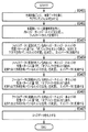
エッジデータ生成部202の処理を図5のフローチャートに示す。ステップS501においてエッジデータ生成部202は、画像データの色材の版ごとに、画像データ全体にラプラシアンフィルタをかける。このラプラシアンフィルタは図6(a)に示すような3×3のマトリックスのフィルタである。エッジデータ生成部202は注目画素とその隣接画素の値を参照して図6(a)のラプラシアンフィルタの畳み込み計算を行う。そして、エッジデータ生成部202は、畳み込み計算を行った計算結果をさらに16で割り128のオフセットを加算することで、最小値が0、中心値が128、最大値が255に正規化された値が算出される。ラプラシアンフィルタの効果を説明する。図3(a)の画像データに対して点線301のある色材の濃度分布の断面図を図6(b)に示す。そして、これに対してラプラシアンフィルタをかけて正規化を行うと、図6(c)のような分布となる。図6(c)では、オブジェクトのエッジの内側が中心値128より大きく、エッジの外側が中心値128より小さくなっている。この中心値128より大きいか小さいかで、オブジェクトのエッジ位置だけでなくオブジェクトの内側と外側に関する情報も判別することができる。これがラプラシアンフィルタの効果である。ここで、オブジェクトの内側にあるエッジ部のことを内エッジと称し、オブジェクトの外側にあるエッジ部のことを外エッジと称する。
[Description of Edge Data Generation Unit 202]
The process of the edge data generation unit 202 is shown in the flowchart of FIG. In step S501, the edge data generation unit 202 applies a Laplacian filter to the entire image data for each plane of the color material of the image data. This Laplacian filter is a 3 × 3 matrix filter as shown in FIG. 6 (a). The edge data generation unit 202 performs convolution calculation of the Laplacian filter of FIG. 6A with reference to the value of the pixel of interest and its adjacent pixels. Then, the edge data generation unit 202 further divides the calculation result of the convolution calculation by 16 and adds an offset of 128, so that the minimum value is 0, the center value is 128, and the maximum value is normalized to 255. Is calculated. The effect of the Laplacian filter will be described. FIG. 6B is a cross-sectional view of the density distribution of the coloring material having a dotted
ステップS502においてエッジデータ生成部202は、各画素に対して、ステップS501で得られたラプラシアンフィルタを適用して得られた値を基に、各画素が内エッジか、外エッジか、あるいは非エッジかを決定する。具体的には、エッジデータ生成部202は、各画素に対して、ステップS501で得られた値を基に閾値判定を行う。この処理の目的は、ある一定以上の強度のエッジのみ拾うこと、さらに2つのオブジェクトが互いに隣接するエッジは除外することである。2つのオブジェクトが互いに隣接する領域では、ラプラシアンフィルタの結果が正となる版と負となる版が混在することになる。そのような箇所で双方のオブジェクトを太らせると、版が重なりあって別の擬似的なオブジェクトが発生してしまう。このステップS502の処理によりそのような領域を除外できる。 In step S502, the edge data generation unit 202 determines whether each pixel is an inner edge, an outer edge, or a non-edge based on the value obtained by applying the Laplacian filter obtained in step S501 to each pixel. Decide. Specifically, the edge data generation unit 202 performs threshold determination on each pixel based on the value obtained in step S501. The purpose of this process is to pick up only edges of a certain intensity or more and to exclude edges where two objects are adjacent to each other. In a region where two objects are adjacent to each other, a version in which the result of the Laplacian filter is positive and a version in which the result is negative are mixed. If you fatten both objects in such places, the versions overlap and another pseudo object is generated. Such an area can be excluded by the process of step S502.
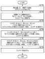
図7は、ステップS502における閾値判定の処理のフローチャートを示す図である。ステップS701においてエッジデータ生成部202は、注目画素について閾値TH1を越える版が存在するかを判定する。閾値TH1を越える版が存在する場合は、ステップS702においてさらに閾値TH2を下回る版が存在するかを判定する。閾値TH2を下回る版が存在しない場合は、ステップS703においてエッジデータ生成部202は、注目画素はオブジェクトの内側のエッジである内エッジであると判定する。一方、ステップS702で閾値TH2を下回る版が存在する場合は、オブジェクトの内部である版とオブジェクトの外部である版が混在することを意味している。このような画素はエッジ用の画像処理は不要である。よって、ステップS704においてエッジデータ生成部202は、注目画素は非エッジであると判定する。また、ステップS701で閾値TH1を越える版が存在しない場合は、ステップS705において、さらに閾値TH2を下回る版が存在するかを判定する。閾値TH2を下回る版が存在する場合は、ステップS706においてエッジデータ生成部202は、注目画素はオブジェクトの外側のエッジである外エッジと判定する。一方、ステップS705で閾値TH2を下回る版が存在しない場合は、エッジデータ生成部202は、注目画素は非エッジと判定する。 FIG. 7 is a diagram showing a flowchart of processing of threshold determination in step S502. In step S701, the edge data generation unit 202 determines whether a version exceeding the threshold TH1 exists for the pixel of interest. If a version exceeding the threshold TH1 exists, it is further determined in step S702 whether a version below the threshold TH2 exists. If there is no version smaller than the threshold TH2, the edge data generation unit 202 determines in step S703 that the pixel of interest is an inner edge that is an inner edge of the object. On the other hand, if there is a version below the threshold TH2 in step S702, it means that the version inside the object and the version outside the object are mixed. Such pixels do not require image processing for edges. Therefore, in step S704, the edge data generation unit 202 determines that the pixel of interest is a non-edge. If there is no version exceeding the threshold TH1 in step S701, it is determined in step S705 whether there is a version below the threshold TH2. If there is a version smaller than the threshold TH2, the edge data generation unit 202 determines in step S706 that the pixel of interest is an outer edge that is an outer edge of the object. On the other hand, if there is no plate below the threshold TH2 in step S705, the edge data generation unit 202 determines that the pixel of interest is not an edge.
このようにして決定した「内エッジ」「外エッジ」「非エッジ」を、画像データと同じ画素数分のビットマップ形式に記録したデータを生成する。このデータを「フィルタデータ」と呼ぶことにする。実際の記録方法はフィルタデータの画素ごとに内エッジを1、外エッジを2、非エッジを0として記録すれば良い。図4(a)は、図3(a)の画像データから生成したフィルタデータを示す。ここでは説明をわかりやすくするため、塗り401で示すセルは内エッジの画素を示し、塗り402で示すセルは外エッジの画素を示す。
Data in which “inner edge”, “outer edge”, and “non-edge” determined in this manner are recorded in a bitmap format for the same number of pixels as the image data is generated. This data is called "filter data". In the actual recording method, the inner edge may be recorded as 1 for the filter data, the outer edge may be 2 and the non-edge may be 0. FIG. 4 (a) shows filter data generated from the image data of FIG. 3 (a). Here, in order to make the description easy to understand, a cell indicated by a
次に、図5のフローチャートに戻り説明を続ける。ステップS503においてエッジデータ生成部202はフィルタデータに「内エッジ」と記録された画素が「オブジェクトを太らせる前のエッジの位置」であると決定する。そして、エッジデータ生成部202はエッジデータのその画素の値の下位から1ビット目に1を立てることで「オブジェクトを太らせる前のエッジ部の位置」をエッジデータに記録する。 Next, returning to the flowchart of FIG. 5, the description will be continued. In step S503, the edge data generation unit 202 determines that the pixel recorded as "inner edge" in the filter data is "the position of the edge before thickening the object". Then, the edge data generation unit 202 records “the position of the edge portion before thickening the object” in the edge data by setting 1 to the first bit from the low order of the value of the pixel of the edge data.
ステップS504においてエッジデータ生成部202は、フィルタデータに記録された「内エッジ」「外エッジ」「非エッジ」の配置パターンにより、「オブジェクトを太らせた後のエッジ部の位置」を判定する。判定方法としては、フィルタデータに対して図8に示す全てのパターンのパターンマッチングを行う。図8において太い枠で囲まれたセルは注目画素であり、また、「内」「外」「非」と記載しているセルはそれぞれ順番に内エッジ、外エッジ、非エッジとマッチする画素を示す。また、斜線で塗られたセルは、パターンがマッチした場合に「オブジェクトを太らせる後のエッジ部の位置」を示す画素を示す。また、それぞれのパターンについて、基本パターンを90度、180度、270度回転させたパターンもパターンとして使用する。これは、第1の実施形態において太らせる方向は上・下・右・左であり方向に依存性がないためである。このパターンマッチングを図4(a)のフィルタデータに適用して生成したエッジデータが、前述のように図4(b)で示すエッジデータとなる。前述のように、内エッジの画素に対して、「オブジェクトを太らす前のエッジ部の位置」を示す「1」の値が付されている。また、図8に示すパターンマッチングの結果、パターン3に一致する各画素(つまり外エッジの画素)に対して、「オブジェクトを太らせた後のエッジ部の位置」を示す「2」の値が付されている。また、その他の画素には非エッジを示す「0」の値が付されている。 In step S 504, the edge data generation unit 202 determines “the position of the edge portion after thickening the object” based on the “inner edge”, “outer edge”, and “non-edge” arrangement pattern recorded in the filter data. As a determination method, pattern matching of all the patterns shown in FIG. 8 is performed on the filter data. In FIG. 8, the cells surrounded by thick frames are the pixels of interest, and the cells described as “in”, “out”, and “not” sequentially correspond to the pixels matching the inner edge, the outer edge, and the non-edge. Show. In addition, shaded cells indicate pixels indicating “the position of the edge portion after thickening the object” when the patterns match. Also, for each pattern, a pattern obtained by rotating the basic pattern by 90 degrees, 180 degrees, and 270 degrees is used as a pattern. This is because the fattening direction in the first embodiment is upper, lower, right, left, and there is no dependency on the direction. The edge data generated by applying this pattern matching to the filter data of FIG. 4A becomes the edge data shown in FIG. 4B as described above. As described above, the value of “1” indicating “the position of the edge before thickening the object” is assigned to the pixel of the inner edge. Further, as a result of pattern matching shown in FIG. 8, a value of “2” indicating “the position of the edge portion after thickening the object” is given to each pixel matching the pattern 3 (that is, the pixel of the outer edge). It is attached. Also, the other pixels are assigned a value of “0” indicating non-edge.
次に、図8のパターンを用いる理由について詳細に説明する。「オブジェクトを太らせた後のエッジ部の位置」は、基本的には、内エッジに上・下・左・右の方向に隣接する外エッジとなる。よって、パターン3がそのような配置を検出するパターンである。しかしながら、全ての外エッジが「オブジェクトを太らせた後のエッジ部の位置」になる訳ではない。それは、図9(a)や図9(d)に示すような、2つのオブジェクトが2画素以内の距離で描画されているようなオブジェクト同士が近接する場合のケースである。図9(a)や図9(d)は、画像データを示しており、ハッチングが施された画素がオブジェクトの画素を示している。図9(a)および図9(d)に対して生成したフィルタデータを、それぞれ図9(b)および図9(e)に示す。この外エッジを「オブジェクトを太らせた後のエッジ部の位置」とすると、オブジェクトを太らせた後に2つのオブジェクトが結合されてしまう。そのため、2つの内エッジが外エッジを挟んで3画素以内に存在するようなケースでは、オブジェクトが太らないように、外エッジではなく内エッジを「オブジェクトを太らせた後のエッジ部の位置」とする。図8のパターン4とパターン5がそのような配置を検出するパターンである。図9(a)および図9(d)から生成したエッジデータをそれぞれ図9(c)と図9(f)に示す。前述のように、内エッジの画素には、「オブジェクトを太らせる前のエッジ部の位置」を示す下位から1ビット目が「1」となっている。そしてさらに内エッジの画素には「オブジェクトを太らせた後のエッジ部の位置」を示す下位から2ビット目が「1」となっている。従って、図9(c)および図9(f)のエッジデータでは、内エッジの画素に10進表記で3の値が付されている。なお、隣接する方向以外の外エッジは、図8のパターン3と一致することにより、「オブジェクトを太らせた後のエッジ部の位置」を示す下位から2ビット目が「1」(すなわち、10進表記で2)が付されている。
Next, the reason for using the pattern of FIG. 8 will be described in detail. The “position of the edge after thickening the object” is basically an outer edge adjacent to the inner edge in the upper, lower, left, and right directions. Thus,
また、図8のパターン3では、内エッジに隣接する外エッジの隣は非エッジとなっているが、外エッジでも構わない。そのさらに隣が内エッジのケース(パターン4とパターン5)でなければ良い。例えば、図10(a)に斜めの線や曲線の図形を表す画像データを示す。図10(a)の画像データに対応するフィルタデータは図10(b)のようになる。前述のように、第1の実施形態において太らせる方向は上・下・右・左であり方向に依存性がないので、パターン3だけでもこのような斜めの線や曲線を太らすことが可能ではある。しかしながら、後述する第3の実施形態で説明するように、ある方向のみに太らす方向を限定する形態では、図10(b)のようなフィルタデータではパターン3だけだと右・左方向に太ることはできない。そこで図8のパターン1とパターン2を用意することで、図10(b)斜めの線を横方向に太らすことができる。パターン1とパターン2がそのような配置を検出するパターンである。
Moreover, in the
上記のような理由のもと、図8のパターン1〜3は外エッジが「オブジェクトを太らせた後のエッジ部の位置」となるパターンを検出するものである。また、パターン4〜5は内エッジが「オブジェクトを太らせた後のエッジ部の位置」となるパターンを検出するものである。
For the reasons as described above, the
このように、エッジデータ生成部202の処理により、太らせ処理の前に、太らせた後のエッジ位置を特定することが可能となる。 As described above, by the processing of the edge data generation unit 202, it is possible to specify the edge position after thickening before the thickening processing.
[太らせ処理部203の説明]
太らせ処理部203の処理について説明する。太らせ処理部203は、「オブジェクトを太らせた後のエッジ部の位置」の画素に「太らせる前のエッジ部の位置」の画素値を上書きすることでオブジェクトを太らせる処理を実現する。
[Description of fattening processing unit 203]
The processing of the
図11は太らせ処理部203の処理のフローチャートを示す図である。ステップS1101において太らせ処理部203は画像データの注目画素について、対応するエッジデータの画素の2ビット目に1が立っているかどうかを判定する。2ビット目に1が立っていない場合は「オブジェクトを太らせた後のエッジ部の位置」ではないため、処理を終えて次の画素の処理へと進む。2ビット目に1が立っている場合は、ステップS1102において、さらに1ビット目に1が立っているかどうかを判定する。1ビット目に1が立っている場合、太らせ処理前後でエッジの位置が変わらないことを示すため、処理を終えて次の画素の処理へと進む。1ビット目に1が立っていない場合、ステップS1103において、上・下・左・右の方向に隣接する画素のうち、1ビット目に1が立っている画素を検出する。1ビット目に1が立っている隣接画素が見つかった場合は、ステップS1104において画像データにおけるその画素の値を注目画素の値に上書きする。
FIG. 11 is a flowchart of the processing of the
以上の処理を画像データとエッジデータの全体に行うことで、画像データのオブジェクトを上・下・左・右方向に1画素だけ太らせることができる。一例として、図3(a)の画像データと図4(b)のエッジデータを基に、オブジェクトを太らせた後の画像データを図3(b)に示す。 By performing the above processing on the entire image data and edge data, the object of the image data can be made thicker by one pixel in the upper, lower, left, and right directions. As an example, FIG. 3 (b) shows image data after thickening an object based on the image data of FIG. 3 (a) and the edge data of FIG. 4 (b).
以上により、第1の実施形態によれば、画像データのオブジェクトを太らせる前に、「オブジェクトを太らせた後のエッジ部の位置」を決定している。これにより、オブジェクトを太らせた後に、もう一度エッジ部の位置を判定することなくオブジェクトのエッジ部とオブジェクトの内部とで画像処理の手法を切り替えることが可能となる。 As described above, according to the first embodiment, “the position of the edge portion after thickening the object” is determined before thickening the object of the image data. Thus, after thickening the object, it is possible to switch the image processing method between the edge portion of the object and the inside of the object without determining the position of the edge portion again.
なお、上記の第1の実施形態では、画像データにおけるオブジェクトの変形処理の一例として幅を太らせる例について記載したが、変形処理としてオブジェクトの幅を細らせる処理でも構わない。具体的には、図8のパターンマッチングに用いるパターンを、オブジェクトの幅を細らせる処理に対応するパターンを用いればよい。例えば、図8のパターン3の基本パターンのような場合には、内エッジのさらに左側に非エッジの画素を含むパターンを用意し、変形後のエッジの位置を、その内エッジの左側の非エッジの画素とすればよい。その場合、内エッジの画素の画素値をその右隣の非エッジの画素(オブジェクト外の画素)の画素値で上書きすることで細らせる処理が行なわれてもよい。オブジェクトの幅を細らせる処理の場合にも、画像処理制御部105は操作部106から取得する「オブジェクトの変形後のエッジ部の変形幅」の設定情報に基づいて上述したような処理を行なうことができる。
In the first embodiment described above, although an example in which the width is increased is described as an example of the deformation processing of an object in image data, a process in which the width of the object is reduced may be used as the deformation processing. Specifically, the pattern used in the pattern matching in FIG. 8 may be a pattern corresponding to the process of reducing the width of the object. For example, in the case of the basic pattern of
<第2の実施形態>
第1の実施形態では、画像データのオブジェクトを太らせた後に、予め生成しておいた「太らせ後のエッジ部の位置」の情報に基づいて各種の画像処理を行う例を説明した。
Second Embodiment
In the first embodiment, after thickening an object of image data, an example in which various kinds of image processing are performed based on the information of “position of edge part after thickening” generated in advance has been described.
第2の実施形態では、オブジェクトを太らせる前の各種の画像処理では「太らせる前のエッジ部の位置」の情報に基づいて各種の画像処理を行う。そして、太らせた後の各種の画像処理では「太らせた後のエッジ部の位置」の情報に基づいて各種の画像処理を行うような、画像処理装置について説明する。 In the second embodiment, in various types of image processing before thickening an object, various types of image processing are performed based on the information of “the position of the edge portion before thickening”. Then, in various image processing after thickening, an image processing apparatus that performs various image processing based on the information of “position of edge part after thickening” will be described.
図12に第2の実施形態における画像処理部104の構成を示す。第1の実施形態と異なる点は3つある。1つ目は、下色除去処理部1203が太らせ処理部1204よりも前段にあること。2つ目は、エッジデータ生成部1202が生成する「オブジェクトを太らせる前のエッジ部の位置」の情報は、下色除去処理部1203と太らせ処理部1204に出力すること。3つ目は、エッジデータ生成部1202が生成する「オブジェクトを太らせた後のエッジ部の位置」の情報は、太らせ処理部1204、色材載量制限処理部1205とスクリーン処理部1206に出力することである。
FIG. 12 shows the configuration of the
エッジデータ生成部1202はメモリバッファ1201から取得した画像データについて、「オブジェクトを太らせる前のエッジ部の位置」と「オブジェクトを太らせた後のエッジ部の位置」とを決定する。ただし、その情報を別々含むエッジデータを合計2つ生成する。すなわち、第2の実施形態においては、エッジデータ生成部1202は「オブジェクトを太らせる前のエッジ部の位置」の情報を1ビットのビットマップ形式で保持するエッジデータを生成する。また、エッジデータ生成部1202は「オブジェクトを太らせた後のエッジ部の位置」の情報を1ビットのビットマップ形式で保持するエッジデータを生成する。
The edge
下色除去処理部1203は、エッジデータ生成部1202から「オブジェクトを太らせる前のエッジの位置」の情報を持つエッジデータを取得し、メモリバッファ1201から取得した画像データのエッジ部に対して下色除去処理を行う。なお、下地除去処理が行なわれたエッジ部の画素値は、その後の太らせ処理部1204において、太らせた後の画素の画素値として用いられる。従って、太らせた後のエッジ位置の下色除去を行なうことと同様の効果が得られる。
The under color removal processing unit 1203 acquires edge data having the information of “the position of the edge before thickening the object” from the edge
太らせ処理部1204はエッジデータ生成部から「オブジェクトを太らせる前のエッジ部の位置」の情報を持つエッジデータと「オブジェクトを太らせた後のエッジ部の位置」の情報を持つエッジデータとを取得する。そして、これらのエッジデータに基づいて下色除去処理部1203から取得した画像データのオブジェクトを太らせる処理を行う。太らせ処理の方法は実施形態1と同じである。
From the edge data generation unit, the
色材載量制限処理部1205とスクリーン処理部1206とは、エッジデータ生成部1202から「オブジェクトを太らせた後のエッジ部の位置」の情報を持つエッジデータを取得する。そして色材載量制限処理部1205は、太らせ処理部1204から取得した画像データに対して画像処理を行い、スクリーン処理部1206は色材載量制限処理部1205から取得した画像データに対して画像処理を行なう。
The color material amount limiting
以上により、第2の実施形態によれば、オブジェクトを太らせる前の画像処理では「オブジェクトを太らせる前のエッジ部の位置」の情報を基に処理を行い、太らせた後の画像処理では「オブジェクトを太らせた後のエッジ部の位置」の情報を基に処理を行う。これにより、画像データのオブジェクトを太らせる前と太らせた後のどちらにおいても、エッジと内部で画像処理の手法を切り替えることが可能となる。 As described above, according to the second embodiment, in the image processing before thickening the object, processing is performed based on the information of “the position of the edge portion before thickening the object”, and in the image processing after thickening Processing is performed based on the information of "the position of the edge portion after thickening the object". This makes it possible to switch the image processing method between the edge and the inside, both before and after thickening the object of the image data.
<第3の実施形態>
第1の実施形態では、画像データにおけるオブジェクトを上・下・左・右の4方向に1画素だけ太らせる例を説明した。これにより、オブジェクトの幅は合計で2画素だけ太ることになる。オブジェクトの幅を合計で1画素だけ太らせるには、オブジェクトをある方向、例えば右・下の2方向にだけ1画素太らせることで対応が可能である。第3の実施形態では、「オブジェクトを太らせる幅」の設定として「0画素」「1画素」「2画素」の3種類の設定を操作部がユーザから取得し、その指示通りにオブジェクトの幅を太らせる。そしてその後に適切な画像処理をかけることを可能とする画像処理装置の実施形態について説明する。なお、太らせる幅が「0画素」の場合、太らせる処理を行なわないことを示す。「1画素」の場合には、例えば右・下の2方向にだけ1画素太らせることを示す。「2画素」の場合には、第1の実施形態で説明したように上・下・左・右の4方向に1画素だけ太らせることを示す。
Third Embodiment
In the first embodiment, an example has been described in which an object in image data is fattened by one pixel in four directions of up, down, left, and right. As a result, the width of the object is increased by two pixels in total. In order to make the width of the object thicker by one pixel in total, it is possible to cope by making the object thicker by one pixel in a certain direction, for example, two directions of right and lower. In the third embodiment, the operation unit acquires three types of settings of “0 pixel”, “1 pixel”, and “2 pixels” from the user as the “width for thickening the object” setting, and the width of the object as instructed Fatten Then, an embodiment of an image processing apparatus capable of applying appropriate image processing after that will be described. Note that if the width to be fattened is “0 pixel”, it indicates that the fattening process is not performed. In the case of "one pixel", for example, it is indicated that one pixel is made to be thickened only in the two directions of right and lower. In the case of "two pixels", it indicates that one pixel is made thicker in the four directions of upper, lower, left and right as described in the first embodiment.
第3の実施形態における画像処理装置100および画像処理部104の構成は第1の実施形態と同じである。第1の実施形態と処理内容が異なる箇所について説明する。
The configurations of the
操作部106は「オブジェクトを太らせる幅」の設定として「0画素」「1画素」「2画素」の3種類の設定をユーザから取得し、画像処理制御部105に通知する。
The
画像処理制御部105は、この設定情報に基づいて、画像処理部104の有する各部が「オブジェクトを太らせる前のエッジ部の位置」と「オブジェクトを太らせた後のエッジ部の位置」を判定する方法を画像処理部104に指示する。オブジェクトを太らせる幅に応じて、「オブジェクトを太らせた後のエッジ部の位置」は異なるものとなるので、どの位置を「オブジェクトを太らせた後のエッジ部の位置」と決定するかの元となる指示を送る。
Based on the setting information, the image
エッジデータ生成部202はメモリバッファ201から取得した画像データにおける、オブジェクトを太らせる前の、右または下方向を向いているエッジと左または上方向を向いているエッジとの位置とを決定する。またエッジデータ生成部202は、オブジェクトを太らせた後の、右または下方向を向いているエッジと左または上方向を向いているエッジとの位置を決定する。そして、その情報を含むエッジデータを生成する。このエッジデータを生成するためのエッジデータ生成部202の処理の詳細については[第3の実施形態におけるエッジデータ生成部202の説明]で後述する。エッジデータ生成部202は生成したエッジデータを太らせ処理部203、下色除去処理部204、色材載量制限処理部205、スクリーン処理部206に出力する。
The edge data generation unit 202 determines, in the image data acquired from the
第3の実施形態におけるエッジデータは画像データと同じサイズのビットマップ形式をしており、画素ごとに4ビットの情報を持つ。下位から1ビット目は「オブジェクトを太らせる前の、右または下方向を向いているエッジ部の位置」についての情報であり、値が0ならばその画素はエッジ部ではないことを示し、値が1ならばその画素はエッジ部であることを示す。また、下位から2ビット目は「オブジェクトを太らせる前の、左または上方向を向いているエッジ部の位置」についての情報であり、値が0ならばその画素はエッジ部ではないことを示し、値が1ならばその画素はエッジ部であることを示す。また、下位から3ビット目は「オブジェクトを1画素太らせた後の、右または下方向を向いているエッジ部の位置」についての情報であり、値が0ならばその画素はエッジ部ではないことを示し、値が1ならばその画素はエッジ部であることを示す。また、下位から4ビット目は「オブジェクトを1画素太らせた後の、左または上方向を向いているエッジ部の位置」についての情報であり、値が0ならばその画素はエッジ部ではないことを示し、値が1ならばその画素はエッジ部であることを示す。第3の実施形態におけるエッジデータの一例として、図3(a)に示す画像データから生成したエッジデータを図4(c)に示す。図4(c)のエッジデータは画素ごとに4ビットの情報を持つが、説明のため、便宜上各画素の値を、10進数の数値で表している。 The edge data in the third embodiment has a bitmap format of the same size as the image data, and has 4 bits of information for each pixel. The first bit from the bottom is information about "the position of the edge facing to the right or downward before thickening the object", and a value of 0 indicates that the pixel is not an edge, and a value If is 1, it indicates that the pixel is an edge portion. Also, the second least significant bit is information about "the position of the edge facing left or upward before thickening the object", and a value of 0 indicates that the pixel is not an edge. If the value is 1, it indicates that the pixel is an edge portion. Also, the third lowest bit is information about "the position of the edge facing to the right or downward after thickening the object one pixel", and if the value is 0, the pixel is not an edge Indicates that the pixel is an edge if the value is one. Also, the fourth lowest bit is information on "the position of the edge facing left or upward after thickening the object one pixel", and if the value is 0, the pixel is not an edge Indicates that the pixel is an edge if the value is one. As an example of edge data in the third embodiment, edge data generated from image data shown in FIG. 3A is shown in FIG. The edge data in FIG. 4C has 4-bit information for each pixel, but for the sake of convenience, the value of each pixel is represented by a decimal number.
次に、太らせ処理部203、下色除去処理部204、色材載量制限処理部205、スクリーン処理部206について説明する。これらの処理方法は第1の実施形態と同様であるが、「オブジェクトを太らせた後のエッジ部の位置」を判定する方法が第1の実施形態と異なる。第1の実施形態では「オブジェクトを太らせた後のエッジ部の位置」そのものがエッジデータ生成部202の出力するエッジデータに含まれていた。しかし、第3の実施形態では、ユーザが操作部で設定した「オブジェクトを太らせる幅」の設定に応じて、「オブジェクトを太らせた後のエッジ部の位置」を示すエッジデータのビットが異なる。
Next, the
「オブジェクトを太らせる幅」の設定が「0画素」のときはエッジデータの1ビット目または2ビット目が「1」の画素が「オブジェクトを太らせた後のエッジ部の位置」を示す。 When the setting of "width for thickening object" is "0 pixel", a pixel whose first bit or second bit of edge data is "1" indicates "position of edge portion after thickening object".
また、「オブジェクトを太らせる幅」の設定が「1画素」のときはエッジデータの2ビット目のみまたは3ビット目のみが「1」の画素が「オブジェクトを太らせた後のエッジ部の位置」を示す。なお、2ビット目のみまたは3ビット目のみが「1」の画素としている理由を図4(c)を用いて説明する。図4(c)において2ビット目のみが「1」の画素は、10進表記で「2」で示される画素である。3ビット目のみが「1」の画素は、10進表記で「4」で示される画素である。ここで、図4(c)の内エッジの左下の画素は、オブジェクトを太らせる前の「下方向」を向いており、かつ「左方向」を向いている画素である。従って、1ビット目と2ビット目が「1」であるので10進表記で「3」と示されている。この画素は、実際の1画素幅だけ太らせた場合には下方向に太らせられることになるので太らせた後のエッジ部の位置の画素とはならない。よって、また、「オブジェクトを太らせる幅」の設定が「1画素」のときはエッジデータの2ビット目のみまたは3ビット目のみが「1」の画素が「オブジェクトを太らせた後のエッジ部の位置」を示すものとしている。 In addition, when the setting of "Bread width for object" is "1 pixel", only the second bit or the third bit of edge data "1" pixel "The position of the edge after thickening the object" ". The reason why only the second bit or only the third bit is a pixel of “1” will be described with reference to FIG. 4C. In FIG. 4C, a pixel of which only the second bit is “1” is a pixel indicated by “2” in decimal notation. The pixel of "1" only at the third bit is a pixel indicated by "4" in decimal notation. Here, the pixel at the lower left of the inner edge in FIG. 4C is a pixel facing in the “down” direction before thickening the object and facing in the “left direction”. Therefore, since the first bit and the second bit are "1", they are shown as "3" in decimal notation. If this pixel is made thicker by one actual pixel width, it will be made thicker in the lower direction, so it will not be a pixel at the position of the edge portion after being made fat. Therefore, also, when the setting of "Bread width for object" is "1 pixel", the pixel after "2" only for the second bit or only for the third bit of the edge data "edge part after thickening the object Indicates the position of
また、「オブジェクトを太らせる幅」の設定が「2画素」のときはエッジデータの3ビット目または4ビット目が「1」の画素が「オブジェクトを太らせた後のエッジの位置」を示す。以上説明したような判定の仕方を図13に示す。画像処理制御部105は、この判定の仕方を太らせ処理部203、下色除去処理部204、色材載量制限処理部205、スクリーン処理部206に指示する。
In addition, when the setting for "Bread width for object" is "2 pixels", the pixel whose "3" or "4" bit of edge data is "1" indicates "the position of edge after thickening object". . The manner of the determination as described above is shown in FIG. The image
<第3の実施形態におけるエッジデータ生成部202の詳細>
エッジデータ生成部202の処理の図14のフローチャートに示す。まず、ステップS1401においてエッジデータ生成部202は画像データの色材の版ごとに、画像データ全体にラプラシアンフィルタをかける。これは実施形態1におけるS501と同じ処理である。
<Details of Edge Data Generation Unit 202 in Third Embodiment>
The process of the edge data generation unit 202 is shown in the flowchart of FIG. First, in step S1401, the edge data generation unit 202 applies a Laplacian filter to the entire image data for each color material plate of the image data. This is the same process as S501 in the first embodiment.
次に、ステップS1402においてエッジデータ生成部202は、各画素に対して、ラプラシアンフィルタの計算値を基に閾値判定を行い、フィルタデータを生成する。これは実施形態1におけるS502と同じ処理である。 Next, in step S1402, the edge data generation unit 202 performs threshold determination on each pixel based on the calculated value of the Laplacian filter to generate filter data. This is the same process as S502 in the first embodiment.
次に、ステップS1403においてエッジデータ生成部202はフィルタデータに記録されている内エッジ・外エッジ・非エッジの配置パターンに基づき、「オブジェクトを太らせる前の、右または下方向を向いているエッジ部の位置」を判定する。そしてその位置を、エッジデータに記録する。このとき、エッジデータの対応する画素の画素値の下位から1ビット目に1を立てる。この判定方法は、エッジデータにおける内エッジを注目画素として、右または下に隣接する画素に外エッジが存在するかどうかを判定すれば良い。 Next, in step S1403, based on the arrangement pattern of the inner edge, the outer edge, and the non-edge recorded in the filter data, the edge data generation unit 202 reads “the edge facing to the right or downward before thickening the object. Determine the position of the set. Then, the position is recorded in edge data. At this time, 1 is set to the first bit from the low order of the pixel value of the corresponding pixel of the edge data. In this determination method, it may be determined whether the outer edge exists in the pixel adjacent to the right or lower with the inner edge in the edge data as the target pixel.
次に、ステップS1404においてエッジデータ生成部202はフィルタデータに記録されている内エッジ・外エッジ・非エッジの配置パターンに基づき、「オブジェクトを太らせる前の、左または上方向を向いているエッジ部の位置」を判定する。そしてその位置をエッジデータに記録する。このとき、エッジデータの対応する画素の画素値の下位から2ビット目に1を立てる。この判定方法は、エッジデータにおける内エッジを注目画素として、左または上に隣接する画素に外エッジが存在するかどうかを判定すれば良い。
Next, in
次に、ステップS1405においてエッジデータ生成部202はフィルタデータに記録されている内エッジ・外エッジ・非エッジの配置パターンに基づき、「オブジェクトを太らせた後の、右または下方向を向いているエッジ部の位置」を判定する。そしてその位置をエッジデータに記録する。この判定では、フィルタデータに対して図15(a)に示すパターンのパターンマッチングを行う。図15(a)に示すパターンは、図8のパターンのうち0度と90度回転のものに対応する。パターンがマッチしたとき、斜線で塗られているセルの画素に対応するエッジデータの画素の画素値の下位から3ビット目に1を立てる。 Next, in step S1405, based on the arrangement pattern of the inner edge, the outer edge, and the non-edge recorded in the filter data, the edge data generation unit 202 "turns right or downward after thickening the object. The position of the edge portion is determined. Then, the position is recorded in edge data. In this determination, pattern matching of the pattern shown in FIG. 15A is performed on the filter data. The pattern shown in FIG. 15A corresponds to the pattern of FIG. 8 rotated by 0 degrees and 90 degrees. When the patterns match, 1 is set to the third bit from the low order of the pixel value of the pixel of the edge data corresponding to the shaded pixel of the cell.
次に、ステップS1406においてエッジデータ生成部202はフィルタデータに記録されている内エッジ・外エッジ・非エッジの配置パターンに基づき、「オブジェクトを太らせた後の、左または上方向を向いているエッジ部の位置」を判定する。そしてその位置をエッジデータに記録する。この判定では、フィルタデータに対して図15(b)に示すパターンのパターンマッチングを行う。図15(b)に示すパターンは、図8のパターンの180度回転、270度回転したものに対応する。パターンがマッチしたとき、斜線で塗られているセルの画素に対応するエッジデータの画素の画素値の下位から4ビット目に1を立てる。 Next, in step S1406, based on the arrangement pattern of the inner edge, the outer edge, and the non-edge recorded in the filter data, the edge data generation unit 202 "turns left or upward after thickening the object. The position of the edge portion is determined. Then, the position is recorded in edge data. In this determination, pattern matching of the pattern shown in FIG. 15B is performed on the filter data. The pattern shown in FIG. 15B corresponds to the pattern of FIG. 8 rotated 180 degrees and 270 degrees. When the patterns match, 1 is set to the fourth bit from the low order of the pixel value of the pixel of edge data corresponding to the pixel of the shaded cell.
最後に、ステップS1407においてエッジデータ生成部202は、生成したエッジデータを太らせ処理部203に出力する。
Finally, in step S1407, the edge data generation unit 202 outputs the generated edge data to the
以上により、第3の実施形態によれば、オブジェクトを太らせる幅として「0画素」「1画素」「2画素」の3種類の設定を操作部がユーザから取得する。そして、その指示通りにオブジェクトの幅を太らせた後、オブジェクトのエッジ部とオブジェクトの内部とでそれぞれ適切な画像処理を行うことが可能となる。 As described above, according to the third embodiment, the operation unit acquires, from the user, three types of settings of “0 pixel”, “1 pixel”, and “2 pixels” as a width for thickening the object. Then, after thickening the width of the object as instructed, it becomes possible to perform appropriate image processing on the edge part of the object and inside the object.
なお、第3の実施形態では、オブジェクトの太らせ幅として「1画素」を指示した場合、右及び下方向に太らせる例を説明した。しかしながら、太らせる方向はこれに限られるものではなく、例えば左及び上方向を太らせても良い。 In the third embodiment, when “1 pixel” is designated as the thickening width of the object, an example in which the thickening is performed in the right and lower directions has been described. However, the fattening direction is not limited to this, and for example, the left and upper directions may be fattened.
<第4の実施形態>
第1の実施形態では、画像データにおけるオブジェクトを上・下・左・右の4方向に1画素だけ太らせる例を説明した。これにより、「オブジェクトの幅」は合計で2画素だけ太ることになる。しかしながら、レンダリング処理部103やプリント処理部107の解像度がより高い場合は、解像度に応じた効果を出すためにエッジ部の幅が2画素であり、オブジェクトを太らせる幅が合計で4画素まで可能であることが望ましい。第4の実施形態では、エッジ部の幅を2画素とし、「オブジェクトを太らせる幅」の設定として合計で「0画素」「2画素」「4画素」の3段階での設定を操作部がユーザから取得する。そして、その指示通りにオブジェクトの幅を複数画素分太らせた後、適切な画像処理をかけることを可能とする、画像処理装置の実施形態について説明する。
Fourth Embodiment
In the first embodiment, an example has been described in which an object in image data is fattened by one pixel in four directions of up, down, left, and right. As a result, "the width of the object" is increased by two pixels in total. However, when the resolution of the
第4の実施形態における画像処理装置100および画像処理部104の構成は第1の実施形態と同じである。第1の実施形態と処理内容が異なる箇所について説明する。
The configurations of the
操作部106は「オブジェクトを太らせる幅」の設定として「0画素」「2画素」「4画素」の3種類の設定をユーザから取得し、画像処理制御部105に通知する。
The
画像処理制御部105は、この設定情報に基づいて、画像処理部104の有する各部が「オブジェクトを太らせる前のエッジ部の位置」と「オブジェクトを太らせた後のエッジ部の位置」を判定する方法を画像処理部104に指示する。エッジデータ生成部202はメモリバッファ201から取得した画像データについて各位置を決定する。すなわち、「オブジェクトを太らせる前のエッジ部の位置」と「オブジェクトの幅を2画素太らせた後のエッジ部の位置」と「オブジェクトの幅を4画素太らせた後のエッジ部の位置」を決定する。そして、その情報を含むエッジデータを生成する。このエッジデータを生成するためのエッジデータ生成部202の処理の詳細については[第4の実施形態におけるエッジデータ生成部202の説明]で後述する。エッジデータ生成部202は生成したエッジデータを太らせ処理部203、下色除去処理部204、色材載量制限処理部205、スクリーン処理部206に出力する。
Based on the setting information, the image
第4の実施形態のエッジデータは画像データと同じサイズのビットマップ形式をしており、画素ごとに3ビットの情報を持つ。下位から1ビット目は「オブジェクトを太らせる前のエッジ部の位置」についての情報であり、値が0ならばその画素はエッジ部ではないことを示し、値が1ならばその画素はエッジ部であることを示す。また、下位から2ビット目は「オブジェクトの幅を2画素だけ太らせた後のエッジ部の位置」についての情報であり、値が0ならばその画素はエッジ部ではないことを示し、値が1ならばその画素はエッジ部であることを示す。また、下位から3ビット目は「オブジェクトの幅を4画素だけ太らせた後のエッジ部の位置」についての情報であり、値が0ならばその画素はエッジ部ではないことを示し、値が1ならばその画素はエッジ部であることを示す。第4の実施形態におけるエッジデータの一例として、図3(a)に示す画像データから生成したエッジデータを図4(d)に示す。図4(d)のエッジデータは画素ごとに3ビットの情報を持つが、説明のため、便宜上各画素の値を、10進数の数値で表している。図4(d)では、エッジ部の幅が2画素であるので内エッジのさらに内側の画素もオブジェクトを太らせる前のエッジ部の位置となっている。第4の実施形態におけるエッジデータ生成部202の処理の詳細については後述する。 The edge data in the fourth embodiment has a bitmap format of the same size as the image data, and has 3 bits of information for each pixel. The first bit from the bottom is information about "the position of the edge before thickening the object", and a value of 0 indicates that the pixel is not an edge, and a value of 1 indicates that the pixel is edge To indicate that The second least significant bit is information on "the position of the edge after thickening the width of the object by 2 pixels", and a value of 0 indicates that the pixel is not an edge, and the value is If it is 1, it indicates that the pixel is an edge portion. The third least significant bit is information on "the position of the edge after thickening the width of the object by 4 pixels", and a value of 0 indicates that the pixel is not an edge, and the value is If it is 1, it indicates that the pixel is an edge portion. As an example of edge data in the fourth embodiment, edge data generated from image data shown in FIG. 3A is shown in FIG. The edge data in FIG. 4D has 3-bit information for each pixel, but for the sake of convenience, the value of each pixel is represented by a decimal number. In FIG. 4D, since the width of the edge portion is 2 pixels, the pixel further inside the inner edge is also the position of the edge portion before thickening the object. Details of the processing of the edge data generation unit 202 in the fourth embodiment will be described later.
次に、下色除去処理部204、色材載量制限処理部205、スクリーン処理部206について説明する。これらの処理方法は第1の実施形態と同様であるが、「オブジェクトを太らせた後のエッジ部の位置」を判定する方法が第1の実施形態と異なる。第4の実施形態では、ユーザが操作部で設定した「オブジェクトを太らせる幅」の設定に応じて、「オブジェクトを太らせた後のエッジ部の位置」が示すエッジデータのビットが異なる。「オブジェクトを太らせる幅」の設定が「0画素」のときはエッジデータの1ビット目が「オブジェクトを太らせた後のエッジ部の位置」を示す。また、「オブジェクトを太らせる幅」の設定が「2画素」のときはエッジデータの2ビット目が「オブジェクトを太らせた後のエッジ部の位置」を示す。また、「オブジェクトを太らせる幅」の設定が「4画素」のときはエッジデータの3ビット目が「オブジェクトを太らせた後のエッジ部の位置」を示す。この判定の仕方を図16に示す。画像処理制御部105は、この判定の仕方を太らせ処理部203、下色除去処理部204、色材載量制限処理部205、スクリーン処理部206に指示する。
Next, the under color
次に、太らせ処理部203の処理について説明する。太らせ処理部203も図16に従って「オブジェクトを太らせた後のエッジの位置」を判定する。そして、オブジェクトを太らせる処理として、まずエッジデータから「オブジェクトを太らせた後のエッジの位置」である画素を検出する。そして、その画素を注目画素として、そこから上下左右方向に2画素以内に「オブジェクトを太らせる前のエッジの位置」を示す画素を検出する。そのような画素が見つかれば、その画素の画像データにおける画素値を、画像データにおける注目画素に上書きする。
Next, the processing of the
<第4の実施形態におけるエッジデータ生成部202の詳細>
エッジデータ生成部202の処理の図17のフローチャートに示す。なお、第4の実施形態では説明を簡単にするため、第1の実施形態の際に考慮した、図9に示すような「太らせると結合されてしまうオブジェクト」については考慮しないこととする。
<Details of Edge Data Generation Unit 202 in Fourth Embodiment>
The process of the edge data generation unit 202 is shown in the flowchart of FIG. In the fourth embodiment, in order to simplify the description, the “object which is combined with fatting” as shown in FIG. 9 considered in the first embodiment will not be considered.
まず、ステップS1701においてエッジデータ生成部202は画像データの色材の版ごとに、画像データ全体にラプラシアンフィルタをかける。これは実施形態1におけるS501と同じ処理である。次に、ステップS1702においてエッジデータ生成部202は、各画素に対して、ラプラシアンフィルタの計算値を基に閾値判定を行い、フィルタデータを生成する。これは実施形態1におけるS502と同じ処理である。 First, in step S1701, the edge data generation unit 202 applies a Laplacian filter to the entire image data for each color material plate of the image data. This is the same process as S501 in the first embodiment. Next, in step S1702, the edge data generation unit 202 performs threshold determination on each pixel based on the calculated value of the Laplacian filter, and generates filter data. This is the same process as S502 in the first embodiment.
次に、ステップS1703においてエッジデータ生成部202は、フィルタデータにおいて、内エッジと、内エッジに上下左右に隣接する非エッジとを「オブジェクトを太らせる前のエッジの位置」と判定し、エッジデータに記録する。このとき、エッジデータの対応する画素の画素値の下位から1ビット目に1を立てる。 Next, in step S 1703, the edge data generation unit 202 determines that the inner edge and the non-edge adjacent to the inner edge vertically and horizontally in the filter data are “the position of the edge before thickening the object”, and edge data Record on At this time, 1 is set to the first bit from the low order of the pixel value of the corresponding pixel of the edge data.
次に、ステップS1704においてエッジデータ生成部202は、フィルタデータにおいて、内エッジおよび外エッジに対して、「オブジェクトの幅を2画素だけ太らせた後のエッジ部の位置」と判定し、エッジデータに記録する。すなわち、オブジェクトの幅を合計で2画素太らせた後のエッジ部の位置と判定する。このとき、エッジデータの対応する画素の画素値の下位から2ビット目に1を立てる。 Next, in step S1704, the edge data generation unit 202 determines that “the position of the edge portion after thickening the width of the object by 2 pixels” with respect to the inner edge and the outer edge in the filter data, and the edge data Record on That is, it is determined that the position of the edge portion is obtained after thickening the width of the object by 2 pixels in total. At this time, 1 is set to the second bit from the low order of the pixel value of the corresponding pixel of the edge data.
次に、ステップS1705においてエッジデータ生成部202は、フィルタデータにおいて、外エッジと、外エッジに上下左右に隣接する非エッジとに対して、「オブジェクトの幅を4画素だけ太らせた後のエッジの位置」と判定し、エッジデータに記録する。すなわち、オブジェクトの幅を合計で4画素太らせた後のエッジ部の位置と判定する。このとき、エッジデータの対応する画素の画素値の下位から3ビット目に1を立てる。 Next, in step S1705, the edge data generation unit 202 determines that the edge after increasing the width of the object by 4 pixels with respect to the outer edge and the non-edge adjacent to the outer edge vertically and horizontally in the filter data. And the edge data is recorded. That is, it is determined that the position of the edge portion after the width of the object is increased by 4 pixels in total. At this time, 1 is set to the third bit from the low order of the pixel value of the corresponding pixel of the edge data.
最後に、ステップS1707においてエッジデータ生成部202はエッジデータを太らせ処理部203に出力する。
Finally, in step S1707, the edge data generation unit 202 outputs the edge data to the
以上により、第4の実施形態によれば、エッジの幅を2画素とし、太らせるオブジェクトの幅を「0画素」「2画素」「4画素」の3段階でオブジェクトの幅を太らせた後、適切な画像処理をかけることが可能となる。 As described above, according to the fourth embodiment, after the width of the object is increased in three steps of “0 pixel”, “2 pixel”, and “4 pixel” with the width of the edge being 2 pixels and the width of the object being fat It is possible to apply appropriate image processing.
(その他の実施形態)
本発明の目的は、以下の処理を実行することによっても達成される。即ち、前記実施形態の機能を実現するソフトウェアのプログラムコードを記録した記憶媒体を、システム或いは装置に供給し、そのシステム或いは装置のコンピュータ(またはCPUやMPU等)が記憶媒体に格納されたプログラムコードを読み出す処理である。
(Other embodiments)
The object of the present invention is also achieved by performing the following processing. That is, a storage medium storing a program code of software for realizing the functions of the above embodiments is supplied to a system or apparatus, and a program code stored in the storage medium by a computer (or CPU or MPU etc.) of the system or apparatus. Is a process of reading out
この場合、記憶媒体から読み出されたプログラムコード自体が前述した実施形態の機能を実現することになり、そのプログラムコード及び該プログラムコードを記憶した記憶媒体は本発明を構成することになる。 In this case, the program code itself read from the storage medium implements the functions of the above-described embodiments, and the program code and the storage medium storing the program code constitute the present invention.
Claims (12)
画像データに含まれるオブジェクトのエッジ部から所定距離だけ当該オブジェクトから離れた位置を決定する決定手段と、
前記決定された位置に基づいて、前記決定された位置が前記オブジェクトの新たなエッジ部となるように前記オブジェクトを変形する変形手段と、
前記決定された位置に基づいて、前記変形が行われた後の前記オブジェクトの前記新たなエッジ部に所定の画像処理を行う処理手段と
を有し、
前記決定手段は、前記変形が行なわる前に、前記離れた位置の他に、前記変形が行なわれる前の前記オブジェクトの元々のエッジ部の位置も決定し、
前記処理手段は、前記決定された元々のエッジ部の位置に基づいて、前記変形が行なわれる前の前記オブジェクトの元々のエッジ部に前記所定の画像処理とは異なる別の所定の画像処理を行なうことを特徴とする画像処理装置。 An image processing apparatus that deforms an object included in image data, the image processing apparatus comprising:
A determination unit configured to determine a position away from the object by a predetermined distance from an edge portion of the object included in the image data;
Deforming means for deforming the object such that the determined position becomes a new edge portion of the object based on the determined position;
Processing means for performing predetermined image processing on the new edge portion of the object after the deformation is performed based on the determined position;
The determination means also determines the position of the original edge of the object before the deformation is performed, in addition to the separated position, before the deformation is performed;
The processing means performs another predetermined image processing different from the predetermined image processing on the original edge portion of the object before the deformation based on the determined position of the original edge portion. An image processing apparatus characterized by
画像データに含まれるオブジェクトのエッジ部から所定距離だけ当該オブジェクトから離れた位置を決定する決定ステップと、
前記決定された位置に基づいて、前記決定された位置が前記オブジェクトの新たなエッジ部となるように前記オブジェクトを変形する変形ステップと、
前記決定された位置に基づいて、前記変形が行われた後の前記オブジェクトの前記新たなエッジ部に所定の画像処理を行う処理ステップと
を有し、
前記決定ステップでは、前記変形が行なわる前に、前記離れた位置の他に、前記変形が行なわれる前の前記オブジェクトの元々のエッジ部の位置も決定し、
前記処理ステップでは、前記決定された元々のエッジ部の位置に基づいて、前記変形が行なわれる前の前記オブジェクトの元々のエッジ部に前記所定の画像処理とは異なる別の所定の画像処理を行なうことを特徴とする画像処理方法。 An image processing method for deforming an object included in image data, comprising:
A determination step of determining a position away from the object by a predetermined distance from an edge portion of the object included in the image data;
Deforming the object such that the determined position becomes a new edge of the object based on the determined position;
Performing a predetermined image processing on the new edge portion of the object after the deformation based on the determined position;
In the determination step, before the deformation is performed, in addition to the separated position, the position of the original edge of the object before the deformation is also determined.
In the processing step, another predetermined image processing different from the predetermined image processing is performed on the original edge portion of the object before the deformation based on the determined position of the original edge portion. An image processing method characterized in that.
Priority Applications (2)
| Application Number | Priority Date | Filing Date | Title |
|---|---|---|---|
| JP2014159745A JP6525526B2 (en) | 2014-08-05 | 2014-08-05 | IMAGE PROCESSING APPARATUS, IMAGE PROCESSING METHOD, AND PROGRAM |
| US14/810,837 US9313366B2 (en) | 2014-08-05 | 2015-07-28 | Image processing apparatus and image processing method |
Applications Claiming Priority (1)
| Application Number | Priority Date | Filing Date | Title |
|---|---|---|---|
| JP2014159745A JP6525526B2 (en) | 2014-08-05 | 2014-08-05 | IMAGE PROCESSING APPARATUS, IMAGE PROCESSING METHOD, AND PROGRAM |
Related Child Applications (1)
| Application Number | Title | Priority Date | Filing Date |
|---|---|---|---|
| JP2019038533A Division JP6746740B2 (en) | 2019-03-04 | 2019-03-04 | Image processing apparatus, image processing method, and program |
Publications (3)
| Publication Number | Publication Date |
|---|---|
| JP2016039408A JP2016039408A (en) | 2016-03-22 |
| JP2016039408A5 JP2016039408A5 (en) | 2017-09-21 |
| JP6525526B2 true JP6525526B2 (en) | 2019-06-05 |
Family
ID=55268384
Family Applications (1)
| Application Number | Title | Priority Date | Filing Date |
|---|---|---|---|
| JP2014159745A Active JP6525526B2 (en) | 2014-08-05 | 2014-08-05 | IMAGE PROCESSING APPARATUS, IMAGE PROCESSING METHOD, AND PROGRAM |
Country Status (2)
| Country | Link |
|---|---|
| US (1) | US9313366B2 (en) |
| JP (1) | JP6525526B2 (en) |
Families Citing this family (3)
| Publication number | Priority date | Publication date | Assignee | Title |
|---|---|---|---|---|
| JP6671188B2 (en) * | 2016-02-17 | 2020-03-25 | キヤノン株式会社 | Image forming apparatus, method, and program |
| JP6869709B2 (en) | 2016-12-06 | 2021-05-12 | キヤノン株式会社 | Image processing equipment, image processing methods and programs |
| JP6977390B2 (en) * | 2017-08-18 | 2021-12-08 | 富士フイルムビジネスイノベーション株式会社 | Image processing equipment, image forming equipment, and programs |
Family Cites Families (7)
| Publication number | Priority date | Publication date | Assignee | Title |
|---|---|---|---|---|
| JP4779987B2 (en) * | 2007-02-08 | 2011-09-28 | コニカミノルタビジネステクノロジーズ株式会社 | Image processing apparatus and image processing method |
| US8467089B2 (en) | 2008-11-24 | 2013-06-18 | Xerox Corporation | Systems and methods for line width control and pixel retagging |
| JP2010278714A (en) * | 2009-05-28 | 2010-12-09 | Seiko Epson Corp | Image processor, printing system, image processing method, and computer program |
| JP5691448B2 (en) * | 2010-11-30 | 2015-04-01 | 富士ゼロックス株式会社 | Print document processing system, cache device, data processing device, and program |
| JP2012121265A (en) * | 2010-12-09 | 2012-06-28 | Canon Inc | Image forming apparatus and control method thereof |
| JP2012203298A (en) * | 2011-03-28 | 2012-10-22 | Brother Ind Ltd | Image processor and program |
| JP6049437B2 (en) * | 2012-12-14 | 2016-12-21 | キヤノン株式会社 | Image processing apparatus, image processing method, and computer program |
-
2014
- 2014-08-05 JP JP2014159745A patent/JP6525526B2/en active Active
-
2015
- 2015-07-28 US US14/810,837 patent/US9313366B2/en active Active
Also Published As
| Publication number | Publication date |
|---|---|
| US20160044208A1 (en) | 2016-02-11 |
| JP2016039408A (en) | 2016-03-22 |
| US9313366B2 (en) | 2016-04-12 |
Similar Documents
| Publication | Publication Date | Title |
|---|---|---|
| JP5643574B2 (en) | Image processing apparatus and image processing method | |
| JP5032911B2 (en) | Image processing apparatus and image processing method | |
| EP3155593B1 (en) | Method and device for color processing of digital images | |
| US8503025B2 (en) | Image processing apparatus, image processing method, and computer program product | |
| US9253368B2 (en) | Image processing device setting binary value without using dither matrix when prescribed condition is satisfied | |
| JP6525526B2 (en) | IMAGE PROCESSING APPARATUS, IMAGE PROCESSING METHOD, AND PROGRAM | |
| JP6000172B2 (en) | Data creation apparatus, image forming apparatus, and data creation method | |
| JP2017024321A (en) | Image processor, image formation device, and image processing time prediction method and program | |
| KR20150030604A (en) | Image processing apparatus, image processing method, and storage medium | |
| EP3032498B1 (en) | Image processing apparatus, image processing method, and a program | |
| US9989875B2 (en) | Image processing apparatus, image processing method, and storage medium | |
| JP5607296B2 (en) | Method for performing trapping, computer-readable medium and apparatus | |
| JP5457123B2 (en) | Method for generating LUT, method for reading luminance value from LUT, program and apparatus | |
| JP6746740B2 (en) | Image processing apparatus, image processing method, and program | |
| JP2019140538A (en) | Image processing system, image formation device, image processing method, and program | |
| JP4131205B2 (en) | Image processing apparatus and image processing program causing computer to execute image processing | |
| JP5689090B2 (en) | Image forming method and image forming apparatus | |
| US8654403B2 (en) | Image processing apparatus and program therefor | |
| US8482825B2 (en) | Image processing apparatus and image processing method | |
| JP7321885B2 (en) | Image processing device, image processing method, and program | |
| JP5884509B2 (en) | Image processing apparatus, image reading apparatus, and program | |
| US20160219188A1 (en) | Dot area extraction method, dot area extraction device, and non-transitory computer readable medium storing dot area extraction program | |
| JP6521650B2 (en) | INFORMATION PROCESSING APPARATUS, CONTROL METHOD FOR INFORMATION PROCESSING APPARATUS, AND PROGRAM | |
| KR101769945B1 (en) | Method and apparatus for pre-treating image for printing | |
| JP2016200999A (en) | Printing instruction device, printing system, and program |
Legal Events
| Date | Code | Title | Description |
|---|---|---|---|
| A521 | Request for written amendment filed |
Free format text: JAPANESE INTERMEDIATE CODE: A523 Effective date: 20170807 |
|
| A621 | Written request for application examination |
Free format text: JAPANESE INTERMEDIATE CODE: A621 Effective date: 20170807 |
|
| A977 | Report on retrieval |
Free format text: JAPANESE INTERMEDIATE CODE: A971007 Effective date: 20180209 |
|
| A131 | Notification of reasons for refusal |
Free format text: JAPANESE INTERMEDIATE CODE: A131 Effective date: 20180220 |
|
| A521 | Request for written amendment filed |
Free format text: JAPANESE INTERMEDIATE CODE: A523 Effective date: 20180420 |
|
| A131 | Notification of reasons for refusal |
Free format text: JAPANESE INTERMEDIATE CODE: A131 Effective date: 20180911 |
|
| A521 | Request for written amendment filed |
Free format text: JAPANESE INTERMEDIATE CODE: A523 Effective date: 20181108 |
|
| A02 | Decision of refusal |
Free format text: JAPANESE INTERMEDIATE CODE: A02 Effective date: 20181204 |
|
| A521 | Request for written amendment filed |
Free format text: JAPANESE INTERMEDIATE CODE: A523 Effective date: 20190304 |
|
| A911 | Transfer to examiner for re-examination before appeal (zenchi) |
Free format text: JAPANESE INTERMEDIATE CODE: A911 Effective date: 20190312 |
|
| TRDD | Decision of grant or rejection written | ||
| A01 | Written decision to grant a patent or to grant a registration (utility model) |
Free format text: JAPANESE INTERMEDIATE CODE: A01 Effective date: 20190409 |
|
| A61 | First payment of annual fees (during grant procedure) |
Free format text: JAPANESE INTERMEDIATE CODE: A61 Effective date: 20190507 |
|
| R151 | Written notification of patent or utility model registration |
Ref document number: 6525526 Country of ref document: JP Free format text: JAPANESE INTERMEDIATE CODE: R151 |