JP6524922B2 - Driving support device, driving support method - Google Patents
Driving support device, driving support method Download PDFInfo
- Publication number
- JP6524922B2 JP6524922B2 JP2016003749A JP2016003749A JP6524922B2 JP 6524922 B2 JP6524922 B2 JP 6524922B2 JP 2016003749 A JP2016003749 A JP 2016003749A JP 2016003749 A JP2016003749 A JP 2016003749A JP 6524922 B2 JP6524922 B2 JP 6524922B2
- Authority
- JP
- Japan
- Prior art keywords
- image
- vehicle
- opacity
- target
- area
- Prior art date
- Legal status (The legal status is an assumption and is not a legal conclusion. Google has not performed a legal analysis and makes no representation as to the accuracy of the status listed.)
- Active
Links
Images

Classifications
-
- B—PERFORMING OPERATIONS; TRANSPORTING
- B60—VEHICLES IN GENERAL
- B60R—VEHICLES, VEHICLE FITTINGS, OR VEHICLE PARTS, NOT OTHERWISE PROVIDED FOR
- B60R1/00—Optical viewing arrangements; Real-time viewing arrangements for drivers or passengers using optical image capturing systems, e.g. cameras or video systems specially adapted for use in or on vehicles
- B60R1/20—Real-time viewing arrangements for drivers or passengers using optical image capturing systems, e.g. cameras or video systems specially adapted for use in or on vehicles
- B60R1/22—Real-time viewing arrangements for drivers or passengers using optical image capturing systems, e.g. cameras or video systems specially adapted for use in or on vehicles for viewing an area outside the vehicle, e.g. the exterior of the vehicle
- B60R1/23—Real-time viewing arrangements for drivers or passengers using optical image capturing systems, e.g. cameras or video systems specially adapted for use in or on vehicles for viewing an area outside the vehicle, e.g. the exterior of the vehicle with a predetermined field of view
- B60R1/27—Real-time viewing arrangements for drivers or passengers using optical image capturing systems, e.g. cameras or video systems specially adapted for use in or on vehicles for viewing an area outside the vehicle, e.g. the exterior of the vehicle with a predetermined field of view providing all-round vision, e.g. using omnidirectional cameras
-
- G—PHYSICS
- G08—SIGNALLING
- G08G—TRAFFIC CONTROL SYSTEMS
- G08G1/00—Traffic control systems for road vehicles
- G08G1/16—Anti-collision systems
- G08G1/165—Anti-collision systems for passive traffic, e.g. including static obstacles, trees
-
- G—PHYSICS
- G08—SIGNALLING
- G08G—TRAFFIC CONTROL SYSTEMS
- G08G1/00—Traffic control systems for road vehicles
- G08G1/16—Anti-collision systems
- G08G1/166—Anti-collision systems for active traffic, e.g. moving vehicles, pedestrians, bikes
-
- H—ELECTRICITY
- H04—ELECTRIC COMMUNICATION TECHNIQUE
- H04N—PICTORIAL COMMUNICATION, e.g. TELEVISION
- H04N23/00—Cameras or camera modules comprising electronic image sensors; Control thereof
- H04N23/90—Arrangement of cameras or camera modules, e.g. multiple cameras in TV studios or sports stadiums
-
- H—ELECTRICITY
- H04—ELECTRIC COMMUNICATION TECHNIQUE
- H04N—PICTORIAL COMMUNICATION, e.g. TELEVISION
- H04N5/00—Details of television systems
- H04N5/222—Studio circuitry; Studio devices; Studio equipment
- H04N5/262—Studio circuits, e.g. for mixing, switching-over, change of character of image, other special effects ; Cameras specially adapted for the electronic generation of special effects
- H04N5/2628—Alteration of picture size, shape, position or orientation, e.g. zooming, rotation, rolling, perspective, translation
-
- H—ELECTRICITY
- H04—ELECTRIC COMMUNICATION TECHNIQUE
- H04N—PICTORIAL COMMUNICATION, e.g. TELEVISION
- H04N5/00—Details of television systems
- H04N5/222—Studio circuitry; Studio devices; Studio equipment
- H04N5/262—Studio circuits, e.g. for mixing, switching-over, change of character of image, other special effects ; Cameras specially adapted for the electronic generation of special effects
- H04N5/265—Mixing
-
- H—ELECTRICITY
- H04—ELECTRIC COMMUNICATION TECHNIQUE
- H04N—PICTORIAL COMMUNICATION, e.g. TELEVISION
- H04N5/00—Details of television systems
- H04N5/44—Receiver circuitry for the reception of television signals according to analogue transmission standards
- H04N5/445—Receiver circuitry for the reception of television signals according to analogue transmission standards for displaying additional information
- H04N5/44504—Circuit details of the additional information generator, e.g. details of the character or graphics signal generator, overlay mixing circuits
-
- H—ELECTRICITY
- H04—ELECTRIC COMMUNICATION TECHNIQUE
- H04N—PICTORIAL COMMUNICATION, e.g. TELEVISION
- H04N7/00—Television systems
- H04N7/18—Closed-circuit television [CCTV] systems, i.e. systems in which the video signal is not broadcast
- H04N7/181—Closed-circuit television [CCTV] systems, i.e. systems in which the video signal is not broadcast for receiving images from a plurality of remote sources
-
- B—PERFORMING OPERATIONS; TRANSPORTING
- B60—VEHICLES IN GENERAL
- B60R—VEHICLES, VEHICLE FITTINGS, OR VEHICLE PARTS, NOT OTHERWISE PROVIDED FOR
- B60R2300/00—Details of viewing arrangements using cameras and displays, specially adapted for use in a vehicle
- B60R2300/10—Details of viewing arrangements using cameras and displays, specially adapted for use in a vehicle characterised by the type of camera system used
- B60R2300/105—Details of viewing arrangements using cameras and displays, specially adapted for use in a vehicle characterised by the type of camera system used using multiple cameras
-
- B—PERFORMING OPERATIONS; TRANSPORTING
- B60—VEHICLES IN GENERAL
- B60R—VEHICLES, VEHICLE FITTINGS, OR VEHICLE PARTS, NOT OTHERWISE PROVIDED FOR
- B60R2300/00—Details of viewing arrangements using cameras and displays, specially adapted for use in a vehicle
- B60R2300/30—Details of viewing arrangements using cameras and displays, specially adapted for use in a vehicle characterised by the type of image processing
- B60R2300/303—Details of viewing arrangements using cameras and displays, specially adapted for use in a vehicle characterised by the type of image processing using joined images, e.g. multiple camera images
-
- B—PERFORMING OPERATIONS; TRANSPORTING
- B60—VEHICLES IN GENERAL
- B60R—VEHICLES, VEHICLE FITTINGS, OR VEHICLE PARTS, NOT OTHERWISE PROVIDED FOR
- B60R2300/00—Details of viewing arrangements using cameras and displays, specially adapted for use in a vehicle
- B60R2300/30—Details of viewing arrangements using cameras and displays, specially adapted for use in a vehicle characterised by the type of image processing
- B60R2300/307—Details of viewing arrangements using cameras and displays, specially adapted for use in a vehicle characterised by the type of image processing virtually distinguishing relevant parts of a scene from the background of the scene
-
- B—PERFORMING OPERATIONS; TRANSPORTING
- B60—VEHICLES IN GENERAL
- B60R—VEHICLES, VEHICLE FITTINGS, OR VEHICLE PARTS, NOT OTHERWISE PROVIDED FOR
- B60R2300/00—Details of viewing arrangements using cameras and displays, specially adapted for use in a vehicle
- B60R2300/60—Details of viewing arrangements using cameras and displays, specially adapted for use in a vehicle characterised by monitoring and displaying vehicle exterior scenes from a transformed perspective
- B60R2300/602—Details of viewing arrangements using cameras and displays, specially adapted for use in a vehicle characterised by monitoring and displaying vehicle exterior scenes from a transformed perspective with an adjustable viewpoint
- B60R2300/605—Details of viewing arrangements using cameras and displays, specially adapted for use in a vehicle characterised by monitoring and displaying vehicle exterior scenes from a transformed perspective with an adjustable viewpoint the adjustment being automatic
-
- G—PHYSICS
- G08—SIGNALLING
- G08G—TRAFFIC CONTROL SYSTEMS
- G08G1/00—Traffic control systems for road vehicles
- G08G1/16—Anti-collision systems
Landscapes
- Engineering & Computer Science (AREA)
- Multimedia (AREA)
- Signal Processing (AREA)
- Physics & Mathematics (AREA)
- General Physics & Mathematics (AREA)
- Mechanical Engineering (AREA)
- Computer Graphics (AREA)
- Closed-Circuit Television Systems (AREA)
- Image Processing (AREA)
- Traffic Control Systems (AREA)
Description
本開示は、車両運転者に運転支援画像を提示するための表示制御技術に関する。 The present disclosure relates to a display control technique for presenting a driving support image to a vehicle driver.
従来、複数の車載カメラにより車両の周囲を撮像し、各撮像画像を仮想視点から見た画像にそれぞれ変換して、各変換画像の一部を繋ぎ合わせた合成画像を運転支援画像としてディスプレイに表示する技術が知られている。 Conventionally, the surroundings of a vehicle are imaged by a plurality of on-vehicle cameras, and each captured image is converted into an image viewed from a virtual viewpoint, and a composite image obtained by connecting a part of each converted image is displayed on the display as a driving assistance image Technology is known.
特許文献1には、車両の前方から車両の後方を含む周囲を見るような仮想視点による運転支援画像を生成する際に、例えばその仮想視点から見たような車両の位置及び形状を示す車両画像を合成画像に重畳する技術が開示されている。 In patent document 1, when generating the driving assistance image by a virtual viewpoint which looks at the surroundings including the back of the vehicle from the front of the vehicle, a vehicle image showing the position and shape of the vehicle as viewed from the virtual viewpoint, for example There is disclosed a technique for superimposing an image on a composite image.
しかしながら、従来技術では、運転支援画像において車両画像が合成画像に重畳されていることにより、その重畳部分において合成画像中に映し出されているはずの重要な要素が車両画像によって表示されない場合がある、という問題があった。 However, in the prior art, since the vehicle image is superimposed on the composite image in the driving support image, there may be a case where an important element which should be shown in the composite image in the superimposed portion is not displayed by the vehicle image. There was a problem that.
本開示は、こうした問題等に鑑みてなされたものであり、車両運転者にとって、より気の利いた運転支援画像を表示可能な技術を提供することを目的としている。 The present disclosure has been made in view of these problems and the like, and it is an object of the present disclosure to provide a technology capable of displaying a more daunting driving assistance image for a vehicle driver.
本開示の一局面である運転支援装置は、変換部(22)と、合成部(23)と、調整部(25)と、出力部(26)と、を備える。変換部は、車両の周囲を撮像する車載撮像装置の撮像画像を予め設定された仮想視点から見た画像に変換する。 The driving support device according to one aspect of the present disclosure includes a conversion unit (22), a combining unit (23), an adjustment unit (25), and an output unit (26). The conversion unit converts a captured image of the on-vehicle imaging device for capturing the surroundings of the vehicle into an image viewed from a preset virtual viewpoint.
合成部は、変換部により撮像画像が変換された画像(以下、対象画像)に、その対象画像において車両の位置及び形状を示す画像(即ち、車両画像)を上位のレイヤーとして合成する。調整部は、合成部により対象画像に合成される車両画像について、対象画像との重畳部分において下位のレイヤーである対象画像が見えるように画像の不透明度を調整する。 The combining unit combines an image (that is, a vehicle image) indicating the position and the shape of the vehicle in the target image as an upper layer with the image (hereinafter, the target image) obtained by converting the captured image by the converting unit. The adjustment unit adjusts the opacity of the vehicle image that is to be combined with the target image by the combining unit so that the target image, which is a lower layer, can be seen in the overlapping portion with the target image.
その際に、調整部は、車両の周囲の状況、及び、車両の走行状況、のうち少なくとも一つの状況に応じて、車両画像の不透明度を可変設定する。こうした調整を経て、合成部により車両画像が合成される対象画像は、運転支援画像として出力部によって出力される。 At this time, the adjustment unit variably sets the opacity of the vehicle image in accordance with at least one of the situation around the vehicle and the traveling situation of the vehicle. After such adjustment, the target image on which the vehicle image is combined by the combining unit is output by the output unit as a driving assistance image.
このような構成によれば、車両の周囲の状況、及び、車両の走行状況、のうち少なくとも一つの状況に応じて、車両画像の不透明度が可変設定される。このため、対象画像に重畳される部分において、各種シーンによって異なる不透明度で車両画像を重畳表示したり、場合によっては不透明度をゼロに設定することで車両画像の表示をなくしたりすることが可能となる。このように車両画像の表示態様が可変制御されることにより、車両運転者にとって、より気の利いた運転支援画像を表示することができる。 According to such a configuration, the opacity of the vehicle image is variably set according to at least one of the situation around the vehicle and the traveling situation of the vehicle. For this reason, it is possible to superimpose and display the vehicle image with different opacity depending on various scenes in a portion to be superimposed on the target image, or to eliminate the display of the vehicle image by setting the opacity to zero in some cases. It becomes. By variably controlling the display mode of the vehicle image as described above, it is possible for the vehicle driver to display a more dignified driving assistance image.
また、本開示の一局面である運転支援方法によれば、上記同様の理由により、本開示の一局面である運転支援装置において既に述べた効果と同様の効果を得ることができる。
なお、この欄及び特許請求の範囲に記載した括弧内の符号は、一つの態様として後述する実施形態に記載の具体的手段との対応関係を示すものであって、本発明の技術的範囲を限定するものではない。
Further, according to the driving support method which is one aspect of the present disclosure, it is possible to obtain the same effects as the effects already described in the driving support device which is one aspect of the present disclosure for the same reason as described above.
In addition, the reference numerals in the parentheses described in this column and the claims indicate the correspondence with specific means described in the embodiment described later as one aspect, and the technical scope of the present invention It is not limited.
以下、図面を参照しながら、発明を実施するための形態を説明する。
[1.第1実施形態]
[1−1.全体構成]
図1に示す運転支援装置1は、複数の車載カメラ10と、表示制御ユニット20と、ディスプレイ30と、を備える。また、図示を省略しているが、運転支援装置1は、車内ローカルエリアネットワーク(以下、車内LAN)に接続されており、車内LANに接続された他の電子制御ユニット(以下、ECU)との間で、各種センサの検出情報やECU内の制御情報等の車両情報を共有するように構成されている。以下の説明では、これらの構成要素が搭載された車両を自車両という。
Hereinafter, embodiments of the present invention will be described with reference to the drawings.
[1. First embodiment]
[1-1. overall structure]
The driving support device 1 illustrated in FIG. 1 includes a plurality of on-vehicle cameras 10, a display control unit 20, and a display 30. Although illustration is omitted, the driving support device 1 is connected to an in-vehicle local area network (hereinafter, in-vehicle LAN), and is connected to another electronic control unit (hereinafter, ECU) connected to the in-vehicle LAN. Among them, vehicle information such as detection information of various sensors and control information in the ECU is shared. In the following description, a vehicle equipped with these components is referred to as a host vehicle.
なお、車内LANは、自車両の内部に配備されているローカルエリアネットワークであり、例えば、周知のCANやFlexRay、LIN、MOST、AVC−LAN等の通信プロトコルを利用して各種情報を伝送するものである。運転支援装置1においては、表示制御ユニット20が車内LANに接続されており、車両情報として、シフトレバー位置、車速、加速度、操舵角、ヨーレート、照度、物標情報等を、他のECUから取得する。 Note that the in-vehicle LAN is a local area network deployed inside the host vehicle, and transmits various information using communication protocols such as the well-known CAN, FlexRay, LIN, MOST, AVC-LAN, etc. It is. In the driving support device 1, the display control unit 20 is connected to the in-vehicle LAN, and acquires shift lever position, vehicle speed, acceleration, steering angle, yaw rate, illuminance, target information, etc. from other ECUs as vehicle information. Do.
照度は、自車両の周囲の明るさを示す情報であり、暗くなると自動的にヘッドライトを点灯させる、いわゆるオートライトの機能を実現するための制御等を行う他のECUから伝送される。この情報は、周知の照度センサにより検出される構成でも良いし、車載カメラ10の撮像画像に基づいて推定される構成でも良いし、これらの組合せでも良い。 The illuminance is information indicating the brightness around the host vehicle, and is transmitted from another ECU that performs control for realizing a so-called autolight function that automatically turns on a headlight when it gets dark. This information may be detected by a known illuminance sensor, may be estimated based on a captured image of the on-vehicle camera 10, or may be a combination of these.
物標情報は、車両の周囲の対象物との距離や相対速度等を示す情報であり、車両の前方の対象物に関しては、いわゆる衝突被害軽減ブレーキやアダプティブクルーズコントロールの機能を実現するための制御等を行う他のECUから伝送される。この情報は、周知のミリ波レーダ等の車載レーダにより検出される構成でも良いし、車載カメラ10の撮像画像に基づいて計測される構成でも良いし、これらの組合せでも良い。 The target information is information indicating the distance to the object around the vehicle, the relative velocity, etc. With respect to the object in front of the vehicle, control for realizing the function of so-called collision damage reduction brake or adaptive cruise control Etc. are transmitted from other ECUs. This information may be detected by a known on-vehicle radar such as a millimeter-wave radar, may be measured based on an image captured by the on-vehicle camera 10, or may be a combination of these.
また、車両の後方及び側方を含む周囲の対象物に関する物標情報は、周囲の駐車車両や障害物等に接触しないように駐車枠に自車両を駐車させるため、自動でステアリング操作等を行う、いわゆる駐車支援機能を実現するための制御等を行う他のECUから伝送される。この情報は、超音波センサ等の車載ソナーにより検出される構成でも良いし、車載カメラ10の撮像画像に基づいて計測される構成でも良いし、これらの組合せでも良い。 In addition, target information about the surrounding objects including the back and sides of the vehicle automatically performs steering operation etc. in order to park the own vehicle in the parking frame so as not to contact the surrounding parked vehicles and obstacles etc. That is, it is transmitted from another ECU that performs control for realizing a so-called parking assistance function. This information may be detected by an on-board sonar such as an ultrasonic sensor, or may be measured based on a captured image of the on-vehicle camera 10, or a combination thereof.
各車載カメラ10は、自車両の周囲を撮像するように自車両に搭載された車載撮像装置であり、本実施形態においては自車両の前後左右における各位置に設置される。車載カメラ10による撮像画像は、表示制御ユニット20に出力される他、自車両の周囲の対象物として予め設定された他車両や歩行者や障害物等、その他、車線や駐車枠等を認識するために、他のECUにも出力される。 Each on-vehicle camera 10 is an on-vehicle imaging device mounted on the own vehicle so as to image the surroundings of the own vehicle, and is installed at each position in the front, rear, left and right of the own vehicle in the present embodiment. The image captured by the on-vehicle camera 10 is output to the display control unit 20, and recognizes other vehicles, pedestrians, obstacles, etc. preset as an object around the own vehicle, lanes, parking frames, etc. Output to other ECUs.
本実施形態において、各車載カメラ10は、自車両におけるそれぞれの設置位置及び撮像領域に応じて、前方カメラ2と、後方カメラ4と、右側方カメラ6と、左側方カメラ8と、に大別される。
In the present embodiment, each on-vehicle camera 10 is roughly divided into the
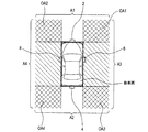
図2に示すように、前方カメラ2は、自車両の前部(例えば、前部中央部)に搭載され、自車両の前方領域A1を撮像する。後方カメラ4は、自車両の後部(例えば、後部中央部)に搭載され、自車両の後方領域A2を撮像する。右側方カメラ6は、自車両の右側部(例えば、右側バックミラー部)に搭載され、自車両の右側方領域A3を撮像する。左側方カメラ8は、自車両の左側部(例えば、左側バックミラー部)に搭載され、自車両の左側方領域A4を撮像する。
As shown in FIG. 2, the
また、各車載カメラ10は、各撮像領域の一部が他の少なくとも1つの車載カメラ10の撮像領域の一部と重複する領域(以下、重複領域)を有するように自車両に設置されている。例えば、図2に示すように、前方カメラ2の撮像領域である前方領域A1は、右側方カメラ6の撮像領域である右側方領域A3と一部が重複する右前重複領域OA1と、左側方カメラ8の撮像領域である左側方領域A4と一部が重複する左前重複領域OA2と、を有している。後方カメラ4の撮像領域である後方領域A2は、右側方カメラ6の撮像領域である右側方領域A3と一部が重複する右後重複領域OA3と、左側方カメラ8の撮像領域である左側方領域A4と一部が重複する左後重複領域OA4と、を有している。
In addition, each on-vehicle camera 10 is installed in the vehicle so as to have an area (hereinafter referred to as an overlapping area) in which a part of each imaging area overlaps with a part of the imaging area of at least one other on-vehicle camera 10 . For example, as shown in FIG. 2, a front area A1 which is an imaging area of the
つまり、撮像領域に重複領域を有するように車載カメラ10を配備することにより、自車両の全周囲をより確実に撮像可能とされている。ただし、図2において太線で囲まれた領域に示すように、本実施形態においては、自車両の本体部分の領域(以下、本体領域)がいずれの車載カメラ10からも撮像不可な領域とされている。 That is, by arranging the on-vehicle camera 10 so as to have the overlapping area in the imaging area, it is possible to more reliably image the entire periphery of the host vehicle. However, as shown in a region surrounded by a thick line in FIG. 2, in the present embodiment, the region of the main body of the vehicle (hereinafter referred to as the main region) is a region where imaging can not be performed by any on-vehicle camera 10 There is.
ディスプレイ30は、自車両に搭載される表示装置として、車室内等に設置されるものである。例えば、ディスプレイ30は、液晶ディスプレイ、ヘッドアップディスプレイ、又はこれらの組合せ等によって構成され、自車両の運転者が視認しやすい位置に設置される。 The display 30 is installed in a vehicle interior or the like as a display device mounted on the host vehicle. For example, the display 30 is configured by a liquid crystal display, a head-up display, a combination thereof, or the like, and is installed at a position where the driver of the host vehicle can easily view.
[1−2.表示制御ユニット20の構成]
表示制御ユニット20は、CPU12と、RAM、ROM、フラッシュメモリ等の半導体メモリに代表される非遷移的実体的記録媒体(以下、メモリ14)と、を有する周知のマイクロコンピュータ、及び車内LAN用の通信コントローラを中心に構成されたECUである。表示制御ユニット20においては、メモリ14に格納されているプログラムに基づいてCPU12により各種処理が実行される。つまり、このプログラムが実行されることにより、プログラムに対応する方法が実行される。なお、マイクロコンピュータの数は1つでも複数でもよく、1ないし複数のマイクロコンピュータの各設置場所は車両内部の何れでもよい。
[1-2. Configuration of Display Control Unit 20]
The display control unit 20 includes a well-known microcomputer having a CPU 12 and a non-transitional tangible storage medium (hereinafter, memory 14) represented by a semiconductor memory such as a RAM, a ROM, and a flash memory, and an in-vehicle LAN. It is an ECU composed mainly of a communication controller. In the display control unit 20, the CPU 12 executes various processes based on the programs stored in the memory 14. That is, by executing this program, a method corresponding to the program is executed. The number of microcomputers may be one or more, and the installation locations of one or more microcomputers may be anywhere inside the vehicle.
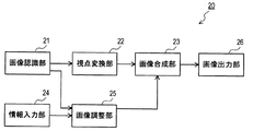
表示制御ユニット20は、CPU12の各種処理の実行により実現される機能の構成として、図3に示すように、画像入力部21と、視点変換部22と、画像合成部23と、情報入力部24と、画像調整部25と、画像出力部26と、を備える。なお、表示制御ユニット20が提供するこれら機能の一部又は全部を、一つあるいは複数の論理回路やIC等の電子回路によりハードウェア的に構成しても良い。つまり、表示制御ユニット20においては、ソフトウェアに限らず、ハードウェアあるいはそれらの組合せによっても上記機能を提供することができる。
The display control unit 20 has a configuration of functions realized by execution of various processes of the CPU 12, as shown in FIG. 3, an
画像入力部21は、各車載カメラ10から自車両の周囲を示す画像(以下、周囲画像)を取得する。本実施形態では、各車載カメラ10から、前方領域A1、後方領域A2、右側方領域A3、左側方領域A4を撮像した各周囲画像を所定のフレームレートで取得し、これらの周囲画像を互いに識別可能な態様でメモリ14に格納する。なお、メモリ14には、各車載カメラ10の位置及び姿勢を示す外部パラメータや、焦点距離や画像中心や画像サイズや歪収差係数等を示す内部パラメータ等を含む周知のカメラパラメータが格納されている。画像入力部21は、これらのカメラパラメータのうち一部又は全部を各車載カメラ10から取得しても良い。カメラパラメータは、以下で述べる視点変換画像や対象画像を生成する際等に用いられる。
The
視点変換部22は、画像入力部21により取得した各周囲画像を予め設定された仮想視点から見た画像(以下、視点変換画像)に変換する。視点変換画像は、車載カメラ10の視点から見た周囲画像を、仮想カメラの視点(すなわち、仮想視点)から見ているかのように座標変換した画像である。例えば、カメラ座標系の光軸を基準とすると、撮像画像上のあらゆる点の座標位置を光軸からの角度と距離とによって求め、これらの座標位置を仮想カメラの光軸に基づいて回転及び並進させることにより、画像を視点変換することができる。つまり、仮想カメラの光軸として、仮想視点の位置及び向きを設定すれば、所望の視点変換画像を得ることが可能となる。なお、画像の視点変換に関する技術自体は当業者にとって周知のため、その詳細な説明については省略する。
The
視点変換部22は、複数の周囲画像のうち1つの周囲画像に基づく視点変換画像を対象画像として後段の画像合成部23に出力しても良い。あるいは、視点変換部22は、複数の周囲画像のそれぞれを仮想視点から見た画像に変換して、各視点変換画像の一部を繋ぎ合わせた画像(以下、アラウンドビュー画像)を対象画像として画像合成部23に出力しても良い。具体的には、アラウンドビュー画像においては、各視点変換画像の一部として、右前重複領域OA1、左前重複領域OA2、右後重複領域OA3、左後重複領域OA4等の重複領域に対応する画像領域が繋ぎ合わされる。こうした画像の繋ぎ合わせに関する技術自体は当業者にとって周知のため、その詳細な説明については省略する。
The
なお、アラウンドビュー画像の態様としては、フロントビュー画像やバックビュー画像、サイドビュー画像、鳥瞰画像等があり、これらの画像からユーザによる運転操作やスイッチ操作等の内容に応じた画像が選択される。 In addition, there are a front view image, a back view image, a side view image, a bird's-eye view image, etc. as an aspect of an around view image, and an image according to contents such as a driving operation or a switch operation by the user is selected from these images. .
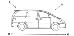
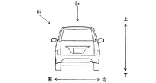
例えば、図4に示す仮想視点E1が設定された場合、視点変換部22は、自車両の後側斜め上方の位置から自車両を含む前側斜め下方を所定角度で見たフロントビュー画像を対象画像として生成する。また例えば、図4に示す仮想視点E2が設定された場合、視点変換部22は、自車両の前側斜め上方の位置から自車両を含む後側斜め下方を所定角度で見たバックビュー画像を対象画像として生成する。また例えば、図5に示す仮想視点E3が設定された場合、視点変換部22は、自車両の左側方斜め上側の位置から自車両を含む右側方斜め下方を所定角度で見たサイドビュー画像を対象画像として生成する。また例えば、図5に示す仮想視点E4が設定された場合、視点変換部22は、自車両の上方の位置から自車両を含む下方を見た鳥瞰画像を対象画像として生成する。
For example, when the virtual viewpoint E1 shown in FIG. 4 is set, the
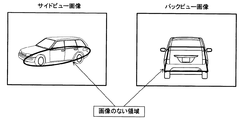
画像合成部23は、視点変換部22により生成された対象画像に、その対象画像において自車両の位置及び形状を示す画像(以下、車両画像)を上位のレイヤーとして合成する。例えば、対象画像がアラウンドビュー画像である場合、このアラウンドビュー画像においては、いずれの車載カメラ10からも撮像不可な領域(すなわち、本体領域)に対応する画像領域が存在することになる。本実施形態では、画像合成部23は、このように画像のない領域に、仮想視点の位置及び向きに応じた仮想的な素材画像としての車両画像を合成する。
The
車両画像は、仮想視点の位置及び向きに応じた複数パターンの形状を示す画像が予め用意されてメモリ14に格納されている。この車両画像は、図6に示すように、サイドビュー画像やバックビュー画像等のアラウンドビュー画像において、画像のない領域がなるべく露出しないように重畳される。つまり、画像合成部23は、対象画像において、視点変換画像が存在する画像領域と、視点変換画像が存在しない非画像領域と、を有する場合、非画像領域の大部分が隠れる位置及び大きさに設定した車両画像を対象画像に合成するようにされている。
As the vehicle image, images showing shapes of a plurality of patterns according to the position and direction of the virtual viewpoint are prepared in advance and stored in the memory 14. As shown in FIG. 6, this vehicle image is superimposed on an around view image such as a side view image or a back view image so that an area without an image is not exposed as much as possible. That is, when the
情報入力部24は、他のECUから車内LANを介して、シフトレバー位置、車速、加速度、操舵角、ヨーレート、照度、物標情報等の車両情報を所定の周期で取得する。そして、この車両情報を、画像入力部21により周囲画像を取得したタイミングと対応付けてメモリ14に格納する。
The
画像調整部25は、画像合成部23により対象画像に合成される車両画像について、対象画像との重畳部分において下位のレイヤーである対象画像が見えるように画像の不透明度を調整する。また、この際に、車両の周囲の状況、及び、車両の走行状況、のうち少なくとも一つの状況に応じて、車両画像の不透明度を可変設定する。
The
不透明度は、対象画像との重畳部分において下位のレイヤーである対象画像がどの程度見えるか、換言すれば対象画像がシースルー表示される程度を数値化したものである。不透明度が高いほど、車両画像が濃くなることによって対象画像が見えにくくなり、不透明度が低いほど、車両画像が薄くなることによって対象画像が見えやすくなる。なお、不透明度がゼロに設定されると、車両画像が全く表示されないことになる。また、不透明度が最大値に設定される場合、すなわち不透明度が調整されない場合は、車両画像との重畳部分において対象画像が全く表示されないことになる。こうした重畳画像のシースルー表示に関する技術自体は当業者にとって周知のため、その詳細な説明については省略する。 The opacity is a numerical value of how much the target image, which is a lower layer, can be seen in the overlapping portion with the target image, in other words, the degree to which the target image is see-through displayed. As the opacity is higher, the target image becomes harder to see because the vehicle image is darker, and as the opacity is lower, the target image becomes easier to see because the vehicle image is thinner. If the opacity is set to zero, the vehicle image will not be displayed at all. Further, when the opacity is set to the maximum value, that is, when the opacity is not adjusted, the target image is not displayed at all in the overlapping portion with the vehicle image. The technology relating to such see-through display of superimposed images is known to those skilled in the art, and thus the detailed description thereof is omitted.
また、車両画像の不透明度は、対象画像との重畳部分の全領域において一律に設定されても良いし、対象画像との重畳部分のうち、視点変換画像が存在する画像領域と、視点変換画像が存在しない非画像領域と、においてそれぞれ異なるように設定されても良い。つまり、画像調整部25は、車両画像のうち、画像領域と重なる部分についての不透明度と、非画像領域と重なる部分についての不透明度と、を個別に設定することができる。例えば、画像調整部25は、車両画像のうち、画像領域と重なる部分について不透明度を調整し、非画像領域と重なる部分については不透明度を調整しない、こととすることもできる。
In addition, the opacity of the vehicle image may be set uniformly in the entire area of the overlapping portion with the target image, or the image area where the viewpoint conversion image is present and the viewpoint conversion image in the overlapping portion with the target image. In the non-image area where is not present, they may be set differently. That is, the
車両の周囲の状況は、情報入力部24により取得した車両情報のうち、照度や物標情報等から推測される情報である。例えば、昼間等、自車両の周囲が明るい場合には、対象画像の輝度が充分足りていることから、車両画像の不透明度を比較的高く設定しても、車両画像との重畳部分において対象画像が視認可能な状態で表示されることになる。逆に、夜間等、自車両の周囲が暗い場合には、車両画像の不透明度を比較的低く設定することにより、車両画像との重畳部分において対象画像を車両運転者に視認させやすくすることができる。
Among the vehicle information acquired by the
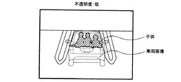
また、車両の周囲に他車両や歩行者や障害物等の対象物が存在している場合には、車両画像との重畳部分において対象画像中に対象物が存在している可能性があることから、車両画像の不透明度を比較的低く設定することにより、対象物を車両運転者に認知させやすくすることができる。例えば、図7に示すように、駐車場に停車中の自車両の後方に子供がいる場合には、車両画像の不透明度が低く設定されることにより、車両画像が透過されることから、バックビュー画像中において子供の存在を車両運転者に認知させやすくすることができる。逆に、車両の周囲に他車両や歩行者や障害物等の対象物が存在していない場合には、車両画像の不透明度を比較的高く設定することにより、自車両を車両運転者に認知させやすくすることができる。 In addition, when an object such as another vehicle, a pedestrian or an obstacle is present around the vehicle, there is a possibility that the object may be present in the object image in the overlapping portion with the vehicle image. Thus, by setting the opacity of the vehicle image to be relatively low, it is possible to make the object of the vehicle easier to recognize by the vehicle driver. For example, as shown in FIG. 7, when there is a child behind the own vehicle stopping in the parking lot, the opacity of the vehicle image is set low, and the vehicle image is transmitted. It is possible to make it easy for the vehicle driver to recognize the presence of a child in the view image. Conversely, when there is no other vehicle, pedestrian or obstacle such as an obstacle around the vehicle, the driver of the vehicle is recognized by setting the opacity of the vehicle image relatively high. It can be made easy.
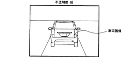
車両の走行状況は、情報入力部24により取得した車両情報のうち、シフトレバー位置、車速、加速度、操舵角、ヨーレート等に基づく情報である。車両の走行状況からは、例えば、車両運転者の運転負荷状況や、車両運転者がアラウンドビュー画像を見る蓋然性等が推測される。例えば、図8に示すように、車速や加速度や操舵角やヨーレートが大きい場合には、運転負荷状況が高いと推測されることから、車両画像の不透明度を比較的高く設定することにより、車両運転者に運転操作の方へ注力を向けさせやすくすることができる。逆に、車速や加速度や操舵角やヨーレートが小さい場合には、運転負荷状況が低いと推測されることから、車両画像の不透明度を比較的低く設定することにより、対象物等を車両運転者に認知させやすくすることができる。また例えば、シフトレバー位置がリバース位置である場合には、バックビュー画像を見る蓋然性が高いと推測されることから、車両画像の不透明度を比較的低く設定することにより、対象物等を車両運転者に認知させやすくすることができる。
The traveling condition of the vehicle is information based on the shift lever position, the vehicle speed, the acceleration, the steering angle, the yaw rate, and the like among the vehicle information acquired by the
画像出力部26は、画像合成部23により車両画像が合成された対象画像を運転支援画像として出力する。具体的には、画像出力部26は、画像調整部25により不透明度を調整した場合には、その不透明度を調整した車両画像が重畳された対象画像を運転支援画像としてディスプレイ30に表示する。また、画像出力部26は、画像調整部25により車両画像の不透明度を調整しなかった場合には、視点変換部22により生成された対象画像を運転支援画像としてディスプレイ30に表示する。
The
このように運転支援画像は、視点変換部22により生成された対象画像に基づく画像であり、本実施形態ではアラウンドビュー画像そのものである場合や、アラウンドビュー画像に車両画像が重畳された画像である場合や、さらに車両画像の不透明度が調整された画像である場合がある。
As described above, the driving support image is an image based on the target image generated by the
なお、視点変換部22が変換部及び変換工程、画像合成部23が合成部及び合成工程、画像調整部25が調整部及び調整工程、画像出力部26が出力部及び出力工程に相当する。
The
[1−3.処理]
[1−3−1.表示制御処理]
次に、表示制御ユニット20のCPU12が実行する処理(以下、表示制御処理)の一例について、図9のフローチャートを用いて説明する。なお、本処理は、例えば自車両のイグニッションスイッチがON状態であり、運転支援機能に係るスイッチがONされている間、所定サイクル毎に繰り返し起動される。
[1-3. processing]
[1-3-1. Display control processing]
Next, an example of processing (hereinafter, display control processing) executed by the CPU 12 of the display control unit 20 will be described using the flowchart of FIG. In addition, this processing is repeatedly started for every predetermined cycle, for example, while the ignition switch of the own vehicle is ON state and the switch which concerns on a driving assistance function is ON.
本処理が起動すると、S110において画像入力部21は、各車載カメラ10から周囲画像を取得して周囲画像をメモリ14に格納する。また、S120において情報入力部24は、他のECUから車内LANを介して車両情報を取得して、S110により周囲画像を取得したタイミングと対応付けて車両情報をメモリ14に格納する。
When this process is activated, the
続くS130において視点変換部22は、画像入力部21により取得した各周囲画像について、ユーザによる運転操作やスイッチ操作等の内容に応じた仮想視点から見た各視点変換画像に変換する。そして、S140において視点変換部22は、S130により各周囲画像が変換された各視点変換画像について、各重複領域に対応する画像領域を繋ぎ合わせることによりアラウンドビュー画像を生成する。このアラウンドビュー画像においては、前述のとおり、視点変換画像が存在する画像領域と、視点変換画像が存在しない非画像領域とが含まれている。
In S130, the
そこで、続くS150において画像合成部23は、S140により生成したアラウンドビュー画像のうち非画像領域を少なくとも含む画像中央の領域に、S130にて使用した仮想視点に応じた車両画像を重畳する。つまり、車両画像を上位のレイヤー、アラウンドビュー画像を下位のレイヤーとして、車両画像をアラウンドビュー画像に合成する。この合成画像では、前述のとおり、車両画像とアラウンドビュー画像とが重なる部分(すなわち、画像中央の領域)において、下位のレイヤー(すなわち、アラウンドビュー画像)の方に画像領域と非画像領域とが含まれている。
Therefore, in the subsequent S150, the
このため、続くS160において画像調整部25は、S150によりアラウンドビュー画像に合成する車両画像のうち、アラウンドビュー画像の画像領域と重なる部分については不透明度を調整し、アラウンドビュー画像の非画像領域と重なる部分については透明度を調整しないようにすることができる。このうち不透明度の調整を行う処理(以下、不透明度調整処理)については後述する。
Therefore, in the subsequent S160, the
なお、アラウンドビュー画像の非画像領域については、過去に車載カメラ10により撮像された周囲画像に基づく視点変換画像を履歴画像として、こうした履歴画像の少なくとも一部を埋め込むこともできる。例えば、この場合、不透明度調整処理については、アラウンドビュー画像の非画像領域と重なる部分だけでなく、車両画像全体の不透明度の調整を行うようにしても良い。履歴画像は、自車両の速度・加速度・操舵角・ヨーレート等を組み合せて使用し、視点変換画像の各画素に対する自車両の相対位置を推定する自己位置推定方法によって得られる公知のデッドレコニングの結果と対応づけてメモリ14に格納されることで、上記のような埋め込みが可能なものとなる。 Note that for a non-image area of the around view image, at least a part of such a history image can be embedded as a history image, with a viewpoint conversion image based on an ambient image captured by the on-vehicle camera 10 in the past. For example, in this case, as to the opacity adjustment processing, the opacity of the entire vehicle image may be adjusted not only in the portion overlapping with the non-image area of the around view image. The history image is a result of a known dead reckoning obtained by the self position estimation method of estimating the relative position of the vehicle with respect to each pixel of the viewpoint conversion image by using the speed, acceleration, steering angle, yaw rate etc. of the vehicle in combination. By being stored in the memory 14 in association with the above, it becomes possible to embed as described above.
そして、S170において画像出力部26は、S160により不透明度が調整された車両画像がS150によりアラウンドビュー画像(即ち、対象画像)に合成された画像を運転支援画像として、ディスプレイ30に表示し、本処理を終了する。
Then, in S170, the
[1−3−2.不透明度調整処理]
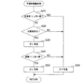
次に、S160において画像調整部25が実行する不透明度調整処理の一例について、図10のフローチャートを用いて説明する。
[1-3-2. Opacity adjustment processing]
Next, an example of the opacity adjustment process performed by the
本処理が開始されると、S210において画像調整部25は、S120により取得した車両情報に基づき、自車両の速度(すなわち、自車速)が予め定められたしきい値を上回っているか否かを判定する。このしきい値判定において、自車速がしきい値を上回っている場合には、S260に移行し、自車速がしきい値以下である場合には、S220に移行する。ここでのしきい値は、運転負荷状況が高いか否かを推測するためのしきい値速度を意味し、自車速がしきい値(例えば、時速50km)を上回っていると、運転負荷状況が高いと推測し、自車速がしきい値以下であると、運転負荷状況が低いと推測される。
When this process is started, the
ここでS260に移行した場合、画像調整部25は、対象画像の不透明度を最大値に設定する、つまり不透明度を調整しないことによるオフ性能を働かせる。これにより、S170により出力される運転支援画像は、車両画像との重畳部分において下位のレイヤーである対象画像が見えない画像、つまり上位のレイヤーである車両画像が透過されない画像となる。
Here, when the process proceeds to S260, the
一方、S220に移行した場合、画像調整部25は、S110により取得した周囲画像と、S140により生成したアラウンドビュー画像(すなわち、対象画像)と、に基づき、車両画像との重畳部分において対象画像中に対象物が存在しているか否かを判定する。この判定には、例えば周知のパターンマッチングの技術が用いられる。この判定において、対象物が存在している場合には、S230に移行し、対象物が存在していない場合には、S260に移行する。
On the other hand, when the process proceeds to S220, the
ここでS230に移行した場合、画像調整部25は、対象物が存在していない場合よりも車両画像の不透明度を低く設定することによるオン性能を働かせる。これにより、S170により出力される運転支援画像は、車両画像との重畳部分において下位のレイヤーである対象画像がより見えやすくなる画像、つまり上位のレイヤーである車両画像の透過度が高い画像となる。さらに、画像調整部25は、S240に移行する。
Here, when the process proceeds to S230, the
一方、ここでS260に移行した場合、画像調整部25は、対象物が存在している場合よりも車両画像の不透明度を高く設定することによるオフ性能を働かせる。これにより、S170により出力される運転支援画像は、車両画像との重畳部分において下位のレイヤーである対象画像がより見えにくくなる画像、つまり上位のレイヤーである車両画像の透過度が低い画像となる。
On the other hand, when the process proceeds to S260, the
S240において画像調整部25は、S120により取得した車両情報、具体的には物標情報に基づき、対象物と自車両との距離が予め定められたしきい値を下回っているか否かを判定する。このしきい値判定において、距離がしきい値を下回っている場合には、S250に移行し、距離がしきい値以上である場合には、S260に移行する。ここでのしきい値は、車両運転者に認知させる必要性が高いか否かを推測するためのしきい値距離を意味し、距離がしきい値を下回っていると、その必要性が高いと推測し、距離がしきい値以上であると、その必要性が低いと推測される。なお、このしきい値距離は、自車速に応じて可変設定することができる。
In S240, the
ここでS250に移行した場合、画像調整部25は、距離がしきい値以上である場合よりも車両画像の不透明度を低く設定することによるオン性能を働かせる。これにより、S170により出力される運転支援画像は、車両画像との重畳部分において下位のレイヤーである対象画像がより見えやすくなる画像、つまり上位のレイヤーである車両画像の透過度が高い画像となる。なお、S250において画像調整部25は、対象物と自車両との距離が第2のしきい値距離を下回る場合に、車両画像の不透明度をゼロに設定しても良い。
Here, when the process proceeds to S250, the
一方、ここでS260に移行した場合、画像調整部25は、対象物が存在している場合よりも車両画像の不透明度を高く設定することによるオフ性能を働かせる。これにより、S170により出力される運転支援画像は、車両画像との重畳部分において下位のレイヤーである対象画像がより見えにくくなる画像、つまり上位のレイヤーである車両画像の透過度が低い画像となる。
On the other hand, when the process proceeds to S260, the
[1−4.効果]
以上詳述した第1実施形態によれば、以下の効果が得られる。
(1a)車両の周囲の状況、及び、車両の走行状況、のうち少なくとも一つの状況に応じて、車両画像の不透明度が可変設定される。このため、対象画像に重畳される部分において、各種シーンによって異なる不透明度で車両画像を重畳表示したり、場合によっては不透明度をゼロに設定することで車両画像の表示をなくしたりすることが可能となる。このように車両画像の表示態様が可変制御されることにより、車両運転者にとって、より気の利いた運転支援画像を表示することができる。
[1-4. effect]
According to the first embodiment described above, the following effects can be obtained.
(1a) The opacity of the vehicle image is variably set according to at least one of the surrounding condition of the vehicle and the traveling condition of the vehicle. For this reason, it is possible to superimpose and display the vehicle image with different opacity depending on various scenes in a portion to be superimposed on the target image, or to eliminate the display of the vehicle image by setting the opacity to zero in some cases. It becomes. By variably controlling the display mode of the vehicle image as described above, it is possible for the vehicle driver to display a more dignified driving assistance image.
(2a)運転負荷状況が高いと推測される場合に、車両運転者が運転支援画像を見る蓋然性が低いことから、自車速に応じて車両画像の不透明度を高く設定することにより、車両運転者に運転操作の方へ注力を向けさせやすくすることができる。特に、車両画像の不透明度を最大に設定することにより、不透明度の調整を省略可能となり、不要な処理をなくすことができる。 (2a) When the driving load situation is estimated to be high, the probability that the vehicle driver looks at the driving support image is low, so the opacity of the vehicle image is set high according to the own vehicle speed. Can make it easier to focus on driving operations. In particular, by setting the opacity of the vehicle image to the maximum, the adjustment of the opacity can be omitted, and unnecessary processing can be eliminated.
(3a)自車両の周囲に対象物が存在している場合は、対象物が存在しない場合よりも車両画像の不透明度を低く設定することにより、対象物を車両運転者に認知させやすくすることができる。 (3a) When an object is present around the host vehicle, the vehicle driver can easily recognize the object by setting the opacity of the vehicle image to be lower than when the object is not present. Can.
(4a)対象物と自車両との距離に応じて車両画像の不透明度を高く設定することにより、距離が大きい場合は、運転支援画像において自車両とその周囲との位置関係を車両運転者により認知させやすくすることができる。また、距離が小さい場合は、不透明度が低く設定されるので、例えば自車両の近傍に位置する歩行者等の対象物を車両運転者に認知させやすくすることができる。 (4a) By setting the opacity of the vehicle image high according to the distance between the object and the vehicle, the distance between the vehicle and the surroundings in the driving support image is determined by the vehicle driver when the distance is large. It can be made easy to recognize. Further, when the distance is short, the opacity is set low, so that it is possible to make the driver of the vehicle easy to recognize an object such as a pedestrian located near the host vehicle, for example.
(5a)車両画像のうち、対象画像の画像領域と重なる部分について不透明度を調整し、対象画像の非画像領域と重なる部分については不透明度を調整しない。これにより、対象物を車両運転者に認知させやすくすることと、自車両とその周囲との位置関係を車両運転者により認知させやすくすることと、を好適に両立させることができる。 (5a) Adjust the opacity of the portion of the vehicle image overlapping the image area of the target image, and do not adjust the opacity of the portion overlapping the non-image area of the target image. Accordingly, it is possible to preferably achieve both of making the vehicle driver easily recognize the object and making the vehicle driver easily recognize the positional relationship between the own vehicle and the surroundings thereof.
[2.他の実施形態]
以上、本発明を実施するための形態について説明したが、本発明は上述の実施形態に限定されることなく、種々変形して実施することができる。
[2. Other embodiments]
As mentioned above, although the form for implementing this invention was demonstrated, this invention can be variously deformed and implemented, without being limited to the above-mentioned embodiment.
(2A)上記実施形態では、不透明度調整処理において、自車速がしきい値以下である場合に、自車両の周囲における対象物の有無を判定しているが、これに限定されるものではない。例えば、自車速がしきい値以下である場合に、対象物の有無にかかわらず、自車速がしきい値を上回っている場合よりも車両画像の不透明度を低く設定するオン性能を働かせても良い。 (2A) In the above embodiment, when the vehicle speed is equal to or less than the threshold in the opacity adjustment processing, the presence or absence of the object around the vehicle is determined, but the present invention is not limited to this. . For example, even when the own vehicle speed is equal to or less than the threshold value, the on-performance is set to set the opacity of the vehicle image lower than when the own vehicle speed exceeds the threshold value regardless of the presence or absence of the object. good.
(2B)上記実施形態における1つの構成要素が有する複数の機能を、複数の構成要素によって実現したり、1つの構成要素が有する1つの機能を、複数の構成要素によって実現したりしてもよい。また、複数の構成要素が有する複数の機能を、1つの構成要素によって実現したり、複数の構成要素によって実現される1つの機能を、1つの構成要素によって実現したりしてもよい。また、上記実施形態の構成の一部を省略してもよい。また、上記実施形態の構成の少なくとも一部を、他の上記実施形態の構成に対して付加又は置換してもよい。なお、特許請求の範囲に記載した文言のみによって特定される技術思想に含まれるあらゆる態様が本開示の実施形態である。 (2B) The multiple functions of one component in the above embodiment may be realized by multiple components, or one function of one component may be realized by multiple components. . Also, a plurality of functions possessed by a plurality of components may be realized by one component, or one function realized by a plurality of components may be realized by one component. In addition, part of the configuration of the above embodiment may be omitted. In addition, at least a part of the configuration of the above-described embodiment may be added to or replaced with the configuration of the other above-described embodiment. In addition, all the aspects contained in the technical thought specified only by the words described in the claim are an embodiment of this indication.
(2C)上述した運転支援装置1の他、当該運転支援装置1を構成要素とするシステム、当該運転支援装置1としてコンピュータを機能させるための1ないし複数のプログラム、このプログラムの少なくとも一部を記録した1ないし複数の半導体メモリ等の非遷移的実体的記録媒体、運転支援方法など、種々の形態で本発明を実現することもできる。 (2C) In addition to the driving support device 1 described above, a system having the driving support device 1 as a component, one or more programs for causing a computer to function as the driving support device 1, and at least a part of this program The present invention can also be realized in various forms, such as a non-transitional tangible storage medium such as one or more semiconductor memories, and a driving support method.
1…運転支援装置、10…車載カメラ、12…CPU、14…メモリ、20…表示制御ユニット、21…画像入力部、22…視点変換部、23…画像合成部、24…情報入力部、25…画像調整部、26…画像出力部、30…ディスプレイ。 DESCRIPTION OF SYMBOLS 1 ... Driving assistance apparatus, 10 ... Vehicle-mounted camera, 12 ... CPU, 14 ... Memory, 20 ... Display control unit, 21 ... Image input part, 22 ... View point conversion part, 23 ... Image synthetic | combination part, 24 ... Information input part, 25 ... image adjustment unit, 26 ... image output unit, 30 ... display.
Claims (6)
前記変換部により前記撮像画像が変換された画像を対象画像とし、前記対象画像において前記車両の位置及び形状を示す車両画像を上位のレイヤーとして前記対象画像に合成する合成部(23)と、
前記合成部により前記対象画像に合成される車両画像について、前記対象画像との重畳部分において下位のレイヤーである前記対象画像が見えるように画像の不透明度を調整する際に、前記車両の周囲の状況、及び、前記車両の走行状況、のうち少なくとも一つの状況に応じて、前記車両画像の不透明度を可変設定する調整部(25)と、
前記合成部により前記車両画像が合成された対象画像を運転支援画像として出力する出力部(26)と、
を備え、
前記変換部は、複数の前記車載撮像装置の各撮像画像を前記仮想視点から見た画像にそれぞれ変換して、各変換画像の一部を繋ぎ合わせた画像を前記対象画像として生成し、
前記対象画像は、前記変換画像が存在する画像領域と、前記変換画像が存在しない非画像領域と、を有しており、
前記調整部は、前記車両画像のうち、前記画像領域と重なる部分について前記不透明度を調整し、前記非画像領域と重なる部分については前記不透明度を調整しない、
運転支援装置。 A converter (22) for converting a captured image of a vehicle-mounted imaging device for capturing an image of the surroundings of the vehicle into an image viewed from a preset virtual viewpoint;
A combining unit (23) that combines an image obtained by converting the captured image by the conversion unit into a target image, and a vehicle image indicating the position and shape of the vehicle in the target image as the upper layer on the target image;
When adjusting the opacity of the vehicle image to be combined with the target image by the combining unit so that the target image, which is a lower layer, can be seen in the overlapping portion with the target image, An adjusting unit (25) that variably sets the opacity of the vehicle image according to at least one of the condition and the traveling condition of the vehicle;
An output unit (26) for outputting, as a driving assistance image, a target image on which the vehicle image is combined by the combining unit;
Equipped with
The conversion unit converts each captured image of a plurality of on-vehicle imaging devices into an image viewed from the virtual viewpoint, and generates an image obtained by connecting a part of each converted image as the target image.
The target image includes an image area in which the converted image is present, and a non-image area in which the converted image is not present.
The adjustment unit adjusts the opacity of a portion of the vehicle image overlapping the image area, and does not adjust the opacity of a portion overlapping the non-image area.
Driving support device.
前記調整部は、前記車両の速度に応じて前記車両画像の不透明度を高く設定する、運転支援装置。 The driving support apparatus according to claim 1,
The driving support apparatus, wherein the adjustment unit sets the opacity of the vehicle image to be high according to the speed of the vehicle.
前記調整部は、前記車両の周囲に予め定められた対象物が存在している場合は、前記対象物が存在しない場合よりも前記車両画像の不透明度を低く設定する、運転支援装置。 The driving support apparatus according to claim 1 or 2, wherein
The driving support device, wherein, when a predetermined target is present around the vehicle, the adjustment unit sets the opacity of the vehicle image to a lower level than when no target is present.
前記調整部は、前記対象物と前記車両との距離に応じて前記車両画像の不透明度を高く設定する、運転支援装置。 The driving support apparatus according to claim 3,
The driving support apparatus, wherein the adjustment unit sets the opacity of the vehicle image to be high according to the distance between the object and the vehicle.
前記変換工程により前記撮像画像が変換された画像を対象画像とし、前記対象画像において前記車両の位置及び形状を示す車両画像を上位のレイヤーとして前記対象画像に合成する合成工程(23)と、
前記合成工程により前記対象画像に合成される車両画像について、前記対象画像との重畳部分において下位のレイヤーである前記対象画像が見えるように画像の不透明度を調整する際に、前記車両の周囲の状況、及び、前記車両の走行状況、のうち少なくとも一つの状況に応じて、前記車両画像の不透明度を可変設定する調整工程(25)と、
前記合成工程により前記車両画像が合成された対象画像を運転支援画像として出力する出力工程(26)と、
を備え、
前記変換工程は、複数の前記車載撮像装置の各撮像画像を前記仮想視点から見た画像にそれぞれ変換して、各変換画像の一部を繋ぎ合わせた画像を前記対象画像として生成し、
前記対象画像は、前記変換画像が存在する画像領域と、前記変換画像が存在しない非画像領域と、を有しており、
前記調整工程は、前記車両画像のうち、前記画像領域と重なる部分について前記不透明度を調整し、前記非画像領域と重なる部分については前記不透明度を調整しない、
運転支援方法。 A conversion step (22) of converting a captured image of a vehicle-mounted imaging device for capturing the surroundings of the vehicle into an image viewed from a preset virtual viewpoint;
Combining an image obtained by converting the captured image in the conversion step as a target image, and combining a vehicle image indicating the position and shape of the vehicle in the target image with the target image as an upper layer;
When adjusting the opacity of the vehicle image to be viewed as the lower layer in the overlapping portion with the target image, the vehicle image to be combined with the target image in the combining step, when the opacity of the image is adjusted; An adjusting step (25) of variably setting the opacity of the vehicle image in accordance with at least one of the condition and the traveling condition of the vehicle;
An output step (26) for outputting, as a driving support image, the target image on which the vehicle image has been combined by the combining step;
Equipped with
The conversion step converts each captured image of the plurality of on-vehicle imaging devices into an image viewed from the virtual viewpoint, and generates an image obtained by connecting a part of each converted image as the target image.
The target image includes an image area in which the converted image is present, and a non-image area in which the converted image is not present.
The adjusting step adjusts the opacity of a portion of the vehicle image overlapping the image area, and does not adjust the opacity of a portion overlapping the non-image area.
Driving support method.
前記撮像画像が変換された画像を対象画像とし、前記対象画像において前記車両の位置及び形状を示す車両画像を上位のレイヤーとして前記対象画像に合成し、
前記対象画像に合成される車両画像について、前記対象画像との重畳部分において下位のレイヤーである前記対象画像が見えるように画像の不透明度を調整する際に、前記車両の周囲の状況、及び、前記車両の走行状況、のうち少なくとも一つの状況に応じて、前記車両画像の不透明度を可変設定し、
前記合成により前記車両画像が合成された対象画像を運転支援画像として出力し、
前記変換は、複数の前記車載撮像装置の各撮像画像を前記仮想視点から見た画像にそれぞれ変換して、各変換画像の一部を繋ぎ合わせた画像を前記対象画像として生成し、
前記対象画像は、前記変換画像が存在する画像領域と、前記変換画像が存在しない非画像領域と、を有しており、
前記調整は、前記車両画像のうち、前記画像領域と重なる部分について前記不透明度を調整し、前記非画像領域と重なる部分については前記不透明度を調整しない、運転支援方法。 Converting a captured image of a vehicle-mounted imaging device for capturing the surroundings of a vehicle into an image viewed from a preset virtual viewpoint;
An image obtained by converting the captured image is used as a target image, and a vehicle image indicating the position and shape of the vehicle in the target image is combined with the target image as an upper layer,
The condition around the vehicle when adjusting the opacity of the vehicle image combined with the object image so that the object image, which is a lower layer, can be seen in the overlapping portion with the object image; The opacity of the vehicle image is variably set according to at least one of the traveling conditions of the vehicle,
Outputs target image more the vehicle image is synthesized in the synthesis as the driving support image,
In the conversion, each captured image of a plurality of the on-vehicle imaging devices is converted into an image viewed from the virtual viewpoint, and an image obtained by connecting a part of each converted image is generated as the target image.
The target image includes an image area in which the converted image is present, and a non-image area in which the converted image is not present.
The adjustment is performed by adjusting the opacity of a portion of the vehicle image overlapping the image area and not adjusting the opacity of a portion overlapping the non-image area .
Priority Applications (5)
| Application Number | Priority Date | Filing Date | Title |
|---|---|---|---|
| JP2016003749A JP6524922B2 (en) | 2016-01-12 | 2016-01-12 | Driving support device, driving support method |
| CN201780006210.3A CN108463998A (en) | 2016-01-12 | 2017-01-11 | Driving assistance device and driving assistance method |
| DE112017000342.3T DE112017000342T5 (en) | 2016-01-12 | 2017-01-11 | TRAVEL SUPPORT DEVICE AND TRAVEL SUPPORT PROCEDURE |
| PCT/JP2017/000559 WO2017122654A1 (en) | 2016-01-12 | 2017-01-11 | Drive assist device and drive assist method |
| US16/069,060 US10875452B2 (en) | 2016-01-12 | 2017-01-11 | Driving assistance device and driving assistance method |
Applications Claiming Priority (1)
| Application Number | Priority Date | Filing Date | Title |
|---|---|---|---|
| JP2016003749A JP6524922B2 (en) | 2016-01-12 | 2016-01-12 | Driving support device, driving support method |
Publications (2)
| Publication Number | Publication Date |
|---|---|
| JP2017126834A JP2017126834A (en) | 2017-07-20 |
| JP6524922B2 true JP6524922B2 (en) | 2019-06-05 |
Family
ID=59310979
Family Applications (1)
| Application Number | Title | Priority Date | Filing Date |
|---|---|---|---|
| JP2016003749A Active JP6524922B2 (en) | 2016-01-12 | 2016-01-12 | Driving support device, driving support method |
Country Status (5)
| Country | Link |
|---|---|
| US (1) | US10875452B2 (en) |
| JP (1) | JP6524922B2 (en) |
| CN (1) | CN108463998A (en) |
| DE (1) | DE112017000342T5 (en) |
| WO (1) | WO2017122654A1 (en) |
Families Citing this family (11)
| Publication number | Priority date | Publication date | Assignee | Title |
|---|---|---|---|---|
| JP2018063294A (en) * | 2016-10-11 | 2018-04-19 | アイシン精機株式会社 | Display control device |
| JP6730177B2 (en) * | 2016-12-28 | 2020-07-29 | 株式会社デンソーテン | Image generating apparatus and image generating method |
| JP6809331B2 (en) * | 2017-03-28 | 2021-01-06 | トヨタ自動車株式会社 | Vehicle control device |
| JP7125893B2 (en) * | 2018-11-26 | 2022-08-25 | 本田技研工業株式会社 | TRIP CONTROL DEVICE, CONTROL METHOD AND PROGRAM |
| JP7293648B2 (en) * | 2018-12-21 | 2023-06-20 | トヨタ自動車株式会社 | Driving support device, vehicle, driving support system, and driving support method |
| JP7443705B2 (en) * | 2019-09-12 | 2024-03-06 | 株式会社アイシン | Peripheral monitoring device |
| JP7018923B2 (en) * | 2019-12-13 | 2022-02-14 | 本田技研工業株式会社 | Parking Assistance Equipment, Parking Assistance Methods and Programs |
| JP7065068B2 (en) * | 2019-12-13 | 2022-05-11 | 本田技研工業株式会社 | Vehicle surroundings monitoring device, vehicle, vehicle surroundings monitoring method and program |
| WO2021199318A1 (en) * | 2020-03-31 | 2021-10-07 | 本田技研工業株式会社 | Image processing device, vehicle, image processing method, and program |
| JP7276280B2 (en) * | 2020-08-18 | 2023-05-18 | トヨタ自動車株式会社 | VEHICLE IMAGE RECORDING DEVICE AND VEHICLE IMAGE RECORDING METHOD |
| US12208741B2 (en) * | 2022-05-27 | 2025-01-28 | Caterpillar Paving Products Inc. | Augmented machine user interface system |
Family Cites Families (15)
| Publication number | Priority date | Publication date | Assignee | Title |
|---|---|---|---|---|
| US7307655B1 (en) | 1998-07-31 | 2007-12-11 | Matsushita Electric Industrial Co., Ltd. | Method and apparatus for displaying a synthesized image viewed from a virtual point of view |
| JP4707109B2 (en) * | 2006-03-02 | 2011-06-22 | アルパイン株式会社 | Multi-camera image processing method and apparatus |
| JP5421788B2 (en) * | 2008-02-20 | 2014-02-19 | クラリオン株式会社 | Vehicle periphery image display system |
| WO2010058759A1 (en) * | 2008-11-20 | 2010-05-27 | 旭硝子株式会社 | Transparent body inspecting device |
| JP5031801B2 (en) * | 2009-07-28 | 2012-09-26 | 日立オートモティブシステムズ株式会社 | In-vehicle image display device |
| JP5077307B2 (en) | 2009-08-05 | 2012-11-21 | 株式会社デンソー | Vehicle surrounding image display control device |
| JP5223811B2 (en) | 2009-08-06 | 2013-06-26 | 株式会社日本自動車部品総合研究所 | Image correction apparatus, image correction method, and conversion map creation method used therefor |
| WO2011070641A1 (en) * | 2009-12-07 | 2011-06-16 | クラリオン株式会社 | Vehicle periphery monitoring system |
| CN102933428B (en) | 2010-06-15 | 2015-07-15 | 爱信精机株式会社 | Drive assist device |
| JP2013100057A (en) * | 2011-11-09 | 2013-05-23 | Aisin Seiki Co Ltd | Driving support device |
| JP6014433B2 (en) * | 2012-09-19 | 2016-10-25 | 富士通テン株式会社 | Image processing apparatus, image processing method, and image processing system |
| JP6148887B2 (en) * | 2013-03-29 | 2017-06-14 | 富士通テン株式会社 | Image processing apparatus, image processing method, and image processing system |
| JP6252316B2 (en) * | 2014-03-31 | 2017-12-27 | 株式会社デンソー | Display control device for vehicle |
| US10099615B2 (en) * | 2014-09-29 | 2018-10-16 | Ambarella, Inc. | All-round view monitoring system for a motor vehicle |
| JP6585995B2 (en) * | 2015-11-06 | 2019-10-02 | クラリオン株式会社 | Image processing system |
-
2016
- 2016-01-12 JP JP2016003749A patent/JP6524922B2/en active Active
-
2017
- 2017-01-11 US US16/069,060 patent/US10875452B2/en active Active
- 2017-01-11 CN CN201780006210.3A patent/CN108463998A/en not_active Withdrawn
- 2017-01-11 DE DE112017000342.3T patent/DE112017000342T5/en active Pending
- 2017-01-11 WO PCT/JP2017/000559 patent/WO2017122654A1/en not_active Ceased
Also Published As
| Publication number | Publication date |
|---|---|
| JP2017126834A (en) | 2017-07-20 |
| US20190009720A1 (en) | 2019-01-10 |
| WO2017122654A1 (en) | 2017-07-20 |
| DE112017000342T5 (en) | 2018-09-20 |
| US10875452B2 (en) | 2020-12-29 |
| CN108463998A (en) | 2018-08-28 |
Similar Documents
| Publication | Publication Date | Title |
|---|---|---|
| JP6524922B2 (en) | Driving support device, driving support method | |
| US10909750B2 (en) | Periphery monitoring device | |
| US10308283B2 (en) | Parking assist apparatus | |
| JP5099451B2 (en) | Vehicle periphery confirmation device | |
| JP5251947B2 (en) | Image display device for vehicle | |
| US9902323B2 (en) | Periphery surveillance apparatus and program | |
| JP7222254B2 (en) | Peripheral display controller | |
| JP2008033901A (en) | Image display system for vehicles | |
| JP2017034543A (en) | On-vehicle display control device and on-vehicle display control method | |
| JP7000383B2 (en) | Image processing device and image processing method | |
| WO2017022497A1 (en) | Device for presenting assistance images to driver, and method therefor | |
| US20190087665A1 (en) | Information processing apparatus and program | |
| WO2019058585A1 (en) | Display control device | |
| US11025828B2 (en) | Imaging control apparatus, imaging control method, and electronic device | |
| JP2019028920A (en) | Display control device | |
| JP7314518B2 (en) | Perimeter monitoring device | |
| JP6130118B2 (en) | Image processing system, image processing apparatus, image processing method, and program | |
| JP2017220876A (en) | Perimeter monitoring device | |
| KR20190046579A (en) | Multiple camera control system and method for controlling output of multiple camera image | |
| JP6876236B2 (en) | Display control device | |
| US10922977B2 (en) | Display control device | |
| JP2017111739A (en) | Driving support apparatus and driving support method | |
| CN119452672A (en) | Method for coordinated display of camera images in a motor vehicle and correspondingly arranged motor vehicle | |
| JP5195776B2 (en) | Vehicle periphery monitoring device | |
| JP7283514B2 (en) | display controller |
Legal Events
| Date | Code | Title | Description |
|---|---|---|---|
| A621 | Written request for application examination |
Free format text: JAPANESE INTERMEDIATE CODE: A621 Effective date: 20171121 |
|
| A131 | Notification of reasons for refusal |
Free format text: JAPANESE INTERMEDIATE CODE: A131 Effective date: 20181113 |
|
| A521 | Request for written amendment filed |
Free format text: JAPANESE INTERMEDIATE CODE: A523 Effective date: 20181206 |
|
| TRDD | Decision of grant or rejection written | ||
| A01 | Written decision to grant a patent or to grant a registration (utility model) |
Free format text: JAPANESE INTERMEDIATE CODE: A01 Effective date: 20190409 |
|
| A61 | First payment of annual fees (during grant procedure) |
Free format text: JAPANESE INTERMEDIATE CODE: A61 Effective date: 20190422 |
|
| R151 | Written notification of patent or utility model registration |
Ref document number: 6524922 Country of ref document: JP Free format text: JAPANESE INTERMEDIATE CODE: R151 |
|
| R250 | Receipt of annual fees |
Free format text: JAPANESE INTERMEDIATE CODE: R250 |
|
| R250 | Receipt of annual fees |
Free format text: JAPANESE INTERMEDIATE CODE: R250 |
|
| R250 | Receipt of annual fees |
Free format text: JAPANESE INTERMEDIATE CODE: R250 |
|
| R250 | Receipt of annual fees |
Free format text: JAPANESE INTERMEDIATE CODE: R250 |