JP6524061B2 - Expandable vertebral body replacement device, system and method - Google Patents
Expandable vertebral body replacement device, system and method Download PDFInfo
- Publication number
- JP6524061B2 JP6524061B2 JP2016502569A JP2016502569A JP6524061B2 JP 6524061 B2 JP6524061 B2 JP 6524061B2 JP 2016502569 A JP2016502569 A JP 2016502569A JP 2016502569 A JP2016502569 A JP 2016502569A JP 6524061 B2 JP6524061 B2 JP 6524061B2
- Authority
- JP
- Japan
- Prior art keywords
- vertebral body
- replacement device
- housing
- body replacement
- bone contacting
- Prior art date
- Legal status (The legal status is an assumption and is not a legal conclusion. Google has not performed a legal analysis and makes no representation as to the accuracy of the status listed.)
- Active
Links
Images


Classifications
-
- A—HUMAN NECESSITIES
- A61—MEDICAL OR VETERINARY SCIENCE; HYGIENE
- A61F—FILTERS IMPLANTABLE INTO BLOOD VESSELS; PROSTHESES; DEVICES PROVIDING PATENCY TO, OR PREVENTING COLLAPSING OF, TUBULAR STRUCTURES OF THE BODY, e.g. STENTS; ORTHOPAEDIC, NURSING OR CONTRACEPTIVE DEVICES; FOMENTATION; TREATMENT OR PROTECTION OF EYES OR EARS; BANDAGES, DRESSINGS OR ABSORBENT PADS; FIRST-AID KITS
- A61F2/00—Filters implantable into blood vessels; Prostheses, i.e. artificial substitutes or replacements for parts of the body; Appliances for connecting them with the body; Devices providing patency to, or preventing collapsing of, tubular structures of the body, e.g. stents
- A61F2/02—Prostheses implantable into the body
- A61F2/30—Joints
- A61F2/44—Joints for the spine, e.g. vertebrae, spinal discs
- A61F2/4455—Joints for the spine, e.g. vertebrae, spinal discs for the fusion of spinal bodies, e.g. intervertebral fusion of adjacent spinal bodies, e.g. fusion cages
- A61F2/447—Joints for the spine, e.g. vertebrae, spinal discs for the fusion of spinal bodies, e.g. intervertebral fusion of adjacent spinal bodies, e.g. fusion cages substantially parallelepipedal, e.g. having a rectangular or trapezoidal cross-section
-
- A—HUMAN NECESSITIES
- A61—MEDICAL OR VETERINARY SCIENCE; HYGIENE
- A61F—FILTERS IMPLANTABLE INTO BLOOD VESSELS; PROSTHESES; DEVICES PROVIDING PATENCY TO, OR PREVENTING COLLAPSING OF, TUBULAR STRUCTURES OF THE BODY, e.g. STENTS; ORTHOPAEDIC, NURSING OR CONTRACEPTIVE DEVICES; FOMENTATION; TREATMENT OR PROTECTION OF EYES OR EARS; BANDAGES, DRESSINGS OR ABSORBENT PADS; FIRST-AID KITS
- A61F2/00—Filters implantable into blood vessels; Prostheses, i.e. artificial substitutes or replacements for parts of the body; Appliances for connecting them with the body; Devices providing patency to, or preventing collapsing of, tubular structures of the body, e.g. stents
- A61F2/02—Prostheses implantable into the body
- A61F2/30—Joints
- A61F2/44—Joints for the spine, e.g. vertebrae, spinal discs
- A61F2/4455—Joints for the spine, e.g. vertebrae, spinal discs for the fusion of spinal bodies, e.g. intervertebral fusion of adjacent spinal bodies, e.g. fusion cages
-
- A—HUMAN NECESSITIES
- A61—MEDICAL OR VETERINARY SCIENCE; HYGIENE
- A61F—FILTERS IMPLANTABLE INTO BLOOD VESSELS; PROSTHESES; DEVICES PROVIDING PATENCY TO, OR PREVENTING COLLAPSING OF, TUBULAR STRUCTURES OF THE BODY, e.g. STENTS; ORTHOPAEDIC, NURSING OR CONTRACEPTIVE DEVICES; FOMENTATION; TREATMENT OR PROTECTION OF EYES OR EARS; BANDAGES, DRESSINGS OR ABSORBENT PADS; FIRST-AID KITS
- A61F2/00—Filters implantable into blood vessels; Prostheses, i.e. artificial substitutes or replacements for parts of the body; Appliances for connecting them with the body; Devices providing patency to, or preventing collapsing of, tubular structures of the body, e.g. stents
- A61F2/02—Prostheses implantable into the body
- A61F2/30—Joints
- A61F2/46—Special tools or methods for implanting or extracting artificial joints, accessories, bone grafts or substitutes, or particular adaptations therefor
- A61F2/4603—Special tools or methods for implanting or extracting artificial joints, accessories, bone grafts or substitutes, or particular adaptations therefor for insertion or extraction of endoprosthetic joints or of accessories thereof
- A61F2/4611—Special tools or methods for implanting or extracting artificial joints, accessories, bone grafts or substitutes, or particular adaptations therefor for insertion or extraction of endoprosthetic joints or of accessories thereof of spinal prostheses
-
- A—HUMAN NECESSITIES
- A61—MEDICAL OR VETERINARY SCIENCE; HYGIENE
- A61B—DIAGNOSIS; SURGERY; IDENTIFICATION
- A61B17/00—Surgical instruments, devices or methods, e.g. tourniquets
- A61B17/02—Surgical instruments, devices or methods, e.g. tourniquets for holding wounds open; Tractors
- A61B17/025—Joint distractors
- A61B2017/0256—Joint distractors for the spine
-
- A—HUMAN NECESSITIES
- A61—MEDICAL OR VETERINARY SCIENCE; HYGIENE
- A61F—FILTERS IMPLANTABLE INTO BLOOD VESSELS; PROSTHESES; DEVICES PROVIDING PATENCY TO, OR PREVENTING COLLAPSING OF, TUBULAR STRUCTURES OF THE BODY, e.g. STENTS; ORTHOPAEDIC, NURSING OR CONTRACEPTIVE DEVICES; FOMENTATION; TREATMENT OR PROTECTION OF EYES OR EARS; BANDAGES, DRESSINGS OR ABSORBENT PADS; FIRST-AID KITS
- A61F2/00—Filters implantable into blood vessels; Prostheses, i.e. artificial substitutes or replacements for parts of the body; Appliances for connecting them with the body; Devices providing patency to, or preventing collapsing of, tubular structures of the body, e.g. stents
- A61F2/02—Prostheses implantable into the body
- A61F2/28—Bones
- A61F2002/2835—Bone graft implants for filling a bony defect or an endoprosthesis cavity, e.g. by synthetic material or biological material
-
- A—HUMAN NECESSITIES
- A61—MEDICAL OR VETERINARY SCIENCE; HYGIENE
- A61F—FILTERS IMPLANTABLE INTO BLOOD VESSELS; PROSTHESES; DEVICES PROVIDING PATENCY TO, OR PREVENTING COLLAPSING OF, TUBULAR STRUCTURES OF THE BODY, e.g. STENTS; ORTHOPAEDIC, NURSING OR CONTRACEPTIVE DEVICES; FOMENTATION; TREATMENT OR PROTECTION OF EYES OR EARS; BANDAGES, DRESSINGS OR ABSORBENT PADS; FIRST-AID KITS
- A61F2/00—Filters implantable into blood vessels; Prostheses, i.e. artificial substitutes or replacements for parts of the body; Appliances for connecting them with the body; Devices providing patency to, or preventing collapsing of, tubular structures of the body, e.g. stents
- A61F2/02—Prostheses implantable into the body
- A61F2/30—Joints
- A61F2002/30001—Additional features of subject-matter classified in A61F2/28, A61F2/30 and subgroups thereof
- A61F2002/30108—Shapes
- A61F2002/3011—Cross-sections or two-dimensional shapes
- A61F2002/30112—Rounded shapes, e.g. with rounded corners
- A61F2002/30131—Rounded shapes, e.g. with rounded corners horseshoe- or crescent- or C-shaped or U-shaped
-
- A—HUMAN NECESSITIES
- A61—MEDICAL OR VETERINARY SCIENCE; HYGIENE
- A61F—FILTERS IMPLANTABLE INTO BLOOD VESSELS; PROSTHESES; DEVICES PROVIDING PATENCY TO, OR PREVENTING COLLAPSING OF, TUBULAR STRUCTURES OF THE BODY, e.g. STENTS; ORTHOPAEDIC, NURSING OR CONTRACEPTIVE DEVICES; FOMENTATION; TREATMENT OR PROTECTION OF EYES OR EARS; BANDAGES, DRESSINGS OR ABSORBENT PADS; FIRST-AID KITS
- A61F2/00—Filters implantable into blood vessels; Prostheses, i.e. artificial substitutes or replacements for parts of the body; Appliances for connecting them with the body; Devices providing patency to, or preventing collapsing of, tubular structures of the body, e.g. stents
- A61F2/02—Prostheses implantable into the body
- A61F2/30—Joints
- A61F2002/30001—Additional features of subject-matter classified in A61F2/28, A61F2/30 and subgroups thereof
- A61F2002/30108—Shapes
- A61F2002/30199—Three-dimensional shapes
- A61F2002/30224—Three-dimensional shapes cylindrical
- A61F2002/30235—Three-dimensional shapes cylindrical tubular, e.g. sleeves
-
- A—HUMAN NECESSITIES
- A61—MEDICAL OR VETERINARY SCIENCE; HYGIENE
- A61F—FILTERS IMPLANTABLE INTO BLOOD VESSELS; PROSTHESES; DEVICES PROVIDING PATENCY TO, OR PREVENTING COLLAPSING OF, TUBULAR STRUCTURES OF THE BODY, e.g. STENTS; ORTHOPAEDIC, NURSING OR CONTRACEPTIVE DEVICES; FOMENTATION; TREATMENT OR PROTECTION OF EYES OR EARS; BANDAGES, DRESSINGS OR ABSORBENT PADS; FIRST-AID KITS
- A61F2/00—Filters implantable into blood vessels; Prostheses, i.e. artificial substitutes or replacements for parts of the body; Appliances for connecting them with the body; Devices providing patency to, or preventing collapsing of, tubular structures of the body, e.g. stents
- A61F2/02—Prostheses implantable into the body
- A61F2/30—Joints
- A61F2002/30001—Additional features of subject-matter classified in A61F2/28, A61F2/30 and subgroups thereof
- A61F2002/30316—The prosthesis having different structural features at different locations within the same prosthesis; Connections between prosthetic parts; Special structural features of bone or joint prostheses not otherwise provided for
- A61F2002/30329—Connections or couplings between prosthetic parts, e.g. between modular parts; Connecting elements
- A61F2002/30433—Connections or couplings between prosthetic parts, e.g. between modular parts; Connecting elements using additional screws, bolts, dowels, rivets or washers e.g. connecting screws
-
- A—HUMAN NECESSITIES
- A61—MEDICAL OR VETERINARY SCIENCE; HYGIENE
- A61F—FILTERS IMPLANTABLE INTO BLOOD VESSELS; PROSTHESES; DEVICES PROVIDING PATENCY TO, OR PREVENTING COLLAPSING OF, TUBULAR STRUCTURES OF THE BODY, e.g. STENTS; ORTHOPAEDIC, NURSING OR CONTRACEPTIVE DEVICES; FOMENTATION; TREATMENT OR PROTECTION OF EYES OR EARS; BANDAGES, DRESSINGS OR ABSORBENT PADS; FIRST-AID KITS
- A61F2/00—Filters implantable into blood vessels; Prostheses, i.e. artificial substitutes or replacements for parts of the body; Appliances for connecting them with the body; Devices providing patency to, or preventing collapsing of, tubular structures of the body, e.g. stents
- A61F2/02—Prostheses implantable into the body
- A61F2/30—Joints
- A61F2002/30001—Additional features of subject-matter classified in A61F2/28, A61F2/30 and subgroups thereof
- A61F2002/30316—The prosthesis having different structural features at different locations within the same prosthesis; Connections between prosthetic parts; Special structural features of bone or joint prostheses not otherwise provided for
- A61F2002/30329—Connections or couplings between prosthetic parts, e.g. between modular parts; Connecting elements
- A61F2002/30471—Connections or couplings between prosthetic parts, e.g. between modular parts; Connecting elements connected by a hinged linkage mechanism, e.g. of the single-bar or multi-bar linkage type
-
- A—HUMAN NECESSITIES
- A61—MEDICAL OR VETERINARY SCIENCE; HYGIENE
- A61F—FILTERS IMPLANTABLE INTO BLOOD VESSELS; PROSTHESES; DEVICES PROVIDING PATENCY TO, OR PREVENTING COLLAPSING OF, TUBULAR STRUCTURES OF THE BODY, e.g. STENTS; ORTHOPAEDIC, NURSING OR CONTRACEPTIVE DEVICES; FOMENTATION; TREATMENT OR PROTECTION OF EYES OR EARS; BANDAGES, DRESSINGS OR ABSORBENT PADS; FIRST-AID KITS
- A61F2/00—Filters implantable into blood vessels; Prostheses, i.e. artificial substitutes or replacements for parts of the body; Appliances for connecting them with the body; Devices providing patency to, or preventing collapsing of, tubular structures of the body, e.g. stents
- A61F2/02—Prostheses implantable into the body
- A61F2/30—Joints
- A61F2002/30001—Additional features of subject-matter classified in A61F2/28, A61F2/30 and subgroups thereof
- A61F2002/30316—The prosthesis having different structural features at different locations within the same prosthesis; Connections between prosthetic parts; Special structural features of bone or joint prostheses not otherwise provided for
- A61F2002/30329—Connections or couplings between prosthetic parts, e.g. between modular parts; Connecting elements
- A61F2002/30476—Connections or couplings between prosthetic parts, e.g. between modular parts; Connecting elements locked by an additional locking mechanism
- A61F2002/30481—Connections or couplings between prosthetic parts, e.g. between modular parts; Connecting elements locked by an additional locking mechanism using a locking clip
-
- A—HUMAN NECESSITIES
- A61—MEDICAL OR VETERINARY SCIENCE; HYGIENE
- A61F—FILTERS IMPLANTABLE INTO BLOOD VESSELS; PROSTHESES; DEVICES PROVIDING PATENCY TO, OR PREVENTING COLLAPSING OF, TUBULAR STRUCTURES OF THE BODY, e.g. STENTS; ORTHOPAEDIC, NURSING OR CONTRACEPTIVE DEVICES; FOMENTATION; TREATMENT OR PROTECTION OF EYES OR EARS; BANDAGES, DRESSINGS OR ABSORBENT PADS; FIRST-AID KITS
- A61F2/00—Filters implantable into blood vessels; Prostheses, i.e. artificial substitutes or replacements for parts of the body; Appliances for connecting them with the body; Devices providing patency to, or preventing collapsing of, tubular structures of the body, e.g. stents
- A61F2/02—Prostheses implantable into the body
- A61F2/30—Joints
- A61F2002/30001—Additional features of subject-matter classified in A61F2/28, A61F2/30 and subgroups thereof
- A61F2002/30316—The prosthesis having different structural features at different locations within the same prosthesis; Connections between prosthetic parts; Special structural features of bone or joint prostheses not otherwise provided for
- A61F2002/30329—Connections or couplings between prosthetic parts, e.g. between modular parts; Connecting elements
- A61F2002/30476—Connections or couplings between prosthetic parts, e.g. between modular parts; Connecting elements locked by an additional locking mechanism
- A61F2002/30494—Cooperating protrusions and recesses, e.g. radial serrations, located on abutting end surfaces of a longitudinal connection
-
- A—HUMAN NECESSITIES
- A61—MEDICAL OR VETERINARY SCIENCE; HYGIENE
- A61F—FILTERS IMPLANTABLE INTO BLOOD VESSELS; PROSTHESES; DEVICES PROVIDING PATENCY TO, OR PREVENTING COLLAPSING OF, TUBULAR STRUCTURES OF THE BODY, e.g. STENTS; ORTHOPAEDIC, NURSING OR CONTRACEPTIVE DEVICES; FOMENTATION; TREATMENT OR PROTECTION OF EYES OR EARS; BANDAGES, DRESSINGS OR ABSORBENT PADS; FIRST-AID KITS
- A61F2/00—Filters implantable into blood vessels; Prostheses, i.e. artificial substitutes or replacements for parts of the body; Appliances for connecting them with the body; Devices providing patency to, or preventing collapsing of, tubular structures of the body, e.g. stents
- A61F2/02—Prostheses implantable into the body
- A61F2/30—Joints
- A61F2002/30001—Additional features of subject-matter classified in A61F2/28, A61F2/30 and subgroups thereof
- A61F2002/30316—The prosthesis having different structural features at different locations within the same prosthesis; Connections between prosthetic parts; Special structural features of bone or joint prostheses not otherwise provided for
- A61F2002/30329—Connections or couplings between prosthetic parts, e.g. between modular parts; Connecting elements
- A61F2002/30476—Connections or couplings between prosthetic parts, e.g. between modular parts; Connecting elements locked by an additional locking mechanism
- A61F2002/30495—Connections or couplings between prosthetic parts, e.g. between modular parts; Connecting elements locked by an additional locking mechanism using a locking ring
-
- A—HUMAN NECESSITIES
- A61—MEDICAL OR VETERINARY SCIENCE; HYGIENE
- A61F—FILTERS IMPLANTABLE INTO BLOOD VESSELS; PROSTHESES; DEVICES PROVIDING PATENCY TO, OR PREVENTING COLLAPSING OF, TUBULAR STRUCTURES OF THE BODY, e.g. STENTS; ORTHOPAEDIC, NURSING OR CONTRACEPTIVE DEVICES; FOMENTATION; TREATMENT OR PROTECTION OF EYES OR EARS; BANDAGES, DRESSINGS OR ABSORBENT PADS; FIRST-AID KITS
- A61F2/00—Filters implantable into blood vessels; Prostheses, i.e. artificial substitutes or replacements for parts of the body; Appliances for connecting them with the body; Devices providing patency to, or preventing collapsing of, tubular structures of the body, e.g. stents
- A61F2/02—Prostheses implantable into the body
- A61F2/30—Joints
- A61F2002/30001—Additional features of subject-matter classified in A61F2/28, A61F2/30 and subgroups thereof
- A61F2002/30316—The prosthesis having different structural features at different locations within the same prosthesis; Connections between prosthetic parts; Special structural features of bone or joint prostheses not otherwise provided for
- A61F2002/30329—Connections or couplings between prosthetic parts, e.g. between modular parts; Connecting elements
- A61F2002/30518—Connections or couplings between prosthetic parts, e.g. between modular parts; Connecting elements with possibility of relative movement between the prosthetic parts
- A61F2002/3052—Connections or couplings between prosthetic parts, e.g. between modular parts; Connecting elements with possibility of relative movement between the prosthetic parts unrestrained in only one direction, e.g. moving unidirectionally
-
- A—HUMAN NECESSITIES
- A61—MEDICAL OR VETERINARY SCIENCE; HYGIENE
- A61F—FILTERS IMPLANTABLE INTO BLOOD VESSELS; PROSTHESES; DEVICES PROVIDING PATENCY TO, OR PREVENTING COLLAPSING OF, TUBULAR STRUCTURES OF THE BODY, e.g. STENTS; ORTHOPAEDIC, NURSING OR CONTRACEPTIVE DEVICES; FOMENTATION; TREATMENT OR PROTECTION OF EYES OR EARS; BANDAGES, DRESSINGS OR ABSORBENT PADS; FIRST-AID KITS
- A61F2/00—Filters implantable into blood vessels; Prostheses, i.e. artificial substitutes or replacements for parts of the body; Appliances for connecting them with the body; Devices providing patency to, or preventing collapsing of, tubular structures of the body, e.g. stents
- A61F2/02—Prostheses implantable into the body
- A61F2/30—Joints
- A61F2002/30001—Additional features of subject-matter classified in A61F2/28, A61F2/30 and subgroups thereof
- A61F2002/30316—The prosthesis having different structural features at different locations within the same prosthesis; Connections between prosthetic parts; Special structural features of bone or joint prostheses not otherwise provided for
- A61F2002/30329—Connections or couplings between prosthetic parts, e.g. between modular parts; Connecting elements
- A61F2002/30518—Connections or couplings between prosthetic parts, e.g. between modular parts; Connecting elements with possibility of relative movement between the prosthetic parts
- A61F2002/30523—Connections or couplings between prosthetic parts, e.g. between modular parts; Connecting elements with possibility of relative movement between the prosthetic parts by means of meshing gear teeth
-
- A—HUMAN NECESSITIES
- A61—MEDICAL OR VETERINARY SCIENCE; HYGIENE
- A61F—FILTERS IMPLANTABLE INTO BLOOD VESSELS; PROSTHESES; DEVICES PROVIDING PATENCY TO, OR PREVENTING COLLAPSING OF, TUBULAR STRUCTURES OF THE BODY, e.g. STENTS; ORTHOPAEDIC, NURSING OR CONTRACEPTIVE DEVICES; FOMENTATION; TREATMENT OR PROTECTION OF EYES OR EARS; BANDAGES, DRESSINGS OR ABSORBENT PADS; FIRST-AID KITS
- A61F2/00—Filters implantable into blood vessels; Prostheses, i.e. artificial substitutes or replacements for parts of the body; Appliances for connecting them with the body; Devices providing patency to, or preventing collapsing of, tubular structures of the body, e.g. stents
- A61F2/02—Prostheses implantable into the body
- A61F2/30—Joints
- A61F2002/30001—Additional features of subject-matter classified in A61F2/28, A61F2/30 and subgroups thereof
- A61F2002/30316—The prosthesis having different structural features at different locations within the same prosthesis; Connections between prosthetic parts; Special structural features of bone or joint prostheses not otherwise provided for
- A61F2002/30535—Special structural features of bone or joint prostheses not otherwise provided for
- A61F2002/30537—Special structural features of bone or joint prostheses not otherwise provided for adjustable
- A61F2002/30538—Special structural features of bone or joint prostheses not otherwise provided for adjustable for adjusting angular orientation
-
- A—HUMAN NECESSITIES
- A61—MEDICAL OR VETERINARY SCIENCE; HYGIENE
- A61F—FILTERS IMPLANTABLE INTO BLOOD VESSELS; PROSTHESES; DEVICES PROVIDING PATENCY TO, OR PREVENTING COLLAPSING OF, TUBULAR STRUCTURES OF THE BODY, e.g. STENTS; ORTHOPAEDIC, NURSING OR CONTRACEPTIVE DEVICES; FOMENTATION; TREATMENT OR PROTECTION OF EYES OR EARS; BANDAGES, DRESSINGS OR ABSORBENT PADS; FIRST-AID KITS
- A61F2/00—Filters implantable into blood vessels; Prostheses, i.e. artificial substitutes or replacements for parts of the body; Appliances for connecting them with the body; Devices providing patency to, or preventing collapsing of, tubular structures of the body, e.g. stents
- A61F2/02—Prostheses implantable into the body
- A61F2/30—Joints
- A61F2002/30001—Additional features of subject-matter classified in A61F2/28, A61F2/30 and subgroups thereof
- A61F2002/30316—The prosthesis having different structural features at different locations within the same prosthesis; Connections between prosthetic parts; Special structural features of bone or joint prostheses not otherwise provided for
- A61F2002/30535—Special structural features of bone or joint prostheses not otherwise provided for
- A61F2002/30537—Special structural features of bone or joint prostheses not otherwise provided for adjustable
- A61F2002/30556—Special structural features of bone or joint prostheses not otherwise provided for adjustable for adjusting thickness
-
- A—HUMAN NECESSITIES
- A61—MEDICAL OR VETERINARY SCIENCE; HYGIENE
- A61F—FILTERS IMPLANTABLE INTO BLOOD VESSELS; PROSTHESES; DEVICES PROVIDING PATENCY TO, OR PREVENTING COLLAPSING OF, TUBULAR STRUCTURES OF THE BODY, e.g. STENTS; ORTHOPAEDIC, NURSING OR CONTRACEPTIVE DEVICES; FOMENTATION; TREATMENT OR PROTECTION OF EYES OR EARS; BANDAGES, DRESSINGS OR ABSORBENT PADS; FIRST-AID KITS
- A61F2/00—Filters implantable into blood vessels; Prostheses, i.e. artificial substitutes or replacements for parts of the body; Appliances for connecting them with the body; Devices providing patency to, or preventing collapsing of, tubular structures of the body, e.g. stents
- A61F2/02—Prostheses implantable into the body
- A61F2/30—Joints
- A61F2002/30001—Additional features of subject-matter classified in A61F2/28, A61F2/30 and subgroups thereof
- A61F2002/30316—The prosthesis having different structural features at different locations within the same prosthesis; Connections between prosthetic parts; Special structural features of bone or joint prostheses not otherwise provided for
- A61F2002/30535—Special structural features of bone or joint prostheses not otherwise provided for
- A61F2002/30579—Special structural features of bone or joint prostheses not otherwise provided for with mechanically expandable devices, e.g. fixation devices
-
- A—HUMAN NECESSITIES
- A61—MEDICAL OR VETERINARY SCIENCE; HYGIENE
- A61F—FILTERS IMPLANTABLE INTO BLOOD VESSELS; PROSTHESES; DEVICES PROVIDING PATENCY TO, OR PREVENTING COLLAPSING OF, TUBULAR STRUCTURES OF THE BODY, e.g. STENTS; ORTHOPAEDIC, NURSING OR CONTRACEPTIVE DEVICES; FOMENTATION; TREATMENT OR PROTECTION OF EYES OR EARS; BANDAGES, DRESSINGS OR ABSORBENT PADS; FIRST-AID KITS
- A61F2/00—Filters implantable into blood vessels; Prostheses, i.e. artificial substitutes or replacements for parts of the body; Appliances for connecting them with the body; Devices providing patency to, or preventing collapsing of, tubular structures of the body, e.g. stents
- A61F2/02—Prostheses implantable into the body
- A61F2/30—Joints
- A61F2002/30001—Additional features of subject-matter classified in A61F2/28, A61F2/30 and subgroups thereof
- A61F2002/30316—The prosthesis having different structural features at different locations within the same prosthesis; Connections between prosthetic parts; Special structural features of bone or joint prostheses not otherwise provided for
- A61F2002/30535—Special structural features of bone or joint prostheses not otherwise provided for
- A61F2002/30593—Special structural features of bone or joint prostheses not otherwise provided for hollow
-
- A—HUMAN NECESSITIES
- A61—MEDICAL OR VETERINARY SCIENCE; HYGIENE
- A61F—FILTERS IMPLANTABLE INTO BLOOD VESSELS; PROSTHESES; DEVICES PROVIDING PATENCY TO, OR PREVENTING COLLAPSING OF, TUBULAR STRUCTURES OF THE BODY, e.g. STENTS; ORTHOPAEDIC, NURSING OR CONTRACEPTIVE DEVICES; FOMENTATION; TREATMENT OR PROTECTION OF EYES OR EARS; BANDAGES, DRESSINGS OR ABSORBENT PADS; FIRST-AID KITS
- A61F2/00—Filters implantable into blood vessels; Prostheses, i.e. artificial substitutes or replacements for parts of the body; Appliances for connecting them with the body; Devices providing patency to, or preventing collapsing of, tubular structures of the body, e.g. stents
- A61F2/02—Prostheses implantable into the body
- A61F2/30—Joints
- A61F2002/30001—Additional features of subject-matter classified in A61F2/28, A61F2/30 and subgroups thereof
- A61F2002/30316—The prosthesis having different structural features at different locations within the same prosthesis; Connections between prosthetic parts; Special structural features of bone or joint prostheses not otherwise provided for
- A61F2002/30535—Special structural features of bone or joint prostheses not otherwise provided for
- A61F2002/30601—Special structural features of bone or joint prostheses not otherwise provided for telescopic
-
- A—HUMAN NECESSITIES
- A61—MEDICAL OR VETERINARY SCIENCE; HYGIENE
- A61F—FILTERS IMPLANTABLE INTO BLOOD VESSELS; PROSTHESES; DEVICES PROVIDING PATENCY TO, OR PREVENTING COLLAPSING OF, TUBULAR STRUCTURES OF THE BODY, e.g. STENTS; ORTHOPAEDIC, NURSING OR CONTRACEPTIVE DEVICES; FOMENTATION; TREATMENT OR PROTECTION OF EYES OR EARS; BANDAGES, DRESSINGS OR ABSORBENT PADS; FIRST-AID KITS
- A61F2/00—Filters implantable into blood vessels; Prostheses, i.e. artificial substitutes or replacements for parts of the body; Appliances for connecting them with the body; Devices providing patency to, or preventing collapsing of, tubular structures of the body, e.g. stents
- A61F2/02—Prostheses implantable into the body
- A61F2/30—Joints
- A61F2/30767—Special external or bone-contacting surface, e.g. coating for improving bone ingrowth
- A61F2/30771—Special external or bone-contacting surface, e.g. coating for improving bone ingrowth applied in original prostheses, e.g. holes or grooves
- A61F2002/30772—Apertures or holes, e.g. of circular cross section
- A61F2002/30777—Oblong apertures
-
- A—HUMAN NECESSITIES
- A61—MEDICAL OR VETERINARY SCIENCE; HYGIENE
- A61F—FILTERS IMPLANTABLE INTO BLOOD VESSELS; PROSTHESES; DEVICES PROVIDING PATENCY TO, OR PREVENTING COLLAPSING OF, TUBULAR STRUCTURES OF THE BODY, e.g. STENTS; ORTHOPAEDIC, NURSING OR CONTRACEPTIVE DEVICES; FOMENTATION; TREATMENT OR PROTECTION OF EYES OR EARS; BANDAGES, DRESSINGS OR ABSORBENT PADS; FIRST-AID KITS
- A61F2/00—Filters implantable into blood vessels; Prostheses, i.e. artificial substitutes or replacements for parts of the body; Appliances for connecting them with the body; Devices providing patency to, or preventing collapsing of, tubular structures of the body, e.g. stents
- A61F2/02—Prostheses implantable into the body
- A61F2/30—Joints
- A61F2/30767—Special external or bone-contacting surface, e.g. coating for improving bone ingrowth
- A61F2/30771—Special external or bone-contacting surface, e.g. coating for improving bone ingrowth applied in original prostheses, e.g. holes or grooves
- A61F2002/30841—Sharp anchoring protrusions for impaction into the bone, e.g. sharp pins, spikes
-
- A—HUMAN NECESSITIES
- A61—MEDICAL OR VETERINARY SCIENCE; HYGIENE
- A61F—FILTERS IMPLANTABLE INTO BLOOD VESSELS; PROSTHESES; DEVICES PROVIDING PATENCY TO, OR PREVENTING COLLAPSING OF, TUBULAR STRUCTURES OF THE BODY, e.g. STENTS; ORTHOPAEDIC, NURSING OR CONTRACEPTIVE DEVICES; FOMENTATION; TREATMENT OR PROTECTION OF EYES OR EARS; BANDAGES, DRESSINGS OR ABSORBENT PADS; FIRST-AID KITS
- A61F2/00—Filters implantable into blood vessels; Prostheses, i.e. artificial substitutes or replacements for parts of the body; Appliances for connecting them with the body; Devices providing patency to, or preventing collapsing of, tubular structures of the body, e.g. stents
- A61F2/02—Prostheses implantable into the body
- A61F2/30—Joints
- A61F2/30767—Special external or bone-contacting surface, e.g. coating for improving bone ingrowth
- A61F2/30771—Special external or bone-contacting surface, e.g. coating for improving bone ingrowth applied in original prostheses, e.g. holes or grooves
- A61F2002/30904—Special external or bone-contacting surface, e.g. coating for improving bone ingrowth applied in original prostheses, e.g. holes or grooves serrated profile, i.e. saw-toothed
Description
(発明の分野)
本発明は、概して、脊柱外科手術に関し、より具体的には、椎体を除去し、それを拡張可能構造体と置換し、融合目的のために、隣接骨を安定させ、それらの間に通路を提供することに続く、脊椎の安定化のデバイスおよび方法に関する。
Field of the Invention
The present invention relates generally to spinal surgery, and more specifically, removing the vertebral body, replacing it with an expandable structure, stabilizing adjacent bones for fusion purposes, and passage between them And providing a device and method for spinal stabilization.
(発明の背景)
多くの場合、外傷性骨折に起因する、または腫瘍による骨の侵入に起因する、椎骨への損傷は、時として、椎体の除去を必要とする。この手術は、椎体切除術として既知である。椎体切除術に続いて、結果として生じる間隙は、概して、椎体置換(VBR)として既知である耐荷重支持体によって、充填される。これは、隣接骨の間に適切な空間を復元かつ維持することに役立ち、多くの場合、融合が生じることを可能にするために、隣接骨に及ぶ移植片材料を留置するための面積を提供する。
BACKGROUND OF THE INVENTION
Damage to the vertebrae, often due to traumatic fractures or due to tumor invasion of bone, sometimes requires removal of the vertebral body. This operation is known as vertebrectomy. Following vertebrectomy, the resulting gap is generally filled with a load bearing support known as vertebral body replacement (VBR). This helps restore and maintain the proper space between adjacent bones, and often provides an area for placement of graft material spanning adjacent bones to allow fusion to occur. Do.
VBRは、間隙に嵌合する、またはある範囲にわたって拡張可能であるようにサイズ決定されてもよい。現在、利用可能である拡張可能なVBRは、有意な制限を有する。これらは、拡張後にそれらの中のチャネル内に移植片材料を適切に詰めることの不能性、隣接骨表面に対するインプラントの上側および底側の満足のいく合致の欠如、複雑である拡張機構を含み、または作動させるために過度の時間がかかる。これらの欠点を克服するであろう、インプラントおよび外科技術の必要性が存在する。 The VBR may be sized to fit in the gap or be expandable over a range. Currently, expandable VBRs that are available have significant limitations. These include the inability to properly pack the graft material into the channels in them after expansion, the lack of a satisfactory match of the top and bottom sides of the implant to the adjacent bone surface, an expansion mechanism that is complex, Or take excessive time to activate. There is a need for implants and surgical techniques that will overcome these drawbacks.
(要旨)
本明細書に提示されるのは、頸部、胸郭、または腰椎の椎骨椎体切除術に続く、脊柱外科手術の際の使用のための拡張可能VBRデバイスである。このVBRデバイスは、内側筐体および外側筐体を備える。内側筐体および外側筐体は、VBRデバイスの高さを増加または減少させるために、長手方向に相互に対して移動することができる。VBRデバイスは、第1の非拡張位置から第2の完全拡張位置までの範囲、または実質的に、それらの間の任意の位置の範囲内で拡張されることができる。
(Summary)
Presented herein is an expandable VBR device for use in spinal surgery following a vertebrectomy of the cervix, thorax or lumbar spine. The VBR device comprises an inner housing and an outer housing. The inner and outer housings can be moved relative to each other longitudinally to increase or decrease the height of the VBR device. The VBR device can be expanded within the range from the first non-expanded position to the second fully expanded position, or virtually any position between them.
システムがまた、提示され、本システムは、VBRデバイスおよびVBR拡張ツールを備える。一例示的側面では、VBR拡張ツールは、平準化部材に結合される作動部材を備える。使用時、第1の位置から第2の位置までの作動部材のハンドルの圧縮は、相互に実質的に隣接する位置から分離位置まで平準化部材を移動させ、非拡張位置から拡張位置まで拡張可能VBRデバイスを移動させる。 A system is also presented, the system comprising a VBR device and a VBR expansion tool. In one exemplary aspect, the VBR expansion tool comprises an actuating member coupled to the leveling member. In use, compression of the handle of the actuating member from the first position to the second position moves the leveling member from substantially adjacent positions from one another to the disengaging position, expandable from the unexpanded position to the expanded position Move the VBR device.
拡張可能なVBRを椎体切除術欠陥の中に留置し、VBR拡張ツールを使用して本デバイスの高さを拡張する方法もまた、提示される。本方法は、所望の運動区画にアクセスするステップと、所望の椎体を除去するステップと、除去された椎体の代わりに拡張可能VBRデバイスを位置付けるステップと、拡張可能VBRデバイスを拡張するステップと、拡張可能VBRデバイスを拡張位置に固定するステップとを含む。本方法はまた、上側骨接触部材および/または下側骨接触部材の前湾角度を固定するステップを含むことができる。別の側面では、本方法はまた、移植片空洞を骨成長助長材料で詰めるステップを含む。 Also provided is a method of placing an expandable VBR into a vertebroplasty defect and expanding the height of the device using a VBR expansion tool. The method comprises the steps of: accessing a desired motion area; removing the desired vertebral body; positioning the expandable VBR device in place of the removed vertebral body; expanding the expandable VBR device Securing the expandable VBR device in the expanded position. The method may also include the step of fixing the anterior angulation angle of the upper and / or lower bone contact members. In another aspect, the method also includes the step of stuffing the graft cavity with a bone growth promoting material.
関連方法もまた、提供される。拡張可能VBRデバイスおよびその使用方法の他の装置、方法、システム、特徴、および利点は、当業者に明白である、または以下の図および発明を実施するための形態の検討に応じて、明白となるであろう。全てのそのような付加的装置、方法、システム、特徴、および利点は、本説明内に含まれ、拡張可能VBRデバイスおよびその使用方法の範囲であって、添付の請求項によって保護されることが意図される。
本願明細書は、例えば、以下の項目も提供する。
(項目1)
椎体置換デバイスであって、
内部空洞を画定する第1の筐体と、
前記第1の筐体の内部空洞の少なくとも一部の中に入れ子になる第2の筐体であって、長手方向に沿って移動可能であり、前記椎体置換デバイスの高さを増加させる、第2の筐体と、
前記椎体置換デバイスの拡張を可能にしながら、前記椎体置換デバイスの収縮を防止するための手段と、
第1の骨接触表面を有する第1の骨接触部材と、
第2の骨接触表面を有する第2の骨接触部材と、
を備える、椎体置換デバイス。
(項目2)
前記第2の筐体および第1の筐体は、骨移植片材料の留置のための移植片空洞を画定する、項目1に記載の椎体置換デバイス。
(項目3)
前記第1の骨接触部材は、前記第1の筐体の上部の一部に枢動可能に接続され、前記第1の骨接触部材が、前方向または後方向のいずれかに角形成されることを可能にする、項目1に記載の椎体置換デバイス。
(項目4)
前記第2の骨接触部材は、前記第2の筐体の下部の一部に枢動可能に接続され、前記第2の骨接触部材が、前方向または後方向のいずれかに角形成されることを可能にする、項目1に記載の椎体置換デバイス。
(項目5)
前記第1の骨接触表面および第2の骨接触表面のうちの少なくとも1つは、隣接骨構造に係合するように構成される複数のスパイクを画定する、項目1に記載の椎体置換デバイス。
(項目6)
前記第1の筐体は、歯状内部表面を備え、前記第2の筐体は、前記第1の筐体の歯状内部表面に相補的である歯状外部表面を備え、前記2つの歯状表面の係合は、前記椎体置換デバイスの後退を防止しながら、前記椎体置換デバイスの拡張を可能にする、項目1に記載の椎体置換デバイス。
(項目7)
前記第1の筐体の外部表面に係合し、前記第2の筐体に対して前記第1の筐体の移動を制限するように構成される、保持部材をさらに備える、項目1に記載の椎体置換デバイス。
(項目8)
前記保持部材は、少なくとも部分的に、前記第1の筐体の周囲に巻着し、前記第1の筐体の外部表面の少なくとも一部に係合するように構成される、cリングを備える、項目7に記載の椎体置換デバイス。
(項目9)
椎体置換デバイスであって、
歯状表面を備える内部表面を有する第1のスリーブと、
前記歯状表面に相補的である外部表面を有する第2のスリーブと、
を備え、前記第1のスリーブおよび第2のスリーブは、後退位置から拡張位置まで相互に対して長手方向に移動するように構成され、前記第1のスリーブおよび第2のスリーブは、内部空洞を画定する、
椎体置換デバイス。
(項目10)
前記歯状表面は、複数の歯を備え、各歯は、カム表面および平坦表面を備える、項目9に記載の椎体置換デバイス。
(項目11)
前記椎体置換デバイスが、前記後退位置から前記拡張位置まで移動されるとき、前記歯のうちの少なくとも1つのカム表面は、前記第2のスリーブの外部表面の一部のその上に摺動し、前記第1のスリーブが、前記第2のスリーブに対して摺動することを可能にし、前記椎体置換デバイスが、前記拡張位置から前記後退位置まで移動されるとき、前記歯のうちの少なくとも1つの平坦表面は、前記第2のスリーブの外部表面の一部に係合し、実質的に、そのような移動を防止する、項目10に記載の椎体置換デバイス。
(項目12)
前記第2のスリーブの外部表面は、相補的に歯状であり、前記歯状表面は、相補的に対向し、前記拡張方向では、前記第2のスリーブ上の歯のカム表面は、前記第1のスリーブ上の歯のカム表面と噛合し、前記後退方向では、前記第2のスリーブ上の歯の平坦表面は、前記第1のスリーブ上の歯の平坦表面に係合することを意味し、前記2つのスリーブが、歯止め様式で前記拡張方向に移動することを可能にし、前記2つのスリーブが前記後退方向に移動することを防止する、項目11に記載の椎体置換デバイス。
(項目13)
前記第1のスリーブは、歯状内部表面を備え、前記第2のスリーブは、1つまたはそれを上回る相補的陥凹を備え、前記陥凹は、前記第1の表面の歯のうちの少なくとも1つの平坦表面を補完する、平坦内部縁部を有する、項目11に記載の椎体置換デバイス。
(項目14)
前記第2のスリーブの上部に蝶着取着される上側骨接触部材と、前記第1のスリーブの下部に蝶着取着される下側骨接触部材とをさらに備え、前記隣接椎体を補完するために骨接触部材の角形成を可能にする、項目9に記載の椎体置換デバイス。
(項目15)
前記第1のスリーブおよび第2のスリーブは、相互に中に入れ子になり、支柱窓を画定し、前記椎体置換デバイスはさらに、前記支柱窓を介して、前記内部空洞の中に留置される、前記内部空洞内に嵌合するように構成される支柱を備え、前記支柱の上部が、角度付けされ、前記上側骨接触部材の一部に係合し、前記支柱の底部が、角度付けされ、前記下側骨接触部材の一部に係合し、前湾のための所望の角度において前記上側骨接触部材および下側骨接触部材を留置する、項目14に記載の椎体置換デバイス。
(項目16)
前記支柱は、前記内部空洞のその中に位置付けられるとき、実質的に、前記椎体置換デバイスが前記拡張位置から前記後退位置まで移動することを防止する、項目15に記載の椎体置換デバイス。
(項目17)
椎体を置換するための方法であって、
所望の運動区画にアクセスするステップと、
所望の椎体を除去するステップと、
前記除去された椎体の代わりに、拡張可能な椎体置換デバイスを位置付けるステップと、
前記拡張可能な椎体置換デバイスを拡張するステップと、
前記拡張可能な椎体置換デバイスを拡張位置に固定するステップと、
を含み、前記椎体置換デバイスは、
内部空洞を画定する第1の筐体と、
前記第1の筐体の内部空洞の少なくとも一部の中に入れ子になる第2の筐体であって、前記第2の筐体は、長手方向に沿って移動可能であり、前記椎体置換デバイスの高さを増加させ、前記第1の筐体は、前記第2の筐体に対して拡張方向に移動することができる、第2の筐体と、
第1の骨接触表面を有する第1の骨接触部材と、
第2の骨接触表面を有する第2の骨接触部材と、
を備える、方法。
(項目18)
前記第2の筐体および第1の筐体は、骨移植片材料の留置のための移植片空洞を画定し、前記方法はさらに、前記移植片空洞を骨成長助長材料で詰めるステップを含む、項目17に記載の方法。
(項目19)
前記第1の骨接触部材は、前記第1の筐体の上部の一部に枢動可能に接続され、前記第1の骨接触部材が、前方向または後方向のいずれかに角形成されることを可能にし、前記第2の骨接触部材は、前記第2の筐体の下部の一部に枢動可能に接続され、前記第2の骨接触部材が、前方向または後方向のいずれかに角形成されることを可能にする、項目17に記載の方法。
(項目20)
椎体置換デバイスであって、
内部空洞を画定し、内部歯状表面を有する、外側筐体と、
前記外側筐体の内部空洞の少なくとも一部の中に入れ子になる内側筐体であって、長手方向に沿って移動可能であり、前記椎体置換デバイスの高さを増加させる、内側筐体と、
前記内側筐体の一部と取り外し可能に係合可能である保持部材であって、前記外側筐体の内部歯状表面にカム作用され、かつそれに相補的である、少なくとも1つの外側縁部を画定し、前記内側筐体と係合して位置付けられるとき、前記椎体置換デバイスの収縮を防止しながら、前記椎体置換デバイスの拡張を可能にする、保持部材と、
上側骨接触表面を有する上側骨接触部材と、
下側骨接触表面を有する下側骨接触部材と、
を備える、デバイス。
(項目21)
前記内側筐体および外側筐体は、骨移植片材料の留置のための移植片空洞を画定する、項目20に記載の椎体置換デバイス。
(項目22)
前記上側骨接触部材は、前記外側筐体の上部の一部に枢動可能に接続され、前記上側骨接触部材が、前方向または後方向のいずれかに角形成されることを可能にする、項目20に記載の椎体置換デバイス。
(項目23)
前記下側骨接触部材は、前記内側筐体の下部の一部に枢動可能に接続され、前記下側骨接触部材が、前記前方向または後方向のいずれかに角形成されることを可能にする、項目20に記載の椎体置換デバイス。
(項目24)
前記上側接触部材および下側骨接触部材のうちの少なくとも1つは、前記それぞれの上側骨接触部材または下側骨接触部材を所望の角度位置に係止するための手段を備える、項目23に記載の椎体置換デバイス。
(項目25)
前記それぞれの上側骨接触部材または下側骨接触部材を所望の角度位置に係止するための前記手段は、前記それぞれの骨接触部材と前記それぞれの骨接触部材が接続される前記筐体との間に、取り外し可能に位置付けられるように構成される、楔合部材を備える、項目24に記載の椎体置換デバイス。
(項目26)
前記上側接触表面および下側接触表面のうちの少なくとも1つは、隣接骨構造に係合するように構成される、複数の表面突起部を画定する、項目20に記載の椎体置換デバイス。
(項目27)
前記複数の表面突起部は、非展開状態から移動することができる、スパイクであり、実質的に、前記スパイクの全ては、展開状態に対して、前記それぞれの接触表面の下方にあり、前記スパイクの少なくとも一部は、前記それぞれの接触表面の上方に延在する、項目26に記載の椎体置換デバイス。
(項目28)
前記スパイクを展開するための手段をさらに備える、項目27に記載の椎体置換デバイス。
(項目29)
椎体を置換するための方法であって、
所望の運動区画にアクセスするステップと、
所望の椎体を除去するステップと、
前記除去された椎体の代わりに、拡張可能な椎体置換デバイスを位置付けるステップと、
前記拡張可能な椎体置換デバイスを拡張するステップと、
前記拡張可能な椎体置換デバイスを前記拡張位置に固定するステップと、
を含み、前記椎体置換デバイスは、
内部空洞を画定し、内部歯状表面を有する、外側筐体と、
前記外側筐体の内部空洞の少なくとも一部の中に入れ子になる内側筐体であって、長手方向に沿って移動可能であり、前記椎体置換デバイスの高さを増加させる、内側筐体と、
前記内側筐体の一部と取り外し可能に係合可能である保持部材であり、前記外側筐体の内部歯状表面にカム作用され、かつそれに相補的である、少なくとも1つの外側縁部を画定し、前記内側筐体と係合して位置付けられるとき、前記椎体置換デバイスの収縮を防止しながら、前記椎体置換デバイスの拡張を可能にする、保持部材と、
上側骨接触表面を有する上側骨接触部材と、
下側骨接触表面を有する下側骨接触部材と、
を備える、方法。
(項目30)
前記内側筐体および外側筐体は、骨移植片材料の留置のための移植片空洞を画定し、前記方法はさらに、前記移植片空洞を骨成長助長材料で詰めるステップを含む、項目29に記載の方法。
(項目31)
前記上側骨接触部材は、前記外側筐体の上部の一部に枢動可能に接続され、前記上側骨接触部材が、前方向または後方向のいずれかに角形成されることを可能にし、前記下側骨接触部材は、内側筐体の下部の一部に枢動可能に接続され、前記下側骨接触部材が、前方向または後方向のいずれかに角形成されることを可能にし、前記方法はさらに、前記上側骨接触部材および下側骨接触部材のうちの少なくとも1つの前湾角度を固定するステップを含む、項目29に記載の方法。
(項目32)
椎体を置換するためのシステムであって、前記システムは、
拡張可能な椎体置換デバイスであって、
内部空洞を画定し、内部歯状表面を有する、外側筐体と、
前記外側筐体の内部空洞の少なくとも一部の中に入れ子になる内側筐体であって、長手方向に沿って移動可能であり、前記拡張可能な椎体置換デバイスの高さを増加させる、内側筐体と、
前記内側筐体の一部と取り外し可能に係合可能である保持部材であって、前記外側筐体の内部歯状表面にカム作用され、かつそれに相補的である、少なくとも1つの外側縁部を画定し、前記内側筐体と係合して位置付けられるとき、前記拡張可能な椎体置換デバイスの収縮を防止しながら、前記椎体置換デバイスの拡張を可能にする、保持部材と、
上側骨接触表面を有する上側骨接触部材と、
下側骨接触表面を有する下側骨接触部材と、
を備える、拡張可能椎体置換デバイスと、
椎体置換拡張ツールと、
を備える、システム。
(項目33)
前記内側筐体および外側筐体は、骨移植片材料の留置のための移植片空洞を画定する、項目32に記載のシステム。
(項目34)
前記上側骨接触部材は、前記外側筐体の上部の一部に枢動可能に接続され、前記上側骨接触部材が、前方向または後方向のいずれかに角形成されることを可能にし、前記下側骨接触部材は、前記内側筐体の下部の一部に枢動可能に接続され、前記下側骨接触部材が、前方向または後方向のいずれかに角形成されることを可能にする、項目32に記載のシステム。
(項目35)
前記椎体置換拡張ツールは、
第1のハンドルおよび対向する第2のハンドルを有する作動部材であって、前記第1のハンドルおよび第2のハンドルは、蝶着点において蝶着結合され、前記蝶着点は、前記第1のハンドルおよび第2のハンドルのそれぞれの近位端と遠位端との間に位置付けられる、作動部材と、
前記作動部材に結合される平準化部材であって、上側平準化部材および下側平準化部材を有し、前記上側平準化部材および下側平準化部材は、剪刀部材によって分離かつ接続され、前記剪刀部材は、実質的に、それらの中間区分にピン留めされる、第1の剪刀アームおよび第2の剪刀アームを備え、前記第1の剪刀アームの近位端は、前記上側平準化部材の近位端にピン留めされ、前記第1の剪刀アームの遠位端は、摺動関係において、前記下側平準化部材内に画定される伸長スロットに係合するように構成されるピンを備え、前記第2の剪刀アームの近位端は、前記下側平準化部材の近位端にピン留めされ、前記第2の剪刀アームの遠位端は、前記上側平準化部材の近位端が前記下側平準化部材の近位端から分離されるにつれて、前記上側平準化部材の遠位端もまた、前記下側平準化部材の遠位端から高められ、かつ等しく分離されるように、摺動関係において、前記上側平準化部材内に画定される伸長スロットに係合するように構成されるピンを備える、平準化部材と、
を備える、項目34に記載のシステム。
(項目36)
前記第1のハンドルの遠位端は、前記上側平準化部材の近位端に蝶着接続され、前記第2のハンドルの遠位端は、前記下側平準化部材の近位端に蝶着接続されることができる、項目35に記載のシステム。
(項目37)
前記上側平準化部材および下側平準化部材の遠位端は、それぞれ、フォークを備え、前記拡張可能な椎体置換デバイスの部分に係合し、それによって、使用時、第1の分離位置から第2の圧縮位置までの前記作動部材のハンドルの圧縮は、前記平準化部材を相互に実質的に隣接する位置から分離位置まで移動させる、項目35に記載のシステム。
Related methods are also provided. Other devices, methods, systems, features, and advantages of the expandable VBR device and its method of use will be apparent to those of ordinary skill in the art or upon review of the figures and the following detailed description of the invention. It will be. It is intended that all such additional apparatus, methods, systems, features and advantages be included within this description, be within the scope of the expandable VBR device and its method of use, and be protected by the accompanying claims. Intended.
The present specification also provides, for example, the following items.
(Item 1)
A vertebral body replacement device,
A first housing defining an internal cavity;
A second housing nested within at least a portion of the internal cavity of the first housing, movable along a longitudinal direction to increase the height of the vertebral body replacement device; A second case,
Means for preventing contraction of the vertebral body replacement device while allowing expansion of the vertebral body replacement device;
A first bone contacting member having a first bone contacting surface;
A second bone contacting member having a second bone contacting surface;
A vertebral body replacement device.
(Item 2)
The vertebral body replacement device according to claim 1, wherein the second housing and the first housing define a graft cavity for placement of bone graft material.
(Item 3)
The first bone contacting member is pivotally connected to a portion of the top of the first housing, and the first bone contacting member is angulated in either an anterior or posterior direction The vertebral body replacement device according to item 1, which makes it possible.
(Item 4)
The second bone contacting member is pivotally connected to a portion of the lower portion of the second housing, and the second bone contacting member is angulated in either the anterior or posterior direction The vertebral body replacement device according to item 1, which makes it possible.
(Item 5)
The vertebral body replacement device of claim 1, wherein at least one of the first bone contacting surface and the second bone contacting surface define a plurality of spikes configured to engage adjacent bone structures. .
(Item 6)
The first housing comprises a toothed inner surface, and the second housing comprises a toothed outer surface that is complementary to the toothed inner surface of the first housing, the two teeth The vertebral body replacement device according to claim 1, wherein engagement of the scaloid surfaces allows expansion of the vertebral body replacement device while preventing retraction of the vertebral body replacement device.
(Item 7)
Item 2, further comprising a retaining member configured to engage an outer surface of the first housing and limit movement of the first housing relative to the second housing. Vertebral replacement device.
(Item 8)
The retention member comprises a c-ring configured to at least partially wrap around the first housing and engage at least a portion of an outer surface of the first housing The vertebral body replacement device according to
(Item 9)
A vertebral body replacement device,
A first sleeve having an inner surface comprising a toothed surface;
A second sleeve having an outer surface that is complementary to the toothed surface;
Wherein the first and second sleeves are configured to move longitudinally relative to one another from a retracted position to an extended position, and the first and second sleeves Define
Vertebral replacement device.
(Item 10)
10. The vertebral body replacement device of item 9, wherein the toothed surface comprises a plurality of teeth, each tooth comprising a cam surface and a flat surface.
(Item 11)
When the vertebral body replacement device is moved from the retracted position to the expanded position, at least one cam surface of the teeth slides over that of a portion of the outer surface of the second sleeve Allowing the first sleeve to slide relative to the second sleeve, and when the vertebral body replacement device is moved from the expanded position to the retracted position, at least one of the teeth 11. The vertebral body replacement device of
(Item 12)
The outer surface of the second sleeve is complementarily toothed, the toothed surfaces complementarily opposite, and in the expansion direction the cam surfaces of the teeth on the second sleeve are Meshing with the cam surfaces of the teeth on one sleeve, which in the reverse direction means that the flat surfaces of the teeth on the second sleeve engage the flat surfaces of the teeth on the first sleeve A vertebral body replacement device according to claim 11, enabling the two sleeves to move in the extension direction in a pawl fashion and preventing the two sleeves from moving in the retraction direction.
(Item 13)
The first sleeve comprises a toothed inner surface and the second sleeve comprises one or more complementary recesses, the recesses being at least one of the teeth of the first surface. Item 12. The vertebral body replacement device according to item 11, having a flat inner edge that complements one flat surface.
(Item 14)
An upper bone contact member hinged to an upper portion of the second sleeve, and a lower bone contact member hinged to a lower portion of the first sleeve, and complement the adjacent
(Item 15)
The first and second sleeves are nested within one another to define a post window, and the vertebral body replacement device is further deployed into the internal cavity via the post window. A post configured to fit within the internal cavity, the top of the post being angled, engaging a portion of the upper bone contacting member, and the bottom of the post being angled 15. The vertebral body replacement device according to item 14, engaging a portion of the lower bone contact member and indwelling the upper bone contact member and the lower bone contact member at a desired angle for the anterior lordosis.
(Item 16)
16. The vertebral body replacement device according to claim 15, wherein the post substantially prevents the vertebral body replacement device from moving from the extended position to the retracted position when positioned within the internal cavity.
(Item 17)
A method for replacing a vertebral body,
Accessing the desired exercise area;
Removing the desired vertebral body;
Positioning an expandable vertebral body replacement device instead of the removed vertebral body;
Expanding the expandable vertebral body replacement device;
Securing the expandable vertebral body replacement device in an expanded position;
Said vertebral body replacement device comprises
A first housing defining an internal cavity;
A second housing nested within at least a portion of an internal cavity of the first housing, the second housing being movable along a longitudinal direction, the vertebral body replacement A second housing that can increase the height of the device, and the first housing can be moved in an expansion direction relative to the second housing;
A first bone contacting member having a first bone contacting surface;
A second bone contacting member having a second bone contacting surface;
A method comprising.
(Item 18)
The second housing and the first housing define an implant cavity for placement of bone graft material, and the method further comprises packing the implant cavity with a bone growth promoting material. The method according to item 17.
(Item 19)
The first bone contacting member is pivotally connected to a portion of the top of the first housing, and the first bone contacting member is angulated in either an anterior or posterior direction Enabling the second bone contacting member to be pivotably connected to a portion of the lower portion of the second housing, the second bone contacting member being either forward or backward 18. A method according to item 17, which allows to be angulated.
(Item 20)
A vertebral body replacement device,
An outer housing defining an inner cavity and having an inner toothed surface;
An inner housing nested within at least a portion of an inner cavity of the outer housing, the inner housing being movable along a longitudinal direction to increase the height of the vertebral body replacement device; ,
A retaining member releasably engageable with a portion of the inner housing, the at least one outer edge being cammed and complementary to the inner toothed surface of the outer housing; A retaining member that defines and allows for expansion of the vertebral body replacement device while preventing contraction of the vertebral body replacement device when positioned in engagement with the inner housing;
An upper bone contacting member having an upper bone contacting surface;
A lower bone contacting member having a lower bone contacting surface;
A device comprising:
(Item 21)
21. The vertebral body replacement device according to
(Item 22)
The upper bone contacting member is pivotally connected to a portion of the upper portion of the outer housing, allowing the upper bone contacting member to be angulated in either the anterior or posterior direction. The vertebral body replacement device according to
(Item 23)
The lower bone contacting member is pivotally connected to a portion of the lower portion of the inner housing, and the lower bone contacting member can be angulated in either the anterior or
(Item 24)
Item 23. The item according to item 23, wherein at least one of the upper and lower bone contact members comprises means for locking the respective upper or lower bone contact member in a desired angular position. Vertebral replacement device.
(Item 25)
The means for locking the respective upper or lower bone contact member in the desired angular position comprises the respective bone contact member and the housing to which the respective bone contact member is connected. 25. A vertebral body replacement device according to item 24, comprising an interlocking member configured to be removably positioned therebetween.
(Item 26)
21. The vertebral body replacement device according to
(Item 27)
The plurality of surface protrusions are spikes capable of moving from a non-deployed state, substantially all of the spikes being below the respective contact surface with respect to the deployed state, the spikes A vertebral body replacement device according to claim 26, wherein at least a part of the vertebrae extend above the respective contact surface.
(Item 28)
30. Vertebral replacement device according to item 27, further comprising means for deploying the spikes.
(Item 29)
A method for replacing a vertebral body,
Accessing the desired exercise area;
Removing the desired vertebral body;
Positioning an expandable vertebral body replacement device instead of the removed vertebral body;
Expanding the expandable vertebral body replacement device;
Securing the expandable vertebral body replacement device in the expanded position;
Said vertebral body replacement device comprises
An outer housing defining an inner cavity and having an inner toothed surface;
An inner housing nested within at least a portion of an inner cavity of the outer housing, the inner housing being movable along a longitudinal direction to increase the height of the vertebral body replacement device; ,
A retaining member releasably engageable with a portion of the inner housing and defining at least one outer edge cammed to and complementary to an inner toothed surface of the outer housing A retention member that allows expansion of the vertebral body replacement device while preventing contraction of the vertebral body replacement device when positioned in engagement with the inner housing;
An upper bone contacting member having an upper bone contacting surface;
A lower bone contacting member having a lower bone contacting surface;
A method comprising.
(Item 30)
The inner and outer housings define an implant cavity for placement of bone graft material, and the method further comprises the step of packing the implant cavity with a bone growth promoting material. the method of.
(Item 31)
The upper bone contacting member is pivotally connected to a portion of the upper portion of the outer housing, enabling the upper bone contacting member to be angulated in either the anterior or posterior direction; The lower bone contact member is pivotally connected to a portion of the lower portion of the inner housing, allowing the lower bone contact member to be angulated in either the anterior or posterior direction, 30. The method according to claim 29, further comprising the step of: fixing an anterior forearm angle of at least one of the upper and lower bone contact members.
(Item 32)
A system for replacing a vertebral body, said system comprising
An expandable vertebral body replacement device,
An outer housing defining an inner cavity and having an inner toothed surface;
An inner housing nested within at least a portion of an inner cavity of the outer housing, the inner housing being movable along a longitudinal direction to increase the height of the expandable vertebral body replacement device And
A retaining member releasably engageable with a portion of the inner housing, the at least one outer edge being cammed and complementary to the inner toothed surface of the outer housing; A retaining member that defines and allows expansion of the vertebral body replacement device while preventing contraction of the expandable vertebral body replacement device when positioned in engagement with the inner housing;
An upper bone contacting member having an upper bone contacting surface;
A lower bone contacting member having a lower bone contacting surface;
An expandable vertebral body replacement device comprising:
Vertebral replacement dilation tool,
A system comprising:
(Item 33)
33. The system of item 32, wherein the inner and outer housings define an implant cavity for placement of bone graft material.
(Item 34)
The upper bone contacting member is pivotally connected to a portion of the upper portion of the outer housing, enabling the upper bone contacting member to be angulated in either the anterior or posterior direction; The lower bone contacting member is pivotally connected to a portion of the lower portion of the inner housing, allowing the lower bone contacting member to be angulated in either the anterior or posterior direction , System according to item 32.
(Item 35)
The vertebral body replacement and expansion tool is
An actuating member having a first handle and an opposing second handle, the first handle and the second handle being hingedly connected at a hinge point, the hinge point being the first An actuation member positioned between the proximal end and the distal end of each of the handle and the second handle;
A leveling member coupled to the actuating member, the upper leveling member and the lower leveling member, the upper leveling member and the lower leveling member being separated and connected by a scissors member; The scissor members comprise a first scissor arm and a second scissor arm substantially pinned to their mid section, the proximal end of said first scissor arm being of said upper leveling member A distal end of the first scissoring arm comprises a pin configured to engage, in sliding relationship, an extension slot defined in the lower leveling member, pinned to a proximal end The proximal end of the second scissoring arm is pinned to the proximal end of the lower leveling member and the distal end of the second scissoring arm is the proximal end of the upper leveling member The upper side as separated from the proximal end of the lower leveling member The distal end of the dimensioning member is also in an extension slot defined in the upper leveling member in a sliding relationship so that it is raised and equally separated from the distal end of the lower leveling member A leveling member comprising a pin configured to engage;
The system according to
(Item 36)
The distal end of the first handle is hingedly connected to the proximal end of the upper leveling member and the distal end of the second handle is hinged to the proximal end of the lower leveling member The system according to item 35, which can be connected.
(Item 37)
The distal ends of the upper and lower leveling members each include a fork to engage a portion of the expandable vertebral replacement device, thereby, in use, from the first separated position 36. The system according to item 35, wherein compression of the handle of the actuating member to the second compressed position causes the leveling member to move from substantially adjacent positions to one another.
本明細書内に組み込まれ、その一部を構成する、添付の図面は、本発明のある側面を図示し、説明とともに、限定ではないが、本発明の原理を説明する役割を果たす。そこで使用される同様の参照文字は、いくつかの図面を通して、同様の部品を示す。 The accompanying drawings, which are incorporated in and constitute a part of the specification, illustrate certain aspects of the present invention and, together with the description, serve to illustrate but not limit the principles of the present invention. Similar reference characters used therein indicate similar parts throughout the several views.
(発明の説明)
本発明は、以下の発明を実施するための形態、実施例、および請求項、ならびにその前後の説明を参照することによって、より容易に理解され得る。本システム、デバイス、および/または方法が、開示および説明される前に、本発明は、別様に規定されない限り、開示される具体的システム、デバイス、および/または方法に限定されず、それらは、当然ながら、可変であり得ることを理解されたい。また、本明細書で使用される専門用語は、特定の側面を説明する目的のためのものであって、限定を意図するものではないことを理解されたい。
Description of the invention
The present invention may be understood more readily by reference to the following detailed description, embodiments, and claims, and the preceding and following description. Before the present systems, devices, and / or methods are disclosed and described, the present invention is not limited to the specific systems, devices, and / or methods disclosed, unless otherwise specified. Of course, it should be understood that it can be variable. Also, it is to be understood that the terminology used herein is for the purpose of describing particular aspects and is not intended to be limiting.
本発明の以下の説明は、その最良の現在既知の側面における本発明の有効教示として提供される。当業者は、依然として、本発明の有益な結果を得ながら、多くの変更が、説明される側面に行なわれ得ることを認識するであろう。また、本発明の所望の利点のいくつかは、他の特徴を利用せずに、本発明の特徴のいくつかを選択することによって得られ得ることが明白となるであろう。故に、当業者は、本発明に対する多くの修正および適合が、可能性として考えられ、ある状況においては望ましくさえあり得、かつ本発明の一部であることを認識するであろう。したがって、以下の説明は、その限定としてではなく、本発明の原理の例証として提供される。 The following description of the invention is provided as an advantageous teaching of the invention in its best, currently known aspect. One skilled in the art will still recognize that many modifications can be made to the described aspects while still obtaining the beneficial results of the present invention. It will also be apparent that some of the desired advantages of the present invention may be obtained by selecting some of the features of the present invention without utilizing other features. Thus, those skilled in the art will recognize that many modifications and adaptations to the present invention are considered as possible, may even be desirable in certain circumstances, and are part of the present invention. Thus, the following description is provided as illustrative of the principles of the present invention and not as a limitation thereof.
本明細書で使用されるように、単数形「a」、「an」、および「the」は、文脈によって明確に別様に示されない限り、複数参照も含む。したがって、例えば、「プレート」という言及は、文脈によって明確に別様に示されない限り、2つまたはそれを上回るプレートを有する側面を含む。 As used herein, the singular forms "a", "an", and "the" also include plural references unless the context clearly indicates otherwise. Thus, for example, reference to "plate" includes a side having two or more plates, unless the context clearly indicates otherwise.
範囲は、本明細書では、「about(約)」ある特定の値から、および/または「about(約)」別の特定の値までとして表現され得る。そのような範囲が表現されるとき、別の側面は、ある特定の値から、および/または他の特定の値までを含む。同様に、値が、先行詞「約」の使用によって、近似値として表現されるとき、特定の値が別の側面を形成することを理解されるであろう。さらに、範囲のそれぞれの終点は、他の終点に関連して、および他の終点から独立しての両方において重要であることを理解されたい。 Ranges may be expressed herein as from "about" one particular value, and / or to "about" another particular value. When such a range is expressed, another aspect includes from the one particular value and / or to the other particular value. Similarly, when values are expressed as approximations, by use of the antecedent "about," it will be understood that the particular value forms another aspect. Further, it should be understood that the endpoints of each of the ranges are significant both in relation to the other endpoint, and independently of the other endpoint.
本明細書で使用されるように、用語「optional(随意の)」または「optionally(随意に)」は、続いて説明される事象または状況が、生じてもよく、またはそうでなくてもよく、その説明が、該事象または状況が生じる事例および生じない事例を含むことを意味する。 As used herein, the terms "optional" or "optionally" may or may not result in the events or conditions described subsequently It is meant that the description includes cases where the event or situation occurs and cases where it does not occur.
「exemplary(例示的)」または「exemplified(例示される)」等の本明細書に使用される用語は、選好を示すことを意味しないが、むしろ、その後に議論された側面が、単に提示される側面の一実施例であることを説明することを意味する。 The terms used herein, such as "exemplary" or "exemplified" do not mean to indicate preference, but rather, the aspects discussed thereafter are merely presented. It is meant to explain that it is an embodiment of the
加えて、本明細書で使用されるように、「substantially(実質的に)」、「generally(概して)」、「approximately(約)」、および同等物等の関連用語は、任意の定量的比較、値、測定、または他の表現に帰属され得る、不確実性の特有の程度を表すために本明細書で利用される。これらの用語はまた、定量的表現が、争点の主題の基本的な機能の変更をもたらさずに、述べられた参照から変形し得る、程度を表すために本明細書で利用される。 In addition, as used herein, related terms such as "substantially", "generally", "approximate", and the like, can be any quantitative comparison It is used herein to denote the particular degree of uncertainty that may be attributed to, value, measurement, or other representations. These terms are also used herein to indicate the extent to which quantitative expressions can be varied from the stated references without resulting in a change in the underlying function of the subject matter of the issue.
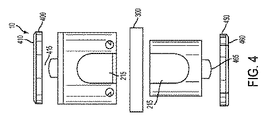
一側面では、本明細書に提示されるのは、頸部、胸郭、または腰椎の椎骨椎体切除術に続く、脊柱外科手術の際の使用のための拡張可能なVBRデバイス10である。VBRデバイスは、内側筐体100および外側筐体200を備える。内側筐体100および外側筐体200は、長手方向に相互に対して移動し、VBRデバイス10の高さを増加または減少させることができる。一例示的側面では、外側筐体は、内側筐体が非拡張位置で入れ子になることができる、内部空洞210を画定する。別の側面では、内側筐体100および外側筐体200はともに、限定ではないが、同種移植片、代替骨、または他の生体適合性骨成長助長材料を含む、骨移植片材料の留置のための移植片空洞215を画定する。
In one aspect, presented herein is an
VBRデバイスは、第1の非拡張位置から第2の完全拡張位置までの範囲、または実質的に、それらの間の任意の位置の範囲内で拡張されることができる。例示的側面では、外側筐体200の内部表面220が、歯状表面225を備える。歯状表面は、突起等の凸型、または陥凹等の凹型であることができる。一側面では、同様に、内側筐体100の外部表面110は、歯状表面125を備える。各歯は、カム表面130およびカム表面230と、平坦表面135および平坦表面235とを備えることができる。一側面では、歯状表面は、相補的に対向し、拡張方向において、外側筐体200上の歯225のカム表面230は、内側筐体100上の歯125のカム表面130と噛合し、後退方向において、外側筐体200上の歯230の平坦表面235は、内側筐体100上の歯125の平坦表面135に係合することを意味する。この関係は、2つの筐体が、歯止め様式で拡張方向に移動することを可能にするが、2つの筐体が後退方向に移動することを防止する。
The VBR device can be expanded within the range from the first non-expanded position to the second fully expanded position, or virtually any position between them. In the exemplary aspect, the
別の例示的側面では、各歯125および225は、平坦表面を伴わずに、2つのカム表面130および230を備えることができる。加えて、VBRデバイスは、内側筐体の歯状表面の少なくとも一部に係合し、内側筐体に対して外側筐体の長手方向の上下移動を防止するように構成された保持部材300を備えることができる。一側面では、保持部材は、内側筐体100の外部表面110の少なくとも一部分の周囲に水平に摺動するようにサイズ決定されるu字形部材であることができる。
In another exemplary aspect, each
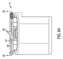
さらに別の例示的側面では、内側筐体は、歯状縁部165を有する窓160を画定してもよい。この側面では、ギヤ260が、内側筐体100の窓160の歯状縁部165に係合するように構成される外側筐体200上に位置付けられることができる。一側面では、内側筐体の外部表面110は、歯状表面125を備えてもよい。VBRデバイスはまた、内側筐体の外部表面に係合し、外側筐体に対して内側筐体の移動を制限するように構成される、保持部材300を備えることができる。保持部材は、少なくとも部分的に、内側筐体の周囲に巻着し、内側筐体の外部表面上の歯の少なくとも1つに係合するように構成されるcリングであることができる。
In yet another exemplary aspect, the inner housing may define a
保持部材300は、例えば、外側筐体200の内部表面220の歯状表面225にカム作用され、かつそれに相補的である、縁部310を有することができる。しかしながら、歯状表面は、概して、傾斜されるため、保持部材の縁部は、角度付けされる、傾斜される、またはカム作用される必要がない。また、保持部材の縁部310は、外側筐体200の内部表面220の歯状表面225の平坦部235を保持するために、実質的に平坦である上面表面315を有することが想定される。さらに別の側面では、保持部材は、内側筐体の一部に取り外し可能に取着されることができる。図20に例証されるように、内側筐体100の上部140は、トング部145を備えることができ、保持部材300の縁部310は、対応する溝320を備え、保持部材が、内側筐体の上部の位置に摺動することを可能にすることができる。この側面では、保持部材が内側筐体と係合して位置付けられるとき、外側筐体は、依然として、拡張位置に向かって上方向に歯止めで動かすことが可能でありながら、非拡張位置に向かって下方に後退することが防止される。保持部材が、内側筐体との係合から移動されるとき、外側筐体は、したがって、実質的に妨げられない、いずれかの方向に移動することができる。
The retaining
例示的側面では、VBRデバイスは、上側骨接触部材400および下側骨接触部材450を備える。上側骨接触部材400は、第1の椎骨の下部と接触のために構成される上側骨接触表面410を有する。下側骨接触部材450は、第2の椎骨の上部と接触のために構成される下側骨接触表面460を有する。上側骨接触部材および下側骨接触部材の一方または両方は、実質的に平面状であることができる。一側面では、上側骨接触部材は、外側筐体の上部240の一部に枢動可能に接続されることができる。枢動点415は、例えば、実質的に、上側骨接触部材の中心にあり、上側骨接触部材が、前方向または後方向のいずれかに角形成することを可能にすることができる。本機能は、VBRデバイスが、患者の解剖学的構造に適応することを可能にする。認識されることができるように、下側骨接触部材450は、内側筐体100の底部150の一部に枢動可能に接続されることができる。枢動点465は、例えば、実質的に、下側骨接触部材450の中心にあり、下側骨接触部材が、前方向または後方向のいずれかに角形成することを可能にすることができる。
In an exemplary aspect, the VBR device comprises an upper
さらに別の側面では、VBRデバイスは、内側スリーブ500および外側スリーブ550を備え、外側スリーブおよび内側スリーブは、後退位置から拡張位置まで相互に対して長手方向に移動するように構成される。内側スリーブおよび外側スリーブは、内部空洞555を画定する。例示的側面では、外側スリーブ550の内部表面560は、歯状表面565を備える。一側面では、内側スリーブ500の外部表面510は、同様に、歯状表面515を備える。各歯は、カム表面516およびカム表面566と、平坦表面517および平坦表面567とを備えることができる。一側面では、歯状表面は、相補的に対向し、拡張方向において、外側スリーブ上の歯のカム表面は、内側スリーブ上の歯のカム表面と噛合し、後退方向において、外側スリーブ上の歯の平坦表面は、内側スリーブ上の歯の平坦表面に係合することを意味する。この関係は、2つのスリーブが、歯止め様式で拡張方向に移動することを可能にするが、2つのスリーブが後退方向に移動することを防止する。当業者が認識することができるように、相補的歯状表面の代わりに、内側スリーブおよび外側スリーブは、一方の歯状表面を備え、他方の表面上に相補的陥凹520を画定することができ、ここで、陥凹520は、他方の表面の歯の平坦表面567を相補する、平坦な内部縁部522を有する。
In yet another aspect, the VBR device comprises an
この側面では、上側骨接触部材は、外側スリーブの上部580に蝶着取着されることができ、下側骨接触部材は、内側スリーブの下部530に蝶着取着されることができる。この構成は、隣接椎体を相補するために骨接触部材の角形成を可能にする。例示的側面では、内側スリーブおよび外側スリーブは、相互に中に入れ子になり、支柱窓570を画定する。この側面では、VBRデバイスは、支柱窓570を介して内部空洞の中に留置される、内部空洞555内に嵌合するように構成される支柱20を備える。例示的側面では、支柱の上部21が、角度付けされ、支柱22の底部もまた、角度付けされる。支柱の上部21は、上側骨接触部材400の一部に係合し、支柱の上部の角度は、前湾のための所望の角度に上側骨接触部材を留置する。同様に、支柱の底部22は、下側骨接触部材450の一部に係合し、支柱の下部の角度は、前湾のための所望の角度に下側骨接触部材を設置する。支柱は、当然ながら、実質的に、VBRデバイスが拡張位置から後退位置まで移動することを防止する。
In this aspect, the upper bone contacting member can be hingedly attached to the upper portion 580 of the outer sleeve and the lower bone contacting member can be hingedly attached to the lower portion 530 of the inner sleeve. This configuration allows angulation of the bone contact member to complement the adjacent vertebral bodies. In an exemplary aspect, the inner and outer sleeves nest within one another and define a post window 570. In this aspect, the VBR device comprises a
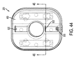
上側骨接触部材400および下側骨接触部材450の一方または両方は、スパイク600または突起部を備え、それぞれの椎骨との係合を促進することができる。スパイクは、それぞれの上側骨接触部材または下側骨接触部材と統合することができるか、またはディスク空間の中に挿入の後に展開されることができる。一例示的側面では、図42に例証されるように、それぞれの骨接触部材は、スパイク空洞620と連通する少なくとも1つのスパイク開口610を画定することができる。スパイクは、実質的かつ完全に、スパイク空洞620のその中に嵌合するようにサイズ決定されることができる。一側面では、傾斜部材630が、部分的に、スパイク空洞620と同軸であるオリフィス635を画定する骨接触部材内に画定される、チャネル650内に位置付けられることができる。オリフィスおよびスパイクの縁部は、相補的カム640およびフォロア645を備え、傾斜部材630が、第1の方向に移動されるとき、スパイクは、傾斜部材に沿って乗り上げ、それを持ち上げ、スパイクの遠位部を骨接触部材の骨接触表面の上方に延在させるように表面に出る。当然ながら、スパイクは、複数のスパイクを備えることができ、スパイク空洞は、複数のスパイク空洞を備えることができることが想定される。加えて、傾斜部材は、複数の傾斜部材を備えることができる。各傾斜部材は、図42に例証されるように、それぞれ、スパイクおよびスパイク空洞に対応する、複数のオリフィスを画定してもよい。
One or both of the superior
別の側面では、スパイク600は、ニチノールまたはばね鋼鉄等の可撓性材料を備えることができる。この側面では、スパイクは、それぞれの骨接触表面に実質的に平行である平面内のそれぞれの骨接触部材内のチャネル650内に最初に埋め込まれることができる。スパイク開口610のそれぞれは、可撓性があるスパイクが、スパイク開口に向かって移動されるとき、スパイクが、スパイク開口の上方に、かつそれを通して角度付けするであろうように、骨接触部材の傾斜または角度付けされた部分655と関連付けられることができる。
In another aspect, the
一例示的側面では、骨接触部材の一方または両方は、角度位置に係止され、実質的に、それぞれの骨接触部材が、それぞれの内側筐体または外側筐体に対して枢動することを拘止することができる。一側面では、図25に示されるように、それぞれの骨接触部材は、骨接触部材400および骨接触部材450の第2の表面420および第2の表面470上に位置付けられるブレード700を備え、これは、骨接触表面に対向し、第2の表面に実質的に垂直であることができる。この側面では、どの骨接触部材が議論されているかに応じて、外側筐体の上側または内側筐体の底側は、ブレード700の受容のために構成されたブレードスロット710を画定することができる。それぞれの筐体はまた、ねじ山付き開口720内に嵌合するように適合される止めねじ730の受容のために構成されたねじ山付き開口720を画定し、ブレード700の一部に係合し、実質的に、それぞれの筐体に対してその位置に固定することができる。図に示されるように、ブレードは、止めねじの端部がそれぞれの骨接触部材を角度位置に保持することを補助するために係合し得る、複数のブレード開口を画定することができる。
In one exemplary aspect, one or both of the bone contacting members are locked in an angular position, substantially pivoting each bone contacting member relative to the respective inner or outer housing. You can hold him. In one aspect, as shown in FIG. 25, each bone contacting member comprises a
別の側面では、図32aに示されるように、それぞれの骨接触部材は、外側筐体の上面表面240(または内側筐体の底側表面)に画定されるそれぞれの溝部810内に嵌合するように構成される、少なくとも1つの伸長枢動部材800を備えることができる。伸長枢動部材800は、実質的に円筒状の形状を備えることができるが、他の形状も想定される。一側面では、少なくとも、伸長枢動部材の遠位端805が、隆起および/または陥凹パターン820を画定することができる。この側面では、溝部810の一部は、相補的にパターン化された隆起および/または陥凹区分825を画定する。一側面では、パターンは、図32aに示されるように、星形であるが、他の相補的パターンも想定される。この側面では、溝部のパターン化された部分と係合する枢動部材の遠位端を押勢することは、それぞれの筐体に対して骨接触部材の角度を固定する。例えば、止めねじ830が、図37に示されるように、溝部のパターン化された部分と係合する枢動部材を押勢するために、使用されてもよい。
In another aspect, as shown in FIG. 32a, each bone contacting member fits within a
さらに別の側面では、それぞれの骨接触部材は、骨接触部材とそれぞれの筐体との間の空間内において、楔合部材900の挿入によって、角度位置に係止することができる。図20は、上側骨接触部材と外側筐体との間の楔合部材と、下側骨接触部材と内側筐体との間の別の楔合部材とを示す。楔合部材は、所望の角度を達成するために、種々の方法で構成されることができる。一側面では、楔合部材は、ねじ等の固定デバイスでVBRに固定されることができる。
In yet another aspect, each bone contacting member can be locked in an angular position by insertion of the
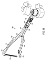
VBRデバイスおよびVBR拡張ツール1000を備える、システムが提示される。一例示的側面では、VBR拡張ツール1000は、平準化部材1200に結合される、作動部材1100を備える。作動部材は、対向する第2のハンドル1120に蝶着に結合される第1のハンドル1110を備える。第1のハンドルは、人の手および遠位端1114によってそれらの間に蝶着点1130を伴って保持されるように構成される近位端1112を備える。第2のハンドル1120もまた、人の手および遠位端1124によってそれらの間に蝶着点1130を伴って保持されるように構成される近位端1122を備える。作動部材は、ハンドルの近位端がそれらの最大分離位置であり、ハンドルの遠位端が実質的にその最近接位置である第1の位置から、ハンドルの近位端が相互に向かって圧縮され、ハンドルの遠位端が分離される第2の位置まで、移動するように構成される。VBR拡張ツールはまた、他のハンドル上に位置付けられるキャッチ機構1145に係合するように構成される第1のハンドルまたは第2のハンドルのうちの1つの近位端に蝶着接続される、圧縮保持部材1140を備えることができる。圧縮保持部材は、キャッチ機構と係合されるとき、実質的に、圧力を第1のハンドルおよび第2のハンドル上に維持する。
A system is presented comprising a VBR device and a
VBR拡張ツールについて継続し、平準化部材1200は、上側平準化部材1210および下側平準化部材1220を備え、2つの平準化部材は、剪刀部材1250によって分離かつ接続される。剪刀部材は、第1の剪刀アーム1260および第2の剪刀アーム1270を備える。一般的剪刀と同様に、剪刀アーム1260および剪刀アーム1270は、実質的に、それらの中間区分1280にピン留めされる。第1の剪刀アーム1260の近位端1262は、上側平準化部材1210の近位端1212にピン留めされ、第1の剪刀アームの遠位端1264は、摺動関係において、下側平準化部材内に画定される伸長スロット1218に係合するように構成される、第1のピン1266を備える。同様に、第2の剪刀アーム1270の近位端1272は、下側平準化部材1220の近位端1222にピン留めされ、第2の剪刀アームの遠位端1274は、摺動関係において、上側平準化部材内に画定される伸長スロット1216に係合するように構成される、第2のピン1276を備える。この方式では、上側平準化部材の近位端が下側平準化部材の近位端から分離されるにつれて、上側平準化部材の遠位端もまた、下側平準化部材の遠位端から高められ、かつ等しく分離される。認識されることができるように、平準化部材に対するアームの関係は、類似する結果を伴って逆転され得る。
Continuing with the VBR expansion tool, the leveling
図69に例証されるように、第1のハンドル1114の遠位端は、上側平準化部材の近位端1214に蝶着接続されることができ、第2のハンドルの遠位端1124は、下側平準化部材の近位端1222に蝶着接続されることができる。加えて、上側平準化部材および下側平準化部材の遠位端は、フォーク1300を備え、拡張可能なVBRデバイスの部分に係合することができる。使用時、第1の位置から第2の位置までの作動部材のハンドルの圧縮は、相互に実質的に隣接する位置から分離位置まで平準化部材を移動させる。そうすることによって、フォークが内側筐体および外側筐体の部分と係合されるとき、拡張可能VBRデバイスは、非拡張位置から拡張位置まで移動する。
As illustrated in FIG. 69, the distal end of the
拡張可能なVBRを椎体切除術欠陥の中に留置し、VBR拡張ツールを使用して本デバイスの高さを拡張する方法が、提示される。本方法は、所望の運動区画にアクセスするステップと、所望の椎体を除去するステップと、除去された椎体の代わりに拡張可能なVBRデバイスを位置付けるステップと、拡張可能なVBRデバイスを拡張するステップと、拡張可能なVBRデバイスを拡張位置に固定するステップとを備える。本方法はまた、上側骨接触部材および/または下側骨接触部材の前湾角度を固定するステップを備えることができる。別の側面では、本方法はまた、移植片空洞を骨成長助長材料で詰めるステップを含む。 A method is presented for placing an expandable VBR into a vertebroplasty defect and expanding the height of the device using a VBR expansion tool. The method comprises the steps of accessing a desired motion area, removing the desired vertebral body, positioning the expandable VBR device in place of the removed vertebral body, and expanding the expandable VBR device Securing the expandable VBR device in the expanded position. The method may also comprise the step of fixing the anterior angulation angle of the upper and / or lower bone contact members. In another aspect, the method also includes the step of stuffing the graft cavity with a bone growth promoting material.
本発明のいくつかの側面が、前述の明細書に開示されたが、本発明の多くの修正および他の側面が、前述の説明および関連付けられた図面に提示される教示の利益を有する当業者に想起されるであろうことが、当業者によって理解される。したがって、本発明は、本明細書に前述で開示される具体的側面に限定されず、多くの修正および他の側面が、添付の請求項の範囲内に含まれることが意図されることを理解されたい。さらに、具体的用語が、本明細書ならびに以下の請求項で採用されるが、それらは、説明される発明を限定する目的のためではなく、一般的かつ説明的意味でのみ使用される。 Although several aspects of the present invention have been disclosed in the foregoing specification, many modifications and other aspects of the present invention will be apparent to those skilled in the art having the benefit of the teachings presented in the foregoing description and the associated drawings. It will be understood by those skilled in the art that will be recalled. Thus, it is understood that the present invention is not limited to the specific aspects disclosed herein above, but that many modifications and other aspects are intended to be included within the scope of the appended claims. I want to be Furthermore, although specific terms are employed herein and in the following claims, they are used for their general and descriptive sense only and not for the purpose of limiting the described invention.
Claims (31)
内部空洞を画定し、内部歯状表面を有する第1の筐体と、
外部表面を有し、前記第1の筐体の前記内部空洞の少なくとも一部の中に入れ子になる第2の筐体であって、前記第2の筐体は、前記椎体置換デバイスの高さを増加させるように、長手方向に沿って前記第1の筐体に対して移動可能であり、前記第2の筐体の前記外部表面は、前記第1の筐体の前記内部表面と係合可能である、第2の筐体と、
前記第2の筐体の一部と取り外し可能に係合可能な保持部材であって、前記保持部材は、前記椎体置換デバイスの拡張を可能にしながら、前記椎体置換デバイスの収縮を防止するように構成されており、前記保持部材は、前記第1の筐体の前記内部歯状表面にカム作用されかつ前記内部歯状表面に相補的である少なくとも1つの外側縁部を画定する、保持部材と、
第1の骨接触表面を有する第1の骨接触部材と、
第2の骨接触表面を有する第2の骨接触部材と
を備える、椎体置換デバイス。 A vertebral body replacement device,
Defining an internal cavity, a first housing to have a inner-toothed surface,
Having an external surface, and at least a portion the second housing to be nested within the interior cavity of the first housing, the second housing, high of the vertebral body replacement device Movable with respect to the first housing along a longitudinal direction, the outer surface of the second housing being engaged with the inner surface of the first housing so as to increase A second housing, which is
A retention member releasably engageable with a portion of the second housing, the retention member preventing contraction of the vertebral body replacement device while allowing expansion of the vertebral body replacement device Configured so that the retaining member defines at least one outer edge cammed to the internal toothed surface of the first housing and complementary to the internal toothed surface Members,
A first bone contacting member having a first bone contacting surface;
And a second bone contacting member having a second bone contacting surface.
内部空洞を画定し、歯状表面を備える内部表面を有する第1のスリーブと、
前記第1のスリーブの前記歯状表面に相補的である外部表面を有する第2のスリーブと、
前記第2のスリーブの一部と取り外し可能に係合可能な保持部材であって、前記保持部材は、前記椎体置換デバイスの拡張を可能にしながら、前記椎体置換デバイスの収縮を防止し、前記保持部材は、前記第1のスリーブの前記歯状表面にカム作用されかつ前記歯状表面に相補的である少なくとも1つの外側縁部を画定する、保持部材と
を備え、前記第1のスリーブおよび第2のスリーブは、後退位置から拡張位置まで相互に対して長手方向に移動するように構成される、椎体置換デバイス。 A vertebral body replacement device,
A first sleeve defining an internal cavity and having an internal surface comprising a tooth-like surface;
A second sleeve having an outer surface that is complementary to the toothed surface of the first sleeve ;
A retaining member removably engageable with a portion of the second sleeve, the retaining member preventing contraction of the vertebral body replacement device while allowing expansion of the vertebral body replacement device; Said holding member comprising: a holding member which is cammed on said toothed surface of said first sleeve and which defines at least one outer edge complementary to said toothed surface ; first sleeve and the second sleeve, Ru is configured to move longitudinally relative to one another from a retracted position to an extended position, a vertebral body replacement device.
内部空洞を画定し、内部歯状表面を有する、外側筐体と、
前記外側筐体の前記内部空洞の少なくとも一部の中に入れ子になる内側筐体であって、前記内側筐体は、前記椎体置換デバイスの高さを増加させるように、長手方向に沿って移動可能である、内側筐体と、
前記内側筐体の一部と取り外し可能に係合可能である保持部材であって、前記保持部材は、前記外側筐体の前記内部歯状表面にカム作用されかつ前記内部歯状表面に相補的である少なくとも1つの外側縁部を画定し、前記保持部材は、前記内側筐体と係合して位置付けられるとき、前記椎体置換デバイスの収縮を防止しながら、前記椎体置換デバイスの拡張を可能にする、保持部材と、
上側骨接触表面を有する上側骨接触部材と、
下側骨接触表面を有する下側骨接触部材と
を備える、椎体置換デバイス。 A vertebral body replacement device,
An outer housing defining an inner cavity and having an inner toothed surface;
An inner housing is nested within at least a portion of said interior cavity of said outer housing, said inner housing, so that increasing the height of the vertebral body replacement device, along the longitudinal direction Ru movable der, an inner housing,
A holding member portion removably engageable in said inner housing, wherein the holding member is complementary to the outer to the inner tooth-shaped surface of the housing One or cammed the internal tooth-shaped surface manner even without least a defining one outer edge, wherein the retaining member, when positioned in engagement with said inner housing, while preventing the shrinkage of the vertebral body replacement device, the vertebral body replacement device A holding member, which enables the expansion of the
An upper bone contacting member having an upper bone contacting surface;
And a lower bone contacting member having a lower bone contacting surface.
拡張可能な椎体置換デバイスであって、
内部空洞を画定し、内部歯状表面を有する、外側筐体と、
前記外側筐体の前記内部空洞の少なくとも一部の中に入れ子になる内側筐体であって、前記内側筐体は、前記拡張可能な椎体置換デバイスの高さを増加させるように、長手方向に沿って移動可能である、内側筐体と、
前記内側筐体の一部と取り外し可能に係合可能である保持部材であって、前記保持部材は、前記外側筐体の前記内部歯状表面にカム作用されかつ前記内部歯状表面に相補的である少なくとも1つの外側縁部を画定し、前記保持部材は、前記内側筐体と係合して位置付けられるとき、前記拡張可能な椎体置換デバイスの収縮を防止しながら、前記椎体置換デバイスの拡張を可能にする、保持部材と、
上側骨接触表面を有する上側骨接触部材と、
下側骨接触表面を有する下側骨接触部材と、
を備える、拡張可能な椎体置換デバイスと、
椎体置換拡張ツールと
を備える、システム。 A system for replacing a vertebral body, said system comprising
An expandable vertebral body replacement device,
An outer housing defining an inner cavity and having an inner toothed surface;
Wherein an inner housing is nested within at least a portion of the interior cavity of the outer housing, said inner housing, so as to increase the height of the expandable vertebral body replacement device, longitudinal Ru movable der along an inner housing,
A holding member portion removably engageable in said inner housing, wherein the holding member is complementary to the outer to the inner tooth-shaped surface of the housing One or cammed the internal tooth-shaped surface manner der Ru defines at least one outer edge, wherein the retaining member, when positioned in engagement with said inner housing, while preventing the shrinkage of the expandable vertebral body replacement device, the vertebral bodies A retaining member, which allows the expansion of the replacement device;
An upper bone contacting member having an upper bone contacting surface;
A lower bone contacting member having a lower bone contacting surface;
And a expandable vertebral body replacement device,
And a vertebral body replacement and expansion tool.
第1のハンドルおよび対向する第2のハンドルを有する作動部材であって、前記第1のハンドルおよび第2のハンドルは、蝶着点において蝶着結合され、前記蝶着点は、前記第1のハンドルおよび第2のハンドルのそれぞれの近位端と遠位端との間に位置付けられる、作動部材と、
前記作動部材に結合される平準化部材であって、前記平準化部材は、上側平準化部材および下側平準化部材を有し、前記上側平準化部材および下側平準化部材は、剪刀部材によって分離かつ接続され、前記剪刀部材は、実質的に、それらの中間区分にピン留めされる、第1の剪刀アームおよび第2の剪刀アームを備え、前記第1の剪刀アームの近位端は、前記上側平準化部材の近位端にピン留めされ、前記第1の剪刀アームの遠位端は、摺動関係において、前記下側平準化部材内に画定される伸長スロットに係合するように構成されるピンを備え、前記第2の剪刀アームの近位端は、前記下側平準化部材の近位端にピン留めされ、前記第2の剪刀アームの遠位端は、前記上側平準化部材の近位端が前記下側平準化部材の近位端から分離されるにつれて、前記上側平準化部材の遠位端もまた、前記下側平準化部材の遠位端から高められ、かつ等しく分離されるように、摺動関係において、前記上側平準化部材内に画定される伸長スロットに係合するように構成されるピンを備える、平準化部材と
を備える、請求項28に記載のシステム。 The vertebral body replacement and expansion tool is
An actuating member having a first handle and an opposing second handle, the first handle and the second handle being hingedly connected at a hinge point, the hinge point being the first An actuation member positioned between the proximal end and the distal end of each of the handle and the second handle;
A leveling member coupled to the actuating member, the leveling member having an upper leveling member and a lower leveling member, the upper leveling member and the lower leveling member by a scissoring member Separated and connected, the scissor members comprise a first scissoring arm and a second scissoring arm substantially pinned to their middle section, the proximal end of the first scissoring arm being Pinned to the proximal end of the upper leveling member, the distal end of the first scissors arm is in sliding relation to engage an elongated slot defined in the lower leveling member A proximal end of the second scissoring arm is pinned to a proximal end of the lower leveling member, and a distal end of the second scissoring arm is the upper leveling The proximal end of the member is separated from the proximal end of the lower leveling member And the distal end of the upper leveling member is also defined in the upper leveling member in sliding relationship so as to be elevated and equally separated from the distal end of the lower leveling member 29. A system according to claim 28, comprising a leveling member comprising a pin configured to engage in the elongated slot.
Applications Claiming Priority (7)
| Application Number | Priority Date | Filing Date | Title |
|---|---|---|---|
| US201361802360P | 2013-03-15 | 2013-03-15 | |
| US61/802,360 | 2013-03-15 | ||
| PCT/US2014/030848 WO2014145982A1 (en) | 2013-03-15 | 2014-03-17 | Expandable vertebral body replacement device, system, and methods |
| US14/216,513 | 2014-03-17 | ||
| US14/216,893 US20140277510A1 (en) | 2013-03-15 | 2014-03-17 | Expandable vertebral body replacement device, system, and methods |
| US14/216,893 | 2014-03-17 | ||
| US14/216,513 US20140277509A1 (en) | 2013-03-15 | 2014-03-17 | Expandable vertebral body replacement and methods |
Publications (3)
| Publication Number | Publication Date |
|---|---|
| JP2016512730A JP2016512730A (en) | 2016-05-09 |
| JP2016512730A5 JP2016512730A5 (en) | 2017-03-23 |
| JP6524061B2 true JP6524061B2 (en) | 2019-06-05 |
Family
ID=51531338
Family Applications (1)
| Application Number | Title | Priority Date | Filing Date |
|---|---|---|---|
| JP2016502569A Active JP6524061B2 (en) | 2013-03-15 | 2014-03-17 | Expandable vertebral body replacement device, system and method |
Country Status (3)
| Country | Link |
|---|---|
| US (2) | US20140277510A1 (en) |
| JP (1) | JP6524061B2 (en) |
| WO (1) | WO2014145982A1 (en) |
Families Citing this family (26)
| Publication number | Priority date | Publication date | Assignee | Title |
|---|---|---|---|---|
| US8597360B2 (en) | 2004-11-03 | 2013-12-03 | Neuropro Technologies, Inc. | Bone fusion device |
| US10420654B2 (en) | 2011-08-09 | 2019-09-24 | Neuropro Technologies, Inc. | Bone fusion device, system and method |
| WO2013023098A1 (en) | 2011-08-09 | 2013-02-14 | Neuropro Spinal Jaxx Inc. | Bone fusion device, apparatus and method |
| US10292830B2 (en) | 2011-08-09 | 2019-05-21 | Neuropro Technologies, Inc. | Bone fusion device, system and method |
| US9532883B2 (en) | 2012-04-13 | 2017-01-03 | Neuropro Technologies, Inc. | Bone fusion device |
| US10159583B2 (en) * | 2012-04-13 | 2018-12-25 | Neuropro Technologies, Inc. | Bone fusion device |
| CA2906531C (en) | 2013-03-15 | 2020-10-06 | Neuropro Technologies, Inc. | Bodiless bone fusion device, apparatus and method |
| EP2967899B1 (en) * | 2013-03-15 | 2022-04-20 | Spectrum Spine IP Holdings, LLC | Expandable vertebral body replacement device |
| US9974663B2 (en) * | 2014-10-09 | 2018-05-22 | Warsaw Orthopedic, Inc. | Spinal implant system and method |
| US11452612B2 (en) * | 2014-10-09 | 2022-09-27 | Warsaw Orthopedic, Inc. | Spinal implant system and method |
| US9561113B2 (en) * | 2014-12-23 | 2017-02-07 | Globus Medical, Inc. | Vertebral implants and methods for installation thereof |
| JP6643364B2 (en) | 2015-06-25 | 2020-02-12 | インスティテュート フォー マスキュロスケレタル サイエンス アンド エジュケイション,リミテッド | Interbody fusion device and system for implantation |
| ES2718060T3 (en) * | 2015-09-08 | 2019-06-27 | Ulrich Gmbh & Co Kg | Implant |
| US10327908B2 (en) | 2015-09-18 | 2019-06-25 | K2M, Inc. | Corpectomy device and methods of use thereof |
| AU2016381191B2 (en) | 2015-12-30 | 2021-05-20 | Nuvasive, Inc. | Lordotic expandable fusion implant |
| US10537434B2 (en) | 2016-08-08 | 2020-01-21 | Wu Jau Ching | Intervertebral implant |
| US10307265B2 (en) | 2016-10-18 | 2019-06-04 | Institute for Musculoskeletal Science and Education, Ltd. | Implant with deployable blades |
| US10405992B2 (en) | 2016-10-25 | 2019-09-10 | Institute for Musculoskeletal Science and Education, Ltd. | Spinal fusion implant |
| US10973657B2 (en) | 2017-01-18 | 2021-04-13 | Neuropro Technologies, Inc. | Bone fusion surgical system and method |
| US10729560B2 (en) | 2017-01-18 | 2020-08-04 | Neuropro Technologies, Inc. | Bone fusion system, device and method including an insertion instrument |
| US10213321B2 (en) | 2017-01-18 | 2019-02-26 | Neuropro Technologies, Inc. | Bone fusion system, device and method including delivery apparatus |
| US10111760B2 (en) * | 2017-01-18 | 2018-10-30 | Neuropro Technologies, Inc. | Bone fusion system, device and method including a measuring mechanism |
| US11135070B2 (en) * | 2018-02-14 | 2021-10-05 | Titan Spine, Inc. | Modular adjustable corpectomy cage |
| JP2021535780A (en) * | 2018-09-05 | 2021-12-23 | ウォーソー・オーソペディック・インコーポレーテッド | Spinal implant system and method |
| US11458024B2 (en) | 2021-02-02 | 2022-10-04 | Bret Michael Berry | Expandable implant |
| US20230075024A1 (en) * | 2021-09-09 | 2023-03-09 | Warsaw Orthopedic, Inc. | End cap and bone screw for use therewith |
Family Cites Families (24)
| Publication number | Priority date | Publication date | Assignee | Title |
|---|---|---|---|---|
| ES2182055T3 (en) * | 1997-04-15 | 2003-03-01 | Synthes Ag | TELESCOPIC VERTEBRA PROTESIS. |
| US6527803B1 (en) * | 1998-06-23 | 2003-03-04 | Dimso (Distribution Medicale Du Sud-Ouest) | Intersomatic spine implant having anchoring elements |
| ES2222608T3 (en) | 1998-10-15 | 2005-02-01 | Synthes Ag Chur | TELESCOPIC VERTEBRAL PROTESIS. |
| US6648917B2 (en) | 2001-10-17 | 2003-11-18 | Medicinelodge, Inc. | Adjustable bone fusion implant and method |
| US6808538B2 (en) * | 2002-03-15 | 2004-10-26 | Stryker Spine | Vertebral body spacer having variable wedged endplates |
| US6783547B2 (en) * | 2002-04-05 | 2004-08-31 | Howmedica Corp. | Apparatus for fusing adjacent bone structures |
| FR2850563B1 (en) * | 2003-02-05 | 2005-11-04 | Scient X | VERTEBRAL REPLACEMENT IMPLANT AND DISTRACTION APPARATUS FOR IMPLANT PLACEMENT |
| US7094257B2 (en) | 2003-02-14 | 2006-08-22 | Zimmer Spine, Inc. | Expandable intervertebral implant cage |
| US7918876B2 (en) | 2003-03-24 | 2011-04-05 | Theken Spine, Llc | Spinal implant adjustment device |
| US7544208B1 (en) | 2004-05-03 | 2009-06-09 | Theken Spine, Llc | Adjustable corpectomy apparatus |
| US20060095136A1 (en) * | 2004-11-03 | 2006-05-04 | Mcluen Design, Inc. | Bone fusion device |
| US7758648B2 (en) | 2006-04-27 | 2010-07-20 | Warsaw Orthopedic, Inc. | Stabilized, adjustable expandable implant and method |
| US7914581B2 (en) | 2006-04-27 | 2011-03-29 | Warsaw Orthopedic, Inc. | Expandable implant, instrument, and method |
| US7879096B2 (en) | 2006-04-27 | 2011-02-01 | Warsaw Orthopedic, Inc. | Centrally driven expandable implant |
| US20080288071A1 (en) | 2006-05-16 | 2008-11-20 | Ashok Biyani | Expandable corpectomy device |
| US7815683B2 (en) | 2006-10-16 | 2010-10-19 | Warsaw Orthopedic, Inc. | Implants with helical supports and methods of use for spacing vertebral members |
| US8062366B2 (en) | 2007-01-08 | 2011-11-22 | Warsaw Orthopedic, Inc. | Ratcheting expandable corpectomy/vertebrectomy cage |
| US8197546B2 (en) | 2007-11-27 | 2012-06-12 | Ortho Innovations, Llc | Corpectomy implant |
| US8241363B2 (en) * | 2007-12-19 | 2012-08-14 | Depuy Spine, Inc. | Expandable corpectomy spinal fusion cage |
| EP2268219B1 (en) | 2008-03-28 | 2016-11-09 | K2M, Inc. | Expandable cage |
| US8177846B2 (en) * | 2009-10-22 | 2012-05-15 | Warsaw Orthopedic, Inc. | End cap for a vertebral implant |
| US8932357B2 (en) * | 2010-10-13 | 2015-01-13 | DePuy Synthes Products, LLC | Intervertebral implant |
| US20120109307A1 (en) * | 2010-10-29 | 2012-05-03 | Wasaw Orthopedic, Inc. | Vertebral implant end cap |
| US9283086B2 (en) | 2011-03-03 | 2016-03-15 | Life Spine, Inc. | Expandable corpectomy cage |
-
2014
- 2014-03-17 US US14/216,893 patent/US20140277510A1/en not_active Abandoned
- 2014-03-17 WO PCT/US2014/030848 patent/WO2014145982A1/en active Application Filing
- 2014-03-17 JP JP2016502569A patent/JP6524061B2/en active Active
-
2015
- 2015-08-20 US US14/830,869 patent/US9724208B2/en active Active
Also Published As
| Publication number | Publication date |
|---|---|
| US20160045327A1 (en) | 2016-02-18 |
| US20140277510A1 (en) | 2014-09-18 |
| JP2016512730A (en) | 2016-05-09 |
| US9724208B2 (en) | 2017-08-08 |
| WO2014145982A1 (en) | 2014-09-18 |
Similar Documents
| Publication | Publication Date | Title |
|---|---|---|
| JP6524061B2 (en) | Expandable vertebral body replacement device, system and method | |
| EP2967899B1 (en) | Expandable vertebral body replacement device | |
| US11033404B2 (en) | Stabilized expandable intervertebral spacer | |
| US10278832B2 (en) | Adjustable interbody fusion devices and methods of use | |
| JP7451411B2 (en) | Intervertebral cage with integrated expansion and angle adjustment mechanism | |
| US10864086B2 (en) | Expandable intervertebral spacer and method of posterior insertion thereof | |
| EP2849686B1 (en) | Articulating interbody cage | |
| US10369004B2 (en) | Expandable intervertebralspacer | |
| AU2006230068B2 (en) | Spinal system and method including lateral approach | |
| US8394145B2 (en) | Expandable intervertebral spacer and method of posterior insertion thereof | |
| US20160007983A1 (en) | Configurable Intervertebral Implant | |
| US20060142858A1 (en) | Expandable implants for spinal disc replacement | |
| WO2006105068A1 (en) | Spinal device including lateral approach | |
| JP2016512730A5 (en) |
Legal Events
| Date | Code | Title | Description |
|---|---|---|---|
| A521 | Request for written amendment filed |
Free format text: JAPANESE INTERMEDIATE CODE: A523 Effective date: 20170215 |
|
| A621 | Written request for application examination |
Free format text: JAPANESE INTERMEDIATE CODE: A621 Effective date: 20170215 |
|
| A131 | Notification of reasons for refusal |
Free format text: JAPANESE INTERMEDIATE CODE: A131 Effective date: 20171227 |
|
| A977 | Report on retrieval |
Free format text: JAPANESE INTERMEDIATE CODE: A971007 Effective date: 20171227 |
|
| A601 | Written request for extension of time |
Free format text: JAPANESE INTERMEDIATE CODE: A601 Effective date: 20180326 |
|
| A601 | Written request for extension of time |
Free format text: JAPANESE INTERMEDIATE CODE: A601 Effective date: 20180525 |
|
| A521 | Request for written amendment filed |
Free format text: JAPANESE INTERMEDIATE CODE: A523 Effective date: 20180625 |
|
| A131 | Notification of reasons for refusal |
Free format text: JAPANESE INTERMEDIATE CODE: A131 Effective date: 20181018 |
|
| TRDD | Decision of grant or rejection written | ||
| A01 | Written decision to grant a patent or to grant a registration (utility model) |
Free format text: JAPANESE INTERMEDIATE CODE: A01 Effective date: 20190404 |
|
| A61 | First payment of annual fees (during grant procedure) |
Free format text: JAPANESE INTERMEDIATE CODE: A61 Effective date: 20190426 |
|
| R150 | Certificate of patent or registration of utility model |
Ref document number: 6524061 Country of ref document: JP Free format text: JAPANESE INTERMEDIATE CODE: R150 |
|
| R250 | Receipt of annual fees |
Free format text: JAPANESE INTERMEDIATE CODE: R250 |
|
| R250 | Receipt of annual fees |
Free format text: JAPANESE INTERMEDIATE CODE: R250 |