JP6523964B2 - Device and method for delivery of intravascular filters - Google Patents
Device and method for delivery of intravascular filters Download PDFInfo
- Publication number
- JP6523964B2 JP6523964B2 JP2015549406A JP2015549406A JP6523964B2 JP 6523964 B2 JP6523964 B2 JP 6523964B2 JP 2015549406 A JP2015549406 A JP 2015549406A JP 2015549406 A JP2015549406 A JP 2015549406A JP 6523964 B2 JP6523964 B2 JP 6523964B2
- Authority
- JP
- Japan
- Prior art keywords
- delivery device
- filter
- ivc
- struts
- sheath
- Prior art date
- Legal status (The legal status is an assumption and is not a legal conclusion. Google has not performed a legal analysis and makes no representation as to the accuracy of the status listed.)
- Active
Links
- 238000000034 method Methods 0.000 title claims description 41
- 238000002608 intravascular ultrasound Methods 0.000 claims description 50
- 238000002604 ultrasonography Methods 0.000 claims description 25
- 210000004204 blood vessel Anatomy 0.000 claims description 16
- 238000003384 imaging method Methods 0.000 claims description 12
- 238000012546 transfer Methods 0.000 claims description 6
- 241000282414 Homo sapiens Species 0.000 claims 1
- 230000000717 retained effect Effects 0.000 claims 1
- 210000001631 vena cava inferior Anatomy 0.000 description 98
- 238000013461 design Methods 0.000 description 13
- 239000000463 material Substances 0.000 description 8
- 210000003462 vein Anatomy 0.000 description 8
- 208000007536 Thrombosis Diseases 0.000 description 7
- 230000006870 function Effects 0.000 description 7
- 239000012634 fragment Substances 0.000 description 5
- 210000004072 lung Anatomy 0.000 description 5
- 238000011084 recovery Methods 0.000 description 5
- 239000000919 ceramic Substances 0.000 description 4
- 238000002594 fluoroscopy Methods 0.000 description 4
- 230000033001 locomotion Effects 0.000 description 4
- 208000005189 Embolism Diseases 0.000 description 3
- 238000013459 approach Methods 0.000 description 3
- 206010051055 Deep vein thrombosis Diseases 0.000 description 2
- 208000010378 Pulmonary Embolism Diseases 0.000 description 2
- 206010047249 Venous thrombosis Diseases 0.000 description 2
- 230000008901 benefit Effects 0.000 description 2
- 230000017531 blood circulation Effects 0.000 description 2
- 230000008859 change Effects 0.000 description 2
- 238000002788 crimping Methods 0.000 description 2
- 229920002457 flexible plastic Polymers 0.000 description 2
- 230000006872 improvement Effects 0.000 description 2
- 208000014674 injury Diseases 0.000 description 2
- 238000012986 modification Methods 0.000 description 2
- 230000004048 modification Effects 0.000 description 2
- 210000004197 pelvis Anatomy 0.000 description 2
- 229910001220 stainless steel Inorganic materials 0.000 description 2
- 239000010935 stainless steel Substances 0.000 description 2
- 238000012285 ultrasound imaging Methods 0.000 description 2
- 238000012795 verification Methods 0.000 description 2
- 208000028399 Critical Illness Diseases 0.000 description 1
- 244000208734 Pisonia aculeata Species 0.000 description 1
- 239000004698 Polyethylene Substances 0.000 description 1
- 208000027418 Wounds and injury Diseases 0.000 description 1
- 210000001015 abdomen Anatomy 0.000 description 1
- 230000009471 action Effects 0.000 description 1
- 230000001580 bacterial effect Effects 0.000 description 1
- 239000000560 biocompatible material Substances 0.000 description 1
- 239000008280 blood Substances 0.000 description 1
- 210000004369 blood Anatomy 0.000 description 1
- 239000011248 coating agent Substances 0.000 description 1
- 238000000576 coating method Methods 0.000 description 1
- 238000012790 confirmation Methods 0.000 description 1
- 230000006378 damage Effects 0.000 description 1
- 238000002716 delivery method Methods 0.000 description 1
- 230000010339 dilation Effects 0.000 description 1
- 238000000605 extraction Methods 0.000 description 1
- 210000003191 femoral vein Anatomy 0.000 description 1
- 239000012530 fluid Substances 0.000 description 1
- 230000007774 longterm Effects 0.000 description 1
- 230000014759 maintenance of location Effects 0.000 description 1
- 238000004519 manufacturing process Methods 0.000 description 1
- HLXZNVUGXRDIFK-UHFFFAOYSA-N nickel titanium Chemical compound [Ti].[Ti].[Ti].[Ti].[Ti].[Ti].[Ti].[Ti].[Ti].[Ti].[Ti].[Ni].[Ni].[Ni].[Ni].[Ni].[Ni].[Ni].[Ni].[Ni].[Ni].[Ni].[Ni].[Ni].[Ni] HLXZNVUGXRDIFK-UHFFFAOYSA-N 0.000 description 1
- 229910001000 nickel titanium Inorganic materials 0.000 description 1
- -1 polyethylene Polymers 0.000 description 1
- 229920000573 polyethylene Polymers 0.000 description 1
- 230000002028 premature Effects 0.000 description 1
- 230000008569 process Effects 0.000 description 1
- 230000001737 promoting effect Effects 0.000 description 1
- 210000001147 pulmonary artery Anatomy 0.000 description 1
- 210000002796 renal vein Anatomy 0.000 description 1
- 238000007493 shaping process Methods 0.000 description 1
- 238000004513 sizing Methods 0.000 description 1
- 239000007787 solid Substances 0.000 description 1
- 230000002966 stenotic effect Effects 0.000 description 1
- 238000003860 storage Methods 0.000 description 1
- 239000013589 supplement Substances 0.000 description 1
- 238000001356 surgical procedure Methods 0.000 description 1
- 230000037317 transdermal delivery Effects 0.000 description 1
- 230000008733 trauma Effects 0.000 description 1
- 210000005166 vasculature Anatomy 0.000 description 1
- 230000000007 visual effect Effects 0.000 description 1
- 238000012800 visualization Methods 0.000 description 1
Images


Classifications
-
- A—HUMAN NECESSITIES
- A61—MEDICAL OR VETERINARY SCIENCE; HYGIENE
- A61F—FILTERS IMPLANTABLE INTO BLOOD VESSELS; PROSTHESES; DEVICES PROVIDING PATENCY TO, OR PREVENTING COLLAPSING OF, TUBULAR STRUCTURES OF THE BODY, e.g. STENTS; ORTHOPAEDIC, NURSING OR CONTRACEPTIVE DEVICES; FOMENTATION; TREATMENT OR PROTECTION OF EYES OR EARS; BANDAGES, DRESSINGS OR ABSORBENT PADS; FIRST-AID KITS
- A61F2/00—Filters implantable into blood vessels; Prostheses, i.e. artificial substitutes or replacements for parts of the body; Appliances for connecting them with the body; Devices providing patency to, or preventing collapsing of, tubular structures of the body, e.g. stents
- A61F2/01—Filters implantable into blood vessels
- A61F2/011—Instruments for their placement or removal
-
- A—HUMAN NECESSITIES
- A61—MEDICAL OR VETERINARY SCIENCE; HYGIENE
- A61F—FILTERS IMPLANTABLE INTO BLOOD VESSELS; PROSTHESES; DEVICES PROVIDING PATENCY TO, OR PREVENTING COLLAPSING OF, TUBULAR STRUCTURES OF THE BODY, e.g. STENTS; ORTHOPAEDIC, NURSING OR CONTRACEPTIVE DEVICES; FOMENTATION; TREATMENT OR PROTECTION OF EYES OR EARS; BANDAGES, DRESSINGS OR ABSORBENT PADS; FIRST-AID KITS
- A61F2/00—Filters implantable into blood vessels; Prostheses, i.e. artificial substitutes or replacements for parts of the body; Appliances for connecting them with the body; Devices providing patency to, or preventing collapsing of, tubular structures of the body, e.g. stents
- A61F2/01—Filters implantable into blood vessels
- A61F2/0105—Open ended, i.e. legs gathered only at one side
-
- A—HUMAN NECESSITIES
- A61—MEDICAL OR VETERINARY SCIENCE; HYGIENE
- A61F—FILTERS IMPLANTABLE INTO BLOOD VESSELS; PROSTHESES; DEVICES PROVIDING PATENCY TO, OR PREVENTING COLLAPSING OF, TUBULAR STRUCTURES OF THE BODY, e.g. STENTS; ORTHOPAEDIC, NURSING OR CONTRACEPTIVE DEVICES; FOMENTATION; TREATMENT OR PROTECTION OF EYES OR EARS; BANDAGES, DRESSINGS OR ABSORBENT PADS; FIRST-AID KITS
- A61F2/00—Filters implantable into blood vessels; Prostheses, i.e. artificial substitutes or replacements for parts of the body; Appliances for connecting them with the body; Devices providing patency to, or preventing collapsing of, tubular structures of the body, e.g. stents
- A61F2/01—Filters implantable into blood vessels
- A61F2002/016—Filters implantable into blood vessels made from wire-like elements
-
- A—HUMAN NECESSITIES
- A61—MEDICAL OR VETERINARY SCIENCE; HYGIENE
- A61F—FILTERS IMPLANTABLE INTO BLOOD VESSELS; PROSTHESES; DEVICES PROVIDING PATENCY TO, OR PREVENTING COLLAPSING OF, TUBULAR STRUCTURES OF THE BODY, e.g. STENTS; ORTHOPAEDIC, NURSING OR CONTRACEPTIVE DEVICES; FOMENTATION; TREATMENT OR PROTECTION OF EYES OR EARS; BANDAGES, DRESSINGS OR ABSORBENT PADS; FIRST-AID KITS
- A61F2230/00—Geometry of prostheses classified in groups A61F2/00 - A61F2/26 or A61F2/82 or A61F9/00 or A61F11/00 or subgroups thereof
- A61F2230/0002—Two-dimensional shapes, e.g. cross-sections
- A61F2230/0028—Shapes in the form of latin or greek characters
- A61F2230/005—Rosette-shaped, e.g. star-shaped
-
- A—HUMAN NECESSITIES
- A61—MEDICAL OR VETERINARY SCIENCE; HYGIENE
- A61F—FILTERS IMPLANTABLE INTO BLOOD VESSELS; PROSTHESES; DEVICES PROVIDING PATENCY TO, OR PREVENTING COLLAPSING OF, TUBULAR STRUCTURES OF THE BODY, e.g. STENTS; ORTHOPAEDIC, NURSING OR CONTRACEPTIVE DEVICES; FOMENTATION; TREATMENT OR PROTECTION OF EYES OR EARS; BANDAGES, DRESSINGS OR ABSORBENT PADS; FIRST-AID KITS
- A61F2230/00—Geometry of prostheses classified in groups A61F2/00 - A61F2/26 or A61F2/82 or A61F9/00 or A61F11/00 or subgroups thereof
- A61F2230/0063—Three-dimensional shapes
- A61F2230/0067—Three-dimensional shapes conical
Landscapes
- Health & Medical Sciences (AREA)
- Cardiology (AREA)
- Oral & Maxillofacial Surgery (AREA)
- Transplantation (AREA)
- Engineering & Computer Science (AREA)
- Biomedical Technology (AREA)
- Heart & Thoracic Surgery (AREA)
- Vascular Medicine (AREA)
- Life Sciences & Earth Sciences (AREA)
- Animal Behavior & Ethology (AREA)
- General Health & Medical Sciences (AREA)
- Public Health (AREA)
- Veterinary Medicine (AREA)
- Surgical Instruments (AREA)
- Ultra Sonic Daignosis Equipment (AREA)
Description
関連出願への相互参照
本出願は、参照により本明細書に組み込まれる2012年12月19日出願の米国仮出願第61/739070の利益を主張する。
This application claims the benefit of US Provisional Application No. 61 / 7,390, filed Dec. 19, 2012, which is incorporated herein by reference.
背景
血管内フィルタの搬送に使用するための装置が開示される。また、血管内フィルタの搬送に開示された装置を使用する方法が開示される。
BACKGROUND An apparatus for use in the delivery of an intravascular filter is disclosed. Also disclosed is a method of using the disclosed device for delivery of an intravascular filter.
血管内のフィルタは、塞栓を捕捉するための循環系での使用のために構成され、配置される。本明細書で使用する「塞栓」という用語は、血流を通って移動し、血管に詰まると、血管を通ずる流れのある程度の閉塞を生み得るような構造、形状を有するものをいう。塞栓の例には、分離された血栓、血液凝固の大きな断片、細菌の塊、狭窄物質、より一般的に障害物を作成するリスクをもたらす可能性のあるものを含む。血栓が静脈の壁から除去され、肺に移動して肺動脈の血流をブロックすると肺塞栓症が発生する。このような血栓は、病気、けが、術後によって固定された患者に可能性が高くなる。肺塞栓症は、重症患者の傷害または死を引き起こす可能性があるので、本明細書に記載の種類の血管内のフィルタが必要とされている。具体的には、安全かつ有効な下大静脈(IVC)フィルタを持つ必要がある。 Intravascular filters are constructed and arranged for use in the circulatory system to capture emboli. As used herein, the term "emboli" refers to those structures, shapes, etc. that can travel through the bloodstream and become clogged with blood vessels, resulting in some occlusion of the flow through the blood vessels. Examples of emboli include isolated thrombi, large fragments of blood clots, bacterial masses, stenotic material, and more generally those that may pose a risk of creating an obstruction. A thrombus is removed from the wall of the vein and travels to the lungs to block the blood flow in the pulmonary artery causing pulmonary embolism. Such thrombi are more likely in patients who are ill, injured, or fixed after surgery. Since pulmonary embolism can cause injury or death in critically ill patients, there is a need for an intravascular filter of the type described herein. Specifically, it is necessary to have a safe and effective inferior vena cava (IVC) filter.
IVCフィルタのような血管内フィルタの設計の焦点は、心臓および肺に到達するのを防止するように、これらの塞栓を捕捉することが可能な構造を提供することにある。安全で有効な治療を得るために、血管内フィルタの設計および構成だけでなく、搬送装置の設計および構成が重要ある。血管内フィルタの配置および位置決めのための搬送装置の使用方法も重要である。 The focus of the design of intravascular filters, such as IVC filters, is to provide a structure capable of capturing these embolism to prevent reaching the heart and lungs. Not only the design and configuration of the intravascular filter, but also the design and configuration of the delivery device are important for obtaining a safe and effective treatment. The use of the delivery device for placement and positioning of intravascular filters is also important.
開示された装置および方法の具体的な焦点は、図示および説明した実施形態で例示されるように、下大静脈(IVC)に血管内フィルタを搬送することに向けられている。IVCは、下半身から心臓に血を返す腹部内の大静脈である。このように、IVCは、除去された血栓や脚や骨盤の静脈に発症し得る血栓の大きな断片のような塞栓を補足し、トラップし、保持するための血管内フィルタの好ましい位置を表す。脚や骨盤の静脈に発症する血栓は、深部静脈血栓症(DVT)と呼ばれる状態であり、時折破壊して血栓の大きな断片が心臓や肺に移動し得る。心臓および肺への流路は、IVCを通る通路を含む。これは、本明細書に開示されるIVCフィルタのような血管内フィルタのキャプチャのための配置および位置決めのためIVCを適切な場所にする。 The specific focus of the disclosed device and method is directed to delivering an intravascular filter to the inferior vena cava (IVC) as illustrated in the illustrated and described embodiments. The IVC is a large vein in the abdomen that returns blood from the lower body to the heart. Thus, IVC represents a preferred location for an intravascular filter to capture, trap and retain emboli such as removed thrombi and large fragments of thrombi that may develop in veins of the leg and pelvis. Thrombus that develops in veins in the legs and pelvis is a condition called deep vein thrombosis (DVT), which can be broken occasionally and large fragments of the thrombus can travel to the heart or lungs. The flow path to the heart and lungs includes the path through the IVC. This places the IVC in place for placement and positioning for capture of intravascular filters, such as the IVC filters disclosed herein.
先行技術は、恒久的に取り付けられている装置として構成して配置されたIVCフィルターが含まれている。しかし、代わりにIVCフィルターを残すことに関連する長期的なリスクが生じる可能性もある。そのため、より最近の設計努力は、仮置きとその後の回収および除去のためのIVCフィルタの設計と設計に向けられている。離脱した血栓(血栓または塞栓または他の大きな断片)などの移動する塞栓の危険が経過したときに、患者からIVCフィルタの除去を行ってもよい。心臓や肺に到達する移動する塞栓のリスクが軽減されると、IVCフィルタの除去を考慮することができる。 The prior art includes an IVC filter configured and arranged as a permanently attached device. However, there may be long-term risks associated with leaving IVC filters instead. As such, more recent design efforts are directed to the design and design of IVC filters for temporary storage and subsequent recovery and removal. Removal of the IVC filter may be performed from the patient when the risk of migrating emboli such as detached clots (thrombosis or embolism or other large fragments) has passed. Removal of the IVC filter can be considered when the risk of moving emboli reaching the heart or lungs is reduced.
定置された、移植された、または患者に何らかの形で搬送されている任意の装置または器具と同様に、搬送を容易にすることが重要である。装置の適切な配置および位置決めを確実にすることができることも重要である。特定の装置では、装置の初期の位置決めが許容パラメータの範囲内でない場合、装置が取得され、除去される必要があり、手順が繰り返される。そのため、装置のためのガイダンスの方法と、手順の信頼性と、手順の再現性とは重要な態様である。ある時点で患者から除去されるべきいずれの装置または器具でも、回収および除去を可能にし容易にするような装置の設計を持つことが重要である。 As with any device or instrument that has been placed, implanted, or otherwise delivered to the patient, it is important to facilitate delivery. It is also important to be able to ensure proper placement and positioning of the device. In certain devices, if the initial positioning of the device is not within the range of acceptable parameters, the device needs to be acquired and removed, and the procedure is repeated. Thus, the method of guidance for the device, the reliability of the procedure, and the repeatability of the procedure are important aspects. It is important to have a device design that allows and facilitates retrieval and removal of any device or instrument that should be removed from the patient at some point in time.
搬送プロセスの別の態様は、実行可能な方法および手順を実行するために必要な環境である。先行技術の手順は、現在、透視下で行われる。経皮搬送セットと蛍光透視スイート(特別室)は、従来技術の手順を実行するために必要とされる。また、蛍光透視スイートに対する患者の輸送が必要とされ、特に、外傷患者のために、困難で時間がかかる可能性がある。本発明による手順は、代わりに視覚的なガイダンスのために血管内超音波(IVUS)トランスデューサを使用している。重要なことは、本発明によれば、超音波の全体手順は、IVCフィルタが実質的に完全に定置されるまでIVUSトランスデューサを除去することなく、実行可能であることである。静脈からのIVUSトランスデューサの除去は、IVCフィルタの最終的な位置決めおよび定置を確認することを、臨床医を可能にする。これは、拡張、シースの配置、フィルタ搬送および配置の確認の際により安全な手順によって行うことができることを意味する。臨床医は、超音波イメージングに基づいて何が起こっているのかを「見る」ことができるので、さらなる利点として、臨床医は、手順においてより高い信頼性を有する。記載のIVUSの手順は、ベッドサイドで行うことができ、コストを削減し、安全性を向上させる。 Another aspect of the delivery process is the environment required to perform the viable methods and procedures. Prior art procedures are currently performed under fluoroscopy. Transdermal delivery sets and fluoroscopy suites (specialty rooms) are required to perform the prior art procedure. Also, transport of the patient to the fluoroscopy suite is required, which can be difficult and time consuming, especially for trauma patients. The procedure according to the invention instead uses an intravascular ultrasound (IVUS) transducer for visual guidance. Importantly, according to the present invention, the entire procedure of ultrasound can be performed without removing the IVUS transducer until the IVC filter is substantially completely placed. Removal of the IVUS transducer from the vein allows the clinician to confirm the final positioning and placement of the IVC filter. This means that it can be done by a safer procedure in dilation, sheath placement, filter delivery and placement confirmation. As a further advantage, the clinician has more confidence in the procedure as the clinician can "see" what is happening based on ultrasound imaging. The described IVUS procedure can be performed bedside to reduce costs and improve safety.
概要
患者の身体の血管内に血管内フィルタを導入するための搬送装置は管腔を規定するシースと、管腔内に配置された血管内フィルタと、血管内フィルタのアプリケーション側に位置する超音波トランスデューサと、ガイドワイヤーカニューレと、ガイドワイヤカニューレの端部に隣接する搬送装置のアプリケーション端に位置する先端と、を含む。
Overview A delivery device for introducing an intravascular filter into a patient's blood vessel includes a sheath defining a lumen, an intravascular filter disposed within the lumen, and ultrasound located on the application side of the intravascular filter A transducer, a guidewire cannula, and a tip located at the application end of the delivery device adjacent to the end of the guidewire cannula.
患者の下大静脈内にIVCフィルターを配置するための搬送装置であって、搬送装置は、管腔を規定するシースと、管腔内に配置されたIVCフィルタと、IVCフィルタのアプリケーション側に配置されたIVUSトランスデューサと、ガイドワイヤカニューレに組み付けられたガイドワイヤカニューレと拡張器とを含み、IVUSトランスデューサは拡張器およびIVCフィルタの間に位置決めされる。 A delivery device for placing an IVC filter in the lower vena cava of a patient, the delivery device comprising: a sheath defining the lumen; an IVC filter placed in the lumen; and an application side of the IVC filter The IVUS transducer is positioned between the dilator and the IVC filter, and the guidewire cannula and the dilator assembled to the guidewire cannula, the IVUS transducer being positioned between the dilator and the IVC filter.
本明細書に開示された搬送装置を用いて患者の体内の血管内に血管内フィルタを導入する方法は、適切な搬送装置を提供するステップと、患者の身体の血管内にその搬送装置を挿入するステップと、超音波トランスデューサの撮像面内で搬送装置を位置決めするステップと、トランスデューサの撮像面へ血管内フィルタの一部を移動させるように搬送装置を操作するステップと、身体の血管内に残る血管内フィルタなしに搬送装置を引き抜くステップと、を含む。 The method of introducing an intravascular filter into a blood vessel of a patient using the delivery device disclosed herein comprises the steps of providing a suitable delivery device and inserting the delivery device into a blood vessel of a patient's body. Positioning the delivery device within the imaging surface of the ultrasound transducer; operating the delivery device to move a portion of the intravascular filter to the imaging surface of the transducer; and Withdrawing the delivery device without an intravascular filter.
選択された実施形態の説明
本発明の原理の理解を促進する目的で、図面を参照して図示された実施形態について説明し、特定の用語が等価物を記述するために使用される。しかし、本発明の範囲を限定することを意図されないことが理解されるであろう。実施の形態における任意の変更およびさらなる修正および、本明細書に記載される本発明の原理のさらなる応用は、本発明に関係する当業者にとって通常起こるであろうものとして考えられる。本発明の一実施形態が詳細に示されるが、当業者には明らかであるように、本発明に関連しないいくつかの特徴は、明確さのために示されない場合がある。
Description of Selected Embodiments For the purpose of promoting an understanding of the principles of the present invention, the embodiments illustrated with reference to the drawings are described and specific language is used to describe the equivalents. However, it will be understood that it is not intended to limit the scope of the present invention. Any changes and further modifications in the embodiments and further applications of the principles of the invention described herein are considered as would normally occur to a person skilled in the art to which this invention pertains. While one embodiment of the present invention is shown in detail, as will be apparent to those skilled in the art, some features not relevant to the present invention may not be shown for the sake of clarity.
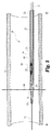
図1を参照して、血管内フィルタ22のための搬送装置20が示されている。例示的な実施形態では、フィルタ22は、下大静脈(IVC)23おけるその配置によって規定されるようなIVCフィルタである。IVCフィルタ22は初期的に搬送装置20内にパッケージ化され、および本明細書で使用されるように、搬送装置20は、IVC23に供給されるIVCフィルタ22を含むものとして規定される。しかしながら、これは搬送装置であるので、搬送される部品はIVCフィルタ22と理解されるべきである。患者に一旦配備されて適切に位置決めされると(すなわち、定置されると)、搬送装置20は、IVCフィルタ22なしに患者から除去される。向きの理解と搬送装置20の相対的な位置決めおよび大きさの見方を支援するためIVC23の断面は、図1に示されている。IVCフィルタ22に加えて、搬送装置20は、外側シース24と、ガイドワイヤカニューレ26と、超音波トランスデューサ28と、例示的な実施形態では拡張器30である先端部と、を含んでいる。図1に示すように、文字Aは、本明細書で言及されるようにアプリケーション側、端または方向を表し、文字Cは、本明細書で言及されるように制御側、端または方向を示す。
Referring to FIG. 1, a
搬送装置20の端部および構成部品の端部または側の向きと、動作または走行の方向の観点から、「アプリケーション側」(A)と「制御側」(C)の規則が採用され、本明細書中で使用される。これらの表現が示すように、装置20のまたは任意の部品のいずれかのアプリケーション側は、任意の治療、装置の配置などが発生する場所の方向またはより近くにある側または端部である。同様に、制御側は、医師が位置する場所の方向またはより近くにある装置20または任意の構成部品のいずれかの側または端部であり、制御機能またはアクションが実行される場所を表す。
From the viewpoint of the end or side direction of the end and components of the
「近位」および「遠位」を使用した場合、基準の異なるフレームが存在し得るので、この採択の理由の1つは、明確さを追加するためである。医療分野では、「近位」は、典型的には、心臓により近いことを意味するが、これは、患者へのカテーテルなどの装置のエントリのポイントに基づいて変更し得る。論理的には、医療分野では、「遠位」は、典型的には、心臓から遠いことを意味する。他の分野では、「近位」は、典型的には、オペレータまたはユーザに近いことを意味し、「遠位」は、典型的には、オペレータまたはユーザから遠いことを意味する。「アプリケーション側」と「制御側」の規則を採用することにより、任意の近位と遠位あいまいさが排除されるべきである。 One of the reasons for this adoption is to add clarity, as different frames of reference may be present when "proximal" and "distal" are used. In the medical field, "proximal" typically means closer to the heart, but this may change based on the point of entry of a device such as a catheter into the patient. Logically, in the medical field, "distal" typically means far from the heart. In other fields, "proximal" typically means closer to the operator or user, and "distal" typically means farther from the operator or user. By employing the "application side" and "control side" rules, any proximal and distal ambiguities should be eliminated.
搬送装置20の一部であるさらなる部品は、フィルタ搬送装置25と、制御ワイヤ27と、カテーテル29とを含む。典型的な実施形態では、カテーテル29は3つの(3)管腔カテーテルである。1つの管腔はガイドワイヤカニューレ26を受け、別の管腔は、超音波トランスデューサ28に接続するワイヤのために使用される。フィルタ22およびフィルタ搬送装置25は、カテーテル29専用の管腔の内部にはない。カテーテル29は搬送装置25の制御側端より短く、フィルタ22と搬送装置25は、シース管腔62の内側に位置する。明瞭に描画する目的のため、超音波トランスデューサに接続配線は、図示されていない。搬送装置25は、IVCフィルタ22の初期配備と位置決めの一部として初期に4つ(4)の長ストラット69を補足する。
Further parts which are part of the
搬送装置20は、ガイドワイヤカニューレ26を通って延びているワイヤガイド21によって、IVC23に導入される。ワイヤガイド21は、本明細書に記載の搬送手順の間、位置決めされたままであってもよく、または搬送装置20が図1に示すように正常に配置されると、除去されることができる。ワイヤガイド21は、搬送装置20の初期導入において重要であるが、ワイヤガイド21は、搬送装置20の適切な除去のために必要ではない。ワイヤガイド21の前進および位置決めは、既存の技術または方法のいずれかを使用して実行される。ワイヤガイド21に適した選択肢の中には、強化されたサポートを提供する固定芯ワイヤ、形状記憶と操縦性をを提供する「ニチノール」ワイヤ、低い摩擦係数のための潤滑性コーティングを有する親水性のワイヤを含む。
The
IVCフィルタ22は、塞栓、たとえば、IVCを通って血流を移動している分離した血栓または血栓のより大きな断片の捕捉において使用するために構成され、配置されている。この用途に適したIVCフィルタの一例は、インディアナ州ブルーミントンのクックメディカルが提供するCELECT(登録商標)大静脈フィルターである。また導入シースと呼ばれる外側シース24は、管腔62を規定し形成する管状壁60で構成され、配置されている。好ましくは、本明細書に開示される使用のために、搬送セットの全体の長さ、すなわち、搬送装置20は、約65センチメートルある。「FR」のスケールを使用してゲージは、約8.5Frであるか、または外径約2.83ミリメートルである。ガイドワイヤーカニューレ26は、ほぼ環状で、横断面がほぼ円形状の管状形状で構成され、配置されている。ガイドワイヤーカニューレ26とワイヤガイド21とカテーテル29との間の関係は、それらのそれぞれのサイズ、形状および材料を含めて、所望の支持および剛性を提供し、適切な許容可能なレベルまでIVCフィルタ22上の負荷を減少させる。
The
超音波トランスデューサ28は、IVC23内IVCフィルタ22の配備と位置決めとを視覚化する際に使用するために構成され配置されている超音波トランスデューサ28の血管内の位置決めおよび使用を考慮し、IVUSという略語は、超音波トランスデューサ28、すなわちIVUSトランスデューサ28の省略形として適用可能であり、本明細書で使用される。この略語はまた、IVCフィルタ22の配置および位置決めをガイドする方法を参照し説明するために使用される。拡張器30は、静脈に入る搬送装置20のの先端としてテーパ端部32を用いて構成され、配置される。ここでの焦点は、搬送装置20の導入およびIVCフィルタ22の定置のための大腿静脈アプローチを使用することにある。
The
例示的な実施形態では、IVUSトランスデューサ28は、セラミックスリーブに包まれたステンレス鋼の管状コアを含む。セラミックスリーブに巻き付けられているのは、フレキシブルなプリント回路基板である。IVUSトランスデューサ「構造」は、複数の素子から構成されたアレイを含む。多素子フェーズのアレイに必要なワイヤの数は、サイズによって定められる。スキャンオプションは、固定トランスデューサを備えたモータ駆動回転トランスデューサ、または代替としてモータ駆動鏡などを含む。サイズの考慮事項により、モータは、患者の外部にあり、回転ケーブルによって、トランスデューサの回転要素またはミラーのいずれかと接続する。代替的に、モータは、マイクロサイズであり、カテーテルのアプリケーション端部に組み込むことができる。
In the exemplary embodiment, the
装置20は血管内装置であるため、その大きさ、形状、材料の選択は、たとえば、静脈内に適合し、移動する必要があるすべての装置および器具と一致している。搬送装置20の使用方法または方法における重要な検討事項の1つは、正しい位置にIVCフィルタ22をガイドする方法である。「ガイド」は、搬送装置20をトラッキングすることおよび定置のための搬送装置20からIVCフィルタ22を配備することの両方を伴う。「ガイド」はまた、最終的な配置のチェックを行い、IVCフィルター22を位置決めする。IVCフィルタの「ガイド」の1つのオプションは、透視ガイダンスを使用することである。しかしながら、IVCフィルタ22の位置を監視するための血管内超音波(IVUS)を使用することは、必要な設備と実行されるステップの構成の観点とから透視より向上すると考えられる。搬送装置20の設計および構成は、搬送装置20に直接IVUSトランスデューサ28を統合することにより、改善されたレベルへのIVUSトランスデューサ28の使用を行う。
Because the
図2−6を参照して、搬送装置20の一部である部品の選択された1つがより詳細に示されている。拡張器30の詳細は、図2および2Aに示されている。IVUSトランスデューサ28の詳細のいくつかは、図3および3Aに示されている。ガイドワイヤカニューレ26の詳細が図4および4Aに示されている。外側シース24の詳細は、図5および5Aに示されている。IVCフィルタ22の詳細は、図6に示されている。
Referring to FIGS. 2-6, a selected one of the parts that are part of the
図2および図2Aを参照して、拡張器30は、制御側端部40からアプリケーション側端32へ収束するテーパ状の側壁38を有するほぼ円錐台の本体36を含む。本体36は、ガイドワイヤカニューレ26を受ける同軸中心ボア44を規定する。カウンタボア44aはボア44と同軸であり、IVUSトランスデューサ28のアプリケーション側ハブ部を受けるような大きさ、形状とされる。ガイドワイヤカニューレ26は、ワイヤガイド21と協働してIVC23におけるIVCフィルタ22の配備のために搬送装置20の位置決めに使用され、支援される。配備の後の搬送装置20の(IVCフィルタなしの)除去は、ワイヤガイド21の継続的な使用を必要としない。適切にこれらの統合された機能を実行するために、ガイドワイヤカニューレ26のアプリケーション側端部48は、確実に中央ボア44内に固定される。固定の関係は、好ましくは、中央ボア44およびアプリケーション側端部48の適合する大きさおよび形状を含む。拡張器30は、搬送装置20のアプリケーションの側端部に配置されガイドワイヤカニューレ26のアプリケーション側の端部を受ける。
Referring to FIGS. 2 and 2A, the
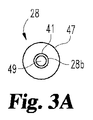
図3および3Aを参照して、IVUSトランスデューサ28は、本体45およびそのほぼ円筒形の外壁47によって規定されるほぼ円筒形の形状を有する。アライメントと位置決めのために、第1の同軸のハブ28aおよび第2の同軸のハブ28bが含まれる。ハブ28aはカウンタボア44a内に収まる。本体45を通って延びるステンレス鋼コア41は、ほぼ円筒形、管状の形状を有し、中央ボア49を規定する。コア41は、同軸ハブ28aおよび28bを提供する。管状コア41を包むのは、ほぼ円筒状のセラミックスリーブ43である。フレキシブルなプリント回路基板(図示せず)は、セラミックスリーブ43の周りに巻かれている。プリント基板面の部品は、追加の保護を提供するために、内側向きである。中心ボア49は、ガイドワイヤカニューレ26の一部を通して受け入れるように構成され配置されている。IVUSトランスデューサ28の制御側端部は、管腔62のアプリケーション側内で初期的に受けられる(図1参照)。
Referring to FIGS. 3 and 3A,
図1〜3Aはの例示的な実施形態によって表される構成は、ガイドワイヤカニューレ26と、ガイドワイヤ21と、IVUSトランスデューサ28と、拡張器30(すなわち、搬送装置20の先端)との間の特定の配置および関係を提供する。別の実施形態は、図11−13に示されており、これらの各々は、以下により詳細に記載される。加えて、IVUSトランスデューサの選択、形式、構成および動作は、例示的な実施形態のために開示されているものから変えることができることに留意されたい。1つの(1)変形例が図11−13に開示されているが、さらに、3Dスキャン機能が選択されたIVUSトランスデューサに統合され得ることが企図される。3Dスキャン機能は、2つ(2)の異なる機械的軸へとモータ駆動するように構成され配置された単一要素のトランスデューサを含むことができる。この3次元スキャン機能を提供するための別のオプションは、直線アレイトランスデューサーを使用して、回転運動を用いてそれを駆動することである。この3次元スキャン機能を提供するための別のオプションは、完全な2次元の線形アレイを使用することである。このオプションでは行−列アドレス指定スキームは、異なる送信イベントの別の要素にアクセスするために使用される。
The configuration represented by the exemplary embodiment of FIGS. 1-3A is between the
図4および図4Aを参照して、ガイドワイヤカニューレ26は、中空内部57を規定する側壁55を有する環状、管状の形状を有している。中空内部57の大きさは、0.035−0.040インチのサイズ範囲内のワイヤガイドを受けて収容する。ガイドワイヤーカニューレ26は、ほぼ管状の形状を有するものとして説明されているが、ガイドワイヤカニューレ26は、好ましくは、実質的に均一な側壁の厚さを有するほぼ円筒形の形状を有するであろう。このように、カニューレ26の全体は、横断面でほぼ円形の形状を持っているだろうし、中空内部57は、図4Aを参照して、好ましくは、横断面でほぼ円形の形状を有する。。ガイドワイヤーカニューレ26は、アプリケーション側端部または先端48と、制御側部分50と、傾斜部分52を規定する離間した2つの屈曲部51および53と、を含む。先端部48は、拡張器30内に位置し、IVUSトランスデューサ28通って延びているか渡される。部分50は、カテーテル29の管腔のの1つを通って延びる断面を表す。2つの屈曲部51および53は、オフセット傾斜部52を作成する。傾斜部52は、図1に示される初期の位置決めにおいてIVCフィルタ22のハブ72に隣接して位置決めされている。このオフセット傾斜部52は、エッジ位置から実質的に軸上の中心位置への位置合わせのシフトを生む。
Referring to FIGS. 4 and 4A,
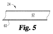
図5および5Aを参照して、外側シース24は、中空内部または管腔62を規定する外筒壁60を有する環状の可撓性スリーブである。外側シース24の機能と使用とを考慮すると、適切な材料は、ポリエチレンまたは他の半可撓性プラスチックが含まれる。これらの材料は、容易に形成されるか、または、ほぼ円筒形の管またはスリーブの所望の開始形状に押し出すことができる耐久性のあるが柔軟性のある、生体適合性材料を表す。外壁60の厚さは、選択された材料に部分的に依存するが、一般的に0.015−0.020インチの範囲である。論理的には、耐久性が低く硬い材料ほど僅かに厚い壁を必要とするであろう。外側シース24は、半径方向に最も外側のコンポーネントを表しているので、その内部寸法は、拡張器30とガイドワイヤカニューレ26のアプリケーション側端部48とを除く他のコンポーネントを収容するように選択される。同時に、外側管状壁60の最大サイズは、IVC23内の配置と移動のために制限され、制御されなければならない。外側シース24は、IVCフィルタ22のための定置場所への経皮的エントリを介して患者の外側に延びるのに十分な長さを有していてもよい。このような実施形態ではたとえば、外側シース24の制御側部または端部、および/またはそれに取り付けられた操作部は、身体の外側にあり、一方、アプリケーション側部分は、IVCフィルタ22に隣接しており、初期的にIVUSトランスデューサ28の端部の上に延びている。好ましくは、外側シース24は、統合性を維持し、フィルタの負荷を可能にしながら、血管を通って移動できるよう、血管内カテーテルに用いられる材料といった、半可撓性プラスチックまたは他の材料である。
現在利用可能なシースは血管系におけるシースの配置によって当然に示唆されるように、それらの中に収まるように折り畳まれたフィルタを認めながら、直径が小さくなるように寸法決めされる。
With reference to FIGS. 5 and 5A, the
Currently available sheaths are sized to be smaller in diameter, allowing for filters folded to fit within them, as is naturally suggested by the placement of the sheath in the vasculature.
図6を参照して、IVCフィルタ22は、複数のバイアスばねのワイヤー脚部または複数の短ストラット68と複数の長ストラット69とを含むように構成され配置されているストラット68および69を含む。短ストラット68は、「セカンダリ」と呼ばれる。長ストラット69は、「プライマリ」と呼ばれる。ストラット68および69は、ハブ72の制御側端部70に圧着することによりともに確実に固定される。ハブ72のアプリケーション側端部74は外方に延びる除去フック76を含む。除去フック76は、ハブ72のアプリケーション側端部74を越えてアプリケーション側方向に延びる。除去フック76は、IVCフィルタ22の回収および除去のために、その後の手順で使用されるので、除去フック76が適切に位置決めされ配向されることは、IVCフィルタ22のための位置決めのと配置(すなわち定置)の一部として重要である除去フック76およびストラット68および69とが互いに確実に接続することは、ハブ72にともにに圧着されるか、またはいくつかの他の方法または構造によるかによらず、重要である。IVCフィルタ22の回収および除去の際に、フック76は、回収装置のループによる初期的に係合のために使用されるだろう。フック48を引っ張ることは、除去手順の一部であり、ハブに力を及ぼして、順にストラット38および40に力を及ぼし、このときハブからフックまたはストラットからハブのいずれかで分離しようとする傾向にある。一体に連結し、確実に接合した状態にあることは、回収および除去手順の一部として重要である。
Referring to FIG. 6,
図7−10、および図1を引き続き参照すると、これらの図は、IVC23内でのIVCフィルタ22の搬送と、配備と、位置決めと、その最終的な位置決めの超音波画像検証のステップまたは段階に関連する構造的構成を示す。搬送と配備と位置決めとのこれらのフェーズはまとめて「定置」と呼ばれる。搬送方法の開始段階またはステップは図1で表される。この図は、初期的に構成され初期的に患者の体内の位置に移動される搬送装置20を示す。IVC23の壁は、2対の破線で表されている。IVUSトランスデューサ28は、意図された方法で通電されると、撮像面84が生成されるように構成され配置されている。IVCフィルタ22は、撮像面に対する相対的位置に搬送されることが重要である。これは、医師が正確に自分の専門知識ごとにフィルタの搬送場所を制御することを可能とする。IVC内の搬送装置20の初期的な位置決めのために、例示的な実施形態によれば、撮像面は、患者の下腎静脈にあり、図1中の破線84によって表される。図面の描画は概略であり、必ずしも一定の縮尺で描かれていないと、理解されるであろう。撮像面84は、約5センチメートルの半径を包含する。この半径は、静脈−静脈壁と周囲の組織の良好な被覆を提供する。
With continued reference to FIGS. 7-10 and 1, these figures illustrate the steps or stages of ultrasound image verification of
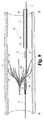
図7に示すように、搬送方法の他のステップまたは段階は、制御側の方向にわずかに戻って外側シース24を引っ張るステップを含む。外側シース24が引き戻されると、開口90はシース24のアプリケーション側の端部92とIVUSトランスデューサ28との間に生成される。別の動作は、さらに図7を参照すると、IVCフィルタ22の前進させることである。IVCフィルタ22は、フィルタ搬送装置25および制御ワイヤ27を用いて組み合わせて協働して初期的に前進する。いったん初期的に配備されると、IVCフィルタ22の次のステップは、搬送装置外に、つまり外側シース24の外に前進することである。外側シース24が後退されるうちに、ストラット68は拡大され、IVCフィルタ22は、ほぼIVCの中心になる。
As shown in FIG. 7, another step or stage of the delivery method involves pulling back on the
図7および8に示すように、IVCフィルタ22の配備と位置決めに関連して、それが配備されるときに、IVCフィルタ22のための好ましい配向を有するために、搬送装置20を回転させることが望ましい場合がある。このような任意の所望の回転は、ストラット68が配備される前に発生する必要がある。これらのステップの間に、フィルタ搬送装置25は、装置25の内部の小さいボア断面の中にともに効率的に押し込まれているの4つの(4)長いストラット69を受け、固定する。制御ワイヤは、装置25の制御側端部を押し込み、次いでくさび形のストラット69が装置25によって押し込まれ、それによってIVCフィルタ22の全体が押し込まれる。IVCフィルタ22のアプリケーション側部が前進されながら、それは開口部90へと進む。開口部90へとそして外へと通ってIVCフィルタ22を導くことは、IVCフィルタ22の直接的に当接する任意の可能性を軽減し、曲面を提供する可能性を改善することを目的としてIVUSトランスデューサ28の制御側端部の形成しまたは丸みを帯びさせることによって、大幅に改善することができる。
As shown in FIGS. 7 and 8, in connection with the deployment and positioning of the
一旦除去フック76が撮像面84におかれると、IVUSトランスデューサ28によって提供されるガイダンスは、IVCフィルタ22の前進を停止するために使用される。以上の説明から理解されるように、外側シース24は移動可能である。
Once
外側シース24およびカテーテル29の回転の後、IVCフィルタ22がほぼ中央位置を有しフック76の所望の配向を有するために、次のステップは、制御側方向に、外側シース24を引き戻すことであり、IVCフィルタ22のセカンダリストラット68が拡大することを可能にすることである。セカンダリストラット68がIVC23の内部を横切って完全に配備され(図9参照)た状態で、搬送装置20の残りの部分は引き抜かれ、除去される(図10参照)。引き抜きの初期段階は、制御側方向へのフィルタ搬送装置25の動きを生む。例示的な実施形態では、長ストラット69は、装置25に接続された解放構成を介して配備されている。カテーテルを単独で後退させるのは十分ではなく、装置25は特に不注意な早期の配備を防止するように構成されている。ストラット69は今度は、装置25内のそのくさび形の保持から装置25のより広い開口部へ、最終的には装置25の外に移動する。長ストラット69は、より大きな長さを有し、外側に延びてIVC23の壁に接触する。装置25からストラット69の初期的な解放は、図9に示されている。完全な解放およびストラット68および69の伸張は、図10に示される。
After rotation of the
本明細書での搬送装置20との関連における「残り」という用語の使用は、IVCフィルタ22が初期的には搬出装置20の一部として含まれているが、IVCフィルタ22が一旦静脈内に配備(すなわち定置)されると、搬送装置20の「残り」はIVCフィルタ22なしであるという事実を指す。IVUSの引き戻しのデータセットは、搬送装置の残りの部分が引き抜かれ、除去されながら記録される。記録されたデータセットは、IVCフィルタ22の正しい配置を確認する医療記録として役立つ。以上の記載から理解されるように、外側シース24とIVCフィルタ22とは、外側シース24の回転がIVCフィルタ22を回転させるように各々協働的に構成され配置される
搬送装置20の一部として含まれてもよい別の機能は、加えシース24の外表面に印刷された定規を追加することである。シース24に印刷された定規を追加することは、IVUSガイド手順の間困難であり得る手順の間に状況認識を向上させる。(定規の可視化を介しての)奥行き情報もまた、配置を計画および確認するために使用することが可能である。
The use of the term "remainder" in the context of the
搬送装置20の一部として含まれ得るさらに別の機能は、超音波で撮像されたときに、IVCフィルタ22の視認性を向上させるために、エコー源性の機能の追加または包含によって、IVCフィルタ22の構成を変更することである。
Yet another feature that may be included as part of the
開示された搬送装置の例示的な実施形態が本明細書に記載されていることを認識するために、以下のことを考慮することは、可能な変形及びオプションの完全な理解に役立つであろう。まず、フィルタフック76が角度的にIVCの中央付近に位置合わせされるように回転するステップを含む搬送手順は任意である。このセンタリングは現在、透視下で行われておらず、IVUSガイダンスの下では、オプションである。ストラット68が拡張されると、フック76は、自然にIVCの中心に向かって押し出される。IVCフィルタ22は、従って、ほとんどの場合自己センタリングである。角度のアライメントステップは、実行される場合、既に小さな可能性である非中心の配備をさらに減らすことが期待される。
In order to appreciate that the exemplary embodiments of the disclosed transport apparatus are described herein, consideration of the following will aid in a thorough understanding of possible variations and options . First, the transport procedure is optional, including the step of rotating the
また、角度のアライメントステップは、必ずしもフックが図7のようにIVUSの撮像面内に前進されることを必要としない。同じ機能は、IVUS画像に対してフィルタの向きを示すためにコンソールを製造および構成する間、IVUSトランスデューサとフィルタとを整合(アライン)することによって達成することができる。この構成は、IVUSトランスデューサ28とフィルタホルダ25とが、それらが独立して動くことができるように構成される必要を除く。
Also, the angular alignment step does not necessarily require the hooks to be advanced into the imaging plane of the IVUS as in FIG. The same function can be achieved by aligning the IVUS transducer with the filter while manufacturing and configuring the console to indicate the filter's orientation to the IVUS image. This configuration eliminates the need for the
さらなる設計バリエーションとして、回転トランスデューサアセンブリを含むことが可能である。このタイプの設計では、トランスデューサは、中空ではないので、ガイドワイヤの管腔は、トランスデューサの中心を通ることができない。従来のトルクケーブルが回転駆動するために使用されている場合は、ガイドワイヤカニューレ26は、トルクケーブルを収容するために使用される。オンサイトのモータが使用される場合、ガイドワイヤカニューレ26が中空である必要はなく、機械的支持のみを提供する。回転トランスデューサを収容するために、代替のガイドワイヤの経路が必要とされる。ガイドワイヤは、拡張器の先端のアプリケーション側の端部から突出する固定長の拡張器管腔44内に恒久的に接着することができる。また、管腔44は拡張器管腔を出ることができ、拡張器36側の制御側部に迅速交換型のワイヤガイドシステムを構成する。
As a further design variation, it is possible to include a rotating transducer assembly. In this type of design, the lumen of the guidewire can not pass through the center of the transducer because the transducer is not hollow. If a conventional torque cable is used to rotationally drive, the
搬送装置20にIVUSトランスデューサ28を組み込むことにより、超音波手順の全体は、IVUSトランスデューサ28を取り外すことなく行うことができる。この設計態様は、拡張とシースの配置とフィルタの搬送とIVCフィルタの配置の検証との間に臨床医が超音波イメージングの観点から何が起こっているのか「見る」ことができるので、臨床医は、安全だと感じることができるということを意味する。開示された方法や手順は、潜在的な安全上の問題となる臨床医が「見えない」ことを要とするいずれの手順を有さない。また、患者内にIVUSトランスデューサ28が残るので、カテーテルの交換が必要ではない。これは、手続きを大幅に高速化し、簡素化する。IVCフィルタ22の前に(すなわちアプリケーション側に)IVUSトランスデューサ28を配置することにより、IVCフィルタの配置は、IVCフィルタ22を介してカテーテルを押し込むことなく行うことができる。そうでなければ、カテーテルはIVCフィルタ頂部で捕捉され、誤ってIVCフィルタを移動させ得るため、これは潜在的な安全上のリスクとなる。搬送装置20の開示された実施形態によって、IVCフィルタ22は、超音波ガイド下で迅速かつ簡単に、安全に搬送することが可能である。このアプローチは、本発明によって具現化されるように、透視ガイダンスされた搬送セットを使用する従来技術の手法の改善であると考えられる。搬送装置20は、単一のアクセスサイトを介して導入され、除去されることができる。
By incorporating the
図11〜13を参照して、搬送装置のアプリケーション側端部のための3つの(3)他の実施形態が示される。最初に図11を参照して、埋め込まれたIVUSトランスデューサ102を含むIVUSフィルタ搬送装置100が開示される。この実施形態は、IVUSトランスデューサ102と「迅速交換」ワイヤガイド104と先端106との設計オプションを提供する。この実施形態は、IVUSトランスデューサ102の特定の構成に依存しない。
Referring to FIGS. 11-13, three (3) other embodiments for the application end of the transport device are shown. Referring first to FIG. 11, an IVUS
任意には、IVUSトランスデューサは、中空であってもよいし、中空でなくてもないが、後者がIVUSトランスデューサ102として開示される。このため、利用可能であり、搬送装置100の図示された構造と互換性があるような代替案は、1つの(1)オプションとして、トルクケーブル駆動トランスデューサの使用を含む。その他のオプションは、様々な構成のオンサイトのモータ回転トランスデューサ、アレイトランスデューサ、3Dトランスデューサの使用を含む。
Optionally, the IVUS transducer may or may not be hollow, the latter being disclosed as an
搬送装置は、IVUSフィルタ22と機械的支持108とを含み、機械的支持108は、先端106およびトランスデューサ102が配置されるカテーテル110のアプリケーション側または端部と、IVUSフィルタ22およびカテーテル110の本体とが配置される制御側または端部との間の接続を提供する。
The delivery device includes an
図11の例示的な実施形態では、機械的支持108は中空であり、ワイヤガイド、トランスデューサケーブル、トルクケーブル、流体管腔、などを受けることができるように構成され、配置されている。代替的に、機械的な支持は、固体部材であってもよい。文字Aで示されるアプリケーション側または端部は、トランスデューサ102の1つの(1)端に隣接する先端106を含む。
In the exemplary embodiment of FIG. 11, the
図11、12および13に示すように、いくつかの設計オプションが、トランスデューサの先端106に利用できる。図11に関連する1つの(1)のオプションは、迅速交換管腔112を用いてトランスデューサの先端部106を構成することである。図12に関連する別のオプションは、ワイヤガイド114の1つの(1)端部がトランスデューサの先端116のアプリケーション側または端部の受開口部118に永久的に埋め込まれるように、ワイヤガイド114とトランスデューサの先端116とを構成することである。図13に関連する別のオプションは、ワイヤガイド(104、114)を除去し、代わりに先端120のアプリケーション側または端部を実質的に半球形状に丸くして形成することである。先端または面におけるこの実質的な半球形状は、対応する搬送装置が所望の位置に移動される際に血管の穿刺または引き裂きのリスクを低減する。
Several design options are available for the
本発明は、図面および前述の説明において詳細に図示および説明してきたが、同じことが例示的であり文字において限定的ではないと考えられるべきであり、好ましい実施形態のみが示され説明され、以下の特許請求の範囲によって定義される本発明の精神内にあるすべて変更、均等物、および修正が保護されることが望まれると理解される。本明細書で引用したすべての刊行物、特許、および特許出願は、各個々の刊行物、特許、または特許出願が具体的かつ個々に参照により組み込まれその全体が本明細書に記載されると示されるように、参照により本明細書に組み込まれる。 While the invention has been illustrated and described in detail in the drawings and the foregoing description, the same should be considered as illustrative and not restrictive in character, only the preferred embodiments being shown and described, It is understood that it is desired that all changes, equivalents, and modifications that are within the spirit of the present invention as defined by the following claims be protected. All publications, patents, and patent applications cited herein are specifically and individually incorporated by reference and are incorporated herein by reference in their respective individual publications, patents, or patent applications. As indicated, it is incorporated herein by reference.
Claims (23)
管腔を規定する環状壁を有するシースと、
前記管腔内に位置決めされる血管内フィルタとを備え、前記血管内フィルタは、前記身体の血管内に二段階配備されるように協働的に配置された複数のプライマリストラットと複数のセカンダリストラットとを有し、前記セカンダリストラットは先に配備されるように構成および配置され、前記プライマリストラットは後に配備されるように構成および配置され、前記搬送装置はさらに、
前記管腔内に位置決めされる搬送デバイスを備え、前記プライマリストラットの各々は、共通のハブに固定される一端と、前記血管内フィルタの前記二段階配備のために前記搬送デバイス内に捕捉される反対側の自由端とを有し、前記セカンダリストラットの各々は、前記共通のハブに固定される一端と、反対側の自由端とを有し、前記搬送装置はさらに、
前記シースに受け入れられ、前記血管内フィルタのアプリケーション側に位置決めされる超音波トランスデューサを備え、前記血管内フィルタの前記身体の血管への導入は、前記血管内フィルタの配備の第2段階として前記プライマリストラットの前記自由端を前記搬送デバイス内から解放することを含み、
前記超音波トランスデューサは、前記血管内フィルタの配備と同時に使用される、搬送装置。 A delivery device for introducing an intravascular filter into a blood vessel of a patient's body, comprising
A sheath having an annular wall defining a lumen;
And a plurality of primary struts and a plurality of secondary struts cooperatively arranged to be deployed in two stages in the blood vessel of the body. And the secondary struts are configured and arranged to be deployed first, and the primary struts are configured and arranged to be deployed later, and the transport apparatus is further configured to:
A delivery device positioned within the lumen, each of the primary struts being captured within the delivery device for the two stage deployment of the intravascular filter, with one end secured to a common hub Having opposite ends, each of the secondary struts having one end fixed to the common hub and the opposite free end, the transport device further comprising:
The ultrasound transducer received by the sheath and positioned on the application side of the intravascular filter, and the introduction of the intravascular filter into the blood vessel of the body is the primary as a second step of the deployment of the intravascular filter Releasing the free end of the strut from within the delivery device;
The delivery device, wherein the ultrasound transducer is used simultaneously with the deployment of the intravascular filter.
管腔を規定する環状壁を有するシースと、
前記管腔内に位置決めされる血管内フィルタとを備え、前記血管内フィルタは、前記身体の血管内に二段階配備されるように協働的に配置された複数のプライマリストラットと複数のセカンダリストラットとを有し、前記セカンダリストラットは先に配備されるように構成および配置され、前記プライマリストラットは後に配備されるように構成および配置され、前記搬送装置はさらに、
前記管腔内に位置決めされる搬送デバイスを備え、前記プライマリストラットの各々は、共通のハブに固定される一端と、前記血管内フィルタの前記二段階配備のために前記搬送デバイス内に捕捉される反対側の自由端とを有し、前記セカンダリストラットの各々は、前記共通のハブに固定される一端と、反対側の自由端とを有し、前記セカンダリストラットは前記搬送デバイス内に保持されておらず、前記搬送装置はさらに、
前記シースに受け入れられ、前記血管内フィルタのアプリケーション側に位置決めされる超音波トランスデューサを備え、前記血管内フィルタの前記身体の血管への導入は、前記血管内フィルタの配備の第2段階として前記プライマリストラットの前記自由端を前記搬送デバイス内から解放することを含み、前記超音波トランスデューサは、前記血管内フィルタの配備と同時に使用され、前記搬送装置はさらに、
前記管腔を通って延び、アプリケーション側端部を含むガイドワイヤカニューレと、
前記搬送装置のアプリケーション側端部に位置する拡張器とを備え、前記拡張器は前記ガイドワイヤカニューレのアプリケーション側端部を受ける、搬送装置。 A delivery device for introducing an intravascular filter into a blood vessel of a patient's body, said delivery device comprising:
A sheath having an annular wall defining a lumen;
And a plurality of primary struts and a plurality of secondary struts cooperatively arranged to be deployed in two stages in the blood vessel of the body. And the secondary struts are configured and arranged to be deployed first, and the primary struts are configured and arranged to be deployed later, and the transport apparatus is further configured to:
A delivery device positioned within the lumen, each of the primary struts being captured within the delivery device for the two stage deployment of the intravascular filter, with one end secured to a common hub Having opposite ends, each of the secondary struts having one end fixed to the common hub and the opposite free end, the secondary struts being retained within the transport device The transport device is further
The ultrasound transducer received by the sheath and positioned on the application side of the intravascular filter, and the introduction of the intravascular filter into the blood vessel of the body is the primary as a second step of the deployment of the intravascular filter Releasing the free end of the strut from within the delivery device, the ultrasound transducer being used simultaneously with the deployment of the intravascular filter, the delivery device further comprising:
A guidewire cannula extending through the lumen and including an application end;
And a dilator located at the application end of the delivery device, the dilator receiving the application end of the guidewire cannula.
管腔を規定する環状壁を有するシースと、
前記管腔内に位置決めされるIVCフィルタとを備え、前記IVCフィルタは、前記IVC内に二段階配備されるように協働的に配置された複数のプライマリストラットと複数のセカンダリストラットとを有し、前記セカンダリストラットは先に配備されるように構成および配置され、前記プライマリストラットは後に配備されるように構成および配置され、前記搬送装置はさらに、
前記管腔内に位置決めされる搬送デバイスを備え、前記プライマリストラットの各々は、共通のハブに固定される一端と、前記IVCフィルタの前記二段階配備のために前記搬送デバイス内に捕捉される反対側の自由端とを有し、前記セカンダリストラットの各々は、前記共通のハブに固定される一端と、反対側の自由端とを有し、前記搬送デバイスはアプリケーション側端部を有し、前記搬送装置はさらに、
前記シースに受け入れられ、前記IVCフィルタのアプリケーション側に位置決めされるIVUSトランスデューサを備え、前記IVCフィルタの前記IVCへの導入は、前記IVCフィルタの配備の第2段階として前記自由端を前記搬送デバイス内から解放することを含み、前記IVCフィルタの前記複数のプライマリストラットおよびセカンダリストラットは、前記搬送デバイスの前記アプリケーション側端部と前記IVUSトランスデューサとの間に位置決めされ、前記IVUSトランスデューサは、前記IVCフィルタの配備と同時に使用され、前記搬送装置はさらに、
前記管腔を通って延び、前記IVUSトランスデューサのアプリケーション側で終端するガイドワイヤカニューレと、
前記ガイドワイヤカニューレに組み付けられる拡張器と、を備え、前記IVUSトランスデューサは前記拡張器と前記IVCフィルタとの間に配置される、搬送装置。 A delivery device for placement of an IVC filter in a patient's lower vena cava (IVC), the delivery device comprising: a sheath having an annular wall defining a lumen;
An IVC filter positioned in the lumen, the IVC filter having a plurality of primary struts and a plurality of secondary struts cooperatively arranged to be deployed in two stages in the IVC The secondary struts are configured and arranged to be deployed first, and the primary struts are configured and arranged to be deployed later, and the transport apparatus is further configured to
A delivery device positioned within the lumen, each of the primary struts having one end fixed to a common hub and an opposite captured within the delivery device for the two stage deployment of the IVC filter Free ends, each of the secondary struts having one end fixed to the common hub and the opposite free end, the transport device having an application end, The transport device further
The IVUS transducer is received in the sheath and positioned on the application side of the IVC filter, and the introduction of the IVC filter into the IVC takes the free end into the delivery device as a second step of the IVC filter deployment. Releasing the plurality of primary struts and secondary struts of the IVC filter positioned between the application end of the transport device and the IVUS transducer, the IVUS transducer being of the IVC filter. Used simultaneously with deployment, the transport device further
A guidewire cannula extending through the lumen and terminating on the application side of the IVUS transducer;
A dilator assembled to the guidewire cannula, wherein the IVUS transducer is disposed between the dilator and the IVC filter.
前記搬送装置を提供するステップと、
前記搬送装置を患者の身体の血管内に挿入するステップと、
前記撮像面が患者内の選択した場所と一致するように前記搬送装置を位置決めするステップと、
前記血管内フィルタの配備と同時に前記超音波トランスデューサを使用するステップと、
前記セカンダリストラットを先に配備し、続いて前記プライマリストラットの前記自由端を前記搬送デバイス内から解放して配備することによって前記血管内フィルタを二段階で配備するステップと、
前記搬送装置を前記身体の血管内に残される前記血管内フィルタなしに引き抜くステップと、を含む方法。 An intravascular filter comprising a sheath, a plurality of primary struts and a plurality of secondary struts, a delivery device for deployment of the intravascular filter, an ultrasound transducer received in the sheath, a guide wire cannula, a dilator A method of introducing an intravascular filter into a blood vessel in a patient's body (except for human beings) using a delivery device comprising: one end fixed to a common hub; The opposite free end captured within the device, each of the secondary struts having one end fixed to the common hub and the opposite free end, the ultrasound transducer imaging Have a face, the method
Providing the transport device;
Inserting the delivery device into a blood vessel of a patient's body;
Positioning the transport device such that the imaging plane coincides with a selected location in the patient;
Using the ultrasound transducer simultaneously with the deployment of the intravascular filter;
Deploying the endovascular filter in two stages by first deploying the secondary struts and subsequently deploying the free end of the primary struts from within the delivery device;
Withdrawing the delivery device without the intravascular filter left in a blood vessel of the body.
Applications Claiming Priority (3)
| Application Number | Priority Date | Filing Date | Title |
|---|---|---|---|
| US201261739070P | 2012-12-19 | 2012-12-19 | |
| US61/739,070 | 2012-12-19 | ||
| PCT/US2013/071264 WO2014099247A1 (en) | 2012-12-19 | 2013-11-21 | Apparatus and method for the delivery of an intravascular filter |
Publications (3)
| Publication Number | Publication Date |
|---|---|
| JP2016502878A JP2016502878A (en) | 2016-02-01 |
| JP2016502878A5 JP2016502878A5 (en) | 2016-09-08 |
| JP6523964B2 true JP6523964B2 (en) | 2019-06-05 |
Family
ID=50931782
Family Applications (1)
| Application Number | Title | Priority Date | Filing Date |
|---|---|---|---|
| JP2015549406A Active JP6523964B2 (en) | 2012-12-19 | 2013-11-21 | Device and method for delivery of intravascular filters |
Country Status (6)
| Country | Link |
|---|---|
| US (1) | US9649183B2 (en) |
| EP (1) | EP2934651B1 (en) |
| JP (1) | JP6523964B2 (en) |
| CN (1) | CN104918652B (en) |
| AU (1) | AU2013363670B2 (en) |
| WO (1) | WO2014099247A1 (en) |
Families Citing this family (6)
| Publication number | Priority date | Publication date | Assignee | Title |
|---|---|---|---|---|
| WO2012003369A2 (en) * | 2010-06-30 | 2012-01-05 | Muffin Incorporated | Percutaneous, ultrasound-guided introduction of medical devices |
| GB2524289B (en) * | 2014-03-19 | 2016-03-09 | Cook Medical Technologies Llc | Vascular filter |
| EP3197368B1 (en) * | 2014-09-24 | 2018-11-28 | Koninklijke Philips N.V. | Endoluminal filter having enhanced echogenic properties |
| CN107550524B (en) * | 2016-07-01 | 2020-01-03 | 先健科技(深圳)有限公司 | Conveying device |
| FR3080273B1 (en) * | 2018-04-18 | 2023-12-29 | A L N | UMBRELLA-TYPE FILTER WITH ANTI-TRANSFIXATION PROTECTION |
| CN110811918B (en) * | 2019-11-20 | 2021-11-09 | 湖南埃普特医疗器械有限公司 | Recoverable filter and filter pusher |
Family Cites Families (33)
| Publication number | Priority date | Publication date | Assignee | Title |
|---|---|---|---|---|
| US3672367A (en) | 1970-05-25 | 1972-06-27 | Abbott Lab | Retaining clip for catheter sheath |
| US4525157A (en) | 1983-07-28 | 1985-06-25 | Manresa, Inc. | Closed system catheter with guide wire |
| US4917097A (en) * | 1987-10-27 | 1990-04-17 | Endosonics Corporation | Apparatus and method for imaging small cavities |
| US5415630A (en) | 1991-07-17 | 1995-05-16 | Gory; Pierre | Method for removably implanting a blood filter in a vein of the human body |
| US5324304A (en) * | 1992-06-18 | 1994-06-28 | William Cook Europe A/S | Introduction catheter set for a collapsible self-expandable implant |
| US5911734A (en) * | 1997-05-08 | 1999-06-15 | Embol-X, Inc. | Percutaneous catheter and guidewire having filter and medical device deployment capabilities |
| US6530902B1 (en) | 1998-01-23 | 2003-03-11 | Medtronic, Inc. | Cannula placement system |
| US6080178A (en) * | 1999-04-20 | 2000-06-27 | Meglin; Allen J. | Vena cava filter |
| US6645152B1 (en) | 1999-06-02 | 2003-11-11 | Matthew T. Jung | Apparatus for the intravascular ultrasound-guided placement of a vena cava filter |
| US6440077B1 (en) * | 1999-06-02 | 2002-08-27 | Matthew T. Jung | Apparatus and method for the intravascular ultrasound-guided placement of a vena cava filter |
| US20030125751A1 (en) * | 2001-06-27 | 2003-07-03 | Patrick Griffin | Catheter |
| US7763045B2 (en) | 2003-02-11 | 2010-07-27 | Cook Incorporated | Removable vena cava filter |
| US7717865B2 (en) | 2003-09-30 | 2010-05-18 | Boston Scientific Scimed, Inc. | Side loading wire torquing device |
| US7591813B2 (en) | 2003-10-01 | 2009-09-22 | Micrus Endovascular Corporation | Long nose manipulatable catheter |
| ATE503438T1 (en) | 2004-04-16 | 2011-04-15 | Cook Inc | REMOVABLE VENA CAVA FILTER TO REDUCE TRAUMA IN FOLDED STATE |
| US7625390B2 (en) | 2004-04-16 | 2009-12-01 | Cook Incorporated | Removable vena cava filter |
| WO2005102211A1 (en) * | 2004-04-16 | 2005-11-03 | Cook, Inc. | Removable vena cava filter |
| US7803171B1 (en) | 2004-06-14 | 2010-09-28 | Uflacker Renan P | Retrievable inferior vena cava filter |
| US20060069405A1 (en) * | 2004-09-20 | 2006-03-30 | Schaeffer Darin G | Anti-thrombus filter having enhanced identifying features |
| US7794473B2 (en) * | 2004-11-12 | 2010-09-14 | C.R. Bard, Inc. | Filter delivery system |
| EP1965852A4 (en) | 2005-12-30 | 2012-10-31 | Bard Inc C R | Embolus blood clot filter removal system and method |
| US7988674B2 (en) | 2006-10-30 | 2011-08-02 | Medtronic, Inc. | Externally releasable body portal anchors and systems |
| US20080119867A1 (en) | 2006-10-31 | 2008-05-22 | Cook Incorporated | Puncture and abrasion resistant sheath |
| US8043324B2 (en) * | 2007-10-30 | 2011-10-25 | Boston Scientific Scimed, Inc. | Intravascular filter device with piezoelectric transducer |
| US20090118760A1 (en) | 2007-11-07 | 2009-05-07 | William Cook Europe Aps | Vascular filter retrieval device |
| CA2835549C (en) * | 2008-05-30 | 2015-07-28 | Gore Enterprise Holdings, Inc. | Real time ultrasound catheter probe |
| US9962523B2 (en) | 2008-06-27 | 2018-05-08 | Merit Medical Systems, Inc. | Catheter with radiopaque marker |
| FR2945206B1 (en) | 2009-05-06 | 2011-06-17 | Aln | EXTRACTION KIT FOR FILTER FOR CELLAR VEIN |
| EP2493428B1 (en) * | 2009-10-29 | 2015-11-25 | Cook Medical Technologies LLC | Stent delivery system with nitinol trigger wire |
| WO2012003369A2 (en) * | 2010-06-30 | 2012-01-05 | Muffin Incorporated | Percutaneous, ultrasound-guided introduction of medical devices |
| US20120022578A1 (en) | 2010-07-20 | 2012-01-26 | Cook Medical Technologies Llc | Frame-based vena cava filter |
| US9259306B2 (en) * | 2010-12-30 | 2016-02-16 | Claret Medical, Inc. | Aortic embolic protection device |
| AU2013363667B2 (en) * | 2012-12-19 | 2017-08-03 | Muffin Incorporated | Apparatus and method for the retrieval of an intravascular filter |
-
2013
- 2013-11-21 JP JP2015549406A patent/JP6523964B2/en active Active
- 2013-11-21 EP EP13864888.6A patent/EP2934651B1/en active Active
- 2013-11-21 WO PCT/US2013/071264 patent/WO2014099247A1/en active Application Filing
- 2013-11-21 AU AU2013363670A patent/AU2013363670B2/en active Active
- 2013-11-21 CN CN201380070245.5A patent/CN104918652B/en active Active
- 2013-11-21 US US14/086,208 patent/US9649183B2/en active Active
Also Published As
| Publication number | Publication date |
|---|---|
| CN104918652B (en) | 2019-05-17 |
| AU2013363670B2 (en) | 2017-07-20 |
| AU2013363670A1 (en) | 2015-07-23 |
| EP2934651B1 (en) | 2018-04-11 |
| CN104918652A (en) | 2015-09-16 |
| EP2934651A4 (en) | 2016-07-13 |
| WO2014099247A1 (en) | 2014-06-26 |
| US9649183B2 (en) | 2017-05-16 |
| US20140172007A1 (en) | 2014-06-19 |
| JP2016502878A (en) | 2016-02-01 |
| EP2934651A1 (en) | 2015-10-28 |
Similar Documents
| Publication | Publication Date | Title |
|---|---|---|
| JP6282283B2 (en) | Device and method for collecting intravascular filter | |
| US11903811B2 (en) | Embolus blood clot filter removal system and method | |
| JP6523964B2 (en) | Device and method for delivery of intravascular filters | |
| JP6466419B2 (en) | Thrombectomy and intravascular distal embolism protection device | |
| JP3715988B2 (en) | Rapid exchange catheter | |
| KR101652615B1 (en) | Methods and apparatus for luminal stenting | |
| US20190209047A1 (en) | Devices, systems and methods for enhanced visualization of the anatomy of a patient | |
| JP4922942B2 (en) | Filter sending system | |
| EP2895059B1 (en) | Delivery system | |
| JP6590887B2 (en) | Method and apparatus for aligning a microcatheter within a vascular system | |
| JP2017513661A (en) | Method and apparatus for placing a catheter in the vascular system | |
| EP3389507B1 (en) | Introducer systems and devices for heart valve reductions | |
| WO2020232030A1 (en) | Guide catheter with support wires | |
| CN115697245A (en) | Systems, methods, and devices for embolic protection | |
| WO2023235707A1 (en) | Delivery system for over the wire implantation of a medical device |
Legal Events
| Date | Code | Title | Description |
|---|---|---|---|
| A521 | Request for written amendment filed |
Free format text: JAPANESE INTERMEDIATE CODE: A523 Effective date: 20160721 |
|
| A621 | Written request for application examination |
Free format text: JAPANESE INTERMEDIATE CODE: A621 Effective date: 20160721 |
|
| A977 | Report on retrieval |
Free format text: JAPANESE INTERMEDIATE CODE: A971007 Effective date: 20170517 |
|
| A131 | Notification of reasons for refusal |
Free format text: JAPANESE INTERMEDIATE CODE: A131 Effective date: 20170523 |
|
| A521 | Request for written amendment filed |
Free format text: JAPANESE INTERMEDIATE CODE: A523 Effective date: 20170823 |
|
| A02 | Decision of refusal |
Free format text: JAPANESE INTERMEDIATE CODE: A02 Effective date: 20170919 |
|
| A521 | Request for written amendment filed |
Free format text: JAPANESE INTERMEDIATE CODE: A523 Effective date: 20180119 |
|
| A911 | Transfer to examiner for re-examination before appeal (zenchi) |
Free format text: JAPANESE INTERMEDIATE CODE: A911 Effective date: 20180227 |
|
| A912 | Re-examination (zenchi) completed and case transferred to appeal board |
Free format text: JAPANESE INTERMEDIATE CODE: A912 Effective date: 20180406 |
|
| A521 | Request for written amendment filed |
Free format text: JAPANESE INTERMEDIATE CODE: A523 Effective date: 20190208 |
|
| A61 | First payment of annual fees (during grant procedure) |
Free format text: JAPANESE INTERMEDIATE CODE: A61 Effective date: 20190426 |
|
| R150 | Certificate of patent or registration of utility model |
Ref document number: 6523964 Country of ref document: JP Free format text: JAPANESE INTERMEDIATE CODE: R150 |
|
| R250 | Receipt of annual fees |
Free format text: JAPANESE INTERMEDIATE CODE: R250 |
|
| R250 | Receipt of annual fees |
Free format text: JAPANESE INTERMEDIATE CODE: R250 |
|
| R250 | Receipt of annual fees |
Free format text: JAPANESE INTERMEDIATE CODE: R250 |