JP6523205B2 - Corrosion test method and corrosion test apparatus - Google Patents
Corrosion test method and corrosion test apparatus Download PDFInfo
- Publication number
- JP6523205B2 JP6523205B2 JP2016085343A JP2016085343A JP6523205B2 JP 6523205 B2 JP6523205 B2 JP 6523205B2 JP 2016085343 A JP2016085343 A JP 2016085343A JP 2016085343 A JP2016085343 A JP 2016085343A JP 6523205 B2 JP6523205 B2 JP 6523205B2
- Authority
- JP
- Japan
- Prior art keywords
- sample
- electrode
- test
- drying
- corrosion
- Prior art date
- Legal status (The legal status is an assumption and is not a legal conclusion. Google has not performed a legal analysis and makes no representation as to the accuracy of the status listed.)
- Active
Links
Images


Landscapes
- Testing Resistance To Weather, Investigating Materials By Mechanical Methods (AREA)
- Investigating Or Analyzing Materials By The Use Of Electric Means (AREA)
Description
本発明は、腐食試験方法、および、腐食試験装置に関する。 The present invention relates to a corrosion test method and a corrosion test apparatus.
屋外で長時間使用される鋼材や、鋼材の塗膜の腐食に対する耐性の評価をするため、JISやISO等に定められた複合サイクル試験が広く適用されてきた。この試験では、試料である鋼材に対し、塩水噴霧工程、乾燥工程、湿潤工程という3つの工程からなるサイクルを繰り返す(非特許文献1参照)。 In order to evaluate the resistance to corrosion of steel materials used for a long time outdoors or of a coating film of steel materials, a composite cycle test defined in JIS, ISO, etc. has been widely applied. In this test, a cycle consisting of three steps of a salt spray step, a drying step, and a wetting step is repeated on a steel material which is a sample (see Non-Patent Document 1).
しかし、上記の試験では、屋外で長時間使用される環境を模擬するため、試験に長時間を要するという問題がある。例えば、上記のJIS K5600-7-9のサイクルAにおいて、試料に対する、塩水噴霧工程(2時間)、乾燥工程(4時間)、湿潤工程(2時間)という3つの工程からなるサイクルを長時間(数百〜数千時間程度)にわたり繰り返す必要があった。そこで、本発明は、前記した問題を解決し、鋼材等に用いられる塗料の腐食試験に要する時間を短縮することを課題とする。 However, in the above test, there is a problem that the test takes a long time to simulate an environment used for a long time outdoors. For example, in cycle A of JIS K 5600-7-9 described above, a cycle consisting of three steps of a salt spray step (2 hours), a drying step (4 hours), and a wetting step (2 hours) Needs to be repeated for several hundred to several thousand hours). Then, this invention makes it a subject to solve the above-mentioned problem and to shorten the time which the corrosion test of the coating material used for steel materials etc requires.
前記した課題を解決するため、本発明は、塗料に対する腐食試験方法であって、試料である前記塗料が塗装された鋼材と、前記鋼材と同じ塗装仕様で塗装された塗装電極とに、所定時間、塩水を噴霧する塩水噴霧ステップと、前記塩水噴霧ステップの後、前記試料および塗装電極の乾燥を開始し、前記乾燥を開始した塗装電極に対し、所定時間ごとに電気化学測定を実施し、単位時間当たりの前記塗装電極のインピーダンス、塗膜抵抗および静電容量の少なくともいずれか1つの変化量が所定値以下となった場合、前記試料の乾燥を終了させる乾燥ステップと、前記乾燥ステップの後、前記試料を所定の温度および湿度の湿潤状態にする湿潤ステップと、を含んだことを特徴とする。 In order to solve the above-described problems, the present invention is a method for testing corrosion on paint, wherein a steel material coated with the paint, which is a sample, and a coated electrode coated with the same paint specifications as the steel material After the salt spray step of spraying salt water and the salt spray step, drying of the sample and the painted electrode is started, and the electrochemical measurement is performed at predetermined time intervals on the painted electrode which has started the drying, and the unit A drying step for terminating the drying of the sample when the change amount of at least one of the impedance, the coating resistance and the capacitance of the coating electrode per time becomes equal to or less than a predetermined value; And D. wetting the sample to a predetermined temperature and humidity.
本発明によれば、鋼材等に用いられる塗料の腐食試験に要する時間を短縮することができる。 According to the present invention, it is possible to shorten the time required for the corrosion test of the paint used for steel materials and the like.
以下、図面を参照しながら、本発明を実施するための形態(実施形態)について説明する。本発明は本実施形態に限定されない。 Hereinafter, embodiments (embodiments) for carrying out the present invention will be described with reference to the drawings. The present invention is not limited to this embodiment.
(実施形態)
まず、本実施形態の腐食試験装置(試験装置)10の構成を説明する。試験装置10は、塗料の腐食試験を実施する。腐食試験に用いる試料は、例えば、試験対象の塗料が塗装された鋼材(塗装鋼材)や、塗装鋼材を含む物品である。なお、試験対象が樹脂であれば、試料は、樹脂ライニングがされた金属やこの金属が構成に含まれる物品等を用いる。
(Embodiment)
First, the structure of the corrosion test apparatus (test apparatus) 10 of this embodiment is demonstrated. The
腐食試験は、試料に対し、塩水噴霧工程、乾燥工程および湿潤工程の3つの工程からなるサイクルを繰り返すことにより行われる。ここで試験装置10は、試料と同じ塗装仕様・膜厚の塗装電極115を用いて試料の乾燥が完了したタイミングを判断し、次の工程(湿潤工程)に進む。すなわち、試験装置10は、試料が収納される試験槽11内に塗装電極115を設置し、試料および塗装電極115に上記の3つの工程からなるサイクルを繰り返す。そして、試験装置10は、乾燥工程において塗装電極115の塗料(塗膜)の電気化学測定を行い、塗装電極115の単位時間当たりのインピーダンスもしくは塗膜抵抗の変化が緩やかになったとき、塗膜の乾燥が完了したと判断する。つまり、試験装置10は、塗装電極115における塗膜の乾燥が完了したとき、試料の塗膜も乾燥が完了したと判断して、次の工程(湿潤工程)に進む。
The corrosion test is performed on the sample by repeating a cycle consisting of three steps of salt spray, drying and wetting. Here, the
これにより、試験装置10は、腐食試験の試験時間を短縮することができる。なお、以下では、試験装置10は、交流インピーダンス法により塗装電極115の塗膜のインピーダンスの測定を行う場合について説明するが、これに限定されない。例えば、試験装置10は、他の電気化学測定、例えば、ACケミカルインピーダンス法等により、塗装電極115の塗膜のインピーダンスを測定してもよい。また、試験装置10は、塗装電極115の塗膜抵抗を測定してもよい。この場合の電気化学測定としては、例えば、直流塗膜抵抗測定法、カレントインタラプタ法等を用いる。
Thereby, the
試験装置10は、図1に示すように、試験槽11と、空気供給部12と、塩水タンク13と、制御部14と、加湿部15と、加熱部16と、測定部17とを備える。試験槽11は、試料の腐食試験を行うための槽である。また、試験装置10には純水供給部20が接続される。なお、図示を省略しているが、試験槽11には、試料に噴霧された塩水を排水するための排水口や、試験槽11内に供給された空気を排気するための排気口が設けられている。なお、破線で示す空気濃度センサ113は、試験装置10に装備される場合と装備されない場合とがあり、装備される場合について後記する。
The
試験槽11は、試料に対する腐食試験を行うための槽である。空気供給部12は、試験槽11内に空気の供給を行う。 The test tank 11 is a tank for performing a corrosion test on a sample. The air supply unit 12 supplies air into the test tank 11.
塩水タンク13は、塩水噴霧部112に対し塩水を供給する。この塩水タンク13は、例えば、試験装置10の外部に設置された純水供給部20から供給される水に塩化ナトリウム(NaCl)を添加して塩水を供給する。また、この塩水タンク13にはヒータ131が設置され、このヒータ131により塩水の温度が調整される。
The salt water tank 13 supplies salt water to the salt water spray unit 112. For example, sodium chloride (NaCl) is added to water supplied from a pure
制御部14は、試験装置10全体の制御を司り、ここでは主に、試料の塩水噴霧工程→乾燥工程→湿潤工程の順で行われる各工程の制御を行う。
The control unit 14 controls the
まず、制御部14は、塩水噴霧工程を行う。つまり、制御部14は、塩水タンク13から塩水噴霧部112に所定温度の塩水を供給させ、塩水噴霧部112に、所定時間、試料に塩水を噴霧させる。 First, the control unit 14 performs a salt spray process. That is, the control unit 14 supplies salt water of a predetermined temperature from the salt water tank 13 to the salt spray unit 112, and causes the salt spray unit 112 to spray salt water on the sample for a predetermined time.
次に、制御部14は、乾燥工程を行う。つまり、制御部14は、加熱部16および加湿部15を用いて試験槽11内の温度および湿度を調整し、試料および塗装電極115を乾燥させる。具体的には、制御部14は、試験槽11内の温度および湿度を温湿度センサ114によりモニタリングし、試験槽11内の温度および湿度が所定値となるよう加熱部16および加湿部15を制御する。
Next, the control unit 14 performs a drying process. That is, the control unit 14 adjusts the temperature and humidity in the test tank 11 using the
また、制御部14は、試料および塗装電極115の乾燥開始後、所定時間ごとに測定部17から塗装電極115のインピーダンスの測定結果を得る。そして、制御部14において、単位時間当たりの塗装電極115のインピーダンスの変化が所定値よりも少なくなったと判断したとき、加熱部16および加湿部15を停止させる。つまり、制御部14は、試料の乾燥の開始後、単位時間当たりの塗装電極115のインピーダンスの変化量が所定値以下となったとき、試料の乾燥が完了したと判断して、乾燥工程を終了させる。
In addition, the control unit 14 obtains the measurement result of the impedance of the
次に、制御部14は、湿潤工程を行う。つまり、制御部14は、加熱部16および加湿部15を用いて試験槽11内の温度および湿度を調整し、試料および塗装電極115を湿潤状態に移行させる。具体的には、制御部14は、試験槽11内の温度および湿度を温湿度センサ114によりモニタリングし、試験槽11内の温度および湿度が所定値となるよう加熱部16および加湿部15を制御し、所定時間、試料および塗装電極115を湿潤状態にする。制御部14は、上記の塩水噴霧工程、乾燥工程、湿潤工程の3つの工程からなるサイクルを繰り返す。
Next, the control unit 14 performs a wetting process. That is, the control unit 14 adjusts the temperature and the humidity in the test tank 11 using the
なお、上記の塩水噴霧工程、乾燥工程、湿潤工程の3つの工程それぞれにおける、所要時間、塩水の濃度、試験槽11内の温度および湿度等の試験条件については、試験条件記憶部141に記憶されている試験条件を用いるものとする。なお、この試験条件は、試験装置10の管理者等により入力される。
The test condition storage unit 141 stores test conditions such as required time, concentration of salt water, temperature in the test tank 11, and humidity in each of the above-described three steps of the salt spray step, the drying step, and the wetting step. Test conditions shall be used. The test conditions are input by the administrator of the
加湿部15は、制御部14からの指示に基づき、試験槽11内の加湿を行う。加熱部16は、制御部14からの指示に基づき試験槽11内の加熱を行う。
The
測定部17は、塗装電極115の電気化学測定を行う。例えば、測定部17は、所定時間ごとに塗装電極115のインピーダンスを測定する。この測定部17は、例えば、FRA(周波数応答解析器)内臓のポテンショスタットが用いられる。
The measurement unit 17 performs electrochemical measurement of the
次に、試験槽11を詳細に説明する。試験槽11には、試料ホルダ111と、塩水噴霧部112と、温湿度センサ114と、塗装電極115とが設置される。
Next, the test tank 11 will be described in detail. In the test tank 11, a
試料ホルダ111は、試料を収納するホルダである。塩水噴霧部112は、制御部14からの指示に基づき、塩水タンク13から供給された塩水を試料ホルダ111上の試料および塗装電極115に噴霧する。温湿度センサ114は、試験槽11内の温度および湿度を測定する。
The
塗装電極115は、塗料の電気化学測定を行うための電極である。この塗装電極115は、例えば、図2に示すように、くし型電極を、参照電極とカウンター電極との間に配置し、試料と同じ塗装仕様で塗装したものである。なお、塗装電極115は、くし型電極、参照電極およびカウンター電極をリード線でつないだ後、塗装した範囲以外を樹脂等でシーリングして絶縁する。
The
このように、塗装電極115にくし型電極を用いることにより、インピーダンスもしくは塗膜抵抗測定の際の電極の表面積を大きくできる。また、電極間の距離を短くできるため、絶縁性が高い塗料を塗布した場合でもインピーダンスや塗膜抵抗が測定しやすい。
As described above, by using the comb-shaped electrode as the
なお、塗装電極115にくし型電極を用いる場合、このくし型電極は、電極間の距離が可能な限り近いものが望ましい。例えば、電極間の距離は、10μm以下、より望ましくは3μm以下である。また、このような塗装電極115にインピーダンス測定を実施する場合の周波数は、例えば、0.01Hz〜1000Hz程度が好ましい。これは、電極間の距離が長すぎると抵抗やインピーダンスが高くなりすぎて、抵抗やインピーダンスの測定ができなくなる可能性があり、また、測定できる限界付近の高抵抗・高インピーダンス領域について測定できても精度が悪い可能性があるからである。
When a comb-shaped electrode is used as the
次に、図3を用いて、試験装置10の動作手順を説明する。まず、試験装置10は、所定時間(例えば、2時間)、塩水噴霧部112により試料および塗装電極115に塩水を噴霧する(S1:塩水噴霧工程)。
Next, an operation procedure of the
例えば、制御部14は、塩水噴霧部112に塩水噴霧の開始信号を送信し、これを受けた塩水噴霧部112は試料および塗装電極115への塩水噴霧を開始する。このとき、制御部14は温湿度センサ114から試験槽11内の温度情報を得ながら、加熱部16および塩水タンク13内のヒータ131の出力を調整し、試験槽11内の温度を所定の設定値(例えば、35℃等)に制御する。そして、制御部14は、塩水噴霧の開始から所定時間(例えば、2時間)経過後、塩水噴霧部112の塩水噴霧を停止させる。
For example, the control unit 14 transmits a salt spray start signal to the salt spray unit 112, and the salt spray unit 112 receiving the start signal starts salt spray on the sample and the
S1の後、試験装置10は、試料および塗装電極115を乾燥させる(S2:乾燥工程)。
After S1, the
例えば、制御部14は、温湿度センサ114から、試験槽11内の温度情報および湿度情報を得ながら、加熱部16および加湿部15の出力を調整し、試験槽11内の温度および湿度を乾燥環境の設定値(例えば、温度:60℃、湿度:30%等)に制御することで、試料および塗装電極115を乾燥させる。また、制御部14は、乾燥を開始した塗装電極115のインピーダンスを測定部17でモニタリングする。そして、制御部14は、単位時間あたりの塗装電極115のインピーダンス(Z)の絶対値|Z|の変化が所定値以下になった場合(例えば、5分間でのインピーダンスの絶対値の対数(log|Z|)の変化が0.05以下になった場合)、試料の乾燥が完了したとみなして加熱部16および加湿部15による乾燥を停止させる。
For example, the control unit 14 adjusts the outputs of the
例えば、塗装電極115として、くしの間隔が3μmであるくし型電極にリード線を接続し、エポキシ樹脂塗料を塗装したものを用いる場合を考える。この場合、塗装電極115に対して充分に水を含浸させ、周波数1Hzで測定した電極間のインピーダンスの絶対値|Z|は「107」を示したとする。
For example, it is assumed that a lead wire is connected to a comb-shaped electrode having a distance of 3 μm between combs and coated with an epoxy resin paint as the
この場合、塗装電極115を乾燥させながら、所定時間ごとに(例えば、10分間隔で)、インピーダンスの絶対値|Z|を測定すると、乾燥とともにインピーダンスの絶対値|Z|は増加し、完全に乾燥すると、増加が停止する。このとき、制御部14は、インピーダンスの単位時間あたりの変化量が所定値以下になったことをもって、試料の乾燥が完了したとみなすが、インピーダンスは、塗料や添加物の種類により、その乾燥時や含水時の値の変化が非常に大きい。このため、制御部14は、インピーダンスの絶対値|Z|ではなくインピーダンスの絶対値の対数(log|z|)の変化が所定値以下になったことをもって乾燥が終了したとみなしてもよい。例えば、インピーダンスの絶対値の対数(log|z|)の単位時間あたりの変化が0.05以下になった場合、制御部14は、試料の乾燥が完了したとみなしてもよい。
In this case, when the absolute value | Z | of the impedance is measured at predetermined time intervals (for example, at intervals of 10 minutes) while drying the
なお、上記のS2の乾燥工程において、試験装置10は、試料ホルダ111と測定部17との組み合わせを複数用意し、制御部14において、すべての試料ホルダ111で単位時間あたりのインピーダンスの変化が所定値以下になったとき、試料の乾燥が完了したとみなして乾燥工程を終了させてもよい。
In the above-described drying step of S2, the
また、上記のS2の工程において、制御部14は、試料および塗装電極115の乾燥の開始から所定時間(例えば、30分間)経過するまでの塗装電極115のインピーダンスの変化(初期インピーダンス変化)と、所定時間ごと(例えば、10分間ごと)の塗装電極115のインピーダンスの変化とを得る。そして、制御部14は、初期インピーダンス変化に対して、塗装電極115のインピーダンスの変化が、所定の割合以下(例えば、最初の30分のインピーダンスの変化に対して1/20以下)となったとき、試料の乾燥が完了したとみなして乾燥工程を終了させてもよい。
Further, in the above-described step S2, the control unit 14 changes the impedance of the paint electrode 115 (initial impedance change) until a predetermined time (for example, 30 minutes) elapses from the start of drying of the sample and the
また、塗装電極115と試料との間には、塗膜の厚さの個体差があったり、塗膜に存在する水の乾燥時の挙動がやや異なったりすることもありうる。そこで、試料を完全に乾燥させるため、制御部14は、塗装電極115のインピーダンスの変化が、所定の割合以下となって所定時間経過後(例えば、10分後)に乾燥工程を終了させてもよい。
In addition, there may be individual differences in the thickness of the coating film between the
さらに、測定部17が、交流インピーダンスの測定を実施する場合、例えば、非特許文献9に示すように3つの異なる周波数を測定すれば、制御部14は、インピーダンスの絶対値の測定結果から塗装電極115に存在する塗膜の静電容量を求めることができる。ここで、塗料を含む高分子材料の比誘電率は「5」程度であるのに対し、水の比誘電率は「78」程度であり、乾燥した塗膜が含水していく過程で静電容量が変化する。よって、制御部14は、インピーダンスの絶対値の測定結果から求めた塗装電極115の単位時間あたりの静電容量の変化が所定値以下になったとき、試料の乾燥が完了したとみなして乾燥工程を終了させてもよい。
Furthermore, when the measurement unit 17 performs measurement of AC impedance, for example, if three different frequencies are measured as shown in Non-Patent Document 9, the control unit 14 determines from the measurement result of the absolute value of the impedance that the paint electrode The capacitance of the coating present at 115 can be determined. Here, while the relative dielectric constant of the polymer material containing the paint is about "5", the relative dielectric constant of water is about "78", and in the process in which the dried coating film is hydrated, electrostatic The capacity changes. Therefore, when the change of the capacitance per unit time of the
S2の後、制御部14は、所定時間(例えば、2時間)、試料を湿潤状態にする(S3:湿潤工程)。 After S2, the control unit 14 wets the sample for a predetermined time (for example, 2 hours) (S3: wetting step).
例えば、制御部14は、温湿度センサ114から試験槽11内の温度情報および湿度情報を得ながら、加熱部16および加湿部15の出力を調整し、試験槽11内の温度および湿度を湿潤環境の設定値(例えば、温度:50℃、湿度:98%など)に制御する。そして、制御部14は、試験槽11内の温度および湿度を湿潤環境の設定値に設定してから、所定時間(例えば、2時間)経過後に、S3の湿潤工程を終了させる。その後、制御部14は、試験開始から所定時間経過したか否かを判断し(S4)、まだ所定時間経過していなければ(S4のNo)、S1の塩水噴霧工程に戻る。一方、試験開始から既に所定時間経過していれば(S4のYes)、試験を終了させる。なお、制御部14は、S1〜S3の工程からなるサイクルを所定回数実行したときに試験を終了させてもよい。
For example, the control unit 14 adjusts the outputs of the
試験装置10は、上記のS1〜S3の工程を繰り返すことで、試料の腐食を進行させる。
The
このように、試験装置10は、S2の乾燥工程において、塗装電極115のインピーダンスの変化が所定値以下となったときに乾燥を終了させるので、乾燥工程に要する時間を短縮することができる。
As described above, since the
つまり、従来の腐食試験(非特許文献1参照)では、乾燥しにくい試料が用いられることも考慮し、乾燥工程において長めの乾燥時間(4時間)が設定されているが、実際には4時間以内に試料の乾燥が完了する場合もある。そこで、試験装置10は、乾燥工程において、塗装電極115のインピーダンスの変化を測定し、試料の単位時間あたりのインピーダンスの変化が所定値以下になったとき、試料の乾燥が完了したと判断して、乾燥工程を終了させ、次の湿潤工程に移る。その結果、試験装置10は、様々な試料について確実に乾燥させつつ、短い乾燥時間で次の湿潤工程に移ることができる。
That is, in the conventional corrosion test (see Non-Patent Document 1), a longer drying time (4 hours) is set in the drying step in consideration of the use of a sample that is difficult to dry, but actually it is 4 hours Within some cases, drying of the sample may be completed. Therefore, the
また、S2の乾燥工程のように、試験装置10が、塗装電極115のインピーダンスの変化が所定値以下になったら、試料の乾燥を終了させることにより、乾燥時間は、例えば、100〜200μm程度の塗膜(下塗り・中塗り:エポキシ樹脂塗料、上塗り:ポリウレタン樹脂塗料)の場合、4時間→1時間程度に短縮される。その結果、例えば、従来技術(非特許文献1参照)では、厚さ100〜200μm程度の塗装鋼材に対し、塩水噴霧工程(温度:35℃、時間:2時間)→乾燥工程(温度:60℃、時間:4時間)→湿潤工程(温度:50℃、湿度95%以上、時間:2時間)というサイクルであったところ、試験装置10は、塩水噴霧工程(温度:35℃、時間:2時間)→乾燥工程(温度:60℃、時間:1時間)→湿潤工程(温度:50℃、湿度95%以上、時間:2時間)というサイクルになる。つまり、1サイクルに要する時間が8時間→5時間に短縮されるので、従来技術と同程度に試料の腐食が進行するまでの試験時間を約5/8にまで短縮することができる。換言すると、本実施形態の腐食試験を従来技術の腐食試験と同時間行うと、従来技術の腐食試験に比べて試料を約8/5(1.6)倍程度、腐食させることができる。よって、本実施形態の腐食試験の腐食速度は従来技術の腐食速度の1.6倍になる。
In addition, as in the drying step of S2, when the change of the impedance of the
また、試験時間が短縮される結果、試験装置10の加熱部16、ヒータ131等の使用時間も短縮されるので、腐食試験に要する消費電力を低減することもできる。
Further, as a result of shortening the test time, the usage time of the
(その他の実施形態)
なお、試験装置10の空気供給部12は、腐食試験の実施中(つまり、S1〜S3の各工程において)、試験槽11内に酸素濃度を高めた空気を供給するようにしてもよい。この場合、空気供給部12は、例えば、酸素ボンベや酸素濃縮装置等を用いる。また、試験装置10は、図1において破線で示す空気濃度センサ113をさらに備える。この空気濃度センサ113は、試験槽11内の酸素濃度等を測定する。そして、制御部14は、腐食試験の実施中、試験槽11内の酸素濃度を空気濃度センサ113によりモニタリングし、試験槽11内の酸素濃度が所定の値となるよう空気供給部12を制御する。つまり、空気供給部12は、制御部14からの指示に基づき、腐食試験の実施中、試験槽11内に大気よりも酸素の濃度を高めた空気を供給する。
(Other embodiments)
The air supply unit 12 of the
なお、ここでの酸素濃度は、例えば、通常の大気における酸素濃度の2倍(約40%)程度とすることが望ましい。このように試験槽11内に供給される空気の酸素濃度を高めることで、従来技術による場合と同程度に試料の腐食が進行するまでの時間を短縮することができる。 The oxygen concentration here is desirably, for example, about twice (about 40%) the oxygen concentration in the normal atmosphere. By increasing the oxygen concentration of the air supplied into the test tank 11 in this manner, it is possible to shorten the time until the corrosion of the sample progresses as in the case of the prior art.
また、試験対象となる塗料が、亜鉛等の二酸化炭素の有無が腐食速度に大きく影響する金属を含む場合、試験装置10の空気供給部12は、試験槽11内に供給する空気に二酸化炭素も含める方が望ましい。例えば、空気供給部12は、試験槽11内に供給する空気における酸素と二酸化炭素の濃度比を、現実の大気の濃度比に近い200000:350程度とする。このようにすることで、試験対象となる試料が、亜鉛等の二酸化炭素の有無が腐食速度に大きく影響する金属を含む場合、現実の屋外環境での試料の腐食を模擬した腐食試験を行うことができる。
In addition, when the paint to be tested contains a metal whose presence or absence of carbon dioxide such as zinc greatly affects the corrosion rate, the air supply unit 12 of the
上記のように空気供給部12が、試験槽11内に供給する空気に二酸化炭素も含める場合、空気濃度センサ113は試験槽11内の酸素および二酸化炭素の濃度を測定する。そして、制御部14は、この空気濃度センサ113から、試験槽11内の酸素濃度情報および二酸化炭素濃度情報を得ながら、空気供給部12の酸素および二酸化炭素の濃度を調整し、例えば、試験槽11内の酸素濃度:40%、二酸化炭素濃度:700ppm程度に制御する。なお、この場合、空気供給部12は、例えば、酸素ボンベと二酸化炭素ボンベとブレンダーとを用いる。そして、空気供給部12がブレンダーにより一般大気をブレンドし、酸素40%程度、二酸化炭素700ppm程度に調整する。
As described above, when the air supply unit 12 also includes carbon dioxide in the air supplied into the test tank 11, the
また、空気供給部12は、酸素濃縮装置を用いてもよい。この場合、酸素濃縮装置は中空糸膜方式のものが望ましい。これは、中空糸膜方式の酸素濃縮装置では、分子径の小さい酸素、二酸化炭素等は、膜の外側に排出され、分子径の大きい窒素はそのまま中空糸内を通り抜けるため、膜の側面から出てきた気体を集めると、酸素および二酸化炭素濃度の高い空気が得られるからである。 In addition, the air supply unit 12 may use an oxygen concentrator. In this case, it is desirable that the oxygen concentration device be a hollow fiber membrane type. This is because in the hollow fiber membrane type oxygen concentrator, oxygen and carbon dioxide having a small molecular diameter are discharged to the outside of the membrane, and nitrogen having a large molecular diameter passes directly through the hollow fiber, so that it leaves the side of the membrane. The reason is that the collection of the new gas provides air having a high concentration of oxygen and carbon dioxide.
なお、他の方式の酸素濃縮装置は、酸素の濃度を高めることができても二酸化炭素の濃度が下がってしまうことが多いため、酸素も二酸化炭素も高濃度化された気体を得るには、上記の中空糸膜方式の酸素濃縮装置が望ましい。また、中空糸膜方式の酸素濃縮装置の場合、酸素と二酸化炭素の濃縮効率が異なるため、酸素:二酸化炭素の濃度比が現実の大気の値に近い200000:350から多少外れるが、酸素のみ濃縮される場合と比べれば、二酸化炭素も濃縮されるため、現実の屋外環境での腐食を比較的よく模擬できる。 In addition, since the concentration of carbon dioxide is often lowered even if the concentration of oxygen can be increased in other types of oxygen concentrators, in order to obtain a gas in which both oxygen and carbon dioxide are highly concentrated, The hollow fiber type oxygen concentrator described above is desirable. In addition, in the case of the hollow fiber membrane type oxygen concentrator, the concentration efficiency of oxygen and carbon dioxide is different, so the concentration ratio of oxygen: carbon dioxide deviates somewhat from 200,000: 350, which is close to the value of the actual atmosphere, but only oxygen is concentrated Since carbon dioxide is also concentrated as compared with the case where it is used, it can simulate corrosion in a real outdoor environment relatively well.
このように試験装置10が、試験槽11内に供給する空気に二酸化炭素も含めることで、亜鉛等の二酸化炭素の有無が腐食速度に大きく影響する金属を含む試料の腐食試験についても、現実の屋外環境での試料の腐食を模擬した腐食試験を行うことができる。また、試験装置10が、試験槽11内に供給する空気の二酸化炭素濃度についても高めることで、腐食試験の試験時間を短縮することができる。
As described above, by including carbon dioxide in the air supplied into the test chamber 11 by the
なお、上記の試験槽11内に供給する空気の酸素濃度、二酸化炭素濃度等の試験条件は、試験条件記憶部141に設定されるものとする。 The test conditions such as the oxygen concentration and the carbon dioxide concentration of the air supplied into the test tank 11 are set in the test condition storage unit 141.
(実験結果)
次に、本実施形態の試験装置10を用いた試験方法の効果を検証するため、従来技術の試験方法(非特許文献1参照)との比較を行った。
(Experimental result)
Next, in order to verify the effect of the test method using the
ここで、従来の試験方法に比べて短い試験時間で、試料を従来技術の試験方法と同程度に腐食させることができるということは、単位時間あたりの腐食の度合い(腐食速度)が従来技術の試験方法よりも高いということである。つまり、従来技術の試験方法の腐食速度よりも、本実施形態の試験装置10を用いた試験方法の腐食速度が速いことを確認できれば、本実施形態の試験装置10を用いた試験方法が有効であることが確認できる。
Here, the fact that the sample can be corroded to the same extent as the test method of the prior art in a test time shorter than that of the conventional test method is that the degree of corrosion per unit time (corrosion rate) It is higher than the test method. That is, if it can be confirmed that the corrosion rate of the test method using the
そこで、本実施形態の試験装置10を用いた試験方法における腐食速度と、従来技術の試験方法の腐食速度とを比較する実験を行った。ここでは、試料として、7cm×15cm×2mm厚の鋼板および亜鉛版を用い、塗装電極115として、塗装くし型電極を用いた。そして、本実施形態の試験装置10を用いた試験方法および従来技術の試験方法それぞれで、試料を腐食させてその腐食速度を比較した。
Then, the experiment which compared the corrosion rate in the test method using the
なお、本実験では、試験装置10を用いて、塗装くし型電極と、試料(鋼板および亜鉛板)とを同時に腐食試験に供し、塗装くし型電極を電気化学測定しながら、試験を次の工程に進める処理を行い、その際の試料の腐食速度を従来技術の試験方法と比較した。腐食速度は、試験後の試料の重量減少を試料の面積および試験時間で除した値とした。試験条件を図4に示す。
In this experiment, using the
図4に示すように従来技術の試験方法では、試験の各工程において試験槽11内に供給する空気の酸素および二酸化炭素の濃度を一般大気と同じとし、また、塩水噴霧工程における塩水のNaCl濃度:5wt%、試験槽11内の温度:35℃、時間:2hとした。また、乾燥工程における試験槽11内の温度:60℃、時間:4hとし、湿潤工程における試験槽11内の温度:50℃、時間:2hとした。 As shown in FIG. 4, in the test method of the prior art, the concentration of oxygen and carbon dioxide in the air supplied into the test tank 11 in each test step is made the same as that in the general atmosphere, and the NaCl concentration of salt water in the salt spray step The temperature in the test tank 11 was 35 ° C., and the time was 2 h. Further, the temperature in the test tank 11 in the drying step: 60 ° C., the time: 4 h, and the temperature in the test tank 11 in the wetting step: 50 ° C., the time: 2 h.
また、図4におけるパターンAでは、試験の各工程において試験槽11内に供給する空気の酸素の濃度および二酸化炭素の濃度を一般大気と同じとしたが、乾燥工程において単位時間あたりの塗装電極115のインピーダンスの変化が所定値以下になったとき、乾燥を終了させた。例えば、5分間でのインピーダンスの絶対値の対数(log|Z|)の変化が0.05以下になったときに乾燥を終了させ、次の工程に移行させた。このパターンAの乾燥工程において単位時間あたりの塗装電極115のインピーダンスの絶対値の対数(log|Z|)の変化が0.05以下となるまでの時間は、乾燥工程の開始から1時間程度であった。
In addition, in the pattern A in FIG. 4, the concentration of oxygen and carbon dioxide in the air supplied into the test tank 11 in each step of the test is the same as that in the general atmosphere, but the
さらに、図4におけるパターンBでは、試験の各工程において試験槽11内に供給する空気の酸素の濃度および二酸化炭素の濃度を一般大気の2倍とし、乾燥工程の時間は従来技術と同様に4時間とした。 Furthermore, in pattern B in FIG. 4, the concentration of oxygen and carbon dioxide in the air supplied into the test chamber 11 in each step of the test is twice that in the general atmosphere, and the time of the drying step is 4 as in the prior art. It was time.
また、図4におけるパターンA+Bは、パターンAとパターンBを併合させたパターンである。つまり、パターンA+Bでは、試験の各工程において試験槽11内に供給する空気の酸素および二酸化炭素の濃度を一般大気の2倍とし、かつ、乾燥工程において単位時間あたりの塗装電極115のインピーダンスの変化が所定値以下になったとき、乾燥を終了させた。また、パターンA,B,A+Bのいずれの場合も、塩水噴霧工程における塩水のNaCl濃度:5wt%、試験槽11内の温度:35℃、時間:2hとし、湿潤工程における試験槽11内の温度:50℃、時間:2hとした。なお、このパターンA+Bの乾燥工程において単位時間あたりの塗装電極115のインピーダンスの変化が所定値以下となるまでの時間も、乾燥工程の開始から1時間程度であった。
Further, pattern A + B in FIG. 4 is a pattern in which pattern A and pattern B are merged. That is, in the pattern A + B, the concentration of oxygen and carbon dioxide in the air supplied into the test tank 11 in each test step is twice that in the general atmosphere, and the change in impedance of the
図4に示した試験条件により試験を行い、試験終了後の試料(鋼および亜鉛)の重量減少から試料の腐食速度を求めた。その結果を図5に示す。図5に示すように、試料(鋼および亜鉛)の腐食速度は、パターンA,B,A+Bいずれの場合も、従来技術よりも速いことが確認できた。 The test was conducted under the test conditions shown in FIG. 4, and the corrosion rate of the sample was determined from the weight loss of the sample (steel and zinc) after the test. The results are shown in FIG. As shown in FIG. 5, it was confirmed that the corrosion rates of the samples (steel and zinc) were faster than those of the prior art in any of the patterns A, B and A + B.
また、図5に示すように、従来技術の試験方法では、鋼の腐食速度は80(g/m2/day)であり、亜鉛の腐食速度は、15(g/m2/day)であった。一方、パターンAの場合、鋼の腐食速度は120(g/m2/day)であり、亜鉛の腐食速度は21(g/m2/day)であった。つまり、乾燥工程に要する時間が従来技術においては4時間であったところ、パターンAでは1時間に短縮できたので、それに伴い腐食試験の1サイクルに要する時間も8時間→5時間に短縮でき、試料の腐食速度が向上した。 Also, as shown in FIG. 5, in the test method of the prior art, the corrosion rate of steel is 80 (g / m 2 / day), and the corrosion rate of zinc is 15 (g / m 2 / day) The On the other hand, in the case of pattern A, the corrosion rate of steel was 120 (g / m 2 / day), and the corrosion rate of zinc was 21 (g / m 2 / day). That is, although the time required for the drying step was 4 hours in the prior art, the pattern A could be shortened to 1 hour, and accordingly the time required for one cycle of the corrosion test could be shortened to 8 hours → 5 hours, The corrosion rate of the sample was improved.
また、パターンBの場合、鋼の腐食速度は150(g/m2/day)であり、亜鉛の腐食速度は27(g/m2/day)であった。つまり、試験の各工程において試験槽11内に供給する空気の酸素の濃度および二酸化炭素の濃度を一般大気の2倍とすることで、亜鉛、鋼いずれの試料についても腐食速度を約2倍にすることができた。これにより、本実施形態の試験方法は、例えば、亜鉛を含まない鋼材のみならず、亜鉛を含む鋼材や、亜鉛を含む塗膜を対象とした腐食試験においても腐食速度を向上させることが確認できた。 Moreover, in the case of pattern B, the corrosion rate of steel was 150 (g / m 2 / day), and the corrosion rate of zinc was 27 (g / m 2 / day). In other words, by doubling the concentration of oxygen and carbon dioxide in the air supplied into the test tank 11 in each test step to that of the general atmosphere, the corrosion rate is approximately doubled for both zinc and steel samples. We were able to. Thereby, it is possible to confirm that the test method of the present embodiment improves the corrosion rate also in corrosion tests for steels not containing zinc but steels containing zinc and coatings containing zinc, for example. The
また、パターンA+Bの場合、鋼の腐食速度は220(g/m2/day)であり、亜鉛の腐食速度は36(g/m2/day)であった。つまり、パターンA+Bの場合、パターンAやパターンBの場合よりも、さらに試料の腐食速度が向上した。 Moreover, in the case of pattern A + B, the corrosion rate of steel was 220 (g / m 2 / day), and the corrosion rate of zinc was 36 (g / m 2 / day). That is, in the case of the pattern A + B, the corrosion rate of the sample was further improved than in the case of the pattern A or the pattern B.
つまり、従来技術では、乾燥工程で4時間も試料を乾燥していると乾燥工程の大半は腐食が進行していない時間となる。それに対し、パターンAは、塗装電極115のインピーダンスの変化から試料の乾燥を検知して次の工程に移るので、試料の腐食が進行しない時間を省ける。その結果、試験全体の平均的な腐食速度を向上させることができる。また、パターンBでは、高濃度酸素により腐食が促進し、腐食速度を向上させることができる。さらに、パターンA+Bでは、これらの組み合わせによりさらに腐食速度を向上させることができる。
That is, in the prior art, when the sample is dried for 4 hours in the drying step, most of the drying step is a time during which the corrosion does not progress. On the other hand, the pattern A detects the drying of the sample from the change in the impedance of the
すなわち、本実施形態の試験装置10のように、試験の各工程において試験槽11内に供給する空気の酸素および二酸化炭素の濃度を一般大気よりも高め、かつ、乾燥工程において単位時間あたりの塗装電極115のインピーダンス変化が所定値以下になったとき、試料の乾燥を終了させることにより、試料の腐食速度を向上させることができる。
That is, as in the
なお、非特許文献2には、腐食試験の信頼性の確保のためには、塩水噴霧工程、乾燥工程、湿潤工程の全工程に要する時間に対し、試料が濡れている状態(つまり、塩水噴霧工程および湿潤工程)の時間比率を50%とすることが条件として記載されている。これは試料が濡れている状態の時間比率をより高く(50%超)した場合、試料の腐食はより促進されるが、実環境で生じる腐食とは大幅に様相の異なる腐食が生じてしまい、腐食試験の信頼性が確保できなくなるという実験結果に基づくものである。このことから、従来、非特許文献1に記載のJISの試験条件、例えば、1サイクルあたり塩水噴霧工程(2時間)→乾燥工程(4時間)→湿潤工程(2時間)という試料が濡れている状態の時間比率50%の試験条件が用いられてきた。
In addition, in
これに対して、本発明の発明者は塗装鋼板の腐食プロセスにおいて「試料が濡れている状態の時間比率」よりも「試料が連続で濡れている時間」が重要であると考え、「試料が濡れている状態の時間」を所定時間以下(本実施形態においては4時間)とし、「試料が濡れている状態の時間比率」を高くして促進性を高めても実環境で生じる腐食と近似性の高い腐食を再現でき、試験の信頼性を確保できると考えた。 On the other hand, the inventor of the present invention considers that "the time for which the sample is continuously wetted" is more important than "the time ratio for the state where the sample is wetted" in the corrosion process of the coated steel sheet. Assuming that the time of wet state is less than a predetermined time (4 hours in this embodiment), the "proportion of time of wet state of sample" may be increased to promote acceleration by approximating the corrosion that occurs in a real environment It is thought that high corrosion can be reproduced and the reliability of the test can be ensured.
そこで、本実施形態の試験方法で腐食させた塗装鋼板の腐食生成物をX線回折分析で同定したところ、非特許文献1に記載のJISの試験条件で腐食させた塗装鋼板と同じ腐食生成物が生成していることを確認できた。つまり、本実施形態の試験方法によっても、実環境で生じる腐食と近似性の高い腐食を再現できることが確認できた。 Then, when the corrosion product of the coated steel plate corroded by the test method of this embodiment was identified by X-ray diffraction analysis, the same corrosion product as the coated steel plate corroded under the test conditions of JIS described in Non-Patent Document 1 Was confirmed to be generated. That is, it has been confirmed that the test method of the present embodiment can also reproduce corrosion highly similar to the corrosion that occurs in a real environment.
ここで、試験装置10において、「連続で試料が濡れている時間(湿潤工程+塩水噴霧工程)を4時間」と設定した上で、腐食試験の乾燥工程において、塗装電極115のインピーダンスの変化が所定値以下となったときに乾燥工程を終了させた場合、多くの試料では30分〜2時間程度で乾燥が終了するため試料が濡れている状態の時間比率は50%超となる。このため、本実施形態の試験方法によれば、試料の腐食が促進されると同時に「連続で試料が濡れている時間は所定時間以下」となるため、腐食の信頼性も確保しつつ、乾燥工程に要する時間を短縮することができる。よって、試料の腐食試験の時間を短縮することができる。
Here, in the
また、亜鉛を含む鋼材や、亜鉛を含む塗膜は、実環境においては酸素および二酸化炭素の影響を受ける。従って、試験槽11に供給する空気に二酸化炭素を含めると、非特許文献3のTable IIに示すような組成の亜鉛酸化物が生成される。ここで、亜鉛を含む試料の腐食試験の塩水噴霧工程において、試験槽11に供給する空気の酸素のみを高濃度として二酸化炭素を加えなかったところ、試験後の腐食生成物の組成分析結果で、非特許文献3のTable IIに記載の炭素(C)を含む酸化物が確認できなかった。つまり、亜鉛を含む鋼材や、亜鉛を含む塗膜を対象とした腐食試験において、試験槽11に供給する空気に二酸化炭素を含めることで実環境を模擬した腐食試験を実現できることが確認できた。 In addition, steel materials containing zinc and coatings containing zinc are affected by oxygen and carbon dioxide in a real environment. Therefore, when carbon dioxide is included in the air supplied to the test chamber 11, a zinc oxide having a composition as shown in Table II of Non-Patent Document 3 is produced. Here, in the salt spray step of the corrosion test of the sample containing zinc, when only carbon dioxide of the air supplied to the test tank 11 was made high concentration and carbon dioxide was not added, the composition analysis result of the corrosion product after the test An oxide containing carbon (C) described in Table II of Non-Patent Document 3 could not be identified. That is, it has been confirmed that the corrosion test simulating the real environment can be realized by including carbon dioxide in the air supplied to the test tank 11 in the corrosion test for steel containing zinc and the coating film containing zinc.
なお、非特許文献4〜8に示す技術のように、従来、鋼材等の腐食の検出のため、電気化学測定法で塗膜の抵抗やインピーダンスを測定することは数多く行われている。しかし、これらの技術により、塗膜の乾燥を検出するために用いることは難しい。その理由を以下に説明する。
As in the techniques shown in
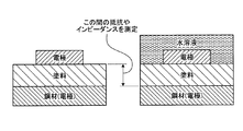
例えば、これらの技術では、図6に示すように、電極を塗料(塗膜)の表面側の水溶液中と塗装基材である鋼材に配置し、水溶液を介して塗膜表面〜塗装基材間の抵抗やインピーダンスを測定している。そのため、抵抗やインピーダンスの測定により、塗膜の乾燥を検出することは難しい。 For example, in these techniques, as shown in FIG. 6, the electrodes are disposed in the aqueous solution on the surface side of the paint (coated film) and on the steel material which is the coated substrate, and between the coated surface and the coated substrate through the aqueous solution The resistance and impedance of the Therefore, it is difficult to detect the drying of the coating film by the measurement of resistance and impedance.
また、図7のように、水溶液を介さないように配置された電極により塗膜の抵抗やインピーダンスを測定し、塗膜の乾燥を検出することも考えられる。しかし、塗膜(塗料)上に電極が存在するために、電極の直下は、塗膜の他の部分(電極と接していない部分)と比較して、乾燥したり吸水したりしにくくなる。よって、塗膜の乾燥や吸水の挙動を正確に検出できない可能性が高い。また、図7のように、水溶液を介さないように配置された電極によれば、塗膜全体の平均的な乾燥については検出できるが、塗膜における鋼材との界面付近の乾燥や吸水の挙動を正確に検出できない可能性が高い。 Moreover, it is also conceivable to measure the resistance or impedance of the coating film with an electrode disposed without an aqueous solution as shown in FIG. 7 to detect the drying of the coating film. However, due to the presence of the electrode on the coating (paint), it is difficult to dry or absorb water directly below the electrode as compared to the other part of the coating (the part not in contact with the electrode). Therefore, there is a high possibility that the drying or water absorption behavior of the coating can not be accurately detected. In addition, as shown in FIG. 7, according to the electrode disposed so as not to intervene in the aqueous solution, the average drying of the entire coating can be detected, but the behavior of drying and water absorption near the interface with the steel material in the coating Is likely not to be detected accurately.
一方、本実施形態の試験装置10は、塗膜が含水すると電極間の抵抗やインピーダンスが低下し、塗膜が乾燥すると抵抗やインピーダンスが上昇するという性質を利用し、塗装電極115に用いられる電極を、例えば、図8に示すように、塗膜(塗料)の内部に配置し、電極間の塗膜の抵抗やインピーダンスを測定する。これにより、塗膜における塗装基材との界面(図8における塗料内の電極が配置される位置付近)の乾燥や吸水の挙動を正確にモニタリングできる。
On the other hand, the
なお、塗装により塗装基材(例えば、鋼材)を腐食から守る場合、塗膜表面が含水していても塗膜と塗装基材との界面付近まで水が到達しなければ、塗装基材は腐食しない。このため、塗膜の平均的な含水量よりも、塗膜における塗装基材との界面付近が乾燥したか否かを検出することが重要である。このため、塗膜における塗装基材との界面付近の乾燥や吸水の挙動を正確にモニタリングできる本実施形態の試験装置10の適用効果は高い。
When the coated substrate (for example, steel material) is protected from corrosion by coating, the coated substrate is corroded if water does not reach near the interface between the coated film and the coated substrate even if the film surface is hydrated. do not do. For this reason, it is important to detect whether or not the vicinity of the interface with the coating substrate in the coating has been dried, rather than the average water content of the coating. For this reason, the application effect of the
また、図9に示すように、試験装置10は、塗膜表面からの深さ(距離)の異なる複数の位置(距離A、距離B、距離C)に電極を配置し、それぞれの深さにおける乾燥や含水の挙動をモニタリングしてもよい。なお、この場合、塗膜表面から電極までの深さは、渦電流式膜厚計等で測定すればよい。
Further, as shown in FIG. 9, the
10 試験装置
11 試験槽
12 空気供給部
13 塩水タンク
14 制御部
15 加湿部
16 加熱部
17 測定部
20 純水供給部
111 試料ホルダ
112 塩水噴霧部
113 空気濃度センサ
114 温湿度センサ
115 塗装電極
131 ヒータ
141 試験条件記憶部
DESCRIPTION OF
Claims (6)
試料である前記塗料が塗装された鋼材と、前記鋼材と同じ塗装仕様で塗装された塗装電極とに、所定時間、塩水を噴霧する塩水噴霧ステップと、
前記塩水噴霧ステップの後、前記試料および前記塗装電極の乾燥を開始し、前記乾燥を開始した塗装電極に対し、所定時間ごとに電気化学測定を実施し、単位時間当たりの前記塗装電極のインピーダンス、塗膜抵抗および静電容量の少なくともいずれか1つの変化量が所定値以下となった場合、前記試料の乾燥を終了させる乾燥ステップと、
前記乾燥ステップの後、前記試料を所定の温度および湿度の湿潤状態にする湿潤ステップと、
を含んだことを特徴とする腐食試験方法。 It is a corrosion test method to paint,
A salt spray step of spraying salt water for a predetermined time on a steel material coated with the paint as a sample and a coated electrode coated with the same paint specifications as the steel material;
After the salt spray step, drying of the sample and the painting electrode is started, and an electrochemical measurement is performed every predetermined time on the painting electrode which has started the drying, and the impedance of the painting electrode per unit time, A drying step for terminating the drying of the sample when the amount of change in at least one of the coating film resistance and the capacitance becomes equal to or less than a predetermined value;
Wetting the sample to a predetermined temperature and humidity after the drying step;
Corrosion test method characterized in that
前記各ステップにおいて、前記試料および前記塗装電極が設置される試験槽内の空気の酸素の濃度および二酸化炭素の濃度を大気中濃度よりも高めた状態とすることを特徴とする請求項1に記載の腐食試験方法。 If the paint contains zinc,
In each of the steps, the concentration of oxygen and the concentration of carbon dioxide in the air in the test tank in which the sample and the painting electrode are installed are set higher than the concentration in the atmosphere. Corrosion test method.
試料である前記塗料が塗装された鋼材と、前記鋼材と同じ塗装仕様で塗装された塗装電極とが設置される試験槽と、
前記試験槽内において前記試料および前記塗装電極に塩水を噴霧する塩水噴霧部と、
前記試験槽内に空気を供給する空気供給部と、
前記試験槽内の加熱を行う加熱部と、
前記試験槽内の加湿を行う加湿部と、
前記塗装電極に電気化学測定を実施し、前記塗装電極のインピーダンス、塗膜抵抗および静電容量の少なくともいずれか1つを測定する測定部と、
前記塩水噴霧部に、所定時間、前記試料および前記塗装電極へ塩水を噴霧させ、前記塩水の噴霧を終了した後、前記加熱部に前記試料および前記塗装電極の乾燥を開始させ、前記測定部により測定された単位時間当たりの前記塗装電極のインピーダンス、塗膜抵抗および静電容量の少なくともいずれか1つの変化量が所定値以下となったとき、前記加熱部による前記試料の乾燥を終了させ、前記加熱部および前記加湿部により、所定時間、前記試料を所定の温度および湿度の湿潤状態にさせる制御部と
を備えることを特徴とする腐食試験装置。 It is a corrosion test device for paint,
A test tank in which a steel material coated with the paint, which is a sample, and a paint electrode coated with the same paint specification as the steel material are installed;
A salt spray section for spraying salt water on the sample and the painting electrode in the test tank;
An air supply unit for supplying air into the test tank;
A heating unit that heats the inside of the test chamber;
A humidifying unit for humidifying the inside of the test tank;
A measurement unit which performs electrochemical measurement on the painted electrode and measures at least one of the impedance, the coating film resistance, and the capacitance of the painted electrode;
After the salt water is sprayed to the sample and the painting electrode for a predetermined time in the salt water spraying portion and the spraying of the salt water is finished, the drying of the sample and the painting electrode is started by the heating portion. The drying of the sample by the heating unit is ended when the measured change amount of at least one of the impedance, the coating film resistance, and the capacitance of the coating electrode per unit time becomes less than a predetermined value, And a control unit for bringing the sample into a wet state at a predetermined temperature and humidity for a predetermined time by a heating unit and the humidifying unit.
Priority Applications (1)
| Application Number | Priority Date | Filing Date | Title |
|---|---|---|---|
| JP2016085343A JP6523205B2 (en) | 2016-04-21 | 2016-04-21 | Corrosion test method and corrosion test apparatus |
Applications Claiming Priority (1)
| Application Number | Priority Date | Filing Date | Title |
|---|---|---|---|
| JP2016085343A JP6523205B2 (en) | 2016-04-21 | 2016-04-21 | Corrosion test method and corrosion test apparatus |
Publications (2)
| Publication Number | Publication Date |
|---|---|
| JP2017194377A JP2017194377A (en) | 2017-10-26 |
| JP6523205B2 true JP6523205B2 (en) | 2019-05-29 |
Family
ID=60155430
Family Applications (1)
| Application Number | Title | Priority Date | Filing Date |
|---|---|---|---|
| JP2016085343A Active JP6523205B2 (en) | 2016-04-21 | 2016-04-21 | Corrosion test method and corrosion test apparatus |
Country Status (1)
| Country | Link |
|---|---|
| JP (1) | JP6523205B2 (en) |
Cited By (1)
| Publication number | Priority date | Publication date | Assignee | Title |
|---|---|---|---|---|
| KR20220011451A (en) * | 2020-07-21 | 2022-01-28 | 주식회사 엔엔티 | Salt water spray test device |
Families Citing this family (4)
| Publication number | Priority date | Publication date | Assignee | Title |
|---|---|---|---|---|
| JP6891848B2 (en) * | 2018-04-16 | 2021-06-18 | 日本電信電話株式会社 | Corrosion test method and corrosion test equipment |
| WO2022003856A1 (en) * | 2020-07-01 | 2022-01-06 | 日本電信電話株式会社 | Weather resistance testing method and device |
| KR102265974B1 (en) * | 2020-12-04 | 2021-06-15 | 임진현 | Apparatus for salt water spray test with multi-type structure |
| CN113515157B (en) * | 2021-09-13 | 2021-11-30 | 中国电器科学研究院股份有限公司 | Environmental test equipment for salt spray concentration and relative humidity cooperative control |
Family Cites Families (7)
| Publication number | Priority date | Publication date | Assignee | Title |
|---|---|---|---|---|
| US4282181A (en) * | 1978-12-11 | 1981-08-04 | Ipm Corporation | Accelerated corrosion test apparatus |
| JPS5968649A (en) * | 1982-10-14 | 1984-04-18 | Toyota Motor Corp | Weather resistance and corrosion testing machine |
| JPH04109155A (en) * | 1990-08-29 | 1992-04-10 | Nissan Motor Co Ltd | Composite corrosion test method |
| JPH0743314B2 (en) * | 1992-05-25 | 1995-05-15 | スガ試験機株式会社 | Test method for accelerating deterioration of coating film adhesion performance |
| JP4888901B2 (en) * | 2007-03-16 | 2012-02-29 | 公益財団法人鉄道総合技術研究所 | Deterioration state measuring device and deterioration state measuring method |
| CN104020099B (en) * | 2014-05-27 | 2016-06-01 | 中国科学院金属研究所 | The cycle of metal and metal protection coating soaks accelerated corrosion test system and application |
| JP6755086B2 (en) * | 2015-11-12 | 2020-09-16 | 日本電信電話株式会社 | Corrosion test method and corrosion test equipment |
-
2016
- 2016-04-21 JP JP2016085343A patent/JP6523205B2/en active Active
Cited By (2)
| Publication number | Priority date | Publication date | Assignee | Title |
|---|---|---|---|---|
| KR20220011451A (en) * | 2020-07-21 | 2022-01-28 | 주식회사 엔엔티 | Salt water spray test device |
| KR102384758B1 (en) | 2020-07-21 | 2022-04-08 | 주식회사 엔엔티 | Salt water spray test device |
Also Published As
| Publication number | Publication date |
|---|---|
| JP2017194377A (en) | 2017-10-26 |
Similar Documents
| Publication | Publication Date | Title |
|---|---|---|
| JP6523205B2 (en) | Corrosion test method and corrosion test apparatus | |
| JP6891848B2 (en) | Corrosion test method and corrosion test equipment | |
| Dehri et al. | The effect of relative humidity on the atmospheric corrosion of defective organic coating materials: an EIS study with a new approach | |
| US6054038A (en) | Portable, hand-held, in-situ electrochemical sensor for evaluating corrosion and adhesion on coated or uncoated metal structures | |
| Leng et al. | The delamination of polymeric coatings from steel. Part 1: Calibration of the Kelvinprobe and basic delamination mechanism | |
| Magalhaes et al. | Electrochemical characterization of chromate coatings on galvanized steel | |
| Cano et al. | Electrochemical characterization of organic coatings for protection of historic steel artefacts | |
| Ritter et al. | A finite element model for mixed potential sensors | |
| CN110132741A (en) | Test device for simulating dynamic and static combined loading concrete of marine environment | |
| Castela et al. | Influence of unsupported concrete media in corrosion assessment for steel reinforcing concrete by electrochemical impedance spectroscopy | |
| Caldona et al. | Surface electroanalytical approaches to organic polymeric coatings | |
| Li et al. | Thermal transition effects and electrochemical properties in organic coatings: part 1—initial studies on corrosion protective organic coatings | |
| Kendig et al. | Rapid electrochemical assessment of paint | |
| CN109477810B (en) | Electrochemical method for determining the sensitivity of a gas sensor by means of a pulse sequence | |
| Chen et al. | Challenges and recent progress in unraveling the intrinsic pH effect in electrocatalysis | |
| CN103913499A (en) | Preparation method of molecular imprinting electrochemical sensor for detecting bovine hemoglobin | |
| Sykes et al. | Does “coating resistance” control corrosion? | |
| Grassini et al. | An in situ corrosion study of Middle Ages wrought iron bar chains in the Amiens Cathedral | |
| JP6755086B2 (en) | Corrosion test method and corrosion test equipment | |
| Davis et al. | Coating evaluation and validation of accelerated test conditions using an in-situ corrosion sensor | |
| Haji-Sulaiman et al. | Equilibrium of CO2 in aqueous diethanolamine (DEA) and amino methyl propanol (AMP) solutions | |
| CN107014878B (en) | Preparation method and application of carbon nano material modified foam nickel electrode | |
| Belmokre et al. | Corrosion study of carbon steel protected by a primer, by electrochemical impedance spectroscopy (EIS) in 3% NaCl medium and in a soil simulating solution | |
| Hoseinpoor et al. | Novel approach to measure water vapor permeability in pre-painted metals using adapted cup method: Correlation between permeation rate and tendency to blistering | |
| CN104713926A (en) | BP-neural-network-based non-destructive determination method for characteristics of steel corrosion product |
Legal Events
| Date | Code | Title | Description |
|---|---|---|---|
| A621 | Written request for application examination |
Free format text: JAPANESE INTERMEDIATE CODE: A621 Effective date: 20180622 |
|
| TRDD | Decision of grant or rejection written | ||
| A01 | Written decision to grant a patent or to grant a registration (utility model) |
Free format text: JAPANESE INTERMEDIATE CODE: A01 Effective date: 20190423 |
|
| A977 | Report on retrieval |
Free format text: JAPANESE INTERMEDIATE CODE: A971007 Effective date: 20190426 |
|
| A61 | First payment of annual fees (during grant procedure) |
Free format text: JAPANESE INTERMEDIATE CODE: A61 Effective date: 20190425 |
|
| R150 | Certificate of patent or registration of utility model |
Ref document number: 6523205 Country of ref document: JP Free format text: JAPANESE INTERMEDIATE CODE: R150 |