JP6522940B2 - Moving coil type stereo pickup cartridge - Google Patents
Moving coil type stereo pickup cartridge Download PDFInfo
- Publication number
- JP6522940B2 JP6522940B2 JP2014262384A JP2014262384A JP6522940B2 JP 6522940 B2 JP6522940 B2 JP 6522940B2 JP 2014262384 A JP2014262384 A JP 2014262384A JP 2014262384 A JP2014262384 A JP 2014262384A JP 6522940 B2 JP6522940 B2 JP 6522940B2
- Authority
- JP
- Japan
- Prior art keywords
- pair
- coil
- cantilever
- coils
- attached
- Prior art date
- Legal status (The legal status is an assumption and is not a legal conclusion. Google has not performed a legal analysis and makes no representation as to the accuracy of the status listed.)
- Active
Links
- 230000005291 magnetic effect Effects 0.000 claims description 31
- 241001422033 Thestylus Species 0.000 claims description 11
- 238000000926 separation method Methods 0.000 claims description 8
- 239000000853 adhesive Substances 0.000 claims description 7
- 230000001070 adhesive effect Effects 0.000 claims description 7
- 238000004804 winding Methods 0.000 claims description 5
- 239000000463 material Substances 0.000 claims description 4
- 230000015572 biosynthetic process Effects 0.000 claims description 2
- 230000007423 decrease Effects 0.000 claims description 2
- 230000004907 flux Effects 0.000 description 19
- 238000010248 power generation Methods 0.000 description 14
- RYGMFSIKBFXOCR-UHFFFAOYSA-N Copper Chemical compound [Cu] RYGMFSIKBFXOCR-UHFFFAOYSA-N 0.000 description 3
- XEEYBQQBJWHFJM-UHFFFAOYSA-N Iron Chemical group [Fe] XEEYBQQBJWHFJM-UHFFFAOYSA-N 0.000 description 3
- 241000209094 Oryza Species 0.000 description 2
- 235000007164 Oryza sativa Nutrition 0.000 description 2
- 238000006073 displacement reaction Methods 0.000 description 2
- 230000000694 effects Effects 0.000 description 2
- 239000003302 ferromagnetic material Substances 0.000 description 2
- 230000007274 generation of a signal involved in cell-cell signaling Effects 0.000 description 2
- 238000004519 manufacturing process Methods 0.000 description 2
- 235000009566 rice Nutrition 0.000 description 2
- 206010026749 Mania Diseases 0.000 description 1
- BGPVFRJUHWVFKM-UHFFFAOYSA-N N1=C2C=CC=CC2=[N+]([O-])C1(CC1)CCC21N=C1C=CC=CC1=[N+]2[O-] Chemical compound N1=C2C=CC=CC2=[N+]([O-])C1(CC1)CCC21N=C1C=CC=CC1=[N+]2[O-] BGPVFRJUHWVFKM-UHFFFAOYSA-N 0.000 description 1
- BQCADISMDOOEFD-UHFFFAOYSA-N Silver Chemical compound [Ag] BQCADISMDOOEFD-UHFFFAOYSA-N 0.000 description 1
- 230000003213 activating effect Effects 0.000 description 1
- XAGFODPZIPBFFR-UHFFFAOYSA-N aluminium Chemical compound [Al] XAGFODPZIPBFFR-UHFFFAOYSA-N 0.000 description 1
- 229910052782 aluminium Inorganic materials 0.000 description 1
- 210000003298 dental enamel Anatomy 0.000 description 1
- 239000002320 enamel (paints) Substances 0.000 description 1
- 239000003822 epoxy resin Substances 0.000 description 1
- PCHJSUWPFVWCPO-UHFFFAOYSA-N gold Chemical compound [Au] PCHJSUWPFVWCPO-UHFFFAOYSA-N 0.000 description 1
- 229920000647 polyepoxide Polymers 0.000 description 1
- 229920005989 resin Polymers 0.000 description 1
- 239000011347 resin Substances 0.000 description 1
- 238000005096 rolling process Methods 0.000 description 1
- 239000002904 solvent Substances 0.000 description 1
- 230000001052 transient effect Effects 0.000 description 1
Images

Classifications
-
- H—ELECTRICITY
- H04—ELECTRIC COMMUNICATION TECHNIQUE
- H04R—LOUDSPEAKERS, MICROPHONES, GRAMOPHONE PICK-UPS OR LIKE ACOUSTIC ELECTROMECHANICAL TRANSDUCERS; DEAF-AID SETS; PUBLIC ADDRESS SYSTEMS
- H04R9/00—Transducers of moving-coil, moving-strip, or moving-wire type
- H04R9/12—Gramophone pick-ups using a stylus; Recorders using a stylus
-
- H—ELECTRICITY
- H04—ELECTRIC COMMUNICATION TECHNIQUE
- H04R—LOUDSPEAKERS, MICROPHONES, GRAMOPHONE PICK-UPS OR LIKE ACOUSTIC ELECTROMECHANICAL TRANSDUCERS; DEAF-AID SETS; PUBLIC ADDRESS SYSTEMS
- H04R11/00—Transducers of moving-armature or moving-core type
- H04R11/08—Gramophone pick-ups using a stylus; Recorders using a stylus
-
- H—ELECTRICITY
- H04—ELECTRIC COMMUNICATION TECHNIQUE
- H04R—LOUDSPEAKERS, MICROPHONES, GRAMOPHONE PICK-UPS OR LIKE ACOUSTIC ELECTROMECHANICAL TRANSDUCERS; DEAF-AID SETS; PUBLIC ADDRESS SYSTEMS
- H04R9/00—Transducers of moving-coil, moving-strip, or moving-wire type
- H04R9/02—Details
- H04R9/025—Magnetic circuit
-
- H—ELECTRICITY
- H04—ELECTRIC COMMUNICATION TECHNIQUE
- H04R—LOUDSPEAKERS, MICROPHONES, GRAMOPHONE PICK-UPS OR LIKE ACOUSTIC ELECTROMECHANICAL TRANSDUCERS; DEAF-AID SETS; PUBLIC ADDRESS SYSTEMS
- H04R9/00—Transducers of moving-coil, moving-strip, or moving-wire type
- H04R9/12—Gramophone pick-ups using a stylus; Recorders using a stylus
- H04R9/16—Gramophone pick-ups using a stylus; Recorders using a stylus signals recorded or played back by vibration of a stylus in two orthogonal directions simultaneously
-
- H—ELECTRICITY
- H04—ELECTRIC COMMUNICATION TECHNIQUE
- H04R—LOUDSPEAKERS, MICROPHONES, GRAMOPHONE PICK-UPS OR LIKE ACOUSTIC ELECTROMECHANICAL TRANSDUCERS; DEAF-AID SETS; PUBLIC ADDRESS SYSTEMS
- H04R11/00—Transducers of moving-armature or moving-core type
- H04R11/08—Gramophone pick-ups using a stylus; Recorders using a stylus
- H04R11/12—Gramophone pick-ups using a stylus; Recorders using a stylus signals being recorded or played back by vibration of a stylus in two orthogonal directions simultaneously
-
- H—ELECTRICITY
- H04—ELECTRIC COMMUNICATION TECHNIQUE
- H04R—LOUDSPEAKERS, MICROPHONES, GRAMOPHONE PICK-UPS OR LIKE ACOUSTIC ELECTROMECHANICAL TRANSDUCERS; DEAF-AID SETS; PUBLIC ADDRESS SYSTEMS
- H04R17/00—Piezoelectric transducers; Electrostrictive transducers
- H04R17/04—Gramophone pick-ups using a stylus; Recorders using a stylus
- H04R17/08—Gramophone pick-ups using a stylus; Recorders using a stylus signals being recorded or played back by vibration of a stylus in two orthogonal directions simultaneously
-
- H—ELECTRICITY
- H04—ELECTRIC COMMUNICATION TECHNIQUE
- H04R—LOUDSPEAKERS, MICROPHONES, GRAMOPHONE PICK-UPS OR LIKE ACOUSTIC ELECTROMECHANICAL TRANSDUCERS; DEAF-AID SETS; PUBLIC ADDRESS SYSTEMS
- H04R19/00—Electrostatic transducers
- H04R19/06—Gramophone pick-ups using a stylus; Recorders using a stylus
- H04R19/10—Gramophone pick-ups using a stylus; Recorders using a stylus signals being recorded or played back by vibration of a stylus in two orthogonal directions simultaneously
Description
この発明は、45−45方式のステレオレコードから信号を抽出する可動コイル型ピックアップカートリッジに関し、特に単純な形状の発電コイルを利用することで、高い生産性と均一な品質を得ることが可能であると共に、左右の出力信号間のクロストークを低減し得る可動コイル型ステレオピックアップカートリッジに関する。 The present invention relates to a movable coil type pickup cartridge for extracting a signal from a 45-45 stereo record, and it is possible to obtain high productivity and uniform quality by using a power generating coil with a particularly simple shape. In addition, the present invention relates to a moving coil type stereo pickup cartridge capable of reducing crosstalk between left and right output signals.
この種の可動コイル型ステレオピックアップカートリッジ(以下、単にMCカートリッジとも言う。)は、大きく分けて鉄芯型と空芯型が提案されている。
前者の鉄芯型のMCカートリッジは、代表的なものとしてオルトフォンタイプと呼ばれるものが存在し、これはアーマチュアと称される発電コイルの巻き芯に強磁性体が用いられている。したがって信号の発電効率が良好であるという特質を有しており、MCカートリッジの大半に鉄芯型が採用されている。
An iron-core type and an air-core type are proposed for this type of movable coil type stereo pickup cartridge (hereinafter, also simply referred to as an MC cartridge), roughly divided.
The former iron core type MC cartridge is typically referred to as an orthophone type, and a ferromagnetic material is used for a winding core of a power generation coil called an armature. Therefore, it has the characteristic that the signal generation efficiency is good, and the iron core type is adopted in most of the MC cartridges.
一方、後者の空芯型のMCカートリッジは、信号の発電効率が低いという技術的な課題を有するものの、再生信号は前記した鉄芯型に採用される強磁性体による磁気歪み(ヒステリシス歪み)の影響を受けることはない。
したがって、再生音の音色にクセのない、より率直な再生音を得ることができると言われており、マニアの間においては根強い人気がある。
On the other hand, although the latter air core type MC cartridge has a technical problem that the power generation efficiency of the signal is low, the reproduced signal has a magnetostriction (hysteresis distortion) due to the ferromagnetic material adopted for the iron core type described above. It is not affected.
Therefore, it is said that it is possible to obtain a more straightforward reproduced sound without any peculiarity in the tone of the reproduced sound, and it is persistently popular among mania.
前記した可動コイル型ピックアップカートリッジの発電メカニズムは、周知のとおりスタイラスによりレコード信号を拾い、カンチレバーを介して磁気回路中の発電コイルを振動させることにより、発電コイルの両端部に信号電圧を出力させる。
しかしながら、カンチレバーを介して発電をするために、カンチレバーのたわみやモーメントによる歪みを生じさせて音質を損なうという技術的な課題を有している。しかも、発電コイルはカンチレバーの根元部分に配置されているために、発電コイルの振幅動作はレコードに刻まれた音溝の振幅よりもさらに小さく、したがって発電効率はきわめて小さいものとなる。
As described above, the power generation mechanism of the movable coil type pickup cartridge picks up a record signal with a stylus and vibrates a power generation coil in a magnetic circuit through a cantilever to output a signal voltage to both ends of the power generation coil.
However, in order to generate power through a cantilever, there is a technical problem that distortion due to flexure or moment of the cantilever is generated to impair the sound quality. Moreover, since the generating coil is disposed at the root portion of the cantilever, the amplitude operation of the generating coil is smaller than the amplitude of the sound groove carved on the record, and hence the generating efficiency is extremely small.
そこで、カンチレバーの途中に発電コイルを配置するなどして、空芯型のMCカートリッジでありながら、音質を損なうことなく発電効率も向上させたMCカートリッジの提案がなされており、これは次に示す特許文献1〜4などに開示されている。 Therefore, there has been proposed a MC cartridge which is an air-core type MC cartridge by disposing a power generation coil in the middle of a cantilever or the like, but improving the power generation efficiency without losing the sound quality. Patent documents 1-4 etc. are indicated.
ところで、この種のMCカートリッジは、信号発生源となる発電コイルのインピーダンスは極力低く、かつ高出力を得られることが望ましく、この条件が整うことにより、広いダイナミックレンジ、ハイ・トランジェント、低歪み、高S/Nなどの各要件を備えることができると言われている。 By the way, in this type of MC cartridge, it is desirable that the impedance of the power generation coil as a signal generation source is as low as possible and that high output can be obtained. By satisfying this condition, wide dynamic range, high transient, low distortion, It is said that each requirement such as high S / N can be provided.
これに対して前記した特許文献1に開示されたMCカートリッジは、その発電コイルとして、それぞれ8角形状に形成されたプリントコイルによる構成が採用されている。これによると発電コイルとしての実効質量は小さくできるものの、信号源となる発電コイルのインピーダンスが大きく、結果としてMCカートリッジとしての前項に記載した要件を整えることは難しいものとなる。
On the other hand, in the MC cartridge disclosed in
また、前記した特許文献2に開示されたMCカートリッジは、カンチレバーに連結されたパンタグラフ状に成形されたアーマチュアの対向する両端部に、角を丸めた3角形状(いわゆるおむすび型)の左右の発電コイルをそれぞれ取り付けた構成が採用されている。
これによると、パンタグラフ状のアーマチュアの繊細なメカニズムと、いわゆるおむすび型の発電コイルの製作が難しく、高い生産性と均一な品質のMCカートリッジを得ることが困難となる。
In addition, the MC cartridge disclosed in
According to this, the delicate mechanism of the pantograph-like armature and the production of the so-called rice ball-type generating coil are difficult, and it becomes difficult to obtain the MC cartridge with high productivity and uniform quality.
さらに、前記した特許文献3および4に開示されたMCカートリッジは、一方のチャンネルの発電コイルに交差するようにして、他方のチャンネルの発電コイルを互いに井桁状に重畳して巻回した構成が採用されている。
これによると、四辺形状の巻き枠を利用して、発電コイルを互いに井桁状に重畳して巻回するために、左右の発電コイルの巻回操作が複雑で容易ではない。したがって同様に、高い生産性と均一な品質のMCカートリッジを得ることが困難である。
Furthermore, the MC cartridges disclosed in
According to this, the winding operation of the left and right power generating coils is complicated and not easy because the power generating coils are wound in the form of parallel crosses using the four-side-shaped winding frame. Therefore, similarly, it is difficult to obtain an MC cartridge with high productivity and uniform quality.
この発明は、前記した各特許文献に開示された従来の可動コイル型ステレオピックアップカートリッジの技術的な問題点に着目してなされたものであり、単純な形状の発電コイルを利用することで高い生産性と均一な品質を得ることが可能な可動コイル型ステレオピックアップカートリッジを得ようとするものである。
加えて、発電コイルのインピーダンスが極力低く、高出力を得ることができるように構成すると共に、左右チャンネル間のクロストークも効果的に低減し得る可動コイル型ステレオピックアップカートリッジを提供することを課題とするものである。
The present invention has been made focusing on the technical problems of the conventional moving coil type stereo pickup cartridge disclosed in the above-mentioned patent documents, and high production is achieved by using a simple-shaped power generating coil. It is an object of the present invention to obtain a moving coil type stereo pickup cartridge capable of obtaining a uniform and uniform quality.
In addition, it is an object of the present invention to provide a movable coil type stereo pickup cartridge in which the impedance of the power generation coil is as low as possible and high output can be obtained and crosstalk between left and right channels can be effectively reduced. It is
前記した課題を達成するためになされたこの発明に係る可動コイル型ステレオピックアップカートリッジは、カンチレバーと、前記カンチレバーに取り付けられたスタイラスと、前記カンチレバーに取り付けられ前記スタイラスの振動に応答して振動する左右一対のコイルとを含む振動部と、磁石と一対のヨークを含み磁路を形成する磁気回路とを備えた可動コイル型ステレオピックアップカートリッジであって、前記一対のヨーク間に間隙が形成され、この間隙に前記コイルが配置されると共に、前記磁路は前記間隙を通過し、前記コイルは円形状のコイルであり、前記一対のヨークには、前記コイルを間にした対向する面にV字状の切欠きがそれぞれ形成され、前記V字状切欠きの交差角度θは、66度以上70度以下の範囲にあり、前記一対のコイルより得られる左右の出力信号のチャンネルセパレーションが、20db以上であることを特徴とする。 A moving coil type stereo pick-up cartridge according to the present invention made to achieve the above-mentioned problems comprises a cantilever, a stylus attached to the cantilever, and left and right attached to the cantilever and vibrating in response to the vibration of the stylus A moving coil type stereo pickup cartridge comprising: a vibrating portion including a pair of coils; and a magnetic circuit including a magnet and a pair of yokes to form a magnetic path, wherein a gap is formed between the pair of yokes. together with the coil gap is arranged, the magnetic path passes through the gap, the coil is co-yl circular shape, the pair of yoke, V-shaped on the surface facing the between the coil Jo of formed notches but each said V-shaped notch crossing angle theta, is in the range of 70 degrees 66 degrees, before Channel separation of the left and right output signals obtained from the pair of coils, characterized in that at least 20 db.
この場合、好ましい形態においては前記左右一対のコイルは、前記スタイラスの直上におけるカンチレバーの前端部に取り付けられた非磁性体により構成されたコイル支持体の面に沿って配置される。
加えて、円形状の左右一対のコイルの各中心と、前記カンチレバーの軸芯とにおいて二等辺三角形が形成されるように、前記コイルが前記コイル支持体に配置されることが望ましい。
In this case, the pair of left and right coils in the preferred embodiment are arranged along the surface of the coil support made of a nonmagnetic material which is attached to the front end of the cantilever directly above the stylus.
In addition, each center of the pair of left and right coils of circular, as isosceles triangle in the axis of the cantilever is formed, the coil are desirably positioned on the coil support.
そして、前記左右一対のコイルは、接着剤を付着させた被覆導線を利用し、これを円形状に巻き固めて形成することができる自己融着線を好適に利用することができる。
また、前記一対のコイルより得られる1kHzの信号出力のチャンネルセパレーションが、27dB以上であることが望ましい。
加えて、前記一対のヨークの端部は、互いに内側に近接するように折り曲げられると共に、折り曲げ部には対向するようにせり出して、ヨークの肉厚部が形成され、前記端部と肉厚部との間に、前記間隙が形成される。
また望ましくは、前記左右一対のコイルの中心は、前記V字状の切欠きの外側に位置するように設定される。
さらに、前記カンチレバーの前端部は、カンチレバーの軸に直交する断面が前端部に向かって漸次小さくなるテーパ部が形成されて先細りの状態に構成され、前記テーパ部に前記スタイラスが取り付けられると共に、前記テーパ部の形成位置とは反対側のカンチレバー上に、前記コイルが取り付けられた構成を好適に採用することができる。
Then, the right and left pair of coils utilizes insulated conductive wires with attached adhesive, which can be suitably used a self-fusing line can be formed by hardening wound in a circular shape.
Preferably, the channel separation of the 1 kHz signal output obtained from the pair of coils is 27 dB or more.
In addition, the end portions of the pair of yokes are bent so as to be close to each other inside, and the bent portions are protruded so as to face each other to form thick portions of the yoke, and the end portions and the thick portions And the gap is formed therebetween.
Preferably, the centers of the pair of left and right coils are set to be located outside the V-shaped notch.
Further, the front end portion of the cantilever is formed in a tapered state in which a tapered portion in which a cross section orthogonal to the axis of the cantilever gradually decreases toward the front end portion is formed, and the stylus is attached to the tapered portion The configuration in which the coil is attached on the cantilever opposite to the formation position of the tapered portion can be suitably adopted.
前記した構成のMCカートリッジによると、発電コイルとして機能する左右一対の真円形状の平面コイルは、対向する面にV字状の切欠きがそれぞれ形成された一対のヨーク間に配置される。そして、左右一対の平面コイルは、前記スタイラスの直上におけるカンチレバーの前端部に取り付けられたコイル支持体の面に沿って配置されることで、コイル振幅を大きく採ることができる。 According to the MC cartridge having the above-described configuration, the pair of left and right perfectly circular planar coils functioning as a power generation coil is disposed between the pair of yokes in which V-shaped notches are formed on the opposing surfaces. The pair of left and right planar coils are disposed along the surface of the coil support attached to the front end of the cantilever immediately above the stylus, so that the coil amplitude can be increased.
左右一対の真円形状の平面コイルは、例えば銅線にエナメル被覆が施されると共に、接着剤がオーバコートされた自己融着線を利用することにより、比較的容易に成形することができるので、単純な真円形状の発電コイルを利用することで高い生産性と均一な品質を得ることができる。これによりインピーダンスが低く、高出力を得ることができるMCカートリッジを提供することが可能となる。 The pair of right and left perfect circular planar coils can be relatively easily formed by utilizing, for example, a self-bonding wire coated with an enamel coating on a copper wire and overcoated with an adhesive. The high productivity and uniform quality can be obtained by using a simple round shape generating coil. As a result, it is possible to provide an MC cartridge capable of obtaining high output with low impedance.
さらに、一対のヨークの対向する面にはV字状の切欠きが形成されると共に、このV字状の交差角度を、90度以下の最適値に設定することで、漏洩磁束を考慮した磁束の仮想角度を実質的に90度となるように設定することができる。これにより左右チャンネル間のクロストークも効果的に低減し得るMCカートリッジを提供することが可能となる。この交差角度は63度以上80度以下の範囲に設定するのが望ましく、さらに望ましくは66度以上70度以下の範囲に設定するのが望ましい。 Furthermore, a V-shaped notch is formed on the facing surfaces of the pair of yokes, and the V-shaped crossing angle is set to an optimum value of 90 degrees or less, thereby considering the magnetic flux in consideration of the leakage flux. The virtual angle of can be set to be substantially 90 degrees. This makes it possible to provide an MC cartridge in which crosstalk between left and right channels can be effectively reduced. The crossing angle is preferably set in the range of 63 degrees to 80 degrees, and more preferably in the range of 66 degrees to 70 degrees.
この発明に係るMCカートリッジについて、図に示す実施の形態に基づいて説明する。なお、以下に説明する各図においては、それぞれ同一部分を同一符号で示しているが、紙面の都合により一部の図面においては代表的な部分に符号を付けて、その詳細な構成は他の図面に付けた符号を引用して説明する場合もある。 An MC cartridge according to the present invention will be described based on the embodiment shown in the drawings. In the drawings described below, the same parts are denoted by the same reference numerals, but for convenience of the drawing, reference numerals are attached to representative parts in some of the drawings, and the detailed configuration thereof is not shown. The description may be made with reference to the reference numerals attached to the drawings.
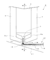
図1に全体構成で示したとおり、このMCカートリッジはその要素を大きくわけると、振動部と磁気回路およびこれらを支持するケーシングとにより構成されている。
すなわち、ケーシング1の前端部には、磁気回路2を構成する角柱状の磁石3と、この磁石3の磁極に対向して磁石3を挟むように配置された一対のヨーク4,5とが、これらを貫通するボルト6によって取り付けられている。そして図1に示されているように、前記磁気回路2はケーシング1の前端面における傾斜角度に対応して、若干下向きとなるようにケーシング1の前面側に取り付けられている。
As shown in FIG. 1 as a whole, the MC cartridge is composed of a vibration part, a magnetic circuit, and a casing for supporting them, when its elements are roughly divided.
That is, at the front end of the
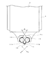
また、磁気回路2を構成する前記一対のヨーク4,5の下端部は、図2に示したように、互いに内側に近接するように折り曲げ形成されており、また一対のヨーク4,5の下端部の内側は、対向するようにせり出して肉厚部4a,5aが形成されている。
そして、ヨーク4,5の下端部と肉厚部4a,5aとの間には、平行面による間隙(磁気ギャップとも言う。)7が形成されている。これにより、磁石3を挟む一対のヨーク4,5と、前記磁気ギャップ7とにより磁路が形成されている。
なお、一対のヨーク4,5の内側に向かってせり出した肉厚部4a,5aは、前記磁気ギャップ7の磁束密度をより高めるように機能するものとなる。
Further, lower ends of the pair of
A gap (also referred to as a magnetic gap) 7 in a parallel plane is formed between the lower end portions of the
The thick portions 4a and 5a protruding toward the inside of the pair of
図1に示すように前記ケーシング1の下側面と、ケーシング1の底面に取り付けられた底面カバー1aとの間には、空間部が形成されている。そしてこの空間部にはケーシング1に取り付けられた支持具9によって、図示せぬダンパー等を含み円柱状に形成されたホルダー10が取り付けられている。
なお、前記ホルダー10は、その前端部が若干下向きとなるように前記支持具9に取り付けられており、このホルダー10の中央部に取り付けられた止めネジ11は、後述するカンチレバーの抜け止めの機能を果たす。
As shown in FIG. 1, a space is formed between the lower side surface of the
The
前記ホルダー10は、このホルダー10の前端部に取り付けられたカンチレバー14を含む振動部13を揺動可能に支持するものであり、カンチレバー14の前端部には、下向きにスタイラス15が取り付けられている。
そして、図2にも示されているように、スタイラス15の直上におけるカンチレバー14の前端部には、樹脂フィルムなどの非磁性体により形成されたコイル支持体16が、カンチレバー14の軸方向に直交するように、例えばエポキシ樹脂などの接着剤を利用して取り付けられている。
The
Then, as also shown in FIG. 2, at the front end portion of the
このコイル支持体16には真円形状に巻回された一対の平面コイル17A,17Bが配置され、コイル支持体16に配置された一対の平面コイル17A,17Bは前記磁気ギャップ7内に位置するように構成されている。
なお、図2に符号31で示す線は、カンチレバー14の前端部に取り付けられたスタイラス15がトレースするレコード盤の音溝を示している。
A pair of
The line indicated by reference numeral 31 in FIG. 2 indicates the sound groove of the record board traced by the
図3は、コイル支持体16に配置された左右一対のコイル17A,17Bと、ヨーク4,5による磁気ギャップ7に対向するようにして、それぞれのヨークに形成されたV字状切欠きとの好ましい位置関係を示している。
左右一対のコイル17A,17Bは、例えば接着剤を付着させた被覆導線(エナメル線)を真円形状に巻き固めて形成されている。
これには、好ましくはφ20μm程度の高純度銅線が用いられ、例えば円柱状の治具を利用してφ0.9mmで7ターン程度巻回することでコイル状に成形する。
FIG. 3 shows a pair of left and
The pair of left and
For this purpose, a high purity copper wire of preferably about φ20 μm is used, and for example, it is formed into a coil by winding about 7 turns at φ0.9 mm using a cylindrical jig.
そして被覆導線にオーバコートされた接着剤を、熱または溶剤により活性化することで、コイル状の被覆導線は自己融着により固まり、平面状のコイル17A,17Bを成形することができる。
真円形状に巻回された平面状コイル17A,17Bは、図3に仮想線(一点鎖線)で示したように、平面状コイル17A,17Bの各中心と、前記カンチレバーの軸芯とにおいて二等辺三角形が形成されるように、前記コイル支持体16を介して、カンチレバー14の前端部に取り付けられる。
Then, by activating the adhesive coated on the coated lead with heat or a solvent, the coiled coated lead is solidified by self-fusion and the
The
なお、前記各コイル17A,17Bの各引き出し線18は、図2に示すようにカンチレバー14の長手方向に沿って接着剤により固着され、ケーシング1の後端部に取り付けられた端子ピン20a,20bに接続されている。
The lead wires 18 of the
前記した構成の平面コイル17A,17Bによると、それぞれのインピーダンスは3Ω程度と、きわめて低い数値のものを得ることができる。
加えて、平面コイル17A,17Bが配置されたコイル支持体16は、スタイラス15の直上におけるカンチレバー14の前端部に取り付けられるので、コイル17A,17Bによる発電効率は高く、その出力電圧値は0.15〜0.25mV/5cmの特性を得ることができる。
なお、前記したコイル17A,17Bを構成する素材としては、前記した銅線以外にアルミニウム線、金線、銀線などを利用することができる。
According to the
In addition, since the
In addition to the copper wire described above, an aluminum wire, a gold wire, a silver wire or the like can be used as a material forming the
一方、前記したコイル17A,17Bを間にした一対のヨーク4,5の対向する面、すなわち磁気ギャップ7におけるヨーク4,5の対向する面には、それぞれV字状の切欠き19が形成されている。
なお、図3においては一方のヨーク5に形成されたV字状の切欠きを符号19で示しているが、他方のヨーク4おいても対向する位置に、同様のV字状の切欠きが形成されている。
On the other hand, V-shaped
In addition, although the V-shaped notch formed in one
ヨーク4,5に形成されたV字状切欠き19に対して、予め定められた針圧が加わった状態における前記一対のコイル17A,17Bの位置関係は、好ましくは図3に示した状態になされる。
すなわちコイル17A,17Bは、対向するヨーク4,5の間に位置して磁束に交差する部分(磁束を切る部分)と、V字状の切欠き19によって磁束を切らない部分が存在するように位置される。
The positional relationship between the pair of
That is, the
この場合、V字状の切欠き19に沿って漏洩磁束が発生するため、好ましくは真円形状のコイル17A,17Bの中心が、図3に示したようにV字状の切欠き19の若干外側に位置するように設定される。
この状態において、スタイラスが15がレコード盤の音溝をトレースし、コイル17A,17Bが矢印X方向およびY方向に振動する。これによりコイル17A,17Bが、磁束を横切ることにより生ずる起電力が左右の出力信号として取り出される。
In this case, since a leakage flux is generated along the V-shaped
In this state, the
ところで前記した構成によると、ヨーク4,5に形成されたV字状切欠き19に沿って漏洩磁束が発生し、その漏洩磁束の磁束密度はV字状切欠きの頂部付近が高く、V字状切欠きの裾野付近は低くなることが知られている。
したがって、V字状切欠き19の交差角度θを、例えば90度に設定した場合には、前記した漏洩磁束の不均衡な分布により、漏洩磁束による等磁束密度線(磁束の仮想角度)は実質的に90度よりも拡がり、これがクロストークを発生させる原因となる。
By the way, according to the configuration described above, a leakage flux is generated along the V-shaped
Therefore, when the crossing angle θ of the V-shaped
すなわち、図3においてコイル支持体16が例えば矢印X方向に振動変位した場合には、コイル17Aには起電力が発生すべきではないところ、コイル17AにおけるV字状切欠き19の頂部付近と裾野付近においては、横切る磁束密度に差が生じ、これがクロストークとなる。
同様に、コイル支持体16が例えば矢印Y方向に振動変位した場合には、コイル17Bには起電力が発生すべきではないところ、コイル17BにおけるV字状切欠き19の頂部付近と裾野付近においては、横切る磁束密度に差が生じ、これがクロストークとなる。
That is, when the
Similarly, when the
したがって、ヨーク4,5に形成されるV字状切欠き19の交差角度θを90度以下となるように設定して、V字状切欠き19に沿って生ずる漏洩磁束による等磁束密度線が実質的に90度となるようにすることで、クロストークの少ないMCカートリッジを得ることができる。
Therefore, by setting the crossing angle θ of the V-shaped
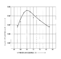
図4は、ヨーク4,5に形成されるV字状切欠き19の交差角度に対するクロストーク特性を示したものであり、横軸はV字状切欠き19の交差角度θを示し、縦軸はクロストーク特性に代わる1kHzの信号出力のチャンネルセパレーションの値を示している。
この図4に示すようにV字状切欠き19の交差角度θが、66度〜70度付近が最良のクロストーク特性(チャンネルセパレーションが27dB以上)を得ることができる。
そして、チャンネルセパレーションが20dB以上となるV字状切欠き19の交差角度θは63度〜80度であり、この範囲がMCカートリッジとして実用上において好適に採用し得るものであると言うことができる。
FIG. 4 shows the crosstalk characteristic with respect to the crossing angle of the V-shaped
As shown in FIG. 4, the best crosstalk characteristic (channel separation of 27 dB or more) can be obtained when the crossing angle θ of the V-shaped
And, the crossing angle θ of the V-shaped
以上のとおり、この発明に係るMCカートリッジによると、単純な真円形状の発電コイルを利用することで、高い生産性と均一な品質を得ることができ、インピーダンスが低く高出力を得ることができるMCカートリッジを提供することが可能となる。
そして、対向する各ヨークに形成されるV字状切欠きの交差角度θを、63度〜80度の範囲に設定することで、クロストーク特性に優れたMCカートリッジを提供することができるなど、前記した発明の効果の欄に記載したとおりの作用効果を得ることができる。
As described above, according to the MC cartridge of the present invention, high productivity and uniform quality can be obtained, and high output can be obtained with low impedance, by using a simple perfect circular shape generating coil. It becomes possible to provide an MC cartridge.
And, by setting the crossing angle θ of the V-shaped notches formed in the respective facing yokes to a range of 63 degrees to 80 degrees, it is possible to provide an MC cartridge excellent in crosstalk characteristics, etc. It is possible to obtain the operation and effect as described in the column of the above-mentioned effect of the invention.
1 ケーシング
2 磁気回路
3 磁石
4,5 ヨーク
6 ボルト
7 間隙(磁気ギャップ)
9 支持具
10 ホルダー
11 支軸
13 振動部
14 カンチレバー
15 スタイラス
16 コイル支持体
17A,17B コイル
19 V字状切欠き
31 音溝
1 casing 2
9
Claims (8)
を備えた可動コイル型ステレオピックアップカートリッジであって、
前記一対のヨーク間に間隙が形成され、この間隙に前記コイルが配置されると共に、前記磁路は前記間隙を通過し、
前記コイルは円形状のコイルであり、
前記一対のヨークには、前記コイルを間にした対向する面にV字状の切欠きがそれぞれ形成され、
前記V字状切欠きの交差角度θは、66度以上70度以下の範囲にあり、前記一対のコイルより得られる左右の出力信号のチャンネルセパレーションが、20db以上であることを特徴とする可動コイル型ステレオピックアップカートリッジ。 A vibrator including a cantilever, a stylus attached to the cantilever, a pair of left and right coils attached to the cantilever and vibrating in response to the vibration of the stylus, a magnet and a pair of yokes to form a magnetic path Magnetic circuit,
A moving coil type stereo pick-up cartridge provided with
A gap is formed between the pair of yokes, the coil is disposed in the gap, and the magnetic path passes through the gap;
The coil is a circular coil,
In the pair of yokes, V-shaped notches are respectively formed on opposing surfaces with the coil interposed therebetween;
Said V-shaped notch crossing angle theta, is in the range of 70 degrees 66 degrees, channel separation of the left and right output signals obtained from the pair of coils, moving coil, characterized in that at least 20db Stereo pickup cartridge.
Priority Applications (4)
| Application Number | Priority Date | Filing Date | Title |
|---|---|---|---|
| JP2014262384A JP6522940B2 (en) | 2014-12-25 | 2014-12-25 | Moving coil type stereo pickup cartridge |
| US14/958,242 US9497548B2 (en) | 2014-12-25 | 2015-12-03 | Moving-coil type stereo pickup cartridge |
| EP15201693.7A EP3038380B1 (en) | 2014-12-25 | 2015-12-21 | Moving-coil type stereo pickup cartridge |
| CN201510977600.8A CN105744450B (en) | 2014-12-25 | 2015-12-23 | Moving-coil type stereo pick-up head |
Applications Claiming Priority (1)
| Application Number | Priority Date | Filing Date | Title |
|---|---|---|---|
| JP2014262384A JP6522940B2 (en) | 2014-12-25 | 2014-12-25 | Moving coil type stereo pickup cartridge |
Publications (3)
| Publication Number | Publication Date |
|---|---|
| JP2016122999A JP2016122999A (en) | 2016-07-07 |
| JP2016122999A5 JP2016122999A5 (en) | 2018-01-25 |
| JP6522940B2 true JP6522940B2 (en) | 2019-05-29 |
Family
ID=55024884
Family Applications (1)
| Application Number | Title | Priority Date | Filing Date |
|---|---|---|---|
| JP2014262384A Active JP6522940B2 (en) | 2014-12-25 | 2014-12-25 | Moving coil type stereo pickup cartridge |
Country Status (4)
| Country | Link |
|---|---|
| US (1) | US9497548B2 (en) |
| EP (1) | EP3038380B1 (en) |
| JP (1) | JP6522940B2 (en) |
| CN (1) | CN105744450B (en) |
Families Citing this family (5)
| Publication number | Priority date | Publication date | Assignee | Title |
|---|---|---|---|---|
| JP6649209B2 (en) * | 2016-08-29 | 2020-02-19 | 株式会社オーディオテクニカ | Swing prevention member of needle tip protector and pickup cartridge |
| CN106658316B (en) * | 2016-12-28 | 2022-03-11 | 合肥市菲凡音响有限责任公司 | Moving coil phonograph head demagnetizing device and method |
| USD876429S1 (en) * | 2018-01-05 | 2020-02-25 | Audio-Technica Corporation | Pick-up cartridge |
| JP7079908B1 (en) * | 2021-10-22 | 2022-06-03 | 正史 三宅 | Moving coil type stereo record and monaural record playback cartridge |
| CN116261081B (en) * | 2023-05-16 | 2023-08-01 | 合肥联宝信息技术有限公司 | Earphone circuit and control method thereof |
Family Cites Families (13)
| Publication number | Priority date | Publication date | Assignee | Title |
|---|---|---|---|---|
| JPS5134406U (en) | 1974-09-06 | 1976-03-13 | ||
| JPS5114002A (en) | 1974-07-24 | 1976-02-04 | Fidelity Research | Mc gatakaatoritsuji |
| JPS5210105A (en) | 1975-07-15 | 1977-01-26 | Kenkichi Tsukamoto | Moving coild cartidge |
| JPS53137106A (en) * | 1977-05-06 | 1978-11-30 | Ogura Jewel Industry Co Ltd | Moving coil type cartridge |
| GB2002619B (en) * | 1977-07-13 | 1982-03-17 | Victor Company Of Japan | Moving-coil type stereo pickup cartridge |
| JPS5420102U (en) * | 1977-07-13 | 1979-02-08 | ||
| JPS5448503A (en) | 1977-09-01 | 1979-04-17 | Matsushita Electric Ind Co Ltd | Moving coil type pickup cartridge |
| US4209670A (en) * | 1977-10-24 | 1980-06-24 | Victor Company Of Japan, Limited | Moving-coil type pickup cartridge |
| US4251695A (en) * | 1977-10-24 | 1981-02-17 | Victor Company Of Japan Ltd. | Pickup cartridge having means for producing magnetic fields of opposite directions for coil plate |
| JPS5950197U (en) * | 1982-09-24 | 1984-04-03 | 日本ビクター株式会社 | Moving coil type pick-up cartridge |
| JPH05308028A (en) * | 1991-03-28 | 1993-11-19 | Toshiba Lighting & Technol Corp | Planar coil |
| EP0996311B1 (en) * | 1997-07-09 | 2007-03-21 | FPS Inc. | Planar acoustic transducer |
| CN202584709U (en) * | 2012-02-14 | 2012-12-05 | 嘉强电子股份有限公司 | Pickup apparatus for musical instrument |
-
2014
- 2014-12-25 JP JP2014262384A patent/JP6522940B2/en active Active
-
2015
- 2015-12-03 US US14/958,242 patent/US9497548B2/en active Active
- 2015-12-21 EP EP15201693.7A patent/EP3038380B1/en active Active
- 2015-12-23 CN CN201510977600.8A patent/CN105744450B/en active Active
Also Published As
| Publication number | Publication date |
|---|---|
| EP3038380B1 (en) | 2017-11-29 |
| US9497548B2 (en) | 2016-11-15 |
| JP2016122999A (en) | 2016-07-07 |
| CN105744450B (en) | 2020-10-16 |
| CN105744450A (en) | 2016-07-06 |
| EP3038380A1 (en) | 2016-06-29 |
| US20160192080A1 (en) | 2016-06-30 |
Similar Documents
| Publication | Publication Date | Title |
|---|---|---|
| JP6522940B2 (en) | Moving coil type stereo pickup cartridge | |
| JP7319603B2 (en) | Magnetic head and magnetic recording device | |
| US4251695A (en) | Pickup cartridge having means for producing magnetic fields of opposite directions for coil plate | |
| US3526728A (en) | Variable reluctance type pickup cartridge | |
| US3504134A (en) | Multiple magnetic head with a strip core having a common base portion | |
| US3633274A (en) | Method of making magnetic head device | |
| JPS6042680B2 (en) | Pickup Cartridge | |
| JPS61150139A (en) | Objective lens driving device of optical information processor | |
| JP2001333492A (en) | Ribbon speaker | |
| JP6616095B2 (en) | Movable magnet type pickup cartridge | |
| JPS6334400Y2 (en) | ||
| US4493071A (en) | Pickup cartridge | |
| JPS5846635Y2 (en) | Moving coil type pickup cartridge | |
| JPS5934238Y2 (en) | Moving coil type pick-up cartridge | |
| KR200265289Y1 (en) | Pickup cartridge for mc-type | |
| JPH0227897A (en) | Electrically driven electroacoustic exchange | |
| JPH0256199A (en) | Electro-dynamic type electro-acoustic transducer | |
| JPH0227896A (en) | Electrically driven electroacoustic exchange | |
| JPS58218299A (en) | Moving coil type pickup cartridge | |
| JPH0721574A (en) | Object lens holding member of optical disk device | |
| JPH01258595A (en) | Speaker | |
| JPH0227898A (en) | Electrically driven electroacoustic exchange | |
| JPS5820200B2 (en) | MC type pickup cartridge | |
| JPH01242000A (en) | Dynamic type electroacoustic transducer | |
| JPS639281B2 (en) |
Legal Events
| Date | Code | Title | Description |
|---|---|---|---|
| A521 | Request for written amendment filed |
Free format text: JAPANESE INTERMEDIATE CODE: A523 Effective date: 20171208 |
|
| A621 | Written request for application examination |
Free format text: JAPANESE INTERMEDIATE CODE: A621 Effective date: 20171208 |
|
| A977 | Report on retrieval |
Free format text: JAPANESE INTERMEDIATE CODE: A971007 Effective date: 20181015 |
|
| A131 | Notification of reasons for refusal |
Free format text: JAPANESE INTERMEDIATE CODE: A131 Effective date: 20181017 |
|
| A521 | Request for written amendment filed |
Free format text: JAPANESE INTERMEDIATE CODE: A523 Effective date: 20181214 |
|
| TRDD | Decision of grant or rejection written | ||
| A01 | Written decision to grant a patent or to grant a registration (utility model) |
Free format text: JAPANESE INTERMEDIATE CODE: A01 Effective date: 20190423 |
|
| A61 | First payment of annual fees (during grant procedure) |
Free format text: JAPANESE INTERMEDIATE CODE: A61 Effective date: 20190425 |
|
| R150 | Certificate of patent or registration of utility model |
Ref document number: 6522940 Country of ref document: JP Free format text: JAPANESE INTERMEDIATE CODE: R150 |
|
| R250 | Receipt of annual fees |
Free format text: JAPANESE INTERMEDIATE CODE: R250 |