JP6520700B2 - Hot water storage type hot water heater - Google Patents
Hot water storage type hot water heater Download PDFInfo
- Publication number
- JP6520700B2 JP6520700B2 JP2015253181A JP2015253181A JP6520700B2 JP 6520700 B2 JP6520700 B2 JP 6520700B2 JP 2015253181 A JP2015253181 A JP 2015253181A JP 2015253181 A JP2015253181 A JP 2015253181A JP 6520700 B2 JP6520700 B2 JP 6520700B2
- Authority
- JP
- Japan
- Prior art keywords
- hot water
- water supply
- water storage
- time
- unit
- Prior art date
- Legal status (The legal status is an assumption and is not a legal conclusion. Google has not performed a legal analysis and makes no representation as to the accuracy of the status listed.)
- Active
Links
Images


Description
本発明は、温水の貯湯及び給湯を行う貯湯式給湯機に関する。 BACKGROUND OF THE INVENTION Field of the Invention The present invention relates to a hot water storage type hot water supply device that stores hot water and supplies hot water.
一般に、ヒートポンプ等の加熱手段により沸き上げた湯を貯湯タンクに貯える貯湯式給湯機が広く用いられている。貯湯式給湯機は、貯湯タンクから取出した湯を用いて、台所、洗面所等の蛇口、または、浴槽、シャワー等の給湯先に給湯する。また、従来技術としては、例えば特許文献1に記載されているような貯湯式給湯機が知られている。この貯湯式給湯機においては、1日の時間帯を電力料金制度に応じて深夜電力時間帯、第1昼間時間帯及び第2昼間時間帯に区分し、現在時刻情報と、電力料金制度の設定内容と、残湯量情報とに基いて湯水の沸き上げを制御する構成としている。
In general, a hot water storage type hot water heater that stores hot water boiled up by heating means such as a heat pump in a hot water storage tank is widely used. The hot water storage type hot water supply device uses the hot water extracted from the hot water storage tank to supply hot water to a faucet such as a kitchen or a washroom or a hot water destination such as a bath or a shower. Moreover, as a prior art, for example, a storage water heater as described in
従来技術の貯湯式給湯機は、電力料金制度を深夜電力時間帯、第1昼間時間帯及び第2昼間時間帯から選択することができる。しかしながら、これら3種類以外の電力料金制度が存在する場合には、当該電力料金制度に対応することができないため、電力料金が実現可能な最低料金よりも高くなることがあり、沸き上げの制御を最適化することができないという問題がある。 The conventional hot water storage type hot-water heater can select a power rate system from a late-night power period, a first daytime period, and a second daytime period. However, if there is a power rate system other than these three types, the system can not cope with the power rate system, so the power rate may be higher than the lowest achievable rate, and the control of heating is There is a problem that it can not be optimized.
本発明は、上述のような課題を解決するためになされたもので、電力料金の異なる時間帯が4つ以上に細分化された場合でも、加熱運転を適切なタイミングで小刻みに実行しつつ、必要な貯湯量を確保することができ、電力コストを抑制することが可能な貯湯式給湯機を提供することにある。 The present invention has been made to solve the problems as described above, and even when the time zone of different power rates is subdivided into four or more, the heating operation is performed in small steps at appropriate timings. The present invention is to provide a hot water storage type hot water supply device capable of securing a necessary amount of hot water storage and suppressing power costs.
本発明に係る貯湯式給湯機は、温水を貯湯するための貯湯タンクと、貯湯タンクに貯湯される温水を加熱する加熱手段と、ユーザーが希望する給湯使用量、給湯温度及び給湯使用時刻を給湯負荷要求として入力する入力手段と、給湯負荷要求を満たすために必要な貯湯温度及び貯湯量の温水を貯湯タンクに貯湯するように加熱手段を制御して貯湯タンク内の湯水を加熱する加熱運転を行う制御部と、加熱運転に用いる電力料金の時間帯別単価情報であって、4つ以上の異なる時間帯の時間帯別単価情報を外部との通信により入手する電力料金情報入手手段と、を備え、制御部は、電力料金情報入手手段により入手した時間帯別単価情報に基いて加熱運転を制御し、他の時間帯と比較して電力料金が安い時間帯にのみ加熱運転を行うことで給湯負荷要求を満たすことが可能であるか否かの判定を実行し、判定が不成立となる場合に、他の時間帯のうち給湯使用時刻に近い時間帯から順に給湯負荷要求が満たされるまで加熱運転を行うものである。
A hot water storage type water heater according to the present invention comprises a hot water storage tank for storing hot water, a heating means for heating the hot water stored in the hot water storage tank, a hot water usage amount desired by a user, a hot water temperature and a hot water use time A heating operation for heating the hot and cold water in the hot water storage tank by controlling the heating means so as to store the hot water of the hot water storage temperature and the hot water storage amount necessary to satisfy the hot water supply load demand. A control unit to perform, and power rate information obtaining means for obtaining time range unit price information of four or more different time zones by communication with an external device; The control unit controls the heating operation based on the unit price information according to the time zone acquired by the power rate information acquiring unit, and performs the heating operation only in the time zone where the power rate is lower than other time zones. Hot water supply It is judged whether or not it is possible to satisfy the load request, and if the judgment is not satisfied, the heating operation is continued until the hot water supply load request is satisfied in order from the time zone closer to the hot water supply use time among other time zones. To do .
本発明によれば、電力自由化等により電力料金の異なる時間帯が4つ以上に細分化された場合でも、ユーザーが意識することなく、加熱運転を適切なタイミングで小刻みに実行して必要な貯湯量を確保することができ、電力コストを抑制することができる。 According to the present invention, even when time zones of different power rates are subdivided into four or more due to power deregulation etc., it is necessary to execute heating operation little by little at appropriate timing without being conscious of the user. The amount of stored water can be secured, and the power cost can be suppressed.
実施の形態1.
以下、図面を参照して、本発明の実施の形態1について説明する。なお、各図においては、共通する要素に同一の符号を付し、重複する説明を省略する。また、本発明は、以下の実施の形態に限定されるものではなく、本発明の主旨を逸脱しない範囲で種々に変形することが可能である。また、本明細書において、「湯水」とは、温水(湯)及び水を総称している。
Hereinafter,
図1は、本発明の実施の形態1による貯湯式給湯機を示す構成図である。この図に示すように、貯湯式給湯機35は、タンクユニット33と、ヒートポンプサイクルを利用するHPユニット7と、ユーザーが運転状態の操作及び各種の設定値の変更等を行うリモコン44とを備えている。HPユニット7とタンクユニット33とは、HP往き配管14及びHP戻り配管15を介して接続されると共に、図示しない配線を介して電気的に接続されている。タンクユニット33には、制御部36が内蔵されている。制御部36には、湯水が流れる配管の配管長に関するデータが予め記憶されている。これにより、制御部36は、外気温センサ70と配管長の組合わせにより配管内の温度を推測する機能を備えている。タンクユニット33及びHPユニット7が備える各種の弁類、ポンプ類等の作動は、これらと電気的に接続された制御部36により制御される。
FIG. 1 is a block diagram showing a hot water storage type hot water supply apparatus according to a first embodiment of the present invention. As shown in this figure, the hot water storage type hot
HPユニット7は、後述する貯湯タンク8の下部または給水配管9から供給される湯水を加熱する(沸き上げる)もので、加熱手段を構成している。HPユニット7により加熱された温水は、運転形態に応じて、貯湯タンク8の上部に貯湯されるか、または、給湯対象に供給される。給湯対象としては、各部屋に設置された給湯栓、シャワー、カラン等の蛇口、温水暖房機等の温水機器、浴槽等が挙げられる。HPユニット7は、圧縮機1、水冷媒熱交換器3、膨張弁4及び空気熱交換器6を冷媒配管5により環状に接続したもので、ヒートポンプサイクルを構成している。水冷媒熱交換器3は、冷媒配管5を流れる冷媒と、貯湯タンク8から導入された低温水との間で熱交換を行うためのものである。
The HP
タンクユニット33には、貯湯タンク8を含めて、以下に述べる各種の部品、配管等が内蔵されている。貯湯タンク8は、HPユニット7により沸き上げた温水を貯湯するものである。貯湯タンク8の下部に設けられた水導入口8aには、第3給水配管9cが接続されている。水道等の水源から供給される低温水は、減圧弁31で所定圧力に調圧された上で、第3給水配管9cを通って貯湯タンク8内に流入する。貯湯タンク8の上部には、温水導入出口8dが設けられている。温水導入出口8dには、貯湯タンク8内に貯留された湯をタンクユニット33の外部に供給するための給湯配管21と、送湯配管13とが接続されている。
The
なお、貯湯タンク8の温水導入出口8dには、HPユニット7により加熱された温水が導入される。また、貯湯タンク8内の湯水が給湯に使用されるときには、市水等の水源から第1給水配管9a及び第2給水配管9b等を経由して貯湯タンク8の水導入口8aに低温水が導入される。このため、貯湯タンク8の内部には、上下方向において上部側ほど湯水の温度が高くなり、下部側ほど湯水の温度が低くなる温度成層が形成される。また、貯湯タンク8の表面には、複数の貯湯温度センサ42,43が高さを変えて取付けられている。これらの貯湯温度センサ42,43は、貯湯タンク8内の湯水の温度分布を検出するものである。制御部36は、貯湯温度センサ42,43の検出結果に基いて貯湯タンク8内の貯湯温度及び貯湯量を把握し、後述する沸き上げ運転の開始、停止等を制御する。
The hot water heated by the HP
タンクユニット33には、熱源ポンプ12及びふろ用熱交換器20が内蔵されている。熱源ポンプ12は、タンクユニット33内の後述する各種配管に湯水を循環させるためのポンプであり、HP往き配管14上に設けられている。ふろ用熱交換器20は、貯湯タンク8から供給される高温水を利用して2次側の加熱対象水(浴槽水、暖房用水等)を加熱するための熱交換器である。本実施の形態では、ふろ用熱交換器20の2次側の構成として、浴槽30内の湯水を循環させるふろ往き配管27及びふろ戻り配管28を例示して説明する。ふろ用熱交換器20は、ふろ往き配管27とふろ戻り配管28の途中に設置されている。また、ふろ往き配管27とふろ戻り配管28の途中には、浴槽水を循環させるためのふろ循環ポンプ29と、浴槽30から出た浴槽水の温度を検出するためのふろ戻り温度センサ38と、ふろ用熱交換器20から出た熱交換後の湯の温度を検出するためのふろ往き温度センサ37とが設置されている。ふろ用熱交換器20は、ふろ往き配管27と、ふろ戻り配管28と、浴槽30とで形成される循環経路の途中に設置されている。
The
また、タンクユニット33には、三方弁11及び四方弁18が内蔵されている。三方弁11は、湯水が流入するa,bポートと、湯水が流出するcポートとを有する流路切替手段であり、2つの経路a−c,b−cの間で湯水の流路を切換えるように構成されている。三方弁11は、水導出口配管10とHP往き配管14とを連通させる形態と、温水導出配管20bとHP往き配管14とを連通させる形態とからなる2つの流路形態のうち、何れか一方の流路形態に切換えられる。四方弁18は、湯水が流入するb,cポートと、湯水が流出するa,dポートとを有する流路切換手段であり、4つの経路a−b,a−c,b−d,c−dの間で湯水の流路を切換えるように構成されている。四方弁18は、HP戻り配管15と送湯配管13とを連通させる形態と、HP戻り配管15と第1バイパス配管16とを連通させる形態と、第1バイパス配管16と第2バイパス配管17とを連通させる形態と、送湯配管13と第2バイパス配管17とを連通させる形態とからなる4つの流路形態のうち、何れか1つの流路形態に切換えられる。
Further, the
また、タンクユニット33は、水導出口配管10、温水導入配管20a、第1バイパス配管16、温水導出配管20b及び第2バイパス配管17を備えている。水導出口配管10は、貯湯タンク8の下部に設けられた水導出口8bと三方弁11のaポートとを接続している。HP往き配管14は、三方弁11のcポートとHPユニット7の入口側とを接続している。HP戻り配管15は、HPユニット7の出口側と四方弁18のcポートとを接続している。送湯配管13は、四方弁18のdポートと、貯湯タンク8の温水導入出口8dとを接続している。第1バイパス配管16は、四方弁18のaポートと、貯湯タンク8の中央部から下部の間に設けられた温水導入口8cとを接続している。温水導入配管20aは、送湯配管13の途中から分岐し、ふろ用熱交換器20の1次側入口に接続されている。温水導出配管20bは、ふろ用熱交換器20の1次側出口と三方弁11のbポートとを接続している。第2バイパス配管17は、HP往き配管14のうち熱源ポンプ12とHPユニット7との間の部位から分岐し、四方弁18のbポートに接続されている。
The
さらに、タンクユニット33は、第1給水配管9a、第2給水配管9b、給湯用混合弁22、ふろ用混合弁23、第1給湯配管24及び第2給湯配管25を備えている。第1給水配管9aの一端は水道等の水源に接続され、第1給水配管9aの他端には減圧弁31を介して第2給水配管9b及び第3給水配管9cが接続され、これらの配管9a,9b,9cは給水配管9を構成している。第2給水配管9bは、途中から分岐して給湯用混合弁22とふろ用混合弁23とにそれぞれ接続されている。また、給湯配管21は、途中から分岐して給湯用混合弁22とふろ用混合弁23とにそれぞれ接続されている。第2給湯配管25の途中には、第2給湯配管25を開閉するふろ用電磁弁26と、第2給湯配管25を通る温水の流量を検出するふろ用流量センサ45とが設けられている。
Furthermore, the
給湯用混合弁22およびふろ用混合弁23は、給湯配管21から供給される高温水と、第2給水配管9bから供給される低温水との流量比を調整することにより、ユーザーがリモコン44にて設定した設定温度の温水を生成し、生成した温水を第1給湯配管24及び第2給湯配管25にそれぞれ流入させる。給湯用混合弁22で温度調整された温水は、第1給湯配管24から給湯栓34を経由してシャワー、カラン等の蛇口50に供給される。また、第1給湯配管24には、給湯用水流センサ51が設けられている。給湯用水流センサ51は、第1給湯配管24を流れる湯水の流れを検出するもので、制御部36と接続されている。一方、ふろ用混合弁23で設定温度に調整された温水は、第2給湯配管25からふろ用電磁弁26、ふろ用流量センサ45、ふろ往き配管27及びふろ戻り配管28を経由して浴槽30に供給される。
The user controls the
制御部36は、貯湯式給湯機35を制御するもので、マイクロコンピュータ等により構成され、タンクユニット33に内蔵されている。制御部36は、制御プログラム等が予め記憶された記憶回路と、前記制御プログラムに基いて演算を行う演算処理装置(CPU)と、信号の入出力を行う入出力ポートとを備えている。入出力ポートには、HPユニット7及びタンクユニット33が備える前述の各種センサ類、各種弁類、ポンプ類等が接続されている。制御部36は、各センサの出力、リモコン44の設定等に基いて各種弁類、ポンプ類等を駆動することにより、各種の運転動作を実行する。一例を挙げると、制御部36は、リモコン44から入力された給湯負荷要求を満たすために必要な貯湯温度及び貯湯量の目標値を決定し、貯湯タンク8の実際の貯湯温度及び貯湯量が前記目標値と一致するようにHPユニット7を制御して沸き上げ運転を実行する。
The
また、制御部36は、宅内のルーター80、ホームゲートウエイ81等を経由して、インターネット回線39に接続されている。ホームゲートウエイ81は、HEMS(ホームマネージメントシステム)を構成するものである。制御部36は、インターネット回線39を経由して外部と通信することにより、電力会社から電力料金の時間帯別単価情報を入手することができる。また、制御部36は、給湯機の動作情報、現在のエラー情報等をHEMSに送信する。これにより、HEMSは、貯湯式給湯機35を含む各種の家電機器を管理する。
Further, the
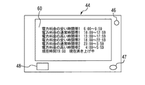
制御部36には、入力手段としてのリモコン44が相互通信可能に接続されている。図3は、リモコンの構成及び表示の一例を示す説明図である。この図に示すように、リモコン44は、貯湯式給湯機35の状態等の情報を表示する表示部60、ユーザーが操作するスイッチ48等を含む操作部、スピーカ46、マイク47等を備えている。また、リモコン44は、ユーザーが希望する給湯使用量、給湯温度、給湯使用時刻等を給湯負荷要求として入力する機能を備えている。
A
次に、制御部36により実行される貯湯式給湯機の制御について説明する。まず、HPユニット7により貯湯タンク8内の湯水を加熱する加熱運転としての沸き上げ運転について説明する。沸き上げ運転では、まず、三方弁11により、水導出口配管10とHP往き配管14とを連通すると共に、温水導出配管20bを閉じてふろ用熱交換器20から戻る流路を遮断する。また、四方弁18により、HP戻り配管15と送湯配管13とを連通すると共に、第1バイパス配管16を閉じて貯湯タンク8の温水導入口8cに向かう流路を遮断する。そして、この状態でHPユニット7及び熱源ポンプ12を駆動する。
Next, control of the hot water storage type hot water supply performed by the
これにより、貯湯タンク8の下部から流出する低温水は、水導出口配管10、三方弁11、熱源ポンプ12及びHP往き配管14を順次経由してHPユニット7に流入し、HPユニット7により加熱される。そして、HPユニット7から流出した高温水は、HP戻り配管15、四方弁18及び送湯配管13を順次経由して、貯湯タンク8の温水導入出口8dに流入し、貯湯タンク8の内部に貯湯される。このように、沸き上げ運転が実行されることで、貯湯タンク8の内部には、上部側から高温水が貯留されていき、この貯湯量の増加は、貯湯温度センサ42,43により検出される。そして、沸き上げ運転は、貯湯量が目標値に到達した時点で終了され、熱源ポンプ12及びHPユニット7が停止される。
Thus, the low temperature water flowing out from the lower part of the hot water storage tank 8 flows into the
次に、図2を参照して、制御部36により実行される基本的な制御について説明する。図2は、電力料金の時間帯別単価情報に基いて沸き上げ運転の有無を制御する制御例を示すフローチャートである。この図に示すように、制御部36は、まず、ステップS1において、インターネット回線39から電力料金の時間帯別単価情報を入手する。ここで、時間帯別単価情報とは、複数の時間帯における電力料金の相対的な高さ(安さ)、及び、前記各時間帯の開始時間及び終了時間を含む情報である。なお、電力料金の相対的な高さ(安さ)に代えて、個々の時間帯における電力料金単価の具体値を用いてもよい。また、ステップS1では、電力会社により設定されている全ての時間帯の時間帯別単価情報、即ち、電力料金単価が前後の時間帯と異なる全ての時間帯の時間帯別単価情報を入手することが好ましい。なお、図2中のステップS1は、4つ以上の異なる時間帯の時間帯別単価情報を外部との通信により入手する電力料金情報入手手段の具体例に相当している。
Next, basic control performed by the
制御部36は、入手した電力料金の時間帯別単価情報と、現在時刻と、HPユニット7の現在の作動情報とをリモコン44に送信する。そして、図3に示すように、時間帯別単価情報を現在時刻と関連させてリモコン44に表示し、電力料金単価が異なる複数の時間帯のうち現在時刻がどの時間帯に属しているのかをユーザーに報知する。また、制御部36は、HPユニット7の現在の作動状態、即ち、現在沸き上げ運転中であるか否かをリモコン44に表示させる。これにより、複数の時間帯に個別の電力料金単価が設定されている場合でも、ユーザーは、リモコン44の表示を見るだけで、各時間帯の電力料金体系、現在時刻の電力料金単価及び現在の沸き上げ運転の状態を容易に把握することができ、ユーザーの利便性を向上させることができる。
The
なお、図3では、例えば電力料金が異なる6つの時間帯が存在する場合において、各時間帯の電力料金単価の高さ及び安さを相対的に表示している。具体的に述べると、「電力料金の高い時間帯」とは、他の時間帯と比較して電力料金単価が高い時間帯(例えば、電力料金単価が最も高い時間帯)に相当している。「電力料金の安い時間帯」とは、他の時間帯と比較して電力料金単価が安い時間帯(例えば、電力料金単価が最も安い時間帯)に相当している。また、「電力料金の通常時間帯」とは、電力料金単価が「電力料金の高い時間帯」よりも安く、かつ、「電力料金の安い時間帯」よりも高い時間帯に相当している。なお、本発明は、4つ以上の複数の時間帯の時間帯別単価情報に対応できればよいもので、対応する時間帯は、図3に示す6つの時間帯に限定されるものではない。 In FIG. 3, for example, when there are six time zones in which the power rates differ, the height and the price of the power rate unit price in each time zone are displayed relatively. Specifically, the “time zone where the power rate is high” corresponds to the time zone where the power rate unit price is high (for example, the time zone where the power rate unit price is the highest) as compared with other time zones. The “time zone where the power charge is cheap” corresponds to a time zone where the power rate unit price is lower than other time zones (for example, the time zone where the power rate unit price is the lowest). Further, the “normal time zone of the power charge” is equivalent to a time zone in which the power charge unit price is cheaper than the “time zone where the power charge is high” and higher than the “time zone where the power charge is low”. Note that the present invention only needs to correspond to unit price information classified by time zone of four or more time zones, and the corresponding time zone is not limited to the six time zones shown in FIG.
次に、図2中のステップS2では、例えば電力料金の時間帯別単価情報、現在時刻等に基いて、沸き上げ運転により湯を沸かす必要があるか否かを判定する。なお、ステップS2で行う具体的な判定処理については、後述する。ステップS2の判定が成立した場合には、ステップS3に移行し、HPユニット7を作動させることにより沸き上げ運転を実行する。また、ステップS2の判定が不成立の場合には、本ルーチンを終了する。これにより、制御部36は、給湯負荷が逼迫していない限り、電力料金の安い時間帯で沸き上げ運転を優先して実行することができる。また、制御部36は、図4に示すように、上記制御により実行された沸き上げ運転の開始時間及び完了時間を示す履歴をリモコン44に表示させてもよい。なお、図4は、沸き上げ運転の履歴の表示例を示す説明図である。
Next, in step S2 in FIG. 2, it is determined whether it is necessary to boil the hot water by the boiling operation based on, for example, the unit price information according to the time zone of the power rate, the current time, and the like. The specific determination process performed in step S2 will be described later. If the determination in step S2 is established, the process proceeds to step S3, and the
次に、図5を参照して、電力料金の安い時間帯での制御について説明する。図5は、電力料金の安い時間帯での沸き上げ運転により給湯負荷要求に対応可能な場合の制御例を示すフローチャートである。この図において、まず、ステップS10では、電力料金が安い時間帯であるか否かを判定し、この判定が成立した場合には、ステップS11に移行する。また、ステップS10の判定が不成立の場合には、本ルーチンを終了する。 Next, with reference to FIG. 5, control in a time zone in which the power rate is low will be described. FIG. 5 is a flowchart showing a control example in the case where it is possible to cope with the hot water supply load request by the boiling operation in the time zone where the power rate is low. In this figure, first, in step S10, it is determined whether or not it is a time zone where the power rate is low, and when this determination is established, the process proceeds to step S11. If the determination in step S10 is not established, the present routine is ended.
次に、ステップS10では、ユーザーが入力した給湯負荷要求をリモコン44から読込むと共に、貯湯温度センサ42,43の検出結果に基いて貯湯タンク8の現在の貯湯温度及び貯湯量を検出する。そして、現在の貯湯温度、貯湯量、給湯負荷要求の給水温度及びHPユニット7の加熱能力によって電気料金が安い時間帯のみで沸き上げ運転を実行することで給湯負荷要求を満足できるか否かを判定する。この判定が成立した場合には、電力料金が相対的に高い他の時間帯に沸き上げ運転を行う必要がないので、ステップS12に移行して沸き上げ運転を実行する。一方、ステップS11の判定が不成立の場合には、本ルーチンを終了する。
Next, in step S10, the hot water supply load request input by the user is read from the
このように、図5に示す制御では、他の時間帯と比較して電力代が安い時間帯にのみ沸き上げ運転を行うことで給湯負荷要求を満足できるか否かの判定を実行し、前記判定が成立する場合には、電力代が安い時間帯にのみ沸き上げ運転を効率よく行うようにしている。これにより、電力代が安い時間帯のみで供給可能な給湯負荷要求に対しては、他の時間帯で沸き上げ運転を行わずに対応することができ、電力料金を削減することができる。 As described above, in the control shown in FIG. 5, it is determined whether the hot water supply load request can be satisfied by performing the boiling operation only in the time zone where the power cost is lower than other time zones. When the determination is established, the boiling operation is efficiently performed only in the time zone where the power cost is low. As a result, it is possible to cope with the hot water supply load request that can be supplied only in the time zone where the power cost is low, without performing the boiling operation in another time zone, and it is possible to reduce the power cost.
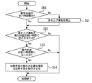
次に、図6を参照して、電力料金の安い時間帯のみでは給湯負荷要求を満足できない場合の制御について説明する。図6は、電力料金の安い時間帯での沸き上げ運転では、貯湯量が不足する場合の制御例を示すフローチャートである。この図において、まず、ステップS20では、電力料金の安い時間帯であるか否かを判定し、この判定が成立した場合には、本ルーチンを終了する。また、ステップS20の判定が不成立の場合には、ステップS21に移行する。 Next, with reference to FIG. 6, control in the case where the hot water supply load request can not be satisfied only in the time zone in which the power rate is low will be described. FIG. 6 is a flowchart showing a control example in the case where the amount of stored hot water is insufficient in the boiling operation in the time zone in which the power rate is low. In this figure, first, in step S20, it is determined whether or not it is a time zone in which the power rate is low, and when this determination is established, this routine is ended. If the determination in step S20 is not established, the process proceeds to step S21.
ステップS21では、現在時刻が給湯負荷要求として入力された給湯使用時刻に近いか否かを判定する。具体例を挙げると、現在時刻と給湯使用時刻との時間差が予め設定された判定時間よりも小さいか否かを判定する。ステップS21の判定が不成立の場合には、まだ給湯使用時刻が近くないので、本ルーチンを終了する。一方、ステップS21の判定が成立した場合には、ステップS22に移行する。 In step S21, it is determined whether the current time is near the hot water supply use time input as the hot water supply load request. As a specific example, it is determined whether the time difference between the current time and the hot water supply use time is smaller than a predetermined determination time. When the determination in step S21 is not established, the hot water supply use time is not near yet, so this routine is ended. On the other hand, when the determination in step S21 is established, the process proceeds to step S22.
ステップS22では、湯を沸かす必要があるか否かを判定する。具体的には、例えば貯湯タンク8の現在の貯湯量及び貯湯温度と、給湯負荷要求として入力された給湯使用量及び給湯温度とを比較することにより、沸き上げ運転を行う必要があるか否かを判定する。ステップS22の判定が成立した場合には、現在時刻が電力料金の安い時間帯ではなく、かつ、給湯使用時刻が近く、更に、給湯負荷要求と比較して貯湯タンク8内の貯湯熱量が不足していると判断される。そこで、この場合には、ステップS23に移行し、沸き上げ運転を行った後に、本ルーチンを終了する。一方、ステップS22の判定が不成立の場合には、貯湯タンク8内に十分な貯湯熱量を存在するので、本ルーチンを終了する。 In step S22, it is determined whether it is necessary to boil the hot water. Specifically, for example, whether or not the heating operation needs to be performed by comparing the current storage amount and storage temperature of the hot water storage tank 8 with the hot-water use amount and the hot-water supply temperature input as the hot-water supply load request. Determine When the determination in step S22 is established, the current time is not a time zone in which the power rate is low, and the hot-water use time is near, and the amount of stored heat in the hot-water storage tank 8 is insufficient compared to the hot-water supply load request. It is determined that Therefore, in this case, the process proceeds to step S23, and after the heating operation is performed, the present routine is ended. On the other hand, when the determination in step S22 is not established, a sufficient amount of heat storage in the hot water storage tank 8 exists, so this routine ends.
このように、図6に示す制御では、電力料金が安い時間帯にのみ沸き上げ運転を行うことで給湯負荷要求を満足できない場合に、給湯使用時刻に最も近い他の時間帯で沸き上げ運転を行うことができる。また、この制御では、給湯使用時刻に最も近い時間帯の全ての時間にわたって沸き上げ運転を実行しても給湯負荷要求を満足できない場合に、他の時間帯のうち給湯使用時刻に近い時間帯から順に沸き上げ運転を実行し、給湯負荷要求が満たされる時間帯まで沸き上げ運転を続行することができる。これにより、電力料金が安い時間帯では対応しきれない場合でも、電力料金の上昇を最低限に抑制しつつ、沸き上げを効率よく行うことができる。 As described above, in the control shown in FIG. 6, when the hot water supply load request can not be satisfied by performing the boiling operation only in the time zone in which the power rate is low, the boiling operation is performed in the other time zone closest to the hot water supply use time. It can be carried out. Also, in this control, if the hot water supply load request can not be satisfied even if the heating operation is performed over the entire time zone closest to the hot water supply use time, the time period near the hot water use time among other time bands The boiling operation can be sequentially performed, and the boiling operation can be continued until the time period when the hot water supply load requirement is satisfied. As a result, even if the system can not cope with the time zone in which the power rate is low, boiling can be efficiently performed while minimizing the increase in the power rate.
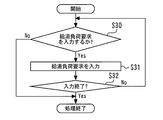
次に、ユーザーが給湯モードを設定する場合の動作について説明する。制御部36は、ユーザーが給湯負荷要求の入力を簡単に行えるように、複数の給湯モードを備えている。個々の給湯モードは、1組の給湯使用量及び給湯温度がセットにして記憶されたものである。図7は、給湯モードを設定する場合の制御例を示すフローチャートである。この図において、まず、ステップS30では、例えばリモコン44の操作内容に基いて、ユーザーが給湯負荷要求を入力するか否かを判定する。この判定が成立した場合には、ステップS31に移行する。ステップS30の判定が不成立の場合には、本ルーチンを終了する。
Next, the operation when the user sets the hot water supply mode will be described. The
ステップS31では、ユーザーがリモコン44にて所望の給湯使用量及び給湯温度を入力したときに、これらの入力内容を1つの給湯モードとして記憶する。図12は、給湯モードの設定時におけるリモコンの表示例を示している。この例では、例えば給湯使用量50Lと給湯温度42℃とをセットにした給湯負荷要求1、及び、給湯使用量100Lと給湯温度40℃とをセットにした給湯負荷要求2が、2つの給湯モードとして表示されている。このように、制御部36は、ユーザーにより入力された複数の給湯モードを記憶し、記憶内容をリモコン44に表示させることができる。
In step S31, when the user inputs a desired hot water supply usage amount and hot water supply temperature with the
次に、ステップS32では、給湯モードの入力が終了したか否かを判定し、この判定が成立した場合には、本ルーチンを終了する。一方、ステップS32の判定が不成立の場合には、ステップS30に戻り、ユーザーにより新たな給湯モードを入力させる。このような処理により、ユーザーは、所望の給湯使用量及び給湯温度をセットにした複数の給湯モードを設定することができる。 Next, in step S32, it is determined whether or not the input of the hot water supply mode is completed, and when this determination is established, the present routine is ended. On the other hand, if the determination in step S32 is not established, the process returns to step S30, and the user inputs a new hot water supply mode. By such processing, the user can set a plurality of hot water supply modes in which a desired hot water use amount and hot water supply temperature are set.
上記制御によれば、ユーザーは、使用頻度が高い給湯使用量と給湯温度のセットを、複数の給湯モードとして予め設定しておくことができる。これにより、給湯使用時には、例えば給湯負荷要求1、給湯負荷要求2等を選択する操作を行うだけで、所望の給湯使用量及び給湯温度を容易に設定することができ、ユーザーの利便性を向上させることができる。なお、本発明では、上記制御に加えて、個々の給湯モードを使用すると予想される予想使用時刻を前記給湯使用時刻として給湯モード毎に設定してもよい。具体例を挙げると、ステップS31において、1つの給湯モードとなる給湯負荷要求を入力したときに、当該給湯負荷要求の予想使用時刻も入力するようにする。これにより、制御部36は、ユーザーが時刻に応じて給湯負荷要求を設定しなくても、給湯モードを自動的に切換えることができ、利便性を更に向上させることができる。
According to the above control, the user can set in advance a set of hot water use amount and hot water supply temperature, which are frequently used, as a plurality of hot water supply modes. As a result, when using the hot water supply, the desired hot water supply usage amount and hot water supply temperature can be easily set simply by performing an operation to select, for example, the hot water
次に、時間帯別の電力料金及びHPユニット7の作動状態をリモコン44に表示する処理について説明する。図8は、これらを表示するためのフローチャートである。図8において、まず、ステップS40では、インターネット回線39から入手した電力料金の時間帯別単価情報をリモコン44の表示部60に表示する。続いて、ステップS41では、HPユニット7の作動状態を表示し、本ルーチンを終了する。
Next, a process of displaying on the
次に、電力料金が安い時間帯以外は沸き上げ運転を禁止する制御について説明する。図9は、この制御の一例を示すフローチャートである。図9において、まず、ステップS50では、電力料金が安い時間帯であるかを判定する。この判定が不成立の場合には、ステップS51に移行して沸き上げ運転を禁止してから、ステップS52に移行する。なお、ステップS51の処理は、実行中の沸き上げ運転を停止すること、及び、沸き上げ運転の開始条件が成立してもこれを無視することを意味する。一方、ステップS50の判定が成立した場合には、ステップS51を実行せずに、そのままステップS52に移行する。 Next, control for prohibiting the heating operation except for the time zone in which the power rate is low will be described. FIG. 9 is a flowchart showing an example of this control. In FIG. 9, first, in step S50, it is determined whether it is a time zone in which the power rate is low. If this determination is not established, the process proceeds to step S51 to prohibit the heating operation, and then proceeds to step S52. In addition, the process of step S51 means stopping the boiling operation under execution and ignoring this even if the start condition of the boiling operation is satisfied. On the other hand, when the determination in step S50 is established, the process directly proceeds to step S52 without executing step S51.
ステップS52では、電力料金が高い時間帯に沸き上げ運転を停止させたか否かを判定し、この判定が成立した場合には、ステップS53に移行する。ステップS53では、電力料金が安い時間帯になったか否かを判定し、この判定が成立した場合には、ステップS54へ移行する。ステップS54では、現在時刻が電力料金の安い時間帯に属しているので、貯湯量等からみて沸き上げ運転が必要と判断した場合には、HPユニット7を作動させて沸き上げ運転を実行する。一方、ステップS52,S53の何れかで判定が不成立となった場合には、本ルーチンを終了する。
In step S52, it is determined whether the heating operation has been stopped in a time zone where the power rate is high, and when this determination is established, the process proceeds to step S53. In step S53, it is determined whether or not the time slot for which the power rate is low has been reached, and when this determination is established, the process proceeds to step S54. In step S54, since the current time belongs to a time zone where the power rate is low, the
このように、図9に示す制御では、電力料金単価が現在の時間帯よりも安くなる時間帯まで沸き上げ運転を禁止し、電力料金が安い時間帯となってから必要に応じて沸き上げ運転を実行するようにしている。これにより、沸き上げ運転が非効率な時間帯に行われるのを回避し、消費電力を削減することができる。なお、図9中のステップS50,S51は、加熱禁止手段の具体例に相当している。 Thus, in the control shown in FIG. 9, the boiling operation is prohibited until the time zone when the power rate unit price is lower than the current time zone, and the heating mode is operated as needed after the time period when the power rate is low. To do. As a result, it is possible to prevent the boiling operation from being performed in an inefficient time zone, and to reduce the power consumption. Steps S50 and S51 in FIG. 9 correspond to a specific example of the heating inhibiting means.
次に、図10を参照して、給湯負荷の学習制御について説明する。図10は、給湯負荷要求と、当該給湯負荷要求に対応して生じた実際の給湯負荷との差分を学習する制御の一例を示すフローチャートである。この図において、まず、ステップS60では、ユーザーが事前に予想して入力した給湯負荷要求と、実際に使用された給湯負荷との差分を求める。具体例を挙げると、ステップS60では、給湯負荷要求として入力された給湯の予想使用時刻に対応する給湯の利用開始時刻から利用終了時刻までの時間長と、実際の給湯の利用開始時刻から利用終了時刻までの時間長とを比較し、両者の時間長の差分を求める。 Next, learning control of the hot water supply load will be described with reference to FIG. FIG. 10 is a flowchart showing an example of control for learning the difference between the hot water supply load request and the actual hot water supply load generated in response to the hot water supply load request. In this figure, first, in step S60, the difference between the hot water supply load request predicted and input by the user in advance and the actually used hot water supply load is obtained. As a specific example, in step S60, the time length from the usage start time of hot water supply to the usage end time corresponding to the expected use time of hot water supply input as the hot water supply load request, and the usage end from actual usage start time of hot water supply The time length until time is compared, and the difference of both time length is calculated | required.
次に、ステップS61では、上記2つの時間長に差があるか否かを判定し、この判定が成立した場合には、ステップS62に移行する。また、ステップS61の判定が不成立の場合には、本ルーチンを終了する。次に、ステップS62では、給湯負荷要求が実際の給湯負荷よりも大きいか否かを時間長の大小関係から判定し、この判定が成立した場合には、ステップS63に移行する。 Next, in step S61, it is determined whether or not there is a difference between the two time lengths. If this determination is established, the process proceeds to step S62. If the determination in step S61 is not established, the present routine is ended. Next, in step S62, it is determined from the magnitude relationship of time length whether the hot water supply load request is larger than the actual hot water supply load, and when this determination is established, the process proceeds to step S63.
ステップS63では、入力されている給湯負荷要求を上記時間長の差分に相当する分だけ減少させる補正を実行し、本ルーチンを終了する。このようなマイナス補正の具体例を挙げると、例えば給湯負荷要求の時間長と比較して実際に給湯を使用した時間長が5分短い場合には、入力されている給湯負荷要求の時間長(予想される給湯使用時間)を5分短縮する。この補正内容は、制御部36により学習、記憶される。そして、次回の給湯負荷要求の設定時において、例えばユーザーにより今回と同じ給湯負荷要求が入力された場合には、入力された給湯負荷要求を今回学習した給湯負荷要求に置き換える補正、即ち、給湯負荷要求の入力値を短縮する補正を行う。このような補正の有無及び補正量については、ユーザーの操作により変更可能な構成とするのが好ましい。
In step S63, a correction is performed to reduce the input hot water supply load request by an amount corresponding to the difference of the time length, and the present routine is ended. As a specific example of such negative correction, for example, when the length of time actually using the hot water supply is 5 minutes shorter than the time length of the hot water supply load request, the time length of the input hot water supply load request ((1) Reduce the expected hot water supply usage time) by 5 minutes. The correction content is learned and stored by the
なお、上記説明では、入力された給湯負荷要求と実際の給湯負荷との差分を給湯使用時間の時間長として求める場合を例示した。しかし、本発明は、これに限らず、給湯負荷のうち使用時間以外の要素の差分を求めて学習するようにしてもよい。具体例を挙げると、例えば入力された給湯負荷要求が予定給湯量30Lかつ給湯温度45℃であり、実際に使用した給湯負荷が給湯量20Lかつ給湯温度42℃であった場合には、給湯量と給湯温度の組合わせにおいて、給湯負荷要求と実際の給湯負荷との差分を学習する。そして、次回の予定として入力された給湯負荷要求が予定給湯量30Lかつ湯温45℃であった場合には、これらの入力値を給湯量20Lかつ給湯温度42℃に補正する。このような補正の有無及び補正量については、ユーザーの操作により変更可能な構成とするのが好ましい。
In the above description, the difference between the input hot water supply load request and the actual hot water supply load is obtained as the time length of the hot water supply use time. However, the present invention is not limited to this, and the difference between elements other than the usage time of the hot water supply load may be determined and learned. As a specific example, for example, when the input hot water supply load request is the planned hot water supply amount 30 L and the hot
一方、ステップS62の判定が不成立の場合には、ステップS64に移行する。ステップS64では、入力されている給湯負荷要求を前記時間長の差分に相当する分だけ減少させる補正を実行し、本ルーチンを終了する。このようなプラス補正の具体例を挙げると、例えば給湯負荷要求の時間長と比較して実際に給湯を使用した時間長が5分長い場合には、入力されている給湯負荷要求の時間長(予想される給湯使用時間)を5分延長する。この補正内容は、制御部36により学習、記憶される。そして、次回の給湯負荷要求の設定時において、例えばユーザーにより今回と同じ給湯負荷要求が入力された場合には、入力された給湯負荷要求を今回学習した給湯負荷要求に置き換える補正、即ち、給湯負荷要求の入力値を延長する補正を行う。この補正の有無及び補正量については、ユーザーの操作により変更可能な構成とするのが好ましい。
On the other hand, when the determination in step S62 is not established, the process proceeds to step S64. In step S64, correction is performed to reduce the input hot water supply load request by an amount corresponding to the difference of the time length, and the present routine is ended. As a specific example of such positive correction, for example, when the time length actually using hot water supply is 5 minutes longer than the time length required for the hot water supply load request, the time length of the input hot water supply load request ((1) Extend the expected hot water supply usage time) by 5 minutes. The correction content is learned and stored by the
また、ステップS62においても、前述したように、使用時間以外の要素の差分を求めて学習するようにしてもよい。具体例を挙げると、例えば入力された給湯負荷要求が予定給湯量20Lかつ給湯温度42℃であり、実際に使用した給湯負荷が給湯量30Lかつ給湯温度45℃であった場合には、給湯量と給湯温度の組合わせにおいて、給湯負荷要求と実際の給湯負荷との差分を学習する。そして、次回の予定として入力された給湯負荷要求が予定給湯量20Lかつ湯温42℃であった場合には、これらの入力値を給湯量30Lかつ給湯温度45℃に補正する。この補正の有無及び補正量については、ユーザーの操作により変更可能な構成とするのが好ましい。
Further, also in step S62, as described above, learning may be performed by obtaining the difference of elements other than the use time. As a specific example, for example, when the input hot water supply load request is the planned hot water supply amount 20 L and the hot
図10に示す制御では、ユーザーが給湯負荷要求を設定するときの傾向、癖等を学習し、学習結果に基いて給湯負荷要求が給湯実績に近づくように適切な補正を行うことができる。これにより、沸き上げ運転を更に効率よく実行し、ユーザーの利便性を向上させることができる。なお、図10に示すルーチンは、学習手段の具体例に相当している。 In the control shown in FIG. 10, it is possible to learn the tendency when the user sets the hot water supply load request, the habit, and the like, and perform appropriate correction so that the hot water supply load request approaches the hot water supply performance based on the learning result. Thus, the boiling operation can be performed more efficiently, and the convenience of the user can be improved. The routine shown in FIG. 10 corresponds to a specific example of learning means.
次に、最低貯湯量を保持するための制御について説明する。貯湯式給湯機35は、貯湯タンク8内に予め設定された最低貯湯量以上の湯を常時保持するように構成されている。図11は、最低貯湯量を保持するための制御例を示すフローチャートである。この図において、まず、ステップS70では、現在の貯湯量が最低貯湯量よりも多いか否かを判定し、この判定が成立した場合には、ステップS71に移行する。即ち、例えば最低貯湯量が50Lである場合には、現在の貯湯量が50Lよりも多い場合には、ステップS71に移行する。一方、ステップS70の判定が不成立の場合には、ステップS73に移行する。
Next, control for maintaining the minimum amount of stored water will be described. The hot water storage
ステップS71では、給湯負荷要求があるか否かを判定し、この判定が成立した場合には、ステップS72に移行する。また、ステップS71の判定が不成立の場合には、ステップS73に移行する。ステップS72では、沸き上げ運転を実行することにより、(最低貯湯量+給湯負荷要求)分の湯を沸き上げてから、本ルーチンを終了する。一方、ステップS73では、沸き上げ運転により最低貯湯量分の湯を沸き上げてから、本ルーチンを終了する。 In step S71, it is determined whether or not there is a hot water supply load request, and when this determination is established, the process proceeds to step S72. When the determination in step S71 is not established, the process proceeds to step S73. In step S72, the boiling operation is performed to boil the hot water for (minimum storage amount + hot water supply load request), and then this routine is ended. On the other hand, in step S73, after boiling water for the minimum amount of hot water storage by boiling operation, this routine is ended.
図11に示す制御では、貯湯タンク8に貯湯される温水の総貯湯量が最低貯湯量に対して給湯負荷要求による必要湯量の分だけ多くなるように総貯湯量を制御することができる。そして、総貯湯量が最低貯湯量よりも低下した場合には、沸き上げ運転を開始することができる。従って、給湯負荷要求がどのように変化する場合でも、貯湯タンク8内に最低貯湯量分の湯を残しておくことができ、想定外の給湯負荷等に対しても湯切れを抑制することができる。 In the control shown in FIG. 11, the total amount of hot water stored in the hot water storage tank 8 can be controlled so that the total amount of hot water stored in the hot water storage tank 8 is larger than the minimum amount of hot water. And, when the total amount of hot water storage is lower than the minimum amount of hot water storage, the boiling operation can be started. Therefore, no matter how much the hot water supply load request changes, it is possible to keep the hot water for the minimum amount of hot water storage in the hot water storage tank 8, and to control the hot water shortage against unexpected hot water supply load etc. it can.
なお、本実施の形態において、制御部36は、上述した図2及び図5から図11に示す制御の全部または一部を適宜組合わせて沸き上げ運転を制御するものである。
In the present embodiment, the
以上詳述した通り、本実施の形態では、4つ以上の異なる時間帯の時間帯別単価情報を外部との通信により入手し、入手した時間帯別単価情報に基いて沸き上げ運転を制御するようにしている。これにより、電力料金体系が複雑な場合でも、1日のうちで電力料金が安い時間帯と電力料金が高い時間帯とを細かく把握し、例えば電力料金が安い時間帯を利用して沸き上げ運転を数回に分けて行うことができる。従って、電力自由化等により電力料金の異なる時間帯が4つ以上に細分化された場合でも、ユーザーが意識することなく、沸き上げ運転を適切なタイミングで小刻みに実行して必要な貯湯量を確保することができ、電力コストを抑制することができる。 As described above in detail, in the present embodiment, the unit price information classified by time zone of four or more different time zones is obtained through communication with the outside, and the boiling operation is controlled based on the unit price information classified by time zone obtained. It is like that. Thereby, even when the power rate system is complicated, the time zone in which the power rate is low and the time zone in which the power rate is high can be grasped in detail in one day, for example, the heating operation is performed using the time zone Can be done in several times. Therefore, even if the time zone of different power rates is subdivided into four or more due to the liberalization of power, etc., the user need not be aware, the boiling operation is performed in small steps at an appropriate timing, and the required amount of stored water is Therefore, the power cost can be reduced.
なお、前記実施の形態1では、加熱手段としてヒートポンプサイクルを利用するHPユニット7を例示した。しかし、本発明はこれに限らず、例えばヒータ式、燃料燃焼式の加熱手段を備える貯湯式給湯機に適用してもよい。
In the first embodiment, the
1 圧縮機,3 水冷媒熱交換器,4 膨張弁,5 冷媒配管,6 空気熱交換器,7 HPユニット(加熱手段),8 貯湯タンク,8a 水導入口,8c 温水導入口,8d 温水導入出口,9 給水配管,9a 第1給水配管,9b 第2給水配管,9c 第3給水配管,10 水導出口配管,11 三方弁,12 熱源ポンプ,13 送湯配管,14 HP往き配管,15 HP戻り配管,16 第1バイパス配管,17 第2バイパス配管,18 四方弁,20a 温水導入配管,20b 温水導出配管,20 ふろ用熱交換器,21 給湯配管,22 給湯用混合弁,23 ふろ用混合弁,24 第1給湯配管,25 第2給湯配管,26 ふろ用電磁弁,27 ふろ往き配管,28 ふろ戻り配管,29 ふろ循環ポンプ,30 浴槽,31 減圧弁,33 タンクユニット,34 給湯栓,35 貯湯式給湯機,36 制御部,37 ふろ往き温度センサ,38 ふろ戻り温度センサ,39 インターネット回線,42,43 貯湯温度センサ,44 リモコン(入力手段),45 ふろ用流量センサ,46 スピーカ,47 マイク,48 スイッチ,60 表示部,70 外気温センサ,80 ルーター,81 ホームゲートウエイ Reference Signs List 1 compressor, 3 water refrigerant heat exchanger, 4 expansion valve, 5 refrigerant piping, 6 air heat exchanger, 7 HP unit (heating means), 8 hot water storage tank, 8a water inlet, 8c hot water inlet, 8d hot water inlet Outlet, 9 water supply piping, 9a 1st water supply piping, 9b 2nd water supply piping, 9c 3rd water supply piping, 10 water outlet piping, 11 three-way valve, 12 heat source pump, 13 hot water supply piping, 14 HP forward piping, 15 HP Return piping, 16 first bypass piping, 17 second bypass piping, 18 four-way valve, 20a hot water introduction piping, 20b hot water lead piping, 20 heat exchanger for bath, 21 hot water supply pipe, 22 hot water mixing valve, 23 bath mixing Valve, 24 1st hot water supply piping, 25 2nd hot water supply piping, 26 Solenoid valve for bath, 27 Flowing pipe, 28 Reflow piping, 29 Bath circulation pump, 30 bath, 31 pressure reducing valve, Reference Signs List 3 tank unit, 34 hot water supply tap, 35 hot water storage type water heater, 36 control unit, 37 flow going temperature sensor, 38 flow return temperature sensor, 39 internet connection, 42, 43 hot water storage temperature sensor, 44 remote control (input means), 45 flow Flow Sensor, 46 Speaker, 47 Microphone, 48 Switch, 60 Display, 70 Outdoor Temperature Sensor, 80 Router, 81 Home Gateway
Claims (7)
前記貯湯タンクに貯湯される温水を加熱する加熱手段と、
ユーザーが希望する給湯使用量、給湯温度及び給湯使用時刻を給湯負荷要求として入力する入力手段と、
前記給湯負荷要求を満たすために必要な貯湯温度及び貯湯量の温水を前記貯湯タンクに貯湯するように前記加熱手段を制御して前記貯湯タンク内の湯水を加熱する加熱運転を行う制御部と、
前記加熱運転に用いる電力料金の時間帯別単価情報であって、4つ以上の異なる時間帯の時間帯別単価情報を外部との通信により入手する電力料金情報入手手段と、を備え、
前記制御部は、前記電力料金情報入手手段により入手した前記時間帯別単価情報に基いて前記加熱運転を制御し、他の時間帯と比較して電力料金が安い時間帯にのみ前記加熱運転を行うことで前記給湯負荷要求を満たすことが可能であるか否かの判定を実行し、前記判定が不成立となる場合に、前記他の時間帯のうち前記給湯使用時刻に近い時間帯から順に前記給湯負荷要求が満たされるまで前記加熱運転を行う貯湯式給湯機。 With a hot water storage tank for storing hot water,
Heating means for heating the hot water stored in the hot water storage tank;
And input means for inputting a hot water supply usage amount, a hot water supply temperature and a hot water supply use time desired by the user as a hot water supply load request,
A control unit performing a heating operation of heating the hot and cold water in the hot water storage tank by controlling the heating unit so as to store the hot water of the hot water storage temperature and the hot water storage amount necessary to satisfy the hot water supply load request in the hot water storage tank;
Power rate information obtaining means for obtaining time range unit price information of power rates to be used for the heating operation according to time zones, and obtaining time zone price information of four or more different time zones by communication with the outside;
The control unit controls the heating operation based on the unit price information classified by time zone obtained by the power rate information acquiring unit, and performs the heating operation only in a time zone where the power charge is cheaper than other time zones. It is determined whether it is possible to satisfy the hot water supply load request by performing, and when the determination is not satisfied, the other time periods among the other time periods are sequentially ordered from the time period closer to the hot water supply use time. A storage water heater that performs the heating operation until a hot water supply load request is satisfied .
前記制御部は、前記電力料金情報入手手段により入手した前記時間帯別単価情報を現在時刻と関連させて前記入力手段に表示させると共に、前記加熱手段の作動状態を前記入力手段に表示させる請求項1から3のうち何れか1項に記載の貯湯式給湯機。 The input unit has a function of receiving information from the control unit and displaying the information.
The control unit causes the input unit to display the unit price information classified by time zone acquired by the power rate information acquisition unit in association with the current time, and causes the input unit to display the operating state of the heating unit. The hot water storage type water heater according to any one of 1 to 3 .
前記学習手段は、ユーザーにより入力された前記給湯負荷要求を前記学習手段の学習結果に基いて補正する請求項1から5のうち何れか1項に記載の貯湯式給湯機。 The control unit includes a learning unit that learns a difference between the hot water supply load request and an actual hot water supply load generated in response to the hot water supply load request.
The hot water storage type hot water supply apparatus according to any one of claims 1 to 5 , wherein the learning means corrects the hot water supply load request inputted by the user based on a learning result of the learning means.
Priority Applications (1)
| Application Number | Priority Date | Filing Date | Title |
|---|---|---|---|
| JP2015253181A JP6520700B2 (en) | 2015-12-25 | 2015-12-25 | Hot water storage type hot water heater |
Applications Claiming Priority (1)
| Application Number | Priority Date | Filing Date | Title |
|---|---|---|---|
| JP2015253181A JP6520700B2 (en) | 2015-12-25 | 2015-12-25 | Hot water storage type hot water heater |
Publications (2)
| Publication Number | Publication Date |
|---|---|
| JP2017116199A JP2017116199A (en) | 2017-06-29 |
| JP6520700B2 true JP6520700B2 (en) | 2019-05-29 |
Family
ID=59233896
Family Applications (1)
| Application Number | Title | Priority Date | Filing Date |
|---|---|---|---|
| JP2015253181A Active JP6520700B2 (en) | 2015-12-25 | 2015-12-25 | Hot water storage type hot water heater |
Country Status (1)
| Country | Link |
|---|---|
| JP (1) | JP6520700B2 (en) |
Families Citing this family (2)
| Publication number | Priority date | Publication date | Assignee | Title |
|---|---|---|---|---|
| JP7000841B2 (en) * | 2017-12-21 | 2022-01-19 | 三菱電機株式会社 | Water heater |
| WO2023145077A1 (en) * | 2022-01-31 | 2023-08-03 | 三菱電機株式会社 | Heat storage system control device, heat storage system, heat storage system control method, control program, and recording medium |
Family Cites Families (4)
| Publication number | Priority date | Publication date | Assignee | Title |
|---|---|---|---|---|
| JP2011160607A (en) * | 2010-02-03 | 2011-08-18 | Panasonic Electric Works Co Ltd | Electric power monitoring system |
| JP5494422B2 (en) * | 2010-11-01 | 2014-05-14 | 三菱電機株式会社 | Hot water storage hot water supply system |
| JP5813980B2 (en) * | 2011-04-08 | 2015-11-17 | 株式会社コロナ | Heat pump bath water heater |
| JP6036501B2 (en) * | 2013-04-10 | 2016-11-30 | 三菱電機株式会社 | Hot water storage water heater |
-
2015
- 2015-12-25 JP JP2015253181A patent/JP6520700B2/en active Active
Also Published As
| Publication number | Publication date |
|---|---|
| JP2017116199A (en) | 2017-06-29 |
Similar Documents
| Publication | Publication Date | Title |
|---|---|---|
| JP6044326B2 (en) | Hot water storage water heater and solar system | |
| JP6070151B2 (en) | Hot water storage water heater and solar system | |
| JP6089781B2 (en) | Hot water storage water heater and solar system equipped with the hot water heater | |
| JP6515859B2 (en) | Hot water storage system | |
| JP5589943B2 (en) | Hot water storage water heater | |
| JP6520700B2 (en) | Hot water storage type hot water heater | |
| JP6020362B2 (en) | Hot water storage water heater | |
| JP6897331B2 (en) | Hot water storage type water heater | |
| JP6628643B2 (en) | Hot water supply system | |
| JP6344156B2 (en) | Hybrid hot water supply system | |
| JP2014114965A (en) | Hot water storage type water heater | |
| JP6036501B2 (en) | Hot water storage water heater | |
| JP2016217545A (en) | Hot water storage type heat pump water heater | |
| WO2020225905A1 (en) | Storage type hot water supply system | |
| JP6323358B2 (en) | Hot water storage type electric water heater | |
| JP6210019B2 (en) | Hot water storage water heater | |
| JP6036560B2 (en) | Hot water storage water heater | |
| JP7334850B2 (en) | Storage hot water heater | |
| JP2018132231A (en) | Water heater | |
| JP7172670B2 (en) | Storage hot water heater | |
| JP5870844B2 (en) | Hot water storage water heater | |
| JP6747424B2 (en) | Hot water storage system | |
| JP7226062B2 (en) | heat pump water heater | |
| JP6805910B2 (en) | Hot water storage type hot water supply device | |
| JP6717075B2 (en) | Hot water storage type water heater |
Legal Events
| Date | Code | Title | Description |
|---|---|---|---|
| A621 | Written request for application examination |
Free format text: JAPANESE INTERMEDIATE CODE: A621 Effective date: 20180119 |
|
| A977 | Report on retrieval |
Free format text: JAPANESE INTERMEDIATE CODE: A971007 Effective date: 20180817 |
|
| A131 | Notification of reasons for refusal |
Free format text: JAPANESE INTERMEDIATE CODE: A131 Effective date: 20180904 |
|
| A521 | Request for written amendment filed |
Free format text: JAPANESE INTERMEDIATE CODE: A523 Effective date: 20181019 |
|
| TRDD | Decision of grant or rejection written | ||
| A01 | Written decision to grant a patent or to grant a registration (utility model) |
Free format text: JAPANESE INTERMEDIATE CODE: A01 Effective date: 20190402 |
|
| A61 | First payment of annual fees (during grant procedure) |
Free format text: JAPANESE INTERMEDIATE CODE: A61 Effective date: 20190415 |
|
| R150 | Certificate of patent or registration of utility model |
Ref document number: 6520700 Country of ref document: JP Free format text: JAPANESE INTERMEDIATE CODE: R150 |
|
| R250 | Receipt of annual fees |
Free format text: JAPANESE INTERMEDIATE CODE: R250 |
|
| R250 | Receipt of annual fees |
Free format text: JAPANESE INTERMEDIATE CODE: R250 |