JP6516722B2 - Control based on laser emission of beam positioner - Google Patents
Control based on laser emission of beam positioner Download PDFInfo
- Publication number
- JP6516722B2 JP6516722B2 JP2016503316A JP2016503316A JP6516722B2 JP 6516722 B2 JP6516722 B2 JP 6516722B2 JP 2016503316 A JP2016503316 A JP 2016503316A JP 2016503316 A JP2016503316 A JP 2016503316A JP 6516722 B2 JP6516722 B2 JP 6516722B2
- Authority
- JP
- Japan
- Prior art keywords
- laser
- workpiece
- pulse
- beam axis
- sorting device
- Prior art date
- Legal status (The legal status is an assumption and is not a legal conclusion. Google has not performed a legal analysis and makes no representation as to the accuracy of the status listed.)
- Active
Links
Images


Classifications
-
- B—PERFORMING OPERATIONS; TRANSPORTING
- B23—MACHINE TOOLS; METAL-WORKING NOT OTHERWISE PROVIDED FOR
- B23K—SOLDERING OR UNSOLDERING; WELDING; CLADDING OR PLATING BY SOLDERING OR WELDING; CUTTING BY APPLYING HEAT LOCALLY, e.g. FLAME CUTTING; WORKING BY LASER BEAM
- B23K26/00—Working by laser beam, e.g. welding, cutting or boring
- B23K26/08—Devices involving relative movement between laser beam and workpiece
- B23K26/082—Scanning systems, i.e. devices involving movement of the laser beam relative to the laser head
-
- B—PERFORMING OPERATIONS; TRANSPORTING
- B23—MACHINE TOOLS; METAL-WORKING NOT OTHERWISE PROVIDED FOR
- B23K—SOLDERING OR UNSOLDERING; WELDING; CLADDING OR PLATING BY SOLDERING OR WELDING; CUTTING BY APPLYING HEAT LOCALLY, e.g. FLAME CUTTING; WORKING BY LASER BEAM
- B23K26/00—Working by laser beam, e.g. welding, cutting or boring
- B23K26/02—Positioning or observing the workpiece, e.g. with respect to the point of impact; Aligning, aiming or focusing the laser beam
- B23K26/04—Automatically aligning, aiming or focusing the laser beam, e.g. using the back-scattered light
-
- B—PERFORMING OPERATIONS; TRANSPORTING
- B23—MACHINE TOOLS; METAL-WORKING NOT OTHERWISE PROVIDED FOR
- B23K—SOLDERING OR UNSOLDERING; WELDING; CLADDING OR PLATING BY SOLDERING OR WELDING; CUTTING BY APPLYING HEAT LOCALLY, e.g. FLAME CUTTING; WORKING BY LASER BEAM
- B23K26/00—Working by laser beam, e.g. welding, cutting or boring
- B23K26/08—Devices involving relative movement between laser beam and workpiece
- B23K26/083—Devices involving movement of the workpiece in at least one axial direction
- B23K26/0853—Devices involving movement of the workpiece in at least in two axial directions, e.g. in a plane
Landscapes
- Physics & Mathematics (AREA)
- Optics & Photonics (AREA)
- Engineering & Computer Science (AREA)
- Plasma & Fusion (AREA)
- Mechanical Engineering (AREA)
- Laser Beam Processing (AREA)
Description
本出願は、2013年3月15日に提出された米国仮特許出願第61/800,903号の本出願であり、当該出願の内容はその全体があらゆる目的のために参照により本明細書に組み込まれる。 This application is a US Provisional Patent Application No. 61 / 800,903 filed on March 15, 2013, the contents of which are incorporated herein by reference in its entirety for all purposes. .
(c) 2014 Electro Scientific Industries, Inc.この特許文書の開示の一部には、著作権保護を受ける構成要素が含まれている。この特許文書又は特許開示は米国特許商標庁の特許ファイル又は記録に記載されているので、著作権者は、いかなる者による特許文書又は特許開示のファクシミリによる複製に対して異議を唱えることはないが、それ以外についてはどのようなものであってもすべての著作権を留保する。米国連邦規則集第37巻第1.71条(d)。 (c) 2014 Electro Scientific Industries, Inc. A portion of the disclosure of this patent document contains material that is subject to copyright protection. This patent document or patent disclosure is described in the patent file or record of the USPTO, so the copyright holder does not object to any facsimile copy of the patent document or patent disclosure by facsimile. , All other rights reserved for anything else. 37 U.S. Federal Regulations Vol. 37, 1.71 (d).
本出願は、ビーム位置をレーザ出射に同期させるためのシステム及び方法に関するものであり、特に、ワークピース及びビーム軸位置をレーザパルスの出射のタイミングに同期させるためのシステム及び方法に関するものである。 The present application relates to systems and methods for synchronizing beam position to laser emission, and more particularly to systems and methods for synchronizing workpiece and beam axis position to laser pulse emission timing.
レーザ加工システムは、一般的に、ビーム位置決めシステムによって生成され、レーザ制御電子機器に外部入力として伝搬されるトリガ信号によってワークピース上の位置へのレーザパルスの照射を調整する。そのような手法においては、いつレーザを照射するかについてのタイミングの判断がビーム位置決めシステムによって全面的に計算され決定されるので、ビーム位置決めシステムを「マスタ装置」として考えることができ、レーザは「スレーブ装置」として考えられる。ビーム位置決めシステムからのトリガ信号によって、レーザ制御電子機器は、レーザパルスを出射するようにQスイッチのようなパルス初期化デバイスを始動する。 Laser processing systems generally adjust the emission of laser pulses to locations on the workpiece with trigger signals generated by the beam positioning system and propagated as external inputs to the laser control electronics. In such an approach, the beam positioning system can be considered as a "master unit", since the determination of the timing of when to irradiate the laser is calculated and determined entirely by the beam positioning system; It can be considered as a "slave device". The trigger signal from the beam positioning system causes the laser control electronics to initiate a pulse initialization device, such as a Q-switch, to emit a laser pulse.
これらの位置決めを利用した加工システムの一部は、ビームポジショナがターゲット位置に到達したときにのみレーザパルスが照射される「デフォルトオフ」アプローチを使ってパルスエネルギーの変動性を最小限にしようとしている。低いレーザパワー、このプロセスの性質、及びシステム構成によって、そのようなシステムにおけるレーザパルスのデューティサイクルが比較的低くなる。一部のウェハダイシングレーザ加工システムにおいては、ガルバノメータコントローラが、任意にトリガ信号をQスイッチに送信し、ガルバノメータミラーによって方向付けられたビーム軸が既知の速度で所望の位置に到達したときにレーザパルスの出射を開始する。 Some of these positioning based processing systems attempt to minimize pulse energy variability using a "default off" approach in which the laser pulse is emitted only when the beam positioner reaches the target position. . The low laser power, the nature of this process, and the system configuration result in relatively low duty cycles of laser pulses in such systems. In some wafer dicing laser processing systems, the galvanometer controller optionally sends a trigger signal to the Q-switch and the laser pulse when the beam axis directed by the galvanometer mirror reaches the desired position at a known speed Start emitting the
上述した「レーザがビームポジショナに追随する」シナリオの問題点は、レーザが定常状態で駆動されているときに、レーザが最善の状態となり、それらのパルスパラメータがより一貫性のあるものになることである。また、Qスイッチに送信されるトリガ信号パルス列のタイミングにおいて、開始や停止、周波数変化などが一定でなければ、初期ホットパルスのようなレーザ出力ビームにおける望ましくない過渡状態が生じ、低周波数平均パワードリフトが生じ、パルス間のパルス幅の変動性が高まり、ピークパワーの変動性が高くなってしまう。これらの変化によって、ワーク表面に適用されるレーザパラメータの制御が縮小され、これにより加工ウィンドウが縮小してしまい、レーザ加工品質が悪化することがある。Brian Baird等による米国特許第6,172,325号及びKeith Grant等による米国特許第7.61,669号は、ビーム位置決めシステムがマスタ装置であるビーム位置をベースとしたレーザ同期方法における改良について述べている。これらの特許は、いずれも本出願の譲受人に譲渡されており、いずれも本明細書に参照により組み込まれる。 The problem with the "Laser follows the beam positioner" scenario mentioned above is that when the laser is driven in steady state, the laser will be at its best and its pulse parameters will be more consistent It is. Also, at the timing of the trigger signal pulse train sent to the Q-switch, undesirable transients in the laser output beam, such as an initial hot pulse, occur if the start, stop, frequency change etc are not constant, resulting in low frequency average power drift This increases the variability of pulse width between pulses and increases the variability of peak power. These changes reduce the control of the laser parameters applied to the workpiece surface, which may reduce the processing window and degrade the laser processing quality. U.S. Pat. No. 6,172,325 by Brian Baird et al. And U.S. Pat. No. 7,61,669 by Keith Grant et al. Describe an improvement in the beam position based laser synchronization method where the beam positioning system is the master device. All of these patents are assigned to the assignee of the present application, both of which are incorporated herein by reference.
本概要は、本発明の詳細な説明においてさらに述べられる概念を厳選したものを簡略化した形態で紹介するために提供されるものである。本概要は、特許請求の範囲に記載された主題の重要な又は必須の創作的な概念を特定すること意図しているものでも、あるいは、特許請求の範囲に記載された主題の範囲を決定することを意図しているものでもない。 This summary is provided to introduce a selection of concepts in a simplified form that are further described in the Detailed Description of the Invention. This summary is intended to identify important or essential inventive concepts of the claimed subject matter, or to determine the scope of the claimed subject matter. It is not intended to be.
ある実施形態において、ビーム軸位置及びビーム軸速度を一定のレーザパルス繰り返し率でのレーザの出射に連係するための方法では、レーザからの光路に沿った伝搬に関して一定のレーザパルス繰り返し率でレーザパルスからなるビームを生成し、上記光路に沿って配置され、ワークピース上で上記光路のビーム軸を移動パターンに方向付けることが可能なファーストポジショナを利用し、上記移動パターンは、上記ワークピースの非切断領域上で上記ビーム軸を方向付けること及び上記ワークピースに対する開始位置及び終了位置の間の切断経路上をビーム軸速度で上記ビーム軸を方向付けて上記レーザパルス繰り返し率で、かつ上記切断経路に沿って上記ワークピースの物理的特性を変化させる放射照度で上記レーザパルスを伝搬することを含み、上記レーザパルスのうち選択されたものが上記光路に沿って上記ワークピースに伝搬することを許可又は阻止するパルス選別デバイスを利用し、上記ワークピースに伝搬することを許可された上記レーザパルスは作動レーザパルスであり、上記ワークピースに伝搬することを阻止された上記レーザパルスは非作動レーザパルスであり、ワークピースの上記物理的特性を変化させるレーザ加工パラメータを受信可能で、上記レーザ、上記ビーム位置決めシステム、及び上記パルス選別デバイスに直接的又は間接的に制御信号を供給可能なコントローラを利用し、上記レーザ加工パラメータは、上記レーザパルス繰り返し率、上記切断経路、上記ビーム軸速度、及び上記放射照度を含むか、あるいはこれらを決定し、上記コントローラと通信をする又は上記コントローラに関連付けられたタイミングデバイスを利用し、上記タイミングデバイスは、上記レーザの上記レーザパルス繰り返し率を一定にするために、レーザトリガ信号を一定の繰り返し率でレーザトリガデバイスに送信させることができ、これにより、安定的で予測可能なパルス特性を呈するように上記レーザパルスの出射を一定にし、上記コントローラに関連付けられた処理回路であって、上記ファーストポジショナにファーストポジショナ制御信号を供給可能な処理回路を利用して、上記ワークピース上の上記切断経路に沿って移動するように上記ビーム軸を案内し、上記レーザパルス繰り返し率に基づいて、上記処理回路は、上記ワークピースに対する上記開始位置に上記ビーム軸を案内し、上記作動レーザパルスのうち最初のレーザパルスが上記ワークピースに当たったときに上記ビーム軸速度で移動させることが可能であり、上記タイミングデバイスを通してゲートされた1以上のパルス選別信号が、上記パルス選別デバイスに上記ワークピースの非切断領域上の非作動レーザパルスの伝搬を阻止させ、上記ワークピースに対する上記開始位置と上記終了位置とを含みこれらの間の上記切断経路上で上記ワークピースに当てさせることができる。 In one embodiment, the method for coordinating the beam axis position and beam axis velocity to the laser emission at a constant laser pulse repetition rate comprises laser pulses at a constant laser pulse repetition rate for propagation along the optical path from the laser. Using a first positioner, which generates a beam consisting of a plurality of beams, arranged along the light path and capable of directing the beam axis of the light path in a movement pattern on the workpiece, the movement pattern comprising the non-workpiece Orienting the beam axis over the cutting area and directing the beam axis at a beam axis velocity over the cutting path between the start and end positions with respect to the workpiece at the laser pulse repetition rate and the cutting path Propagate the laser pulse at an irradiance that changes the physical properties of the workpiece along And a pulse sorting device that permits or blocks selected ones of the laser pulses from propagating along the optical path to the workpiece, and is permitted to propagate to the workpiece. The laser pulse is a working laser pulse, and the laser pulse blocked from propagating to the workpiece is a non-working laser pulse, capable of receiving a laser processing parameter that changes the physical property of the workpiece, and A laser, the beam positioning system, and a controller capable of supplying a control signal directly or indirectly to the pulse sorting device, the laser processing parameters include the laser pulse repetition rate, the cutting path, the beam axis velocity And / or determine the irradiance, and Communicating with or using a timing device associated with the controller, the timing device generates a laser trigger signal to the laser trigger device at a constant repetition rate to make the laser pulse repetition rate of the laser constant. A processing circuit associated with the controller for providing a constant emission of the laser pulses to provide stable, predictable pulse characteristics, and a first positioner control signal to the first positioner. Guiding the beam axis to move along the cutting path on the workpiece using a processing circuit capable of delivering the workpiece, based on the laser pulse repetition rate, the processing circuit comprising: Guiding the beam axis to the starting position relative to the It is possible to move at the beam axis velocity when the first laser pulse of the pulses strikes the workpiece, and one or more pulse sorting signals gated through the timing device cause the pulse sorting device to The propagation of inactive laser pulses over the non-cutting region of the workpiece can be blocked and the workpiece can be hit on the cutting path between and including the start position and the end position relative to the workpiece .
ある実施形態において、表面を有するワークピースを加工するためのレーザ加工システムは、レーザからの光路に沿った伝搬に関してあるレーザパルス繰り返し率でレーザパルスを出射させるレーザトリガデバイスを含むレーザと、上記光路に沿って配置され、ワークピース上で上記光路のビーム軸を移動パターンに方向付けることが可能なファーストポジショナを含むビーム位置決めシステムであって、上記移動パターンは、上記ワークピースの非切断領域上で上記ビーム軸を方向付けること及び上記ワークピースに対する開始位置及び終了位置の間の切断経路上をビーム軸速度で上記ビーム軸を方向付けて上記レーザパルス繰り返し率で、かつ上記切断経路に沿って上記ワークピースの物理的特性を変化させる放射照度で上記レーザパルスを伝搬することを含むビーム位置決めシステムと、上記光路に沿って配置され、上記レーザパルスのうち選択されたものが上記光路に沿って上記ワークピースに伝搬することを許可又は阻止することが可能なパルス選別デバイスであって、上記ワークピースに伝搬することを許可された上記レーザパルスは作動レーザパルスであり、上記ワークピースに伝搬することを阻止された上記レーザパルスは非作動レーザパルスであるパルス選別デバイスと、ワークピースの上記物理的特性を変化させるレーザ加工パラメータを受信可能で、上記レーザ、上記ビーム位置決めシステム、及び上記パルス選別デバイスに直接的又は間接的に制御信号を供給可能なコントローラであって、上記レーザ加工パラメータは、上記レーザパルス繰り返し率、上記切断経路、上記ビーム軸速度、及び上記放射照度を含むか、あるいはこれらを決定するコントローラと、上記コントローラに関連付けられたタイミングデバイスであって、上記レーザの上記レーザパルス繰り返し率を一定にするために、レーザトリガ信号を一定の繰り返し率でレーザトリガデバイスに送信させることができ、これにより、安定的で予測可能なパルス特性を呈するように上記レーザパルスの出射を一定にするタイミングデバイスと、上記コントローラに関連付けられ、上記ファーストポジショナにファーストポジショナ制御信号を供給可能な処理回路であって、上記ワークピース上の上記切断経路に沿って移動するように上記ビーム軸を案内し、上記レーザパルス繰り返し率に基づいて、上記処理回路は、上記ワークピースに対する上記開始位置に上記ビーム軸を案内し、上記作動レーザパルスのうち最初のレーザパルスが上記ワークピースに当たったときに上記ビーム軸速度で移動させることが可能であり、上記タイミングデバイスを通してゲートされた1以上のパルス選別信号が、上記パルス選別デバイスに上記ワークピースの非切断領域上の非作動レーザパルスの伝搬を阻止させ、上記ワークピースに対する上記開始位置と上記終了位置とを含みこれらの間の上記切断経路上で上記ワークピースに当てさせることができるできる処理回路とを備える。 In one embodiment, a laser processing system for processing a workpiece having a surface comprises: a laser including a laser trigger device for emitting a laser pulse at a laser pulse repetition rate for propagation along a light path from the laser; A beam positioning system including a first positioner arranged along the workpiece and capable of directing the beam axis of the light path to a displacement pattern on the workpiece, the displacement pattern being on a non-cutting area of the workpiece Directing the Beam Axis and Directing the Beam Axis at a Beam Axis Velocity on a Cutting Path Between the Starting Position and the Ending Position with respect to the Workpiece at the Laser Pulse Repetition Rate and Along the Cutting Path Laser pulsing at the irradiance to change the physical properties of the workpiece A beam positioning system that includes propagating the light path, and can be disposed along the optical path to allow or block selected ones of the laser pulses from propagating to the workpiece along the optical path A pulse sorting device, wherein said laser pulse permitted to propagate to said workpiece is a working laser pulse and said laser pulse blocked to propagate to said workpiece is a non-working laser pulse A sorting device and a controller capable of receiving laser processing parameters for changing the physical characteristics of the workpiece and capable of supplying control signals directly or indirectly to the laser, the beam positioning system, and the pulse sorting device And the laser processing parameter is the laser pulse repetition rate, A controller comprising or determining the cutting path, the beam axis velocity and the irradiance, and a timing device associated with the controller, for making the laser pulse repetition rate of the laser constant A timing device capable of transmitting a laser trigger signal to the laser trigger device at a constant repetition rate, thereby making the emission of the laser pulse constant so as to exhibit stable and predictable pulse characteristics; A processing circuit capable of supplying a first positioner control signal to the first positioner, guiding the beam axis to move along the cutting path on the workpiece, to the laser pulse repetition rate The processing circuit is based on the workpiece The beam axis may be guided to the start position relative to and may be moved at the beam axis velocity when the first laser pulse of the operating laser pulses strikes the workpiece, gated through the timing device. One or more pulse sorting signals cause the pulse sorting device to block propagation of inactive laser pulses on the non-cutting region of the workpiece, including the start position and the end position with respect to the workpiece, between them Processing circuitry capable of being applied to the workpiece on the cutting path of
他の実施形態又は追加の実施形態においては、上記処理回路は、上記パルス選別器信号の伝達と上記最初の作動レーザパルスの上記ワークピースの上記表面への到達との間のレーザパルス伝搬遅延を提供可能である。 In another embodiment or an additional embodiment, the processing circuit delays the laser pulse propagation delay between the transmission of the pulse sorter signal and the arrival of the first working laser pulse on the surface of the workpiece. It can be provided.
他の実施形態、追加の実施形態、又は累積的な実施形態においては、上記処理回路は、上記パルス選別器信号の伝達と上記パルス選別器の動作能力との間のパルス選別器伝搬遅延を提供し、上記ワークピース上での非作動レーザパルスの伝搬の阻止から作動レーザパルスの伝搬の許可へ切り替え可能である。 In another, additional, or cumulative embodiment, the processing circuit provides a pulse sorter propagation delay between the transmission of the pulse sorter signal and the operational capability of the pulse sorter. Switchable from blocking the propagation of inactive laser pulses on the workpiece to allowing the propagation of working laser pulses.
他の実施形態、追加の実施形態、又は累積的な実施形態においては、上記処理回路は、上記ファーストポジショナ制御信号の伝達と、上記ビーム軸速度での上記ワークピースに対する上記開始位置への上記ビーム軸への案内との間のファーストポジショナ遅延を提供可能である。 In another embodiment, an additional embodiment or a cumulative embodiment, the processing circuit transmits the first positioner control signal and the beam to the start position relative to the workpiece at the beam axis velocity. A first positioner delay between guiding to the axis can be provided.
他の実施形態、追加の実施形態、又は累積的な実施形態においては、上記処理回路は、上記ワークピース上の非作動レーザパルスの伝搬の阻止から作動レーザパルスの伝搬の許可への上記パルス選別器の有効な変更と、上記最初の作動レーザパルスの上記パルス選別デバイスの通過との間のパルス選別器リードタイムを提供可能である。 In another embodiment, an additional embodiment or a cumulative embodiment, the processing circuit performs the pulse sorting from blocking the propagation of inactive laser pulses on the workpiece to allowing the propagation of actuated laser pulses. A pulse sorter lead time can be provided between the effective change of the pulse and the passage of the pulse sorting device of the first working laser pulse.
他の実施形態、追加の実施形態、又は累積的な実施形態においては、上記処理回路は、上記ワークピース上の作動レーザパルスの伝搬の許可から非作動レーザパルスの伝搬の阻止への上記パルス選別器の有効な変更と、上記ワークピース上の上記切断経路の上記終点位置に当たる上記作動レーザパルスの上記パルス選別デバイスの通過との間のパルス選別器遅れ時間を提供可能である。 In another embodiment, an additional embodiment or a cumulative embodiment, the processing circuit separates the pulses from allowing the propagation of actuated laser pulses on the workpiece to the blocking of the propagation of non-actuated laser pulses. It is possible to provide a pulse sorter lag time between the effective modification of the cutter and the passage of the pulse sorting device of the working laser pulse which strikes the end position of the cutting path on the workpiece.
他の実施形態、追加の実施形態、又は累積的な実施形態においては、上記ファーストポジショナは、上記移動パターンを含むのに十分な大きさの利用可能なスキャン領域を有し、上記ファーストポジショナは、上記利用可能なスキャン領域内で複数のパスにわたって上記移動パターンを繰り返すことができる。 In another embodiment, an additional embodiment or a cumulative embodiment, the first positioner has an available scan area large enough to contain the movement pattern, and the first positioner comprises The movement pattern may be repeated across multiple passes within the available scan area.
他の実施形態、追加の実施形態、又は累積的な実施形態においては、上記ワークピースは、上記ファーストポジショナの第1及び第2の隣接する利用可能なスキャン領域を含むのに十分大きく、上記第1のスキャン領域内の第1の切断経路の上記終了位置は、上記第2の切断経路内の第2の切断経路の上記開始位置に隣接しており、上記レーザ照射により変化させた上記物理的特性は、上記第1の切断経路、上記第2の切断経路、及びこれらの接続点において同一である。 In another embodiment, an additional embodiment or a cumulative embodiment, the workpiece is large enough to include the first and second adjacent available scan areas of the first positioner; The end position of the first cutting path in one scan area is adjacent to the starting position of the second cutting path in the second cutting path, and the physical position changed by the laser irradiation The characteristics are identical at the first cutting path, the second cutting path and their connection points.
他の実施形態、追加の実施形態、又は累積的な実施形態においては、上記レーザトリガデバイスはQスイッチであり、加えて/あるいは、上記ファーストポジショナは1対のガルバノメータミラーであり、加えて/あるいは、上記パルス選別デバイスはAOMであり、加えて/あるいは、上記タイミングデバイスはフィールドプログラマブルゲートアレイであり、加えて/あるいは、上記処理回路はデジタル信号プロセッサであり、加えて/あるいは、上記ワークピースは1mm未満の厚さを有する。 In another, additional, or cumulative embodiment, the laser trigger device is a Q-switch and / or the first positioner is a pair of galvanometer mirrors, additionally / or , The pulse sorting device is AOM, additionally / or the timing device is a field programmable gate array, additionally / or the processing circuit is a digital signal processor, additionally / or the workpiece is It has a thickness of less than 1 mm.
他の実施形態、追加の実施形態、又は累積的な実施形態においては、上記レーザはモードロックレーザであり、加えて/あるいは、上記レーザトリガデバイスは上記レーザ内の内部クロックであり、加えて/あるいは、上記ファーストポジショナは1対のガルバノメータミラーであり、加えて/あるいは、上記パルス選別デバイスはAOMであり、加えて/あるいは、上記タイミングデバイスはフィールドプログラマブルゲートアレイであり、加えて/あるいは、上記処理回路はデジタル信号プロセッサであり、加えて/あるいは、上記ワークピースは1mm未満の厚さを有する。 In other, additional or cumulative embodiments, the laser is a mode-locked laser and / or the laser triggering device is an internal clock in the laser, additionally / Alternatively, the first positioner is a pair of galvanometer mirrors, additionally / or the pulse sorting device is AOM, additionally / or the timing device is a field programmable gate array, additionally / or The processing circuit is a digital signal processor and / or the workpiece has a thickness of less than 1 mm.
他の実施形態、追加の実施形態、又は累積的な実施形態においては、上記ファーストポジショナは、上記レーザ加工システム内に固定位置を有しており、上記ワークピースは、上記ファーストポジショナの上記固定位置に対して移動するステージにより支持されている。 In another, additional, or cumulative embodiment, the first positioner has a fixed position within the laser processing system, and the workpiece is a fixed position of the first positioner. Supported by a stage that moves relative to the
これらの実施形態の多くの利点のうちの1つは、レーザパルスが、一定で安定的で予測可能なパラメータを有することである。 One of the many advantages of these embodiments is that the laser pulse has constant, stable and predictable parameters.
追加の態様及び利点は、添付図面を参照して述べられる以下の好ましい実施形態の詳細な説明から明らかになるであろう。 Additional aspects and advantages will be apparent from the following detailed description of the preferred embodiments, which proceeds with reference to the accompanying drawings.
以下、添付図面を参照しつつ実施形態の例を説明する。本開示の精神及び教示を逸脱することのない多くの異なる形態及び実施形態が考えられ、本開示を本明細書で述べた実施形態に限定して解釈すべきではない。むしろ、これらの実施形態の例は、本開示が完全かつすべてを含むものであって、本開示の範囲を当業者に十分に伝えるように提供されるものである。図面においては、理解しやすいように、構成要素のサイズや相対的なサイズが誇張されている場合がある。明細書において使用される用語は、特定の例示的な実施形態を説明するためだけのものであり、限定を意図しているものではない。本明細書で使用される場合には、内容が明確にそうではないことを示している場合を除き、単数形は複数形を含むことを意図している。さらに、「備える」及び/又は「備えている」という用語は、本明細書で使用されている場合には、述べられた特徴、整数、ステップ、動作、要素、及び/又は構成要素の存在を特定するものであるが、1つ以上の他の特徴、整数、ステップ、動作、要素、構成要素、及び/又はそのグループの存在又は追加を排除するものではないことも理解されよう。特に示している場合を除き、値の範囲が記載されているときは、その範囲は、その範囲の上限と下限の間にあるサブレンジだけではなく、その上限及び下限を含むものである。 Hereinafter, examples of embodiments will be described with reference to the accompanying drawings. Many different forms and embodiments are possible without departing from the spirit and teachings of the present disclosure, and the present disclosure should not be construed as limited to the embodiments set forth herein. Rather, these examples of embodiments are intended to be complete and complete, including the present disclosure, and are provided to fully convey the scope of the present disclosure to those skilled in the art. In the drawings, the sizes and relative sizes of components may be exaggerated for ease of understanding. The terminology used herein is for the purpose of describing particular exemplary embodiments only and is not intended to be limiting. As used herein, the singular forms are intended to include the plural, unless the context clearly indicates otherwise. Further, the terms "comprising" and / or "including", as used herein, mean the presence of the recited feature, integer, step, action, element, and / or component. It will also be appreciated that the identification does not exclude the presence or addition of one or more other features, integers, steps, acts, elements, components, and / or groups thereof. Unless otherwise indicated, when ranges of values are recited, the ranges include the upper and lower limits as well as the subranges between the upper and lower limits of the range.
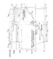
図1は、ワークピース26上でビーム軸24を位置決めするレーザ制御を行うことができるビーム位置決めシステム22を利用した簡略版レーザ微細加工システム20の模式図である。本明細書において述べられる実施形態は、「ビーム位置決めシステム22がレーザ28に追従する」ようにビーム位置決めシステムとレーザ28との間の主従関係を逆転させている。ビーム位置決めシステム22が、ビーム軸24をワークピース26の表面36上の所望のスポット位置30にワークピース26に対する所望の速度で案内したとき、レーザ28からレーザパルスを出射するのではなく、レーザシステムが初期化された後、コントローラ40によりQスイッチ信号経路38に沿ってレーザ28のレーザ共振器内のQスイッチ42に送られたパルス列を一定の周波数に維持することができる。ワークピース26上での所定の動作に対するレーザ加工ウィンドウ内にあり、一定のレーザ出力を維持するのに好適なレーザ28の動作パラメータであるレーザ繰り返し率を提供するように、Qスイッチコマンドトリガ信号のパルス列を選択することができる。初期化後は、トリガ信号は停止されず、開始されず、あるいは周波数偏移されることがなく、レーザ共振器の不安定性が最小限にされる。
FIG. 1 is a schematic diagram of a simplified
Qスイッチコマンドトリガ信号に応答してレーザパルスが生成されると、ビーム位置決めシステム22のビーム軸24の軌跡が時間的及び空間的に少し調整され、レーザ28の出力に合わされ、これにより、所望のレーザパルスがワークピース26の表面36に到達するときに、ビーム軸24が所望のスポット位置30に所望の速度で到達する。また、レーザ28からのレーザパルスの出射のタイミングは、ワークピース26に対するビーム軸24の位置を気にしていない。この能力は、デジタルレーザコントローラとビーム位置決めコントローラとの間のタイミングを正確に較正するだけでなく、コントローラ40によって実現されるビーム位置決めとレーザパワー制御の複合構造に対する制約を利用し、高速デジタル加工を利用するものである。
When a laser pulse is generated in response to the Q-switch command trigger signal, the trajectory of the beam axis 24 of the
レーザパルスを一定の速度で連続して出射し続けることの1つの利点は、レーザ28がレーザ共振器内で過渡状態を経ることなく、したがって、生成可能なものの中で最も一貫したレーザパルスを生成することである。
One advantage of continuing to emit laser pulses continuously at a constant speed is that the
レーザパルスパラメータの例としては、レーザの種類、波長、パルス持続時間、パルス補充速度、パルス数、パルスエネルギー、パルス時間的形状、パルス空間的形状、及び焦点スポットサイズ及び形状が挙げられる。付加的なレーザパルスパラメータには、ワークピース26の表面36に対して焦点スポットの位置を特定すること及びワークピース26に対してレーザパルスの相対運動を方向付けることが含まれる。
Examples of laser pulse parameters include laser type, wavelength, pulse duration, pulse replenishment rate, pulse number, pulse energy, pulse temporal shape, pulse spatial shape, and focal spot size and shape. Additional laser pulse parameters include locating the focal spot relative to the
ある実施形態において、一部の実施形態に対して有利に利用され得るレーザパラメータとしては、IRからUV、特に約10.6ミクロンから約266nmまでの範囲の波長を有するレーザ28を用いることが挙げられる。レーザ28は、1Wから100W、より好ましくは1Wから12Wの範囲にある2Wで動作し得る。パルス持続時間は、1ピコ秒から1000ns、より好ましくは約1ピコ秒から200nsの範囲にある。レーザ繰り返し率は、1KHzから100MHz、より好ましくは10KHzから1MHzの範囲にあり得る。レーザフルエンスは、約0.1×10⁻⁶J/cm2から100J/cm2、より好ましくは1.0×10-2J/cm2から10J/cm2の範囲にあり得る。ビーム軸24がワークピース26に対して移動する速度は、1mm/sから10m/s、より好ましくは100mm/sから1m/sの範囲にある。ワークピース26の表面36で測定した静止レーザスポット32(図5)の空間的長軸は、10ミクロンから1000ミクロン、あるいは50ミクロンから500ミクロンの範囲にあり得る。ビーム軸24の速度は、ワークピース26上でのレーザスポット32の有効サイズを増加させ得る。ある実施形態においては、スポットサイズが1/e2、FWHMでのレーザパルスのビームウェストを表しているものと考えることができる。
In certain embodiments, laser parameters that may be advantageously utilized for some embodiments include using a
ほとんどどんなタイプのレーザ28でも使用することができる。ある実施形態は、5MHzまでのパルス繰り返し率で約366nm(UV)から約1320nm(IR)の波長を出射するように構成可能なダイオード励起固体レーザ28を用いる。しかしながら、適切なレーザやレーザ光学系、部品取り扱い機器、及び制御ソフトウェアを代用したり追加したりすることによって、これらのシステムを上述したようにワークピース26上に選択されたレーザスポット32を確実に繰り返し生成するように適合させることができる。これらの修正により、レーザ加工システムが適切なレーザパラメータを使って所望の速度及び所望のレーザスポット32間バイトサイズで、適切に位置決めされ保持されたワークピース26上の所望の位置にレーザパルスを案内することが可能となる。
Almost any type of
ある実施形態においては、特定の周波数でレーザパルスをトリガするために内部クロックが使用されるモードロックレーザを用いることができる。 In one embodiment, a mode locked laser can be used where an internal clock is used to trigger the laser pulse at a particular frequency.
ある実施形態においては、レーザ加工システム20は、532nm、355nm、又は266nmで出射し、532nmで45Wもの出力パワーのあるCoherent Aviaダイオード励起固体Qスイッチレーザを用いる。
In one embodiment, the
ある実施形態においては、レーザ加工システム20は、ドイツ連邦共和国カイザースラウテルンのLumera Laser社により製造されるモデルRapidのような、1064nm波長で動作するダイオード励起Nd:YVO4固体レーザ28を用いる。このレーザは、必要に応じて固体調波発生器を用いて波長を532nmに下げて二逓倍され、これにより可視(緑色)レーザパルスを生成することができ、あるいは、約355nmに三逓倍され、あるいは、266nmに四逓倍され、これにより紫外(UV)レーザパルスを生成することができる。このレーザ28は、6ワットの連続パワーを生成するとされており、1000KHzの最大パルス繰り返し率を有する。このレーザ28は、コントローラ40と連係して1ピコ秒から1,000ナノ秒の持続時間を有するレーザパルスを生成する。
In one embodiment, the
これらのレーザパルスは、ガウス型であるか、あるいはレーザ光学系、典型的には、光路50に沿って配置された1以上の光学構成要素を備えたレーザ光学系によって特別に整形され、レーザスポット32で所望の特性を実現する。回折光学要素又は他のビーム整形構成要素を用いて特別に整形された空間プロファイルを生成してもよい。レーザスポット32の空間放射照度プロファイルを修正することについての詳細な説明がCorey Dunsky等による米国特許第6,433,301号に見られる。この米国特許は、本出願の譲受人に譲渡されており、参照により本明細書に組み込まれる。
These laser pulses are specially shaped by means of a Gaussian or laser optics, typically with one or more optical components arranged along the
再び図1を参照すると、レーザ微細加工システム例20のレーザ28は、様々な光学構成要素52、パルス選別デバイス54、1以上の折り畳みミラー56を通って、最終的に光路50のビーム軸24をワークピース26の表面36のスポット位置30上に案内するビーム位置決めシステム22のファーストポジショナ68まで広がる光路50に沿ってレーザパルスビームを出射する。光学構成要素52は、光路50に沿った様々な位置に配置されるビームエキスパンダレンズ要素、音響光学デバイスや電気光学デバイスなどの光学減衰器、及び/又はエネルギー用、タイミング用、又は位置用のフィードバックセンサなどの既知の様々な光学系を含み得る。
Referring again to FIG. 1, the
パルス選別デバイス54は、レーザパルスがさらに光路に沿って伝搬するのを阻止又は許容し、ワークピース26上に当てるレーザパルスを決定する高速シャッタとして動作する。パルス選別デバイス54は、電気光学デバイス又は音響光学変調器(AOM)60を含み得る。便宜上、本明細書においては、AOM60に対する例としてパルス選別器54を述べる。AOM60は、AOM信号経路58に沿ってコントローラ40から送られるAOMコマンド信号に応答するものである。AOMコマンド信号により、AOM60上の変換器は、AOM60を通過するビームを光路50に揃っているか揃っていない所定の出口角に方向転換させる音波をAOM内でファーストポジショナ68に向けて開始する。
The
ファーストポジショナ68は、比較的大きなスキャン領域72(図4)を有する任意の高速ビーム位置決めデバイスを含み得る。ある実施形態では、ファーストポジショナ68は、ワークピース26を横断する比較的大きな視野72にわたってビーム軸24の方向を素早く変更可能な、ガルバノメータにより駆動される1対のX軸及びY軸ミラー70を含み得る。ある実施形態においては、利用可能な視野72は10mmから100mmの直径(又は長軸)を有している。ある実施形態においては、利用可能な視野72は15mmより大きな直径を有している。ある実施形態においては、利用可能な視野72は25mmから50mmの直径を有している。ある実施形態においては、利用可能な視野72は75mmより小さな直径を有している。ある実施形態においては、利用可能な視野72は、スキャンレンズのエッジ効果によってレーザ加工には使用されないガルバノメータ移動領域を含んでいてもよく、このため、利用可能な加工領域が利用可能な視野72よりも小さくなっていてもよい。
The
あるいは、所望のスキャン領域72のサイズによっては、ファーストポジショナ68は、ガルバノメータミラー70よりビーム偏向範囲が小さい傾向があるものの、音響光学デバイス又は変形可能ミラー(又は他のファーストステアリングミラー)のような高速ポジショナを用いてもよい。あるいは、ガルバノメータミラー70に加えて高速ポジショナを利用してもよく、ガルバノメータミラー70によるビーム軸24の制御及び移動と一体化することができ、あるいは、エラー補正などのために、ガルバノメータミラー70によるビーム軸24の移動に重ね合わせることができる。ある実施形態においては、ファーストポジショナ68は、ワークピース26上の固定位置に支持される。他の実施形態においては、ファーストポジショナ68は、ワークピース26に対して移動可能なステージにより分割軸システム(split-axis system)内などに支持される。例示的なファーストポジショナ68は、数百キロヘルツの帯域幅を有し、約2又は3m/sから約10m/sの線速度及び約1000から2000Gの加速度を実現することができる。線速度がこれらの範囲より遅くてもよいことは言うまでもない。
Alternatively, depending on the size of the desired
ある実施形態においては、ビーム位置決めシステム22は、好ましくはワークピース26を支持する上側ステージ82及び上側ステージ82を支持する下側ステージ84のような少なくとも2つのプラットフォームを制御するワークピース位置決めステージ80を用いている。これらの上側ステージ82及び下側ステージ84は、典型的にはリニアモータにより移動され、一般的には、上側ステージがある軸に移動可能で下側ステージが別の軸に移動可能なX−Yステージと呼ばれる。典型的なワークピース位置決めステージ80は、数十キロヘルツの帯域幅を有し、約2又は3m/secの速度及び1.5G以上の加速度を実現することができる。現在費用対効果のよい並進ステージは約400mm/sから約1m/sの範囲で動作する。これらは、これよりずっと遅く移動してもよいことは言うまでもない。ワークピース位置決めステージ80の動作包絡面は、典型的には、ガルバノメータミラー70の視野72よりもずっと大きい。
In one embodiment,
ある実施形態においては、レーザ加工システム20は、段階ごとに繰り返しレーザダイシングを行い、ファーストポジショナ68により行われるダイシング動作中にワークピース位置が維持されるようにワークピース位置決めステージ80がファーストポジショナ68及びビーム軸24に対してワークピース26をある位置まで移動する。特に、ワークピース位置決めステージ80は、ワークピース26の特定の領域をガルバノメータミラー70の利用可能な視野72内に位置付けてもよい。スキャン領域72上でワークピース位置決めステージ80を完全に停止させてもよいが、ガルバノメータミラー70は、ワークピース26にわたるスキャン領域72内で1以上の切断経路92を含む1以上の移動パターン90を実行するようにビーム軸24を方向付けてもよい。ある実施形態においては、所望のスループットのために、与えられたスキャン領域72中の移動パターン90のパスのすべてが完了するまでビーム軸24は停止しない。
In one embodiment, the
移動パターン90におけるビーム軸24の1以上のパスの後、ガルバノメータミラー70のスキャン領域72を隣接する領域といったワークピース26の異なる領域に位置付けるために、ワークピース位置決めステージ80が移動してもよい。このように、ある実施形態に関しては、ビーム軸が加速している間はレーザ加工が行われない。一定速度の移動と一定の繰り返し率のパルスとともにビーム軸を用いることの利点は、レーザパルスの特性が安定し、予測可能になることである。
After one or more passes of beam axis 24 in
ある実施形態においては、既知のビーム軸24の速度でワークピース26上の切断経路92に沿って所望の放射照度を達成するように既知の間隔で離された一連のレーザパルスを生成することによってレーザダイシングが行われる。このプロセスは、切断経路92に沿った第1のレーザパルスの開始位置におけるオフセットをパスごとに変化させ、ワークピース26が所望のパラメータに加工されるまで任意の1つのスポット位置で累積放射照度を均等に分布させつつ、このプロセスを繰り返すことができる。しかしながら、パルス分離やパス分離が必要とされるものではない。したがって、パスは、スポットサイズよりも小さなパルス分離を有する重複パルスを含んでいてもよく、パルスの連続パスが空間的にオフセットされている必要はない。
In one embodiment, by generating a series of laser pulses separated by known intervals to achieve the desired irradiance along the cutting
上述した構成要素の一部又はすべてを含み、ワークピース26上又はワークピース26内で切断経路92(図4)に沿って切溝を形成可能なレーザ加工システムの例としては、いずれもオレゴン州97229ポートランドのElectro Scientific Industries社により製造されるESI 5320、MM5330、ML5900、及び5955微細加工システムが挙げられる。
Any example of a laser processing system capable of forming a kerf along cutting path 92 (FIG. 4) on or in
ある実施形態においては、ファーストポジショナ68及びワークピース位置決めステージ80は、コントローラ40からコマンドを受信する。ガルバノメータミラー70は、コントローラ40から直接的又は間接的に1以上のガルバノメータ信号経路104に沿ってガルバノメータコマンド信号を受信し得る。上側ステージ82及び下側ステージ84は、コントローラから直接的又は間接的に単一のステージ経路に沿って又は別個のステージ信号経路106a及び106bに沿って独立してワークピース位置決めステージ80コマンド信号を受信し得る。コマンド信号の性質を変更したり、それらのタイミングに影響を及ぼしたりするために、必要に応じていずれかの信号経路に沿ってサブコントローラを配置してもよい。例えば、ガルバノメータミラーは、JANUSアナログインタフェイス/ドライバモジュールを用いてもよい。
In one embodiment,
ある実施形態においては、本明細書に開示されるレーザを利用した位置決め手法を行うために、コントローラ40は、フィールドプログラマブルゲートアレイ(FPGA)のような主クロック又はタイミングデバイスを利用する。ある実施形態においては、FPGAは、基本クロック周波数ffgpa[Hz]を有しており、これは、典型的には、そのレジスタを更新可能な最速の周波数となるように選択される。割込率やレーザ繰り返し率などの他のパラメータが、推測的に選択されるコントローラ40に対する外因性入力であってもよい。
In one embodiment, the
例えば、DSP割込率fs[Hz]は、コントローラ40内のデジタル信号プロセッサ(DSP)がリアルタイム実行ループを行うサーボ割込率である。FPGAは、割込要求(IRQ)出力を介してDSPに対する割込を生成する。割込がffgpa[Hz]の整数倍ではない場合、FPGAにおける量子効果によって割込が少し異なることがある。この例では、この状態を仮定している。
For example, the DSP interrupt rate f s [Hz] is a servo interrupt rate at which a digital signal processor (DSP) in the
レーザ繰り返し率flaser[Hz]は、レーザ28のレーザ共振器から出射したレーザパルスの繰り返し率に等しい。実際の繰り返し率がffgpa[Hz]の整数倍ではない場合、FPGAにおける量子効果によって実際の繰り返し率が少し異なることがある。この例では、この状態を仮定している。
The laser repetition rate f laser [Hz] is equal to the repetition rate of the laser pulse emitted from the laser resonator of the
特定のレーザシステム構成要素及びスキャン領域72におけるガルバノメータミラー70の相対運動速度に対して、レーザ伝搬遅延、AOM伝搬遅延、サーボ遅れ時間、AOM−レーザリードタイム、及びAOM−レーザ遅れ時間などのパラメータを較正することができる。
Parameters such as laser propagation delay, AOM propagation delay, servo delay time, AOM-laser lead time, and AOM-laser delay time for specific laser system components and relative motion velocity of galvanometer mirror 70 in
レーザ伝搬遅延Tlaser_prop[s]は、FPGAからQスイッチコマンドパルスが出力されてからワークピース26の表面にレーザパルスが到達するまでの推測時間である。
The laser propagation delay T laser — prop [s] is an estimated time from the output of the Q switch command pulse from the FPGA to the arrival of the laser pulse on the surface of the
AOM伝搬遅延Taom_prop[s]は、FPGAからAOMコマンドレジスタの立ち上がり/立ち下がりが出力されてから、AOM60から出る所望の光路に沿ってレーザパルスが所望の減衰レベルで伝搬可能な完全励起AOM結晶状態になるまでの推測時間である。すなわち、Taom_prop[s]は、AOM60がAOMコマンド信号に応答して「開」又は「閉」になるのにかかる時間である。ある実施形態においては、AOM60から出る所望の光路は1次光路である。
The AOM propagation delay Taom_prop [s] is a fully pumped AOM crystal that allows the laser pulse to propagate at the desired attenuation level along the desired optical path out of the
サーボ遅れ時間Klag[s2/m]は、ガルバノメータミラーコマンド信号と、ガルバノメータミラー70によりワークピース26とビーム軸24との間で一定速度の相対運動を行っているときのワークピース26上の位置との間の時間遅延を推測したスケールファクターである。
The servo delay time K lag [s 2 / m] is a galvanometer mirror command signal, and on the
AOM−レーザリードタイムTaom_lead[s]は、AOMを開いてから、切断経路92に沿ってAOM60を通過してワークピース26の表面36に至る最初のレーザパルスまでの特定の時間である。AOM−レーザリードタイムは、レーザ繰り返し率flaserに関連付けられたレーザ期間よりも短くなるように選択される。
The AOM-laser lead time Taom lead (s) is the specific time from opening the AOM to the first laser pulse along the cutting
AOM−レーザ遅れ時間Taom_lag[s]は、AOM60を通過してワークピース26の表面に至る最後のレーザパルスからAOMを閉じるまでの特定の時間である。この時間は、AOM伝搬遅延Taom_propとレーザ繰り返し率flaserに関連付けられたレーザ期間との合計よりも短くなるように選択される。
AOM-laser lag time T aom — lag [s] is the specific time from the last laser pulse passing through the
ダイスレーン開始位置、ダイスレーン終了位置、公称パルス分離、公称パス速度、及びプロファイルされた移動時間などのレシピパラメータをユーザが選択するか、あるいはユーザ入力、位置データ、ルックアップテーブル、及び/又はプロファイリングソフトウェアに基づいてコントローラ40が決定することができる。
User-selected recipe parameters such as die lane start position, die lane end position, nominal pulse separation, nominal pass speed, and profiled travel time, or user input, position data, look-up tables, and / or profiling The
ダイスレーン開始位置p1[μm]は、X−Yワークピースステージ82及び84の現在位置に対するガルバノメータミラー座標でのレーザ切断経路92の所望の開始点である。
The die lane starting position p 1 [μm] is the desired starting point of the
ダイスレーン終了位置p2[μm]は、レシピパラメータに基づくX−Yワークピースステージ82及び84の現在位置に対するガルバノメータミラー座標でのレーザ切断経路92の所望の終了点である。
The die lane end position p 2 [μm] is the desired end point of the
公称パルス分離Δppulse[μm]は、ワークピース26の表面36に当たるレーザパルス間の所望の距離である。リアルタイム制御システムにおける量子効果によりこの値を少し調整することができる。
The nominal pulse separation Δp pulse [μm] is the desired distance between the laser pulses striking the
公称パス速度Vpass[μm/s]は、レシピパラメータに基づくワークピース26の表面36でのビーム軸24の所望の速度である。リアルタイム制御システムにおける量子効果によりこの値を少し調整することができる。
The nominal pass velocity V pass [μm / s] is the desired velocity of the beam axis 24 at the
プロファイルされた移動時間tprof[s]は、移動のプロファイルされた(加速度制限された)部分をワークピース26内の移動の一定速度切断経路部分にするのに必要な時間である。この値は、コントローラ40又は他のシステムコンピュータ内のプロファイリングソフトウェアにより計算することができ、移動時間計算器と呼ぶこともできる。
The profiled travel time t prof [s] is the time required to make the profiled (acceleration limited) portion of the motion into a constant velocity cutting path portion of motion within the
リアルタイム測定は、Qスイッチパルスから、切断経路92に沿った切断が開始するDSP割込サイクルの開始までに経過した時間であるレーザパルス位相オフセットtφ[s]を含んでいる。この値は、FPGAにより与えられる。
The real-time measurement includes the laser pulse phase offset tφ [s] which is the time elapsed from the Q-switched pulse to the start of the DSP interrupt cycle where the cut along
図2は、ワークピース26の切断経路92に沿ったレーザパスを実現するためのレーザパルス及び様々なビーム伝搬及び位置決めシステム構成要素の例示タイミング図である。図2を参照すると、ある実施形態においては、p1及びp2により特定される切断経路92の開始位置及び終了位置に正確に位置するように2点間でレーザを用いて切断経路92に沿って線を形成することが目標となる。繰り返し率flaserが一定のレーザ28を用いると、公称パルス分離Δppulse及びパス速度Vpassは互いに独立しているのでこれらが独立して特定される。位置に基づくレシピについて、公称パス速度は、
Vpass=Δppulseflaser (1)
である。あるいは、速度に基づくレシピについて、公称パルス分離は、
Δppulse=Vpass/flaser (2)
である。いずれの場合も、切断経路92に沿って並ぶであろうパルス数は、round()関数が0.5以上の端数を切り上げることによって整数値を得るものであり、切断経路92の終端で余分なパルスを入れるために+1が追加されるとすると、
Npulse=(round(p2−p1)/Δppulse))+1 (3)
である。
FIG. 2 is an exemplary timing diagram of laser pulses and various beam propagation and positioning system components to provide a laser path along the cutting
V pass = Δp pulse f laser (1)
It is. Alternatively, for velocity based recipes, the nominal pulse separation is
Δp pulse = V pass / f laser (2)
It is. In any case, the number of pulses that will be aligned along the cutting
N pulse = (round (p 2 −p 1 ) / Δp pulse )) + 1 (3)
It is.
FPGAの量子効果は、外部からトリガされたQスイッチレーザがFPGAにより制御される場合、レーザの実際の繰り返し期間は、Tlaser=1/flaserであるとして、
Tlaser=(round(Tlaser/Tfpga))Tfpga (4)
であることを意味している。
The quantum effect of the FPGA is that if the externally triggered Q-switched laser is controlled by the FPGA, then the actual repetition period of the laser is T laser = 1 / f laser
T laser = (round (T laser / T fpga )) T fpga (4)
Is meant to be.
そして、レーザ繰り返し率の量子効果後の実際のパス速度は、
Vpass=(p2−p1)/((Npulse−1)Tlaser) (5)
から算出される。
And the actual pass speed after the quantum effect of the laser repetition rate is
V pass = (p 2 −p 1 ) / ((N pulse −1) T laser ) (5)
Calculated from
移動のプロファイルセグメント中に生じるレーザパルスの数は、floor()関数がその数の端数値を切り捨てることにより整数値を得るものであるとすると、
nstart=floor(tprof/Tlaser) (6)
である。
Assuming that the number of laser pulses generated in the profile segment of movement is such that the floor () function obtains an integer value by rounding off the fractional value of the number:
n start = floor (t prof / T laser ) (6)
It is.
ある実施形態においては、パターン90の一定速度セグメントが、最後のレーザパルスが切断経路92の終点に到達した後、単一のDSP割込内で終了することが好ましい場合がある。すなわち、nirqがパターン90内の移動の一定速度セグメント中の生じるDSP割込の数であるとすると、
nirqTs≦npulseTlaser≦(nirq+1)Ts (7)
である。nirqを以下のように選択すれば、この関係を維持することができる。
nirq=floor((npulse)(Tlaser/Ts)+1)) (8)
In certain embodiments, it may be preferable for the constant velocity segment of
n irq T s n n pulse T laser ≦ (n irq +1) T s (7)
It is. This relationship can be maintained by selecting n irq as follows.
n irq = floor ((n pulse ) (T laser / T s ) +1)) (8)
移動パターン90が始まるDSP割込サイクルの開始時に、プロファイルされたセグメントの終点直後の最初のレーザパルスがワークピース26の表面36に到達するまでの時間は、レーザパルス位相オフセットtφがFPGAレジスタに維持され、DSPにより読み取られるとすると、
Tstart=((nstart+1)Tlaser)+(Tlaser_prop−tφ) (9)
である。
At the start of DSP interrupt
T start = ((n start +1) T laser ) + (T laser_prop −t φ ) (9)
It is.
ガルバノメータサーボループに対する位置コマンドと、ガルバノメータミラー70により指示されたビーム軸24の実際の位置との間の遅れ時間は、およそ以下のようになり得る。
Tlag=KlagVpass (10)
レーザスケーリングKlagはパス速度の範囲にわたって独立して特徴付けることができる。
The delay time between the position command for the galvanometer servo loop and the actual position of the beam axis 24 pointed by the galvanometer mirror 70 may be approximately:
T lag = K lag V pass (10)
Laser scaling K lag can be characterized independently over a range of pass speeds.
ガルバノメータミラー70により指示されたワークピース26上のビーム軸24の位置を時間的に前方に見積もり、推測されるガルバノメータ遅れを考慮すると、コマンドがp1に到達する時点に対する調整は、
δt=tstart−tprof+tlag (11)
となる。式(11)においては、時間上の遅れの方向を考慮してガルボ遅れ時間tlagがこの式の右項から引かれるのではなく、足されているいることに留意されたい。
Considering the position of beam axis 24 on
δ t = t start −t prof + t lag (11)
It becomes. Note that in equation (11), the galvo delay time t lag is added rather than subtracted from the right term of this equation, taking into account the direction of the time delay.
その後、最初のパルスランドp1などに適用されるプロファイルされた移動セグメントδpの最終位置に対する調整が、以下のように最初のレーザパルスに対して時間的に後方に見積もることにより計算される。
δp=−Vpassδt (12)
The adjustment to the final position of the profiled moving segment δ p applied to the first pulse land p 1 etc. is then calculated by estimating the time backwards with respect to the first laser pulse as follows.
δ p = −V pass δ t (12)
最後に、プロファイルされた移動セグメントの開始に対するAOMのアンブロック時間及びブロック時間は、
Tunblock=tstart−taom_lead−Taom_prop (13)
及び
Tblock=tstart+((npulse−1)Tlaser)+Taom_lag (14)
により計算される。AOMのアンブロック時間及びブロック時間は、浮動小数点演算として計算することができ、以下のようにFPGAクロックサイクルの整数に計算される。
nunblock=round(Tunblock/Tlaser) (15)
及び
nblock=round(Tblock/Tlaser) (16)
そして、得られた数字は、tφが読み込まれたサイクルに対してAOMコマンドをゲートするためにFPGAタイマにおいて使用される。
Finally, the AOM unblock and block times for the start of the profiled mobile segment are
T unblock = t start -t aom_lead -T aom_prop (13)
And T block = t start + ((n pulse −1) T laser ) + T aom_lag (14)
Calculated by The AOM unblock time and block time can be calculated as floating point operations and are calculated to integer numbers of FPGA clock cycles as follows.
n unblock = round (T unblock / T laser ) (15)
And n block = round (T block / T laser ) (16)
Then, the resulting figures, t phi are used in FPGA timer to gate the AOM command to read cycles.
これらの実施形態の一部を実証するために、FPGA及びDSP割込ロジックの挙動をエミュレートするシミュレーションを行った。シミュレーションはリアルタイムコントローラ/ガルバノメータ組み込みソフトウェア(TaskProcessorやServoThreadなど)に非常によく似ており、FPGAクロック周波数レベルでの時間に対してQSW、IRQ、AOMパルス列、及びビーム軸位置を捕捉するためにこのシミュレーションを用いた。 To demonstrate some of these embodiments, simulations were performed to emulate the behavior of the FPGA and DSP interrupt logic. The simulation is very similar to the real-time controller / galvanometer embedded software (such as TaskProcessor or ServoThread) and is used to capture QSW, IRQ, AOM pulse trains, and beam axis position versus time at the FPGA clock frequency level. Was used.
図3は、ワークピース26中のスキャン領域72を通る選択されたビーム軸のルート内の切断経路92の異なるセグメントに沿った単一のパスに対するシミュレーションのタイミング図を示している。上側の3つのプロットは、100MHzのFPGA及び140kHzのレーザパルスにより生成されたパルス列を示すものであり、下側の2つのプロットは、ビーム軸24が加工領域を前後にスキャンする際にガルバノメータにより方向付けられ、20kHzで更新されるビーム軸位置を示すものである。しかしながら、理解を容易にするために、上側のレーザプロットに示されているレーザパルス間の間隔は誇張されている。さらに、Qスイッチトリガ信号は図示されていないが、レーザパルスのそれぞれの間の白色の領域で生じている。しかしながら、ある実施形態においては、一定で予測可能なレーザパルスパラメータを再確立するためにQスイッチトリガとレーザパルス化が切断セグメントの十分前に再起動される限り、切断工程間でQスイッチトリガとレーザパルス化が抑制されることがある。
FIG. 3 shows a timing diagram of a simulation for a single pass along different segments of cutting
同様に、IRQ信号間の間隔が誇張されている。IRQ信号はそれ自身の周波数を有しており、不連続性を有し得るが、レーザパルスは自律的に一定速度で作動する。 Similarly, the spacing between the IRQ signals is exaggerated. The IRQ signal has its own frequency and may have discontinuities, but the laser pulse operates autonomously at a constant speed.
図4は、ガルバノメータミラー70の2軸スキャン領域72にわたるレーザビーム軸24の代表的な移動パターン90の上面図であり、図5は、図4の移動パターン90の拡大部の上面図であり、レーザパスの開始時のレーザパルスの相対位置を示すものである。図4を参照すると、切断経路92は、異なる方向に加工される4つのストリートセグメントを形成している。本明細書において開示された手法により提供されるパルスの一貫性と位置決め能力と連係するパルス選別デバイスは、ストリートセグメントの交差を過度に加工することを防止するように有利な方法で配置することができる。
FIG. 4 is a top view of a
図4及び図5を参照すると、公称パス速度vpass及びSSC上のレシピから特定されるレーザパルス分離は、それぞれ2850mm/s及び20.36μmであった。DSP及びレーザ繰り返し率の制約を満たすためにリアルタイムソフトウェアによる調整をした後は、これらの数値が2852mm/s及び20.00μmとなり、この特定のパスに関してプロファイルされた移動δpに対する得られた位置調整は14.89μmとなった。 With reference to FIGS. 4 and 5, the nominal pulse velocity v pass and the laser pulse separation specified from the recipe on the SSC were 2850 mm / s and 20.36 μm, respectively. After adjustment with real-time software to meet DSP and laser repetition rate constraints, these numbers become 2852 mm / s and 20.00 μm, and the resulting alignment for the profiled movement δ p for this particular path is It became 14.89 μm.
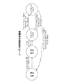
図6Aは、開示された手法の一部を実現するためのデジタル信号プロセッサにおけるリアルタイム論理状態の例のタイミング図である。より簡単なステップのプロセスフローは、1)一定のパラメータでレーザをトリガし、2)同期に対するタイミングオフセットを算出し、3)リアルタイムでδp及びδtを算出し、4)位置と時間に関してプロファイルコマンドを調整し、5)実行することを含み得る。 FIG. 6A is a timing diagram of an example of real-time logic states in a digital signal processor to implement some of the disclosed techniques. A simpler step process flow: 1) trigger the laser with constant parameters, 2) calculate timing offsets for synchronization, 3) calculate δ p and δ t in real time, 4) profile with respect to position and time It may include adjusting commands and 5) executing.
図6Bは、利用可能なスキャン領域72にわたる図6Aのタイミング図により表されるビーム軸移動とパルス選別器の連係を示している。図6Cは、図6Aの例に関してパルス選別デバイス54への指令例を示す一般的なフロー図である。
FIG. 6B illustrates the alignment of the beam axis movement and the pulse sorter represented by the timing diagram of FIG. 6A across the
本明細書に開示された手法は、レーザ切断動作だけではなく、レーザマーキング、レーザスクライビング、又はレーザビア穿孔にも有用であり得ることは理解できよう。加えて、本明細書に開示された手法は、James N. O'Brien等による米国再発行特許第RE43,440号に述べられたセグメント切断手法のような様々な他の切断手法とともに用られてもよい。この米国再発行特許は、参照により本明細書に組み込まれる。 It will be appreciated that the techniques disclosed herein may be useful not only for laser cutting operations, but also for laser marking, laser scribing, or laser via drilling. In addition, the techniques disclosed herein may be used with various other cutting techniques, such as the segmentation technique described in US Reissue Patent RE 43,440 by James N. O'Brien et al. It is also good. This US Reissue Patent is incorporated herein by reference.
上記は、本発明の実施形態を説明したものであって、これに限定するものとして解釈されるものではない。いくつかの特定の実施形態例が述べられたが、当業者は、本発明の新規な教示や利点から大きく逸脱することなく、開示された実施形態例及び他の実施形態に対して多くの改良が可能であることを容易に認識するであろう。 The foregoing describes the embodiments of the present invention and is not to be construed as limiting. Although several specific example embodiments have been described, those skilled in the art will appreciate that many improvements can be made to the disclosed example embodiments and other embodiments without departing substantially from the novel teachings and advantages of the present invention. Will readily recognize that it is possible.
したがって、そのような改良はすべて、以下の特許請求の範囲において規定される発明の範囲に含まれることを意図している。例えば、当業者は、そのような組み合わせが互いに排他的になる場合を除いて、いずれかの文や段落の主題を他の文や段落の一部又は全部の主題と組み合わせることができることを理解するであろう。 Accordingly, all such modifications are intended to be included within the scope of the invention as defined in the following claims. For example, one skilled in the art will understand that the subject matter of any sentence or paragraph may be combined with the subject matter of some or all of the other sentences or paragraphs, unless such combination is mutually exclusive. Will.
本発明の根底にある原理を逸脱することなく上述の実施形態の詳細に対して多くの変更をなすことが可能であることは当業者にとって自明なことであろう。したがって、本発明の範囲は、以下の特許請求の範囲とこれに含まれるべき請求項の均等物とによって決定されるべきである。 It will be apparent to those skilled in the art that many changes can be made to the details of the above-described embodiments without departing from the underlying principles of the invention. Accordingly, the scope of the present invention should be determined by the following claims and the equivalents of the claims to be included therein.
Claims (17)
レーザからの光路に沿った伝搬に関して一定のレーザパルス繰り返し率でレーザパルスからなるビームを生成し、
前記光路に沿って配置され、ワークピース上で前記光路のビーム軸を移動パターンに方向付けることが可能なファーストポジショナを含むビーム位置決めシステムを利用し、前記移動パターンは、前記ワークピースの非切断領域上で前記ビーム軸を方向付けること及び前記ワークピースに対する開始位置及び終了位置の間の切断経路上をビーム軸速度で前記ビーム軸を方向付けて前記レーザパルス繰り返し率で、かつ前記切断経路に沿って前記ワークピースの物理的特性を変化させる放射照度で前記レーザパルスを伝搬することを含み、
前記レーザパルスのうち選択されたものが前記光路に沿って前記ワークピースに伝搬することを許可又は阻止するパルス選別デバイスを利用し、前記ワークピースに伝搬することを許可された前記レーザパルスは作動レーザパルスであり、前記ワークピースに伝搬することを阻止された前記レーザパルスは非作動レーザパルスであり、
ワークピースの前記物理的特性を変化させるレーザ加工パラメータを受信可能で、前記レーザ、ビーム位置決めシステム、及び前記パルス選別デバイスに直接的又は間接的に制御信号を供給可能なコントローラを利用し、前記レーザ加工パラメータは、前記レーザパルス繰り返し率、前記切断経路、前記ビーム軸速度、及び前記放射照度を含むか、あるいはこれらを決定し、
前記コントローラに関連付けられた処理回路であって、前記ファーストポジショナにファーストポジショナ制御信号を供給可能な処理回路を利用して、前記ワークピース上の前記切断経路に沿って移動するように前記ビーム軸を案内し、前記レーザパルス繰り返し率に基づいて、前記処理回路は、前記ワークピースに対する前記開始位置に前記ビーム軸を案内し、前記作動レーザパルスのうち最初のレーザパルスが前記ワークピースに当たったときに前記ビーム軸速度で移動させることが可能であり、前記タイミングデバイスを通してゲートされた1以上のパルス選別デバイス信号が、前記パルス選別デバイスに前記ワークピースの非切断領域上の非作動レーザパルスの伝搬を阻止させ、前記ワークピースに対する前記開始位置と前記終了位置とを含みこれらの間の前記切断経路上で前記ワークピースに当てさせることができ、
前記処理回路は、前記ファーストポジショナ制御信号の伝達と、前記ビーム軸速度での前記ワークピースに対する前記開始位置への前記ビーム軸への案内との間のファーストポジショナ遅延を提供可能である、レーザ加工方法。 A laser processing method for linking a beam axis position and a beam axis velocity to laser emission at a constant laser pulse repetition rate,
Generate a beam consisting of laser pulses at a constant laser pulse repetition rate for propagation along the optical path from the laser,
Utilizing a beam positioning system including a first positioner disposed along the optical path and capable of directing the beam axis of the optical path to a movement pattern on the workpiece, the movement pattern comprising a non-cutting area of the workpiece Orienting the beam axis above and orienting the beam axis at a beam axis velocity on a cutting path between a starting position and an ending position with respect to the workpiece, at the laser pulse repetition rate, and along the cutting path Propagation of the laser pulse at an irradiance that changes the physical properties of the workpiece;
Using a pulse sorting device to allow or block selected ones of the laser pulses from propagating along the optical path to the workpiece, the laser pulses being allowed to propagate to the workpiece are activated A laser pulse, said laser pulse blocked from propagating to said workpiece being a non-actuating laser pulse,
A laser capable of receiving laser processing parameters for changing the physical properties of the workpiece and utilizing a controller capable of supplying control signals directly or indirectly to the laser, the beam positioning system, and the pulse sorting device; The processing parameters include or determine the laser pulse repetition rate, the cutting path, the beam axis velocity, and the irradiance,
A processing circuit associated with the controller, the processing circuit capable of supplying a first positioner control signal to the first positioner to move the beam axis along the cutting path on the workpiece. Guiding and based on the laser pulse repetition rate, the processing circuit guides the beam axis to the starting position relative to the workpiece, when the first laser pulse of the working laser pulses hits the workpiece And at least one pulse sorting device signal gated through the timing device can propagate at the beam axial velocity to the pulse sorting device the propagation of inactive laser pulses on the non-cutting region of the workpiece. Block the start position and the end position with respect to the workpiece Wherein the door can be caused to hit the workpiece on the cutting path between them,
The processing circuit may be capable of providing a first positioner delay between the transmission of the first positioner control signal and the guiding of the beam axis to the start position relative to the workpiece at the beam axis velocity. Method.
レーザからの光路に沿った伝搬に関して一定のレーザパルス繰り返し率でレーザパルスからなるビームを生成し、
前記光路に沿って配置され、ワークピース上で前記光路のビーム軸を移動パターンに方向付けることが可能なファーストポジショナを含むビーム位置決めシステムを利用し、前記移動パターンは、前記ワークピースの非切断領域上で前記ビーム軸を方向付けること及び前記ワークピースに対する開始位置及び終了位置の間の切断経路上をビーム軸速度で前記ビーム軸を方向付けて前記レーザパルス繰り返し率で、かつ前記切断経路に沿って前記ワークピースの物理的特性を変化させる放射照度で前記レーザパルスを伝搬することを含み、
前記レーザパルスのうち選択されたものが前記光路に沿って前記ワークピースに伝搬することを許可又は阻止するパルス選別デバイスを利用し、前記ワークピースに伝搬することを許可された前記レーザパルスは作動レーザパルスであり、前記ワークピースに伝搬することを阻止された前記レーザパルスは非作動レーザパルスであり、
ワークピースの前記物理的特性を変化させるレーザ加工パラメータを受信可能で、前記レーザ、ビーム位置決めシステム、及び前記パルス選別デバイスに直接的又は間接的に制御信号を供給可能なコントローラを利用し、前記レーザ加工パラメータは、前記レーザパルス繰り返し率、前記切断経路、前記ビーム軸速度、及び前記放射照度を含むか、あるいはこれらを決定し、
前記コントローラに関連付けられた処理回路であって、前記ファーストポジショナにファーストポジショナ制御信号を供給可能な処理回路を利用して、前記ワークピース上の前記切断経路に沿って移動するように前記ビーム軸を案内し、前記レーザパルス繰り返し率に基づいて、前記処理回路は、前記ワークピースに対する前記開始位置に前記ビーム軸を案内し、前記作動レーザパルスのうち最初のレーザパルスが前記ワークピースに当たったときに前記ビーム軸速度で移動させることが可能であり、前記タイミングデバイスを通してゲートされた1以上のパルス選別デバイス信号が、前記パルス選別デバイスに前記ワークピースの非切断領域上の非作動レーザパルスの伝搬を阻止させ、前記ワークピースに対する前記開始位置と前記終了位置とを含みこれらの間の前記切断経路上で前記ワークピースに当てさせることができ、
前記処理回路は、前記ワークピース上の非作動レーザパルスの伝搬の阻止から作動レーザパルスの伝搬の許可への前記パルス選別デバイスの有効な変更と、前記最初の作動レーザパルスの前記パルス選別デバイスの通過との間のパルス選別デバイスリードタイムを提供可能である、レーザ加工方法。 A laser processing method for linking a beam axis position and a beam axis velocity to laser emission at a constant laser pulse repetition rate,
Generate a beam consisting of laser pulses at a constant laser pulse repetition rate for propagation along the optical path from the laser,
Utilizing a beam positioning system including a first positioner disposed along the optical path and capable of directing the beam axis of the optical path to a movement pattern on the workpiece, the movement pattern comprising a non-cutting area of the workpiece Orienting the beam axis above and orienting the beam axis at a beam axis velocity on a cutting path between a starting position and an ending position with respect to the workpiece, at the laser pulse repetition rate, and along the cutting path Propagation of the laser pulse at an irradiance that changes the physical properties of the workpiece;
Using a pulse sorting device to allow or block selected ones of the laser pulses from propagating along the optical path to the workpiece, the laser pulses being allowed to propagate to the workpiece are activated A laser pulse, said laser pulse blocked from propagating to said workpiece being a non-actuating laser pulse,
A laser capable of receiving laser processing parameters for changing the physical properties of the workpiece and utilizing a controller capable of supplying control signals directly or indirectly to the laser, the beam positioning system, and the pulse sorting device; The processing parameters include or determine the laser pulse repetition rate, the cutting path, the beam axis velocity, and the irradiance,
A processing circuit associated with the controller, the processing circuit capable of supplying a first positioner control signal to the first positioner to move the beam axis along the cutting path on the workpiece. Guiding and based on the laser pulse repetition rate, the processing circuit guides the beam axis to the starting position relative to the workpiece, when the first laser pulse of the working laser pulses hits the workpiece And at least one pulse sorting device signal gated through the timing device can propagate at the beam axial velocity to the pulse sorting device the propagation of inactive laser pulses on the non-cutting region of the workpiece. Block the start position and the end position with respect to the workpiece Wherein the door can be caused to hit the workpiece on the cutting path between them,
The processing circuit is configured to: effectively change the pulse sorting device from blocking propagation of non-working laser pulses on the workpiece to allow propagation of working laser pulses; and for the pulse sorting device of the first working laser pulse. A laser processing method capable of providing a pulse sorting device lead time between passing.
レーザからの光路に沿った伝搬に関して一定のレーザパルス繰り返し率でレーザパルスからなるビームを生成し、
前記光路に沿って配置され、ワークピース上で前記光路のビーム軸を移動パターンに方向付けることが可能なファーストポジショナを含むビーム位置決めシステムを利用し、前記移動パターンは、前記ワークピースの非切断領域上で前記ビーム軸を方向付けること及び前記ワークピースに対する開始位置及び終了位置の間の切断経路上をビーム軸速度で前記ビーム軸を方向付けて前記レーザパルス繰り返し率で、かつ前記切断経路に沿って前記ワークピースの物理的特性を変化させる放射照度で前記レーザパルスを伝搬することを含み、
前記レーザパルスのうち選択されたものが前記光路に沿って前記ワークピースに伝搬することを許可又は阻止するパルス選別デバイスを利用し、前記ワークピースに伝搬することを許可された前記レーザパルスは作動レーザパルスであり、前記ワークピースに伝搬することを阻止された前記レーザパルスは非作動レーザパルスであり、
ワークピースの前記物理的特性を変化させるレーザ加工パラメータを受信可能で、前記レーザ、ビーム位置決めシステム、及び前記パルス選別デバイスに直接的又は間接的に制御信号を供給可能なコントローラを利用し、前記レーザ加工パラメータは、前記レーザパルス繰り返し率、前記切断経路、前記ビーム軸速度、及び前記放射照度を含むか、あるいはこれらを決定し、
前記コントローラに関連付けられた処理回路であって、前記ファーストポジショナにファーストポジショナ制御信号を供給可能な処理回路を利用して、前記ワークピース上の前記切断経路に沿って移動するように前記ビーム軸を案内し、前記レーザパルス繰り返し率に基づいて、前記処理回路は、前記ワークピースに対する前記開始位置に前記ビーム軸を案内し、前記作動レーザパルスのうち最初のレーザパルスが前記ワークピースに当たったときに前記ビーム軸速度で移動させることが可能であり、前記タイミングデバイスを通してゲートされた1以上のパルス選別デバイス信号が、前記パルス選別デバイスに前記ワークピースの非切断領域上の非作動レーザパルスの伝搬を阻止させ、前記ワークピースに対する前記開始位置と前記終了位置とを含みこれらの間の前記切断経路上で前記ワークピースに当てさせることができ、
前記処理回路は、前記ワークピース上の作動レーザパルスの伝搬の許可から非作動レーザパルスの伝搬の阻止への前記パルス選別デバイスの有効な変更と、前記ワークピース上の前記切断経路の前記終了位置に当たる前記作動レーザパルスの前記パルス選別デバイスの通過との間のパルス選別デバイス遅れ時間を提供可能である、レーザ加工方法。 A laser processing method for linking a beam axis position and a beam axis velocity to laser emission at a constant laser pulse repetition rate,
Generate a beam consisting of laser pulses at a constant laser pulse repetition rate for propagation along the optical path from the laser,
Utilizing a beam positioning system including a first positioner disposed along the optical path and capable of directing the beam axis of the optical path to a movement pattern on the workpiece, the movement pattern comprising a non-cutting area of the workpiece Orienting the beam axis above and orienting the beam axis at a beam axis velocity on a cutting path between a starting position and an ending position with respect to the workpiece, at the laser pulse repetition rate, and along the cutting path Propagation of the laser pulse at an irradiance that changes the physical properties of the workpiece;
Using a pulse sorting device to allow or block selected ones of the laser pulses from propagating along the optical path to the workpiece, the laser pulses being allowed to propagate to the workpiece are activated A laser pulse, said laser pulse blocked from propagating to said workpiece being a non-actuating laser pulse,
A laser capable of receiving laser processing parameters for changing the physical properties of the workpiece and utilizing a controller capable of supplying control signals directly or indirectly to the laser, the beam positioning system, and the pulse sorting device; The processing parameters include or determine the laser pulse repetition rate, the cutting path, the beam axis velocity, and the irradiance,
A processing circuit associated with the controller, the processing circuit capable of supplying a first positioner control signal to the first positioner to move the beam axis along the cutting path on the workpiece. Guiding and based on the laser pulse repetition rate, the processing circuit guides the beam axis to the starting position relative to the workpiece, when the first laser pulse of the working laser pulses hits the workpiece And at least one pulse sorting device signal gated through the timing device can propagate at the beam axial velocity to the pulse sorting device the propagation of inactive laser pulses on the non-cutting region of the workpiece. Block the start position and the end position with respect to the workpiece Wherein the door can be caused to hit the workpiece on the cutting path between them,
The processing circuit is operative to change the pulse sorting device from allowing the propagation of actuated laser pulses on the workpiece to blocking the propagation of non-actuated laser pulses, and the end position of the cutting path on the workpiece 6. A laser processing method that can provide a pulse sorting device lag time between the passing of the pulse sorting device of the actuation laser pulse that strikes.
レーザからの光路に沿った伝搬に関してあるレーザパルス繰り返し率でレーザパルスを出射させるレーザトリガデバイスを含むレーザと、
前記光路に沿って配置され、ワークピース上で前記光路のビーム軸を移動パターンに方向付けることが可能なファーストポジショナを含むビーム位置決めシステムであって、前記移動パターンは、前記ワークピースの非切断領域上で前記ビーム軸を方向付けること及び前記ワークピースに対する開始位置及び終了位置の間の切断経路上をビーム軸速度で前記ビーム軸を方向付けて前記レーザパルス繰り返し率で、かつ前記切断経路に沿って前記ワークピースの物理的特性を変化させる放射照度で前記レーザパルスを伝搬することを含むビーム位置決めシステムと、
前記光路に沿って配置され、前記レーザパルスのうち選択されたものが前記光路に沿って前記ワークピースに伝搬することを許可又は阻止することが可能なパルス選別デバイスであって、前記ワークピースに伝搬することを許可された前記レーザパルスは作動レーザパルスであり、前記ワークピースに伝搬することを阻止された前記レーザパルスは非作動レーザパルスであるパルス選別デバイスと、
ワークピースの前記物理的特性を変化させるレーザ加工パラメータを受信可能で、前記レーザ、前記ビーム位置決めシステム、及び前記パルス選別デバイスに直接的又は間接的に制御信号を供給可能なコントローラであって、前記レーザ加工パラメータは、前記レーザパルス繰り返し率、前記切断経路、前記ビーム軸速度、及び前記放射照度を含むか、あるいはこれらを決定するコントローラと、
前記コントローラと通信をするタイミングデバイスであって、前記レーザの前記レーザパルス繰り返し率を一定にするために、レーザトリガ信号を一定の繰り返し率でレーザトリガデバイスに送信させることができ、これにより、安定的で予測可能なパルス特性を呈するように前記レーザパルスの出射を一定にするタイミングデバイスと、
前記コントローラに関連付けられ、前記ファーストポジショナにファーストポジショナ制御信号を供給可能な処理回路であって、前記ワークピース上の前記切断経路に沿って移動するように前記ビーム軸を案内し、前記レーザパルス繰り返し率に基づいて、前記処理回路は、前記ワークピースに対する前記開始位置に前記ビーム軸を案内し、前記作動レーザパルスのうち最初のレーザパルスが前記ワークピースに当たったときに前記ビーム軸速度で移動させることが可能であり、前記タイミングデバイスを通してゲートされた1以上のパルス選別信号が、前記パルス選別デバイスに前記ワークピースの非切断領域上の非作動レーザパルスの伝搬を阻止させ、前記ワークピースに対する前記開始位置と前記終了位置とを含みこれらの間の前記切断経路上で前記ワークピースに当てさせることができる処理回路と、
を備え、
前記処理回路は、前記ファーストポジショナ制御信号の伝達と、前記ビーム軸速度での前記ワークピースに対する前記開始位置への前記ビーム軸への案内との間のファーストポジショナ遅延を提供可能である、レーザ加工システム。 A laser processing system for processing a workpiece having a surface, comprising:
A laser including a laser trigger device for emitting a laser pulse at a laser pulse repetition rate for propagation along a light path from the laser;
A beam positioning system including a first positioner disposed along the optical path and capable of directing a beam axis of the optical path to a movement pattern on the workpiece, the movement pattern being a non-cutting area of the workpiece Orienting the beam axis above and orienting the beam axis at a beam axis velocity on a cutting path between a starting position and an ending position with respect to the workpiece, at the laser pulse repetition rate, and along the cutting path A beam positioning system, comprising propagating the laser pulse at an irradiance that alters the physical properties of the workpiece;
A pulse sorting device disposed along the optical path and capable of permitting or blocking propagation of a selected one of the laser pulses to the workpiece along the optical path, the workpiece being A pulse sorting device in which the laser pulses that are allowed to propagate are working laser pulses and the laser pulses that are blocked from propagating to the workpiece are non-working laser pulses;
A controller capable of receiving a laser processing parameter that changes the physical property of a workpiece, and supplying a control signal directly or indirectly to the laser, the beam positioning system, and the pulse sorting device, A controller that includes or determines the laser processing parameters include the laser pulse repetition rate, the cutting path, the beam axis velocity, and the irradiance;
A timing device in communication with the controller, wherein the laser trigger signal can be transmitted to the laser trigger device at a constant repetition rate to make the laser pulse repetition rate of the laser constant, thereby providing stability. A timing device for making the emission of the laser pulse constant so as to exhibit the target characteristic and the predictable pulse characteristic;
A processing circuit associated with the controller and capable of supplying a first positioner control signal to the first positioner, guiding the beam axis to move along the cutting path on the workpiece, the laser pulse repetition Based on the rate, the processing circuit guides the beam axis to the starting position relative to the workpiece and moves at the beam axial velocity when the first laser pulse of the working laser pulse hits the workpiece One or more pulse sorting signals gated through the timing device can cause the pulse sorting device to block the propagation of inactive laser pulses on the non-cutting region of the workpiece, and for the workpiece. The cutting between and including the start position and the end position A processing circuit which can cause against the workpiece along the path,
Equipped with
The processing circuit may be capable of providing a first positioner delay between the transmission of the first positioner control signal and the guiding of the beam axis to the start position relative to the workpiece at the beam axis velocity. system.
レーザからの光路に沿った伝搬に関してあるレーザパルス繰り返し率でレーザパルスを出射させるレーザトリガデバイスを含むレーザと、
前記光路に沿って配置され、ワークピース上で前記光路のビーム軸を移動パターンに方向付けることが可能なファーストポジショナを含むビーム位置決めシステムであって、前記移動パターンは、前記ワークピースの非切断領域上で前記ビーム軸を方向付けること及び前記ワークピースに対する開始位置及び終了位置の間の切断経路上をビーム軸速度で前記ビーム軸を方向付けて前記レーザパルス繰り返し率で、かつ前記切断経路に沿って前記ワークピースの物理的特性を変化させる放射照度で前記レーザパルスを伝搬することを含むビーム位置決めシステムと、
前記光路に沿って配置され、前記レーザパルスのうち選択されたものが前記光路に沿って前記ワークピースに伝搬することを許可又は阻止することが可能なパルス選別デバイスであって、前記ワークピースに伝搬することを許可された前記レーザパルスは作動レーザパルスであり、前記ワークピースに伝搬することを阻止された前記レーザパルスは非作動レーザパルスであるパルス選別デバイスと、
ワークピースの前記物理的特性を変化させるレーザ加工パラメータを受信可能で、前記レーザ、前記ビーム位置決めシステム、及び前記パルス選別デバイスに直接的又は間接的に制御信号を供給可能なコントローラであって、前記レーザ加工パラメータは、前記レーザパルス繰り返し率、前記切断経路、前記ビーム軸速度、及び前記放射照度を含むか、あるいはこれらを決定するコントローラと、
前記コントローラと通信をするタイミングデバイスであって、前記レーザの前記レーザパルス繰り返し率を一定にするために、レーザトリガ信号を一定の繰り返し率でレーザトリガデバイスに送信させることができ、これにより、安定的で予測可能なパルス特性を呈するように前記レーザパルスの出射を一定にするタイミングデバイスと、
前記コントローラに関連付けられ、前記ファーストポジショナにファーストポジショナ制御信号を供給可能な処理回路であって、前記ワークピース上の前記切断経路に沿って移動するように前記ビーム軸を案内し、前記レーザパルス繰り返し率に基づいて、前記処理回路は、前記ワークピースに対する前記開始位置に前記ビーム軸を案内し、前記作動レーザパルスのうち最初のレーザパルスが前記ワークピースに当たったときに前記ビーム軸速度で移動させることが可能であり、前記タイミングデバイスを通してゲートされた1以上のパルス選別信号が、前記パルス選別デバイスに前記ワークピースの非切断領域上の非作動レーザパルスの伝搬を阻止させ、前記ワークピースに対する前記開始位置と前記終了位置とを含みこれらの間の前記切断経路上で前記ワークピースに当てさせることができる処理回路と、
を備え、
前記処理回路は、前記ワークピース上の作動レーザパルスの伝搬の許可から非作動レーザパルスの伝搬の阻止への前記パルス選別デバイスの有効な変更と、前記ワークピース上の前記切断経路の前記終点位置に当たる前記作動レーザパルスの前記パルス選別デバイスの通過との間のパルス選別デバイス遅れ時間を提供可能である、レーザ加工システム。 A laser processing system for processing a workpiece having a surface, comprising:
A laser including a laser trigger device for emitting a laser pulse at a laser pulse repetition rate for propagation along a light path from the laser;
A beam positioning system including a first positioner disposed along the optical path and capable of directing a beam axis of the optical path to a movement pattern on the workpiece, the movement pattern being a non-cutting area of the workpiece Orienting the beam axis above and orienting the beam axis at a beam axis velocity on a cutting path between a starting position and an ending position with respect to the workpiece, at the laser pulse repetition rate, and along the cutting path A beam positioning system, comprising propagating the laser pulse at an irradiance that alters the physical properties of the workpiece;
A pulse sorting device disposed along the optical path and capable of permitting or blocking propagation of a selected one of the laser pulses to the workpiece along the optical path, the workpiece being A pulse sorting device in which the laser pulses that are allowed to propagate are working laser pulses and the laser pulses that are blocked from propagating to the workpiece are non-working laser pulses;
A controller capable of receiving a laser processing parameter that changes the physical property of a workpiece, and supplying a control signal directly or indirectly to the laser, the beam positioning system, and the pulse sorting device, A controller that includes or determines the laser processing parameters include the laser pulse repetition rate, the cutting path, the beam axis velocity, and the irradiance;
A timing device in communication with the controller, wherein the laser trigger signal can be transmitted to the laser trigger device at a constant repetition rate to make the laser pulse repetition rate of the laser constant, thereby providing stability. A timing device for making the emission of the laser pulse constant so as to exhibit the target characteristic and the predictable pulse characteristic;
A processing circuit associated with the controller and capable of supplying a first positioner control signal to the first positioner, guiding the beam axis to move along the cutting path on the workpiece, the laser pulse repetition Based on the rate, the processing circuit guides the beam axis to the starting position relative to the workpiece and moves at the beam axial velocity when the first laser pulse of the working laser pulse hits the workpiece One or more pulse sorting signals gated through the timing device can cause the pulse sorting device to block the propagation of inactive laser pulses on the non-cutting region of the workpiece, and for the workpiece. The cutting between and including the start position and the end position A processing circuit which can cause against the workpiece along the path,
Equipped with
The processing circuit is configured to: enable change of the pulse sorting device from allowing propagation of actuating laser pulses on the workpiece to blocking propagation of non-actuating laser pulses; and the end position of the cutting path on the workpiece A laser processing system capable of providing a pulse sorting device lag time between the passing of the pulse sorting device of the actuation laser pulse that strikes.
Applications Claiming Priority (3)
| Application Number | Priority Date | Filing Date | Title |
|---|---|---|---|
| US201361800903P | 2013-03-15 | 2013-03-15 | |
| US61/800,903 | 2013-03-15 | ||
| PCT/US2014/030043 WO2014145305A1 (en) | 2013-03-15 | 2014-03-15 | Laser emission-based control of beam positioner |
Publications (3)
| Publication Number | Publication Date |
|---|---|
| JP2016516585A JP2016516585A (en) | 2016-06-09 |
| JP2016516585A5 JP2016516585A5 (en) | 2017-04-06 |
| JP6516722B2 true JP6516722B2 (en) | 2019-05-22 |
Family
ID=51537945
Family Applications (1)
| Application Number | Title | Priority Date | Filing Date |
|---|---|---|---|
| JP2016503316A Active JP6516722B2 (en) | 2013-03-15 | 2014-03-15 | Control based on laser emission of beam positioner |
Country Status (6)
| Country | Link |
|---|---|
| US (1) | US9527159B2 (en) |
| JP (1) | JP6516722B2 (en) |
| KR (1) | KR102166134B1 (en) |
| CN (1) | CN105102174B (en) |
| TW (1) | TWI583477B (en) |
| WO (1) | WO2014145305A1 (en) |
Families Citing this family (11)
| Publication number | Priority date | Publication date | Assignee | Title |
|---|---|---|---|---|
| JP5338890B2 (en) * | 2011-12-15 | 2013-11-13 | Jfeスチール株式会社 | Laser welding welding position detection apparatus and welding position detection method |
| EP2961012A1 (en) * | 2014-06-26 | 2015-12-30 | Light Speed Marker, S.L. | Laser system for modifying objects |
| WO2017034807A1 (en) | 2015-08-26 | 2017-03-02 | Electro Scientific Industries, Inc. | Laser scan sequencing and direction with respect to gas flow |
| CN108025396B (en) | 2015-09-09 | 2020-09-11 | 伊雷克托科学工业股份有限公司 | Laser processing apparatus, method of laser processing a workpiece and related arrangements |
| WO2018126078A1 (en) | 2016-12-30 | 2018-07-05 | Electro Scientific Industries, Inc. | Method and system for extending optics lifetime in laser processing apparatus |
| US20180207748A1 (en) * | 2017-01-23 | 2018-07-26 | Lumentum Operations Llc | Machining processes using a random trigger feature for an ultrashort pulse laser |
| DE102018205270A1 (en) * | 2018-04-09 | 2019-10-10 | Scanlab Gmbh | Laser beam positioning system, laser processing device and control method |
| CN112074370B (en) * | 2018-06-05 | 2023-03-14 | 伊雷克托科学工业股份有限公司 | Laser processing apparatus, method of operating the same, and method of processing workpiece using the same |
| CN112570881A (en) * | 2020-11-27 | 2021-03-30 | 沧州领创激光科技有限公司 | Visual edge finding and positioning method for laser cutting machine |
| US11683090B1 (en) | 2022-01-18 | 2023-06-20 | T-Mobile Usa, Inc. | Laser-based enhancement of signal propagation path for mobile communications |
| CN117782773A (en) * | 2024-02-26 | 2024-03-29 | 中国地质大学(武汉) | Sample injector for degrading solid sample by multi-pulse femtosecond laser and degradation method |
Family Cites Families (22)
| Publication number | Priority date | Publication date | Assignee | Title |
|---|---|---|---|---|
| US6172325B1 (en) | 1999-02-10 | 2001-01-09 | Electro Scientific Industries, Inc. | Laser processing power output stabilization apparatus and method employing processing position feedback |
| TW482705B (en) | 1999-05-28 | 2002-04-11 | Electro Scient Ind Inc | Beam shaping and projection imaging with solid state UV Gaussian beam to form blind vias |
| US6407363B2 (en) * | 2000-03-30 | 2002-06-18 | Electro Scientific Industries, Inc. | Laser system and method for single press micromachining of multilayer workpieces |
| US7245412B2 (en) | 2001-02-16 | 2007-07-17 | Electro Scientific Industries, Inc. | On-the-fly laser beam path error correction for specimen target location processing |
| US8497450B2 (en) * | 2001-02-16 | 2013-07-30 | Electro Scientific Industries, Inc. | On-the fly laser beam path dithering for enhancing throughput |
| CA2438566A1 (en) | 2001-02-16 | 2002-08-29 | Electro Scientific Industries, Inc. | On-the-fly beam path error correction for memory link processing |
| WO2002076666A2 (en) * | 2001-03-22 | 2002-10-03 | Xsil Technology Limited | A laser machining system and method |
| US6706998B2 (en) * | 2002-01-11 | 2004-03-16 | Electro Scientific Industries, Inc. | Simulated laser spot enlargement |
| JP2004042103A (en) * | 2002-07-12 | 2004-02-12 | Sumitomo Heavy Ind Ltd | Trigger controller of laser beam machining mechanism |
| US20040017431A1 (en) * | 2002-07-23 | 2004-01-29 | Yosuke Mizuyama | Laser processing method and laser processing apparatus using ultra-short pulse laser |
| US7616669B2 (en) | 2003-06-30 | 2009-11-10 | Electro Scientific Industries, Inc. | High energy pulse suppression method |
| US6947454B2 (en) | 2003-06-30 | 2005-09-20 | Electro Scientific Industries, Inc. | Laser pulse picking employing controlled AOM loading |
| CN100563903C (en) * | 2003-08-19 | 2009-12-02 | 电子科学工业公司 | Utilize laser instrument to carry out the method for link process |
| US7521651B2 (en) | 2003-09-12 | 2009-04-21 | Orbotech Ltd | Multiple beam micro-machining system and method |
| US7133182B2 (en) * | 2004-06-07 | 2006-11-07 | Electro Scientific Industries, Inc. | AOM frequency and amplitude modulation techniques for facilitating full beam extinction in laser systems |
| GB2428399B (en) * | 2004-06-07 | 2010-05-05 | Electro Scient Ind Inc | AOM modulation techniques for improving laser system performance |
| US7605343B2 (en) | 2006-05-24 | 2009-10-20 | Electro Scientific Industries, Inc. | Micromachining with short-pulsed, solid-state UV laser |
| US8084706B2 (en) | 2006-07-20 | 2011-12-27 | Gsi Group Corporation | System and method for laser processing at non-constant velocities |
| JP4612733B2 (en) * | 2008-12-24 | 2011-01-12 | 東芝機械株式会社 | Pulse laser processing equipment |
| TWI594828B (en) | 2009-05-28 | 2017-08-11 | 伊雷克托科學工業股份有限公司 | Acousto-optic deflector applications in laser processing of features in a workpiece, and related laser processing method |
| JP4873578B2 (en) * | 2009-09-07 | 2012-02-08 | 住友重機械工業株式会社 | Laser processing apparatus and method for determining processing conditions |
| US20110210105A1 (en) * | 2009-12-30 | 2011-09-01 | Gsi Group Corporation | Link processing with high speed beam deflection |
-
2014
- 2014-03-15 WO PCT/US2014/030043 patent/WO2014145305A1/en active Application Filing
- 2014-03-15 JP JP2016503316A patent/JP6516722B2/en active Active
- 2014-03-15 KR KR1020157023854A patent/KR102166134B1/en active IP Right Grant
- 2014-03-15 US US14/214,787 patent/US9527159B2/en active Active
- 2014-03-15 CN CN201480015616.4A patent/CN105102174B/en active Active
- 2014-03-17 TW TW103110047A patent/TWI583477B/en active
Also Published As
| Publication number | Publication date |
|---|---|
| WO2014145305A1 (en) | 2014-09-18 |
| JP2016516585A (en) | 2016-06-09 |
| US9527159B2 (en) | 2016-12-27 |
| KR20150132127A (en) | 2015-11-25 |
| CN105102174B (en) | 2017-05-31 |
| US20140312013A1 (en) | 2014-10-23 |
| KR102166134B1 (en) | 2020-10-16 |
| TW201446374A (en) | 2014-12-16 |
| CN105102174A (en) | 2015-11-25 |
| TWI583477B (en) | 2017-05-21 |
Similar Documents
| Publication | Publication Date | Title |
|---|---|---|
| JP6516722B2 (en) | Control based on laser emission of beam positioner | |
| JP6220775B2 (en) | Laser direct ablation at high pulse repetition frequency using picosecond laser pulses | |
| JP2006075902A (en) | Continuous motion laser shock peening | |
| JP6773822B2 (en) | Laser system and method for AOD laut processing | |
| TW201637764A (en) | Fast beam manipulation for cross-axis micromachining | |
| JP2016516585A5 (en) | ||
| US20140263212A1 (en) | Coordination of beam angle and workpiece movement for taper control | |
| KR102632454B1 (en) | Systems and methods for controlling laser firing within an LPP EUV light source | |
| JP2018020373A (en) | Laser machining method for metal material under optical axis position control of laser over assist gas stream and machine and computer program for executing the same | |
| JPWO2017134964A1 (en) | Laser processing machine and laser processing method | |
| WO2010117683A2 (en) | Improved method and apparatus for laser machining | |
| JPH10305384A (en) | Laser processing apparatus | |
| US20160001397A1 (en) | Laser processing apparatus | |
| JP2010075953A (en) | Laser beam machining apparatus and laser beam machining method | |
| JP2009006369A (en) | Laser beam machining apparatus and laser beam machining method | |
| US20220258279A1 (en) | Device and method for processing material by means of laser radiation | |
| JP2003053579A (en) | Device and method for laser beam machining | |
| JP4695363B2 (en) | High-throughput laser shock peening with a single-head laser | |
| KR102574782B1 (en) | Device for 3D shaping of workpieces by means of a liquid jet guided laser beam | |
| JP2015026720A (en) | Laser annealing device and laser annealing method | |
| JP4205282B2 (en) | Laser processing method and processing apparatus | |
| JP2020182974A (en) | Multi-laser cutting method and system | |
| JP5002250B2 (en) | Laser processing equipment | |
| JP2003126976A (en) | Laser processing equipment | |
| JP2003285178A (en) | Laser beam machining device and machining method |
Legal Events
| Date | Code | Title | Description |
|---|---|---|---|
| A521 | Request for written amendment filed |
Free format text: JAPANESE INTERMEDIATE CODE: A523 Effective date: 20170224 |
|
| A621 | Written request for application examination |
Free format text: JAPANESE INTERMEDIATE CODE: A621 Effective date: 20170224 |
|
| A977 | Report on retrieval |
Free format text: JAPANESE INTERMEDIATE CODE: A971007 Effective date: 20171225 |
|
| A131 | Notification of reasons for refusal |
Free format text: JAPANESE INTERMEDIATE CODE: A131 Effective date: 20180109 |
|
| A521 | Request for written amendment filed |
Free format text: JAPANESE INTERMEDIATE CODE: A523 Effective date: 20180404 |
|
| A131 | Notification of reasons for refusal |
Free format text: JAPANESE INTERMEDIATE CODE: A131 Effective date: 20180814 |
|
| A521 | Request for written amendment filed |
Free format text: JAPANESE INTERMEDIATE CODE: A523 Effective date: 20181029 |
|
| A521 | Request for written amendment filed |
Free format text: JAPANESE INTERMEDIATE CODE: A523 Effective date: 20181031 |
|
| TRDD | Decision of grant or rejection written | ||
| A01 | Written decision to grant a patent or to grant a registration (utility model) |
Free format text: JAPANESE INTERMEDIATE CODE: A01 Effective date: 20190326 |
|
| A61 | First payment of annual fees (during grant procedure) |
Free format text: JAPANESE INTERMEDIATE CODE: A61 Effective date: 20190416 |
|
| R150 | Certificate of patent or registration of utility model |
Ref document number: 6516722 Country of ref document: JP Free format text: JAPANESE INTERMEDIATE CODE: R150 |
|
| R250 | Receipt of annual fees |
Free format text: JAPANESE INTERMEDIATE CODE: R250 |
|
| R250 | Receipt of annual fees |
Free format text: JAPANESE INTERMEDIATE CODE: R250 |