JP6516331B2 - System and method for providing ReNAT communication environment - Google Patents
System and method for providing ReNAT communication environment Download PDFInfo
- Publication number
- JP6516331B2 JP6516331B2 JP2015551749A JP2015551749A JP6516331B2 JP 6516331 B2 JP6516331 B2 JP 6516331B2 JP 2015551749 A JP2015551749 A JP 2015551749A JP 2015551749 A JP2015551749 A JP 2015551749A JP 6516331 B2 JP6516331 B2 JP 6516331B2
- Authority
- JP
- Japan
- Prior art keywords
- renat
- address
- private
- vpn
- noc
- Prior art date
- Legal status (The legal status is an assumption and is not a legal conclusion. Google has not performed a legal analysis and makes no representation as to the accuracy of the status listed.)
- Expired - Fee Related
Links
- 238000004891 communication Methods 0.000 title claims description 34
- 230000006854 communication Effects 0.000 title claims description 34
- 238000000034 method Methods 0.000 title description 20
- 238000013519 translation Methods 0.000 claims description 5
- 238000012546 transfer Methods 0.000 claims description 2
- 230000008569 process Effects 0.000 description 15
- 230000006870 function Effects 0.000 description 12
- 230000008520 organization Effects 0.000 description 9
- 238000012545 processing Methods 0.000 description 9
- 230000002457 bidirectional effect Effects 0.000 description 8
- 230000001133 acceleration Effects 0.000 description 5
- 230000004044 response Effects 0.000 description 5
- 230000005540 biological transmission Effects 0.000 description 4
- 230000009977 dual effect Effects 0.000 description 4
- 230000009471 action Effects 0.000 description 3
- 238000006243 chemical reaction Methods 0.000 description 3
- 238000013500 data storage Methods 0.000 description 2
- 238000005516 engineering process Methods 0.000 description 2
- 238000012986 modification Methods 0.000 description 2
- 230000004048 modification Effects 0.000 description 2
- 241000699670 Mus sp. Species 0.000 description 1
- 230000004888 barrier function Effects 0.000 description 1
- 230000007175 bidirectional communication Effects 0.000 description 1
- 238000004590 computer program Methods 0.000 description 1
- 238000010586 diagram Methods 0.000 description 1
- 239000000835 fiber Substances 0.000 description 1
- 238000007726 management method Methods 0.000 description 1
- 238000013507 mapping Methods 0.000 description 1
- 230000007246 mechanism Effects 0.000 description 1
- 238000010295 mobile communication Methods 0.000 description 1
- 238000011330 nucleic acid test Methods 0.000 description 1
- 230000002093 peripheral effect Effects 0.000 description 1
- 230000009466 transformation Effects 0.000 description 1
Images


Classifications
-
- H—ELECTRICITY
- H04—ELECTRIC COMMUNICATION TECHNIQUE
- H04L—TRANSMISSION OF DIGITAL INFORMATION, e.g. TELEGRAPHIC COMMUNICATION
- H04L45/00—Routing or path finding of packets in data switching networks
- H04L45/74—Address processing for routing
- H04L45/741—Routing in networks with a plurality of addressing schemes, e.g. with both IPv4 and IPv6
-
- H—ELECTRICITY
- H04—ELECTRIC COMMUNICATION TECHNIQUE
- H04L—TRANSMISSION OF DIGITAL INFORMATION, e.g. TELEGRAPHIC COMMUNICATION
- H04L45/00—Routing or path finding of packets in data switching networks
- H04L45/74—Address processing for routing
- H04L45/745—Address table lookup; Address filtering
-
- H—ELECTRICITY
- H04—ELECTRIC COMMUNICATION TECHNIQUE
- H04L—TRANSMISSION OF DIGITAL INFORMATION, e.g. TELEGRAPHIC COMMUNICATION
- H04L61/00—Network arrangements, protocols or services for addressing or naming
- H04L61/09—Mapping addresses
- H04L61/25—Mapping addresses of the same type
- H04L61/2503—Translation of Internet protocol [IP] addresses
- H04L61/2521—Translation architectures other than single NAT servers
- H04L61/2525—Translation at a client
-
- H—ELECTRICITY
- H04—ELECTRIC COMMUNICATION TECHNIQUE
- H04L—TRANSMISSION OF DIGITAL INFORMATION, e.g. TELEGRAPHIC COMMUNICATION
- H04L63/00—Network architectures or network communication protocols for network security
- H04L63/02—Network architectures or network communication protocols for network security for separating internal from external traffic, e.g. firewalls
- H04L63/0272—Virtual private networks
-
- H—ELECTRICITY
- H04—ELECTRIC COMMUNICATION TECHNIQUE
- H04L—TRANSMISSION OF DIGITAL INFORMATION, e.g. TELEGRAPHIC COMMUNICATION
- H04L61/00—Network arrangements, protocols or services for addressing or naming
- H04L61/09—Mapping addresses
- H04L61/25—Mapping addresses of the same type
- H04L61/2503—Translation of Internet protocol [IP] addresses
- H04L61/2514—Translation of Internet protocol [IP] addresses between local and global IP addresses
-
- H—ELECTRICITY
- H04—ELECTRIC COMMUNICATION TECHNIQUE
- H04L—TRANSMISSION OF DIGITAL INFORMATION, e.g. TELEGRAPHIC COMMUNICATION
- H04L61/00—Network arrangements, protocols or services for addressing or naming
- H04L61/09—Mapping addresses
- H04L61/25—Mapping addresses of the same type
- H04L61/2503—Translation of Internet protocol [IP] addresses
- H04L61/2592—Translation of Internet protocol [IP] addresses using tunnelling or encapsulation
-
- H—ELECTRICITY
- H04—ELECTRIC COMMUNICATION TECHNIQUE
- H04L—TRANSMISSION OF DIGITAL INFORMATION, e.g. TELEGRAPHIC COMMUNICATION
- H04L61/00—Network arrangements, protocols or services for addressing or naming
- H04L61/50—Address allocation
- H04L61/5007—Internet protocol [IP] addresses
Landscapes
- Engineering & Computer Science (AREA)
- Computer Networks & Wireless Communication (AREA)
- Signal Processing (AREA)
- Computer Hardware Design (AREA)
- Computer Security & Cryptography (AREA)
- Computing Systems (AREA)
- General Engineering & Computer Science (AREA)
- Data Exchanges In Wide-Area Networks (AREA)
- Small-Scale Networks (AREA)
- Radar Systems Or Details Thereof (AREA)
- Information Transfer Between Computers (AREA)
Description
ここで提供される実施の形態は、一般的には、ReNAT通信環境の提供に関し、特に、ネットワークを通じてReNAT機能を提供するシステム及び方法に関する。 Embodiments provided herein relate generally to providing a ReNAT communication environment, and more particularly, to systems and methods for providing ReNAT functionality through a network.
インターネットは、一群の標準プロトコルを用いるコンピュータ間の世界中の通信をサポートする。これらのプロトコルのうちの一つであるインターネットプロトコル(IP)は、IPアドレスとして知られている固有のアドレスを各コンピュータに割り当てる。IPは、二つのバージョン:32ビットアドレスを有するIPv4及び128ビットアドレスを有するIPv6で現在利用できる。 The Internet supports worldwide communication between computers using a set of standard protocols. One of these protocols, the Internet Protocol (IP), assigns each computer a unique address known as an IP address. IP is currently available in two versions: IPv4 with 32 bit address and IPv6 with 128 bit address.
インターネットの成長は、IPv4の全ての利用できる32ビットアドレスの利用をもたらした。限られた数のアドレスの一つの結果は、大抵の組織が現在IPv4によって規定された三つのプライベートアドレス空間の一つを使用することである。これらのプライベートIPアドレスを公衆インターネット上で使用することができない。ゲートウェイルータは、専用イントラネットと公衆インターネットとの間のインタフェースを管理する。ゲートウェイルータは、プライベートネットワーク外の通信が要求されるときにプライベート内部IPを秘密にする又は隠すために種々の機能を提供する。 The growth of the Internet has led to the use of all available 32-bit addresses for IPv4. One consequence of the limited number of addresses is that most organizations now use one of the three private address spaces defined by IPv4. These private IP addresses can not be used on the public Internet. The gateway router manages the interface between the dedicated intranet and the public Internet. The gateway router provides various functions to keep or hide the private internal IP when communication outside the private network is required.
商業環境においてゲートウェイルータによって用いられる共通する一つの方法は、外部ユーザを内部プライベートネットワークに接続するために仮想プライベートネットワーク(VPN)を作成することである。VPNは、パケットを公衆インターネットを通じてユーザに送る間に内部IPアドレス及びデータを隠すためのエンベロープ(envelope)又はラッパープロトコル(wrapper protocol)を提供する。 One common method used by gateway routers in a commercial environment is to create a virtual private network (VPN) to connect external users to an internal private network. The VPN provides an internal IP address and an envelope or wrapper protocol for hiding data while sending packets to the user through the public Internet.
ReNATアーキテクチャは、インターネット上でパブリックソフトウェアリソースを共有するためのプライベートアドレス体系を有するVPNを用いる複数の組織に対するメカニズムを提供する。各組織は、公衆インターネット上で遠隔ユーザと通信を行うためにVPNを用いる。このようにして、VPNは、組織のプライベートIPネットワークと、サーバーと、遠隔ユーザとの間の仮想トンネルを形成する。各VPNは、安全な通信を可能にするための二つの機能を提供する。第1の機能は、仮想トンネルの情報を不正アクセスから保護するために当該情報を暗号化できるようにすることである。第2の機能は、組織のプライベートIPネットワークをユーザワークステーションまで拡張することである。 The ReNAT architecture provides a mechanism for multiple organizations that use VPNs with private address schemes to share public software resources over the Internet. Each organization uses a VPN to communicate with remote users over the public Internet. In this way, the VPN forms a virtual tunnel between the organization's private IP network, the server and the remote user. Each VPN provides two functions to enable secure communication. The first function is to be able to encrypt information in the virtual tunnel to protect it from unauthorized access. The second function is to extend the organization's private IP network to user workstations.
プライベートIPアドレス及びVPNの使用によってユーザがプライベートネットワークに安全にアクセスできるが、これらの二つの事実は、VPNを用いる組織が公衆インターネット上でソフトウェア機能を使用できないことを意味する。他の問題が更に存在し、それを以下で更に詳細に説明する。 While users can securely access private networks through the use of private IP addresses and VPNs, these two facts mean that organizations using VPNs can not use software functions over the public Internet. Other problems exist, which will be described in more detail below.
図面に記載された実施の形態は、本来は説明のためのものであるとともに例示的であり、特許請求の範囲によって規定される対象を限定することを意図するものではない。実施の形態の以下の詳細な説明を、以下の図面に関連して読んだときに理解することができ、同様な構造に同様な参照番号を付す。 The embodiments described in the drawings are illustrative and exemplary in nature and are not intended to limit the subject matter defined by the claims. The following detailed description of the embodiments can be understood when read in conjunction with the following drawings, like structures being provided with like reference numerals.
ここで説明する実施の形態は、広域ネットワーク(又は他のネットワーク)上でプライベートアドレス体系のユーザコンピューティング装置と遠隔コンピューティング装置との間の通信を促進するReNATシステム及び方法を有する。特に、ユーザコンピューティング装置は、衛星ネットワーク又は所望の接続速度より遅い速度を有してもよい他のネットワークを介して遠隔コンピューティング装置と通信を行ってもよい。ユーザは、仮想プライベートネットワークを利用してもよいが、情報を、ReNAT双方向NAT(ネットワークアドレス変換)クライアント及び商用オフザシェル(COTS)VPNクライアントを有するユーザワークステーションからネットワーク運営センター(NOC)に送ってもよい。NOCは、COTS VPN、COTSクリアテキストソフトウェア、ReNAT双方向NAT及びReNAT VPNを有する。 The embodiments described herein comprise ReNAT systems and methods that facilitate communication between user computing devices of a private address scheme and remote computing devices over a wide area network (or other network). In particular, the user computing device may communicate with the remote computing device via a satellite network or other network that may have a slower connection speed than desired. Users may utilize a virtual private network, but send information from a user workstation with a ReNAT bi-directional NAT (network address translation) client and a commercial off the shell (COTS) VPN client to a network operations center (NOC) It is also good. The NOC has COTS VPN, COTS clear text software, ReNAT bi-directional NAT and ReNAT VPN.
したがって、ここで説明する実施の形態は、プライベートアドレス体系を有するVPN通信を用いるネットワークアクセスを有する一群の組織がアクセラレーション技術(acceleration technology)のようなソフトウェア機能を共有できるようにするプロセスを提供する。COTSアクセラレーション技術は、現在利用でき、組織のプライベートIPネットワーク内のクリアテキスト上で実行してもよい。実行中、ここで説明する実施の形態は、公衆インターネットIPアドレス及び組織のプライベートIPアドレスの両方から離間したプライベートIPアドレス体系又はアドレス空間を作成する。したがって、ここで説明する実施の形態は、全ての組織システムがReNATプライベートIPアドレス体系内に固有のIPアドレスを有するようにするために、COTSプロセスを通じて通信を行う組織システムのそれぞれに対して固有のプライベートIPアドレス(UPIP)を割り当てる。複数の組織が同一のプライベートIPアドレスを有するときでさえも、クリアテキストプロセスソフトウェアとして構成してもよいCOTSクリアテキストコンポーネントが、全てのユーザ組織システムに対して固有のIPアドレスを有するようにするために、ReNAT双方向NATクライアントは、顧客に割り当てられたプライベートIPアドレスと割り当てられたUPIPとの間の変換を行う。 Thus, the embodiments described herein provide a process that allows a group of organizations with network access using VPN communications with private address schemes to share software functions such as acceleration technology. . COTS acceleration technology is currently available and may run on clear text within an organization's private IP network. In operation, the embodiments described herein create a private IP address scheme or address space that is remote from both the public Internet IP address and the organization's private IP address. Thus, the embodiments described herein are specific to each of the organizational systems communicating through the COTS process in order to ensure that all organizational systems have unique IP addresses within the ReNAT private IP address scheme. Assign a private IP address (UPIP). To ensure that COTS clear text components, which may be configured as clear text processing software, have unique IP addresses for all user organization systems, even when multiple organizations have the same private IP address In addition, the ReNAT bi-directional NAT client performs conversion between the private IP address assigned to the customer and the assigned UPIP.
ReNAT環境の外側では、(ユーザワークステーションの)ユーザアプリケーション及び企業のオフィスの遠隔コンピューティング装置は、顧客の内部のプライベートIPアドレスしか確かめない。ReNAT双方向NATクライアント及びReNAT双方向NATは、ユーザアプリケーション及び企業のオフィスサーバが組織の内部のプライベートIPアドレスしか確かめないようにするために、顧客に割り当てられたプライベートIPアドレスとReNATに割り当てられたUPIPとの間の変換を行うように調整される。 Outside the ReNAT environment, user applications (at user workstations) and remote computing devices at corporate offices only verify the customer's internal private IP address. ReNAT Bidirectional NAT Client and ReNAT Bidirectional NAT were assigned to the customer-assigned private IP address and ReNAT so that user applications and corporate office servers could only verify the organization's internal private IP address. Coordinated to convert between UPIP.
さらに、ここで説明する一部の実施の形態は、クライアントワークステーションと広域ネットワークとの間の通信のためのネットワークアドレスの変換を促進するように構成される。一部の実施の形態において、変換は、上述したように仮想プライベートネットワーク(VPN)を横断する。したがって、これらの実施の形態を、双方向通信として構成してもよく、この場合、デュアル(Dual)NATソフトウェアは、(IPv4,IPv6又は他の同様なプロトコルの)IPアドレスのファミリーを、企業ネットワークのようなプライベートアドレス体系に割り当てる。同様に、(プライベートアドレス体系と広域ネットワークとの間にある)ネットワーク運営センター(NOC)側において、複数のIPアドレスが、各プライベートアドレス体系に対して一つ割り当てられる。一例として、第1のプライベートアドレス体系を、割り当てられたIPアドレス10.0.0.xとしてもよく、この場合、x=1,...,nである。NOCは、これらのアドレスを10.254.254.254のようなIPアドレスと関連させてもよく、他のプライベートアドレス体系を、各々がネットワーク内アドレスとして10.0.0.xを有する10.254.254.253等のようなIPアドレスと関連させてもよい。さらに、NAT関係を、クライアントワークステーション及び広域ネットワークが任意のIPアドレス変換に気付かない間に、企業のオフィスのサーバーを有するプライベートネットワークのユーザコンピューティング装置からの変換を促進する二つのデュアルNATに記憶させてもよい。 In addition, some embodiments described herein are configured to facilitate network address translation for communication between the client workstation and the wide area network. In some embodiments, the transformation traverses a virtual private network (VPN) as described above. Thus, these embodiments may be configured as bi-directional communication, in which case dual NAT software can be used to address a family of IP addresses (of IPv4, IPv6 or other similar protocols), corporate networks Assign to private address system like. Similarly, at the network operation center (NOC) side (which is between the private address system and the wide area network), a plurality of IP addresses are allocated to each private address system. As an example, the first private address scheme may be assigned an IP address 10.0.0. It may be x, in this case x = 1,. . . , N. The NOC may associate these addresses with IP addresses such as 10.254.254.254, and other private addressing schemes may be used as 10.0.0. It may be associated with an IP address such as 10.254.254.253 etc with x. In addition, NAT relationships are stored in two dual NATs that facilitate translation from user computing devices in private networks with enterprise office servers while client workstations and wide area networks are not aware of any IP address translation You may
さらに、一部の実施の形態は、ソースゲートウェイ又は第2のVPNを識別するための外部パケットのソースIPアドレスを提供する。デュアルNATからのパケットは、宛先ゲートウェイ又は第2のVPNを識別するための宛先パブリックIPアドレスを有してもよい。 Furthermore, some embodiments provide the source IP address of the outer packet to identify the source gateway or the second VPN. Packets from dual NAT may have a destination public IP address to identify the destination gateway or the second VPN.
ここで説明する別の一部の実施の形態は、広域ネットワークとプライベートアドレス体系のクライアントワークステーションとの間のデータの通信を促進するためのネットワーク運営センター(NOC)内の仮想プライベートネットワークを提供する。上述したように、NOCを、例えば、アクセラレーション技術を用いることによって衛星通信を通じてプライベートアドレス体系と広域ネットワークとの間のデータの通信を促進するように構成してもよい。したがって、NOCで作成されるVPNを、商用オフザシェル(COTS)の動作が装置内でのみ実行されるが装置間では通信されないようセキュリティバリア(security barrier)を提供するために利用してもよい。ここで説明する実施の形態は、デュアルNATの利用を介してIPv4及び/又はIPv6のIPアドレスの割当てを促進してもよい。 Another embodiment described herein provides a virtual private network in a network operations center (NOC) to facilitate communication of data between a wide area network and a client workstation with a private address scheme. . As mentioned above, the NOC may be configured to facilitate communication of data between the private addressing scheme and the wide area network through satellite communication, for example by using acceleration techniques. Thus, VPNs created by the NOC may be utilized to provide a security barrier that prevents commercial off-the-shell (COTS) operations from being performed only within the device, but not communicated between the devices. The embodiments described herein may facilitate the assignment of IPv4 and / or IPv6 IP addresses through the use of dual NAT.
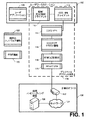
ここで図面を参照すると、図1は、ここで説明する実施の形態による遠隔コンピューティング装置126とデータの通信を行うネットワーク環境を描写する。図示したように、ネットワーク環境は、パーソナルコンピュータ、タブレット、モバイルコンピューティング装置等を含んでもよいユーザワークステーション102を有する。ユーザワークステーション102を、プライベートIPアドレス体系104を介して遠隔コンピューティング装置126と通信するように構成してもよい。ユーザワークステーション102は、ユーザアプリケーション108と、公衆インターネットIPアドレスと組織のプライベートIPアドレスの使用の両方から離間したプライベートIPアドレス体系又はアドレス空間(ReNATプライベートIPアドレス体系)を作成するためのReNAT双方向NATクライアント110及びCOTS VPNクライアント112と、を有してもよい。特に、ReNAT双方向NATクライアント110は、(ユーザワークステーション102のような)全てのコンピューティング装置がプライベートIPアドレス体系104内に固有のIPアドレスを有するために、COTS VPNクライアントを通じて通信を行う(ユーザワークステーション102のような)プライベートIPアドレス体系104にアクセスするコンピューティング装置のそれぞれに対して固有のプライベートIPアドレス(UPIP)を割り当てる。ReNAT双方向NATクライアント110は、遠隔コンピューティング装置126のプライベートIPアドレス体系を管理するためのペアの調整された双方向NAT機能を提供する。
Referring now to the drawings, FIG. 1 depicts a network environment for communicating data with a
COTS VPN114、COTSクリアテキスト機能116、ReNAT双方向NAT118及びReNAT VPN120は、プライベートIPアドレス体系104に含まれる。ReNAT双方向NATクライアント110及びReNAT双方向NAT118は、複数の組織が同一のプライベートIPアドレスを有するときでもCOTSクリアテキスト機能116が全てのユーザ組織システムに対して固有のIPアドレスを有するようにするために、顧客に割り当てられたプライベートIPアドレスと割り当てられたUPIPとの間でデータの変換を行う。
COTS VPN 114, COTS
プライベートIPアドレス体系104の外側では、ユーザアプリケーション108と、企業のオフィス106の遠隔コンピューティング装置126とは、顧客の内部のプライベートIPアドレスしか確かめない。ReNAT双方向NATクライアント110及びReNAT双方向NAT118は、ユーザアプリケーション108及び遠隔コンピューティング装置126がユーザワークステーション102の内部のプライベートIPアドレスしか確かめないようにするために、顧客に割り当てられたプライベートIPアドレスとReNATに割り当てられたUPIPとの間の変換を行うように調整される。したがって、ユーザワークステーション102から送信されたデータは、プライベートネットワーク124のゲートウェイ装置122において企業のオフィス106で受信される。遠隔コンピューティング装置126は、それに応じてデータを処理してもよい。
Outside of the private
既存のソフトウェア機能128及びReNAT機能マネージャ130も図1に示す。これらのコンポーネントは、図1で参照された他のコンポーネントによって利用及び/又はアクセスされてもよい既存の論理を表す。
An existing
図2は、ここで説明する実施の形態による双方向NAT形態を利用する更に別のコンピューティング環境を描写する。図示したように、ユーザワークステーション202は、プライベートIPアドレスをUPIPアドレスに変換することによってデータをNOC204に送信してもよい。データを、企業のオフィス206に送信する前にプライベートアドレスに戻してもよい。ユーザワークステーション202は、ユーザアプリケーション208と、クライアントソフトウェア209と、を有する。クライアントソフトウェア209は、ReNAT双方向NATクライアント210と、COTSクリアテキスト処理(COTS CTP)クライアント212と、COTS VPNクライアント214と、クライアントログインマネージャ216と、クライアントセッションマネージャ218と、を有する。特に、ユーザアプリケーション208は、データを企業のオフィス206の遠隔コンピューティング装置234に送信するようユーザワークステーション202に指示してもよい。したがって、クライアントログインマネージャ216は、NOC204のログイン認証情報の通信を促進することができる。ユーザのNOCへのロギングの際に、クライアントセッションマネージャ218は、所望のコンピューティング装置(この場合、遠隔コンピューティング装置234)の識別及び/又はアクセスのためにユーザインタフェース及び/又は他のデータを提供してもよい。それに応じて、ReNAT双方向NATクライアント210は、ユーザアプリケーション208から受信したデータにUPIPを割り当てる。ReNAT双方向NATクライアント210を、クリアテキストパケットのソースIPアドレスから割り当てられたUPIPへの変換及び割り当てられたUPIPからクリアテキストパケットの宛先IPアドレスへの変換の両方を行うように構成してもよい。COTS CTPクライアント212は、クリアテキスト処理(又は他のプロトコル)を用いてデータを受信及び処理する。COTS VPNクライアント214は、データを受信し、データをNOC204に安全に送信するためのVPNトンネルを形成する。
FIG. 2 depicts yet another computing environment that utilizes a bi-directional NAT configuration in accordance with the embodiments described herein. As shown,
NOC204は、VPN暗号化を解除するCOTS VPN220でデータを受信し、COTSクリアテキスト処理マネージャ222による処理のためにデータを提供する。COTクリアテキスト処理マネージャ222は、クリアテキスト又は他の同様なプロトコルに従ってデータを処理する。データをReNAT双方向NAT224によって処理してもよい。ReNAT双方向NAT224は、UPIPを取り出し、UPIPを、プライベートネットワーク233からの顧客規定IPに置換し、顧客ゲートウェイ装置232の公衆IPアドレスを提供する。ReNAT双方向NAT224を、クリアテキストパケットのソースIPアドレスから割り当てられたUPIPへの変換及び割り当てられたUPIPからクリアテキストパケットの宛先IPアドレスへの変換の両方を行うように構成してもよい。入ってくるパケットに対して、ReNAT双方向NAT224は、ユーザを識別するためにReNAT VPN226によって提供されたソースIPを用いる。ReNAT双方向NAT224からReNAT VPN226に出てゆくパケットは、遠隔コンピューティング装置234を識別するための宛先パブリックIPを有する。出てゆくパケットに対して、ReNAT双方向NAT224は、宛先ゲートウェイ/VPN232に対する宛先パブリックIPアドレスを識別するためにソース及び宛先UPIPアドレスを用いる。さらに、VPN機能は、ソースゲートウェイ/VPNを識別するよう企業のオフィスから外部パケットのソースIPを提供するために変更される。ReNAT双方向NAT224からのパケットは、宛先ゲートウェイ/VPNを識別するために宛先パブリックIPを有する。
The
ログインマネージャ228及びセッションマネージャ230もNOC204内に含み、これらは、ユーザワークステーション202のログインを管理するとともにユーザワークステーションのセッションを管理する。ReNAT双方向NAT224とReNAT VPN226との間のリンク上で、パケットは、パブリックソース及び宛先IPを有するプライベートReNATで規定したIPプロトコルにおいてラッピングされる。さらに、ReNAT双方向NAT224は、顧客に割り当てられたプライベートIPアドレスとオーバーラップするUPIPを割り当ててもよい。しかしながら、これは、ルーティングの問題を生じない。その理由は、割り当てられたアドレスがNOC内で固有であるとともにセッションマネージャ230によってパブリックIPにマッピングされるからである。上述したように、セッションマネージャ230は、サービスにログインされるユーザワークステーション202の各々に対するセッション情報を維持する。セッションマネージャ230は、UPIP調整情報をReNAT双方向NAT224に提供し、この顧客に対して割り当てられたUPIPによってクライアントセッションマネージャ218を更新する。セッションマネージャ230は、UPIPと顧客のゲートウェイ/VPNのパブリックIPとの間の関係も維持する。会社のオフィス206は、顧客ゲートウェイ装置232と、プライベートネットワーク233と、遠隔コンピューティング装置234と、を有する。
Also included in the
図3は、ここで説明する実施の形態による遠隔コンピューティング装置308と通信を行うコンピューティング環境を描写する。図示したように、顧客は、顧客の企業のオフィスに対するVPNを有しなくてもよいが、ONCとワークステーションとの間のVPNを利用することを所望してもよい。それでも、図3のユーザワークステーション302は、ユーザアプリケーション310と、COTS CTPクライアント312と、COTS VPNクライアント314と、クライアントログインマネージャ316と、クライアントセッションマネージャ318と、を有する。上述したように、ユーザアプリケーション310は、ネットワーク304を介した遠隔コンピューティング装置308への最終的な送信のためのデータをCOTS CTPクライアント312に送信してもよい。ネットワーク304は、インターネットのような任意の広域及び/又はローカルエリアネットワークを有してもよい。
FIG. 3 depicts a computing environment in communication with a
それに応じて、クライアントログインマネージャ316及びクライアントセッションマネージャ318は、NOC306によるログイン及びセッションの管理を促進するためにログインマネージャ324及びセッションマネージャ326と通信を行ってもよい。セッションが確立されると、COTS CTPクライアント312は、データを処理してもよい。さらに、COTS VPNクライアント314は、ユーザワークステーション302とNOC306のCOTS VPN320との間のVPNトンネルを形成してもよい。ユーザワークステーション302は、データを受信するとともにデータをNOC306に送信してもよい。NOC306は、VPNからのデータを解読するためにCOTS VPN320を用いることができ、COTSクリアテキスト処理322は、遠隔コンピューティング装置308に送信するためにデータを更に処理することができる。
In response,
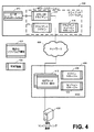
図4は、ここで説明する実施の形態によるVPNを利用することなく遠隔コンピューティング装置408と通信を行うコンピューティング環境を描写する。特に、図4は、顧客が所望のレベルのサービスを選択できるようにする複数のCOTS処理を描写する。例えば、あるCOTS処理は、全てのトラフィックの全アクセラレーション(full acceleration)を提供してもよく、第2のCOTS処理は、(全てのハイパーテキスト転送プロトコルのような)トラフィックの一部のみをアクセラレートする。それに応じて、図4のユーザワークステーション402は、遠隔コンピューティング装置408と情報のやり取りを行うためにユーザアプリケーション410を有してもよい。それに応じて、クライアントログインマネージャ414及びクライアントセッションマネージャ416は、ユーザワークステーション402とNOC406との間の接続を確立するためにログインマネージャ420及びセッションマネージャ422と通信を行ってもよい。ユーザアプリケーション410は、COTS CTPクライアント412が処理するデータを更に生成してもよい。この場合、データは、ネットワーク404を用いて送信され、ネットワーク404は、データをNOC406に送信する。上述したように、ネットワーク404を、任意の広域又はローカルエリアネットワークとしてもよい。ユーザ設定、ユーザ選択、NOC設定等に応じて、MOC406は、受信したデータの一部又は全てを処理するために一つ以上の異なるCOTSクリアテキスト処理418を実現してもよい。NOC406は、処理のためにデータを遠隔コンピューティング装置408に送信してもよい。
FIG. 4 depicts a computing environment that communicates with
図5は、ここで説明する実施の形態によるクライアントワークステーションが遠隔コンピューティング装置との通信を実行することができる動作を含むフローチャートを描写する。ブロック550に示すように、ライセンスIDを、例えば、ログインマネージャを介して認証してもよい。ブロック552において、サービスを要求する顧客を識別してもよい。ブロック554において、ユーザを追跡するためにセッションを作成してもよい。ブロック556において、VPNトンネルを、ユーザワークステーションのために形成してもよく、UPIPアドレスを、ライセンスIDに対してユーザワークステーションに割り当ててもよい。ブロック558において、VPNトンネルを、遠隔コンピューティング装置に対して形成してもよい。ブロック560において、遠隔コンピューティング装置へのユーザログインのエミュレーションを実行してもよい。ブロック562において、顧客VPNログインデータを、ログイン認証情報を入力するためにワークステーションに戻してもよい。ブロック564において、セッションマネージャをログイン結果によって更新してもよい。ブロック566において、ReNAT双方向NATを、遠隔コンピューティング装置に対するUPIPアドレスによって更新してもよい。ブロック568において、システムが準備できていることを表すメッセージを提供してもよい。
FIG. 5 depicts a flowchart that includes operations that allow client workstations to perform communications with remote computing devices according to the embodiments described herein. As indicated at
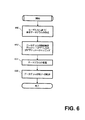
図5を参照して説明したように、ユーザワークステーションは、遠隔コンピューティング装置との通信を行うためにセッションを初期化してもよい。図6は、ここで説明する実施の形態によるセッションが確立された時点でワークステーションが遠隔コンピューティング装置との通信を促す際に実行することができる動作を含むフローチャートを描写する。ブロック650に示すように、NOCは、ユーザ入力に基づいて要求データグラム(request datagram)を作成してもよい。特に、この動作を、ユーザアプリケーションを介したユーザワークステーションによって作成してもよい。とにかく、ブロック652において、ユーザワークステーションは、データグラムの顧客規定プライベートIPアドレスをUPIPアドレスにマッピングしてもよい。ブロック654において、ユーザワークステーションは、データグラムを処理してもよい。ブロック656において、データグラムをNOCに転送してもよい。
As described with reference to FIG. 5, the user workstation may initialize a session to communicate with a remote computing device. FIG. 6 depicts a flowchart that includes operations that may be performed by a workstation to facilitate communication with a remote computing device once a session is established according to the embodiments described herein. As indicated at
図3及び図4において、ネットワーク304,404を公衆インターネット又は他のコンピューティングネットワークの利用を説明するためにシステムコンポーネント間に描写していることを理解すべきである。理解できるように、これらは単なる例であり、図1〜6に表現したコンポーネントのいずれかを、実施の形態に応じてネットワークインフラに接続してもよい。
It should be understood that in FIGS. 3 and 4 the
図7は、ここで説明する実施の形態によるNOCがユーザワークステーションと遠隔コンピューティング装置との間の通信を促進する際に実行することができる動作を含む他のフローチャートを描写する。ブロック750に示すように、データグラムを、NOCによって処理してもよく、異なるデータグラムを、遠隔コンピューティング装置に送信するために生成してもよい。ブロック752において、UPIPアドレスを、データグラムにおいて顧客規定プライベートIPアドレスにマッピングしてもよい。ブロック754において、データグラムを暗号化するとともに遠隔コンピューティング装置に転送してもよい。
FIG. 7 depicts another flowchart that includes operations that an NOC may perform in facilitating communication between a user workstation and a remote computing device according to the embodiments described herein. As shown at
図8は、ここで説明する実施の形態によるNOCがユーザワークステーションと遠隔コンピューティング装置との間の通信を促進する際に実行することができる動作を含む更に別のフローチャートを描写する。特に、図7は、ユーザワークステーションがデータを遠隔コンピューティング装置に送信するときに実行してもよい動作を描写するが、図8は、遠隔コンピューティング装置がデータをユーザワークステーションに送信するときに実行してもよい動作を描写する。したがって、ブロック850において、ユーザワークステーションのための顧客プライベートIPに対する宛先IPアドレスを有する暗号化された応答データゴラムを受信してもよい。ブロック852において、データグラムを解読してもよい。ブロック854において、顧客規定プライベートIPアドレスをデータグラムにおいてUPIPアドレスにマッピングする。ブロック856において、新たな顧客プライベートIPを、解読したデータグラムのソースIPから記録してもよく、新たなUPIPを割り当ててもよい。ブロック858において、クライアントセッションマネージャは、新たなUPIPについての情報を顧客プライベートIPマッピングに対して通知してもよい。ブロック860において、データグラムを処理してもよく、新たなデータグラムをユーザアプリケーションのために生成してもよい。ブロック862において、新たなデータグラムをユーザワークステーションに送信してもよい。
FIG. 8 depicts yet another flowchart including operations that may be performed by an NOC in facilitating communication between a user workstation and a remote computing device according to the embodiments described herein. In particular, FIG. 7 depicts actions that may be performed when a user workstation transmits data to a remote computing device, while FIG. 8 illustrates when the remote computing device transmits data to a user workstation Depicts actions that may be performed on Thus, at
特定の実施の形態に応じて、一つ以上のデータグラムを、ユーザワークステーションに対する新たなデータグラムを生成する前に遠隔コンピューティング装置に送信してもよいことを理解すべきである。一例として、コンピューティング環境がCOTS処理としてアクセラレーションを利用する場合、遠隔コンピューティング装置による複数のデータグラムの通信を実行してもよい。 It should be understood that, depending on the particular embodiment, one or more datagrams may be sent to the remote computing device prior to generating a new datagram for the user workstation. As an example, if the computing environment utilizes acceleration as a COTS process, communication of multiple datagrams by remote computing devices may be performed.
図9は、ここで説明する実施の形態によるユーザワークステーションがNOCを介して遠隔コンピューティング装置からデータを受信する際に実行することができる動作を含むフローチャートを描写する。ブロック950に示すように、受信したデータグラムを処理してもよい。ブロック952において、UPIPアドレスを、ダイヤグラムにおいて顧客規定プライベートIPアドレスにマッピングしてもよい。ブロック954において、データグラムの結果を表示のために提供してもよい。
FIG. 9 depicts a flowchart including operations that can be performed when a user workstation receives data from a remote computing device via a NOC according to the embodiments described herein. As indicated at
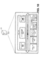
図10は、ここで説明する実施の形態によるNOCに存在してもよい種々のハードウェアコンポーネントを描写する。図示した実施の形態において、NOC204は、一つ以上のプロセッサ1030と、入力/出力ハードウェア1032と、ネットワークインタフェースハードウェア1034と、(ログインデータ1038a及びセッションデータ1038bを記憶する)データ記憶部1036と、メモリ構成要素1040と、を有する。メモリ構成要素1040は、揮発性及び/又は不揮発性メモリとして構成されてもよく、したがって、(SRAM、DRAM及び/又は他のタイプのRAMを含む)ランダムアクセスメモリ、フラッシュメモリ、レジスタ、コンパクトディスク(CD)、デジタル多用途ディスク(DVD)及び/又は他のタイプの非一時的なコンピュータ可読媒体を有してもよい。特定の実施の形態に応じて、非一時的なコンピュータ可読媒体は、NOC204の内部及び/又はNOC204の外部に存在してもよい。
FIG. 10 depicts various hardware components that may be present in the NOC according to the embodiments described herein. In the illustrated embodiment, the
さらに、メモリ構成要素1040は、一例としてコンピュータプログラム、ファームウェア及び/又はハードウェアとして実施してもよいオペレーティング論理1042、データ通信論理1044a及びマネージャ論理1044bを記憶するように構成されてもよい。ローカル通信インタフェース1046も図10に含まれるが、ローカル通信インタフェース1046を、バスとして又はNOC204のコンポーネント間の通信を促進する他のインタフェースとして実現してもよい。
Further, memory component 1040 may be configured to store
プロセッサ1030は、(データ記憶部1036及び/又はメモリ構成要素1040からのような)命令を受信及び実行する任意の処理構成要素を有してもよい。入力/出力ハードウェア1032は、モニタ、キーボード、マウス、プリンタ、カメラ、マイクロホン、スピーカ及び/又はデータを受信、送信及び/又は提示する他の装置を有してもよい及び/又はこれらとインタフェースで接続するように構成されてもよい。ネットワークインタフェースハードウェア1034は、任意の有線又は無線ネットワークハードウェア、衛星、アンテナ、モデム、LANポート、ワイヤレスフェディリティー(Wi−Fi(登録商標))、WiMax(登録商標)カード、モバイル通信ハードウェア、ファイバー及び/又は他のネットワーク及び/又はデバイスと通信を行うための他のハードウェアを有してもよい及び/又はこれらと通信を行うように構成されてもよい。この接続から、通信をNOC204と他のコンピューティング装置との間で促進してもよい。
Processor 1030 may include any processing component that receives and executes instructions (such as from data store 1036 and / or memory component 1040). Input / output hardware 1032 may include and / or interface with monitors, keyboards, mice, printers, cameras, microphones, speakers and / or other devices that receive, transmit and / or present data. It may be configured to connect. The network interface hardware 1034 may be any wired or wireless network hardware, satellite, antenna, modem, LAN port, wireless fediity (Wi-Fi®), WiMax® card, mobile communication hardware, It may have and / or be configured to communicate with other hardware to communicate with fibers and / or other networks and / or devices. From this connection, communication may be facilitated between the
同様に、データ記憶部1036が、NOC204に近接して及び/又はNOC204から離間して存在してもよく、かつ、NOC204及び/又は他のコンポーネントによってアクセスされる一つ以上のデータを記憶するように構成されてもよいことを理解すべきである。一部の実施の形態において、データ記憶部1036を、NOC204から離間して配置してもよく、したがって、ネットワーク接続を介してアクセス可能にしてもよい。しかしながら、一部の実施の形態において、データ記憶部1036を、単なる周辺装置としてもよいが、NOC204の外部にする。
Similarly, data store 1036 may be present proximate to and / or spaced from
オペレーティング論理1042、データ通信論理1044a及びマネージャ論理1044bはメモリ構成要素1040に含まれる。オペレーティング論理1042は、オペレーティングシステム及び/又はNOC204のコンポーネントを管理する他のソフトウェアを有してもよい。同様に、データ通信論理1044aは、COTS VPN220、COTSクリアテキスト処理マネージャ222、ReNAT双方向NAT224、ReNAT VPN226及び/又はデータを操作するとともにユーザワークステーション202と遠隔コンピューティング装置234との間の通信を行うための他の論理を有してもよい。マネージャ論理1044bは、ログインマネージャ228、セッションマネージャ230及び/又はユーザワークステーション202とのセッションを確立するためのNOC204をもたらす他のコンポーネントを有してもよい。
図10に示すコンポーネントは単なる例示であり、この開示の範囲を限定することを意図しないことを理解すべきである。図10のコンポーネントがNOC204内に存在するものとして図示したが、これは単なる一例である。一部の実施の形態において、コンポーネントの一つ以上はNOC204の外部に存在してもよい。NOC204を図10に表現したが、図2又は他の図面に記載した他のコンピューティング装置が上述した機能を提供する同様なハードウェア及びソフトウェアを有してもよい。
It should be understood that the components shown in FIG. 10 are merely exemplary and are not intended to limit the scope of this disclosure. Although the components of FIG. 10 are illustrated as being present in the
特定の実施の形態をここで説明及び記載したが、種々の他の変形及び変更を特許請求の範囲に記載された対象の精神及び範囲から逸脱することなく行うことができる。さらに、特許請求の範囲に記載された対象の種々の態様をここで説明したが、そのような態様を一緒に利用する必要はない。したがって、添付した特許請求の範囲が特許請求の範囲に記載された対象の範囲内にある全てのそのような変形及び変更をカバーすることを意図する。 While particular embodiments have been described and described herein, various other changes and modifications can be made without departing from the spirit and scope of the subject matter recited in the claims. Furthermore, while various aspects of the claimed subject matter have been described herein, such aspects need not be utilized together. Accordingly, it is intended that the appended claims cover all such variations and modifications as fall within the scope of the subject matter recited in the claims.
Claims (1)
プライベートネットワークとの仮想プライベートネットワーク(VPN)通信を開始する第1の従来のVPNと、
前記第1の従来のVPNに結合されたReNAT双方向NATであって、前記ReNAT双方向NATは、顧客に割り当てられたプライベートIPアドレスと固有のプライベートIP(UPIP)アドレスとの間の変換を行うReNAT双方向NATと、
前記ReNAT双方向NATに結合されたReNAT VPNコンポーネントであって、前記ReNAT VPNコンポーネントは、前記ReNAT双方向NATにソースIPアドレスを提供するReNAT VPNコンポーネントと、
プロセッサによって実行されるときに、前記システムに、従来のVPNクライアント及びReNAT双方向NATクライアントを有するユーザワークステーションとの通信を促進させ、前記プライベートネットワークを用いてデータを送信する際に、前記NOCは、従来のVPNポータルを介してデータを受信し、アドレス変換が、前記ReNAT双方向NATクライアントによって実行される論理と、を備え、
前記ReNAT双方向NATは、前記データのアドレスを、顧客規定プライベートアドレスにマッピングし、前記ReNAT VPNは、前記データを暗号化し、前記データを前記プライベートネットワークに転送するシステム。 A system for performing ReNAT communication, comprising a network operation center (NOC), the NOC comprising
The first conventional VPN, which initiates virtual private network (VPN) communication with the private network,
A ReNAT bi-directional NAT coupled to the first conventional VPN, wherein the ReNAT bi-directional NAT translates between a customer-assigned private IP address and a unique private IP (UPIP) address ReNAT bi-directional NAT,
A ReNAT VPN component coupled to the ReNAT bi-directional NAT, wherein the ReNAT VPN component provides a source IP address to the ReNAT bi-directional NAT;
When executed by a processor, the system facilitates communication with a user workstation having a conventional VPN client and a ReNAT bi-directional NAT client, and when transmitting data using the private network, the NOC Receiving data via a conventional VPN portal, and address translation comprising logic performed by said ReNAT bi-directional NAT client,
The ReNAT bi-directional NAT maps the address of the data to a customer defined private address, and the ReNAT VPN encrypts the data and transfers the data to the private network.
Applications Claiming Priority (3)
| Application Number | Priority Date | Filing Date | Title |
|---|---|---|---|
| US201361748248P | 2013-01-02 | 2013-01-02 | |
| US61/748,248 | 2013-01-02 | ||
| PCT/US2014/010023 WO2014107482A1 (en) | 2013-01-02 | 2014-01-02 | Systems and methods for providing a renat communications environment |
Related Child Applications (1)
| Application Number | Title | Priority Date | Filing Date |
|---|---|---|---|
| JP2018234438A Division JP6990647B2 (en) | 2013-01-02 | 2018-12-14 | Systems and methods that provide a ReNAT communication environment |
Publications (3)
| Publication Number | Publication Date |
|---|---|
| JP2016507968A JP2016507968A (en) | 2016-03-10 |
| JP2016507968A5 JP2016507968A5 (en) | 2017-02-09 |
| JP6516331B2 true JP6516331B2 (en) | 2019-05-22 |
Family
ID=51062452
Family Applications (2)
| Application Number | Title | Priority Date | Filing Date |
|---|---|---|---|
| JP2015551749A Expired - Fee Related JP6516331B2 (en) | 2013-01-02 | 2014-01-02 | System and method for providing ReNAT communication environment |
| JP2018234438A Active JP6990647B2 (en) | 2013-01-02 | 2018-12-14 | Systems and methods that provide a ReNAT communication environment |
Family Applications After (1)
| Application Number | Title | Priority Date | Filing Date |
|---|---|---|---|
| JP2018234438A Active JP6990647B2 (en) | 2013-01-02 | 2018-12-14 | Systems and methods that provide a ReNAT communication environment |
Country Status (16)
| Country | Link |
|---|---|
| US (1) | US9258226B2 (en) |
| EP (3) | EP3920514A1 (en) |
| JP (2) | JP6516331B2 (en) |
| KR (1) | KR102103704B1 (en) |
| CN (1) | CN105122231A (en) |
| AU (4) | AU2014204085B2 (en) |
| BR (1) | BR112015015971A2 (en) |
| CA (3) | CA3073419C (en) |
| ES (1) | ES2827221T3 (en) |
| HK (1) | HK1215814A1 (en) |
| IL (1) | IL239730B (en) |
| MX (1) | MX346342B (en) |
| PH (1) | PH12015501503A1 (en) |
| RU (1) | RU2685036C2 (en) |
| WO (1) | WO2014107482A1 (en) |
| ZA (1) | ZA201505477B (en) |
Families Citing this family (2)
| Publication number | Priority date | Publication date | Assignee | Title |
|---|---|---|---|---|
| CN107872542B (en) | 2016-09-27 | 2021-05-04 | 阿里巴巴集团控股有限公司 | Data transmission method and network equipment |
| CN113765802B (en) * | 2021-07-26 | 2023-08-08 | 深圳市智微智能科技股份有限公司 | android device network card dynamic switching method, system, terminal and storage medium |
Family Cites Families (38)
| Publication number | Priority date | Publication date | Assignee | Title |
|---|---|---|---|---|
| US20020042832A1 (en) | 2000-08-14 | 2002-04-11 | Fallentine Mark D. | System and method for interoperability of H.323 video conferences with network address translation |
| US20020042875A1 (en) * | 2000-10-11 | 2002-04-11 | Jayant Shukla | Method and apparatus for end-to-end secure data communication |
| US6954790B2 (en) * | 2000-12-05 | 2005-10-11 | Interactive People Unplugged Ab | Network-based mobile workgroup system |
| US7047314B2 (en) * | 2000-12-28 | 2006-05-16 | Oki Electric Industry Co., Ltd. | Duplicate private address translating system and duplicate address network system |
| JP3789348B2 (en) | 2001-03-07 | 2006-06-21 | 日本電信電話株式会社 | Remote maintenance execution method, system and program, and recording medium recording remote maintenance execution program |
| US7136374B1 (en) | 2001-03-19 | 2006-11-14 | Juniper Networks, Inc. | Transport networks supporting virtual private networks, and configuring such networks |
| US6993037B2 (en) * | 2001-03-21 | 2006-01-31 | International Business Machines Corporation | System and method for virtual private network network address translation propagation over nested connections with coincident local endpoints |
| US7068646B2 (en) * | 2001-04-03 | 2006-06-27 | Voxpath Networks, Inc. | System and method for performing IP telephony including internal and external call sessions |
| US7149808B2 (en) | 2002-01-14 | 2006-12-12 | Array Networks, Inc. | Application protocol offloading |
| US7099319B2 (en) | 2002-01-23 | 2006-08-29 | International Business Machines Corporation | Virtual private network and tunnel gateway with multiple overlapping, remote subnets |
| US7260649B1 (en) | 2002-04-16 | 2007-08-21 | Cisco Technology, Inc. | Apparatus and methods for forwarding data between public networks via a private network |
| US7593388B1 (en) * | 2003-09-30 | 2009-09-22 | Nortel Networks Limited | Convertor shared by multiple virtual private networks |
| US7640319B1 (en) * | 2003-09-30 | 2009-12-29 | Nortel Networks Limited | Gateway shared by multiple virtual private networks |
| CA2457368C (en) * | 2004-02-11 | 2013-01-08 | Solutioninc Limited | A server, system and method for providing access to a public network through an internal network of a multi-system operator |
| CN1756259B (en) | 2004-09-27 | 2011-04-20 | 国际商业机器公司 | Method and system for using a network address translation (nat) in an IP network |
| US7661128B2 (en) * | 2005-03-31 | 2010-02-09 | Google Inc. | Secure login credentials for substantially anonymous users |
| US7983254B2 (en) * | 2005-07-20 | 2011-07-19 | Verizon Business Global Llc | Method and system for securing real-time media streams in support of interdomain traversal |
| JP4830450B2 (en) | 2005-11-02 | 2011-12-07 | 株式会社島津製作所 | Mass spectrometer |
| US20070180088A1 (en) | 2006-01-27 | 2007-08-02 | Array Networks, Inc. | Seamless roaming across multiple data networks |
| US7814541B1 (en) * | 2006-05-19 | 2010-10-12 | Array Networks, Inc. | Virtual routing for virtual local area networks having overlapping IP addresses |
| US8281387B2 (en) | 2006-06-30 | 2012-10-02 | Intel Corporation | Method and apparatus for supporting a virtual private network architecture on a partitioned platform |
| US20080034420A1 (en) | 2006-08-01 | 2008-02-07 | Array Networks, Inc. | System and method of portal customization for a virtual private network device |
| US8249081B2 (en) * | 2006-09-29 | 2012-08-21 | Array Networks, Inc. | Dynamic virtual private network (VPN) resource provisioning using a dynamic host configuration protocol (DHCP) server, a domain name system (DNS) and/or static IP assignment |
| US8108550B2 (en) * | 2006-10-25 | 2012-01-31 | Hewlett-Packard Development Company, L.P. | Real-time identification of an asset model and categorization of an asset to assist in computer network security |
| US7840701B2 (en) * | 2007-02-21 | 2010-11-23 | Array Networks, Inc. | Dynamic system and method for virtual private network (VPN) packet level routing using dual-NAT method |
| US7764691B2 (en) | 2007-03-15 | 2010-07-27 | Microsoft Corporation | Allowing IPv4 clients to communicate using teredo addresses when both clients are behind a NAT |
| US7743155B2 (en) | 2007-04-20 | 2010-06-22 | Array Networks, Inc. | Active-active operation for a cluster of SSL virtual private network (VPN) devices with load distribution |
| US8295285B2 (en) * | 2008-03-20 | 2012-10-23 | Telefonaktiebolaget Lm Ericsson (Publ) | Method and apparatus for communication of data packets between local networks |
| US8170014B1 (en) | 2009-07-22 | 2012-05-01 | Cisco Technology, Inc. | Multiple NAT traversal protocol |
| JP2011188448A (en) * | 2010-03-11 | 2011-09-22 | Evrika Inc | Gateway apparatus, communication method and communication program |
| US8704863B2 (en) * | 2010-04-07 | 2014-04-22 | Apple Inc. | Transitioning between circuit switched calls and video calls |
| US8127350B2 (en) * | 2010-06-30 | 2012-02-28 | Juniper Networks, Inc. | Multi-service VPN network client for mobile device |
| US8549617B2 (en) * | 2010-06-30 | 2013-10-01 | Juniper Networks, Inc. | Multi-service VPN network client for mobile device having integrated acceleration |
| US9143480B2 (en) * | 2011-01-10 | 2015-09-22 | Secure Global Solutions, Llc | Encrypted VPN connection |
| US8805977B2 (en) * | 2011-06-09 | 2014-08-12 | Freescale Semiconductor, Inc. | Method and system for address conflict resolution |
| CN103748861B (en) * | 2011-07-08 | 2017-07-11 | 威尔耐特斯公司 | For the system and method for Dynamic VPN address distribution |
| US8745722B2 (en) * | 2012-03-09 | 2014-06-03 | Wapice Oy | Managing remote network addresses in communications |
| US20140215050A1 (en) | 2013-01-29 | 2014-07-31 | Array Networks, Inc. | Method and system for web analytics using a proxy |
-
2014
- 2014-01-02 CA CA3073419A patent/CA3073419C/en active Active
- 2014-01-02 KR KR1020157020909A patent/KR102103704B1/en active IP Right Grant
- 2014-01-02 EP EP21187981.2A patent/EP3920514A1/en active Pending
- 2014-01-02 ES ES14735319T patent/ES2827221T3/en active Active
- 2014-01-02 JP JP2015551749A patent/JP6516331B2/en not_active Expired - Fee Related
- 2014-01-02 EP EP14735319.7A patent/EP2941716B1/en active Active
- 2014-01-02 CA CA3073411A patent/CA3073411C/en active Active
- 2014-01-02 EP EP20191949.5A patent/EP3779712A1/en active Pending
- 2014-01-02 CN CN201480008583.0A patent/CN105122231A/en active Pending
- 2014-01-02 RU RU2015132089A patent/RU2685036C2/en not_active Application Discontinuation
- 2014-01-02 MX MX2015008609A patent/MX346342B/en active IP Right Grant
- 2014-01-02 CA CA2897105A patent/CA2897105C/en active Active
- 2014-01-02 BR BR112015015971A patent/BR112015015971A2/en active Search and Examination
- 2014-01-02 WO PCT/US2014/010023 patent/WO2014107482A1/en active Application Filing
- 2014-01-02 AU AU2014204085A patent/AU2014204085B2/en not_active Ceased
- 2014-02-07 US US14/175,298 patent/US9258226B2/en active Active
-
2015
- 2015-07-01 IL IL239730A patent/IL239730B/en active IP Right Grant
- 2015-07-01 PH PH12015501503A patent/PH12015501503A1/en unknown
- 2015-07-30 ZA ZA2015/05477A patent/ZA201505477B/en unknown
-
2016
- 2016-03-31 HK HK16103718.7A patent/HK1215814A1/en unknown
-
2018
- 2018-12-14 JP JP2018234438A patent/JP6990647B2/en active Active
-
2019
- 2019-11-01 AU AU2019257538A patent/AU2019257538B2/en not_active Ceased
-
2021
- 2021-11-15 AU AU2021269297A patent/AU2021269297A1/en not_active Abandoned
-
2023
- 2023-05-25 AU AU2023203289A patent/AU2023203289A1/en not_active Abandoned
Also Published As
Similar Documents
| Publication | Publication Date | Title |
|---|---|---|
| KR102235849B1 (en) | Systems and methods for providing a multiple secure link architecture | |
| US10652204B2 (en) | ReNAT systems and methods | |
| AU2023203289A1 (en) | Systems and methods for providing a ReNAT communications environment | |
| US9210129B2 (en) | Systems and methods for providing a multiple secure link architecture | |
| JP2019050628A5 (en) | ||
| JP6894060B2 (en) | Systems and methods that provide a composite secure link architecture |
Legal Events
| Date | Code | Title | Description |
|---|---|---|---|
| A521 | Request for written amendment filed |
Free format text: JAPANESE INTERMEDIATE CODE: A523 Effective date: 20161222 |
|
| A621 | Written request for application examination |
Free format text: JAPANESE INTERMEDIATE CODE: A621 Effective date: 20161222 |
|
| A977 | Report on retrieval |
Free format text: JAPANESE INTERMEDIATE CODE: A971007 Effective date: 20171221 |
|
| A131 | Notification of reasons for refusal |
Free format text: JAPANESE INTERMEDIATE CODE: A131 Effective date: 20180116 |
|
| A02 | Decision of refusal |
Free format text: JAPANESE INTERMEDIATE CODE: A02 Effective date: 20180814 |
|
| A521 | Request for written amendment filed |
Free format text: JAPANESE INTERMEDIATE CODE: A523 Effective date: 20181214 |
|
| A521 | Request for written amendment filed |
Free format text: JAPANESE INTERMEDIATE CODE: A523 Effective date: 20181220 |
|
| A911 | Transfer to examiner for re-examination before appeal (zenchi) |
Free format text: JAPANESE INTERMEDIATE CODE: A911 Effective date: 20190115 |
|
| TRDD | Decision of grant or rejection written | ||
| A01 | Written decision to grant a patent or to grant a registration (utility model) |
Free format text: JAPANESE INTERMEDIATE CODE: A01 Effective date: 20190212 |
|
| A601 | Written request for extension of time |
Free format text: JAPANESE INTERMEDIATE CODE: A601 Effective date: 20190308 |
|
| A711 | Notification of change in applicant |
Free format text: JAPANESE INTERMEDIATE CODE: A711 Effective date: 20190405 |
|
| A61 | First payment of annual fees (during grant procedure) |
Free format text: JAPANESE INTERMEDIATE CODE: A61 Effective date: 20190412 |
|
| R150 | Certificate of patent or registration of utility model |
Ref document number: 6516331 Country of ref document: JP Free format text: JAPANESE INTERMEDIATE CODE: R150 |
|
| S111 | Request for change of ownership or part of ownership |
Free format text: JAPANESE INTERMEDIATE CODE: R313113 |
|
| R350 | Written notification of registration of transfer |
Free format text: JAPANESE INTERMEDIATE CODE: R350 |
|
| R250 | Receipt of annual fees |
Free format text: JAPANESE INTERMEDIATE CODE: R250 |
|
| LAPS | Cancellation because of no payment of annual fees |