JP6515355B2 - H-shaped steel manufacturing method - Google Patents
H-shaped steel manufacturing method Download PDFInfo
- Publication number
- JP6515355B2 JP6515355B2 JP2017506506A JP2017506506A JP6515355B2 JP 6515355 B2 JP6515355 B2 JP 6515355B2 JP 2017506506 A JP2017506506 A JP 2017506506A JP 2017506506 A JP2017506506 A JP 2017506506A JP 6515355 B2 JP6515355 B2 JP 6515355B2
- Authority
- JP
- Japan
- Prior art keywords
- hole type
- hole
- rolled
- flange
- angle
- Prior art date
- Legal status (The legal status is an assumption and is not a legal conclusion. Google has not performed a legal analysis and makes no representation as to the accuracy of the status listed.)
- Active
Links
Images


Classifications
-
- B—PERFORMING OPERATIONS; TRANSPORTING
- B21—MECHANICAL METAL-WORKING WITHOUT ESSENTIALLY REMOVING MATERIAL; PUNCHING METAL
- B21B—ROLLING OF METAL
- B21B1/00—Metal-rolling methods or mills for making semi-finished products of solid or profiled cross-section; Sequence of operations in milling trains; Layout of rolling-mill plant, e.g. grouping of stands; Succession of passes or of sectional pass alternations
- B21B1/08—Metal-rolling methods or mills for making semi-finished products of solid or profiled cross-section; Sequence of operations in milling trains; Layout of rolling-mill plant, e.g. grouping of stands; Succession of passes or of sectional pass alternations for rolling structural sections, i.e. work of special cross-section, e.g. angle steel
- B21B1/088—H- or I-sections
-
- B—PERFORMING OPERATIONS; TRANSPORTING
- B21—MECHANICAL METAL-WORKING WITHOUT ESSENTIALLY REMOVING MATERIAL; PUNCHING METAL
- B21B—ROLLING OF METAL
- B21B27/00—Rolls, roll alloys or roll fabrication; Lubricating, cooling or heating rolls while in use
- B21B27/02—Shape or construction of rolls
-
- B—PERFORMING OPERATIONS; TRANSPORTING
- B21—MECHANICAL METAL-WORKING WITHOUT ESSENTIALLY REMOVING MATERIAL; PUNCHING METAL
- B21B—ROLLING OF METAL
- B21B1/00—Metal-rolling methods or mills for making semi-finished products of solid or profiled cross-section; Sequence of operations in milling trains; Layout of rolling-mill plant, e.g. grouping of stands; Succession of passes or of sectional pass alternations
- B21B1/08—Metal-rolling methods or mills for making semi-finished products of solid or profiled cross-section; Sequence of operations in milling trains; Layout of rolling-mill plant, e.g. grouping of stands; Succession of passes or of sectional pass alternations for rolling structural sections, i.e. work of special cross-section, e.g. angle steel
- B21B1/088—H- or I-sections
- B21B1/0883—H- or I-sections using forging or pressing devices
-
- B—PERFORMING OPERATIONS; TRANSPORTING
- B21—MECHANICAL METAL-WORKING WITHOUT ESSENTIALLY REMOVING MATERIAL; PUNCHING METAL
- B21B—ROLLING OF METAL
- B21B13/00—Metal-rolling stands, i.e. an assembly composed of a stand frame, rolls, and accessories
- B21B13/06—Metal-rolling stands, i.e. an assembly composed of a stand frame, rolls, and accessories with axes of rolls arranged vertically, e.g. edgers
-
- B—PERFORMING OPERATIONS; TRANSPORTING
- B21—MECHANICAL METAL-WORKING WITHOUT ESSENTIALLY REMOVING MATERIAL; PUNCHING METAL
- B21B—ROLLING OF METAL
- B21B13/00—Metal-rolling stands, i.e. an assembly composed of a stand frame, rolls, and accessories
- B21B13/08—Metal-rolling stands, i.e. an assembly composed of a stand frame, rolls, and accessories with differently-directed roll axes, e.g. for the so-called "universal" rolling process
- B21B13/10—Metal-rolling stands, i.e. an assembly composed of a stand frame, rolls, and accessories with differently-directed roll axes, e.g. for the so-called "universal" rolling process all axes being arranged in one plane
- B21B2013/106—Metal-rolling stands, i.e. an assembly composed of a stand frame, rolls, and accessories with differently-directed roll axes, e.g. for the so-called "universal" rolling process all axes being arranged in one plane for sections, e.g. beams, rails
-
- B—PERFORMING OPERATIONS; TRANSPORTING
- B21—MECHANICAL METAL-WORKING WITHOUT ESSENTIALLY REMOVING MATERIAL; PUNCHING METAL
- B21B—ROLLING OF METAL
- B21B2267/00—Roll parameters
- B21B2267/02—Roll dimensions
-
- B—PERFORMING OPERATIONS; TRANSPORTING
- B21—MECHANICAL METAL-WORKING WITHOUT ESSENTIALLY REMOVING MATERIAL; PUNCHING METAL
- B21B—ROLLING OF METAL
- B21B2267/00—Roll parameters
- B21B2267/18—Roll crown; roll profile
Landscapes
- Engineering & Computer Science (AREA)
- Mechanical Engineering (AREA)
- Physics & Mathematics (AREA)
- Geometry (AREA)
- Metal Rolling (AREA)
- Reduction Rolling/Reduction Stand/Operation Of Reduction Machine (AREA)
Description
(関連出願の相互参照)
本願は、2015年3月19日に日本国に出願された特願2015−056638号に基づき、優先権を主張し、その内容をここに援用する。(Cross-reference to related applications)
Priority is claimed on Japanese Patent Application No. 2015-056638, filed March 19, 2015, the content of which is incorporated herein by reference.
本発明は、例えば矩形断面であるスラブ等を素材としてH形鋼を製造する製造方法及び製造されるH形鋼製品に関する。 The present invention relates to a method of manufacturing an H-shaped steel, for example, using a slab having a rectangular cross section as a raw material, and an H-shaped steel product manufactured.
H形鋼を製造する場合には、加熱炉から抽出されたスラブやブルーム等の素材を粗圧延機(BD)によって粗形材(所謂ドッグボーン形状の被圧延材)に造形し、中間ユニバーサル圧延機によって上記粗形材のウェブやフランジの厚さを圧下し、併せて前記中間ユニバーサル圧延機に近接したエッジャー圧延機によって被圧延材のフランジに対し幅圧下や端面の鍛錬と整形が施される。そして、仕上ユニバーサル圧延機によってH形鋼製品が造形される。 When manufacturing H-shaped steel, materials such as slabs and blooms extracted from the heating furnace are formed into rough shapes (so-called dog bone-shaped material to be rolled) by a rough rolling mill (BD), and intermediate universal rolling The thickness of the web and the flange of the above-mentioned rough shape is reduced by the machine, and at the same time the width reduction and the forging and shaping of the end face are applied to the flange of the material to be rolled by the edger rolling machine close to the intermediate universal rolling machine. . Then, the H-shaped steel product is shaped by the finishing universal rolling mill.
このようなH形鋼の製造方法において、矩形断面であるスラブ素材から所謂ドッグボーン形状の粗形材を造形する際には、粗圧延工程の第1の孔型においてスラブ端面に割り込みを入れた後、第2以降の孔型において当該割り込みを割広げる、又は、割り込み深さを深くさせエッジング圧延を行い、それ以降の孔型にてスラブ端面の割り込みを消去する技術が知られている(例えば特許文献1参照)。 In such a method of manufacturing an H-shaped steel, when forming a so-called dog bone-shaped rough shape from a slab material having a rectangular cross section, the end face of the slab is interrupted in the first hole type of the rough rolling process. After that, there is known a technique for dividing the interrupt in the second and subsequent hole types or for increasing the depth of the interrupt to perform edging rolling and for erasing the interrupt on the slab end surface in the hole type after that (for example, Patent Document 1).
また、例えば特許文献2には、スラブ端面に割り込みを入れ当該割り込みを順次深くし、その後ボックス孔型において押し拡げ、H形鋼のフランジ相当部を形成させる技術が開示されている。
Further, for example,
近年、構造物等の大型化に伴い大型のH形鋼製品の製造が望まれている。特にH形鋼の強度・剛性に大きく寄与するフランジを従来に比べて広幅化した製品が望まれている。フランジが広幅化されたH形鋼製品を製造するためには、粗圧延工程における造形から従来に比べフランジ幅の大きな被圧延材を造形する必要がある。 In recent years, with the upsizing of structures and the like, production of large H-shaped steel products is desired. In particular, a product having a wider flange than that in the past, which greatly contributes to the strength and rigidity of the H-shaped steel, is desired. In order to manufacture an H-shaped steel product in which the flange is widened, it is necessary to form a material to be rolled having a wider flange width than in the past because of shaping in the rough rolling process.
しかしながら、例えば上記特許文献1に開示されている技術では、スラブ等の素材の端面(スラブ端面)に割り込みを入れ、当該端面をエッジングし、その幅拡がりを利用して粗圧延を行う方法では、フランジの広幅化に限界がある。即ち、従来の粗圧延方法においてフランジの広幅化を図るためにはウェッジ設計(割り込み角度の設計)、圧下調整、潤滑調整といった技術により幅拡がりの向上が図られるが、いずれの方法もフランジ幅に大幅に寄与するものではないため、エッジング量に対するフランジ幅の拡がり量の比率を示す幅拡がり率は、エッジングの初期段階の効率が最も高い条件でも0.8程度であり、同一孔型でエッジングを繰り返す条件では、フランジ幅の拡がり量が大きくなるにつれて低下し、最終的には0.5程度になることが知られている。また、スラブ等の素材自体を大型化し、エッジング量を大きくすることも考えられるが、粗圧延機の設備規模や圧下量等には装置限界があるため十分な製品フランジの広幅化が実現されないといった事情がある。
However, for example, in the technique disclosed in
また、例えば特許文献2に開示されている技術では、割り込みを入れたスラブ等の素材に対して、特に割り込み形状の変遷等を経ずに、即座に底面がフラット形状のボックス孔型によってエッジング圧延を行い、フランジ相当部を造形しており、このような方法では被圧延材の形状を急激に変化させることに伴う形状不良が生じやすい。特に、このような造形における被圧延材の形状変化は、被圧延材とロールとの接触部の力と、被圧延材の曲げ剛性との関係によって定まるものであり、従来に比べフランジ幅の大きなH形鋼を製造する場合には形状不良がより生じやすいといった問題がある。
Further, for example, in the technology disclosed in
上記事情に鑑み、本発明の目的は、H形鋼を製造する際の孔型を用いた粗圧延工程において、スラブ等の素材の端面に鋭角の先端形状をした突起部で深く割り込みを入れ、それによって形成されたフランジ部を順次折り曲げることによって、被圧延材における形状不良の発生を抑制させ、従来に比べフランジ幅の大きなH形鋼製品を効率的且つ安定的に製造することが可能なH形鋼の製造方法を提供することにある。 In view of the above circumstances, it is an object of the present invention to deeply interrupt the end face of a material such as a slab with an acute-tipped protrusion in the rough rolling process using a hole type for producing H-shaped steel, By sequentially bending the flange portion formed thereby, it is possible to suppress the occurrence of shape defects in the material to be rolled, and to efficiently and stably manufacture an H-shaped steel product having a wider flange width than conventional H. It is in providing the manufacturing method of a section steel.
前記の目的を達成するため、本発明によれば、粗圧延工程、中間圧延工程、仕上圧延工程を備えたH形鋼の製造方法であって、前記粗圧延工程を行う圧延機には、被圧延材を造形する4以上の複数の孔型が刻設され、当該複数の孔型では被圧延材の1又は複数パス造形が行われ、前記複数の孔型のうち第1孔型及び第2孔型には、被圧延材の幅方向に対し鉛直に割り込みを入れる突起部が形成され、前記複数の孔型のうち第2孔型以降では少なくとも1パス以上の造形において被圧延材の端面と孔型周面とが接触した状態で圧下が行われ、前記複数の孔型のうち第3孔型以降の2以上の孔型では前記割り込みによって成形された分割部位を順次折り曲げる工程が行われ、第1孔型及び第2孔型に形成される前記突起部の先端角度は40°以下であることを特徴とする、H形鋼の製造方法が提供される。 In order to achieve the above object, according to the present invention, there is provided a method of manufacturing an H-shaped steel including a rough rolling process, an intermediate rolling process, and a finish rolling process, the rolling mill performing the rough rolling process being a workpiece A plurality of four or more hole molds for forming the rolled material are engraved, and one or more pass molding of the material to be rolled is performed in the plurality of hole molds, and the first hole mold and the second of the plurality of hole molds are formed. In the hole type, there is formed a projection portion for interrupting vertically in the width direction of the material to be rolled, and in the formation of at least one pass or more in the second hole type or later among the plurality of hole types, In the state of contact with the peripheral surface of the mold, pressure reduction is performed, and in the case of two or more of the plurality of the molds of the third and subsequent ones, a step of sequentially bending divided portions formed by the interruption is performed. The tip angle of the projections formed in the first and second hole molds is 40 ° or less Wherein there method of H-shaped steel is provided.
被圧延材の端面と孔型周面とが接触した状態で圧下が行われるパスは、前記複数の孔型のうち第2孔型以降の各孔型での複数パス造形における最終パスであっても良い。 The pass where the reduction is performed in a state in which the end face of the material to be rolled is in contact with the circumferential surface of the hole is the final pass in multipass molding in each hole type after the second hole type among the plurality of hole types Also good.
前記第1孔型及び第2孔型に形成される突起部の先端角度は25°以上35°以下であっても良い。 The tip angle of the projections formed in the first and second hole molds may be 25 ° or more and 35 ° or less.
前記複数の孔型のうち、第3孔型以降の各孔型には、前記分割部位に押し当てることで当該分割部位を折り曲げる突起部が形成され、第2孔型以降の各孔型に形成される突起部の先端角度は、後段の孔型になるほど順次大きな角度となるように構成されても良い。
Among the plurality of hole types, in each hole type of the third and subsequent hole types, a projection that bends the divided portion by pressing against the divided portion is formed, and formed into each hole type of the second and subsequent hole types. The tip angle of the projection to be formed may be configured to be gradually larger as the hole type is in the latter stage.
前記複数の孔型は、被圧延材を造形する第1孔型〜第4孔型の4つの孔型であり、前記複数の孔型のうち第3孔型及び第4孔型において、前記割り込みによって成形された分割部位を順次折り曲げる工程が行われ、前記第3孔型に形成される突起部の先端角度は70°以上110°以下であり、前記第4孔型に形成される突起部の先端角度は130°以上170°以下であっても良い。 The plurality of hole molds are four hole molds of a first hole mold to a fourth hole mold for forming a material to be rolled, and in the third hole mold and the fourth hole mold among the plurality of hole molds, the interruption is performed And the tip angle of the protrusion formed in the third hole type is 70 ° or more and 110 ° or less, and the protrusion formed in the fourth hole shape is The tip angle may be 130 ° or more and 170 ° or less.
本発明によれば、H形鋼を製造する際の孔型を用いた粗圧延工程において、スラブ等の素材の端面に鋭角の先端形状をした突起部で深く割り込みを入れ、それによって形成されたフランジ部を順次折り曲げることによって、被圧延材における形状不良の発生を抑制させ、従来に比べフランジ幅の大きなH形鋼製品を効率的且つ安定的に製造することが可能となる。 According to the present invention, in the rough rolling process using a hole type when manufacturing H-shaped steel, the end face of the material such as slab is deeply interrupted by the projection having an acute tip shape, and is thereby formed. By sequentially bending the flange portion, it is possible to suppress the occurrence of shape defects in the material to be rolled, and to efficiently and stably manufacture an H-shaped steel product having a wider flange width than in the prior art.
1…圧延設備
2…加熱炉
3…サイジングミル
4…粗圧延機
5…中間ユニバーサル圧延機
8…仕上ユニバーサル圧延機
9…エッジャー圧延機
11…スラブ
12…フランジ対応部
13…H形粗形材
14…中間材
16…H形鋼製品
20…上孔型ロール(第1孔型)
21…下孔型ロール(第1孔型)
25、26…突起部(第1孔型)
28、29…割り込み(第1孔型)
30…上孔型ロール(第2孔型)
31…下孔型ロール(第2孔型)
35、36…突起部(第2孔型)
38、39…割り込み(第2孔型)
40…上孔型ロール(第3孔型)
41…下孔型ロール(第3孔型)
45、46…突起部(第3孔型)
48、49…割り込み(第3孔型)
50…上孔型ロール(第4孔型)
51…下孔型ロール(第4孔型)
55、56…突起部(第4孔型)
58、59…割り込み(第4孔型)
80…フランジ部
K1…第1孔型
K2…第2孔型
K3…第3孔型
K4…第4孔型
T…製造ライン
A…被圧延材DESCRIPTION OF
21 ... Lower hole type roll (first hole type)
25, 26 ... Protrusions (1st hole type)
28, 29 ... Interruption (1st hole type)
30 ... Upper hole type roll (2nd hole type)
31 ··· Lower hole type roll (2nd hole type)
35, 36 ... Protrusions (second hole type)
38, 39 ... Interruption (2nd hole type)
40 ... Upper hole type roll (3rd hole type)
41: Lower hole type roll (third hole type)
45, 46 ... Protrusions (3rd hole type)
48, 49 ... Interruption (3rd hole type)
50 ... Upper hole type roll (4th hole type)
51 ··· Lower hole type roll (4th hole type)
55, 56 ... Protrusions (4th hole type)
58, 59 ... Interruption (4th hole type)
80 ... flange portion K1 ... first hole type K2 ... second hole type K3 ... third hole type K4 ... fourth hole type T ... production line A ... rolled material
以下、本発明の実施の形態について図面を参照して説明する。なお、本明細書および図面において、実質的に同一の機能構成を有する構成要素については、同一の符号を付することにより重複説明を省略する。 Hereinafter, embodiments of the present invention will be described with reference to the drawings. In the present specification and the drawings, components having substantially the same functional configuration will be assigned the same reference numerals and redundant description will be omitted.
図1は、本実施の形態にかかる圧延設備1を含むH形鋼の製造ラインTについての説明図である。図1に示すように、製造ラインTには上流側から順に、加熱炉2、サイジングミル3、粗圧延機4、中間ユニバーサル圧延機5、仕上ユニバーサル圧延機8が配置されている。また、中間ユニバーサル圧延機5に近接してエッジャー圧延機9が設けられている。なお、以下では、説明のために製造ラインTにおける鋼材を、総称して「被圧延材A」と記載し、各図において適宜その形状を破線・斜線等を用いて図示する場合がある。
FIG. 1 is an explanatory view of a production line T of H-shaped steel including the rolling
図1に示すように、製造ラインTでは、加熱炉2から抽出された例えばスラブ11等の被圧延材Aがサイジングミル3ならびに粗圧延機4において粗圧延される。次いで、中間ユニバーサル圧延機5において中間圧延される。この中間圧延時には、必要に応じてエッジャー圧延機9によって被圧延材の端部等(フランジ対応部12)に対して圧下が施される。通常の場合、サイジングミル3及び粗圧延機4のロールには、合わせて4〜6個程度の孔型が刻設されており、これらを経由して10数パス程度のリバース圧延でH形粗形材13が造形され、該H形粗形材13を前記中間ユニバーサル圧延機5−エッジャー圧延機9の2つの圧延機からなる圧延機列を用いて、複数パスの圧下が加えられ、中間材14が造形される。そして中間材14は、仕上ユニバーサル圧延機8において製品形状に仕上圧延され、H形鋼製品16が製造される。
As shown in FIG. 1, in the production line T, a material to be rolled A such as a
次に、以下では図1に示したサイジングミル3及び粗圧延機4に刻設される孔型構成や孔型形状について図面を参照して説明する。なお、通常、粗圧延機4には、以下に説明する第1孔型〜第4孔型に加え、それら孔型にて造形された被圧延材Aをいわゆるドッグボーン形状のH形粗形材13とする孔型が更に設けられているが、この孔型は従来より既知のものであるため本明細書での図示・説明は省略する。また、製造ラインTにおける加熱炉2や中間ユニバーサル圧延機5、仕上ユニバーサル圧延機8、エッジャー圧延機9等は、従来よりH形鋼の製造に用いられている一般的な装置であり、その装置構成等は既知であるため本明細書では説明を省略する。
Next, a description will be given below of the configuration and shape of the holes formed in the sizing mill 3 and the rough rolling mill 4 shown in FIG. 1 with reference to the drawings. In addition to the first through fourth hole molds described below, the rough rolling mill 4 normally has a so-called dog-bone shaped H-shaped rough material having a rolling material A shaped by these holes. Although a
図2〜図5は粗圧延工程を行うサイジングミル3及び粗圧延機4に刻設される孔型についての概略説明図である。ここで、説明する第1孔型〜第4孔型は、例えばサイジングミル3に全て刻設されても良く、サイジングミル3及び粗圧延機4に第1孔型〜第4孔型の4つの孔型が分けて刻設されても良い。即ち、第1孔型〜第4孔型はサイジングミル3及び粗圧延機4の両方に亘って刻設されても良く、どちらか一方の圧延機に刻設されても良い。通常のH形鋼の製造における粗圧延工程では、これら各孔型において1又は複数パスでの造形が行われる。 FIGS. 2 to 5 are schematic explanatory views of a sizing mill 3 for performing a rough rolling process and a hole type provided in the rough rolling mill 4. Here, the first through fourth hole molds to be described may be, for example, all cut in the sizing mill 3, and the sizing mill 3 and the rough rolling mill 4 have four first through fourth hole molds. The hole type may be divided and engraved. That is, the first through fourth hole types may be engraved across both the sizing mill 3 and the roughing mill 4 or may be engraved in either one of the rolling mills. In the rough rolling process in the production of a normal H-section steel, shaping is performed in one or more passes in each of these hole types.
また、本実施の形態では刻設される孔型が4つの場合を例示して説明するが、その孔型数についても、必ずしも4孔型である必要はなく、4以上の複数の孔型数であっても良い。即ち、H形粗形材13を造形するために好適な孔型構成であれば良い。なお、図2〜図5では、各孔型における造形時の被圧延材Aの概略最終パス形状を破線にて図示している。
Further, in the present embodiment, although the case in which four hole types are engraved will be described as an example, the number of hole types is not necessarily four, and a plurality of four or more hole types may be used. It may be That is, any hole-type configuration suitable for forming the H-shaped
図2は第1孔型K1の概略説明図である。第1孔型K1は、一対の水平ロールである上孔型ロール20と下孔型ロール21に刻設され、これら上孔型ロール20と下孔型ロール21のロール隙において被圧延材Aが圧下・造形される。また、上孔型ロール20の周面(即ち、第1孔型K1の上面)には、孔型内部に向かって突出する突起部25が形成されている。更に、下孔型ロール21の周面(即ち、第1孔型K1の底面)には、孔型内部に向かって突出する突起部26が形成されている。これら突起部25、26はテーパー形状を有しており、その突出長さ等の寸法は、突起部25と突起部26とでそれぞれ等しく構成されている。突起部25、26の高さ(突出長さ)をh1とし、先端部角度をθ1aとする。
FIG. 2 is a schematic explanatory view of the first hole type K1. The first hole type K1 is engraved on the upper
この第1孔型K1においては、突起部25、26が被圧延材Aの上下端部(スラブ端面)に押し当てられ、割り込み28、29が形成される。ここで、突起部25、26の先端部角度(ウェッジ角度とも呼称される)θ1aは例えば25°以上40°以下であることが望ましく、更には25°以上35°以下であることが望ましい。この理由については図6〜図8を参照して後述する。
In the first hole type K1, the
ここで、第1孔型K1の孔型幅は、被圧延材Aの厚み(即ち、スラブ厚)とほぼ等しいことが好ましい。具体的には、第1孔型K1に形成された突起部25、26の先端部における孔型の幅と、スラブ厚を同一にすることで、被圧延材Aの左右センタリング性が好適に確保される。また、このような孔型寸法の構成とすることで、図2に示すように、第1孔型K1での造形時において、被圧延材Aの上下端部(スラブ端面)においては、上記突起部25、26及び孔型側面(側壁)の一部が被圧延材Aと接していて、割り込み28、29により4つの要素(部位)に分割されたスラブ上下端部に対して、第1孔型K1の上面及び底面にて積極的な圧下が行われない方が好ましい。孔型の上面及び底面による圧下は、被圧延材Aの長手方向への伸びを生じさせてしまい、フランジ(後述するフランジ部80)の生成効率を低下させてしまうからである。即ち、第1孔型K1においては、突起部25、26が被圧延材Aの上下端部(スラブ端面)に押し当てられ、割り込み28、29が形成される際の突起部25、26における圧下量(ウェッジ先端圧下量ΔT)は、スラブ上下端部における圧下量(スラブ端面圧下量ΔE)よりも十分に大きなものとされ、これにより割り込み28、29が形成される。
Here, it is preferable that the hole width of the first hole type K1 be substantially equal to the thickness of the material to be rolled A (that is, the slab thickness). Specifically, the left-right centering property of the material to be rolled A is suitably secured by making the width of the hole mold at the tip of the
図3は第2孔型K2の概略説明図である。第2孔型K2は、一対の水平ロールである上孔型ロール30と下孔型ロール31に刻設される。上孔型ロール30の周面(即ち、第2孔型K2の上面)には、孔型内部に向かって突出する突起部35が形成されている。更に、下孔型ロール31の周面(即ち、第2孔型K2の底面)には、孔型内部に向かって突出する突起部36が形成されている。これら突起部35、36はテーパー形状を有しており、その突出長さ等の寸法は、突起部35と突起部36とでそれぞれ等しく構成されている。これら突起部35、36の先端部角度は25°以上40°以下のウェッジ角度θ1bであることが望ましく、更には25°以上35°以下であることが望ましい。
FIG. 3 is a schematic explanatory view of the second hole type K2. The second hole type K2 is engraved on the upper
ここで、突起部35、36のウェッジ角度θ1bの好適な数値範囲を25°以上40°以下(より好ましくは、25°以上35°以下)とすべき理由と、それに合わせて上記第1孔型K1のウェッジ角度θ1aの数値も好適な数値範囲とする理由について説明する。
Here, the preferable numerical range of the wedge angle θ1b of the
ウェッジ角度の下限値は通常ロールの強度により決まる。被圧延材Aがロール(第2孔型K2では上孔型ロール30及び下孔型ロール31、第1孔型K1では上孔型ロール20及び下孔型ロール21)と接触し、その間に受ける熱によりロールが膨張し、被圧延材Aがロールから離れるとロールが冷却され収縮する。造形中はこれらのサイクルが繰り返されるが、ウェッジ角度が小さすぎると、突起部(第2孔型K2では突起部35、36、第1孔型K1では突起部25、26)の厚みが薄いために被圧延材Aからの入熱が当該突起部の左右から入りやすくなり、ロールがより高温になり易い。ロールが高温になると熱振れ幅が大きくなるためにヒートクラックが入り、ロール破損に至る恐れがある。このような理由によりウェッジ角度θ1a、θ1b共に25°以上であることが望ましい。
The lower limit of the wedge angle is usually determined by the strength of the roll. The material to be rolled A is in contact with the rolls (upper
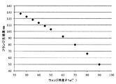
一方、ウェッジ角度θ1a、θ1bが大きくなると、ウェッジ傾斜角が拡大するために、被圧延材Aに対して摩擦力による上下方向への押し下げ力が作用し易く、割り込み形成時にフランジ相当部の内面部において肉引けが生じ、特に第2孔型K2以降での造形においてフランジの生成効率が低下する。ここで、図6を参照し、第2孔型K2のウェッジ角度θ1bと最終的に造形される被圧延材Aのフランジ幅との関係について説明し、好適なウェッジ角度θ1bの上限値について説明する。 On the other hand, when the wedge angles θ1a and θ1b increase, the wedge inclination angle increases, and thus the material A is easily pushed down by the frictional force in the vertical direction, and the inner surface portion of the flange equivalent portion at the time of interruption formation In the second hole type K2 and later, the generation efficiency of the flange decreases. Here, with reference to FIG. 6, the relationship between the wedge angle .theta.1b of the second hole type K2 and the flange width of the material A to be finally formed is described, and the upper limit value of the suitable wedge angle .theta.1b is described. .
図6はFEMによる解析結果であり、第2孔型K2のウェッジ角度θ1bを変えた場合の後段の工程(以下に説明する第3孔型K3での工程)におけるフランジ厚・フランジ幅の数値との関係を示すグラフである。計算条件としては素材のスラブ幅2300mm、スラブ厚300mmとし、本実施の形態にて説明する方法を用いた際に、ウェッジ角度θ1bを所定の角度である約20°〜約70°で変化させて被圧延材Aの造形を行うものとした。 FIG. 6 shows the results of analysis by FEM, and the numerical values of the flange thickness and the flange width in the subsequent steps (steps for the third hole type K3 described below) when the wedge angle θ1b of the second hole type K2 is changed Is a graph showing the relationship of The calculation conditions are a slab width of 2300 mm and a slab thickness of 300 mm, and when the method described in the present embodiment is used, the wedge angle θ1b is changed at a predetermined angle of about 20 ° to about 70 °. It is assumed that shaping of the material to be rolled A is performed.
図6に示すように、ウェッジ角度θ1bを40°超として粗圧延工程を実施し、H形鋼製品を造形した場合、フランジ幅・フランジ厚ともに顕著に低下するようなグラフとなっており、フランジ生成効率が低下していることが分かる。即ち、ウェッジ角度θ1bを40°超とした場合には、グラフの傾きが顕著に上昇しており、ウェッジ角度θ1bが40°以下の場合と比べてフランジ幅・フランジ厚が大きく低下している。ウェッジ角度θ1bの鈍角化によりフランジ相当部の肉引け(被圧延材Aの長手方向へのメタルフローの誘起)が大きくなる。このような観点から、ウェッジ角度θ1bを40°以下とすることで高いフランジ生成効率を実現することが可能であることが分かる。また、図6からは、より高いフランジ生成効率を実現させるためには、ウェッジ角度θ1bを35°以下とすることが望ましいことも分かる。 As shown in FIG. 6, when the rough rolling process is carried out with the wedge angle θ 1 b exceeding 40 ° and the H-shaped steel product is formed, the graph shows that both the flange width and the flange thickness are significantly reduced. It can be seen that the generation efficiency is decreasing. That is, when the wedge angle θ1b is more than 40 °, the inclination of the graph is significantly increased, and the flange width and the flange thickness are significantly reduced as compared with the case where the wedge angle θ1b is 40 ° or less. The obtuse of the wedge angle θ1b increases the thickness reduction (induction of metal flow in the longitudinal direction of the material to be rolled A) of the flange equivalent portion. From such a point of view, it is understood that high flange formation efficiency can be realized by setting the wedge angle θ1b to 40 ° or less. Further, it can also be understood from FIG. 6 that in order to realize higher flange formation efficiency, it is desirable to set the wedge angle θ1b to 35 ° or less.
また、上記第1孔型K1のウェッジ角度θ1aは、誘導性を高め、圧延の安定性を担保するためには、後段の第2孔型K2のウェッジ角度θ1bと同じ角度であることが好ましい。
特に第1孔型K1のウェッジ角度θ1aはフランジ相当部(後のフランジ部80)の先端部厚みに大きく寄与することが知られており、その点からは、ウェッジ角度θ1aはできるだけ小さくすることが好ましい。図7は、第1孔型K1の途中パスの概略断面図であり、一方のスラブ端面(図2における上方端部)に割り込み28を付与している状態を示している。図7では割り込み28を付与する際のウェッジ角度θ1aの大小による差異について記載しており、それぞれの場合の割り込み形状を図示している。また、図8は第1孔型K1のウェッジ角度θ1aとフランジ相当部の先端厚み(フランジ先端厚)との関係を示すグラフであり、一例としてウェッジ高さが100mm、スラブ厚が300mmの場合を示している。
Further, the wedge angle θ1a of the first hole type K1 is preferably the same angle as the wedge angle θ1b of the second hole type K2 in the latter stage in order to enhance the inductive property and secure the rolling stability.
In particular, it is known that the wedge angle θ1a of the first hole type K1 greatly contributes to the thickness of the tip of the flange equivalent portion (rear flange portion 80), and from that point the wedge angle θ1a should be as small as possible preferable. FIG. 7 is a schematic cross-sectional view of an intermediate path of the first hole type K1, showing a state in which an interrupt 28 is applied to one of the slab end faces (upper end in FIG. 2). FIG. 7 describes the difference due to the magnitude of the wedge angle θ1a at the time of applying the interrupt 28 , and illustrates the interrupt shape in each case. Further, FIG. 8 is a graph showing the relationship between the wedge angle θ1a of the first hole type K1 and the tip thickness (flange tip thickness) of the flange equivalent portion. As an example, the case where the wedge height is 100 mm and the slab thickness is 300 mm It shows.
図7、8に示すように、ウェッジ角度θ1aが小さい場合の断面に比べ、ウェッジ角度θ1aが大きい場合の断面では、スラブ端面のメタルがそがれ、スラブ端面のフランジ相当部(後のフランジ部80)の先端部厚みが減厚される。フランジ相当部(後のフランジ部80)の先端部厚みが減厚されることは後のH形鋼製品の形状に鑑みて好ましくないため、フランジ相当部の先端部厚みを確保するためには、好適なウェッジ角度θ1aの上限値を定める必要がある。 As shown in FIGS. 7 and 8, in the cross section in the case where the wedge angle θ1a is large as compared with the cross section in the case where the wedge angle θ1a is small, the metal of the slab end surface is deviated, and the flange equivalent portion of the slab end surface (rear flange 80) The tip thickness of the is reduced. Since it is not preferable in view of the shape of the H-shaped steel product to be reduced that the thickness of the tip of the flange equivalent (the later flange 80) is reduced, in order to secure the thickness of the tip of the flange equivalent, It is necessary to set an upper limit value of a suitable wedge angle θ1a.
以上説明したように、第2孔型K2のウェッジ角度θ1bを25°以上40°以下とすることに加え、フランジ相当部の先端部厚みを確保し、且つ、誘導性や圧延安定性を担保するといった観点から第1孔型K1のウェッジ角度θ1aも25°以上40°以下とすることが望ましい。更にこれらのウェッジ角度θ1a、θ1bは、高いフランジ生成効率を実現させるとの観点からは25°以上35°以下とすることが望ましい。 As described above, in addition to setting the wedge angle θ1b of the second hole type K2 to 25 ° or more and 40 ° or less, the thickness of the tip portion of the flange equivalent portion is secured, and the conductivity and rolling stability are ensured. From the viewpoint of the above, it is desirable that the wedge angle θ1a of the first hole type K1 is also 25 ° or more and 40 ° or less. Furthermore, it is desirable that the wedge angles θ1a and θ1b be 25 ° or more and 35 ° or less from the viewpoint of realizing high flange formation efficiency.
また、突起部35、36の高さ(突出長さ)h2は、上記第1孔型K1の突起部25、26の高さh1より高く構成されており、h2>h1となっている。ここで、上述したように、突起部35、36の先端部角度(ウェッジ角度θ1b)は上記第1孔型K1の突起部25、26の先端部角度と同じ(即ち、θ1a=θ1b)であることが好ましい。これら上孔型ロール30と下孔型ロール31のロール隙において、上記第1孔型K1通材後の被圧延材Aが更に造形される。
Further, the height (protruding length) h2 of the
ここで、第1孔型K1に形成される突起部25、26の高さh1より、第2孔型K2に形成される突起部35、36の高さh2の方が高く、被圧延材Aの上下端部(スラブ端面)への侵入長さも同様に第2孔型K2の方が長くなる。第2孔型K2での突起部35、36の被圧延材Aへの侵入深さは、突起部35、36の高さh2と同じである。即ち、第1孔型K1での突起部25、26の被圧延材Aへの侵入深さh1’と、第2孔型K2での突起部35、36の被圧延材Aへの侵入深さh2はh1’<h2との関係になっている。
また、被圧延材Aの上下端部(スラブ端面)に対向する孔型上面30a、30b及び孔型底面31a、31bと、突起部35、36の傾斜面とのなす角度θfは、図3に示す4箇所ともに約90°(略直角)に構成されている。Here, the height h2 of the
In addition, an angle θf formed by the
図3に示すように、被圧延材Aの上下端部(スラブ端面)へ押し当てられた時の突起部の侵入長さが長いことから、第2孔型K2においては、第1孔型K1において形成された割り込み28、29が更に深くなるように造形が行われ、割り込み38、39が形成される。なお、ここで形成される割り込み38、39の寸法に基づき粗圧延工程でのフランジ造形工程終了時のフランジ片幅が決定される。
As shown in FIG. 3, since the penetration length of the protrusion when pressed against the upper and lower end portions (slab end face) of the material to be rolled A is long, in the second hole type K2, the first hole type K1 is used. The shaping is performed so that the
また、図3に示す第2孔型K2での造形は多パスにより行われるが、この多パス造形のうちの少なくとも1パス以上は、被圧延材Aの上下端部(スラブ端面)と孔型内部(第2孔型K2の上面及び底面)が接触している必要がある。但し、全てのパスにおいて接触していることが望ましいのではなく、例えば最終パスのみ被圧延材Aの上下端部(スラブ端面)と孔型内部が接触し、スラブ端面圧下量ΔEが正の値となる(ΔE>0)ことが望ましい。これは、第2孔型K2での全てのパスにおいて被圧延材Aの上下端部と孔型内部とを非接触とすると、フランジ相当部(後述するフランジ部80)が左右非対称に造形されるといった形状不良が生じる恐れがあり、通材性の面で問題があるからである。
一方で、その他のパスにおいては、被圧延材Aの上下端部(スラブ端面)において上記突起部35、36を除き孔型と被圧延材Aは接触しておらず、これらのパスにおいて被圧延材Aの積極的な圧下は行われない。これは、圧下により被圧延材Aの長手方向への伸びを生じさせ、フランジ相当部(後述するフランジ部80に相当)の生成効率を低下させてしまうからである。
Further, although the formation in the second hole type K2 shown in FIG. 3 is performed by multiple passes, at least one pass or more of this multi-pass formation is the upper and lower end portions (slab end faces) of the material to be rolled A and the hole type It is necessary for the inside (the upper and lower surfaces of the second hole type K2) to be in contact with each other. However, it is not desirable for all passes to be in contact with each other. For example, only the final pass makes contact between the upper and lower end portions (slab end face) of the material to be rolled A and the inside of the hole mold, and the slab end face reduction amount ΔE is a positive value It is desirable that (ΔE> 0) be satisfied. This is because, if a non-contacting the inner lower end and grooved on the material to be rolled A in all paths in the second grooved K2, flange corresponding portion (
On the other hand, in the other passes, the hole type and the material to be rolled A are not in contact with each other except for the
即ち、第2孔型K2での多パス造形においては、必要最小限のパス(例えば最終パスのみ)において被圧延材Aの上下端部(スラブ端面)と孔型内部を接触させて圧下を行い、その他のパスにおいては積極的な圧下を行わないといったパススケジュールを設定することが好ましい。また、この第2孔型K2においても、上記第1孔型K1同様、突起部35、36における圧下量(ウェッジ先端圧下量ΔT)は、スラブ上下端部における圧下量(スラブ端面圧下量ΔE)よりも十分に大きなものとされ、これにより割り込み38、39が形成される。
That is, in multipass molding with the second hole type K2, the upper and lower end portions (slab end face) of the material to be rolled A are brought into contact with the inside of the hole type in the minimum necessary pass (for example, only the final pass) It is preferable to set a pass schedule such that no aggressive pressure reduction is performed in other passes. Further, also in the second hole type K2, as in the case of the first hole type K1, the amount of reduction at the
図4は第3孔型K3の概略説明図である。第3孔型K3は、一対の水平ロールである上孔型ロール40と下孔型ロール41に刻設される。上孔型ロール40の周面(即ち、第3孔型K3の上面)には、孔型内部に向かって突出する突起部45が形成されている。更に、下孔型ロール41の周面(即ち、第3孔型K3の底面)には、孔型内部に向かって突出する突起部46が形成されている。これら突起部45、46はテーパー形状を有しており、その突出長さ等の寸法は、突起部45と突起部46とでそれぞれ等しく構成されている。
FIG. 4 is a schematic explanatory view of the third hole type K3. The third hole type K3 is engraved on the upper
上記突起部45、46の先端部角度θ2は、上記角度θ1bに比べ広角に構成され、突起部45、46の被圧延材Aへの侵入深さh3は、上記突起部35、36の侵入深さh2よりも短くなっている(即ち、h3<h2)。
また、被圧延材Aの上下端部(スラブ端面)に対向する孔型上面40a、40b及び孔型底面41a、41bと、突起部45、46の傾斜面とのなす角度θfは、図4に示す4箇所ともに約90°(略直角)に構成されている。The tip angle θ2 of the
Further, in FIG. 4, an angle θf formed by the
図4に示すように、第3孔型K3では、第2孔型K2通材後の被圧延材Aに対し、被圧延材Aの上下端部(スラブ端面)において第2孔型K2において形成された割り込み38、39が、突起部45、46が押し当てられることにより、割り込み48、49となる。即ち、第3孔型K3での造形における最終パスでは、割り込み48、49の最深部角度(以下、割り込み角度とも呼称する)がθ2となる。換言すると、第2孔型K2において割り込み38、39の形成と共に造形された分割部位(後述するフランジ部80に対応する部位)が外側に折り曲げられるような造形が行われる。
As shown in FIG. 4, in the third hole type K3, the second hole type K2 is formed at the upper and lower end portions (slab end face) of the material to be rolled A with respect to the material to be rolled A after passing the second hole type K2 When the
また、図4に示す第3孔型K3での造形は少なくとも1パス以上によって行われ、このうちの少なくとも1パス以上は、被圧延材Aの上下端部(スラブ端面)と孔型内部(第3孔型K3の上面及び底面)が接触している必要がある。但し、全てのパスにおいて接触していることが望ましいのではなく、例えば最終パスのみ被圧延材Aの上下端部(スラブ端面)と孔型内部が接触し、スラブ端面圧下量ΔEが正の値となる(ΔE>0)ことが望ましい。これは、第3孔型K3での全てのパスにおいて被圧延材Aの上下端部と孔型内部とを非接触とすると、フランジ相当部(後述するフランジ部80)が左右非対称に造形されるといった形状不良が生じる恐れがあり、通材性の面で問題があるからである。
一方で、その他のパスにおいては、被圧延材Aの上下端部(スラブ端面)において上記突起部45、46を除き孔型と被圧延材Aは接触しておらず、これらのパスにおいて被圧延材Aの積極的な圧下は行われない。これは、圧下により被圧延材Aの長手方向への伸びを生じさせ、フランジ相当部(後述するフランジ部80に相当)の生成効率を低下させてしまうからである。
In addition, the formation in the third hole type K3 shown in FIG. 4 is performed by at least one or more passes, and at least one or more of these passes are the upper and lower end portions (slab end face) of the material to be rolled A It is necessary for the top and bottom surfaces of the three-hole type K3 to be in contact with each other. However, it is not desirable for all passes to be in contact with each other. For example, only the final pass makes contact between the upper and lower end portions (slab end face) of the material to be rolled A and the inside of the hole mold, and the slab end face reduction amount ΔE is a positive value It is desirable that (ΔE> 0) be satisfied. This is because, if a non-contacting the inner lower end and grooved on the material to be rolled A in all paths of the third grooved K3, flange corresponding portion (
On the other hand, in the other passes, the hole type and the material to be rolled A are not in contact with each other except for the
なお、この第3孔型K3における造形では、被圧延材Aの上下端部の4箇所の部位に対する曲げ加工が同時に行われる。そのため、4箇所の部位が均一に曲げ加工されないといった事情により通材が不安定になる恐れがあり、1パスでの造形が好ましい。この場合、1パス造形では被圧延材Aの上下端部(スラブ端面)と孔型内部(第3孔型K3の上面及び底面)が接触した状態で造形が行われる。 In addition, in shaping | molding in this 3rd hole type | mold K3, the bending process with respect to the site | part of four places of the upper-and-lower-ends part of the to-be-rolled material A is performed simultaneously. Therefore, there is a possibility that the threading material may become unstable due to the fact that the four portions are not bent uniformly, and modeling in one pass is preferable. In this case, in the one-pass shaping, shaping is performed in a state where the upper and lower end portions (slab end faces) of the material to be rolled A and the inside of the hole (the upper surface and the bottom of the third hole K3) are in contact.
図5は第4孔型K4の概略説明図である。第4孔型K4は、一対の水平ロールである上孔型ロール50と下孔型ロール51に刻設される。上孔型ロール50の周面(即ち、第4孔型K4の上面)には、孔型内部に向かって突出する突起部55が形成されている。更に、下孔型ロール51の周面(即ち、第4孔型K4の底面)には、孔型内部に向かって突出する突起部56が形成されている。これら突起部55、56はテーパー形状を有しており、その突出長さ等の寸法は、突起部55と突起部56とでそれぞれ等しく構成されている。
FIG. 5 is a schematic explanatory view of the fourth hole type K4. The fourth hole type K4 is engraved on the upper
上記突起部55、56の先端部角度θ3は、上記角度θ2に比べ広角に構成され、突起部55、56の被圧延材Aへの侵入深さh4は、上記突起部45、46の侵入深さh3よりも短くなっている(即ち、h4<h3)。
また、被圧延材Aの上下端部(スラブ端面)に対向する孔型上面50a、50b及び孔型底面51a、51bと、突起部55、56の傾斜面とのなす角度θfは、上記第3孔型K3と同様に、図5に示す4箇所ともに約90°(略直角)に構成されている。The tip angle θ3 of the
In addition, the angle θf formed by the
第4孔型K4では、第3孔型K3通材後の被圧延材Aに対し、被圧延材Aの上下端部(スラブ端面)において第3孔型K3において形成された割り込み48、49が、突起部55、56が押し当てられることにより押し広げられ、割り込み58、59となる。即ち、第4孔型K4での造形における最終パスでは、割り込み58、59の最深部角度(以下、割り込み角度とも呼称する)がθ3となる。換言すると、第3孔型K3において割り込み48、49の形成と共に造形された分割部位(後述するフランジ部80に対応する部位)が更に外側に折り曲げられるような造形が行われる。このようにして造形された被圧延材Aの上下端部の部位は、後のH形鋼製品のフランジに相当する部位であり、ここではフランジ部80と呼称する。なお、第4孔型K4の割り込み角度θ3は180°よりもやや小さい角度に設定されることが望ましい。これは、割り込み角度θ3を180°としてしまうと、次工程である平造形孔型においてウェブ厚の減厚を行う際に、フランジ部80の外側に拡がりが生じ、平造形孔型での圧延においてかみ出しが生じやすいからである。即ち、次工程の平造形孔型の形状及びウェブ厚の圧下量に応じてフランジ部80の外側での拡がり量が決まるため、ここでの割り込み角度θ3は、平造形孔型の形状及びウェブ厚の圧下量を勘案して好適に定められることが望ましい。
In the fourth hole type K4, the
また、図5に示す第4孔型K4での造形は少なくとも1パス以上によって行われ、この多パス造形のうちの少なくとも1パス以上は、被圧延材Aの上下端部(スラブ端面)と孔型内部(第4孔型K4の上面及び底面)が接触している必要がある。但し、全てのパスにおいて接触していることが望ましいのではなく、例えば最終パスのみ被圧延材Aの上下端部(スラブ端面)と孔型内部が接触し、スラブ端面圧下量ΔEが正の値となる(ΔE>0)ことが望ましい。これは、第4孔型K4での全てのパスにおいて被圧延材Aの上下端部と孔型内部とを非接触とすると、フランジ相当部(後述するフランジ部80)が左右非対称に造形されるといった形状不良が生じる恐れがあり、通材性の面で問題があるからである。
一方で、その他のパスにおいては、被圧延材Aの上下端部(スラブ端面)において上記突起部55、56を除き孔型と被圧延材Aは接触しておらず、これらのパスにおいて被圧延材Aの積極的な圧下は行われない。これは、圧下により被圧延材Aの長手方向への伸びを生じさせ、フランジ部80の生成効率を低下させてしまうからである。
Further, the formation in the fourth hole type K4 shown in FIG. 5 is performed by at least one pass or more, and at least one pass or more of this multi-pass formation is the upper and lower end portions (slab end face) and the holes of the material to be rolled A The inside of the mold (the top and bottom of the fourth hole K4) needs to be in contact. However, it is not desirable for all passes to be in contact with each other. For example, only the final pass makes contact between the upper and lower end portions (slab end face) of the material to be rolled A and the inside of the hole mold, and the slab end face reduction amount ΔE is a positive value It is desirable that (ΔE> 0) be satisfied. This is because, if a non-contacting the inner lower end and grooved on the material to be rolled A in all paths of the fourth grooved K4, flange corresponding portion (
On the other hand, in the other passes, the hole type and the material to be rolled A are not in contact with each other except for the
なお、この第4孔型K4における造形では、被圧延材Aの上下端部の4箇所の部位に対する曲げ加工が同時に行われる。そのため、4箇所の部位が均一に曲げ加工されないといった事情により通材が不安定になる恐れがあり、1パスでの造形が好ましい。この場合、1パス造形では被圧延材Aの上下端部(スラブ端面)と孔型内部(第4孔型K4の上面及び底面)が接触した状態で造形が行われる。 In addition, in shaping | molding in this 4th hole type | mold K4, the bending process with respect to the site | part of four places of the upper and lower end part of the to-be-rolled material A is performed simultaneously. Therefore, there is a possibility that the threading material may become unstable due to the fact that the four portions are not bent uniformly, and modeling in one pass is preferable. In this case, in the one-pass shaping, shaping is performed in a state in which the upper and lower end portions (slab end faces) of the material to be rolled A contact the inside of the hole (the top and bottom of the fourth hole K4).
以上説明した第1孔型K1〜第4孔型K4によって造形された被圧延材Aに対し、既知の孔型を用いて更に圧下・造形が行われ、いわゆるドッグボーン形状であるH形粗形材13が造形される。通常はこの後、スラブ厚に相当する部分を減厚する平造形孔型でウェブ厚が減厚される。その後、図1に示す中間ユニバーサル圧延機5−エッジャー圧延機9の2つの圧延機からなる圧延機列を用いて、通常7〜10数パスの圧下が加えられ、中間材14が造形される。そして中間材14は、仕上ユニバーサル圧延機8において製品形状に仕上圧延され、H形鋼製品16が製造される。
The material to be rolled A shaped by the first through fourth hole types K1 to K4 described above is further pressed and shaped using a known hole type, so-called dog bone shape H-shaped rough shape The
上述したように、本実施の形態にかかる第1孔型K1〜第4孔型K4を用いて被圧延材Aの上下端部(スラブ端面)に割り込みを入れ、それら割り込みによって左右に分かれた各部分を左右に折り曲げる加工を行い、フランジ部80を形成するといった造形をすることで、被圧延材A(スラブ)の上下端面を上下方向に圧下することなくH形粗形材13の造形を行うことができる。即ち、従来行われていたスラブ端面を常に圧下する粗圧延方法に比べ、フランジ幅を広幅化させてH形粗形材13を造形することが可能となり、その結果、フランジ幅の大きな最終製品(H形鋼)を製造することができる。また、サイジングミル3あるいは粗圧延機4における圧下量や設備規模に装置限界があるといったことに影響されずにH形粗形材13の造形を行うことができるため、素材のスラブサイズを従来に比べ小型化(スラブ幅の縮小)させることができ、フランジ幅の大きな最終製品を効率的に製造することができる。
As described above, the upper and lower end portions (slab end faces) of the material to be rolled A are interrupted using the first through fourth hole types K1 to K4 according to the present embodiment, and each of the left and right parts are separated by the interruptions. By shaping the
また、特に第2孔型K2での造形においては、必要最小限のパス(例えば最終パスのみ)において被圧延材Aの上下端部(スラブ端面)と孔型内部を接触させて圧下を行い、その他のパスにおいては積極的な圧下を行わないものとしている。これにより、割り込み38、39を形成する際に、左右のフランジ相当部(後のフランジ部80)の肉量が不均一になることにより生じる形状不良を抑制し、効率的で安定した粗圧延工程を実現することが可能となる。
Further, particularly in forming with the second hole type K2, the upper and lower end portions (slab end face) of the material to be rolled A and the inside of the hole type are brought into contact in the minimum necessary path (for example, only the final path) In the other passes, positive pressure is not applied. Thereby, when forming the
また、特に第3孔型K3、第4孔型K4での造形においては、多パス造形のうちの少なくとも1パス以上は、被圧延材Aの上下端部(スラブ端面)と孔型内部(孔型の上面及び底面)が接触している構成としている。ここで、全てのパスにおいて接触している必要はなく、例えば最終パスのみ被圧延材Aの上下端部(スラブ端面)と孔型内部が接触し、スラブ端面圧下量ΔEが正の値となる(ΔE>0)構成とされる。これにより、分割部位(後のフランジ部80)を折り曲げて造形を行う際に、左右の分割部位の肉量が不均一となり通材が安定しないといった問題を回避することができる。 In addition, particularly in modeling with the third hole type K3 and the fourth hole type K4, at least one pass or more of the multi-pass shaping is the upper and lower end portions (slab end face) of the material to be rolled A and the inside of the hole type (holes The top and bottom surfaces of the mold are in contact with each other. Here, it is not necessary to make contact in all the passes, for example, the upper and lower end (slab end face) of the material to be rolled A and the inside of the hole form contact only in the final pass, and the slab end face reduction amount ΔE becomes a positive value (ΔE> 0) configuration. Thereby, when shaping | molding by bending a division part (following flange part 80), the problem that the thickness of a division | segmentation part on either side becomes non-uniform | heterogenous, and a material is not stabilized can be avoided.
また、上記のように、各孔型(例えば第2孔型K2〜第4孔型K4)においては、必要最小限のパス数において圧下を行い、その他のパスにおいては積極的な圧下は行われないため、従来に比べ被圧延材Aの圧下に伴う長手方向の伸びが抑えられ、従来のH形鋼の圧延に比べクロップ部の発生が抑制され、歩留まりの向上が実現される。 Further, as described above, in each hole type (for example, the second hole type K2 to the fourth hole type K4), the reduction is performed with the minimum necessary number of passes, and in the other paths, the positive reduction is performed. Since there is not, the elongation in the longitudinal direction accompanying the pressure reduction of the material to be rolled A is suppressed as compared to the conventional case, the generation of cropped portions is suppressed as compared to the conventional rolling of H-section steel, and the improvement of the yield is realized.
また、第2孔型K2〜第4孔型K4においては、被圧延材Aの上下端部(スラブ端面)に対向する2箇所の孔型上面及び2箇所の孔型底面と、孔型に形成された突起部の傾斜面とのなす角度θfは約90°(略直角)に構成されている。
これにより、第2孔型K2〜第4孔型K4にて行われる造形時の通材性を向上させることができる。上記角度θfが約90°よりも大きい構成の場合、フランジ相当部(後のフランジ部80)が孔型ロールに沿って折り曲がらない恐れがある。具体的には、孔型ロール形状以上に曲がってしまう恐れがある。その結果、4箇所のフランジ相当部の寸法形状が不均一となり通材性が悪くなってしまうと共に、製品寸法の低下にもつながるからである。
また、フランジ相当部(後のフランジ部80)の先端部を早い造形段階で略直角に造形しておくことで、造形後の製品形状の向上が見込める。特に、大型でフランジが広幅化されたH形鋼製品を製造する場合には、より早い段階でフランジ相当部の造形を好適に行うことで、製造可能なサイズの拡大化が見込める。Further, in the second through fourth hole types K2 to K4, the upper and lower end portions (slab end faces) of the material to be rolled A are formed into the upper and lower two hole types and the two bottom surfaces and the hole type The angle θf between the projection and the inclined surface of the projection is about 90 ° (approximately right angle).
Thereby, the material passing property at the time of modeling performed in the 2nd hole type K2-the 4th hole type K4 can be improved. In the case where the angle θf is larger than about 90 °, there is a risk that the flange equivalent portion (rear flange portion 80) will not be bent along the hole type roll. Specifically, there is a risk of bending more than the hole-type roll shape. As a result, the dimensions and shapes of the four flanges are not uniform, which results in poor passability and leads to a reduction in product size.
Further, by forming the tip portion of the flange equivalent portion (the later flange portion 80) at an approximately right angle in the early formation stage, it is possible to improve the product shape after formation. In particular, in the case of manufacturing a large H-shaped steel product having a wide flange, it is possible to expand the manufacturable size by suitably forming the flange equivalent portion at an earlier stage.
以上、本発明の実施の形態の一例を説明したが、本発明は図示の形態に限定されない。当業者であれば、特許請求の範囲に記載された思想の範疇内において、各種の変更例または修正例に想到し得ることは明らかであり、それらについても当然に本発明の技術的範囲に属するものと了解される。 Although the example of the embodiment of the present invention has been described above, the present invention is not limited to the illustrated embodiment. It is obvious that those skilled in the art can conceive of various modifications or alterations within the scope of the idea described in the claims, and they are naturally within the technical scope of the present invention. It is understood that.
上記実施の形態においては、第3孔型K3の突起部45、46の先端部角度θ2はθ1bよりも大きい角度であり、第4孔型K4の突起部55、56の先端部角度θ3はθ2よりも大きい角度であると説明したが、これらの角度θ2、θ3については、更に好適な範囲を具体的な角度で定めることができる。即ち、第3孔型K3の突起部45、46の先端部角度θ2を70°以上110°以下と規定し、第4孔型K4の突起部55、56の先端部角度θ3を130°以上170°以下と規定することが好ましい。このように規定することで、被圧延材における形状不良の発生を抑制させ、従来に比べフランジ幅の大きなH形鋼製品を効率的且つ安定的に製造することが可能となる。以下では上記θ2及びθ3の好適な角度の範囲が規定される根拠について説明する。
In the above embodiment, the tip angle θ2 of the
先ず、本発明者らは、第3孔型K3で造形が完了した被圧延材Aに対し、第4孔型K4において実施される折り曲げ加工の加工限界(加工限界角度)について検討を行った。図9は、第4孔型K4での折り曲げ角度(即ち、θ3−θ2)とフランジ厚偏差(フランジ厚バラツキ)との関係を示すグラフである。ここで、図9のグラフの縦軸であるフランジ厚偏差は、割り広げて造形された4つのフランジ相当部の平均フランジ厚からのバラツキ3σを示している。 First, the present inventors examined the processing limit (processing limit angle) of the bending process performed in the fourth hole type K4 on the material to be rolled A which has been completed in the third hole type K3. FIG. 9 is a graph showing the relationship between the bending angle (i.e., [theta] 3- [theta] 2) and the flange thickness deviation (flange thickness variation) in the fourth hole type K4. Here, the flange thickness deviation, which is the vertical axis of the graph in FIG. 9, indicates the variation 3σ from the average flange thickness of the four flange equivalent parts formed by dividing and spreading.
図9に示すように、第4孔型K4において、折り曲げ角度(即ち、θ3−θ2)が60°を超えると、フランジ厚偏差が5%を超えるため、粗圧延工程の後工程である中間圧延工程や仕上圧延工程において寸法を収束させることが困難となり、好適な寸法精度でもって造形を実施することができなくなる。 As shown in FIG. 9, in the fourth hole type K4, when the bending angle (ie, θ3-θ2) exceeds 60 °, the flange thickness deviation exceeds 5%, so intermediate rolling which is a step after the rough rolling step It becomes difficult to converge the dimensions in the process or finish rolling process, and it becomes impossible to carry out shaping with a suitable dimensional accuracy.
なお、左右のフランジ相当部の厚みバラツキは5%以下に抑えられることが好ましい理由は以下の通りである。大型サイズのH形鋼の形状寸法の許容差は、JIS規格(JIS G 3192)によると、フランジ厚が40mmを超える場合、当該フランジ厚の公差範囲は4mm(即ち、±2mm)であり、製品のフランジ厚の10%に相当する。製品のフランジ寸法が上記公差から外れた場合、加工修正は困難であり、所定品質の製品として認められないため、製造効率やコストの面で問題が大きい。従って、各造形工程の工程能力を十分とし、左右のフランジ相当部の厚みバラツキを抑えてH形鋼製品を製造する必要がある。通常、各造形工程の工程能力を十分とするためには、フランジ厚の公差範囲を6σに設定することが望ましい。上記JIS規格に基づき、H形鋼製品のフランジ厚の10%を6σに合わせるため、左右のフランジ相当部の厚みバラツキ3σの目標値は5%以下とすることが望ましい。 The reason why the thickness variation of the left and right flange equivalent parts is preferably suppressed to 5% or less is as follows. According to JIS (JIS G 3192), when the flange thickness exceeds 40 mm, the tolerance range of the flange thickness is 4 mm (that is, ± 2 mm) according to the JIS standard (JIS G 3192). Equivalent to 10% of the flange thickness of If the flange size of the product deviates from the above tolerance, machining correction is difficult, and it can not be recognized as a product of a predetermined quality, which causes a large problem in terms of manufacturing efficiency and cost. Therefore, it is necessary to make the process capability of each shaping process sufficient, and to suppress the thickness variation of the flange equivalent part on either side, and to manufacture a H-shaped steel product. In general, it is desirable to set the tolerance range of the flange thickness to 6σ in order to make the process capability of each forming process sufficient. In order to make 10% of flange thickness of H section steel product into 6σ based on the above-mentioned JIS standard, it is desirable to make target value of thickness variation 3σ of flange equivalent part on either side into 5% or less.
図9に示すように、第4孔型K4での加工角度は60°以下である必要がある。即ち、第3孔型K3の突起部45、46の先端部角度θ2と、第4孔型K4の突起部55、56の先端部角度θ3との差は60°以下とする必要があり、以下の式(1)を満たす条件に設計される必要がある。
θ3−θ2≦60° ・・・(1)As shown in FIG. 9, the processing angle in the fourth hole type K4 needs to be 60 ° or less. That is, the difference between the tip angle θ2 of the
θ3-θ2 ≦ 60 ° (1)
次に、本発明者らは、第3孔型K3の突起部45、46の先端部角度θ2の上限値について検討を行った。図10は、第3孔型K3における先端部角度θ2を変化させた場合のフランジ相当部の先端における幅変化量(フランジ先端つぶし量)を示すグラフである。
フランジ先端つぶし量は、第3孔型K3において折り曲げられたフランジ相当部の先端幅方向に関する潰された距離Δi(i=1〜4:4箇所の先端に対応)の平均値によって定義される。なお、以下に説明する図11には、このフランジ先端つぶし量Δ1〜Δ4を図示している。Next, the present inventors examined the upper limit value of the tip end angle θ2 of the
The flange tip crushing amount is defined by the average value of the crushed distances Δi (i = 1 to 4: corresponding to the four tips of four places) in the tip width direction of the flange equivalent portion bent in the third hole type K3. In addition, FIG. 11 described below illustrates the flange tip crushing amounts Δ1 to Δ4.
図10に示すように、上記角度θ2が100°以下であれば、フランジ相当部の先端幅変化量は5mm以下の小さなレベルで留まる。しかしながら、角度θ2が110°以上になると、フランジ相当部の先端幅変化量も大きくなり、4箇所のフランジ相当部の肉量アンバランスが生じてしまう(以下に説明する図11参照)。 As shown in FIG. 10, when the angle θ2 is 100 ° or less, the tip width change amount of the flange equivalent portion remains at a small level of 5 mm or less. However, when the angle θ2 becomes 110 ° or more, the tip width change amount of the flange equivalent part also becomes large, and the unbalance in the meat amount of the four flange equivalent parts occurs (see FIG. 11 described below).
図11は、本実施の形態に係る方法で第3孔型K3の突起部45、46の先端部角度θ2を110°超とした場合の、造形後の被圧延材の形状を示す概略図である。図11に示すように、角度θ2を110°超に設定して第3孔型K3での造形を実施すると、曲げ加工による変形よりもフランジ相当部の外側面が押し潰される変形の方が容易となり、フランジ相当部の外側のメタルが削がれる変形モードとなってしまうことが確認される。
以上、図10、11を参照して説明したことから、第3孔型K3の突起部45、46の先端部角度θ2は以下の式(2)を満たす条件に設計される必要がある。
θ2≦110° ・・・(2)FIG. 11 is a schematic view showing the shape of the material to be rolled after shaping in the case where the tip angle θ2 of the
As described above with reference to FIGS. 10 and 11, it is necessary to design the tip end angle θ2 of the
θ2 ≦ 110 ° (2)
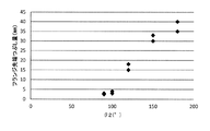
続いて、本発明者らは、ウェブ減厚孔型での造形に基づき、第4孔型K4の突起部55、56の先端部角度θ3の上限値ならびに下限値について検討を行った。図12は、第4孔型K4の突起部55、56の先端部角度θ3を変化させた場合の、ウェブ減厚孔型において実施される後段の工程での肉溜まりの発生に伴って生じる製品疵深さを示すグラフである。なお、ウェブ減厚孔型で生じる肉溜まりとは、フランジ相当部の外面において生じる突起状の形状不良であり、その詳細は図13を参照して後述する。
Subsequently, the present inventors examined the upper limit value and the lower limit value of the tip end portion angle θ3 of the
図12に示すように、上記角度θ3が130°未満である場合には、製品疵が生じてしまい、その製品疵深さは角度θ3が小さければ小さい程、増大してしまう。そして、最終製品のフランジ外面にこの製品疵が残ってしまう。 As shown in FIG. 12, when the angle θ3 is less than 130 °, product wrinkles occur, and the product bag depth increases as the angle θ3 becomes smaller. Then, this product cake remains on the flange outer surface of the final product.
図13はウェブ減厚孔型におけるウェブ減厚に関する概略説明図であり、(a)は上記角度θ3が170°超である場合にフランジ部の外面に形状不良が生じている場合を示し、(b)は上記角度θ3が130°未満である場合にフランジ部の外面に形状不良が生じている場合を示し、(c)は製品疵を示している。 FIG. 13 is a schematic explanatory view regarding web thinning in the web thinning hole type, and (a) shows a case where a shape defect occurs on the outer surface of the flange when the angle θ3 is more than 170 °, b) shows the case where shape defect has arisen in the outer surface of a flange part when said angle (theta) 3 is less than 130 degrees, (c) has shown the product wrinkles.
図13(a)に示すように、ウェブ減厚孔型においてウェブ減厚を行った場合、ウェブ部81の減厚に伴い、フランジ部80の外側(図中左右方向)へのメタルの拡がり量が大きくなる。全断面に対するウェブ部81の断面割合が大きい程、その拡がり量は大きくなる。これにより、図中の破線部に示す突起状の膨らみ部60が形成される。この膨らみ部60は形状不良の要因であるため、対応策として、フランジ部80の外面に拡がりを見込んで凹みを設けておくことが考えられる。その凹み量を調整するために、第4孔型K4の突起部55、56の先端部角度θ3を好適に定めることが有効である。実験上、角度θ3を170°超とした場合に、図13(a)に示すような形状不良が生じることが分かっており、角度θ3の上限値は170°となる。
また、上記式(1)及び式(2)から、角度θ2の上限値は110°であり、角度θ3と角度θ2の差は最大で60°であることからも、角度θ3の上限値は170°と定まる。
As shown in FIG. 13A, when the web thickness reduction is performed in the web thickness reduction hole type, the amount of metal spread to the outside (horizontal direction in the figure) of the
Also, from the above equations (1) and (2), the upper limit value of the angle θ2 is 110 °, and the difference between the angle θ3 and the angle θ2 is 60 ° at the maximum. It becomes settled with °.
また、図13(b)に示すように、ウェブ減厚孔型では、ウェブ部81の減厚と同時にフランジ部80の幅圧下も行われ、フランジ部80の幅圧下により、当該フランジ部80の中央部に上下からの圧下歪が加わるが、角度θ3が130°未満になるとフランジ部80の外側面中央部(図中破線で囲んだ部分)に形成されている溝61が消えずに疵として残存し、それに伴う製品疵が発生し、最終製品であるH形鋼において当該製品疵が残存してしまう。実験上、角度θ3を130°未満とした場合に、図13(b)に示す溝61が疵の起点となり残存し、図13(c)のような製品疵63が生じてしまうことが分かっている。
以上、図12、13を参照して説明したことから、第4孔型K4の突起部55、56の先端部角度θ3は上限値を170°とすることが望ましく、下限値を130°とすることが望ましい。
特に、図12に基づき、角度θ3は以下の式(3)を満たす条件に設計される必要がある。
θ3≧130° ・・・(3)Further, as shown in FIG. 13B, in the web thinning hole type, the width reduction of the
As described above with reference to FIGS. 12 and 13, the tip end portion angle θ3 of the
In particular, based on FIG. 12, the angle θ3 needs to be designed to satisfy the following equation (3).
θ 3 130 130 ° (3)
以上説明した式(1)〜(3)を同時に満たすような設計条件を構成する場合、θ2の下限値は70°(=130°−60°)となり、θ3の上限値は170°(=110°+60°)となる。図14は、上記式(1)〜(3)に示した設計条件をまとめたグラフであり、θ2とθ3の好適な設計範囲を示すものである。図14中の各条件を示す線(図中破線)に囲まれた範囲が好適な設計範囲となる。即ち、角度θ2は以下の式(4)を満たす条件に設計される必要があり、角度θ3は以下の式(5)を満たす条件に設計される必要があり、且つ、上記式(1)を満たすことが必要となる。
70°≦θ2≦110° ・・・(4)
130°≦θ3≦170° ・・・(5)When designing conditions that simultaneously satisfy the equations (1) to (3) described above, the lower limit of θ2 is 70 ° (= 130 ° -60 °), and the upper limit of θ3 is 170 ° (= 110). ° + 60 °). FIG. 14 is a graph summarizing the design conditions shown in the above formulas (1) to (3), and shows a preferable design range of θ2 and θ3. A range surrounded by lines (broken lines in the drawing) indicating the respective conditions in FIG. 14 is a preferable design range. That is, the angle θ2 needs to be designed to satisfy the following equation (4), the angle θ3 needs to be designed to satisfy the following equation (5), and the above equation (1) It is necessary to satisfy.
70 ° ≦ θ2 ≦ 110 ° (4)
130 ° ≦ θ3 ≦ 170 ° (5)
上記式(1)、(4)、(5)を満たすような設計条件によって第3孔型K3の突起部45、46の先端部角度θ2、ならびに第4孔型K4の突起部55、56の先端部角度θ3が定められる。これにより、左右のフランジ部80の変形アンバランスが生じることなく造形が実施され、更に、フランジ相当部の外側面が押し潰される変形といった形状不良(図11参照)や、ウェブ減厚孔型においてフランジ部80の外側面中央部が肉溜まり形状となり製品疵が発生してしまうといった形状不良(図13参照)が生じることなく、各造形工程を実施することが可能となる。
The tip angle θ2 of the
また、例えば、上記実施の形態において、第1孔型K1〜第4孔型K4の4つの孔型を刻設して被圧延材Aの造形を行うものとして説明したが、粗圧延工程を実施するための孔型数はこれに限られるものではない。即ち、サイジングミル3や粗圧延機4に刻設される孔型の数は任意に変更可能であり、好適に粗圧延工程を実施することができる程度に適宜変更される。
なお、上記実施の形態では、フランジ相当部(後のフランジ部80)を折り曲げる造形を第3孔型K3及び第4孔型K4で行うものとして説明した。これは、折り曲げ角度(即ち、各孔型でのウェッジ角度)を急激に大きくして折り曲げ造形を行うと、突起部と被圧延材Aとの摩擦力によって肉引けが起こり易くなることや、折り曲げ加工力が大きくなり、4箇所のフランジ相当部(後のフランジ部80)の肉量の均等化が損なわれる恐れがあるため、複数の孔型(上記実施の形態では第3孔型K3及び第4孔型K4)にて分担して折り曲げ造形を実施することが望ましいからである。本発明者らの実験結果によれば、上記実施の形態で説明した第3孔型K3及び第4孔型K4の2孔型において折り曲げ造形を実施することが望ましい。Further, for example, in the above embodiment, although it has been described that four hole types of the first hole type K1 to the fourth hole type K4 are engraved to form the material to be rolled A, the rough rolling process is performed The number of holes to be made is not limited to this. That is, the number of hole types provided in the sizing mill 3 and the rough rolling mill 4 can be arbitrarily changed, and is appropriately changed to such an extent that the rough rolling process can be suitably performed.
In the above embodiment, the third hole type K3 and the fourth hole type K4 are used to form the flange equivalent portion (the rear flange portion 80) by bending. This is because when the bending angle (that is, the wedge angle in each hole type) is rapidly increased and bending is performed, the friction between the projection and the material to be rolled A makes it easy to cause thinning, or bending There is a risk that the processing force will be large and the equalization of the thickness of the four flange equivalent parts (the later flange part 80) may be lost. Therefore, the plural hole types (third hole type K3 and the third hole type K3 in the above embodiment) This is because it is desirable to share the four-hole type K4) and perform bending and shaping. According to the experimental results of the present inventors, it is desirable to perform bending and shaping in the two-hole type of the third hole type K3 and the fourth hole type K4 described in the above embodiment.
また、H形鋼を製造する際の素材(被圧延材A)としてはスラブを例示して説明したが、類似形状のその他素材についても本発明は当然適用可能である。即ち、例えばビームブランク素材を造形してH形鋼を製造する場合にも適用できる。 Moreover, although the slab was illustrated and demonstrated as a raw material (rolling material A) at the time of manufacturing H-section steel, this invention is naturally applicable also to the other raw material of similar shape. That is, for example, it is applicable also when shaping | molding beam blank raw material and manufacturing H-section steel.
本発明は、例えば矩形断面であるスラブ等を素材としてH形鋼を製造する製造方法に適用できる。 The present invention can be applied to a manufacturing method for manufacturing an H-shaped steel, for example, using a slab having a rectangular cross section as a raw material.
Claims (5)
前記粗圧延工程を行う圧延機には、被圧延材を造形する4以上の複数の孔型が刻設され、
当該複数の孔型では被圧延材の1又は複数パス造形が行われ、
前記複数の孔型のうち第1孔型及び第2孔型には、被圧延材の幅方向に対し鉛直に割り込みを入れる突起部が形成され、
前記複数の孔型のうち第2孔型以降では少なくとも1パス以上の造形において被圧延材の端面と孔型周面とが接触した状態で圧下が行われ、
前記複数の孔型のうち第3孔型以降の2以上の孔型では前記割り込みによって成形された分割部位を順次折り曲げる工程が行われ、
第1孔型及び第2孔型に形成される前記突起部の先端角度は40°以下であることを特徴とする、H形鋼の製造方法。 A method of manufacturing an H-shaped steel comprising a rough rolling process, an intermediate rolling process, and a finish rolling process, comprising:
In the rolling mill which performs the rough rolling process, a plurality of four or more hole molds for forming a material to be rolled are engraved.
In the plurality of hole types, one or more pass shaping of the material to be rolled is performed,
Among the plurality of hole types, the first hole type and the second hole type are formed with projections that vertically interrupt the width direction of the material to be rolled,
Of the plurality of hole types, at least one pass or more of the second hole type or more, the rolling is performed in a state where the end surface of the material to be rolled and the hole peripheral surface are in contact with each other
Among the plurality of hole types, in the second or more hole type after the third hole type, the step of sequentially bending the divided portions formed by the interruption is performed,
The tip angle of the said projection part formed in a 1st hole type | mold and a 2nd hole type | mold is 40 degrees or less, The manufacturing method of H section steel characterized by the above-mentioned.
第2孔型以降の各孔型に形成される突起部の先端角度は、後段の孔型になるほど順次大きな角度となるように構成されることを特徴とする、請求項1〜3のいずれか一項に記載のH形鋼の製造方法。 Among the plurality of hole types, in each of the third and subsequent hole types, a protrusion that bends the divided portion by pressing the divided portion is formed.
The tip angle of the projection formed in each hole type after the second hole type is configured to become gradually larger as the hole type is in the latter stage. The manufacturing method of H section steel as described in one paragraph.
前記複数の孔型のうち第3孔型及び第4孔型において、前記割り込みによって成形された分割部位を順次折り曲げる工程が行われ、
前記第3孔型に形成される突起部の先端角度は70°以上110°以下であり、
前記第4孔型に形成される突起部の先端角度は130°以上170°以下であることを特徴とする、請求項1〜4のいずれか一項に記載のH形鋼の製造方法。
The plurality of hole molds are four hole molds of a first hole mold to a fourth hole mold for forming a material to be rolled,
In the third and fourth hole molds among the plurality of hole molds, a step of sequentially bending the divided portions formed by the interruption is performed,
The tip angle of the projection formed in the third hole type is 70 ° or more and 110 ° or less,
The method for manufacturing an H-shaped steel according to any one of claims 1 to 4, wherein a tip angle of the projection formed in the fourth hole type is 130 ° or more and 170 ° or less.
Applications Claiming Priority (3)
| Application Number | Priority Date | Filing Date | Title |
|---|---|---|---|
| JP2015056638 | 2015-03-19 | ||
| JP2015056638 | 2015-03-19 | ||
| PCT/JP2016/057647 WO2016148030A1 (en) | 2015-03-19 | 2016-03-10 | H-shaped steel production method |
Publications (2)
| Publication Number | Publication Date |
|---|---|
| JPWO2016148030A1 JPWO2016148030A1 (en) | 2017-12-28 |
| JP6515355B2 true JP6515355B2 (en) | 2019-05-22 |
Family
ID=56918989
Family Applications (1)
| Application Number | Title | Priority Date | Filing Date |
|---|---|---|---|
| JP2017506506A Active JP6515355B2 (en) | 2015-03-19 | 2016-03-10 | H-shaped steel manufacturing method |
Country Status (5)
| Country | Link |
|---|---|
| US (1) | US10730086B2 (en) |
| EP (1) | EP3260210B1 (en) |
| JP (1) | JP6515355B2 (en) |
| CN (1) | CN107427875B (en) |
| WO (1) | WO2016148030A1 (en) |
Families Citing this family (5)
| Publication number | Priority date | Publication date | Assignee | Title |
|---|---|---|---|---|
| EP3272435B1 (en) * | 2015-03-19 | 2020-04-29 | Nippon Steel Corporation | H-shaped steel production method |
| EP3260210B1 (en) | 2015-03-19 | 2019-09-11 | Nippon Steel Corporation | H-shaped steel production method |
| KR20180097665A (en) * | 2016-01-07 | 2018-08-31 | 신닛테츠스미킨 카부시키카이샤 | Manufacturing method of H-shaped steel and rolling apparatus |
| US20190023307A1 (en) * | 2016-01-07 | 2019-01-24 | Nippon Steel & Sumitomo Metal Corporation | Method for producing h-shaped steel and h-shaped steel product |
| WO2019013262A1 (en) * | 2017-07-12 | 2019-01-17 | 新日鐵住金株式会社 | Method for manufacturing steel h-beam |
Family Cites Families (21)
| Publication number | Priority date | Publication date | Assignee | Title |
|---|---|---|---|---|
| JPS5819361B2 (en) * | 1975-08-11 | 1983-04-18 | 新日本製鐵株式会社 | Manufacturing method of rough shaped steel billet |
| JPS5953121B2 (en) * | 1981-03-05 | 1984-12-24 | 川崎製鉄株式会社 | Rolling method for widening large material for rough shaped steel billet and its rolling roll |
| JPS58188501A (en) | 1982-04-30 | 1983-11-04 | Sumitomo Metal Ind Ltd | Production of rough shape steel ingot for h-shaped steel |
| CA1179171A (en) * | 1981-07-10 | 1984-12-11 | Yoshiaki Kusaba | Method for producing beam blank for universal beam |
| FR2543027B1 (en) * | 1983-03-21 | 1986-05-16 | Sacilor | PROCESS OF INTEGRAL UNIVERSAL LAMINATION OF METAL PROFILES OF THE POUTRELLE H OR I TYPE |
| JPS6021101A (en) | 1983-07-14 | 1985-02-02 | Sumitomo Metal Ind Ltd | Rolling method of rough shape billet for shape steel |
| US5009094A (en) | 1988-06-27 | 1991-04-23 | Kawasaki Steel Corporation | Method of rolling H-shaped steels |
| JP3457362B2 (en) | 1993-09-21 | 2003-10-14 | 新日本製鐵株式会社 | Method for producing intermediate coarse shaped billet for H-section steel |
| JP2727943B2 (en) * | 1993-12-16 | 1998-03-18 | 住友金属工業株式会社 | Manufacturing method of coarse shaped billet |
| JPH07178404A (en) | 1993-12-24 | 1995-07-18 | Nkk Corp | Production of shape steel for steel-made continuous wall |
| JP3678003B2 (en) | 1998-06-03 | 2005-08-03 | Jfeスチール株式会社 | Rolling method of rough steel slab |
| JP3456438B2 (en) | 1999-03-02 | 2003-10-14 | Jfeスチール株式会社 | Rolling method of crude slab for section steel |
| JP2002045902A (en) | 2000-08-02 | 2002-02-12 | Sumitomo Metal Ind Ltd | Method for rolling large size wide flange shape |
| JP2004358541A (en) * | 2003-06-06 | 2004-12-24 | Sumitomo Metal Ind Ltd | Method for manufacturing shaped bloom and caliber roll |
| CN1745917A (en) | 2004-09-06 | 2006-03-15 | 李宝安 | Rolling process of H-shaped or I-shapec steel |
| CN201070634Y (en) | 2007-05-30 | 2008-06-11 | 南京钢铁集团无锡金鑫轧钢有限公司 | Inequilateral different-thickness corner iron caliber system |
| JP5724749B2 (en) | 2011-08-23 | 2015-05-27 | Jfeスチール株式会社 | Manufacturing method of H-section steel |
| CN202762723U (en) | 2012-06-15 | 2013-03-06 | 莱芜钢铁集团有限公司 | Embedded slotting layout structure of H-shaped steel cogging roll |
| CN103056160A (en) | 2013-01-24 | 2013-04-24 | 中冶赛迪工程技术股份有限公司 | X-I short-process rolling unit for H-shaped steel |
| EP3260210B1 (en) | 2015-03-19 | 2019-09-11 | Nippon Steel Corporation | H-shaped steel production method |
| EP3272435B1 (en) * | 2015-03-19 | 2020-04-29 | Nippon Steel Corporation | H-shaped steel production method |
-
2016
- 2016-03-10 EP EP16764860.9A patent/EP3260210B1/en active Active
- 2016-03-10 WO PCT/JP2016/057647 patent/WO2016148030A1/en active Application Filing
- 2016-03-10 US US15/559,310 patent/US10730086B2/en active Active
- 2016-03-10 CN CN201680016996.2A patent/CN107427875B/en active Active
- 2016-03-10 JP JP2017506506A patent/JP6515355B2/en active Active
Also Published As
| Publication number | Publication date |
|---|---|
| EP3260210B1 (en) | 2019-09-11 |
| US20180111178A1 (en) | 2018-04-26 |
| CN107427875B (en) | 2019-09-10 |
| WO2016148030A1 (en) | 2016-09-22 |
| JPWO2016148030A1 (en) | 2017-12-28 |
| EP3260210A1 (en) | 2017-12-27 |
| EP3260210A4 (en) | 2018-12-12 |
| CN107427875A (en) | 2017-12-01 |
| US10730086B2 (en) | 2020-08-04 |
Similar Documents
| Publication | Publication Date | Title |
|---|---|---|
| JP6515355B2 (en) | H-shaped steel manufacturing method | |
| JP2019111584A (en) | Rolled H-shaped steel | |
| JP6447286B2 (en) | H-section steel manufacturing method and H-section steel products | |
| JP6536415B2 (en) | H-shaped steel manufacturing method | |
| JP6446716B2 (en) | Manufacturing method of H-section steel | |
| JP6686809B2 (en) | Method for manufacturing H-section steel | |
| JP6565691B2 (en) | H-section steel manufacturing method and H-section steel products | |
| JP6593457B2 (en) | H-section steel manufacturing method and rolling device | |
| JP6597321B2 (en) | H-section steel manufacturing method and H-section steel products | |
| JP6668963B2 (en) | Method of manufacturing H-section steel | |
| JP6627641B2 (en) | Method for manufacturing H-section steel | |
| JP6569535B2 (en) | H-section steel manufacturing method and H-section steel products | |
| JP6855885B2 (en) | H-section steel manufacturing method and H-section steel products | |
| JP6515365B1 (en) | H-shaped steel manufacturing method | |
| JP6699415B2 (en) | Method for manufacturing H-section steel | |
| JP6593456B2 (en) | H-section steel manufacturing method and H-section steel products | |
| JP6531653B2 (en) | H-shaped steel manufacturing method | |
| JP6825463B2 (en) | Manufacturing method of H-section steel | |
| JP6447285B2 (en) | Manufacturing method of H-section steel | |
| JP2018176188A (en) | Manufacturing method of h-shaped steel | |
| JP2013202621A (en) | Forming rolling method of rough shape slab and method for manufacturing wide flange beam |
Legal Events
| Date | Code | Title | Description |
|---|---|---|---|
| A621 | Written request for application examination |
Free format text: JAPANESE INTERMEDIATE CODE: A621 Effective date: 20170913 |
|
| A521 | Written amendment |
Free format text: JAPANESE INTERMEDIATE CODE: A523 Effective date: 20171024 |
|
| A131 | Notification of reasons for refusal |
Free format text: JAPANESE INTERMEDIATE CODE: A131 Effective date: 20181030 |
|
| A521 | Written amendment |
Free format text: JAPANESE INTERMEDIATE CODE: A523 Effective date: 20181225 |
|
| A131 | Notification of reasons for refusal |
Free format text: JAPANESE INTERMEDIATE CODE: A131 Effective date: 20190122 |
|
| RD04 | Notification of resignation of power of attorney |
Free format text: JAPANESE INTERMEDIATE CODE: A7424 Effective date: 20190208 |
|
| A521 | Written amendment |
Free format text: JAPANESE INTERMEDIATE CODE: A523 Effective date: 20190221 |
|
| TRDD | Decision of grant or rejection written | ||
| A01 | Written decision to grant a patent or to grant a registration (utility model) |
Free format text: JAPANESE INTERMEDIATE CODE: A01 Effective date: 20190305 |
|
| A61 | First payment of annual fees (during grant procedure) |
Free format text: JAPANESE INTERMEDIATE CODE: A61 Effective date: 20190318 |
|
| R151 | Written notification of patent or utility model registration |
Ref document number: 6515355 Country of ref document: JP Free format text: JAPANESE INTERMEDIATE CODE: R151 |