JP6513708B2 - Adjustable wearable system with modular sensor platform - Google Patents
Adjustable wearable system with modular sensor platform Download PDFInfo
- Publication number
- JP6513708B2 JP6513708B2 JP2016568043A JP2016568043A JP6513708B2 JP 6513708 B2 JP6513708 B2 JP 6513708B2 JP 2016568043 A JP2016568043 A JP 2016568043A JP 2016568043 A JP2016568043 A JP 2016568043A JP 6513708 B2 JP6513708 B2 JP 6513708B2
- Authority
- JP
- Japan
- Prior art keywords
- sensor
- sensor module
- module
- band
- wearable system
- Prior art date
- Legal status (The legal status is an assumption and is not a legal conclusion. Google has not performed a legal analysis and makes no representation as to the accuracy of the status listed.)
- Expired - Fee Related
Links
Images


Classifications
-
- A—HUMAN NECESSITIES
- A61—MEDICAL OR VETERINARY SCIENCE; HYGIENE
- A61B—DIAGNOSIS; SURGERY; IDENTIFICATION
- A61B5/00—Measuring for diagnostic purposes; Identification of persons
- A61B5/68—Arrangements of detecting, measuring or recording means, e.g. sensors, in relation to patient
- A61B5/6801—Arrangements of detecting, measuring or recording means, e.g. sensors, in relation to patient specially adapted to be attached to or worn on the body surface
- A61B5/6802—Sensor mounted on worn items
-
- A—HUMAN NECESSITIES
- A61—MEDICAL OR VETERINARY SCIENCE; HYGIENE
- A61B—DIAGNOSIS; SURGERY; IDENTIFICATION
- A61B5/00—Measuring for diagnostic purposes; Identification of persons
- A61B5/0002—Remote monitoring of patients using telemetry, e.g. transmission of vital signals via a communication network
- A61B5/0004—Remote monitoring of patients using telemetry, e.g. transmission of vital signals via a communication network characterised by the type of physiological signal transmitted
- A61B5/0006—ECG or EEG signals
-
- A—HUMAN NECESSITIES
- A61—MEDICAL OR VETERINARY SCIENCE; HYGIENE
- A61B—DIAGNOSIS; SURGERY; IDENTIFICATION
- A61B5/00—Measuring for diagnostic purposes; Identification of persons
- A61B5/0002—Remote monitoring of patients using telemetry, e.g. transmission of vital signals via a communication network
- A61B5/0015—Remote monitoring of patients using telemetry, e.g. transmission of vital signals via a communication network characterised by features of the telemetry system
- A61B5/0022—Monitoring a patient using a global network, e.g. telephone networks, internet
-
- A—HUMAN NECESSITIES
- A61—MEDICAL OR VETERINARY SCIENCE; HYGIENE
- A61B—DIAGNOSIS; SURGERY; IDENTIFICATION
- A61B5/00—Measuring for diagnostic purposes; Identification of persons
- A61B5/0002—Remote monitoring of patients using telemetry, e.g. transmission of vital signals via a communication network
- A61B5/0015—Remote monitoring of patients using telemetry, e.g. transmission of vital signals via a communication network characterised by features of the telemetry system
- A61B5/0024—Remote monitoring of patients using telemetry, e.g. transmission of vital signals via a communication network characterised by features of the telemetry system for multiple sensor units attached to the patient, e.g. using a body or personal area network
-
- A—HUMAN NECESSITIES
- A61—MEDICAL OR VETERINARY SCIENCE; HYGIENE
- A61B—DIAGNOSIS; SURGERY; IDENTIFICATION
- A61B5/00—Measuring for diagnostic purposes; Identification of persons
- A61B5/0059—Measuring for diagnostic purposes; Identification of persons using light, e.g. diagnosis by transillumination, diascopy, fluorescence
-
- A—HUMAN NECESSITIES
- A61—MEDICAL OR VETERINARY SCIENCE; HYGIENE
- A61B—DIAGNOSIS; SURGERY; IDENTIFICATION
- A61B5/00—Measuring for diagnostic purposes; Identification of persons
- A61B5/02—Detecting, measuring or recording pulse, heart rate, blood pressure or blood flow; Combined pulse/heart-rate/blood pressure determination; Evaluating a cardiovascular condition not otherwise provided for, e.g. using combinations of techniques provided for in this group with electrocardiography or electroauscultation; Heart catheters for measuring blood pressure
- A61B5/0205—Simultaneously evaluating both cardiovascular conditions and different types of body conditions, e.g. heart and respiratory condition
- A61B5/02055—Simultaneously evaluating both cardiovascular condition and temperature
-
- A—HUMAN NECESSITIES
- A61—MEDICAL OR VETERINARY SCIENCE; HYGIENE
- A61B—DIAGNOSIS; SURGERY; IDENTIFICATION
- A61B5/00—Measuring for diagnostic purposes; Identification of persons
- A61B5/05—Detecting, measuring or recording for diagnosis by means of electric currents or magnetic fields; Measuring using microwaves or radio waves
- A61B5/053—Measuring electrical impedance or conductance of a portion of the body
- A61B5/0531—Measuring skin impedance
-
- A—HUMAN NECESSITIES
- A61—MEDICAL OR VETERINARY SCIENCE; HYGIENE
- A61B—DIAGNOSIS; SURGERY; IDENTIFICATION
- A61B5/00—Measuring for diagnostic purposes; Identification of persons
- A61B5/24—Detecting, measuring or recording bioelectric or biomagnetic signals of the body or parts thereof
- A61B5/25—Bioelectric electrodes therefor
-
- A—HUMAN NECESSITIES
- A61—MEDICAL OR VETERINARY SCIENCE; HYGIENE
- A61B—DIAGNOSIS; SURGERY; IDENTIFICATION
- A61B5/00—Measuring for diagnostic purposes; Identification of persons
- A61B5/24—Detecting, measuring or recording bioelectric or biomagnetic signals of the body or parts thereof
- A61B5/316—Modalities, i.e. specific diagnostic methods
- A61B5/318—Heart-related electrical modalities, e.g. electrocardiography [ECG]
-
- A—HUMAN NECESSITIES
- A61—MEDICAL OR VETERINARY SCIENCE; HYGIENE
- A61B—DIAGNOSIS; SURGERY; IDENTIFICATION
- A61B5/00—Measuring for diagnostic purposes; Identification of persons
- A61B5/68—Arrangements of detecting, measuring or recording means, e.g. sensors, in relation to patient
- A61B5/6801—Arrangements of detecting, measuring or recording means, e.g. sensors, in relation to patient specially adapted to be attached to or worn on the body surface
- A61B5/6802—Sensor mounted on worn items
- A61B5/681—Wristwatch-type devices
-
- A—HUMAN NECESSITIES
- A61—MEDICAL OR VETERINARY SCIENCE; HYGIENE
- A61B—DIAGNOSIS; SURGERY; IDENTIFICATION
- A61B5/00—Measuring for diagnostic purposes; Identification of persons
- A61B5/68—Arrangements of detecting, measuring or recording means, e.g. sensors, in relation to patient
- A61B5/6801—Arrangements of detecting, measuring or recording means, e.g. sensors, in relation to patient specially adapted to be attached to or worn on the body surface
- A61B5/6843—Monitoring or controlling sensor contact pressure
-
- A—HUMAN NECESSITIES
- A61—MEDICAL OR VETERINARY SCIENCE; HYGIENE
- A61B—DIAGNOSIS; SURGERY; IDENTIFICATION
- A61B5/00—Measuring for diagnostic purposes; Identification of persons
- A61B5/72—Signal processing specially adapted for physiological signals or for diagnostic purposes
- A61B5/7235—Details of waveform analysis
- A61B5/7264—Classification of physiological signals or data, e.g. using neural networks, statistical classifiers, expert systems or fuzzy systems
-
- A—HUMAN NECESSITIES
- A61—MEDICAL OR VETERINARY SCIENCE; HYGIENE
- A61B—DIAGNOSIS; SURGERY; IDENTIFICATION
- A61B5/00—Measuring for diagnostic purposes; Identification of persons
- A61B5/74—Details of notification to user or communication with user or patient ; user input means
- A61B5/742—Details of notification to user or communication with user or patient ; user input means using visual displays
- A61B5/7445—Display arrangements, e.g. multiple display units
-
- A—HUMAN NECESSITIES
- A61—MEDICAL OR VETERINARY SCIENCE; HYGIENE
- A61B—DIAGNOSIS; SURGERY; IDENTIFICATION
- A61B2560/00—Constructional details of operational features of apparatus; Accessories for medical measuring apparatus
- A61B2560/02—Operational features
- A61B2560/0204—Operational features of power management
- A61B2560/0214—Operational features of power management of power generation or supply
-
- A—HUMAN NECESSITIES
- A61—MEDICAL OR VETERINARY SCIENCE; HYGIENE
- A61B—DIAGNOSIS; SURGERY; IDENTIFICATION
- A61B2560/00—Constructional details of operational features of apparatus; Accessories for medical measuring apparatus
- A61B2560/02—Operational features
- A61B2560/0223—Operational features of calibration, e.g. protocols for calibrating sensors
-
- A—HUMAN NECESSITIES
- A61—MEDICAL OR VETERINARY SCIENCE; HYGIENE
- A61B—DIAGNOSIS; SURGERY; IDENTIFICATION
- A61B2560/00—Constructional details of operational features of apparatus; Accessories for medical measuring apparatus
- A61B2560/02—Operational features
- A61B2560/0242—Operational features adapted to measure environmental factors, e.g. temperature, pollution
- A61B2560/0247—Operational features adapted to measure environmental factors, e.g. temperature, pollution for compensation or correction of the measured physiological value
-
- A—HUMAN NECESSITIES
- A61—MEDICAL OR VETERINARY SCIENCE; HYGIENE
- A61B—DIAGNOSIS; SURGERY; IDENTIFICATION
- A61B2560/00—Constructional details of operational features of apparatus; Accessories for medical measuring apparatus
- A61B2560/04—Constructional details of apparatus
- A61B2560/0443—Modular apparatus
-
- A—HUMAN NECESSITIES
- A61—MEDICAL OR VETERINARY SCIENCE; HYGIENE
- A61B—DIAGNOSIS; SURGERY; IDENTIFICATION
- A61B2560/00—Constructional details of operational features of apparatus; Accessories for medical measuring apparatus
- A61B2560/04—Constructional details of apparatus
- A61B2560/0475—Special features of memory means, e.g. removable memory cards
-
- A—HUMAN NECESSITIES
- A61—MEDICAL OR VETERINARY SCIENCE; HYGIENE
- A61B—DIAGNOSIS; SURGERY; IDENTIFICATION
- A61B2562/00—Details of sensors; Constructional details of sensor housings or probes; Accessories for sensors
- A61B2562/02—Details of sensors specially adapted for in-vivo measurements
- A61B2562/0257—Proximity sensors
-
- A—HUMAN NECESSITIES
- A61—MEDICAL OR VETERINARY SCIENCE; HYGIENE
- A61B—DIAGNOSIS; SURGERY; IDENTIFICATION
- A61B2562/00—Details of sensors; Constructional details of sensor housings or probes; Accessories for sensors
- A61B2562/12—Manufacturing methods specially adapted for producing sensors for in-vivo measurements
-
- A—HUMAN NECESSITIES
- A61—MEDICAL OR VETERINARY SCIENCE; HYGIENE
- A61B—DIAGNOSIS; SURGERY; IDENTIFICATION
- A61B2562/00—Details of sensors; Constructional details of sensor housings or probes; Accessories for sensors
- A61B2562/16—Details of sensor housings or probes; Details of structural supports for sensors
- A61B2562/164—Details of sensor housings or probes; Details of structural supports for sensors the sensor is mounted in or on a conformable substrate or carrier
-
- A—HUMAN NECESSITIES
- A61—MEDICAL OR VETERINARY SCIENCE; HYGIENE
- A61B—DIAGNOSIS; SURGERY; IDENTIFICATION
- A61B5/00—Measuring for diagnostic purposes; Identification of persons
- A61B5/01—Measuring temperature of body parts ; Diagnostic temperature sensing, e.g. for malignant or inflamed tissue
-
- A—HUMAN NECESSITIES
- A61—MEDICAL OR VETERINARY SCIENCE; HYGIENE
- A61B—DIAGNOSIS; SURGERY; IDENTIFICATION
- A61B5/00—Measuring for diagnostic purposes; Identification of persons
- A61B5/05—Detecting, measuring or recording for diagnosis by means of electric currents or magnetic fields; Measuring using microwaves or radio waves
- A61B5/053—Measuring electrical impedance or conductance of a portion of the body
- A61B5/0531—Measuring skin impedance
- A61B5/0533—Measuring galvanic skin response
Description
本発明は個人の生理学的な情報をモニターリングし、通信するためのウェアラブル(wearable)装置に関し、その中でも特に、身体の一部に対して調整可能なウェアラブルモジュール型センサープラットフォームに関する。 The present invention relates to wearable devices for monitoring and communicating physiological information of an individual, and more particularly to a wearable modular sensor platform that is adjustable relative to a part of the body.
数年に掛けて腕時計バンド、ジュエリー(jewelry)バンド、磁気健康バンド、ブレスレット、及びネックレス等の様々タイプが取引されてきた。
センサーが装着されたウェアラブル装置は、活動データ(継続時間、ステップカウント、消費されたカロリー)、睡眠統計、及び/又は生理学的なデータ(例えば、心拍数、汗、及び皮膚温度)のような使用者データをいくつかの方式にて追跡することができる。
Over the years, various types of watch bands, jewelry bands, magnetic health bands, bracelets, necklaces, etc. have been traded.
Wearable devices equipped with sensors use such as activity data (duration, step count, calories consumed), sleep statistics and / or physiological data (eg heart rate, sweat and skin temperature) Data can be tracked in several ways.
しかし、このような既存の装置は、多くの場合、非常に繊細及び/又はあまりにも薄っぺらで、また柔軟性に欠けるものであり、そして肉体的運動、フィットネス活動、及びスポーツに適当でなく、充分な信頼性あるセンサー測定が行われない。
例えば、ヘルスケアモニターリング(health care monitoring)は基本的に長時間を要求する。
However, such existing devices are often very delicate and / or too flimsy, inflexible, and not suitable for physical exercise, fitness activities, and sports, and are sufficient. Reliable sensor measurement is not performed.
For example, health care monitoring basically requires a long time.
その上に、既存のウェアラブル装置は多くの不都合点を有する。
それは一般的に体積が大きくて、不便であり、そして外来患者又は個人単位に長時間使用するのに適当ではない。
このような装置は、また幼児又は非協力的な患者(予測できないように既存のセンサーを除去することができる精神分裂症患者のような)によって長時間着用されるには適切ではない。このようなウェアラブル装置は移動性又は長時間のモニターリングを要する動物にも適合ではない。
このような不都合を除いても、今までのウェアラブル装置は、敏感である生理学的及び環境的測定、プロセシング(processing)及び通信を遂行するライフスタイル(lifestyle)製品として適合するものではなかった。
Additionally, existing wearable devices have many disadvantages.
It is generally bulky, inconvenient, and not suitable for extended use on an outpatient or personal basis.
Such devices are also not suitable for being worn for extended periods by infants or non-cooperative patients (such as schizophrenic patients who can remove existing sensors in an unpredictable manner). Such wearable devices are also not suitable for animals that require mobility or long-term monitoring.
Even with these disadvantages, wearable devices to date have not been adapted as lifestyle products to perform sensitive physiological and environmental measurements, processing and communications.
別の欠点として、既存のセンサーが面倒な電極を有することである。
結果として、このような装置は、一般に、比較的大きなプラスチックシェルケースに包まれ、快適な又はより数時間着用するのに適しておらず、そのようなものとして、生理学的測定のためのより適切な位置の特定の利点を欠いている。
Another disadvantage is that existing sensors have cumbersome electrodes.
As a result, such devices are generally enclosed in a relatively large plastic shell case and not suitable for wearing for a comfortable or more hours, as such being more suitable for physiological measurements Lack of specific advantages of location.
腕時計の場合、センサーは、一般的にディスプレイと共に手首の上に位置する。
このような装置で、他のもの間で、ゴム電極、標準金属医療電極、及び関連した接着パッドが不便であるので、特に老齢の使用者及び敏感な皮膚を有する使用者が使用する場合、連続的であり、かつ長時間の着用は望ましくない。
接触される皮膚の一部が使用する間に数日又は数週の間において、適切に空気に露出されなければ、このような装置の継続的な着用は、また皮膚刺激を発生する傾向がある。
In the case of a watch, the sensor is generally located on the wrist with the display.
Among such devices, rubber electrodes, standard metal medical electrodes, and related adhesive pads are inconvenient among others, especially when used by elderly users and users with sensitive skin. And long wearing is not desirable.
Continuous wear of such devices also tends to generate skin irritation if the portion of the skin being contacted is not properly exposed to air for days or weeks during use .
ウェアラブル装置で特定のセンサーの配置は他の理由で面倒なことである。
例えば、一部の測定(例えば、皮膚伝導度)は共通的に指先に固定されるか、或いはウェアラブル装置から分離される接着パッチを使用する追加的な電極を要求する。
このような状況で、他の日常的な仕事を遂行するには使用者の能力に深刻な制限が生じる。
このようなセンサー配置の短所は、すべての使用者に対して身体の一部(例えば、手首、首、足首、胸、腰又は頭)が同一の大きさ及び形状ではないという事実によって悪化される。
The placement of a particular sensor in a wearable device is cumbersome for other reasons.
For example, some measurements (e.g., skin conductivity) require additional electrodes using adhesive patches that are commonly fixed to the fingertip or separated from the wearable device.
Under these circumstances, the ability of the user to perform other routine tasks is severely limited.
Disadvantages of such sensor placement are exacerbated by the fact that parts of the body (e.g. wrist, neck, ankle, chest, waist or head) are not the same size and shape for all users .
今までのウェアラブル装置は、非対称的に調整する(例えば、ベルトバックル(belt buckle)タイプバンド)。
今までの他のバンドは、1つでなされたバンドであり、さらに小さい人に比べてさらに大きい人に対して又はそれ反対の場合に対して、身体の一部の大きさが増加して皮膚に加えられた圧力(あまりにも多いか、或いはあまりにも少ない)を解決できない。
Traditional wearable devices adjust asymmetrically (e.g., belt buckle type band).
The other bands so far are the ones made in one part, and the size of the part of the body increases with the size of the body for the larger person and vice versa compared to the smaller one. The pressure applied to it (too much or too little) can not be resolved.
即ち、ウェアラブル装置の調節にこのようなアプローチは、またセンサーが含まれた場合、圧迫感や緩みによって装置を着用するのが不便であった。
追加的に、身体一部で装置の移動は不便であるか、或いはセンサー及びディスプレイの位置を変更することは信頼できない測定及び測定を表示する傾向がある。
不快感は、皮膚の痛み又は刺激を減少させるために適切な位置の外へ装置を移動させる可能性がある。
要するに、装置の移動は不正確な測定に至ることになり、長時間使用に対して装置を不利になる。
That is, such an approach to adjusting a wearable device, and also when a sensor was included, was inconvenient to wear the device due to pressure and looseness.
Additionally, movement of the device on a part of the body is inconvenient, or changing the position of the sensor and display tends to display unreliable measurements and measurements.
The discomfort can move the device out of the proper position to reduce skin pain or irritation.
In short, movement of the device leads to inaccurate measurements, which makes the device disadvantageous for long-term use.
他の不利な点は、無線接続する既存のシステムは、例えば一般的に短いバッテリー寿命を示す。
それは数時間以上の継続的又は長時間の無線伝送に適切ではない。
しかし、例えば、慢性疾患(例えば、睡眠障害、糖尿病、その他の等)が存在する場合には数日、数週、及び数ヶ月に亘って継続的な生理データ収集が必要とする。
既存の無線装置は、一般的に単独使用者に制限される他の不利な点を有し、強力なデータ収集及び装置の遠隔分析を支援できない。
また、既存の装置は、一般的に基本的なボードデータ分析(rudimentary board data analysis)よりはるかに多いことを提供できない。
Another disadvantage is that existing wirelessly connected systems, for example, generally exhibit short battery life.
It is not suitable for continuous or long-time wireless transmission over several hours.
However, for example, in the presence of chronic diseases (eg, sleep disorders, diabetes, etc.), continuous physiological data collection is required over several days, weeks and months.
Existing wireless devices have other disadvantages that are generally limited to single users and can not support powerful data collection and remote analysis of the device.
Also, existing devices generally can not provide much more than basic board data analysis.
つまり、今までの装置は、小さく、コンパクト(compact)であり、軽く、また正確であり、継続的に使用可能であり、非侵襲性(non−invasive)、及び/又は、また多様な使用者の生理及び環境条件下で楽な位置を持続的に維持することができるフォームファクタ(form factor)で継続的に又は長時間使用するための装置の着用を可能であるようにする大きさ及び便利性のイッシュー(issues:論点)(例えば、柔軟性、空気流れ、ソフトな接触領域、皮膚刺激)を解決できなかった。 That is, previous devices are small, compact, light, accurate, continuously usable, non-invasive, and / or diverse users. Size and convenience to allow the wearing of the device for continuous or long-term use in a form factor that can maintain a comfortable position continuously under physiological and environmental conditions of Sexual issues (eg, softness, air flow, soft contact area, skin irritation) could not be resolved.
そのような装置は、また単一モジュール型センサープラットフォームでセンサー機能(例えば、心電図ECG、血糖(glucose)、血圧、水分供給(hydration)、その他の等)を勢揃いさせることができなかった。
このようなセンサー機能は、このような装置が使用され得る最適な環境より悪い環境に対する又は厳しい動的使用に対する信頼できる医療水準の測定値を提供できなかった。
このような装置は、また身体に対する日々データ収集が使用者又は適当な処理能力を要する医療専門家に提供することができる洞察力を活用できなかった。
適当な処理能力は、常に着用する装置で適切なバッテリー寿命を要求するが、ウェアラブル装置はそれを達成できなかった。
さらに、このような装置は、健康関連データの通信と関連して個人情報保護及び保安イッシュー(問題点)に直面していない。
Such devices have also failed to align sensor functions (eg, ECG, glucose, blood pressure, hydration, etc.) with a single modular sensor platform.
Such sensor functions have failed to provide reliable medical grade measurements for environments worse than the optimum environment in which such devices may be used or for severe dynamic use.
Such devices have also failed to take advantage of the insights that daily data collection on the body can provide to the user or healthcare professional who needs adequate processing power.
Proper processing power requires an adequate battery life on the device that is always worn, but the wearable device has failed to achieve that.
Furthermore, such devices do not face personal information protection and security issues in connection with the communication of health related data.
本発明は上記従来のウェアラブル装置における問題点に鑑みてなされたものであって、本発明の目的は、身体部位の人体測定学的大きさに関係なく、使用者の生理学的データを測定するために調整可能なセンサーモジュールを含むウェアラブルシステム及びその測定方法を提供することにある。 The present invention has been made in view of the problems in the above-described conventional wearable device, and an object of the present invention is to measure physiological data of a user regardless of the anthropometric size of a body part. It is an object of the present invention to provide a wearable system including an adjustable sensor module and a measurement method thereof.
上記のような目的を達成するために、本発明の一実施態様によれば、使用者の身体部位に着用される装置から生理学的データを測定するためのウェアラブルシステム及び方法は、ベースモジュール及びセンサーモジュールを含むように提供される。
ベースモジュールは、ディスプレイ及びベースコンピューティングユニットを含む。
センサーモジュールは、ベースモジュールに対して空間的に配置され、1つ以上の生理学的特性を測定するために身体部位の一部分上を覆って空間的に配置される。
ベースモジュールは、身体部位の人体計測サイズに関係なく、生理学的データの正確な測定のための身体部位と充分な接触をするために身体部位上を覆ってセンサーモジュールの位置を維持するように使用者によってセンサーモジュールに対して調整可能に配置されることを特徴とする。
In order to achieve the above objects, according to one embodiment of the present invention, a wearable system and method for measuring physiological data from a device worn on a body part of a user comprises a base module and a sensor Provided to include modules.
The base module includes a display and a base computing unit.
The sensor module is spatially disposed relative to the base module and spatially disposed over a portion of the body site to measure one or more physiological characteristics.
The base module is used to cover the body part and maintain the position of the sensor module to make sufficient contact with the body part for accurate measurement of physiological data regardless of the anthropometric size of the body part It is characterized in that it is adjustably arranged with respect to the sensor module by
本発明に係るモジュール型センサープラットフォームを有する調整可能なウェアラブルシステムによれば、身体部位の人体計測サイズに関係なく、使用者の生理学的データを測定するための調整可能なセンサーモジュールを含むウェアラブルシステム及びその測定方法を提供することができる。 According to an adjustable wearable system having a modular sensor platform according to the present invention, a wearable system including an adjustable sensor module for measuring physiological data of a user regardless of the anthropometric size of a body part The measurement method can be provided.
次に、本発明に係るモジュール型センサープラットフォームを有する調整可能なウェアラブルシステムを実施するための形態の具体例を図面を参照しながら説明する。 Next, a specific example of an embodiment for implementing an adjustable wearable system having a modular sensor platform according to the present invention will be described with reference to the drawings.
添付した図面に図示した例及び本発明の実施形態を詳細に説明するものであり、類似の参照番号は類似の構成要素を指す。
以下で、本発明の技術的な思想を説明するために図面を参照して実施形態が説明する。
本発明のいくつかの実施形態を詳細に説明する前に、本発明が以下の説明又は図面で図示したことに開示した構成要素の配列及び構造の細部事項に対するそのアプリケーションに限定されないことが理解されるべきである。
本発明の長所及び特徴、及びこれを達成するための方法は以下の実施形態の詳細な説明及び添付した図面を参照することで、容易に理解することができる。
しかし、本発明の技術的な思想は多様な他の形態に具現することができ、本文に開示した実施形態に限定されないで構成することもできる。
むしろ、本文が完璧になることで、技術分野の通常の技術者に本発明の技術的事実が伝達されるようにこのような実施形態は提供することができる。
本発明の技術的な思想は添付された特許請求範囲によって定義される。図面で、層(膜)及び領域の厚さは視覚的な明確性のために誇張されている。
Reference will now be made in detail to the example illustrated in the accompanying drawings and embodiments of the present invention in which like reference numerals refer to like components.
Hereinafter, embodiments will be described with reference to the drawings in order to explain the technical concept of the present invention.
Before describing some embodiments of the present invention in detail, it is understood that the present invention is not limited to its application to the details of the arrangements and structures of the components disclosed in the following description or illustrated in the drawings. It should.
The advantages and features of the present invention and methods for achieving the same can be easily understood with reference to the detailed description of the embodiments below and the attached drawings.
However, the technical idea of the present invention can be embodied in various other forms, and can be configured without being limited to the embodiments disclosed in the text.
Rather, by perfecting the text, such embodiments can be provided such that the technical facts of the present invention can be communicated to the person skilled in the art.
The technical idea of the present invention is defined by the appended claims. In the drawings, the thicknesses of layers (membranes) and areas are exaggerated for visual clarity.
また、本明細書で使用される語法及び用語は説明の目的のためのものであり、これに限定するものではない。
単数用語及び発明を説明する脈絡での類似の指示対象(特に、以下の特許請求範囲)の使用は本文で異なって称されるか、又は明確に反しない限り、単数及び複数を全てを含むように理解される。異なることに言及されない限り、“含む”(comprising、having、including、及びcontaining)の用語は開放形の意味として理解される(即ち、“含むが、制限されない”を意味する)。
Also, the phraseology and terminology used herein is for the purpose of description and not of limitation.
The use of singular terms and similar indicators (in particular, the following claims) in the context of describing the invention are intended to include the singular and the plural unless the context clearly dictates otherwise. To be understood. Unless stated otherwise, the terms "comprising,""having, including, and containing" are understood as meaning open (ie, "means including but not limited to").
図面で示すシステムが実際にいくつかのシステムと同様なモデルであることは技術分野で通常の知識を有する者に明確である。
説明したモジュール及び論理構造の一部は、マイクロプロセッサ又は類似の装置によって遂行されるソフトウェアで具現されるか、又は例えば、“ASICs”(application specific integrated circuits)を含む多様な構成要素を使用してハードウェアで具現することができる。
“プロセッサ”のような用語は、ハードウェア及び/又はソフトウェアの全てを言及するか、又は含むことができる。大文字の使用が特定な意味を暗示するものではなく、このように単純に推論されるべきでない。
It is clear to those skilled in the art that the system shown in the drawings is in fact a model similar to some systems.
Some of the modules and logic structures described may be embodied in software performed by a microprocessor or similar device, or using various components including, for example, "ASICs" (application specific integrated circuits). It can be embodied in hardware.
Terms such as "processor" may refer to or include all of the hardware and / or software. The use of capital letters does not imply any particular meaning, and thus should not be simply inferred.
同様に、本文で使用される“構成(component)”又は“モジュール(module)”の用語は特定動作を遂行する、FPGA(field programmable gate array)又はASICのような、ソフトウェア又はハードウェア構成を意味する。
しかし、これに限定されるものではない。構成又はモジュールは有利にアドレス指定のストレージ媒体内に位置するように構成されることができ、1つ以上のプロセスを遂行するように構成されることができる。
したがって、構成要素は、例として、ソフトウェア構成要素(software components)、客体指向ソフトウェア構成要素(object−oriented software components)、クラス構成要素及びタスク構成要素(class components and task components)、プロセス(processes)、機能(functions)、属性(attributes)、プロシージャ(procedures)、サブルーチン(subroutines)、プログラムコードのセグメント(segments of program code)、ドライバー(drivers)、ファームウェア(firmware)、プログラムコード(microcode)、回路(circuitry)、データ(data)、データベース(databases)、データ構造(data structures)、テーブル(tables)、アレイ(arrays)、及び変数(variables)を含む。
構成又はモジュールのために提供される機能は、さらに少ない構成及び/又はモジュールで組み合わされるか、また追加的な構成及び/又はモジュールで分離することができる。
Similarly, the terms "component" or "module" as used herein mean software or hardware configurations, such as field programmable gate array (FPGA) or ASICs, that perform specific operations. Do.
However, it is not limited to this. The configuration or module may advantageously be arranged to be located in the addressed storage medium and may be arranged to perform one or more processes.
Thus, the components are, by way of example, software components, object-oriented software components, class components and task components, processes, Functions (functions), attributes (attributes), procedures (procedures), subroutines (subroutines), segments of program code (segments of program code), drivers (drivers), firmware (firmware), program code (microcode), circuit (cir) cuitry, data, databases, data structures, tables, tables, arrays, and variables.
The functionality provided for a configuration or module may be combined in fewer configurations and / or modules and may be separated in additional configurations and / or modules.
異なって定義されない限り、ここに使用されるすべての技術的及び科学的用語はこの発明が属する技術分野の当業者によって共通的に理解されることができる同一の意味を有する。
さらに、異なって定義されない限り、一般的な辞書的な用語内定義されたすべての用語はそれらの一般的な意味として解釈されなければならない。
任意及びすべての実施形態、又はここに提供された例示的な用語は単なる一般的な発明の概念をさらに詳しく説明するために使用したものであり、別の言及がなければ、本発明の範囲を限定しない。
Unless defined otherwise, all technical and scientific terms used herein have the same meaning as can be commonly understood by one of ordinary skill in the art to which this invention belongs.
Further, unless otherwise defined, all terms defined within the generic lexical term should be interpreted as their general meanings.
The optional and all embodiments, or the exemplary terms provided herein are merely used to further illustrate the general inventive concept and, unless otherwise stated, the scope of the present invention Not limited
本発明の実施形態は、使用者の手首を通じて心電図(electrocardiogram、ECG)をモニターリングするためのウェアラブル装置を提供するシステムに関する。 Embodiments of the present invention relate to a system for providing a wearable device for monitoring an electrocardiogram (ECG) through the wrist of a user.
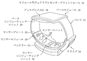
図1及び図2は、本発明の一実施形態によるモジュール型ウェアラブルセンサープラットフォーム(modular wearable sensor platform)を示す斜視図である。
一方、図3は、本発明の他の実施形態によるウェアラブルセンサープラットフォーム10の分解側面図である。
たとえば、図1及び図2でウェアラブルセンサープラットフォームの構成要素は実質的に同一であるが、モジュール及び/又は構成要素の位置は異なることを特徴とする。
1 and 2 are perspective views of a modular wearable sensor platform according to an embodiment of the present invention.
Meanwhile, FIG. 3 is an exploded side view of the wearable sensor platform 10 according to another embodiment of the present invention.
For example, the components of the wearable sensor platform in FIGS. 1 and 2 are substantially identical, but the positions of the modules and / or components are different.
図1に示す実施形態で、ウェアラブルセンサープラットフォーム10は身体の一部(ここでは使用者の手首)にフィッティング(fitting)されるスマート時計又は他のウェアラブル装置として具現することができる。
ウェアラブルセンサープラットフォーム10は、ベースモジュール(base module)18、バンド(band)12、クラスプ(clasp)34、バッテリー(battery)22、及びバンド12に結合されたセンサーモジュール(sensor module)16を含む。
In the embodiment shown in FIG. 1, the wearable sensor platform 10 may be embodied as a smart watch or other wearable device that is fitted to a part of the body (here the user's wrist).
Wearable sensor platform 10 includes a base module 18, a
一部の実施形態で、ウェアラブルセンサープラットフォーム10のモジュール及び/又は構成要素は、最終使用者(例えば、消費者、患者、医師等)によって着脱可能である。
しかし、他の実施形態で、ウェアラブルセンサープラットフォーム10のモジュール及び/又は構成要素は、製造者によってウェアラブルセンサープラットフォーム10に統合されることができ、そして最終使用者によって除去されるように意図しなくともよい。
ウェアラブルセンサープラットフォーム10は防水処理され得る。
In some embodiments, the modules and / or components of wearable sensor platform 10 are removable by the end user (eg, a consumer, a patient, a physician, etc.).
However, in other embodiments, the modules and / or components of wearable sensor platform 10 may be integrated into wearable sensor platform 10 by the manufacturer and are not intended to be removed by the end user Good.
The wearable sensor platform 10 may be waterproofed.
バンド又はストラップ(strap)12は、一体型又はモジュール型である。
バンド12は、織物で構成されてもよい。
例えば、バンド12は巻かれ、拡張できるゴム材質のメッシュ/織物を幅広く考慮することができる。
また、バンド12は、マルチ−バンド(multi−band)又はモジュール型リンク(modular link)で構成することができる。
バンド12は、特定の段階で時計が固定されるようにクラスプ又はラッチを含むことができる。
特定の実施形態で、バンド12は、他の事物の中で、ベースモジュール18及びセンサーモジュール16を連結する配線(図示せず)を含む。
The band or
For example, the
Also, the
In certain embodiments, the
ベースモジュール18とセンサーモジュール16との間の無線通信又はこの無線通信と有線通信との組み合わせも考慮することができる。
センサーモジュール16がウェアラブルセンサープラットフォーム10の底に位置するか、又はそれとは異なる方式に、ベースモジュール18の反対側の端部上に位置するように、センサーモジュール16はバンド12に脱着可能であるように付着することができる。
センサーモジュール16が使用者の手首下部の皮膚と少なくとも部分的に接触するようにセンサーモジュール16を配置することによって、センサーユニット28は使用者から生理学的なデータを感知することができる。
センサーユニット28の接触面は、センサーモジュール16の表面上に、表面又は下に、又はこのような位置を組み合わせた位置に位置する。
Wireless communication between the base module 18 and the
The
By positioning the
The contact surface of the
ベースモジュール18がウェアラブルセンサープラットフォーム10の上端に位置するように、ベースモジュール18はバンド12に付着される。
このような方法にベースモジュール18を位置させる場合、ベースモジュール18は手首の上部と少なくとも部分的に接触することができる。
ベースモジュール18は、ベースコンピューティングユニット(basecomputing unit)20及びグラフィックユーザインターフェイス(graphical user interface)GUIを提供することができるディスプレイ26を含む。
ベースモジュール18は、例えば、時間の表示、計算の遂行及び/又はセンサーモジュール16から収集されたセンサーデータを含むデータの表示を含む機能を遂行する。
The base module 18 is attached to the
When positioning the base module 18 in such a manner, the base module 18 can at least partially contact the top of the wrist.
The base module 18 includes a base computing unit 20 and a display 26 that can provide a graphical user interface GUI.
Base module 18 performs functions including, for example, displaying time, performing calculations, and / or displaying data including sensor data collected from
センサーモジュール16との通信に加えて、ベースモジュール18は身体領域ネットワーク(body area network)を形成するために使用者の他の身体部位に着用された他のセンサーモジュール(図示せず)、又はスマートフォン、タブレットコンピュータ、ディスプレイ装置又は他のコンピューティング装置のような、無線接続可能装置(図示せず)と無線で通信することができる。
In addition to communicating with the
図4でさらに詳しく説明するが、ベースコンピューティングユニット20、プロセッサ36、メモリ38、入出力部(I/O)40、通信インターフェイス42、バッテリー22、及び加速度計/ジャイロスコープ(accelerometer/gyroscope)46、及び温度計48のようなセンサー44のセットを含むことができる。
他の実施形態で、ベースモジュール18は、また他の大きさ、ケース、及び/又はフォームファクタ、例えば、大型(oversized)、インライン型(in−line)、ラウンド型(round)、長方形型、正方形型、楕円形型、カレ型(Carre)、キャリッジ型(Carage)、トノウ型(Tonneau)、非対称形型等のようなフォームファクタを有することができる。
As described in more detail in FIG. 4, base computing unit 20, processor 36,
In other embodiments, the base module 18 may also have other sizes, cases, and / or form factors, such as oversized, in-line, round, rectangular, square It may have a form factor such as mold, oval, carre, carriage (Carage), tonneau (Tonneau), asymmetrical, and so on.
センサーモジュール16は、使用者からデータ(例えば、生理学的データ、活動データ、睡眠統計、及び/又は他のデータ)を収集し、そしてベースモジュール18と通信する。
センサーモジュール16は、センサープレート(sensor plate)30に収容されたセンサーユニット28を含む。
特定の具現において、腕時計のような、携帯用装置は非常に小さい体積及び限定されたバッテリー電力を有するので、開示された形態のセンサーユニット28は腕時計でのセンサー測定の具現に特に適切である。
一部の実施形態で、センサーモジュール16はベースモジュール18が固定的に配置されないようにバンド12に調節可能に付着されるが、手首の生理学的気質にしたがって異なって構成することができる。
The
In particular implementations, the portable unit, such as a watch, has a very small volume and limited battery power, so the
In some embodiments, the
センサーユニット28は、光センサーアレイ、温度計、ガルバニック皮膚反応(Galvanic Skin Response、GSR)センサーアレイ、生体抵抗(bioimpedance、BioZ)センサーアレイ、心電図(electrocardiogram又はelectrocardiography、ECG)センサー、又はこれらの組み合わせを含むことができる。
センサーユニット28は、外界(outside world)に関する情報を取得し、それをモジュール型ウェアラブルセンサープラットフォーム10に提供することができる。
The
センサーユニット28は、また、使用者に、使用者入力又は環境入力及び、フィードバックを提供するための他の構成要素と共に機能することができる。
例えば、MEMS(microelectromechanical systems)加速度計は、プロセッサ36によって使用される位置、動き、傾き、衝撃、及び振動のような情報を測定するのに使用することができる。
また、他のセンサーも使用することができる。センサーモジュール16は、またセンサーコンピューティングユニット(sensor computing unit)32を含む。
センサーユニット28は、また、生物学的センサー(例えば、パルス、パルスオキシメトリー(pulse oximetry)、体温、血圧、体脂肪、等)、物体の接近を探知するための接近探知器、及び環境センサー(例えば、温度、濕度、周辺光、気圧、高度、方位、その他の等)を含む。
For example, microelectromechanical systems (MEMS) accelerometers can be used to measure information such as position, motion, tilt, shock, and vibration used by processor 36.
Other sensors can also be used.
The
他の実施形態において、クラスプ34は、またECG電極を提供する。
1つ以上のセンサーユニット28及びクラスプ34のECG電極は、クラスプ34が接触された場合、完全なECG信号回路を形成する。
センサーコンピューティングユニット32はデータを分析し、データに対する動作(例えば、計算)を遂行し、データを伝達し、一部の実施形態においては、センサーユニット28によって収集されたデータを格納する。
一部の実施形態において、センサーコンピューティングユニット32はセンサーユニット28の1つ以上のセンサーからデータ(例えば、ECG信号を示すデータ)を受信し、信号(例えば、ECG信号)の予め定義された表現を形成するために受信されたデータを処理する。
In another embodiment, clasp 34 also provides an ECG electrode.
The ECG electrodes of one or
In some embodiments,
センサーコンピューティングユニット32は、またデータ及び/又は受信されたデータの処理された形態を1つ以上の予め定義された受信先(recipient)(例えば、ベースコンピューティングユニット20)に追加的な処理、表示、通信等のために伝達するように構成する。
例えば、特定の具現例において、ベースコンピューティングユニット20及び/又はセンサーコンピューティングユニットは、データが信頼できるか否かを判別し、そして使用者にデータに対する信頼性の表示を決定する。
For example, in particular embodiments, the base computing unit 20 and / or the sensor computing unit may determine whether the data is trustworthy and determine an indication of trustworthiness for the data to the user.
センサーコンピューティングユニット32がセンサープレート30に統合できるので、センサーコンピューティングユニット32は図1では点線で示した。
他の実施形態において、センサーコンピューティングユニット32は省略されるか、又はウェアラブルセンサープラットフォーム10上のいずれかのところ又はウェアラブルセンサープラットフォーム10で離れたいずれかのところに位置することができる。
センサーコンピューティングユニット32が省略された実施形態でも、ベースコンピューティングユニット20はセンサーコンピューティングユニット32によって遂行することができる機能を遂行することができる。
センサーモジュール16とベースモジュール18との組み合わせを通じて、データは収集、伝送、格納、分析、使用者に伝送、及び表示することができる。
In other embodiments,
The base computing unit 20 may perform functions that can be performed by the
Through the combination of the
図1で示したウェアラブルセンサープラットフォーム10は、図2及び図3で示したウェアラブルセンサープラットフォーム10と類似である。
したがって、ウェアラブルセンサープラットフォーム10は、バンド12、バッテリー22、クラスプ34、ディスプレイ/GUI26を含むベースモジュール18、ベースコンピューティングユニット20、センサーユニット28を含むセンサーモジュール16、センサープレート30、及び選択的なセンサーコンピューティングユニット32を含む。
しかし、図3で分かるように、特定のモジュールの位置は変更され得る。
Wearable sensor platform 10 shown in FIG. 1 is similar to wearable sensor platform 10 shown in FIGS. 2 and 3.
Thus, the wearable sensor platform 10 comprises a
However, as can be seen in FIG. 3, the position of a particular module can be changed.
例えば、図3でクラスプ34は図1でのクラスプ34に比べてディスプレイ/GUI26にさらに近い。
同様に、図3で、バッテリー22は、ベースモジュール18に収容される。
図1で示した実施形態で、バッテリー22はディスプレイ26の反対側のバンド12上に収容される。しかし、一部の実施形態では、バッテリー22はベースモジュール18及び選択的にベースモジュール18の内部又は永久的なバッテリー(図示せず)を充電するものと理解されなければならない。
このような方式で、ウェアラブルセンサープラットフォーム10は持続的に着用することができる。
したがって、多様な実施形態で、モジュール及び他の構成要素の位置及び/又は機能は変更することができる。
For example, in FIG. 3, clasp 34 is closer to display / GUI 26 than clasp 34 in FIG.
Similarly, in FIG. 3, the
In the embodiment shown in FIG. 1, the
In such a manner, the wearable sensor platform 10 can be worn continuously.
Thus, in various embodiments, the location and / or function of modules and other components can be changed.
図4は、本発明の他の実施形態によるベースモジュール18を含むモジュール型ウェアラブルセンサープラットフォーム10の構成を示すブロック図である。
ウェアラブルセンサープラットフォーム10は、図1及び図2のウェアラブルセンサープラットフォーム10と類似であり、したがって類似の図面符号を有する類似の構成要素を含む。
本実施形態において、ウェアラブルセンサープラットフォーム10は、バンド12及びバンド12に付着されたセンサーモジュール16を含む。
着脱可能なセンサーモジュール16は、バンド12に付着されたセンサープレート30及びセンサープレート30に付着されたセンサーユニット28をさらに含む。
センサーモジュール16は、またセンサーコンピューティングユニット32を含む。
FIG. 4 is a block diagram illustrating the configuration of a modular wearable sensor platform 10 including a base module 18 according to another embodiment of the present invention.
The wearable sensor platform 10 is similar to the wearable sensor platform 10 of FIGS. 1 and 2 and thus includes similar components with similar reference numerals.
In the present embodiment, the wearable sensor platform 10 includes a
The
ウェアラブルセンサープラットフォーム10は、ベースコンピューティングユニット20と類似の図3のベースコンピューティングユニット20及び図3の1つ以上のバッテリー22を含む。
例えば、図1及び図2のバッテリー22と類似の永久的な及び/又は着脱可能なバッテリー22を提供することができる。
一実施形態において、ベースコンピューティングユニット20は、通信インターフェイス42を通じてセンサーコンピューティングユニット32と通信するか、或いはセンサーコンピューティングユニット32を制御することができる。
一実施形態において、通信インターフェイス42は直列インターフェイスを含む。
ベースコンピューティングユニット20は、プロセッサ36、メモリ38、I/O40、ディスプレイ26、通信インターフェイス42、センサー44、及び電源管理ユニット(power management unit)88を含む。
Wearable sensor platform 10 includes base computing unit 20 of FIG. 3 similar to base computing unit 20 and one or
For example, a permanent and / or
In one embodiment, the base computing unit 20 can communicate with the
In one embodiment, communication interface 42 includes a serial interface.
Base computing unit 20 includes processor 36,
プロセッサ36、メモリ38、I/O40、通信インターフェイス42、及びセンサー44は、システムバス(図示せず)を通じて互いに接続される。
プロセッサ36は、1つ以上のコアを有するシングルプロセッサ、又は1つ以上のコアを有するマルチプロセッサを含む。
プロセッサ36は、使用者によって与えられた口頭によるオーディオ周波数命令(verbal audio frequency command)を収容、受信、変換、及び処理するI/Oと共に構成される。
例えば、オーディオコーデック(audio codec)を使用することができる。
Processor 36,
The processor 36 includes a single processor having one or more cores or a multiprocessor having one or more cores.
Processor 36 is configured with I / O that receives, receives, converts, and processes verbal audio frequency commands provided by the user.
For example, an audio codec can be used.
プロセッサ36は、オペレーティングシステム(operating system)OS90及び多様なアプリケーションの命令を実行する。
プロセッサ36は、装置構成要素の間の命令相互作用及びI/Oインターフェイスを通じた通信を制御する。
OS90の例示は、リナックス(登録商標)アンドロイド(Linux(登録商標) Android(登録商標))、アンドロイドウェア(Android(登録商標) Wear)、及びタイゼン(Tizen(登録商標))OSを含むが、これに制限されることではない。
The processor 36 executes instructions of an operating system OS 90 and various applications.
The processor 36 controls the instruction interaction between the device components and the communication through the I / O interface.
Examples of OS 90 include Linux® Android (Linux® Android®), Android Wear (Android® Wear), and Tizen® OS. It is not limited to
メモリ38は、例えば、RAM(例えば、DRAM及びSRAM)、ROM、キャッシュ、仮想メモリ、マイクロドライブ、ハードディスク、マイクロSDカード、及びフラッシュメモリを含む他のメモリタイプを含む1つ以上のメモリを含む。
I/O40は、情報を受信し、そして情報を出力する構成要素の集合を含む。
入力された、出力された又は他の処理されたデータを収容することができるI/O40を含む構成要素の例としては、マイク、メッセージング(messaging)、カメラ、及びスピーカーを含む。
I/O40は、またオーディオチップ(図示せず)、ディスプレイ制御器(図示せず)、及びタッチスクリーン制御器(図示せず)を含む。
図4で示す実施形態で、メモリ38はプロセッサ36の外部に位置する。
他の実施形態で、メモリ38はプロセッサ36に内装された内部メモリである。
The I /
Examples of components including I /
The I /
In the embodiment shown in FIG. 4,
In another embodiment,
通信インターフェイス42は、単方向又は双方向無線通信を支援するための構成要素を含み、そして一部の具現例としてネットワークを通じた無線通信、他の具現例として有線インターフェイス、又は多重インターフェイスのための無線ネットワークインターフェイス制御器(又はこれと類似の構成要素)を含む。
一実施形態において、通信インターフェイス42は、データ(ディスプレイ26上で表示され、アップデートされるストリーミングデータを含む)を主に遠隔で受信するためのものである。
しかし、代案的な実施形態として、データを送信することの他に、通信インターフェイス42は、また音声伝送を支援することができる。
例示的な実施形態において、通信インターフェイス42は、低い電力及び中間電力の無線(radio frequency)通信を支援する。
特定の具現例において、無線通信の例示的な形態は、BLE(Bluetooth(登録商標) Low Energy)、WLAN(wireless local area network)、WiMAX(登録商標)、受動RFID(radio−frequency identification)、ネットワークアダプター及びモデムを含む。
The communication interface 42 includes components for supporting unidirectional or two-way wireless communication, and in some embodiments, wireless communication via a network, in another embodiment, a wired interface, or wireless for multiple interfaces. Network interface controller (or similar component) is included.
In one embodiment, communication interface 42 is primarily for remotely receiving data (displayed on display 26, including streaming data to be updated).
However, as an alternative embodiment, besides transmitting data, the communication interface 42 may also support voice transmission.
In the exemplary embodiment, communication interface 42 supports low power and medium power radio frequency communications.
In certain embodiments, exemplary forms of wireless communication include BLE (Bluetooth Low Energy), WLAN (wireless local area network), WiMAX (registered trademark), passive RFID (radio-frequency identification), network Includes adapter and modem.
しかし、他の実施形態において、無線通信の例示的な形態は、WAN(Wide Area Network)インターフェイス、Wi−Fi、WPAN、マルチホップネットワーク(multi−hop network)、又は3G、4G、5G、又はLTE(Long Term Evolution)のようなセルラーネットワークを含む。
他の無線オプションは、例えば、UWB(ultra−wide band)及び赤外線通信を含む。
通信インターフェイス42は、また接触を通じた直列通信及び/又はUSB通信のような、無線以外の他のタイプの通信装置(図示せず)を含む。
例えば、マイクロUSB−タイプのUSB、フラッシュドライブ、又は他の有線接続は通信インターフェイス42と共に使用することができる。
However, in other embodiments, an exemplary form of wireless communication is a Wide Area Network (WAN) interface, Wi-Fi, WPAN, multi-hop network, or 3G, 4G, 5G, or LTE. Includes cellular networks such as (Long Term Evolution).
Other wireless options include, for example, ultra-wide band (UWB) and infrared communication.
Communication interface 42 also includes other types of communication devices (not shown) other than wireless, such as serial communication through contact and / or USB communication.
For example, a micro USB-type USB, flash drive, or other wired connection can be used with communication interface 42.
一実施形態において、ディスプレイ26は、ベースコンピューティングユニット20と共に統合することができる。
一方、他の実施形態では、ディスプレイ26は、ベースコンピューティングユニット20の外部に位置することができる。
ディスプレイ26は、平面(flat)又は曲面(curved)、例えば、モジュール型ウェアラブルセンサープラットフォーム10が位置する身体部位(例えば、手首、足首、頭、その他の等)と類似の曲率を有する曲面形状であってもよい。
In one embodiment, display 26 may be integrated with base computing unit 20.
On the other hand, in other embodiments, the display 26 may be located outside of the base computing unit 20.
The display 26 is flat or curved, for example, a curved shape having a curvature similar to that of the body part where the modular wearable sensor platform 10 is located (e.g. wrist, ankle, head, etc.) May be
ディスプレイ26は、タッチスクリーン又はジェスチャーで制御することができる。
ディスプレイ26は、OLED(Organic Light Emitting Diode)ディスプレイ、TFT LCD(Thin−Film−Transistor Liquid Crystal Display)、又は他の適当なディスプレイ技術である。
ディスプレイ26は、アクティブマトリックス(active−matrix)であり得る。
ディスプレイ26の例示は、AMOLED(active−matrix organic light−emitting diode)ディスプレイ又はSLCD(super liquid−crystal−display)である。
ディスプレイは、3D又はフレキシブル(flexible)ディスプレイである。
The display 26 can be controlled by a touch screen or a gesture.
The display 26 is an OLED (Organic Light Emitting Diode) display, a TFT LCD (Thin-Film-Transistor Liquid Crystal Display), or other suitable display technology.
The display 26 may be an active-matrix.
An example of the display 26 is an AMOLED (active-matrix organic light-emitting diode) display or an SLCD (super liquid-crystal-display).
The display is a 3D or flexible display.
センサー44は、すべてのMEMs(microelectromechanical systems)センサーを含む。
例えば、このようなセンサーは、加速度計/ジャイロスコープ46及び温度計48を含むことができる。
The sensors 44 include all MEMs (microelectromechanical systems) sensors.
For example, such sensors may include an accelerometer /
電源管理ユニット88は、電源22に接続され、そして少なくともベースコンピューティングユニット20の電力機能(power function)を伝達及び/又は制御するマイクロコントローラを含む。
電源管理ユニット88は、プロセッサ36と通信し、そして電源管理を調節する。
一部の実施形態において、電源管理ユニット88は電源レベルが特定の閾値レベル下に低下したか否かを判別する。
他の実施形態において、電源管理ユニット88は補助充電のためにどのくらいの時間が経過したのかを判別する。
The power management unit 88 includes a microcontroller that is connected to the
A power management unit 88 communicates with the processor 36 and regulates power management.
In some embodiments, power management unit 88 determines if the power supply level has dropped below a certain threshold level.
In another embodiment, the power management unit 88 determines how much time has elapsed for auxiliary charging.
電源22は、永久的な又は着脱可能なバッテリー、燃料電池、又は光電圧電池等である。
バッテリー22は、使い捨てであってもよい。
一実施形態において、電源22は再充電可能であり、例えば、リチウムイオンバッテリー又はそのようなものを使用することができる。
電源管理ユニット88は、バッテリー22を充電するために電圧コントローラ及び充電コントローラを含む。
一部の具現において、1つ以上の太陽電池を電源22として使用することができる。
電源22は、また、AC/DC電源供給を動力として利用するか、或いはこれらによって充電され得る。
電源22は、非接触又は接触充電方式に充電することができる。
一実施形態において、電源管理ユニット88は、また電源インターフェイス52を通じて着脱可能なセンサーモジュール16にバッテリー電力の供給を伝達及び/又は制御することができる。
一部の実施形態では、バッテリー22はベースコンピューティングユニット20に内装され得る。他の実施形態では、バッテリー22はベースコンピューティングユニット20の外部に位置することができる。
The
The
In one embodiment, the
Power management unit 88 includes a voltage controller and a charge controller to charge
In some implementations, one or more solar cells can be used as
The
The
In one embodiment, power management unit 88 may also communicate and / or control the supply of battery power to
In some embodiments,
他のウェアラブル装置構成も使用することができる。
例えば、ウェアラブルセンサーモジュールプラットフォーム10は、下腕、腰、手指、足首、首、胸、又は足に着用することができる。
即ち、ウェアラブルセンサーモジュールプラットフォーム10が正確であり、信頼性あるデータを取得するためにセンサーユニット28が使用者の皮膚に近接した位置で接触することを十分に保障できる足又は腕バンド、胸バンド、腕時計、頭バンド、快適にフィッティングされるシャツのような使用者によって着用される衣類、又は使用者によって着用される何らかの他の物理的装置又は装置の集合で具現することができる。
Other wearable device configurations can also be used.
For example, the wearable sensor module platform 10 can be worn on the lower arm, waist, fingers, ankles, neck, chest or legs.
That is, a foot or arm band, chest band, which can sufficiently ensure that the wearable sensor module platform 10 is accurate and in contact with the
図5は、手首に使用されたセンサーが装着されたバンドと接触された手首14の断面図である。
さらに具体的には、例えば、図6は、ウェアラブルセンサーモジュール10の一実施形態を示す図である。
図6の上端部は、使用者の手首14の断面周囲を囲んだウェアラブルセンサーモジュール10を示し、一方、図6の下端部は、平らに開けたバンド12を示す。
FIG. 5 is a cross-sectional view of the
More specifically, for example, FIG. 6 is a diagram illustrating an embodiment of the wearable sensor module 10.
The upper end of FIG. 6 shows the wearable sensor module 10 encircling the cross-sectional circumference of the
本実施形態によれば、ウェアラブルセンサーモジュール10は、少なくとも光センサーアレイ54を含み、そしてまたガルバニック皮膚反応(galvanic skin response、GSR)センサーアレイ56、生体抵抗(bioimpedance、BioZ)センサーアレイ58、及び心電図センサー(electrocardiogram以下、ECG)60のような、選択的なセンサーを含むか、又はセンサーアレイを含む何らかの組み合わせを含むことができる。
他の実施形態によれば、バンド12が身体部位に着用される場合、各センサーアレイが特定の血管(即ち、動脈、静脈、又は毛細血管)又は血管と関係なく、高い電気的な反応を有する領域上を覆っているか、又はそうでなければ、特定の血管又は血管と関係なく、高い電気的な反応を有する領域を取り扱うように、センサーユニット28はバンド12上に配列又は配置される個別センサーのアレイを含むセンサーアレイで構成される。
According to the present embodiment, the wearable sensor module 10 includes at least a light sensor array 54, and also a galvanic skin response (GSR) sensor array 56, a bioimpedance (bioimpedance, BioZ) sensor array 58, and an electrocardiogram The sensor (electrocardiogram or less, ECG) 60 may include selective sensors, or some combination including a sensor array.
According to another embodiment, when the
さらに具体的には、図5及び図6で示すように、センサーアレイは、血管(例えば、橈骨動脈14R及び/又は尺骨動脈14U)の縦軸に実質的に垂直に配置され、そして最適の信号を取得するために血管の幅に重ねる。
一実施形態において、バンド12は、センサーアレイを含むセンサーユニット28が使用者の皮膚と接触するように着用され、使用者の手首14のような身体部位に対する動きを防がなく、センサー接触点において使用者を不便にしない程度にタイトに装着される。
More specifically, as shown in FIGS. 5 and 6, the sensor array is positioned substantially perpendicular to the longitudinal axis of the blood vessel (eg,
In one embodiment, the
他の実施形態において、センサーユニット28は、相対的な血流量、パルス及び/又は血中酸素濃度を測定することができるPPG(photoplethysmograph)センサーアレイを含む光センサーアレイ54を含む。
本実施形態では、光センサーアレイ54は充分な正確性及び信頼性を有する適切な測定をするために動脈(橈骨動脈又は尺骨動脈のような)上に十分に近接するようにセンサーモジュール16を配列させる。
In another embodiment, the
In this embodiment, the light sensor array 54 arranges the
以下で、光センサーアレイ54をより具体的に説明する。
一般的に、個別光センサー55の各々の構成及びレイアウトは、使用する場合によって多様に変更し得る。
一実施形態では、光センサーアレイ54は個別光センサー55のアレイを含む。
個別光センサー55の各々は、少なくとも1つの光検出器62及び光検出器62に隣接するように位置した少なくとも2つのマッチング光源64の組み合わせである。
一実施形態では、個別光センサー55の各々は、隣接する光センサーから約0.5mm乃至2mmの予め決定された距離程度バンド12上で互いに離隔している。
The photosensor array 54 will be described more specifically below.
In general, the configuration and layout of each of the individual
In one embodiment, light sensor array 54 includes an array of individual
Each individual
In one embodiment, each of the discrete
接触する皮膚の一部が、使用する期間の間に(数日または数週の間に)適切に空気に露出されなければ、このような装置の継続的な着用は、皮膚刺激を発生させる傾向がある。
LEDが放出する例示的な光の色は、緑色、赤色、近赤外線、及び赤外線波長を含む。
光検出器62の各々は、受信された光エネルギーを電気的な信号に変換する。
一実施形態において、信号は反射光容積脈波(reflective photoplethysmograph)信号を含む。
他の実施形態において、信号は透過光容積脈波(transmittance photoplethysmograph)信号を含む。
一実施形態では、光検出器62はフォトトランジスタ(phototransistor)を含む。
代案的な実施形態では、光検出器62はCCD(charge−coupled device)を含む。
Continuous wear of such a device tends to cause skin irritation if the part of the skin in contact is not properly exposed to air during the period of use (due to days or weeks) There is.
Exemplary light colors emitted by LEDs include green, red, near infrared, and infrared wavelengths.
Each of the
In one embodiment, the signal comprises a reflective photoplethysmograph signal.
In another embodiment, the signal comprises a transmitted light plethysmograph signal.
In one embodiment,
In an alternative embodiment,
図7は、本発明の更に他の実施形態によるウェアラブルセンサーモジュールの構成要素の他の構成を示すブロック図である。
本実施形態で、ECG60、生体抵抗センサーアレイ58、GSRアレイ56、温度計48、光センサーアレイ54は、バンド12上のセンサーからデータを制御し、受信する光電子ユニット(optical−electric)66に連結される。
他の具現では、光電子ユニット66はバンド12の一部である。
代案的な具現では、光電子ユニット66はバンド12から分離される。
FIG. 7 is a block diagram showing another configuration of the components of the wearable sensor module according to still another embodiment of the present invention.
In the present embodiment, the
In another implementation, optoelectronic unit 66 is part of
In an alternative implementation, the optoelectronic unit 66 is separated from the
光電子ユニット66は、「ECG及びBIOZ(bioimpedance)AFE(analog front end)」(76、78)、「GSR AFE」70、光センサーAFE72、プロセッサ36、ADC(analog−to−digital converter)74、メモリ38、加速度計46、圧力センサー80、及び電源22を含む。
ここで使用されるように、AFE68は、対応するセンサーとADC74又はプロセッサ36の間のアナログ信号コンディショニング回路インターフェイス(analog signal conditioning circuitry interface)を含む。
「ECG及びBIOZ AFE」(76、78)は、ECG60及び生体抵抗センサーアレイ58と信号を交換する。
「GSR AFE」70はGSRアレイ56と信号を交換し、そして光センサーAFE72は光センサーアレイ54と信号を交換する。
The optoelectronic unit 66 includes "ECG and bioimpedance (AFE)" (76, 78), "GSR AFE" 70,
As used herein, the AFE 68 includes an analog signal conditioning circuitry interface between the corresponding sensor and the
“ECG and BIOZ AFE” (76, 78) exchange signals with the
The “GSR AFE” 70 exchanges signals with the GSR array 56, and the
一実施形態では、「GSR AFE」70、光センサーAFE72、加速度計46、及び圧力センサー80はバス86を通じてADC74と接続される。
ADC74は電圧のような物理量の大きさを示すデジタル値に変換する。
一実施形態では、「ECG及びBIOZ AFE」(76、78)、メモリ38、プロセッサ36、及びADC74は、マイクロコントローラ82の構成要素を含む。
一実施形態では、「GSR AFE」70及び光センサーAFE72は、またマイクロコントローラ82の一部である。
In one embodiment, “GSR AFE” 70,
The
In one embodiment, “ECG and BIO Z AFE” (76, 78),
In one embodiment, “GSR AFE” 70 and
一実施形態において、プロセッサ36は、例えば、ARMホールディングスのCortex 32−bit RISC ARMプロセッサコアのような、RISC(reduced instruction set computer)を含む。
図7で示した実施形態では、メモリ38はマイクロコントローラ82に内装された内部メモリである。
他の実施形態では、メモリ38はマイクロコントローラ82の外部に位置する。
In one embodiment, processor 36 includes a reduced instruction set computer (RISC), such as, for example, a Cortex 32-bit RISC ARM processor core from ARM Holdings.
In the embodiment shown in FIG. 7,
In another embodiment,
例示的な実施形態によれば、プロセッサ36は、センサー補正及びデータ獲得機能を遂行する数ある補正及びデータ獲得部84を実行する。
一実施形態において、センサー補正機能は、血管に対して1つ以上のセンサーアレイを自己整列(self−aligning)するためのプロセスを含む。
一実施形態では、センサー補正は、センサーからデータを受信する前、開始段階で、又は動作する間に、周期的な間隔で遂行することができる。
According to an exemplary embodiment, processor 36 performs a number of correction and data acquisition units 84 that perform sensor correction and data acquisition functions.
In one embodiment, the sensor correction function includes a process for self-aligning one or more sensor arrays with respect to a blood vessel.
In one embodiment, sensor correction may be performed at periodic intervals prior to receiving data from the sensor, at an initiation phase, or while operating.
他の実施形態で、センサーユニット28は、またガルバニック皮膚反応(GSR)センサーアレイ56を含み、それは水分レベルによって変わる皮膚の電気伝導度を測定する4つ以上のGSRセンサーを含む。
通常的に、2つのGSRセンサーが皮膚表面に沿って抵抗を測定するために必要である。
本実施形態の一側面によれば、GSRセンサーアレイ56は、4つのGSRセンサーを含むものと示され、4つの中のいずれか2つであっても使用のために選択することができる。
一実施形態では、GSRセンサー56はバンド上で互いに2mm乃至5mm離れて位置する。
In another embodiment, the
Usually, two GSR sensors are required to measure the resistance along the skin surface.
According to one aspect of this embodiment, the GSR sensor array 56 is shown to include four GSR sensors, and any two of the four can be selected for use.
In one embodiment, the GSR sensors 56 are located 2 to 5 mm apart on the band.
その他の実施形態において、センサーユニット28は、また生体抵抗センサーアレイ58を含み、それは生体電気インピーダンス又は組織を通じた電流の流れの反対を測定する4つ以上の生体抵抗センサー59を含む。
通常的に、生体抵抗を測定するためには単なる2対の電極が必要である。
一対の電極は電流(I)用電極であり、他の一対の電極は電圧(V)用電極である。
しかし、例示的な実施形態によれば、生体抵抗センサーアレイ58は少なくとも4つ乃至6個の生体抵抗センサー59を含むように提供され、電極の中のいずれかの4つは電流(I)の対と電圧(V)の対のために選択される。
このような選択は、マルチプレクサーを使用してなされる。
In other embodiments, the
Usually, only two pairs of electrodes are needed to measure bioresistance.
The pair of electrodes is an electrode for current (I), and the other pair of electrodes is an electrode for voltage (V).
However, according to an exemplary embodiment, the bioresistance sensor array 58 is provided to include at least four to six bioresistance sensors 59, any four of the electrodes being of the current (I) The pair and voltage (V) are selected for pairing.
Such selection is made using a multiplexer.
図に示した実施形態で、生体抵抗センサーアレイ58は、橈骨動脈又は尺骨動脈のような、動脈上を覆っていることと示した。
一実施形態では、生体抵抗センサー59はバンド上で5mm乃至13mm離れて位置する。
一実施形態では、生体抵抗センサー59を含む1つ以上の電極が1つ以上のGSRセンサー56と多重化される。
その他の実施形態において、バンド12は、使用者の心臓の周期的な電気活動を測定する1つ以上の心電図ECGセンサー60を含む。
さらに、バンド12は、温度又は温度勾配を測定するために温度計48を含み得る。
In the illustrated embodiment, the bioresistance sensor array 58 is shown as overlying an artery, such as the radial artery or the ulnar artery.
In one embodiment, bioresistance sensors 59 are located 5 mm to 13 mm apart on the band.
In one embodiment, one or more electrodes including a bioresistance sensor 59 are multiplexed with one or more GSR sensors 56.
In other embodiments, the
Additionally,
調節可能なセンサー支持構造(adjustable sensor support structure)の例示的な実施形態によれば、フレキシブルブリッジ(flexible bridge)構造によって支持される一連のセンサーはバンドに沿って角と角が直列に連結される。
ブリッジで支持されるセンサーを具備するそのようなバンドは、例えば、手首14に着用され得る。
手首14のような測定位置に対して着用された場合、手首14の変化するトポロジー(topology)は、このような手首14の変化するトポロジに沿うバンドのため、ブリッジに同時に加えられる力を引き起こす。
According to an exemplary embodiment of an adjustable sensor support structure, a series of sensors supported by a flexible bridge structure are connected in series with corners along the band. .
Such a band comprising a bridge-supported sensor may, for example, be worn on the
When worn against a measurement location such as the
その上に、他の種類の装置も使用者との相互作用を提供するために使用することができる。
例えば、使用者に提供されるフィードバックは感覚フィードバック(例えば、時刻フィードバック、聴覚フィードバック、又は触覚フィードバック)の何らかの形態であってもよく、そして使用者からの入力は音響、言語、又は触覚入力を含む何らかの形態にも受信することができる。
Additionally, other types of devices can also be used to provide user interaction.
For example, the feedback provided to the user may be some form of sensory feedback (eg, time-of-day feedback, auditory feedback, or tactile feedback), and input from the user includes acoustic, verbal, or tactile input. It can also be received in some form.
重力(gravity)は力である。
それは一般的に物体が互いに対してどのようにして相互作用するかを説明する。
例えば、地球が人に及ぶ重力(gravitational force)は人が地球上に残っているようにする。
地球の重力は、しばしば地球ジーフォース(g−force)と称される。
微細重力(micro−gravity)又はハイポ重力(hypo−gravity)は、一般的に重力が地球ジーフォースよりさらに小さい条件を指す。
例えば、月によって及ぶ重力は単なる地球ジーフォースによって及ぶ重力の一部に過ぎない。
他の例として、人工重力が無い場合、宇宙飛行又は宇宙ステーションで人は微細重力の対象になる。
同様に、超重力(super−gravity)又は過重力(hyper−gravity)は、重力が地球ジーフォースよりさらに大きい条件を指す。
例えば、離陸する宇宙船でジーフォースを受けた人は超重力の対象になる。
Gravity is a force.
It generally describes how the objects interact with each other.
For example, the gravitational force of the earth over people causes people to remain on the earth.
The gravity of the earth is often referred to as the Earth's g-force.
Micro-gravity or hypo-gravity generally refers to conditions under which gravity is less than Earth's Geforce.
For example, the gravity exerted by the moon is only part of the gravity exerted by the Earth GeForce.
As another example, in the absence of artificial gravity, people are subject to microgravity in space flight or space stations.
Similarly, super-gravity or hyper-gravity refers to conditions under which gravity is greater than the Earth's Geforce.
For example, a person taking GeForce in a takeoff spacecraft is subject to supergravity.
生物学的過程(process)は重力の変化によって影響を受ける。
このような重力の変化は、有機体の健康及び機能に影響を与える。
例えば、人間心臓は、重力に対抗して頭及び上体に血液をポンプし、臓や肺に血液を戻すこと、また下肢に血液をポンプすることに対して地球重力が提供する利点を受け入れるように進化してきた。
例えば、微細重力下で、心臓の普通のポンピング機能は“パフィフェース症候群(puffy face syndrome)”と称される現象につながるが、心臓が地球重力の利点を有しなく、そして低い下肢に血液を送るためにさらに強くポンプしなければならなく、脚の筋肉からあまり助けを受けないので、首と顔の静脈が拡張され、目は腫れて赤くなり、そして足はさらに細くなる。
Biological processes are affected by changes in gravity.
Such changes in gravity affect the health and function of organisms.
For example, the human heart will pump blood into the head and upper body against gravity, return the blood to the heart and lungs, and accept the benefits that Earth gravity offers to pump blood in the lower extremities. Has evolved into
For example, under microgravity, the normal pumping function of the heart leads to a phenomenon called "puffy face syndrome", but the heart does not have the benefits of earth gravity, and the blood in the lower limbs is low. Because you have to pump harder to deliver and receive less help from the leg muscles, the neck and face veins are expanded, the eyes become swollen and red, and the legs become thinner.
このように、人間の生理学的パラメーター(例えば、血流、血液量、血液細胞生産、筋肉量及び骨質量のような)は人体に及ぶ重力によって変わる。
また、時間は、一般的に宇宙で異なって進行することが知られている(時間遅滞(time dilation))。そして、光もまた異なって進行することが知られている。
例えば、戦闘機が変化する“重力(g)”条件下で飛行する場合、ジェット機飛行士の血流は変化することが知られている。
宇宙旅行、及び変化する重力条件は、血がそのような条件下で人間の動脈に流れる方式及びMEMSのような一部センサーが特定パラメーターを測定する方法に影響を与える。
追加的に、ECG信号、血液及び/又は血流のように光を使用する測定は、変化する重力条件下で時間及び光配列動作によって異なるようになる。
即ち、そのようなセンサーの正確性は、また、生理学的変化及び/又は微細重力や超重力条件下で時間と光を測定する方法によって影響を受ける。
Thus, human physiological parameters (such as blood flow, blood volume, blood cell production, muscle mass and bone mass) are altered by the force of gravity affecting the human body.
Also, time is generally known to travel differently in space (time dilation). And it is known that light also travels differently.
For example, it is known that the jet astronaut's blood flow changes when the fighter flies under changing "gravity (g)" conditions.
Space travel and changing gravity conditions affect the way blood flows into human arteries under such conditions and the way some sensors like MEMS measure specific parameters.
Additionally, measurements using light, such as ECG signals, blood and / or blood flow, will differ by time and light alignment under varying gravity conditions.
That is, the accuracy of such sensors is also influenced by physiological changes and / or methods of measuring time and light under microgravity or supergravity conditions.
一部の実施形態において、したがって、センサーは他の重力条件を考慮して動作するように構成される。
例えば、加速度計/ジャイロスコープ46は、モジュールによって経験される重力(例えば、微細重力)を測定するように構成することができる。
重力測定又は測定の表示データは、プロセッサ36、ガルバニック皮膚反応GSRセンサーアレイ56、生体抵抗BioZセンサーアレイ58、心電図ECGセンサー60、及び/又はセンサーユニット28の中の1つ以上で供給され得る。
そうすると、プロセッサ36、ガルバニック皮膚反応GSRセンサーアレイ56、生体抵抗BioZセンサーアレイ58、心電図ECGセンサー60、及び/又はセンサーユニット28は、重力データ及び/又は測定に基づいて較正(calibrate)される。
同様に、重力測定又は測定の表示データに基づいて、プロセッサ36は、時間差(time differential)及び光速度差(light speed differential)を判別するように構成され、時間と光の測定差による追加的な較正のためにそのような相違をガルバニック皮膚反応GSRセンサーアレイ56、生体抵抗BioZセンサーアレイ58、心電図ECGセンサー60、及び/又はセンサーユニット28の中の1つ以上に送るように構成することができる。
In some embodiments, therefore, the sensor is configured to operate in consideration of other gravity conditions.
For example, the accelerometer /
The gravity measurement or measurement display data may be supplied by one or more of the processor 36, the galvanic skin response GSR sensor array 56, the bioresistance BioZ sensor array 58, the
The processor 36, galvanic skin response GSR sensor array 56, bioresistance BioZ sensor array 58,
Similarly, based on the gravimetric measurement or measurement display data, the processor 36 is configured to determine time differential and light speed differential, and additionally with the measurement difference of time and light. Such differences may be configured to be sent to one or more of the galvanic skin response GSR sensor array 56, the bioresistance BioZ sensor array 58, the
本明細書で記述したシステム及び技術は、バックエンド構成要素(back end component)(例えば、データサーバー)、又はミドルウェア構成要素(例えば、アプリケーションサーバー)、又はフロントエンド構成要素(例えば、使用者が本明細書で記述したシステム及び技術の具現と相互作用することができるグラフィックユーザインターフェイス又はウェブブラウザを有するクライアントコンピュータ)、又はこのようなバックエンド、ミドルウェア、又はフロントエンド構成要素のいずれかの組み合わせも含むコンピューティングシステムで具現することができる。
システムの構成要素は、デジタルデータ通信(例えば、通信ネットワーク)のいずれかの形式又は媒体によっても互いに接続される。
通信ネットワークの例示は、LAN(local area network)、WAN(wide area network)、及びインターネットを含む。
The systems and techniques described herein may be back end components (eg, data servers), or middleware components (eg, application servers), or front end components (eg, users can be Also included is a client computer having a graphical user interface or web browser that can interact with the implementations of the systems and techniques described herein, or any combination of such back end, middleware, or front end components. It can be embodied in a computing system.
The components of the system are connected together by any form or medium of digital data communication (eg, communication network).
Examples of communication networks include local area networks (LANs), wide area networks (WANs), and the Internet.
コンピューティングシステムは、クライアント及びサーバーを含む。
クライアント及びサーバーは、一般的に互いに離れており、そして一般的に通信ネットワークを通じて相互作用する。
クライアント及びサーバーの関係は、各コンピュータ上で駆動され、そして互いに対するクライアント−サーバー関係を有するコンピュータプログラムによって発生する。
多様なクラウドベースプラットフォーム及び/又は他のデータベースプラットフォームは、例えば、モジュール型センサープラットフォーム10にデータを受信し、送信するためのモジュール型センサープラットフォーム10の特定の具現例で使用することができる。
The computing system includes clients and servers.
Clients and servers are generally remote from one another and generally interact through a communication network.
The client-server relationship is generated by computer programs which are driven on each computer and have a client-server relationship to each other.
Various cloud based platforms and / or other database platforms may be used, for example, in particular implementations of modular sensor platform 10 for receiving and transmitting data to modular sensor platform 10.
1つのこのような具現としては、マルチ−モーダルインタラクション(multi−modal interaction)のためのアーキテクチャ(図示せず)である。
このようなアーキテクチャは、モジュール型センサープラットフォーム10のような、ウェアラブル装置及び他の装置、ウェブサイト、オンラインサービス、及びアプリケーション(apps)のさらに大きいクラウドの間で人工知能の階層として使用することができる。
このようなアーキテクチャは、保管されたデータを有するモジュール型センサープラットフォーム10からのデータを解釈(例えば、モニターリング及び比較によって)することを提供し、そしてこれは、例えば、使用者又は医療専門家に状態の変化を通知するのに使用することができる。
このようなアーキテクチャは、また、モジュール型センサープラットフォーム10と、例えば、幾つかのソーシャルメディア、スポーツ、音楽、映画、電子メール、文字メッセージ、病院、処方箋のような、他の情報の間での相互作用を可能にすることができる。
One such implementation is an architecture (not shown) for multi-modal interaction.
Such an architecture can be used as a hierarchy of artificial intelligence among wearable devices and other devices, such as modular sensor platforms 10, even larger clouds of websites, online services, and applications (apps) .
Such an architecture provides for interpreting (e.g., by monitoring and comparing) data from modular sensor platform 10 having stored data, and this can, for example, be made to the user or medical professional It can be used to notify of changes in state.
Such an architecture also allows interaction between the modular sensor platform 10 and other information, such as, for example, some social media, sports, music, movies, email, text messages, hospitals, prescriptions, etc. The action can be made possible.
図8〜12は、バンド12上に装着された脱着可能なセンサーモジュール16を示すモジュール型ウェアラブルセンサープラットフォーム又は装置10の様々な実施形態を示す。
ウェアラブルセンサープラットフォーム又はシステム(800、900、1000、1100、及び1200)は、ウェアラブルセンサープラットフォーム10と類似であり、したがって類似の図面符号を有する類似の構成要素を含む。
FIGS. 8-12 show various embodiments of a modular wearable sensor platform or device 10 showing the
The wearable sensor platform or system (800, 900, 1000, 1100, and 1200) is similar to the wearable sensor platform 10 and thus includes similar components with similar reference numerals.
図に示した実施形態の各々は、脱着可能な電源22を含み、センサーモジュール16とベースモジュール18との間、又はセンサーモジュール16と遠隔装置やシステム(図示せず)との間での無線(又は有線)通信能力を含むことができる。
同様に、当業者によって理解することができるように、図8〜12に示した1つ以上の実施形態は必要である用度によって図1〜3に示した実施形態を使用することができる。
Each of the illustrated embodiments includes a
Similarly, as can be understood by one skilled in the art, one or more of the embodiments shown in FIGS. 8-12 can use the embodiments shown in FIGS. 1-3 depending on the degree of need.
図8〜12は、身体部位の人体計測サイズが増加(又は減少)することによって、センサーモジュール16は、使用期間にわたって生理学的測定及び使用者に便宜で適当なその最適又は最適に近い位置を維持し、一方でディスプレイ26は人体計測サイズの大きい範囲にわたって身体部位に関するその位置を維持するように、ディスプレイ26に相対的にセンサーモジュール16を位置させた構成を使用する多様な実施形態を示す。
FIGS. 8-12 show that by increasing (or decreasing) the anthropometric size of the body part, the
例えば、システム10が手首に着用される場合、センサーモジュール16は、手首の下方で、最適又は最適に近い位置及びソフトな圧力を維持し、一方でディスプレイ26は、手首の大きさの範囲に関係なく、手首の上方で使用者が望む位置を維持する。
さらに具体的には、図8に示した実施形態で、センサーモジュール816は、選択的に脱着可能であり、またバンド812に付着されたセンサーモジュール816を含みセンサープレートに付着されたセンサーユニット(完全に図示されない)含む。
センサーモジュール816は、また図1〜3のセンサーコンピューティングユニット32と同様のプロセッサ又はセンサーコンピューティングユニット(図示せず)を含む。
For example, if the system 10 is worn on the wrist, the
More specifically, in the embodiment shown in FIG. 8, the sensor module 816 is selectively detachable and includes a sensor module 816 attached to the band 812 and a sensor unit attached to the sensor plate (completely Not shown).
Sensor module 816 also includes a processor or sensor computing unit (not shown) similar to
ウェアラブルセンサープラットフォーム又はシステム800は、選択的なスマート装置又はベースモジュール818、ストラップ又はバンド812、ベースコンピューティングユニット820、ディスプレイ/GUI826、及びバンド812に付着されたセンサーモジュール816を含むものとして示す。
一部の他の実施形態では、ウェアラブルセンサープラットフォーム800は、選択的なベースモジュール818は含まない。
一部の実施形態では、ベースモジュール818は、通信インターフェイスと類似のインターフェイス(図示せず)を含む。
一部の実施形態では、モジュール型センサープラットフォーム又はシステム800は、スマート時計(smart watch)又はスマートフォン(smart phone)である。
Wearable sensor platform or system 800 is shown as including optional smart device or base module 818, strap or band 812, base computing unit 820, display / GUI 826, and sensor module 816 attached to band 812.
In some other embodiments, the wearable sensor platform 800 does not include the optional base module 818.
In some embodiments, base module 818 includes an interface (not shown) similar to the communication interface.
In some embodiments, the modular sensor platform or system 800 is a smart watch or smart phone.
多様な実施形態において、バンド812は、各固有の使用者に対して多様な大きさを有する他の身体部位の範囲(例えば、頭、胸、手首、足首、リング(ring))を快適に合わせるように構成される。
例えば、手首(wrist:(又は手首回り))対して、バンド812は、小さい手首(手首回り)に対する約135mmから大きい手首(手首回り)に対する約210mmまでに至るように、同時に使用期間(例えば、継続的な、短時間又は長時間)に掛けて信頼できる測定及び使いやすさのために身体部位と充分なセンサーユニット828接触を維持するように、バンド812の長さに対する広い範囲の大きさに掛けて対称的に調節可能することができる。
In various embodiments, the band 812 comfortably accommodates a range of other body parts (eg, head, chest, wrist, ankle, ring) having various sizes for each unique user. Configured as.
For example, for the wrist (or around the wrist), the band 812 can be used simultaneously (for example, from about 135 mm for the small wrist (around the wrist) to about 210 mm for the large wrist (around the wrist). A wide range of sizes for the length of the band 812 so as to maintain
このようなバンド812は、また身体部位周辺で同様の対称調整のための複数のサブ−バンド(図示せず)を含み、手首及びその周辺の空気が容易に循環され、それによって追加的な快適さを提供することができる。
このようなサブ−バンドは、水平又は垂直方向の層に配置することができる。
バンド812は、また多様な弾性を有することができる。
例えば、バンド812は、ベースモジュール818及び/又はセンサーモジュール816で、又はその付近で、より小さい弾性領域を有し、バンド812の残る位置でより大きい弾性領域を有することができる。
バンド812に対する他の材料特性は考慮され、当業者によって理解されるべきである。
Such band 812 also includes a plurality of sub-bands (not shown) for similar symmetry adjustment around the body part so that the air in and around the wrist is easily circulated, thereby providing additional comfort Can be provided.
Such sub-bands can be arranged in horizontal or vertical layers.
Band 812 can also have a variety of elasticity.
For example, the band 812 can have a smaller elastic area at or near the base module 818 and / or the sensor module 816 and can have a larger elastic area at the remaining position of the band 812.
Other material properties for band 812 are considered and should be understood by those skilled in the art.
例えば、バンド812は、一般的に化学的に不活性物質、医療用物質、低刺激性シリコン、ゴム、グラフェン(graphene)、及びその他の等で構成される。
バンド812は、弾性重合体物質、非金属物質、非磁性金属、成形プラスチック、衝撃−抵抗プラスチック、フレキシブル(flexible)プラスチック、プラスチック、ゴム、木、ファブリック(fabric)、布、弾性重合体物質、又はこれらの組み合わせ構成されるグループから選択された物質を含むことができる。
バンド812は、また継続的な皮膚との同等の感じ及び快適さを提供するために皮膚移植、人工皮膚、又は他の同様なファブリックで製造することができる。
For example, the band 812 is generally composed of chemically inert substances, medical substances, hypoallergenic silicon, rubber, graphene, and the like.
Band 812 may be an elastomeric polymeric material, non-metallic material, nonmagnetic metal, molded plastic, impact-resistant plastic, flexible plastic, plastic, rubber, wood, fabric, cloth, elastomeric polymeric material, or A substance selected from these combined groups can be included.
Band 812 can also be made of skin grafts, artificial skin, or other similar fabrics to provide continuous skin feel and comfort.
一部の実施形態において、バンド812は、通気性素材で製造され、大きい体積のプラスチック素材を避ける、織物ベースのウェアラブルフォームファクタ(例えば、手首及び手のひら)を使用することができる。
フレキシブルファブリックは、多様な位置に移動することができる。
このような移動は、いくつかの非通気性構成要素として、あまりにも長い期間皮膚の同一の領域を覆うことを避けることができる。
このように、ファブリックバンド812は、また追加された通気性を提供し、短期又は長期アプリケーションで持続的に(年中無休24時間使用)着用するシステムで感染の危険を最小化することができる。
追加的に、バンド812は、滑りを最小限にする製織された内部表面を有する。
バンド812は、また同様な対称調整のために重ねるか、或いは互いに絡み合うストラップを含む。
In some embodiments, the band 812 can be made of a breathable material and use textile based wearable form factors (eg, wrist and palm) that avoid large volumes of plastic material.
Flexible fabrics can be moved to various locations.
Such movement, as some non-breathable components, can avoid covering the same area of skin for too long.
In this way, the fabric band 812 can also provide added breathability and minimize the risk of infection in systems that wear continuously (24 hours a day, 7 days a week) for short or long term applications.
Additionally, band 812 has a woven interior surface that minimizes slippage.
Band 812 also includes straps that overlap or entangle each other for similar symmetry adjustment.
図8に示した実施形態で、センサーモジュール816及び脱着可能な電源インターフェイス822(使用される仮定下で、図8には図示せず)の全ては身体部位(ここでは使用者の手首)の輪郭に沿って形成される。
システム800が手首に着用される場合、センサーモジュール816は手首の皮膚に接触する。
一部の実施形態では、センサーモジュール816は、フレキシブルプレート(flexible plate)である。
一部の実施形態では、センサーユニット828は、例えば、身体部位に接触するセンサーユニット828がバンドの調整無しで快適性及び/又は測定安定性及び正確度を向上させるように、スプリングロード(spring loaded)又はフレキシブルゲル(flexible gel)に共成形(co−molded)されて配置することができる。
追加的に、センサーモジュール816は、昼の間にはバンド812の1つのタイプに着用され、寝る間にはバンド812の他のタイプに挿入及び着用することができる。
In the embodiment shown in FIG. 8, all of the sensor module 816 and the detachable power supply interface 822 (under the assumption used, not shown in FIG. 8) are contours of the body part (here the user's wrist) It is formed along the
When the system 800 is worn on the wrist, the sensor module 816 contacts the skin on the wrist.
In some embodiments, sensor module 816 is a flexible plate.
In some embodiments, the
Additionally, the sensor module 816 may be worn on one type of band 812 during the day and inserted and worn on the other type of band 812 while sleeping.
図9のシステム900は、ウェアラブルセンサープラットフォーム10及び図8のシステム800と類似である。
したがって、システム900は、類似の図面符号を有する類似の構成要素を含む。
図9の、本実施形態でバンド912はバンド812と類似である。
バンド912は、バンド912に共成形(co−molded)又は統合されたセンサーモジュール816(完全に図示されない)を使用する。
センサーモジュール816は、フレキシブルゲル(flexible gel)又は類似の流体に配置されたセンサーユニット828をさらに有する。
The system 900 of FIG. 9 is similar to the wearable sensor platform 10 and the system 800 of FIG.
Thus, system 900 includes similar components with similar reference numerals.
Band 912 is similar to band 812 in this embodiment of FIG.
Band 912 uses sensor module 816 (not shown completely) that is co-molded or integrated into band 912.
The sensor module 816 further comprises a
図10のシステム1000は、ウェアラブルセンサープラットフォーム10、図8及び図9のシステム800、900と類似である。
したがって、システム1000は類似の図面符号を有する類似の構成要素を含む。
図10で、バンド1012は、バンド812、912と類似である。
バンド1012は、センサーモジュール1016に重なるために本実施形態でオーバーストラップ(overstrap)配列に構成される。
他のストラップ付着配列も考慮することができる。
バンド1012は、センサーモジュール1030に解放可能(releasably)に付着され、身体部位の他の大きさを収容して調整でき、一方でベースモジュール1018に対してセンサーモジュール1016の適切な位置を維持することができる。
センサーモジュール1016の調整機能は、多様な付着メカニズム(例えば、磁石(magnet)、ラチェッティング(ratcheting)、溝(groove)、スナップ(snap)及び当業者において明白な位置にセンサーモジュール1016を固定する他の方式)を通じて達成することができる。
The system 1000 of FIG. 10 is similar to the wearable sensor platform 10 and the systems 800 900 of FIGS.
Thus, system 1000 includes similar components with similar reference numerals.
In FIG. 10, band 1012 is similar to bands 812,912.
Bands 1012 are configured in an overstrap arrangement in this embodiment to overlap sensor modules 1016.
Other strap attachment arrangements can also be considered.
The band 1012 is releasably attached to the sensor module 1030 and can accommodate and adjust other sizes of body parts while maintaining the proper position of the sensor module 1016 relative to the base module 1018 Can.
The adjustment function of the sensor module 1016 secures the sensor module 1016 in a variety of attachment mechanisms (eg, magnets, ratchets, grooves, snaps, and positions apparent to those skilled in the art) Other schemes).
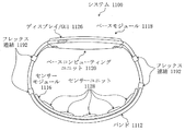
図11のシステム1100は、ウェアラブルセンサープラットフォーム10、図8〜10のシステム800、900、1000と類似である。
したがって、システム1100は類似の図面符号を有する類似の構成要素を含む。
図11で、バンド1112は、本実施形態で分割又はモジュールリンク配置(segmented or modular link arrangement)に構成することができる。
バンド1112のリンクは、フレックス連結(flex connection)1192によって連結される。
フレックス連結1192は多様な形態を有することができる。
1つの具現として、フレックス連結1192は、バンド1112のリンクに付着される別個の弾性ユニットである。
The system 1100 of FIG. 11 is similar to the wearable sensor platform 10, and the systems 800, 900, 1000 of FIGS.
Thus, system 1100 includes similar components with similar reference numerals.
In FIG. 11, bands 1112 may be configured in a segmented or modular link arrangement in this embodiment.
The links of band 1112 are connected by flex connection 1192.
The flex connection 1192 can have various forms.
In one implementation, the flex connection 1192 is a separate elastic unit attached to the links of the band 1112.
身体部位の大きさは、増加(又は減少)することによって、センサーモジュール1116が使用期間にわたって生理学的測定及び使用者の便宜に適切なその最適又は最適に近い位置を維持し、一方でディスプレイ1126は人体計測サイズの大きい範囲に掛けて身体部位に関するその位置を維持するように、このような弾性ユニット(フレックス連結1192)は、センサーモジュール1116がディスプレイ1126に対して位置が指定されるようにする。 By increasing (or decreasing) the size of the body part, the sensor module 1116 maintains its optimal or near-optimum position suitable for physiological measurements and user convenience over the period of use, while the display 1126 Such an elastic unit (flex coupling 1192) allows the sensor module 1116 to be positionally specified relative to the display 1126 so as to span over a large range of anthropometric sizes and maintain its position relative to the body part.
一実施形態では、各フレキシブル連結1192は、バンド1112の各リンクの内及び外へ滑って入るか、或いは出てくる。
他の実施形態では、バンド1112のリンクが、結果的に、そのようなリンク(例えば、時計リンク)を連結する多様なメカニズムによって連結することができる場合、フレックス連結1192はバンド1112のリンクに統合することができる。
リンクを使用する実施形態で、例えば、身体部位に対するシステム1100の大きさ調節は、使用者によるリンクの除去又は追加によってさらに改良することができる。
追加的に、センサーモジュール1116とベースモジュール1118との間の無線通信を含む実施形態で、モジュールの間に配線は必要としなく、又はセンサーモジュール1116とベースモジュール1118との間で電源専用配線が使用することができる。
他の実施形態で、電源及びデータ伝送のための配線配置は、センサーモジュール1116及びベースモジュール1118の間で使用することができる。
In one embodiment, each flexible connection 1192 slides in and out of each link of the band 1112.
In another embodiment, the flex connection 1192 integrates into the link of the band 1112 if the links of the band 1112 can consequently be connected by various mechanisms connecting such links (e.g. watch links). can do.
In embodiments that use links, for example, sizing of system 1100 relative to a body part may be further improved by the removal or addition of links by the user.
Additionally, in embodiments that include wireless communication between the sensor module 1116 and the base module 1118, no wiring is required between the modules, or power supply dedicated wiring is used between the sensor module 1116 and the base module 1118 can do.
In other embodiments, wiring arrangements for power and data transmission may be used between the sensor module 1116 and the base module 1118.
図12のシステム1200は、ウェアラブルセンサープラットフォーム10、図8〜11のシステム800、900、1000、1100と類似である。
したがって、システム1200は類似の図面符号を有する類似の構成要素を含む。
図12で、ベースモジュール1218及びセンサーモジュール1216は身体部位に自己接着(self−adhering)する。
一部の実施形態で、図12に示した部分的なバンド1212は、身体部位に向上された接着表面積をさらに増加させるためにベースモジュール1218又はセンサーモジュール1216に使用することができる。
他の実施形態で、バンド1212は使用されない。
The system 1200 of FIG. 12 is similar to the wearable sensor platform 10, systems 800, 900, 1000, 1100 of FIGS.
Thus, system 1200 includes similar components with similar reference numerals.
In FIG. 12, base module 1218 and sensor module 1216 are self-adhering to the body part.
In some embodiments, the partial bands 1212 shown in FIG. 12 can be used with the base module 1218 or the sensor module 1216 to further increase the enhanced adhesion surface area to the body site.
In other embodiments, band 1212 is not used.
ウェアラブルセンサープラットフォーム10及びシステム800〜1200の一部の実施形態で、ディスプレイ1226はセンサーモジュール1216から使用者に向けて、又は、使用者から離れる方向に向けられることは理解されなければならない。
例えば、センサーモジュール1216は、使用者の額に適用することができ、例えば、眼鏡(図示せず)に対する眼鏡形状(glasses for eyewear)又はヘルメットフェイスシールド(helmet face shield)(図示せず)で、ディスプレイは使用者の方向に向けることができる。
他の実施形態で、センサーモジュール1216は、額(又は他の身体部位)の皮膚にセンサーモジュール1216を接着する皮膚に似たタトゥで構成することができ、一方、ディスプレイ1226は、手首(又は他の身体部位)の皮膚に適用された薄い、フレキシブルスクリーンであり、センサーモジュール1216及びディスプレイ1226の全ての電源を含むことができる。
It should be understood that in some embodiments of the wearable sensor platform 10 and systems 800-1200, the display 1226 may be directed from the sensor module 1216 to the user or away from the user.
For example, the sensor module 1216 can be applied to the user's forehead, for example with glasses for eyewear or helmet face shield (not shown) for glasses (not shown). The display can be oriented towards the user.
In other embodiments, the sensor module 1216 can be configured with a skin-like tattoo that adheres the sensor module 1216 to the skin of the forehead (or other body part), while the display 1226 can be a wrist (or other) A thin, flexible screen applied to the skin of the body part of the body) and can include all power sources of the sensor module 1216 and the display 1226.
図13及び図14は、図1の実施に使用する実施形態を示し、図13及び図14の全ての類似の図面符号を有する類似の構成要素を含む。
図13及び図14の実施形態は、ウェアラブルセンサープラットフォーム10の他の実施形態で使用することができる。
本実施形態は、ECGクラスプ1334を含んで、又は含まないで、使用することができる。
図13で、センサーモジュール1316は微細調整可能に配置される。
本実施形態の微細調整可能なセンサーモジュール1316は、バンド1312でトラック(track)に配置される。
13 and 14 show an embodiment for use in the implementation of FIG. 1 and include similar components with all similar reference numerals in FIGS. 13 and 14.
The embodiments of FIGS. 13 and 14 can be used in other embodiments of the wearable sensor platform 10.
This embodiment can be used with or without the
In FIG. 13, the sensor module 1316 is finely adjustable.
The finely adjustable sensor module 1316 of the present embodiment is arranged in a track at a band 1312.
バンド1312は、センサーモジュールフレキシブルリード(sensor module flex lead)1394を通じてバンド1312のトラック(track)に沿って、手動又は自動で、調整可能である。
本実施形態で、センサーモジュールフレキシブルリード1394は、トラックに沿って調整できるアコーディオン状(accordion−like)リードとして図に示す。
図13は、第1位置でセンサーモジュール1316を示し、一方、図14は図13の第1位置に対して第2位置でセンサーモジュール1416を示す。
センサーモジュール1316の多様な他の位置は、特定の使用者に対するセンサーモジュールの位置設定を収容するトラック内で可能である。
The band 1312 can be manually or automatically adjusted along the track of the band 1312 through a sensor module flex lead 1394.
In the present embodiment, the sensor module flexible leads 1394 are illustrated as accordion-like leads that can be adjusted along the track.
FIG. 13 shows sensor module 1316 in a first position, while FIG. 14 shows sensor module 1416 in a second position relative to the first position of FIG.
Various other locations of the sensor module 1316 are possible in the truck that accommodates the positioning of the sensor module with respect to a particular user.
追加的に、微細調整可能なセンサーモジュール1316の他の実施形態も考慮されることは理解されなければならない。
例えば、図15及び図16に示すように、図13のフレキシブルリード1394を使用すること、又は微細調整可能なセンサーモジュール1316に対する他の構成の代わりに又は追加に、1つ以上のセンサーユニット1528が同一又は反対の回転方向に、手動又は自動で、回転可能することができる。
センサーユニット1528は、アプリケーションによって互いに同期又は非同期することができる。
センサーユニット1528の回転は、他のセンサーユニット1528と結合して個別的に生じるか、又は図16に示すように、センサーモジュール1516がバンド1512のトラックに沿って移動し、センサーユニット1628が回転するように生じる。
このような回転は、身体部位にしたがって改善された快適さ又は改善された生理学的測定のためにセンサーユニット1628の精密な位置設定を容易にすることができる。
Additionally, it should be understood that other embodiments of the finely adjustable sensor module 1316 are also contemplated.
For example, as shown in FIGS. 15 and 16, one or more sensor units 1528 may be used instead of or in addition to using the flexible leads 1394 of FIG. 13 or other configurations for the finely adjustable sensor module 1316. It can be rotatable manually or automatically in the same or opposite rotational direction.
Sensor units 1528 may be synchronized or asynchronously with one another depending on the application.
The rotation of the sensor unit 1528 occurs separately in combination with the other sensor units 1528 or, as shown in FIG. 16, the
Such rotation may facilitate precise positioning of the sensor unit 1628 for improved comfort or improved physiological measurements according to the body part.
図17及び図18は図1の実施に使用する実施形態を示し、図17及び図18は全て類似の図面符号を有する類似の構成要素を含む。
図17及び図18の実施は、ウェアラブルセンサープラットフォーム10の他の実施形態で使用することができる。
図17で、微細調整可能なセンサーモジュール1716は、バンド1712のトラックに、又はトラックの上に、位置したセンサースライド(sensor slide)上に配置される。
センサーモジュール16(図示せず)は、センサースライド1796を通じてバンド1712に、又はバンド1712の上に、調整可能に配置される。
本実施形態で、センサースライド1796は、センサーモジュール16(図示せず)の位置を所望通りに修正するために、手動又は自動で調整される。
図17は第1位置でのセンサースライド1796を示し、一方、図18は図17の第1位置に対して第2位置でのセンサースライド1796を示す。
センサースライド1796の多様な他の位置は、特定の使用者の必要に対するセンサーモジュールの位置設定を収容するトラック内で可能である。
17 and 18 show an embodiment used in the implementation of FIG. 1, and FIGS. 17 and 18 all include similar components with similar reference numerals.
The implementations of FIGS. 17 and 18 can be used in other embodiments of the wearable sensor platform 10.
In FIG. 17, the fine adjustable sensor module 1716 is placed on the sensor slide located on the track of the band 1712 or on the track.
The sensor module 16 (not shown) is adjustably disposed on the band 1712 or on the band 1712 through the
In this embodiment, the
FIG. 17
Various other positions of the
追加的に、微細調整可能なセンサーモジュール1316の他の実施形態も考慮されることは理解されなければならない。
例えば、図13のフレキシブルリード1394を使用することの代わりに、又は追加に、1つ以上のセンサーユニット1328を回転可能することができる。
センサーユニット1328の回転は、他のセンサーユニット1328と結合して個別的に生じるか、又はセンサーモジュールが図13のバンド1312のトラックをしたがって移動するように生じさせることができる。
このような回転は、身体部位にしたがって改善された快適さ又は改善された生理学的測定のためにセンサーユニット1328の精密な位置設定を容易にすることができる。
明確に、微細調整可能なセンサーモジュール16に対する多様な実施形態は使用者及びアプリケーションによって単独又は一緒に使用することができる。
Additionally, it should be understood that other embodiments of the finely adjustable sensor module 1316 are also contemplated.
For example, one or more sensor units 1328 can be rotatable instead of or in addition to using the flexible leads 1394 of FIG.
The rotation of the sensor unit 1328 may occur separately in combination with the other sensor units 1328 or cause the sensor module to move accordingly the track of the band 1312 of FIG.
Such rotation may facilitate precise positioning of the sensor unit 1328 for improved comfort or improved physiological measurements according to the body part.
Clearly, various embodiments for the finely
図に示した実施形態によって本発明が説明され、実施形態は変形することができ、いずれの変形も本発明の思想及び範囲に含まれる。
例えば、例示的な実施形態は、ハードウェア、ソフトウェア、プログラム指示を含むコンピュータ読出し可能媒体、又はそれらの組み合わせを使用して具現することができる。
本発明にしたがって書込みされたソフトウェアは、メモリ、ハードディスク、又はCD/DVD−ROMのようなコンピュータで読出し可能である媒体の形態に格納されることができ、プロセッサによって実行されることができる。
The invention is illustrated by the embodiments shown in the figures, which can be modified and any variant is included within the spirit and scope of the invention.
For example, the exemplary embodiments can be implemented using hardware, software, computer readable media including program instructions, or a combination thereof.
Software written according to the invention may be stored in the form of a memory, a hard disk, or a computer readable medium such as a CD / DVD-ROM and may be executed by a processor.
本発明を特定な実施形態を参照して説明したが、技術分野で通常の知識を有する者であれば、本発明の範囲を逸脱しなく、多様な変形及び均等な他の実施形態が可能である点を理解されるべきである。
また、本発明の範囲を逸脱しなく、特定の状況又は材料を本発明の教示に適合するようにする多くの変形が行うことができる。
したがって、本発明は開示した特定の実施形態によって限定されなく、本発明は添付された特許請求の範囲内のすべての実施形態を含む。
その上に、図面に示した論理の流れは、所望する結果を達成するために示した特定の順序、又は順次的な順序を要求しない。
その上に、他の段階を提供するか、又は開示した流れから段階を除去することができ、そして他の構成要素が開示したシステムに追加するか、又は開示したシステムで除去することができる。
したがって、他の実施形態は本発明の請求項の範囲内にある。
Although the invention has been described with reference to particular embodiments, one of ordinary skill in the art will appreciate that various modifications and equivalent alternative embodiments are possible without departing from the scope of the invention. It should be understood that there is a point.
Also, many modifications may be made to adapt a particular situation or material to the teachings of the present invention without departing from the scope of the present invention.
Thus, the present invention is not limited by the specific embodiments disclosed, but the present invention includes all embodiments within the scope of the appended claims.
Moreover, the logic flow shown in the drawings does not require the particular order shown, or sequential order, to achieve the desired results.
Additionally, other steps may be provided or steps may be removed from the disclosed flow, and other components may be added to the disclosed system or removed in the disclosed system.
Accordingly, other embodiments are within the scope of the claims of the present invention.
10 (モジュール型)ウェアラブルセンサー(モジュール)(プラットフォーム)
12 バンド
14 手首
16 センサーモジュール
18 ベースモジュール
20 ベースコンピューティングユニット
22 電源(バッテリー)
26 ディスプレイ(/GUI)
28 センサーユニット
30 センサープレート
32 センサーコンピューティングユニット
34 クラスプ
36 プロセッサ
38 メモリ
40 I/O
42 通信インターフェイス
44 センサー
46 加速度計(/ジャイロスコープ)
48 温度計
54 光センサーアレイ
55 個別光センサー
56 ガルバニック皮膚反応センサー(GSR)アレイ
58 生体抵抗センサーアレイ
60 心電図センサー(ECG)
62 光検出器
64 (マッチング)光源
88 電源管理ユニット
90 オペレーティングシステム(OS)
10 (module type) wearable sensor (module) (platform)
12
26 Display (/ GUI)
28
42 communication interface 44
48 thermometer 54
62 light detector 64 (matching) light source 88 power management unit 90 operating system (OS)
Claims (16)
ディスプレイとベースコンピューティングユニットとを含むベースモジュールと、
前記ベースモジュールに対して空間的に配置され、1つ以上の生理学的特性を測定するために前記身体部位の一部分上を覆って配置されるセンサーモジュールと、を有し、
前記ベースモジュールは、前記身体部位の人体計測サイズに関係なく、生理学的データの正確な測定のための前記身体部位と充分な接触をするために、前記センサーモジュールが前記身体部位上で位置を維持するように、前記センサーモジュールに対して前記使用者によって調整可能に配置され、
前記センサーモジュールは、相対的な重力を測定する重力センサーをさらに含み、
前記センサーモジュールは、前記測定された相対的な重力に基づいて前記測定を較正(calibrate)するよう構成され、
前記測定された重力に基づいて前記生理学的特性を測定するのに使用される継続時間を調整するタイマーをさらに有し、
前記センサーモジュールは、前記調整された時間に基づいて前記測定を較正するよう構成されることを特徴とするウェアラブルシステム。 A wearable system for measuring physiological data from a device worn on a body part of a user, comprising:
A base module comprising a display and a base computing unit;
A sensor module spatially disposed relative to the base module and disposed over a portion of the body part to measure one or more physiological characteristics;
The base module maintains the position on the body part in order to make sufficient contact with the body part for accurate measurement of physiological data regardless of the anthropometric size of the body part To be adjustable by the user with respect to the sensor module ,
The sensor module further includes a gravity sensor that measures relative gravity.
The sensor module is configured to calibrate the measurement based on the measured relative gravity.
It further comprises a timer for adjusting the duration used to measure the physiological characteristic based on the measured gravity,
The wearable system , wherein the sensor module is configured to calibrate the measurement based on the adjusted time .
他の種類のセンサーモジュールと交替可能であることを特徴とする請求項1に記載のウェアラブルシステム。 The sensor module is removable,
The wearable system according to claim 1, wherein the wearable system is replaceable with another type of sensor module.
光センサーアレイ、温度計、ガルバニック皮膚反応(GSR)センサーアレイ、生体抵抗(BioZ)センサーアレイ、及び心電図(ECG)センサーのいくつかの組み合わせを含むセンサーユニットをさらに含むことを特徴とする請求項1に記載のウェアラブルシステム。 The sensor module includes one or more of a biometric sensor, a proximity detector that detects proximity of an object, and an environmental sensor,
A sensor unit characterized in that it further comprises a sensor unit comprising a light sensor array, a thermometer, a galvanic skin response (GSR) sensor array, a bioresistance (BioZ) sensor array, and some combination of an electrocardiogram (ECG) sensor. The wearable system described in.
前記生体抵抗センサーアレイは、血管をまたがるようにバンド上に配置されることを特徴とする請求項7に記載のウェアラブルシステム。 The light sensor array is disposed on a band so as to straddle a blood vessel.
The wearable system according to claim 7, wherein the bioresistance sensor array is disposed on a band so as to straddle a blood vessel.
前記センサーモジュールは、前記調節された発光に基づいて前記測定を較正するよう構成されることを特徴とする請求項1に記載のウェアラブルシステム。 It further comprises a light calibrator that adjusts the light emission based on the measured gravity.
The wearable system of claim 1 , wherein the sensor module is configured to calibrate the measurement based on the adjusted light emission.
前記微細調整可能なセンサーモジュールを、前記ベースモジュールに対して空間的に調整可能に配置し、1つ以上の生理学的特性を測定するために第1位置で前記身体部位の一部分上を覆って配置する段階と、
前記身体部位の人体計測サイズと関わらず、生理学的データの正確な測定のための第2位置で前記身体部位と充分な接触をするために、前記第1位置と相対的な(relative)前記身体部位の前記第2位置に前記微細調整可能なセンサーモジュールを、前記第1位置からに前記第2位置に調整可能であるように再配置する段階と、を有し、
相対な重力を測定する段階と、
前記測定された相対な重力に基づいて前記生理学的データを較正する段階と、
前記測定された重力に基づいて前記生理学的データを測定するのに使用される継続時間を調整する段階と、
前記調整された時間に基づいて前記生理学的データを較正する段階と、
前記測定された重力に基づいて発光を調節する段階と、
前記調節された発光に基づいて前記生理学的データを較正する段階と、をさらに有することを特徴とするウェアラブル装置から生理学的データを測定するための方法。 Is worn on a body part of a user, a method for measuring the physiological data from a wearable device including a base module, a fine adjustable sensor modules, the including a display and a base computing unit,
The finely adjustable sensor module is spatially adjustably disposed relative to the base module and disposed over a portion of the body site at a first position to measure one or more physiological characteristics. Stage to
Regardless of the anthropometric size of the body part, the body relative to the first position to provide sufficient contact with the body part at a second position for accurate measurement of physiological data. the fine adjustable sensor module in the second position of the site, have a, a step of re-arranged to be adjusted to the second position from the first position,
Measuring relative gravity,
Calibrating the physiological data based on the measured relative gravity;
Adjusting the duration used to measure the physiological data based on the measured gravity;
Calibrating the physiological data based on the adjusted time;
Adjusting light emission based on the measured gravity;
And D. calibrating the physiological data based on the modulated luminescence . A method for measuring physiological data from a wearable device , further comprising:
生理学的データの正確な測定のための前記身体部位との接触を改善するために前記複数のセンサーユニットを互いに相対的(relative)に再配置させる段階をさらに有することを特徴とする請求項15に記載のウェアラブル装置から生理学的データを測定するための方法。
The finely adjustable sensor module is used in alternation to provide sufficient contact with the body part for accurate measurement of physiological data regardless of the anthropometric size of the body part ) Including multiple sensor units
The method according to claim 15 , further comprising repositioning the plurality of sensor units relative to one another to improve contact with the body part for accurate measurement of physiological data. Method for measuring physiological data from the described wearable device.
Applications Claiming Priority (5)
| Application Number | Priority Date | Filing Date | Title |
|---|---|---|---|
| US201462002589P | 2014-05-23 | 2014-05-23 | |
| US62/002,589 | 2014-05-23 | ||
| US201462061290P | 2014-10-08 | 2014-10-08 | |
| US62/061,290 | 2014-10-08 | ||
| PCT/IB2015/001559 WO2015177649A2 (en) | 2014-05-23 | 2015-05-21 | Adjustable wearable system having a modular sensor platform |
Publications (3)
| Publication Number | Publication Date |
|---|---|
| JP2017516539A JP2017516539A (en) | 2017-06-22 |
| JP2017516539A5 JP2017516539A5 (en) | 2018-07-05 |
| JP6513708B2 true JP6513708B2 (en) | 2019-05-15 |
Family
ID=54554910
Family Applications (1)
| Application Number | Title | Priority Date | Filing Date |
|---|---|---|---|
| JP2016568043A Expired - Fee Related JP6513708B2 (en) | 2014-05-23 | 2015-05-21 | Adjustable wearable system with modular sensor platform |
Country Status (7)
| Country | Link |
|---|---|
| US (1) | US9592007B2 (en) |
| JP (1) | JP6513708B2 (en) |
| KR (1) | KR20170008216A (en) |
| CN (1) | CN106102565A (en) |
| DE (1) | DE112015002436T5 (en) |
| TW (1) | TWI660710B (en) |
| WO (1) | WO2015177649A2 (en) |
Families Citing this family (84)
| Publication number | Priority date | Publication date | Assignee | Title |
|---|---|---|---|---|
| EP2575600B1 (en) | 2010-06-07 | 2019-04-24 | The Medical College Of Wisconsin, Inc. | Detection and treatment of abnormal upper esophageal sphincter functionality |
| AU2012356129B2 (en) * | 2011-12-20 | 2016-04-07 | Geosatis Sa | Electronic monitoring bracelet |
| GB201317746D0 (en) | 2013-10-08 | 2013-11-20 | Smith & Nephew | PH indicator |
| GB2516259A (en) * | 2013-07-16 | 2015-01-21 | Nokia Corp | An apparatus, method and computer program for detecting physiological parameters |
| US10136857B2 (en) * | 2014-05-23 | 2018-11-27 | Samsung Electronics Co., Ltd. | Adjustable wearable system having a modular sensor platform |
| US10488936B2 (en) | 2014-09-30 | 2019-11-26 | Apple Inc. | Motion and gesture input from a wearable device |
| US10342485B2 (en) * | 2014-10-01 | 2019-07-09 | Covidien Lp | Removable base for wearable medical monitor |
| US10449415B2 (en) * | 2014-12-01 | 2019-10-22 | Polar Electro Oy | Wrist-worn physical activity measurement apparatus |
| US9332940B1 (en) | 2015-01-05 | 2016-05-10 | Analog Devices, Inc. | Compact wearable biological sensor modules |
| EP3067678B1 (en) * | 2015-03-12 | 2019-10-09 | STBL Medical Research AG | Method for producing a strain gauge device |
| USD862277S1 (en) | 2015-03-16 | 2019-10-08 | Fitbit, Inc. | Set of bands for a fitness tracker |
| US9871373B2 (en) | 2015-03-27 | 2018-01-16 | Analog Devices Global | Electrical overstress recording and/or harvesting |
| US10557881B2 (en) | 2015-03-27 | 2020-02-11 | Analog Devices Global | Electrical overstress reporting |
| US9939899B2 (en) | 2015-09-25 | 2018-04-10 | Apple Inc. | Motion and gesture input from a wearable device |
| US9984540B2 (en) * | 2015-12-17 | 2018-05-29 | Harman International Industries, Incorporated | Fan-driven force device |
| US20190336020A1 (en) * | 2016-02-25 | 2019-11-07 | Vladimir Kranz | Equipment for monitoring health conditions of monitored persons |
| EP3422944A4 (en) | 2016-03-03 | 2019-08-14 | Dynometrics Inc. D/B/A Humon | Tissue oxygen saturation detection and related apparatus and methods |
| US9609921B1 (en) | 2016-03-04 | 2017-04-04 | Feinstein Patents, Llc | Self-fitting, self-adjusting, automatically adjusting and/or automatically fitting magnetic clasp |
| US11141105B2 (en) * | 2016-03-11 | 2021-10-12 | Respiratory Technology Corporation | Long-term therapeutic pressure applicator and real-time monitoring system |
| JP2019527566A (en) | 2016-05-13 | 2019-10-03 | スミス アンド ネフュー ピーエルシーSmith & Nephew Public Limited Company | Wound monitoring and treatment device using sensor |
| CN107426483A (en) * | 2016-05-24 | 2017-12-01 | 鸿富锦精密工业(深圳)有限公司 | Wearable biological information of human body detection means, system and detection method |
| WO2017208168A2 (en) * | 2016-05-31 | 2017-12-07 | Lab Schöpfergeist Ag | Strap arrangement for a nerve stimulator |
| US10478099B2 (en) * | 2016-09-22 | 2019-11-19 | Apple Inc. | Systems and methods for determining axial orientation and location of a user's wrist |
| US10120455B2 (en) | 2016-12-28 | 2018-11-06 | Industrial Technology Research Institute | Control device and control method |
| CN108283485A (en) * | 2017-01-09 | 2018-07-17 | 深圳仙苗科技有限公司 | A kind of algorithm calculating high correlation blood pressure with differentiated waveform |
| TWI624246B (en) * | 2017-01-25 | 2018-05-21 | 美盛醫電股份有限公司 | Blood pressure measurement device and method thereof |
| US11395628B2 (en) * | 2017-02-16 | 2022-07-26 | Samsung Electronics Co., Ltd. | Method of providing service based on biometric information and wearable electronic device |
| WO2018159191A1 (en) * | 2017-03-02 | 2018-09-07 | アルプス電気株式会社 | Biological information acquisition device and band for mounting biological sensor |
| EP3594893A1 (en) * | 2017-03-06 | 2020-01-15 | Sony Corporation | Information processing device, information processing method, and program |
| EP3592212A1 (en) | 2017-03-09 | 2020-01-15 | Smith & Nephew PLC | Wound dressing, patch member and method of sensing one or more wound parameters |
| EP3592230A1 (en) | 2017-03-09 | 2020-01-15 | Smith & Nephew PLC | Apparatus and method for imaging blood in a target region of tissue |
| EP3609449A1 (en) | 2017-04-11 | 2020-02-19 | Smith & Nephew PLC | Component positioning and stress relief for sensor enabled wound dressings |
| JP7272962B2 (en) | 2017-05-15 | 2023-05-12 | スミス アンド ネフュー ピーエルシー | wound analyzer |
| US20180356888A1 (en) * | 2017-06-13 | 2018-12-13 | Immersion Corporation | Generating haptic effect for a wearable electronic device based on tightness level |
| US11633153B2 (en) | 2017-06-23 | 2023-04-25 | Smith & Nephew Plc | Positioning of sensors for sensor enabled wound monitoring or therapy |
| US11317814B2 (en) * | 2017-06-27 | 2022-05-03 | Beijing Shunyuan Kaihua Technology Limited | Systems and methods for collecting physiological information of a user |
| GB201804502D0 (en) | 2018-03-21 | 2018-05-02 | Smith & Nephew | Biocompatible encapsulation and component stress relief for sensor enabled negative pressure wound therapy dressings |
| GB201809007D0 (en) | 2018-06-01 | 2018-07-18 | Smith & Nephew | Restriction of sensor-monitored region for sensor-enabled wound dressings |
| US11331019B2 (en) | 2017-08-07 | 2022-05-17 | The Research Foundation For The State University Of New York | Nanoparticle sensor having a nanofibrous membrane scaffold |
| CN107529129A (en) * | 2017-08-09 | 2017-12-29 | 浙江工业大学 | The athletic training monitoring system of multi-path RFDC processing based on ARM |
| JP2019030595A (en) * | 2017-08-09 | 2019-02-28 | オムロンヘルスケア株式会社 | Measurement device, transmission method and program |
| CN107506578A (en) * | 2017-08-09 | 2017-12-22 | 浙江工业大学 | The medical treatment & health clinical monitoring system of multi-path RFDC processing based on ARM |
| JP7086541B2 (en) | 2017-08-09 | 2022-06-20 | オムロンヘルスケア株式会社 | Data receiver, data transmitter and data transmission system |
| WO2019030384A2 (en) | 2017-08-10 | 2019-02-14 | Smith & Nephew Plc | Positioning of sensors for sensor enabled wound monitoring or therapy |
| GB201718870D0 (en) | 2017-11-15 | 2017-12-27 | Smith & Nephew Inc | Sensor enabled wound therapy dressings and systems |
| GB201804971D0 (en) | 2018-03-28 | 2018-05-09 | Smith & Nephew | Electrostatic discharge protection for sensors in wound therapy |
| EP3681376A1 (en) | 2017-09-10 | 2020-07-22 | Smith & Nephew PLC | Systems and methods for inspection of encapsulation and components in sensor equipped wound dressings |
| US10746614B2 (en) | 2017-09-18 | 2020-08-18 | Korea University Research And Business Foundation, Sejong Campus | Stretchable multimodal sensor and method of fabricating of the same |
| GB201718859D0 (en) | 2017-11-15 | 2017-12-27 | Smith & Nephew | Sensor positioning for sensor enabled wound therapy dressings and systems |
| WO2019063481A1 (en) | 2017-09-27 | 2019-04-04 | Smith & Nephew Plc | Ph sensing for sensor enabled negative pressure wound monitoring and therapy apparatuses |
| US11839464B2 (en) | 2017-09-28 | 2023-12-12 | Smith & Nephew, Plc | Neurostimulation and monitoring using sensor enabled wound monitoring and therapy apparatus |
| CN111343950A (en) | 2017-11-15 | 2020-06-26 | 史密夫及内修公开有限公司 | Integrated wound monitoring and/or therapy dressing and system implementing sensors |
| US11389063B2 (en) * | 2017-11-20 | 2022-07-19 | Welch Allyn, Inc. | Modular vital signs monitor |
| CN107808493A (en) * | 2017-11-24 | 2018-03-16 | 四川大学 | A kind of calling wrister in imminent danger based on BDS |
| KR102081327B1 (en) * | 2018-02-14 | 2020-02-25 | 주식회사 아이센스 | Continuous Glucose Monitoring apparatus comprising sensor usage information |
| KR20200144550A (en) * | 2018-03-20 | 2020-12-29 | 그래프웨어 테크놀로지스 인크. | Replaceable sensor systems and methods |
| EP3787508A4 (en) * | 2018-05-01 | 2022-01-26 | Whoop, Inc. | Pressure sensitive strap for wearable electronics |
| CN108937930B (en) * | 2018-05-30 | 2022-09-13 | 歌尔科技有限公司 | Auxiliary device for measuring biological impedance and biological impedance measuring system with same |
| USD902203S1 (en) | 2018-07-13 | 2020-11-17 | Fitbit, Inc. | Smart watch with curved body |
| KR102574087B1 (en) * | 2018-07-27 | 2023-09-04 | 삼성전자주식회사 | Optical sensor, Optical sensor array, Biological signal measurement apparatus and method |
| CN109009966A (en) * | 2018-08-03 | 2018-12-18 | 深圳市生物钟健康咨询有限责任公司 | Intelligent neck ring with microcirculation physical therapy function |
| CN109407827A (en) * | 2018-08-31 | 2019-03-01 | 联想(北京)有限公司 | Wearable device and adjusting method |
| US11944418B2 (en) | 2018-09-12 | 2024-04-02 | Smith & Nephew Plc | Device, apparatus and method of determining skin perfusion pressure |
| KR102173308B1 (en) * | 2018-10-15 | 2020-11-03 | 나유미 | Wearable device for emergency measures assistance |
| KR102182737B1 (en) * | 2018-11-15 | 2020-11-24 | 대한민국 | Remote biotelemetric apparatus and biotelemetry analyzing system for livestock |
| CN109669340B (en) * | 2019-02-12 | 2023-09-26 | 浙江吉利控股集团有限公司 | Intelligent watch |
| EP3948169A4 (en) * | 2019-04-03 | 2022-12-28 | Pouria Ghods | Embedded sensor devices and methods |
| JP2022534604A (en) * | 2019-05-29 | 2022-08-02 | ウェア2ビー リミテッド | ADJUSTABLE NON-INVASIVE WEARABLE MONITOR |
| KR102308547B1 (en) * | 2019-06-10 | 2021-10-06 | (주)참케어 | Portable blood pressure measuring device |
| KR20210016715A (en) * | 2019-08-05 | 2021-02-17 | 삼성전자주식회사 | Apparatus and method for measuring bio-information |
| JP7043688B1 (en) * | 2019-08-07 | 2022-03-29 | 蘇州康孚智能科技有限公司 | Wearable flexible sensor device |
| TWI772689B (en) * | 2019-10-09 | 2022-08-01 | 鉅怡智慧股份有限公司 | Non-contact physiological signal measuring device |
| CN110833409A (en) * | 2019-12-24 | 2020-02-25 | 苏州海思健康科技有限公司 | Anti-skid muscle activity assessment device and assessment method |
| CN113412081A (en) * | 2019-12-31 | 2021-09-17 | 南京瀚宇彩欣科技有限责任公司 | Wearable device with function of measuring physiological signals |
| WO2022050457A1 (en) * | 2020-09-04 | 2022-03-10 | 주식회사 클리엔 | Head-adaptive near-infrared spectrometer |
| CN214712540U (en) * | 2020-12-03 | 2021-11-16 | Oppo广东移动通信有限公司 | Blood pressure detection module, bandage subassembly and wearable equipment |
| CN113069092A (en) * | 2021-03-18 | 2021-07-06 | 安徽中屏科技有限公司 | Health monitoring device and control system based on wrist-watch is dressed to intelligence |
| KR20220133010A (en) * | 2021-03-24 | 2022-10-04 | 삼성전자주식회사 | Wearable device for measuring biometric signals |
| WO2022246310A2 (en) * | 2021-05-21 | 2022-11-24 | The Texas A&M University System | Technologies for multimodal sensor wearable device for biomedical monitoring |
| CN113485085B (en) * | 2021-05-25 | 2022-06-17 | 深圳盈科达科技有限公司 | Intelligent watch with movement track recording and body blood oxygen content detection functions |
| CN113331814A (en) * | 2021-05-27 | 2021-09-03 | 广东新一代工业互联网创新技术有限公司 | Multi-functional intelligent health monitoring equipment of distributing type convertible multiple wearing mode |
| CN113425262B (en) * | 2021-06-26 | 2023-12-19 | 沈阳天仁合一科技有限公司 | Treatment head assembly for sleep monitoring treatment instrument |
| WO2023167373A1 (en) * | 2022-03-03 | 2023-09-07 | 젠트리 주식회사 | Wearable sensing apparatus with easily replaceable sensor and diagnostic apparatus using same |
| WO2023183208A1 (en) * | 2022-03-20 | 2023-09-28 | The Regents Of The University Of California | Programmable multi-wavelength rf spectrometry networks |
Family Cites Families (39)
| Publication number | Priority date | Publication date | Assignee | Title |
|---|---|---|---|---|
| WO1990000366A1 (en) | 1988-07-12 | 1990-01-25 | John Patrick Mccarthy | Monitoring apparatus |
| JP3876889B2 (en) * | 1996-06-12 | 2007-02-07 | セイコーエプソン株式会社 | Body temperature measuring device |
| US6654724B1 (en) | 1999-02-12 | 2003-11-25 | Adheris, Inc. | System for processing pharmaceutical data while maintaining patient confidentially |
| JP2001169808A (en) * | 1999-12-20 | 2001-06-26 | Seiko Instruments Inc | Arm holder of arm portable information equipment |
| US6595929B2 (en) * | 2001-03-30 | 2003-07-22 | Bodymedia, Inc. | System for monitoring health, wellness and fitness having a method and apparatus for improved measurement of heat flow |
| JP3772691B2 (en) * | 2001-05-09 | 2006-05-10 | オムロンヘルスケア株式会社 | Pulse wave detector |
| US20030107487A1 (en) * | 2001-12-10 | 2003-06-12 | Ronen Korman | Method and device for measuring physiological parameters at the wrist |
| US20040073123A1 (en) * | 2002-10-11 | 2004-04-15 | Hessel Stephen R. | Apparatus and methods for non-invasively measuring hemodynamic parameters |
| WO2005083546A1 (en) | 2004-02-27 | 2005-09-09 | Simon Richard Daniel | Wearable modular interface strap |
| JP2005324004A (en) * | 2004-04-16 | 2005-11-24 | Denso Corp | Living body state measuring instrument |
| US20080294058A1 (en) | 2004-08-16 | 2008-11-27 | Dror Shklarski | Wearable Device, System and Method for Measuring a Pulse While a User is in Motion |
| CN2754416Y (en) * | 2004-11-15 | 2006-02-01 | 天迈工业有限公司 | Fixer of watch strap |
| JP2009519737A (en) * | 2005-12-19 | 2009-05-21 | コーニンクレッカ フィリップス エレクトロニクス エヌ ヴィ | Device for monitoring a person's heart rate and / or heart rate variability and wristwatch including the same function |
| JP2007325675A (en) * | 2006-06-06 | 2007-12-20 | Sharp Corp | Annular detector and biological information measuring device |
| US8504145B2 (en) * | 2006-12-11 | 2013-08-06 | Seiko Epson Corporation | Biometric information processing device, biometric information processing method, and control program |
| US20090270743A1 (en) | 2008-04-17 | 2009-10-29 | Dugan Brian M | Systems and methods for providing authenticated biofeedback information to a mobile device and for using such information |
| US7512985B1 (en) | 2008-04-30 | 2009-03-31 | International Business Machines Corporation | System, method, and computer program product for implementing search-and retrieval-compatible data obfuscation |
| KR101068116B1 (en) * | 2008-05-23 | 2011-09-27 | (주)한별메디텍 | Apparatus and method for sensing radial arterial pulses for noninvasive and continuous measurement of blood pressure |
| US7894888B2 (en) * | 2008-09-24 | 2011-02-22 | Chang Gung University | Device and method for measuring three-lead ECG in a wristwatch |
| US20120065514A1 (en) * | 2008-12-30 | 2012-03-15 | Morteza Naghavi | Cardiohealth Methods and Apparatus |
| JP2010183970A (en) * | 2009-02-10 | 2010-08-26 | Sharp Corp | Biological information measuring device |
| US8978231B2 (en) * | 2009-04-01 | 2015-03-17 | David L. LeMieux | System for rivet fastening |
| US10102398B2 (en) | 2009-06-01 | 2018-10-16 | Ab Initio Technology Llc | Generating obfuscated data |
| EP2555676B1 (en) | 2010-02-05 | 2015-10-14 | Biovotion AG | Wearable sensor device |
| US20110245630A1 (en) | 2010-03-31 | 2011-10-06 | St Pierre Shawn C | Integrated Patient Data Management for Physiological Monitor Devices |
| US8965498B2 (en) * | 2010-04-05 | 2015-02-24 | Corventis, Inc. | Method and apparatus for personalized physiologic parameters |
| CN101953679B (en) * | 2010-05-19 | 2012-12-05 | 浙江好络维医疗技术有限公司 | Wrist infrared pulse monitoring method and monitor |
| US9298878B2 (en) | 2010-07-29 | 2016-03-29 | Oracle International Corporation | System and method for real-time transactional data obfuscation |
| KR20120033526A (en) | 2010-09-30 | 2012-04-09 | 경북대학교 산학협력단 | Detection device for biometric information and thereof system |
| WO2012048347A1 (en) | 2010-10-08 | 2012-04-12 | Brian Lee Moffat | Private data sharing system |
| CN101953549A (en) * | 2010-10-11 | 2011-01-26 | 鸿富锦精密工业(深圳)有限公司 | Watchband and electronic device with same |
| JP6224005B2 (en) * | 2012-01-19 | 2017-11-01 | ナイキ イノベイト シーブイ | Power management in activity monitoring equipment |
| KR20130111713A (en) * | 2012-04-02 | 2013-10-11 | 삼성전자주식회사 | Apparatus and method for measuring body signal |
| ES2865187T3 (en) * | 2012-04-16 | 2021-10-15 | Myoton As | Device and method for the non-invasive measurement of the state of tension, the biomechanical and viscoelastic properties of soft biological tissue surfaces |
| EP2653984A1 (en) | 2012-04-18 | 2013-10-23 | Software AG | Method and system for anonymizing data during export |
| TWM444568U (en) | 2012-06-05 | 2013-01-01 | Rfid Guider Technology Co Ltd | Wearable care device |
| CN103505193B (en) * | 2012-06-19 | 2015-06-10 | 北京超思电子技术股份有限公司 | Wrist strap type physiological information monitoring device |
| US9049998B2 (en) * | 2012-06-22 | 2015-06-09 | Fitbit, Inc. | Biometric monitoring device with heart rate measurement activated by a single user-gesture |
| CN103536283B (en) * | 2012-07-17 | 2018-05-01 | 北京超思电子技术有限责任公司 | A kind of wrist strap type physiological information monitoring device |
-
2015
- 2015-05-21 KR KR1020167031255A patent/KR20170008216A/en not_active Application Discontinuation
- 2015-05-21 US US14/719,043 patent/US9592007B2/en active Active
- 2015-05-21 CN CN201580012723.6A patent/CN106102565A/en active Pending
- 2015-05-21 JP JP2016568043A patent/JP6513708B2/en not_active Expired - Fee Related
- 2015-05-21 WO PCT/IB2015/001559 patent/WO2015177649A2/en active Application Filing
- 2015-05-21 DE DE112015002436.0T patent/DE112015002436T5/en not_active Withdrawn
- 2015-05-22 TW TW104116497A patent/TWI660710B/en not_active IP Right Cessation
Also Published As
| Publication number | Publication date |
|---|---|
| US9592007B2 (en) | 2017-03-14 |
| TW201545714A (en) | 2015-12-16 |
| WO2015177649A2 (en) | 2015-11-26 |
| KR20170008216A (en) | 2017-01-23 |
| US20150335284A1 (en) | 2015-11-26 |
| DE112015002436T5 (en) | 2017-04-06 |
| TWI660710B (en) | 2019-06-01 |
| JP2017516539A (en) | 2017-06-22 |
| WO2015177649A3 (en) | 2016-03-10 |
| CN106102565A (en) | 2016-11-09 |
Similar Documents
| Publication | Publication Date | Title |
|---|---|---|
| JP6513708B2 (en) | Adjustable wearable system with modular sensor platform | |
| US10136857B2 (en) | Adjustable wearable system having a modular sensor platform | |
| TWI660709B (en) | Modular sensor platform | |
| US20190261888A1 (en) | Re-wearable wireless device | |
| US20170135633A1 (en) | Integrated System for Managing Cardiac Rhythm Including Wearable and Implanted Devices | |
| US9844340B2 (en) | Electrocardiogram watch clasp | |
| US20170296070A1 (en) | Wearable Wireless Multisensor Health Monitor with Head Photoplethysmograph | |
| US20230031613A1 (en) | Wearable device | |
| US20170273574A1 (en) | Wearable physiological measuring device | |
| JP2018507080A (en) | System and method for vital sign monitoring using earpieces | |
| TW201542161A (en) | Adjustable sensor support structure for optimizing skin contact | |
| US20220117504A1 (en) | Modular physiological monitoring system | |
| US11596353B2 (en) | Multilayer wearable device | |
| CA3191150A1 (en) | A gait moderation aiding system | |
| ES2800296T3 (en) | Vital signs measurement / monitoring device | |
| WO2016055853A1 (en) | Adjustable wearable system having a modular sensor platform | |
| WO2023225484A1 (en) | Hydration measurement using optical sensors | |
| US20240081656A1 (en) | Wearable physiological monitoring system | |
| Maclay | Wearable Devices and Remote Patient Monitoring | |
| VANGAL | Designing a wearable pulse oximeter for geriatric care |
Legal Events
| Date | Code | Title | Description |
|---|---|---|---|
| A521 | Request for written amendment filed |
Free format text: JAPANESE INTERMEDIATE CODE: A523 Effective date: 20180521 |
|
| A621 | Written request for application examination |
Free format text: JAPANESE INTERMEDIATE CODE: A621 Effective date: 20180521 |
|
| A131 | Notification of reasons for refusal |
Free format text: JAPANESE INTERMEDIATE CODE: A131 Effective date: 20181211 |
|
| A977 | Report on retrieval |
Free format text: JAPANESE INTERMEDIATE CODE: A971007 Effective date: 20181212 |
|
| A521 | Request for written amendment filed |
Free format text: JAPANESE INTERMEDIATE CODE: A523 Effective date: 20190311 |
|
| TRDD | Decision of grant or rejection written | ||
| A01 | Written decision to grant a patent or to grant a registration (utility model) |
Free format text: JAPANESE INTERMEDIATE CODE: A01 Effective date: 20190402 |
|
| A61 | First payment of annual fees (during grant procedure) |
Free format text: JAPANESE INTERMEDIATE CODE: A61 Effective date: 20190410 |
|
| R150 | Certificate of patent or registration of utility model |
Ref document number: 6513708 Country of ref document: JP Free format text: JAPANESE INTERMEDIATE CODE: R150 |
|
| LAPS | Cancellation because of no payment of annual fees |