JP6512852B2 - Information processing apparatus, information processing method - Google Patents
Information processing apparatus, information processing method Download PDFInfo
- Publication number
- JP6512852B2 JP6512852B2 JP2015024693A JP2015024693A JP6512852B2 JP 6512852 B2 JP6512852 B2 JP 6512852B2 JP 2015024693 A JP2015024693 A JP 2015024693A JP 2015024693 A JP2015024693 A JP 2015024693A JP 6512852 B2 JP6512852 B2 JP 6512852B2
- Authority
- JP
- Japan
- Prior art keywords
- small
- size
- information processing
- area
- processing apparatus
- Prior art date
- Legal status (The legal status is an assumption and is not a legal conclusion. Google has not performed a legal analysis and makes no representation as to the accuracy of the status listed.)
- Expired - Fee Related
Links
Images


Description
本発明は、距離計測技術に関するものである。 The present invention relates to distance measurement technology.
従来より、いわゆる部品のバラ積みピッキングを実現するビジョンシステムが存在している。例えば、特許文献1のように、対象物体である部品の様々な方向からの撮影データを事前に取得しておいて、入力画像と該事前に取得した撮影データとをパターンマッチングすることで対象物体の位置・姿勢を決定する方法が存在している。但し、この方法では部品のサイズに比べて探索領域のサイズが大幅に大きい場合、検出に非常に時間がかかってしまうという欠点があった。このような欠点に対応するために、例えば特許文献2のように、バラバラに山積みされた部品群の中で最も高い地点を求め、その地点を中心とした部品探索領域を設定することで、部品検出処理の高速化を実現する手法が開示されている。この高い地点を求める方法は、ロボットを用いて部品を把持するという目的からすると理にかなっている。なぜなら、高い位置にある部品を検出できればその部品は表層にある可能性が高いので、他の部品との干渉もなく、安全にピッキング出来る確率が高くなるからである。 Heretofore, there have been vision systems for realizing so-called bulk picking of parts. For example, as in Patent Document 1, shooting data from various directions of parts as a target object is acquired in advance, and the target object is subjected to pattern matching with the input image and the shooting data acquired in advance. There is a method to determine the position / posture of However, this method has a disadvantage that it takes a very long time to detect if the size of the search area is significantly larger than the size of the part. In order to cope with such a defect, for example, as in Patent Document 2, the highest point in the group of parts piled up separately is found, and the parts search area is set around the point to obtain parts. A technique is disclosed that realizes speeding up of detection processing. The method of finding this high point makes sense from the purpose of holding the part using a robot. This is because if it is possible to detect a component at a high position, the component is likely to be on the surface, so that there is a high probability of being able to pick safely without interference with other components.
しかしながら、従来技術においては以下の課題が存在した。つまり、山積み状態にある部品群までの距離を測定する際に計測ノイズが発生することによって、本来高い位置にない部分が選択されることがあった。より具体的には、従来の方法を用いて高いと推定される場所を求めても、それが実際は部品積載状態の谷の場所に位置してしまうことがあった。そして、その結果、その場所から検出された部品の把持が不可能になり、ピッキング可能な部品が検出できない、という課題があった。 However, the following problems existed in the prior art. That is, when measuring the distance to the parts group in a piled state, a part which is not originally at a high position may be selected due to the generation of measurement noise. More specifically, even if the location estimated to be high using the conventional method is found, it may actually be located at the location of the valley at the part loading state. As a result, there is a problem that gripping of a part detected from the location becomes impossible, and a pickable part can not be detected.
また、部品が少なくなってきた時、本来部品が存在するはずのない場所が距離測定ノイズによって高くなり、そこが探索領域として設定されることがあった。その結果として、求めた部品探索領域に部品が1つも検出できない、または、誤って部品ではない物体を部品として認識してしまうという課題もあった。 In addition, when the number of parts has decreased, the location where the parts should not exist is increased by the distance measurement noise, and this may be set as a search area. As a result, there is also a problem that no part can be detected in the obtained part search area, or an object that is not a part is erroneously recognized as a part.
本発明はこのような問題に鑑みてなされたものであり、山積み状態にある物体群の中から高い位置にある物体を高速かつ安定的に特定するための技術を提供する。 The present invention has been made in view of such problems, and provides a technique for identifying an object located at a high position among piled objects at high speed and stably.
本発明の一様態は、物体群に対する距離計測の結果に基づいて該物体群の存在範囲を特定する特定手段と、
前記存在範囲を前記物体のサイズに基づいて複数の小領域に区分した場合に、該複数の小領域のうち前記距離計測により得られる距離値が小さい順に一部の小領域を特定し、該一部の小領域のそれぞれについて、該小領域を含み且つ該小領域よりも大きいサイズの領域を物体の探索領域として決定する決定手段と
を備えることを特徴とする。
According to one aspect of the present invention, there is provided identification means for identifying an existence range of an object group based on a result of distance measurement on the object group.
When the existence range is divided into a plurality of small areas based on the size of the object , a part of the small areas is specified in ascending order of the distance value obtained by the distance measurement among the plurality of small areas, and And determining means for determining an area including the small area and having a size larger than the small area as the search area of the object for each small area of the part .
本発明の構成によれば、山積み状態にある物体群の中から高い位置にある物体を高速かつ安定的に特定することができる。 According to the configuration of the present invention, an object located at a high position can be identified at high speed and stably from among a group of objects in a stacked state.
以下、添付図面を参照し、本発明の好適な実施形態について説明する。なお、以下説明する実施形態は、本発明を具体的に実施した場合の一例を示すもので、特許請求の範囲に記載した構成の具体的な実施例の1つである。 Hereinafter, preferred embodiments of the present invention will be described with reference to the accompanying drawings. The embodiment described below shows an example when the present invention is specifically implemented, and is one of the specific examples of the configuration described in the claims.
[第1の実施形態]
本実施形態では、物体群に対する距離計測の結果に基づいて該物体群の存在範囲を特定し、該存在範囲を物体のサイズに基づいて複数の小領域に区分した場合に、該複数の小領域に対応する上記結果に基づいて、該複数の小領域から物体の探索領域を決定する情報処理装置の一例について説明する。
First Embodiment
In this embodiment, the existence range of the object group is specified based on the result of the distance measurement on the object group, and the existence range is divided into a plurality of small areas based on the size of the object. An example of an information processing apparatus that determines a search area of an object from the plurality of small areas will be described based on the result corresponding to.
先ず、本実施形態に係る情報処理装置のハードウェア構成例について、図2のブロック図を用いて説明する。なお、図2の構成を有する装置には、例えば、一般のPC(パーソナルコンピュータ)が適用可能であるが、以下に説明する各処理を実現可能な構成であれば、如何なる装置に適用しても構わない。例えば、図2に示す構成を、撮像装置等の装置に組み込んでも構わない。また、図2の構成を、ネットワークを介して互いにデータ通信が可能な複数の装置で構成しても構わない。 First, an example of the hardware configuration of the information processing apparatus according to the present embodiment will be described using the block diagram of FIG. For example, a general PC (personal computer) can be applied to the apparatus having the configuration of FIG. 2, but the present invention can be applied to any apparatus that can implement each process described below. I do not care. For example, the configuration shown in FIG. 2 may be incorporated into an apparatus such as an imaging apparatus. Further, the configuration of FIG. 2 may be configured by a plurality of devices capable of data communication with each other via a network.
CPU201は、RAM203に格納されているコンピュータプログラムやデータを用いて処理を実行することで、情報処理装置全体の動作制御を行うと共に、情報処理装置が行うものとして後述する各処理を実行若しくは制御する。
The
ROM202には、ブートプログラムや設定データなどが格納されている。
The
RAM203は、ROM202や2次記憶装置204からロードされたコンピュータプログラムやデータ、I/Oデバイス209から入力されたデータ、等を格納するためのエリアを有する。更に、RAM203は、CPU201が各種の処理を実行する際に用いるワークエリアを有する。このように、RAM203は、各種のエリアを適宜提供することができる。
The
2次記憶装置204は、ハードディスクドライブ装置などの大容量情報記憶装置である。2次記憶装置204には、OS(オペレーティングシステム)211や、情報処理装置が行うものとして後述する各処理をCPU201に実行させるためのコンピュータプログラムやデータが保存されている。このコンピュータプログラムには、モジュール213やアプリケーション212などが含まれる。また、このデータには、データ214が含まれている。また、2次記憶装置204には、以下の説明において既知の情報として取り扱う情報も保存されている。2次記憶装置204に保存されているコンピュータプログラムやデータは、CPU201による制御に従って適宜RAM203にロードされ、CPU201による処理対象となる。
The
ディスプレイ206は、CRTや液晶画面等により構成されており、CPU201による処理結果を画像や文字などでもって表示することができる装置である。なお、ディスプレイ206の代わりに、プロジェクタなど、CPU201による処理結果を画像や文字として投影する装置を用いても構わない。
The
キーボード207やマウス208は、情報処理装置の操作者が操作することで各種の指示をCPU201に対して入力することができる、ユーザインターフェースとして機能する装置である。
A
I/Oデバイス209は、情報処理装置に対して様々な情報を入力する機器、様々な情報を情報処理装置から外部の装置に対して出力する機器、を含むものである。本実施形態では、I/Oデバイス209は、少なくとも、距離計測範囲内の各位置までの3次元距離を計測可能な機器を含んでいる。
The I /
例えば、I/Oデバイス209が3次元距離計測を行う機器(例えば、TOFセンサ装置等の3次元入力装置)である場合には、該機器の距離計測範囲内の各位置までの3次元距離を計測することができる。
For example, if the I /
また例えば、I/Oデバイス209が2台のステレオカメラである場合には、該2台のステレオカメラのそれぞれは対象物体を含む撮像画像を撮像し、CPU201は該2台のステレオカメラのそれぞれによる撮像画像を用いて三角測量技術を適用することで、該撮像画像に写っている空間の各位置までの3次元距離を求めることができる。
Also, for example, when the I /
また例えば、I/Oデバイス209が1台のパターン光投影装置(プロジェクタ)と、1台以上の撮像装置と、を有する場合、パターン光投影装置は、投影パターン(例えば、空間符号化画像や位相シフト法に用いられる空間的三角関数画像)を対象物体に投影し、撮像装置は該投影パターンが投影された対象物体の画像を撮像し、CPU201は該画像を用いて周知の技術を適用することで、対象物体までの距離の計測を行うことができる。また、同様の目的のために、パターン光投影装置でランダムドットパターンを対象物体に投影し、該対象物体を2台の撮像装置で撮影する方法もある。また、同様の目的のために、レーザースリット光を用いた光切断法を用いても良い。
Also, for example, when the I /
また、I/Oデバイス209は、情報処理装置が後述する各処理により求めた、対象物体の候補位置に係る情報を、該対象物体を把持するためのロボット等の外部の機器に対して送出する機器であっても良い。
In addition, the I /
CPU201、ROM202、RAM203、2次記憶装置204、ディスプレイ206、キーボード207、マウス208、I/Oデバイス209、は何れも、バス205に接続されている。
The
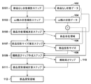
次に、物体群のうち1つの物体の位置を探索するための探索候補位置を求めるために情報処理装置が行う処理について、同処理のフローチャートを示す図1を用いて説明する。以下では、物体が部品である場合について説明するが、物体が他のものであったとしても、以下の説明は同様に適用することができる。 Next, processing performed by the information processing apparatus to obtain a search candidate position for searching for the position of one object in the object group will be described using FIG. 1 showing a flowchart of the processing. Although the case where the object is a part will be described below, the following description can be applied similarly even if the object is another one.
<ステップS101>
先ず、CPU201は、部品群(バラ積みされた部品群)を配置する場所を表すデータを部品なし状態データ102として取得する。例えば、部品群をバラ積みするパレットと呼ばれる容器のみを表すデータを部品なし状態データ102として取得する。パレットと呼ばれる容器のみを表すデータを部品なし状態データ102として取得する方法には様々な方法が考えられる。
<Step S101>
First, the
例えば、上記のパターン光投影装置と撮像装置とを用いて(この場合、I/Oデバイス209はパターン光投影装置及び撮像装置を有することになる)、パターン光が投影された容器の撮像画像を取得し、CPU201が、該撮像画像中の各画素位置に対応する3次元距離(撮像装置から該画素位置に写っている空間中の位置までの3次元距離)を表す距離画像(距離画像中の画素位置(x、y)における画素値は、撮像装置から撮像画像中の画素位置(x、y)に写っている空間中の位置までの3次元距離を表す)を、部品なし状態データ102として求めても良い。
For example, using the above-described pattern light projection device and imaging device (in this case, the I /
また、上記のパターン光投影装置及び撮像装置の代わりに、TOFセンサ装置などのセンサ装置を用いても同様の距離画像(各画素の画素値がTOFセンサ装置などのセンサ装置からの距離を表す距離画像)を部品なし状態データ102として取得することができる(この場合、I/Oデバイス209はTOFセンサ装置などのセンサ装置を有することになる)。
Also, even if a sensor device such as a TOF sensor device is used instead of the pattern light projection device and the imaging device described above, the same distance image (the pixel value of each pixel represents the distance from the sensor device such as the TOF sensor device) The image can be acquired as part-less status data 102 (in this case, the I /
なお、部品群をパレットではなく机など適当な面上に配置する場合には、該面を表すデータを部品なし状態データ102として取得することになる。その場合も、上記の方法を用いることで、各画素の画素値がI/Oデバイス209からの距離を表す距離画像を取得することができる。
When the component group is arranged on an appropriate surface such as a desk instead of a pallet, data representing the surface is acquired as the component-
以下では、部品なし状態データ102は、各画素の画素値がI/Oデバイス209からの距離を表す距離画像であるものとして説明する。
In the following, the no-
このように、部品なし状態データ102は、I/Oデバイス209により取得することができる。I/Oデバイス209はこのようにして取得した部品なし状態データ102をRAM203や2次記憶装置204に格納するので、CPU201は、RAM203や2次記憶装置204に格納された部品なし状態データ102を取得することになる。
In this manner, the part
<ステップS103>
次に、CPU201は、上記場所に配置した部品群(バラ積みされた部品群)を表すデータを山積み状態データ104として取得する。ステップS101で、パレットの距離画像を部品なし状態データ102として取得した場合、ステップS103では、パレット上にバラ積みされた部品群の距離画像を、山積み状態データ104として取得する。すなわち、山積み状態データ104は、部品なし状態データ102を取得する際にI/Oデバイス209が距離計測を行った範囲内に部品群を配置してから、部品なし状態データ102と同様の方法でI/Oデバイス209によって取得したデータである。然るに、山積み状態データ104もまた、各画素の画素値がI/Oデバイス209からの距離を表す距離画像である。I/Oデバイス209はこのようにして取得した山積み状態データ104をRAM203や2次記憶装置204に格納するので、CPU201は、RAM203や2次記憶装置204に格納された山積み状態データ104を取得することになる。
<Step S103>
Next, the
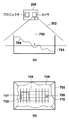
パターン光投影装置と撮像装置とを有するI/Oデバイス209を用いて山積み状態データ104を取得するための処理について、図3を用いて説明する。図3(a)は、山積みされた部品群304が収容されているパレット303を側面から見た図、図3(b)は、山積みされた部品群304が収容されているパレット303を上面から見た図、である。
A process for acquiring the piled
図3(a)に示す如く、I/Oデバイス209は、対象物体(ここでは部品)に対して規定のパターン光を投影するプロジェクタと、該パターン光が投影された該対象物体を撮像するカメラと、を有しており、CPU201は、カメラによる撮像画像を用いて、該カメラから対象物体上の各点までの3次元距離を周知の技術でもって求めることができる。図3(a)において302はカメラの画角(撮像範囲)を示している。
As shown in FIG. 3A, the I /
なお、パレット303は、典型的な形としては直方体の箱の上の面がないような物体であるが、その形状は直方体に限るものではなく、基本的にはどのような形でも構わない。例えば、底面の4辺が上枠の4辺より短い四角錐台の形となっていてもよい。また、パレットのコーナはラウンドしてもよいし、パレットの辺が曲がっていてもよい。
In addition, although the
<ステップS105>
CPU201は、山積み状態データ104が表す距離画像において、部品が存在するであろう範囲を、部品存在範囲106として求める。例えば、部品なし状態データ102と山積み状態データ104とで位置的に対応する画素の画素値を比較し、部品なし状態データ102の画素位置(x、y)における画素の画素値<山積み状態データ104の画素位置(x、y)における画素の画素値である場合には、山積み状態データ104における画素位置(x、y)は部品存在範囲106に含まれているものと判断する。このような判断を、全ての画素位置について行うことで、山積み状態データ104上で部品が存在するものとおぼしき領域を求めることができる。
<Step S105>
In the distance image represented by the piled
なお、本ステップでは、山積み状態データ104上で部品が存在するものとおぼしき領域を求めることができるのであれば、他の方法を用いても構わない。例えば、背景差分法を用いて、山積み状態データ104において部品なし状態データ102と画素値が規定値以上異なる画素位置を特定し、該特定した画素位置の集合を部品存在範囲106として特定しても構わない。また、部品なし状態データ102におけるパレットの領域を特定し、該特定したパレットの領域に対応する山積み状態データ104上の領域を部品存在範囲106として特定しても構わない。また、山積み状態データ104を得るために撮像装置が撮像した撮像画像をディスプレイ206に表示し、ディスプレイ206に表示された撮像画像を見たユーザがキーボード207やマウス208を用いて指定した領域を部品存在範囲106として特定しても構わない。また、部品なし状態データ102を得るためにカメラが撮像した撮像画像と、山積み状態データ104を得るためにカメラが撮像した撮像画像と、で位置的に対応する画素間で画素値の差分を計算し、該差分が閾値以上となる画素から成る山積み状態データ104上の領域を部品存在範囲106として特定しても構わない。
Note that in this step, another method may be used as long as it is possible to obtain an area that seems to be a part on the piled
<ステップS107>
次に、CPU201は、山積み状態データ104を用いて、I/Oデバイス209の位置からみた山積み状態の部品群304における代表的な部品のサイズ(推定サイズ)を推定する。
<Step S107>
Next, the
例えば、山積み状態データ104において部品存在範囲106に属する画素の画素値から代表値を求める。本実施形態では、山積み状態データ104において部品存在範囲106に属する画素の画素値の平均値を代表値とする。図3(a)において305は、I/Oデバイス209(カメラ)からの、代表値が表す距離を表している。なお、代表値は他の方法を用いて求めても良く、山積み状態データ104において部品存在範囲106に属する画素の画素値の中央値や最頻値などの統計量をもって代表値としても構わない。
For example, a representative value is obtained from the pixel values of the pixels belonging to the
次に、CPU201は、「代表値が表す距離だけI/Oデバイス209から離間した位置に部品を配置した場合にI/Oデバイス209から見える該部品のサイズ」を、部品投影サイズ108として求める。例えば、部品のバウンディングボックスの長辺の長さL、カメラの焦点距離f、代表値D、カメラの解像度R、から部品投影サイズ108=R×f×L/Dを求める。また、予め作成した部品のモデルを用いて、「代表値が表す距離だけI/Oデバイス209から離間した位置に該モデルを配置した場合にI/Oデバイス209から見える該モデルの画像」を、該モデルの姿勢を様々な姿勢に変化させながら生成し、該生成したそれぞれの画像におけるモデルの領域の一辺の平均値や最大値を部品投影サイズ108として求めても構わない。例えば、モデルとしては、部品の形状を表現するCADモデルを用いることができる。
Next, the
すなわち、ステップS107では、「山積み状態データ104において部品存在範囲106に属する画素の画素値から求めた代表値が表す距離だけI/Oデバイス209から離間した位置に部品を配置した場合にI/Oデバイス209から見える該部品のサイズ」を求めることができるのであれば、そのための処理は特定の処理に限るものではない。
That is, in step S107, “I / O is performed when the component is disposed at a position separated from the I /
<ステップS109>
次に、CPU201は、山積み状態データ104及び部品投影サイズ108を用いて、概略高さマップ110を作成する。概略高さマップ110とは、山積み状態データ104における部品存在範囲106を複数の小領域(セル)に区分した場合に、それぞれの小領域における代表的な距離値を表すデータ、である。「小領域における代表的な距離値」とは、該小領域内の画素値の平均値や中央値などの統計値である。
<Step S109>
Next, the
なお、小領域の形状は特定の形状に限るものではないが、そのサイズは、部品投影サイズ108に基づくサイズとなる。例えば、図3(b)の場合、306で示す如く、小領域は正方形となっており、その一辺は、部品投影サイズ108若しくはその定数倍のサイズを有する。また、例えば、図5(a)の場合、小領域は円形となっており、行毎にその中心位置がずれており且つ互いに重複する領域を有するものとなっている。また、その直径(半径でも良い)は、部品投影サイズ108若しくはその定数倍のサイズを有する。また、例えば、図5(b)の場合、小領域は六角形となっており、ハニカム構造を形成している。また、小領域に外接する円の直径(半径でも良い)は、部品投影サイズ108若しくはその定数倍のサイズを有する。なお、小領域の一辺が部品投影サイズ108若しくはその定数倍のサイズを有するようにしても構わない。
Although the shape of the small area is not limited to a specific shape, the size thereof is a size based on the
一般的に、部品存在範囲106を区分する小領域(正方形でも円形でも六角形でも良い)のサイズが小さすぎると、特許文献2と近いアルゴリズムとなり、距離測定ノイズに影響され、山積み部品において位置が高い(I/Oデバイス209により近い)部品の特定が不安定となる。一方、部品存在範囲106を区分する小領域のサイズが大きすぎると図3(a)の部品群304にあるような部品山積みの表面起伏が正確に評価できなくなり、山積み部品において位置が高い(I/Oデバイス209により近い)部品の特定が不正確となる。
In general, if the size of a small area (which may be a square, a circle, or a hexagon) that divides the
これに対し、本実施形態では、山積み状態データ104における部品存在範囲106を複数の小領域(セル)に区分する場合に、そのサイズを、部品投影サイズ108若しくはその定数倍のサイズ、とする。
On the other hand, in the present embodiment, in the case where the
図3(a)に示したように、パレット303の中に部品が山積みされた状態において、カメラから部品までの距離305は非常に大きく変化する場合がある。特にパレットが深くて大量に部品を積載することができる場合、部品山積みを入れ替えた最初の頃はパレットの上枠近くに表層部品が存在するが、パレット中に部品が残りわずかになる頃は、カメラと部品との間の距離は、ほぼカメラとパレット底面との距離となる。この時、仮にカメラから部品までの距離305が当初より2倍長くなったとすると、部品投影サイズ108は2分の1となる。このように部品投影サイズが2分の1に変化した場合でも、上記の小領域のサイズを本実施形態のように変化させずに固定し、それを元に山積み部品において位置が高い(I/Oデバイス209により近い)部品を特定しようとしても、その特定が不正確になってしまう。これに対し、本実施形態によれば、現在の山積み状態に最適なサイズを有する小領域を単位に部品存在範囲106を区分するので、安定して正確な特定(山積み部品において位置が高い(I/Oデバイス209により近い)部品の特定)が実現できる。
As shown in FIG. 3A, in the state where the parts are stacked in the
<ステップS111>
CPU201は、概略高さマップ110を参照して、部品存在範囲106を区分したそれぞれの小領域のうち、代表的な距離値が最も小さい小領域を中心小領域として特定する。そしてCPU201は、中心小領域、及び該中心小領域を囲む周囲の小領域群、から成る小領域群を、部品探索領域112として特定する。ステップS111における処理について、図4を用いて説明する。
<Step S111>
The
図4(a)は、山積みされた部品群402を収容している状態のパレット401を上から見た図を示しており、概略高さマップ110が表す小領域群の一部403を模式的に重ねて示している。図4(a)では、中心小領域として小領域404が選択されており、小領域404、及び小領域404を囲む周囲の小領域群、から成る小領域群405を部品探索領域として特定している。この部品探索領域の縦横サイズは、例えば、小領域の縦横サイズの4倍である。
FIG. 4A shows a top view of the
なお、中心小領域を中心とする部品探索領域のサイズは、小領域の整数倍に限るものではない。例えば、距離305の代わりに中心小領域内の画素値の平均値を用いて部品投影サイズ108を求め、中心小領域を中心とする部品探索領域の縦横サイズを、該求めた部品投影サイズ108の定数倍としても構わない。
The size of the parts search area centered on the central small area is not limited to an integral multiple of the small area. For example, the
図4(b)は、山積みされた部品群402を収容している状態のパレット401を上から見た図を示しており、概略高さマップ110が表す小領域群の一部403を模式的に重ねて示している。図4(b)では、中心小領域として小領域406が選択されており、小領域406、及び小領域406を囲む周囲の小領域群、から成る小領域群407を部品探索領域として特定している。この部品探索領域の縦横サイズは、例えば、小領域の縦横サイズの4倍である。なお、部品探索領域(小領域群407)においてパレット401からはみ出した部分は削除してもよい。その際は、部品探索領域の面積は通常の場合より小さくなる。
FIG. 4B shows a top view of the
図4(c)は、山積みされた部品群402を収容している状態のパレット401を上から見た図を示しており、概略高さマップ110が表す小領域群の一部403を模式的に重ねて示している。図4(c)でも、中心小領域として小領域406が選択されているが、パレットからはみ出している部分を逆側に押し込めるべく、部品探索領域(小領域群407)をシフトした部品探索領域(小領域群408)を設定している。この部品探索領域の縦横サイズは、例えば、小領域の縦横サイズの4倍である。パレットからはみ出した部分を削除するのではなく、図4(c)の例のように部品探索領域自体を移動させることで、常に部品探索領域の面積が一定となる。
FIG. 4C shows a top view of the
このように、ステップS111では、概略高さマップ110を参照して、部品存在範囲106を区分したそれぞれの小領域のうち、代表的な距離値が最も小さい小領域を中心小領域として特定し、該中心小領域を含む部品探索領域を設定するのであれば、部品探索領域の設定方法は特定の方法に限らない。
Thus, in step S111, a small area having the smallest representative distance value is specified as a central small area among the small areas obtained by dividing the
また、図4では部品探索領域が1つの矩形として設定される例を示したが、複数の矩形を部品探索領域として選んでもよいし、矩形ではなく例えば円形の領域を部品探索領域としてもよい。複数の場所を部品探索領域として設定する場合は、例えばそれぞれの小領域を代表的な距離値が小さい順にソートし、距離値が最も小さい順に上位から所定個数の小領域を中心小領域として選択し、それぞれの中心小領域について、該中心小領域を含む部品探索領域を設定するようにしても構わない。また、その際に互いに重なりがない、もしくは重なりが一定割合以下となるように部品探索領域を選ぶ方法もある。 Although FIG. 4 shows an example in which the part search area is set as one rectangle, a plurality of rectangles may be selected as the part search area, or a circular area instead of the rectangle may be used as the part search area. When setting a plurality of places as part search areas, for example, the small areas are sorted in the order of small representative distance values, and a predetermined number of small areas from the top are selected as central small areas in the order of the smallest distance value. For each central small area, a parts search area including the central small area may be set. In addition, there is also a method of selecting a part search area so that the overlap does not overlap each other or the overlap is equal to or less than a predetermined ratio.
[第2の実施形態]
本実施形態では、図1のフローチャートに従った処理の代わりに、図6のフローチャートに従った処理を実行する点が、第1の実施形態と異なる。以下では、第1の実施形態との差分について重点的に説明し、以下で特に触れない限りは、第1の実施形態と同様であるものとする。また、図6において、図1に示した処理ステップと同じ処理ステップには同じステップ番号を付しており、該処理ステップに係る説明は省略する。
Second Embodiment
The present embodiment differs from the first embodiment in that the process according to the flowchart of FIG. 6 is executed instead of the process according to the flowchart of FIG. 1. In the following, differences from the first embodiment will be mainly described, and it is assumed that the second embodiment is the same as the first embodiment unless otherwise specified. Moreover, in FIG. 6, the same step number is attached | subjected to the process step same as the process step shown in FIG. 1, and the description regarding this process step is abbreviate | omitted.
本実施形態が適用されるのに好適な部品山積み状態を図7に示す。図7において、図3に示したものと同じものには同じ参照番号を付しており、これに係る説明は省略する。図7でも図3と同様、パターン光投影装置と撮像装置とを有するI/Oデバイス209を用いて、部品群704に対する山積み状態データ104を取得する。図7(a)は、山積みされた部品群704が収容されているパレット703を側面から見た図、図7(b)は、山積みされた部品群704が収容されているパレット703を上面から見た図、である。
A part stacking condition suitable for applying the present embodiment is shown in FIG. 7, the same reference numerals as in FIG. 3 denote the same parts as in FIG. 3, and a description thereof will be omitted. In FIG. 7 as well as FIG. 3, the piled
図7では、部品群の山の形状(特に高さ)において、カメラからの最近点と最遠点の差が、図3と比べても大きい。具体的には、図7(b)に示す如く、小領域群706において、小領域707における代表的な距離値と、小領域709における代表的な距離値と、は大きく異なる。結果として、その地点におけるその高さでの部品投影サイズ708と部品投影サイズ710とでは大きく異なってくる。
In FIG. 7, the difference between the closest point and the farthest point from the camera is larger than that in FIG. Specifically, as shown in FIG. 7B, in the
本実施形態では、それぞれの小領域について求めた代表的な距離値を用いて、それぞれの小領域に対応する部品投影サイズ108を第1の実施形態で説明した方法でもって再計算し、それぞれの小領域について求めた代表的な距離値を該小領域について再計算した部品投影サイズ108に基づいて修正する。この処理を施すことによって、小領域毎に部品投影サイズが大きく異なる場合でも本実施形態の情報処理方法なら対応できることになる。
In the present embodiment, the
具体的には、ステップS611では、それぞれの小領域について求めた代表的な距離値を用いて、それぞれの小領域に対応する部品投影サイズ108を第1の実施形態で説明した方法でもって再計算し、該小領域のサイズを該小領域について再計算した部品投影サイズ108若しくはその定数倍のサイズに変更する。そして、サイズ変更後のそれぞれの小領域について、該小領域内の画素値から代表的な画素値を、該小領域に対する代表的な距離値として求める。そして以降では、それぞれの小領域の代表的な距離値として、このステップS611で該小領域について求めた代表的な距離値を用いる。
Specifically, in step S611, using the representative distance value obtained for each small area, the
(その他の実施例)
本発明は、上述の実施形態の1以上の機能を実現するプログラムを、ネットワーク又は記憶媒体を介してシステム又は装置に供給し、そのシステム又は装置のコンピュータにおける1つ以上のプロセッサーがプログラムを読出し実行する処理でも実現可能である。また、1以上の機能を実現する回路(例えば、ASIC)によっても実現可能である。
(Other embodiments)
The present invention supplies a program that implements one or more functions of the above-described embodiments to a system or apparatus via a network or storage medium, and one or more processors in a computer of the system or apparatus read and execute the program. Can also be realized. It can also be implemented by a circuit (eg, an ASIC) that implements one or more functions.
201:CPU 203:RAM 204:2次記憶装置 201: CPU 203: RAM 204: secondary storage device
Claims (10)
前記存在範囲を前記物体のサイズに基づいて複数の小領域に区分した場合に、該複数の小領域のうち前記距離計測により得られる距離値が小さい順に一部の小領域を特定し、該一部の小領域のそれぞれについて、該小領域を含み且つ該小領域よりも大きいサイズの領域を物体の探索領域として決定する決定手段と
を備えることを特徴とする情報処理装置。 Specifying means for specifying an existence range of the object group based on a result of distance measurement on the object group;
When the existence range is divided into a plurality of small areas based on the size of the object , a part of the small areas is specified in ascending order of the distance value obtained by the distance measurement among the plurality of small areas, and An information processing apparatus comprising: determination means for determining an area having a size larger than the small area including the small area as the search area of the object for each small area of the part .
前記物体群に対する距離計測により得られる距離値の代表値を求め、該距離計測を行う装置から該代表値だけ離間した位置に物体を配置した場合に該装置から見える該物体のサイズを求め、前記存在範囲を該求めたサイズに基づいて複数の小領域に区分した場合に、該複数の小領域のうち距離値が小さい順に一部の小領域を特定し、該一部の小領域のそれぞれについて、該小領域を含み且つ該小領域よりも大きいサイズの領域を前記探索領域として決定することを特徴とする請求項1に記載の情報処理装置。 The determining means is
The representative value of the distance value obtained by measuring the distance to the object group is determined, and the size of the object seen from the device when the object is arranged at a position separated from the device for performing the distance measurement by the representative value is determined When the existence range is divided into a plurality of small areas based on the determined size, a part of the small areas is specified in ascending order of the distance value among the plurality of small areas, and each of the partial areas is selected. the information processing apparatus according to claim 1, characterized in that determining the small region a region of greater size than unrealized and the small area as the search area.
前記複数の小領域のそれぞれのサイズを、該小領域に対応する距離値に応じて修正し、該修正の後、前記複数の小領域のうち距離値が小さい順に一部の小領域を特定し、該一部の小領域のそれぞれについて、該小領域を含み且つ該小領域よりも大きいサイズの領域を前記探索領域として決定することを特徴とする請求項2に記載の情報処理装置。 The determining means is
The size of each of the plurality of small areas is corrected according to the distance value corresponding to the small area, and after the correction, a part of the small areas is specified in the order of smaller distance value among the plurality of small areas. , wherein each of some small areas, the information processing apparatus according to claim 2, characterized in that to determine the regions of a size larger than and the small area viewed including the said small regions as the search area.
前記物体群を配置していない状態で行った距離計測の結果と、前記物体群を配置した状態で行った距離計測の結果と、を用いて前記存在範囲を特定することを特徴とする請求項1乃至4の何れか1項に記載の情報処理装置。 The identification means is
The present range is specified using a result of distance measurement performed in a state where the object group is not arranged and a result of distance measurement performed in a state where the object group is arranged. An information processing apparatus according to any one of 1 to 4.
前記決定手段が決定した探索領域を示す情報を、前記物体を操作するための装置に対して出力することを特徴とする請求項1乃至7の何れか1項に記載の情報処理装置。 Furthermore,
The information processing apparatus according to any one of claims 1 to 7, wherein information indicating a search area determined by the determination means is output to an apparatus for operating the object.
前記情報処理装置の特定手段が、物体群に対する距離計測の結果に基づいて該物体群の存在範囲を特定する特定工程と、
前記情報処理装置の決定手段が、前記存在範囲を前記物体のサイズに基づいて複数の小領域に区分した場合に、該複数の小領域のうち前記距離計測により得られる距離値が小さい順に一部の小領域を特定し、該一部の小領域のそれぞれについて、該小領域を含み且つ該小領域よりも大きいサイズの領域を物体の探索領域として決定する決定工程と
を備えることを特徴とする情報処理方法。 An information processing method performed by the information processing apparatus;
A specifying step of specifying the presence range of the object group based on the result of the distance measurement on the object group, the specification means of the information processing apparatus;
When the determination unit of the information processing apparatus divides the existing range into a plurality of small areas based on the size of the object, a part of the plurality of small areas is in the order of small distance value obtained by the distance measurement And determining, for each of the partial areas, an area including the small area and having a size larger than that of the small area as the search area of the object. Information processing method.
Priority Applications (1)
| Application Number | Priority Date | Filing Date | Title |
|---|---|---|---|
| JP2015024693A JP6512852B2 (en) | 2015-02-10 | 2015-02-10 | Information processing apparatus, information processing method |
Applications Claiming Priority (1)
| Application Number | Priority Date | Filing Date | Title |
|---|---|---|---|
| JP2015024693A JP6512852B2 (en) | 2015-02-10 | 2015-02-10 | Information processing apparatus, information processing method |
Publications (3)
| Publication Number | Publication Date |
|---|---|
| JP2016148558A JP2016148558A (en) | 2016-08-18 |
| JP2016148558A5 JP2016148558A5 (en) | 2018-03-29 |
| JP6512852B2 true JP6512852B2 (en) | 2019-05-15 |
Family
ID=56691720
Family Applications (1)
| Application Number | Title | Priority Date | Filing Date |
|---|---|---|---|
| JP2015024693A Expired - Fee Related JP6512852B2 (en) | 2015-02-10 | 2015-02-10 | Information processing apparatus, information processing method |
Country Status (1)
| Country | Link |
|---|---|
| JP (1) | JP6512852B2 (en) |
Families Citing this family (1)
| Publication number | Priority date | Publication date | Assignee | Title |
|---|---|---|---|---|
| JP6526100B2 (en) | 2017-04-28 | 2019-06-05 | ファナック株式会社 | Material pick-up system |
Family Cites Families (5)
| Publication number | Priority date | Publication date | Assignee | Title |
|---|---|---|---|---|
| JP2004160567A (en) * | 2002-11-11 | 2004-06-10 | Fanuc Ltd | Article taking-out device |
| JP2007188417A (en) * | 2006-01-16 | 2007-07-26 | Fujitsu Ten Ltd | Image recognition device, image recognition method, and image recognition program |
| US7983487B2 (en) * | 2007-11-07 | 2011-07-19 | Mitsubishi Electric Research Laboratories, Inc. | Method and system for locating and picking objects using active illumination |
| JP2012071394A (en) * | 2010-09-29 | 2012-04-12 | Dainippon Screen Mfg Co Ltd | Simulation system and simulation program therefor |
| JP2013101045A (en) * | 2011-11-08 | 2013-05-23 | Fanuc Ltd | Recognition device and recognition method of three-dimensional position posture of article |
-
2015
- 2015-02-10 JP JP2015024693A patent/JP6512852B2/en not_active Expired - Fee Related
Also Published As
| Publication number | Publication date |
|---|---|
| JP2016148558A (en) | 2016-08-18 |
Similar Documents
| Publication | Publication Date | Title |
|---|---|---|
| US11724400B2 (en) | Information processing apparatus for determining interference between object and grasping unit, information processing method, and storage medium | |
| KR102326097B1 (en) | Pallet detection using units of physical length | |
| US11667036B2 (en) | Workpiece picking device and workpiece picking method | |
| US10363664B2 (en) | Information processing apparatus, information processing method, and recording medium | |
| JP5295828B2 (en) | Object gripping system and interference detection method in the system | |
| JP6692107B1 (en) | Method and computing system for object identification | |
| JP6632208B2 (en) | Information processing apparatus, information processing method, and program | |
| JP2015147256A (en) | Robot, robot system, control device, and control method | |
| US20180150969A1 (en) | Information processing device, measuring apparatus, system, calculating method, storage medium, and article manufacturing method | |
| KR20160003776A (en) | Posture estimation method and robot | |
| US10778902B2 (en) | Sensor control device, object search system, object search method, and program | |
| US20170323456A1 (en) | Information processing apparatus, information processing method, program, system, and article manufacturing method | |
| JP5544464B2 (en) | 3D position / posture recognition apparatus and method for an object | |
| CN115249324A (en) | Method and device for determining position to be stacked in stack shape and computing equipment | |
| JP6237122B2 (en) | Robot, image processing method and robot system | |
| JP6512852B2 (en) | Information processing apparatus, information processing method | |
| JP7264247B2 (en) | Information processing device and information processing method | |
| US20170330334A1 (en) | Movement direction determination method and movement direction determination device | |
| JP2018146347A (en) | Image processing device, image processing method, and computer program | |
| JP7119606B2 (en) | Measuring system and measuring method | |
| US20200193624A1 (en) | Method and apparatus for dimensioning objects | |
| US11900652B2 (en) | Method and computing system for generating a safety volume list for object detection | |
| CN112837370A (en) | Object stacking judgment method and device based on 3D bounding box and computing equipment | |
| CN116342858B (en) | Object detection method, device, electronic equipment and storage medium | |
| CN113313803B (en) | Stack type analysis method, apparatus, computing device and computer storage medium |
Legal Events
| Date | Code | Title | Description |
|---|---|---|---|
| A621 | Written request for application examination |
Free format text: JAPANESE INTERMEDIATE CODE: A621 Effective date: 20180213 |
|
| A521 | Request for written amendment filed |
Free format text: JAPANESE INTERMEDIATE CODE: A523 Effective date: 20180219 |
|
| A977 | Report on retrieval |
Free format text: JAPANESE INTERMEDIATE CODE: A971007 Effective date: 20181207 |
|
| A131 | Notification of reasons for refusal |
Free format text: JAPANESE INTERMEDIATE CODE: A131 Effective date: 20181214 |
|
| A521 | Request for written amendment filed |
Free format text: JAPANESE INTERMEDIATE CODE: A523 Effective date: 20190212 |
|
| TRDD | Decision of grant or rejection written | ||
| A01 | Written decision to grant a patent or to grant a registration (utility model) |
Free format text: JAPANESE INTERMEDIATE CODE: A01 Effective date: 20190311 |
|
| A61 | First payment of annual fees (during grant procedure) |
Free format text: JAPANESE INTERMEDIATE CODE: A61 Effective date: 20190409 |
|
| R151 | Written notification of patent or utility model registration |
Ref document number: 6512852 Country of ref document: JP Free format text: JAPANESE INTERMEDIATE CODE: R151 |
|
| LAPS | Cancellation because of no payment of annual fees |