JP6512164B2 - Object detection apparatus, object detection method - Google Patents
Object detection apparatus, object detection method Download PDFInfo
- Publication number
- JP6512164B2 JP6512164B2 JP2016086408A JP2016086408A JP6512164B2 JP 6512164 B2 JP6512164 B2 JP 6512164B2 JP 2016086408 A JP2016086408 A JP 2016086408A JP 2016086408 A JP2016086408 A JP 2016086408A JP 6512164 B2 JP6512164 B2 JP 6512164B2
- Authority
- JP
- Japan
- Prior art keywords
- image
- search area
- area
- target
- camera sensor
- Prior art date
- Legal status (The legal status is an assumption and is not a legal conclusion. Google has not performed a legal analysis and makes no representation as to the accuracy of the status listed.)
- Active
Links
Images


Classifications
-
- G—PHYSICS
- G08—SIGNALLING
- G08G—TRAFFIC CONTROL SYSTEMS
- G08G1/00—Traffic control systems for road vehicles
- G08G1/16—Anti-collision systems
-
- B—PERFORMING OPERATIONS; TRANSPORTING
- B60—VEHICLES IN GENERAL
- B60R—VEHICLES, VEHICLE FITTINGS, OR VEHICLE PARTS, NOT OTHERWISE PROVIDED FOR
- B60R21/00—Arrangements or fittings on vehicles for protecting or preventing injuries to occupants or pedestrians in case of accidents or other traffic risks
- B60R21/01—Electrical circuits for triggering passive safety arrangements, e.g. airbags, safety belt tighteners, in case of vehicle accidents or impending vehicle accidents
- B60R21/013—Electrical circuits for triggering passive safety arrangements, e.g. airbags, safety belt tighteners, in case of vehicle accidents or impending vehicle accidents including means for detecting collisions, impending collisions or roll-over
- B60R21/0134—Electrical circuits for triggering passive safety arrangements, e.g. airbags, safety belt tighteners, in case of vehicle accidents or impending vehicle accidents including means for detecting collisions, impending collisions or roll-over responsive to imminent contact with an obstacle, e.g. using radar systems
-
- B—PERFORMING OPERATIONS; TRANSPORTING
- B60—VEHICLES IN GENERAL
- B60T—VEHICLE BRAKE CONTROL SYSTEMS OR PARTS THEREOF; BRAKE CONTROL SYSTEMS OR PARTS THEREOF, IN GENERAL; ARRANGEMENT OF BRAKING ELEMENTS ON VEHICLES IN GENERAL; PORTABLE DEVICES FOR PREVENTING UNWANTED MOVEMENT OF VEHICLES; VEHICLE MODIFICATIONS TO FACILITATE COOLING OF BRAKES
- B60T7/00—Brake-action initiating means
- B60T7/12—Brake-action initiating means for automatic initiation; for initiation not subject to will of driver or passenger
-
- B—PERFORMING OPERATIONS; TRANSPORTING
- B60—VEHICLES IN GENERAL
- B60W—CONJOINT CONTROL OF VEHICLE SUB-UNITS OF DIFFERENT TYPE OR DIFFERENT FUNCTION; CONTROL SYSTEMS SPECIALLY ADAPTED FOR HYBRID VEHICLES; ROAD VEHICLE DRIVE CONTROL SYSTEMS FOR PURPOSES NOT RELATED TO THE CONTROL OF A PARTICULAR SUB-UNIT
- B60W30/00—Purposes of road vehicle drive control systems not related to the control of a particular sub-unit, e.g. of systems using conjoint control of vehicle sub-units, or advanced driver assistance systems for ensuring comfort, stability and safety or drive control systems for propelling or retarding the vehicle
- B60W30/08—Active safety systems predicting or avoiding probable or impending collision or attempting to minimise its consequences
-
- G—PHYSICS
- G01—MEASURING; TESTING
- G01S—RADIO DIRECTION-FINDING; RADIO NAVIGATION; DETERMINING DISTANCE OR VELOCITY BY USE OF RADIO WAVES; LOCATING OR PRESENCE-DETECTING BY USE OF THE REFLECTION OR RERADIATION OF RADIO WAVES; ANALOGOUS ARRANGEMENTS USING OTHER WAVES
- G01S13/00—Systems using the reflection or reradiation of radio waves, e.g. radar systems; Analogous systems using reflection or reradiation of waves whose nature or wavelength is irrelevant or unspecified
- G01S13/86—Combinations of radar systems with non-radar systems, e.g. sonar, direction finder
- G01S13/867—Combination of radar systems with cameras
-
- G—PHYSICS
- G01—MEASURING; TESTING
- G01S—RADIO DIRECTION-FINDING; RADIO NAVIGATION; DETERMINING DISTANCE OR VELOCITY BY USE OF RADIO WAVES; LOCATING OR PRESENCE-DETECTING BY USE OF THE REFLECTION OR RERADIATION OF RADIO WAVES; ANALOGOUS ARRANGEMENTS USING OTHER WAVES
- G01S13/00—Systems using the reflection or reradiation of radio waves, e.g. radar systems; Analogous systems using reflection or reradiation of waves whose nature or wavelength is irrelevant or unspecified
- G01S13/88—Radar or analogous systems specially adapted for specific applications
- G01S13/93—Radar or analogous systems specially adapted for specific applications for anti-collision purposes
- G01S13/931—Radar or analogous systems specially adapted for specific applications for anti-collision purposes of land vehicles
-
- G—PHYSICS
- G01—MEASURING; TESTING
- G01S—RADIO DIRECTION-FINDING; RADIO NAVIGATION; DETERMINING DISTANCE OR VELOCITY BY USE OF RADIO WAVES; LOCATING OR PRESENCE-DETECTING BY USE OF THE REFLECTION OR RERADIATION OF RADIO WAVES; ANALOGOUS ARRANGEMENTS USING OTHER WAVES
- G01S17/00—Systems using the reflection or reradiation of electromagnetic waves other than radio waves, e.g. lidar systems
- G01S17/88—Lidar systems specially adapted for specific applications
- G01S17/93—Lidar systems specially adapted for specific applications for anti-collision purposes
- G01S17/931—Lidar systems specially adapted for specific applications for anti-collision purposes of land vehicles
-
- G—PHYSICS
- G01—MEASURING; TESTING
- G01V—GEOPHYSICS; GRAVITATIONAL MEASUREMENTS; DETECTING MASSES OR OBJECTS; TAGS
- G01V11/00—Prospecting or detecting by methods combining techniques covered by two or more of main groups G01V1/00 - G01V9/00
-
- G—PHYSICS
- G06—COMPUTING; CALCULATING OR COUNTING
- G06F—ELECTRIC DIGITAL DATA PROCESSING
- G06F18/00—Pattern recognition
- G06F18/20—Analysing
- G06F18/25—Fusion techniques
-
- G—PHYSICS
- G06—COMPUTING; CALCULATING OR COUNTING
- G06V—IMAGE OR VIDEO RECOGNITION OR UNDERSTANDING
- G06V20/00—Scenes; Scene-specific elements
- G06V20/50—Context or environment of the image
- G06V20/56—Context or environment of the image exterior to a vehicle by using sensors mounted on the vehicle
- G06V20/58—Recognition of moving objects or obstacles, e.g. vehicles or pedestrians; Recognition of traffic objects, e.g. traffic signs, traffic lights or roads
-
- G—PHYSICS
- G08—SIGNALLING
- G08G—TRAFFIC CONTROL SYSTEMS
- G08G1/00—Traffic control systems for road vehicles
- G08G1/16—Anti-collision systems
- G08G1/165—Anti-collision systems for passive traffic, e.g. including static obstacles, trees
-
- G—PHYSICS
- G08—SIGNALLING
- G08G—TRAFFIC CONTROL SYSTEMS
- G08G1/00—Traffic control systems for road vehicles
- G08G1/16—Anti-collision systems
- G08G1/166—Anti-collision systems for active traffic, e.g. moving vehicles, pedestrians, bikes
-
- B—PERFORMING OPERATIONS; TRANSPORTING
- B60—VEHICLES IN GENERAL
- B60R—VEHICLES, VEHICLE FITTINGS, OR VEHICLE PARTS, NOT OTHERWISE PROVIDED FOR
- B60R2300/00—Details of viewing arrangements using cameras and displays, specially adapted for use in a vehicle
- B60R2300/80—Details of viewing arrangements using cameras and displays, specially adapted for use in a vehicle characterised by the intended use of the viewing arrangement
- B60R2300/8093—Details of viewing arrangements using cameras and displays, specially adapted for use in a vehicle characterised by the intended use of the viewing arrangement for obstacle warning
-
- G—PHYSICS
- G01—MEASURING; TESTING
- G01S—RADIO DIRECTION-FINDING; RADIO NAVIGATION; DETERMINING DISTANCE OR VELOCITY BY USE OF RADIO WAVES; LOCATING OR PRESENCE-DETECTING BY USE OF THE REFLECTION OR RERADIATION OF RADIO WAVES; ANALOGOUS ARRANGEMENTS USING OTHER WAVES
- G01S13/00—Systems using the reflection or reradiation of radio waves, e.g. radar systems; Analogous systems using reflection or reradiation of waves whose nature or wavelength is irrelevant or unspecified
- G01S13/88—Radar or analogous systems specially adapted for specific applications
- G01S13/93—Radar or analogous systems specially adapted for specific applications for anti-collision purposes
- G01S13/931—Radar or analogous systems specially adapted for specific applications for anti-collision purposes of land vehicles
- G01S2013/93185—Controlling the brakes
-
- G—PHYSICS
- G01—MEASURING; TESTING
- G01S—RADIO DIRECTION-FINDING; RADIO NAVIGATION; DETERMINING DISTANCE OR VELOCITY BY USE OF RADIO WAVES; LOCATING OR PRESENCE-DETECTING BY USE OF THE REFLECTION OR RERADIATION OF RADIO WAVES; ANALOGOUS ARRANGEMENTS USING OTHER WAVES
- G01S13/00—Systems using the reflection or reradiation of radio waves, e.g. radar systems; Analogous systems using reflection or reradiation of waves whose nature or wavelength is irrelevant or unspecified
- G01S13/88—Radar or analogous systems specially adapted for specific applications
- G01S13/93—Radar or analogous systems specially adapted for specific applications for anti-collision purposes
- G01S13/931—Radar or analogous systems specially adapted for specific applications for anti-collision purposes of land vehicles
- G01S2013/9324—Alternative operation using ultrasonic waves
Description
本発明は、送信波を送信しこの送信波に対応する反射波に基づいて物体までの距離を検出する反射波センサと、撮像画像を取得するカメラセンサと、を用いて物体を検出する物体検出装置、及び物体検出方法に関する。 The present invention detects an object by using a reflected wave sensor that transmits a transmission wave and detects the distance to the object based on a reflected wave corresponding to the transmission wave, and a camera sensor that acquires a captured image. The present invention relates to an apparatus and an object detection method.
特許文献1には、レーダセンサとカメラセンサとを併用して物体を検出する物体検出装置が開示されている。特許文献1に開示された物体検出装置は、レーダセンサにより検出された物体の検出位置に基づいて探索領域を設定し、かつ、カメラセンサにより検出された物体の検出結果に基づいて探索領域を設定する。そして、物体検出装置は、両探索領域で重複する領域が存在する場合、レーダセンサで検出された物体とカメラセンサで検出された物体とを同一物体として判定する。
カメラセンサが物体を検出する場合、周辺の明るさに応じて物体の検出精度が低下する場合がある。この場合、カメラセンサの検出結果に基づいて設定される探索領域が誤設定され、物体検出装置は2つの探索領域を用いて物体の判定を行う際、同一の物体を異なる物体として誤判定するおそれがある。 When the camera sensor detects an object, the detection accuracy of the object may decrease depending on the brightness of the surroundings. In this case, the search area set based on the detection result of the camera sensor is erroneously set, and when the object detection apparatus determines an object using two search areas, the same object may be erroneously determined as a different object. There is.
本発明は、上記課題に鑑みてなされたものであり、車両周辺の明るさに起因する、物体の誤判定を抑制する物体検出装置、及び物体検出方法を提供することを目的とする。 The present invention has been made in view of the above problems, and an object of the present invention is to provide an object detection apparatus and an object detection method which suppress erroneous determination of an object caused by the brightness around the vehicle.
上記課題を解決するために本発明では、送信波を送信しこの送信波に対応する反射波に基づいて物体までの距離を取得する反射波センサと、前記物体を撮像して撮像画像を取得するカメラセンサと、を用いて車両周辺に存在する前記物体を検出する物体検出装置であって、前記反射波センサにより検出された前記物体の検出位置である第1位置を基準として、前記第1位置を含む領域を反射波探索領域として設定する反射領域設定部と、前記カメラセンサにより検出された前記物体の検出位置である第2位置を基準として、前記第2位置を含む領域を画像探索領域として設定する画像領域設定部と、前記反射波探索領域と前記画像探索領域とで重複する領域が存在することを条件に、前記反射波センサ及び前記カメラセンサで検出された前記物体が同一の物体であることを判定する物体判定部と、前記カメラセンサによる前記物体の検出方向における明るさを判定する明るさ判定部と、を有し、前記画像領域設定部は、判定された前記物体の検出方向における明るさに基づいて、当該画像探索領域の大きさを変更する。 In order to solve the above problems, in the present invention, a reflected wave sensor for transmitting a transmission wave and acquiring a distance to the object based on a reflected wave corresponding to the transmission wave, and imaging the object to acquire a captured image An object detection device for detecting the object existing around the vehicle using a camera sensor, wherein the first position is a first position that is a detection position of the object detected by the reflected wave sensor; An area including the second position is set as an image search area based on a reflection area setting unit which sets an area including B as a reflected wave search area and a second position which is a detected position of the object detected by the camera sensor The image detected by the reflected wave sensor and the camera sensor on condition that an image area setting unit to be set, and an area overlapping the reflected wave search area and the image search area exist. The image area setting unit includes an object determination unit that determines that the body is the same object, and a brightness determination unit that determines the brightness in the detection direction of the object by the camera sensor. The size of the image search area is changed based on the brightness in the detection direction of the object.
カメラセンサによる物体の検出位置である第2位置は、周辺の明るさに応じてその位置に誤差を生じさせる場合がある。例えば、周辺が暗いことで、カメラセンサは、物体と背景とを適正に区別できず、上端や下端が切れた状態で物体を検出しまうことがある。このような場合、物体の位置が適正に検出されず、第2位置に誤差を生じさせる。また、第2位置の誤差は、この第2位置を基準として設定される画像探索領域の設定位置を異ならせる。その結果、この画像探索領域と反射波探索領域との重複する領域がなくなり、物体判定部が同一の物体を異なる物体と誤判定するおそれがある。そこで、上記のように構成された発明では、物体を検出する方向での明るさを判定し、この判定結果に応じて画像探索領域の大きさを変更する。例えば、車両周辺が暗いことで画像探索領域が誤設定されている場合、この画像探索領域の大きさを変更することで、反射波探索領域との間で重複する領域を発生し易くし、明るさに伴う物体判定部の誤判定を抑制することができる。 The second position, which is the detection position of the object by the camera sensor, may cause an error in the position according to the surrounding brightness. For example, when the periphery is dark, the camera sensor can not properly distinguish between an object and a background, and may detect an object with its upper end and lower end cut off. In such a case, the position of the object is not properly detected, which causes an error in the second position. In addition, the error of the second position makes the set position of the image search area set based on the second position. As a result, there is no overlapping area between the image search area and the reflected wave search area, and the object determination unit may erroneously determine that the same object is a different object. Therefore, in the invention configured as described above, the brightness in the direction of detecting an object is determined, and the size of the image search area is changed according to the determination result. For example, when the image search area is incorrectly set because the vehicle periphery is dark, changing the size of the image search area makes it easy to generate an overlapping area with the reflected wave search area. It is possible to suppress an erroneous determination of the object determination unit accompanying the image.
以下、物体検出装置及び物体検出方法の実施の形態を、図面を使用して説明する。以下では、物体検出装置は、自車の運転を支援する運転支援装置の一部として適用される。なお、以下の実施形態相互において、互いに同一もしくは均等である部分には、図中、同一符号を付しており、同一符号の部分についてはその説明を援用する。 Hereinafter, embodiments of an object detection apparatus and an object detection method will be described using the drawings. In the following, the object detection device is applied as part of a driving support device that supports the driving of the vehicle. In the following embodiments, parts identical or equivalent to each other are denoted by the same reference numerals in the drawings, and the description of the parts having the same reference numerals is incorporated.
(第1実施形態)
図1は、運転支援装置10を示す構成図である。運転支援装置10は、車両に搭載されており、車両前方に位置する物体の移動を監視する。そして、物体と車両とが衝突するおそれがある場合、自動ブレーキによる衝突の回避動作、又は衝突の緩和動作を実施する。また、図1に示すように、運転支援装置10は、各種センサと、ECU20と、ブレーキユニット25と、を備えている。図1に示す実施形態において、ECU20が物体検出装置として機能する。以下では、この運転支援装置10が搭載された車両を車両CSと記載する。また、運転支援装置10により認識される物体を物標Obと記載する。
First Embodiment
FIG. 1 is a block diagram showing the
各種センサは、ECU20に接続されており、物体に対する検出結果をこのECU20に出力する。図1では、センサは、反射波センサとして機能することで物標Obを検出するレーダセンサ31、撮像画像に基づいて物標Obを検出するカメラセンサ32、明るさを検出する照度センサ33、を備えている。物標Obのうちレーダセンサ31により検出される物標とカメラセンサ32により検出される物標とを区別する場合、レーダセンサ31により検出された物標をレーダ物標Orと記載し、カメラセンサ32により検出された物標を画像物標Oiと記載する。
The various sensors are connected to the
レーダセンサ31は、ミリ波やレーダ等の指向性のある送信波を送信し、この送信波に応じてレーダ物標Orから反射される反射波を受信する。そして、レーダセンサ31は反射波に応じてレーダ物標Orとの距離、方位および相対速度等を算出し、レーダ信号としてECU20に出力する。
The
カメラセンサ32は、車両CSの前側に配置されており、自車前方に位置する画像物標Oiを認識する。カメラセンサ32は、車両周辺を撮像する撮像ユニット、この撮像ユニットにより撮像された撮像画像に対して周知の画像処理を実施するコントローラ、コントローラとECU20との通信を可能にするECUI/F、を備えている。なお、カメラセンサ32は、単眼カメラであってもよく、ステレオカメラであってもよい。
The
カメラセンサ32は、撮影画像を解析することで検出される物体を画像物標Oiとして識別する。例えば、予め登録されている辞書を用いたマッチング処理で画像物標Oiを識別する。辞書は、画像物標Oiの種類ごとに用意されており、これにより画像物標Oiの種別も特定される。画像物標Oiの種別としては、四輪以上の自動車、二輪車、歩行者、ガードレール等の障害物等が挙げられる。なお、二輪車には自転車、鞍乗型の自動二輪車等が含まれているものとする。また、カメラセンサ32は、認識された画像物標Oiに応じて、当該画像物標Oiの位置情報を含む検出結果を出力する。位置情報は、撮像画像における画像物標Oiの中心位置と、両端位置と、を含んでいる。例えば、両端位置は、撮像画像内において認識された画像物標Oiの領域を示す検出領域の両端での座標を示している。
The
照度センサ33は、カメラセンサ32の検知方向である撮像軸の方向での明るさを検知する。照度センサ33は、その検知部を撮像軸の方向に向けた状態で車両CSに配置されている。照度センサ33は、明るさを検知する検知部を備えており、この検知部の検知結果に応じた信号をECU20に出力する。検知部は、例えば、フォトダイオードである。
The
ECU20は、CPU,ROM,RAM等を備えた周知のコンピュータとして構成されている。そして、CPUが、ROMに格納されたプログラムを実行することで、レーダ物標検出部11、レーダ領域設定部12(反射領域設定部)、画像物標検出部13、画像領域設定部14、物体判定部15、明るさ判定部16、として機能する。
The
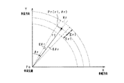
レーダ物標検出部11は、レーダセンサ31による検出結果を、図2に示すXY平面に当てはめることにより、車両CSに対するレーダ物標の検出位置(第1位置)を特定する。なお、図2のXY平面は、車両の幅方向(横方向)をX軸、車両の車長方向(前方方向)をY軸、として設定されたものである。このXY平面では、車両CSの先端位置(レーダセンサ31が設けられた位置)が基準点Poとして設定され、レーダ物標Orの第1位置Prが基準点Poに対する相対位置として表されている。なお、図2では、レーダ物標Orが車両CSの前方かつ右寄りに存在する例を示している。
The radar target detection unit 11 specifies the detection position (first position) of the radar target with respect to the vehicle CS by applying the detection result of the
レーダ領域設定部12は、図2に示すように、レーダ物標Orの第1位置Prを中心とするレーダ探索領域Rr(反射波探索領域)を設定する。詳しくは、図3に示すように、レーダ領域設定部12は、第1位置Prの基準点Poからの距離r1、及びY軸からの円周方向の角度θrを基準として、距離方向及び円周方向のそれぞれについて、レーダセンサ31の特性に基づき予め設定されている想定誤差分の幅を持たせた領域をレーダ探索領域Rrとして設定する。なお、円周方向は、基準点Poと第1位置Prとを結ぶ直線に対して直交する方向であるとも言える。
As shown in FIG. 2, the radar
例えば、図3では、第1位置Pr(r1,θr)を基準として、距離方向の想定誤差を±Er1、及び円周方向の角度の想定誤差を±Eθrとして示している。そのため、レーダ探索領域Rrは、第1位置Pr(r1,θr)を基準とする、距離方向が(r1−Er1)から(r1+Er1)の範囲で、円周方向の角度が(θr−Eθr)から(θr+Eθr)の範囲で、設定されている。 For example, in FIG. 3, with the first position Pr (r1, θr) as a reference, the assumed error in the distance direction is shown as ± Er1, and the assumed error in the circumferential direction is shown as ± Eθr. Therefore, the radar search area Rr is based on the first position Pr (r1, θr), and the distance direction is in the range of (r1−Er1) to (r1 + Er1), and the circumferential direction angle is from (θr−Eθr) It is set in the range of (θr + Eθr).
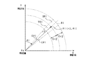
画像物標検出部13は、カメラセンサ32により検出された画像物標Oiの検出結果を、図2に示すXY平面に当てはめることにより、車両CSに対する画像物標Oiの検出位置(第2位置)を特定する。なお、画像物標検出部13は、撮影画像における画像物標Oiの上下方向の位置に基づいて、XY平面における画像物標Oiの位置を特定する。
The image
図4の撮影画像の例を用いて詳しく説明すると、まず、画像物標検出部13は、辞書を用いたマッチング処理によって、撮影画像中から画像物標Oiの検出領域T1を抽出する。そして抽出された検出領域T1の撮影画像中における上下方向の位置(座標)からXY平面における距離方向の位置を特定する。ここでは、検出領域T1に含まれる画像物標Oiの接地点T1aの位置に基づいて、図2のXY平面における距離方向の位置を特定する。
Describing in detail using the example of the photographed image of FIG. 4, first, the image
なお、撮影画像中において、画像物標Oiの接地点T1aが無限遠点FOE(FOE:Focus of Expansion)に接近した位置にあるほど、画像物標Oiは車両CSから遠方の位置に存在することとなり、物標のXY平面における距離方向での距離r2が大きくなる。このような相関関係を予め記憶しておくことにより、画像物標Oiの接地点T1aから、図2のXY平面の距離方向の距離r2を特定できる。 In the photographed image, the image target Oi should be located farther from the vehicle CS as the ground point T1a of the image target Oi is closer to the infinity point FOE (FOE: Focus of Expansion). Thus, the distance r2 in the distance direction on the XY plane of the target increases. By storing such a correlation in advance, the distance r2 in the distance direction of the XY plane in FIG. 2 can be specified from the ground point T1a of the image target Oi.
また、画像物標検出部13は、撮影画像中における画像物標Oiの左右方向の位置に基づいて、その画像物標Oiの円周方向の角度(車両の前方方向を基準とする角度位置)を特定する。すなわち、車両の前方方向(詳細にはX=0の直線)を基準とする画像物標Oiの角度方向のずれ(傾き)が大きいほど、カメラセンサ32の無限遠点FOEを基準として、その画像物標Oiの左右方向へのずれが大きくなる傾向にある。このため、図4の撮影画像における無限遠点FOEから画像物標Oiの中心を通る鉛直線までの距離に基づいて、図2のXY平面での画像物標Oiの円周方向の位置を特定することができる。
In addition, the image
画像領域設定部14は、図2に示すように、第2位置Piを中心とする画像探索領域Riを設定する。具体的には、基準点Poからの距離(基準点Poを中心とする円の半径)について想定誤差分の幅を持たせるとともに、基準点Poを中心とする円の円周方向に想定誤差分の幅を持たせた領域を、画像探索領域Riとして設定する。
The image
詳しくは、図5に示すように、第2位置Pi(r2,θi)を基準として、距離方向及び円周方向のそれぞれについて、カメラセンサ32の特性に基づき予め設定されている想定誤差分の幅を持たせた領域を、画像探索領域Riとして設定する。図5では、第2位置Pi(r2,θi)を基準として、距離方向の想定誤差を±Er2、及び円周方向の角度の想定誤差を±Eθiとしている。そのため、画像探索領域Riは、第2位置Piを基準とする、距離方向が(r2−Er2)から(r2+Er2)の範囲で、円周方向が(θi−Eθi)から(θi+Eθi)の角度範囲で、で設定される。
More specifically, as shown in FIG. 5, with respect to the second position Pi (r2, θi), the width for an assumed error preset based on the characteristics of the
以下では、画像探索領域Riにおいて、第2位置Pi(r2,θi)を基準として、距離方向が(r2−Er2)から(r2)までの領域を手前側領域TRiと記載し、距離方向が(r2)から(r2+Er2)までの領域を奥側領域BRiと記載する。なお、Er2は、カメラセンサ32の特性に応じて変化する値である。
Hereinafter, in the image search area Ri, an area from (r2-Er2) to (r2) in the distance direction is described as the near side area TRi with the second direction Pi based on the second position Pi (r2, θi) as the near side area TRi. The region from r2) to (r2 + Er2) is referred to as the back region BRi. Er2 is a value that changes in accordance with the characteristics of the
物体判定部15は、図2に示すようにレーダ探索領域Rrと画像探索領域Riとで重なる領域OLが存在する場合、レーダ物標Orと画像物標Oiとに基づいて、同一物体であるとの判定を行う。この場合、物体判定部15は、レーダセンサ31の第1位置Pr(r1,θr)と、カメラセンサ32の第2位置Pi(r2,θi)とを用いて、検出物標の位置を設定してもよい。
If there is an area OL overlapping between the radar search area Rr and the image search area Ri as shown in FIG. 2, the object determination unit 15 determines that the object is the same based on the radar target Or and the image target Oi. Make a decision on In this case, the object determination unit 15 sets the position of the detection target using the first position Pr (r1, θr) of the
ここで、カメラセンサ32の検出方向が暗くなることで、カメラセンサ32が画像物標Oiと背景とを適正に分離できず、上端や下端が切れた状態で画像物標Oiを検出する場合がある。この場合、検出領域T1の接地点T1aは、実際の画像物標Oiの下端位置と比べて上側又は下側として取得される。このような場合、カメラセンサ32の検出結果(r2,θi)の内、距離r2が誤検出されることとなる。また、距離r2の誤検出により、画像探索領域Riが誤設定される場合がある。そのため、この実施形態では、画像領域設定部14は、画像探索領域Riをカメラセンサ32の検出方向での明るさに応じて変更することで、明るさに伴う画像探索領域Riの誤設定を抑制している。
Here, when the detection direction of the
明るさ判定部16は、照度センサ33からの出力に基づいてカメラセンサ32の検出方向での明るさを判定する。明るさ判定部16による車両周辺の明るさの判定結果は、画像領域設定部14に出力される。
The
ブレーキユニット25は、車両CSの車速Vを減速させるブレーキ装置として機能する。また、ブレーキユニット25は、ECU20による制御に基づいて車両CSの自動ブレーキを実施する。ブレーキユニット25は、例えば、マスターシリンダと、車輪に制動力を与えるホイルシリンダと、マスターシリンダからホイルシリンダへの圧力(油圧)の分配を調整するABSアクチュエータとを備えている。ABSアクチュエータは、ECU20に接続されており、このECU20からの制御によりマスターシリンダからホイルシリンダへの油圧を調整することで、車輪に対する制動量を調整する。
The
ECU20は、同一の物標Obであると判定された物標Obに対する衝突回避制御が必要であるか否かを判定し、衝突回避制御が必要であると判定した場合にブレーキユニット25を作動させる。例えば、ECU20は、同一物標であると判定された物標Obと自車両との衝突余裕時間TTC(Time to Collision)を算出する。衝突余裕時間TTCとは、このままの自車速度で走行した場合に、何秒後に物標Obに衝突するかを示す評価値であり、TTCが小さいほど、衝突の危険性は高くなり、TTCが大きいほど衝突の危険性は低くなる。衝突余裕時間TTCは、物標Obと自車両との進行方向の距離を、物標Obとの相対速度で除算する等の方法で算出できる。物標Obとの相対速度は、先行車両の車速Vから自車速を減算して求められる。なお、相対加速度を加味して衝突余裕時間TTCを算出してもよい。
The
そして、衝突余裕時間TTCが車載機器の作動時間以下であれば、ブレーキユニット25を作動させる。例えば、ブレーキユニット25の作動時間は物標Obの種類に応じて設定される。例えば、物標Obが歩行者の場合の作動時間と、物標Obが二輪車の場合の作動時間とでは、二輪車の場合の方の危険度が高くなるために、早めの作動時間に設定する。なお、運転支援装置10は、ブレーキユニット25に加えて、警報音や案内音を出力するスピーカ、シートベルト等を備えており、スピーカ及びシートベルトに対しても、ECU20の判定結果に応じて、その作動を制御する。そのため、ECU20は、衝突回避制御部としても機能する。
Then, if the collision margin time TTC is equal to or less than the operation time of the in-vehicle device, the
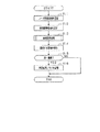
次に、ECU20より実施される物体検出処理を、図6を用いて説明する。図6に示す処理は、ECU20により所定周期で実施される。
Next, an object detection process performed by the
ステップS11では、第1位置Prに基づいてレーダ探索領域Rrを設定する。次に、ステップS12では、第2位置Piに基づいて画像探索領域Riを設定する。ステップS11が反射領域設定工程として機能する。また、ステップS12が画像領域設定工程として機能する。 In step S11, a radar search area Rr is set based on the first position Pr. Next, in step S12, the image search area Ri is set based on the second position Pi. Step S11 functions as a reflection area setting process. In addition, step S12 functions as an image area setting process.
ステップS13では、画像探索領域Riを変更する領域変更処理を実施する。なお、ステップS13での詳細な処理は後述する。 In step S13, area change processing for changing the image search area Ri is performed. The detailed processing in step S13 will be described later.
ステップS14では、レーダ探索領域Rrと画像探索領域Riとに重複する領域OLを検出する。ステップS15では、レーダ物標Orと画像物標Oiとに基づいて、同一の物体が検出されているか、検出されていないかを判定する。即ち、同一物標であるか否かの判定が行われる。レーダ探索領域Rrと画像探索領域Riとに重複する領域OLが検出されない場合、もしくは、重複する領域が検出された場合でレーダ物標の距離が閾値よりも大きい場合には、物標Obは同一の物標でないと判定する(ステップS15:NO)。そして、ECU20は、図6に示す処理を、一旦、終了する。ステップS14,S15が物体判定工程として機能する。 In step S14, an area OL overlapping the radar search area Rr and the image search area Ri is detected. In step S15, it is determined whether the same object is detected or not detected based on the radar target Or and the image target Oi. That is, it is determined whether the target is the same. If no overlapping area OL is detected in the radar search area Rr and the image search area Ri, or if the overlapping area is detected and the distance of the radar target is larger than the threshold, the target Ob is the same. It is determined that the target is not (step S15: NO). And ECU20 once complete | finishes the process shown in FIG. Steps S14 and S15 function as an object determination step.
なお、上記レーダ物標Orまでの距離を判定する閾値は、物標種別や周囲の明るさに応じて可変とする。例えば、周囲が明るい場合は暗い場合と比べ、閾値を大きくする。一方、周囲が暗い場合は、画像検出可能距離が低下するため、一定距離以上のレーダ物標Orとフュージョンする場合、その物標は、同一物標でない可能性が高いと判断することになる。 The threshold for determining the distance to the radar target Or is variable according to the target type and the brightness of the surroundings. For example, when the surroundings are bright, the threshold is increased compared to when the surroundings are dark. On the other hand, when the surroundings are dark, the image detectable distance decreases, and therefore, when fusing with a radar target Or more than a predetermined distance, it is determined that the target is not likely to be the same target.
一方、レーダ探索領域Rrと画像探索領域Riとに重複する領域OLが検出された場合、物標Obの検出が成功したと判定する(ステップS15:YES)、ステップS16では、判定成功フラグを記憶する。判定成功フラグは、今回の処理において、レーダ探索領域Rrと画像探索領域Riとで同じ物標Obを検出していることを示すフラグである。ECU20は、ステップS16の処理が終了すると、図6の処理を一旦終了する。
On the other hand, when the area OL overlapping the radar search area Rr and the image search area Ri is detected, it is determined that the detection of the target Ob is successful (step S15: YES), and in step S16, the determination success flag is stored. Do. The determination success flag is a flag indicating that the same target Ob is detected in the radar search area Rr and the image search area Ri in the current processing. When the process of step S16 ends, the
次に、図6のステップS13で実施される画像探索領域Riの変更処理を、図7を用いて説明する。図7に示す画像探索領域Riの変更処理において、ECU20は、車両前方の明るさに応じて、画像探索領域Riの領域サイズを変更する。
Next, the process of changing the image search area Ri performed in step S13 of FIG. 6 will be described using FIG. In the process of changing the image search area Ri shown in FIG. 7, the
ステップS20では、カメラセンサ32の検出方向である車両前方が明るいか暗いかを判定する。明るさ判定部16は、照度センサ33からの出力に基づいて、車両前方の明るさを判定する。
In step S20, it is determined whether the front of the vehicle, which is the detection direction of the
検出方向が明るい場合(ステップS20:NO)、カメラセンサ32の検出精度は高いと判断できるため、画像探索領域Riの大きさを変更することなく、図7の処理を終了する。
When the detection direction is bright (step S20: NO), it can be determined that the detection accuracy of the
一方、検出方向が暗い場合(ステップS20:YES)、ステップS21では、同一物標を検出しているか否かを判定する。例えば、判定成功フラグが記録されている場合、同一物標を検出していると判定する。同一物標を検出している場合(ステップS21:YES)、ステップS22では、現在の画像探索領域Riの設定方法を維持する。この場合、現在の設定方法での画像探索領域Riにより物標Obが検出されているため、設定方法を変更することなくステップS28に進む。なお、設定方法とは、後述するステップS24,S26,S27で実施される処理を意味する。 On the other hand, if the detection direction is dark (step S20: YES), in step S21, it is determined whether the same target is detected. For example, when the determination success flag is recorded, it is determined that the same target is detected. When the same target is detected (step S21: YES), the setting method of the current image search area Ri is maintained in step S22. In this case, since the target Ob is detected in the image search area Ri in the current setting method, the process proceeds to step S28 without changing the setting method. The setting method means the process performed in steps S24, S26 and S27 described later.
一方、同一物標Obが検出できていない場合(ステップS21:NO)、ステップS23では、車両CSのヘッドライトがオンされているかオフされているかを判定する。ヘッドライトがオフの場合(ステップS23:YES)、ステップS24に進み、車両の周囲の明るさに応じて画像探索領域Riの大きさを変更する(領域拡大処理1)。 On the other hand, when the same target Ob can not be detected (step S21: NO), it is determined in step S23 whether the headlight of the vehicle CS is turned on or off. If the headlight is off (step S23: YES), the process proceeds to step S24, and the size of the image search area Ri is changed according to the brightness around the vehicle (area enlargement process 1).
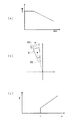
図8(a)の例示では、画像探索領域Riは明るさが低下するに従い拡大量が増加するようその値が設定されている。例えば、ECU20は、図8(a)に示す明るさと拡大量との関係を示すマップを記憶しており、画像領域設定部14はこのマップを参照することで、画像探索領域Riの拡大量を設定する。なお、図8(b)では、手前側領域TRiと奥側領域BRiとを同じ拡大量により変更しているが、手前側領域TRiの拡大量を奥側領域BRiの拡大量よりも大きくするものであってもよい。逆に、奥側領域BRiの拡大量を手前側領域TRiの拡大量よりも大きくするものであってもよい。
In the example of FIG. 8A, the value of the image search area Ri is set so that the amount of enlargement increases as the brightness decreases. For example, the
ステップS28では拡大された領域に対してガード領域GRを設定する。ガード領域GRは、図6のステップS14で、レーダ探索領域Rrとの間で重複する領域OLの判定が行われない領域である。例えば、図8(b)では、画像探索領域Riのうち、拡大された奥側領域BRiの距離方向での後端側にガード領域GRが設定されている。カメラセンサ32の検出精度は、画像物標Oiとの距離r2によっても変化するため、距離r2が閾値TD以上の場合、画像領域設定部14は、画像探索領域Riの拡大に伴う画像物標Oiの誤判定が増加しないよう、ガード領域GRを設定する。
In step S28, a guard area GR is set for the enlarged area. The guard area GR is an area where the determination of the area OL overlapping with the radar search area Rr is not performed in step S14 of FIG. For example, in FIG. 8B, a guard area GR is set on the rear end side in the distance direction of the enlarged back side area BRi in the image search area Ri. The detection accuracy of the
図8(c)は、一例として、距離r2とガード領域GRとの関係を示している。ガード領域GRは、距離r2が境界となる閾値TD以下の場合は設定されず、距離r2が閾値TD以上の場合、距離r2の増加に応じて変更後の領域に設定されるガード領域GRの範囲が増加するよう設定される。一例として、距離r2が閾値TD以上である場合、距離r2の増加に応じて、変更後の奥側領域BRiの距離方向での後端から手前側領域TRiに向けて、ガード領域GRが拡大していく。 FIG. 8C shows, as an example, the relationship between the distance r2 and the guard area GR. The guard area GR is not set when the distance r2 is equal to or less than the threshold value TD which is the boundary, and when the distance r2 is equal to or more than the threshold value TD, the range of the guard area GR set in the changed area according to the increase of the distance r2. Is set to increase. As an example, when the distance r2 is equal to or greater than the threshold value TD, the guard area GR is expanded from the rear end in the distance direction of the back side area BRi to the near side area TRi according to the increase of the distance r2. To go.
ステップS23に戻り、ヘッドライトがオンされている場合(ステップS23:NO)、ステップS25ではロービームが使用されているか、ハイビームが使用されているかを判定する。カメラセンサ32の検出方向での明るさは、ハイビームが使用されている場合とロービームが使用されている場合とでも変化するためである。図9(a)に示すように、ハイビームが使用されている場合、車両CSを基準として、明るく照らされる距離は遠方まで及ぶこととなる。そのため、カメラセンサ32の検出精度は遠方まで高い値を維持する。一方、図9(b)に示すように、ロービームが使用されている場合、ハイビームが使用されている場合と比べて、車両前方での明るく照らされる距離は近方となる。そのため、カメラセンサ32の検出精度は、遠方に行くに従い低い値となる。
Returning to step S23, if the headlight is on (step S23: NO), it is determined in step S25 whether a low beam or a high beam is used. The brightness in the detection direction of the
ロービームが使用されていれば(ステップS25:YES)、ステップS26では、ロービームを使用する場合の画像探索領域Riの拡大処理を実施する(領域拡大処理2)。ステップS26では、画像物標Oiまでの距離に応じて、画像探索領域Riの拡大量が変更される。ロービームが使用されている場合に、カメラセンサ32から画像物標Oiまでの距離が遠ざかると画像物標Oiの周囲の明るさが低下するため、カメラセンサ32の検出精度が低下する。そのため、図9(c)の例示では、画像探索領域Riの拡大量はカメラセンサ32から画像物標Oiまでの第2位置Piでの距離r2が増加するに従い増加するようその値が設定されている。また、図9(c)では、距離r2が閾値TBを超える場合、カメラセンサ32の検出精度が極端に低くなるため、領域の拡大をこれ以上実施しないようにしている。なお、この実施形態では、手前側領域TRiと奥側領域BRiとで同じ拡大量により領域を拡大しているが、奥側領域BRiの拡大量を手前側領域TRiの拡大量よりも大きくするものであってもよい。
If the low beam is used (step S25: YES), in step S26, the enlargement process of the image search area Ri in the case of using the low beam is performed (area enlargement process 2). In step S26, the amount of enlargement of the image search area Ri is changed according to the distance to the image target Oi. When a low beam is used, when the distance from the
一方、ハイビームが使用されていれば(ステップS25:NO)、ステップS27では、ハイビームを使用する場合の画像探索領域Riの拡大処理を実施する(領域拡大処理3)。ステップS27では、画像物標Oiまでの距離に応じて、画像探索領域Riの拡大量が変更される。また、ハイビームを使用する場合、ロービームを使用する場合と比べて、カメラセンサ32の検出精度が極端に低くなる距離r2が車両CSよりも遠方となるため、閾値TBが図9(c)に示す場合よりも車両CSを基準として遠方となる。
On the other hand, if the high beam is used (step S25: NO), the enlargement process of the image search area Ri in the case of using the high beam is performed in step S27 (area enlargement process 3). In step S27, the amount of enlargement of the image search area Ri is changed according to the distance to the image target Oi. Further, when using a high beam, the distance r2 at which the detection accuracy of the
そして、ステップS28によりガード領域を設定後、図7の処理を終了し、図6のステップS14に進む。 Then, after the guard area is set in step S28, the process of FIG. 7 is ended, and the process proceeds to step S14 of FIG.
次に、変更処理により領域サイズが変更される画像探索領域Riを、図10を用いて説明する。図10(a),(b)は、車両周辺の明るさがBr1である場合の例を示し、図10(c)から(f)は、車両周辺の明るさがBr2である場合の例を示している。なお、図10(c),(d)は、比較として、図6のステップS14に示す領域変更処理を実施しない場合の画像探索領域Riとレーダ探索領域Rrとを示している。なお、図10において、明るさBr1と明るさBr2とは、Br1>Br2の関係性を有している。 Next, an image search area Ri in which the area size is changed by the change process will be described with reference to FIG. 10 (a) and 10 (b) show an example where the brightness around the vehicle is Br1, and FIGS. 10 (c) to 10 (f) show an example where the brightness around the vehicle is Br2. It shows. 10C and 10D show, as a comparison, the image search area Ri and the radar search area Rr when the area change process shown in step S14 of FIG. 6 is not performed. In FIG. 10, the brightness Br1 and the brightness Br2 have a relationship of Br1> Br2.
車両周辺の明るさがBr1である場合、図10(a)に示すように、カメラセンサ32は撮像画像内の画像物標Oiと背景とを適正に区別しており、画像物標Oiの距離r2は適正に検出される。そのため、図10(b)に示すように、カメラセンサ32からの検出結果に基づいて画像探索領域Riは適正な領域に設定される。この例では、画像探索領域Riの手前側領域TRiと、レーダ探索領域Rrとの間で重複する領域OLが形成されており、カメラセンサ32とレーダセンサ31とは同一の物標を検出していると判定される。
When the brightness around the vehicle is Br1, as shown in FIG. 10A, the
車両周辺の明るさがBr2である場合、図10(c)示すように、カメラセンサ32は撮像画像内の画像物標Oiと背景とを適正に区別できず、検出領域T1の接地点T1aが高さ方向で、図10(a)で示す接地点T1aよりも上側に設定されている。そのため、図10(d)に示すように、第2位置Piは、図10(b)と比べて車長方向Yで上側に設定され、この第2位置Piを基準とする画像探索領域Riは、手前側領域TRiが図10(b)と比べて車長方向Yで上側に設定されている。そのため、画像探索領域Riとレーダ探索領域Rrとに重複する領域OLが生じず、カメラセンサ32とレーダセンサ31とが同一の画像物標Oiを検出していないと判定される。
When the brightness around the vehicle is Br2, as shown in FIG. 10C, the
一方、図10(e)では、図10(c)と同様、カメラセンサ32は撮像画像内の画像物標Oiと背景とを適正に区別できず、第2位置Piは、図10(b)と比べて車長方向Yで上側に設定されている。しかし、図10(f)では、車両周辺の明るさに応じて手前側領域TRiが図10(d)と比べて車長方向Yで下側まで拡大され、画像探索領域Riとレーダ探索領域Rrとに重複する領域OLが生じている。その結果、カメラセンサ32とレーダセンサ31とが同一の画像物標Oiを検出していると判定される。
On the other hand, in FIG. 10 (e), as in FIG. 10 (c), the
以上説明したように、この第1実施形態では、ECU20はカメラセンサ32の検出方向での明るさを判定し、この判定結果に応じて画像探索領域Riを変更する。例えば、検出方向が暗いことで画像探索領域Riが適正に設定されない場合でも、この画像探索領域Riを変更することでレーダ探索領域Rrとの間で重複する領域OLを生じ易くする。その結果、明るさに伴う物体判定部15の誤判定を抑制することができる。
As described above, in the first embodiment, the
画像領域設定部14は、画像探索領域Riを、カメラセンサ32から第2位置Piまでの距離に基づいて、画像探索領域Riの大きさを変更する際の変更量を設定する。
The image
カメラセンサ32の検出精度は、検出される画像物標Oiとの距離によっても変化する。そこで、画像探索領域Riを変更する場合は、カメラセンサ32から第2位置Piまでの距離に基づいて変更量を設定することで、画像探索領域Riの拡大に伴う画像物標Oiの誤判定の増加を抑制することができる。
The detection accuracy of the
画像領域設定部14は、車両CSのヘッドライトの光軸の上下の向きに基づいて、画像探索領域Riの大きさを変更する際の変更量を設定する。ヘッドライトの光軸の向きが異なる場合では、明るく照らされる物標までの距離範囲が異なる。そのため、上記構成では、光軸の上下の向きに基づいて画像探索領域Riの大きさの変更量を設定することで画像物標Oiの誤判定を抑制することができる。
The image
画像領域設定部14は、物体判定部15による物標Obが同一の物標Obであるとの判定が行われた後、明るさ判定部16による判定結果が変更されても、画像探索領域Riの大きさを維持する。上記構成により、物標Obが判定された後に周囲の明るさが変化することで物体が同一の物標Obとして判定されなくなるのを回避することができる。
After the image
また、ECU20は、変更後の画像探索領域Riとレーダ探索領域Rrとを用いて検出された物標が同一の物標であると判定した場合、この物標との衝突を回避するための衝突回避制御を実施する。ここで、ECU20が明るさに基づいて画像探索領域Riを拡大することで、画像探索領域Riとレーダ探索領域Rrとの重なる領域OLが増加し、結果として衝突回避制御の動作を作動させ易くする結果となる。そのため、ECU20は、判定された物標Obの検出方向における明るさに基づいて、画像探索領域Riを拡大することで、前記衝突回避制御における動作を作動させ易くしている。
Further, when the
(第2実施形態)
ECU20は、画像物標Oiの種別に応じて、画像探索領域Riを変更する際の変更量を設定するものであってもよい。図11は、第2実施形態における画像探索領域Riの大きさの変更を説明するフローチャートである。図11に示すフローチャートは、図6のステップS13においてECU20に実施される処理である。
Second Embodiment
The
この第2実施形態では、カメラセンサ32は、画像物標Oiを四輪以上の自動車、二輪車、歩行者として区別する。また、図11に示すように、ECU20は、画像物標Oiまでの距離r2と種別(二輪車、歩行者、自動車)とに応じて画像探索領域Riを変更する。
In the second embodiment, the
ステップS31では、画像物標Oiの種別を判定する。この実施形態では、画像物標Oiの種別は、カメラセンサ32から出力される画像物標Oiの種別に基づいて判定される。ステップS31が種別判定部として機能する。
In step S31, the type of the image target Oi is determined. In this embodiment, the type of the image target Oi is determined based on the type of the image target Oi output from the
画像物標Oiの種別が歩行者であれば(ステップS32:YES)、ステップS33では、歩行者である場合の変更処理を実施する。ステップS33における変更処理では、車両周辺の明るさと、画像物標Oiの種別との関係性とをもとに、画像探索領域Riの大きさの変更量が設定される。 If the type of the image target Oi is a pedestrian (step S32: YES), in step S33, the change processing in the case of being a pedestrian is performed. In the change process in step S33, the change amount of the size of the image search area Ri is set based on the brightness around the vehicle and the relationship between the type of the image target Oi.
画像物標Oiの種別と画像探索領域Riの変更量との関係を、図12を用いて説明する。図12(a)に示すように、カメラセンサ32が歩行者を検出する場合、下端が認識されない場合がある。この場合、図12(b)に例示するように、認識されない画像物標Oiの下端を補うように、画像探索領域Riの手前側領域TRiの大きさのみが拡大される。また、手前側領域TRiの大きさの拡大量は、明るさ判定部16で判定される明るさの判定結果に基づいて設定される。
The relationship between the type of the image target Oi and the change amount of the image search area Ri will be described with reference to FIG. As shown to Fig.12 (a), when the
画像物標Oiの種別が歩行者でなく(ステップS32:NO)、二輪車であれば(ステップS34:YES)、ステップS35では、二輪車である場合の変更処理を実施する。ステップS35における変更処理では、車両周辺の明るさと、画像物標Oiの種別との関係性とをもとに、画像探索領域Riの変更量が設定される。 If the type of the image target Oi is not a pedestrian (step S32: NO) and it is a two-wheeled vehicle (step S34: YES), in step S35, a change process for a two-wheeled vehicle is performed. In the change process in step S35, the change amount of the image search area Ri is set based on the brightness around the vehicle and the relationship between the type of the image target Oi.
図12(c)に示すように、カメラセンサ32が二輪車を検出する場合、上側の運転者のみが認識され下側の車両CSが認識されない場合がある。この場合、図12(d)に例示するように、認識されない画像物標Oiの下部を補うように、手前側領域TRiの拡大量が図12(b)に示す場合と比べて大きく設定される。また、手前側領域TRiの大きさの拡大量は、明るさ判定部16で判定される明るさの判定結果に基づいて設定される。
As shown in FIG. 12C, when the
ステップS34において二輪車でなく(ステップS34:NO)、自動車であれば(ステップS36:YES)、ステップS37では、自動車である場合の変更処理を実施する。ステップS37における変更処理では、車両周辺の明るさと、画像物標Oiの種別との関係性とをもとに、画像探索領域Riの変更量が設定される。 If it is not a two-wheeled vehicle in step S34 (step S34: NO) and it is an automobile (step S36: YES), in step S37, change processing in the case of an automobile is carried out. In the change process in step S37, the change amount of the image search area Ri is set based on the brightness around the vehicle and the relationship between the type of the image target Oi.
そして、自動車でない場合(ステップS36:NO)、この場合は、画像探索領域Riの大きさを変更せず、図11に示す処理を終了する。 If the vehicle is not a car (step S36: NO), in this case, the process shown in FIG. 11 is ended without changing the size of the image search area Ri.
以上説明したようにこの第2実施形態では、ECU20は、画像物標Oiの種別を判定し、判定された種別に基づいて、画像探索領域Riの大きさを変更する際の変更量を設定する。画像物標Oiの種別が異なればその特徴も異なるため、カメラセンサ32により誤検出される画像物標Oiの領域も異なる。誤検出される画像物標Oiの領域が異なると、第2位置Piも異なることとなり、画像探索領域Riの設定領域を異ならせる。そのため、上記構成により画像物標Oiの種別に応じて、画像探索領域Riの大きさの変更量を設定することで、画像物標Oiの種別に応じた適正な画像探索領域Riを設定することができる。
As described above, in the second embodiment, the
また、カメラセンサ32の検出方向が暗い場合でも、四輪以上の自動車はヘッドライトやテールライトを発光させることで画像物標Oiの周囲に明るさを生じさせるため、カメラセンサ32の検出精度は高くなる。一方、歩行者や二輪車はライト等を発光させたとしても、四輪以上の自動車と比べて画像物標Oiの明るさの増加はわずかでしかなく検出精度の低下の抑制に貢献しない。そのため、ECU20は、画像物標Oiを四輪以上の自動車、二輪車、歩行者として区別し、画像物標Oiの種別に応じて画像探索領域Riの大きさを変更する。
In addition, even when the detection direction of the
(第3実施形態)
ECU20は、カメラセンサ32が検出する物標Obが画像探索領域Riを変更する対象物体であるか、非対象物体であるかを判定し、この判定結果に基づいて、画像探索領域Riを変更する際の変更量を設定してもよい。
Third Embodiment
The
図13は、第3実施形態における画像探索領域Riの変更を説明するフローチャートである。図13に示すフローチャートは、図6のステップS14においてECU20に実施される処理である。図13に示す例において、ECU20は、画像物標Oiが歩行者及び二輪車である場合に、画像探索領域Riを変更し、その他(非対象物体)の場合画像探索領域Riを変更しないものとする。
FIG. 13 is a flowchart for explaining the change of the image search area Ri in the third embodiment. The flowchart shown in FIG. 13 is a process performed by the
ステップS41では、カメラセンサ32が画像物標Oiを検出している場合の、画像物標Oiの移動量を算出する。例えば、画像領域設定部14は、第2位置Piの時系列での変化に応じて移動ベクトルを算出し、この移動ベクトルを移動量として用いる。ここで、移動ベクトルは、画像物標Oiの各画素における単位時間での変化量と向きとを示すベクトルである。なお、画像物標Oiを周知のオプティカルフローを用いて検出している場合、このオプティカルフローを用いて移動量を算出するものであってもよい。
In step S41, the movement amount of the image target Oi is calculated when the
図14は、画像物標Oiと移動量との関係性を説明する図である。図14(a)に示すように、画像物標Oiが歩行者や二輪車である場合、画像物標Oiは時間の変化に伴って車幅方向Xに移動する。そのため、画像物標Oiが歩行者や二輪車であれば、ある時間での移動量は所定値以上となる。一方、図13(b)に示すように、固定物ROを検出している場合、固定物ROは時間が経過しても、車幅方向Xに移動することはない。そのため、画像物標Oiが固定物であれば、ある時間での移動量は所定値未満となる。そこで、画像物標Oiの車幅方向Xでの移動量を閾値TAと比較することで、カメラセンサ32が固定物を検出対象の画像物標Oiとして検出している可能性を判定することができる。
FIG. 14 is a diagram for explaining the relationship between the image target Oi and the movement amount. As shown in FIG. 14 (a), when the image target Oi is a pedestrian or a two-wheeled vehicle, the image target Oi moves in the vehicle width direction X with the change of time. Therefore, if the image target Oi is a pedestrian or a two-wheeled vehicle, the movement amount in a certain time will be equal to or more than a predetermined value. On the other hand, as shown in FIG. 13B, when the stationary object RO is detected, the stationary object RO does not move in the vehicle width direction X even if time passes. Therefore, if the image target Oi is a fixed object, the amount of movement in a given time will be less than a predetermined value. Therefore, by comparing the movement amount of the image target Oi in the vehicle width direction X with the threshold value TA, it is possible to determine the possibility that the
図13に戻り、画像物標Oiが車両CSに対して横移動していれば(ステップS42:YES)、ステップS45では、画像物標Oiの検出頻度を判定する。この実施形態では、画像領域設定部14は所定期間においてこの画像物標Oiを連続して検出している回数である連続検出回数Nを用いて検出頻度を判定する。
Returning to FIG. 13, if the image target Oi is moving laterally with respect to the vehicle CS (step S42: YES), the detection frequency of the image target Oi is determined in step S45. In this embodiment, the image
図15は、カメラセンサ32の検出結果と物体との関係性を説明する図である。図15(a),(b),(c)は、撮像画像に含まれる物体の時系列での変化を示している。画像物標Oiが歩行者であれば、カメラセンサ32はこの画像物標Oiを検出する頻度が高くなる。そのため、所定期間におけるカメラセンサ32の連続検出回数Nが多くなる。
FIG. 15 is a diagram for explaining the relationship between the detection result of the
図15(d),(e),(f)は、撮像画像に含まれる物体の時系列での変化を示している。パイロン等にヘッドライドが照射されることで、カメラセンサ32がパイロンの模様に反射する光を歩行者等として誤検出したとする。この場合、パイロンからの反射光の形状は一時的なものであるため、画像物標Oiの検出頻度は少なくなる。そのため、所定時間におけるカメラセンサ32の連続検出回数Nは少なくなる。そこで、カメラセンサ32が所定時間において画像物標Oiを連続して検出する回数を示す連続検出回数Nを閾値TNと比較することで、カメラセンサ32が非対象物体を検出している可能性を判定することができる。ここで、連続検出回数Nを判定する閾値TNは、固定値であってもよいし、画像物標Oiの種別に応じて異なる値を用いるものであってもよい。
FIGS. 15 (d), (e), and (f) show changes in time series of an object included in a captured image. It is assumed that the
連続検出回数Nが閾値TN以上であれば(ステップS45:YES)、ステップS47では、画像探索領域Riの変更量の範囲を最も大きな範囲に設定し、画像探索領域Riを変更する。この場合、画像物標Oiは横方向(車幅方向X)に移動しており、かつ、連続検出回数Nも多いため、画像領域設定部14はカメラセンサ32が非検出対象物体を検出している可能性は最も低いと判定する。そのため、画像領域設定部14は画像探索領域Riの変更量の範囲をステップS44,S46,S47の処理の中で最も大きな範囲に設定する。なお、ステップS44,S46,S47において、画像探索領域Riの大きさの変更量は、検出方向での明るさに応じて設定されるが、ステップ間で実施される変更量の範囲(最大値、最少値)がそれぞれ異なることとなる。
If the continuous detection number N is equal to or more than the threshold value TN (step S45: YES), in step S47, the range of the change amount of the image search area Ri is set to the largest range, and the image search area Ri is changed. In this case, the image target Oi moves in the lateral direction (the vehicle width direction X), and the number of times of continuous detection N is also large. Is determined to be the least likely. Therefore, the image
ステップS45において、連続検出回数Nが閾値TA未満であれば(ステップS45:NO)、ステップS46では、画像探索領域Riの変更量の範囲を中程度に設定し、画像探索領域Riを変更する。この場合、画像物標Oiは横方向に移動しているが、連続検出回数Nが少ないため、画像領域設定部14はカメラセンサ32が非検出対象物体を検出している可能性は低いが、ステップS47の場合よりは高いと判定する。そのため、画像領域設定部14は画像探索領域Riの変更量の範囲をステップS44,S46,S47の処理の中で中間の範囲に設定する。
In step S45, if the number of times of continuous detection N is less than the threshold value TA (step S45: NO), in step S46, the range of the change amount of the image search area Ri is set to be medium and the image search area Ri is changed. In this case, although the image target Oi moves in the lateral direction, since the number of times of continuous detection N is small, there is a low possibility that the
一方、ステップS42において、画像物標Oiの移動方向において車両CSに対して横方向での移動がなければ(ステップS42:NO)、ステップS43では、画像物標Oiの連続検出回数Nを判定する。画像物標Oiの検出回数が閾値TN以上であれば(ステップS43:YES)、ステップS44では、画像探索領域Riの大きさの変更量の範囲を小程度に設定し、画像探索領域Riを変更する。この場合、画像物標Oiは横方向に移動していないが、連続検出回数Nが多いため、画像領域設定部14は非検出対象物体を検出している可能性はステップS46,S47の場合よりは高いと判定する。そのため、画像領域設定部14は画像探索領域Riの変更量の範囲をステップS44,S46,S47の処理の中で最も小さい範囲に設定する。
On the other hand, if there is no movement in the lateral direction with respect to the vehicle CS in the movement direction of the image target Oi in step S42 (step S42: NO), the number N of continuous detections of the image target Oi is determined in step S43. . If the number of times of detection of the image target Oi is equal to or more than the threshold value TN (step S43: YES), in step S44, the range of the change amount of the size of the image search area Ri is set to a small degree, and the image search area Ri is changed. Do. In this case, although the image target Oi has not moved in the lateral direction, the number of times of continuous detection N is large, the possibility that the image
画像物標Oiの検出回数が閾値TN未満であれば(ステップS43:NO)、画像探索領域Riの変更量を変更することなく処理を終了する。この場合、画像物標Oiは横方向に移動しておらず、かつ、連続検出回数Nが少ないため、画像領域設定部14はカメラセンサ32が非検出対象物体を検出している可能性は最も高いと判定する。そのため、画像領域設定部14は画像探索領域Riを拡大しない。
If the number of times of detection of the image target Oi is less than the threshold value TN (step S43: NO), the process ends without changing the change amount of the image search area Ri. In this case, since the image target Oi has not moved in the lateral direction and the number N of continuous detections is small, the possibility that the
上記の説明により、ステップS41〜43,S45が可能性判定部として機能する。 According to the above description, steps S41 to 43 and S45 function as a possibility determination unit.
以上説明したようにこの第3実施形態では、ECU20は、カメラセンサ32の撮像画像により認識される物標Obが、画像探索領域Riを変更する対象となる対象物体と、同対象とならない非対象物体とのうち、非対象物体である可能性を判定する。そして、ECU20は、可能性の判定結果に基づいて、画像探索領域Riの大きさを変更する際の変更量を設定する。上記構成により、カメラセンサ32が非対象物体を検出している可能性に基づいて画像探索領域Riの大きさの変更量を設定するため、カメラセンサ32が画像探索領域Riを変更する対象でない画像物標Oiを検出している状態で画像探索領域Riを拡大してしまうことによる、判定精度の低下を抑制することができる。
As described above, in the third embodiment, the
対象物体は移動を行う物体であり、非対象物体は移動を行わない固定物であり、ECU20は、カメラセンサ32が物体を検出している期間での第2位置Piの移動量に基づいて、可能性を判定する。上記構成では、第2位置Piの移動量に基づいて画像探索領域Riを変更する対象物体であるか非対象物体であるかの判定をすることで、画像探索領域Riの拡大に伴い動きを伴わない非対象物体を検出したことによる、判定精度の低下を抑制することができる。
The target object is an object that moves, the non-target object is a fixed object that does not move, and the
可能性判定部は、カメラセンサ32が画像物標Oiを検出している頻度に基づいて、画像物標Oiの変更を伴う対象物体であるか非対象物体であるかを判定する。上記構成とすることで、画像探索領域Riの拡大に伴い光等の一時的に生じる無対物を誤検出したことによる判定精度の低下を抑制することができる。
The possibility determination unit determines, based on the frequency at which the
(その他の実施形態)
明るさ判定部16が照度センサ33からの出力に基づいて車両周辺の明るさを判定することは一例に過ぎない。これ以外にも、明るさ判定部16は現在の時刻を取得し、現在の時刻に基づいて車両周辺の明るさを判定するものであってもよい。また、カメラセンサ32が自車両の周囲を撮像することで生成された撮像画像の輝度値に基づいて、自車両の前方の明るさを判定するものであってもよい。
(Other embodiments)
The determination of the brightness around the vehicle based on the output from the
画像領域設定部14が実施する画像探索領域Riの変更は拡大のみに限定されず、縮小するものであってもよい。この場合、図7のステップS22及びステップS25において画像領域設定部14は、車両周辺の明るさが所定の閾値以上であれば画像探索領域Riを縮小し、車両周辺の明るさが閾値未満であれば画像探索領域Riを拡大する。
The change of the image search area Ri performed by the image
図7のステップS28において、距離r2に応じて画像探索領域Riにガード領域GRを設定したことは一例に過ぎない。例えば、ガード領域GRの設定に代えて、距離r2に応じて画像探索領域Riの大きさの変更量を設定し、この変更量に応じて画像探索領域Riを変更するものであってもよい。 Setting the guard area GR in the image search area Ri in accordance with the distance r2 in step S28 in FIG. 7 is merely an example. For example, instead of setting the guard area GR, the change amount of the size of the image search area Ri may be set according to the distance r2, and the image search area Ri may be changed according to the change amount.
反射波センサは、ミリ波を用いたレーダセンサ以外にも、レーザ光を送信波として用いるレーザーセンサや、超音波を送信波として用いる超音波センサを用いてもよい。 The reflected wave sensor may use a laser sensor using laser light as a transmission wave, or an ultrasonic sensor using an ultrasonic wave as a transmission wave, in addition to a radar sensor using millimeter waves.
運転支援装置10は、ECU20とカメラセンサ32とを個別に備える構成に代えて、ECU20とカメラセンサ32とを一体の装置として備えるものであってもよい。この場合、カメラセンサ32の内部に上述したECU20を備えることとなる。
The driving
12…レーダ領域設定部、14…画像領域設定部、15…物体判定部、16…明るさ判定部、20…ECU、31…レーダセンサ、32…カメラセンサ、CS…車両。
12 radar
Claims (9)
前記反射波センサにより検出された前記物体の検出位置である第1位置を基準として、前記第1位置を含む領域を反射波探索領域として設定する反射領域設定部(12)と、
前記カメラセンサにより検出された前記物体の検出位置である第2位置を基準として、前記第2位置を含む領域を画像探索領域として設定する画像領域設定部(14)と、
前記反射波探索領域と前記画像探索領域とで重複する領域が存在することを条件に、前記反射波センサ及び前記カメラセンサで検出された前記物体が同一の物体であることを判定する物体判定部(15)と、
前記カメラセンサによる前記物体の検出方向における明るさを判定する明るさ判定部(16)と、を有し、
前記画像領域設定部は、判定された前記物体の検出方向における明るさに基づいて、前記画像探索領域の大きさを変更する、物体検出装置。 A reflected wave sensor (31) for transmitting a transmission wave and acquiring a distance to the object based on a reflected wave corresponding to the transmission wave; and a camera sensor (32) for imaging the object to acquire a captured image An object detection device (20) for detecting the object existing around a vehicle using
A reflection area setting unit (12) configured to set an area including the first position as a reflection wave search area based on a first position which is a detection position of the object detected by the reflection wave sensor;
An image area setting unit (14) for setting an area including the second position as an image search area based on a second position that is a detected position of the object detected by the camera sensor;
An object determining unit that determines that the objects detected by the reflected wave sensor and the camera sensor are the same object on condition that there is an overlapping area between the reflected wave search area and the image search area (15),
A brightness determination unit (16) that determines the brightness in the detection direction of the object by the camera sensor;
The object detection device, wherein the image area setting unit changes the size of the image search area based on the determined brightness in the detection direction of the object.
前記画像領域設定部は、前記車両のヘッドライトにおける光軸の上下方向での向きに基づいて、前記画像探索領域の大きさを変更する際の変更量を設定する、請求項1又は請求項2に記載の物体検出装置。 The camera sensor captures an image in front of the vehicle.
The image area setting unit sets an amount of change when changing the size of the image search area, based on the vertical direction of the optical axis of the headlight of the vehicle. The object detection apparatus according to claim 1.
前記画像領域設定部は、前記種別判定部により判定された前記種別に基づいて、前記画像探索領域の大きさを変更する際の変更量を設定する、請求項1から請求項4のいずれか一項に記載の物体検出装置。 A type determination unit that determines the type of the object;
5. The image area setting unit according to any one of claims 1 to 4, wherein the amount of change when changing the size of the image search area is set based on the type determined by the type determination unit. The object detection apparatus as described in a term.
前記画像領域設定部は、前記可能性判定部の判定結果に基づいて、前記画像探索領域の大きさを変更する際の変更量を設定する、請求項1から請求項4のいずれか一項に記載の物体検出装置。 The possibility that the object recognized by the image captured by the camera sensor is the non-target object among the target object to be changed in the image search area and the non-target object not to be the same object is determined Has a possibility judgment unit,
5. The image area setting unit according to any one of claims 1 to 4, wherein the amount of change in changing the size of the image search area is set based on the determination result of the possibility determination unit. The object detection apparatus as described.
前記可能性判定部は、前記カメラセンサが前記物体を検出している期間での前記第2位置の移動量に基づいて、前記可能性を判定する、請求項6に記載の物体検出装置。 The target object is a moving object, and the non-target object is a fixed object not moving.
The object detection device according to claim 6, wherein the possibility determination unit determines the possibility based on a movement amount of the second position in a period in which the camera sensor is detecting the object.
前記反射波センサにより検出された前記物体の検出位置である第1位置を基準として、前記第1位置を含む領域を反射波探索領域として設定する反射領域設定工程と、
前記カメラセンサにより検出された前記物体の検出位置である第2位置を基準として、前記第2位置を含む領域を画像探索領域として設定する画像領域設定工程と、
前記反射波探索領域と前記画像探索領域とで重複する領域が存在することを条件に、前記反射波センサ及び前記カメラセンサで検出された前記物体が同一の物体であることを判定する物体判定工程と、
前記カメラセンサによる前記物体の検出方向における明るさを判定する明るさ判定工程と、を有し、
前記画像領域設定工程は、判定された前記物体の検出方向における明るさに基づいて、前記画像探索領域の大きさを変更する、物体検出方法。 A reflected wave sensor (31) for transmitting a transmission wave and acquiring a distance to the object based on a reflected wave corresponding to the transmission wave; and a camera sensor (32) for imaging the object to acquire a captured image An object detection method for detecting the object existing around a vehicle using
A reflection area setting step of setting an area including the first position as a reflection wave search area based on a first position which is a detection position of the object detected by the reflection wave sensor;
An image area setting step of setting an area including the second position as an image search area based on a second position which is a detected position of the object detected by the camera sensor;
An object determining step of determining that the objects detected by the reflected wave sensor and the camera sensor are the same object on condition that there is an overlapping area between the reflected wave search area and the image search area; When,
A brightness determination step of determining brightness in the detection direction of the object by the camera sensor;
The image area setting step changes the size of the image search area based on the determined brightness in the detection direction of the object.
Priority Applications (5)
| Application Number | Priority Date | Filing Date | Title |
|---|---|---|---|
| JP2016086408A JP6512164B2 (en) | 2016-04-22 | 2016-04-22 | Object detection apparatus, object detection method |
| DE112017002120.0T DE112017002120T5 (en) | 2016-04-22 | 2017-04-19 | Object detection device and object detection method |
| CN201780024337.8A CN109073778B (en) | 2016-04-22 | 2017-04-19 | Object detection device and object detection method |
| PCT/JP2017/015778 WO2017183667A1 (en) | 2016-04-22 | 2017-04-19 | Object detection device and object detection method |
| US16/094,772 US10535264B2 (en) | 2016-04-22 | 2017-04-19 | Object detection apparatus and object detection method |
Applications Claiming Priority (1)
| Application Number | Priority Date | Filing Date | Title |
|---|---|---|---|
| JP2016086408A JP6512164B2 (en) | 2016-04-22 | 2016-04-22 | Object detection apparatus, object detection method |
Publications (3)
| Publication Number | Publication Date |
|---|---|
| JP2017194432A JP2017194432A (en) | 2017-10-26 |
| JP2017194432A5 JP2017194432A5 (en) | 2018-06-07 |
| JP6512164B2 true JP6512164B2 (en) | 2019-05-15 |
Family
ID=60116161
Family Applications (1)
| Application Number | Title | Priority Date | Filing Date |
|---|---|---|---|
| JP2016086408A Active JP6512164B2 (en) | 2016-04-22 | 2016-04-22 | Object detection apparatus, object detection method |
Country Status (5)
| Country | Link |
|---|---|
| US (1) | US10535264B2 (en) |
| JP (1) | JP6512164B2 (en) |
| CN (1) | CN109073778B (en) |
| DE (1) | DE112017002120T5 (en) |
| WO (1) | WO2017183667A1 (en) |
Families Citing this family (12)
| Publication number | Priority date | Publication date | Assignee | Title |
|---|---|---|---|---|
| JP6649865B2 (en) * | 2016-10-27 | 2020-02-19 | 株式会社Soken | Object detection device |
| JP6759995B2 (en) * | 2016-11-11 | 2020-09-23 | 株式会社デンソー | Image processing device |
| JP6654999B2 (en) * | 2016-12-12 | 2020-02-26 | 株式会社Soken | Target detection device |
| CN108694363A (en) * | 2017-04-12 | 2018-10-23 | 日立汽车系统株式会社 | The method and apparatus that the pedestrian of vehicle periphery is detected |
| JP6996353B2 (en) | 2018-03-06 | 2022-01-17 | トヨタ自動車株式会社 | Object recognition device and vehicle travel control system |
| JP7176415B2 (en) * | 2019-01-15 | 2022-11-22 | トヨタ自動車株式会社 | Pre-collision control device |
| CN109901156A (en) * | 2019-01-25 | 2019-06-18 | 中国汽车技术研究中心有限公司 | A kind of subject fusion method and apparatus of vehicle millimetre-wave radar and camera |
| KR20200095691A (en) * | 2019-02-01 | 2020-08-11 | 삼성전자주식회사 | the method for recognizing the object using the mmWave and the electronic device supporting the same |
| EP4035353A1 (en) * | 2019-09-27 | 2022-08-03 | Ricoh Company, Ltd. | Apparatus, image processing system, communication system, method for setting, image processing method, and recording medium |
| US11847833B2 (en) | 2020-02-12 | 2023-12-19 | Strattec Security Corporation | Broad coverage non-contact obstacle detection |
| CN112689842B (en) * | 2020-03-26 | 2022-04-29 | 华为技术有限公司 | Target detection method and device |
| KR20240031778A (en) * | 2022-09-01 | 2024-03-08 | 현대모비스 주식회사 | Backward driving assist method of vehicle and apparutus thereof |
Family Cites Families (22)
| Publication number | Priority date | Publication date | Assignee | Title |
|---|---|---|---|---|
| CN1190952C (en) * | 2002-04-10 | 2005-02-23 | 中华电信股份有限公司 | Digital image monitoring control system capable of automatic adjusting lens diaphragm and detecting object movement |
| JP3918791B2 (en) * | 2003-09-11 | 2007-05-23 | トヨタ自動車株式会社 | Object detection device |
| JP4598653B2 (en) * | 2005-05-13 | 2010-12-15 | 本田技研工業株式会社 | Collision prediction device |
| EP1887382A1 (en) * | 2005-05-19 | 2008-02-13 | Olympus Corporation | Distance measuring apparatus, distance measuring method and distance measuring program |
| JP5177510B2 (en) * | 2008-03-27 | 2013-04-03 | アイシン精機株式会社 | Ultrasonic sensor |
| JP5803061B2 (en) * | 2010-06-16 | 2015-11-04 | 日産自動車株式会社 | Collision avoidance support device |
| JP5556508B2 (en) | 2010-08-30 | 2014-07-23 | 株式会社デンソー | Object detection device |
| GB201015745D0 (en) * | 2010-09-21 | 2010-10-27 | Rolls Royce Goodrich Engine Co | Position sensor system |
| JP5716343B2 (en) * | 2010-10-01 | 2015-05-13 | トヨタ自動車株式会社 | Vehicle object recognition system |
| JP5953655B2 (en) * | 2011-05-02 | 2016-07-20 | マツダ株式会社 | Vehicle driving support device |
| WO2013121911A1 (en) * | 2012-02-16 | 2013-08-22 | 日産自動車株式会社 | Solid-object detection device and solid-object detection method |
| US8705797B2 (en) * | 2012-03-07 | 2014-04-22 | GM Global Technology Operations LLC | Enhanced data association of fusion using weighted Bayesian filtering |
| EP2669846B1 (en) * | 2012-06-01 | 2017-11-01 | Ricoh Company, Ltd. | Target recognition system and target recognition method executed by the target recognition system, target recognition program executed on the target recognition system, and recording medium storing the target recognition program |
| WO2014017317A1 (en) * | 2012-07-27 | 2014-01-30 | 日産自動車株式会社 | Three-dimensional object detection device and foreign object detection device |
| MY170950A (en) * | 2012-07-27 | 2019-09-20 | Nissan Motor | Three-dimensional object detection device and three-dimensional object detection method |
| EP2879109B1 (en) * | 2012-07-27 | 2022-02-09 | Clarion Co., Ltd. | Vehicle-mounted surrounding environment recognition device |
| JP5812064B2 (en) * | 2012-11-22 | 2015-11-11 | 株式会社デンソー | Target detection device |
| JP5812061B2 (en) * | 2013-08-22 | 2015-11-11 | 株式会社デンソー | Target detection apparatus and program |
| EP3104192A4 (en) * | 2014-02-05 | 2017-03-08 | Panasonic Intellectual Property Management Co., Ltd. | Object detection device |
| JP6413620B2 (en) * | 2014-10-22 | 2018-10-31 | 株式会社Soken | Object detection device |
| JP6585413B2 (en) | 2014-10-24 | 2019-10-02 | 新日本無線株式会社 | Insulator for audio equipment |
| JP6528690B2 (en) * | 2015-02-10 | 2019-06-12 | 株式会社デンソー | Save control device, save control method |
-
2016
- 2016-04-22 JP JP2016086408A patent/JP6512164B2/en active Active
-
2017
- 2017-04-19 WO PCT/JP2017/015778 patent/WO2017183667A1/en active Application Filing
- 2017-04-19 DE DE112017002120.0T patent/DE112017002120T5/en active Pending
- 2017-04-19 CN CN201780024337.8A patent/CN109073778B/en active Active
- 2017-04-19 US US16/094,772 patent/US10535264B2/en active Active
Also Published As
| Publication number | Publication date |
|---|---|
| US10535264B2 (en) | 2020-01-14 |
| US20190130752A1 (en) | 2019-05-02 |
| WO2017183667A1 (en) | 2017-10-26 |
| JP2017194432A (en) | 2017-10-26 |
| CN109073778B (en) | 2020-02-28 |
| DE112017002120T5 (en) | 2019-01-03 |
| CN109073778A (en) | 2018-12-21 |
Similar Documents
| Publication | Publication Date | Title |
|---|---|---|
| JP6512164B2 (en) | Object detection apparatus, object detection method | |
| JP7397807B2 (en) | Rider assistance system and method | |
| US10457278B2 (en) | Lane changing support apparatus | |
| JP6611353B2 (en) | Image processing device, external recognition device | |
| JP6561584B2 (en) | Vehicle control apparatus and vehicle control method | |
| CN109204311B (en) | Automobile speed control method and device | |
| WO2016159288A1 (en) | Target presence determination method and device | |
| KR20200047886A (en) | Driver assistance system and control method for the same | |
| JP5785578B2 (en) | Vehicle periphery monitoring device | |
| CN109891262B (en) | Object detecting device | |
| US10246038B2 (en) | Object recognition device and vehicle control system | |
| JP6787157B2 (en) | Vehicle control device | |
| WO2017171082A1 (en) | Vehicle control device and vehicle control method | |
| JP6614108B2 (en) | Vehicle control apparatus and vehicle control method | |
| WO2016186171A1 (en) | Object detection device and object detection method | |
| JP6669090B2 (en) | Vehicle control device | |
| US11042996B2 (en) | Recognition apparatus | |
| JP2012008718A (en) | Obstacle avoiding apparatus | |
| JP6970547B2 (en) | Vehicle control device and vehicle control method | |
| JP2008037361A (en) | Obstacle recognition device | |
| JP2016009251A (en) | Control device for vehicle | |
| JP2018106487A (en) | Vehicle collision avoidance support apparatus and vehicle collision avoidance support method | |
| WO2018070335A1 (en) | Movement detection device, movement detection method | |
| JP2017194926A (en) | Vehicle control apparatus and vehicle control method | |
| JP2018142297A (en) | Information processing apparatus and program |
Legal Events
| Date | Code | Title | Description |
|---|---|---|---|
| A521 | Request for written amendment filed |
Free format text: JAPANESE INTERMEDIATE CODE: A523 Effective date: 20180423 |
|
| A621 | Written request for application examination |
Free format text: JAPANESE INTERMEDIATE CODE: A621 Effective date: 20180423 |
|
| TRDD | Decision of grant or rejection written | ||
| A01 | Written decision to grant a patent or to grant a registration (utility model) |
Free format text: JAPANESE INTERMEDIATE CODE: A01 Effective date: 20190312 |
|
| A61 | First payment of annual fees (during grant procedure) |
Free format text: JAPANESE INTERMEDIATE CODE: A61 Effective date: 20190325 |
|
| R151 | Written notification of patent or utility model registration |
Ref document number: 6512164 Country of ref document: JP Free format text: JAPANESE INTERMEDIATE CODE: R151 |
|
| R250 | Receipt of annual fees |
Free format text: JAPANESE INTERMEDIATE CODE: R250 |
|
| R250 | Receipt of annual fees |
Free format text: JAPANESE INTERMEDIATE CODE: R250 |