JP6511568B2 - Steering device - Google Patents

Steering device Download PDF

Info

Publication number
JP6511568B2
JP6511568B2 JP2018101704A JP2018101704A JP6511568B2 JP 6511568 B2 JP6511568 B2 JP 6511568B2 JP 2018101704 A JP2018101704 A JP 2018101704A JP 2018101704 A JP2018101704 A JP 2018101704A JP 6511568 B2 JP6511568 B2 JP 6511568B2
Authority
JP
Japan
Prior art keywords
lock
jacket
steering
lock member
shaft
Prior art date
Legal status (The legal status is an assumption and is not a legal conclusion. Google has not performed a legal analysis and makes no representation as to the accuracy of the status listed.)
Active
Application number
JP2018101704A
Other languages
Japanese (ja)
Other versions
JP2018144810A (en
Inventor
愛仁 吉原
愛仁 吉原
友紀 杉浦
友紀 杉浦
高橋 祐司
祐司 高橋
篤宗 長谷
篤宗 長谷
健朗 久保田
健朗 久保田
茂 星野
茂 星野
陽太 上坂
陽太 上坂
Current Assignee (The listed assignees may be inaccurate. Google has not performed a legal analysis and makes no representation or warranty as to the accuracy of the list.)
Fuji Kiko Co Ltd
JTEKT Corp
Toyota Motor Corp
Original Assignee
Fuji Kiko Co Ltd
JTEKT Corp
Toyota Motor Corp
Priority date (The priority date is an assumption and is not a legal conclusion. Google has not performed a legal analysis and makes no representation as to the accuracy of the date listed.)
Filing date
Publication date
Application filed by Fuji Kiko Co Ltd, JTEKT Corp, Toyota Motor Corp filed Critical Fuji Kiko Co Ltd
Priority to JP2018101704A priority Critical patent/JP6511568B2/en
Publication of JP2018144810A publication Critical patent/JP2018144810A/en
Application granted granted Critical
Publication of JP6511568B2 publication Critical patent/JP6511568B2/en
Active legal-status Critical Current
Anticipated expiration legal-status Critical

Links

Images

Description

この発明は、ステアリング装置に関する。   The present invention relates to a steering device.

たとえば、特許文献1に開示された自動車用ステアリングコラムでは、ステアリングホイールが取り付けられるステアリングシャフトが、支持ユニットに支持された調節ユニットによって回転可能に支持されている。ステアリングシャフトの軸方向において調節ユニットを移動させると、ステアリングホイールの軸方向の位置を調節することができる。
調節ユニットは、支持ユニットにおける一対の側板の間に配置されている。各側板には穴が設けられていて、この穴には、締付けボルトが挿通されている。締付けボルトには、ロック部材が取り付けられているとともに、操作レバーが連結されている。調節ユニットには、多数の切欠きが形成された相手ロック部材が連結されている。
For example, in the automotive steering column disclosed in Patent Document 1, a steering shaft to which a steering wheel is attached is rotatably supported by an adjustment unit supported by a support unit. By moving the adjusting unit in the axial direction of the steering shaft, the axial position of the steering wheel can be adjusted.
The adjustment unit is disposed between the pair of side plates in the support unit. Each side plate is provided with a hole through which a tightening bolt is inserted. A lock member is attached to the tightening bolt and an operation lever is connected. The adjustment unit is connected to a mating lock member in which a large number of notches are formed.

操作レバーを操作して締付けボルトを回転させると、いずれかの切欠きにロック部材の突起が差し込まれ、軸方向におけるステアリングホイールの位置がロックされる。   When the operating lever is operated to turn the tightening bolt, the projection of the locking member is inserted into any of the notches, and the position of the steering wheel in the axial direction is locked.

特表2011−516323号公報JP 2011-516323 gazette

特許文献1のステアリングコラムでは、操作レバーと、相手ロック部材の切欠きに差し込まれる突起を有するロック部材とが締付けボルトを介して機械的に連結されている。そのため、ステアリング装置の組み立ての一環として操作レバーおよびロック部材を締付けボルトに組み付ける際、ステアリングホイールの位置をロックするための切欠きへの突起の差し込みが不十分とならないように、締付けボルトの回転方向におけるロック部材と操作レバーとの相対位置(回転位相)を調節しなければならないので、組み立て時に困難性を伴う。   In the steering column of Patent Document 1, the operation lever and the lock member having the protrusion inserted into the notch of the mating lock member are mechanically connected via the tightening bolt. Therefore, when assembling the control lever and the lock member to the tightening bolt as part of the assembly of the steering device, the rotational direction of the tightening bolt is prevented so that the protrusion is not inserted into the notch for locking the position of the steering wheel. However, the relative position (rotational phase) of the lock member and the control lever in the above must be adjusted, resulting in difficulties in assembly.

この発明は、かかる背景のもとでなされたものであり、組み立ての困難性を低減することができるステアリング装置を提供することを目的とする。   The present invention has been made under such background, and it is an object of the present invention to provide a steering device capable of reducing the difficulty of assembly.

請求項1記載の発明は、一端(3A)に操舵部材(8)が取り付けられ、軸方向(X)に伸縮可能なステアリングシャフト(3)と、前記操舵部材側(X1)のアッパージャケット(16)および前記操舵部材とは反対側(X2)のロアージャケット(17)を有して前記ステアリングシャフトを回転自在に支持し、前記ロアージャケットに対する前記アッパージャケットの前記軸方向への相対移動によって前記ステアリングシャフトとともに伸縮可能なコラムジャケット(4)と、前記軸方向に並ぶ複数の穴(57)を有し、前記アッパージャケットに固定されたロックプレート(42)と、車体(2)に固定され、前記コラムジャケットを支持するブラケット(6)と、前記ロックプレートに進出していずれかの前記穴に係合した進出位置と、前記ロックプレートから退避して前記穴から外れた退避位置との間で前記ロックプレートに対して進退可能なロック部材(40)と、前記ロック部材とは機械的に分離した状態で前記ブラケットに支持され、前記ステアリングシャフトおよびコラムジャケットの伸縮調整のために操作される操作部材(30)と、前記操作部材の操作位置に関わらず、前記ロック部材を前記進出位置へ向けて常に付勢する付勢部材(41)と、前記操作部材の操作に応じて、前記ロック部材を押圧することによって、前記付勢部材の付勢力に抗して前記退避位置まで前記ロック部材を移動させる伝達部材(38,68)とを含み、前記付勢部材が、前記ロック部材に取り付けられた取付部(54)と、前記取付部から延び出て前記ロック部材に当接する第1延設部(56)と、前記取付部から延び出て前記伝達部材に当接する第2延設部(55)とを有し、前記第1延設部と前記第2延設部との間で前記ロック部材および前記伝達部材を挟み込む、ステアリング装置(1)である。   In the invention according to claim 1, the steering member (8) is attached to one end (3A), and the steering shaft (3) is extendable in the axial direction (X), and the upper jacket (16) of the steering member side (X1) And a lower jacket (17) on the opposite side (X2) of the steering member to rotatably support the steering shaft, and the relative movement of the upper jacket relative to the lower jacket in the axial direction of the steering A lock plate (42) having a column jacket (4) expandable with the shaft and a plurality of holes (57) aligned in the axial direction, fixed to the vehicle body (2), fixed to the upper jacket; A bracket (6) for supporting the column jacket, and an advanced position where the lock plate is advanced and engaged in any of the holes And the lock member (40) which can be advanced and retracted with respect to the lock plate between a retracted position where it is retracted from the lock plate and removed from the hole, and the bracket in a state in which the lock member is mechanically separated The lock member is always urged toward the advanced position regardless of the operation position of the operation member supported by the control member and operated to adjust the expansion and contraction of the steering shaft and the column jacket A biasing member (41) and a transmission member for moving the locking member to the retracted position against the biasing force of the biasing member by pressing the locking member according to the operation of the operation member 38, 68), wherein the biasing member extends from the mounting portion (54) attached to the locking member and from the mounting portion and abuts on the locking member A first extending portion (56) and a second extending portion (55) extending from the mounting portion and coming into contact with the transmission member; and the first extending portion and the second extending portion It is a steering device (1) which sandwiches the lock member and the transmission member between each other.

請求項2記載の発明は、前記ロック部材が、前記ロックプレート側とは反対側から前記伝達部材に当接する当接部(48)と、前記ロックプレートの前記穴に嵌り込むツース(51)を有するロック部(47)とを一体に含み、前記伝達部材が、前記ロックプレート側とは反対側に前記当接部を押圧して前記ロック部の前記ツースを前記ロックプレートの前記穴から退避させることによって、前記ロック部材を前記退避位置まで移動させる、請求項1に記載のステアリング装置である。   The invention according to claim 2 is characterized in that the lock member contacts a contact portion (48) which contacts the transmission member from the side opposite to the lock plate side, and a tooth (51) which fits into the hole of the lock plate. And the lock portion (47) integrally included, and the transmission member presses the contact portion to the side opposite to the lock plate side to retract the tooth of the lock portion from the hole of the lock plate The steering apparatus according to claim 1, wherein the locking member is moved to the retracted position.

請求項3記載の発明は、前記第1延設部が、前記ロック部材の表面に沿うように折れ曲がり、前記ロック部材に当接する先端部(56A)を有する、請求項1または2に記載のステアリング装置である。
請求項4記載の発明は、前記伝達部材が、前記軸方向に対する交差方向(Y)に延びる回転軸線まわりに前記操作部材の操作に応じて回転可能な筒状部(38A,68A)と、前記筒状部の外周面から突出したカム部(38B,68B)とを有し、前記ロックプレートから離れるように前記ロック部材を前記カム部の外面で押圧することによって前記ロック部材を前記進出位置から前記退避位置に移動させる、請求項1〜3のいずれか一項に記載のステアリング装置である。
The steering wheel according to claim 1 or 2, wherein the first extension portion has a tip (56A) which is bent along the surface of the lock member and abuts on the lock member. It is an apparatus.
The invention according to claim 4 is characterized in that the transmission member can rotate around the rotation axis extending in the cross direction (Y) with respect to the axial direction according to the operation of the operation member, and the cylindrical portion (38A, 68A) And a cam portion (38B, 68B) protruding from the outer peripheral surface of the cylindrical portion, and pressing the lock member with the outer surface of the cam portion away from the lock plate to move the lock member from the advanced position The steering apparatus according to any one of claims 1 to 3, wherein the steering apparatus is moved to the retracted position.

なお、上記において、括弧内の数字等は、後述する実施形態における対応構成要素の参照符号を表すものであるが、これらの参照符号により特許請求の範囲を限定する趣旨ではない。   In the above, the numerals and the like in the parentheses represent the reference numerals of the corresponding components in the embodiments to be described later, but they are not intended to limit the scope of the claims by these reference numerals.

請求項1記載の発明によれば、ステアリング装置では、コラムジャケットが、操舵部材側のアッパージャケットおよび操舵部材とは反対側のロアージャケットを有している。アッパージャケットがロアージャケットに対して相対移動することによって、コラムジャケットがステアリングシャフトとともに伸縮する。
アッパージャケットに固定されたロックプレートに対して、ロック部材が進退する。ロック部材は、ロックプレートのいずれかの穴に係合した進出位置と、穴から外れた退避位置との間でロックプレートに対して進退する。ロック部材が進出位置にある場合には、ステアリングシャフトおよびコラムジャケットの伸縮が停止するので、ステアリングシャフトの軸方向における操舵部材の位置がロックされる。ロック部材が退避位置にある場合には、コラムジャケットおよびステアリングシャフトの伸縮が可能になるので、ステアリングシャフトの軸方向における操舵部材の位置を調整することができる。
According to the first aspect of the present invention, in the steering apparatus, the column jacket has the upper jacket on the steering member side and the lower jacket opposite to the steering member. As the upper jacket moves relative to the lower jacket, the column jacket expands and contracts with the steering shaft.
The lock member advances and retracts with respect to the lock plate fixed to the upper jacket. The lock member moves relative to the lock plate between an advanced position engaged with any hole of the lock plate and a retracted position deviated from the hole. When the lock member is in the advanced position, the expansion and contraction of the steering shaft and the column jacket stop, so the position of the steering member in the axial direction of the steering shaft is locked. When the lock member is in the retracted position, the column jacket and the steering shaft can be extended and contracted, so that the position of the steering member in the axial direction of the steering shaft can be adjusted.

ステアリング装置では、ステアリングシャフトおよびコラムジャケットの伸縮調整のために操作部材が操作される。ロック部材は、操作部材とは機械的に分離されていて、操作部材の操作位置に関わらず、付勢部材によって進出位置へ向けて常に付勢されている。ロック部材は、退避位置まで移動するときだけ、伝達部材を介して操作部材の操作に連動する。   In the steering device, the operating member is operated to adjust the steering shaft and the column jacket in an expandable manner. The lock member is mechanically separated from the operating member, and is always biased toward the advanced position by the biasing member regardless of the operating position of the operating member. The lock member interlocks with the operation of the operation member via the transmission member only when moving to the retracted position.

そのため、ステアリング装置の組み立ての一環としてロック部材と操作部材とを組み合わせる際、ロック部材が退避位置まで移動するときに操作部材の操作に連動することだけを注意すればよい。そのため、ロック部材が進出位置および退避位置のそれぞれに正確に移動できるようにロック部材と操作部材との相対位置を調節するといった手間を省略できる。そのため、ステアリング装置の組み立ての困難性を低減することができる。   Therefore, when combining the lock member and the operation member as part of the assembly of the steering apparatus, it is only necessary to be careful that the lock member interlocks with the operation of the operation member when moving to the retracted position. Therefore, it is possible to omit the trouble of adjusting the relative position between the lock member and the operation member so that the lock member can be accurately moved to the advanced position and the retracted position. Therefore, the difficulty in assembling the steering apparatus can be reduced.

また、ロック部材が、進出位置にあるときに車両衝突が発生したときに脆弱部で破断することにより、コラムジャケットおよびステアリングシャフトが収縮する。ここでの収縮とロック部材の破断とによって、車両衝突時のエネルギーを吸収することができる。また、既存のロック部材に脆弱部を設けることによって、脆弱部を有する新たな部品を追加せずに済むので、部品点数の増加を抑えてコストの低減を図ることができる。   In addition, the column jacket and the steering shaft contract due to the locking member breaking at the fragile portion when a vehicle collision occurs when in the advanced position. By the contraction here and the breaking of the lock member, energy at the time of a vehicle collision can be absorbed. Further, by providing the fragile portion in the existing lock member, it is not necessary to add a new part having the fragile portion, so it is possible to suppress the increase in the number of parts and to reduce the cost.

図1は、本発明の一実施形態に係るステアリング装置1の模式的な斜視図である。FIG. 1 is a schematic perspective view of a steering device 1 according to an embodiment of the present invention. 図2は、ステアリング装置1の概略構成を示す模式的な側面図である。FIG. 2 is a schematic side view showing a schematic configuration of the steering device 1. 図3は、図2のIII−III線に沿うステアリング装置1の概略断面図である。FIG. 3 is a schematic cross-sectional view of the steering device 1 taken along the line III-III in FIG. 図4は、ステアリング装置1の要部の分解斜視図である。FIG. 4 is an exploded perspective view of the main part of the steering device 1. 図5は、図2のV−V線に沿うステアリング装置1の概略断面図である。FIG. 5 is a schematic cross-sectional view of the steering device 1 taken along the line V-V in FIG. 図6は、図5のVI−VI線に沿うステアリング装置1の概略断面図である。6 is a schematic cross-sectional view of the steering device 1 taken along the line VI-VI of FIG. 図7は、図6においてツース51が穴57から退避した状態を示す図である。FIG. 7 is a view showing a state in which the tooth 51 is retracted from the hole 57 in FIG. 図8は、図6においてツース51がハーフロックした状態を示す図である。FIG. 8 is a view showing a state in which the tooth 51 is half locked in FIG. 図9は、図6に本発明の第1変形例を適用した図である。FIG. 9 is a diagram in which the first modification of the present invention is applied to FIG. 図10は、図6に本発明の第2変形例を適用した図である。FIG. 10 is a diagram in which the second modified example of the present invention is applied to FIG. 図11は、図6に本発明の第3変形例を適用した図である。FIG. 11 is a diagram in which the third modified example of the present invention is applied to FIG.

以下では、本発明の実施形態を、添付図面を参照して詳細に説明する。
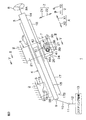
図1は、本発明の一実施形態に係るステアリング装置1の模式的な斜視図である。図2は、ステアリング装置1の概略構成を示す模式的な側面図である。
図2において、紙面左側が、ステアリング装置1が取り付けられる車体2の前側であり、紙面右側が車体2の後側であり、紙面上側が車体2の上側であり、紙面下側が車体2の下側である。
Hereinafter, embodiments of the present invention will be described in detail with reference to the accompanying drawings.
FIG. 1 is a schematic perspective view of a steering device 1 according to an embodiment of the present invention. FIG. 2 is a schematic side view showing a schematic configuration of the steering device 1.
2, the left side of the drawing is the front side of the vehicle body 2 to which the steering device 1 is attached, the right side of the drawing is the rear side of the vehicle body 2, the upper side of the drawing is the upper side of the vehicle body 2, and the lower side of the drawing is the lower side of the vehicle body 2. It is.

図2を参照して、ステアリング装置1は、ステアリングシャフト3と、コラムジャケット4と、ロアーブラケット5と、ブラケットとしてのアッパーブラケット6と、ロック機構7とを主に含んでいる。
ステアリングシャフト3では、後側の一端3Aに操舵部材8が取り付けられ、前側の他端3Bが、自在継手9、インターミディエイトシャフト10、自在継手11およびピニオン軸12を順に介してステアリング機構13に連結されている。ステアリング機構13は、ラックアンドピニオン機構等で構成されている。ステアリング機構13は、ステアリングシャフト3の回転が伝達されたことに応じて、図示しないタイヤ等の転舵輪を転舵させる。
Referring to FIG. 2, the steering apparatus 1 mainly includes a steering shaft 3, a column jacket 4, a lower bracket 5, an upper bracket 6 as a bracket, and a lock mechanism 7.
In the steering shaft 3, the steering member 8 is attached to one end 3A on the rear side, and the other end 3B on the front side is connected to the steering mechanism 13 via the universal joint 9, the intermediate shaft 10, the universal joint 11 and the pinion shaft 12 in order It is done. The steering mechanism 13 is configured by a rack and pinion mechanism or the like. The steering mechanism 13 steers steered wheels such as tires (not shown) in response to the rotation of the steering shaft 3 being transmitted.

ステアリングシャフト3は、全体として、車体2の前後方向に延びる略円筒状または略円柱状である。
以下では、ステアリングシャフト3が延びる方向を軸方向Xとする。この実施形態の軸方向Xは、他端3Bが一端3Aよりも低くなるように水平方向に対して傾斜している。軸方向Xにおいて操舵部材8側である後側には、符号「X1」を付し、軸方向Xにおいて操舵部材8とは反対側である前側には、符号「X2」を付す。後側X1は、車体2の後側と一致し、前側X2は、車体2の前側と一致している。
The steering shaft 3 has a generally cylindrical or substantially cylindrical shape extending in the front-rear direction of the vehicle body 2 as a whole.
Hereinafter, the direction in which the steering shaft 3 extends is referred to as an axial direction X. The axial direction X in this embodiment is inclined with respect to the horizontal direction such that the other end 3B is lower than one end 3A. The rear side which is the steering member 8 side in the axial direction X is given the code “X1”, and the front side which is the opposite side to the steering member 8 in the axial direction X is given the code “X2”. The rear side X1 coincides with the rear side of the vehicle body 2, and the front side X2 coincides with the front side of the vehicle body 2.

軸方向Xに直交する方向のうち、図2において紙面と垂直な方向を左右方向Yといい、図2において略上下に延びる方向を上下方向Zという。左右方向Yにおいて、図2の紙面の奥側は、右側Y1であり、紙面の手前側は、左側Y2である。上下方向Zにおける上側には、符号「Z1」を付し、上下方向Zにおける下側には、符号「Z2」を付す。
なお、図2以外の各図において図2のX〜Zの各方向に対応する方向には、図2と同じ符号を付している。
Of the directions orthogonal to the axial direction X, the direction perpendicular to the paper surface in FIG. 2 is referred to as the lateral direction Y, and the direction extending substantially vertically in FIG. 2 is referred to as the vertical direction Z. In the left-right direction Y, the back side of the paper surface of FIG. 2 is the right side Y1, and the near side of the paper surface is the left side Y2. The code "Z1" is attached to the upper side in the vertical direction Z, and the code "Z2" is attached to the lower side in the vertical direction Z.
In the drawings other than FIG. 2, the same reference numerals as in FIG. 2 are given to directions corresponding to the directions X to Z in FIG. 2.

ステアリングシャフト3は、円筒状または円柱状のアッパーシャフト14およびロアーシャフト15を含んでいる。アッパーシャフト14は、ロアーシャフト15よりも後側X1に配置されている。アッパーシャフト14とロアーシャフト15とは、同軸状に並んでいる。
アッパーシャフト14における後側X1の端部が、ステアリングシャフト3の一端3Aであり、当該端部に操舵部材8が連結されている。アッパーシャフト14では、少なくとも前側X2の端部が円筒状になっている。アッパーシャフト14の前側X2の端部には、ロアーシャフト15の後側X1の端部が前側X2から挿入されている。
The steering shaft 3 includes a cylindrical or cylindrical upper shaft 14 and a lower shaft 15. The upper shaft 14 is disposed on the rear side X1 relative to the lower shaft 15. The upper shaft 14 and the lower shaft 15 are coaxially aligned.
The end of the rear side X1 in the upper shaft 14 is one end 3A of the steering shaft 3, and the steering member 8 is connected to the end. In the upper shaft 14, at least the end of the front side X2 is cylindrical. The end of the rear side X1 of the lower shaft 15 is inserted into the end of the front side X2 of the upper shaft 14 from the front side X2.

アッパーシャフト14とロアーシャフト15とは、スプライン嵌合やセレーション嵌合によって嵌合している。そのため、アッパーシャフト14とロアーシャフト15とは、一体回転可能であるとともに、軸方向Xに沿って相対移動可能である。よって、ステアリングシャフト3は、軸方向Xに伸縮可能である。
コラムジャケット4は、全体として、軸方向Xへ延びる中空体である。コラムジャケット4には、ステアリングシャフト3が収容されている。コラムジャケット4は、軸方向Xに延びる略筒状をなすアッパージャケット16およびロアージャケット17を有している。
The upper shaft 14 and the lower shaft 15 are fitted by spline fitting or serration fitting. Therefore, the upper shaft 14 and the lower shaft 15 are integrally rotatable and relatively movable along the axial direction X. Therefore, the steering shaft 3 can expand and contract in the axial direction X.
The column jacket 4 is a hollow body extending in the axial direction X as a whole. A steering shaft 3 is accommodated in the column jacket 4. The column jacket 4 has a substantially cylindrical upper jacket 16 and a lower jacket 17 extending in the axial direction X.

アッパージャケット16は、ロアージャケット17よりも後側X1に位置している。言い換えると、ロアージャケット17は、アッパージャケット16よりも前側X2に位置している。ロアージャケット17は、アッパージャケット16よりも太く、アッパージャケット16に対して外嵌されている。詳しくは、アッパージャケット16の前側X2の端部16Aが、ロアージャケット17の後側X1の端部17Aに対して後側X1から挿入されている。言い換えると、ロアージャケット17は、アッパージャケット16の一部を収容している。この状態で、アッパージャケット16は、ロアージャケット17に対する軸方向Xへの相対移動が可能である。この相対移動によって、コラムジャケット4は、軸方向Xに沿って伸縮可能である。   The upper jacket 16 is located on the rear side X1 of the lower jacket 17. In other words, the lower jacket 17 is located on the front side X2 of the upper jacket 16. The lower jacket 17 is thicker than the upper jacket 16 and externally fitted to the upper jacket 16. Specifically, the end 16A of the front side X2 of the upper jacket 16 is inserted into the end 17A of the rear side X1 of the lower jacket 17 from the rear side X1. In other words, the lower jacket 17 accommodates a portion of the upper jacket 16. In this state, upper jacket 16 can move relative to lower jacket 17 in the axial direction X. The column jacket 4 can expand and contract along the axial direction X by this relative movement.

また、ステアリングシャフト3は、図示しない軸受によってコラムジャケット4に対して連結されていることから、コラムジャケット4は、ステアリングシャフト3を回転自在に支持している。
詳しくは、アッパーシャフト14とアッパージャケット16とは、図示しない軸受を介して連結されている。また、ロアーシャフト15とロアージャケット17とは、図示しない軸受を介して連結されている。そのため、アッパーシャフト14およびアッパージャケット16の連結体が、ロアーシャフト15およびロアージャケット17に対して、軸方向Xに相対移動可能である。これにより、コラムジャケット4は、ステアリングシャフト3とともに伸縮可能である。
Further, since the steering shaft 3 is connected to the column jacket 4 by a bearing (not shown), the column jacket 4 rotatably supports the steering shaft 3.
Specifically, the upper shaft 14 and the upper jacket 16 are connected via a bearing (not shown). Further, the lower shaft 15 and the lower jacket 17 are connected via a bearing (not shown). Therefore, the combined body of the upper shaft 14 and the upper jacket 16 is movable relative to the lower shaft 15 and the lower jacket 17 in the axial direction X. Thus, the column jacket 4 can extend and contract with the steering shaft 3.

ここでのステアリングシャフト3およびコラムジャケット4の伸縮を「テレスコ」と呼び、この伸縮調整、つまり、テレスコによる操舵部材8の軸方向Xでの位置調整をテレスコ調整と呼ぶ。
ロアーブラケット5は、コラムジャケット4の前側X2の部分を支持し、ステアリング装置1を車体2に連結している。詳しくは、ロアーブラケット5は、ロアージャケット17の前側X2の部分を支持している。
The expansion and contraction of the steering shaft 3 and the column jacket 4 here is referred to as "telesco", and this expansion and contraction adjustment, that is, the positional adjustment of the steering member 8 in the axial direction X by the telescopic adjustment is called telescopic adjustment.
The lower bracket 5 supports the front portion X2 of the column jacket 4 and connects the steering device 1 to the vehicle body 2. Specifically, the lower bracket 5 supports a portion of the front side X2 of the lower jacket 17.

ロアーブラケット5は、ロアージャケット17に固定された可動ブラケット18と、車体2に固定された固定ブラケット19と、左右方向Yに延びる中心軸20とを含んでいる。
可動ブラケット18は、たとえばロアージャケット17の前側X2の端部17Bの上側外周面に左右一対で設けられている(図1参照)。可動ブラケット18は、固定ブラケット19によって、中心軸20を介して回動可能に支持されている。そのため、コラムジャケット4全体は、ステアリングシャフト3を伴って、中心軸20を中心に上下に回動することができる。ここでの回動を「チルト」と呼び、チルトによる操舵部材8の向き調整をチルト調整と呼ぶ。ロアージャケット17は、中心軸20を介して車体2側の固定ブラケット19に連結されているので、チルトできるものの、軸方向Xに移動することはできない。
Lower bracket 5 includes a movable bracket 18 fixed to lower jacket 17, a fixed bracket 19 fixed to vehicle body 2, and a central axis 20 extending in the left-right direction Y.
The movable bracket 18 is provided, for example, on the upper side outer peripheral surface of the end portion 17B of the front side X2 of the lower jacket 17 in a pair (see FIG. 1). The movable bracket 18 is rotatably supported by the fixed bracket 19 via the central shaft 20. Therefore, the entire column jacket 4 can be pivoted up and down around the central axis 20 with the steering shaft 3. The rotation here is referred to as "tilt", and the direction adjustment of the steering member 8 by the tilt is referred to as tilt adjustment. The lower jacket 17 is connected to the fixed bracket 19 on the side of the vehicle body 2 via the central axis 20. Therefore, although the lower jacket 17 can be tilted, it can not move in the axial direction X.

アッパーブラケット6は、コラムジャケット4において可動ブラケット18よりも後側X1の部分を支持する。詳しくは、アッパーブラケット6は、ロアージャケット17の後側X1の部分を支持している。
図3は、図2のIII−III線に沿うステアリング装置1の概略断面図である。
図3を参照して、アッパーブラケット6は、下向きに開放する溝形であり、軸方向Xから見て上下が逆になった略U字状をなすように、コラムジャケット4を挟んで左右対称に形成されている。詳述すると、アッパーブラケット6は、左右方向Yに薄くコラムジャケット4を挟んで対向する一対の側板21と、一対の側板21のそれぞれの上側端部に連結された上下方向Zに薄い連結板22とを一体的に備えている。
The upper bracket 6 supports a portion of the column jacket 4 behind the movable bracket 18 on the rear side X1. Specifically, the upper bracket 6 supports a portion of the rear side X1 of the lower jacket 17.
FIG. 3 is a schematic cross-sectional view of the steering device 1 taken along the line III-III in FIG.
Referring to FIG. 3, the upper bracket 6 is a groove that opens downward, and is symmetrical with respect to the column jacket 4 so as to form a substantially U shape whose upper and lower sides are reversed as viewed in the axial direction X Is formed. More specifically, the upper bracket 6 has a pair of side plates 21 which are thin in the lateral direction Y with the column jacket 4 interposed therebetween, and a connecting plate 22 which is thin in the vertical direction Z connected to upper end portions of the pair of side plates 21. And are integrated.

一対の側板21において、左右方向Yから見て同じ位置には、チルト用長孔23が形成されている。チルト用長孔23は、上下方向Z、厳密には、中心軸20(図2参照)を中心とした周方向であるチルト方向に延びている。連結板22は、たとえば一対の側板21よりも左右方向Yにおいて両外側へ延びた部分を有しており、当該部分に挿通される図示しないボルト等によって、アッパーブラケット6全体が車体2に固定されている。   In the pair of side plates 21, long holes for tilt 23 are formed at the same position when viewed in the left-right direction Y. The tilt elongated hole 23 extends in the vertical direction Z, strictly speaking, in a tilt direction which is a circumferential direction around the central axis 20 (see FIG. 2). The connecting plate 22 has, for example, a portion extending outward in the left-right direction Y more than the pair of side plates 21. The entire upper bracket 6 is fixed to the vehicle body 2 by a bolt or the like (not shown) ing.

ここで、ロアージャケット17において後側X1の端部17Aにおける下側Z2の部分には、軸方向Xに延びて端部17Aを切り欠くスリット24が形成されている(図1も参照)。スリット24は、端部17Aからロアージャケット17の外部へ向けて後側X1および下側Z2の両方へ露出されている(図1も参照)。そのため、ロアージャケット17の端部17Aは、上下が逆になった略U字状の断面を有している。   Here, a slit 24 which extends in the axial direction X and cuts out the end 17A is formed in the lower jacket 17 at the lower portion Z2 at the end 17A of the rear side X1 (see also FIG. 1). The slits 24 are exposed from the end 17A to the outside of the lower jacket 17 to both the rear side X1 and the lower side Z2 (see also FIG. 1). Therefore, the end 17A of the lower jacket 17 has a substantially U-shaped cross section whose upper and lower sides are reversed.

また、ロアージャケット17の端部17Aには、左右方向Yからスリット24を区画しつつ下側Z2へ延びる一対の支持部25が一体的に設けられている。支持部25は、軸方向Xおよび上下方向Zに広がる略直方体である。
一対の支持部25のそれぞれには、左右方向Yから見て同じ位置に、左右方向Yに支持部25を貫通する貫通孔26が形成されている。
Further, at the end 17A of the lower jacket 17, a pair of support portions 25 extending to the lower side Z2 while dividing the slit 24 in the left-right direction Y is integrally provided. The support portion 25 is a substantially rectangular parallelepiped that extends in the axial direction X and the vertical direction Z.
In each of the pair of support portions 25, a through hole 26 penetrating the support portion 25 in the left-right direction Y is formed at the same position as viewed in the left-right direction Y.

ステアリング装置1は、左右方向Yから見て貫通孔26とチルト用長孔23とが重なる部分に挿通される締付軸27を含む。締付軸27は、左右方向Yに細長く延びる略円柱状である。締付軸27の左右方向Yにおける両端は、アッパーブラケット6の一対の側板21から左右方向Yの外側にはみ出ている。締付軸27の左側Y2の端部には、締付軸27よりも大径な頭部29が形成されている。   The steering device 1 includes a tightening shaft 27 which is inserted into a portion where the through hole 26 and the long hole for tilt 23 overlap when viewed in the left-right direction Y. The tightening shaft 27 has a substantially cylindrical shape elongated in the lateral direction Y. Both ends of the tightening shaft 27 in the left-right direction Y protrude from the pair of side plates 21 of the upper bracket 6 to the outside in the left-right direction Y. At the end of the left side Y2 of the tightening shaft 27, a head 29 larger in diameter than the tightening shaft 27 is formed.

ステアリング装置1では、頭部29と左側Y2の側板21との間に、テレスコ調整やチルト調整のために操作される把持可能なレバータイプの操作部材30と、環状のカム31およびカムフォロワ32とが、左側Y2からこの順に並んで配置されている。
締付軸27は、操作部材30の長手方向一端側の基端部30A、カム31およびカムフォロワ32のそれぞれに対して挿通されている。締付軸27がアッパーブラケット6の各チルト用長孔23に挿通されていることから、操作部材30、カム31およびカムフォロワ32は、締付軸27を介してアッパーブラケット6によって支持されている。アッパーブラケット6は、ロアージャケット17を支持しているため、操作部材30は、ロアージャケット17によっても支持されている。
In the steering apparatus 1, between the head 29 and the side plate 21 of the left side Y 2, a grippable lever type operation member 30 operated for telescopic adjustment and tilt adjustment, an annular cam 31 and a cam follower 32 , From the left Y2 are arranged in this order.
The tightening shaft 27 is inserted through each of the proximal end portion 30A at one end side in the longitudinal direction of the operation member 30, the cam 31, and the cam follower 32. Since the tightening shaft 27 is inserted into the respective tilt elongated holes 23 of the upper bracket 6, the operation member 30, the cam 31 and the cam follower 32 are supported by the upper bracket 6 via the tightening shaft 27. Since the upper bracket 6 supports the lower jacket 17, the operation member 30 is also supported by the lower jacket 17.

操作部材30およびカム31が締付軸27に対して一体回転可能であるのに対して、カムフォロワ32は、締付軸27に対して相対回転可能かつ左右方向Yに移動可能である。ただし、カムフォロワ32において左側Y2の側板21のチルト用長孔23に挿通される部分には、二面幅が形成されているので、カムフォロワ32の空転がチルト用長孔23によって防止されている。   While the operation member 30 and the cam 31 are integrally rotatable with respect to the clamping shaft 27, the cam follower 32 is relatively rotatable with respect to the clamping shaft 27 and movable in the left-right direction Y. However, since a two-faced width is formed in a portion of the cam follower 32 which is inserted into the long hole 23 for tilt of the side plate 21 of the left Y2, idle rotation of the cam follower 32 is prevented by the long hole 23 for tilt.

締付軸27の右側Y1の端部には、ナット33が取り付けられている。ナット33と右側の側板21との間には、介在部材34、針状ころ軸受35およびスラストワッシャ36が、左側Y2からこの順に並んでいる。締付軸27は、介在部材34、針状ころ軸受35およびスラストワッシャ36のそれぞれに対して挿通されている。
締付軸27は、アッパーブラケット6の各チルト用長孔23内で、前述したチルト方向に移動可能である。運転者がチルト調整のために操舵部材8を上下方向Zに移動させると、アッパーブラケット6に対し相対的に、コラムジャケット4全体が前述したようにチルトする。操舵部材8のチルト調整は、締付軸27がチルト用長孔23内で移動可能な範囲で行われる。
A nut 33 is attached to the end of the right side Y1 of the tightening shaft 27. Between the nut 33 and the right side plate 21, the interposing member 34, the needle roller bearing 35 and the thrust washer 36 are arranged in this order from the left side Y2. The tightening shaft 27 is inserted through each of the interposing member 34, the needle roller bearing 35 and the thrust washer 36.
The tightening shaft 27 is movable in the tilt direction described above in each tilt elongated hole 23 of the upper bracket 6. When the driver moves the steering member 8 in the vertical direction Z for tilt adjustment, the entire column jacket 4 tilts as described above relative to the upper bracket 6. The tilt adjustment of the steering member 8 is performed in a range in which the tightening shaft 27 can move within the tilt elongated hole 23.

運転者等の使用者がテレスコ調整やチルト調整をした後に、操作部材30の長手方向一端側の先端部30Bを掴んで操作部材30を締付軸27回りに回動させると、カム31が回転し、カム31およびカムフォロワ32に形成されたカム突起37が互いに乗り上げる。これにより、カムフォロワ32は、締付軸27の軸方向に沿って右側Y1に移動し、左側Y2の側板21に押し付けられる。当該押し付けによって、一対の側板21は、カムフォロワ32と介在部材34との間で左右方向Yの両側から締め付けられる。   When the user such as the driver etc. adjusts the telescopic adjustment and tilt adjustment, the cam 31 rotates when the operating member 30 is turned around the tightening shaft 27 by grasping the leading end 30B at one end side in the longitudinal direction of the operating member 30 The cam projections 37 formed on the cam 31 and the cam follower 32 ride on each other. Accordingly, the cam follower 32 moves to the right Y1 along the axial direction of the tightening shaft 27, and is pressed against the side plate 21 of the left Y2. By the pressing, the pair of side plates 21 is tightened from both sides in the left-right direction Y between the cam follower 32 and the interposing member 34.

これにより、一対の側板21が左右方向Yの両側からロアージャケット17の支持部25を挟持することで各側板21と支持部25との間に摩擦力が生じる。当該摩擦力によって、コラムジャケット4の位置がロックされ、操舵部材8がチルト調整後の位置でロックされ、チルト方向に移動できなくなる。
また、ロアージャケット17の一対の支持部25が側板21によって挟持されることによって、一対の支持部25の間隔が狭まるので、ロアージャケット17の内周部が狭くなって、ロアージャケット17は、ロアージャケット17内のアッパージャケット16に圧接する。
Thereby, when the pair of side plates 21 sandwich the support portion 25 of the lower jacket 17 from both sides in the left-right direction Y, a frictional force is generated between each side plate 21 and the support portion 25. Due to the frictional force, the position of the column jacket 4 is locked, and the steering member 8 is locked at the position after tilt adjustment, and can not move in the tilt direction.
Further, since the pair of support portions 25 of the lower jacket 17 is sandwiched by the side plates 21, the distance between the pair of support portions 25 is narrowed, so the inner peripheral portion of the lower jacket 17 is narrowed. The upper jacket 16 in the jacket 17 is in pressure contact.

これにより、アッパージャケット16とロアージャケット17との間に摩擦力が生じることによって、アッパージャケット16の位置がロックされ、操舵部材8がテレスコ調整後の位置でロックされ、軸方向Xに移動できなくなる。
このように、チルト方向および軸方向Xにおいて操舵部材8の位置が固定されているときのステアリング装置1の状態を「ロック状態」と呼ぶ。
As a result, a frictional force is generated between the upper jacket 16 and the lower jacket 17, whereby the position of the upper jacket 16 is locked and the steering member 8 is locked at the position after telescopic adjustment and can not move in the axial direction X .
As described above, the state of the steering device 1 when the position of the steering member 8 is fixed in the tilt direction and the axial direction X is referred to as a “locked state”.

ロック状態のステアリング装置1において、先程とは逆方向に操作部材30を回動させると、カム31がカムフォロワ32に対して回転し、カムフォロワ32は、締付軸27の軸方向に沿って左側Y2に移動する。すると、カムフォロワ32と介在部材34との間における一対の側板21に対する締め付けが解除される。そのため、各側板21と支持部25との間の摩擦力や、ロアージャケット17とアッパージャケット16との間の摩擦力が無くなるので、操舵部材8が軸方向Xおよびチルト方向に移動できるようになる。これにより、操舵部材8のテレスコ調整やチルト調整が再び可能となる。   In the steering apparatus 1 in the locked state, when the operation member 30 is rotated in the opposite direction to the above, the cam 31 rotates relative to the cam follower 32, and the cam follower 32 moves leftward Y2 along the axial direction of the tightening shaft 27. Move to Then, the tightening of the pair of side plates 21 between the cam follower 32 and the interposing member 34 is released. Therefore, the frictional force between each side plate 21 and the support portion 25 and the frictional force between the lower jacket 17 and the upper jacket 16 are eliminated, so that the steering member 8 can move in the axial direction X and the tilt direction. . Thereby, the telescopic adjustment and the tilt adjustment of the steering member 8 become possible again.

このように、チルト方向および軸方向Xにおいて操舵部材8の位置の固定が解除されているときのステアリング装置1の状態を「ロック解除状態」と呼ぶ。
次に、ロック機構7について詳しく説明する。ロック機構7は、ロック状態のステアリング装置1においてアッパージャケット16を軸方向Xに動かないように強固にロックするためのものであって、締付軸27の左右方向Yにおける中央部の周辺に設けられている。
As described above, the state of the steering device 1 when the fixing of the position of the steering member 8 in the tilt direction and the axial direction X is released is referred to as the “unlocked state”.
Next, the lock mechanism 7 will be described in detail. The lock mechanism 7 is for firmly locking the upper jacket 16 so as not to move in the axial direction X in the locked steering apparatus 1, and is provided around the central portion in the left-right direction Y of the tightening shaft 27. It is done.

図4は、ステアリング装置1の要部の分解斜視図である。図4では、説明の便宜上、アッパージャケット16を2点鎖線で表している。図5は、図2のV−V線に沿うステアリング装置1の概略断面図である。図6は、図5のVI−VI線に沿うステアリング装置1の概略断面図である。図6では、説明の便宜上、ステアリングシャフト3の図示を省略している(後述する図7〜図11においても同様)。   FIG. 4 is an exploded perspective view of the main part of the steering device 1. In FIG. 4, the upper jacket 16 is represented by a two-dot chain line for convenience of explanation. FIG. 5 is a schematic cross-sectional view of the steering device 1 taken along the line V-V in FIG. 6 is a schematic cross-sectional view of the steering device 1 taken along the line VI-VI of FIG. In FIG. 6, the steering shaft 3 is omitted for convenience of explanation (the same applies to FIGS. 7 to 11 described later).

図4を参照して、ロック機構7は、伝達部材としてのカム38と、支持軸39と、ロック部材40と、付勢部材41と、ロックプレート42とを含んでいる。
カム38は、左右方向Yに延びる円筒状のボス部38Aと、ボス部38Aの周上1箇所からボス部38Aの径方向外側へ突出したカム部38Bとを一体的に含む。カム部38Bは、左右方向Yから見て、ボス部38Aの径方向外側へ細くなる略三角形状である。
Referring to FIG. 4, the lock mechanism 7 includes a cam 38 as a transmission member, a support shaft 39, a lock member 40, a biasing member 41, and a lock plate 42.
The cam 38 integrally includes a cylindrical boss 38A extending in the left-right direction Y, and a cam 38B projecting outward in the radial direction of the boss 38A from one circumferential position of the boss 38A. The cam portion 38B has a substantially triangular shape that narrows outward in the radial direction of the boss portion 38A when viewed in the left-right direction Y.

カム部38Bにおいて当該径方向外側の先端部には、符号「38C」を付すことにする。カム部38Bは、先端部38Cとボス部38Aの外周面との間を結び、ボス部38Aの外周面に滑らかにつながる一対の円弧面38Dを有している。
カム38は、ロアージャケット17のスリット24内に配置されていて、ボス部38Aには、締付軸27において一対の支持部25の間でスリット24内に露出された部分が挿通されている(図3も参照)。ボス部38Aと締付軸27とは、スプライン嵌合等によって嵌合している。そのため、カム38は、操作部材30の操作に応じて締付軸27と一体回転可能である。
In the cam portion 38B, the distal end portion in the radial direction is given the reference numeral "38C". The cam portion 38B has a pair of arc surfaces 38D that connect the tip end portion 38C and the outer peripheral surface of the boss portion 38A and smoothly connect to the outer peripheral surface of the boss portion 38A.
The cam 38 is disposed in the slit 24 of the lower jacket 17, and a portion of the tightening shaft 27 exposed in the slit 24 between the pair of support portions 25 is inserted through the boss portion 38A (see FIG. See also Figure 3). The boss 38A and the tightening shaft 27 are fitted by spline fitting or the like. Therefore, the cam 38 can rotate integrally with the tightening shaft 27 in accordance with the operation of the operation member 30.

支持軸39は、左右方向Yに延びる1本の略円柱状である。支持軸39に関連して、図5を参照して、ロアージャケット17の各支持部25において貫通孔26よりも前側X2の位置には、支持部25を左右方向Yに貫通する貫通孔43が1つずつ形成されている。各支持部25において、貫通孔43は、左右方向Yにおける外側において拡径された拡径部44を有している。支持軸39は、各支持部25の貫通孔43に挿通されていて、支持軸39の周方向C(図4参照)に回転可能である。   The support shaft 39 has a single substantially cylindrical shape extending in the left-right direction Y. With reference to FIG. 5, in relation to the support shaft 39, at each support 25 of the lower jacket 17, a through hole 43 passing through the support 25 in the left-right direction Y at a position X2 ahead of the through hole 26. It is formed one by one. In each support portion 25, the through hole 43 has an enlarged diameter portion 44 which is expanded in diameter in the lateral direction Y on the outer side. The support shafts 39 are inserted into the through holes 43 of the support portions 25 and can rotate in the circumferential direction C (see FIG. 4) of the support shafts 39.

支持軸39の左右方向Yにおける両端部は、拡径部44まで到達している。支持軸39の左右方向Yにおけるいずれかの端部には、プッシュナット45が取り付けられている。本実施形態では、プッシュナット45は、支持軸39の左側Y2の端部に取り付けられている。支持軸39は、プッシュナット45によってロアージャケット17に対して左右方
向Yに位置決めされている。このように、支持軸39は、貫通孔43に挿通されることでロアージャケット17によって支持されている。
Both end portions of the support shaft 39 in the left-right direction Y reach the enlarged diameter portion 44. A push nut 45 is attached to either end of the support shaft 39 in the left-right direction Y. In the present embodiment, the push nut 45 is attached to the end of the left side Y 2 of the support shaft 39. The support shaft 39 is positioned by the push nut 45 in the left-right direction Y with respect to the lower jacket 17. As described above, the support shaft 39 is supported by the lower jacket 17 by being inserted into the through hole 43.

図4に戻り、ロック部材40は、左右方向Yから見て、後側X1へ略90°傾いた略V字状である。ロック部材40は、基端部46と、基端部46から後側X1へ延びるロック部47および当接部48と、を含んでいる。
基端部46は、ロック部47と当接部48との連結部分である。基端部46には、基端部46を左右方向Yに貫通する挿通孔49が形成されている。基端部46の左右方向Yにおける両側面には、挿通孔49を取り囲みながら左右方向Yにおける外側へ突出する円筒部50が1つずつ形成されている。円筒部50は、基端部46の一部とみなされる。
Returning to FIG. 4, the lock member 40 has a substantially V shape inclined approximately 90 ° to the rear side X1 when viewed in the left-right direction Y. The lock member 40 includes a proximal end 46 and a lock 47 and an abutment 48 extending from the proximal end 46 to the rear side X1.
The base end portion 46 is a connecting portion between the lock portion 47 and the contact portion 48. The proximal end portion 46 is formed with an insertion hole 49 penetrating the proximal end portion 46 in the left-right direction Y. On both side surfaces of the base end portion 46 in the left-right direction Y, cylindrical portions 50 that protrude outward in the left-right direction Y are formed one by one while surrounding the insertion hole 49. The cylindrical portion 50 is considered to be part of the proximal end 46.

ロック部47は、基端部46から後側X1かつ上側Z1へ細長く延びる形状を有する。ロック部47の後側X1の端部は、ツース51であり、上側Z1に向けて折り曲げられている。また、ロック部47の下面47Aにおいて、ツース51に前側X2から隣接する位置には、左右方向Yに延びる切り欠き52が形成されている。
切り欠き52は、左右方向Yに延びる1本の溝である。ロック部47において切り欠き52が形成された部分を脆弱部53という。ロック部47は、脆弱部53において局所的に薄くなっていることによって、脆弱部53において局所的に強度が低くなっている。
The lock portion 47 has a shape elongated from the base end 46 to the rear side X1 and the upper side Z1. The end of the rear side X1 of the lock portion 47 is a tooth 51 and is bent toward the upper side Z1. In the lower surface 47A of the lock portion 47, a notch 52 extending in the left-right direction Y is formed at a position adjacent to the tooth 51 from the front side X2.
The notch 52 is a single groove extending in the left-right direction Y. A portion where the notch 52 is formed in the lock portion 47 is referred to as a fragile portion 53. The strength of the lock portion 47 is locally reduced in the fragile portion 53 by being locally thinned in the fragile portion 53.

当接部48は、基端部46から後側X1へ細長く延びる形状を有する。当接部48は、ロック部47よりも下側Z2に位置している。
このようなロック部材40は、ロアージャケット17のスリット24内において、カム38よりも前側X2に配置されている(図6も参照)。前述した支持軸39においてスリット24内に位置する部分が、ロック部材40の基端部46の挿通孔49に挿通されている。支持軸39と基端部46とは、スプライン嵌合等によって嵌合している。そのため、ロック部材40は、支持軸39と共に、支持軸39の軸中心まわりの周方向Cに回転可能である。
The abutment portion 48 has a shape that elongates from the proximal end portion 46 to the rear side X1. The contact portion 48 is located on the lower side Z2 of the lock portion 47.
Such a locking member 40 is disposed on the front side X2 of the cam 38 in the slit 24 of the lower jacket 17 (see also FIG. 6). A portion of the support shaft 39 described above located in the slit 24 is inserted into the insertion hole 49 of the proximal end 46 of the lock member 40. The support shaft 39 and the base end 46 are fitted by spline fitting or the like. Therefore, the lock member 40 can rotate in the circumferential direction C around the axial center of the support shaft 39 together with the support shaft 39.

支持軸39がロアージャケット17の各支持部25の貫通孔43に挿通されているため(図5参照)、ロック部材40は、支持軸39を介してロアージャケット17によって支持されている。また、前述したように、操作部材30は、締付軸27を介してロアージャケット17によって支持されている。つまり、操作部材30は、ロック部材40とは機械的に分離した状態でロアージャケット17に支持されている。   Since the support shaft 39 is inserted through the through holes 43 of the support portions 25 of the lower jacket 17 (see FIG. 5), the lock member 40 is supported by the lower jacket 17 via the support shaft 39. Further, as described above, the operation member 30 is supported by the lower jacket 17 via the tightening shaft 27. That is, the operation member 30 is supported by the lower jacket 17 in a state of being mechanically separated from the lock member 40.

また、前述したカム38は、ロック部材40のロック部47と当接部48との間に配置され、カム38のカム部38Bが当接部48の上面48Aに対して上側Z1から接触している(図6参照)。
付勢部材41は、針金等を曲げて形成されたばねである。付勢部材41は、基端部46における左側Y2の円筒部50の外周面に外から巻き付けられるコイル状部54と、コイル状部54から後側X1へ延びる保持部55および変形部56を一体的に含んでいる。変形部56は、保持部55よりも下側Z2に配置されている。変形部56の後側X1の端部56Aは、右側Y1に折れ曲がっている。
Further, the cam 38 described above is disposed between the lock portion 47 and the contact portion 48 of the lock member 40, and the cam portion 38B of the cam 38 contacts the upper surface 48A of the contact portion 48 from the upper side Z1. (See Figure 6).
The biasing member 41 is a spring formed by bending a wire or the like. The biasing member 41 integrally integrates a coiled portion 54 wound from the outside on the outer peripheral surface of the cylindrical portion 50 on the left side Y2 at the base end portion 46, a holding portion 55 extending from the coiled portion 54 to the rear side X1, Is included. The deformation portion 56 is disposed on the lower side Z <b> 2 of the holding portion 55. The end 56A of the rear side X1 of the deformation portion 56 is bent to the right side Y1.

付勢部材41では、保持部55が、カム38のボス部38Aにおいてカム部38Bよりも左側Y2の部分の外周面に対して上側Z1から係止され、変形部56の端部56Aが、ロック部材40の当接部48に対して下側Z2から係止されている(図6参照)。付勢部材41では、変形部56が保持部55へ向けて上側Z1に移動しようとする力が常に発生しており、この力が、ロック部材40全体を周方向Cに沿って上側Z1へ向けて付勢する付勢力となる。   In the biasing member 41, the holding portion 55 is locked from the upper side Z1 to the outer peripheral surface of the portion of the left side Y2 of the cam portion 38B at the boss portion 38A of the cam 38, and the end 56A of the deformation portion 56 It is locked from lower side Z2 to contact part 48 of member 40 (refer to Drawing 6). In the biasing member 41, a force is constantly generated to move the deformation portion 56 toward the holding portion 55 toward the upper side Z1, and this force is directed to the entire lock member 40 in the circumferential direction C toward the upper side Z1. Becomes a biasing force to

ロックプレート42は、軸方向Xに長手で上下方向Zに厚みを有する板状であって、アッパージャケット16の外周面16Bに沿って湾曲している。ロックプレート42の軸方向Xにおける後側X1の端部42Aは、第1ストッパ64である。第1ストッパ64は、下側Z2へ向けて折り曲げられている。
ロックプレート42は、アッパージャケット16の外周面16Bの下側部分において、ロアージャケット17のスリット24に露出される部分に配置されている(図3および図5参照)。ロックプレート42は、アッパージャケット16に溶接等で固定されている。そのため、ロックプレート42は、アッパージャケット16と共にロアージャケット17に対して軸方向Xに相対移動可能である。
The lock plate 42 is in the form of a plate that is long in the axial direction X and thick in the vertical direction Z, and is curved along the outer circumferential surface 16 B of the upper jacket 16. An end 42A of the rear side X1 in the axial direction X of the lock plate 42 is a first stopper 64. The first stopper 64 is bent toward the lower side Z2.
The lock plate 42 is disposed at a lower portion of the outer circumferential surface 16B of the upper jacket 16 in a portion exposed to the slit 24 of the lower jacket 17 (see FIGS. 3 and 5). The lock plate 42 is fixed to the upper jacket 16 by welding or the like. Therefore, the lock plate 42 is movable in the axial direction X relative to the lower jacket 17 together with the upper jacket 16.

ロックプレート42は、ロック部材40の上側Z1、厳密には、真上に位置している。そのため、付勢部材41によって上側Z1へ向けて付勢されたロック部材40のツース51は、ロックプレート42側に付勢されている。
ロックプレート42には、アッパージャケット16の外周面16Bの周方向に沿って延びる複数の穴57が軸方向Xに並んで形成されている。本実施形態において穴57の数は、9つであるが、これに限らない。各穴57は、ロックプレート42の厚み方向である上下方向Zにロックプレート42を貫通している。ロックプレート42において複数の穴57のそれぞれに対して後側X1から隣接する位置には、仕切部58が1つずつ設けられている。そのため、仕切部58は、複数の穴57と同数になるように複数設けられていて、複数の仕切部58は、軸方向Xに並んでいる。操舵部材8に最も近い最後尾の仕切部58以外の各仕切部58は、軸方向Xに隣り合う2つの穴57の境界部分をなしている。
The lock plate 42 is located on the upper side Z1 of the lock member 40, strictly above. Therefore, the teeth 51 of the lock member 40 biased toward the upper side Z1 by the biasing member 41 are biased toward the lock plate 42 side.
A plurality of holes 57 extending in the circumferential direction of the outer circumferential surface 16B of the upper jacket 16 are formed in the lock plate 42 so as to be aligned in the axial direction X. Although the number of holes 57 is nine in the present embodiment, it is not limited thereto. Each hole 57 penetrates the lock plate 42 in the vertical direction Z which is the thickness direction of the lock plate 42. One partition 58 is provided at a position adjacent to each of the plurality of holes 57 in the lock plate 42 from the rear side X1. Therefore, a plurality of partitioning portions 58 are provided so as to have the same number as the plurality of holes 57, and the plurality of partitioning portions 58 are arranged in the axial direction X. Each partition portion 58 other than the rearmost partition portion 58 closest to the steering member 8 forms a boundary portion between two holes 57 adjacent in the axial direction X.

図6に示す前述したロック状態において、カム38のカム部38Bは、前側X2を向いていて、カム部38Bにおける下側Z2の円弧面38Dがロック部材40の当接部48の上面48Aに上側Z1から面接触している。
ロック状態において、ロック部材40におけるロック部47のツース51は、正常であれば、下側Z2からロックプレート42に進出した状態で、ロックプレート42におけるいずれかの穴57に下側Z2から嵌まって係合している。このようにロックプレート42に進出したときのロック部材40およびツース51の位置を「進出位置」という。
In the locked state shown in FIG. 6, the cam portion 38B of the cam 38 faces the front side X2, and the arc surface 38D of the lower side Z2 of the cam portion 38B is on the upper surface 48A of the contact portion 48 of the lock member 40. There is surface contact from Z1.
In the locked state, tooth 51 of lock portion 47 in lock member 40 is fitted into any hole 57 in lock plate 42 from lower side Z2 in a state where it is advanced to lock plate 42 from lower side Z2, if normal. Are engaged. The position of the lock member 40 and the tooth 51 when the lock plate 42 is thus advanced is referred to as an “advanced position”.

付勢部材41は、前述したようにロック部材40全体を上側Z1へ向けて常に付勢している。これにより、ツース51は、ロックプレート42の穴57に係合した状態で維持される。つまり、ロック状態において、ツース51は、常に進出位置に位置するように付勢される。また、付勢部材41によって上側Z1へ向けて付勢されているロック部材40では、当接部48が、カム38のカム部38Bに下側Z2から押圧するように付勢されている。そのため、付勢部材41は、ロック部材40を進出位置へ向けて常に付勢するとともに、ロック部材40とカム38とを互いに接近するように常に付勢している。   As described above, the biasing member 41 always biases the entire lock member 40 toward the upper side Z1. Thereby, the teeth 51 are maintained in engagement with the holes 57 of the lock plate 42. That is, in the locked state, the tooth 51 is always urged to be in the advanced position. Further, in the lock member 40 biased toward the upper side Z1 by the biasing member 41, the contact portion 48 is biased so as to press the cam portion 38B of the cam 38 from the lower side Z2. Therefore, the biasing member 41 always biases the lock member 40 toward the advanced position, and always biases the lock member 40 and the cam 38 so as to approach each other.

そのため、ロック部材40とカム38との間のがたつきを小さく抑えることができるので、カム38は、操作部材30の操作に応じて、この操作に遅れることなく、ロック部材40を後述する退避位置まで移動させることができる。
また、付勢部材41の保持部55と変形部56とがロック部材40とカム38とを挟み込んでいるため、カム38の上下方向Zにおける位置が決まりやすく、カム38と締付軸27とのがたつきを抑えることができる。
Therefore, since rattling between the lock member 40 and the cam 38 can be suppressed small, the cam 38 retracts the lock member 40 later according to the operation of the operation member 30 without delaying the operation. It can be moved to the position.
Further, since the holding portion 55 of the biasing member 41 and the deformation portion 56 sandwich the lock member 40 and the cam 38, the position of the cam 38 in the vertical direction Z can be easily determined, and the cam 38 and the tightening shaft 27 It is possible to suppress rattling.

このようにロック状態においてツース51が進出位置にあって、ロックプレート42におけるいずれかの穴57に係合している状態では、穴57に係合しているツース51が、軸方向Xにおける両側の仕切部58に挟まれている。そのため、ロックプレート42は、軸方向Xにおける移動がロック部材40によって規制されている。ちなみに、ツース51が最も前側X2の穴57に係合する場合は、ツース51は、最も前側X2の仕切部58と、この穴57を前側X2から区画するロックプレート42の前端部42Bとに挟まれる。   Thus, in the locked state, the tooth 51 is in the advanced position, and in the state engaged with any hole 57 in the lock plate 42, the tooth 51 engaged with the hole 57 has both sides in the axial direction X. Is sandwiched by the partition portions 58 of the Therefore, the movement of the lock plate 42 in the axial direction X is restricted by the lock member 40. By the way, when the tooth 51 engages with the hole 57 on the most front side X2, the tooth 51 is sandwiched between the partition portion 58 on the most front side X2 and the front end 42B of the lock plate 42 that divides the hole 57 from the front side X2. Be

また、前述したように、ロックプレート42は、アッパージャケット16に固定されており、ロック部材40は、支持軸39を介してロアージャケット17に固定されている。そのため、ロック状態においてツース51が進出位置にあれば、ロアージャケット17に対するアッパージャケット16の軸方向Xにおける相対移動が規制される。
これにより、ロアージャケット17とアッパージャケット16との間の摩擦力に加えて、ロアージャケット17側のツース51がアッパージャケット16側のロックプレート42の穴57に係合することで、軸方向Xにおけるアッパージャケット16の位置を強固にロックできる。そのため、ステアリングシャフト3およびコラムジャケット4の伸縮が停止して、軸方向Xにおける操舵部材8の位置がロックされるので、テレスコ調整が規制された状態になる。
Further, as described above, the lock plate 42 is fixed to the upper jacket 16, and the lock member 40 is fixed to the lower jacket 17 via the support shaft 39. Therefore, when the tooth 51 is in the advanced position in the locked state, the relative movement of the upper jacket 16 with respect to the lower jacket 17 in the axial direction X is restricted.
Thereby, in addition to the frictional force between the lower jacket 17 and the upper jacket 16, the tooth 51 on the lower jacket 17 side engages with the hole 57 of the lock plate 42 on the upper jacket 16 side, whereby the axial direction X is obtained. The position of the upper jacket 16 can be firmly locked. Therefore, the expansion and contraction of the steering shaft 3 and the column jacket 4 is stopped, and the position of the steering member 8 in the axial direction X is locked, so that the telescopic adjustment is restricted.

図6に示すようにステアリング装置1がロック状態にあってツース51が進出位置にある場合に、ステアリング装置1および車体2を有する車両が通常走行することができる。
車両衝突時には、ステアリングシャフト3およびコラムジャケット4には、いわゆる2次衝突による後側X1からの衝突荷重が作用する。車両の通常走行時に車両衝突が起こったとき、ツース51は、係合しているロックプレート42の穴57に後側X1から隣接する仕切部58によって後側X1から当接される。そのため、ツース51には、仕切部58を介して2次衝突時の衝突荷重が伝達される。これにより、ロック部材40のロック部47は、ロック部47において最も強度が弱い脆弱部53で破断する。これにより、2次衝突時のエネルギーの一部が吸収される。
As shown in FIG. 6, when the steering device 1 is in the lock state and the tooth 51 is in the advanced position, a vehicle having the steering device 1 and the vehicle body 2 can normally travel.
At the time of a vehicle collision, a collision load from the rear side X1 due to a so-called secondary collision acts on the steering shaft 3 and the column jacket 4. When a vehicle collision occurs during normal travel of the vehicle, the tooth 51 is abutted from the rear side X1 by the partition 58 adjacent to the hole 57 of the lock plate 42 engaged from the rear side X1. Therefore, the collision load at the time of the secondary collision is transmitted to the tooth 51 via the partition portion 58. Thereby, the lock portion 47 of the lock member 40 is broken at the weak portion 53 having the weakest strength in the lock portion 47. Thereby, a part of energy at the time of secondary collision is absorbed.

また、ロック部47が破断することによって、ロック部47においてロックプレート42の穴57に係合していたツース51と、ロック部47においてツース51以外の部分とが脆弱部53を境界として分離される。そのため、ロックプレート42側のアッパージャケット16が、固定されているロアージャケット17に対し、収縮するように移動する。ここでの相対移動によって、車両衝突時の2次衝突時のエネルギーをほぼ完全に吸収することができる。   Further, when the lock portion 47 is broken, the tooth 51 engaged with the hole 57 of the lock plate 42 in the lock portion 47 and the portion other than the tooth 51 in the lock portion 47 are separated with the fragile portion 53 as a boundary. Ru. Therefore, the upper jacket 16 on the lock plate 42 side moves so as to contract relative to the fixed lower jacket 17. By the relative movement here, the energy at the time of the secondary collision at the time of a vehicle collision can be absorbed almost completely.

このように、コラムジャケット4およびステアリングシャフト3の収縮とロック部材40の破断とによって、車両衝突時のエネルギーを吸収することができる。また、既存のロック部材40に脆弱部53を設けることによって、脆弱部53を有する新たな部品を追加せずに済むので、部品点数の増加を抑えてコストの低減を図ることができる。
ロック部47が脆弱部53で破断した状態では、ロック部47の後側X1の端部は、ロックプレート42の第1ストッパ64よりも下側Z2に位置している。そのため、ロアージャケット17に対するアッパージャケット16の前側X2への相対移動の際、ロック部47が第1ストッパ64に干渉することがない。
Thus, the energy at the time of a vehicle collision can be absorbed by the contraction of the column jacket 4 and the steering shaft 3 and the breakage of the lock member 40. Further, by providing the fragile portion 53 in the existing lock member 40, it is not necessary to add a new part having the fragile portion 53, so that the increase in the number of parts can be suppressed and the cost can be reduced.
When the lock portion 47 is broken at the fragile portion 53, the end of the rear side X 1 of the lock portion 47 is located on the lower side Z 2 of the lock plate 42 with respect to the first stopper 64. Thus, the lock portion 47 does not interfere with the first stopper 64 when the upper jacket 16 moves relative to the lower jacket 17 to the front side X2.

図7は、図6においてツース51が穴57から退避した状態を示す図である。
図6の状態において、ステアリング装置1がロック状態からロック解除状態になるように操作部材30を操作して締付軸27を回動させる。すると、カム38は、今まで前側X2を向いていたカム部38Bが下側Z2を向くように、左側Y2から見て反時計回りに締付軸27と一体的に回動する。カム38の回動に伴い、カム部38Bがロック部材40の当接部48を下側Z2へ押し下げる。
FIG. 7 is a view showing a state in which the tooth 51 is retracted from the hole 57 in FIG.
In the state shown in FIG. 6, the operating member 30 is operated to turn the tightening shaft 27 so that the steering device 1 is shifted from the locked state to the unlocked state. Then, the cam 38 rotates integrally with the tightening shaft 27 counterclockwise as viewed from the left side Y2 so that the cam portion 38B which has been facing the front side X2 faces the lower side Z2. With the rotation of the cam 38, the cam portion 38B pushes the contact portion 48 of the lock member 40 to the lower side Z2.

これにより、ロック部材40全体は、付勢部材41の付勢力に抗して、下側Z2へ向けて、支持軸39を中心に回動する。これにより、ロック部材40のツース51は、ロックプレート42から下側Z2へ退避し始め、今まで係合していたロックプレート42の穴57から下側Z2へ外れようとする。
図7に示すようにステアリング装置1がロック解除状態に達すると、カム38のカム部38Bが下側Z2を向き、ロック部材40は、下側Z2へ向けて目一杯回動した状態にある。このとき、ロック部材40のツース51は、ロックプレート42から下側Z2へ完全に退避し、今まで係合していたロックプレート42の穴57から下側Z2へ完全に外れた状態にある。ロックプレート42から退避した状態のロック部材40およびツース51の位置を「退避位置」という。このように、ロック部材40およびツース51は、カム部38Bに押し下げられることで、付勢部材41の付勢力に抗して退避位置まで移動させられる。
As a result, the entire lock member 40 rotates about the support shaft 39 toward the lower side Z2 against the biasing force of the biasing member 41. Thereby, the tooth 51 of the lock member 40 starts to retract from the lock plate 42 to the lower side Z2, and tries to come out of the hole 57 of the lock plate 42 which has been engaged up to the lower side Z2.
As shown in FIG. 7, when the steering device 1 reaches the unlocked state, the cam portion 38B of the cam 38 faces the lower side Z2, and the lock member 40 is fully pivoted toward the lower side Z2. At this time, the tooth 51 of the lock member 40 is completely retracted from the lock plate 42 to the lower side Z2, and completely disengaged from the hole 57 of the lock plate 42 which has been engaged so far to the lower side Z2. The position of the lock member 40 and the tooth 51 in a state of being retracted from the lock plate 42 is referred to as a “retracted position”. Thus, the lock member 40 and the tooth 51 are moved to the retracted position against the biasing force of the biasing member 41 by being pushed down by the cam portion 38B.

なお、退避位置において、ツース51の上側Z1の端部は、ロックプレート42の第1ストッパ64の下側Z2の端部よりも上側Z1に位置している。
ロック状態と同様に、ロック解除状態においても、付勢部材41が、ロック部材40全体を上側Z1に付勢している。また、カム38のカム部38Bがロック部材40の当接部48に対して上側Z1から接触している。そのため、ロック部材40のツース51は、付勢部材41によって進出位置(ロックプレート42側)へ常に付勢されているものの、ロック解除状態では、退避位置に位置している。このように、ツース51を含むロック部材40全体は、ロックプレート42に対して進退可能である。
In the retracted position, the end of the upper side Z1 of the tooth 51 is located on the upper side Z1 than the end of the lower side Z2 of the first stopper 64 of the lock plate 42.
As in the locked state, in the unlocked state, the biasing member 41 biases the entire lock member 40 to the upper side Z1. Further, the cam portion 38B of the cam 38 is in contact with the contact portion 48 of the lock member 40 from the upper side Z1. Therefore, although the tooth 51 of the lock member 40 is always biased to the advanced position (the lock plate 42 side) by the biasing member 41, it is located at the retracted position in the unlocked state. Thus, the entire lock member 40 including the tooth 51 can be advanced and retracted relative to the lock plate 42.

ツース51をロックプレート42に対して進退させるためには、締付軸27の周方向における操作部材30の位置である操作位置を、ロック状態とロック解除状態との間で変化させる必要がある。操作部材30の操作位置に関わらず、付勢部材41は、ロック部材40を進出位置へ向けて常に付勢している。
また、前述したように、操作部材30は、ロック部材40とは機械的に分離されている。また、ロック部材40は、退避位置まで移動するときだけ、カム38を介して操作部材30の操作に連動する。
In order to move the tooth 51 relative to the lock plate 42, it is necessary to change the operating position, which is the position of the operating member 30 in the circumferential direction of the tightening shaft 27, between the locked state and the unlocked state. Regardless of the operating position of the operating member 30, the biasing member 41 always biases the locking member 40 toward the advanced position.
Further, as described above, the operation member 30 is mechanically separated from the lock member 40. Further, the lock member 40 interlocks with the operation of the operation member 30 via the cam 38 only when moving to the retracted position.

そのため、ステアリング装置1の組み立ての一環としてロック部材40と操作部材30とを組み合わせる際、ロック部材40が退避位置まで移動するときに操作部材30の操作に連動することだけを注意すればよい。そのため、ロック部材40が進出位置および退避位置のそれぞれに正確に移動できるようにロック部材40と操作部材30との相対位置を調節するといった手間を省略できる。そのため、ステアリング装置1の組み立ての困難性を低減することができる。   Therefore, when combining the lock member 40 and the operation member 30 as a part of the assembly of the steering device 1, it is only necessary to interlock with the operation of the operation member 30 when the lock member 40 moves to the retracted position. Therefore, it is possible to omit the trouble of adjusting the relative position of the lock member 40 and the operation member 30 so that the lock member 40 can be moved to the advanced position and the retracted position accurately. Therefore, the difficulty in assembling the steering device 1 can be reduced.

ツース51が退避位置にある状態では、軸方向Xにおけるロックプレート42の移動についてのロック部材40による規制が解除されている。そのため、アッパージャケット16は、ロックプレート42を伴って、ロアージャケット17に対して軸方向Xへ自在に移動できるので、ステアリングシャフト3およびコラムジャケット4を伸縮させて、操舵部材8のテレスコ調整が可能になる。テレスコ調整の際、退避位置のツース51の上側Z1を、ロックプレート42の各穴57が軸方向Xに沿って順に通過する。また、この状態では、チルト調整も可能である。   When the tooth 51 is in the retracted position, the restriction by the lock member 40 on the movement of the lock plate 42 in the axial direction X is released. Therefore, the upper jacket 16 can be freely moved in the axial direction X with respect to the lower jacket 17 with the lock plate 42. Therefore, the steering shaft 3 and the column jacket 4 can be extended and contracted to enable telescopic adjustment of the steering member 8. become. At the time of telescopic adjustment, the holes 57 of the lock plate 42 sequentially pass along the axial direction X on the upper side Z1 of the tooth 51 at the retracted position. In this state, tilt adjustment is also possible.

ここで、ロアージャケット17では、上下方向Zにおいてアッパージャケット16を挟んで支持部25の反対側に位置する上側壁59に、長さL(図1参照)で軸方向Xに延びる長孔60が形成されている。
長孔60は、ロアージャケット17の上側壁を上下方向Zに貫通している。長孔60において軸方向Xにおける両端部は、いずれも塞がれており、ロアージャケット17の外部へ開放されていない。
Here, in the lower jacket 17, a long hole 60 extending in the axial direction X with a length L (see FIG. 1) is formed on the upper side wall 59 located on the opposite side of the support 25 across the upper jacket 16 in the vertical direction Z. It is formed.
The long hole 60 penetrates the upper side wall of the lower jacket 17 in the vertical direction Z. Both ends of the long hole 60 in the axial direction X are closed and are not open to the outside of the lower jacket 17.

長孔60には、係合部61が遊びを持って軸方向Xへ移動可能に挿通されている。係合部61は、略直方体形状のピンである。係合部61では、下側Z2の面に設けられた係合凸部62が、アッパージャケット16の外周面16Bに設けられた係合凹部63にたとえば圧入によって嵌め込まれている。これにより、係合部61は、アッパージャケット16に対して固定されている。係合部61は、溶接やねじ締結等によってアッパージャケット16に固定されていてもよい。   The engaging portion 61 is inserted into the elongated hole 60 so as to be movable in the axial direction X with play. The engaging portion 61 is a substantially rectangular solid pin. In the engagement portion 61, the engagement convex portion 62 provided on the surface of the lower side Z2 is fitted into the engagement concave portion 63 provided on the outer peripheral surface 16B of the upper jacket 16 by, for example, press fitting. Thereby, the engaging portion 61 is fixed to the upper jacket 16. The engagement portion 61 may be fixed to the upper jacket 16 by welding, screw fastening, or the like.

図7を参照して、テレスコ調整の際、操舵部材8を軸方向Xに移動させると、アッパージャケット16がロアージャケット17に対して軸方向Xに相対移動する。操舵部材8のテレスコ調整でのアッパージャケット16の最大移動量に相当する距離には、符号「D」を付すことにする。距離Dは、ロックプレート42の最も後側X1の穴57と最も前側X2の穴57とのそれぞれに後側X1から隣接する仕切部58の前側X2の端面同士の間の距離に相当する。   Referring to FIG. 7, at the time of telescopic adjustment, when the steering member 8 is moved in the axial direction X, the upper jacket 16 is moved relative to the lower jacket 17 in the axial direction X. The distance “D” is attached to the distance corresponding to the maximum movement amount of the upper jacket 16 in the telescopic adjustment of the steering member 8. The distance D corresponds to the distance between the end faces of the front side X2 of the partition 58 adjacent to the rear side X1 from the rear side X1 to the hole 57 on the rearmost side X1 of the lock plate 42 and the hole 57 on the front side X2.

テレスコ調整の際、操舵部材8を前側X2へ向けて移動させると、アッパージャケット16は、ロアージャケット17に対して前側X2へ相対移動する。アッパージャケット16の当該相対移動に伴い、ロックプレート42の第1ストッパ64は、前側X2へ移動する。
ここで、前述したように、退避位置において、ツース51の上側Z1の端部は、ロックプレート42の第1ストッパ64の下側Z2の端部よりも上側Z1に位置している。そのため、第1ストッパ64は、ツース51と第1ストッパ64との間の軸方向Xにおける距離D1を移動すると、後側X1からロック部材40のツース51に当接する。なお、このときの当接ではロック部材40が破断しないように、脆弱部53の強度が設定されている。
During telescopic adjustment, when the steering member 8 is moved toward the front side X2, the upper jacket 16 moves relative to the lower jacket 17 to the front side X2. With the relative movement of the upper jacket 16, the first stopper 64 of the lock plate 42 moves to the front side X2.
Here, as described above, in the retracted position, the end of the upper side Z1 of the tooth 51 is located on the upper side Z1 than the end of the lower side Z2 of the first stopper 64 of the lock plate 42. Therefore, when the first stopper 64 moves the distance D1 in the axial direction X between the tooth 51 and the first stopper 64, the first stopper 64 abuts on the tooth 51 of the lock member 40 from the rear side X1. Note that the strength of the fragile portion 53 is set so that the lock member 40 does not break in the contact at this time.

よって、アッパージャケット16は、ロアージャケット17に対する前側X2への相対移動を第1ストッパ64によって規制される。また、既存のロックプレート42に第1ストッパ64を設けることによって、第1ストッパ64を有する新たな部品を追加せずに済むので、部品点数の増加を抑えてコストの低減を図ることができる。
なお、ロアージャケット17に対するアッパージャケット16の前側X2へ向けた相対移動に伴い、係合部61は、長孔60内で前側X2へ移動する。ここで、長孔60の距離Lが距離Dよりも長い。そのため、係合部61は、ロックプレート42の第1ストッパ64とロック部材40とのツース51とが当接するよりも先に、ロアージャケット17の上側壁59における長孔60の前側X2の端部の周縁部65と当接することはない。
Accordingly, the relative movement of the upper jacket 16 to the front side X 2 with respect to the lower jacket 17 is restricted by the first stopper 64. Further, by providing the first stopper 64 on the existing lock plate 42, it is not necessary to add a new part having the first stopper 64, so it is possible to suppress an increase in the number of parts and to reduce the cost.
Note that, with the relative movement of the upper jacket 16 toward the front side X 2 with respect to the lower jacket 17, the engagement portion 61 moves to the front side X 2 in the long hole 60. Here, the distance L of the long hole 60 is longer than the distance D. Therefore, the engagement portion 61 is an end of the front side X2 of the long hole 60 in the upper sidewall 59 of the lower jacket 17 before the first stopper 64 of the lock plate 42 and the tooth 51 of the lock member 40 abut each other. It does not abut on the rim 65 of the

テレスコ調整の際、逆に、操舵部材8を後側X1へ向けて移動させると、アッパージャケット16は、ロアージャケット17に対して後側X1へ相対移動する。アッパージャケット16の当該相対移動に伴い、係合部61は、長孔60内で後側X1へ移動する。係合部61は、係合部61と長孔60の軸方向Xの後側X1の端部60Aの周縁部66との間の距離D2を移動して周縁部66に当接する。   Conversely, when the steering member 8 is moved toward the rear side X1 during telescopic adjustment, the upper jacket 16 moves relative to the lower jacket 17 toward the rear side X1. With the relative movement of the upper jacket 16, the engagement portion 61 moves to the rear side X1 in the long hole 60. The engaging portion 61 moves a distance D2 between the engaging portion 61 and the peripheral portion 66 of the end portion 60A on the rear side X1 in the axial direction X of the elongated hole 60 and abuts on the peripheral portion 66.

このように、係合部61と長孔60とは、アッパージャケット16のロアージャケット17に対する後側X1への相対移動を規制する第2ストッパ67を構成している。
そのため、テレスコ調整の際、係合部61が長孔60の周縁部66に当接することで、第2ストッパ67は、ロアージャケット17に対するアッパージャケット16の後側X1への必要以上の相対移動を規制することができる。また、長孔60では、軸方向Xにおける両端部60Aおよび60Bが塞がれていることから、長孔60内の係合部61が長孔60から軸方向Xにおける両側へ外れないので、アッパージャケット16がロアージャケット17に対して不意に抜けることを防止することができる。
As described above, the engaging portion 61 and the elongated hole 60 constitute the second stopper 67 that restricts the relative movement of the upper jacket 16 with respect to the lower jacket 17 to the rear side X1.
Therefore, at the time of telescopic adjustment, the second stopper 67 makes a relative movement of the upper jacket 16 relative to the lower jacket 17 to the rear side X 1 more than necessary by the engagement portion 61 coming into contact with the peripheral portion 66 of the long hole 60. It can be regulated. Further, in the long hole 60, since both end portions 60A and 60B in the axial direction X are closed, the engaging portion 61 in the long hole 60 does not come off from the long hole 60 to both sides in the axial direction X. It is possible to prevent the jacket 16 from coming off the lower jacket 17 unexpectedly.

テレスコ調整において、アッパージャケット16がロアージャケット17に対して軸方向Xに相対移動する最大移動量に相当する距離Dは、距離D1と、距離D2との合計よりも小さく設定されている。
そして、操舵部材8のテレスコ調整やチルト調整を終えてから、操作部材30を再び操作して、図6に示すように、ステアリング装置1をロック状態にすると共に、ツース51をロック位置に移動させる。すると、軸方向Xおよびチルト方向におけるアッパージャケット16の位置がロックされる。このように、ツース51は、操作部材30の操作に応じてロックプレート42に対して進退可能であり、進出位置でロックプレート42に進出した状態でロックプレート42におけるいずれかの穴57に係合する。
In telescopic adjustment, the distance D corresponding to the maximum moving amount of the upper jacket 16 relative to the lower jacket 17 in the axial direction X is set smaller than the sum of the distance D1 and the distance D2.
Then, after the telescopic adjustment and tilt adjustment of the steering member 8 are finished, the operation member 30 is operated again, and as shown in FIG. 6, the steering device 1 is locked and the tooth 51 is moved to the lock position. . Then, the position of the upper jacket 16 in the axial direction X and the tilt direction is locked. Thus, the tooth 51 can be advanced and retracted with respect to the lock plate 42 in response to the operation of the operation member 30, and engaged with any hole 57 in the lock plate 42 in a state of advancing to the lock plate 42 at the advanced position Do.

また、前述したように、2次衝突時において、アッパージャケット16は、ロアージャケット17に対して前側X2に相対移動する。このとき、アッパージャケット16の当該相対移動に伴い、係合部61は、長孔60の軸方向Xにおける長さL(図1参照)から距離D2を差し引いた分の距離だけ長孔60内で前側X2へ移動する。その後、係合部61は、長孔60の軸方向Xにおける前側X2の端部60Bまで移動し、周縁部65と当接する(図1参照)。   Further, as described above, at the time of the secondary collision, the upper jacket 16 moves relative to the lower jacket 17 to the front side X2. At this time, with the relative movement of the upper jacket 16, the engaging portion 61 is formed in the long hole 60 by a distance obtained by subtracting the distance D2 from the length L (see FIG. 1) of the long hole 60 in the axial direction X. Move to the front side X2. Thereafter, the engaging portion 61 moves to the end 60B of the front side X2 in the axial direction X of the long hole 60, and abuts on the peripheral edge 65 (see FIG. 1).

なお、2次衝突後も係合部61は、長孔60内で軸方向Xに移動することができる。そのため、2次衝突後にアッパージャケット16をロアージャケット17に対して後側X1に相対移動させた場合、係合部61は、周縁部66に当接するので、係合部61および周縁部66は、2次衝突後も第2ストッパ67として機能する。
このように、長孔60の軸方向Xにおける長さLは、操舵部材8のテレスコ調整でのアッパージャケット16の最大移動量に相当する距離Dと、車両衝突時のエネルギー吸収のためのアッパージャケット16の最大移動量との合計に相当する。
The engaging portion 61 can move in the axial direction X within the elongated hole 60 even after the secondary collision. Therefore, when the upper jacket 16 is moved relative to the lower jacket 17 to the rear side X1 after the secondary collision, the engaging portion 61 abuts on the peripheral portion 66, so the engaging portion 61 and the peripheral portion 66 Even after the secondary collision, it functions as the second stopper 67.
Thus, the length L of the long hole 60 in the axial direction X corresponds to the distance D corresponding to the maximum movement of the upper jacket 16 in telescopic adjustment of the steering member 8, and the upper jacket for energy absorption at the time of vehicle collision. This corresponds to the sum of the 16 maximum movement amounts.

次に、ツース51が穴57に係合することなくいずれかの仕切部58に下側Z2から圧接したハーフロック状態について説明する。
図8は、図6においてツース51がハーフロックした状態を示す図である。
テレスコ調整やチルト調整の後に、操作部材30を操作することによって、退避位置の
ツース51を進出位置まで移動させようとすると、大抵の場合、ツース51は、ロックプレート42の各仕切部58にぶつかることなく、いずれかの穴57に嵌まる。
Next, a half lock state in which the tooth 51 is in pressure contact with any of the partition portions 58 from the lower side Z2 without engaging with the hole 57 will be described.
FIG. 8 is a view showing a state in which the tooth 51 is half locked in FIG.
When moving the tooth 51 in the retracted position to the advanced position by operating the operation member 30 after telescopic adjustment or tilt adjustment, in most cases, the tooth 51 collides with each partition 58 of the lock plate 42. Without, it fits in one of the holes 57.

しかし、図8に示すように、操作部材30を操作するときの軸方向Xにおけるツース51の位置によっては、ツース51が、進出位置に達するまでに、仕切部58に下側Z2からぶつかって、そのまま仕切部58に圧接する事態が想定される。
ハーフロック状態でロックされ、この場合に車両衝突が起きると、ロック部材40のロック部47が脆弱部53において破断する前、すなわち離脱前に、ロックプレート42が、アッパージャケット16に伴われて前側X2へ移動する。
However, as shown in FIG. 8, depending on the position of the tooth 51 in the axial direction X when operating the operation member 30, until the tooth 51 reaches the advanced position, it collides with the partition 58 from the lower side Z2, It is assumed that the pressure is applied to the partition 58 as it is.
In the half lock state, when a vehicle collision occurs, the lock plate 42 is carried along with the upper jacket 16 before the lock portion 47 of the lock member 40 breaks at the fragile portion 53 in the event of a vehicle collision. Move to X2.

ロックプレート42の移動により、ツース51が今まで圧接していた仕切部58に後側X1から隣接する穴57(「次の穴57」という)とツース51の位置が合う。前述したように、ツース51は、付勢部材41の付勢力により上側Z1に常に付勢されている。そのため、ツース51は、仕切部58の下側Z2の面を後側X1に滑った直後に当該次の穴57に嵌まる。その後、ロック部47が脆弱部53において破断することで離脱が生じる。   The movement of the lock plate 42 aligns the position of the tooth 51 with the hole 57 (referred to as “next hole 57”) adjacent from the rear side X1 to the partition portion 58 to which the tooth 51 has been pressed until now. As described above, the tooth 51 is always biased to the upper side Z1 by the biasing force of the biasing member 41. Therefore, the tooth 51 is fitted into the next hole 57 immediately after sliding the surface of the lower side Z2 of the partition 58 to the rear side X1. Thereafter, the locking portion 47 breaks at the fragile portion 53 to cause detachment.

このように、ハーフロック状態が生じた場合でも、車両衝突が起きた直後にツース51が当該次の穴57に嵌ることによって、2次衝突時のエネルギーを確実に吸収することができる。
次に本発明の第1変形例について説明する。
図9は、図6に本発明の第1変形例を適用した図である。図9において、上記に説明した部材と同様の部材には、同一の参照符号を付し、その説明を省略する(後述する図10および図11においても同様)。
As described above, even when the half lock state occurs, the energy at the secondary collision can be reliably absorbed by the tooth 51 fitting into the next hole 57 immediately after the vehicle collision occurs.
Next, a first modification of the present invention will be described.
FIG. 9 is a diagram in which the first modification of the present invention is applied to FIG. In FIG. 9, the same members as those described above are denoted by the same reference numerals, and the description thereof is omitted (the same applies to FIGS. 10 and 11 described later).

図9を参照して、第1変形例では、カム38の代わりにカム68が用いられている。カム68は、左右方向Yに延びる円筒状のボス部68Aと、ボス部68Aの径方向外側へ突出した一対のカム部68Bを一体的に含んでいる。各カム部68Bは、左右方向Yから見て、ボス部68Aの径方向外側へ膨出する略円弧状の外周面68Cと、外周面68Cの両端に位置する一対の凹面68Dとを有している。各凹面68Dは、外周面68Cとボス部68Aの外周面との境界として凹湾曲した略円弧状である。   Referring to FIG. 9, in the first modification, a cam 68 is used instead of the cam 38. The cam 68 integrally includes a cylindrical boss 68A extending in the left-right direction Y and a pair of cams 68B projecting radially outward of the boss 68A. Each cam portion 68B has a substantially arc-shaped outer peripheral surface 68C that bulges outward in the radial direction of the boss 68A when viewed in the left-right direction Y, and a pair of concave surfaces 68D located at both ends of the outer peripheral surface 68C. There is. Each concave surface 68D has a substantially arc shape concavely curved as a boundary between the outer peripheral surface 68C and the outer peripheral surface of the boss portion 68A.

一対のカム部68Bは、ボス部68Aの周方向に並んでいる。図9に示すようにロック部材40が進出位置にあるときを基準として、一対のカム部68Bのうちの一方は、ボス部68Aから下側Z2に突出して、一対のカム部68Bの内の他方は、ボス部68Aから前側X2に突出している。ボス部68Aの周方向において互いに近い側の凹面68D同士は、滑らかに繋がっている。そのため、左右方向Yから見て、当該凹面68D同士は、全体として略円弧状の凹面69を構成している。ここで、一対のカム部68Bの間に区画された谷状の空間に、符号「70」を付す。空間70は、凹面69と、カム部68Bの外周面68Cにおいて凹面69に隣接する部分とによって区画されている。空間70は、ボス部68Aの径方向外側へ露出されている。   The pair of cam portions 68B are arranged in the circumferential direction of the boss portion 68A. One of the pair of cam portions 68B protrudes from the boss portion 68A to the lower side Z2 based on when the lock member 40 is in the advanced position as shown in FIG. 9, and the other of the pair of cam portions 68B Projects from the boss 68A to the front side X2. The concave surfaces 68D closer to each other in the circumferential direction of the boss portion 68A are smoothly connected. Therefore, when viewed in the left-right direction Y, the concave surfaces 68D form a substantially arc-shaped concave surface 69 as a whole. Here, the valley-shaped space partitioned between the pair of cam portions 68B is denoted by a symbol "70". The space 70 is partitioned by the concave surface 69 and a portion adjacent to the concave surface 69 in the outer peripheral surface 68C of the cam portion 68B. The space 70 is exposed radially outward of the boss 68A.

カム68は、前述したカム31と同様に、ロアージャケット17のスリット24内に配置されていて、ボス部68Aには、締付軸27において一対の支持部25の間でスリット24内に露出された部分が挿通されている。ボス部68Aと締付軸27とは、スプライン嵌合等によって嵌合している。そのため、カム68は、操作部材30の操作に応じて締付軸27と一体回転可能である。   The cam 68 is disposed in the slit 24 of the lower jacket 17 similarly to the cam 31 described above, and exposed to the boss portion 68A in the slit 24 between the pair of support portions 25 at the tightening shaft 27. Part is inserted. The boss 68A and the tightening shaft 27 are fitted by spline fitting or the like. Therefore, the cam 68 can rotate integrally with the tightening shaft 27 in accordance with the operation of the operation member 30.

第1変形例のロック部材40の当接部48の後側X1の端部48Bは、左右方向Yから見て、後側X1に突出した略円弧状である。左右方向Yから見て、端部48Bを縁取る略円弧状の表面には、符号「48C」を付す。また、表面48Cの前側X2に隣接する当接部48の表面48Dは、下側Z2に窪んでいる。表面48Dは、表面48Cと滑らかに繋がっている。   When viewed from the left-right direction Y, the end 48B of the rear side X1 of the contact portion 48 of the lock member 40 of the first modification example has a substantially arc shape projecting to the rear side X1. When viewed from the left-right direction Y, a substantially arc-shaped surface bordering the end 48B is denoted by a symbol "48C". Further, the surface 48D of the contact portion 48 adjacent to the front side X2 of the surface 48C is recessed in the lower side Z2. The surface 48D is smoothly connected to the surface 48C.

ロック部材40のツース51が進出位置にある状態で、当接部48の端部48Bは、空間70に配置されており、一対のカム部68Bによって挟まれている。この状態で、このとき、当接部48の端部48Bの表面48Cは、凹面69とそれぞれのカム部68Bの外周面68Cと接触している。この状態で、付勢部材41からの付勢力は、主に前側X2のボス部68Aに伝達されている。このようにして、当接部48の端部48Bは、一対のカム部68Bと噛み合っている。第1変形例では、ステアリング装置1の組み立ての際、ロック部材40とカム68とを容易に位置決めをすることができる。つまり、一対のカム部68Bは、ロック部材40を位置決めする位置決め部71として機能している
ロック部材40のツース51が進出位置にある状態から操作部材30を操作し、カム68を締付軸27の周方向に沿って反時計回りに回動させると、当接部48は、徐々に下側Z2に押し下げられる。これに伴い、ツース51も下側Z2に押し下げられて退避位置まで移動する。ここでは図示しないが、ツース51が退避位置に位置している状態で、凹面69と当接部48の表面48Cとは、接触しておらず、前側X2のカム部68Bの外周面68Cと当接部48の表面48Dと接触している。この状態で操舵部材8のテレスコ調整が可能である。
With the tooth 51 of the lock member 40 in the advanced position, the end 48B of the contact portion 48 is disposed in the space 70 and is sandwiched by the pair of cam portions 68B. In this state, at this time, the surface 48C of the end 48B of the contact portion 48 is in contact with the concave surface 69 and the outer peripheral surface 68C of each cam portion 68B. In this state, the biasing force from the biasing member 41 is mainly transmitted to the boss portion 68A of the front side X2. Thus, the end 48B of the contact portion 48 meshes with the pair of cam portions 68B. In the first modification, when assembling the steering device 1, the lock member 40 and the cam 68 can be easily positioned. That is, the pair of cam portions 68B functions as the positioning portion 71 for positioning the lock member 40. The operation member 30 is operated from the state where the tooth 51 of the lock member 40 is at the advanced position, and the cam 68 is tightened. The contact portion 48 is gradually pushed down to the lower side Z2 when it is turned counterclockwise along the circumferential direction of the. Along with this, the tooth 51 is also pushed down to the lower side Z2 and moves to the retracted position. Although not shown here, when the tooth 51 is at the retracted position, the concave surface 69 and the surface 48C of the contact portion 48 are not in contact with each other, and are in contact with the outer peripheral surface 68C of the cam portion 68B on the front side X2. It is in contact with the surface 48D of the contact portion 48. In this state, telescopic adjustment of the steering member 8 is possible.

ツース51が退避位置にある状態から再び操作部材30を操作し、カム68を締付軸27の周方向にそって時計回りに回動させると、当接部48は、付勢部材41の付勢力によって徐々に上側Z1に押し上げられる。これに伴いツース51も上側Z1に押し上げられて、最終的に進出位置へ戻る。
なお、ロック機構7が上下方向Zにおいてアッパージャケット16を挟んで反対側(つまり、上側壁59側)に配置されている構成のステアリング装置の場合でも、第1変形例のステアリング装置1と共通のカム68を用いることができる。
When the operation member 30 is operated again from the state where the tooth 51 is in the retracted position and the cam 68 is rotated clockwise along the circumferential direction of the tightening shaft 27, the contact portion 48 is attached to the biasing member 41. The force is gradually pushed up to the upper side Z1. Along with this, the tooth 51 is also pushed up to the upper side Z1, and finally returns to the advanced position.
Even in the case of the steering apparatus having a configuration in which the lock mechanism 7 is disposed on the opposite side (that is, the upper side wall 59 side) across the upper jacket 16 in the vertical direction Z, it is common to the steering apparatus 1 of the first modification. The cam 68 can be used.

カム68の一対のカム部68Bは、第1変形例で示した形状に限られず、径方向外側へ突出した略三角形状であってもよい。この場合でも、一対のカム部68Bの間にロック部材40が挟まれることにより、ロック部材40とカム68とを容易に位置決めをすることができる。
また、カム68のカム部68Bは、1つであってもよい。この場合、ロック部材40の当接部48の端部48Bが締付軸27の周方向の両側からカム部68Bを挟み込めるように、当接部48が端部48Bにおいて二股に分かれている。
The pair of cam portions 68B of the cam 68 is not limited to the shape shown in the first modified example, and may be a substantially triangular shape protruding radially outward. Even in this case, the lock member 40 and the cam 68 can be easily positioned by the lock member 40 being sandwiched between the pair of cam portions 68B.
Further, the cam portion 68B of the cam 68 may be one. In this case, the contact portion 48 is bifurcated at the end portion 48B such that the end 48B of the contact portion 48 of the lock member 40 can sandwich the cam portion 68B from both sides in the circumferential direction of the tightening shaft 27.

また、カム68のカム部68Bが1つであって当接部48の端部48Bも二股に分かれていない場合もあり得る。この場合、当接部48の表面48Cがカム部68Bの凹面68Dに接触し、カム部68Bと端部48Bとが噛み合うことで、カム部68Bが位置決め部として機能する。よって、ロック部材40とカム68との位置決めを達成することができる。   In addition, the cam portion 68B of the cam 68 may be one, and the end 48B of the contact portion 48 may not be bifurcated. In this case, the surface 48C of the contact portion 48 contacts the concave surface 68D of the cam portion 68B, and the cam portion 68B functions as a positioning portion by meshing between the cam portion 68B and the end portion 48B. Thus, the positioning of the lock member 40 and the cam 68 can be achieved.

次に、本発明の第2変形例について説明する。
図10は、図6に本発明の第2変形例を適用した図である。
図10を参照して、第2変形例のロック部材40は、前述した実施形態のロック部材40と脆弱部53以外の構成がほぼ同じであり、時計回りに90°傾いた略U字状である。基端部46は、前側X2へ膨出するように湾曲した略C字状である。基端部46の内側面には、符号「89」を付すことにする。内側面89は、支持軸39の外周面に沿っている。第2変形例の基端部46は、本実施形態の挿通孔49および円筒部50を有していない。
Next, a second modification of the present invention will be described.
FIG. 10 is a diagram in which the second modified example of the present invention is applied to FIG.
Referring to FIG. 10, the lock member 40 of the second modification has substantially the same configuration as the lock member 40 of the above-described embodiment except for the fragile portion 53, and has a substantially U shape inclined 90 ° clockwise. is there. The proximal end 46 is a substantially C-shape curved so as to bulge to the front side X2. The inside surface of the proximal end 46 is given the symbol "89". The inner side surface 89 is along the outer peripheral surface of the support shaft 39. The proximal end portion 46 of the second modified example does not have the insertion hole 49 and the cylindrical portion 50 of the present embodiment.

ロック部材40のロック部47は、基端部46の上側Z1の端部から後側X1へ延びる板状である。ロック部47には、切り欠き52が形成されていないため、脆弱部53も存在しない。ロック部材40の当接部48は、基端部46の下側の端部から後側X1へ延びる板状である。
基端部46の内側面89と、ロック部47の下面47Aと、当接部48の上面48Aとは、軸方向Xに長手の溝部90を区画している。溝部90は、ロック部材40の後側X1へ向けてロック部材40の外部へ露出されている。溝部90は、軸方向Xに支持軸39が通過できる程度の幅を上下方向Zに有している。
The lock portion 47 of the lock member 40 has a plate shape extending from the end of the upper side Z1 of the base end 46 to the rear side X1. Since the notch 52 is not formed in the lock portion 47, the fragile portion 53 does not exist either. The contact portion 48 of the lock member 40 is in the form of a plate extending from the lower end of the proximal end 46 to the rear side X1.
The inner side surface 89 of the proximal end portion 46, the lower surface 47A of the lock portion 47, and the upper surface 48A of the contact portion 48 define a groove 90 elongated in the axial direction X. The groove 90 is exposed to the outside X 1 of the lock member 40 toward the rear side X 1 of the lock member 40. The groove portion 90 has a width in the vertical direction Z such that the support shaft 39 can pass in the axial direction X.

ロック部47および当接部48のそれぞれには、上下方向Zに貫通する第1挿通孔91および第2挿通孔92が形成されている。第1挿通孔91は、上下方向Zにおいてロック部47および当接部48を貫通している。第2挿通孔92は、ロック部47および当接部48のそれぞれにおいて、第1挿通孔91よりも後側X1に位置している。
ロック部47および当接部48のそれぞれの第1挿通孔91には、上下方向Zに延びる1本の第1ピン93が挿通されている。ロック部47および当接部48のそれぞれの第2挿通孔92には、上下方向Zに延びる第2ピン94が挿通されている。第1ピン93および第2ピン94のそれぞれは、ロック部47と当接部48との間に架設され、第1挿通孔91および第2挿通孔92内でロック部材40に固定されている。
In each of the lock portion 47 and the contact portion 48, a first insertion hole 91 and a second insertion hole 92 penetrating in the vertical direction Z are formed. The first insertion hole 91 penetrates the lock portion 47 and the contact portion 48 in the vertical direction Z. The second insertion hole 92 is located on the rear side X1 of the first insertion hole 91 in each of the lock portion 47 and the contact portion 48.
One first pin 93 extending in the vertical direction Z is inserted into the first insertion holes 91 of the lock portion 47 and the contact portion 48. A second pin 94 extending in the vertical direction Z is inserted into the second insertion holes 92 of the lock portion 47 and the contact portion 48. Each of the first pin 93 and the second pin 94 is bridged between the lock portion 47 and the contact portion 48, and is fixed to the lock member 40 in the first insertion hole 91 and the second insertion hole 92.

第2変形例の支持軸39は、ロアージャケット17に対して、回転不能に支持されている。支持軸39は、第1ピン93よりもX2側に位置するように、溝部90の前側X2の端部に配置されている。支持軸39の外周面は、ロック部材40の基端部46の内側面89と、ロック部47の下面47Aと、当接部48の上面48Aと、第1ピン93の外周面とに接触している。ロック部材40は、溝部90に挿通された支持軸39回りに回動することで、前述した進出位置と退避位置との間で進退する。   The support shaft 39 of the second modification is supported non-rotatably with respect to the lower jacket 17. The support shaft 39 is disposed at the end of the front side X2 of the groove 90 so as to be located on the X2 side of the first pin 93. The outer peripheral surface of the support shaft 39 contacts the inner side surface 89 of the base end portion 46 of the lock member 40, the lower surface 47A of the lock portion 47, the upper surface 48A of the contact portion 48, and the outer peripheral surface of the first pin 93 ing. The lock member 40 is advanced and retracted between the advanced position and the retracted position described above by rotating around the support shaft 39 inserted into the groove 90.

第2変形例の付勢部材41のコイル状部54は、支持軸39に巻き付けられている。
前述したように、ロック部材40のツース51が進出位置にある状態で、車両衝突時の衝突荷重は、ロックプレート42からツース51に伝達される。これにより、ロック部材40全体は、ロックプレート42の移動に伴い、前側X2へ移動しようとする。そのため、ロック部材40に固定された第1ピン93が、その前側X2にある支持軸39によって破断される。これにより、車両衝突時のエネルギーが吸収される。
The coiled portion 54 of the biasing member 41 of the second modification is wound around the support shaft 39.
As described above, with the tooth 51 of the lock member 40 in the advanced position, the collision load at the time of a vehicle collision is transmitted from the lock plate 42 to the tooth 51. Thus, the entire lock member 40 tends to move to the front side X2 with the movement of the lock plate 42. Therefore, the first pin 93 fixed to the lock member 40 is broken by the support shaft 39 at the front side X2. Thereby, the energy at the time of a vehicle collision is absorbed.

第1ピン93が破断すると、ロック部材40全体がさらに前側X2へ移動する。これに伴い、支持軸39が、破断した第1ピン93よりも後側X1に位置して、第2ピン94に当接する。これにより、第2ピン94が破断するので、車両衝突時のエネルギーがさらに吸収される。第2ピン94が破断した後、支持軸39が溝部90から後側X1へ外れるので、ロック部材40は、支持軸39によって支持されなくなる。そのため、ロック部材40は、下側Z2へ落下する。これに伴い、ツース51がロックプレート42の穴57から外れるので、アッパージャケット16が前側X2に移動する。   When the first pin 93 breaks, the entire lock member 40 further moves to the front side X2. Along with this, the support shaft 39 is located on the rear side X1 of the broken first pin 93 and abuts on the second pin 94. Thereby, since the second pin 94 is broken, energy at the time of a vehicle collision is further absorbed. After the second pin 94 is broken, the support shaft 39 is removed from the groove 90 to the rear side X 1, so that the lock member 40 is not supported by the support shaft 39. Therefore, the lock member 40 falls to the lower side Z2. Along with this, since the tooth 51 is disengaged from the hole 57 of the lock plate 42, the upper jacket 16 moves to the front side X2.

以上のように、第2変形例では、第1ピン93および第2ピン94が本実施形態における脆弱部53に相当し、2次衝突時のエネルギーを吸収する。第2変形例では、ロック部材40本体に脆弱部53を設ける必要がないため、ロック部材40の強度の向上を図ることができる。
次に本発明の第3変形例について説明する。
As described above, in the second modified example, the first pin 93 and the second pin 94 correspond to the fragile portion 53 in the present embodiment, and absorb energy at the time of secondary collision. In the second modification, since it is not necessary to provide the fragile portion 53 in the lock member 40 main body, the strength of the lock member 40 can be improved.
Next, a third modification of the present invention will be described.

図11は、図6に本発明の第3変形例を適用した図である。
図11を参照して、第3変形例のロック部材40の形状は第2変形例のロック部材40とほぼ同じである。しかし、第3変形例のロック部材40のロック部47および当接部48には、第1挿通孔91および第2挿通孔92が形成されていない。そのため、第1ピン93および第2ピン94は、第3変形例のロック部材40には、設けられていない。
FIG. 11 is a diagram in which the third modified example of the present invention is applied to FIG.
Referring to FIG. 11, the shape of the lock member 40 of the third modification is substantially the same as that of the lock member 40 of the second modification. However, the first insertion hole 91 and the second insertion hole 92 are not formed in the lock portion 47 and the contact portion 48 of the lock member 40 of the third modification. Therefore, the first pin 93 and the second pin 94 are not provided in the lock member 40 of the third modification.

第3変形例のロック部材40のロック部47の下面47Aには、第1突起95が形成されている。第1突起95は、下側Z2へ突出しており、左右方向Yから見て略円弧状である。第1突起95は、後側X1から支持軸39に隣接している。また、ロック部材40の当接部48の上面48Aには、第2突起96が形成されている。第2突起96は、上側Z1へ突出しており、左右方向Yから見て略円弧状である。第2突起96は、軸方向Xにおいて第1突起95と同じ位置に形成されている。   A first projection 95 is formed on the lower surface 47A of the lock portion 47 of the lock member 40 of the third modification. The first protrusion 95 protrudes to the lower side Z2, and has a substantially arc shape as viewed in the left-right direction Y. The first protrusion 95 is adjacent to the support shaft 39 from the rear side X1. Further, a second protrusion 96 is formed on the upper surface 48A of the contact portion 48 of the lock member 40. The second protrusion 96 protrudes to the upper side Z1 and has a substantially arc shape as viewed in the left-right direction Y. The second protrusion 96 is formed at the same position as the first protrusion 95 in the axial direction X.

支持軸39は、ロアージャケット17に対して、回転不能に支持されている。支持軸39は、溝部90の前側X2の端部に配置されている。支持軸39の外周面は、ロック部材40の基端部46の内側面89と、ロック部47の下面47Aと、当接部48の上面48Aと、第1突起95と、第2突起96とに接触している。ロック部材40は、溝部90に挿通された支持軸39を中心に支持軸39の周方向Cに回転する。   The support shaft 39 is non-rotatably supported with respect to the lower jacket 17. The support shaft 39 is disposed at the end of the front side X 2 of the groove 90. The outer peripheral surface of the support shaft 39 is the inner side surface 89 of the base end 46 of the lock member 40, the lower surface 47A of the lock 47, the upper surface 48A of the contact portion 48, the first projection 95, and the second projection 96. In contact with The lock member 40 rotates in the circumferential direction C of the support shaft 39 around the support shaft 39 inserted into the groove 90.

付勢部材41のコイル状部54は、支持軸39に巻き付けられている。
前述したように、ロック部材40のツース51が進出位置にある状態で、車両衝突時の衝突荷重は、ロックプレート42からツース51に伝達される。これにより、ロック部材40全体は、ロックプレート42の移動に伴い、前側X2へ移動しようとする。そのため、支持軸39が溝部90を上下方向Zの両側に広げるように第1突起95および第2突起96を乗り越える。これにより、2次衝突時のエネルギーが吸収される。そして、支持軸39がロック部材40の溝部90から後側X1へ外れると、ロック部材40は、支持軸39に支持されなくなる。そのため、ロック部材40は、下側Z2へ落下する。このように、第3変形例では、ロック部材40本体に脆弱部53を設ける必要がないため、ロック部材40の強度の向上を図ることができる。さらに、第3変形例では、車両衝突時のエネルギーを吸収するために新たな部材を設ける必要がないため、コストの低減を図ることもできる。
The coiled portion 54 of the biasing member 41 is wound around the support shaft 39.
As described above, with the tooth 51 of the lock member 40 in the advanced position, the collision load at the time of a vehicle collision is transmitted from the lock plate 42 to the tooth 51. Thus, the entire lock member 40 tends to move to the front side X2 with the movement of the lock plate 42. Therefore, the support shaft 39 passes over the first protrusion 95 and the second protrusion 96 so as to spread the groove 90 on both sides in the vertical direction Z. Thereby, the energy at the time of the secondary collision is absorbed. Then, when the support shaft 39 is removed from the groove 90 of the lock member 40 to the rear side X1, the lock member 40 is not supported by the support shaft 39. Therefore, the lock member 40 falls to the lower side Z2. As described above, in the third modification, since it is not necessary to provide the fragile portion 53 in the lock member 40 main body, the strength of the lock member 40 can be improved. Furthermore, in the third modification, since it is not necessary to provide a new member to absorb energy at the time of a vehicle collision, cost can be reduced.

この発明は、以上に説明した実施形態に限定されるものではなく、請求項記載の範囲内において種々の変更が可能である。
たとえば、本実施形態とは異なり、長孔60がアッパージャケット16に設けられており、係合部61がロアージャケット17に設けられていてもよい。この場合、ロアージャケット17に対するアッパージャケット16の後側X1への相対移動に伴って、長孔60が係合部61に対して後側X1へ移動する。係合部61が長孔60の前側X2の端部と係合部61とが当接することで、第2ストッパ67は、ロアージャケット17に対するアッパージャケット16の後側X1への必要以上の相対移動を規制することができる。これにより、ロアージャケット17に対してアッパージャケット16が不意に抜けることを防止することができる。
The present invention is not limited to the embodiments described above, and various modifications are possible within the scope of the claims.
For example, unlike the present embodiment, the long hole 60 may be provided in the upper jacket 16, and the engagement portion 61 may be provided in the lower jacket 17. In this case, along with the relative movement of the upper jacket 16 to the rear side X1 with respect to the lower jacket 17, the elongated hole 60 moves to the rear side X1 with respect to the engaging portion 61. When the engaging portion 61 abuts the end of the front side X2 of the long hole 60 and the engaging portion 61, the second stopper 67 moves relative to the lower jacket 17 more than necessary relative movement of the upper jacket 16 to the rear side X1. Can be regulated. As a result, it is possible to prevent the upper jacket 16 from coming off unexpectedly with respect to the lower jacket 17.

要は、長孔60がロアージャケット17およびアッパージャケット16の一方に設けられ、係合部61がロアージャケット17およびアッパージャケット16の他方に設けられていればよい。
また、軸方向Xにおける支持軸39と締付軸27との位置関係は、本実施形態と逆であってもよい。つまり、支持軸39が締付軸27よりも後側X1に配置されていてもよい。この場合、ロック部材40は、ロック部47および当接部48が基端部46よりも前側X2に配置されるように支持軸39に組み付けられている。
In short, the long hole 60 may be provided in one of the lower jacket 17 and the upper jacket 16, and the engagement portion 61 may be provided in the other of the lower jacket 17 and the upper jacket 16.
Further, the positional relationship between the support shaft 39 and the tightening shaft 27 in the axial direction X may be opposite to that of the present embodiment. That is, the support shaft 39 may be disposed on the rear side X1 relative to the tightening shaft 27. In this case, the lock member 40 is assembled to the support shaft 39 such that the lock portion 47 and the contact portion 48 are disposed on the front side X2 of the base end portion 46.

A1.一端に操舵部材が取り付けられ、軸方向に伸縮可能なステアリングシャフトと、前記操舵部材側のアッパージャケットおよび前記操舵部材とは反対側のロアージャケットを有して前記ステアリングシャフトを回転自在に支持し、前記ロアージャケットに対する前記アッパージャケットの前記軸方向への相対移動によって前記ステアリングシャフトとともに伸縮可能なコラムジャケットと、前記軸方向に並ぶ複数の穴を有し、前記アッパージャケットに固定されたロックプレートと、車体に固定され、前記コラムジャケットを支持するブラケットと、前記ロックプレートに進出していずれかの前記穴に係合した進出位置と、前記ロックプレートから退避して前記穴から外れた退避位置との間で前記ロックプレートに対して進退可能なロック部材と、前記ロック部材とは機械的に分離した状態で前記ブラケットに支持され、前記ステアリングシャフトおよびコラムジャケットの伸縮調整のために操作される操作部材と、前記操作部材の操作位置に関わらず、前記ロック部材を前記進出位置へ向けて常に付勢する付勢部材と、前記操作部材の操作に応じて、前記ロック部材を、前記付勢部材の付勢力に抗して前記退避位置まで移動させる伝達部材と、を含み、前記ロック部材は、脆弱部を有し、前記進出位置にあるときに車両衝突が発生したときに前記脆弱部で破断する、ステアリング装置。   A1. A steering member is attached at one end, and the steering shaft is rotatably supported by an axially extendable steering shaft, an upper jacket on the steering member side, and a lower jacket opposite to the steering member. A column jacket extendable with the steering shaft by relative movement of the upper jacket in the axial direction with respect to the lower jacket, and a lock plate having a plurality of holes aligned in the axial direction and fixed to the upper jacket; A bracket fixed to the vehicle body and supporting the column jacket, an extended position advanced to the lock plate and engaged with any of the holes, and a retracted position retracted from the lock plate and removed from the hole Locking member that can move back and forth with respect to the lock plate between The lock member is supported by the bracket in a state of being mechanically separated from the lock member, and the lock is operated regardless of the operation position of the operation member and the operation member operated to adjust the expansion and contraction of the steering shaft and the column jacket. A biasing member which always biases the member toward the advanced position, and a transmission member which moves the lock member against the biasing force of the biasing member to the retracted position according to the operation of the operation member And the locking member has a weakened portion, and the locking member is broken at the weakened portion when a vehicle collision occurs when in the advanced position.

A2.一端に操舵部材が取り付けられ、軸方向に伸縮可能なステアリングシャフトと、前記操舵部材側のアッパージャケットおよび前記操舵部材とは反対側のロアージャケットを有して前記ステアリングシャフトを回転自在に支持し、前記ロアージャケットに対する前記アッパージャケットの前記軸方向への相対移動によって前記ステアリングシャフトとともに伸縮可能なコラムジャケットと、前記軸方向に並ぶ複数の穴を有し、前記アッパージャケットに固定されたロックプレートと、車体に固定され、前記コラムジャケットを支持するブラケットと、前記ロックプレートに進出していずれかの前記穴に係合した進出位置と、前記ロックプレートから退避して前記穴から外れた退避位置との間で前記ロックプレートに対して進退可能なロック部材と、前記ロック部材とは機械的に分離した状態で前記ブラケットに支持され、前記ステアリングシャフトおよびコラムジャケットの伸縮調整のために操作される操作部材と、前記操作部材の操作位置に関わらず、前記ロック部材を前記進出位置へ向けて常に付勢する付勢部材と、前記操作部材の操作に応じて、前記ロック部材を、前記付勢部材の付勢力に抗して前記退避位置まで移動させる伝達部材と、前記ロックプレートにおいて前記操舵部材側の端部に設けられ、前記ステアリングシャフトおよびコラムジャケットの伸縮調整の際、前記ロック部材に前記操舵部材側から当接することによって前記ロアージャケットに対する前記アッパージャケットの前記操舵部材側とは反対側への相対移動を規制する第1ストッパとを含む、ステアリング装置。   A2. A steering member is attached at one end, and the steering shaft is rotatably supported by an axially extendable steering shaft, an upper jacket on the steering member side, and a lower jacket opposite to the steering member. A column jacket extendable with the steering shaft by relative movement of the upper jacket in the axial direction with respect to the lower jacket, and a lock plate having a plurality of holes aligned in the axial direction and fixed to the upper jacket; A bracket fixed to the vehicle body and supporting the column jacket, an extended position advanced to the lock plate and engaged with any of the holes, and a retracted position retracted from the lock plate and removed from the hole Locking member that can move back and forth with respect to the lock plate between The lock member is supported by the bracket in a state of being mechanically separated from the lock member, and the lock is operated regardless of the operation position of the operation member and the operation member operated to adjust the expansion and contraction of the steering shaft and the column jacket. A biasing member which always biases the member toward the advanced position, and a transmission member which moves the lock member against the biasing force of the biasing member to the retracted position according to the operation of the operation member The lock plate is provided at an end portion on the steering member side in the lock plate, and abuts on the lock member from the steering member side at the time of expansion and contraction adjustment of the steering shaft and the column jacket, the upper jacket with respect to the lower jacket And a first stopper for restricting relative movement to the side opposite to the steering member side. Apparatus.

A3.前記伝達部材に設けられ、前記ロック部材を位置決めする位置決め部を含む、A1またはA2に記載のステアリング装置。
A4.前記付勢部材は、前記ロック部材と前記伝達部材とを互いに接近するように付勢する、A1〜A3のいずれかに記載のステアリング装置。
A5.前記ロアージャケットは、前記アッパージャケットを収容する筒状であり、前記ロアージャケットおよび前記アッパージャケットの一方に設けられて前記軸方向における両端部が塞がれた長孔と、前記ロアージャケットおよび前記アッパージャケットの他方に固定されて前記長孔に対して前記軸方向へ移動可能に挿通される係合部と、で構成された第2ストッパを含み、前記ステアリングシャフトおよびコラムジャケットの伸縮調整の際、前記係合部が前記長孔の前記軸方向における端部の周縁部に当接することによって、前記第2ストッパは、前記ロアージャケットに対する前記アッパージャケットの前記操舵部材側への相対移動を規制する、A1〜A4のいずれかに記載のステアリング装置。
A3. The steering apparatus according to A1 or A2, including a positioning portion provided on the transmission member and positioning the lock member.
A4. The steering apparatus according to any one of A1 to A3, wherein the biasing member biases the lock member and the transmission member so as to approach each other.
A5. The lower jacket has a tubular shape that accommodates the upper jacket, and is provided on one of the lower jacket and the upper jacket and has an elongated hole closed at both ends in the axial direction, the lower jacket, and the upper And a second stopper which is fixed to the other of the jacket and configured to be inserted in the axial direction so as to be movable in the axial direction with respect to the long hole. The second stopper restricts the relative movement of the upper jacket with respect to the lower jacket toward the steering member by the abutment of the engagement portion with the peripheral edge of the axial end of the elongated hole. The steering apparatus according to any one of A1 to A4.

1…ステアリング装置、2…車体、3…ステアリングシャフト、3A…一端、4…コラムジャケット、6…アッパーブラケット、8…操舵部材、16…アッパージャケット、17…ロアージャケット、30…操作部材、38…カム、38A…ボス部、38B…カム部、40…ロック部材、41…付勢部材、42…ロックプレート、42A…端部、47…ロック部、48…当接部、51…ツース、54…コイル状部、55…保持部、56…変形部、56A…先端部57…穴、68…カム、68A…ボス部、68B…カム部X…軸方向、X1…後側、X2…前側、Y…左右方向 DESCRIPTION OF SYMBOLS 1 ... Steering apparatus, 2 ... Vehicle body, 3 ... Steering shaft, 3A ... One end, 4 ... Column jacket, 6 ... Upper bracket, 8 ... Steering member, 16 ... Upper jacket, 17 ... Lower jacket, 30 ... Operation member, 38 ... Cam, 38A: boss portion, 38B: cam portion, 40: lock member, 41: urging member, 42: lock plate, 42A: end portion, 47: lock portion, 48: contact portion, 51: tooth, 54: Coiled part, 55: holding part, 56: deformed part, 56A: tip part 57: hole, 68: cam, 68A: boss part, 68B: cam part X: axial direction, X1: rear side, X2: front side, Y ... horizontal direction

Claims (4)

一端に操舵部材が取り付けられ、軸方向に伸縮可能なステアリングシャフトと、
前記操舵部材側のアッパージャケットおよび前記操舵部材とは反対側のロアージャケットを有して前記ステアリングシャフトを回転自在に支持し、前記ロアージャケットに対する前記アッパージャケットの前記軸方向への相対移動によって前記ステアリングシャフトとともに伸縮可能なコラムジャケットと、
前記軸方向に並ぶ複数の穴を有し、前記アッパージャケットに固定されたロックプレートと、
車体に固定され、前記コラムジャケットを支持するブラケットと、
前記ロックプレートに進出していずれかの前記穴に係合した進出位置と、前記ロックプレートから退避して前記穴から外れた退避位置との間で前記ロックプレートに対して進退可能なロック部材と、
前記ロック部材とは機械的に分離した状態で前記ブラケットに支持され、前記ステアリングシャフトおよびコラムジャケットの伸縮調整のために操作される操作部材と、
前記操作部材の操作位置に関わらず、前記ロック部材を前記進出位置へ向けて常に付勢する付勢部材と、
前記操作部材の操作に応じて、前記ロック部材を押圧することによって、前記付勢部材の付勢力に抗して前記ロック部材を前記退避位置まで移動させる伝達部材とを含み、
前記付勢部材が、前記ロック部材に取り付けられた取付部と、前記取付部から延び出て前記ロック部材に当接する第1延設部と、前記取付部から延び出て前記伝達部材に当接する第2延設部とを有し、前記第1延設部と前記第2延設部との間で前記ロック部材および前記伝達部材を挟み込む、ステアリング装置。
An axially expandable steering shaft having a steering member attached at one end thereof;
An upper jacket on the steering member side and a lower jacket opposite to the steering member rotatably support the steering shaft, and the steering relative to the lower jacket in the axial direction of the upper jacket A column jacket that can expand and contract with the shaft,
A lock plate having a plurality of axially aligned holes and fixed to the upper jacket;
A bracket fixed to the vehicle body and supporting the column jacket;
A lock member capable of advancing and retracting with respect to the lock plate between an advanced position advanced to the lock plate and engaged with any of the holes, and a retracted position retracted from the lock plate and removed from the hole; ,
An operating member which is supported by the bracket in a state of being mechanically separated from the locking member and operated to adjust the expansion and contraction of the steering shaft and the column jacket;
An urging member which always urges the lock member toward the advanced position regardless of the operation position of the operation member;
And a transmission member configured to move the lock member to the retracted position against the biasing force of the biasing member by pressing the lock member according to the operation of the operation member.
The biasing member includes a mounting portion attached to the lock member, a first extension portion extending from the mounting portion to abut the lock member, and extending from the mounting portion to abut the transmission member A steering apparatus, comprising: a second extending portion; and sandwiching the lock member and the transmission member between the first extending portion and the second extending portion.
前記ロック部材が、前記ロックプレート側とは反対側から前記伝達部材に当接する当接部と、前記ロックプレートの前記穴に嵌り込むツースを有するロック部とを一体に含み、
前記伝達部材が、前記ロックプレート側とは反対側に前記当接部を押圧して前記ロック部の前記ツースを前記ロックプレートの前記穴から退避させることによって、前記ロック部材を前記退避位置まで移動させる、請求項1に記載のステアリング装置。
The lock member integrally includes an abutment portion which abuts the transmission member from the side opposite to the lock plate side, and a lock portion having a tooth fitted into the hole of the lock plate;
The transmission member moves the lock member to the retracted position by pressing the contact portion to the side opposite to the lock plate side to retract the tooth of the lock portion from the hole of the lock plate. The steering apparatus according to claim 1.
前記第1延設部が、前記ロック部材の表面に沿うように折れ曲がり、前記ロック部材に当接する先端部を有する、請求項1または2に記載のステアリング装置。 The steering apparatus according to claim 1, wherein the first extending portion has a tip that bends along a surface of the lock member and that abuts on the lock member. 前記伝達部材が、前記軸方向に対する交差方向に延びる回転軸線まわりに前記操作部材の操作に応じて回転可能な筒状部と、前記筒状部の外周面から突出したカム部とを有し、前記ロックプレートから離れるように前記ロック部材を前記カム部の外面で押圧することによって前記ロック部材を前記進出位置から前記退避位置に移動させる、請求項1〜3のいずれか一項に記載のステアリング装置。
The transmission member has a cylindrical portion rotatable in accordance with the operation of the operation member around a rotation axis extending in a direction intersecting with the axial direction, and a cam portion protruding from an outer peripheral surface of the cylindrical portion. The steering according to any one of claims 1 to 3, wherein the lock member is moved from the advanced position to the retracted position by pressing the lock member with the outer surface of the cam portion away from the lock plate. apparatus.
JP2018101704A 2018-05-28 2018-05-28 Steering device Active JP6511568B2 (en)

Priority Applications (1)

Application Number Priority Date Filing Date Title
JP2018101704A JP6511568B2 (en) 2018-05-28 2018-05-28 Steering device

Applications Claiming Priority (1)

Application Number Priority Date Filing Date Title
JP2018101704A JP6511568B2 (en) 2018-05-28 2018-05-28 Steering device

Related Parent Applications (1)

Application Number Title Priority Date Filing Date
JP2014060934A Division JP6351009B2 (en) 2014-03-24 2014-03-24 Steering device

Publications (2)

Publication Number Publication Date
JP2018144810A JP2018144810A (en) 2018-09-20
JP6511568B2 true JP6511568B2 (en) 2019-05-15

Family

ID=63589846

Family Applications (1)

Application Number Title Priority Date Filing Date
JP2018101704A Active JP6511568B2 (en) 2018-05-28 2018-05-28 Steering device

Country Status (1)

Country Link
JP (1) JP6511568B2 (en)

Family Cites Families (8)

* Cited by examiner, † Cited by third party
Publication number Priority date Publication date Assignee Title
JPH0549564U (en) * 1991-12-17 1993-06-29 日本精工株式会社 Telescopic steering column device
JPH092294A (en) * 1995-06-21 1997-01-07 Nippon Seiko Kk Position adjusting type steering gear
FR2781748B1 (en) * 1998-07-31 2000-11-24 Lemforder Nacam Sa POSITIVE HOLDING DEVICE IN POSITION OF A TIGHTENING SYSTEM OF TWO ELEMENTS
FR2915950B1 (en) * 2007-05-11 2009-07-03 Zf Systemes De Direction Nacam Sas DEVICE FOR HOLDING IN THE ENERGY ABSORPTION POSITION OF A STEERING COLUMN OF A MOTOR VEHICLE
JP2009090856A (en) * 2007-10-10 2009-04-30 Nsk Ltd Steering device
JP5293381B2 (en) * 2009-04-28 2013-09-18 日本精工株式会社 Telescopic steering device
DE102010021956A1 (en) * 2009-05-29 2011-02-17 GM Global Technology Operations, Inc., Detroit An energy absorbing device for a collapsible steering column assembly
JP5423722B2 (en) * 2011-04-01 2014-02-19 日本精工株式会社 Steering device

Also Published As

Publication number Publication date
JP2018144810A (en) 2018-09-20

Similar Documents

Publication Publication Date Title
JP6351009B2 (en) Steering device
JP6270141B2 (en) Steering device
JP6283241B2 (en) Steering device
US9545943B2 (en) Steering device
JP6270140B2 (en) Steering device
JP5321688B2 (en) Steering device
JP4932388B2 (en) Movable steering device
US9840270B2 (en) Steering system
WO2010122958A1 (en) Position adjustment device for steering wheel
US9840269B2 (en) Steering system
JP4060223B2 (en) Shock absorbing steering device
JP6351007B2 (en) Steering device
US10093340B2 (en) Steering device
WO2005023622A1 (en) Impact absorbing steering column device with telescopic mechanism
JP2016137772A (en) Steering device
JP5293374B2 (en) Steering wheel position adjustment device
JP6511568B2 (en) Steering device
JP2005138825A (en) Steering column device
JP2016060337A (en) Steering device
JP6598001B2 (en) Steering device
JP6508512B2 (en) Steering device
JP2019031290A (en) Steering device
JP2022030410A (en) Steering device
JP2015140021A (en) Steering column device
JP6418644B2 (en) Steering device

Legal Events

Date Code Title Description
A977 Report on retrieval

Free format text: JAPANESE INTERMEDIATE CODE: A971007

Effective date: 20190308

TRDD Decision of grant or rejection written
A01 Written decision to grant a patent or to grant a registration (utility model)

Free format text: JAPANESE INTERMEDIATE CODE: A01

Effective date: 20190314

A61 First payment of annual fees (during grant procedure)

Free format text: JAPANESE INTERMEDIATE CODE: A61

Effective date: 20190408

R150 Certificate of patent or registration of utility model

Ref document number: 6511568

Country of ref document: JP

Free format text: JAPANESE INTERMEDIATE CODE: R150

S533 Written request for registration of change of name

Free format text: JAPANESE INTERMEDIATE CODE: R313533

R350 Written notification of registration of transfer

Free format text: JAPANESE INTERMEDIATE CODE: R350