JP6511517B2 - Trajectory guidance device and system for surgical instruments - Google Patents
Trajectory guidance device and system for surgical instruments Download PDFInfo
- Publication number
- JP6511517B2 JP6511517B2 JP2017514388A JP2017514388A JP6511517B2 JP 6511517 B2 JP6511517 B2 JP 6511517B2 JP 2017514388 A JP2017514388 A JP 2017514388A JP 2017514388 A JP2017514388 A JP 2017514388A JP 6511517 B2 JP6511517 B2 JP 6511517B2
- Authority
- JP
- Japan
- Prior art keywords
- instrument
- high precision
- surgical tool
- trajectory
- aiming
- Prior art date
- Legal status (The legal status is an assumption and is not a legal conclusion. Google has not performed a legal analysis and makes no representation as to the accuracy of the status listed.)
- Expired - Fee Related
Links
Images


Classifications
-
- A—HUMAN NECESSITIES
- A61—MEDICAL OR VETERINARY SCIENCE; HYGIENE
- A61B—DIAGNOSIS; SURGERY; IDENTIFICATION
- A61B17/00—Surgical instruments, devices or methods, e.g. tourniquets
- A61B17/34—Trocars; Puncturing needles
- A61B17/3403—Needle locating or guiding means
-
- A—HUMAN NECESSITIES
- A61—MEDICAL OR VETERINARY SCIENCE; HYGIENE
- A61B—DIAGNOSIS; SURGERY; IDENTIFICATION
- A61B10/00—Other methods or instruments for diagnosis, e.g. instruments for taking a cell sample, for biopsy, for vaccination diagnosis; Sex determination; Ovulation-period determination; Throat striking implements
- A61B10/02—Instruments for taking cell samples or for biopsy
- A61B10/0233—Pointed or sharp biopsy instruments
- A61B10/025—Pointed or sharp biopsy instruments for taking bone, bone marrow or cartilage samples
-
- A—HUMAN NECESSITIES
- A61—MEDICAL OR VETERINARY SCIENCE; HYGIENE
- A61B—DIAGNOSIS; SURGERY; IDENTIFICATION
- A61B17/00—Surgical instruments, devices or methods, e.g. tourniquets
- A61B17/34—Trocars; Puncturing needles
- A61B17/3472—Trocars; Puncturing needles for bones, e.g. intraosseus injections
-
- A—HUMAN NECESSITIES
- A61—MEDICAL OR VETERINARY SCIENCE; HYGIENE
- A61B—DIAGNOSIS; SURGERY; IDENTIFICATION
- A61B6/00—Apparatus for radiation diagnosis, e.g. combined with radiation therapy equipment
- A61B6/12—Devices for detecting or locating foreign bodies
-
- A—HUMAN NECESSITIES
- A61—MEDICAL OR VETERINARY SCIENCE; HYGIENE
- A61B—DIAGNOSIS; SURGERY; IDENTIFICATION
- A61B90/00—Instruments, implements or accessories specially adapted for surgery or diagnosis and not covered by any of the groups A61B1/00 - A61B50/00, e.g. for luxation treatment or for protecting wound edges
- A61B90/10—Instruments, implements or accessories specially adapted for surgery or diagnosis and not covered by any of the groups A61B1/00 - A61B50/00, e.g. for luxation treatment or for protecting wound edges for stereotaxic surgery, e.g. frame-based stereotaxis
- A61B90/11—Instruments, implements or accessories specially adapted for surgery or diagnosis and not covered by any of the groups A61B1/00 - A61B50/00, e.g. for luxation treatment or for protecting wound edges for stereotaxic surgery, e.g. frame-based stereotaxis with guides for needles or instruments, e.g. arcuate slides or ball joints
-
- A—HUMAN NECESSITIES
- A61—MEDICAL OR VETERINARY SCIENCE; HYGIENE
- A61B—DIAGNOSIS; SURGERY; IDENTIFICATION
- A61B10/00—Other methods or instruments for diagnosis, e.g. instruments for taking a cell sample, for biopsy, for vaccination diagnosis; Sex determination; Ovulation-period determination; Throat striking implements
- A61B10/02—Instruments for taking cell samples or for biopsy
- A61B10/0233—Pointed or sharp biopsy instruments
- A61B10/025—Pointed or sharp biopsy instruments for taking bone, bone marrow or cartilage samples
- A61B2010/0258—Marrow samples
-
- A—HUMAN NECESSITIES
- A61—MEDICAL OR VETERINARY SCIENCE; HYGIENE
- A61B—DIAGNOSIS; SURGERY; IDENTIFICATION
- A61B90/00—Instruments, implements or accessories specially adapted for surgery or diagnosis and not covered by any of the groups A61B1/00 - A61B50/00, e.g. for luxation treatment or for protecting wound edges
- A61B90/36—Image-producing devices or illumination devices not otherwise provided for
- A61B90/37—Surgical systems with images on a monitor during operation
- A61B2090/376—Surgical systems with images on a monitor during operation using X-rays, e.g. fluoroscopy
-
- A—HUMAN NECESSITIES
- A61—MEDICAL OR VETERINARY SCIENCE; HYGIENE
- A61B—DIAGNOSIS; SURGERY; IDENTIFICATION
- A61B90/00—Instruments, implements or accessories specially adapted for surgery or diagnosis and not covered by any of the groups A61B1/00 - A61B50/00, e.g. for luxation treatment or for protecting wound edges
- A61B90/39—Markers, e.g. radio-opaque or breast lesions markers
- A61B2090/3966—Radiopaque markers visible in an X-ray image
Description
本願は、X線装置と共に用いられる手術道具に固定可能な軌道誘導器具に関する。特に、当該デバイスは、X線透過性のアウトリガー(out rigger)を含み、当該アウトリガーはアウトリガー上に配置されたX線不透過性の目印体(indicia, indicium)を含み、当該目印体はX線装置によって視認可能であり、当該器具の角度軌道を定める。 The present application relates to a trajectory guide that can be secured to a surgical tool used with an x-ray device. In particular, the device comprises a radiolucent outrigger, the outrigger comprising radiopaque markers disposed on the outrigger, the markers being x-rays. It is visible by the device and defines the angular trajectory of the instrument.
脊椎に影響を与える医療処置は通常は複雑であり、これは神経の損傷及び主要な血管の損傷の両方を防ぐために正確さや精密さが要求されることに起因する。経皮の脊椎手術を行うためには、高精度に深さ誘導された器具が必要である。これらの手術において時々、脊椎の固い皮質骨を貫通し、その下にある柔らかい海綿状骨を横断することが要求される。皮質骨の貫通には通常、執刀医の大きな腕力が要求される。皮質骨が貫通されると、急速な海綿状骨全体への貫通を防ぐために、細心の注意が払われなければならない。急速に海綿状骨を貫通した後に脊椎の反対側の皮質骨を貫通することにも危険がある。これは、脊髄及び/又は他の脊椎に隣接した位置にある器官又は血管の損傷あるいはダメージをもたらし得る。場合によっては、皮質骨の貫通に必要な力は、執刀医が手で加え得る力よりも大きい。このような場合、当該器具に力を加えて皮質骨を貫通させるために、ハンマー又は他の類似の道具が必要である。ハンマー又は同様の道具が用いられる場合、当該器具が急速に海綿状骨を貫通して脊椎のもう一方の側から出るというさらなる危険がある。 Medical procedures that affect the spine are usually complex, due to the required accuracy and precision to prevent both nerve damage and major blood vessel damage. In order to perform percutaneous spinal surgery, highly accurate, depth-guided instruments are required. Sometimes these operations are required to penetrate the hard cortical bone of the spine and to traverse the underlying soft cancellous bone. The penetration of the cortical bone usually requires a large surgeon's strength. As the cortical bone is penetrated, great care must be taken to prevent rapid penetration throughout the cancellous bone. There is also the danger of penetrating the cancellous bone rapidly and then the cortical bone on the other side of the spine. This can result in damage or damage to organs or blood vessels located adjacent to the spinal cord and / or other spines. In some cases, the force required to penetrate the cortical bone is greater than the force the surgeon can apply by hand. In such cases, a hammer or other similar tool is needed to force the device to penetrate the cortical bone. If a hammer or similar tool is used, there is the additional risk that the instrument rapidly penetrates the cancellous bone and exits the other side of the spine.
本願は、X線装置と共に用いられる手術道具に固定可能な軌道誘導器具に関する。より具体的には、当該デバイスは、X線透過性のアウトリガーを含み、当該アウトリガーはアウトリガー上に配置されたX線不透過性の目印体を含み、当該目印体はX線装置によって視認可能であり、当該器具の角度軌道を定める。当該アウトリガーは、処置中に執刀医にリアルタイムの軌道誘導を提供する目的で様々な手術道具に固定可能である。通常、当該高精度の軌道誘導器具は、軌道誘導用の手術道具の一部分に固定可能な実質的に剛性のアウトリガーデバイスを含む。当該軌道誘導器具は、クリップ、ファスナー、接着剤、フック及びループ、又はその他のものなどによって取り付けられても良い。あるいは、当該軌道誘導器具は、永久的に貼られても良く、手術道具と一体的に形成されていても良い。1つ以上の軌道誘導器具が同じ手術道具に固定されても良く、又は当該軌道誘導器具は手術道具の周囲を回転可能であっても良く、軌道の合成角を定めても良い。従って、本発明の目的は、手術道具の正確な軌道を定めることに用いることが可能な軌道誘導器具を提供することである。 The present application relates to a trajectory guide that can be secured to a surgical tool used with an x-ray device. More specifically, the device includes a radiolucent outrigger that includes a radiopaque marker disposed on the outrigger, the marker being visible by the x-ray device Yes, determine the angular trajectory of the instrument. The outrigger can be fixed to various surgical tools in order to provide the surgeon with real time trajectory guidance during the procedure. Typically, the high precision trajectory guide includes a substantially rigid outrigger device that can be secured to a portion of the surgical tool for trajectory guidance. The track guide may be attached by clips, fasteners, adhesives, hooks and loops, or the like. Alternatively, the trajectory guiding instrument may be permanently affixed or may be integrally formed with the surgical tool. One or more track guides may be fixed to the same surgical tool, or the track guides may be rotatable around the surgical tool and may define a composite angle of the track. Accordingly, it is an object of the present invention to provide a trajectory guide that can be used to determine the exact trajectory of a surgical tool.
本発明の他の目的は、手術道具に固定可能であり患者に挿入する当該道具の正確な軌道を定める軌道誘導器具を提供することである。 Another object of the present invention is to provide a trajectory guiding instrument which is fixable to a surgical tool and which defines the correct trajectory of the tool to be inserted into a patient.
本発明の他の目的は、既存の手術道具に固定可能であり、手術道具の正確な軌道を定める軌道誘導器具を提供することである。 Another object of the present invention is to provide a trajectory guiding instrument which can be fixed to an existing surgical tool and determines the precise trajectory of the surgical tool.
本発明のさらに他の目的は、手術道具の一部分として一体的に形成され得り、当該手術道具に軌道誘導を提供する軌道誘導器具を提供することである。 Yet another object of the present invention is to provide a trajectory guide that can be integrally formed as part of a surgical tool and provides trajectory guidance for the surgical tool.
本発明のさらに他の目的は、手術道具の周囲を回転可能であり、当該手術道具の合成角の軌道を定める軌道誘導器具を提供することである。 Yet another object of the present invention is to provide a trajectory guiding instrument which is rotatable around a surgical tool and which tracks the synthetic angle of the surgical tool.
本発明のさらに他の目的は、特に脊椎の手術に用いられることに適しており、測定された角度で椎骨の中の軌道を定め、当該測定された角度及び距離はX線撮影法によって事前に定められる軌道誘導器具を提供することである。 Yet another object of the invention is particularly suitable for use in surgery of the spine, which determines the trajectory within the vertebra at the measured angle, said measured angle and distance being previously determined by means of radiography It is providing the track guidance instrument defined.
本発明のさらに他の目的は、骨髄生検、脊椎のインプラントの設置、脊椎の手術といったあらゆる外科的処置において、椎弓根を固定する処置中に椎弓根スクリューの適切な配置の確保、及び脊椎の標的部位に手術の通路を確立する際の適切な軌道の確保を含む、手術器具及び/又はインプラントの所望の軌道及び/又は軌道をモニタすることの確保に用いられ得る軌道誘導器具を提供することである。 Yet another object of the present invention is to ensure proper placement of the pedicle screw during the procedure to fix the pedicle in any surgical procedure such as bone marrow biopsy, placement of implant in the spine, surgery of the spine, and Provided is a trajectory guiding instrument that can be used to ensure monitoring of a desired trajectory and / or trajectory of a surgical instrument and / or implant, including securing an appropriate trajectory in establishing a surgical path at a target site in the spine It is to be.
本発明の他の目的及び利益は、添付の図面と共に示す以下の記載から明らかとなるであろう。当該記載は、説明及び例示によって本発明のいつくかの実施例を示したものである。本明細書に含まれる図は本明細書の一部を構成し、本発明の例示的な実施例を含み、本発明の様々な目的及び特徴を示している。 Other objects and advantages of the present invention will be apparent from the following description taken in conjunction with the accompanying drawings. The description sets forth several embodiments of the invention by description and illustration. The drawings contained herein, which constitute a part of this specification, include exemplary embodiments of the present invention, and illustrate various objects and features of the present invention.
本発明の多くの利点は、添付の図面と共に本明細書を読むことで、当業者にとって明白であろう。以下のように、同様の要素に同様の参照番号が付されている。
本発明は様々な形態で実施可能であり、図面及び本明細書の以下の記載によって出願時点での好ましい実施形態が示されているが、これに限定するものではない。本願の開示は、本発明の例示と考えられるべきであり、本発明は示された特定の実施形態に限定されるものではない。 While the present invention can be practiced in various forms, preferred embodiments at the time of filing are illustrated by the drawings and the following description of the present specification, but the present invention is not limited thereto. The present disclosure is to be considered as an exemplification of the present invention, and the present invention is not limited to the specific embodiments shown.
外科的処置における安全性及び効率を向上させる軌道モニタリングシステムの様々な実施形態及び手術上の用途が記載されている。1つの例において、ほんの一例として説明すると、本発明は、パイロットホールの形成及び/又はスクリューの挿入の際に使用される様々な手術器具の軸の軌道をモニタすることによって、安全で再現可能な椎弓根スクリュー(pedicle screw)の設置を容易にし得る。他の例においては、ほんの一例として説明すると、手術中の結像性能が改善し得り、加えて、結像デバイスの正確な方向をモニタすることによって放射線被ばくが最小限に抑えられる。さらに他の例において、手術用アクセス器具の方向をモニタすることは、その後手術用アクセス器具を通して又は手術用アクセス器具によって器具の挿入及び/又は埋め込み(implant,インプラント)を補助することと同様に、アクセス器具自体の挿入及び位置決めの両方を補助することができる。これらの例は、一例として説明されることが明示的に述べられており、本発明は、器具の使用及び/又はインプラントにおいて、角度方向又は軌道又は深さ(移動の直線距離)が重要であるような追加的なあらゆる外科的アクションに適切に使用され得る。ほんの一例として、本発明は、方向付けに有用であり得り、特に、靱帯又は腱の修復のためのトンネルの形成及び椎間関節スクリューの設置に利用され得る。他の用途は、ドリル、のこぎり、カッター又は他の手術上の動作において使用され、手動にて操作される道具の方向付けを含み得る。当該手術において、特定の基準マーカーが有効であり得る。 Various embodiments and surgical applications of trajectory monitoring systems have been described that improve safety and efficiency in surgical procedures. In one example, and by way of example only, the present invention is safe and reproducible by monitoring the trajectory of the axes of the various surgical instruments used in forming the pilot hole and / or inserting the screw. It may facilitate the installation of a pedicle screw. In other instances, described by way of example only, imaging performance during surgery may be improved, and additionally, radiation exposure may be minimized by monitoring the correct orientation of the imaging device. In yet another example, monitoring the orientation of the surgical access device, as well as assisting in the insertion and / or implantation of the device through the surgical access device or by the surgical access device, Both insertion and positioning of the access device itself can be assisted. These examples are explicitly mentioned to be described as an example, and in the present invention the angular orientation or the trajectory or depth (linear distance of movement) is important in the use of the instrument and / or the implant It can be used appropriately for any additional surgical actions such as: By way of example only, the present invention may be useful for orientation, and in particular may be utilized to form a tunnel for ligament or tendon repair and to install a facet joint screw. Other applications may include the orientation of manually operated tools used in drills, saws, cutters or other surgical operations. In the surgery, certain reference markers may be effective.
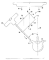
図1−2を参照すると、本発明の1つの実施形態及び当該実施形態が構成され得る1つの態様を示している。様々な図面において、同様の参照番号は同様の構成要素を参照している。図1は模式図であり、本明細書においてジャムシディ針40に固定されたアウトリガー10として示される高精度の軌道誘導器具100の1つの実施形態を示している。器具10は、前照準(front sight)30及び後照準(rear sight)32を形成するX線不透過性の目印体18を有するX線透過性の本体部14を含み、当該X線不透過性の目印体は、周辺の組織、神経、血管、軟骨又は骨の意図しない損傷を防止する目的で、X線照射下でアライメントされ得る。X線照射下の目印体18の可視性は、骨髄生検、脊椎インプラントの設置、脊椎の手術などといったあらゆる外科的処置において手術器具及び/又はインプラントの正確な軌道及び/又は軌道のモニタを確保する。当該目印体18の可視性が確保することには、椎弓根を固定する処置中に椎弓根スクリューの適切な配置を確保すること、及び脊椎の標的部位に手術の通路を確立する際に適切な軌道を確保することが含まれる。軌道目印体19は、例えば後照準32であり、これもまたX線不透過性であり、角度位置(angular relationship)を決定するように設けられ、加えて、前照準30との間の水平又は垂直な平面にアライメントされている。目印体18は、少なくとも1つの参照軌道照準(reference trajectory sight)34も含み得り、当該照準は、前照準30との間の様々な段階の目盛りを示す。いくつかの実施形態において、目印体18は、エンボス加工され、印刷され、塗料で塗られ、埋め込まれ、又は他の方法でステッカー、クリップ又はアウトリガーに刻印されていても良い。当該目印体に用いられるX線不透過性の材料は、X線不透過性であることが知られているいくつかの金属のうちの1つを含み得り、例えば、限定するものではないが、鉛、タンタル、タングステン、金、ステンレススチール、又はその他のものを含み得る。あるいは、当該目印体はX線不透過性のポリマーであっても良い。そのようなポリマーは、イタリアのLATI S.p.A.社(LATI Industries Thermoplastici S.p.A.)からLATYGRAYの商品名で入手可能である。また、そのようなポリマーは、アウトリガーに直接的に接着され又は成型され得る。
Referring to FIGS. 1-2, one embodiment of the present invention and one aspect in which the embodiment may be configured are shown. Like reference numerals refer to like components in the various drawings. FIG. 1 is a schematic diagram illustrating one embodiment of a high precision
一例として、椎弓根42(小さく、通常は管状の構造であり、椎骨44の後部の要素を脊椎本体に接続している)を介して骨ねじを設置する際に、当該スクリューが椎弓根の中に収容されていること及び椎弓根の外側の壁を破損していないことを確実にすることが重要である。椎弓根42は繊細な神経組織に囲まれており、破損すると、軽度な痛みから麻痺まで、患者に深刻な結果をもたらし得る。スクリューの設置(パイロットホールの形成及び穿刺など、スクリュー設置の準備を含む)の際に椎弓根が破損するリスクを軽減する1つの方法は、椎弓根の角度方向を決定すること、その後、必要な器具及びスクリューを決められた軌道に沿って前進させることである。手術用のアクセス部品を椎弓根の軌道に沿って方向合わせをすることで、手術器具及び椎弓根スクリューは容易に、かつ効果的に同じ軌道に沿って前進され得る。そして、当該アクセス部品を「目測」でアライメントすることによる破損を防ぐことができる。
As an example, when installing a bone screw through the pedicle 42 (small, usually tubular structure connecting the posterior elements of the
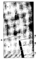
従って、脊椎の手術において、ジャムシディ40でパイロットホールが形成される前に、所望の角度軌道が最初に決定されるべきである。AP蛍光透視法(AP fluoroscopy)、MRI、又はCATスキャンのイメージングデバイス20を用いた術前の上面視画像が使用されて、ジャムシディ40がアウトリガー10と組み合わされて身体構造上の手術が行われるべき箇所に配置されるとすぐに当該軌道が決定される。CアームのX線透視装置(C-arm fluoroscope)は多くの外科的処置の際に広く用いられている。例えば脊椎の手術の際に、Cアームが頻繁に用いられ、特に、脊椎の特定の構造体を配置すること、手術器具及び/又は器具類の位置決めを指示すること、及び椎骨の適切なアライメント及び高さを確認することを補助する。Cアームのようなイメージングデバイスは通常、X線ビーム24の患者に関する向きを示すスケール(図示せず)と共に設けられ、従って、この例において、アウトリガー10に組み合わされたジャムシディ40と共に設けられる。この態様において、イメージングデバイス20は、X線24をアウトリガー10を横切って既知の角度に向けることができ、目印体18を結果の画像20(図2)において可視化する。図2に示されるように、目印体18は例えば前照準30であり、後照準32と組み合わされて視認され得り、所望の角度の外側の境界を画定する。当該境界は、複数の前照準30の間に視認される。複数の前照準30同士の間隔は変更され得り、所望の角度表示の範囲を定める。前照準30が2つだけ図示されているが、任意の数の参照軌道照準34が備えられても良く、本発明の範囲から逸脱せずに角度又は角度の一部分を示しても良い。図13、図15、図16及び図17を参照すると、少なくとも3つの異なる角度表示を有する実施形態を示している。この態様において、脊椎に対するような外科的処置について、冠状の(内側の)角度26は、L1から仙骨(図10)までの中央線28に関してレベル当たり約5度ずつ増大し、複数の前照準30又は参照軌道照準34が備えられてもよく、執刀医は、脊椎のレベルのそれぞれについて異なる前照準30又は参照軌道照準34を利用することができる。いくつかの実施形態において、前照準30、後照準32及び参照軌道照準34は、異なる形状を含み得る。当該異なる形状は、限定するものではないが、数字、文字、二次元又は三次元の幾何学的図形又は同様のものを含み得り、異なる角度、照準、又は参照照準を示す。目印体18は、アウトリガー10が視認されることと同様に、裸眼で見えても良く、見えなくても良い。本願の開示はジャムシディ針を描写しているが、本願の開示が教示するものは、本発明の範囲から逸脱すること無く、他の種類の手術道具に適用されても良い。例えば、ドリル、のこぎり、リーマー、シェーパー又は他の外科手術に用いられて手で操作される道具は、本発明の教示するものから利益を得ることができる。さらに、本発明が教示するものは、本発明の範囲から逸脱すること無く、様々なインプラント類(implants)、カテーテル類(catheters)、スコープ類(scopes)及び同様のものを埋め込むこと(implantation)に利用されても良い。本実施例のアウトリガー10は、手術道具に取り付けられるものとして示されているが、本願のデバイスが教示するものは、本発明の範囲から逸脱すること無く、手術道具に恒久的に固定されて又は手術道具と一体的に形成されて利用されても良い。
Thus, in spinal surgery, the desired angular trajectory should first be determined before the pilot holes are formed in Jamsid. A preoperative top view image using an AP fluoroscopy (M) or MRI or CAT
図1及び図3を参照すると、アウトリガー10の1つの実施形態が示されている。この実施形態において、アウトリガーのX線透過性の本体部14には、ジャムシディ40のような手術道具に取り付けられるべく、チューブ部50が設けられている。チューブ部50は、シャフト46を囲んで延びる寸法の内部ルーメン(inner lumen)52を含む。サムスクリュー54、摩擦などが用いられてアウトリガーがシャフト46上の位置又は手術道具の通常丸い形をしているその他の部分に保持されても良い。この構造によってアウトリガー10は当該手術道具の周囲を必要に応じて回転することができ、異なる平面でさらなるX線写真が取得されて合成角又はそのようなものが当該デバイスによって示され得る。
Referring to FIGS. 1 and 3, one embodiment of the
図1、図4及び図5を参照すると、アウトリガー10の1つの実施形態が示されている。この実施形態において、アウトリガーのX線透過性の本体部14には手術道具に取り付けられるべくタブ部60又は垂直タブ部70が設けられている。当該垂直タブ部60及びタブ部70は、接着剤62などのもの及び接着剤カバー64を含み、手術道具の表面に容易に取り付けられる。この構造によって、アウトリガー10は必要に応じて手術道具に固定され得る。
Referring to FIGS. 1, 4 and 5, one embodiment of the
図1及び図6を参照すると、アウトリガー10の1つの実施形態が示されている。この実施形態において、アウトリガーのX線透過性の本体部14には、手術道具に取り付けられるべくクリップ80が設けられている。クリップ80は、ばね部材82又は同様のもの、及びレバー84を含み、手術道具の表面に容易に取り付けられる。この構造は、アウトリガー10が必要に応じて手術道具の一部分に固定されることも可能にする。この構造において、当該クリップは十分に大きく広がって当該手術道具の少なくとも一部分に巻きついてフィットする。
Referring to FIGS. 1 and 6, one embodiment of the
図7−9及び図11−14を参照すると、本発明の1つの実施形態及び当該実施形態の構成される態様を示している。図7は、精密な深さ及び軌道誘導器具200の実施形態を示す模式図である。器具200は、第1端部102及び第2端部103を含む実質的に剛性のカニューレ101を備え、前記第1端部は固定手段又はねじ部材104aを含みハンドル105に固定され、前記第2端部は鋭い先端106を含み患者の皮膚及び組織を貫通する。ハンドル105はカニューレ101の第1端部102に固定される。当該ハンドルは、外側被覆(オーバーモールド、overmolding)及び取り外し可能であり得る手段を含む様々な手段でカニューレに固定され得る。ハンドル105が取り外し可能な実施形態において、図2に示すように、当該ハンドルは、下方部分であって、限定するものではないがバヨネット・マウント(bayonet mount)、ロッキングテーパー(locking taper)、接着剤又はねじ部材104bを含み得る固定手段を含む環状又は円筒状の部分107を備える。当該ねじ部材104bは、カニューレ101の固定手段又はねじ部材104aと協働するように構成及び配置されて当該カニューレに取り外し可能に取り付けられる。この下方部分であって環状又は円筒状の部分107は、カニューレ101にしっかりと固定される。
Referring to FIGS. 7-9 and 11-14, one embodiment of the present invention and configured aspects of the embodiment are shown. FIG. 7 is a schematic diagram illustrating an embodiment of a precision depth and
当該ハンドル105は恒久的に又は取り外し可能にカニューレ101に固定され得り、あらゆる適した変化形の形状及び寸法にされ得る。いくつかの実施例において、カニューレ101はジャムシディ型の針であり、ハンドル105は、執刀医又は医療技術者の手に容易になじむことができるような人間工学的形状を有することが好ましい。当該ハンドルは、個人の手のひらに合うように形成された上方の湾曲部109を含むように形成され得る。当該ハンドルの下方部分である110も湾曲している。当該ハンドルの下方部分の湾曲は、個人の指によって握られるように設計されてカニューレ101の制御を支援する。当該ハンドル105はカニューレを脊椎の骨の中へ、時には貫通して打ち込む際に用いられる。ある場合には、カニューレ101は、個人の手によって及ぼされる圧力のみによって、当該骨を貫通して打ち込まれ得る。他の場合には、カニューレを骨に貫通させるためには、ハンマー又は他の器具が採用されなければならない。ハンマー又は類似の器具が用いられる場合、ジャムシディ型のカニューレ101は椎骨にあまりに深くまで貫通し過ぎるという危険がある。このことは、近くに位置する神経の損傷を引き起こし得る。当該針は完全に椎骨を貫通して近接する血管又は内臓を傷つける場合がある。
The
周辺の組織、神経、血管、軟骨又は骨の意図しない損傷を防ぐ目的で、目印体108がハンドル105に配置される。当該目印体108は、あらゆる外科的処置において、精密な軌道及び/又は、手術器具及び/又はインプラントの軌道及び/又は深さのモニタリングを確保する。当該あらゆる外科的処置とは例えば、骨髄生検、脊椎インプラントの設置、脊椎の手術などであり、当該確保は椎弓根固定の処置の際に椎弓根スクリューの適切な位置を確保すること、及び脊椎の標的部位に手術の通路を確立する際に適切な軌道を確保することを含む。角度位置を決定する軌道目印体は、軌道目印体とカニューレの鋭い先端との間の水平又は垂直な平面にアライメントされる。目印体108は少なくとも1つの参照軌道目印体120(図14)を含み得る。当該参照目印体は、標的部位よりもさらに所定の距離だけ挿入された場合に当該器具の先端がどこになるかを示す参照点又は参照領域を定める。いくつかの実施形態において、目印体108は、エンボス加工され、印刷され、埋め込まれ、又は他の方法でステッカー又はクリップに刻印されても良い。他の実施形態において、当該目印体はハンドルにエッチング又は電気めっきされていても良い。いくつかの実施形態において、当該ハンドルは切り欠き部を含み、軌道及び深さの目印体を含む自在クリップ(universal clip)の取り付けに対応している。本願の開示はジャムシディ針を描写しているが、本願の開示が教示するものは、本発明の範囲から逸脱すること無く、他の種類の手術道具に適用され得る。例えば、ドリル、のこぎり、リーマー、シェーパー又は他の外科手術に用いられて手で操作される道具は、本発明の教示するものから利益を得ることができる。
A
図11−14を参照すると、いくつかの実施形態において軌道目印体は、30度の目印体、15度の目印体、又はこれらの組み合わせを含む。ジャムシディ針の場合、当該手術道具上の軌道目印体の位置決めは、カニューレのサイズに従って変化するであろう。例えば、30度の角度122を示す目印体は、15cmの長さのカニューレのハンドルの反対側の端部124から8.66cmの位置にマークされる。上面から見ると、30度の角度122をマーキングする目印体は、カニューレ101の先端106にアライメントされて手術器具の軌道を定める。10cmの長さを有するカニューレに関しては、30度の目印体は、ハンドルの中心から5.77cmの位置に配置されるであろう。同様に、動いた距離をマーキングする目印体は、環状の部品及び/又はカニューレ上に配置される。
Referring to FIGS. 11-14, in some embodiments, the track marks include a 30 degree mark, a 15 degree mark, or a combination thereof. In the case of a jam-sidi needle, the positioning of the orbital markings on the surgical tool will vary according to the size of the cannula. For example, a marking indicating an
従って、パイロットホールが形成される前に、所望の角度軌道が最初に決定されなければならない。術前の上から見たAP蛍光透視、MRI、又はCATスキャンの画像が、手術が執り行われるべき解剖学的位置に当該器具が置かれた時点での軌道の決定に用いられる。軌道ライン21は、当該器具の先端から適切な目印体まで描かれている。参照ラインはカニューレである。軌道ラインと参照ラインとの間に生じる角度はパイロットホールの形成に用いられる所望の角度である。椎弓根の角度を予測する代替の及び/又は追加の方法も検討され、本発明の範囲から逸脱すること無く利用され得る。本明細書において用いられるように、パイロットホールの形成は、皮膚、組織、骨などに(例に過ぎないが、突きぎり、ボーリング、ドリルなどにより)穴をあけること、及び既に形成された穴(例に過ぎないが、穿刺による穴など)を調整することを包含し、又はこれらのうちのいくつかの組み合わせである。
Thus, the desired angular trajectory must first be determined before the pilot holes are formed. A preoperative top-view AP fluoroscopic, MRI or CAT scan image is used to determine the trajectory when the instrument is placed at the anatomical location where surgery is to be performed.
図9、14−17を参照すると、執刀医又は医療技術者にとって、椎骨又は他の解剖学上の構造に手術器具を貫通させる深さを判断することは非常に困難である。この問題の改善策が本発明の中にある。まず、軌道及び深さの器具が解剖学的位置に配置される。当該解剖学的位置は、外科的処置がなされるべき位置であり、手術を受けている椎骨のX線画像が取得される位置である(図9、図16及び図17)。外科医が器具又はデバイスを椎骨に貫通させたい軌道及び深さは、こうして手術に先立って特定され、正確な手術用の通路を許容する。従って、他の実施形態において、深さ目印体120はカニューレが人体に挿入される深さの直線距離を示すであろう。例えば、20mm前進した点を想定すると、深さ目印体は角度参照マーク(図14)から9.815cmの位置になるであろう。 Referring to FIGS. 9, 14-17, it is very difficult for the surgeon or medical technician to determine the depth to which the surgical instrument passes through the vertebra or other anatomical structure. A remedy for this problem is in the present invention. First, instruments of trajectory and depth are placed at anatomical locations. The anatomical position is a position where a surgical procedure is to be performed, and is a position where an X-ray image of a vertebra undergoing surgery is obtained (FIGS. 9, 16 and 17). The trajectory and depth at which the surgeon wants the instrument or device to penetrate the vertebrae are thus identified prior to surgery, allowing for a precise surgical path. Thus, in another embodiment, the depth marking 120 will indicate a linear distance of the depth at which the cannula is inserted into the human body. For example, assuming a point advanced 20 mm, the depth marking will be 9.815 cm from the angle reference mark (FIG. 14).
もう一つの実施形態において、患者の脊椎の椎弓根に安全にアクセスするための最適な角度軌道及び直線深度を決定する方法は、深さ及び軌道誘導器具を患者の皮膚表面の所望の貫通位置に位置決めするステップを含む。例えば、図9において、椎弓根201の貫通の開始点を選択するために、当該器具は椎弓根に関して軌道側部位置に配置され得る。当該器具は、ハンドル及び/又はカニューレ101上に配置されて軌道及び直線深さ誘導に関する目印体108を含み、所望の軌道に沿って器具の方向を合わせることを可能にする。当該器具の方向合わせは、軌道目印体を鋭い先端106にアライメントすること、及び患者の人体の画像に対する器具の位置合わせの画像を取得し、最適な手術軌道及び深さ通路を決定することによって可能となる(図9)。
In another embodiment, a method of determining optimal angular trajectory and linear depth for safely accessing a patient's spine pedicle comprises depth and trajectory guiding instruments for desired penetration of a patient's skin surface. Including the steps of For example, in FIG. 9, the instrument can be placed in an orbital side position with respect to the pedicle to select the start point of penetration of the
図18を参照すると、本発明の代替的実施形態が示されている。この実施例において、本願のデバイスの水準器の構成200が提供され得る。当該水準器は、ジャムシディのハンドルにクリップで留められても良く、あるいはハンドル内に含まれていても良く、手術中に当該器具の軌道が逸脱しないこと及び角度が正確であることを確保する。当該水準器はハンドルを含み、当該ハンドル内にブルズアイ水準器が搭載されている。当該ハンドルが平坦な表面に置かれると、指示リング204がガラス208内に捕捉された気泡206を取り囲む。当該気泡が第1の指示リング204内にある場合、当該表示は約0度と読む。付随するリング210は角度を示す。例えば、10度、20度、及び30度の指示リング210がガラス内に捕捉された気泡206を取り囲み得る。当該水準器が円形の場合、当該道具の軸方向にアライメントするために一組の平行なライン212が施されても良い。代替的実施例(図示せず)において当該水準器は、度数指示がプリントされて曲がった細長いチューブであり得る。当該指示及び水準器内の液体は、X線の下で視認可能に構成されていても良く、執刀医はX線透視法又は同様のものを通して当該デバイスを読むことができる。
Referring to FIG. 18, an alternate embodiment of the present invention is shown. In this example, an
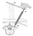
図19を参照すると、代替的実施例である高精度な誘導器具300が示されている。高精度な誘導器具300は、本明細書において、ジャムシディ針40に固定されたアウトリガー310として示されている。アウトリガー310は、X線不透過性の目印体18を有するX線不透過性の本体314を含み、当該目印体は少なくとも1つ以上の、好ましくは一組の後照準32を形成し、当該照準は、手術道具の一部分にアライメントされていても良い。当該手術道具の一部分は、本明細書において、X線下のジャムシディ針の先端106として示されており、周囲の組織、神経、血管、軟骨又は骨への意図しない損傷を防止することを目的としている。X線下における目印体18の可視性は、骨髄生検、脊椎インプラントの設置、脊椎の手術などといった様々な外科的処置において手術器具及び/又はインプラントの正確な軌道及び/又は軌道のモニタを確保する。当該目印体18の可視性が確保することには、椎弓根を固定する処置中に椎弓根スクリューの適切な配置を確保すること、及び脊椎の標的部位に手術の通路を確立する際に適切な軌道を確保することが含まれる。軌道目印体19は、これもX線不透過性であり、手術道具の意図した目標へのパスを決定するように備えられている。目印体18は、少なくとも1つの参照軌道照準34も含み得り、前照準30間の様々な度数の目盛りを示す。いくつかの実施形態において、目印体18は、エンボス加工され、印刷され、塗料で塗られ、埋め込まれ、又は他の方法でステッカー、クリップ又はアウトリガーに刻印されていても良い。
Referring to FIG. 19, an alternative embodiment high
本明細書で述べた全ての特許及び出版物は、本発明が属する分野の当業者の水準を示している。全ての特許及び出版物は、個々の出版物が、参照されることで包含されるように具体的に、かつ、個別的に、示されていることと同程度に、参照されることで本願明細書に包含される。 All patents and publications mentioned in the specification are indicative of the levels of those skilled in the art to which the invention pertains. All patents and publications are herein incorporated by reference to the same extent as if each individual publication was specifically and individually indicated to be incorporated by reference. It is included in the specification.
本発明のいくつかの形態が示されているが、本明細書に記載又は示された特定の形態又は構成に限定されないものと理解されるべきである。本発明の範囲から逸脱しない範囲で様々な変更がなされ得ること並びに本発明は発明の詳細な説明及び本明細書に含まれる図面に提示及び記載されていることに限定されないと考えられるべきであることは当業者にとって明白であろう。 While several forms of the present invention are shown, it is to be understood that the present invention is not limited to the specific forms or configurations described or illustrated. It should be understood that various modifications may be made without departing from the scope of the present invention, and the present invention is not limited to what is shown and described in the detailed description of the invention and the drawings included herein. It will be apparent to those skilled in the art.
当業者は、目的を達成すること並びに上記した結果及び利益を得ることに、同様に、当該発明に本来備わるそれらのものに、本発明は適切に適応していることを容易に理解するであろう。本明細書に記載された実施形態、方法、手順及び技術は、出願時点の好ましい実施形態を代表するものであり、例示するものであって、本発明の範囲を限定するものではない。当業者が想到し得るであろう変形及び他の用途は、本発明の精神に包含され、特許請求の範囲によって画定される。本発明は、特定の好ましい実施例に関連して記載されているが、特許請求の範囲に記載されている本発明はこのような特定の実施例に不当に限定されるべきではない。本発明を実施するための開示された態様の様々な変形であって、当業者にとって明白なものは、特許請求の範囲内のものである。 Those skilled in the art will readily understand that the present invention is properly adapted to achieve the objects and obtain the results and benefits described above as well as those inherently possessed by the present invention. I will. The embodiments, methods, procedures and techniques described herein are representative of and preferred embodiments at the time of filing and are not intended to limit the scope of the present invention. Variations and other applications that may occur to those skilled in the art are encompassed within the spirit of the invention and are defined by the appended claims. Although the invention has been described in connection with specific preferred embodiments, the invention as claimed should not be unduly limited to such specific embodiments. Various modifications of the disclosed embodiments for carrying out the invention which are obvious to those skilled in the art are within the scope of the claims.
Claims (23)
X線透過性の本体を有する高精度の軌道誘導器具を含み、前記X線透過性の本体は、前記X線画像に関連するX線を前記X線透過性の本体に既知の角度で通過させる位置及び方向で前記手術道具に取り付けられるべく構成され、前記X線透過性の本体は、X線不透過性の材料から構成された少なくとも1つの前照準及びX線不透過性の材料から構成された少なくとも1つの後照準を含み、前記少なくとも1つの前照準及び前記少なくとも1つの後照準は、前記X線透過性の本体の角度位置を定めるように前記X線透過性の本体上に位置決めされて、X線画像を介して前記前照準及び前記後照準が観察される際に、動物の骨格の一部分に関する前記手術道具の角度軌道を定めることを特徴とする器具。 A high precision trajectory guidance instrument for use with a surgical tool, requiring an x-ray image to guide the surgical tool to a target site for surgery
A high precision trajectory guide having an x-ray transparent body, the x-ray transparent body passing x-rays associated with the x-ray image through the x-ray transparent body at a known angle Configured to be attached to the surgical tool in position and orientation, the radiolucent body is comprised of at least one forward aiming and radiopaque material comprised of a radiopaque material The at least one front aiming and the at least one rear aiming are positioned on the radiolucent body to define an angular position of the radiolucent body An instrument for defining the angular trajectory of the surgical tool with respect to a portion of an animal skeleton as the anterior and posterior aiming is observed via an x-ray image.
第1端部及び第2端部を含む実質的に剛性のカニューレを備え、前記第1端部がハンドル部材に固定され、前記第2端部が動物の皮膚及び組織を貫通する鋭い先端を含む手術道具と、前記手術道具に固定されたX線透過性の本体と、を含み、前記X線透過性の本体は、X線画像に関連するX線を前記X線透過性の本体に既知の角度で通過させる位置及び方向で前記手術道具に固定され、前記X線透過性の本体はX線不透過性の材料から構成された少なくとも1つの前照準及びX線不透過性の材料から構成された少なくとも1つの後照準を含み、前記少なくとも1つの前照準及び前記少なくとも1つの後照準は、前記X線画像を介して観察される際に前記X線透過性の本体の角度位置を定めるように前記X線透過性の本体上に位置決めされて、動物の骨格の一部分に関する前記手術道具の角度軌道を定めることを特徴とする器具。 It is a high precision orbit guidance instrument,
Substantially example Bei cannula rigid including a first end and a second end, said first end portion is secured to the handle member, a sharp tip where the second end penetrates the animal skin and tissue and including surgical tool includes an X-ray transparent body fixed to the surgical tool, the X-ray transparent body, the X-rays associated with the X-ray image on the X-ray transparent body Fixed to the surgical tool at a known angle and passing position and direction, the radiolucent body is made of at least one forward aiming and radiopaque material composed of radiopaque material The at least one front aiming and the at least one rear aiming define an angular position of the radiolucent body when viewed via the x-ray image, including at least one rear aiming configured. is positioned on the X-ray transparent body as, Instrument, characterized in that angularly trajectory of the surgical instrument about a portion of the skeleton of the object.
本体を有する高精度の軌道誘導器具を含み、前記本体は前記X線画像に関連するX線を前記本体に既知の角度で通過させる位置及び方向で前記手術道具に取り付けられるように構成され、前記本体はX線不透過性の材料から構成された少なくとも1つの前照準及びX線不透過性の材料から構成された少なくとも1つの後照準を含み、前記少なくとも1つの前照準及び前記少なくとも1つの後照準は、前記X線画像を介して観察される際に前記本体の角度位置を定めるように前記本体上に位置決めされて、動物の骨格の一部分に関する前記手術道具の角度軌道を定めることを特徴とする器具。 A high precision trajectory guidance instrument for use with a surgical tool, requiring an x-ray image to guide the surgical tool to a target site for surgery
A high precision trajectory guiding instrument having a body, the body being configured to be attached to the surgical tool at a position and orientation that allows the X-ray associated with the x-ray image to pass through the body at a known angle, The body includes at least one front aiming comprised of radiopaque material and at least one rear aiming comprised of radiopaque material, the at least one front aiming and the at least one rear boresight, said the is positioned on the body to define the angular position of the body when it is observed through the X-ray image, characterized in that angularly trajectory of the surgical instrument about a portion of the skeleton of the animal The equipment to be.
20. A high precision trajectory guidance device according to claim 19, wherein the front aim is the tip of the jammed needle.
Applications Claiming Priority (5)
| Application Number | Priority Date | Filing Date | Title |
|---|---|---|---|
| US201462002734P | 2014-05-23 | 2014-05-23 | |
| US62/002,734 | 2014-05-23 | ||
| US201462059455P | 2014-10-03 | 2014-10-03 | |
| US62/059,455 | 2014-10-03 | ||
| PCT/US2015/032235 WO2015183747A2 (en) | 2014-05-23 | 2015-05-22 | Trajectory guidance device and system for surgical instruments |
Publications (3)
| Publication Number | Publication Date |
|---|---|
| JP2017524487A JP2017524487A (en) | 2017-08-31 |
| JP2017524487A5 JP2017524487A5 (en) | 2017-10-12 |
| JP6511517B2 true JP6511517B2 (en) | 2019-05-15 |
Family
ID=54427827
Family Applications (1)
| Application Number | Title | Priority Date | Filing Date |
|---|---|---|---|
| JP2017514388A Expired - Fee Related JP6511517B2 (en) | 2014-05-23 | 2015-05-22 | Trajectory guidance device and system for surgical instruments |
Country Status (6)
| Country | Link |
|---|---|
| US (2) | US10687845B2 (en) |
| EP (1) | EP3145415A2 (en) |
| JP (1) | JP6511517B2 (en) |
| CN (2) | CN106999168A (en) |
| AU (1) | AU2015267251B2 (en) |
| WO (1) | WO2015183747A2 (en) |
Families Citing this family (21)
| Publication number | Priority date | Publication date | Assignee | Title |
|---|---|---|---|---|
| US20190000571A1 (en) * | 2012-06-21 | 2019-01-03 | Globus Medical, Inc. | Surgical robotic automation with tracking markers |
| US10758315B2 (en) | 2012-06-21 | 2020-09-01 | Globus Medical Inc. | Method and system for improving 2D-3D registration convergence |
| US11857149B2 (en) | 2012-06-21 | 2024-01-02 | Globus Medical, Inc. | Surgical robotic systems with target trajectory deviation monitoring and related methods |
| US11253327B2 (en) | 2012-06-21 | 2022-02-22 | Globus Medical, Inc. | Systems and methods for automatically changing an end-effector on a surgical robot |
| US10799298B2 (en) | 2012-06-21 | 2020-10-13 | Globus Medical Inc. | Robotic fluoroscopic navigation |
| US11793570B2 (en) | 2012-06-21 | 2023-10-24 | Globus Medical Inc. | Surgical robotic automation with tracking markers |
| US10874466B2 (en) | 2012-06-21 | 2020-12-29 | Globus Medical, Inc. | System and method for surgical tool insertion using multiaxis force and moment feedback |
| US11786324B2 (en) | 2012-06-21 | 2023-10-17 | Globus Medical, Inc. | Surgical robotic automation with tracking markers |
| US11864745B2 (en) | 2012-06-21 | 2024-01-09 | Globus Medical, Inc. | Surgical robotic system with retractor |
| US11317971B2 (en) | 2012-06-21 | 2022-05-03 | Globus Medical, Inc. | Systems and methods related to robotic guidance in surgery |
| US11864839B2 (en) | 2012-06-21 | 2024-01-09 | Globus Medical Inc. | Methods of adjusting a virtual implant and related surgical navigation systems |
| US11857266B2 (en) | 2012-06-21 | 2024-01-02 | Globus Medical, Inc. | System for a surveillance marker in robotic-assisted surgery |
| US11896446B2 (en) | 2012-06-21 | 2024-02-13 | Globus Medical, Inc | Surgical robotic automation with tracking markers |
| US10624710B2 (en) | 2012-06-21 | 2020-04-21 | Globus Medical, Inc. | System and method for measuring depth of instrumentation |
| CN106999168A (en) | 2014-05-23 | 2017-08-01 | 英特格锐迪移植股份公司 | Trajectory guide for surgical operation |
| US11883217B2 (en) | 2016-02-03 | 2024-01-30 | Globus Medical, Inc. | Portable medical imaging system and method |
| CN106137335A (en) * | 2016-07-15 | 2016-11-23 | 于海龙 | A kind of Thoracolumbar disk percutaneous puncture device and using method thereof |
| JP6417487B1 (en) * | 2018-01-12 | 2018-11-07 | 浩太 須田 | Puncture device guide device |
| US11259880B1 (en) | 2018-01-25 | 2022-03-01 | Integrity Implants Inc. | Guiding the trajectory of a second surgical device |
| EP3666212A1 (en) * | 2018-12-14 | 2020-06-17 | Globus Medical, Inc. | Surgical robotic automation with tracking markers |
| JP7211582B1 (en) | 2021-08-31 | 2023-01-24 | 慶應義塾 | puncture probe |
Family Cites Families (15)
| Publication number | Priority date | Publication date | Assignee | Title |
|---|---|---|---|---|
| DE3205404A1 (en) * | 1982-02-16 | 1983-09-15 | Patrick Dr.med. 3590 Bad Wildungen Kluger | Device for checking the directionally accurate guidance of a surgical tool |
| US6036696A (en) * | 1997-12-19 | 2000-03-14 | Stryker Technologies Corporation | Guide-pin placement device and method of use |
| DE19956814B4 (en) * | 1999-11-25 | 2004-07-15 | Brainlab Ag | Shape detection of treatment devices |
| US20030208202A1 (en) * | 2002-05-04 | 2003-11-06 | Falahee Mark H. | Percutaneous screw fixation system |
| US7406775B2 (en) * | 2004-04-22 | 2008-08-05 | Archus Orthopedics, Inc. | Implantable orthopedic device component selection instrument and methods |
| US20060217731A1 (en) * | 2005-03-28 | 2006-09-28 | Sdgi Holdings, Inc. | X-ray and fluoroscopic visualization slots |
| JP2007105392A (en) * | 2005-10-17 | 2007-04-26 | Homuzu Giken:Kk | Guide instrument set for surgery |
| US9826992B2 (en) * | 2007-12-21 | 2017-11-28 | Smith & Nephew, Inc. | Multiple portal guide |
| JP4231540B1 (en) * | 2008-04-23 | 2009-03-04 | 浩太 須田 | Drilling instrument guide device and drilling device |
| GB2487331B (en) * | 2010-09-27 | 2012-10-24 | Acumed Llc | Instruments having a radiopaque region to facilitate positioning a bone plate on bone |
| US8758383B2 (en) * | 2011-03-01 | 2014-06-24 | Safe Wire Holding, Llc | Depth controlled Jamshidi needle |
| BR112013024743A2 (en) * | 2011-03-28 | 2016-12-27 | Amendia Inc | spine surgery pedicle drill guide |
| WO2013180191A1 (en) * | 2012-05-31 | 2013-12-05 | サンエー精工株式会社 | Centering guide for surgical tool for treatment of bone fractures and surgical tool for treatment of bone fractures comprising said guide |
| CA2910261C (en) * | 2012-07-03 | 2020-09-15 | 7D Surgical Inc. | Attachments for tracking handheld implements |
| CN106999168A (en) | 2014-05-23 | 2017-08-01 | 英特格锐迪移植股份公司 | Trajectory guide for surgical operation |
-
2015
- 2015-05-22 CN CN201580037623.9A patent/CN106999168A/en active Pending
- 2015-05-22 CN CN202210485419.5A patent/CN115530869A/en active Pending
- 2015-05-22 AU AU2015267251A patent/AU2015267251B2/en not_active Ceased
- 2015-05-22 US US15/313,463 patent/US10687845B2/en active Active
- 2015-05-22 JP JP2017514388A patent/JP6511517B2/en not_active Expired - Fee Related
- 2015-05-22 EP EP15790705.6A patent/EP3145415A2/en not_active Withdrawn
- 2015-05-22 WO PCT/US2015/032235 patent/WO2015183747A2/en active Application Filing
-
2020
- 2020-05-13 US US15/931,061 patent/US11701142B2/en active Active
Also Published As
| Publication number | Publication date |
|---|---|
| US20200268409A1 (en) | 2020-08-27 |
| AU2015267251B2 (en) | 2019-09-26 |
| WO2015183747A3 (en) | 2016-04-21 |
| CN115530869A (en) | 2022-12-30 |
| AU2015267251A1 (en) | 2017-01-19 |
| US20170189058A1 (en) | 2017-07-06 |
| CN106999168A (en) | 2017-08-01 |
| US11701142B2 (en) | 2023-07-18 |
| US10687845B2 (en) | 2020-06-23 |
| WO2015183747A2 (en) | 2015-12-03 |
| EP3145415A2 (en) | 2017-03-29 |
| JP2017524487A (en) | 2017-08-31 |
Similar Documents
| Publication | Publication Date | Title |
|---|---|---|
| JP6511517B2 (en) | Trajectory guidance device and system for surgical instruments | |
| US9402641B2 (en) | Pedicle drill guide for spinal surgery | |
| EP2091459B1 (en) | An image guided whole body stereotactic needle placement device with falling arc | |
| US8685034B2 (en) | Distal targeting device | |
| EP2266474B1 (en) | Boring instrument guiding device and boring instrument | |
| US7846164B2 (en) | Pedicle punch with cannula | |
| US20170296202A1 (en) | Surgical targeting systems and methods | |
| US11633223B2 (en) | Surgical guidance device | |
| US20200390465A1 (en) | Guide device for biopsy needle | |
| US20230110238A1 (en) | Surgical device for insertion of guide wire and pedicle screw | |
| US20230293217A1 (en) | Surgical guidance device | |
| US20230097125A1 (en) | Robotically guiding the trajectory of a second surgical device | |
| CN205866812U (en) | Backbone puncture locator | |
| US11896243B2 (en) | Surgical tool guide | |
| JP4309289B2 (en) | Surgical control instrument | |
| WO2010116359A1 (en) | Ultrasound bone imaging assembly | |
| US20050182317A1 (en) | Method and apparatus for locating medical devices in tissue | |
| CN102100580A (en) | Intramedullary fixation guider | |
| US20130066205A1 (en) | Ultrasound bone imaging assembly | |
| JP2013528074A (en) | Minimally invasive spinal surgery instrument and use thereof | |
| WO2008020833A1 (en) | Improved pedicle punch |
Legal Events
| Date | Code | Title | Description |
|---|---|---|---|
| A521 | Request for written amendment filed |
Free format text: JAPANESE INTERMEDIATE CODE: A821 Effective date: 20170523 |
|
| A711 | Notification of change in applicant |
Free format text: JAPANESE INTERMEDIATE CODE: A711 Effective date: 20170523 |
|
| A521 | Request for written amendment filed |
Free format text: JAPANESE INTERMEDIATE CODE: A523 Effective date: 20170803 |
|
| A621 | Written request for application examination |
Free format text: JAPANESE INTERMEDIATE CODE: A621 Effective date: 20170803 |
|
| A977 | Report on retrieval |
Free format text: JAPANESE INTERMEDIATE CODE: A971007 Effective date: 20180511 |
|
| A131 | Notification of reasons for refusal |
Free format text: JAPANESE INTERMEDIATE CODE: A131 Effective date: 20180522 |
|
| A601 | Written request for extension of time |
Free format text: JAPANESE INTERMEDIATE CODE: A601 Effective date: 20180821 |
|
| A601 | Written request for extension of time |
Free format text: JAPANESE INTERMEDIATE CODE: A601 Effective date: 20181022 |
|
| A521 | Request for written amendment filed |
Free format text: JAPANESE INTERMEDIATE CODE: A523 Effective date: 20181116 |
|
| TRDD | Decision of grant or rejection written | ||
| A01 | Written decision to grant a patent or to grant a registration (utility model) |
Free format text: JAPANESE INTERMEDIATE CODE: A01 Effective date: 20190205 |
|
| A601 | Written request for extension of time |
Free format text: JAPANESE INTERMEDIATE CODE: A601 Effective date: 20190306 |
|
| A61 | First payment of annual fees (during grant procedure) |
Free format text: JAPANESE INTERMEDIATE CODE: A61 Effective date: 20190408 |
|
| R150 | Certificate of patent or registration of utility model |
Ref document number: 6511517 Country of ref document: JP Free format text: JAPANESE INTERMEDIATE CODE: R150 |
|
| LAPS | Cancellation because of no payment of annual fees |