JP6511397B2 - Magnetic resonance imaging apparatus, antenna apparatus and method of manufacturing the same - Google Patents
Magnetic resonance imaging apparatus, antenna apparatus and method of manufacturing the same Download PDFInfo
- Publication number
- JP6511397B2 JP6511397B2 JP2015542539A JP2015542539A JP6511397B2 JP 6511397 B2 JP6511397 B2 JP 6511397B2 JP 2015542539 A JP2015542539 A JP 2015542539A JP 2015542539 A JP2015542539 A JP 2015542539A JP 6511397 B2 JP6511397 B2 JP 6511397B2
- Authority
- JP
- Japan
- Prior art keywords
- holding member
- conductor
- shield conductor
- rung
- antenna device
- Prior art date
- Legal status (The legal status is an assumption and is not a legal conclusion. Google has not performed a legal analysis and makes no representation as to the accuracy of the status listed.)
- Active
Links
Images


Classifications
-
- G—PHYSICS
- G01—MEASURING; TESTING
- G01R—MEASURING ELECTRIC VARIABLES; MEASURING MAGNETIC VARIABLES
- G01R33/00—Arrangements or instruments for measuring magnetic variables
- G01R33/20—Arrangements or instruments for measuring magnetic variables involving magnetic resonance
- G01R33/28—Details of apparatus provided for in groups G01R33/44 - G01R33/64
- G01R33/32—Excitation or detection systems, e.g. using radio frequency signals
- G01R33/34—Constructional details, e.g. resonators, specially adapted to MR
- G01R33/34046—Volume type coils, e.g. bird-cage coils; Quadrature bird-cage coils; Circularly polarised coils
- G01R33/34076—Birdcage coils
-
- G—PHYSICS
- G01—MEASURING; TESTING
- G01R—MEASURING ELECTRIC VARIABLES; MEASURING MAGNETIC VARIABLES
- G01R33/00—Arrangements or instruments for measuring magnetic variables
- G01R33/20—Arrangements or instruments for measuring magnetic variables involving magnetic resonance
- G01R33/28—Details of apparatus provided for in groups G01R33/44 - G01R33/64
- G01R33/32—Excitation or detection systems, e.g. using radio frequency signals
- G01R33/34—Constructional details, e.g. resonators, specially adapted to MR
- G01R33/34007—Manufacture of RF coils, e.g. using printed circuit board technology; additional hardware for providing mechanical support to the RF coil assembly or to part thereof, e.g. a support for moving the coil assembly relative to the remainder of the MR system
-
- G—PHYSICS
- G01—MEASURING; TESTING
- G01R—MEASURING ELECTRIC VARIABLES; MEASURING MAGNETIC VARIABLES
- G01R33/00—Arrangements or instruments for measuring magnetic variables
- G01R33/20—Arrangements or instruments for measuring magnetic variables involving magnetic resonance
- G01R33/28—Details of apparatus provided for in groups G01R33/44 - G01R33/64
- G01R33/32—Excitation or detection systems, e.g. using radio frequency signals
- G01R33/34—Constructional details, e.g. resonators, specially adapted to MR
- G01R33/345—Constructional details, e.g. resonators, specially adapted to MR of waveguide type
- G01R33/3453—Transverse electromagnetic [TEM] coils
-
- G—PHYSICS
- G01—MEASURING; TESTING
- G01R—MEASURING ELECTRIC VARIABLES; MEASURING MAGNETIC VARIABLES
- G01R33/00—Arrangements or instruments for measuring magnetic variables
- G01R33/20—Arrangements or instruments for measuring magnetic variables involving magnetic resonance
- G01R33/28—Details of apparatus provided for in groups G01R33/44 - G01R33/64
- G01R33/42—Screening
- G01R33/422—Screening of the radio frequency field
Landscapes
- Physics & Mathematics (AREA)
- Condensed Matter Physics & Semiconductors (AREA)
- General Physics & Mathematics (AREA)
- Electromagnetism (AREA)
- Health & Medical Sciences (AREA)
- Epidemiology (AREA)
- Magnetic Resonance Imaging Apparatus (AREA)
Description
本発明は、被検体中の水素や燐等からの核磁気共鳴(Nuclear Magnetic Resonance:以下NMRという)信号を計測し、核の密度分布や緩和時間分布等を画像化する核磁気共鳴イメージング(Magnetic Resonance Imaging:以下MRIとする)技術に関し、特に、高周波信号の送信およびNMR信号の受信の少なくとも一方を行うアンテナ装置およびその製造方法に関する。
The present invention measures nuclear magnetic resonance (hereinafter referred to as NMR) signals from hydrogen, phosphorus and the like in a subject, and images nuclear density distribution, relaxation time distribution and the like by nuclear magnetic resonance imaging (Magnetic The present invention relates to resonance imaging (hereinafter referred to as "MRI") technology, and more particularly to an antenna device for transmitting at least one of high frequency signals and receiving NMR signals and a method of manufacturing the same .
MRI装置では、静磁場マグネットが発生する均一な静磁場中に配置された被検体に電磁波である高周波信号を照射し、被検体内の核スピンを励起すると共に、核スピンが発生する電磁波である核磁気共鳴信号を受信し、信号処理することにより、被検体を画像化する。高周波信号の照射と核磁気共鳴信号の受信とは、ラジオ周波数(RF)の電磁波を送信あるいは受信するRFアンテナもしくはRFコイルと呼ばれるアンテナ装置(以下、RFアンテナと呼ぶ。)によって行なわれる。実際の画像化のためには静磁場マグネット、RFアンテナに加えて、空間的に傾斜した磁場を発生する傾斜磁場コイルが必要である。
トンネル型のMRI装置ではこれらの静磁場マグネット、傾斜磁場コイル、RFアンテナは共に円筒形をしており、通常外側から、静磁場マグネット、次に傾斜磁場コイル、一番内側(被検体側)にRFアンテナが配置される。
In the MRI apparatus, a high frequency signal, which is an electromagnetic wave, is irradiated to a subject placed in a uniform static magnetic field generated by a static magnetic field magnet to excite nuclear spins in the subject and to generate nuclear spins. An object is imaged by receiving nuclear magnetic resonance signals and processing the signals. The irradiation of a high frequency signal and the reception of a nuclear magnetic resonance signal are performed by an antenna device (hereinafter referred to as an RF antenna) called an RF antenna or an RF coil which transmits or receives an electromagnetic wave of a radio frequency (RF). For actual imaging, in addition to a static magnetic field magnet and an RF antenna, a gradient magnetic field coil that generates a spatially inclined magnetic field is required.
In the tunnel type MRI apparatus, the static magnetic field magnet, the gradient magnetic field coil, and the RF antenna are both cylindrical, and usually from outside, the static magnetic field magnet, then the gradient magnetic field coil, the innermost (subject side) An RF antenna is arranged.
トンネル型のMRI装置で使用される代表的なRFアンテナに、円筒形のボリュームアンテナと呼ばれるものがある。円筒形のボリュームアンテナには、鳥かご型もしくはバードケージ型と呼ばれるものと、TEM(transverse electromagnetic)型やマイクロストリップライン型と呼ばれるもの(例えば、特許文献1、2参照。)と、がある。これらのRFアンテナでは、通常、ラング(横木、あるいは、はしごの横棒)と呼ばれる棒状の導体(ラング導体)が、円筒側面に沿って、円筒の中心軸と平行に、16〜32本程度配置される。 A typical RF antenna used in a tunnel type MRI apparatus is called a cylindrical volume antenna. There are cylindrical volume antennas such as those called a birdcage or birdcage type, and those called a TEM (transverse electromagnetic) type or a microstrip line type (see, for example, Patent Documents 1 and 2). In these RF antennas, generally, rod-like conductors (rung conductors) called rungs (cross bars or ladder bars) are arranged along the side of the cylinder in parallel to the central axis of the cylinder, at about 16 to 32 Be done.
TEM型のアンテナやマイクロストリップライン型のアンテナ(以下、TEM型アンテナと総称することもある。)は、内側の円筒面と外側の円筒面とで構成され、内側の円筒面にラング導体が貼り付けられ、外側の円筒面には、設置面の役割を果たすシールド導体が貼り付けられる。そして前述の16〜32本程度あるラング導体各々と、シールド導体とを電気的に接続し、各ラング導体に流れる電流を互いにカップリングさせて使用する。
TEM-type antenna or a microstrip line type antenna (hereinafter, sometimes collectively referred to as TEM-type antenna.) Is composed of an inner cylindrical surface and an outer cylindrical surface, Lang conductor paste on the inside of the cylindrical surface On the outer cylindrical surface that is attached, a shield conductor that acts as an installation surface is attached. Then, each of the 16 to 32 rung conductors described above is electrically connected to the shield conductor, and the current flowing in each rung conductor is coupled to each other and used.
撮影時の快適性を高めるため、MRI装置内部の被検体配置空間はなるべく広いことが望ましい。しかし、トンネル型MRI装置を構成する超電導マグネットや傾斜磁場コイルは作製コストが大きく、これらの円筒内径を大きくすることは、コストの大幅な上昇につながる。このような制約下で被検体配置空間を広くし、被検体の快適性を向上させるためにはRFアンテナの円筒の外径を変えずに内径をなるべく大きくする必要がある。これは、RFアンテナの厚みを薄くすることにより実現できる。 It is desirable that the object placement space inside the MRI apparatus be as wide as possible in order to enhance the comfort at the time of imaging. However, the superconducting magnet and the gradient magnetic field coil that constitute the tunnel type MRI apparatus are expensive to produce, and increasing the inner diameter of these cylinders leads to a significant increase in cost. Under such restrictions, in order to widen the subject arrangement space and improve the comfort of the subject, it is necessary to make the inside diameter as large as possible without changing the outside diameter of the cylinder of the RF antenna. This can be realized by reducing the thickness of the RF antenna.
しかしながら、TEM型のアンテナでは、感度を維持するためには、ラング導体とシールド導体との間に所定の距離(ギャップ)を設ける必要がある。従って、内径と外径の差を小さくする、すなわち、厚みを薄くすると、アンテナ感度が低下する。アンテナ感度の低下は、受信アンテナであればシグナル対ノイズ比が減少し、照射アンテナであれば照射効率が低下する。 However, in the TEM type antenna, in order to maintain sensitivity, it is necessary to provide a predetermined distance (gap) between the rung conductor and the shield conductor. Therefore, if the difference between the inner diameter and the outer diameter is reduced, that is, the thickness is reduced, the antenna sensitivity is reduced. The decrease in antenna sensitivity is a decrease in signal-to-noise ratio in the case of a receiving antenna, and a decrease in illumination efficiency in the case of a radiation antenna.
また、RFアンテナの回路と被検体との直接の接触を避けるとともに、回路から発生する高電界から被検体を少しでも離すため、一番内側の被検体に近い円筒面は、所定の厚みが必要である。この厚みとして、一般に3ミリ程度は必要と考えられている。 In addition, in order to avoid direct contact between the circuit of the RF antenna and the subject and to separate the subject from the high electric field generated from the circuit, the cylindrical surface near the innermost subject needs to have a predetermined thickness. It is. Generally, about 3 mm is considered necessary as this thickness.
鳥かご型アンテナは、シールド導体とラング導体との電気的接続がないため、被検体に最も近い側の円筒面を堅牢な構造体とし、その外筒面にラング導体を貼り付けることにより作製できる。ところが、TEM型アンテナでは、シールド導体とラング導体とを電気的に接続し、一体構造にする必要があるため、作製してから傾斜磁場コイル内に取り付けることになる。このとき、シールド導体は、外側の円筒面を全て覆う形状であるため、作製手順を考慮すると、堅牢な構造体とするのは、最も外側の円筒とせざるを得ない。従って、最も外側の円筒面も構造体として機能するだけの厚みを必要とする。また、一体構造で作成後、傾斜磁場コイルに挿入することになるため、傾斜磁場コイルとの間に所定のギャップも必要となる。 Since there is no electrical connection between the shield conductor and the rung conductor, the birdcage antenna can be manufactured by using a cylindrical surface closest to the subject as a rigid structure and pasting the rung conductor on the outer cylindrical surface. However, in the TEM type antenna, since it is necessary to electrically connect the shield conductor and the rung conductor to form an integral structure, they are manufactured and then attached in the gradient magnetic field coil. At this time, since the shield conductor is shaped so as to cover all the outer cylindrical surfaces, the most rigid structure must be the outermost cylinder in consideration of the manufacturing procedure. Therefore, the outermost cylindrical surface also needs to have a thickness sufficient to function as a structure. Moreover, since it will insert in a gradient magnetic field coil after producing by integral structure, a predetermined gap between gradient magnetic field coils is also needed.
以上の諸事情により、TEM型アンテナは、内径と外径の差を小さくして、感度を犠牲にするか、内側半径を小さくして、快適な使用感や安全性を犠牲にするか、選択を迫られる。 Due to the above-mentioned circumstances, the TEM antenna has a small difference between the inner diameter and the outer diameter to sacrifice sensitivity or to decrease the inner radius to sacrifice comfortable use and safety, or Be forced to
本発明は、上記事情に鑑みてなされたもので、TEM型アンテナ、マイクロストリップライン型アンテナといった、ラング導体およびシールド導体を有し、それらを電気的に接続して使用するアンテナにおいて、コストを大幅に増加させることなく、使用感や安全性と、感度とを両立可能な技術を提供することを目的とする。 The present invention has been made in view of the above circumstances, and has significant cost in an antenna having a rung conductor and a shield conductor such as a TEM type antenna and a microstrip line type antenna and electrically connecting them. It is an object of the present invention to provide a technology capable of achieving both usability and safety as well as sensitivity without increasing the
本発明は、TEM型アンテナ、マイクロストリップ型アンテナといった、ラング導体およびシールド導体を有し、それらを電気的に接続して使用するアンテナにおいて、シールド導体の形状を保つ保持部材を、間隔保持部材と薄い壁とを組み合わせることにより構成する。また、内側の保持部材を構造材とする。そして、シールド導体とそれに接着された保持部材、または、内側の保持部材の少なくとも一方に穴を開け、作製時に、当該穴を介して筒形のアンテナ外部から導体の接合を可能にする。 According to the present invention, in an antenna having a rung conductor and a shield conductor, such as a TEM antenna and a microstrip antenna, which are used by electrically connecting them, a holding member for maintaining the shape of the shield conductor, a spacing member and It comprises by combining with a thin wall. Further, the inner holding member is a structural material. Then, a hole is made in at least one of the shield conductor and the holding member bonded thereto or the inner holding member, and at the time of preparation, the conductor can be joined from the outside of the cylindrical antenna via the hole.
具体的には、本発明の磁気共鳴イメージング装置は、所定の周波数の電磁波の送信および受信の少なくとも一方を行う筒状のアンテナ装置を備え、前記アンテナ装置は、当該アンテナ装置の径方向に内側から外側に向かって順に、筒状の内側構造保持部材と、前記内側構造保持部材の軸方向に延びる複数のラング導体と、筒状のシールド導体と、前記シールド導体を保持する筒状のシールド導体保持部材と、を備え、前記内側構造保持部材と前記シールド導体との間には、前記ラング導体と前記シールド導体との間に空間を形成する間隔保持部材が配置され、前記複数のラング導体は、前記内側構造保持部材の外周面に当該内側構造保持部材の周方向に沿って所定の間隔をあけて配置され、各前記ラング導体の前記軸方向の両端部と前記シールド導体とは、当該ラング導体と当該シールド導体とがループ回路を形成するよう電気的に接続され、前記シールド導体および前記シールド導体保持部材と、前記内側構造保持部材との少なくとも一方は、前記ラング導体と前記シールド導体とが電気的に接続される箇所の近傍に穴を備え、前記各ループ回路は、当該アンテナ装置が送信および受信の少なくとも一方を行う電磁波の周波数で共振するよう調整され、少なくとも1つの前記ループ回路は、前記電磁波の送信および受信の少なくとも一方を行う給電部を備えることを特徴とする。 Specifically, the magnetic resonance imaging apparatus of the present invention includes a cylindrical antenna device that performs at least one of transmission and reception of an electromagnetic wave of a predetermined frequency, and the antenna device is arranged from the inside in the radial direction of the antenna device. A cylindrical inner structure holding member, a plurality of rung conductors extending in the axial direction of the inner structure holding member, a cylindrical shield conductor, and a cylindrical shield conductor holding the shield conductor in this order from the outside. A spacing member for forming a space between the rung conductor and the shield conductor between the inner structure holding member and the shield conductor, the plurality of rung conductors being The outer structural surface of the inner structure holding member is disposed at a predetermined interval along the circumferential direction of the inner structure holding member, and the axial both end portions of each of the rung conductors and the sea are disposed. The rung conductor and the shield conductor are electrically connected to form a loop circuit, and at least one of the shield conductor, the shield conductor holding member, and the inner structure holding member is the rung. A hole is provided in the vicinity of the place where the conductor and the shield conductor are electrically connected, and each loop circuit is adjusted to resonate at the frequency of the electromagnetic wave at which the antenna device performs at least one of transmission and reception; One of the loop circuits is characterized by including a power feeding unit that performs at least one of transmission and reception of the electromagnetic waves.
また、本発明の磁気共鳴イメージング装置は、所定の周波数の電磁波の送信および受信の少なくとも一方を行う複数チャンネルの筒状のアンテナ装置を備え、前記アンテナ装置は、径方向に内側から外側に向かって順に、筒状の内側構造保持部材と、チャンネル数の、部分筒形状の単一チャンネル部と、を備え、各前記単一チャンネル部は、前記径方向に内側から外側に向かって順に、前記アンテナ装置の軸方向に伸びる複数の部分ラング導体と、部分筒形状の部分筒状シールド導体と、前記部分筒状シールド導体を保持する部分筒形状の部分筒状シールド導体保持部材と、を備え、前記チャンネル数の単一チャンネル部は、前記内側構造保持部材の外側の面に、前記アンテナ装置の周方向に所定の間隔をあけて配置され、前記内側構造保持部材と前記部分筒状シールド導体との間には、前記部分ラング導体と前記部分筒状シールド導体との間に空間を形成する間隔保持部材が配置され、前記複数の部分ラング導体は、前記内側構造保持部材の外側の面に前記アンテナ装置の周方向に所定の間隔をあけて配置され、各前記部分ラング導体の前記軸方向の両端部と前記部分筒状シールド導体とは、当該部分ラング導体と当該部分筒状シールド導体とがループ回路を形成するよう電気的に接続され、前記部分筒状シールド導体および前記部分筒状シールド導体保持部材と、前記内側構造保持部材との少なくとも一方は、前記部分ラング導体と前記部分筒状シールド導体とが電気的に接続される箇所の近傍に穴を備え、前記各ループ回路は、当該アンテナ装置が送信および受信の少なくとも一方を行う電磁波の周波数で共振するよう調整され、各部分筒状シールド導体は、前記電磁波の送信および受信の少なくとも一方を行う給電部を備えることを特徴とする。
The magnetic resonance imaging apparatus according to the present invention further includes a plurality of tubular cylindrical antenna devices that perform at least one of transmission and reception of electromagnetic waves of a predetermined frequency, and the antenna devices are radially directed from the inside to the outside. In order, the antenna is provided with a tubular inner structure holding member and a partial tubular single channel portion of the number of channels, each single channel portion in the radial direction from the inside to the outside in order, the antenna comprising a plurality of portions rungs conductors extending in the axial direction of the apparatus, the partial tubular shield conductor part cylindrical shape, and a partial tubular shield conductor holding member part cylindrical shape for holding the partial tubular shield conductor, said A single channel portion of the number of channels is disposed on the outer surface of the inner structure holding member at a predetermined interval in the circumferential direction of the antenna device, and the inner structure holding member A spacer for forming a space between the partial rung conductor and the partial cylindrical shield conductor is disposed between the material and the partial cylindrical shield conductor, and the plurality of partial rung conductors are disposed on the inner side. A predetermined spacing is provided on the outer surface of the structure holding member in the circumferential direction of the antenna device, and the axial both end portions of the partial rung conductors and the partial cylindrical shield conductors are the partial rung conductors. And the partial cylindrical shield conductor are electrically connected to form a loop circuit, and at least one of the partial cylindrical shield conductor, the partial cylindrical shield conductor holding member, and the inner structure holding member is The loop circuit includes a hole in the vicinity of the portion where the rung conductor and the cylindrical shield conductor are electrically connected, and each of the loop circuits has at least one of the transmission and the reception of the antenna device. Be adjusted to resonate at the frequency of an electromagnetic wave to perform one, each part cylindrical shield conductor, characterized in that it comprises a feeding unit for performing at least one of transmission and reception of the electromagnetic wave.
また、本発明のアンテナ装置は、所定の周波数の電磁波の送信および受信の少なくとも一方を行う筒状のアンテナ装置であって、当該アンテナ装置の径方向の内側から外部に向かって順に、筒状の内側構造保持部材と、前記内側構造保持部材の軸方向に延びる複数のラング導体と、筒状のシールド導体と、前記シールド導体を保持する筒状のシールド導体保持部材と、を備え、前記内側構造保持部材と前記シールド導体との間には、前記ラング導体と前記シールド導体との間に空間を形成する間隔保持部材が配置され、前記複数のラング導体は、前記内側構造保持部材の外周面に当該内側構造保持部材の周方向に沿って所定の間隔をあけて配置され、各前記ラング導体の前記軸方向の両端部と前記シールド導体とは、当該ラング導体と当該シールド導体とがループ回路を形成するよう電気的に接続され、前記シールド導体および前記シールド導体保持部材と、前記内側構造保持部材との少なくとも一方は、前記ラング導体と前記シールド導体とが電気的に接続される箇所の近傍に穴を備え、前記各ループ回路は、当該アンテナ装置が送信および受信の少なくとも一方を行う電磁波の周波数で共振するよう調整され、少なくとも1つの前記ループ回路は、前記電磁波の送信および受信の少なくとも一方を行う給電部を備えることを特徴とする。
Further, the antenna device of the present invention is a cylindrical antenna device that performs at least one of transmission and reception of an electromagnetic wave of a predetermined frequency, and the cylindrical device is in order from the inside to the outside in the radial direction of the antenna device. An inner structure holding member, a plurality of rung conductors extending in the axial direction of the inner structure holding member, a cylindrical shield conductor, and a cylindrical shield conductor holding member holding the shield conductor, the inner structure A spacing member is disposed between the holding member and the shield conductor to form a space between the rung conductor and the shield conductor, and the plurality of rung conductors are formed on the outer peripheral surface of the inner structure holding member. The rung conductor and the shield conductor are disposed at predetermined intervals along the circumferential direction of the inner structure holding member, and the axial end portions of the rung conductors and the shield conductor The rung conductor is electrically connected to form a loop circuit, and at least one of the shield conductor, the shield conductor holding member, and the inner structure holding member, the rung conductor and the shield conductor are electrically connected. A hole is provided in the vicinity of the point to be connected, each loop circuit is adjusted to resonate at the frequency of the electromagnetic wave for which the antenna device performs at least one of transmission and reception, and at least one of the loop circuits is It is characterized by including a power supply unit that performs at least one of transmission and reception.
また、本発明のアンテナ装置の製造方法は、筒状の内側構造保持部材の外周面に、当該内側保持部材の軸方向に延びるラング導体を貼り付け、前記ラング導体の前記軸方向の両端部にそれぞれキャパシタを接続し、前記内側構造保持部材に少なくとも1つの給電部品を固定し、前記内側構造保持部材の前記外周面に、間隔保持部材を固定し、予め内周面にシールド導体を貼り付けるとともに前記ラング導体の数の2倍の数の穴をあけた筒状のシールド導体保持部材の、前記シールド導体が貼り付けられた面を、前記間隔保持部材に接着し、前記穴近傍で前記各キャパシタをそれぞれ前記シールド導体に接続するとともに、前記給電部品を、前記ラング導体および前記シールド導体に接続することを特徴とする。
Further, according to the method of manufacturing an antenna device of the present invention, a rung conductor extending in the axial direction of the inner holding member is attached to the outer peripheral surface of the cylindrical inner structure holding member, and both axial ends of the rung conductor are attached. Capacitors are respectively connected, at least one power feeding component is fixed to the inner structure holding member, a spacing holding member is fixed to the outer peripheral surface of the inner structure holding member, and a shield conductor is attached in advance to the inner peripheral surface. A surface of the cylindrical shield conductor holding member having a number of holes twice as large as the number of the rung conductors, to which the shield conductor is attached, is bonded to the spacing member, and the capacitors are provided near the holes. together with connecting to the shield conductor, respectively, the power supply part, characterized in that connected to the rung conductor and the shield conductor.
本発明によれば、TEM型アンテナ、マイクロストリップライン型アンテナといった、ラング導体およびシールド導体を有し、それらを電気的に接続して使用するアンテナにおいて、コストを大幅に増加させることなく、使用感や安全性と、感度とを両立できる。 According to the present invention, the antenna having a rung conductor and a shield conductor such as a TEM type antenna and a microstrip line type antenna and using them electrically connected can be used without significantly increasing the cost. And safety and sensitivity.
<<第一の実施形態>>
以下、本発明を適用する第一の実施形態について説明する。本発明の実施形態を説明する全図において、同一機能を有するものは同一符号を付し、その繰り返しの説明は省略する場合がある。<< First Embodiment >>
Hereinafter, a first embodiment to which the present invention is applied will be described. In all the drawings for explaining the embodiments of the present invention, components having the same function are denoted by the same reference numerals, and repeated descriptions thereof may be omitted.
<MRI装置の構成>
まず、本実施形態のMRI装置の構成について説明する。図1は、本実施形態のMRI装置100の概略構成図である。MRI装置100は、被検体112が配置される計測空間に静磁場を形成するマグネット101と、静磁場に所定の方向の磁場勾配を与える傾斜磁場コイル102と、高周波信号(RF信号)を被検体112に送信するとともに被検体112から発生する核磁気共鳴信号(NMR信号)を受信するRFアンテナ103と、RFアンテナ103から送信されるRF信号を作成してRFアンテナ103に送信するとともに、RFアンテナ103が受信したNMR信号に対し信号処理を行う送受信機104と、傾斜磁場コイル102に電流を供給する傾斜磁場電源109と、送受信機104および傾斜磁場電源109の駆動を制御するとともに、種々の情報処理およびオペレータによる操作を受け付けるデータ処理部105と、データ処理部105の処理結果を表示するための表示装置108と、被検体112を載置するベッド111と、を備える。<Configuration of MRI apparatus>
First, the configuration of the MRI apparatus of the present embodiment will be described. FIG. 1 is a schematic configuration diagram of an
なお、データ処理部105は、RFアンテナ103が受信し、送受信機104により各種の信号処理が行われたNMR信号から被検体112の内部情報を画像化する画像化部として機能する。
The
傾斜磁場電源109と傾斜磁場コイル102とは傾斜磁場制御ケーブル107で接続される。また、RFアンテナ103と送受信機104とは、RFアンテナ103と送受信機104との間で信号を送受信する送受信ケーブル106で接続される。送受信機104は、図示していないが、シンセサイザ、パワーアンプ、受信ミキサ、アナログデジタルコンバータ、送受信切り替えスイッチなどを備える。
The gradient magnetic
MRI装置100は、マグネット101が形成する静磁場の方向によって、水平磁場方式と垂直磁場方式とに区別される。水平磁場方式の場合は、一般的に、マグネット101は円筒状のボア(中心空間)を有し、図1中左右方向の静磁場を発生し、トンネル型MRI装置と呼ばれる。一方、垂直磁場方式の場合は、一対の磁石が被検体を挟んで上下に配置され、図1中上下方向の静磁場を発生する。本実施形態は、主に、円筒状のボアを有する水平磁場方式のトンネル型MRI装置を用いる場合を例にあげて説明する。
The
上記構成を有するMRI装置100では、上述のように、マグネット101、傾斜磁場コイル102、およびRFアンテナ103は、円筒形である。そして、外側から、マグネット101、傾斜磁場コイル102、RFアンテナ103の順に配置される。被検体112は、ベッド111に横たわり、RFアンテナ103の内部に配置される。RFアンテナ103、傾斜磁場コイル102、および、ベッド111は、マグネット101が形成する静磁場空間内に配置される。
In the
静磁場中に配置された被検体112に対し、RFアンテナ103および傾斜磁場コイル102により、数ミリ秒間隔程度の断続したRF信号および傾斜磁場を、それぞれ照射および印加する。また、そのRF信号に共鳴して被検体112から発せられるNMR信号をRFアンテナ103にて受信し、送受信機104およびデータ処理部105にて信号処理を行い、磁気共鳴像を取得する。被検体112は、例えば、人体の所定の部位である。
The
なお、図1では、RF信号の送信とNMR信号の受信とを行なうRFアンテナ103として、単一のRFアンテナが示されているが、これに限られない。例えば、広範囲撮像用のRFアンテナと局所用のRFアンテナとを組み合わせるなど、複数のアンテナから構成されるRFアンテナをRFアンテナ103として用いてもよい。また、特に区別する必要が無い場合、RFアンテナ103が送信するRF信号と、RFアンテナ103が受信するNMR信号とを、電磁波と総称する。
Although FIG. 1 shows a single RF antenna as the
本実施形態では、RFアンテナ103として、複数のラング導体と、当該ラング導体に流れる電流を互いにカップリングさせて使用するTEM型アンテナであるアンテナ装置200(図3)を用いる。
In this embodiment, as the
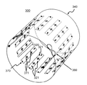
本実施形態のアンテナ装置200の説明に先立ち、従来の、最も簡略なTEM型アンテナを説明する。図2は、RFアンテナ103として用いる、従来のTEM型アンテナであるアンテナ装置300の斜視図である。アンテナ装置300は、傾斜磁場コイル102の内側に配置され、円筒形状を有する。
Prior to the description of the
図2に示すアンテナ装置300は最も簡略なTEM型アンテナの構成例である。シールド導体、ラング導体キャパシタなどの電気部品は示されているが、それらを空間的に支える部材などは示していない。
The
本図に示すように、アンテナ装置300は、円筒状のグラウンドプレーン(接地面)の役割を果たすシールド導体340と、複数セットのラング導体320と、2つまたは4つの給電部に接続される給電部品380と、を備える。また、各ラング導体320は、複数のラング導体片321と、シャントキャパシタ370と、ラングキャパシタ371とを備える。図2では、ラング導体320を16セット、給電部品380を2つ、1つのラング導体320が、3つのラング導体片321を備える場合を例示する。
As shown to this figure, the
図2に示すように、アンテナ装置300は、全体として円筒形となる。そして、アンテナ装置300が形成する円筒の外周部には、円筒の側面の全周を覆うシールド導体340が配置され、その内部に複数セットのラング導体320やキャパシタ(シャントキャパシタ370およびラングキャパシタ371)などの部品が配置される。
As shown in FIG. 2, the
図2には図示していないが、アンテナ装置300は、2つの同軸の円筒状の保持部材を備える。内側の保持部材を内側保持部材、外側の保持部材を外側保持部材と呼ぶ。複数セットのラング導体320は、円筒状の内側保持部材上に取り付けられる。また、シールド導体340は、円筒状の外側保持部材上に張り付けられる。
Although not shown in FIG. 2, the
ここで、アンテナ装置300の円筒の中心軸方向を軸方向と呼び、中心軸に直交する断面の円の円周方向を周方向、直径方向を径方向と呼ぶ。
Here, the central axis direction of the cylinder of the
複数のラング導体320は、内側保持部材の外周面上に、周方向に所定の間隔をあけて配置される。
The plurality of
また、ラング導体320は、その軸方向の両端において、シャントキャパシタ370により、シールド導体340に接続される。これにより、各ラング導体320とシールド導体340とは、電気的に接続され、ループ回路を構成する。なお、電気的な接続は、通常、ハンダ付けにより実現される。
Also, the
また、1つのラング導体320を構成する複数のラング導体片321は、ラングキャパシタ371により、軸方向に、直列に接続される。各ラング導体片321は、ストリップ状(細長い平板またはテープ状)、棒状、もしくは、筒状の導体で作成される。
Further, a plurality of
このアンテナ装置300により実現されるTEM型アンテナは、上記各構成部品を予め一体的に作製し、その後、MRI装置100に組み込む。TEM型アンテナの作製は、全周を覆う外側のシールド導体340を避けて、円筒内部側から、ラング導体320とシールド導体340とをハンダ付けする。
The TEM type antenna realized by the
大学での研究目的ではなく、病院などの一般的に検査で使用するMRI装置100を製造する場合、MRI装置100内部に入る被検体112である患者の安心と安全とを確保することが重要である。そのためには、被検体112の最も近くに配置されるRFアンテナ103(アンテナ装置300)の被検体112側の面、すなわち、内面は、ある程度厚みを有する円筒形状の壁面である必要がある。また、見た目の観点や堅牢性からアンテナの内面は一体形成し、穴や分割部分などが無い方が望ましい。
When manufacturing the
また、TEM型アンテナのアンテナ感度は対向する2つの導体である、シールド導体340とラング導体320との間の距離に依存する。シールド導体340とラング導体320との距離が大きいほど、感度は良くなる。しかしながら、TEM型アンテナの場合、鳥かご型アンテナと比較して、上記のように予め一体的に作製する必要性と、電気的な接続をする必要性とからその距離が狭くなってしまう場合が多い。
Also, the antenna sensitivity of the TEM antenna depends on the distance between the
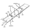
本実施形態では、TEM型アンテナにおいて、使用感や安全性と、感度とを両立させる。これを実現する本実施形態のTEM型アンテナであるアンテナ装置200について説明する。ここでは、RFアンテナ103として、体幹部用ボリュームアンテナとして用いるアンテナ装置200を例にあげて説明する。図3は、アンテナ装置200の斜視図である。
In the present embodiment, in the TEM antenna, the sense of use, the safety, and the sensitivity are made compatible. The
本実施形態のアンテナ装置200は、図3に示すように、所定の周波数の電磁波の送信および受信の少なくとも一方を行う筒状の装置である。以下、本実施形態では、円筒状である場合を例にあげて説明する。また、アンテナ装置200においても、アンテナ装置200の中心軸方向を軸方向と呼び、中心軸に直交する断面の円の円周方向を周方向、直径方向を径方向と呼ぶ。
As shown in FIG. 3, the
図3は、本実施形態のアンテナ装置200の外観斜視図である。また、図4は、本実施形態のアンテナ装置200の中心軸に直交する方向の断面図であり、構成を説明するための説明図である。本実施形態のアンテナ装置200は、図4に示すように、径方向に内側から外側に向かって順に、筒状の内側構造保持部材210と、内側構造保持部材210の軸方向に延びる複数のラング導体220と、筒状のシールド導体240と、シールド導体240を保持する筒状のシールド導体保持部材250と、を備える。
FIG. 3 is an external perspective view of the
また、図3に示すように、内側構造保持部材210とシールド導体240との間には、ラング導体220とシールド導体240との間に空間を形成する間隔保持部材(以下、リブと呼ぶ)230が配置される。
Further, as shown in FIG. 3, a space maintaining member (hereinafter referred to as a rib) 230 which forms a space between the
図3では、ラング導体220を16セット備える場合を例示するが、数は限定されない。また、アンテナ装置200には他の構成部品も存在するが、それらはより詳細な図5、図6、図7および図8で説明する。さらに、図4においては、リブ230も図示しない。
Although FIG. 3 illustrates the case where 16 sets of
また、複数のラング導体220は、内側構造保持部材210の外周面に当該内側構造保持部材の周方向に沿って所定の間隔をあけて配置され、各ラング導体220の軸方向の両端部とシールド導体240とは、ラング導体220とシールド導体240とがループ回路を形成するよう電気的に接続され、シールド導体240およびシールド導体保持部材250と、内側構造保持部材210との少なくとも一方は、ラング導体220とシールド導体240とが電気的に接続される箇所の近傍に穴260を備え、各ループ回路は、アンテナ装置200が送信および受信の少なくとも一方を行う電磁波の周波数で共振するよう調整される。
Further, the plurality of
電気的接続は、例えば、キャパシタ(シャントキャパシタ)270をシールド導体240とラング導体220との間に接続することによりなされる。すなわち、ループ回路は、シャントキャパシタ270を備え、ループ回路の共振周波数は、このシャントキャパシタ270により調整される。つまり、シャントキャパシタ270の容量は、このループ回路が、このアンテナ装置200が送受信する電磁波の周波数で共振するよう調整される。
The electrical connection is made, for example, by connecting a capacitor (shunt capacitor) 270 between the
さらに、少なくとも1つのループ回路は、電磁波の送信および受信の少なくとも一方を行う給電部品280が接続される。図3では、給電部品280を接続する給電点を2つ備える場合を例示するが、数は限定されない。
Furthermore, at least one loop circuit is connected with a
<内側構造保持部材>
内側構造保持部材210は、最も被検体112側に配置される構造部材である。内側構造保持部材210は、1例として厚み3ミリの、比較的厚みのあるガラス繊維強化プラスチック等で作製する。本実施形態では、この内側構造保持部材210に、形状保持機能、難燃性維持機能、および、被検体112と電気部品との電気的、熱的接触を防ぐ機能とをもたせる。このため、後述するシールド導体保持部材250より、その厚みは大きくする。<Internal structure holding member>
The inner
<シールド導体保持部材>
シールド導体保持部材250は、1例として、0.5ミリ厚のガラスエポキシ樹脂など比較的薄い素材で作製する。<Shield conductor holding member>
The shield
本実施形態では、内側構造保持部材210とシールド導体保持部材250とは、傾斜磁場コイル102と中心軸を同じとする。本実施形態では、アンテナ装置200と、内側構造保持部材210と、シールド導体保持部材250とは、同軸の円筒形状とする。そして、内側構造保持部材210の内径はシールド導体保持部材250の内径より小さいものとし、内側構造保持部材210は、シールド導体保持部材250の内側に配置される。
In the present embodiment, the inner
<ラング導体>
ラング導体220は、基本的に従来のTEM型アンテナであるアンテナ装置300のラング導体320と同様の構成を有する。図5は、図3のラング導体220の1つを含む部分を切り出し、拡大した図である。本図に示すように、複数のラング導体片221と、複数のキャパシタ(ラングキャパシタ)271とを備える。<Rang conductor>
The
各ラング導体片221は、ストリップ状(細長い平板またはテープ状)、棒状、もしくは、筒状の導体で作成される。1つのラング導体220を構成する複数のラング導体片221は、ラングキャパシタ271により、軸方向に、直列に接続される。すなわち、各ラング導体220は、軸方向に複数のラング導体片221に分割され、各ラング導体片221は、軸方向に隣接するラング導体片とラングキャパシタ271により接続される。
Each
本実施形態では、ラング導体220を軸方向に複数のラング導体片221に分割することにより、ループ回路を分断する。これにより、シャントキャパシタ270だけでなく、その間に配置するラングキャパシタ271も用いて、ループ回路の共振周波数を調整できる。
In the present embodiment, the loop circuit is divided by dividing the
各キャパシタと各導体とは、ハンダ付けなどにより、電気的に接続される。これらのキャパシタ(シャントキャパシタ270およびラングキャパシタ271)の容量は、ラング導体220とシールド導体240とが、アンテナ装置200が送受信する電磁波の周波数で共振するループ回路を構成するよう調整される。これにより、本実施形態のアンテナ装置200は、RFアンテナ103が送受信する信号の周波数で共振し、送受信の少なくとも一方を行うアンテナとしての機能を実現する。
Each capacitor and each conductor are electrically connected by soldering or the like. The capacitances of these capacitors (the
図5では、ラング導体片221が3つ、それを接続するラングキャパシタ271が2つの場合を例示するが、これらの数は、限定されない。例えば、ラング導体片221が1つで、ラングキャパシタ271は0であってもよい。ラング導体片221およびラングキャパシタ271の数が多い(直列数が多い)と、ラング導体220の両端での電圧を低下させることができる利点がある。
Although FIG. 5 exemplifies a case in which three
なお、シャントキャパシタ270は、各ラング導体220の軸方向の両端に1つづつ接続され、シールド導体240と接続される。それぞれのシャントキャパシタ270は、2つあるいは5つなど、多数並列して配置してもよい。
The
また、図5では、3つのラング導体片221の導体間のギャップ各々に配置されるラングキャパシタ271は1つであるが、2並列あるいは5並列などギャップに横並びに複数配置してもよい。
Further, although one
また、複数セットのラング導体220は、内側構造保持部材210の外周面上に、周方向に、所定の間隔をあけて配置される。このとき、長手方向が軸方向に略平行となるよう配置される。その結果、隣接するラング導体220同士は略平行になる。各ラング導体220は、内側構造保持部材210の外周面に、両面テープなどを用いて密着するよう貼り付けられる。なお、ラング導体220の本数は、一般に、16〜32本程度である。
In addition, a plurality of sets of
なお、ラング導体220は、10から数10ミクロンの薄い銅箔等を用いる。本実施形態では、ストリップ状(細長い平板またはテープ状)の場合を例示するが、棒状や筒状の導体で作成されてもよい。
The
<シールド導体>
シールド導体240は、シールド導体保持部材250の内周面に貼り付けられる。シールド導体240は円筒形のシールド導体保持部材250の内面全面に接着され、円筒形状を有する。TEM型アンテナとして機能させるためには、シールド導体240は、アンテナとして送受信する周波数の電磁波がシールド外部に漏れ出ないように、アンテナ装置200が形成する円筒面を1周、連続して切れ目なく覆う必要がある。このため、シールド導体240は、シールド導体保持部材250の円筒内面をほぼ覆う。ただし、軸方向の長さは、ラング導体の軸方向の長さと同等か、より長ければ良く、シールド導体保持部材250の長さよりも短くてもよい。<Shield conductor>
The
シールド導体240にも、ラング導体220同様、10から数10ミクロンの薄い銅箔等を用いる。
Similar to the
<間隔保持部材>
間隔保持部材(リブ)230は、内側構造保持部材210とシールド導体保持部材250との間に配置され、両者の間に空間(ギャップ)を形成するとともに、このギャップを安定して保持する役割を果たす。上述のように、ラング導体220は、内側構造保持部材210に取り付けられ、シールド導体240は、シールド導体保持部材250に貼りつけられる。従って、両保持部材間のギャップは、ラング導体220とシールド導体240との間のギャップとなり、上述のようにアンテナ装置200の感度を決定する。<Space maintaining member>
Spacing members (ribs) 230 are disposed between inner
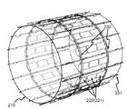
リブ230は、1以上の軸方向に延びる直線状部材(直線状リブ)231と、1以上の周方向に延びる円弧状部材(円弧状リブ)232とを備える。図6および図7は、直線状リブ231と円弧状リブ232との配置を説明するための図であり、内側構造保持部材210、ラング導体220と、直線状リブ231と、円弧状リブ232とのみを示す。
The
各直線状リブ231は、橋台および橋桁を有する橋のような構造を有し、アンテナ装置200の軸方向に延伸し、ラング導体220同様、周方向に所定の間隔をおいて配置される。図6では、各ラング導体220間に配置される。直線状リブ231は、図6および図7に示すように、橋桁に相当する部分が、シールド導体240の、内側、すなわち、シールド導体保持部材250に接着した側と反対側に接着される。接着は、例えば、両面テープなどでなされる。これにより、薄いシールド導体保持部材250の変形、たわみを防止する。また、橋台に相当する部分は、内側構造保持部材210の外周面に取り付けられる。取り付けは、ネジなどでなされる。
Each
円弧状リブ232は、円弧状で、橋脚および橋桁を有する橋のような構造を有する。アンテナ装置200の周方向に1周し、軸方向に所定の間隔をおいて配置される。図6では、ラング導体220の軸方向の両端部近傍に、それぞれ1つ、計2つ配置される場合を例示する。橋脚に相当する部分は、図6および図7に示すように、ラング導体220を跨ぐよう配置される。円弧状リブ232は、橋桁に相当する部分が、シールド導体240の、内側、すなわち、シールド導体保持部材250に接着した側と反対側に接着される。接着は、例えば、両面テープなどでなされる。これにより、薄いシールド導体保持部材250の変形、たわみを防止する。また、橋脚に相当する部分は、内側構造保持部材210の外周面に取り付けられる。取り付けは、ネジなどでなされる。
The
図6に示すように、16本の直線状リブ231と、2つの円弧状リブ232とが、その外側のシールド導体240とシールド導体保持部材250とを支える。また、その形状により、ラングキャパシタ271などの発熱に対し、風を流して空冷する際、風が通りやすくなっている。
As shown in FIG. 6, sixteen
なお、図6および図7では、円弧状リブ232は1つの円形に連続した形状で示しているが、周方向に、複数に分割されていてもよい。
In FIG. 6 and FIG. 7, the arc-shaped
<穴>
上述のように、本実施形態では、シールド導体240およびシールド導体保持部材250、または、内側構造保持部材210の少なくとも一方が、穴260を備える。図3では、穴260を32個備える場合を例示するが、数は限定されない。<Hole>
As described above, in the present embodiment, at least one of the
この穴260は、本実施形態のアンテナ装置200の作製時に、シャントキャパシタ270を、ラング導体220とシールド導体240との間に取り付けるためのものである。
このため、シャントキャパシタ270の接続位置近傍に開けられる。本実施形態では、ラング導体220の軸方向の両端部近傍に開けられる。以下、本実施形態では、シールド導体240およびシールド導体保持部材250に開けられる場合を例にあげて説明する。The
Therefore, it is opened near the connection position of the
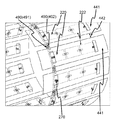
図8は、1つの穴260近傍の拡大図である。上述のように、シールド導体保持部材250とシールド導体240とには、ラング導体220の数の2倍の数の穴260があけられる。なお、シールド導体240に開けられる穴260のサイズは、シールド導体保持部材250に開けられる穴のサイズよりも小さいサイズとする。
FIG. 8 is an enlarged view of the vicinity of one
本図に示すように、円弧状リブ232の一部分233は、穴260と重なるように配置され、穴260の内側にはみ出した円弧状リブ232の一部分233の外周面は、シールド導体240が覆う。つまり、シールド導体240にあけられた穴260は、シールド導体保持部材250にあけられた穴260よりも、円弧状リブ232のはみ出した一部分233だけ小さい。
As shown in the drawing, the
本実施形態のアンテナ装置200は、製造時に、シールド導体240の、円弧状リブ232のはみ出した一部分233を覆う箇所に、シャントキャパシタ270を接続し、ラング導体220と接続する。すなわち、このような構造にすることで、シャントキャパシタ270を、シールド導体240とラング導体220との双方に、図8の上方から容易にはんだづけすることができる。
In the
シャントキャパシタ270をはんだづけするためには、ハンダ箇所にハンダゴテやピンセット、ハンダ棒などをアクセスする必要があり、穴260は、そのアクセスを容易にする。本実施形態のアンテナ装置200では、円弧状リブ232と穴260とが重なる部分で、シールド導体240の外周面が露出することで、図8において、上側から無理のない形でシャントキャパシタ270の両端のリードのハンダ付けが可能になる。
In order to solder the
なお、上述のように、シールド導体240は、アンテナ装置200が送受信する周波数の電磁波がシールド外部に漏れ出ないよう、アンテナ装置200が形成する円筒面を覆う必要がある。このため、穴260の大きさは、必要最小限とすることが望ましい。すなわち、穴260は、この穴260を介してシャントキャパシタ270を接続可能な最小の大きさとすることが望ましい。
As described above, the
<給電部品>
給電部品280は、主として同軸ケーブル281から構成され、図8に示すように、そのアンテナ装置200側の端部に、ラング導体220側の接続点282およびシールド導体240側の接続点283を備える。他方の端部はN型などのコネクタとする。<Feeding parts>
The
接続点282および接続点283のペアは、アンテナとしての送信および/または受信端子である。同軸ケーブル281の中心導体はラング導体220に、外皮導体はシールド導体240側に、それぞれ接続される。この同軸ケーブル281は、上述の送受信ケーブル106として用いられるもので、アンテナ装置200とMRI装置100本体(送受信機104)とを接続する。アンテナ装置200は、この同軸ケーブル281を介して電磁波を送受信する。なお、接続点282および接続点283は、送受信端子、アンテナ装置200のポート、給電点等とも呼ばれる。また、接続点282および接続点283は、チャンネル毎に1ペア設けられる。
The pair of connection points 282 and connection points 283 is a transmitting and / or receiving terminal as an antenna. The center conductor of the
なお、図3に示すように、給電部品280の同軸ケーブル281は、8の字に曲げて外皮導体同士をキャパシタでつなぐことにより、外皮導体に流れる電流を抑制するバラン回路を途中に組み込んでもよい。また、接続点282および接続点283の部分に、キャパシタやインダクタなど数個の集中定数素子を使用して、マッチング回路の機能も持たせてもよい。
In addition, as shown in FIG. 3, the
本実施形態のアンテナ装置200では、給電部品280を接続する給電点は、図3に示すように、アンテナ装置200が型造る円筒の中心軸に対して90度離れた2箇所に設けられる。具体的には、接続点282が、90度離れた2つのラング導体220に設けられる。ただし、90度おきに4箇所設けてもよい。
In the
<製作手順>
次に、本実施形態のアンテナ装置200の製作手順を説明する。<Production procedure>
Next, the manufacturing procedure of the
まず、内側構造保持部材210の外筒面にラング導体220を貼り付ける。そして、ラング導体片221にラングキャパシタ271をハンダ付けする。その後、内側構造保持部材210に給電部品280を固定する。そして、直線状リブ231および円弧状リブ232を、内側構造保持部材210にネジ止めなどの方法で固定する。
First, the
また、予めシールド導体保持部材250の内側となる面(内周面)にシールド導体240を貼り付けておく。シールド導体保持部材250およびシールド導体240には、それぞれ、穴260をあけておく。シールド導体保持部材250と一体となったシールド導体240を、直線状リブ231および円弧状リブ232の橋桁部に接着する。
In addition, the
最後に、シールド導体240の穴260付近において、シャントキャパシタ270をはんだづけし、ラング導体220とシールド導体240とを電気的に接続する。また、給電部品280の先端の、シールド導体240側およびラング導体220側の2つの接続点をハンダ付けする。
Finally, in the vicinity of the
<具体例>
RFアンテナ103として用いる下記3種のボディアンテナを、以下の条件で作製し、各々のシールド導体とラング導体との間の距離を比較する。<Specific example>
The following three types of body antennas used as the
作製するボディアンテナ
1)鳥かご型アンテナ
2)従来のTEM型アンテナ
3)本実施形態のTEM型アンテナ
条件
傾斜磁場コイル102の内径:740ミリ
アンテナの内径:700ミリ
アンテナの一番内側の円筒の厚み:3ミリ
鳥かご型アンテナは、一般に、シールド導体は、傾斜磁場コイル102の内壁深さ1ミリの部分に埋め込まれる。このため、鳥かご型アンテナでは、シールド導体とラング導体との間の距離は、(740−700)/2−3+1で計算でき、18ミリとなる。Body antenna to be produced
1) Birdcage antenna
2) Conventional TEM antenna
3) TEM type antenna of this embodiment Condition inner diameter of gradient magnetic field coil 102: 740 mm inner diameter of antenna: 700 mm thickness of innermost cylinder of antenna: 3 mm For birdcage type antenna, shield conductor is generally gradient magnetic field The
TEM型アンテナの場合、予め作製しておき、設置する際、傾斜磁場コイル102に挿入する。従って、公差を考慮する必要がある。公差を2ミリとする。従来のTEM型アンテナ(アンテナ装置300)の場合、作製手順を考慮すると、外側の保持部材を構造部材とする必要がある。従って、外側の保持部材の厚みを3ミリとすると、シールド導体とラング導体との間の距離は、(740−2−700)/2―3−3で計算でき、13ミリとなる。これは、上記の鳥かご型の18ミリに比べて72%の距離しか取れない。
In the case of a TEM antenna, it is prepared in advance and inserted into the gradient
本実施形態のTEM型アンテナの場合、一番内側の円筒を、そのまま構造体として用いる(内側構造保持部材210)。従って、他のサイズは従来のTEM型アンテナと同じとし、外側の保持部材(シールド導体保持部材250)の厚みを0.5ミリとすると、シールド導体とラング導体との間の距離は、(740−2−700)/2―3−0.5で計算でき、15.5ミリとなる。これは、上記の鳥かご型の18ミリに比べて86%の距離が取れる。 In the case of the TEM antenna of this embodiment, the innermost cylinder is used as a structure as it is (inner structure holding member 210). Therefore, assuming that the other size is the same as that of the conventional TEM antenna and the thickness of the outer holding member (shield conductor holding member 250) is 0.5 mm, the distance between the shield conductor and the rung conductor is (740-2 It can be calculated by -700) /2-3-0.5, which is 15.5 mm. This is 86% longer than the 18 mm birdcage type described above.
以上説明したように、本実施形態のMRI装置100は、所定の周波数の電磁波の送信および受信の少なくとも一方を行う筒状のアンテナ装置200を備え、前記アンテナ装置200は、当該アンテナ装置200の径方向に内側から外側に向かって順に、筒状の内側構造保持部材210と、前記内側構造保持部材210の軸方向に延びる複数のラング導体220と、筒状のシールド導体240と、前記シールド導体240を保持する筒状のシールド導体保持部材250と、を備え、前記内側構造保持部材210と前記シールド導体240との間には、前記ラング導体220と前記シールド導体240との間に空間を形成する間隔保持部材230が配置され、前記複数のラング導体220は、前記内側構造保持部材210の外周面に当該内側構造保持部材210の周方向に沿って所定の間隔をあけて配置され、各前記ラング導体220の前記軸方向の両端部と前記シールド導体240とは、当該ラング導体220と当該シールド導体240とがループ回路を形成するよう電気的に接続され、前記シールド導体240および前記シールド導体保持部材250と、前記内側構造保持部材210との少なくとも一方は、前記ラング導体220と前記シールド導体240とが電気的に接続される箇所の近傍に穴260を備え、前記各ループ回路は、当該アンテナ装置200が送信および受信の少なくとも一方を行う電磁波の周波数で共振するよう調整され、少なくとも1つの前記ループ回路は、前記電磁波の送信および受信の少なくとも一方を行う給電部を備える。
As described above, the
このように、本実施形態のアンテナ装置200によれば、TEM型アンテナであっても、外側に配置されるシールド導体保持部材250と、シールド導体240とに穴があけられているため、その穴を介して、ラング導体220とシールド導体240とを電気的に接続することができる。このため、アンテナ装置200の外周面から電気的接続を行うことができ、内周面にあたる内側の円筒(内側構造保持部材210)を、堅牢な構造体とすることができる。すなわち、内側構造保持部材210に、構造体としての機能と安全性を確保する機能とを兼ねさせることができる。そして、その分、外側の保持部材であるシールド導体保持部材250を薄くすることができ、アンテナ装置200の、径方向の厚み自体を薄くすることができる。
As described above, according to the
また、アンテナ装置200の径方向の厚みを薄くできるため、アンテナ設置スペースの内径と外径の差が小さい場合であっても、シールド導体240とラング導体220との距離を維持広く保ち、アンテナ感度を保つことができる。
In addition, since the thickness in the radial direction of the
従って、本実施形態のアンテナ装置200によれば、ラング導体220とシールド導体240との間の距離を短くすることなく、所定の内径を確保できる。従って、本実施形態のアンテナ装置200は、感度を落とすことなく円筒形状の外径と内径の差を小さくすることができるので、被検体112にとって快適な広い検査空間を提供することができる。
また、本実施形態のアンテナ装置200によれば、アンテナ装置200の径方向の厚みを薄くでき、アンテナ装置200の内径と外径との差が小さい場合であっても、シールド導体240とラング導体220との距離を広く保ち、アンテナ感度を保つことができる。Therefore, according to the
Further, according to the
このように、本実施形態のアンテナ装置200によれば、安全性や使用感と、感度とを両立できる。また、本実施形態によれば、このようなアンテナ装置を、容易に作製できる。
As described above, according to the
<<第二の実施形態>>
次に、本発明の第二の実施形態を説明する。第一の実施形態では、RFアンテナ103に用いるアンテナ装置は、TEM型アンテナとした。一方、本実施形態では、RFアンテナ103に用いるアンテナ装置は、マイクロストリップライン型のアンテナとする。
<< Second Embodiment >>
Next, a second embodiment of the present invention will be described. In the first embodiment, the antenna device used for the
本実施形態のMRI装置は、基本的に第一の実施形態のMRI装置100と同様の構成を有する。ただし、上述のように、本実施形態では、RFアンテナ103として、マイクロストリップライン型アンテナであるアンテナ装置400を用いる。
The MRI apparatus of the present embodiment basically has the same configuration as the
TEM型のアンテナは、互いにカップリングが少ない独立なチャンネルが2チャンネルしか無いのに対して、マイクロストリップライン型のアンテナは、ラング数をN(Nは1以上の整数)とすると、Nチャンネルの独立したチャンネルを持つことが特徴である。 The TEM type antenna has only two independent channels with few couplings, whereas the microstrip line type antenna has N rung numbers N (N is an integer of 1 or more). It is characterized by having an independent channel.
図9は、本実施形態のアンテナ装置400の外観斜視図である。本実施形態のアンテナ装置400は、図9に示すように、所定の周波数の電磁波の送信および受信の少なくとも一方を行う筒状の装置である。以下、アンテナ装置400においても、アンテナ装置の中心軸方向を軸方向と呼び、中心軸に直交する断面の円の円周方向を周方向、直径方向を径方向と呼ぶ。
FIG. 9 is an external perspective view of the
本実施形態のアンテナ装置400は、図9に示すように、第一の実施形態のアンテナ装置200と同様に、径方向に内側から外側に向かって順に、筒状の内側構造保持部材210と、内側構造保持部材210の軸方向に延びる複数のラング導体220と、筒状のシールド導体440と、シールド導体440を保持する筒状のシールド導体保持部材250と、を備える。そして、内側構造保持部材210とシールド導体440との間には、ラング導体220とシールド導体440との間に空間を形成する間隔保持部材(以下、リブと呼ぶ)230が配置される。
As shown in FIG. 9, as in the
図9では、ラング導体220を16セット備える16チャンネルのマイクロストリップライン型アンテナを例示するが、ラング導体220の数、チャンネル数Nは限定されない。
Although FIG. 9 illustrates a 16-channel microstrip line antenna having 16 sets of
また、本実施形態のアンテナ装置400は、第一の実施形態同様、内側構造保持部材210と、シールド導体保持部材250およびシールド導体440と、の少なくとも一方に穴260を備える。ラング導体220とシールド導体440とは、この穴260に隣接した部分で、シャントキャパシタ270により電気的に接続される。これにより、ラング導体220とシールド導体440とは、ループ状の導体(ループ回路)を形成する。
Moreover, the
内側構造保持部材210、ラング導体220、リブ230、シールド導体保持部材250、穴260、キャパシタ270は、第一の実施形態の同名の構成と同様とする。以下、第一の実施形態のアンテナ装置200と異なる構成に主眼をおいて、本実施形態のアンテナ装置400を説明する。
The inner
シールド導体440が、チャンネル数分、分割され、隣り合うチャンネル間のカップリングを分断するため、デカップリング回路を備える点が、第一の実施形態のTEM型アンテナであるアンテナ装置200との構造上の大きな違いである。
The
本実施形態のアンテナ装置400のシールド導体440は、チャンネル数分、周方向に、軸に平行に分割される。例えば、本実施形態では、ラング導体220の数に分割される。すなわち、図9の例では、16分割される。以下、各分割されたシールド導体440を、それぞれ、部分シールド導体441と呼ぶ。
The
図10は、図9に示す、本実施形態のアンテナ装置400の外観斜視図の、電気回路部分だけを拡大表示した説明図である。シールド導体440には、ラング導体220に流れる電流の鏡像電流が流れるが、図10に示すように、鏡像電流が流れる範囲を充分覆うように、ラング導体よりも通常大きな面積を持つように、分割される。各ラング導体220に対応する部分シールド導体441は、ラング導体220同様、シールド導体保持部材250の内周面上に、周方向に所定の間隔442をあけて配置される。各部分シールド導体441と、各ラング導体220とは、シャントキャパシタ270により電気的に接続される。
FIG. 10 is an explanatory view in which only an electric circuit portion is enlarged and displayed in the external appearance perspective view of the
なお、本実施形態においても、給電部品280は、チャンネル毎に接続される。従って、本実施形態の給電部品280は、例えば、図9の例では、16個接続される。なお、各給電部品280の構成は、第一の実施形態と同様である。
Also in the present embodiment, the
さらに、アンテナ装置400は、隣り合うチャンネル間のカップリングを取るためのデカップリング回路490を備える。本実施形態では、デカップリング回路490として、デカップリングキャパシタ491および492を備える。
Furthermore, the
図10に示すように、本実施形態のアンテナ装置400は、部分シールド導体441間に間隔442を設ける。隣り合う部分シールド導体441間には、デカップリングキャパシタ492を配置し、隣り合うラング導体220間には、デカップリングキャパシタ491を配置する。
As shown in FIG. 10, in the
なお、本図では、デカップリングキャパシタ491およびデカップリングキャパシタ492は、軸方向に伸びるラング導体220および部分シールド導体441の片側の端に寄せてそれぞれ1箇所設置しているが、それぞれの導体の両端の2箇所に設置してもよい。
Note that, in this figure, the
また、デカップリング回路490は、キャパシタに限定されない。インダクタを用いてもよい。これにより、外径と内径の差が少ない設置環境においても3チャンネル以上の円筒形状のマイクロストリップライン型のアンテナを感度良く作製することができる。
Also, the
<作製手順>
次に、本実施形態のアンテナ装置400の作製手順を説明する。ここでは、第一の実施形態のアンテナ装置200と異なる手順に主眼をおいて説明する。<Production procedure>
Next, the manufacturing procedure of the
内側構造保持部材210へのラング導体220への取り付け、給電部品280の取り付け、リブ230の固定は第一の実施形態と同様である。ただし、本実施形態のアンテナ装置400では、隣り合うチャンネル間のカップリングを防ぐため、隣り合うラング導体220間には、デカップリングキャパシタ491を配置する。
The attachment to the
一方、シールド導体保持部材250の側については、本実施形態のアンテナ装置400では、まず、シールド導体440を、周方向に16個に分割する。そして、周方向に隣り合う部分シールド導体441間に、間隔(スペース)442を設け、シールド導体保持部材250の内周面に貼り付ける。図10に示すように、隣接するラング導体220間の間隔222の周方向の中心と、スペース442の周方向の中心とが略合致するよう貼り付けることが望ましい。また、本実施形態のアンテナ装置400では、隣り合うチャンネル間のカップリングを防ぐため、隣り合う部分シールド導体441間には、デカップリングキャパシタ492を配置する。
On the other hand, on the side of the shield
このとき、アンテナ装置200同様、シールド導体保持部材250および各部分シールド導体441には、それぞれ、穴260をあけておく。シールド導体保持部材250と一体となった、複数の部分シールド導体441を、直線状リブ231および円弧状リブ232の橋桁部に接着する。
At this time, as in the
最後に、シールド導体440の穴260付近において、シャントキャパシタ270をはんだづけし、ラング導体220と部分シールド導体441とを電気的に接続する。また、給電部品280の先端の、シールド導体440側およびラング導体220側の2つの接続点をハンダ付けする。なお、給電部品280は、チャンネル数分、設ける。すなわち、各部分シールド導体441に対し、1つ接続する。図9の例では、16個設ける。
Finally, in the vicinity of the
以上説明したように、本実施形態のMRI装置100は、所定の周波数の電磁波の送信および受信の少なくとも一方を行う通常のアンテナ装置400を備え、アンテナ装置400は、当該アンテナ装置400の径方向に内側から外側に向かって順に、筒状の内側構造保持部材210と、前記内側構造保持部材210の軸方向に延びる複数のラング導体220と、筒状のシールド導体440と、前記シールド導体440を保持する筒状のシールド導体保持部材250と、を備え、前記内側構造保持部材210と前記シールド導体440との間には、前記ラング導体220と前記シールド導体440との間に空間を形成する間隔保持部材230が配置され、前記複数のラング導体220は、前記内側構造保持部材210の外周面に当該内側構造保持部材210の周方向に沿って所定の間隔をあけて配置され、各前記ラング導体220の前記軸方向の両端部と前記シールド導体440とは、当該ラング導体220と当該シールド導体440とがループ回路を形成するよう電気的に接続され、前記シールド導体440および前記シールド導体保持部材250と、前記内側構造保持部材210との少なくとも一方は、前記ラング導体220と前記シールド導体440とが電気的に接続される箇所の近傍に穴260を備え、前記各ループ回路は、当該シールド導体440が送信および受信の少なくとも一方を行う電磁波の周波数で共振するよう調整され、少なくとも1つの前記ループ回路は、前記電磁波の送信および受信の少なくとも一方を行う給電部を備える。
As described above, the
そして、前記シールド導体440は、前記シールド導体保持部材250の周方向に、前記ラング導体220数以下の部分シールド導体441に分割され、前記給電部は、各前記ループ回路に備えられる。
The
このように、本実施形態のアンテナ装置400によれば、マイクロストリップ型アンテナであっても、第一の実施形態のTEM型アンテナであるアンテナ装置200同様、内側構造保持部材210に、構造体としての機能と安全性を確保する機能とをかねさせることができる。このため、アンテナ装置400の、径方向の厚み自体を薄くすることができる。
As described above, according to the
従って、本実施形態のアンテナ装置400によれば、ラング導体220とシールド導体440との間の距離を短くすることなく、所定の内径を確保できる。従って、本実施形態のアンテナ装置400は、感度を落とすことなく円筒形状の外径と内径の差を小さくすることができるので、被検体112にとって快適な広い検査空間を提供することができる。
すなわち、安全性や使用感と、感度とを両立できる。Therefore, according to the
That is, safety and a sense of use can be compatible with sensitivity.
なお、上記第一および第二の実施形態では、アンテナ装置200、400の外観を規定するシールド導体保持部材250および内側構造保持部材210の形状は、円筒とした。
しかし、この形状に限定されない。これらは、例えば、楕円筒形状であってもよい。この場合、円弧状リブは、楕円弧状リブとなる。In the first and second embodiments, the shapes of the shield
However, it is not limited to this shape. These may be, for example, an elliptical cylinder shape. In this case, the arcuate rib is an elliptical arcuate rib.
図11は、第二の実施形態のアンテナ装置400において、シールド導体保持部材および内側構造保持部材の形状を、楕円筒形状(シールド導体保持部材650、内側構造保持部材610)とした、アンテナ装置600の外観斜視図である。このアンテナ装置600の、軸方向に直交する断面は、長軸602および短軸603を持つ、楕円となる。
FIG. 11 shows an
MRI装置100は、ヒトが仰向けに寝て、内部空間に入る場合が多いので、断面が楕円形状のアンテナ装置600は、さらに被検体112の快適性を向上させる。
In many cases, the
<<第三の実施形態>>
次に、本発明の第三の実施形態を説明する。本実施形態のアンテナ装置は、第二の実施形態同様、マイクロストリップライン型のアンテナとする。ただし、本実施形態では、シールド導体だけでなく、シールド導体保持部材も、チャンネル数に分割される。本実施形態のアンテナ装置は、複数チャンネルのマイクロストリップライン型のアンテナ装置で、各チャンネルのラング導体は、周方向に複数に分割され、軸方向の両端部で周方向に電気的に接続される。また、筒の形状は楕円である。
<< Third Embodiment >>
Next, a third embodiment of the present invention will be described. The antenna device of the present embodiment is a microstrip line antenna as in the second embodiment. However, in the present embodiment, not only the shield conductor but also the shield conductor holding member is divided into the number of channels. The antenna device of this embodiment is a microstrip line type antenna device of a plurality of channels, and the rung conductor of each channel is divided into a plurality in the circumferential direction, and electrically connected in the circumferential direction at both axial end portions. . Moreover, the shape of the tube is an ellipse.
本実施形態のMRI装置は、基本的に第一の実施形態のMRI装置100と同様の構成を有する。だたし、本実施形態では、RFアンテナ103として、第二の実施形態同様、マイクロストリップライン型アンテナであるアンテナ装置500を用いる。
The MRI apparatus of the present embodiment basically has the same configuration as the
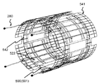
図12は、本実施形態のアンテナ装置500の外観斜視図である。また、図13(a)は、本実施形態のアンテナ装置500の、中心軸に垂直な断面における断面図であり、構成を説明するための図である。ここでは、4チャンネルである場合を例示する。しかし、チャンネル数は、これに限定されない。
FIG. 12 is an external perspective view of the
図12および図13(a)に示すように、本実施形態のアンテナ装置500は、所定の周波数の電磁波の送信および受信の少なくとも一方を行う、複数チャンネルのアンテナ装置であって、チャンネル数分の、部分楕円筒形状の単一チャンネル部501を備え、全体として楕円筒形状を有する装置である。以下、アンテナ装置500においても、アンテナ装置の中心軸方向を軸方向と呼び、中心軸に直交する断面の楕円の楕円周方向を周方向、直径方向を径方向と呼ぶ。部分楕円筒形状は、楕円筒を、軸方向に平行に周方向に複数に分割した形状である。
As shown in FIGS. 12 and 13A, the
図13(a)に示すように、本実施形態のアンテナ装置500は、径方向に内側から外側に向かって順に、内側構造保持部材510と、チャンネル数分の、部分筒形状の単一チャンネル部501とを備える。チャンネル数分の単一チャンネル部501は、内側構造保持部材510の外側の面に、アンテナ装置500の周方向に所定の間隔をあけて配置される。
As shown in FIG. 13A, in the
本実施形態の内側構造保持部材510は、第一の実施形態の内側構造保持部材210同様、最も被検体112側に配置される構造部材である、その厚み、素材は、第一の実施形態の内側構造保持部材210と同様とする。ただし、軸方向に直交する断面形状は、楕円形状とする。
The inner
各単一チャンネル部501は、アンテナ装置500の径方向に内側から外側に向かって順に、軸方向に延びる1つのラング導体520と、部分筒形状を有する部分筒状シールド導体541と、部分筒状シールド導体541を保持する部分筒形状を有する部分筒状シールド導体保持部材551と、を備える。
Each
なお、アンテナ装置500は、後述するように他の構成部品も備えるが、図13(a)では、これらは省略する。
In addition, although the
また、部分筒状シールド導体541および部分筒状シールド導体保持部材551は、周方向に、中心軸に平行に、第一の実施形態のアンテナ装置200で楕円筒形状のものが備える、シールド導体240およびシールド導体保持部材250を、チャンネル数に分割したものである。
In addition, the partially
部分筒状シールド導体541および部分筒状シールド導体保持部材551の、素材、厚みは、第一の実施形態のシールド導体240およびシールド導体保持部材250とそれぞれ同様とする。
The material and thickness of the partial
また、本実施形態においても、部分筒状シールド導体541は、第一の実施形態のシールド導体240がシールド導体保持部材250の内面全面に接着される構成と同様に、部分筒状シールド導体保持部材551の内面全面に接着される。
Also in the present embodiment, the partial
図13(b)は、ラング導体520を、平面に展開したものである。本図に示すように、チャンネル毎に設けられるラング導体520は、感度範囲を広くするために、周方向に、中心軸に平行に複数に分割する。分割されたラング導体520の各部分を、それぞれ、部分ラング導体522と呼ぶ。
FIG. 13 (b) is a
各部分ラング導体522の両端は、互いに隣り合う部分ラング導体522と、例えば、2000pF程度の高容量のキャパシタ573で、高周波的に低インピーダンスで接続される。このような構造にすることで、周方向に感度範囲を広げ、楕円筒内部の感度均一度を向上させることができる。なお、図13(b)では、ラング導体520を、5分割した場合を例示する。
Both ends of each
各部分ラング導体522の詳細は、第一の実施形態のラング導体220と同様とする。
すなわち、軸方向に複数のラング導体片に分割され、ラング導体片間は、ラングキャパシタ271で接続される。The details of each
That is, it is divided into a plurality of rung conductor pieces in the axial direction, and the rung conductor pieces are connected by the
また、各部分ラング導体522の軸方向の両端部と、部分筒状シールド導体541とは、部分ラング導体522と部分筒状シールド導体541とがループ回路を形成するように電気的に接続される。電気的な接続は、例えば、シャントキャパシタ270などにより行われる。
Further, both axial ends of each
本実施形態においても、各ループ回路は、当該アンテナ装置500が送信および受信の少なくとも一方を行う電磁波の周波数で共振するよう調整される。調整は、シャントキャパシタ270の容量を調整することによりなされる。
Also in the present embodiment, each loop circuit is adjusted to resonate at the frequency of the electromagnetic wave at which the
また、本実施形態においても、部分筒状シールド導体541および部分筒状シールド導体保持部材551と、内側構造保持部材510と、の少なくとも一方の、部分ラング導体522と部分筒状シールド導体541との電気的な接続箇所近傍には、穴260が開けられる。
Also in the present embodiment, at least one of the partial
図12では、穴260が、部分筒状シールド導体保持部材551および部分筒状シールド導体541に開けられる場合を例示する。穴260は、第一の実施形態同様、アンテナ装置500を作製時に、ラング導体520と部分筒状シールド導体541とを接続する作業を行うためのものである。従って、この作業が行える位置に、この作業が行える数だけ備えられていればよい。例えば、部分ラング導体522の2倍の数を備える。詳細は、第一の実施形態と同様とする。
In FIG. 12, the case where the
さらに、各単一チャンネル部501には、電磁波の送信および受信の少なくとも一方を行う給電部品280が接続される。図12に示すアンテナ装置500の例では、4チャンネルのアンテナ装置であるため、給電部品280を、4つ備える。各部分筒状シールド導体541は、その電磁波の送信および受信の少なくとも一方を行う給電部を備え、この給電部を介してこれらの給電部品280は接続される。
Furthermore, each
また、内側構造保持部材510と部分筒状シールド導体541との間には、ラング導体520と部分筒状シールド導体541との間に空間を形成する間隔保持部材(リブ)530が配置される。その機能は第一の実施形態のリブ230と同様である。本実施形態のリブ530も、第一の実施形態同様、直線状リブ531と部分楕円弧状リブ532とを備える。
In addition, a spacing member (rib) 530 which forms a space between the
図14は、アンテナ装置500の、リブ530の配置を説明するために、部分筒状シールド導体保持部材551および部分筒状シールド導体541を取り除いて、リブ530(直線状リブ531および部分楕円弧状リブ532)を露出させた部分拡大図である。なお、図14ではシャントキャパシタ270、ラングキャパシタ271、キャパシタ573等の回路部品は省略する。
14 illustrates the arrangement of the
直線状リブ531は、第一の実施形態の直線状リブ231と同様に、橋台および橋桁を有する構造であり、アンテナ装置500の軸方向に延伸し、周方向に所定の間隔をおいて配置される。内側構造保持部材510および部分筒状シールド導体保持部材551への取り付け態様は、第一の実施形態の直線状リブ231と同様である。
Similar to the
部分楕円弧状リブ532は、楕円弧を周方向に分割した部分楕円弧形状の橋桁と、橋脚とを有する。本実施形態では、複数の部分楕円弧状リブ532が、軸方向に所定の間隔をおいて、配置される。内側構造保持部材510および部分筒状シールド導体保持部材551への取り付け態様は、第一の実施形態の円弧状リブ232と同様である。
The partial elliptical arc-shaped
すなわち、内側構造保持部材510の外周面上に部分ラング導体522が接着される。
そして、部分ラング導体522を避けて、内側構造保持部材510の外周面上に、直線状リブ531と部分楕円弧状リブ532とが設置される。That is,
Then, the
図15は、アンテナ装置500の部分筒状シールド導体541、部分ラング導体522、給電部品280、および、後述するデカップリングブリッジ591を説明するための説明図(透視図)である。
FIG. 15 is an explanatory diagram (perspective view) for describing the partial
なお、本実施形態のアンテナ装置500では、周方向に複数(4つ)に分割された単一チャンネル部501について、周方向に隣接するもの同士を接続し、1つの楕円筒状のアンテナ装置500を形成する。具体的には、部分筒状シールド導体保持部材551および部分筒状シールド導体541を、隣接する単一チャンネル部501の部分筒状シールド導体保持部材551および部分筒状シールド導体541と、それぞれ接続する。このとき、部分筒状シールド導体541どうしは、接続部542を介して接続する。
In the
また、本実施形態のアンテナ装置500は、マイクロストリップ型アンテナであるため、第二の実施形態同様、隣接するチャンネル間のカップリングを防止するデカップリング回路590を備える。本実施形態では、デカップリング回路590として、隣接する単一チャンネルの部分501の部分ラング導体522であって、隣り合う部分ラング導体522間を接続するデカップリングブリッジ591を用いる。
Further, since the
次に、本実施形態のアンテナ装置500の作製手順を説明する。
Next, the manufacturing procedure of the
まず、内側構造保持部材510の外筒面に部分ラング導体522を貼り付ける。そして、各ラング導体520にラングキャパシタ271およびキャパシタ573をハンダ付けする。その後、内側構造保持部材510に給電部品280を固定する。そして、直線状リブ531および部分楕円弧状リブ532を、内側構造保持部材510にネジ止めなどの方法で固定する。
First, the
また、予め、部分筒状シールド導体保持部材551の内側となる面(内周面)に部分筒状シールド導体541を貼り付けておく。部分筒状シールド導体保持部材551および部分筒状シールド導体541には、それぞれ、穴260をあけておく。部分筒状シールド導体保持部材551と一体となった部分筒状シールド導体541を、直線状リブ531および部分楕円弧状リブ532の橋桁部に接着する。
Further, the partial
そして、部分筒状シールド導体541の穴260付近において、シャントキャパシタ270をはんだづけし、部分ラング導体522と部分筒状シールド導体541とを電気的に接続する。また、給電部品280の先端の、部分筒状シールド導体541側および部分ラング導体522側の2つの接続点をハンダ付けする。
Then, the
最後に、各単一チャンネル部501の、隣り合う部分ラング導体522間をデカップリングブリッジ591で接続し、部分筒状シールド導体541を、隣接する単一チャンネル部501の部分筒状シールド導体541に接続し、楕円筒状のアンテナ装置500を形成する。
Finally, the adjacent
なお、本実施形態では、アンテナ装置500が楕円筒形状である場合を例にあげて説明したが、本実施形態のアンテナ装置500は、円筒形状であってもよい。この場合、内側構造保持部材510は円筒形状となり、各単一チャンネル部501は、円筒を、周方向に軸に平行に分割した形状となる。また、部分楕円弧状リブ532は、部分円弧状リブとなる。
In the present embodiment, the case where the
以上説明したように、本実施形態のMRI装置100は、所定の周波数の電磁波の送信および受信の少なくとも一方を行う複数チャンネルの筒状のアンテナ装置500を備え、前記アンテナ装置500は、径方向に内側から外側に向かって順に、筒状の内側構造保持部材510と、チャンネル数の、部分筒形状の単一チャンネル部501と、を備え、各前記単一チャンネル部501は、前記アンテナ装置500の軸方向に伸びる複数の部分ラング導体522と、前記部分筒形状の部分筒状シールド導体541と、前記部分筒状シールド導体541を保持する前記部分筒形状の部分筒状シールド導体保持部材551と、を備え、前記チャンネル数の単一チャンネル部501は、前記内側構造保持部材510の外側の面に、前記アンテナ装置500の周方向に所定の間隔をあけて配置され、前記内側構造保持部材510と前記部分筒状シールド導体541との間には、前記部分ラング導体522と前記部分筒状シールド導体541との間に空間を形成する間隔保持部材530が配置され、前記複数の部分ラング導体522は、前記内側構造保持部材510の外側の面に前記アンテナ装置500の周方向に所定の間隔をあけて配置され、各前記部分ラング導体522の前記軸方向の両端部と前記部分筒状シールド導体541とは、当該部分ラング導体522と当該部分筒状シールド導体541とがループ回路を形成するよう電気的に接続され、前記部分筒状シールド導体541および前記部分筒状シールド導体保持部材551と、前記内側構造保持部材510との少なくとも一方は、前記部分ラング導体522と前記部分筒状シールド導体541とが電気的に接続される箇所の近傍に穴260を備え、前記各ループ回路は、当該アンテナ装置500が送信および受信の少なくとも一方を行う電磁波の周波数で共振するよう調整され、各部分筒状シールド導体541は、前記電磁波の送信および受信の少なくとも一方を行う給電部を備える。
As described above, the
このように、本実施形態のアンテナ装置500によれば、マイクロストリップ型アンテナであっても、第一の実施形態のTEM型アンテナであるアンテナ装置200同様、内側構造保持部材510に、構造体としての機能と安全性を確保する機能とをかねさせることができる。このため、アンテナ装置500の、径方向の厚み自体を薄くすることができる。
As described above, according to the
従って、本実施形態のアンテナ装置500によれば、ラング導体520と部分筒状シールド導体541との間の距離を短くすることなく、所定の内径を確保できる。従って、本実施形態のアンテナ装置500は、感度を落とすことなく円筒形状の外径と内径の差を小さくすることができるので、被検体112にとって快適な広い検査空間を提供することができる。
すなわち、安全性や使用感と、感度とを両立できる。
Therefore, according to the
That is, safety and a sense of use can be compatible with sensitivity.
なお、本実施形態では、単一チャンネル部501のみ部分筒形状の分割構造としているが、これに限定されない。内側構造保持部材510も、同様に、周方向に軸方向に平行に、チャンネル数に分割された、部分筒形状を有していてもよい。この場合、アンテナ装置500の作製時は、チャンネル単位で筒を周方向に分割した部分筒形状のコイルを作成し、最後に1つの筒状に組み合わせてもよい。
In addition, in this embodiment, although it is set as the division | segmentation structure of a partial cylindrical shape only in the
また、本実施形態では、各部分筒状シールド導体541として、1枚のシート状導体を用いる場合を例にあげて説明しているが、これに限定されない。例えば、図15に示すように、一部、細かくタイル状に分割された導体を用いてもよい。このような形状を用いることにより、傾斜磁場により発生する渦電流を防止し、発熱を防ぐことができる。
Moreover, in this embodiment, although the case where the sheet-like conductor of 1 sheet is used is mentioned as an example and demonstrated as each partial
この場合、各部分筒状シールド導体541は、例えば、厚さ25ミクロン程度のポリイミド膜の両面に、厚さ12ミクロン程度の銅箔を貼り付けて、作成する。すなわち、この場合の部分筒状シールド導体541は、両面銅箔シートを用いる。なお、図15では、説明を簡単にするため、内側の銅箔のタイル状のパターンのみ示す。実際には、外側の銅箔にも縞の位置が互い違いにずれた、異なる縞状のタイルパターンがエッチングによって作られる。縞状のタイルパターン同士は、直流の電流に対しては断線しているが、高周波に対しては容量的に結合し、導体となる。
In this case, each partial
このような、タイル状に分割された導体は、第一の実施形態および第二の実施形態のシールド導体にも用いることができる。 Such tiled conductors can also be used for the shield conductors of the first and second embodiments.
また、上記各実施形態では、穴260のサイズをできるだけ小さくし、その数を、ラング導体の数の2倍としたが、これに限定されない。当該穴260を介して、各ラング導体とシールド導体とを電気的に接続できればよく、穴260の数は限定されない。
In the above embodiments, and minimize the size of the
以上説明したように、各実施形態によれば、MRI装置に用いられるTEM型あるいはマイクロストリップライン型のアンテナ装置において、アンテナ装置の円筒面のいずれかに穴をあけ、その周辺部でシールド導体とラング導体とを電気的に接続し、ループ回路を形成する。 As described above, according to each embodiment, in a TEM type or microstrip line type antenna device used for an MRI apparatus, a hole is made in one of the cylindrical surfaces of the antenna device, and a shield conductor is formed at the periphery thereof. The rung conductor is electrically connected to form a loop circuit.
従って、予め一体形成しておくことを要するアンテナ装置であって、外側面の略一面を覆うシールド導体を配置するアンテナ装置において、アンテナ装置の内側の面を堅牢な構造体とすることができる。すなわち、内側の面に、構造体としての機能と安全性を確保する機能とを兼ねさせることができる。従って、外側の面を構造体とする必要がないため、その分、薄く作製することができ、アンテナ装置の内径と外径との差を縮めることなく、アンテナ装置全体の径方向の厚みを薄くすることができる。 Therefore, in the antenna device that needs to be integrally formed in advance, in the antenna device in which the shield conductor covering approximately one surface of the outer side surface is disposed, the inner surface of the antenna device can be a robust structure. That is, the inner surface can have both the function as a structure and the function of securing safety. Therefore, since it is not necessary to make the outer surface into a structure, it can be made thinner accordingly, and the radial thickness of the entire antenna device can be reduced without reducing the difference between the inner diameter and the outer diameter of the antenna device. can do.
従って、上記各実施形態によれば、感度を落とすことなく、広い内部空間を有するアンテナ装置を提供できる。 Therefore, according to each of the above embodiments, it is possible to provide an antenna device having a wide internal space without reducing sensitivity.
なお、上記各実施形態のアンテナ装置は、受信専用アンテナ、または、送信専用アンテナであってもよいし、送受信兼用アンテナであってもよい。また、上記各実施形態のアンテナ装置は、MRI装置のRFアンテナとしてだけでなく、数MHzから数GHzの周波数を持つ電磁波を使用するあらゆる機器に応用可能である。 The antenna device of each of the above embodiments may be a reception-only antenna, a transmission-only antenna, or a transmission / reception antenna. Moreover, the antenna apparatus of each said embodiment is applicable not only as an RF antenna of an MRI apparatus but to any apparatus which uses the electromagnetic waves which have a frequency of several MHz to several GHz.
100 MRI装置、101 マグネット、102 傾斜磁場コイル、103 RFアンテナ、104 送受信機、105 データ処理部、106 送受信ケーブル、107 傾斜磁場制御ケーブル、108 表示装置、109 傾斜磁場電源、111 ベッド、112 被検体、200 アンテナ装置、210 内側構造保持部材、220 ラング導体、221 ラング導体片、222 間隔、230 リブ(間隔保持部材)、231 直線状リブ、232 円弧状リブ、233 円弧状リブの一部分、240 シールド導体、250 シールド導体保持部材、260 穴、270 シャントキャパシタ、271 ラングキャパシタ、280 給電部品、281 同軸ケーブル、282 接続点、283 接続点、300 アンテナ装置、320 ラング導体、321 ラング導体片、340 シールド導体、370 シャントキャパシタ、371 ラングキャパシタ、380 給電部品、400 アンテナ装置、440 シールド導体、441 部分シールド導体、442 間隔、490 デカップリング回路、491 デカップリングキャパシタ、492 デカップリングキャパシタ、500 アンテナ装置、501 単一チャンネル部、510 内側構造保持部材、520 ラング導体、522 部分ラング導体、530 リブ(間隔保持部材)、531 直線状リブ、532 部分楕円弧状リブ、541 部分筒状シールド導体、542 接続部、551 部分筒状シールド導体保持部材、573 キャパシタ、590 デカップリング回路、591 デカップリングブリッジ、600 アンテナ装置、602 長軸、603 短軸、610 内側構造保持部材、650 シールド導体保持部材 DESCRIPTION OF SYMBOLS 100 MRI apparatus, 101 magnet, 102 gradient magnetic field coil, 103 RF antenna, 104 transceiver, 105 data processing part, 106 transmission / reception cable, 107 gradient magnetic field control cable, 108 display apparatus, 109 gradient magnetic field power supply, 111 bed, 112 object , 200 antenna device, 210 inner structure holding member, 220 rung conductor, 221 rung conductor piece, 222 interval, 230 rib (space maintaining member), 231 linear rib, 232 arc rib, 233 arc rib portion, 240 shield Conductor, 250 shield conductor holding member, 260 hole, 270 shunt capacitor, 271 rung capacitor, 280 feed component, 281 coaxial cable, 282 connection point, 283 connection point, 300 antenna device, 320 rung conductor, 321 rung conductor piece, 340 shield Conductor, 370 shunt capacitor, 371 rung capacitor, 380 feed component, 400 antenna device, 440 shield conductor, 441 partial sea Conductor, 442 spacing, 490 decoupling circuit, 491 decoupling capacitor, 492 decoupling capacitor, 500 antenna device, 501 single channel portion, 510 inner structure holding member, 520 rung conductor, 522 partial rung conductor, 530 rib (spacing Holding member), 531 linear rib, 532 partial elliptic arc rib, 541 partial cylindrical shield conductor, 542 connection portion, 551 partial cylindrical shield conductor holding member, 573 capacitor, 590 decoupling circuit, 591 decoupling bridge, 600 antenna Device, 602 long axis, 603 short axis, 610 inner structure holding member, 650 shield conductor holding member
Claims (13)
前記アンテナ装置は、当該アンテナ装置の径方向に内側から外側に向かって順に、
筒状の内側構造保持部材と、
前記内側構造保持部材の軸方向に延びる複数のラング導体と、
筒状のシールド導体と、
前記シールド導体を保持する筒状のシールド導体保持部材と、を備え、
前記内側構造保持部材と前記シールド導体との間には、前記ラング導体と前記シールド導体との間に空間を形成する間隔保持部材が配置され、
前記複数のラング導体は、前記内側構造保持部材の外周面に当該内側構造保持部材の周方向に沿って所定の間隔をあけて配置され、
各前記ラング導体の前記軸方向の両端部と前記シールド導体とは、当該ラング導体と当該シールド導体とがループ回路を形成するよう電気的に接続され、
各前記ループ回路は、キャパシタを備え、当該アンテナ装置が送信および受信の少なくとも一方を行う電磁波の周波数で共振するよう当該キャパシタにより調整され、
前記シールド導体および前記シールド導体保持部材と、前記内側構造保持部材との少なくとも一方は、前記ラング導体と前記シールド導体とが電気的に接続される箇所の近傍に穴を備え、
前記穴の大きさは前記キャパシタを接続可能な大きさであり、
少なくとも1つの前記ループ回路は、前記電磁波の送信および受信の少なくとも一方を行う給電部を備えることを特徴とする磁気共鳴イメージング装置。 A cylindrical antenna device for performing at least one of transmission and reception of an electromagnetic wave of a predetermined frequency;
The antenna device is arranged in order from the inside to the outside in the radial direction of the antenna device.
A tubular inner structure holding member,
A plurality of rung conductors extending in the axial direction of the inner structure holding member;
With a cylindrical shield conductor,
And a cylindrical shield conductor holding member for holding the shield conductor,
A spacing member is disposed between the inner structure holding member and the shield conductor to form a space between the rung conductor and the shield conductor,
The plurality of rung conductors are disposed on the outer peripheral surface of the inner structure holding member at predetermined intervals along the circumferential direction of the inner structure holding member.
Both axial ends of each rung conductor and the shield conductor are electrically connected such that the rung conductor and the shield conductor form a loop circuit,
Each of the loop circuits comprises a capacitor, which is adjusted by the capacitor to resonate at the frequency of the electromagnetic wave at which the antenna device performs at least one of transmission and reception,
At least one of the shield conductor, the shield conductor holding member, and the inner structure holding member includes a hole in the vicinity of a portion where the rung conductor and the shield conductor are electrically connected,
The size of the hole is a size capable of connecting the capacitor,
At least one said loop circuit is equipped with the electric power feeding part which performs at least one of transmission and reception of the said electromagnetic waves, The magnetic resonance imaging apparatus characterized by the above-mentioned.
前記内側構造保持部材の厚みは、前記シールド導体保持部材の厚みより大きいことを特徴とする磁気共鳴イメージング装置。 The magnetic resonance imaging apparatus according to claim 1,
The thickness of the said inner-structure holding member is larger than the thickness of the said shield conductor holding member, The magnetic resonance imaging apparatus characterized by the above-mentioned.
前記給電部は、前記アンテナ装置の中心軸に対して90度離れた2つのラング導体に設けられることを特徴とする磁気共鳴イメージング装置。 The magnetic resonance imaging apparatus according to claim 1 or 2,
The magnetic resonance imaging apparatus, wherein the feeding portion is provided on two rung conductors separated by 90 degrees with respect to a central axis of the antenna device.
前記シールド導体は、前記シールド導体保持部材の周方向に、前記複数のラング導体の数以下の部分シールド導体に分割され、
前記給電部は、各前記ループ回路に備えられることを特徴とする磁気共鳴イメージング装置。 The magnetic resonance imaging apparatus according to any one of claims 1 to 3, wherein
The shield conductor is divided in the circumferential direction of the shield conductor holding member into partial shield conductors equal to or less than the number of the plurality of rung conductors,
The magnetic resonance imaging apparatus, wherein the power feeding unit is provided in each of the loop circuits.
前記アンテナ装置と、前記内側構造保持部材と、前記シールド導体保持部材とは、同軸の円筒形状であることを特徴とする磁気共鳴イメージング装置。 The magnetic resonance imaging apparatus according to any one of claims 1 to 3, wherein
A magnetic resonance imaging apparatus characterized in that the antenna device, the inner structure holding member, and the shield conductor holding member have a coaxial cylindrical shape.
前記アンテナ装置と、前記内側構造保持部材と、前記シールド導体保持部材とは、楕円の長軸と短軸とを共有した楕円筒形状であることを特徴とする磁気共鳴イメージング装置。 The magnetic resonance imaging apparatus according to any one of claims 1 to 3, wherein
A magnetic resonance imaging apparatus characterized in that the antenna device, the inner structure holding member, and the shield conductor holding member have an elliptical cylindrical shape in which a long axis and a short axis of an ellipse are shared.
前記ラング導体は、前記軸方向に複数のラング導体片に分割され、
前記各ラング導体片は、軸方向に隣接するラング導体片と前記キャパシタにより接続されることを特徴とする磁気共鳴イメージング装置。 The magnetic resonance imaging apparatus according to any one of claims 1 to 6, wherein
The rung conductor is divided into a plurality of rung conductor pieces in the axial direction,
Each of the rung conductor pieces is connected to an axially adjacent rung conductor piece by the capacitor.
前記間隔保持部材は、
前記軸方向に延びる直線状部材と、
前記周方向に延びる円弧状部材と、を備えることを特徴とする磁気共鳴イメージング装置。 The magnetic resonance imaging apparatus according to any one of claims 1 to 7, wherein
The spacing member is
The axially extending linear member;
A magnetic resonance imaging apparatus comprising: the arc-shaped member extending in the circumferential direction.
前記穴は、前記シールド導体および前記シールド導体保持部材に備えられ、
前記シールド導体が備える穴は、前記シールド導体保持部材が備える穴より小さいことを特徴とする磁気共鳴イメージング装置。 The magnetic resonance imaging apparatus according to any one of claims 1 to 8, wherein
The holes are provided in the shield conductor and the shield conductor holding member,
A magnetic resonance imaging apparatus characterized in that a hole provided in the shield conductor is smaller than a hole provided in the shield conductor holding member.
前記アンテナ装置は、径方向に内側から外側に向かって順に、
筒状の内側構造保持部材と、
チャンネル数の、部分筒形状の単一チャンネル部と、を備え、
各前記単一チャンネル部は、前記径方向に内側から外側に向かって順に、
前記アンテナ装置の軸方向に伸びる複数の部分ラング導体と、
部分筒形状の部分筒状シールド導体と、
前記部分筒状シールド導体を保持する部分筒形状の部分筒状シールド導体保持部材と、を備え、
前記チャンネル数の単一チャンネル部は、前記内側構造保持部材の外側の面に、前記アンテナ装置の周方向に所定の間隔をあけて配置され、
前記内側構造保持部材と前記部分筒状シールド導体との間には、前記部分ラング導体と前記部分筒状シールド導体との間に空間を形成する間隔保持部材が配置され、
前記複数の部分ラング導体は、前記内側構造保持部材の外側の面に前記アンテナ装置の周方向に所定の間隔をあけて配置され、
各前記部分ラング導体の前記軸方向の両端部と前記部分筒状シールド導体とは、当該部分ラング導体と当該部分筒状シールド導体とがループ回路を形成するよう電気的に接続され、
各前記ループ回路は、キャパシタを備え、当該アンテナ装置が送信および受信の少なくとも一方を行う電磁波の周波数で共振するよう当該キャパシタにより調整され、
前記部分筒状シールド導体および前記部分筒状シールド導体保持部材と、前記内側構造保持部材との少なくとも一方は、前記部分ラング導体と前記部分筒状シールド導体とが電気的に接続される箇所の近傍に穴を備え、
前記穴の大きさは前記キャパシタを接続可能な大きさであり、
各前記部分筒状シールド導体は、前記電磁波の送信および受信の少なくとも一方を行う給電部を備えることを特徴とする磁気共鳴イメージング装置。 A multi-channel cylindrical antenna device for performing at least one of transmission and reception of an electromagnetic wave of a predetermined frequency;
The antenna device is arranged in order from the inside to the outside in the radial direction,
A tubular inner structure holding member,
And a single-channel portion with a partial cylindrical shape,
Each of the single channel portions is, in order from the inside to the outside in the radial direction,
A plurality of rung conductors extending in the axial direction of the antenna device;
A partial cylindrical shield conductor,
A partial cylindrical shield conductor holding member for holding the partial cylindrical shield conductor;
The single channel portions of the number of channels are disposed at predetermined intervals in the circumferential direction of the antenna device on the outer surface of the inner structure holding member,
A spacing member is disposed between the inner structure holding member and the partial cylindrical shield conductor to form a space between the partial rung conductor and the partial cylindrical shield conductor,
The plurality of partial rung conductors are disposed on the outer surface of the inner structure holding member at predetermined intervals in the circumferential direction of the antenna device,
Both axial end portions of each of the partial rung conductors and the partial cylindrical shield conductor are electrically connected such that the partial rung conductor and the partial cylindrical shield conductor form a loop circuit,
Each of the loop circuits comprises a capacitor, which is adjusted by the capacitor to resonate at the frequency of the electromagnetic wave at which the antenna device performs at least one of transmission and reception,
At least one of the partial cylindrical shield conductor, the partial cylindrical shield conductor holding member, and the inner structure holding member is in the vicinity of a portion where the partial rung conductor and the partial cylindrical shield conductor are electrically connected. With holes in the
The size of the hole is a size capable of connecting the capacitor,
Each of the said partial cylindrical shield conductors is equipped with the electric power feeding part which performs at least one of transmission and reception of the said electromagnetic waves, The magnetic resonance imaging apparatus characterized by the above-mentioned.
前記穴は、前記部分筒状シールド導体および前記部分筒状シールド導体保持部材に備えられ、
前記部分筒状シールド導体が備える穴は、前記部分筒状シールド導体保持部材が備える穴より小さいことを特徴とする磁気共鳴イメージング装置。 The magnetic resonance imaging apparatus according to claim 10,
The hole is provided in the partial cylindrical shield conductor and the partial cylindrical shield conductor holding member,
A magnetic resonance imaging apparatus characterized in that a hole provided in the partial cylindrical shield conductor is smaller than a hole provided in the partial cylindrical shield conductor holding member.
筒状の内側構造保持部材と
前記内側構造保持部材の軸方向に延びる複数のラング導体と、
筒状のシールド導体と、
前記シールド導体を保持する筒状のシールド導体保持部材と、を備え、
前記内側構造保持部材と前記シールド導体との間には、前記ラング導体と前記シールド導体との間に空間を形成する間隔保持部材が配置され、
前記複数のラング導体は、前記内側構造保持部材の外周面に当該内側構造保持部材の周方向に沿って所定の間隔をあけて配置され、
各前記ラング導体の前記軸方向の両端部と前記シールド導体とは、当該ラング導体と当該シールド導体とがループ回路を形成するよう電気的に接続され、
各前記ループ回路は、キャパシタを備え、当該アンテナ装置が送信および受信の少なくとも一方を行う電磁波の周波数で共振するよう当該キャパシタにより調整され、
前記シールド導体および前記シールド導体保持部材と、前記内側構造保持部材との少なくとも一方は、前記ラング導体と前記シールド導体とが電気的に接続される箇所の近傍に穴を備え、
前記穴の大きさは前記キャパシタを接続可能な大きさであり、
少なくとも1つの前記ループ回路は、前記電磁波の送信および受信の少なくとも一方を行う給電部を備えることを特徴とするアンテナ装置。 A cylindrical antenna device that performs at least one of transmission and reception of an electromagnetic wave of a predetermined frequency, which is in order from the inside to the outside in the radial direction of the antenna device,
A cylindrical inner structure holding member and a plurality of rung conductors extending in the axial direction of the inner structure holding member;
With a cylindrical shield conductor,
And a cylindrical shield conductor holding member for holding the shield conductor,
A spacing member is disposed between the inner structure holding member and the shield conductor to form a space between the rung conductor and the shield conductor,
The plurality of rung conductors are disposed on the outer peripheral surface of the inner structure holding member at predetermined intervals along the circumferential direction of the inner structure holding member.
Both axial ends of each rung conductor and the shield conductor are electrically connected such that the rung conductor and the shield conductor form a loop circuit,
Each of the loop circuits comprises a capacitor, which is adjusted by the capacitor to resonate at the frequency of the electromagnetic wave at which the antenna device performs at least one of transmission and reception,
At least one of the shield conductor, the shield conductor holding member, and the inner structure holding member includes a hole in the vicinity of a portion where the rung conductor and the shield conductor are electrically connected,
The size of the hole is a size capable of connecting the capacitor,
At least one of the loop circuits is provided with a feeding unit that performs at least one of transmission and reception of the electromagnetic wave.
前記ラング導体の軸方向の両端部にそれぞれキャパシタを接続し、
前記内側構造保持部材に少なくとも1つの給電部品を固定し、
前記内側構造保持部材の前記外周面に、間隔保持部材を固定し、
予め内周面にシールド導体を貼り付けるとともに前記ラング導体の数の2倍の数の穴をあけた筒状のシールド導体保持部材の、前記シールド導体が貼り付けられた面を、前記間隔保持部材に接着し、
前記穴近傍で前記各キャパシタをそれぞれ前記シールド導体に接続するとともに、前記給電部品を、前記ラング導体および前記シールド導体に接続することを特徴とするアンテナ装置の製造方法。 Sticking a rung conductor extending in the axial direction of the inner structure holding member to the outer peripheral surface of the cylindrical inner structure holding member,
Connect capacitors to both axial ends of the rung conductor,
Securing at least one feed component to the inner structure retaining member;
Fixing a spacing holding member to the outer peripheral surface of the inner structure holding member;
The space holding member is a surface of the cylindrical shield conductor holding member in which the shield conductor is attached in advance to the inner peripheral surface and in which the number of holes twice as many as the rung conductors is attached. Glue to
With connecting the respective capacitors in each of the shielded conductor in said hole near manufacturing method of antenna device, characterized in that the feed part is connected to the rung conductor and the shield conductor.
Applications Claiming Priority (3)
| Application Number | Priority Date | Filing Date | Title |
|---|---|---|---|
| JP2013216227 | 2013-10-17 | ||
| JP2013216227 | 2013-10-17 | ||
| PCT/JP2014/073335 WO2015056494A1 (en) | 2013-10-17 | 2014-09-04 | Magnetic resonance imaging device, and antenna device and production method therefor |
Publications (2)
| Publication Number | Publication Date |
|---|---|
| JPWO2015056494A1 JPWO2015056494A1 (en) | 2017-03-09 |
| JP6511397B2 true JP6511397B2 (en) | 2019-05-15 |
Family
ID=52827947
Family Applications (1)
| Application Number | Title | Priority Date | Filing Date |
|---|---|---|---|
| JP2015542539A Active JP6511397B2 (en) | 2013-10-17 | 2014-09-04 | Magnetic resonance imaging apparatus, antenna apparatus and method of manufacturing the same |
Country Status (5)
| Country | Link |
|---|---|
| US (1) | US10107878B2 (en) |
| JP (1) | JP6511397B2 (en) |
| CN (1) | CN205586003U (en) |
| DE (1) | DE212014000181U1 (en) |
| WO (1) | WO2015056494A1 (en) |
Cited By (1)
| Publication number | Priority date | Publication date | Assignee | Title |
|---|---|---|---|---|
| JP2024051689A (en) * | 2022-09-30 | 2024-04-11 | 和夫 加藤 | Warming device |
Families Citing this family (10)
| Publication number | Priority date | Publication date | Assignee | Title |
|---|---|---|---|---|
| US9404983B2 (en) * | 2013-03-12 | 2016-08-02 | Viewray, Incorporated | Radio frequency transmit coil for magnetic resonance imaging system |
| CN107407716A (en) * | 2014-10-17 | 2017-11-28 | 皇家飞利浦有限公司 | Z-Segmented RF Coil with Gap and RF Screen Elements |
| EP3382410A1 (en) * | 2017-03-30 | 2018-10-03 | Koninklijke Philips N.V. | Mri system with optimized rf transmit and receive capabilities |
| US11061090B2 (en) * | 2017-11-08 | 2021-07-13 | Canon Medical Systems Corporation | Magnetic resonance imaging apparatus and RF coil |
| EP3527999B1 (en) * | 2018-02-16 | 2024-03-27 | Siemens Healthineers AG | Transmitting antenna for a magnetic resonance device |
| JP7267816B2 (en) * | 2018-04-13 | 2023-05-02 | キヤノンメディカルシステムズ株式会社 | MAGNETIC RESONANCE IMAGING DEVICE, RF COIL, AND MAGNETIC RESONANCE IMAGING METHOD |
| EP3800478A1 (en) * | 2019-10-06 | 2021-04-07 | Université catholique de Louvain | Improved birdcage antenna |
| CN117980763A (en) | 2021-08-04 | 2024-05-03 | 优瑞技术公司 | RF Coil Assemblies |
| US12478803B2 (en) | 2021-10-22 | 2025-11-25 | Viewray Systems, Inc. | Systems, methods and computer software for optimized radiation therapy |
| US12350523B2 (en) | 2021-10-22 | 2025-07-08 | Viewray Systems, Inc. | MRI guided radiotherapy |
Family Cites Families (12)
| Publication number | Priority date | Publication date | Assignee | Title |
|---|---|---|---|---|
| US4887039A (en) * | 1988-12-22 | 1989-12-12 | General Electric Company | Method for providing multiple coaxial cable connections to a radio-frequency antenna without baluns |
| US5557247A (en) | 1993-08-06 | 1996-09-17 | Uab Research Foundation | Radio frequency volume coils for imaging and spectroscopy |
| DE4408195C2 (en) * | 1994-03-11 | 1996-09-05 | Bruker Analytische Messtechnik | Magnetic resonance resonator |
| EP1991888A4 (en) * | 2006-03-09 | 2010-01-20 | Insight Neuroimaging Systems L | Microstrip coil designs for mri devices |
| JP4891692B2 (en) * | 2006-08-03 | 2012-03-07 | 独立行政法人放射線医学総合研究所 | Multi-coil, MR apparatus using the same, and RF transmission / reception method |
| US8742759B2 (en) * | 2008-08-18 | 2014-06-03 | Hitachi Medical Corporation | High-frequency coil and magnetic resonance imaging device |
| JP5368641B2 (en) | 2010-08-17 | 2013-12-18 | 株式会社日立メディコ | High frequency coil and magnetic resonance imaging apparatus using the same |
| JP6087834B2 (en) * | 2011-11-01 | 2017-03-01 | 株式会社日立製作所 | Magnetic resonance imaging apparatus and antenna apparatus |
| WO2013165470A1 (en) * | 2012-04-30 | 2013-11-07 | Cincinnati Children's Hospital Medical Center | Acoustic noise reducing rf coil for magnetic resonance imaging |
| RU2015120519A (en) * | 2012-11-01 | 2016-12-20 | Конинклейке Филипс Н.В. | Z-SEGMENTED RADIO FREQUENCY ANTENNA DEVICE FOR MAGNETIC RESONANCE TOMOGRAPHY |
| US9498174B2 (en) * | 2012-12-27 | 2016-11-22 | General Electric Company | Whole body RF coil for PET-MR system |
| DE102013216859B4 (en) * | 2013-08-23 | 2018-11-22 | Siemens Healthcare Gmbh | Magnetic resonance coil and thus working magnetic resonance apparatus and magnetic resonance system, and method for operating the magnetic resonance coil |
-
2014
- 2014-09-04 WO PCT/JP2014/073335 patent/WO2015056494A1/en not_active Ceased
- 2014-09-04 CN CN201490000973.9U patent/CN205586003U/en not_active Expired - Lifetime
- 2014-09-04 US US15/021,110 patent/US10107878B2/en active Active
- 2014-09-04 DE DE212014000181.1U patent/DE212014000181U1/en not_active Expired - Lifetime
- 2014-09-04 JP JP2015542539A patent/JP6511397B2/en active Active
Cited By (2)
| Publication number | Priority date | Publication date | Assignee | Title |
|---|---|---|---|---|
| JP2024051689A (en) * | 2022-09-30 | 2024-04-11 | 和夫 加藤 | Warming device |
| JP7615097B2 (en) | 2022-09-30 | 2025-01-16 | 和夫 加藤 | Warming device |
Also Published As
| Publication number | Publication date |
|---|---|
| JPWO2015056494A1 (en) | 2017-03-09 |
| CN205586003U (en) | 2016-09-21 |
| WO2015056494A1 (en) | 2015-04-23 |
| DE212014000181U1 (en) | 2016-04-26 |
| US20160216344A1 (en) | 2016-07-28 |
| US10107878B2 (en) | 2018-10-23 |
Similar Documents
| Publication | Publication Date | Title |
|---|---|---|
| JP6511397B2 (en) | Magnetic resonance imaging apparatus, antenna apparatus and method of manufacturing the same | |
| JP6087834B2 (en) | Magnetic resonance imaging apparatus and antenna apparatus | |
| CN109937006B (en) | Conformal Posterior Radio Frequency (RF) Coil Arrays for Magnetic Resonance Imaging (MRI) Systems | |
| US9599685B2 (en) | Antenna device and magnetic resonance imaging device for suppressing absorption rate of irradiated waves | |
| CN110554337A (en) | Methods and systems for radio frequency coil assemblies | |
| CN110568389A (en) | Method and system for radio frequency coil assembly | |
| JP6402112B2 (en) | Z-segmented radio frequency antenna apparatus for magnetic resonance imaging | |
| JP5572688B2 (en) | Magnetic resonance inspection apparatus and antenna apparatus | |
| JPWO2008075614A1 (en) | Nuclear magnetic resonance measuring apparatus and coil unit | |
| US9520636B2 (en) | Linear resonator of a high-frequency antenna for a nuclear magnetic resonance imaging apparatus | |
| US10324145B2 (en) | Transverse-electromagnetic (TEM) radio-frequency coil for magnetic resonance | |
| US8648597B2 (en) | Antenna system and magnetic resonance imaging apparatus | |
| KR20160026567A (en) | Radio frequency coil comprising dielectric structure and Magnetic resonance imaging system comprising the radio frequency coil | |
| JP6222849B2 (en) | Magnetic resonance imaging apparatus and antenna apparatus | |
| JP7092541B2 (en) | Array coil and magnetic resonance imaging device | |
| CN102435969A (en) | Magnetic resonance device, reflector array and high-frequency shield system for a magnetic resonance device | |
| US20110204890A1 (en) | Antenna device and magnetic resonance imaging device | |
| US20080161675A1 (en) | Ultra-Short Mri Body Coil | |
| KR20150142489A (en) | Radio frequency surface coil and Magnetic resonance imaging system comprising the same | |
| CN117192454A (en) | Multi-channel high-frequency array for tracking medical devices | |
| CN116482592A (en) | Receiving coil device for magnetic resonance imaging and magnetic resonance imaging system | |
| CN121633945A (en) | Integrated circularly polarized RF transceiver coil for ultra-low field magnetic resonance imaging | |
| CN116449275A (en) | Receiving coil device for magnetic resonance imaging and magnetic resonance imaging system |
Legal Events
| Date | Code | Title | Description |
|---|---|---|---|
| A521 | Request for written amendment filed |
Free format text: JAPANESE INTERMEDIATE CODE: A523 Effective date: 20170809 |
|
| A621 | Written request for application examination |
Free format text: JAPANESE INTERMEDIATE CODE: A621 Effective date: 20170809 |
|
| RD02 | Notification of acceptance of power of attorney |
Free format text: JAPANESE INTERMEDIATE CODE: A7422 Effective date: 20171030 |
|
| RD04 | Notification of resignation of power of attorney |
Free format text: JAPANESE INTERMEDIATE CODE: A7424 Effective date: 20171107 |
|
| A131 | Notification of reasons for refusal |
Free format text: JAPANESE INTERMEDIATE CODE: A131 Effective date: 20180821 |
|
| A521 | Request for written amendment filed |
Free format text: JAPANESE INTERMEDIATE CODE: A523 Effective date: 20181012 |
|
| TRDD | Decision of grant or rejection written | ||
| A01 | Written decision to grant a patent or to grant a registration (utility model) |
Free format text: JAPANESE INTERMEDIATE CODE: A01 Effective date: 20190319 |
|
| A61 | First payment of annual fees (during grant procedure) |
Free format text: JAPANESE INTERMEDIATE CODE: A61 Effective date: 20190408 |
|
| R150 | Certificate of patent or registration of utility model |
Ref document number: 6511397 Country of ref document: JP Free format text: JAPANESE INTERMEDIATE CODE: R150 |
|
| S111 | Request for change of ownership or part of ownership |
Free format text: JAPANESE INTERMEDIATE CODE: R313111 |
|
| R350 | Written notification of registration of transfer |
Free format text: JAPANESE INTERMEDIATE CODE: R350 |
|
| R250 | Receipt of annual fees |
Free format text: JAPANESE INTERMEDIATE CODE: R250 |
|
| R250 | Receipt of annual fees |
Free format text: JAPANESE INTERMEDIATE CODE: R250 |
|
| R250 | Receipt of annual fees |
Free format text: JAPANESE INTERMEDIATE CODE: R250 |
|
| S111 | Request for change of ownership or part of ownership |
Free format text: JAPANESE INTERMEDIATE CODE: R313111 |
|
| R350 | Written notification of registration of transfer |
Free format text: JAPANESE INTERMEDIATE CODE: R350 |
|
| R250 | Receipt of annual fees |
Free format text: JAPANESE INTERMEDIATE CODE: R250 |