JP6510316B2 - Electrical connection box - Google Patents
Electrical connection box Download PDFInfo
- Publication number
- JP6510316B2 JP6510316B2 JP2015098902A JP2015098902A JP6510316B2 JP 6510316 B2 JP6510316 B2 JP 6510316B2 JP 2015098902 A JP2015098902 A JP 2015098902A JP 2015098902 A JP2015098902 A JP 2015098902A JP 6510316 B2 JP6510316 B2 JP 6510316B2
- Authority
- JP
- Japan
- Prior art keywords
- pair
- bus bars
- box
- cover
- disposed
- Prior art date
- Legal status (The legal status is an assumption and is not a legal conclusion. Google has not performed a legal analysis and makes no representation as to the accuracy of the status listed.)
- Active
Links
- 230000000903 blocking effect Effects 0.000 claims description 19
- 238000005192 partition Methods 0.000 claims description 17
- 230000002093 peripheral effect Effects 0.000 claims description 5
- 238000009434 installation Methods 0.000 claims 1
- 239000000758 substrate Substances 0.000 description 19
- 239000004065 semiconductor Substances 0.000 description 9
- 238000000034 method Methods 0.000 description 4
- RYGMFSIKBFXOCR-UHFFFAOYSA-N Copper Chemical compound [Cu] RYGMFSIKBFXOCR-UHFFFAOYSA-N 0.000 description 3
- 229910052802 copper Inorganic materials 0.000 description 3
- 239000010949 copper Substances 0.000 description 3
- 230000017525 heat dissipation Effects 0.000 description 3
- 229910000570 Cupronickel Inorganic materials 0.000 description 1
- 229910000914 Mn alloy Inorganic materials 0.000 description 1
- 229910045601 alloy Inorganic materials 0.000 description 1
- 239000000956 alloy Substances 0.000 description 1
- HPDFFVBPXCTEDN-UHFFFAOYSA-N copper manganese Chemical compound [Mn].[Cu] HPDFFVBPXCTEDN-UHFFFAOYSA-N 0.000 description 1
- YOCUPQPZWBBYIX-UHFFFAOYSA-N copper nickel Chemical compound [Ni].[Cu] YOCUPQPZWBBYIX-UHFFFAOYSA-N 0.000 description 1
- 238000005516 engineering process Methods 0.000 description 1
- 238000001746 injection moulding Methods 0.000 description 1
- 238000009413 insulation Methods 0.000 description 1
- 239000000463 material Substances 0.000 description 1
- 229910052751 metal Inorganic materials 0.000 description 1
- 239000002184 metal Substances 0.000 description 1
- 238000012986 modification Methods 0.000 description 1
- 230000004048 modification Effects 0.000 description 1
- 230000000149 penetrating effect Effects 0.000 description 1
- 230000005855 radiation Effects 0.000 description 1
- 229920005989 resin Polymers 0.000 description 1
- 239000011347 resin Substances 0.000 description 1
- 229920003002 synthetic resin Polymers 0.000 description 1
- 239000000057 synthetic resin Substances 0.000 description 1
- 238000003466 welding Methods 0.000 description 1
Images


Landscapes
- Casings For Electric Apparatus (AREA)
- Connection Or Junction Boxes (AREA)
Description
本発明は、車両に搭載されて電源分配を行う電気接続箱に関する。 The present invention relates to an electric connection box mounted on a vehicle to perform power distribution.
従来、自動車といった車両には多種多様な電子機器が搭載されている。これら電子機器に電力を供給するために、自動車には、バッテリ等の電源と電子機器との間の適宜箇所に、リレー等の電気部品が集約されて構成された電気接続箱が設置されている。 Conventionally, a wide variety of electronic devices are mounted on vehicles such as automobiles. In order to supply electric power to these electronic devices, an electric connection box in which electric parts such as relays are integrated is installed at an appropriate place between a power source such as a battery and the electronic devices in an automobile. .
また、近年では、電気自動車やハイブリッドカーなどの車両では、高電圧バッテリとインバータなどの高電圧負荷との間に配置され、通電又は遮断を行う電気接続箱(以下「電源分配ボックス」という)が知られている。この電源分配ボックスでは、従来の機械式のリレーに代えて、パワーモジュール(半導体モジュール)が使用されつつある。半導体モジュールは大電力に対応することができるものの、モジュール自身の大きさやモジュール制御用の制御基板を搭載することから、大型化の要因となる。 Also, in recent years, in vehicles such as electric vehicles and hybrid cars, electrical connection boxes (hereinafter referred to as "power supply distribution boxes") disposed between high voltage batteries and high voltage loads such as inverters for conducting or interrupting Are known. In this power distribution box, a power module (semiconductor module) is being used instead of the conventional mechanical relay. Although the semiconductor module can cope with a large amount of power, the size of the module itself and the control board for module control are mounted, which causes an increase in size.
例えば特許文献1には、電気接続箱が開示されている。この電気接続箱は、スイッチングモジュールとスイッチングモジュールが実装された電力回路基板とを備える回路構成体をカバーに収容して構成されている。ここで、スイッチングモジュールは、電力回路基板に流れる電流の通電又は遮断を実行する半導体スイッチと、半導体スイッチが実装され当該半導体スイッチの駆動を制御する制御基板とを備える。半導体スイッチの一端部には、制御基板に接続可能な制御端子が設けられるとともに、半導体スイッチの他端部には、電力回路基板に接続可能な電力端子が設けられ、制御端子と電力端子とは、制御基板の板面に対して実質的に垂直となる方向に沿って設けられている。そして、制御基板と電力回路基板とが対向状に配されている。 For example, Patent Document 1 discloses an electrical connection box. The electrical connection box is configured by housing a circuit assembly including a switching module and a power circuit board on which the switching module is mounted in a cover. Here, the switching module includes a semiconductor switch that performs energization or cutoff of the current flowing to the power circuit board, and a control board that mounts the semiconductor switch and controls driving of the semiconductor switch. A control terminal connectable to the control substrate is provided at one end of the semiconductor switch, and a power terminal connectable to a power circuit board is provided at the other end of the semiconductor switch, and the control terminal and the power terminal are It is provided along a direction substantially perpendicular to the surface of the control board. Then, the control board and the power circuit board are disposed in an opposing manner.
この特許文献1に開示された手法では、半導体スイッチの端子を当該スイッチ(ハウジング)の上面又は下面に向け、電力回路基板と制御基板とを分離して、基板面積の小型化を図っている。 In the method disclosed in Patent Document 1, the terminals of the semiconductor switch are directed to the upper surface or the lower surface of the switch (housing), and the power circuit board and the control board are separated to reduce the area of the board.
しかしながら、特許文献1に開示された手法によれば、大電流が流れる回路が回路基板内に配索される。高電圧用の電源分配ボックスのように高電圧大電流を扱う回路では、基板内のパターン幅や厚さを十分に確保する必要があることから、多くの場合厚銅基板等が使用される。そのため、コストアップや重量増加を招くという不都合がある。また、特許文献1に開示された手法では、基板同士が対向状に配置されるので、背高となり大型化を招くという不都合がある。 However, according to the method disclosed in Patent Document 1, a circuit through which a large current flows is routed in the circuit board. In circuits that handle high voltage and high current, such as high voltage power supply distribution boxes, thick copper substrates and the like are often used because it is necessary to ensure sufficient pattern width and thickness in the substrate. Therefore, there is a disadvantage that cost increase and weight increase are caused. Further, in the method disclosed in Patent Document 1, since the substrates are arranged in an opposing manner, there is a disadvantage that the substrate is tall and the enlargement is caused.
本発明はかかる事情に鑑みてなされたものであり、その目的は、軽量化及び低コスト化とともに、ボックス全体の低背化を図ることができる電気接続箱を提供する。 The present invention has been made in view of the above circumstances, and an object thereof is to provide an electrical connection box capable of reducing the overall height of the box as well as reducing the weight and cost.
かかる課題を解決するために、本発明は、電源と電子機器との間の電気的な経路を形成する一対のバスバと、一対のバスバの間に配置されて、当該一対のバスバ間の通電及び遮断を行う遮断部と、遮断部を制御する制御信号を出力する制御部を実装するとともに、当該制御部と遮断部の制御端子とを電気的に接続する制御基板と、箱状のカバーと、箱状のカバーの底面に形成され、遮断部の配置領域と位置的に対応して、カバー内外を貫通する開口と、電気接続箱が配置される車両内の配置面と、箱状のカバーの底面との間に配設されるシート状の絶縁部材と、を有する電気接続箱を提供する。ここで、一対のバスバ、遮断部及び制御基板は、箱状のカバー内に収容されて略同一平面上に配設される。遮断部の底面は、シート状の絶縁部材を介して前記車両内の配置面に接触配置される。 In order to solve such problems, the present invention is directed to a pair of bus bars that form an electrical path between a power supply and an electronic device, and a pair of bus bars disposed between the pair of bus bars to energize the pair of bus bars. A control unit for outputting a control unit for controlling the control unit, and a control board for electrically connecting the control unit and the control terminal of the control unit; a box-like cover; An opening formed on the bottom surface of the box-like cover and passing through the inside and the outside of the cover corresponding in position to the arrangement area of the blocking part, an arrangement surface in the vehicle where the electric connection box is disposed, and the box-like cover And a sheet-like insulating member disposed between the bottom and the electrical connection box. Here, the pair of bus bars, the blocking portion, and the control board are accommodated in a box-like cover and disposed on substantially the same plane. The bottom surface of the blocking portion is disposed in contact with the disposition surface in the vehicle via a sheet-like insulating member.
また、本発明は、電源と電子機器との間の電気的な経路を形成する一対のバスバと、一対のバスバの間に配置されて、当該一対のバスバ間の通電及び遮断を行う遮断部と、遮断部を制御する制御信号を出力する制御部を実装するとともに、当該制御部と遮断部の制御端子とを電気的に接続する制御基板と、箱状のカバーと、箱状のカバーの底面に立設され、当該箱状のカバーの周側壁に沿って一対のバスバの配索経路を形成する隔壁と、を有する電気接続箱を提供する。ここで、一対のバスバ、遮断部及び制御基板は、箱状のカバー内に収容されて略同一平面上に配設される。制御基板は、箱状のカバーの底面における中央領域に配置されて、一対のバスバの配索経路が隔壁を隔てて当該制御基板の周囲に配置される。 Further, according to the present invention, there are provided a pair of bus bars that form an electrical path between a power supply and an electronic device, and a blocking unit disposed between the pair of bus bars for energizing and blocking the pair of bus bars. A control board for outputting a control signal for controlling the shutoff unit, and a control board electrically connecting the control unit and the control terminal of the shutoff unit; a box-like cover; and a bottom face of the box-like cover And a partition wall which is erected along the circumferential side wall of the box-like cover to form a routing path of a pair of bus bars. Here, the pair of bus bars, the blocking portion, and the control board are accommodated in a box-like cover and disposed on substantially the same plane. The control board is disposed in the central region of the bottom surface of the box-like cover, and the routing paths of the pair of bus bars are disposed around the control board with the partition walls separated.
また、本発明は、箱状のカバーの底面に立設され、当該箱状のカバーの周側壁に沿って一対のバスバの配索経路を形成する隔壁をさらに有することが好ましい。ここで、制御基板は、箱状のカバーの底面における中央領域に配置されて、一対のバスバの配索経路が隔壁を隔てて当該制御基板の周囲に配置されることが望ましい。 Further, in the present invention, it is preferable to further have a partition wall provided upright on the bottom surface of the box-like cover and forming a wiring path of the pair of bus bars along the circumferential side wall of the box-like cover. Here, it is preferable that the control substrate is disposed in a central region of the bottom surface of the box-like cover, and the routing paths of the pair of bus bars are disposed around the control substrate with the partition walls separated.
さらに、本発明において、遮断部は、配索経路に沿って配置された一対のバスバの上から積層的に配置され、遮断部の一対の電力端子が一対のバスバの端部にそれぞれ取り付けられることが好ましい。 Furthermore, in the present invention, the blocking portion is stacked on the pair of bus bars disposed along the wiring path, and the pair of power terminals of the blocking portion are respectively attached to the ends of the pair of bus bars. Is preferred.
本発明によれば、大電流が流れる電気的な経路が一対のバスバによって形成されるので、大電流が流れる回路を制御基板に形成する必要がない。このため、厚銅基板等を用いる必要がないので、安価で軽量な基板を使用することができる。また、一対のバスバ、遮断部及び制御基板が、略同一平面上に位置付けられるため、箱状のカバーにおける高さ方向の大きさを抑えることができ、電気接続箱の低背化を図ることができる。その結果、軽量化及び低コスト化とともに、ボックス全体の低背化を図ることができる。 According to the present invention, since an electrical path through which a large current flows is formed by the pair of bus bars, it is not necessary to form a circuit through which a large current flows on the control substrate. For this reason, since it is not necessary to use a thick copper substrate etc., a cheap and lightweight substrate can be used. In addition, since the pair of bus bars, the blocking portion, and the control board are positioned on substantially the same plane, the size in the height direction of the box-like cover can be suppressed, and the height of the electrical connection box can be reduced. it can. As a result, it is possible to reduce the overall height of the box as well as to reduce the weight and cost.
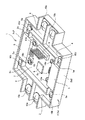
図1は、本実施形態に係る電気接続箱1の構成を模式的に示す斜視図である。図2は、本実施形態に係る電気接続箱1の構成を模式的に示す分解斜視図である。図3は、本実施形態に係る電気接続箱1の構成を模式的に示す断面図である。本実施形態に係る電気接続箱1は、高電圧バッテリとインバータ等の高電圧負荷との間の通電及び遮断を行う電源分配ボックスである。 FIG. 1 is a perspective view schematically showing the configuration of the electrical connection box 1 according to the present embodiment. FIG. 2 is an exploded perspective view schematically showing the configuration of the electric connection box 1 according to the present embodiment. FIG. 3 is a cross-sectional view schematically showing the configuration of the electric connection box 1 according to the present embodiment. The electric connection box 1 according to the present embodiment is a power supply distribution box that performs energization and interruption between a high voltage battery and a high voltage load such as an inverter.
電気接続箱1は、カバー本体2と、2組からなる一対のバスバ3,4と、2組のパワーモジュール5と、制御基板7とを主体に構成されている。
The electric connection box 1 mainly includes a cover
カバー本体2は、一対のバスバ3,4、パワーモジュール5及び制御基板7を収容する箱状のカバー(箱体)である。カバー本体2は、絶縁性の合成樹脂で構成され、周知の射出成形によって成形されている。
The cover
カバー本体2は、ロアカバー2aと、アッパーカバー2bとで構成されている。ロアカバー2aは、上方が開口された凹形状の箱体であり、その底面2a1に一対のバスバ3,4、パワーモジュール5及び制御基板7が配置される。アッパーカバー2bは、下方が開口された凹形状の箱体であり、ロアカバー2aに対して上方より組み付けられ、箱体としてのカバー本体2を構成する。
The
ここで、ロアカバー2aは、一対のバスバ3,4、パワーモジュール5及び制御基板7が略同一平面上に位置付けられるように設定されている。
Here, the
また、ロアカバー2aの底面2a1には、当該ロアカバー2aの周側壁2a2に沿って隔壁2cが立設されている。この隔壁2cとロアカバー2aの周側壁2a2とにより、当該ロアカバー2aの周側壁2a2に沿って、一対のバスバ3,4の配索経路が形成される。
Further, on the bottom surface 2a1 of the
隔壁2cの内側に位置するロアカバー2aの底面2a1の中央領域には、制御基板7の配置領域が設けられている。これにより、制御基板7の周囲に、隔壁2cを隔てて一対のバスバ3,4の配索経路が配置される。隔壁2cの近傍には、制御基板7をロアカバー2aの底面2a1から離間して支持するための柱部2dが複数配設されている。
In the central region of the bottom surface 2a1 of the
また、ロアカバー2aの底面2a1のうちパワーモジュール5の配置領域には、ロアカバー2aの内外を貫通する開口2eが形成されている。
Further, an opening 2e passing through the inside and the outside of the
一方の組における一対のバスバ3,4は、高電圧バッテリと高電圧負荷との間の電気的な経路(電圧回路)を形成するものであり、本実施形態では、正極側に対応する電圧回路である。一対のバスバ3,4は、パワーモジュール5の両側にそれぞれ配置されており、パワーモジュール5を介して連続する電圧回路を構成する。個々のバスバ3,4は、略平板形状の導電部材であり、例えば銅マンガン合金や銅ニッケル合金などの平板から、プレス成形により所望の形状、例えばクランク形状に形成されている。
The pair of
一方のバスバ(以下「第1バスバ」という)3の一端は、高電圧バッテリに通じる接続電線(図示せず)と接続し、その他端は、パワーモジュール5と接続する。一方、他方のバスバ(以下「第2バスバ」という)4の一端は、高電圧負荷に通じる接続電線(図示せず)と接続し、その他端は、パワーモジュール5と接続する。
One end of one bus bar (hereinafter referred to as “first bus bar”) 3 is connected to a connecting wire (not shown) leading to the high voltage battery, and the other end is connected to the
第1バスバ3の各両端部には貫通孔がそれぞれ形成されている。一方の貫通孔(図示せず)にはネジ10aが挿通され、当該ネジ10aにより、第1バスバ3がロアカバー2aに固定されるとともに高電圧バッテリの接続電線と締結される。また、他方の貫通孔3aにはネジ10bが挿通され、当該ネジ10bにより、第1バスバ3がパワーモジュール5の電力端子と締結されるとともにロアカバー2aに固定される。
Through holes are formed at both ends of the
第2バスバ4の各両端部にも、第1バスバ3と同様に、貫通孔がそれぞれ形成されている。一方の貫通孔(図示せず)にはネジ10cが挿通され、当該ネジ10cにより、第2バスバ4がロアカバー2aに固定されるとともに高電圧負荷の接続電線と締結される。また、他方の貫通孔4aにはネジ10dが挿通され、当該ネジ10dにより、第2バスバ4がパワーモジュール5の電力端子と締結されるとともにロアカバー2aに固定される。
Similarly to the
他方の組における一対のバスバ3,4は、高電圧バッテリと高電圧負荷との間の電気的な経路(電圧回路)を形成するものであり、本実施形態では、負極側に対応する電圧回路である。一対のバスバ3,4は、パワーモジュール5の両側にそれぞれ配置されており、パワーモジュール5を介して連続する電圧回路を構成する。なお、負極側の一対のバスバ3,4の構成は、上述した正極側の一対のバスバ3,4の構成と同様であり、その説明については省略する。
The pair of
パワーモジュール5は、電圧回路の通電又は遮断を行うものである(遮断部)。正極側及び負極側それぞれの電圧回路の通電遮断を行うため、本実施形態の電気接続箱1には、2組のパワーモジュール5が搭載されている。これにより、もしどちらか一方のパワーモジュール5が故障した場合でも、他方のパワーモジュール5を用いて遮断動作をすることができる。そのため、電圧回路を高電圧負荷側から確実に電気的に遮断することができる。
The
パワーモジュール5は、一対のバスバ3,4の間に配置される。パワーモジュール5は、複数のパワー半導体(例えばn型のMOSFET)をモジュール化して構成されている。パワーモジュール5のバスバ3,4側の各側面には、一対の電力端子(ドレイン端子,ソース端子)5aが設けられ、その制御基板7側の側面には、パワーモジュール5を制御する為の制御端子(ゲート端子)5bが設けられている。一方の電力端子5aは、ネジ10bにより第1バスバ3と締結され、他方の電力端子5aは、ネジ10dにより第2バスバ4と締結される。また、制御端子5bは、制御基板7に接続される。
The
制御基板7は、パワーモジュール5を制御する制御部8を実装する基板である。制御基板7の所要の位置には、スルーホール7aが貫通形成されており、このスルーホール7aにパワーモジュール5の制御端子5bが挿通される。また、制御基板7には、プリント配線技術により配線パターンが形成されている。これにより、スルーホール7aに挿通された制御端子5bと制御部8とが電気的に接続される。パワーモジュール5と制御基板7との固定はネジ10eにより行われる。
The
制御部8としては、CPU、ROM、RAM、I/Oインターフェースを主体に構成されたマイクロコンピュータを用いることができる。制御部8は、2組のパワーモジュール5を制御する制御信号を出力する。
As the
制御基板7には、外部信号端子9が配置されており、この外部信号端子9を介して外部装置(ECU等)と制御基板7との電気的な接続を行うことができる。制御部8は、当該外部信号端子9を介して外部装置と通信を行い、この外部装置からの指令に応じて、上述した制御信号を出力することができる。
An
このような構成の電気接続箱1は、高電圧バッテリとインバータ等の高電圧負荷との間の通電又は遮断を行う高電圧電源分配ボックスとして用いられる。この電気接続箱1を作成する場合には、まず、ロアカバー2aの中央に制御基板7を配置する。つぎに、ロアカバー2aの周側壁2a2と隔壁2cとにより画定される配索経路に一対のバスバ3,4を配置する。そして、一対のバスバ3,4の上からパワーモジュール5を積層的に配置し、ネジ10b、10dにより、パワーモジュール5における一対の電力端子5aと、一対のバスバ3,4とを接続する。同様に、ネジ10eにより、パワーモジュール5と制御基板7との取り付けを行う。これより、一対のバスバ3,4、パワーモジュール5及び制御基板7が、ロアカバー2a内に収容されて略同一平面上に配設される。一対のバスバ3,4、及びパワーモジュール5の組み付け作業は、正極側及び負極側に対応してそれぞれ実施される。
The electric connection box 1 having such a configuration is used as a high voltage power distribution box that energizes or cuts off between a high voltage battery and a high voltage load such as an inverter. In order to form the electrical connection box 1, first, the
つぎに、第1バスバ3の端部に、高電圧バッテリに通じる接続電線をネジ10aにより接続するとともに、ロアカバー2aに対する第1バスバ3の固定を行う。同様に、第2バスバ4の端部に、高電圧負荷に通じる接続電線をネジ10cにより接続するとともに、ロアカバー2aに対する第2バスバ4の固定を行う。
Next, a connecting wire leading to the high voltage battery is connected to the end of the
電気接続箱1は、その使用時には、車両内の金属筐体等といった配置面20に取り付けられる。この場合、電気接続箱1は、ロアカバー2aの底面2a1が配置面20と向き合うように配置され、当該底面2a1と配置面20との間には、絶縁シート12が設けられる。この絶縁シート12は、ロアカバー2aに搭載されたパワーモジュール5と対応する位置に配置される。上述したように、ロアカバー2aのパワーモジュール5が搭載される領域には開口2eが形成されており、パワーモジュール5の底面は、絶縁シート12を介して配置面20に接触配置される。なお、この絶縁シート12も電気接続箱1の構成要素の一つである。
The electric connection box 1 is attached to the
このような構成の電気接続箱1において、制御部8は、外部装置からの遮断命令等を受けると、制御信号を出力する。この制御信号がパワーモジュール5の制御端子5bに出力されると、当該制御端子5bに制御電圧が印加される。これにより、パワーモジュール5のオンオフ、すなわち、電圧回路の通電又は遮断を切り換えることができる。また、制御部8自身が遮断の判断を行い、制御信号を出力する、もしくは、パワーモジュール5自身が遮断の判断を行い、遮断動作を行う方式であってもよい。
In the electric connection box 1 having such a configuration, the
このように本実施形態において、電気接続箱1は、高電圧バッテリと高電圧負荷との間の電気的な経路を形成する一対のバスバ3,4と、一対のバスバ3,4の間に配置されて当該一対のバスバ3,4間の通電及び遮断を行うパワーモジュール5と、パワーモジュール5を制御する制御信号を出力する制御部8を実装するとともに当該制御部8とパワーモジュール5の制御端子5bとを電気的に接続する制御基板7と、箱状のカバー本体2と、を有している。ここで、一対のバスバ3,4、パワーモジュール5及び制御基板7は、カバー本体2内に収容されて略同一平面上に配設される。
As described above, in the present embodiment, the electrical connection box 1 is disposed between the pair of
この構成によれば、電気的な経路をバスバ3,4で構成し、パワーモジュール5に流れる大電流がバスバ3,4を流れるようにしている。そして、制御基板7では、パワーモジュール5を制御する制御信号を扱うこととしている。このため、大電流が流れる回路を制御基板7に形成する必要がないので、当該制御基板7に厚銅基板等を用いる必要がなく、安価で軽量な基板を使用することができる。また、一対のバスバ3,4、パワーモジュール5及び制御基板7が、略同一平面上に位置付けられるため、カバー本体2の高さ方向の大きさを抑えることでき、電気接続箱1の低背化を図ることができる。その結果、軽量化及び低コスト化とともに、ボックス全体の低背化を図ることができる。
According to this configuration, an electrical path is formed by the
なお、本実施形態において、略同一平面上とは、一対のバスバ3,4、パワーモジュール5及び制御基板7が同一平面上に位置することのみを指すのではなく、これらの要素間で重なりをもって配置されることも含むものである。
In the present embodiment, the term “substantially on the same plane” does not only indicate that the pair of
また、本実施形態の電気接続箱1は、当該電気接続箱1が配置される車両内の配置面20と、ロアカバー2aの底面2a1との間に配設される絶縁シート12(シート状の絶縁部材)をさらに有している。この場合、カバー本体2の底面2a1は、パワーモジュール5の配置領域と位置的に対応して、ロアカバー2aの内外を貫通する開口2eが形成されている。そして、パワーモジュール5の底面は、絶縁シート12を介して車両内の配置面20に接触配置される。
Further, in the electric connection box 1 of the present embodiment, the insulating sheet 12 (sheet-like insulation) disposed between the
この構成によれば、パワーモジュール5から絶縁シート12を経由して、車両内の配置面20へと至る放熱ルートを確保することできる。これにより、パワーモジュール5からバスバ3,4を経由して接続電線へと至る放熱ルートと合わせて、2つの経路でパワーモジュール5の熱を外部に逃がすことができる。その結果、パワーモジュール5の放熱を有効に行うことができる。
According to this configuration, it is possible to secure a heat radiation route from the
なお、パワーモジュール5の上面に放熱パッドを設け、アッパーカバー2bに熱伝導性の良い材質を採用することで、パワーモジュール5の上面から放熱をすることも可能である。
It is also possible to dissipate heat from the upper surface of the
また、本実施形態において、電気接続箱1は、ロアカバー2aの底面2a1に立設され、ロアカバー2aの周側壁2a2に沿って一対のバスバ3,4の配索経路を形成する隔壁2cをさらに有している。この場合、制御基板7は、ロアカバー2aの底面2a1における中央領域に配置されて、一対のバスバ3,4の配索経路が隔壁2cを隔ててその周囲に配置される。
Further, in the present embodiment, the electrical connection box 1 is provided upright on the bottom surface 2a1 of the
この構成によれば、一対のバスバ3,4、パワーモジュール5及び制御基板7を、略同一平面上に効率的に配置することができる。これにより、カバー本体2の高さ方向の大きさを抑えることができ、電気接続箱1の低背化を図ることができる。
According to this configuration, the pair of
また、本実施形態において、パワーモジュール5は、配索経路に沿って配置された一対のバスバ3,4の上から積層的に配置され、パワーモジュール5の一対の電力端子5aが一対のバスバ3,4の端部にそれぞれ取り付けられる。
Further, in the present embodiment, the
この構成によれば、簡素な手法で、バスバ3,4とパワーモジュール5とを組み付けることができる。
According to this configuration, the
特に、本実施形態では、バスバ3,4とパワーモジュール5との組み付けにネジ止めを用いている。これにより、部品点数の増加を抑制し、かつ、組み付け性の向上を図ることができる。
In particular, in the present embodiment, screwing is used to assemble the
なお、図4に示すように、バスバ3,4とパワーモジュール5との組み付けは端子3b、4bによるものであってもよい。これにより、部品点数の増加を抑制し、かつ、組み付け性の向上を図ることができる。
As shown in FIG. 4, the assembly of the bus bars 3, 4 and the
また、バスバ3,4はロアカバー2aに一体成形されたり、樹脂の溶接により位置が設定され、電気的接続をネジ止めで行うものであってもよい。
Further, the
以上、本実施形態にかかる電気接続箱について説明したが、本発明はこの実施形態に限定されることなく、その発明の範囲において種々の変更が可能である。例えば、上述した実施形態では、電源分配ボックスとして説明したが、種々の電気接続箱に適用可能である。 Although the electrical connection box according to the present embodiment has been described above, the present invention is not limited to this embodiment, and various modifications can be made within the scope of the invention. For example, in the above-mentioned embodiment, although demonstrated as a power supply distribution box, it is applicable to various electrical connection boxes.
1 電気接続箱
2 カバー本体
2a ロアカバー
2a1 底面
2a2 周側壁
2b アッパーカバー
2c 隔壁
2d 柱部
2e 開口
3,4 バスバ
5 パワーモジュール
5a 電力端子(ドレイン端子、ソース端子)
5b 制御端子(ゲート端子)
7 制御基板
8 制御部
9 外部信号端子
10a,10b,10c,10d,10e ネジ
12 絶縁シート
20 配置面
DESCRIPTION OF SYMBOLS 1
5b Control terminal (gate terminal)
7
Claims (4)
前記一対のバスバの間に配置されて、当該一対のバスバ間の通電及び遮断を行う遮断部と、
前記遮断部を制御する制御信号を出力する制御部を実装するとともに、当該制御部と前記遮断部の制御端子とを電気的に接続する制御基板と、
箱状のカバーと、
前記箱状のカバーの底面に形成され、前記遮断部の配置領域と位置的に対応して、カバー内外を貫通する開口と、
電気接続箱が配置される車両内の配置面と、前記箱状のカバーの底面との間に配設されるシート状の絶縁部材と、を有し、
前記一対のバスバ、前記遮断部及び前記制御基板は、前記箱状のカバー内に収容されて略同一平面上に配設され、
前記遮断部の底面は、前記シート状の絶縁部材を介して前記車両内の配置面に接触配置されることを特徴とする電気接続箱。 A pair of bus bars that form an electrical path between the power supply and the electronics;
A blocking unit disposed between the pair of bus bars for performing energization and blocking between the pair of bus bars;
A control board for mounting a control unit for outputting a control signal for controlling the shutoff unit, and electrically connecting the control unit to the control terminal of the shutoff unit;
With a box-like cover,
An opening formed on the bottom surface of the box-like cover and passing through the inside and the outside of the cover corresponding in position to the arrangement area of the blocking portion;
Possess the placement surface in a vehicle electrical connection box is disposed, and a sheet-shaped insulating member disposed between the bottom of the box-like cover,
The pair of bus bars, the blocking portion, and the control board are accommodated in the box-like cover and disposed on substantially the same plane,
The bottom surface of the cut-off portion, said sheet-like insulating through member contact arranged the electrical connection box you characterized in that the arrangement surface of the said vehicle.
前記一対のバスバの間に配置されて、当該一対のバスバ間の通電及び遮断を行う遮断部と、
前記遮断部を制御する制御信号を出力する制御部を実装するとともに、当該制御部と前記遮断部の制御端子とを電気的に接続する制御基板と、
箱状のカバーと、
前記箱状のカバーの底面に立設され、当該箱状のカバーの周側壁に沿って前記一対のバスバの配索経路を形成する隔壁と、を有し、
前記一対のバスバ、前記遮断部及び前記制御基板は、前記箱状のカバー内に収容されて略同一平面上に配設され、
前記制御基板は、前記箱状のカバーの底面における中央領域に配置されて、前記一対のバスバの配索経路が前記隔壁を隔てて当該制御基板の周囲に配置されることを特徴とする電気接続箱。 A pair of bus bars that form an electrical path between the power supply and the electronics;
A blocking unit disposed between the pair of bus bars for performing energization and blocking between the pair of bus bars;
A control board for mounting a control unit for outputting a control signal for controlling the shutoff unit, and electrically connecting the control unit to the control terminal of the shutoff unit;
With a box-like cover,
Erected on the bottom surface of the box-shaped cover, it possesses the partition walls forming the routing path of the pair of bus bars along the peripheral side wall of the box-like cover, and
The pair of bus bars, the blocking portion, and the control board are accommodated in the box-like cover and disposed on substantially the same plane,
The control board is disposed in the central region of the bottom surface of the box-shaped cover, the installation path of the pair of bus bars spaced the partitions you being disposed around the control board electrostatic Air connection box.
前記制御基板は、前記箱状のカバーの底面における中央領域に配置されて、前記一対のバスバの配索経路が前記隔壁を隔てて当該制御基板の周囲に配置されることを特徴とする請求項1に記載された電気接続箱。 And a partition wall standing on the bottom surface of the box-like cover and forming a wiring path of the pair of bus bars along the circumferential side wall of the box-like cover,
The control board is disposed in a central region of the bottom surface of the box-like cover, and a routing path of the pair of bus bars is disposed around the control board with the partition walls separated. Electrical connection box described in 1 .
Priority Applications (1)
| Application Number | Priority Date | Filing Date | Title |
|---|---|---|---|
| JP2015098902A JP6510316B2 (en) | 2015-05-14 | 2015-05-14 | Electrical connection box |
Applications Claiming Priority (1)
| Application Number | Priority Date | Filing Date | Title |
|---|---|---|---|
| JP2015098902A JP6510316B2 (en) | 2015-05-14 | 2015-05-14 | Electrical connection box |
Publications (2)
| Publication Number | Publication Date |
|---|---|
| JP2016220276A JP2016220276A (en) | 2016-12-22 |
| JP6510316B2 true JP6510316B2 (en) | 2019-05-08 |
Family
ID=57581787
Family Applications (1)
| Application Number | Title | Priority Date | Filing Date |
|---|---|---|---|
| JP2015098902A Active JP6510316B2 (en) | 2015-05-14 | 2015-05-14 | Electrical connection box |
Country Status (1)
| Country | Link |
|---|---|
| JP (1) | JP6510316B2 (en) |
Families Citing this family (5)
| Publication number | Priority date | Publication date | Assignee | Title |
|---|---|---|---|---|
| JP6656202B2 (en) | 2017-04-27 | 2020-03-04 | 矢崎総業株式会社 | Routing material connection structure |
| JP6949692B2 (en) | 2017-12-06 | 2021-10-13 | 矢崎総業株式会社 | Connection structure of wiring material |
| JP6926132B2 (en) * | 2019-01-23 | 2021-08-25 | 矢崎総業株式会社 | Protection circuit unit and vehicle power supply |
| CN110492409A (en) * | 2019-07-24 | 2019-11-22 | 沈阳兴华航空电器有限责任公司 | A kind of underwater robot DC bus block terminal |
| JP7443814B2 (en) | 2020-02-21 | 2024-03-06 | 住友電装株式会社 | electrical junction box |
Family Cites Families (3)
| Publication number | Priority date | Publication date | Assignee | Title |
|---|---|---|---|---|
| JPH1118429A (en) * | 1997-06-24 | 1999-01-22 | Hitachi Ltd | Control module |
| JP2009017705A (en) * | 2007-07-05 | 2009-01-22 | Yazaki Corp | Electrical junction box and manufacturing method therefor |
| JP2010104135A (en) * | 2008-10-23 | 2010-05-06 | Hitachi Ltd | Power conversion apparatus and electrical machine system for mobile |
-
2015
- 2015-05-14 JP JP2015098902A patent/JP6510316B2/en active Active
Also Published As
| Publication number | Publication date |
|---|---|
| JP2016220276A (en) | 2016-12-22 |
Similar Documents
| Publication | Publication Date | Title |
|---|---|---|
| JP6510316B2 (en) | Electrical connection box | |
| CN110709958B (en) | Relay set | |
| JP3958589B2 (en) | Electrical junction box | |
| JP2016220277A (en) | Electric connection box | |
| US10091903B2 (en) | Power conversion device having bus bar with improved vibration resistance | |
| US10367426B2 (en) | Power conversion device | |
| US9368309B2 (en) | Electronic part and electronic control unit | |
| US7137829B2 (en) | Electric power distribution unit for electric connection box and electric connection box | |
| JP2020127302A (en) | Electric connection box | |
| JP6923013B2 (en) | Wiring module | |
| JP2017118672A (en) | Electric junction box | |
| JP2016222057A (en) | Power supply device for vehicle | |
| WO2018180356A1 (en) | Circuit device | |
| JP6926132B2 (en) | Protection circuit unit and vehicle power supply | |
| US20210368618A1 (en) | Circuit assembly and electrical junction box | |
| JP4822050B2 (en) | Circuit structure and manufacturing method thereof | |
| JP2022082893A (en) | Electrification control device | |
| JP2020022235A (en) | Power conversion device and bus bar | |
| US11343913B2 (en) | Circuit board structure | |
| JP2022178134A (en) | Energization control device | |
| JP3902051B2 (en) | Power distribution box | |
| JP6662911B2 (en) | Power converter | |
| WO2018180671A1 (en) | Circuit device | |
| WO2018207598A1 (en) | Circuit device | |
| JP2023076491A (en) | Electric connection box |
Legal Events
| Date | Code | Title | Description |
|---|---|---|---|
| A621 | Written request for application examination |
Free format text: JAPANESE INTERMEDIATE CODE: A621 Effective date: 20180419 |
|
| A977 | Report on retrieval |
Free format text: JAPANESE INTERMEDIATE CODE: A971007 Effective date: 20181225 |
|
| A131 | Notification of reasons for refusal |
Free format text: JAPANESE INTERMEDIATE CODE: A131 Effective date: 20190122 |
|
| A521 | Request for written amendment filed |
Free format text: JAPANESE INTERMEDIATE CODE: A523 Effective date: 20190313 |
|
| TRDD | Decision of grant or rejection written | ||
| A01 | Written decision to grant a patent or to grant a registration (utility model) |
Free format text: JAPANESE INTERMEDIATE CODE: A01 Effective date: 20190326 |
|
| A61 | First payment of annual fees (during grant procedure) |
Free format text: JAPANESE INTERMEDIATE CODE: A61 Effective date: 20190404 |
|
| R150 | Certificate of patent or registration of utility model |
Ref document number: 6510316 Country of ref document: JP Free format text: JAPANESE INTERMEDIATE CODE: R150 |
|
| R250 | Receipt of annual fees |
Free format text: JAPANESE INTERMEDIATE CODE: R250 |
|
| R250 | Receipt of annual fees |
Free format text: JAPANESE INTERMEDIATE CODE: R250 |
|
| S531 | Written request for registration of change of domicile |
Free format text: JAPANESE INTERMEDIATE CODE: R313531 |
|
| R350 | Written notification of registration of transfer |
Free format text: JAPANESE INTERMEDIATE CODE: R350 |
|
| R250 | Receipt of annual fees |
Free format text: JAPANESE INTERMEDIATE CODE: R250 |