JP6504347B2 - Clutch actuator - Google Patents
Clutch actuator Download PDFInfo
- Publication number
- JP6504347B2 JP6504347B2 JP2015045846A JP2015045846A JP6504347B2 JP 6504347 B2 JP6504347 B2 JP 6504347B2 JP 2015045846 A JP2015045846 A JP 2015045846A JP 2015045846 A JP2015045846 A JP 2015045846A JP 6504347 B2 JP6504347 B2 JP 6504347B2
- Authority
- JP
- Japan
- Prior art keywords
- slider
- clutch
- crank
- motor
- main shaft
- Prior art date
- Legal status (The legal status is an assumption and is not a legal conclusion. Google has not performed a legal analysis and makes no representation as to the accuracy of the status listed.)
- Active
Links
Images


Landscapes
- Mechanical Operated Clutches (AREA)
- Transmission Devices (AREA)
Description
本発明は、クラッチを作動するクラッチアクチュエータに関する。 The present invention relates to a clutch actuator for operating a clutch.
車両の変速機等に採用されているクラッチにおいて、その作動をクラッチアクチュエータにより行う技術が開発されている。例えば特許文献1には、クラッチの係合離脱をモータの駆動によって行うクラッチアクチュエータが開示されている。特許文献1のクラッチアクチュエータでは、クランク機構とスライダを組み合わせたスライダクランク機構により、モータの回転運動をスライダの直線運動に変換する構成となっており、詳しくはモータにより回転駆動される歯車の外周部付近の部位とスライド可能なピストン(スライダ)とをリンク部材で連結しており、ピストンの直線運動によってクラッチの係合離脱を行う。 In a clutch employed in a transmission or the like of a vehicle, there has been developed a technology for performing the operation by a clutch actuator. For example, Patent Document 1 discloses a clutch actuator that performs engagement and disengagement of a clutch by driving a motor. In the clutch actuator of Patent Document 1, the rotary motion of the motor is converted into the linear motion of the slider by the slider crank mechanism combining the crank mechanism and the slider, and in detail, the outer peripheral portion of the gear rotationally driven by the motor A link member connects a nearby portion and a slidable piston (slider) with each other, and the linear movement of the piston causes the clutch to be disengaged.
更に、特許文献1は、デュアルクラッチトランスミッションにおける2つのクラッチをモータによって駆動する構成となっている。 Further, Patent Document 1 is configured to drive two clutches in a dual clutch transmission by a motor.
ところで、一般的なシングルクラッチでは、スプリング等により係合方向に付勢しており、アクチュエータ等で離脱方向に作動させることが多い。
これに対し、デュアルクラッチトランスミッションでは、アクチュエータ等の故障時に変速機内での駆動系のロックを防止するために、スプリング等により離脱方向に付勢しており、アクチュエータによりクラッチを押し付けて係合する構成となっている。
By the way, in a general single clutch, it is biased in the engaging direction by a spring or the like, and is often operated in the disengaging direction by an actuator or the like.
On the other hand, in the dual clutch transmission, in order to prevent the lock of the drive system in the transmission at the time of failure of the actuator etc., it is biased in the disengaging direction by the spring etc. It has become.
このように、アクチュエータによりクラッチを押し付ける構成のクラッチ装置では、アクチュエータによってクラッチを押し付ける際に大きい押し付け力が必要となる。したがって、特許文献1のような、モータによってスライダクランク機構を介してクラッチを作動させる構成では、モータの回転トルクに対してクラッチを押し付けるためのスライダ推力が大きくなるようなリンク構成が望ましい。一方、クラッチの接続開始位置付近では、クラッチにおける伝達トルクを細かくコントロールするために、モータの回転角に対してスライダの移動距離を大きくした構成が望ましい。モータの回転トルクに対してスライダ推力を大きくするには、モータの回転角に対してスライダの移動距離を小さくすることになるので、クラッチの締結位置とクラッチの接続開始位置付近とでは相反する機能が要求されることになり、この要求を満たすようなスライダクランク機構に設定することが困難である。 Thus, in the clutch device configured to press the clutch by the actuator, a large pressing force is required when pressing the clutch by the actuator. Therefore, in the configuration in which the clutch is operated by the motor via the slider crank mechanism as in Patent Document 1, it is desirable to have a link configuration in which the slider thrust for pressing the clutch against the rotational torque of the motor is large. On the other hand, in the vicinity of the connection start position of the clutch, in order to finely control the transmission torque in the clutch, it is desirable to increase the moving distance of the slider with respect to the rotation angle of the motor. In order to increase the slider thrust with respect to the rotational torque of the motor, the movement distance of the slider is reduced with respect to the rotational angle of the motor. Therefore, functions opposite to each other between the clutch engagement position and the clutch connection start position It is difficult to set a slider crank mechanism that meets this requirement.
また、このようなクラッチアクチュエータは、変速機に内蔵するので、スライダクランク機構の各要素の長さ等に制約があり、スライダクランク機構の設定が更に困難となってしまう。
本発明はこのような問題点を解決するためになされたもので、スライダクランク機構を介してモータによりクラッチの係合離脱を行なうクラッチアクチュエータにおいて、クラッチの押し付け力確保とクラッチの伝達力の制御精度を両立させるとともに、押し付け力の設定を容易に行なうことのできるクラッチアクチュエータを提供することにある。
In addition, since such a clutch actuator is incorporated in the transmission, the length of each element of the slider crank mechanism and the like are restricted, and the setting of the slider crank mechanism becomes more difficult.
The present invention has been made to solve such problems, and in a clutch actuator that performs clutch engagement and disengagement by a motor via a slider crank mechanism, control accuracy of the clutch pressing force and control accuracy of the transmission force of the clutch To provide a clutch actuator capable of easily setting the pressing force.
上記の目的を達成するために、本願発明のクラッチアクチュエータは、モータの出力軸の回転運動をスライダクランク機構により直線運動に変換して、クラッチを係合離脱させるクラッチアクチュエータであって、前記スライダクランク機構は、前記モータによりクランク軸回りに回転駆動されるクランク部材と、往復移動して前記クラッチの係合離脱を行なうスライダと、前記クランク部材の前記クランク軸から離間した先端部と前記スライダとを回転可能に連結するリンク部材と、により構成され、前記スライダの移動線に対し、前記クランク軸がオフセットして配置されるとともに、前記クランク部材が、前記スライダの移動線と垂直でかつ前記クランク軸を通る垂線から前記クラッチの押し付け方向と反対側に回転し、かつ前記クランク部材と前記リンク部材とが垂直であるときの前記スライダの移動位置を、前記クラッチが完全に開放される初期位置とする一方、前記クラッチの締結位置となる前記スライダの移動位置を、前記クラッチの接続開始から前記締結位置までの前記スライダの移動位置よりも、前記クランク部材の回転トルクに対する前記スライダによる前記クラッチの押し付け力が大きくなる位置とすることを特徴とする。 In order to achieve the above object, a clutch actuator according to the present invention is a clutch actuator which converts a rotational movement of an output shaft of a motor into a linear movement by a slider crank mechanism to engage and disengage the clutch. The mechanism comprises: a crank member rotationally driven about the crankshaft by the motor; a slider for reciprocating movement to engage and disengage the clutch; a tip of the crank member separated from the crank shaft; And a link member rotatably connected, wherein the crankshaft is arranged offset with respect to the movement line of the slider, and the crank member is perpendicular to the movement line of the slider and is the crank shaft From the vertical line passing through the clutch to the direction opposite to the pressing direction of the clutch, and The movement position of the slider when click member and said link member is vertical, while the initial position in which said clutch is completely opened, the movement position of the slider to be engaged position of the clutch, the clutch The pressing force of the clutch by the slider with respect to the rotational torque of the crank member is larger than the movement position of the slider from the connection start to the fastening position.
また、好ましくは、前記締結位置となる前記スライダの移動位置は、前記スライダの移動範囲の中で、前記回転トルクに対する前記押し付け力が最も大きくなる位置であるとよい。
また、好ましくは、前記クラッチは、複数の変速段の変速ギヤが2つのグループに分けられて第1の主軸及び第2の主軸のいずれかに配置された変速機の入力軸と前記第1の主軸及び前記第2の主軸との間に介装されるデュアルクラッチであるとよい。
Preferably, the movement position of the slider, which is the fastening position, is a position at which the pressing force with respect to the rotational torque is the largest in the movement range of the slider.
In addition, preferably, in the clutch, an input shaft of a transmission in which transmission gears of a plurality of shift speeds are divided into two groups and disposed on one of a first main shaft and a second main shaft and the first It may be a dual clutch interposed between the main shaft and the second main shaft.
本願発明のクラッチアクチュエータによれば、モータの駆動によってクラッチの係合離脱を行ない、モータとクラッチとの間にスライダクランク機構が介在することで、モータの駆動トルクに対してクラッチの押し付け力を非線形に制御することができる。そして、クラッチの締結位置となるスライダの移動位置を、クラッチの接続開始から締結位置までのスライダの移動位置よりも、スライダによるクラッチの押し付け力が大きくなる位置とすることで、クラッチの締結位置においてはクラッチの押し付け力を大きく、かつクラッチの接続開始から締結位置においてはモータの回転に対するスライダの移動距離を長くしてクラッチの押し付け力を細かく制御することができる。これにより、クラッチの接続の際に伝達力の制御を容易にすることができるとともに、締結後のクラッチの保持力を少ないモータの出力トルクで確保することができる。 According to the clutch actuator of the present invention, the clutch is engaged and disengaged by driving the motor, and the slider crank mechanism intervenes between the motor and the clutch, whereby the pressing force of the clutch is non-linear to the driving torque of the motor. Can be controlled. Then, by setting the movement position of the slider, which is the engagement position of the clutch, to a position where the pressing force of the clutch by the slider is larger than the movement position of the slider from the connection start of the clutch to the engagement position, The pressing force of the clutch can be finely controlled by increasing the pressing force of the clutch and lengthening the moving distance of the slider with respect to the rotation of the motor from the start of connection of the clutch to the engaging position. Thus, the control of the transmission force can be facilitated at the time of connection of the clutch, and the holding force of the clutch after engagement can be secured with a small motor output torque.
更に、スライダの移動線に対してクランク軸がオフセットして配置されるので、当該オフセット量を変更することでモータの回転トルクに対するクラッチの押し付け力を変更することができる。これにより、スライダクランク機構の設計自由度が増し、スライダクランク機構の設定を容易にすることができる。 Furthermore, since the crankshaft is arranged offset to the movement line of the slider, the pressing force of the clutch with respect to the rotational torque of the motor can be changed by changing the offset amount. As a result, the degree of freedom in design of the slider crank mechanism is increased, and the setting of the slider crank mechanism can be facilitated.
以下、図面に基づき本発明の実施形態について説明する。
図1は、本実施形態のクラッチアクチュエータ20を採用した車両の走行駆動系の模式図である。
本実施形態のクラッチアクチュエータ20は、デュアルクラッチトランスミッション1(変速機)を搭載した車両に採用されている。
Hereinafter, embodiments of the present invention will be described based on the drawings.
FIG. 1 is a schematic view of a traveling drive system of a vehicle adopting a
The
図1に示すように、デュアルクラッチトランスミッション1は、第1の主軸2及び第2の主軸3を備えている。この第1の主軸2及び第2の主軸3と、フライホイール4を介してエンジン5の出力軸6に連結されるデュアルクラッチトランスミッション1の入力軸7との間には、夫々クラッチ8、9が備えられている(デュアルクラッチ10)。第1の主軸2には偶数段の変速ギヤ、第2の主軸3には奇数段の変速ギヤが設けられており、これらの変速ギヤのうち任意のギヤを出力軸11に設けられたギヤと係合して出力軸11に動力を伝達する構造となっている。出力軸11は、デフ12を介して、車両の駆動輪13に連結されている。
As shown in FIG. 1, the dual clutch transmission 1 includes a first
そして、2つのクラッチ8、9を交互に接続して、奇数及び偶数の変速ギヤに順次つなぎ替えることで変速時にエンジン5から駆動輪13に切れ目の少ない動力伝達が可能となっている。
また、デュアルクラッチ10に用いられるクラッチ8、9は、乾式単板のクラッチが用いられている。更に、クラッチ8、9は、動力を伝達しない離脱方向に向けて図示しないスプリングによって付勢されている。
Then, by alternately connecting the two
Further, as the
クラッチ8、9は、図示しないダイヤフラムスプリングにより、プレッシャプレートを介して押し付けられて係合する。本実施形態では、クラッチアクチュエータ20によって図示しないダイヤフラムスプリングに荷重を付与してクラッチ8、9を押し付ける構成となっている。
図2は、本実施形態のクラッチアクチュエータ20の構成図である。
The
FIG. 2 is a block diagram of the
なお、図2は、デュアルクラッチ10の2つのクラッチ8、9のうち一方のクラッチ8を係合離脱させるクラッチアクチュエータ20について記載しており、他のクラッチ9も同様に、異なるクラッチアクチュエータ20によって係合離脱させる。
図2に示すように、クラッチアクチュエータ20は、モータ21、減速機22、スライダクランク機構23を含んで構成されている。
2 shows a
As shown in FIG. 2, the
減速機22は複数の歯車によって構成され、モータ21の出力軸の回転を減速して、最終段の扇形歯車24を回転させる。なお、モータ21は、例えば電気モータであって、限られた角度範囲内で回転するよう制御されており、よって扇形歯車24も限られた角度範囲内で回転する。
スライダクランク機構23は、クランク30(クランク部材)と、スライダ31と、リンク部材32により構成されている。
The
The
クランク30は、扇形歯車24の回転中心軸(クランク軸33)に一端が固定されており、扇形歯車24の回転によって揺動する。
スライダ31は、クラッチ8の押し付け方向に移動可能に支持されている。
リンク部材32は、一端部(連結部32a)において揺動するクランク30の先端に回転可能に連結されるとともに、他端部(連結部32b)においてスライダ31に回転可能に連結されている。
The
The
The
更に、本実施形態のスライダクランク機構23では、クランク軸33とスライダ31の移動線であるスライダ軸線m(スライダ移動線)とがオフセットして配置されている。
本実施形態のクラッチアクチュエータ20は、モータ21の回転を減速機22により減速し、スライダクランク機構23により直線運動に変換してスライダ31をクラッチ8の軸線方向に直線移動させ、クラッチ8の係合離脱を行なう構成となっており、特に、モータ21の回転トルクによってクラッチ8を押し付け方向に移動させて係合させる。
Furthermore, in the
The
図3は、スライダクランク機構23の模式図である。
図3に示すように、スライダクランク機構23の構成について、クランク30の回転半径(クランク軸33と連結部32aとの間の長さ)をA、リンク長(リンク部材32の連結部32aと連結部32bとの間の長さ)をB、クランク軸33とスライダ軸線mとのオフセット量をCとし、モータ21によって減速機22を介してクランク30に回転トルクTを与えると、スライダ軸線mと垂直でかつクランク軸33を通る線n(垂線)とクランク30との角度であるクランク角θであるときに、スライダ31がスライダ軸線m方向に押す力であるスライダ推力Fは、以下の式(1)で求められる。
FIG. 3 is a schematic view of the
As shown in FIG. 3, regarding the configuration of the
したがって、クランク角θが変化することでスライダ推力Fが変化する。
また、クランク30の回転角に対するスライダ31の移動距離についても、クランク角θに伴って変化する。なお、スライダ31の移動距離は、スライダ推力Fが小さくなるクランク角θでは大きく、スライダ推力Fが大きくなるクランク角θでは小さくなるといったように相反関係となる。
Therefore, the slider thrust F changes as the crank angle θ changes.
Further, the moving distance of the
本実施形態では、このスライダクランク機構23のクランク30が線nからクラッチ8の押し付け方向と反対側に角度θ1回転した位置(例えばクランク30とリンク部材32とが垂直になる位置)を、クラッチ8が完全に開放されるスライダ初期位置(初期位置)とし、スライダ初期位置からクラッチ8の押し付け側に角度θ2回転した位置をクラッチ8が締結する締結位置とする。
In this embodiment, the position at which the
なお、上記のように、スライダ31とクラッチ8を押すプレッシャプレートとの間には、ダイヤフラムスプリングが介在しており、ダイヤフラムスプリングは、クラッチ8が接続開始してからスライダ31の移動量が増加するに伴ってクラッチ8を押す力が増加する荷重特性であるので、このダイヤフラムスプリングの荷重特性とクラッチアクチュエータ20によるスライダ推力Fの出力特性を加えて、クラッチ8の締結位置において確実に締結されるのに必要な押し付け力が得られるように設定すればよい。
As described above, the diaphragm spring intervenes between the
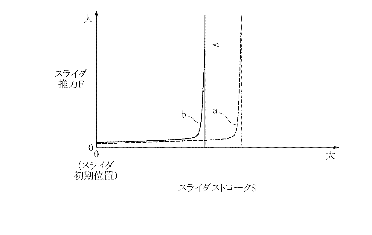
図4は、スライダクランク機構23におけるスライダストロークSとスライダ推力Fとの関係の一例を示すグラフである。
本実施形態では、スライダクランク機構23を用いることで、図4に示すように、スライダ初期位置から押し付け方向へのスライダ31の移動量(スライダストロークS)とスライダ推力Fとが非線形の関係となる。特に、クランク30とリンク部材32との角度が180度付近でスライダ推力Fは急激に大きくなる。
FIG. 4 is a graph showing an example of the relationship between the slider stroke S and the slider thrust F in the slider crank
In this embodiment, by using the slider crank
そして、このスライダクランク機構23によって非線形となるクラッチアクチュエータ20の出力特性とクラッチ8の締結位置とを関連付けて設定しており、クラッチ8が締結されるスライダ31の移動位置(締結領域E)では、クラッチ8の接続開始から締結位置までのスライダ31の移動位置(領域D)よりもスライダ推力Fが大きくなるように設定されている。特にクラッチ8の締結位置では、スライダ31の移動範囲の中で、クランク30の回転トルクTに対するスライダ推力Fが最も大きくなるように、例えばクランク30とリンク部材32との角度を180度付近の領域に設定するとよい。
The slider crank
なお、図4では、回転トルクTを変更した場合でのスライダ推力Fを示しており、図4中のa線が回転トルクTの最小設定時、b線が回転トルクTの最大設定時を示している。図4に示すように、スライダストロークSが増加するに伴ってスライダ推力Fが大きくなるが、回転トルクTが小さくなるほど締結位置付近でより急激にスライダ推力Fが増加するようになる。 FIG. 4 shows the slider thrust F when the rotational torque T is changed, and the line a in FIG. 4 indicates the minimum setting of the rotational torque T and the line b indicates the maximum setting of the rotational torque T. ing. As shown in FIG. 4, as the slider stroke S increases, the slider thrust F increases, but as the rotational torque T decreases, the slider thrust F increases more rapidly near the fastening position.
図5〜図7は、本実施形態においてスライダクランク機構23の各部位の長さを変更した場合での、スライダ推力Fの変化の一例を示すグラフである。クランク30の回転トルクTを一定にした状態で、図5はクランク30の回転半径Aを変更した場合、図6はリンク長Bを変更した場合、図7はオフセット量Cを変更した場合を示す。図5〜図7において、線aは基準値であり、線bは長さを基準値の1.3倍に変更した場合を示す。
5 to 7 are graphs showing an example of the change in the slider thrust F when the length of each portion of the slider crank
図5に示すように、クランク30の回転半径Aを1.3倍に変更するとスライダ推力Fは増加する。図6に示すように、リンク長Bを1.3倍に変更するとスライダ推力Fは大幅に増加する。図7に示すように、オフセット量Cを1.3倍に変更すると、スライダ推力Fは減少する。このように、クランク30の回転半径A、リンク長B、オフセットCのいずれを変更しても、スライダ推力F、即ちクラッチアクチュエータ20の出力特性を変更することができる。
As shown in FIG. 5, when the rotation radius A of the
以上のように、本実施形態では、スライダクランク機構23を備えたクラッチアクチュエータ20をクラッチ8に採用することで、モータ21による回転運動をスライダ31の直線運動に変換する構成となっており、クランク30の回転位置によって、モータ21の回転トルクに対するスライダ推力Fが変化する。このとき、クラッチアクチュエータ20の出力であるスライダ推力Fは、非線形の特性となる。そして、この非線形となるクラッチアクチュエータ20の出力特性とクラッチ8の接続状態とを関連づけて設定することで、図4に示すように、クラッチ8の接続開始から締結するまでのクラッチストロークSの領域(D)ではクラッチストロークSに対するスライダ推力Fの増加率を抑え、クラッチ8が締結される締結領域(E)ではスライダ推力Fを大幅に増加させることができる。
As described above, in the present embodiment, the
したがって、クラッチ8の接続開始から締結するまでは、クラッチストロークSの変化に対してスライダ推力Fの変化が抑えられ、モータ21の回転角の制御によってスライダ推力Fを細かく制御することができる。これにより、クラッチ8の接続の際に伝達トルクの制御を精度よく行なうことができる。
また、クラッチ8の締結時(締結後)には、モータ21の回転トルクに対してスライダ推力Fを大幅に大きくすることができるので、モータ21の回転トルクを抑えた上でスライダ推力Fを大きく確保して、クラッチ8を確実に締結保持することができる。
Therefore, from the connection start of the clutch 8 to the engagement, the change of the slider thrust F is suppressed with respect to the change of the clutch stroke S, and the slider thrust F can be finely controlled by the control of the rotation angle of the motor 21. Thereby, when the clutch 8 is connected, control of the transmission torque can be performed with high accuracy.
Further, when the clutch 8 is engaged (after engagement), the slider thrust F can be made significantly larger than the rotational torque of the motor 21. Therefore, while suppressing the rotational torque of the motor 21, the slider thrust F is increased. Thus, the clutch 8 can be securely engaged and held.
更に、本実施形態では、減速機22によってモータ21の回転トルクを増幅してクランク30の回転トルクTとし、更にスライダクランク機構23によってクランク30の回転トルクTから大きなスライダ推力Fに変換することができるので、モータ21の必要な出力が抑えられ小型化することができる。
また、スライダクランク機構23を用いることで、クランク30の回転半径A、リンク長B、オフセット量Cの各設定によって、クラッチアクチュエータ20の出力特性を夫々変更することができるので、所望の出力特性となるようにスライダクランク機構23の構成を容易に設定することができる。
Furthermore, in the present embodiment, the rotational torque of the motor 21 is amplified by the
Further, by using the slider crank
特に、本実施形態では、クランク30の回転半径A、リンク長Bだけでなく、オフセット量Cも変更設定可能であるので、設計自由度を大幅に増加させることができる。また、オフセット量Cを設ける、即ちクランク軸33とスライダ軸線mとをオフセットして配置することで、クランク軸33とクラッチ8の中心軸との干渉を容易に防止することができる。
In particular, in the present embodiment, not only the rotation radius A and the link length B of the
また、本実施形態では、デュアルクラッチ10に本発明のクラッチアクチュエータ20を採用しているが、デュアルクラッチトランスミッション1では、2個のクラッチ8、9が同時に接続されると内部でロックしてしまう虞がある。
しかし、本実施形態では、クラッチアクチュエータ20が、減速機22及びスライダクランク機構23によってモータ21からスライダ31に動力を伝達する構造であり、スライダ31からモータ21へ動力を伝達可能な可逆性を有している。したがって、例えばモータ21等の故障によりモータ21の出力軸の回転がフリーとなった場合には、クラッチ8の離脱方向へのスライダ31の移動が可能であり、クラッチ8の押し戻しによる自動開放が可能となり、デュアルクラッチトランスミッション1内でのロックを防止することができる。
Moreover, in this embodiment, although the
However, in the present embodiment, the
なお、本願発明は上記実施形態に限定するものではない。例えば、スライダクランク機構23におけるスライダ初期位置等の詳細な設定については、適宜変更してもよい。また、シングルクラッチの変速機に本願発明のクラッチアクチュエータを適用してもよい。
本願発明は、クラッチをモータによって作動させるクラッチアクチュエータにおいて、広く適用することができる。
The present invention is not limited to the above embodiment. For example, the detailed setting of the slider initial position and the like in the slider crank
The present invention can be widely applied to a clutch actuator in which a clutch is operated by a motor.
1 デュアルクラッチトランスミッション(変速機)
2 第1の主軸
3 第2の主軸
8、9 クラッチ
10 デュアルクラッチ
20 クラッチアクチュエータ
21 モータ
23 スライダクランク機構
30 クランク(クランク部材)
31 スライダ
32 リンク部材
33 クランク軸
m スライダ軸線(スライダ移動線)
1 Dual clutch transmission (transmission)
2 first spindle 3
31
Claims (3)
前記スライダクランク機構は、
前記モータによりクランク軸回りに回転駆動されるクランク部材と、
往復移動して前記クラッチの係合離脱を行なうスライダと、
前記クランク部材の前記クランク軸から離間した部位と前記スライダとを回転可能に連結するリンク部材と、により構成され、
前記スライダの移動線に対し、前記クランク軸がオフセットして配置されるとともに、
前記クランク部材が、前記スライダの移動線と垂直でかつ前記クランク軸を通る垂線から前記クラッチの押し付け方向と反対側に回転し、かつ前記クランク部材と前記リンク部材とが垂直であるときの前記スライダの移動位置を、前記クラッチが完全に開放される初期位置とする一方、
前記クラッチの締結位置となる前記スライダの移動位置を、前記クラッチの接続開始から前記締結位置までの前記スライダの移動位置よりも、前記クランク部材の回転トルクに対する前記スライダによる前記クラッチの押し付け力が大きくなる位置とすることを特徴とするクラッチアクチュエータ。 A clutch actuator that converts rotational motion of an output shaft of a motor into linear motion by a slider crank mechanism, and causes a clutch to be disengaged,
The slider crank mechanism
A crank member rotationally driven about a crankshaft by the motor;
A slider that reciprocates to engage and disengage the clutch;
A portion of the crank member separated from the crank shaft and a link member rotatably connecting the slider to the slider;
The crankshaft is disposed offset with respect to the movement line of the slider, and
The slider when the crank member rotates in a direction perpendicular to the movement line of the slider and opposite to the pressing direction of the clutch from a perpendicular passing through the crankshaft, and the crank member and the link member are vertical While the clutch is at an initial position where the clutch is completely released,
The moving position of the slider, which is the engaging position of the clutch, is larger than the moving position of the slider from the connection start of the clutch to the engaging position, the pressing force of the clutch by the slider against the rotational torque of the crank member Clutch actuator characterized in that
Priority Applications (1)
| Application Number | Priority Date | Filing Date | Title |
|---|---|---|---|
| JP2015045846A JP6504347B2 (en) | 2015-03-09 | 2015-03-09 | Clutch actuator |
Applications Claiming Priority (1)
| Application Number | Priority Date | Filing Date | Title |
|---|---|---|---|
| JP2015045846A JP6504347B2 (en) | 2015-03-09 | 2015-03-09 | Clutch actuator |
Publications (2)
| Publication Number | Publication Date |
|---|---|
| JP2016166629A JP2016166629A (en) | 2016-09-15 |
| JP6504347B2 true JP6504347B2 (en) | 2019-04-24 |
Family
ID=56897521
Family Applications (1)
| Application Number | Title | Priority Date | Filing Date |
|---|---|---|---|
| JP2015045846A Active JP6504347B2 (en) | 2015-03-09 | 2015-03-09 | Clutch actuator |
Country Status (1)
| Country | Link |
|---|---|
| JP (1) | JP6504347B2 (en) |
Families Citing this family (1)
| Publication number | Priority date | Publication date | Assignee | Title |
|---|---|---|---|---|
| CN108443335B (en) * | 2018-05-30 | 2024-04-05 | 江苏理工学院 | Crank sliding block type radial protection bearing |
Family Cites Families (1)
| Publication number | Priority date | Publication date | Assignee | Title |
|---|---|---|---|---|
| JP2009299738A (en) * | 2008-06-11 | 2009-12-24 | Aisin Ai Co Ltd | Operation device of dual clutch |
-
2015
- 2015-03-09 JP JP2015045846A patent/JP6504347B2/en active Active
Also Published As
| Publication number | Publication date |
|---|---|
| JP2016166629A (en) | 2016-09-15 |
Similar Documents
| Publication | Publication Date | Title |
|---|---|---|
| JP6381418B2 (en) | Motor driven transfer case with concentric operation | |
| AU2013267046A1 (en) | Clutch actuated by inertia mass and friction damping | |
| EP3099952B1 (en) | Composite friction and dog clutch | |
| CN211869497U (en) | Vehicle steering system and vehicle | |
| US20080264746A1 (en) | Latching Linear Actuator | |
| EP2738421A1 (en) | Transmission and electric vehicle comprising same | |
| CN206036159U (en) | Motion conversion equipment and clutch actuator | |
| US9611917B2 (en) | Transmission | |
| US9518621B2 (en) | Clutch arrangement comprising a shift piston and a piston housing | |
| JP2009299738A (en) | Operation device of dual clutch | |
| US8573085B2 (en) | Power unit for vehicle | |
| JP6504347B2 (en) | Clutch actuator | |
| US8348038B2 (en) | Disk friction clutch apparatus using self-energizing effect | |
| US20150204387A1 (en) | Mechanical clutch with friction reducing interface | |
| US9777778B2 (en) | Engaging/disengaging mechanism of dual clutch | |
| JP6351708B2 (en) | Multi-plate clutch mechanism | |
| JP4975723B2 (en) | Motorcycle clutch device | |
| CN102444675A (en) | Passive mechanical launch device | |
| US20200400200A1 (en) | Clutch device for a transmission | |
| US952535A (en) | Combined friction and positive clutch. | |
| CN111536210A (en) | Transmission, double-clutch mechanism and two-gear bridge driving system | |
| JP2006038091A (en) | Actuator | |
| US11280392B2 (en) | Gearbox for vehicles and vehicles comprising such a gearbox | |
| EP3418099B1 (en) | Combined power take-off and synchronizer assembly | |
| US20200355226A1 (en) | Meshing engagement device and controller |
Legal Events
| Date | Code | Title | Description |
|---|---|---|---|
| A621 | Written request for application examination |
Free format text: JAPANESE INTERMEDIATE CODE: A621 Effective date: 20180223 |
|
| A977 | Report on retrieval |
Free format text: JAPANESE INTERMEDIATE CODE: A971007 Effective date: 20181207 |
|
| A131 | Notification of reasons for refusal |
Free format text: JAPANESE INTERMEDIATE CODE: A131 Effective date: 20190109 |
|
| A521 | Written amendment |
Free format text: JAPANESE INTERMEDIATE CODE: A523 Effective date: 20190215 |
|
| TRDD | Decision of grant or rejection written | ||
| A01 | Written decision to grant a patent or to grant a registration (utility model) |
Free format text: JAPANESE INTERMEDIATE CODE: A01 Effective date: 20190227 |
|
| A61 | First payment of annual fees (during grant procedure) |
Free format text: JAPANESE INTERMEDIATE CODE: A61 Effective date: 20190312 |
|
| R151 | Written notification of patent or utility model registration |
Ref document number: 6504347 Country of ref document: JP Free format text: JAPANESE INTERMEDIATE CODE: R151 |