JP6503360B2 - Compatible die, joining tool and joining method - Google Patents
Compatible die, joining tool and joining method Download PDFInfo
- Publication number
- JP6503360B2 JP6503360B2 JP2016540490A JP2016540490A JP6503360B2 JP 6503360 B2 JP6503360 B2 JP 6503360B2 JP 2016540490 A JP2016540490 A JP 2016540490A JP 2016540490 A JP2016540490 A JP 2016540490A JP 6503360 B2 JP6503360 B2 JP 6503360B2
- Authority
- JP
- Japan
- Prior art keywords
- die
- compatible
- shank
- tool
- receiving portion
- Prior art date
- Legal status (The legal status is an assumption and is not a legal conclusion. Google has not performed a legal analysis and makes no representation as to the accuracy of the status listed.)
- Active
Links
- 238000005304 joining Methods 0.000 title claims description 53
- 238000000034 method Methods 0.000 title claims description 19
- 230000000903 blocking effect Effects 0.000 claims description 53
- 238000012546 transfer Methods 0.000 claims description 42
- 238000003466 welding Methods 0.000 claims description 21
- 238000003780 insertion Methods 0.000 claims description 20
- 230000037431 insertion Effects 0.000 claims description 20
- 238000003860 storage Methods 0.000 description 9
- 238000013461 design Methods 0.000 description 6
- 238000001514 detection method Methods 0.000 description 3
- 238000005516 engineering process Methods 0.000 description 3
- 238000004080 punching Methods 0.000 description 3
- 238000011161 development Methods 0.000 description 2
- 238000004519 manufacturing process Methods 0.000 description 2
- 230000003287 optical effect Effects 0.000 description 2
- 230000002093 peripheral effect Effects 0.000 description 2
- 238000010276 construction Methods 0.000 description 1
- 238000007667 floating Methods 0.000 description 1
- 230000014759 maintenance of location Effects 0.000 description 1
- 230000000149 penetrating effect Effects 0.000 description 1
- 230000000717 retained effect Effects 0.000 description 1
Images


Classifications
-
- B—PERFORMING OPERATIONS; TRANSPORTING
- B21—MECHANICAL METAL-WORKING WITHOUT ESSENTIALLY REMOVING MATERIAL; PUNCHING METAL
- B21J—FORGING; HAMMERING; PRESSING METAL; RIVETING; FORGE FURNACES
- B21J15/00—Riveting
- B21J15/10—Riveting machines
- B21J15/36—Rivet sets, i.e. tools for forming heads; Mandrels for expanding parts of hollow rivets
-
- B—PERFORMING OPERATIONS; TRANSPORTING
- B21—MECHANICAL METAL-WORKING WITHOUT ESSENTIALLY REMOVING MATERIAL; PUNCHING METAL
- B21J—FORGING; HAMMERING; PRESSING METAL; RIVETING; FORGE FURNACES
- B21J15/00—Riveting
- B21J15/02—Riveting procedures
- B21J15/025—Setting self-piercing rivets
Description
本発明は、接合工具のための互換性ダイに関し、該互換性ダイは、ダイ形状部がその上に設けられたダイ頭部と、該ダイ頭部から軸線方向に延びるとともに接合工具のダイ受入れ部分のシャンクレセプタクル内に挿入可能なダイシャンクとを有しており、該互換性ダイを接合工具上に締結するための締結輪郭が、互換性ダイ上に設けられている。 The present invention relates to a compatible die for a joining tool, which compatible die comprises a die head on which a die shape is provided, extending axially from the die head and a die receiving of the joining tool A fastening profile is provided on the compatible die for fastening the compatible die on a joining tool, and having a die shank insertable in a partial shank receptacle.
さらに、本発明は、互換性ダイ、特に上述のタイプの互換性ダイのダイシャンクを受け入れるためのシャンクレセプタクルを備えたダイ受入れ部分を有する接合工具であって、互換性ダイを該接合工具上に締結するための締結装置がダイ受入れ部分内に設けられている、接合工具に関する。 Furthermore, the present invention is a joining tool having a compatible die, in particular a die receiving portion with a shank receptacle for receiving a die shank of a compatible die of the type described above, on which the compatible die is mounted The invention relates to a joining tool in which a fastening device for fastening is provided in a die receiving part.
最後に、本発明は、互換性ダイのためのダイ受入れ部分を備えた接合工具によって接合するための方法に関し、該方法は、接合工具を互換性ダイが一時的に保管される移送ステーションへ移動させるステップと、互換性ダイを接合工具のダイ受入れ部分内へ移送するステップであって、ダイ受入れ部分と互換性ダイとの間で相対軸線方向運動が行われるステップと、最後に互換性ダイを用いて接合プロセスを実行するステップとを含む。 Finally, the invention relates to a method for joining by means of a joining tool with a die receiving part for a compatible die, which method transfers the joining tool to a transfer station where the compatible die is temporarily stored. And moving the compatible die into the die receiving portion of the bonding tool, wherein relative axial movement is performed between the die receiving portion and the compatible die, and finally the compatible die. And performing the bonding process.
当該互換性ダイは、クリンチ留め又はリベット留めのために、特に打抜きリベット留めのために用いることができる。ダイ形状部は、例えば軸線方向凹所とすることができ、これは中央に隆起を有するか又は有さない切頭円錐の様式等で設けることができる。 The compatible die can be used for clinching or riveting, in particular for punching and riveting. The die shape may, for example, be an axial recess, which may be provided in the form of a frusto-cone with or without a ridge in the middle.
接合工具は、上記の接合プロセスに適した工具とすることができ、特にCフレームを備え、その一方の脚部上には例えば打抜き工具などが配置され、他方の脚部上に互換性ダイが固定される。 The joining tool can be a tool suitable for the joining process described above, in particular provided with a C-frame, on one leg of which for example a punching tool is arranged and on the other leg a compatible die It is fixed.
今までの、互換性ダイをダイレセプタクル上に締結するための通例の概念は、ダイ受入れ部分内のシャンクレセプタクルに向かって横穴を設けることにある。互換性ダイは、この横穴により例えばグラブねじを用いて固定することができる。しかしながら、このタイプの締結では、ダイを自動的に交換するには多大な費用をかけざるを得ない。さらに、横穴が比較的大きいので、強度に関してダイ受入れ部分が脆弱化することになる。 A conventional concept for fastening a compatible die onto a die receptacle is to provide a lateral hole towards the shank receptacle in the die receiving part. The compatible die can be fixed by means of this lateral hole, for example using a grub screw. However, with this type of fastening, the cost of replacing the die automatically is high. In addition, the relatively large side holes will weaken the die receiving portion in terms of strength.
最後に述べた問題を回避するために、特許文献1から、穴を有するダイ受入れ部分を設け、該ダイ受入れ部分に工具又は工具ホルダを解除可能に締結するために、ダイ受入れ部分の穴内に、穴壁に支持される締結手段を設けることが公知である。これは、例えば、ねじ係合の結果として、又は該穴によって工具ホルダと協働するねじの結果として達成することができるが、ダイの反対側の端部からである。軸線方向の固定に関して、この文献は、クランプ留め手段を設けることも記載しており、これは端面くさび原理に従って実現することができ、又はエラストマー要素を用いて実現することができる。 In order to avoid the problems mentioned at the end, according to US Pat. No. 5,958,014, a die receiving portion with a hole is provided, in the die receiving portion in order to releasably fasten a tool or tool holder on the die receiving portion It is known to provide fastening means supported on the bore wall. This can be achieved, for example, as a result of a threaded engagement or as a result of a screw cooperating with the tool holder by means of the hole, but from the opposite end of the die. In the context of axial fixing, this document also describes the provision of clamping means, which can be realized according to the end face wedge principle or can be realized using an elastomeric element.
ダイを固定するためにダイ受入れ部分内に横穴を設けなければならないという問題はこの方法で回避されるが、自動ダイ交換を実現するには未だ困難が伴う。 Although the problem of having to provide a lateral hole in the die receiving part to fix the die is avoided in this way, there are still difficulties in achieving automatic die replacement.
比較的簡単に交換できる互換性ダイは、例えば特許文献2から公知である。ここで示されている互換性ダイは、ダイ頭部及びダイシャンクを備え、半径方向溝がダイシャンク上に設けられている。例えば、ラッチ、締付け又はクランプ接続として実現することができるクイックチェンジ受入れ手段を、Cフレーム上に設けることができる。さらにこの文献は、工具頭部及びダイを保管場所に保持することができる交換ステーションを開示する。 A compatible die which can be replaced relatively easily is known, for example, from US Pat. The compatible die shown here comprises a die head and a die shank, radial grooves being provided on the die shank. For example, quick change receiving means, which can be realized as a latch, clamp or clamp connection, can be provided on the C-frame. Furthermore, this document discloses an exchange station which can hold the tool head and the die in a storage location.
上記背景に対して、本発明の目的は、接合工具での自動化されたダイ交換が可能な、改善された互換性ダイ、改善された接合工具、及び改善された接合方法を提供することである。自動化された交換は、この場合、一方で、できる限りすばやく実現可能なものであることが好ましい。それにもかかわらず他方で、接合動作後に互換性ダイがダイ受入れ部分から偶発的に引き抜かれることを防止する高い保持力が、互換性ダイとダイ受入れ部分との間に軸線方向に確立されることが好ましい。 Against the above background, it is an object of the present invention to provide an improved compatible die, an improved bonding tool, and an improved bonding method capable of automated die replacement with a bonding tool. . The automated exchange is in this case, on the one hand, preferably as fast as possible. Nevertheless, on the other hand, a high retention force is established axially between the compatible die and the die receiving portion that prevents the compatible die from being accidentally pulled out of the die receiving portion after bonding operation. Is preferred.
この目的は、導入部で明示した互換性ダイの場合、締結輪郭が、互換性ダイと接合工具との間に挿入/回転接続を確立することができるように設けられることで達成される。 This object is achieved in the case of the compatible die specified in the introduction, in that a fastening contour is provided in such a way that an insertion / rotational connection can be established between the compatible die and the joining tool.
導入部で明示した接合工具の場合、上記目的は、締結装置が、互換性ダイと接合工具との間に挿入/回転接続を確立することができるように設けられることで達成される。 In the case of the joining tool specified in the introductory part, the above object is achieved in that the fastening device is provided such that an insertion / rotational connection can be established between the compatible die and the joining tool.
最後に、導入部で明示した接続方法の場合、上記目的は、互換性ダイが該互換性ダイとダイ受入れ部分との相対回転の結果として移送されるときに、ダイ受入れ部分と互換性ダイとの間に挿入/回転接続が確立されることで達成される。 Finally, in the case of the connection method specified in the introductory part, the above purpose is to be compatible with the die receiving part and the die when the compatible die is transported as a result of relative rotation between the compatible die and the die receiving part. Is achieved by establishing an insertion / rotational connection between them.
挿入/回転接続は、互換性ダイと接合工具との間の相対軸線方向オフセット及び互換性ダイと接合工具との間の相対回転オフセットの結果として確立される接続として理解すべきものであり、これら2つの相対オフセットは、一方を他方の後に生じさせることも又は少なくとも部分的に重複して一緒に生じさせることも可能である。 Insertion / rotational connection is to be understood as the connection established as a result of the relative axial offset between the compatible die and the joining tool and the relative rotational offset between the compatible die and the joining tool, these two One relative offset can occur one after the other or at least partially overlap and occur together.
さらに、挿入/回転接続は、挿入/回転接続を確立するための相対回転が回転角<360°、特に<80°にわたるような接続として理解すべきである。挿入/回転接続を確立するための回転角が30°と150°との間の範囲内、特に45°と135°との間の範囲内にあることが特に好ましい。好ましい実施形態において、回転角は正確に90°である。 Furthermore, the insertion / rotation connection should be understood as a connection in which the relative rotation for establishing the insertion / rotation connection spans a rotation angle of <360 °, in particular <80 °. It is particularly preferred that the rotation angle for establishing the insertion / rotational connection is in the range between 30 ° and 150 °, in particular in the range between 45 ° and 135 °. In a preferred embodiment, the rotation angle is exactly 90 °.
挿入/回転接続は、この場合、互換性ダイをダイ受入れ部分に対して直接回転させた結果として生じさせることができる。しかしながら、回転運動は、さらなる構成要素、例えばある種の差込み(bayonet)接続で用いられているようなクロージャ・リングによって確立することもまた可能である。 The insert / rotate connection can in this case be the result of rotating the compatible die directly to the die receiving part. However, it is also possible to establish rotational movement by means of further components, for example a closure ring as used in certain bayonet connections.
したがって、挿入/回転接続は、2つの単純な運動、すなわちダイシャンクをシャンク受入れ手段に挿入する長手方向運動と、定められた回転角の回転運動との結果として実現することができる。このようなタイプの運動は、比較的単純な方式で自動化することができ、かつ迅速に実行することができるので、自動化ダイ交換が容易に実現される。 Thus, the insertion / rotational connection can be realized as a result of two simple movements: longitudinal movement of inserting the die shank into the shank receiving means and rotational movement of a defined rotational angle. This type of movement can be automated in a relatively simple manner and can be performed quickly, so automated die replacement is easily realized.
さらに、このタイプの挿入/回転接続は、ダイがダイ受入れ部分から引き抜かれるのに抗する高い保持力を軸線方向で確立することができるように実現することができる。したがって、接合工具を「頭上で」で使用することも可能であり、接合動作後にダイが偶発的に外れることを信頼性の高い方式で防止することができる。 Furthermore, this type of insertion / rotational connection can be realized such that a high holding force can be established in the axial direction that resists the die being pulled out of the die receiving portion. Thus, it is also possible to use the joining tool "overhead", and in a reliable manner it is possible to prevent accidental removal of the die after the joining operation.
締結輪郭は、締結輪郭の少なくとも1つの軸線方向部分がダイシャンクのシャンク端面から直接続いて延びるように設けることが好ましい。締結輪郭は、回転対称ではないことが好ましい。さらに、締結輪郭は、均一の又は連続した様式で設けることができるが、互いに接続していないいくつかの個別の輪郭部分から成るものとすることもできる。 The fastening profile is preferably provided in such a way that at least one axial part of the fastening profile extends directly from the shank end face of the die shank. The fastening contour is preferably not rotationally symmetrical. Furthermore, the fastening contours can be provided in a uniform or continuous manner, but can also consist of several individual contour portions which are not connected to one another.
互換性ダイは、ダイ頭部とダイシャンクとが互いに一体に接続された一体式の構成要素として理解されることが好ましい。しかしながら一般に、ダイアダプタに接続された標準ダイによって互換性ダイを提供することもまた可能である。この場合、締結輪郭は、アダプタのシャンク上に設けることができ、ダイは、締結輪郭を有さない単純なダイシャンクを有するものとして設けることができ、これがダイアダプタの受入れ部分内に、例えば従来技術の場合のようにグラブねじにより、実質的に永久に挿入される。 A compatible die is preferably understood as an integral component in which the die head and the die shank are integrally connected to one another. However, in general, it is also possible to provide compatible dies by means of standard dies connected to the die adapter. In this case, the fastening profile can be provided on the shank of the adapter, and the die can be provided as having a simple die shank without the fastening profile, which in the receiving part of the die adapter, for example conventionally It is inserted virtually permanently by means of a grub screw as in the case of the technology.
この目的は、結果として完全に達成される。 This goal is completely achieved as a result.
本発明による互換性ダイの場合、締結輪郭は、阻止部分を有する第1の周部分と、解除部分を有する第2の周部分とを備え、第1の回転位置において、ダイシャンクは、シャンクレセプタクル内に軸線方向に挿入可能であり、及び/又はシャンクレセプタクルから軸線方向に取出し可能であり、第2の回転位置において、接合工具に対する接続を確立することが可能であるようになっており、該接続は、軸線方向の確動ロック及び/又は非確動ロックであることが特に好ましい。 In the case of the compatible die according to the invention, the fastening profile comprises a first circumferential portion with a blocking portion and a second circumferential portion with a release portion, and in the first rotational position the die shank comprises a shank receptacle It is axially insertable into the interior and / or axially removable from the shank receptacle so that in the second rotational position it is possible to establish a connection to the welding tool It is particularly preferred that the connection is an axial positive lock and / or a non positive lock.
確動ロック接続を確立することができる限りにおいて、このことは、具体的には、互換性ダイがダイ受入れ部分から偶発的に引き抜かれることを確動ロックが防止するように実現される。非確動ロック接続の場合には、非確動ロックは、互換性ダイがダイ受入れ部分から偶発的に引き抜かれることが同じく防止される程に大きくされる。 To the extent that a positive lock connection can be established, this is specifically implemented such that the positive lock prevents the compatible die from being accidentally pulled out of the die receiving portion. In the case of a non-positive lock connection, the non-positive lock is so large that the compatible die is also prevented from being accidentally pulled out of the die receiving part.
この場合、ダイシャンク内で解除部分が軸線方向に延びる軸線方向凹所を備えること、及び/又は、ダイシャンク内で阻止部分が軸線方向に対して横方向に延びる横方向凹所を備えることが特に有利である。 In this case, the release portion may comprise an axially extending axial recess in the die shank and / or the blocking portion may comprise a transverse recess extending transversely to the axial direction in the die shank. It is particularly advantageous.
軸線方向凹所は、この場合、阻止部材が締結輪郭内に軸線方向で挿入されることを可能にするために、ダイシャンクの端面から直接始まり、少なくとも部分で純粋に軸線方向に延びることが好ましい。横方向凹所は、軸線方向凹所に対して0°より大きくかつ90°より小さい角度で延びることができる。 The axial recess preferably in this case starts directly from the end face of the die shank and extends purely axially at least in part in order to allow the blocking member to be axially inserted into the fastening profile . The transverse recess can extend at an angle greater than 0 ° and less than 90 ° with respect to the axial recess.
1つの実施形態において、横方向凹所は、シャンクの周りにらせん状輪郭又はらせん輪郭を備えることが好ましい。 In one embodiment, the lateral recess preferably comprises a helical or helical contour around the shank.
軸線方向に対する横方向凹所の角度(すなわち、らせんピッチ)は、この場合、セルフロッキングが達成されないようにされることが好ましい。引抜き力は、これに関連して一部にはらせん状輪郭上で支持されることができ、この場合、互換性ダイがゆるんでダイ受入れ部分から外れないように保証するために、さらなる手段が、例えばラッチ手段、クランプ手段又はその種の手段によって設けられることが好ましい。 The angle of the transverse recess with respect to the axial direction (i.e. the helical pitch) is preferably such that self locking is not achieved in this case. The pull-out force can be supported in part on the helical contour in this connection, in which case additional measures are taken to ensure that the compatible die does not loosen and come out of the die receiving part It is preferably provided, for example by means of latches, clamps or the like.
しかしながら、横方向凹所は、軸線方向凹所に対して、軸線方向に確動ロックが達成されるような角度を成していることが特に好ましい。この目的で、横方向凹所は、異なるねじれ角を含むこともできる。 However, it is particularly preferred that the transverse recess is at an angle to the axial recess such that a positive locking is achieved in the axial direction. For this purpose, the lateral recesses can also contain different twist angles.
しかしながら、特に、横方向凹所は軸線方向凹所に対して垂直であることが好ましい。この場合、軸線方向の確動接続を、各々の場合に互換性ダイとダイ受入れ部分との間で確立することができる。 However, in particular it is preferred that the transverse recess is perpendicular to the axial recess. In this case, an axial positive connection can be established in each case between the compatible die and the die receiving part.
さらに、第1及び第2の周部分は、互いに周方向に接続することが有利である。 Furthermore, it is advantageous for the first and second circumferential portions to be circumferentially connected to one another.
結果として、締結輪郭を、構造及び製造技術に関して簡単に製造することができる。 As a result, the fastening profile can be easily manufactured in terms of construction and manufacturing technology.
全体として、ダイラッチ手段が互換性ダイ上に設けられ、その結果、互換性ダイが接合工具に対してラッチ方式で回転及び/又は長手方向位置に固定可能になっていることがさらに好ましい。 Overall, it is further preferred that the die latch means be provided on the compatible die so that the compatible die can be latched and rotationally fixed to the bonding tool in longitudinal position.
結果として、互換性ダイとダイ受入れ部分との間の確動ロック及び/又は非確動ロック接続が偶発的に解除されないことを保証することができる。 As a result, it can be ensured that positive locking and / or non positive locking connections between compatible dies and die receiving parts are not accidentally released.
この場合、ダイラッチ手段は、ダイシャンクのシャンク周部分上、及び/又はダイシャンクのダイ頭部から遠い方のシャンク端面上に設けられることが特に有利である。 In this case, it is particularly advantageous for the die latch means to be provided on the shank peripheral portion of the die shank and / or on the shank end face remote from the die head of the die shank.
ダイラッチ手段は、周方向半径方向溝又は周方向に定められた半径方向溝により形成することができる。しかしながら、例えば、ダイ受入れ部分のラッチ手段が係合することができる溝又はくぼみをシャンク端面上に設けることもできる。 The die latch means may be formed by circumferential radial grooves or circumferentially defined radial grooves. However, it is also possible, for example, to provide a groove or recess on the shank end face which can be engaged by the latching means of the die receiving part.
全体として好ましいさらなる実施形態によれば、互換性ダイを回転させるために回転装置が協働することができる、ダイ頭部上に設けられることが好ましい回転同伴輪郭(rotary entrainment contour)が、互換性ダイ上に設けられる。 According to a further preferred embodiment as a whole, the rotary entrainment contour, preferably provided on the die head, with which the rotary device can cooperate to rotate the compatible die is compatible Provided on the die.
このような回転同伴輪郭により、一方で、挿入/回転接続を確立することを目的とした方式で互換性ダイを回転させることが可能になる。 Such a rotational companion profile, on the other hand, makes it possible to rotate the compatible die in a manner aimed at establishing an insertion / rotational connection.
さらに、回転同伴輪郭の結果として、互換性ダイを移送ステーション内で定められた回転位置に保持することが可能である。 Furthermore, it is possible to hold the compatible die in a defined rotational position within the transfer station as a result of the rotational entrainment contour.
移送ステーションは、少なくとも1つの互換性ダイを一時的に保管する役割を果たし、互換性ダイは、接合工具により移送ステーションから取り出されて、該互換性ダイを使用する少なくとも1つの接合動作を実行することができ、ひとたび接合動作が実行されると再び移送ステーションへ戻されて保管されることができる。このタイプの移送ステーションは、互換性ダイを回転させるための回転装置を備えることが好ましく、互換性ダイが保管場所から取り出されるときに互換性ダイと接合工具との間に挿入/回転接続を確立することができるようになっている。 The transfer station serves to temporarily store at least one compatible die, and the compatible die is removed from the transfer station by the bonding tool to perform at least one bonding operation using the compatible die. Once the bonding operation is performed, it can be returned to the transfer station and stored. This type of transfer station preferably comprises a rotating device for rotating the compatible die, establishing an insertion / rotational connection between the compatible die and the joining tool when the compatible die is removed from the storage location It can be done.
このような移送ステーションは、接合工具及び複数の互換性ダイと共に、接合工具システムを形成することができる。 Such transfer stations can form a bonding tool system with the bonding tool and the plurality of compatible dies.
移送ステーションにおいて、互換性ダイは、もっぱらそのダイ頭部で保持されて、ダイシャンクが移送ステーションの互換性ダイ受入れ手段に対して突き出していることがさらに好ましく、その結果、接合工具は、移送ステーション内に保持された互換性ダイのダイシャンクが接合工具のダイ受入れ部分のシャンクレセプタクル内に挿入されるように、移動することができる。 It is further preferred that at the transfer station the compatible die is held exclusively at its die head so that the die shanks project relative to the compatible die receiving means of the transfer station, so that the bonding tool is transferred to the transfer station The die shank of the compatible die held therein can be moved so as to be inserted into the shank receptacle of the die receiving portion of the joining tool.
回転同伴輪郭の結果として、互換性ダイは、この場合、挿入/回転接続を確立するために回転してセットされる(又は回転位置に保持される)ことができることが好ましい。 Preferably, as a result of the rotational entrainment contour, the compatible die can in this case be rotationally set (or held in a rotational position) to establish the insertion / rotational connection.
さらなる好ましい展開によれば、互換性ダイには、光学的に検出可能な識別手段が設けられ、及び/又は、互換性ダイがダイ受入れ部分に対して移動した場合に音響的に検出可能な特性音響信号を発生させることができる識別手段が設けられる。 According to a further preferred development, the compatible die is provided with optically detectable identification means and / or acoustically detectable properties when the compatible die is moved relative to the die receiving part Identification means are provided which can generate an acoustic signal.
一般に、識別手段はまた、RFID手段によって形成することもできる。最後に、互換性ダイの識別情報を、例えばカメラなどにより検出される、単なるそのダイ形状部の結果として検出することもまた考えられる。 In general, the identification means can also be formed by RFID means. Finally, it is also conceivable to detect the identification information of the compatible die as a result of just that die shape, which is detected, for example, by a camera or the like.
識別手段を検出する手段は、接合工具上及び/又は移送ステーション内に配置することができる。さらに、識別手段を検出する手段を単に接合工具及び/又は移送ステーションに関連付けて、ダイが移送ステーション内に保管される前、及び/又はダイが接合工具によって移送される前に、接合工具が該検出手段を通過して移動することができるようにすることもできる。 The means for detecting the identification means can be arranged on the welding tool and / or in the transfer station. Furthermore, the means for detecting the identification means may simply be associated with the bonding tool and / or the transfer station so that the bonding tool is stored before the die is stored in the transfer station and / or before the die is transferred by the bonding tool. It may also be possible to move past the detection means.
本発明による接合工具の場合、ダイ受入れ部分の締結装置は、互換性ダイを接合工具上に確動ロック及び/又は非確動ロック方式で軸線方向に固定するために互換性ダイの締結輪郭の阻止部分と協働することができる、阻止部材を備えることが特に好ましい。 In the case of the joining tool according to the invention, the fastening device of the die receiving part is of the fastening contour of the compatible die in order to axially fix the compatible die on the joining tool in positive locking and / or non positive locking manner. It is particularly preferred to provide a blocking member that can cooperate with the blocking portion.
阻止部材は、この場合、ダイ受入れ部分に対して剛直な要素とすることができる。 The blocking member may in this case be a rigid element relative to the die receiving portion.
阻止部材は、ダイ受入れ部分のシャンクレセプタクル内に突出していることが特に好ましい。 It is particularly preferred that the blocking member projects into the shank receptacle of the die receiving portion.
このタイプの展開は、特に、締結輪郭が、ダイシャンク内の軸線方向凹所及び/又は横方向凹所又はらせん状凹所により、互換性ダイ上に形成される場合に好ましい。 This type of deployment is particularly preferred if the fastening profile is formed on the compatible die by means of axial and / or lateral recesses or helical recesses in the die shank.
第1及び/又は第2の阻止部材が、シャンク受入れ手段内に弦の様式で突出することが特に好ましい。 It is particularly preferred that the first and / or the second blocking member project in the manner of a chord into the shank receiving means.
このタイプの阻止部材は、構造的に簡単な方式で、例えばダイ受入れ部分内の細い横穴を貫通するピンにより実現することができる。このタイプのピンは、その直径のおよそ半分がシャンク受入れ手段内に突き出していることが好ましい。 This type of blocking member can be realized in a structurally simple manner, for example by means of pins passing through narrow lateral holes in the die receiving part. Preferably, about half of the diameter of this type of pin projects into the shank receiving means.
すべての場合において、締結輪郭は、第1の回転位置において、その解除部分がダイシャンクをシャンク受入れ手段内に軸線方向に挿入することを可能にし、第2の回転位置において、阻止部材が締結輪郭の阻止部分に対する確動ロック及び/又は非確動ロック接続を確立するように設けられることが有利である。 In all cases, the fastening profile enables its release portion to insert the die shank axially into the shank receiving means in the first rotational position, and in the second rotational position the blocking member engages the fastening profile Advantageously, it is provided to establish a positive locking and / or non positive locking connection to the blocking portion of the.
締結輪郭がらせん状阻止部分を有する場合には、阻止部材は、その長軸によりシャンク受入れ手段内に半径方向に突出するピンとして設けられることが好ましい。 If the fastening profile comprises a helical blocking portion, the blocking member is preferably provided as a pin projecting radially into the shank receiving means by its longitudinal axis.
さらに、本発明による接合工具の場合、工具ラッチ手段が設けられることが全体で有利であり、該工具ラッチ手段は、ダイ受入れ部分内に受け入れた互換性ダイをラッチ方式で回転及び/又は長手方向位置に固定するために、ダイラッチ手段と相互作用する目的で設けられる。 Furthermore, in the case of the joining tool according to the invention, it is generally advantageous to provide tool latching means, which latch and rotate the compatible die received in the die receiving portion in the die receiving portion and / or longitudinal direction. It is provided for the purpose of interacting with the die latch means to secure it in position.
工具ラッチ手段は、この場合、特に、ばねによってラッチ方向にあらかじめ応力をかけられたラッチ要素を備えることができ、該ラッチ要素は、互換性ダイの適切なラッチ凹所内に係合する。 The tool latch means may in this case comprise, in particular, a spring element prestressed latch element in the latch direction, which engages in the appropriate latch recess of the compatible die.
好ましい方式において、工具ラッチ手段は、シャンク周部分上及び/又は互換性ダイのダイ頭部から遠い方のシャンク端面上に設けられたダイラッチ手段と相互作用することができるように配置され、すなわち、工具ラッチ手段は、シャンク受入れ手段の周領域又は軸線方向端部領域に配置される。 In a preferred manner, the tool latch means are arranged to be able to interact with the die latch means provided on the shank circumferential part and / or on the shank end face remote from the die head of the compatible die, ie Tool latch means are arranged at the circumferential area or axial end area of the shank receiving means.
結果として、工具ラッチ手段は、構造及び製造技術に関して簡単な方式で実現することができる。 As a result, the tool latch means can be realized in a simple manner in terms of structure and manufacturing technology.
さらに、接合工具の場合、ダイ受入れ部分は、接合工具のフレームに剛直に解除可能に接続可能なダイホルダ上に設けられることが全体で有利である。 Furthermore, in the case of a joining tool, it is generally advantageous for the die receiving portion to be provided on a die holder which is rigidly releasably connectable to the frame of the joining tool.
これに関連して、ダイホルダは、「ドーム」として設けられることが好ましく、これは、例えば接合工具のフレームに対して、例えばCフレームの脚部に対して、ねじ型接続などにより接続可能である。 In this context, the die holder is preferably provided as a "dome", which can be connected, for example, by means of a screw connection, for example to the frame of the joining tool, for example to the legs of the C frame. .
この接合動作の場合に生じる高い力の結果として、互換性ダイのみならずダイ受入れ部分もまたある程度の摩耗を受けるので、フレームに対する解除可能な接続は、簡単な交換を可能にする。 The releasable connection to the frame allows simple replacement, as not only the compatible die but also the die receiving part suffers some wear as a result of the high forces occurring in the case of this bonding operation.
本発明は、特に、互換性ダイ、ダイホルダ又は接合工具のフレームの幾何学的形状を大きくすることなく実現可能である。ダイ交換の自動化を実現が容易な方式で達成することができる。好ましい展開において、互換性ダイは、接続状態において軸線方向に確動ロック方式で接合工具に接続される。 The invention can be implemented, in particular, without increasing the geometry of the compatible die, the die holder or the frame of the joining tool. Automation of die exchange can be achieved in a manner that is easy to implement. In a preferred development, the compatible die is connected to the joining tool in an axial positive locking manner in the connection state.
2つの接線方向に位置合わせされたピンがダイ受入れ部分内で阻止要素として用いられる場合、軸線方向凹所は、ダイシャンクの端面から続く半径方向に対向する平行な平面加工により、ダイシャンク上に設けることができる。 If two tangentially aligned pins are used as blocking elements in the die receiving part, the axial recess is on the die shank by means of a radially opposite parallel planing which continues from the end face of the die shank It can be provided.
底部シャンク領域の領域における円錐形状は、ダイをダイ受入れ部分内に確実に挿入することを容易にすることができる。 The conical shape in the area of the bottom shank region can facilitate the secure insertion of the die into the die receiving portion.
移送ステーション内への互換性ダイの移送は、ダイ頭部が互換性ダイの長軸に対して垂直な方向で移送ステーションの互換性ダイ受入れ手段内に挿入されるように行うことができ、定められた回転位置が達成されるようにダイ頭部上の回転同伴輪郭との確動ロックが生じることが好ましい。互換性ダイ受入れ手段又はその一部は、好ましくは回転可能であり、該構成要素の回転の結果として、互換性ダイをダイ受入れ部分内にロックすることができるようになっており、及び/又は、回転/挿入接続を解除する回転オフセットを実行することができるようになっている。次いで、ダイは、接合工具を下方に離れるように移動させることにより、ダイ受入れ部分から垂直に抜き出すことができる。対応する方式で、互換性ダイは、最初にシャンク部分がシャンク受入れ手段内に挿入されるように移動される接合工具により、移送ステーションから取り出すことができる。次いで互換性ダイを回転させて、確動ロック挿入/回転接続が確立されるようにする。回転の結果として、これに関連して、移送ステーションの互換性ダイ受入れ手段が開放されることが好ましく、その結果、工具は次に、受け入れた互換性ダイと共に、互換性ダイの長軸に対して垂直な方向に移動して移送ステーションから出ることができるようになっている。 Transfer of the compatible die into the transfer station can be performed such that the die head can be inserted into the compatible die receiving means of the transfer station in a direction perpendicular to the long axis of the compatible die Preferably, positive locking with the rotationally entrained contour on the die head takes place such that a defined rotational position is achieved. The compatible die receiving means or parts thereof are preferably rotatable so as to be able to lock the compatible die in the die receiving portion as a result of the rotation of the component and / or , Can be performed rotational offset to release the rotational / insertion connection. The die can then be withdrawn vertically from the die receiving portion by moving the bonding tool downward and away. In a corresponding manner, the compatible die can be removed from the transfer station by means of a joining tool which is moved so that the shank portion is initially inserted into the shank receiving means. The compatible die is then rotated so that a positive lock insertion / rotational connection is established. As a result of the rotation, in this context, the compatible die receiving means of the transfer station are preferably opened, so that the tool, together with the received compatible die, is then against the long axis of the compatible die. Can be moved vertically out of the transfer station.
らせん状締結輪郭を有する互換性ダイの場合、互換性ダイを、頭部が(回転同伴輪郭によって)確動ロック方式で周方向に保持されるようにもう一度受入れ手段内に移動させることで、互換性ダイを移送ステーション内の保管場所に配置することができる。次いで接合工具が下方に離れるように移動され、その結果として、互換性ダイが互換性ダイ受入れ手段内で回転し、これが同時に、互換性ダイが移送ステーション内でロックされることを保証することができる。 In the case of a compatible die having a helical fastening profile, the compatibility die may be moved back into the receiving means so that the head is held circumferentially in a positive locking manner (by means of a rotational companion profile) The die may be located at a storage location within the transfer station. The bonding tool is then moved downwards away so that the compatible die rotates within the compatible die receiving means, which simultaneously ensures that the compatible die is locked in the transfer station it can.
この手順は、互換性ダイを移送ステーションから外に移送する場合には逆に行われる。 This procedure is reversed when transferring compatible dies out of the transfer station.
一般に、互換性ダイは、標準ダイに実質的に対応する外形を有することができる。 In general, compatible dies can have an outer shape that substantially corresponds to a standard die.
上記で明示された特徴及び後述でさらに明示される特徴は、各々の場合において特定された組合せで使用されるのみならず、本発明の枠組みから逸脱することなく他の組合せで又は独立して使用することができることが明らかである。 The features specified above and the features further specified below are used not only in the combination specified in each case, but also in other combinations or independently without departing from the framework of the invention It is clear that it can be done.
本発明の例示的な実施形態は、図面に示され、かつ以下の説明でより詳細に説明される。 Exemplary embodiments of the invention are illustrated in the drawings and are explained in more detail in the following description.
図1及び図2は、一般符号10で示される本発明による互換性ダイの実施形態の側面からの略図を示す。
FIGS. 1 and 2 show schematic views from the side of an embodiment of a compatible die according to the invention indicated by the
互換性ダイ10は、好ましくは断面円形のダイ頭部12、並びに同じく断面円形のダイシャンク14を含む。ダイシャンク14の直径は、ダイ頭部12の直径よりも小さいことが好ましい。長軸は符号16で示される。
The compatible die 10 preferably includes a
ダイ頭部12は、ダイシャンク14から遠い方に頭部端面20を含む。ダイ形状部18は、頭部端面20上に、打抜きリベット留め又はその他の接合プロセスに関して通例の通り、例えば軸線方向凹所の形態で設けられる。
The
回転同伴輪郭22は、例えば弦の様式で延びた1つ又は2つの半径方向溝により形成することができ、ダイ頭部12の頭部の周部分24の上に設けられる。
The
シャンクの周部分を符号26により図1に示す。ダイ頭部12から遠い方のシャンク端面には、符号28を付す。
The peripheral portion of the shank is shown in FIG.
締結輪郭30は、ダイシャンク14上に設けられる。締結輪郭30は、阻止部分34を備えた第1の周部分32を含む。阻止部分34は、例えば長軸16を横切る方向に延びる横方向凹所35により、ダイシャンク14上に設けることができる。締結輪郭30は、解除部分38として設けられる第2の周部分36をさらに含む。解除部分38は、長軸16に対して平行に延びる長手方向凹所39を含むことが好ましい。第1の周部分32及び第2の周部分36は、図1に示すように、周方向に互いに接続して実質的にL形の輪郭を生成するようになっている。締結輪郭30は、好ましくは360°より小さい、特に180°より小さい周方向角度にわたって延びている。周方向角度は、好ましくは45°と135°との間の範囲内にあり、特に70°と110°との間の範囲内にある。
The
互換性ダイ10は、ダイシャンク14上に設けられることが好ましいダイラッチ手段42をさらに備える。ダイラッチ手段42は、例えば図1及び図2に示すようなラッチ凹所44により形成することができる。
The compatible die 10 further comprises die latch means 42 which is preferably provided on the
識別手段46は、ダイ頭部12上に設けられることが好ましい。
The identification means 46 are preferably provided on the
図2は、接合工具50と関連して略断面図を示す。接合工具50は、シャンク受入れ手段(レセプタクル)54を含むダイ受入れ部分52を備える。シャンク受入れ手段54の内径は、ダイシャンク14の外径に対応する。さらに、接合工具50は、締結装置56を含み、これは本事例では、シャンク受入れ手段54内に半径方向に延びる阻止部材58を備える。阻止部材58は、例えば、半径方向に位置合わせされたピンなどによって形成することができる。
FIG. 2 shows a schematic cross section in connection with the
接合工具50は、ボール62などのラッチ要素及びばね64を含むことが好ましい、工具ラッチ手段60をさらに備える。
The
工具ラッチ手段60は、図2に示すようにダイラッチ手段42と相互作用することができる。これに関連して、ラッチ要素62がラッチ凹所44内に係合する。
The tool latch means 60 may interact with the die latch means 42 as shown in FIG. In this regard, the
図2は、阻止部材58が阻止部分34内に係合する回転位置Bにある互換性ダイ10を示す。
FIG. 2 shows the compatible die 10 in rotational position B where the blocking
これに先立って、互換性ダイ10は、阻止部材58が周方向で解除部分38と位置合わせされるようにてシャンク受入れ手段54内へ挿入されたダイシャンク14により、ダイ受入れ部分52内に軸線方向で挿入されていた。その結果、解除部分38はシャンク端面28から延びているので、軸線方向の挿入が可能であった。次いで互換性ダイ10をダイ受入れ部分52に対して回転させて、阻止部材58が阻止部分34内へ進んでいくようにした。その結果として、挿入/回転接続が確立される。これに関連して、図2に示す位置において、挿入/回転接続は、互換性ダイ10とダイ受入れ部分52との間に軸線方向の確動ロックである接続をもたらす。
Prior to this, the
この相対回転位置が偶発的に解除(例えば、接合工具50が急に動いた結果として)されないように、この位置において工具ラッチ手段60がダイラッチ手段42と付加的に係合状態になる。
At this position the tool latch means 60 is additionally engaged with the die latch means 42 so that this relative rotational position is not accidentally released (e.g. as a result of the
さらなる互換性ダイ10の実施形態が図3に示されており、一般符号10’が付されている。設計及び動作方法に関して、互換性ダイ10’は、概ね互換性ダイ10に対応する。したがって同一要素は同一符号で特徴付けられる。本質的な違いを以下で説明する。
A further compatible die 10 embodiment is shown in FIG. 3 and is generally designated 10 '. In terms of design and method of operation, compatible die 10 ′ generally corresponds to
互換性ダイ10’は、締結輪郭30’を有するダイシャンク14’を備え、該締結輪郭は、ダイシャンク14’の外周上にらせん状に設けられる。締結輪郭30’は、同じくシャンク端面から延びており、解除部分38’を有する狭い第2の周部分36を備え、ここにらせん状輪郭が阻止部分34’により接続する。図3に示す回転位置において、ダイ受け入れ部分52の阻止部材58は、締結輪郭30’の端部の領域内に位置している。この位置において、互換性ダイ10’は、これをダイ受入れ部分52から引き抜こうとする力に対して確動ロック及び非確動ロックの組合せにより軸線方向に固定される。阻止部材58は、この場合、シャンク14’の外周上にらせん溝によって設けられた阻止部分34’上に支持されることができる。締結輪郭30’のピッチは、セルフロッキングが達成されないようなピッチとされることが好ましい。それに応じて、ダイ受入れ部分52に対する回転位置をラッチ係合によって付加的に確保する必要があり、そのラッチ力は、図1の実施形態の場合よりも大きいことが好ましい。とはいえ、互換性ダイ10’及びダイ受入れ部分52上のラッチ手段の方式は、それ以外は実質的に同一の方式で実現することができる。
The compatible die 10 'comprises a die shank 14' having a fastening profile 30 'which is helically provided on the outer periphery of the die shank 14'. The fastening contour 30 'likewise extends from the shank end face and comprises a narrow second
これもまた前の実施形態の場合と同じく、ラッチ凹所44をシャンク端面28の領域内に設けることもできる。
Also as in the previous embodiment, the
図4及び図5は、設計及び動作方法に関して概ね図1及び図2の互換性ダイ10に対応する互換性ダイ10”のさらなる実施形態を示す。したがって、同一要素は同一符号で特徴付けられる。本質的な違いを以下で説明する。図4に示す接合工具50”にも同じことが当てはまる。
Figures 4 and 5 show a further embodiment of a
互換性ダイ10”は、シャンク端面から続く止まり穴が設けられたダイシャンク14”を備える。阻止部材は、図4では符号58”で示されており、互換性ダイ10”の締結輪郭30”を形成し、止まり穴の内部に突き出している。
The compatible die 10 "comprises a
この実施形態の場合、ダイ受入れ部分52”は、底部から突出した、ダイシャンク14”の止まり穴に貫入する目的で設計されたジャーナルを備える、シャンク受入れ手段54”を含む。締結輪郭は、図4において符号56”で示され、これは設計に関して、図1の互換性ダイ10の締結輪郭30に対応するものとすることができ、ジャーナル上に設けられる。したがって、この実施形態の場合、阻止部材58及び締結輪郭30の機能は、図1の実施形態と比べて、互換性ダイ10”とダイ受入れ部分52”との間で逆になっている。
In the case of this embodiment, the
図4の符号58は、図1の実施形態の場合に用いられるような阻止部材を模式的に示す。
図6は、接合工具50の一部を示しており、接合工具50は、ダイホルダ68を備え、該ダイホルダは、接合工具50のフレーム72、例えば打抜きリベット留めプロセス用のCフレームに、解除可能な接続部70(例えばねじ型接続部)によって剛に接続される。
FIG. 6 shows a part of the
したがって、ダイホルダ68は、簡単な方式で交換可能である。
Thus, the
ダイ受入れ部分52は、シャンク受入れ手段54と、シャンク受入れ手段54内に突出した阻止部材58とを有しており、ダイホルダ68上に設けられる。
The
接合工具システム74は、接合工具50と共に、複数の互換性ダイ10及び移送ステーション76により形成される。
The
移送ステーション76は、少なくとも1つの、特に複数の互換性ダイ10を一時的に保管する役割を果たす。図6は、2つの互換性ダイ10を保管することができる移送ステーション76の略図を示す。移送ステーション76は、互換性ダイ10が直線状に配置されるように構築されている。しかしながら、互換性ダイをサーキットに沿って配置することも可能であることが明らかである。
The
移送ステーション76は、第1の互換性ダイ受入れ手段80及び第2の互換性ダイ受入れ手段82を備えた基部78を備える。互換性ダイ受入れ手段80、82は、各場合において同一に構築されているので、以下、第1の互換性ダイ受入れ手段80だけを説明する。
第1の互換性ダイ受入れ手段80は、基部78に対して回転可能なU形部分84を含む。
The first compatible die receiving means 80 includes a
U形部分84は、実質的に水平に配置される。U形部分84は、それぞれの互換性ダイ10が、実質的に水平位置にあるU形部分84の中へ、しかし具体的には互換性ダイ10の長軸に対して横方向に移動することができるような寸法にされる。U形部分は、互換性ダイ10を受け入れた状態で回転方向に特に確動方式で保持するために、互換性ダイ10の回転同伴輪郭22と協働するように付加的に設けられる。
The
互換性ダイ10は、そのダイシャンク14自体が露出するように、すなわちダイ受入れ部分52への移送のためにアクセス可能となるように、互換性ダイ受入れ手段80内に保持される。
The compatible die 10 is retained within the compatible die receiving means 80 such that the
U形部分84は、そこで回転装置88に関連付けられている。U形部分84は、U形部分が開放されている図6に示す位置と、U形部分84が基部78に対して回転されており、互換性ダイ10が一部はU形部分で一部は基部78で周方向に囲まれるさらなる位置との間で、回転装置88によって基部78に対して回転させることができる。結果として、互換性ダイ10を、この第2の位置においてロックされた状態で移送ステーション76内に受け入れることができる。
The
互換性ダイ受入れ手段80を開放するため及び互換性ダイ10を移送ステーション76から取り出すために、U形部分84を回転装置88によって回転させて再び元に戻すこともできる。
In order to open the compatible die receiving means 80 and to remove the compatible die 10 from the
回転装置88は、能動回転装置88とすることができる。この目的で、U形部分84を(好ましくはすべてのU形部分84を同時に)回転させる回転駆動部を設けることができる。回転駆動部は、例えば、空気式駆動部、電気式駆動部又は別のタイプの駆動部とすることができる。
The
しかしながら、回転装置88は、単に回転を可能にする受動回転装置とすることもできる。これに関連して、U形部分を回転させるための駆動は、例えば、このタイプの回転運動を直接的又は間接的な方式で発生させる工具50の結果として達成することができる。
However, the
基部78は、基部78が浮動状態で取り付けられるように複数の弾性要素92によって静止フレームワーク90上に取り付けられる。これにより、互換性ダイを保管場所に置いたとき及びこれを保管場所から取り出したときに基部が補償運動を行うようにすることが可能になる。これは動作の信頼性を高め、摩耗及び引裂きを減らすことになる。
The
互換性ダイ10を移送ステーション76から出してダイ受入れ部分52内に移送することは、以下のように行われる。該方法は、互換性ダイ10が移送ステーション76内にロックされている状態、したがってU形部分84が回転されて互換性ダイ受入れ手段80が閉じている状態から進行する。
Transfer of the compatible die 10 out of the
第1のステップにおいて、符号94で示すように、工具50を(特にロボットなどにより)移動させて、ダイ受入れ部分52をダイシャンク14へ向かって移動させる。工具50の回転位置は、この場合、阻止部材58が締結輪郭30の解除部分38に対して周方向で位置合わせされるように選択される。したがって、ダイシャンク14をシャンク受入れ手段54内に挿入することができる。阻止部材58が軸線方向で見て阻止部分34(図1参照)の高さに位置されるとすぐに、U形部分84を回転装置88によって符号96で示すように回転させる。
In a first step, the
回転運動の結果として、阻止部材58が阻止部分34内へと移送される。同時に、互換性ダイ受入れ手段80が開放されて、図6に示すようにU形部分84が露出される。
As a result of the rotational movement, the blocking
次いで互換性ダイ10を、互換性ダイ受入れ手段80から、符号98で示すように長軸に対して横方向に取り出すことができる。 The compatible die 10 can then be removed from the compatible die receiving means 80 transversely to the long axis as indicated at 98.
この手順は、互換性ダイ10を保管場所に置く際には逆にされる。まず、互換性ダイを、工具50により互換性ダイ受入れ手段80の中に並進方向に滑り込ませる(矢印98の反対方向に)。互換性ダイ10は次に、回転装置88により回転される(方向96の反対方向に)。結果として、阻止部材58が阻止部分34から出て締結輪郭30の解除部分38に入る。同時に、互換性ダイ10が互換性ダイ受入れ手段80内にロックされる。次に工具50を、ダイシャンク14から軸線方向に矢印94の反対方向に取り外すことができる。
This procedure is reversed when placing the compatible die 10 in storage. First, the compatible die is slid translationally into the compatible die receiving means 80 by the tool 50 (in the opposite direction of the arrow 98). The compatible die 10 is then rotated (in the opposite direction of the direction 96) by the
多くの場合、どの互換性ダイが接合工具システム74の内部のどこに配置されているのかを知ること及び文書化することが望ましい。この目的で、図1を参照して上述したように、互換性ダイ10は識別手段46を備えることができる。
In many cases, it is desirable to know and document which compatible dies are located inside the
対応する方式で、接合工具システム74は、移送ステーション76及び/又は工具50に関連づけることができる識別手段センサ100(識別検出手段)を備えることができる。IDセンサ100は、スキャナ又はカメラなどの光学センサとすることができる。しかしながら、識別手段センサ100は、音響センサ(マイクロホン)又はRFIDセンサとすることもできる。
In a corresponding manner, the
識別手段センサ100は、図6に示すように、移送ステーション76に隣接して配置することができる。この場合、工具は、保管場所内へ配置するプロセス又は保管場所から取り出すプロセスを文書化するために、保管場所内に配置するための動作又は保管場所から取り出す動作の前に識別手段センサ100を通過して移動することができる。
The identification means
しかしながら、安全性を高めるために、各互換性ダイ受入れ手段80、82等が各自に関連付けられた独自の識別手段センサ100を有することが望ましい。
However, to enhance security, it is desirable that each compatible die receiving means 80, 82, etc. have its own identification means
識別手段センサ100がカメラ又は光学スキャナを含む場合には、互換性ダイ10上に別個の識別手段46を設けないこともまた一般に考えられる。むしろ、それぞれの互換性ダイがそのダイ形状部18の結果として識別されることが考えられる。
Where the identification means
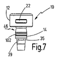
図7から図12は、異なるタイプの識別手段46を示す。図7及び図8は、ダイシャンク14の外周上の半径方向溝102の形態で設けられた識別手段46を有する互換性ダイ10を示す。溝は、各互換性ダイに特徴的である。この場合には、接合工具50上に、溝102がその上を通過するときに音を発生させる手段が設けられることが好ましい。この手段は、例えば工具ラッチ手段60又はその他のラッチ手段により形成することができる。次いで特徴的な音を音響センサで受信することができ、該音響センサが音響信号を評価して互換性ダイ10を識別する。
7 to 12 show different types of identification means 46. FIG. 7 and 8 show a
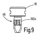
図9は、図8に相当する図を示し、同じく識別のために溝が用いられており、図9において符号102aで示されている。しかしながら、図9の溝102aは長手方向の溝として設けられ、これが互換性ダイ10の特徴的な形状部を与える。
FIG. 9 shows a view corresponding to FIG. 8, with grooves also being used for identification, which is indicated by 102a in FIG. However, the
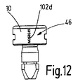
図10から図12は、各々の場合において、光学的に検出可能な識別手段46を示す。図10は、この場合、頭部の周部分24上に取り付けられたバーコード102bを示す。図11は、頭部の周部分24上に取り付けられた2Dコード102cを示す。図12は、頭部の周部分24上に取り付けられた英数字コード102dを示す。
Figures 10 to 12 show in each case optically detectable identification means 46. FIG. 10 shows a
識別手段46を頭部の周部分24上に取り付ける場合、これらは周方向で回転同伴輪郭22の間に配置されることが好ましい。
If the identification means 46 are mounted on the
図13から図17は、接合工具50のさらなる実施形態をダイホルダ68と共に示す。ここには互換性ダイ10が付加的に示されている。これらの実施形態は、設計及び動作方法に関して概ね図1の実施形態に対応する。したがって同一要素には同一符号が付される。本質的な違いを以下で説明する。
FIGS. 13-17 show a further embodiment of a
互換性ダイ10は、横方向凹所35を形成するためのほぼ三角形の断面を有する周方向溝を含むダイシャンク14を備える。解除部分38は、長手方向凹所39を形成する直径方向に対向する2つの平行な平面加工により形成され、そのうちの一方のみが図13に示されている。
The compatible die 10 includes a
ラッチ凹所44’は、断面三角形の直径方向の凹所として設けられており、シャンク端面28上に設けられる。
The
ダイ受入れ部分52は、横方向凹所35に対応する軸線方向高さに2つの細いロックピン穴106を備える。ロックピン穴106は、シャンク受入れ手段54に対して接線方向に位置合わせされる。2つのロックピン108がロックピン穴106の中に挿入される。ロックピン108間の間隔(図13において符号D2で示される)は、この場合、互換性ダイ10の長手方向凹所39の間の半径方向間隔に対応する。ロックピン108の長軸間の間隔(図13で符号D1で示される)は、シャンク受入れ手段54の内径と同一であることが好ましい。
The
したがって、これら寸法は、図13に示す表示の互換性ダイ10が、長手方向凹所39がロックピン108の間に正確に嵌ったときにそのダイシャンク14によりシャンク受入れ手段54内に挿入されることができるように、選択されている。ダイ頭部12がダイ受入れ部分52の表面上に載った途端に、ロックピン108は横方向凹所35の軸線方向高さに位置することになり、その結果、互換性ダイ10をシャンク受入れ手段54の内部で、具体的には約90°回転させることが可能になり、確動ロック挿入/回転接続をこのようにして確立するようになっている。
Thus, these dimensions allow the compatible die 10 of the display shown in FIG. 13 to be inserted into the shank receiving means 54 by its
工具ラッチ手段60を設けるために、ラッチ要素は中空ブッシング62’の形態で設けられ、これはラッチ凹所44’と係合することができるラッチコグが生成されるようにその一端がくさび形にテーパ付けされている。図14及び図16に詳細が示されるように、保持ピン110上で軸線方向に支持されるばね要素64’がラッチ要素62’の内側に配置される。保持ピン110は、この場合、保持ピン穴112によりダイホルダ68に挿入され、長手方向開口部116によりラッチ要素62’に挿入される。
In order to provide the tool latching means 60, the latching element is provided in the form of a hollow bushing 62 'which tapers at one end into a wedge so as to produce a latch cog which can be engaged with the latch recess 44'. It is attached. As shown in detail in FIGS. 14 and 16, a spring element 64 'axially supported on the retaining
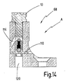
このラッチ手段60の取り付けは、図14でも分かるように、シャンク受入れ手段54がダイホルダ68内に軸線方向に連続した穴として設けられることが好ましいので、比較的簡単である。
The attachment of the latch means 60 is relatively simple as preferably the shank receiving means 54 is provided as an axially continuous hole in the
さらに、ダイホルダ68内に設けられた、シャンク受入れ手段54に向かって上方に傾いて延びる排出開口部114を、図13及び図14で見ることができる。互換性ダイ10は、該互換性ダイがダイホルダ68内に締め付けられたなどの場合に限り、排出開口部114によって強制的に排出させることができる。
Furthermore, a
図6に示す機能と同様に、ダイホルダ68をフレームワーク上に解除可能に締結するための締結穴118が符号118により図13に示されている。シャンク受入れ手段54のための連続した長手方向穴は、図14において符号120で示されている。
Similar to the function shown in FIG. 6, the fastening holes 118 for releasably fastening the
図14及び図15は、互換性ダイ10がシャンク受入れ手段54内に挿入され、長手方向凹所39がピン108に位置合わせされた状態を示す。この位置において、ピン108は、横方向凹所35の軸線方向高さにある。さらに、ラッチ凹所44’は、ラッチ要素62’のラッチコグに対してオフセットされており、ラッチコグがラッチ凹所44’と係合しないようになっている。
14 and 15 show the compatible die 10 inserted into the shank receiving means 54 with the
この状態は、互換性ダイ10とダイホルダ68との間の相対回転位置に対応し、この位置は、図15において符号Aで示されている。
This state corresponds to the relative rotational position between the
図16及び図17は、互換性ダイ10がダイホルダ68に対して約90°回転した、さらなる回転位置Bを示す。それに応じて、ピン108は、軸線方向に確動ロック方式で横方向凹所35に係合する。さらに、ラッチ要素62’のラッチコグがラッチ凹所44’内にラッチされる。ラッチ力は、回転位置Bの意図しない解除を回避することができるように選択される。しかしながら、回転装置88(図6参照)による回転は可能である。
16 and 17 show a further rotational position B, in which the
図18は、設計及び動作に関して図3の互換性ダイ10’に概ね対応する互換性ダイ10’のさらなる実施形態を示す。したがって同一要素は同一符号で特徴付けられる。本質的な違いを以下で説明する。 FIG. 18 shows a further embodiment of a compatible die 10 'that generally corresponds to the compatible die 10' of FIG. 3 in terms of design and operation. Therefore, the same elements are characterized by the same symbols. The essential differences are described below.
図18の互換性ダイ10’の締結輪郭30’は、比較的幅広(周方向で見たとき)の第2の周部分36を備え、阻止部材(図3の半径方向に突出した阻止部材58と同様のもの)が締結輪郭30’内を通って容易に進むことができるようになっている。
The fastening profile 30 'of the compatible die 10' of FIG. 18 comprises a relatively wide (as viewed in the circumferential direction) second
さらにラッチ凹所44の形態のラッチ手段42が示されており、これは、周方向に円周状であり、かつ実質的に三角形の断面を有する。 Furthermore, latch means 42 in the form of latch recesses 44 are shown, which are circumferentially circumferential and have a substantially triangular cross section.
互換性ダイ10’は、回転装置88のための能動回転駆動部を備えていない移送ステーション76の利用を可能にする。ダイ受入れ部分52がダイシャンク14’の方向に移動する(図6の運動94に対応する)とき、阻止部材58は、その結果として第2の周部分36の領域内の解除部分38内を通って進んで行き、そして阻止部分34のらせん形態の結果として、移送ステーション76の内部で互換性ダイ10’の確動回転を発生させる。
The compatible die 10 ′ allows the use of a
互換性ダイ10’を使用する接合工具システム74の場合、結果として、構造的により単純な移送ステーション76を使用することができる。
In the case of a
阻止部分34のらせん状凹所のピッチは、この場合、ロッキング部分34とロッキング部材58との間にセルフロッキングが生じることができないようには選択されることが好ましい。
The pitch of the helical recess of the blocking
ダイ受入れ部分52からのダイ10’の意図しない引抜きは、この実施形態の場合には、ラッチ凹所44に係合する比較的強力なラッチ手段により軸線方向運動が制限されることの結果として防止されることもまた好ましい。
Unintended withdrawal of the die 10 'from the
互換性ダイ10’に、図7から図12の例に示されるような識別手段46を設けることもできることは明らかである。 It will be appreciated that the compatibility die 10 'may also be provided with identification means 46 as shown in the example of FIGS. 7-12.
10、10’、10”:互換性ダイ
12:ダイ頭部
14、14’:ダイシャンク
16:軸線方向
18:ダイ形状部
20:頭部端面
22:回転同伴輪郭
26:シャンク周部分
28:シャンク端面
30、30’:締結輪郭
32:第1の周部分
34、34’:阻止部分
35:横方向凹所
36:第2の周部分
38、38’:解除部分
39:軸線方向凹所
42:ダイラッチ手段
44、44’:ラッチ凹所
46、18、102、102a、102b、102c、102d:識別手段
50:接合工具
52、52”:ダイ受入れ部分
54:シャンク受入れ手段、シャンクレセプタクル
56:締結装置
58:阻止部材
60:工具ラッチ手段
62、62’:ラッチ要素
64、64’:ばね要素
68:ダイホルダ
72:フレーム
74:接合工具システム
76:移送ステーション
78:基部
80、82:互換性ダイ受入れ手段
88:回転装置
94:相対軸線方向運動
96:相対回転
100:識別手段センサ
108:第1及び/又は第2の阻止部材
10, 10 ′, 10 ′ ′: compatible die 12: die
Claims (15)
前記互換性ダイ(10)を回転させるために回転装置(88)と協働することができる回転同伴輪郭(22)が前記互換性ダイ(10)上に設けられ、前記回転同伴輪郭(22)は、前記ダイ頭部(12)の周部分(24)上の1つ又は2つの半径方向溝により形成され、前記1つ又は2つの半径方向溝は、弦形状に延びる
ことを特徴とする、互換性ダイ。 A die head (12) on which a die shape (18) is provided, and a shank of a die receiving portion (52) of the joining tool (50) extending axially from said die head (12) A fastening profile (30) having a die shank (14) insertable in a receptacle (54) and for fastening a compatible die (10) on a joining tool (50) is said compatible die (10) A joining tool (provided on top, said fastening contour (30) being able to establish an insertion / rotational connection between said compatible die (10) and said joining tool (50)) 50) compatible die (10),
A rotation entrainment contour (22) capable of cooperating with a rotation device (88) to rotate the compatibility die (10) is provided on the compatibility die (10), the rotation entrainment contour (22) Are formed by one or two radial grooves on the circumferential portion (24) of the die head (12), said one or two radial grooves extending in a chordal shape, Compatible die.
前記締結装置(56)が、前記互換性ダイ(10)と前記接合工具(50)との間に挿入/回転接続を確立することができるように設けられた、接合工具において、
前記ダイ受入れ部分(52)が、前記接合工具(50)のCフレーム(72)に解除可能な接続部(70)によって剛に接続されるダイホルダ(68)上に設けられることを特徴とする、接合工具。 Have a die receiving portion with a shank receptacle (54) for receiving the die shank (14) Compatibility die (10) according to any one of claims 1 to 7 (52), said compatibility A fastening device (56) for fastening a die (10) on the joining tool (50) is provided in the die receiving portion (52);
A joining tool, wherein the fastening device (56) is arranged to be able to establish an insertion / rotational connection between the compatible die (10) and the joining tool (50),
The die receiving portion (52) is provided on a die holder (68) rigidly connected by a releasable connection (70) to the C-frame (72) of the joining tool (50); Welding tool.
−前記接合工具(50)を互換性ダイ(10)が一時的に保管される移送ステーション(76)に移動させるステップと、
−前記互換性ダイ(10)を前記接合工具(50)の前記ダイ受入れ部分(52)内に移送するステップであって、前記ダイ受入れ部分(52)と前記互換性ダイ(10)との間で相対軸線方向運動(94)が行われるステップと、
−前記互換性ダイ(10)を用いて接合プロセスを実行するステップと、
を含み、
前記互換性ダイ(10)が前記互換性ダイ(10)と前記ダイ受入れ部分(52)との相対回転(96)の結果として移送されるときに、前記ダイ受入れ部分(52)と前記互換性ダイ(10)との間に挿入/回転接続が確立され、前記相対回転は、45°から135°までの範囲内の回転角にわたるものである、方法。 Claim 1 with a die receiving portion for compatibility die according to any of claims 8 (10) (52), bonding tool according to any of claims 8 to claim 14 (50) A method for joining by
Moving the joining tool (50) to a transfer station (76) where the compatible die (10) is temporarily stored;
Transferring the compatible die (10) into the die receiving portion (52) of the joining tool (50), between the die receiving portion (52) and the compatible die (10) The relative axial movement (94) is performed at
Performing a bonding process using said compatible die (10);
Including
The compatibility with the die receiving portion (52) when the compatibility die (10) is transported as a result of relative rotation (96) of the compatibility die (10) and the die receiving portion (52) A method wherein an insertion / rotational connection is established between the die (10) and the relative rotation is over a rotation angle in the range 45 ° to 135 °.
Applications Claiming Priority (3)
| Application Number | Priority Date | Filing Date | Title |
|---|---|---|---|
| DE102013021056.9A DE102013021056A1 (en) | 2013-12-18 | 2013-12-18 | Interchangeable die, joining tool and joining method |
| DE102013021056.9 | 2013-12-18 | ||
| PCT/EP2014/076376 WO2015090962A1 (en) | 2013-12-18 | 2014-12-03 | Interchangeable die, joining tool and joining method |
Publications (3)
| Publication Number | Publication Date |
|---|---|
| JP2016540647A JP2016540647A (en) | 2016-12-28 |
| JP2016540647A5 JP2016540647A5 (en) | 2017-09-28 |
| JP6503360B2 true JP6503360B2 (en) | 2019-04-17 |
Family
ID=52003780
Family Applications (1)
| Application Number | Title | Priority Date | Filing Date |
|---|---|---|---|
| JP2016540490A Active JP6503360B2 (en) | 2013-12-18 | 2014-12-03 | Compatible die, joining tool and joining method |
Country Status (5)
| Country | Link |
|---|---|
| US (1) | US11020789B2 (en) |
| EP (1) | EP3083100B1 (en) |
| JP (1) | JP6503360B2 (en) |
| DE (2) | DE202013011928U1 (en) |
| WO (1) | WO2015090962A1 (en) |
Families Citing this family (5)
| Publication number | Priority date | Publication date | Assignee | Title |
|---|---|---|---|---|
| DE102015100922A1 (en) | 2015-01-22 | 2016-07-28 | Newfrey Llc | Interchangeable die, joining tool and joining method |
| DE102015107337A1 (en) | 2015-05-11 | 2016-11-17 | Böllhoff Verbindungstechnik GmbH | Die changer with adapted replaceable die and die dome as well as method for removing and inserting the replaceable die |
| CN105057546B (en) * | 2015-07-31 | 2017-10-03 | 南京惠德机械有限公司 | Outstanding riveting rivet positioner |
| GB2563441B (en) | 2017-06-16 | 2022-03-23 | Atlas Copco Ias Uk Ltd | Die changing apparatus |
| DE102018120500A1 (en) * | 2018-08-22 | 2020-02-27 | Tox Pressotechnik Gmbh & Co. Kg | Adapter element for attaching a die holder to tool pliers |
Family Cites Families (22)
| Publication number | Priority date | Publication date | Assignee | Title |
|---|---|---|---|---|
| US1569136A (en) * | 1925-03-27 | 1926-01-12 | Anthracite Separator Co | Tool holder |
| US1892739A (en) * | 1928-12-13 | 1933-01-03 | Smith J Hugo | Tool and tool holder |
| US2105391A (en) * | 1933-11-14 | 1938-01-11 | Midland Steel Prod Co | Adjustable ram nose for cold riveting fixtures |
| US2773693A (en) * | 1954-05-20 | 1956-12-11 | Windsor N Chittenden | Positive shank-locking means for collet-held cutting tools |
| US3474710A (en) * | 1967-09-01 | 1969-10-28 | Air Mite Devices Inc | Cylinder construction using roll pins |
| GB1280293A (en) * | 1968-10-19 | 1972-07-05 | Wickman Mach Tool Sales Ltd | Coining presses |
| DE2822548C2 (en) * | 1978-05-23 | 1982-11-18 | Sandvik AB, 81181 Sandviken | Tool, in particular mining chisel, with a holding shaft for fastening in a receiving part of a machine |
| JPS6413610U (en) * | 1987-07-15 | 1989-01-24 | ||
| US5185992A (en) * | 1991-08-19 | 1993-02-16 | Garcia Roque P | Garden tool expanding assembly |
| US5361473A (en) * | 1992-07-09 | 1994-11-08 | Heavy Duty Marketing Corporation | Rivet setting anvil |
| US5727302A (en) * | 1994-01-31 | 1998-03-17 | Btm Corporation | Die and punch for forming a joint and method of making the die |
| IT1289514B1 (en) * | 1996-12-23 | 1998-10-15 | Ronchi Mario Off Mec | QUICK COUPLING DEVICE FOR APPLICATION GROUPS OF CAPS TO CONTAINERS, ESPECIALLY FOR AUTOMATIC MACHINE SPINDLES |
| US5915482A (en) * | 1998-02-26 | 1999-06-29 | Carruthers; Robert B. | Hand tool with interchangeable attachments |
| US6785959B2 (en) * | 2002-08-15 | 2004-09-07 | Btm Corporation | Tool assembly employing a flexible retainer |
| DE10335085B4 (en) | 2003-07-31 | 2016-07-28 | Böllhoff GmbH | Setting tool with interchangeable modules |
| DE202006013082U1 (en) | 2005-08-29 | 2006-11-02 | Newfrey Llc, Newark | Frame for a connection unit, comprises a shank with a bore at its free end, which is surrounded by a closed shank wall |
| JP5293601B2 (en) * | 2007-06-06 | 2013-09-18 | 三星ダイヤモンド工業株式会社 | Multi-head-mounted scribing device and tip holder automatic replacement system |
| US8683869B2 (en) * | 2008-09-04 | 2014-04-01 | The Boeing Company | Monitoring fastener preload |
| DE102012101894A1 (en) * | 2012-03-06 | 2013-09-12 | Tkr Spezialwerkzeuge Gmbh | connection tool |
| DE102012207651A1 (en) * | 2012-05-08 | 2013-11-14 | Aesculap Ag | Quick-coupling |
| DE102012013829B4 (en) * | 2012-07-13 | 2024-03-14 | Newfrey Llc | Punch rivet die, punch rivet tool and punch rivet process |
| US9409241B2 (en) * | 2012-12-13 | 2016-08-09 | Iscar, Ltd. | Cutting tool and replaceable cutting head having spiral driven surfaces therefor |
-
2013
- 2013-12-18 DE DE202013011928.4U patent/DE202013011928U1/en not_active Expired - Lifetime
- 2013-12-18 DE DE102013021056.9A patent/DE102013021056A1/en active Granted
-
2014
- 2014-12-03 EP EP14806273.0A patent/EP3083100B1/en active Active
- 2014-12-03 WO PCT/EP2014/076376 patent/WO2015090962A1/en active Application Filing
- 2014-12-03 JP JP2016540490A patent/JP6503360B2/en active Active
-
2016
- 2016-06-17 US US15/185,594 patent/US11020789B2/en active Active
Also Published As
| Publication number | Publication date |
|---|---|
| EP3083100B1 (en) | 2021-08-25 |
| US20160288197A1 (en) | 2016-10-06 |
| WO2015090962A1 (en) | 2015-06-25 |
| DE102013021056A1 (en) | 2015-06-18 |
| DE202013011928U1 (en) | 2014-10-30 |
| EP3083100A1 (en) | 2016-10-26 |
| JP2016540647A (en) | 2016-12-28 |
| US11020789B2 (en) | 2021-06-01 |
Similar Documents
| Publication | Publication Date | Title |
|---|---|---|
| JP6503360B2 (en) | Compatible die, joining tool and joining method | |
| JP6453340B2 (en) | Compatible die transfer station, joining tool system and joining method | |
| US9796014B2 (en) | Tool connection | |
| KR101456663B1 (en) | Universal chuck | |
| CN103052813A (en) | Pin and clamping system having pins | |
| JPH06500053A (en) | Tool holder with tool change mechanism | |
| JP2016016508A (en) | Fastening chuck having quick exchange function and fastening mechanism part | |
| KR970703226A (en) | Tool holders for a handhold type boring machine, in particular hammer drill, and handhold type boring machine including the tool holder | |
| JP6763862B2 (en) | Replaceable dies, joining tools and joining methods | |
| RU2615097C2 (en) | Tool holding structure | |
| TWI661881B (en) | Powder press assembly | |
| JP4722142B2 (en) | Shank attachment device | |
| KR101505812B1 (en) | block locking device | |
| JP2013167347A (en) | Fastening device using insert screw | |
| ITBO20090626A1 (en) | CUTTER FOR SKIN PROCESSING AND SYSTEM FOR THE REMOVABLE LOCKING OF THE SAME TO A TREE OF A SKIN MACHINE | |
| US8262095B2 (en) | Chuck | |
| US6953198B2 (en) | Short pull-back chuck | |
| JP4757304B2 (en) | Chuck and rotary direction aligner | |
| JP5202237B2 (en) | Tip side drawbar changer for tool clamping device | |
| US10014085B2 (en) | Reuseable holder for a radioactive source capsule | |
| JP2005238364A (en) | Work holding chuck | |
| JP2008229801A (en) | Tool holder | |
| ITBO20080532A1 (en) | LOCKING SYSTEM OF A DIE CUTTER TO A TREE OF A MACHINE FOR THE PROCESSING OF SKINS AND THE LIKE. |
Legal Events
| Date | Code | Title | Description |
|---|---|---|---|
| A521 | Request for written amendment filed |
Free format text: JAPANESE INTERMEDIATE CODE: A523 Effective date: 20170821 |
|
| A621 | Written request for application examination |
Free format text: JAPANESE INTERMEDIATE CODE: A621 Effective date: 20170821 |
|
| A131 | Notification of reasons for refusal |
Free format text: JAPANESE INTERMEDIATE CODE: A131 Effective date: 20180903 |
|
| A601 | Written request for extension of time |
Free format text: JAPANESE INTERMEDIATE CODE: A601 Effective date: 20181130 |
|
| A521 | Request for written amendment filed |
Free format text: JAPANESE INTERMEDIATE CODE: A523 Effective date: 20190108 |
|
| TRDD | Decision of grant or rejection written | ||
| A01 | Written decision to grant a patent or to grant a registration (utility model) |
Free format text: JAPANESE INTERMEDIATE CODE: A01 Effective date: 20190221 |
|
| A61 | First payment of annual fees (during grant procedure) |
Free format text: JAPANESE INTERMEDIATE CODE: A61 Effective date: 20190325 |
|
| R150 | Certificate of patent or registration of utility model |
Ref document number: 6503360 Country of ref document: JP Free format text: JAPANESE INTERMEDIATE CODE: R150 |
|
| R250 | Receipt of annual fees |
Free format text: JAPANESE INTERMEDIATE CODE: R250 |
|
| R250 | Receipt of annual fees |
Free format text: JAPANESE INTERMEDIATE CODE: R250 |
|
| R250 | Receipt of annual fees |
Free format text: JAPANESE INTERMEDIATE CODE: R250 |