JP6502375B2 - Fluorescent lamp compatible type LED lighting device and electric shock protection device therefor - Google Patents
Fluorescent lamp compatible type LED lighting device and electric shock protection device therefor Download PDFInfo
- Publication number
- JP6502375B2 JP6502375B2 JP2016557136A JP2016557136A JP6502375B2 JP 6502375 B2 JP6502375 B2 JP 6502375B2 JP 2016557136 A JP2016557136 A JP 2016557136A JP 2016557136 A JP2016557136 A JP 2016557136A JP 6502375 B2 JP6502375 B2 JP 6502375B2
- Authority
- JP
- Japan
- Prior art keywords
- switch
- fluorescent lamp
- led lighting
- power supply
- lighting device
- Prior art date
- Legal status (The legal status is an assumption and is not a legal conclusion. Google has not performed a legal analysis and makes no representation as to the accuracy of the status listed.)
- Expired - Fee Related
Links
Images


Classifications
-
- F—MECHANICAL ENGINEERING; LIGHTING; HEATING; WEAPONS; BLASTING
- F21—LIGHTING
- F21V—FUNCTIONAL FEATURES OR DETAILS OF LIGHTING DEVICES OR SYSTEMS THEREOF; STRUCTURAL COMBINATIONS OF LIGHTING DEVICES WITH OTHER ARTICLES, NOT OTHERWISE PROVIDED FOR
- F21V25/00—Safety devices structurally associated with lighting devices
- F21V25/02—Safety devices structurally associated with lighting devices coming into action when lighting device is disturbed, dismounted, or broken
- F21V25/04—Safety devices structurally associated with lighting devices coming into action when lighting device is disturbed, dismounted, or broken breaking the electric circuit
-
- H—ELECTRICITY
- H05—ELECTRIC TECHNIQUES NOT OTHERWISE PROVIDED FOR
- H05B—ELECTRIC HEATING; ELECTRIC LIGHT SOURCES NOT OTHERWISE PROVIDED FOR; CIRCUIT ARRANGEMENTS FOR ELECTRIC LIGHT SOURCES, IN GENERAL
- H05B45/00—Circuit arrangements for operating light-emitting diodes [LED]
- H05B45/30—Driver circuits
- H05B45/31—Phase-control circuits
-
- H—ELECTRICITY
- H05—ELECTRIC TECHNIQUES NOT OTHERWISE PROVIDED FOR
- H05B—ELECTRIC HEATING; ELECTRIC LIGHT SOURCES NOT OTHERWISE PROVIDED FOR; CIRCUIT ARRANGEMENTS FOR ELECTRIC LIGHT SOURCES, IN GENERAL
- H05B45/00—Circuit arrangements for operating light-emitting diodes [LED]
- H05B45/30—Driver circuits
- H05B45/357—Driver circuits specially adapted for retrofit LED light sources
- H05B45/3578—Emulating the electrical or functional characteristics of discharge lamps
-
- H—ELECTRICITY
- H05—ELECTRIC TECHNIQUES NOT OTHERWISE PROVIDED FOR
- H05B—ELECTRIC HEATING; ELECTRIC LIGHT SOURCES NOT OTHERWISE PROVIDED FOR; CIRCUIT ARRANGEMENTS FOR ELECTRIC LIGHT SOURCES, IN GENERAL
- H05B47/00—Circuit arrangements for operating light sources in general, i.e. where the type of light source is not relevant
- H05B47/20—Responsive to malfunctions or to light source life; for protection
- H05B47/26—Circuit arrangements for protecting against earth faults
-
- F—MECHANICAL ENGINEERING; LIGHTING; HEATING; WEAPONS; BLASTING
- F21—LIGHTING
- F21K—NON-ELECTRIC LIGHT SOURCES USING LUMINESCENCE; LIGHT SOURCES USING ELECTROCHEMILUMINESCENCE; LIGHT SOURCES USING CHARGES OF COMBUSTIBLE MATERIAL; LIGHT SOURCES USING SEMICONDUCTOR DEVICES AS LIGHT-GENERATING ELEMENTS; LIGHT SOURCES NOT OTHERWISE PROVIDED FOR
- F21K9/00—Light sources using semiconductor devices as light-generating elements, e.g. using light-emitting diodes [LED] or lasers
- F21K9/20—Light sources comprising attachment means
- F21K9/27—Retrofit light sources for lighting devices with two fittings for each light source, e.g. for substitution of fluorescent tubes
- F21K9/278—Arrangement or mounting of circuit elements integrated in the light source
-
- F—MECHANICAL ENGINEERING; LIGHTING; HEATING; WEAPONS; BLASTING
- F21—LIGHTING
- F21Y—INDEXING SCHEME ASSOCIATED WITH SUBCLASSES F21K, F21L, F21S and F21V, RELATING TO THE FORM OR THE KIND OF THE LIGHT SOURCES OR OF THE COLOUR OF THE LIGHT EMITTED
- F21Y2115/00—Light-generating elements of semiconductor light sources
- F21Y2115/10—Light-emitting diodes [LED]
-
- Y—GENERAL TAGGING OF NEW TECHNOLOGICAL DEVELOPMENTS; GENERAL TAGGING OF CROSS-SECTIONAL TECHNOLOGIES SPANNING OVER SEVERAL SECTIONS OF THE IPC; TECHNICAL SUBJECTS COVERED BY FORMER USPC CROSS-REFERENCE ART COLLECTIONS [XRACs] AND DIGESTS
- Y02—TECHNOLOGIES OR APPLICATIONS FOR MITIGATION OR ADAPTATION AGAINST CLIMATE CHANGE
- Y02B—CLIMATE CHANGE MITIGATION TECHNOLOGIES RELATED TO BUILDINGS, e.g. HOUSING, HOUSE APPLIANCES OR RELATED END-USER APPLICATIONS
- Y02B20/00—Energy efficient lighting technologies, e.g. halogen lamps or gas discharge lamps
- Y02B20/30—Semiconductor lamps, e.g. solid state lamps [SSL] light emitting diodes [LED] or organic LED [OLED]
Description
本発明は従来の蛍光灯を代替して使用することができる蛍光灯互換タイプのLED照明装置に関するもので、特に蛍光灯器具にLED照明装置を着脱する過程で発生する恐れがある感電事故を防止することができるようになったLED照明装置とそのための感電保護装置に関するものである。 The present invention relates to a fluorescent lamp compatible type LED lighting device that can be used instead of a conventional fluorescent lamp, and in particular, prevents an electric shock accident that may occur in the process of attaching and detaching the LED lighting device to a fluorescent lamp fixture. The present invention relates to an LED lighting device and an electric shock protection device therefor.
最近、LED(Light Emitting Diode)を用いる照明装置への関心が急増している。LED照明装置は従来に使用していた蛍光灯、白熱灯、ハロゲンランプなどに比べて消費電力が少なく、寿命が半永久的という長所を有している。これにより、従来の白熱灯や蛍光灯を代替してそのまま使用することができる互換タイプのLED照明装置が開発され広く普及している。 Recently, interest in lighting devices using LEDs (Light Emitting Diodes) has been rapidly increasing. The LED lighting device consumes less power than fluorescent lamps, incandescent lamps, halogen lamps and the like conventionally used, and has an advantage that the life is semipermanent. As a result, compatible type LED lighting devices that can be used as they are instead of conventional incandescent lamps and fluorescent lamps have been developed and widely used.
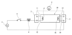
図1は現在使用される蛍光灯器具の構成を示す構成図である。蛍光灯器具は蛍光灯を結合するためのソケット2、3、安定器4、及びスターター5を備えて構成され、これらの構成部品は電源スイッチ6を介して交流電源1に結合される。
蛍光灯10は、その一側に第1接続手段、即ち第1及び第2端子ピン11、12が設けられ、他側には第2接続手段、即ち第3及び第4端子ピン13、14が設けられる。これらの端子ピン13〜14はソケット2、3に挿入されて蛍光灯器具に電気的に結合される。そして、前記第1及び第2端子ピン11、12の間と、第3及び第4端子ピン13、14の間にはそれぞれ、蛍光灯の放電動作のためのフィラメント15、16が結合される。
前記蛍光灯器具において、ソケット2、3に蛍光灯が結合され電源スイッチ6がオンされると、交流電源1が安定器4とスターター5を介して流れるようになる。そして、スターター5の固定電極と可動電極が離間してスターター5がオフされると、安定器4の両端間に発生する瞬間的な高電圧がフィラメント15、16に与えられるようになり、このような高電圧によりフィラメント15、16の間に放電が発生することで、蛍光灯10が点灯されるようになる。そして、蛍光灯10が点灯された後には、フィラメント15、16の間に電流が 安定して流れるようになる。
FIG. 1 is a block diagram showing the configuration of a fluorescent lamp apparatus currently used. The fluorescent lamp apparatus comprises
The
In the fluorescent lamp apparatus, when the fluorescent lamp is coupled to the
図2は蛍光灯互換タイプのLED照明装置20の構成を示すブロック構成図である。蛍光灯互換タイプのLED照明装置20は通常の蛍光灯と同様に、蛍光灯器具のソケット2に締結される第1接続手段、即ち第1及び第2端子ピン21、22と、ソケット3に締結される第2接続手段、即ち第3及び第4端子ピン23、24が備えられる。第1接続手段21、24と第2接続手段23、24との間の距離は、通常の蛍光灯と同一に設定する。前記第1接続手段21、22と第2接続手段23、24にはそれぞれ整流部25、26が電気的に結合される。これらの整流部25、26は例えばブリッジダイオードで構成される。整流部25、26は第1〜第4端子ピン21〜24を介して入力される交流電源を整流して駆動部28に供給する。
LEDモジュール27には複数のLEDが設けられ、図面には具体的に示されなかったが、これらのLEDはLED照明装置の長さ方向に沿って配列される。駆動部28は整流部25、26から印加される動作電源を用いてLEDモジュール27を駆動する。
FIG. 2 is a block diagram showing a configuration of the fluorescent lamp compatible type
The
ところが、前述した従来のLED照明装置20においては、次のような問題がある。
一般的に、蛍光灯は寿命が比較的短いため、一定期間ごとに、これを交換する作業が要求される。通常の蛍光灯の交換作業は電源スイッチ6をオン状態に設定した状態で進行する場合が多い。これは蛍光灯の交換と同時に、その点灯状況を目で確認することができるからである。
図1の蛍光灯器具において、作業者が蛍光灯器具に蛍光灯10や蛍光灯互換タイプのLED照明装置20を新たに装着した場合は、まず一側のソケットに蛍光灯の一側端子ピンを締結した後、他側のソケットに他側端子ピンを締結する。
However, the conventional
Generally, since fluorescent lamps have a relatively short life, work is required to replace them at regular intervals. Ordinary fluorescent lamp replacement work often proceeds with the power switch 6 set in the on state. This is because the lighting condition can be visually confirmed simultaneously with the replacement of the fluorescent lamp.
In the case of the fluorescent lamp apparatus shown in FIG. 1, when the operator newly attaches the
ところが、現在の蛍光灯器具に採用されているほとんどの安定器4は電源スイッチ6がオンの状態になっている時に、両側ソケット2、3に蛍光灯の端子ピンが全て締結されず、いずれか一方のソケット2または3のみに蛍光灯の端子ピンが締結される場合にも蛍光灯器具に蛍光灯が締結されていることと認識して蛍光灯の放電動作を行う。つまり、他の一つのソケット2または3に端子ピンが締結されていないことをスターター5のオフ状態として認識して、蛍光灯10または20に継続して高電圧を印加する。
従来の蛍光灯10においては放電されて蛍光灯10が点灯した後にならなければ、フィラメント15、16の間には電流の流れが形成されない。そのため、蛍光灯10の一側端子ピンに高電圧が印加されても他側端子ピンには如何なる電圧の変動も発生しない。
しかし、蛍光灯互換タイプのLED照明装置20は、その内部回路が大部分半導体素子や電子素子からなる。これらの部品は通常に寄生容量を有しているので、非動作状態でも外部からの電源が印加されると、リーク電流が流れるようになる。従って、蛍光灯互換タイプのLED照明装置20は一側端子ピンに高電圧が印加されると、その高電圧が他側端子ピンに伝達されることで、作業者が感電する事故が発生する恐れがある。
However, most of the ballasts 4 used in the present fluorescent lamp fixtures do not have all the terminal pins of the fluorescent lamp fastened to both
In the conventional
However, the internal circuit of the fluorescent lamp compatible type
従って、本発明は前述した事情を勘案してなされたものであり、作業者の感電事故を根本的に防止することができるようになった蛍光灯互換タイプのLED照明装置を提供することにその技術的な目的がある。
また、本発明の他の技術的な目的は、蛍光灯互換タイプのLED照明装置の両側端子ピン、即ち第1及び第2接続手段の両方が蛍光灯器具のソケットに結合されていない状態では、端子ピンと内部回路を電気的に遮断することで、作業者の感電事故を防止することができる蛍光灯互換タイプのLED照明装置用の感電保護装置を提供することにある。
Accordingly, the present invention has been made in consideration of the above-mentioned circumstances, and it is an object of the present invention to provide a fluorescent lamp compatible type LED lighting apparatus capable of fundamentally preventing an operator's electric shock accident. It has a technical purpose.
In addition, another technical object of the present invention is that both terminal pins of the fluorescent lamp compatible type LED lighting apparatus, that is, both the first and second connection means are not coupled to the socket of the fluorescent lamp fixture An object of the present invention is to provide an electric shock protection device for a fluorescent lamp compatible type LED lighting device capable of preventing an electric shock accident of a worker by electrically disconnecting a terminal pin and an internal circuit.
前述の目的を達成するための本発明の第1観点に係る蛍光灯互換タイプのLED照明装置は、安定器を備えて構成され、前記安定器は蛍光灯器具に蛍光灯の第1及び第2接続端子の両方が締結される場合には第1放電電圧を印加し、蛍光灯器具に蛍光灯の第1または第2接続端子が締結される場合には第2放電電圧を印加するようになった蛍光灯器具に使用される蛍光灯互換タイプのLED照明装置において、蛍光灯器具の両側ソケットに電気的に結合される第1及び第2接続手段と、前記第1または第2接続手段に選択的に結合される感電保護装置と、前記第1及び第2接続手段を介して入力される外部交流電源を整流する整流手段と、複数のLEDを備えるLEDモジュールと、前記整流手段から提供される駆動電力に基づいて、前記LEDモジュールを駆動する駆動手段を含んで構成され、前記感電保護装置は蛍光灯器具から第1放電電圧が印加される場合には第1または第2接続手段を内部回路と電気的に結合させ、蛍光灯器具から第2放電電圧が印加される場合には第1または第2接続手段を内部回路と開放状態に設定することを特徴とする。 The fluorescent lamp compatible type LED lighting device according to the first aspect of the present invention for achieving the above object is configured to include a ballast, the ballast being a fluorescent lamp fixture for the first and second of the fluorescent lamp. The first discharge voltage is applied when both of the connection terminals are fastened, and the second discharge voltage is applied when the first or second connection terminal of the fluorescent lamp is fastened to the fluorescent lamp fixture. In the fluorescent lamp compatible type LED lighting apparatus used for the fluorescent lamp apparatus, the first and second connection means electrically coupled to the sockets of the fluorescent lamp apparatus and the first or second connection means are selected. Provided from the rectifying means, the rectifying means for rectifying an external AC power input through the first and second connecting means, an LED module comprising a plurality of LEDs, and The L based on the driving power The electric shock protection device electrically couples the first or second connection means to the internal circuit when the first discharge voltage is applied from the fluorescent lamp device. When the second discharge voltage is applied from the fluorescent lamp device, the first or second connection means is set in an open state with the internal circuit.
また、前記感電保護装置は第1または第2接続端子と内部回路との間の電気的な結合を取り締まるための第1スイッチと、前記第1または第2接続端子から印加される第1及び第2放電電圧によって前記第1スイッチをオン/オフ駆動する第1検出手段と、前記第1スイッチの出力側に結合され、第1スイッチを介して内部回路に電流が供給される場合には前記第1スイッチのオン状態を維持する第1スイッチング駆動手段を含んで構成されることを特徴とする。 Further, the electric shock protection device comprises a first switch for tightening an electrical connection between the first or second connection terminal and the internal circuit, and the first and second switches applied from the first or second connection terminal. (2) A first detection means for driving the first switch on / off by a discharge voltage, and an output side of the first switch, wherein the current is supplied to the internal circuit through the first switch. It is characterized in that it comprises first switching driving means for maintaining the on state of one switch.
また、前記第1スイッチはトライアックで構成されることを特徴とする。 Also, the first switch is configured by a triac.
また、前記第1検出手段は直列接続された2つ以上のネオンランプを含んで構成されることを特徴とする。 The first detection means may include two or more neon lamps connected in series.
また、前記第1スイッチング駆動手段は前記検出手段に並列に結合される第1ブリッジ回路と、前記第1ブリッジ回路の電流通路に設けられる第1フォトカプラと、前記第1スイッチと内部回路との間に電気的に結合されると共に、前記第1フォトカプラをオン/オフ駆動する第2ブリッジ回路を含んで構成されることを特徴とする。 The first switching drive means may include a first bridge circuit coupled in parallel to the detection means, a first photocoupler provided in a current path of the first bridge circuit, a first switch, and an internal circuit. And a second bridge circuit electrically connected between the first and second photocouplers and driving the first photocoupler on and off.
また、前記感電保護装置は第1または第2接続端子と内部回路との間の電流通路に直列に設けられる第2及び第3スイッチと、前記第1または第2接続端子に直列に結合されると共に、第1または第2接続端子から印加される第1及び第2放電電圧によって前記第2スイッチ及び第3スイッチをそれぞれオン/オフ駆動する第2及び第3検出手段と、前記第2スイッチの出力側に結合され、第2スイッチを介して内部回路に電流が供給される場合には前記第2及び第3スイッチのオン状態を維持するスイッチング駆動手段を含んで構成されることを特徴とする。 Also, the electric shock protection device is coupled in series to the first and second connection terminals, and second and third switches provided in series in the current path between the first and second connection terminals and the internal circuit. And second and third detection means for respectively driving the second switch and the third switch by the first and second discharge voltages applied from the first or second connection terminal, and the second switch It is characterized in that it comprises switching driving means which is coupled to the output side and which maintains the on state of the second and third switches when current is supplied to the internal circuit through the second switch. .
また、前記第2及び第3スイッチはトライアックで構成されることを特徴とする。 The second and third switches may be configured by a triac.
また、前記第2及び第3検出手段は直列接続された2つ以上のネオンランプを含んで構成されることを特徴とする。 The second and third detection means may include two or more neon lamps connected in series.
さらに、前記第2スイッチング駆動手段は前記第2及び第3検出手段にそれぞれ並列に結合される第3及び第4ブリッジ回路と、前記第3及び第4ブリッジ回路の電流通路にそれぞれ設けられる第2及び第3フォトカプラと、前記第2スイッチと内部回路との間に電気的に結合されると共に、前記第2及び第3フォトカプラをオン/オフ駆動する第5ブリッジ回路を含んで構成されることを特徴とする。 Further, the second switching driving means is provided in third and fourth bridge circuits respectively coupled in parallel to the second and third detecting means, and secondly provided in current paths of the third and fourth bridge circuits, respectively. And a third photocoupler, and a fifth bridge circuit electrically coupled between the second switch and the internal circuit and driving the second and third photocouplers on / off It is characterized by
本発明の第2観点に係る蛍光灯互換タイプのLED電源装置のための感電保護装置は、蛍光灯器具に締結される第1及び第2接続手段と、前記第1及び第2接続手段を介して入力される外部電源を用いて動作電源を生成する電源手段と、複数のLEDを備えるLEDモジュールと、前記電源手段の動作電源を用いてLEDモジュールを駆動する駆動手段を備える蛍光灯互換タイプのLED照明装置に採用される感電保護装置において、前記感電保護装置は前記第1または第2接続手段と電源手段との間に設けられ、第1または第2接続端子と電源手段との間の電気的な結合を取り締まるためのスイッチと、前記第1または第2接続端子から印加される放電電圧の電圧値を検出して前記スイッチをオン/オフ駆動する検出手段と、前記スイッチの出力側に結合され、スイッチを介して電源手段に電流が供給される場合には前記スイッチのオン状態を維持するスイッチング駆動手段を含んで構成されることを特徴とする。 An electric shock protection device for a fluorescent lamp compatible type LED power supply device according to a second aspect of the present invention comprises first and second connection means fastened to a fluorescent lamp fixture, and the first and second connection means. Type of fluorescent lamp compatible type comprising: power supply means for generating operation power supply using an external power supply input thereto; LED module comprising a plurality of LEDs; and drive means for driving the LED module using operation power supply of said power supply means In the electric shock protection device employed in an LED lighting device, the electric shock protection device is provided between the first or second connection means and the power supply means, and electricity between the first or second connection terminal and the power supply means is provided. Switch for tightening the mechanical coupling, detection means for detecting the voltage value of the discharge voltage applied from the first or second connection terminal and driving the switch on / off, the switch Coupled to the output side, when a current is supplied to the power supply means via a switch, characterized in that it is configured to include a switching driving means for maintaining the ON state of the switch.
また、前記スイッチはトライアックで構成されることを特徴とする。 Also, the switch is characterized by being configured by a triac.
また、前記検出手段は直列接続された2つ以上のネオンランプを含んで構成されることを特徴とする。 Also, the detection means is characterized by comprising two or more neon lamps connected in series.
さらに、前記スイッチング駆動手段は前記検出手段に並列に結合される第1ブリッジ回路と、前記第1ブリッジ回路の電流通路に設けられるフォトカプラと、前記スイッチと内部回路との間に電気的に結合されると共に、前記フォトカプラをオン/オフ駆動する第2ブリッジ回路を含んで構成されることを特徴とする。 Furthermore, the switching drive means is electrically coupled between the first bridge circuit coupled in parallel to the detection means, a photocoupler provided in the current path of the first bridge circuit, the switch and the internal circuit. And a second bridge circuit for driving the photocoupler on / off.
本発明の第3観点に係る蛍光灯互換タイプのLED照明装置のための感電保護装置は、蛍光灯器具に締結される第1及び第2接続手段と、前記第1及び第2接続手段を介して入力される外部電源を用いて動作電源を生成する電源手段と、複数のLEDを備えるLEDモジュールと、前記電源手段の動作電源を用いてLEDモジュールを駆動する駆動手段を備える蛍光灯互換タイプのLED照明装置に採用される感電保護装置において、前記感電保護装置は前記第1または第2接続手段と電源手段との間に設けられ、前記第1または第2接続端子と電源手段との間の電流通路に直列に設けられる第1及び第2スイッチと、前記第1または第2接続端子に直列に結合されると共に、第1または第2接続端子から印加される第1及び第2放電電圧によって前記第1スイッチ及び第2スイッチをそれぞれオン/オフ駆動する第1及び第2検出手段と、 前記第2スイッチの出力側に結合され、第2スイッチを介して電源手段に電流が供給される場合には前記第1及び第2スイッチのオン状態を維持するスイッチング駆動手段を含んで構成されることを特徴とする。 An electric shock protection device for a fluorescent lamp compatible type LED lighting device according to a third aspect of the present invention comprises first and second connection means fastened to a fluorescent light fixture, and the first and second connection means. Type of fluorescent lamp compatible type comprising: power supply means for generating operation power supply using an external power supply input thereto; LED module comprising a plurality of LEDs; and drive means for driving the LED module using operation power supply of said power supply means In the electric shock protection device employed in an LED lighting device, the electric shock protection device is provided between the first or second connection means and a power supply means, and between the first or second connection terminal and the power supply means. The first and second switches provided in series in the current path, and the first and second discharge voltages coupled in series to the first and second connection terminals and applied from the first and second connection terminals First and second detection means for driving the first switch and the second switch on / off, and an output side of the second switch, and a current is supplied to the power supply means via the second switch. In this case, the first and second switches are characterized by including switching driving means for maintaining the on state of the first and second switches.
また、前記第1及び第2スイッチはトライアックで構成されることを特徴とする。 The first and second switches may be configured by a triac.
さらに、前記第1及び第2検出手段は直列接続された2つ以上のネオンランプを含んで構成されることを特徴とする。 Furthermore, the first and second detection means are characterized by comprising two or more neon lamps connected in series.
前述した構成を有する本発明に係る蛍光灯互換タイプのLED照明装置とそのための感電保護装置よれば、蛍光灯器具の安定器から印加される放電電圧に基づいて、蛍光灯互換タイプのLED照明装置が蛍光灯器具に正常に装着された否かを判断する。そして、LED照明装置を蛍光灯器具に締結する作業状態では、安定器からの高電圧がLED照明装置に印加されることを遮断することで、作業者の感電事故を防止する。 According to the fluorescent lamp compatible type LED lighting device according to the present invention having the above-described configuration and the electric shock protection device therefor, the fluorescent lamp compatible type LED lighting device based on the discharge voltage applied from the ballast of the fluorescent lamp Determine whether the fluorescent lamp has been properly installed. Then, in a working state in which the LED lighting device is fastened to the fluorescent lamp fixture, the application of the high voltage from the ballast to the LED lighting device is blocked, thereby preventing an electric shock accident of the worker.
以下、添付した図面に基づき本発明に係る実施形態を詳述する。但し、以下で説明する実施形態は本発明の一つの好ましい具現例を示すものであって、これらの本実施形態の例示は本発明の権利範囲を制限するためのものではない。本発明は以下で説明する実施形態に基づいて多様に変形させて実施することができる。 Hereinafter, embodiments of the present invention will be described in detail based on the attached drawings. However, the embodiments described below show one preferred embodiment of the present invention, and the exemplification of these embodiments is not intended to limit the scope of the present invention. The present invention can be variously modified and implemented based on the embodiments described below.
まず、本発明の基本的な概念を説明する。
現在商用化されている蛍光灯器具には非常に多くの種類の安定器が採用されている。これらの安定器は構造と動作特性が互いに異なっている。本発明者が非常に多くの種類の安定器の特性を研究した結果、安定器は蛍光灯器具に対する蛍光灯の結合状態によって相異なる放電電圧を生成して出力する事実を確認した。例えば、電源電圧220Vで使用するようになった安定器の場合は、図1で両側ソケト2、3に対して第1及び第2接続手段、即ち第1〜第4端子ピン11〜14が全て結合されている状態ではソケト2、3に第1電圧、即ち約600V前後の電圧を印加するのに対して、一側ソケト2または3のみに端子ピンが結合されている状態ではソケト2、3に第2電圧、即ち約500V前後の電圧を印加する。
本発明においては、前記第1電圧と第2電圧との間の電圧を基準電圧に設定し、蛍光灯互換タイプのLED照明装置の端子ピンを介して導入される外部電圧が基準電圧より低い場合には、図2で第1接続手段21、22と第2接続手段23、24との間の電流経路を遮断することで、作業者の感電事故を防止する。
First, the basic concept of the present invention will be described.
A great variety of ballasts are employed in currently commercialized fluorescent light fixtures. These ballasts differ in structure and operating characteristics from one another. As a result of studying the characteristics of a great variety of ballasts by the present inventor, it was confirmed that the ballasts generate and output different discharge voltages depending on the coupling state of the fluorescent lamp to the fluorescent lamp apparatus. For example, in the case of a ballast intended to be used at a power supply voltage of 220 V, the first and second connection means, ie, all of the first to fourth terminal pins 11 to 14 are shown in FIG. In the coupled state, while the first voltage, that is, a voltage of about 600 V is applied to the
In the present invention, when the voltage between the first voltage and the second voltage is set as a reference voltage and the external voltage introduced through the terminal pin of the fluorescent lamp compatible type LED lighting device is lower than the reference voltage In addition, by interrupting the current path between the first connection means 21 and 22 and the second connection means 23 and 24 in FIG.
図3は本発明に係る蛍光灯互換タイプのLED照明装置30の構成を示す構成図である。また、図3で前述した図2と実質的に同様である部分には同一の参照番号を付してその詳細な説明は省略する。
図3においては蛍光灯互換タイプのLED照明装置30の一側端子ピンに感電保護装置100が備えられる。図3には第1接続手段21、22に感電保護装置100が結合されるものと示したが、感電保護装置100は第2接続手段23、24に同一の方式で結合されることもできる。前記感電保護装置100は第1接続手段21、22、または第2接続手段23、24を介して外部から印加される初期外部電源を検出して、外部電源が前記基準電圧より低い場合には第1接続手段21、 22と内部回路との間の電源経路を遮断する。つまり、LED照明装置30の交換作業等によりLED照明装置30の一側端子ピンのみが蛍光灯器具のソケト2または3に結合されている。これにより、LED照明装置30の一側端子ピンを介して安定器から不適切な高電圧が印加される場合には、LED照明装置の一側端子ピンと他側端子ピンとの間の電流経路を遮断することで、前記不適切な高電圧により作業者が感電する事故を確実に防止する。
FIG. 3 is a block diagram showing the configuration of a fluorescent lamp compatible type
In FIG. 3, the electric
図4は前記感電保護装置100の第1構成例を示すブロック構成図である。
図4において、LED照明装置30の一側端子ピン、即ち本実施形態で第1接続手段21、22と整流部25との間にはスイッチ110が設けられる。このスイッチ110は第1接続手段21、22と整流部25との間の電流の流れを取り締まるためのものである。第1及び第2端子ピン21、22にはそれぞれ抵抗R1、R2が結合される。この抵抗R1、R2は図1に示したフィラメント15に対応する抵抗値を有するように設定される。前記抵抗R1、R2はソケト2または3に蛍光灯10が結合されたことを安定器4により認識できるようにしたものである。
FIG. 4 is a block diagram showing a first configuration example of the electric
In FIG. 4, a
前記スイッチ110は検出部120と、スイッチング駆動部130によりオン/オフ制御される。検出部120は初期外部電源に基づいて、スイッチ110をオン/オフ制御する。図1で説明したように、ユーザーが蛍光灯器具の電源スイッチ6をオンさせると、初期には安定器4から蛍光灯の放電のための高電圧が印加される。また、この時、印加される高電圧は前述したように、蛍光灯器具のLED照明装置30の結合状態によって第1または第2電圧値を有するようになる。検出部120は第1接続手段21、22を介して印加される初期外部電圧が基準電圧より高い場合に、前記スイッチ110をオンさせる。
前記スイッチ110と整流部25との間には抵抗R3が設けられ、この抵抗R3の両端にはスイッチング駆動部130が備えられる。スイッチング駆動部130はスイッチ110がオンされて抵抗R3を介して外部電源が整流部25に供給される場合に、スイッチング駆動信号を出力して前記スイッチ110がオンの状態を維持できるようにする。
The
A resistor R3 is provided between the
図4に示した感電保護装置100は第1接続手段21、22を介して安定器4から正常な放電電圧、即ち基準電圧より高い電圧が印加されると、検出部120によりスイッチ110がオンされる。そして、スイッチ110がオンされて抵抗R3を介して外部電源が整流部25に供給されると、スイッチング駆動部130がスイッチ110をオン状態に維持することで、蛍光灯器具からの駆動電源が正常に整流部25に供給されるようにする。
一方、蛍光灯器具に対するLED照明装置30の交換作業の過程などによりソケト2または3に第1接続手段21、22が結合され、第2接続手段23、24は結合されない状態では第1接続手段21、22を介して流入される初期外部電源が基準電圧より低く設定されるので、検出部120はスイッチ110をオフ状態に維持する。そして、スイッチ110のオフにより抵抗R3を介した電流の流れが遮断されるので、スイッチング駆動部130も非駆動状態に設定されるようになる。従って、この場合には、スイッチ110がオフの状態を継続的に維持して第1接続手段21、22と内部回路が開放状態に設定されるので、作業者が第2接続手段21、22を接触しても感電事故が発生することを防止するようになる。
また、作業者がLED照明装置30の交換作業を行うことにおいて、第2接続手段23、24を蛍光灯器具のソケト2または3に結合させた場合には、まず、第1接続手段21、22には如何なる外部電圧も印加されないので、検出部120が非駆動状態に設定されながら、スイッチ110はオフされるようになる。そして、スイッチ110がオフ状態に設定されると、抵抗R3を介した電流の流れが遮断されるので、スイッチング駆動部130も非駆動状態に設定されるようになる。従って、この場合にも、第1接続手段21、22と内部回路は開放状態に設定されるので、作業者が第1接続手段21、22を接触しても感電事故が発生することを防止するようになる。
When the normal discharge voltage, that is, a voltage higher than the reference voltage is applied from the ballast 4 via the first connection means 21 and 22, the
On the other hand, the first connection means 21 and 22 are coupled to the
In addition, when the worker carries out the replacement work of the
図5は図4に示した感電保護装置100の具体的な回路構成を示す回路図である。
本実施形態においては、図5で第1及び第2端子ピン21、22と整流部25との間の電流の流れを取り締まるスイッチ110としてトライアックが採用される。トライアックは電流の流れを取り締まるための半導体スイッチのうち、相対的に寄生容量が非常に低いため、前記スイッチ110として好ましく採用される。
図4において検出部120は直列接続された複数のネオンランプ121−1、121−2、…、121−nを備えて構成される。前述したように、半導体素子などの電子部品は寄生容量を有しており、これにより、リーク電流が発生するという問題がある。そして、図1で従来の蛍光灯が感電事故などから自由になったことは蛍光灯が放電管であるためである。即ち、放電管は放電により点灯されなければ、電流の流れが生成されない。放電管は点灯していない状態では、ほぼ「0」に近い寄生容量を有するようになる。本実施形態おいては、検出部120を構成するネオンランプ121は蛍光灯と同様に放電管である。このため、検出部120はリーク電流による影響を排除することができるという長所を有する。
FIG. 5 is a circuit diagram showing a specific circuit configuration of the electric
In the present embodiment, a triac is employed as a
In FIG. 4, the
前述したように、安定器4から供給される放電電圧は蛍光灯の締結状態によって、約600V前後の第1電圧と、約500V前後の第2電圧に設定される。定格電圧220Vネオンランプは、その臨界電圧が約90Vに設定される。図5で6個のネオンランプ121を直列に接続して検出部120を構成すると、検出部120の全体的な臨界電圧は約540Vに設定される。これは蛍光灯器具から供給される第1または第2電圧の基準電圧として適切に採用することができる値である。
前記検出部120の出力端はバイアス抵抗R4を介してトライアック110のゲート電極に結合される。図面において、第1及び第2端子ピン21、22を介して印加される外部電圧が第1電圧、例えば600Vである場合には、検出部120を構成するネオンランプ121が点灯されながら、外部電源がトライアック110のゲート電極に印加される。従って、この場合にはトライアック110がオンされると共に、第1及び第2端子ピン21、22と整流部25が電気的に結合される。
As described above, the discharge voltage supplied from the ballast 4 is set to a first voltage of about 600 V and a second voltage of about 500 V depending on the fastening state of the fluorescent lamp. The critical voltage of the rated voltage 220V neon lamp is set to about 90V. When six
The output terminal of the
一方、第1及び第2端子ピン21、22を介して印加される外部電圧が第2電圧、例えば500Vである場合には、検出部120を構成するネオンランプ121がオフ状態を維持するようになる。それにより、トライアック110はオフ状態に設定される。従って、この場合には第1及び第2端子ピン21、22と整流部25は開放状態に設定される。
スイッチング駆動部130は抵抗R3の両端間に結合された第1ブリッジ回路131と、前記検出部120に並列に結合される第2ブリッジ回路132と、第2ブリッジ回路132の電流通路を取り締まるフォトカプラ133を備えて構成される。そして、前記フォトカプラ133のフォトダイオードPDの両端間には充放電用コンデンサキャパシターC1が結合される。
On the other hand, when the external voltage applied through the first and second terminal pins 21 and 22 is the second voltage, for example, 500 V, the
The switching
前記第1ブリッジ回路131はダイオードD1〜D4を備えて構成され、第2ブリッジ回路132はダイオードD5〜D8を備えて構成される。そして、第2ブリッジ回路132の電流通路にはフォトカプラ133のフォトトランジスタPTが結合され、フォトカプラ133のフォトダイオードPDはアノードが第1ブリッジ回路131に結合されると共に、カソードが抵抗R5を介して第1ブリッジ回路131に結合される。
前記スイッチング駆動部130においては、トライアック110がオンされて抵抗R3を介して電流が流れると、抵抗R3の両端間の電圧差により第1ブリッジ回路131を介してフォトダイオード133に電流が供給されながら、フォトトランジスタPTがオンされる。そして、フォトトランジスタPTがオンされると、第1及び第2端子ピン21、22から第2ブリッジ回路132のダイオードD5、D8を介してトライアック110にゲート電圧が継続的に供給されることで、トライアック110が安定してオン状態を維持する。
The
In the switching
即ち、図1で説明したように、蛍光灯器具は電源スイッチ6がオンされると、動作初期には安定器4により蛍光灯10に高電圧の放電電圧が供給され、蛍光灯10が点灯されると、以降安定した駆動電源がソケット2、3を介して蛍光灯10に供給されるようになる。
図5の構成においては、蛍光灯器具の電源スイッチ6がオンされて蛍光灯器具から高電圧の放電電圧が印加されると、検出部120によりトライアック110がターンオンされながら、第1及び第2端子ピン21、22から整流部25に外部電源が供給されるようになる。この時、スイッチング駆動部130のフォトカプラ133が駆動されながら、トライアック110が安定してオン状態を維持する。そして、このような電源の流れによって蛍光灯器具から安定した駆動電源、即ち交流電源が第1接続端子21、22と第2接続端子23、24を介して供給されると、この駆動電源はトライアック110を介して安定して整流部25に供給されるようになる。
That is, as described in FIG. 1, when the power switch 6 is turned on in the fluorescent lamp fixture, the ballast 4 supplies a high discharge voltage to the
In the configuration of FIG. 5, when the power switch 6 of the fluorescent lamp is turned on and a high voltage discharge voltage is applied from the fluorescent lamp, the first and second terminals are turned on while the
図5でコンデンサC1はフォトカプラ133を安定して駆動するためのものである。前記LED照明装置は交流電源により駆動される。正常な動作状態で蛍光灯器具から供給される電源電流は第1接続端子21、22と第2接続端子23、24との間を一定の周期を有して交互に流れるようになる。第1ブリッジ回路131からフォトダイオードPDに駆動電流が供給される場合には、その駆動電流によりコンデンサC1が充電されるようになる。そして、交流電源のゼロ交差点の区間によって第1ブリッジ回路131からフォトダイオードPDに駆動電流が供給されていない時間の区間にはコンデンサC1が放電され、その充電電流がフォトダイオードPDに駆動電流として供給されるようになる。これにより、フォトカプラ133は交流電源のゼロ交差点とは無関係に駆動されて第1ブリッジ回路132を常に安定して動作状態に設定する。
In FIG. 5, a capacitor C1 is for stably driving the
従って、図5で外部電源が第1接続端子21、22から第2接続端子23、24側に流れる場合には、第1接続端子21、22を介して入力される駆動電源が第2ブリッジ回路132のダイオードD5、フォトトランジスタPT、及びダイオードD8を介してトライアック110のゲートに供給されることで、トライアック110がオン状態に設定される。これにより、駆動電源はトライアック110を主電極を介して整流部25に供給されるようになる。また、外部電源が第2接続端子23、24から第1接続端子21、22側に流れる場合には、整流部25と抵抗R3、トライアック110の主電極−ゲート電極、抵抗R4、ダイオードD6、フォトトランジスタPT及びダイオードD7を介して第1接続端子21、22側に繋がる電流パスが形成されることで、トライアック110がオン状態に設定される。これにより、駆動電源は整流部25からトライアック110の主電極を介して第1接続端子21、22側に流れるようになる。
前述した動作は蛍光灯器具の電源スイッチ6がオフされて第1及び第2端子ピン21、22を介して流入される駆動電源が遮断されるまで持続するようになる。
Therefore, when the external power supply flows from the
The above-described operation is continued until the power switch 6 of the fluorescent lamp is turned off and the driving power supplied through the first and second terminal pins 21 and 22 is cut off.
図6は図3に示した感電保護装置100の第2構成例を示す構成図である。
本実施形態においては、第1及び第2端子ピン21、22と整流部25との間に、第1及び第2スイッチ210、220が直列に設けられ、これらの第1及び第2スイッチ210、220はそれぞれ第1検出部230と第2検出部240によりオン/オフ駆動される。また、スイッチング駆動部250はスイッチ210、220がオンされて抵抗R3を介して外部電源が整流部25に供給される場合には、スイッチング駆動信号を出力して前記スイッチ110がオンの状態を維持できるようにする。
前述したように、半導体素子などの電子部品は寄生容量を有している。周知のように、コンデンサなどの容量値は複数のコンデンサを直列に結合している場合に大きく低下する。図4及び図5でスイッチ110を構成するトライアックは、たとえ寄生容量値が相対的に非常に低いが、一定の値を有している。本構成例では、例えばトライアックで構成されるスイッチを多段に直列結合することで、スイッチ210、220による全体的な寄生容量値をさらに下げることができようにしたものである。
FIG. 6 is a block diagram showing a second configuration example of the electric
In the present embodiment, the first and
As described above, electronic components such as semiconductor elements have parasitic capacitances. As is well known, the capacitance value of a capacitor or the like is greatly reduced when a plurality of capacitors are coupled in series. The triacs that make up the
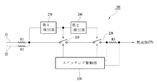
図7は図6に示した感電保護装置100の具体的な回路構成を示す回路図である。また、図7には前述した図5と実質的に同様である部分には同一の参照番号を付してその詳細な説明は省略する。図7においては、第1及び第2端子ピン21、22と整流部25との間に、第1及び第2トライアック210、220が設けられる。この第1及び第2トライアック210、220はそれぞれ第1及び第2検出部230、240でオン/オフ駆動される。第1検出部230は第1〜第3ネオンランプ231〜233が直列に結合されて構成され、第2検出部240は第4〜第6ネオンランプ241〜243が直列に結合されて構成される。そして、前記第1検出部230と第2検出部240は第1トライアック210のゲート−主電極間の電流経路を介して直列に結合される。従って、本構成においても、前記第1及び第2検出部230、240により設定される全体的な基準電圧は図4及び図5の構成と実質的に同様である。
FIG. 7 is a circuit diagram showing a specific circuit configuration of the electric
つまり、本構成例は蛍光灯器具から印加される放電電圧に対する基準電圧はそのまま維持しながら、トライアック210、220を多段に直列に結合することで、トライアック210、220により設定される寄生容量値を下げたものである。
そして、前記第1検出部230に並列に第3ブリッジ回路252が結合され、第2検出部240に並列に第4ブリッジ回路253が結合される。また、第3ブリッジ回路252の電流通路には第2フォトカプラ254が設けられ、第4ブリッジ回路253の電流通路には第3フォトカプラ255が設けられる。これらの第2及び第3フォトカプラ254、255は第1ブリッジ回路131により駆動される。このスイッチング駆動部250の構成と動作は図5と実質的に同様であるので、その具体的な動作説明は省略する。
That is, in this configuration example, the parasitic capacitance value set by the
The
以上で、本発明に係る実施形態を説明した。しかし、本発明は前述の実施形態に限定されるものではない。本発明はその技術的思想を逸脱しない範囲内で多様に変形させて実施することができる。
例えば、前述の実施形態においては、図4及び図6のスイッチ110、210、220としてトライアックを採用することを例に挙げて説明したが、前記スイッチとしては特定のものが要求されず、寄生容量が低い他の任意のスイッチも同一の方式で適用して実施することができる。
The embodiment according to the present invention has been described above. However, the present invention is not limited to the embodiments described above. The present invention can be variously modified and implemented without departing from its technical concept.
For example, in the above-mentioned embodiment, although adopting a TRIAC as
以上のように、本発明に係る蛍光灯互換タイプのLED照明装置とそのための感電保護装置よれば、蛍光灯器具の安定器から印加される放電電圧に基づいて、蛍光灯互換タイプのLED照明装置が蛍光灯器具に正常に装着された否かを判断し、LED照明装置を蛍光灯器具に締結する作業状態では、安定器からの高電圧がLED照明装置に印加されることを遮断することで、作業者の感電事故を防止できる。従って、本発明の産業利用性はきわめて高いものといえる。 As described above, according to the fluorescent lamp compatible type LED lighting device and the electric shock protection device therefor according to the present invention, the fluorescent lamp compatible type LED lighting device based on the discharge voltage applied from the ballast of the fluorescent light fixture Determines whether or not the fluorescent light fixture is properly mounted, and in a working state where the LED lighting device is fastened to the fluorescent light fixture, by blocking application of high voltage from the ballast to the LED lighting device , You can prevent electrical shock accident of workers. Therefore, the industrial applicability of the present invention can be said to be extremely high.
21〜24 端子ピン
25、26 整流部
27 LEDモジュール
28 駆動部
30 蛍光灯互換タイプのLED照明装置
100 感電保護装置
21 to 24
Claims (9)
蛍光灯器具の両側ソケットに電気的に結合される第1及び第2接続手段と、
前記第1または第2接続手段と整流手段との間に設けられる感電保護装置と、
前記第1及び第2接続手段を介して入力される外部交流電源を整流する整流手段と、
複数のLEDを備えるLEDモジュールと、
前記整流手段から提供される駆動電力に基づいて、前記LEDモジュールを駆動する駆動手段を含んで構成され、
前記感電保護装置は、第1または第2接続端子と内部回路との間の電気的な結合を取り締まるための第1スイッチと、前記第1または第2接続端子側に結合されて出力端を介してスイッチ駆動電圧を出力し、前記第1または第2接続端子側と出力端との間に直列に接続されると共に、前記第1または第2接続端子から印加される放電電圧が前記基準電圧以上である場合には点灯することで、放電電圧をスイッチ駆動電圧として前記第1スイッチに供給するネオンランプを備える第1検出手段と、前記第1スイッチの出力側に結合され、第1スイッチを介して内部回路に電流が供給される場合には、前記第1スイッチのオン状態を維持する第1スイッチング駆動手段を含んで構成される
ことを特徴とする蛍光灯互換タイプのLED照明装置。 A ballast is provided, and the ballast applies a first discharge voltage higher than a reference voltage when both the first and second connection terminals of the fluorescent lamp are fastened to the fluorescent lamp apparatus, and the fluorescent lamp apparatus In a fluorescent lamp compatible type LED lighting device used for a fluorescent lamp fixture adapted to apply a second discharge voltage lower than a reference voltage when the first or second connection terminal of the fluorescent lamp is not fastened to the
First and second connection means electrically coupled to the sockets on both sides of the fluorescent light fixture;
An electric shock protection device provided between the first or second connection means and the rectifying means ;
Rectifying means for rectifying an external AC power input through the first and second connection means;
An LED module comprising a plurality of LEDs,
Drive means for driving the LED module based on the drive power provided from the rectifying means,
The electric shock protection device comprises a first switch for tightening an electrical connection between the first or second connection terminal and the internal circuit, and a first switch connected to the first or second connection terminal via an output end. Switch drive voltage, and is connected in series between the first or second connection terminal side and the output end, and the discharge voltage applied from the first or second connection terminal is equal to or higher than the reference voltage And the first switch is coupled to the output side of the first switch, and is connected to the first switch through the first switch. A fluorescent lamp compatible type LED lighting device comprising: first switching driving means for maintaining the on state of the first switch when current is supplied to the internal circuit .
請求項1に記載の蛍光灯互換タイプのLED照明装置。 The first switch comprises a triac
The fluorescent lamp compatible type LED lighting device according to claim 1 .
請求項1に記載の蛍光灯互換タイプのLED照明装置。 The first switching drive means is provided between a first bridge circuit coupled in parallel to the detection means, a first photocoupler provided in a current path of the first bridge circuit, the first switch, and the internal circuit. A second bridge circuit electrically coupled and driving the first photo coupler on / off is provided.
The fluorescent lamp compatible type LED lighting device according to claim 1 .
前記第1スイッチ及び第1検出手段を介して第1または第2接続端子に結合されると共に、第1または第2接続端子から印加される放電電圧によって前記第2スイッチをオン/オフ駆動する第2検出手段と、
前記第2スイッチを介して内部回路に電流が供給される場合には、前記第2スイッチのオン状態を維持する第2スイッチング駆動手段を含んで構成される
請求項1に記載の蛍光灯互換タイプのLED照明装置。 The electric shock protection device comprises a second switch provided in series in a current path between the first switch and an internal circuit;
The first switch is coupled to the first or second connection terminal through the first switch and the first detection means, and the second switch is turned on / off by a discharge voltage applied from the first or second connection terminal. 2 detection means,
When the current is supplied to the internal circuit through the second switch, the fluorescent lamp compatible type according to claim 1, further comprising second switching driving means for maintaining the on state of the second switch. LED lighting device.
前記感電保護装置は前記第1または第2接続手段と電源手段との間に設けられ、
第1または第2接続端子と電源手段との間の電気的な結合を取り締まるためのスイッチと、
前記第1または第2接続端子側に結合されて出力端を介してスイッチ駆動電圧を出力し、前記第1または第2接続端子側と出力端との間に直列に接続されると共に、前記第1または第2接続端子から印加される放電電圧が基準電圧以上である場合には点灯することで、放電電圧をスイッチ駆動電圧として前記スイッチに供給するネオンランプを備える検出手段と、
前記スイッチの出力側に結合され、スイッチを介して電源手段に電流が供給される場合には前記スイッチのオン状態を維持するスイッチング駆動手段を含んで構成される
ことを特徴とする蛍光灯互換タイプのLED照明装置のための感電保護装置。 An LED comprising: first and second connection means to be fastened to a fluorescent lamp fixture; power supply means for generating operating power using an external power supply input via the first and second connection means; and a plurality of LEDs In the electric shock protection device employed in a fluorescent lamp compatible type LED lighting device comprising: a module; and driving means for driving the LED module using the operation power supply of the power supply means,
The electric shock protection device is provided between the first or second connection means and a power supply means.
A switch for breaking the electrical connection between the first or second connection terminal and the power supply means;
The switch drive voltage is coupled to the first or second connection terminal side to output a switch drive voltage through an output terminal, and is connected in series between the first or second connection terminal side and the output terminal, and a detecting means comprising one or by discharge voltage applied from the second connection terminal is turned on when it is based on the reference voltage or more, the neon lamp is supplied to the switch discharge voltage as a switch driving voltage,
A fluorescent lamp compatible type comprising switching drive means coupled to the output side of the switch and maintaining the on state of the switch when current is supplied to the power supply means via the switch. Shock protection device for LED lighting device.
請求項5に記載の蛍光灯互換タイプのLED照明装置のための感電保護装置。 The switch is configured with a triac
An electric shock protection device for the fluorescent lamp compatible type LED lighting device according to claim 5 .
請求項5に記載の蛍光灯互換タイプのLED照明装置のための感電保護装置。 The switching drive means is electrically coupled between a first bridge circuit coupled in parallel to the detection means, a photocoupler provided in a current path of the first bridge circuit, the switch and an internal circuit. And a second bridge circuit for driving the photocoupler on / off.
An electric shock protection device for the fluorescent lamp compatible type LED lighting device according to claim 5 .
前記感電保護装置は前記第1または第2接続手段と電源手段との間に設けられ、
前記第1または第2接続端子と電源手段との間の電流通路に直列に設けられる第1及び第2スイッチと、
前記第1または第2接続端子に直列に結合されると共に、第1または第2接続端子から印加される放電電圧によって前記第1スイッチ及び第2スイッチをそれぞれオン/オフ駆動する第1及び第2検出手段と、
前記第2スイッチの出力側に結合され、第2スイッチを介して電源手段に電流が供給される場合には前記第1及び第2スイッチのオン状態を維持するスイッチング駆動手段を含んで構成され、
前記第1及び第2検出手段は前記第1または第2接続端子から印加される放電電圧が基準電圧以上である場合には点灯することで、放電電圧をスイッチ駆動電圧として前記第1及び第2スイッチにそれぞれ供給するネオンランプを備える
ことを特徴とする蛍光灯互換タイプのLED照明装置のための感電保護装置。 An LED comprising: first and second connection means to be fastened to a fluorescent lamp fixture; power supply means for generating operating power using an external power supply input via the first and second connection means; and a plurality of LEDs In the electric shock protection device employed in a fluorescent lamp compatible type LED lighting device comprising: a module; and driving means for driving the LED module using the operation power supply of the power supply means,
The electric shock protection device is provided between the first or second connection means and a power supply means.
First and second switches provided in series in a current path between the first or second connection terminal and the power supply means;
Together coupled in series with said first or second connecting terminals, first and second respectively on / off driving the first and second switches by discharge electric voltage that is applied from the first or second connecting terminal 2 detection means,
Switching drive means coupled to the output side of the second switch and configured to maintain the on state of the first and second switches when current is supplied to the power supply means via the second switch ;
When the discharge voltage applied from the first or second connection terminal is equal to or higher than a reference voltage, the first and second detection means turn on the discharge voltage as a switch drive voltage. An electric shock protection device for a fluorescent lamp compatible type LED lighting device, characterized by comprising a neon lamp for supplying each switch .
請求項8に記載の蛍光灯互換タイプのLED照明装置のための感電保護装置。 The first and second switches are configured with a triac
An electric shock protection device for the fluorescent lamp compatible type LED lighting device according to claim 8 .
Applications Claiming Priority (5)
| Application Number | Priority Date | Filing Date | Title |
|---|---|---|---|
| KR1020140031113A KR20150108206A (en) | 2014-03-17 | 2014-03-17 | High Current Flow Prevention Circuit For LED Lamp |
| KR10-2014-0031113 | 2014-03-17 | ||
| KR1020150037113A KR101796445B1 (en) | 2015-03-17 | 2015-03-17 | Fluorescent Lamp Compatible LED Illuminating Device And Electric Shock Protectiong Device Thereof |
| PCT/KR2015/002596 WO2015142042A1 (en) | 2014-03-17 | 2015-03-17 | Fluorescent lamp-compatible led lighting device and electric shock protection apparatus therefor |
| KR10-2015-0037113 | 2015-03-17 |
Publications (3)
| Publication Number | Publication Date |
|---|---|
| JP2017513184A JP2017513184A (en) | 2017-05-25 |
| JP2017513184A5 JP2017513184A5 (en) | 2018-04-26 |
| JP6502375B2 true JP6502375B2 (en) | 2019-04-17 |
Family
ID=54144933
Family Applications (1)
| Application Number | Title | Priority Date | Filing Date |
|---|---|---|---|
| JP2016557136A Expired - Fee Related JP6502375B2 (en) | 2014-03-17 | 2015-03-17 | Fluorescent lamp compatible type LED lighting device and electric shock protection device therefor |
Country Status (3)
| Country | Link |
|---|---|
| US (1) | US9686835B2 (en) |
| JP (1) | JP6502375B2 (en) |
| WO (1) | WO2015142042A1 (en) |
Families Citing this family (5)
| Publication number | Priority date | Publication date | Assignee | Title |
|---|---|---|---|---|
| US10136483B2 (en) * | 2012-06-15 | 2018-11-20 | Aleddra Inc. | Solid-state lighting with auto-select settings for line voltage and ballast voltage |
| US10390396B1 (en) * | 2012-06-15 | 2019-08-20 | Aleddra Inc. | Linear solid-state lighting with multiple switches |
| US10021753B2 (en) * | 2012-06-15 | 2018-07-10 | Aleddra Inc. | Linear solid-state lighting with front end electric shock detection |
| US11137119B2 (en) | 2016-05-12 | 2021-10-05 | Signify Holding B.V. | Tubular device for fitting to a tubular light fitting |
| CN111148309B (en) * | 2018-10-16 | 2023-08-25 | 卡任特照明解决方案有限公司 | Lamp driving circuit and method for operating the same |
Family Cites Families (7)
| Publication number | Priority date | Publication date | Assignee | Title |
|---|---|---|---|---|
| JPS5890086U (en) * | 1981-12-09 | 1983-06-18 | シャープ株式会社 | phase control device |
| JP3050754B2 (en) * | 1994-08-30 | 2000-06-12 | 三菱電機株式会社 | Backlight control device |
| JP4370794B2 (en) * | 2003-03-26 | 2009-11-25 | パナソニック電工株式会社 | LED dimming lighting device and lighting fixture |
| JP2011165634A (en) * | 2010-02-08 | 2011-08-25 | Solar Japan:Kk | Led fluorescent tube |
| FI122933B (en) * | 2010-03-19 | 2012-09-14 | Teknoware Oy | LED tube lamp and lighting arrangement |
| KR101246940B1 (en) * | 2011-05-04 | 2013-03-25 | 홍삼표 | Led lamp |
| KR101400369B1 (en) * | 2012-08-23 | 2014-05-28 | 주식회사 하이딥 | Led lighting device using ballaster for fluorescent lamp |
-
2015
- 2015-03-17 US US15/127,321 patent/US9686835B2/en active Active
- 2015-03-17 JP JP2016557136A patent/JP6502375B2/en not_active Expired - Fee Related
- 2015-03-17 WO PCT/KR2015/002596 patent/WO2015142042A1/en active Application Filing
Also Published As
| Publication number | Publication date |
|---|---|
| JP2017513184A (en) | 2017-05-25 |
| US9686835B2 (en) | 2017-06-20 |
| US20170142787A1 (en) | 2017-05-18 |
| WO2015142042A1 (en) | 2015-09-24 |
Similar Documents
| Publication | Publication Date | Title |
|---|---|---|
| JP6293729B2 (en) | Lamp device and method of operating the lamp device | |
| EP2914065B1 (en) | Illumination lamp and illumination apparatus | |
| US9277603B2 (en) | Linear solid-state lighting with frequency sensing free of fire and shock hazards | |
| EP2477456B1 (en) | Drive circuit for light-emitting diode array | |
| US9480109B2 (en) | Power source module for LED lamp | |
| JP6502375B2 (en) | Fluorescent lamp compatible type LED lighting device and electric shock protection device therefor | |
| JP5480668B2 (en) | Light source module, lighting device, and lighting apparatus using the same | |
| JP5379921B2 (en) | LED lighting device and lighting apparatus using the same | |
| US10314134B1 (en) | Retrofit LED lamp | |
| US9967947B1 (en) | LED driving circuit for controlling leakage current and compatible with ballast | |
| EP3030051B1 (en) | Signal converter circuit for dimming of a light source | |
| CN103249213B (en) | Luminaire | |
| US10959309B2 (en) | LED lamp protection circuit | |
| KR20140142134A (en) | LED lamp driving device operating connected to the ballast for fluorcent lamp and the LED lamp comprising the driving device | |
| EP3397026A1 (en) | Miswiring protection circuit for use with a dc power supply and an led lamp | |
| KR101796445B1 (en) | Fluorescent Lamp Compatible LED Illuminating Device And Electric Shock Protectiong Device Thereof | |
| JP6970839B2 (en) | Retrofit LED lamp | |
| CN111712013B (en) | Protection device for lighting assembly, lighting assembly and protection method thereof | |
| CN111148309B (en) | Lamp driving circuit and method for operating the same | |
| CN109915797B (en) | Electronic driver for LED lighting module and LED lamp | |
| CN111212499B (en) | Rectifier circuit for LED lamp driver | |
| US10111302B2 (en) | Compatible inductor-type circuit structure with direct input from commercial power | |
| KR101391976B1 (en) | Lighting emitting diode lamp with multiple safety | |
| KR20170009484A (en) | Apparatus for driving light emitting diode lamp |
Legal Events
| Date | Code | Title | Description |
|---|---|---|---|
| A521 | Request for written amendment filed |
Free format text: JAPANESE INTERMEDIATE CODE: A523 Effective date: 20180316 |
|
| A621 | Written request for application examination |
Free format text: JAPANESE INTERMEDIATE CODE: A621 Effective date: 20180316 |
|
| A977 | Report on retrieval |
Free format text: JAPANESE INTERMEDIATE CODE: A971007 Effective date: 20181228 |
|
| A131 | Notification of reasons for refusal |
Free format text: JAPANESE INTERMEDIATE CODE: A131 Effective date: 20190108 |
|
| A521 | Request for written amendment filed |
Free format text: JAPANESE INTERMEDIATE CODE: A523 Effective date: 20190109 |
|
| TRDD | Decision of grant or rejection written | ||
| A01 | Written decision to grant a patent or to grant a registration (utility model) |
Free format text: JAPANESE INTERMEDIATE CODE: A01 Effective date: 20190219 |
|
| A61 | First payment of annual fees (during grant procedure) |
Free format text: JAPANESE INTERMEDIATE CODE: A61 Effective date: 20190320 |
|
| R150 | Certificate of patent or registration of utility model |
Ref document number: 6502375 Country of ref document: JP Free format text: JAPANESE INTERMEDIATE CODE: R150 |
|
| LAPS | Cancellation because of no payment of annual fees |