JP6502270B2 - Medical circuit components - Google Patents
Medical circuit components Download PDFInfo
- Publication number
- JP6502270B2 JP6502270B2 JP2015562956A JP2015562956A JP6502270B2 JP 6502270 B2 JP6502270 B2 JP 6502270B2 JP 2015562956 A JP2015562956 A JP 2015562956A JP 2015562956 A JP2015562956 A JP 2015562956A JP 6502270 B2 JP6502270 B2 JP 6502270B2
- Authority
- JP
- Japan
- Prior art keywords
- gas
- rim
- dry
- expiratory limb
- temperature
- Prior art date
- Legal status (The legal status is an assumption and is not a legal conclusion. Google has not performed a legal analysis and makes no representation as to the accuracy of the status listed.)
- Active
Links
- 238000010438 heat treatment Methods 0.000 claims description 86
- XLYOFNOQVPJJNP-UHFFFAOYSA-N water Chemical compound O XLYOFNOQVPJJNP-UHFFFAOYSA-N 0.000 claims description 41
- 239000000463 material Substances 0.000 claims description 32
- 230000005540 biological transmission Effects 0.000 claims description 25
- 239000007788 liquid Substances 0.000 claims description 21
- 230000029058 respiratory gaseous exchange Effects 0.000 claims description 16
- 239000012774 insulation material Substances 0.000 claims description 13
- 230000009467 reduction Effects 0.000 claims description 8
- 239000011810 insulating material Substances 0.000 claims description 6
- 239000007789 gas Substances 0.000 description 241
- 230000007246 mechanism Effects 0.000 description 33
- 238000009833 condensation Methods 0.000 description 28
- 230000005494 condensation Effects 0.000 description 28
- 238000001035 drying Methods 0.000 description 24
- 239000006261 foam material Substances 0.000 description 21
- 238000009413 insulation Methods 0.000 description 18
- 238000013461 design Methods 0.000 description 15
- 230000003014 reinforcing effect Effects 0.000 description 14
- 238000000034 method Methods 0.000 description 11
- 230000035699 permeability Effects 0.000 description 9
- 230000000241 respiratory effect Effects 0.000 description 7
- 230000008901 benefit Effects 0.000 description 6
- 239000000203 mixture Substances 0.000 description 6
- 238000004804 winding Methods 0.000 description 6
- 230000006870 function Effects 0.000 description 5
- 238000001816 cooling Methods 0.000 description 4
- 238000013500 data storage Methods 0.000 description 4
- 239000006260 foam Substances 0.000 description 4
- 230000003434 inspiratory effect Effects 0.000 description 4
- 239000004721 Polyphenylene oxide Substances 0.000 description 3
- 238000009954 braiding Methods 0.000 description 3
- 230000008859 change Effects 0.000 description 3
- 238000002474 experimental method Methods 0.000 description 3
- 239000012212 insulator Substances 0.000 description 3
- 238000012986 modification Methods 0.000 description 3
- 230000004048 modification Effects 0.000 description 3
- 229920000570 polyether Polymers 0.000 description 3
- 230000008569 process Effects 0.000 description 3
- 229920002725 thermoplastic elastomer Polymers 0.000 description 3
- 238000013459 approach Methods 0.000 description 2
- 238000004891 communication Methods 0.000 description 2
- 238000010276 construction Methods 0.000 description 2
- 230000007423 decrease Effects 0.000 description 2
- 238000001704 evaporation Methods 0.000 description 2
- 230000008020 evaporation Effects 0.000 description 2
- 239000012530 fluid Substances 0.000 description 2
- 208000001797 obstructive sleep apnea Diseases 0.000 description 2
- -1 polypropylene Polymers 0.000 description 2
- 238000012360 testing method Methods 0.000 description 2
- 238000012546 transfer Methods 0.000 description 2
- 238000013022 venting Methods 0.000 description 2
- 0 C1CC*CC1 Chemical compound C1CC*CC1 0.000 description 1
- 235000004035 Cryptotaenia japonica Nutrition 0.000 description 1
- 239000004743 Polypropylene Substances 0.000 description 1
- 102000007641 Trefoil Factors Human genes 0.000 description 1
- 235000015724 Trifolium pratense Nutrition 0.000 description 1
- 210000000683 abdominal cavity Anatomy 0.000 description 1
- 239000000853 adhesive Substances 0.000 description 1
- 230000001070 adhesive effect Effects 0.000 description 1
- 230000002411 adverse Effects 0.000 description 1
- 239000003570 air Substances 0.000 description 1
- 239000003994 anesthetic gas Substances 0.000 description 1
- QVGXLLKOCUKJST-UHFFFAOYSA-N atomic oxygen Chemical compound [O] QVGXLLKOCUKJST-UHFFFAOYSA-N 0.000 description 1
- 238000005452 bending Methods 0.000 description 1
- 230000036760 body temperature Effects 0.000 description 1
- 239000003990 capacitor Substances 0.000 description 1
- 238000004590 computer program Methods 0.000 description 1
- 239000000470 constituent Substances 0.000 description 1
- 229920001971 elastomer Polymers 0.000 description 1
- 239000003000 extruded plastic Substances 0.000 description 1
- 238000011534 incubation Methods 0.000 description 1
- 238000002347 injection Methods 0.000 description 1
- 239000007924 injection Substances 0.000 description 1
- 230000001788 irregular Effects 0.000 description 1
- 238000007726 management method Methods 0.000 description 1
- 239000007769 metal material Substances 0.000 description 1
- 229910052609 olivine Inorganic materials 0.000 description 1
- 239000010450 olivine Substances 0.000 description 1
- 239000001301 oxygen Substances 0.000 description 1
- 229910052760 oxygen Inorganic materials 0.000 description 1
- 239000004033 plastic Substances 0.000 description 1
- 229920003023 plastic Polymers 0.000 description 1
- 229920000728 polyester Polymers 0.000 description 1
- 229920000642 polymer Polymers 0.000 description 1
- 229920001155 polypropylene Polymers 0.000 description 1
- 229920001343 polytetrafluoroethylene Polymers 0.000 description 1
- 239000004810 polytetrafluoroethylene Substances 0.000 description 1
- 210000002345 respiratory system Anatomy 0.000 description 1
- 230000004044 response Effects 0.000 description 1
- 239000005060 rubber Substances 0.000 description 1
- 239000004065 semiconductor Substances 0.000 description 1
- 238000000926 separation method Methods 0.000 description 1
- 239000007787 solid Substances 0.000 description 1
- 238000006467 substitution reaction Methods 0.000 description 1
- 238000001356 surgical procedure Methods 0.000 description 1
- 229920006344 thermoplastic copolyester Polymers 0.000 description 1
- 230000007704 transition Effects 0.000 description 1
- 238000011144 upstream manufacturing Methods 0.000 description 1
- 238000009423 ventilation Methods 0.000 description 1
- 210000001835 viscera Anatomy 0.000 description 1
Images


Classifications
-
- A—HUMAN NECESSITIES
- A61—MEDICAL OR VETERINARY SCIENCE; HYGIENE
- A61M—DEVICES FOR INTRODUCING MEDIA INTO, OR ONTO, THE BODY; DEVICES FOR TRANSDUCING BODY MEDIA OR FOR TAKING MEDIA FROM THE BODY; DEVICES FOR PRODUCING OR ENDING SLEEP OR STUPOR
- A61M16/00—Devices for influencing the respiratory system of patients by gas treatment, e.g. mouth-to-mouth respiration; Tracheal tubes
- A61M16/08—Bellows; Connecting tubes ; Water traps; Patient circuits
- A61M16/0808—Condensation traps
-
- A—HUMAN NECESSITIES
- A61—MEDICAL OR VETERINARY SCIENCE; HYGIENE
- A61M—DEVICES FOR INTRODUCING MEDIA INTO, OR ONTO, THE BODY; DEVICES FOR TRANSDUCING BODY MEDIA OR FOR TAKING MEDIA FROM THE BODY; DEVICES FOR PRODUCING OR ENDING SLEEP OR STUPOR
- A61M16/00—Devices for influencing the respiratory system of patients by gas treatment, e.g. mouth-to-mouth respiration; Tracheal tubes
- A61M16/08—Bellows; Connecting tubes ; Water traps; Patient circuits
- A61M16/0883—Circuit type
-
- A—HUMAN NECESSITIES
- A61—MEDICAL OR VETERINARY SCIENCE; HYGIENE
- A61M—DEVICES FOR INTRODUCING MEDIA INTO, OR ONTO, THE BODY; DEVICES FOR TRANSDUCING BODY MEDIA OR FOR TAKING MEDIA FROM THE BODY; DEVICES FOR PRODUCING OR ENDING SLEEP OR STUPOR
- A61M16/00—Devices for influencing the respiratory system of patients by gas treatment, e.g. mouth-to-mouth respiration; Tracheal tubes
- A61M16/08—Bellows; Connecting tubes ; Water traps; Patient circuits
- A61M16/0816—Joints or connectors
- A61M16/0833—T- or Y-type connectors, e.g. Y-piece
-
- A—HUMAN NECESSITIES
- A61—MEDICAL OR VETERINARY SCIENCE; HYGIENE
- A61M—DEVICES FOR INTRODUCING MEDIA INTO, OR ONTO, THE BODY; DEVICES FOR TRANSDUCING BODY MEDIA OR FOR TAKING MEDIA FROM THE BODY; DEVICES FOR PRODUCING OR ENDING SLEEP OR STUPOR
- A61M16/00—Devices for influencing the respiratory system of patients by gas treatment, e.g. mouth-to-mouth respiration; Tracheal tubes
- A61M16/08—Bellows; Connecting tubes ; Water traps; Patient circuits
- A61M16/0875—Connecting tubes
-
- A—HUMAN NECESSITIES
- A61—MEDICAL OR VETERINARY SCIENCE; HYGIENE
- A61M—DEVICES FOR INTRODUCING MEDIA INTO, OR ONTO, THE BODY; DEVICES FOR TRANSDUCING BODY MEDIA OR FOR TAKING MEDIA FROM THE BODY; DEVICES FOR PRODUCING OR ENDING SLEEP OR STUPOR
- A61M16/00—Devices for influencing the respiratory system of patients by gas treatment, e.g. mouth-to-mouth respiration; Tracheal tubes
- A61M16/10—Preparation of respiratory gases or vapours
- A61M16/1045—Devices for humidifying or heating the inspired gas by using recovered moisture or heat from the expired gas
-
- A—HUMAN NECESSITIES
- A61—MEDICAL OR VETERINARY SCIENCE; HYGIENE
- A61M—DEVICES FOR INTRODUCING MEDIA INTO, OR ONTO, THE BODY; DEVICES FOR TRANSDUCING BODY MEDIA OR FOR TAKING MEDIA FROM THE BODY; DEVICES FOR PRODUCING OR ENDING SLEEP OR STUPOR
- A61M16/00—Devices for influencing the respiratory system of patients by gas treatment, e.g. mouth-to-mouth respiration; Tracheal tubes
- A61M16/10—Preparation of respiratory gases or vapours
- A61M16/1075—Preparation of respiratory gases or vapours by influencing the temperature
- A61M16/1095—Preparation of respiratory gases or vapours by influencing the temperature in the connecting tubes
-
- A—HUMAN NECESSITIES
- A61—MEDICAL OR VETERINARY SCIENCE; HYGIENE
- A61M—DEVICES FOR INTRODUCING MEDIA INTO, OR ONTO, THE BODY; DEVICES FOR TRANSDUCING BODY MEDIA OR FOR TAKING MEDIA FROM THE BODY; DEVICES FOR PRODUCING OR ENDING SLEEP OR STUPOR
- A61M16/00—Devices for influencing the respiratory system of patients by gas treatment, e.g. mouth-to-mouth respiration; Tracheal tubes
- A61M16/10—Preparation of respiratory gases or vapours
- A61M16/14—Preparation of respiratory gases or vapours by mixing different fluids, one of them being in a liquid phase
- A61M16/16—Devices to humidify the respiration air
- A61M16/161—Devices to humidify the respiration air with means for measuring the humidity
-
- A—HUMAN NECESSITIES
- A61—MEDICAL OR VETERINARY SCIENCE; HYGIENE
- A61M—DEVICES FOR INTRODUCING MEDIA INTO, OR ONTO, THE BODY; DEVICES FOR TRANSDUCING BODY MEDIA OR FOR TAKING MEDIA FROM THE BODY; DEVICES FOR PRODUCING OR ENDING SLEEP OR STUPOR
- A61M16/00—Devices for influencing the respiratory system of patients by gas treatment, e.g. mouth-to-mouth respiration; Tracheal tubes
- A61M16/10—Preparation of respiratory gases or vapours
- A61M16/14—Preparation of respiratory gases or vapours by mixing different fluids, one of them being in a liquid phase
- A61M16/16—Devices to humidify the respiration air
-
- A—HUMAN NECESSITIES
- A61—MEDICAL OR VETERINARY SCIENCE; HYGIENE
- A61M—DEVICES FOR INTRODUCING MEDIA INTO, OR ONTO, THE BODY; DEVICES FOR TRANSDUCING BODY MEDIA OR FOR TAKING MEDIA FROM THE BODY; DEVICES FOR PRODUCING OR ENDING SLEEP OR STUPOR
- A61M2205/00—General characteristics of the apparatus
- A61M2205/33—Controlling, regulating or measuring
- A61M2205/3368—Temperature
-
- A—HUMAN NECESSITIES
- A61—MEDICAL OR VETERINARY SCIENCE; HYGIENE
- A61M—DEVICES FOR INTRODUCING MEDIA INTO, OR ONTO, THE BODY; DEVICES FOR TRANSDUCING BODY MEDIA OR FOR TAKING MEDIA FROM THE BODY; DEVICES FOR PRODUCING OR ENDING SLEEP OR STUPOR
- A61M2205/00—General characteristics of the apparatus
- A61M2205/36—General characteristics of the apparatus related to heating or cooling
- A61M2205/3633—General characteristics of the apparatus related to heating or cooling thermally insulated
-
- A—HUMAN NECESSITIES
- A61—MEDICAL OR VETERINARY SCIENCE; HYGIENE
- A61M—DEVICES FOR INTRODUCING MEDIA INTO, OR ONTO, THE BODY; DEVICES FOR TRANSDUCING BODY MEDIA OR FOR TAKING MEDIA FROM THE BODY; DEVICES FOR PRODUCING OR ENDING SLEEP OR STUPOR
- A61M2205/00—General characteristics of the apparatus
- A61M2205/36—General characteristics of the apparatus related to heating or cooling
- A61M2205/3673—General characteristics of the apparatus related to heating or cooling thermo-electric, e.g. Peltier effect, thermocouples, semi-conductors
-
- A—HUMAN NECESSITIES
- A61—MEDICAL OR VETERINARY SCIENCE; HYGIENE
- A61M—DEVICES FOR INTRODUCING MEDIA INTO, OR ONTO, THE BODY; DEVICES FOR TRANSDUCING BODY MEDIA OR FOR TAKING MEDIA FROM THE BODY; DEVICES FOR PRODUCING OR ENDING SLEEP OR STUPOR
- A61M2205/00—General characteristics of the apparatus
- A61M2205/50—General characteristics of the apparatus with microprocessors or computers
Description
参照による組込み
本出願は、2013年3月15日に出願された「DRYING EXPIRATORY LIMB WITH TAILORED TEMPERATURE PROFILE,」と題する米国仮特許出願第61/790,424号明細書、2013年3月15日に出願された「DRYING EXPIRATORY LIMB WITH TAILORED TEMPERATURE PROFILE AND MULTI−LUMEN CONFIGURATION,」と題する米国仮特許出願第61/789,754号明細書、および2014年1月8日に出願された「COMPONENTS FOR MEDICAL CIRCUITS,」と題する米国仮特許出願第61/925,099号明細書の利益を主張し、前記仮特許のそれぞれは参照することにより全体的に本明細書に組み込まれる。
This application is based on US Provisional Patent Application No. 61 / 790,424, filed March 15, 2013, entitled "DRYING EXPIRATORY LIMB WITH TAILORED TEMPERATURE PROFILE", filed March 15, 2013. U.S. Provisional Patent Application No. 61 / 789,754 entitled "DRYING EXPIRATORY LIMB WITH TAILORED TEMPERATURE PROFILE AND MULTI-LUMEN CONFIGURATION," and "COMPONENTS FOR MEDICAL CIRCUITS" filed on Jan. 8, 2014 Claiming the benefit of US Provisional Patent Application No. 61 / 925,099, entitled Which is incorporated herein by reference in its entirety.
分野
本開示は、概して医療回路の構成要素に関し、詳細には、閉塞性睡眠時無呼吸などの患者、新生児、呼吸加湿、およびガス注入システムを含む手術用加湿システムに加湿ガスを供給する、および/またはそれらから加湿ガスを取り除く医療回路の構成要素に関する。
FIELD The present disclosure relates generally to components of medical circuits, and in particular, supplies humidified gas to surgical humidification systems including patients such as obstructive sleep apnea, neonates, respiratory humidification, and insufflation systems, and And / or relates to the components of the medical circuit that removes humidified gases therefrom.
医療回路において、様々な構成要素が、自然にまたは人工的に加湿されたガスを患者へおよび患者から搬送する。例えば、CPAP(持続式陽圧呼吸療法:continuous positive airway pressure)などの一部の呼吸回路または補助式呼吸回路において、患者によって吸い込まれるガスは加熱器加湿ユニットから吸気リム(limb)を通って、マスクなどの患者インターフェースに送出される。別の例として、手術用加湿リムがガス注入回路において加湿ガス(一般にCO2)を腹腔へ送出可能である。これは、患者の内臓の「乾燥」を防止する一助となり得、また、手術からの回復に必要な時間量を低減することができる。 In medical circuits, various components deliver naturally or artificially humidified gas to and from patients. For example, in some or assisted breathing circuits, such as CPAP (continuous positive airway pressure), gas inhaled by the patient from the heater humidification unit, through the inspiratory limb (limb), It is sent to a patient interface such as a mask. As another example, a surgical humidification rim can deliver humidified gas (generally CO 2 ) to the abdominal cavity in a gas injection circuit. This can help to prevent "drying" of the patient's viscera and can also reduce the amount of time required to recover from surgery.
これらの医療用途において、ガスは好ましくは、飽和レベルに近い湿度を有しおよび体温(一般に33℃〜37度の温度)に近い条件で搬送される。高湿ガスが冷却するとき、凝結または「レインアウト(rain−out)」が構成要素の内側表面に形成される場合がある。医療回路内の改善された加湿および凝結の管理を可能にする構成要素に対する必要性が依然としてある。従って、本明細書に開示される特定構成要素および方法の目的は、従来技術システムの問題の1つまたは複数を改善すること、または少なくとも一般社会に有用な選択肢を提供することである。 In these medical applications, the gas is preferably delivered at a humidity close to the saturation level and at conditions close to body temperature (generally temperatures of 33 ° C to 37 ° C). As the high humidity gas cools, condensation or "rain-out" may form on the inside surface of the component. There is still a need for components that allow for improved management of humidification and condensation within the medical circuit. Accordingly, the purpose of certain components and methods disclosed herein is to ameliorate one or more of the problems of the prior art systems, or at least provide the public with a useful choice.
本開示の各態様は、医療回路で使用するためのリムに関する。リムは広義語でありその通常のかつ慣習的な意味合いを当業者に与え(すなわち、特別および特定的な意味合いに制限されない)、および限定することなく、チューブ、導管およびガスを搬送するための装置構成要素を含む。本明細書に開示されるリムは、ガス流の滞留時間(すなわち、ガス体積がリム内に存在する時間の平均長さ)を延ばすことから恩恵を受け得る様々な用途で利用可能である。 Aspects of the present disclosure relate to a rim for use in a medical circuit. The rim is a broad term and gives the person skilled in the art its ordinary and customary meaning (i.e. without being restricted to the special and specific meanings), and without limitation, devices for conveying tubes, conduits and gases Contains the component. The rims disclosed herein are available in a variety of applications that can benefit from extending the residence time of the gas stream (ie, the average length of time that a gas volume is present in the rim).
本開示の特定実施形態は、患者から離れる方に延びる呼気リムに関し、この呼気リムでは、患者インターフェースから流れ出るガスストリームの絶対湿度および露点が、凝結を排除するために調整且つ制御された方法で低減される。この使用法は、呼吸の加湿および新生児への適用を限定せずに含むいくつかの医療環境に好適である。患者から加湿空気を移送する用途で使用されるとき、本明細書に記載される特定のリムは、Evaqua 2(商標)導管(Fisher & Paykel Healthcare Ltd., Auckland, New Zealand)などの商業製品に勝る低減された露点を実現可能である。 Certain embodiments of the present disclosure relate to an exhalation rim extending away from the patient in which the absolute humidity and dew point of the gas stream flowing out of the patient interface is reduced in a controlled and controlled manner to eliminate condensation. Be done. This usage is suitable for several medical settings, including but not limited to respiratory humidification and neonatal application. When used in applications to transfer humidified air from patients, certain rims described herein are used in commercial products such as Evaqua 2TM conduit (Fisher & Paykel Healthcare Ltd., Auckland, New Zealand) It is possible to realize a superior reduced dew point.
本開示のさらなる実施形態は、患者に流れるガスストリームを加湿することに関する。特に、少なくとも1つの実施形態は、加湿ユニットでの使用に好適なリムに関する。この使用法は、閉塞性睡眠時無呼吸(CPAPなど)および手術用加湿用途を限定せずに含むいくつかの医療環境に好適である。患者へ加湿空気を移送する用途で使用されるとき、本明細書に記載される特定のリムは、これまでの商業製品に勝る上昇した露点を実現可能である。 A further embodiment of the present disclosure relates to humidifying a gas stream flowing to a patient. In particular, at least one embodiment relates to a rim suitable for use in a humidification unit. This usage is suitable for several medical environments, including but not limited to obstructive sleep apnea (such as CPAP) and surgical humidification applications. When used in applications to transfer humidified air to a patient, the particular rims described herein are capable of achieving elevated dew points over previous commercial products.
本明細書に記載されるシステム、方法および装置は革新的な態様を有し、それらの1つが不可欠であることはなく、また、それらの望ましい属性に単独で責を負うこともない。請求項の範囲を制限することなく、有利な特徴のいくつかをここで要約する。 The systems, methods, and devices described herein have innovative aspects, one of which is not essential and is not solely responsible for their desirable attributes. Without limiting the scope of the claims, some of the advantageous features are summarized here.
概して、呼気リムは、ガスがベンチレータに達する前に呼気リムを通過するとき、ガスを乾燥するように構成される。呼気リムはガスをベンチレータ内の凝結を低減または排除するのに十分に乾燥するように構成可能である。乾燥は、一定の体積流量において、リムの表面領域および/または呼気リム内のガスの滞留時間によって少なくとも部分的に制限することができる。特定の実施形態は、乾燥を高めるため、リムに沿ったレインアウトを低減または防止するため、および/またはベンチレータ内の凝結を低減または防止するために呼気リムに沿ってガスの調整された温度プロファイルを提供する乾燥呼気リムを提供することが有利であり得るという認識を含む。 Generally, the expiratory limb is configured to dry the gas as it passes through the expiratory limb before reaching the ventilator. The expiratory limb can be configured to dry the gas sufficiently to reduce or eliminate condensation in the ventilator. The drying can be at least partially limited by the surface area of the rim and / or the residence time of the gas in the expiratory limb at a constant volumetric flow rate. Certain embodiments adjust the temperature profile of the gas along the expiratory limb to enhance drying, to reduce or prevent rainout along the rim, and / or to reduce or prevent condensation within the ventilator. It is recognized that it may be advantageous to provide a dry exhalation rim that provides
いくつかの実施形態では、乾燥呼気リム内のガスの改良または最適化された乾燥は、ガスが乾燥呼気リムに沿って流れるとき、ガス温度とその露点温度の差をほぼ一定に維持するようにガスの温度を制御することによって達成される。いくつかの実施形態では、この温度差は約2℃未満、約1.5℃未満、または約0.9℃〜約1℃の間である。いくつかの実施形態では、乾燥呼気リム内のガスの改良または最適化された乾燥は、ガスの相対湿度を約90%〜約99%、約95%〜約99%または約95%〜約97%の間に維持することによって達成される。いくつかの実施形態では、これは、呼気リムの長さに沿って露点温度と絶対湿度を略直線状に維持することによって達成され得る。いくつかの実施形態では、リムの始点から乾燥呼気リムの最初の約300mmまたは400mmまでのガスの温度低下は、0.01℃/mm未満または0℃/mm〜約0.009℃/mmの間であり、呼気リムの長さにわたる合計温度低下は、約10℃未満、または約3℃〜約10℃の間である。従って乾燥呼気リムおよび本明細書に開示される温度制御機構は、ガスの乾燥を向上または最適化し、リム内のレインアウトを低減または排除し、および/またはベンチレータ内の凝結を低減または排除するようにガスの温度プロファイルを調整するように構成可能である。いくつかの実施形態では、ガスの最適な乾燥を提供する乾燥呼気リムが開示され、最適な乾燥は乾燥の際、調整された温度制御プロセスによってリム内およびベンチレータ内で凝結が生じない。 In some embodiments, the improved or optimized drying of the gas in the dry exhalation rim is such that the difference between the gas temperature and its dew point temperature is maintained approximately constant as the gas flows along the dry exhalation rim It is achieved by controlling the temperature of the gas. In some embodiments, the temperature difference is less than about 2 ° C., less than about 1.5 ° C., or between about 0.9 ° C. and about 1 ° C. In some embodiments, the improved or optimized drying of the gas in the dry expiratory limb comprises about 90% to about 99%, about 95% to about 99%, or about 95% to about 97 relative humidity of the gas. Achieved by maintaining between%. In some embodiments, this may be accomplished by maintaining the dew point temperature and the absolute humidity substantially linear along the length of the expiratory limb. In some embodiments, the temperature drop of gas from the beginning of the rim to the first about 300 mm or 400 mm of the dry exhalation rim is less than 0.01 ° C./mm or 0 ° C./mm to about 0.009 ° C./mm And the total temperature drop across the length of the expiratory limb is less than about 10 ° C, or between about 3 ° C and about 10 ° C. Thus, the dry exhalation rim and the temperature control mechanism disclosed herein may improve or optimize the drying of the gas, reduce or eliminate rainout in the rim, and / or reduce or eliminate condensation in the ventilator. It can be configured to adjust the temperature profile of the gas. In some embodiments, a dry exhalation rim is provided that provides for optimal drying of the gas, wherein optimal drying does not result in condensation within the rim and in the ventilator due to the controlled temperature control process during drying.
いくつかの実施形態は、呼気リムの長さによって分離された第1端部および第2端部を有する壁を含むことができる呼吸回路で使用するための乾燥呼気リムを提供する。壁は内部に空間を画定し、前記壁の少なくとも一部は、水蒸気の透過を許容するが液体の水の透過を実質的に防止するように構成された通気性材料を含む。乾燥呼気リムは壁の第1端部に第1開口を含み、第1開口は第1温度および第1相対湿度のガスを受け入れるように構成される。乾燥呼気リムは壁の第2端部に第2開口を含み、第2開口はガスが乾燥呼気リムを出ることを許容し、ガスは乾燥呼気リムを出るとき第2温度および第2相対湿度を有する。乾燥呼気リムは、乾燥呼気リムに沿ったガスの温度とガスの露点温度との間の差がほぼ一定であるように構成される。 Some embodiments provide a dry expiratory limb for use in a breathing circuit that can include a wall having a first end and a second end separated by a length of the expiratory limb. The wall defines a space therein and at least a portion of the wall includes a breathable material configured to allow water vapor transmission but substantially prevent liquid water transmission. The dry expiratory limb includes a first opening at a first end of the wall, the first opening being configured to receive a gas of a first temperature and a first relative humidity. The dry exhalation rim includes a second opening at the second end of the wall, the second opening allowing gas to exit the dry exhalation rim, the gas having a second temperature and a second relative humidity as it exits the dry exhalation rim Have. The dry expiratory limb is configured such that the difference between the temperature of the gas along the dry expiratory limb and the dew point temperature of the gas is approximately constant.
実施形態のいくつかの態様では、乾燥呼気リムはさらに、壁の外側表面に取り付けられた断熱材料を含む。断熱材料は、呼気リムの長さに沿ってガスの乾燥を高めるためにガスの温度低下を制御するように構成可能である。いくつかの実施形態では、断熱材料の量は呼気リムの長さに沿って実質的に一定である。断熱材料の量は呼気リムの長さに沿って変わることができる。 In some aspects of the embodiments, the dry exhalation rim further comprises a thermal insulation material attached to the outer surface of the wall. The thermal insulation material can be configured to control the temperature drop of the gas to enhance the drying of the gas along the length of the expiratory limb. In some embodiments, the amount of thermal insulation material is substantially constant along the length of the expiratory limb. The amount of insulation material can vary along the length of the expiratory limb.
いくつかの態様では、乾燥呼気リムは、乾燥呼気リム内のガスに熱を提供するために電力を選択的に受け取るように構成された加熱ワイヤを含むことができる。いくつかの態様では、加熱ワイヤは、呼気リムの長さに沿ってガスの乾燥を高めるためにガスの温度低下を制御するように構成される。さらなる態様では、乾燥呼気リムは、ガスの温度を目標量だけ露点温度を超えるように制御するように構成された2つ以上の加熱器を含む。別の態様では、加熱ワイヤは、呼気リムの長さに沿って可変ピッチ間隔を有し、いくつかの実行では、ピッチ間隔は第1端部からの距離とともに増大する。いくつかの実行では、加熱ワイヤは少なくとも2つのセクションを含み、2つのセクションは制御回路を用いて独立して制御されるように構成される。 In some aspects, the dry exhalation rim can include a heating wire configured to selectively receive power to provide heat to the gas in the dry exhalation rim. In some aspects, the heating wire is configured to control the temperature drop of the gas to enhance the drying of the gas along the length of the expiratory limb. In a further aspect, the dry exhalation rim includes two or more heaters configured to control the temperature of the gas to exceed the dew point temperature by a target amount. In another aspect, the heating wire has a variable pitch spacing along the length of the expiratory limb, and in some implementations the pitch spacing increases with distance from the first end. In some implementations, the heating wire includes at least two sections, and the two sections are configured to be independently controlled using a control circuit.
いくつかの態様では、乾燥呼気リムの流量は、通気性を改善するように構成される。例えば、乾燥呼気リムの断面は通気性を改善するために増大可能である。 In some aspects, the dry expiratory limb flow rate is configured to improve air permeability. For example, the cross section of the dry expiratory limb can be increased to improve air permeability.
いくつかの態様では、滞留時間は通気性を改善するように延長される。いくつかの態様では、ガスの絶対湿度のプロファイルはガスの露点温度のプロファイルと実質的に平行である。いくつかの態様では、乾燥呼気リムは、リムの第1端部でおよびリムの第2端部でレインアウトを実質的に排除するように構成される。いくつかの態様では、乾燥呼気リムは、リムの第2端部に配置されたベンチレータのレインアウトを実質的に排除するように構成される。 In some embodiments, the residence time is extended to improve air permeability. In some aspects, the profile of absolute humidity of the gas is substantially parallel to the profile of dew point temperature of the gas. In some aspects, the dry exhalation rim is configured to substantially eliminate rainout at the first end of the rim and at the second end of the rim. In some aspects, the dry exhalation rim is configured to substantially eliminate rainout of a ventilator disposed at the second end of the rim.
いくつかの実施形態は、呼吸回路で使用するために乾燥呼気リムを提供する。乾燥呼気リムは、呼気リムの長さによって分離された第1端部および第2端部を有する壁を含み、壁は内部に空間を画定し、前記壁の少なくとも一部は、水蒸気の透過を許容するが液体の水の透過を実質的に防止するように構成された通気性材料を含む。乾燥呼気リムは壁の第1端部に第1開口を含み、第1開口は第1温度および第1相対湿度のガスを受け入れるように構成される。乾燥呼気リムは壁の第2端部に第2開口を含み、第2開口はガスが乾燥呼気リムを出ることを許容し、ガスは乾燥呼気リムを出るとき第2温度および第2相対湿度を有する。乾燥呼気リムは、第1相対湿度および第2相対湿度がほぼ等しく、乾燥呼気リムに沿ったあらゆる地点でのガスの相対湿度が第1相対湿度とほぼ等しいように構成される。 Some embodiments provide a dry exhalation rim for use in a breathing circuit. The dry expiratory limb includes a wall having a first end and a second end separated by a length of the expiratory limb, the wall defining a space therein, at least a portion of the wall being permeable to water vapor Including a breathable material configured to permit but substantially prevent liquid water permeation. The dry expiratory limb includes a first opening at a first end of the wall, the first opening being configured to receive a gas of a first temperature and a first relative humidity. The dry exhalation rim includes a second opening at the second end of the wall, the second opening allowing gas to exit the dry exhalation rim, the gas having a second temperature and a second relative humidity as it exits the dry exhalation rim Have. The dry expiratory limb is configured such that the first relative humidity and the second relative humidity are approximately equal, and the relative humidity of the gas at any point along the dry expiratory limb is approximately equal to the first relative humidity.
いくつかの態様では、ガスの相対湿度は少なくとも約95%、または少なくとも約99%である。いくつかの態様では、呼気リムの長さに沿った温度の低減は、相対湿度を目標湿度値に維持する乾燥率に従い制御され、ここで目標湿度値は、約90%〜約99%の間、約95%〜約99%の間、または約95%〜約97%の間である。 In some embodiments, the relative humidity of the gas is at least about 95%, or at least about 99%. In some aspects, the reduction in temperature along the length of the exhalation rim is controlled according to the dryness to maintain the relative humidity at the target humidity value, wherein the target humidity value is between about 90% and about 99% , About 95% to about 99%, or about 95% to about 97%.
いくつかの実施形態は、呼吸回路の乾燥呼気リムを提供し、乾燥呼気リムは呼気リムの長さによって分離された第1端部および第2端部を有する壁を含み、壁は内部に空間を画定し、前記壁の少なくとも一部は、水蒸気の透過を許容するが液体の水の透過を実質的に防止するように構成された通気性材料を含む。乾燥呼気リムは壁の第1端部に第1開口を含み、第1開口は第1温度および第1相対湿度のガスを受け入れるように構成される。乾燥呼気リムは壁の第2端部に第2開口を含み、第2開口はガスが乾燥呼気リムを出ることを許容し、ガスは乾燥呼気リムを出るとき第2温度および第2相対湿度を有する。乾燥呼気リムは、ガスの温度が乾燥呼気リムの長さに沿ってガスの露点温度より上に維持される構成可能である。いくつかの態様では、乾燥呼気リムは、乾燥呼気リムの長さに沿ったガスの温度とガスの露点温度との差がほぼ一定であるように構成される。 Some embodiments provide a dry expiratory limb of a breathing circuit, the dry expiratory limb including a wall having a first end and a second end separated by a length of the expiratory limb, the wall being internally spaced And at least a portion of the wall comprises a breathable material configured to allow water vapor transmission but substantially prevent liquid water transmission. The dry expiratory limb includes a first opening at a first end of the wall, the first opening being configured to receive a gas of a first temperature and a first relative humidity. The dry exhalation rim includes a second opening at the second end of the wall, the second opening allowing gas to exit the dry exhalation rim, the gas having a second temperature and a second relative humidity as it exits the dry exhalation rim Have. The dry exhalation rim can be configured such that the temperature of the gas is maintained above the dew point temperature of the gas along the length of the dry exhalation rim. In some aspects, the dry expiratory limb is configured such that the difference between the temperature of the gas along the length of the dry expiratory limb and the dew point temperature of the gas is approximately constant.
いくつかの態様では、乾燥呼気リムはまた、壁の外側表面に断熱材料を含む。さらなる態様では、断熱材料は、ガスの温度を露点温度より約0.9℃〜1℃高くなるように制御するべく構成される。別の態様では断熱材料の量は呼気リムの長さに沿って実質的に一定である。別の態様では、断熱材料の量は呼気リムの長さに沿って変わる。 In some aspects, the dry exhalation rim also includes an insulating material on the outer surface of the wall. In a further aspect, the thermal insulation material is configured to control the temperature of the gas to be about 0.9 ° C. to 1 ° C. above the dew point temperature. In another aspect, the amount of thermal insulating material is substantially constant along the length of the expiratory limb. In another aspect, the amount of insulating material varies along the length of the expiratory limb.
いくつかの態様では、第1端部から、第1端部から約300mmの距離までの温度低減率は、約0.01℃/mm以下である。 In some embodiments, the rate of temperature reduction from the first end to a distance of about 300 mm from the first end is about 0.01 ° C./mm or less.
いくつかの態様では、乾燥呼気リムはさらに、乾燥呼気リム内のガスに熱を提供するために電力を選択的に受け取るように構成された加熱ワイヤを含む。さらなる態様では、加熱ワイヤは、ガスの温度を、露点温度より約0.9℃〜1℃高くなるように制御するべく構成される。別の態様では、乾燥呼気リムはさらに、ガスの温度低減率を制御するように構成された第2加熱器を含む。別の態様では、加熱器ワイヤは、呼気リムの長さに沿って可変ピッチ間隔を有する。さらなる態様では、ピッチ間隔は第1端部からの距離とともに増大する。別の態様では、加熱ワイヤは少なくとも2つのセクションを含み、2つのセクションは制御回路を用いて独立して制御されるように構成される。 In some aspects, the dry exhalation rim further includes a heating wire configured to selectively receive power to provide heat to the gas in the dry exhalation rim. In a further aspect, the heating wire is configured to control the temperature of the gas to be about 0.9 ° C. to 1 ° C. above the dew point temperature. In another aspect, the dry exhalation rim further includes a second heater configured to control the rate of temperature reduction of the gas. In another aspect, the heater wires have variable pitch spacing along the length of the expiratory limb. In a further aspect, the pitch spacing increases with distance from the first end. In another aspect, the heating wire comprises at least two sections, the two sections being configured to be independently controlled using a control circuit.
いくつかの態様では、乾燥呼気リムの滞留時間は、通気性を改善するように構成される。さらなる態様では、乾燥呼気リムの滞留時間は、通気性を改善するために減少される。 In some aspects, the residence time of the dry expiratory limb is configured to improve breathability. In a further aspect, the residence time of the dry expiratory limb is reduced to improve air permeability.
いくつかの態様では、ガスの絶対湿度のプロファイルは、ガスの露点温度のプロファイルと実質的に平行である。 In some aspects, the gas absolute humidity profile is substantially parallel to the gas dew point temperature profile.
いくつかの態様では、乾燥呼気リムは、壁の第1端部で、および壁の第2端部でレインアウトを実質的に排除するように構成される。 In some aspects, the dry exhalation rim is configured to substantially eliminate rainout at the first end of the wall and at the second end of the wall.
いくつかの実施形態は、呼吸回路の乾燥呼気リムを提供し、乾燥呼気リムは、呼気リムの長さによって分離された第1端部および第2端部を有する壁を含み、壁は内部に空間を画定し、前記壁の少なくとも一部は、水蒸気の透過を許容するが液体の水の透過を実質的に防止するように構成された通気性材料を含む。乾燥呼気リムは壁の第1端部に第1開口を含み、第1開口は第1温度および第1相対湿度のガスを受け入れるように構成される。乾燥呼気リムは壁の第2端部に第2開口を含み、第2開口はガスが乾燥呼気リムを出ることを許容し、ガスは乾燥呼気リムを出るとき第2温度および第2相対湿度を有する。乾燥呼気リムは、第1相対湿度と第2相対湿度がほぼ約90%〜約99%の間であるように構成される。 Some embodiments provide a dry expiratory limb of a breathing circuit, the dry expiratory limb comprising a wall having a first end and a second end separated by a length of the expiratory limb, the wall being internally A space is defined, and at least a portion of the wall comprises a breathable material configured to allow water vapor transmission but substantially prevent liquid water transmission. The dry expiratory limb includes a first opening at a first end of the wall, the first opening being configured to receive a gas of a first temperature and a first relative humidity. The dry exhalation rim includes a second opening at the second end of the wall, the second opening allowing gas to exit the dry exhalation rim, the gas having a second temperature and a second relative humidity as it exits the dry exhalation rim Have. The dry expiratory limb is configured such that the first relative humidity and the second relative humidity are between approximately about 90% and about 99%.
いくつかの態様では、ガスの第1相対湿度またはガスの第2相対湿度あるいは両方は、少なくとも約95%である。いくつかの態様では、ガスの第1相対湿度またはガスの第2相対湿度あるいは両方は、少なくとも約99%である。いくつかの態様では、呼気リムの長さに沿った温度の低減は、呼気リムの長さに沿ったガスの相対湿度を目標相対湿度範囲に維持する乾燥率に従って制御される。さらなる態様では、目標相対湿度範囲は、約90%〜約99%の間である。 In some embodiments, the first relative humidity of the gas or the second relative humidity of the gas or both is at least about 95%. In some embodiments, the first relative humidity of the gas or the second relative humidity of the gas or both is at least about 99%. In some aspects, the reduction in temperature along the length of the expiratory limb is controlled according to a dryness that maintains the relative humidity of the gas along the length of the expiratory limb within the target relative humidity range. In a further aspect, the target relative humidity range is between about 90% and about 99%.
いくつかの実施形態は、呼吸回路の乾燥呼気リムを提供し、乾燥呼気リムは、呼気リムの長さによって分離された第1端部および第2端部を有する壁を含み、壁は内部に空間を画定し、前記壁の少なくとも一部は、水蒸気の透過を許容するが液体の水の透過を実質的に防止するように構成された通気性材料を含む。乾燥呼気リムは壁の第1端部に第1開口を含み、第1開口は第1温度および第1相対湿度のガスを受け入れるように構成される。乾燥呼気リムは壁の第2端部に第2開口を含み、第2開口はガスが乾燥呼気リムを出ることを許容し、ガスは乾燥呼気リムを出るとき第2温度および第2相対湿度を有する。乾燥呼気リムは、ガスの温度が乾燥呼気リムの長さに沿ってガスの露点温度のほぼ上に維持されるように、およびガスの相対湿度がほぼ約90%〜約99%の間に維持されるように構成される。 Some embodiments provide a dry expiratory limb of a breathing circuit, the dry expiratory limb comprising a wall having a first end and a second end separated by a length of the expiratory limb, the wall being internally A space is defined, and at least a portion of the wall comprises a breathable material configured to allow water vapor transmission but substantially prevent liquid water transmission. The dry expiratory limb includes a first opening at a first end of the wall, the first opening being configured to receive a gas of a first temperature and a first relative humidity. The dry exhalation rim includes a second opening at the second end of the wall, the second opening allowing gas to exit the dry exhalation rim, the gas having a second temperature and a second relative humidity as it exits the dry exhalation rim Have. The dry exhalation rim is maintained so that the temperature of the gas is maintained approximately above the dew point temperature of the gas along the length of the dry exhalation rim, and the relative humidity of the gas is between approximately 90% and approximately 99%. Configured to be.
いくつかの態様では、乾燥呼気リムは、ガスの温度が乾燥呼気リムの長さに沿ってガスの露点温度より約1℃上に維持されるように構成される。 In some aspects, the dry exhalation rim is configured such that the temperature of the gas is maintained about 1 ° C. above the dew point temperature of the gas along the length of the dry exhalation rim.
いくつかの実施形態は、呼吸回路の乾燥呼気リムを提供し、乾燥呼気リムは、呼気リムの長さによって分離された第1端部および第2端部を有する壁を含み、壁は内部に空間を画定し、前記壁の少なくとも一部は、水蒸気の透過を許容するが液体の水の透過を実質的に防止するように構成された通気性材料を含む。乾燥呼気リムは壁の第1端部に第1開口を含み、第1開口は第1温度および第1相対湿度のガスを受け入れるように構成される。乾燥呼気リムは壁の第2端部に第2開口を含み、第2開口はガスが乾燥呼気リムを出ることを許容し、ガスは乾燥呼気リムを出るとき第2温度および第2相対湿度を有する。乾燥呼気リムは、ガスの温度が乾燥呼気リムの長さに沿ってガスの露点温度より約1℃上に維持されるように構成される。 Some embodiments provide a dry expiratory limb of a breathing circuit, the dry expiratory limb comprising a wall having a first end and a second end separated by a length of the expiratory limb, the wall being internally A space is defined, and at least a portion of the wall comprises a breathable material configured to allow water vapor transmission but substantially prevent liquid water transmission. The dry expiratory limb includes a first opening at a first end of the wall, the first opening being configured to receive a gas of a first temperature and a first relative humidity. The dry exhalation rim includes a second opening at the second end of the wall, the second opening allowing gas to exit the dry exhalation rim, the gas having a second temperature and a second relative humidity as it exits the dry exhalation rim Have. The dry expiratory limb is configured such that the temperature of the gas is maintained about 1 ° C. above the dew point temperature of the gas along the length of the dry expiratory limb.
いくつかの実施形態は、加湿ガスを患者へまたは患者から送出するために複数ルーメン設計を有するリムを提供する。そのようなリムは特に加湿ガスを患者から送出し乾燥するのに有用である。リムは複数ルーメン構造を含み、各ルーメンは第1端部および第2端部と、壁によって画定されたルーメン内の空間とを有し、前記壁の少なくとも一部は、水蒸気の透過を許容するが液体の水の透過を実質的に防止するように構成された通気性材料を含む。リムは、リムに沿った透過のために入口温度および入口相対湿度のガスを受けるように構成されたガス入口ポートを含む。リムは、ガスがリムから出ることを許容するように構成されたガス出口ポートを含み、ガスはリムを出るとき出口温度および出口相対湿度を有する。リムは、同様のサイズおよび同様の材料の単一ルーメンを含む呼気リムと比較して、ガスがリムを通過するときガスの乾燥を高めるように構成可能である。リムは、リムの長さに沿ったガスの温度とガスの露点温度との差がほぼ一定であるように構成可能である。 Some embodiments provide a rim having a multi-lumen design for delivering humidified gas to or from a patient. Such rims are particularly useful for delivering humidified gas from the patient and drying. The rim includes a multi-lumen structure, each lumen having a first end and a second end, and a space within the lumen defined by the wall, at least a portion of the wall permitting water vapor transmission Comprises a breathable material configured to substantially prevent liquid water permeation. The rim includes a gas inlet port configured to receive gas at inlet temperature and inlet relative humidity for permeation along the rim. The rim includes a gas outlet port configured to allow gas to exit the rim, the gas having an outlet temperature and an outlet relative humidity as it exits the rim. The rim can be configured to enhance the dryness of the gas as it passes through the rim, as compared to an expiratory limb that includes a single lumen of similar size and similar material. The rim can be configured such that the difference between the temperature of the gas along the length of the rim and the dew point temperature of the gas is approximately constant.
いくつかの態様では、複数ルーメン構造は、複数の導管を含む。さらなる態様では、複数の導管は、一定の体積流量においてガスの滞留時間を延ばすように構成される。 In some aspects, the multi-lumen structure includes a plurality of conduits. In a further aspect, the plurality of conduits are configured to extend the residence time of the gas at a constant volumetric flow rate.
いくつかの態様では、リムはさらに、呼気リムを通過するガスに熱を提供する構成された加熱ワイヤを含む。いくつかの態様では、加熱ワイヤは、出口ポートに近いガスよりもリムの入口ポートに近いガスにより多くの熱量を送出するように構成される。 In some aspects, the rim further includes a heating wire configured to provide heat to the gas passing through the exhalation rim. In some aspects, the heating wire is configured to deliver more heat to the gas closer to the inlet port of the rim than the gas closer to the outlet port.
いくつかの実施形態は、医療回路において患者へまたは患者から加湿ガスを送出するために複数ルーメン設計を有するリムを提供する。上で考察されたように、そのようなリムは特に患者から加湿ガスを送出し乾燥するのに有用である。リムは複数ルーメン構造を含み、各ルーメンは第1端部および第2端部と、壁によって画定されたルーメン内の空間とを有し、前記壁の少なくとも一部は、水蒸気の透過を許容するが液体の水の透過を実質的に防止するように構成された通気性材料を含む。リムは、リムに沿った透過のために入口温度および入口相対湿度でガスを受けるように構成されたガス入口ポートを含む。リムは、ガスがリムから出ることを許容するように構成されたガス出口ポートを含み、ガスはリムを出るとき出口温度および出口相対湿度を有する。 Some embodiments provide a rim having a multi-lumen design for delivering humidified gas to or from a patient in a medical circuit. As discussed above, such rims are particularly useful for delivering and drying humidified gas from the patient. The rim includes a multi-lumen structure, each lumen having a first end and a second end, and a space within the lumen defined by the wall, at least a portion of the wall permitting water vapor transmission Comprises a breathable material configured to substantially prevent liquid water permeation. The rim includes a gas inlet port configured to receive gas at inlet temperature and inlet relative humidity for permeation along the rim. The rim includes a gas outlet port configured to allow gas to exit the rim, the gas having an outlet temperature and an outlet relative humidity as it exits the rim.
いくつかの実施形態では、リムは、同様のサイズおよび同様の材料の単一ルーメンを含む呼気リムと比較して、ガスがリムを通過するときガスの乾燥を高めるように構成される。リムは、第1相対湿度および第2相対湿度がほぼ等しく、リムに沿ったあらゆる地点でのガスの相対湿度が第1相対湿度とほぼ等しいように構成可能である。 In some embodiments, the rim is configured to enhance the dryness of the gas as it passes through the rim, as compared to an exhalation rim that includes a single lumen of similar size and similar material. The rim may be configured such that the first relative humidity and the second relative humidity are approximately equal and the relative humidity of the gas at any point along the rim is approximately equal to the first relative humidity.
いくつかの実施形態は、医療回路用のリムを提供し、リムは複数ルーメン構造を含み、各ルーメンは第1端部および第2端部と、壁によって画定されたルーメン内の空間とを有し、前記壁の少なくとも一部は、水蒸気の透過を許容するが液体の水の透過を実質的に防止するように構成された通気性材料を含む。リムは、呼気リムに沿った透過のために入口温度および入口相対湿度でガスを受けるように構成されたガス入口ポートを含む。リムは、ガスが呼気リムから出ることを許容するように構成されたガス出口ポートを含み、ガスは呼気リムを出るとき出口温度および出口相対湿度を有する。複数ルーメン設計は、同様のサイズおよび同様の材料の単一ルーメンを含む呼気リムと比較して、ガスが呼気リムを通過するときガスの乾燥を高めるように構成可能である。リムは、リムの長さに沿ってガスの温度がガスの露点温度より上に維持されるように構成可能である。 Some embodiments provide a rim for a medical circuit, the rim including a multi-lumen structure, each lumen having a first end and a second end, and a space in the lumen defined by the wall. And at least a portion of the wall comprises a breathable material configured to allow water vapor transmission but substantially prevent liquid water transmission. The rim includes a gas inlet port configured to receive gas at inlet temperature and inlet relative humidity for permeation along the exhalation rim. The rim includes a gas outlet port configured to allow gas to exit the expiratory limb, the gas having an outlet temperature and an outlet relative humidity as it exits the expiratory limb. The multi-lumen design can be configured to enhance the dryness of the gas as it passes through the expiratory limb as compared to the expiratory limb comprising a single lumen of similar size and similar material. The rim can be configured such that the temperature of the gas is maintained above the dew point temperature of the gas along the length of the rim.
いくつかの態様では、複数ルーメン構造は複数の導管を含む。さらなる態様では、複数の導管は、各ルーメンの流量を低減するように構成される。 In some aspects, the multi-lumen structure comprises a plurality of conduits. In a further aspect, the plurality of conduits are configured to reduce the flow rate of each lumen.
いくつかの態様では、リムはさらに、呼気リムを通過するガスに熱を提供する構成された加熱ワイヤを含む。さらなる態様では、加熱ワイヤは、出口ポートに近いガスよりも呼気リムの入口ポートに近いガスにより多くの熱量を送出するように構成される。 In some aspects, the rim further includes a heating wire configured to provide heat to the gas passing through the exhalation rim. In a further aspect, the heating wire is configured to deliver more heat to the gas closer to the inlet port of the expiratory limb than the gas closer to the outlet port.
いくつかの態様では、ルーメンの数は5以下である。さらなる態様では、ルーメンの数は3に等しい。 In some embodiments, the number of lumens is 5 or less. In a further aspect, the number of lumens is equal to three.
いくつかの実施形態は、医療回路用のリムを提供し、リムは複数ルーメン構造を含み、各ルーメンは第1端部および第2端部と、壁によって画定されたルーメン内の空間とを有し、前記壁の少なくとも一部は、水蒸気の透過を許容するが液体の水の透過を実質的に防止するように構成された通気性材料を含む。リムは、呼気リムに沿った透過のために入口温度および入口相対湿度でガスを受けるように構成されたガス入口ポートを含む。リムは、ガスが呼気リムから出ることを許容するように構成されたガス出口ポートを含み、ガスは呼気リムを出るとき出口温度および出口相対湿度を有する。複数ルーメン設計は、同様のサイズおよび同様の材料の単一ルーメンを含む呼気リムと比較して、ガスが呼気リムを通過するときガスの乾燥を高めるように構成可能である。リムは、第1相対湿度および第2相対湿度がほぼ約90%〜約99%の間であるように構成される。いくつかの態様では、ルーメンの数は5以下である。 Some embodiments provide a rim for a medical circuit, the rim including a multi-lumen structure, each lumen having a first end and a second end, and a space in the lumen defined by the wall. And at least a portion of the wall comprises a breathable material configured to allow water vapor transmission but substantially prevent liquid water transmission. The rim includes a gas inlet port configured to receive gas at inlet temperature and inlet relative humidity for permeation along the exhalation rim. The rim includes a gas outlet port configured to allow gas to exit the expiratory limb, the gas having an outlet temperature and an outlet relative humidity as it exits the expiratory limb. The multi-lumen design can be configured to enhance the dryness of the gas as it passes through the expiratory limb as compared to the expiratory limb comprising a single lumen of similar size and similar material. The rim is configured such that the first relative humidity and the second relative humidity are approximately between about 90% and about 99%. In some embodiments, the number of lumens is 5 or less.
いくつかの実施形態は、呼吸回路で使用するためのリムを提供し、リムは6未満のルーメンを含む複数ルーメン構造を含み、各ルーメンは第1端部および第2端部と、壁によって画定されたルーメン内の空間とを有し、前記壁の少なくとも一部は、水蒸気の透過を許容するが液体の水の透過を実質的に防止するように構成された通気性材料を含む。リムは、呼気リムに沿った透過のために入口温度および入口相対湿度のガスを受けるように構成されたガス入口ポートを含む。リムは、ガスが呼気リムから出ることを許容するように構成されたガス出口ポートを含み、ガスは呼気リムを出るとき出口温度および出口相対湿度を有する。複数ルーメン設計は、同様のサイズおよび同様の材料の単一ルーメンを含む呼気リムと比較して、ガスが呼気リムを通過するときガスの乾燥を高めるように構成される。 Some embodiments provide a rim for use in a breathing circuit, the rim including a multi-lumen structure including less than six lumens, each lumen defined by a first end and a second end, and a wall And a space within the lumen, wherein at least a portion of the wall comprises a breathable material configured to allow water vapor transmission but substantially prevent liquid water transmission. The rim includes a gas inlet port configured to receive gas at inlet temperature and inlet relative humidity for permeation along the exhalation rim. The rim includes a gas outlet port configured to allow gas to exit the expiratory limb, the gas having an outlet temperature and an outlet relative humidity as it exits the expiratory limb. The multi-lumen design is configured to enhance the dryness of the gas as it passes through the expiratory limb as compared to the expiratory limb comprising a single lumen of similar size and similar material.
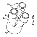
少なくとも1つの実施形態では、医療回路で使用するのに適したリムが提供され、リムは、第1温度および第1相対湿度のガスを受けるように構成された第1開口と、ガスがリムから出ることを許容するように構成された第2開口であって、ガスが第2温度および第2相対湿度を有する第2開口と、複数の導管とを含み、導管はそれぞれ、第1開口に近い第1端部と、第2開口に近い第2端部と、端部および第2端部の間に延在しかつルーメンを内部に画定する壁とを含み、ルーメンを通って、使用時、ガスが第1端部から第2端部に向かう方向に流れ、前記壁の少なくとも一部は、水蒸気の透過を許容するが液体の水の透過を実質的に防止するように構成された通気性材料を含む。 In at least one embodiment, a rim suitable for use in a medical circuit is provided, the rim comprising a first opening configured to receive a gas at a first temperature and a first relative humidity, and the gas from the rim A second opening configured to allow exiting, wherein the gas includes a second opening having a second temperature and a second relative humidity, and a plurality of conduits, each of the conduits being close to the first opening Including a first end, a second end proximate the second opening, and a wall extending between the end and the second end and defining a lumen therein, and in use, through the lumen, Gas permeable in a direction from the first end to the second end, at least a portion of said wall being permeable to allow the transmission of water vapor but to substantially prevent the transmission of liquid water Contains the material.
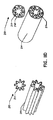
様々な実施形態において、前述のリムは、以下の特性、ならびに本開示の他の場所に記載された特性の1つ、いくつか、または全てを有する。通気性材料は発泡材料であることができる。材料は実質的に均一の厚さを有することができる。リムは3つの導管を含むことができる。複数の導管は波形であることができる。発泡材料の空隙率は40%を超えることができる。リムの空気圧コンプライアンス(pneumatic compliance)は10mL/kPa/m未満であることができる。発泡材料の空隙率は約45%であることができる。リムの空気圧コンプライアンスは3mL/kPa/m未満であることができる。複数の導管は第1開口と第2開口の間で撚り合せられるか編組みされることができる。リムはさらに、複数の導管を一緒に保持するように構成された1つまたは複数の固定機構を含むことができる。各固定機構は複数の出張り部を含むことができ、および導管のそれぞれは出張り部の1つを通過することができる。各固定機構は、複数のリングを含む三つ葉形器具であることができ、導管のそれぞれはリングの1つを通過することができる。リムはさらにコネクタを含み、コネクタは第1開口または第2開口を画定するアパーチャを含む単一部分と、複数の導管の1つと接続するようにそれぞれ構成された複数の通路を構成する多部構成部分と、複数の通路の間で多部構成部分に取り付けられるかそれに形成された基部を含む内側オジーブ(ogive)とを含み、オジーブは単一部分の方向に延在し、ガスの流れを多部構成部分から単一部分へ、または単一部分から多部構成部分へ方向付けるように構成される。リムはさらに、リムを通過するガスに熱を提供するように構成された少なくとも1つの加熱ワイヤを含むことができる。導管の少なくとも1つの壁は、ルーメンを通過するガスに熱を提供するように構成された加熱ワイヤを取り囲むか埋め込むことができる。導管の少なくとも1つのルーメンは、ルーメンを通過するガスに熱を提供するように構成された加熱ワイヤを包み込むことができる。リムは呼気リムであることができ、および第1開口は患者インターフェースからガスを受けるように構成可能である。 In various embodiments, the aforementioned rim has the following characteristics, as well as one, some or all of the characteristics described elsewhere in this disclosure. The breathable material can be a foam material. The material can have a substantially uniform thickness. The rim can include three conduits. The plurality of conduits can be corrugated. The porosity of the foam material can exceed 40%. The pneumatic compliance of the rim can be less than 10 mL / kPa / m. The porosity of the foam material can be about 45%. The pneumatic compliance of the rim can be less than 3 mL / kPa / m. The plurality of conduits can be twisted or braided between the first and second openings. The rim may further include one or more fixation mechanisms configured to hold the plurality of conduits together. Each securing mechanism can include a plurality of lugs, and each of the conduits can pass through one of the lugs. Each fixation mechanism can be a trefoil device comprising a plurality of rings, and each of the conduits can pass through one of the rings. The rim further includes a connector, the connector comprising a single part including an aperture defining the first opening or the second opening, and a multi-part component defining a plurality of passageways each configured to connect with one of the plurality of conduits. And an inner ogive including a base attached to or formed in the multipart component between the plurality of passageways, the ogive extending in the direction of the single part to form the gas flow in the multipart configuration It is configured to be directed from part to single part or from single part to multipart component. The rim may further include at least one heating wire configured to provide heat to the gas passing through the rim. At least one wall of the conduit can surround or embed a heating wire configured to provide heat to the gas passing through the lumen. At least one lumen of the conduit can encase a heating wire configured to provide heat to the gas passing through the lumen. The rim can be an exhalation rim and the first opening can be configured to receive gas from the patient interface.
少なくとも1つの実施形態において、医療回路のリムと使用するのに適した装置は、患者インターフェースまたは加湿装置に接続するように構成されたアパーチャを含む単一部分と、複数の導管の1つと接続するようにそれぞれ構成された複数の通路を含む多部構成部分と、複数の通路の間で多部構成部分に取り付けられるかそれに形成された基部を含む内側オジーブとを含み、オジーブは単一部分の方向に延在し、ガスの流れを多部構成部分から単一部分へ、または単一部分から多部構成部分へ方向付けるように構成される。 In at least one embodiment, a device suitable for use with the rim of a medical circuit is to connect with a single portion including an aperture configured to connect to a patient interface or humidification device and one of a plurality of conduits The multi-part component comprising a plurality of passageways each configured in each of the plurality of passageways, and the inner olivine comprising a base attached to or formed on the multi-piece component between the plurality of passageways, the It extends and is configured to direct the flow of gas from a multipart component to a single part or from a single part to a multipart component.
様々な実施形態において、前述の装置は、以下の特性、ならびに本開示の他の場所に記載された特性の1つ、いくつか、または全てを有する。多部構成部分は3つの通路を含むことができる。 In various embodiments, the aforementioned devices have the following characteristics, as well as one, some or all of the characteristics described elsewhere in this disclosure. The multipart component can include three passages.
少なくとも1つの実施形態において、医療回路で使用するのに適したリムは、第1温度および第1相対湿度のガスを受けるように構成された第1開口と、ガスがリムから出ることを許容するように構成された第2開口であって、ガスが第2温度および第2相対湿度を有する第2開口と、リム内の第1開口および第2開口の間のガス流の滞留時間を延ばすための手段とを含む。 In at least one embodiment, a rim suitable for use in a medical circuit includes a first opening configured to receive a gas at a first temperature and a first relative humidity, and allowing gas to exit the rim A second opening configured to extend the residence time of the gas flow between the second opening where the gas has a second temperature and a second relative humidity, and the first opening and the second opening in the rim And means of
様々な実施形態において、前述のリムは、以下の特性、ならびに本開示の他の場所に記載された特性の1つ、いくつか、または全てを有する。滞留時間延長手段は、第1開口および第2開口の間に複数の導管を含むことができ、導管のそれぞれは、第1開口および第2開口の間に延在しかつ内部にルーメンを画定する壁を含み、ルーメンを通って、使用時、ガスが第1開口から第2開口に向かう方向に流れる。壁の少なくとも一部は、水蒸気の透過を許容するが液体の水の透過を実質的に防止するように構成された通気性発泡材料を含むことができる。 In various embodiments, the aforementioned rim has the following characteristics, as well as one, some or all of the characteristics described elsewhere in this disclosure. The residence time extension means may include a plurality of conduits between the first and second openings, each of the conduits extending between the first and second openings and defining a lumen therein A gas is flowed from the first opening toward the second opening during use, including a wall, through the lumen. At least a portion of the wall can include a breathable foam material configured to allow water vapor transmission but substantially prevent liquid water transmission.
これらおよび他の実施形態を以下でより詳細に記載する。 These and other embodiments are described in more detail below.
図面を通して参照番号は参照要素間の全体的な一致を示すために再使用される場合がある。図面は本明細書に記載される例示的実施形態を示すために提供され、本開示の範囲を制限するつもりはない。 Throughout the drawings, reference numbers may be reused to indicate an overall match between reference elements. The drawings are provided to illustrate the exemplary embodiments described herein and are not intended to limit the scope of the present disclosure.
医療回路内で加湿ガスを搬送するためのリムの特定の実施形態および例が本明細書に開示される。当業者は、本開示内容が、具体的に開示された実施形態および/または使用、およびその明白な修正例および等価物を超えるまでに及ぶことを認識する。従って、本開示の範囲は本明細書に記載されたいかなる特定の実施形態にも限定されないことが意図される。 Disclosed herein are specific embodiments and examples of rims for transporting humidified gas within a medical circuit. One skilled in the art will recognize that the present disclosure extends beyond the specifically disclosed embodiments and / or uses and apparent modifications and equivalents thereof. Thus, it is intended that the scope of the present disclosure is not limited to any particular embodiment described herein.
医療回路で使用するための通気性リムを提供することが望ましい。本明細書において通気性リムは、水蒸気に対する認識可能な透湿性および液体の水およびバルクガス流に対する実質的に不透湿性を意味するように用いられる。通気性はレインアウトを低減または防止するのに望ましい。「レインアウト(Rain out)」、または凝結は、リム内の高湿ガスが低温のリムの壁と接触するとき問題になり得る。しかしながら、レインアウトは、リム内の温度プロファイルだけでなくガス流量、構成要素の形状、および構成要素を形成するために使用される材料の固有の通気性も含む多数の要因に依存する。一般的に通気性リムは、リム内の高湿ガスに由来する水が低湿環境へ通過することを許容し、リム内のレインアウトの潜在性を改良するので望ましい可能性がある。反対に、およびその用途に依存して、通気性はまた、高湿環境に由来する水が通過し、それによりリム内のガス流を加湿することを許容することが望ましい場合がある。 It is desirable to provide a breathable rim for use in a medical circuit. Breathable rims are used herein to mean perceptible vapor permeability to water vapor and substantially impermeability to liquid water and bulk gas flows. Breathability is desirable to reduce or prevent rainout. "Rain out" or condensation can be a problem when the humid gas in the rim contacts the cold rim wall. However, rainout depends on a number of factors including the temperature profile within the rim as well as the gas flow rate, the shape of the component, and the inherent breathability of the material used to form the component. In general, a breathable rim may be desirable as it allows water from the high humidity gas in the rim to pass into a low humidity environment and improves the potential for rainout in the rim. Conversely, and depending on the application, breathability may also be desirable to allow water from the high humidity environment to pass, thereby humidifying the gas flow in the rim.
さらに、リムを通過するガスの温度および/または相対湿度を制御することが同じく有利である場合がある。温度および/または相対湿度の制御は、下流/上流装置またはインターフェース内の凝結、リム内のレインアウト、ガスの乾燥を高めること、またはそれらのいずれかの組合せを制限または防止する。 Furthermore, it may also be advantageous to control the temperature and / or relative humidity of the gas passing through the rim. Control of temperature and / or relative humidity limits or prevents condensation in downstream / upstream equipment or interfaces, rainout in the rim, enhanced drying of the gas, or any combination thereof.
医療回路内で加湿ガスを搬送するためのリムの説明が本明細書に提供され、リムは、水蒸気を通過するように、および液体の水の通過を実質的に防止するように構成された通気性材料を含む。いかなる適切な通気性材料も使用できる。それにもかかわらず、特に適切な通気性材料が、2010年12月22日に出願された「Components for Medical Circuits,」と題するPCT公開物の国際公開第2011/077250号パンフレットに記載されており、この出願は参照することによって全体的に本明細書に組み込まれ、本明細書の一部を成す。この公開物に記載されるように、通気性材料は、水蒸気の透過を許容するが液体の水の透過を実質的に防止するように構成された通気性発泡材料であることができる。通気性発泡材料は、ポリマーの混合物を含むことができる。通気性発泡材料は、ポリエーテル軟質セグメントを有する熱可塑性エラストマを含むことができる。通気性発泡材料は、ポリエーテル軟質セグメントを有するコポリエステル熱可塑性エラストマを含むことができる。通気性発泡材料はポリエーテル軟質セグメントを有する熱可塑性エラストマを含むことができる。 A description of a rim for conveying humidified gas in a medical circuit is provided herein, wherein the rim is configured to pass water vapor and to substantially prevent the passage of liquid water. Containing sex material. Any suitable breathable material can be used. Nevertheless, a particularly suitable breathable material is described in PCT Publication WO 2011/077250 entitled "Components for Medical Circuits," filed December 22, 2010, This application is incorporated herein by reference in its entirety and forms part of this specification. As described in this publication, the breathable material can be a breathable foam material configured to allow water vapor transmission but substantially prevent liquid water transmission. The breathable foam material can comprise a mixture of polymers. The breathable foam material can comprise a thermoplastic elastomer having a polyether soft segment. The breathable foam material can comprise a copolyester thermoplastic elastomer having a polyether soft segment. The breathable foam material can comprise a thermoplastic elastomer having a polyether soft segment.
少なくとも図1を参照して以下でより詳細に考察されるように、呼気リムは医療回路内に含めることができる。本明細書で使用される際、呼気リムは、医療回路内で患者から加湿ガスを送るリムを意味するように広く定義される。呼気リムは呼吸アプリケーションで使用するための呼吸回路に適している。加熱されない呼気リムに関して、ガスがリムに沿ってベンチレータ、周囲環境、またはガス源に向かって移動するとき、ガスは、その乾燥率より高い率で冷却し得る。結果として、ガスの温度は、露点温度未満に低下する可能性があり、これは呼気リムの内側に凝結が形成することを引き起こす。加熱される呼気リムに関して、ガスは長過ぎる間高温に維持される場合がある。ガスが乾燥するので、ガスの相対湿度は(ガスの温度がリムの一部にわたり比較的一定であるとき)低下する可能性があり、これは、乾燥は相対湿度が約100%またはその近くのときにより効果的であるので、さらなる乾燥を損なう。ガスが十分に乾燥されない場合、温度がベンチレータ内で低下するとき、凝結がベンチレータ内で形成され得る。 The expiratory limb may be included in the medical circuit, as discussed in more detail below with reference to at least FIG. As used herein, an exhalation rim is broadly defined to mean a rim that delivers humidified gas from a patient in a medical circuit. The exhalation rim is suitable for breathing circuits for use in respiratory applications. With respect to the non-heated exhalation rim, as the gas travels along the rim towards the ventilator, the ambient environment, or the gas source, the gas may cool at a rate higher than its dryness. As a result, the temperature of the gas can drop below the dew point temperature, which causes condensation to form inside the expiratory limb. For a heated expiratory limb, the gas may be maintained at high temperature for too long. As the gas dries, the relative humidity of the gas may drop (when the temperature of the gas is relatively constant across a portion of the rim), which means that drying has a relative humidity of about 100% or near As it is sometimes more effective, it impairs further drying. If the gas is not sufficiently dried, condensation may be formed in the ventilator when the temperature is reduced in the ventilator.
従って、呼気リムの長さに沿って乾燥を改良または最適化することが有利であり得、これはいくつかの実施形態において相対湿度を実質的に一定の値に維持することによって達成可能である。いくつかの実施形態では、改良または最適化された乾燥は、相対湿度が約90%〜約99%、約95%〜約99%、または約95%〜約97%に維持される場合に生じ得る。呼気リムを出るガスの温度がベンチレータ、ガス源または周囲環境の温度またはその近くであるようにリムの長さに沿ってガスの温度を低減することも有利であり得る。 Thus, it may be advantageous to improve or optimize the drying along the length of the expiratory limb, which can be achieved by maintaining the relative humidity at a substantially constant value in some embodiments . In some embodiments, improved or optimized drying occurs when the relative humidity is maintained at about 90% to about 99%, about 95% to about 99%, or about 95% to about 97%. obtain. It may also be advantageous to reduce the temperature of the gas along the length of the rim such that the temperature of the gas leaving the exhalation rim is at or near the temperature of the ventilator, the gas source or the surrounding environment.
これを実行する効果的な方法は、湿度および/または温度をリムの長さに沿って調整された方法で低下させることである。例えば、約0.01℃/mmを超えないように、または温度低下が約0℃/mm〜約0.009℃/mmの間であるように、呼気リムの第1の部分を横切る温度低下率を調整することが有利であり得る。いくつかの実施形態では、温度低下率を、リムの開始地点から呼気リムの最初の約300mmまたは400mmまで、記載の範囲に制限することが有利であり得る。また、リムを横切る合計温度低下を約10℃以下および/または約3℃〜10℃であるように制限することが有利であり得る。いくつかの実施形態では、リム内の乾燥は相対湿度によって制限される。いくつかの実施形態では、リムに沿って直線状またはほぼ直線状の温度低下を有することが望ましいかもしれない。 An effective way to do this is to reduce the humidity and / or temperature in a controlled manner along the length of the rim. For example, the temperature drop across the first portion of the expiratory limb such that the temperature drop does not exceed about 0.01 ° C./mm, or the temperature drop is between about 0 ° C./mm and about 0.009 ° C./mm It may be advantageous to adjust the rate. In some embodiments, it may be advantageous to limit the rate of temperature reduction to the described range from the start point of the rim to about the first 300 mm or 400 mm of the expiratory limb. Also, it may be advantageous to limit the total temperature drop across the rim to about 10 ° C. or less and / or about 3 ° C. to 10 ° C. In some embodiments, drying in the rim is limited by relative humidity. In some embodiments, it may be desirable to have a linear or nearly linear temperature drop along the rim.
従って、本明細書に記載される呼気リムは、リム内の環境を制御することにより、ベンチレータ内のレインアウトまたは凝結を低減または排除するという目的を達成するために構成される。例えば、約95%の相対湿度を有するガスに関して、呼気リムは、ガスの温度と露点温度との差が約1.5℃未満、約1℃未満、または約0.9℃〜約1℃であるように温度プロファイルを調整するように構成可能である。リムの加熱または隔絶は、呼気リムまたはベンチレータ内で凝結がほとんどまたは全く生じないように、露点温度ラインと絶対湿度ラインとの間に横たわる温度範囲であり得る「非凝結ウィンドウ」内に温度を維持するように構成可能である。 Thus, the expiratory limb described herein is configured to achieve the goal of reducing or eliminating rainout or condensation in the ventilator by controlling the environment within the rim. For example, for a gas having a relative humidity of about 95%, the exhalation rim may have a difference between the gas temperature and the dew point temperature of less than about 1.5 ° C., less than about 1 ° C., or about 0.9 ° C. to about 1 ° C. It can be configured to adjust the temperature profile as it is. Heating or isolating the rim maintains the temperature within the "non-condensing window" which may be the temperature range lying between the dew point temperature line and the absolute humidity line so that little or no condensation occurs in the exhalation rim or ventilator Can be configured to
いくつかの実施形態では、凝結を低減する、レインアウトを低減する、および本明細書に記載される有利な特性を提供する例示的な温度プロファイルは、リムの開始地点から最初の約300または400mmまでの(例えば患者インターフェースからの)初期温度低下が、約0℃/mm〜約0.01℃/mmである勾配を有することができる。いくつかの実施形態では、約3℃〜約10℃の間の温度の合計低下を有する温度プロファイルが、本明細書に記載される利点の少なくともいくつかを提供し得る。 In some embodiments, an exemplary temperature profile that reduces condensation, reduces rainout, and provides the advantageous properties described herein is about 300 or 400 mm initially from the start point of the rim The initial temperature drop of up to (e.g., from the patient interface) can have a slope that is about 0 ° C / mm to about 0.01 ° C / mm. In some embodiments, a temperature profile having a total decrease in temperature between about 3 ° C. and about 10 ° C. may provide at least some of the benefits described herein.
次に呼気リムの実施形態を呼吸システムにおけるそれらの使用を参照して本明細書において記載する。しかしながら、本明細書に記載されるリムは、インキュベーションシステム、手術用加湿システム等など、第1環境から、異なる温度および/または湿度を有する第2環境までのガス流の滞留時間を延ばすことが望ましい様々な用途で使用可能であることが理解される。 Embodiments of the expiratory limb will now be described herein with reference to their use in the respiratory system. However, it is desirable that the rims described herein extend the residence time of the gas flow from a first environment, such as an incubation system, a surgical humidification system, etc., to a second environment having a different temperature and / or humidity. It is understood that it can be used in various applications.
図1は、加湿ガスを使用者に送出するための例示的呼吸システム100を示し、加湿システム100は、吸気リム202と呼気リム210とを含む呼吸回路200を有する。示される呼吸加湿システム100は加圧ガス源102を含む。いくつかの実行では、加圧ガス源102は、送風機、ブロワ等を含む。いくつかの実行では、加圧ガス源102はベンチレータまたは他の陽圧生成装置を含む。加圧ガス源102は入口104および出口106を含む。
FIG. 1 shows an exemplary breathing system 100 for delivering humidified gas to a user, the humidifying system 100 having a
加圧ガス源102は、流体(例えば酸素、麻酔ガス、空気等)の流れを加湿ユニット108に供給する。流体流は加圧ガス源102の出口106から加湿ユニット108の入口110へ流れる。示される構造では、加湿ユニット108は、加圧ガス源102と別個に示され、加湿ユニット108の入口110は加圧ガス源102の出口106と導管112によって接続されている。いくつかの実行では、加圧ガス源102および加湿ユニット108は単一ハウジングに一体化することができる。
The
ガスは吸気リム202を通り、患者インターフェース115を介して患者101へ流れる。呼気リム210も同じく患者インターフェース115に接続される。呼気リム210は吐き出された加湿ガスを患者101から移動するように構成される。ここで、呼気リム210は吐き出された加湿ガスを患者インターフェース115からガス源102へ戻す。あるいは、吐き出された加湿ガスは直接周囲環境へまたは空気清浄器/フィルタ(不図示)などの他の付随装置へ直接送ることができる。いずれかの適切な患者インターフェース115を組み込むことができる。患者インターフェースは広義語であり、当業者に一般的かつ慣習的な意味合いを与えられ(すなわち、特別かつ特定の意味合いに限定されない)、および限定せずにマスク(フェースマスクおよび鼻マスクなど)、カニューレ、およびネーザルピロー(nasal pillow)を含む。患者インターフェースは通常、使用中に温かい湿潤通気ガスを受け入れるガス空間を画定する。
Gas flows through the inspiratory limb 202 and through the patient interface 115 to the patient 101. The
本開示に記載される特定の特徴、態様および利点を有する他の種類の加湿ユニットを使用できる一方で、示される加湿ユニット108は、通過型(pass−over)加湿器であり、加湿チャンバ114と、加湿チャンバ114への入口110を含む。いくつかの実行では、加湿チャンバ114は本体116を含み、それに基部118が取り付けられる。隔室を加湿チャンバ116内に画定可能である。隔室は液体質量を保持するように適合され、液体は基部118を介して導入または提供される熱によって加熱可能である。いくつかの実行では、基部118は加熱プレート120と接触するように適合される。加熱プレート120は、液体に伝導される熱を変えることができるように、制御器122または他の適切な構成要素を介して制御可能である。
While other types of humidification units having the particular features, aspects and advantages described in the present disclosure can be used, the humidification unit 108 shown is a pass-over humidifier and can be used with the
加湿ユニット108の制御器122は、呼吸加湿システム100の様々な実施形態の動作を制御することができる。示されるようなシステムは単一の制御器122を使用するが、多数の制御器を他の構成において使用することができる。多数の制御器は別個の機能を伝送可能または提供可能であり、従って、制御器は連通する必要がない。いくつかの実行では、制御器122は、コンピュータプログラムのソフトウェアコードを含有する関連メモリまたは記憶装置を有するマイクロプロセッサ、プロセッサ、または論理回路を含み得る。そのような実行では、制御器122は、コンピュータプログラムに含まれるものなどの命令に従い、およびまた内部または外部入力に応答して、呼吸加湿システム100の動作を制御可能である。 Controller 122 of humidification unit 108 can control the operation of various embodiments of respiratory humidification system 100. The system as shown uses a single controller 122, although multiple controllers can be used in other configurations. Many controllers can transmit or provide separate functions, so the controllers do not need to be in communication. In some implementations, controller 122 may include a microprocessor, processor, or logic circuit with associated memory or storage containing computer program software code. In such an implementation, controller 122 can control the operation of respiratory humidification system 100 in accordance with instructions such as those included in a computer program, and also in response to internal or external inputs.
加湿チャンバ114の本体116は、入口110を画定するポート124と、加湿チャンバ114の出口128を画定するポート126とを含む。加湿チャンバ114に含有される液体が加熱されるとき、入口ポート124を通って加湿チャンバ114に導入されるガスと水蒸気が混合される。ガスと蒸気の混合物は出口ポート126を通って加湿チャンバ114から出る。
The body 116 of the
加湿システム100は呼吸回路200を含み、呼吸回路200は加湿ユニット108の出口ポート126を画定する出口128に接続される吸気リム202を含む。吸気リム202は、加湿チャンバ114を出るガスと水蒸気の混合物を使用者に運ぶ。吸気リム202は、吸気リム202に沿って配置された加熱要素206を含むことができ、加熱要素206は、吸気リム202に沿って凝結を低減するように、使用者に到達するガスの温度を制御するように、またはその両方を実行するように構成される。加熱要素206は、吸気リム202によって運ばれるガスと水蒸気の混合物の温度を上昇または維持することができる。いくつかの実行では、加熱要素206は、抵抗加熱器を確定するワイヤであることができる。加湿チャンバ114から離れるガスと水蒸気の混合物の温度を上昇または維持することによって、水蒸気は混合物から凝結しにくくなる。
Humidification system 100 includes a
呼気リム
加湿システム100は、呼気されたガスを使用者から運び出し、ガス源102へ送出するように構成された呼気リム210を含む。呼気リム210は、呼気されたまたは吐き出されたガスを受けるための患者端部の第1端部と、ガス源102の第2端部とを有する壁を含むことができ、2つの端部は呼気リムの長さによって分離される。壁はガスが移動するための空間を画成可能であり(例えば1つまたは複数のルーメン)、および壁の少なくとも一部は通気性材料を含むことができる。
Exhalation Rim Humidification system 100 includes an
ガスが呼気リム210に沿って急に冷却しすぎる場合、水蒸気は通気層を十分に速く通過できないので、ガスは過飽和状態になり得る。これは、少なくとも部分的に、呼気リム210の患者端部の近くにレインアウトを引き起こし得る。ガスがゆっくり冷却し過ぎる場合、レインアウトは呼気リム210の第2端部の近くで形成し得、そこで比較的暖かいガスがガス源102または周囲環境でより冷たい空気と接触する。呼気リム中のレインアウトを低減または防止するために、ガスまたは呼気リム210の特性を制御することができる。例えば、ガスの温度プロファイルおよび呼気リム210の他の変数を制御することによって、呼気リム210の通気性を改良することができる。いくつかの実行では、呼気リム210の通気性は、呼気リム210を通る通過時間を延ばすことによって向上可能であり、これは、いくつかの実施形態では、流量を低減することによって、または呼気リム210を通る通路の長さを延ばすことによって達成可能である。呼気リムを通る通過時間を延ばすことは、いくつかの実行では、呼気壁を通過するガスの熱損失を増大する。これが急速に発生した場合、上記のように、レインアウトが発生し得る。いくつかの実施形態では、呼気リム210に沿って実質的に直線的な温度プロファイルを提供することおよび/または呼気リム210を通る通過時間を延ばすことは、呼気壁の通気性を約40%〜約70%以上向上することができる。従って、いくつかの実施形態では、呼気リム210は、ガスの温度が呼気リム210の長さにわたって直線状に低下するように、実質的に直線状の温度プロファイルを有するように肯定可能である。関連して、いくつかの実施形態では、呼気リム210は、呼気リム210の長さにわたってガス温度とその露点温度との差を実質的に一定に維持するように構成可能である。同様に、いくつかの実施形態では、呼気リム210は、ガスの相対湿度を、呼気リム210の長さにわたり約95%〜約99%の間に維持するように構成可能である。
If the gas cools too quickly along the
いくつかの実施形態では、呼気リム210は、呼気リム内の温度プロファイルを制御するように構成された絶縁部を含む。いくつかの実施形態では、呼気リム210は、呼気リム210に沿って配置された関連加熱要素212を含み、加熱要素212は呼気リム202に沿って実質的に直線状の温度低下を維持するように、ガスの相対湿度を制御するように、ガスの温度をその露点温度に対し制御するように、またはそれらのいずれかの組合せを実行するように構成される。
In some embodiments,
加熱要素212は加湿システム100の制御器122によってまたは他の手段によって選択的に制御可能である。制御器122は、加熱要素210を制御するように、フィードバックをシステムのセンサから受け取るように、加熱要素212への電力を制御するロジックを提供するように、センサからの温度の読取り値に応答して加熱要素212の制御を調整するように、などを実行するように構成可能である。いくつかの実施形態では、制御器122は、電力を加熱要素212に送出するように構成された電源を含む。制御器122は、例えば、可変電力、可変電流、可変電圧またはこれらのいずれかの組合せを加熱要素212に送出することによって、加熱要素212によって送出される熱量を制御することができる。制御器122は、加熱要素212を制御するためにパルス幅変調を実行可能である。制御器122は、所望の温度が呼気リム210内で到達されるまで実質的に一定の電力を適用することができる。いくつかの実施形態では、呼気リム210は、例えば温度、相対湿度、絶対湿度、またはこれらのいずれかの組合せを含み得る呼気リム210内のガスの特性に関する情報を、制御器または使用者に提供するように構成された1つまたは複数のセンサを含み、この情報は呼気リム210に沿った1つまたは複数の地点で提供されることができる。いくつかの実行では、加熱要素206は抵抗性加熱器を確定するワイヤであり得る。
The
いくつかの実施形態では、呼気リム210は、加熱要素212と組み合わせた絶縁部を含むことができる。いくつかの実施形態では、加熱要素210は、呼気リム210の異なる部分が異なる熱量を受けるように領域加熱能力を提供するように構成可能である。これは例えば、多数の加熱ワイヤ、または異なる巻き密度またはピッチ間隔を異なる地点で有する1本のワイヤを使用することによって達成可能である。
In some embodiments,
調整された温度プロファイルを有する例示的呼気リム
図2は、呼気リムに沿った位置の関数としてのガスの温度のプロットを示す。「対照」として記載されかつ破線で示される2本のプロットは、通気性材料を使用してガスを乾燥するように構成された呼気リムを示す。「改良された乾燥」と記載されかつ実線で示された4本のプロットは、本発明に記載された実施形態を使用したときの結果を示す。それらは呼気リムを通過するガスの改良または最適化された乾燥を示す。「凝結」として記載されかつ点線で示された6本のプロットは、リム内でまたはベンチレータでレインアウトまたは凝結を経験する温度プロファイルを有する呼気リムを示す。これらの呼気リムは、約0.009度/mmまたは約0.01℃/mmを超える、呼気リムの始点から約300mmまたは400mmまでの温度低下率を経験する、および/またはそこでの合計温度低下が約10℃を超えるか約3℃〜約10℃の間である。
Exemplary Expiratory Limb with Adjusted Temperature Profile FIG. 2 shows a plot of the temperature of the gas as a function of position along the expiratory limb. Two plots, described as "control" and indicated by dashed lines, show an expiratory limb configured to dry the gas using a breathable material. The four plots described as "improved drying" and shown as solid lines show the results when using the embodiment described in the present invention. They show improved or optimized drying of the gas passing through the exhalation rim. The six plots described as "condensed" and shown as dotted lines show an expiratory limb having a temperature profile that experiences rainout or condensation within the rim or at the ventilator. These exhalation limbs experience a temperature reduction rate of about 0.009 degrees / mm or more than about 0.01 degrees C / mm, to about 300 mm or 400 mm from the beginning of the exhalation rim, and / or a total temperature reduction there Is greater than about 10 ° C or between about 3 ° C and about 10 ° C.
表1は、図2の2本の「対照」プロットおよび4本の「改良された乾燥」プロットの温度プロファイルの絶対湿度および露点温度に関する情報を記載する。表は、流出ガスの、入力絶対湿度(「AH In」)および出力絶対湿度(「AH Out」)および露点温度(「DPT」)を記載する。 Table 1 provides information on the absolute humidity and dew point temperatures of the temperature profiles of the two "control" plots and the four "modified drying" plots of FIG. The table describes the input absolute humidity ("AH In") and the output absolute humidity ("AH Out") and the dew point temperature ("DPT") of the effluent gas.

例示的呼気リム
呼気リムの例示的な構成を次に記載する。本明細書に記載され且つ図面に示される様々な実施形態は、ベンチレータ内の凝結を低減するおよび/または呼気リム内のレインアウトを低減するという記載の目標を達成する様々な実行の例であることが意図される。本明細書に提供された例の範囲から逸脱しない多数の異なる変形および置換が可能である。従って、以下の例は本開示内容の範囲を制限するものとして解釈すべきでなく、また本開示内容の範囲はこれら列挙された例を超えて拡大することが理解される。
Exemplary Exhalation Limb An exemplary configuration of the exhalation rim will now be described. The various embodiments described herein and illustrated in the drawings are examples of various implementations that achieve the stated goal of reducing condensation in the ventilator and / or reducing rainout in the expiratory limb. Is intended. Many different variations and substitutions are possible without departing from the scope of the examples provided herein. Accordingly, the following examples should not be construed as limiting the scope of the present disclosure, and it is understood that the scope of the present disclosure extends beyond the listed examples.
概して、例示的な呼気リムの設計は、呼気リムから周囲環境または外部大気へのエネルギーの放出が呼気リムの入口で急過ぎる温度低下を引き起こす可能性があり、これがリムのこの部分に凝結を引き起こし得る状況に対処するように構成可能である。この状況は外部温度が比較的低いとき、流量が比較的低いときおよび/または外部相対湿度が比較的高いとき(呼気リムの透過性を低減し得る要素)に共通であり得る。そのような状況下において、温度変化率を低減することが有利であり得る。 In general, the exemplary exhalation rim design can cause a temperature drop that the release of energy from the exhalation rim to the surrounding environment or the external atmosphere causes an abrupt temperature drop at the exhalation rim inlet, which causes condensation in this part of the rim It can be configured to handle the situations it gains. This situation may be common when the external temperature is relatively low, when the flow rate is relatively low and / or when the external relative humidity is relatively high (an element that can reduce the permeability of the expiratory limb). Under such circumstances, it may be advantageous to reduce the rate of temperature change.
関連して、呼気リムの通気性を制限または低減する状況が存在する場合、(例えばベンチレータまたはガス源に入りつつあるとき)リムの出口の凝結を制限するために比較的高い出口温度を有することが有利であり得る。例えば、外部相対湿度が比較的高い場合、または流量が比較的高い場合、呼気リムの通気性は低減され得る。 Relatedly, having a relatively high outlet temperature to limit condensation on the rim outlet (eg, when entering a ventilator or gas source) when conditions exist to limit or reduce the breathability of the exhalation rim May be advantageous. For example, if the external relative humidity is relatively high, or if the flow rate is relatively high, the breathability of the expiratory limb may be reduced.
従って、凝結を引き起こし得る幅広い状況に対処するように構成可能である例示的な呼気リムが本明細書に含められ且つ記載される。これらの設計は、1つの状況に対処することがもう1つの状況に対処することよりも望ましい場合、または特定の問題に関連する有効性を向上または改善することがより望ましい場合、修正可能である。本明細書に示される呼気リムは、外部温度が比較的低い、流量が比較的低い、または外部相対湿度が比較的高い状況に対処するように構成可能である。 Thus, an exemplary expiratory limb that can be configured to address a wide range of situations that may cause condensation is included and described herein. These designs can be modified if it is more desirable to address one situation than to address another, or where it is more desirable to improve or improve the effectiveness associated with a particular problem. . The expiratory limb shown herein can be configured to address situations where the external temperature is relatively low, the flow rate is relatively low, or the external relative humidity is relatively high.
図3は、リムに沿ってガスの温度を制御するために可変断熱材214を有する呼気リム210を示す。1つの導管が、異なる断熱値を有するいくつかの異なるセクションを有する。断熱値は、断熱材料214の異なるサイズとして図3に示される。しかしながら、断熱要素214の物理的なサイズは長さに沿って低減する必要はなく、サイズは長さに沿って実質的に同一であることができる。断熱要素214の効果を高めるために、断熱材料214の厚さを増大可能であり、断熱材料214の密度を増大可能であり、異なる材料を使用することなどが可能である。断熱値は、ある範囲の温度状況、相対湿度および/または流量にわたって比較的直線状またはわずかに凹状の温度プロファイルを提供するように構成可能である。いくつかの実施形態では、リムに沿った断熱セクションは分離せず、実質的に連続的であることができ、または、それは、実質的に連続して変化する断熱セクションを、別個の断熱値の変化を提供するセクションと組み合わせるように構成可能である。断熱セクションの数は例えば2、3、4、5、6、7、8、10、15、20、50またはそれ以上を含むいずれかの適切な数であることができる。
FIG. 3 shows an
図4は、リムの始点およびリムの終点での温度低下を制御するために通気性断熱材214を含む2つのセクションを有する呼気リム210を示す。この構成は、ガスが比較的急な冷却を経験する傾向のある場所で断熱材料214が使用されるので有利である。断熱値、断熱の範囲、および断熱材214の配置は、本明細書に記載される有利性を提供するように構成可能である。さらなる断熱セクションを同様に含めてもよい。
FIG. 4 shows an
図5は、異なるセクションで異なるピッチ間隔を有する多数の加熱ワイヤ212、または可変ピッチ間隔を有する1つの加熱ワイヤ212または両方の組合せを有する呼気リム210を示す。これは能動的な温度制御機構を示す。従って、加熱ワイヤ212は、図1を参照して本明細書に記載されるように、制御器122に結合可能であり、付随制御機構がそこに記載されている。同様に、図4〜9に示される加熱ワイヤは加熱ワイヤを使用して制御可能である。
FIG. 5 shows an
加熱ワイヤ212は管の外側にあるように構成可能であり、またリムに沿って異なる間隔を有することができる。患者端部の近くで、間隔は比較的相互に狭くなることができ、結果、リム出口の近くで適用される熱と比較してより多くの熱を生成または適用する。いくつかの実施形態では、ほぼ直線状の温度プロファイルを得るために、異なる巻き密度を有する異なる領域が存在することができる。いくつかの実施形態では、異なる間隔を有するセクションの数は、2、3、4、5、6、7、8、10、15、20、25、50またはそれ以上であることができ、または巻きの間隔は患者端部からの距離とともに実質的に滑らかに大きくなることができる。いくつかの実施形態では、加熱ワイヤ212は、集合的におよび/または独立的に制御可能な多数の別個の加熱要素を含む。
The
図6は、異なるセクションで異なるピッチ間隔を有するコイル状加熱ワイヤ212を有する呼気リム210を示す。加熱ワイヤ212はリムの中に配置可能である。巻き構成は図5を参照して本明細書に記載された構成と類似し得る。いくつかの実施形態では、加熱ワイヤ212は集合的におよび/または独立的に制御可能な多数の別個の加熱要素を含む。
FIG. 6 shows an
図7は、ワイヤ内に可変ピッチ間隔の領域を有する直線状加熱ワイヤを有する呼気リム210を示す。ピッチ間隔は図5および6を参照して本明細書に記載された巻き密度および間隔に類似して構成可能である。いくつかの実施形態では、加熱ワイヤ212は集合的におよび/または独立的に制御可能な多数の別個の加熱要素を含む。
FIG. 7 shows an
図8は多数の加熱セクションを有する呼気リム210を示し、ここでシステムは加熱ワイヤ212の異なるセクションを独立して制御するように構成される。示されるように、加熱器は、コネクタ216aおよび216bを介して、制御器122によって選択的に制御可能なセクションに分割される。付随コネクタとともにより多くのセクションが存在可能であり、ここでの記載は2つのコネクタを有する3つのセクションに制限される。
FIG. 8 shows an
コネクタ216aおよび216bは第1および第2加熱器セグメントを結合し、制御器が呼気リム210の異なるセクションに選択的に熱を適用することを可能にする。コネクタ216a、216bは、制御器122を使用した加熱ワイヤ212の制御を可能にするために、セグメント内で加熱ワイヤ212を電気的に結合するように構成可能である。コネクタ216a、216bは、制御器122がそれらそれぞれの出力を獲得することを可能にするために温度センサ(不図示)を電気的に接続するように構成可能である。コネクタ216a、216bは、加熱ワイヤ212の選択的制御を可能にする電気構成要素を含むことができる。例えば、コネクタ216a、216bは、第1動作モードにおいて第1セクションの加熱ワイヤ212を介して、および第2動作モードにおいて第1および第2セクションの両方の加熱ワイヤ212を介して電力を方向付ける電気構成要素を含むことができる。コネクタ216a、216bに含まれる電気構成要素は、例えばおよび限定せずに、抵抗器、ダイオード、トランジスタ、継電器、整流器、スイッチ、コンデンサ、インダクタ、集積回路、マイクロコントローラ、マイクロプロセッサ等を含むことができる。いくつかの実施形態では、コネクタ216a、216bは、それが外部要素から実質的に保護されるよう呼気リム210の内側にあるように構成可能である。いくつかの実施形態では、コネクタ216a、216b上の電気構成要素のいくつかは、湿気への露出に起因し得る損傷を低減または防止するように呼気リム210内で加湿ガスから物理的に隔絶されるように構成可能である。いくつかの実施形態では、コネクタ216a、216bは、コストを低減するためにおよび/または信頼性を高めるために、比較的安価な受動的電気構成要素を含むことができる。
Connectors 216a and 216b couple the first and second heater segments and allow the controller to selectively apply heat to different sections of the
図9は、呼気リム210の前端部で温度低下を制御するために患者端部でそれ自体に対し折り戻された加熱ワイヤ212を有する呼気リム210を示す。折り曲げの範囲は、リム210の患者端部近くで所望のまたは有利な温度プロファイルを提供するように構成可能である。例えば、患者入口での凝結を低減するために初期温度低下を制限することが有利であり得る。この場所で追加の熱を提供することは入口近くでのレインアウトを低減または防止し得るためである。
FIG. 9 shows the
図10は、可変断熱材層214を、可変ピッチを有する加熱ワイヤ212と組み合わせた呼気リム210を示す。この実施形態は図3および図6に由来する要素を組み合わせることに類似している。比較的一定の断熱値のセクションと比較的一定の巻き密度のセクションは一致しなくてもよい。断熱値および/または巻き密度間の移行は変えることができ、また、互いに独立することができる。この実施形態はまた、受動的および能動的制御手法が呼気リム210で利用できることを示す。
FIG. 10 shows an
非円筒状ルーメンおよび/または複数ルーメンを有するリム
図11〜15は、非円筒状または複数ルーメン設計を採用するリムのいくつかの実施形態を示す。本明細書で使用される際、複数ルーメンリムは、1つより多いルーメンを有するリムを意味するように幅広く定義され、その結果、1つのルーメンを通って流れるガス流が、少なくとも1つの壁によって他のいずれかのルーメンを通って流れるガス流から分離される。複数ルーメンの非限定的な実施形態が、図11A、11B、12、14および15に示されている。本明細書で使用される際、非円筒状リムは、円筒のように成形されてないルーメンを有するリムを意味するように幅広く定義される。非円筒状の設計の非限定的な実施形態が、図11C、11Dおよび13に示されている。特定の実施形態はそのような要素の組合せを含むことができる。例えばリムは、1つまたは複数の非円筒状ルーメンを含む複数ルーメン設計を有することができる。
Non-cylindrical lumens and / or rims with multiple lumens FIGS. 11-15 illustrate some embodiments of rims that employ non-cylindrical or multi-lumen designs. As used herein, a multi-lumen rim is broadly defined to mean a rim having more than one lumen, such that the flow of gas flowing through one lumen is at least one other wall. It is separated from the gas flow flowing through any of the lumens. Non-limiting embodiments of multiple lumens are shown in FIGS. 11A, 11 B, 12, 14 and 15. As used herein, non-cylindrical rim is broadly defined to mean a rim having a lumen that is not shaped like a cylinder. Non-limiting embodiments of non-cylindrical designs are shown in FIGS. 11C, 11D and 13. Certain embodiments can include combinations of such elements. For example, the rim can have a multi-lumen design that includes one or more non-cylindrical lumens.
いくつかの実施形態では、複数ルーメンリムは、一緒に撚られたまたは編組された複数の導管を含む。これは、各ルーメンのガス流が比較可能な単一ルーメンリムのガス流の3分の1であるので、ガスのリム内の低減された流れ体積を有利に提供し得る。より低い流れ体積は、ルーメンを囲む壁からの蒸発の機会を増大することができる。この構成はまた、ガスのリム内の延長された滞留時間を有利に提供する。各導管の長さが、少なくとも部分的に撚りまたは編組のためにより長い一方でリムの全体長さはより短い標準的市販長さであるためである。延長された滞留時間はルーメンを囲む壁からの蒸発の機会を増大するので、それは一定の質量流量においてリムの通気性を向上することができる。 In some embodiments, the multi-lumen rim comprises a plurality of conduits twisted or braided together. This may advantageously provide a reduced flow volume within the gas rim, as the gas flow in each lumen is one third of the comparable single lumen rim gas flow. Lower flow volumes can increase the opportunity for evaporation from the walls surrounding the lumens. This arrangement also advantageously provides extended residence time in the gas rim. This is because the length of each conduit is at least partially longer for twisting or braiding while the overall length of the rim is a shorter standard commercial length. Because the extended residence time increases the opportunity for evaporation from the wall surrounding the lumen, it can improve the breathability of the rim at a constant mass flow rate.
リムは呼気リム210を参照して以下に記載されているが、そのようなリムは、延長された滞留時間から恩恵を受け得る患者へまたは患者から加湿空気を搬送する様々な環境で使用するのに適していることを理解すべきである。
Although the rims are described below with reference to
図11A〜11Bは様々な複数ルーメン構造を示す。複数ルーメンリム210は、様々な方法でおよび様々な形状的構造において結合された2つ以上の別個の導管211を含むことができる。いくつかの実施形態では、導管211は、導管壁を介した通気性の向上を可能にするために互いに物理的に分離される。いくつかの実施形態では、リム210は、図11Bに示されるように、束ねられた導管211を囲む断熱材料214を含むことができる。いくつかの形状的構造が図11Aおよび11Bに示されているが、他の構造も可能である。例えば図11C〜11Dは、多数の別個の導管を含まず、異なる断面形状を使用して滞留時間を延長するように構成されたリム210を示す。図11Dは特に、規則的または不規則的な形状を含む多数の異なる断面形状が可能であることを示す。さらに、前述の複数ルーメン実施形態のいずれも、図11Dに示されるように断熱材料214を含んでもよい。いくつかの実施形態では、導管211の形状はリムの長さに沿って変わることができる。例えば導管211は、患者端部の近くで概ね円形の形状を有し、これは長さに沿ったある地点で三角形に変わることができ、これはその後、星形または図11Cまたは11Dの実施形態のいずれかと同様の形状に変わることができる。これはリムの長さにわたって表面面積を変えることができ、これは通気性に、従って温度プロファイルに影響を及ぼす。
11A-11B show various multi-lumen structures. The multiple lumen rim 210 can include two or more
図12は、多数導管211および可変断熱材214を組み合わせたリム210を示す。このリム210は複数ルーメン設計に基づく受動的温度制御手法を示す。いくつかの実施形態では、複数ルーメン設計を使用することはリム210の通気性を向上することができる。断熱材料214を使用することは、通気性が向上する場合に増大し得る冷却率を低下することができる。断熱材料は、冷却を低減する一方で呼気リム210の通気性に悪影響を及ぼさないように構成可能である。
FIG. 12 shows a
複数ルーメンリムの別個の導管は、通気性材料から望ましくは形成される。少なくとも1つの実施形態において、複数ルーメンリム210の別個の導管は、PCT公開物の国際公開第2011/077250号パンフレットに記載されるようなおよび/またはEvaqua 2(商標)導管として商業的に製造されているような波形発泡材から形成される。別の適切な材料は、約14%の多孔度を有する通気性ポリエステル熱可塑性エラストマである。そのような材料は、Evaqua(商標)導管として商業的に製造されている。少なくとも1つの実施形態では、複数ルーメンリムの各導管は波形である。波形の導管は14.45mm(または約14.45mm)または15.15mm(または約15.15mm)の(波の頂点における)最大外径を有することができる。波形の導管は12.7mm(または約12.7mm)の(波の頂点における)最小外径を有することができる。波プロファイルのピリオド(頂点間の距離)は3.14mm(または約3.14mm)であることができる。波の振幅(頂点から谷底までの距離)は1.7525mm(または約1.7525mm)であることができる。壁厚は0.5mmおよび1.0mmの範囲(または約0.5mmおよび約1.0mmの範囲)、より具体的には0.6mmおよび0.9mm(または約0.6mmおよび約0.9mmの範囲)であることができる。例えば、波の頂点近くの壁厚は0.50mmおよび0.65mmの範囲(または約0.5mmおよび約0.65mmの範囲)であることができる。さらなる例として、波の谷底近くの壁厚は0.80mmおよび1.0mm(または約0.80mmおよび約1.0mm)の範囲であることができる。
The separate conduits of the multi-lumen rim are desirably formed of a breathable material. In at least one embodiment, the separate conduits of the
導管は所望なら補強リブを含むことができる。そのようなリブは、PCT公開物の国際公開第2011/077250号パンフレットの少なくとも図7A、7B、8Aおよび8Bと併せて示され記載されている。そのようなリブはまた、Evaqua 2(商標)導管として商業的に製造されている。この公開物に記載されているように、これらのリブは発泡材を補強するために使用され、とりわけ、空気圧コンプライアンスを許容値(10mL/kPa/m未満)まで下げるために使用される。 The conduit can include reinforcing ribs if desired. Such ribs are shown and described in conjunction with at least FIGS. 7A, 7B, 8A and 8B of PCT Publication WO 2011/077250. Such ribs are also manufactured commercially as Evaqua 2 (TM) conduits. As described in this publication, these ribs are used to reinforce the foam, in particular to reduce the pneumatic compliance to an acceptable value (less than 10 mL / kPa / m).
複数ルーメン構造は自己補強型であり得ることが理解され、これは、導管壁に配置される内側または外側リブなどの追加補強構造の必要性を低減または排除することができる。従って、リブは特定実施形態において排除することができる。 It is understood that the multi-lumen structure may be self-reinforcing, which may reduce or eliminate the need for additional reinforcing structures, such as inner or outer ribs disposed on the conduit wall. Thus, the ribs can be eliminated in certain embodiments.
通気性を改善できるので補強リブを排除することは望ましい可能性がある。PCT公開物の国際公開第2011/077250号パンフレットの図7A、7B、8Aおよび8Bに示されるように、リブ部分の導管壁厚は、リブ間の導管壁厚より実質的に大きい。従ってリブはリブの全体作用(通気性)面積を低減する。本開示によるリブのない複数ルーメン構造は、Evaqua 2(商標)導管より15%(または約15%)多い作用面積を有することができる。 It may be desirable to eliminate the stiffening ribs as they can improve the breathability. As shown in Figures 7A, 7B, 8A and 8B of PCT Publication WO 2011/077250, the conduit wall thickness of the rib portion is substantially greater than the conduit wall thickness between the ribs. The ribs thus reduce the overall functional (ventilated) area of the ribs. Rib-free multi-lumen structures according to the present disclosure may have a 15% (or about 15%) more active area than the Evaqua 2TM conduit.
表2は、3つの別個の導管を含む複数ルーメンリムの通気性を様々な単一ルーメンリムと比較する。導管/リムの全ては、PCT公開物の国際公開第2011/077250号パンフレットに記載されるものと同じ発泡材料から形成される。成人用Evaqua 2(商標)リムは補強リブを有し、発泡材料は0.35の空隙率を有する。複数ルーメンリムの別個の導管は補強リブを有さず、発泡材料は0.448の空隙率を有する。リムAは成人用Evaqua 2(商標)リムであり、そのガスストリームは加熱ケーブルで加熱されている。リムBおよびCは成人用Evaqua 2(商標)リムであり、そのガスストリームは加熱されていない。リムDは複数ルーメンリムでありそのガスストリームは加熱されていない。全ての実験は、20L/minのガス流量が試料リムを通過する状態で、名目外部温度18〜19℃で行われた。実験の実行時間は6.5時間で合計ガス流は7,800Lだった。入口ガスは98%相対湿度(RH)で36℃であると見積もられた。測定された結果は、実験の終了時の、出口ガス温度、出口ガスの露点、リム外側の水凝結の量、およびリム内の水凝結の量だった。 Table 2 compares the breathability of a multi-lumen rim containing three separate conduits to various single-lumen rims. All of the conduits / rims are formed from the same foam material as described in PCT Publication WO 2011/077250. The adult Evaqua 2TM rim has reinforcing ribs and the foam material has a porosity of 0.35. The separate conduits of the multi-lumen rim do not have reinforcing ribs and the foam material has a porosity of 0.448. Rim A is the adult Evaqua 2TM rim, whose gas stream is heated by a heating cable. Rims B and C are adult Evaqua 2TM rims and the gas stream is not heated. The rim D is a multi-lumen rim and its gas stream is not heated. All experiments were performed at a nominal external temperature of 18-19 C with a gas flow of 20 L / min passing through the sample rim. The run time of the experiment was 6.5 hours and the total gas flow was 7,800 liters. The inlet gas was estimated to be 36 ° C. at 98% relative humidity (RH). The measured results were the outlet gas temperature, the outlet gas dew point, the amount of water condensation outside the rim, and the amount of water condensation in the rim at the end of the experiment.
結果は、リムAは低い合計凝結を有するが、非常に高い露点を有する。これはリムの外側例えばベンチレータ内の凝結の機会を増大する。リムBおよびCはリムAよりはるかに低い出口ガスの露点を有したが、合計の凝結は許容できないほど高かった。リムD(複数ルーメンリム)は全ての試料の中で最も低い凝結および出口ガスの最も低い露点を有した。従って、リムDはベンチレータ内においてリムの外側で最も低い凝結の機会を有した。 The result is that rim A has a low total condensation but very high dew point. This increases the chance of condensation outside the rim, for example in the ventilator. Rims B and C had a much lower outlet gas dew point than rim A, but the total condensation was unacceptably high. Rim D (multiple lumen rim) had the lowest condensation and lowest dew point of the outlet gas of all the samples. Thus, rim D had the lowest chance of condensation outside the rim within the ventilator.
補強リブのない複数の別個の導管を含む複数ルーメンリム210の別個の導管は、10mL/kPa/m未満の空気圧コンプライアンスを維持しながら予想外に高い空隙率を有することができる。特定の実施形態では、補強リブのない3つの別個の導管を含む複数ルーメンリムの導管は、45%(または約45%)など、40%および50%の範囲(または約40%および約50%の範囲)の空隙率を有し、一方で複数ルーメンリムの全体空気圧コンプライアンスは、10mL/kPa/m未満である。この結果は、高い空隙率の発泡材は脆弱であると予想され、またリブのない発泡材導管はさらに脆弱であると予想され得るので、意外である。従って、そのような構造によって過度に高い空気圧コンプライアンスを一般的に予想するであろう。表3に示されるように、構成導管のより高い空隙率およびそれが補強リブを持たないことにもかかわらず、複数ルーメンリムは、35%±4%の空隙率を有するEvaqua 2(商標)リムの波形、リブ補強型、単一ルーメン発泡材リムの空気圧コンプライアンスと同様の空気圧コンプライアンスを有する。
The separate conduits of the
表3は複数ルーメン試料と単一ルーメンリム試料の空気圧コンプライアンスを比較する。導管/リムの全ては、PCT公開物の国際公開第2011/077250号パンフレットに記載されるものと同じ発泡材料から形成される。リムA〜Cは補強リブを有する成人用Evaqua 2(商標)リムであり、発泡材料は0.35の空隙率を有する。リムDは補強リブのない3つの幼児サイズ導管を含む3ルーメンリムであり、発泡材料は0.448の空隙率を有する。 Table 3 compares the pneumatic compliance of multi-lumen and single lumen rim samples. All of the conduits / rims are formed from the same foam material as described in PCT Publication WO 2011/077250. The rims A to C are adult Evaqua 2TM rims with reinforcing ribs and the foam material has a porosity of 0.35. The rim D is a three lumen rim comprising three infant size conduits without reinforcing ribs, the foam material has a porosity of 0.448.
表3に示されるように、リムDの各導管は補強リブがないにもかかわらず、リムDはリムA〜Cの空気圧コンプライアンスをと比較可能な空気圧コンプライアンスを有する。 As shown in Table 3, despite the absence of reinforcing ribs, rim D has pneumatic compliance that is comparable to that of rims A-C, even though each conduit of rim D has no reinforcing rib.
図13および14に示されるリム210は、図11A〜11Dの複数ルーメン設計と組み合わせた温度制御の能動的手法を示す。図13は、図11Dに示されるリム210と同様の断面と、図6および10を参照して記載したリムと同様の、長さに沿って可変ピッチ間隔を有する加熱ワイヤ212とを有するリム210を示す。
The
加熱ワイヤ212は、過度に低い外部温度のせいで生じ得るガスの冷却を制限するために使用される。図14は、各別個の導管211内の加熱ワイヤ212と組み合わせた複数ルーメン設計を有するリム210を示す。加熱ワイヤ212は別個の導管211の長さに沿って全体的に長手方向に延在可能である。例えば、図14に示されるように、加熱ワイヤ212は各別個の導管211の実質的に全範囲に沿ってらせん状に巻かれることができる。それにもかかわらず、加熱ワイヤはより短いセクションに沿って延在可能である。加熱ワイヤ212は別個の導管211の壁に埋設または封入できる、またはルーメンの内側に配置可能である。図11の加熱ワイヤ212は可変ピッチを有する。あるいは、らせん巻き構成において、加熱ワイヤは規則的なピッチを有することができる。他の適切な加熱ワイヤ構成が当該技術分野で知られ、本開示の範囲内にあると考えられる。
The
図15はリム210の様々な複数ルーメン構造を示す。上で考察されたように、別個の導管211は、機械的安定性および/または支持のため、互いに撚り合せることができる。別個の導管を撚り合せることによって、各導管の長さは結果として得られるリム210の長さより長い。これは一定の体積流量においてリム内でガスが費やす滞留時間を延長することができ、これはさらに有利な温度プロファイル、通気性およびレインアウトの低減をもたらすことができる。いくつかの実施形態では、多数の別個の導管211は、接着剤を使用して一緒に保持可能である。いくつかの実施形態では、多数の別個の導管はクリップ、ゴムバンド、タイ、等などの固定機構215を使用して一緒に保持可能である。いくつかの実施形態では、別個の導管はシース214を使用して一緒に保持可能であり、シース214はまた断熱材であることができおよび/またはシース214は審美的に心地良くなるように構成可能である。撚り合せられた導管の数は例えば2、3、4、5または5より多いことができる。少なくとも1つの実施形態では、リム210は3つの導管を含む。
FIG. 15 shows various multi-lumen constructions of the
図16はリムの3導管構成で使用するのに適した例示的固定機構215を示す。この例では、固定機構215は三つ葉状に配置された複数のリングを含む。図16に示される固定機構215三つ葉形器具は、押出しプラスチック、金属または発泡材料から形成可能である。
FIG. 16 shows an
図15に示されるようにリムを組み立てるために、3つの導管211のそれぞれは、図16に示されるような第1固定機構215三つ葉形器具のリングの1つに押し通され、続いて撚り合せられるか編組みされることができる。3つの導管211は次に、第1固定機構215三つ葉形器具から所望の距離に配置された第2固定機構215三つ葉形器具のリングに押し通され、続いて再び撚り合せられるか編組みされることができる。3つの導管211は次に、第2固定機構215三つ葉形器具から所望の距離に配置された第3固定機構215三つ葉形器具のリングに押し通され、続いてさらに再び撚り合せられるか編組みされることができる。しかしながら、より緩い構成が望まれる場合、3つの導管211は固定機構215三つ葉形器具を通過した後撚り合せられなくても編組みされなくてもよい。例えば、撚り合せまたは編組みは、3つの導管211が第2固定機構215三つ葉形器具のリングに通された後、排除可能である。撚り合せまたは編組みはまた、完全に排除することもできる。さらに、より密着した構成が望まれる場合、3つの導管211は固定機構215の間で複数回撚り合わせる編組みすることができる。本明細書に記載される方法は、工程の固定された順番をほのめかさない。どれか1つの工程が方法を実行するために必要であることもほのめかさない。実施形態は、任意の順番および実用的な組合せで実行されてもよい。
To assemble the rim as shown in FIG. 15, each of the three
固定機構215三つ葉形器具の適切な間隔は、250mmまたはその付近など、150mmおよび500mmの範囲(または約150mmおよび約500mmの範囲)であることができる。いくつかの実施形態では、複数の固定機構215、例えば2または3など、2および9の範囲の数を、商業的に標準的な長さのチューブに沿って配置可能である。望ましくは、固定機構215は互いにおよび両端部から均一またはほぼ均一に離間される。例えば、2つの固定機構215が使用されるとき、1つの固定機構を1/3の長さの位置に配置可能であり、1つの固定機構を2/3の長さの位置に配置可能である。2つの固定機構215は500mm(または約500mm)間隔をあけて離すことができる。9個の固定機構215は150(または約150mm)間隔をあけて離すことができる。より少ない固定機構を撚り合せまたは編組み構造において使用することができる。
A suitable spacing of the
前記の間隔構成は、別個の導管の分離を防止する一方で通気性を大幅に低減しないことが分かっている。また、固定機構215三つ葉形器具は互いに十分な近さ(例えば約250mmの間隔)で配置されるとき、導管211の外側の波形が十分な摩擦を生成し、その結果撚り合せが簡単に戻されないことも見出された。さらに、別個の導管211を一緒に保持する固定機構215の数はリムの全体コンプライアンスに大幅に影響を及ぼさないことも見出された。表4は、異なる数の固定機構215三つ葉形器具を有する3導管211リム構造のコンプライアンス試験の結果を示す。比較のため、表5は単一導管リムのコンプライアンス試験の結果を示す。表4および5に記載される導管/リムの全ては、PCT公開物の国際公開第2011/077250号パンフレットに記載されるものと同じ発泡材料から形成される。表4のリムは補強リブのない3つの幼児サイズ導管を含む3ルーメンリムであり、発泡材料は0.448の空隙率を有する。表5の「成人用」リムは補強リブを有する24mm外径のEvaqua 2(商標)リムであり、発泡材料は0.35の空隙率を有する。表5の「幼児用」リムは補強リブのない15mm外径のEvaqua 2(商標)リムであり、発泡材料は0.448の空隙率を有する。
It has been found that the spacing arrangement described above does not significantly reduce the breathability while preventing separation of the separate conduits. Also, when the
上記の三つ葉形状は例として提供される。異なる数の導管211は異なる数のリングを必要とする。例えば四つ葉状に配置された4つのリングを含む固定機構215は、4導管構造で使用可能であり、五弁状に配置された5つのリングを含む固定機構215は、5導管構造で使用可能、などである。さらに、前述の例は全体的に対称的な多葉形状を記載するが、非対称的なリング構造も考えられる。
The above three-leaf shape is provided as an example. Different numbers of
図17A〜17Eは、3ルーメンリム210の一端または両端での使用に適した3方向コネクタ301を示す。コネクタ301は好ましくは、ポリプロピレンまたはポリテトラフルオロエチレンなどのプラスチックなど、適切な材料から形成された成形部品である。
17A-17E illustrate a three-
3方向コネクタ301は単一部分305および3部構成部分307を含む。単一部分305は、加湿器または加圧ガス源などの装置のポートに、または鼻カニューレ、フェースマスク、鼻マスク、鼻/ピローマスクなどの患者インターフェースのポートに接続するのに適した導管を含む。望ましくは単一部分305の導管は、所望の装置または患者インターフェースで使用するのに適した標準サイズの医療テーパを有する。図17Eにより詳細に示されるように、3部構成部分307は、それぞれ導管211との接続に適した3つの導管311を含む。
Three-
図17Cおよび17Dに示されるように、3方向コネクタ301は内側オジーブ315を含むことができる。本明細書で使用される際、オジーブは、弾丸または魚雷に全体的に似ているテーパ状の流線型3次元物体を意味するように定義される。図17Cおよび17Dにおいて、オジーブ315の前縁は尖っている。それにもかかわらず、その用語は、本明細書においてその最も広い意味で使用され、尖った、丸いまたは尖ってない前縁を有する形状を包含し、限定することなく円錐、角錐または4面体、円錐台、角錐台または4面体、および他の切頭オジーブを含む。オジーブ315の基部(最大幅部分)は3部構成部分307の近くに配置される。オジーブ315は単一部分305の方向にテーパする。オジーブ315は、単一部分301からのガス流を3部構成部分307の3つの導管311により均等に分割することができる。オジーブ315はまた、ガス流が単一部分301に入るとき3部構成部分307の3つの導管311からのガス流をより均一に組み合わせ、層流を促進することができる。
As shown in FIGS. 17C and 17D, the three-
結論
医療回路で使用するための様々なリムの例を図面を参照して記載してきた。図面の表現は本明細書に記載される原理を明確に説明するために提供され、モジュールまたはシステムの部分に関連する詳細は、別個の物理的実施形態を正確に描こうとするよりもむしろ説明を容易にするために提供された。例および図は本明細書に記載される実施形態の範囲を示すことを目的とし、範囲を限定するつもりはない。例えば、本明細書の原理は、呼吸回路と同様に、手術用加湿器を含む他の回路で使用するためのリムに適用されてもよい。
Conclusion Examples of various rims for use in medical circuits have been described with reference to the drawings. The depictions in the drawings are provided to clearly illustrate the principles described herein, and the details associated with parts of the module or system may provide an explanation rather than attempt to accurately depict separate physical embodiments. Provided for ease. The examples and figures are intended to illustrate the scope of the embodiments described herein and are not intended to limit the scope. For example, the principles herein may be applied to rims for use in other circuits, including surgical humidifiers, as well as breathing circuits.
本明細書で使用される際、用語「プロセッサ」は、あらゆる適切な装置、論理ブロック、モジュール、回路、または命令を実行するための要素の組合せのことを幅広く指す。例えば、制御器122は、Pentium(登録商標)プロセッサ、MIPS(登録商標)プロセッサ、Power PC(登録商標)プロセッサ、AMD(登録商標)プロセッサ、ARM(登録商標)プロセッサ、またはALPHA(登録商標)プロセッサなどのあらゆる従来型の汎用シングルまたはマルチチップマイクロプロセッサを含むことができる。さらに、制御器122は、デジタル信号プロセッサなどのあらゆる従来型の専用マイクロプロセッサを含むことができる。本明細書に開示される実施形態に関連して記載される様々な例示的論理ブロック、モジュール、および回路は、汎用プロセッサ、デジタル信号プロセッサ(DSP)、特定用途向け集積回路(ASIC)、現場プログラム可能ゲートアレイ(FPGA)、または他のプログラム可能な論理装置、離散ゲートまたはトランジスタ論理、離散ハードウェアコンポーネント、または本明細書に記載の機能を実行するように設計されたそれらのいずれかの組合せによって実施または実行することができる。制御器122は、計算装置の組合せとして、例えばDSPとマイクロプロセッサの組合せ、複数のマイクロプロセッサ、DSPコアと組み合わせた1つまたは複数のマイクロプロセッサ、または他のいずれかのそのような構成として実装可能である。 As used herein, the term "processor" broadly refers to any suitable device, logic block, module, circuit, or combination of elements for executing instructions. For example, the controller 122 may be a Pentium® processor, a MIPS® processor, a Power PC® processor, an AMD® processor, an ARM® processor, or an ALPHA® processor And the like, and may include any conventional general purpose single or multi-chip microprocessor. Additionally, controller 122 can include any conventional dedicated microprocessor, such as a digital signal processor. Various exemplary logic blocks, modules, and circuits described in connection with the embodiments disclosed herein may be implemented as general purpose processors, digital signal processors (DSPs), application specific integrated circuits (ASICs), field programs. By means of a programmable gate array (FPGA) or other programmable logic device, discrete gates or transistor logic, discrete hardware components, or any combination thereof designed to perform the functions described herein. It can be implemented or implemented. The controller 122 may be implemented as a combination of computing devices, eg, a combination of a DSP and a microprocessor, multiple microprocessors, one or more microprocessors in combination with a DSP core, or any other such configuration. It is.
データ記憶装置は、情報、典型的にはコンピュータまたはデジタルデータが記録され、回収されることを可能にする電子回路のことを指すことができる。データ記憶装置は、外部装置またはシステム、例えばディスクドライブまたは固体ドライブのことを指すことができる。データ記憶装置はまた、高速半導体記憶装置(チップ)例えばランダムアクセスメモリ(RAM)、または様々な形態のリードオンメモリ(ROM)のことを指すことができ、これらはコミュニケーションバスまたは制御器122に直接接続される。他の種類のメモリはバブルメモリおよびコアメモリを含む。データ記憶装置は、情報を非一時的媒体に記憶するように構成された物理的ハードウェアであることができる。 Data storage can refer to an electronic circuit that allows information, typically a computer or digital data, to be recorded and retrieved. Data storage can refer to an external device or system, such as a disk drive or solid state drive. Data storage may also refer to high-speed semiconductor storage (chip), such as random access memory (RAM), or various forms of read-on-memory (ROM), which are directly connected to communication bus or controller 122. Connected Other types of memory include bubble memory and core memory. A data storage device can be physical hardware configured to store information on a non-transitory medium.
本明細書で使用される条件付き言語、とりわけ、「できる(can)」、「できる(could)」、「〜得る(might)」、「〜得る(may)」、「例えば(e.g)」などは、特に明記しない限り、または使用される際に文脈内でそうでないと理解されない限り、特定の実施形態が、他の実施形態は含まないが、特定の特徴、要素および/または状態を含むことを伝えることを一般に目的としている。従って、そのような条件付き言語は、特徴、要素および/または状態が1つまたは複数の実施形態に必ず必要とされることを暗示することを一般に目的としない。本明細書で使用される際、用語「含む(comprises)」、「含む(comprising)」、「含む(includes)」、「含む(including)」、「有する(has)」、「有する(having)」または他のいずれかのそれらの変形は、非排他的な包含を網羅することを目的としている。例えば、要素の列記を含むプロセス、方法、物品または装置は、必ずしもそれらの要素だけに限定されず、明示的に挙げられない、またはそのようなプロセス、方法、物品または装置に固有の他の要素を含んでもよい。また、用語「または(or)」は包括的な意味で(排他的な意味でなく)使用され、それにより例えば要素の列記を接続するために使用されるとき、用語「または(or)」は、列記された要素の1つ、いくつかまたは全てを意味する。語句「X、YおよびZの少なくとも1つ(at least one of X,Y and Z)」などの接続言語は、特に明記しない限り、物品、用語等がX、YまたはZのいずれかであってよいことを伝えるために一般に使用されていると文脈によって理解される。従って、そのような接続言語は一般に、特定の実施形態が、Xの少なくとも1つ、Yの少なくとも1つ、およびZの少なくとも1つがそれぞれ存在することを必要としていることを暗示することを目的としない。 A conditional language as used herein, among others, "can", "could", "might", "may", "e.g. Unless otherwise stated or otherwise understood as otherwise within context when used, a particular embodiment does not include other embodiments, but does not include particular features, elements and / or conditions. It is generally intended to convey the inclusion. Thus, such conditional language is not generally intended to imply that features, elements and / or states are necessarily required in one or more embodiments. As used herein, the terms "comprises", "comprising", "includes", "including", "has", "having" Or any other of those variations is intended to cover non-exclusive inclusions. For example, a process, method, article or device that includes a list of elements is not necessarily limited to just those elements, is not explicitly listed, or other elements that are unique to such processes, methods, articles or devices May be included. Also, the term "or" is used in an inclusive sense (not in an exclusive sense), whereby, for example, when used to connect a list of elements, the term "or" , Means one, some or all of the listed elements. A connecting language such as the phrase "at least one of X, Y and Z" is an article, term or the like, which is either X, Y or Z, unless otherwise stated. It is understood by the context that it is commonly used to convey good things. Thus, such connection language is generally intended to imply that a particular embodiment requires the presence of at least one of X, at least one of Y, and at least one of Z respectively. do not do.
本明細書に記載される実施形態に対し多くの変更および修正が行われてもよいことが強調されるべきであり、その要素はとりわけ許容可能な例であると理解されるべきである。全てのそのような修正および変更は、本開示の範囲内で本明細書に含まれ、また以下の請求項によって保護されることが意図される。さらに、前述の開示内容はいずれも、あらゆる特定の構成要素、特徴、またはプロセスステップが必要または必須であることを暗示することを目的としない。 It should be emphasized that many variations and modifications may be made to the embodiments described herein, and it should be understood that the element is a particularly acceptable example. All such modifications and variations are intended to be included herein within the scope of the present disclosure and protected by the following claims. Furthermore, none of the above disclosure is intended to imply that any particular component, feature or process step is necessary or necessary.
Claims (16)
呼気リムの長さによって分離された第1端部および第2端部を有する壁であって、前記壁が内部に空間を画定し、および前記壁の少なくとも一部が、水蒸気の透過を許容するが液体の水の透過を実質的に防止するように構成された通気性材料を含む壁と、
前記壁の前記第1端部の第1開口であって、第1温度および第1相対湿度のガスを受けるように構成された第1開口と、
前記壁の前記第2端部の第2開口であって、前記ガスが前記乾燥呼気リムを出ることを許容するように構成され、前記乾燥呼気リムを出るとき前記ガスが第2温度および第2相対湿度を有する第2開口と、
を含み、
前記乾燥呼気リムの長さに沿うガスの温度低下は、前記ガスの乾燥を高めるように制御され、前記温度低下は、
a)前記乾燥呼気リムの長さに沿って、前記壁の外側表面上の断熱材料の量を変化させること、
b)前記乾燥呼気リムの長さに沿って、加熱ワイヤのピッチ間隔を変化させること、
及び、
c)前記乾燥呼気リムの長さに沿って、少なくとも2つの加熱ワイヤセクションを制御し、前記少なくとも2つの加熱ワイヤセクションは、それぞれ独立して制御されるように構成されること、
のうちの1つ以上によって制御される、乾燥呼気リム。 A dry expiratory limb of the breathing circuit,
A wall having a first end and a second end separated by a length of the exhalation rim, said wall defining a space therein, and at least a part of said wall allowing water vapor transmission A wall comprising a breathable material configured to substantially prevent liquid water permeation;
A first opening at the first end of the wall, the first opening configured to receive a gas at a first temperature and a first relative humidity;
A second opening at the second end of the wall, configured to allow the gas to exit the dry expiratory limb, wherein the gas has a second temperature and a second when exiting the dry expiratory limb A second opening having a relative humidity,
Including
The temperature drop of the gas along the length of the dry expiratory limb is controlled to enhance the dryness of the gas, the temperature drop being
a) varying the amount of insulating material on the outer surface of the wall along the length of the dry exhalation rim,
b) changing the pitch spacing of the heating wires along the length of the dry exhalation rim,
as well as,
c) controlling at least two heating wire sections along the length of the dry exhalation rim, wherein the at least two heating wire sections are each configured to be controlled independently;
Controlled by one or more of: a dry exhalation rim.
Applications Claiming Priority (7)
| Application Number | Priority Date | Filing Date | Title |
|---|---|---|---|
| US201361790424P | 2013-03-15 | 2013-03-15 | |
| US201361789754P | 2013-03-15 | 2013-03-15 | |
| US61/790,424 | 2013-03-15 | ||
| US61/789,754 | 2013-03-15 | ||
| US201461925099P | 2014-01-08 | 2014-01-08 | |
| US61/925,099 | 2014-01-08 | ||
| PCT/NZ2014/000039 WO2014142680A1 (en) | 2013-03-15 | 2014-03-14 | Components for medical circuits |
Related Child Applications (1)
| Application Number | Title | Priority Date | Filing Date |
|---|---|---|---|
| JP2018233529A Division JP7046787B2 (en) | 2013-03-15 | 2018-12-13 | Components for medical circuits |
Publications (3)
| Publication Number | Publication Date |
|---|---|
| JP2016511053A JP2016511053A (en) | 2016-04-14 |
| JP2016511053A5 JP2016511053A5 (en) | 2017-07-13 |
| JP6502270B2 true JP6502270B2 (en) | 2019-04-17 |
Family
ID=51537166
Family Applications (4)
| Application Number | Title | Priority Date | Filing Date |
|---|---|---|---|
| JP2015562956A Active JP6502270B2 (en) | 2013-03-15 | 2014-03-14 | Medical circuit components |
| JP2018233529A Active JP7046787B2 (en) | 2013-03-15 | 2018-12-13 | Components for medical circuits |
| JP2020183758A Pending JP2021035530A (en) | 2013-03-15 | 2020-11-02 | Components for medical circuits |
| JP2021175973A Active JP7355796B2 (en) | 2013-03-15 | 2021-10-27 | Components for medical circuits |
Family Applications After (3)
| Application Number | Title | Priority Date | Filing Date |
|---|---|---|---|
| JP2018233529A Active JP7046787B2 (en) | 2013-03-15 | 2018-12-13 | Components for medical circuits |
| JP2020183758A Pending JP2021035530A (en) | 2013-03-15 | 2020-11-02 | Components for medical circuits |
| JP2021175973A Active JP7355796B2 (en) | 2013-03-15 | 2021-10-27 | Components for medical circuits |
Country Status (9)
| Country | Link |
|---|---|
| US (3) | US10682484B2 (en) |
| EP (2) | EP2968823B8 (en) |
| JP (4) | JP6502270B2 (en) |
| CN (5) | CN105188821B (en) |
| AU (4) | AU2014230083B2 (en) |
| CA (3) | CA2907069C (en) |
| DE (1) | DE112014001468T5 (en) |
| GB (4) | GB2582067B (en) |
| WO (1) | WO2014142680A1 (en) |
Cited By (1)
| Publication number | Priority date | Publication date | Assignee | Title |
|---|---|---|---|---|
| JP7400342B2 (en) | 2019-10-24 | 2023-12-19 | オムロンヘルスケア株式会社 | Blood pressure monitor, blood pressure measurement method, and program |
Families Citing this family (10)
| Publication number | Priority date | Publication date | Assignee | Title |
|---|---|---|---|---|
| CN105188821B (en) | 2013-03-15 | 2020-01-07 | 费雪派克医疗保健有限公司 | Assembly for medical circuit |
| USD775732S1 (en) * | 2015-03-24 | 2017-01-03 | Asfora Ip, Llc | Bone plate |
| USD807508S1 (en) * | 2015-03-24 | 2018-01-09 | Asfora Ip, Llc | Bone plate |
| USD775731S1 (en) * | 2015-03-24 | 2017-01-03 | Asfora Ip, Llc | Bone plate |
| US20210252248A1 (en) * | 2016-07-21 | 2021-08-19 | Fisher & Paykel Healthcare Limited | Medical tubes for breathing circuit |
| US10960165B2 (en) | 2017-07-10 | 2021-03-30 | Teleflex Medical Incorporated | Moisture removal and condensation and humidity management apparatus for a breathing circuit |
| ES2798399T3 (en) * | 2017-09-18 | 2020-12-11 | Fraunhofer Ges Forschung | Device for delivering a humidified aerosol to a patient interface |
| EP3743143A4 (en) * | 2018-01-24 | 2021-10-27 | Fisher & Paykel Healthcare Limited | Medical tubes for breathing circuit |
| CN110384849A (en) * | 2019-08-09 | 2019-10-29 | 陈炳瑛 | A kind of evaporated condensation water mechanical ventilation breathing pipeline |
| CN112604111A (en) * | 2020-12-25 | 2021-04-06 | 北京怡和嘉业医疗科技股份有限公司 | Respiratory gas delivery pipe, nasal catheter and ventilation treatment equipment |
Family Cites Families (72)
| Publication number | Priority date | Publication date | Assignee | Title |
|---|---|---|---|---|
| US3670726A (en) * | 1969-09-23 | 1972-06-20 | Becton Dickinson Co | Breathing circuit |
| US4051847A (en) * | 1972-01-17 | 1977-10-04 | Melvyn Lane Henkin | Anesthesia rebreathing apparatus |
| US4265235A (en) | 1979-05-11 | 1981-05-05 | Fukunaga Atsuo F | Anesthetic system |
| US4456058A (en) * | 1982-11-30 | 1984-06-26 | Brown Fintube Company | Heat exchanger tube support |
| GB2139110B (en) | 1982-12-27 | 1987-05-20 | Gen Electric | Water vapor exchange system |
| GB2142376B (en) | 1983-06-09 | 1987-06-24 | United Carr Ltd Trw | Retaining clip |
| US4727871A (en) | 1985-10-28 | 1988-03-01 | Infrasonics, Inc. | Ventilator exhalation system |
| US4698890A (en) | 1985-10-31 | 1987-10-13 | The Gates Rubber Company | Method for making a formable and curve shape retentive hose |
| US5233996A (en) | 1988-05-20 | 1993-08-10 | Boc Health Care, Inc. | Patient interfacing system and method to prevent water contamination |
| NZ226784A (en) | 1988-09-29 | 1992-10-28 | Fisher & Paykel | Gas humidifier with microporous wall |
| FR2642814B1 (en) | 1989-02-08 | 1991-05-10 | Labinal | RING OF CLOSING OF RINGS |
| US5079802A (en) | 1990-08-13 | 1992-01-14 | Bissell Inc. | Suction hose attachment clip and vacuum cleaning device using same |
| US5188609A (en) | 1991-07-08 | 1993-02-23 | Bryman Medical Inc. | Swivel clip medical tube holder |
| SE502780C2 (en) * | 1991-09-25 | 1996-01-08 | Siemens Elema Ab | dehumidifying device |
| US5284160A (en) | 1991-11-13 | 1994-02-08 | Dryden Gale E | Consolidated anesthesia circuit |
| FR2708327B1 (en) * | 1993-07-01 | 1995-10-13 | Hutchinson | Tubular profile, for use as a seal, muffler or flexible conduit for motor vehicles. |
| DE4410921C2 (en) | 1994-03-29 | 1996-12-19 | Atochem Elf Deutschland | Polymer blend and its use |
| US5454061A (en) | 1994-05-27 | 1995-09-26 | Steward Plastics, Inc. | Apparatus and method for making flexible tubing with helically wound heating conductor |
| US5988164A (en) * | 1995-07-31 | 1999-11-23 | Paluch; Bernard | Breathing circuits with humidity controls |
| EP0873148A4 (en) * | 1995-11-13 | 1999-12-29 | Fisher & Paykel | Heated respiratory conduit |
| US5778872A (en) | 1996-11-18 | 1998-07-14 | Medlis, Inc. | Artificial ventilation system and methods of controlling carbon dioxide rebreathing |
| US5918640A (en) * | 1996-12-26 | 1999-07-06 | Dana Corporation | Twin tube air brake hose |
| CA2240812C (en) * | 1997-06-17 | 2004-06-01 | Fisher & Paykel Limited | Respiratory humidification system |
| DE19817264A1 (en) | 1998-04-18 | 1999-10-21 | Bayer Ag | New dihydropyrimidine derivatives and their corresponding mesomers useful as antiviral agents |
| JP2000024111A (en) | 1998-07-13 | 2000-01-25 | Senko Medical Instr Mfg Co Ltd | Respiration circuit |
| US6098666A (en) * | 1999-01-13 | 2000-08-08 | Parker-Hannifin Corporation | Dual coil tubing assembly |
| US6209539B1 (en) * | 1999-03-22 | 2001-04-03 | Hudson Respiratory Care Inc. | Asymmetric patient adapter for ventilator circuits |
| ATE446468T1 (en) | 1999-08-21 | 2009-11-15 | Flexa Gmbh & Co Kg | FASTENING COUPLING FOR CORRUGATED PIPES |
| US6918389B2 (en) * | 2000-03-21 | 2005-07-19 | Fisher & Paykel Healthcare Limited | Breathing assistance apparatus |
| US7971588B2 (en) * | 2000-05-05 | 2011-07-05 | Novartis Ag | Methods and systems for operating an aerosol generator |
| BR0102116B1 (en) | 2000-05-10 | 2010-09-21 | component for a breathing circuit member. | |
| US7559324B2 (en) * | 2000-06-21 | 2009-07-14 | Fisher & Paykel Healthcare Limited | Conduit with heated wick |
| CN1267167C (en) * | 2000-09-06 | 2006-08-02 | 辅助呼吸产品公司 | Medical air flexible tube with internal fluid heater |
| US7708013B2 (en) * | 2000-12-08 | 2010-05-04 | Vapotherm, Inc. | Apparatus and method for delivering water vapor to a gas |
| GB2379996B (en) * | 2001-06-05 | 2004-05-19 | Tayside Flow Technologies Ltd | Flow means |
| JP3695354B2 (en) | 2001-06-08 | 2005-09-14 | 住友電装株式会社 | Clamp for wire harness |
| US6513767B1 (en) | 2001-09-04 | 2003-02-04 | J. Linn Rodgers | Ergonomic encirclement |
| DE60212158T2 (en) * | 2001-09-24 | 2007-04-19 | Atsuo F. Palos Verdes Peninsula Fukunaga | AIR CIRCUITS WITH UNCONVENTIONAL AIR INTAKES AND SYSTEMS AND METHOD FOR OPTIMIZING THE USE OF FRESH GASES |
| IL148468A (en) * | 2002-03-03 | 2012-12-31 | Exalenz Bioscience Ltd | Breath collection system |
| US20050061326A1 (en) * | 2002-08-09 | 2005-03-24 | Payne Charles E. | Headwear for use by a sleep apnea patient |
| US20030188746A1 (en) * | 2003-05-13 | 2003-10-09 | Roger Daugherty | Apparatus and method for humidification of inspired gases |
| US20040250815A1 (en) * | 2003-05-27 | 2004-12-16 | Hudson | Heated wire respiratory circuit |
| US7472707B2 (en) * | 2003-08-06 | 2009-01-06 | Innomed Technologies, Inc. | Nasal interface and system including ventilation insert |
| US6854694B1 (en) | 2003-11-03 | 2005-02-15 | Wayne Van Etten | Tube retainer |
| US8536496B2 (en) * | 2004-09-15 | 2013-09-17 | Watlow Electric Manufacturing Company | Adaptable layered heater system |
| JP4658565B2 (en) | 2004-10-28 | 2011-03-23 | オリンパス株式会社 | Microscope and microscope heating method |
| US7591267B2 (en) * | 2005-09-06 | 2009-09-22 | General Electric Company | Room temperature heat exchanger for breathing circuit |
| DE202006007397U1 (en) * | 2006-05-08 | 2007-09-20 | GRÜNDLER GmbH | Ventilation hose with different heating zones |
| JP2008006067A (en) * | 2006-06-29 | 2008-01-17 | Senko Medical Instr Mfg Co Ltd | Temperature adjusting structure of temperature/humidity exchanger for respiration, and jacket used for the same |
| CN110141752B (en) * | 2006-11-08 | 2022-03-04 | 瑞思迈私人有限公司 | Catheter for use in a respiratory device |
| CN101541367B (en) * | 2006-11-08 | 2014-02-26 | 雷斯梅德有限公司 | Conduit for use in a respiratory apparatus |
| EP3088031B1 (en) * | 2007-01-23 | 2020-03-18 | Fisher & Paykel Healthcare Limited | Humidification apparatus with rfid tag sensor |
| NZ583968A (en) | 2007-08-14 | 2012-10-26 | Plastiflex Group | Respiratory system with a humidifier and a pre-conditioning system with a dewpoint controller |
| US8397719B2 (en) * | 2008-02-26 | 2013-03-19 | Koninklijke Philips Electronics N.V. | Pressure support system with upstream humidifier |
| EP3756719B1 (en) * | 2008-05-27 | 2024-01-24 | Fisher & Paykel Healthcare Limited | A breathing assistance system for delivering gases |
| NZ618492A (en) * | 2008-06-05 | 2015-09-25 | Resmed Ltd | Treatment of respiratory conditions |
| US9032952B2 (en) * | 2008-08-15 | 2015-05-19 | Honeywell International Inc. | Apparatus having cross conditioned breathing air |
| EP2163275B1 (en) * | 2008-09-15 | 2013-11-27 | General Electric Company | Branching unit for delivering respiratory gas of a subject |
| CN102648018B (en) | 2009-05-12 | 2016-03-30 | 费雪派克医疗保健有限公司 | Patient interface and many aspects thereof |
| JP6017312B2 (en) | 2009-12-22 | 2016-10-26 | フィッシャー アンド ペイケル ヘルスケア リミテッド | Medical circuit components |
| US9295801B2 (en) | 2010-05-25 | 2016-03-29 | Fisher & Paykel Healthcare Limited | Breathing tube |
| WO2011162622A1 (en) * | 2010-06-22 | 2011-12-29 | Fisher & Paykel Healthcare Limited | Components for medical circuits |
| US9314582B2 (en) * | 2010-11-23 | 2016-04-19 | Carefusion 2200, Inc. | Humidification system |
| GB201020496D0 (en) | 2010-12-03 | 2011-01-19 | Intersurgical Ag | Improvements relating to breathing systems |
| CN107551376B (en) * | 2011-05-06 | 2021-05-18 | 费雪派克医疗保健有限公司 | Medical circuit component |
| RU2657935C2 (en) | 2011-06-03 | 2018-06-18 | Фишер Энд Пейкел Хелткэа Лимитед | Medical tubes and methods for their manufacture |
| CN202128784U (en) * | 2011-06-23 | 2012-02-01 | 朗活医药耗材(北京)有限公司 | Temperature adjusting and control hose |
| CN103857434B (en) * | 2011-06-28 | 2017-11-24 | 费雪派克医疗保健有限公司 | Improved medical tube |
| WO2013073970A2 (en) | 2011-09-22 | 2013-05-23 | Fisher & Paykel Healthcare Limited | Locking tube clip |
| DE112013003149T5 (en) | 2012-07-19 | 2015-04-02 | Mitsubishi Electric Corporation | Energy conversion device |
| CN105188821B (en) | 2013-03-15 | 2020-01-07 | 费雪派克医疗保健有限公司 | Assembly for medical circuit |
| US10500364B2 (en) | 2013-03-15 | 2019-12-10 | Fisher & Paykel Healthcare Limited | Drying expiratory limb with tailored temperature profile and multi-lumen configuration |
-
2014
- 2014-03-14 CN CN201480025039.7A patent/CN105188821B/en active Active
- 2014-03-14 DE DE112014001468.0T patent/DE112014001468T5/en active Pending
- 2014-03-14 EP EP14765748.0A patent/EP2968823B8/en active Active
- 2014-03-14 GB GB2002389.1A patent/GB2582067B/en active Active
- 2014-03-14 CN CN202311255132.4A patent/CN117180582A/en active Pending
- 2014-03-14 EP EP21214032.1A patent/EP4011426A1/en active Pending
- 2014-03-14 WO PCT/NZ2014/000039 patent/WO2014142680A1/en active Application Filing
- 2014-03-14 CA CA2907069A patent/CA2907069C/en active Active
- 2014-03-14 GB GB2006023.2A patent/GB2582076B/en active Active
- 2014-03-14 GB GB1516686.1A patent/GB2526991B/en active Active
- 2014-03-14 CN CN201911281334.XA patent/CN110960777B/en active Active
- 2014-03-14 CN CN201911282261.6A patent/CN110960778B/en active Active
- 2014-03-14 CN CN201911281332.0A patent/CN110960776B/en active Active
- 2014-03-14 AU AU2014230083A patent/AU2014230083B2/en active Active
- 2014-03-14 CA CA3093754A patent/CA3093754A1/en active Pending
- 2014-03-14 US US14/777,438 patent/US10682484B2/en active Active
- 2014-03-14 GB GB2008484.4A patent/GB2583032B/en active Active
- 2014-03-14 CA CA3176050A patent/CA3176050A1/en active Pending
- 2014-03-14 JP JP2015562956A patent/JP6502270B2/en active Active
-
2018
- 2018-12-13 JP JP2018233529A patent/JP7046787B2/en active Active
-
2019
- 2019-10-21 AU AU2019253777A patent/AU2019253777B2/en active Active
-
2020
- 2020-05-06 US US16/867,832 patent/US11712534B2/en active Active
- 2020-11-02 JP JP2020183758A patent/JP2021035530A/en active Pending
- 2020-11-23 AU AU2020277084A patent/AU2020277084B2/en active Active
-
2021
- 2021-10-27 JP JP2021175973A patent/JP7355796B2/en active Active
-
2023
- 2023-02-25 AU AU2023201143A patent/AU2023201143A1/en active Pending
- 2023-06-12 US US18/333,343 patent/US20240017034A1/en active Pending
Cited By (1)
| Publication number | Priority date | Publication date | Assignee | Title |
|---|---|---|---|---|
| JP7400342B2 (en) | 2019-10-24 | 2023-12-19 | オムロンヘルスケア株式会社 | Blood pressure monitor, blood pressure measurement method, and program |
Also Published As
Similar Documents
| Publication | Publication Date | Title |
|---|---|---|
| JP7355796B2 (en) | Components for medical circuits | |
| US20230052731A1 (en) | Drying expiratory limb with tailored temperature profile and multi-lumen configuration | |
| CN115105707A (en) | Medical tube and method of manufacture | |
| JP7278944B2 (en) | Medical tubing for breathing circuits | |
| JP2023116557A (en) | Medical tube for breathing circuit |
Legal Events
| Date | Code | Title | Description |
|---|---|---|---|
| A521 | Request for written amendment filed |
Free format text: JAPANESE INTERMEDIATE CODE: A523 Effective date: 20151117 |
|
| A621 | Written request for application examination |
Free format text: JAPANESE INTERMEDIATE CODE: A621 Effective date: 20170310 |
|
| A521 | Request for written amendment filed |
Free format text: JAPANESE INTERMEDIATE CODE: A523 Effective date: 20170530 |
|
| A977 | Report on retrieval |
Free format text: JAPANESE INTERMEDIATE CODE: A971007 Effective date: 20180126 |
|
| A131 | Notification of reasons for refusal |
Free format text: JAPANESE INTERMEDIATE CODE: A131 Effective date: 20180302 |
|
| A521 | Request for written amendment filed |
Free format text: JAPANESE INTERMEDIATE CODE: A523 Effective date: 20180530 |
|
| A02 | Decision of refusal |
Free format text: JAPANESE INTERMEDIATE CODE: A02 Effective date: 20180817 |
|
| A521 | Request for written amendment filed |
Free format text: JAPANESE INTERMEDIATE CODE: A523 Effective date: 20181213 |
|
| C60 | Trial request (containing other claim documents, opposition documents) |
Free format text: JAPANESE INTERMEDIATE CODE: C60 Effective date: 20181213 |
|
| C11 | Written invitation by the commissioner to file amendments |
Free format text: JAPANESE INTERMEDIATE CODE: C11 Effective date: 20181225 |
|
| A911 | Transfer to examiner for re-examination before appeal (zenchi) |
Free format text: JAPANESE INTERMEDIATE CODE: A911 Effective date: 20190128 |
|
| C21 | Notice of transfer of a case for reconsideration by examiners before appeal proceedings |
Free format text: JAPANESE INTERMEDIATE CODE: C21 Effective date: 20190129 |
|
| TRDD | Decision of grant or rejection written | ||
| A01 | Written decision to grant a patent or to grant a registration (utility model) |
Free format text: JAPANESE INTERMEDIATE CODE: A01 Effective date: 20190219 |
|
| A61 | First payment of annual fees (during grant procedure) |
Free format text: JAPANESE INTERMEDIATE CODE: A61 Effective date: 20190320 |
|
| R150 | Certificate of patent or registration of utility model |
Ref document number: 6502270 Country of ref document: JP Free format text: JAPANESE INTERMEDIATE CODE: R150 |
|
| R250 | Receipt of annual fees |
Free format text: JAPANESE INTERMEDIATE CODE: R250 |
|
| R250 | Receipt of annual fees |
Free format text: JAPANESE INTERMEDIATE CODE: R250 |
|
| R250 | Receipt of annual fees |
Free format text: JAPANESE INTERMEDIATE CODE: R250 |