JP6501812B2 - Method of melting / sintering powder particles to produce three-dimensional objects layer by layer - Google Patents
Method of melting / sintering powder particles to produce three-dimensional objects layer by layer Download PDFInfo
- Publication number
- JP6501812B2 JP6501812B2 JP2017058621A JP2017058621A JP6501812B2 JP 6501812 B2 JP6501812 B2 JP 6501812B2 JP 2017058621 A JP2017058621 A JP 2017058621A JP 2017058621 A JP2017058621 A JP 2017058621A JP 6501812 B2 JP6501812 B2 JP 6501812B2
- Authority
- JP
- Japan
- Prior art keywords
- layer
- powder
- powder bed
- radiation
- temperature
- Prior art date
- Legal status (The legal status is an assumption and is not a legal conclusion. Google has not performed a legal analysis and makes no representation as to the accuracy of the status listed.)
- Active
Links
- 239000000843 powder Substances 0.000 title claims description 110
- 238000000034 method Methods 0.000 title claims description 18
- 238000002844 melting Methods 0.000 title claims description 7
- 230000008018 melting Effects 0.000 title claims description 7
- 238000005245 sintering Methods 0.000 title claims description 5
- 239000002245 particle Substances 0.000 title description 6
- 230000005855 radiation Effects 0.000 claims description 60
- 238000004519 manufacturing process Methods 0.000 claims description 27
- 230000005670 electromagnetic radiation Effects 0.000 claims description 16
- 239000000463 material Substances 0.000 claims description 14
- 238000010438 heat treatment Methods 0.000 claims description 13
- 229920000642 polymer Polymers 0.000 description 12
- OKTJSMMVPCPJKN-UHFFFAOYSA-N Carbon Chemical compound [C] OKTJSMMVPCPJKN-UHFFFAOYSA-N 0.000 description 2
- 230000004927 fusion Effects 0.000 description 2
- 229910002804 graphite Inorganic materials 0.000 description 2
- 239000010439 graphite Substances 0.000 description 2
- 230000001678 irradiating effect Effects 0.000 description 2
- 239000002861 polymer material Substances 0.000 description 2
- 238000000110 selective laser sintering Methods 0.000 description 2
- 238000007669 thermal treatment Methods 0.000 description 2
- 238000010146 3D printing Methods 0.000 description 1
- 229920001634 Copolyester Polymers 0.000 description 1
- 229920000299 Nylon 12 Polymers 0.000 description 1
- 239000004952 Polyamide Substances 0.000 description 1
- 229920002614 Polyether block amide Polymers 0.000 description 1
- 239000000654 additive Substances 0.000 description 1
- 230000000996 additive effect Effects 0.000 description 1
- 230000032683 aging Effects 0.000 description 1
- 238000000149 argon plasma sintering Methods 0.000 description 1
- 238000001816 cooling Methods 0.000 description 1
- -1 copolyamides Polymers 0.000 description 1
- 238000006073 displacement reaction Methods 0.000 description 1
- 230000006698 induction Effects 0.000 description 1
- 238000005259 measurement Methods 0.000 description 1
- 239000000155 melt Substances 0.000 description 1
- 238000000465 moulding Methods 0.000 description 1
- 229920001643 poly(ether ketone) Polymers 0.000 description 1
- 229920002647 polyamide Polymers 0.000 description 1
- 229920000728 polyester Polymers 0.000 description 1
- 239000012254 powdered material Substances 0.000 description 1
- 238000003672 processing method Methods 0.000 description 1
- 239000007787 solid Substances 0.000 description 1
- WJCNZQLZVWNLKY-UHFFFAOYSA-N thiabendazole Chemical group S1C=NC(C=2NC3=CC=CC=C3N=2)=C1 WJCNZQLZVWNLKY-UHFFFAOYSA-N 0.000 description 1
Images


Classifications
-
- B—PERFORMING OPERATIONS; TRANSPORTING
- B33—ADDITIVE MANUFACTURING TECHNOLOGY
- B33Y—ADDITIVE MANUFACTURING, i.e. MANUFACTURING OF THREE-DIMENSIONAL [3-D] OBJECTS BY ADDITIVE DEPOSITION, ADDITIVE AGGLOMERATION OR ADDITIVE LAYERING, e.g. BY 3-D PRINTING, STEREOLITHOGRAPHY OR SELECTIVE LASER SINTERING
- B33Y10/00—Processes of additive manufacturing
-
- B—PERFORMING OPERATIONS; TRANSPORTING
- B22—CASTING; POWDER METALLURGY
- B22F—WORKING METALLIC POWDER; MANUFACTURE OF ARTICLES FROM METALLIC POWDER; MAKING METALLIC POWDER; APPARATUS OR DEVICES SPECIALLY ADAPTED FOR METALLIC POWDER
- B22F10/00—Additive manufacturing of workpieces or articles from metallic powder
- B22F10/20—Direct sintering or melting
- B22F10/28—Powder bed fusion, e.g. selective laser melting [SLM] or electron beam melting [EBM]
-
- B—PERFORMING OPERATIONS; TRANSPORTING
- B29—WORKING OF PLASTICS; WORKING OF SUBSTANCES IN A PLASTIC STATE IN GENERAL
- B29C—SHAPING OR JOINING OF PLASTICS; SHAPING OF MATERIAL IN A PLASTIC STATE, NOT OTHERWISE PROVIDED FOR; AFTER-TREATMENT OF THE SHAPED PRODUCTS, e.g. REPAIRING
- B29C64/00—Additive manufacturing, i.e. manufacturing of three-dimensional [3D] objects by additive deposition, additive agglomeration or additive layering, e.g. by 3D printing, stereolithography or selective laser sintering
- B29C64/10—Processes of additive manufacturing
- B29C64/141—Processes of additive manufacturing using only solid materials
- B29C64/153—Processes of additive manufacturing using only solid materials using layers of powder being selectively joined, e.g. by selective laser sintering or melting
-
- B—PERFORMING OPERATIONS; TRANSPORTING
- B29—WORKING OF PLASTICS; WORKING OF SUBSTANCES IN A PLASTIC STATE IN GENERAL
- B29C—SHAPING OR JOINING OF PLASTICS; SHAPING OF MATERIAL IN A PLASTIC STATE, NOT OTHERWISE PROVIDED FOR; AFTER-TREATMENT OF THE SHAPED PRODUCTS, e.g. REPAIRING
- B29C64/00—Additive manufacturing, i.e. manufacturing of three-dimensional [3D] objects by additive deposition, additive agglomeration or additive layering, e.g. by 3D printing, stereolithography or selective laser sintering
- B29C64/20—Apparatus for additive manufacturing; Details thereof or accessories therefor
- B29C64/295—Heating elements
-
- B—PERFORMING OPERATIONS; TRANSPORTING
- B33—ADDITIVE MANUFACTURING TECHNOLOGY
- B33Y—ADDITIVE MANUFACTURING, i.e. MANUFACTURING OF THREE-DIMENSIONAL [3-D] OBJECTS BY ADDITIVE DEPOSITION, ADDITIVE AGGLOMERATION OR ADDITIVE LAYERING, e.g. BY 3-D PRINTING, STEREOLITHOGRAPHY OR SELECTIVE LASER SINTERING
- B33Y70/00—Materials specially adapted for additive manufacturing
-
- B—PERFORMING OPERATIONS; TRANSPORTING
- B22—CASTING; POWDER METALLURGY
- B22F—WORKING METALLIC POWDER; MANUFACTURE OF ARTICLES FROM METALLIC POWDER; MAKING METALLIC POWDER; APPARATUS OR DEVICES SPECIALLY ADAPTED FOR METALLIC POWDER
- B22F10/00—Additive manufacturing of workpieces or articles from metallic powder
- B22F10/30—Process control
- B22F10/36—Process control of energy beam parameters
-
- B—PERFORMING OPERATIONS; TRANSPORTING
- B22—CASTING; POWDER METALLURGY
- B22F—WORKING METALLIC POWDER; MANUFACTURE OF ARTICLES FROM METALLIC POWDER; MAKING METALLIC POWDER; APPARATUS OR DEVICES SPECIALLY ADAPTED FOR METALLIC POWDER
- B22F12/00—Apparatus or devices specially adapted for additive manufacturing; Auxiliary means for additive manufacturing; Combinations of additive manufacturing apparatus or devices with other processing apparatus or devices
- B22F12/50—Means for feeding of material, e.g. heads
- B22F12/57—Metering means
-
- B—PERFORMING OPERATIONS; TRANSPORTING
- B29—WORKING OF PLASTICS; WORKING OF SUBSTANCES IN A PLASTIC STATE IN GENERAL
- B29K—INDEXING SCHEME ASSOCIATED WITH SUBCLASSES B29B, B29C OR B29D, RELATING TO MOULDING MATERIALS OR TO MATERIALS FOR MOULDS, REINFORCEMENTS, FILLERS OR PREFORMED PARTS, e.g. INSERTS
- B29K2071/00—Use of polyethers, e.g. PEEK, i.e. polyether-etherketone or PEK, i.e. polyetherketone or derivatives thereof, as moulding material
-
- B—PERFORMING OPERATIONS; TRANSPORTING
- B29—WORKING OF PLASTICS; WORKING OF SUBSTANCES IN A PLASTIC STATE IN GENERAL
- B29K—INDEXING SCHEME ASSOCIATED WITH SUBCLASSES B29B, B29C OR B29D, RELATING TO MOULDING MATERIALS OR TO MATERIALS FOR MOULDS, REINFORCEMENTS, FILLERS OR PREFORMED PARTS, e.g. INSERTS
- B29K2077/00—Use of PA, i.e. polyamides, e.g. polyesteramides or derivatives thereof, as moulding material
-
- B—PERFORMING OPERATIONS; TRANSPORTING
- B29—WORKING OF PLASTICS; WORKING OF SUBSTANCES IN A PLASTIC STATE IN GENERAL
- B29K—INDEXING SCHEME ASSOCIATED WITH SUBCLASSES B29B, B29C OR B29D, RELATING TO MOULDING MATERIALS OR TO MATERIALS FOR MOULDS, REINFORCEMENTS, FILLERS OR PREFORMED PARTS, e.g. INSERTS
- B29K2995/00—Properties of moulding materials, reinforcements, fillers, preformed parts or moulds
- B29K2995/0012—Properties of moulding materials, reinforcements, fillers, preformed parts or moulds having particular thermal properties
-
- B—PERFORMING OPERATIONS; TRANSPORTING
- B33—ADDITIVE MANUFACTURING TECHNOLOGY
- B33Y—ADDITIVE MANUFACTURING, i.e. MANUFACTURING OF THREE-DIMENSIONAL [3-D] OBJECTS BY ADDITIVE DEPOSITION, ADDITIVE AGGLOMERATION OR ADDITIVE LAYERING, e.g. BY 3-D PRINTING, STEREOLITHOGRAPHY OR SELECTIVE LASER SINTERING
- B33Y30/00—Apparatus for additive manufacturing; Details thereof or accessories therefor
-
- B—PERFORMING OPERATIONS; TRANSPORTING
- B33—ADDITIVE MANUFACTURING TECHNOLOGY
- B33Y—ADDITIVE MANUFACTURING, i.e. MANUFACTURING OF THREE-DIMENSIONAL [3-D] OBJECTS BY ADDITIVE DEPOSITION, ADDITIVE AGGLOMERATION OR ADDITIVE LAYERING, e.g. BY 3-D PRINTING, STEREOLITHOGRAPHY OR SELECTIVE LASER SINTERING
- B33Y80/00—Products made by additive manufacturing
-
- Y—GENERAL TAGGING OF NEW TECHNOLOGICAL DEVELOPMENTS; GENERAL TAGGING OF CROSS-SECTIONAL TECHNOLOGIES SPANNING OVER SEVERAL SECTIONS OF THE IPC; TECHNICAL SUBJECTS COVERED BY FORMER USPC CROSS-REFERENCE ART COLLECTIONS [XRACs] AND DIGESTS
- Y02—TECHNOLOGIES OR APPLICATIONS FOR MITIGATION OR ADAPTATION AGAINST CLIMATE CHANGE
- Y02P—CLIMATE CHANGE MITIGATION TECHNOLOGIES IN THE PRODUCTION OR PROCESSING OF GOODS
- Y02P10/00—Technologies related to metal processing
- Y02P10/25—Process efficiency
Description
本発明は、三次元物体を層ごとに製造するために、粉末粒子を溶融/焼結する方法に関する。 The present invention relates to a method of melting / sintering powder particles to produce three-dimensional objects layer by layer.
プロトタイプ、又は小さなバッチを迅速に提供することは、近年しばしば設定される課題である。これを可能にする方法は、ラピッドプロトタイピング/ラピッドマニファクチャリング、又は付加製造法(additive manufacturing)、又は単に3Dプリンティングとも呼ばれる。粉末状素材を選択的に溶融及び/又は固化することによって、所望の構造を層ごとに製造する方法が、特に適している。この原理に従って作業する方法は、粉末床溶融結合(powder bed fusion)という上位概念でまとめられる。 Providing prototypes or small batches quickly is an issue that is often set up in recent years. Methods that make this possible are also called rapid prototyping / rapid manufacturing, or additive manufacturing, or simply 3D printing. A method of producing the desired structure layer by layer by selectively melting and / or solidifying the powdered material is particularly suitable. The method of working according to this principle is summarized in the broader term powder bed fusion.
この粉末床溶融結合法のための例は、選択的なレーザー焼結(SLS)である。この方法では、粉末に対してチャンバ内で選択的に短時間、レーザー光線を照射し、これによってレーザー光線を当てた粉末粒子が溶融する。溶融した粒子は一体化し、迅速に凝固して、再度固体物質になる。常に新たに施与された層に繰り返し照射することにより、この方法で三次元物体が容易、かつ迅速に製造できる。 An example for this powder bed fusion bonding process is selective laser sintering (SLS). In this method, the powder is selectively irradiated with a laser beam for a short time selectively in a chamber, whereby the powder particles to which the laser beam is applied are melted. The molten particles coalesce and solidify quickly to become a solid again. By constantly and repeatedly irradiating a newly applied layer, a three-dimensional object can be produced easily and rapidly in this way.
粉末状ポリマーから成形体を製造するためのレーザー焼結法は、米国特許第6136948号明細書(US 6136948)、及び国際公開第9606881号(WO 9606881)に、詳細に記載されている(ともにDTM Corporation)。特許文献の国際公開第9208566号(WO 9208566)には、製造領域を加熱するリング状の放射加熱が記載されている。特許文献の独国特許出願公開第102005024790号明細書(DE102005024790 A1)には、平面的な放射要素、特に黒鉛製のもの、によって製造領域を迅速に加熱する放射加熱が記載されている。 Laser sintering methods for producing moldings from powdered polymers are described in detail in U.S. Pat. No. 6,136,948 (US 6,136,984) and in WO 96,6881, WO 9606881 (both DTM). Corporation). The patent document WO 9208566 (WO 9208566) describes ring-shaped radiant heating which heats the production area. DE 102 0050 24 790 A1 (DE 10 2005 024 790 A1) describes radiative heating which rapidly heats the production area by means of planar radiating elements, in particular those made of graphite.
粉末溶融結合法のためのさらなる例は、特許文献の米国特許第6531086号明細書(US 6531086)、及び欧州特許出願公開1740367号明細書(EP 1740367)に記載されている。 Further examples for powder melt bonding processes are described in the patent documents US Pat. No. 6,531,086 (US Pat. No. 6,531,086) and in the European patent application publication No. 1740367 (EP 1740367).
粉末床における粉末状ポリマーの温度は、加工安全性にとって、またこの方法により製造される三次元物体の品質にとって、決定的に重要である。粉末床の表面における粒子の温度をできるだけ高くすることには、例えばレーザー光線によって、それほど多くのエネルギーを選択的に投入する必要が無くなるという利点がある。例えばレーザーによる照射後に、付加的なエネルギーの投入(事後的な焼結)は、もはや必要では無い。 The temperature of the powdered polymer in the powder bed is of critical importance for processing safety and also for the quality of the three-dimensional object produced by this method. Having the temperature of the particles at the surface of the powder bed as high as possible has the advantage that it is not necessary to selectively introduce so much energy, for example by means of a laser beam. After irradiation, for example with a laser, additional energy input (post-sintering) is no longer necessary.
加えて、粉末床の表面における粉末粒子の温度が高いことには、溶融したばかりの溶融層の歪みを低減するという利点がある。溶融層の著しい歪み、特に縁部の反り/まくれは通常、カール(curling)と呼ばれる。そこでこのカールを、特にポリマー材料を加工する際に避けるために、粉末床表面における温度を制御して、歪み及び/又はカールができるだけ小さくなるようにしながらも、粉末が温度処理によって既に焼結、又は溶融してしまわないようにする。多くのポリマー粉末にとって、この加工温度はたいてい、ポリマー粉末の融点を10〜20℃だけ下回る。新たに載せた粉末層はまた、製造プロセスの速度を高めるため、できるだけ迅速に温度処理しなければならない。よって粉末床表面の温度処理は、従来技術によれば、放射が約1400nmの波長で最大強度を有する熱放射要素によって行われる。 In addition, the high temperature of the powder particles at the surface of the powder bed has the advantage of reducing the distortion of the as-melted melt layer. Significant distortion of the molten layer, in particular edge curl / burl, is usually referred to as curling. Therefore, to avoid this curling, in particular when processing the polymer material, the powder is already sintered by temperature treatment, while controlling the temperature at the powder bed surface to minimize distortion and / or curling, Or try not to melt it. For many polymer powders, this processing temperature is usually below the melting point of the polymer powder by 10-20 ° C. The freshly loaded powder layer should also be temperature treated as quickly as possible to speed up the manufacturing process. The temperature treatment of the powder bed surface is thus performed according to the prior art by means of a thermal radiation element whose radiation has a maximum intensity at a wavelength of about 1400 nm.
上記利点に加えて、高温処理法には決定的な欠点もある。ポリマーの老化は、温度の上昇とともに劇的に増加する。粉末床溶融結合法による製造には、多くの時間が必要となることが普通である。このためポリマー素材に対して、高い熱負荷が生じる。従来技術による放射加熱では必然的に、粉末床内にある比較的深い層も電磁線によって加熱され、不所望の熱負荷にさらされてしまう。 In addition to the above advantages, high temperature processing methods also have critical disadvantages. Polymer aging increases dramatically with increasing temperature. It is common that production by powder bed melt bonding process requires a lot of time. This causes a high heat load on the polymer material. In prior art radiative heating, the relatively deep layers present in the powder bed are also heated by electromagnetic radiation and are exposed to undesirable heat loads.
本発明の課題は、粉末床の表面を放射加熱によって温度処理し、放射によって比較的深い層にエネルギーが投入されることを回避する、三次元物体を製造するための改善された方法を提供することである。加えて、粉末床表面について充分に迅速、かつ均一な温度処理が保証されるのが望ましい。 The object of the present invention is to provide an improved method for producing a three-dimensional object in which the surface of the powder bed is temperature-treated by radiative heating and energy is not introduced into the relatively deep layer by radiation. It is. In addition, it is desirable to ensure a sufficiently rapid and uniform temperature treatment of the powder bed surface.
意外なことに、5000nmの波長、又はそれより長い波長で最大放射強度を有する放射を放つ熱放射要素によって、最上部の粉末層を迅速に加熱することができ、その下にある粉末層は、電磁線によって過度に加熱されないことが判明した。ここで最上部の粉末層とは、粉末を層状に載せた層厚がどれほど大きいかに拘わらず、粉末床の粉末堆積物の最上部0.5mmと規定される。熱放射要素の最大放射強度の波長は、熱放射要素の温度を測定し(測定装置は、PT100測定センサ付きのtesto 735-1)、それからウィーンの変位則(2897800nm・Kをウィーン定数とする)によって、最大放射強度を有する波長をnmで算出することによって特定する。 Surprisingly, the top powder layer can be heated rapidly by means of a thermal radiation element emitting radiation having a maximum radiation intensity at a wavelength of 5000 nm or longer, the underlying powder layer being It was found that it was not overheated by electromagnetic radiation. Here, the top powder layer is defined as the top 0.5 mm of the powder deposit of the powder bed, regardless of how large the layer thickness of the powder loaded is. The wavelength of the maximum radiation intensity of the thermal radiation element measures the temperature of the thermal radiation element (the measurement device is testo 735-1 with a PT100 measuring sensor) and then the Wien's displacement law (2897800 nm · K is the Wien constant) Identify the wavelength with the largest radiation intensity by calculating in nm.
本発明の対象は、三次元物体を層ごとに製造する方法であって、ここで第一の工程では、製造フレーム(10)内にある高さ調節可能な製造プラットフォーム(6)を下げ、装置(9)を用いて、電磁線の作用により固化可能な材料の層を製造プラットフォーム(6)に載せ、ここで粉末材料は、粉末配分装置(7)によって供給される。過剰な粉末材料は、余剰分容器(8)に押し出される。第二の工程では粉末材料を、放射加熱器(2)、温度測定装置(11)、及び温度調節器(12)から成る加熱系によって加熱する。粉末材料の加熱は、5000nm、又はそれより長い波長で最大放射強度を有する放射によって行う。粉末材料の加熱は、好ましくは5250nm、又はそれより長い波長、特に好ましくは6000nm、又はそれより長い波長で最大放射強度を有する放射によって行う。粉末材料の加熱は、極めて特に好ましくは7000nm、又はそれより長い波長で最大放射強度を有する放射によって行う。第三の工程では、電磁線を放射する放射源(1)によって粉末床(3)の表面における所望の箇所で、選択的に溶融及び/又は焼結する。これらの工程は、三次元物体(4)が生じるまで層ごとに繰り返す。製造プロセス、及び場合によっては必要な粉末ケーク(5)の冷却が終了した後、三次元物体(4)を粉末ケークから取り出すことができる。 The subject of the present invention is a method for producing a three-dimensional object layer by layer, in a first step, lowering the height-adjustable production platform (6) present in the production frame (10) Using (9), a layer of solidifiable material is placed on the manufacturing platform (6) by the action of electromagnetic radiation, wherein the powder material is supplied by the powder distribution device (7). Excess powder material is pushed into the surplus container (8). In the second step, the powder material is heated by a heating system consisting of a radiant heater (2), a temperature measuring device (11) and a temperature controller (12). The heating of the powder material takes place by means of radiation having a maximum radiation intensity at wavelengths of 5000 nm or longer. The heating of the powder material is preferably carried out by means of radiation having a maximum radiation intensity at a wavelength of 5250 nm or more, particularly preferably at a wavelength of 6000 nm or more. The heating of the powder material takes place very particularly preferably by means of radiation having a maximum radiation intensity at wavelengths of 7000 nm or longer. In the third step, the radiation source (1) emitting electromagnetic radiation selectively melts and / or sinters at a desired location on the surface of the powder bed (3). These steps are repeated layer by layer until a three dimensional object (4) is produced. The three-dimensional object (4) can be removed from the powder cake after the production process and, if necessary, cooling of the powder cake (5) has been completed.
ここで最大放射強度の波長は20%未満しか、変動しないのが望ましい。最大放射強度の波長は好ましくは、最大10%変動する。最大放射強度の波長は特に好ましくは、最大5%変動する。 Here, it is desirable for the wavelength of the maximum radiation intensity to fluctuate less than 20%. The wavelength of maximum radiation intensity preferably varies up to 10%. The wavelength of the maximum radiation intensity particularly preferably varies up to 5%.
5000nm超の波長で最大放射強度を有する熱放射要素は緩慢であるとみなされ、このため迅速な温度制御/調整は、非常に困難であるように思われる。意外なことに、粉末床の表面を、面積の大きい熱放射要素によって様々な方向から同時に照射することにより、粉末床表面の迅速な温度処理が、5000nmの波長、又はそれより高い波長で最大放射強度を有する電磁線によっても可能であることが判明した。ここで放射照度は好ましくは、加熱すべき粉末床の垂直投影面積に対して少なくとも2000W/m2である。粉末床の垂直投影面積は、製造フレームによって区切られている製造領域の面積にも相当する。ここで放射照度は特に好ましくは、加熱すべき粉末床の垂直投影面積に対して少なくとも3000W/m2である。ここで、粉末床の表面に電磁線を放つ熱放射要素の面積は、加熱すべき粉末床の垂直投影面積の少なくとも100%である。粉末床の表面に電磁線を放つ熱放射要素の面積は好ましくは、加熱すべき粉末床の垂直投影面積の少なくとも150%である。粉末床の表面に電磁線を放つ熱放射要素の面積は好ましくは、加熱すべき粉末床の垂直投影面積の少なくとも200%である。 Thermal radiation elements with maximum radiation intensity at wavelengths greater than 5000 nm are considered slow, so rapid temperature control / adjustment seems to be very difficult. Surprisingly, by simultaneously irradiating the surface of the powder bed with large-area thermal radiation elements from different directions simultaneously, the rapid thermal treatment of the powder bed surface produces maximum emission at wavelengths of 5000 nm or higher It has been found that this is also possible by means of electromagnetic radiation having a strength. The irradiance here is preferably at least 2000 W / m 2 with respect to the vertical projected area of the powder bed to be heated. The vertical projected area of the powder bed also corresponds to the area of the production area delimited by the production frame. The irradiance here is particularly preferably at least 3000 W / m 2 with respect to the vertical projected area of the powder bed to be heated. Here, the area of the thermal radiation element which emits electromagnetic radiation on the surface of the powder bed is at least 100% of the vertical projected area of the powder bed to be heated. The area of the thermal radiation element which emits electromagnetic radiation on the surface of the powder bed is preferably at least 150% of the vertical projected area of the powder bed to be heated. The area of the thermal radiation element which emits electromagnetic radiation on the surface of the powder bed is preferably at least 200% of the vertical projected area of the powder bed to be heated.
図1は、三次元物体を製造するための装置の基本的な構造を示す。本発明のさらなる対象は、三次元物体を層ごとに製造するための装置である。この装置は、高さ調節可能な製造プラットフォーム(6)を有する製造フレーム(10)、電磁線の作用によって固化可能な材料の層を製造プラットフォーム(6)上に施与するための装置(9)、放射加熱器(2)、及び固化可能な材料を選択的に溶融及び/又は焼結させる電磁線放射源(1)を備える。放射加熱器は、熱源、及び熱放射要素から成る。温度制御器はここでも、温度測定装置(11)と、制御ユニット(12)とから成る。温度測定装置は有利には、非接触型放射温度計として構成されている。 FIG. 1 shows the basic structure of an apparatus for producing a three-dimensional object. A further object of the invention is an apparatus for producing a three-dimensional object layer by layer. This device comprises a manufacturing frame (10) having a height-adjustable manufacturing platform (6), a device (9) for applying a layer of solidifiable material by the action of electromagnetic radiation on the manufacturing platform (6) A radiation heater (2) and an electromagnetic radiation source (1) for selectively melting and / or sintering the solidifiable material. A radiant heater consists of a heat source and a thermal radiating element. The temperature controller again comprises a temperature measuring device (11) and a control unit (12). The temperature measuring device is preferably configured as a noncontact radiation thermometer.
ここで、粉末床の表面に電磁線を放つ熱放射要素(2)の面積は合計で、製造フレーム(10)によって区切られている粉末床の垂直投影面積の少なくとも100%である。ここで粉末床の表面に電磁線を放つ熱放射要素の面積は好ましくは、製造フレーム(10)によって区切られている粉末床の垂直投影面積の少なくとも150%である。ここで粉末床の表面に電磁線を放つ熱放射要素の面積は特に好ましくは、製造フレーム(10)によって区切られている粉末床の垂直投影面積の少なくとも200%である。ここで熱放射要素の面法線の方向への合計放射率は、少なくとも0.2である。ここで熱放射要素の面法線の方向への合計放射率は、好ましくは少なくとも0.5である。熱放射要素は、熱放射要素の放射の最大強度が、少なくとも5000nmの波長にあるように構成されている。熱放射要素は好ましくは、熱放射要素の放射の最大強度が、少なくとも5250nm、特に好ましくは少なくとも6000nmの波長にあるように構成されている。熱放射要素は極めて特に好ましくは、熱放射要素の放射の最大強度が、少なくとも7000nmの波長にあるように構成されている。 Here, the area of the thermal radiation element (2) which emits electromagnetic radiation on the surface of the powder bed in total is at least 100% of the vertical projected area of the powder bed delimited by the production frame (10). The area of the thermal radiation element which now emits electromagnetic radiation on the surface of the powder bed is preferably at least 150% of the vertical projected area of the powder bed which is delimited by the production frame (10). The area of the thermal radiation element which emits electromagnetic radiation on the surface of the powder bed here is particularly preferably at least 200% of the vertical projected area of the powder bed which is delimited by the production frame (10). Here, the total emissivity in the direction of the surface normal of the heat emitting element is at least 0.2. The total emissivity in the direction of the surface normal of the heat-emitting element here is preferably at least 0.5. The heat emitting element is configured such that the maximum intensity of the radiation of the heat emitting element is at a wavelength of at least 5000 nm. The heat emitting element is preferably configured such that the maximum intensity of the radiation of the heat emitting element is at a wavelength of at least 5250 nm, particularly preferably at least 6000 nm. The heat emitting element is very particularly preferably configured such that the maximum intensity of the radiation of the heat emitting element is at a wavelength of at least 7000 nm.
熱放射要素は、熱放射要素の放射の最大強度が、最大で20%変動するように構成されている。熱放射要素は好ましくは、熱放射要素の放射の最大強度が、最大で10%変動するように構成されている。熱放射要素は特に好ましくは、熱放射要素の放射の最大強度が、最大で5%変動するように構成されている。熱放射要素の温度処理は例えば、誘導、対流、熱伝導、又は電磁線によって、熱源により行うことができる。ここで熱放射要素の放射発散度は、少なくとも500W/m2である。ここで熱放射要素の放射発散度は好ましくは、少なくとも1000W/m2である。放射加熱器において、熱源(14)、及び熱放射要素(13)は、1つの部材に統合されていてよく、及び/又は熱源は熱放射要素によって完全に取り囲まれていてよく、又は熱放射要素(15)及び熱源(16)は、別個の部材として存在していてよい。好ましい実施形態において、粉末床表面における温度分布を均一に調整するため、熱放射要素は相互に独立して温度処理することができる。 The heat emitting element is configured such that the maximum intensity of the radiation of the heat emitting element varies by at most 20%. The heat emitting element is preferably configured such that the maximum intensity of the radiation of the heat emitting element varies by at most 10%. The heat emitting element is particularly preferably configured such that the maximum intensity of the radiation of the heat emitting element varies by at most 5%. Thermal treatment of the heat-radiating element can be performed by a heat source, for example by induction, convection, heat conduction or electromagnetic radiation. Here radiant emittance of heat radiating element is at least 500 W / m 2. Here radiant emittance of heat emitting elements is preferably at least 1000W / m 2. In a radiant heater, the heat source (14) and the heat emitting element (13) may be integrated into one piece and / or the heat source may be completely surrounded by the heat emitting element, or the heat emitting element (15) and the heat source (16) may be present as separate members. In a preferred embodiment, the heat-radiating elements can be temperature-treated independently of one another in order to adjust the temperature distribution uniformly on the powder bed surface.
基本的に、当業者に公知のあらゆる粉末が、本発明による装置、又は本発明による方法において使用するために適している。特に適しているのは、ポリアミド、コポリアミド、ポリエステル、コポリエステル、ポリエーテルアミド、及びポリエーテルケトンからの粉末である。特に適しているのは、5000nmの波長における吸収率が0.8超であるポリマー粉末である。極めて特に適しているのは、5000nmの波長における吸収率が0.9超であるポリマー粉末である。本発明による方法により製造される三次元物体も、同様に本発明の対象である。 Basically, any powder known to the person skilled in the art is suitable for use in the device according to the invention or in the method according to the invention. Particularly suitable are powders from polyamides, copolyamides, polyesters, copolyesters, polyetheramides and polyetherketones. Particularly suitable are polymer powders whose absorptivity at a wavelength of 5000 nm is greater than 0.8. Very particularly suitable are polymer powders whose absorptivity at a wavelength of 5000 nm is greater than 0.9. Three-dimensional objects manufactured by the method according to the invention are likewise subject of the invention.
さらなる説明をせずとも、当業者は上記説明を幅広い範囲で利用できる。よって、好ましい実施形態及び実施例は、単に説明のためのものであり、何らかの形で本開示を制限するものと理解されるべきではない。以下、本発明を実施例により詳細に説明する。本発明の代替的な実施形態は、同様のやり方で得られる。 Without further elaboration, it is possible for a person skilled in the art to make extensive use of the above description. Thus, the preferred embodiments and examples are for illustrative purposes only and should not be understood as limiting the disclosure in any way. Hereinafter, the present invention will be described in detail by way of examples. Alternative embodiments of the invention are obtained in a similar manner.
実施例
例1(本発明によるものではない)
表1に記載した特性値を有するポリアミド12からの粉末を、製造領域(寸法は35cm×35cm、面積は1225cm2)内に室温(23℃)で載せ、高さ100mmの粉末床を作る。放射加熱器(この放射加熱器の熱放射要素は、1400nmの波長で最大強度を有する放射を発する)が、粉末床を加熱する。ここで最大放射強度の波長は30%超、変動する。ここで熱放射要素の面積は、224cm2である。粉末床の表面における温度と、粉末床内で深さ20mmの温度を測定し、記録する。その結果が、表4に示されている。
Example 1 (not according to the invention)
Powder from
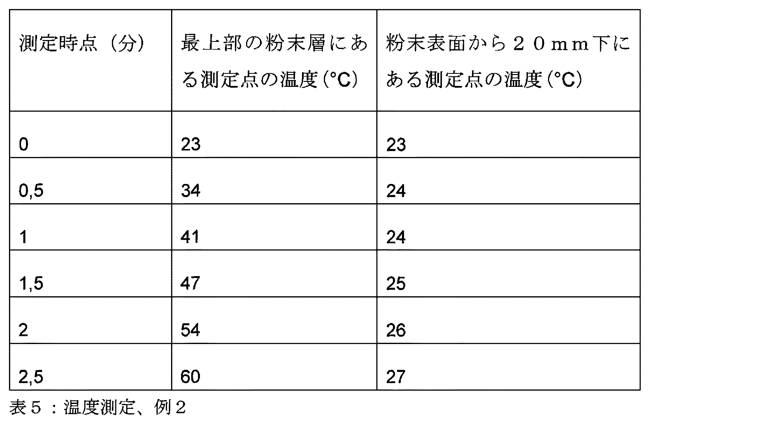
例2(本発明によるものではない)
表1に記載した特性値を有するポリマー粉末を、製造領域(寸法は35cm×35cm、面積は1225cm2)内に載せ、高さ100mmの粉末床を作る。黒鉛シートから成る熱放射要素を有する放射加熱器(この要素は、2000nmの波長で最大強度を有する放射を発する)が、粉末床を加熱する。ここで熱放射要素の面積は、775cm2である。粉末床の表面における温度と、粉末床内で深さ20mmの温度を測定し、記録する。その結果が、表5に示されている。
Example 2 (not according to the invention)
The polymer powder having the characteristic values described in Table 1 is placed in the production area (size 35 cm × 35 cm, area 1225 cm 2 ) to make a powder bed 100 mm high. A radiant heater (which emits radiation having a maximum intensity at a wavelength of 2000 nm) with a thermal emitting element consisting of a graphite sheet heats the powder bed. Here, the area of the heat emitting element is 775 cm 2 . The temperature at the surface of the powder bed and the temperature at a depth of 20 mm in the powder bed are measured and recorded. The results are shown in Table 5.
例3(本発明によるもの)
表1に記載した特性値を有するポリマー粉末を、製造領域(寸法は35cm×35cm、面積は1225cm2)内に載せ、高さ100mmの粉末床を作る。この粉末床を、放射加熱器により加熱する。この放射加熱器の熱放射要素は、6200nmの波長で最大強度を有する放射を発する。ここで最大放射強度の波長は10%未満、変動する。ここで熱放射要素の面積は、1852cm2である。粉末床の表面における温度と、粉末床内で深さ20mmの温度を測定し、記録する。その結果が、表6に示されている。ここで表面における温度は、本発明によらない例と比較して、明らかにより迅速に上昇する。これに対して深さ20mmにおける温度は、非常にゆっくりとしか上昇しない。これはつまり、比較的深い粉末層内にある粉末を過度に加熱することなく、このため熱によって不必要な負荷をかけることなく、粉末床の表面における温度を高められるということである。
Example 3 (according to the invention)
The polymer powder having the characteristic values described in Table 1 is placed in the production area (size 35 cm × 35 cm, area 1225 cm 2 ) to make a powder bed 100 mm high. The powder bed is heated by a radiant heater. The thermal radiation element of this radiant heater emits radiation having a maximum intensity at a wavelength of 6200 nm. Here, the wavelength of the maximum radiation intensity fluctuates by less than 10%. Here, the area of the heat emitting element is 1852 cm 2 . The temperature at the surface of the powder bed and the temperature at a depth of 20 mm in the powder bed are measured and recorded. The results are shown in Table 6. Here, the temperature at the surface obviously rises more rapidly compared to the examples not according to the invention. The temperature at a depth of 20 mm, on the other hand, rises only very slowly. This means that the temperature at the surface of the powder bed can be increased without excessively heating the powder in the relatively deep powder layer and thus without unnecessary load by heat.
例4(本発明によるもの)
表2に記載した特性値を有するポリマー粉末を、製造領域(寸法は35cm×35cm、面積は1225cm2)内に載せ、高さ100mmの粉末床を作る。この粉末床を、放射加熱器により加熱する。この放射加熱器の熱放射要素は、5700nmの波長で最大強度を有する放射を発する。ここで最大放射強度の波長は10%未満、変動する。ここで熱放射要素の面積は、2466cm2である。粉末床の表面における温度と、粉末床内で深さ20mmの温度を測定し、記録する。その結果が、表7に示されている。ここで表面における温度は、本発明によらない例と比較して、明らかにより迅速に上昇する。これに対して深さ20mmにおける温度は、非常にゆっくりとしか上昇しない。これはつまり、比較的深い粉末層内にある粉末を過度に加熱することなく、このため熱によって不必要な負荷をかけることなく、粉末床の表面における温度を高められるということである。
Example 4 (according to the invention)
The polymer powder with the characteristic values described in Table 2 is placed in the production area (size 35 cm × 35 cm, area 1225 cm 2 ) to make a powder bed 100 mm high. The powder bed is heated by a radiant heater. The thermal radiation element of this radiant heater emits radiation having a maximum intensity at a wavelength of 5700 nm. Here, the wavelength of the maximum radiation intensity fluctuates by less than 10%. Here, the area of the heat emitting element is 2466 cm 2 . The temperature at the surface of the powder bed and the temperature at a depth of 20 mm in the powder bed are measured and recorded. The results are shown in Table 7. Here, the temperature at the surface obviously rises more rapidly compared to the examples not according to the invention. The temperature at a depth of 20 mm, on the other hand, rises only very slowly. This means that the temperature at the surface of the powder bed can be increased without excessively heating the powder in the relatively deep powder layer and thus without unnecessary load by heat.
例5(本発明によるもの)
表3に記載した特性値を有するポリマー粉末を、製造領域(寸法は35cm×35cm、面積は1225cm2)内に載せ、高さ100mmの粉末床を作る。この粉末床を、放射加熱器により加熱する。この放射加熱器の熱放射要素は、5000nmの波長で最大強度を有する放射を発する。ここで最大放射強度の波長は10%未満、変動する。ここで熱放射要素の面積は、2466cm2である。粉末床の表面における温度と、粉末床内で深さ20mmの温度を測定し、記録する。その結果が、表8に示されている。ここで表面における温度は、本発明によらない例と比較して、明らかにより迅速に上昇する。これに対して深さ20mmにおける温度は、非常にゆっくりとしか上昇しない。これはつまり、比較的深い粉末層内にある粉末を過度に加熱することなく、このため熱によって不必要な負荷をかけることなく、粉末床の表面における温度を高められるということである。
Example 5 (according to the invention)
The polymer powder having the characteristic values described in Table 3 is placed in a production area (size 35 cm × 35 cm, area 1225 cm 2 ) to make a powder bed 100 mm high. The powder bed is heated by a radiant heater. The thermal radiation element of this radiant heater emits radiation having a maximum intensity at a wavelength of 5000 nm. Here, the wavelength of the maximum radiation intensity fluctuates by less than 10%. Here, the area of the heat emitting element is 2466 cm 2 . The temperature at the surface of the powder bed and the temperature at a depth of 20 mm in the powder bed are measured and recorded. The results are shown in Table 8. Here, the temperature at the surface obviously rises more rapidly compared to the examples not according to the invention. The temperature at a depth of 20 mm, on the other hand, rises only very slowly. This means that the temperature at the surface of the powder bed can be increased without excessively heating the powder in the relatively deep powder layer and thus without unnecessary load by heat.
例6(本発明によるもの)
表1に記載した特性値を有するポリマー粉末を、製造領域(寸法は35cm×35cm、面積は1225cm2)内に載せ、高さ100mmの粉末床を作る。この粉末床を、放射加熱器により加熱する。この放射加熱器の熱放射要素は、7050nmの波長で最大強度を有する放射を発する。ここで熱放射要素の面積は、1852cm2である。ここで最大放射強度の波長は5%未満、変動する。粉末床の表面における温度と、粉末床内で深さ20mmの温度を測定し、記録する。その結果が、表9に示されている。ここで表面における温度は、本発明によらない例と比較して、明らかにより迅速に上昇する。これに対して深さ20mmにおける温度は、非常にゆっくりとしか上昇しない。これはつまり、比較的深い粉末層内にある粉末を過度に加熱することなく、このため熱によって不必要な負荷をかけることなく、粉末床の表面における温度を高められるということである。
Example 6 (according to the invention)
The polymer powder having the characteristic values described in Table 1 is placed in the production area (size 35 cm × 35 cm, area 1225 cm 2 ) to make a powder bed 100 mm high. The powder bed is heated by a radiant heater. The thermal radiation element of this radiant heater emits radiation having a maximum intensity at a wavelength of 7050 nm. Here, the area of the heat emitting element is 1852 cm 2 . Here, the wavelength of the maximum radiation intensity fluctuates by less than 5%. The temperature at the surface of the powder bed and the temperature at a depth of 20 mm in the powder bed are measured and recorded. The results are shown in Table 9. Here, the temperature at the surface obviously rises more rapidly compared to the examples not according to the invention. The temperature at a depth of 20 mm, on the other hand, rises only very slowly. This means that the temperature at the surface of the powder bed can be increased without excessively heating the powder in the relatively deep powder layer and thus without unnecessary load by heat.
Claims (5)
以下の工程:
a)電磁線の作用によって固化可能な粉末材料の層を載せる工程、
b)熱放射要素の放射によって、最大温度がDIN 53765に従う融点を10K下回る温度に、粉末材料を加熱する工程、前記熱放射要素の最大放射強度は、5000nmの波長、又はそれよりも長い波長にあり、ここで、前記熱放射要素の面積が、加熱すべき粉末床の垂直投影面積の少なくとも100%であり、かつ、前記最大放射強度の波長変動は10%未満であり、
c)三次元物体の断面に相当する前記粉末材料の少なくとも1つの領域を、選択的に溶融及び/又は焼結させる工程、
d)三次元物体が得られるまで、前記工程a)〜c)を繰り返す工程、
が含まれている、前記方法。 A method of producing a three-dimensional object layer by layer,
The following steps:
a) placing a layer of powder material that can be solidified by the action of electromagnetic radiation,
b ) heating the powder material to a temperature at which the maximum temperature is 10 K below the melting point according to DIN 53765 by the radiation of the heat-emitting element, the maximum radiation intensity of said heat-emitting element is at a wavelength of 5000 nm or longer Wherein the area of the thermal radiation element is at least 100% of the vertical projected area of the powder bed to be heated, and the wavelength variation of the maximum radiation intensity is less than 10%,
c) selectively melting and / or sintering at least one region of said powder material corresponding to the cross section of a three-dimensional object;
d) repeating the steps a) to c) until a three-dimensional object is obtained,
Said method.
前記熱放射要素の放射照度が、加熱すべき粉末床の垂直投影面積に対して少なくとも2000W/m2であることを特徴とする、前記方法。 In the method according to claim 1,
Said method, characterized in that the irradiance of the thermal radiation element is at least 2000 W / m 2 with respect to the vertical projected area of the powder bed to be heated.
熱放射要素が含まれており、電磁線を粉末床の表面に放つ前記熱放射要素の面積が、製造フレームによって区切られている粉末床の垂直投影面積の少なくとも100%であり、ここで、前記熱放射要素の最大放射強度は、少なくとも5000nmの波長にあるように構成されており、かつ、前記最大放射強度の波長変動は10%未満であることを特徴とする、前記装置。 An apparatus for producing a three-dimensional object layer by layer,
Includes heat radiating elements, the area of the heat radiating element which emits electromagnetic radiation on the surface of the powder bed, Ri least 100% der vertical projected area of the powder bed that is delimited by the manufacturing frame, wherein The apparatus, wherein the maximum radiation intensity of the thermal radiation element is configured to be at a wavelength of at least 5000 nm, and the wavelength variation of the maximum radiation intensity is less than 10% .
前記熱放射要素は、該熱放射要素の面法線の方向への合計放射率が、少なくとも0.2であるように構成されていることを特徴とする、前記装置。 In the device according to claim 3 ,
Said device, characterized in that said heat emitting element is arranged such that the total emissivity in the direction of the surface normal of said heat emitting element is at least 0.2.
5000nmを超える波長における吸収率が、少なくとも0.8であることを特徴とする、前記粉末材料。 A powder material used in the method according to claim 1 or 2
The powder material characterized in that the absorptivity at wavelengths above 5000 nm is at least 0.8.
Applications Claiming Priority (2)
| Application Number | Priority Date | Filing Date | Title |
|---|---|---|---|
| DE102016205053.2A DE102016205053A1 (en) | 2016-03-24 | 2016-03-24 | Process for melting / sintering powder particles for the layered production of three-dimensional objects |
| DE102016205053.2 | 2016-03-24 |
Publications (3)
| Publication Number | Publication Date |
|---|---|
| JP2017170899A JP2017170899A (en) | 2017-09-28 |
| JP2017170899A5 JP2017170899A5 (en) | 2018-11-01 |
| JP6501812B2 true JP6501812B2 (en) | 2019-04-17 |
Family
ID=58387698
Family Applications (1)
| Application Number | Title | Priority Date | Filing Date |
|---|---|---|---|
| JP2017058621A Active JP6501812B2 (en) | 2016-03-24 | 2017-03-24 | Method of melting / sintering powder particles to produce three-dimensional objects layer by layer |
Country Status (7)
| Country | Link |
|---|---|
| US (2) | US10632730B2 (en) |
| EP (1) | EP3222410B1 (en) |
| JP (1) | JP6501812B2 (en) |
| CN (1) | CN107225758B (en) |
| DE (1) | DE102016205053A1 (en) |
| ES (1) | ES2785600T3 (en) |
| PL (1) | PL3222410T3 (en) |
Families Citing this family (5)
| Publication number | Priority date | Publication date | Assignee | Title |
|---|---|---|---|---|
| DE102016219080A1 (en) | 2016-09-30 | 2018-04-05 | Evonik Degussa Gmbh | Polyamide powder for selective sintering |
| DE102017203523A1 (en) | 2016-10-04 | 2017-06-29 | Evonik Degussa Gmbh | Apparatus for heating polymeric powders by radiation in powder coating processes |
| DE102018100508A1 (en) * | 2017-10-18 | 2019-04-18 | Value & Intellectual Properties Management Gmbh | 3D melt printing processes |
| EP3501695A1 (en) | 2017-12-22 | 2019-06-26 | Evonik Degussa GmbH | Device for the layered production of three-dimensional objects and process |
| CN108480625A (en) * | 2018-03-12 | 2018-09-04 | 北京工业大学 | A kind of enhancing aluminum-base composite material by silicon carbide particles manufacturing process based on selective laser melting process |
Family Cites Families (22)
| Publication number | Priority date | Publication date | Assignee | Title |
|---|---|---|---|---|
| US5155321A (en) | 1990-11-09 | 1992-10-13 | Dtm Corporation | Radiant heating apparatus for providing uniform surface temperature useful in selective laser sintering |
| US5527877A (en) * | 1992-11-23 | 1996-06-18 | Dtm Corporation | Sinterable semi-crystalline powder and near-fully dense article formed therewith |
| US5990268A (en) | 1992-11-23 | 1999-11-23 | Dtm Corporation | Sinterable semi-crystalline powder and near-fully dense article formed therewith |
| US5648450A (en) | 1992-11-23 | 1997-07-15 | Dtm Corporation | Sinterable semi-crystalline powder and near-fully dense article formed therein |
| US5342919A (en) | 1992-11-23 | 1994-08-30 | Dtm Corporation | Sinterable semi-crystalline powder and near-fully dense article formed therewith |
| SE509088C2 (en) | 1997-04-30 | 1998-12-07 | Ralf Larsson | Methods and apparatus for the production of volume bodies |
| US6007764A (en) * | 1998-03-27 | 1999-12-28 | United Technologies Corporation | Absorption tailored laser sintering |
| JP2003080604A (en) * | 2001-09-10 | 2003-03-19 | Fuji Photo Film Co Ltd | Laminate shaping apparatus |
| DE10236697A1 (en) * | 2002-08-09 | 2004-02-26 | Eos Gmbh Electro Optical Systems | Method and device for producing a three-dimensional object by means of sintering |
| US7159535B2 (en) * | 2003-05-21 | 2007-01-09 | Mdf Powder Coat Systems L.L.C. | Apparatus for heating and curing powder coatings on porous wood products |
| DE102004020452A1 (en) * | 2004-04-27 | 2005-12-01 | Degussa Ag | Method for producing three-dimensional objects by means of electromagnetic radiation and applying an absorber by inkjet method |
| US7521652B2 (en) * | 2004-12-07 | 2009-04-21 | 3D Systems, Inc. | Controlled cooling methods and apparatus for laser sintering part-cake |
| DE102005022308B4 (en) * | 2005-05-13 | 2007-03-22 | Eos Gmbh Electro Optical Systems | Apparatus and method for manufacturing a three-dimensional object with a heated powder coating material build-up material |
| DE102005024790A1 (en) | 2005-05-26 | 2006-12-07 | Eos Gmbh Electro Optical Systems | Radiant heating for heating the building material in a laser sintering device |
| DE102007016656B4 (en) * | 2007-04-05 | 2018-10-11 | Eos Gmbh Electro Optical Systems | PAEK powder, in particular for use in a process for producing a three-dimensional object in layers, and method for its production |
| DE102007024469B4 (en) * | 2007-05-25 | 2009-04-23 | Eos Gmbh Electro Optical Systems | Method of layering a three-dimensional object |
| JP5467714B2 (en) * | 2007-08-08 | 2014-04-09 | テクノポリマー株式会社 | Laser-sinterable powder and shaped product thereof |
| CN102380711B (en) * | 2010-09-01 | 2014-08-06 | 中国科学院光电研究院 | Selective sintering laser processing system |
| GB2493398B (en) | 2011-08-05 | 2016-07-27 | Univ Loughborough | Methods and apparatus for selectively combining particulate material |
| DE102011085154A1 (en) * | 2011-10-25 | 2013-04-25 | Evonik Industries Ag | Device for preventing deposits on optical components in laser sintering |
| JP5995202B2 (en) * | 2012-07-31 | 2016-09-21 | 株式会社アスペクト | Powder additive manufacturing apparatus and powder additive manufacturing method |
| DE102013109162A1 (en) * | 2013-08-23 | 2015-02-26 | Fit Fruth Innovative Technologien Gmbh | Device for producing three-dimensional objects |
-
2016
- 2016-03-24 DE DE102016205053.2A patent/DE102016205053A1/en not_active Withdrawn
-
2017
- 2017-03-17 EP EP17161624.6A patent/EP3222410B1/en active Active
- 2017-03-17 PL PL17161624T patent/PL3222410T3/en unknown
- 2017-03-17 ES ES17161624T patent/ES2785600T3/en active Active
- 2017-03-23 CN CN201710177152.2A patent/CN107225758B/en active Active
- 2017-03-24 JP JP2017058621A patent/JP6501812B2/en active Active
- 2017-03-24 US US15/468,465 patent/US10632730B2/en active Active
-
2020
- 2020-02-27 US US16/803,464 patent/US11285662B2/en active Active
Also Published As
| Publication number | Publication date |
|---|---|
| CN107225758B (en) | 2020-03-03 |
| US11285662B2 (en) | 2022-03-29 |
| JP2017170899A (en) | 2017-09-28 |
| ES2785600T3 (en) | 2020-10-07 |
| PL3222410T3 (en) | 2020-07-13 |
| CN107225758A (en) | 2017-10-03 |
| US20200230937A1 (en) | 2020-07-23 |
| US20170274591A1 (en) | 2017-09-28 |
| EP3222410A1 (en) | 2017-09-27 |
| EP3222410B1 (en) | 2020-02-12 |
| US10632730B2 (en) | 2020-04-28 |
| DE102016205053A1 (en) | 2017-09-28 |
Similar Documents
| Publication | Publication Date | Title |
|---|---|---|
| JP6501812B2 (en) | Method of melting / sintering powder particles to produce three-dimensional objects layer by layer | |
| US11731361B2 (en) | Process and apparatus for producing 3D moldings comprising a spectrum converter | |
| US11951681B2 (en) | Method and device for lithography-based additive production of three-dimensional shaped bodies | |
| US11752697B2 (en) | Device and method for making a three-dimensional object | |
| US20180326662A1 (en) | Method and device for 3d printing with a narrow wavelength spectrum | |
| KR102393703B1 (en) | Method and device for producing 3d shaped articles by layering | |
| TWI724321B (en) | Lamination molding apparatus and method for manufacturing lamination molded product | |
| JP6496406B2 (en) | Surface heating control | |
| US9327450B2 (en) | Device and method for manufacturing a three-dimensional object by means of an application device for building material in powder form | |
| EP2851180A1 (en) | Method and apparatus for forming three-dimensional articles | |
| CN105764674B (en) | 3D printing method using slip | |
| JP2017170899A5 (en) | ||
| US10981322B2 (en) | Process for the accelerated production of objects by means of generative manufacturing | |
| CN109070455B (en) | Method and device for the generative production of three-dimensional objects | |
| US10967575B2 (en) | Method and device for the generative manufacturing of a three-dimensional object | |
| US20200079009A1 (en) | Method and device for producing a three-dimensional object | |
| JP2021508293A (en) | Equipment for laminating and manufacturing 3D objects | |
| JP2019196523A (en) | Apparatus and method for lamination molding | |
| KR102476579B1 (en) | Printer for manufacturing three-dimensional object | |
| JP7462185B2 (en) | How to create 3D fired objects | |
| EP3565704B1 (en) | Additive manufacturing | |
| CN117561149A (en) | Article containing silicon carbide as main component and method for producing same |
Legal Events
| Date | Code | Title | Description |
|---|---|---|---|
| A977 | Report on retrieval |
Free format text: JAPANESE INTERMEDIATE CODE: A971007 Effective date: 20180510 |
|
| A131 | Notification of reasons for refusal |
Free format text: JAPANESE INTERMEDIATE CODE: A131 Effective date: 20180625 |
|
| A524 | Written submission of copy of amendment under article 19 pct |
Free format text: JAPANESE INTERMEDIATE CODE: A524 Effective date: 20180918 |
|
| TRDD | Decision of grant or rejection written | ||
| A01 | Written decision to grant a patent or to grant a registration (utility model) |
Free format text: JAPANESE INTERMEDIATE CODE: A01 Effective date: 20190304 |
|
| A61 | First payment of annual fees (during grant procedure) |
Free format text: JAPANESE INTERMEDIATE CODE: A61 Effective date: 20190319 |
|
| R150 | Certificate of patent or registration of utility model |
Ref document number: 6501812 Country of ref document: JP Free format text: JAPANESE INTERMEDIATE CODE: R150 |
|
| S533 | Written request for registration of change of name |
Free format text: JAPANESE INTERMEDIATE CODE: R313533 |
|
| R350 | Written notification of registration of transfer |
Free format text: JAPANESE INTERMEDIATE CODE: R350 |
|
| R250 | Receipt of annual fees |
Free format text: JAPANESE INTERMEDIATE CODE: R250 |
|
| R250 | Receipt of annual fees |
Free format text: JAPANESE INTERMEDIATE CODE: R250 |
|
| R250 | Receipt of annual fees |
Free format text: JAPANESE INTERMEDIATE CODE: R250 |