JP6501166B2 - Tooth cleaning device with internal flow path formed - Google Patents
Tooth cleaning device with internal flow path formed Download PDFInfo
- Publication number
- JP6501166B2 JP6501166B2 JP2017561216A JP2017561216A JP6501166B2 JP 6501166 B2 JP6501166 B2 JP 6501166B2 JP 2017561216 A JP2017561216 A JP 2017561216A JP 2017561216 A JP2017561216 A JP 2017561216A JP 6501166 B2 JP6501166 B2 JP 6501166B2
- Authority
- JP
- Japan
- Prior art keywords
- cleaning
- tube
- main body
- flow path
- internal flow
- Prior art date
- Legal status (The legal status is an assumption and is not a legal conclusion. Google has not performed a legal analysis and makes no representation as to the accuracy of the status listed.)
- Active
Links
- 238000004140 cleaning Methods 0.000 title claims description 158
- 230000008878 coupling Effects 0.000 claims description 61
- 238000010168 coupling process Methods 0.000 claims description 61
- 238000005859 coupling reaction Methods 0.000 claims description 61
- 238000000034 method Methods 0.000 claims description 23
- 230000008569 process Effects 0.000 claims description 22
- 238000005406 washing Methods 0.000 claims description 18
- 238000003780 insertion Methods 0.000 claims description 13
- 230000037431 insertion Effects 0.000 claims description 13
- 239000007788 liquid Substances 0.000 claims description 9
- 230000002093 peripheral effect Effects 0.000 claims description 8
- 210000000214 mouth Anatomy 0.000 description 12
- 239000012530 fluid Substances 0.000 description 10
- XLYOFNOQVPJJNP-UHFFFAOYSA-N water Substances O XLYOFNOQVPJJNP-UHFFFAOYSA-N 0.000 description 5
- 239000000470 constituent Substances 0.000 description 4
- 238000010586 diagram Methods 0.000 description 4
- 230000001680 brushing effect Effects 0.000 description 3
- 230000000694 effects Effects 0.000 description 3
- 238000007599 discharging Methods 0.000 description 2
- 238000012423 maintenance Methods 0.000 description 2
- 230000008439 repair process Effects 0.000 description 2
- 230000009471 action Effects 0.000 description 1
- 238000004891 communication Methods 0.000 description 1
- 238000000354 decomposition reaction Methods 0.000 description 1
- 210000003128 head Anatomy 0.000 description 1
- 238000012986 modification Methods 0.000 description 1
- 230000004048 modification Effects 0.000 description 1
- 238000007789 sealing Methods 0.000 description 1
- 238000009751 slip forming Methods 0.000 description 1
- 239000007921 spray Substances 0.000 description 1
- 230000003813 thin hair Effects 0.000 description 1
- 238000004078 waterproofing Methods 0.000 description 1
Images


Classifications
-
- A—HUMAN NECESSITIES
- A61—MEDICAL OR VETERINARY SCIENCE; HYGIENE
- A61C—DENTISTRY; APPARATUS OR METHODS FOR ORAL OR DENTAL HYGIENE
- A61C17/00—Devices for cleaning, polishing, rinsing or drying teeth, teeth cavities or prostheses; Saliva removers; Dental appliances for receiving spittle
- A61C17/02—Rinsing or air-blowing devices, e.g. using fluid jets or comprising liquid medication
- A61C17/0208—Rinsing or air-blowing devices, e.g. using fluid jets or comprising liquid medication combined with means providing suction
-
- A—HUMAN NECESSITIES
- A46—BRUSHWARE
- A46B—BRUSHES
- A46B11/00—Brushes with reservoir or other means for applying substances, e.g. paints, pastes, water
- A46B11/0006—Brushes with reservoir or other means for applying substances, e.g. paints, pastes, water specially adapted to feed the bristle upper surface
-
- A—HUMAN NECESSITIES
- A46—BRUSHWARE
- A46B—BRUSHES
- A46B11/00—Brushes with reservoir or other means for applying substances, e.g. paints, pastes, water
- A46B11/001—Brushes with reservoir or other means for applying substances, e.g. paints, pastes, water with integral reservoirs
- A46B11/002—Brushes with reservoir or other means for applying substances, e.g. paints, pastes, water with integral reservoirs pressurised at moment of use manually or by powered means
-
- A—HUMAN NECESSITIES
- A46—BRUSHWARE
- A46B—BRUSHES
- A46B11/00—Brushes with reservoir or other means for applying substances, e.g. paints, pastes, water
- A46B11/06—Brushes with reservoir or other means for applying substances, e.g. paints, pastes, water connected to supply pipe or to other external supply means
- A46B11/063—Brushes with reservoir or other means for applying substances, e.g. paints, pastes, water connected to supply pipe or to other external supply means by means of a supply pipe
-
- A—HUMAN NECESSITIES
- A46—BRUSHWARE
- A46B—BRUSHES
- A46B15/00—Other brushes; Brushes with additional arrangements
- A46B15/0002—Arrangements for enhancing monitoring or controlling the brushing process
- A46B15/0016—Arrangements for enhancing monitoring or controlling the brushing process with enhancing means
- A46B15/0036—Arrangements for enhancing monitoring or controlling the brushing process with enhancing means with a lighting means, e.g. laser, bulb
-
- A—HUMAN NECESSITIES
- A46—BRUSHWARE
- A46B—BRUSHES
- A46B7/00—Bristle carriers arranged in the brush body
- A46B7/04—Bristle carriers arranged in the brush body interchangeably removable bristle carriers
- A46B7/042—Clip or snap connection for bristle carriers
-
- A—HUMAN NECESSITIES
- A46—BRUSHWARE
- A46B—BRUSHES
- A46B9/00—Arrangements of the bristles in the brush body
- A46B9/02—Position or arrangement of bristles in relation to surface of the brush body, e.g. inclined, in rows, in groups
- A46B9/04—Arranged like in or for toothbrushes
-
- A—HUMAN NECESSITIES
- A61—MEDICAL OR VETERINARY SCIENCE; HYGIENE
- A61C—DENTISTRY; APPARATUS OR METHODS FOR ORAL OR DENTAL HYGIENE
- A61C1/00—Dental machines for boring or cutting ; General features of dental machines or apparatus, e.g. hand-piece design
-
- A—HUMAN NECESSITIES
- A61—MEDICAL OR VETERINARY SCIENCE; HYGIENE
- A61C—DENTISTRY; APPARATUS OR METHODS FOR ORAL OR DENTAL HYGIENE
- A61C1/00—Dental machines for boring or cutting ; General features of dental machines or apparatus, e.g. hand-piece design
- A61C1/0061—Air and water supply systems; Valves specially adapted therefor
- A61C1/0076—Sterilising operating fluids or fluid supply elements such as supply lines, filters
-
- A—HUMAN NECESSITIES
- A61—MEDICAL OR VETERINARY SCIENCE; HYGIENE
- A61C—DENTISTRY; APPARATUS OR METHODS FOR ORAL OR DENTAL HYGIENE
- A61C17/00—Devices for cleaning, polishing, rinsing or drying teeth, teeth cavities or prostheses; Saliva removers; Dental appliances for receiving spittle
- A61C17/02—Rinsing or air-blowing devices, e.g. using fluid jets or comprising liquid medication
- A61C17/0202—Hand-pieces
-
- A—HUMAN NECESSITIES
- A61—MEDICAL OR VETERINARY SCIENCE; HYGIENE
- A61C—DENTISTRY; APPARATUS OR METHODS FOR ORAL OR DENTAL HYGIENE
- A61C17/00—Devices for cleaning, polishing, rinsing or drying teeth, teeth cavities or prostheses; Saliva removers; Dental appliances for receiving spittle
- A61C17/02—Rinsing or air-blowing devices, e.g. using fluid jets or comprising liquid medication
- A61C17/024—Rinsing or air-blowing devices, e.g. using fluid jets or comprising liquid medication with constant liquid flow
-
- A—HUMAN NECESSITIES
- A61—MEDICAL OR VETERINARY SCIENCE; HYGIENE
- A61C—DENTISTRY; APPARATUS OR METHODS FOR ORAL OR DENTAL HYGIENE
- A61C17/00—Devices for cleaning, polishing, rinsing or drying teeth, teeth cavities or prostheses; Saliva removers; Dental appliances for receiving spittle
- A61C17/02—Rinsing or air-blowing devices, e.g. using fluid jets or comprising liquid medication
- A61C17/028—Rinsing or air-blowing devices, e.g. using fluid jets or comprising liquid medication with intermittent liquid flow
-
- A—HUMAN NECESSITIES
- A61—MEDICAL OR VETERINARY SCIENCE; HYGIENE
- A61C—DENTISTRY; APPARATUS OR METHODS FOR ORAL OR DENTAL HYGIENE
- A61C17/00—Devices for cleaning, polishing, rinsing or drying teeth, teeth cavities or prostheses; Saliva removers; Dental appliances for receiving spittle
- A61C17/16—Power-driven cleaning or polishing devices
- A61C17/22—Power-driven cleaning or polishing devices with brushes, cushions, cups, or the like
- A61C17/222—Brush body details, e.g. the shape thereof or connection to handle
-
- A—HUMAN NECESSITIES
- A46—BRUSHWARE
- A46B—BRUSHES
- A46B2200/00—Brushes characterized by their functions, uses or applications
- A46B2200/10—For human or animal care
- A46B2200/1066—Toothbrush for cleaning the teeth or dentures
-
- A—HUMAN NECESSITIES
- A46—BRUSHWARE
- A46B—BRUSHES
- A46B7/00—Bristle carriers arranged in the brush body
- A46B7/04—Bristle carriers arranged in the brush body interchangeably removable bristle carriers
- A46B7/046—Threaded or screw connections for bristle carriers
-
- A—HUMAN NECESSITIES
- A61—MEDICAL OR VETERINARY SCIENCE; HYGIENE
- A61C—DENTISTRY; APPARATUS OR METHODS FOR ORAL OR DENTAL HYGIENE
- A61C1/00—Dental machines for boring or cutting ; General features of dental machines or apparatus, e.g. hand-piece design
- A61C1/08—Machine parts specially adapted for dentistry
- A61C1/088—Illuminating devices or attachments
Description
本発明は、歯洗浄器具に関し、さらに詳細には、内部に形成された流路を通して洗浄液を供給するか、または口腔の流体を外部に排出できる歯洗浄器具に関する。 BACKGROUND OF THE INVENTION Field of the Invention The present invention relates to a tooth cleaning device, and more particularly to a tooth cleaning device capable of supplying a cleaning solution through an internally formed flow path or discharging an oral fluid to the outside.
歯洗浄のための最も一般的な器具は歯ブラシであり、このような歯ブラシ(Toothbrush)は、歯の健康管理と衛生清潔のために歯磨き粉をつけて歯磨きをするために使われる道具である。歯ブラシは、スティック形態の把持部と、把持部の先端に形成された胴体に細い毛部材がぎっしり植毛されるブラシとを含む。 The most common tool for cleaning teeth is a toothbrush, and such a toothbrush (Toothbrush) is a tool used to brush and brush a tooth for care and hygiene of the teeth. The toothbrush includes a stick-shaped gripping portion, and a brush in which a thin hair member is closely flocked on a body formed at the tip of the gripping portion.
そして、歯洗浄時には、歯ブラシのブラシを歯に当ててブラッシングしながら口腔内の含嗽水を除去する行動を繰り返すこととなり、ブラッシングを終えると、洗浄水で口腔内を洗浄し、含嗽水を吐き出すようになる。 And at the time of tooth washing, the action of removing the rinse water in the oral cavity will be repeated while brushing by putting the brush of the toothbrush on the teeth, and after finishing brushing, wash the mouth with wash water and spit the rinse water become.
従来の伝統的な構造の歯ブラシ以外にも、近年は、洗浄液を供給する歯洗浄器具が開発されて使われている。このような歯洗浄器具は、口腔内部に水のような洗浄液を強い圧力で供給し、歯または歯間の洗浄がなされるようにするが、このような方式の歯洗浄器具は、洗浄液が噴射されるノズルの取り替えが不可能であったり、分解時に防水性能に問題が発生したりする場合が多い。 In addition to the traditional toothbrushes of the conventional structure, in recent years, tooth cleaning appliances for supplying cleaning fluid have been developed and used. Such a tooth cleaning device supplies a cleaning solution such as water to the inside of the oral cavity under strong pressure so that the teeth or teeth can be cleaned. However, such a type of tooth cleaning device sprays the cleaning solution. Replacement of the nozzle is often impossible, or problems with waterproof performance often occur during disassembly.
従って、歯洗浄器具のノズル及び一部の部品だけを取り替えることが可能で、歯洗浄器具の内部を維持補修する作業が便利であり、防水性能に優れた歯洗浄器具が必要な実情である。 Therefore, it is possible to replace only the nozzle and part of the tooth cleaning device, the operation of maintaining and repairing the inside of the tooth cleaning device is convenient, and a tooth cleaning device having excellent waterproof performance is required.
本発明は、上述したような従来の技術の問題点を解決するためのものであって、本発明の目的は、歯洗浄器具からノズル側の部品を容易に組み立て及び分解できるようにすると同時に、組み立て後、防水性能が維持され得るようにすることである。 The present invention solves the problems of the prior art as described above, and the object of the present invention is to make it possible to easily assemble and disassemble the parts on the nozzle side from the tooth cleaning device, After assembly, the waterproof performance is to be maintained.
上述したような目的を達成するための本発明の特徴によると、本発明は、駆動部と選択的に連結可能なチューブが内部に備えられるメイン胴体と、前記メイン胴体の一側に組み立てられ、内部には、前記チューブと連結可能な内部流路が形成され、前記内部流路の一端には、少なくとも一つ以上のノズルが開口して形成される洗浄胴体を含み、前記メイン胴体と前記洗浄胴体が組み立てられると、前記チューブの一端が前記内部流路の一端に連結され、連続した流路を形成する。 According to a feature of the present invention for achieving the objects as described above, the present invention is assembled on one side of a main body in which a tube selectively connectable with a drive unit is provided, and one side of the main body. An internal flow path connectable to the tube is formed in the inside, and at one end of the internal flow path includes a cleaning body formed by opening at least one or more nozzles, and the main body and the cleaning When the body is assembled, one end of the tube is connected to one end of the internal channel to form a continuous channel.
そして、前記洗浄胴体と前記メイン胴体には、互いに対応する結合突起と結合チャネルが形成され、前記洗浄胴体が前記メイン胴体に結合される過程で前記結合突起が前記結合チャネルに沿って案内された後、前記結合チャネルの一側に係止して固定される。 The washing body and the main body have coupling protrusions and coupling channels corresponding to each other, and the binding protrusions are guided along the binding channels in the process of bonding the washing body to the main body. Then, it is locked to one side of the coupling channel.
前記メイン胴体には、フランジが分離可能に結合され、前記結合チャネルは、前記フランジの内面に凹入して形成され、前記結合チャネルは、一端が外側に開口した導入部と、前記導入部から前記メイン胴体と洗浄胴体の結合方向に延びる連結部と、前記連結部から直交または傾斜した方向に延びる回転部とを含み、前記回転部の一端には、係止ジョーが突出して形成され得る。 A flange is separably connected to the main body, and the coupling channel is formed by being recessed into the inner surface of the flange, and the coupling channel has an introducing portion open at one end, and the introducing portion from the introducing portion A locking jaw may be formed to protrude from one end of the rotating portion, including a connecting portion extending in a connecting direction of the main body and the cleaning body, and a rotating portion extending in a direction orthogonal or inclined from the connecting portion.
そして、前記チューブは、前記メイン胴体から分離可能に前記メイン胴体に備えられ、前記内部流路は、前記洗浄胴体に一体に形成される。 The tube is provided on the main body so as to be separable from the main body, and the internal flow path is integrally formed on the cleaning body.
前記フランジの内側には、前記メイン胴体の内部に備えられたチューブの一端が位置され、前記洗浄胴体が前記フランジに結合されると、前記洗浄胴体の内部流路の一端と前記チューブの一端が互いに連結される。 One end of a tube provided inside the main body is positioned inside the flange, and when the cleaning body is connected to the flange, one end of the internal flow path of the cleaning body and one end of the tube Connected to each other.
一方、前記フランジの下部には、チューブガイドが備えられ、前記チューブガイドは、前記メイン胴体の内面に支持されて固定されるガイドプレートと、前記ガイドプレートの底面に突出し、前記チューブの一端と結合されるチューブ結合部と、前記ガイドプレートの上面に突出し、前記フランジの内部に位置され、前記フランジに前記洗浄胴体が結合されると、前記洗浄胴体の内部流路に少なくとも一部が挿入される流路挿入部とを含んで構成される。 Meanwhile, a tube guide is provided at a lower portion of the flange, and the tube guide protrudes from a guide plate supported and fixed to the inner surface of the main body and a bottom surface of the guide plate, and is coupled to one end of the tube The tube connection portion is protruded to the upper surface of the guide plate, and is positioned inside the flange, and when the cleaning body is connected to the flange, at least a portion is inserted into the internal flow path of the cleaning body And a channel insertion portion.
前記流路挿入部の外面には、防水室が備えられる。 A waterproof chamber is provided on the outer surface of the flow path insertion part.
そして、前記チューブ結合部は、突出した一端へ行くほど幅が狭くなるように形成され、前記チューブ結合部の外面には、少なくとも一つの結合リブが突出して形成され得る。 The tube connection part may be formed such that the width becomes narrower toward the protruding end, and at least one connection rib may be formed on the outer surface of the tube connection part.
また、前記メイン胴体には、光を照射する発光部が備えられ、前記チューブガイドには、回避部が凹入または開口するように形成され、前記発光部から照射される光を通過させるか、または前記発光部が安着されるようにする。 In addition, the main body may be provided with a light emitting unit for emitting light, and the tube guide may be formed to be recessed or opened with an avoidance unit, and the light emitted from the light emitting unit may be transmitted. Alternatively, the light emitting unit may be seated.
ここで、前記洗浄胴体は、内部に内部流路が形成された連結バーと、前記連結バーの一端に備えられ、外面には少なくとも一つ以上のノズルが形成される洗浄ヘッドと、前記連結バーの他端に突出し、外面には前記結合突起が備えられた結合ボスとを含んで構成される。 Here, the cleaning body is provided with a connection bar having an internal flow path formed therein, a cleaning head provided at one end of the connection bar, and at least one or more nozzles formed on the outer surface, and the connection bar And a coupling boss provided on the outer surface with the coupling protrusion.
前記洗浄ヘッドは、円柱状に形成され、前記ノズルは、前記洗浄ヘッドの外周面または洗浄ヘッドの上面及び底面の少なくともいずれか一側に多数個が形成され、前記ノズルは、前記洗浄ヘッドの外周面に向かって放射状に形成され得る。 The cleaning head is formed in a cylindrical shape, and a large number of the nozzles are formed on the outer peripheral surface of the cleaning head or at least one side of the upper surface and the bottom surface of the cleaning head, and the nozzles are the outer periphery of the cleaning head It can be formed radially towards the surface.
また、前記洗浄ヘッドには、ブラシが分離可能に結合される。 Also, a brush is detachably coupled to the cleaning head.
前記チューブは、前記メイン胴体から分離可能に前記メイン胴体の内部に備えられ、前記駆動部は、前記チューブに洗浄液を供給するか、または前記チューブに負圧を提供し、前記ノズルから液体を吸入する。 The tube is provided inside the main body so as to be separable from the main body, and the driving unit supplies a cleaning solution to the tube or provides a negative pressure to the tube and sucks a liquid from the nozzle. Do.
先に検討したような本発明による内部流路が形成された歯洗浄器具では、下記のような効果が期待できる。 The following effects can be expected with the tooth washing apparatus having the internal flow passage according to the present invention as discussed above.
本発明においては、歯洗浄器具を構成するメイン胴体と洗浄胴体の組み立て及び分解が可能であり、分解を通してチューブ及び内部流路等の一部の部品の修理や取り替えまたは洗浄が可能であるので、歯洗浄器具の維持補修性が良くなる効果がある。 In the present invention, it is possible to assemble and disassemble the main body and the cleaning body that constitute the tooth cleaning device, and it is possible to repair, replace, or clean some parts such as the tube and the internal flow passage through the decomposition. This has the effect of improving the maintenance and repairability of the tooth cleaning device.
そして、本発明においては、回転動作を通してメイン胴体と洗浄胴体が互いに容易に組み立て及び分解が可能であり、このような組み立て過程でチューブガイドを通してチューブの一端と洗浄胴体の内部流路が自然に連結されるので、組み立て性が向上し、また、別途の作業なしにもメイン胴体と洗浄胴体の組み立て過程でチューブガイドの防水室が内部流路に圧着されて防水機能が具現されるので、動作信頼性が向上し得る。 And, in the present invention, the main body and the washing body can be easily assembled and disassembled with each other through the rotation operation, and in the assembling process, one end of the tube and the inner flow path of the washing body are naturally connected through the tube guide. As a result, the assemblability is improved, and the waterproofing chamber of the tube guide is crimped to the internal flow path in the assembling process of the main fuselage and the cleaning fuselage without any additional work, so that the waterproof function is realized. Sex can be improved.
また、本発明においては、ブラシが洗浄ヘッドに選択的に結合されるので、ブラシを除去し、歯洗浄器具を単に洗浄液の供給または排出用途に使用するか、またはブラシを結合して一般の歯ブラシのように使用することもでき、歯洗浄器具の活用度が大きくなる効果もある。 Also, in the present invention, since the brush is selectively coupled to the cleaning head, the brush is removed, and the tooth cleaning device is simply used for supplying or discharging the cleaning solution, or the brush is coupled to a general toothbrush There is also an effect that the degree of utilization of the tooth cleaning device can be increased.
以下、本発明の一部の実施例を例示的な図面を通して詳細に説明する。各図面の構成要素に参照符号を付するにあたって、同じ構成要素に対しては、他の図面上に表示されても、できる限り同じ符号を有するようにしていることに留意すべきである。また、本発明の実施例を説明するにあたって、関連の公知構成または機能についての具体的な説明が本発明の実施例に対する理解を妨害すると判断される場合は、その詳細な説明は省略する。 Hereinafter, some embodiments of the present invention will be described in detail through exemplary drawings. It should be noted that, when the reference numerals are given to the constituent elements of each drawing, the same constituent elements have the same reference numerals as much as possible even if they are displayed on other drawings. Further, in the description of the embodiments of the present invention, when it is determined that the detailed description of related known configurations or functions disturbs the understanding of the embodiments of the present invention, the detailed description will be omitted.
また、本発明の実施例の構成要素を説明するにあたって、第1、第2、A、B、(a)、(b)等の用語を用いることができる。このような用語は、その構成要素を他の構成要素と区別するためのものであるだけで、その用語により該当構成要素の本質や手順または順序等は限定されない。ある構成要素が他の構成要素に「連結」、「結合」または「接続」されると記載された場合、その構成要素は、その他の構成要素に直接的に連結または接続され得るが、各構成要素の間にまた他の構成要素が「連結」、「結合」または「接続」されることもあると理解されるべきである。 Further, in describing the components of the embodiment of the present invention, terms such as first, second, A, B, (a), (b) can be used. Such terms are merely to distinguish the component from the other components, and the nature, procedure, order, or the like of the corresponding component is not limited by the term. Where a component is described as being "connected", "coupled" or "connected" to another component, that component may be directly connected or connected to the other component, but each configuration It should be understood that other components may also be "connected", "coupled" or "connected" between elements.
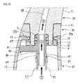
図1には、本発明による内部流路が形成された歯洗浄器具の一実施例の構成が斜視図で示されている。 FIG. 1 is a perspective view showing the configuration of an embodiment of a tooth cleaning device having an internal flow passage according to the present invention.
それから見られるように、本発明による内部流路58が形成された歯洗浄器具(以下、「歯洗浄器具」という)は、大きくメイン胴体10と洗浄胴体50とで構成される。前記メイン胴体10は、歯洗浄器具の下部骨格及び外形を形成するものであって、使用者が歯洗浄器具を使用するとき、実質的に把持する一種の把持部分に該当し、洗浄胴体50は、歯の洗浄がなされる部分である。
As can be seen from this, the tooth cleaning device (hereinafter referred to as "tooth cleaning device") in which the
そして、下記においてまた説明するように、歯洗浄器具には、駆動部100が連結されるが、駆動部100は、チューブT1を通して洗浄液を供給するか、または口腔内の流体を吸入するための外力を発生させる部分である。参考までに、本実施例において、前記駆動部100は、歯洗浄器具の外部に備えられた外部本体で構成されるが、前記駆動部100は、歯洗浄器具と一体に構成されてもよい。例えば、前記駆動部100は、メイン胴体10の内部に組み込まれるか、またはメイン胴体10に結合された部品であってもよい。
And although the
以下においては、これらの構造について順次に検討する。先ず、メイン胴体10は、内部が空いている一種の長いバー(bar)形状であって、使用者が把持する部分である。本実施例においては、図1から見られるように、前記メイン胴体10の外面12が曲面形状に形成されるが、多角形状に形成されるか、または把持する部分を表示できるように凹入された形状等、様々な外形が可能である。
In the following, these structures will be considered sequentially. First of all, the
前記メイン胴体10の内部には、内部空間が形成される。前記内部空間は、前記メイン胴体10の長手方向に沿って長く延びて形成されるものであり、前記内部空間には、下記において説明されるチューブT1とチューブガイド40が挿入される。
An internal space is formed in the
図5から見られるように、前記メイン胴体10の一側には、第1締結突部15が形成される。前記第1締結突部15は、下記において説明されるフランジ30の第2締結凹溝39aに対応するものであり、フランジ30の第2締結凹溝39aに第1締結突部15が挿入され、メイン胴体10とフランジ30との間の結合がなされる。もちろん、前記メイン胴体10に締結溝が形成され、フランジ30に締結突部が備えられてもよい。
As seen from FIG. 5, a
参考までに、前記メイン胴体10は、2つの部品で構成され、2つの部品がフランジ30を挟んで結合されることにより、フランジ30がメイン胴体10と結合されるように構成されてもよい。
For reference, the
前記メイン胴体10には、チューブT1が挿入される。前記チューブT1は、前記メイン胴体10の長手方向に沿って延びるものであり、その一端は、下記において説明される洗浄胴体50の内部流路58と連結され、他端は、駆動部100と連結される。これによって、前記チューブT1は、前記駆動部100の吸入力による負圧を洗浄胴体50に伝達するか、または、逆に駆動部100の吐出力による洗浄液の排出を洗浄胴体50に伝達することができる。
The tube T1 is inserted into the
前記チューブT1の一端は、下記において説明されるチューブガイド40のチューブ結合部45と結合されるが、本実施例においては、図5から見られるように、前記チューブT1の一端が、幅が広くなる方向に弾性変形してチューブ結合部45に圧入される方式で結合がなされる。そして、チューブT1の他端は、駆動部100と分離可能に連結される。
One end of the tube T1 is coupled to the
このように、本実施例において、前記チューブT1は、その両端がそれぞれチューブガイド40及び駆動部100と分離可能に結合されるので、使用者は、チューブT1を分離して取り替えるか、または、洗浄後、再組立てする等の維持補修を容易に実施することができる。もちろん、前記チューブT1は、前記メイン胴体10の内部に一体に形成されるか、または少なくとも一部がメイン胴体10に一体に形成され、残りの一部は、それに連結される方式で構成されてもよい。参考までに、図面上において、前記チューブを、駆動部100に連結されたチューブTと、メイン胴体10の内部に備えられたチューブT1とに区分したが、これらは、一つのチューブが延びて構成されたものであってよい。
Thus, in the present embodiment, since the tube T1 is releasably coupled to the
図示されてはいないが、前記メイン胴体10の外面には、操作部が備えられてもよい。前記操作部は、駆動部100を作動するための一種のスイッチであってよく、後述する発光部も、前記操作部により操作され得る。
Although not shown, an operation unit may be provided on the outer surface of the
前記メイン胴体10の一端には、フランジ30が結合される。前記フランジ30は、前記メイン胴体10の上部に結合され、前記メイン胴体10と洗浄胴体50との間を連結させる役割をする。より正確には、洗浄胴体50が前記フランジ30に結合されることにより、前記洗浄胴体50とメイン胴体10とが互いに連結される。
A
図2から見られるように、本実施例において、前記フランジ30の外観及び骨格は、略リング状のフランジ胴体31で形成されるが、必ずしもこれに限定されるものではなく、前記メイン胴体10の形状によって様々な形状を有することができる。
As seen from FIG. 2, in the present embodiment, the outer appearance and frame of the
前記フランジ30は、前記メイン胴体10の上部に分離可能に結合され、前記フランジ30の内面には、結合チャネル33が形成される。前記結合チャネル33は、下記において説明される洗浄胴体50の結合突起57に対応するものであり、前記フランジ30の内面に凹入して前記フランジ30と洗浄胴体50の結合過程で結合突起57の移動を案内する役割をする。
The
前記結合チャネル33のより正確な形状は、図3及び図4によく示されている。それから見られるように、前記結合チャネル33は、前記フランジ30の内面が所定の深さで凹入し、結合突起57がそれに沿って移動できるように形成される。より正確には、前記結合チャネル33は、導入部34、連結部35及び回転部36を含んで構成される。
The more precise shape of the coupling channel 33 is better illustrated in FIGS. 3 and 4. As seen therefrom, the coupling channel 33 is formed such that the inner surface of the
前記導入部34は、その一端が外側、即ち、図2を基準に上方に開口した部分であり、前記連結部35は、前記導入部34から前記メイン胴体10と洗浄胴体50の結合方向に延びる部分である。
The
そして、前記回転部36は、前記連結部35から直交または傾斜した方向に延びる。これは、前記メイン胴体10と洗浄胴体50が結合される過程で、前記メイン胴体10及び洗浄胴体50が前記メイン胴体10の長手方向を回転中心として相対回転しながら互いに結合されるようにするためのものである。
The rotating
このとき、図4によく示されたように、前記回転部36の一端には、係止ジョー38が突出して形成される。前記係止ジョー38は、前記回転部36の一端から突出し、洗浄胴体50の結合突起57が前記係止ジョー38を乗り越えた後には、任意に反対方向、即ち、分離される方向に移動することを防止する役割をする。前記係止ジョー38は、係止突起が比較的に容易に越えることができるように曲面形状に形成されることが好ましい。
At this time, as shown in FIG. 4, a locking
そして、前記係止ジョー38を基準に前記回転部36の他側には、安着部36’が形成される。前記安着部36’は、メイン胴体10と洗浄胴体50が完全に結合されると、係止ジョー38を越えた結合突起57が安着される部分に該当し、前記回転部36の一部と見ることもできる。
A seating portion 36 'is formed on the other side of the rotating
このとき、図4から見られるように、前記導入部34の開口した入口は、内側に比べて相対的に広い幅を有するように形成される。より正確には、前記導入部34は、外側に向かうほど開口した幅が大きくなるように形成されるものであるが、これは、結合突起57が容易に導入部34の内側に挿入され得るようにするためのものである。
At this time, as can be seen from FIG. 4, the open inlet of the introducing
前記フランジ30の下部には、締結部37が突出して備えられる。前記締結部37は、一種のリング状で前記締結部37の下方から突出し、その外周面には、第2締結突部39bと第2締結凹溝39aが形成される。前記第2締結突部39b及び第2締結凹溝39aは、メイン胴体10の内面に形成された第1締結凹溝(図示しない)及び第1締結突部15にそれぞれ対応するものであり、これらが互いに結合され、フランジ30がメイン胴体10に固定され得る。
A
一方、前記フランジ30の下部には、チューブガイド40が備えられる。前記チューブガイド40は、前記フランジ30の下部に該当する前記メイン胴体10の内部に備えられ、前記チューブT1の経路をガイドする役割をする。即ち、前記チューブガイド40は、前記メイン胴体10の内部に固定された状態で前記チューブT1の一部を支持してチューブT1が正確な方向に向かうようにし、下記において説明される洗浄胴体50の内部流路58と連結されるようにするものである。
Meanwhile, a
このために、前記チューブガイド40の内部には、一方向に長く連結流路48が形成される。
For this purpose, a connecting
図2及び図5によく示されたように、本実施例において、前記チューブガイド40は、前記メイン胴体10の内面に支持されて固定されるガイドプレート41と、前記ガイドプレート41の両方向にそれぞれ突出して備えられるチューブ結合部45と流路挿入部47とを含む。
As well illustrated in FIGS. 2 and 5, in the present embodiment, the
前記ガイドプレート41は、略円板状に形成され、その側面が前記メイン胴体10の内面に支持されて固定される。図示されてはいないが、前記メイン胴体10には、光を照射する発光部が備えられ、前記チューブガイド40には、回避部49が凹入または開口するように形成され、前記発光部から照射される光を通過させるか、または前記発光部が安着されるようにすることもできる。
The
ここで、前記発光部は、LEDのような小型の照明器具で構成され得、前記発光部から照射された光は、内部流路58及びノズル65の照度を高めて夜間に使用する場合に使用性を高め、歯洗浄器具の外観を美麗にすることもできる。
Here, the light emitting unit may be configured by a small-sized lighting apparatus such as an LED, and the light emitted from the light emitting unit is used when the illuminance of the
前記チューブ結合部45は、前記ガイドプレート41の底面から突出して前記チューブT1の一端と結合され、前記流路挿入部47は、前記ガイドプレート41の上面に突出して前記フランジ30の内部32に位置され、前記フランジ30に洗浄胴体50が結合されると、洗浄胴体50の内部流路58に少なくとも一部が挿入される。
The
このように、前記チューブガイド40は、前記チューブT1と洗浄胴体50の内部流路58との間を連結する連結手段である。特に、図5から見られるように、前記チューブガイド40の流路挿入部47は、上部に突出して前記フランジ30の内側で洗浄胴体50の内部流路58と一部が重畳されることで互いに連結される。即ち、洗浄胴体50が前記フランジ30に結合される過程で洗浄胴体50の結合ボス55が自然に前記流路挿入部47と重なることで流路が連続的に形成されるのである。
Thus, the
前記流路挿入部47の外面には、防水室Sが備えられる。前記防水室Sは、前記流路挿入部47の外周面に備えられ、前記チューブガイド40の流路挿入部47の外面と、下記において説明される洗浄胴体50の結合ボス55の内面が互いに結合される過程で両側に圧着されて防水機能を遂行することとなる。未説明符号47’は、前記防水室Sが安着される室安着溝を示す。
A waterproof room S is provided on the outer surface of the flow
一方、図5から見られるように、前記チューブ結合部45は、突出した一端へ行くほど幅が狭くなるように形成され、また、前記チューブ結合部45の外面には、少なくとも一つの結合リブが突出して形成されることが好ましい。これは、前記チューブ結合部45の外面にはチューブT1が結合されるので、チューブT1との結合力を高めるためのものである。
On the other hand, as can be seen from FIG. 5, the
しかし、本発明は、これに限定されず、チューブ結合部45の外面に一つの結合リブが突出して形成されてもよい。
However, the present invention is not limited thereto, and one coupling rib may be formed on the outer surface of the
参考までに、結合リブは、図面上に正確に表現されてはいないが、凹凸形状を始めとして、前記チューブ結合部45の外面から突出した形状であればいかなる構造でも可能である。 For reference, although the coupling rib is not exactly represented on the drawing, it may be any structure as long as it has a shape projecting from the outer surface of the tube joint 45 including the concavo-convex shape.
次に、洗浄胴体50について説明すれば、前記洗浄胴体50は、前記メイン胴体10と分離可能に結合され、実質的に洗浄機能を遂行する部分に該当する。
Next, the cleaning
前記洗浄胴体50は、前記メイン胴体10から連続的に延びるように構成されるが、本実施例において、前記洗浄胴体50は、長いバー(bar)形状に形成される。より正確には、前記洗浄胴体50は、内部に内部流路58が形成された連結バー51がその外観及び骨格を形成し、前記洗浄胴体50の両端には、それぞれ洗浄ヘッド60と結合ボス55とが備えられる。
The cleaning
前記結合ボス55は、前記洗浄胴体50の下端から突出して形成されたものであり、その外面に結合突起57が突出して前記フランジ30の結合チャネル33に挿入され、洗浄胴体50とメイン胴体10との間が結合されるようにする。
The
図3から見られるように、前記結合突起57は、前記結合ボス55の外面から相対的に少なく突出した第1突起部57aと、前記第1突起部57aと連結され、相対的に一層突出した第2突起部57bとで構成される。前記第1突起部57aは、突出した程度が相対的に小さく、先に説明した結合チャネル33の係止ジョー38を容易に乗り越えることができ、前記係止突起が前記係止ジョー38を越えた後には、一層突出した第2突起部57bが前記係止ジョー38と向かい合って反対方向には容易に移動できなくなる。
As can be seen from FIG. 3, the
図3及び図4から見られるように、前記結合突起57は、前記結合ボス55の外面に2つが備えられるが、必ずしもこれに限定されるものではなく、1つまたは3つ以上が備えられてもよい。もちろん、この場合は、前記結合チャネル33もまた前記フランジ30に前記結合突起57に対応する個数と位置に形成されなければならない。
As can be seen from FIGS. 3 and 4, two
図4から見られるように、前記結合ボス55の内側空間56には、内部流路58の一端が露出し、前記内部流路58の一端内側には、先に説明したチューブガイド40の流路挿入部47の一部が挿入され、互いに連結される。
As can be seen from FIG. 4, one end of the
一方、前記洗浄ヘッド60は、前記連結バー51の一端に備えられ、外面には少なくとも一つ以上のノズル65が形成され、前記チューブ流路T1’、連結流路48及び内部流路58を経て伝達された洗浄液を口腔内部に噴射するか、または口腔内部の水分を吸入し、内部流路58、連結流路48及びチューブ流路T1’を通して外部に排出するようにする。
Meanwhile, the cleaning
図2から見られるように、本実施例において、前記洗浄ヘッド60は、円柱または円板状に形成されるが、使用者の口腔内部に挿入され得る構造であれば、様々な大きさと形状に変形され得る。
As seen from FIG. 2, in the present embodiment, the cleaning
前記洗浄ヘッド60のノズル65は、前記洗浄ヘッド60の外周面61または洗浄ヘッド60の前面62及び背面(図面符号を与えない)の少なくともいずれか一側に多数個が形成され得る。参考までに、図2には、洗浄ヘッド60の外周面61と、前面62にそれぞれ多数個のノズル65が形成された様子が示されている。
A plurality of
図6から見られるように、前記ノズル65は、前記内部流路58の一端から連結されて形成され、前記洗浄ヘッド60の外周面に向かって放射状に形成され得る。前記ノズル65は、前記内部流路58から伝達された高圧の洗浄液を効果的に噴射できるように多数個のノズル65で構成され得るものである。図面符号63’は、前記ノズル65と内部流路58を連結する連結チャネルを示す。もちろん、前記ノズル65を通して口腔内の水分が外部に排出されることもあることは、先に説明したとおりである。
As seen from FIG. 6, the
図1から見られるように、前記洗浄ヘッド60には、ブラシ70が備えられてもよい。前記ブラシ70は、歯磨きのためのものであり、多数個の毛が束になって構成される。前記ブラシ70は、前記洗浄ヘッド60に分離可能に結合されるか、または一体に形成されてもよい。前記ブラシ70は、前記洗浄ヘッド60にネジ締結方式で結合されるか、または圧入、または組み立て突起(図示しない)により結合がなされてもよい。もちろん、前記ブラシ70は、前記洗浄ヘッド60に必ず備えられる必要はなく、省略可能である。
As can be seen from FIG. 1, the cleaning
以下においては、本発明による内部流路が形成された歯洗浄器具の組み立て過程と使用過程を詳細に説明する。 Hereinafter, the assembly process and the use process of the tooth cleaning device having the internal flow passage according to the present invention will be described in detail.
図7−9には、本発明実施例を構成する洗浄胴体とフランジが結合される過程で洗浄胴体の結合突起が移動する過程を順次に示した動作状態図が示されている。 FIGS. 7-9 are operation state diagrams sequentially showing the process of moving the coupling protrusion of the cleaning body in the process of connecting the cleaning body and the flange constituting the embodiment of the present invention.
洗浄胴体50は、洗浄ヘッド60を利用して使用者の口腔を洗浄するようになるが、保管の便宜や部品の取り替え等、様々な理由から前記洗浄ヘッド60をメイン胴体10から分離及び組み立てることがある。先ず、洗浄胴体50とメイン胴体10が互いに分離された状態であるという仮定下で前記洗浄胴体50とメイン胴体10の結合について説明する。
Although the
結合のために、前記洗浄胴体50の結合ボス55がメイン胴体10のフランジ30に向かった状態で前記洗浄胴体50及びメイン胴体10が互いに近づく方向に移動される。このとき、前記洗浄胴体50の結合突起57は、前記メイン胴体10の結合チャネル33に向かった状態であるが、より正確には、前記結合チャネル33の導入部34を通して結合突起57がフランジ30の内側32に挿入される。このような状態が図7に示されている。
For connection, the cleaning
そして、前記メイン胴体10及び洗浄胴体50が互いに近づく方向に移動し続けると、図8から見られるように、前記結合突起57は、前記導入部34と連結された連結部35に沿って下方に移動され、この過程で前記結合ボス55の内側に備えられた内部流路58にチューブガイド40の流路挿入部47の一部が挿入される。これは、前記流路挿入部4 7が上方に突出してフランジ30の内側32に位置するので、自然になされ得る。
When the
この状態で使用者が前記メイン胴体10と洗浄胴体50を前記メイン胴体10の長手方向を回転軸として相対回転させると、前記結合突起57は、前記結合チャネル33の係止ジョー38を乗り越えるようになる。この過程で、前記結合突起57は、前記フランジ30をある程度弾性変形させることもできる。
In this state, when the user rotates the
そして、前記結合突起57が前記係止ジョー38を完全に越えると、前記結合突起57は、安着部36’に安着され、反対方向に任意に回転することが防止される。このような様子が図9に示されている。
Then, when the
このように、前記メイン胴体10と洗浄胴体50が相対回転を通して結合されるので、メイン胴体10と洗浄胴体50が互いに分離される方向に外力が作用しても容易に分離されない。また、メイン胴体10と洗浄胴体50が相対回転する過程で発生するトルクを通してチューブガイド40の流路挿入部47に備えられた防水室Sがより容易に圧着され得る。
As described above, since the
このようになると、前記フランジ30の内側32で前記内部流路58とチューブガイド40の流路挿入部47が互いに連結されるので、一つの連通された流動経路を有するようになる。即ち、前記メイン胴体10と洗浄胴体50を回転方式で簡単に組み立てる過程を通して流路の連結が可能であり、同時に流路間のシーリングも共になされ得るのである。
In this case, the
また、前記フランジ30のチューブ結合部45にはチューブT1が結合されることで、チューブ流路T1’、連結流路48及び内部流路58が一つの連続した流動経路を形成することとなり、これを通して洗浄液が供給されるか、または流体が排出され得る。
Further, the tube T1 is coupled to the
例えば、駆動部100が強い正圧を提供する場合であれば、前記チューブ流路T1’と連結流路48及び内部流路58を順次に経た洗浄液が前記ノズル65を通して外部、即ち、使用者の口腔内側に排出され、使用者の歯洗浄がなされる。
For example, if the
そして、逆に駆動部100が強い負圧を提供する場合は、前記内部流路58、連結流路48及びチューブ流路T1’を順次に経た液体が外部に排出され得る。
Conversely, when the driving
より具体的には、駆動部100から高圧の洗浄液が供給されると、前記洗浄液は、先ず、チューブT1を通して移動される。そして、洗浄液は、前記チューブT1に沿って前記メイン胴体10の内部に流入し、メイン胴体10の内部で前記チューブT1と結合されるチューブガイド40のチューブ結合部45を通してチューブガイド40の連結流路48に伝達される。
More specifically, when the high-pressure cleaning liquid is supplied from the driving
このとき、前記チューブガイド40は、前記流路挿入部47を通して洗浄胴体50の内部流路58と連結されるので、洗浄液は、前記連結流路48を経て内部流路58に伝達され、洗浄ヘッド60方向に移動することとなる。
At this time, since the
最後に、洗浄ヘッド60のノズル65を通して前記洗浄液が吐出され、使用者の口腔内部を洗浄することとなる。もちろん、前記洗浄ヘッド60にブラシ70が備えられた場合は、使用者が、洗浄液が排出されると同時にブラシ70を利用して歯磨きをすることもできる。
Finally, the cleaning solution is discharged through the
逆に使用者の口腔内部に残存する流体は、上述の順序と逆順に排出され得る。即ち、駆動部100から加えられる負圧がノズル65に伝達されると、ノズル65を通して流入した流体が内部流路58と連結流路48、そしてチューブT1を通して外部に排出されるのである。
Conversely, fluid remaining inside the user's oral cavity can be discharged in the reverse order as described above. That is, when the negative pressure applied from the driving
以上において、本発明に係る実施例を構成する全ての構成要素が一つに結合するか、または結合して動作するものと説明されたとして、本発明が必ずしもこのような実施例に限定されるものではない。即ち、本発明の目的範囲内であれば、その全ての構成要素が一つ以上に選択的に結合して動作することもできる。また、以上において記載された「含む」、「構成する」または「有する」等の用語は、特に反対となる記載がない限り、該当構成要素が内在し得ることを意味するものであるので、他の構成要素を除くのではなく、他の構成要素をさらに含むことができるものと解釈されるべきである。技術的または科学的な用語を含む全ての用語は、異に定義されない限り、本発明の属する技術の分野における通常の知識を有する者により一般的に理解されるものと同一の意味がある。辞書に定義された用語のように一般的に用いられる用語は、関連技術の文脈上の意味と一致するものと解釈されるべきであり、本発明において明らかに定義しない限り、理想的であるか、または過度に形式的な意味に解釈されない。 The present invention is necessarily limited to such an embodiment as it is described above that all the constituent elements constituting the embodiment according to the present invention are combined or operated in combination. It is not a thing. That is, within the scope of the present invention, all of the components can be selectively coupled to one or more of the components. In addition, the terms "including", "constituting" or "having", etc. described above mean that the corresponding constituent can be included unless otherwise stated to the contrary. It is to be understood that the present invention should not be excluded from the components of, but may further include other components. Unless otherwise defined, all terms including technical or scientific terms have the same meaning as commonly understood by one of ordinary skill in the art to which this invention belongs. Commonly used terms such as those defined in the dictionary should be construed as consistent with the contextual meaning of the relevant art and, unless expressly defined in the present invention, are they ideal? Or is not interpreted in an overly formal sense.
以上の説明は、本発明の技術思想を例示的に説明したものに過ぎないものであって、本発明の属する技術の分野における通常の知識を有する者であれば、本発明の本質的な特性から外れない範囲で様々な修正及び変形が可能であるだろう。従って、本発明に開示された実施例は、本発明の技術思想を限定するためのものではなく、説明するためのものであり、このような実施例によって本発明の技術思想の範囲が限定されるものではない。本発明の保護範囲は、下記の請求の範囲によって解釈されるべきであり、それと同等な範囲内にある全ての技術思想は、本発明の権利範囲に含まれるものと解釈されるべきである。 The above description is merely an exemplification of the technical concept of the present invention, and an essential characteristic of the present invention can be obtained by those skilled in the art to which the present invention belongs. Various modifications and variations will be possible without departing from the scope of the invention. Accordingly, the embodiments disclosed in the present invention are not intended to limit the technical spirit of the present invention, but are for illustration, and the scope of the technical spirit of the present invention is limited by such embodiments. It is not a thing. The protection scope of the present invention should be interpreted by the following claims, and all technical ideas within the equivalent scope should be interpreted as being included in the scope of the present invention.
例えば、先の実施例において、チューブガイド40が省略され、前記フランジ30の内側32に前記メイン胴体10の内部に備えられたチューブT1の一端が位置され、前記洗浄胴体50が前記フランジ30に結合されると、前記洗浄胴体50の内部流路58の一端と前記チューブT1の一端が互いに直接連結されることもあり得る。
For example, in the previous embodiment, the
Claims (14)
前記メイン胴体の一側に組み立てられ、内部には、前記チューブと連結可能な内部流路が形成され、前記内部流路の一端には、少なくとも一つ以上のノズルが開口して形成される洗浄胴体とを含み、
前記メイン胴体と前記洗浄胴体が組み立てられると、前記チューブの一端が前記内部流路の一端に連結され、連続した流路を形成し、
前記洗浄胴体にフランジが結合され、前記フランジの下部には、チューブガイドが備えられ、前記チューブガイドは、
前記メイン胴体の内面に支持されて固定されるガイドプレートと、
前記ガイドプレートの底面に突出し、前記チューブの一端と結合されるチューブ結合部と、
前記ガイドプレートの上面に突出し、前記フランジの内部に位置され、前記フランジに前記洗浄胴体が結合されると、前記洗浄胴体に少なくとも一部が挿入される流路挿入部とを含んで構成されることを特徴とする、内部流路が形成された歯洗浄器具。 A main body provided with a tube selectively connectable with the drive;
An internal flow path is formed on one side of the main body and connected to the tube, and at least one or more nozzles are opened at one end of the internal flow path. Including the torso,
When the main body and the cleaning body are assembled, one end of the tube is connected to one end of the internal flow path to form a continuous flow path ,
A flange is coupled to the cleaning body, and a lower portion of the flange is provided with a tube guide, the tube guide being
A guide plate supported and fixed to the inner surface of the main body;
A tube coupling part projecting from the bottom of the guide plate and coupled to one end of the tube;
A channel insertion portion which protrudes on the upper surface of the guide plate and is located inside the flange, and at least a part of which is inserted into the cleaning body when the cleaning body is coupled to the flange A tooth cleaning device having an internal flow path formed therein, characterized in that:
内部に内部流路が形成された連結バーと、
前記連結バーの一端に備えられ、外面には少なくとも一つ以上のノズルが形成される洗浄ヘッドと、
前記連結バーの他端に突出し、外面には結合突起が備えられた結合ボスとを含んで構成される、請求項1に記載の内部流路が形成された歯洗浄器具。 The cleaning body is
A connecting bar having an internal flow passage formed therein;
A cleaning head provided at one end of the connection bar and having at least one nozzle formed on an outer surface thereof;
The tooth cleaning apparatus according to claim 1, further comprising: a connecting boss projecting to the other end of the connecting bar and including a connecting boss provided on the outer surface with a connecting protrusion.
Applications Claiming Priority (3)
| Application Number | Priority Date | Filing Date | Title |
|---|---|---|---|
| KR10-2015-0023293 | 2015-02-16 | ||
| KR1020150023293A KR101646053B1 (en) | 2015-02-16 | 2015-02-16 | Teeth cleaning device having water flow channel |
| PCT/KR2015/011919 WO2016133265A1 (en) | 2015-02-16 | 2015-11-06 | Tooth cleaning device having internal fluid conduit formed therein |
Publications (3)
| Publication Number | Publication Date |
|---|---|
| JP2018508327A JP2018508327A (en) | 2018-03-29 |
| JP2018508327A5 JP2018508327A5 (en) | 2018-05-17 |
| JP6501166B2 true JP6501166B2 (en) | 2019-04-17 |
Family
ID=56692634
Family Applications (1)
| Application Number | Title | Priority Date | Filing Date |
|---|---|---|---|
| JP2017561216A Active JP6501166B2 (en) | 2015-02-16 | 2015-11-06 | Tooth cleaning device with internal flow path formed |
Country Status (6)
| Country | Link |
|---|---|
| US (1) | US9974628B2 (en) |
| EP (1) | EP3260080B1 (en) |
| JP (1) | JP6501166B2 (en) |
| KR (1) | KR101646053B1 (en) |
| CN (1) | CN107257672A (en) |
| WO (1) | WO2016133265A1 (en) |
Families Citing this family (22)
| Publication number | Priority date | Publication date | Assignee | Title |
|---|---|---|---|---|
| KR101671273B1 (en) * | 2016-01-08 | 2016-11-03 | 주식회사 블루레오 | The closed type teeth cleaning device |
| USD819974S1 (en) * | 2016-09-14 | 2018-06-12 | Bruzzoni International AB | Electric toothbrush |
| GB2555417B (en) | 2016-10-26 | 2020-01-22 | Dyson Technology Ltd | Cleaning Appliance |
| JP1573588S (en) * | 2016-11-22 | 2017-04-10 | ||
| USD820599S1 (en) * | 2016-12-23 | 2018-06-19 | Samsung Electronics Co., Ltd. | Electric toothbrush |
| USD852509S1 (en) * | 2017-01-21 | 2019-07-02 | Airway Medix S.A | Toothbrush assembly |
| USD830699S1 (en) * | 2017-02-03 | 2018-10-16 | Harria Investment Group Ltd. | Brush head for an electric toothbrush |
| USD816999S1 (en) * | 2017-03-06 | 2018-05-08 | Ranir, Llc | Toothbrush |
| USD817000S1 (en) * | 2017-03-08 | 2018-05-08 | Filip Sedic | Toothbrush |
| US10864065B2 (en) * | 2017-06-27 | 2020-12-15 | Braun Gmbh | Refill for electric toothbrush |
| KR102401906B1 (en) | 2017-06-27 | 2022-05-26 | 브라운 게엠베하 | electric toothbrush |
| CN109223230B (en) | 2017-07-11 | 2020-09-25 | Js控股股份有限公司 | Removable brush head for a power toothbrush |
| KR101822645B1 (en) | 2017-07-28 | 2018-01-26 | 주식회사 블루레오 | Oral cleaner |
| CN107837116B (en) * | 2017-10-26 | 2023-06-23 | 上海杰达齿科制作有限公司 | Dental implant guide plate, drill bit and application method of drill bit |
| KR102057152B1 (en) | 2017-11-24 | 2019-12-18 | 주식회사 블루레오 | Oral cleaner |
| US20190239991A1 (en) * | 2018-02-05 | 2019-08-08 | WATERLOO Co. | Water toothbrush |
| GB2575022B (en) | 2018-06-20 | 2020-09-30 | Dyson Technology Ltd | Dental treatment appliance |
| JP7049523B6 (en) * | 2018-07-24 | 2022-06-01 | コーニンクレッカ フィリップス エヌ ヴェ | Workpiece holding mechanism for oral care devices |
| GB2599812B (en) | 2019-05-31 | 2023-11-08 | Dignity Health | Toothbrush with controlled suction and/or irrigation |
| JPWO2021006277A1 (en) * | 2019-07-09 | 2021-01-14 | ||
| CN111150510A (en) * | 2019-12-25 | 2020-05-15 | 浙江中医药大学附属第三医院 | Flushing type electric toothbrush |
| US11819372B2 (en) | 2021-07-07 | 2023-11-21 | OralKleen, LLC | Toothbrush with disposable irrigator |
Family Cites Families (19)
| Publication number | Priority date | Publication date | Assignee | Title |
|---|---|---|---|---|
| JPH0313301Y2 (en) * | 1986-04-11 | 1991-03-27 | ||
| CH676544A5 (en) * | 1988-12-08 | 1991-02-15 | Trisa Buerstenfabrik Ag | |
| JPH0647452Y2 (en) * | 1991-06-18 | 1994-12-07 | 三洋電機株式会社 | Mouthwash |
| JP2540205Y2 (en) * | 1991-08-21 | 1997-07-02 | リコーエレメックス株式会社 | Liquid biasing device |
| JPH11290356A (en) * | 1998-04-08 | 1999-10-26 | Masaru Goto | Mouth syringe |
| US7004662B1 (en) * | 2002-04-22 | 2006-02-28 | Gordon C David | Toothbrush assembly with toothpaste dispenser |
| KR200326536Y1 (en) | 2003-04-18 | 2003-09-19 | 김종진 | Washing water jet |
| US10028811B2 (en) | 2004-01-20 | 2018-07-24 | Koninklijke Philips N.V. | Droplet jet system for cleansing |
| WO2005122950A1 (en) * | 2004-06-17 | 2005-12-29 | Koninklijke Philips Electronics N.V. | Structural arrangement for a fluid-dispensing power toothbrush |
| KR200374492Y1 (en) | 2004-07-02 | 2005-01-31 | 양원동 | tooth bruch equipment with an attachable replace ment head and spouting water system. |
| US7789583B2 (en) * | 2005-08-19 | 2010-09-07 | Youti Kuo | Manual and electrical pump toothbrushes for dispensing liquid and paste dentifrices |
| EP2032069B1 (en) * | 2006-06-15 | 2014-03-05 | Koninklijke Philips N.V. | Droplet jet system for cleaning teeth |
| DE202008016469U1 (en) * | 2008-12-12 | 2009-04-09 | Lin, Szu Teng | Dental cleaning device |
| US20100167236A1 (en) | 2008-12-29 | 2010-07-01 | Koninklijke Philips Electronics N.V. | Non-pressurized system fore creating liquid droplets in a dental cleaning appliance |
| JP5643284B2 (en) * | 2009-03-20 | 2014-12-17 | ウォーターピック,インコーポレイティド | Oral irrigator with bactericidal action by radiant energy delivery |
| KR101059622B1 (en) * | 2009-12-11 | 2011-08-25 | 심종원 | Tooth cleaning device |
| KR101255575B1 (en) * | 2011-05-11 | 2013-04-17 | 서성덕 | A hand washer for dental cleaner with brush and water-jet |
| US10105201B2 (en) * | 2012-10-11 | 2018-10-23 | Water Pik, Inc. | Interdental cleaner using water supply |
| CN204032658U (en) * | 2014-04-01 | 2014-12-24 | 王军 | Cleaning brush on water injector and cleaning device |
-
2015
- 2015-02-16 KR KR1020150023293A patent/KR101646053B1/en active IP Right Grant
- 2015-11-06 CN CN201580076296.8A patent/CN107257672A/en active Pending
- 2015-11-06 WO PCT/KR2015/011919 patent/WO2016133265A1/en active Application Filing
- 2015-11-06 US US15/305,981 patent/US9974628B2/en active Active
- 2015-11-06 JP JP2017561216A patent/JP6501166B2/en active Active
- 2015-11-06 EP EP15882798.0A patent/EP3260080B1/en active Active
Also Published As
| Publication number | Publication date |
|---|---|
| US20170042638A1 (en) | 2017-02-16 |
| EP3260080A1 (en) | 2017-12-27 |
| WO2016133265A1 (en) | 2016-08-25 |
| JP2018508327A (en) | 2018-03-29 |
| US9974628B2 (en) | 2018-05-22 |
| CN107257672A (en) | 2017-10-17 |
| KR101646053B1 (en) | 2016-08-08 |
| EP3260080A4 (en) | 2019-03-13 |
| EP3260080B1 (en) | 2022-01-05 |
Similar Documents
| Publication | Publication Date | Title |
|---|---|---|
| JP6501166B2 (en) | Tooth cleaning device with internal flow path formed | |
| JP6882302B2 (en) | Sealed tooth cleaning device | |
| JP6703716B2 (en) | electric toothbrush | |
| JP7100579B2 (en) | Oral care equipment including replacement heads and replacement heads | |
| EP3669822A1 (en) | Sprayer for visual oral irrigator, and visual oral irrigator | |
| JP2018508327A5 (en) | ||
| JP5758954B2 (en) | Rotating toothbrush | |
| US11000352B2 (en) | Toothbrush and oral cleaner with suctioning and cleaning functions | |
| KR101726718B1 (en) | Teeth cleaning device having backflow prevention function | |
| KR20070074304A (en) | Interdental brush comprising detachable container | |
| KR102167980B1 (en) | Apparatus for open and shut water pipe and functional washing device for mouth with the same | |
| KR20190050598A (en) | Toothbrush with cleaning function | |
| US9138303B2 (en) | Rotary toothbrush | |
| CN208582526U (en) | A kind of clean the teeth protects the electric toothbrush of gum | |
| US20190239991A1 (en) | Water toothbrush | |
| CN219021649U (en) | Electric toothbrush tooth-flushing device | |
| WO2021095320A1 (en) | Mouth cleaning device nozzle | |
| KR20130021274A (en) | Toothbrush | |
| KR101590983B1 (en) | toothbrush provided with three modes | |
| TWI516227B (en) | Active multi-functional toothbrush | |
| CN101797092A (en) | Tooth cleaning device | |
| KR20190080027A (en) | Toothbrush with segmented toothbrush head, left and right | |
| KR20160001174U (en) | Tooth brush having a segmental head left and right side | |
| JP2015205244A (en) | Stream cleaning applicator |
Legal Events
| Date | Code | Title | Description |
|---|---|---|---|
| A521 | Request for written amendment filed |
Free format text: JAPANESE INTERMEDIATE CODE: A523 Effective date: 20180326 |
|
| A131 | Notification of reasons for refusal |
Free format text: JAPANESE INTERMEDIATE CODE: A131 Effective date: 20180807 |
|
| A977 | Report on retrieval |
Free format text: JAPANESE INTERMEDIATE CODE: A971007 Effective date: 20180803 |
|
| A601 | Written request for extension of time |
Free format text: JAPANESE INTERMEDIATE CODE: A601 Effective date: 20181105 |
|
| A521 | Request for written amendment filed |
Free format text: JAPANESE INTERMEDIATE CODE: A523 Effective date: 20181221 |
|
| TRDD | Decision of grant or rejection written | ||
| A01 | Written decision to grant a patent or to grant a registration (utility model) |
Free format text: JAPANESE INTERMEDIATE CODE: A01 Effective date: 20190205 |
|
| A61 | First payment of annual fees (during grant procedure) |
Free format text: JAPANESE INTERMEDIATE CODE: A61 Effective date: 20190307 |
|
| R150 | Certificate of patent or registration of utility model |
Ref document number: 6501166 Country of ref document: JP Free format text: JAPANESE INTERMEDIATE CODE: R150 |
|
| R250 | Receipt of annual fees |
Free format text: JAPANESE INTERMEDIATE CODE: R250 |
|
| R250 | Receipt of annual fees |
Free format text: JAPANESE INTERMEDIATE CODE: R250 |
|
| R250 | Receipt of annual fees |
Free format text: JAPANESE INTERMEDIATE CODE: R250 |