JP6501095B2 - Wireless communication terminal, wireless communication method and integrated circuit - Google Patents
Wireless communication terminal, wireless communication method and integrated circuit Download PDFInfo
- Publication number
- JP6501095B2 JP6501095B2 JP2018033187A JP2018033187A JP6501095B2 JP 6501095 B2 JP6501095 B2 JP 6501095B2 JP 2018033187 A JP2018033187 A JP 2018033187A JP 2018033187 A JP2018033187 A JP 2018033187A JP 6501095 B2 JP6501095 B2 JP 6501095B2
- Authority
- JP
- Japan
- Prior art keywords
- pdcch
- terminal
- resource
- prb
- ack
- Prior art date
- Legal status (The legal status is an assumption and is not a legal conclusion. Google has not performed a legal analysis and makes no representation as to the accuracy of the status listed.)
- Active
Links
- 238000004891 communication Methods 0.000 title claims description 72
- 238000000034 method Methods 0.000 title claims description 39
- 101000741965 Homo sapiens Inactive tyrosine-protein kinase PRAG1 Proteins 0.000 claims description 136
- 102100038659 Inactive tyrosine-protein kinase PRAG1 Human genes 0.000 claims description 136
- 238000012545 processing Methods 0.000 claims description 42
- 101150071746 Pbsn gene Proteins 0.000 claims description 33
- 238000013507 mapping Methods 0.000 claims description 11
- 230000008569 process Effects 0.000 claims description 5
- 238000005284 basis set Methods 0.000 claims 2
- 230000005540 biological transmission Effects 0.000 description 107
- 230000000694 effects Effects 0.000 description 58
- 230000007480 spreading Effects 0.000 description 40
- 238000010586 diagram Methods 0.000 description 24
- 125000004122 cyclic group Chemical group 0.000 description 19
- 238000013468 resource allocation Methods 0.000 description 14
- 208000015979 hopping Diseases 0.000 description 13
- 230000009467 reduction Effects 0.000 description 10
- 239000000284 extract Substances 0.000 description 9
- 230000008859 change Effects 0.000 description 8
- 230000004048 modification Effects 0.000 description 8
- 238000012986 modification Methods 0.000 description 8
- 238000009792 diffusion process Methods 0.000 description 7
- 238000000605 extraction Methods 0.000 description 7
- 230000002776 aggregation Effects 0.000 description 6
- 238000004220 aggregation Methods 0.000 description 6
- 230000015556 catabolic process Effects 0.000 description 6
- 238000006731 degradation reaction Methods 0.000 description 6
- 239000000969 carrier Substances 0.000 description 4
- 238000005516 engineering process Methods 0.000 description 4
- 238000012937 correction Methods 0.000 description 3
- 230000010354 integration Effects 0.000 description 3
- 230000008901 benefit Effects 0.000 description 2
- 230000006866 deterioration Effects 0.000 description 2
- 201000001432 Coffin-Siris syndrome Diseases 0.000 description 1
- 238000010794 Cyclic Steam Stimulation Methods 0.000 description 1
- 108010076504 Protein Sorting Signals Proteins 0.000 description 1
- 230000003044 adaptive effect Effects 0.000 description 1
- 239000006185 dispersion Substances 0.000 description 1
- PCHJSUWPFVWCPO-UHFFFAOYSA-N gold Chemical compound [Au] PCHJSUWPFVWCPO-UHFFFAOYSA-N 0.000 description 1
- 239000010931 gold Substances 0.000 description 1
- 229910052737 gold Inorganic materials 0.000 description 1
- 230000006872 improvement Effects 0.000 description 1
- 230000007774 longterm Effects 0.000 description 1
- 238000010295 mobile communication Methods 0.000 description 1
- 239000013307 optical fiber Substances 0.000 description 1
- 239000004065 semiconductor Substances 0.000 description 1
Images


Classifications
-
- H—ELECTRICITY
- H04—ELECTRIC COMMUNICATION TECHNIQUE
- H04L—TRANSMISSION OF DIGITAL INFORMATION, e.g. TELEGRAPHIC COMMUNICATION
- H04L1/00—Arrangements for detecting or preventing errors in the information received
- H04L1/12—Arrangements for detecting or preventing errors in the information received by using return channel
- H04L1/16—Arrangements for detecting or preventing errors in the information received by using return channel in which the return channel carries supervisory signals, e.g. repetition request signals
- H04L1/18—Automatic repetition systems, e.g. Van Duuren systems
- H04L1/1829—Arrangements specially adapted for the receiver end
- H04L1/1861—Physical mapping arrangements
-
- H—ELECTRICITY
- H04—ELECTRIC COMMUNICATION TECHNIQUE
- H04L—TRANSMISSION OF DIGITAL INFORMATION, e.g. TELEGRAPHIC COMMUNICATION
- H04L1/00—Arrangements for detecting or preventing errors in the information received
- H04L1/12—Arrangements for detecting or preventing errors in the information received by using return channel
- H04L1/16—Arrangements for detecting or preventing errors in the information received by using return channel in which the return channel carries supervisory signals, e.g. repetition request signals
- H04L1/18—Automatic repetition systems, e.g. Van Duuren systems
- H04L1/1829—Arrangements specially adapted for the receiver end
- H04L1/1864—ARQ related signaling
-
- H—ELECTRICITY
- H04—ELECTRIC COMMUNICATION TECHNIQUE
- H04L—TRANSMISSION OF DIGITAL INFORMATION, e.g. TELEGRAPHIC COMMUNICATION
- H04L5/00—Arrangements affording multiple use of the transmission path
- H04L5/003—Arrangements for allocating sub-channels of the transmission path
- H04L5/0053—Allocation of signaling, i.e. of overhead other than pilot signals
- H04L5/0055—Physical resource allocation for ACK/NACK
-
- H—ELECTRICITY
- H04—ELECTRIC COMMUNICATION TECHNIQUE
- H04W—WIRELESS COMMUNICATION NETWORKS
- H04W72/00—Local resource management
- H04W72/20—Control channels or signalling for resource management
- H04W72/23—Control channels or signalling for resource management in the downlink direction of a wireless link, i.e. towards a terminal
-
- H—ELECTRICITY
- H04—ELECTRIC COMMUNICATION TECHNIQUE
- H04W—WIRELESS COMMUNICATION NETWORKS
- H04W74/00—Wireless channel access
- H04W74/08—Non-scheduled access, e.g. ALOHA
- H04W74/0833—Random access procedures, e.g. with 4-step access
- H04W74/0841—Random access procedures, e.g. with 4-step access with collision treatment
- H04W74/085—Random access procedures, e.g. with 4-step access with collision treatment collision avoidance
-
- H—ELECTRICITY
- H04—ELECTRIC COMMUNICATION TECHNIQUE
- H04J—MULTIPLEX COMMUNICATION
- H04J13/00—Code division multiplex systems
- H04J13/16—Code allocation
- H04J13/22—Allocation of codes with a zero correlation zone
-
- H—ELECTRICITY
- H04—ELECTRIC COMMUNICATION TECHNIQUE
- H04L—TRANSMISSION OF DIGITAL INFORMATION, e.g. TELEGRAPHIC COMMUNICATION
- H04L1/00—Arrangements for detecting or preventing errors in the information received
- H04L1/12—Arrangements for detecting or preventing errors in the information received by using return channel
- H04L1/16—Arrangements for detecting or preventing errors in the information received by using return channel in which the return channel carries supervisory signals, e.g. repetition request signals
- H04L1/18—Automatic repetition systems, e.g. Van Duuren systems
- H04L1/1812—Hybrid protocols; Hybrid automatic repeat request [HARQ]
-
- H—ELECTRICITY
- H04—ELECTRIC COMMUNICATION TECHNIQUE
- H04W—WIRELESS COMMUNICATION NETWORKS
- H04W72/00—Local resource management
- H04W72/04—Wireless resource allocation
-
- H—ELECTRICITY
- H04—ELECTRIC COMMUNICATION TECHNIQUE
- H04W—WIRELESS COMMUNICATION NETWORKS
- H04W84/00—Network topologies
- H04W84/02—Hierarchically pre-organised networks, e.g. paging networks, cellular networks, WLAN [Wireless Local Area Network] or WLL [Wireless Local Loop]
- H04W84/04—Large scale networks; Deep hierarchical networks
- H04W84/042—Public Land Mobile systems, e.g. cellular systems
Landscapes
- Engineering & Computer Science (AREA)
- Signal Processing (AREA)
- Computer Networks & Wireless Communication (AREA)
- Mobile Radio Communication Systems (AREA)
Description
本発明は、無線通信端末、無線通信方法および集積回路に関する。 The present invention relates to a wireless communication terminal, a wireless communication method, and an integrated circuit.
3GPP(3rd Generation Partnership Project Radio Access Network)にて策定されたLTE(Long Term Evolution) Rel.8(Release 8)およびその拡張版であるLTE Rel.10(LTE-Advanced)といった規格がある。これらの規格では、基地局は、無線通信端末(「UE(User Equipment)」とも呼ばれる。以下、「端末」と記す)がデータを送受信するための制御情報を、下り回線のPDCCH(Physical Downlink Control Channel:物理下り制御チャネル)にて送信する(非特許文献1〜3)。図1は、下り回線のサブフレーム構成を示す。サブフレーム内には、制御信号を送信するPDCCHとデータ信号を送信するPDSCH(Physical Downlink Shared Channel:物理下りデータチャネル)とが時間多重される。端末は、初めに、PDCCHによって自身に送信された制御情報を復号し、下り回線でのデータ受信に必要な周波数割り当て、および、適応制御などに関する情報を得る。その後、端末は、制御情報に基づき、PDSCHに含まれる自身のデータを復号する。また、PDCCHに上り回線でのデータ送信を許可する制御情報が含まれている場合には、端末は、制御情報に基づき上り回線のPUSCH(Physical Uplink Shared Channel:物理上りデータチャネル)にてデータを送信する。
Long Term Evolution (LTE) Rel. Developed by 3GPP (3rd Generation Partnership Project Radio Access Network). 8 (Release 8) and its extended version LTE Rel. There is a standard such as 10 (LTE-Advanced). In these standards, a base station is also referred to as PDCCH (Physical Downlink Control) for downlink control information for transmitting and receiving data by a wireless communication terminal (also referred to as “UE (User Equipment)”, hereinafter referred to as “terminal”). Channel: Transmit on a physical downlink control channel (non-patent
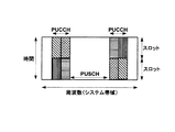
下り回線のデータ送受信には、誤り訂正復号と自動再送要求とを組み合わせたHARQ(Hybrid automatic request)が導入されている。端末は受信データの誤り訂正復号を行った後、データに付加されたCRC(Cyclic redundancy checksum)に基づき、データが正しく復号できているか否かを判定する。データが正しく復号できていれば、端末は、基地局に対してACKをフィードバックする。一方、データが正しく復号できなければ、端末は、基地局に対してNACKをフィードバックし、誤りが検出されたデータの再送を促す。このようなACK/NACK(確認応答、以下「A/N」と記す)のフィードバックは、上り回線で送信される。A/Nは、送信時点でPUSCHにデータ割り当てがなければPUCCH(Physical Uplink Control Channel:物理上り制御チャネル)にて送信される。一方、A/N送信時点でPUSCHにデータ割り当てがある場合、A/Nは、PUCCHまたはPUSCHいずれかにて送信される。このときPUCCH又はPUSCHのどちらで送信するかについては、基地局が予め端末に対して指示している。図2は、PUSCHとPUCCHとを含む上り回線サブフレーム構成を示す。 For downlink data transmission and reception, HARQ (Hybrid automatic request) combining error correction decoding and automatic retransmission request has been introduced. After performing error correction decoding on the received data, the terminal determines whether the data has been correctly decoded based on a CRC (Cyclic redundancy checksum) added to the data. If the data is correctly decoded, the terminal feeds back an ACK to the base station. On the other hand, if the data can not be decoded correctly, the terminal feeds back a NACK to the base station to prompt retransmission of data for which an error has been detected. Feedback of such ACK / NACK (acknowledgement, hereinafter referred to as "A / N") is transmitted on the uplink. A / N is transmitted on PUCCH (Physical Uplink Control Channel: Physical Uplink Control Channel) if there is no data assignment to PUSCH at the time of transmission. On the other hand, when PUSCH has data allocation at the time of A / N transmission, A / N is transmitted by either PUCCH or PUSCH. At this time, the base station instructs in advance to the terminal whether to transmit on PUCCH or PUSCH. FIG. 2 shows an uplink subframe configuration including PUSCH and PUCCH.
A/NをPUCCHで送信する場合には、複数の場合分けが存在する。例えば、A/Nの送信が周期的に上り回線で送信されるCSI(Channel state information)のフィードバックと重複した場合、PUCCH formats 2a/2bが用いられる。また、下り回線において、複数のキャリアを束ねて送信するキャリアアグリゲーション(Carrier Aggregation)がONとなっていて、かつキャリア数が3以上の場合には、PUCCH format 3が用いられる。一方、キャリアアグリゲーションがOFF、またはONでもキャリア数が2以下であって、A/N以外と上りスケジューリングリクエスト以外に送信する制御情報が無ければ、PUCCH formats 1a/1bが用いられる。下りデータの方が上りデータよりも頻繁に送信されること、CSIフィードバックの周期は下りデータの割り当てよりも頻繁でないことを考慮すれば、A/NはPUCCH formats 1a/1bで送信されることが最も多い。以下では、PUCCH formats 1a/1bに着目して述べる。
When transmitting A / N on PUCCH, there are multiple cases. For example, PUCCH formats 2a / 2b are used when transmission of A / N overlaps with feedback of CSI (Channel state information) periodically transmitted on the uplink. Also, in the downlink, when carrier aggregation (Carrier Aggregation) that bundles and transmits a plurality of carriers is ON and the number of carriers is 3 or more,
図3は、PUCCH formats 1a/1bのスロット構成を示す。複数の端末が送信するA/N信号は、系列長4のウォルシュ系列および系列長3のDFT(Discrete Fourier transform)系列により拡散され、符号多重して基地局で受信される。図3において(W0、W1、W2、W3)および(F0、F1、F2)はそれぞれ前述のウォルシュ系列およびDFT系列を表す。端末では、ACK又はNACKを表す信号が、まず周波数軸上でZAC(Zero auto-correlation)系列(系列長12[サブキャリア])によって1SC−FDMAシンボルに対応する周波数成分へ1次拡散される。すなわち、系列長12のZAC系列に対して複素数で表されるA/N信号成分が乗算される。次いで、1次拡散後のA/N信号および参照信号としてのZAC系列が、ウォルシュ系列(系列長4:W0〜W3。ウォルシュ符号系列(Walsh Code Sequence)と呼ばれることもある)およびDFT系列(系列長3:F0〜F2)によって2次拡散される。すなわち、系列長12の信号(1次拡散後のA/N信号、又は、参照信号としてのZAC系列(Reference Signal Sequence))のそれぞれの成分に対して、直交符号系列(Orthogonal sequence:例えばウォルシュ系列又はDFT系列)の各成分が乗算される。さらに、2次拡散された信号が、IFFT(Inverse Fast Fourier Transform)によって時間軸上の系列長12[サブキャリア]の信号に変換される。そして、IFFT後の信号それぞれに対しCP(Cyclic Prefix)が付加されて、7つのSC−FDMAシンボルからなる1スロットの信号が形成される。
FIG. 3 shows the slot configuration of PUCCH formats 1a / 1b. A / N signals transmitted by a plurality of terminals are spread by a Walsh sequence of
異なる端末からのA/N信号同士は、異なる巡回シフト量(Cyclic Shift Index)に対応するZAC系列、又は、異なる系列番号(Orthogonal Cover Index : OC index)に対応する直交符号系列を用いて拡散されている。直交符号系列は、ウォルシュ系列とDFT系列との組である。また、直交符号系列はブロックワイズ拡散符号系列(Block-wise spreading code)と称されることもある。従って、基地局は、従来の逆拡散及び相関処理を用いることにより、これら符号多重および巡回シフト多重された複数のA/N信号を分離することができる。なお、周波数リソースブロック(RB)あたりに符号多重および巡回シフト多重できるA/N数は限りがあるため、端末の数が多くなると異なるRBに周波数多重される。以下、A/Nが送信される符号−RBリソースをA/Nリソースと呼ぶ。A/Nリソースの番号は、A/Nを送信するRB番号と、そのRBにおける符号番号および巡回シフト量により決定される。ZAC系列の巡回シフトによる多重も一種の符号多重とみなせることから、以降では、直交符号および巡回シフトを併せて符号と記す場合がある。 A / N signals from different terminals are spread using ZAC sequences corresponding to different cyclic shift indexes (Cyclic Shift Index) or orthogonal code sequences corresponding to different sequence numbers (Orthogonal Cover Index: OC index) ing. An orthogonal code sequence is a set of a Walsh sequence and a DFT sequence. The orthogonal code sequence may also be referred to as a block-wise spreading code sequence. Therefore, the base station can separate the code-multiplexed and cyclic shift-multiplexed multiple A / N signals by using conventional despreading and correlation processing. Since the number of A / Ns that can be code-multiplexed and cyclic shift-multiplexed per frequency resource block (RB) is limited, frequency multiplexing is performed on different RBs as the number of terminals increases. Hereinafter, the code-RB resource in which the A / N is transmitted is referred to as an A / N resource. The number of an A / N resource is determined by the RB number transmitting the A / N, the code number in the RB, and the amount of cyclic shift. Since multiplexing by cyclic shift of a ZAC sequence can also be regarded as a kind of code multiplexing, hereinafter, an orthogonal code and a cyclic shift may be collectively referred to as a code.
なお、LTEでは、PUCCHにおける他セルからの干渉を低減するために、セルIDに基づき使用するZAC系列が決定される。異なるZAC系列間では互いの相関が小さいため、異なるセル間で異なるZAC系列を用いることにより、干渉を小さくすることができる。また同様に、セルIDに基づく系列ホッピングおよび巡回シフトホッピング(Cyclic shift Hopping)も導入されている。これらのホッピングでは、セルIDに基づき定められる巡回シフトホッピングパターンを用いて、巡回シフト軸上および直交符号軸上で互いの相関関係を保ちつつ、SC−FDMAシンボル単位で循環的にシフトさせる。これにより、セル内ではA/N信号が互いに直交関係を保ちながらも、他セルから強い干渉を受けるA/N信号の組合せをランダム化でき、一部の端末のみが他セルからの強い干渉を受け続けることがないようにすることができる。 In LTE, in order to reduce interference from other cells in PUCCH, a ZAC sequence to be used is determined based on the cell ID. Since the correlation between different ZAC sequences is small, interference can be reduced by using different ZAC sequences between different cells. Similarly, cell ID based sequence hopping and cyclic shift hopping have also been introduced. In these hoppings, cyclic shift hopping patterns determined based on cell IDs are used to cyclically shift in SC-FDMA symbol units while maintaining correlation between cyclic shift axes and orthogonal code axes. By this, it is possible to randomize the combination of A / N signals which receive strong interference from other cells while maintaining A / N signals in an orthogonal relationship in the cell, and only some terminals receive strong interference from other cells. It is possible not to keep receiving.
以下の説明では、1次拡散にZAC系列を用い、2次拡散にブロックワイズ拡散コード系列を用いる場合について説明する。しかし、1次拡散には、ZAC系列以外の、互いに異なる循環シフト量により互いに分離可能な系列を用いてもよい。例えば、GCL(Generalized Chirp like)系列、CAZAC(Constant Amplitude Zero Auto Correlation)系列、ZC(Zadoff-Chu)系列、M系列や直交ゴールド符号系列等のPN系列、または、コンピュータによってランダムに生成された自己相関特性が急峻な系列等を1次拡散に用いてもよい。また、2次拡散には、互いに直交する系列、または、互いにほぼ直交すると見なせる系列であればいかなる系列をブロックワイズ拡散コード系列として用いてもよい。例えば、ウォルシュ系列またはフーリエ系列等をブロックワイズ拡散コード系列として2次拡散に用いることができる。 In the following description, the case where a ZAC sequence is used for primary spreading and a block-wise spreading code sequence is used for secondary spreading will be described. However, it is possible to use a sequence that can be separated from each other by different cyclic shift amounts other than the ZAC sequence for the first spreading. For example, GCL (Generalized Chirp like) sequences, CAZAC (Constant Amplitude Zero Auto Correlation (CAZAC) sequences, ZC (Zadoff-Chu) sequences, PN sequences such as M sequences and orthogonal gold code sequences, or self generated randomly by computer A sequence or the like having a steep correlation characteristic may be used for the first spreading. Further, in the second spreading, any sequence orthogonal to each other or any sequence that can be regarded as substantially orthogonal to each other may be used as a block-wise spreading code sequence. For example, Walsh sequences or Fourier sequences can be used for second spreading as block-wise spreading code sequences.
ところでLTEでは、異なる端末に異なるA/Nリソースを割り当てる方法として、PDCCHの制御情報マッピング結果に基づく割り当てを採用している。すなわち、PDCCHの制御情報は複数の端末間で同一のリソースにマッピングされないことを利用し、PDCCHのリソースとPUCCH formats 1a/1bのA/Nリソース(以下、単にA/Nリソースと記載する)とを1対1に対応付けている。以下、このことについて詳述する。 By the way, in LTE, as a method of allocating different A / N resources to different terminals, allocation based on the control information mapping result of PDCCH is adopted. That is, the control information of PDCCH is not mapped to the same resource among a plurality of terminals, and the PDCCH resource and A / N resource of PUCCH formats 1a / 1b (hereinafter simply referred to as A / N resource) Are associated with one to one. This will be described in detail below.
PDCCHは1つ又は複数のL1/L2CCH(L1/L2 Control Channel)から構成される。各L1/L2CCHは、1つ又は複数CCE(Control Channel Element:制御チャネル要素)から構成される。すなわちCCEは、制御情報をPDCCHにマッピングするときの基本単位である。また、1つのL1/L2CCHが複数(2、4、8個)のCCEから構成される場合には、そのL1/L2CCHには偶数のインデックスを持つCCEを起点とする連続する複数のCCEが割り当てられる。基地局は、リソース割当対象端末に対する制御情報の通知に必要なCCE数に従って、そのリソース割当対象端末に対してL1/L2CCHを割り当てる。そして、基地局は、このL1/L2CCHのCCEに対応する物理リソースに制御情報をマッピングして送信する。またここで、各CCEはA/Nリソースと1対1に対応付けられている。従って、L1/L2CCHを受信した端末は、このL1/L2CCHを構成するCCEに対応するA/Nリソースを特定し、このリソース(つまり符号および周波数)を用いてA/N信号を基地局へ送信する。ただし、L1/L2CCHが連続する複数のCCEを占有する場合には、端末は、複数のCCEにそれぞれ対応する複数のPUCCH構成リソースのうち一番インデックスが小さいCCEに対応するA/Nリソース(すなわち、偶数番号のCCEインデックスを持つCCEに対応付けられたA/Nリソース)を利用して、A/N信号を基地局へ送信する。具体的には、次式(1)に基づきA/Nリソース番号nPUCCHが定まる(例えば、非特許文献3参照)。
![]()
![]()
ここで、上記A/Nリソース番号nPUCCHは、前述のA/Nリソース番号である。Nはセル内共通に与えられるA/Nリソースオフセット値を表し、nCCEはPDCCHがマッピングされたCCEの番号を表す。式(1)より、nCCEの取り得る範囲に応じて、一定範囲のA/Nリソースが使用され得ることがわかる。以下、このようにPDCCHの制御情報スケジューリングに依存してリソースが定まるA/Nを、D−A/N(Dynamic A/N:動的ACK/NACK)と記載する。 Here, the A / N resource number n PUCCH is the aforementioned A / N resource number. N represents an A / N resource offset value commonly given in the cell, and n CCE represents a CCE number to which a PDCCH is mapped. From equation (1), it can be understood that a range of A / N resources can be used depending on the possible range of n CCE . Hereinafter, A / N in which resources are determined depending on control information scheduling of PDCCH in this manner will be referred to as DA / N (Dynamic A / N: Dynamic ACK / NACK).
前述のように、A/Nリソースには符号リソースに加え周波数リソースが含まれている。上り回線ではPUCCH、PUSCHが同じ周波数帯域を共有しているから、D−A/Nを含むPUCCHの領域とPUSCHの帯域幅とはトレードオフとなる。 As described above, A / N resources include frequency resources in addition to code resources. In the uplink, since PUCCH and PUSCH share the same frequency band, the area of PUCCH including DA / N and the bandwidth of PUSCH are traded off.
PDCCHでは、制御情報の割り当て領域に限りがあるため、同時に割り当て可能な端末数および制御情報量に限界がある。また、PDCCHは、セル固有のパラメータに従って受信することが前提となっている。セル固有のパラメータに従うため、PDCCHは、複数のセル間で協調を行うCoMP(Coordinated multipoint operation)、または、マクロ基地局のセル内にピコ基地局を配置して運用するHetNet(Heterogeneous network)に適さないという課題がある。そこで、Rel.11では、PDCCHとは異なる新たな制御チャネルとしてE−PDCCH(enhanced PDCCH:拡張物理下り制御チャネル)の採用が検討されている。 In PDCCH, since the allocation area of control information is limited, the number of terminals that can be allocated simultaneously and the amount of control information are limited. Also, PDCCH is assumed to be received according to cell-specific parameters. In order to comply with cell-specific parameters, PDCCH is suitable for Coordinated Multipoint Operation (CoMP) that coordinates between multiple cells, or HetNet (Heterogeneous network), which operates by placing pico base stations in the cells of macro base stations. There is a problem that there is not. Therefore, Rel. In No. 11, adoption of E-PDCCH (enhanced PDCCH: enhanced physical downlink control channel) as a new control channel different from PDCCH is being considered.
E−PDCCHの導入により、制御情報の割り当て領域を増加させることができる。さらに、E−PDCCHには、セル単位の設定に制約されない柔軟な制御情報割り当てを行えるという利点があるため、E−PDCCHの導入により、特にセル間で協調を行うCoMP、または、セル間の干渉制御が重要なHetNetに適した運用が可能になると期待されている。 With the introduction of E-PDCCH, the allocation area of control information can be increased. Furthermore, since E-PDCCH has the advantage of flexible control information allocation that is not restricted by the configuration on a cell basis, the introduction of E-PDCCH makes it possible to perform CoMP, especially for cooperation between cells, or interference between cells. It is expected that operations suitable for HetNet where control is important will be possible.
しかしながら、E−PDCCHを採用した場合、何ら工夫がないと、E−PDCCHの制御情報で制御される端末と、PDCCHの制御情報で制御される端末との間で、上り回線のA/Nの衝突が生じることが考えられる。或いは、A/Nの衝突が生じないようにA/Nリソースが無駄に確保されて、PUSCHの帯域が減少するという課題が生じることが考えられる。 However, if E-PDCCH is adopted, uplink A / N between the terminal controlled by the control information of E-PDCCH and the terminal controlled by the control information of PDCCH without any improvement. It is possible that a collision will occur. Alternatively, it is conceivable that a problem arises in that the bandwidth of the PUSCH is reduced by wasting the A / N resource so as not to cause an A / N collision.
本発明の目的は、E−PDCCHの制御情報が送信されるシステムにおいて、A/Nの衝突を回避しつつ、A/Nリソースの利用効率を高めてPUSCHの帯域を無駄に減少させない無線通信端末、無線通信方法および集積回路を提供することである。 An object of the present invention is a wireless communication terminal that avoids A / N collisions and does not wastefully reduce the PUSCH bandwidth while avoiding A / N collisions in a system in which E-PDCCH control information is transmitted. , Wireless communication method and integrated circuit.
本発明の一態様に係る無線通信端末は、拡張物理下り制御チャネル(E-PDCCH)を構成する周波数リソースブロックセット(PRBセット)を用いて制御情報を受信し、前記PRBセットは1つ又は複数のPRBを含む、受信手段と、予め設定された複数のPRBセットのうち、いずれのPRBセットが受信されたかを検出し、前記受信したPRBセットおよび前記検出されたPRBセットのE-PDCCHに含まれるACK/NACK Resource Indicator(ARI)の値に基づいて、ACK/NACKをマッピングする物理上り制御チャネル(PUCCH)のリソースを決定する、制御手段と、前記決定されたPUCCHのリソースを用いて、前記ACK/NACKを送信する送信手段と、を有し、前記ARIは、前記E-PDCCHで受信したPRBセットを構成するeCCE(enhanced control channel element)の番号に依存しない値であり、かつ、前記受信したPRBセットに対して複数の値を取り得る。 A wireless communication terminal according to an aspect of the present invention receives control information using a frequency resource block set (PRB set) configuring an extended physical downlink control channel (E-PDCCH), and one or more of the PRB sets are used. The receiver detects which PRB set is received among a plurality of PRB sets set in advance, including a PRB of PRB, and is included in the received PRB set and E-PDCCH of the detected PRB set. Using control means for determining a resource of a physical uplink control channel (PUCCH) to which the ACK / NACK is mapped based on the value of the ACK / NACK Resource Indicator (ARI), and using the determined PUCCH resource, And ARI is a value independent of the number of an enhanced control channel element (eCCE) that configures a PRB set received on the E-PDCCH, and the reception Against a set of PRBs It can take multiple values.
本発明の一態様に係る無線通信方法は、拡張物理下り制御チャネル(E-PDCCH)を構成する周波数リソースブロックセット(PRBセット)を用いて制御情報を受信し、前記PRBセットは1つ又は複数のPRBを含み、予め設定された複数のPRBセットのうち、いずれのPRBセットが受信されたかを検出し、前記受信したPRBセットおよび前記検出されたPRBセットのE-PDCCHに含まれるACK/NACK Resource Indicator(ARI)に基づいて、ACK/NACKをマッピングする物理上り制御チャネル(PUCCH)のリソースを決定し、前記決定されたPUCCHのリソースを用いて、前記ACK/NACKを送信し、前記ARIは、前記E-PDCCHで受信したPRBセットを構成するeCCE(enhanced control channel element)の番号に依存しない値であり、かつ、前記受信したPRBセットに対して複数の値を取り得る。 A wireless communication method according to an aspect of the present invention receives control information using a frequency resource block set (PRB set) forming an extended physical downlink control channel (E-PDCCH), and one or more of the PRB sets are used. And detects which PRB set is received among a plurality of PRB sets set in advance, and detects ACK / NACK included in the received PRB set and E-PDCCH of the detected PRB set. The resource of the physical uplink control channel (PUCCH) to which the ACK / NACK is mapped is determined based on the Resource Indicator (ARI), and the ACK / NACK is transmitted using the determined PUCCH resource, and the ARI is The value may be independent of the number of the enhanced control channel element (eCCE) configuring the PRB set received on the E-PDCCH, and may take a plurality of values for the received PRB set.
本発明の一態様に係る集積回路は、拡張物理下り制御チャネル(E-PDCCH)を構成する周波数リソースブロックセット(PRBセット)を用いて制御情報を受信し、前記PRBセットは1つ又は複数のPRBを含む、処理と、予め設定された複数のPRBセットのうち、いずれのPRBセットが受信されたかを検出し、前記受信したPRBセットおよび前記検出されたPRBセットのE-PDCCHに含まれるACK/NACK Resource Indicator(ARI)に基づいて、ACK/NACKをマッピングする物理上り制御チャネル(PUCCH)のリソースを決定する処理と、前記決定されたPUCCHのリソースを用いて、前記ACK/NACKを送信する処理と、を制御し、前記ARIは、前記E-PDCCHで受信したPRBセットを構成するeCCE(enhanced control channel element)の番号に依存しない値であり、かつ、前記受信したPRBセットに対して複数の値を取り得る。 An integrated circuit according to an aspect of the present invention receives control information using a frequency resource block set (PRB set) configuring an extended physical downlink control channel (E-PDCCH), and the PRB set includes one or more PRBs. An ACK included in the received PRB set and the E-PDCCH of the detected PRB set, which detects a process including PRBs and which one of a plurality of PRB sets set in advance is received. Processing for determining a resource of a physical uplink control channel (PUCCH) to which an ACK / NACK is mapped based on a / NACK Resource Indicator (ARI), and transmitting the ACK / NACK using the determined PUCCH resource Processing, and the ARI is a value independent of the number of the enhanced control channel element (eCCE) configuring the PRB set received on the E-PDCCH, and a plurality of the ARIs for the received PRB set Can take the value of
本発明によれば、拡張物理下り制御チャネルと物理下り制御チャネルとで制御情報が送信される場合に、下りデータに対するA/N信号の衝突を回避しつつ、A/Nリソースの利用効率を高めてPUSCHの帯域が無駄に減少することを回避できる。 According to the present invention, when control information is transmitted on the extended physical downlink control channel and the physical downlink control channel, the efficiency of A / N resource utilization is improved while avoiding the collision of A / N signals with downlink data. Thus, it is possible to avoid that the PUSCH bandwidth is reduced unnecessarily.
以下、本発明の各実施の形態について図面を参照して詳細に説明する。 Hereinafter, each embodiment of the present invention will be described in detail with reference to the drawings.
(実施の形態1)
<本発明に係る一形態を得るに至った経緯>
先ず、実施の形態1の具体的な構成および動作を説明する前に、E−PDCCHが採用された場合のA/Nリソースの割当方法として、本発明者らが着目した一つの方法について説明する。
<Background of achieving one embodiment of the present invention>
First, before describing the specific configuration and operation of the first embodiment, a method focused on by the present inventors will be described as an A / N resource allocation method when E-PDCCH is adopted. .
図4は、E−PDCCHが送信される時の下り回線サブフレームの例を示す。図5は、E−PDCCHが採用された場合のシステム構成を示す。 FIG. 4 shows an example of downlink subframes when E-PDCCH is transmitted. FIG. 5 shows a system configuration when E-PDCCH is adopted.
E−PDCCHは次のような特徴の一部またはすべてを有する。
(1)全端末共通のリソースを用いて送信されるPDCCHとは異なり、端末ごとに割り当てられた周波数リソースブロックにて送信される。
(2)セル内全端末共通の参照信号を用いて復調されるPDCCHとは異なり、端末ごとに与えられた端末固有の参照信号にて復調される。
(3)セル内全端末共通のスクランブル符号を用いてスクランブルされるPDCCHとは異なり、端末ごとに与えられるスクランブル符号を用いてスクランブルされる。
(4)E−PDCCHを送信するか否かは、設定により変えることができる。
E-PDCCH has some or all of the following features.
(1) Unlike PDCCH transmitted using resources common to all terminals, transmission is performed on frequency resource blocks allocated to each terminal.
(2) Unlike PDCCH that is demodulated using a reference signal common to all terminals in a cell, demodulation is performed using a terminal-specific reference signal given to each terminal.
(3) Unlike PDCCH scrambled using a scramble code common to all terminals in a cell, scrambled using a scramble code given to each terminal.
(4) Whether to transmit the E-PDCCH can be changed depending on the setting.
図4に示すように、全端末共通のリソースを用いて送信されるPDCCHとは異なり、E−PDCCHは、端末ごとに周波数リソースブロック(PRB)が設定され、そのPRBで送信される。図4の例では、PRB番号2、4、・・・、24、26がE−PDCCHとして設定されている。また、E−PDCCHは、1つまたは複数のリソースeCCE(enhanced Control Channel Element:拡張制御チャネル要素)で構成される。eCCE番号とPRB番号との関係はまだ明確となっていないが、E−PDCCHは端末ごとに設定されることを考慮すると、以下のような関係が考えられる。
(1)システム帯域全体のすべてのPRBでeCCE番号が異なる番号付け(図4A)
(2)端末ごとに設定される、E−PDCCHが送信される1つまたは複数のPRBセットの中ですべてのeCCE番号が異なる番号付け(図4B)
(3)設定されるPRBに関わらず、各PRB内で全てのeCCE番号が異なる番号付け(図4C)
As shown in FIG. 4, unlike PDCCH transmitted using resources common to all terminals, in E-PDCCH, a frequency resource block (PRB) is set for each terminal, and is transmitted by the PRB. In the example of FIG. 4,
(1) eCCE numbering is different for all PRBs in the entire system band (Figure 4A)
(2) All eCCE numbers are numbered differently among one or more PRB sets to which E-PDCCH is transmitted, which are set for each terminal (FIG. 4B)
(3) Regardless of the set PRB, all eCCE numbers are numbered differently in each PRB (FIG. 4C)
また、図5に示すように、E−PDCCHを採用した通信システムでは、1つのセル内にPDCCH端末とE−PDCCH端末とが混在することが想定される(図5中、E−PDCCH端末を黒色で示している)。ここで、PDCCH端末とは、PDCCHの制御情報を受信して通信の制御が行われる端末、E−PDCCH端末とは、E−PDCCHの制御情報を受信して通信の制御が行われる端末を示す。 Also, as shown in FIG. 5, in a communication system adopting E-PDCCH, it is assumed that PDCCH terminals and E-PDCCH terminals are mixed in one cell (in FIG. 5, E-PDCCH terminals Shown in black). Here, a PDCCH terminal indicates a terminal that receives PDCCH control information to perform communication control, and an E-PDCCH terminal indicates a terminal that receives E-PDCCH control information to perform communication control. .
したがって、E−PDCCHの導入により、制御情報の領域が増加されることに加え、セル単位の設定に制約されない柔軟な制御情報割り当てが可能となる。例えばセル内で異なる設定のE−PDCCHを複数使用したり、セル間で同じ設定のE−PDCCHを使用したりできる。よって、E−PDCCHの導入は、特にセル間で協調を行うCoMP、ならびに、セル間の干渉制御が重要なHetNetに適した運用で効果が大きいと期待されている。 Therefore, the introduction of E-PDCCH enables flexible control information allocation that is not restricted by cell-based setting, in addition to the area of control information being increased. For example, multiple E-PDCCHs with different settings can be used in a cell, or E-PDCCHs with the same settings can be used between cells. Therefore, introduction of E-PDCCH is expected to be highly effective particularly in CoMP that performs coordination between cells, and HetNet in which interference control between cells is important.
一方、E−PDCCHを制御情報として割り当てられたPDSCHに対するA/Nのフィードバックリソースの決定法は、これまで定められていなかった。 On the other hand, the determination method of the feedback resource of A / N with respect to PDSCH allocated E-PDCCH as control information was not determined until now.
最も簡単な方法は、E−PDCCHもPDCCHと同様に、例えば次式(2)のようにA/Nリソース番号を定めることである。

ここで、nPUCCH E-PDCCHは、当該E−PDCCH端末がA/Nを送信するリソース番号である。NeはA/Nリソースオフセット値であり、neCCEはE−PDCCHがマッピングされたeCCEの番号である。また、NeはD−A/Nリソースオフセットパラメータであり、セル固有の値でも、端末ごとに独立に与えられる値でも良い。関数f(a、b)は、例えばf(a、b)=a+bである。 Here, n PUCCH E-PDCCH is a resource number to which the E-PDCCH terminal transmits A / N. N e is an A / N resource offset value, and n eCCE is an eCCE number to which an E-PDCCH is mapped. Further, Ne is a DA / N resource offset parameter, and may be a cell-specific value or a value independently given to each terminal. The function f (a, b) is, for example, f (a, b) = a + b.
この方法であれば、A/Nリソースを端末ごとに通知する必要が無く、なおかつE−PDCCH端末間でA/Nが衝突する可能性がないという利点がある。その一方で、E−PDCCH端末のA/Nが広範囲に分散してしまうこと、複数の端末間でA/Nが衝突し、割り当てブロックが生じるという欠点がある。図6にその様子を示す。 This method has an advantage that there is no need to notify A / N resources for each terminal, and there is no possibility that A / Ns will collide among E-PDCCH terminals. On the other hand, there is a disadvantage that A / Ns of E-PDCCH terminals are widely dispersed, and A / Ns collide among a plurality of terminals, resulting in allocation blocks. The situation is shown in FIG.
図6は、PDCCH端末用のA/NリソースとE−PDCCH端末用のA/Nリソースとを4つずつ設定した場合の例を示している。PDCCH端末用のA/Nリソースは従来の式(1)に従って決定されているとする。また、E−PDCCH端末用のA/Nリソースは、式(2)に従って決定されているとする。 FIG. 6 shows an example in which four A / N resources for PDCCH terminals and four A / N resources for E-PDCCH terminals are set. It is assumed that the A / N resource for the PDCCH terminal is determined according to the conventional equation (1). Also, it is assumed that the A / N resource for the E-PDCCH terminal is determined according to Equation (2).
まず、E−PDCCH端末のA/NリソースをeCCE番号により決定することにより、A/Nリソースが広範囲に分散してしまうという問題がある。分散の程度はeCCE番号の取り得る値の範囲および式(2)によって異なる。例えば図4AのようなeCCE番号付けがなされると、A/Nリソースの分散は非常に大きいものとなり、PUSCHを送信できるはずであった帯域を減少させてしまう。これは上り回線のスループット劣化を引き起こしてしまう。 First, there is a problem that A / N resources are widely dispersed by determining A / N resources of E-PDCCH terminals by eCCE numbers. The degree of dispersion depends on the range of possible values of the eCCE number and equation (2). For example, when eCCE numbering is performed as shown in FIG. 4A, the distribution of A / N resources becomes very large, which reduces the band that could transmit PUSCH. This causes the throughput degradation of the uplink.
さらに、A/Nリソースが衝突してしまうという問題が生じる。図6では、PDCCH端末とE−PDCCH端末との間でA/Nが衝突する様子を表している。実際には、セル内で複数のE−PDCCHが設定される可能性があり、この場合、異なるE−PDCCH間でもA/Nの衝突が生じる可能性がある。衝突はA/Nの品質を大きく劣化させるものであり許容できないため、複数の端末間でA/Nリソースの衝突が起きた場合には、割り当てを諦める必要がある。一方で、複数端末間のPDCCHまたはE−PDCCHスケジューリングをやり直すことで割り当てブロックの回避を試みることもできるが、これには下り制御信号および上りA/N信号の双方のスケジューリングを同時に調整しなければならず、実現には複雑なシステムおよびアルゴリズムが必要となる。また、下り制御信号の配置と上りA/Nリソースのいずれか一方が定まるともう一方も自動的に決定するため、両方の配置が割り当てブロック確率またはリソース利用効率の観点から適切になるようスケジューリングするのは困難である。 Furthermore, there is a problem that A / N resources collide. FIG. 6 shows how A / N collides between the PDCCH terminal and the E-PDCCH terminal. In practice, multiple E-PDCCHs may be configured in a cell, and in this case, A / N collisions may occur even between different E-PDCCHs. Since a collision greatly degrades the quality of A / N and can not be tolerated, it is necessary to give up allocation when a collision of A / N resources occurs between a plurality of terminals. On the other hand, it is possible to try to avoid the allocation block by re-scheduling PDCCH or E-PDCCH scheduling between multiple terminals, but without adjusting the scheduling of both the downlink control signal and the uplink A / N signal simultaneously. In addition, implementation requires complex systems and algorithms. Also, since one of the downlink control signal allocation and the uplink A / N resource is determined automatically, the other is automatically determined, so that both allocations are scheduled to be appropriate from the viewpoint of allocation block probability or resource utilization efficiency. It is difficult.
もう1つの方法は、RRC(Radio resource control)制御情報などにより、事前に端末ごとにA/Nリソースを割り当てておく方法である。 Another method is a method of allocating an A / N resource for each terminal in advance by RRC (Radio resource control) control information or the like.
Rel.10では、キャリアアグリゲーション時など、より多くのA/Nビットをフィードバックする必要がある場合のA/Nリソース決定法として、RRCにより複数のA/Nリソース候補を4つ設定しておき、PDCCHに含まれる2ビットのARI(ACK/NACK Resource Indicator)を用いてサブフレーム単位で動的に選択する方法が採用された(非特許文献3)。図7は、RRC制御情報により設定されたA/Nリソース候補と、ARIの値を対応付けた表である。端末は、復号したPDCCHのARIが示す値からA/Nリソースを決定する。 Rel. In 10, as a method of determining A / N resources when it is necessary to feed back more A / N bits, such as at the time of carrier aggregation, four plural A / N resource candidates are set by RRC and set as PDCCH. A method of dynamically selecting on a subframe basis using a 2-bit ARI (ACK / NACK Resource Indicator) included is adopted (Non-Patent Document 3). FIG. 7 is a table in which A / N resource candidates set by RRC control information are associated with values of ARI. The terminal determines an A / N resource from the value indicated by ARI of the decoded PDCCH.
E−PDCCHにもARIを導入し、前記と同様のA/Nリソース選択を行うことで、E−PDCCHのスケジューリングに依存しないA/Nリソース設定が可能となる。この場合、複数のE−PDCCH端末に同じA/Nリソース候補を設定し、各端末に送信するE−PDCCHのARIでA/Nリソースを制御すれば良い。また、選択肢が複数あるので、PDCCH端末のA/Nリソースおよび異なるE−PDCCHが設定された端末のA/Nリソースと割り当てブロックを回避することができる。また、割り当てブロックの回避はARIの調整で行えるので、PDCCHおよびE−PDCCHのスケジューリングを再調整するのは不要である。 By introducing an ARI also to the E-PDCCH and performing the same A / N resource selection as described above, it becomes possible to set an A / N resource independent of the scheduling of the E-PDCCH. In this case, the same A / N resource candidate may be set to a plurality of E-PDCCH terminals, and the A / N resource may be controlled by the ARI of the E-PDCCH transmitted to each terminal. Also, since there are multiple options, it is possible to avoid A / N resources of PDCCH terminals and A / N resources and allocation blocks of terminals for which different E-PDCCHs are configured. Also, since avoidance of allocation blocks can be performed by ARI adjustment, it is not necessary to re-adjust PDCCH and E-PDCCH scheduling.
しかしながら、ARIによるA/Nリソース選択は、ARIのビット数に応じた数しかA/Nリソース候補を設定することができない。例えばARIが2ビットの場合、選択可能なA/Nリソースは4つである。PDCCH端末または他のE−PDCCHが設定された端末とA/Nリソースの衝突が起こりうることを考慮すると、4つのうちいくつかのA/Nリソースは使用できない可能性もある。このため、ARIだけでは選択肢が少なく、柔軟なA/Nリソース制御が行えないという問題が生じる。 However, in A / N resource selection by ARI, only the number corresponding to the number of bits of ARI can be set as A / N resource candidates. For example, when ARI is 2 bits, four selectable A / N resources are available. Considering that collisions of A / N resources may occur with PDCCH terminals or other E-PDCCH configured terminals, some of the four A / N resources may not be available. For this reason, ARI alone has few options and there is a problem that flexible A / N resource control can not be performed.
A/Nリソース候補の数は、ARIのビット数を増加させることで増やすことができる。しかし、過度なARIビット数増加はE−PDCCHのオーバーヘッド増大になるため、性能およびカバレッジの観点から望ましくない。 The number of A / N resource candidates can be increased by increasing the number of bits of ARI. However, an excessive increase in the number of ARI bits is not desirable in terms of performance and coverage because it results in an increase in overhead of E-PDCCH.
そこで、本実施の形態1の通信システムは、E−PDCCHにARIが導入されることを前提に、(1)ARIのビット数を増加させることなく、(2)A/Nリソース候補の数を増やす、という2点を同時に実現することを目的としている。 Therefore, on the premise that the ARI is introduced into the E-PDCCH, the communication system according to the first embodiment (1) (2) the number of A / N resource candidates without increasing the number of bits of the ARI. The purpose is to realize two points of increasing at the same time.
[通信システムの概要]
本実施の形態1の通信システムは、図5の例のように、セル内の1つの基地局100、および、複数の端末200等から構成される。
[Overview of communication system]
The communication system according to the first embodiment is configured of one
[基地局100構成]
図8は、基地局100の要部を示すブロック図である。
[
FIG. 8 is a block diagram showing the main part of
基地局100は、図8に示すように、複数の端末200へそれぞれ送信する複数の制御情報を生成する制御部110と、制御情報および送信データを無線送信用の信号に変換しアンテナ11を介して信号を無線送信する送信部120と、を備えている。
As shown in FIG. 8,
制御部110は、下り回線のリソース割当情報等から各端末200の制御情報を生成する。また、制御部110は、各端末200に送信する制御情報をPDCCHまたはE−PDCCHにスケジューリングする。このときE−PDCCHは、あらかじめ端末200に対して設定された1つまたは複数のConfigurationのうち、いずれか1つのConfigurationにより送信される。また、E−PDCCH端末には、E−PDCCHに含まれるARIを用いて、RRCの通知により予め指定された通知A/Nリソース候補のいずれを用いてA/Nを送信するかが通知される。したがって、制御部110は、ARIを含んだE−PDCCH端末の制御情報を生成して、送信部120へ出力する。
送信部120は、送信データおよび制御情報が含まれる各チャネルの信号を無線送信する。すなわち、送信部120は、送信データをPDSCHで送信し、PDCCH端末の制御情報をPDCCHで送信し、E−PDCCH端末の制御情報をE−PDCCHで送信する。 The transmission unit 120 wirelessly transmits signals of each channel including transmission data and control information. That is, transmitting section 120 transmits transmission data on PDSCH, transmits control information on PDCCH terminal on PDCCH, and transmits control information on E-PDCCH terminal on E-PDCCH.
図9は、基地局100の詳細を示すブロック図である。
FIG. 9 is a block diagram showing details of the
詳細には、基地局100は、図9に示すように、アンテナ11、制御情報生成部12、制御情報符号化部13、変調部14、17、データ符号化部15、再送制御部16、サブフレーム構成部18、IFFT部19、CP付加部20、および、無線送信部21等を備えている。また、基地局100は、無線受信部22、CP除去部23、逆拡散部24、相関処理部25、および、判定部26等を備えている。
Specifically, as shown in FIG. 9, the
これらのうち、制御情報生成部12が主に制御部110として機能し、制御情報符号化部13から無線送信部21ならびにデータ符号化部15から無線送信部21にかけた構成が主に送信部120として機能する。
Among them, the configuration in which the control
基地局100は、下り回線にてPDCCH、E−PDCCH、PDSCHを送信する。また、基地局100は、上り回線にてA/N信号を運ぶPUCCHを受信する。なお、ここでは、説明が煩雑になることを避けるために、本実施の形態の特徴と密接に関連する下り回線のPDCCH、E−PDCCH、PDSCHの送信、および、その下り回線データに対するPUCCHの上り回線での受信に係わる構成部を主に示している。そして、上り回線データの受信に係わる構成部の図示および説明を省略する。
The
基地局100が生成する下り回線の制御信号とデータ信号は、それぞれ別個に符号化および変調され、サブフレーム構成部18へと入力される。
The downlink control signal and data signal generated by
まず、制御信号の生成について述べる。制御情報生成部12は、下り回線の割り当てを行う各端末200のリソース割り当て結果(リソース割当情報)と符号化率情報とから、各端末200への制御情報を生成する。端末200毎の制御情報には、どの端末200に宛てた制御情報であるかを示す端末ID情報が含まれる。例えば、制御情報の通知先の端末200のID番号でマスキングされたCRCビットが端末ID情報として制御情報に含まれる。ここで、PDCCHにマッピングされる制御情報とE−PDCCHにマッピングされる制御情報とで、異なる情報が含まれる。特にE−PDCCHにマッピングされる制御情報には、RRCで予め通知したA/Nリソース候補のどれを用いるかを指示するARIが含まれる。生成した各端末200への制御情報は制御情報符号化部13へ入力される。
First, generation of control signals will be described. The control
制御情報符号化部13は、端末200ごとの制御情報を、符号化率情報に基づいて、それぞれ独立に符号化する。符号化は、PDCCHにマッピングされる制御情報とE−PDCCHにマッピングされる制御情報とで同じでも良いし異なっても良い。制御情報符号化部13の出力は、変調部14へ入力される。
Control
変調部14は、端末200ごとの制御情報をそれぞれ独立に変調する。変調は、PDCCHにマッピングされる制御情報とE−PDCCHにマッピングされる制御情報とで同じでも良いし異なっても良い。変調部14の出力は、サブフレーム構成部18へ入力される。
Modulating
次に、データ信号の生成について述べる。データ符号化部15では、各端末200に送信するデータビット系列に対して各端末200のIDに基づきマスキングされたCRCビットを付加し、それぞれ誤り訂正符号化する。データ符号化部15の出力は、再送制御部16へ入力される。
Next, generation of data signals will be described. The
再送制御部16は、端末200ごとの符号化送信データを保持しておき、初回送信時には送信データを変調部17へ出力する。一方、再送制御部16は、判定部26からNACK信号が入力された端末200、すなわち再送を行う端末200に対しては、その再送に対応する送信データを変調部17に出力する。
変調部17は、入力された各端末200へのデータ符号化系列をそれぞれデータ変調する。変調系列は、サブフレーム構成部18へ入力される。
The
サブフレーム構成部18は、リソース割当情報に基づいて、入力された制御情報系列とデータ系列をサブフレームの時間および周波数で分割されたリソースへとマッピングする。これにより、サブフレーム構成部18は、サブフレームを構成し、IFFT部19へと出力する。
The
IFFT部19は、入力された送信サブフレームに対してIFFT(Inverse Fast Fourier Transform)を行い、時間波形を得る。得られた時間波形はCP付加部20へ入力される。
The
CP付加部20は、サブフレーム内の各OFDMシンボルにCPを付加して無線送信部21へ出力する。
無線送信部21は、入力したシンボルに対して搬送波周波数帯へ無線変調が行われ、アンテナ11を介して変調された下り回線信号を送信する。
The
無線受信部22は、端末200のA/N信号を受信したアンテナ11からの入力を受け、無線復調が行われる。復調された下り回線信号はCP除去部23へと入力される。
The
CP除去部23は、下り回線信号内の各SC−FDMA(Single Carrier-Frequency-Division Multiple Access)シンボルからCPを除去する。CP除去後のシンボルは逆拡散部24へ入力される。
The
逆拡散部24は、符号多重された複数端末200のA/N信号から対象となる端末200のA/Nを取りだすため、対応する直交符号による逆拡散を行う。逆拡散後された信号は相関処理部25へと出力される。
The
相関処理部25は、A/Nを取りだすためZAC系列による相関処理を行う。相関処理後の信号は、判定部26へと入力される。
The
判定部26は、当該端末200のA/NがACK、NACKいずれであったか判定する。判定結果がACKであった場合、判定部26は再送制御部16に次のデータの送信を促す。一方、判定結果がNACKであった場合、判定部26は再送制御部16に再送を促す。
The
[端末200の構成]
図10は、端末の要部を示すブロック図である。
[Configuration of terminal 200]
FIG. 10 is a block diagram showing the main part of the terminal.
端末200は、アンテナ41を介して制御情報および下りデータを受信する受信部230と、制御情報に基づいてA/N信号を送信するリソースを決定する制御部220と、決定したリソースでA/N信号を送信する送信部210とを備えている。
The terminal 200 includes a
端末200は、E−PDCCHの制御情報を受信するよう設定されている場合に、E−PDCCH端末となり、PDCCHの制御情報を受信するよう設定されている場合に、PDCCH端末となる。また、端末200は、両方を受信するよう設定される場合もある。すなわち、両方受信するよう設定された端末200は、E−PDCCHとPDCCHの両方から制御情報の受信を試み、E−PDCCHから自身の制御情報を抽出できたらE−PDCCH端末に、PDCCHから自身の制御情報を抽出できたらPDCCH端末となる。特に通知や指定がない場合には、端末200は、PDCCH端末となる。 The terminal 200 becomes an E-PDCCH terminal when configured to receive control information of E-PDCCH, and becomes a PDCCH terminal when configured to receive control information of PDCCH. Also, the terminal 200 may be configured to receive both. That is, terminal 200 configured to receive both attempts to receive control information from both E-PDCCH and PDCCH, and if it can extract its control information from E-PDCCH, E-PDCCH terminal transmits its own control information to PDCCH. If control information can be extracted, it becomes a PDCCH terminal. In particular, when there is no notification or designation, the terminal 200 is a PDCCH terminal.
さらに端末200は、自身の制御情報が含まれる可能性のあるE−PDCCHのConfigurationをRRC等の上位レイヤより通知されている。このConfigurationは1つであってもよいし、複数であってもよい。端末200は、複数のConfigurationのE−PDCCHを設定された場合、それぞれのConfigurationのいずれにより自身のE−PDCCHが送信されたか調べる。基地局100は、端末200に対し、いずれか1つのConfigurationでE−PDCCHを送信している。
Furthermore, the terminal 200 is notified of the configuration of the E-PDCCH that may include its own control information from a higher layer such as RRC. This configuration may be one or more than one. When the terminal 200 sets E-PDCCHs of a plurality of configurations, the terminal 200 checks which of the configurations has transmitted its own E-PDCCH. The
受信部230は、PDSCHを介して受信データを受信し、E−PDCCHまたはPDCCHを介して制御情報を受信する。すなわち、受信部230は、E−PDCCH端末200の場合には、E−PDCCHを介してARIを含んだ制御情報を受信し、PDCCH端末200の場合には、PDCCHを介して制御情報を受信する。受信部230は、受信した制御情報を制御部220へ出力する。
The receiving
制御部220は、E−PDCCH端末200である場合、受信データのA/N信号の送信リソースを、受信したE−PDCCHのConfigurationおよびARIの値の2つに基づいて、RCC等により通知されたA/Nリソース(RRC通知A/Nリソース)のうち、何れを用いるかを同定する。また、制御部220は、PDCCH端末200である場合、従前のPDCCH端末と同様に、A/N信号の送信リソースを決定する。制御部220は、決定内容を送信部210へ出力する。
When the
送信部210は、決定されたリソースを使用して、受信データのA/N信号を無線送信する。
The
図11は、端末の詳細を示すブロック図である。 FIG. 11 is a block diagram showing the details of the terminal.
端末200は、詳細には、図11に示すように、アンテナ41、無線受信部42、CP除去部43、FFT部44、抽出部45、データ復調部46、データ復号部47、判定部48、制御情報復調部49、制御情報復号部50、制御情報判定部51、制御処理部52、A/N信号変調部53、1次拡散部54、IFFT部55、CP付加部56、2次拡散部57、多重部58、および、無線送信部59を備えている。また、端末200は、参照信号用のIFFT部60、CP付加部61および拡散部62を備えている。
In detail, as shown in FIG. 11, the terminal 200 has an
これらのうち、制御処理部52が主に制御部220として機能する。また、A/N信号変調部53から無線送信部59にかけた構成が主に送信部210として機能し、無線受信部42から判定部48および無線受信部42から制御情報判定部51にかけた構成が主に受信部230として機能する。
Among these, the
端末200は、下り回線でPDCCHまたはE−PDCCHにマッピングされた制御情報、および、PDSCHにマッピングされた下り回線データを受信する。また、端末200は、上り回線でPUCCHを送信する。ここでは、説明が煩雑になることを避けるために、本実施の形態の特徴と密接に関連する下り回線(具体的には、PDCCH、E−PDCCH、PDSCH)の受信、および、下り回線の受信データに対する上り回線(具体的には、PUCCH)での送信に係わる構成部のみを示す。
無線受信部42は、基地局から送信された下り回線信号を受信したアンテナ41からの入力を受け、無線復調を行い、CP除去部43へ出力する。
CP除去部43はサブフレーム内の各OFDMシンボル時間波形からCPを除去し、FFT部44へ出力する。
FFT部44は、入力された時間波形に対し、OFDM(Orthogonal frequency division multiplexing)復調を行うためにFFT(Fast Fourier Transform)を行い、周波数領域におけるサブフレームを得る。得られた受信サブフレームは抽出部45へ入力される。
The
抽出部45は、PDCCH領域またはE−PDCCH領域から自端末向けの制御情報を抽出する。PDCCH、E−PDCCHのいずれに制御情報が含まれているかという情報は、基地局100から予め指示されているものとする(図示せず)。抽出部45は、制御情報の符号化率情報を用いて、自身の制御情報がマッピングされている可能性のある制御情報領域から1つまたは複数の制御情報候補を抽出し、制御情報復調部49へ出力する。また、抽出部45は、制御情報判定部51から結果が得られたら、自端末宛の制御情報に含まれるリソース割り当て結果に基づき、受信サブフレームから自端末向けのデータ信号を抽出する。得られたデータ信号はデータ復調部46へ入力される。
The
制御情報復調部49は、入力された1つまたは複数の制御情報に対して復調を行い、制御情報復号部50へ出力する。
The control
制御情報復号部50は、制御情報の符号化率情報を用いて、入力された1つまたは複数の復調系列に対してそれぞれ復号を行う。復号結果は制御情報判定部51へ入力される。
The control
制御情報判定部51は、1つまたは複数の復号結果から、端末ID情報を用いて自端末宛の制御情報を判定する。判定には、制御情報に含まれる自端末ID情報でマスキングされたCRCビットなどが用いられる。制御情報判定部51は、自端末宛の制御情報があった場合、その制御情報を抽出部45へ出力する。また、制御情報判定部51は、その制御情報を制御処理部52へ出力する。
The control
制御処理部52は、PDCCH端末200の場合とE−PDCCH端末200の場合とで、異なる動作を行う。
The
PDCCH端末200の場合、制御処理部52は、制御情報がマッピングされたリソース(CCE)番号から、式(1)に基づきA/N信号のリソース番号を求める。制御処理部52は、求めたA/N信号リソース番号から、1次拡散、2次拡散および参照信号に用いる各拡散符号と、PUCCHを送信する周波数リソースブロック(RB)とを決定する。これらの情報は、1次拡散部54、2次拡散部57および参照信号の拡散部62へ入力される。
In the case of the
一方、E−PDCCH端末200の場合、制御処理部52は、受信したE−PDCCHのConfigurationおよび制御情報に含まれるARIが指示する値の2つに基づいて、RRC制御情報として通知されたA/Nリソース候補のうち何れを用いるかを決定する。なお、ここでのRRC通知A/Nリソースは、予め基地局100から端末200に対して指示されているものとする(図示せず)。制御処理部52は、指示されたA/Nリソース番号に対応する1次拡散、2次拡散および参照信号に用いる各拡散符号と、PUCCHを送信する周波数リソースブロック(RB)とを決定する。そして、制御処理部52は、各拡散符号をそれぞれ1次拡散部54、2次拡散部57および参照信号の拡散部62へ出力する。
On the other hand, in the case of the
データ復調部46は、入力された自端末向けのデータ信号を復調する。復調結果はデータ復号部47へ入力される。
The
データ復号部47は、入力された復調データに対して復号を行う。復号結果は判定部48へ入力される。
The
判定部48は、端末200のIDでマスキングされたCRCを用いて、復号結果が正しいか否かを判定する。復号結果が正しい場合には、判定部48は、ACK信号をA/N信号変調部53へ出力し、また、受信データを取りだす。復号結果が正しくない場合には、判定部48は、NACK信号をA/N信号変調部53へ出力する。
The
A/N信号変調部53は、入力信号がACKであるかNACKであるかによって値の異なる変調シンボルを生成する。生成された変調シンボルは、1次拡散部54へ入力される。
The A / N
1次拡散部54は、制御処理部52より入力されたZAC系列を用いてA/N信号を1次拡散し、1次拡散後のA/N信号をIFFT部55に出力する。ここで、循環シフトホッピングに用いる循環シフト量はSC−FDMA単位で異なるため、1次拡散部54は、SC−FDMAシンボル毎に異なる循環シフト量を用いてA/N信号を1次拡散する。
The primary spreading
IFFT部55は、1次拡散部54から入力されたSC−FDMAシンボルごとにIFFTを行い、得られる時間波形をCP付加部56へ出力する。
The
CP付加部56は、入力されたSC−FDMA時間波形ごとにCPを付加し、この信号を2次拡散部57へ出力する。
2次拡散部57は、CP付加後のSC−FDMA時間波形に対し、ブロックワイズ拡散コード系列を用いて2次拡散を行う。拡散符号は、制御処理部52によって指示された符号が用いられる。2次拡散された系列は多重部58へ入力される。
The secondary spreading
多重部58は、参照信号の拡散部62と2次拡散部57とからそれぞれ入力された2つの系列を時間多重し、PUCCHサブフレームを構成する。時間多重された信号は無線送信部59へ入力される。
The multiplexing
無線送信部59は、入力された信号に対して搬送波周波数帯へ無線変調を行い、アンテナ41から上り回線信号を無線送信する。
The
IFFT部60は、参照信号に対してIFFTを行い、得られる時間波形をCP付加部61へ出力する。
The
CP付加部61は、入力された参照信号の時間波形にCPを付加し、この信号を拡散部62へ出力する。
The
拡散部62は、CP付加後の時間波形に対し拡散を行う。拡散符号は、制御処理部52によって指示された符号が用いられる。拡散された系列は多重部58へ入力される。
The
[動作]
本実施の形態1の基地局100及び端末200の処理フローをステップ(1)〜(6)で説明する。
[Operation]
The process flow of the
図12は、E−PDCCHに含まれるARIと、E−PDCCHのConfigurationにより定まるA/Nリソースを表した表である。 FIG. 12 is a table showing ARI included in E-PDCCH and A / N resources determined by the configuration of E-PDCCH.
ステップ(1):基地局100は、PDSCHの送受信よりも前に、E−PDCCHで制御情報を送信し得る端末200に対し、E−PDCCHの使用を通知しておく。なお、E−PDCCHで送信しない端末200には、特に通知を行わなくても良い。端末200も、特に通知が無い、または認識できない場合には、PDCCHで制御情報が送信されるものとして制御情報を受信する。また、基地局100は、E−PDCCHで制御情報を送信する可能性がある端末200には、PDSCHの送受信よりも前に、使用する可能性のあるE−PDCCHのConfigurationを通知しておく。例えば図12において、ある端末200には3つすべてのConfigurationが設定され、ある端末200にはConfiguration A、Configuration Bが設定され、ある端末200にはConfiguration Aのみが設定される。また、基地局100は、PDSCHの送受信よりも前に、ARIの値とE−PDCCHのConfigurationによって定まるA/Nリソース候補を通知しておく。このA/Nリソース候補は、図12におけるA〜D、W〜Z、O〜Rである。これらの通知には、RRC制御信号などを用いる。
Step (1): The
ステップ(2):基地局100は、各サブフレームにおいてデータを割り当てる端末200を決定し、PDSCH内にスケジューリングする。スケジューリングには、各端末200へのトラフィック量に加え、端末200が送信するCSIフィードバックまたはサウンディング参照信号(SRS)なども利用される。
Step (2): The
ステップ(3):基地局100は、スケジューリング結果を含む制御情報を各端末200宛に生成し、それらをPDCCHまたはE−PDCCHにスケジューリングする。基地局100は、複数のE−PDCCH Configurationが設定された端末200に対しては、E−PDCCHを送信するConfigurationを決定し、そのConfigurationのもとでスケジューリングを行う。
Step (3): The
また、基地局100は、制御情報をスケジューリングしたすべての端末200間で、A/Nリソースの衝突が起こらないか確認する。A/Nリソースの衝突が起こる場合には、基地局100は、PDCCHのスケジューリング結果、E−PDCCHのARIの値、E−PDCCHのConfigurationなどを変えることにより、A/Nリソースの衝突を回避できるか調べる。基地局100は、A/Nリソースの衝突を回避できない場合、衝突が起こる端末200に対するスケジューリングを諦める(割り当てブロック)。
Also, the
ステップ(4):基地局100は、全端末200の制御情報スケジューリングが終了したら、PDCCHおよびE−PDCCHの制御情報とPDSCHの下りデータとを下り回線で無線送信する。
Step (4): When control information scheduling of all the
ステップ(5):端末200は、受信信号から自端末宛の制御情報を得て、データ信号の抽出および復号を行う。特にE−PDCCHで制御情報が送信されている可能性がある端末200は、使用され得る1つまたは複数のConfigurationのうち、いずれのConfigurationで送信されているかも確認する。また、端末200は、制御情報をもとに受信データ信号に対応するA/N信号を送信する符号および周波数のリソースを特定する。特にE−PDCCH端末200は、自端末宛のE−PDCCHのConfiguration、E−PDCCHに含まれるARIの値に基づき、RRCで事前に通知されたA/Nリソース候補の何れを用いるかを決定する。
Step (5): The terminal 200 obtains control information addressed to the own terminal from the received signal, and extracts and decodes a data signal. In particular, the terminal 200 that may have control information transmitted on the E-PDCCH confirms which configuration out of one or more configurations that may be used. Further, terminal 200 specifies a resource of code and frequency for transmitting an A / N signal corresponding to the received data signal based on the control information. In particular, the
ステップ(6):端末200は、データ信号の判定結果に応じてACKまたはNACKを特定し、上記のように特定したA/Nリソース(符号および周波数のリソース)を用いてA/N信号を送信する。 Step (6): The terminal 200 specifies ACK or NACK according to the determination result of the data signal, and transmits an A / N signal using the A / N resource (resource of code and frequency) specified as described above. Do.
[効果]
以上のように、実施の形態1の基地局100および端末200によれば、複数のE−PDCCH Configurationが設定された端末200に対して、ARIのビット数を増加させることなく、A/Nリソース候補の数を増やすことができる。
[effect]
As described above, according to
また、実施の形態1によれば、通信環境または端末状況などに応じてE−PDCCH端末に使用され得るConfigurationを追加することにより、A/Nリソース候補の数を、必要に応じて段階的に増やすことができる。 Further, according to the first embodiment, the number of A / N resource candidates can be phased in as needed by adding the Configuration that can be used for the E-PDCCH terminal according to the communication environment or the terminal status etc. It can be increased.
また、実施の形態1によれば、A/Nリソース候補、すなわち図12におけるA〜D、W〜Z、O〜Rは全てRRC制御情報などにより事前に通知されたA/Nリソースである。したがって、eCCE番号等、E−PDCCHがスケジューリングされたリソースによりA/Nリソースが決定される、式(2)のような割り当て法と比較して、基地局100は容易にA/Nリソースを調整できる。また、これにより基地局100の回路規模を削減できる。
Further, according to the first embodiment, A / N resource candidates, that is, A to D, W to Z, and O to R in FIG. 12 are all A / N resources notified in advance by RRC control information or the like. Therefore,
(変形例1)
なお、実施の形態1の通信システムは、次のような変更を行っても同様の効果を得ることができる。
(Modification 1)
The communication system of the first embodiment can obtain the same effect even if the following change is made.
E−PDCCHのConfigurationによって、ARIのビット数を変えてもよい。 The number of bits of ARI may be changed according to the configuration of E-PDCCH.
図13Aおよび図13Bは、ConfigurationによってARIのビット数が異なる場合の例を示している。図13Aは、Configuration AのみARIが2ビットであり、他のConfigurationは1ビットの場合の例である。図13BではConfiguration Aのみ1ビットであり、他のConfigurationは2ビットの場合の例である。 FIGS. 13A and 13B show an example in which the number of bits of ARI differs depending on the configuration. FIG. 13A is an example of the case where only the configuration A has ARI of 2 bits and the other configuration has 1 bit. In FIG. 13B, only Configuration A is 1 bit, and the other configurations are examples of 2 bits.
このようにすることで、実施の形態1と同様の効果に加え、ARIのビット数を低減することによるオーバーヘッド低減効果も得ることができる。例えば、Configuration Aは高頻度にE−PDCCHに用いられ、Configuration BおよびCは少ないE−PDCCH端末のみに使用されるような運用では、Configuration BおよびCでE−PDCCHを送信する端末200は少ないので、Configuration AのARIビット数を多くし、Configuration BおよびCのときのARIビット数を少なくすることができる。このときARIビット分のオーバーヘッドが低減できるが、Configuration BおよびCのE−PDCCH端末は少ないので、ARIビット数を減らしたことによる割り当てブロック率の劣化は小さく抑えることができる。一方、同じ運用においても、割り当てブロック率の劣化よりもARIビットのオーバーヘッドを低減することが優先される環境では、反対にConfiguration AのARIビット数を少なくし、Configuration BおよびCのARIビット数を多くしてもよい。これにより、実施の形態1と同等の効果を達成しつつ、Configuration AのARIビット数を少なくして制御情報に含まれる情報ビット数を減らすことで、さまざまな環境の送受信が想定されるE−PDCCH Configuration Aの受信品質を改善することができる。
By doing this, in addition to the same effects as in
(変形例2)
なお、実施の形態1の通信システムは、次のような変更を行っても、同様の効果を得ることができる。
(Modification 2)
The communication system of the first embodiment can obtain the same effect even if the following change is made.
E−PDCCHのConfiguration毎に、ARIにより指定可能なA/Nリソース候補の範囲を限定してもよい。 The range of A / N resource candidates that can be specified by ARI may be limited for each configuration of E-PDCCH.
図14は、E−PDCCHのConfigurationによってA/Nリソース候補を設定できる範囲に制限を与えた例を示している。図14Aの例では、Configuration BおよびCのA/Nリソース範囲がPDCCH端末のA/Nリソース範囲と異なる領域のみに制限されており、図14Bの例では、Configuration AのA/Nリソース範囲がPDCCH端末のA/Nリソース範囲と同じ領域に制限されている。 FIG. 14 illustrates an example in which the range in which the A / N resource candidate can be set is limited by the configuration of the E-PDCCH. In the example of FIG. 14A, the A / N resource range of Configurations B and C is limited to only a region different from the A / N resource range of the PDCCH terminal, and in the example of FIG. 14B, the A / N resource range of Configuration A is It is limited to the same area as the A / N resource range of the PDCCH terminal.
このようにすることで、実施の形態1と同様の効果に加え、A/Nリソース候補設定可能範囲を制限することによるRRC制御信号のオーバーヘッド低減効果も得ることができる。例えば、Configuration Aは高頻度にE−PDCCHに用いられるConfigurationであり、Configuration BおよびCは少ないE−PDCCH端末のみに使用されるConfigurationであるような運用では、Configuration BまたはCでE−PDCCHを送信する端末200は少ない。そこで、Configuration AのA/Nリソース候補設定可能範囲を広くとり、Configuration BおよびCのA/Nリソース候補設定可能範囲を狭くすることで、実施の形態1と同様の効果を得つつ、RRCのオーバーヘッドを低減できる。一方、同じ運用であっても、Configuration AのA/Nリソース候補設定可能範囲を狭くとり、Configuration BまたはCのA/Nリソース候補設定可能範囲を広くとってもよい。この場合、割り当てブロックが起こらない限り設定範囲の狭いConfiguration Aを用いるので、PUSCHに割当可能なリソースを確保し、上り回線スループットを改善できる。
By doing this, in addition to the effects similar to the first embodiment, it is possible to obtain the overhead reduction effect of the RRC control signal by limiting the A / N resource candidate settable range. For example, in an operation where Configuration A is Configuration used frequently for E-PDCCH, and Configuration B and C are Configuration used only for a few E-PDCCH terminals, E-PDCCH is used in Configuration B or C. There are
(実施の形態2)
[通信システムの概要]
実施の形態2では、E−PDCCHは、端末に対して1つまたは複数のPRBより構成されるPRB setとして設定される。当該端末では、設定されたPRB setの中でE−PDCCHが送受信される。
Second Embodiment
[Overview of communication system]
In the second embodiment, the E-PDCCH is set as a PRB set configured of one or more PRBs for the terminal. The terminal transmits and receives E-PDCCH in the set PRB set.
また、E−PDCCHのPRB setは、各E−PDCCH端末に対し、1つまたは複数が設定される。設定されたPRB setの情報は、RRC制御情報などにより基地局から端末に通知される。設定されるPRB setの数は、端末ごとに変えることができる。 Also, one or more PRBs of E-PDCCH are set for each E-PDCCH terminal. The information of the set PRB set is notified from the base station to the terminal by RRC control information or the like. The number of PRB sets to be set can be changed for each terminal.
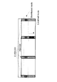
図15は、サブフレーム内に2つのPRB setが設定された例を表している。図15Aは、2つのPRB setでPRBの周波数間隔が同じ例を示し、図15Bは、2つのPRB setでPRBの周波数間隔が異なる例を示している。実施の形態2では、このようなPRBの周波数間隔も、1つまたは複数のPRB setごとに設定可能とする。なお、あらかじめ定められた複数のPRB setが規定されており、その中から使用するPRB setを選択する、としてもよい。 FIG. 15 shows an example in which two PRBs set are set in a subframe. FIG. 15A shows an example in which PRB frequency intervals are the same in two PRB sets, and FIG. 15B shows an example in which PRB frequency intervals are different in two PRB sets. In the second embodiment, the frequency intervals of such PRBs can also be set for each of one or more PRB sets. A plurality of predetermined PRB sets may be defined, and a PRB set to be used may be selected from among them.
以下では説明が煩雑になることを避けるために、実施の形態1と同様の構成には同一の符号を付して、実施の形態1との差分のみ説明する。 In the following, in order to prevent the description from being complicated, the same components as those of the first embodiment are denoted by the same reference numerals, and only the differences from the first embodiment will be described.
[基地局の構成]
基地局100の構成は、主に、制御部110の処理内容が異なるだけで、他は実施の形態1と同様である。制御部110の処理内容については続く動作の説明で詳述する。
[Base station configuration]
The configuration of
[端末の構成]
端末200の構成は、主に、制御部220の処理内容が異なるだけで、他は実施の形態1と同様である。制御部220の処理内容については続く動作の説明で詳述する。
[Terminal configuration]
The configuration of the terminal 200 is the same as that of the first embodiment except for the processing contents of the
[動作]
本実施の形態2の基地局100及び端末200の処理フローをステップ(1)〜(6)で説明する。
[Operation]
The processing flow of
図16は、E−PDCCHに含まれるARIと、E−PDCCHのPRB setにより定まるA/Nリソースを表した表である。 FIG. 16 is a table showing A / N resources determined by ARI included in E-PDCCH and PRB set of E-PDCCH.
ステップ(1):基地局100は、PDSCHの送受信よりも前に、E−PDCCHで制御情報を送信し得る端末200に対し、PRB setの設定を通知しておく。なお、全てのE−PDCCH端末に使用され得るPRB setである場合には、その設定は通知しなくともよい。また、通知されるPRB setの設定およびPRB setの個数は、個別端末200ごとに定められる。例えば図15において、ある端末200にはPRB set AおよびBが設定され、ある端末200にはPRB set Aのみが設定される。また、基地局100は、PDSCHの送受信よりも前に、ARIの値とE−PDCCHのPRB setによって定まるA/Nリソース候補を通知しておく。このA/Nリソース候補は、図16におけるA〜DおよびW〜Zである。これらの通知には、RRC制御信号などが用いられる。
Step (1): The
ステップ(2):基地局100は、各サブフレームにおいてデータを割り当てる端末200を決定し、PDSCH内にスケジューリングする。スケジューリングには、各端末200へのトラフィック量に加え、端末200が送信するCSIフィードバックまたはサウンディング参照信号(SRS)なども利用される。
Step (2): The
ステップ(3):基地局100は、スケジューリング結果を含む制御情報を各端末200宛に生成し、それらをPDCCHまたはE−PDCCHにスケジューリングする。基地局100は、複数のE−PDCCH PRB setが設定された端末200に対しては、E−PDCCHを送信するPRB setを決定し、そのPRB setの中でスケジューリングを行う。
Step (3): The
また、基地局100は、スケジューリングしたすべての端末200間で、A/Nリソースの衝突が起こらないか確認する。A/Nリソースの衝突が起こる場合には、基地局100は、PDCCHのスケジューリング結果、E−PDCCHのARIの値、E−PDCCHのPRB setなどを変えることにより、A/Nリソースの衝突を回避できるか調べる。基地局100は、A/Nリソースの衝突を回避できない場合、衝突が起こる端末200に対するスケジューリングを諦める(割り当てブロック)。
Also, the
ステップ(4):基地局100は、全端末200の制御情報マッピングが終了したら、PDCCHおよびE−PDCCHの制御情報とPDSCHの下りデータとを下り回線で無線送信する。
Step (4): When mapping of control information of all the
ステップ(5):端末200は、受信信号から自端末宛の制御情報を得て、データ信号の抽出および復号を行う。特にE−PDCCHで制御情報が送信されている可能性がある端末200は、事前に設定され、使用され得る1つまたは複数のPRB setのうち、いずれのPRB setで送信されているかも確認する。また、端末200は、制御情報をもとに受信データ信号に対応するA/N信号を送信する符号および周波数のリソースを特定する。特にE−PDCCH端末200は、自端末宛のE−PDCCHが送信されたPRB setとE−PDCCHに含まれるARIの値とに基づき、RRCで事前に通知されたA/Nリソース候補の何れを用いるかを決定する(例えば図17参照)。
Step (5): The terminal 200 obtains control information addressed to the own terminal from the received signal, and extracts and decodes a data signal. In particular, the terminal 200 that may have control information transmitted on the E-PDCCH also confirms which PRB set is transmitted among one or more PRB sets that may be configured and used in advance. . Further, terminal 200 specifies a resource of code and frequency for transmitting an A / N signal corresponding to the received data signal based on the control information. In particular, the
ステップ(6):端末200は、データ信号の判定結果に応じてACKまたはNACKを特定し、上記のように特定したA/Nリソース(符号および周波数のリソース)を用いてA/N信号を送信する。 Step (6): The terminal 200 specifies ACK or NACK according to the determination result of the data signal, and transmits an A / N signal using the A / N resource (resource of code and frequency) specified as described above. Do.
[効果]
以上のように、実施の形態2の基地局100および端末200によれば、複数のE−PDCCH PRB setが設定された端末200に対して、ARIのビット数を増加させることなく、A/Nリソース候補の数を増やすことができる。さらに、実施の形態2によれば、複数のPRB setが設定された端末200が選択可能なA/Nリソース候補の数が増えたことで、単一のPRB setしか設定されていない端末200のA/Nリソースが割り当てブロックとなる確率も低減することができる。
[effect]
As described above, according to
反対に、端末200の数が少ない場合、または、同一サブフレームにおいて下り回線で割り当てる端末200の数が少ない場合など、A/Nリソースの数が割り当てる端末200の数に対して多いときには、使用するA/Nリソースを、例えばA〜Dに制限することにより、使用するPRB set数を減らすことができる。これにより、データを送信する下り回線PRBの数を多くすることができるので、端末あたりのスループットを高めることができる。
Conversely, when the number of A / N resources is large relative to the number of
また、実施の形態2によれば、通信環境または端末状況などに応じてE−PDCCH端末に使用され得るPRB setを追加することにより、A/Nリソース候補の数を、必要に応じて段階的に増やすことができる。 Further, according to the second embodiment, the number of A / N resource candidates can be gradually increased, as necessary, by adding PRB set that can be used for the E-PDCCH terminal according to the communication environment, terminal status, etc. Can be increased.
また、実施の形態1によれば、A/Nリソース候補、すなわち図16におけるA〜D、W〜Zは全てRRC制御情報などにより事前に通知されたA/Nリソースである。したがって、eCCE番号等、E−PDCCHがスケジューリングされたリソースによりA/Nリソースが決定される、式(2)のような割り当て法と比較して、基地局100は容易にA/Nリソースを調整できる。また、これにより基地局100の回路規模を削減できる。
Further, according to the first embodiment, A / N resource candidates, that is, A to D and W to Z in FIG. 16 are all A / N resources notified in advance by RRC control information or the like. Therefore,
(変形例1)
なお、実施の形態2の通信システムは、次のような変更を行っても同様の効果を得ることができる。
(Modification 1)
The communication system of the second embodiment can obtain the same effect even if the following change is made.
E−PDCCHのPRB setによって、ARIのビット数を変えてもよい。例えばPRB set Aで送信されたE−PDCCHに含まれるARIのビット数は2ビット、PRB set Bで送信されたE−PDCCHに含まれるARIのビット数は1ビット、などである。あるいは、PRB setによっては、ARIを0ビットとしてもよい。このとき、RRC制御情報として通知された1つのA/Nリソースを使用する。 The number of bits of ARI may be changed according to PRB set of E-PDCCH. For example, the number of bits of ARI included in E-PDCCH transmitted by PRB set A is 2 bits, the number of bits of ARI included in E-PDCCH transmitted by PRB set B is 1 bit, and the like. Alternatively, ARI may be 0 bit depending on PRB set. At this time, one A / N resource notified as RRC control information is used.
このようにすることで、実施の形態2と同様の効果に加え、ARIのビット数を低減することによるオーバーヘッド低減効果も得ることができる。例えば、PRB set Aは高頻度にE−PDCCHに用いられ、PRB set Bは少ないE−PDCCH端末のみに使用されるような運用では、PRB set BでE−PDCCHを送信する端末200は少ないので、PRB set AのARIビット数を多くし、PRB set BのARIビット数を少なくすることができる。このときARIビット分のオーバーヘッドが低減できるが、PRB set BのE−PDCCH端末は少ないので、ARIビット数を減らしたことによる割り当てブロック率の劣化は小さく抑えることができる。一方、同じ運用においても、割り当てブロック率の劣化よりもARIビットのオーバーヘッドを低減することが優先される環境では、反対にPRB set AのARIビット数を少なくし、PRB set BのARIビット数を多くしてもよい。これにより、実施の形態1と同等の効果を達成しつつ、PRB set AのARIビット数を少なくして制御情報に含まれる情報ビット数を減らすことで、E−PDCCH PRB set Aの受信品質を改善することができる。
By doing this, in addition to the same effects as the second embodiment, it is possible to obtain an overhead reduction effect by reducing the number of bits of ARI. For example, in an operation where PRB set A is frequently used for E-PDCCH and PRB set B is used only for a small number of E-PDCCH terminals,
(変形例2)
なお、実施の形態2の通信システムは、次のような変更を行っても、同様の効果を得ることができる。
(Modification 2)
The communication system of the second embodiment can obtain the same effect even if the following change is made.
E−PDCCHのPRB set毎に、ARIにより指定可能なA/Nリソース候補の範囲を限定してもよい。 The range of A / N resource candidates that can be specified by ARI may be limited for each PRB set of E-PDCCH.
このようにすることで、実施の形態2と同様の効果に加え、A/Nリソース候補設定可能範囲を制限することによるRRC制御信号のオーバーヘッド低減効果も得ることができる。例えば、PRB set Aは高頻度にE−PDCCHに用いられるPRB setであり、PRB set Bは少ないE−PDCCH端末のみに使用されるPRB setであるような運用では、PRB set BでE−PDCCHを送信する端末200は少ない。そこで、PRB set AのA/Nリソース候補設定可能範囲を広くとり、PRB set BのA/Nリソース候補設定可能範囲を狭くすることで、実施の形態2と同様の効果を得つつ、RRCのオーバーヘッドを低減できる。一方、同じ運用であっても、PRB set AのA/Nリソース候補設定可能範囲を狭くとり、PRB set BまたはCのA/Nリソース候補設定可能範囲を広くとってもよい。この場合、割り当てブロックが起こらない限り設定範囲の狭いPRB set Aを用いるので、PUSCHに割当可能なリソースを確保し、上り回線スループットを改善できる。
By doing this, in addition to the effects similar to the second embodiment, the overhead reduction effect of the RRC control signal by limiting the A / N resource candidate settable range can also be obtained. For example, in an operation where PRB set A is a PRB set frequently used for E-PDCCH and PRB set B is a PRB set used only for a small number of E-PDCCH terminals, E-PDCCH with PRB set B There are
[バリエーション]
実施の形態2では、あるPRBが、2つ以上の異なるPRB setに含まれる可能性がある。図18に例を示す。このように、いずれのPRB setにも含まれるPRBでE−PDCCHが送信されたとき、端末200は、ARIと2つのPRB setで定まる2つのA/Nリソースのうち、いずれを用いればよいか判別することができない。基地局100は、端末200がいずれのA/Nリソースを用いて送信するか分からないため、2つのA/Nリソース両方とも端末200のために予約しなければならない。これは、A/Nリソースの利用効率を劣化につながる。
[variation]
In the second embodiment, a certain PRB may be included in two or more different PRB sets. An example is shown in FIG. Thus, when E-PDCCH is transmitted by PRB included in any PRB set, which of two A / N resources which should be used by terminal 200 should be used by ARI and two PRBs set? It can not be determined. Since the
そこで実施の形態2では、いずれのPRB setにも含まれるPRBでE−PDCCHが送受信されたとき、必ずPRB set Aから送信されたとみなすように規定することで、上述した判別できないという問題を解決できる。これにより、端末200がPRB setの設定に関わらず、必ずARIで指定するA/Nリソースを1つに定めることができるので、PUCCHリソースの利用効率劣化を防ぐことができる。 Therefore, in the second embodiment, when E-PDCCH is transmitted / received by PRB included in any PRB set, it is defined that it is always regarded as transmitted from PRB set A, thereby solving the problem that the above-mentioned discrimination can not be made. it can. As a result, regardless of the setting of PRB set, terminal 200 can always define one A / N resource designated by ARI, and therefore, degradation of the utilization efficiency of PUCCH resources can be prevented.
なお、実施の形態2では、いずれのPRB setにも含まれるPRBでE−PDCCHが送受信されたとき、PRB setに含まれるPRBの周波数間隔が小さい方のPRB setに対応するA/Nリソースを使用する、としてもよい。PRB setの周波数間隔は、広がりが大きいほど周波数ダイバーシチ効果が高いため、さまざまな通信環境、通信品質のE−PDCCH端末が受信できる。したがって、主に周波数間隔の広がりが大きいPRB setを使用する運用が考えられる。このような場合には、周波数間隔が大きいPRB setほど多くの端末200を収容している可能性が高い。したがって、いずれのPRB setにも含まれるPRBでE−PDCCHが送受信されたとき、PRB setに含まれるPRBの周波数間隔が小さい方のPRB setに対応するA/Nリソースを使用することにより、A/Nリソースの衝突確率を下げることができる。また、このようにすることで、PRB setに含まれるPRBの周波数間隔が大きい方のPRB setに対応するA/Nリソースが使用可能となるので、より多くの端末200を収容することが可能となる。
In the second embodiment, when E-PDCCH is transmitted / received by a PRB included in any PRB set, an A / N resource corresponding to a PRB set having a smaller frequency interval of PRBs included in the PRB set is selected. It may be used. As the frequency interval of PRB set is wider, the frequency diversity effect is higher, so E-PDCCH terminals of various communication environments and communication qualities can be received. Therefore, an operation using PRB set having a wide spread of frequency intervals can be considered. In such a case, there is a high possibility that
あるいは、実施の形態2では、いずれのPRB setにも含まれるPRBでE−PDCCHが送受信されたとき、PRB setに含まれるPRBの周波数間隔が大きい方のPRB setに対応するA/Nリソースを使用する、としてもよい。セル内のE−PDCCH端末200の通信環境および通信品質が比較的良く、大きな周波数ダイバーシチ効果を必要としない運用では、周波数間隔の広がりが小さいPRB setを使用した方が、下り回線のPDSCHの連続帯域を大きくとることができるため、端末あたり高い下りスループットを達成することができる。したがって、この場合には周波数間隔の広がりが小さいPRB setを主に使用する運用が考えられる。このような場合には、周波数間隔が小さいPRB setほど多くの端末200を収容している可能性が高い。したがって、いずれのPRB setにも含まれるPRBでE−PDCCHが送受信されたとき、PRB setに含まれるPRBの周波数間隔が大きい方のPRB setに対応するA/Nリソースを使用することにより、A/Nリソースの衝突可能性を下げることができる。また、このようにすることで、PRB setに含まれるPRBの周波数間隔が小さい方のPRB setに対応するA/Nリソースが使用可能となるので、より多くの端末200を収容することが可能となる。
Alternatively, in the second embodiment, when E-PDCCH is transmitted / received by a PRB included in any PRB set, an A / N resource corresponding to a PRB set having a larger frequency interval of PRBs included in the PRB set is selected. It may be used. In the operation with relatively good communication environment and communication quality of E-PDCCH terminal 200 in the cell and without the need for a large frequency diversity effect, using PDB set with a smaller spread of frequency intervals leads to continuous PDSCH in downlink. Since a large bandwidth can be taken, high downstream throughput per terminal can be achieved. Therefore, in this case, an operation may be considered that mainly uses PRB set having a small spread of frequency intervals. In such a case, there is a high possibility that
(実施の形態3)
[通信システムの概要]
実施の形態3では、E−PDCCHは、端末に対して1つまたは複数のPRBにより構成されるサーチスペース(SS:Search Space)により送受信される。当該端末では、設定されたサーチスペースの中でE−PDCCHが受信される。
Third Embodiment
[Overview of communication system]
In the third embodiment, E-PDCCH is transmitted / received by a search space (SS: Search Space) configured of one or more PRBs to a terminal. The terminal receives E-PDCCH in the set search space.
また、各E−PDCCH端末に対し、1つまたは複数のサーチスペースが設定される。多くの端末200にとって共通のサーチスペースは共通サーチスペース(CSS:Common Search Space)と呼ばれ、1つまたは少ない端末200にとってのみ共通のサーチスペースはUE固有サーチスペース(USS:UE-specific Search Space)と呼ばれる。設定されたサーチスペースの情報は、RRC制御情報などにより基地局100から端末200に通知される。設定されるサーチスペースの数は、端末ごとに変えることができる。
Also, one or more search spaces are set for each E-PDCCH terminal. The common search space for
図19は、サブフレーム内にCSSおよびUSSの2つが設定された例を表している。CSSは、E−PDCCHの平均受信信号対干渉雑音電力比(SINR)が低い端末200または高い精度でE−PDCCHの周波数スケジューリングができない端末200も収容されるため、PRB間隔を広くとり、周波数ダイバーシチ効果を得られるように配置される可能性が高い。一方、USSは、CSSで収容する必要のない端末200、または、周波数スケジューリング効果を得られる端末が収容されるため、PRB間隔を狭くとり、特定の周波数帯域に集中して配置される可能性が高い。サーチスペースを設定するPRBは、端末200ごとに設定可能であってもよいし、予め定められた設定であってもよい。
FIG. 19 shows an example in which two of CSS and USS are set in a subframe. Since the CSS also accommodates
以下では説明が煩雑になることを避けるために、実施の形態2と同様の構成には同一の符号を付して、実施の形態2との差分のみ説明する。 In the following, in order to prevent the description from being complicated, the same reference numerals are given to the same configuration as that of the second embodiment, and only the difference from the second embodiment will be described.
[基地局の構成]
基地局100の構成は、主に、制御部110の処理内容が異なるだけで、他は実施の形態1と同様である。制御部110の処理内容については続く動作の説明で詳述する。
[Base station configuration]
The configuration of
[端末の構成]
端末200の構成は、主に、制御部220の処理内容が異なるだけで、他は実施の形態1と同様である。制御部220の処理内容については続く動作の説明で詳述する。
[Terminal configuration]
The configuration of the terminal 200 is the same as that of the first embodiment except for the processing contents of the
[動作]
本実施の形態3の基地局100及び端末200の処理フローをステップ(1)〜(6)で説明する。
[Operation]
The processing flow of
図20は、CSSとUSSの2つが設定された場合に、E−PDCCHに含まれるARIと、E−PDCCHのサーチスペースにより定まるA/Nリソースを表した表である。 FIG. 20 is a table showing A / N resources determined by ARI included in E-PDCCH and search space of E-PDCCH when two of CSS and USS are set.
ステップ(1):基地局100は、PDSCHの送受信よりも前に、E−PDCCHで制御情報を送信し得る端末200に対し、サーチスペースの設定を通知しておく。なお、全てのE−PDCCH端末に使用され得るCSSの設定情報は、あらかじめ規定されているとしてもよい。また、サーチスペースの設定およびサーチスペースの個数は、個別端末200ごとに定められる。例えば図19において、ある端末200にはCSSおよびUSSが設定され、ある端末200にはCSSのみが設定される。また、基地局100は、PDSCHの送受信よりも前に、ARIの値とサーチスペースとによって定まるA/Nリソース候補を通知しておく。このA/Nリソース候補は、図20におけるA〜DおよびW〜Zである。これらの通知には、RRC制御信号などが用いられる。
Step (1): The
ステップ(2):基地局100は、各サブフレームにおいてデータを割り当てる端末200を決定し、PDSCH内にスケジューリングする。スケジューリングには、各端末200へのトラフィック量に加え、端末200が送信するCSIフィードバックまたはサウンディング参照信号(SRS)なども利用される。
Step (2): The
ステップ(3):基地局100は、スケジューリング結果を含む制御情報を各端末200宛に生成し、それらをPDCCHまたはE−PDCCHにスケジューリングする。基地局100は、複数のサーチスペースが設定された端末200に対しては、E−PDCCHを送信するサーチスペースを決定し、そのサーチスペースの中でスケジューリングを行う。
Step (3): The
また、基地局100は、スケジューリングしたすべての端末200間で、A/Nリソースの衝突が起こらないか確認する。A/Nリソースの衝突が起こる場合には、基地局100は、PDCCHのスケジューリング結果、E−PDCCHのARIの値、E−PDCCHのサーチスペースなどを変えることにより、A/Nリソースの衝突を回避できるか調べる。基地局100は、A/Nリソースの衝突を回避できない場合、衝突が起こる端末200に対するスケジューリングを諦める(割り当てブロック)。
Also, the
ステップ(4):基地局100は、全端末200の制御情報マッピングが終了したら、PDCCHおよびE−PDCCHの制御情報とPDSCHの下りデータとを下り回線で無線送信する。
Step (4): When mapping of control information of all the
ステップ(5):端末200は、受信信号から自端末宛の制御情報を得て、データ信号の抽出および復号を行う。特にE−PDCCHで制御情報が送信されている可能性がある端末200は、事前に設定され、使用され得る1つまたは複数のサーチスペースのうち、いずれのサーチスペースで送信されているかも確認する。また、端末200は、制御情報をもとに受信データ信号に対応するA/N信号を送信する符号および周波数のリソースを特定する。特にE−PDCCH端末200は、自端末宛のE−PDCCHが送信されたサーチスペースとE−PDCCHに含まれるARIの値とに基づき、RRCで事前に通知されたA/Nリソース候補の何れを用いるかを決定する(例えば図21参照)。
Step (5): The terminal 200 obtains control information addressed to the own terminal from the received signal, and extracts and decodes a data signal. In particular, the terminal 200 where control information may be transmitted on the E-PDCCH confirms which search space is transmitted among one or more search spaces which may be preset and used. . Further, terminal 200 specifies a resource of code and frequency for transmitting an A / N signal corresponding to the received data signal based on the control information. In particular,
ステップ(6):端末200は、データ信号の判定結果に応じてACKまたはNACKを特定し、上記のように特定したA/Nリソース(符号および周波数のリソース)を用いてA/N信号を送信する。 Step (6): The terminal 200 specifies ACK or NACK according to the determination result of the data signal, and transmits an A / N signal using the A / N resource (resource of code and frequency) specified as described above. Do.
[効果]
以上のように、実施の形態3の基地局100および端末200によれば、複数のE−PDCCHサーチスペースが設定された端末200に対して、ARIのビット数を増加させることなく、A/Nリソース候補の数を増やすことができる。さらに、実施の形態3によれば、複数のサーチスペースが設定された端末200が選択可能なA/Nリソース候補の数が増えたことで、単一のサーチスペースしか設定されていない端末200のA/Nリソースが割り当てブロックとなる確率を低減することができる。
[effect]
As described above, according to
反対に、端末200の数が少ない場合、または、同一サブフレームにおいて下り回線で割り当てる端末200の数が少ない場合など、A/Nリソースの数が割り当てる端末200の数に対して多いときには、使用するA/Nリソースを、例えばA〜Dに制限することにより、使用するサーチスペースの数を減らすことができる。これにより、データを送信する下り回線PRBの数を多くすることができるので、端末あたりのスループットを高めることができる。
Conversely, when the number of A / N resources is large relative to the number of
また、実施の形態3によれば、通信環境または端末状況などに応じてE−PDCCH端末に使用され得るサーチスペースを追加設定することにより、A/Nリソース候補の数を、必要に応じて段階的に増やすことができる。 Further, according to the third embodiment, the number of A / N resource candidates can be graded as necessary by additionally setting a search space that can be used for the E-PDCCH terminal according to the communication environment, terminal conditions, etc. Can be increased.
また、実施の形態3によれば、A/Nリソース候補、すなわち図20におけるA〜D、W〜Zは全てRRC制御情報などにより事前に通知されたA/Nリソースである。したがって、eCCE番号等、E−PDCCHがスケジューリングされたリソースによりA/Nリソースが決定される、式(2)のような割り当て法と比較して、基地局100は容易にA/Nリソースを調整できる。また、これにより基地局100の回路規模を削減できる。
Further, according to the third embodiment, A / N resource candidates, that is, A to D and W to Z in FIG. 20 are all A / N resources notified in advance by RRC control information or the like. Therefore,
(変形例1)
なお、実施の形態3の通信システムは、次のような変更を行っても同様の効果を得ることができる。
(Modification 1)
The communication system of the third embodiment can obtain the same effect even if the following change is made.
E−PDCCHのサーチスペースによって、ARIのビット数を変えてもよい。例えばCSSで送信されたE−PDCCHに含まれるARIのビット数は2ビット、USSで送信されたE−PDCCHに含まれるARIのビット数は1ビット、などである。あるいは、サーチスペースによっては、ARIを0ビットとしてもよい。このとき、RRC制御情報として1つのA/Nリソースを必ず使用する。 The number of bits of ARI may be changed according to the search space of E-PDCCH. For example, the number of bits of ARI included in E-PDCCH transmitted by CSS is 2 bits, the number of bits of ARI included in E-PDCCH transmitted by USS is 1 bit, and so on. Alternatively, depending on the search space, ARI may be 0 bit. At this time, one A / N resource is always used as RRC control information.
このようにすることで、実施の形態3と同様の効果に加え、CSSのオーバーヘッドを低減し、CSSで送信されるE−PDCCHの受信品質を高めることができる。また、CSSのカバレッジを拡大し、様々な平均受信SINRの端末がE−PDCCHを受信可能となる。反対に、カバレッジの拡大が不要な運用においては、CSSに含まれるARIのビット数を多くすることで、CSSでE−PDCCHを送受信する端末200のA/Nリソース選択の自由度を高め、割り当てブロック率を小さくすることができる。
By doing so, in addition to the same effects as in
(変形例2)
なお、実施の形態3の通信システムは、次のような変更を行っても、同様の効果を得ることができる。
(Modification 2)
The communication system of the third embodiment can obtain the same effect even if the following change is made.
E−PDCCHが送受信されるサーチスペース毎に、ARIにより指定可能なA/Nリソース候補の範囲を限定してもよい。 The range of A / N resource candidates that can be specified by ARI may be limited for each search space in which E-PDCCH is transmitted / received.
このようにすることで、実施の形態3と同様の効果に加え、A/Nリソース候補設定可能範囲を制限することによるRRC制御信号のオーバーヘッド低減効果も得ることができる。例えば、CSSは高頻度にE−PDCCHに用いられるサーチスペースであり、USSは少ないE−PDCCH端末のみに使用されるサーチスペースであるような運用では、USSでE−PDCCHを送信する端末200は少ない。そこで、CSSのA/Nリソース候補設定可能範囲を広くとり、USSのA/Nリソース候補設定可能範囲を狭くすることで、実施の形態3と同様の効果を得つつ、RRCのオーバーヘッドを低減できる。一方、同じ運用であっても、CSSのA/Nリソース候補設定可能範囲を狭くとり、USSのA/Nリソース候補設定可能範囲を広くとってもよい。この場合、割り当てブロックが起こらない限り設定範囲の狭いCSSを用いるので、PUSCHに割当可能なリソースを確保し、上り回線スループットを改善できる。また、USSは高頻度でE−PDCCHに用いられるサーチスペースであり、CSSは少ないE−PDCCH端末のみに使用されるサーチスペースであるような運用では、USSでE−PDCCHを送信する端末200が多い。そこで、USSのA/Nリソース候補設定可能範囲を広くとり、CSSのA/Nリソース候補設定可能範囲を狭くすることで、実施の形態3と同様の効果を得つつ、RRCのオーバーヘッドを低減できる。 By doing this, in addition to the effects similar to the third embodiment, it is possible to obtain the overhead reduction effect of the RRC control signal by limiting the A / N resource candidate settable range. For example, in an operation where CSS is a search space frequently used for E-PDCCH and USS is a search space used only for a small number of E-PDCCH terminals, terminal 200 transmitting E-PDCCH in USS Few. Therefore, the overhead of the RRC can be reduced while obtaining the same effect as the third embodiment by widening the A / N resource candidate setting possible range of the CSS and narrowing the A / N resource candidate setting possible range of the USS. . On the other hand, even in the same operation, the A / N resource candidate settable range of the CSS may be narrowed, and the A / N resource candidate settable range of the USS may be widened. In this case, since a CSS having a narrow setting range is used unless an allocation block occurs, resources that can be allocated to PUSCH can be secured, and uplink throughput can be improved. Also, in the operation where USS is a search space used frequently for E-PDCCH and CSS is a search space used only for a small number of E-PDCCH terminals, terminal 200 transmitting E-PDCCH in USS There are many. Therefore, the overhead of RRC can be reduced while obtaining the same effect as the third embodiment by widening the A / N resource candidate setting possible range of USS and narrowing the A / N resource candidate setting possible range of CSS. .
[バリエーション]
実施の形態3では、あるPRBが、2つ以上のサーチスペースに同時に含まれる可能性がある。いずれのサーチスペースにも含まれるPRBでE−PDCCHが送信されたとき、端末200は、ARIとサーチスペースとで定まる複数のA/Nリソースのうち、いずれを用いればよいか判別することができない。基地局100は、端末200がいずれのA/Nリソースを用いて送信するか分からないため、2つのA/Nリソース両方とも端末200のために予約しなければならない。これは、A/Nリソースの利用効率を劣化させてしまう。
[variation]
In the third embodiment, a certain PRB may be simultaneously included in two or more search spaces. When E-PDCCH is transmitted in a PRB included in any search space, terminal 200 can not determine which of a plurality of A / N resources to be determined by ARI and search space should be used. . Since the
そこで実施の形態3では、いずれのサーチスペースにも含まれるPRBでE−PDCCHが送受信されたとき、必ずCSSから送信されたとみなすように規定することで、上述した判別できないという問題を解決できる。これにより、端末200がサーチスペースの設定に関わらず、必ずARIで指定するA/Nリソースを1つに定めることができるので、PUCCHリソースの利用効率劣化を防ぐことができる。 Therefore, in the third embodiment, when E-PDCCH is transmitted / received by the PRB included in any search space, it is possible to solve the problem that the above-mentioned discrimination can not be made by defining to be regarded as transmitted from the CSS. As a result, regardless of the setting of the search space, the terminal 200 can always define one A / N resource designated by ARI, so that deterioration in the utilization efficiency of PUCCH resources can be prevented.
なお、実施の形態3では、いずれのサーチスペースにも含まれるPRBでE−PDCCHが送受信されたとき、USSに対応するA/Nリソースを使用する、としてもよい。CSSは広い範囲で受信されるE−PDCCHであるため、対応するA/Nリソースも今頻度に使用されている可能性がある。そこでいずれのサーチスペースにも含まれるPRBでE−PDCCHが送受信されたとき、USSに対応するA/Nリソースを使用する、とすることで、空いている可能性の高いA/Nリソースを割り当てることができるので、A/Nリソースの衝突確率を下げることができる。また、このようにすることで、CSSのA/Nリソースが使用可能となるので、より多くの端末200を収容することが可能となる。
In the third embodiment, when E-PDCCH is transmitted / received in PRBs included in any search space, A / N resources corresponding to USS may be used. As CSSs are widely received E-PDCCH, corresponding A / N resources may also be used frequently now. Therefore, when E-PDCCH is transmitted / received in PRBs included in any search space, A / N resources corresponding to USS are used, thereby allocating A / N resources highly likely to be free. Can reduce the collision probability of A / N resources. Also, this makes it possible to use the A / N resource of the CSS, so that
(実施の形態4)
[通信システムの概要]
実施の形態4では、E−PDCCHは、端末に対してDistributedモードまたはLocalizedモードにより送受信される。Distributedモードとは、E−PDCCHが2つ以上のPRBにまたがって配置および送信されるモードであり、Localizedモードとは、1つのPRBに配置および送信されるモードである。
[Overview of communication system]
In the fourth embodiment, the E-PDCCH is transmitted / received to / from the terminal in the distributed mode or the localized mode. The distributed mode is a mode in which E-PDCCHs are arranged and transmitted across two or more PRBs, and the localized mode is a mode in which E-PDCCHs are arranged and transmitted in one PRB.
各E−PDCCH端末には、DistributedモードおよびLocalizedモードの両方か、または、いずれか一方が設定される。Distributedモードは複数のPRBに単一の制御情報が配置されるため、高い周波数ダイバーシチ効果が得られる。Localizedモードは単一のPRBのみに制御情報が配置されるため、周波数ダイバーシチ効果は小さいものの、周波数スケジューリング効果および干渉回避効果が得られる。いずれの送信モードが使用され得るか、という情報は、RRC制御情報などにより基地局100から端末200に通知される。
For each E-PDCCH terminal, both or one of Distributed mode and Localized mode is set. In distributed mode, a single control information is allocated to a plurality of PRBs, so high frequency diversity effect can be obtained. Since control information is arranged only in a single PRB in Localized mode, frequency scheduling effect and interference avoidance effect can be obtained although the frequency diversity effect is small. Information that which transmission mode can be used is notified from
図22は、DistributedモードとLocalizedモードで送信されたE−PDCCHがサブフレーム内に存在する場合の例を表している。Distributedモードでは、広がったPRBを用いるため、周波数ダイバーシチ効果を得ることができる。一方、Localizedモードでは、単一のPRBで制御情報が送信されることから、周波数ダイバーシチ効果は得られないものの、周波数スケジューリング効果および干渉回避効果を得ることができる。 FIG. 22 illustrates an example where E-PDCCH transmitted in Distributed mode and Localized mode is present in a subframe. In the distributed mode, since the spread PRB is used, a frequency diversity effect can be obtained. On the other hand, in the localized mode, since control information is transmitted by a single PRB, although frequency diversity effects can not be obtained, frequency scheduling effects and interference avoidance effects can be obtained.
以下では説明が煩雑になることを避けるために、実施の形態1と同様の構成には同一の符号を付して、実施の形態3との差分のみ説明する。 In the following, in order to prevent the description from being complicated, the same components as those in the first embodiment are denoted by the same reference numerals, and only differences from the third embodiment will be described.
[基地局の構成]
基地局100の構成は、主に、制御部110の処理内容が異なるだけで、他は実施の形態1と同様である。制御部110の処理内容については続く動作の説明で詳述する。
[Base station configuration]
The configuration of
[端末の構成]
端末200の構成は、主に、制御部220の処理内容が異なるだけで、他は実施の形態1と同様である。制御部220の処理内容については続く動作の説明で詳述する。
[Terminal configuration]
The configuration of the terminal 200 is the same as that of the first embodiment except for the processing contents of the
[動作]
本実施の形態4の基地局100及び端末200の処理フローをステップ(1)〜(6)で説明する。
[Operation]
The processing flow of
図23は、DistributedモードとLocalizedモードの2つが設定された場合に、E−PDCCHに含まれるARIと、E−PDCCHのサーチスペースにより定まるA/Nリソースを表した表である。 FIG. 23 is a table showing A / N resources determined by ARI included in E-PDCCH and E-PDCCH search space when two modes of Distributed mode and Localized mode are set.
ステップ(1):基地局100は、PDSCHの送受信よりも前に、E−PDCCHで制御情報を送信する可能性のある端末200に対し、E−PDCCHの使用を通知しておく。なお、E−PDCCHで送信しない端末200には、特に通知を行わなくても良い。端末200も、特に通知が無い、または認識できない場合には、PDCCHで制御情報が送信されるものとして制御情報を受信する。また、E−PDCCHで制御情報を送信する可能性がある端末200には、PDSCHの送受信よりも前に、使用する可能性のある送信モードの設定情報を通知しておく。例えば、ある端末200にはDistributedモードとLocalizedモードの両方が設定され、ある端末200にはいずれか片方、例えばDistributedモードのみが設定される。また、基地局100は、PDSCHの送受信よりも前に、ARIの値とE−PDCCHを送受信する送信モードとによって定まるA/Nリソース候補を通知しておく。このA/Nリソース候補は、図23におけるA〜D、W〜Zである。これらの通知には、RRC制御信号などが用いられる。
Step (1): The
ステップ(2):基地局100は、各サブフレームにおいてデータを割り当てる端末200を決定し、PDSCH内にスケジューリングする。スケジューリングには、各端末200へのトラフィック量に加え、端末200が送信するCSIフィードバックまたはサウンディング参照信号(SRS)なども利用される。
Step (2): The
ステップ(3):基地局100は、スケジューリング結果を含む制御情報を各端末200宛に生成し、PDCCHおよびE−PDCCHをスケジューリングする。E−PDCCHで複数のサーチスペースが設定された端末200に対しては、送信に使用する送信モードも定められる。
Step (3): The
また、基地局100は、スケジューリングしたすべての端末200間で、A/Nリソースの衝突が起こらないか確認する。A/Nリソースの衝突が起こる場合には、基地局100は、PDCCHのスケジューリング結果、E−PDCCHのARIの値、E−PDCCHの送信モードなどを変えることにより、A/Nリソースの衝突を回避できるか調べる。基地局100は、A/Nリソースの衝突を回避できない場合、衝突が起こる端末200に対するスケジューリングを諦める(割り当てブロック)。
Also, the
ステップ(4):基地局100は、全端末200の制御情報スケジューリングが終了したら、PDCCHおよびE−PDCCHの制御情報とPDSCHの下りデータとを下り回線で無線送信する。
Step (4): When control information scheduling of all the
ステップ(5):端末200は、受信信号から自端末宛の制御情報を得て、データ信号の抽出および復号を行う。特にE−PDCCHで制御情報が送信されている可能性がある端末200は、事前に設定され、使用され得る1つまたは複数の送信モードのうち、いずれの送信モードで送信されたかも確認する。また、端末200は、制御情報をもとに受信データ信号に対応するA/N信号を送信する符号および周波数のリソースを特定する。特にE−PDCCH端末200は、自端末宛のE−PDCCHが送信された送信モードとE−PDCCHに含まれるARIの値とに基づき、RRCで事前に通知されたA/Nリソース候補の何れを用いるかを決定する(例えば図24参照)。
Step (5): The terminal 200 obtains control information addressed to the own terminal from the received signal, and extracts and decodes a data signal. In particular, the terminal 200 in which control information may be transmitted on the E-PDCCH also confirms which transmission mode has been transmitted among one or more transmission modes that may be configured and used in advance. Further, terminal 200 specifies a resource of code and frequency for transmitting an A / N signal corresponding to the received data signal based on the control information. In particular, the
ステップ(6):端末200は、データ信号の判定結果に応じてACKまたはNACKを特定し、上記のように特定したA/Nリソース(符号および周波数のリソース)を用いてA/N信号を送信する。 Step (6): The terminal 200 specifies ACK or NACK according to the determination result of the data signal, and transmits an A / N signal using the A / N resource (resource of code and frequency) specified as described above. Do.
[効果]
以上のように、実施の形態4の基地局100および端末200によれば、複数のE−PDCCHの送信モードが設定された端末200に対して、ARIのビット数を増加させることなく、A/Nリソース候補の数を増やすことができる。さらに、実施の形態4によれば、複数の送信モードが設定された端末200が選択可能なA/Nリソース候補の数が増えたことで、単一の送信モード、例えばDistributedモードしか設定されていない端末200のA/Nリソースが割り当てブロックとなる確率を低減することができる。
[effect]
As described above, according to
反対に、端末200の数が少ない場合、または、同一サブフレームにおいて下り回線で割り当てる端末200の数が少ない場合など、A/Nリソースの数が割り当てる端末200の数に対して多いときには、使用するA/Nリソースを、例えばA〜Dに制限することにより、使用する送信モードを限定することができる。例えば送信モードをDistributedモードに限定することにより、いずれの端末200のE−PDCCHも周波数ダイバーシチ効果を得られるので、E−PDCCHの高品質受信を実現できる。また、反対に、送信モードをLocalizedモードに限定することにより、いずれの端末200のE−PDCCHも単一PRBで送信されるので、E−PDCCHに使用されるPRBの総数を減らすことができる。これにより、PDSCHに使用できるPRB数を増やすことができ、端末あたりの下り回線スループットを向上することができる。
Conversely, when the number of A / N resources is large relative to the number of
また、実施の形態4によれば、通信環境または端末状況などに応じてE−PDCCH端末に使用され得る送信モードを追加設定することにより、A/Nリソース候補の数を、必要に応じて段階的に増やすことができる。 Further, according to the fourth embodiment, the number of A / N resource candidates can be graded as necessary by additionally setting the transmission mode that can be used for the E-PDCCH terminal according to the communication environment, terminal status, etc. Can be increased.
また、実施の形態4によれば、A/Nリソース候補、すなわち図23におけるA〜D、W〜Zは全てRRC制御情報などにより事前に通知されたA/Nリソースである。したがって、eCCE番号等、E−PDCCHがスケジューリングされたリソースによりA/Nリソースが決定される、式(2)のような割り当て法と比較して、基地局100は容易にA/Nリソースを調整できる。また、これにより基地局100の回路規模を削減できる。
Further, according to the fourth embodiment, A / N resource candidates, that is, A to D and W to Z in FIG. 23 are all A / N resources notified in advance by RRC control information or the like. Therefore,
[バリエーション]
実施の形態4では、E−PDCCHで送信される制御信号がeCCE等の単位リソースを1つしか使用しない場合、すなわちAggregation levelが1である場合には、Localizedモードで送信されたとみなしてA/Nリソースを決定するようにしてもよい。周波数ダイバーシチ効果が高く、多くの端末200が受信できるDistributedモードの方が、収容される端末数が多い可能性が高い。したがって、Aggregation levelが1の場合にはLocalizedモードで送信されたとみなしてA/Nを決定することにより、A/Nリソースの割り当てブロック確率を低減することができる。
[variation]
In the fourth embodiment, when the control signal transmitted on the E-PDCCH uses only one unit resource such as eCCE, that is, when the aggregation level is 1, it is regarded as transmitted in the localized mode and the A / N resources may be determined. The distributed mode, which has a high frequency diversity effect and can be received by
(変形例1)
なお、実施の形態4の通信システムは、次のような変更を行っても同様の効果を得ることができる。
(Modification 1)
The communication system of the fourth embodiment can obtain the same effect even if the following change is made.
E−PDCCHの送信モードによって、ARIのビット数を変えてもよい。例えばDistributedモードで送信されたE−PDCCHに含まれるARIのビット数は2ビット、Localizedモードで送信されたE−PDCCHに含まれるARIのビット数は1ビット、などである。あるいは、送信モードによっては、ARIを0ビットとしてもよい。ARIが0ビットのときには、RRC制御情報として与えられた1つのA/Nリソースを必ず使用する。 The number of bits of ARI may be changed depending on the transmission mode of E-PDCCH. For example, the number of bits of ARI included in E-PDCCH transmitted in Distributed mode is 2 bits, the number of bits of ARI included in E-PDCCH transmitted in Localized mode is 1 bit, and so on. Alternatively, depending on the transmission mode, ARI may be 0 bit. When ARI is 0 bit, one A / N resource given as RRC control information is always used.
このようにすることで、実施の形態4と同様の効果に加え、ARIのビット数を低減することによるオーバーヘッド低減効果も得ることができる。Distributedモードでより多くの端末にE−PDCCHを送信する運用では、DistributedモードのE−PDCCH含まれるARIビット数をLocalizedモードの場合よりも多くすることで、ARIビット数低減の影響を押さえつつ、割り当てブロック率を低減することができる。反対に、積極的にLocalizedモードでE−PDCCHを送信する運用では、LocalizedモードのE−PDCCHに含まれるARIビット数をDistributedモードの場合よりも多くすることで、ARIビット数低減の影響を押さえつつ、割り当てブロック率を低減することができる。 By doing this, in addition to the same effects as the fourth embodiment, it is possible to obtain an overhead reduction effect by reducing the number of bits of ARI. In the operation of transmitting E-PDCCH to more terminals in the distributed mode, the effect of reducing the number of ARI bits is suppressed by increasing the number of ARI bits included in the E-PDCCH in the distributed mode as compared to the case of the localized mode. The allocation block rate can be reduced. On the contrary, in the operation of actively transmitting E-PDCCH in the Localized mode, the effect of the reduction in the number of ARI bits is suppressed by increasing the number of ARI bits contained in the E-PDCCH in Localized mode compared to the case in Distributed mode. While, the allocation block rate can be reduced.
(変形例2)
なお、実施の形態4の通信システムは、次のような変更を行っても、同様の効果を得ることができる。
(Modification 2)
The communication system of the fourth embodiment can obtain the same effect even if the following change is made.
E−PDCCHが送受信される送信モード毎に、ARIにより指定可能なA/Nリソース候補の範囲を限定してもよい。 The range of A / N resource candidates that can be specified by ARI may be limited for each transmission mode in which E-PDCCH is transmitted / received.
このようにすることで、実施の形態4と同様の効果に加え、A/Nリソース候補設定可能範囲を制限することによるRRC制御信号のオーバーヘッド低減効果も得ることができる。例えば、Distributedモードは高頻度にE−PDCCHに用いられ、Localizedモードは少ないE−PDCCH端末のみに使用される運用では、LocalizedモードでE−PDCCHを受信する端末200は少ない。そこで、DistributedモードのA/Nリソース候補設定可能範囲を広くとり、LocalizedモードのA/Nリソース候補設定可能範囲を狭くすることで、実施の形態4と同様の効果を得つつ、RRCのオーバーヘッドを低減できる。
By doing this, in addition to the effects similar to the fourth embodiment, the overhead reduction effect of the RRC control signal by limiting the A / N resource candidate settable range can also be obtained. For example, in an operation in which the Distributed mode is frequently used for E-PDCCH and the localized mode is used only for a small number of E-PDCCH terminals,
(実施の形態5)
実施の形態5では、E−PDCCHは、端末に設定された1つまたは複数のComponent Carrier(CC)のうち、いずれか1つで送受信される。ここで、E−PDCCHを受信する端末200には、E−PDCCHの送信に使用されるCCとして1つまたは複数が設定されているものとする。基地局100は、PDSCHの送信よりも前に、端末200に対し、ARIの値と、E−PDCCHが送信されるCCとによって決定するA/Nリソースを通知しておく。
Fifth Embodiment
In the fifth embodiment, the E-PDCCH is transmitted / received by any one of one or more Component Carriers (CCs) set in the terminal. Here, it is assumed that one or more CCs used for transmission of the E-PDCCH are set in the terminal 200 that receives the E-PDCCH. Before transmitting the PDSCH, the
実施の形態5では、基地局100は、E−PDCCH端末200が使用するA/Nリソースを、E−PDCCHに含まれるARIの値と、E−PDCCHが送信されたCCとによって決定する。そして、実施の形態1〜4と同様に、端末200は、受信したE−PDCCHに含まれるARIの値、および、E−PDCCHがいずれのCCから検出されたか、に基づいて、使用するA/Nリソースを、予め通知されたA/Nリソース候補の中から選択する。例えば図25のようにE−PDCCHを送受信するCCとして2つが設定されており、E−PDCCHがCC1またはCC2から送信される場合、端末200は、ARIの値、および、E−PDCCHがCC1、CC2の何れから送信されたか、によって使用するA/Nリソースを決定する。
In the fifth embodiment,
以上のように、実施の形態5の基地局100および端末200によれば、複数のCCが設定された端末200に対して、ARIのビット数を増加させることなく、A/Nリソース候補の数を増やすことができる。さらに、実施の形態5によれば、複数のCCが設定された端末200が選択可能なA/Nリソース候補の数が増えたことで、単一のCCしか設定されていない端末200のA/Nリソースが割り当てブロックとなる確率を低減することができる。
As described above, according to
また、実施の形態5によれば、ARIとCCとにより選択され得るA/Nリソースは、全てRRC制御情報などにより事前に通知されたリソースである。したがって、eCCE番号等、E−PDCCHがスケジューリングされたリソースによりA/Nリソースが決定される、式(2)のような割り当て法と比較して、基地局100は容易にA/Nリソースを調整できる。また、これにより基地局100の回路規模を削減できる。
Further, according to the fifth embodiment, all the A / N resources that can be selected by ARI and CC are resources notified in advance by RRC control information or the like. Therefore,
(実施の形態6)
実施の形態6では、E−PDCCHは、干渉コーディネーションサブフレームまたはノーマルサブフレームのいずれかで送信される。図26に干渉コーディネーションサブフレームとノーマルサブフレームの両方を送受信する例を示す。干渉コーディネーションサブフレームでは、一部または全ての基地局100は、小さな電力で送信を行う。基地局100は、一部またはすべての端末200に対し、干渉コーディネーションサブフレームとノーマルサブフレームとの時間関係を、RRC制御情報などにより予め通知しておく。
Sixth Embodiment
In the sixth embodiment, E-PDCCH is transmitted in either an interference coordination subframe or a normal subframe. FIG. 26 shows an example in which both interference coordination subframes and normal subframes are transmitted and received. In the interference coordination subframe, some or all of the
実施の形態6では、E−PDCCH端末200が使用するA/Nリソースは、E−PDCCHに含まれるARIの値、および、E−PDCCHが干渉コーディネーションサブフレームで送信されたかノーマルサブフレームで送信されたか、によって決定される。基地局100は、PDSCHの送信よりも前に、端末200に対し、ARIの値とE−PDCCHが送信されたサブフレームの種類とによって決定するA/Nリソースを予め通知しておく。そして、実施の形態1〜4と同様に、端末200は、受信したE−PDCCHに含まれるARIの値、および、E−PDCCHがいずれのサブフレームで受信されたか、によって、使用するA/Nリソースを、予め通知されたA/Nリソース候補の中から選択する。
In the sixth embodiment, the A / N resource used by
以上のように、実施の形態6の基地局100および端末200によれば、干渉コーディネーションサブフレームの情報が通知された端末200に対して、ARIのビット数を増加させることなく、A/Nリソース候補の数を増やすことができる。さらに、実施の形態6によれば、干渉コーディネーションサブフレームが設定された端末200が選択可能なA/Nリソース候補の数が増えたことで、ノーマルサブフレームしか設定されていない端末200のA/Nリソースが割り当てブロックとなる確率を低減することができる。
As described above, according to
また、実施の形態6によれば、ARIとサブフレームの種類とにより選択され得るA/Nリソースは、全てRRC制御情報などにより事前に通知されたリソースである。したがって、eCCE番号等、E−PDCCHがスケジューリングされたリソースによりA/Nリソースが決定される、式(2)のような割り当て法と比較して、基地局100は容易にA/Nリソースを調整できる。また、これにより基地局100の回路規模を削減できる。
Further, according to the sixth embodiment, all of the A / N resources that can be selected by the ARI and the type of subframe are all resources notified in advance by RRC control information or the like. Therefore,
[バリエーション1]
実施の形態6では、干渉コーディネーションはサブフレーム単位で行っている場合について説明したが、干渉コーディネーションがPRB単位で行われている場合でも、実施の形態6を用いることで同様の効果を達成することができる。この場合、端末200は、E−PDCCHが干渉コーディネーションPRBかノーマルPRBかということと、ARIの値とに基づいて、A/Nリソースを決定する。
[Variation 1]
In the sixth embodiment, the interference coordination is performed in units of subframes, but even when the interference coordination is performed in units of PRBs, the same effects can be achieved by using the sixth embodiment. Can. In this case, terminal 200 determines an A / N resource based on whether the E-PDCCH is interference coordination PRB or normal PRB and the value of ARI.
この場合、実施の形態6の効果に加えて、干渉コーディネーションを行うか否かがPRB単位で設定されるので、同一サブフレームの中でもPRBによって使用するA/Nリソースを変えることができる。 In this case, in addition to the effects of the sixth embodiment, whether or not to perform interference coordination is set on a per PRB basis, so that the A / N resources to be used can be changed by the PRB even in the same subframe.
[バリエーション2]
実施の形態6では、干渉コーディネーションサブフレームであるかノーマルサブフレームであるか、をA/Nリソース決定に用いる場合について説明した。しかし、E−PDCCHが送受信されたサブフレームが、ブロードキャスト型(MBSFN)サブフレームであるかノーマルサブフレームであるか、をA/Nリソース決定に用いても、実施の形態6と同じ効果を得ることができる。なお、MBSFNサブフレームであるか否かはセル固有参照信号(CRS)がPDCCH時間領域にのみ有るか、そうでないかにより定まる(例えば図27参照)。どのサブフレームがMBSFNサブフレームであるか、という情報は、基地局100から端末200に予め通知される。なお、バリエーション1と同様に、MBSFNはサブフレーム単位でなくPRB単位であってもよい。PRB単位であれば、全てのサブフレームでARIのビット数を増加させることなく、A/Nリソース候補の数を増やすことができる。
[Variation 2]
In the sixth embodiment, the case where it is determined whether an interference coordination subframe or a normal subframe is used for A / N resource determination has been described. However, the same effect as in Embodiment 6 can be obtained by using, for A / N resource determination, whether a subframe in which E-PDCCH is transmitted / received is a broadcast (MBSFN) subframe or a normal subframe. be able to. Note that whether or not an MBSFN subframe is determined depends on whether the cell-specific reference signal (CRS) is present only in the PDCCH time domain or not (see, for example, FIG. 27). Information as to which subframe is an MBSFN subframe is notified in advance from
[バリエーション3]
または、E−PDCCHが送受信されたサブフレームが、CRSを含むサブフレーム(w/ CRS)であるか、CRSを含まないサブフレーム(w/o CRS)であるか、をA/Nリソース決定に用いても、実施の形態6と同じ効果を得ることができる(例えば、図28参照)。バリエーション1および2と同様に、CRSを含むか否かは、サブフレーム単位でなく、PRB単位であってもよい。PRB単位であれば、全てのサブフレームでARIのビット数を増加させることなく、A/Nリソース候補の数を増やすことができる。
[Variation 3]
Or, whether the subframe in which the E-PDCCH is transmitted / received is a subframe including CRS (w / CRS) or a subframe not including CRS (w / o CRS) in the A / N resource determination Even when used, the same effect as in Embodiment 6 can be obtained (see, for example, FIG. 28). As in the
[バリエーション4]
あるいは、E−PDCCHが送受信されたサブフレームが、Semi−staticな下り回線送信を割り当てられたサブフレームか、DCIによる下り回線送信を割り当てられたサブフレームか、をA/Nリソース決定に用いても、実施の形態6と同じ効果を得ることができる。バリエーション1、2、3と同様に、Semi−staticな割り当てか否かは、サブフレーム単位でなく、PRB単位であってもよい。PRB単位であれば、全てのサブフレームでARIのビット数を増加させることなく、A/Nリソース候補の数を増やすことができる。
[Variation 4]
Alternatively, whether the subframe in which the E-PDCCH is transmitted / received is the subframe to which the semi-static downlink transmission is assigned or the subframe to which the DCI is assigned downlink transmission is used for A / N resource determination The same effect as the sixth embodiment can be obtained. Similar to the
なお、ここまで述べた実施の形態2〜6は、いずれか単独で用いるのではなく、複数を組み合わせて使用してもよい。組み合わせることにより、ARIのビット数を増やさずに、A/Nリソースの選択自由度をさらに高めることができる。
Note that
(実施の形態7)
[通信システムの概要]
実施の形態7の通信システムは、図29に示すように、1つまたは複数のノード(マクロ基地局、ピコ基地局)と複数の端末とから構成される。大きなセルを形成するマクロ基地局(以下、CoMPシナリオ4におけるマクロ基地局をマクロノード、ピコ基地局をピコノードと記載する)のセル内に、複数のピコノードが配置される。基地局は、複数のノードを用いて下り回線の協調送信および上り回線の協調受信を行うことができる。
Seventh Embodiment
[Overview of communication system]
As shown in FIG. 29, the communication system of the seventh embodiment is configured of one or more nodes (macro base station, pico base station) and a plurality of terminals. A plurality of pico nodes are arranged in a cell of a macro base station forming a large cell (hereinafter, the macro base station in
ピコ基地局は、RRH(Remote radio head)のようなものであっても良い。マクロ基地局とピコ基地局とは、光ファイバのような低遅延大容量インターフェースで接続され、CoMPセットを形成しているものとする。以下では説明が煩雑になることを避けるために、実施の形態1と同様の構成には同一の符号を付して、実施の形態1との差分のみ説明する。 The pico base station may be like a remote radio head (RRH). It is assumed that the macro base station and the pico base station are connected by a low delay and large capacity interface such as an optical fiber to form a CoMP set. In the following, in order to prevent the description from being complicated, the same components as those of the first embodiment are denoted by the same reference numerals, and only the differences from the first embodiment will be described.
[基地局の構成]
基地局(マクロ基地局、ピコ基地局)100の構成は、主に、制御部110の処理内容が異なるだけで、他は実施の形態1と同様である。ただし、マクロセル内に複数の基地局100が配置され、前述のように、それらは低遅延大容量インターフェースで接続され、CoMPセットを形成している。制御部110の処理内容については続く動作の説明で詳述する。
[Base station configuration]
The configuration of the base station (macro base station, pico base station) 100 is mainly the same as that of
[端末の構成]
端末200の構成は、主に、制御部220の処理内容が異なるだけで、他は実施の形態1と同様である。制御部220の処理内容については続く動作の説明で詳述する。
[Terminal configuration]
The configuration of the terminal 200 is the same as that of the first embodiment except for the processing contents of the
[動作]
本実施の形態7の基地局100及び端末200の処理フローをステップ(1)〜(6)で説明する。
[Operation]
The processing flow of
ステップ(1):基地局100は、PDSCHの送受信よりも前に、E−PDCCHで制御情報を送信する可能性のある端末200に対し、E−PDCCHの使用を通知しておく。なお、E−PDCCHで送信しない端末200には、特に通知を行わなくても良い。端末200も、特に通知が無い、または認識できない場合には、PDCCHで制御情報が送信されるものとして制御情報を受信する。また、E−PDCCHで制御情報を送信する可能性がある端末200には、PDSCHの送受信よりも前に、使用する可能性のあるE−PDCCHのConfigurationをRRC制御情報として通知しておく。また、基地局100は、PDSCHの送受信よりも前に、ARIの値とE−PDCCHのConfigurationとによって定まるA/Nリソース候補をRRC制御情報として通知しておく。このA/Nリソース候補は、図30におけるA〜D、W〜Zである。さらに、基地局100は、各A/Nリソースに対応するバーチャルセルIDをRRC制御情報として通知しておく。ここで、バーチャルセルIDとは、PUCCHを送信する際に必要なベース系列の番号、系列ホッピングパターン、または、Cyclic Shift(CS)ホッピングパターンを決定するのに必要なIDである。Rel.10における従前のシステムでは、このIDはセルIDであり、セル内のすべての端末200間で共通のパラメータであったが、本実施の形態7では、バーチャルセルIDは端末200個別に設定可能なパラメータであるとする。
Step (1): The
ステップ(2):基地局100は、各サブフレームにおいてデータを割り当てる端末200を決定し、PDSCH内にスケジューリングする。スケジューリングには、各端末200へのトラフィック量に加え、端末200が送信するCSIフィードバックまたはサウンディング参照信号(SRS)なども利用される。
Step (2): The
ステップ(3):基地局100は、スケジューリング結果を含む制御情報を各端末200宛に生成し、PDCCHおよびE−PDCCHをスケジューリングする。複数のE−PDCCH Configurationが設定された端末200に対しては、E−PDCCH送信に使用するConfigurationも決定する。
Step (3): The
また、基地局100は、スケジューリングしたすべての端末200間で、A/Nリソースの衝突が起こらないか確認する。A/Nリソースの衝突が起こる場合には、基地局100は、PDCCHのスケジューリング結果、E−PDCCHのARIの値、E−PDCCHのConfigurationなどを変えることにより、A/Nリソースの衝突を回避できるか調べる。基地局100は、A/Nリソースの衝突を回避できない場合、衝突が起こる端末200に対するスケジューリングを諦める(割り当てブロック)。
Also, the
ステップ(4):基地局100は、全端末200の制御情報マッピングが終了したら、PDCCHおよびE−PDCCHの制御情報とPDSCHの下りデータとを下り回線で無線送信する。
Step (4): When mapping of control information of all the
ステップ(5):端末200は、受信信号から自端末宛の制御情報を得て、データ信号の抽出および復号を行う。特にE−PDCCHで制御情報が送信されている可能性がある端末200は、使用され得る1つまたは複数のConfigurationのうち、いずれのConfigurationで送信されているかも確認する。また、端末200は、制御情報をもとに受信データ信号に対応するA/N信号を送信する符号および周波数のリソースを特定する。特にE−PDCCH端末200は、自端末宛のE−PDCCHのConfiguration、E−PDCCHに含まれるARIの値に基づき、RRCで事前に通知されたA/Nリソース候補の何れを用いるかを決定する。また、端末200は、当該A/Nリソースに対応するバーチャルセルIDも決定する。図30に、E−PDCCHのConfigurationとARIとにより定まるA/Nリソースとそれに対応するバーチャルセルIDの例を示す。図30ではバーチャルセルIDとしてVCID−0とVCID−1が設定されているが、全てのA/Nリソースに対して異なるバーチャルセルIDを設定してもよい。
Step (5): The terminal 200 obtains control information addressed to the own terminal from the received signal, and extracts and decodes a data signal. In particular, the terminal 200 that may have control information transmitted on the E-PDCCH confirms which configuration out of one or more configurations that may be used. Further, terminal 200 specifies a resource of code and frequency for transmitting an A / N signal corresponding to the received data signal based on the control information. In particular, the
ステップ(6):端末200は、データ信号の判定結果に応じてACKまたはNACKを特定し、上記のように特定したA/Nリソース(符号および周波数のリソース)を用いてA/N信号を送信する。A/N信号の送信はPUCCHにより行われる。また、端末200は、上記A/Nリソースに対応するバーチャルセルIDを用いてPUCCHのベース系列番号、ベース系列ホッピングパターン、CSホッピングパターンを生成する。 Step (6): The terminal 200 specifies ACK or NACK according to the determination result of the data signal, and transmits an A / N signal using the A / N resource (resource of code and frequency) specified as described above. Do. Transmission of the A / N signal is performed by PUCCH. Also, the terminal 200 generates a PUCCH base sequence number, a base sequence hopping pattern, and a CS hopping pattern using the virtual cell ID corresponding to the A / N resource.
[効果]
実施の形態7では、実施の形態1の効果に加え、E−PDCCHのConfigurationに応じて異なるバーチャルセルIDによりPUCCHを生成できる。PUCCHのA/Nリソースは、バーチャルセルIDまたはセルIDが同一の端末200間でのみ直交できる。したがって、実施の形態7によれば、E−PDCCHのConfigurationごとに異なる端末200群と多重可能なA/N信号を送信できる。これにより、例えばマクロ基地局とピコ基地局との間に位置する端末200が、マクロ基地局で受信されるマクロ端末と多重受信可能なA/N信号と、ピコ基地局で受信されるピコ端末と多重可能なA/N信号と、をE−PDCCHのConfigurationに応じて生成することができる。
[effect]
In the seventh embodiment, in addition to the effects of the first embodiment, PUCCHs can be generated with different virtual cell IDs according to the configuration of E-PDCCH. PUCCH A / N resources can be orthogonalized only between
E−PDCCHのConfigurationが異なる送信基地局に対応しているとき、実施の形態7によれば、A/N信号をE−PDCCHの送信局で受信するバーチャルセルIDに切り替えることができる。A/N信号は再送制御に用いる信号であるため、E−PDCCH送信基地局で受信することにより、遅延またはバックホールの負担を抑えて再送制御を行うことができる。 According to the seventh embodiment, when the E-PDCCH configurations correspond to different transmission base stations, it is possible to switch the A / N signal to a virtual cell ID received by the E-PDCCH transmission station. Since the A / N signal is a signal used for retransmission control, retransmission control can be performed while suppressing the burden of delay or backhaul by receiving at the E-PDCCH transmission base station.
バーチャルセルIDだけでなく、送信電力またはタイミングオフセット等のパラメータも、E−PDCCHのConfigurationによって動的に切り替えるよう設定してもよい。これにより、端末200からマクロ基地局までの距離と、端末200からピコ基地局までの距離とが大きく異なる場合であっても、A/N信号の受信局を切り替えて受信することができる。 Not only the virtual cell ID but also parameters such as transmission power or timing offset may be set to be dynamically switched by E-PDCCH configuration. As a result, even when the distance from the terminal 200 to the macro base station and the distance from the terminal 200 to the pico base station are largely different, it is possible to switch and receive the A / N signal receiving station.
また、実施の形態7では、バーチャルセルIDは2つとしたが、片方はセル固有のID(セルID)であってもよい。これは、E−PDCCH送信基地局のうちいずれか一方は、下り回線で端末に接続しているセルである可能性が高いためである。このように一方を既知のセルIDとすることで、実施の形態7と同等の効果を得つつ、RRC制御信号のオーバーヘッドを低減することができる。 In the seventh embodiment, two virtual cell IDs are used, but one of them may be a cell-specific ID (cell ID). This is because any one of the E-PDCCH transmission base stations is highly likely to be a cell connected to the terminal on the downlink. By setting one as a known cell ID in this way, it is possible to reduce the overhead of the RRC control signal while obtaining the same effect as that of the seventh embodiment.
以上、本発明の各実施の形態について説明した。 Hereinabove, the embodiments of the present invention have been described.
また、上記実施の形態では、本発明をハードウェアで構成する場合を例にとって説明したが、本発明はハードウェアとの連携においてソフトウェアで実現することも可能である。 Further, in the above embodiment, the present invention is described using hardware as an example, but the present invention can also be realized by software in cooperation with hardware.
また、上記実施の形態の説明に用いた各機能ブロックは、典型的には集積回路であるLSIとして実現される。これらは個別に1チップ化されてもよいし、一部又は全てを含むように1チップ化されてもよい。ここでは、LSIとしたが、集積度の違いにより、IC、システムLSI、スーパーLSI、ウルトラLSIと呼称されることもある。 Further, each functional block employed in the description of the aforementioned embodiment may typically be implemented as an LSI constituted by an integrated circuit. These may be individually made into one chip, or may be made into one chip so as to include some or all. Although an LSI is used here, it may be called an IC, a system LSI, a super LSI, or an ultra LSI depending on the degree of integration.
また、集積回路化の手法はLSIに限るものではなく、専用回路又は汎用プロセッサで実現してもよい。LSI製造後に、プログラムすることが可能なFPGA(Field Programmable Gate Array)や、LSI内部の回路セルの接続や設定を再構成可能なリコンフィギュラブル・プロセッサを利用してもよい。 Further, the method of circuit integration is not limited to LSI's, and implementation using dedicated circuitry or general purpose processors is also possible. After the LSI is manufactured, a programmable field programmable gate array (FPGA) may be used, or a reconfigurable processor that can reconfigure connection and setting of circuit cells in the LSI may be used.
さらには、半導体技術の進歩又は派生する別技術によりLSIに置き換わる集積回路化の技術が登場すれば、当然、その技術を用いて機能ブロックの集積化を行ってもよい。バイオ技術の適用等が可能性としてありえる。 Furthermore, if integrated circuit technology comes out to replace LSI's as a result of the advancement of semiconductor technology or a derivative other technology, it is naturally also possible to carry out function block integration using this technology. The application of biotechnology etc. may be possible.
以上、上記実施の形態に係る無線通信端末は、ACK/NACK指標を含んだ制御信号を、1つまたは複数のConfiguration候補の中からいずれか1つのConfigurationを用いて送信された拡張物理下り制御チャネル(E−PDCCH)を介して受信する受信部と、前記E−PDCCHの送受信に用いられたE−PDCCHのConfiguration情報および前記ACK/NACK指標に基づき、下りデータのACK/NACK信号に使用するリソースを、予め指定された指定リソースの中から選択する制御部と、選択された前記指定リソースを用いて前記ACK/NACK信号を送信する送信部と、を具備する構成を採る。 As described above, the radio communication terminal according to the above-described embodiment transmits the control signal including the ACK / NACK index using any one Configuration out of one or a plurality of Configuration candidates. A resource used for an ACK / NACK signal of downlink data based on a receiver received via (E-PDCCH), configuration information of the E-PDCCH used for transmission / reception of the E-PDCCH, and the ACK / NACK indicator. And a transmission unit for transmitting the ACK / NACK signal using the selected designated resource.
これにより、複数のE−PDCCH Configurationが予め設定されている端末200に対して、ARIのビット数を増加させることなく、A/Nリソース候補の数を増やすことができる。これにより、単一のE−PDCCH Configurationしか設定されていない端末200でも割り当てブロック確率を低減できる。また、通信環境または端末状況などに応じてE−PDCCH端末に使用され得るConfigurationを追加することにより、A/Nリソース候補の数を、必要に応じて段階的に増やすことができる。
Thereby, the number of A / N resource candidates can be increased without increasing the number of bits of ARI with respect to
また、上記実施の形態に係る無線通信端末では、前記ACK/NACK指標は、送信されるE−PDCCHのConfigurationにより異なる状態数を有しており、前記制御部は、E−PDCCHの送受信に用いられたConfiguration情報および前記ACK/NACK指標に基づき、下りデータのACK/NACK信号に使用するリソースを、予め指定された指定リソースの中から選択する。 Further, in the radio communication terminal according to the above embodiment, the ACK / NACK indicator has the number of states different according to the configuration of the E-PDCCH to be transmitted, and the control unit is used for transmission / reception of the E-PDCCH. Based on the configuration information and the ACK / NACK indicator, a resource to be used for an ACK / NACK signal of downlink data is selected from among designated resources designated in advance.
これにより、ACK/NACK指標によるACK/NACKリソース選択に要するビット数を低減し、オーバーヘッドを軽減できる。 As a result, the number of bits required for ACK / NACK resource selection based on the ACK / NACK indicator can be reduced, and overhead can be reduced.
また、上記実施の形態に係る無線通信端末では、前記指定リソースは、E−PDCCHの送受信に用いられるConfigurationにより指定可能な範囲が異なり、前記制御部は、E−PDCCHの送受信に用いられたConfiguration情報および前記ACK/NACK指標に基づき、下りデータのACK/NACK信号に使用するリソースを、予め指定された指定リソースの中から選択する。 Further, in the radio communication terminal according to the above embodiment, the specifiable resource differs in specifiable range depending on the configuration used for transmission and reception of E-PDCCH, and the control unit is configured for use in transmission and reception of E-PDCCH. Based on the information and the ACK / NACK indicator, a resource used for an ACK / NACK signal of downlink data is selected from among designated resources designated in advance.
これにより、ACK/NACKリソースとして使用可能な範囲を制限することで、ACK/NACKリソースの取り得る範囲を狭め、指定リソースの通知に要するオーバーヘッドを軽減できる。 Thus, by limiting the range that can be used as the ACK / NACK resource, the possible range of the ACK / NACK resource can be narrowed, and the overhead required for notification of the designated resource can be reduced.
また、上記実施の形態に係る無線通信端末では、前記Configuration候補は、周波数リソースブロック(PRB)セットである。 Further, in the radio communication terminal according to the above embodiment, the Configuration candidate is a frequency resource block (PRB) set.
これにより、複数のE−PDCCH PRBセットが予め設定されている端末200に対して、ACK/NACK指標の状態数を増加させることなく、指定リソースの数を増やすことができる。また、通信環境または端末状況などに応じてE−PDCCH端末に使用され得るPRBセットを追加することにより、A/Nリソース候補の数を、必要に応じて段階的に増やすことができる。さらに、増やした指定リソースはすべて基地局からあらかじめ通知されたACK/NACKリソースであるため、基地局にとって端末間のACK/NACKリソース調整が容易であり、小さな回路規模またはアルゴリズムで基地局を運用できる。 Thereby, the number of designated resources can be increased without increasing the number of states of the ACK / NACK indicator with respect to the terminal 200 in which a plurality of E-PDCCH PRBs are set in advance. In addition, the number of A / N resource candidates can be gradually increased as necessary by adding a PRB set that can be used for the E-PDCCH terminal according to the communication environment or terminal conditions. Furthermore, since all of the increased designated resources are ACK / NACK resources notified in advance from the base station, it is easy for the base station to adjust ACK / NACK resources between terminals, and the base station can be operated with a small circuit size or algorithm. .
また、上記実施の形態に係る無線通信端末では、前記制御部は、前記ACK/NACK指標を含んだ制御信号が送受信されるPRBが2つ以上のPRBセットに所属するPRBだった場合に、あらかじめ決められた特定のPRBセットに所属しているとみなし、前記特定のPRBセットとACK/NACK指標でACK/NACKリソースをあらかじめ指定された指定リソースの中から選択する。 Further, in the radio communication terminal according to the above embodiment, the control unit predetermines that the PRB to which the control signal including the ACK / NACK indicator is transmitted / received belongs to two or more PRB sets. It is considered that it belongs to a determined specific PRB set, and an ACK / NACK resource is selected from among designated resources specified in advance by the specific PRB set and the ACK / NACK indicator.
これにより、ACK/NACK指標を含んだ制御信号が送受信されるPRBのPRBセットが判別できない場合でもACK/NACKリソースを一意に定めることができるため、基地局が複数のPRBセットに対応するACK/NACKリソースを空けておく必要が無くなり、ACK/NACKリソースの利用効率が向上する。 As a result, the ACK / NACK resource can be uniquely determined even when the PRB set of the transmitted / received PRB can not be determined even if the control signal including the ACK / NACK indicator is transmitted or received. There is no need to reserve NACK resources, and the utilization efficiency of ACK / NACK resources is improved.
また、上記実施の形態に係る無線通信端末では、前記制御部は、前記ACK/NACK指標を含んだ制御信号が送受信されるPRBが2つ以上のPRBセットに所属するPRBだった場合に、最も周波数の低いPRBと最も周波数の高いPRBとの間隔が小さい特定のPRBセットに所属しているとみなし、前記特定のPRBセットとACK/NACK指標でACK/NACKリソースをあらかじめ指定された指定リソースの中から選択する。 Further, in the radio communication terminal according to the above embodiment, the control unit is the most effective when the PRBs to which the control signal including the ACK / NACK indicator is transmitted / received belongs to two or more PRB sets. It is considered that the interval between the low frequency PRB and the highest frequency PRB belongs to a small specific PRB set, and the ACK / NACK resource is specified in advance by the specific PRB set and the ACK / NACK indicator. Choose from
これにより、端末数の少ないPRBセットに所属しているとみなしてACK/NACKリソースを決定するため、当該ACK/NACKが他の端末に使用されている可能性が低く、割り当てブロックとなる確率を低減できる。 As a result, since ACK / NACK resources are determined considering that they belong to a PRB set with a small number of terminals, the probability that the ACK / NACK is used by other terminals is low and the probability of becoming an allocation block is It can be reduced.
また、上記実施の形態に係る無線通信端末では、前記Configuration候補は、サーチスペースである。 In the wireless communication terminal according to the above embodiment, the Configuration candidate is a search space.
これにより、複数のサーチスペースが予め設定されている端末200に対して、ACK/NACK指標の状態数を増加させることなく、指定リソースの数を増やすことができる。また、通信環境または端末状況などに応じてE−PDCCH端末に使用され得るサーチスペースを追加することにより、A/Nリソース候補の数を、必要に応じて段階的に増やすことができる。さらに、増やした指定リソースはすべて基地局からあらかじめ通知されたACK/NACKリソースであるため、基地局にとって端末間のACK/NACKリソース調整が容易であり、小さな回路規模またはアルゴリズムで基地局を運用できる。 As a result, the number of designated resources can be increased without increasing the number of ACK / NACK index states for the terminal 200 in which a plurality of search spaces are set in advance. In addition, the number of A / N resource candidates can be gradually increased as necessary by adding a search space that can be used for the E-PDCCH terminal according to the communication environment, terminal conditions, and the like. Furthermore, since all of the increased designated resources are ACK / NACK resources notified in advance from the base station, it is easy for the base station to adjust ACK / NACK resources between terminals, and the base station can be operated with a small circuit size or algorithm. .
また、上記実施の形態に係る無線通信端末では、前記制御部は、前記ACK/NACK指標を含んだ制御信号が送受信されるPRBが2つ以上のサーチスペースに所属するPRBだった場合に、端末固有サーチスペース(USS)に所属しているとみなし、前記USSとACK/NACK指標でACK/NACKリソースをあらかじめ指定された指定リソースの中から選択する。 Further, in the radio communication terminal according to the above embodiment, the control unit is configured to transmit the control signal including the ACK / NACK indicator to the PRB belonging to two or more search spaces. It is regarded as belonging to a unique search space (USS), and an ACK / NACK resource is selected from among designated resources designated in advance by the USS and the ACK / NACK indicator.
これにより、ACK/NACK指標を含んだ制御信号が送受信されるサーチスペースが判別できない場合でもACK/NACKリソースを一意に定めることができるため、基地局が複数のサーチスペースに対応するACK/NACKリソースを空けておく必要が無くなり、ACK/NACKリソースの利用効率が向上する。また、同時収容端末数が少ない可能性が高いUSSに対応するACK/NACKリソースを使用することで、割り当てブロックとなる確率を低減できる。 Thus, even if the search space in which the control signal including the ACK / NACK indicator is transmitted can not be determined, the ACK / NACK resource can be uniquely determined. Therefore, the ACK / NACK resource corresponding to a plurality of search spaces can be determined by the base station. There is no need to leave space, and the utilization efficiency of ACK / NACK resources is improved. Moreover, the probability of becoming an allocation block can be reduced by using an ACK / NACK resource corresponding to a USS which is highly likely to have a small number of simultaneously accommodated terminals.
また、上記実施の形態に係る無線通信端末では、前記Configuration候補は、E−PDCCHの送信に使用される送信モードであり、前記送信モードは、2つ以上のPRBで送信されるDistributedモードまたは1つのPRBのみで送信されるLocalizedモードである。 Further, in the radio communication terminal according to the above embodiment, the Configuration candidate is a transmission mode used for transmission of E-PDCCH, and the transmission mode is a distributed mode or one for transmission in two or more PRBs. It is Localized mode which is sent by only one PRB.
これにより、DistributedモードおよびLocalizedモード両方が予め設定されている端末200に対して、ACK/NACK指標の状態数を増加させることなく、指定リソースの数を増やすことができる。また、通信環境または端末状況などに応じてE−PDCCH端末に使用され得る送信モードを追加することにより、A/Nリソース候補の数を、必要に応じて段階的に増やすことができる。さらに、増やした指定リソースはすべて基地局から予め通知されたACK/NACKリソースであるため、基地局にとって端末間のACK/NACKリソース調整が容易であり、小さな回路規模またはアルゴリズムで基地局を運用できる。 As a result, the number of designated resources can be increased without increasing the number of states of the ACK / NACK indicator for the terminal 200 in which both the Distributed mode and the Localized mode are set in advance. In addition, the number of A / N resource candidates can be gradually increased as necessary by adding a transmission mode that can be used for the E-PDCCH terminal according to the communication environment or terminal conditions. Furthermore, since all of the increased designated resources are ACK / NACK resources notified in advance from the base station, it is easy for the base station to adjust ACK / NACK resources among terminals, and the base station can be operated with a small circuit size or algorithm. .
また、上記実施の形態に係る無線通信端末では、前記Configuration候補は、Component Carrier(CC)である。 Further, in the wireless communication terminal according to the above embodiment, the Configuration candidate is Component Carrier (CC).
これにより、複数のCCの使用が予め設定されている端末200に対して、ACK/NACK指標の状態数を増加させることなく、指定リソースの数を増やすことができる。また、通信環境または端末状況などに応じてE−PDCCH端末に使用され得るCCを追加することにより、A/Nリソース候補の数を、必要に応じて段階的に増やすことができる。さらに、増やした指定リソースはすべて基地局から予め通知されたACK/NACKリソースであるため、基地局にとって端末間のACK/NACKリソース調整が容易であり、小さな回路規模またはアルゴリズムで基地局を運用できる。 Thereby, the number of designated resources can be increased without increasing the number of states of the ACK / NACK indicator with respect to the terminal 200 in which the use of a plurality of CCs is set in advance. In addition, the number of A / N resource candidates can be gradually increased as necessary by adding a CC that can be used for an E-PDCCH terminal according to a communication environment, a terminal condition, and the like. Furthermore, since all of the increased designated resources are ACK / NACK resources notified in advance from the base station, it is easy for the base station to adjust ACK / NACK resources among terminals, and the base station can be operated with a small circuit size or algorithm. .
また、上記実施の形態に係る無線通信端末では、前記制御部は、前記E−PDCCHの送受信に用いられたE−PDCCHのConfiguration情報および前記ACK/NACK指標に基づき、下りデータのACK/NACK信号に使用するリソースと、ACK/NACK信号を送信するPUCCHのベース系列、ホッピングパターンまたは巡回シフト(CS)ホッピングパターンを生成するために用いるバーチャルセルIDとを、予め指定された指定リソースおよび指定バーチャルセルIDの中からそれぞれ選択し、前記送信部は、選択された前記指定リソースおよび前記指定バーチャルセルIDを用いて前記ACK/NACK信号を送信する。 Further, in the radio communication terminal according to the above embodiment, the control unit performs ACK / NACK signal of downlink data based on Configuration information of E-PDCCH used for transmission and reception of the E-PDCCH and the ACK / NACK index. And a virtual cell ID used to generate a base sequence of PUCCH transmitting an ACK / NACK signal, a hopping pattern or a cyclic shift (CS) hopping pattern, a designated resource designated in advance, and a designated virtual cell Each transmission ID is selected from the IDs, and the transmission unit transmits the ACK / NACK signal using the selected designated resource and the designated virtual cell ID.
これにより、複数のE−PDCCH Configurationが予め設定されている端末200に対して、ARIのビット数を増加させることなく、A/Nリソース候補の数を増やすことができる。さらに、ConfigurationとACK/NACK指標の状態に応じて送信するACK/NACK信号の形式を変えることで、複数の異なる端末群と、ACK/NACK信号を多重送信することができる。
Thereby, the number of A / N resource candidates can be increased without increasing the number of bits of ARI with respect to
また、上記実施の形態に係る基地局装置は、無線通信端末に予め通知してある1つまたは複数のE−PDCCH Configurationのうち、E−PDCCHの送信に使用されたConfigurationが何れであるかということと、制御信号に含まれるACK/NACK指標とにより、無線通信端末から下りデータのACK/NACK信号を送信させるリソースを、予め指定した指定リソースの中から決定する制御部と、前記制御部の決定結果を表わすACK/NACK指標を含んだ制御信号を、決定された前記指定リソースに対応するConfigurationを用いたE−PDCCHを介して送信する送信部と、を具備する構成を採る。 Further, the base station apparatus according to the above embodiment refers to which one of the one or more E-PDCCH configurations notified in advance to the wireless communication terminal is the Configuration used for E-PDCCH transmission. And a controller configured to determine, from among designated resources designated in advance, resources for transmitting downlink ACK / NACK signals from the wireless communication terminal based on the control signal and an ACK / NACK indicator included in the control signal; A transmission unit configured to transmit a control signal including an ACK / NACK indicator indicating a determination result via E-PDCCH using a configuration corresponding to the determined designated resource.
これにより、ACK/NACK指標により指定可能なE−PDCCH端末の指定リソースを、送信するE−PDCCHのConfigurationにより切り替えることができる。よって、ACK/NACK指標の状態数を増やさずに、ACK/NACKの選択肢を増やすことができる。 Thereby, the designated resource of the E-PDCCH terminal that can be designated by the ACK / NACK indicator can be switched by the configuration of the E-PDCCH to be transmitted. Therefore, it is possible to increase the number of ACK / NACK options without increasing the number of states of the ACK / NACK indicator.
また、上記実施の形態に係る基地局装置では、前記Configurationは、周波数リソースブロック(PRB)セットである。 Further, in the base station apparatus according to the above embodiment, the Configuration is a frequency resource block (PRB) set.
これにより、ACK/NACK指標により指定可能なE−PDCCH端末の指定リソースを、送信するE−PDCCHのPRBセットにより切り替えることができる。よって、ACK/NACK指標の状態数を増やさずに、ACK/NACKの選択肢を増やすことができる。 Thereby, the designated resource of the E-PDCCH terminal that can be designated by the ACK / NACK indicator can be switched by the PRB set of the E-PDCCH to be transmitted. Therefore, it is possible to increase the number of ACK / NACK options without increasing the number of states of the ACK / NACK indicator.
また、上記実施の形態に係る基地局装置では、前記Configurationは、サーチスペースである。 Further, in the base station apparatus according to the above embodiment, the Configuration is a search space.
これにより、ACK/NACK指標により指定可能なE−PDCCH端末の指定リソースを、送信するE−PDCCHのサーチスペースにより切り替えることができる。よって、ACK/NACK指標の状態数を増やさずに、ACK/NACKの選択肢を増やすことができる。 Thereby, the designated resource of the E-PDCCH terminal that can be designated by the ACK / NACK indicator can be switched by the search space of the E-PDCCH to be transmitted. Therefore, it is possible to increase the number of ACK / NACK options without increasing the number of states of the ACK / NACK indicator.
また、上記実施の形態に係る基地局装置では、前記Configurationは、E−PDCCHの送信に使用される送信モードであり、前記送信モードは、2つ以上のPRBで送信されるDistributedモードまたは1つのPRBのみで送信されるLocalizedモードである。 Further, in the base station apparatus according to the above embodiment, the Configuration is a transmission mode used for transmission of E-PDCCH, and the transmission mode is a distributed mode or one transmitted in two or more PRBs. This is Localized mode, which is sent only with PRB.
これにより、ACK/NACK指標により指定可能なE−PDCCH端末の指定リソースを、送信するE−PDCCHの送信モードにより切り替えることができる。よって、ACK/NACK指標の状態数を増やさずに、ACK/NACKの選択肢を増やすことができる。 Thereby, the designated resource of the E-PDCCH terminal that can be designated by the ACK / NACK indicator can be switched by the transmission mode of the E-PDCCH to be transmitted. Therefore, it is possible to increase the number of ACK / NACK options without increasing the number of states of the ACK / NACK indicator.
また、上記実施の形態に係る基地局装置では、前記Configurationは、Component Carrier(CC)である。 Further, in the base station apparatus according to the above embodiment, the Configuration is Component Carrier (CC).
これにより、ACK/NACK指標により指定可能なE−PDCCH端末の指定リソースを、E−PDCCHが何れのCCにより送信されたかに応じて切り替えることができる。よって、ACK/NACK指標の状態数を増やさずに、ACK/NACKの選択肢を増やすことができる。 Thereby, the designated resource of the E-PDCCH terminal that can be designated by the ACK / NACK indicator can be switched according to which CC the E-PDCCH has been transmitted. Therefore, it is possible to increase the number of ACK / NACK options without increasing the number of states of the ACK / NACK indicator.
また、上記実施の形態に係る基地局装置では、前記制御部は、無線通信端末に予め通知してある1つまたは複数のE−PDCCH Configurationのうち、E−PDCCHの送信に使用されたConfigurationが何れであるかということと、制御信号に含まれるACK/NACK指標とにより、無線通信端末から下りデータのACK/NACK信号を送信させるリソースと、PUCCHを生成するバーチャルセルIDとを、予め指定した指定リソースならびに指定バーチャルセルIDの中から決定し、前記送信部は、前記制御部の決定結果を表わすACK/NACK指標を含んだ制御信号を、決定された前記指定リソースおよび前記指定バーチャルセルIDに対応するConfigurationを用いたE−PDCCHを介して送信する。 In the base station apparatus according to the above embodiment, the control unit is configured to transmit E-PDCCH among one or more E-PDCCH configurations notified to the wireless communication terminal in advance. A resource for causing the wireless communication terminal to transmit an ACK / NACK signal of downlink data and a virtual cell ID for generating a PUCCH are specified in advance by using an ACK / NACK index included in the control signal and which one is used. The transmission resource is determined from among the designated resource and the designated virtual cell ID, and the transmission unit sets a control signal including an ACK / NACK indicator representing a decision result of the control unit to the designated resource and the designated virtual cell ID determined. E-PDC with corresponding Configuration Transmitted via the H.
これにより、ACK/NACK指標により指定可能なE−PDCCH端末の指定リソースを、E−PDCCHが何れのConfigurationにより送信されたかに応じて切り替えることができる。よって、ACK/NACK指標の状態数を増やさずに、ACK/NACKの選択肢を増やすことができる。また、PUCCHを生成するバーチャルセルIDを、E−PDCCHが何れのConfigurationにより送信されたかに応じて切り替えることにより、PUCCHにより送信されるACK/NACK信号が多重可能な端末群を切り替えることができる。 Thereby, the designated resource of the E-PDCCH terminal that can be designated by the ACK / NACK indicator can be switched according to which configuration the E-PDCCH is transmitted. Therefore, it is possible to increase the number of ACK / NACK options without increasing the number of states of the ACK / NACK indicator. Moreover, the terminal group which can multiplex the ACK / NACK signal transmitted by PUCCH can be switched by switching virtual cell ID which produces | generates PUCCH according to which Configuration the E-PDCCH was transmitted.
また、上記実施の形態に係るリソース割り当て方法は、ACK/NACK指標を含んだ制御信号を拡張物理下り制御チャネル(E−PDCCH)を介して受信し、前記ACK/NACK指標およびE−PDCCHのConfigurationに基づいて、周波数および符号領域で互いに分離された複数のACK/NACKリソースのうち予め指定された指定リソース候補の中から、何れかを選択する。 Further, in the resource allocation method according to the above embodiment, a control signal including an ACK / NACK indicator is received via an enhanced physical downlink control channel (E-PDCCH), and the configuration of the ACK / NACK indicator and the E-PDCCH is performed. And select any one of a plurality of ACK / NACK resources separated from each other in the frequency and code domain from among designated resource candidates designated in advance.
これにより、ACK/NACK指標により指定可能なE−PDCCH端末の指定リソースを、送信するE−PDCCHのConfigurationにより切り替えることができる。よって、ACK/NACK指標の状態数を増やさずに、ACK/NACKの選択肢を増やすことができる。 Thereby, the designated resource of the E-PDCCH terminal that can be designated by the ACK / NACK indicator can be switched by the configuration of the E-PDCCH to be transmitted. Therefore, it is possible to increase the number of ACK / NACK options without increasing the number of states of the ACK / NACK indicator.
また、上記実施の形態に係るリソース割り当て方法では、前記Configurationは、周波数リソースブロック(PRB)セットである。 Further, in the resource allocation method according to the above embodiment, the Configuration is a frequency resource block (PRB) set.
これにより、ACK/NACK指標により指定可能なE−PDCCH端末の指定リソースを、E−PDCCHが送受信されるPRBセットにより切り替えることができる。よって、ACK/NACK指標の状態数を増やさずに、ACK/NACKの選択肢を増やすことができる。 Thereby, the designated resource of the E-PDCCH terminal that can be designated by the ACK / NACK indicator can be switched by the PRB set in which the E-PDCCH is transmitted / received. Therefore, it is possible to increase the number of ACK / NACK options without increasing the number of states of the ACK / NACK indicator.
また、上記実施の形態に係るリソース割り当て方法では、前記Configurationは、サーチスペースである。 Further, in the resource allocation method according to the above embodiment, the Configuration is a search space.
これにより、ACK/NACK指標により指定可能なE−PDCCH端末の指定リソースを、送信するE−PDCCHのサーチスペースにより切り替えることができる。よって、ACK/NACK指標の状態数を増やさずに、ACK/NACKの選択肢を増やすことができる。 Thereby, the designated resource of the E-PDCCH terminal that can be designated by the ACK / NACK indicator can be switched by the search space of the E-PDCCH to be transmitted. Therefore, it is possible to increase the number of ACK / NACK options without increasing the number of states of the ACK / NACK indicator.
また、上記実施の形態に係るリソース割り当て方法では、前記Configurationは、E−PDCCHの送受信に用いられる送信モードであり、前記送信モードは、2つ以上のPRBで送信されるDistributedモードまたは1つのPRBのみで送信されるLocalizedモードである。 Further, in the resource allocation method according to the above embodiment, the Configuration is a transmission mode used for transmission and reception of E-PDCCH, and the transmission mode is a distributed mode transmitted by two or more PRBs or one PRB. It is Localized mode which is sent only by
これにより、ACK/NACK指標により指定可能なE−PDCCH端末の指定リソースを、送信するE−PDCCHの送信モードにより切り替えることができる。よって、ACK/NACK指標の状態数を増やさずに、ACK/NACKの選択肢を増やすことができる。 Thereby, the designated resource of the E-PDCCH terminal that can be designated by the ACK / NACK indicator can be switched by the transmission mode of the E-PDCCH to be transmitted. Therefore, it is possible to increase the number of ACK / NACK options without increasing the number of states of the ACK / NACK indicator.
また、上記実施の形態に係るリソース割り当て方法では、前記Configurationは、Component Carrier(CC)である。 Further, in the resource allocation method according to the above embodiment, the Configuration is Component Carrier (CC).
これにより、ACK/NACK指標により指定可能なE−PDCCH端末の指定リソースを、E−PDCCHが何れのCCにより送信されたかに応じて切り替えることができる。よって、ACK/NACK指標の状態数を増やさずに、ACK/NACKの選択肢を増やすことができる。 Thereby, the designated resource of the E-PDCCH terminal that can be designated by the ACK / NACK indicator can be switched according to which CC the E-PDCCH has been transmitted. Therefore, it is possible to increase the number of ACK / NACK options without increasing the number of states of the ACK / NACK indicator.
また、上記実施の形態に係るリソース割り当て方法では、前記ACK/NACK指標およびE−PDCCHの送受信に用いられたConfigurationに基づいて、ACK/NACK信号を送信するPUCCHのベース系列、ホッピングパターンまたは巡回シフトホッピングパターンの生成に必要なバーチャルセルIDを、さらに選択する。 Further, in the resource allocation method according to the above embodiment, a base sequence, hopping pattern or cyclic shift of PUCCH transmitting an ACK / NACK signal based on the ACK / NACK indicator and the configuration used for transmission / reception of E-PDCCH Further, the virtual cell ID required to generate the hopping pattern is further selected.
これにより、ACK/NACK指標により指定可能なE−PDCCH端末の指定リソースを、E−PDCCHが何れのConfigurationにより送信されたかに応じて切り替えることができる。よって、ACK/NACK指標の状態数を増やさずに、ACK/NACKの選択肢を増やすことができる。また、PUCCHを生成するバーチャルセルIDを、E−PDCCHが何れのConfigurationにより送信されたかに応じて切り替えることにより、PUCCHにより送信されるACK/NACK信号が多重可能な端末群を切り替えることができる。 Thereby, the designated resource of the E-PDCCH terminal that can be designated by the ACK / NACK indicator can be switched according to which configuration the E-PDCCH is transmitted. Therefore, it is possible to increase the number of ACK / NACK options without increasing the number of states of the ACK / NACK indicator. Moreover, the terminal group which can multiplex the ACK / NACK signal transmitted by PUCCH can be switched by switching virtual cell ID which produces | generates PUCCH according to which Configuration the E-PDCCH was transmitted.
2012年8月2日出願の特願2012−172224の日本出願に含まれる明細書、図面および要約書の開示内容は、すべて本願に援用される。 The disclosures of the specification, drawings and abstract included in the Japanese application of Japanese Patent Application No. 2012-172224 filed on Aug. 2, 2012 are all incorporated herein by reference.
本開示に係る一態様は、移動体通信システムの無線通信端末および無線通信方法等に適用できる。 One aspect according to the present disclosure can be applied to a wireless communication terminal, a wireless communication method, and the like of a mobile communication system.
11 アンテナ
12 制御情報生成部
13 制御情報符号化部
14、17 変調部
15 データ符号化部
16 再送制御部
18 サブフレーム構成部
19 IFFT部
20 CP付加部
21 無線送信部
22 無線受信部
23 CP除去部
24 逆拡散部
25 相関処理部
26 判定部
41 アンテナ
42 無線受信部
43 CP除去部
44 FFT部
45 抽出部
46 データ復調部
47 データ復号部
48 判定部
49 制御情報復調部
50 制御情報復号部
51 制御情報判定部
52 制御処理部
53 A/N信号変調部
54 1次拡散部
55、60 IFFT部
56 CP付加部
57 2次拡散部
58 多重部
59 無線送信部
61 CP付加部
62 拡散部
100 基地局
110 制御部
120 送信部
200 端末
210 送信部
220 制御部
230 受信部
11
Claims (15)
前記受信したPRBセットおよびARIの値に基づいて、ACK/NACKをマッピングする物理上り制御チャネル(PUCCH)のリソースを決定する、制御手段と、
前記決定されたPUCCHのリソースを用いて、前記ACK/NACKを送信する送信手段と、
を有し、
前記ARIは、前記E-PDCCHで受信したeCCE(enhanced control channel element)の番号に依存しない値であり、かつ、前記受信したPRBセットに対して複数の値を取り得る、
無線通信端末。 Using one PRB sets of one or more frequency resource block set (PRB set) that is set in advance, control information including the extended physical downlink control channel (E-PDCCH) by ACK / NACK Resource Indicator (ARI) Receiving means, the PRB set comprising one or more PRBs,
Based on the values of the PRB set and A R I received before reporting, to determine the resources of the physical uplink control channel (PUCCH) for mapping the ACK / NACK, and control means,
Transmitting means for transmitting the ACK / NACK using the determined PUCCH resource;
Have
The ARI is a value does not depend on the number of received by the E-PDCCH e CCE (enhanced control channel element), and may take a plurality of values for PRB sets the received,
Wireless communication terminal.
請求項1に記載の無線通信端末。 A PUCCH resource candidate mapping the ACK / NACK corresponding to the received PRB set is set by radio resource control (RRC).
The wireless communication terminal according to claim 1.
請求項1に記載の無線通信端末。 A plurality of PRB sets are pre-Symbol preset is notified by the radio resource control (RRC),
The wireless communication terminal according to claim 1.
請求項1に記載の無線通信端末。 Before receiving the downlink data by using the physical downlink data channel (PDSCH), the relationship between said P RB set that will be set in advance ARI is notified by the radio resource control (RRC),
The wireless communication terminal according to claim 1.
請求項1に記載の無線通信端末。 The number of P RB set and PRB sets the Ru is set in advance, is set individually for the radio communication terminal,
The wireless communication terminal according to claim 1.
前記受信したPRBセットおよびARIに基づいて、ACK/NACKをマッピングする物理上り制御チャネル(PUCCH)のリソースを決定し、
前記決定されたPUCCHのリソースを用いて、前記ACK/NACKを送信し、
前記ARIは、前記E-PDCCHで受信したeCCE(enhanced control channel element)の番号に依存しない値であり、かつ、前記受信したPRBセットに対して複数の値を取り得る、
無線通信方法。 Using one PRB sets of one or more frequency resource block set (PRB set) that is set in advance, control information including the extended physical downlink control channel (E-PDCCH) by ACK / NACK Resource Indicator (ARI) , And the PRB set includes one or more PRBs,
Before SL on PRB basis set and A R I received, to determine the resources of the physical uplink control channel (PUCCH) for mapping the ACK / NACK,
Transmitting the ACK / NACK using the determined PUCCH resource;
The ARI is a value does not depend on the number of received by the E-PDCCH e CCE (enhanced control channel element), and may take a plurality of values for PRB sets the received,
Wireless communication method.
請求項6に記載の無線通信方法。 A PUCCH resource candidate mapping the ACK / NACK corresponding to the received PRB set is set by radio resource control (RRC).
The wireless communication method according to claim 6 .
請求項6に記載の無線通信方法。 A plurality of PRB sets are pre-Symbol preset is notified by the radio resource control (RRC),
The wireless communication method according to claim 6 .
請求項6に記載の無線通信方法。 Before receiving the downlink data by using the physical downlink data channel (PDSCH), the relationship between said P RB set that will be set in advance ARI is notified by the radio resource control (RRC),
The wireless communication method according to claim 6 .
請求項6に記載の無線通信方法。 The number of P RB set and PRB sets the Ru is set in advance, is set individually for the radio communication terminal,
The wireless communication method according to claim 6 .
前記受信したPRBセットおよびARIに基づいて、ACK/NACKをマッピングする物理上り制御チャネル(PUCCH)のリソースを決定する処理と、
前記決定されたPUCCHのリソースを用いて、前記ACK/NACKを送信する処理と、
を制御し、
前記ARIは、前記E-PDCCHで受信したeCCE(enhanced control channel element)の番号に依存しない値であり、かつ、前記受信したPRBセットに対して複数の値を取り得る、
集積回路。 Using one PRB sets of one or more frequency resource block set (PRB set) that is set in advance, control information including the extended physical downlink control channel (E-PDCCH) by ACK / NACK Resource Indicator (ARI) Processing, and the PRB set includes one or more PRBs.
Before SL on PRB basis set and A R I received, a process of determining the resources of the physical uplink control channel (PUCCH) for mapping the ACK / NACK,
A process of transmitting the ACK / NACK using the determined PUCCH resource;
Control
The ARI is a value does not depend on the number of received by the E-PDCCH e CCE (enhanced control channel element), and may take a plurality of values for PRB sets the received,
Integrated circuit.
請求項11に記載の集積回路。 A PUCCH resource candidate mapping the ACK / NACK corresponding to the received PRB set is set by radio resource control (RRC).
An integrated circuit according to claim 11 .
請求項11に記載の集積回路。 A plurality of PRB sets are pre-Symbol preset is notified by the radio resource control (RRC),
An integrated circuit according to claim 11 .
請求項11に記載の集積回路。 Before receiving the downlink data by using the physical downlink data channel (PDSCH), the relationship between said P RB set that will be set in advance ARI is notified by the radio resource control (RRC),
An integrated circuit according to claim 11 .
請求項11に記載の集積回路。 The number of P RB set and PRB sets the Ru is set in advance, is set individually for the radio communication terminal,
An integrated circuit according to claim 11 .
Applications Claiming Priority (2)
| Application Number | Priority Date | Filing Date | Title |
|---|---|---|---|
| JP2012172224 | 2012-08-02 | ||
| JP2012172224 | 2012-08-02 |
Related Parent Applications (1)
| Application Number | Title | Priority Date | Filing Date |
|---|---|---|---|
| JP2014509956A Division JP6308394B2 (en) | 2012-08-02 | 2013-06-21 | Wireless communication terminal and wireless communication method |
Related Child Applications (1)
| Application Number | Title | Priority Date | Filing Date |
|---|---|---|---|
| JP2019038650A Division JP6719091B2 (en) | 2012-08-02 | 2019-03-04 | Wireless communication terminal, wireless communication method, wireless communication base station, and integrated circuit |
Publications (3)
| Publication Number | Publication Date |
|---|---|
| JP2018121343A JP2018121343A (en) | 2018-08-02 |
| JP2018121343A5 JP2018121343A5 (en) | 2018-12-13 |
| JP6501095B2 true JP6501095B2 (en) | 2019-04-17 |
Family
ID=50027534
Family Applications (3)
| Application Number | Title | Priority Date | Filing Date |
|---|---|---|---|
| JP2014509956A Active JP6308394B2 (en) | 2012-08-02 | 2013-06-21 | Wireless communication terminal and wireless communication method |
| JP2018033187A Active JP6501095B2 (en) | 2012-08-02 | 2018-02-27 | Wireless communication terminal, wireless communication method and integrated circuit |
| JP2019038650A Active JP6719091B2 (en) | 2012-08-02 | 2019-03-04 | Wireless communication terminal, wireless communication method, wireless communication base station, and integrated circuit |
Family Applications Before (1)
| Application Number | Title | Priority Date | Filing Date |
|---|---|---|---|
| JP2014509956A Active JP6308394B2 (en) | 2012-08-02 | 2013-06-21 | Wireless communication terminal and wireless communication method |
Family Applications After (1)
| Application Number | Title | Priority Date | Filing Date |
|---|---|---|---|
| JP2019038650A Active JP6719091B2 (en) | 2012-08-02 | 2019-03-04 | Wireless communication terminal, wireless communication method, wireless communication base station, and integrated circuit |
Country Status (6)
| Country | Link |
|---|---|
| US (7) | US9591519B2 (en) |
| EP (2) | EP2882250B1 (en) |
| JP (3) | JP6308394B2 (en) |
| CN (2) | CN103959886B (en) |
| TW (3) | TWI736878B (en) |
| WO (1) | WO2014020819A1 (en) |
Families Citing this family (19)
| Publication number | Priority date | Publication date | Assignee | Title |
|---|---|---|---|---|
| WO2014020819A1 (en) | 2012-08-02 | 2014-02-06 | パナソニック株式会社 | Wireless communication terminal, base station device, resource allocation method |
| US10085247B2 (en) | 2013-03-08 | 2018-09-25 | Sharp Kabushiki Kaisha | Physical control channel monitoring |
| US10624075B2 (en) * | 2013-03-16 | 2020-04-14 | Qualcomm Incorporated | Apparatus and method for scheduling delayed ACKs/NACKs in LTE cellular systems |
| EP3525384B1 (en) | 2014-10-30 | 2021-03-24 | LG Electronics Inc. | Pucch transmission method by wireless device |
| EP3907921B1 (en) * | 2015-08-12 | 2023-10-18 | LG Electronics Inc. | Method and user equipment for performing uplink transmission |
| US11496872B2 (en) * | 2015-11-06 | 2022-11-08 | Qualcomm Incorporated | Search spaces and grants in eMTC |
| US10841041B2 (en) * | 2016-09-30 | 2020-11-17 | Sony Corporation | Infrastructure equipment, wireless telecommunications system and method for HARQ-ACK bundling |
| CN107888340B (en) * | 2016-09-30 | 2023-04-07 | 中兴通讯股份有限公司 | Response processing method, response configuration method, information transmission method, device, terminal and base station |
| CN112887074B (en) * | 2017-03-24 | 2023-06-09 | Oppo广东移动通信有限公司 | Information sending method, device, terminal, access network equipment and system |
| US11496255B2 (en) * | 2017-04-17 | 2022-11-08 | Qualcomm Incorporated | Multiplexing for sequence based acknowledgement design for new radio |
| US11196526B2 (en) * | 2017-08-10 | 2021-12-07 | Lg Electronics Inc. | Method for transmitting and receiving uplink control channel and device therefor |
| CN110048817B (en) * | 2018-01-15 | 2021-08-20 | 展讯通信(上海)有限公司 | Method and device for determining HARQ feedback PUCCH resource and user equipment |
| WO2020000446A1 (en) * | 2018-06-29 | 2020-01-02 | 北京小米移动软件有限公司 | Method and device for information transmission and reception, base station, and user equipment |
| CN110769509B (en) * | 2018-07-27 | 2022-11-04 | 珠海市魅族科技有限公司 | Method and device for sending and indicating feedback information, network side equipment and terminal equipment |
| CN110876185B (en) * | 2018-08-31 | 2021-07-09 | 中国移动通信有限公司研究院 | Indication signaling transmission and receiving method, device, network side equipment and terminal |
| CN113170415B (en) * | 2019-02-28 | 2023-03-28 | 华为技术有限公司 | Communication method and device |
| CN114175558B (en) * | 2019-08-02 | 2024-04-05 | 夏普株式会社 | User equipment, base station and method |
| CN112584534A (en) | 2019-09-30 | 2021-03-30 | 中兴通讯股份有限公司 | Data transmission method, base station, terminal, system and storage medium |
| CN112583461B (en) * | 2020-12-09 | 2021-10-01 | 中国科学技术大学 | Super-large scale MIMO communication system power distribution method based on quadratic transformation |
Family Cites Families (26)
| Publication number | Priority date | Publication date | Assignee | Title |
|---|---|---|---|---|
| WO2008130156A1 (en) * | 2007-04-19 | 2008-10-30 | Lg Electronics Inc. | Grouping based resource allocation method, method for transmitting signal using the same, and grouping based resource allocation controller |
| US8374143B2 (en) * | 2008-03-17 | 2013-02-12 | Lg Electronics Inc. | Method of transmitting uplink data in wireless communication system |
| EP2326131B1 (en) * | 2008-09-04 | 2019-06-26 | Sharp Kabushiki Kaisha | Base station device, mobile station device, and communication methods for carrier aggregation |
| WO2010060455A1 (en) * | 2008-11-03 | 2010-06-03 | Nokia Siemens Networks Oy | Transmitting scheduling request with multiple antennas |
| EP2200208A1 (en) * | 2008-12-19 | 2010-06-23 | Panasonic Corporation | HARQ ACK/NACK for dynamic PDSCH |
| US20100172308A1 (en) | 2009-01-07 | 2010-07-08 | Samsung Electronics Co., Ltd. | System and method for downlink physical indicator channel mapping with asymmetric carrier aggregation |
| KR101717521B1 (en) * | 2009-04-26 | 2017-03-17 | 엘지전자 주식회사 | Method for trasmitting uplink control signal in wireless communication system and apparatus therefor |
| KR101650749B1 (en) * | 2009-08-18 | 2016-08-24 | 삼성전자주식회사 | Method and apparatus for allocation and indication of control channel in backhaul subframe for relay |
| KR101673906B1 (en) | 2010-04-29 | 2016-11-22 | 삼성전자주식회사 | Method and apparatus for mapping of ack/nack channel for supporting sdma downlink control channel in ofdm system |
| CN102281636B (en) * | 2010-06-12 | 2016-04-13 | 中兴通讯股份有限公司 | The resource allocation methods of the Physical Downlink Control Channel of repeated link and system |
| KR20120030839A (en) | 2010-09-20 | 2012-03-29 | 주식회사 팬택 | Method of transmitting and receiving ack/nack signal and apparatus thereof |
| KR101771550B1 (en) * | 2010-10-15 | 2017-08-29 | 주식회사 골드피크이노베이션즈 | Method of Transmitting and Receiving Ack/Nack Signal and Apparatus Thereof |
| JP2012172224A (en) | 2011-02-23 | 2012-09-10 | Nippon Steel Corp | Apparatus and method for charging raw material into blast furnace |
| US9413509B2 (en) * | 2011-06-17 | 2016-08-09 | Texas Instruments Incorporated | Hybrid automatic repeat request acknowledge resource allocation for enhanced physical downlink control channel |
| US8995385B2 (en) * | 2011-08-05 | 2015-03-31 | Samsung Electronics Co., Ltd. | Apparatus and method for UE-specific demodulation reference signal scrambling |
| US20130201926A1 (en) | 2011-08-11 | 2013-08-08 | Samsung Electronics Co., Ltd. | System and method for physical downlink control and hybrid-arq indicator channels in lte-a systems |
| JP5927661B2 (en) | 2011-08-12 | 2016-06-01 | シャープ株式会社 | Terminal device, base station device, integrated circuit, and communication method |
| US9014210B2 (en) * | 2011-11-04 | 2015-04-21 | Qualcomm Incorporated | Method and apparatus for managing retransmission resources |
| US20130121304A1 (en) | 2011-11-11 | 2013-05-16 | Motorola Mobility Llc | Acknowledgement signaling in wireless communication network |
| EP2637344B1 (en) | 2012-03-05 | 2022-01-12 | Samsung Electronics Co., Ltd. | HARQ-ACK signal transmission in response to detection of control channel type in case of multiple control channel types |
| US9215058B2 (en) | 2012-03-06 | 2015-12-15 | Blackberry Limited | Enhanced PHICH transmission for LTE-advanced |
| US9055569B2 (en) * | 2012-06-29 | 2015-06-09 | Samsung Electronics Co., Ltd. | Uplink hybrid acknowledgement signaling in wireless communications systems |
| WO2014020819A1 (en) * | 2012-08-02 | 2014-02-06 | パナソニック株式会社 | Wireless communication terminal, base station device, resource allocation method |
| BR112015000119A2 (en) * | 2012-08-03 | 2017-10-03 | Intel Corp | GENERATION OF DEMODULATION REFERENCE SIGNAL SEQUENCE AND SCAFFLED OF THE PHYSICAL AUGMENTED DOWN LINK CONTROL CHANNEL |
| DE202013012662U1 (en) * | 2012-10-26 | 2018-04-03 | Intel Corporation | Report user plane overloads |
| US10361831B2 (en) * | 2013-04-16 | 2019-07-23 | Telefonaktiebolaget Lm Ericsson (Publ) | Wireless device and method for selecting uplink transmission parameters |
-
2013
- 2013-06-21 WO PCT/JP2013/003906 patent/WO2014020819A1/en active Application Filing
- 2013-06-21 JP JP2014509956A patent/JP6308394B2/en active Active
- 2013-06-21 EP EP13825710.0A patent/EP2882250B1/en active Active
- 2013-06-21 EP EP23160309.3A patent/EP4216646A1/en active Pending
- 2013-06-21 US US14/342,283 patent/US9591519B2/en active Active
- 2013-06-21 CN CN201380002808.7A patent/CN103959886B/en active Active
- 2013-06-21 CN CN201810198018.5A patent/CN108462997B/en active Active
- 2013-07-01 TW TW108114150A patent/TWI736878B/en active
- 2013-07-01 TW TW107122638A patent/TWI662849B/en active
- 2013-07-01 TW TW102123524A patent/TWI632818B/en active
-
2017
- 2017-01-09 US US15/401,817 patent/US10014987B2/en active Active
-
2018
- 2018-02-27 JP JP2018033187A patent/JP6501095B2/en active Active
- 2018-05-31 US US15/994,774 patent/US10355831B2/en active Active
-
2019
- 2019-03-04 JP JP2019038650A patent/JP6719091B2/en active Active
- 2019-04-08 US US16/377,713 patent/US10581563B2/en active Active
-
2020
- 2020-01-22 US US16/749,053 patent/US10972231B2/en active Active
-
2021
- 2021-03-08 US US17/195,233 patent/US11569946B2/en active Active
-
2022
- 2022-12-15 US US18/066,964 patent/US11881951B2/en active Active
Also Published As
Similar Documents
| Publication | Publication Date | Title |
|---|---|---|
| JP6501095B2 (en) | Wireless communication terminal, wireless communication method and integrated circuit | |
| JP6561325B2 (en) | Wireless communication terminal and resource allocation method | |
| JP2019071698A (en) | Integrated circuit |
Legal Events
| Date | Code | Title | Description |
|---|---|---|---|
| A521 | Request for written amendment filed |
Free format text: JAPANESE INTERMEDIATE CODE: A523 Effective date: 20181101 |
|
| TRDD | Decision of grant or rejection written | ||
| A01 | Written decision to grant a patent or to grant a registration (utility model) |
Free format text: JAPANESE INTERMEDIATE CODE: A01 Effective date: 20190205 |
|
| A61 | First payment of annual fees (during grant procedure) |
Free format text: JAPANESE INTERMEDIATE CODE: A61 Effective date: 20190305 |
|
| R150 | Certificate of patent or registration of utility model |
Ref document number: 6501095 Country of ref document: JP Free format text: JAPANESE INTERMEDIATE CODE: R150 |
|
| R154 | Certificate of patent or utility model (reissue) |
Free format text: JAPANESE INTERMEDIATE CODE: R154 |
|
| R150 | Certificate of patent or registration of utility model |
Ref document number: 6501095 Country of ref document: JP Free format text: JAPANESE INTERMEDIATE CODE: R150 |
|
| R250 | Receipt of annual fees |
Free format text: JAPANESE INTERMEDIATE CODE: R250 |
|
| R250 | Receipt of annual fees |
Free format text: JAPANESE INTERMEDIATE CODE: R250 |