JP6500890B2 - Transmission apparatus, transmission method, reception apparatus and reception method - Google Patents
Transmission apparatus, transmission method, reception apparatus and reception method Download PDFInfo
- Publication number
- JP6500890B2 JP6500890B2 JP2016506404A JP2016506404A JP6500890B2 JP 6500890 B2 JP6500890 B2 JP 6500890B2 JP 2016506404 A JP2016506404 A JP 2016506404A JP 2016506404 A JP2016506404 A JP 2016506404A JP 6500890 B2 JP6500890 B2 JP 6500890B2
- Authority
- JP
- Japan
- Prior art keywords
- data
- unit
- mhl
- tmds
- identification information
- Prior art date
- Legal status (The legal status is an assumption and is not a legal conclusion. Google has not performed a legal analysis and makes no representation as to the accuracy of the status listed.)
- Active
Links
- 230000005540 biological transmission Effects 0.000 title claims description 76
- 238000000034 method Methods 0.000 title claims description 19
- GJWAPAVRQYYSTK-UHFFFAOYSA-N [(dimethyl-$l^{3}-silanyl)amino]-dimethylsilicon Chemical compound C[Si](C)N[Si](C)C GJWAPAVRQYYSTK-UHFFFAOYSA-N 0.000 claims description 95
- 238000012545 processing Methods 0.000 claims description 38
- 230000002441 reversible effect Effects 0.000 claims description 11
- 238000003780 insertion Methods 0.000 claims description 2
- 230000037431 insertion Effects 0.000 claims description 2
- 238000005516 engineering process Methods 0.000 description 17
- 238000010586 diagram Methods 0.000 description 9
- 238000004891 communication Methods 0.000 description 7
- 239000000758 substrate Substances 0.000 description 6
- 238000005401 electroluminescence Methods 0.000 description 4
- 238000006243 chemical reaction Methods 0.000 description 2
- 238000012937 correction Methods 0.000 description 2
- 238000000354 decomposition reaction Methods 0.000 description 2
- 238000013461 design Methods 0.000 description 2
- 238000003384 imaging method Methods 0.000 description 2
- 239000004973 liquid crystal related substance Substances 0.000 description 2
- 230000000630 rising effect Effects 0.000 description 2
- 230000002730 additional effect Effects 0.000 description 1
- 230000002457 bidirectional effect Effects 0.000 description 1
- 230000015572 biosynthetic process Effects 0.000 description 1
- 230000006378 damage Effects 0.000 description 1
- 238000013144 data compression Methods 0.000 description 1
- 230000000694 effects Effects 0.000 description 1
- 239000000284 extract Substances 0.000 description 1
- 239000000203 mixture Substances 0.000 description 1
- 230000008054 signal transmission Effects 0.000 description 1
- 238000003786 synthesis reaction Methods 0.000 description 1
- 230000000007 visual effect Effects 0.000 description 1
Images


Classifications
-
- G—PHYSICS
- G09—EDUCATION; CRYPTOGRAPHY; DISPLAY; ADVERTISING; SEALS
- G09G—ARRANGEMENTS OR CIRCUITS FOR CONTROL OF INDICATING DEVICES USING STATIC MEANS TO PRESENT VARIABLE INFORMATION
- G09G3/00—Control arrangements or circuits, of interest only in connection with visual indicators other than cathode-ray tubes
- G09G3/20—Control arrangements or circuits, of interest only in connection with visual indicators other than cathode-ray tubes for presentation of an assembly of a number of characters, e.g. a page, by composing the assembly by combination of individual elements arranged in a matrix no fixed position being assigned to or needed to be assigned to the individual characters or partial characters
- G09G3/2092—Details of a display terminals using a flat panel, the details relating to the control arrangement of the display terminal and to the interfaces thereto
- G09G3/2096—Details of the interface to the display terminal specific for a flat panel
-
- H—ELECTRICITY
- H04—ELECTRIC COMMUNICATION TECHNIQUE
- H04L—TRANSMISSION OF DIGITAL INFORMATION, e.g. TELEGRAPHIC COMMUNICATION
- H04L12/00—Data switching networks
- H04L12/28—Data switching networks characterised by path configuration, e.g. LAN [Local Area Networks] or WAN [Wide Area Networks]
- H04L12/40—Bus networks
- H04L12/403—Bus networks with centralised control, e.g. polling
- H04L12/4035—Bus networks with centralised control, e.g. polling in which slots of a TDMA packet structure are assigned based on a contention resolution carried out at a master unit
-
- H—ELECTRICITY
- H04—ELECTRIC COMMUNICATION TECHNIQUE
- H04B—TRANSMISSION
- H04B3/00—Line transmission systems
- H04B3/50—Systems for transmission between fixed stations via two-conductor transmission lines
-
- H—ELECTRICITY
- H04—ELECTRIC COMMUNICATION TECHNIQUE
- H04L—TRANSMISSION OF DIGITAL INFORMATION, e.g. TELEGRAPHIC COMMUNICATION
- H04L65/00—Network arrangements, protocols or services for supporting real-time applications in data packet communication
- H04L65/60—Network streaming of media packets
- H04L65/75—Media network packet handling
- H04L65/756—Media network packet handling adapting media to device capabilities
-
- H—ELECTRICITY
- H04—ELECTRIC COMMUNICATION TECHNIQUE
- H04L—TRANSMISSION OF DIGITAL INFORMATION, e.g. TELEGRAPHIC COMMUNICATION
- H04L65/00—Network arrangements, protocols or services for supporting real-time applications in data packet communication
- H04L65/60—Network streaming of media packets
- H04L65/75—Media network packet handling
- H04L65/762—Media network packet handling at the source
-
- G—PHYSICS
- G09—EDUCATION; CRYPTOGRAPHY; DISPLAY; ADVERTISING; SEALS
- G09G—ARRANGEMENTS OR CIRCUITS FOR CONTROL OF INDICATING DEVICES USING STATIC MEANS TO PRESENT VARIABLE INFORMATION
- G09G2370/00—Aspects of data communication
- G09G2370/04—Exchange of auxiliary data, i.e. other than image data, between monitor and graphics controller
- G09G2370/045—Exchange of auxiliary data, i.e. other than image data, between monitor and graphics controller using multiple communication channels, e.g. parallel and serial
- G09G2370/047—Exchange of auxiliary data, i.e. other than image data, between monitor and graphics controller using multiple communication channels, e.g. parallel and serial using display data channel standard [DDC] communication
-
- H—ELECTRICITY
- H04—ELECTRIC COMMUNICATION TECHNIQUE
- H04N—PICTORIAL COMMUNICATION, e.g. TELEVISION
- H04N21/00—Selective content distribution, e.g. interactive television or video on demand [VOD]
- H04N21/40—Client devices specifically adapted for the reception of or interaction with content, e.g. set-top-box [STB]; Operations thereof
- H04N21/41—Structure of client; Structure of client peripherals
- H04N21/414—Specialised client platforms, e.g. receiver in car or embedded in a mobile appliance
- H04N21/41407—Specialised client platforms, e.g. receiver in car or embedded in a mobile appliance embedded in a portable device, e.g. video client on a mobile phone, PDA, laptop
-
- H—ELECTRICITY
- H04—ELECTRIC COMMUNICATION TECHNIQUE
- H04N—PICTORIAL COMMUNICATION, e.g. TELEVISION
- H04N21/00—Selective content distribution, e.g. interactive television or video on demand [VOD]
- H04N21/40—Client devices specifically adapted for the reception of or interaction with content, e.g. set-top-box [STB]; Operations thereof
- H04N21/43—Processing of content or additional data, e.g. demultiplexing additional data from a digital video stream; Elementary client operations, e.g. monitoring of home network or synchronising decoder's clock; Client middleware
- H04N21/436—Interfacing a local distribution network, e.g. communicating with another STB or one or more peripheral devices inside the home
- H04N21/4363—Adapting the video or multiplex stream to a specific local network, e.g. a IEEE 1394 or Bluetooth® network
- H04N21/43632—Adapting the video or multiplex stream to a specific local network, e.g. a IEEE 1394 or Bluetooth® network involving a wired protocol, e.g. IEEE 1394
Landscapes
- Engineering & Computer Science (AREA)
- Multimedia (AREA)
- Computer Networks & Wireless Communication (AREA)
- Signal Processing (AREA)
- Physics & Mathematics (AREA)
- Computer Hardware Design (AREA)
- General Physics & Mathematics (AREA)
- Theoretical Computer Science (AREA)
- Two-Way Televisions, Distribution Of Moving Picture Or The Like (AREA)
- Controls And Circuits For Display Device (AREA)
Description
本技術は、送信装置、送信方法、受信装置および受信方法に関し、特に、複数のデータチャネルにそれぞれ対応した複数系列のデータを送信する送信装置等に関する。 The present technology relates to a transmitting apparatus, a transmitting method, a receiving apparatus, and a receiving method, and more particularly to a transmitting apparatus that transmits multiple series of data respectively corresponding to a plurality of data channels.
従来、例えば、送信機器(ソース機器)から受信機器(シンク機器)に画像および音声のデータを高速に伝送する通信インタフェースとして、MHL(Mobile High-definition Link)規格が提案されている。従来のMHLシステムでは、例えば、送信機器から受信機器にコンテンツデータを一つのデータチャネルで送信するようになっている。 Conventionally, for example, MHL (Mobile High-definition Link) standard has been proposed as a communication interface for transmitting image and audio data at high speed from a transmitting device (source device) to a receiving device (sink device). In the conventional MHL system, for example, content data is transmitted from one transmitting device to one receiving device via one data channel.
従来、HDMI(High-Definition Multimedia Interface)のデジタルインタフェースでは、コンテンツデータを複数系列のデータに分配し、これら複数系列のデータを送信機器から受信機器に複数のデータチャネルで送信することが行われている。この場合、受信機器での処理が適切に行われるように、複数系列のデータをそれぞれ対応した受信機器のレセプタクルのピンに正しく入力する必要があった。 Conventionally, in a digital interface of High-Definition Multimedia Interface (HDMI), content data is distributed into a plurality of data series, and the plurality of data series are transmitted from a transmitting device to a receiving device by a plurality of data channels. There is. In this case, in order to appropriately perform processing in the receiving device, it has been necessary to correctly input a plurality of series of data to the corresponding receptacle pins of the receiving device.
例えば、特許文献1には、信号の送信回路側のコネクタの信号ピンにコネクタの識別子を挿入することでコネクタの誤接続による内部回路の破壊を防止すること記載されている。
For example,
本技術の目的は、複数のデータチャネルにそれぞれ対応した複数系列のデータの良好な送受信を可能とすることにある。 An object of the present technology is to enable good transmission and reception of a plurality of sequences of data respectively corresponding to a plurality of data channels.
本技術の概念は、
複数のデータチャネルにそれぞれ対応した複数系列のデータを伝送路を介して外部機器に送信する送信部と、
上記複数系列のデータのそれぞれに、対応するデータチャネルを識別するための識別情報を付加する情報付加部を備える
送信装置にある。The concept of this technology is
A transmitter configured to transmit a plurality of series of data respectively corresponding to a plurality of data channels to an external device via a transmission path;
According to another aspect of the present invention, there is provided a transmitting apparatus comprising: an information adding unit that adds identification information for identifying a corresponding data channel to each of the plurality of sets of data.
本技術において、送信部により、複数のデータチャネルにそれぞれ対応した複数系列のデータが伝送路を介して外部機器に送信される。そして、情報挿入部により、複数系列のデータのそれぞれに、対応するデータチャネルを識別するための識別情報が挿入される。 In the present technology, the transmission unit transmits a plurality of series of data respectively corresponding to the plurality of data channels to the external device via the transmission path. Then, the information insertion unit inserts identification information for identifying the corresponding data channel into each of the plurality of series of data.
例えば、データチャネルは、TMDSチャネルであり、情報付加部は、各TMDSラインデータのコントロール期間に、対応するデータチャネルを識別するための識別情報を付加する、ようにされてもよい。また、例えば、対応するデータチャネルを識別するための識別情報には、総データチャネル数の情報が付加されている、ようにされてもよい。 For example, the data channel may be a TMDS channel, and the information adding unit may be configured to add identification information for identifying a corresponding data channel in the control period of each TMDS line data. Also, for example, identification information for identifying a corresponding data channel may be added with information on the total number of data channels.
このように本技術においては、複数系列のデータのそれぞれに対応するデータチャネルを識別するための識別情報を付加するものである。そのため、受信側では、受信された複数系列のデータのそれぞれが対応するデータチャネルを容易かつ的確に判別でき、適切な処理を施すことが可能となる。 As described above, in the present technology, identification information for identifying a data channel corresponding to each of a plurality of series of data is added. Therefore, on the reception side, the data channel to which each of the plurality of received series of data corresponds can be easily and accurately determined, and appropriate processing can be performed.
なお、本技術において、例えば、一つまたは複数のコンテンツデータから複数系列のデータを得るデータ処理部をさらに備える、ようにされてもよい。また、本技術において、例えば、複数系列のデータをそれぞれ出力する複数のピンを持つレセプタクルをさらに備え、レセプタクルは、伝送路を構成するケーブルのプラグがリバーシブルに接続可能とされている、ようにされてもよい。この場合、ケーブルのプラグの接続方向がいずれにあっても、受信側では、受信された複数系列のデータのそれぞれが対応するデータチャネルを容易かつ的確に判別できることから、適切な処理を施すことが可能となる。 In the present technology, for example, a data processing unit may be further provided that obtains multiple series of data from one or more pieces of content data. Further, in the present technology, for example, a receptacle having a plurality of pins that respectively output a plurality of series of data is further provided, and the receptacle is configured such that the plug of the cable constituting the transmission path is reversible connectable. May be In this case, regardless of the connection direction of the plug of the cable, the receiving side can appropriately and appropriately determine the data channel to which each of the plurality of received series of data corresponds, so that appropriate processing can be performed. It becomes possible.
また、本技術の他の概念は、
外部機器から伝送路を介して、それぞれ対応するデータチャネルを識別するための識別情報が挿入されている、複数系列のデータを受信する受信部と、
上記複数系列のデータに対応するデータチャネルを、それぞれ上記挿入されている識別情報に基づいて判別する判別部を備える
受信装置にある。Also, the other concept of this technology is
A receiving unit for receiving a plurality of sequences of data, into each of which a piece of identification information for identifying a corresponding data channel is inserted from an external device via the transmission path;
According to another aspect of the present invention, there is provided a receiving apparatus including a determination unit that determines data channels corresponding to the plurality of sets of data based on the inserted identification information.
本技術において、受信部により、外部機器から伝送路を介して複数系列のデータが受信される。ここで、複数系列のデータには、それぞれ対応するデータチャネルを識別するための識別情報が挿入されている。例えば、データチャネルは、TMDSチャネルであり、識別情報は、TMDSラインデータのコントロール期間に挿入されている。そして、判別部により、複数系列のデータに対応するデータチャネルが、それぞれ、挿入されている識別情報に基づいて判別される。 In the present technology, the reception unit receives a plurality of series of data from the external device via the transmission path. Here, identification information for identifying the corresponding data channel is inserted in the plural series of data. For example, the data channel is a TMDS channel, and identification information is inserted in the control period of TMDS line data. Then, the determination unit determines the data channels corresponding to the plurality of series of data based on the inserted identification information.
このように本技術においては、複数系列のデータに対応するデータチャネルを、それぞれ、挿入されている識別情報に基づいて判別するものである。そのため、受信された複数系列のデータのそれぞれが対応するデータチャネルを容易かつ的確に判別でき、適切な処理を施すことが可能となる。 As described above, in the present technology, data channels corresponding to a plurality of series of data are determined based on the inserted identification information. Therefore, it is possible to easily and accurately determine the data channel corresponding to each of the received plurality of data series, and to perform appropriate processing.
なお、本技術において、例えば、複数系列のデータを判別結果に基づいて合成し、一つまたは複数のコンテンツデータを得るデータ処理部をさらに備える、ようにされてもよい。また、本技術において、例えば、複数系列のデータをそれぞれ入力する複数のピンを持つレセプタクルをさらに備え、レセプタクルは、伝送路を構成するケーブルのプラグがリバーシブルに接続可能とされている、ようにされていてもよい。この場合、ケーブルのプラグの接続方向がいずれにあっても、受信された複数系列のデータのそれぞれが対応するデータチャネルを容易かつ的確に判別できることから、適切な処理を施すことが可能となる。 Note that, in the present technology, for example, a data processing unit may be further provided, which combines plural series of data based on the determination result, and obtains one or more content data. Further, in the present technology, for example, a receptacle having a plurality of pins for respectively receiving a plurality of series of data is further provided, and the receptacle is configured such that the plug of the cable constituting the transmission path is reversible connectable. It may be In this case, regardless of the connection direction of the plug of the cable, it is possible to easily and accurately determine the data channel to which each of the plurality of received series of data corresponds, so that appropriate processing can be performed.
本技術によれば、複数のデータチャネルにそれぞれ対応した複数系列のデータの良好な送受信が可能となる。なお、本明細書に記載された効果はあくまで例示であって限定されるものではなく、また付加的な効果があってもよい。 According to the present technology, it is possible to favorably transmit and receive a plurality of series of data respectively corresponding to a plurality of data channels. The effects described in the present specification are merely examples and are not limited, and additional effects may be present.
以下、発明を実施するための形態(以下、「実施の形態」とする)について説明する。なお、説明は以下の順序で行う。
1.実施の形態
2.変形例Hereinafter, modes for carrying out the invention (hereinafter referred to as “embodiments”) will be described. The description will be made in the following order.
1.
<1.実施の形態>
[画像表示システム]
図1は、実施の形態としての画像表示システム10の構成例を示している。この画像表示システム10は、MHL(Mobile High-definition Link)ソース機器としてのモバイルフォーン(Mobile Phone)100と、MHLシンク機器としてのテレビ受信機200とにより構成されている。これらの機器は、伝送路としてのMHLケーブル300によって接続されている。<1. Embodiment>
[Image display system]
FIG. 1 shows a configuration example of an
MHLの概要を説明する。MHLは、主に、モバイル機器用のAV(Audio Visual)デジタルインタフェース規格である。MHLは、MHLソース機器とMHLシンク機器をMHLケーブルで接続し、MHLソース機器が持っている動画、静止画、音声等のコンテンツをMHLシンク機器で再生する(AVストリーム・単方向)。 Give an overview of MHL. MHL is mainly an AV (Audio Visual) digital interface standard for mobile devices. The MHL connects the MHL source device and the MHL sink device with the MHL cable, and reproduces the contents of the MHL source device such as moving images, still images, and audio using the MHL sink device (AV stream, unidirectional).
また、機器間では、EDID読出し、HDCP認証、レジスタリード/ライト、リモコン制御等のコントロールを、DDCコマンド、およびMSC(MHL Sideband channel)コマンドを送受信することで行う(リンクコントロール・双方向)。モバイルフォーン100およびテレビ受信機200は、互いの機器間でリンク設定を行い、そのリンク設定の内容により、MHLケーブル300を介して、コンテンツデータを送受信する。
Also, between devices, control such as EDID reading, HDCP authentication, register read / write, remote control is performed by transmitting and receiving a DDC command and an MSC (MHL Sideband channel) command (link control / bidirectional). The
モバイルフォーン100は、ビデオやオーディオなどのデータ、つまりコンテンツデータを複数系列のデータに分配し、複数のTMDSデータチャネルで送信する。この際、モバイルフォーン100は、複数系列のデータのそれぞれに、対応するTMDSデータチャネルを識別するための識別情報、(例えば番号など)を付加する。この実施の形態において、モバイルフォーン100は、各TMDSラインデータのコントロール期間に上述の識別情報を挿入する。
The
テレビ受信機200は、複数系列のデータを受信する。テレビ受信機200は、各系列のデータがそれぞれ対応するTMDSデータチャネルを、付加されている識別情報に基づいて判断する。そして、テレビ受信機200は、その判別結果に基づいて、複数系列のデータを合成して、ビデオやオーディオなどのコンテンツデータを得る。
The
[モバイルフォーンおよびテレビ受信機の構成]
図2は、モバイルフォーン100の構成例を示している。モバイルフォーン100は、制御部としてのCPU101、ユーザ操作部102、表示制御部103、表示部104、3G/4Gモデム部105、カメラ部106、記録再生部107、送信処理部108、MHL送信部109、MHL端子(レセプタクル)110および電源部111を有している。Mobile Phone and TV Receiver Configuration
FIG. 2 shows an example of the configuration of the
CPU101は、モバイルフォーン100の各部の動作を制御する。ユーザ操作部102および表示部104は、ユーザインタフェースを構成する。ユーザ操作部102は、CPU101に接続されている。ユーザ操作部102は、モバイルフォーン100の図示しない筐体に配置されたキー、釦、ダイアル、スイッチ、あるいは表示部104の表示面に配置されたタッチパネル、あるいはマウスやキーボード、あるいはカメラで検出するジェスチャ入力部、あるいはマイクロホンで検出する音声入力部、さらにはリモートコントロールの送受信機等で構成される。
The
表示制御部103は、表示部104における表示を制御する。表示部104は、例えば、LCD(Liquid Crystal Display)、有機EL(Organic Electro-Luminescence)パネル等で構成されている。なお、この実施の形態では、CPU101の他に表示制御部103を有する例を示した。しかし、表示部104における表示をCPU101が直接制御するようにしてもよい。また、CPU101と表示制御部103は、1つのチップになっていても、複数コアであってもよい。電源部111は、モバイルフォーン100の各部に電源を供給する。この電源部111は、AC電源であっても、電池(蓄電池、乾電池)であってもよい。
The
3G/4Gモデム105は、携帯電話通信を行う。カメラ部106は、動画、静止画の撮像を行う。記録再生部107は、例えば、内蔵メモリ(不揮発性メモリ)、あるいはメモリカード等の記録媒体にドライブして記録再生(書き込み読み出し)を行う。この記録再生部107は、モデム部105を通じて行われる通話の記録再生を行う。
The 3G /
また、この記録再生部107は、モデム部105を通じて取得される動画、静止画の画像データ、音声データの記録再生、カメラ部(マイクロホンを含む)106で撮像されて得られる動画、静止画の画像データ、音声データの記録再生等を行う。なお、記録再生部107では、カメラ部106で撮像されて得られた動画、静止画の画像データに対して、データ圧縮のためのコーデック処理も行う。
Also, the recording / reproducing
ユーザは、ユーザ操作部102から指示することで、記録再生部107における記録媒体内の記録内容を、コンテンツリストとして、表示部104に表示させることができる。また、このコンテンツリスト中の任意の1つをユーザがユーザ操作部102から指定すると、記録再生部107において記録媒体からその指定されたコンテンツのデータが再生され、送信処理部108に転送される。
By instructing from the
なお、3G/4Gモデム105で取得されたビデオデータ、オーディオデータ、あるいはカメラ部106で得られたビデオデータ、オーディオデータを、リアルタイムで送信する場合も考えられる。その場合、それらのコンテンツデータは、図示していないが、直接、送信処理部108に転送される。また、メモリカードを他のデバイスに挿入してコンテンツデータを書き込んだ後、記録再生部107に装着して、送信処理部108に送信する場合も考えられる。
The video data and audio data acquired by the 3G /
送信処理部108は、記録再生部107から供給され、テレビ受信機200に送信するための画像データの解像度、フレームレート、Color Depth 、Color Space などを、MHL送信部109におけるリンク設定の内容に合うように処理する。MHL送信部109は、MHL端子110に接続されている。
The
このMHL送信部109は、MHL規格に準拠した通信により、送信処理部108で処理されたビデオ、オーディオなどのコンテンツデータを、MHL端子110から、MHLケーブル300を介して、テレビ受信機200に、一方向に送信する。この実施の形態において、MHL送信部109は、MHLデータを複数のTMDSラインデータに分配して、複数のTMDSチャネルで送信する。その際、MHL送信部109は、各TMDSラインデータのコントロール期間に、対応するTMDSデータチャネルを識別するための識別情報を付加する。このMHL送信部109の詳細については後述する。
The
図3は、テレビ受信機200の構成例を示している。テレビ受信機200は、制御部としてのCPU201、ユーザ操作部202、表示制御部203、MHL端子(レセプタクル)204、MHL受信部205、受信処理部206、チューナ207、アンテナ端子208、切り替え部209、表示部210および電源部211を有している。
FIG. 3 shows a configuration example of the
制御部201は、テレビ受信機200の各部の動作を制御する。ユーザ操作部202は、ユーザインタフェースを構成し、制御部201に接続されている。ユーザ操作部202は、テレビ受信機200の図示しない筐体に配置されたキー、釦、ダイアル、スイッチ、あるいは表示部210の表示面に配置されたタッチパネル、あるいはマウスやキーボード、あるいはカメラで検出するジェスチャ入力部、あるいはマイクロホンで検出する音声入力部、さらにはリモートコントロールの送受信機等で構成される。
The
表示制御部203は、表示部210における表示を制御する。表示部210は、例えば、LCD(Liquid Crystal Display)、有機EL(Organic Electro-Luminescence)パネル等で構成されている。なお、この実施の形態では、CPU201の他に表示制御部203を有する例を示した。しかし、表示部210における表示をCPU201が直接制御するようにしてもよい。また、CPU201と表示制御部203は、1つのチップになっていても、複数コアであってもよい。電源部211は、テレビ受信機200の各部に電源を供給する。この電源部211は、AC電源であっても、電池(蓄電池、乾電池)であってもよい。
The
MHL受信部205は、MHL端子204に接続されている。このMHL受信部205は、MHL規格に準拠した通信により、MHLケーブル300を介して接続されているモバイルフォーン100のMHL送信部109から一方向に送信されてくるビデオやオーディオなどのコンテンツデータを受信する。MHL受信部205は、受信したビデオデータを受信処理部206に送る。なお、MHL受信部205が受信したオーディオデータは、図示していない音声データ用の受信処理部に供給される。
The
この実施の形態において、このMHL受信部205は、複数のTMDSラインデータを受信する。その際、MHL受信部205は、各TMDSラインデータのコントロール期間に挿入されている識別情報に基づいて、各TMDSラインデータが対応するTMDSデータチャネルを判別し、その判別結果に基づいて各TMDSラインデータを必要に応じて並べ替えて合成し、送信側におけると同様のMHLデータを得る。このMHL受信部205の詳細については後述する。
In this embodiment, the
受信処理部206は、MHL受信部205で得られたビデオデータに対して、スケーリング処理(解像度変換処理)、ガンマ補正などの必要な処理を施す。受信処理部206は、処理後の画像データを、切り替え部209に供給する。
The
チューナ207は、BS放送、地上波デジタル放送等を受信する。このチューナ207には、アンテナ端子208に接続された図示しないアンテナで捕らえられた放送信号が供給される。このチューナ207は、放送信号に基づいて、所定の番組のビデオデータ(映像信号)およびオーディオデータを取得する。切り替え部209は、受信処理部206で処理されたビデオデータまたはチューナ207で取得されたビデオデータを選択的に取り出し、表示部210に供給する。
The
図2に示すモバイルフォーン100および図3に示すテレビ受信機200の動作を簡単に説明する。モバイルフォーン100の記録再生部207で再生されたコンテンツデータ、あるいは3G/4Gモデム105で取得されたコンテンツデータ、あるいはカメラ部106で得られたコンテンツデータは、送信処理部108に供給される。
The operation of the
この送信処理部108では、テレビ受信機200に送信するための画像データの解像度、フレームレート、Color Depth 、Color Space などが、MHL送信部109におけるリンク設定の内容に合うように処理される。MHL送信部109では、送信処理部108で処理されたコンテンツデータが、MHL規格に準拠した通信により、MHL端子110から、MHLケーブル300を介して、テレビ受信機200に、一方向に送信される。
The
テレビ受信機200のMHL受信部205では、MHL規格に準拠した通信により、MHLケーブル300を介して接続されているモバイルフォーン100のMHL送信部109から一方向に送信されてくるコンテンツデータが受信される。MHL受信部205で受信された画像データは、受信処理部206に送られ、スケーリング処理(解像度変換処理)、ガンマ補正などの必要な処理が施される。処理後のビデオデータは、切り替え部209に供給される。
The
チューナ207では、BS放送、地上波デジタル放送等が受信される。このチューナ207で取得されたビデオデータは、切り替え部209に供給される。切り替え部209では、受信処理部206で処理されたビデオデータまたはチューナ207で取得されたビデオデータが選択的に取り出され、表示部210に供給されて、画像表示が行われる。
The
[MHL送信部、MHL受信部の構成]
図4は、図2のモバイルフォーン100のMHL送信部109と、図3のテレビ受信機200のMHL受信部205の構成例を示している。MHL送信部109はトランスミッタ(Transmitter)を備え、MHL受信部205はレシーバ(Receiver)を備えている。MHL送信部109およびMHL受信部205は、(X+1)本(Xは1以上の整数)のTMDSデータチャネルと、CBUS(eCBUS)、VBUSで接続される。[Configuration of MHL Transmission Unit, MHL Reception Unit]
FIG. 4 shows a configuration example of the
各TMDSデータチャネルは、一対のツイストペアでAVストリーム、および、その同期信号(MHLクロック)を伝送する。CBUSは、DDCコマンドとMSCコマンドを双方向に伝送するために使用する。DDCコマンドは、EDID読出しやHDCPの認証に使用する。また、MSCコマンドは、EDID読出し制御、各種レジスタのリードライト、リモコン制御等に使用する。VBUSは、MHLシンク機器からMHLソース機器、またはMHLソース機器からMHLシンク機器に+5Vの電源を供給するために使用する。 Each TMDS data channel transmits an AV stream and its synchronization signal (MHL clock) in a pair of twisted pairs. CBUS is used to transmit DDC commands and MSC commands bi-directionally. DDC command is used for EDID reading and HDCP authentication. The MSC command is used for EDID read control, read / write of various registers, remote control control, and the like. VBUS is used to supply +5 V power from the MHL sink device to the MHL source device, or from the MHL source device to the MHL sink device.
図5は、MHL送信部109のトランスミッタの詳細な構成例を示している。トランスミッタは、MHLデータ生成部121と、分配部122と、TMDSエンコーダ123-0〜123-Xと、シライアライザ124-1〜124-Xを有している。MHLデータ生成部121は、ビデオデータ、オーディオデータ、コントロール信号などからMHLデータを生成する。
FIG. 5 shows a detailed configuration example of the transmitter of the
図6は、MHLデータ構造の概念図を示している。この図6は、TMDSデータチャネル#0〜#Xにおいて、横×縦がBピクセル×Aラインの画像データが伝送される場合の、各種の伝送データの区間を示している。TMDSデータチャネルで伝送データが伝送されるビデオフィールド(Video Field)には、伝送データの種類に応じて、3種類の区間が存在する。この3種類の区間は、ビデオデータ区間(Video Data period)、データアイランド区間(Data Island period)、およびコントロール区間(Control period)である。
FIG. 6 shows a conceptual diagram of the MHL data structure. FIG. 6 shows sections of various transmission data in the case where image data of B pixels × A lines in width × length is transmitted in the TMDS
ここで、ビデオフィールド区間は、一の垂直同期信号の立ち上がりエッジ(active edge)から次の垂直同期信号の立ち上がりエッジまでの区間である。このビデオフィールド区間は、水平ブランキング期間(horizontal blanking)、垂直ブランキング期間(vertical blanking)、並びに、アクティブビデオ区間(Active Video)に分けられる。このアクティブビデオ区間は、ビデオフィールド区間から、水平ブランキング期間および垂直ブランキング期間を除いた区間であるビデオデータ区間は、アクティブビデオ区間に割り当てられる。このビデオデータ区間では、非圧縮の1画面分の画像データを構成するBピクセル(画素)×Aライン分の有効画素(Active pixel)のデータが伝送される。 Here, the video field period is a period from the rising edge (active edge) of one vertical synchronization signal to the rising edge of the next vertical synchronization signal. The video field period is divided into a horizontal blanking period, a vertical blanking period, and an active video period. The active video period is a video data period obtained by removing the horizontal blanking period and the vertical blanking period from the video field period, and is assigned to the active video period. In this video data section, data of effective pixels (Active pixels) corresponding to B pixels (pixels) x A lines constituting image data for one screen which is not compressed is transmitted.
データアイランド区間およびコントロール区間は、水平ブランキング期間および垂直ブランキング期間に割り当てられる。このデータアイランド区間およびコントロール区間では、補助データ(Auxiliary data)が伝送される。すなわち、データアイランド区間は、水平ブランキング期間と垂直ブランキング期間の一部分に割り当てられている。このデータアイランド区間では、補助データのうち、制御に関係しないデータである、例えば、オーディオデータのパケット等が伝送される。コントロール区間は、水平ブランキング期間と垂直ブランキング期間の他の部分に割り当てられている。このコントロール区間では、補助データのうちの、制御に関係するデータである、例えば、垂直同期信号および水平同期信号、制御パケット等が伝送される。 The data island period and the control period are assigned to the horizontal blanking period and the vertical blanking period. Auxiliary data (Auxiliary data) is transmitted in the data island period and the control period. That is, the data island period is allocated to a part of the horizontal blanking period and the vertical blanking period. Among the auxiliary data, in the data island period, for example, a packet of audio data, which is data not related to control, is transmitted. The control period is assigned to the horizontal blanking period and other parts of the vertical blanking period. In the control section, of the auxiliary data, data related to control, for example, a vertical synchronization signal and a horizontal synchronization signal, a control packet, etc. are transmitted.
図5に戻って、分配部122は、MHLデータ生成部121で生成されるMHLデータを分配して、TMDSデータチャネル0〜Xで伝送する0〜XのTMDSラインデータを生成する。この際、分配部122は、各TMDSラインデータのコントロール区間に、対応するTMDSデータチャネルを識別するための識別情報、例えばチャネル番号データを挿入する。
Referring back to FIG. 5, the
図7は、各TMDSラインデータの構造の概念図を示している。図示のように、コントロール区間に、コントロールデータとして、チャネル番号データと総チャネル数データが挿入される。 FIG. 7 shows a conceptual diagram of the structure of each TMDS line data. As illustrated, channel number data and total channel number data are inserted as control data in the control section.
TMDSエンコーダ123-0〜123-Xは、それぞれ、0〜XのTMDSラインデータをTMDS信号に変換する。シリアライザ124-0〜124-Xは、それぞれ、0〜XのTMDS信号をシリアル化し、送信信号としての0〜XのTMDSラインデータを得る。
The TMDS encoders 123-0 to 123-
図8は、MHL受信部205のレシーバの詳細な構成例を示している。レシーバは、デシリアライザ221-0〜221-Xと、TMDSデコーダ222-0〜222-Xと、合成部223と、MHLデータ分解部224を有している。デシリアライザ221-0〜221-Xは、それぞれ、受信信号としての(X+1)系列のTMDSラインデータをデシリアル化し、(X+1)系列のTMDS信号に変換する。
FIG. 8 shows a detailed configuration example of the receiver of the
TMDSデコーダ222-0〜222-Xは、それぞれ、(X+1)系列のTMDS信号をTMDSラインデータに変換する。合成部223は、(X+1)系列のTMDSラインデータがそれぞれ対応するTMDSデータチャネルを、コントロール区間に挿入されているチャネル番号データに基づいて判別する。そして、合成部223は、判別信号に基づいて、0〜XのTMDSラインデータを必要に応じて並べ替えて合成し、MHLデータを得る。MHLデータ分解部224は、MHLデータを分解して、ビデオデータ、オーディオデータ、コントロール信号などを得る。
The TMDS decoders 222-0 to 222-X respectively convert the (X + 1) series of TMDS signals into TMDS line data. The combining
図9のフローチャートは、MHL送信部109およびMHL受信部205におけるMHLデータの送受信処理を概略的に示している。ステップST1において、処理を開始する。そして、ステップST2において、MHL送信部109およびMHL受信部205は、CBUSによる通信を行って、MHLリンクを確立する。
The flowchart of FIG. 9 schematically shows transmission / reception processing of MHL data in the
次に、ステップST3において、MHL送信部109は、MHLデータを複数のTMDSデータチャネルに対応した複数系列のTMDSラインデータに分配し、各TMDSラインデータにID(チャネル番号データ+総チャネル数データ)を挿入して、送信する。
Next, in step ST3, the
次に、ステップST4において、MHL受信部205は、受信された各TMDSラインデータに挿入されているIDに基づいて、それぞれが対応するTMDSデータチャネルを判別し、その判別結果に基づいて各TMDSラインデータを必要に応じて並べ替えて合成し、MHLデータを得る。ステップST4の処理の後、ステップST5において、処理を終了する。
Next, in step ST4, the
上述したように、図1に示す画像表示システム10においては、モバイルフォーン100のMHL送信部109は、MHLデータを複数のTMDSラインデータに分配して、複数のTMDSチャネルで送信する際、MHL送信部109は、各TMDSラインデータのコントロール期間に、対応するTMDSデータチャネルを識別するための識別情報を付加するものである。一方、テレビ受信機200のMHL受信部205は、各TMDSラインデータのコントロール期間に挿入されている識別情報に基づいて、含まれる各系列のデータが対応するTMDSデータチャネルを判別し、その判別結果に基づいて各TMDSラインデータを必要に応じて並べ替えて合成し、MHLデータを得るものである。
As described above, in the
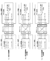
従って、図1に示す画像表示システム10においては、リバーシブルコネクタに対応可能となる。例えば、図10(a)に示すように、順方向接続では、MHL送信部の出力(1)から出るTMDSチャネル1に対応したTMDSラインデータ(1)は、MHLソース機器側でレセプタクルのピン(1)、MHLケーブルのプラグのピン(1)を通過し、MHLシンク機器側でMHLケーブルのプラグのピン(1)、レセプタクルのピン(1)を通過して、MHL受信部の入力(1)に入る。MHL受信部は、このTMDSラインデータ(1)を、挿入されているIDからTMDSチャネル1に対応したものと判別し、TMDSチャネル1に対応したTMDSラインデータとして処理する。
Therefore, the
また、例えば、図10(b)に示すように、受信側の逆方向接続では、MHL送信部の出力(1)から出るTMDSチャネル1に対応したTMDSラインデータ(1)は、MHLソース機器側でレセプタクルのピン(1)、MHLケーブルのプラグのピン(1)を通過し、MHLシンク機器側でMHLケーブルのプラグのピン(1)、レセプタクルのピン(X)を通過して、MHL受信部の入力(X)に入る。この場合、レセプタクルは、ケーブルのプラグがリバーシブルに接続可能とされている。MHL受信部は、このTMDSラインデータ(1)を、挿入されているIDからTMDSチャネル1に対応したものと判別し、TMDSチャネル1に対応したTMDSラインデータとして処理する。
Also, for example, as shown in FIG. 10B, in the reverse connection on the receiving side, the TMDS line data (1) corresponding to the
また、例えば、図10(c)に示すように、送信側の逆方向接続では、MHL送信部の出力(1)から出るTMDSチャネル1に対応したTMDSラインデータ(1)は、MHLソース機器側でレセプタクルのピン(1)、MHLケーブルのプラグのピン(X)を通過し、MHLシンク機器側でMHLケーブルのプラグのピン(X)、レセプタクルのピン(X)を通過して、MHL受信部の入力(X)に入る。この場合、レセプタクルは、ケーブルのプラグがリバーシブルに接続可能とされている。MHL受信部は、このTMDSラインデータ(1)を、挿入されているIDからTMDSチャネル1に対応したものと判別し、TMDSチャネル1に対応したTMDSラインデータとして処理する。
Also, for example, as shown in FIG. 10C, in the reverse connection on the transmission side, the TMDS line data (1) corresponding to the
このように、MHL受信部は、入力(1)〜(X)に入る各TMDSラインデータがどのTMDSチャネルに対応したものかをIDに基づいて判別して必要に応じて並べ替えて処理するので、MHL受信部の入力(1)〜(X)にTMDSラインデータ(1)〜(X)が正しく入らなくても、MHLデータの復元を適切に行うことができる。 As described above, since the MHL receiving unit determines which TMDS channel each TMDS line data input to the inputs (1) to (X) corresponds to based on the ID, and rearranges and processes as necessary. Even if the TMDS line data (1) to (X) are not correctly input to the inputs (1) to (X) of the MHL receiving unit, the MHL data can be restored properly.
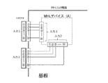
また、図1に示す画像表示システム10においては、基板設計の効率化を図ることができる。この場合、例えば、図11に示すような基板形状、コネクタの配置が決められているMHLシンク機器があり、このMHLシンク機器に、例えば、図12に示すMHLデバイス(MHL受信部)(A),(B),(C)を配置する場合を考える。MHLデバイス(A)を配置する場合、図13に示すように、コネクタからデバイスまで最短パターンを配置することができ、良好な特性を得ることができる。
Moreover, in the
また、MHLデバイス(B)を配置する場合、通常であれば、図14に示すように、配線パターンが複雑になり、良好な特性を得るために多層基板を使用し、あるいは特性の良い基板を使う必要がある。しかし、本技術を使用することで、各TMDSラインデータがMHLデバイスのどの入力に入るかは問題でなくなることから、図15に示すように、最短のパターンで設計することができる。 Also, when arranging the MHL device (B), normally, as shown in FIG. 14, the wiring pattern becomes complicated, and a multilayer substrate is used to obtain good characteristics, or a substrate with good characteristics is used. I need to use it. However, by using the present technology, it does not matter which input of the MHL device each TMDS line data enters, it can be designed with the shortest pattern as shown in FIG.
また、MHLデバイス(C)を配置する場合、通常であれば、図16に示すように、クロスポイントが生じるパターン設計となり、良好な特性を得るために、多層基板、特性の良い基板を使用する必要が生じる。しかし、本技術を使用することで、各TMDSラインデータがMHLデバイスのどの入力に入るかは問題でなくなることから、図17に示すように、最短のパターンで設計することができる。 In the case of arranging the MHL device (C), normally, as shown in FIG. 16, a cross point will be generated in the pattern design, and a multilayer substrate and a substrate with good characteristics are used in order to obtain good characteristics. A need arises. However, by using the present technology, it does not matter which input of the MHL device each TMDS line data enters, it can be designed with the shortest pattern as shown in FIG.
<2.変形例>
なお、上述実施の形態においては、1つのコンテンツデータをTMDSデータチャネル0〜Xで送受信する例を示した。しかし、TMDSデータチャネル0〜Xを複数組に分割し、複数のコンテンツデータを並行して送受信する構成も考えられる。<2. Modified example>
In the above embodiment, an example in which one content data is transmitted and received on the
また、上述実施の形態においては、MHLソース機器とMHLシンク機器とがMHLのデジタルインタフェースで接続される例を示した。しかし、本技術は、送信装置と受信装置とがHDMI(High-Definition Multimedia Interface)などのその他のデジタルインタフェースで接続される場合にも同様に適用できる。なお、「HDMI」、「MHL」は、登録商標である。 Moreover, in the above-mentioned embodiment, the example which MHL source apparatus and MHL sink apparatus are connected by the digital interface of MHL was shown. However, the present technology is also applicable to the case where the transmission device and the reception device are connected by another digital interface such as HDMI (High-Definition Multimedia Interface). "HDMI" and "MHL" are registered trademarks.
また、本技術は、以下のような構成を取ることもできる。
(1)複数のデータチャネルにそれぞれ対応した複数系列のデータを伝送路を介して外部機器に送信する送信部と、
上記複数系列のデータのそれぞれに、対応するデータチャネルを識別するための識別情報を付加する情報付加部を備える
送信装置。
(2)上記データチャネルは、TMDSデータチャネルであり、
上記情報付加部は、
各TMDSラインデータのコントロール期間に、上記対応するデータチャネルを識別するための識別情報を挿入する
前記(1)に記載の送信装置。
(3)上記対応するデータチャネルを識別するための識別情報には、総データチャネル数の情報が付加されている
前記(1)または(2)に記載の送信装置。
(4)一つまたは複数のコンテンツデータから上記複数系列のデータを得るデータ処理部をさらに備える
前記(1)から(3)のいずれかに記載の送信装置。
(5)上記複数系列のデータをそれぞれ出力する複数のピンを持つレセプタクルをさらに備え、
上記レセプタクルは、上記伝送路を構成するケーブルのプラグがリバーシブルに接続可能とされている
前記(1)から(4)のいずれかに記載の送信装置。
(6)送信部により複数のデータチャネルにそれぞれ対応した複数系列のデータを伝送路を介して外部機器に送信する送信ステップと、
上記複数系列のデータのそれぞれに、対応するデータチャネルを識別するための識別情報を付加する情報付加ステップを有する
送信方法。
(7)外部機器から伝送路を介して、それぞれ対応するデータチャネルを識別するための識別情報が付加されている、複数系列のデータを受信する受信部と、
上記複数系列のデータに対応するデータチャネルを、それぞれ上記挿入されている識別情報に基づいて判別する判別部を備える
受信装置。
(8)上記データチャネルは、TMDSデータチャネルであり、
上記識別情報は、TMDSラインデータのコントロール期間に挿入されている
前記(7)に記載の受信装置。
(9)上記複数系列のデータを上記判別結果に基づいて合成し、一つまたは複数のコンテンツデータを得るデータ処理部をさらに備える
前記(7)または(8)に記載の受信装置。
(10)上記複数系列のデータをそれぞれ入力する複数のピンを持つレセプタクルをさらに備え、
上記レセプタクルは、上記伝送路を構成するケーブルのプラグがリバーシブルに接続可能とされている
前記(7)から(9)のいずれかに記載の受信装置。
(11)受信部により、外部機器から伝送路を介して、それぞれ対応するデータチャネルを識別するための識別情報が付加されている、複数系列のデータを受信する受信ステップと、
上記複数系列のデータに対応するデータチャネルを、それぞれ上記挿入されている識別情報に基づいて判別する判別ステップを有する
受信方法。Furthermore, the present technology can also be configured as follows.
(1) A transmitter configured to transmit a plurality of series of data respectively corresponding to a plurality of data channels to an external device via a transmission path;
A transmission apparatus comprising: an information addition unit that adds identification information for identifying a corresponding data channel to each of the plurality of sets of data.
(2) The data channel is a TMDS data channel,
The above information addition unit
The transmission device according to (1), wherein identification information for identifying the corresponding data channel is inserted in a control period of each TMDS line data.
(3) The transmission apparatus according to (1) or (2), wherein information of the total number of data channels is added to the identification information for identifying the corresponding data channel.
(4) The transmission device according to any one of (1) to (3), further including: a data processing unit that obtains the plurality of sets of data from one or more pieces of content data.
(5) A receptacle further comprising a plurality of pins for outputting the plurality of series of data,
The transmitting device according to any one of (1) to (4), wherein the receptacle is configured such that a plug of a cable forming the transmission path is reversible connectable.
(6) a transmitting step of transmitting a plurality of series of data respectively corresponding to a plurality of data channels by the transmission unit to an external device through the transmission path;
A transmission method comprising an information addition step of adding identification information for identifying a corresponding data channel to each of the plurality of series of data.
(7) A receiving unit for receiving a plurality of sequences of data, to which identification information for identifying the corresponding data channel is added from the external device through the transmission path,
A receiver comprising: a determination unit that determines a data channel corresponding to the plurality of sets of data based on the inserted identification information.
(8) The data channel is a TMDS data channel,
The receiver according to (7), wherein the identification information is inserted in a control period of TMDS line data.
(9) The receiving device according to (7) or (8), further including: a data processing unit that combines the plurality of sets of data based on the determination result and obtains one or more pieces of content data.
(10) It further comprises a receptacle having a plurality of pins for inputting the plurality of series of data,
The receiver according to any one of (7) to (9), in which the receptacle of the cable constituting the transmission path can be reversibly connected to the receptacle.
(11) a receiving step of receiving data of a plurality of sequences to which identification information for identifying the corresponding data channel is added from the external device via the transmission path by the reception unit;
A receiving method comprising: determining a data channel corresponding to the plurality of series of data based on the inserted identification information.
10・・・画像表示システム
100・・・モバイルフォーン
101・・・CPU
102・・・ユーザ操作部
103・・・表示制御部
104・・・表示部
105・・・3G/4Gモデム部
106・・・カメラ部
107・・・記録再生部
108・・・送信処理部
109・・・MHL送信部
110・・・MHL端子
111・・・電源部
121・・・MHLデータ生成部
122・・・分配部
123-1〜123-X・・・TMDSエンコーダ
124-1〜124-X・・・シリアライザ
200・・・テレビ受信機
201・・・CPU
202・・・ユーザ操作部
203・・・表示制御部
204・・・MHL端子
205・・・MHL受信部
206・・・受信処理部
207・・・チューナ
208・・・アンテナ端子
209・・・切り替え部
210・・・表示部
211・・・電源部
221-1〜221-X・・・デシリアライザ
222-1〜222-X・・・TMDSデコーダ
223・・・合成部
224・・・MHLデータ分解部
300・・・MHLケーブル10: Image display system 100: Mobile phone 101: CPU
102: user operation unit 103: display control unit 104: display unit 105: 3G / 4G modem unit 106: camera unit 107: recording and reproducing unit 108:
202: User operation unit 203: Display control unit 204: MHL terminal 205: MHL reception unit 206: Reception processing unit 207: Tuner 208: Antenna terminal 209: Switching Unit 210: Display unit 211: Power supply unit 221-1 to 221-X: Deserializer 222-1 to 222-X: TMDS decoder 223: Synthesis unit 224: MHL
Claims (9)
上記複数系列のデータのそれぞれに、対応するデータチャネルを識別するための識別情報を付加する情報付加部を備え、
上記データチャネルは、TMDSデータチャネルであり、
上記情報付加部は、
各TMDSラインデータのコントロール期間に、上記対応するデータチャネルを識別するための識別情報を挿入する
送信装置。 A transmitter configured to transmit a plurality of series of data respectively corresponding to a plurality of data channels to an external device via a transmission path;
An information adding unit for adding identification information for identifying a corresponding data channel to each of the plurality of series of data ;
The data channel is a TMDS data channel,
The above information addition unit
The control period of each TMDS line data transmission device to insert the identification information for identifying the corresponding data channel.
請求項1に記載の送信装置。 The transmission apparatus according to claim 1, wherein information of the total number of data channels is added to the identification information for identifying the corresponding data channel.
請求項1に記載の送信装置。 The transmission device according to claim 1, further comprising: a data processing unit that obtains the plurality of series of data from one or more pieces of content data.
上記レセプタクルは、上記伝送路を構成するケーブルのプラグがリバーシブルに接続可能とされている
請求項1に記載の送信装置。 And a receptacle having a plurality of pins for outputting the plurality of series of data.
The transmission device according to claim 1, wherein the receptacle of the cable, which constitutes the transmission path, is reversible connectable to the receptacle.
上記複数系列のデータのそれぞれに、対応するデータチャネルを識別するための識別情報を付加する情報付加ステップを有し、
上記データチャネルは、TMDSデータチャネルであり、
上記情報付加ステップでは、
各TMDSラインデータのコントロール期間に、上記対応するデータチャネルを識別するための識別情報を挿入する
送信方法。 A transmitting step of transmitting a plurality of series of data respectively corresponding to a plurality of data channels by the transmission unit to an external device via the transmission path;
The respective data of said plurality of sequences, have a information adding step of adding identification information for identifying the corresponding data channel,
The data channel is a TMDS data channel,
In the above information addition step,
A transmission method for inserting identification information for identifying the corresponding data channel in a control period of each TMDS line data .
上記複数系列のデータに対応するデータチャネルを、それぞれ上記挿入されている識別情報に基づいて判別する判別部を備え、
上記データチャネルは、TMDSデータチャネルであり、
上記識別情報は、TMDSラインデータのコントロール期間に挿入されている
受信装置。 A receiving unit for receiving a plurality of sequences of data to which identification information for identifying the corresponding data channel is added from the external device via the transmission path;
A determination unit configured to determine data channels corresponding to the plurality of series of data based on the inserted identification information ;
The data channel is a TMDS data channel,
The identification information, the receiving device that is inserted in the control period of TMDS line data.
請求項6に記載の受信装置。 The receiving apparatus according to claim 6 , further comprising: a data processing unit that combines the plurality of sets of data based on the determination result and obtains one or more pieces of content data.
上記レセプタクルは、上記伝送路を構成するケーブルのプラグがリバーシブルに接続可能とされている
請求項6に記載の受信装置。 And a receptacle having a plurality of pins for inputting the plurality of series of data,
The receiver according to claim 6 , wherein the plug of the cable forming the transmission path is reversible connectable to the receptacle.
上記複数系列のデータに対応するデータチャネルを、それぞれ上記挿入されている識別情報に基づいて判別する判別ステップを有し、
上記データチャネルは、TMDSデータチャネルであり、
上記識別情報は、TMDSラインデータのコントロール期間に挿入されている
受信方法。 A receiving step of receiving data of a plurality of sequences to which identification information for identifying the corresponding data channel is added from the external device via the transmission path by the receiving unit;
The data channel corresponding to the data of the plurality of streams, respectively have a determination step of determining based on the identification information being the insertion,
The data channel is a TMDS data channel,
The identification information receiving method that are inserted into the control period of TMDS line data.
Applications Claiming Priority (3)
| Application Number | Priority Date | Filing Date | Title |
|---|---|---|---|
| JP2014041034 | 2014-03-03 | ||
| JP2014041034 | 2014-03-03 | ||
| PCT/JP2015/054086 WO2015133249A1 (en) | 2014-03-03 | 2015-02-16 | Transmission device, transmission method, reception device, and reception method |
Publications (2)
| Publication Number | Publication Date |
|---|---|
| JPWO2015133249A1 JPWO2015133249A1 (en) | 2017-04-06 |
| JP6500890B2 true JP6500890B2 (en) | 2019-04-17 |
Family
ID=54055059
Family Applications (1)
| Application Number | Title | Priority Date | Filing Date |
|---|---|---|---|
| JP2016506404A Active JP6500890B2 (en) | 2014-03-03 | 2015-02-16 | Transmission apparatus, transmission method, reception apparatus and reception method |
Country Status (4)
| Country | Link |
|---|---|
| US (1) | US20170012798A1 (en) |
| JP (1) | JP6500890B2 (en) |
| CN (1) | CN106031187B (en) |
| WO (1) | WO2015133249A1 (en) |
Families Citing this family (7)
| Publication number | Priority date | Publication date | Assignee | Title |
|---|---|---|---|---|
| US10512074B2 (en) * | 2015-08-31 | 2019-12-17 | Intel IP Corporation | Uplink (UL) multi-user (MU) feedback using high-efficiency (HE) long training fields in a wireless local-area network |
| US20180183899A1 (en) * | 2016-12-23 | 2018-06-28 | Intel Corporation | Transport agnostic display protocol |
| US11093197B2 (en) * | 2017-07-31 | 2021-08-17 | Stmicroelectronics, Inc. | System and method to increase display area utilizing a plurality of discrete displays |
| US10535493B2 (en) * | 2017-10-10 | 2020-01-14 | Kla-Tencor Corporation | Photocathode designs and methods of generating an electron beam using a photocathode |
| US10791003B2 (en) | 2017-10-30 | 2020-09-29 | Intel Corporation | Streaming on diverse transports |
| KR102559966B1 (en) | 2018-05-25 | 2023-07-26 | 라인플러스 주식회사 | Method and system for transmitting and reproducing video of dynamic bit rate using a plurality of channels |
| TWI783588B (en) * | 2021-07-23 | 2022-11-11 | 瑞昱半導體股份有限公司 | Scaler integrated circuit applicable to performing multi-picture processing in display device |
Family Cites Families (24)
| Publication number | Priority date | Publication date | Assignee | Title |
|---|---|---|---|---|
| US4383316A (en) * | 1980-04-14 | 1983-05-10 | Bell Telephone Laboratories, Incorporated | Apparatus for and method of collating partitioned time disordered synchronous data streams |
| US7292604B2 (en) * | 1996-09-05 | 2007-11-06 | The Directv Group, Inc. | Device and method for efficient delivery of redundant national television signals |
| CN100525443C (en) * | 1997-03-17 | 2009-08-05 | 松下电器产业株式会社 | Method and apparatus for processing, transmitting and receiving dynamic image data |
| US6307543B1 (en) * | 1998-09-10 | 2001-10-23 | Silicon Image, Inc. | Bi-directional data transfer using two pair of differential lines as a single additional differential pair |
| EP1241844B1 (en) * | 2001-03-16 | 2019-11-06 | Super Interconnect Technologies LLC | Combining a clock signal and a data signal |
| US7215679B2 (en) * | 2001-08-30 | 2007-05-08 | Thomson Licensing | Method, apparatus and data structure enabling multiple channel data stream transmission |
| US7558326B1 (en) * | 2001-09-12 | 2009-07-07 | Silicon Image, Inc. | Method and apparatus for sending auxiliary data on a TMDS-like link |
| TWI361615B (en) * | 2006-11-30 | 2012-04-01 | Princeton Technology Corp | Video and audio data synchronization method and related apparatus for a multimedia interface |
| EP2183927A4 (en) * | 2007-05-14 | 2014-12-17 | Sigma Group Inc | Wireless multimedia system |
| JP5003389B2 (en) * | 2007-09-28 | 2012-08-15 | ソニー株式会社 | Electronic device and control method in electronic device |
| US9462020B2 (en) * | 2008-01-16 | 2016-10-04 | Qualcomm Incorporated | Intelligent client: multiple channel switching over a digital broadcast network |
| JP4645717B2 (en) * | 2008-09-26 | 2011-03-09 | ソニー株式会社 | Interface circuit and video apparatus |
| WO2010119326A1 (en) * | 2009-04-14 | 2010-10-21 | Ati Technologies Ulc | Embedded clock recovery |
| JP5372687B2 (en) * | 2009-09-30 | 2013-12-18 | ソニー株式会社 | Transmitting apparatus, transmitting method, receiving apparatus, and receiving method |
| WO2011080911A1 (en) * | 2009-12-28 | 2011-07-07 | パナソニック株式会社 | Display device and method, transmission device and method, and reception device and method |
| US8755431B2 (en) * | 2010-01-14 | 2014-06-17 | Silicon Image, Inc. | Transmission and detection of multi-channel signals in reduced channel format |
| JP2011172156A (en) * | 2010-02-22 | 2011-09-01 | Sony Corp | Content reproduction system, content receiving apparatus, audio reproduction apparatus, content reproduction method and program |
| JP6057383B2 (en) * | 2011-01-22 | 2017-01-11 | ヴィアサット, インコーポレイテッドViaSat, Inc. | Frame format for high-speed optical communication |
| US20120269207A1 (en) * | 2011-04-22 | 2012-10-25 | Samsung Electronics Co., Ltd. | Receiver for receiving and displaying a plurality of streams through separate routes, method for processing the plurality of streams and transmitting method thereof |
| JP5278503B2 (en) * | 2011-06-27 | 2013-09-04 | ソニー株式会社 | Information transmitting apparatus, information transmitting method, and information transmitting / receiving system |
| US9293876B2 (en) * | 2011-11-07 | 2016-03-22 | Apple Inc. | Techniques for configuring contacts of a connector |
| WO2013122385A1 (en) * | 2012-02-15 | 2013-08-22 | Samsung Electronics Co., Ltd. | Data transmitting apparatus, data receiving apparatus, data transreceiving system, data transmitting method, data receiving method and data transreceiving method |
| WO2013122387A1 (en) * | 2012-02-15 | 2013-08-22 | Samsung Electronics Co., Ltd. | Data transmitting apparatus, data receiving apparatus, data transceiving system, data transmitting method, and data receiving method |
| US8858262B2 (en) * | 2012-12-04 | 2014-10-14 | Genesis Technology Usa, Inc. | F-connector with integrated surge protection |
-
2015
- 2015-02-16 JP JP2016506404A patent/JP6500890B2/en active Active
- 2015-02-16 CN CN201580010533.0A patent/CN106031187B/en active Active
- 2015-02-16 US US15/121,162 patent/US20170012798A1/en not_active Abandoned
- 2015-02-16 WO PCT/JP2015/054086 patent/WO2015133249A1/en active Application Filing
Also Published As
| Publication number | Publication date |
|---|---|
| JPWO2015133249A1 (en) | 2017-04-06 |
| CN106031187B (en) | 2019-12-24 |
| US20170012798A1 (en) | 2017-01-12 |
| CN106031187A (en) | 2016-10-12 |
| WO2015133249A1 (en) | 2015-09-11 |
Similar Documents
| Publication | Publication Date | Title |
|---|---|---|
| JP6500890B2 (en) | Transmission apparatus, transmission method, reception apparatus and reception method | |
| JP5003389B2 (en) | Electronic device and control method in electronic device | |
| US8359628B2 (en) | Display device and transmitting device | |
| JP4835568B2 (en) | Display device, data transmission method in display device, transmission device, and data reception method in transmission device | |
| JP5916771B2 (en) | Transforming multimedia data streams for use by connected devices | |
| JP5386984B2 (en) | Transmitting apparatus, video signal transmitting method in transmitting apparatus, receiving apparatus, and video signal receiving method in receiving apparatus | |
| JP5428186B2 (en) | Electronics | |
| JP2010073054A (en) | Image display, connector display method, transmission line state detector, transmission line state detection method, and semiconductor integrated circuit | |
| KR20170028165A (en) | Image processing apparatus and control method thereof | |
| JP2009055149A (en) | Electronic apparatus | |
| JP2009272791A (en) | Transmitter, information transmission method, receiver, and information processing method | |
| US8001289B2 (en) | Digital audio/video apparatus and method that can perform additional operations | |
| US20080281990A1 (en) | Expansion device adapted for use with a portable electronic device | |
| US8959257B2 (en) | Information processing apparatus and information processing method | |
| US20150040158A1 (en) | Receiving device, transmitter and transmitting/receiving system | |
| US20140379941A1 (en) | Receiving device, transmitting device and transmitting/receiving system | |
| WO2015174357A1 (en) | Receptacle, plug, transmission device, method for transmitting data in transmission device, reception device, and method for receiving data in reception device | |
| US20150029398A1 (en) | Information processing apparatus and information processing method for outputting a charging status | |
| US10460646B2 (en) | Display system, display device, electronic apparatus, and image signal transmission method for displaying an original image based on combining divided image signals | |
| US20150032912A1 (en) | Information processing apparatus and information processing method | |
| KR20160089824A (en) | Realtime remote monitoring and playing system using digital video recoder, and method thereof | |
| JP5910660B2 (en) | Transmitting apparatus and information processing method | |
| WO2014199494A1 (en) | Transmitting device, receiving device, and transmitting/receiving system | |
| KR20130076675A (en) | Display apparatus, external peripheral device connectable thereof and image displaying method | |
| KR20150085723A (en) | A method for synchronizing auxiliary signal |
Legal Events
| Date | Code | Title | Description |
|---|---|---|---|
| A621 | Written request for application examination |
Free format text: JAPANESE INTERMEDIATE CODE: A621 Effective date: 20180105 |
|
| A131 | Notification of reasons for refusal |
Free format text: JAPANESE INTERMEDIATE CODE: A131 Effective date: 20181204 |
|
| A521 | Request for written amendment filed |
Free format text: JAPANESE INTERMEDIATE CODE: A523 Effective date: 20190128 |
|
| TRDD | Decision of grant or rejection written | ||
| A01 | Written decision to grant a patent or to grant a registration (utility model) |
Free format text: JAPANESE INTERMEDIATE CODE: A01 Effective date: 20190219 |
|
| A61 | First payment of annual fees (during grant procedure) |
Free format text: JAPANESE INTERMEDIATE CODE: A61 Effective date: 20190304 |
|
| R151 | Written notification of patent or utility model registration |
Ref document number: 6500890 Country of ref document: JP Free format text: JAPANESE INTERMEDIATE CODE: R151 |