JP6500456B2 - Image forming device - Google Patents
Image forming device Download PDFInfo
- Publication number
- JP6500456B2 JP6500456B2 JP2015014248A JP2015014248A JP6500456B2 JP 6500456 B2 JP6500456 B2 JP 6500456B2 JP 2015014248 A JP2015014248 A JP 2015014248A JP 2015014248 A JP2015014248 A JP 2015014248A JP 6500456 B2 JP6500456 B2 JP 6500456B2
- Authority
- JP
- Japan
- Prior art keywords
- developer
- transport
- image forming
- unit
- forming apparatus
- Prior art date
- Legal status (The legal status is an assumption and is not a legal conclusion. Google has not performed a legal analysis and makes no representation as to the accuracy of the status listed.)
- Active
Links
- 230000032258 transport Effects 0.000 claims description 130
- 238000003780 insertion Methods 0.000 claims description 3
- 230000037431 insertion Effects 0.000 claims description 3
- 238000004140 cleaning Methods 0.000 description 9
- 230000000694 effects Effects 0.000 description 8
- 238000003756 stirring Methods 0.000 description 5
- 238000010438 heat treatment Methods 0.000 description 4
- 238000011144 upstream manufacturing Methods 0.000 description 4
- 239000003795 chemical substances by application Substances 0.000 description 3
- 238000007599 discharging Methods 0.000 description 3
- 230000005540 biological transmission Effects 0.000 description 2
- 239000000969 carrier Substances 0.000 description 2
- 230000015572 biosynthetic process Effects 0.000 description 1
- 239000003086 colorant Substances 0.000 description 1
- 230000001678 irradiating effect Effects 0.000 description 1
Images


Classifications
-
- G—PHYSICS
- G03—PHOTOGRAPHY; CINEMATOGRAPHY; ANALOGOUS TECHNIQUES USING WAVES OTHER THAN OPTICAL WAVES; ELECTROGRAPHY; HOLOGRAPHY
- G03G—ELECTROGRAPHY; ELECTROPHOTOGRAPHY; MAGNETOGRAPHY
- G03G15/00—Apparatus for electrographic processes using a charge pattern
- G03G15/01—Apparatus for electrographic processes using a charge pattern for producing multicoloured copies
- G03G15/0105—Details of unit
- G03G15/0126—Details of unit using a solid developer
-
- G—PHYSICS
- G03—PHOTOGRAPHY; CINEMATOGRAPHY; ANALOGOUS TECHNIQUES USING WAVES OTHER THAN OPTICAL WAVES; ELECTROGRAPHY; HOLOGRAPHY
- G03G—ELECTROGRAPHY; ELECTROPHOTOGRAPHY; MAGNETOGRAPHY
- G03G15/00—Apparatus for electrographic processes using a charge pattern
- G03G15/06—Apparatus for electrographic processes using a charge pattern for developing
- G03G15/08—Apparatus for electrographic processes using a charge pattern for developing using a solid developer, e.g. powder developer
- G03G15/0822—Arrangements for preparing, mixing, supplying or dispensing developer
- G03G15/0865—Arrangements for supplying new developer
- G03G15/0867—Arrangements for supplying new developer cylindrical developer cartridges, e.g. toner bottles for the developer replenishing opening
- G03G15/0868—Toner cartridges fulfilling a continuous function within the electrographic apparatus during the use of the supplied developer material, e.g. toner discharge on demand, storing residual toner, acting as an active closure for the developer replenishing opening
-
- G—PHYSICS
- G03—PHOTOGRAPHY; CINEMATOGRAPHY; ANALOGOUS TECHNIQUES USING WAVES OTHER THAN OPTICAL WAVES; ELECTROGRAPHY; HOLOGRAPHY
- G03G—ELECTROGRAPHY; ELECTROPHOTOGRAPHY; MAGNETOGRAPHY
- G03G15/00—Apparatus for electrographic processes using a charge pattern
- G03G15/06—Apparatus for electrographic processes using a charge pattern for developing
- G03G15/08—Apparatus for electrographic processes using a charge pattern for developing using a solid developer, e.g. powder developer
- G03G15/0822—Arrangements for preparing, mixing, supplying or dispensing developer
- G03G15/0877—Arrangements for metering and dispensing developer from a developer cartridge into the development unit
- G03G15/0879—Arrangements for metering and dispensing developer from a developer cartridge into the development unit for dispensing developer from a developer cartridge not directly attached to the development unit
-
- G—PHYSICS
- G03—PHOTOGRAPHY; CINEMATOGRAPHY; ANALOGOUS TECHNIQUES USING WAVES OTHER THAN OPTICAL WAVES; ELECTROGRAPHY; HOLOGRAPHY
- G03G—ELECTROGRAPHY; ELECTROPHOTOGRAPHY; MAGNETOGRAPHY
- G03G2215/00—Apparatus for electrophotographic processes
- G03G2215/01—Apparatus for electrophotographic processes for producing multicoloured copies
- G03G2215/0103—Plural electrographic recording members
- G03G2215/0119—Linear arrangement adjacent plural transfer points
- G03G2215/0122—Linear arrangement adjacent plural transfer points primary transfer to an intermediate transfer belt
- G03G2215/0125—Linear arrangement adjacent plural transfer points primary transfer to an intermediate transfer belt the linear arrangement being horizontal or slanted
- G03G2215/0132—Linear arrangement adjacent plural transfer points primary transfer to an intermediate transfer belt the linear arrangement being horizontal or slanted vertical medium transport path at the secondary transfer
Landscapes
- Physics & Mathematics (AREA)
- General Physics & Mathematics (AREA)
- Dry Development In Electrophotography (AREA)
- Color Electrophotography (AREA)
- Electrophotography Configuration And Component (AREA)
Description
本発明は、画像形成装置に関する。 The present invention relates to an image forming apparatus.
現像剤容器の配置に関する画像形成装置の発明として、例えば、下記特許文献1には、像担持体と、前記像担持体周りに画像形成手段の一部を配し、装置本体に対して着脱可能な像担持体ユニットと、前記像担持体に形成した各色成分の潜像を現像するための各色成分に対応する複数の現像手段を有し、前記現像手段へ現像剤カートリッジを着脱可能な現像ユニットと、前記各色成分毎に形成した現像像を記録媒体に転写するための転写手段と、前記記録媒体を搬送するための搬送手段と、前記記録媒体を収納し、装置本体に対して着脱可能な記録媒体カセットと、を有し、前記像担持体ユニット、現像剤カートリッジ及び記録媒体カセットを着脱するためのそれぞれの着脱口を装置本体の同一側に配置し、且つそれぞれの着脱方向が同一方向であると共に、前記搬送手段による記録媒体の搬送方向と直交する方向となるように構成したことを特徴とする画像形成装置が開示されている。 As an invention of an image forming apparatus relating to the arrangement of a developer container, for example, in Patent Document 1 below, an image carrier and a part of an image forming unit are disposed around the image carrier and can be detachably attached to the apparatus main body Image carrier unit, and a plurality of developing means corresponding to each color component for developing a latent image of each color component formed on the image carrier, and a developing unit capable of attaching and detaching the developer cartridge to the developing means A transfer unit for transferring the developed image formed for each color component to a recording medium, a transfer unit for conveying the recording medium, and the recording medium, which are detachable from the apparatus main body And a recording medium cassette, wherein the mounting holes for mounting and demounting the image carrier unit, the developer cartridge and the recording medium cassette are disposed on the same side of the apparatus main body, and the respective mounting and demounting directions are the same. With it, the image forming apparatus is disclosed which is characterized by being configured such that the direction perpendicular to the conveying direction of the recording medium by the conveying means.
また、下記特許文献2には、本体ケーシングと、現像剤を収容するための複数の現像剤収容部材と、前記現像剤収容部材から供給された現像剤により記録シートに画像を形成する画像担持体とを備えた画像形成装置であって、前記各現像剤収容部材は、長手方向が側方を向くように配置されるとともに、下側において下方を向く現像剤の供給口を有し、複数の前記現像剤収容部材のうち少なくとも2つは、略鉛直方向に並列されるとともに、前記各供給口が前記現像剤収容部材の長手方向に互いにずれて配置されたことを特徴とする画像形成装置の発明が開示されている。 Further, in Patent Document 2 below, an image carrier that forms an image on a recording sheet by the main body casing, a plurality of developer containing members for containing a developer, and the developer supplied from the developer containing member. And each of the developer containing members is disposed so that the longitudinal direction is directed to the side, and has a plurality of developer supply ports directed downward at the lower side. The image forming apparatus is characterized in that at least two of the developer containing members are juxtaposed in a substantially vertical direction, and the supply ports are mutually offset in the longitudinal direction of the developer containing member. The invention is disclosed.
また、下記特許文献3には、トナーカートリッジを設置するトナーカートリッジケースと前記トナーカートリッジから供給されるトナーを搬送するトナー搬送手段とが互いに直交して構成されていることを特徴とする画像形成装置の発明が開示されている。 Further, in Patent Document 3 below, an image forming apparatus is characterized in that a toner cartridge case for installing a toner cartridge and a toner conveying means for conveying the toner supplied from the toner cartridge are orthogonal to each other. Invention is disclosed.
本発明は、複数の現像剤容器から排出された現像剤をすべて同じ方向に搬送する現像剤搬送装置を有する場合と比較して、現像剤の攪拌を行いつつ現像剤の搬送距離を短くすることができる画像形成装置を提供することを目的とする。 The present invention shortens the transport distance of the developer while stirring the developer, as compared with the case where the developer transport device transports all the developers discharged from the plurality of developer containers in the same direction. It is an object of the present invention to provide an image forming apparatus capable of
請求項1に記載の本発明は、第1の方向に並列に設けられた複数の現像装置と、前記第1の方向において前記複数の現像装置の間に排出口が配置される且つ現像剤を収容する複数の現像剤容器と、前記現像剤容器から前記現像装置へ前記現像剤を搬送する複数の現像剤搬送装置と、を有し、前記現像剤搬送装置は、並列に設けられた搬送部をそれぞれ有し、前記搬送部のうち、少なくとも1つは前記排出口から前記現像剤を搬送するときに他の搬送部とは反対方向に前記現像剤を搬送する画像形成装置である。 According to the first aspect of the present invention, discharge ports are disposed between a plurality of developing devices provided in parallel in a first direction, and the plurality of developing devices in the first direction, and a developer. A plurality of developer containers to be accommodated, and a plurality of developer transport devices for transporting the developer from the developer container to the developing device, wherein the developer transport devices are provided in parallel , And at least one of the transport units is an image forming apparatus that transports the developer in the opposite direction to the other transport units when transporting the developer from the discharge port.
請求項2に記載の本発明は、前記搬送部は、前記現像剤容器の長手方向に沿ってそれぞれ設けられている請求項1に記載の画像形成装置である。 The present invention according to claim 2 is the image forming apparatus according to claim 1, wherein the transport section is provided along the longitudinal direction of the developer container.
請求項3に記載の本発明は、前記搬送部は、前記現像剤容器から供給された直後の現像剤が搬送され、前記現像剤の搬送量を調整する搬送量調整部がそれぞれ設けられている請求項1又は2に記載の画像形成装置である。 According to a third aspect of the present invention, the transport section is provided with a transport amount adjusting section for transporting the developer immediately after being supplied from the developer container and adjusting the transport amount of the developer. It is an image forming apparatus according to claim 1 or 2.
請求項4に記載の本発明は、前記搬送量調整部は、前記現像剤容器から前記現像剤が排出される前記排出口を基準として、等しい距離にそれぞれ設けられている請求項3に記載の画像形成装置である。 According to a fourth aspect of the present invention, the transport amount adjusting part is provided at equal distances with respect to the discharge port through which the developer is discharged from the developer container. It is an image forming apparatus.
請求項5に記載の本発明は、前記搬送部の内部には、前記搬送部の長手方向に沿って設けられた回転軸部と、前記回転軸部の半径方向に突出した螺旋状の壁体で形成された搬送体とを有し、前記搬送体の回転に応じて前記現像剤が搬送される搬送部材がそれぞれ設けられ、前記搬送量調整部にかかる回転軸部は、他の部分の前記回転軸部に比べ、太く形成されている請求項3又は4に記載の画像形成装置である。 According to a fifth aspect of the present invention, there is provided a rotary shaft portion provided along the longitudinal direction of the transport portion inside the transport portion, and a spiral wall body protruding in the radial direction of the rotary shaft portion. And a transport member formed on the transport member, the transport member configured to transport the developer according to the rotation of the transport member. The image forming apparatus according to claim 3, wherein the image forming apparatus is formed thicker than the rotation shaft portion.
請求項6に記載の本発明は、前記複数の現像剤搬送装置には、前記搬送部に対して、下方向に落下させて搬送する下方向搬送部を有し、前記下方向搬送部の下端部が前記現像装置と接続される請求項1〜5のいずれかの画像形成装置である。 According to a sixth aspect of the present invention, the plurality of developer transport devices have a downward transport portion for causing the transport portion to drop downward and transport the lower transport portion, the lower end of the lower transport portion The image forming apparatus according to any one of claims 1 to 5, wherein the unit is connected to the developing device.
請求項7に記載の本発明は、前記下方向搬送部の内側には、搬送される前記現像剤を崩す崩し部材がそれぞれ設けられ、前記崩し部材は、前記回転部材の回転によって前記下方向搬送部内を反復移動するようにされた請求項6に記載の画像形成装置である。 The present invention according to claim 7 is characterized in that a collapsing member for collapsing the developer being conveyed is provided inside the downward conveying portion, and the colliding member is configured to convey the downward direction by the rotation of the rotating member. The image forming apparatus according to claim 6, wherein the image forming apparatus repeatedly moves within the unit.
請求項8に記載の本発明は、前記搬送部のうちの少なくとも1つの搬送部は、前記下方向搬送部と直接繋がれており、他の搬送部は、前記下方向搬送部との間を繋ぐ中間搬送部を有している請求項6又は7に記載の画像形成装置である。 In the present invention according to claim 8, at least one transport unit of the transport units is directly connected to the downward transport unit, and another transport unit is connected to the lower transport unit. The image forming apparatus according to claim 6, further comprising an intermediate conveyance unit connecting the plurality of sheets.
請求項9に記載の本発明は、前記下方向搬送部のすべては、前記複数の現像剤容器のうち、外側に配置される現像剤容器側に設けられる請求項6〜8のいずれかに記載の画像形成装置である。 In the present invention according to claim 9, all of the downward conveying sections are provided on the side of the developer container disposed outside of the plurality of developer containers. Image forming apparatus.
請求項1に係る本発明によれば、複数の現像剤容器から排出された現像剤をすべて同じ方向に搬送する現像剤搬送装置を有する場合と比較して、現像剤の攪拌を行いつつ現像剤の搬送距離を短くすることができる。 According to the first aspect of the present invention, the developer is stirred while the developer is stirred, as compared with the case where the developer transport device transports all the developers discharged from the plurality of developer containers in the same direction. Transport distance can be shortened.
請求項2に係る本発明によれば、請求項1に係る本発明の効果に加え、搬送部が現像剤容器の長手方向に沿って設けられていない場合に比べて、現像剤の搬送距離を短くすることができる。 According to the second aspect of the present invention, in addition to the effect of the present invention according to the first aspect, the transport distance of the developer is increased compared to the case where the transport portion is not provided along the longitudinal direction of the developer container. It can be shortened.
請求項3に係る本発明によれば、請求項1又は2に係る本発明の効果に加え、現像剤の搬送量の調整を現像剤搬送装置に供給された位置から離れて行なう場合に比べて、現像剤搬送装置の長さや角度、方向に依存せずに安定した現像剤の搬送量を調整することができる。 According to the third aspect of the present invention, in addition to the effects of the present invention according to the first or second aspect, the adjustment of the transport amount of the developer is performed as compared with the case of performing away from the position supplied to the developer transport device. The developer transport amount can be adjusted stably without depending on the length, angle, and direction of the developer transport device.
請求項4に係る本発明によれば、請求項3に係る本発明の効果に加え、それぞれ排出口からの距離が異なる位置に搬送量調整部が設けられた場合に比べて、現像剤の搬送量を同じように調整することができる。 According to the fourth aspect of the present invention, in addition to the effect of the present invention according to the third aspect, the transport of the developer is carried out as compared with the case where the transport amount adjusting portion is provided at positions different in distance from the discharge port. The amount can be adjusted in the same way.
請求項5に係る本発明によれば、請求項3又は4に係る本発明の効果に加え、同じ太さの回転軸部により搬送量調整部を形成する場合に比べ、搬送量調整部の構造を容易にすることができる。 According to the fifth aspect of the present invention, in addition to the effects of the third aspect or the fourth aspect of the present invention, the structure of the conveyance amount adjustment portion is compared to the case where the conveyance amount adjustment portion is formed by the rotary shaft portion having the same thickness Can be made easier.
請求項6に係る本発明によれば、請求項1〜5のいずれかに係る本発明の効果に加え、落下させずに搬送する下方向搬送部を有する場合に比べ、現像剤の搬送距離を短くすることができる。 According to the sixth aspect of the present invention, in addition to the effect of the present invention according to any one of the first to fifth aspects, the transport distance of the developer can be increased compared to the case where the downward transport portion transports without dropping. It can be shortened.
請求項7に係る本発明によれば、請求項6に係る本発明の効果に加え、現像剤が固まることを防止することができる。 According to the seventh aspect of the present invention, in addition to the effects of the sixth aspect of the present invention, the developer can be prevented from being solidified.
請求項8に係る本発明によれば、請求項6又は7に係る本発明の効果に加え、すべての現像剤搬送装置に搬送部と下方向搬送部との間に中間搬送路を設けた場合に比べ、が像形成装置を小型化することができる。 According to the eighth aspect of the present invention, in addition to the effect of the present invention according to the sixth or seventh aspect, when all the developer transport devices are provided with an intermediate transport path between the transport portion and the downward transport portion. However, the image forming apparatus can be miniaturized.
請求項9に係る本発明によれば、請求項6〜8のいずれかに係る本発明の効果に加え、複数の下方向搬送部が異なる側に設けられた場合に比べ、画像形成装置を小型化することができる。 According to the ninth aspect of the present invention, in addition to the effect of the present invention according to any one of the sixth to eighth aspects, the image forming apparatus can be miniaturized compared to the case where the plurality of downward conveying sections are provided on different sides. Can be
[実施形態]
実施形態に係る画像形成装置について、図1〜図8を参照して説明する。実施形態に係る画像形成装置10は、4つの現像装置34Y、34M、34C、34Kをそれぞれ有する4つの像形成部22Y、22M、22C、22Kと、転写装置50と、イエロー、マゼンタ、シアン及び黒の各現像剤が収容された4つの現像剤容器40Y、40M、40C、40Kと、各現像剤容器40Y、40M、40C、40Kが装着される現像剤容器装着装置500と、現像剤容器40Y、40M、40C、40Kに収容された各現像剤が対応する各像形成部22Y、22M、22C、22Kに搬送される4つの現像剤搬送装置504Y、504M、504C、504Kと、給紙装置100と、定着ユニット200と、を有している。また、画像形成装置10内には、記録媒体16の搬送に用いられる記録媒体搬送路400が形成され、画像形成装置10の上部は、画像形成がなされた記録媒体16が排出される排出部14が設けられている。なお、現像剤容器40Y、40M、40C、40Kは、まとめて現像剤容器40という場合がある。また、像形成部22Y、22M、22C、22Kは、まとめて像形成部22という場合がある。また、現像剤搬送装置504Y、504M、504C、504Kは、まとめて現像剤搬送装置504という場合がある。
[Embodiment]
An image forming apparatus according to the embodiment will be described with reference to FIGS. 1 to 8. The
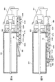
実施形態に係る画像形成装置10は、図1及び図2に示すように、各現像剤容器40Y、40M、40C、40Kは、記録媒体16の記録媒体搬送路400及び各像形成部22Y、22M、22C、22Kと直交する方向(第1の方向)に長手配置されるように並列に現像剤容器装着装置500に装着されている。また、各現像剤搬送装置504Y、504M、504C、504Kは、各現像剤容器40Y、40M、40C、40Kから排出された各現像剤が、像形成部22Y、22M、22C、22Kの上方を搬送され、その後、下方向に落下して対応する各像形成部22Y、22M、22C、22Kに供給されるように設けられている。
In the
像形成部22Y、22M、22C、22Kは、それぞれが像保持体24Y、24M、24C、24Kを有し、それぞれがイエローの現像剤を用いてイエローの現像剤像を形成し、マゼンタの現像剤を用いてマゼンタの現像剤像を形成し、シアンの現像剤像を用いてシアンの現像剤像を形成し、黒の現像剤を用いて黒の現像剤像を形成する。なお、実施形態の像形成部22は、画像形成装置本体12内において、記録媒体16が搬送される記録媒体搬送路400に対して遠い側からイエローの像形成部22Y、マゼンタの像形成部22M、シアンの像形成部22C、黒の像形成部22Kの順に並べられている。
The
4つの現像剤容器40Y、40M、40C、40Kは、それぞれイエロー、マゼンタ、シアン、黒の各現像剤が収納されている。この各現像剤容器40Y、40M、40C、40Kは、画像形成装置本体12内に設けられた現像剤容器装着装置500に装着されている。なお、現像剤容器40Y、40M、40C、40Kは現像剤容器装着装置500に設けられた現像剤容器接続部502と接続されるようになる。
The four
また、各現像剤容器40Y、40M、40C、40K内の各現像剤は、各現像剤に対応する現像剤搬送装置504Y、504M、504C、504Kを介して、各現像剤に対応する現像装置34Y、34M、34C、34Kに供給されるようになっている。また、実施形態の各現像剤容器40Y、40M、40C、40Kは、現像剤容器装着装置500に、図1の奥側からイエロー、マゼンタ、シアン、黒の順に並列に装着されている。
Further, each developer in each
ここで、図3を参照して、現像剤容器について説明する。なお、4つの現像剤容器40Y、40M、40C、40Kはそれぞれ同じ構成となっているので、イエローの現像剤容器40Yを代表して説明する。現像剤容器40Yは、外形が例えば円筒状となっており、内部に現像剤供給部42を有している。現像剤容器40Yの現像剤供給部42の中心軸方向には攪拌部材46が設けられており、この攪拌部材46を構成する回転軸48が現像剤容器40Yの両側で回転自在に支持されている。また、現像剤容器40Yの一端近傍、例えば、現像剤容器40Yが画像形成装置本体12に挿入される方向の奥側には現像剤容器40Yに収容された現像剤が排出される排出口44が形成されている。そして、攪拌部材46の回転軸48が駆動部501(図5参照)からの駆動力を受け、図2Bの矢印で示すように、攪拌部材46が反時計方向に回転ことで、現像剤が攪拌されると共に排出口44に向けて移動され、現像剤搬送装置504Yに供給されるようになる(図7参照)。なお、各現像剤容器40Y、40M、40C、40Kの各排出口44は、複数の現像装置の間に配置されるようになっている。
Here, referring to FIG. 3, the developer container will be described. The four
次に、図4を参照して、像形成部22Y、22M、22C、22Kの詳細について説明する。なお、像形成部22Y、22M、22C、22Kは、用いる現像剤の色が異なるものの、構成は共通するので、イエローの像形成部22Yを代表して説明をする。
Next, the details of the
像形成部22Yは、図4に示すように、像保持体24Yと、帯電装置30Yと、潜像形成装置32Yと、現像装置34Yと、像保持体用の清掃装置38Yと有する。帯電装置30Yは、例えば帯電ロールを有し、像保持体24Yの表面を均一に帯電する。潜像形成装置32Yとしては、例えばLEDアレイが用いられている。潜像形成装置32Yは、帯電装置30Yによって均一に帯電された像保持体24Yの表面に光を照射することによって、像保持体24Yの表面に潜像を形成する。
As shown in FIG. 4, the
現像装置34Yは、現像剤保持体として用いられる現像ロール36Yを有し、現像ロール36Yでイエローの現像剤を像保持体24Yに供給し、像保持体24Yの表面に形成された潜像をイエローの現像剤によって現像する。像保持体用の清掃装置38Yは、例えば板状の清掃部材を有し、この清掃部材で、イエローの現像剤像が中間転写体52に転写された後に像保持体24Yの表面に残留したイエローの現像剤を掻き落とすようにして、像保持体24Yを清掃する。
The developing
また、現像装置34Yへのイエローの現像剤の供給は、現像剤容器装着装置500に設けられた現像装置接続部524Yと接続された側から行なわれる。この現像装置接続部524Yには、現像剤搬送装置504Yの末端が繋がれており、現像剤容器40Yからイエローの現像剤が現像装置接続部524Yに搬送され、現像装置34Yに供給される。
The yellow developer is supplied to the developing
なお、実施形態の現像装置34Y、34M、34C、34Kに各現像剤が供給される現像剤装置接続部524Y、524M、524C、524Kは、すべて同じ側となっており、画像形成装置本体12においてイエローの現像剤容器40Yが配置される側に設けられている(図1及び図5参照)。なお、現像装置接続部524Y、524M、524C、524Kをまとめて現像装置接続部524という場合がある。
The developer
転写装置50は、中間転写体52と、1次転写装置54Y、54M、54C、54Kと、2次転写装置58と有する。中間転写体52は、保持した現像剤を搬送する搬送部材として用いられていて、この実施形態においては、ベルト形状を有し、無端状であり複数の支持ロール62、64に回転することができるように支持されている。
The
複数の支持ロール62、64のうちの少なくとも一つは、中間転写体52に駆動を伝達する駆動ロールとして用いられていて、図示を省略する駆動伝達機構等を介して、例えばモータ等の図示を省略する駆動源からの駆動が伝達され、駆動が伝達されることにより回転して中間転写体52を回転させる。この実施形態では、支持ロール64が駆動伝達ロールとして用いられている。また、複数の支持ロール62、64のうちの少なくとも一つは、中間転写体52にテンションを付与するテンションロールとして用いられていて、この実施形態では、支持ロール62がテンションロールとして用いられている。
At least one of the plurality of support rolls 62 and 64 is used as a drive roll for transmitting a drive to the
1次転写装置54Y、54M、54C、54Kは、1次転写バイアスが印加される1次転写ロール56Y、56M、56C、56K(図4参照)をそれぞれに有し、像保持体24Y、24M、24C、24Kの表面に形成された現像剤からなる像を、中間転写体52に転写する。
The
2次転写装置58は、2次転写ロール60を有し、中間転写体52が保持する現像剤を記録媒体16に転写する転写装置として用いられている。
The
中間転写体用の清掃装置70は、中間転写体52の表面から現像剤を除去する清掃装置として用いられていて、中間転写体52の移動方向(回転方向)において、2次転写装置58よりも下流側であって、同方向において最も上流側にある1次転写装置54Yよりも、同方向において上流側の位置に配置されている。中間転写体52の内側には、中間転写体用の清掃装置70の一部をなすバックアップロール72が設けられている。
The
給紙装置100は、記録媒体16を積層した状態で収納する、給紙装置100は、例えば一つの記録媒体収納部102と、記録媒体収納部102に収納された記録媒体16を送り出す送り出しロール104と、記録媒体16が重なった状態で送り出されることを防止するために用いられるリタードロール106とを有する。
The
定着ユニット200は、画像形成装置10の画像形成装置本体12に対して着脱自在に構成されている。定着ユニット200には、この実施形態においては、定着装置202と一体に排出装置210が設けられている。
The fixing
定着装置202は、記録媒体16を加熱する加熱ロール204と、加熱ロール204に記録媒体16を加圧する加圧ロール206とを有する。
The fixing
排出装置210は、記録媒体16を排出部14へ排出する方向と、排出部14側から後述する反転記録媒体搬送路404に記録媒体16を搬送する方向との両方向に回転することができるようになっている。
The
定着装置202と排出装置210との間には、記録媒体16を案内する案内部材208が設けられている。案内部材208は、定着装置202から排出装置210に向けて記録媒体16を案内する位置と、排出装置210から反転記録媒体搬送路404へ向けて記録媒体16を案内する位置との間で移動することができるようになっている。
A
記録媒体搬送路400は、主記録媒体搬送路402と、反転記録媒体搬送路404とを有する。主記録媒体搬送路402は、給紙装置100から2次転写装置58に向けて記録媒体16を搬送し、2次転写装置58から排出部14へ排出するように記録媒体16を搬送する記録媒体搬送路である。主記録媒体搬送路402に沿って、記録媒体搬送方向における上流側から順に、給紙装置100、レジストロール410、2次転写装置58、及び定着ユニット200が設けられている。
The recording
レジストロール410は、2次転写装置58に向けて搬送される記録媒体16の先端部の2次転写装置58側に向けての移動を一時的に停止させ、中間転写体52の現像剤像が転写された部分が2次転写装置58の位置に到達するタイミングに合致するように、記録媒体16の先端部の2次転写装置58に向けての移動を再開させる。
The resist
反転記録媒体搬送路404は、一方の面に画像が形成された記録媒体16を反転させるために用いられる記録媒体搬送路であり、排出装置210からレジストロール410の上流側に記録媒体16を搬送する。反転記録媒体搬送路404に沿って、例えば二つの反転搬送ロール414、414が設けられている。
The reversal recording
一方の面に画像が形成された記録媒体16の他方の面に画像を形成する場合は、画像が形成された記録媒体16の後端部に排出装置210が接触した状態で、この排出装置210によって記録媒体16の進行方向を反転させることで、記録媒体16を後端側から反転記録媒体搬送路404へと案内し、記録媒体16をレジストロール410へと搬送する。
When an image is formed on the other side of the
各現像剤搬送装置504Y、504M、504C、504Kは、図1、図2、図5及び図6に示すように、画像形成装置本体12内において記録媒体16の排出部14側と現像装置34Y、34M、34C、34Kの間に設けられている。また、現像剤搬送装置504Y、504M、504C、504Kと現像装置34Y、34M、34C、34Kが接続される部分には、現像装置接続部524Y、524M、524C、524Kが設けられている。なお、現像剤容器装着装置500の現像剤容器接続部502は、装着される現像剤容器40の長手方向の奥側に設けられており、現像剤容器接続部502側には、各現像剤容器40Y、40M、40C、40Kの攪拌部材46を駆動させる駆動部501が設けられている。
The
また、実施形態の各色の現像剤容器40Y、40M、40C、40Kは、図1を平面視した場合、奥側からイエロー、マゼンタ、シアン、黒の順に並列して現像剤容器装着装置500に装着されている。そして、各現像装置34Y、34M、34C、34Kは、記録媒体搬送路400と離れた側からイエローの現像装置34Y、マゼンタの現像装置34M、シアンの現像装置34C、黒の現像装置34Kの順に並んでいる。さらに、各現像装置34Y、34M、34C、34Kに現像剤が供給される部分である現像装置接続部524Y、524M、524C、524Kが設けられる側は、すべて同じ側となっており、実施形態では、イエローの現像剤容器40Yが配置される側に設けられている。
In addition, the
図5〜図8を参照して、現像剤搬送装置について説明する。実施形態の各現像剤搬送装置504Y、504M、504C、504Kは、各現像剤容器40Y、40M、40C、40Kが現像剤容器装着装置500に装着される位置により構成が異なっている。この構成は、図5に示すように、マゼンタ、シアン、黒の現像剤容器40M、40C、40Kから現像剤が供給された直後の現像剤搬送装置504M、504C、504Kと、イエローの現像剤容器40Yから現像剤が供給された直後の現像剤搬送装置504Yとでは搬送方向が異なっている。具体的には、マゼンタ、シアン、黒の各現像剤搬送装置504M、504C、504Kでは、現像剤容器40の長手方向に沿って、現像剤容器40が現像剤容器装着装置500に装着されために挿入される方向、すなわち、画像形成装置本体12の排出部14側の方向に各現像剤が搬送され、イエローの現像剤搬送装置504Yでは、現像剤容器40の長手方向に沿って、現像剤容器40が現像剤容器装着装置500に装着されるために挿入される方向とは反対方向、すなわち、画像形成装置本体12の排出部14側とは反対方向に現像剤が搬送される。したがって、イエローの現像剤の搬送方向とマゼンタ、シアン、黒の各現像剤の搬送方向とは反対の方向に搬送されている。
The developer transport device will be described with reference to FIGS. 5 to 8. The configurations of the
まず、黒の現像剤が搬送される現像剤搬送装置504Kについて説明する。黒の現像剤搬送装置504Kは、黒の現像剤容器40Kの排出口44から排出された直後の現像剤を搬送する搬送部506Kと、搬送部506Kと繋がれた中間搬送部510Kと、中間搬送部510Kと繋がれた下方向搬送部512Kとで構成されている。また、下方向搬送部512Kの下端には、現像装置34Kと接続される現像装置接続部524Kが設けられている。
First, the
搬送部506Kは、図7Aに示すように、黒の現像剤容器40Kの長手方向に沿って設けられた中空の筒状体であって、内部に現像剤を搬送する搬送部材514Kが設けられている。搬送部材514Kは、筒状体の長手方向に沿って設けられた回転軸部516Kと、この回転軸部516Kの半径方向に向かって螺旋状に突出した壁体で形成された搬送体517Kを有している。そして、この搬送部材514Kが回転することで、現像剤が螺旋状の搬送体517Kによって、現像剤容器40が装着される際に挿入される方向、すなわち、画像形成装置本体12の排出部14側に向かって搬送されるようになる。
As shown in FIG. 7A, the
また、搬送部506Kには、搬送量調整部518Kが設けられている。搬送量調整部518Kでは、搬送部材514Kの回転軸部520Kの太さが、他の回転軸部516Kの太さに比べ太く形成されている。そのため、搬送量調整部518Kでは、現像剤が搬送される空間が狭くなり、搬送部材514Kにより搬送される現像剤の量が制限されることで、現像剤の搬送量が調整されるようになっている。
Further, a conveyance
搬送部506Kによる現像剤の搬送が終了した後、現像剤は、中間搬送部510Kに移動される。この中間搬送部510Kは、搬送部506Kと下方向搬送部512Kとの間を連結する部分である。また、中間搬送部510Kは、画像形成装置本体12内の現像剤容器40Kと現像装置34Kの間に配置されており、実施形態では、図6に示すように画像形成装置本体12内に略水平となるように設けられている。
After the transport of the developer by the
中間搬送部510Kは、図5及び図8Aに示すように、搬送部506Kと下方向搬送部512Kとを繋ぐ長さの中空の筒状体であって、内部に搬送部材514Kaが設けられている。搬送部材514Kaは、搬送部506Kと略同じ構成となっており、筒状体の長手方向に沿って設けられた長尺の回転軸部516Kaと、この回転軸部516Kaの半径方向に向かって螺旋状に突出した壁体で形成された搬送体517Kaを有している。そして、この搬送部材514Kaが回転することで、現像剤が螺旋状の搬送体517Kaによって、搬送部506K側から下方向搬送部512Kに向かって搬送されるようになる。
As shown in FIGS. 5 and 8A, the
中間搬送部510Kによる現像剤の搬送が終了した後、現像剤は、下方向搬送部512Kに移動される。下方向搬送部512Kは、中間搬送部510Kと現像装置34Kを繋ぐ部分であり、中空の筒状体で形成されており、実施形態では、図5及び図6に示すように、画像形成装置本体12の一方の端部側のイエローの現像剤容器40Yが配置される側に縦向きとなるように設けられている。すなわち、下方向搬送部512Kによる現像剤の搬送は、中間搬送部510K側の下方向搬送部512Kの頂部から現像剤が落下することで行なわれる。また、下方向搬送部512Kは、図6に示すように、やや傾斜して設けられている。
After the conveyance of the developer by the
なお、下方向搬送部512K内には、図8Bに示すように、現像剤と接触することで、現像剤を崩す、崩し部材522が設けられている。崩し部材522は、細長い棒状体を螺旋状に形成し、中間搬送部510K側の端部が回転軸部516Kに引っ掛かるような形状、例えば鉤状やフック状となるように形成されている。さらに、中間搬送部510Kの回転軸部516Kの崩し部材522を引っ掛ける部分は、回転軸部516Kの軸線からずらして形成されており、いわゆるクランク状に形成されている。このようにすることで、中間搬送部510Kの回転軸部516Kが回転することで、回転軸部516Kに引っ掛けた崩し部材522が上下に反復移動するようになり、現像剤と接触して、現像剤が崩される。
In the downward conveying
下方向搬送部512Kによる現像剤の搬送が終了した後、現像剤は、現像装置34Kに移動され、像形成部22Kにおいて上述したように現像が行なわれるようになる。
After the conveyance of the developer by the downward conveying
次に、マゼンタの現像剤が搬送される現像剤搬送装置504Mについて説明する。図5及び図6に示すようにマゼンタの現像剤搬送装置504Mは、マゼンタの現像剤容器40Mの排出口44から排出された直後の現像剤を搬送する搬送部506Mと、搬送部506Mと繋がれた中間搬送部510Mと、中間搬送部510Mと繋がれた下方向搬送部512Mとで構成されている。また、下方向搬送部512Mの下端には、現像装置34Mと接続される現像装置接続部524Mが設けられている。また、マゼンタの現像剤搬送装置504Mの構成は、黒の現像剤搬送装置504Kと比べて中間搬送部510Mの長さが短くなっており、下方向搬送部512Mが黒の下方向搬送部512Kと並列して配置されている。なお、他の構成は黒の現像剤搬送装置504Kと共通するので詳細な説明は省略する。
Next, the
次に、シアンの現像剤が搬送される現像剤搬送装置504Cについて説明する。図5及び図6に示すようにシアンの現像剤搬送装置504Cは、シアンの現像剤容器40Cの排出口44から排出された直後の現像剤を搬送する搬送部506Cと、搬送部506Cと繋がれた中間搬送部510Cと、中間搬送部510Cと繋がれた下方向搬送部512Cとで構成されている。また、下方向搬送部512Cの下端には、現像装置34Cと接続される現像装置接続部524Cが設けられている。また、シアンの現像剤搬送装置504Cの構成は、黒の現像剤搬送装置504Cと比べて中間搬送部510Cの長さが短くなっており、黒及びマゼンタの下方向搬送部512K、412Mと並列して配置されている。なお、他の構成は黒の現像剤搬送装置504Kと共通するので、詳細な説明は省略する。
Next, the
次に、イエローの現像剤搬送装置504Yについて説明する。イエローの現像剤搬送装置504Yは、現像剤容器40Yの排出口44から排出された直後の現像剤を搬送する搬送部508Yと、搬送部508Yと繋がれた下方向搬送部512Yとで構成されている。また、下方向搬送部512Yの下端には、現像装置34Yと接続される現像装置接続部524Yが設けられている。すなわち、イエローの現像剤搬送装置504Yは、マゼンタ、シアン、黒の現像剤搬送装置504M、504C、504Kと比べて、中間搬送部を有していない構成となっている。
Next, the yellow
搬送部508Yは、図7Bに示すように、イエローの現像剤容器40Yの長手方向に沿って設けられた中空の筒状体であって、内部に搬送部材514Yが設けられている。搬送部材514Yは、筒状体の長手方向に沿って設けられた長尺の回転軸部516Yと、この回転軸部516Yの半径方向に向かって螺旋状に突出した壁体で形成された搬送体517Yを有している。そして、この搬送部材514Yが回転することで、現像剤が螺旋状の搬送体517Yによって、現像剤容器装着装置500に現像剤容器40が装着される際に挿入される方向とは反対の方向、すなわち、画像形成装置本体12の排出部14側と反対側に搬送されるようになる。そのため、イエローの現像剤が搬送される搬送部508Yは、マゼンタ、シアン及び黒の現像剤が搬送される搬送部506M、506C、506Kと搬送される方向が反対向きとなっている。
As shown in FIG. 7B, the
また、搬送部508Yには、搬送量調整部518Yが設けられている。搬送量調整部518Yでは、搬送部材514Yの回転軸部520の太さが、他の回転軸部516の太さに比べ太く形成されている。そのため、搬送量調整部518Yでは、現像剤が搬送される空間が狭くなり、搬送部材514Yにより搬送される現像剤の量が制限されることで、現像剤の搬送量が調整されるようになっている。
Further, a conveyance
搬送部508Yによる現像剤の搬送が終了した後、現像剤は、下方向搬送部512Yに移動される。下方向搬送部512Yは、上記の黒の下方向搬送部512Kと同様に、中空の筒状体で形成されており、内部に崩し部材が設けられている。また、実施形態では、図5及び図6に示すように、画像形成装置本体12の一方の端部側のイエローの現像剤容器40Yが配置される側に縦向きとなるように設けられている。そのため、下方向搬送部512Y内の現像剤の搬送は、搬送部508Y側の下方向搬送部512Yの頂部から現像剤が落下することで行なわれる。なお、イエローの下方向搬送部512Yは、黒、マゼンタ、シアンの下方向搬送部512K、512M、512Cと並列して配置されている。
After the transport of the developer by the
また、イエローの下方向搬送部512Y内には、上述した黒の下方向搬送部512Kと同様に、現像剤と接触することで、現像剤を崩す、崩し部材522が設けられている(図8B参照)。なお、イエローの下方向搬送部512Yの崩し部材522は、搬送部508Yに設けられた搬送部材514Yの回転軸部516Yに取り付けられている。そのため、下方向搬送部512Yと対応する部分の回転軸部516Yに崩し部材522が引っ掛けられるようになっており、実施形態では図7Bに示すように、搬送量調整部518Yを構成する太い回転軸部520Yに崩し部材522が引っ掛けられるようになる。そして、崩し部材522が引っ掛けられる部分は、太い回転軸部520Yの軸線からずらして形成されており、いわゆるクランク状に形成されている。なお、崩し部材522の構成は共通するので詳細な説明は省略する。
Further, in the yellow downward conveying
下方向搬送部512Yによる現像剤の搬送が終了した後、現像剤は、現像装置34Yに移動され、像形成部22Yにおいて上述したように現像が行なわれるようになる。
After the conveyance of the developer by the downward conveying
以上より、実施形態によればイエローの現像剤搬送装置504Yのうちの搬送部508Yを、他のマゼンタ、シアン、黒の搬送部506M、506C、506Kの搬送方向と反対方向に搬送するように設けることで、現像剤搬送装置の経路が短くなり、画像形成装置10が小型となる。
As described above, according to the embodiment, the
なお、マゼンタ、シアン、黒の搬送部506M、506C、506K及びイエローの搬送部508Yにそれぞれ設けられた搬送量調整部518Y、518M、518C、518Kは、各現像剤容器40Y、40M、40C、40Kの排出口44から同じ距離にそれぞれ設けるようにしてもよい(図7参照)。
The conveyance
また、実施形態では、イエローの現像剤とマゼンタ、シアン、黒の現像剤の搬送方向が異なる場合を説明したが、これに限らず、各現像剤容器及び各現像装置の配置位置により、イエロー、マゼンタの現像剤とシアン、黒の現像剤の搬送方向が異なるようにしてもよく、また、イエロー、マゼンタ、シアンの現像剤と黒の現像剤の搬送方向が異なるようにしてもよい。さらに、各現像装置に現像剤が供給される側が黒の現像剤容器が配置される側としてもよい。 In the embodiment, the transport direction of the yellow developer is different from the transport direction of the magenta, cyan, and black developers. However, the present invention is not limited to this, and yellow may be selected depending on the arrangement position of each developer container and each developing device. The conveying directions of the magenta developer and the cyan and black developers may be different, and the conveying directions of the yellow, magenta and cyan developers and the black developer may be different. Furthermore, the side where the developer is supplied to each developing device may be the side where the black developer container is disposed.
10:画像形成装置
12:画像形成装置本体
14:排出部
16:記録媒体
22、22Y、22M、22C、22K:像形成部
24Y:像保持体
30Y:帯電装置
32Y:潜像形成装置
34Y、34M、34C、34K:現像装置
36Y:現像ロール
38Y:清掃装置
40、40Y、40M、40C、40K:現像剤容器
42:現像剤供給部
44:排出口
46:攪拌部材
48:回転軸
50:転写装置
52:中間転写体
54Y:1次転写装置
56Y:1次転写ロール
58:2次転写装置
60:2次転写ロール
62:支持ロール
64:支持ロール
70:清掃装置
72:バックアップロール
100:給紙装置
102:記録媒体収納部
104:送り出しロール
106:リタードロール
200:定着ユニット
202:定着装置
204:加熱ロール
206:加圧ロール
208:案内部材
210:排出装置
400:記録媒体搬送路
402:主記録媒体搬送路
404:反転記録媒体搬送路
410:レジストロール
414:反転搬送ロール
500:現像剤容器装着装置
502:現像剤容器接続部
504、504Y、504M、504C、504K:現像剤搬送装置
506M、506C、506K:搬送部
508Y:搬送部
510M、510C、510K:中間搬送部
512Y、512M、512C、512K:下方向搬送部
514Y、514K、514Ka:搬送部材
516Y、516K、516Ka:回転軸部
517Y、517K、517Ka:搬送体
518Y、518M、518C、518K:搬送量調整部
520Y、520K:回転軸部
522:崩し部材
524、524Y、524M、524C、524K:現像装置接続部
10: image forming apparatus 12: image forming apparatus main body 14: discharge unit 16: recording medium 22, 22Y, 22M, 22C, 22K: image forming section 24Y: image carrier 30Y: charging device 32Y: latent image forming apparatus 34Y, 34M , 34C, 34K: developing device 36Y: developing roller 38Y: cleaning device 40, 40Y, 40M, 40C, 40K: developer container 42: developer supply unit 44: discharge port 46: stirring member 48: rotating shaft 50: transfer device 52: intermediate transfer member 54Y: primary transfer device 56Y: primary transfer roller 58: secondary transfer device 60: secondary transfer roller 62: support roller 64: support roller 70: cleaning device 72: backup roller 100: paper feed device 102: recording medium storage unit 104: delivery roll 106: retard roll 200: fixing unit 202: fixing device 204: heating roll 206: Pressure roller 208: guiding member 210: discharging device 400: recording medium conveyance path 402: main recording medium conveyance path 404: reverse recording medium conveyance path 410: resist roll 414: reverse conveyance roll 500: developer container mounting device 502: developer Container connection parts 504, 504Y, 504M, 504C, 504K: developer conveying devices 506M, 506C, 506K: conveying parts 508Y: conveying parts 510M, 510C, 510K: intermediate conveying parts 512Y, 512M, 512C, 512K: downward conveying parts 514Y, 514K, 514Ka: transport members 516Y, 516K, 516Ka: rotary shaft portions 517Y, 517K, 517Ka: transport bodies 518Y, 518M, 518C, 518K: transport amount adjustment units 520Y, 520K: rotary shaft portions 522: breaking members 524, 524Y, 524M, 524C, 24K: developing device connection part
Claims (8)
前記画像形成装置本体内に配置され、第1の方向に、前記第1の方向と直交する方向を長手方向として並列に設けられた複数の現像装置と、
前記第1の方向を長手方向とし、前記第1の方向とは直交する方向に並列に設けられ、前記第1の方向から前記画像形成装置本体に挿入して装着され、前記第1の方向において前記複数の現像装置の間に排出口が配置され、且つ現像剤を収容する複数の現像剤容器と、
前記現像剤容器から前記現像装置へ前記現像剤を搬送する複数の現像剤搬送装置と、を有し、
前記現像剤搬送装置は、並列に設けられた搬送部をそれぞれ有し、
前記搬送部のうち、少なくとも1つは前記排出口から前記現像剤を搬送するときに前記現像剤容器の挿入方向へ前記現像剤を搬送し、他の搬送部は前記現像剤容器の挿入方向とは反対方向に前記現像剤を搬送する画像形成装置。 An image forming apparatus body,
A plurality of developing devices disposed in the main body of the image forming apparatus and provided in parallel, with a first direction being a direction perpendicular to the first direction as a longitudinal direction ;
The first direction is a longitudinal direction, and the first direction is provided in parallel in a direction perpendicular to the first direction, and the first direction is inserted into and attached to the image forming apparatus main body from the first direction. A plurality of developer containers each having a discharge port disposed between the plurality of developing devices and containing a developer;
And a plurality of developer conveying devices for conveying the developer from the developer container to the developing device,
The developer transport devices each have transport portions provided in parallel,
Among the transport units, at least one transports the developer in the insertion direction of the developer container when transporting the developer from the discharge port, and the other transport unit is in the insertion direction of the developer container An image forming apparatus for conveying the developer in the opposite direction;
前記搬送部の長手方向に沿って設けられた回転軸部と、前記回転軸部の半径方向に突出した螺旋状の壁体で形成された搬送体とを有し、前記搬送体の回転に応じて前記現像剤が搬送される搬送部材がそれぞれ設けられ、
前記搬送量調整部にかかる回転軸部は、他の部分の前記回転軸部に比べ、太く形成されている請求項3又は4に記載の画像形成装置。 Inside the transport unit,
It has a rotary shaft portion provided along the longitudinal direction of the transport portion, and a transport body formed of a spiral wall body protruding in the radial direction of the rotary shaft portion, and according to rotation of the transport body Transport members for transporting the developer.
5. The image forming apparatus according to claim 3, wherein a rotation shaft portion applied to the conveyance amount adjustment unit is formed thicker than the rotation shaft portions of other portions.
前記下方向搬送部の下端部が前記現像装置と接続される請求項1〜5のいずれかの画像形成装置。 Each of the plurality of developer transport devices includes a downward transport portion that drops and transports the transport portion downward.
The image forming apparatus according to claim 1, wherein a lower end portion of the downward conveying unit is connected to the developing device.
他の搬送部は、前記下方向搬送部との間を繋ぐ中間搬送部を有している請求項6に記載の画像形成装置。 At least one transport unit of the transport units is directly connected to the downward transport unit,
The image forming apparatus according to claim 6, wherein the other conveyance unit includes an intermediate conveyance unit connecting the downward conveyance unit.
7. The apparatus according to claim 6, wherein all the downward conveying sections are arranged in parallel on the developer container side disposed at the end of the plurality of developer containers in the direction orthogonal to the first direction. The image forming apparatus according to 7.
Priority Applications (4)
| Application Number | Priority Date | Filing Date | Title |
|---|---|---|---|
| JP2015014248A JP6500456B2 (en) | 2015-01-28 | 2015-01-28 | Image forming device |
| US14/796,158 US9298131B1 (en) | 2015-01-28 | 2015-07-10 | Image forming apparatus |
| CN201510496828.5A CN106200309B (en) | 2015-01-28 | 2015-08-13 | Image forming apparatus with a toner supply unit |
| CN201510882234.8A CN105824211B (en) | 2015-01-28 | 2015-12-03 | Image forming apparatus |
Applications Claiming Priority (1)
| Application Number | Priority Date | Filing Date | Title |
|---|---|---|---|
| JP2015014248A JP6500456B2 (en) | 2015-01-28 | 2015-01-28 | Image forming device |
Publications (2)
| Publication Number | Publication Date |
|---|---|
| JP2016139028A JP2016139028A (en) | 2016-08-04 |
| JP6500456B2 true JP6500456B2 (en) | 2019-04-17 |
Family
ID=55537437
Family Applications (1)
| Application Number | Title | Priority Date | Filing Date |
|---|---|---|---|
| JP2015014248A Active JP6500456B2 (en) | 2015-01-28 | 2015-01-28 | Image forming device |
Country Status (3)
| Country | Link |
|---|---|
| US (1) | US9298131B1 (en) |
| JP (1) | JP6500456B2 (en) |
| CN (1) | CN106200309B (en) |
Family Cites Families (23)
| Publication number | Priority date | Publication date | Assignee | Title |
|---|---|---|---|---|
| JPH04110957A (en) * | 1990-08-31 | 1992-04-13 | Konica Corp | Color process cartridge |
| JPH05173397A (en) * | 1991-12-26 | 1993-07-13 | Konica Corp | Color image forming device |
| JPH08115042A (en) | 1994-10-18 | 1996-05-07 | Canon Inc | Image forming device |
| JPH08211715A (en) * | 1995-02-06 | 1996-08-20 | Konica Corp | Color image forming device |
| JP3750483B2 (en) * | 2000-04-17 | 2006-03-01 | 富士ゼロックス株式会社 | Toner supply device |
| JP2003107885A (en) | 2001-09-28 | 2003-04-09 | Matsushita Electric Ind Co Ltd | Image forming apparatus |
| JP2003107876A (en) * | 2001-09-28 | 2003-04-09 | Matsushita Electric Ind Co Ltd | Image forming apparatus |
| JP4259074B2 (en) * | 2002-09-17 | 2009-04-30 | 富士ゼロックス株式会社 | Developer supply device and image forming apparatus |
| JP2006030957A (en) * | 2004-06-16 | 2006-02-02 | Canon Inc | Image forming apparatus |
| KR100677576B1 (en) * | 2005-04-22 | 2007-02-02 | 삼성전자주식회사 | Electrophotographic image forming apparatus |
| JP4290157B2 (en) * | 2005-11-21 | 2009-07-01 | シャープ株式会社 | Image forming apparatus |
| US7684730B2 (en) * | 2007-01-18 | 2010-03-23 | Kyocera Mita Corporation | Image forming apparatus and intermediate transfer unit |
| KR101421142B1 (en) * | 2007-05-21 | 2014-07-22 | 삼성전자주식회사 | Developing unit and image forming apparatus having the same |
| KR100859860B1 (en) * | 2007-06-11 | 2008-09-24 | 삼성전자주식회사 | Developer supplying appratus and developing apparatus having the same |
| JP4882973B2 (en) * | 2007-11-16 | 2012-02-22 | 富士ゼロックス株式会社 | Image forming apparatus |
| JP2009156993A (en) | 2007-12-25 | 2009-07-16 | Brother Ind Ltd | Image forming apparatus |
| KR100891117B1 (en) * | 2008-03-03 | 2009-03-30 | 삼성전자주식회사 | Image forming apparatus and developer container |
| JP2010156910A (en) * | 2009-01-05 | 2010-07-15 | Fuji Xerox Co Ltd | Powder conveying device and image forming apparatus |
| JP5540613B2 (en) * | 2009-09-08 | 2014-07-02 | 富士ゼロックス株式会社 | Image forming apparatus and toner container |
| JP5691196B2 (en) * | 2010-03-03 | 2015-04-01 | 富士ゼロックス株式会社 | Image forming apparatus |
| JP5776263B2 (en) * | 2011-03-28 | 2015-09-09 | 富士ゼロックス株式会社 | Image forming apparatus |
| JP5966770B2 (en) * | 2012-08-24 | 2016-08-10 | 富士ゼロックス株式会社 | Image forming apparatus |
| JP6003713B2 (en) * | 2013-02-20 | 2016-10-05 | 富士ゼロックス株式会社 | Conveying member, developing device, and image forming apparatus |
-
2015
- 2015-01-28 JP JP2015014248A patent/JP6500456B2/en active Active
- 2015-07-10 US US14/796,158 patent/US9298131B1/en active Active
- 2015-08-13 CN CN201510496828.5A patent/CN106200309B/en active Active
Also Published As
| Publication number | Publication date |
|---|---|
| US9298131B1 (en) | 2016-03-29 |
| CN106200309B (en) | 2020-04-17 |
| CN106200309A (en) | 2016-12-07 |
| JP2016139028A (en) | 2016-08-04 |
Similar Documents
| Publication | Publication Date | Title |
|---|---|---|
| JP4492667B2 (en) | Developing device and image forming apparatus having the same | |
| JP2009162853A (en) | Powder transport screw, development device, process unit and image forming apparatus | |
| US8180253B2 (en) | Image forming apparatus collecting and distributing untransferred developer | |
| JP4455525B2 (en) | Toner supply device, toner supply device, and image forming apparatus | |
| JP2010156910A (en) | Powder conveying device and image forming apparatus | |
| JP2015059946A (en) | Unnecessary toner conveying device, and image forming apparatus including the same | |
| JP4702466B2 (en) | Developing device, process cartridge, and image forming apparatus | |
| JP5521661B2 (en) | Developer conveying apparatus and image forming apparatus using the same | |
| US8208837B2 (en) | Developing device and image forming apparatus | |
| JP2008051933A (en) | Waste toner recovery box and image forming apparatus | |
| JP6500456B2 (en) | Image forming device | |
| CN102955400B (en) | Developing device and image forming apparatus | |
| KR101074745B1 (en) | Conveyance apparatus and image forming apparatus | |
| JP4534581B2 (en) | Development device | |
| JP4951681B2 (en) | Developing device and image forming apparatus having the same | |
| JP2009025768A (en) | Toner-accommodating container | |
| JP2007298797A (en) | Powder convey device, process cartridge and image forming apparatus | |
| JP2006282305A (en) | Paper carrying mechanism for image forming apparatus | |
| JP2012058575A (en) | Toner recovery apparatus and image formation apparatus | |
| JP2014186090A (en) | Powder container and image forming apparatus including the same | |
| JP2011197050A (en) | Image forming apparatus and toner conveyance device | |
| JP6866674B2 (en) | Developing equipment and image forming equipment | |
| JP2015114470A (en) | Toner supply device and image formation device | |
| US20200301315A1 (en) | Developing device and image forming apparatus | |
| JP5618203B2 (en) | Developing device and image forming apparatus |
Legal Events
| Date | Code | Title | Description |
|---|---|---|---|
| A621 | Written request for application examination |
Free format text: JAPANESE INTERMEDIATE CODE: A621 Effective date: 20171214 |
|
| A977 | Report on retrieval |
Free format text: JAPANESE INTERMEDIATE CODE: A971007 Effective date: 20180717 |
|
| A131 | Notification of reasons for refusal |
Free format text: JAPANESE INTERMEDIATE CODE: A131 Effective date: 20180720 |
|
| A521 | Request for written amendment filed |
Free format text: JAPANESE INTERMEDIATE CODE: A523 Effective date: 20180914 |
|
| A131 | Notification of reasons for refusal |
Free format text: JAPANESE INTERMEDIATE CODE: A131 Effective date: 20181120 |
|
| A521 | Request for written amendment filed |
Free format text: JAPANESE INTERMEDIATE CODE: A523 Effective date: 20190116 |
|
| TRDD | Decision of grant or rejection written | ||
| A01 | Written decision to grant a patent or to grant a registration (utility model) |
Free format text: JAPANESE INTERMEDIATE CODE: A01 Effective date: 20190219 |
|
| A61 | First payment of annual fees (during grant procedure) |
Free format text: JAPANESE INTERMEDIATE CODE: A61 Effective date: 20190304 |
|
| R150 | Certificate of patent or registration of utility model |
Ref document number: 6500456 Country of ref document: JP Free format text: JAPANESE INTERMEDIATE CODE: R150 |
|
| S533 | Written request for registration of change of name |
Free format text: JAPANESE INTERMEDIATE CODE: R313533 |
|
| R350 | Written notification of registration of transfer |
Free format text: JAPANESE INTERMEDIATE CODE: R350 |