JP6498692B2 - Confocal laser eye surgery system - Google Patents
Confocal laser eye surgery system Download PDFInfo
- Publication number
- JP6498692B2 JP6498692B2 JP2016558805A JP2016558805A JP6498692B2 JP 6498692 B2 JP6498692 B2 JP 6498692B2 JP 2016558805 A JP2016558805 A JP 2016558805A JP 2016558805 A JP2016558805 A JP 2016558805A JP 6498692 B2 JP6498692 B2 JP 6498692B2
- Authority
- JP
- Japan
- Prior art keywords
- electromagnetic radiation
- eye
- reflected
- polarization
- intensity
- Prior art date
- Legal status (The legal status is an assumption and is not a legal conclusion. Google has not performed a legal analysis and makes no representation as to the accuracy of the status listed.)
- Active
Links
- 238000001356 surgical procedure Methods 0.000 title description 21
- 230000005670 electromagnetic radiation Effects 0.000 claims description 271
- 238000003384 imaging method Methods 0.000 claims description 101
- 238000000034 method Methods 0.000 claims description 97
- 230000010287 polarization Effects 0.000 claims description 83
- 230000004044 response Effects 0.000 claims description 37
- 230000008859 change Effects 0.000 claims description 18
- 238000011017 operating method Methods 0.000 claims 1
- 210000001508 eye Anatomy 0.000 description 253
- 230000003287 optical effect Effects 0.000 description 144
- 210000004087 cornea Anatomy 0.000 description 125
- 238000011282 treatment Methods 0.000 description 96
- 210000000695 crystalline len Anatomy 0.000 description 50
- 238000001514 detection method Methods 0.000 description 49
- 230000008569 process Effects 0.000 description 39
- 238000010586 diagram Methods 0.000 description 30
- 238000007667 floating Methods 0.000 description 20
- 230000007246 mechanism Effects 0.000 description 18
- 230000005540 biological transmission Effects 0.000 description 16
- 239000002775 capsule Substances 0.000 description 13
- 230000015654 memory Effects 0.000 description 11
- 238000005259 measurement Methods 0.000 description 9
- 230000004048 modification Effects 0.000 description 8
- 238000012986 modification Methods 0.000 description 8
- 238000012795 verification Methods 0.000 description 8
- 210000005252 bulbus oculi Anatomy 0.000 description 7
- 238000012876 topography Methods 0.000 description 7
- 230000009471 action Effects 0.000 description 6
- 238000010226 confocal imaging Methods 0.000 description 6
- 230000006870 function Effects 0.000 description 6
- 238000004891 communication Methods 0.000 description 5
- 230000004424 eye movement Effects 0.000 description 5
- 238000013507 mapping Methods 0.000 description 5
- 230000000644 propagated effect Effects 0.000 description 5
- 230000001902 propagating effect Effects 0.000 description 5
- 208000002177 Cataract Diseases 0.000 description 4
- 238000005286 illumination Methods 0.000 description 4
- 210000001747 pupil Anatomy 0.000 description 4
- 238000002560 therapeutic procedure Methods 0.000 description 4
- 230000000007 visual effect Effects 0.000 description 4
- 206010020675 Hypermetropia Diseases 0.000 description 3
- 230000004913 activation Effects 0.000 description 3
- 201000009310 astigmatism Diseases 0.000 description 3
- 230000002238 attenuated effect Effects 0.000 description 3
- 230000008901 benefit Effects 0.000 description 3
- 230000004305 hyperopia Effects 0.000 description 3
- 201000006318 hyperopia Diseases 0.000 description 3
- 238000002430 laser surgery Methods 0.000 description 3
- 208000001491 myopia Diseases 0.000 description 3
- 230000004379 myopia Effects 0.000 description 3
- 238000003325 tomography Methods 0.000 description 3
- 238000012384 transportation and delivery Methods 0.000 description 3
- 230000001154 acute effect Effects 0.000 description 2
- 230000000903 blocking effect Effects 0.000 description 2
- 239000002131 composite material Substances 0.000 description 2
- 238000010276 construction Methods 0.000 description 2
- 230000000694 effects Effects 0.000 description 2
- 238000005516 engineering process Methods 0.000 description 2
- 239000000463 material Substances 0.000 description 2
- 238000013439 planning Methods 0.000 description 2
- 238000012545 processing Methods 0.000 description 2
- 210000001525 retina Anatomy 0.000 description 2
- 239000007787 solid Substances 0.000 description 2
- 238000003860 storage Methods 0.000 description 2
- 230000001225 therapeutic effect Effects 0.000 description 2
- 238000011269 treatment regimen Methods 0.000 description 2
- 206010054760 Corneal thinning Diseases 0.000 description 1
- 206010061818 Disease progression Diseases 0.000 description 1
- 238000002679 ablation Methods 0.000 description 1
- 210000002159 anterior chamber Anatomy 0.000 description 1
- 238000003491 array Methods 0.000 description 1
- 230000000712 assembly Effects 0.000 description 1
- 238000000429 assembly Methods 0.000 description 1
- 230000009286 beneficial effect Effects 0.000 description 1
- 210000004204 blood vessel Anatomy 0.000 description 1
- 238000006555 catalytic reaction Methods 0.000 description 1
- 230000003750 conditioning effect Effects 0.000 description 1
- 238000012937 correction Methods 0.000 description 1
- 230000008878 coupling Effects 0.000 description 1
- 238000010168 coupling process Methods 0.000 description 1
- 238000005859 coupling reaction Methods 0.000 description 1
- 230000007547 defect Effects 0.000 description 1
- 230000001419 dependent effect Effects 0.000 description 1
- 238000013461 design Methods 0.000 description 1
- 230000005750 disease progression Effects 0.000 description 1
- 238000000605 extraction Methods 0.000 description 1
- 230000004438 eyesight Effects 0.000 description 1
- 230000004907 flux Effects 0.000 description 1
- 238000002513 implantation Methods 0.000 description 1
- 238000011065 in-situ storage Methods 0.000 description 1
- 238000003698 laser cutting Methods 0.000 description 1
- 239000007788 liquid Substances 0.000 description 1
- 239000004973 liquid crystal related substance Substances 0.000 description 1
- 238000007726 management method Methods 0.000 description 1
- 230000005055 memory storage Effects 0.000 description 1
- 230000005855 radiation Effects 0.000 description 1
- 238000002310 reflectometry Methods 0.000 description 1
- 230000002207 retinal effect Effects 0.000 description 1
- 230000002441 reversible effect Effects 0.000 description 1
- 239000000758 substrate Substances 0.000 description 1
- 230000026676 system process Effects 0.000 description 1
Images


Classifications
-
- A—HUMAN NECESSITIES
- A61—MEDICAL OR VETERINARY SCIENCE; HYGIENE
- A61B—DIAGNOSIS; SURGERY; IDENTIFICATION
- A61B3/00—Apparatus for testing the eyes; Instruments for examining the eyes
- A61B3/10—Objective types, i.e. instruments for examining the eyes independent of the patients' perceptions or reactions
- A61B3/117—Objective types, i.e. instruments for examining the eyes independent of the patients' perceptions or reactions for examining the anterior chamber or the anterior chamber angle, e.g. gonioscopes
- A61B3/1173—Objective types, i.e. instruments for examining the eyes independent of the patients' perceptions or reactions for examining the anterior chamber or the anterior chamber angle, e.g. gonioscopes for examining the eye lens
-
- A—HUMAN NECESSITIES
- A61—MEDICAL OR VETERINARY SCIENCE; HYGIENE
- A61B—DIAGNOSIS; SURGERY; IDENTIFICATION
- A61B3/00—Apparatus for testing the eyes; Instruments for examining the eyes
- A61B3/10—Objective types, i.e. instruments for examining the eyes independent of the patients' perceptions or reactions
- A61B3/1025—Objective types, i.e. instruments for examining the eyes independent of the patients' perceptions or reactions for confocal scanning
-
- A—HUMAN NECESSITIES
- A61—MEDICAL OR VETERINARY SCIENCE; HYGIENE
- A61B—DIAGNOSIS; SURGERY; IDENTIFICATION
- A61B3/00—Apparatus for testing the eyes; Instruments for examining the eyes
- A61B3/10—Objective types, i.e. instruments for examining the eyes independent of the patients' perceptions or reactions
- A61B3/14—Arrangements specially adapted for eye photography
-
- A—HUMAN NECESSITIES
- A61—MEDICAL OR VETERINARY SCIENCE; HYGIENE
- A61F—FILTERS IMPLANTABLE INTO BLOOD VESSELS; PROSTHESES; DEVICES PROVIDING PATENCY TO, OR PREVENTING COLLAPSING OF, TUBULAR STRUCTURES OF THE BODY, e.g. STENTS; ORTHOPAEDIC, NURSING OR CONTRACEPTIVE DEVICES; FOMENTATION; TREATMENT OR PROTECTION OF EYES OR EARS; BANDAGES, DRESSINGS OR ABSORBENT PADS; FIRST-AID KITS
- A61F9/00—Methods or devices for treatment of the eyes; Devices for putting-in contact lenses; Devices to correct squinting; Apparatus to guide the blind; Protective devices for the eyes, carried on the body or in the hand
- A61F9/007—Methods or devices for eye surgery
- A61F9/00736—Instruments for removal of intra-ocular material or intra-ocular injection, e.g. cataract instruments
- A61F9/00754—Instruments for removal of intra-ocular material or intra-ocular injection, e.g. cataract instruments for cutting or perforating the anterior lens capsule, e.g. capsulotomes
-
- A—HUMAN NECESSITIES
- A61—MEDICAL OR VETERINARY SCIENCE; HYGIENE
- A61F—FILTERS IMPLANTABLE INTO BLOOD VESSELS; PROSTHESES; DEVICES PROVIDING PATENCY TO, OR PREVENTING COLLAPSING OF, TUBULAR STRUCTURES OF THE BODY, e.g. STENTS; ORTHOPAEDIC, NURSING OR CONTRACEPTIVE DEVICES; FOMENTATION; TREATMENT OR PROTECTION OF EYES OR EARS; BANDAGES, DRESSINGS OR ABSORBENT PADS; FIRST-AID KITS
- A61F9/00—Methods or devices for treatment of the eyes; Devices for putting-in contact lenses; Devices to correct squinting; Apparatus to guide the blind; Protective devices for the eyes, carried on the body or in the hand
- A61F9/007—Methods or devices for eye surgery
- A61F9/008—Methods or devices for eye surgery using laser
-
- A—HUMAN NECESSITIES
- A61—MEDICAL OR VETERINARY SCIENCE; HYGIENE
- A61B—DIAGNOSIS; SURGERY; IDENTIFICATION
- A61B3/00—Apparatus for testing the eyes; Instruments for examining the eyes
- A61B3/0016—Operational features thereof
- A61B3/0025—Operational features thereof characterised by electronic signal processing, e.g. eye models
-
- A—HUMAN NECESSITIES
- A61—MEDICAL OR VETERINARY SCIENCE; HYGIENE
- A61F—FILTERS IMPLANTABLE INTO BLOOD VESSELS; PROSTHESES; DEVICES PROVIDING PATENCY TO, OR PREVENTING COLLAPSING OF, TUBULAR STRUCTURES OF THE BODY, e.g. STENTS; ORTHOPAEDIC, NURSING OR CONTRACEPTIVE DEVICES; FOMENTATION; TREATMENT OR PROTECTION OF EYES OR EARS; BANDAGES, DRESSINGS OR ABSORBENT PADS; FIRST-AID KITS
- A61F9/00—Methods or devices for treatment of the eyes; Devices for putting-in contact lenses; Devices to correct squinting; Apparatus to guide the blind; Protective devices for the eyes, carried on the body or in the hand
- A61F9/007—Methods or devices for eye surgery
- A61F9/008—Methods or devices for eye surgery using laser
- A61F2009/00844—Feedback systems
-
- A—HUMAN NECESSITIES
- A61—MEDICAL OR VETERINARY SCIENCE; HYGIENE
- A61F—FILTERS IMPLANTABLE INTO BLOOD VESSELS; PROSTHESES; DEVICES PROVIDING PATENCY TO, OR PREVENTING COLLAPSING OF, TUBULAR STRUCTURES OF THE BODY, e.g. STENTS; ORTHOPAEDIC, NURSING OR CONTRACEPTIVE DEVICES; FOMENTATION; TREATMENT OR PROTECTION OF EYES OR EARS; BANDAGES, DRESSINGS OR ABSORBENT PADS; FIRST-AID KITS
- A61F9/00—Methods or devices for treatment of the eyes; Devices for putting-in contact lenses; Devices to correct squinting; Apparatus to guide the blind; Protective devices for the eyes, carried on the body or in the hand
- A61F9/007—Methods or devices for eye surgery
- A61F9/008—Methods or devices for eye surgery using laser
- A61F2009/00878—Planning
-
- A—HUMAN NECESSITIES
- A61—MEDICAL OR VETERINARY SCIENCE; HYGIENE
- A61F—FILTERS IMPLANTABLE INTO BLOOD VESSELS; PROSTHESES; DEVICES PROVIDING PATENCY TO, OR PREVENTING COLLAPSING OF, TUBULAR STRUCTURES OF THE BODY, e.g. STENTS; ORTHOPAEDIC, NURSING OR CONTRACEPTIVE DEVICES; FOMENTATION; TREATMENT OR PROTECTION OF EYES OR EARS; BANDAGES, DRESSINGS OR ABSORBENT PADS; FIRST-AID KITS
- A61F9/00—Methods or devices for treatment of the eyes; Devices for putting-in contact lenses; Devices to correct squinting; Apparatus to guide the blind; Protective devices for the eyes, carried on the body or in the hand
- A61F9/007—Methods or devices for eye surgery
- A61F9/008—Methods or devices for eye surgery using laser
- A61F2009/00897—Scanning mechanisms or algorithms
Description
〔関連出願への相互参照〕
本出願は、2014年3月26日出願の米国仮特許出願第61/970,854号及び2014年8月29日出願の米国仮特許出願第62/043,749号に対する優先権を主張するものであり、これらの内容全体を引用によって組み込んでいる。完全なパリ条約上の優先権が、これにより明示的に保持される。
[Cross-reference to related applications]
This application claims priority to US Provisional Patent Application No. 61 / 970,854, filed March 26, 2014, and US Provisional Patent Application No. 62 / 043,749, filed August 29, 2014. These are incorporated by reference in their entirety. This fully retains the priority under the Paris Convention.
本発明の分野は、一般的に、レーザ手術システムに関し、より具体的には、眼を撮像かつ治療するためのシステム及び方法に関する。 The field of the invention relates generally to laser surgical systems, and more specifically to systems and methods for imaging and treating the eye.
多くの患者は、近視、遠視、及び乱視のような眼の屈折特性に関連付けられた視覚誤差を有する場合がある。乱視は、角膜の曲率が2又は3以上の方向に不均等である時に発生する場合がある。近視は、光が網膜の前で集束する時に発生する可能性があり、遠視は、光が網膜の背後にある焦点に屈折されることによって発生する可能性がある。 Many patients may have visual errors associated with refractive properties of the eye such as myopia, hyperopia, and astigmatism. Astigmatism may occur when the curvature of the cornea is uneven in two or more directions. Myopia can occur when light is focused in front of the retina, and hyperopia can be caused by light being refracted into a focal point behind the retina.
角膜を再成形するための従来の手術手法は数多く存在する。眼科処置では、長年をかけて外科レーザシステムが手動外科ツールに置き換わっている。実際に、様々な異なる処置における応用により、外科レーザシステムは、眼球手術において定着した。例えば、LASIK(レーザ支援原位置角膜曲率形成術)として公知の処置では、角膜の前面を切除し、再成形して近視又は遠視のような屈折状態を補正するために紫外放射線を使用するレーザ眼球手術システムが使用される。LASIK中に、切除の前に、非紫外超短パルスレーザビームを使用する別の外科レーザシステムを用いて角膜床の下層部分を露出させるためのフラップが生成され、その後に、この下層部分は、エキシマレーザからの紫外レーザビームを用いて切除され、再成形される。その後に、治療された部分は、角膜フラップで覆われる。 There are many conventional surgical procedures for reshaping the cornea. In ophthalmic procedures, surgical laser systems have been replaced by manual surgical tools over the years. In fact, surgical laser systems have become established in eye surgery with applications in a variety of different procedures. For example, in a procedure known as LASIK (Laser Assisted In-situ Corneal Curvature), a laser eye that uses ultraviolet radiation to excise the front of the cornea and reshape it to correct refractive conditions such as myopia or hyperopia. A surgical system is used. During LASIK, prior to ablation, a flap is generated to expose the underlying portion of the corneal bed using another surgical laser system that uses a non-ultraviolet ultrashort pulsed laser beam, after which the underlying portion is It is excised and reshaped using an ultraviolet laser beam from an excimer laser. Thereafter, the treated area is covered with a corneal flap.
レーザ眼球手術システムは、白内障処置に向けても開発されている。これらのシステムは、例えば、(1)角膜を再成形するために角膜内又は角膜輪部内に1又は2以上の切開部を生成する段階、(2)白内障手術器具のためのアクセスを与えるために、及び/又は眼内水晶体の埋め込みのためのアクセスを与えるために角膜内に1又は2以上の切開部を生成する段階、(3)白内障水晶体を除去するためのアクセスを与えるに水晶体前嚢を切開する段階(前嚢切開)、(4)白内障水晶体をセグメント化及び/又は断片化する段階、及び/又は(5)様々な白内障関連の処置に向けて水晶体後嚢を切開する段階(後嚢切開)を含む様々な外科処置に向けて使用することができる。 Laser eye surgery systems have also been developed for the treatment of cataracts. These systems can, for example, (1) create one or more incisions in the cornea or limbus to reshape the cornea, (2) to provide access for cataract surgical instruments. And / or creating one or more incisions in the cornea to provide access for implantation of the intraocular lens; (3) providing an anterior lens capsule to provide access to remove the cataractous lens; Incision (anterior capsulotomy), (4) segmenting and / or fragmenting the cataractous lens, and / or (5) incising the posterior lens capsule for various cataract related procedures (posterior capsule) It can be used for a variety of surgical procedures, including incisions.
例えば、弧状切開部は、角膜内に作られる円錐状切開部である。一般的に、切開部が角膜を完全に貫通することのないように、角膜の後面を貫通しない弧状切開部が作られる。一部のレーザ眼球手術システムは、切開部が角膜の厚みの範囲に完全に閉じ込められ、角膜の前面又は後面を貫通しない基質内弧状切開部をレーザによって作ることができる。 For example, an arcuate incision is a conical incision made in the cornea. Generally, an arcuate incision is made that does not penetrate the posterior surface of the cornea so that the incision does not completely penetrate the cornea. Some laser eye surgery systems allow the laser to make an intramatrix incision that the incision is completely confined to the thickness of the cornea and does not penetrate the anterior or posterior surface of the cornea.
典型的には、眼球の1又は2以上の面を撮像して識別するために、レーザ白内障手術システムと共にいずれかの形態の撮像が使用される。一部の事例では、手術の前、最中、又は後に、角膜の様々な面を正確に識別、検出、及び/又は撮像することが望ましい場合がある。例えば、一部の状況では、角膜の前面及び後面を撮像及び/又は識別することにより、角膜の厚みを正確に決定することが望ましい場合がある。しかし、角膜の複屈折特性は、角膜の後面の識別、検出、及び/又は撮像をかなり困難にする場合がある。 Typically, some form of imaging is used with a laser cataract surgery system to image and identify one or more surfaces of the eyeball. In some cases, it may be desirable to accurately identify, detect, and / or image various surfaces of the cornea before, during, or after surgery. For example, in some situations, it may be desirable to accurately determine the thickness of the cornea by imaging and / or identifying the anterior and posterior surfaces of the cornea. However, the birefringent properties of the cornea can make identification, detection and / or imaging of the posterior surface of the cornea quite difficult.
他の状況では、提案切開部が角膜の後面を貫通しないことを施術者が検証するために、提案レーザ切断弧状切開部の画像が、撮像された角膜の上に重ねられる。切開部が基質内のものである場合に、施術者は、提案切開部が角膜の前面を貫通しないことも検証する。しかし、与えられた画像は、典型的には、提案切開部の1つの平面しか示さず、角膜上に重ねられた切断部の断面画像でしかない。施術者は、表示された断面平面の提案切開部が正しいことを検証することはできるが、提案切断部の全長にわたって切開部が正しいことを検証することはできない。すなわち、より的確な撮像、検出、及び治療を可能にするように改善された特性を有するレーザ手術撮像システムが有益であると考えられる。 In other situations, an image of the proposed laser-cut arcuate incision is superimposed on the imaged cornea to allow the practitioner to verify that the proposed incision does not penetrate the posterior surface of the cornea. If the incision is in the substrate, the practitioner also verifies that the proposed incision does not penetrate the anterior surface of the cornea. However, a given image typically shows only one plane of the proposed incision and is only a cross-sectional image of the cut overlaid on the cornea. The practitioner can verify that the suggested incision in the displayed cross-sectional plane is correct, but cannot verify that the incision is correct over the entire length of the proposed cut. That is, a laser surgical imaging system with improved characteristics to allow more accurate imaging, detection, and treatment would be beneficial.
従って、本発明の開示は、関連技術の制約及び欠点に起因する1又は2以上の問題を排除するために、レーザ眼球手術システムを含む適切なレーザ手術システムに使用することができる撮像システム及び関連の方法を提供する。多くの実施形態において、眼球、並びに角膜面、水晶体のような様々な眼球構造を撮像するための改善された方法、デバイス、及びシステムを提供する。例えば、一部の実施形態は、角膜の後面、並びに水晶体面の撮像及び識別を可能にする。眼球構造を低電力撮像モードで撮像し、これらの構造を高電力治療モードで治療するためのシステム及び方法も提供する。他の実施形態において、切開部をその全長にわたって試写することによって眼球構造に対する外科処置を撮像するためのシステム及び方法を提供する。 Accordingly, the present disclosure discloses an imaging system and associated that can be used in a suitable laser surgical system, including a laser eye surgery system, to eliminate one or more problems due to limitations and disadvantages of the related art. Provide a way. In many embodiments, improved methods, devices, and systems are provided for imaging the eye and various eye structures such as the cornea surface, lens. For example, some embodiments allow for imaging and identification of the posterior surface of the cornea as well as the lens surface. Systems and methods are also provided for imaging eye structures in a low power imaging mode and treating these structures in a high power therapy mode. In another embodiment, a system and method for imaging a surgical procedure on an ocular structure by previewing an incision over its entire length is provided.
一部の実施形態において、眼を撮像する方法を提供する。これらの方法は、第1の偏光を有する第1の電磁放射線ビームを眼内の位置にある焦点に集束させる段階を含むことができる。本方法は、第1の偏光とは異なる第2の偏光を有する第2の電磁放射線ビームを眼内のこの位置にある焦点に集束させる段階を更に含むことができる。本方法は、第1の電磁放射線ビームを集束させる段階に応答して眼から反射された電磁放射線の強度を示す第1の強度信号を発生させる段階と、第2の電磁放射線ビームを集束させる段階に応答して眼から反射された電磁放射線の強度を示す第2の強度信号を発生させる段階とを更に含むことができる。次いで、第1及び第2の強度信号を用いて眼の1又は2以上の画像を発生させ、治療計画に向けて利用することができる。 In some embodiments, a method for imaging an eye is provided. These methods can include focusing a first electromagnetic radiation beam having a first polarization to a focal point located in the eye. The method can further include focusing a second electromagnetic radiation beam having a second polarization different from the first polarization to a focal point at this position in the eye. The method includes generating a first intensity signal indicative of the intensity of electromagnetic radiation reflected from the eye in response to focusing the first electromagnetic radiation beam, and focusing the second electromagnetic radiation beam. In response to generating a second intensity signal indicative of the intensity of the electromagnetic radiation reflected from the eye. The first and second intensity signals can then be used to generate one or more images of the eye for use in treatment planning.
任意的に、第1及び第2の電磁放射線ビームは、ビームスキャナを用いて集束させることができる。本方法は、第1の電磁放射線ビームの焦点を眼の第1の領域内の複数の異なる位置に対して走査する段階と、第2の電磁放射線ビームの焦点を眼の第2の領域内の複数の異なる位置に対して走査する段階とを更に含むことができる。第1の電磁放射線ビームの焦点を走査する段階に応答して眼から反射された電磁放射線の強度を示す第1の強度プロファイルを発生させることができる。第2の電磁放射線ビームの焦点を走査する段階に応答して眼から反射された電磁放射線の強度を示す第2の強度プロファイルを発生させることができる。一部の実施形態において、第1及び第2の強度プロファイル毎に1つの眼の画像が発生される。ビームスキャナは、第1及び第2の電磁放射線ビームを第1及び第2の電磁放射線ビームの伝播に対して横断方向の2つの次元内に偏向するように構成されたXY走査デバイスを含むことができる。一部の実施形態により、第1及び第2の電磁放射線ビームの焦点は、XY走査デバイスを用いて2つの次元内で走査することができ、それによって少なくとも2つの次元を有する眼の画像を提供することができる。 Optionally, the first and second electromagnetic radiation beams can be focused using a beam scanner. The method scans the focal point of the first electromagnetic radiation beam to a plurality of different positions within the first region of the eye, and the focal point of the second electromagnetic radiation beam within the second region of the eye. Scanning for a plurality of different positions. In response to scanning the focus of the first electromagnetic radiation beam, a first intensity profile may be generated that indicates the intensity of the electromagnetic radiation reflected from the eye. In response to scanning the focus of the second electromagnetic radiation beam, a second intensity profile may be generated that indicates the intensity of the electromagnetic radiation reflected from the eye. In some embodiments, one eye image is generated for each of the first and second intensity profiles. The beam scanner may include an XY scanning device configured to deflect the first and second electromagnetic radiation beams into two dimensions transverse to the propagation of the first and second electromagnetic radiation beams. it can. According to some embodiments, the focal points of the first and second electromagnetic radiation beams can be scanned in two dimensions using an XY scanning device, thereby providing an image of the eye having at least two dimensions. can do.
任意的に、ビームスキャナは、眼内でビームの収束深度を変化させるように構成されたZ走査デバイスを更に含むことができる。一部の実施形態において、Z走査デバイスは、ビームの収束角を変化させることができる。この場合に、第1及び第2の電磁放射線ビームの焦点は、XY走査デバイス及びZ走査デバイスを用いて3つの次元内で走査することができる。従って、一部の実施形態により、眼の1つの画像は、3次元とすることができる。 Optionally, the beam scanner can further include a Z-scan device configured to change the depth of convergence of the beam within the eye. In some embodiments, the Z scanning device can change the convergence angle of the beam. In this case, the focal points of the first and second electromagnetic radiation beams can be scanned in three dimensions using an XY scanning device and a Z scanning device. Thus, according to some embodiments, one image of the eye can be three dimensional.
一部の実施形態において、第1及び第2の強度信号は、センサによって発生させることができる。センサは、共焦点センサとすることができる。本方法は、第1及び第2の電磁放射線ビームの焦点の位置以外の眼の位置から反射された反射電磁放射線がセンサに到達するのを阻止する段階を更に含むことができる。 In some embodiments, the first and second intensity signals can be generated by a sensor. The sensor can be a confocal sensor. The method can further include blocking reflected electromagnetic radiation reflected from an eye position other than the focal position of the first and second electromagnetic radiation beams from reaching the sensor.
一部の実施形態において、第1の電磁放射線ビームは、電磁放射線ビームを第1の偏光を有するように偏光させるために、第1の位置にある波長板に電磁ビームを通すことによって発生させることができる。波長板は、ある角度だけ第2の位置まで回転させることができる。第2の電磁放射線ビームは、第2の位置にある波長板に電磁放射線ビームを通すことによって発生させることができる。 In some embodiments, the first electromagnetic radiation beam is generated by passing the electromagnetic beam through a wave plate at a first location to polarize the electromagnetic radiation beam to have a first polarization. Can do. The waveplate can be rotated to a second position by an angle. The second electromagnetic radiation beam can be generated by passing the electromagnetic radiation beam through a wave plate in a second position.
任意的に、波長板は、4分の1波長板とすることができる。一部の実施形態において、第2の電磁放射線ビームを発生させるために、波長板を鋭角の角度だけ回転させることができる。一部の実施形態において、第2の電磁放射線ビームを発生させるために、波長板を90度回転させることができる。一部の実施形態において、ファラデー回転子又は回転ビームスプリッタを使用することにより、第1及び第2の電磁放射線ビームは、第1及び第2の偏光を有するように偏光させることができる。 Optionally, the wave plate can be a quarter wave plate. In some embodiments, the wave plate can be rotated by an acute angle to generate the second electromagnetic radiation beam. In some embodiments, the waveplate can be rotated 90 degrees to generate a second electromagnetic radiation beam. In some embodiments, by using a Faraday rotator or rotating beam splitter, the first and second electromagnetic radiation beams can be polarized to have first and second polarizations.
一部の実施形態において、本方法は、第1の電磁放射線ビームを集束させる段階に応答して眼から反射された電磁放射線を第1の位置にある波長板に通す段階を含むことができる。更に、第2の電磁放射線ビームを集束させる段階に応答して眼から反射された電磁放射線を第2の位置にある波長板に通すことができる。 In some embodiments, the method can include passing electromagnetic radiation reflected from the eye through a wave plate at a first location in response to focusing the first electromagnetic radiation beam. Furthermore, electromagnetic radiation reflected from the eye in response to focusing the second electromagnetic radiation beam can be passed through the wave plate at the second position.
追加の実施形態において、第1の偏光を有する第1の電磁放射線ビームの焦点を眼内の複数の位置に対して走査する段階を含む眼を撮像する方法を提供する。本方法は、第1の偏光とは異なる第2の偏光を有する第2の電磁放射線ビームの焦点を眼内のこの複数の位置の少なくとも一部分に対して走査する段階を更に含むことができる。第1の電磁放射線ビームを走査する段階に応答して眼から反射された電磁放射線の強度を示す第1の強度プロファイルを発生させることができる。更に、第2の電磁放射線ビームを走査する段階に応答して眼から反射された電磁放射線の強度を示す第2の強度プロファイルを発生させることができる。第1及び第2の強度プロファイルを用いて眼の画像を発生させることができる。 In an additional embodiment, a method for imaging an eye comprising scanning a focal point of a first electromagnetic radiation beam having a first polarization with respect to a plurality of positions in the eye is provided. The method may further include scanning a focal point of a second electromagnetic radiation beam having a second polarization different from the first polarization against at least a portion of the plurality of positions in the eye. In response to scanning the first electromagnetic radiation beam, a first intensity profile indicative of the intensity of the electromagnetic radiation reflected from the eye may be generated. Further, a second intensity profile can be generated that indicates the intensity of the electromagnetic radiation reflected from the eye in response to scanning the second electromagnetic radiation beam. An image of the eye can be generated using the first and second intensity profiles.
任意的に、本方法は、治療計画に対応する複数のパラメータを受信する段階と、治療計画の3次元表現を発生させる段階と、3次元表現を眼の画像の上にマッピングする段階と、マッピングされた画像を治療計画に向けて表示する段階とを含むことができる。治療計画は、弧状切開を含むことができる。システムは、弧状切開部が角膜に位置することを検証することができる。受信パラメータは、治療軸と、この軸に対して横断方向の治療長さとを含むことができる。眼の画像は、治療軸と治療長さとの平面にあるとすることができる。一部の実施形態において、3次元表現は、それを2次元空間の上に投影することによって眼の画像の上にマッピングされる。表示画像は、前領域及び後領域を含む眼の角膜を含むことができる。角膜の前部及び後部は、任意的に強調表示される。治療計画は、主切開部と側口切開部との一方を含むことができる。 Optionally, the method includes receiving a plurality of parameters corresponding to a treatment plan, generating a three-dimensional representation of the treatment plan, mapping the three-dimensional representation onto an eye image, mapping Displaying the rendered image for a treatment plan. The treatment plan can include an arcuate incision. The system can verify that the arcuate incision is located in the cornea. The received parameters can include a treatment axis and a treatment length transverse to the axis. The eye image may be in the plane of the treatment axis and the treatment length. In some embodiments, the 3D representation is mapped onto the eye image by projecting it onto a 2D space. The display image can include the cornea of the eye including an anterior region and a posterior region. The anterior and posterior portions of the cornea are optionally highlighted. The treatment plan can include one of a main incision and a side incision.
一部の実施形態において、本方法は、前面と後面とを有する眼の角膜を撮像するためのものである場合がある。第1の強度プロファイルを用いて角膜の前面を識別することができ、第2の強度プロファイルの少なくとも一部分を用いて角膜の後面を識別することができる。 In some embodiments, the method may be for imaging an eye cornea having an anterior surface and a posterior surface. The first intensity profile can be used to identify the anterior surface of the cornea, and at least a portion of the second intensity profile can be used to identify the posterior surface of the cornea.
一部の実施形態において、角膜を撮像する方法は、ビーム源を用いて第1の電磁放射線ビームを発生させる段階と、第1の電磁放射線ビームを波長板に通す段階と、を含むことができる。第1の電磁放射線ビームは、ビームスキャナに伝播させることができる。第1の電磁放射線ビームは、眼の角膜内の位置にある焦点にビームスキャナを用いて集束させることができる。第1の電磁放射線ビームを集束させた後に、焦点から反射された第1の電磁放射線は受光することができる。第1の受光電磁放射線は、波長板を通してセンサの方向に向けることができる。第1の受光電磁放射線の強度を示す第1の強度信号を発生させることができる。第1の強度信号を発生させた後に、次いで、波長板をある角度で回転させることができる。第2の電磁放射線ビームは、回転された波長板に通すことができ、眼の角膜内の位置にある焦点に集束させることができる。第2の電磁放射線ビームを集束させる段階に応答して焦点から反射された第2の電磁放射線は受光することができる。第2の受光電磁放射線は、回転された波長板を通してセンサの方向に向けることができる。第2の受光電磁放射線の強度を示す第2の強度信号を発生させることができる。第1の強度信号を用いて角膜の前面を識別することができ、第2の強度信号を用いて角膜の後面の少なくともいくつかの部分を識別することができる。 In some embodiments, a method of imaging the cornea can include generating a first electromagnetic radiation beam using a beam source and passing the first electromagnetic radiation beam through a waveplate. . The first electromagnetic radiation beam can be propagated to a beam scanner. The first electromagnetic radiation beam can be focused using a beam scanner to a focal point located within the cornea of the eye. After focusing the first electromagnetic radiation beam, the first electromagnetic radiation reflected from the focal point can be received. The first received electromagnetic radiation can be directed toward the sensor through the wave plate. A first intensity signal indicative of the intensity of the first received electromagnetic radiation can be generated. After generating the first intensity signal, the wave plate can then be rotated at an angle. The second electromagnetic radiation beam can be passed through a rotated waveplate and focused to a focal point at a position within the cornea of the eye. The second electromagnetic radiation reflected from the focal point in response to focusing the second electromagnetic radiation beam can be received. The second received electromagnetic radiation can be directed toward the sensor through the rotated waveplate. A second intensity signal indicative of the intensity of the second received electromagnetic radiation can be generated. The first intensity signal can be used to identify the anterior surface of the cornea and the second intensity signal can be used to identify at least some portions of the posterior surface of the cornea.
一部の実施形態において、本方法は、識別された角膜の前面及び後面を用いて眼の画像を発生させる段階と、治療計画に対応する複数のパラメータを受信する段階と、治療計画の3次元表現を発生させる段階と、3次元表現を眼の画像の上にマッピングする段階と、マッピングされた画像を検証に向けて表示する段階とを含むことができる。 In some embodiments, the method includes generating an eye image using the front and back surfaces of the identified cornea, receiving a plurality of parameters corresponding to the treatment plan, and a three-dimensional treatment plan. Generating a representation, mapping the three-dimensional representation onto an eye image, and displaying the mapped image for verification.
任意的に、治療計画は、弧状切開を含むことができる。弧状切開部が角膜に位置することは検証することができる。受信パラメータは、治療軸と、この軸に対して横断方向の治療長さと、を含むことができる。眼の画像は、治療軸と治療長さとの平面にあるとすることができる。一部の実施形態において、3次元表現は、それを2次元空間の上に投影することによって眼の画像の上にマッピングされる。角膜の前面及び後面は強調表示することができる。これに代えて、治療計画は、主切開部及び側口切開部の一方を含む。 Optionally, the treatment plan can include an arcuate incision. It can be verified that the arcuate incision is located in the cornea. The received parameters can include a treatment axis and a treatment length transverse to the axis. The eye image may be in the plane of the treatment axis and the treatment length. In some embodiments, the 3D representation is mapped onto the eye image by projecting it onto a 2D space. The anterior and posterior surfaces of the cornea can be highlighted. Instead, the treatment plan includes one of a main incision and a side incision.
本発明のある一定の態様は、第1の複屈折を有する第1の領域と第2の複屈折を有する第2の領域とを有する角膜を撮像する方法を提供する。本方法は、第1の偏光を有することができる第1の電磁放射線ビームを角膜の第1の領域を通して眼内の第1の位置に向ける段階を含むことができる。第1の偏光とは異なる第2の偏光を有することができる第2の電磁放射線ビームは、角膜の第2の領域を通して眼内の第2の位置に向けることができる。第1及び第2の電磁放射線ビームを向ける段階に応答して眼から反射された電磁放射線信号を用いて、第1及び第2の位置を網羅する眼の画像を発生させることができる。 Certain aspects of the present invention provide a method for imaging a cornea having a first region having a first birefringence and a second region having a second birefringence. The method can include directing a first electromagnetic radiation beam, which can have a first polarization, through a first region of the cornea to a first location in the eye. A second electromagnetic radiation beam, which can have a second polarization different from the first polarization, can be directed through the second region of the cornea to a second location in the eye. An electromagnetic radiation signal reflected from the eye in response to directing the first and second electromagnetic radiation beams can be used to generate an image of the eye that covers the first and second positions.
眼を撮像する方法が提供される本発明の更に他の態様において、本方法は、ビーム源を用いて電磁放射線ビームを発生させる段階を含むことができる。電磁放射線ビームは、楕円偏光することができ、眼内の焦点に集束させることができる。更に、楕円偏光電磁放射線ビームの焦点は、眼内の複数の異なる位置に対して走査することができる。楕円偏光電磁放射線を走査する段階に応答して焦点から反射された電磁放射線は受光することができる。この受光反射電磁放射線は、センサに向けることができ、受光反射電磁放射線の強度を示す強度プロファイルを発生させることができる。強度プロファイルを用いて眼の第1の面及び第2の面を識別することができる。 In yet another aspect of the invention in which a method for imaging an eye is provided, the method can include generating an electromagnetic radiation beam using a beam source. The electromagnetic radiation beam can be elliptically polarized and can be focused to a focal point in the eye. Furthermore, the focal point of the elliptically polarized electromagnetic radiation beam can be scanned for a plurality of different positions in the eye. Electromagnetic radiation reflected from the focal point in response to scanning the elliptically polarized electromagnetic radiation can be received. This received and reflected electromagnetic radiation can be directed to the sensor and an intensity profile indicative of the intensity of the received and reflected electromagnetic radiation can be generated. The intensity profile can be used to identify the first and second surfaces of the eye.
一部の実施形態において、本方法は、楕円偏光電磁放射線ビームの焦点の位置以外の眼の位置から反射された電磁放射線を阻止するために、反射電磁放射線をアパーチャに通す段階を更に含むことができる。 In some embodiments, the method may further comprise passing reflected electromagnetic radiation through an aperture to block electromagnetic radiation reflected from an eye position other than the focal position of the elliptically polarized electromagnetic radiation beam. it can.
一部の実施形態において、本方法は、識別された角膜の第1の面と第2の面を用いて眼の画像を発生させる段階と、治療計画に対応する複数のパラメータを受信する段階と、治療計画の3次元表現を発生させる段階と、3次元表現を眼の画像の上にマッピングする段階と、マッピングされた画像を検証に向けて表示する段階と、を含むことができる。治療計画は、弧状切開を含むことができる。弧状切開部が角膜に位置することは検証することができる。受信パラメータは、治療軸と、この軸に対して横断方向の治療長さとを含むことができる。一部の実施形態において、眼の画像は、治療軸と治療長さとの平面にあるとすることができる。3次元表現は、それを2次元空間の上に投影することによって眼の画像の上にマッピングすることができる。任意的に、角膜の第1の面及び第2の面は強調表示される。これに代えて、治療計画は、主切開部及び側口切開部の一方を含む。 In some embodiments, the method includes generating an image of the eye using the identified first and second surfaces of the cornea and receiving a plurality of parameters corresponding to the treatment plan. Generating a three-dimensional representation of the treatment plan, mapping the three-dimensional representation onto an eye image, and displaying the mapped image for verification. The treatment plan can include an arcuate incision. It can be verified that the arcuate incision is located in the cornea. The received parameters can include a treatment axis and a treatment length transverse to the axis. In some embodiments, the eye image may be in the plane of the treatment axis and the treatment length. A three-dimensional representation can be mapped onto an eye image by projecting it onto a two-dimensional space. Optionally, the first and second surfaces of the cornea are highlighted. Instead, the treatment plan includes one of a main incision and a side incision.
他の実施形態において、眼を撮像するためのシステムを提供し、当該システムは、ビームを眼に向けてビーム経路に沿って出力するように構成されたレーザビーム源を含むことができる。出力ビームを眼内の位置の焦点に集束させるために、ビームスキャナを含めることができる。システムは、レーザビーム源と眼との間にビーム経路に沿って位置決めされた可変軸偏光システムを含むことができる。偏光システムは、出力ビームを第1の偏光又は第2の偏光を有するように偏光するように構成することができる。偏光システムは、第1の構成にある時に出力ビームを第1の偏光を有するように偏光することができ、第2の構成にある時に出力ビームを第2の偏光を有するように偏光することができる。システムは、眼から反射された電磁放射線を受光するように位置決めされたセンサを更に含むことができる。 In other embodiments, a system for imaging the eye is provided, which can include a laser beam source configured to output a beam along the beam path toward the eye. A beam scanner can be included to focus the output beam to a focal point at a location in the eye. The system can include a variable axis polarization system positioned along the beam path between the laser beam source and the eye. The polarization system can be configured to polarize the output beam to have a first polarization or a second polarization. The polarization system can polarize the output beam to have a first polarization when in the first configuration and polarize the output beam to have a second polarization when in the second configuration. it can. The system can further include a sensor positioned to receive electromagnetic radiation reflected from the eye.
一部の実施形態において、波長板は、焦点から反射された電磁放射線を反射電磁放射線がセンサに到達する前に受光するように更に位置決めし、かつそのように構成することができる。任意的に、システムは、波長板を通過した反射電磁放射線をセンサに向けるように配置された偏光ビームスプリッタを更に含むことができる。出力ビームの焦点の位置以外の眼の位置からの反射電磁放射線を阻止するために、アパーチャを位置決めすることができる。波長板は、4分の1波長板とすることができる。 In some embodiments, the waveplate can be further positioned and configured to receive electromagnetic radiation reflected from the focal point before the reflected electromagnetic radiation reaches the sensor. Optionally, the system can further include a polarizing beam splitter arranged to direct reflected electromagnetic radiation that has passed through the waveplate to the sensor. The aperture can be positioned to block reflected electromagnetic radiation from eye positions other than the focus position of the output beam. The wave plate can be a quarter wave plate.
一部の実施形態において、波長板は、第1の位置と第2の位置の間で回転可能とすることができる。波長板は、第1の位置と第2の位置の間で45度回転させることができる。任意的に、波長板は、第1の位置と第2の位置の間で90度回転させることができる。ビームスキャナは、XY走査デバイスとZ走査デバイスを含むことができる。XY走査デバイスは、出力ビームをその伝播に対して横断方向の2つの次元内に偏向するように構成することができ、それに対してZ走査デバイスは、ビームの収束角を変化させるように構成することができる。 In some embodiments, the waveplate can be rotatable between a first position and a second position. The wave plate can be rotated 45 degrees between the first position and the second position. Optionally, the wave plate can be rotated 90 degrees between the first position and the second position. The beam scanner can include an XY scanning device and a Z scanning device. The XY scanning device can be configured to deflect the output beam in two dimensions transverse to its propagation, whereas the Z scanning device is configured to change the convergence angle of the beam. be able to.
一部の実施形態において、システムは、センサの出力を用いて眼の画像を発生させるプロセッサと、治療計画に対応する複数のパラメータを受信するユーザインタフェースデバイスとを含むことができる。プロセッサは、治療計画の3次元表現を発生させて、この3次元表現を眼の画像の上にマッピングすることができる。ディスプレイシステムは、マッピングされた画像を検証に向けて表示する。治療計画は、弧状切開を含むことができる。プロセッサは、弧状切開部が角膜に位置することを検証することができる。パラメータは、治療軸と、この軸に対して横断方向の治療長さとを含むことができる。眼の画像は、治療軸と治療長さとの平面にあるとすることができる。一部の実施形態において、3次元表現は、それを2次元空間の上に投影することによって眼の画像の上にマッピングすることができる。表示画像は、前部及び後部を含む眼の角膜を含むことができる。角膜の前部及び後部は選択的に強調表示される。これに代えて、治療計画は、主切開部及び側口切開部の一方を含む。 In some embodiments, the system can include a processor that generates the eye image using the output of the sensor and a user interface device that receives a plurality of parameters corresponding to the treatment plan. The processor can generate a three-dimensional representation of the treatment plan and map this three-dimensional representation onto the eye image. The display system displays the mapped image for verification. The treatment plan can include an arcuate incision. The processor can verify that the arcuate incision is located in the cornea. The parameters can include a treatment axis and a treatment length transverse to the axis. The eye image may be in the plane of the treatment axis and the treatment length. In some embodiments, the three-dimensional representation can be mapped onto the eye image by projecting it onto a two-dimensional space. The display image can include the cornea of the eye including an anterior portion and a posterior portion. The anterior and posterior portions of the cornea are selectively highlighted. Instead, the treatment plan includes one of a main incision and a side incision.
本発明のある一定の態様は、楕円偏光光を用いて眼を撮像するためのシステムを開示する。システムは、眼に向けてビーム経路に沿ってビームを出力するように構成されたレーザビーム源を含むことができる。レーザビーム源と眼の間にビーム経路に沿って波長板を配置することができ、波長板は、出力ビームを楕円偏光するように構成することができる。ビームスキャナは、楕円偏光出力ビームを眼内の位置にある焦点に集束させるように構成することができる。焦点から反射された電磁放射線を受光するために、センサを配置することができる。更に、出力ビームの焦点の位置以外の眼の位置からの反射電磁放射線を阻止するために、アパーチャを位置決めすることができる。 Certain aspects of the present invention disclose a system for imaging an eye using elliptically polarized light. The system can include a laser beam source configured to output a beam along the beam path toward the eye. A waveplate can be placed along the beam path between the laser beam source and the eye, and the waveplate can be configured to elliptically polarize the output beam. The beam scanner can be configured to focus the elliptically polarized output beam to a focal point located in the eye. A sensor can be arranged to receive the electromagnetic radiation reflected from the focal point. In addition, the aperture can be positioned to block reflected electromagnetic radiation from eye positions other than the focus position of the output beam.
一部の実施形態において、システムは、センサの出力を用いて眼の画像を発生させるプロセッサと、治療計画に対応する複数のパラメータを受信するユーザインタフェースデバイスとを更に含むことができる。プロセッサは、治療計画の3次元表現を発生させて、この3次元表現を眼の画像の上にマッピングすることができる。ディスプレイシステムは、マッピングされた画像を検証に向けて表示する。治療計画は、弧状切開を含むことができる。 In some embodiments, the system can further include a processor that generates an eye image using the output of the sensor and a user interface device that receives a plurality of parameters corresponding to the treatment plan. The processor can generate a three-dimensional representation of the treatment plan and map this three-dimensional representation onto the eye image. The display system displays the mapped image for verification. The treatment plan can include an arcuate incision.
別の実施形態において、眼を治療かつ撮像するためのレーザベースの眼球手術システムは、電磁放射線ビームを眼内のターゲットに送出するためのレーザ送出システムと、電磁放射線ビームを偏光するための減衰器と、電磁放射線ビームを通過させるか又は阻止するためのシャッターと、帰還共焦点ビームを反射するために実質的に非偏光とすることができる電磁放射線ビームを分離するためのビームスプリッタとを含むことができる。電磁放射線ビームを向けるためのバイパスアセンブリと、眼を撮像するためのセンサとを含めることができる。 In another embodiment, a laser-based eye surgery system for treating and imaging an eye includes a laser delivery system for delivering an electromagnetic radiation beam to a target in the eye, and an attenuator for polarizing the electromagnetic radiation beam. A shutter for passing or blocking the electromagnetic radiation beam and a beam splitter for separating the electromagnetic radiation beam that can be substantially unpolarized to reflect the return confocal beam Can do. A bypass assembly for directing the electromagnetic radiation beam and a sensor for imaging the eye may be included.
実施形態の多くのものにおいて、電磁放射線ビームは、治療モードにおいて非偏光ビームスプリッタをバイパスするように向けることができる。電磁放射線ビームは、撮像モードにおいてバイパスアセンブリをバイパスすると同時に非偏光ビームスプリッタの方向に向けることができる。バイパスアセンブリは、1又は2以上のミラー又はプリズムを含むことができる。非偏光ビームスプリッタをバイパスするときの電磁放射線ビームは、治療に向けて高い電力レベルを与える。非偏光ビームスプリッタの方向に向けられた時の電磁放射線ビームは、撮像に向けて低い電力レベルを与える。 In many of the embodiments, the electromagnetic radiation beam can be directed to bypass the non-polarizing beam splitter in the treatment mode. The electromagnetic radiation beam can be directed toward the non-polarizing beam splitter while bypassing the bypass assembly in the imaging mode. The bypass assembly can include one or more mirrors or prisms. The electromagnetic radiation beam when bypassing the non-polarizing beam splitter provides a high power level for treatment. The electromagnetic radiation beam when directed in the direction of the non-polarizing beam splitter provides a low power level for imaging.
システムの多くの実施形態において、システムは、センサの出力を用いて眼の画像を発生させるプロセッサと、治療計画に対応する複数のパラメータを受信するユーザインタフェースデバイスとを含む。プロセッサは、治療計画の3次元表現を発生させて、この3次元表現を眼の画像の上にマッピングする。ディスプレイシステムは、マッピングされた画像を検証に向けて表示する。治療計画は、弧状切開を含むことができる。 In many embodiments of the system, the system includes a processor that generates an image of the eye using the output of the sensor and a user interface device that receives a plurality of parameters corresponding to the treatment plan. The processor generates a three-dimensional representation of the treatment plan and maps this three-dimensional representation onto the eye image. The display system displays the mapped image for verification. The treatment plan can include an arcuate incision.
別の実施形態において、レーザベースの眼球手術システムを用いて眼を治療かつ撮像する方法は、電磁放射線ビームを発生させる段階と、電磁放射線ビームを眼内のターゲットに送出する段階と、治療に向けて電磁放射線ビームをバイパスアセンブリに向ける段階と、撮像に向けて電磁放射線ビームをビームスプリッタに向ける段階とを含む。ビームスプリッタは、帰還共焦点ビームを反射するために実質的に非偏光とすることができる。更に、電磁放射線ビームをバイパスアセンブリに向ける段階は、治療に向けて高い電力レベルを与えることができる。更に、電磁放射線ビームをビームスプリッタの方向に向ける段階は、撮像に向けて低い電力レベルを与えることができる。 In another embodiment, a method of treating and imaging an eye using a laser-based ocular surgery system includes generating an electromagnetic radiation beam, delivering the electromagnetic radiation beam to a target in the eye, and directing treatment Directing the electromagnetic radiation beam toward the bypass assembly and directing the electromagnetic radiation beam toward the beam splitter for imaging. The beam splitter can be substantially unpolarized to reflect the return confocal beam. Furthermore, directing the electromagnetic radiation beam to the bypass assembly can provide a high power level for treatment. Furthermore, directing the electromagnetic radiation beam in the direction of the beam splitter can provide a low power level for imaging.
眼を治療かつ撮像する方法の一部の実施形態は、撮像に向けて低い電力レベルにある電磁放射線ビームを向ける段階に応答して眼の画像を発生させる段階と、治療計画に対応する複数のパラメータを受信する段階と、治療計画の3次元表現を発生させる段階と、3次元表現を眼の画像の上にマッピングする段階と、マッピングされた画像を治療計画に向けて表示する段階とを含むことができる。治療計画は、弧状切開を含むことができる。 Some embodiments of a method for treating and imaging an eye include generating an image of the eye in response to directing an electromagnetic radiation beam at a low power level for imaging, and a plurality of methods corresponding to a treatment plan Receiving parameters, generating a three-dimensional representation of a treatment plan, mapping the three-dimensional representation onto an eye image, and displaying the mapped image for a treatment plan be able to. The treatment plan can include an arcuate incision.
別の実施形態は、レーザ手術システムの光路内の撮像アセンブリを可逆的にバイパスする方法を提供する。本方法は、ビーム源を用いて電磁ビームを発生させる段階を含む。電磁ビームは、共焦点検出アセンブリに関連付けられた第1の光学要素を含む光路に沿ってビーム源からスキャナに伝播する。電磁ビームは、眼内の位置にある焦点に集束され、スキャナは、焦点を眼内の様々な位置に対して走査する。電磁ビームの一部分は、焦点位置から光路を逆に辿って、反射電磁放射線の一部分をスキャナに伝達する第1の光学要素まで反射される。センサは、電磁ビームのうちで焦点位置から反射されて第1の光学要素を通じてセンサに伝播した部分の強度を示す強度信号を発生させる。本方法は、電磁ビームを第1の光学要素の周りの迂回光路に沿って可逆的に迂回させる段階を含み、好ましくは、ビームの方向及び場所は、電磁ビームの伝播方向に対して横断する方向に迂回光路の入口とそこからの出口とにおいて実質的に同じである。 Another embodiment provides a method for reversibly bypassing an imaging assembly in the optical path of a laser surgical system. The method includes generating an electromagnetic beam using a beam source. The electromagnetic beam propagates from the beam source to the scanner along an optical path that includes a first optical element associated with the confocal detection assembly. The electromagnetic beam is focused to a focal point at a position in the eye, and the scanner scans the focal point for various positions in the eye. A portion of the electromagnetic beam is reflected back from the focal position back to the first optical element that transmits a portion of the reflected electromagnetic radiation to the scanner. The sensor generates an intensity signal indicative of the intensity of the portion of the electromagnetic beam reflected from the focal position and propagated to the sensor through the first optical element. The method includes reversibly diverting the electromagnetic beam along a detour optical path around the first optical element, preferably the direction and location of the beam is a direction transverse to the propagation direction of the electromagnetic beam. The entrance of the detour optical path and the exit from there are substantially the same.
好ましくは、第1の光学要素は、反射電磁放射線の一部分をセンサに向けるビームスプリッタである。ビームスプリッタは、好ましくは、据え置きのものである。一実施形態において、ビームスプリッタは、偏光ビームスプリッタではなく、すなわち、ビームを分割するビームスプリッタの機能は、反射光の偏光特性に基づくものではない。 Preferably, the first optical element is a beam splitter that directs a portion of the reflected electromagnetic radiation to the sensor. The beam splitter is preferably stationary. In one embodiment, the beam splitter is not a polarizing beam splitter, ie, the beam splitter's ability to split the beam is not based on the polarization characteristics of the reflected light.
本方法の多くの実施形態において、電磁ビームは、組織を修正しないように光路に沿って構成することができる。例えば、電磁ビームは、組織修正に対する閾値レベルよりも小さいエネルギレベルを有することができる。これに代えて、電磁ビームは、組織を修正するように設計されたエネルギレベルにあるように構成することができる。 In many embodiments of the method, the electromagnetic beam can be configured along the optical path so as not to modify the tissue. For example, the electromagnetic beam can have an energy level that is less than a threshold level for tissue modification. Alternatively, the electromagnetic beam can be configured to be at an energy level designed to modify the tissue.
電磁ビームは、あらゆる適切な構成を有することができる。例えば、電磁ビームは、320ナノメートルと430ナノメートルの間の波長を有する複数のレーザパルスを含むことができる。別の例として、電磁ビームは、800ナノメートルと1100ナノメートルの間の波長を有する複数のレーザパルスを含むことができる。 The electromagnetic beam can have any suitable configuration. For example, the electromagnetic beam can include a plurality of laser pulses having a wavelength between 320 nanometers and 430 nanometers. As another example, the electromagnetic beam can include a plurality of laser pulses having a wavelength between 800 nanometers and 1100 nanometers.
別の実施形態において、レーザ眼球手術システムを提供する。システムは、光源と、眼球インタフェースデバイスと、走査アセンブリと、共焦点検出アセンブリと、共焦点バイパスアセンブリとを含む。光源は、電磁ビームを発生させるように構成される。走査アセンブリは、電磁ビームの焦点を眼内の様々な位置に対して走査するように作動可能である。眼球インタフェースデバイスは、患者の眼とのインタフェースとして作用するように構成される。光路は、電磁ビームを光源から焦点に伝播させるように構成され、かつ、電磁ビームのうちで焦点位置から反射して戻された部分を光路の少なくとも一部分に沿って伝播させるようにも構成される。光路は、反射電磁放射線の一部分をセンサに伝達する共焦点検出アセンブリに関連付けられた第1の光学要素を含む。共焦点検出アセンブリは、電磁ビームのうちで焦点位置から反射された部分の強度を示す強度信号を発生させるように構成される。共焦点バイパスアセンブリは、第1の光学要素の周りの迂回光路に沿って電磁放射線ビームを可逆的に迂回させるように構成される。好ましくは、ビームの場所は、電磁ビームの伝播方向に対して横断方向の迂回光路の入口とそこからの出口とにおいて実質的に同じである。更に、伝播方向も、迂回光路の入口とそこからの出口とにおいて実質的に同じである。 In another embodiment, a laser eye surgery system is provided. The system includes a light source, an eyeball interface device, a scanning assembly, a confocal detection assembly, and a confocal bypass assembly. The light source is configured to generate an electromagnetic beam. The scanning assembly is operable to scan the focus of the electromagnetic beam for various positions within the eye. The eyeball interface device is configured to act as an interface with the patient's eye. The optical path is configured to propagate the electromagnetic beam from the light source to the focal point, and is also configured to propagate the portion of the electromagnetic beam reflected back from the focal position along at least a portion of the optical path. . The optical path includes a first optical element associated with a confocal detection assembly that transmits a portion of the reflected electromagnetic radiation to the sensor. The confocal detection assembly is configured to generate an intensity signal indicative of the intensity of the portion of the electromagnetic beam reflected from the focal position. The confocal bypass assembly is configured to reversibly divert the electromagnetic radiation beam along a detour optical path around the first optical element. Preferably, the location of the beam is substantially the same at the entrance and exit from the bypass optical path transverse to the propagation direction of the electromagnetic beam. Furthermore, the propagation direction is substantially the same at the entrance of the detour optical path and the exit from it.
走査アセンブリは、焦点の位置を電磁ビームの伝播方向に変化させるように作動可能なZ走査デバイスと、焦点の位置を電磁ビームの伝播方向に対して横断方向に変化させるように作動可能なXY走査デバイスと、を含む。 The scanning assembly includes a Z-scanning device operable to change the focal position in the propagation direction of the electromagnetic beam, and an XY scan operable to change the focal position in a direction transverse to the propagation direction of the electromagnetic beam. And a device.
好ましくは、検出アセンブリは、電磁ビームのうちで焦点以外の位置から反射された部分がセンサに到達するのを阻止するように構成されたアパーチャを含む。 Preferably, the detection assembly includes an aperture configured to prevent a portion of the electromagnetic beam reflected from a location other than the focal point from reaching the sensor.
第1の光学要素は、共焦点撮像アセンブリに一般的に関連付けられ、好ましくは、反射電磁放射線の一部分をセンサに向けるビームスプリッタである。ビームスプリッタは、好ましくは、据え置きのものである。一実施形態において、ビームスプリッタは、偏光ビームスプリッタではなく、すなわち、ビームを分割するビームスプリッタの機能は、反射光の偏光特性に基づくものではない。 The first optical element is generally associated with a confocal imaging assembly and is preferably a beam splitter that directs a portion of the reflected electromagnetic radiation to the sensor. The beam splitter is preferably stationary. In one embodiment, the beam splitter is not a polarizing beam splitter, ie, the beam splitter's ability to split the beam is not based on the polarization characteristics of the reflected light.
一実施形態において、共焦点バイパスアセンブリは、バイパスプリズムを含む。共焦点バイパスアセンブリは、当該バイパスプリズムを光路の内外に可逆的に移動し、それによって電磁ビームの一部分をセンサに伝達する共焦点検出アセンブリの光学要素の周りの迂回光路に沿って電磁ビームをバイパスさせる。好ましい実施形態において、迂回光路は、この光学要素の周りだけに電磁ビームをバイパスさせる。一実施形態において、共焦点バイパスプリズムは、電磁ビームの一部分をセンサに伝達する光学要素のみの周りに電磁ビームをバイパスさせる。 In one embodiment, the confocal bypass assembly includes a bypass prism. The confocal bypass assembly bypasses the electromagnetic beam along a detour optical path around the optical element of the confocal detection assembly that reversibly moves the bypass prism in and out of the optical path, thereby transmitting a portion of the electromagnetic beam to the sensor. Let In a preferred embodiment, the bypass optical path bypasses the electromagnetic beam only around this optical element. In one embodiment, the confocal bypass prism allows the electromagnetic beam to be bypassed only around the optical element that transmits a portion of the electromagnetic beam to the sensor.
別の実施形態において、レーザ眼球手術システムは、電磁放射線ビームを眼内のターゲットに送出するためのレーザ送出システムと、電磁放射線ビームの直径を調節するためにレーザ送出システムに結合されたビーム拡大器と、電磁放射線ビームを偏光するために拡大器に結合された減衰器と、電磁放射線ビームを通過させるか又は阻止するために減衰器に結合されたシャッターと、センサとを含む。シャッターには、治療モードにおいて非偏光ビームスプリッタ及びダンプをバイパスするように電磁放射線ビームを伝播させ、撮像モードにおいてバイパスアセンブリをバイパスすると同時に電磁放射線ビームを非偏光ビームスプリッタの方向に向けるためのバイパスアセンブリが結合される。別の実施形態において、眼球手術システムは、電磁放射線ビームを治療に向けて高い電力レベルで送出し、撮像に向けて低い電力レベルで送出する。 In another embodiment, a laser eye surgery system includes a laser delivery system for delivering an electromagnetic radiation beam to a target in the eye, and a beam expander coupled to the laser delivery system to adjust the diameter of the electromagnetic radiation beam. And an attenuator coupled to the magnifier to polarize the electromagnetic radiation beam, a shutter coupled to the attenuator to pass or block the electromagnetic radiation beam, and a sensor. The shutter has a bypass assembly for propagating the electromagnetic radiation beam to bypass the non-polarizing beam splitter and dump in the treatment mode and bypassing the bypass assembly in the imaging mode while simultaneously directing the electromagnetic radiation beam toward the non-polarizing beam splitter Are combined. In another embodiment, the eye surgery system delivers an electromagnetic radiation beam at a high power level for therapy and at a low power level for imaging.
多くの実施形態において、バイパスアセンブリは、1又は2以上のミラー又はプリズムを含む。眼内のターゲットの共焦点撮像を可能にするために、1又は2以上の波長板を設けることができる。眼内のターゲットの眼球構造を撮像するための1又は2以上の波長板角度は、撮像構造内の複屈折効果を補償することができる。 In many embodiments, the bypass assembly includes one or more mirrors or prisms. One or more wave plates can be provided to allow confocal imaging of the target in the eye. One or more waveplate angles for imaging the target eyeball structure in the eye can compensate for birefringence effects in the imaging structure.
任意的に、システムは、センサの出力を用いて眼の画像を発生させるプロセッサと、治療計画に対応する複数のパラメータを受信するユーザインタフェースデバイスとを更に含むことができる。プロセッサは、治療計画の3次元表現を発生させて、この3次元表現を眼の画像の上にマッピングすることができる。ディスプレイシステムは、マッピングされた画像を検証に向けて表示することができる。治療計画は、弧状切開を含むことができる。 Optionally, the system can further include a processor that generates an eye image using the output of the sensor and a user interface device that receives a plurality of parameters corresponding to the treatment plan. The processor can generate a three-dimensional representation of the treatment plan and map this three-dimensional representation onto the eye image. The display system can display the mapped image for verification. The treatment plan can include an arcuate incision.
眼を撮像する方法が提供される本発明の更に他の態様において、本方法は、第1の電磁放射線ビームを眼内の位置にある焦点に集束させる段階と、第2の電磁放射線ビームを眼内のこの位置にある焦点に集束させる段階とを含むことができる。第1の電磁放射線ビームを集束させる段階に応答して眼から反射された電磁放射線の強度を示す第1の強度信号が発生される。第2の電磁放射線ビームを集束させる段階に応答して眼から反射された電磁放射線の強度を示す第2の強度信号が発生される。第1及び第2の強度信号を用いて、眼の1又は2以上の画像が治療計画に向けて発生される。治療計画に対応する複数のパラメータが受信される。治療計画の3次元表現が発生される。3次元表現が眼の画像の上にマッピングされる。マッピングされた画像が、治療計画に向けて表示される。 In yet another aspect of the invention in which a method for imaging an eye is provided, the method includes focusing a first electromagnetic radiation beam to a focal point at a position in the eye, and applying the second electromagnetic radiation beam to the eye. Focusing to a focal point at this position within. A first intensity signal indicative of the intensity of the electromagnetic radiation reflected from the eye is generated in response to the step of focusing the first electromagnetic radiation beam. In response to focusing the second electromagnetic radiation beam, a second intensity signal is generated that indicates the intensity of the electromagnetic radiation reflected from the eye. Using the first and second intensity signals, one or more images of the eye are generated for the treatment plan. A plurality of parameters corresponding to the treatment plan are received. A three-dimensional representation of the treatment plan is generated. A three-dimensional representation is mapped onto the eye image. The mapped image is displayed for the treatment plan.
別の実施形態において、レーザ手術システムは、ビームを眼に向けてビーム経路に沿って出力するように構成されたレーザビーム源を含む。ビームスキャナは、出力ビームを眼内の複数の位置に向けるように構成される。眼から反射された電磁放射線を受光するために、センサが配置される。プロセッサは、治療計画に向けて第1及び第2の強度信号を用いて眼の1又は2以上の画像を発生させるように構成される。ユーザ入力デバイスは、治療計画に対応する複数のパラメータを受信するように構成される。プロセッサは、治療計画の3次元表現を発生させ、3次元表現を眼の画像の上にマッピングする。ディスプレイは、マッピングされた画像を治療計画に向けて表示するように構成される。 In another embodiment, a laser surgical system includes a laser beam source configured to output a beam toward the eye along the beam path. The beam scanner is configured to direct the output beam to a plurality of positions in the eye. A sensor is arranged to receive the electromagnetic radiation reflected from the eye. The processor is configured to generate one or more images of the eye using the first and second intensity signals for the treatment plan. The user input device is configured to receive a plurality of parameters corresponding to the treatment plan. The processor generates a three-dimensional representation of the treatment plan and maps the three-dimensional representation onto the eye image. The display is configured to display the mapped image toward the treatment plan.
この概要及び以下の詳細な説明は、単に例示的、例証的、かつ説明的なものに過ぎず、請求する本発明を限定するのではなく、そのより詳しい説明を提供するように意図したものである。本発明の実施形態の更に別の特徴、態様、目的、及び利点は、本明細書、図面、及び特許請求の範囲に示され、これらは、部分的に図面及び詳細な説明から明らかになり、又は実施によって習得することができるであろう。特許請求の範囲は、当該引用によって本明細書に組み込まれる。 This summary and the following detailed description are exemplary, exemplary and explanatory only and are not intended to limit the invention as claimed, but to provide a more detailed description thereof. is there. Additional features, aspects, objects, and advantages of embodiments of the present invention are set forth in the specification, drawings, and claims, and in part will be apparent from the drawings and detailed description, Or it could be learned by implementation. The claims are hereby incorporated by reference.
本発明の新しい特徴は、特許請求の範囲に詳細に示されている。本発明の特徴及び利点のより明確な理解は、本発明の原理を使用する例示的実施形態を示す以下の詳細な説明、並びに添付図面、を参照することによって得られるであろう。 The novel features of the invention are set forth with particularity in the appended claims. A clearer understanding of the features and advantages of the present invention will be obtained by reference to the following detailed description that sets forth illustrative embodiments, in which the principles of the invention are utilized, and the accompanying drawings of which:
以下の説明は、本発明の様々な実施形態を説明するものである。説明目的で、これらの実施形態の完全な理解をもたらすために、特定の構成及び詳細が示されている。しかし、当業者には、本発明の実施形態をある具体的詳細を用いずに実施することができることは、明らかであろう。更に、説明する実施形態を不明瞭にすることを避けるために、様々な公知の特徴は、本明細書では省略又は簡略化される場合がある。 The following description illustrates various embodiments of the invention. For purposes of explanation, specific configurations and details are set forth in order to provide a thorough understanding of these embodiments. However, it will be apparent to one skilled in the art that embodiments of the present invention may be practiced without certain specific details. Moreover, various known features may be omitted or simplified herein in order to avoid obscuring the described embodiments.
本明細書に使用する場合に、前及び後という用語は、患者に関する既知の向きを指示する。手術に向けた患者の向きに基づいて、前及び後という用語は、患者がベッドの上に仰臥位で置かれた時のような上及び下という用語それぞれと類似とすることができる。遠位及び前という用語は、使用者の視点からの構造の向きを指示することができ、従って、近位及び遠位という用語は、例えば、眼の上に置かれた構造を指示するときの前及び後という用語と類似とすることができる。当業者は、本明細書で説明する方法及び装置の向きの多くの変形、並びに前、後、近位、遠位、上、及び下という用語は例示的に用いているに過ぎないことを認識するであろう。 As used herein, the terms front and back indicate a known orientation with respect to the patient. Based on the patient's orientation towards the surgery, the terms front and back can be similar to the terms up and down, respectively, such as when the patient is placed in a supine position on a bed. The terms distal and front can indicate the orientation of the structure from the user's point of view, so the terms proximal and distal are, for example, when referring to a structure placed on the eye It can be similar to the terms before and after. Those skilled in the art will recognize that many variations in the orientation of the methods and devices described herein, and that the terms front, back, proximal, distal, top, and bottom are merely exemplary. Will do.
患者の眼を撮像及び/又は治療するためのシステムを提供する。多くの実施形態において、自由浮遊機構は、眼内に配置された焦点から反射された電磁ビームの一部分を共焦点検出アセンブリのような経路長に依存しない撮像アセンブリに向ける可変光路を形成する。多くの実施形態において、自由浮遊機構は、電磁放射線ビームと患者の間のアラインメントを維持しながら患者の移動を受け入れるように構成される。電磁放射線ビームは、眼を撮像することに向けて構成することができ、眼を治療することに向けて構成することができ、かつ眼を撮像かつ治療することに向けて構成することができる。 A system for imaging and / or treating a patient's eye is provided. In many embodiments, the free-floating mechanism forms a variable optical path that directs a portion of the electromagnetic beam reflected from a focal point located within the eye to an imaging assembly that is independent of path length, such as a confocal detection assembly. In many embodiments, the free-floating mechanism is configured to accept patient movement while maintaining an alignment between the electromagnetic radiation beam and the patient. The electromagnetic radiation beam can be configured for imaging the eye, can be configured for treating the eye, and can be configured for imaging and treating the eye.
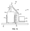
図1は、多くの実施形態によるレーザ手術システム10を略示している。レーザ手術システム10は、レーザアセンブリ12と、共焦点検出アセンブリ14と、自由浮遊機構16と、走査アセンブリ18と、対物レンズアセンブリ20と、患者インタフェースデバイス22とを含むことができる。患者インタフェースデバイス22は、患者24とのインタフェースとして作用するように構成することができる。患者インタフェースデバイス22は、対物レンズアセンブリ20によって支持することができ、対物レンズアセンブリ20は、走査アセンブリ18によって支持することができ、走査アセンブリ18は、自由浮遊機構16によって支持することができる。自由浮遊機構16は、レーザアセンブリ12及び共焦点検出アセンブリ14に対して固定された場所及び向きを有する部分を有することができる。
FIG. 1 schematically illustrates a laser surgical system 10 according to many embodiments. The laser surgical system 10 can include a
一部の実施形態において、患者インタフェースデバイス22は、全開示内容が引用によって本明細書に組み込まれている2013年10月31日出願の「レーザ眼球手術システムのための液体光学インタフェース(Liquid Optical Interface for Laser Eye Surgery System)」という名称の現在特許出願中の米国特許出願第14/068,994号明細書に記載されているように、真空吸引を用いて患者24の眼に結合されるように構成することができる。レーザ手術システム10は、定位置に固定すること又は再位置決め可能とすることができるベースアセンブリ26を任意的に含むことができる。例えば、ベースアセンブリ26は、患者に対するベースアセンブリ26の選択的な再位置決めを可能にし、及び/又はベースアセンブリ26を患者に対する選択固定場所に固定することを可能にするように構成された支持リンケージによって支持することができる。そのような支持リンケージは、固定支持ベースとするか又は患者に近い適切な位置に再位置決めすることができる可動カートとすることができる。多くの実施形態において、支持リンケージは、各セットアップ継手がその選択的な関節結合を可能にするように構成されたセットアップ継手を含み、その不用意な関節結合を防止するために選択的に係止することができ、それによってセットアップ継手が係止された時にベースアセンブリ26が患者に対して選択された固定場所に固定される。
In some embodiments, the
多くの実施形態において、レーザアセンブリ12は、電磁放射線ビーム28を放出するように構成することができる。ビーム28は、あらゆる適切なエネルギレベル、持続時間、及び繰り返し数の一連のレーザパルスを含むことができる。
In many embodiments, the
多くの実施形態において、レーザアセンブリ12は、フェムト秒(FS)レーザ技術を組み込んでいる。フェムト秒レーザ技術を使用することにより、組織を破壊するために短い持続時間(例えば、持続時間で約10-13秒)のレーザパルス(マイクロジュール範囲のエネルギレベルを有する)を密に集束させた点に送出することができ、それによってより長い持続時間を有するレーザパルスと比較して、眼内ターゲットを撮像及び/又は修正するのに必要とされるエネルギレベルが有意に低下する。
In many embodiments, the
レーザアセンブリ12は、組織を治療及び/又は撮像するのに適する波長を有するレーザパルスを発生させることができる。例えば、レーザアセンブリ12は、開示内容が当該引用によって本明細書に組み込まれる2013年10月31日出願の「レーザ眼球手術システム(Laser Eye Surgery System)」という名称の現在特許出願中の米国特許出願第14/069,044号明細書及び2011年1月7日出願の「眼球組織及び眼内水晶体を修正する方法及びシステム(Method and System For Modifying Eye Tissue and Intraocular Lenses)」という名称の米国特許出願第12/987,069号明細書に記載されているレーザ手術システムのうちのいずれかによって放出されるもののような電磁放射線ビーム28を放出するように構成することができる。一実施形態において、レーザアセンブリ12は、1020nmから1050nmの範囲の波長を有するレーザパルスを発生させることができる。別の実施形態において、レーザアセンブリ12は、1030(±5)nmの中心波長を有するダイオード励起固体構成を有することができる。追加の実施形態において、レーザアセンブリ12は、320nmから430nmまでの波長を有するレーザパルスを発生させることができる。例えば、レーザアセンブリ12は、3次調波波長(355nm)で作動し、50ピコ秒から15ナノ秒までのパルス持続時間を有するパルスを生成するNd:YAGレーザ源を含むことができる。スポットサイズに基づいて、一般的な使用パルスエネルギは、ナノジュールからマイクロジュールの範囲にあるとすることができる。レーザアセンブリ12は、あらゆる適切な構成の2又は3以上のレーザを含むことができる。
The
レーザアセンブリ12は、制御構成要素及び調整構成要素を含むことができる。一部の実施形態において、制御構成要素は、レーザパルスのエネルギ及びパルス列の平均電力を制御するためのビーム減衰器と、レーザパルスを含むビームの断面空間広がりを制御するための固定アパーチャと、ビーム列の流束及び繰り返し数、従って、レーザパルスエネルギをモニタするための1又は2以上の電力モニターと、レーザパルスの透過を許可/阻止するためのシャッターとを含むことができる。調整構成要素は、レーザパルスビームの場所及び/又は方向の変化性を受け入れながら、ある距離にわたってレーザパルスを伝達するための調節可能ズームアセンブリ及び固定光学リレーを含むことができ、それによって構成要素の変化に対して高い許容性が与えられる。
The
多くの実施形態において、レーザアセンブリ12及び共焦点検出アセンブリ14は、ベースアセンブリ26に対して固定された位置を有することができる。レーザアセンブリ12によって放出されたビーム28は、固定光路に沿って共焦点検出アセンブリ14を抜けて自由浮遊機構16に伝播することができる。ビーム28は、それを走査アセンブリ18に送出することができる自由浮遊機構16を可変光路30に沿って抜けて伝播することができる。多くの実施形態において、レーザアセンブリ12によって放出されたビーム28は、それが、患者の移動によって誘起されるレーザアセンブリ12とスキャナ16の間の光路の長さ変化による影響を受けないように平行化(collimated)することができる。走査アセンブリ18は、ビーム28を少なくとも1つの次元内で走査する(例えば、ビーム28の制御式可変偏向により)ように作動可能とすることができる。多くの実施形態において、走査アセンブリ18は、ビーム28の伝播方向に対して横断方向の2つの次元内でビーム28を走査するように作動可能であり、更に、ビーム28の伝播方向にその焦点の位置を走査するように作動可能とすることができる。走査ビームは、走査アセンブリ18から対物レンズアセンブリ20を抜け、インタフェースデバイス22を抜けて患者24に伝播するように放出することができる。
In many embodiments, the
自由浮遊機構16は、走査アセンブリ18によって放出されるビーム28と患者24とのアラインメントを維持しながら、レーザアセンブリ12及び共焦点検出アセンブリ14に対する患者24の1又は2以上の方向の様々な移動を受け入れるように構成することができる。例えば、自由浮遊機構16は、単位直交方向(X、Y、及びZ)のあらゆる組合せによって定められるいずれかの方向の患者24の様々な移動を受け入れるように構成することができる。
The free-floating
患者インタフェースデバイス22は、患者24とのインタフェースとして作用することができるので、患者24の移動は、患者インタフェースデバイス22、対物レンズアセンブリ20、及び走査アセンブリ18の対応する移動をもたらす可能性がある。自由浮遊機構16は、例えば、走査アセンブリ18と例えば共焦点検出アセンブリ14との間の相対移動を受け入れるリンケージと、可変光路30を形成するように当該リンケージに適切に結合された光学構成要素と、のあらゆる適切な組合せを含むことができる。一部の実施形態において、自由浮遊機構16は、開示内容が当該引用によって本明細書に組み込まれている2014年2月26日出願の「レーザ手術システム(Laser Surgery System)」という名称の米国特許出願第14/191,095号明細書及びPCT出願PCT/US2014/018752に記載されているように構成することができる。
Since
電磁放射線ビーム28の一部分は、焦点の場所にある眼球組織から反射することができ、共焦点検出アセンブリ14に伝播して戻ることができる。具体的には、電磁放射線ビーム28の反射部分は、患者インタフェースデバイス22を抜け、対物レンズアセンブリ20を抜け、走査アセンブリ18を抜け(更にそれによって脱走査され)、自由浮遊機構16を抜けて(可変光路30に沿って)共焦点検出アセンブリ14まで進行して戻ることができる。多くの実施形態において、共焦点検出アセンブリ14まで進行して戻る電磁放射線ビームの反射部分は、電磁放射線ビームの入射部分の強度を示す強度信号を発生させるセンサ上に入射するように向けることができる。眼内の焦点の関連走査と結合されて、強度信号は、角膜の前面、角膜の後面、虹彩、水晶体嚢の前面、水晶体嚢の後面、などのような眼の構造を、撮像する/位置付けるための走査パラメータに関連付けて処理することができる。多くの実施形態において、共焦点検出アセンブリ14に進行する反射電磁放射線ビームの量は、患者の移動に起因して予想される可変光路30の長さの変化に実質的に依存せず、それによって眼の構造を撮像する/位置付けるために前記強度信号を処理する時に患者の移動を無視すること(機能)が可能になる。
A portion of the
眼の1又は2以上の光学構造の位置は、本明細書で解説するようにして得られた測定値から決定することができる。眼の画像は、眼の矢状面表示、眼の横断面表示、眼の前面表示、及びこれらの組合せを含むことができる。眼の1又は2以上の画像は、眼の平面と眼の前房表示とを示すトモグラフィ画像を含むことができ、ユーザに1又は2以上の基準位置を提供するために、1又は2以上の画像上に1又は2以上の光学構造を配置することができる。多くの実施形態において、1又は2以上の画像は、ユーザが眼の切開部を計画して検証するために与えられる実時間画像を含む。 The position of one or more optical structures of the eye can be determined from measurements obtained as described herein. The eye image may include an eye sagittal plane display, an eye cross-section display, an eye front display, and combinations thereof. The one or more images of the eye can include tomographic images that show the plane of the eye and the anterior chamber representation of the eye, and one or more to provide the user with one or more reference positions. One or more optical structures can be arranged on the image. In many embodiments, the one or more images include real-time images that are provided for a user to plan and verify an eye incision.
眼の光学構造は、眼の光学系に関する眼の1又は2以上の構造を含むことができ、眼の組織構造は、眼の1又は2以上の組織を含むことができる。眼の光学構造は、眼の光軸、眼の視軸、眼の視線、眼の瞳孔軸、眼の注視線、角膜の頂点、眼の前節点、眼の後節点、眼の前主点、眼の後主点、角膜曲率測定軸、角膜前面の曲率中心、角膜後面の曲率中心、水晶体前嚢の曲率中心、水晶体後嚢の曲率中心、瞳孔の中心、虹彩の中心、入射瞳孔の中心、又は眼の射出瞳孔の中心のうちの1又は2以上を含むことができる。1又は2以上の組織構造は、虹彩、虹彩の平面、虹彩の外側境界、角膜輪部、角膜輪部の中心、強膜血管、角膜の中心、角膜の厚みプロファイル、角膜の厚みプロファイルの曲率中心、インクのような染料で染色した組織、角膜の頂点、眼の光軸、角膜の前面の曲率中心、水晶体前嚢の曲率の中心、水晶体後嚢の曲率の中心のうちの1又は2以上を含むことができる。
The optical structure of the eye can include one or more structures of the eye with respect to the optical system of the eye, and the tissue structure of the eye can include one or more tissues of the eye. The optical structure of the eye is the optical axis of the eye, the visual axis of the eye, the visual line of the eye, the pupil axis of the eye, the eye gaze, the apex of the cornea, the front node of the eye, the rear node of the eye, the front principal point of the eye, Posterior principal point of eye, corneal curvature measurement axis, center of curvature of anterior cornea, center of curvature of posterior cornea, center of curvature of anterior lens capsule, center of curvature of posterior lens capsule, center of pupil, center of iris, center of entrance pupil, Or one or more of the centers of the exit pupils of the eye can be included. One or more tissue structures are the iris, the plane of the iris, the outer boundary of the iris, the limbus, the center of the limbus, the scleral blood vessel, the center of the cornea, the corneal thickness profile, the center of curvature of the
一部の実施形態は、レーザ手術システム10を用いて角膜又は水晶体を撮像する方法を提供する。これらの方法は、ビーム源を用いて第1の電磁放射線ビームを発生させる段階と、第1の電磁放射線ビームを波長板に通す段階とを含むことができる。第1の電磁放射線ビームは、ビームスキャナに伝播させることができる。第1の電磁放射線ビームは、眼の角膜内の位置にある焦点にビームスキャナを用いて集束させることができる。第1の電磁放射線ビームを集束させた後に、焦点から反射された第1の電磁放射線は受光することができる。第1の受光電磁放射線は、波長板を通してセンサの方向に向けることができる。第1の受光電磁放射線の強度を示す第1の強度信号を発生させることができる。第1の強度信号を発生させた後に、次いで、波長板をある角度に回転させることができる。第2の電磁放射線ビームは、回転された波長板に通すことができ、眼の角膜内の位置にある焦点に集束させることができる。第2の電磁放射線ビームを集束させる段階に応答して焦点から反射された第2の電磁放射線は受光することができる。第2の受光電磁放射線は、回転された波長板を通してセンサの方向に向けることができる。第2の受光電磁放射線の強度を示す第2の強度信号を発生させることができる。第1の強度信号を用いて角膜の前面を識別することができ、第2の強度信号を用いて角膜の後面の少なくともいくつかの部分を識別することができる。水晶体の前面を高いコントラストで撮像するために、複数の波長板角度を利用する類似の手法が使用される。 Some embodiments provide a method of imaging the cornea or lens using the laser surgical system 10. These methods can include generating a first electromagnetic radiation beam using a beam source and passing the first electromagnetic radiation beam through a waveplate. The first electromagnetic radiation beam can be propagated to a beam scanner. The first electromagnetic radiation beam can be focused using a beam scanner to a focal point located within the cornea of the eye. After focusing the first electromagnetic radiation beam, the first electromagnetic radiation reflected from the focal point can be received. The first received electromagnetic radiation can be directed toward the sensor through the wave plate. A first intensity signal indicative of the intensity of the first received electromagnetic radiation can be generated. After generating the first intensity signal, the wave plate can then be rotated to an angle. The second electromagnetic radiation beam can be passed through a rotated waveplate and focused to a focal point at a position within the cornea of the eye. The second electromagnetic radiation reflected from the focal point in response to focusing the second electromagnetic radiation beam can be received. The second received electromagnetic radiation can be directed toward the sensor through the rotated waveplate. A second intensity signal indicative of the intensity of the second received electromagnetic radiation can be generated. The first intensity signal can be used to identify the anterior surface of the cornea and the second intensity signal can be used to identify at least some portions of the posterior surface of the cornea. In order to image the front surface of the crystalline lens with high contrast, a similar technique using multiple wave plate angles is used.
レーザ手術システム10は、レーザビーム源と眼の間にビーム経路に沿って位置決めされた可変軸偏光システムを含むことができる。偏光システムは、出力ビームを第1の偏光状態又は第2の偏光状態を有するように偏光するように構成することができる。偏光システムは、第1の構成にある時に出力ビームのこの偏光状態を設定することができ、第2の構成にある時に別の偏光状態を設定することができる。 The laser surgical system 10 can include a variable axis polarization system positioned along the beam path between the laser beam source and the eye. The polarization system can be configured to polarize the output beam to have a first polarization state or a second polarization state. The polarization system can set this polarization state of the output beam when in the first configuration and can set another polarization state when in the second configuration.
一部の実施形態において、波長板は、焦点からの反射電磁放射線をそれがセンサに到達する前に受光するように更に位置決めしてそのように構成することができる。任意的に、レーザ手術システム10は、波長板を通過した反射電磁放射線をセンサに向けるように配置された偏光ビームスプリッタを更に含むことができる。出力ビームの焦点の位置以外の眼の位置からの反射電磁放射線を阻止するために、アパーチャを位置決めすることができる。 In some embodiments, the waveplate can be further positioned and configured to receive reflected electromagnetic radiation from the focal point before it reaches the sensor. Optionally, the laser surgical system 10 can further include a polarizing beam splitter positioned to direct reflected electromagnetic radiation that has passed through the waveplate to the sensor. The aperture can be positioned to block reflected electromagnetic radiation from eye positions other than the focus position of the output beam.
一部の実施形態において、波長板は、第1の場所と第2の場所の間で回転可能とすることができる。波長板は、第1の場所と第2の場所の間で45度回転させることができる。任意的に、波長板は、第1の場所と第2の場所の間で90度回転させることができる。ビームスキャナは、XY走査デバイスとZ走査デバイスを含むことができる。XY走査デバイスは、出力ビームをその伝播に対して横断方向の2つの次元内に偏向するように構成することができる。Z走査デバイスは、ビームの収束角を変化させるように構成することができる。 In some embodiments, the waveplate can be rotatable between a first location and a second location. The wave plate can be rotated 45 degrees between the first location and the second location. Optionally, the wave plate can be rotated 90 degrees between the first location and the second location. The beam scanner can include an XY scanning device and a Z scanning device. The XY scanning device can be configured to deflect the output beam into two dimensions transverse to its propagation. The Z scanning device can be configured to change the convergence angle of the beam.
図2は、レーザ手術システム10の一実施形態の詳細を略示している。具体的には、レーザアセンブリ12、共焦点検出アセンブリ14、及び走査アセンブリ18に関する例示的構成を略示している。図示の実施形態に示すように、レーザアセンブリ12は、超高速(UF)レーザ32(例えば、フェムト秒レーザ)と、アラインメントミラー34、36と、ビーム拡大器38と、2分の1波長板40と、偏光子及びビーム廃棄デバイス42と、出力ピックオフ及びモニター44と、システム制御式シャッター46とを含むことができる。レーザ32によって出力された電磁放射線ビーム28は、アラインメントミラー34、36によって偏向することができる。多くの実施形態において、アラインメントミラー34、36は、ビーム28を下流光学構成要素を通る下流光路に位置合わせする機能を与えるために、場所及び/又は向きにおいて調節可能とすることができる。次いで、ビーム28は、その直径を増大させることができるビーム拡大器38を通過することができる。拡大されたビーム28は、次いで、2分の1波長板40を通過することができ、その後に、偏光子を通過する。偏光子42を射出するビームは、直線偏光状態にあるとすることができる。2分の1波長板40は、この偏光を回転させることができる。偏光子42を通過する光の量は、直線偏光の回転角に依存する。従って、偏光子42を有する2分の1波長板40は、ビーム28の減衰器として機能することができる。この減衰から除外された光は、ビームダンプ内に向けることができる。次いで、減衰されたビーム28は、出力ピックオフ及びモニター44を通過し、次いで、システム制御式シャッター46を通過することができる。システム制御式シャッター46を出力ピックオフ及びモニター44の下流に位置付けることにより、システム制御式シャッター46を開く前に、ビーム28の電力を検査することができる。
FIG. 2 schematically illustrates details of one embodiment of the laser surgical system 10. Specifically, exemplary configurations for the
図示の実施形態に示すように、共焦点検出アセンブリ14は、偏光又は非偏光のビームスプリッタのような偏光感応デバイス48と、フィルタ50と、集束レンズ51と、ピンホールアパーチャ52と、検出センサ54とを含むことができる。偏光ビームスプリッタ48の下流には、4分の1波長板56を配置することができる。レーザアセンブリ12から受光されるビーム28は、偏光ビームスプリッタ48を通過するように偏光することができる。次いで、ビーム28は、4分の1波長板56を通過することができ、それによってビーム28の偏光軸が回転される。好ましい回転量は、4分の1回転とすることができる。患者の眼内の焦点から反射された後に、ビーム28のうちで帰還する反射部分は、4分の1波長板56を逆に通過することができ、それによってビーム28の帰還反射部分の偏光軸が回転される。4分の1波長板56を逆に通過した後に、ビームの帰還反射部分は、眼から反射された光を偏光ビームスプリッタ48によって完全に反射することができるように、90°の合計偏光回転を受けることができる。例えば、撮像ターゲットの構造が水晶体である場合に、角膜の複屈折に対処することができる。この場合に、波長板56の2回通過並びに角膜の2回通過が90°の偏光回転に加え合わせられるように波長板56を調節及び/又は構成することができる。一部の実施形態において、角膜の複屈折は、図7Aに関して後に解説するように、角膜の撮像中に考慮することができる。角膜の複屈折は患者毎に異なる可能性があるので、検出センサ54に帰還する信号を最適化するために、波長板56の構成/調節を動的に行うことができる。一部の実施形態において、波長板56は、ある角度で回転させることができる。従って、ビーム28の帰還反射部分は、フィルタ50を抜け、レンズ51を抜けてピンホールアパーチャ52に向けられるように、偏光ビームスプリッタ48によって少なくとも部分的に反射されるように偏光することができる。フィルタ50は、当該波長以外の波長を阻止するように構成することができる。ピンホールアパーチャ52は、焦点以外の位置から反射されたビーム28のいずれかの帰還反射部分が検出センサ54に到達することを阻止することができる。検出センサ54に到達するビーム28の帰還反射部分の量は、ビーム28の焦点の場所にある組織の性質に依存するので、検出センサ54によって発生される信号は、眼の構造に関する画像/位置を生成するために関連の焦点位置に関するデータとの組合せで処理することができる。
As shown in the illustrated embodiment, the
図示の実施形態に示すように、走査アセンブリ18は、Z走査デバイス58とXY走査デバイス60を含むことができる。Z走査デバイス58は、ビーム28の収束/発散の角度を変化させ、それによって焦点の位置をビーム28の伝播方向に変更するように作動可能とすることができる。例えば、Z走査デバイス58は、ビーム28の収束/発散の角度を変化させるためにビーム28の伝播方向に制御可能に可動な1又は2以上のレンズを含むことができる。XY走査デバイス60は、ビーム28の伝播方向に対して横断方向の2つの次元内でビーム28を偏向するように作動可能とすることができる。例えば、xy走査デバイス60は、ビーム28の伝播方向に対して横断方向の2つの次元内でビーム28を走査するように制御可能に偏向可能な1又は2以上のミラーを含むことができる。従って、Z走査デバイス58とXY走査デバイス60の組合せは、例えば患者の眼内で焦点を3つの次元内で制御可能に走査するように作動させることができる。
As shown in the illustrated embodiment, the
図示の実施形態に更に示すように、カメラ62及び関連のビデオ照明64は、走査アセンブリ18と統合することができる。カメラ62とビーム28は、対物レンズアセンブリ20を抜けて眼に至る共通の光路を共有することができる。ビーム28をカメラによって使用される照明波長と組み合わせる/そこから分離するために、ビデオダイクロイック66を使用することができる。例えば、ビーム28は、約355nmの波長を有することができ、ビデオ照明64は、450nmよりも長い波長を有する照明を放出するように構成することができる。従って、ビデオダイクロイック66は、450nmよりも長い波長を透過すると同時に355nmの波長を反射するように構成することができる。
As further shown in the illustrated embodiment, the camera 62 and associated
図3は、眼を撮像するための多くの実施形態によるレーザ手術システム10の処理200の作動の概略ブロック図である。レーザ手術システム10は、ビーム源を用いて電磁放射線ビームを発生させる(作動ブロック202)。レーザ手術システム10は、電磁放射線ビームをビーム源からスキャナまで眼の移動に応答して変化する光路長を有する可変光路に沿って伝播させる(作動ブロック204)。レーザ手術システム10は、電磁放射線ビームを眼内の位置にある焦点に集束させる(作動ブロック206)。レーザ手術システム10のスキャナは、焦点を眼内の様々な位置に対して走査する(作動ブロック208)。レーザ手術システム10は、電磁放射線ビームのうちで焦点位置から反射された部分を可変光路に沿ってセンサに逆に伝播させる(作動ブロック210)。センサは、電磁放射線ビームのうちで焦点位置から反射され、センサに伝播した部分の強度を示す強度信号を発生させる(作動ブロック212)。
FIG. 3 is a schematic block diagram of the operation of the
図4、図5、及び図6は、処理200の一部として達成することができるオプションを示している。例えば、レーザ手術システム10は、眼の移動を受け入れるようにスキャナを支持するための第1の支持アセンブリを含むことができる(作動ブロック214)。レーザ手術システム10は、眼の移動を受け入れるように第1の支持アセンブリを更に支持する第2の支持アセンブリを使用することができる(作動ブロック216)。第1の支持アセンブリは、可変光路の一部分に沿ってスキャナに伝播するように電磁放射線ビームを反射するように構成された第1の反射器を支持する(作動ブロック218)。ベースアセンブリは、眼の移動を受け入れるように第2の支持アセンブリを支持する(作動ブロック220)。第2の支持アセンブリは、可変光路の一部分に沿って伝播して第1の反射器上に入射するように電磁放射線ビームを反射するように構成された第2の反射器を支持することができる(作動ブロック222)。電磁放射線ビームのうちで焦点位置以外の位置から反射された部分を阻止するために、電磁放射線ビームの反射部分をアパーチャに通すことにより、センサは、強度信号を発生させる(作動ブロック224)。電磁放射線ビームが、偏光感応デバイスを通過し(作動ブロック226)、それによって電磁放射線ビーム及び電磁放射線ビームのうちで焦点位置から反射された部分のうちの少なくとも一方の偏光が修正される(作動ブロック228)。偏光感応デバイスは、電磁放射線ビームのうちで焦点位置から反射された部分をセンサ上に入射するように反射する(作動ブロック230)。
4, 5, and 6 illustrate options that can be achieved as part of the
図7Aは、本発明の一部の実施形態による眼の角膜を撮像するためのレーザ手術システムの処理100を示している。一部の状況では、共焦点検出器を用いて角膜を正確に撮像することが望ましい場合がある。更に、例えば、角膜の厚みを決定するために、角膜の前境界及び後境界を正確に識別又は検出することが望ましい場合がある。共焦点信号の強度は、角膜の前面と裏面との間で有意に変化することができ、それによって検出が理想的な場合よりも困難になる可能性がある。この強度変化は、共焦点検出器において信号損失をもたらす可能性がある角膜の局所複屈折変化に関連付けることができる。更に、少なくとも一部の眼では、角膜の複屈折特性が角膜の深度と共に変化する可能性がある。更に、角膜複屈折特性は、横方向及び半径方向に予想不能な量で変化する可能性がある。従って、一部の実施形態において、4分の1波長板を逆に通過する光の一部が、センサに向けてではなく光源に向けて反射されるように、この光を偏光ビームスプリッタを抜ける2回目の通過時に90度以外の角度だけ回転させることができる。図7Aに提供している処理100は、角膜の裏面を撮像する課題のうちの一部に対処することができる。処理100は、変数θがゼロに等しい状態で開始することができる(作動ブロック102)。変数θは、波長板の初期場所に対する波長板の回転角を表すとすることができる。従って、波長板は、処理100の開始時(作動ブロック102)に初期場所にあるとすることができる。レーザ手術システムが、ビーム源、例えば、レーザ32を用いて電磁放射線ビームを発生させる(作動ブロック104)。電磁放射線ビームは、初期偏光を有するように偏光される(作動ブロック106)。電磁放射線ビームは、偏光感応デバイスを通過し(作動ブロック108)、波長板を通過する(作動ブロック110)。電磁放射線ビームは、眼内の位置にある焦点に集束させることができ(作動ブロック114)、焦点を眼内の複数の異なる位置に対して走査することができる(作動ブロック116)。電磁放射線ビームを集束させること及び/又は電磁放射線の焦点を走査することに応答して、電磁放射線を焦点から反射させて、レーザ手術システムによって受光することができる(作動ブロック118)。受光反射電磁放射線は、波長板に通すことができ(作動ブロック120)、偏光感応デバイスによってセンサに向けて更に反射することができる(作動ブロック122)。電磁放射線のうちで焦点位置以外の位置から反射された部分は、例えば、アパーチャによって阻止することができる(作動ブロック124)。センサにより、受光反射電磁放射線の強度を示す強度信号を発生させることができる(作動ブロック126)。角度θの大きさが90度よりも大きいか又はそれに等しい(例えば、波長板がその初期場所から90度回転した)場合は(作動ブロック128)、レーザ手術システムは、眼の画像を発生させる(作動ブロック129及び終了130)。角度θの大きさが90度よりも小さい場合は(作動ブロック128)、変数θを漸増量xだけ増大させることができる。波長板は、回転角θだけ機械的に回転させることができる(作動ブロック134)。その後に、レーザ手術システムはループバックし、角度θだけ回転された波長板を用いて作動ブロック104〜126を繰り返すことができる。処理100は、波長板の初期場所から90度だけ回転された波長板を用いて段階104〜126が実施された時に終了することができる。
FIG. 7A illustrates a laser
明らかなように、処理100の一実施形態において、レーザ手術システム10は、変化する波長板の向きに起因して変化する偏光度を有する1よりも多い電磁放射線ビームの焦点で眼を走査する。この複数回走査、従って、複数個の強度信号は、角膜の前面及び後面を撮像する際の角膜の複屈折に起因する欠点を補償するのに役立たせることができる。いくつかの強度信号は、眼の角膜の前部からの強い強度信号を含む可能性がある。他の強度信号は、眼の角膜の後部からの強い強度信号を含む可能性がある。一部の実施形態において、前面及び後面のような角膜の前詳細部及び後詳細部を正確に識別するための複合信号を形成するために、複数個の強度信号を部分的又は全体的に使用することができる。従って、複数回走査は、局所角膜複屈折特性に起因する撮像信号損失を補償することができる。
As is apparent, in one embodiment of the
多くの実施形態において、上述の方法は、図1及び図2に示すレーザ手術システム10によって実施することができる。例えば、段階104を実施するには、レーザ32を使用することができる。段階106を実施するには、偏光及びビーム廃棄デバイス42を使用することができる。段階108では、電磁放射線ビームは、偏光ビームスプリッタ48を通過することができる。段階110を実施するには、電磁放射線ビームの初期偏光を修正するために4分の1波長板56を使用することができる。段階114及び段階116を実施するには、XY走査デバイス60及びZ走査デバイス58を使用することができる。段階120では、反射電磁放射線を受光してその偏光を修正するために4分の1波長板56を使用することができる。段階122では、反射電磁放射線をセンサに向けて反射するために偏光ビームスプリッタ48を使用することができる。段階124を実施するには、ピンホールアパーチャ52を使用することができ、段階126を実施するには、検出器54を使用することができる。一部の実施形態において、方法100に従って複数回走査を実施するようにレーザ手術システム10を事前プログラムすることができる。
In many embodiments, the method described above can be performed by the laser surgical system 10 shown in FIGS. For example,
変数xは、あらゆる区分値とすることができる。一部の実施形態において、xは、1度、2度、3度、5度、15度、30度、45度、又は90度とすることができる。一部の状況では、処理100を迅速に実施することが望ましい場合がある。任意的に、処理100は、xが90度である場合に2回の走査で完了することができる。そのような実施形態において、電磁放射線ビーム焦点で眼を2回走査することができる。この2回走査は、好ましくは、連続走査の間又は最中の撮像システムに対する不用意な眼の移動の効果を最小にするために行うことができる。図7B及び図7Cは、そのような処理によって発生された角膜800からの2つの例示的強度プロファイルを示している。図7Bは、4分の1波長板が45度の初期場所を有する場合に発生された角膜800からの反射電磁放射線の強度プロファイルを示している。明らかなように、図7Bの走査は、角膜800の前面802において高めの強度プロファイルを含む可能性があるが、角膜800の後面804のいくつかの部分に向けて低めの強度を有する可能性がある。角膜800の後面804に向かう強度信号は、角膜800の周囲に向けて低下する可能性がある。図7Bに示す走査の後に、図7Cに示す2回目の走査を実施することができる。図7Cは、4分の1波長板が初期場所から135度まで90度回転された後に発生された角膜800からの反射電磁放射線の強度プロファイルを示している。明らかなように、図7Cの走査は、4分の1波長板が135度まで回転された場合に、角膜の前面802において低めの強度を有する強度プロファイルを含む可能性がある。しかし、図7Cの走査は、角膜800の後面804の一部分において高めの強度を有する強度プロファイルを含む可能性がある。特に、図7Cの走査は、角膜800の後面の角膜800の周囲の近くで高めの強度を有する強度プロファイルを与える可能性がある。従って、局所変化に対処して角膜800の前面802と後面804の両方をより正確に識別するために、図7B及び図7Cに示す2つの走査を合わせて使用することができる。任意的に、その後に、角膜の厚みを正確に計算することができる。
The variable x can be any segment value. In some embodiments, x can be 1 degree, 2 degrees, 3 degrees, 5 degrees, 15 degrees, 30 degrees, 45 degrees, or 90 degrees. In some situations, it may be desirable to perform the
角膜の面プロファイルは、多くの方法のうちの1又は2以上で測定することができ、このプロファイルは、角膜前面トポグラフィプロファイル、角膜後面トポグラフィプロファイル、又は角膜厚みプロファイルのうちの1又は2以上を発生された強度プロファイルから得られるものとして含むことができる。多くの実施形態において、面プロファイルは、3次元プロファイル表現を含み、外科レーザに統合された角膜トポグラフィシステム又は角膜トモグラフィシステムからの角膜曲率測定値の抽出値のような1又は2以上の画像からの1又は2以上のパラメータの抽出値を含むことができる。1又は2以上のパラメータは、角位置、深度、弧長、及び切開部の前部から後部までの寸法のような眼の上の組織治療パターンを決定するために使用することができる。例えば、面プロファイルは、複数の弧状切開部の治療軸であって、これらの切開部がこの軸に対して横断方向の弧に沿って延びるという治療軸を決定するために使用することができる。 The corneal surface profile can be measured in one or more of many ways, and this profile generates one or more of the anterior corneal topography profile, the posterior corneal topography profile, or the corneal thickness profile. As obtained from the measured intensity profile. In many embodiments, the surface profile includes a three-dimensional profile representation and from one or more images, such as a corneal topography system integrated into a surgical laser or an extract of corneal curvature measurements from a corneal tomography system. The extracted values of one or more parameters can be included. One or more parameters can be used to determine a tissue treatment pattern on the eye, such as angular position, depth, arc length, and anterior to posterior dimension of the incision. For example, a surface profile can be used to determine a treatment axis of a plurality of arcuate incisions, the incisions extending along an arc transverse to the axis.
多くの実施形態において、眼の光学面は、フーリエ変換、多項式、球面調和関数、テイラー多項式、ウェーブレット変換、又はゼルニケ多項式のうちの1又は2以上に適用される。光学組織面は、例えば、角膜の前面、角膜の後面、水晶体嚢の前面、水晶体嚢の後面、水晶体皮質の前面、水晶体皮質の後面、水晶体核の前面、水晶体核の後面、実質的に一定の屈折率を有する水晶体の1又は2以上の前面、実質的に一定の屈折率を有する水晶体の1又は2以上の後面、網膜面、中心窩面、ターゲット角膜面のような視覚を矯正するためのターゲット組織面、眼内水晶体の前面、又は眼内水晶体の後面のうちの1又は2以上を含むことができる。 In many embodiments, the optical surface of the eye is applied to one or more of a Fourier transform, a polynomial, a spherical harmonic, a Taylor polynomial, a wavelet transform, or a Zernike polynomial. The optical tissue surface can be, for example, the anterior surface of the cornea, the posterior surface of the cornea, the anterior surface of the lens capsule, the posterior surface of the lens capsule, the anterior surface of the lens cortex, the posterior surface of the lens cortex, the anterior surface of the lens nucleus, the posterior surface of the lens nucleus, For correcting vision such as one or more anterior surfaces of a lens having a refractive index, one or more posterior surfaces of a lens having a substantially constant refractive index, retinal surface, foveal surface, target corneal surface One or more of the target tissue surface, the front surface of the intraocular lens, or the posterior surface of the intraocular lens can be included.
一実施形態において、図8に示す角膜150は、第1の複屈折を有する第1の領域152と、第2の複屈折を有する第2の領域154と、を有する場合がある。この場合に、角膜を撮像するのに、第1の電磁放射線ビームは、角膜150の第1の領域152を通して眼内の第1の位置に向けることができる。第1の電磁放射線ビームは、第1の偏光を有することができる。第2の電磁放射線ビームは、角膜150の第2の領域154を通して眼内の第2の位置に向けることができる。第2の電磁放射線ビームは、第1の偏光とは異なる第2の偏光を有することができる。第1及び第2の電磁放射線ビームを向ける段階に応答して眼から反射された電磁放射線信号を用いて、第1及び第2の位置を網羅する眼の画像を発生させることができる。従って、レーザ手術システム10は、角膜複屈折特性における局所差に対処するために、異なる偏光を有する複数のビームを使用する単一複合画像を与えることができる。
In one embodiment, the
図9は、本発明の一部の実施形態による眼の角膜を撮像するためのレーザ手術システム10の別の処理400を示している。一部の状況では、角膜の複屈折を補償して、角膜の前境界及び後境界を正確に識別するために処理400を使用することができる。レーザ手術システム10が電磁放射線ビームを生成し(作動ブロック402)、この電磁放射線ビームを初期偏光を有するように偏光することができる(作動ブロック404)。電磁放射線ビームは偏光感応デバイスを通過し(作動ブロック406)、楕円偏光される(作動ブロック408)。レーザシステム手術器10は、楕円偏光電磁放射線ビームを眼内の位置にある焦点に集束させ(作動ブロック412)、焦点を眼内の複数の異なる位置に対して走査する(作動ブロック414)。レーザシステム手術器10は、焦点から反射された電磁放射線を受光する(作動ブロック416)。受光反射電磁放射線は偏光子を通過し(作動ブロック418)、センサに向けて反射されるか又は誘導される(作動ブロック420)。レーザ手術システム10は、電磁放射線のうちで焦点位置以外の位置から反射された部分を阻止することができる(作動ブロック422)。レーザ手術システム10は、受光反射電磁放射線の強度を示す強度信号を発生させることができる。
FIG. 9 illustrates another
楕円偏光光は、例えば、ビームスプリッタを抜ける2回目の通過時に、1つの角度において直線偏光光を生成することにはならず、従って、信号が小幅の深度で変化することになるので、処理400の一実施形態において、レーザ手術システム10は、角膜の前部及び後部を識別及び/又は撮像するのに楕円偏光光を使用することができる。
The elliptically polarized light, for example, will not produce linearly polarized light at one angle on the second pass through the beam splitter, and therefore the signal will change with a small depth, so the
図10A及び図10Bは、多くの実施形態によるレーザ手術システム11を略示している。レーザ手術システム10は、レーザアセンブリ12と、共焦点検出アセンブリ14と、共焦点バイパスアセンブリ15と、伝達光路17と、走査アセンブリ18と、対物レンズアセンブリ20と、患者インタフェースデバイス22とを含む。レーザ手術システム11は、図2に示すレーザ手術システム10に記述される要素を含む。一般的に共焦点バイパスアセンブリ15は、少なくとも1つの光学要素19を含み、反射電磁ビーム29の一部分を共焦点検出アセンブリ14内のセンサに送出する少なくとも1つの光学要素(図示せず)の周りに反射電磁ビーム29(電磁ビーム28の一部分)の光路を可逆的に迂回させるように作動可能である。共焦点検出アセンブリ14の光学要素をバイパスすることにより、反射光29は共焦点バイパスアセンブリ14内のセンサに伝達されないので、撮像システムは非作動にされる。図10Aに図示の実施形態において、共焦点バイパスアセンブリ15は、電磁ビーム28の光路をバイパスさせるように能動的に作動していない状態で表しており、従って、図10Aでは、反射電磁ビーム29の一部分は、伝達光路16から共焦点検出アセンブリ14に伝播するように示され、それによってレーザ手術システム10の撮像システムが作動可能になる。この状態をレーザ手術システム100の「撮像モード」と呼ぶ場合がある。
10A and 10B schematically illustrate a laser surgical system 11 according to many embodiments. The laser surgical system 10 includes a
図10Aの実施形態に従って作動する時には、電磁ビームは、好ましくは、組織を修正しないように構成される。例えば、電磁ビームを組織修正に対する閾値レベルよりも小さいエネルギレベルを有するように減衰、又は他に修正することができる。これに代えて電磁ビームは、撮像モードにおいても組織を修正するように構成することができる。 When operating in accordance with the embodiment of FIG. 10A, the electromagnetic beam is preferably configured not to modify tissue. For example, the electromagnetic beam can be attenuated or otherwise modified to have an energy level that is less than a threshold level for tissue modification. Alternatively, the electromagnetic beam can be configured to modify the tissue even in the imaging mode.
撮像モードの好ましい実施形態において、電磁ビーム28の一部分は、焦点の場所の眼球組織によって反射され、光路を逆に辿って共焦点検出アセンブリ14に伝播する。具体的には、電磁ビーム28の反射部分29は、患者インタフェースデバイス22を逆に抜け、対物レンズアセンブリ20を逆に抜け、走査アセンブリ15を逆に抜け(更にそれによって脱走査され)、伝達光路15を逆に抜けて共焦点検出アセンブリ14に進行する。多くの実施形態において、本明細書で更に解説するように、電磁ビーム28のうちで共焦点検出アセンブリに至るまで逆進する反射部分29はセンサ上に入射するように向けられ、センサは、電磁ビームのこの入射部分の強度を示す強度信号を発生させる。眼内の焦点の関連の走査に結合された強度信号は、例えば、角膜の前面、角膜の後面、虹彩、水晶体嚢の前面、及び水晶体嚢の後面のような眼の構造を撮像/位置付けるために走査パラメータと共に処理することができる。
In a preferred embodiment of the imaging mode, a portion of the
一般的に、伝達光路17は、ビーム28を共焦点検出アセンブリ14又は共焦点バイパスアセンブリ15から走査アセンブリ18に向ける1又は2以上の光学要素を含む。伝達光路17を図1Aのレーザ手術システム10の別個の構成要素として示すが、伝達光路17は任意的なものであることに注意しなければならない。他の実施形態において、伝達光路17は、様々な他の機能として機能することができる。例えば、別の実施形態において、伝達光路17は、図2の実施形態に関して記述した自由浮遊機構16を含むか又はそれによって置換することができる。
In general, the transmission optical path 17 includes one or more optical elements that direct the
図10Bは、共焦点バイパスアセンブリ15が電磁ビーム28の光路に配置された場合の図1Aのレーザ手術システム11を略示している。図10Bでは、共焦点バイパスアセンブリ15は、電磁ビーム28の反射部分が共焦点検出アセンブリ30内のセンサに伝達されないように共焦点検出アセンブリ14の少なくとも1つの光学要素(図示せず)の周りにビーム28をバイパスさせる別の光路(すなわち、迂回光路)に沿って電磁ビーム28の光路を可逆的に迂回させるように作動可能である。図10Bの実施形態において、共焦点バイパスアセンブリ15は、電磁ビーム28の光路をバイパスさせるように能動的に作動している状態で表しており、従って、図10Bでは、電磁ビーム28は、レーザアセンブリ20から共焦点バイパスアセンブリ15を抜ける光路に沿って共焦点バイパスアセンブリ14の光学要素(図示せず)の周りを伝播するように示され、従って、電磁ビーム28のいかなる部分も共焦点検出アセンブリ14のセンサ(検出器)に向けられない。本明細書ではこの状態をレーザ手術システム10の「非撮像モード」又はこれに代えて「治療モード」と呼ぶ場合がある。
FIG. 10B schematically illustrates the laser surgical system 11 of FIG. 1A when the
図10Bの治療モードの多くの実施形態において、レーザアセンブリ20によって放出されたビーム28は、共焦点バイパスアセンブリ15内の固定光路に沿って伝達光路17に伝播する。伝達光路17に到達すると、ビーム28は、残りのレーザ手術システムを図10Aの実施形態と同じか又は類似の方式で抜けて伝播する。具体的には、ビーム28は、図10Aに関して上述したように伝達光路17に沿って進行し、次いで、走査アセンブリ18に送出され、対物レンズアセンブリ20、インタフェースデバイス22を抜けて伝播して患者24に至る。
In many embodiments of the treatment mode of FIG. 10B, the
図10Bの実施形態において、電磁ビーム28の一部分は、焦点の場所にある患者の組織によって反射され、電磁ビーム28を送出した光路を逆に辿る光路に沿って伝播することに注意しなければならない。具体的には、電磁ビーム28の反射部分は、患者インタフェースデバイス22を逆に抜け、対物レンズアセンブリ20を逆に抜け、走査アセンブリ18を逆に抜け(更にそれによって脱走査され)、伝達光路17を逆に抜けて進行する。しかし、反射ビームは、電磁ビーム28の光路を共焦点検出アセンブリ14の少なくとも1つの光学要素の周りで迂回光路に沿って再度バイパスさせる共焦点バイパスアセンブリ15に入射し、従って、反射光は、共焦点検出アセンブリ14によって検出されない。
It should be noted that in the embodiment of FIG. 10B, a portion of the
治療モードで作動する時には、ビーム28の方向及び場所は、電磁ビームの伝播方向に対して横断方向の平面内で迂回光路の入口とそこからの出口とにおいて好ましくは同じか又は実質的に同じである。ビーム28の方向及び場所は、ビーム特性がシステムレベルのターゲット仕様を満たすのに十分である限り、電磁ビームの伝播方向に対して横断方向の平面内で迂回光路の入口とそこからの出口とにおいて実質的に同じであると見なされる。
When operating in therapeutic mode, the direction and location of the
更に、治療モードにおける共焦点バイパスアセンブリ14の迂回光路からの射出時のビーム28の方向及び場所は、電磁ビーム28の伝播方向に対して横断方向の平面内で撮像モードにおける光路内の同じ場所におけるビーム28の方向及び場所と同じか又は実質的に同じである。
Further, the direction and location of the
治療モードで作動する時には、電磁ビーム28は、好ましくは、組織を修正することができるように構成される。例えば、電磁ビームは、好ましくは、組織修正に対する閾値レベルよりも大きいエネルギレベルを有する。
When operating in the treatment mode, the
図11は、撮像モードに従って眼を撮像する方法による処理500の作動の概略ブロック図である。処理500を実施するには、本明細書で説明するもののようなあらゆる適切なデバイス、アセンブリ、及び/又はシステムを使用することができる。処理500は、ビーム源を用いて電磁ビームを発生させる段階(作動ブロック502)と、電磁ビームを共焦点撮像アセンブリの少なくとも1つの光学要素を含む光路に沿ってビーム源からスキャナに伝播させる段階(作動ブロック504)とを含む。処理500は、電磁ビームを眼内の位置にある焦点に集束させる段階(作動ブロック506)を含む。処理500は、スキャナを用いて焦点を眼内の様々な位置に対して走査する段階(作動ブロック508)を含む。処理500は、電磁ビームのうちで焦点位置から反射された部分を反射電磁ビームをセンサに伝達する少なくとも1つの光学要素に光路を逆に辿って伝播させる段階(作動ブロック510)を含む。処理500は、センサを用いて、焦点位置から反射されてセンサに伝播した電磁ビームの強度を示す強度信号を発生させる段階(作動ブロック512)を含む。
FIG. 11 is a schematic block diagram of the operation of
図12は、撮像モードから非撮像モードに作動を可逆的に切り換えるための処理501であり、レーザ源を用いて電磁ビームを発生させる段階(作動ブロック502)と、電磁ビームを共焦点撮像アセンブリの少なくとも1つの光学要素を含む光路に沿ってビーム源から伝播させる段階(作動ブロック504)と、共焦点バイパスアセンブリを光路の中に移動し、それによって電磁ビームを共焦点撮像アセンブリの少なくとも1つの要素の周りにバイパスさせる段階(作動ブロック514)と、バイパスした電磁放射線をスキャナに伝播させる段階(作動ブロック516)と、スキャナを用いて焦点を眼内の様々な位置に対して走査する段階(作動ブロック518)と、焦点位置から反射された電磁ビームのいずれかの部分が少なくとも1つの光学要素によって共焦点バイパスアセンブリのセンサに伝達されるのを防ぐ段階(作動ブロック520)と、共焦点バイパスアセンブリを光路の外に移動する段階(作動ブロック522)とを含むことができる。
FIG. 12 is a
共焦点バイパスアセンブリの一実施形態700を図13に示している。共焦点バイパスアセンブリ700は、起動アーム720の一端に固定可能に接続され、先端716によって定位置に固定されたアーム715を有するプッシュソレノイド710を含む。図5の実施形態において、プッシュソレノイド710は、ベース750に固定可能に装着されたフレーム417内に保持される。プッシュソレノイドのアーム715は、「A」方向に可逆的に移動する。起動アーム720の他端は、バイパス光学要素730が上部に装着されたプラットフォーム735を有する担体725に接続される。共焦点バイパスアセンブリ700は、「A」方向に沿って相互移動する2つの側面を有するスライド部材745を更に含むことができる。図5の実施形態において、担体725は、スライド745の一方の側面に固定可能に接続され、プッシュソレノイド710を保持するフレーム717は、スライド745の他方の側面に固定可能に接続され、それによってプッシュソレノイドと担体とは、互いに対して方向「A」に移動する。
One
作動時に、図5の実施形態において、プッシュソレノイド410のアーム715は、プッシュソレノイドの本体から離れるように方向「A」に移動し、アーム715のこの移動は、起動アーム720を通して担体725に伝達され、スライド745の作用によってプッシュソレノイドの本体に対する同じ「A」方向の担体725の移動をもたらす。このようにして、バイパス光学要素730は、電磁ビームの電磁経路の光路内に持ち上げられる。次いで、プッシュソレノイド710のアーム715を制御電子機器の制御下でプッシュソレノイド710の本体に向けて移動することによってバイパス光学要素730を光路から取り出すことができ、それによってバイパス光学要素735がビーム28の光路の外に移動される。
In operation, in the embodiment of FIG. 5, the
一般的に、共焦点バイパスアセンブリは、電磁ビームの光路の中に挿入されてビームを共焦点検出アセンブリの少なくとも1つの光学要素の周りにバイパスさせる、本明細書ではバイパス光学要素と呼ぶ1又は2以上の光学要素を含む。それによって共焦点バイパスアセンブリは、共焦点検出アセンブリの1又は2以上の光学要素の周りに、本明細書では迂回光路と呼ぶ別の光路を確立する。従って、共焦点バイパスアセンブリは、撮像モード又は治療モードが望ましい時に、システム制御電子機器の制御下で1又は2以上のバイパス光学要素を電磁ビームの光路の内外に可逆的に移動するように構成しなければならない。当業者は、この場合に、光路の内外への光学要素の可逆移動が多くの方法で達成できることを認識するであろう。
Generally, the confocal bypass assembly is inserted into the optical path of the electromagnetic beam to bypass the beam around at least one optical element of the confocal detection assembly, referred to herein as a bypass
好ましい実施形態において、バイパス光学要素は、当該バイパスプリズムの中での一連の反射によってビーム28を共焦点検出アセンブリの光学要素の周りにバイパスさせるように設計されたバイパスプリズムである。一実施形態において、バイパスプリズムは、単一の一体ユニットを形成するように任意的に互いに接合することができる2つの偏菱形プリズムから構成される。これに代えて、ビームを共焦点検出アセンブリの光学要素の周りにバイパスさせる上でミラーセットを使用することができる。
In a preferred embodiment, the bypass optical element is a bypass prism designed to bypass the
図14A及び図14Bは、レーザ手術システムのある一定の態様を示し、バイパス光学要素としてバイパスプリズムを含む共焦点バイパスアセンブリの作動を示している。図14Aでは、バイパス要素は、光学ビーム28の下にあり、上から見た時の共焦点検出アセンブリに対するバイパス要素の相対的な場所を指定するために、この要素を破線に示している。図14Aでは共焦点バイパスアセンブリが光路に存在しないので、図14Aは、撮像が有効なシステムモードを示している。図14Aでは、電磁ビーム28は、ビームスプリッタ(BS)305を通過し、次いで、スキャナに送出され、更に、光をターゲット組織上に集束させる対物系に送出される(図示せず)。ターゲット組織から帰還する散乱光29は、再度ビームスプリッタ305を抜けるように向けられ、更に、集束レンズ310、ピンホールアパーチャ315、及びセンサ(光検出器)320に向けられる。
14A and 14B illustrate certain aspects of a laser surgical system and illustrate the operation of a confocal bypass assembly that includes a bypass prism as a bypass optical element. In FIG. 14A, the bypass element is below the
好ましくは、ビームスプリッタ305は、電磁ビーム28の一部分だけしかターゲットに透過させず、その結果、高電力の除外ビーム31がダンプ301に向けられ、同時に電磁ビーム28の残りの部分が光源からスキャナに伝播する、というようにビーム28を減衰するように構成される。好ましくは、ビームスプリッタは、入射光のうちの20%未満、より好ましくは90%未満、より好ましくは95%未満、より好ましくは入射光のうちの99%又はそれ未満、を透過させる。更に、ビームスプリッタ310は、センサ320に向けられる帰還散乱光29の高い反射率を有するように構成される。好ましくは、ビームスプリッタは、反射光のうちの80%、より好ましくは反応光のうちの90%、より好ましくは反射光のうちの95%、より好ましくは反射光のうちの99%又は99%超を反射する。こうして図14Aの撮像モードでは、ビームスプリッタ305を射出するビーム28は減衰され、撮像に対して最適化される。ビームスプリッタ305を射出するビーム28は、ターゲット組織を修正するのに十分である必要はなく、好ましい実施形態において、ビーム28は、ビームスプリッタ305を射出してターゲット組織に向けて伝播する時にターゲット組織を修正するようには構成されない。
Preferably, the
好ましくは、ビームスプリッタ305は、ビーム28の光路内に固定され、偏光ビームスプリッタではない(すなわち、ビームスプリッタ305は、反射光の偏光特性に基づいてビームを分割するようには作動しない)。より好ましくは、ビームスプリッタ305はビームスプリッタプリズムである。
Preferably,
図14Bは、ビームスプリッタ305に近い光路内に挿入されたバイパスプリズム302を示している。バイパスプリズム302が、図14Bに示すようにビーム28の光路内に挿入されると、ビーム28は、点Cにおいて迂回光路に入射し、バイパスプリズム302の本体内で迂回光路を形成する一連の反射を受けることでバイパスプリズム302によってビームスプリッタの周りに向けられ、その後に、バイパスプリズムを点Bにおいて射出する。光路を確立するのに必要とされる厳密な反射回数は必ずしも限定されないが、ビーム28の場所、方向、及び向きが、ビーム28が迂回光路に入射する点(図14Bの点C)及び光路を射出する点(図14Bの点B)で同じに留まるように、合計反射回数は偶数でなければならない。図14Bでは、一連の4回の反射を示しており、各反射角が直角であるように表されており、これらは好ましいが、いずれも必要とされない。当業者は、様々な反射角を使用する迂回光路に沿って偶数回の反射を達成するために迂回光路を様々な光学要素で構成することができることを認識するであろう。
FIG. 14B shows the
好ましくは、電磁ビーム28の方向及び向きは、電磁ビーム28が迂回光路を射出する点(図14Bの点B)と、撮像モードの光路内の同じ位置(図14Aの点B)と、で同じか又は実質的に同じに留まる。「実質的に同じ」は、ビーム特性が、システムレベルのターゲット仕様を満たすのに十分であることを意味する。
Preferably, the direction and direction of the
ビーム28をビームスプリッタ305の周りにバイパスさせることにより、ビームスプリッタプリズム300の電力減衰が回避され、撮像光路に対して必要とされる照準精度が得られ、レーザビームは、ターゲット上に集束させるための顕微鏡対物系の方向に向けられる。好ましくは、図14Bの治療モードでは、電磁ビームは、ターゲット組織を修正するように構成される。
Bypassing the
バイパスプリズム及び共焦点バイパスアセンブリを使用するシステムの一実施形態を図15A及び図15Bに示している。システム350は、制御電子機器325と、光源320と、光学減衰器340と、ビーム拡大器335と、任意的な光学可変ビーム減衰器340と、別個の集束レンズ組合せ345と、走査手段350とを含む。光源320の光ビーム328は、ビームスプリッタを抜けて伝播し、レンズ360を通してそのターゲット位置375に集束される。更に、ターゲット構造375から反射された光は、再度ビームスプリッタ305を抜けて誘導され、レンズ310に迂回される。ターゲット構造375内のレーザビーム焦点の共役部(conjugate)としての反射ビームの焦点スポット内に、アパーチャピンホール315が配置される。ビームアパーチャ315を抜けて反射される電磁ビームの強度が検出され、制御ユニット325によって読み取ることができる電気信号に変換される。図15A及び図15Bの実施形態において、治療部位の画像は、CCDカメラ又はCMOSカメラとすることができる画像捕捉デバイス370上にレンズ365によって撮像される。この信号も制御ユニット325に送信される。
One embodiment of a system using a bypass prism and confocal bypass assembly is shown in FIGS. 15A and 15B.
図16は、バイパスアセンブリを含む別の実施形態による眼を撮像かつ治療するのに使用されるレーザ手術システム1000を示している。レーザ手術システム1000は、図2に示すレーザ手術システム10に記述される要素を含む。更に、レーザ手術システム1000は、低レベルにおける撮像と高レベルにおける治療とに必要とされる異なる電力レベルを管理し、同時に撮像光路と治療光路の間の切り換えを管理することができる。同時に、この管理は、全体のアセンブリを機械設計の選択に依存しないようにする方式で行うべきである。レーザ手術システム1000は、基準面の位置を決定するために低電力撮像モードにおいて眼球構造を撮像する段階と、次いで、第2の高電力治療モードにおいてこの情報を用いて治療を行う段階と、を更に含むことができる。
FIG. 16 illustrates a laser
一実施形態において、レーザ手術システム1000は、角膜の偏光回転に伴ってもたらされる問題を回避するために、偏光要素を利用しない。この問題回避は、撮像に向けて当該ビームを分離するのに高比率非偏光ビームスプリッタ1048を利用することによって達成される。このビームスプリッタ1048の高い分割比は、第1に安全な撮像に向けて利用することができる用量への入射電力の低減、及び第2に撮像ターゲット構造からの光に対する高反射器としての機能、という2つの方式で機能する。高エネルギレベルでの治療を実質的にするために、第1の高コントラストビームスプリッタ1048をバイパスしてこのスプリッタ1048の周りで利用可能な全てのレーザ光を経路変更するための第2の可動光学要素1014がビーム経路に挿入される。このバイパス要素1014は、1つ又は複数のプリズム又はミラーを有することができる。この実施形態を使用する利点は、バイパス要素1014の移動に対する機械的変化への高い許容量にある。高コントラストビームスプリッタ1048だけを移動することができるが、上述の機械的変化を可能にする機械的許容量は非常に高くなる。全ての許容量は、バイパスアセンブリ1014を利用することによって1桁だけ緩和される。
In one embodiment, the laser
一実施形態において、レーザ手術システム1000は、第1の偏光を有する第1の電磁放射線ビームを眼内の位置にある焦点に集束させる。レーザ手術システム1000は、第1の偏光状態とは異なる第2の偏光状態を有する第2の電磁放射線ビームを眼内の位置にある焦点に更に集束させることができる。更に、レーザ手術システム1000は、第1の電磁放射線ビームを集束させる段階に応答して眼から反射された電磁放射線の強度を示す第1の強度信号を発生させ、第2の電磁放射線ビームを集束させる段階に応答して眼から反射された電磁放射線の強度を示す第2の強度信号を発生させることができる。次いで、第1及び第2の強度信号を用いて眼の1又は2以上の画像を発生させることができる。
In one embodiment, the laser
一実施形態において、第1及び第2の電磁放射線ビームは、ビームスキャナを用いて集束させることができる。更に、レーザ手術システム1000は、第1の電磁放射線ビームの焦点を眼の第1の領域内の複数の異なる位置に対して走査することができ、第2の電磁放射線ビームの焦点を眼の第2の領域内の複数の異なる位置に対して走査することができる。第1の電磁放射線ビームの焦点を走査する段階に応答して眼から反射された電磁放射線の強度を示す第1の強度プロファイルを発生させることができる。第2の電磁放射線ビームの焦点を走査する段階に応答して眼から反射された電磁放射線の強度を示す第2の強度プロファイルを発生させることができる。一部の実施形態において、第1の強度プロファイルと第2の強度プロファイルとを用いて眼の1つの画像が発生される。例えば、眼の角膜を撮像する段階では、第1の強度プロファイルを用いて角膜の前面を識別することができ、第2の強度プロファイルの少なくとも一部分を用いて角膜の後面を識別することができる。別の実施形態において、第1の電磁放射線ビームは第1の偏光を有し、第2の電磁放射線ビームは、第1の偏光とは異なる第2の偏光を有する。
In one embodiment, the first and second electromagnetic radiation beams can be focused using a beam scanner. Furthermore, the laser
ビームスキャナは、第1及び第2の電磁放射線ビームをこれらの電磁放射線ビームの伝播に対して横断方向の2つの次元内に偏向するように構成されたXY走査デバイス1060を含むことができる。一部の実施形態によるXY走査デバイス1060を用いて、第1及び第2の電磁放射線ビームの焦点は、2つの次元内で走査することができ、それによって少なくとも2つの次元を有する画像を発生させることができる。
The beam scanner can include an
ビームスキャナは、眼内でビームの収束深度を変化させるように構成されたZ走査デバイス1058を更に含むことができる。一部の実施形態において、Z走査デバイス1058は、ビームの収束角を変化させることができる。この場合に、第1及び第2の電磁放射線ビームの焦点は、XY走査デバイス1060及びZ走査デバイス1058を用いて3つの次元内で走査することができる。従って、一部の実施形態により、眼の画像は、3次元とすることができる。
The beam scanner can further include a
一実施形態において、センサ1054によって第1及び第2の強度信号を発生させることができる。センサ1054は共焦点センサとすることができ、更にレーザ手術システム1000は、第1及び第2の電磁放射線ビームの焦点の位置以外の眼の位置から反射された電磁放射線がセンサ1054に到達するのを阻止することができる。
In one embodiment, the
一実施形態において、電磁放射線ビームを第1の偏光を有するように偏光させるために、電磁放射線ビームを第1の場所にある波長板、すなわち図2に示すような波長板、に通すことによって第1の電磁放射線ビームを発生させることができる。波長板は、第2の場所にある角度だけ回転させることができる。電磁放射線ビームを第2の場所にある波長板に通すことにより、第2の電磁放射線ビームを発生させることができる。この波長板は、4分の1波長板とすることができる。一部の実施形態において、波長板は、第2の電磁放射線ビームを発生させるためにある鋭角の角度だけ回転させることができる。一部の実施形態において、波長板は、第2の電磁放射線ビームを発生させるために90度回転させることができる。一部の実施形態において、第1及び第2の電磁放射線ビームをファラデー回転子又は回転ビームスプリッタを使用することによって第1及び第2の偏光を有するように偏光することができる。 In one embodiment, to polarize the electromagnetic radiation beam to have a first polarization, the electromagnetic radiation beam is passed through a wave plate at a first location, ie, a wave plate as shown in FIG. One electromagnetic radiation beam can be generated. The wave plate can be rotated by an angle at the second location. A second electromagnetic radiation beam can be generated by passing the electromagnetic radiation beam through a wave plate at a second location. This wave plate can be a quarter wave plate. In some embodiments, the waveplate can be rotated by an acute angle to generate a second electromagnetic radiation beam. In some embodiments, the waveplate can be rotated 90 degrees to generate a second electromagnetic radiation beam. In some embodiments, the first and second electromagnetic radiation beams can be polarized to have first and second polarizations by using a Faraday rotator or rotating beam splitter.
第1の電磁放射線ビームを集束させる段階に応答して眼から反射された電磁放射線は、第1の場所にある波長板を通過する。更に、第2の電磁放射線ビームを集束させる段階に応答して眼から反射された電磁放射線を第2の場所にある波長板に通すことができる。 Electromagnetic radiation reflected from the eye in response to focusing the first electromagnetic radiation beam passes through a wave plate at a first location. Further, electromagnetic radiation reflected from the eye can be passed through a wave plate at a second location in response to focusing the second electromagnetic radiation beam.
別の実施形態において、レーザ手術システム1000は、第1の偏光を有する第1の電磁放射線ビームの焦点を眼内の複数の位置に対して走査することができる。レーザ手術システム1000は、第1の偏光とは異なる第2の偏光を有する第2の電磁放射線ビームの焦点を眼内の複数の位置の少なくとも一部分に対して更に走査することができる。第1の電磁放射線ビームを走査する段階に応答して眼から反射された電磁放射線の強度を示す第1の強度プロファイルを発生させることができる。更に、第2の電磁放射線ビームを走査する段階に応答して眼から反射された電磁放射線の強度を示す第2の強度プロファイルを発生させることができる。第1及び第2の強度プロファイルを用いて眼の画像を発生させることができる。
In another embodiment, the laser
図17は、一実施形態による治療モードに使用されるバイパスアセンブリ1014を示している。図示のように、電磁放射線ビームは、バイパスアセンブリ1014のバイパスミラー又はバイパスプリズムの方向に向けられ、ビームスプリッタ1048をバイパスする。その結果、100%の電磁放射線ビームが下流に進行し、治療モードに向けて高い電力レベルを与える。図18は、一実施形態による撮像モードに使用されるシステム1000を示している。この実施形態において、電磁放射線ビームは、非偏光ビームスプリッタ及びダンプ1048の方向に向けられ、バイパスアセンブリ1014をバイパスする。非偏光ビームスプリッタは1/99%ビームスプリッタである。その結果、電磁放射線ビームのうちの99%がダンプの方向に向けられ、電磁放射線ビームのうちの1%が患者の眼に向けて下流に進行し、撮像に向けて低い電力レベルがもたらされる。患者の眼内の焦点から反射された後に、ビームの帰還反射部分は再度ビームスプリッタによって誘導される。その結果、ビームの反射部分のうちの99%が、撮像に向けてセンサ1054上に向けられる。
FIG. 17 illustrates a
1つ又は複数のミラー又はプリズムを有するバイパスアセンブリ1014の他の実施形態を使用することができることに注意しなければならない。例えば、図19及び図20は、治療モードにあるバイパスアセンブリ1014の他の実施形態を示している。図19では、ある角度で位置決めされた2つのミラー又はプリズムが第3のプリズムに更に接続される。図20では、バイパスアセンブリ1014は、図示のように4つのミラー又はプリズムを利用する。
It should be noted that other embodiments of the
図21は、本発明の一実施形態により眼球、例えば角膜、を撮像かつ治療するためのレーザ手術システム1000の処理1100を示している。レーザ手術システム1000は、ビーム源を用いて電磁放射線ビームを発生させる(作動ブロック1110)。システム1000が治療モードにある場合は(作動ブロック1120)、システム1000は、電磁放射線ビームをバイパスアセンブリ1014に伝播させる(作動ブロック1130)。システム1000が撮像モードにある場合は(作動ブロック1120)、システム1000は、電磁放射線ビームを偏光ビームスプリッタ及びダンプ1048に伝播させる(作動ブロック1140)。ビームスプリッタは、帰還ビーム(すなわち、反射ビーム)においては実質的に非偏光状態にあるだけでよいことに注意しなければならない。放出ビーム(透過ビーム)は、事前に内在偏光状態にあるとすることができ、正しい放出ビーム透過が発生する限り、偏光依存又は偏光非依存のいずれかとすることができる。撮像モードでは、電磁放射線ビームの一部が眼内の焦点位置から反射される時に、システム1000は、撮像に向けて反射電磁放射線ビームの一部分をセンサ1054に伝播させる(作動ブロック1150)。
FIG. 21 illustrates a
更に、上述の方法のうちの一部は、波長板、より具体的には4分の1波長板を使用するものとして記述したが、他の可変軸偏光システムを使用することができることを理解しなければならない。例えば、処理100及び400の一部の実施形態において、レーザ手術システム10は、空間光変調器(例えば、液晶パネル)、2又は3以上の遅延波長板、ファラデー回転子、及び回転偏光ビームスプリッタなどを使用することができる。
Furthermore, although some of the methods described above have been described as using wave plates, more specifically quarter wave plates, it is understood that other variable axis polarization systems can be used. There must be. For example, in some embodiments of
一部の実施形態において、偏光回転程度が組織状態のインジケータでありかつ計画された治療の反復を招く可能性がある他の治療用途において、角膜偏光に関する知識を使用することができる。例えば、角膜の位相差は、角膜菲薄化のような疾患進行のインジケータとすることができ、又は角膜組織の強靭さを示すことができ、これは、次に、角膜の弧状切開部又は乱視矯正に使用される角膜輪部減張切開部を正しく計算するのに価値があると考えられる。 In some embodiments, knowledge of corneal polarization can be used in other therapeutic applications where the degree of polarization rotation is an indicator of tissue condition and can lead to repeated planned treatments. For example, the corneal phase difference can be an indicator of disease progression, such as corneal thinning, or can indicate the toughness of the corneal tissue, which in turn can be an arcuate incision or astigmatism correction. It is considered worthwhile to correctly calculate the corneal limbal incision used in the case.
多くの実施形態において、角膜切開部のような角膜の切開部の位置を決定するために、角膜の1又は2以上の測定値が入力パラメータと共に使用される。1又は2以上の測定値は、多くの方法で、例えば、角膜のトポグラフィ又はトモグラフィを測定するのに使用される画像を用いて、又は眼を撮像することなく、達成することができる。1又は2以上の測定値が得られる場合に、1又は2以上の追加の画像を達成することができ、測定座標と切断座標を位置合わせするために、これらの1又は2以上の追加の画像を測定値と組み合わせて使用することができる。 In many embodiments, one or more measurements of the cornea are used with input parameters to determine the location of a corneal incision, such as a corneal incision. One or more measurements can be accomplished in a number of ways, for example, with images used to measure corneal topography or tomography, or without imaging the eye. If one or more measurements are obtained, one or more additional images can be achieved, and these one or more additional images can be aligned to align the measurement coordinates with the cut coordinates. Can be used in combination with measurements.
多くの実施形態において、角膜の面プロファイルは、多くの方法のうちの1又は2以上で測定され、角膜前面トポグラフィプロファイル、角膜後面トポグラフィプロファイル、又は角膜厚みプロファイルのうちの1又は2以上を含むことができる。多くの実施形態において、面プロファイルは、3次元プロファイル表現を含み、例えば、外科レーザに統合された角膜トポグラフィシステム又は角膜トモグラフィシステムからの角膜曲率測定値の抽出値のような1又は2以上の画像からの1又は2以上のパラメータの抽出値を含むことができる。当該1又は2以上のパラメータは、角位置、深度、弧長、及び減張切開部の前部から後部までの寸法のような、眼上の組織治療パターンを決定するために使用することができる。 In many embodiments, the corneal surface profile is measured in one or more of many ways and includes one or more of a corneal anterior corneal topography profile, a posterior corneal topography profile, or a corneal thickness profile. Can do. In many embodiments, the surface profile includes a three-dimensional profile representation, such as one or more corneal topography systems integrated into a surgical laser or an extract of corneal curvature measurements from a corneal tomography system. Extraction values of one or more parameters from the image can be included. The one or more parameters can be used to determine a tissue treatment pattern on the eye, such as angular position, depth, arc length, and anterior to posterior dimension of the extension incision. .
図22は、本明細書で説明する眼を撮像するための多くの実施形態による提案切開部を有する眼を撮像する処理900の概略図である。図23A〜図23Bは、本発明の実施形態に従って発生された眼の角膜の例示的切開部概観表示を示している。図22及び図23A〜図23Bを弧状切開部を用いて説明するが、レーザ切断部試写画像は、弧状切開部に限定されず、主切開部及び側口切開部、並びに眼内のいずれかの他の切開部に対して発生させることができる。
FIG. 22 is a schematic diagram of a
処理は、レーザ手術システム10等により、本明細書の実施形態のうちのいずれかにおいて解説した眼の画像を取得する段階で開始することができる(作動ブロック902)。次いで、レーザ切開部を定める複数のパラメータが受信される(作動ブロック904)。例えば、弧状切開部切断のパラメータは、切断タイプ、軸(度)、光学域(mm)、長さ(mm)、中心法、水平スポット間隔(μm)、垂直スポット間隔(μm)、パルスエネルギ(μj)、前部密度、前部線距離(μm)、中心線密度、非切断前部(μm)、非切断後部(μm)、及び斜め切断角(度)を含むことができる。切断タイプは、単一、対称、非対称、及び円環を含むことができる。非切断前部及び非切断後部は、百分率値として入力し、角膜前部及び角膜後部それぞれからの切断部のマージンを示している。これらのパラメータは、入力するか又は予め決めることができる。図23Aは、前部1204及び後部1206を含む角膜の画像1200を示している。角膜画像1200と同じ断面平面のものである弧状切開部1202の試写が角膜画像上に重ね合わされる。図23Aだけからは、切開部1202の1つの平面しか示されていないので、ユーザは、切開部がその全長を通して角膜を貫通しないことを検証することができない。
The process can begin at the stage of acquiring an eye image as described in any of the embodiments herein, such as with laser surgery system 10 (actuation block 902). A plurality of parameters defining a laser incision are then received (actuation block 904). For example, the parameters of arcuate incision cutting are: cutting type, axis (degrees), optical zone (mm), length (mm), center method, horizontal spot spacing (μm), vertical spot spacing (μm), pulse energy ( μj), front density, front line distance (μm), center line density, non-cut front (μm), non-cut back (μm), and diagonal cut angle (degrees). Cutting types can include single, symmetric, asymmetric, and toric. The non-cutting front part and the non-cutting back part are input as percentage values, and indicate the margins of the cutting part from the front and rear corneas, respectively. These parameters can be entered or predetermined. FIG. 23A shows an
次いで、眼の2次元画像が、切断部の長さと深度との交線によって定められる平面に発生される(作動ブロック906)。特に、この画像は、切開軸と、切開軸に対して横断方向の切開長との平面にある。画像は、図23Bに示し、下記でより詳細に説明するように、角膜前部及び角膜後部を含むことができ、角膜前部及び角膜後部を強調表示するための画像品質処理を含むことができる。受信された切断パラメータに基づいて、弧状切開部の円錐面のような切断部の3次元表現が発生される(作動ブロック908)。発生された切断部の3次元表現から、切断部の長さに沿う円錐面の3次元断面が決定される(作動ブロック910)。この「切断部に沿う」画像は、弧状切開部を含む円錐面のセクションを表す点のセットとして定められる。眼の2次元画像上に3次元断面を表示するために、3次元面の点が画像の2次元平面上にマッピングされるように、「切断部に沿う」画像が3D投影等によって必然的に変形される(作動ブロック912)。これに代えて、眼の上に弧状切開部を重ねるために、3次元表現内の点セットを円錐面内の共通角度値が2次元画像の同じ列内にあるように設定することができる。3次元表現が2次元眼画像上にどのように表示されるにせよ、重ね合わせ画像は、ユーザが見ることができるシステムのディスプレイ上に検証に向けて表示される(作動ブロック914)。これに代えて、システム10のプロセッサは、提案切断部が角膜の前部又は後部と交差するか否かを決定するための検証を実施することができる。 A two-dimensional image of the eye is then generated in a plane defined by the intersection of the length and depth of the cut (actuation block 906). In particular, the image is in the plane of the incision axis and the incision length transverse to the incision axis. The image can include an anterior cornea and a posterior cornea, as shown in FIG. 23B and described in more detail below, and can include an image quality process for highlighting the anterior and posterior corneas. . Based on the received cutting parameters, a three-dimensional representation of the cut, such as a conical surface of the arcuate cut, is generated (action block 908). From the generated three-dimensional representation of the cut, a three-dimensional cross section of the conical surface along the length of the cut is determined (action block 910). This “along the cut” image is defined as a set of points representing the section of the conical surface containing the arcuate incision. In order to display a three-dimensional cross-section on a two-dimensional image of the eye, an image “along the cut” is inevitably produced by 3D projection or the like so that the points of the three-dimensional surface are mapped onto the two-dimensional plane of the image. It is deformed (actuation block 912). Alternatively, the point set in the three-dimensional representation can be set so that the common angle value in the conic plane is in the same row of the two-dimensional image, so as to overlay the arcuate incision on the eye. Regardless of how the three-dimensional representation is displayed on the two-dimensional eye image, the superimposed image is displayed for verification on the display of the system that can be viewed by the user (action block 914). Alternatively, the processor of the system 10 can perform a verification to determine whether the proposed cut intersects the anterior or posterior portion of the cornea.
図23Bは、ユーザに表示される眼の画像上に重ね合わされた切断部に沿う画像の例示的表示1250である。陰付き部位1252は、切断部の長さに沿う提案切断部を表している。特に、施術者が、陰付きの弧状切開部位1252がいかなる点でも角膜後部を貫通しないことを検証するために、角膜前部1254及び角膜後部1256を実線及び破線それぞれで強調している。弧状切開部1252は、2次元眼画像上への3次元面の投影であり、切開部が角膜の後面を単一断面だけではなく切断部に沿うあらゆる点で貫通するか否かを施術者が視覚的に決定することを可能にする。「切断部に沿う」画像は、レーザパルス毎に1つのピクセルを生成する共焦点撮像を用いて、又は各パルスに対してA回の垂直ピクセル走査をもたらすOCTによって、発生させることができる。
FIG. 23B is an
図23Aの切開部試写画像は切開部の1つの平面だけしか表示していないが、図23Bの切開部試写は、切断部の全長に沿う提案切開部を表示しており、それによって提案切断部が、切断部の長さに沿うあらゆる点で角膜を横断することになるか否か、を施術者が正確に検証することが可能になる。 Although the incision preview image of FIG. 23A displays only one plane of the incision, the incision preview of FIG. 23B displays the proposed incision along the entire length of the cut, thereby However, it is possible for the practitioner to accurately verify whether or not the cornea will be crossed at every point along the length of the cut portion.
一実施形態において、レーザ手術システム10は、治療計画に対応する複数のパラメータを受信し、治療計画の3次元表現を発生させ、3次元表現を眼の画像上にマッピングし、マッピングされた画像を治療計画に向けて表示する。治療計画は、弧状切開を含む。システムは、弧状切開部が角膜に位置することを検証することができる。受信パラメータは、治療軸と、この軸に対して横断方向の治療長さとを含むことができる。眼の画像は、傾斜軸と治療長さとの平面にある。3次元表現は、それを2次元空間の上に投影することによって眼の画像の上にマッピングされる。表示画像は、前部及び後部を含む眼の角膜を含む。角膜の前部及び後部は強調される。治療計画は、主切開部及び側口切開部の一方を含むことができる。 In one embodiment, the laser surgical system 10 receives a plurality of parameters corresponding to a treatment plan, generates a three-dimensional representation of the treatment plan, maps the three-dimensional representation onto an eye image, and maps the mapped image. Display for treatment plan. The treatment plan includes an arcuate incision. The system can verify that the arcuate incision is located in the cornea. The received parameters can include a treatment axis and a treatment length transverse to the axis. The eye image is in the plane of the tilt axis and the treatment length. The 3D representation is mapped onto the eye image by projecting it onto the 2D space. The display image includes the cornea of the eye including the front and back. The front and back of the cornea are emphasized. The treatment plan can include one of a main incision and a side incision.
一実施形態において、レーザ手術システム10は、第1の電磁放射線ビームを眼内の位置にある焦点に集束させ、更に、第2の電磁放射線ビームを眼内のこの位置にある焦点に集束させる。第1の電磁放射線ビームを集束させる段階に応答して眼から反射された電磁放射線の強度を示す第1の強度信号が発生される。第2の電磁放射線ビームを集束させる段階に応答して眼から反射された電磁放射線の強度を示す第2の強度信号が発生される。第1及び第2の強度信号を用いて、眼の1又は2以上の画像が治療計画に向けて発生される。治療計画に対応する複数のパラメータが受信される。治療計画の3次元表現が発生される。3次元表現は、眼の画像の上にマッピングされる。マッピングされた画像が治療計画に向けて表示される。 In one embodiment, the laser surgical system 10 focuses the first electromagnetic radiation beam to a focal point at a position in the eye, and further focuses the second electromagnetic radiation beam to a focal point at this position in the eye. A first intensity signal indicative of the intensity of the electromagnetic radiation reflected from the eye is generated in response to the step of focusing the first electromagnetic radiation beam. In response to focusing the second electromagnetic radiation beam, a second intensity signal is generated that indicates the intensity of the electromagnetic radiation reflected from the eye. Using the first and second intensity signals, one or more images of the eye are generated for the treatment plan. A plurality of parameters corresponding to the treatment plan are received. A three-dimensional representation of the treatment plan is generated. The 3D representation is mapped onto the eye image. The mapped image is displayed for the treatment plan.
一実施形態において、レーザ手術システムは、眼に向けてビーム経路に沿ってビームを出力するように構成されたレーザビーム源を含む。ビームスキャナは、出力ビームを眼内の複数の位置に向けるように構成される。眼からの反射電磁放射線を受光するために、センサが配置される。プロセッサは、治療計画に向けて第1及び第2の強度信号を用いて眼の1又は2以上の画像を発生させるように構成される。ユーザ入力デバイスは、治療計画に対応する複数のパラメータを受信するように構成される。プロセッサは、治療計画の3次元表現を発生させ、3次元表現を眼の画像の上にマッピングする。ディスプレイは、マッピングされた画像を治療計画に向けて表示するように構成される。 In one embodiment, the laser surgical system includes a laser beam source configured to output a beam along the beam path toward the eye. The beam scanner is configured to direct the output beam to a plurality of positions in the eye. A sensor is arranged to receive the reflected electromagnetic radiation from the eye. The processor is configured to generate one or more images of the eye using the first and second intensity signals for the treatment plan. The user input device is configured to receive a plurality of parameters corresponding to the treatment plan. The processor generates a three-dimensional representation of the treatment plan and maps the three-dimensional representation onto the eye image. The display is configured to display the mapped image toward the treatment plan.
図24及び図25は、それぞれが多くの実施形態によるレーザ手術システム600及び650を略示している。図24のレーザ手術システム600は、レーザアセンブリ12と、共焦点検出アセンブリ14と、自由浮遊機構16と、走査アセンブリ18と、対物レンズアセンブリ20と、患者インタフェース22と、通信経路302と、制御電子機器304と、制御パネル/グラフィカルユーザインタフェース(GUI)306と、ユーザインタフェースデバイス308とを含む。制御電子機器304は、メモリ312を含むプロセッサ310を含む。患者インタフェース22は、患者24とのインタフェースとして作用するように構成される。制御電子機器304は、通信経路302を通してレーザアセンブリ12、共焦点検出アセンブリ14、自由浮遊機構16、走査アセンブリ18、制御パネル/GUI306、及びユーザインタフェースデバイス308と作動的に結合される。図25のレーザ手術システム650は、これに加えて、共焦点バイパスアセンブリ15を含み、自由浮遊機構16のための伝達光路17を置換する。しかし、レーザ手術システム650では、自由浮遊アセンブリ16が伝達光路17を置換することができることに注意すべきである。
24 and 25 schematically illustrate laser
走査アセンブリ18は、Z走査デバイスとXY走査デバイスとを含むことができる。レーザ手術システム300は、電磁放射線ビーム28を3つの次元内で走査される焦点に集束させるように構成することができる。Z走査デバイスは、焦点の位置をビーム28の伝播方向に変化させるように作動可能とすることができる。XY走査デバイスは、焦点の位置をビーム28の伝播方向に対して横断方向の2つの次元内で走査するように作動可能とすることができる。従って、Z走査デバイスとXY走査デバイスとの組合せは、患者24の組織、例えば眼球組織内、を含む3つの次元内でビームの焦点を制御可能に走査するように作動させることができる。走査アセンブリ18は、3つの次元内のレーザアセンブリ12及び共焦点検出アセンブリ14に対する患者の移動、走査アセンブリ18の移動を受け入れることができる自由浮遊機構16によって支持することができる。
The
患者インタフェース22は、当該患者インタフェース22と対物レンズアセンブリ20と走査アセンブリ18とが患者24と共に移動するように、患者24に結合される。例えば、多くの実施形態において、患者インタフェース22は、患者24の眼に真空取り付けされた吸引リングを使用する。当該吸引リングは、例えば、真空を用いて患者インタフェース22に結合することができる。
制御電子機器304は、通信経路302を介して、レーザアセンブリ12、共焦点検出アセンブリ14、自由浮遊アセンブリ16、走査アセンブリ18、患者インタフェース22、制御パネル/GUI306、及びユーザインタフェースデバイス308の作動を制御し、及び/又はこれらから入力を受信することができる。通信経路302は、制御電子機器304とそれぞれのシステム構成要素との間のあらゆる適切な共有又は専用通信経路を含む、あらゆる適切な構成で実施することができる。
制御電子機器304は、1又は2以上のプロセッサ、1又は2以上のフィールドプログラマブルゲートアレイ(FPGA)、及び、1又は2以上のメモリストレージデバイスのようなあらゆる適切な構成要素を含むことができる。多くの実施形態において、制御電子機器304は、ユーザ特定の治療パラメータに従った処置前計画を可能にし、レーザ眼科外科処置にわたってユーザ制御を適用するというように制御パネル/GUI306を制御する。
The
制御電子機器304は、システム作動に関する計算を実施するのに使用されるプロセッサ/コントローラ310を含み、様々なシステム要素に制御信号を供給することができる。プロセッサ310には、それ自体及び他のシステム要素によって使用されるデータを格納するためにコンピュータ可読媒体312が結合される。プロセッサ310は、本明細書を通じてより完全に説明するシステムの他の構成要素と対話型処理を行う。実施形態において、メモリ312は、レーザシステム手術システム300の1又は2以上の構成要素を制御するために利用することができるルックアップテーブルを含むことができる。
The
プロセッサ310は、米国カリフォルニア州サンタクララのIntel Corporationによって製造されているプロセッサのような、命令及びデータを実行するように構成された汎用マイクロプロセッサとすることができる。プロセッサ310は、本発明の開示の実施形態による方法を実施するための命令の少なくとも一部をソフトウエア、ファームウエア、及び/又はハードウエアに具現化する特定用途向け集積回路(ASIC)とすることができる。一例として、そのようなプロセッサは、専用回路、ASIC、組合せ論理回路、他のプログラム可能プロセッサ、これらの組合せなどを含む。
The
メモリ312は、特定の用途に応答してローカルメモリ又は分散メモリとすることができる。メモリ312は、プログラム実行中の命令及びデータの格納のための主ランダムアクセスメモリ(RAM)と、内部に固定命令が格納される読取専用メモリ(ROM)と、を含むいくつかのメモリを含むことができる。従って、メモリ312は、プログラムファイル及びデータファイルに対する非一時的(不揮発性)ストレージを与え、ハードディスクドライブ、フラッシュメモリ、フロッピーディスクドライブ及び関連の取外し可能媒体、コンパクトディスク読取専用メモリ(CD−ROM)ドライブ、光ドライブ、取外し可能媒体カートリッジ、並びに他の類似のストレージ媒体、を含むことができる。
ユーザインタフェースデバイス308は、ユーザ入力/出力を制御電子機器304に供給するのに適するあらゆる適切なユーザ入力/出力デバイスを含むことができる。例えば、ユーザインタフェースデバイス308は、タッチスクリーンディスプレイ/入力デバイス、キーボード、足踏みスイッチ、キーパッド、患者インタフェース無線周波数識別(RFID)読取器、緊急停止ボタン、及びキースイッチ、のようなデバイスを含むことができる。
本明細書で開示する実施形態は、Optimedicaから市販のCatalys Precision Laser System及び類似のシステムのような従来のレーザ手術システムとの組合せに非常に適している。そのようなシステムは、本明細書で開示する教示に従って眼をより正確に測定及び治療するように修正することができる。 The embodiments disclosed herein are well suited for combination with conventional laser surgical systems such as the Catalysis Precision Laser System and similar systems available from Optimedica. Such a system can be modified to more accurately measure and treat the eye according to the teachings disclosed herein.
他の変形は、本発明の精神の範囲にある。従って、本発明は、様々な修正及び別の構造を受け入れる余地があるが、そのうちのある一定の例示的実施形態を図面に示し、上記で詳細に記述した。しかし、本発明は、開示する1つ又は複数の特定の形態に限定する意図はなく、それとは対照的に、特許請求の範囲に定める本発明の精神及び範囲の中に収まる全ての修正、別の構造、及び均等物を網羅するように意図することを理解しなければならない。 Other variations are within the spirit of the invention. Accordingly, while the invention is susceptible to various modifications and alternative constructions, certain exemplary embodiments thereof have been shown in the drawings and have been described above in detail. However, the invention is not intended to be limited to the particular form or forms disclosed, in contrast, to all modifications, alternatives falling within the spirit and scope of the invention as defined by the claims. It should be understood that it is intended to cover the structure of and the equivalents.
本明細書では共焦点バイパスアセンブリを特定のレーザ眼球手術システムとの関連で記述した。図13に例示して本明細書で記述したもののようなバイパスアセンブリは、特定の手術分野で撮像モードを治療モードから分離することが有利である場合がある他のレーザ手術システムに一般的に適用することができる。これらのバイパスアセンブリは、様々な材料処理システム及びマイクロ加工システムのような手術以外のシステム及び方法に適用可能とすることができる。 The confocal bypass assembly has been described herein in the context of a specific laser eye surgery system. A bypass assembly, such as that illustrated in FIG. 13 and described herein, is generally applicable to other laser surgical systems where it may be advantageous to separate the imaging mode from the treatment mode in certain surgical fields. can do. These bypass assemblies can be applicable to systems and methods other than surgery, such as various material processing systems and microfabrication systems.
他の実施形態は、2013年3月13日出願の米国特許出願第61/780,736号明細書、及び米国特許出願第61/780,736号に対する優先権を取る2014年2月26日出願の米国特許出願第14/191,095号明細書、並びに2013年3月13日出願の米国特許出願第61/780,881号明細書、及び米国特許出願第61/780,881号に対する優先権を取る2014年2月26日出願の米国特許出願第14/190,827号明細書に記載されている、レーザアセンブリと、共焦点検出アセンブリと、眼球インタフェース、走査アセンブリ、自由浮遊機構を含む患者の移動を受け入れるシステムと、を有する撮像システムを含み、かつそれを組み込んでいる。 Other embodiments include U.S. Patent Application No. 61 / 780,736 filed on March 13, 2013, and U.S. Patent Application No. 61 / 780,736, filed February 26, 2014. US Patent Application No. 14 / 191,095 and US Patent Application No. 61 / 780,881 filed March 13, 2013, and US Patent Application No. 61 / 780,881 A patient including a laser assembly, a confocal detection assembly, an eyeball interface, a scanning assembly, and a free floating mechanism as described in US patent application Ser. No. 14 / 190,827 filed Feb. 26, 2014. And includes an imaging system having a system for accepting movement of
本明細書で引用する全ての特許及び特許出願は、その全体が当該引用によって組み込まれる。 All patents and patent applications cited herein are incorporated by reference in their entirety.
本発明を説明する状況における(特に以下の特許請求の範囲の関連における)「a」及び「an」及び「the」及び同様の指示語の使用は、本明細書で別途示さない限り又は状況が明確に矛盾しない限り、単数及び複数の両方を網羅すると解釈しなければならない。「備える」、「有する」、「含む」、及び「収容する」という用語は、別途特筆しない限り、非限定的用語(すなわち、「含むがそれに限定されない」)として解釈されるものとする。「接続される」という用語は、介在するいずれかの物が存在する場合であっても、部分的又は完全に内部に含まれ、取り付けられ、又は互いに結合されることとして解釈しなければならない。本明細書に対する値の範囲の具陳は、本明細書で別途示さない限り、当該範囲に収まる各別個の値を個々に指す簡略的な方法として機能し、本明細書で別途示さない限り、各別個の値は、それが本明細書で個々に具陳されているかのように本明細書に組み込まれている。本明細書で説明する全ての方法は、本明細書で別途示さない限り又は他に状況が明確に矛盾しない限り、あらゆる適切な順序で実施することができる。本明細書で提供するいずれかの又は全ての例及び例示的文言(例えば、「のような」)の使用は、本発明の実施形態をより明確に照らし出すためのものでしかなく、別途主張しない限り、本発明の範囲に対して制限を課するように意図したものではない。本明細書内のいかなる文言も、いずれかの非請求要素が本発明の実施に対して不可欠であることを示すものと解釈すべきではない。本明細書に使用する第1及び第2という用語は、本明細書に提供する教示に基づいて当業者には明らかなように、あらゆる順序にあるとすることができる構造及び方法の順序に関して制約なしにそれを説明するために使用するものである。 The use of “a” and “an” and “the” and like directives in the context of describing the present invention (especially in the context of the following claims) is intended to be used unless otherwise indicated herein. Unless explicitly contradicted, it should be interpreted as covering both singular and plural. The terms “comprising”, “having”, “including”, and “accommodating” are to be interpreted as non-limiting terms (ie, “including but not limited to”), unless otherwise specified. The term “connected” should be construed as being partially or completely contained, attached, or coupled together, even in the presence of any intervening material. The specification of a range of values for this specification serves as a simplified way to individually point to each distinct value that falls within that range, unless otherwise indicated herein, and unless indicated otherwise herein. Each distinct value is incorporated herein as if it were individually included herein. All methods described herein can be performed in any suitable order unless otherwise indicated herein or otherwise clearly contradicted by circumstances. Use of any or all examples and exemplary language (eg, “such as”) provided herein is for the purpose of more clearly illuminating embodiments of the present invention and is claimed separately. Unless intended, it is not intended to impose limitations on the scope of the invention. No language in the specification should be construed as indicating any non-claimed element as essential to the practice of the invention. As used herein, the terms first and second are constrained with respect to the order of structures and methods that can be in any order, as will be apparent to those of skill in the art based on the teachings provided herein. It is meant to be used to explain it without.
本発明の開示のある一定の例示的実施形態をある詳細度を有する例示的形態で図示かつ説明したが、当業者は、これらの実施形態は単なる例として提供したものであり、本発明の精神又は範囲から逸脱することなく様々な変形を生成することができることを理解するであろう。従って、本発明の開示は、以下の特許請求の範囲及びその均等物によって一般的に表される本発明の精神及び範囲の中に収まる全ての修正、別の構造、変形、代替物、変形、並びに部分、構造、及び段階の組合せ及び配置を網羅するように意図している。 While certain exemplary embodiments of the present disclosure have been illustrated and described in exemplary form with a certain level of detail, those skilled in the art have provided these embodiments by way of example only and are within the spirit of the present invention. Or it will be understood that various modifications may be made without departing from the scope. Accordingly, this disclosure is intended to embrace all modifications, alternative constructions, variations, alternatives, variations, which fall within the spirit and scope of the present invention as generally represented by the following claims and their equivalents. It is intended to cover combinations and arrangements of parts, structures, and steps.
Claims (7)
ビームを前記眼に向けてビーム経路に沿って出力するように構成されたレーザビーム源と、
前記出力ビームを前記眼内の複数の位置に向けるように構成されたビームスキャナと、
前記レーザビーム源と前記眼の間の前記ビーム経路に沿って位置決めされ、前記出力ビームを第1の偏光又は第2の偏光を有するように偏光するように構成され、第1の構成にある時に該出力ビームを該第1の偏光を有するように偏光しかつ第2の構成にある時に該出力ビームを該第2の偏光を有するように偏光する、可変軸偏光システムと、
前記眼から反射された電磁放射線を受光するように位置決めされたセンサと、
を含み、
前記偏光システムは、焦点からの当該反射電磁放射線を当該反射電磁放射線が当該センサに到達する前に受光するように更に構成されている、
ことを特徴とするシステム。 A system for imaging an eye,
A laser beam source configured to output a beam along the beam path toward the eye;
A beam scanner configured to direct the output beam to a plurality of positions in the eye;
Positioned along the beam path between the laser beam source and the eye and configured to polarize the output beam to have a first polarization or a second polarization, and when in the first configuration A variable axis polarization system that polarizes the output beam to have the first polarization and polarizes the output beam to have the second polarization when in the second configuration;
A sensor positioned to receive electromagnetic radiation reflected from the eye;
Including
The polarization system is further configured to receive the reflected electromagnetic radiation from a focal point before the reflected electromagnetic radiation reaches the sensor;
A system characterized by that.
前記第1の偏光を有する第1の電磁放射線ビームを前記眼内の位置にある焦点に集束させる段階と、
前記第1の偏光とは異なる前記第2の偏光を有する第2の電磁放射線ビームを前記眼内の前記位置にある焦点に集束させる段階と、
前記第1の電磁放射線ビームを集束させる前記段階に応答して前記眼から反射された電磁放射線の強度を示す第1の強度信号を発生させる段階と、
前記第2の電磁放射線ビームを集束させる前記段階に応答して前記眼から反射された電磁放射線の強度を示す第2の強度信号を発生させる段階と、
前記第1及び第2の強度信号を用いて前記眼の1又は2以上の画像を発生させる段階と、
が前記眼を撮像するためのシステムにより実行されることを特徴とする方法。 A laser beam source configured to output a beam along the beam path toward the eye, a beam scanner configured to direct the output beam to a plurality of positions in the eye, and the laser beam source Positioned along the beam path between the eye and the eye and configured to polarize the output beam to have a first polarization or a second polarization, the output beam being in the first configuration A variable axis polarization system that polarizes to have the first polarization and polarizes the output beam to have the second polarization when in the second configuration; and electromagnetic radiation reflected from the eye A sensor positioned to receive, wherein the polarization system is further configured to receive the reflected electromagnetic radiation from a focal point before the reflected electromagnetic radiation reaches the sensor. Have a system The operating method for imaging the eye,
A step of focusing the first beam of electromagnetic radiation having the first polarization to a focus at a location in the eye,
A step of focusing the second beam of electromagnetic radiation having a second polarization different from the first polarization to a focal point in said position in the eye,
Generating a first intensity signal indicative of the intensity of electromagnetic radiation reflected from the eye in response to the step of focusing the first electromagnetic radiation beam;
Generating a second intensity signal indicative of the intensity of electromagnetic radiation reflected from the eye in response to the step of focusing the second electromagnetic radiation beam;
A step of generating one or more images of the eye using said first and second intensity signals,
Is performed by a system for imaging the eye .
当該方法は、
前記第1の電磁放射線ビームの前記焦点を前記眼の第1の領域内の複数の異なる位置に対して走査する段階と、
前記第2の電磁放射線ビームの前記焦点を前記眼の第2の領域内の複数の異なる位置に対して走査する段階と、
前記第1の電磁放射線ビームの前記焦点を走査する前記段階に応答して前記眼から反射された電磁放射線の強度を示す第1の強度プロファイルを発生させる段階と、
前記第2の電磁放射線ビームの前記焦点を走査する前記段階に応答して前記眼から反射された電磁放射線の強度を示す第2の強度プロファイルを発生させる段階と、
を更に含み、
前記眼の1つの画像が、前記第1及び第2の強度プロファイル毎に発生される、
ことを特徴とする請求項2に記載の方法。 The first and second electromagnetic radiation beams are focused using a beam scanner;
The method is
Scanning the focal point of the first electromagnetic radiation beam against a plurality of different positions within a first region of the eye;
Scanning the focal point of the second electromagnetic radiation beam against a plurality of different positions within a second region of the eye;
Generating a first intensity profile indicative of the intensity of electromagnetic radiation reflected from the eye in response to the step of scanning the focus of the first electromagnetic radiation beam;
Generating a second intensity profile indicative of the intensity of electromagnetic radiation reflected from the eye in response to the step of scanning the focus of the second electromagnetic radiation beam;
Further including
An image of the eye is generated for each of the first and second intensity profiles;
The method according to claim 2 .
前記第1及び第2の電磁放射線ビームの前記焦点は、前記XY走査デバイスを用いて前記2つの次元で走査され、
前記眼の前記1つの画像は、少なくとも2つの次元を有し、
前記ビームスキャナは、前記眼内で前記ビームの収束深度を変化させるように構成されたZ走査デバイスを含み、
前記第1及び第2の電磁放射線ビームの前記焦点は、前記XY走査デバイス及び前記Z走査デバイスを用いて3つの次元で走査され、
前記眼の前記1つの画像は、3次元である、
ことを特徴とする請求項3に記載の方法。 The beam scanner includes an XY scanning device configured to deflect the first and second electromagnetic radiation beams in two dimensions transverse to the propagation of the first and second electromagnetic radiation beams. ,
The focal points of the first and second electromagnetic radiation beams are scanned in the two dimensions using the XY scanning device;
The one image of the eye has at least two dimensions;
The beam scanner includes a Z scanning device configured to change a depth of convergence of the beam within the eye;
The focal points of the first and second electromagnetic radiation beams are scanned in three dimensions using the XY scanning device and the Z scanning device;
The one image of the eye is three-dimensional;
The method according to claim 3 .
前記波長板を第2の位置まである角度だけ回転させる段階と、
前記第2の位置にある前記波長板に前記電磁放射線ビームを通すことによって前記第2の電磁放射線ビームを発生させる段階と、
を更に含むことを特徴とする請求項2に記載の方法。 A step of generating the first electromagnetic radiation beam by passing the beam of electromagnetic radiation in the wavelength plate in a first position in order to polarize the electromagnetic radiation beam to have said first polarization,
Rotating the wave plate by an angle to a second position;
Generating the second electromagnetic radiation beam by passing the electromagnetic radiation beam through the waveplate in the second position;
The method of claim 2 , further comprising:
前記第2の電磁放射線ビームを通す前記段階に応答して前記眼から反射された電磁放射線を前記第2の位置にある前記波長板に通す段階と、
を更に含むことを特徴とする請求項5に記載の方法。 Passing electromagnetic radiation reflected from the eye through the waveplate in the first position in response to passing the first electromagnetic radiation beam;
Passing electromagnetic radiation reflected from the eye through the waveplate in the second position in response to passing the second electromagnetic radiation beam;
The method of claim 5 , further comprising:
前記第2の電磁放射線ビームの前記焦点を前記眼内の前記複数の位置の少なくとも一部分に対して走査する段階と、
前記第1の電磁放射線ビームの前記焦点を走査する前記段階に応答して前記眼から反射された電磁放射線の強度を示す第1の強度プロファイルを発生させる段階と、
前記第2の電磁放射線ビームの前記焦点を走査する前記段階に応答して前記眼から反射された電磁放射線の強度を示す第2の強度プロファイルを発生させる段階と、
前記第1及び第2の強度プロファイルを用いて前記眼の画像を発生させる段階と、
を含むことを特徴とする請求項5に記載の方法。 Scanning the focal point of the first electromagnetic radiation beam for a plurality of positions in the eye;
Scanning the focus of the second electromagnetic radiation beam against at least a portion of the plurality of locations in the eye;
Generating a first intensity profile indicative of the intensity of electromagnetic radiation reflected from the eye in response to the step of scanning the focus of the first electromagnetic radiation beam;
Generating a second intensity profile indicative of the intensity of electromagnetic radiation reflected from the eye in response to the step of scanning the focus of the second electromagnetic radiation beam;
Generating an image of the eye using the first and second intensity profiles;
The method of claim 5 comprising:
Applications Claiming Priority (5)
| Application Number | Priority Date | Filing Date | Title |
|---|---|---|---|
| US201461970854P | 2014-03-26 | 2014-03-26 | |
| US61/970,854 | 2014-03-26 | ||
| US201462043749P | 2014-08-29 | 2014-08-29 | |
| US62/043,749 | 2014-08-29 | ||
| PCT/US2014/071392 WO2015147925A1 (en) | 2014-03-26 | 2014-12-19 | Confocal laser eye surgery system |
Related Child Applications (1)
| Application Number | Title | Priority Date | Filing Date |
|---|---|---|---|
| JP2018218147A Division JP6743111B2 (en) | 2014-03-26 | 2018-11-21 | Confocal laser eye surgery system |
Publications (3)
| Publication Number | Publication Date |
|---|---|
| JP2017510352A JP2017510352A (en) | 2017-04-13 |
| JP2017510352A5 JP2017510352A5 (en) | 2018-02-15 |
| JP6498692B2 true JP6498692B2 (en) | 2019-04-10 |
Family
ID=52434940
Family Applications (2)
| Application Number | Title | Priority Date | Filing Date |
|---|---|---|---|
| JP2016558805A Active JP6498692B2 (en) | 2014-03-26 | 2014-12-19 | Confocal laser eye surgery system |
| JP2018218147A Active JP6743111B2 (en) | 2014-03-26 | 2018-11-21 | Confocal laser eye surgery system |
Family Applications After (1)
| Application Number | Title | Priority Date | Filing Date |
|---|---|---|---|
| JP2018218147A Active JP6743111B2 (en) | 2014-03-26 | 2018-11-21 | Confocal laser eye surgery system |
Country Status (6)
| Country | Link |
|---|---|
| US (4) | US10123696B2 (en) |
| EP (2) | EP3122297B8 (en) |
| JP (2) | JP6498692B2 (en) |
| AU (1) | AU2014388248A1 (en) |
| CA (1) | CA2943807A1 (en) |
| WO (1) | WO2015147925A1 (en) |
Families Citing this family (22)
| Publication number | Priority date | Publication date | Assignee | Title |
|---|---|---|---|---|
| US20130218145A1 (en) | 2010-05-10 | 2013-08-22 | Tel Hashomer Medical Research Infrastructure And Services Ltd. | System and method for treating an eye |
| US11771596B2 (en) | 2010-05-10 | 2023-10-03 | Ramot At Tel-Aviv University Ltd. | System and method for treating an eye |
| WO2015147925A1 (en) | 2014-03-26 | 2015-10-01 | Optimedica Corporation | Confocal laser eye surgery system |
| US10441463B2 (en) | 2014-03-26 | 2019-10-15 | Optimedica Corporation | Confocal laser eye surgery system and improved confocal bypass assembly |
| US10441465B2 (en) | 2014-03-26 | 2019-10-15 | Optimedica Corporation | Registration of LOI fiducials with camera |
| DE102015002729A1 (en) * | 2015-02-27 | 2016-09-01 | Carl Zeiss Meditec Ag | Ophthalmic laser therapy device and method for generating corneal access incisions |
| WO2017007503A1 (en) | 2015-07-08 | 2017-01-12 | Optimedica Corporation | Laser surgical systems with laser scan location verification |
| CA3002763A1 (en) | 2015-10-21 | 2017-04-27 | Optimedica Corporation | Laser beam calibration and beam quality measurement in laser surgery systems |
| AU2016405564B2 (en) * | 2016-05-06 | 2021-10-21 | Amo Development, Llc | Confocal laser eye surgery system and improved confocal bypass assembly |
| DE102017107915A1 (en) * | 2016-07-18 | 2018-01-18 | Carl Zeiss Meditec Ag | System for eye therapy by tissue treatment by nonlinear interaction |
| US20190314194A1 (en) * | 2016-08-12 | 2019-10-17 | Alex Artsyukhovich | A surgical laser capsulorhexis system and patient interface lens accessory |
| WO2018049265A1 (en) | 2016-09-08 | 2018-03-15 | Amo Development, Llc | Eye tissue measurements |
| US10786389B2 (en) * | 2016-10-26 | 2020-09-29 | Amo Development, Llc | Ophthalmic laser delivery apparatus using MEMS micromirror arrays for scanning and focusing laser beam |
| CA3042338C (en) | 2016-12-17 | 2024-03-26 | Novartis Ag | Determining eye surface contour using multifocal keratometry |
| US10743765B2 (en) | 2017-10-19 | 2020-08-18 | Amo Development, Llc | Miniature imaging system for ophthalmic laser beam delivery system |
| JP7454243B2 (en) | 2018-07-02 | 2024-03-22 | ベルキン ヴィジョン リミテッド | System for direct selective laser trabeculoplasty |
| AU2019353187A1 (en) * | 2018-10-05 | 2021-03-18 | Alcon Inc. | Occlusion sensing in ophthalmic laser probes |
| US10973688B2 (en) * | 2019-03-15 | 2021-04-13 | Amo Development, Llc | Eye suction loss and corneal applanation detection in ophthalmic docking system using optical signal |
| DE102019219122A1 (en) | 2019-09-10 | 2021-03-11 | Carl Zeiss Meditec Ag | Positioning device |
| KR102231939B1 (en) * | 2020-06-23 | 2021-03-25 | 가톨릭대학교 산학협력단 | A laser feedback device irradiated to eyeball and laser feedback method using the same |
| AU2021311097B2 (en) * | 2020-07-19 | 2024-02-01 | Belkin Vision Ltd. | Automated capsulotomy |
| EP4203876A1 (en) * | 2020-08-28 | 2023-07-05 | AMO Development, LLC | Posterior corneal surface mapping and deep lamellar corneal incision parallel to posterior corneal surface |
Family Cites Families (56)
| Publication number | Priority date | Publication date | Assignee | Title |
|---|---|---|---|---|
| DE3638226A1 (en) * | 1986-11-08 | 1988-05-11 | Rodenstock Instr | DEVICE FOR OBSERVING THE REAR EYE SECTIONS |
| US5177511A (en) | 1986-11-08 | 1993-01-05 | G. Rodenstock Instruments Gmbh | Apparatus for producing images of an object and in particular for observing the rear portions of the eye |
| US5984916A (en) | 1993-04-20 | 1999-11-16 | Lai; Shui T. | Ophthalmic surgical laser and method |
| US5743902A (en) | 1995-01-23 | 1998-04-28 | Coherent, Inc. | Hand-held laser scanner |
| US6454761B1 (en) | 1995-01-30 | 2002-09-24 | Philip D. Freedman | Laser surgery device and method |
| US5720894A (en) | 1996-01-11 | 1998-02-24 | The Regents Of The University Of California | Ultrashort pulse high repetition rate laser system for biological tissue processing |
| US7655002B2 (en) | 1996-03-21 | 2010-02-02 | Second Sight Laser Technologies, Inc. | Lenticular refractive surgery of presbyopia, other refractive errors, and cataract retardation |
| JPH09325279A (en) * | 1996-06-04 | 1997-12-16 | Nikon Corp | Tandem scanning type confocal microscope |
| US6019472A (en) | 1997-05-12 | 2000-02-01 | Koester; Charles J. | Contact lens element for examination or treatment of ocular tissues |
| US6134010A (en) | 1997-11-07 | 2000-10-17 | Lucid, Inc. | Imaging system using polarization effects to enhance image quality |
| US7136159B2 (en) * | 2000-09-12 | 2006-11-14 | Kla-Tencor Technologies Corporation | Excimer laser inspection system |
| WO2002076355A2 (en) | 2001-03-27 | 2002-10-03 | Wavelight Laser Technologie Ag | Method for treatment and diagnosis of eye tissues |
| US20020167655A1 (en) * | 2001-04-26 | 2002-11-14 | Friedman Melvin H. | Image integration and multiple laser source projection |
| WO2002088818A1 (en) | 2001-04-30 | 2002-11-07 | The Schepens Eye Research Institute | Apparatus for near simultaneous observation of directly scattered light and multiply scattered light |
| JP2004531983A (en) * | 2001-06-26 | 2004-10-14 | ハネウェル・インターナショナル・インコーポレーテッド | Projection system using optical fiber irradiation |
| US6927888B2 (en) * | 2002-05-13 | 2005-08-09 | Juan Manuel Bueno Garcia | Method and apparatus for imaging using polarimetry and matrix based image reconstruction |
| GB2409033C (en) * | 2003-12-12 | 2006-05-24 | Lein Applied Diagnostics Ltd | Extended focal region measuring apparatus and method |
| CN2762415Y (en) | 2004-08-10 | 2006-03-01 | 中国科学院福建物质结构研究所 | Instaneous interupt incoming protection controller for laser medical apparatus |
| US8262646B2 (en) | 2006-01-20 | 2012-09-11 | Lensar, Inc. | System and method for providing the shaped structural weakening of the human lens with a laser |
| US20070282313A1 (en) * | 2006-06-01 | 2007-12-06 | University Of Southern California | Method and apparatus to guide laser corneal surgery with optical measurement |
| US20110319875A1 (en) | 2007-01-19 | 2011-12-29 | Frieder Loesel | Apparatus and Method for Morphing a Three-Dimensional Target Surface into a Two-Dimensional Image for Use in Guiding a Laser Beam in Ocular Surgery |
| US7554654B2 (en) * | 2007-01-26 | 2009-06-30 | Kla-Tencor Corporation | Surface characteristic analysis |
| DE102007019812B4 (en) * | 2007-04-26 | 2021-08-26 | Carl Zeiss Meditec Ag | Laser surgical device for eye treatment |
| DE102007028042B3 (en) | 2007-06-14 | 2008-08-07 | Universität Zu Lübeck | Using laser to make bubbles or cavities in transparent materials by focused, non-linear pulse absorption, operates at specified wavelength and pulse duration with controlled, uniform intensity |
| JP5623907B2 (en) * | 2007-09-05 | 2014-11-12 | アルコン レンゼックス, インコーポレーテッド | Laser-induced protective shield in laser surgery |
| HUP0700635A2 (en) * | 2007-09-28 | 2009-05-28 | Mta Szegedi Biolog Koezpont | Differential-polarizing accessory measuring block for laser scanning microscopes |
| EP2057973A1 (en) | 2007-10-26 | 2009-05-13 | Thomas A. Burba | Eye positioner |
| US7717907B2 (en) | 2007-12-17 | 2010-05-18 | Technolas Perfect Vision Gmbh | Method for intrastromal refractive surgery |
| US8852175B2 (en) * | 2008-11-21 | 2014-10-07 | Amo Development Llc | Apparatus, system and method for precision depth measurement |
| DE102008062658A1 (en) | 2008-12-17 | 2010-06-24 | Carl Zeiss Meditec Ag | Ophthalmic laser system and operating procedures |
| US8382745B2 (en) | 2009-07-24 | 2013-02-26 | Lensar, Inc. | Laser system and method for astigmatic corrections in association with cataract treatment |
| EP2464412A4 (en) | 2009-08-13 | 2014-08-20 | Michael Simms Shuler | Methods and dressing systems for promoting healing of injured tissue |
| EP2521520B1 (en) | 2010-01-08 | 2017-08-16 | Optimedica Corporation | System for modifying eye tissue and intraocular lenses |
| WO2011091326A1 (en) * | 2010-01-22 | 2011-07-28 | Optimedica Corporation | Apparatus for automated placement of scanned laser capsulorhexis incisions |
| US8414564B2 (en) | 2010-02-18 | 2013-04-09 | Alcon Lensx, Inc. | Optical coherence tomographic system for ophthalmic surgery |
| EP2547298B1 (en) * | 2010-03-19 | 2019-05-08 | Avedro, Inc. | Systems for applying and monitoring eye therapy |
| US8845624B2 (en) | 2010-06-25 | 2014-09-30 | Alcon LexSx, Inc. | Adaptive patient interface |
| US20120165798A1 (en) * | 2010-12-23 | 2012-06-28 | Christian Rathjen | Device for treating eye tissue |
| WO2012135073A2 (en) * | 2011-03-25 | 2012-10-04 | Board Of Trustees Of Michigan State University | Adaptive laser system for ophthalmic use |
| US9521949B2 (en) * | 2011-06-23 | 2016-12-20 | Amo Development, Llc | Ophthalmic range finding |
| US9237967B2 (en) | 2011-10-21 | 2016-01-19 | Optimedica Corporation | Patient interface for ophthalmologic diagnostic and interventional procedures |
| US9066784B2 (en) | 2011-12-19 | 2015-06-30 | Alcon Lensx, Inc. | Intra-surgical optical coherence tomographic imaging of cataract procedures |
| JP5997450B2 (en) * | 2012-02-08 | 2016-09-28 | キヤノン株式会社 | Aberration correction method and aberration correction apparatus |
| JP6040578B2 (en) * | 2012-06-02 | 2016-12-07 | 株式会社ニデック | Ophthalmic laser surgery device |
| US10314746B2 (en) | 2012-11-02 | 2019-06-11 | Optimedica Corporation | Laser eye surgery system calibration |
| US9445946B2 (en) | 2012-11-02 | 2016-09-20 | Optimedica Corporation | Laser eye surgery system |
| US9987165B2 (en) | 2012-11-02 | 2018-06-05 | Optimedica Corporation | Liquid optical interface for laser eye surgery system |
| AU2013337653B2 (en) | 2012-11-02 | 2017-11-30 | Optimedica Corporation | Optical surface identification for laser surgery |
| KR101272867B1 (en) | 2012-11-30 | 2013-06-10 | (주)인스웨이브시스템즈 | Apparatus and method for displaying grid in mobile terminal |
| EP3434235B1 (en) | 2013-03-13 | 2023-04-26 | AMO Development, LLC | Laser eye surgery system |
| AU2014249857B2 (en) | 2013-03-13 | 2017-11-23 | Amo Development, Llc. | Ophthalmic range finding |
| CN105338932B (en) | 2013-03-13 | 2017-07-04 | 光学医疗公司 | For the free floating patient interface of laser surgery system |
| US9640946B2 (en) | 2013-06-06 | 2017-05-02 | Prima Electro North America | Electronic fail-safe laser shutter |
| US10441463B2 (en) | 2014-03-26 | 2019-10-15 | Optimedica Corporation | Confocal laser eye surgery system and improved confocal bypass assembly |
| WO2015147925A1 (en) | 2014-03-26 | 2015-10-01 | Optimedica Corporation | Confocal laser eye surgery system |
| US10441465B2 (en) | 2014-03-26 | 2019-10-15 | Optimedica Corporation | Registration of LOI fiducials with camera |
-
2014
- 2014-12-19 WO PCT/US2014/071392 patent/WO2015147925A1/en active Application Filing
- 2014-12-19 JP JP2016558805A patent/JP6498692B2/en active Active
- 2014-12-19 EP EP14833311.5A patent/EP3122297B8/en active Active
- 2014-12-19 EP EP23204977.5A patent/EP4306036A3/en active Pending
- 2014-12-19 AU AU2014388248A patent/AU2014388248A1/en not_active Abandoned
- 2014-12-19 US US14/576,593 patent/US10123696B2/en active Active
- 2014-12-19 CA CA2943807A patent/CA2943807A1/en not_active Abandoned
-
2018
- 2018-11-12 US US16/188,119 patent/US11229357B2/en active Active
- 2018-11-21 JP JP2018218147A patent/JP6743111B2/en active Active
-
2021
- 2021-04-21 US US17/236,937 patent/US20210307606A1/en not_active Abandoned
- 2021-12-23 US US17/645,747 patent/US20220110520A1/en active Pending
Also Published As
| Publication number | Publication date |
|---|---|
| US20150272782A1 (en) | 2015-10-01 |
| EP4306036A3 (en) | 2024-01-24 |
| JP2017510352A (en) | 2017-04-13 |
| EP3122297B1 (en) | 2023-12-27 |
| WO2015147925A1 (en) | 2015-10-01 |
| US20210307606A1 (en) | 2021-10-07 |
| EP4306036A2 (en) | 2024-01-17 |
| US11229357B2 (en) | 2022-01-25 |
| JP6743111B2 (en) | 2020-08-19 |
| EP3122297B8 (en) | 2024-02-14 |
| AU2014388248A1 (en) | 2016-10-06 |
| JP2019051354A (en) | 2019-04-04 |
| EP3122297A1 (en) | 2017-02-01 |
| US20190076017A1 (en) | 2019-03-14 |
| US10123696B2 (en) | 2018-11-13 |
| CA2943807A1 (en) | 2015-10-01 |
| US20220110520A1 (en) | 2022-04-14 |
Similar Documents
| Publication | Publication Date | Title |
|---|---|---|
| JP6743111B2 (en) | Confocal laser eye surgery system | |
| US11426068B2 (en) | Laser eye surgery system | |
| JP6530039B2 (en) | Device for making eye surgery and reducing incisions | |
| JP6549284B2 (en) | Laser surgery system | |
| JP6621816B2 (en) | Lens fragmentation by laser eye surgery | |
| US20220287882A1 (en) | System and method for laser corneal incisions for keratoplasty procedures | |
| JP6556750B2 (en) | Automatic calibration of laser and tomography systems using fluorescence imaging of scanning patterns | |
| US11779491B2 (en) | Adjustable laser surgery system | |
| US20200237558A1 (en) | Monitoring laser pulse energy in a laser eye surgery system | |
| US10441463B2 (en) | Confocal laser eye surgery system and improved confocal bypass assembly | |
| AU2016405564B2 (en) | Confocal laser eye surgery system and improved confocal bypass assembly |
Legal Events
| Date | Code | Title | Description |
|---|---|---|---|
| RD04 | Notification of resignation of power of attorney |
Free format text: JAPANESE INTERMEDIATE CODE: A7424 Effective date: 20170425 |
|
| A521 | Request for written amendment filed |
Free format text: JAPANESE INTERMEDIATE CODE: A523 Effective date: 20171219 |
|
| A621 | Written request for application examination |
Free format text: JAPANESE INTERMEDIATE CODE: A621 Effective date: 20171219 |
|
| A521 | Request for written amendment filed |
Free format text: JAPANESE INTERMEDIATE CODE: A523 Effective date: 20171222 |
|
| A521 | Request for written amendment filed |
Free format text: JAPANESE INTERMEDIATE CODE: A821 Effective date: 20180330 |
|
| RD02 | Notification of acceptance of power of attorney |
Free format text: JAPANESE INTERMEDIATE CODE: A7422 Effective date: 20180330 |
|
| RD04 | Notification of resignation of power of attorney |
Free format text: JAPANESE INTERMEDIATE CODE: A7424 Effective date: 20180405 |
|
| A131 | Notification of reasons for refusal |
Free format text: JAPANESE INTERMEDIATE CODE: A131 Effective date: 20180821 |
|
| A977 | Report on retrieval |
Free format text: JAPANESE INTERMEDIATE CODE: A971007 Effective date: 20180822 |
|
| A521 | Request for written amendment filed |
Free format text: JAPANESE INTERMEDIATE CODE: A523 Effective date: 20181121 |
|
| TRDD | Decision of grant or rejection written | ||
| A01 | Written decision to grant a patent or to grant a registration (utility model) |
Free format text: JAPANESE INTERMEDIATE CODE: A01 Effective date: 20190212 |
|
| A61 | First payment of annual fees (during grant procedure) |
Free format text: JAPANESE INTERMEDIATE CODE: A61 Effective date: 20190313 |
|
| R150 | Certificate of patent or registration of utility model |
Ref document number: 6498692 Country of ref document: JP Free format text: JAPANESE INTERMEDIATE CODE: R150 |
|
| R250 | Receipt of annual fees |
Free format text: JAPANESE INTERMEDIATE CODE: R250 |
|
| R250 | Receipt of annual fees |
Free format text: JAPANESE INTERMEDIATE CODE: R250 |
|
| R250 | Receipt of annual fees |
Free format text: JAPANESE INTERMEDIATE CODE: R250 |